New automatic quality control methods for geometrical treatment planning system tools in external conformal radiotherapy Elo¨ ıse Denis, St´ ephane Beaumont, Jean-Pierre Gu´ edon, Tarraf Torfeh, Nicolas Normand, Ailleres Norbert To cite this version: Elo¨ ıse Denis, St´ ephane Beaumont, Jean-Pierre Gu´ edon, Tarraf Torfeh, Nicolas Normand, et al.. New automatic quality control methods for geometrical treatment planning system tools in external conformal radiotherapy. Medical Imaging 2008: Physics of Medical Imaging, Feb 2008, San Diego, CA, USA, United States. 6913, pp.69133F, 2008, <10.1117/12.768670>. <hal-00331678> HAL Id: hal-00331678 https://hal.archives-ouvertes.fr/hal-00331678 Submitted on 17 Oct 2008

Welcome message from author
This document is posted to help you gain knowledge. Please leave a comment to let me know what you think about it! Share it to your friends and learn new things together.
Transcript

New automatic quality control methods for geometrical
treatment planning system tools in external conformal
radiotherapy
Eloıse Denis, Stephane Beaumont, Jean-Pierre Guedon, Tarraf Torfeh, Nicolas
Normand, Ailleres Norbert
To cite this version:
Eloıse Denis, Stephane Beaumont, Jean-Pierre Guedon, Tarraf Torfeh, Nicolas Normand, etal.. New automatic quality control methods for geometrical treatment planning system toolsin external conformal radiotherapy. Medical Imaging 2008: Physics of Medical Imaging, Feb2008, San Diego, CA, USA, United States. 6913, pp.69133F, 2008, <10.1117/12.768670>.<hal-00331678>
HAL Id: hal-00331678
https://hal.archives-ouvertes.fr/hal-00331678
Submitted on 17 Oct 2008

HAL is a multi-disciplinary open accessarchive for the deposit and dissemination of sci-entific research documents, whether they are pub-lished or not. The documents may come fromteaching and research institutions in France orabroad, or from public or private research centers.
L’archive ouverte pluridisciplinaire HAL, estdestinee au depot et a la diffusion de documentsscientifiques de niveau recherche, publies ou non,emanant des etablissements d’enseignement et derecherche francais ou etrangers, des laboratoirespublics ou prives.
New automatic quality control methods for geometricaltreatment planning system tools in external
conformal radiotherapy
Eloïse Denisa, Stéphane Beaumontb, JeanPierre Guédona,Tarraf Torfeha, Nicolas Normanda, Norbert Ailleresc
ABSTRACT
Quality control of external conformal radiotherapy treatment planning systems softwares is a crucial issue. Thetreatment quality depends directly on the quality of treatment planning systems (TPS). Radiotherapists need tobe sure that softwares compute accurately each parameter of the treatment. This paper focuses on the qualitycontrol of geometrical tools of the treatment planning systems, i.e. the virtual simulation software. These TPScompute the geometrical part of the treatment. They define the targets and shapes of the irradiation beams.Four operations done by these TPS are examined in this work. The quality control of the auto-contouring,auto-margin, isocenter computation and collimator conformation tools is treated with a new method based onDigital Test Objects (DTO). Standard methods for this quality control have been set up from the development ofsome Physical Test Objects (PTO).1,2 These methods are time-consuming, incomplete and inaccurate. Resultsare biased by the CT-scanner acquisition of PTOs and error evaluation is done with the graphic tools of theTPS. Our method uses DTOs and allows for an automated qualitative error evaluation. DTOs present manyadvantages for TPS quality control.3–5 They lead to a fast, accurate, complete and automatic quality assessment.Special DTOs have been developed to control the TPS tools mentioned previously as well as their automaticresult analysis methods. A TPS has been controlled with these test objects. The quality assessment shows someerrors and highlights some particularities in the TPS tools functioning. This quality control was then comparedwith the standard quality control.
Keywords: Quality control, treatment planning system, radiotherapy, virtual simulation, CT-simulation, digitaltest object, digital phantom, physical test object, phantom
1. INTRODUCTION
This paper focuses on the quality control of the geometrical part of the Treatment Planning Systems (TPS) i.e.virtual simulation software for external radiotherapy. The main functions of this geometric simulation softwareare the automatic organ contouring, automatic expansion of the target volume, automatic isocenter localizationand collimator conformation. These four steps, contribute to determine the accuracy and consequently theeffectiveness of the treatment by ensuring the delivery of the X-ray dose on all the tumor and preserving thehealthy tissues near the tumor. The TPS quality control is traditionally done using Physical Test Objects(PTO) aligned in the CT-scanner. The PTO images are taken down indirectly on the TPS and compared withgeometrical characteristics of the PTO. This quality control method is not optimal: the alignment of the objectand acquisition of the PTO with the CT-scanner is very time-consuming and source of inaccuracies. CT-scanneris monopolized during all the quality control leading to only partial accomplishment. Moreover, physical testobjects are very expensive to manufacture. It is also difficult to modify and adapt their design to follow thelegislation or the evolution of the controlled software. And first of all, the CT acquisition of the physical testobjects distorts its reality and disturbs the accuracy of the TPS quality control. This paper proposes a new
Further author information: (Send correspondence to Eloïse Denis)a IRCCyN/IVC - UMR CNRS 6597, Image & Video Communication, Nantes – FranceEmail: {eloise.denis, jean-pierre.guedon, tarraf.torfeh , nicolas.normand}@polytech.univ-nantes.frb QualiFormeD, La Roche Sur Yon – FranceEmail: [email protected] Centre Régional de Lutte Contre le Cancer, Val d’Aurelle, 34298 Montpellier – France
method to control the quality of these geometrical parts of the TPS with the use of Digital Test Objects (DTO).Such objects are used to make the quality control automatic. They avoid alignment and acquisition problemsleading the control more precise and accurate. Associated with automatic analysis method, they allow for anobjective quantitative error assessment. Moreover, DTOs are easier to manufacture than PTO and can bemodified easily to be adjustable and progressive.
2. CLASSICAL QUALITY CONTROL METHODSQuality control of radiotherapy treatment planning systems is now mandatory in every hospital.6–9 It ensures agood treatment parameters computation to target accurately all the tumor with a minimum irradiation of theneighboring healthy organs. Standard methods are based on the use of physical test objects (PTOs or phantoms).We present here the major PTOs used for the TPS geometric tools quality assessment.
The American Association of Physicists (AAPM) recommends in its task groups n˚536 to check the cor-rectness of the geometric tools algorithms, and adds in its task group n˚667 to use the geometric part of theCraig phantom1 which commercial version is distributed by Modus.10 Craig’s physical test objects are made upof two volumes and allows for a quality control for the whole TPS. The first one is made up of a divergenceshape put on two degrees of freedom rotation system which simulate gantry and table rotation of the linac, i.e.beam incidence. It is used to control all the geometrical part of the beams definition: the beam divergence andincidence, the isocenter positioning, the conformation of the collimator (with or without multi-leaf system) andthe digital reconstructed radiographs (DRR) computation. The second one is made of an acrylic oval shape withcylindrical holes to put a specific object for each quality test. This volume allows for controlling the precision of2D and 3D reconstruction, the tumor contouring, the auto-margin tools to expand the target, the dose volumehistograms and the conversion of CT numbers to relative electron densities.
The first object is thus used to control the collimator parameterization. It is made up of a divergent volumewith a cross shaped section. This volume dimensions correspond to several multi-leaf collimators specificationsthat makes possible to conform the collimator exactly to the shape. Positioning the PTO in several incidences,it is possible to check if the TPS computes the right parameters for the collimator. This object can be used inthe same way for a traditional collimator. The second object is used to control the targeting of the tumor by theTPS. Different shapes as cubes, cylinders and spheres of different densities can be inserted in the object. Thequality control consists to make an automatic targeting in the TPS and seeing on the screen if the computedregion of interest (ROI) fits well with the tested shape. The quality control of auto-margin algorithms using thephysical test object is done with the same devices. Some expansions are computed from a ROI including theshapes and the characteristics of the expansions can be seen on the TPS screen. It is then possible to comparethe response of different TPSs to the same expansion test of a particular shape.
Tenon hospital of Paris (France) developed and patented its own phantom.2 Among a lot of functionalitiesfor DRR quality, it allows for controlling the auto-contouring, auto-margin and isocenter positioning TPS tools.Auto-contouring verification is done with a polystyrene cube and two cylinders of different densities. The errorevaluation is assessed comparing the surface of the PTO to the surface of the resulted structure, computed bythe TPS. The auto-margin tool is controlled using a cone with two different concentric densities. Along an axis,margins between the two cones are uniform and non uniform along the perpendicular axis. The error evaluationis done using the same technique as for auto-contouring verification. Isocenter positioning is checked with a cubeincluding a central bead, marked on the faces to be aligned with the lasers. The error is assessed by verifying ifthe computed isocenter coordinates correspond to the laser marks on the TPS display.
In his PhD thesis, Georges Madelis11 suggested a quality control method for auto-margin algorithms basednot on shapes phantoms but on digital test objects defined by discretized shapes for radiotherapy. A panel ofseveral objects is designed to cover all the requirements for a complete quality test. Uniform and non uniformmargins are tested on cubic, cylindrical and concave regions of interest. He defined moreover some test objectsto analyze the way the TPS takes the slice thickness in the expansion computation and to check the avoidance ofan organ. His approach is then to base the expansion quality control not on a TPS computed region of interestbut on a perfect and well known structure. With this method, the expansion test can be very accurate. Onlyauto-margin is tested and the targeting does not interfere with the control as it is the case with the physical testobject used.

3. MATERIAL
In this work, new digital test objects are presented for the geometric quality control of a TPS. These test objectsare made up of transversal slices of geometric shapes, beams and structures information. In order to create them,a dedicated software tool has been developed. This tool – named DTO-Creator – allows for creating almost anykind of geometrical volume, beam and structure objects adapted to each quality control requirement.
The main part of a digital test object is firstly a pure volume description, and then a discrete volume is storedin slices as some CT data of a physical object. However, DTOs have the major advantage to keep a perfectgeometry corresponding to their shapes and densities definition as they are not deteriorated by their acquisitionand possible non alignment in the CT-scanner. All shapes contained into the DTO volume are defined on thesoftware in a continuous way from some primitive shapes and operations of these shapes. The available primitiveshapes are associated with some sampling methods insuring equivalence or mastered non equivalence betweenthe analytical model and the discrete one.4 The recording of the continuous description of the test object allowsfor an easy modification of the object geometry or density from its tree organization description. This imagepart of the digital test object can be completed by some files containing information about treatment beamand structures (regions of interest). DTO-Creator allows for the definition of some beams with gantry, couchand collimator angles, collimator conformation and almost any treatment parameters. It is moreover possible todefine the contours of regions of interest (radiotherapy structures) corresponding to the target for the irradiationbeams. All these DTO files can then be transferred to the controlled TPS in DICOM 3.0 and DICOM-RTformat.12 Finally DTO-Creator software acts as a kind of inverted TPS. Actually, a TPS produces a virtualcontinuous model of the patient with 2D CT-scanner slices, and DTO-Creator produces 2D CT-scanner slicesfrom a continuous geometry of a virtual phantom.
4. METHODS
We developed a quality control method based on digital test objects, specially designed for each quality criterion.Furthermore we set up a general method for the different geometrical TPS tools. Moreover, we defined someconcepts in order to formalize it.
4.1 General DTO method: input and output DTOsThe quality control test object presented in this paper fits to a general method defined for all TPS quality controlbased on digital test objects. This method consists in replacing PTO CT-scanner images by digital test objectperfect images. At the same time, output digital test objects are computed with some reference algorithms inorder to serve as standards to characterize the TPS performances. They correspond to the theoretical responseof a perfect TPS. These reference output objects are compared to the TPS results of the quality test, themselvesconsidered as DTOs: result output DTOs. These comparisons are done using adapted distance calculations andcan then give a quantitative assessment of the TPS error for the tested quality criterion. Results analysis methodis developed with the exact knowing of both the input characteristics and the reference algorithm. The use ofdigital test object for TPS quality control has been validated in previous works.3,5
4.2 Complete DTOs and DTO classesThe nature of the input and output reference DTOs needs to be the same as the nature of the input and theoutput of the tool they control. Some DTOs for different tests are based on the same geometry and require thesame images slices. Moreover, a DTO that serves as reference output can be used for input in another test. Thuswe developed the notion of DTOs. We defined DTO classes that describe the nature of the single DTO and wedefine the concept of complete DTO. A complete DTO is based on a particular geometry and contains everysingle DTOs of each class, related to this geometry. The four DTO classes follow the nature of the data used bya TPS:
• images DTOs consist of the CT-slices of the whole DTO, and describe the discrete 3D scene of the DTO;
• structure DTOs contain information about specific contouring descriptions;
• isocenter DTOs represent an isocenter definition;
• collimator DTOs describe the parameters to conform the treatment machine collimator.
All the DTO classes can be import or export in a DICOM or DICOM-RT file. All the DTO can be generatedby DTO-Creator (cf. section 3).
A distance calculation algorithm was defined for each DTO class to compare automatically two objects ofsame nature. Thus the automatic and quantitative result analysis method of a quality control test is the distancecalculation algorithm of the test output DTO class. The structure DTOs are evaluated comparing its volume,center of gravity and roughness with the reference DTO. Isocenter DTOs are evaluated by computing the distancebetween the two points.
All the DTO class evaluation parameters are computed from a dedicated software that we implemented,from the DICOM files containing the complete DTO including the result output DTOs. Collimator DTOs arecompared by studying the position of each leaf, and the irradiated surface area at the isocenter level. We didnot define an evaluation method for images DTO class because it is never used as output DTO.
4.3 Links and chain quality controlThe geometrical treatment planning process is composed by a series (chain) of basic operations (links) computedby the TPS tools. In this chain, the output of a tool is the input of the next one. Each link must be controlledindividually as well as the global and partial chains to study the possible errors propagation. With the standardmethods, the use of PTOs does not make possible the quality control of a single link but only of the global andthe partial chains, including the CT-scanner acquisition. The quality control of one tool is then dependent onthe quality of the previous tool in the chain.
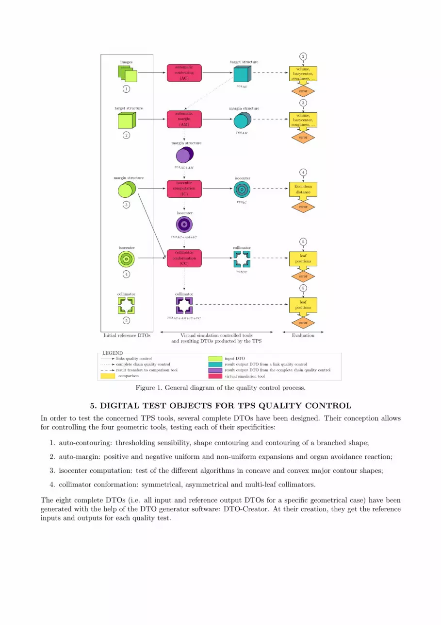
For a quality control of the whole chain, only the image part of the DTO is taken for input of the TPS. Thephysicist computes each step of the beam parameterization following the instructions for the applied test. Atthe end of this chain, the treatment planning system gives a beam specification that defined the volume thatwill be irradiated. The quality control consists then to use this information and the reference beam parametersto compare the theoretical irradiated volume to the one defined by the TPS. Figure 1 shows how the qualityassessment is organized. The quality control of each link of the chain is described as well as the quality controlof the complete and partial chains. In each case, inputs, reference and resulting outputs and the quantitativequality assessment methods are described.
It is moreover possible to individually test each link of this parameterization chain. The first one is theautomatic contouring of the volume. The input of the TPS is then only the geometrical part of the testobject. The result of the automatic shape contouring by the TPS is compared to the structure of the theoreticalcontouring, meaning the analytic description of the tested shape. For the auto-margin test, the input test objectis the reference output test object of the first link of the chain, in order to have the structure that exactly fitsthe tested shape of the geometric test object. The expansion of the ROI is done on the TPS following thequality test requirements. The result of this manipulation is compared with the description of the theoreticalvolume expansion by the specified margins in each spatial direction. For some tests as the analysis of the slicethickness taking into account a three dimensional expansion, several methods can be used and in this caseseveral references can be computed. The TPS result is thus described in function of theses reference structuresin order to characterize the TPS expansion algorithm. All of these reference structures of the expansion test aretaken as input for the isocenter calculation test. The physicist can then ask the TPS to compute the isocentercoordinates. The beam information files are then used for the reference result since containing the theoreticalisocenter position for a given ROI. Moreover the same input can be used for the collimator conformation test.In the same way, the test object beam information can be used as the reference output. The chain of the beamparameterization can now completely be tested. In this purpose, the input of the TPS is the same as the firstlink test input DTO, and the reference output the same as the reference output DTO of the last tested link.
images
1
target structure
2
margin structure
3
isocenter
4
collimator
5
automaticcontouring
(AC)
automaticmargin(AM)
isocentercomputation
(IC)
collimatorconformation
(CC)
target structure
resAC
margin structure
resAM
isocenter
resIC
collimator
resCC
margin structure
resAC+AM
isocenter
resAC+AM+IC
collimator
resAC+AM+IC+CC
2
3
4
5
5
volume,barycenter,roughness, ...
volume,barycenter,roughness, ...
Euclideandistance
leafpositions
leafpositions
error
error
error
error
error
EvaluationVirtual simulation controlled toolsand resulting DTOs producted by the TPS
Initial reference DTOs
LEGENDlinks quality controlcomplete chain quality controlresult transfert to comparison toolcomparison
input DTOresult output DTO from a link quality controlresult output DTO from the complete chain quality controlvirtual simulation tool
Figure 1. General diagram of the quality control process.
5. DIGITAL TEST OBJECTS FOR TPS QUALITY CONTROLIn order to test the concerned TPS tools, several complete DTOs have been designed. Their conception allowsfor controlling the four geometric tools, testing each of their specificities:
1. auto-contouring: thresholding sensibility, shape contouring and contouring of a branched shape;
2. auto-margin: positive and negative uniform and non-uniform expansions and organ avoidance reaction;
3. isocenter computation: test of the different algorithms in concave and convex major contour shapes;
4. collimator conformation: symmetrical, asymmetrical and multi-leaf collimators.
The eight complete DTOs (i.e. all input and reference output DTOs for a specific geometrical case) have beengenerated with the help of the DTO generator software: DTO-Creator. At their creation, they get the referenceinputs and outputs for each quality test.
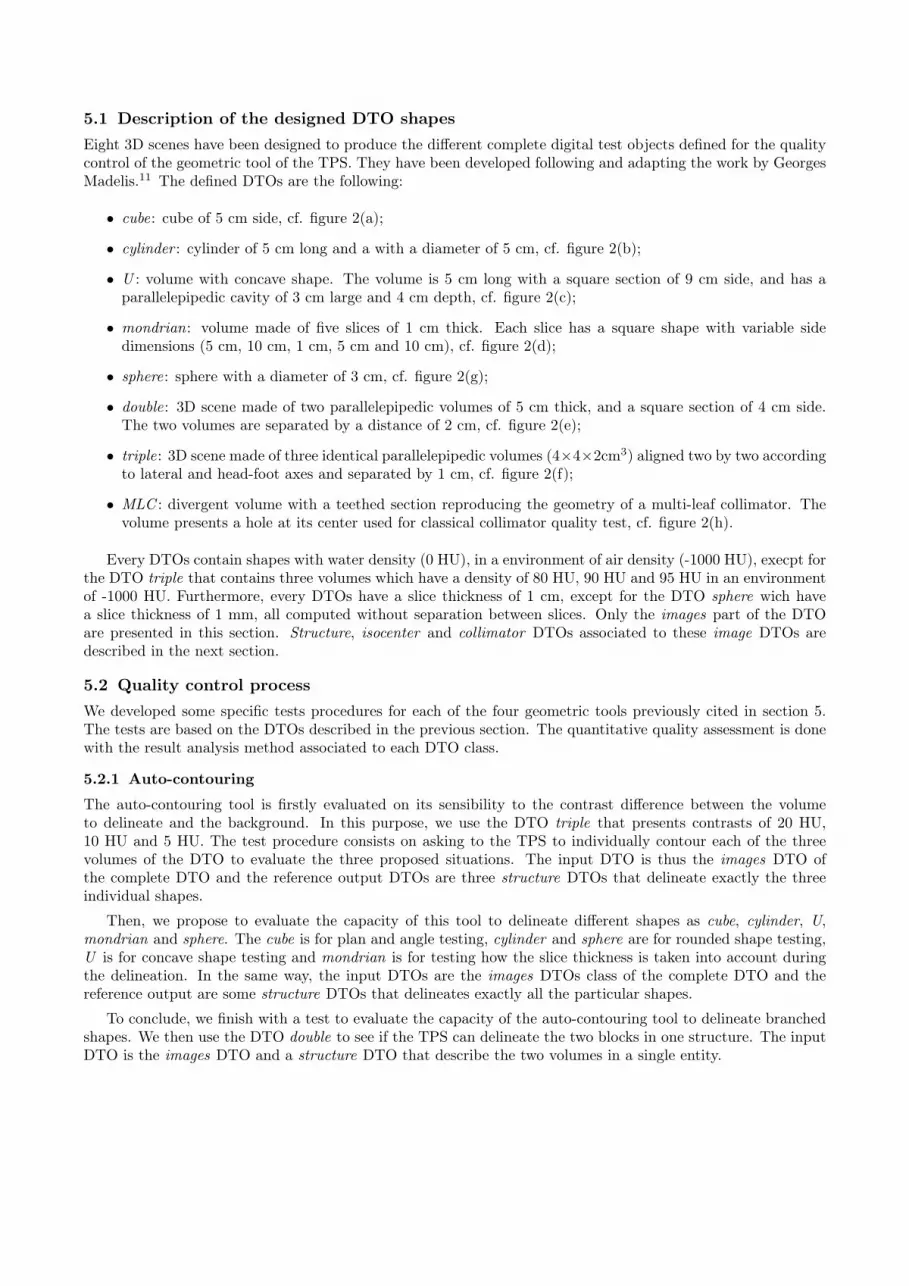
5.1 Description of the designed DTO shapesEight 3D scenes have been designed to produce the different complete digital test objects defined for the qualitycontrol of the geometric tool of the TPS. They have been developed following and adapting the work by GeorgesMadelis.11 The defined DTOs are the following:
• cube: cube of 5 cm side, cf. figure 2(a);
• cylinder : cylinder of 5 cm long and a with a diameter of 5 cm, cf. figure 2(b);
• U : volume with concave shape. The volume is 5 cm long with a square section of 9 cm side, and has aparallelepipedic cavity of 3 cm large and 4 cm depth, cf. figure 2(c);
• mondrian: volume made of five slices of 1 cm thick. Each slice has a square shape with variable sidedimensions (5 cm, 10 cm, 1 cm, 5 cm and 10 cm), cf. figure 2(d);
• sphere: sphere with a diameter of 3 cm, cf. figure 2(g);
• double: 3D scene made of two parallelepipedic volumes of 5 cm thick, and a square section of 4 cm side.The two volumes are separated by a distance of 2 cm, cf. figure 2(e);
• triple: 3D scene made of three identical parallelepipedic volumes (4×4×2cm3) aligned two by two accordingto lateral and head-foot axes and separated by 1 cm, cf. figure 2(f);
• MLC : divergent volume with a teethed section reproducing the geometry of a multi-leaf collimator. Thevolume presents a hole at its center used for classical collimator quality test, cf. figure 2(h).
Every DTOs contain shapes with water density (0 HU), in a environment of air density (-1000 HU), execpt forthe DTO triple that contains three volumes which have a density of 80 HU, 90 HU and 95 HU in an environmentof -1000 HU. Furthermore, every DTOs have a slice thickness of 1 cm, except for the DTO sphere wich havea slice thickness of 1 mm, all computed without separation between slices. Only the images part of the DTOare presented in this section. Structure, isocenter and collimator DTOs associated to these image DTOs aredescribed in the next section.
5.2 Quality control processWe developed some specific tests procedures for each of the four geometric tools previously cited in section 5.The tests are based on the DTOs described in the previous section. The quantitative quality assessment is donewith the result analysis method associated to each DTO class.
5.2.1 Auto-contouring
The auto-contouring tool is firstly evaluated on its sensibility to the contrast difference between the volumeto delineate and the background. In this purpose, we use the DTO triple that presents contrasts of 20 HU,10 HU and 5 HU. The test procedure consists on asking to the TPS to individually contour each of the threevolumes of the DTO to evaluate the three proposed situations. The input DTO is thus the images DTO ofthe complete DTO and the reference output DTOs are three structure DTOs that delineate exactly the threeindividual shapes.
Then, we propose to evaluate the capacity of this tool to delineate different shapes as cube, cylinder, U,mondrian and sphere. The cube is for plan and angle testing, cylinder and sphere are for rounded shape testing,U is for concave shape testing and mondrian is for testing how the slice thickness is taken into account duringthe delineation. In the same way, the input DTOs are the images DTOs class of the complete DTO and thereference output are some structure DTOs that delineates exactly all the particular shapes.
To conclude, we finish with a test to evaluate the capacity of the auto-contouring tool to delineate branchedshapes. We then use the DTO double to see if the TPS can delineate the two blocks in one structure. The inputDTO is the images DTO and a structure DTO that describe the two volumes in a single entity.
5 cm
5 cm 5 cm
zx
yx
(a) Views of the volume of DTO cube.
5 cm
5 cm 5 cm
zx
yx
(b) Views of the volume of DTO cylinder.
9 cm
9 cm
3 cm 3 cm 3 cm
4 cm
5 cmz
xy
x
(c) of the volume of DTO U.
10 cm
10 cm
5 cm
10 cm5 cm1 cm
zx
yx
(d) Views of the volume of DTO mondrian.
4 cm 2 cm 4 cm
4 cm 5 cmzx
yx
(e) Views of the volume of DTO double.
4 cm 2 cm 4 cm
4 cm2 cm1 cm2 cm
zx
yx
(f) Views of the volume of DTO triple.
3 cm
3 cm 3 cm
zx
yx
(g) Views of the volume of DTO sphere.
20 cm
20 cm 20 cm
zx
y = 0
yx
(h) Views of the volume of OTN MLC.
Figure 2. Diagrams of the DTO used of geometric TPS tools quality control. The volumes are sliced along the Y axis.
5.2.2 Auto-margin
We propose nine test procedures to evaluate the quality of the auto-margin TPS tool. The first eight proceduresare carried out with the DTOs cube, cylinder and U to test the positive and negative margins as well as theuniform and non uniform margins. Indeed, a margin is considerate as uniform if it has the same dimensions inthe six directions of the 3D space. The input DTOs of these tests are the images DTOs on which the TPS hasto proceed the following expansions or erosion:
1. positive and negative uniform margin of 1 cm;
2. positive and negative uniform margin of 2 cm;
3. positive and negative non uniform margin of type 1;
4. positive and negative non uniform margin of type 2;
We consider that non uniform margin that conserve the same dimensions for the two directions of a single axisare of type 1 and the other ones are of type 2. If X is the direction for the right of a patient, Y the direction ofhis head and Z is the top direction, we propose for the type 1, a margin of 1.5 cm along X axis, 1 cm along Y
axis and 0.5 cm along Z axis. For the non uniform margin of type 2, we propose a margin of 1.5 cm along X+
(positive direction of X axis), 0.5 cm along X− (negative direction of X axis), 2 cm along Y +, 1 cm along Y −,0.5 cm along Z+ and 1.5 cm along Z−.
The ninth test controls the TPS capacity to avoid a specific region as healthy organs for instance. The DTOdedicated to this test is the DTO triple. Input DTO is the images part and two structure DTOs that delineatethe central volume in one hand, and the two others in a second hand. It is then asked for the TPS to apply a2cm positive margin on the central block, avoiding the other ones, along the slice axis and inside each slice.
Each TPS does not consider the slice thickness in the same way for the auto-margin operation. Some considerthe center of the external voxels as the boundary of the shape, and other consider the edge of these voxels. Wedeveloped reference output DTOs for the two models as standard to characterize the TPS.
5.2.3 Isocenter computation
A TPS usually presents several isocenter positioning algorithms. The isocenter can be placed at the center ofgravity of
• the input structure;
• the parallelepiped including the structure;
• the projection of the structure, at a level chosen by the user.
Three isocenter reference DTOs are computed for the DTOs U, mondrian and double. The input DTOs belongto the images and structure classes. The structure inputs delineate the shape of each DTO volume.
5.2.4 Collimator conformation
We propose to control the conformation of the classical collimators and multi-leaf collimators. The DTO MLCis dedicated to this control. It is basically composed of the images DTO, two structure DTOs (one delineatingthe whole volume and one delineating the hole in the volume), several isocenter DTOs and the reference outputDTOs of each of the proposed tests. Each test consists on conforming the collimator to the input structure usingthe input isocenter. Output DTOs belong to the collimator class.
To control the symmetric collimators conformation, we use the volume structure DTO and an isocenterDTO positioned at the center of the volume. The output DTOs are the perfect collimator conformation to thestructure, with a 0˚or with a 45˚collimator rotation angle. To control the asymmetric collimators conformation,we use the hole structure DTO and an isocenter DTO positioned near a corner of the hole in the volume. Theoutput DTO is the perfect collimator conformation to the hole structure, with a 0˚collimator rotation angle.
The MLC quality control requires several tests to be efficient. The first one consists on conforming thecollimator to the teethed volume, with a central isocenter and a non rotated collimator. It allows for checkingeach leaf positioning. The other tests focus on testing the three conformation algorithms associated to the MLC:
1. all the leaf edges are positioned outside the structure ("outside" algorithm);
2. the centers of the leaf edge are positioned on the structure boundary ("median" algorithm);
3. all the leaf edges are positioned inside the structure ("inside" algorithm).
The tests of these algorithms are also carried out using a central isocenter but conforming the collimator to thehole structure and with a rotation angle of 45˚. The reference output collimator DTOs corresponding to thethree algorithms are developed and included in the complete DTO.

5.2.5 Complete chain quality control
We also propose a test to study the error propagation in the whole geometrical treatment planning process. Weuse the DTO sphere. The input DTO is only the images part of the DTO. The reference output collimatorDTO is the theoretical result of an auto-contouring, a uniform auto-margin of 1 cm, an isocenter positioning atthe barycenter of the structure, following by the conformation of a classical collimator and of an MLC, with a"median" algorithm.
6. RESULTS
All the previously presented tests were carried out on the TPS Varian Eclipse (version 7.5.51) at the radiotherapydepartment of the hospital of La Roche-sur-Yon (France). The four geometric tools have been tested individuallyas well as the whole geometrical planning chain. The quality control showed an accurate quantitative qualityassessment and was very fast. Half a day was enough to proceed the complete quality control. A qualityassessment using PTOs takes more time because of the multiple objects positioning and acquisitions.
6.1 Auto-contouringThe controlled TPS presented good results for auto-contouring. The sensibility criterion showed some particu-larities of the TPS in terms of 3Dl reconstruction of the virtual model.
6.1.1 Sensibility
We used two versions of the DTO triple to test this criterion. The first one presented three blocks with densitiesof 80 HU, 90 HU and 95 HU in a 100 HU environment, and the second one presented three blocks with densities of120 HU, 110 HU and 105 HU in a 100 HU environment too. We compared the auto-contouring of each block withthe corresponding reference output DTO. The differences mainly lied in the volume of the resulted structures.Despite the binary values of the DTO densities, the resulted structure depends on the threshold chosen by theoperator. The nearer the threshold from the density of the block, smaller the delimited volume. This shows thatthe TPS 3D reconstruction is done using interpolations. Nevertheless, the center of gravity and the roughnessof the result DTOs are similar to the reference DTOs.
6.1.2 Shape contouring
Shape contouring did not show significant errors. It was performed on the DTOs cube, cylinder, U and mondrian.Volume errors were inferior to 1% for the cube, cylinder and mondrian, and centers of gravity were at the sameposition. The concave shape was delineated with a volume 2% inferior to the reference. Roughness was the sameas the reference DTOs for the cube, U and mondrian. However, the roughness of the cylinder was 6.5% superiorto the one of the reference output DTO. That reflects the TPS difficulties to delineate a rounded shape.
6.1.3 Branched shape
The branched shape contouring was tested with the DTO double. Eclipse proceeded well to this exercise. Everyresult parameters were the same as the ones of the reference output DTO.
6.2 Auto-marginThe uniform and non uniform auto-margins were performed on the DTOs cube, cylinder and U. The avoidancetest were performed on the DTO triple. Two reference output DTOs were computed for each test as we definedthem for the two slice thickness interpretation modes. During the quality control of Eclipse, we observed lessdifference between the DTOs that take the slice thickness into account and the resulting DTO than between theDTOs that do not take the slice thickness into account and the resulting ones. Consequently, we considered onlythe first series as standard for the TPS auto-margin tool.
6.2.1 Uniform margins
Positive uniform margins seem to be well computed by Eclipse. However, volumes are generally smaller in theirresults than in the references. For a 1 cm margin, the volumes are 1% to 2% smaller, and for a 2 cm margin, thevolumes are about 3% smaller. Centers of gravity are respected but the resulted structures are rougher (from0.5% to 2.5% more). The 2 cm margin fills the cavity of the concave DTO as it was planned.
No difference was found between results and references for the 1 cm negative uniform margin. However, the2 cm negative uniform margin test showed a volume error of 7% smaller for the DTO cylinder that highlightssome erosion algorithm defaults. Moreover, the branch parts of the concave shape disappear with this marginmaking an irregular contour in the TPS result DTO. That imply a volume 15% bigger in the Eclipse result.
6.2.2 Non uniform margins
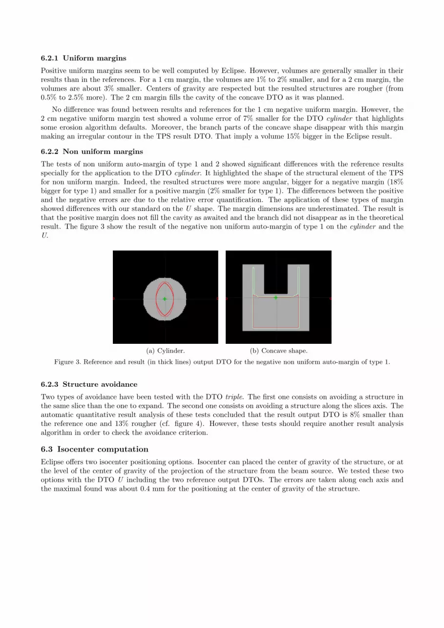
The tests of non uniform auto-margin of type 1 and 2 showed significant differences with the reference resultsspecially for the application to the DTO cylinder. It highlighted the shape of the structural element of the TPSfor non uniform margin. Indeed, the resulted structures were more angular, bigger for a negative margin (18%bigger for type 1) and smaller for a positive margin (2% smaller for type 1). The differences between the positiveand the negative errors are due to the relative error quantification. The application of these types of marginshowed differences with our standard on the U shape. The margin dimensions are underestimated. The result isthat the positive margin does not fill the cavity as awaited and the branch did not disappear as in the theoreticalresult. The figure 3 show the result of the negative non uniform auto-margin of type 1 on the cylinder and theU.
(a) Cylinder. (b) Concave shape.
Figure 3. Reference and result (in thick lines) output DTO for the negative non uniform auto-margin of type 1.
6.2.3 Structure avoidance
Two types of avoidance have been tested with the DTO triple. The first one consists on avoiding a structure inthe same slice than the one to expand. The second one consists on avoiding a structure along the slices axis. Theautomatic quantitative result analysis of these tests concluded that the result output DTO is 8% smaller thanthe reference one and 13% rougher (cf. figure 4). However, these tests should require another result analysisalgorithm in order to check the avoidance criterion.
6.3 Isocenter computationEclipse offers two isocenter positioning options. Isocenter can placed the center of gravity of the structure, or atthe level of the center of gravity of the projection of the structure from the beam source. We tested these twooptions with the DTO U including the two reference output DTOs. The errors are taken along each axis andthe maximal found was about 0.4 mm for the positioning at the center of gravity of the structure.

(a) (b)
Figure 4. Avoidance test result with Eclipse (reference output DTO in thin lines and result output DTO in thick lines).
6.4 Collimator conformationWe tested the Eclipse tool for collimator conformation with the dedicated DTO MLC, for classical and multi-leafcollimators. The collimator result DTO of classical collimator test was analyzed with the appropriate quantitativemethod and no position error was found for symmetrical and asymmetrical collimator conformation.
For the MLC conformation verification, we firstly used the teethed shape, without rotation angle, and thenwe tested the three conformation algorithms. The mean leaf position error was about 0.2 mm but the maximalerror was about 2 mm for all the tests. However we could remark studying the displays and the detailed resultanalysis that some leafs present an excessive closing.
6.5 Complete chain quality controlThe complete beam parametrization process was tested with the DTO sphere. We proceeded to an auto-contouring, an auto-margin of 1 cm and a classical symmetric conformation as well as an MLC conformation.The result output DTOs were compared to the references with the automatic collimator DTO quantitativeanalysis method. We could thus study the error propagation in the whole chain. Very few errors were found onthe classical collimator and MLC conformation. Theoretical and resulting irradiated surfaces differed from lessthan 1 mm2. Thus, we can conclude that the Eclipse beam parametrization process quality is satisfying for thetested conditions.
7. DISCUSSION
The major particularity of the digital test objects is that they do not need to be acquired by a CT-scanneroperation. This insures a perfect positioning of the shapes in the volume that is not guaranteed by the useof a physical test object due to possible errors on the object alignment on the CT-scanner table. Moreover,the CT-scanner acquisition introduces blur, noise and spatial distortions in the digital 3D representation of thephantom. This perfect positioning and non deteriorated object contribute to a real quality assessment becausebiases are not introduced at the TPS test input.
A physical test object like the Modus Quasar phantom allows to test the whole beam parametrization chainbut not each individual link because of its time-consuming CT-scanner acquisition. Indeed, for the auto-margintest for instance, it is necessary to first compute a targeting in order to obtain the volume to expand. If the TPSpresents some error in its targeting tools, then it will be difficult to isolate the expansion ones from them. Thus,the expansion error assessment will depends on the targeting performance of the treatment planning system.
Digital test objects are complete objects. Contrary to the physical ones, they contain structures and beamsinformation. Thus, it is possible to have input and output references for each test. The results of the TPS canbe compared to the theoretical response for the given quality test. This leads to the opportunity to define anautomatic result analysis method in order to quantify the treatment planning system errors.13 It is moreovereasy to display the theoretical result and the real one to visualize the differences.
Only the Digital Test Objects allow a complete quality control for treatment planning systems. MoreoverDTOs are in all situations more accurate than physical test objects. A fully automatic quality assessment isobtained thanks to the objects digital nature and leads to a less time-consuming quality control process as theydo not need a CT-scanner acquisition.
8. CONCLUSION
A new quantitative quality assessment method for geometrical treatment planning tools has been developed.This method, based on the use of digital test objects, allows an accurate control of each individual tool withoutbeing dependent on the quality of the other tools. The quality assessment is automatic and quantitative. Thistechnique leads to a fast quality control with a precise and complete error computation. Some test procedureshave been defined but it is easy to establish new one just adding new DTOs to the complete one. Our methodologyallows to control each tool individually as well as the entire or partial beam parametrization procedure.
REFERENCES1. T. Craig, D. Brochu, and J. Van Dyk, “A quality assurance phantom for three-dimensional radiation treat-
ment planning,” Int. J. Radiat. Oncol. Biol. Phys. 44(4), pp. 955–966, 1999.2. J.-N. Foulquier, “Contrôle de qualité d’une installation de simulaiton virtuelle. les outils de le simulation
virtuelle,” tech. rep., Hôpital Tenon, service de radiothérapie, unité de physique médicale, Paris, 2002.3. E. Denis, S. Beaumont, and J.-P. Guédon, “Digital reconstructed radiography quality control with software
methods,” in Proceedings of SPIE, Medical Imaging 2005: Physics of medical imaging, M. Flynn, ed., 5745,pp. 1002–1013, SPIE, 2005.
4. E. Denis, J.-P. Guédon, S. Beaumont, and N. Normand, “Discrete and continuous description of a threedimensional scene for quality control of radiotherapy treatment planning systems,” in Proceedings of SPIE,Medical Imaging 2006: Physics of medical imaging, M. Flynn, ed., 6142, SPIE, 2006.
5. E. Denis, S. Beaumont, J.-P. Guédon, N. Normand, and T. Torfeh, “Automatic quality control of digitallyreconstructed radiograph computation and comparison with standard methods,” in Proceedings of SPIE,Medical Imaging 2007: Physics of medical imaging, M. Flynn, ed., 6510, SPIE, 2007.
6. B. Fraas, K. Doppke, M. Hunt, G. Kutcher, G. Starkschall, and J. Stern, R. Van Dyke, “American Associa-tion of Physicists in Medicine Radiation Therapy Committee Task Group 53: Quality assurance for clinicalradiotherapy treatment planning,” Med. Phys. 25, pp. 1773–1829, October 1998.
7. S. Mutic, J. Palta, E. Butker, I. Das, M. Huq, L.-N. Dick Loo, B. Salter, C. McCollough, and J. Van Dyk,“Quality assurance for computed-tomography simulators and the computed-tomography-simulation process:Report of the AAPM Radiation Therapy Committee TG No.66,” Med. Phys. 30(10), pp. 2762–2792, 2003.
8. P. Andreo, M. Cohen, J. Gultresa, J. Haywood, J. Novotny, M. Oresegun, P. Ortiz-López, D. Seng, M. Sto-vall, J. van de Geijn, J. Vivanco, and P. Zúgniga Bello, “Lessons learned from accidental exposures inradiotherapy,” Safety Reports Series Nř17, International Atomic Energy Agency (IAEA), 2000.
9. P. Andreo, J. Cramb, B. Fraass, F. Ionescu-Farca, J. Izewska, V. Levin, B. Mijnheer, J.-C. Rosenwald,P. Scalliet, K. Shortt, J. Van Dyk, and S. Vatnitsky, “Commissioning and quality assurance of computerizedplanning systems for radiation treatment of cancer,” Tech. Rep. 430, IAEA, 2004.
10. Modus, “Quality assurance system for advanced radiotherapy,” Phys. Med. Biol. 47(9), pp. 1485–1492, 2002.11. G. Madelis, Assurance qualité et analyse des incertitudes en radiotherapie conformationnelle pour le cancer
de la prostate. PhD thesis, Université de Toulouse 3, Toulouse, France, 1999.12. NEMA, “Digital Imaging and Communications in Medicine (DICOM),” tech. rep., National Electrical Man-
ufacturers Association, 2007.13. QualiFormeD. http://www.qualiformed.com.
Related Documents