Neutronic performance of coupled hybrid blanket fueled with ThO 2 and UO 2 H€ useyin Yapıcı a, * , Osman Ipek b a M€ uhendislik-Mimarlık Fak€ ultesi, Erciyes € U niversitesi, 38039 Tulas, Kayseri, Turkey b M€ uhendislik-Mimarlık Fak€ ultesi, S€ uleyman Demirel € U niversitesi, 32260 Isparta, Turkey Received 4 December 2001; received in revised form 11 May 2002; accepted 2 September 2002 Abstract The main purpose of this study is to investigate the blanket models fueled with ThO 2 and UO 2 that provide the best coupled breeding performance and neutronic behavior as a function of volume fraction under resonance and resonance-free effects. First wall load is taken into consideration as 1 MW/m 2 . The blanket considered in this study contains two fissile fuel zones, which are the fast fission (FF) fuel breeding zone fueled with ThO 2 behind the first wall and the thermal fission (TF) fuel breeding zone fueled with UO 2 for coupled breeding. The fissile fuel blankets mentioned above have been cooled with 4 He and H 2 O coolants, respectively. Each of the fissile fuel zones, containing five fuel rod rows in the radial direction, has been divided into five sub-zones, which correspond to the fuel rows in the fissile zone. The cylindrical fusion plasma chamber, surrounded by the first wall, has 150 cm chamber dimension. The maximum fissile fuel breeding ratios in the FF fuel breeding zone and the TF fuel breeding zone are 0.255 and 0.318, respectively. The fissile fuel breeding ratio and fission spectrum in the FF fuel breeding zone decrease in the radial direction due to the fissioning of the 232 Th by only the energetic neutrons. However, the above mentioned parameters in the TF fuel breeding zone increase up to the center interval of the blankets due to the additional increment of the thermal neutron population caused by H 2 O. After this point, where the above mentioned parameters are maximum, these parameters decrease rapidly in the radial direction due to the decrease of the thermal neutron population. The highest value of the tritium breeding ratio (TBR), indicating the fusil fuel breeding for the fusion reaction, is 1.096 for the above mentioned situation. The blanket models with resonance cases are self sufficient in respect to TBR. The peak-to-average fission power ratio C varies between 1.251 and 1.392 for the system. However, the C value is about 1.392 in the FF fuel breeding zone, and varies between 1.251 and 1.375 in the TF fuel breeding zone. The a parameter, known as the capture-to-fission ratio and defined as energy-dependent, varies between 4.129 and 6.107 in the FF zone fueled with ThO 2 . This variation becomes between 9.031 and 28.428 in the Energy Conversion and Management 44 (2003) 1853–1873 www.elsevier.com/locate/enconman * Corresponding author. Tel.: +90-352-437-4901; fax: +90-352-437-5784. E-mail addresses: [email protected] (H. Yapıcı), [email protected] (O. Ipek). 0196-8904/02/$ - see front matter Ó 2002 Elsevier Science Ltd. All rights reserved. PII:S0196-8904(02)00215-7

Welcome message from author
This document is posted to help you gain knowledge. Please leave a comment to let me know what you think about it! Share it to your friends and learn new things together.
Transcript
Neutronic performance of coupled hybrid blanket fueledwith ThO2 and UO2
H€uuseyin Yapıcı a,*, Osman Ipek b
a M€uuhendislik-Mimarlık Fak€uultesi, Erciyes €UUniversitesi, 38039 Tulas, Kayseri, Turkeyb M€uuhendislik-Mimarlık Fak€uultesi, S€uuleyman Demirel €UUniversitesi, 32260 Isparta, Turkey
Received 4 December 2001; received in revised form 11 May 2002; accepted 2 September 2002
Abstract
The main purpose of this study is to investigate the blanket models fueled with ThO2 and UO2 that
provide the best coupled breeding performance and neutronic behavior as a function of volume fractionunder resonance and resonance-free effects. First wall load is taken into consideration as 1 MW/m2. The
blanket considered in this study contains two fissile fuel zones, which are the fast fission (FF) fuel breeding
zone fueled with ThO2 behind the first wall and the thermal fission (TF) fuel breeding zone fueled with UO2for coupled breeding. The fissile fuel blankets mentioned above have been cooled with 4He and H2O
coolants, respectively. Each of the fissile fuel zones, containing five fuel rod rows in the radial direction, has
been divided into five sub-zones, which correspond to the fuel rows in the fissile zone. The cylindrical fusion
plasma chamber, surrounded by the first wall, has 150 cm chamber dimension.
The maximum fissile fuel breeding ratios in the FF fuel breeding zone and the TF fuel breeding zone are0.255 and 0.318, respectively. The fissile fuel breeding ratio and fission spectrum in the FF fuel breeding
zone decrease in the radial direction due to the fissioning of the 232Th by only the energetic neutrons.
However, the above mentioned parameters in the TF fuel breeding zone increase up to the center interval of
the blankets due to the additional increment of the thermal neutron population caused by H2O. After this
point, where the above mentioned parameters are maximum, these parameters decrease rapidly in the radial
direction due to the decrease of the thermal neutron population. The highest value of the tritium breeding
ratio (TBR), indicating the fusil fuel breeding for the fusion reaction, is 1.096 for the above mentioned
situation. The blanket models with resonance cases are self sufficient in respect to TBR.The peak-to-average fission power ratio C varies between 1.251 and 1.392 for the system. However, the
C value is about 1.392 in the FF fuel breeding zone, and varies between 1.251 and 1.375 in the TF fuelbreeding zone.
The a parameter, known as the capture-to-fission ratio and defined as energy-dependent, varies between4.129 and 6.107 in the FF zone fueled with ThO2. This variation becomes between 9.031 and 28.428 in the
Energy Conversion and Management 44 (2003) 1853–1873www.elsevier.com/locate/enconman
*Corresponding author. Tel.: +90-352-437-4901; fax: +90-352-437-5784.
E-mail addresses: [email protected] (H. Yapıcı), [email protected] (O. Ipek).
0196-8904/02/$ - see front matter � 2002 Elsevier Science Ltd. All rights reserved.
PII: S0196-8904(02)00215-7
TF zone fueled with UO2. A high value of a means a low probability of fission following neutron ab-sorption, and conversely, a low value of a means a high probability of fission. Therefore, the probability offission following neutron capture is higher in the FF zone of ThO2 than that in the TF zone. The lowest and
highest a values are obtained in the FF zone fueled with ThO2 under resonance effect and in the TF zonefueled with UO2 under resonance-free effect.
� 2002 Elsevier Science Ltd. All rights reserved.
1. Introduction
The planning of energy production and its usage has been considered a fairly and unavoidablyuseful tool in the period in which existing energy sources tend to be exhausted, and environmentalproblems are becoming bigger and bigger because of energy production and usage. On the otherhand, mankind needs large amounts of sustainable energy for economic and social developmentand improved quality of life. Therefore, the growing needs for energy in the world make it nec-essary to seek new energy resources. Considering the finiteness of the earth�s natural resources andthe global impacts on the environment, fossil fuels cannot be used forever. The supply potential ofrenewable energy sources to provide the whole energy consumption of human beings is uncertain,since they have low energy density and are currently not suitable for meeting base load energydemand [1]. By taking into consideration the above mentioned realities, it can be concluded thatone of the most important resources for the next century will be a safe, reliable and clean supply ofenergy. It is obvious that the usage of the fossil fuels must be restricted. Therefore, this restrictionwill cause an important gap in global energy production.Nuclear energy in the form of fission technology has been proposed to replace fossil fuels as the
primary energy source for the future [2–4]. Preliminary studies indicate that towards the end of thecentury, most electricity production will be covered by LWRs and coal based systems. LWRscould work with fissile fuel produced from UO2 and ThO2. In LWRs, the isotope
235U that can besubjected to a fission reaction by thermal neutrons has an abundance percentage of 0.7 in naturaluranium, and fissioning of this isotope is the main energy source. The other isotope 238U cannotparticipate in a fission reaction with thermal neutrons, so it is a waste material for LWRs. Thespent fuel problem has prevented nuclear power from claiming to be a completely clean energysource. Many investigations have been performed to solve the spent fuel problem [5–15].At the end of the century, there will be great demand for fissile nuclear fuel due to the projected
large number of LWRs. As fissile fuel resources are rather limited, research on fusion reactors hasbeen intensified throughout the world, especially in the last decade, in order to use the practicallyunlimited deuterium sources as nuclear fuel.Recent progress on the fusion plasma researches have made it possible to proceed intensively
toward a development plant for a breeding blanket system, aiming at electric power generation infusion reactors. As a most realistic blanket system to produce high heat for power generation, asolid breeder blanket cooled by high temperature pressurized water has been proposed and ap-plied in design studies [16,17]. Fusion, another nuclear energy process, is safer and cleaner thenfission and has been known for more than 40 years. The major fusion fuel cycle that has beenexamined is the reaction between deuterium and tritium. To get the benefits of nuclear fusion, to
1854 H. Yapıcı, O. Ipek / Energy Conversion and Management 44 (2003) 1853–1873
Nomenclature
A under resonance effectB under resonance-free effectC energy conversion factor, 1:602189� 10�13 J/MeVD deuteriumD–T deuterium tritium fusion reactionERPF energy release per fission, 200 MeVE neutron energyERexo energies following related 6Li(n,42He)T nuclear reactions, 4.784 MeV/(n cm
3)ERendo energies following related 7Li(n,n0,42He)T nuclear reactions, )2.467 MeV/(n cm
3)FF fast fissionFFZ fast fission zoneFR fusion radiusFW first wallFWA area of FW, 2pRL (cm2)HP heat production, W/cm3
i energy group number of neutronL height of blanket, 1 cmLe neutron leakageLethargy Du ¼ ln½Ei=ðEiþ1 � EiÞ, i ¼ 1; 2; . . . ; 238ÞM energy multiplication ratio (total energy (MeV)/14.1 MeVþ 1)R radius of first wall, 150 cmRF reflectorSH shieldingT tritiumTB tritium breedingTBR tritium breeding ratioTBZ tritium breeding zoneTF thermal fissionTFZ thermal fission zoneT6 T breeding from 6Li(n,42He)T reactionT7 T breeding from 7Li(n,n0,42He)T reaction232Thc
233U breeding from ThO2 (232Th(n,c)233U)
238Uc239Pu breeding from UO2 (
238U(n,c)239Pu)V volume
Greek symbolsa capture-to-fission ratioaTh-232 232Thc/
232ThfaU-238 238Uc/
238Uf
e Vm=Vf , volumetric ratio of coolant-to-fuelU flux, 0:443� 1014 (n/(s cm2)) for 1 MW/m2 (D–T) fusion neutron load
H. Yapıcı, O. Ipek / Energy Conversion and Management 44 (2003) 1853–1873 1855
put them forward and to get rid of the negative results of nuclear fission for the near future,another reactor, the fusion–fission hybrid reactor concept, has been developed [1–3,5,8–12,14,16–24]. Because of the introduction of fissile and fertile materials into the blanket, fission reactor fuelcycle considerations are also introduced. The fusion–fission reactor is a possible future resource.The concept of using a fissile and fertile blanket on a fusion reactor has recently received in-creasing interest. Consequently, the spent fuel not used in existing nuclear reactors will be used inthe coupled hybrid blanket.The coupled hybrid blanket offers important potential advantages. The energy amplification
provided by fission in the blanket can boost the reactor energy output and relieve the fusionperformance requirements. Fissile fuel bred in the blanket can provide revenue to help the reactoreconomics. Recently, the subject of many scientific publications and conceptual design studies ofthe new reactor systems have focused on fusion–fission hybrid reactors [1,5,9,11,12,14–16,21,22,24]. These hybrid reactors can be classified into two types according to their purpose.The fissile fuel producing hybrid reactor constitutes part of a symbiotic electricity generationsystem with a fission reactor, whose fuel is supplied by the hybrid reactor. On the other hand, anelectricity producing hybrid reactor generates electric power in a stand alone manner, independentof the fission reactor. The possibility of rejuvenation of spent nuclear fuel in the hybrid blanket isa popular application field for an early generation fusion reactor.In this study, the coupled fissile breeding performance, fission spectrum, flux distribution in
selected intervals and the neutronic behavior of coupled hybrid blankets fueled with ThO2 andUO2 have been investigated as a function of volume fraction under a 1 MW/m
2 first wall load.Taking into consideration principally the D–T neutrons that reach the first wall of a plasma powersource in the investigated blankets, the calculations have been performed for both resonance andresonance-free situations. In this study, the fusion source of neutrons of 14.1 MeV is simulated bya movable target along the main axis of the cylindrical hybrid blanket as a line source of fusionneutrons. The conventional (D–T) fusion reaction fast neutron source is given by
Dþ T! 42He ð3:5 MeVÞ þ n ð14:1 MeVÞ ð1Þ
Rf total fission rate in first fuel zone (1/n cm3)mP
f fission neutron breedingC peak-to-average fission power ratiod thickness of blanket
SubscriptsRPF release per fissionexo exothermicendo endothermicf fissile fuelm coolantTF thermal fissionp productionc (n,c) reaction
1856 H. Yapıcı, O. Ipek / Energy Conversion and Management 44 (2003) 1853–1873
In the (D–T) reaction, although the amount of the D fusile fuel component is available, the T(tritium) component needs to be produced, since it is an artificial element. The tritium breeding(fusile breeding) takes place in the TBZ, which contains Li2O. However, all natural lithium iscomposed of 7.42% 6Li and 92.58% 7Li. The breeding reactions are
6Liþ n! 42Heþ Tþ 4:784 ðMeVÞ ð2Þ
7Liþ n! 42Heþ T� 2:467 ðMeVÞ ð3Þ
On the other hand, Eqs. (2) and (3) are also designated as 6Li(n,42He)T and7Li(n,n0,42He)T, res-
pectively.The fissile fuel breeding reaction results from the fertile-fissile conversion with the (n,c) reaction
in the fertile blanket. The production of fissile fuel from the fertile(fissionable) fuel in the fuel zoneof the blanket results from the following fission reaction:
Fertile fuelþ n! Fissile fuelþ mn0 þ ERPF ðMeVÞ ð4Þ
The neutron, which is on the left hand side of Eqs. (3) and (4) (i.e. n) and starts the reaction, is afast neutron, and the source of this neutron is the (D–T) fusion reaction. The neutron on the righthand side of Eq. (4) (i.e. n0) and the neutron on the left hand side of Eq. (2) (i.e. n) are relativelythermalized ones and contribute to the continuation of the thermal fission reactions and nuclearenergy production.
2. Coupled blanket geometry and description of the problem
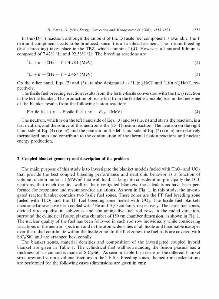
The main purpose of this study is to investigate the blanket models fueled with ThO2 and UO2that provide the best coupled breeding performance and neutronic behavior as a function ofvolume fraction under a 1 MW/m2 first wall load. Taking into consideration principally the D–Tneutrons, that reach the first wall in the investigated blankets, the calculations have been per-formed for resonance and resonance-free situations. As seen in Fig. 1, in this study, the investi-gated reactor blanket contains two fissile fuel zones. These zones are the FF fuel breeding zonefueled with ThO2 and the TF fuel breeding zone fueled with UO2. The fissile fuel blanketsmentioned above have been cooled with 4He and H2O coolants, respectively. The fissile fuel zones,divided into equidistant sub-zones and containing five fuel rod rows in the radial direction,surround the cylindrical fusion plasma chamber of 150 cm chamber dimension, as shown in Fig. 1.The nuclear quality of the fuel has been followed in each rod row individually while consideringvariations in the neutron spectrum and in the atomic densities of all fissile and fissionable isotopesover the radial coordinate within the fissile zone. In the fuel zones, the fuel rods are covered withSiCf/SiC and are arranged hexagonally.The blanket zones, material densities and composition of the investigated coupled hybrid
blanket are given in Table 1. The cylindrical first wall surrounding the fusion plasma has athickness of 1.5 cm and is made of SiCf/SiC. As seen in Table 1, in terms of the different blanketstructures and various volume fractions in the TF fuel breeding zones, the neutronic calculationsare performed for the following cases (dimensions are given in cm):
H. Yapıcı, O. Ipek / Energy Conversion and Management 44 (2003) 1853–1873 1857
Case 1: 150 FRþ1:5 FWþ7:0786 FFZ ðe¼ 1 : 1Þþ10 TBZþ8:53105 TFZ ðe¼ 2 : 1Þþ10 TBZþ20 RFþ5 SH
Case 2: 150 FRþ 1:5 FWþ 7:0786 FFZ ðe¼ 1 : 1Þþ 10 TBZþ 9:7699 TFZ ðe¼ 3 : 1Þþ 10 TBZþ20 RFþ 5 SH
Fig. 1. Basic structure and cross-sectional view of the investigated blanket: (a) for case 1 and 2, (b) for case 3 and 4,
dTF ¼ 8:53 for case 1 and 3, dTF ¼ 9:77 for case 2 and 4 (dimensions are given in cm and not in scale).
Table 1
Material compositions in the zones of the blanket
Zone Material Fraction (%) Density (g/cm3)
FW SiCf /SiCa 100 3.20000
FF Clad: SiCf /SiC 8.971 3.20000
Fuel: ThO2 45.515 9.86000
Coolant: 4He 45.515 0.00715b
TF Clad: SiCf /SiC 6.165c, 4.998d 3.20000
Fuel: UO2 31.278c, 23.753d 10.55000
Coolant: H2O 62.557c, 71.258d 1.00000
TB Li2Oe 100 2.01300
RF SiCf /SiC 100 3.20000
SH B4C 100 2.54000a SiCf /SiC (silicon carbide fiber/silicon carbide composite material).bAt 40 atm.c For case 1 and 3.d For case 2 and 4 (see Fig. 1).e 10% 6Li in Li.
1858 H. Yapıcı, O. Ipek / Energy Conversion and Management 44 (2003) 1853–1873
Case 3: 150 FRþ 1:5 FWþ 7:0786 FFZ ðe ¼ 1 : 1Þ þ 10 TBZþ 10 RFþ 10 TBZþ 8:53105 TFZðe ¼ 2 : 1Þ þ 10 RFþ 5 SH
Case 4: 150 FRþ 1:5 FWþ 7:0786 FFZ ðe ¼ 1 : 1Þ þ 10 TBZþ 10 RFþ 10 TBZþ 9:7699 TFZðe ¼ 3 : 1Þ þ 10 RFþ 5 SH
The FWs, claddings and reflectors of the blankets are constructed from SiCf/SiC compositematerial. SiCf /SiC composite materials have low induced radioactivity, good mechanical prop-erties after heating, excellent chemical stability, compatibility with liquid metals, high temperaturestability and relatively high thermal conductivity, which decreases with temperature and dependson the fabrication procedure and on the fiber characteristics [25–28]. These composite materialsare already widely used in the aerospace industry [26]. SiCf /SiC composite materials have beenconsidered in various fusion power reactors as new structural materials due to their excellentproperties [28–33]. They can be used as cladding material for fuel rods in high temperature lightwater reactors [34,35].
3. Results of the calculations
3.1. Calculation tools
Neutronic calculations have been performed by using the XSDRN/SCALE4.4A code [36]and the 238GROUPNDF4 (FT84F001) neutron transport and activity cross-section data library[37].The neutron cross-sections used consist of 238 energy groups. The integration of the angular
neutron flux has been applied in the S18–P5 approximation by using Gaussian quadrature sets toobtain a high accuracy for the deep neutron penetration problems during different stages of thisstudy [38]. However, integral neutronic data calculations using the output of the XSDRN havebeen performed with the XSCALC interface program [39]. The library has 148 fast groups and 90thermal groups (below 3 eV). All nuclides in the 238-group LAW Library use the same weightingspectrum, consisting of a Maxwellian spectrum (peak at 300 K) from 10�4 to 0.125 eV, a 1=Espectrum from 0.125 eV to 67.4 keV, a fission spectrum (effective temperature at 1.273 MeV) from67.4 keV to 10 MeV and a 1=E spectrum from 10 to 20 MeV.
3.2. Neutronic performance of the overall blanket
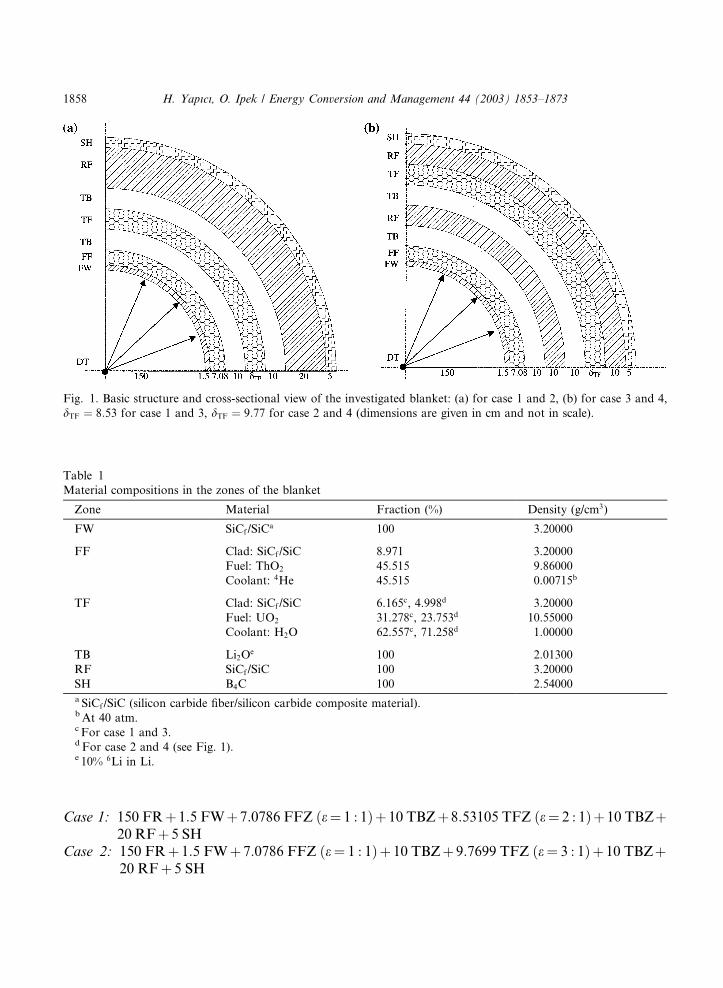
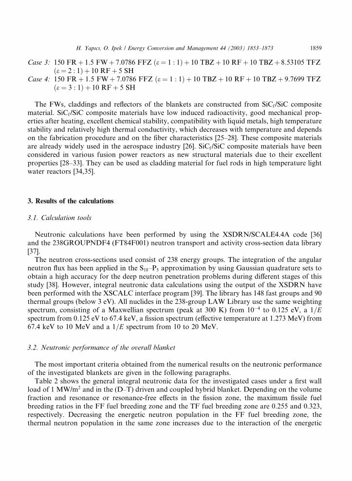
The most important criteria obtained from the numerical results on the neutronic performanceof the investigated blankets are given in the following paragraphs.Table 2 shows the general integral neutronic data for the investigated cases under a first wall
load of 1 MW/m2 and in the (D–T) driven and coupled hybrid blanket. Depending on the volumefraction and resonance or resonance-free effects in the fission zone, the maximum fissile fuelbreeding ratios in the FF fuel breeding zone and the TF fuel breeding zone are 0.255 and 0.323,respectively. Decreasing the energetic neutron population in the FF fuel breeding zone, thethermal neutron population in the same zone increases due to the interaction of the energetic
H. Yapıcı, O. Ipek / Energy Conversion and Management 44 (2003) 1853–1873 1859
neutrons with the medium materials. Thus, the fissile fuel breeding ratio and fission spectrum inthe FF fuel breeding zone decreases in the radial direction due to the fissioning of the 232Th byonly the energetic neutrons. The above mentioned parameters in the TF fuel breeding zone in-crease up to the center interval of the blankets due to the additional increment of the thermalneutron population caused by H2O, which is used as a coolant material in the TF fuel breedingzone. After the point where the above mentioned parameters are maximum, these parametersdecrease rapidly in the radial direction due to the decrease of the thermal neutron population.However, the highest value of the TBR, indicating the fusil fuel breeding for the fusion reaction, is1.096 for the above mentioned situation. While the blanket models with resonance cases are selfsufficient in respect to tritium breeding ratio (TBR > 1:05), the blanket models with resonance-free effect cases are insufficient for tritium breeding ratio (TBR < 1). C, the peak-to-average fis-sion power ratio which is used as the measurement of the fission power distribution in the reactorcore, varies between 1.251 and 1.392 for the system. However, while the C value varies slightlyfrom 1.392 in the FF fuel breeding zone, it varies between 1.251 and 1.375 in the TF fuel breedingzone. According to these results, the fission power density and, consequently, the neutron spec-trum is nearly constant in the reactor core, so that the reactor performance becomes almost in-dependent of the reactor size. The a parameter, known as the capture-to-fission ratio and definedas energy-dependent, varies between 4.129 and 6.107 in the FFZ fueled with ThO2. This variationbecomes between 9.031 and 28.427 in the TFZ fueled with UO2. A high value of a means a lowprobability of fission following neutron absorption, and conversely, a low value of a means a highprobability of fission. Therefore, the probability of fission following neutron capture is higher inthe FFZ with ThO2 than that in the TFZ. The lowest and highest a values are obtained in the FFZfueled with ThO2 under resonance effect and in the TFZ fueled with UO2 under resonance-freeeffect.
Table 2
Integral neutronic data per (D–T) fusion neutron in the overall blanket
Case 1 Case 2 Case 3 Case 4
A B A B A B A B
M 4.243 3.587 4.522 3.832 2.561 2.330 2.604 2.376232Thc 0.175 0.214 0.172 0.211 0.199 0.255 0.199 0.255238Uc 0.226 0.323 0.225 0.318 0.066 0.089 0.063 0.085
Rf in FFZ 0.042 0.042 0.042 0.042 0.042 0.042 0.042 0.042
Rf in TFZ 0.167 0.125 0.187 0.142 0.049 0.035 0.052 0.038
Total Rf 0.209 0.167 0.229 0.184 0.091 0.077 0.094 0.080
mRf 0.589 0.486 0.634 0.524 0.277 0.242 0.284 0.249
aTh-232 4.189 5.130 4.129 5.052 4.786 6.107 4.783 6.104
aU-238 9.031 13.816 10.706 16.177 15.938 24.851 18.306 28.427
T6 0.927 0.763 0.905 0.752 0.895 0.818 0.896 0.821
T7 0.169 0.168 0.169 0.168 0.163 0.163 0.163 0.163
TBR 1.096 0.931 1.074 0.920 1.058 0.981 1.059 0.984
C in FFZ 1.392 1.392 1.392 1.392 1.392 1.392 1.392 1.392
C in TFZ 1.325 1.312 1.375 1.375 1.251 1.254 1.322 1.345
Le 0.011 0.010 0.0010 0.009 0.012 0.010 0.010 0.009
1860 H. Yapıcı, O. Ipek / Energy Conversion and Management 44 (2003) 1853–1873
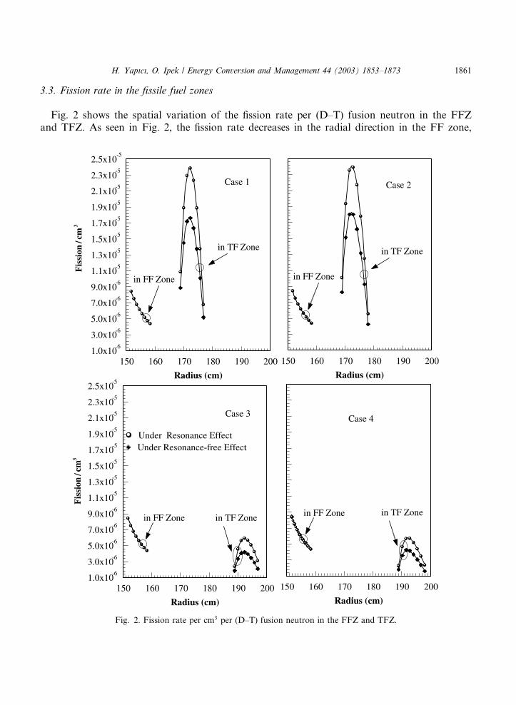
3.3. Fission rate in the fissile fuel zones
Fig. 2 shows the spatial variation of the fission rate per (D–T) fusion neutron in the FFZand TFZ. As seen in Fig. 2, the fission rate decreases in the radial direction in the FF zone,
Fig. 2. Fission rate per cm3 per (D–T) fusion neutron in the FFZ and TFZ.
H. Yapıcı, O. Ipek / Energy Conversion and Management 44 (2003) 1853–1873 1861
and blanket models with resonance and resonance-free effects are not influential on thevariation of the fission rate in the FFZ. In contrast, in the TFZ for all cases, the fission rateincreases up to the center interval of the TFZ, after which it decreases rapidly in the radialdirection for all cases due to the additional increment of the thermal neutron populationcaused by H2O, which is used as a coolant material in the TF fuel breeding zone. For caseswith resonance effect, the variation of the fission rate is higher than that having resonance-freeeffect in the TFZ. The maximum values are 1:7631� 10�5, 1:8324� 10�5, 4:1852� 10�6 and4:266� 10�6 for case 1, case 2, case 3 and case 4, respectively, under resonance-free effect.However, the maximum values of the fission rate in the TF zones are 2:3853� 10�5, 2:391�10�5, 5:9228� 10�6 and 5:7875� 10�6 for case 1, case 2, case 3 and case 4, respectively, underresonance effect. The fission rates, 1:086� 10�5, 1:0074� 10�5, 2:3999� 10�6 and 2:2712�10�6 at the first interval of the TFZ under resonance effect reduce rapidly to 6:7584� 10�6,5:5535� 10�6, 3:1104� 10�6 and 2:3565� 10�6 values for case 1, case 2, case 3 and case 4,respectively, after reaching the above mentioned maximum values. The same variation is alsoobtained under resonance-free effect. The reasons for this variation are due to the contributionof the U235 isotope to the fission rate in addition to the contribution of the U238 isotope anddue to the increase in the thermal neutron population. After the maximum value has beenreached, the fission rate decreases rapidly at the last interval of the TFZ due to the decrease inenergetic neutron population and increase in thermal neutron population caused by H2O. Themaximum value of the fission rate in the FFZ is about 8:43� 10�6 for all cases under reso-nance and resonance-free effect. This value decreases to about 4:37� 10�6 at the last intervalin the FFZ.
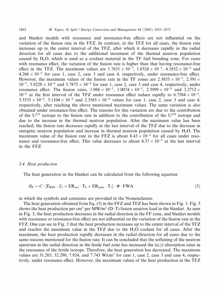
3.4. Heat production
The heat generation in the blanket can be calculated from the following equation
HP ¼ C ERPF Rf½ þ ERexo T6 þ ERendo T7� U FWA ð5Þ
in which the symbols and constants are provided in the Nomenclature.The heat generation obtained from Eq. (5) in the FFZ and TFZ has been shown in Fig. 3. Fig. 3
shows the heat production per cm3 per MW/m2 (D–T) fusion neutron load in the blanket. As seenin Fig. 3, the heat production decreases in the radial direction in the FF zone, and blanket modelswith resonance or resonance-free effect are not influential on the variation of the fission rate in theFFZ. One can see in Fig. 3 that the heat production increases up to the center interval of the TFZand reaches the maximum value in the TFZ due to the H2O coolant for all cases. After themaximum, the heat production rapidly decreases in the radial direction for all cases due to thesame reasons mentioned for the fission rate. It can be concluded that the softening of the neutronspectrum in the radial direction in the fissile fuel zone has increased the (n,c) absorption rates inthe resonance of the fertile isotope. Therefore, the heat generation has decreased. The maximumvalues are 31.265, 32.290, 7.924, and 7.743 W/cm3 for case 1, case 2, case 3 and case 4, respec-tively, under resonance effect. However, the maximum values of the heat production in the TFZ
1862 H. Yapıcı, O. Ipek / Energy Conversion and Management 44 (2003) 1853–1873
are 23.644, 24.514, 5.599 and 5.554 W/cm3 for case 1, case 2, case 3 and case 4, respectively, underresonance-free effect.
Fig. 3. Heat production per cm3 per MW/m2 (D–T) fusion neutron load in the blanket.
H. Yapıcı, O. Ipek / Energy Conversion and Management 44 (2003) 1853–1873 1863
As seen from Fig. 3, the heat generation in the FFZ is lower than that in the TFZ in thecoupled hybrid blanket for case 1 and case 2, whereas the heat generation in the FFZ is higherthan that in the TFZ in the coupled hybrid blanket for case 3 and case 4. For cases with reso-nance effect, the variation of the fission rate is higher than that with resonance-free effect in theTFZ. As seen in Figs. 2 and 3, the heat production has a similar shape to the fission rate in theTFZ.
3.5. Fissile fuel breeding in the fissile fuel zones
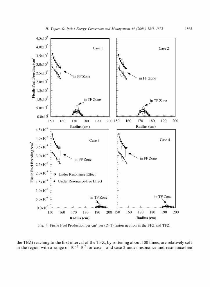
Fig. 4 shows the spatial variation of the fissile fuel production per (D–T) fusion neutron in theFFZ and TFZ. Fig. 4 shows the 232Th(n,c)233U and 238U(n,c)239Pu fissile fuel production rate perincident (D–T) fusion neutron in the FFZ and TFZ, respectively. As seen from this figure, thefissile fuel production decreases in the radial direction. The fissile fuel production under reso-nance-free effect is higher than that under resonance effect in the FFZ for all cases. Therefore, theresonance-free effect has a positive effect on the fissile fuel production rate. However, the fissilefuel production under resonance-free effect is lower than that under resonance effect in the TFZfor all cases. As seen in Figs. 2 and 4, the fissile fuel production has a similar shape to the fissionrate in the TF zone.
3.6. Neutron fluxes in the fissile fuel zones
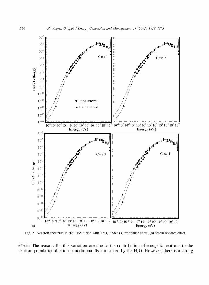
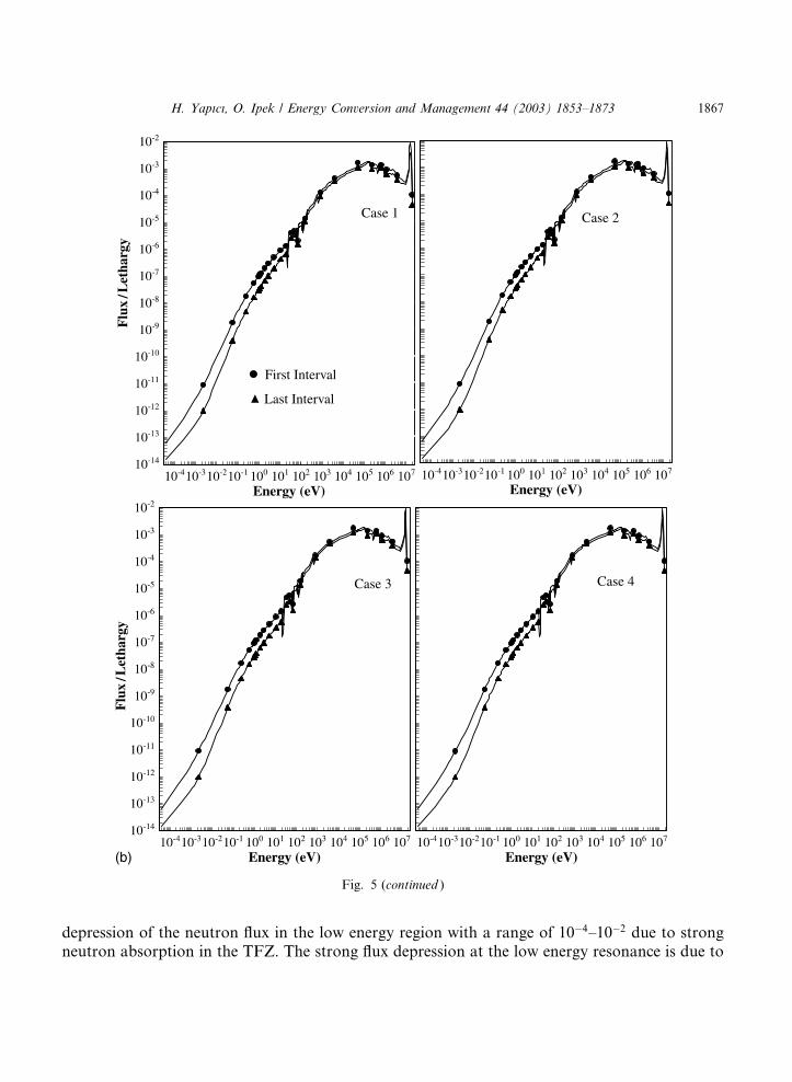
The shifting in the neutron spectrum throughout the blanket can be explained by observingthe neutron flux at different points in the blanket as a function of the average neutron en-ergy, which varies in the radial direction. Neutron spectrum curves (fluxes) drawn for eachmidpoint of the blanket with respect to the FFZ and TFZ are given in Figs. 5 and 6. Fig. 5shows the spatial variation of the neutron spectrum throughout the FFZ fueled with ThO2.In the detail of Fig. 5(a) and (b) show the neutron spectrum in the FFZ for the first interval(adjacent to the first wall) and last interval (adjacent to the first TBZ) under resonance andresonance-free effect, respectively, for all cases. As seen in Fig. 5, the neutron spectrum isrelatively softer, and this is an indication for good breeding characteristics in the FFZ. Thefast neutron fluxes decrease in the radial direction, and the lower energy group fluxes increasebecause they are generated mainly beyond the fuel zone and are reflected back. The uncol-lided fusion neutron peak at the immediate vicinity of the first wall decreases by deeperpenetration in the blanket. In other words, the neutron flux curves show a variation towardthe outer boundary from the harder neutron spectrum shapes to the softer ones. In Fig. 5(a)and (b), the curves related to the first interval of the FFZ (adjacent to the first wall) showthat there is a softening in the neutron spectrum without any fluctuation for all cases underresonance and resonance-free effects. The reason for this behavior can be explained with thedecrease of high energy neutrons and the increase in the number of low energy neutrons. Theflux values in the high energy region, with a range of 10–106 eV, are the same in the FFZ forall cases.Fig. 6(a) and (b) show the neutron spectrum in the TFZ fueled with UO2 under resonance and
resonance-free effect for all cases. As seen in Fig. 6(a) and (b), the neutron flux values (adjacent to
1864 H. Yapıcı, O. Ipek / Energy Conversion and Management 44 (2003) 1853–1873
the TBZ) reaching to the first interval of the TFZ, by softening about 100 times, are relatively softin the region with a range of 10�2–107 for case 1 and case 2 under resonance and resonance-free
Fig. 4. Fissile Fuel Production per cm3 per (D–T) fusion neutron in the FFZ and TFZ.
H. Yapıcı, O. Ipek / Energy Conversion and Management 44 (2003) 1853–1873 1865
effects. The reasons for this variation are due to the contribution of energetic neutrons to theneutron population due to the additional fission caused by the H2O. However, there is a strong
Fig. 5. Neutron spectrum in the FFZ fueled with ThO2 under (a) resonance effect, (b) resonance-free effect.
1866 H. Yapıcı, O. Ipek / Energy Conversion and Management 44 (2003) 1853–1873
depression of the neutron flux in the low energy region with a range of 10�4–10�2 due to strongneutron absorption in the TFZ. The strong flux depression at the low energy resonance is due to
Fig. 5 (continued )
H. Yapıcı, O. Ipek / Energy Conversion and Management 44 (2003) 1853–1873 1867
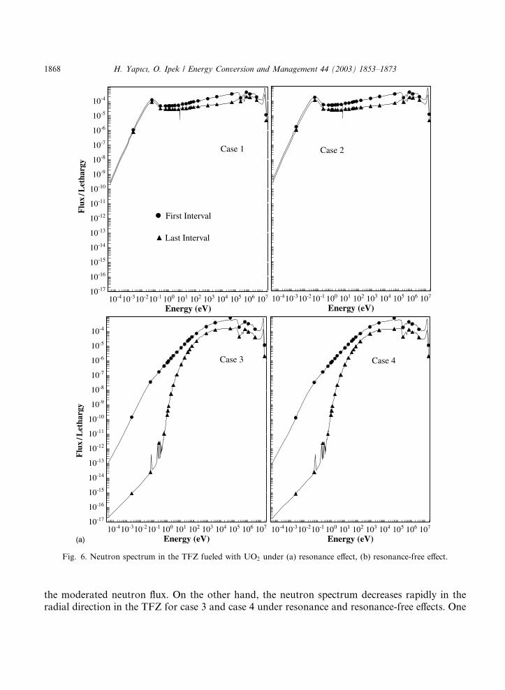
the moderated neutron flux. On the other hand, the neutron spectrum decreases rapidly in theradial direction in the TFZ for case 3 and case 4 under resonance and resonance-free effects. One
Fig. 6. Neutron spectrum in the TFZ fueled with UO2 under (a) resonance effect, (b) resonance-free effect.
1868 H. Yapıcı, O. Ipek / Energy Conversion and Management 44 (2003) 1853–1873
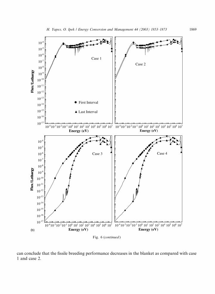
can conclude that the fissile breeding performance decreases in the blanket as compared with case1 and case 2.
Fig. 6 (continued )
H. Yapıcı, O. Ipek / Energy Conversion and Management 44 (2003) 1853–1873 1869
4. Conclusion
The present study evaluates the coupled hybrid reactor fueled with ThO2 and UO2 that pro-vides the best coupled breeding performance and neutronic behavior as a function of volumefraction under 1 MW/m2 first wall load in cylindrical geometry. The main calculations are asfollows:�Depending on the above mentioned factors, the maximum fissile fuel breeding ratios are 0.255
obtained in the FFZ for cases 3 and 4 and 0.323 obtained in the TFZ for case 1 under resonance-free effect, respectively. The fission rate per cm3 per (D–T) fusion neutron in the FFZ is not af-fected for resonance and resonance-free effect. At the last interval in the FFZ, the fission rate hasdecreased about 1.93 times for all cases. In the TFZ for all cases, the fission rate increases up tothe center interval of the TFZ. These increments have been 2.196, 2.373, 2.468 and 2.548 times forcase 1, case 2, case 3 and case 4, respectively, under resonance effect. However, the increments ofthe fission rate have been 1.988, 2.217, 2.248 and 2.357 times for case 1, case 2, case 3 and case 4,respectively, under resonance-free effect. After the maximum values, the fission rates have de-creased rapidly in the radial direction for all cases due to the additional increment of the thermalneutron population caused by H2O. At the last interval in the TFZ, the fission rates have de-creased to 3.529, 4.305, 1.904 and 2.456 for case 1, case 2, case 3 and case 4, respectively, underresonance effect. The decrements of the fission rate have been 3.426, 4.309, 1.992 and 2.669 forcase 1, case 2, case 3 and case 4, respectively, under resonance-free effect. For the cases withresonance effect, the variation of the fission rate is higher than that with resonance-free effect inthe TFZ.� Heat production in the FF fuel breeding zone decreases in the radial direction due to the
fissioning of the 232Th by only the energetic neutrons. Decreasing the energetic neutron populationin the FF fuel breeding zone, the thermal neutron population in the same zone increases due to theinteraction of the energetic neutrons with the medium materials. However, the above mentionedparameters in the TF fuel breeding zone increase up to the center interval of the blankets due tothe additional increment of the thermal neutron population caused by H2O, which is used as acoolant material in the TF fuel breeding zone. The maximum heat production value is 11.27 W/cm3 under resonance and resonance-free effect and is not affected for resonance and resonance-free effect. However, the maximum heat production values are 24.514 and 32.290 W/cm3 in theTFZ under resonance and resonance-free effect, respectively. After the maximum value, the heatproduction decreases rapidly in the radial direction due to the decrease of the fission rate.� The fissile fuel breeding ratio and fission spectrum in the FF fuel breeding zone decreases in
the radial direction due to the fissioning of the 232Th by only the energetic neutrons. Decreasingthe energetic neutron population in the FF fuel breeding zone causes the thermal neutron pop-ulation in the same zone to increase due to the interaction of the energetic neutrons with themedium materials. However, the above mentioned parameters in the TF fuel breeding zone in-crease up to the center interval of the blankets due to the additional increment of the thermalneutron population caused by H2O, which is used as a coolant material in the TF fuel breedingzone. After this point, where the above mentioned parameters are maximum, these parametersdecrease rapidly in the radial direction due to the decrease of the thermal neutron population.� The fissile fuel production under resonance-free effect is higher than that under resonance
effect in the FFZ for all cases, and this situation has a positive effect on the fissile fuel production
1870 H. Yapıcı, O. Ipek / Energy Conversion and Management 44 (2003) 1853–1873
rate. On the other hand, the fissile fuel production under resonance-free effect is lower than thatunder resonance effect in the TFZ for all cases, and the fissile fuel production has a similar shapeto the fission rate in the TFZ.� The highest TBR and energy multiplication factor M are 1.096 in case 1 and 4.522 in case 2
under resonance effect, respectively, for all cases. While the blanket models with resonance casesare self sufficient in respect to TBR, the blanket models with resonance-free effect cases are in-sufficient for TBR. The peak-to-average fission power ratio C varies between 1.251 and 1.392(maximum value as seen in Table 2) for the system. While the C value varies slightly from 1.392 inthe FF fuel breeding zone, it varies between 1.251 and 1.375 in the TF fuel breeding zone. Whilethe a parameter varies between 4.129 and 6.107 in the FFZ fueled with ThO2, this variationbecomes between 9.031 and 28.427 in the TFZ fueled with UO2. The lowest a (4.129) and highest a(28.427) values are obtained in the FFZ fueled with ThO2 under resonance effect and in the TFZfueled with UO2 under resonance-free effect.� Neutron spectrum curves (fluxes) are drawn for each midpoint of the blanket with respect to
the FF and TF zones. The neutron spectrum is relatively softer, and this is an indication for goodbreeding characteristics in the FFZ. While the fast neutron fluxes decrease in the radial direction,the lower energy group fluxes increase because they are generated mainly beyond the fuel zoneand are reflected back. In other words, the neutron flux curves show a variation toward the outerboundary from the harder neutron spectrum shapes to the softer ones. The curves related to thefirst interval of the FFZ show that there is a softening in the neutron spectrum without anyfluctuation for all cases under resonance and resonance-free effects. The reason for this behaviorcan be explained with the decrease of high energy neutrons and the increase in the number of lowenergy neutrons. The flux values in the high energy region with a range of 10–106 eV are the samein the FFZ for all cases. The flux values reaching to the first interval of the TFZ, by softeningabout 100 times, are relatively soft in the region with a range of 10�2–107 for case 1 and case 2under resonance and resonance-free effects. The reason for this variation is due to the contri-bution of the energetic neutrons to the neutron population due to the additional fission caused byH2O. However, there is a strong depression of the neutron flux in the low energy region with arange of 10�4–10�2 due to strong neutron absorption in the TFZ. The strong flux depression at thelow energy resonance is due to the moderated neutron flux. On the other hand, the neutronspectrum decreases rapidly in the radial direction in the TFZ for case 3 and case 4 under reso-nance and resonance-free effects. This explains that the fissile breeding performance decreases inthe blanket as compared with case 1 and case 2.
References
[1] Waris A, Sekimot H. Basic study on characteristics of some important equilibrium fuel cycles of PWR. Ann Nucl
Energy 2001;28:153–67.
[2] Kulcinski GL. Fusion power from lunar resources. Fus Technol 1992;21:2221–9.
[3] Waltar AE, Deitrich LW. Status of research on key LWR safety issues. Nucl Safety 1988;29/2:125–33.
[4] Pease RS. Global energy scenarios and the potential role of fusion energy in 21st century. J Nucl Mater 1992:7–14,
191–4.
[5] Park WS, Shin U, Han SJ, et al. HYPER (hybrid power extraction reactor): a system for clean nuclear energy. Nucl
Eng Des 2000;199:155–65.
H. Yapıcı, O. Ipek / Energy Conversion and Management 44 (2003) 1853–1873 1871
[6] National Research Council. Nuclear wastes; technologies for separation and transmutation. Washington, DC:
National Academy Press; 1996.
[7] S�ahin S, Unalan U, Yapıcı H. Decrease of the CANDU spent nuclear waste inventories in fusion–fission (hybrid)reactors. Int J Energy Environ Econ 1996;4(1):67–97.
[8] Ipek O. Neutronic analysis of flux dispersion in a multi-layered, (D–T) driven hybrid blanket. Turk J Eng Environ
Sci TUBITAK 2000;24/6:373–82.
[9] Ipek O. Decrease of the LWR spent nuclear waste inventories and cumulative fissile fuel enrichment in hybrid
reactor system. In: ICONE-8348, Proceeding of ICONE8, 8th International Conference on Nuclear Engineering,
April 2–6, Baltimore, MD USA, Copyright � 2000 ASME, 2000. p. 1–10.
[10] Ipek O. Neutronic performances of the (D,T) driven hybrid blankets, fueled with U3O8 and UF4 for various
coolants to breed fissile fuel for LWRs. In: Proceedings of Symposium on Energy Engineering in the 21st Century,
Hong Kong, January 9–12, (SEE 2000), vol. 2. 2000. p. 778–86.
[11] Sahin S, Yapıcı H, Sahin N. Neutronic performance of proliferation hardened thorium fusion breeders. Fus Eng
Des 2001;54:63–77.
[12] S�ahin S, €OOzceyhan V, Yapıcı H. Proliferation hardening and power flattening of a thorium fusion breeder with
triple mixed oxide fuel. Ann Nucl Energy 2001;28:204–23.
[13] Abdul KS, Haldy PAS, Kumar A. Blanket design and calculated performance for the LOTUS fusion–fission
hybrid test facility. Nucl Tech/Fusion 1984;5:189–96.
[14] Yapıcı H, Sahin N, Bayrak M. Investigation of neutronic potential of a moderated (D–T) fusion driven hybrid
reactor fueled with thorium to breed fissile fuel for LWRs. Energy Convers Manage 2000;41:435–47.
[15] Yapıcı H, Ipek O, €OOzceyhan V, Eris�en A. Analysis of the rejuvenation performance of hybrid blankets by usinguranium fuels (UN, UC, UO2, U3Si2) and different coolants for various volume fraction. Ann Nucl Energy
2000;27:279–94.
[16] Tanaka S, Ohara Y, Kawamura H. Blanket R&D activities in Japan towards fusion power reactors. Fus Eng Des
2000;51–52:299–307.
[17] Seki Y, et al. In: Proceedings of the 13th International Conference on Plasma Physics and Controlled Nuclear
Fusion Research, Washington, DC, IAEA-CN-53/G-I-2, Vienna, 1991.
[18] Mior RW. In: The fusion–fission fuel factory. Fusion, vol. 1. 1981. Part B [chapter 15].
[19] Al-Kusayer TA, Abdoul Raoof M. Preliminary design studies of a cylindrical experimental hybrid blanket with
(deuterium–tritium) drive. Fus Technol 1986;10/1:84–9.
[20] S�ahin S, Yapıcı H. Investigation of the neutronic potential of moderated and fast (D,T) hybrid blankets forrejuvenation of CANDU spent fuel. Fus Technol 1989;16:331–45.
[21] S�ahin S, Yapıcı H, Baltacıo�gglu E. Rejuvenation of LWR spent fuel in a catalyzed fusion–fission hybrid blanket.Kerntechnik 1994;59/6:270–81.
[22] Yapıcı H, Ipek O, €OOzceyhan V. Temperature distribution in nuclear fuel rod and variation of the neutronicperformance parameters in (D,T) driven hybrid reactor system. Ann Nucl Energy 2001;28/28:1825–50.
[23] Lee JD. Waste disposal assessment of HYLIEE-II structure. Fus Technol 1994;26(4):174.
[24] Ipek O, Eris�en A. Hybrid reactor system. In: The Second International Conference on New Energy System and
Conversion, 31 July–3 August, Istanbul, Turkey. 1995. p. 463–74.
[25] Riccardi B, Fenici P, Frias Rebelo A, Giancarli L, Le Marois G, Philippe E. Status of the European R&D activities
on SiCf /SiC composites for fusion reactors. Fus Eng Des 2000;51–51:11–22.
[26] Aiello G, Golfier H, Maire J-F, Poitevin Y, Salavy J-F. Modeling of SiCf /SiC composite structures for nuclear
components. Fus Eng Des 2000;51–51:73–9.
[27] Noda T, Fujita M, Araki H, Kohyama A. Impurities and evaluation of induced activity of CVI SiCf /SiC
composites. Fus Eng Des 2000;51–51:99–103.
[28] Raffray AR, Jones R, Aiello G, Billone M, Giancarli L, Golfier H, et al. Design and materials issues for high
performance SiCf /SiC-based fusion power cores. Fus Eng Des, pre-print.
[29] Najmabadi FRW, Conn R, et al. The ARIES-I Tokomak reactor study. Final report, UCLA-PPG-1323, UCLA,
CA, 1991.
[30] Najmabadi FRW, Conn R, Aries Team. The ARIES-II and ARIES-IV second stability Tokomak reactors study.
In: Proceedings TMTFE-10, La Grange Park, IL, USA, 1992.
1872 H. Yapıcı, O. Ipek / Energy Conversion and Management 44 (2003) 1853–1873
[31] Waganer LM, et al. Inertial Fusion Energy Reactor Design Studies: Prometheus-L & Prometheus-H, McDonnel
Douglas Company Report, MDC 92E0008/DOE/ER-54101, 1992.
[32] Gofier H, et al. Progress on the TAURO blanket system. In: Proceedings SOFT-21, 2000.
[33] Nishio S, Ueda S, Aoki I, Kurihare R, et al. Improved Tokomak concept focusing on easy maintenance. Fus Eng
Des 1998;41:165–71.
[34] Schulten R. The HTR with SiC-technology. Nucl Eng Des 1993;140:261–7.
[35] LippmannW, Knorr J, N€ooring R, Umbeit M. Investigation of the use of ceramic materials in innovative light waterreactor-fuel rod concepts. Nucl Eng Des 2001;205:13–22.
[36] Greene NM, Petrie LM. XSDN-PM/SCALE4.3, For Transport Analysis, Oak Ridge National Laboratory, 1983.
[37] Greene NM, Arwood JW, Wright RQ, Parks CV. The LAW Library––A Multi Group Cross-Section Library for
Use in Radioactive Waste Analysis Calculations, ORNL/TM-12370.
[38] S�ahin S. Comparison of diffusion and transport theory for fast reactor shielding calculations. Atomkernenergie1973:22.
[39] Yapıcı H. XSCALC for Interfacing Output of XSDRN to Calculate Integral Neutronic Data, Erciyes University/
TURKEY, 2001.
H. Yapıcı, O. Ipek / Energy Conversion and Management 44 (2003) 1853–1873 1873
Related Documents