NeuroPak™ Practical WORKSHOP SUPPORT

Welcome message from author
This document is posted to help you gain knowledge. Please leave a comment to let me know what you think about it! Share it to your friends and learn new things together.
Transcript

NeuroPak™ PracticalWORKSHOP SUPPORT

Prepared by H. Gharbi | © Mauna Kea Technologies
NeuroPak™ Description• NeuroPak is a complete solution for Neuroscientists
• Developped with the Institut Pasteur (Paris)
• Enables deep brain access in freely-moving animals
‣ Calcium transients
‣ Neuron activity
‣ Perfusion studies
‣ Animal model validation
‣ ...
2
Behavioral Studies Calcium flux
Prepared by H. Gharbi | © Mauna Kea Technologies
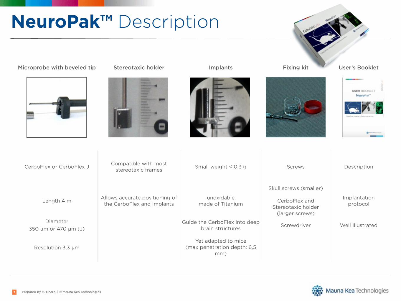
Microprobe with beveled tip Stereotaxic holder Implants Fixing kit User’s Booklet
CerboFlex or CerboFlex J Compatible with most stereotaxic frames Small weight < 0,3 g Screws Description
Length 4 m Allows accurate positioning of the CerboFlex and Implants
unoxidablemade of Titanium
Skull screws (smaller)
CerboFlex and Stereotaxic holder
(larger screws)
Implantation protocol
Diameter 350 µm or 470 µm (J)
Guide the CerboFlex into deep brain structures Screwdriver Well Illustrated
Resolution 3,3 µmYet adapted to mice
(max penetration depth: 6,5 mm)
NeuroPak™ Description
3

Prepared by H. Gharbi | © Mauna Kea Technologies
NeuroPak™ Description
4
x6
Installation disk

Prepared by H. Gharbi | © Mauna Kea Technologies
Requirements• Protocol preparation
• Animal model & neuron labelling
‣ Mouse or rat
‣ WT, transgenic (GFP, Thy1 YFP), transfected (AAV-GCaMP3)
‣ Chemical calcium indicator: Oregon Green BAPTA 1 AM
• Surgery
‣ Needs to be performed at least one week prior to imaging
‣ Detailed implantation procedure inside the Booklet
‣ Surgical skills
‣ Stereotaxic frame control
5
Protocol for CNS deep brain imagery using Cellvizio with anaesthetizedwildtype mouse (protocol used and developped by A. Cressant)
Requirements:
Mouse model: adult wildtype mouse
Fluorophore/Marker oregon green BAPTA 1
Material:
Cellvizio 488 nm
Calibration kit
Microprobe: S300/b
Laboratory material:
Surgery equipment: syringe, hair clipper, scalpel, compresses, scissors, forceps,anesthetic (Ketamine/xylazine solution for example), drilling tool (ex: F.S.T, withsmall drills 0.5 mm of diameter), lead pencil, ear bars, dissecting microscope andstereotactic frame (with mouse adaptator if needed) with electrode/syringe holder
Solutions: 70% ethanol solution, ice, PBS solution, Oregon Green BAPTA 1 solution
Mouse Brain Atlas
Injection system: glass injection needle, precision pump (Harvard, PHD 2000),Hamilton syringe (10 microliter), tubing 0.11”x. 0.24”x.0065” (A-M System, Inc), extrastrong glue
I – Protocol (described for Oregon Green BAPTA 1 AM fluorescent dye use)
Oregon Green BAPTA-1 AM (OGB1) solution preparation: solution is prepared as describedin Stosiek C et coll. (2003). The AM ester (Molecular Probes Invitrogen Ltd, Paisley, UK) isdissolved in DMSO plus 20% Pluronic F-127 (e.g., 2 g of Pluronic F-127 in 10 mlof DMSO).The final concentration is 10 mM. Prior cell loading the OGB1 AM is diluted 1:10, in a solutioncontaining in mM: 150 NaCl, 2.5 KCl, 10 Hepes, pH 7.4. The final solution concentration is 1mM.
If brightness is too strong, OGB1 1mM solution can be successfully diluted 1:5 in PBS beforeinjection into the brain.
Mauna Kea Technologies S.A.S.9, rue d’Enghien75010 Paris, FranceTel +33 1 48 24 03 45Fax +33 1 48 24 12 18
www.maunakeatech.com
Mauna Kea Technologies, Inc.660 Newtown-Yardley Rd., Suite 107
Newtown, PA 18940, USATel +1 215 478 6288Fax +1 215 279 8463
Société par Actions Simplifiée au capital de EUR 351 924,03 • RCS PARIS B 431 268 028 (2000B18081) • NAF 7219Z • SIRET: 431 268 028 00021
Protocol
Calcium imaging using Cellvizio Lab system and GCaMP3 (Genetically encoded calcium indicators)
Prepared by H. Gharbi | © Mauna Kea Technologies
Material Checklist
6
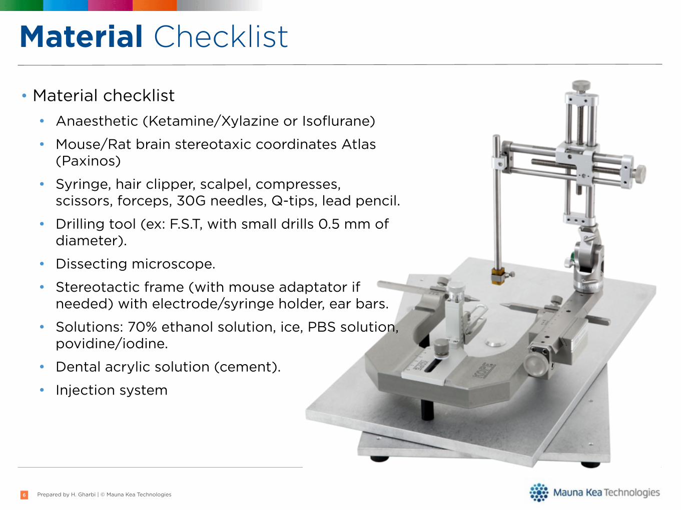
• Material checklist• Anaesthetic (Ketamine/Xylazine or Isoflurane)
• Mouse/Rat brain stereotaxic coordinates Atlas (Paxinos)
• Syringe, hair clipper, scalpel, compresses, scissors, forceps, 30G needles, Q-tips, lead pencil.
• Drilling tool (ex: F.S.T, with small drills 0.5 mm of diameter).
• Dissecting microscope.
• Stereotactic frame (with mouse adaptator if needed) with electrode/syringe holder, ear bars.
• Solutions: 70% ethanol solution, ice, PBS solution, povidine/iodine.
• Dental acrylic solution (cement).
• Injection system
Prepared by H. Gharbi | © Mauna Kea Technologies
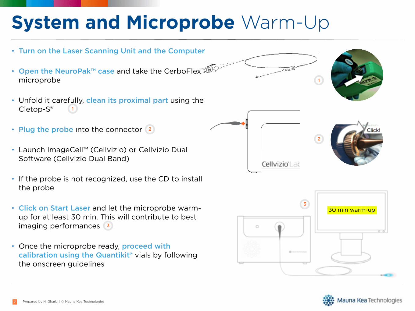
System and Microprobe Warm-Up• Turn on the Laser Scanning Unit and the Computer
• Open the NeuroPak™ case and take the CerboFlex microprobe
• Unfold it carefully, clean its proximal part using the Cletop-S®
• Plug the probe into the connector
• Launch ImageCell™ (Cellvizio) or Cellvizio Dual Software (Cellvizio Dual Band)
• If the probe is not recognized, use the CD to install the probe
• Click on Start Laser and let the microprobe warm-up for at least 30 min. This will contribute to best imaging performances
• Once the microprobe ready, proceed with calibration using the Quantikit® vials by following the onscreen guidelines
7
Note 1 : NeuroPak contents & How to pack the Cerboflex
30 min warm-up
1
1
2
2
3
3

Prepared by H. Gharbi | © Mauna Kea Technologies
Animal Preparation• Anaesthetize the animal and shave off fur:
• From the ears to just in-between the eyes
• Mount it onto the stereotaxic apparatus • Use the right mouth adapter (mouse or rat)
• Secure the animal with the ear bars
8
Dissecting microscope
*
*
*
*

Prepared by H. Gharbi | © Mauna Kea Technologies
Stereotaxic Holder• The stereotaxic holder will replace the standard
vertical manipulator of the stereotaxic frame.• Unmount the original arm using appropriate tools• Place the stereotaxic holder as shown below
9
Toutes les cotes sont en mm/All dimensions in mm Tol. generales :
1
A
1
A B C D E F G H
2
3
4
B C D E F G H
2
3
4
Modifications
A3
Approuvé Matière/Material :
Dessiné
Validé
NomDate Obs :
Feuille : 1 / 1
Echelle/Scale :
PN :
Rév. :
Titre/Title :
Mauna KeaTechnologies 0 . 00 . 04
322-0280
26/02/2009
Accessoire Stéréo
Inox 316L (1,4404)
nicolasb
ISO 2768mK
This document is the property of Mauna Kea Technologies. Reproduction without authorizationof company MKT is strictly prohibited.
5 : 1
1,5:1
5
1004010
170
7
1 5
2,5
2x M1x 0,2
5
7,9
O
4O
1,8
O
R1
3x
R0,05
R2,8
2,50-0,1
3,6±0,05
= =
2,2±0,025
5,6
1,2H8
+0,014
0
O
chanfrein 0,1 x 45°
Rugosité 1,6polissage électrolytique
A
a0,015Aj0,01
Prepared by H. Gharbi | © Mauna Kea Technologies
Mount the CerboFlex on the Holder
10
Toutes les cotes sont en mm/
All dimensions in mm
Tol. generales :
1
A
1
A
B
C
D
E
F
G
H
234
B
C
D
E
F
G
H
234
Ce document est la propriété de Mauna Kea Technologies. Toute reproduction totale ou partielle sous quelque forme que ce
soit de ce document sans une autorisation écrite préalable de la société MKT est strictement interdite.
Modifications
A3
Approuvé
Matière/Material :
Dessiné
Validé
Nom
Date
Obs :
Feuille : 1 / 1
Echelle/Scale :
PN : Rév. :
Titre/Title :Mauna KeaTechnologies
0 . 00 . 02
211-01230
5/01/2009
Jerry (sans lame)
NIB
ISO 2768 mK
1 : 1
Longueur de la fibre 4 m
PN
Description
Rév.
Qté
211-0009
Connecteur LAB
1 . 4
1
215-0002
Valise Proflex
1 . 0
1
313-0024
Guide 10000 Ø0,35mm - D15 - 4m
---
1
321-0117
Vis CS M1 x 2 mm A2
---
1
322-0048
Férule Ø0,35 FIGH-10-350S
1 . 3
1
322-0276
Guide sonde J
0 . 00 . 04
1
322-0277
Ferrule J
0 . 00 . 05
1
325-0030
Olivette plastique 1
---
1
325-0031
Olivette plastique 2
---
1
327-0034
Bouchon connecteur jaune
---
1
327-0037
PTFE extruded special, ID 0,551mm OD 0,8mm
WHITE L=4500 Etched
1 . 4
1
353-0003
CD installation sonde
1 . 0
1
353-0004
Documents annexes aux sondes (notice)
1 . 0
1
361-0028
Colle epotek 301 USP Class VI
---
1
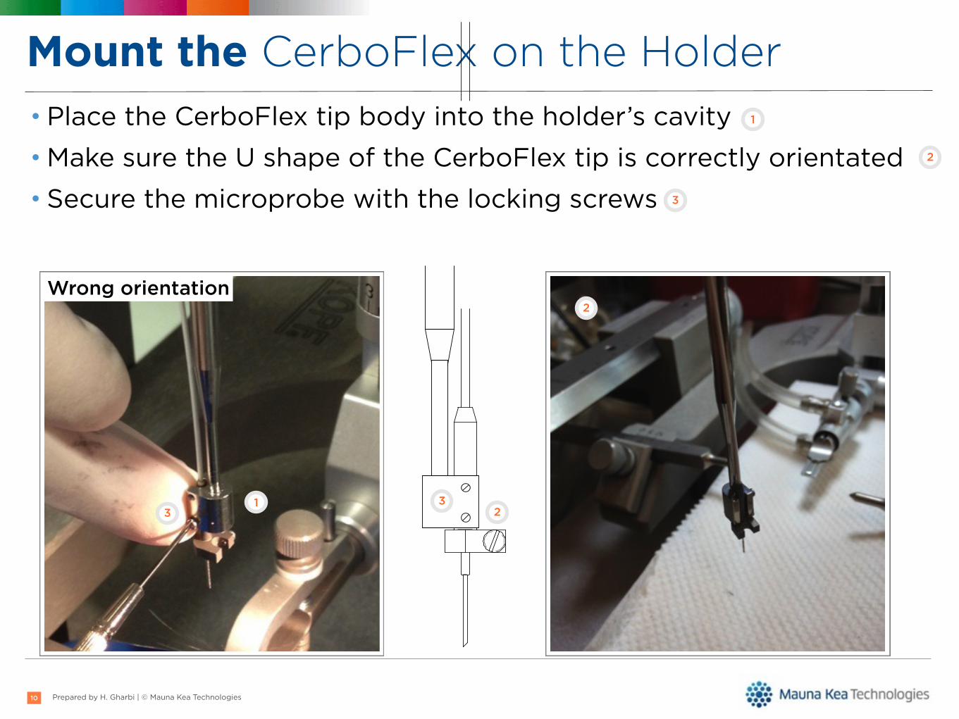
• Place the CerboFlex tip body into the holder’s cavity• Make sure the U shape of the CerboFlex tip is correctly orientated• Secure the microprobe with the locking screws
1
1
2
3
33
2
2
Wrong orientation

Prepared by H. Gharbi | © Mauna Kea Technologies
Skull Surgery: Mouse or Rat• Secure the mouth with the anterior
mount of the stereotaxic frame• The incision is then made down the
midline using a scalpel or surgical scissors
• The top of the skull is exposed
11
11 2 3
2
3
• Find bregma on the skull, and position the CerboFlex tip right over this location.
• Write down the anterior/posterior and lateral coordinates.
• From bregma, find the correct coordinates needed for the placement of your probe with the aid of the stereotaxic atlas.
• This is where you will be drilling.• Better results are obtained if the drill is
fixed to the stereotaxic frame.
4
4

Prepared by H. Gharbi | © Mauna Kea Technologies
Skull Surgery: Mouse or Rat
12
• Next, using a hand drill, make three holes for skull screws.
• Screws are inserted into frontal, parietal, and occipital bones on the opposite side to the imaging target structure/hole.
• Sterilize the screws and place them onto the skull until they are tightly anchored on.
• Remove the CerboFlex and sterilize your drill bit. • Carefully drill a hole at the pencil mark until you
get through the width of the skull. • Check with a sterile 30G needle to see if it would
clear the hole without touching the sides. • Once the hole is made, use a sterile needle to
gently punch the meninges in order to allow unobstructed insertion of the microprobe.
Drilled hole Skull screws

Prepared by H. Gharbi | © Mauna Kea Technologies
Implant Placing
13
Plug and lock the implant onto the holder Align the implant cannula with the hole
Lower the implant into the hole
Leave a space between the holder and the implant
Apply dental cement around the implant base and the skull screws
Once the dental cement is dry: release the implant from the holder
Prepared by H. Gharbi | © Mauna Kea Technologies14
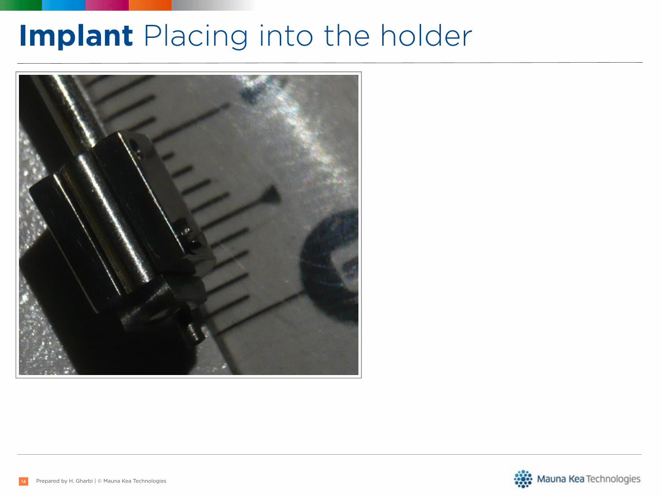
Implant Placing into the holder

Prepared by H. Gharbi | © Mauna Kea Technologies15

Prepared by H. Gharbi | © Mauna Kea Technologies
Incision Suture• The incision is sutured around the
implant• The animal is then allowed to recover for
one week in its cage• Make sure the cement is completely dry• Plug a protective cap into the implant’s
cannula
16
Prepared by H. Gharbi | © Mauna Kea Technologies
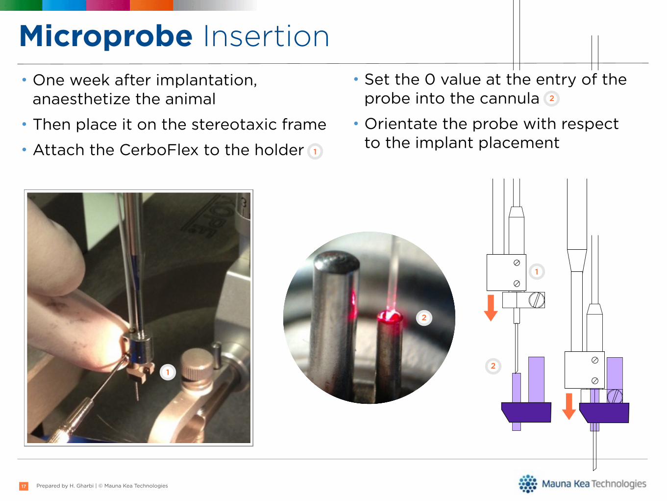
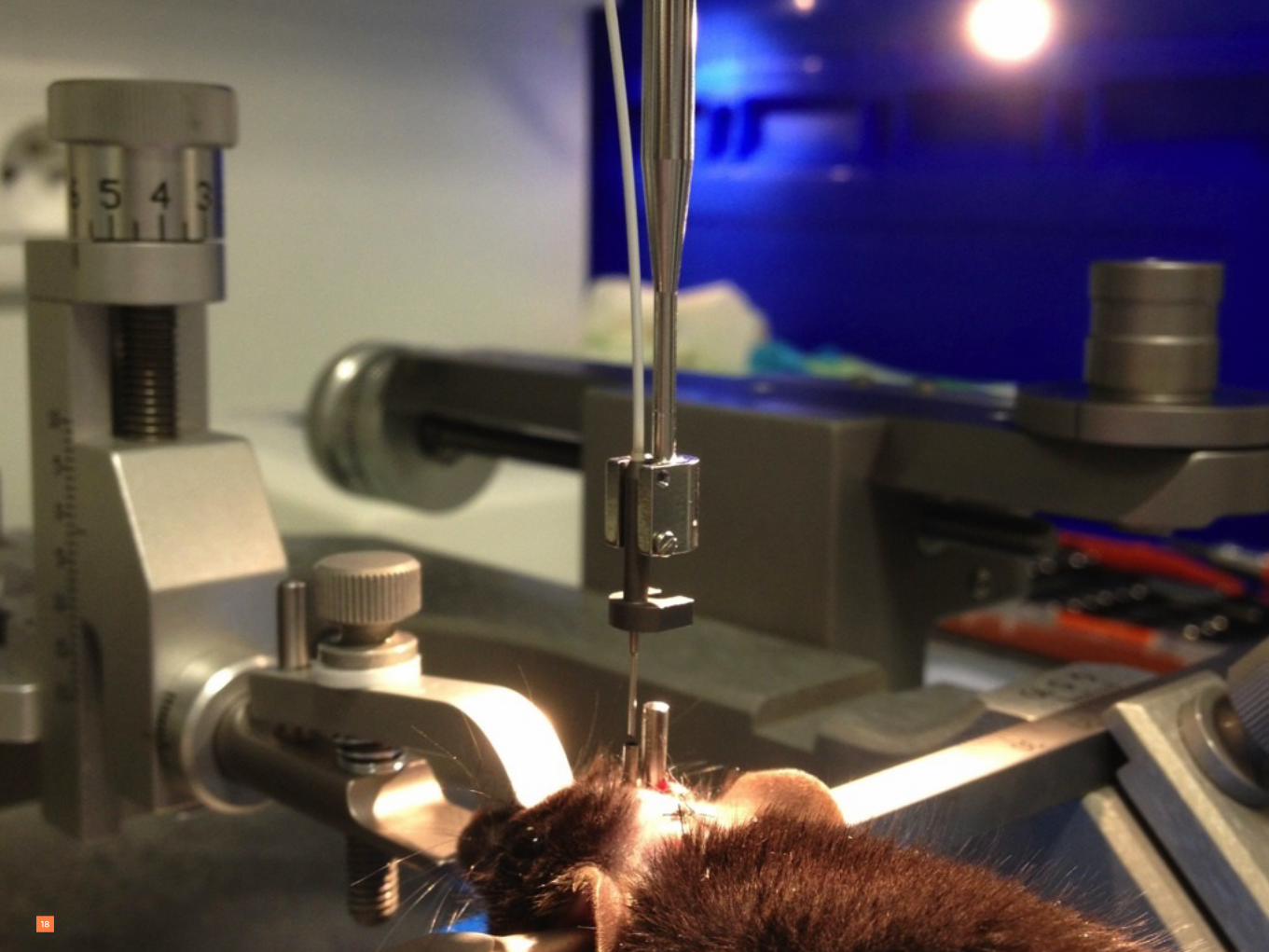
Microprobe Insertion• One week after implantation,
anaesthetize the animal• Then place it on the stereotaxic frame• Attach the CerboFlex to the holder
17
1
2
1
Toutes les cotes sont en mm/
All dimensions in mm
Tol. generales :
1
A
1
A
B
C
D
E
F
G
H
234
B
C
D
E
F
G
H
234
Ce document est la propriété de Mauna Kea Technologies. Toute reproduction totale ou partielle sous quelque forme que ce
soit de ce document sans une autorisation écrite préalable de la société MKT est strictement interdite.
Modifications
A3
Approuvé
Matière/Material :
Dessiné
Validé
Nom
Date
Obs :
Feuille : 1 / 1
Echelle/Scale :
PN : Rév. :
Titre/Title :Mauna KeaTechnologies
0 . 00 . 02
211-01230
5/01/2009
Jerry (sans lame)
NIB
ISO 2768 mK
1 : 1
Longueur de la fibre 4 m
PN
Description
Rév.
Qté
211-0009
Connecteur LAB
1 . 4
1
215-0002
Valise Proflex
1 . 0
1
313-0024
Guide 10000 Ø0,35mm - D15 - 4m
---
1
321-0117
Vis CS M1 x 2 mm A2
---
1
322-0048
Férule Ø0,35 FIGH-10-350S
1 . 3
1
322-0276
Guide sonde J
0 . 00 . 04
1
322-0277
Ferrule J
0 . 00 . 05
1
325-0030
Olivette plastique 1
---
1
325-0031
Olivette plastique 2
---
1
327-0034
Bouchon connecteur jaune
---
1
327-0037
PTFE extruded special, ID 0,551mm OD 0,8mm
WHITE L=4500 Etched
1 . 4
1
353-0003
CD installation sonde
1 . 0
1
353-0004
Documents annexes aux sondes (notice)
1 . 0
1
361-0028
Colle epotek 301 USP Class VI
---
1
• Set the 0 value at the entry of the probe into the cannula
• Orientate the probe with respect to the implant placement
2
2
1
Prepared by H. Gharbi | © Mauna Kea Technologies18

Prepared by H. Gharbi | © Mauna Kea Technologies
4 Toutes les cotes sont en mm/
All dimensions in mm
Tol. generales :
1
A
1
A
B
C
D
E
F
G
H
234
B
C
D
E
F
G
H
234
Ce document est la propriété de Mauna Kea Technologies. Toute reproduction totale ou partielle sous quelque forme que ce
soit de ce document sans une autorisation écrite préalable de la société MKT est strictement interdite.
Modifications
A3
Approuvé
Matière/Material :
Dessiné
Validé
Nom
Date
Obs :
Feuille : 1 / 1
Echelle/Scale :
PN : Rév. :
Titre/Title :Mauna KeaTechnologies
0 . 00 . 02
211-01230
5/01/2009
Jerry (sans lame)
NIB
ISO 2768 mK
1 : 1
Longueur de la fibre 4 m
PN
Description
Rév.
Qté
211-0009
Connecteur LAB
1 . 4
1
215-0002
Valise Proflex
1 . 0
1
313-0024
Guide 10000 Ø0,35mm - D15 - 4m
---
1
321-0117
Vis CS M1 x 2 mm A2
---
1
322-0048
Férule Ø0,35 FIGH-10-350S
1 . 3
1
322-0276
Guide sonde J
0 . 00 . 04
1
322-0277
Ferrule J
0 . 00 . 05
1
325-0030
Olivette plastique 1
---
1
325-0031
Olivette plastique 2
---
1
327-0034
Bouchon connecteur jaune
---
1
327-0037
PTFE extruded special, ID 0,551mm OD 0,8mm
WHITE L=4500 Etched
1 . 4
1
353-0003
CD installation sonde
1 . 0
1
353-0004
Documents annexes aux sondes (notice)
1 . 0
1
361-0028
Colle epotek 301 USP Class VI
---
1
Microprobe Insertion and locking
19
• The microprobe is slightly lowered into the cannula
• Reach the Z coordinates• Then lock the CerboFlex on the
implant’s guide with the lateral screw
3
4
3
4
4
3

Prepared by H. Gharbi | © Mauna Kea Technologies
Release the CerboFlex Microprobe
20
Toutes les cotes sont en mm/
All dimensions in mm
Tol. generales :
1
A
1
A
B
C
D
E
F
G
H
234
B
C
D
E
F
G
H
234
Ce document est la propriété de Mauna Kea Technologies. Toute reproduction totale ou partielle sous quelque forme que ce
soit de ce document sans une autorisation écrite préalable de la société MKT est strictement interdite.
Modifications
A3
Approuvé
Matière/Material :
Dessiné
Validé
Nom
Date
Obs :
Feuille : 1 / 1
Echelle/Scale :
PN : Rév. :
Titre/Title :Mauna KeaTechnologies
0 . 00 . 02
211-01230
5/01/2009
Jerry (sans lame)
NIB
ISO 2768 mK
1 : 1
Longueur de la fibre 4 m
PN
Description
Rév.
Qté
211-0009
Connecteur LAB
1 . 4
1
215-0002
Valise Proflex
1 . 0
1
313-0024
Guide 10000 Ø0,35mm - D15 - 4m
---
1
321-0117
Vis CS M1 x 2 mm A2
---
1
322-0048
Férule Ø0,35 FIGH-10-350S
1 . 3
1
322-0276
Guide sonde J
0 . 00 . 04
1
322-0277
Ferrule J
0 . 00 . 05
1
325-0030
Olivette plastique 1
---
1
325-0031
Olivette plastique 2
---
1
327-0034
Bouchon connecteur jaune
---
1
327-0037
PTFE extruded special, ID 0,551mm OD 0,8mm
WHITE L=4500 Etched
1 . 4
1
353-0003
CD installation sonde
1 . 0
1
353-0004
Documents annexes aux sondes (notice)
1 . 0
1
361-0028
Colle epotek 301 USP Class VI
---
1
Unlock the CerboFlex by unscrewing the holder’s screws Release the CerboFlex from the holder

Prepared by H. Gharbi | © Mauna Kea Technologies
Before Starting Imaging• Calibration must be done before inserting the CerboFlex
microprobe into the implant.• Always control the tip cleanliness on the screen.• In case objects remain stuck on the field of view, clean the probe• Clean the probe’s tip by soaking it into the Quantikit™ cleaning vial
(pink), then rinse in the blue vial.• If the tip is still dirty, use the Coton Q-tips provided with Cellvizio,
impregnated with the blue vial solution.• Always clean from the base to the top of the probe’s bevel
21

Prepared by H. Gharbi | © Mauna Kea Technologies
After the procedure• Catch the animal and anesthetize it• Place it under the stereotaxic frame• Attach the CerboFlex body to the stereotaxic holder• Carefully unlock the CerboFlex’s screws from the implant’s guide• Slightly remove the CerboFlex from the implant• Clean the CerboFlex tip by keeping the Laser ON for onscreen check up• Put the protection cap into the implant’s cannula• Carefully remove the CerboFlex microprobe from the holder• Fold the probe as shown
22
Note 1 : NeuroPak contents & How to pack the Cerboflex
Disconnect the microprobe by turning the Cellvizio’s connector clockwise until the click. Then, release and remove the CerboFlex.
1
Note 1 : NeuroPak contents & How to pack the Cerboflex
Put the distal and proximal protection back over the tip of the CerboFlex.
Note 1 : NeuroPak contents & How to pack the Cerboflex
2
Note 1 : N
euroPak contents & How
to pack the Cerboflex
Curve the fiber into a circle as shown. The diameter should fit the CerboFlex print in the storage box.
3
CAUTION: Do NOT twist or fold the optical fiber bundle of the CerboFlex

Prepared by H. Gharbi | © Mauna Kea Technologies
References
23
• Additional information can be found in the NeuroPak USER BOOKLET
• For any inquiry:
Related Documents