Technical White Paper Network Slicing April 2020

Welcome message from author
This document is posted to help you gain knowledge. Please leave a comment to let me know what you think about it! Share it to your friends and learn new things together.
Transcript

Technical White Paper
Network SlicingApril 2020
Contents
0 4
0 9
1 81 92 02 1
Introduction
Samsung Network Slicing Overview
Key Technologies for Network Slicing
Network Slicing ManagementCore NetworkRadio Access NetworkTerminalAnalytics based Network Slice Optimization
Network Slicing Use Cases
Summary
Abbreviations
References
2

List of Figures
0 40 50 7
0 80 9
1 01 11 2
1 3
1 4
1 5
1 61 71 8
FigureFigureFigureFigureFigureFigureFigureFigureFigureFigureFigureFigureFigureFigureFigureFigureFigureFigureFigureFigure
Concept of network slicing technologyOverall architecture of network slicing solutionExample of deploying network slicing in a four -layer hierarchyMicro service-based network slicing management system architectureOverall network slicing architecture based on O-RANNetwork slice life cycle procedureE2E service orchestration reference architectureMulti-vendor/multi-domain/multi-platform compatible orchestrationCloud native architectureService characteristic of vertical segmentsNetwork slice charging flowDifference of the network slice selection in 4G and 5G networksS-NSSAI structureRAN slicing functionSlice-aware AMF/CU-UP selection exampleFlexible PRB portion control examplePriority control function in radio scheduling for network sliceSlice traffic separation with VLANNetwork slice allocation to UEBusiness model in network slicing
0 1 .0 2 .0 3.0 4.0 5 .0 6 .0 7.08.0 9.1 0 .1 1 .1 2 .1 3 .1 4 .1 5 .1 6 .1 7 .1 8 .1 9 .2 0 .
List of Tables
0 6 TableTable
Brief description of constituent systems for network slicing
Brief description of constituent sub-systems for network slicing0 1 .0 2 .
3
4
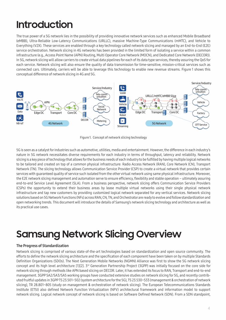
IntroductionThe true power of a 5G network lies in the possibility of providing innovative network services such as enhanced Mobile Broadband (eMBB), Ultra-Reliable Low-Latency Communications (URLLC), massive Machine-Type Communications (mMTC), and Vehicle to Everything (V2X). These services are enabled through a key technology called network slicing and managed by an End-to-End (E2E) service orchestration. Network slicing in 4G networks has been provided in the limited form of isolating a service within a common infrastructure (e.g., Access Point Name (APN) Routing, Multi Operator Core Network (MOCN), and Dedicated Core Network (DECOR)). In 5G, network slicing will allow carriers to create virtual data pipelines for each of its data type services, thereby assuring the QoS for each service. Network slicing will also ensure the quality of data transmission for time-sensitive, mission-critical services such as connected cars. Ultimately, carriers will be able to leverage this technology to enable new revenue streams. Figure 1 shows this conceptual difference of network slicing in 4G and 5G.
5G is seen as a catalyst for industries such as automotive, utilities, media and entertainment. However, the difference in each industry’s nature in 5G network necessitates diverse requirements for each industry in terms of throughput, latency and reliability. Network slicing is a key piece of technology that allows for the business needs of each industry to be fulfilled by having multiple logical networks to be tailored and created on top of a common physical infrastructure: Radio Access Network (RAN), Core Network (CN), Transport Network (TN). The slicing technology allows Communication Service Provider (CSP) to create a virtual network that provides certain services with guaranteed quality of service such isolated from the other virtual network using same physical infrastructure. Moreover, the E2E network slicing management and automation serve to ensure efficiency, flexibility and stable operation – ultimately assuring end-to-end Service Level Agreement (SLA). From a business perspective, network slicing offers Communication Service Providers (CSPs) the opportunity to extend their business areas by lease multiple virtual networks using their single physical network infrastructure and tap new customers by providing customized logical network separated for any vertical services. Network slicing solutions based on 5G Network Functions (NFs) across RAN, CN, TN, and Orchestrator are ready to evolve and follow standardization and open networking trends. This document will introduce the details of Samsung’s network slicing technology and architecture as well as its practical use cases.
Samsung Network Slicing OverviewThe Progress of StandardizationNetwork slicing is comprised of various state-of-the-art technologies based on standardization and open source community. The efforts to define the network slicing architecture and the specification of each component have been taken on by multiple Standards Definition Organizations (SDOs). The Next Generation Mobile Networks (NGMN) Alliance was first to show the 5G network slicing concept and its high level architecture [1][2]. 3rd Generation Partnership Project (3GPP) was initially focused on the core side for network slicing through methods like APN based slicing on DECOR. Later, it has extended its focus to RAN, Transport and end-to-end management. 3GPP SA2/SA3/SA5 working groups have conducted extensive studies on network slicing for 5G, and recently contrib-uted fruitful updates in 3GPP TS 23.501~502 (system architecture for the 5G), TS 23.530~533 (management & orchestration of network slicing), TR 28.801~805 (study on management & orchestration of network slicing). The European Telecommunications Standards Institute (ETSI) also defined Network Function Virtualization (NFV) architectural framework and information model to support network slicing. Logical network concept of network slicing is based on Software Defined Network (SDN). From a SDN standpoint,
Tele-communication
Service/Industry
Social Network
MeteringDECOR4G Network
VoLTE
Data
NB-IoT 5G Network
APN
Core DCTransportEdge DC
VoNR
Robot
Streaming
Vehicle
Core DCTransportEdge DC
Service/Industry
URLLC/mMTC/eMBB Slice
Vehicle
Tele-communication
Factory
OTT Service
Figure 1. Concept of network slicing technology

5
Open Network Foundation (ONF), which introduced OpenFlow for SDN, defined the methods to apply SDN architecture to 5G slicing [3]. More recently, the Internet Engineering Task Force (IETF) has contributed a rich set of control plane protocols (e.g., NETCONF/RESTCONF/ PCEP/BGP-LS, etc.), data plane protocols (e.g., SRv6, SR-MPLS, etc.) and various YANG data models (e.g., ACTN VN, L1/2/3 Service Models, TE/Tunnel Models, etc.) to support transport network slicing. As CSPs’ needs for open networking and open source based cloud environment grow stronger, multiple open networking associations such as ONF, O-RAN, Linux Foundation have been working on several open source projects to specify and implement open network architecture and interfaces in the different telecommunication layers. Open Network Automation Platform (ONAP) is the representative open source project dedicated to defining and realizing common network management framework, covering different types of network functions. Network slicing management is one of the key functions of ONAP and is powered by AI-based automation.
Making 5G Services Easy and Flexible Network slicing is the concept of creating multiple virtual networks on a common physical infrastructure that guarantee an agreed SLA for specific functionality requested from different service providers or tenants. Each slice provides complete network functionality including radio access network functions, core network functions [4]. For creating and managing different sliced virtual network, a collec-tion of platform/systems and well-designed mechanism or tools are needed. Samsung network slicing solution provides these platform and systems to the customer. Figure 2 shows Samsung’s overall architecture of network slicing solution. The orchestration architecture is composed of two layers: Samsung Cloud Orchestration and Domain Resource Orchestration. Domain Resource Orchestration is the orchestration system for the different parts of the networks (i.e., domains) along the communication path, such as RAN, TN, CN; the Cloud Orchestration is the orchestration for the E2E services. The lifecycle management of various Data Center (DC) resources (Compute, Network, or Storage) are supported by Hybrid Platforms such as Docker, Openstack, or Kubernetes. Both VM-based and container-based virtualization are supported.
Samsung’s network slicing solution aims to provide customized network services that can guarantee the service provider's requirements while effectively utilizing limited network resources. To achieve this, a network slice management system needs to be designed carefully, considering the different characteristics of the various technical domains such as access network, core network, transport network that make up the network slice. Accordingly, Samsung’s network slicing solution consists of several systems that operate in various technical domains, from a single domain to all-encompassing end-to-end domains, as shown in Figure 2. While each system performs its own functions independently from other systems, all these systems are closely linked to each other to provide network slicing. Table 1 is a brief description of each constituent system for network slicing and Table 2 is that of each sub-system.
eMBB SliceURLLC Slice
mMTC SliceNetwork Function
RAN Core Apps
Edge Central
Transport Transport
Compute Network Storage
Hybrid Virtualization Platform
Domain Resource Orchestration
RAN Orchestration CN OrchestrationTN Orchestration
RAN NSSMF TN NSSMF CN NSSMF
RAN SliceController
SDNO NFVO Core SliceController
SDNO NFVOTransport SliceController
WANO
Samsung Cloud Orchestration
E2E Service OrchestrationAnalytics
Analytics Applications,Data Collector Mediator
Non-RT RICController
E2 E OrchestratorService OrchestratorService Assurance
Service Fulfillment
CSMF/NSMF
Inventory
NSM
Policy
Portal
HA/Security
Workflow
Figure 2. Overall architecture of network slicing solution

Samsung’s network slicing solution has a standard hierarchical structure but can be arranged in various forms according to the purpose of the operator or the network environment.
Table 1. Brief description of constituent systems for network slicing
Table 2. Brief description of constituent sub-systems for network slicing
System Main Function
Samsung CloudOrchestration
Domain ResourceOrchestration
Sub-System Main Function
Analytics
Service Orchestrator
E2E Orchestrator
RAN Slice Controller
Transport Slice Controller
Core Slice Controller
NFV Orchestrator
SDN Orchestrator
WAN Orchestrator WANO is responsible for Wide Area Network (WAN) resource control and management.
Samsung Cloud Orchestration is composed of Analytics and E2E Service Orchestration products. It has capability to provide network slice and automation of physical and virtual network functions. This enables the delivery of network service to market on time and the reduction of costs.
Domain Resource Orchestration is composed of RAN Orchestration, TN Orchestration and CN Orchestration. It is based on existing products such as ETSI NFV-MANO, RAN Controller (i.e., Near-Real Time RAN Intelligent Controller (Near-RT RIC), RAN Network Slice Subnet Management Function (NSSMF), etc.) which are integrated with each other to support domain resource use cases.
Analytics collects data related of network slice and analyzes it with Non-RT RIC and analytic-applications for network slice optimization and probable root cause detection.
Service Orchestrator provides service fulfillment (i.e. service workflow, activation, etc.) and service assurance (i.e. fault correlation, trouble ticketing, etc.) to extend customers’ business areas by providing customized logical network separated for any vertical services.
E2E Orchestrator provides network service automation. It provides components to slice automation using network slice manager (Communication Service Management Function (CSMF)/Network Slice Management Function (NSMF)), inventory, policy and workflow modules. And portal can offer single view of network operation.
RAN Controller provides AI/ML based analytics applications (Near-RT RIC) and RAN NSSMF for network slice optimization.
TN Controller provides Transport network slice subnet lifecycle.
NFVO is responsible for network service/network function lifecycle management
CN Controller provides AI/ML based analytics applications for Core devices and CN NSSMF for network slice optimization.
SDNO provides the ability to program automated behaviors/policies in a network to coordinate switches and routers for supporting services and applications.
6
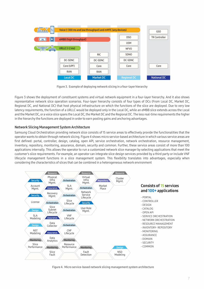
Figure 4. Micro service-based network slicing management system architecture
7
Consists of 15 services and 100+ applications - PORTAL- CONTROLLER- DESIGN- CATALOG- OPEN API- SERVICE ORCHESTRATION- NETWORK ORCHESTRATION- RESOURCE MANAGEMENT- INVENTORY- REPOSITORY- MONITORING- ASSURANCE- DOMAIN- SECURITY- COMMON
Orchestration
Security
Monitoring
Repository
Resource
Assurance
Orchestration
Assurance
Assurance
Monitoring
Resource
Design
Resource
Orchestration
Orchestration
Orchestration
Monitoring
Security
Security
Design
Design
Monitoring
NetworkService
Lifecycle
User RoleMgmt.
FaultDetection
MarketPlace
VirtualInfra
Mgmt.
RecoveryMgmt.
SliceSubnet
Lifecycle
DataCollector
DataAnalytics
SliceFault
PhysicalInfra
Mgmt.
NSDModeling
ClusterMgmt.Orchestration
SLAMgmt.
SliceLifecycle
VNFLifecycle
CNFLifecycle
ResourcePerformance
AccountMgmt.
License
SLAModeling
NSTModeling
SlicePerformance
Figure 3 shows the deployment of constituent systems and virtual network equipment in a four-layer hierarchy. And it also shows representative network slice operation scenarios. Four-layer hierarchy consists of four types of DCs (From Local DC, Market DC, Regional DC, and National DC) that host physical infrastructure on which the functions of the slice are deployed. Due to very low latency requirements, the function of a URLLC would be deployed only in the Local DC, while an eMBB slice extends across the Local and the Market DC, or a voice slice spans the Local DC, the Market DC and the Regional DC. The less real-time requirements the higher in the hierarchy the functions are deployed in order to earn pooling gains and anchoring advantages.
Network Slicing Management System ArchitectureSamsung Cloud Orchestration providing network slice consists of 15 service areas to effectively provide the functionalities that the operator wants to obtain through network slicing. Figure 4 shows micro service-based architecture in which various service areas are first defined: portal, controller, design, catalog, open API, service orchestration, network orchestration, resource management, inventory, repository, monitoring, assurance, domain, security and common. Further, these service areas consist of more than 100 applications internally. This allows the operator to run a customized network slice manager by selecting applications that meet the customer's slice requirements. For example, an operator can integrate slice design services provided by a third party or include VNF lifecycle management functions in a slice management system. This flexibility translates into advantages, especially when considering the characteristics of slices that can be combined in a heterogeneous network environment
Figure 3. Example of deploying network slicing in a four-layer hierarchy
RAN
Core (UPF)
DC-SDNC
Core
TR Controller
GSO
Core
DC-SDNC
SDNO
NFVO
USM
DSO
Local DC Regional DC National DC
Voice (< 300 ms and low throughput) and mMTC (any devices)
eMBB (high throughput)
URLLC (< 2 ms)
RAN
Core
DC-SDNC
RIC
Market DC

Core, Access and Transport Network Slicing ArchitectureWhen providing an E2E network slicing, CN and RAN provide slicing related functions based on the architecture defined in 3GPP standards, while TN provides the slicing related and coordination functions with non-3GPP parts (e.g. TN, DC network) in addition to the network components defined in 3GPP. Core network function can be sliced in order to provide specific services for different users. Some of the network functions can be shared between network slices, while some network functions are deployed only for a specific service within a sliced network. For RAN, the RAN Intelligent Controller (RIC), defined by O-RAN, is added as a component for quick policy application and real time control. For transport network, the TN provides slicing related functions between sets of connection points in the networks such as Front, Mid and Backhaul. TN orchestration can manage/control resources for the slicing of transport domains and coordinate actions across both domains such as IP or Optical domains through multilayer path computation and optimization [5][6].
Figure 5 shows a typical network slicing architecture and key characteristics of this architecture include: • Cloud Orchestration oversees network slice capacity, qualification, SLA, and network health monitoring.• Domain Resource Orchestration has a responsibility to provide life cycle management, reservation, assign, scale, and control
functions for compute, storage and network resources per RAN, TN, and CN domain. For example, NFVO is working with NFVI resources; it can coordinate, assign and release them without interacting with any specific VIM. The orchestrator can manage resources with the VIMs through their northbound APIs.
• Near-RT RIC performs slicing optimization based on real-time monitoring and control of RAN data.• Distributed Unit (DU), Centralized Unit - Control Plane (CU-CP), and Access and Mobility Management Function (AMF) are
typically shared by several network slices.• CU-UP, Session Management Function (SMF) and User Plane Function (UPF) are typically dedicated to particular network slices.• User Data Management (UDM) and Network Slice Selection Function (NSSF) are shared by all network slices.• Network Repository Function (NRF) and Policy Control Function (PCF) can be common or network slice specific.• The slice configured by the SLA provides isolated services for each divided bearer path (DU, CU-UP, UPF, and DN).
NR RU
DU
PHY MAC RLC
CU-UPPDC/SDAP
(eMBB)
CU-UPPDCP/SDAP
(URLLC)MEC/UPF(URLLC)
UPF(eMBB)
UPF(URLLC)
UPF(mMTC)
SMF
SMF
SMF
PCF
NRF
PCF
AMF
AUSF UDM NSSF NRF PCFVNFM/CISMEMS
mMTC slice
URLLC slice
eMBB slice
CU-UPPDCP/SDAP
(mMTC)
CU-CP
RRC
Samsung Cloud Orchestration
E2E Service OrchestrationAnalytics
Analytics Applications,Data Collector Mediator
Non-RT RICController
DN(eMBB)
DN(URLLC)
DN(mMTC)
E2E OrchestratorService Orchestrator
Service Assurance
Service Fulfillment
CSMF/NSMF
Inventory
NSM
Policy
Portal
HA/Security
Workflow
Domain Resource Orchestration
RAN Orchestration CN OrchestrationTN Orchestration
RAN NSSMF TN NSSMF CN NSSMF
RAN SliceController
SDNO NFVO Core SliceController
SDNO NFVOTransport SliceController
WANO
Near-RT RIC(RAN Intelligent Controller)
Figure 5. Overall network slicing architecture based on O-RAN
8

Key Technologies for Network SlicingNetwork Slicing Management
Network Slice Management is tasked with the job of managing the service requirement of the operator to the network slice itself. It consists of Communication Service Instance (CSI) which manages the operator's service requirements and Network Slice Instance (NSI) & Network Slice Subnet Instance (NSSI) which manages the slice requirements.
Network Slice Life Cycle ManagementThe life cycle of network slice generally includes Preparation, Commissioning, Operation and Decommissioning step [7][8]. Figure 6 shows network slice life cycle procedure. In the Preparation phase, network slice design, creation/onboarding of Network Slice Template(NST), and evaluation of network slice requirements are performed. The Commissioning phase includes CSI/NSI/NSSI creation and sets the necessary associations among them. The Operation phase includes CSI/NSI/NSSI activation, modification and deactivation. Lastly, the Decommissioning phase includes CSI/NSI/NSSI termination.
Dynamic and Automated Network Slice OperationThe dynamic network slice – managed by the end-to-end orchestration - is provided by Topology and Orchestration Specification for Cloud Applications (TOSCA) template model for reusable tasks and closed-loop control in network slicing. In order to instantiate or modify the network slice, the network slice template model needs to be created. During the preparation phase, template models are created and include parameters such as tracking area (cell), bandwidth, latency, capacity, and priority for the RAN and CN Network Slice Subnet Template (NSST). During this process, transport network template models are also created using QoS, bandwidth, laten-cy, and other parameters. In the commissioning phase, network slice instantiation and configuration are performed. In the operation phase, network slice is activated and the status of the network slice is observed. And analytics guarantee that SLAs are met. The decommissioning phase involves the deleting of a slice when the service is no longer in use. In addition, as shown in Figure 7, E2E Service Orchestration and Analytics provide disaster recovery management, commissioning configuration, topology, monitoring and root cause analysis, alerting management for network slice.
The E2E Service Orchestration together with Network Slice Manager, Service Orchestrator, Inventory, Policy, and Analytics provides automated and dynamic slice management using closed loop automation. It provides features such as auto-reset, automatic optimization, and conflict resolution for automatic and manual operation. The automatic switching function determines the priority of network slice and automatically relocates resources as needed.
Lifecycle of Network Slice Instance
Preparation
Network Environmentpreparation
Design Onboarding
Decommissioning
Termination
Operation
Activation
Modification
De-activation
Commissioning
CreationSupervision Reporting
Figure 6. Network slice life cycle procedure
Figure 7. E2E service orchestration reference architecture
Samsung Cloud Orchestration
E2E Service OrchestrationAnalytics
Analy�cs Applica�ons,Data Collector Mediator
Non-RT RICController
E2E OrchestratorService Orchestrator
Service Assurance
Service FulfillmentCSMF/NSMF
Inventory
NSM
Policy
Portal
HA/Security
Workflow
9

One-click Network Slice Creation and ProvisioningDuring the network slice deployment process, unexpected constraints may be met or operator intervention is required for resource virtualization and slice instantiation and provisioning for specific services. Slice templates play an important role in solving those problems and ensuring fast and effective slice instantiation. Therefore, careful consideration of performance requirements and service flexibility needs to be made when designing network slice templates. NSM provides predefined slice templates for well-known 5G services. Operators can create slices by either using pre-defined templates or partially customizing them according to the requirements. When network resources for slices are created and deployed through slice templates, provisioning can be automatically performed through the plug-and-play mechanism and configuration file management. Also, provided predefined slice templates can reduce human error by minimizing unnecessary operator intervention and operational convenience. Ultimately, it provides the ability to create and provision network slices with just one click.
Multi-vendor/Multi-domain/Multi-platform Compatible Orchestration
Given that network slices operate in heterogeneous network environments, the NSM must be able to operate in various network domains and virtualization environments. Moreover, it must provide interoperability with third party management systems. Samsung network slice manager provides compatibility with legacy customer OSS / BSS, third party orchestrator and controller, and third party VNF/CNF based on OpenAPI and standardized interfaces as shown below in Figure 8. In addition, Samsung network slice manager is composed of various management systems operating in multi-layer, multi-domain. It also follows the container-based micro service architecture, and can thus be easily operated on distributed and hybrid clouds.
Single Pane of Glass Portal Samsung network slice manager provides a single pane of glass through which slice monitoring results and management functions can be monitored. Slice monitoring results include the overall slice status, the number of raised alarms, SLA metrics and KPIs for each slice at various levels of entity. Integrated SLA metrics are automatically calculated from application metrics and core metrics. NSM also provides user-friendly slice management operations through the same view. This way, network operators reap the benefit of seeing network slices and slice management operations through a unified lens. Moreover, the portal provides quick access to the information needed. A simple straightforward dashboard makes it easy for its users to understand what is being shown and to navigate what they need to see quickly and simply.
Figure 8. Multi-vendor/multi-domain/multi-platform compatible orchestration
Hybrid CloudSupport
Multi-domainOrchestrator
3rd PartyOrchestrator/
Controller
Multi-vendorVNF/CNF/
Applications
HybridVirtualization
Platform
CustomerOSS/BSS
Providing user interface through a single portal
Integration with customermanagement system
based on OpenAPI
Orchestrators ofvarious domains tocontrol E2E/subnet
/single network function
Integration with 3rd party orchestrator
and controller based on OpenAPI
Slice composition independent of
virtualization method (e.g. VM-based or container-based)
Integration with 3rd party
5G network functions and applications
Simultaneously operate slices
in a hybrid environment of private
and public clouds
10

Core Network
Network slicing is a key function supported on the 5G core. With the ability to send traffic that requires ultra-low latency for processing to a near-by-edge network, operators can execute new partnerships with enterprises to create new business models that leverage ultra-reliable and low latency communications. Samsung’s 5G core not only provides the ability to set up these user sessions, but also provides end-to-end visibility of the network path to understand the handling of the user data streams through slice. With such visibility, the network operator can both manage these slices and assure end-to-end SLAs.Samsung considers the following areas as key differentiators in “Core slicing”:
• dynamic scale of network slices, • support of industry/vertical-specific features, • differentiated charging for network slices, and • new network slice features introduced to manage and identify the slice.
Dynamic Scale of Network SlicesThe Samsung 5G core architecture is designed according to key cloud-native design principles as to provide dynamic scale of network slices. Core network is composed of various micro service components enabling faster time to market delivery and deployment. This design principle of micro service and stateless architecture is best suited for telecom network functions which have a lot of common blocks such as operation, administration and management that can be re-used or shared across multiple call processing network functions. Additionally, Samsung core leverages Cloud Native Computing Foundation (CNCF) tool sets to take advantage of open-source environments with improved operational efficiency and reduction in OPEX/CAPEX.
NF-Specific Service OAM ServiceCommon Service
5G Core NF
Micro-serviceµ
Container
Separate DB
Stateless NF
µ µµ µ µ µ µ µ µ µ µ µ µ µ µ µ
CNFDB(UDSF)
NSSFSMFAMF NRF
µ µ
NF Comm. Interface Event LoggingDB TraceSessionMobility
Figure 9. Cloud native architecture
Figure 9 outlines the cloud native architecture. The fundamental concepts of the cloud native 5G Core are defined as Stateless, Micro-services and Container-based.
• Stateless – Network Functions store their state information in a central data base called Unstructured Data Storage Function (UDSF) which makes the network function itself stateless. Stateless NFs can be scaled easily, and specific NFs can be isolated in case of NF failover, enabling service continuity.
• Micro-services architecture – 5G core NFs consist of micro-services. The types of micro-services that constitute an NF are classified as follows:- NF-specific micro-services: services specific to an NF; e.g., AMF-specific micro-services (N1/N2 communication, mobile termination,
N1/N2 interface).- Common micro-services: services commonly used by all NF; e.g., interface, DB, event.- OAM micro-services: services for OAM; e.g., logging, trace.
5G core NFs are created by combining the necessary micro-services, NF-specific, common and OAM micro-services. Each micro-service runs in a container, independently scalable and re-usable, which enables the flexible launch of new services, faster time-to-market and offers enhanced scalability.
• Container-based architecture – Containers have low overheads, which allows quick and easy installation of micro-services, enabling rapid service deployment.
11

12
IMS Voice Mission Critical Smart Factory Site
MMTelsupport
Location based message delivery
Positioning support
Number ofSubscribers: Small
MissionCritical
Support
Group Communication support
AMF Common or Exclusive
SMF Market DC
UPF Market DC
AMF Common Layer
SMF Market DC
UPF On-Premisesor LDC/MDC
User management openness
TSN Simultaneoususe of the
network slice
Number of Subscribers: Small
Support fornon-IP traffic
MMTelsupport SSC Mode: 1
Number of Subscribers: Large
AMF Common Layer
SMF Reginal DC
IMS Reginal DC
PCF Reginal DC
UPF Reginal DC
Figure 10. Service characteristics of vertical segments
Support of Industry/Vertical-specific FeaturesVertical industries are very diverse and their requirements are defined by the service characteristics of the vertical segment. Since the early stages of 5G SA standardization work in 3GPP in 2017, lots of requirements from various vertical industries have been requested to be included as 5G standard requirements. During the 4G era, LTE/EPC technology changed mobile lifestyles with high data rates and low latency but did not much impact the industrial sector. 5G targets industrial innovation with lower latency, reliable data transmission, higher data rates and industry specific features. In Release 16 of its specification, 3GPP has defined various vertical features such as Time Sensitive Network (TSN), Virtual Network (VN), Non Public Network (NPN), URLLC, V2X and Cellular IoTs.Network slicing is a key capability that will enable flexibility in the network, as it allows multiple logical networks to be created. This, in turn, will help to address the cost, efficiency, and flexibility requirements imposed by the variety of industrial vertical services.
Figure 11. Network slice charging flow
Figure 10 shows different service characteristics of each vertical segments. For IP Multimedia Subsystem (IMS) Voice Service, NFs can be located in Regional DC (RDC). For voice service continuity, Session and Service Continuity (SSC) mode 1 is required as to provide stable network connectivity to a large number of subscribers. For Mission Critical Services, NFs can be located in Market DC (MDC). This is to allow for a small group of people to carry out mission critical communication efficiently. For Smart Factory services, UPF needs to be located on premise or Local DC (LDC)/MDC to provide low latency for a small group of people. During this process, TSN may be required for precise control.
Differentiated charging for network slices Depending on the vertical industry, charging requirements and factors may vary - ranging from aggregated network usage to per subscription accounting information. Charging is another key objective of core slicing as customer’s request for different network services based on its own business requirements, which are then converted to SLA and delivered to the network slice management system. The Network slice management system deploys and controls its sub-system, RAN, CN and back-end service components to meet and guarantee SLAs. In such case, it is conducive to customize charging systems or billing systems depending on the objectives of a customer’s business model. Figure 11 shows the basic charging flow per network slice. Charging Policy is delivered to each network slice and usage data of each slice is collected by CHarging Function (CHF) and billing information is sent to the consumer through Network Slice Management.
Network as aService Slice
EnterpriseSlice
URLLC/MEC Slice
MVNO's Network
ChargingPolicy
Customer Portal forSlice Consumer
Customer Portal for Slice Consumer
Service Requirements
SLA Status and Billing Information
CHFCharging DataSet of Slices
Policy
Samsung Cloud Orchestration
E2E Service OrchestrationAnalyticsAnalytics Applications, Data Collector Mediator
Non-RT RIC Controller
E2E OrchestratorService OrchestratorService Assurance
Service Fulfillment
Inventory
NSM
Policy
Portal
HA/Security
Workflow
RANCU/DU AMF
UPF
UPF
UPF
SMF
SMF
Local DC Market DC Regional DC
usagesSMF
PCF
PCF
13
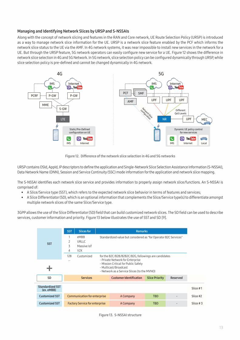
Managing and Identifying Network Slices by URSP and S-NSSAIsAlong with the concept of network slicing and features in the RAN and Core network, UE Route Selection Policy (URSP) is introduced as a way to manage network slice information for the UE. URSP is a network slice feature enabled by the PCF which informs the network slice status to the UE via the AMF. In 4G network systems, it was near impossible to install new services in the network for a UE. But through the URSP feature, 5G network operators can easily configure new service for a UE. Figure 12 shows the difference in network slice selection in 4G and 5G Network. In 5G network, slice selection policy can be configured dynamically through URSP, while slice selection policy is pre-defined and cannot be changed dynamically in 4G network.
URSP contains OSId, AppId, IP descriptors to define the application and Single-Network Slice Selection Assistance Information (S-NSSAI), Data Network Name (DNN), Session and Service Continuity (SSC) mode information for the application and network slice mapping.
The S-NSSAI identifies each network slice service and provides information to properly assign network slice/functions. An S-NSSAI is comprised of:
• A Slice/Service type (SST), which refers to the expected network slice behavior in terms of features and services;• A Slice Differentiator (SD), which is an optional information that complements the Slice/Service type(s) to differentiate amongst
multiple network slices of the same Slice/Service type.
3GPP allows the use of the Slice Differentiator (SD) field that can build customized network slices. The SD field can be used to describe services, customer information and priority. Figure 13 below illustrates the use of SST and SD [9].
Dynamic UE policy controlfor new services
Static/Pre-Definedconfiguration on UE
4G 5G
IMS
InternetIMS
Internet
DifferentQoS Levels
UPF UPFUPF
UPFNR
LocalInternetIMS
InternetIMS
AMF
S-GW
LTE
P-GW P-GWPCF
MEC
SMF
MME
PCRF
Network Slice
configuration
Figure 12. Difference of the network slice selection in 4G and 5G networks
Figure 13. S-NSSAI structure
Slices for Remarks
Standardized value but considered as "for Operator B2C Services"123
Customized for the B2C/B2B/B2B2C/B2G, followings are candidates- Private Network for Enterprise- Mission Critical for Public Safety- Multicast/Broadcast- Network as a Service Slices (to the MVNO)
128 ...
SST
eMBBURLLCMassive IoT
SST
SD Slice Priority ReservedServices Customer Identification
Standardized SST(ex. eMBB)
TBD -Communication for enterprise A Company
TBD -Factory Service for enterprise A Company
4 V2X
Customized SST
Customized SST
Slice #2
Slice # 1
Slice # 3
14
Radio Access Network
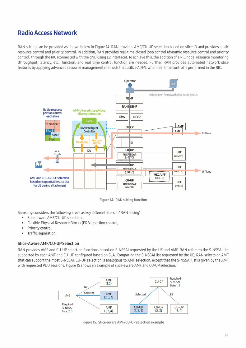
RAN slicing can be provided as shown below in Figure 14. RAN provides AMF/CU-UP selection based on slice ID and provides static resource control and priority control. In addition, RAN provides real-time closed loop control (dynamic resource control and priority control) through the RIC (connected with the gNB using E2 interface). To achieve this, the addition of a RIC node, resource monitoring (throughput, latency, etc.) function, and real time control function are needed. Further, RAN provides automated network slice features by applying advanced resource management methods that utilize AI/ML when real time control is performed in the RIC.
Samsung considers the following areas as key differentiators in “RAN slicing”: • Slice-aware AMF/CU-UP selection, • Flexible Physical Resource Blocks (PRBs) portion control,• Priority control, • Traffic separation.
Slice-Aware AMF/CU-UP SelectionRAN provides AMF and CU-UP selection functions based on S-NSSAI requested by the UE and AMF. RAN refers to the S-NSSAI list supported by each AMF and CU-UP configured based on SLA. Comparing the S-NSSAI list requested by the UE, RAN selects an AMF that can support the most S-NSSAI. CU-UP selection is analogous to AMF selection, except that the S-NSSAI list is given by the AMF with requested PDU sessions. Figure 15 shows an example of slice-aware AMF and CU-UP selection.
Figure 14. RAN slicing function
Figure 15. Slice-aware AMF/CU-UP selection example
AMF(1, 3, 4)
Selected
AMF(1, 2)
gNB
N2
RequiredS-NSSAI
lists: 2, 3
AMF(2, 3, 4)
CU-UP(2, 3)
CU-UP(3, 4)
CU-CPRequiredS-NSSAIlists: 1, 3
Selected E1
CU-UP(1, 3, 4)
E1
CU-UPPDCP/SDAP
(mMTC)
CU-UPPDCP/SDAP
(eMBB)
CU-UPPDCP/SDAP
(URLLC)
CU-CP
RRC
EMS NFVO
RAN NSSMF
NSMF
AMFAMF
UPF(mMTC)
UPF(URLLC)
UPF(eMBB)
MEC/UPF(URLLC)
U-Plane
C-Plane
DU
RAN IntelligentController
AI/ML
RLCMACPHY
AMF and CU-UP/UPF selection based on supportable slice list
for UE during attachment
Operator
Instantiation for network slice based on SLA
AI/ML-based closed-loopslice optimization
Radio resourceportion control
each slice
Common
Slice 3Slice2
Slice1
NR RU
SLA
Monitoring Real timecontrol

15
Figure 16 shows an example of PRB portion control based on minimum and maximum sharing portions.
If all slices are allocated to their maximum portions, i.e. 40%, 20%, and 40%, the common portion will be zero. However, if slice #1, #2, and slice #3 are allocated as 10%, 20%, and 40% respectively, the common portion will be 30%. When a slice consumes all of its allocated portions, it can use segments of the common portion, granted that it has the highest scheduling priority.
Priority ControlIn the conventional Proportional Fairness (PF) scheduling, a gNB is not able to adjust scheduling priority for UEs having different service characteristics. However, the priority control function in 5G allows that operator can control radio scheduling priority among different network slices. For example, if a UE1 has data bearer of high priority service (A Slice) and a UE2 has bearers having low priority (B slice) respectively, the key performance such as throughput of the UE1 could be larger than the UE2’s as shown in Figure 17. This function is normally applied to non-GBR bearer rather than GBR bearer like voice.
Figure 16. Flexible PRB portion control example
Figure 17. Priority control function in radio scheduling for network slice
Flexible PRB Portion ControlThe PRB portion control function allocates radio resources, i.e. PRBs, to each slice based on each slice's minimum and maximum sharing portions which are configured by the operators. Using this function, resources for a specific slice can be isolated. To do so, various methods such as static resource allocation (by Min/Max setting) and dynamic resource allocation (considering service situation per slice with real time by AI/ML) can be applied.
Slice-awareRadio Scheduler in gNB
A slice
(High priority service)
Bearer = 1 2 N
B slice
2 M1
1x Tput . of (A Slice)
2x Tput. of (B Slice)
1 2 3
10% 0% 0% Min portion40% 20% 40% Max portion
Slice #
* Allocated to all slices based on scheduling priority
[Radio resource]
Common*
Slice #2
Slice #1
Slice #3

16
Traffic Separation in the RAN
Figure 18. Slice traffic separation with VLAN
Near-RT RIC(RAN Intelligent Controller)
CU-UPPDCP/SDAP
(mMTC)
CU-UPPDCP/SDAP
(eMBB)
CU-UP
PDCP/SDAP(URLLC)
EMS VNFM/CISM
AMF
VLAN A
VLAN B
VLAN C
CU-CP
RRC
DU
RLCMACPHY
NR RU
UPF(mMTC)
UPF(URLLC)
UPF(eMBB)
Samsung Cloud Orchestration
E2E Service OrchestrationAnalytics
Analy�cs Applica�ons,Data Collector Mediator
Non-RT RICController
Service Orchestrator
Service Assurance
Service Fulfillment
CSMF/NSMF
Inventory
NSM
Policy
Portal
HA/Security
Workflow
Domain Resource Orchestration
RAN Orchestration CN OrchestrationTN Orchestration
RAN NSSMF TN NSSMF CN NSSMF
RAN SliceController SDNO NFVO Core Slice
Controller SDNO NFVOTransport SliceController
WANO
E2E Orchestrator
Since the network slicing technology allows operators to partition their networks in a structured, flexible and scalable manner, the RAN should be made slice-aware and separated by each slice. This can be done by providing information such as slice ID, another abstraction framework or by extended individual data packet tagging on the interface of the RAN. The envisioned scenarios for network slicing may lead to cases where a slice may be composed of multiple services that are treated differently in the RAN. Therefore, the QoS framework needs to take into account some slicing level information in addition to service level information. (This can either be explicit information or some sort of abstraction such as an enhanced identity.) Figure 18 shows the allocation of different VLAN IDs which are predefined at the entity (DU, CU and UPF) based on each NSSAI and 5QI value.

17
Figure 19 shows how UE assisted network slice selection works. In this example, an UE selects the network slice for low latency service and delivers the S-NSSAI list to CU-CP. The CU-CP can then select AMF based on the S-NSSAI. If the UE does not provide S-NSSAI list during initial access, the CU-CP will select a default AMF. The AMF can select SMF based on S-NSSAI and load information while the SMF can select UPF based on S-NSSAI, location, and load information. CU-CP selects CU-UP based on S-NSSAI given by the AMF during PDU setup procedure.
Analytics based Network Slice Optimization
Network slice instances share a common physical infrastructure and its resources. Unlike physical network infrastructure, however, a network slice is dynamic and flexible, meaning it can be easily created and destroyed on demand. Moreover, resource requirements for each slice vary because of mixed traffic classes with different QoS requirements and various SLAs with different parameters. Therefore, resource optimization is pivotal for efficient use of scarce resources (e.g., resource blocks in RAN, bandwidth in TN, number of VMs or containers, or overall computing resources). Analytics-based Network Slice Optimization (NSO) enables the proactive auto-scaling of NSI resources to meet the service requirement of slice customers, as well as to use scarce resources efficiently. Analytics-based NSO monitors and stores NSI performance data during its lifecycle. Based on the historical data and experience, artificial intelligence and machine learning techniques can be utilized to predict service key performance indicators (KPI), service health state and resource usage to spot in advance possible failures and risks. For instance, a sudden increase of traffic load and network congestion can be expected in festivals, sports events, or holidays. NSO predicts the performance degradation and makes a decision to scale out the NSI in advance. Consequently, more resources are allocated to accommodate for increased traffic and UEs to preserve QoE and avoid network congestion, while minimizing the impact on traffic and services in other NSIs in the same network. On the contrary, when the traffic load decreases, NSIs can be scaled down to allocate resources to other slices or can be configured to accommodate more UEs in the slice. This way, OPEX is reduced with the help of the automated optimization process while resources can be utilized cost effectively to prevent wasting resources.
Terminal
Network slicing enables resource sharing for different services without the complicated QoS mechanism in the transport level. In other words, QoS mechanism can be imposed to each slice instead of being imposed to all the traffic to/from the UE. To enable the core and the radio access network to distinguish different slice demands, the UE sends slice assistance information to select the AMF instance according to the slice selection procedure. After the slice selection procedure, the UE and the AMF perform UE context handling procedure to establish the UE context and PDU resource allocation. A maximum of eight slices can be simultaneously supported by the UE. S-NSSAI is set up per PDU session for the policy management in the PDU session level. Since S-NSSAI is a part of the PDU session information for the context transfer, slice-aware admission control is possible for the UE. If the UE is not registered for slice services, the UE should perform registration procedures including authentication and authorization via AMF. The AMF mediates the UE to UDM, Authentication Function (AUSF), and target AMF (in case of the mediating AMF is not the correct target.).
Figure 19. Network slice allocation to UE
5G UEDU Network Slice for Low Latency
Network Slice for IoTAMF SMF
Network Slice for eMBB
gNB (CU and DU)
SMF selectionbased on NSSAI
CU-UP selection based on S-NSSAI given by AMF
AMF selection basedon requested NSSAI
※ AMF can be shared between different Network Slices because UE registers with an AMF but the UE can use multiple different network slices simultaneously
AMF
IoTUPFCU-UP(PDCP)
Internet
VR/AR
UPFCU-UP(PDCP)
CU-CP(RRC)
CU-UP (PDCP)Core UPF
NSSAI
UPF selectionbased on
NSSAI
SMF
AMF SMF

18
Network Slicing Use CasesThe 5G system is expected to support a variety of communication services, performance requirements and user groups according to industrial demands. To meet these diverse request, the evolution of 5G business model and use cases are needed. MGMN divided the 5G business model into three roles: asset provider, connectivity provider and partner service provider [1]. Asset provider can lease a part of own infrastructure to 3rd parties. Connectivity provider delivers both basic connectivity such as best effort IP connectivity for retail or wholesale customers and enhanced IP connectivity with QoS, latency, etc. Partner service provider offers either communication services to the end-customers with enriched contents by 3rd parties or capabilities to the 3rd party/partner for offering services to the end-customers. Business model considering network slicing is shown as below Figure 20.
Physical Infrastructure Provider offers physical infrastructure. A part of physical resources can be sliced. Virtual Infrastructure Service Provider provides virtualized infrastructure services using exposed physical resources from Physical Infrastructure Provider. Network Slice Service Provider is in charge of creating and managing slices based on SLA and allocates appropriate virtual/physical resources per slice. The Network Slice Service Provider provides information about KPIs and accounting data per slice during slice life time. Orchestrator is belonged to the Network Slice Service Provider. Network Operator (NOP) owns and operates its network and CSP provides communication service to their customers. The NOP can decide to provide required network services using network slices depending on the CSP requirements and the NOP policies. CSP can lease a part of their network to CSC, and the CSC can play a role of NOP and CSP also. CSP may operate multiple slices to provide service-specific functions. Slice tenant can be a NOP as seen in the classical business model and can interact with the CSP and the specific Contents Provider for enriched services.
A provider may obtain additional service capabilities from third parties in order to provide enriched services to end-customers and also earn additional revenue from offering its spare services or resources to third parties. The concept of Anything as a Service (XaaS) which allows providers to create and manage services on-demand without owning their infrastructures, brings new business opportunities. According to research by NGMN and Global System for Mobile Communications (GSMA) [1][10], the following use cases are set to reap the most benefits of network slicing.
For AR/VRAugmented Reality (AR) and Virtual Reality (VR) are one of the most emerging industries. AR is an interactive experience of real world overlaid with virtual digital elements. Remote surgery can be an example in some scenarios such as disaster or hazardous areas. It allows a doctor to perform the operation considering the circumstances even though the doctor is not physically in the unsafe area. Remote collaboration is another example. Problems occurred from full automated factory can be solved remotely one by one looking at the situation. VR is a fully immersive experience of virtual reality based on user’s sensory inputs (e.g. sound, touch, and sight). Many VR applications are derived such as VR education or training program. Operator can deploy multiple slices to support AR/VR effectively: one slice for critical voice conversation, another slice for video handling.
Contents Provider
Physical Infrastructure Provider
Network Slice Service Provider
Communication Service Provider (CSP)
Network Operator (NOP)
Communication Service Customer (CSC) CSC’
CSP’
NOP’
Virtual Infrastructure Service Provider Virtual Infra. Service Provider’
Contents Provider
Figure 20. Business model in network slicing

19
Summary5G network slicing is the concept of creating multiple virtual networks on a common physical infrastructure that guarantee an agreed SLA for specific functionality requested from different service providers or tenants. network slicing is a technology that enables the widespread service requirements for emerging industrial use cases. Samsung offers a full-fledged slicing solution starting from the physical network elements in RAN and Core that fully support the slicing mechanism to E2E automated slicing support by E2E orchestrator. Predefined network slice templates based on SLAs from various network domains allow for a one-click network setup. In addition, simple and easy operation for all network slice instances is provided through a unified management tool so that operator is able to seamlessly manage fragmented networks that exist in multi-domain, multi-vendor or multi services. Moreover, Samsung orchestration and automation technologies minimize human error and improve operational convenience. AI/ML gathers and analyzes data from each slice and performs optimization including reduction and expansion of physical, CP/UP resources and network slice itself. By utilizing network slicing, the operator can start undertaking new services without impacting the legacy mobile service or overinvesting. In addition, the operator can lease a part of its network to a CSC who is willing to run new businesses, thereby creating new streams of revenues for the CSP.
Samsung 5G network slicing will bring not only a complete E2E solution that embraces all the diverse requirements but also the potential to enhance a CSPs business by fast addressing new and emerging markets.
For AutomotiveV2X is seen as one of the most prominent use cases for 5G. V2X enables not only communication between vehicles (or vehicles to infrastructure), but also in-car entertainment services. To support mission critical IoT services (e.g., assisted/autonomous driving, collision avoidance system between vehicles or real time traffic/route information), very low latency, high reliability, and robust performances of the network are required. On the contrary, in-car entertainment such as movie, music, TV streaming or voice conference needs eMBB characteristics: high data rata with wide coverage.
For Massive IoTsSmart services such as gas/water metering, city lights management, transport traffic management or tracking/monitoring will become widespread in the future. If various massive IoT devices are introduced to existing networks, service quality and performance to legacy users will not be guaranteed because of massive connectivity and extremely different service characteristics (e.g., low data rate, periodicity, low cost and very long battery device). As a solution, operators can deploy new slices for these different types of use cases to isolate the impact, as well as, to monitor or charge customers differently.
For Public SafetyThe primary requirements for public safety are performance, availability and security – all of which network slicing can fulfill. The isolation of network slicing meets security requirement while preemption/prioritization function with dedicated resource guarantees the performance and availability requirement. In case of emergencies such as natural disasters, reliable group communication and HD image or video communication are essential. To this end, services with high data rates, very low latency, high density of connectivity and reliability are very important.
For Ad-hoc EventsAd-hoc or temporary mass events such as big concerts, sports games or rush hour may cause capacity variation in a particular area. To prepare for such sporadic short-term events, operators can invest in extra network equipment, but will find this a costly solution that is not sustainable. Utilizing AI/ML functions of network slicing, however, dynamically adjusting capacity in real-time becomes a reality and thus provides an alternative solution to offset the ad-hoc situations mentioned above.

20
3GPP5QIACTNAIAMFAPNAUSFBSSCAPEXCHFCISMCNCNCFCNFCSCCSICSMFCSPDECORDCDNNDSOeMBBETSIGSOIETFIoTMLmMTCMANOMOCNMVNONear-RT RICNFVNFVONGMNNPNNon-RT RICNRFNSaaSNSINSMNSMF
3rd Generation Partnership Project5G QoS IndicatorAbstract and Control of TE NetworksArtificial IntelligentAccess and Mobility Management FunctionAccess Point NameAuthentication FunctionBusiness Support SystemCapital ExpenditureCHarging FunctionContainer Infrastructure Service ManagementCore NetworkCloud Native Computing FoundationCloud-native Network FunctionCommunication Service CustomerCommunication Service InstanceCommunication Service Management FunctionCommunication Service ProviderDEdicated COReData CenterData Network NameDomain Service Orchestratorenhanced Mobile BroadbandEuropean Telecommunications Standards InstituteGlobal Service OrchestratorInternet Engineering Task ForceInternet of ThingsMachine Learningmassive Machine-Type CommunicationManagement and Network OrchestrationMultiple Operator Core NetworkMobile Virtual Network OperatorNear-Real Time RICNetwork Function VirtualizationNetwork Function Virtualization OrchestratorNext Generation Mobile Networks AllianceNon Public NetworkNon-Real Time RICNetwork Repository FunctionNetwork Slicing as a ServiceNetwork Slice InstanceNetwork Slice ManagerNetwork Slice Management Function
Abbreviations
NSONSSFNSSINSSMFNSSTNSTONAPONFONOSOPEXOPNFVO-RANOSSPCFPFPNFPRBRANRICSSCSDSDOSDNSDNCSDNOSLASMFS-NSSAI SSTTNTSNTOSCA
UDMUDSF UPFURLLCURSPV2XVNVNFVNFMWANO
Network Services Orchestrator Network Slicing Selection FunctionNetwork Slice Subnet InstanceNetwork Slice Subnet Management FunctionNetwork Slice Subnet TemplateNetwork Slice TemplateOpen Network Automation PlatformOpen Network FoundationOpen Network Operating SystemOperational ExpenditureOpen Platform for NFVOpen-RANOperations Support SystemPolicy Control FunctionProportional FairPhysical Network FunctionPhysical Resource BlockRadio Access NetworkRAN Intelligent ControlSession and Service ContinuitySlice DifferentiatorStandards Definition OrganizationSoftware Defined NetworkSDN ControllerSDN OrchestratorService Level AgreementSession Management FunctionSingle-Network Slice Selection Assistance InformationSlice/Service TypeTransport NetworkTime Sensitive NetworkTopology and Orchestration Specification for Cloud ApplicationsUser Data ManagementUnstructured Data Storage FunctionUser Plane FunctionUltra-Reliable Low-Latency CommunicationUE Route Selection PolicyVehicle to EverythingVirtual NetworkVirtual Network FunctionVirtual Network Function ManagerWide Area Network Orchestrator

21
References[1] Next Generation Mobile Networks Alliance [NGMN Alliance]. (2015, Feb. 17). “5G White Paper”, Version 1.0.[2] NGMN Alliance. (2016, Jan. 13). “Description of Network Slicing Concept”, Version 1.0[3] ONF TR-521. (2016) “SDN Architecture”, Issue 1.1[4] 3GPP TS 22.261. “Service Requirements for the 5G System Stage 1”, Rel.16[5] ONF TR-522. (2016, March) “SDN Architecture for Transport Networks”[6] IETF RFC 8453 (2018, August) “Framework for Abstraction and Control of TE Networks”[7] 3GPP TS 28.530 “Management and orchestration; Concepts, use cases and requirements”, Rel.15 [8] 3GPP TR 28.801 “Study on management and orchestration of network slicing for next generation network”, Rel.15[9] 3GPP TS 23.501. “System Architecture for the 5G System Stage 2”, Rel.16[10] GSMA. (2018, April). “Network Slicing Use Case Requirements”
About Samsung Electronics Co., Ltd.
Samsung inspires the world and shapes the future with transformative ideas and technologies. The company is redefining the worlds of TVs, smartphones, wearable devices, tablets, digital appliances, network systems, and memory, system LSI, foundry and LED solutions.
Address : 129 Samsung-ro, Yeongtong-gu, Suwon-si Gyeonggi-do, Korea
ⓒ 2020 Samsung Electronics Co., Ltd.
All rights reserved. Information in this leaflet is proprietary to Samsung Electronics Co., Ltd. and is subject to change without notice. No information contained here may be copied, translated, transcribed or duplicated by any form without the prior written consent of Samsung Electronics.
www.samsungnetworks.com www.youtube.com/samsung5G
Related Documents