Network Rail Infrastructure Access Points Best Practice Design Guide Network Rail Ltd CS075481

Welcome message from author
This document is posted to help you gain knowledge. Please leave a comment to let me know what you think about it! Share it to your friends and learn new things together.
Transcript
Network Rail
Infrastructure Access Points
Best Practice Design Guide
Network Rail Ltd
CS075481

i
Quality Management
Job No CS075481 Doc No. BPDG/1.0
Title Network Rail Infrastructure Access Points – Best Practice Design Guide
Client Network Rail
File reference X:\075481 - Network Rail Access Points
Date March 2015
Prepared by S Chambers Signature (for file)
Checked by L Carr Signature (for file)
Authorised by J Sheridan Signature (for file)
Change Control
Issue No Description Originator Issue date
1.0 Issued for approval S. Chambers 08/05/2015
This document has been prepared by Capita Property and Infrastructure Ltd (Capita) for the titled project (or named part thereof)
and should not be relied upon or used for any other project without prior written authorization being obtained from Capita. Capita
accepts no responsibility or liability for the consequences of the use of this document, wholly or in part, for any other purpose than
that for which it was commissioned. Any persons so using or relying upon this document for such other purpose do so at their own
risk.
This report was prepared for the sole use of the Client named above, and shall not be relied upon or transferred to any other party
without the express written authorisation of Capita. It may contain material subject to copyright or obtained subject to license;
unauthorised copying of this report will be in breach of copyright/license.
The findings and opinions provided in this document are given in good faith and are subject to the limitations and constraints
imposed by the methods and information sources described in this report. Factual information has been obtained from a variety of
sources. Capita assumes the third party data to be reliable, but has not independently confirmed this; therefore, Capita cannot and
does not guarantee the authenticity or reliability of third party information it has relied upon.
Where opinions expressed in this report are based on current available guidelines and legislation, no liability can be accepted by
Capita for the effects of any future changes to such guidelines and legislation.
The limitations of liability of Capita for the contents of this document have been agreed with the Client, as set out in the terms and
conditions of offer and related contract documentation
CS075481/BPDG/1.0 March 2015
ii
1. Introduction 1
2. Planning & Design Strategy 6
3. Categorisation Matrix 9
4. Security Categorisation 10
5. General Design Requirements 11
6. Applicable Design Standards 50
Appendix A – Access Point Categorisation Table
Appendix B – Access Point Generic Layouts
Appendix C – Standard Details
Appendix D – Specifications & Product Literature
Contents
Appendices

CS075481/BPDG/1.0 March 2015 1/ Introduction
1
1. Introduction 1.1 Appointment
1.1.1 Capita Property and Infrastructure Ltd (“Capita”) was commissioned by Network Rail (Ltd) to
undertake a Best Practice Design Guide for the Infrastructure Access Points project.
1.2 Background
1.3 Access points on the infrastructure vary enormously depending upon line category, purpose and
location (urban / suburban). The vast majority of Network Rail’s access points have not been
formally designed, rather they have evolved over a century and a half with predominantly only
manual maintenance. Historically, health and safety was not at the forefront and the interface
between railway maintenance vehicles, plant delivery, trains and pedestrians has not been a
priority.
1.3.1 With the emphasis changing towards mechanised maintenance using heavy Road Rail Vehicle
(RRV) machines, specialist RRVs for transporting personnel and heavy materials directly from
maintenance depots to worksites, a need has arisen to standardise access points starting with
those capable of Heavy Goods Vehicles (HGVs) delivery of plant and materials. Newly designed
access points must retain the capacity to enable traditional style maintenance and renewal
techniques whilst providing provision for modern vehicles and practices.
1.3.2 This Best Practice Design Guide specifies what is considered ‘Best Practice’ for the design of
access points with the capability for HGV deliveries and for on and off-tracking heavy RRVs by
means of a Road Rail Access Point (RRAP).
1.3.3 For detailed information on sustainable solutions this Design Guide should be read in conjunction
with the following document:
• LNW Access Improvements Sustainability Appraisal by Capita on behalf of Network
Rail Ltd. Reference CS/068368/SA/1.00. March 2014.

CS075481/BPDG/1.0 March 2015 1/ Introduction
2
1.3.4 The sustainability appraisal identifies which of the design solutions for the LNW Access
Improvement project provide the lowest whole life costs whilst also being the most sustainable,
over a 25 year design life. The access point components considered are; steps, handrails,
gates/fences, footway edgings, footway fill, rolled stone road, asphalt road, concrete road, and
kerbs.
1.3.5 The proposed infrastructure will have a design life of 25 years, unless stated otherwise:
• Modular Buildings: 25 years
• Palisade Fence & Gates: 25 years
• Steel/GRP tread staircase: 50+ years
• Electronic equipment and devices: 10-15 years
• Lighting Installation (column mounted): 20-25 years
• Electrical installation including wiring distribution boards and accessories: 25–30
years
1.4 Objectives
1.4.1 The purpose of the best practice guide is to identify the relevant design criteria for Network Rail
RRV Access Points, which provide the required level of facilities defined by the categorisation of
the Access Point.
1.4.2 In order to determine the relevant design criteria, the category of Access Point will be defined (e.g.
from pedestrian to heavy plant), along with the minimum requirements for each. A classification
matrix is included in Appendix A.
1.4.3 This guidance will apply the principles agreed with Network Rail to facilitate an approved design for
delivery and implementation of New or Refurbished Road Rail Access Points nationwide on
Network Rail’s infrastructure.
1.4.4 It will also provide developers, contractors, suppliers, designers and key stakeholders with a
consistent approach and direction on Network Rail’s requirements for these facilities.
1.5 Abbreviations & Definitions
1.5.1 The table below provides abbreviations for terms used in this document:
Table 1 - Abbreviations & Terms
3rd
Rail Third Rail
AC Alternating Current
AFC Approved for Construction
BGS British Geology Society

CS075481/BPDG/1.0 March 2015 1/ Introduction
3
BS British Standard
CAD Computer Aided Design
CCTV Closed-Circuit Television
CEM Contractors Engineering Manager
CEN European Committee for Standardisation – based in Brussels and complements CENELEC
CIP Competent Independent Person
COSS Controller of Site Safety
CR Change Request
CRE Contractors Responsible Engineer
DC Direct Current
DNO Distribution Network Operator (previously known as Regional Electricity Company – REC)
DPE Designated Project Engineer
ELR Engineers Line Reference
EQPT Equipment
FRP Fibre Reinforced Plastic
GB Great Britain
GFRP Glass Fibre Reinforced Plastic
GRP Glass Reinforced Plastic
GRIP Guide to Rail Investment Process
HABD Hot Axle Bearing Detectors
HAZOP HAZard and OPerability study
HGV Heavy Goods Vehicle
HMRI Her Majesty's Railway Inspectorate
ICE Institution of Civil Engineers
LCC Life Cycle Cost
LED Light Emitting Diode
LV Low Voltage
NR Network Rail
OLE Overhead Line Equipment
O&M Operation & Maintenance
OTM On-Track Machine
OTP On-Track Plant
PADS Parts and Drawing System Database
PCD Pitch Circle Diameter
PDD Project Definition Document
PDS Project Design Specification
PPE Personal Protective Equipment
PTS Personnel Track Safety (certificate)
RAM Route Asset Manager
REC Regional Electricity Company
ROGS Railways and Other Guided Transport Systems (Safety) Regulations
RRV Road Rail Vehicle
RRAP Road Rail Access Point
RSSB Railway Safety and Standards Board

CS075481/BPDG/1.0 March 2015 1/ Introduction
4
SA Sustainability Assessment
SIC Safety in Construction
SIU Safety in Use
SPM Scheme Project Manager
S&T Signalling & Telecommunications
SUDS Sustainable Urban Drainage Systems
TOC’s Train Operating Companies
WLCC Whole Life Cycle Costing
UK United Kingdom
URX Under Road (Public Highway) Crossing
UTX Under Track Crossing
V&V Validation & Verification
1.5.2 Access Point
1.5.3 In the context of this guide, Access Point means: Area from Network Rail`s boundary, including the
route from the public highway, up to and including the on/off tracking point. This guide also includes
pedestrian access points.
1.5.4 Cross Tracking
1.5.5 The process of transferring on-track plant from one track to another by off and on tracking.
1.5.6 RRAP (Road Rail Access Point)
1.5.7 A designated pre-planned and suitable location for on/off and cross tracking on-track plant.
1.5.8 On Tracking
1.5.9 On tracking is the process of placing on-track plant on the track.
1.5.10 Off Tracking
1.5.11 Off tracking is the process of removing on-track plant from the track
1.5.12 RRV (Road Rail Vehicles)
1.5.13 A vehicle that can travel on the ground under its own power and also travel on rail by virtue of a rail
wheel system under its own power system. Such vehicles are not allowed to operate, work or travel
on rail outside of possessions.
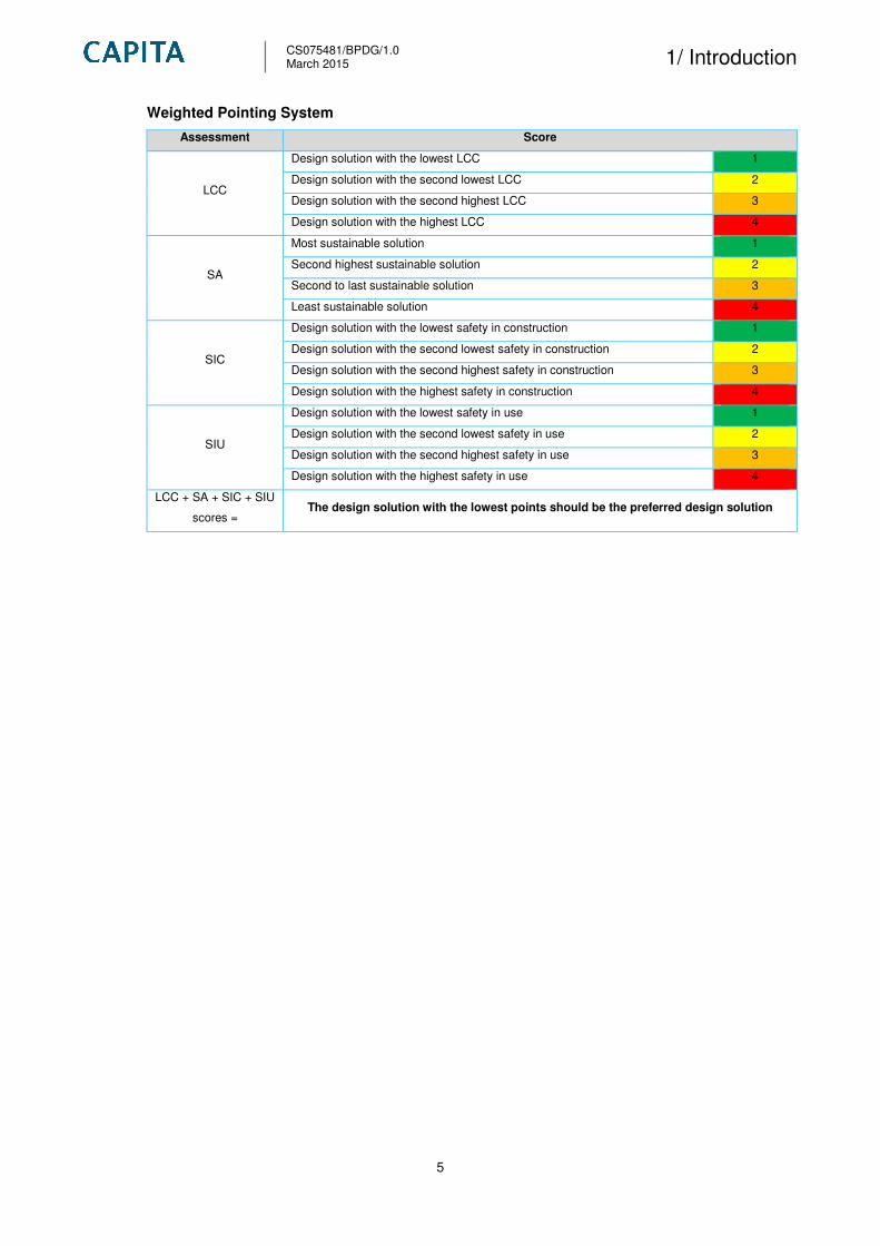
1.6 Interpretation for Sustainability and Safety Assessment Tables
1.6.1 Following the LCC, SA, SIC and SIU a weighted pointing system will be applied in order to
categorize the preferred infrastructure solutions as defined below:
CS075481/BPDG/1.0 March 2015 1/ Introduction
5
Weighted Pointing System
Assessment Score
LCC
Design solution with the lowest LCC 1
Design solution with the second lowest LCC 2
Design solution with the second highest LCC 3
Design solution with the highest LCC 4
SA
Most sustainable solution 1
Second highest sustainable solution 2
Second to last sustainable solution 3
Least sustainable solution 4
SIC
Design solution with the lowest safety in construction 1
Design solution with the second lowest safety in construction 2
Design solution with the second highest safety in construction 3
Design solution with the highest safety in construction 4
SIU
Design solution with the lowest safety in use 1
Design solution with the second lowest safety in use 2
Design solution with the second highest safety in use 3
Design solution with the highest safety in use 4
LCC + SA + SIC + SIU
scores = The design solution with the lowest points should be the preferred design solution

CS075481/BPDG/1.0 March 2015
2/ Planning & Design Strategy
6
2. Planning & Design Strategy 2.1 General
2.1.1 The guidance is applicable to all new & upgraded Network Rail vehicular access points. Each
access point, new or upgraded will need to be assessed individually to determine categorisation.
2.1.2 Access Points can be wide ranging in terms of location, size, history, access to main road,
proximity to track, proximity to residential housing etc. In order to develop a Planning & Design
strategy for an access point there are a number of factors that need to be considered such as:
• Topography;
• Track geometry and infrastructure;
• Environmental issues;
• Planning;
• Land agreements;
• Geotechnical considerations;
• Social issues;
• Whole life costing.
2.2 Topography
2.2.1 Careful consideration is required of the site topography for locations of the access point to ensure a
level surface of suitable size can be achieved for safe unloading of plant and materials. New and
existing Network Rail access points will vary in size and layout.
2.3 Track Geometry and Infrastructure
2.3.1 Careful consideration for siting new access points is to be considered with respect to the existing
track and infrastructure. The design is to take in to account all operational lineside equipment e.g.
OLE, 3rd Rail, cabinets, track, gantries, signals, drainage etc.
2.4 Environmental Issues
2.4.1 The impact on the environment is to be taken into account when siting a new access point. An
environmental report is recommended to investigate any potential environmental issues and risks
which could arise with the new proposal.

CS075481/BPDG/1.0 March 2015
2/ Planning & Design Strategy
7
2.5 Planning
2.5.1 Planning searches and consultations are recommended when siting access points. Due to the size
of the access points planned, several issues could arise with the local authority such as new roads
and housing developments. The local planning authority will need to be informed if existing kerb
lines require modification for dropped kerbing, also access points with larger compounds and
permanent buildings are to be notified.
2.5.2 Network Rail’s Asset Protection department have dedicated teams to provide advice to the public
and developers who are planning activities on or near the railway. The teams deal with a multitude
of issues including neighbouring construction sites, utility works, bridge works, domestic
maintenance, new road schemes, inspections and surveys, and works within the designated
precautionary area of level crossings.
2.6 Land Agreements
2.6.1 All new access points are to be sited on Network Rail owned land. Careful consideration with
respect to the lineside neighbours is necessary. A clear understanding of land ownership is
required to avoid accidents with RRV plant and other 3rd party equipment within proximity of the
access point / road. For example a Network Rail marlin map should be provided to indicate the
location of the access point from the road / property to the rail.
2.7 Geotechnical Considerations
2.7.1 The existing geology of the area is to be considered during the design and when siting new access
points. A Geotechnical Desktop appraisal is to be undertaken to confirm anticipated ground
conditions and verify if further investigations are required. Intrusive investigations such as trial
holes and boreholes will be required for roads and buildings. The appraisal will also identify if a site
is at risk of flooding.
2.8 Social Issues
2.8.1 The majority of rail possessions for maintenance and engineering works occur during the night and
at weekends. Network Rail staff and contractors are to respect the privacy, sensitivity and property
of residents.
2.8.2 Network Rail are advised to notify local authorities and other community representatives such as
Members of Parliament and local councillors for engineering works at the relevant access point and
surrounding area.
2.8.3 Design considerations should be considered such as positioning lighting and generators away from
residential properties and using silenced equipment where practicable.

CS075481/BPDG/1.0 March 2015
2/ Planning & Design Strategy
8
2.9 Whole Life Costing
2.9.1 BS ISO Buildings and Constructed Assets – Service Life Planning – Part 5: Life Cycle Costing:
15686-5:2008, provides the following definitions:
Definitions
Whole Life Costing (WLC)
This is a methodology for the systematic economic consideration of all whole life
costs and benefits over a period of analysis, as defined in the agreed scope.
An economic assessment considering all agreed projected significant and relevant
cost flows over a period of analysis expressed in monetary value. The projected
costs are those needed to achieve defined levels of performance, including
reliability, safety and availability.
2.9.2 Whole life-cycle costing (WLCC) is rapidly becoming the standard method for the long-term cost
appraisal of buildings and civil infrastructure projects.
2.9.3 With clients demanding projects that demonstrate value for money over the long term, WLCC is
increasingly becoming an essential tool for those involved in the design, construction, operation
and risk analysis of construction projects.
2.9.4 We recommend that a WLCC approach should be adopted to understand the broad parameters of
any access point design in order to determine the most cost effective value solution in terms of
design, quality and construction.
2.9.5 For example whilst a “Type 1 road surface” may be economically viable, the same approach may
not be true for longer access roads so another approach e.g. Asphalt road surface with kerbing
should be considered and evaluated as though the capital cost may be high this benefits from a
longer life and less maintenance, and therefore a lower ‘Whole Life Cost’.
CS075481/BPDG/1.0 March 2015 3/ Categorisation Matrix
9
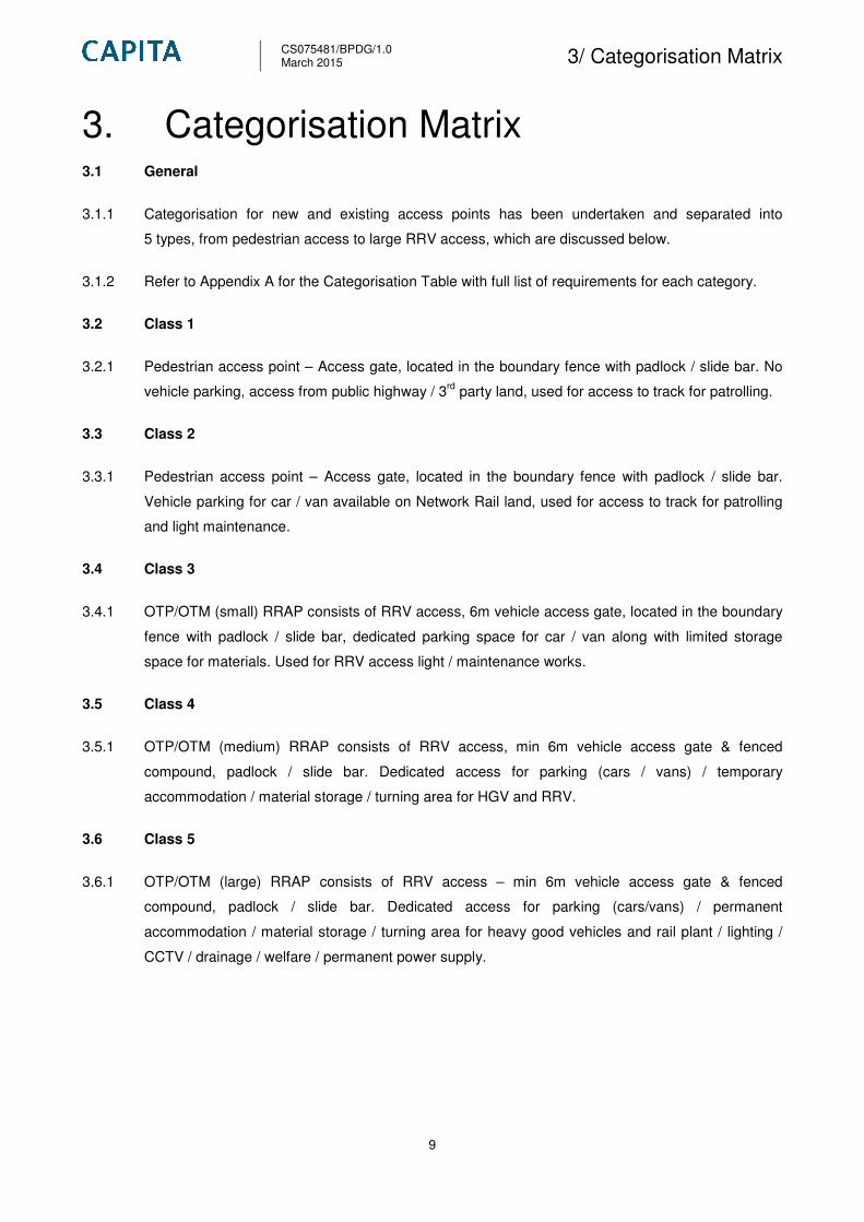
3. Categorisation Matrix 3.1 General
3.1.1 Categorisation for new and existing access points has been undertaken and separated into
5 types, from pedestrian access to large RRV access, which are discussed below.
3.1.2 Refer to Appendix A for the Categorisation Table with full list of requirements for each category.
3.2 Class 1
3.2.1 Pedestrian access point – Access gate, located in the boundary fence with padlock / slide bar. No
vehicle parking, access from public highway / 3rd
party land, used for access to track for patrolling.
3.3 Class 2
3.3.1 Pedestrian access point – Access gate, located in the boundary fence with padlock / slide bar.
Vehicle parking for car / van available on Network Rail land, used for access to track for patrolling
and light maintenance.
3.4 Class 3
3.4.1 OTP/OTM (small) RRAP consists of RRV access, 6m vehicle access gate, located in the boundary
fence with padlock / slide bar, dedicated parking space for car / van along with limited storage
space for materials. Used for RRV access light / maintenance works.
3.5 Class 4
3.5.1 OTP/OTM (medium) RRAP consists of RRV access, min 6m vehicle access gate & fenced
compound, padlock / slide bar. Dedicated access for parking (cars / vans) / temporary
accommodation / material storage / turning area for HGV and RRV.
3.6 Class 5
3.6.1 OTP/OTM (large) RRAP consists of RRV access – min 6m vehicle access gate & fenced
compound, padlock / slide bar. Dedicated access for parking (cars/vans) / permanent
accommodation / material storage / turning area for heavy good vehicles and rail plant / lighting /
CCTV / drainage / welfare / permanent power supply.

CS075481/BPDG/1.0 March 2015 4/ Security Categorisation
10
4. Security Categorisation 4.1 General
4.1.1 With the risk of theft, trespass and vandalism on the railway infrastructure a review has been
undertaken to categorise three anti theft levels for the access points to prevent criminal activity
resulting in financial loss to Network Rail and contractors.
4.1.2 The level of security will be determined by a number of factors and should be confirmed during the
outline design (GRIP 3) stage of development. Below are the standard security levels to be
considered when designing access points:
4.2 Level 1 – Anti Trespass
4.2.1 Basic level of security, this would include standard Network Rail 1.8m high palisade fencing and
gates to prevent access by members of the public.
4.3 Level 2 – Enhanced
4.3.1 Enhanced level of security, this would include same deterrents as basic level, but would also
include permanent switchable lighting of compound areas.
4.4 Level 3 – High
4.4.1 High Security would include same deterrents as Enhanced but would also require CCTV coverage
of the compound / entrance & permanent buildings. The palisade fencing and gates would also be
upgraded to ‘Security’ (SP) as defined in BS 1722: Part 12. This will be 3.0m High Palisade fencing
with anti burrow sill.

CS075481/BPDG/1.0 March 2015
5/ General Design Requirements
11
5. General Design Requirements 5.1 General
5.1.1 Potential solutions for the proposed infrastructure should be designed to provide safe access and
operations at Road Rail Access Points. This should include but not be limited to, segregation of
pedestrians / vehicles in compound areas along with consideration of the access route from the
public highway to the compound.
5.1.2 The designer should consider emerging technology when considering each element of the design,
for example LED lighting along walkways or ‘StarPath’ (aggregate material which stores energy
(UV rays) and releases at night to provide low level glow along route).
5.1.3 The design scope shall identify the general design requirements including:
• Civil and structural design requirements
• Standardisation of design
• RRAP Layout
• Fencing
• Access gates – pedestrian & vehicle access
• Vehicle barriers and railings
• Surface treatment – access track / compound
• Vehicle turning facilities
• Accommodation buildings & storage facilities
• Access of highway to access point
• Parking
• Signage
• Lighting – permanent & temporary
• CCTV
• Power supply (permanent & temporary)
• Drainage
• Hand railing
• Stairwells
• Topography survey
• Environmental assessment
• Site investigation
• Existing / historical site conditions
CS075481/BPDG/1.0 March 2015
5/ General Design Requirements
12
5.2 Civil and Structural Design Requirements
5.2.1 Prior to completion of any designs the Design Consultant / Designer shall make sure that they have
met the requirements of NR/L2/INI/02009 Engineering Management for Projects and submitted the
relevant documentation for review and acceptance as required by the standard.
5.2.2 The designs for the access points shall be in accordance with the requirements of NR/L2/CIV/003
Engineering Assurance of Building and Civil Engineering Works.
5.2.3 The civil and structural design elements of the new and existing sites shall include but not be
limited to the following:
• Geotechnical assessment where applicable;
• Duct routes and chambers;
• Civil and structural works design; and
• Building works design.
5.2.4 The Designer shall take into account any site specific design requirements captured on the Pre-
Construction Information Pack provided by NR.
5.2.5 The checking of all access point designs shall be in accordance with the check category as
described in NR/L2/CIV/003 and documentation referred to therein.
5.2.6 Generic access point layouts are provided in Appendix B.
5.3 Standardisation of Design
5.3.1 The infrastructure required to create access points provides an ideal scenario for standardising
design and selection of components. A set of standard details has been included in Appendix C of
this guide. These should be considered for use on all sites where appropriate.
5.3.2 Sustainable design solutions are also to be considered e.g. Truckpave and GRP/FRP products. For
details refer to LNW Access Improvements Sustainability Appraisal (2014). The document contains
information, regarding access steps, handrails, roads and kerbing etc.
5.3.3 Standardisation will provide several benefits for the design / construction of access points:
• Better product quality, reliability, and improved whole life costs;
• Mass production of components reducing costs e.g. palisade fencing;
• Availability of parts for replacement and maintenance;
• Less time and effort required to construct;
• Reduction in cost and maintenance;
• Standard matting and concrete apron sizes;
• Standard accommodation units (modular); and

CS075481/BPDG/1.0 March 2015
5/ General Design Requirements
13
• Standard fencing / gate sizes.
5.3.4 Where reasonably practicable the designers shall make use of standard / generic details, forms
F002 and F003 (Form B) submission. This should be discussed / agreed with Network Rail at the
beginning of GRIP 4 stage.
5.4 Road Rail Access Point (RRAP)
5.4.1 Wherever possible, locate the RRAP on straight and level track.
5.4.2 RRAP points should not be located:
• On curves of 200m radius or less where continuous check rails are installed;
• High ballast shoulder areas;
• Over rail adjustments switches;
• Over rail joints;
• Where OLE is less than 4165mm and where non level road surface can bring any part of the
on track plant within 600mm of OLE – as stated in the plant manual;
• Rail welds;
• Over treadles;
• Within 20m of a platform ramp;
• Over Hot Axle Bearing Detectors (HABDs); and
• Where guard rails or lateral resistance end plates are present.
5.4.3 Risk Assessed Locations
5.4.4 Unless a risk assessment demonstrates that it is safe to do so, RRAPs should not be located
• Less than 20m from any switch and crossing unit;
• Less than 20m from an underbridge or tunnel where there are vertical or lateral restrictions
that could restrict vehicle manoeuvrability;
• Where infrastructure assets such as signalling equipment and lineside structures are located
which could restrict vehicle manoeuvrability;
• Next to or over under track crossings;
• Within trespass and vandalism hotspots; and
• Where road access is hazardous (e.g. access is directly from a dual-carriageway, busy
roads and areas of limited road visibility).
5.4.5 Assessment of 3rd parties
5.4.6 An assessment shall be undertaken into the effect of a RRAP on lineside neighbours and,
wherever possible, they should not be located next to or within:
CS075481/BPDG/1.0 March 2015
5/ General Design Requirements
14
• Sites of Special Scientific Interest (SSSIs);
• Conservation areas;
• Adjacent to hospitals;
• Residential areas;
• Power Stations; and
• Schools.
5.4.7 Logistic Considerations
5.4.8 RRAP locations shall take into account the delivery logistics regarding:
• Accessing through the boundary gate from public highways;
• Access routes through minor roads;
• Height, width and weight restrictions on public highways;
• Overhead services (e.g. power lines, pipes and telephone wires).
• Overhead Cables (excluding OLE) shall be demarked with “goal posts” to warn of height
restrictions;
• Seasonal or periodic road availability;
• Access rights and suitability of private roads;
• Delivery vehicle size and manoeuvrability;
• Condition of existing highway surface and verges; and
• Access through residential areas.
5.4.9 Requirements in DC electrified line areas
5.4.10 In DC electrified (3rd rail & 4th rail) areas:
• A permanent section gap shall be installed at the RRAP to permit unrestricted access to the
track;
• Where insufficient gaps exist, lower the 3rd rail off the insulators, remove an adequate
number of insulators and protect the rail from damage; and
• The RRAP shall NOT be installed without the appropriate authorisation.
5.4.11 For additional information refer to module P301 – Road Rail Access Points – Figure 5.
5.4.12 Requirements in AC electrified line areas
5.4.13 In overhead line electrified areas, position the RRAP such that:
• The approach to the RRAP under OLE is level where reasonably practicable;
• The minimum clearance of 4165mm is achieved; and
• The appropriate authorisation to install the RRAP has been authorised by Network Rail.

CS075481/BPDG/1.0 March 2015
5/ General Design Requirements
15
5.4.14 For additional information refer to the plant module P301 – Road Rail Access Points – Figure 8.
5.4.15 Proprietary Rubber Matting e.g. Strail & Rosehill Rail
5.4.16 Strail is a direct loading rubber panel system which consists of end restraints and tie rods, locking
the system together as a one unit. It is a high strength and durable covering used for level crossing
and RRAP. The modular system consists of individual full rubber panels, which are secured using
the lock tight system.
5.4.17 Strail has the following benefits:
• Fast installation;
• Easy handling;
• Short assembly times during installations;
• Easy to maintain with minimal maintenance;
• Suitable for any rail or sleeper type; and
• Can be installed manually.
5.4.18 Proprietary systems that are product approved shall be considered where appropriate.
5.4.19 Rosehill Rail (formally Hold Fast) manufacture a similar product but with an alternative fixing
system.
5.4.20 Proprietary matting is to be considered at the RRAP across the number of tracks at the chosen
location.
5.4.21 Matting manufacturers indicate a typical design life to be approx 15 years for new installations.
However, if the there is a reduction in traffic then a longer design life of up to 25 years could be
possible.
5.4.22 It may be possible to re-use and / or relocate existing decking units to avoid / mitigate potential
clashes with existing NR signals / equipment. If existing mats are present then the manufacturers
would require a site visit the site to determine if the units are compatible with the proposed.
5.4.23 For access points class 3, 4 & 5 the length of the matting and concrete apron has been assessed
by the current largest plant registered to On-track, the minimum length to be used is 10m.
Dependant on layout of track, equipment and size of vehicle, it may be necessary to install matting
staggered along the track.
CS075481/BPDG/1.0 March 2015
5/ General Design Requirements
16
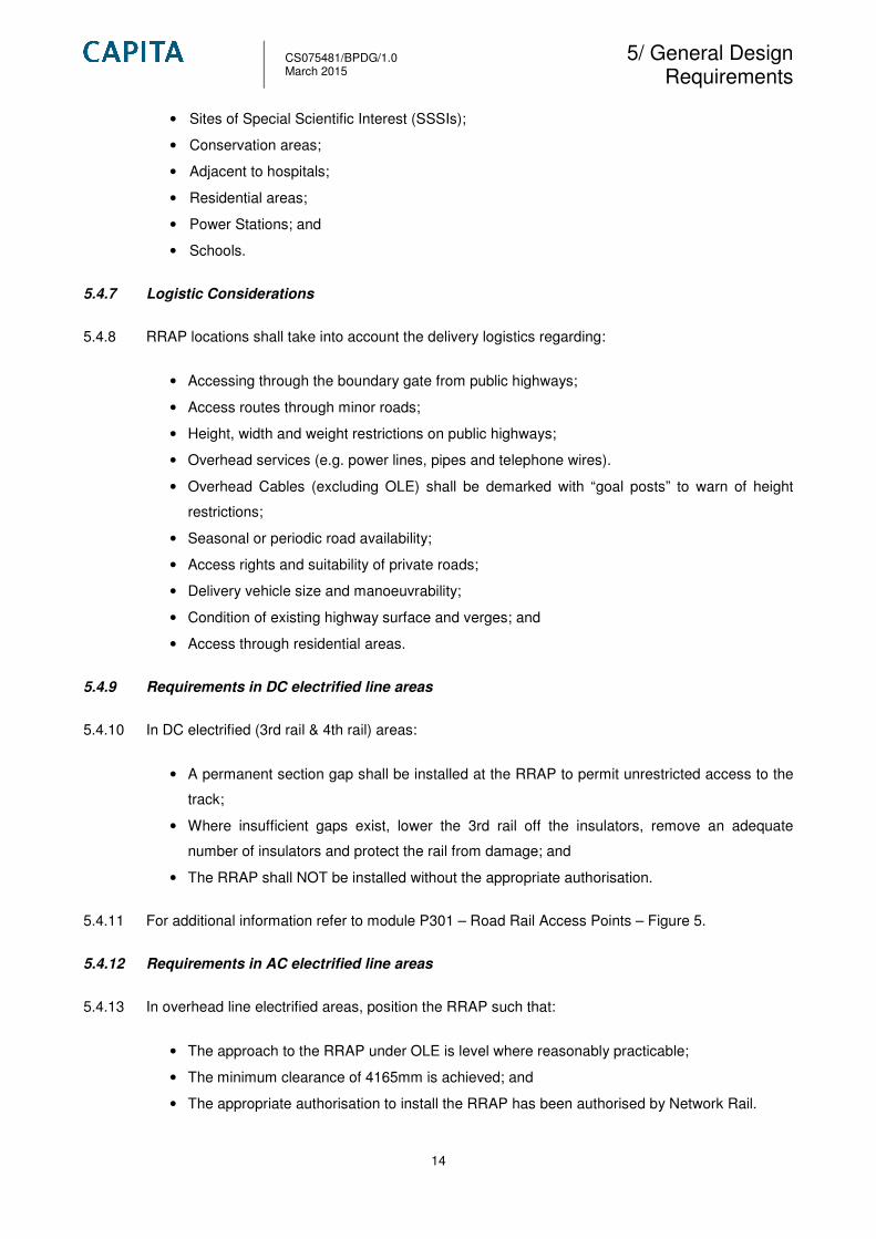
Proprietary Rubber Matting installed at RRV access point
5.4.24 Proprietary rubber matting is the preferred option for this Best Practice Design Guide. However the
following alternative solutions are available:
• Timber; and
• Polysafe (Similar to Bomac).
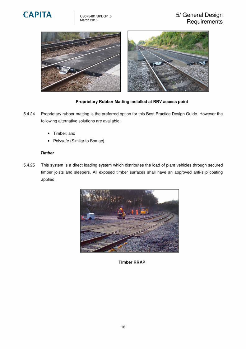
Timber
5.4.25 This system is a direct loading system which distributes the load of plant vehicles through secured
timber joists and sleepers. All exposed timber surfaces shall have an approved anti-slip coating
applied.
Timber RRAP

CS075481/BPDG/1.0 March 2015
5/ General Design Requirements
17
Polysafe - Pedestrian Crossing System
5.4.26 The Polysafe design is a bridging system based on the Tarmac Bomac concrete panel system
which is no longer manufactured. The ‘Bridging’ design accommodates road profile on canted
track. Space sleepers in road level crossings at 600mm centres and ballast to be level with the top
of sleepers. Polysafe panels are held in place by friction between rubber wedges secured against
panel nib and rail web. These wedges are both internal and external and are 600mm in length.
Track fastenings are visible with the crossing panels installed. The system is most used for level
crossings and pedestrian walkways.
Polysafe system installed at pedestrian crossing point
5.4.27 The following table provides an indication of the required matting length for RRV for class 3, 4 and
5 access points.
5.4.28 Concrete Apron
5.4.29 A reinforced concrete apron / plinth is to be installed along the length of the matting to provide a flat
surface for plant vehicles to gain access to the railway line. This apron will, wherever possible, will
have a splayed approach to RRAP as indicted in NR/PLANT/0200.
5.4.30 If existing trough routes cross the apron they are to be re-laid / modified / protected with road plates
which will be determined on a site specific basis. Refer to NR/PLANT/0200 Module P301 Section 6
for the requirements of protection of cable routes.
Road Rail Access Point Matting Length
Plant Size Length of matting
7.5 – 17.0 tonne (Rigid) Min 10m
17.0 tonne or greater (Articulated plant) Min 10m

CS075481/BPDG/1.0 March 2015
5/ General Design Requirements
18
5.4.31 Cable routes shall be protected such that the RRVs cannot damage them.
5.4.32 The approach to the rail should be of a suitable incline for the machine (normally this is
approximately no steeper than 1 in 10). Refer to the manufactures guide for guidance.
5.4.33 The minimum distance of 1100mm from the running rail to the edge of the apron is to apply with
new installations to allow clearance for High Output Ballast Cleaning Machines.
5.4.34 The concrete apron is to have a brush finish to increase slip resistance.
5.4.35 The concrete apron is to comprise a 300mm thick slab with A393 mesh installed top & bottom. The
length and width shall be site specific.
5.4.36 The concrete shall have a compressive strength of C32/40 and be designed in accordance with
BS 8500-2. Air entraining concrete mix is to be considered to prevent freeze-thaw attack.
5.4.37 Welfare and / or storage facilities shall be positioned such that the RRAP is kept clear at all times.
Concrete Apron installed at RRAP
5.4.38 Maintenance requirements for RRAP
5.4.39 Refer to NR/PLANT/0200 module P703 for inspection and maintenance requirements of RRAP.
5.4.40 RRAP upgrades
5.4.41 Refer to NR/PLANT/0200 module P301 section 11.2 for details.
5.5 Fencing
5.5.1 Steel (palisade) fencing is widely used on the railway network and that the application and
maintenance is fundamentally inherent. Consequently, it is envisaged that a change to GRP/FRP
fences or gates may not provide any significantly beneficial impacts.
5.5.2 All palisade fencing shall be designed in accordance with BS 1722-12:2006.

CS075481/BPDG/1.0 March 2015
5/ General Design Requirements
19
5.5.3 Steel fencing shall be designed to prevent unauthorised pedestrian access to the railway
infrastructure.
5.5.4 A secure boundary fence shall be provided, ideally with only one point of entry and egress, to
prevent illegal vehicle entry.
5.5.5 If damaged or vandalised Network Rail emergency / maintenance teams have replaceable fencing
pales / posts readily available for repair.
5.5.6 1.8mm high palisade fencing is to be specified for access points in Security level 1 and 2 (Anti
trespass and Enhanced).
5.5.7 3.0m high palisade fencing is to be specified for access points in enhanced Security Level 3 (High).
5.5.8 The security palisade fencing shall be fit for the intended purpose and consideration shall be given
to the following:
• The line and level of the fencing;
• The installed height of the fencing above the ground level;
• The clearances of the fencing from other structures within and outside the fence line;
• The position type and size of gates and where required, removable panels etc;
• The type, grade, and key suites for security padlocks; and
• Any special requirements regarding the avoidance of touch potential between the fence and
other structures
5.5.9 Environmental conditions should also be considered. The fencing shall be suitable for installation
outdoors at locations adjacent to railway tracks subject to the following conditions:
• The ambient air is polluted outdoors by the presence of iron dust from train brakes; and
• The fence subject is subject to vibration caused by passing trains.
5.5.10 Security palisade fence shall be designed, manufactured and installed in accordance with BS 1722
– Part 12 Specification for Steel Palisade Fence.
5.5.11 In high security areas concrete sills or other suitable methods shall designed to prevent burrowing
under the fence. Where a concrete sill is used it shall form a barrier not less than 300mm wide and
shall extend at least 300mm below ground level.
5.5.12 All fencing within the OLE contact zone shall be equipotential bonded throughout in accordance
with Network Rail Specification RT/E/S/201032 on DC electrified lines and EQH/SP/D/101 on AC
electrified lines. Drilled galvanised steel lugs shall be specified and welded to the inside face of
fence posts 50mm above ground level to accept bolt on earthing lugs.
5.5.13 Standard Details are provided in Appendix C.
CS075481/BPDG/1.0 March 2015
5/ General Design Requirements
20
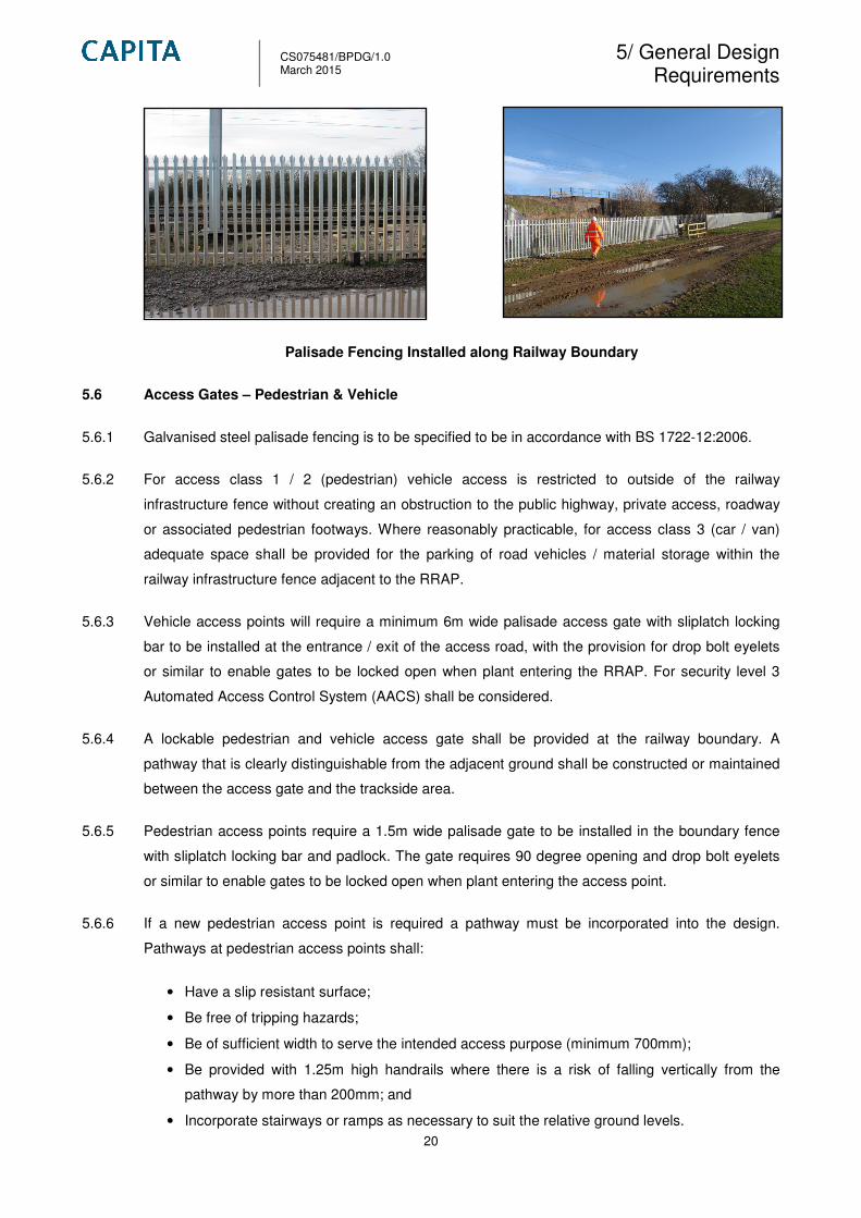
Palisade Fencing Installed along Railway Boundary
5.6 Access Gates – Pedestrian & Vehicle
5.6.1 Galvanised steel palisade fencing is to be specified to be in accordance with BS 1722-12:2006.
5.6.2 For access class 1 / 2 (pedestrian) vehicle access is restricted to outside of the railway
infrastructure fence without creating an obstruction to the public highway, private access, roadway
or associated pedestrian footways. Where reasonably practicable, for access class 3 (car / van)
adequate space shall be provided for the parking of road vehicles / material storage within the
railway infrastructure fence adjacent to the RRAP.
5.6.3 Vehicle access points will require a minimum 6m wide palisade access gate with sliplatch locking
bar to be installed at the entrance / exit of the access road, with the provision for drop bolt eyelets
or similar to enable gates to be locked open when plant entering the RRAP. For security level 3
Automated Access Control System (AACS) shall be considered.
5.6.4 A lockable pedestrian and vehicle access gate shall be provided at the railway boundary. A
pathway that is clearly distinguishable from the adjacent ground shall be constructed or maintained
between the access gate and the trackside area.
5.6.5 Pedestrian access points require a 1.5m wide palisade gate to be installed in the boundary fence
with sliplatch locking bar and padlock. The gate requires 90 degree opening and drop bolt eyelets
or similar to enable gates to be locked open when plant entering the access point.
5.6.6 If a new pedestrian access point is required a pathway must be incorporated into the design.
Pathways at pedestrian access points shall:
• Have a slip resistant surface;
• Be free of tripping hazards;
• Be of sufficient width to serve the intended access purpose (minimum 700mm);
• Be provided with 1.25m high handrails where there is a risk of falling vertically from the
pathway by more than 200mm; and
• Incorporate stairways or ramps as necessary to suit the relative ground levels.
CS075481/BPDG/1.0 March 2015
5/ General Design Requirements
21
5.6.7 For pedestrian access gates that open immediately onto a trackside area, the clearance to the
nearest running line shall not be less than the requirement for a Position of Safety*:
• 0 - 100mph = 1.25m
• 101 - 125mph = 2.00m
*Positions of safety from RT3170 – A Guide to Personal Track Safety
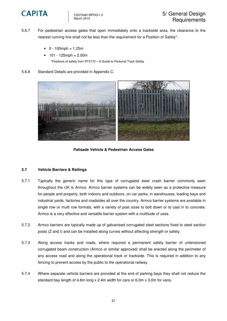
5.6.8 Standard Details are provided in Appendix C.
Palisade Vehicle & Pedestrian Access Gates
5.7 Vehicle Barriers & Railings
5.7.1 Typically the generic name for this type of corrugated steel crash barrier commonly seen
throughout the UK is Armco. Armco barrier systems can be widely seen as a protective measure
for people and property, both indoors and outdoors, on car parks, in warehouses, loading bays and
industrial yards, factories and roadsides all over the country. Armco barrier systems are available in
single row or multi row formats, with a variety of post sizes to bolt down or to cast in to concrete.
Armco is a very effective and versatile barrier system with a multitude of uses.
5.7.2 Armco barriers are typically made up of galvanised corrugated steel sections fixed to steel section
posts (Z and I) and can be installed along curves without affecting strength or safety.
5.7.3 Along access tracks and roads, where required a permanent safety barrier of untensioned
corrugated beam construction (Armco or similar approved) shall be erected along the perimeter of
any access road and along the operational track or trackside. This is required in addition to any
fencing to prevent access by the public to the operational railway.
5.7.4 Where separate vehicle barriers are provided at the end of parking bays they shall not reduce the
standard bay length of 4.8m long x 2.4m width for cars or 6.0m x 3.0m for vans.

CS075481/BPDG/1.0 March 2015
5/ General Design Requirements
22
5.7.5 If Armco (or similar approved) protective barriers are specified to protect the RRAP, lockable
access gates are not required. This will be determined on a site specific basis. Utilising maximum
3m long sections of barrier.
5.7.6 Various heights of barrier posts can be specified so larger vehicles can see them in the rear view
mirrors when if reversing.
5.7.7 Standard details and data sheets are provided in Appendix C and D respectively.
Armco Barrier – Bolted down to concrete surfacing
5.7.8 Bollards should be considered in the design to protect vulnerable areas and equipment, such as
lighting and CCTV columns.
5.8 Surface Treatment – Access track / Compound Area
5.8.1 Collisions between moving vehicles, rail workers and moving vehicles, or the impact of a vehicle
with stationary plant, vehicles or equipment can lead to physical injuries, damage and / or loss of
life. Consequently, the good design of roadways and the control of traffic on-site are important
factors in the prevention of RRV accidents and an important consideration in the prevention of
major accident hazards on-site.
5.8.2 Where necessary, the depth and construction of the roadways, standing and turning areas shall be
designed to accommodate the loads imposed by any normal vehicle permitted to travel on the
public highway (including emergency and commercial vehicles). Particular attention shall be given
to the movement of HGVs.
5.8.3 The road design shall take into account local ground conditions.
5.8.4 Surfaces of traffic routes used by either pedestrians or vehicles should be suitable for their purpose
and be free of any holes, uneven or slippery surfaces that could cause accidents to vehicles or
pedestrians.
CS075481/BPDG/1.0 March 2015
5/ General Design Requirements
23
5.8.5 A standard road width of 7.3m with an average speed of 25mph is to be designed to allow two way
traffic entering the compound area. If this is not possible then a single track road with passing
places are to be considered in the design.
5.8.6 Surface materials shall be hard wearing, low maintenance, non-slip, weather resistant, and
resistant to attack from oil spillage.
5.8.7 Concrete and asphalt roads require suitable drainage. Refer to Section 5.16. for drainage details.
5.8.8 Road surfacing is to be considered in the design of the roadway to the access compounds. A cost
analysis is to undertaken and a scope of work is to be produced by Network Rail for the type of
roadway due to the length and increase in costs for a better hard-wearing surface.
5.8.9 Gradient
5.8.10 For new access roads, where possible, the maximum longitudinal gradient should be 1 in 12, and
the minimum channel gradient should be 1 in 125. A crossfall or camber of 1 in 40 provides
adequate drainage. If minimum gradients are not utilised, surface water tends to pond, which can
be hazardous in freezing conditions.
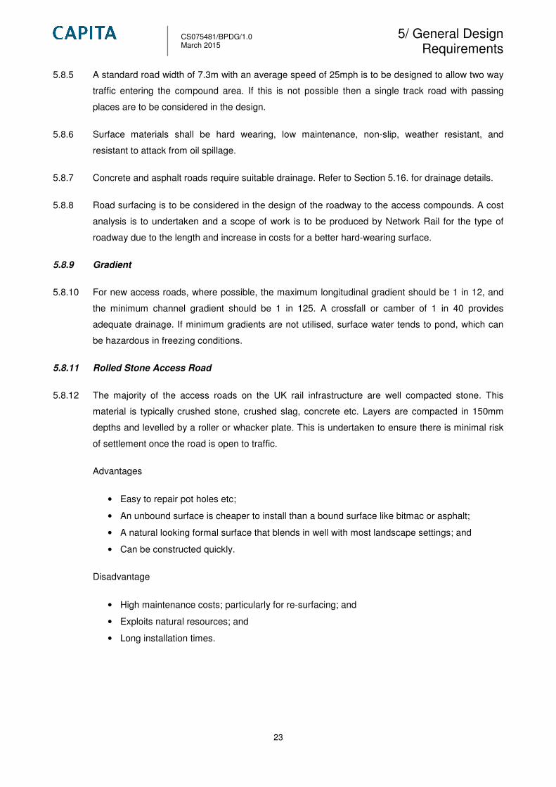
5.8.11 Rolled Stone Access Road
5.8.12 The majority of the access roads on the UK rail infrastructure are well compacted stone. This
material is typically crushed stone, crushed slag, concrete etc. Layers are compacted in 150mm
depths and levelled by a roller or whacker plate. This is undertaken to ensure there is minimal risk
of settlement once the road is open to traffic.
Advantages
• Easy to repair pot holes etc;
• An unbound surface is cheaper to install than a bound surface like bitmac or asphalt;
• A natural looking formal surface that blends in well with most landscape settings; and
• Can be constructed quickly.
Disadvantage
• High maintenance costs; particularly for re-surfacing; and
• Exploits natural resources; and
• Long installation times.

CS075481/BPDG/1.0 March 2015
5/ General Design Requirements
24
Rolled Stone Access Track within Network Rail Access Point
5.8.13 Refer to Appendix C (standard details) for typical layout.
Sustainability & Safety Assessment
Design Solution Sustainability Score
LCC Score SA Score Total
Type 1 – natural aggregate - 2 2
Type 1 with a mechanically stabilised layer - 1 1
LNW Access Improvements Sustainability Appraisal (March 2014)
Design Solution
Safety Score
Safety in
Construction
(SIC)
Safety in Use (SIU) Total
Type 1 – natural aggregate 1 1 4
Type 1 with a mechanically stabilised layer 1 1 3
LCC + SA + SIC + SIU scores = The design solution with the lowest points should be the preferred design
solution
5.8.14 Concrete Hardstanding
5.8.15 Concrete is the ideal material for the construction of parking and working areas around buildings. It
provides a hard-wearing surface which drains well at low gradients. Concrete resists spillages of
diesel and other petroleum-based products. Concrete is relatively light in colour and hence
concrete parking areas are easy to illuminate.
5.8.16 For access roadways expansion joints are required to allow expansion and contraction of the
concrete without generating potentially damaging forces within the slab.
5.8.17 Concrete hardstanding must be drained to suitable new or existing drainage points. Refer to
section 5.16. for details.
Advantages:

CS075481/BPDG/1.0 March 2015
5/ General Design Requirements
25
• Reasonably cheap construction & material costs;
• Simple to construct; and
• If well laid, concrete will provide years of maintenance free service.
Disadvantages:
• Long curing times;
• Must be properly drained to gullies or suitable drainage points;
• Laying can create health and safety risks through possible burns;
• The use of use of de-icing salts can attack the surface of the concrete; and
• Exploits natural resources.
Concrete ramp up to track level
5.8.18 Refer to Appendix C (standard details) for typical layout.
5.8.19 Concrete Hardstanding
5.8.20 Asphalt is a mixture of aggregates, binder and filler, used for constructing and maintaining all kind
of roads, parking areas but also play and sport areas. Aggregates used for asphalt mixtures could
be crushed rock, sand, gravel or slag. In order to bind the aggregates into a cohesive mixture a
binder is used. Most commonly, bitumen is used as a binder. An average asphalt pavement
consists of the road structure above the formation level which includes unbound and bituminous-
bound materials. This gives the pavement the ability to distribute the loads of the traffic before it
arrives at the formation level. Normally, pavements are made of different layers.
Advantages:
• Impermeable asphalt can be used from recycled (asphalt) roads, which limits the exploitation
of natural resources;
• If permeable asphalt is specified it allows rainwater to soakaway to the existing sub-base.
This reduces storm water run-off;

CS075481/BPDG/1.0 March 2015
5/ General Design Requirements
26
• Asphalt roads provide better traction and skid resistance for vehicles; and
• Asphalt tends to help keep roads free from ice and snow
Disadvantages:
• Laying can create health and safety risks through possible burns and toxic fumes;
• Heavy rain and other extreme weather conditions can damage asphalt, and the roads will
need to be repaired frequently; and
• If permeable asphalt is specified, suitable drainage to gullies or other drainage points are
required. Refer to section 5.16. for details.
5.8.21 Refer to Appendix C (standard details) for typical layout.
Asphalt Road / Surfacing
Sustainability & Safety Assessment
Design Solution Score
LCC Score SA Score Total
Impermeable Asphalt - 3 3
Permeable Asphalt - 2 2
Asphalt with a mechanically stabilised layer - 1 1
LNW Access Improvements Sustainability Appraisal (March 2014)
Design Solution
Score
Safety in
Construction
(SIC)
Safety in Use (SIU) Total
Impermeable Asphalt 1 1 5
Permeable Asphalt 1 1 4
Asphalt with a mechanically stabilised layer 1 1 3
LCC + SA + SIC + SIU scores = The design solution with the lowest points should be the preferred design
solution

CS075481/BPDG/1.0 March 2015
5/ General Design Requirements
27
5.8.22 Truckpave (Sustainable Solutions)
5.8.23 Manufactured from recycled plastics, Truckpave cellular paving is robust, durable and capable of
withstanding all levels of traffic up to and including coaches, dustcarts and HGVs.
5.8.24 Truckpave’s cells are filled with gravel, making them suitable for stabilising areas where a hard
wearing surface is desirable. Truckpave are an economic, environmentally-friendly and a
lightweight alternative to concrete grasscrete-type pavers.
5.8.25 Truckpave should be installed on a well-prepared, free-draining, firm and relatively-level stone sub-
base (a reduced-fines Type 1 for example). As an option a Tensar Triax TX160 geogrid at the base
of this layer will allow a reduction in the sub-base depth. The sub-base is overlaid with BGT100
geotextile filter / separator followed by 20mm of coarse sand as a bedding layer for the pavers.
5.8.26 Applications for Truckpave include:
• Lorry, coach and car park areas;
• Emergency fire access roads;
• HGV access roads;
• Road widening ;
• Grass verges;
• Footpaths;
• Service yards;
• Lay-bys; and
• Loading areas.
5.8.27 The benefits of Truckpace include:
• Complies with the HSE guidance for manual handling;
• Flexible and resistant to cracking unlike concrete alternatives;
• Because of its insulating qualities, plastic achieves greatly improved volume and quality of
grass compared to concrete units;
• High compressive strength;
• Environmentally friendly - manufactured from recycled plastics; and
• Has tongue and groove interlocking for additional stability.
5.8.28 Refer to Appendix C & D for Standard Detail and Product Specification.

CS075481/BPDG/1.0 March 2015
5/ General Design Requirements
28
Typical Trackpave Installation along Access Track
5.8.29 The following table has created to give an indication of the preference for road surfacing from the
vehicle gate to the compound area.
5.8.30 Kerbing & Edging
5.8.31 Kerbing to roads should be provided wherever possible to clearly define the roadway and provide a
measure of protection. The kerbing length for the access track will be site specific due to the length
and topography of the location. Dropped kerbing should be provided at the entrance / exits of RRV
access points to enable vehicles to pull off the existing highway to the Network Rail access gate.
5.8.32 Dropped kerbs shall be used at vehicular crossing points. They should be constructed flush with
the existing carriageway and shall be constructed in accordance with local authority specification
drawings.
5.8.33 Pre-cast concrete kerbing is the most common on UK roads, however sustainable products such
as Durakerb should be considered in the design.
5.9 Vehicle Turning Facilities
5.9.1 For access points Class 4 and 5 vehicle turning areas are required for the RRV and HGV to safely
manoeuvre within the compound area.
5.9.2 It is desirable for the layout to be designed so that service vehicles do not need to reverse. The
dimensions of the turning area should suit the largest RRVs.
5.9.3 The need for vehicles to reverse should be avoided where possible as reversing is a major cause
of fatal accidents.
Table - Road Surfacing Preference for Access Tracks & Turning Area
Road Type
Road Surfacing Turning Area Kerbing & Edging Required
Surfacing preference 1 Rolled Stone (MOT) Truckpave No
Surfacing preference 2 Asphalt Rolled Stone (MOT) / Truckpave Yes
Surfacing preference 3 Concrete Hardstanding Rolled Stone (MOT) / Truckpave Yes

CS075481/BPDG/1.0 March 2015
5/ General Design Requirements
29
5.9.4 All vehicle movements within the access point compound should be supervised by competent
person to minimise risk of injury to persons or damage to equipment.
5.9.5 If space permits a turning circle could be installed so that vehicles can turn without reversing. One-
way systems can reduce the risk, especially in storage areas.
5.9.6 A self-draining surface is to be considered for the turning area and compound area. This will be
designed on site specific basis. Refer to section 5.8. for details.
5.9.7 The design should also consider vertical clearances from 3rd
party equipment e.g. overhead power
lines.
5.9.8 A visual routine inspection shall take place for the management of vegetation along the access
track boundary. Vegetation should be correctly managed to provide clear access to the compound
and the RRAP.
5.9.9 The following table provides guidance for the required radius for ridged & articulated plant vehicles
to turn in the compound area. The following table is based on the On-Track registered database.
5.10 Accommodation Buildings
5.10.1 For access points class 4 and 5 general accommodation provisions should be provided for railway
workers. These facilities should include the provision of health & welfare facilities to allow extended
hours of operations.
5.10.2 General accommodation provisions should be considered with the following provisions for staff and
visitors to the compound:
• Staff accommodation (to be in accordance with current welfare standards &
NR/L3/INI/CP0036);
• Welfare facilities;
• First aid / rest room;
• Wet & dry utility area including locker room; and
• Office area complete with IT facility.
5.10.3 For access point class 4 temporary accommodation units are to be considered for rail staff for
longer possession periods. Temporary units would require power by a generator.
5.10.4 Typical specification for a generic temporary accommodation unit:
Table – Recommended Turning Area Radius for RRV Plant
Plant Size Radius (Diameter)
7.5 – 17.0 tonne (Rigid) 15m
17.0 tonne or greater (Articulated plant) 25m

CS075481/BPDG/1.0 March 2015
5/ General Design Requirements
30
External Construction:
• Steel container with side walls formed in flat panels;
• Fork pockets set in base;
• Twist lock base plates set in four corners;
• Window frames with steel shutters;
• Steel personnel doors with built in locking mechanism; and
• Hoglift lifting system.
Internal Construction:
• Lined and Insulated in GRP, panels with block insulation inserts.
Dimensions:
• Length: 7600mm
• Width: 2755mm
• Height: 2565mm
Weight (dry):
• Standard: 4400 kg
• With Full Flush: 4500 kg
Weights (Loaded with Fuel / Water)
• Standard: 4700 kg
• With Full Flush: 5100 kg
Plan of Anti-Vandal – Static Site Accommodation Unit
5.10.5 If required sheltered briefing areas are to be considered in the design for access point class 4 and
5.

CS075481/BPDG/1.0 March 2015
5/ General Design Requirements
31
Anti-Vandal Sheltered Briefing Area
5.10.6 This Anti-Vandal shelter is heavy duty and ideal for access points class 4 and 5 and can be used
as a waiting and briefing area while waiting for railway possessions. These can be ideally located in
compound areas near the point of access to the rail infrastructure. A fixed dimension of 3.0m or
greater is to be achieved so rail personal are not classed as on or near the line.
5.10.7 Typical Specification for a generic briefing area:
• 1365mm roof width x 2480mm tip roof height
• 2-5 person capacity: 3000mm long
• 5-7 person capacity: 4305mm long
• 7-9 person capacity: 5610mm long
• Roof: 6mm dimmed polycarbonate curved
• Glazing: galvanised and powder coated steel sheet
• Seating: timber planked bench with back support as standard (steel or injected plastic
seating also available).
5.10.8 For access point class 5 permanent accommodation units are to be considered for rail staff. Units
would require permanent power & water supplies.
5.10.9 Modular / pre-fabricated buildings are considered to have the following benefits:
• Speed of construction is faster;
• Modular construction reduces waste and site disturbances;
• Favourable pricing with several supplies in the market;
• Low waste;
• 100% reusable components; and
• Environmentally friendly construction process.
CS075481/BPDG/1.0 March 2015
5/ General Design Requirements
32
5.10.10 Where possible two story accommodation units should be considered with canteen / welfare
facilities at ground level and office / meeting rooms located on the first floor.
5.10.11 Refer to the Network Rail Maintenance Delivery Units (MDU) best practice design guide for
information and guidance of permanent office accommodation units.
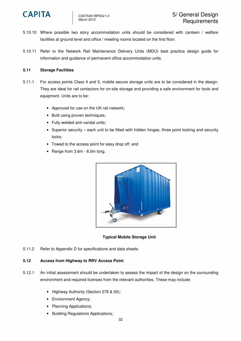
5.11 Storage Facilities
5.11.1 For access points Class 4 and 5, mobile secure storage units are to be considered in the design.
They are ideal for rail contactors for on-site storage and providing a safe environment for tools and
equipment. Units are to be:
• Approved for use on the UK rail network;
• Built using proven techniques;
• Fully welded anti-vandal units;
• Superior security – each unit to be fitted with hidden hinges, three point locking and security
locks;
• Towed to the access point for easy drop off; and
• Range from 3.6m - 6.0m long.
Typical Mobile Storage Unit
5.11.2 Refer to Appendix D for specifications and data sheets.
5.12 Access from Highway to RRV Access Point
5.12.1 An initial assessment should be undertaken to assess the impact of the design on the surrounding
environment and required licenses from the relevant authorities. These may include:
• Highway Authority (Section 278 & 50);
• Environment Agency;
• Planning Applications;
• Building Regulations Applications;

CS075481/BPDG/1.0 March 2015
5/ General Design Requirements
33
• Noise / Section 61 Applications;
• Internal Drainage Board Licences;
5.12.2 For access points class 3, 4 and 5 new / modifications to dropped kerbing could be required for
larger plant vehicles. The local authority should be contacted and the relevant licenses should be
obtained prior to construction.
5.12.3 It is currently assumed that new / upgrade access tracks are situated on Network Rail land and will
therefore not require approval by the Local Highway Authority under a section 278 agreement and
that minor works such as dropped kerbs / crossings could be allowed by the Local Highway
Authorities to be undertaken under a section 50 street works licence. However, this will be
assessed on site specific basics.
5.12.4 Curves should be of sufficiently large radius to allow ridged and articulated vehicles to enter the
access point. Swept path analysis is to be considered in the design due to the size of plant vehicles
entering the access point.
5.12.5 Swept Path Analysis (SPA) is the calculation and analysis of the movement of different parts of the
vehicle during a manoeuvre. At a basic level this includes calculating the path taken by each wheel
during the turn and also calculating the space needed by the vehicle body during the turn.
Historically these forms of calculation were carried out by hand, but in recent years, with modern
software, the process has been computerised.
5.12.6 The software enables the modification of different vehicle sizes. This is ideal due to the size of
RRVs which use Network Rail access points.
5.12.7 SPA benefits engineers, planners, site owners and architects with the means to assess the turning
implications of a wide variety of vehicle types on road design layouts. If modifications are required
to roads at new or existing points in order for the local authority and Network Rail to be confident
that the design can accommodate vehicle movements, a drawing showing the SPA of vehicles can
be overlaid on the proposed site layout. This would demonstrate that vehicles can manoeuvre
safely and efficiently within the site.
5.13 Parking
5.13.1 For access point class 4 and 5 allocated car and RRV parking shall be considered in the design.
Several vehicles will need designated areas allocated within the compound.
5.13.2 The following are standard space requirements of some typical vehicles. These may be used as a
basic minimum reference values but different layouts such as parallel, herringbone and in-line,
have slightly different overall space requirements and detailed layout of areas will be site specific.
• Car 2.4 metres x 4.8 metres
• Light Vans 3.0 metres x 6.0 metres
CS075481/BPDG/1.0 March 2015
5/ General Design Requirements
34
• Rigid Vehicles 3.5 metres x 14.0 metres
• Articulated Vehicles 3.5 metres x 18.5 metres
5.13.3 These dimensions refer to standing space only and do not take into account: access, manoeuvring
space, or space required for loading / unloading.
5.13.4 The design of the parking area shall provide safe, clear and convenient movement for pedestrians,
and give minimal contact and conflict with rail plant.
5.13.5 The type & number of designated parking areas are to be site specific.
5.14 Designated Walkways for Pedestrians / Rail Personal
5.14.1 For access points class 4 & 5 designated walkways are to be considered in the design.
5.14.2 Pedestrian entrance and exit routes, as well as designated pedestrian routes to accommodation
building and storage areas, should be defined and segregated from vehicular routes. Such routes
shall be clearly defined with markings, colours and warning signs, and protected by a barrier or
hand rail. The surface of pedestrian routes shall be of a suitable non slip material.
5.14.3 The walkway within the compound shall be accessible and well lit with permanent lighting. The
position of access and exit points shall be clear and convenient for pedestrian use.
5.14.4 Pedestrian access should be discouraged at vehicle entrance and exit areas, and the design of
these areas shall inhibit access by, for example, omitting footpaths.
5.14.5 Demarcation of pathways within the compound is to be considered in the design to provide
pedestrians with a safe walking route to their intended destination and avoid operational on track
vehicles within the compound area.
5.14.6 Compacted and bonded surfaces are the preferred form of construction, although concrete and
block paving could be used where appropriate.
5.14.7 For additional information refer to NR/L3/CIV/160 – The Design of Car Parks for Railway Stations
and Depots.

CS075481/BPDG/1.0 March 2015
5/ General Design Requirements
35
Designated pedestrian walkway to RRV access point
5.15 Signage
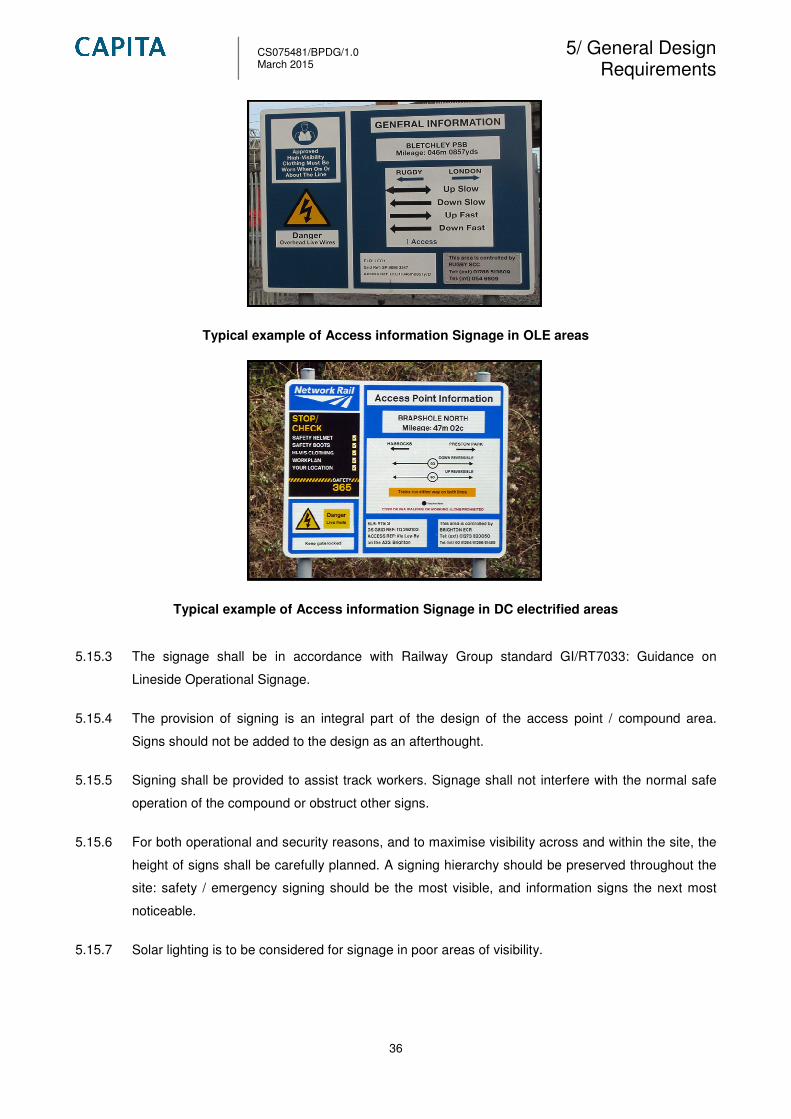
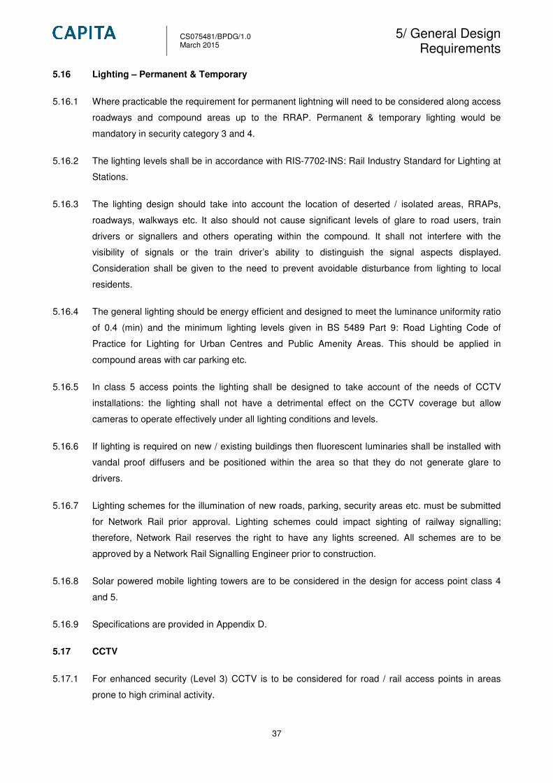
5.15.1 Upon entry / exit to a new or existing access point an access information board should be
displayed with key information. The following indentifies the key hazard, warning, safety and
information that are required:
• Name of the access point;
• Mileage of the access point;
• Access reference (Network Rail) - stating the nearest line;
• Lines and direction of traffic at the location;
• OS Grid reference;
• Engineers Line Reference (ELR);
• Controlling signal box – including telephone number;
• Stop / check board stating PPE / safety equipment (safety helmet, safety boots, hi-vis
clothing etc.);
• OLE / 3rd
rail hazard sign;
• Site Specific hazards; and
• Nearest hospital A&E department details.
5.15.2 Additional information to be included:
• QR code – link to the hazard directory; and
• Site specific information (relevant to the area).
CS075481/BPDG/1.0 March 2015
5/ General Design Requirements
36
Typical example of Access information Signage in OLE areas
Typical example of Access information Signage in DC electrified areas
5.15.3 The signage shall be in accordance with Railway Group standard GI/RT7033: Guidance on
Lineside Operational Signage.
5.15.4 The provision of signing is an integral part of the design of the access point / compound area.
Signs should not be added to the design as an afterthought.
5.15.5 Signing shall be provided to assist track workers. Signage shall not interfere with the normal safe
operation of the compound or obstruct other signs.
5.15.6 For both operational and security reasons, and to maximise visibility across and within the site, the
height of signs shall be carefully planned. A signing hierarchy should be preserved throughout the
site: safety / emergency signing should be the most visible, and information signs the next most
noticeable.
5.15.7 Solar lighting is to be considered for signage in poor areas of visibility.
CS075481/BPDG/1.0 March 2015
5/ General Design Requirements
37
5.16 Lighting – Permanent & Temporary
5.16.1 Where practicable the requirement for permanent lightning will need to be considered along access
roadways and compound areas up to the RRAP. Permanent & temporary lighting would be
mandatory in security category 3 and 4.
5.16.2 The lighting levels shall be in accordance with RIS-7702-INS: Rail Industry Standard for Lighting at
Stations.
5.16.3 The lighting design should take into account the location of deserted / isolated areas, RRAPs,
roadways, walkways etc. It also should not cause significant levels of glare to road users, train
drivers or signallers and others operating within the compound. It shall not interfere with the
visibility of signals or the train driver’s ability to distinguish the signal aspects displayed.
Consideration shall be given to the need to prevent avoidable disturbance from lighting to local
residents.
5.16.4 The general lighting should be energy efficient and designed to meet the luminance uniformity ratio
of 0.4 (min) and the minimum lighting levels given in BS 5489 Part 9: Road Lighting Code of
Practice for Lighting for Urban Centres and Public Amenity Areas. This should be applied in
compound areas with car parking etc.
5.16.5 In class 5 access points the lighting shall be designed to take account of the needs of CCTV
installations: the lighting shall not have a detrimental effect on the CCTV coverage but allow
cameras to operate effectively under all lighting conditions and levels.
5.16.6 If lighting is required on new / existing buildings then fluorescent luminaries shall be installed with
vandal proof diffusers and be positioned within the area so that they do not generate glare to
drivers.
5.16.7 Lighting schemes for the illumination of new roads, parking, security areas etc. must be submitted
for Network Rail prior approval. Lighting schemes could impact sighting of railway signalling;
therefore, Network Rail reserves the right to have any lights screened. All schemes are to be
approved by a Network Rail Signalling Engineer prior to construction.
5.16.8 Solar powered mobile lighting towers are to be considered in the design for access point class 4
and 5.
5.16.9 Specifications are provided in Appendix D.
5.17 CCTV
5.17.1 For enhanced security (Level 3) CCTV is to be considered for road / rail access points in areas
prone to high criminal activity.
CS075481/BPDG/1.0 March 2015
5/ General Design Requirements
38
5.17.2 The design of CCTV systems shall take into account national and industry standards and
guidelines. The following network rail guidance has been produced:
• NR/L2/TEL/30135: Technical Requirements for Security CCTV systems on Network Rail
Infrastructure.
5.17.3 The functional and system performance requirements shall be determined following consultation
with the British Transport Police.
5.17.4 The CCTV system shall, as a minimum, cover the main entrance / exit area of the access point and
locations of significant risk; for example, storage areas, parking areas, amenity blocks etc.
5.17.5 The CCTV system shall provide an adequately defined image in both day and night conditions, and
not be adversely affected by changing light conditions or light emissions from adjacent installations.
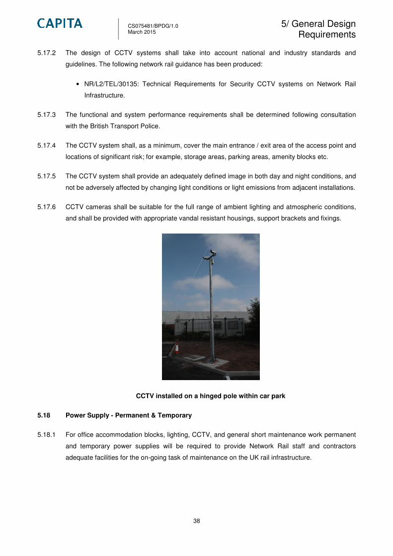
5.17.6 CCTV cameras shall be suitable for the full range of ambient lighting and atmospheric conditions,
and shall be provided with appropriate vandal resistant housings, support brackets and fixings.
CCTV installed on a hinged pole within car park
5.18 Power Supply - Permanent & Temporary
5.18.1 For office accommodation blocks, lighting, CCTV, and general short maintenance work permanent
and temporary power supplies will be required to provide Network Rail staff and contractors
adequate facilities for the on-going task of maintenance on the UK rail infrastructure.
CS075481/BPDG/1.0 March 2015
5/ General Design Requirements
39
5.18.2 Power supplies are designed to supply equipment with particular voltages derived from a main
source of electricity. They can change voltage from one type to another, provide voltages which are
smoothed and free from interference, or protect the equipment and the main supply from excessive
voltages or currents. The supplier of electricity is usually the local electricity company. Commonly
the feed is provided by the railway organisation responsible for the fixed plant, perhaps from the
traction supply. In addition, there will usually be a standby in the form of generators, batteries, or a
different supply source, with appropriate switching arrangements.
5.18.3 Access point class 4 and 5 would require a power supply for lighting, and accommodation units. If
an existing power supply is already supplying railway equipment (points heating, substation,
stations etc) then power monitoring could be undertaken to determine if the existing supply could
take the additional electrical load. This could provide Network Rail time and financial efficiencies.
5.18.4 Possible trackside supplies are to be identified at the survey by a Network Rail site engineer.
5.19 Drainage
5.19.1 For the upgrade of access roads / tracks and installation of new roads on the existing rail
infrastructure, surface water drainage must be considered in the design scope.
5.19.2 Roadways, footpaths and hard standings on site should be adequately drained to prevent the build-
up of standing water. If positive drainage is required this should be by gullies or drainage channels.
All gratings and channel units should be of appropriate load bearing capacity for the location in
which they are set. Connections for surface run-off from roads and hardstandings into drainage
systems may have to include interception facilities in the case of oil or chemical contamination.
5.19.3 The distance from the road to the compound / RRAP will be variable (could range from 50m to 2km
for example). If concrete or impermeable asphalt surfacing is specified the surface water is to be
sufficiently drained to edge assists such as gulley’s and carrier and filter drains. The UK road
network widely uses filter drains as the ideal solution to drain roadways, car parks and compound
areas. This to be considered in the design for the RRV roadway.
5.19.4 A filter drain is a gravel filled trench, generally with a perforated pipe at the base. Run off flows
slowly trough the granular material, trapping sediments and providing attenuation. Flow is then
directed to a perforated pipe, which conveys run-off either back into the sewerage network or into a
waterbody.
5.19.5 Filter drains are normally situated on the roadside verge or medium strip. Consideration of
topography is important to drain road surfaces.
5.19.6 All Network Rail access points will differ in terms of size and shape; therefore drainage design is to
be site specific.

CS075481/BPDG/1.0 March 2015
5/ General Design Requirements
40
Filter drain installed along a typical roadway.
5.19.7 The use of alternative drainage systems including Sustainable Urban Drainage Systems (SUDS) is
to be considered on a site specific basis.
5.19.8 SUDS are the sustainable alternative to conventional drainage methods as they:
• Manage run off flow rates, using infiltration and the retention of storm water;
• Protect or enhance the water quality;
• Are sympathetic to the environment and the needs of the local community; and
• Provide a habitat for wildlife in urban watercourses; and encourage nature and groundwater.
5.19.9 SUDS achieve this by managing:
• Run-off close to where the rain falls;
• Potential pollution at its source protecting water resources from planting trees.
5.19.10 Storm water run-off shall be directed away from the rail track.
5.20 Hand Railing
5.20.1 For access point class 1 and 2 hand railing could be required for access points with stairwells in
cutting slopes or embankments. Network Rail has 2 solutions in the current market (steel & GRP)
which have a design life of 25 years.
5.20.2 For pedestrian access points which require steps, handrail would be required to provide a safety
barrier from slips trips and falls. Landing areas at the bottom of steps are to be installed 3.0m from
the running rail. If this cannot be achieved handrail is required to prevent track personal falling on
to the operational track.
5.20.3 During the design of pedestrian walkways, hand rail shall be considered to define the limits of the
path.
5.20.4 GRP is initially cheaper than steel, maintenance costs for GRP handrails at year 15 result in them
having a low life cost than steel which require no maintenance over 25 years.

CS075481/BPDG/1.0 March 2015
5/ General Design Requirements
41
5.20.5 GRP / FRP
5.20.6 50.0mm diameter modular sections can be fixed to concrete or cast in-situ. The advantage is that
GRP is very lightweight; reducing the risk of injury and it does not require traction bonding. The
height of handrails shall be at least 1100 mm above the level of the adjacent walkway or cess. In
this instance GRP/FRP alternatives should be considered.
GRP/FRP handrail installed at the bottom of a steps
5.20.7 Steel
5.20.8 Kee clamp (or similar approved) is 42.4mm diameter galvanised steel tubing, which can be fixed to
concrete or cast in-situ (to concrete). The height of handrails shall be at least 1100mm above the
level of the adjacent walkway or cess. Steel (Kee-clamp) typically requires little maintenance,
however if the handrail is within the OLE contact zone it will require traction bonding which incurs
further design works and increases the use of natural resources.
Pedestrian Ramp & Steel Handrail
CS075481/BPDG/1.0 March 2015
5/ General Design Requirements
42
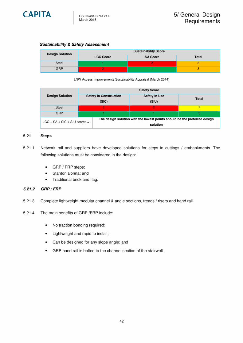
Sustainability & Safety Assessment
Design Solution Sustainability Score
LCC Score SA Score Total
Steel 1 2 3
GRP 2 1 3
LNW Access Improvements Sustainability Appraisal (March 2014)
Design Solution
Safety Score
Safety in Construction
(SIC)
Safety in Use
(SIU) Total
Steel 2 2 7
GRP 1 1 5
LCC + SA + SIC + SIU scores = The design solution with the lowest points should be the preferred design
solution
5.21 Steps
5.21.1 Network rail and suppliers have developed solutions for steps in cuttings / embankments. The
following solutions must be considered in the design:
• GRP / FRP steps;
• Stanton Bonna; and
• Traditional brick and flag.
5.21.2 GRP / FRP
5.21.3 Complete lightweight modular channel & angle sections, treads / risers and hand rail.
5.21.4 The main benefits of GRP /FRP include:
• No traction bonding required;
• Lightweight and rapid to install;
• Can be designed for any slope angle; and
• GRP hand rail is bolted to the channel section of the stairwell.

CS075481/BPDG/1.0 March 2015
5/ General Design Requirements
43
GRP / FRP steps on a cutting slope
5.21.5 Stanton Bonna
5.21.6 Modular precast concrete stairwell with concrete infill with hand railing.
5.21.7 The main benefits of Stanton Bonna steps include:
• System comprise modular components that can be quickly installed saving time and money
over conventional methods;
• Stairwell modules can be installed with minimal ground surface preparation and without the
need for heavy plant;
• A durable system that can be used for both temporary and permanent installations;
• System can be used for slope angles between 25 – 45 degrees;
• System available with various step widths;
• Steel / GRP hand rail can be installed along side of stairwell; and
• Step infill may be type 1 stone or concrete.
5.21.8 Refer to Appendix D for specifications and data sheets.
Stanton & Bonna stairwell built on an embankment (Type 1 stone or concrete infill)

CS075481/BPDG/1.0 March 2015
5/ General Design Requirements
44
5.21.9 Traditional Brick & Flag
5.21.10 Traditionally, steps along the tracks comprised pre-cast concrete (PCC) paving slabs and brick
steps. The handrail is installed along one side for protection.
5.21.11 The main benefit of traditional brick with PCC slabs steps are that typically little maintenance is
required over the design life (25 years).
Brick & PCC flags – Pedestrian Access point
Sustainability & Safety Assessment
Design Solution Sustainability Score
LCC Score SA Score Total
GRP 3 1 4
Cast in-situ Concrete 4 4 8
Stanton Bonna 1 3 4
LNW Access Improvements Sustainability Appraisal (March 2014)
Design Solution Safety Score
Safety in Construction (SIC) Safety in Use (SIU) Total
GRP 1 1 6
Cast in-situ Concrete 3 2 13
Stanton Bonna 4 2 10
LCC + SA + SIC + SIU scores = The design solution with the lowest points should be the preferred design
solution
5.22 Topography Survey
5.22.1 Network Rail standards have been developed to give designers a clear understanding of
topographic, land, engineering and measured building techniques. The standards seek to minimise
site visits by specifying that all information needed is collected in an approximate manner
preventing the need for revisits.

CS075481/BPDG/1.0 March 2015
5/ General Design Requirements
45
5.22.2 The standards align with Network Rail’s policy on sustainability to ensure sustainable policies and
practices are implemented when maintaining, renewing and enhancing the railway.
5.22.3 The following documents provide a strategy and general introduction establishing some basic
principles:
• NR/L2/TRK/3100 – Topographic, engineering, land and measured building surveying,
strategy and general;
• NR/L3/TRK/3101 – Topographic, engineering, land and measured building surveying, track;
• NR/L3/TRK/3102 – Topographic, engineering, land and measured building surveying, Civil
surveying standards (not issued);
• NR/L3/TRK/3103 – Topographic, engineering, land and measured building surveying, survey
and mapping techniques;
• NR/L3/TRK/3104 – Topographic, engineering, land and measured building surveying,
signalling survey standards;
• NR/L3/TRK/3105 – Topographic, engineering, land and measured building surveying,
overhead line electrification; and
• NR/GN/TRK/3106 – Topographic, engineering, land and measured building surveying,
commercial property surveying standards.
5.22.4 For new / existing / upgrades for access points a topographical survey shall be carried out for
design submission.
5.22.5 The topographical survey is required to give the following details:
• Network Rail boundary fence lines;
• Walls;
• Fencing;
• Building footprints;
• Steps;
• Ramps;
• Changes in surface;
• Footpaths, pedestrian walkways;
• Railway running edges 20m intervals, beginning of curves (radius > 500m = 10m <500m =
5m);
• Existing concrete aprons, matting, bollards, lighting columns;
• Railway furniture such as boxes, cable route, ducting, switches etc;
• Roadways, edges, back of pavements, highway boundaries of roads and tracks, changes of
gradient, junctions and intersections;
CS075481/BPDG/1.0 March 2015
5/ General Design Requirements
46
• S & T equipment, point machines, telephones, treadles, location boxes, signal rodding etc.
• Catch pits, manholes, drainage, under track crossings (UTX);
• Reference features: mileposts, adjacent structures, level crossings;
• Individual mature trees (girth and average canopy extent);
• Overall extents of canopy to groups of trees / vegetation;
• Water features e.g. rivers, streams, and canals passing under or over railway tracks;
• Street furniture: transmission lines, poles, pylons, manhole inspection covers, drains, gullies,
signs, lamp posts, overhead utilities crossing the railway (rural / open country areas) and
service covers;
• Spot levels at 10m intervals and changes in slope profile;
• Locations and heights of OLE gantry’s overhead catenary (including return conductor);
• Levels will be related to Ordnance Survey Datum; and
• Road and street names.
5.22.6 Results will be supplied in 2D and 3D AutoCAD DWG format, suitable for plotting at various
drawing scales.
5.22.7 All underground service information to be requested / provided by Network Rail.
5.23 Environmental Assessment
5.23.1 The objective of an Environment Assessment is as follows:
• Identify and investigate potential environmental issues and risks which may arise during,
and as a result of the site investigation and construction works; and
• Ensure that any indentified issues / risks are managed effectively during design and
construction.
5.23.2 When upgrading or siting new access points with buildings the following constraints should be
considered:
• Local soil condition;
• Bearing capacity;
• Subsidence;
• Groundwater table;
• Underground water courses;
• Existing chemical pollutants; and
• Flood zone / plain.
5.23.3 During the site survey a description of the surrounding area, should take the following into
consideration:

CS075481/BPDG/1.0 March 2015
5/ General Design Requirements
47
• Noise - local sources of noise, location, intensity and duration;
• Pollution - local sources of pollution, e.g. industry, historical land-use, motorways and
other dust sources;
• Local micro-climate – wind, driving rain, flooding, frost and shading;
• Sight lines - distance from and impact on operational rail lines, junctions and signals;
• Distance from boundary, surrounding roads, viaducts, railway tracks and / or overhead
power lines. Allowance should be made for zoning around buildings for future external
maintenance (scaffolding or mobile platforms) without the need for road closure or track
possession. Scaffolding tubes need to be at least 3m from overhead lines;
• Access for fire fighting;
• Proposed fenestration in relation to openings in adjacent structures;
• Condition of existing or adjacent property - weathering and effect of pollution, roof and
eaves, lines, nature and use of adjacent properties, as well as access roads and
facilities;
• Security - proximity to sensitive or military installations / areas; and
• Areas of interest or natural beauty - constraints imposed by the local planning authority
to preserve plant or wild life.
5.24 Site Investigation
5.24.1 For upgraded / new access points with modular buildings (class 4) a site investigation would need
to be considered in the design. The scope of the geotechnical investigation will vary according to:
• The type, indicative dimensions, mass, and weight distribution of the structure(s) to be
supported;
• The availability and reliability of existing geotechnical and geological information about the
site;
• The types and characteristics of the ground likely to be encountered at the site; and
• Topographical characteristics of the site concerned.
5.24.2 The hierarchy of the geotechnical investigation shall be as follows:
• Geotechnical appraisal; prior to commencing work on site a desk-based study shall be
undertaken to establish expected site ground conditions and potential site hazards. This
should include, but not be limited to, a review of published geological information from
nearby investigations and BGS borehole records, consideration of previous uses and other
non-natural influences on the site, the sensitivity of any existing structures, the overall
stability, published knowledge and historical railway data, as well as local experience. Coal
Authority and / or other mining reports may be required if indicated by the other desk study
items. If unusual features are anticipated this should be reported to Network Rail prior to
mobilisation to site. The desk study may also help determine the appropriate drilling
equipment, so ensuring the requirements of this specification are met.

CS075481/BPDG/1.0 March 2015
5/ General Design Requirements
48
• Ground investigation, which comprises field investigations, laboratory testing and geological
and geotechnical interpretation. The field investigation (intrusive surveys) comprises direct
investigation including ground gas investigation (ground exploration and soil sampling) and
indirect investigation (in-situ testing such as cone penetration testing (CPT). The Ground
Investigation shall be carried out in accordance with BS EN 1997-1, ‘Geotechnical Design’,
the 'Specification for Ground Investigation’ second edition published by the Site Investigation
Steering Group, and CIRIA C665 ‘Assessing risks posed by hazardous ground gases to
buildings’. Each investigation shall be carried out under the guidance of a Chartered
Engineer or Chartered Geologist with relevant geotechnical experience.
5.24.3 Field investigations
5.24.4 The hierarchy of field investigations (intrusive surveys) undertaken shall be:
1. Trial pit / trench excavation and in-situ testing for shallow depths (maximum 1.2 m
deep);
2. Driven window (or windowless) sampling and in-situ testing for deeper exploration and
sampling (3-5 m deep);
3. Borehole sampling and in-situ testing at greater depths (normally 5-15 m deep), and for
detailed information on material properties and groundwater conditions – primarily for
modular building foundations (including pad, strip or piled foundations), and retaining
structures;
5.24.5 Soil and groundwater sampling/recovery for laboratory testing may be undertaken (in any of the
phases of investigation detailed above) where further detailed information may be required.
5.24.6 All intrusive investigations shall be undertaken in accordance with HSG 47.
5.24.7 Geotechnical Information and Parameters
5.24.8 As a minimum ‘relevant geotechnical parameters’ shall include:
• Ultimate bearing capacity of the soil at foundation level (defined as the least pressure that
would cause shear failure of the soil immediately below and adjacent to the foundation);
• Grading (sieve analysis) of all soils;
• Natural and saturated moisture content of all soils;
• Moisture contents, liquid and plastic limits of clays;
• Unit weights of the soil within each stratum, noting whether saturated, moist or dry; and
• Ground aggressivity in accordance with BRE Special Digest (SD1:2005).
5.24.9 The Contractor must also consider the following ‘relevant geotechnical parameters’, and provide
justification if any of these will not be provided:

CS075481/BPDG/1.0 March 2015
5/ General Design Requirements
49
• Undrained shear strengths of clays determined by laboratory triaxial tests on
boreholes samples, and from in-situ testing;
• Effective stress parameters for all soils determined by laboratory triaxial tests on
borehole samples;
• Pore water pressure log with depth; and
• Permeability of granular strata determined by in-situ permeability tests.
5.24.10 All field investigation shall be performed close to the proposed foundations and / or retaining
structures. Depending upon the proposed structures, at least two exploratory holes within the
footprint of the proposed foundations or structure shall be formed, especially at sites displaying
irregular topography and / or stratigraphy. The depth of the investigation for shallow and piled
foundations shall be in accordance with Eurocode 7.
5.24.11 Where rock is encountered the contractor shall prove that boulders or layers of cemented soils are
not being mistaken for bedrock.
5.24.12 Geological records should be consulted in these circumstances. Rotary diamond core drilling
should also be considered. In all cases, the contractor shall agree laboratory testing items of the
site-specific investigation schedules with Network Rail and the designer. Any changes to the
planned laboratory tests shall be submitted to Network Rail for approval.
5.25 Existing Site Conditions
5.25.1 No planned works shall effect the operation of the existing infrastructure or the supplies and
services to signalling equipment, point heating, existing accommodation etc.
5.25.2 Due care shall be taken at the design stage to eliminate or reduce the risk of accidents in
construction with buried and concealed services.

CS075481/BPDG/1.0 March 2015
6/ Applicable Design Standards
50
6. Applicable Design Standards 6.1.1 The following is a list of relevant rail related standards applicable to the design / construction and
operation of access points which will facilitate the use of heavy RRVs. This list is not exhaustive
and does not include relevant British Standards’ / BS EN’s / Eurocodes for which compliance will
be mandatory:
• NR/PLANT/0200/module P301 – Road Rail Access Points
• NR/PLANT/0200/module P507 – Infrastructure Plant Operations Manual: On Track Plant
• NR/PLANT/0200/module P703 – Infrastructure Plant Operations Manual: Road Rail Access
Point Maintenance
• COP0007 – Code of Practice for On & Off Tracking of Road Rail Vehicles
• NR/L3/INI/CP0036 – The Provision of Welfare Facilities
• NR/SP/OHS/069 – Lineside Facilities for Personnel Safety
• NR/PLANT/0200 – Infrastructure Plant Manual
• NR/L2/TRK/2102 – Design & Construction of Track
• NR/L2/TRK/2049 – Track Design Handbook
• NR/L3/CIV/003 - Engineering Assurance of Building & Civil Engineering Works
• NR/L2/ELP/27239 – Maintenance Specification for Electrical Traction Distribution Equipment
• NR/L2/TRK/4040 – Level Crossing Surface Systems
• BS EN 50122 Railway Applications Fixed Installations
• NR/CAT/STP/001 Catalogue of Network Rail Standards
• NR/GN/CPR/401 Guidance on Contractual Health & Safety Requirements
• NR/L1/INI/CP1010 – Policy on Working Safely in the Vicinity of Buried Services
• NR/L1/INI/PM/GRIP – Governance for Railway Investment Project (GRIP) – Policy manual
• NR/L2/AIF/1040 – Buried Services Data Feedback
• NR/L2/AIR/1020 – Buried Services Data Provision
• NR/L2/CIV/003 – Engineering Assurance of Building and Civils Engineering Works
• NR/L2/CTM/021 –Competence & Training in Track Safety
• NR/L2/EBM/029 Network Rail Definition of Product Acceptance Requirements
• NR/L2/ENV/015 – Contract Requirements – Environment
• NR/L2/INI/002 – Accident and Incident reporting and Investigation
• NR/L2/INI/02009 – Engineering Management for Projects
• NR/L2/INI/CP0047 – Application of the Construction Design and Management Regulations
to Network Rail Construction Works.
• NR/L2/INI/CP0061 – Access Through Land Belonging to an Outside Party
• NR/L2/INI/CP1030 – Working Safely in the Vicinity of Buried Services
• NR/L2/INI/EDT/CP0091- Specification for Computer Aided Design
• NR/L2/OHS/00120 – Pre-employment, Pre-appointment and Periodic Testing for Drugs and
Alcohol

CS075481/BPDG/1.0 March 2015
6/ Applicable Design Standards
51
• NR/L2/OHS/005 – High Street Environment and Conditions for Work Outside Network Rail
Controlled Infrastructure
• NR/L2/OHS/018 – Supplier Requirements for the Approval of Medical Assessments and
Drug and Alcohol Screening and Certification
• NR/L2/OHS/019 – Safety of People Working On or Near the Line
• NR/L2/OHS/020 0 Track Visitor Permits
• NR/L2/OHS/021 – Personal Protective Equipment and Work Wear
• NR/L3/CIV/071 - Geotechnical Design
• NR/L3/CIV/140 – Model Clauses for Civil Engineering Works
• NR/L3/INI/CP0044 – Work Package Planning Process
• NR/L3/INI/CP0046 – The Reporting and Investigation of Accidents and Incidents within
Investment Projects and Asset Management Works Delivery
• NR/L3/INV/0101 – General Requirements for the Reporting of Accidents, Incidents and
Occupational Ill Health
• NR/L3/INV/0113 – Statutory Reporting of Accidents, Incidents and Occupational Ill Health
• NR/SP/BUS/011 - Prevention of Damage to and Danger from Surface and Buried Services
• NR/SP/ELP/29987 - Working on or about AC Electrified Lines
• NR/SP/ENV/007 - Project Management and the Environment
• NR/SP/OHS/00108 - Contract Safety & Assurance Requirements
• NR/SP/OHS/050 – Sentinel Scheme Rules
6.2 Application of Standards
6.2.1 The following are mandatory requirements:
• European and National Legislation;
• Railway Group Standards;
• Network Rail Company Standards;
• Network Rail Asset and Environment Policies;
• The requirements of this Engineering Remit; and
• The requirements of applicable temporary non-compliances pending standard
change for Group and Company Standards.
6.2.2 The following are not mandatory but should be used. They become mandatory requirements if
quoted in this document:
• HMRI principles and guidance;
• Network Rail guidance notes;
• British Standards;
• European Standards;
• Other: industry standards, instructions, guidance, and codes of practice that are
relevant.
CS075481/BPDG/1.0 March 2015
6/ Applicable Design Standards
52
6.2.3 The applicable standards shall be reported by referring to the relevant issue of standards used and
confirming the design and supporting Engineering Deliverables meets the requirements of
standards.
6.2.4 Where documents refer to other updated or superseded standards the current version of the
referenced standard shall apply.
6.2.5 Proposals that provide a business benefit by developing alternatives to standards should be
developed as a non compliant option where the implications of the deviation to standards are
explained.
6.2.6 Proposed deviations should be agreed before work takes places to consider them further.

CS075481/BPDG/1.0 March 2015
Appendix A/ – Access Point Categorisation Table
Appendix A – Access Point Categorisation Table

CS075481/BPDG/1.0 March 2015
Appendix B/ – Access Point Generic Layouts
Appendix B – Access Point Generic Layouts

CS075481/BPDG/1.0 March 2015
Appendix C/ – Standard Details
Appendix C – Standard Details
Related Documents