Network Physical Plant & Standards University Technology Services - Network Communications Team Updated: May 10, 2016

Welcome message from author
This document is posted to help you gain knowledge. Please leave a comment to let me know what you think about it! Share it to your friends and learn new things together.
Transcript

Network Physical Plant & Standards University Technology Services - Network Communications Team Updated: May 10, 2016

Table of Contents
SECTION ONE: GENERAL INFORMATION 3
SECTION TWO: INTER-BUILDING SPECIFICATIONS 5
SECTION THREE: INTRA-BUILDING (RISER/BACKBONE) SPECIFICATIONS 8
SECTION FOUR: HORIZONTAL TELECOMMUNICATIONS SPECIFICATIONS 11
SECTION FIVE: COMMUNICATION OUTLET SPECIFICATIONS 15
SECTION SIX: APPENDIXES 19

Table of Contents
Section One: General Information Introduction The purpose of this document is to identify specific requirements and specifications for telecommunication and data communication infrastructure at Oakland University. This document will outline telecommunication spaces that conform to current and future technology best practices in order to maximize the University’s investments. Please note that the label Telecommunications is used interchangeably throughout the document to describe both telephone and data networking infrastructure. Please note that this is a guide and all designs based off these specifications should be reviewed with Network Communications Services prior to purchase or implementation.
General Requirements Pursuant to Oakland University policy #850, Network Communications Services must be consulted before any project planning, implementation, or installation is considered complete. Project planning Any telecommunications specifications for new buildings or new spaces must be reviewed and approved by Network Communications. This ensures that the planning process includes proper communication ports and the facilities to house the telecommunication infrastructure. During the project-planning phase the requirements and specifications in this document should simply be referred to as a guide. Project implementation Any requirements and specifications in this document, including any ANSI/EIA/TIA specifications should be strictly followed during the implementation or construction phase. Network Communications Services must approve any deviations from the specifications listed in this document. Project Completion All specified test results must be turned over to Network Communication Services as soon as they are available. Network Communication Services reserves the right to verify any test results furnished. A project will be considered complete only after all test results have been verified and considered satisfactory. Network Communication Services requires that the most recent version of the following standards be adhered to in all installations.
• TIA/EIA 569 • TIA/EIA 607 • TIA/EIA 606-A (Labeling standards) • TIA/EIA 570 (Residential Dorms/Apartments only)

Table of Contents
• Panduit Structured Cabling System Specification (Installer must have the most recent certification offered by Panduit, in order to comply with the Panduit warranty).

Section Two: Inter-building Specifications 5
Section Two: Inter-building Specifications (Connections from individual buildings to the master cross connects)
General Guidelines Where possible every building should have two independent connections to the University backbone. Each connection should enter the building from opposite ends of the building. Each connection should be brought in through separate manholes. Providing two distinct connections to the backbone gives the building a redundant connectivity in the case of a cable cut. Due to the number of critical systems that are now run on the University network it is imperative that we provide redundancy into the telecommunications plant. Services such as fire alarm signaling, swipe card door locks, and emergency 911 need a highly available, high quality telecommunications infrastructure. Entrance Facilities An entrance facility is designated as the space into which the telecommunications cabling enters the building. The entrance facility space should be within 50 feet of where the cabling penetrates the building. Specific room requirements are listed below.
• TIA/EIA 569 requires that a locked and dedicated room. • It is preferred to have two separate entrance facilities, located at opposite ends of
the building. • The size of the entrance facility space must be at least 10ft x 12ft. The height of
the room should measure at least 10ft tall. • The room itself must have no dropped ceilings; concrete floor and all surfaces
must be treated to reduce dust. • The location of the entrance facility must be away from any source of
Electromagnetic Interference. (Less than 3V/m interference across the frequency spectrum)
• The room must be used exclusively for telecommunications. No water pipes, sanitation pipes, ductwork, electrical conduit or mechanical equipment should pass through the room.
• Lighting should be ample for this type of room and the type of lighting should not interfere with the electronics within the room. Lighting should also be connected to the emergency power system.
• Electrical outlets should be attached to the top of every rack (110V quad outlet on separate 20A circuits). Note that 220V service may be required in some instances. Check with Network Communications for per project specifications.
• Room must have proper grounding bars in place. • Proper HVAC must be installed in order to accommodate a year round
temperature of 68-75 degrees Fahrenheit, 45-55% humidity. • Door must open on the outside only and be secured with a lock using a
telecommunications only core. • All cabling must be routed through cable trays.

Section Two: Inter-building Specifications 6
Underground Conduit Facilities All new underground telecommunication facilities must meet the following criteria.
• All new conduit installation must be built out from existing locations as specified by Network Communications.
• Every new building should have a minimum of 4 conduits to the identified demarcation point(s) that connects to the campus backbone.
• Size of conduits should be 4-5”. • Conduit must be PVC and conform to the NEMA T6 and T9 standards for PVC.
Conduit must be either Encased Burial or Direct Burial based on requirements of a given project. Manholes should be equipped with sump pumps and provide sufficient space to allow for feed-through and branching of cabling within bend radiuses
• Conduit must be installed in a bank formation of 2 x 2, 2 x 3 or 3 x 3. Conduit should be buried a minimum of 42”. Manholes must be placed as needed to finish the installation. All conduits should be pitched so that it drains into the manholes. After installation conduits should be free from any debris. A test mandrel with diameter no less than 3¾” should be drawn through the conduit to test the installation. Conduits that pass the test should be plugged immediately. Conduits that do not pass must be replaced, free of cost.
• All routing of conduit should be documented on the master campus map. GPS coordinates should be provided for any of the following: turn in direction, penetration of building, or manhole. Depth changes must be documented if they deviate ±6” from the requested depth.
• Network Communications must approve all conduit installations prior to start of construction. Network Communications must receive and approve of all test results and documentation before project is considered complete.
Copper Connectivity Cable and Termination Requirements
• Heavy duty gel-filled armored cabling if cable is directly buried, otherwise no armoring is required. Cable capacity will be specified per project.
• Cabling must be terminated in one of two Building Entrance Protectors. Appropriate part should be used based on mounting location.
• Building Entrance Protectors should use Circa C4B1S-BAL (PTC) protection modules.
• Clearly label and document all copper installations. See appendix for Oakland University labeling standards.
Fiber Connectivity Cable and Termination Requirements
• Single-Mode double-jacket required for conduit installation, double-jacket single armor required for direct burial installation.
• All cable should be 10G and DWDM capable. Documentation must be provided detailing maximum cable distance at specified speed.

Section Two: Inter-building Specifications 7
• All fiber must terminate in Panduit Opticom Rack Mount Fiber Enclosures and use LC style fiber adapter modules unless otherwise noted.
• All fiber installations must be labeled properly on both ends. See appendix for Oakland University labeling standards.
• A BiCSi Certified Fiber Optics Installer is preferred. The fiber installer must minimally be certified by the fiber manufacturer.
• Splicing of fiber optics in manholes is not acceptable, unless approved, in writing, by Network Communication Services.
• The terminated installation must be able to support error-free 10Gb operations over the entire length of the installation. All fiber optic installations must be certified using applicable procedures found in EIA/TIA-455 and EIA/TIA-526.
• Documentation including fiber optic test results, as-built drawings as well as GPS coordinates of building entrance points and major directional changes must be submitted in both print and electronic form (Contact Network Communication Services for acceptable electronic formats).

Section Three: Intra-building (Riser/Backbone) Specifications 8
Section Three: Intra-building (Riser/Backbone) Specifications (Connections from MDF to IDFs)
General Requirements Intra-building telecommunications is defined as the building backbone or riser system. The riser system in most cases should be designed into the center of the building on each floor. If a central location is not possible, a central riser system for each section of a building is acceptable. Each telecommunication space must be stacked on top of each other on every floor of the building. A sufficient number of conduits should be used for backbone cabling so that no conduit is filled more than 25% upon initial installation. Telecommunications Facilities There should be a minimum of 1 telecommunication room per floor. The room must be built to the following specifications:
• Room size must be at least 10’ x 12’ in size. • Room should have no drop ceiling. • All surfaces in room should be treated to reduce dust • Room should be centrally located within the building or section of building. The
distance from this room to any outlet on the floor must not exceed 80m (~260ft). • Room should be exclusively used for telecommunications. No water pipes,
sanitation pipes, ductwork, electrical conduit or mechanical equipment should pass through the room.
• Lighting should be ample for this type of room and the type of lighting should not interfere with the electronics within the room. Lighting should also be connected to the emergency power system.
• Electrical outlets should be installed at the top of every rack (110V quad outlet on separate 20A circuits). 220V service may be required in some instances. Check with Network Communications for per project specifications.
• Proper HVAC must be installed in order to accommodate a year round temperature of 68-75 degrees Fahrenheit, 45-55% humidity.
• Door must open on the outside only and be secured with a lock using a telecommunications only core.
• All cabling must be routed through cable trays. • Must have a minimum of three 4” conduit or duct. Stub out on floor and ceiling
must be a minimum of 1”. • Each conduit should have a maximum fill of 25% on initial installation. • Each conduit should be fire-stopped. Self-sealing pathways are preferred.
Power Requirements and Recommendations Power in telecommunication spaces should be installed with great care. Electrical in these areas will be powering sensitive data networking and telecommunication equipment. Requirements:

Section Three: Intra-building (Riser/Backbone) Specifications 9
• Each box of 110V outlets must be installed on separate 20A circuit. • There should be a quad outlet attached to the top of the equipment racks for
equipment use. At least one duplex outlet should be installed on a wall in close proximity to the racks for instrumentation and test equipment use.
• Use Red outlets if central backup power is used. • Label outlets clearly with Amperage rating and circuit number. • Backup Power allowing a minimum equipment runtime of 30 minutes in
buildings connected to the campus generators. In buildings with no generator, 2 hours runtime is required.
Recommendations: • In some instances it may be more cost effective to install backup power in a
central location and run dedicated circuits to each telecommunication space in the building.
• Installation of a building generator to power network and telecommunication equipment and critical building infrastructure should be considered.
Copper Connectivity These requirements are based on Network Communications current telephone infrastructure; consult with Network Communications for per project specifications.
• A multi-pair UTP cable from entrance facility to each IDF. See Network communications for UTP cable size.
• Maximum conduit fill should not exceed 25% on initial installation. • Cabling must be clearly labeled at each end. Labeling must follow TIA/EIA-
606-A standard. • In each IDF, rack-mounted patch panels should be used with RJ-45 connectors
on front side. See appendix for approved parts list. • Must be wired for 8-pin operation
Fiber Optic Connectivity The requirements listed below are generalizations. Consult with Network Communications for per project specifications.
• A hybrid single-mode/multi-mode 24/24 to each IDF. Multi-mode cable should minimally be OM3.
• Must be terminated in approved rack mount enclosure (see approved parts list) • MDF must have separate fiber enclosure for each IDF/closet. • Must observe bend requirements and tension limitations of installed cable. • All non-armored fiber must be routed through inter-duct. • All fiber installations must be routed through separate conduit. Sharing of
conduit between fiber and any other cable is not permitted. • Maximum conduit fill should not exceed 25% on initial installation. • All terminations must be done using LC style connectors. • All strands must be terminated during install. Any empty bays in the fiber
enclosures should be filled with blanks. • A BiCSi Certified Fiber Optics Installer is preferred. The fiber installer must
minimally be certified by the fiber manufacturer.

Section Three: Intra-building (Riser/Backbone) Specifications 10
• Must leave a service loop of 15’ on each end of cable to allow for re-termination. • The terminated installation must be able to support error-free 10Gb operations
over the entire length of the installation. All fiber optic installations must be certified using applicable procedures found in EIA/TIA-455 and EIA/TIA-526.
• Documentation including fiber optic test results, as-built drawings must be submitted in both print and electronic form (Contact Network Communication Services for acceptable electronic formats).
Section Four: Horizontal Telecommunications Specifications 11
Section Four: Horizontal Telecommunications Specifications (Connections from individual locations to IDF)
General Requirements The horizontal cabling is the most expensive and most complex portion of telecommunication cabling in a building. For this reason extreme care must be taken when installing, as repairs are very costly and time consuming. One of the most important aspects in horizontal cabling is documentation. All horizontal cabling runs MUST be labeled at both ends, on both the cable itself and at the termination point. Labels MUST be: easily read, resistant to the environmental conditions, must have a design life equal to or greater than that of the labeled component, and be generated by a mechanical device (As stated in TIA/EIA 606-A). In addition, the following specifications must be followed. Telecommunications Facilities See Section 3: Telecommunication Facilities. Copper Connectivity
• The telecommunications contractor must be a company specializing in communications cabling installation. Furthermore, the installers must be a certified by the manufacturer of the product being installed.
• Maximum horizontal cable run must not exceed 90m. • Cable must not have any defects, burns, cuts or tears. Any cable exhibiting these
defects must be removed and replaced. • When pulling cable, no more than 110N (25lbs) of pull force should be used.
Utilize appropriate cable lubricant in sufficient quantity to reduce pulling force and ensure that force is within acceptable limits.
• Cables must be dressed and terminated in accordance with manufacturer recommendations.
• Pair untwist must not exceed 1/8”. Specialized manufacturer tools should be used where applicable to attain this specification.
• Bend radius of the cable in the termination area shall not exceed 4 times the outside diameter of the cable.
• Cables shall be neatly dressed and bundled to their corresponding patch panel. Each patch panel bundle must be fed by an individual bundle which should remain distinct bundle back to the point where it enters the rack.
• Color coordinated jacks must be used on both ends, if unsure please consult with Network Communications Services.
o Data - Yellow o Voice – Black (Including Elevators) o Wireless AP's - Orange o IP Cameras - Blue o Emergency Call Stations – Blue o Fire Alarm - Red o See approved part list for part numbers.

Section Four: Horizontal Telecommunications Specifications 12
• Each cable MUST be labeled with a mechanically generated label at both ends (behind the patch panel or jack). See appendix for Oakland University labeling standards.
• A nylon pull cord must be installed with any cable run that is installed through a conduit.
• All twisted pair copper cabling must be tested for continuity, shorts, opens, pair-reversals, and performance as listed below.
o Wire map o Length o Attenuation/Insertion loss over applicable frequencies o Near end cross talk (NEXT) o Return loss o ELFEXT Loss o PSNEXT o PSELFEXT o Propagation Delay o Delay skew
• All cabling must be tested and certified to meet the most current Panduit/Belden requirements.
• Network Communications may ask for a re-test of up to 10% to verify the documented findings. If re-testing disagrees with documented findings, Network Communications may request additional re-testing of up to 100%. Any additional re-test will be done at no additional cost to the project.
Documentation • Complete documentation must be delivered to Network Communications within
ten (10) business days of completion. Documentation should include both original drawings as well as as-built drawings, and test results.
• All as-built drawings should include cable paths and outlet locations. Outlets must be identified by their labeled name. Numbering, icons and drawings must be consistent throughout all documentation.
• Three full sets of documentation both in print and electronic form should be delivered. Check with Network Communications for acceptable electronic formats.
• Laminated drawings should be hung on the wall in each closet representing the area which that closet covers. Drawings should indicate drop location and correlate with the patch panel labels.
Fiber Optic Connectivity Fiber optic cable to the desktop provides and enhanced high-speed connection capable of advanced multimedia, and data applications.
• A certified fiber optic cable installer must complete all fiber installations. • All requirements for bend radii pull and tension must be strictly followed. • All fiber must be terminated at time of installation • Each cable must be labeled with a mechanically generated label at both ends. • All installations must be tested end to end. Detailed test results must be provided
in both print and electronic form. Check with Network Communications for acceptable electronic formats.

Section Four: Horizontal Telecommunications Specifications 13
Coaxial Connectivity
• Only high-grade coaxial cable should be used for all installations. • All installations should be capable of digital cable services. • All installations must be tested end to end and meet the specifications of the
project. • Detailed test results for cable install must be provided in both print and electronic
form. Check with Network Communications for acceptable electronic formats. Cable Path Specifications
General • All cabling paths must be at least 24 inches away from any electrical cabling or
lighting fixtures. • All cabling paths must be used exclusively for Network Communication cabling.
No other cabling may share these paths. • All cabling paths must meet all Fire and Building codes. • Cabling paths should not be more than 50% full on initial installation, unless
approved by Network Communications. • Logical bundles of cables should be grouped together using Hook and Loop tape
at regular intervals and at junctions and turns. • Conduits
o Must have bushings installed at both ends. o Must have a nylon pull cord inserted at time of installation.
• Trays o Trays used in any application must be bonded together. o Must have a minimum of 12” of unobstructed access to tray on all sides.
If an obstruction cannot be avoided, approval must be obtained from Network Communications prior to installation.
o Trays must not be installed on, connected to any other pipe, conduit, or duct. Trays should be installed and connected directly to the building structure.
o Network Communications prefers the use of CabloFil or FlexTray tray products. See approved parts list for part numbers.
Ceilings • All cable routed through ceilings must be installed in a tray. Use of CabloFil or
FlexTray is preferred. See approved parts list for part numbers. • Trays must be mounted to the ceiling or the wall. If mounted to the ceiling, the
tray must be hung from both sides of the tray. Floors • Raised Floors
o All cable routed through raised floors must be installed in a tray. Use of CabloFil or FlexTray is preferred. See approved parts list for part numbers.
o Trays must be mounted to floor support system, and be raised a minimum of 1 inch above the floor.
• Solid Floors (Cement) o Must use at minimum a 2 inch PVC conduit.

Section Four: Horizontal Telecommunications Specifications 14
o Nylon pull string must be installed. o Conduit should be no more than 25% full on initial installation. o The conduit (2 inch) bend radius must be at least 6 times the diameter of
conduit. For conduit greater than 2 inches, a bend radius of 10 times the inside diameter of the conduit must be used.
o Within one section of conduit, the conduit may turn up to 90 degrees. o A continuous section of conduit must not exceed 100 feet in length. A
junction box must be used to connect sections that are longer than 100ft. A separate pull cord should be installed in each section.
Walls • Cabling must be run in conduits. • All conduits must stub into the cable path (wire tray or larger conduit). • Conduits must not be more than 25% full upon initial installation. • All fiber optic cabling must be run in its own conduit. • All conduits larger than 2 inches, housing fiber optic cabling, must use interduct
within the conduit. Alternatively, dielectric armored fiber optic cable may be used without interduct.
Patch Cables
• All patch cables in the telecommunication closets must be 7 feet in length. No other length patch cord should be used. The Panduit cable management system allows for excess cable to be neatly stored.
• All patch cables used from the wall jack to computer/network device must not exceed 10 feet.

Section Five: Communication Outlet Specifications 15
Section Five: Communication Outlet Specifications
General Requirements There are many different spaces in a building, offices, conference rooms, lobby space, classrooms. The number of connections for a specific room depends on the specific function and use of the room. Network Communications will review outlets for other areas not listed on a case-by-case basis. Standard Connectors
• UTP: RJ45 • Fiber: LC • Coax: BNC
Office Space Single Occupant Office Space • Location: Should be centered on either the left or right wall as viewed from the
entrance. Exact location depends on arrangement of furniture. • Outlet Configuration: 3 UTP
Multiple Occupant Office Space • Location: Should be one outlet per 10 feet of wall space, or one outlet per
occupant. • Outlet Configuration: 3 UTP per outlet
Cubicle Office Space • Location: Should be one outlet per cubical, located either on the top of the desk or
along perimeter of cube. • Outlet Configuration: 4 UTP • Main cable feeds for cubicles must never be run on the floor. Cables must always
be run through a flexible conduit, securely attached to the wall or floor and the cubicle. Power poles attached to the cubicle furniture may also be used to bring in cable feeds. Cable feeds must not be located in walking paths. Please note that any construction work such as power pole installation and room renovation needs to be handled through Campus Facilities and Operations via a work order or project request.
• See appendix for modular furniture faceplates.
Wireless Services • Location: Outlet should be installed above ceiling. If it is not concealed by
ceiling tile, a lockable enclosure should be used. • Outlet Configuration: 2 UTP per location (location must not exceed 25 potential
clients) • Notes: Wireless outlets should be installed in accordance with the wireless plan
for the building.

Section Five: Communication Outlet Specifications 16
Conference Room Space
Seminar Room • Location: Outlets should be installed in all four corners of the room. • Outlet Configuration: 2 UTP per outlet • Wireless: One outlet per 25 seats should be installed. Depending on the size of
the room an additional outlet may be installed. Auditorium • Location: Outlets should be installed as specified by Classroom Services and
Instructional Technical Services. • Outlet Configuration: 2-6 UTP per outlet • Wireless: One outlet per 25 seats should be installed for wireless.
Lobby Space • Location: Outlets should be installed as required. • Outlet Configuration: 2 UTP per outlet • Wireless: Outlets should be installed in accordance with building master plan for
wireless.
Class Room Space Listed below are general recommendations, Classroom Services and Instructional Technical Services should be consulted to provide specifications on a per project basis.
Regular Classroom • Location: Outlets should be installed in all four corners of the room. • Outlet Configuration: 3 UTP per outlet, coax if need for multimedia enabled
rooms. • Wireless: One outlet per 25 students should be installed.
Computer Classroom • Location: Outlets should be installed in all four corners of the room. In addition,
one outlet should be installed for every planned computer. Outlets should be installed in wall outlets or floor outlets as appropriate for furniture configuration.
• Outlet Configuration: 2 UTP, coax if needed. • Wireless: One outlet per 25 seats should be installed. • Notes: Setup should be planned to be flexible for future room reconfiguration. Distance Learning Classroom • Location: Outlets should be installed in all four corners of the room. • Outlet Configuration: 3 UTP, coax as needed. • Wireless: One outlet per 25 seats should be installed Laboratory • Location: Outlets should be installed in all four corners of the room.

Section Five: Communication Outlet Specifications 17
• Outlet Configuration: 3 UTP, coax as needed. Laboratories must use water resistant faceplates, see appendix for part number.
• Wireless: One outlet per 25 seats should be installed
Residence Hall Room • Location: One outlet should be installed per occupant/bed. Outlet should be
installed next to planned desk location. • Outlet Configuration: 2 UTP • Wireless: Wireless should be installed according to building master plan for
wireless. Wireless should adequately cover each room.
Utility Space Utility Room (HVAC, Building Controls) • Location: Outlets should be installed as necessary to support HVAC and building
controls equipment. • Outlet Configuration: 3 UTP
Doorways/Entrance Ways Building entranceways, secure areas and certain shared spaces will be secured with an electronic lock. Power and network connectivity are required for installation of the Blackboard card access system. The ID Card Office will specify exact locations and approve final specifications prior to installation. Wireless Networking Equipment The installation of wireless Access Points (AP) requires that equipment be installed so that it is as unobtrusive as possible. It is recommended that the following guidelines be followed to make the wireless infrastructure as invisible as possible.
• Location: AP should be installed above dropped ceilings whenever possible. If there are no dropped ceilings, the AP should be installed as high as possible.
• If security of the AP is in question, it should be installed in a lockable, vented enclosure.
• An outlet containing 2 UTP outlet should be installed for each AP.
Point of Sales Locations Power and network connectivity is required at any location where Blackboard card system is used. The ID Card Office will specify outlet configuration on a case-by-case basis. Typical Services could include:
• Vending Machines • Copiers • Printers • Dining Services • Value Transfer Stations

Section Five: Communication Outlet Specifications 18
Other/Special Space Network Communication Services must handle specifications for any other space not specifically mentioned in this section. Network Communications will continue to add popular environments to this section as needed.
Section Six: Appendixes 19
Section Six: Appendixes
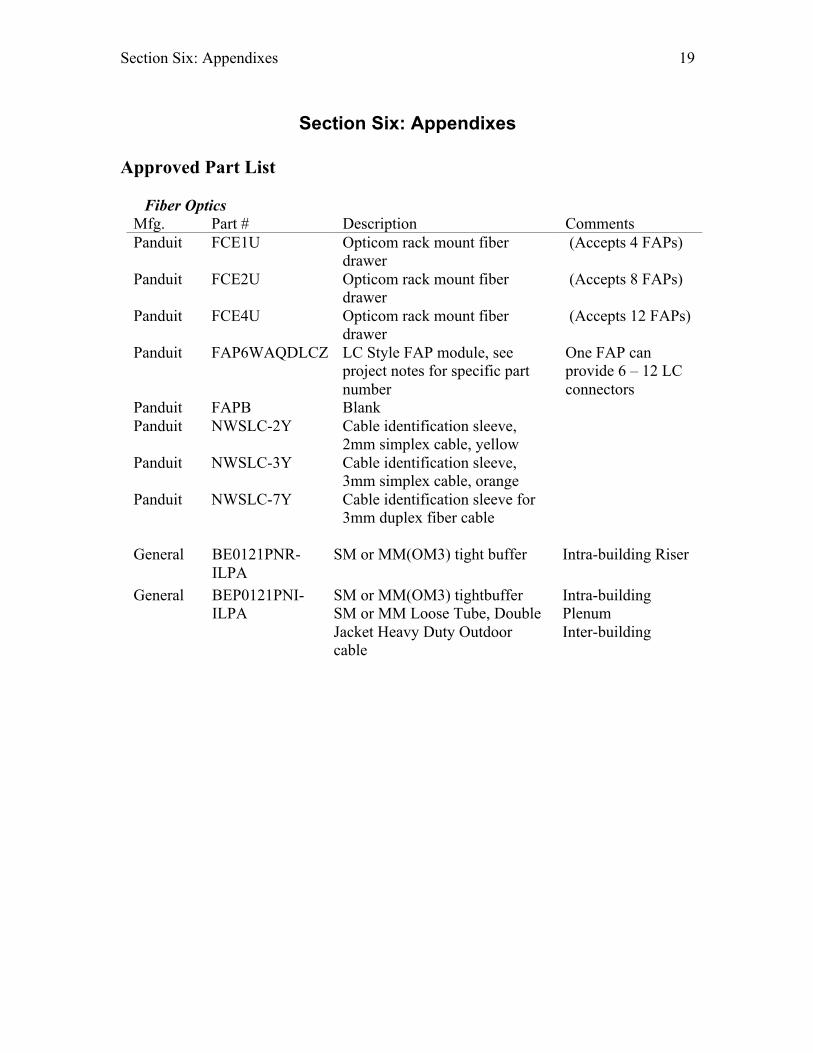
Approved Part List
Fiber Optics Mfg. Part # Description Comments Panduit FCE1U Opticom rack mount fiber
drawer (Accepts 4 FAPs)
Panduit FCE2U Opticom rack mount fiber drawer
(Accepts 8 FAPs)
Panduit FCE4U Opticom rack mount fiber drawer
(Accepts 12 FAPs)
Panduit FAP6WAQDLCZ
LC Style FAP module, see project notes for specific part number
One FAP can provide 6 – 12 LC connectors
Panduit FAPB Blank Panduit NWSLC-2Y
Cable identification sleeve, 2mm simplex cable, yellow
Panduit NWSLC-3Y
Cable identification sleeve, 3mm simplex cable, orange
Panduit NWSLC-7Y
Cable identification sleeve for 3mm duplex fiber cable
General
BE0121PNR-ILPA
SM or MM(OM3) tight buffer Intra-building Riser
General BEP0121PNI-ILPA
SM or MM(OM3) tightbuffer SM or MM Loose Tube, Double Jacket Heavy Duty Outdoor cable
Intra-building Plenum Inter-building

Section Six: Appendixes 20
External Building Copper Mfg. Part # Description Comments Circa 1880ECA1-25G Wall mount entrance
protector 25 pair
Circa 1880ECA1-50G Wall mount entrance protector 50 pair
Circa 1880ECA1-100G Wall mount entrance protector 100 pair.
Circa 1880ENA1/NSC-200 Rack mount entrance protector 200 pair.
Circa C4B1S-BAL (PTC) Solid state protetor module for entrance protectors.
Belden 25 pair gel-filled cable Belden 50 pair gel-filled cable
Horizontal Wiring
Mfg. Part # Description Comments Belden/General Cable
24816995 /7133819
Riser Cat 6A UTP Used ONLY in new buildouts/construction.
Belden 24817995 /7131819
Plenum Cat 6A UTP Used ONLY in new buildouts/construction.
Belden/General Cable
1212/6133712 Riser Cat 5e UTP Used ONLY in existing buildings which have Cat5e or lower.
Belden/General Cable
1213/6131690 Plenum Cat 5e UTP Used ONLY in existing buildings which have Cat5e or lower.
Belden 1189AP Plenum RG6 CATV cable
Or similar product.
Belden PTSP501 Plenum Multi-mode 2 strand fiber 50/125µm
Or similar product. (Fiber to the desktop)
Panduit UICFPSE2WH Single gang vertical sloped faceplate, 2 modules, White
NO SUBSTITUTES
Panduit UICFPSE4WH Single gang vertical sloped faceplate, 4 modules, White
NO SUBSTITUTES
Panduit UICFPSE6WH Single gang vertical sloped faceplate, 6 modules, White
NO SUBSTITUTES
Panduit UICFPSE8WH-2G
Single gang vertical sloped faceplate, 8 modules, double-gang,
NO SUBSTITUTES

Section Six: Appendixes 21
White Panduit CFPWR4CIG Single gang vertical water
resistant faceplate accepts four Mini-Com modules.
NO SUBSTITUTES (Used for laboratories or washdown rooms)
Panduit CJ6X88TG** Mini-com RJ-45 Add suffix BL (Black), YL (Yellow), OR (Orange), BU (Blue), RD (Red)
NO SUBSTITUTES
Panduit CBX1WH-A Mini-com Surface Mount Boxes, single UTP
Used ONLY for above ceiling applications.
Panduit CBX2WH-AY Mini-com Surface Mount Boxes, double UTP
Used ONLY for above ceiling applications
Panduit CFFPLA4BL Modular Furniture Faceplates
Height: 1.34” – 1.40” Width: 2.67” – 2.75”
Panduit CFFPHM4BL Modular Furniture Faceplates
Height: 1.88” – 1.91” Width: 2.98” – 3.03”
Panduit CFFPEBSL4BL Modular Furniture Faceplates
Height: 2.38” Width: 3.44”
Panduit KWP6PY Keystone Phone Plate with Module
For wall mounted phones.

Section Six: Appendixes 22
Cable Path Mfg. Part # Description Comments Cablofil CF54/300 2” Deep tray, 12” wide Or similar product Cablofil CF54/200 2” Deep tray, 8” wide Or similar product Cablofil FAS P400 FAS Profile, for hanging tray Or similar product Cablofil EDRN Fast Splice for joining two
straight sections of tray. Or similar product
Cablofil SWK Splice washer kit for fabricating bends.
Or similar product
Cablofil EZ T90 Kit for creating 1 90º tee or 2 90º bends.
Or similar product
Cabofil CABLEXIT100 6.4” Cable drop off, 2” bend radius.
Or similar product
Cablofil DROP OUT 12.35” Cable drop off, 7” bend radius.
Or similar product
Cablofil GNDCL Grounding lug Or similar product Cablofil EZBN ¼ Nut/Bolt/Clamp assembly Or similar product Cablofil HB2 Wall Termination Bracket Or similar product Cablofil EZJB 5/16 Used with FAS P400 to mount
tray to standard 19” relay rack Or similar product
Cablofil UFCN 300 Under floor Clamp, attaches to under floor support posts.
Or similar product
STI EZ-Path Self adjusting firestop product STI SSB14 1”x4”x9” Firestop Pillow. Use
where code requires

Section Six: Appendixes 23
Telecommunication Closets Mfg. Part # Description Comments Panduit CMR19x84 Standard 19” x 7’ two post rack NO
SUBSTITUTES Panduit PRV12 Panduit PatchRunner Verical
Cable Management system NO SUBSTITUTES (12” between racks)
Panduit PRV8 Panduit PatchRunner Verical Cable Management system
NO SUBSTITUTES (8” end of racks)
Panduit PRD8 Panduit Vertical Cable Management Door
NO SUBSTITUTES (8”)
Panduit PRD12 Panduit Vertical Cable Management Door
NO SUBSTITUTES (12”)
Panduit PREP Panduit PatchRunner Verical Cable Management system
NO SUBSTITUTES (End panels)
Panduit TRGB191 Rack grouding bar NO SUBSTITUTES
Panduit TRGK672 Rack to building ground kit NO SUBSTITUTES
Panduit Type LCA Copper Lugs
Used to connect ground wires to grounding bars
NO SUBSTITUTES
Panduit TTS-35RX0 Panduit Tak-Tape Substitutes must be approved
Panduit CPPLA48WBL Mini-com angled patch panel NO
SUBSTITUTES (48 Port)
Panduit CPPLA24WBLY Mini-com angled patch panel NO SUBSTITUTES (24 Port)
Panduit CJ6X88TG** Mini-com RJ-45 Add suffix BL (Black), YL (Yellow), OR (Orange), BU (Blue), RD (Red)
NO SUBSTITUTES
Panduit UTP6A7GR CAT6A 7ft patch cable (Closet only)
Or similar product

Section Six: Appendixes 24
Labeling Standard Network Communications follows TIA/EIA-606-A Administration Standard for Commercial telecommunications Infrastructure. All labeling must be reviewed and approved with NCS prior to labeling any device, patch panel or outlet. Patch Panel Port: Each patch panel should be designated a unique ID starting with the top patch panel which should be labeled “A”. Each subsequent panel should increment the letter by one. Each port on the patch panel should indicate the room number where the far end terminates. Horizontal Cable: Each cable should be labeled on both ends as follows: <floor><TR> - <patch panel ID><port number>--<room number>
<floor>: numeric character indicating the floor which the telecommunications room (TR) lies
<TR>: alpha character indicating the unique ID of the TR <room number>: room number where the cable terminates. Example 2A-A10--101 = Second floor, telecommunications room A, patch panel A, port 10 terminating in room number 101. Patch Panels: Each port on the patch panel should indicate the room number where the far end terminates. For locations that terminate in a ceiling/corridor please consult with NCS. Example 101 = The other end of this cable terminates in room 101. Outlets: Each port on the outlet should be labeled as follows <floor><TR> - <patch panel ID><port number>
<floor>: numeric character indicating the floor which the telecommunications room (TR) lies
<TR>: alpha character indicating the unique ID of the TR Fiber LIU: Each fiber LIU should be given a unique ID and each port labeled to reflect the location of the other end of the fiber LIU. <floor><TR>-<LIU ID><LIU Port>

Section Six: Appendixes 25
<floor>: numeric character indicating the floor of the opposite end of fiber. <TR>: alpha character indicating the telecommunications room (TR) <LIU ID>: alpha character indicating the unique LIU <LIU Port>: numeric character indicating the individual port Example 1B-A012 = Floor 1, Telco Room B, LIU A, port 012
Related Documents