Network Models Network Models Network uses a combination of hardware and software to send data from one location to another Performing a task is performed on different layers [Higher ---> Lower] LAYERED TASKS Concept of layers in our daily life – Two friends communicate through postal mail

Network Models Network uses a combination of hardware and software to send data from one location to another Performing a task is performed on different.
Dec 21, 2015
Welcome message from author
This document is posted to help you gain knowledge. Please leave a comment to let me know what you think about it! Share it to your friends and learn new things together.
Transcript

Network ModelsNetwork Models
Network uses a combination of hardware and software to send data from one location to another
Performing a task is performed on different layers [Higher ---> Lower]
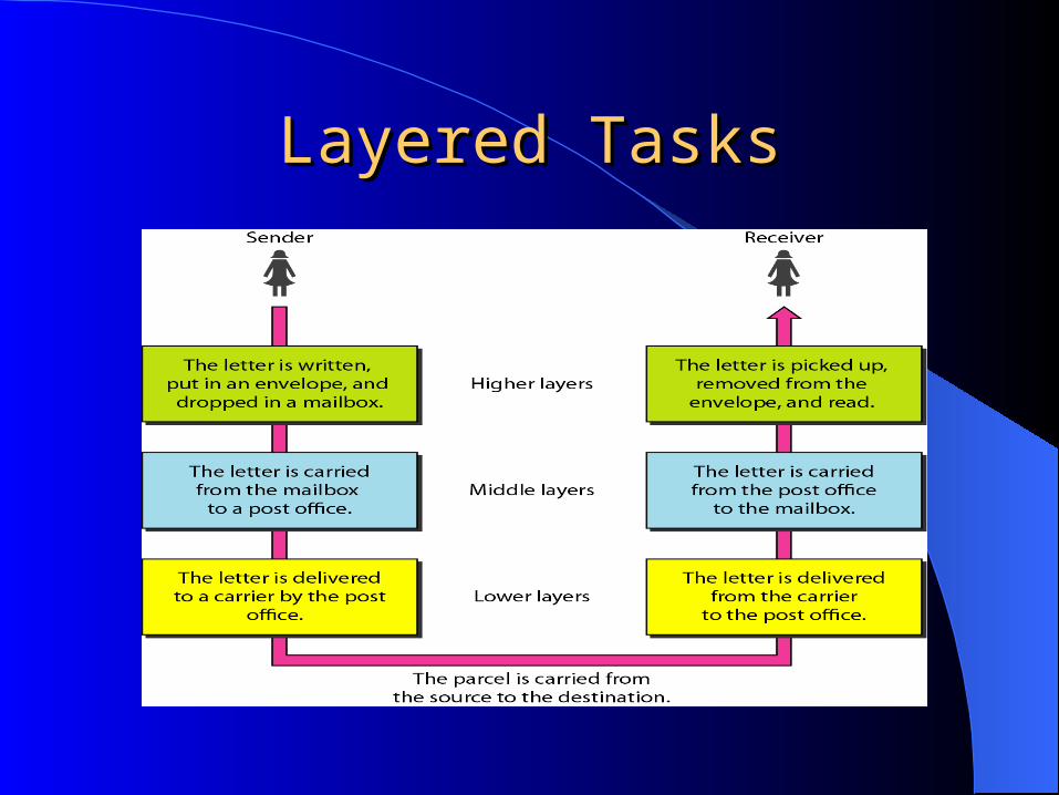
LAYERED TASKS Concept of layers in our daily life
– Two friends communicate through postal mail
Layered TasksLayered Tasks

Layered TasksLayered Tasks
Hierarchy Task must be done in the order given in the hierarchy
– Sender site from up to down– Receiver site from down to up
Services Sender site each layer uses the services of the layer immediately
below it
Higher Middle Lower Carrier

The OSI ModelThe OSI Model
1947 established ISO : International Standards Organization ISO model covers network communications is OSI : Open System
Interconnection Introduced in the late 1970s. Open system: a set of protocols that allows any two different systems
to communicate regardless of their underlying architecture. Purpose of the OSI : to show how to facilitate communication between
different systems without requiring changes to the logic of the underlying hardware and software.
OSI model not a protocol, it is a model for understanding and designing a network architecture that is flexible, robust, and interoperable.
ISO is the organization. OSI is the modelISO is the organization. OSI is the model
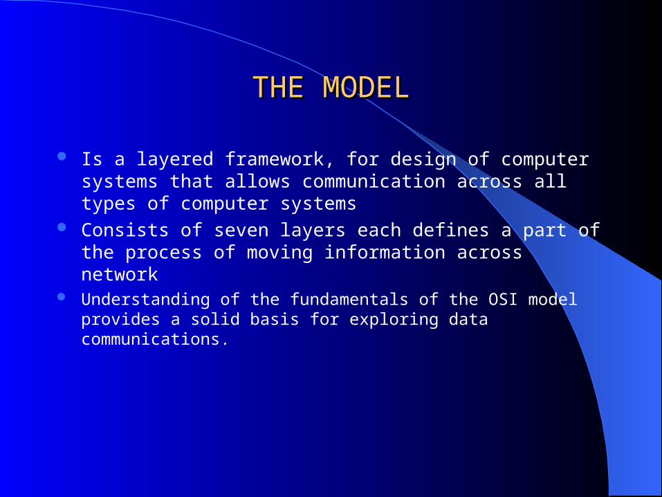
THE MODELTHE MODEL
Is a layered framework, for design of computer systems that allows communication across all types of computer systems
Consists of seven layers each defines a part of the process of moving information across network
Understanding of the fundamentals of the OSI model provides a solid basis for exploring data communications.
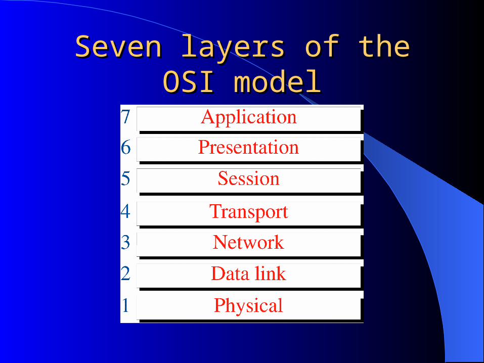
Seven layers of the OSI modelSeven layers of the OSI model

Layered Architecture Layered Architecture
When device A sent message to device B Message may pass intermediate nodes Only the first three layers of the model involve
Layered ArchitectureLayered Architecture
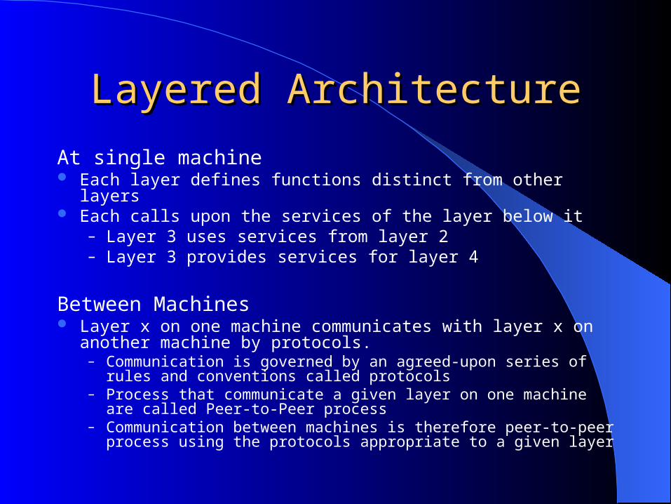
At single machine Each layer defines functions distinct from other layers Each calls upon the services of the layer below it
– Layer 3 uses services from layer 2– Layer 3 provides services for layer 4
Between Machines Layer x on one machine communicates with layer x on another
machine by protocols.– Communication is governed by an agreed-upon series of rules and
conventions called protocols– Process that communicate a given layer on one machine are called Peer-
to-Peer process– Communication between machines is therefore peer-to-peer process using
the protocols appropriate to a given layer

Peer-to-Peer process Peer-to-Peer process
On the sending machine Each layer in sending device
– adds its own information to the message it receives from the layer just above it
– pass the whole package to the layer below it– At layer 1 the message converted to a form that can be transferred
to the receiving machine
On receiving machine– Message is unwrapped layer by layer
layer 2 removes the data meant for it, then passes the rest to layer 3 and so on.
Interfaces Between LayersInterfaces Between Layers
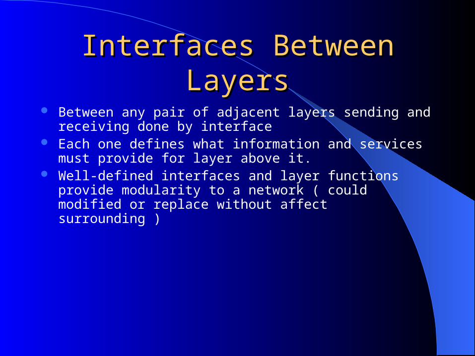
Between any pair of adjacent layers sending and receiving done by interface
Each one defines what information and services must provide for layer above it.
Well-defined interfaces and layer functions provide modularity to a network ( could modified or replace without affect surrounding )
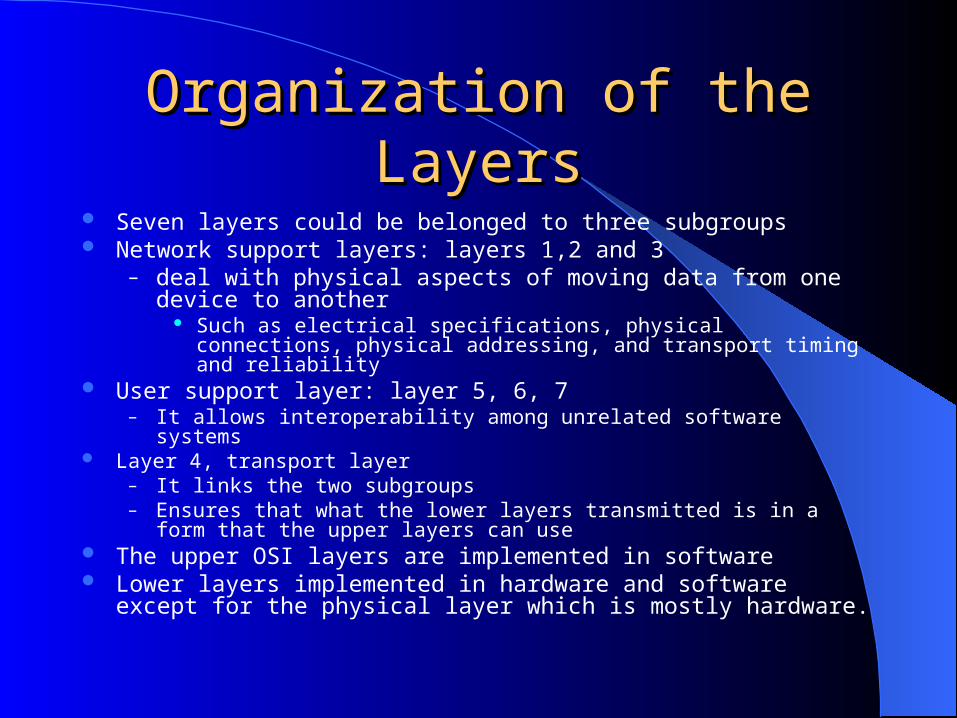
Organization of the LayersOrganization of the Layers Seven layers could be belonged to three subgroups Network support layers: layers 1,2 and 3
– deal with physical aspects of moving data from one device to another Such as electrical specifications, physical connections, physical addressing,
and transport timing and reliability User support layer: layer 5, 6, 7
– It allows interoperability among unrelated software systems Layer 4, transport layer
– It links the two subgroups– Ensures that what the lower layers transmitted is in a form that the upper layers can
use The upper OSI layers are implemented in software Lower layers implemented in hardware and software except for the physical
layer which is mostly hardware.

Organization of the LayersOrganization of the Layers
Organization of the LayersOrganization of the Layers
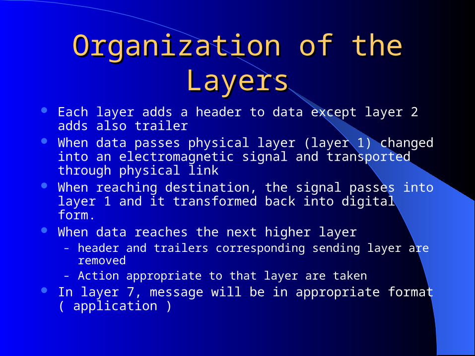
Each layer adds a header to data except layer 2 adds also trailer When data passes physical layer (layer 1) changed into an
electromagnetic signal and transported through physical link When reaching destination, the signal passes into layer 1 and it
transformed back into digital form. When data reaches the next higher layer
– header and trailers corresponding sending layer are removed– Action appropriate to that layer are taken
In layer 7, message will be in appropriate format ( application )
The physical layer is responsible for movements ofindividual bits from one hop (node) to the next.
Note

Physical Layer Physical Layer
The physical layer is responsible for transmitting individual bits
from one node to the next
Physical LayerPhysical Layer
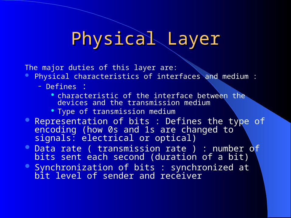
The major duties of this layer are: Physical characteristics of interfaces and medium :
– Defines : characteristic of the interface between the devices and the
transmission medium Type of transmission medium
Representation of bits : Defines the type of encoding (how 0s and 1s are changed to signals: electrical or optical)
Data rate ( transmission rate ) : number of bits sent each second (duration of a bit)
Synchronization of bits : synchronized at bit level of sender and receiver
Physical LayerPhysical Layer
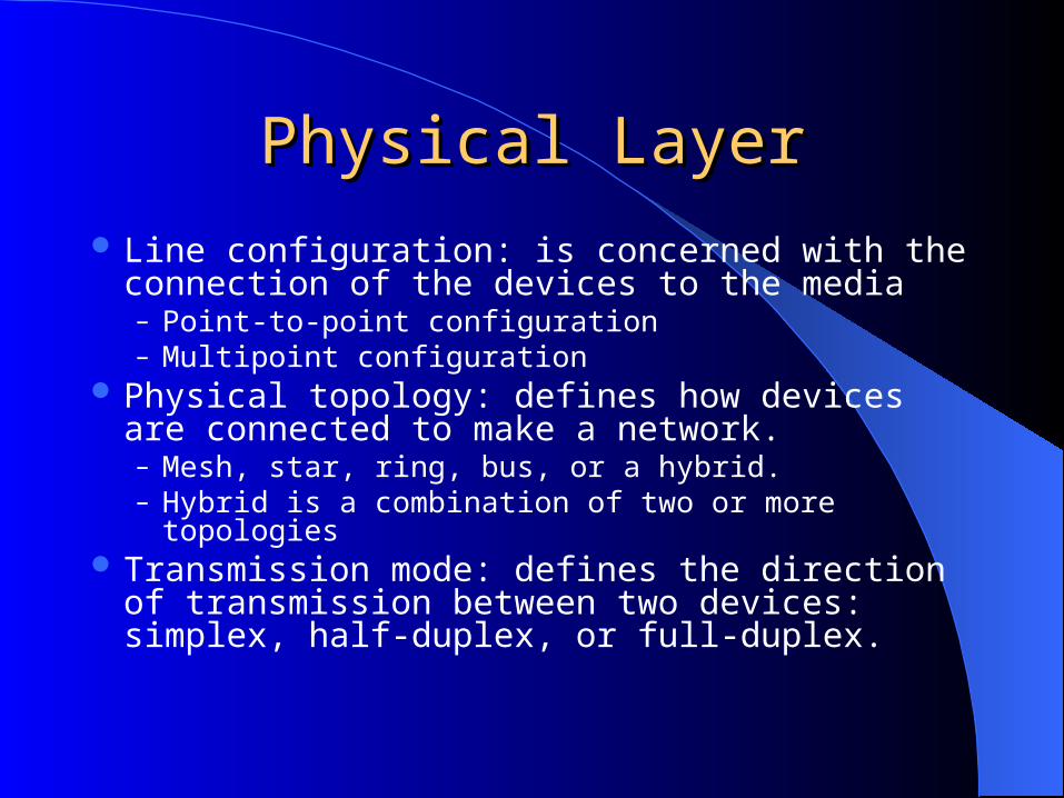
Line configuration: is concerned with the connection of the devices to the media– Point-to-point configuration– Multipoint configuration
Physical topology: defines how devices are connected to make a network. – Mesh, star, ring, bus, or a hybrid. – Hybrid is a combination of two or more topologies
Transmission mode: defines the direction of transmission between two devices: simplex, half-duplex, or full-duplex.

The data link layer is responsible for moving frames from one hop (node) to the next.
Note
Data Link LayerData Link Layer
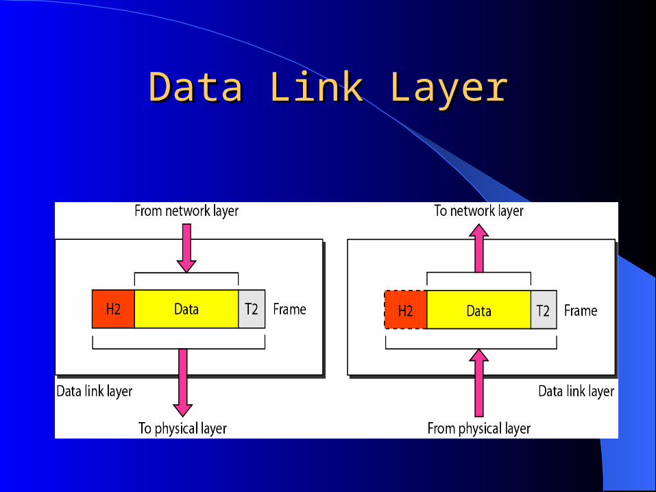
Data Link LayerData Link Layer
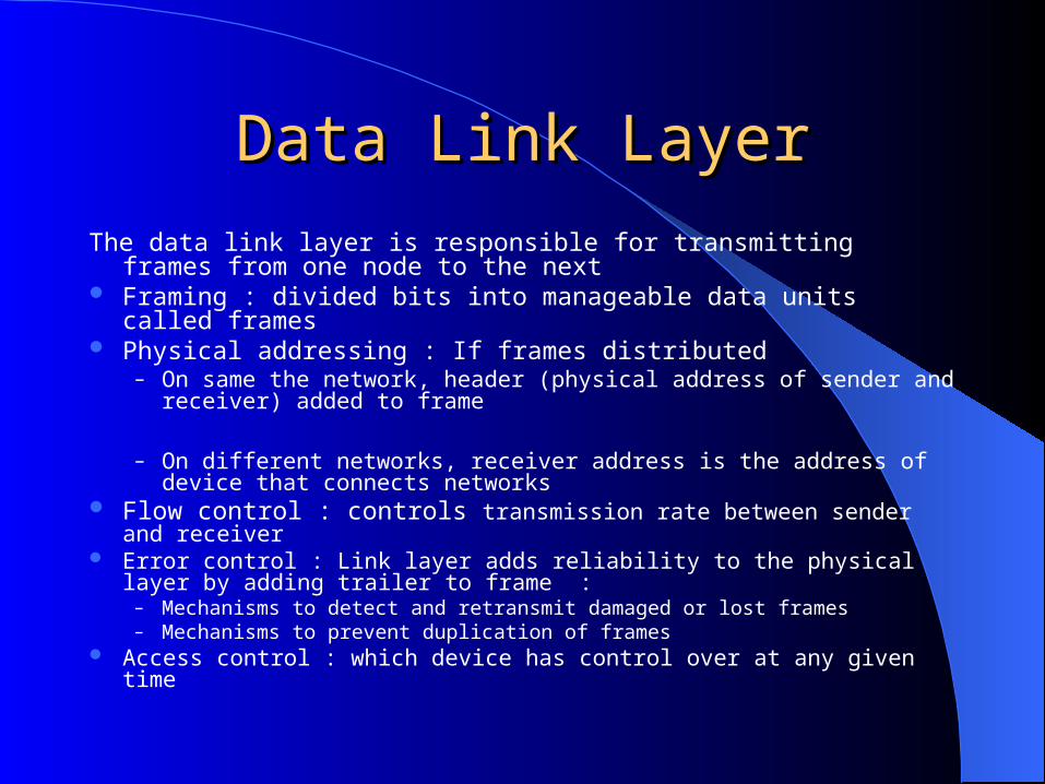
The data link layer is responsible for transmitting frames from one node to the next
Framing : divided bits into manageable data units called frames Physical addressing : If frames distributed
– On same the network, header (physical address of sender and receiver) added to frame
– On different networks, receiver address is the address of device that connects networks
Flow control : controls transmission rate between sender and receiver Error control : Link layer adds reliability to the physical layer by adding trailer
to frame :– Mechanisms to detect and retransmit damaged or lost frames– Mechanisms to prevent duplication of frames
Access control : which device has control over at any given time

Hop-to-hop (node-to-node) deliveryHop-to-hop (node-to-node) delivery
ExampleExample
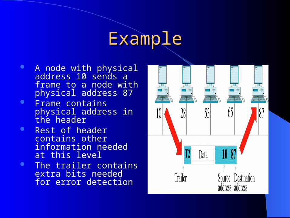
A node with physical address 10 sends a frame to a node with physical address 87
Frame contains physical address in the header
Rest of header contains other information needed at this level
The trailer contains extra bits needed for error detection
Note
The network layer is responsible for the delivery of individual packets from
the source host to the destination host.
Network LayerNetwork Layer
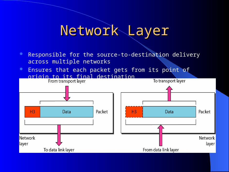
Responsible for the source-to-destination delivery across multiple networks Ensures that each packet gets from its point of origin to its final destination No need for network layer if systems on the same networks
Network LayerNetwork Layer
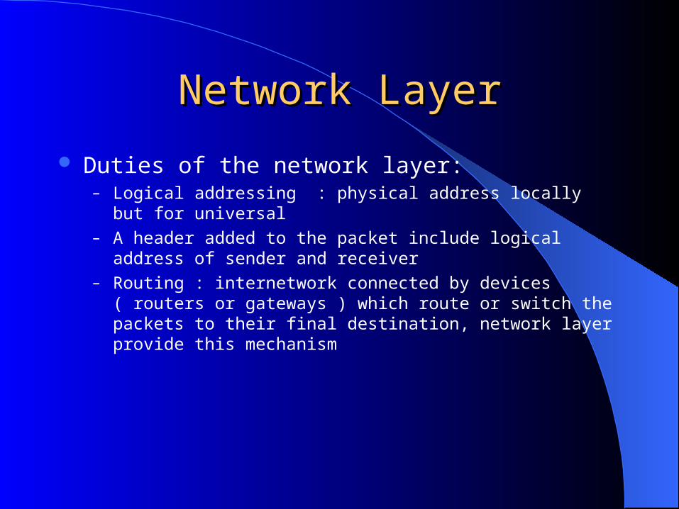
Duties of the network layer:– Logical addressing : physical address locally but for universal – A header added to the packet include logical address of sender and
receiver– Routing : internetwork connected by devices ( routers or gateways ) which
route or switch the packets to their final destination, network layer provide this mechanism
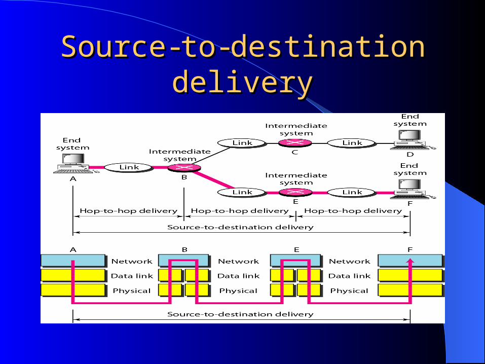
SourceSource--toto--destination deliverydestination delivery
ExampleExample
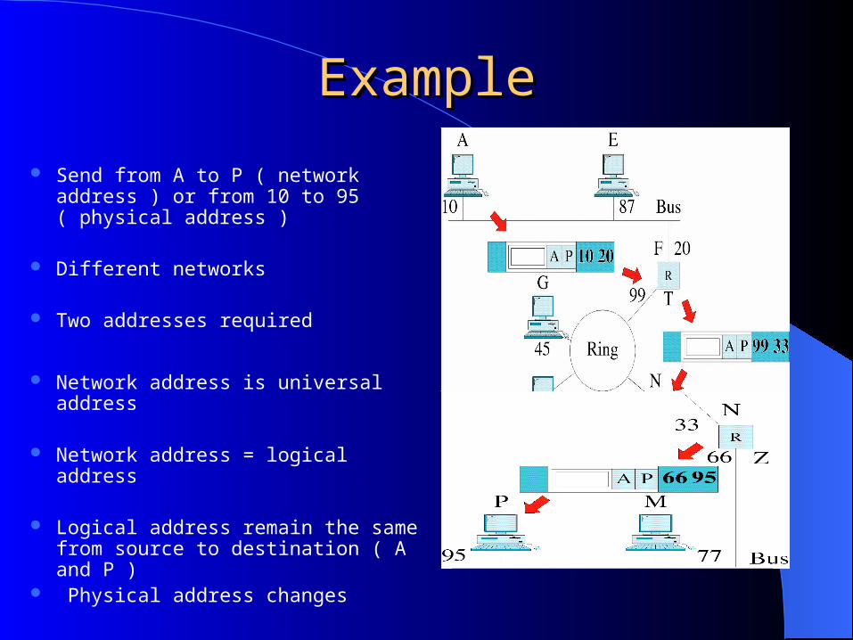
Send from A to P ( network address ) or from 10 to 95 ( physical address )
Different networks
Two addresses required
Network address is universal address
Network address = logical address
Logical address remain the same from source to destination ( A and P )
Physical address changes
The transport layer is responsible for the delivery of a message from one process to another.
Note
Transport LayerTransport Layer
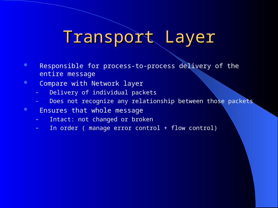
Responsible for process-to-process delivery of the entire message Compare with Network layer
– Delivery of individual packets– Does not recognize any relationship between those packets
Ensures that whole message – Intact: not changed or broken– In order ( manage error control + flow control)
Transport LayerTransport Layer
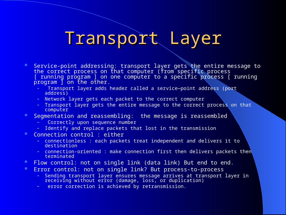
Transport LayerTransport Layer Service-point addressing: transport layer gets the entire message to the correct process
on that computer (from specific process [ running program ] on one computer to a specific process [ running program ] on the other.
– Transport layer adds header called a service—point address (port address)– Network layer gets each packet to the correct computer– Transport layer gets the entire message to the correct process on that computer
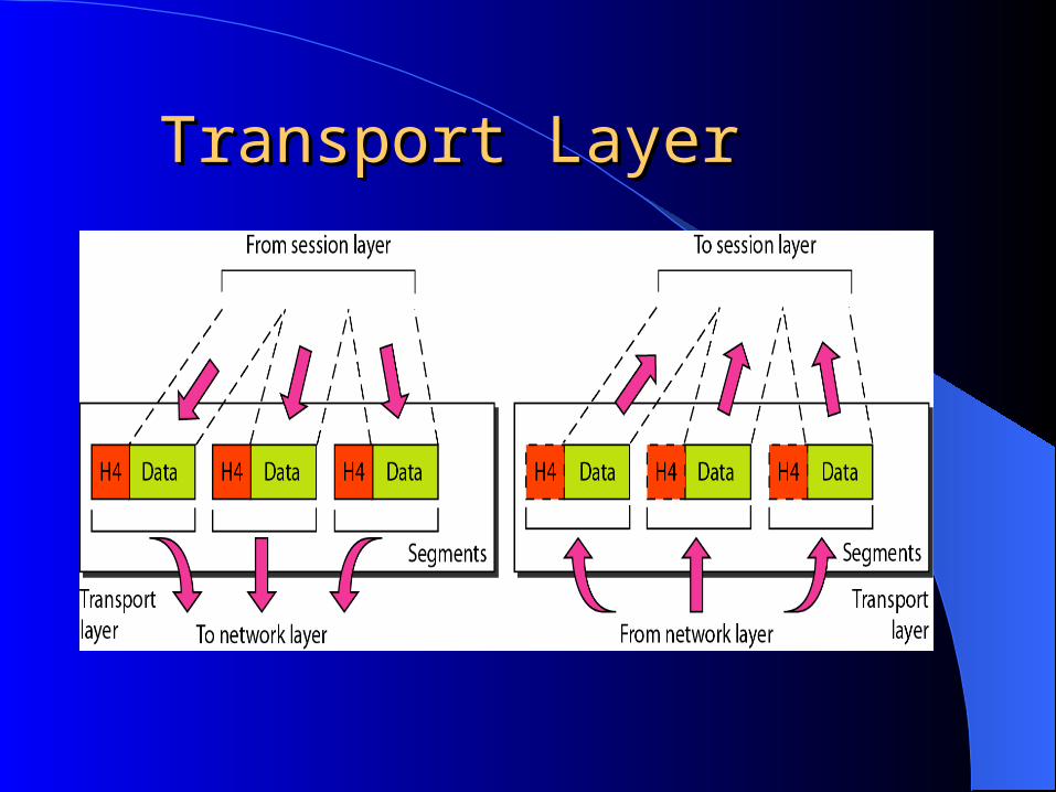
Segmentation and reassembling: the message is reassembled– Correctly upon sequence number– Identify and replace packets that lost in the transmission
Connection control : either – connectionless : each packets treat independent and delivers it to destination– connection-oriented : make connection first then delivers packets then terminated
Flow control: not on single link (data link) But end to end. Error control: not on single link? But process-to-process
– Sending transport layer ensures message arrives at transport layer in receiving without error (damage, loss, or duplication)
– error correction is achieved by retransmission.
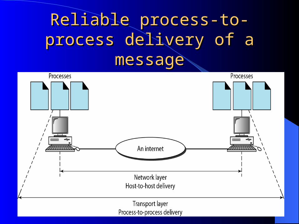
Reliable process-to-process Reliable process-to-process delivery of a messagedelivery of a message
The session layer is responsible for dialog controland synchronization.

Session LayerSession Layer The session layer is the network dialog controller. IT establishes, maintains, and synchronizes the interaction among
communicating systems.
Responsibilities: Dialog control:
– Allows two system to enter into a dialog– Allows the communication between two processes to take place in:
Half-duplex or Full-duplex
Synchronization:– Allows process to add checkpoints (synchronization points) to a stream of
data– Example : add checkpoint every 100 pages for sending 2000 pages – If crash happens during the transmission of page 523 retransmission began
at page 501.

Session LayerSession Layer
The presentation layer is responsible for translation, compression, and encryption.
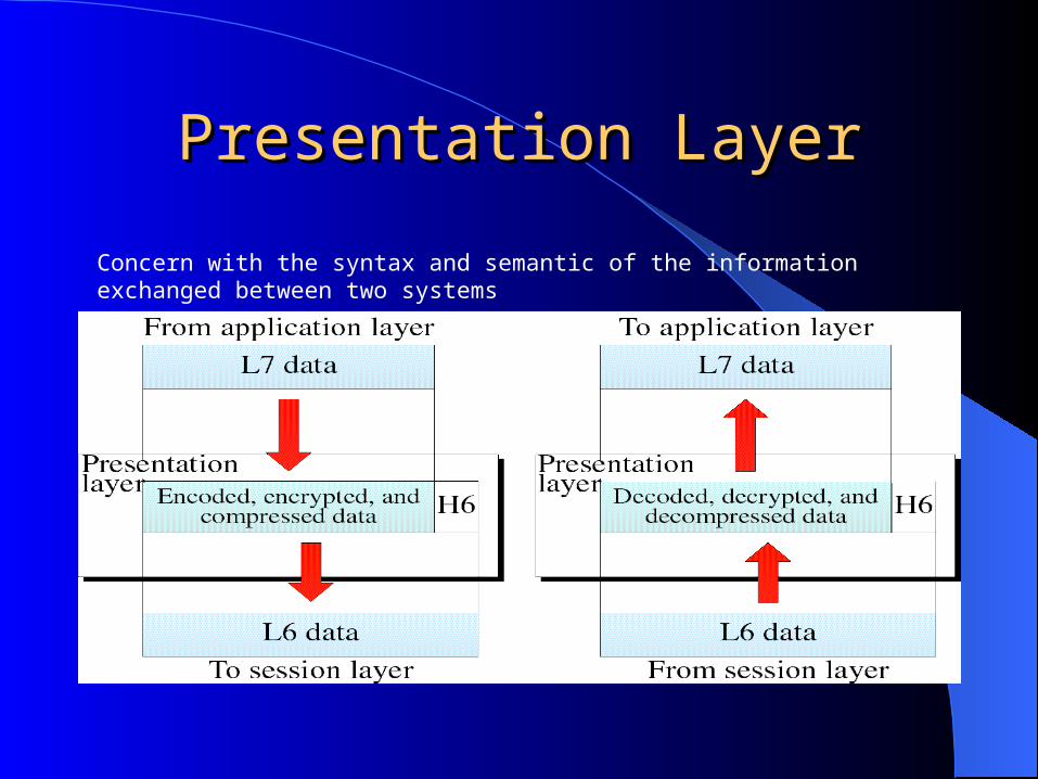
Presentation LayerPresentation Layer
Concern with the syntax and semantic of the information exchanged between two systems
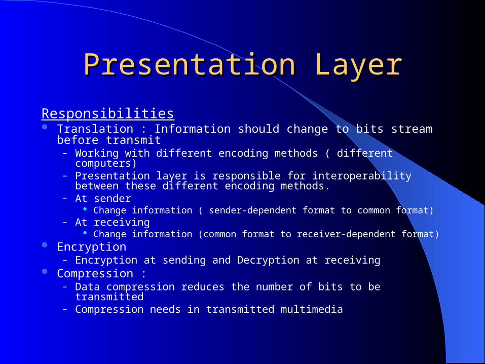
Presentation LayerPresentation Layer
Responsibilities Translation : Information should change to bits stream before transmit
– Working with different encoding methods ( different computers)– Presentation layer is responsible for interoperability between these
different encoding methods. – At sender
Change information ( sender-dependent format to common format) – At receiving
Change information (common format to receiver-dependent format) Encryption
– Encryption at sending and Decryption at receiving Compression :
– Data compression reduces the number of bits to be transmitted– Compression needs in transmitted multimedia

The application layer is responsible for providing services to the user.
Note
Application layerApplication layer
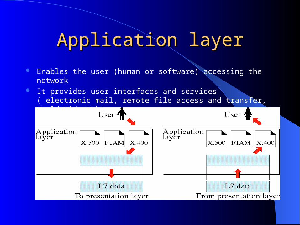
Enables the user (human or software) accessing the network It provides user interfaces and services ( electronic mail, remote file access
and transfer, World Wide Web)
Application layerApplication layer
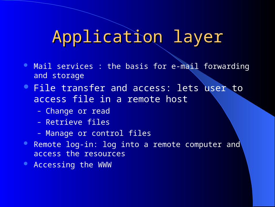
Mail services : the basis for e-mail forwarding and storage
File transfer and access: lets user to access file in a remote host– Change or read– Retrieve files – Manage or control files
Remote log-in: log into a remote computer and access the resources Accessing the WWW
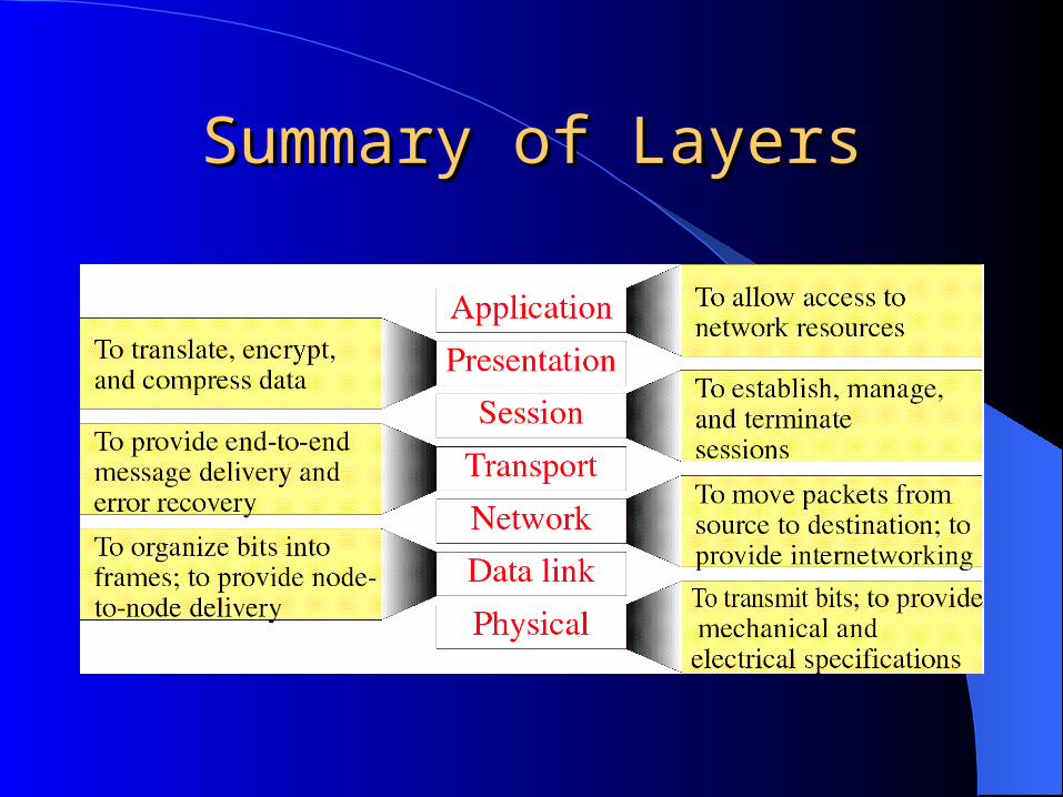
Summary of LayersSummary of Layers

TCP/IP PROTOCOL SUITETCP/IP PROTOCOL SUITE Invented before OSIInvented before OSI The layers in the The layers in the TCP/IP protocol suiteTCP/IP protocol suite do not exactly match those in the do not exactly match those in the
OSI model. OSI model. The original TCP/IP protocol suite was defined as having four layers: The original TCP/IP protocol suite was defined as having four layers:
– host-to-networkhost-to-network equivalent to equivalent to physical + data link physical + data link – internetinternet, equivalent to , equivalent to networknetwork – transporttransport, equivalent to , equivalent to part of duties of sessionpart of duties of session– applicationapplication. equivalent to . equivalent to session + presentation + applicationsession + presentation + application
However, when TCP/IP is compared to OSI, we can say that the TCP/IP However, when TCP/IP is compared to OSI, we can say that the TCP/IP protocol suite is made of five layers: protocol suite is made of five layers:
– physicalphysical, , – data linkdata link, , – networknetwork, , – transporttransport, , – applicationapplication..

TCP/IP PROTOCOL SUITETCP/IP PROTOCOL SUITE
The first four layers provide functions that correspond to the first four layers of the OSI model:
– Physical standers– Network interfaces– Internetworking – Transport functions
The three topmost layers functions in the OSI model are represented in TCP/IP by application layer
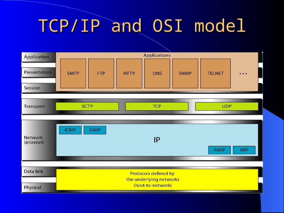
TCP/IP and OSI modelTCP/IP and OSI model

TCP/IP PROTOCOL SUITETCP/IP PROTOCOL SUITE TCP/IP is a hierarchical protocol made up of interactive modules Each layer in TCP/IP provides specific function The modules are not necessarily interdependent, but in OSI module specifies
which functions belong to each of its layers. Each layer has independent protocols TCP/IP is a hierarchical protocol : each upper-level supported by one or more
lower-level protocols depending on the needs of the system. AT transport layer, TCP/IP defines three protocols
– Transmission Control Protocol (TCP)– User Datagram Protocol (UDP)– Stream Control Transmission Protocol (SCTP)
At network layer, the main protocol defined by TCP/IP is the Internetworking Protocol (IP)
TCP/IP PROTOCOL SUITETCP/IP PROTOCOL SUITE
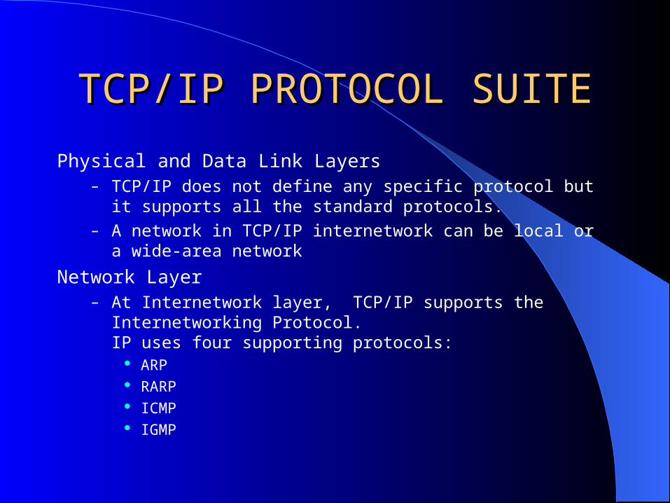
Physical and Data Link Layers– TCP/IP does not define any specific protocol but it supports all the
standard protocols.– A network in TCP/IP internetwork can be local or a wide-area network
Network Layer– At Internetwork layer, TCP/IP supports the Internetworking Protocol.
IP uses four supporting protocols: ARP RARP ICMP IGMP
TCP/IP PROTOCOL SUITETCP/IP PROTOCOL SUITE
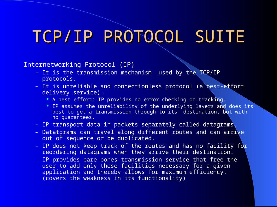
Internetworking Protocol (IP)– It is the transmission mechanism used by the TCP/IP protocols.– It is unreliable and connectionless protocol (a best-effort delivery service).
A best effort: IP provides no error checking or tracking. IP assumes the unreliability of the underlying layers and does its best to get a
transmission through to its destination, but with no guarantees.– IP transport data in packets separately called datagrams.– Datatgrams can travel along different routes and can arrive out of
sequence or be duplicated. – IP does not keep track of the routes and has no facility for reordering
datagrams when they arrive their destination.– IP provides bare-bones transmission service that free the user to add only
those facilities necessary for a given application and thereby allows for maximum efficiency. (covers the weakness in its functionality)

TCP/IP PROTOCOL SUITETCP/IP PROTOCOL SUITE
Address Resolution Protocol– Associated a logical address with a physical address.– On a typical physical network, LAN, each device is identified by a
physical or station address, usually imprinted on the network interface card (NIC).
– ARP is used to find the physical address of the node when its Internet address is known.
Reverse Address Resolution Protocol– RARP allows a host to discover its Internet address when it knows only its
physical address. – RARP is used when a computer is connected to a network for the first
time or when a diskless computer is booted.

TCP/IP PROTOCOL SUITETCP/IP PROTOCOL SUITE
Internet Control Message protocol– ICMP is a mechanism used by a host and gateways to send notification of datagram
problems back to the sender.– ICMP sends query and error reporting messages.
Internet Group Message Protocol– IGMP is used to facilitate the simultaneous transmission of a message to a group of
recipients.
Transport Layer– Traditionally the transport layer represented in TCP/IP by TCP and UDP .– IP is host-to-host protocol, deliver a packet from one physical device to another. – UDP and TCP are transport level protocols responsible for delivery of a message
from a process to another process.– SCTP, has been devised to meet the needs of some newer applications.

TCP/IP PROTOCOL SUITETCP/IP PROTOCOL SUITE
User Datagram Protocol– UDP is the simple of the two standard TCP/IP transport protocol.– UDP is process-to-process adds:
port addresses Checksum error control Length information to the data from the upper layer
Transmission Control Protocol– TCP provides full transport-layer services to applications.– TCP is a reliable stream (connection-oriented) transport protocol.– At sending end of each transmission:
TCP divides a stream of data into smaller units called segments Each segment includes a sequence number for recording after receipt An acknowledgment number for the segments received Segments carried across the internet inside of IP datagrams.
– At receiving end TCP collects each datagram as it comes in and reorders the transmission based on
sequence numbers

TCP/IP PROTOCOL SUITETCP/IP PROTOCOL SUITE
Stream Control Transmission Protocol– SCTP provides support for newer applications as voice over the Internet.– SCTP is a transport layer protocol that combines the best features of UDP
and TCP.
Application Layer– Application layer in TCP/IP is equivalent to the combined session,
presentation, and applications layers in the OSI model.– Many protocols are defined at this layer.
ADDRESSINGADDRESSING
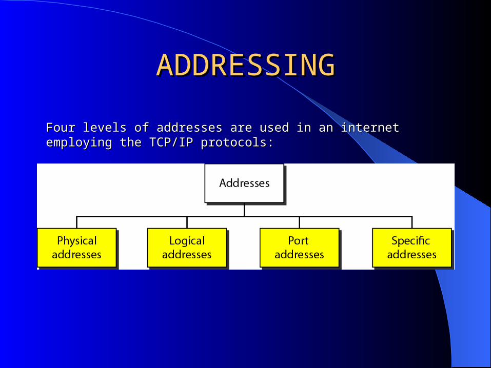
Four levels of addresses are used in an internet employing the TCP/IP Four levels of addresses are used in an internet employing the TCP/IP protocols:protocols:

ADDRESSINGADDRESSING
Each address is related to a specific layer in the TCP/IP architecture.

ADDRESSINGADDRESSING
Physical Addresses– It is known as the link address.– It is the address of a node as defined by its LAN and WAN.– It is included in the frame used by the data link layer.– It is the lowest-level address.– It has authority over the network (LAN or WAN).– The size and format of these addresses vary depending on the network.
The Ethernet uses a 6-byte (48 bit) physical address that is imprinted on NIC. LocalTalk (Apple) has 1-byte dynamic address.

ADDRESSINGADDRESSING
In Figure 2.19 a node with physical address 10 sends a frame to a node with physical address 87. The two nodes are connected by a link (bus topology LAN). As the figure shows, the computer with physical address 10 is the sender, and the computer with physical address 87 is the receiver.
ADDRESSINGADDRESSING
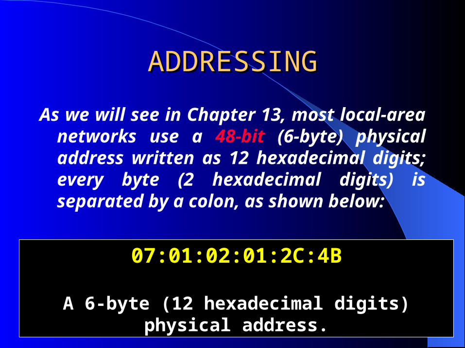
As we will see in Chapter 13, most local-area networks use a 48-bit (6-byte) physical address written as 12 hexadecimal digits; every byte (2 hexadecimal digits) is separated by a colon, as shown below:
07:01:02:01:2C:4B
A 6-byte (12 hexadecimal digits) physical address.
ADDRESSINGADDRESSING
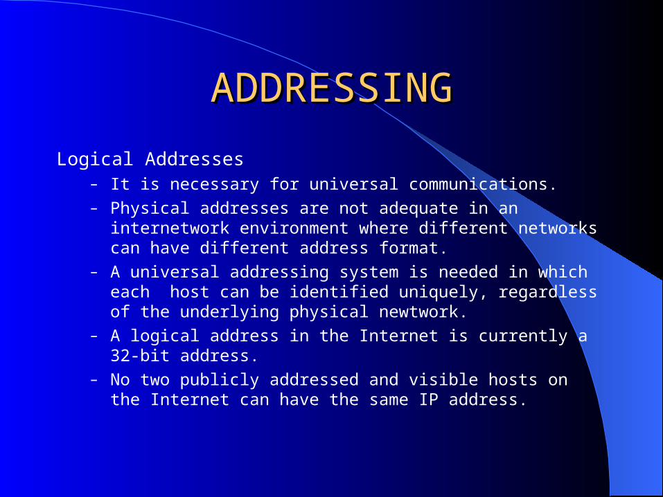
Logical Addresses– It is necessary for universal communications.– Physical addresses are not adequate in an internetwork environment where
different networks can have different address format.– A universal addressing system is needed in which each host can be
identified uniquely, regardless of the underlying physical newtwork.– A logical address in the Internet is currently a 32-bit address.– No two publicly addressed and visible hosts on the Internet can have the
same IP address.
IP AddressesIP Addresses
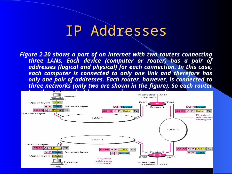
Figure 2.20 shows a part of an internet with two routers connecting three LANs. Each device (computer or router) has a pair of addresses (logical and physical) for each connection. In this case, each computer is connected to only one link and therefore has only one pair of addresses. Each router, however, is connected to three networks (only two are shown in the figure). So each router has three pairs of addresses, one for each connection.
Port AddressesPort Addresses
The end objective of Internet communication is a process communicating with another process.
In TCP/IP architecture, the label assigned to a process is called a port address. A port address in TCP/IP is 16 bits in length.
Port AddressesPort Addresses
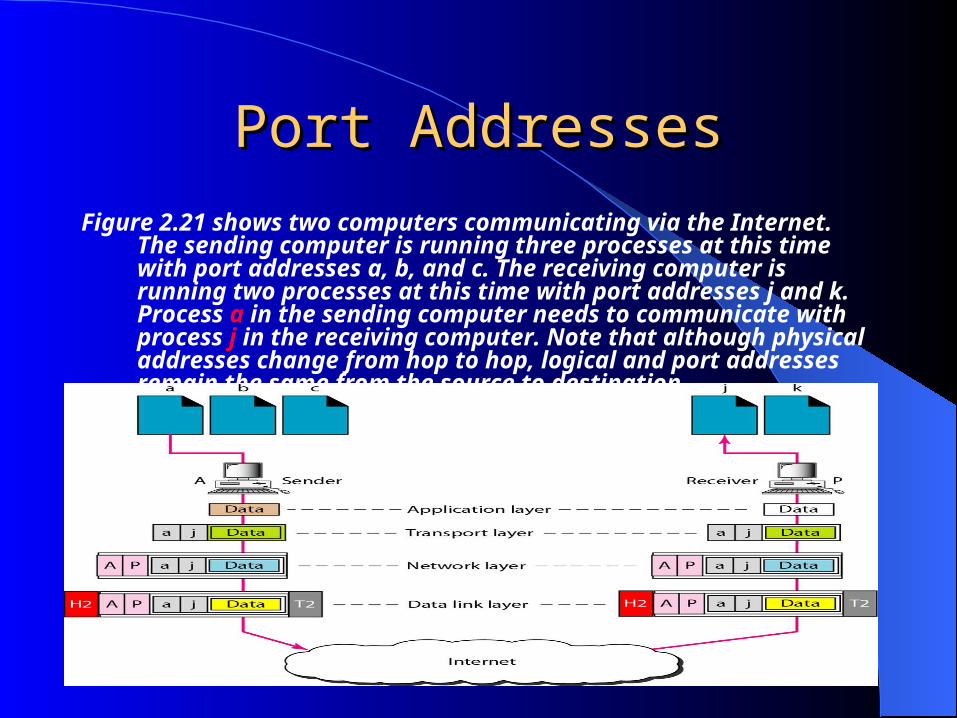
Figure 2.21 shows two computers communicating via the Internet. The sending computer is running three processes at this time with port addresses a, b, and c. The receiving computer is running two processes at this time with port addresses j and k. Process a in the sending computer needs to communicate with process j in the receiving computer. Note that although physical addresses change from hop to hop, logical and port addresses remain the same from the source to destination

AddressesAddresses
The physical addresses will change from hop to hop,but the logical addresses usually remain the same.

Port AddressesPort Addresses
753
A 16-bit port address represented as one single number.
As we will see in Chapter 23, a port address is a 16-bit address represented by one decimal number as shown.

Specific AddressesSpecific Addresses
E-mail address
Universal Resource Locator (URL)
Related Documents


![[HCMC STC Jan 2015] Performing Target Test in UMTS Network](https://static.cupdf.com/doc/110x72/55a92a551a28abae768b48da/hcmc-stc-jan-2015-performing-target-test-in-umts-network.jpg)