Network Layer: The Data Plane • Network Layer Overview • Router Architecture • Network Layer Functions and Service Models – Network Layer Functions – IP Addressing – Network Service Models: Virtual Circuit vs. Datagram • IP Forwarding and IP Protocol – IP Datagram Forwarding Model – IP and ICMP: Datagram Format, IP Fragmentation – DHCP • NAT, IPv6 and IPv6 transition (over IPv4) Readings: Textbook: Chapter 4, Sections 4.1-4.3, review section 1.3 (packet vs. circuit switching) CSci4211: Network Layer: The Data Plane 1

Welcome message from author
This document is posted to help you gain knowledge. Please leave a comment to let me know what you think about it! Share it to your friends and learn new things together.
Transcript
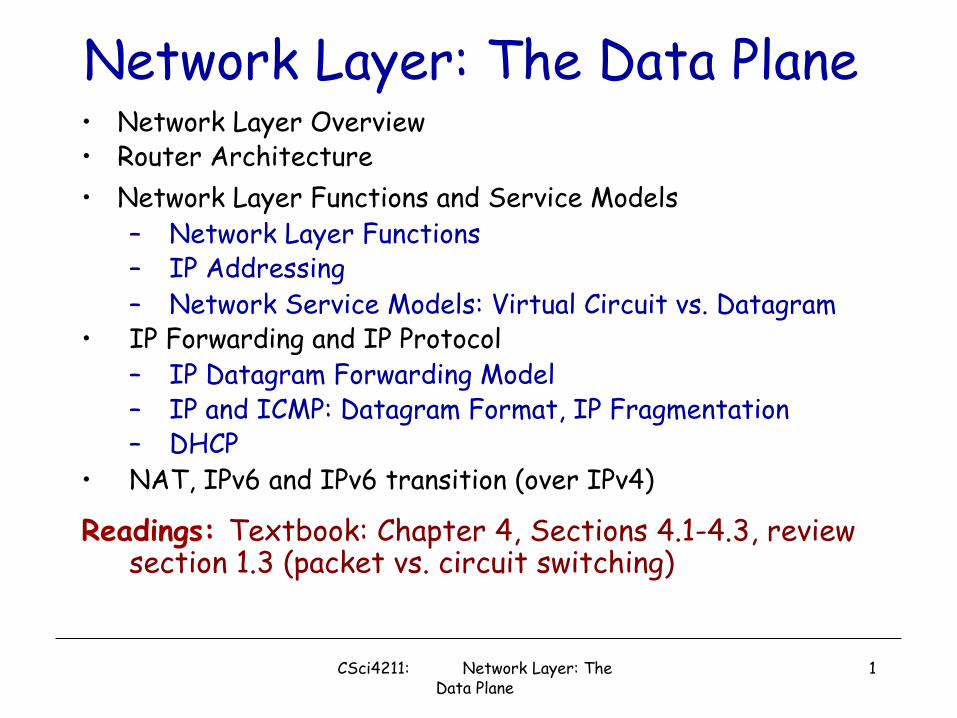
Network Layer: The Data Plane• Network Layer Overview• Router Architecture• Network Layer Functions and Service Models
– Network Layer Functions– IP Addressing– Network Service Models: Virtual Circuit vs. Datagram
• IP Forwarding and IP Protocol– IP Datagram Forwarding Model– IP and ICMP: Datagram Format, IP Fragmentation– DHCP
• NAT, IPv6 and IPv6 transition (over IPv4)
Readings: Textbook: Chapter 4, Sections 4.1-4.3, review section 1.3 (packet vs. circuit switching)
CSci4211: Network Layer: The Data Plane
1
What Does Network Layer Do?
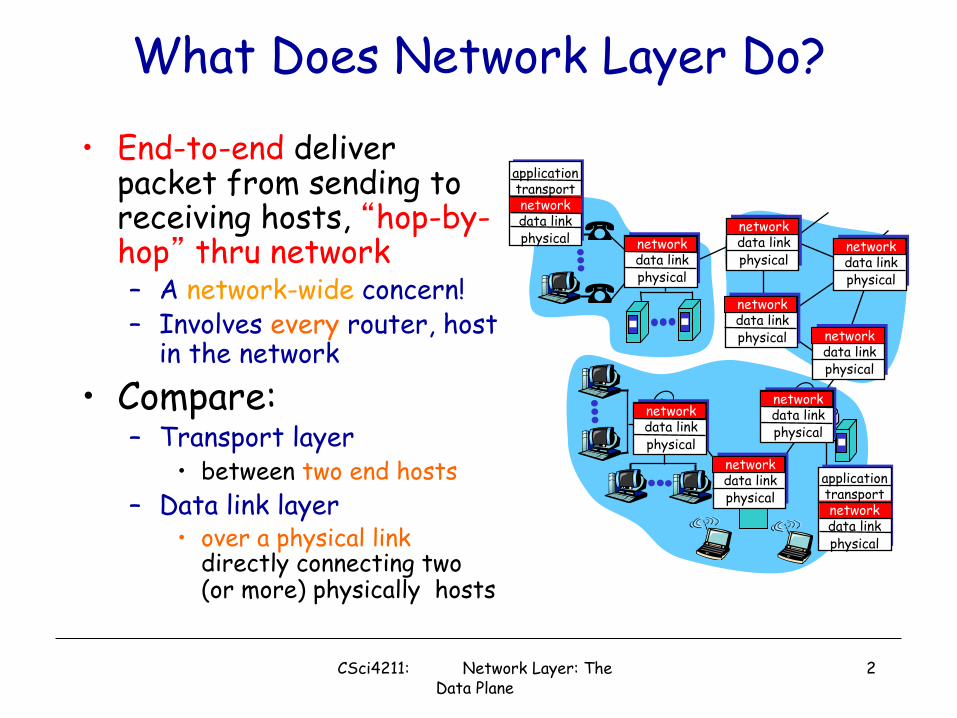
• End-to-end deliver packet from sending to receiving hosts, �hop-by-hop� thru network– A network-wide concern!– Involves every router, host
in the network• Compare:
– Transport layer• between two end hosts
– Data link layer• over a physical link
directly connecting two (or more) physically hosts
networkdata linkphysical
networkdata linkphysical
networkdata linkphysical
networkdata linkphysical
networkdata linkphysical
networkdata linkphysical
networkdata linkphysical
networkdata linkphysical
applicationtransportnetworkdata linkphysical
applicationtransportnetworkdata linkphysical
CSci4211: Network Layer: The Data Plane
2

• transport segment from sending to receiving host
• on sending side encapsulates segments into datagrams
• on rcving side, delivers segments to transport layer
• network layer protocols in every host, router
• Router examines header fields in all IP datagrams passing through it
networkdata linkphysical
networkdata linkphysical
networkdata linkphysical
networkdata linkphysical
networkdata linkphysical
networkdata linkphysical
networkdata linkphysical
networkdata linkphysical
applicationtransportnetworkdata linkphysical
applicationtransportnetworkdata linkphysical
CSci4211: Network Layer: The Data Plane
3
What Does Network Layer Do?
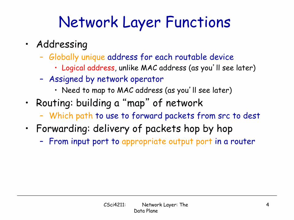
Network Layer Functions• Addressing
– Globally unique address for each routable device• Logical address, unlike MAC address (as you�ll see later)
– Assigned by network operator• Need to map to MAC address (as you�ll see later)
• Routing: building a �map� of network– Which path to use to forward packets from src to dest
• Forwarding: delivery of packets hop by hop– From input port to appropriate output port in a router
CSci4211: Network Layer: The Data Plane
4
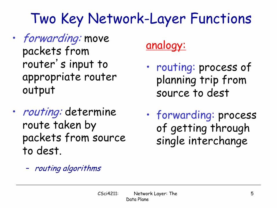
Two Key Network-Layer Functions• forwarding: move
packets from router�s input to appropriate router output
• routing: determine route taken by packets from source to dest. – routing algorithms
analogy:
• routing: process of planning trip from source to dest
• forwarding: process of getting through single interchange
CSci4211: Network Layer: The Data Plane
5

Data plane•local, per-router function•determines how datagram arriving on router input port is forwarded to router output port•forwarding function
Control plane•network-wide logic•determines how datagram is routed among routers along end-end path from source host to destination host•two control-plane approaches:
• traditional routing algorithms: implemented in routers
• software-defined networking (SDN): implemented in (remote) servers
1
23
0111
values in arriving packet header
Network Layer: Data Plane, Control Plane
CSci4211: Network Layer: The Data Plane
6

Per-router Control Plane
RoutingAlgorithm
Individual routing algorithm components in each and every router interact in the control plane
dataplane
controlplane
4.1 • OVERVIEW OF NETWORK LAYER 309
tables. In this example, a routing algorithm runs in each and every router and both forwarding and routing functions are contained within a router. As we’ll see in Sec-tions 5.3 and 5.4, the routing algorithm function in one router communicates with the routing algorithm function in other routers to compute the values for its forward-ing table. How is this communication performed? By exchanging routing messages containing routing information according to a routing protocol! We’ll cover routing algorithms and protocols in Sections 5.2 through 5.4.
The distinct and different purposes of the forwarding and routing functions can be further illustrated by considering the hypothetical (and unrealistic, but technically feasible) case of a network in which all forwarding tables are configured directly by human network operators physically present at the routers. In this case, no routing protocols would be required! Of course, the human operators would need to interact with each other to ensure that the forwarding tables were configured in such a way that packets reached their intended destinations. It’s also likely that human configu-ration would be more error-prone and much slower to respond to changes in the net-work topology than a routing protocol. We’re thus fortunate that all networks have both a forwarding and a routing function!
Values in arrivingpacket’s header
1
23
Local forwardingtable
header
0100011001111001
1101
3221
output
Control plane
Data plane
Routing algorithm
Figure 4.2 ♦ Routing algorithms determine values in forward tables
M04_KURO4140_07_SE_C04.indd 309 11/02/16 3:14 PM
1
2
0111
values in arriving packet header
3
7

dataplane
controlplane
Logically Centralized Control PlaneA distinct (typically remote) controller interacts with local control agents (CAs)
Remote Controller
CA
CA CA CA CA
1
2
0111
3
values in arriving packet header
8
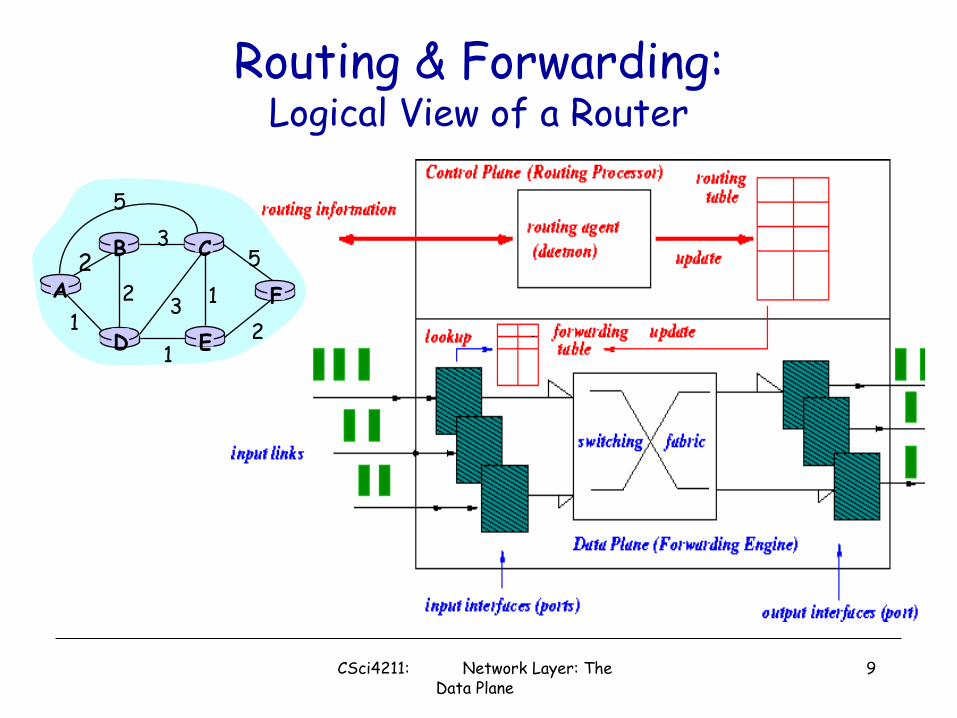
Routing & Forwarding:Logical View of a Router
A
ED
CB
F2
21
3
1
12
53
5
CSci4211: Network Layer: The Data Plane
9

Router Architecture OverviewTwo key router functions:• run routing algorithms/protocol (RIP, OSPF, BGP)• forwarding datagrams from incoming to outgoing link
CSci4211: Network Layer: The Data Plane
10

Input Port Functions
Decentralized switching:• using header field values, lookup output
port using forwarding table in input port memory
• goal: complete input port processing at �line speed�
• queuing: if datagrams arrive faster than forwarding rate into switch fabric
Physical layer:bit-level reception
Data link layer:e.g., Ethernetsee chapter 6
CSci4211: Network Layer: The Data Plane
11

memory
memory
bus crossbar
Switching Fabrics• transfer packet from input buffer to appropriate
output buffer• switching rate: rate at which packets can be
transfer from inputs to outputs• often measured as multiple of input/output line rate• N inputs: switching rate N times line rate desirable
• three types of switching fabrics
CSci4211: Network Layer: The Data Plane
12

Switching Via MemoryFirst generation routers:• traditional computers with switching under direct control of CPU
•packet copied to system�s memory• speed limited by memory bandwidth (2 bus crossings per datagram)
inputport(e.g.,
Ethernet)
memoryoutputport(e.g.,
Ethernet)
system bus
CSci4211: Network Layer: The Data Plane
13

Switching Via a Bus
• datagram from input port memoryto output port memory via a shared bus
• bus contention: switching speed limited by bus bandwidth
• 32 Gbps bus, Cisco 5600: sufficient speed for access and enterprise routers
CSci4211: Network Layer: The Data Plane
14
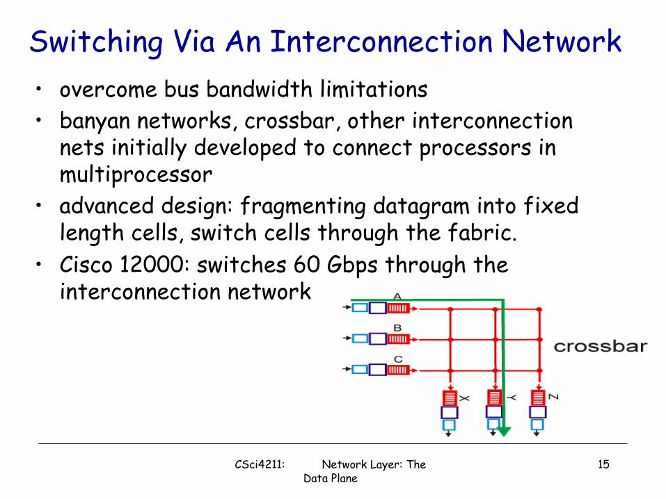
Switching Via An Interconnection Network• overcome bus bandwidth limitations• banyan networks, crossbar, other interconnection
nets initially developed to connect processors in multiprocessor
• advanced design: fragmenting datagram into fixed length cells, switch cells through the fabric.
• Cisco 12000: switches 60 Gbps through the interconnection network
CSci4211: Network Layer: The Data Plane
15

Input Port Queuing• Fabric slower than input ports combined -> queueing
may occur at input queues – queueing delay and loss due to input buffer overflow!
• Head-of-the-Line (HOL) blocking: queued datagram at front of queue prevents others in queue from moving forward
output port contention:only one red datagram can be
transferred.lower red packet is blocked
switchfabric
one packet time later: green packet
experiences HOL blocking
switchfabric
CSci4211: Network Layer: The Data Plane
16

Output Ports
• Buffering required when datagrams arrive from fabric faster than the transmission rate
• Scheduling discipline chooses among queued datagrams for transmission
Datagram (packets) can be lost due to congestion,
lack of buffers
Priority scheduling – who gets best performance,
network neutrality
CSci4211: Network Layer: The Data Plane
17
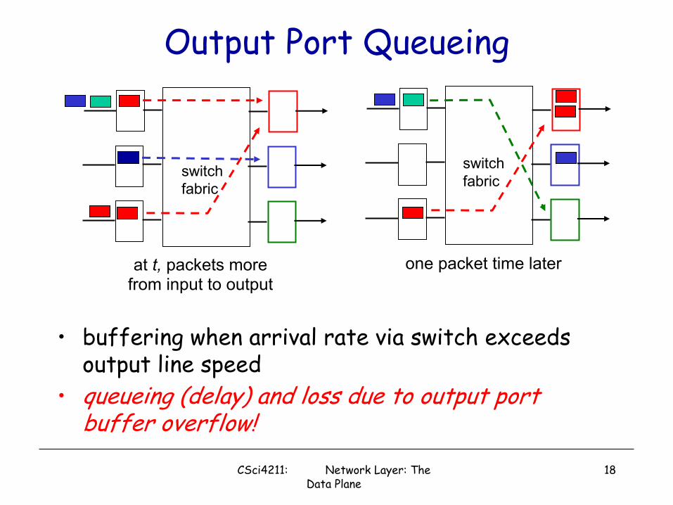
Output Port Queueing
• buffering when arrival rate via switch exceeds output line speed
• queueing (delay) and loss due to output port buffer overflow!
at t, packets morefrom input to output
one packet time later
switchfabric
switchfabric
CSci4211: Network Layer: The Data Plane
18
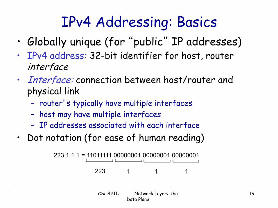
IPv4 Addressing: Basics• Globally unique (for �public� IP addresses)• IPv4 address: 32-bit identifier for host, router
interface• Interface: connection between host/router and
physical link– router�s typically have multiple interfaces– host may have multiple interfaces– IP addresses associated with each interface
• Dot notation (for ease of human reading)
223.1.1.1 = 11011111 00000001 00000001 00000001
223 1 11
CSci4211: Network Layer: The Data Plane
19

IP Addressing: Network vs. Host• Two-level hierarchy
– network part (high order bits)
– host part (low order bits)• What�s a network ? (from IP address perspective)
– device interfaces with same network part of IP address
– can physically reach each other without intervening router
223.1.1.1
223.1.1.3
223.1.1.4
223.1.2.2223.1.2.1
223.1.2.6
223.1.3.2223.1.3.1
223.1.3.27
223.1.1.2
223.1.7.0
223.1.7.1223.1.8.0223.1.8.1
223.1.9.1
223.1.9.2
CSci4211: Network Layer: The Data Plane
20

�Classful� IP Addressing
32 bits
0network host
10 network host
110 network host
1110 multicast address
A
B
C
D
class1.0.0.0 to127.255.255.255
128.0.0.0 to191.255.255.255
192.0.0.0 to223.255.255.255
224.0.0.0 to239.255.255.255
7 15 23 31
• Disadvantage: inefficient use of address space, address space exhaustion
• e.g., class B net allocated enough addresses for 65K hosts, even if only 2K hosts in that network
CSci4211: Network Layer: The Data Plane
21

Classless Addressing: CIDR CIDR: Classless InterDomain Routing• Network portion of address is of arbitrary length• Addresses allocated in contiguous blocks
– Number of addresses assigned always power of 2• Address format: a.b.c.d/x
– x is number of bits in network portion of address
11001000 00010111 00010000 00000000
networkpart
hostpart
200.23.16.0/23
CSci4211: Network Layer: The Data Plane
22

Special IP Addresses
• Network address: host id = all 0�s• Directed broadcast address: host id = all
1�s• Local broadcast address: all 1�s• Local host address (this computer): all 0�s• Loopback address
– network id = 127, any host id (e.g. 127.0.0.1)
CSci4211: Network Layer: The Data Plane
23

IP Addresses: How to Get One?
Q: How does host get IP address?
• �static� assigned: i.e., hard-coded in a file– Wintel: control-panel->network->configuration->tcp/ip-
>properties– UNIX: /etc/rc.config
• Dynamically assigned: using DHCP (Dynamic Host Configuration Protocol)– dynamically get address from as server– �plug-and-play�
CSci4211: Network Layer: The Data Plane
24

DHCP: Dynamic Host Configuration Protocol
Goal: allow host to dynamically obtain its IP address from network server when it joins networkCan renew its lease on address in useAllows reuse of addresses (only hold address while connected an �on�
Support for mobile users who want to join network (more shortly)
DHCP overview:– host broadcasts �DHCP discover� msg– DHCP server responds with �DHCP offer� msg– host requests IP address: �DHCP request� msg– DHCP server sends address: �DHCP ack� msg
CSci4211: Network Layer: The Data Plane
25

DHCP Client-Server Scenario
223.1.1.1
223.1.1.2
223.1.1.3
223.1.1.4 223.1.2.9
223.1.2.2
223.1.2.1
223.1.3.2223.1.3.1
223.1.3.27
A
BE
DHCP server
arriving DHCP client needsaddress in thisnetwork
CSci4211: Network Layer: The Data Plane
26

DHCP Client-Server ScenarioDHCP server: 223.1.2.5 arriving
client
time
DHCP discover
src : 0.0.0.0, 68 dest.: 255.255.255.255,67yiaddr: 0.0.0.0transaction ID: 654
DHCP offersrc: 223.1.2.5, 67 dest: 255.255.255.255, 68yiaddrr: 223.1.2.4transaction ID: 654Lifetime: 3600 secs
DHCP request
src: 0.0.0.0, 68 dest:: 255.255.255.255, 67yiaddrr: 223.1.2.4transaction ID: 655Lifetime: 3600 secs
DHCP ACKsrc: 223.1.2.5, 67 dest: 255.255.255.255, 68yiaddrr: 223.1.2.4transaction ID: 655Lifetime: 3600 secs
CSci4211: Network Layer: The Data Plane
27
DHCP: More Than IP Addresses
DHCP can return more than just allocated IP address on subnet:• address of first-hop router for client• name and IP address of DNS sever• network mask (indicating network versus host portion of
address)
CSci4211: Network Layer: The Data Plane
28

IP Addresses: How to Get One? …Q: How does network get network part of IP
addr?A: gets allocated portion of its provider ISP�s
address space
ISP's block 11001000 00010111 00010000 00000000 200.23.16.0/20
Organization 0 11001000 00010111 00010000 00000000 200.23.16.0/23 Organization 1 11001000 00010111 00010010 00000000 200.23.18.0/23 Organization 2 11001000 00010111 00010100 00000000 200.23.20.0/23
... ….. …. ….Organization 7 11001000 00010111 00011110 00000000 200.23.30.0/23
CSci4211: Network Layer: The Data Plane
29

IP Addressing: the Last Word...
Q: How does an ISP get block of addresses?A: ICANN: Internet Corporation for
Assigned Names and Numbers– allocates addresses– manages DNS– assigns domain names, resolves disputes
CSci4211: Network Layer: The Data Plane
30

Network Service ModelQ: What service model for �channel� transporting packets from sender to receiver?
• guaranteed bandwidth?• preservation of inter-packet
timing (no jitter)?• loss-free delivery?• in-order delivery?• congestion feedback to
sender?
? ??virtual circuit
or datagram?
The most importantabstraction provided
by network layer:
serv
ice
abst
ract
ion
CSci4211: Network Layer: The Data Plane
31

Network Service Model (cont�d)Some Possible Examples:
Example services for individual datagrams:
• guaranteed delivery• guaranteed delivery
with less than 40 msec delay
Example services for a flow of datagrams:
• in-order datagram delivery
• guaranteed minimum bandwidth to flow
• restrictions on changes in inter-packet spacing
CSci4211: Network Layer: The Data Plane
32

Network Layer Connection vs. Connectionless Service
• datagram network provides network-layer connectionless service
• VC network provides network-layer connection service
• analogous to the transport-layer services, but:– service: host-to-host– no choice: network provides one or the other– implementation: in network core
• network vs transport layer connection service:– network: between two hosts, in case of VCs, also involve
intervening routers – transport: between two processes
CSci4211: Network Layer: The Data Plane
33

Virtual Circuit vs. Datagram• Objective of both: move packets through routers from source
to destination• Datagram Model:
– Routing: determine next hop to each destination a priori– Forwarding: destination address in packet header, used at
each hop to look up for next hop • routes may change during �session�
– analogy: driving, asking directions at every gas station, or based on the road signs at every turn
• Virtual Circuit Model:– Routing: determine a path from source to each destination – �Call� Set-up: fixed path (�virtual circuit�) set up at �call�
setup time, remains fixed thru �call�– Data Forwarding: each packet carries �tag� or �label�
(virtual circuit id, VCI), which determines next hop– routers maintain �per-call� state
CSci4211: Network Layer: The Data Plane
34

Datagram Networks: the Internet model• no call setup at network layer• routers: no state about end-to-end connections
– no network-level concept of �connection�• packets forwarded using destination host address
– packets between same source-dest pair may take different paths, when intermediate routes change!
applicationtransportnetworkdata linkphysical
applicationtransportnetworkdata linkphysical
1. Send data 2. Receive data
CSci4211: Network Layer: The Data Plane
35

123
0111
value in arrivingpacket�s header
routing algorithm
local forwarding tableheader value output link
0100010101111001
3221
Interplay Between Routing and Forwarding
CSci4211: Network Layer: The Data Plane
36

Forwarding Table
Destination Address Range Link Interface
11001000 00010111 00010000 00000000through 0
11001000 00010111 00010111 11111111
11001000 00010111 00011000 00000000through 1
11001000 00010111 00011000 11111111
11001000 00010111 00011001 00000000through 2
11001000 00010111 00011111 11111111
otherwise 3
4 billion possible entries
CSci4211: Network Layer: The Data Plane
37

IP Forwarding Table4 billion possible entries! (in reality, far less, but can still have millions of �routes�)
forwarding table entry formatdestination network next-hop (IP address) link interface
(1st IP address , network mask )
11001000 00010111 00010000 00000000, 200.23.16.1 011111111 11111111 11111000 00000000
11001000 00010111 00011000 00000000, - (direct) 111111111 11111111 11111111 00000000
11001000 00010111 00011001 00000000, 200.23.25.6 211111111 11111111 11111000 00000000
otherwise 128.30.0.1 3
CSci4211: Network Layer: The Data Plane
38

Route aggregation: Shrinking the forwarding table
�Send me anythingwith addresses beginning 200.23.0.0/20�
200.23.2.0/23
200.23.4.0/23
200.23.14.0/23
UMN
Organization 0
CSE DepartmentInternet
Organization 1
200.23.6.0/23Organization 2
...
...Port 1
Port 0
Port 7
CSci4211: Network Layer: The Data Plane
39

Route aggregation with more specific routes
UMN-FAST has a more specific route to CSE department
�Send me anythingwith addresses beginning 200.23.0.0/20�
200.23.2.0/23
200.23.14.0/23
UMN
Organization 0
CSE DepartmentInternet
UMN-FAST �Send me anythingwith addresses beginning 200.23.14.0/23�
200.23.4.0/23Organization 2
...
...
CSci4211: Network Layer: The Data Plane
40

DA: 11001000 00010111 00011000 10101010
ExamplesDA: 11001000 00010111 00010110 10100001 interface 0
interface 1
But not interface 2, the 3rd entry is also a match, but shorter!
Prefix Match
11001000 00010111 00010*** *********11001000 00010111 00011000 *********11001000 00010111 00011*** *********otherwise
Link interface
0
1
2
3
41
when looking for forwarding table entry for given destination address, use longest address prefix that matches destination address.
longest prefix matchingLongest Prefix Matching

IP Datagram Forwarding Model
IP datagram:misc
fieldssourceIP addr
destIP addr data
• datagram remains unchanged, as it travels source to destination
• addr fields of interest here
223.1.1.1
223.1.1.2
223.1.1.3
223.1.1.4 223.1.2.9
223.1.2.2
223.1.2.1
223.1.3.2223.1.3.1
223.1.3.27
A
BE
Dest. Net. next router Nhops223.1.1 1223.1.2 223.1.1.4 2223.1.3 223.1.1.4 2
forwarding table in A
CSci4211: Network Layer: The Data Plane
42

IP Forwarding: Destination in Same Net
Starting at A, send IP datagram addressed to B:
• look up net. address of B in forwarding table
• find B is on same net. as A• link layer will send datagram
directly to B inside link-layer frame– B and A are directly connected
miscfields 223.1.1.1 223.1.1.3 data
Dest. Net. next router Nhops223.1.1 1223.1.2 223.1.1.4 2223.1.3 223.1.1.4 2
223.1.1.1
223.1.1.2
223.1.1.3
223.1.1.4 223.1.2.9
223.1.2.2
223.1.2.1
223.1.3.2223.1.3.1
223.1.3.27
A
BE
forwarding table in A
CSci4211: Network Layer: The Data Plane
43
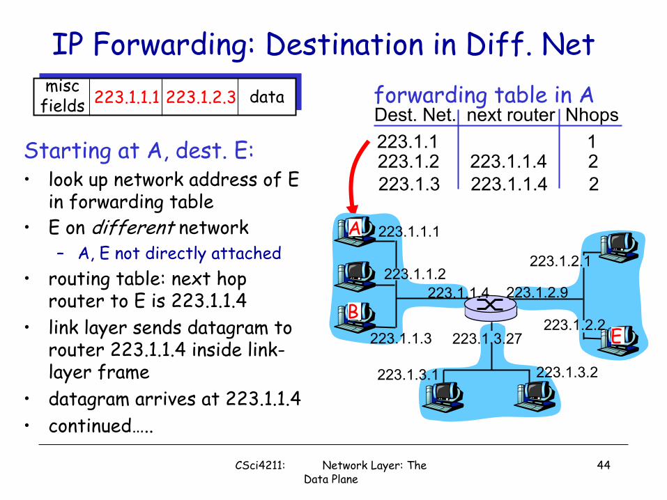
IP Forwarding: Destination in Diff. Net
Starting at A, dest. E:• look up network address of E
in forwarding table• E on different network
– A, E not directly attached• routing table: next hop
router to E is 223.1.1.4 • link layer sends datagram to
router 223.1.1.4 inside link-layer frame
• datagram arrives at 223.1.1.4 • continued…..
miscfields 223.1.1.1 223.1.2.3 data
Dest. Net. next router Nhops223.1.1 1223.1.2 223.1.1.4 2223.1.3 223.1.1.4 2
223.1.1.1
223.1.1.2
223.1.1.3
223.1.1.4 223.1.2.9
223.1.2.2
223.1.2.1
223.1.3.2223.1.3.1
223.1.3.27
A
BE
forwarding table in A
CSci4211: Network Layer: The Data Plane
44

IP Forwarding: Destination in Diff. Net …
Arriving at 223.1.4, destined for 223.1.2.2
• look up network address of E in router�s forwarding table
• E on same network as router�s interface 223.1.2.9– router, E directly attached
• link layer sends datagram to 223.1.2.2 inside link-layer frame via interface 223.1.2.9
• datagram arrives at 223.1.2.2!!! (hooray!)
miscfields 223.1.1.1 223.1.2.3 data Dest. Net router Nhops interface
223.1.1 - 1 223.1.1.4223.1.2 - 1 223.1.2.9223.1.3 - 1 223.1.3.27
223.1.1.1
223.1.1.2
223.1.1.3
223.1.1.4 223.1.2.9
223.1.2.2
223.1.2.1
223.1.3.2223.1.3.1
223.1.3.27
A
BE
forwarding table in router
CSci4211: Network Layer: The Data Plane
45

IP Forwarding & IP/ICMP Protocol
Networklayer forwarding
table
Routing protocols•path selection•RIP, OSPF, BGP
IP protocol•addressing conventions•Datagram format•packet handling conventions
ICMP protocol•error reporting•router �signaling�
Transport layer: TCP, UDP
Data Link layer (Ethernet, WiFi, PPP, …)
Physical Layer (SONET, …)
CSci4211: Network Layer: The Data Plane
46

IP Datagram Format
ver length
32 bits
data (variable length,typically a TCP
or UDP segment)
16-bit identifierInternetchecksum
time tolive
32 bit source IP address
IP protocol versionnumber
header length(bytes)
max numberremaining hops
(decremented at each router)
forfragmentation/reassembly
total datagramlength (bytes)
upper layer protocolto deliver payload to
head.len
type ofservice
�type� of data flgs fragmentoffset
upperlayer
32 bit destination IP address
Options (if any) E.g. timestamp,record routetaken, specifylist of routers to visit.
how much overhead with TCP?
• 20 bytes of TCP• 20 bytes of IP• = 40 bytes + app
layer overhead
CSci4211: Network Layer: The Data Plane
47

Fields in IP Datagram• IP protocol version: current version is 4, IPv4, new: IPv6• Header length: number of 32-bit words in the header• Type of Service:
– 3-bit priority,e.g, delay, throughput, reliability bits, …• Total length: including header (maximum 65535 bytes)• Identification: all fragments of a packet have same
identification• Flags: don�t fragment, more fragments• Fragment offset: where in the original packet (count in 8
byte units)• Time to live: maximum life time of a packet• Protocol Type: e.g., ICMP, TCP, UDP etc• IP Option: non-default processing, e.g., IP source routing
option, etc.
CSci4211: Network Layer: The Data Plane
48

IP Fragmentation & Reassembly: Why• network links have MTU
(max.transfer size) -largest possible link-level frame.– different link types,
different MTUs • large IP datagram divided
(�fragmented�) within net– one datagram becomes
several datagrams– �reassembled� only at
final destination– IP header bits used to
identify, order related fragments
fragmentation: in: one large datagramout: 3 smaller datagrams
reassembly
CSci4211: Network Layer: The Data Plane
49

IP Fragmentation & Reassembly: How• An IP datagram is chopped by a router into smaller pieces if
– datagram size is greater than network MTU– Don�t fragment option is not set
• Each datagram has unique datagram identification– Generated by source hosts– All fragments of a packet carry original datagram id
• All fragments except the last have more flag set– Fragment offset and Length fields are modified appropriately
• Fragments of IP packet can be further fragmented by other routers along the way to destination !
• Reassembly only done at destination host (why?)– Use IP datagram id, fragment offset, fragment flags. Length– A timer is set when first fragment is received (why?)
CSci4211: Network Layer: The Data Plane
50

IP Fragmentation and Reassembly: ExpID=x
offset=0
fragflag=0
length=4000
ID=x
offset=0
fragflag=1
length=1500
ID=x
offset=185
fragflag=1
length=1500
ID=x
offset=370
fragflag=0
length=1040
One large datagram becomesseveral smaller datagrams
Example• 4000 byte datagram• MTU = 1500 bytes
• offset in the second fragment:185x8=1480
(why not 1500 bytes =length?)• offset in the third
fragment:370x8=2960
Except for last fragment, IP fragment payload size (i.e., excluding IP header) must be multiple of 8!
CSci4211: Network Layer: The Data Plane
51

Quiz: Calculating length & Offset
ID=x
offset=0
fragflag=0
length=4000
Example• 4000 byte datagram• MTU = 1500 bytes
A BMTU = 1500 bytes MTU = 900 bytes
CSci4211: Network Layer: The Data Plane
52

AnswerID=x
Offset= 0
fragflag=1
length= 900
ID=x
offset=110
fragflag=1
length=620
ID=x
offset= 185
fragflag=1
length= 900
ID=x
offset= 295
fragflag=1
length= 620
ID=x
offset=370
fragflag=1
length= 900
ID=x
offset= 480
fragflag=0
length= 160
CSci4211: Network Layer: The Data Plane
53

ICMP: Internet Control Message Protocol
• used by hosts, routers, gateways to communication network-level information– error reporting:
unreachable host, network, port, protocol
– echo request/reply (used by ping)
• network-layer �above� IP:– ICMP msgs carried in IP
datagrams• ICMP message: type, code
plus first 8 bytes of IP datagram causing error
Type Code description0 0 echo reply (ping)3 0 dest. network unreachable3 1 dest host unreachable3 2 dest protocol unreachable3 3 dest port unreachable3 6 dest network unknown3 7 dest host unknown4 0 source quench (congestion
control - not used)5 0,1 redirect for network/host8 0 echo request (ping)9 0 route advertisement10 0 router discovery11 0 TTL expired12 0 bad IP header
CSci4211: Network Layer: The Data Plane
54

ICMP Message Transport & Usage
• ICMP messages carried in IP datagrams• Treated like any other datagrams
– But no error message sent if ICMP message causes error
• Message sent to the source– 8 bytes of the original header included
• ICMP Usage (non-error, informational): Examples– Testing reachability: ICMP echo request/reply
• ping– Tracing route to a destination: Time-to-live field
• traceroute– Path MTU discovery
• Don�t fragment bit– IP redirect (for hosts only): inform hosts of better routes
CSci4211: Network Layer: The Data Plane
55

10.0.0.1
10.0.0.2
10.0.0.3
10.0.0.4
138.76.29.7
local network(e.g., home network)
10.0.0.0/24
rest ofInternet
datagrams with source or destination in this networkhave 10.0.0.0/24 address for source, destination (as usual)
all datagrams leaving localnetwork have same single
source NAT IP address: 138.76.29.7,different source
port numbers
NAT (Network Address Translation)A fix to limited IP address space:
CSci4211: Network Layer: The Data Plane
56

motivation: local network uses just one IP address as far as outside world is concerned:§ range of addresses not needed from ISP: just
one IP address for all devices§ can change addresses of devices in local
network without notifying outside world§ can change ISP without changing addresses of
devices in local network§ devices inside local net not explicitly
addressable, visible by outside world (a security plus)
NAT (Network Address Translation)
CSci4211: Network Layer: The Data Plane
57

10.0.0.1
10.0.0.2
10.0.0.3
S: 10.0.0.1, 3345D: 128.119.40.186, 80
1
10.0.0.4
138.76.29.7
1: host 10.0.0.1 sends datagram to 128.119.40.186, 80
NAT translation tableWAN side addr LAN side addr
138.76.29.7, 5001 10.0.0.1, 3345…… ……
S: 128.119.40.186, 80 D: 10.0.0.1, 3345 4
S: 138.76.29.7, 5001D: 128.119.40.186, 802
2: NAT routerchanges datagramsource addr from10.0.0.1, 3345 to138.76.29.7, 5001,updates table
S: 128.119.40.186, 80 D: 138.76.29.7, 5001 3
3: reply arrivesdest. address:138.76.29.7, 5001
4: NAT routerchanges datagramdest addr from138.76.29.7, 5001 to 10.0.0.1, 3345
NAT (Network Address Translation)
CSci4211: Network Layer: The Data Plane
58

IPv6: Motivation• initial motivation: 32-bit address space soon
to be completely allocated. • additional motivation:
– header format helps speed processing/forwarding– header changes to facilitate QoS
IPv6 datagram format: – fixed-length 40 byte header– no fragmentation allowed
CSci4211: Network Layer: The Data Plane
59

No checksum operation
No fragmentation
Longer addressing space
Fix size IP Header
Simplified Design of IPv6
2001:0db8:85a3:0000:0000:8a2e:0370:7334
Can have one or more extension header fields
End hosts must perform path MTU discovery (using ICMP) per destination before sending any data!
data
destination address(128 bits)
source address(128 bits)
payload len next hdr hop limitflow labelpriver
32 bits
CSci4211: Network Layer: The Data Plane
60

IPv6 Transition• Dual stack hosts
– Two TCP/IP stacks co-exists on one host– Supporting IPv4 and IPv6– Client uses whichever protocol it wishes
IPv4 IPv6
www.apnic.net??
IPv4
TCP/UDPApplication
IPv6Link
CSci4211: Network Layer: The Data Plane
61

• IPv6 tunnel over IPv4
IPv6 Transition (cont’d)
IPv4Network
IPv6 IPv6
IPv6 Header Data
IPv4 Header IPv6 Header Data
IPv6 Header Data
tunnel
CSci4211: Network Layer: The Data Plane
62
Network Layer (The Data Plane): Summary
• Network Layer Overview• Router Architecture• Network Layer Functions and Service Models
– Network Layer Functions – IP Addressing– DHCP– Network Service Models: Virtual Circuit vs. Datagram
• IP Forwarding and IP Protocol– IP Datagram Forwarding Model– IP and ICMP: Datagram Format, IP Fragmentation
• NAT, IPv6 and IPv6 transition (over IPv4)
CSci4211: Network Layer: The Data Plane
63
Related Documents