Ch 4 Chapter 4 Network Layer Network Layer A note on the use of these ppt slides: We’re making these slides freely available to all (faculty, students, readers). They’re in PowerPoint form so you can add, modify, and delete slides (including this one) and slide content to suit your needs. They obviously Computer Networking: A T D A h represent a lot of work on our part. In return for use, we only ask the following: If you use these slides (e.g., in a class) in substantially unaltered form, that you mention their source (after all, we’d like people to use our book!) If you post any slides in substantially unaltered form on a www site that A Top Down Approach 5 th edition. Jim Kurose, Keith Ross Addis W sl A il If you post any slides in substantially unaltered form on a www site, that you note that they are adapted from (or perhaps identical to) our slides, and note our copyright of this material. Thanks and enjoy! JFK/KWR Addison-Wesley, April 2009. Network Layer 4-1 All material copyright 1996-2009 J.F Kurose and K.W. Ross, All Rights Reserved

Welcome message from author
This document is posted to help you gain knowledge. Please leave a comment to let me know what you think about it! Share it to your friends and learn new things together.
Transcript
Ch 4Chapter 4Network LayerNetwork Layer
A note on the use of these ppt slides:We’re making these slides freely available to all (faculty, students, readers). They’re in PowerPoint form so you can add, modify, and delete slides (including this one) and slide content to suit your needs. They obviously Computer Networking:
A T D A h ( g ) y y yrepresent a lot of work on our part. In return for use, we only ask the following:
If you use these slides (e.g., in a class) in substantially unaltered form, that you mention their source (after all, we’d like people to use our book!)
If you post any slides in substantially unaltered form on a www site that
A Top Down Approach 5th edition. Jim Kurose, Keith RossAddis W sl A il If you post any slides in substantially unaltered form on a www site, that
you note that they are adapted from (or perhaps identical to) our slides, and note our copyright of this material.
Thanks and enjoy! JFK/KWR
Addison-Wesley, April 2009.
Network Layer 4-1
All material copyright 1996-2009J.F Kurose and K.W. Ross, All Rights Reserved
Chapter 4: Network LayerChapter 4: Network Layer
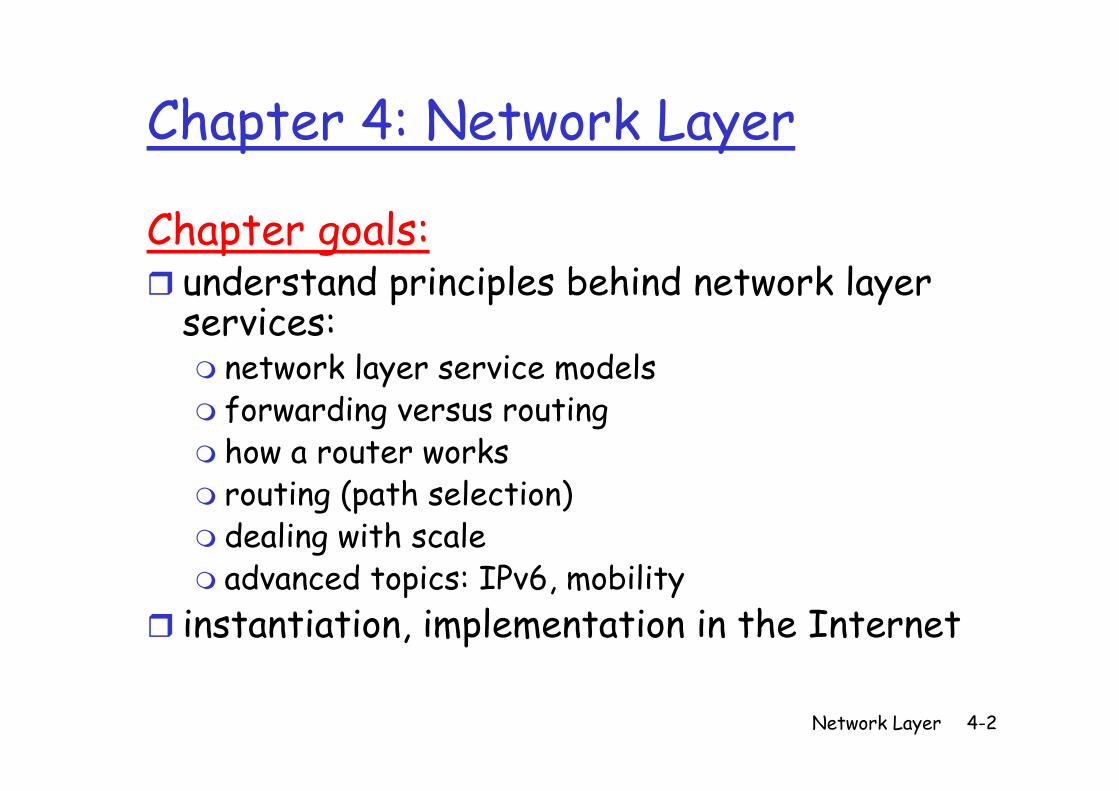
Ch t lChapter goals:understand principles behind network layer services:
network layer service modelsf forwarding versus routinghow a router works
ti ( th l ti )routing (path selection)dealing with scaleadvanced topics: IPv6 mobilityadvanced topics: IPv6, mobility
instantiation, implementation in the Internet
Network Layer 4-2
Chapter 4: Network LayerChapter 4: Network Layer
4 1 I d i 4 5 R i l i h4. 1 Introduction4.2 Virtual circuit and d t t ks
4.5 Routing algorithmsLink stateDistance Vectordatagram networks
4.3 What’s inside a router
Distance VectorHierarchical routing
4 6 Routing in the router4.4 IP: Internet Protocol
4.6 Routing in the Internet
RIPProtocolDatagram formatIPv4 addressing
OSPFBGP
4 B d d g
ICMPIPv6
4.7 Broadcast and multicast routing
Network Layer 4-3
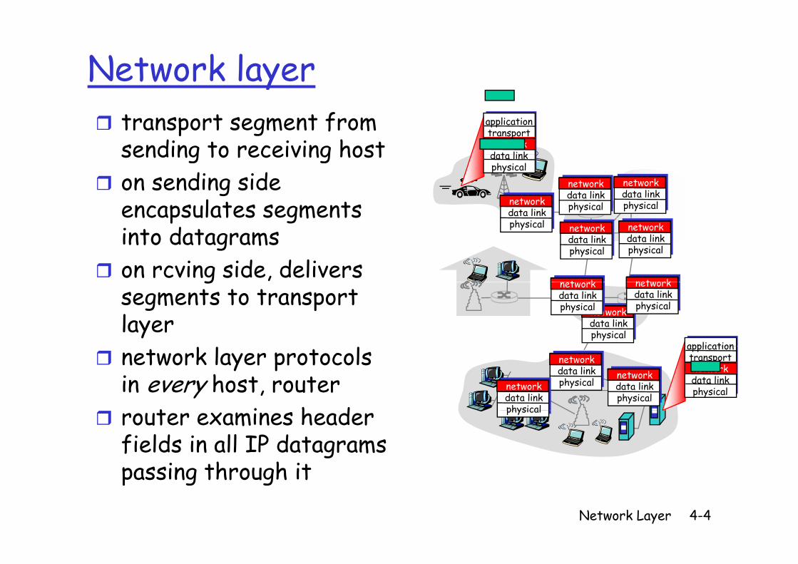
Network layertransport segment from sending to receiving host
applicationtransportnetworkdata linksending to receiving host
on sending side encapsulates segments
data linkphysical
networkdata link
networkdata linkphysical
networkdata linkphysicalp gm
into datagramson rcving side, delivers
physical networkdata linkphysical
networkdata linkphysical
networkt kg
segments to transport layer
application
networkdata linkphysical
networkdata linkphysical
networkdata linkphysical
network layer protocols in every host, router
t i h d
applicationtransportnetworkdata linkphysical
networkdata linkphysical
networkdata linkphysicalnetwork
data linkphysicalrouter examines header
fields in all IP datagrams passing through it
physical
Network Layer 4-4
passing through it
Two Key Network-Layer FunctionsTwo Key Network Layer Functions
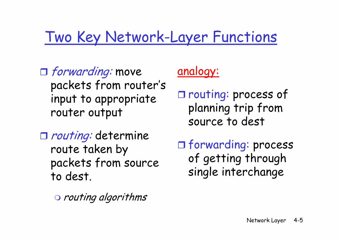
forwarding: move packets from router’s
analogy:
routing: process of input to appropriate router output
routing: process of planning trip from source to dest
routing: determine route taken by
source to dest
forwarding: process route taken by packets from source to dest
forwarding process of getting through single interchangeto dest.
routing algorithms
single interchange
Network Layer 4-5
g g
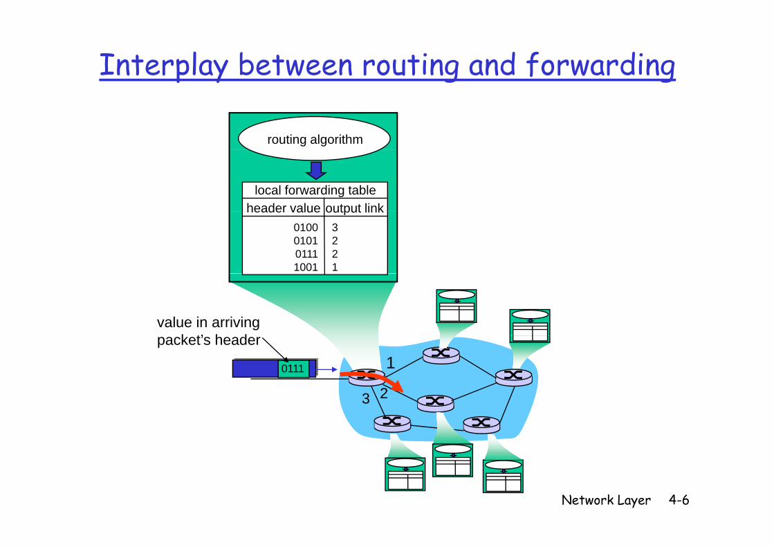
Interplay between routing and forwarding
routing algorithm
local forwarding tableheader value output linkheader value output link
0100010101111001
3221
value in arrivingk t’ h d
1
23
0111
packet’s header
23
Network Layer 4-6
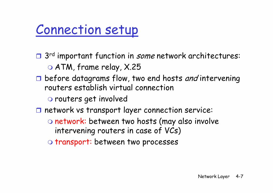
Connection setupConnection setup
3 d i f i i k hi3rd important function in some network architectures:ATM, frame relay, X.25
before datagrams flow, two end hosts and intervening routers establish virtual connection
t t i l drouters get involvednetwork vs transport layer connection service:
k b h ( l i l network: between two hosts (may also involve intervening routers in case of VCs)t nsp t: b t n t p c ss stransport: between two processes
Network Layer 4-7
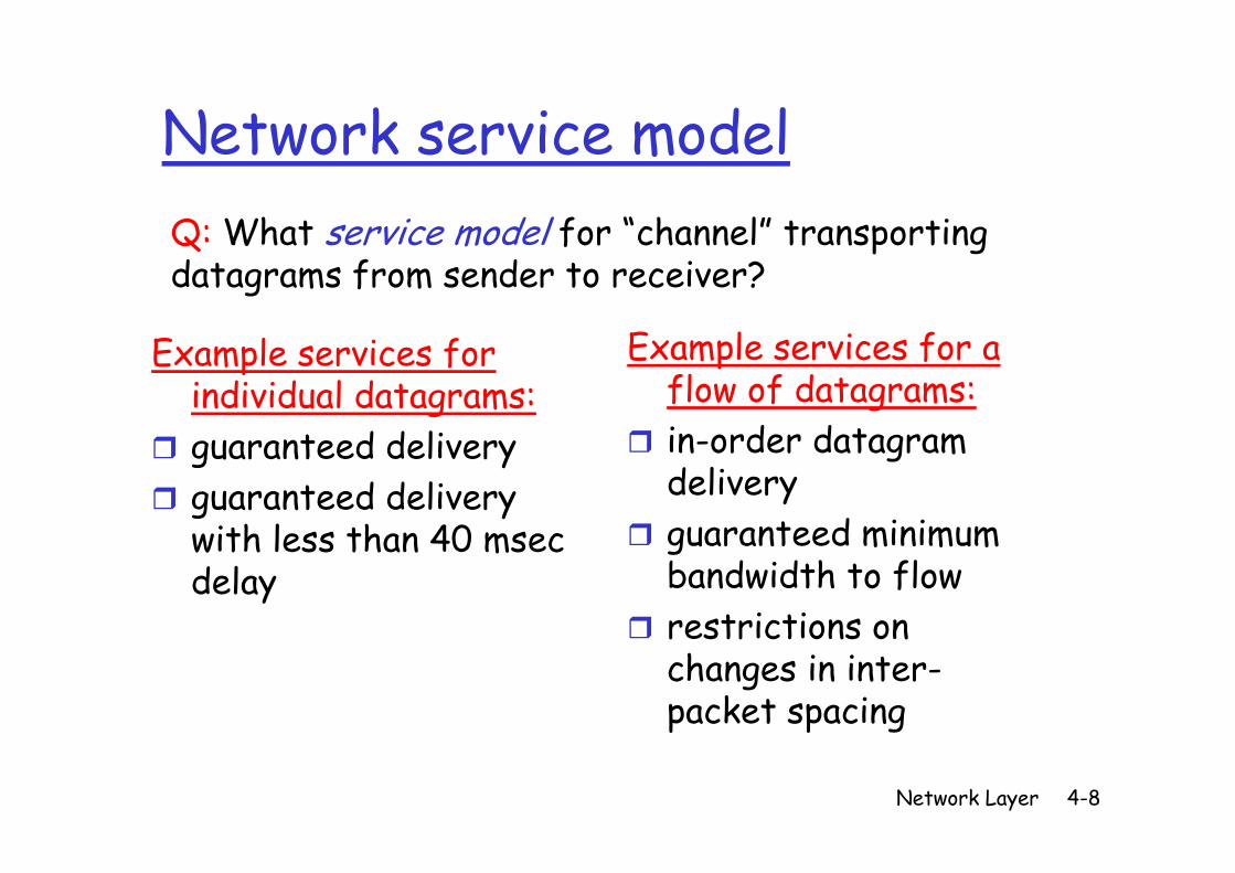
Network service modelNetwork service modelQ: What service model for “channel” transporting Q: What service model for channel transporting datagrams from sender to receiver?
E l i f Example services for individual datagrams:
t d d li
Example services for a flow of datagrams:in order datagram guaranteed delivery
guaranteed delivery with less than 40 msec
in-order datagram deliveryguaranteed minimum with less than 40 msec
delayguaranteed minimum bandwidth to flowrestrictions on restrictions on changes in inter-packet spacing
Network Layer 4-8
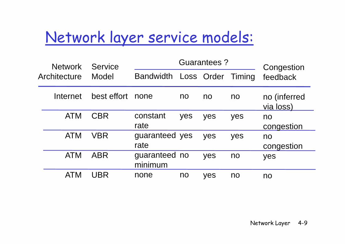
Network layer service models:Network layer service models:
Network Service CongestionGuarantees ?NetworkArchitecture
I t t
ServiceModel
b t ff t
Bandwidth
none
Loss
no
Order TimingCongestionfeedback
(i f dInternet
ATM
best effort
CBR
none
constant
no
yes
no
yes
no
yes
no (inferredvia loss)no
ATM VBRrateguaranteedrate
yes yes yescongestionnocongestion
ATM
ATM
ABR
UBR
guaranteed minimumnone
no
no
yes
yes
no
no
gyes
noATM UBR o e o yes no no
Network Layer 4-9
Chapter 4: Network LayerChapter 4: Network Layer
4 1 I d i 4 5 R i l i h4. 1 Introduction4.2 Virtual circuit and d t t ks
4.5 Routing algorithmsLink stateDistance Vectordatagram networks
4.3 What’s inside a router
Distance VectorHierarchical routing
4 6 Routing in the router4.4 IP: Internet Protocol
4.6 Routing in the Internet
RIPProtocolDatagram formatIPv4 addressing
OSPFBGP
4 B d d g
ICMPIPv6
4.7 Broadcast and multicast routing
Network Layer 4-10
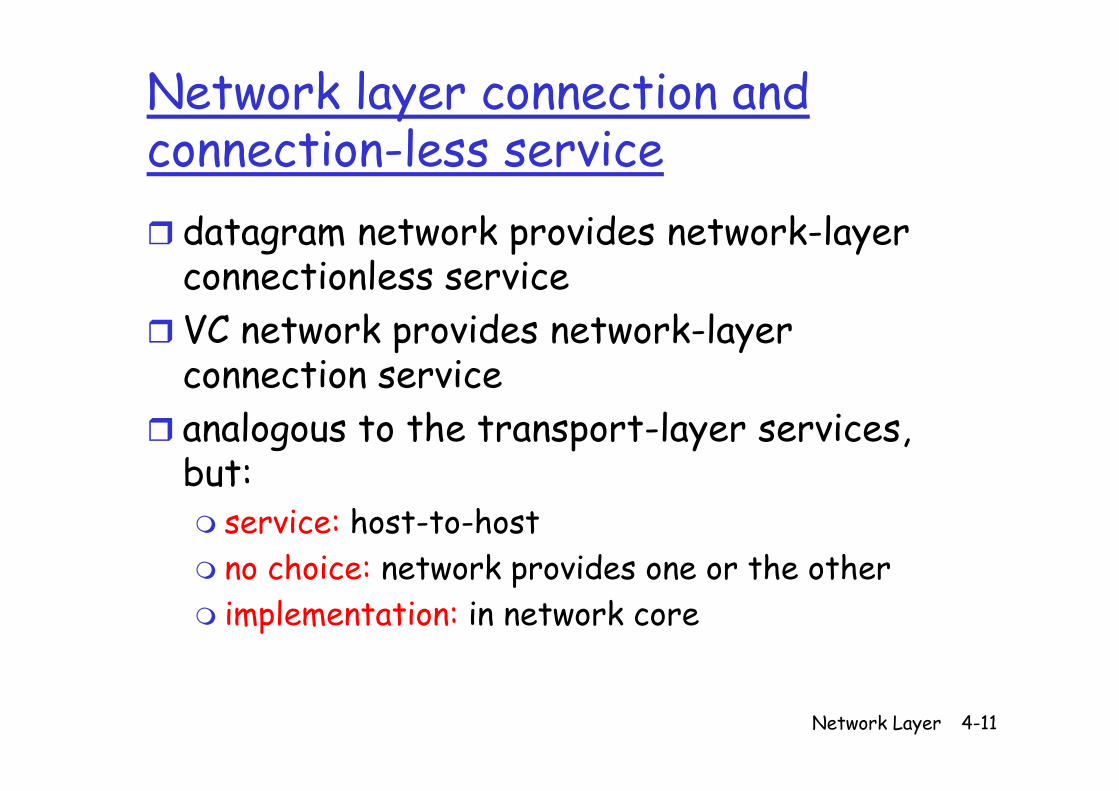
Network layer connection and connection-less service
d k d k l datagram network provides network-layer connectionless serviceVC network provides network-layer connection serviceanalogous to the transport-layer services, but:but
service: host-to-hostno choice: network provides one or the otherno choice: network provides one or the otherimplementation: in network core
Network Layer 4-11
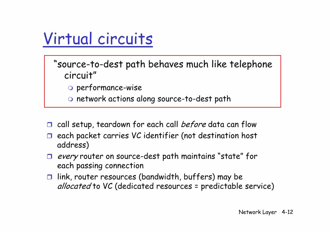
Virtual circuitsVirtual circuits“source to dest path behaves much like telephone source-to-dest path behaves much like telephone
circuit”performance-wiseperformance wisenetwork actions along source-to-dest path
call setup, teardown for each call before data can floweach packet carries VC identifier (not destination host dd )address)
every router on source-dest path maintains “state” for each passing connectionp glink, router resources (bandwidth, buffers) may be allocated to VC (dedicated resources = predictable service)
Network Layer 4-12
VC implementationVC implementation
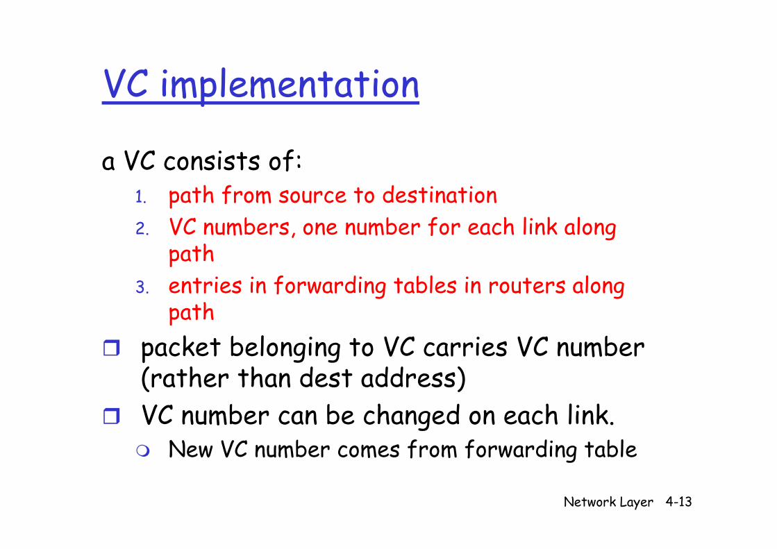
fa VC consists of:1. path from source to destination2. VC numbers, one number for each link along
path3. entries in forwarding tables in routers along
pathk b l i VC i VC b packet belonging to VC carries VC number
(rather than dest address)VC number can be changed on each link.
New VC number comes from forwarding table
Network Layer 4-13
g
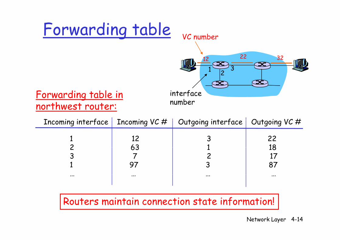
Forwarding table VC numberg12 22 32
VC number
1 23
interfaceF din t bl in interfacenumber
I i i t f I i VC # O t i i t f O t i VC #
Forwarding table innorthwest router:
Incoming interface Incoming VC # Outgoing interface Outgoing VC #
1 12 3 222 63 1 18 2 63 1 18 3 7 2 171 97 3 87
… … … …
Routers maintain connection state information!Network Layer 4-14
Routers maintain connection state information!
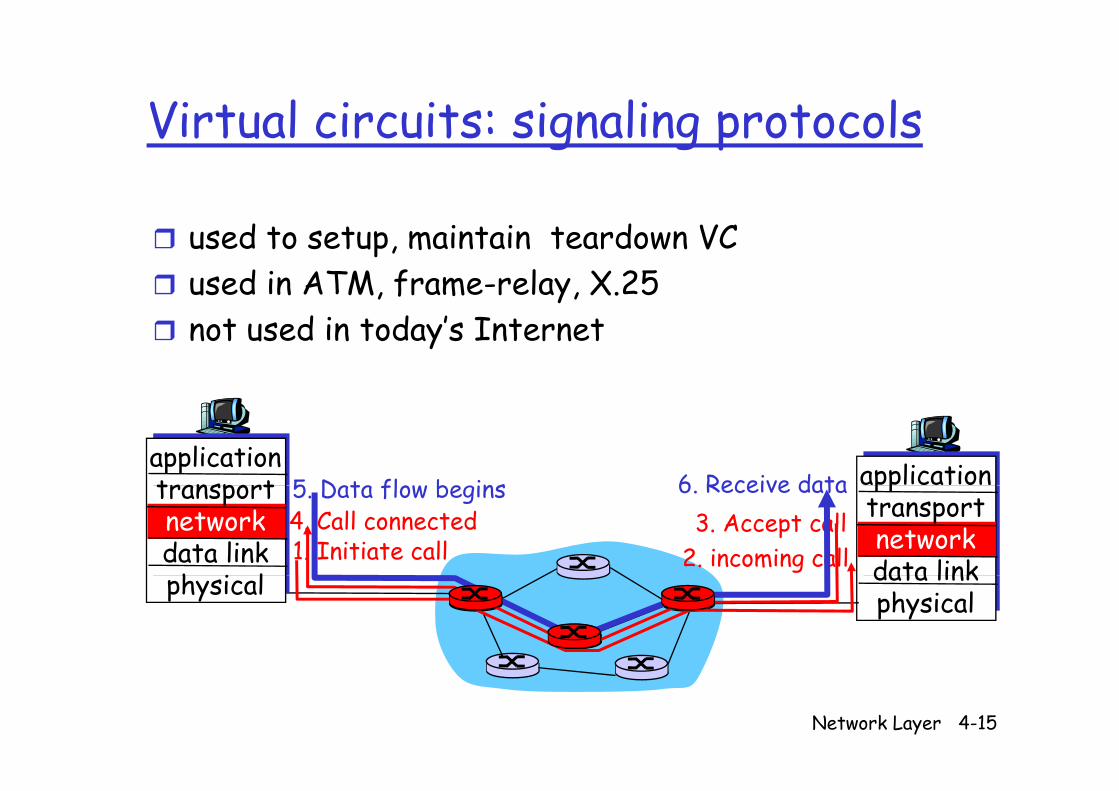
Virtual circuits: signaling protocolsVirtual circuits: signaling protocols
used to setup, maintain teardown VCused in ATM, frame-relay, X.25not used in today’s Internet
applicationtransport application5 Data flow begins 6 Receive datatransportnetworkdata link
h i l
pptransportnetworkdata link
1. Initiate call 2. incoming call3. Accept call4. Call connected
5. Data flow begins 6. Receive data
physical data linkphysical
Network Layer 4-15
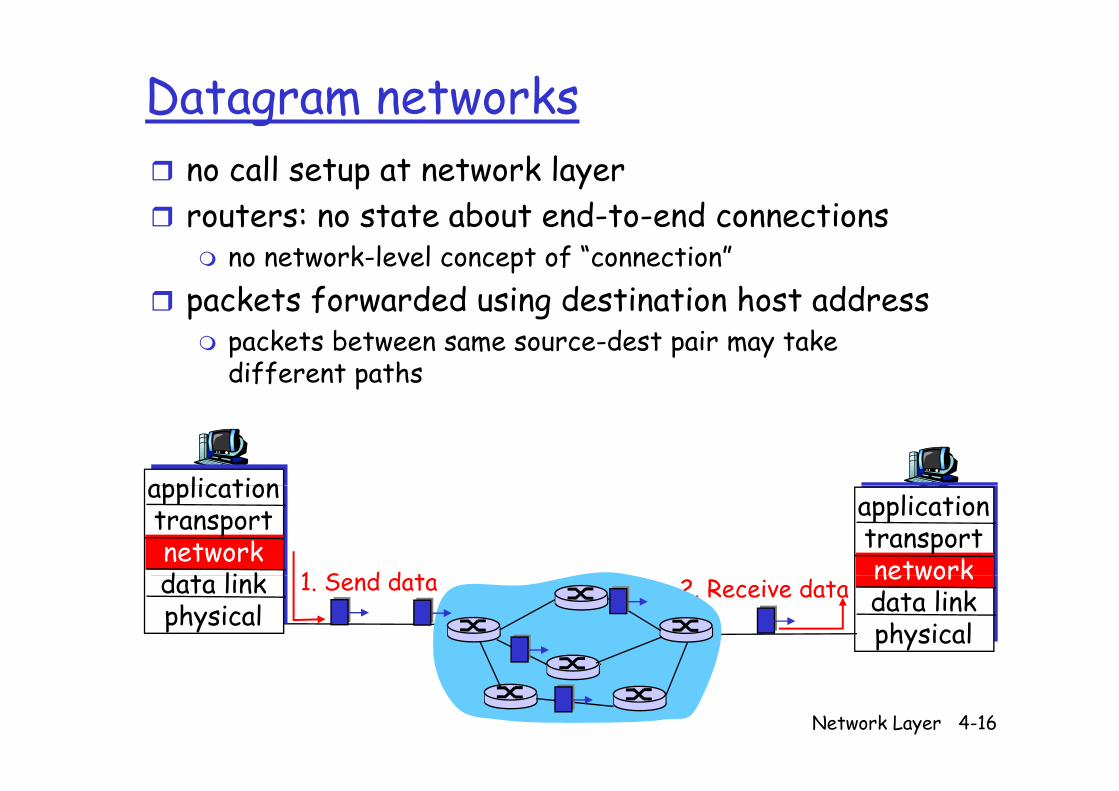
Datagram networksno call setup at network layerrouters: no state about end to end connectionsrouters: no state about end-to-end connections
no network-level concept of “connection”packets forwarded using destination host addresspackets forwarded using destination host address
packets between same source-dest pair may take different paths
applicationapplicationtransportnetworkd t li k
applicationtransportnetwork1 S d d tdata link
physicalnetworkdata linkphysical
1. Send data 2. Receive data
Network Layer 4-16
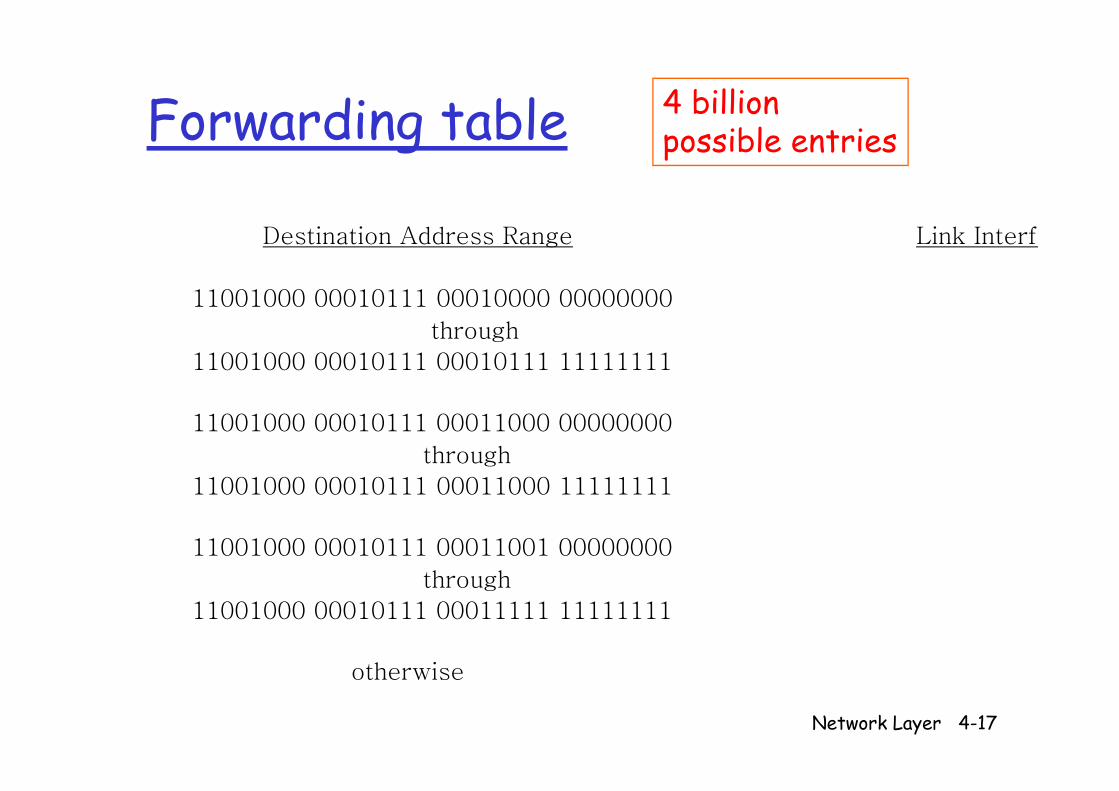
Forwarding table 4 billion Forwarding table possible entries
Destination Address Range Link Interfa
11001000 00010111 00010000 0000000011001000 00010111 00010000 00000000
through
11001000 00010111 00010111 11111111
11001000 00010111 00011000 00000000
through
11001000 00010111 00011000 1111111111001000 00010111 00011000 11111111
11001000 00010111 00011001 00000000
th hthrough
11001000 00010111 00011111 11111111
th i
Network Layer 4-17
otherwise
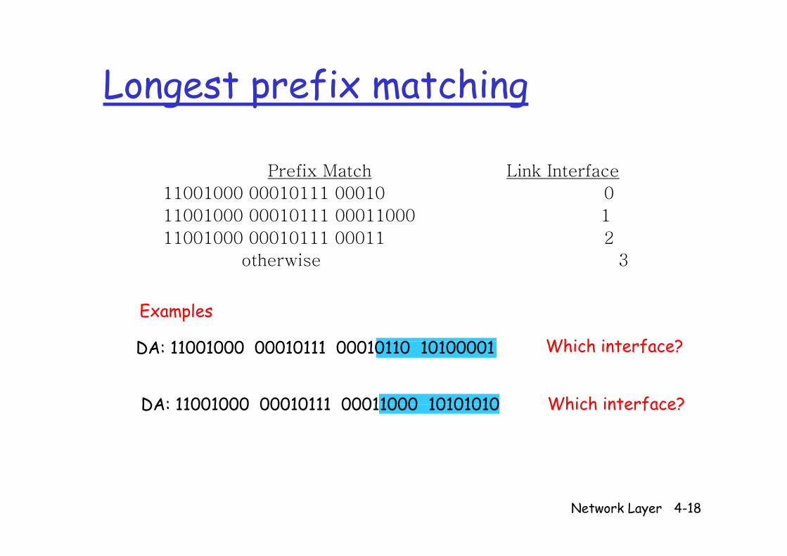
Longest prefix matchingLongest prefix matching
Prefix Match Link Interface
11001000 00010111 00010 0
11001000 00010111 00011000 111001000 00010111 00011000 1
11001000 00010111 00011 2
otherwise 3
Examples
D 11001000 00010111 00010110 10100001 Whi h i t f ?
DA: 11001000 00010111 00011000 10101010
DA: 11001000 00010111 00010110 10100001 Which interface?
Which interface?DA: 11001000 00010111 00011000 10101010 Which interface?
Network Layer 4-18
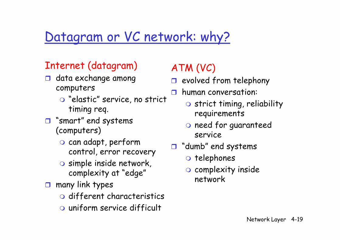
Datagram or VC network: why?Datagram or VC network: why?
Internet (datagram) ATM (VC)Internet (datagram)data exchange among computers
ATM (VC)evolved from telephonyhuman conversation:
“elastic” service, no strict timing req.
“smart” end systems
human conversation: strict timing, reliability requirements
smart end systems (computers)
can adapt, perform
need for guaranteed service
“dumb” end systemscontrol, error recoverysimple inside network, complexity at “edge”
dumb end systemstelephonescomplexity inside complexity at edge
many link types different characteristics
network
Network Layer 4-19
uniform service difficult
Chapter 4: Network LayerChapter 4: Network Layer
4 1 I d i 4 5 R i l i h4. 1 Introduction4.2 Virtual circuit and d t t ks
4.5 Routing algorithmsLink stateDistance Vectordatagram networks
4.3 What’s inside a router
Distance VectorHierarchical routing
4 6 Routing in the router4.4 IP: Internet Protocol
4.6 Routing in the Internet
RIPProtocolDatagram formatIPv4 addressing
OSPFBGP
4 B d d g
ICMPIPv6
4.7 Broadcast and multicast routing
Network Layer 4-20
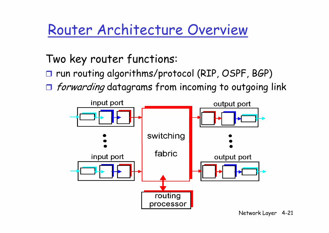
Router Architecture Overview
Two key router functions:yrun routing algorithms/protocol (RIP, OSPF, BGP)forwarding datagrams from incoming to outgoing linkforward ng datagrams from ncom ng to outgo ng l nk
Network Layer 4-21
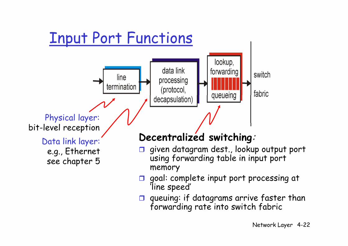
Input Port FunctionsInput Port Functions
Physical layer:
Decentralized switching:given datagram dest lookup output port
bit-level receptionData link layer:
e g Ethernet given datagram dest., lookup output port using forwarding table in input port memorygoal: complete input port processing at
e.g., Ethernetsee chapter 5
goal: complete input port processing at ‘line speed’queuing: if datagrams arrive faster than forwarding rate into switch fabric
Network Layer 4-22
forwarding rate into switch fabric
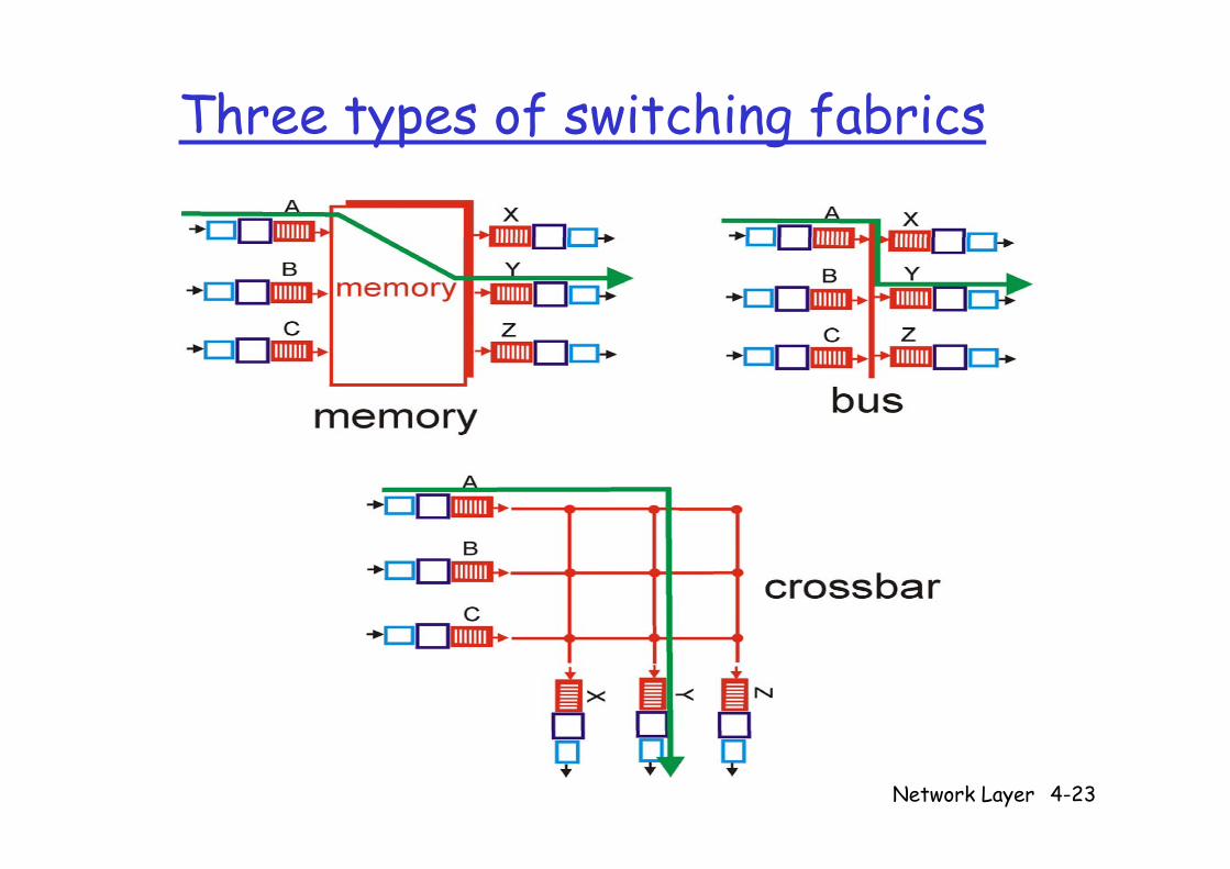
Three types of switching fabricsyp g
Network Layer 4-23
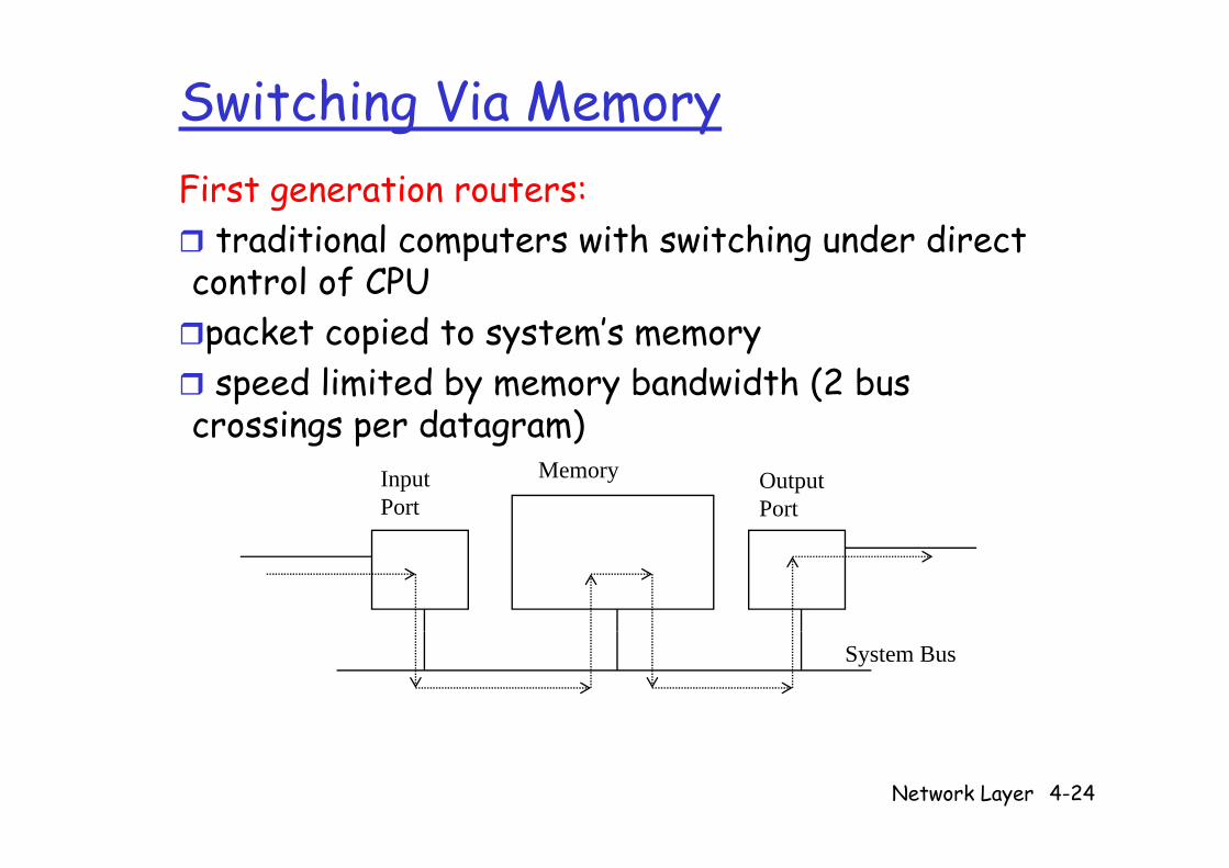
Switching Via MemoryFirst generation routers:
traditional computers with switching under direct traditional computers with switching under direct control of CPUpacket copied to system’s memorypacket copied to system s memoryspeed limited by memory bandwidth (2 bus
crossings per datagram)crossings per datagram)InputPort
OutputPort
Memory
System Bus
Network Layer 4-24
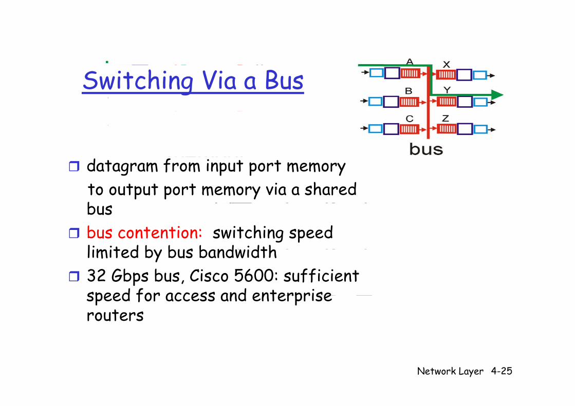
Switching Via a Bus
datagram from input port memoryto output port memory via a shared bbusbus contention: switching speed limit d b bus b nd idthlimited by bus bandwidth32 Gbps bus, Cisco 5600: sufficient speed for access and enterprise speed for access and enterprise routers
Network Layer 4-25
Switching Via An Interconnection Switching Via An Interconnection Network
overcome bus bandwidth limitationsBanyan networks, other interconnection nets initially developed to connect processors in
ltimultiprocessoradvanced design: fragmenting datagram into fixed length cells switch cells through the fabric length cells, switch cells through the fabric. Cisco 12000: switches 60 Gbps through the interconnection networkinterconnection network
Network Layer 4-26
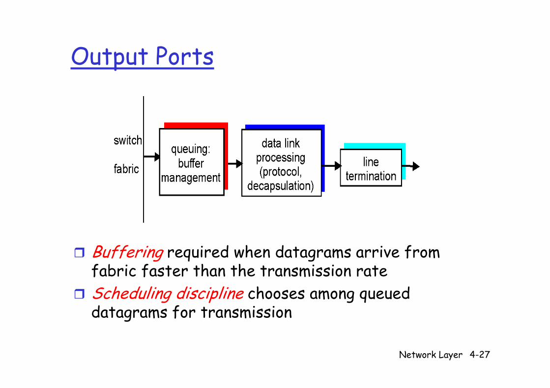
Output PortsOutput Ports
Buffering required when datagrams arrive from fabric faster than the transmission rateScheduling discipline chooses among queued datagrams for transmission
Network Layer 4-27
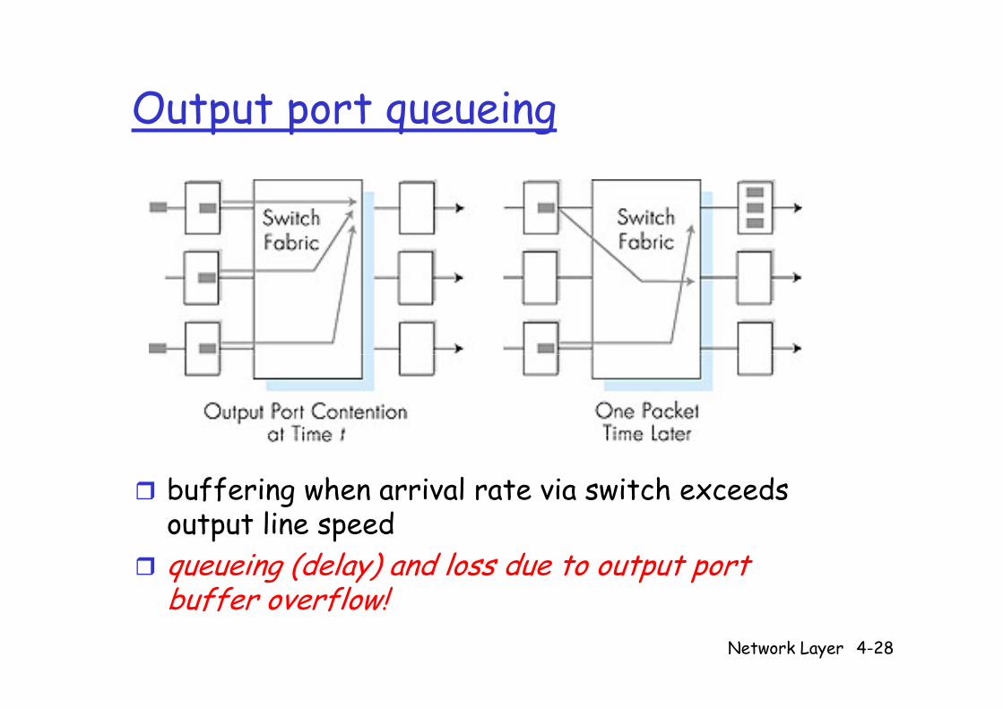
Output port queueingOutput port queueing
buffering when arrival rate via switch exceeds t t li doutput line speed
queueing (delay) and loss due to output port buffer overflow!
Network Layer 4-28
buffer overflow!
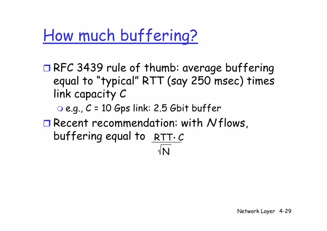
How much buffering?How much buffering?
F 4 l f h b b ff RFC 3439 rule of thumb: average buffering equal to “typical” RTT (say 250 msec) times l k link capacity C
e.g., C = 10 Gps link: 2.5 Gbit bufferRecent recommendation: with N flows, buffering equal to RTT C.g q
N
Network Layer 4-29
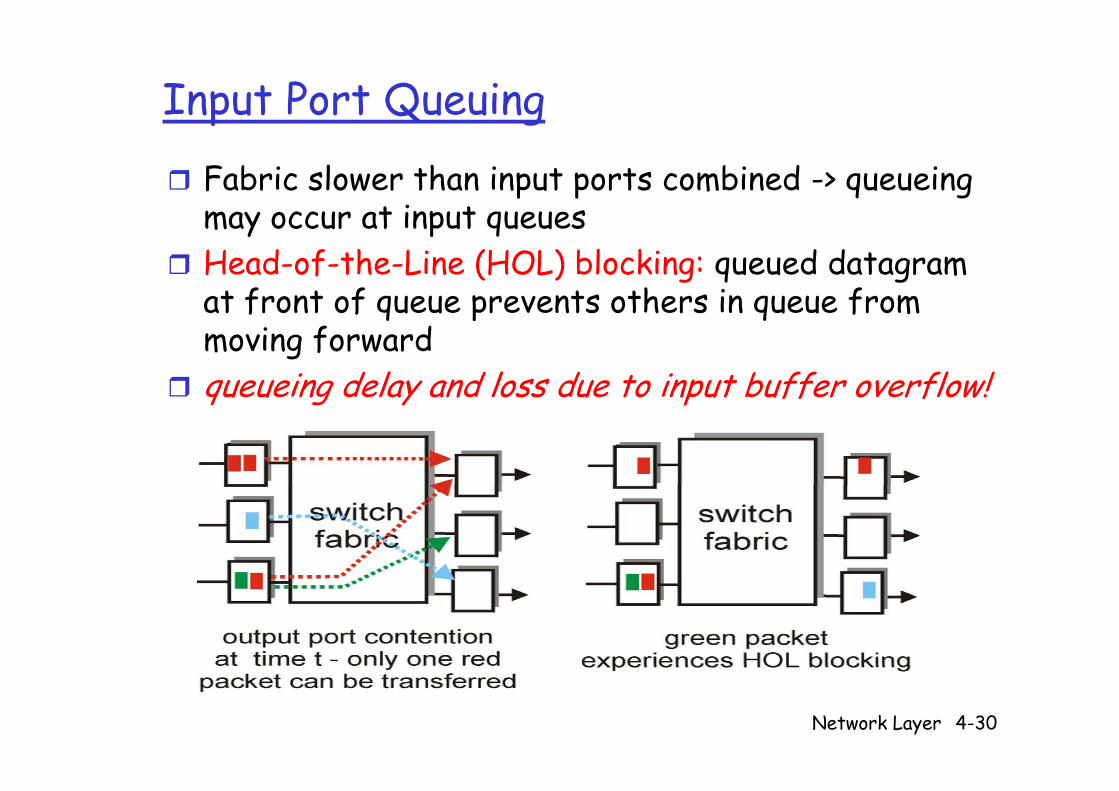
Input Port Queuing
Fabric slower than input ports combined -> queueing may occur at input queues may occur at input queues Head-of-the-Line (HOL) blocking: queued datagram at front of queue prevents others in queue from at front of queue prevents others in queue from moving forwardqueueing delay and loss due to input buffer overflow!queueing delay and loss due to input buffer overflow!
Network Layer 4-30
Related Documents