UNCLASSIFIED NETWORK INFRASTRUCTURE TECHNOLOGY OVERVIEW Version 8, Release 3 27 August 2010 Developed by DISA for the DoD

Welcome message from author
This document is posted to help you gain knowledge. Please leave a comment to let me know what you think about it! Share it to your friends and learn new things together.
Transcript
UNCLASSIFIED
NETWORK INFRASTRUCTURE
TECHNOLOGY OVERVIEW
Version 8, Release 3
27 August 2010
Developed by DISA for the DoD

Network Infrastructure Technology Overview, V8R3 DISA Field Security Operations
27 August 2010 Developed by DISA for the DoD
UNCLASSIFIED ii
This page is intentionally blank.

Network Infrastructure Technology Overview, V8R3 DISA Field Security Operations
27 August 2010 Developed by DISA for the DoD
UNCLASSIFIED iii
TABLE OF CONTENTS
Page
1. INTRODUCTION................................................................................................................. 1
1.1 Background....................................................................................................................... 1
1.2 Authority........................................................................................................................... 1
1.3 Scope ................................................................................................................................ 2
1.4 Writing Conventions ........................................................................................................ 2
1.5 Vulnerability Severity Code Definitions .......................................................................... 2
1.6 STIG Distribution............................................................................................................. 3
1.7 Document Revisions......................................................................................................... 3
2. GENERAL INFORMATION .............................................................................................. 5
2.1 Enclave Assessment using Network Infrastructure STIG and VMS Relationship .......... 5
2.2 White Papers..................................................................................................................... 5
3. ENCLAVE PERIMETER.................................................................................................... 6
3.1 Enclave Protection Mechanisms....................................................................................... 6
3.2 Network Infrastructure Diagram ...................................................................................... 9
3.3 External Connections........................................................................................................ 9
3.4 Leased Lines ................................................................................................................... 10
3.5 Approved Gateway/Internet Service Provider Connectivity.......................................... 10
3.6 Backdoor Connections.................................................................................................... 11
3.7 Network Layer Addressing............................................................................................. 12
3.8 IP Address Registration.................................................................................................. 13
3.9 IPv4 Address Privacy ..................................................................................................... 14
3.10 IPv6 Addresses ............................................................................................................... 14
3.10.1 IPv6 Address Privacy........................................................................................ 15
3.11 Dynamic Host Configuration Protocol Version 4 .......................................................... 16
3.11.1 IPv6 Autoconfiguration .................................................................................... 16
3.11.2 Stateful Autoconfiguration DHCPv6................................................................ 16
3.11.3 Stateless Autoconfiguration .............................................................................. 17
3.12 Physical Security ............................................................................................................ 17
4. FIREWALL......................................................................................................................... 18
4.1 Packet Filters .................................................................................................................. 18
4.2 Bastion Host ................................................................................................................... 18
4.3 Stateful Inspection .......................................................................................................... 19
4.4 Firewalls with Application Awareness........................................................................... 19
4.4.1 Deep Packet Inspection..................................................................................... 19
4.4.2 Application-Proxy Gateway.............................................................................. 19
4.4.3 Hybrid Firewall Technologies .......................................................................... 20
4.5 Dedicated Proxy Servers ................................................................................................ 20
4.6 Layered Firewall Architecture........................................................................................ 21
4.7 Content Filtering............................................................................................................. 23
4.8 Perimeter Protection ....................................................................................................... 24
4.9 Tunnels ........................................................................................................................... 24

Network Infrastructure Technology Overview, V8R3 DISA Field Security Operations
27 August 2010 Developed by DISA for the DoD
UNCLASSIFIED iv
4.9.1 Tunnel Inner Layer Packet................................................................................ 27
4.9.2 Tunnel Endpoints with Explicit IP Addresses .................................................. 28
4.9.3 Tunnel Endpoints Verified by Filter ................................................................. 28
4.9.4 Tunnel Endpoints PPSM Compliance .............................................................. 29
4.10 Configuration.................................................................................................................. 29
APPENDIX A. RELATED PUBLICATIONS ........................................................................ 31
APPENDIX B. FILE EXTENSIONS ....................................................................................... 37
APPENDIX C. LIST OF ACRONYMS................................................................................... 40
APPENDIX D. IPV6 ADDRESSES.......................................................................................... 46

Network Infrastructure Technology Overview, V8R3 DISA Field Security Operations
27 August 2010 Developed by DISA for the DoD
UNCLASSIFIED v
LIST OF TABLES
Table 1-1. Vulnerability Severity Code Definitions ...................................................................... 2
Table 3-1. Well-Known IPv6 Address......................................................................................... 15
TABLE OF FIGURES
Figure 3-1. Component Flow......................................................................................................... 7
Figure 3-2. Enclave Network Architecture.................................................................................... 8
Figure 3-3. Approved Gateway Architecture............................................................................... 11
Figure 3-4. DoD Backdoor Architecture ..................................................................................... 12
Figure 4-1. Firewall design with DMZ and Restricted Segments ............................................... 22
Figure 4-2. Trusted Tunnel Endpoint........................................................................................... 25

Network Infrastructure Technology Overview, V8R3 DISA Field Security Operations
27 August 2010 Developed by DISA for the DoD
UNCLASSIFIED vi
This page is intentionally blank.

Network Infrastructure Technology Overview, V8R3 DISA Field Security Operations
27 August 2010 Developed by DISA for the DoD
UNCLASSIFIED 1
1. INTRODUCTION
1.1 Background
A core mission for the Defense Information Systems Agency (DISA) Field Security Operations
(FSO) is to aid in securing Department of Defense (DoD) Networks. The processes and
procedures outlined in this Security Technical Implementation Guide (STIG), when applied, will
decrease the vulnerability of DoD sensitive information. Network Security is clearly still one of
the biggest concerns for our DoD customers (i.e., the warfighter).
The intent of the Network Infrastructure STIG is to include security considerations at the
network level needed to provide an acceptable level of risk for information as it is transmitted
throughout an enclave. This STIG has been developed to enhance the confidentiality, integrity,
and availability of sensitive DoD Automated Information Systems (AIS).
Each site network/communications infrastructure must provide secure, available, and reliable
data for all customers. This document is designed to supplement the security guidance provided
by DoD-specific requirements. This document will assist sites in meeting the minimum
requirements, standards, controls, and options that must be in place for secure network
operations.
1.2 Authority
DoD Directive 8500.1 requires that “all IA and IA-enabled IT products incorporated into DoD
information systems shall be configured in accordance with DoD-approved security
configuration guidelines” and tasks DISA to “develop and provide security configuration
guidance for IA and IA-enabled IT products in coordination with Director, NSA.” This
document is provided under the authority of DoD Directive 8500.1.
The use of the principles and guidelines in this STIG will provide an environment that meets or
exceeds the security requirements of DoD systems operating at the Mission Assurance Category
(MAC) II Sensitive level, containing sensitive information.
The Information Operations Condition (INFOCON) for the DoD recommends actions during
periods when a heightened defensive posture is required to protect DoD computer networks from
attack. The Information Assurance Officer (IAO) will ensure compliance with the security
requirements of the current INFOCON level and will modify security requirements to comply
with this guidance.
The Joint Task Force-Global Network Operations (JTF-GNO) has also established requirements
(i.e., timelines) for training, verification, installation, and progress reporting. These guidelines
can be found on their website: https://www.jtfgno.mil. Initially, these directives are discussed
and released as Warning Orders (WARNORDs) and feedback to the JTF-GNO is encouraged.
The JTF-GNO may then upgrade these orders to directives; they are then called Communication
Tasking Orders (CTOs). It is each organization's responsibility to take action by complying with
the CTOs and reporting compliance via their respective Computer Network Defense Service
Provider (CNDSP).

Network Infrastructure Technology Overview, V8R3 DISA Field Security Operations
27 August 2010 Developed by DISA for the DoD
UNCLASSIFIED 2
1.3 Scope
This document is a requirement for all DoD-administered systems and all systems connected to
DoD networks. These requirements are designed to assist Security Managers (SMs), Information
Assurance Managers (IAMs), IAOs, Network Security Officers (NSOs), and System
Administrators (SAs) with configuring and maintaining security controls. This guidance
supports DoD system design, development, implementation, certification, and accreditation
efforts.
1.4 Writing Conventions
Throughout this document, statements are written using words such as “will” and “should.” The
following paragraphs are intended to clarify how these STIG statements are to be interpreted.
A reference that uses “will” indicates mandatory compliance. All requirements of this kind will
also be documented in the italicized policy statements in bullet format, which follow the topic
paragraph. This makes all “will” statements easier to locate and interpret from the context of the
topic. The IAO will adhere to the instruction as written.
Each policy bullet includes the STIG Identifier (STIG-ID) in parentheses that precedes the policy
text and references the corresponding vulnerability in the Vulnerability Management System
(VMS). An example of this will be as follows: "(G111: CAT II)." If the item presently does
not have an STIGID, or the STIGID is being developed, it will contain a preliminary severity
code and "N/A" (i.e., "[N/A: CAT III]"). Throughout the document, accountability is directed
to the IAO to “ensure” a task is carried out or monitored. These tasks may be carried out by
the IAO or delegated to someone else as a responsibility or duty.
A reference to “should” indicates a recommendation that further enhances the security posture of
the site. These recommended actions will be documented in the text paragraphs but not in the
italicized policy bullets. All reasonable attempts to meet this criterion will be made.
1.5 Vulnerability Severity Code Definitions
Category I Vulnerabilities that allow an attacker immediate access into a
machine, allow superuser access, or bypass a firewall.
Category II Vulnerabilities that provide information that has a high potential
of giving access to an intruder.
Category III Vulnerabilities that provide information that potentially could
lead to compromise.
Table 1-1. Vulnerability Severity Code Definitions

Network Infrastructure Technology Overview, V8R3 DISA Field Security Operations
27 August 2010 Developed by DISA for the DoD
UNCLASSIFIED 3
1.6 STIG Distribution
Parties within the DoD and Federal Government's computing environments can obtain the
applicable STIG from the Information Assurance Support Environment (IASE) website. This
site contains the latest copies of any STIG, as well as scripts and other related security
information. The Non-classified Internet Protocol Router Network (NIPRNet) Uniform
Resource Locator (URL) for the IASE website is http://iase.disa.mil/.
1.7 Document Revisions
Comments or proposed revisions to this document should be sent via e-mail to [email protected].
DISA FSO will coordinate all change requests with the relevant DoD organizations before
inclusion in this document.

Network Infrastructure Technology Overview, V8R3 DISA Field Security Operations
27 August 2010 Developed by DISA for the DoD
UNCLASSIFIED 4
This page is intentionally blank.

Network Infrastructure Technology Overview, V8R3 DISA Field Security Operations
27 August 2010 Developed by DISA for the DoD
UNCLASSIFIED 5
2. GENERAL INFORMATION
The Network Infrastructure STIG has evolved from a large Microsoft Word document into a
database structure located in VMS. With this evolution, a more accurate caption of the STIG and
its updates are readily available to the customer. The content of the original STIG placed in the
VMS database has allowed the most current policies to be available to the user, after each Bi-
monthly Maintenance release.
2.1 Enclave Assessment using Network Infrastructure STIG and VMS Relationship
The VMS architecture contains two databases defined as ‘non-computing’ and ‘computing’. The
non-computing database is where the Network Infrastructure Policy resides that provides the
following purpose:
• Define vulnerabilities and safeguards that do not require configuration of an asset
• Define required assets that need to be present in the enclave, regardless of customer asset
registration completion
The second database in the VMS architecture is the computing database. Vulnerabilities
contained in the computing database are assigned to a customer’s asset when the asset is
registered in VMS. When an asset is registered in VMS, an operating system (OS) is required to
be assigned. A second task in the asset registration is defining the Asset Posture of the asset.
During this step, the role of the asset and the type of asset is identified. Based on the selection of
OS and Asset Posture (role and asset type) selected during asset registration, the asset will
receive vulnerability identifications (VUL-ID) with the appropriate safeguard procedure for the
OS and Asset Posture. Additional information is provided in the document titled Network
Infrastructure Security STIG – VMS Procedures.
2.2 White Papers
The white papers packaged with the Network Infrastructure STIG assist the reader in subject
areas without the actual procedures defined in the STIG. Their intent is to assist the reader with
illustrations and tables to visualize the need for safeguards in the VMS database, as well as
provide a quick glance of specific topics. For example, the Intrusion Detection and Prevention
Systems – Security Guidance at a Glance white paper contains specific technology related
vulnerabilities for intrusion detection systems (IDS) and intrusion prevention systems (IPS), but
does not contain any associated VUL-IDs. As of the writing of this release, the following
documents are available:
• IDPS Systems – Security Guidance at a Glance
• Network Access Control – Security Guidance at a Glance
• Network Management – Security Guidance at a Glance
• Virtual Local Area Network (VLAN) Provisioning – Security Guidance at a Glance
Network Infrastructure Technology Overview, V8R3 DISA Field Security Operations
27 August 2010 Developed by DISA for the DoD
UNCLASSIFIED 6
3. ENCLAVE PERIMETER
An enclave is a computing environment under the control of a single authority with personnel
and physical security measures. Enclave terminology used in the STIG and white papers refers
to sub-enclave and regional enclave. The sub-enclave reference is intended to describe the sub-
enclaves (i.e., base, camp, post, station, etc.). The sub-enclaves are extensions of the private
Intranet having connectivity to the enterprise Regional Enclave often termed Network
Operations Center (NOC).
3.1 Enclave Protection Mechanisms
Controlling the flow of network traffic between networks employing differing security postures
is required. By using Defense-in-Depth practices such as; firewalls, routers, Intrusion Detection
System/Intrusion Prevention System (IDS/IPS), encryption technology and various other security
devices and software combine to form layers of solutions within and among Information
Technology (IT) assets. In general, enclave protection mechanisms are installed as part of an
Intranet used to connect networks that have similar security requirements and have a common
security domain. A site may have multiple security domains with protection mechanisms
tailored to the security requirements of specific customers. The enclave or system owner will
identify security domain requirements in the Accreditation documentation (such as, System
Security Authorization Agreement [SSAA]) or the emerging DoD Information Assurance
Certification and Accreditation Process (DIACAP) process.
Procedures outlined in the DoD Instruction 8510.01, DoD Information Assurance Certification
and Accreditation Process (DIACAP), lay out the process for the enclave security architecture as
they are applied to specific requirements. Each DIACAP Implementation Plan (DIP) will
include a description of the architectural implementation of the security requirements identified
in this STIG.
The perimeter firewall will allow web traffic to pass through to the web application since the IP
address and port will likely be open. The reverse web proxy (RWP) will terminate the initial
session and validate the destination IP address corresponds to an internal web server. The web
content filter (WCF) will check the data for malware using current signatures and then will pass
back to the RWP. The RWP should then create a new session between itself and the web server
and passes the data it received from the WCF. The web application firewall (WAF) inspects the
inbound connection for application protocol and data element problems. The web server will
then terminate the connection from the RWP and processes the inbound data. If the request
requires an application (A/P) server a new connection is made from the web server to the
application server. The A/P server processes the web server request. If the request requires a call
to a database (DB) than a new connection is made from the AP server to the DB server. The DB
security gateway inspects the inbound connection for protocol and behavioral problems. The DB
then processes the request after terminating the connection from the A/P firewall.

Network Infrastructure Technology Overview, V8R3 DISA Field Security Operations
27 August 2010 Developed by DISA for the DoD
UNCLASSIFIED 7
Figure 3-1. Component Flow
The FSO STIGs and the review process provide the specifications, standards, and inspections for
each of the key enclave components.
Figure 3-2 identifies architecture of many components that could make up an enclave. The
minimum required components are briefly discussed here and depending on the deployment of
components, the security policy can change with additional requirements. The packet filtering
router provides firewall features as the first line of defense securing at layer 3 of the Open
Systems Interconnection (OSI) model. The downstream firewall provides stateful inspection and
application levels of security. A Demilitarized Zone (DMZ) is defined and required by all
medium robust DoD networks as documented in DoD Directive 8500.2.
Sensors should be strategically placed to monitor traditional and wireless traffic. The number of
sensors required is dependent of the architecture and its role, sensor capacity limitations, etc. A
key requirement is avoiding sensor data overflow, thus multiple sensors may be required in a
Regional Enclave. A single sensor may provide the capabilities needed at a local enclave
(extension of a Regional Enclave) depending on the architecture and functions the local enclave
provides.
If the enclave has an Approved Gateway (AG), than an external IDS will be required. Additional
components in the diagram may be required depending on the design of the enclave. Review
appropriate STIGs for details.
Management of remote locations is necessary for many network operation centers within DoD.
A private Wide Area Network (WAN) connection can be used with security measures in place
such as an additional firewall to extend the out-of-band (OOB) network. This is one example of
how this can be accomplished and is similar to some best practice blue prints. Further discussion
and requirements are defined in detail in the STIG under its appropriate sections.
Figure 3-2 is intended to provide best practice architecture and does not call out specific
architectural policies, but does highlight significant perimeter defense solutions to secure the
enclave. It is recommended the reader review all the perimeter policies defined in the Network
Infrastructure STIG for specific requirements pertaining to the Regional Enclave, DECC and
local enclaves.

Network Infrastructure Technology Overview, V8R3 DISA Field Security Operations
27 August 2010 Developed by DISA for the DoD
UNCLASSIFIED 8
Hardened
Packet Filter
External
IDPS
Approved
Gateway
Passive
TAP
IDPS
Private
Database
Servers
Database
Security
Gateway
``
User
Workstations
`
Private
Web Server
Private
Web Server
Private
Web Server
Restricted
Web Server
Restricted
Web Server
Restricted
Web Server
Unrestricted
Web Server
Unrestricted
Web Server
Unrestricted
Web Server
Security
Gateway
RAS Config Policy
VPN
ConcentratorIDPS
Local/Remote Enclaves
LAN segment unrestricted from
internet
LAN segment restricted from
internet, requiring authentication
LAN segment that is private, does not
provide a service to the internet
L2 or L3 switch
Tenant Enclaves
Server Farm
Web A/P
FW
L2 or L3 switch
RWP
Web content
filter
Database
Servers
Database
Security
Gateway
Application
Servers
Application
Servers
Terminal
Server
Authentication
Server
SNMP
Management
Station Syslog
Server
`System Admin
host
NTP
Server
Device
Management
LANIDPS
Possible tunnel
implementation to
perimeter firewall.
Trusted Digital
Server
Blackberry
Server
Wireless IDS
Management
Server
Wireless
IDPSWireless
Restricted
Servers
Figure 3-2. Enclave Network Architecture

Network Infrastructure Technology Overview, V8R3 DISA Field Security Operations
27 August 2010 Developed by DISA for the DoD
UNCLASSIFIED 9
Network Test Access Ports (TAPs) may be considered in network designs where promiscuous
implementations are implemented. TAPs can create a monitoring access port between any two
network devices, including switches, routers, firewalls, and more. TAPs can function as access
ports for any monitoring devices used to collect in-line data. Protocol analyzers, Remote
Network Monitoring (RMON) probes, IDSs, and other management and security solutions can
be connected to the network via TAPs. SPAN is probably a more widely deployment since it is
very scalable and is used with inline implementations.
Restricted LAN segments provide client services and backend servers such as internal Domain
Name Service (DNS) with split DNS architecture, backend mail servers, Active Directory
Domain Controller (AD DC), file and print servers, File Transfer Protocol (FTP), private Hyper
Text Transfer Protocol (HTTP) servers and various proxies. These services are generally located
in an Enclave DMZ.
3.2 Network Infrastructure Diagram
Without current and accurate documentation, any changes to the network infrastructure may
jeopardize the network’s integrity. To assist in the management, auditing, and security of the
network, facility drawings and topology maps are a necessity. Topology maps are important
because they show the overall layout of the network infrastructure and where devices are
physically located. They also show the relationship and inter-connectivity between devices and
where possible intrusive attacks (e.g., wire taps) could take place.
3.3 External Connections
Connecting to external networks is one of the most complex areas of designing, implementing,
and managing a network. An external network can be the NIPRNet or Secret Internet Protocol
Router Network (SIPRNet), as well as a network belonging to another DoD activity, a contractor
site, or even the Internet. An external network is connected to the site’s internal network via an
external connection that can include but is not limited to a dedicated circuit such as the Defense
Information System Network (DISN), Dial-on-Demand Integrated Services Digital Network
(ISDN), or an Ethernet upstream link to a neighboring service or activity’s network on the same
base.
Regardless of technology used, each external connection to the site’s internal network must be
secured such that it does not introduce any unacceptable risk to the network. Every site must
have a security policy to address filtering of the traffic to and from those connections. This
documentation along with diagrams of the network topology is required to be submitted to the
Connection Approval Process (CAP) for approval to connect to the Systems/Network for
NIPRNet or SIPRNet. Depending on the command, service, or activity, additional approvals
may be required.
SIPRNet connections must also comply with the documentation required by the SIPRNet
Connection Approval Office (SCAO) to receive the SIPRNet Interim Approval to Connect
(IATC) or final Approval to Connect (ATC). Also, any additional requirements must be met as

Network Infrastructure Technology Overview, V8R3 DISA Field Security Operations
27 August 2010 Developed by DISA for the DoD
UNCLASSIFIED 10
outlined in the Interim Authority to Operate (IATO) or Authority to Operate (ATO) forms signed
by the Designated Approving Authority (DAA).
Prior to establishing a connection with another activity, a Memorandum of Understanding
(MOU) or Memorandum of Agreement (MOA) must be established between the two sites prior
to connecting with each other. This documentation along with diagrams of the network topology
is required to be submitted to the CAP for approval to connect to the NIPRNet or the SIPRNet.
The policy must ensure that all connections to external networks should conform equally. A
connection to a trusted DoD activity must be treated the same as a connection to the NIPRNet.
The security posture of a network is only as good as its weakest link.
NOTE: Unjustified and unapproved connections will be disconnected and reported to the IAMs.
3.4 Leased Lines
DoD-leased lines carry an aggregate of sensitive and non-sensitive data; therefore, unauthorized
access must be restricted. Leased and dedicated circuits from local exchange carrier (LEC),
channel service units (CSUs), data service units (DSUs) and demarcation points (DEMARCs)
will reside in a secured area as defined in the Traditional Security STIG. These devices should
be secured, at a minimum, in a controlled access room or in a locked closet.
3.5 Approved Gateway/Internet Service Provider Connectivity
An AG is any external connection from a DoD NIPRNet enclave to an Internet Service Provider
(ISP), or network owned by a contractor, or non-DoD federal agency that has been approved.
Analysis of DoD reported incidents reveal current protective measures at the NIPRNet boundary
points are insufficient. Documented ISPs and validated architectures for DMZs are necessary to
protect internal network resources from cyber attacks originating from external Internet sources
by protective environments. Direct ISP connections are prohibited unless written approval is
obtained from the Global Information Grid (GIG) Waiver Panel or the Office of the DoD CIO
who directs the GIG Panel.
NIPRNet enclave connections to contractor or to non-DoD federal agency networks must be
approved by the Office of the Secretary Defense (OSD).
Any enclave with one or more AG connections will have to take additional steps to ensure that
neither their network nor the NIPRNet is compromised. Without verifying the destination
address of traffic coming from the site’s AG, the premise router could be routing transit data
from the Internet into the NIPRNet. This could also make the premise router vulnerable to a
Denial of Service (DoS) attack as well as provide a backdoor into the NIPRNet. The DoD
enclave must ensure that the premise router’s ingress packet filter for any interface connected to
an AG is configured to only permit packets with a destination address belonging to the DoD
enclave’s address block.
The premise router will not use a routing protocol to advertise NIPRNet addresses to the AG.
Most ISPs use Border Gateway Protocol (BGP) to share route information with other
autonomous systems (AS) (that is, any network under a different administrative control and
policy than that of the local site). Regardless of the protocol used, no protocol will redistribute

Network Infrastructure Technology Overview, V8R3 DISA Field Security Operations
27 August 2010 Developed by DISA for the DoD
UNCLASSIFIED 11
routes into the AG and no neighbors will be defined as peer routers from an AS belonging to any
AG. The only method to be used to reach the AG will be through a static route. Unsolicited
traffic that may inadvertently attempt to enter the NIPRNet by traversing the enclave's premise
router can be avoided by not redistributing NIPRNet routes into the AG. All AG connections
will have an external IDS installed and implemented in front of the premise or border router and
must be monitored by the certified CNDSP.
The enclave perimeter requirement for filtering will include JTF-GNO and Ports, Protocols and
Services (PPS) Vulnerability Assessment (VA) filtering guidelines. Monitoring traffic will be
enforced for any traffic from the AG. All traffic entering the enclave from the AG must enter
through the firewall and be monitored by internal IDS. All traffic leaving the enclave, regardless
of the destination – AG or NIPRNet addresses, will be filtered by the premise router's egress
filter to verify that the source Internet Protocol (IP) address belongs to the enclave.
Figure 3-3. Approved Gateway Architecture
3.6 Backdoor Connections
The term “backdoor connection” is used to refer to a connection between two customer sites
(DoD Enclaves) that do not traverse the provider’s network, in this case, the DISN. Routes over
this connection are called “backdoor routes”. Without taking the proper safeguard steps, this
connection could impose security risks to either site. For example, as a result of connection
availability or routing protocol administrative distances (i.e., the backdoor route is more
favorable), it is possible that traffic destined for other networks from Site B’s network and vise
versa could pass through Site A’s premise router. It is also possible that traffic from Site B’s

Network Infrastructure Technology Overview, V8R3 DISA Field Security Operations
27 August 2010 Developed by DISA for the DoD
UNCLASSIFIED 12
network could be destined for Site A’s network. In either case, the premise router external
interface providing the backdoor connection must have the same ingress filtering applied as an
external interface providing a connection to the NIPRNet, SIPRNet, or ISP.
An even greater risk would be a backdoor connection established between two sites’ internal
routers or layer-3 switches. In this case, the traffic between the two sites is bypassing the
perimeter that has been established for each network. Though both networks consider each other
a trusted network, the risk becomes evident when one of the networks has been breached, leaving
the other in a vulnerable position. Backdoor connections bypassing the network’s perimeter (i.e.,
premise or screening router, firewall, IDS, etc.) are prohibited unless the connection is mission
critical and approved by the DAA.
Figure 3-4. DoD Backdoor Architecture
3.7 Network Layer Addressing
The method by which cooperating enclaves exchange Internet Protocol, version 6 (IPv6) traffic
must be approved in accordance with the DISN connection approval process to ensure
compliance with Information Assurance (IA) policies. DoD IPv6 Transition Office (DITO) and
ASD-NII has developed a plan for the DoD IPv6 transition to progress through several
milestones, each representing increased adoption of IPv6 features. Milestone Objective 1 (MO1)
permits the fundamental IPv6 capability needed for limited operation within enclaves. Milestone
Objective 2 (MO2) permits a subset of IPv6 features and applications needed for inter-domain
networking. MO2 version 2 (MO2v2) permits partial IPv6 functional parity with Internet
Protocol, version 4 (IPv4). Milestone Objective 3 (MO3) permits full IPv6 functional parity with
IPv4 and includes additional features unique to IPv6. The following enclave network system
security components will require examination and modification for IPv6:
• Network Protection: IDS scanners, configuration and network management, auditing,
and logging

Network Infrastructure Technology Overview, V8R3 DISA Field Security Operations
27 August 2010 Developed by DISA for the DoD
UNCLASSIFIED 13
• Perimeter Security: Firewalls and Web proxies
• Host Security: Host IDS and host filters
• Data Protection: Virtual Private Network (VPN) and Internet Protocol Security (IPSec)
components
• Transport: Core routers and switches
• Assurance Devices: HAIPE, encryptors
• Configuration: DNS, Network Address Translation (NAT), Access Control List (ACL),
and PPS
• Infrastructure and Services: Dynamic Host Configuration Protocol (DHCP), DNS,
network IDS, Network Time Protocol (NTP)
To ensure a successful migration to IPv6, there will be a transitional period when IPv4 and IPv6
are used simultaneously to ensure network connectivity. MO2 will employ a phased approach
based on eleven architectures. Reference DITO IPv6 documents on the Army Knowledge
Online (AKO) portal for more detail.
3.8 IP Address Registration
The DoD Network Information Center (NIC) assigns blocks of network addressees to local
administrators. Non-DoD activities have been assigned networks by the SIPRNet Support
Center (SSC) and have been given the domain name .sgov.gov. The local network
administrator then assigns individual IP addresses to hosts, servers, printers, and workstations on
their LAN.
In the past, it has been typical to assign globally unique addresses to all hosts that use IP. In
order to extend the life of the IPv4 address space, address registries are requiring more
justification than ever before, making it harder for organizations to acquire additional address
space blocks. It is the intent of RFC 1918 to promote a strategy that will provide constraint relief
to the available globally unique address space that is rapidly diminishing.
Sites may incorporate the use of private network addresses into the site’s NIPRNet architecture
using the address spaces defined in this section. A site that uses any of these private addresses
can do so without any coordination with Internet Assigned Numbers Authority (IANA) or the
NIC. Since these addresses are never injected into the global NIPRNet, SIPRNet, or Internet
routing system, the address space can simultaneously be used by every organization.
As documented in RFC 1918, the IANA has reserved the following three blocks of the IP
address space that can be used for private networks:
10.0.0.0 - 10.255.255.255 (10/8 prefix) Class A
172.16.0.0 - 172.31.255.255 (172.16/12 prefix) Class B
192.168.0.0 - 192.168.255.255 (192.168/16 prefix) Class C

Network Infrastructure Technology Overview, V8R3 DISA Field Security Operations
27 August 2010 Developed by DISA for the DoD
UNCLASSIFIED 14
Using RFC1918 addresses and NAT on the SIPRNet is prohibited and, if implemented, requires
DISN Security Accreditation Working Group (DSAWG) approval.
3.9 IPv4 Address Privacy
Using the private addressing scheme in accordance with RFC 1918 will require an organization
to use NAT for global access. NAT works well with the implementation of RFC 1918
addressing scheme; it also has the privacy benefit of hiding real internal addresses.
NOTE: If the site has implemented an application-level firewall, hiding of the clients’ real
address can also be done by enabling the proxies.
3.10 IPv6 Addresses
An IPv6 address contains 128 bits consisting of two 64 bit parts. The left most 64 bits contain
the network part (prefix) and the right most 64 bits contain the host part (interface identifier), as
shown below. The network part is commonly called the prefix and the host part is identified as
the interface identifier. The structure of the IPv6 address space is defined in RFC 3513.
Network Prefix Interface Identifier
0 63 64 128
IPv6 addresses are represented in eight hex groups of 4 hex decimals each, separated by colons.
Each group contains sixteen binary bits. Below is an example of an IPv6 address in hexadecimal
format. The four leftmost groups contain the network prefix and the remaining four rightmost
groups of hex digits contain the interface identifier.
2001:0db8:0000:0000:0000:0000:0000:0001
The previous IPv6 address has a run of zeros and can be written as described below.
2001:db8:0:0:0:0:0:1
The IPv6 address has a run of zeros and also can be represented as described below. In IPv6,
leading zeros can be omitted and a run of zeros can be replaced with a double colon.
2001:db8::0001
The text representation of IPv6 address prefixes is similar to the way IPv4 addresses prefixes are
written in Classless Inter-Domain Routing (CIDR) notation. An IPv6 address prefix is
represented by the notation: ipv6-address / prefix-length. Prefix notation is used to designate
how many bits are used for the network part. A /48 is a common network allocation for a large
network. The left most 48 bits would identify the network prefix. The remaining would be used
for the hosts.
2001:0db8:0000::/48 or
2001:db8::/48

Network Infrastructure Technology Overview, V8R3 DISA Field Security Operations
27 August 2010 Developed by DISA for the DoD
UNCLASSIFIED 15
Appendix D contains a dated IANA IPv6 address allocation for a quick reference. For current
IPv6 allocations, visit the IANA website identified in Appendix D. Table 3-1 shows some
common IPv6 addresses and some address that have specific security guidance found in this
STIG.
Address Assignment Address Prefix
Unspecified ::/128
Loopback [RFC 2460] ::1/128
IPv4–compatible IPv6 address [Deprecated by RFC 4291] ::/96
IPv4-mapped IPv6 address ::ffff/96
Unicast Global Address [RFC 3513] 2000::/3
Initial Global IPv6 Internet address space [RFC 3056] 2001::/16
6bone testing (retired, do not use) [RFC 2471] 3ffe::/16
Unique Local Unicast Address (ULA) [RFC 4193] fc00::/7
Link Local Address [RFC 3513] fe80::/10
Site Local Address [RFC 3879] fec0::/10
Multicast Address [RFC 3513] ff00::/8
Table 3-1. Well-Known IPv6 Address
3.10.1 IPv6 Address Privacy
The NIC will assign blocks of IPv6 network addressees to local administrators. The IPv6
address, as currently defined, consists of 64 bits of network number and 64 bits of host number.
The large address space of IPv6 makes scanning impractical, but attackers can guess important
router addresses by assuming that the obvious addresses would be chosen. Avoid assigning
easily guessed addresses, such as 2001:db8::1, ::2, ::10, ::20, ::30, and etc., for network device
interfaces. It is recommended that you devise a scheme for assigning hard to guess addresses for
the enclave network devices. Those concerned with privacy issues should note that 64 bits
makes a large enough field to maintain excellent privacy for the enclave.

Network Infrastructure Technology Overview, V8R3 DISA Field Security Operations
27 August 2010 Developed by DISA for the DoD
UNCLASSIFIED 16
Internet Engineering Task Force’s (IETF's) Internet Protocol Next Generation (IPNG) working
group has recommended that the address block given to a single edge network, which may be
recursively, sub-netted be a 48-bit prefix. This gives each such network 2^16 (65,536) subnet
numbers to use in routing. A /48 prefix under the 001 Global Unicast Address prefix contains 45
variable bits. That is, the number of available prefixes is 2 to the power 45 or about 35 trillion
(35,184,372,088,832).
3.11 Dynamic Host Configuration Protocol Version 4
With an increase in Transmission Control Protocol/Internet Protocol (TCP/IP) networks, the
ability to assign IP client configurations automatically for a specific time period (called a lease
period) has alleviated the time consuming process of IP address management. Network
administrators can now automate and control, from a central position, the assignment of IP
address configurations using DHCP.
When connected to a network, every computer must be assigned a unique address. In the past,
when adding a machine to a network, the assignment and configuration of network IP addresses
has required administrator action. The user had to request an IP address, and then the
administrator would manually configure the machine. Mistakes in the configuration process are
easy to make, and can cause difficulties for both the administrator making the error, as well as
users on the network. In order to simplify the process of adding machines to the network and
assigning unique IP addresses manually, the site may decide to deploy DHCP.
If DHCP is used to allocate IP addresses for internal devices, a portion of the network IP
addresses needs to be excluded or reserved from the DHCP scope for devices that require manual
configuration of IP addresses (e.g., servers, routers, firewalls, and administrator workstations,
etc.). The DHCP server is required, at a minimum, to log hostnames or MAC addresses for all
clients. In order to trace, audit, and investigate suspicious activity, DHCP servers within the
SIPRNet infrastructure must have the minimum duration of the lease time configured to 30 days
or more.
3.11.1 IPv6 Autoconfiguration
IPv6 offers two mechanisms for a client to receive an IPv6 address. RFC 3315 documents the
standards for DHCPv6 stateful autoconfiguration and RFC 2462 documents the standards for
stateless autoconfiguration.
3.11.2 Stateful Autoconfiguration DHCPv6
Currently, many vendors are not prepared for Dynamic Host Configuration Protocol Version 6
(DHCPv6) stateful autoconfiguration; thus, there are very few implementations of it. DHCPv6 is
a completely separate protocol than DHCPv4. Unlike IPv4 DHCPDISCOVER use of the
unspecified address 0.0.0.0 with a broadcast address, these messages are sent with a FF02::1:2
(well-known DHCPv6 all-DHCPv6-Relays-and-Servers) via IPv6 support of link-local
autoconfiguration. There is also DHCPv6-Prefix Delegation (PD) that allows nodes to request
not just an address, but also the entire prefix. DHCPv6-PD is primarily used by routers. Stateful
autoconfiguration offers the best auditing capabilities due to the logs being centralized at the
DHCP server and will become the preferred implementation.

Network Infrastructure Technology Overview, V8R3 DISA Field Security Operations
27 August 2010 Developed by DISA for the DoD
UNCLASSIFIED 17
3.11.3 Stateless Autoconfiguration
Stateless autoconfiguration requires no manual configuration of hosts and minimum
configuration, if any, of routers to advertise the routing prefix. The stateless mechanism allows a
host to generate its own addresses using a combination of locally available information and
information advertised by routers. Routers advertise prefixes that identify the subnet associated
with a link, while hosts generate an interface identifier that uniquely identifies an interface on a
subnet combining the two forms an address. In the absence of routers, a host can only generate
link-local addresses. However, link-local addresses are sufficient for allowing communication
among nodes attached to the same link.
One of the design goals of stateless autoconfiguration was giving SAs the ability to specify
whether stateless autoconfiguration, stateful autoconfiguration, or both should be used. Router
Advertisements include flags specifying which mechanisms a host should use.
The use of Duplicate Address Detection opens up the possibility of DoS attacks. Any node can
respond to Neighbor Solicitations for a tentative address, causing the other node to reject the
address as a duplicate. This attack is similar to other attacks involving the spoofing of Neighbor
Discovery messages.
Many of the known attacks in stateless autoconfiguration, defined in RFC 3756, were present in
IPv4 Address Resolution Protocol (ARP) attacks. IPSec Authentication Header (AH) was
originally suggested as mitigation for the link local attacks, but has since been found to have
bootstrapping problems and to be very administrative intensive. Due to first requiring an IP
address in order to set up the IPSec association creates the chicken-before-the-egg dilemma.
There are solutions being developed (Secure Neighbor Discovery and Cryptographic Generated
Addressing) to secure these threats but are not currently available at the time of this writing.
To mitigate these vulnerabilities, links that have no hosts connected (such as the interface
connecting to external gateways) will be configured to suppress router advertisements.
3.12 Physical Security
A secure communications environment is necessary to protect the enclave from physical threats.
Cabinets, closets, and rooms need to meet the traditional security guidance.

Network Infrastructure Technology Overview, V8R3 DISA Field Security Operations
27 August 2010 Developed by DISA for the DoD
UNCLASSIFIED 18
4. FIREWALL
The industry has engineered many firewall platforms over the course of the Internet creation and
expansion as an attempt to provide customers with tools to protect their intranet. This section
identifies and helps the reader understand the weaknesses in many solutions available in today’s
market. The following firewall discussion ultimately defines the firewall requirements for DoD
enclaves, where many are derived by National Information Assurance Partnership (NIAP)
medium robustness standards.
4.1 Packet Filters
A packet filter firewall is a routing device that provides access control for system addresses and
communication sessions via a rule-set. The packet filter operates at layer 3 and filters on source
and destination addresses, and communication session parameters such as source and destination
ports. Allowing only approved IP addresses through the perimeter router will control access to
required ports and services.
The Enclave firewall rules should be based on applications being used within the internal
Enclave; all non-required ports and services will be blocked by the most restrictive rules possible
and what are allowed through the firewall will be configured IAW DoD Instruction 8551.1.
Perimeter filtering rules can be applied to any internal firewall device or router and should be
implemented to the fullest extent possible. This is necessary in order to minimize internal threat
and protect the enclaves. Packet filtering alone does not achieve the enclave robust protection
requirements due to its limitations in examining upper-layer data and limitations in providing
detailed log data. Packet filtering firewalls allow a direct connection to be made between the
two endpoints. Although this type of packet screening is configured to allow or deny traffic
between two networks, the client/server model is never broken. Packet filtering firewalls are an
all-or-nothing approach. If ports are open, they are open to all traffic passing through that port,
which in effect leaves a security hole in your network. There are three common exploits to
which packet filtering firewalls are susceptible. These are IP spoofing, buffer overruns, and
ICMP tunneling. IP spoofing is sending your data and faking a source address that the firewall
will trust. Buffer overruns typically occur when data sizes inside a buffer exceed what was
allotted. ICMP tunneling allows a hacker to insert data into a legitimate ICMP packet.
4.2 Bastion Host
The firewall can be configured as a "Bastion Host", that is, a host that is minimally configured
(containing only necessary software/services) and carefully managed to be as secure as possible.
This architecture is sometimes referred to as a Screened Host. The Screened Host is typically
located on the trusted network, protected from the untrusted network by a packet filtering router.
All traffic coming in through the packet filtering router is directed to the screened host.
Outbound traffic may or may not be directed to the screened host. This type of firewall is most
often software based and runs on a general-purpose computer that is running a secure version of
the operating system. Security is usually implemented at the application level. The most
common threat to the Bastion Host is to the operating system that is not hardened.

Network Infrastructure Technology Overview, V8R3 DISA Field Security Operations
27 August 2010 Developed by DISA for the DoD
UNCLASSIFIED 19
4.3 Stateful Inspection
Stateful Inspection firewalls incorporate added awareness to firewalls at layer 4 and
accommodate features in the TCP/IP protocol suite.
When a TCP connection is established a source port and a destination port pair become part of
the session allowing the source system to receive information from the destination system. The
client source port should be some port number greater than 1023 and less than 16384. Stateful
Inspection firewalls solve the vulnerability of permitting all the high numbered ports by creating
a state table containing the outbound TCP connections and their associated high numbered port.
The directory known as the state table is then used to validate inbound traffic. Entries are
created only for those TCP connections or UDP streams that satisfy a defined security policy.
Stateful Inspection examines only the headers of data packets, which contain information such as
the sender’s and receivers’ addresses and the type of protocol and data contained in the packet
payload. As a result, Stateful Inspection technology cannot tell the difference between valid and
harmful data. Like packet filtering, stateful packet inspection does not break the client/server
model and therefore allows a direct connection to be made between the two endpoints.
4.4 Firewalls with Application Awareness
Recent advances in network infrastructure engineering and information security have resulted in
a blurring of the lines that differentiates the various firewall platforms. Deep Packet Inspection
(DPI), Application-Proxy Gateway and Hybrid firewall technology are all catchy terms used in
the information technology industry for firewall technology that uses stateful inspection, proxies,
and with some IDS signatures and application protocol anomaly detection rules.
4.4.1 Deep Packet Inspection
Firewalls using deep packet inspection also operate at layer 4 of the OSI model with added
enhancements to Stateful Inspection technology.
Attacks can traverse a traditional stateful firewall even if the firewall is deployed and working as
it should be. By adding application-oriented checking logic into processing modules, essentially
merging IDS signatures into the firewall traffic-processing engines of products the firewall
industry increased the depth of protection against worms, trojans, email viruses, and exploits
against software vulnerabilities. Deep Packet Inspection uses an Attack Object Database to store
protocol anomalies and attack patterns (sometimes referred to as signatures), grouping them by
protocol and security level (severity). Packet processing is typically described as performing
application level checks as well as stateful inspection. The primary limitation of the technology
is that it generally cannot detect threats that require many packets to transmit across the Internet.
4.4.2 Application-Proxy Gateway
Application-Proxy Gateway firewalls are advanced firewalls that combine lower layer access
control with upper layer (Layer 7 Application Layer) functionality.
In an application-proxy gateway, two TCP connections are established: one between the packet
source and the firewall, another between the firewall and the packet destination. Application

Network Infrastructure Technology Overview, V8R3 DISA Field Security Operations
27 August 2010 Developed by DISA for the DoD
UNCLASSIFIED 20
proxies intercept arriving packets on behalf of the destination, examine application payload, and
then relay permitted packets to the destination. The technology of application-proxy gateway
does not require network layer routes between the firewall interfaces. The firewall software
performs the routing; meaning packets that traverse the firewall must do so under software
control. Proxy implementations can offer very granular application-level control such as
blocking file transfers involving filenames ending in .exe. Advantages also include capabilities
to enforce user authentication, hardware or software token authentication, source address
authentication, and biometric authentication. Due to full packet awareness application-proxy
gateways can degrade high-bandwidth or real-time solutions. These gateways also tend to be
limited for new applications and protocols and can become capable of tunneling the new
applications in a vendor generic proxy agent. These generic proxy-agents tend to negate many
strengths of the application-proxy gateway.
4.4.3 Hybrid Firewall Technologies
To provide the best of both worlds, many firewalls are actually hybrids that combine stateful
inspection and application proxy methods. Many Application-Proxy Gateway firewall vendors
have implemented basic packet filter functionality in order to provide better support for UDP
(User Datagram) based applications. Likewise, many packet filter or Stateful Inspection packet
filter firewall vendors have implemented basic application-proxy functionality to offset some of
the weaknesses associated with their firewall platform. In most cases, packet filter or stateful
inspection packet filter firewall vendors implement application proxies to provide improved
network traffic logging and user authentication in their firewalls.
4.5 Dedicated Proxy Servers
Dedicated proxy servers differ from application-proxy gateway firewalls in that they retain proxy
control of traffic but they do not contain firewall capability. They are typically deployed behind
traditional firewall platforms for this reason. In typical use, a main firewall might accept
inbound traffic; determine which application is being targeted, and then hand off the traffic to the
appropriate proxy server, (e.g., an email proxy server). The proxy server typically would
perform filtering or logging operations on the traffic and then forward it to internal systems. A
proxy server could also accept outbound traffic directly from internal systems, filter or log the
traffic, and then pass it to the firewall for outbound delivery. An example of this would be an
HTTP proxy deployed behind the firewall; users would need to connect to this proxy en route to
connecting to external web servers. Typically, dedicated proxy servers are used to decrease the
work load on the firewall and to perform more specialized filtering and logging that otherwise
might be difficult to perform on the firewall itself.
As with application-proxy gateway firewalls, dedicated proxies allow an organization to enforce
user authentication requirements as well as other filtering and logging on any traffic that
traverses the proxy server. The implications are that an organization can restrict outbound traffic
to certain locations or could examine all outbound email for viruses or restrict internal users from
writing to the organizations web server. Security experts have stated that most security problems
occur from within an organization; proxy servers can assist in foiling internally based attacks or
malicious behavior. At the same time, filtering outbound traffic will place a heavier load on the
firewall. Dedicated proxy servers are useful for web and email content scanning, including the
following:
Network Infrastructure Technology Overview, V8R3 DISA Field Security Operations
27 August 2010 Developed by DISA for the DoD
UNCLASSIFIED 21
• Java applet or application filtering (signed versus unsigned or universal)
• ActiveX® control filtering (signed versus unsigned or universal)
• JavaScript filtering
• Blocking specific Multipurpose Internet Multimedia Extensions (MIME) types for
example, .application/msword for Microsoft® Word documents (see Appendix B File
Extensions for suggestions for specific types)
• Virus scanning and removal
• Macro virus scanning, filtering, and removal
• Application-specific commands, for example, blocking the HTTP .delete command
• User- specific controls, including blocking certain content types for certain users
4.6 Layered Firewall Architecture
A packet filtering firewall such as a customer premise edge router must be implemented to filter
traffic from external networks such as the NIPRNet, SIPRNet and Internet. This premise router
is the first line of defense in a defense-in-depth firewall solution. The premise router can block
certain attacks, filter PPS CAL red ports and protocols prior to filtering operations at higher
layers of the OSI stack by other firewall technologies.
Following DoD Instruction 8500.2, a DMZ is required for confidentiality levels of High and
Medium identified as classified and sensitive domain respectively. A DMZ is created between
two policy-enforcing components such as two or more firewall components existing in an
environment or off a third firewall interface. Hubs should never be used in a DMZ environment
because they allow any device connected to them to see all the network traffic destined and
originating from any other device connected to the same hub.
Network switches are components that can be found in a DMZ environment to provide
connectivity points making up a defense-in-depth architecture. Unlike hubs, systems that
connect to a switch cannot eavesdrop on each other when switches are in use. Switches are
useful for implementing DMZ environments.
A firewall can be placed at several locations to provide protection from attacks. Each
implementation will differ depending on several factors, including the sensitivity of the
networks, the network infrastructure, and the type of network traffic. Firewalls are used
primarily to protect the boundaries of a network, although at times they can be used to separate
an internal security domain from the rest of an enclave (LAN to LAN). When the main firewall
is located behind the premise router the DMZ is created. There are many variations in firewall
designs and figure 4-1 is not a recommendation, but a reference to the discussion in this guide.

Network Infrastructure Technology Overview, V8R3 DISA Field Security Operations
27 August 2010 Developed by DISA for the DoD
UNCLASSIFIED 22
DMZ for Public Services
VPN
Concentrator
Public WebServer
RAS Config PolicyEmail Front-end
Relays to Back-end
DNS
external
Hardened
Packet Filter
Promiscuous
ports
IPS
IDSPassive
TAP
IDS
Database
Server
Restricted Servers / Databases
AD DC
Private
Web ServerFile & Print
Server
FTP Server Application
Server
Proxy Server Certificate
Server
Back-end
AD DCInternal DNS
Services to
workstations
Passive
TAP
ISA
Server
IPS
Wireless Restricted Servers
Trusted Digital
Server
Blackberry
Server
Wireless IDS
Management ServerWireless
IDS
Host LAN
Figure 4-1. Firewall design with DMZ and Restricted Segments
Many vendors are providing integrated router, firewall, IPS and IDS solutions to reduce
operation costs, space, and power requirements in the remote and small site locations. An
integrated solution implemented within DoD should not waive from defense in depth practices.
Router and firewall integration approved by NIAP is an acceptable solution however; Design
Engineers should consider the number of concurrent sessions and application services the
firewall will inspect to ensure degradation is avoided.
The current trend in firewall development is the incorporation of advanced security features.
Most midrange enterprise firewall manufacturers are rolling in features such as IPS, anti-spam,
and anti-virus. Therefore, it may become increasingly more difficult to find a firewall that only
performs "traditional" firewall functions. As such, guidance for the usage/deployment of
integrated security solutions will be provided. These solutions have leveraged processors and
memory. Once this technology is compromised, all security layers of defense are subject to DOS
in a single attack. The possibility of all of the segments in an integrated security solution losing
functionality (which would result in the loss of external network availability) during an attack of

Network Infrastructure Technology Overview, V8R3 DISA Field Security Operations
27 August 2010 Developed by DISA for the DoD
UNCLASSIFIED 23
one of the security features does indeed exist. This is especially the case in situations where
similar code may exist on certain parts of the packet processing functions. Thus, even if
different components are running on separate hardware, have separate CPUs, and separate
memory, any similar code that may exist on certain parts of the packet processing functions
could open the device up for attacks that could span multiple components of the integrated
security solution.
It is important to note that even though the hardware modules are separated, they can be
configured to run inline and running inline defeats the purpose of having separate hardware.
The IPS can run in either promiscuous mode or inline mode. In inline mode, the IPS interfaces
are associated with the ingress and egress interfaces of the firewall. If the IPS is under attack
and crashed, no traffic will flow to the egress interface of the firewall. However, if running in
promiscuous mode and the IPS module is attacked, the firewall will still function properly, as the
IPS only receives a copy of the traffic, not wedge itself in between the firewalls egress and
ingress interfaces. The drawback in the scenario is that the firewall is not able to stop the first
packet in an attack. Some attacks are only one packet. As such, it may be possible to send one
attack that could crash the integrated security solution. The probability of this or any other DoS
condition occurring depends on the product itself (e.g., how well it performs its functions and its
underlying code) and how it is deployed in the network.
4.7 Content Filtering
The Enclave requirement to place a firewall at the perimeter can be accomplished by multiple
scenarios to include the following:
- An application-level firewall at the perimeter to protect the whole Enclave to include the
Security Domains.
- A non application-level firewall at the perimeter (e.g., packet-filter, stateful inspection,
deep packet inspection) with a dedicated proxy server or application-proxy gateway
protecting every Security Domains.
- A Hybrid firewall at the perimeter to protect the whole Enclave to include the Security
Domains capable of application-proxy functionality.
Due to technological advances there are devices such as SSL Gateways, E-mail Gateways, etc.,
that will proxy services to protect the enclave. Therefore, a layer 4 or Stateful Inspection
firewall, in collaboration with application level proxy devices to service all connections is an
acceptable alternative.
Creating a filter to allow a port or service through the firewall without a proxy, creates a direct
connection between the host in the private network and a host on the outside; thereby, bypassing
additional security measures that could be provided by a proxy server. This places internal hosts
at greater risk of exploitation and could make the entire network vulnerable to an attack. A
solution with a proxy server can accept outbound traffic directly from internal systems, break the
connection and filter or log the traffic, prior to passing it to the firewall for outbound delivery.

Network Infrastructure Technology Overview, V8R3 DISA Field Security Operations
27 August 2010 Developed by DISA for the DoD
UNCLASSIFIED 24
Data entering or leaving the site must be proxied or the firewall is configured to implement the
content, protocol and flow control inspections defined below.
- DNS Inspection: Protocol conformance, malformed packets, message length and domain
name integrity. Query ID and port randomization for DNS query traffic must be enabled.
- SMTP and ESMTP Inspection: Extended SMTP and SMTP inspection will be configured
to detect spam, phishing and malformed message attacks.
- FTP: FTP is not a recommended file transfer solution. Reference the Enclave STIG for
conditional guidance on FTP. The firewall should inspect FTP traffic and drop
connections with embedded commands, truncated commands, provide command and
reply spoofing, drop invalid port negotiations, and protect FTP servers from buffer
overflow.
- HTTP: Inspection will be configured to filter Java applets and ActiveX objects to meet
the enclave security policy. Review the security policy with the Information Assurance
Officer and look for Java and ActiveX filters if the security policy requires restrictions.
4.8 Perimeter Protection
There are a number of firewall solutions available to secure the enclave environment. To obtain
the minimum requirements to secure the enclave, a defense-in-depth practice is required.
If the perimeter is in a Deny-by-Default posture, and what is allowed through the perimeter
filtering is IAW DoD Instruction 8551.1 then the PPS would be covered under the Deny-by-
Default rule, if permit rules are created for each approved port and protocol or all red ports were
explicitly blocked. The permit rule with the port or protocol definition is required to prevent red
PPS ports from traversing trusted subnets, otherwise a trusted subnet could use untrusted or red
ports identified by the PPS, thus negating the blocking of ports identified in the PPS CAL.
Allowing only approved IP addresses through the perimeter router will control access to required
ports and services.
The requirement for perimeter protection includes either a firewall implemented to protect the
enclave and in deny-by-default posture or the premise router ACLs are in a deny-by-default
posture and all tunnel endpoints are in a deny-by-default posture. One or the other will satisfy
the requirement at the enclave boundary.
4.9 Tunnels
The default stance is that IP tunnels are disabled. This guidance does not recommend whether
tunnels need to be disabled or enabled, as that is determined by operational necessity, only that
the default position is “disabled”. The threat from tunneling is caused by the fact that tunneled
traffic has a complete IP packet encapsulated within the payload of the outer tunnel layer(s). If
tunneled traffic enters a network, the inner IP packet may evade the normal scrutiny of firewalls,
IDS, or other security measures. Once inside, the tunneled traffic could be decapsulated allowing

Network Infrastructure Technology Overview, V8R3 DISA Field Security Operations
27 August 2010 Developed by DISA for the DoD
UNCLASSIFIED 25
the inner IP packets to be delivered to inside nodes. Any allowed tunnel traffic must be properly
filtered and secured.
Ensure the firewall is in a deny-by-default posture, then review to determine if explicit
allow/permits are defined for tunnels described. Ensure tunnels are documented in the SAA and
need and justification are current.
The default guidance is:
- Do not enable tunnels, unless it is part of the planned topology to use the known tunnel.
- Do apply filtering to prevent tunnel traffic from entering the network.
Tunneling capabilities can be available as basic operating system features or from various
toolsets or network management software, but they should all be disabled by default in well
behaved implementations. The filtering guidance is a backup measure in case any weak
implementations accept a tunneled packet despite not being explicitly configured to do so. The
IPv4-in-IPv4 specification (RFC 2003), in particular, does not contain strong enough language to
require tunnel traffic to be dropped by default, especially when the decapsulator and final
recipient is one and the same node.
The enclave can not be considered secure if trusted tunnel endpoints are not well defined with
the policies outlined in this section and described in figure 4-2.
Figure 4-2. Trusted Tunnel Endpoint

Network Infrastructure Technology Overview, V8R3 DISA Field Security Operations
27 August 2010 Developed by DISA for the DoD
UNCLASSIFIED 26
The outer tunneling layer can be IPv4 or IPv6, therefore some of the actions below are
technically IPv4 guidance (e.g. IP4-in-IPv4 tunnels). There is no limit, however, to the number
of tunnel layers and an IPv6 packet could be buried several layers deep, so all tunnels must be
filtered in order to preserve security.
Deny-by-Default IPv4-in-IPv4 tunnels - Drop inbound and outbound IPv4 packets with a
protocol value of 0x04 (4).
Deny-by-Default IPv6-in-IPv4 tunnels - Drop inbound and outbound IPv4 packets with a
protocol value of 0x29 (41).
Deny-by-Default IPv4-in-IPv6 tunnels - Drop inbound and outbound IPv6 packets with a
protocol value of 0x04 (4).
Deny-by-Default IPv6-in-IPv6 tunnels - Drop inbound and outbound IPv6 packets with a
protocol value of 0x29 (41).
Report the detection of all outbound tunnel packets as a security event. Outbound tunnel packets
should trigger a security alert. These events are likely due to unauthorized users or malware.
L2TP tunneling technologies that must be disabled by default that pose the same threat as IP-in-
IP tunneling described above since they could potentially carry an IPv6 packet. If they are
needed, additional guidance for enabling them is contained in the Backbone Transport STIG.
The tunneling technologies listed here may be in use in DoD networks today.
The L2TP protocol carries a link layer (and higher) packet within an outer IP tunneling packet. It
is therefore even more likely to evade security scrutiny (IDS etc...) since the inner IP packet is
buried an extra layer deep.
Disable any use of L2TP Tunneling - Refer to additional STIG guidelines for enabling L2TP
tunneling. If required, L2TPv3 is a more robust implementation using authentication. This
guidance recognizes that although L2TP’s default port is 1701, it may be configured to use other
ports. L2TP must not be configured on any port for the default stance.
Drop L2TP protocol - Drop inbound and outbound IPv4 and IPv6 packets with a protocol value
of 0x73 (115).
Drop L2TP protocol in TCP/UDP - Drop inbound and outbound IPv4 and IPv6 packets
containing TCP port 1701 or UDP port 1701.
Deny by default any use of GRE Tunneling - Refer to the PPSM Vulnerability Assessment for
enabling GRE tunneling. GRE must not be configured on any port for the default stance.
Drop GRE Tunnel Packets - Drop inbound and outbound IPv4 and IPv6 packets with a protocol
value of 0x2F (47).

Network Infrastructure Technology Overview, V8R3 DISA Field Security Operations
27 August 2010 Developed by DISA for the DoD
UNCLASSIFIED 27
There are a number of outdated tunneling schemes that should be blocked to avoid importing
IPv6 packets. These must be blocked at the perimeter router or firewall or denied by the deny-by
default policy.
Drop Source Demand Routing Protocol (SDRP) - Drop inbound IPv4 and IPv6 packets with a
protocol value of 0x2A (42).
Drop AX.25 tunneling - Drop inbound IPv4 and IPv6 packets with a protocol value of 0x5D
(93).
Drop IP-within-IP Encapsulation Protocol - Drop inbound IPv4 and IPv6 packets with a protocol
value of 0x5E (94).
Drop EtherIP protocol - Drop inbound IPv4 and IPv6 packets with a protocol value of 0x61 (97).
Drop Encapsulation Header protocol - Drop inbound IPv4 and IPv6 packets with a protocol
value of 0x62 (98).
Drop PPTP protocol - Drop inbound IPv4 and IPv6 packets containing TCP port 1723 or UDP
port 1723.
4.9.1 Tunnel Inner Layer Packet
Once decapsulated, the inner IP layer of a tunneled packet is no different than any other IP
packet. Therefore, the inner IP layer must be filtered at the tunnel exit point network. In fact
some packets are more dangerous tunneled such as attacks against Neighbor Discovery where a
required 255 count in the hop limit field could potentially be delivered.
This guidance describes three ways in which the inner IP layer filtering task may be
accomplished, depending on the advances in firewall technology. Refer to NSA firewall design
considerations for IPv6 section 5.2 for a description of desired firewall filtering capabilities for
tunneled traffic. This reference document defines primary filtering as a firewall that can filter the
inner source and destination IP addresses of a tunneled packet in a manner similar to filtering
source and destination ports of a TCP or UDP packet. Secondary filtering capability is defined to
be the ability to fully filter the entire inner IP layer to the same degree an untunneled packet is
filtered.
The Primary guidance assumes an advanced firewall with the capability to perform both the
primary and secondary filtering functions as explained above. Alternative 1 assumes that the
firewall can perform only the primary filtering function. Alternative 2 assumes the firewall
cannot do either primary or secondary filtering as may be the case with some existing firewall
products.
For Alternatives 1 and 2, the decapsulation point may be an interior router with the filtering of
the inner IP layer performed by a secondary firewall. Additional actions are provided to protect
the decapsulating node itself from being attacked, since this node is in front of the protective
filtering.

Network Infrastructure Technology Overview, V8R3 DISA Field Security Operations
27 August 2010 Developed by DISA for the DoD
UNCLASSIFIED 28
The complexity of securing the enclave with these policies is defined in the Network STIG
procedure of NET-TUNL-002.
4.9.2 Tunnel Endpoints with Explicit IP Addresses
IPv6-in-IPv4 tunnels require explicit configuration (on the tunnel exit point node) of both the
tunnel exit point IP address and the corresponding tunnel entry point address. These are the outer
IP layer destination and source addresses respectively. Unfortunately, the other three tunnel types
(4-in-4, 4-in-6, and 6-in-6) have no such requirement built into the standards. The tunnel exit
point address will likely need to be configured for these tunnel types (i.e. nodes are not expected
to simply accept tunneling by default) and there may be a configuration option to allow the
tunnel entry point address to be declared as well. Administrators should attempt to specify both
addresses regardless of the IP versions being tunneled if the capability is available for the
implementation.
There are no requirements in the GRE tunnel standards to check or restrict IP addresses of the
tunnel end points (outer IP layer), so it is purely up to the software implementer. The tunnel exit
point address will likely need to be configured for these tunnels (i.e. nodes are not expected to
simply accept GRE tunneling by default) and there may be a configuration option to allow the
tunnel entry point address to be declared as well. Administrators should attempt to specify both
addresses if the capability is available for the implementation.
This vulnerability description and required safeguard is not applicable to MPLS auto tunnels
used in traffic engineering.
The following three tunnel types (4-in-4, 4-in-6, and 6-in-6) do not have requirements built into
the standards. Tunnel exit points must be filtered to ensure these protocols have a valid
destination address. If a destination address is not defined for these protocols, than drop the
packets via the deny-by-default tunnel policy.
4-in-4 - protocol number: 0x04 (4)
4-in-6 - protocol number: 0x04 (4)
6-in-6 - protocol number: 0x29 (41)
GRE - protocol number: 0x2F (47)
ESP - protocol (50)
AH - protocol (51)
The language in the actions above such as “Drop any ... packet” should be modified as
appropriate to account for the packets of any legitimate and deliberately chosen mechanisms.
However these deliberate tunnels that do not comply with this policy need to be documented in
the SSAA detailing purpose and verification data.
4.9.3 Tunnel Endpoints Verified by Filter
Tunnel endpoints that do not have the same controls as the network perimeter requirements
become an unprotect entry point into the enclave. These filtering actions enforce proper tunnel
endpoint addresses at the border of the tunnel entry and exit points. Filtering is necessary
because implementations may not enforce tunnel addresses in all cases. Filtering is also

Network Infrastructure Technology Overview, V8R3 DISA Field Security Operations
27 August 2010 Developed by DISA for the DoD
UNCLASSIFIED 29
necessary because GRE tunneling implementations are not required by standards to check or
enforce tunnel endpoint addresses.
The filter for the tunnel Entry-point must be defined to permit expected traffic that enters the
tunnel. All other traffic must be denied. This filter must contain a permit statement that explicitly
permits the tunnel type (protocol) and the source and destination address.
The filter for the tunnel Exit-point must be defined to permit the expect traffic that exits the
tunnel. All other traffic must be denied. This filter must contain a permit statement that explicitly
permits the tunnel type (protocol) and the source and destination address.
4.9.4 Tunnel Endpoints PPSM Compliance
Allowing unknown traffic into the enclave creates high risk and potential compromise by an
intruder. Protocols used by applications the PPSM has reviewed and determined to require
additional mitigation is necessary to protect the GIG. After determining the final decapsulation
endpoints, ensure the tunnel implements protocol inspection, filtering and mitigation as defined
in the PPS VA reports.
4.10 Configuration
If the site has implemented SYN flood protection for the network using the premise router, it is
not an additional requirement to implement this on the firewall.
The firewall must protect the private network from external attacks. The firewall will be
maintained with the current supported version of the software and the Operating System (OS)
will have all security related patches applied. The Firewall Administrator (FA) will subscribe to
the vendor's vulnerability mailing list to be made aware of required upgrades and patches. The
firewall itself must be resistant to penetration to assist in preventing hackers from breaking
through the firewall and accessing the entire network. Firewalls running on a standard OS must
be stripped-down and hardened. Unnecessary executables, compilers, and other dangerous files
must be removed and unnecessary services turned off. These functions are likely to be running
using default configurations, which are usually much less secure. Disabling unused protocols
ensures that attacks on the firewall utilizing protocol encapsulation techniques will not be
effective.
If an IAVM is issued against the OS any time after the firewall installation and implementation,
the FA must contact the firewall vendor to determine if the firewall is vulnerable and if there is a
patch to be applied to the OS. If the vendor does not recommend installing a patch or upgrade,
and has stated that the firewall is not vulnerable, the FA must retain this documentation.
By configuring the firewall to provide a message to the local console regardless of whether an
administrator is logged in by sending alerts due to modification or exceeding capacity of audit
logs ensures administrative staff is aware of critical alerts. The message should be displayed at
the remote console if an administrator is already logged in, or when an administrator logs in.
This requirement specifies that the message be sent to the first established session for each of the
defined roles to ensure someone in the administrator staff is aware of the alert as soon as
possible.

Network Infrastructure Technology Overview, V8R3 DISA Field Security Operations
27 August 2010 Developed by DISA for the DoD
UNCLASSIFIED 30
The firewall shall immediately display an alert message, identifying the potential security
violation and make accessible the audit record contents associated with the event(s) that
generated the alert. The message is displayed at the console if an administrator is already logged
in, or when an administrator logs in if the alarm message has not been acknowledged. The audit
records contents associated with the alert may or may not be part of the message displayed;
however the relevant audit information must be available to administrators.
The firewall will display the alert message identifying the potential security violation and make
accessible the audit record contents associated with the event(s) until it has been acknowledged.
The intent is to ensure that if an administrator is logged in and not physically at the console or
remote workstation the message will remain displayed until they have acknowledged it. The
message will not be scrolled off the screen due to other activities taking place (e.g., the Audit
Administrator is running an audit report).
Acknowledging the message could be a single event, or different events. In addition, assurance
is required that each administrator that received the message also receives the acknowledgement
message, which includes some form of reference to the alert, who acknowledged the message
and when. The firewall shall display an acknowledgement message identifying a reference to the
potential security violation, a notice that it has been acknowledged, the time of the
acknowledgement, and the user identifier that acknowledged the alert.

Network Infrastructure Technology Overview, V8R3 DISA Field Security Operations
27 August 2010 Developed by DISA for the DoD
UNCLASSIFIED 31
APPENDIX A. RELATED PUBLICATIONS
Government Publications
• DoD Directive 8500.1, "Information Assurance (IA)," October 24, 2002
• DoD Instruction 8500.2, "Information Assurance (IA) Implementation," February 6, 2003
• DoD Instruction 8551.1, "Ports, Protocols, and Services Management (PPSM)," August
13, 2004
• DoD CSC-STD-002-85, "DOD Password Management Guideline," April 12, 1985
• CJCSM 6510.01, "Defense-in-Depth: Information Assurance (IA) and Computer Network
Defense (CND)", March 25, 2003
• DoD CM-400-260-01, “Software Requirements Specification (SRS) for the Network
Management (NM) Functional Area Of The Defense Information Infrastructure (DII),”
July 8, 1997
• DoD Directive Number 3020.26, Continuity of Operations (COOP) Policy and Planning,
May 26, 1995
• DoD Instruction Number 3020.39, Integrated Continuity Planning for Defense
Intelligence, ASD (C3I), August 3, 2001
• DoD Directive Number O-8530.1, Computer Network Defense (CND), January 8, 2001
• Defense Information Systems Agency Instruction (DISAI) 630-230-19, "Security
Requirements for Automated Information Systems (AIS)," August 1991, and Supplements
1 and 2, not dated
• ASD (NII) Memo, “Internet Protocol Version 6” (IPv6), June 9, 2003
World-Wide Web (WWW) References
• Network Information Center (NIC) – http://www.internic.net
• Electronic Industry Association/Telecommunications Industry Association (EIA/TIA) –
http://www.eia.org
• Global Engineering Documents – http://global.ihs.com
• Internet Engineering Task Force (IETF) – http://ww.ietf.org
• Internet Assigned Numbers Authority (IANA) – http:///www.iana.org
• CISCO – http://www.cisco.com
• Foundry Networks – http://www.foundrynet.com
• Juniper – http://www.juniper.net
• Cisco Channel Interface Processor – http://www.cisco.com

Network Infrastructure Technology Overview, V8R3 DISA Field Security Operations
27 August 2010 Developed by DISA for the DoD
UNCLASSIFIED 32
• Cisco Field Notices – http://www.cisco.com/warp/public/770/index.shtml
• Cisco Security Advisories – http://www.cisco.com/warp/public/707/advisory.html
• Cisco White Papers Website – http://www.cisco.com/warp/public/126/index.shtml
• CISCO, SAFE Blueprint, Best Practices for Securing Routing Protocols
• JTF-GNO Net Defense home page – http://www.cert.org
• DoD-CERT Home Page – http://www.cert.mil
• CERT Alerts (from 1988) – http://www.cert.org/nav/alerts.html
• DoD-CERT Home Page – http://www.cert.mil
• NIPRNet Connection Approval Process – http://cap.nipr.mil
Firewall References
• Guidelines on Firewalls and Firewall Policies, NIST Special Publication 800-41, January
2002
• Firewall Design Considerations for IPv6, NSA
• U.S. Government Firewall Protection Profile for Medium Robustness Environments,
NIAP, July 2002
• Firewall Evolution, Deep Packet Inspection, Ido Dubrawsky, July 2003
• The Perils of Deep Packet Inspection, Dr. Thomas Porter, January 2005
• Stateful Inspection Technology, Checkpoint, August 2005
• Addressing the Limitations of Deep Packet Inspection with Complete Content Protection,
FORTINET Whitepaper, 2004
• An Introduction to Network Firewalls and the Firewall Selection Process, March 25,
2003 Whitepaper
IDPS, Content Scanning and Proxy References
• NIST Special Publication on Intrusion Detection System, SP800-31
• CISCO SAFE: IDS Deployment, Tuning, and Logging in Depth
• Guide to Intrusion Detection and Prevention Systems (IDPS), SP800-94
• CISCO Configuring the Intrusion Prevention System Sensor Using the Command Line
Interface 5.0
• Secure Computing IronMail: World-Class Enterprise Spam Filtering Whitepaper
• BlueCoat Systems Proxy SG Appliance: Configuration and Management Suite Volume 7:
Managing Content
• BlueCoat Systems Proxy SG Appliance: SSL Proxy Reference Guide—SGOS 5.3.1

Network Infrastructure Technology Overview, V8R3 DISA Field Security Operations
27 August 2010 Developed by DISA for the DoD
UNCLASSIFIED 33
IPv6 References
• Department of Defense Internet Protocol Version 6 Information Assurance Guidance for
Milestone Objective 3 Version 0.20
• Department of Defense Internet Protocol Version 6 Information Assurance Guidance for
Milestone Objective 3 Version 0.10a
• DoD IPv6 IA Guidance documents located on the AKO portal
• NSA MO2v1 and MO2v2 T&E Reports on the AKO portal
• Department of Defense (DoD) Internet Protocol Version 6 (IPv6) Transition Office
(DITO) Information Assurance (IA) Guidance for Milestone Objectives 2 (MO2), January
2006
• [RFC1981] J. McCann, S. Deering, and J. Mogul, "Path MTU Discovery for IP version
6", RFC 1981, August 1996
• [RFC2401] E. Nordmark & R. Gilligan, "Basic IPv6 Transition Mechanisms”, October
2005
• [RFC2401] Kent, S. and R. Atkinson, "Security Architecture for the Internet Protocol",
RFC 2401, November 1998
• [RFC2460] S. Deering. and R. Hinden, "Internet Protocol, Version 6 (IPv6)
Specification", RFC 2460, December 1998
• [RFC2461] Narten, T., Nordmark, E., and W. Simpson, "Neighbor Discovery for IP
Version 6 (IPv6)", RFC 2461, December 1998
• [RFC2462] Thomson, S. and T. Narten, "IPv6 Stateless Address Autoconfiguration",
RFC 2462, December 1998
• [RFC2470] R. Coltun, D. Ferguson and J. Moy, "OSPF for IPv6", RFC 2470, December
1999
• [RFC3053] A. Durand, P. Fasano, I. Guardini, D. Lento, " IPv6 Tunnel Broker", RFC
3513, January 2001
• [RFC3056] Carpenter, B. and K. Moore, "Connection of IPv6 Domains via IPv4 Clouds",
RFC 3056, February 2001
• [RFC3177] Internet Architecture Board and Internet Engineering Steering Group,
"IAB/IESG Recommendations on IPv6 Address Allocations to Sites", RFC 3177,
September 2001
• [RFC3484] Draves, R. "Default Address Selection for Internet Protocol version 6
(IPv6)", RFC 3484, February 2003
• [RFC3513] Hinden, R. and S. Deering, "Internet Protocol Version 6 (IPv6) Addressing
Architecture", RFC 3513, April 2003
• IPv6 for Security Professionals v5.5.0, Command Information, 2006

Network Infrastructure Technology Overview, V8R3 DISA Field Security Operations
27 August 2010 Developed by DISA for the DoD
UNCLASSIFIED 34
• [V6SEC] Savola, P., "IPv6 Transition/Co-existence Security Considerations", Work in
Progress, October 2004
• [V64IPSEC] Graveman, R., et al., "Using IPsec to Secure IPv6-over-IPv4 Tunnels",
Work in Progress, December 2004
• North American IPv6 Task Force (NAv6TF) Technology Report, M. Kaeo, D. Green, J.
Bound, and Y. Pouffary, “IPv6 Security Technology Paper” v1.0, July 22, 2006
• CISCO, C. Popoviciu, E. Levy-Abegnoli, P. Grossetete, “Deploying IPv6 Networks”,
February 2006
• CISCO, CISCO IOS IPv6 Configuration Guide, Release 12.4, Implementing Tunneling
for IPv6
• CISCO, IPv6 Deployment Strategies, December 23, 2002
• NSA, N. Ziring, “Router Security Configuration Guide Supplement – Security for IPv6
Routers”, v0.6, March 7, 2006
• Recommendations for Filtering ICMPv6 Messages in Firewalls draft-ietf-v6ops-icmpv6-
filtering-recs-03.txt, Davies & Mohacsi, February 13, 2007
• Use of VLAN for IPv4 – IPv6 Coexistence in Enterprise Networks, Tim Chown,
University of Southampton Southampton, Hampshire SO17 1BJ United Kingdom
Device Management
• CICSO – Configuring a Terminal /Comm Server, June 13, 2005
• CISCO IOS Security Configuration Guide
• Cisco Safe Blueprint for Small, Midsize, and Remote-User Networks
Network Access Control
• TCG Trusted Network Connect TNC Architecture for Interoperability Specification
Version 1.3 Revision 6
• NSA System Plan Network Access Control on SIPRNet
• Department of the Army: 802.1x Implementation Guidebook
Server Farms
• NSA: System Plan for Malware Content Filtering (MCF) Version 1.0 (FINAL)
• CISCO Server Farm Security in the Business Ready Data Center Architecture v2.0

Network Infrastructure Technology Overview, V8R3 DISA Field Security Operations
27 August 2010 Developed by DISA for the DoD
UNCLASSIFIED 35
Switches and VLANS
• CISCO – Configuring Port Security, Software Configuration Guide – Release 12.2(31)SG
• CISCO SAFE: A Security Blueprint for Enterprise Networks, White Paper
VPN and Tunnel References
• Department of Defense Internet Protocol Version 6 Information Assurance Guidance for
Milestone Objective 3 Version 0.20
• NIST Special publication 800-77 (draft), Guide to IPSec VPNs
• Virtual Private Networks (VPNs) and Encrypted Connections, Information Assurance
Policy & Management Considerations, February, 2006, MITRE
• FINAL DSAWG Position Paper v5a, March 10, 2006. Tunneling Classified Information
over other than SIPRNet
• Communication News March 2005 Issue: SSL VPN vs IPSec VPN
• Face Off: IPSec vs SSL VPNs Whitepaper

Network Infrastructure Technology Overview, V8R3 DISA Field Security Operations
27 August 2010 Developed by DISA for the DoD
UNCLASSIFIED 36
This page is intentionally blank.

Network Infrastructure Technology Overview, V8R3 DISA Field Security Operations
27 August 2010 Developed by DISA for the DoD
UNCLASSIFIED 37
APPENDIX B. FILE EXTENSIONS
This is not a recommendation to enable blocking of active web content, but to be capable of
blocking it should it be necessary. The decision to block active content, excluding viruses,
should be weighed carefully, as blocking active content will render many websites unusable or
difficult to use. Executable files in email attachments that could be blocked include the
following:
.abe .cmd .eml .ins .mdb .mst .reg .url .wsf .adp .com .exe
.isp .mde .pcd .scr .vb .wsh .bas .cpl .hlp .js .msc .pif
.sct .vbe .bat .crt .hta .jse .msi .pl .scx .vbs .chm .dll
.inf .lnk .msp .pot .shs .wsc
In addition to this reference, it is recommended to review the Outlook Email Security in the
Midst of Malicious Attacks document by NSA.

Network Infrastructure Technology Overview, V8R3 DISA Field Security Operations
27 August 2010 Developed by DISA for the DoD
UNCLASSIFIED 38
This page is intentionally blank.

Network Infrastructure Technology Overview, V8R3 DISA Field Security Operations
27 August 2010 Developed by DISA for the DoD
UNCLASSIFIED 39
This page is intentionally blank.

Network Infrastructure Technology Overview, V8R3 DISA Field Security Operations
27 August 2010 Developed by DISA for the DoD
UNCLASSIFIED 40
APPENDIX C. LIST OF ACRONYMS
AAA Authentication, Authorization, and Accounting
ACK Acknowledge Field Significant
ACL Access Control List
AD Active Directory
AG Approved Gateway
AH Authentication Header
AIS Automated Information System
AKO Army Knowledge Online
ARP Address Resolution Protocol
AS Autonomous Systems
AS-NII Assistant Secretary of Defense for Networks & Information Integration
ATC Approval to Connect
ATM Asynchronous Transfer Mode
ATO Authority to Operate
BGP Border Gateway Protocol
BIND Berkeley Internet Name Domain
BOOTP Boot Protocol
CAP Connection Approval Process
CCSD Commercial Circuit System Designator
CDP Cisco Discovery Protocol
CEF Cisco Express Forwarding
CERT Computer Emergency Response Team
CHAP Challenge Handshake Authentication Protocol
CIDR Classless Inter-Domain Routing
CIO Chief Information Officer
CIP Channel Interface Processor (Cisco product)
CJCSM Chairman Joint Chiefs of Staff Manual
CLI Command Line Interface
CND Computer Network Defense
CNDSP Computer Network Defense Service Provider
COOP Continuity of Operations
CPU Central Processing Unit
CS Communication Server
CSU Channel Service Unit
CTO Communication Tasking Order
3DES Triple Digital Encryption Standard
DAA Designated Approving Authority
DC Domain Controller
DDoS Distributed Denial of Service
DECC Defense Enterprise Computing Center

Network Infrastructure Technology Overview, V8R3 DISA Field Security Operations
27 August 2010 Developed by DISA for the DoD
UNCLASSIFIED 41
DECC-D Defense Enterprise Computing Center-Detachment
DEMARCs Demarcation Points
DES Digital Encryption Standard
DHCP Dynamic Host Configuration Protocol
DIACAP DoD Information Assurance Certification and Accreditation Process
DID Defense-in-Depth
DISA Defense Information Systems Agency
DISAI Defense Information Systems Agency Instruction
DISN Defense Information System Network
DITO DoD IPv6 Transition Office
DITSCAP DoD Information Technology Security Certification and Accreditation Process
DMZ Demilitarized Zone
DNS Domain Name Service
DoD Department of Defense
DoD-CERT Department of Defense-Computer Emergency Response Team
DoS Denial of Service
DPI Deep Packet Inspection
DSAWG DISN Security Accreditation Working Group
DSU Data Service Unit
DTP Dynamic Trunking Protocol
EAL Evaluated Assurance Level
EAP Extensible Authentication Protocol
EAPOL Extensible Authentication Protocol over LAN
EIA/TIA Electronic Industry Association/Telecommunications Industry Association
EIGRP Enhanced Interior Gateway Routing Protocol
ESP Encapsulating Security Payload
FA Firewall Administrator
FDDI Fiber Distributed Data Interface
FIPS Federal Information Processing Standard
FPC Flexible PIC Concentrator
FTP File Transfer Protocol
FSO Field Security Office
FSO Field Security Operations
GD General Deployment
GIG Global Information Grid
GNOSC Global Network Operations and Security Center
GRE Generic Routing Encapsulation
GSA General Services Administration
HID Host Intrusion Detection
HIDS Host-Based IDS
HP Hewlett Packard
HTTP Hyper Text Transfer Protocol

Network Infrastructure Technology Overview, V8R3 DISA Field Security Operations
27 August 2010 Developed by DISA for the DoD
UNCLASSIFIED 42
HTTPS Hyper Text Transfer Protocol Security
I&A Identification and Authentication
IA Information Assurance
IAM Information Assurance Manager
IANA Internet Assigned Number Authority
IAO Information Assurance Officer
IASE Information Assurance Support Environment
IATC Interim Approval to Connect
IATO Interim Authority to Operate
IAVA Information Assurance Vulnerability Alert
IAVM Information Assurance Vulnerability Management
IAW In Accordance With
ICMP Internet Control Message Protocol
IDF Intermediate Distribution Frame
IDPS Intrusion Detection and Prevention Systems
IDS Intrusion Detection System
IEEE Institute for Electrical and Electronic Engineers
IETF Internet Engineering Task Force
IGRP Interior Gateway Routing Protocol
IKE Internet Key Exchange
INFOCON Information Operations Condition
INFOSEC Information Security
INFOWAR Information Warfare
IOS Internetworking Operating System
IP Internet Protocol
IPv4 Internet Protocol, version 4
IPv6 Internet Protocol, version 6
IPNG Internet Protocol Next Generation
IPS Intrusion Protection System
IPSec IP Security
IS Information System
ISC Internet Software Consortium
ISDN Integrated Services Digital Network
IS-IS Intermediate System to Intermediate System
ISL Inter-Switch Link
ISP Internet Service Provider
IT Information Technology
ITSDN Integrated Tactical Strategic Data Networking
JID Joint Intrusion Detector
JIS Joint Interoperability System
JTF Joint Task Force
JTF-CNO Joint Task Force-Computer Network Operations
JTF-GNO Joint Task Force-Global Network Operations

Network Infrastructure Technology Overview, V8R3 DISA Field Security Operations
27 August 2010 Developed by DISA for the DoD
UNCLASSIFIED 43
KEA Key Exchange Algorithm
LAN Local Area Network
LEC Local Carrier Exchange
L2F Layer 2 Forwarding Protocol
L2TP Layer 2 Tunneling Protocol
MAC Mission Assurance Category
MD5 Message-Digest Five Algorithm
MIB Management Information Base
MIME Multipurpose Internet Multimedia Extensions
MO1 Milestone Objective 1
MO2 Milestone Objective 2
MO2v2 Milestone Objective 2, version 2
MO3 Milestone Objective 3
MOA Memorandum of Agreement
MOU Memorandum of Understanding
MRU Maximum Receive Unit
MS-CHAP Microsoft Challenge Handshake Authentication Protocol
MTU Maximum Transmission Unit
NA Network Administrator
NAS Network Access Server
NAT Network Address Translator
NIAP National Information Assurance Partnership
NIC Network Information Center
NIC Network Interface Card
NID Network Intrusion Detector
NIPRNet (unclassified but sensitive) Network Internet Protocol Routing Network
NIST National Institute of Standards and Technology
NM Network Management
NMS Network Management System
NOC Network Operations Center
NSA National Security Agency
NSO Network Security Officer
NTP Network Time Protocol
OOB out-of-band
OS Operating System
OSD Office of the Secretary Defense
OSI Open Systems Interconnection
OSPF Open Shortest Path First
PAD Packet Assembler Disassembler
PAP Password Authentication
PagP Port Aggregation Protocol

Network Infrastructure Technology Overview, V8R3 DISA Field Security Operations
27 August 2010 Developed by DISA for the DoD
UNCLASSIFIED 44
PD Prefix Delegation
PDI Potential Discrepancy Item
PDU Protocol Data Unit
PKI Public Key Infrastructure
POC Point-of-Contact
POP Point-of-Presence
PPP Point-to-Point Protocol
PPS Ports, Protocols, and Services
PPTP Point-to-Point-Tunneling Protocol
PSTN Public Switched Telephone Network
RA Registration Authority
RADIUS Remote Authentication Dial-in User Service
RAS Remote Access Server
RCP Remote Copying
RFC Request for Comments
RIP Routing Information Protocol
RLOGIN Remote Login
RMON Remote Network Monitoring
RNOSC Regional Network Operations and Security Center (formerly ROSC)
RPC Remote Procedure Call
RSH Remote Command Execution
RST Reset the Connection
SA System Administrator
SCAO SIPRNet Connection Approval Office
SCP Secure Copy Protocol
SDID Short Description Identifier
SHTTP Secure Hyper Text Transfer Protocol
SIPRNet Secret Internet Protocol Router Network
SLA Service Level Agreement
SLIP Serial Line Interface Protocol
SM Security Manager
SMI Structure of Management Information
SMTP Simple Mail Transfer Protocol
SNA System Network Architecture
SNMP Simple Network Management Protocol
SOP Standard Operating Procedure
SRR Security Readiness Review
SRS Software Requirement Specification
SSAA System Security Authorization Agreement
SSC SIPRNet Support Center
SSH Secure Shell
SSL Secure Socket Layer
STIG Security Technical Implementation Guide
STIGID STIG Identifier

Network Infrastructure Technology Overview, V8R3 DISA Field Security Operations
27 August 2010 Developed by DISA for the DoD
UNCLASSIFIED 45
STEP Standardized Tactical Entry Point
STP Spanning Tree Protocol
SWA Secure Web Access
SYN Synchronize Sequence Numbers
SYSLOG System Log
TACACS Terminal Access Controller Access System
TAP Test Access Port
TCP Transmission Control Protocol
TDY Temporary Duty
TFTP Trivial File Transfer Protocol
TSL Transport Layer Security
TTY Terminal Type
TSIG Transaction Signatures
UDLD Uni-Directional Link Detection
UDP User Datagram Protocol
URL Uniform Resource Locator
URPF Unicast Reverse Path Forwarding
USB Universal Serial Bus
VA Vulnerability Assessment
VCTS Vulnerability Compliance Tracking System
VLAN Virtual Local Area Network
VMPS VLAN Management Policy Server
VMS Vulnerability Management System
VPN Virtual Private Network
VQP VMPS Query Protocol
VTP VLAN Trunking Protocol
VTY Virtual Teletype/Terminal
VUL-ID Vulnerability Identification
WAN Wide Area Network
WESTHEM Western Hemisphere
WIDS Wireless IDS
WWW World Wide Web
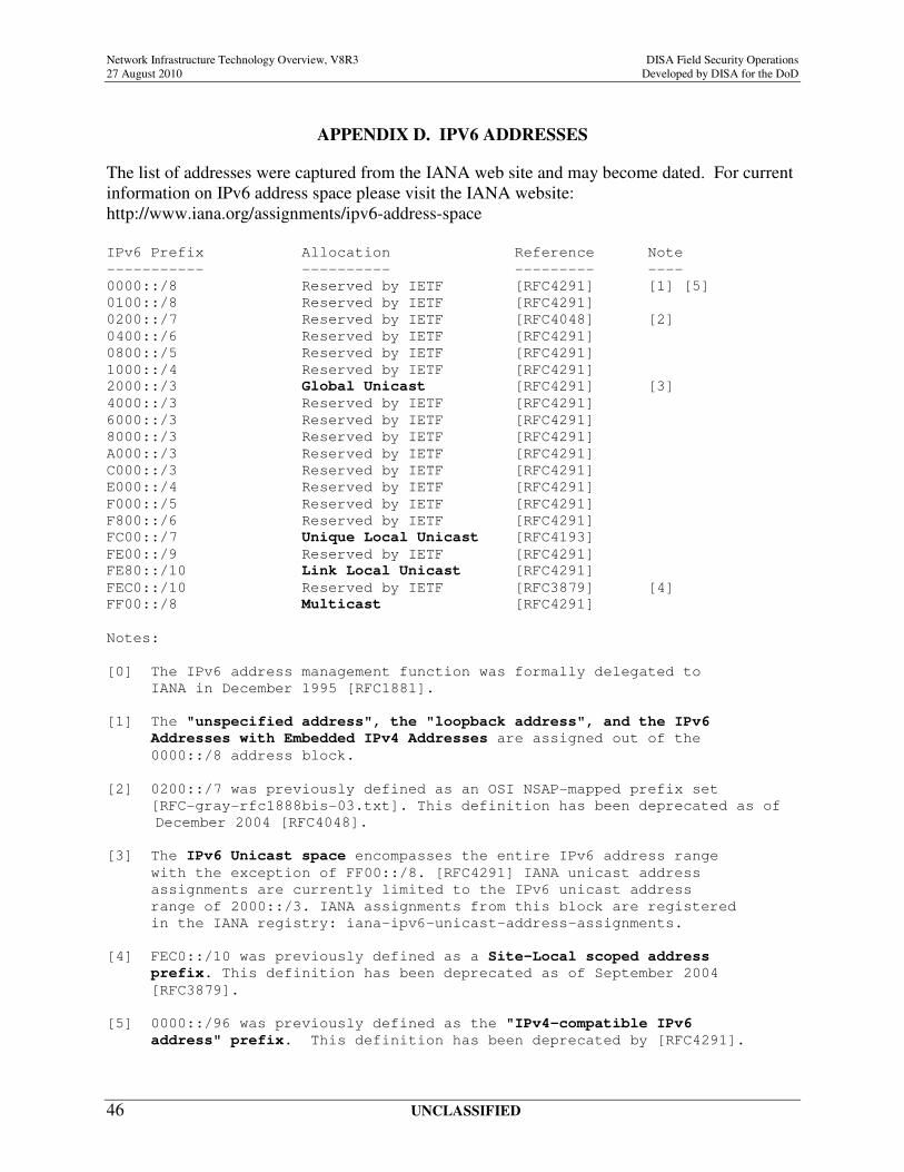
Network Infrastructure Technology Overview, V8R3 DISA Field Security Operations
27 August 2010 Developed by DISA for the DoD
UNCLASSIFIED 46
APPENDIX D. IPV6 ADDRESSES
The list of addresses were captured from the IANA web site and may become dated. For current
information on IPv6 address space please visit the IANA website:
http://www.iana.org/assignments/ipv6-address-space
IPv6 Prefix Allocation Reference Note
----------- ---------- --------- ----
0000::/8 Reserved by IETF [RFC4291] [1] [5]
0100::/8 Reserved by IETF [RFC4291]
0200::/7 Reserved by IETF [RFC4048] [2]
0400::/6 Reserved by IETF [RFC4291]
0800::/5 Reserved by IETF [RFC4291]
1000::/4 Reserved by IETF [RFC4291]
2000::/3 Global Unicast [RFC4291] [3]
4000::/3 Reserved by IETF [RFC4291]
6000::/3 Reserved by IETF [RFC4291]
8000::/3 Reserved by IETF [RFC4291]
A000::/3 Reserved by IETF [RFC4291]
C000::/3 Reserved by IETF [RFC4291]
E000::/4 Reserved by IETF [RFC4291]
F000::/5 Reserved by IETF [RFC4291]
F800::/6 Reserved by IETF [RFC4291]
FC00::/7 Unique Local Unicast [RFC4193]
FE00::/9 Reserved by IETF [RFC4291]
FE80::/10 Link Local Unicast [RFC4291]
FEC0::/10 Reserved by IETF [RFC3879] [4]
FF00::/8 Multicast [RFC4291]
Notes:
[0] The IPv6 address management function was formally delegated to
IANA in December 1995 [RFC1881].
[1] The "unspecified address", the "loopback address", and the IPv6
Addresses with Embedded IPv4 Addresses are assigned out of the
0000::/8 address block.
[2] 0200::/7 was previously defined as an OSI NSAP-mapped prefix set
[RFC-gray-rfc1888bis-03.txt]. This definition has been deprecated as of
December 2004 [RFC4048].
[3] The IPv6 Unicast space encompasses the entire IPv6 address range
with the exception of FF00::/8. [RFC4291] IANA unicast address
assignments are currently limited to the IPv6 unicast address
range of 2000::/3. IANA assignments from this block are registered
in the IANA registry: iana-ipv6-unicast-address-assignments.
[4] FEC0::/10 was previously defined as a Site-Local scoped address
prefix. This definition has been deprecated as of September 2004
[RFC3879].
[5] 0000::/96 was previously defined as the "IPv4-compatible IPv6
address" prefix. This definition has been deprecated by [RFC4291].

Network Infrastructure Technology Overview, V8R3 DISA Field Security Operations
27 August 2010 Developed by DISA for the DoD
UNCLASSIFIED 47
This page is intentionally blank.
Related Documents