Network Essentials FUNDAMENTALS – CHAPTER 2

Welcome message from author
This document is posted to help you gain knowledge. Please leave a comment to let me know what you think about it! Share it to your friends and learn new things together.
Transcript
Network EssentialsFUNDAMENTALS – CHAPTER 2
A network is a collection of systems and devices exchanging data over some form of media.
A host is defined as any device that holds a logical address on your network.
Hosts can be workstations, servers, printers, connection devices, or routers.
Modern networks are charged with delivering our phone calls and, soon, our television and
entertainment options. Data—no matter what its form—is transmitted in the form of bits.
A single bit is a 1 or a 0 (based on the binary number system of two digits versus the typically
used decimal numbering system based on the digits 0–9).
A protocol is simply an agreed upon set of rules for a particular network function.
Bandwidth is generally considered to be the total amount of data (in bits) you can theoretically
transmit within a given time period (typically one second).
Bandwidth is expressed in bits or bytes per second in digital networking.
Network Topologies The topology can refer to how the network actually looks
Physical Topologies:
The physical topology of the network refers to how the network actually looks from a
bird’s-eye view—the physical cabling layout of the network itself.
A bus topology consists of all devices connecting to a single wire—a coaxial cable.
A physical bus looks like a straight line—a stick—with connections to hosts coming off
in a “T” shape.
In a ring topology, all devices are connected to each other in the shape of a circle—the first
device feeds into the second device, which in turn feeds into the third, and so on and so on until
the loop plugs back into the first device
Star topologies can also include extended star, where the central device extends links to other
hubs and switches.
A token passing, or ring, topology works in a more organized, almost friendly format. In a
token passing logical topology, systems can only transmit information when they hold a special
data packet, known as a token. The token is passed from one device to the next, in a prescribed,
circular path. Each device receives the token and examines it. If it holds a message for the
device, it will open and process it.
Network Categories Networks are typically of two types: LANs and WANs.
LANs :
A LAN (local area network) can be defined as a network that serves users within a small geographic footprint.
WANs:
A WAN(wide area network ) is nothing more than the network connecting a collection of LANs across a wide geographic area—perhaps a state, nation, or even the whole world! Aside from the distance variable, another defining characteristic of WANs is the concept of a leased line.
The OSI Reference Model 11 CERTIFICATION OBJECTIVE 1.02 The OSI Reference Model
One word bandied about quite a bit in regards to the OSI model is encapsulation.
Encapsulation is the process of adding a header and a trailer to a piece of data. While each stage
of communication (layer of the model) adds a header to the data, only one layer always adds a
trailer. Some texts define encapsulation as occurring in all layers of the model; however, it
technically only occurs at one—the Data Link layer.
The Layers The OSI Reference Model splits the communications process into seven distinct modular layers,
with each layer accomplishing a specific function independently of all other layers. The layers do
rely on layers above and below to provide something to work with, but they don’t necessarily
care what they receive to work with.
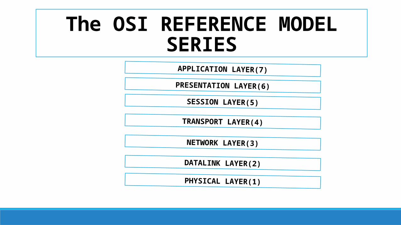
The OSI REFERENCE MODEL SERIESAPPLICATION LAYER(7)
PRESENTATION LAYER(6)
SESSION LAYER(5)
TRANSPORT LAYER(4)
NETWORK LAYER(3)
DATALINK LAYER(2)
PHYSICAL LAYER(1)
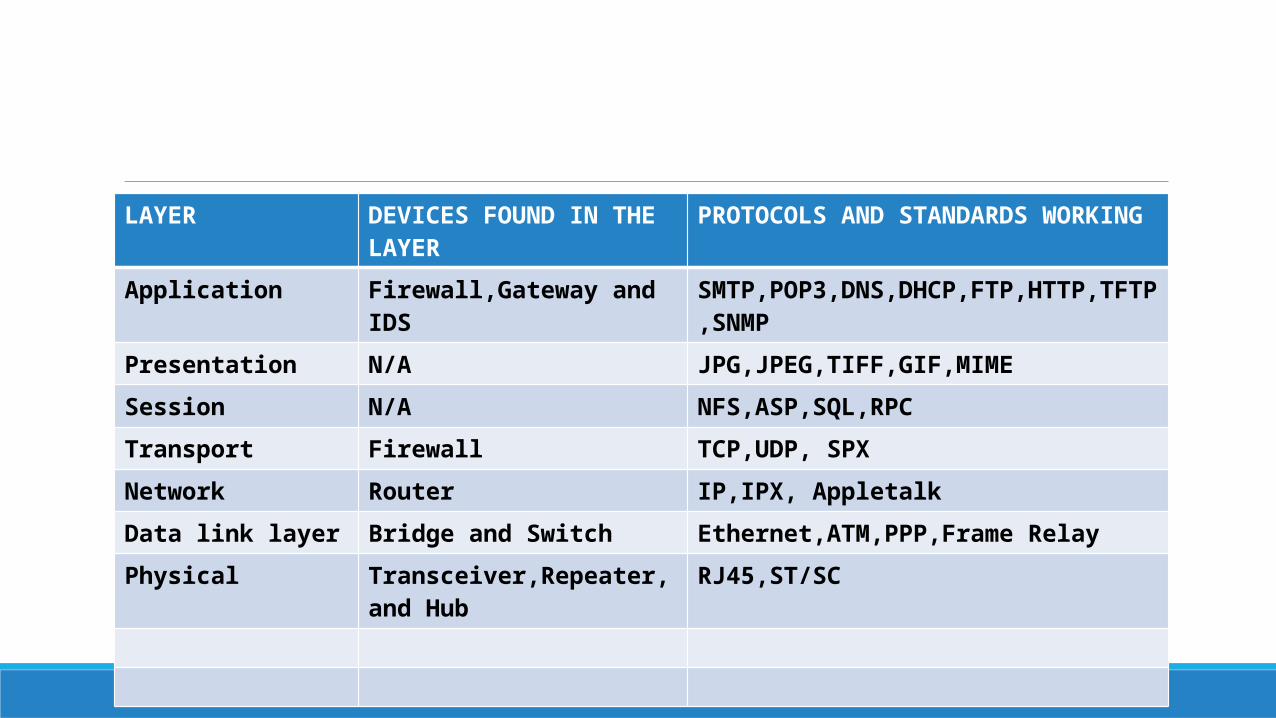
LAYER DEVICES FOUND IN THE LAYER PROTOCOLS AND STANDARDS WORKING
Application Firewall,Gateway and IDS SMTP,POP3,DNS,DHCP,FTP,HTTP,TFTP,SNMP
Presentation N/A JPG,JPEG,TIFF,GIF,MIME
Session N/A NFS,ASP,SQL,RPC
Transport Firewall TCP,UDP, SPX
Network Router IP,IPX, Appletalk
Data link layer Bridge and Switch Ethernet,ATM,PPP,Frame Relay
Physical Transceiver,Repeater, and Hub RJ45,ST/SC
The Data Layers (Application,Presentation, and Session)
Seven layers of the OSI model:-
The data layers would be the top three layers of the model.
At the top of the stack, we find layer 7—the Application layer
The Application layer holds the protocols that allow programs to access and make use of a
Network.
For example, Microsoft Outlook—a common e-mail program—can work just fine without a
network. You can open, edit, create, and delete e-mails offline just as well as you can online.
However, if you wish to use the network to send and receive e-mail, you need an Application
layer protocol to do this. In this example, the Application layer protocol would be SMTP.
Continuing the e-mail analogy, imagine you are sending an e-mail from a Microsoft Outlook
application to a computer running the Thunderbird e-mail application. You may have bold,
italics, and any number of font settings within your e-mail. Additionally, you may attach a picture
file (jpg) for the recipient to enjoy. Thunderbird might treat bold, italics, and font settings
differently than does Outlook, and SMTP is only capable of sending ASCIIcode (a combination of
bits representing an alphanumeric character, commonly referred to as, simply, text).
Enter layer 6—the Presentation layer. The Presentation layer is responsible for formatting and
code conversion between systems. This layer accepts the data from the Application layer and
ensures it is placed in a format the end station can understand. In this case, the e-mail is in text
mode, and another protocol, like MIME, translates the jpg into ASCII for transit. Once received at
the far end, the recipient’s Presentation layer will perform the reverse, handing the data back to
the Application layer protocol. Encryption is another function of the Presentation layer
Layer 5—the Session layer:—is perhaps the most enigmatic and troublesome of the entire
stack. This layer doesn’t necessarily do anything to the data at all. Instead, its function is to
work in the background, ensuring the communications process between two systems runs
smoothly.
The Delivery Layers:-
Transport layer:
Transport the data from receiver to sender.
The three main functions:
1. Segmentation.
2. The reliable delivery
3. Flow control
Segmentation is simply taking a small piece of the bits making up the data as a whole.
A small header is put in front of these bits. Inside the header is all sorts of information,
including:
The Network layer is responsible for logical addressing and routing.
Receiving a segment from the Transport layer, the Network layer adds a header that includes a
source and destination logical (network) address. This address is read by layer-3 devices
(routers) and best path determinations are made to deliver the segment to its final destination
Network Components Physical Layer Devices:
Physical layer devices do nothing more than physically connect wiring together to complete a path, or change the connection from one type to another.
Examples of physical layer devices include transceivers, repeaters, and hubs.
Transceivers connect one media type to another, such as a fiber connection to a copper one.
Repeaters are used to extend the range of a given media—whatever they take in one port,
they regenerate and repeat out the other. Hubs are nothing more than multiport
repeaters. Comparatively, where a repeater takes bits in one port to relay to another,
hubs have several ports they accept and relay bits on.
Data Link Layer Devices Layer-2 devices include bridges and switches. Switches and bridges split (or
segment) collision domains, decrease network traffic problems, and increase effective
available bandwidth to hosts. However, keep in mind they are incapable of moving
traffic outside your LAN.

Network Layer Devices Network layer devices play a unique role in your network design. These devices read the
Logical network addresses on your data and make decisions about which route to
send the data. This sounds very much like the switches and bridges discussed earlier,
but keep in mind the layer-3 device not only knows which port to send the data out,
but also the best route through outside networks to its final destination. Continuing
the analogy from earlier, if the street address on your letter is akin to the physical
address of your hosts, the logical address used by layer-3 devices is equivalent to the
ZIP code.
Other Devices Networks can also include a variety of other devices, such as firewalls, gateways,
and proxies. A firewall is a device that typically works at layers 3 and 4, and is
used to filter network traffic based upon rules the administrator configures on
the device. Generally placed between your network and the Internet, firewalls
work on an implicit deny principle—if you do not explicitly allow the traffic, it is
blocked.
Gateways work at all layers and are generally used to connect networks and applications of
different types together. A proxy is a system that provides a specific service to a host. For
example, a web proxy will make requests to the Internet for web content on behalf of a host.
This increases security and performance since web traffic coming from your network appears
from only one system, and hosts can access cached pages on the proxy instead of going out to
find them. Generally speaking, these devices are usually placed between your network and the
Internet in a special network called a DMZ
Related Documents