1 Network Analysis (Subject Code: 06ES34) Resonance • Introduction • Resonance • Classification of Resonance Circuits • Series Resonance Circuit • Parallel Resonance Circuit • Frequency Response of Series and Parallel Resonance Circuits • Band Width • Selectivity • Q-factor • Problems I. Introduction: If a sinusoidal voltage is applied to a ac network, the impedance offered by the network is purely resistive under special circumstances. This phenomenon is called resonance and the frequency at which resonance takes place is called the frequency of resonance. The resonance circuit must have an inductance and a capacitance. The resistance will be always present either due to lack of ideal elements or due to presence of resistive element itself. When resonance occurs, at any instant, the energy absorbed by one reactive element is equal the energy released by another reactive element within the system. The resonant condition in ac circuits may be achieved by varying the frequency of the supply keeping the network elements constant or by varying inductance, L or Capacitance, C, keeping the frequency constant. The total apparent power is simply the average power dissipated by the resistive elements. The average power absorbed by the system will be maximum at resonance. II.Classification of Resonance Circuits 1) Series resonant circuit. 2) Parallel resonant circuit. 1) Series resonant circuit: The circuit is said to be resonant when the resultant reactance of the circuit is Zero. The impedance of the circuit at any frequency ω is

Welcome message from author
This document is posted to help you gain knowledge. Please leave a comment to let me know what you think about it! Share it to your friends and learn new things together.
Transcript
1
Network Analysis (Subject Code: 06ES34)
Resonance
• Introduction• Resonance• Classification of Resonance Circuits• Series Resonance Circuit• Parallel Resonance Circuit• Frequency Response of Series and Parallel Resonance Circuits• Band Width• Selectivity• Q-factor• Problems
I. Introduction:
If a sinusoidal voltage is applied to a ac network, the impedance offered bythe network is purely resistive under special circumstances. This phenomenon iscalled resonance and the frequency at which resonance takes place is called thefrequency of resonance.
The resonance circuit must have an inductance and a capacitance. Theresistance will be always present either due to lack of ideal elements or due topresence of resistive element itself.
When resonance occurs, at any instant, the energy absorbed by one reactiveelement is equal the energy released by another reactive element within the system.
The resonant condition in ac circuits may be achieved by varying thefrequency of the supply keeping the network elements constant or by varyinginductance, L or Capacitance, C, keeping the frequency constant.
The total apparent power is simply the average power dissipated by theresistive elements. The average power absorbed by the system will be maximum atresonance.
II.Classification of Resonance Circuits
1) Series resonant circuit.2) Parallel resonant circuit.1) Series resonant circuit:
The circuit is said to be resonant when the resultant reactance of the circuit is Zero.The impedance of the circuit at any frequency ω is
2
- )
(1)
Where ω = 2∏f, XL=2∏fL and XC=1/2∏fC.Then, the current, I= = V/ (2)
At resonance, the circuit must have the reactance of the circuit is zero.
i.e. =0
At resonance frequency, fr
=0 (3)
2∏frL= 1/2∏f rCfr =1/2∏ LC or r =1/ LC (4)
Resonance Current, Ir = (5)
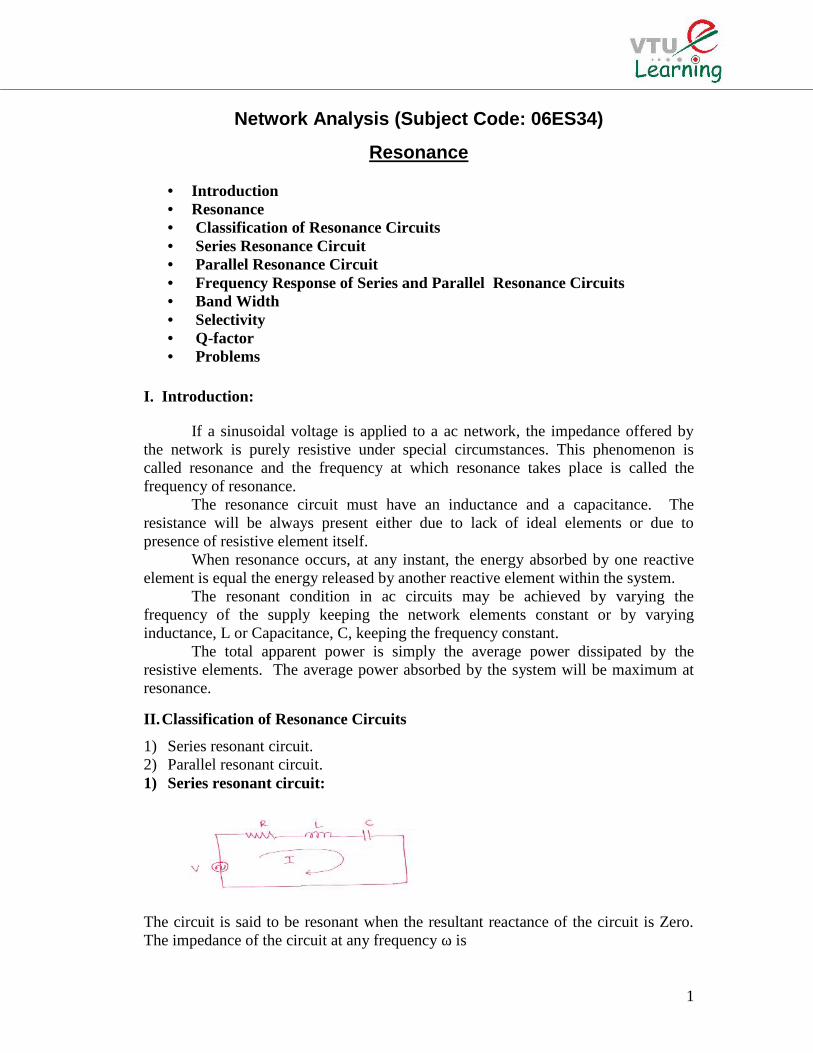
Fig.1. Reactance Curve of Series Resonant Circuit
XL= j L= j2∏fL…….Straight LineXC = j 1/ 1/2∏fC ……. Rectangular Hyperbola(XL –XC) = [j2∏fL- 1/2∏fC]For f fr, (XL –XC) becomes capacitive (i.e. XC XL)For f fr, (XL –XC) becomes inductive (i.e. XL XC)Where fr is the resonant frequency.
The impedance of the entire circuit,
|Z|=√R2+ (ωL-1/ωC)2
The variation of impedance with respect to frequency is shown by curve (b) in figureabove. The variation of (XL-XC) with respect to frequency is shown by curve (a) infigure 1 above.
3
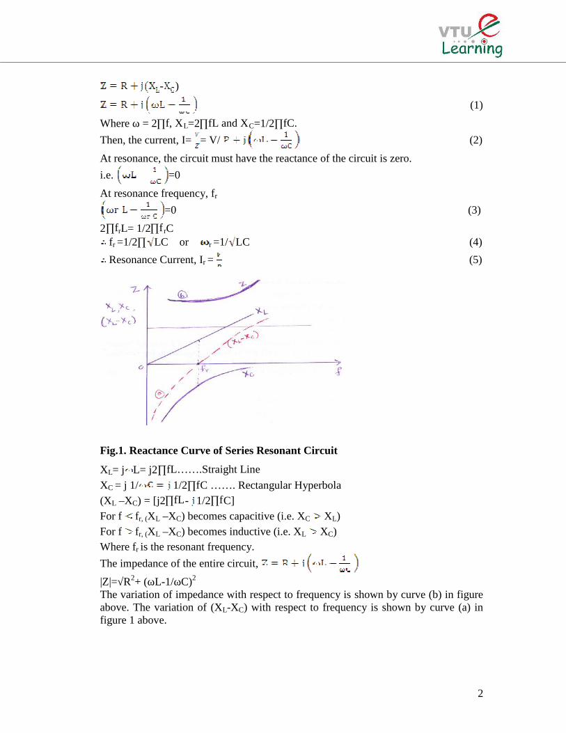
III.Frequency Response of a Series Resonant Circuit
Variation of current, I with respect to frequency, f, when applied voltage, V iskept constant. Frequency f1 & f2 corresponding to Im/ 2 = 0.707 Im are called bandfrequencies or cut-off frequencies or half power frequencies. Because, the powerdelivered by the circuit at these frequencies is half of the power delivered by it atresonant frequency.
This fact can be proved as follows:Let, Pm = Maximum power delivered by the circuit
= Power delivered at resonant frequency= I2
mRPower delivered at f1 & f2 = (Im/ 2)2 R = Im
2x R/2
Band Width (BW)The range of frequencies between these two cut-off frequencies i.e.(f2 –f1) is
called the Band width (BW) of the resonant circuit.
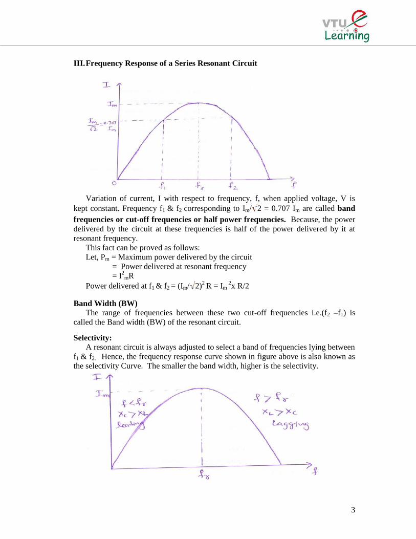
Selectivity:A resonant circuit is always adjusted to select a band of frequencies lying between
f1 & f2. Hence, the frequency response curve shown in figure above is also known asthe selectivity Curve. The smaller the band width, higher is the selectivity.
4
The radio or television receiver has a response curve for each broadcasting stationas shown in figure above. The receiver is tuned at this frequency to obtain signalsfrom that particular station.
Selectivity of a resonant circuit is defined as the ratio of resonant frequency to theBand width.
Selectivity = Resonance frequency /Band width= fr / (f2-f1)
Where f1 & f2 are lower and upper half power frequencies.
Variation of Current and Voltage with Frequency:The impedance of series resonant circuit is (1)
And the current through the circuit is I=V/ (2)
At resonance,
Im = (3)
Hence, the current is maximum at resonance.
The voltage across capacitor ‘C’ is VC = I/jωC = [1/jωC][V/ ] (4)
Hence, magnitude |VC|= [V/ωC√R2+ 2] (5)
The frequency fcmax at which VC is maximum can be obtained by dVC2/dω to zero.
From equation (5),
VC2= [V2/ω2C2R2+ 2]
VC2= [V2/(ω2C2R2 +ω2C2 1/ ω2C2 + ω2L2 -2 L/C)]
VC2= [V2/(ω2C2R2 + 1+ ω4L2C2 -2 ω2LC)]
VC2= [V2/ ω2C2R2 + (ω2LC-1)2] (6)
VC is maximum when dVC2/dω to zero.
dVC2/dω=[0- V22 ωC2R2+ 2(ω2LC-1) ] [ω2C2R2 + (ω2LC-1)2]2 = 0
As V 0, [2ωC2R2+4ω3L2C2-4 ] = 02ωC (CR2+2ω2L2C-2L) = 0
i.e. (CR2+2ω2L2C-2L) = 0ω2= (1/LC) - (R2/ 2L2)
0r ω = √ (1/LC) - (R2/ 2L2)2∏fcmax = √ (1/LC) - (R2/ 2L2)
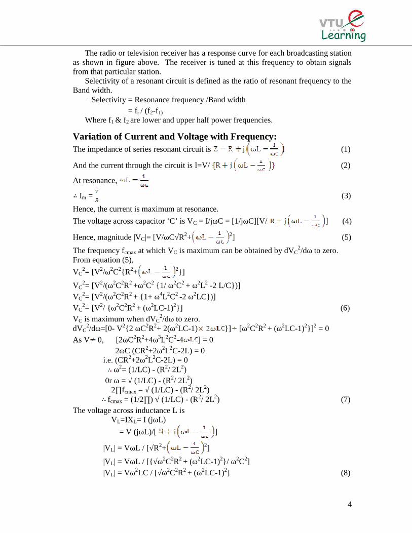
fcmax = (1/2∏) √ (1/LC) - (R2/ 2L2) (7)The voltage across inductance L is
VL=IXL= I (jωL)= V (jωL)/[ ]
|VL| = VωL / [√R2+ 2]
|VL| = VωL / [√ω2C2R2 + (ω2LC-1)2/ ω2C2]|VL| = Vω2LC / [√ω2C2R2 + (ω2LC-1)2] (8)
5
The frequency fLmax at which VL is maximum can be obtained by equatingdVL
2/dω =0From equation (8),VL
2 = (V2 ω4L2C2)/ [ω2C2R2 + (ω2LC-1)2]dVL
2/dω = [ω2C2R2 + (ω2LC-1)24ω3V2L2C2 – V2 ω4L2C22ωC2R2 + (ω2LC-1)2ωLC] ω2C2R2 + (ω2LC-1)2 = 0
ω3V2L2C 2[4 ω2C2R2 + (ω2LC-1)2-ω2ωC2R2 + ω3L2C2-4ωLC]=0i.e. 4ω2C2R2+4ω4L2C2 + ω2LC-2ω2C2R2 - ω4L2C2+4ω2LC=02ω2C2R2- ω2LC + 4 =0Or 4ω2LC-2ω2C2R2 = 4
2ω2LC-ω2C2R2 = 2ω2 =2/(2LC- C2R2) = 1/ [LC – (C2R2/2)]ω = √1/[LC – (C2R2/2)]fLmax= (1/2∏)√1/[LC – (C2R2/2)] (9)
From equation (7) and (9), it is obvious that,fLmax fcmax
The variation of VL and VC with frequency are shown in figure below
6
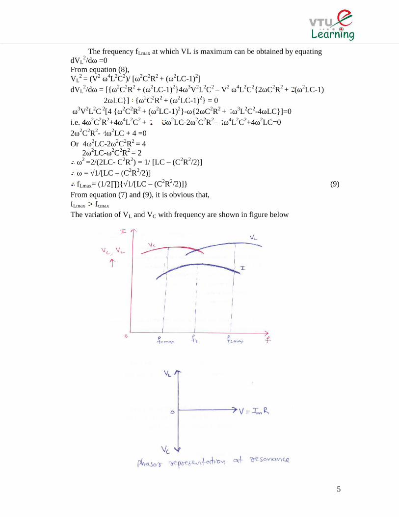
Q-factor:During series resonance, the voltage across reactive elements that is inductance
and capacitance increases to many times more than the applied voltage itself.At resonance, Ir =Im =
The voltage across the inductance L isVL= ImXL= XL= ωrL= XLr V/R=Q V
Where Q= ωrL/R= XLr/R (1)Equation (1) is known as the quality factor of the series resonant circuit or simply thequality factor of the coil.The voltage across capacitance ‘C’ isVC = ImXC= (1/ ωrC) = (1/ωrCR)V= Q V
Where Q =(1/ωrCR)= XCr /R (2)The quality factor of a series resonant circuit in view of equation (1) and (2) may
be defined as the ratio of the inductive reactance or capacitive reactance at resonanceto the resistance of the circuit.
Q= ωrL/R= 2∏frL /R=(2∏L/R) 1/2∏√LC)Q= (1/R) (√L/C) (3)
From equation (3), we understand that, the quality factor depends on theresistance of the resonant circuit. Higher the resistance, smaller will be the value ofQ.
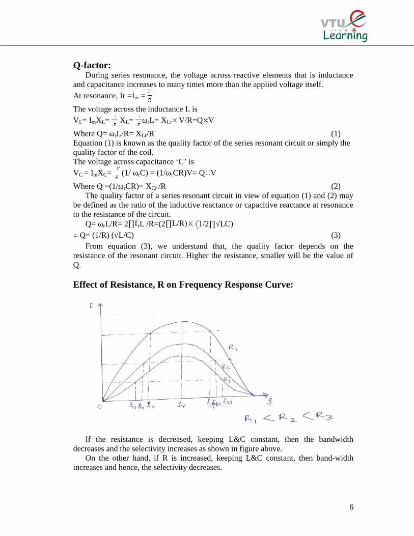
Effect of Resistance, R on Frequency Response Curve:
If the resistance is decreased, keeping L&C constant, then the bandwidthdecreases and the selectivity increases as shown in figure above.
On the other hand, if R is increased, keeping L&C constant, then band-widthincreases and hence, the selectivity decreases.
7
f11 and f21 are the cut-off frequencies for R1
f12 and f22 are the cut-off frequencies for R2
f13 and f23 are the cut-off frequencies for R3
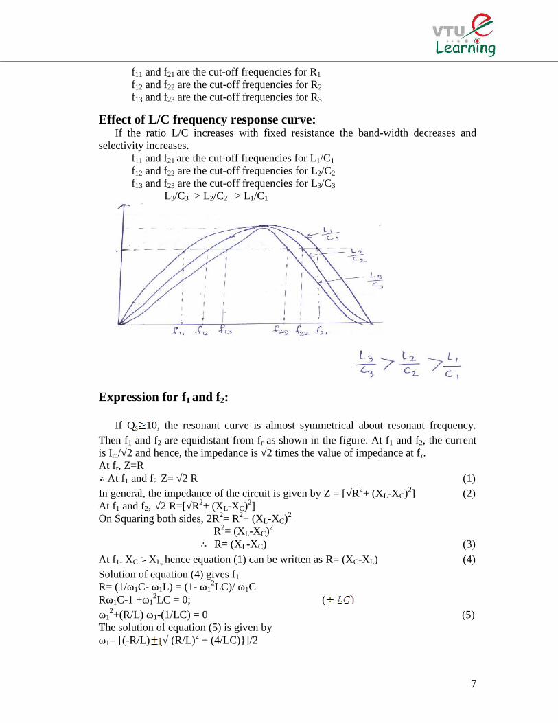
Effect of L/C frequency response curve:If the ratio L/C increases with fixed resistance the band-width decreases and
selectivity increases.f11 and f21 are the cut-off frequencies for L1/C1
f12 and f22 are the cut-off frequencies for L2/C2
f13 and f23 are the cut-off frequencies for L3/C3
L3/C3 > L2/C2 > L1/C1
Expression for f1 and f2:
If Qs 10, the resonant curve is almost symmetrical about resonant frequency.Then f1 and f2 are equidistant from fr as shown in the figure. At f1 and f2, the currentis Im/√2 and hence, the impedance is √2 times the value of impedance at fr.At fr, Z=R
At f1 and f2 Z= √2 R (1)In general, the impedance of the circuit is given by Z = [√R2+ (XL-XC)2] (2)At f1 and f2, √2 R=[√R2+ (XL-XC)2]On Squaring both sides, 2R2= R2+ (XL-XC)2
R2= (XL-XC)2
R= (XL-XC) (3)At f1, XC XL, hence equation (1) can be written as R= (XC-XL) (4)Solution of equation (4) gives f1
R= (1/ω1C- ω1L) = (1- ω12LC)/ ω1C
Rω1C-1 +ω12LC = 0; (
ω12+(R/L) ω1-(1/LC) = 0 (5)
The solution of equation (5) is given byω1= [(-R/L) √ (R/L)2 + (4/LC)]/2
8
or ω1=[(-R/2L)+ √ (R/2L)2 + (1/LC)] ( -Ve sign gives –Ve values for ω1 and hencediscarded)
f1= (1/2∏)[(-R/2L)+√(R/2L)2+(1/LC)] (6)At f2, XL XC, from equation (3), R= XL-XC)
R= (ω2L)-(1/ ω2C) = (ω22LC-1)/ ω2C
ω22LC-1-Rω2C=0……… (
ω22-(R/Lω2)-(1/LC) =0 (7)
The solution of equation (7) givesω2= [(R/L) √ (R/L)2+ (4/LC)]/2ω2= [(R/2L)+ √ (R/2L)2 + (1/LC)] ( -Ve sign gives –Ve values for ω2 and hence
discarded)f2= (1/2∏)[(R/2L)+√(R/2L)2+(1/LC)] (8)
From equation (6) and (8), the band width is given byBand Width = (f2-f1) = 2 R/2∏ 2L) = R/2∏LR/L=2∏ (f2-f1)Since at resonance, Qs= XLr /R=2∏frL/R=2∏fr 1/(R/L)= 2∏fr 1/2∏(f2-f1)
= fr/ (f2-f1) (9)Band Width = (f2-f1) = fr/Qs (10)
From equation (9),(f2-f1)/ f =1/Qs is referred as fractional band width.
Relation between fr, f1& f2:
The impedances of an RLC Resonant Circuit at f1& f2 are given byZ1 = [√R2+ (XC1-XL1)
2] and Z2 = [√R2+ (XL2-XC2)2]
Since Z1 = Z2
R2+ (XC1-XL1)2= R2+ (XL2-XC2)
2
(XC1-XL1)= (XL2-XC2)(XC1+XC2)= (XL1+XL2)(1/ ω1C) + (1/ ω2C) = ω1L+ ω2L
i.e. (1/C)[ (ω1+ ω2)/ ω1ω2]=L(ω1+ ω2)i.e. ω1ω2= (1/LC) =ωr
2 ( fr= (1/2∏√LC) and ω r =(1/√LC)ωr=√ ω1ω2
or fr=√ f1f2
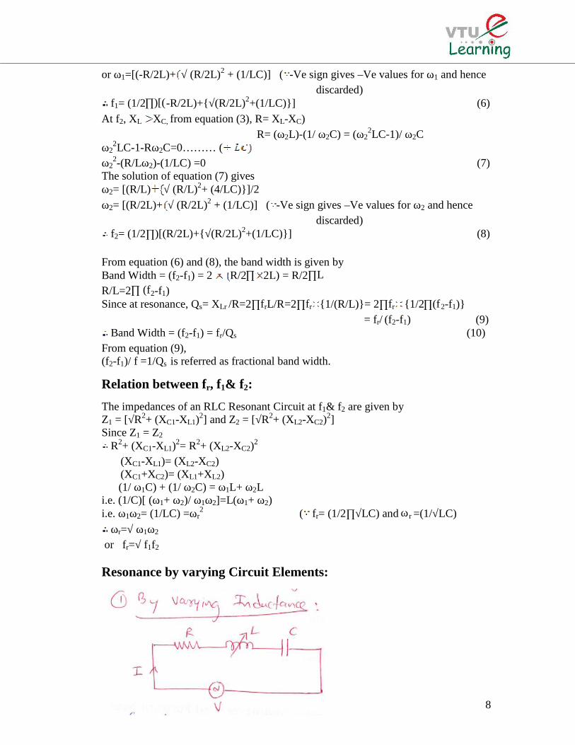
Resonance by varying Circuit Elements:
9
Consider RLC series resonant circuit, resonance condition being obtained by varyingL, as shown in figure. At resonance, XL= XC
ωr Lr = 1/ωrC or Lr = 1/ωr2C
Where Lr=Inductance at resonanceLet L1=Inductance at f1,At f1, (XC-XL) =Ri.e. [(1/ω1C)-(ω1L1)] = R or L1=[(1/ω1
2C) - (R/ω1)]Let L2=Inductance at f2,At f2, (XL-XC) =Ri.e. [(ω2L2) - (1/ω2C)] = R or L2= [(1/ω2
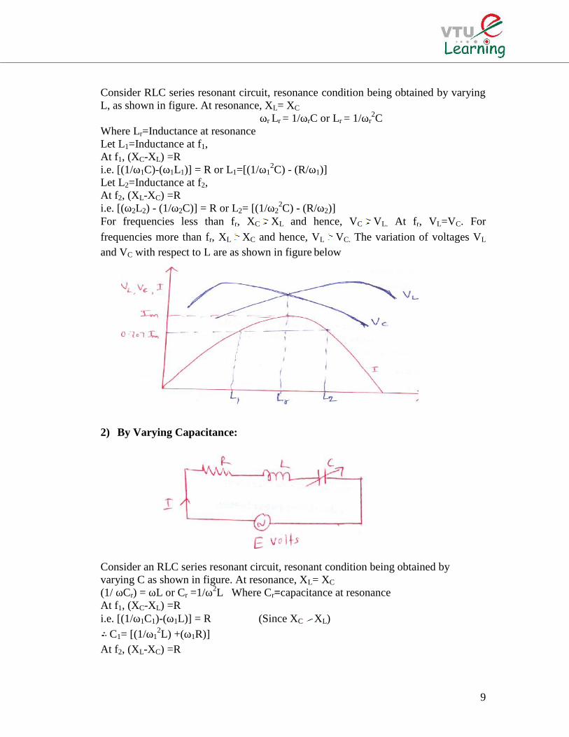
2C) - (R/ω2)]For frequencies less than fr, XC XL and hence, VC VL. At fr, VL=VC. For
frequencies more than fr, XL XC and hence, VL VC. The variation of voltages VL
and VC with respect to L are as shown in figure below
2) By Varying Capacitance:
Consider an RLC series resonant circuit, resonant condition being obtained byvarying C as shown in figure. At resonance, XL= XC
(1/ ωCr) = ωL or Cr =1/ω2L Where Cr=capacitance at resonanceAt f1, (XC-XL) =Ri.e. [(1/ω1C1)-(ω1L)] = R (Since XC XL)
C1= [(1/ω12L) +(ω1R)]
At f2, (XL-XC) =R

10
i.e. [(ω2L)- (1/ω2C2) = R (Since XL XC)C2= [(1/ω2
2L) - (ω2R)]The variation of Voltage across capacitance and inductance with respect to
capacitance is shown in figure
Frequency Deviation ( ):
The frequency deviation of an RLC series circuit is defined as the ratio of thedifferences between the operating frequency and resonant frequency to theresonant frequency.
= (ω-ωr)/ ωr = (f-fr)/ fr (1)Where ω = operating frequency in rad. /sec.
ωr = resonant frequency in rad./secf = operating frequency in Hz.fr = resonant frequency in Hz.
The impedance of an RLC series circuit is given byZ=R+ jXL - jXC = R + j [ωL-(1/ ωC)]
= R [1 + j (ωL/R – 1/ωCR)]= R [1 + j (ωrL/R)(ω/ωr)– (1/ωrCR)(ωr/ω)]= R [1 + j QS(ω/ωr) – QS (ωr/ω)]= R [1 + j QS(ω/ωr) – (ωr/ω)]= R [1 + j QS1+ –(1/1+ )]…..( = (ω-ωr)/ ωr
and ω/ωr=1+= R [1 + j QS(1+δ2+2δ-1)/(1+δ)]
Z= R [1 + j QS δ(2+ δ)/(1+ δ)] (2)Equation (2) gives the value of impedance of an RLC series circuit in terms of δ.If ω=ωr, then δ=0 and hence Z=R which is true at resonance.At frequency near resonant frequency, δ is very small.
Z = R ( 1 + j QS 2δ)= R (1+j 2 QS δ) (3)At f1 or f2, we know that Z=√2 RTo satisfy this condition, in equation (3), QS δ = 0.5 at f2 and QS δ = -0.5 at f1.
At f2, QS δ = 0.5 and At f1, QS δ = -0.5At f1, δ is –ve from equation (1), we get, -δ = (f1-fr)/ fr or f1= fr (1- δ)At f2, δ is +ve from equation (1), we get, δ = (f2-fr)/ fr or f2= fr (1+ δ)
11
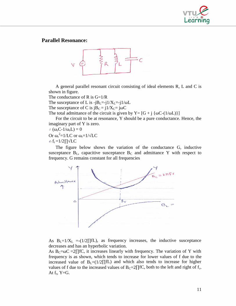
Parallel Resonance:
A general parallel resonant circuit consisting of ideal elements R, L and C isshown in figure.The conductance of R is G=1/RThe susceptance of L is -jBL=-j1/XL=-j1/ωLThe susceptance of C is jBC = j1/XC= jωCThe total admittance of the circuit is given by Y= [G + j ωC-(1/ωL)]
For the circuit to be at resonance, Y should be a pure conductance. Hence, theimaginary part of Y is zero.
(ωrC-1/ωrL) = 0Or ωr
2=1/LC or ωr=1/√LCfr =1/2∏√LC
The figure below shows the variation of the conductance G, inductivesusceptance BL, capacitive susceptance BC and admittance Y with respect tofrequency. G remains constant for all frequencies
As BL=1/XL =-(1/2∏fL), as frequency increases, the inductive susceptancedecreases and has an hyperbolic variation.As BC=ωC =2∏fC, it increases linearly with frequency. The variation of Y withfrequency is as shown, which tends to increase for lower values of f due to theincreased value of BL=(1/2∏fL) and which also tends to increase for highervalues of f due to the increased values of BC=2∏fC, both to the left and right of f r.At fr, Y=G.
12
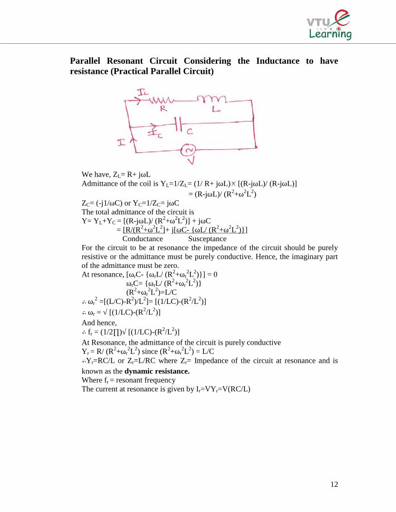
Parallel Resonant Circuit Considering the Inductance to haveresistance (Practical Parallel Circuit)
We have, ZL= R+ jωLAdmittance of the coil is YL=1/ZL= (1/ R+ jωL) [(R-jωL)/ (R-jωL)]
= (R-jωL)/ (R2+ω2L2)ZC= (-j1/ωC) or YC=1/ZC= jωCThe total admittance of the circuit isY= YL+YC = [(R-jωL)/ (R2+ω2L2)] + jωC
= [R/(R2+ω2L2]+ j[ωC- ωL/ (R2+ω2L2)]Conductance Susceptance
For the circuit to be at resonance the impedance of the circuit should be purelyresistive or the admittance must be purely conductive. Hence, the imaginary partof the admittance must be zero.At resonance, [ωrC- ωrL/ (R2+ωr
2L2)] = 0ωrC= ωrL/ (R2+ωr
2L2)(R2+ωr
2L2)=L/Cωr
2 =[(L/C)-R2)/L2]= [(1/LC)-(R2/L2)]ωr = √ [(1/LC)-(R2/L2)]
And hence,fr = (1/2∏)√ [(1/LC)-(R2/L2)]
At Resonance, the admittance of the circuit is purely conductiveYr = R/ (R2+ωr
2L2) since (R2+ωr2L2) = L/C
Yr=RC/L or Zr=L/RC where Zr= Impedance of the circuit at resonance and isknown as the dynamic resistance.Where fr = resonant frequencyThe current at resonance is given by Ir=VYr=V(RC/L)
13
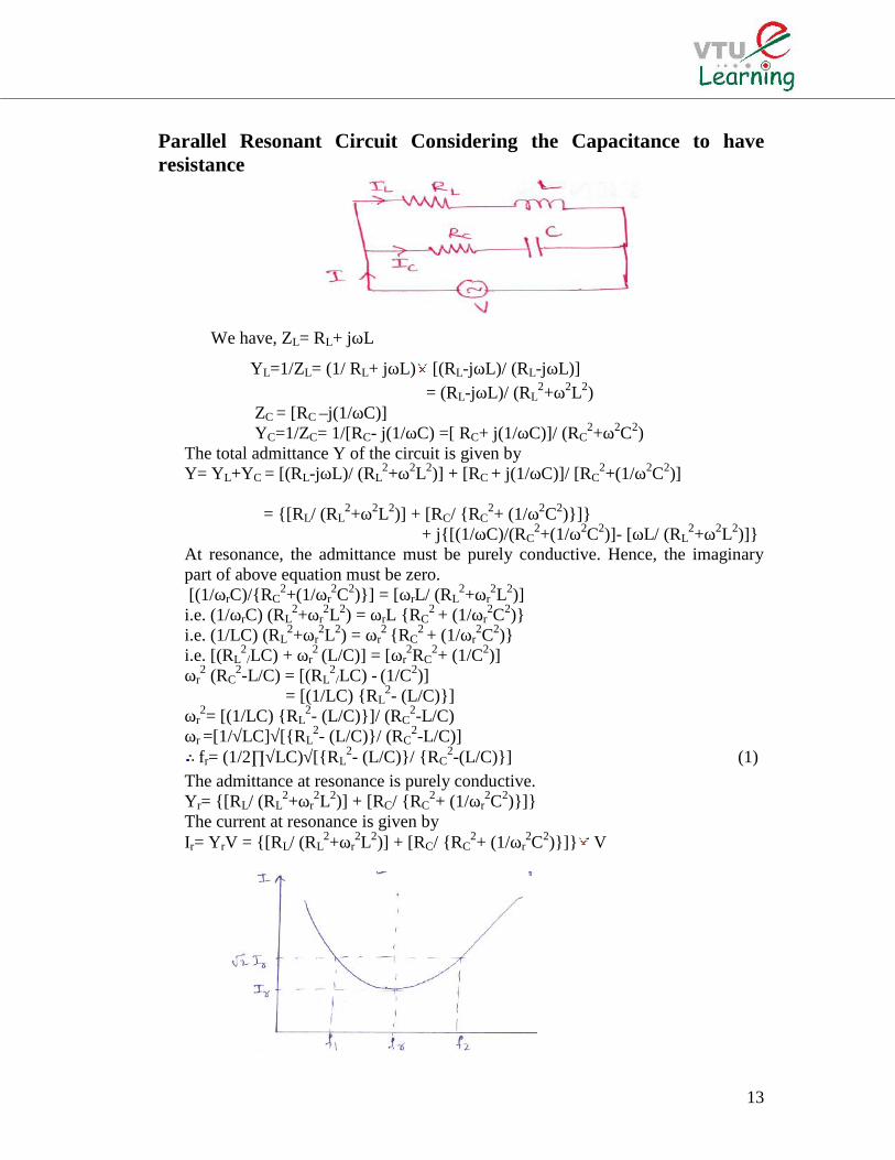
Parallel Resonant Circuit Considering the Capacitance to haveresistance
We have, ZL= RL+ jωL
YL=1/ZL= (1/ RL+ jωL) [(RL-jωL)/ (RL-jωL)]= (RL-jωL)/ (RL
2+ω2L2)ZC = [RC –j(1/ωC)]YC=1/ZC= 1/[RC- j(1/ωC) =[ RC+ j(1/ωC)]/ (RC
2+ω2C2)The total admittance Y of the circuit is given byY= YL+YC = [(RL-jωL)/ (RL
2+ω2L2)] + [RC + j(1/ωC)]/ [RC2+(1/ω2C2)]
= [RL/ (RL2+ω2L2)] + [RC/ RC
2+ (1/ω2C2)]+ j[(1/ωC)/(RC
2+(1/ω2C2)]- [ωL/ (RL2+ω2L2)]
At resonance, the admittance must be purely conductive. Hence, the imaginarypart of above equation must be zero.[(1/ωrC)/RC
2+(1/ωr2C2)] = [ωrL/ (RL
2+ωr2L2)]
i.e. (1/ωrC) (RL2+ωr
2L2) = ωrL RC2 + (1/ωr
2C2)i.e. (1/LC) (RL
2+ωr2L2) = ωr
2 RC2 + (1/ωr
2C2)i.e. [(RL
2/LC) + ωr
2 (L/C)] = [ωr2RC
2+ (1/C2)]ωr
2 (RC2-L/C) = [(RL
2/LC) - (1/C2)]
= [(1/LC) RL2- (L/C)]
ωr2= [(1/LC) RL
2- (L/C)]/ (RC2-L/C)
ωr =[1/√LC]√[RL2- (L/C)/ (RC
2-L/C)]fr= (1/2∏√LC)√[RL
2- (L/C)/ RC2-(L/C)] (1)
The admittance at resonance is purely conductive.Yr= [RL/ (RL
2+ωr2L2)] + [RC/ RC
2+ (1/ωr2C2)]
The current at resonance is given byIr= YrV = [RL/ (RL
2+ωr2L2)] + [RC/ RC
2+ (1/ωr2C2)] V
14
The frequency response curve of a parallel resonant circuit is as shown in figureabove. From the figure, we find that the current is minimum at resonance. Hence,impedance of the circuit is maximum at resonance. Since the current at resonanceis minimum, the parallel circuit at resonance is called as ‘anti-resonant’ (orrejecter circuit). The half power points or cut-off frequencies of the rejectercircuit are given by the points at which the current is √2Ir.
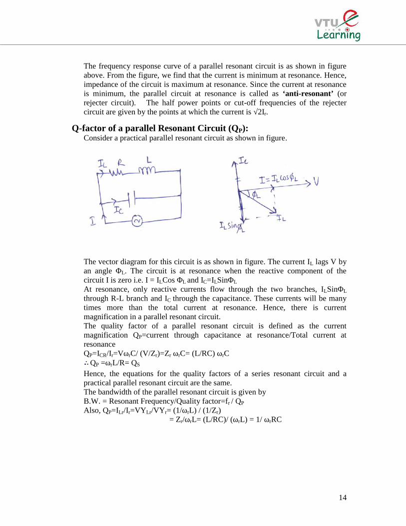
Q-factor of a parallel Resonant Circuit (QP):Consider a practical parallel resonant circuit as shown in figure.
The vector diagram for this circuit is as shown in figure. The current IL lags V byan angle ΦL. The circuit is at resonance when the reactive component of thecircuit I is zero i.e. I = ILCos ΦL and IC=ILSinΦL
At resonance, only reactive currents flow through the two branches, ILSinΦL
through R-L branch and IC through the capacitance. These currents will be manytimes more than the total current at resonance. Hence, there is currentmagnification in a parallel resonant circuit.The quality factor of a parallel resonant circuit is defined as the currentmagnification QP=current through capacitance at resonance/Total current atresonanceQP=ICR/Ir=VωrC/ (V/Zr)=Zr ωrC= (L/RC) ωrC
QP =ωrL/R= QS
Hence, the equations for the quality factors of a series resonant circuit and apractical parallel resonant circuit are the same.The bandwidth of the parallel resonant circuit is given byB.W. = Resonant Frequency/Quality factor=fr / QP
Also, QP=ILr/Ir=VYLr/VYr= (1/ωrL) / (1/Zr)= Zr/ωrL= (L/RC)/ (ωrL) = 1/ ωrRC
15
Comparison between Series and Parallel
Parameters Series Circuit Parallel CircuitImpedance at Resonance, Zr Minimum=R Maximum= L/CRCurrent at Resonance, Ir Maximum=V/R Minimum=VCR/LPower Factor at Resonance Unity UnityResonant Frequency, fr 1/2∏√LC 1/2∏√(1/LC)-(R2/L2)Quality Factor QS=QP 1/ωrCR= ωrL/R ωrL/R=1/ωrCR
Problem [1]
A series RLC circuit has R = 25Ω, L = 0.04H, C= 0.01 µF. Calculate the resonantfrequency. If a 1 volt source of the same frequency as the frequency of resonance isapplied to this circuit, calculate the frequency at which the voltage across L & C ismaximum. Also calculate the voltages.
Solution:We have, Resonant Frequency, fr =1/2∏√LC = 1/ 2∏√0.04 0.01 10-6= 7960 HzAt resonance, the current, Im=V/R= 1/25= 0.04 AThe voltage across the inductance, VL= Im ωrL= 0.04 2∏ 7960 0.04=80VThe voltage across the capacitance, VC = Im ωrC= 0.04/2∏ 7960 0.01 10-6= 80VThe frequency at which VL is maximum isfLmax=(1/2∏)√1/[LC–(C2R2/2)]
=(1/2∏)[√1/(0.04 0.01 10-6)–(25)2 10-6)2/2]fLmax=7958HzThe frequency at which VC is maximum isfcmax= (1/2∏)[√(1/LC)-(R2/2L2)]fcmax= (1/2∏)[√(1/0.04 10-6 -(252/2 0.042)]=7957.43Hz
Problem [2]
An RLC series circuit has a resistance of 10Ω, a capacitance of 100µF and avariable inductance. (a) find the value of the inductance for which the voltage acrossthe resistance is maximum (b)Q-factor (c)Voltage drop across R, L & C. The appliedvoltage is 230V, 50Hz.Solution:
(a)The voltage across the resistance is maximum at resonancefr = 1/2∏√LC50 = 1/2∏√Lr 100 10-6
Lr=Inductance at Resonance=0.10142H=101.42mH(b) QS=2∏fLr/R=2∏ 50 0.10142/10=3.182(c) Ir=Current at resonance=V/R=230/10=23AVR=23 10=230VoltsVC = VL = QSV=3.185 230=732.55Volts
16
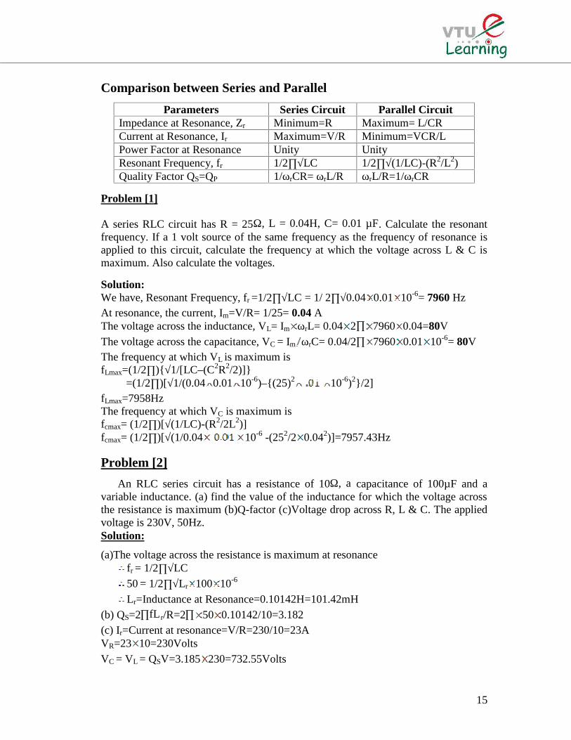
Problem [3]
An ac series circuit consists of a coil connected in series with a capacitance. Thecircuit draws a maximum current of 10A, when connected to 200V, 50Hz supply. Ifhe voltage across the capacitor is 500V at resonance, find the parameters of the circuitand quality factor.
Solution:
The maximum current is drawn by the circuit under resonant condition, VCr =IrXC=500V
XC=500/ Ir=500/10=50Ω
C= = = 63.69µF
At resonance, XL = XC = 50ΩX L = 2∏fL
L = = = 0.159H
VR=Ir R; 200 = 10R; R=20Ω,
QS= = = 2.5
Problem [4]A series RLC series circuit has a resistance of 10Ω, a capacitance of 100µF and a
inductance of 0.1H and it is connected across a 200V variable frequency source. Find(a) the resonant frequency (b) Impedance at this frequency (c) The voltage dropacross inductance and capacitance at this frequency (d) Quality factor (e) Band WidthSolution:
(a)We have, fr= = = 50.36Hz
(b) Zr= R= 10Ω. Hence, Ir = = = 20A
(c) XLr= L= =31.63ΩVLr = VCr =IXLr=31.36X20=632.52V
(d) QS= = = = 3.163
(e) Band width = = =15.92Hz
17
Problem [5]A Coil of resistance 20Ω and inductance of 0.2H is connected in series with a
capacitor across 230V supply. Find (a) The value of capacitance for which resonanceoccurs at 100Hz (b) the current through and voltage across the capacitor and(c) Q-factor of the coil.
Solution:
(a)We have, fr= = = 100 Hz; C=12.67µF
(b) Ir = Im= = = 11.5A
VCr = I XCr=Ix(1/2π fr C)=1445.3V
(c) QS= = = (2πx100x0.2)/20 = 6.28
Problem [6]A series RLC Circuit has R=10Ω, L=0.1 h and C= 100µF and is connected across
a 200V variable frequency source. Find (a) the frequency at which the voltage acrossinductance is maximum and this voltage (b) the frequency at which the voltage acrosscapacitance is maximum and this voltageSolution:(a) fLmax= (1/2Π) [√1/LC-(R2C2/2)]
fLmax= (1/2Π) [√1/(0.1×100×10-06) - 102 × (100×10-06)2 /2]=51.66HzThe impedance at this frequency ZL= RL+ jωL
= 10+j2Π×51.66×0.1= (10+j32.44)=33.95∟72.87Ω
VLmax=IXL= (V/Z) XL=(200/33.95)×32.44=191.12Volts(b) fCmax= (1/2Π) [√1/(1/LC) - (R2/2L2)]
fCmax= (1/2Π) [√1/1/(0.1×100×10 -06) - (102/2×0.12)]=49.08HzThe impedance at this frequency ZL= RL-1/ jωC
= [10- j(1/2Π×49.08×100×10-06]= (10-j32.44) Ω =33.95∟-72.87Ω
VCmax=IXC= (V/Z) XC=(200/33.95)×32.44=191.12Volts
Problem [7]A voltage of e=100sinωt is applied to an RLC series circuit. At resonant
frequency, the voltage across the capacitor was found to be 400V. The bandwidth is75Hz. The impedance at resonance is 100Ω. Find the resonant frequency and theconstants of the circuit.Solution:
V=100/√2=70.2VoltsQS=VC/V=IrXCr/ IrR= XCr/R= 400/70.7=5.66At resonance, R=Z =100ΩBand Width=fr/ QS
fr= Band Width × QS=75×5.66=424.5HzSince (f2-f1) = R/2ΠL
18
L= R/2Π (f2-f1) =100/2Π×75=212.3mHQS=1/ ωrCR
C = 1/2Π×424.5×100×5.66=0.66µF
Problem [8]A series RLC Circuit has R=10Ω, L=0.3H and C= 100µF. The applied voltage is
230V. Find (a) The resonance frequency(b) The quality factor(c) Lower and upper cut-off frequencies(d) Band width(e) Current at resonance(f) Currents at f1 & f2 and(g) Voltage across inductance at resonance
Solution:
(a) fr= = 1/2Π×[√0.3×100×10-06]= 29.07Hz
(b) QS=XLr/R= 2ΠfrL/R= (2Π×29.07×0.3)/10 =5.48(c) At f1, QSδ=-0.5; δ=-0.5/5.48= -0.0912
Since δ= (f1-f2)/fr; f1= (δfr+fr) = (-0.0912×29.07) + 29.07=26.42HzAt f2, QSδ=0.5; δ=-0.5/5.48= 0.0912Since δ = (f1-f2)/fr; f2= (δfr+fr) = (0.0912×29.07) +29.07=31.72HzOr
f1= (1/2∏)[(-R/2L)+√(R/2L)2+(1/LC)]=26.54Hzf2= (1/2∏)[(R/2L)+√(R/2L)2+(1/LC)]=31.6Hz
(d) Band width=(f2-f1) = (31.6-26.54) = 5.06Hz(e) Ir = V/R=230/10=23A(f) Current at f1 and f2 = Ir/√2 = 0.707×23=16.261A(g) Voltage across inductance at resonance= Ir × ωrL= 23×(2Π×29.07×0.3)
= 1259.66VoltsOr VLr=QSV=5.48×230=1260.4Volts
Problem [9]A Coil of resistance 20Ω and inductance 4H is connected in series with a
capacitor across a supply of variable frequency. The resonance occurs at 60Hz andthe current at resonance is 2A. Find the frequency, when the current is 1A.Solution:
fr= = 60Hz
60=1/ 2Π×√4C; C=1.76µF
At resonance, V=Ir R=2×20=40VoltsWhen I=1A, Z=V/I=40/1=40Ω(ωL-1/ωC) = [√ (Z2-R2)] =[√ (402-202)]= ±34.64ΩWhen (ωL-1/ωC) = 34.64(ω2LC-1)=34.64ωC= 34.64×ω×1.76×10-06 = 60.97×10-06ω(ω2 ×4×1.76×10-06-1)= 60.97×10-06ω
19
7.04×10-06 ω2- 60.97×10-06ω-1=07.04ω2- 60.97ω-1006=0ω = 60.97± [√ (60.97)2+4×7.04×1006]/2×7.04For positive sign, ω= 381.24 rad/sec and f=60.71HzWhen (ωL-1/ωC) = -34.64(ω2LC-1) =-34.64ωC = -34.64×ω×1.76×10-06
7.04ω2+ 60.97ω-1006=0On solving for positive signω= 372.58 rad/sec and f=59.33Hz
Problem [10]A Coil of resistance 20Ω and inductance 10 mH is in series with a capacitance
and is supplied with a constant voltage, variable frequency source. The maximumcurrent is 2A at 1000Hz. Find the cut-off frequencies.
Solution:We have, Band Width= ((f2-f1) = fr/ QS
QS=fr /(f2-f1)=XLr/R=2ΠfrL/R=2Π×1000×10×10-03/20=3.14(f2-f1)=fr/QS=1000/3.14=318.47Hz. (1)We have, fr= √f1f2 or f1f2=fr
2 or f1=10002/f2
(f2+f1)2= (f2-f1)
2 +4 f1f2
(f2+f1)= [√(f2-f1)2 +4 f1f2]
From (1), [f2 – (10002/f2)] = 318.47[f2
2 – 10002]=318.47 f2
[f22 – 318.47 f2-10002]=0
f2=318.47±[√(318.47)2+4×1000]=1171.84HzThen f1=853.37Hz
Problem [11]A constant voltage at a frequency of 1MHz is applied to an inductor in series with
a variable capacitor. When a capacitor is set at 500PF, the current has its maximumvalue, while it is reduced to one half, when the capacitance is 600Pf, find (i) theresistance and inductance of the coil and (ii) Q-factor
Solution:When C=500 PF, current is maximum, representing resonant condition.
fr= =106Hz
L=0.05mH.XL= ωrL = 2Π×106×0.05×10-3=314ΩWhen C=600PF,XC=1/2ΠfC=1/2Π×106×600×10-12=265.4Ω(XL- XC)=(314-265.4)= 48.6ΩWhen the current is Im/2; Z=2R (given)
R2+ (XL- XC)2=(2R)2
20
R2 +(48.6)2= (2R)2
R= 48.6/√3=28.06ΩQS=ωrL/R=314/28.06=11.19
Problem [12]A coil of resitance 40Ω and inductance 0.75H forms a part of a series circuit for
which, the resonant frequency is 55Hz. If the supply is 250V, 50Hz, find (a) The linecurrent (b) The power factor (c) The voltage across the coil.Solution:
At resonance, XL=ωrL=1/ωrC=2Π×55×0.75=259.05Ω=XC, at 55HzXL at 50Hz=2ΠfL=2Π×50×0.75=235.5ΩXC at 50Hz=259.05×55/50=284.96ΩZ at 50Hz=40+j(XL-XC)=40+j(235.5-284.96)= 40 –j49.46 =63.61∟-51.04Ω(a) Current=V/Z=250/63.61=3.93A(b) P.f.=Cos(51.04)=0.629 leading(c) The Voltage across the coil= I Zcoil= I(√R2+XL
2)
= 3.93(√402+235.52) = 938.77V
Problem [13]A coil of 20Ω resitance has an inductance of 0.2H and is connected in parallel
with a 100µP capacitor. Calculate the frequency at which the circuit will act as a non-inductive resitance of RΩ. Find also the value of R.Solution:
We have, fr = (1/2∏) √ [(1/LC)-(R2/L2)]= (1/2Π)√[(1/0.2×100×10-6)-(202/0.22)]=31.85Hz.
The dynamic resitance is given byZr =L/CR= 0.2/100×10-6×20=100Ω
Problem [14]A circuit has an inductive reactance of 20Ω at 50Hz in series with a resitance of
15Ω. For an applied voltage of 200 V at 50Hz, Calculate (a) Phase angle betweencurrent and voltage (b)the current (c) the value of shunting capacitance to bring thecircuit to resonance and the current at resonance.Solution:
(a) Z= R + jXL=(15 + j20)= 25 ∟53.13ΩPhase angle between current and voltage=Φ=53.13
(b) I=V/Z=200/25=8A(c) Y=i/Z=1/25 ∟53.13Ω=0.04∟-53.13Ω=0.024 – j0.032=G-jωC
For the circuit to be resonance, ωC=0.032; C=101.9µFCurrent at resonance, Ir=V×Real part of Y=200×0.024=4.8A
Problem [15]An inductive coil of resitance 6Ω and inductance of 1mH is connected in parallel
with another branch consisting of a resistance of 4Ω in series with a capacitance of20µF. Find the resonant frequency and the corresponding current when the appliedvoltage is 200V.
21
Solution:We have, fr= (1/2∏√LC) √[RL
2- (L/C)/ RC2-(L/C)]=722.93Hz
ωr=2Πfr=2Π×722.93=4540 rad/sec.The current at resonance is given byIr= YrV = [RL/ (RL
2+ωr2L2)] + [RC/ RC
2+ (1/ωr2C2)] V=27.03A
Problem [16]Two impedances (10+j12) Ω and (20-j15) Ω are connected in parallel and this
combination is connected in series with an impedance (5-jXC)Ω. Find the value ofXC, for which resonance occurs.Solution:
Z= (5-jXC) + [(10+j12) (20-j15)] / [(10+j12) + (20-j15)] = 17.24+j (4.22-XC)Therefore, for the circuit to be at resonance, the imaginary part of Z is zero.
XC=4.22Ω
Problem [17]A coil of resistance 10Ω and inductance 0.5H is connected in series with a
capacitor. On applying a sinusoidal voltage, the current is maximum, when thefrequency is 50Hz. A second capacitor is connected in parallel with the circuit. Whatcapacitance must it have, so that the combination acts as a non-inductive resistor at100Hz? Calculate the total current supplied in each case, if the applied voltage is220V.Solution:
At 50Hz, current is maximum i.e., the circuit is under resonance.XL=XC= 2Π×50×0.5=157Ω
The inductive reactance at 100Hz will be 2 times the inductive reactance at 50Hz.XL at 50Hz =2×157=314Ω
The capacitive reactance at 100Hz is half of the capacitive reactance at 50Hz.XC at 100Hz =1/2×157=78.5Ω
The impedance at 100 Hz is given byZ=10+j(314-78.5) = 10 +j 235.5=235.7 ∟87.57Ω
Y=1/Z= 0.0042426∟-87.57mho=(0.0001798-j0.0042388) mho
At 100Hz, I=V× Real part of Y= 220×0.0001798=0.04A
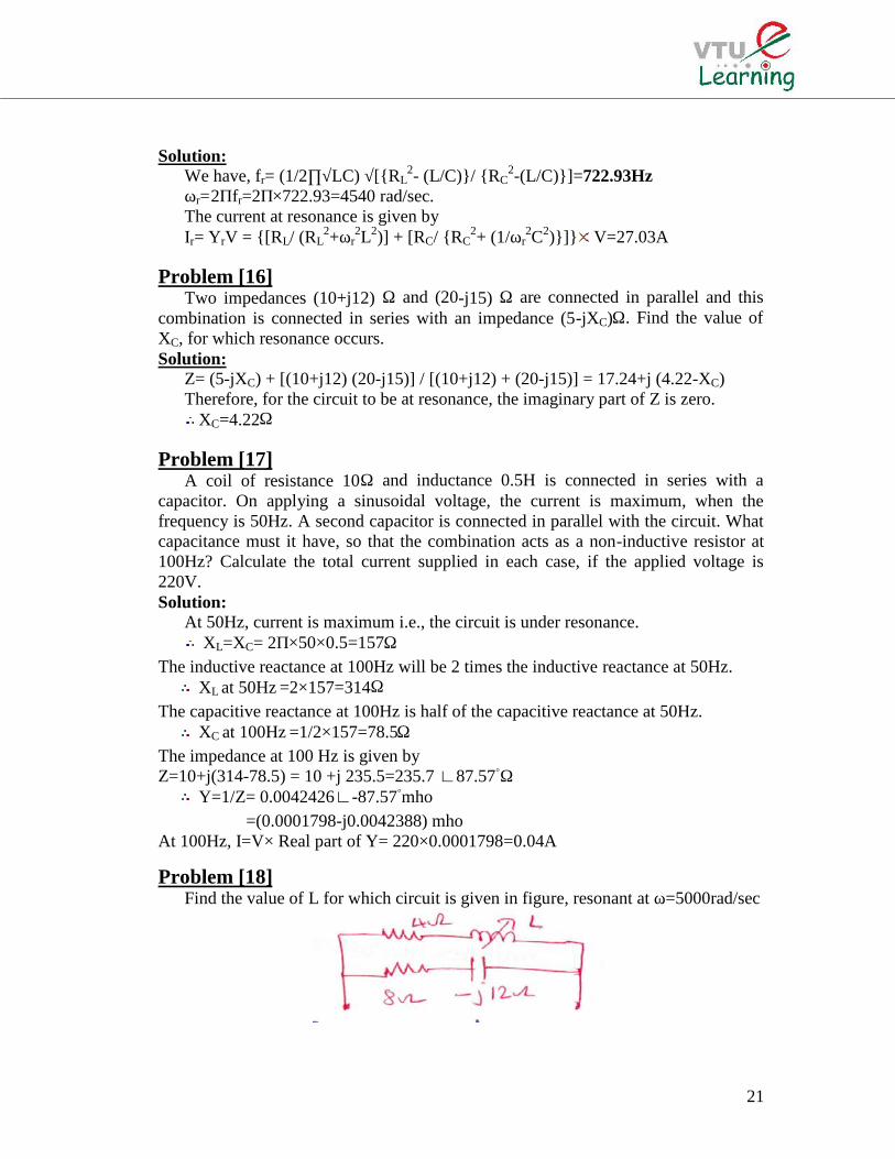
Problem [18]Find the value of L for which circuit is given in figure, resonant at ω=5000rad/sec
22
Solution:The admittance of circuit is given byY=[(1/4+jXL)+(1/8-j12)]mho on rationalizingY=[(4-jXL)/(42+XL
2)]+[(8+j12)/(82+122)]=[(4/(42+XL
2)]+[(8/(82+122)]+j[12/(82+122)-[XL/(42+ XL2)]
At resonance, the imaginary part of Y is zero. Therefore,12/(82+122)=XL/(42+ XL
2)12(42+ XL
2) = XL (82+122)12 XL
2-208 XL+192=03XL
2-52 XL+48=0Therefore, XL= 52±[√522-(4×3×48)]/2×3=16.36 or0.978ΩTherefore, L=16.36/5000=3.27mh or 0.197mH
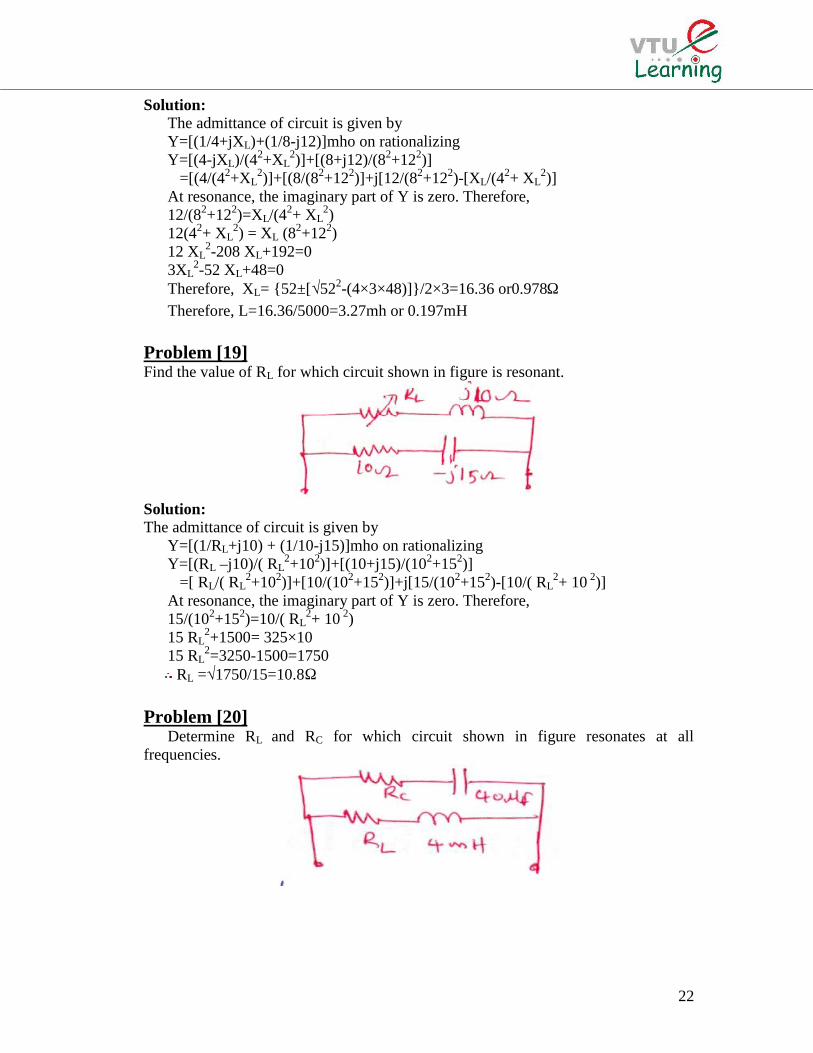
Problem [19]Find the value of RL for which circuit shown in figure is resonant.
Solution:The admittance of circuit is given by
Y=[(1/RL+j10) + (1/10-j15)]mho on rationalizingY=[(RL –j10)/( RL
2+102)]+[(10+j15)/(102+152)]=[ RL/( RL
2+102)]+[10/(102+152)]+j[15/(102+152)-[10/( RL2+ 10 2)]
At resonance, the imaginary part of Y is zero. Therefore,15/(102+152)=10/( RL
2+ 10 2)15 RL
2+1500= 325×1015 RL
2=3250-1500=1750RL =√1750/15=10.8Ω
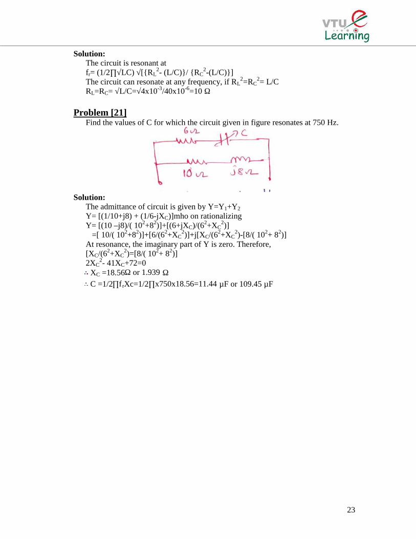
Problem [20]Determine RL and RC for which circuit shown in figure resonates at all
frequencies.
23
Solution:The circuit is resonant atfr= (1/2∏√LC) √[RL
2- (L/C)/ RC2-(L/C)]
The circuit can resonate at any frequency, if RL2=RC
2= L/CRL=RC= √L/C=√4x10-3/40x10-6=10 Ω
Problem [21]Find the values of C for which the circuit given in figure resonates at 750 Hz.
Solution:The admittance of circuit is given by Y=Y1+Y2
Y= [(1/10+j8) + (1/6-jXC)]mho on rationalizingY= [(10 –j8)/( 102+82)]+[(6+jXC)/(62+XC
2)]=[ 10/( 102+82)]+[6/(62+XC
2)]+j[XC/(62+XC2)-[8/( 102+ 82)]
At resonance, the imaginary part of Y is zero. Therefore,[XC/(62+XC
2)=[8/( 102+ 82)]2XC
2- 41XC+72=0XC =18.56Ω or 1.939 ΩC =1/2∏f rXc=1/2∏x750x18.56=11.44 µF or 109.45 µF
Related Documents