Troubleshooting Scenarios When working with networks and systems, it is often required to use the knowledge and skills regarding several technologies, along with applying critical thinking skills to solve a problem or implement a solution. These scenarios will assist you in reinforcing many of the topics covered in this book, as well as providing additional insights and how the technology and troubleshooting techniques can be integrated. Scenario 1 The user at PC2 has called the helpdesk. Internet access is slow intermittently throughout the day. IP phone voice quality is also unacceptable during those same times periods. A technician has been asked to respond. Below are the steps taken by the technician, along with the reasoning behind his actions. From PC2, the command ipconfig /all was issued. Here is a partial output of the results: FastEthernet adapter 1: Description . . . . . . . . . . . : Intel(R) Network Adapter Physical Address. . . . . . . . . : 68-17-29-C8-75-62 DHCP Enabled. . . . . . . . . . . : Yes IPv4 Address. . . . . . . . . . . : 192.168.1.74 Subnet Mask . . . . . . . . . . . : 255.255.255.0 Lease Obtained. . . . . . . . . . : Monday, March 9, 6:16:33 PM Lease Expires . . . . . . . . . . : Tuesday, March 10, 6:16:36 PM Default Gateway . . . . . . . . . : 192.168.1.1 DHCP Server . . . . . . . . . . . : 192.168.1.1 DNS Servers . . . . . . . . . . . : 8.8.8.8 R1’s IP address on its Ethernet interface connected to SW1 port 7 is 192.168.1.1, and the output confirms that the customer has an valid IP address for the current network, as well as default gateway which is reachable on that same network. If DHCP services were not working, the PC may have assigned itself an APIPA address (169.x.x.x). The technician issued the following command frmPC2: PC2:\ >ping 192.168.1.1

Welcome message from author
This document is posted to help you gain knowledge. Please leave a comment to let me know what you think about it! Share it to your friends and learn new things together.
Transcript

Troubleshooting Scenarios When working with networks and systems, it is often required to use the knowledge and skills regarding several technologies, along with applying critical thinking skills to solve a problem or implement a solution. These scenarios will assist you in reinforcing many of the topics covered in this book, as well as providing additional insights and how the technology and troubleshooting techniques can be integrated. Scenario 1 The user at PC2 has called the helpdesk. Internet access is slow intermittently throughout the day. IP phone voice quality is also unacceptable during those same times periods. A technician has been asked to respond. Below are the steps taken by the technician, along with the reasoning behind his actions.
From PC2, the command ipconfig /all was issued. Here is a partial output of the results: FastEthernet adapter 1: Description . . . . . . . . . . . : Intel(R) Network Adapter Physical Address. . . . . . . . . : 68-17-29-C8-75-62 DHCP Enabled. . . . . . . . . . . : Yes IPv4 Address. . . . . . . . . . . : 192.168.1.74 Subnet Mask . . . . . . . . . . . : 255.255.255.0 Lease Obtained. . . . . . . . . . : Monday, March 9, 6:16:33 PM Lease Expires . . . . . . . . . . : Tuesday, March 10, 6:16:36 PM Default Gateway . . . . . . . . . : 192.168.1.1 DHCP Server . . . . . . . . . . . : 192.168.1.1 DNS Servers . . . . . . . . . . . : 8.8.8.8 R1’s IP address on its Ethernet interface connected to SW1 port 7 is 192.168.1.1, and the output confirms that the customer has an valid IP address for the current network, as well as default gateway which is reachable on that same network. If DHCP services were not working, the PC may have assigned itself an APIPA address (169.x.x.x). The technician issued the following command frmPC2: PC2:\ >ping 192.168.1.1

Pinging 192.168.1.1 with 32 bytes of data: Reply from 192.168.1.1: bytes=32 time=3ms TTL=64 Reply from 192.168.1.1: bytes=32 time=2ms TTL=64 Reply from 192.168.1.1: bytes=32 time=1ms TTL=64 Reply from 192.168.1.1: bytes=32 time=2ms TTL=64 Ping statistics for 192.168.1.1: Packets: Sent = 4, Received = 4, Lost = 0 (0% loss), Approximate round trip times in milli-seconds: Minimum = 1ms, Maximum = 3ms, Average = 2ms PC2 could ping the local default gateway. This confirms that the switch port number 2 on SW1 is assigned to the same (and likely correct) VLAN as the default gateway. VLAN assignment is controlled at the switch port level. The fact that the user at PC2 has Internet connectivity at all is also an indicator that IP addressing and default gateway information is correct for PC2. The technician used the ping command to test reachability to an Internet server as well as a loopback interface address on the R2, which is across the WAN. An IPv4 loopback interface with an IP address on a router can be used for reachability testing as well as assisting some protocols such as BGP to be fault‐tolerant by using this internal loopback interface for establishing neighbor relationships when there are multiple physical paths between neighbors. Because the pings were successful to the Internet and R2, that indicates that routing between site 1 and the Internet, as well between site 1 and site 2 is in place and working. The routing was likely implemented through statically configured routes or an interior dynamic routing protocol such as RIPv2, OSPF or an external routing protocol such as BGP. Cisco’s proprietary EIGRP, as well as the open standard BGP routing protocols both use an autonomous system number as an identifier. If the routers were using incorrect autonomous system numbers, that also could break routing due to the misconfiguration of the routing protocol on the router. Some older routing protocols such as RIPv2 (which is a distance vector routing protocol), are slow to converge and may take several minutes before the rest of the network is aware of changes (for example a new network that has been added, or networks that have been removed) in the network. Upon closer inspection of port 2 on SW1 (which is being used to connect PC2 to the network), the output of a show command on that interface revealed the following (partial output shown): FastEthernet0/2 is up, line protocol is up (connected) Hardware is Fast Ethernet, address is 000e.8300.c400 (bia 000e.8300.c400) MTU 1500 bytes, BW 100000 Kbit, DLY 100 usec, reliability 255/255, txload 1/255, rxload 1/255 Encapsulation ARPA, loopback not set Keepalive set (10 sec) Half-duplex, 100Mb/s, media type is 10/100BaseTX input flow-control is off, output flow-control is unsupported ARP type: ARPA, ARP Timeout 04:00:00 Last input 00:00:00, output 00:00:00, output hang never Based on this output, the duplex setting on SW1 port 2 is currently set to half duplex. On a switch, all the access ports should be set to full duplex if when the devices connected to those ports also support full duplex which allows the device to simultaneously send and receive frames at the same time, using
one pair of wires for sending and another pair of wires for receiving. This indeed could cause a slowdown for the user at PC2 when the network is busy. The technician should use proper change control procedures to schedule and modify the configuration for SW1, port 2 to full duplex as well as ensuring that PC2 was also is configured for auto negotiation of the speed and duplex, or is set to full duplex to match the switch port it is connected to. Part of the change control process would involve documenting the proposed changes, including the reasons why they’re being done and include a full backup of the configuration before changes are made. In the event the changes cause a negative impact to the whole switch, a rollback procedure should be planned for and used if necessary. After the changes were implemented, testing and follow‐up should be done. A baseline for the performance of PC2 could be created before the change, and then the testing could be done again after the change and compared against the baseline. It is also very likely that if the user has a voice over IP solution using the same connection to the switch, that there may be some quality of service (QoS) being implemented at layer 2 specifically for the voice traffic. Both voice and video traffic are sensitive to time delays. QoS is often done at layer 2 using class of service (CoS) which gives preferential treatment to the voice traffic so that in the event of congestion on the network applications like voice over IP and video or other applications that use codecs or are sensitive to delays on the network can still perform well, while other protocols which are not as sensitive to delays are given less throughput on the network.
Scenario 2
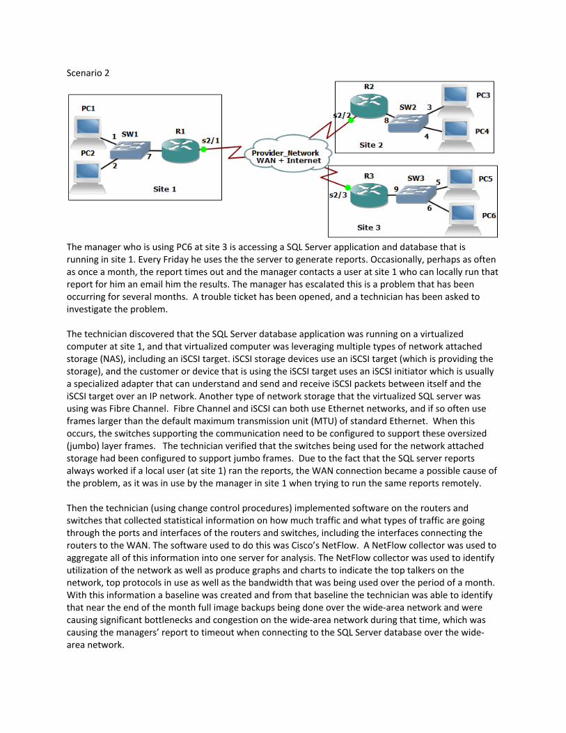
The manager who is using PC6 at site 3 is accessing a SQL Server application and database that is running in site 1. Every Friday he uses the the server to generate reports. Occasionally, perhaps as often as once a month, the report times out and the manager contacts a user at site 1 who can locally run that report for him an email him the results. The manager has escalated this is a problem that has been occurring for several months. A trouble ticket has been opened, and a technician has been asked to investigate the problem. The technician discovered that the SQL Server database application was running on a virtualized computer at site 1, and that virtualized computer was leveraging multiple types of network attached storage (NAS), including an iSCSI target. iSCSI storage devices use an iSCSI target (which is providing the storage), and the customer or device that is using the iSCSI target uses an iSCSI initiator which is usually a specialized adapter that can understand and send and receive iSCSI packets between itself and the iSCSI target over an IP network. Another type of network storage that the virtualized SQL server was using was Fibre Channel. Fibre Channel and iSCSI can both use Ethernet networks, and if so often use frames larger than the default maximum transmission unit (MTU) of standard Ethernet. When this occurs, the switches supporting the communication need to be configured to support these oversized (jumbo) layer frames. The technician verified that the switches being used for the network attached storage had been configured to support jumbo frames. Due to the fact that the SQL server reports always worked if a local user (at site 1) ran the reports, the WAN connection became a possible cause of the problem, as it was in use by the manager in site 1 when trying to run the same reports remotely. Then the technician (using change control procedures) implemented software on the routers and switches that collected statistical information on how much traffic and what types of traffic are going through the ports and interfaces of the routers and switches, including the interfaces connecting the routers to the WAN. The software used to do this was Cisco’s NetFlow. A NetFlow collector was used to aggregate all of this information into one server for analysis. The NetFlow collector was used to identify utilization of the network as well as produce graphs and charts to indicate the top talkers on the network, top protocols in use as well as the bandwidth that was being used over the period of a month. With this information a baseline was created and from that baseline the technician was able to identify that near the end of the month full image backups being done over the wide‐area network and were causing significant bottlenecks and congestion on the wide‐area network during that time, which was causing the managers’ report to timeout when connecting to the SQL Server database over the wide‐area network.

To correct this a procedure was put in place to schedule the archives and backups that were causing the congestion to be scheduled only for early morning hours before regular business begins. Traffic shaping and quality of service were also applied on the routers for their wide‐area network connections in order to provide quality of service (QoS) so that if congestion did happen in the future prioritization would be given to those applications such as real‐time traffic, and other critical applications (such as the manager’s SQL server application), while less critical traffic would receive less priority for bandwidth in a situation where congestion exists and there is not enough bandwidth for all applications at the same time.
Scenario 3
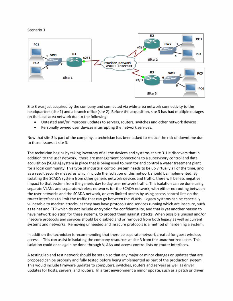
Site 3 was just acquired by the company and connected via wide‐area network connectivity to the headquarters (site 1) and a branch office (site 2). Before the acquisition, site 3 has had multiple outages on the local area network due to the following:
Untested and/or improper updates to servers, routers, switches and other network devices.
Personally owned user devices interrupting the network services. Now that site 3 is part of the company, a technician has been asked to reduce the risk of downtime due to those issues at site 3. The technician begins by taking inventory of all the devices and systems at site 3. He discovers that in addition to the user network, there are management connections to a supervisory control and data acquisition (SCADA) system in place that is being used to monitor and control a water treatment plant for a local community. This type of industrial control system needs to be up virtually all of the time, and as a result security measures which include the isolation of this network should be implemented. By isolating the SCADA system from other generic network devices and traffic, there will be less negative impact to that system from the generic day to day user network traffic. This isolation can be done using separate VLANs and separate wireless networks for the SCADA network, with either no routing between the user networks and the SCADA network, or very limited access by using access control lists on the router interfaces to limit the traffic that can go between the VLANs. Legacy systems can be especially vulnerable to modern attacks, as they may have protocols and services running which are insecure, such as telnet and FTP which do not include encryption for confidentiality, and that is yet another reason to have network isolation for these systems, to protect them against attacks. When possible unused and/or insecure protocols and services should be disabled and or removed from both legacy as well as current systems and networks. Removing unneeded and insecure protocols is a method of hardening a system. In addition the technician is recommending that there be separate network created for guest wireless access. This can assist in isolating the company resources at site 3 from the unauthorized users. This isolation could once again be done through VLANs and access control lists on router interfaces. A testing lab and test network should be set up so that any major or minor changes or updates that are proposed can be properly and fully tested before being implemented as part of the production system. This would include firmware updates to computers, switches, routers and servers as well as driver updates for hosts, servers, and routers. In a test environment a minor update, such as a patch or driver

update could be tested and verified before being rolled out into production. If there is an issue or problem with update a rollback can be done to the initial state. Sometimes a major update does not have a simple rollback procedure, which is even a better reason why they should be tested and practiced in a test environment before being rolled out into production. When testing the upgrading process of the software or system, there should also be a defined downgrading process as well that could be used to revert back to a previous version of the software or system. This might be needed in the event a rollout occurred and it was later discovered that there is a security or performance issue with the upgraded software. A backup of the configuration for network devices should always be created and available in the event the system needs to be restored to its original state. If there is a BYOD policy that allows the users to “bring your own device”, a proper on‐boarding process needs to be established that confirms the devices meet the minimum security requirements for the network, has proper protection for company and sensitive information it will hold or have access to, and has been properly set up for access to the network. An example would be having the MAC address of a mobile device included on access control lists on the wireless AP or Wireless Lan Controller (WLC) that allows the device to access to the network. Other requirements may include a scan of the system prior to the device gaining access to the network. This can be done on demand each time a device accesses the network using a software agent that runs on the device. This agent can scan the device to determine if certain prerequisites (such as a personal firewall or an updated virus definition) is currently present before allowing access to the network. This agent could be persistent software that installed on and continually resides on the device, or it could be a non‐persistent agent which is loaded and run only at the time of network access. Performing scans as well as requiring authentication (before allowing access to the network) at either a port on a switch or through a wireless AP, those are both examples of network access control at the edge of our network. Technologies such as 802.1x can provide the authentication at the edge, and third party vendors such as Cisco, Citrix and Checkpoint can provide the scans in conjunction with an agent to verify pre‐requisites of the device that wants the network access. Once the user gets access to the network, access control can be implemented between various portions of our network by using access control lists on our router interfaces. A well‐defined off‐boarding process should also be set up that does a clean‐up process and removes access from these devices after they are no longer supposed to have access to the network. Care should also be given to the company content that may be resident on a mobile or personal device, so that sensitive company information isn’t left on the device after it is no longer welcome on the corporate network.

Scenario 4 A growing company is having wireless networking issues. An access point was recently added near the window of one of the floors of building 1, in the hopes that their users in a building2 would also be able to access the network. Unfortunately the access point not only failed to provide access for the second building, but also caused many users in the first building to have degraded wireless service. The technician has been called in to evaluate the problem and make recommendations. As part of the troubleshooting methodology the technician gathers information, verifies the problem by questioning users and having them duplicate the issues, identify symptoms, determine if anything is changed, and if there are multiple issues to approach them individually. With that information the technician establishes a theory regarding the probable cause. Several approaches that can be used to establish theory of probable cause would be a top‐to‐bottom or a bottom‐to‐top troubleshooting approach using the OSI reference model. For example if an application layer function like printing works over the wireless network, that implies the lower layers are all functioning correctly. That would be an example of a top‐to‐bottom approach. An example of bottom‐to‐top would be verifying lower layers such as basic IP connectivity using tools such as the ping command, and then working up until a failure or problem is found. An example of the bottom‐to‐top approach would be to check the link status of an interface, and then use the ping command. If those are both successful, that implies that layer 2 and layer 3 are working, but an application service, such as web services may still fail. That would imply there is a failure of the Web server, or something between the client and the Web server which is preventing their connection. The technician decided to divide and conquer, by working on each problem individually. The technician began by powering off the new access point that was recently added, and as a result functionality returned for the users in the first building. As a result of this, it can be deduced that the new access point was causing the problem. The technician went to the wiring closet to identify which port on the patch panel was being used to connect the access point to the network. Fortunately it was correctly labeled which made it easy to find. Next the technician identified the switch port on the switch that connected to that patch panel connector, and tried to connect to the switch on one of its VTY (Virtual Teletype, used for remote management access) lines using an SSH application from his laptop. He was unable to connect, so he called another administrator on the phone to troubleshoot the lack of SSH access to the switch. It was determined that another administrator was already connected to the single logical VTY line on the switch, and that is why a second administrator couldn’t connect. The currently logged in administrator increased the number of the logical VTY lines, and as a result, the second technician was then able to log into the switch. After logging into the switch, the technician used commands on the switch which showed the following: Hardware is Fast Ethernet, address is 001c.b148.3e61 MTU 1504 bytes, BW 100000 Kbit/sec, DLY 100 usec, reliability 255/255, txload 1/255, rxload 1/255 Encapsulation ARPA, loopback not set Keepalive set (10 sec) Full-duplex, 100Mb/s, media type is 10/100BaseTX input flow-control is off, output flow-control is unsupported ARP type: ARPA, ARP Timeout 04:00:00 Last input 00:00:00, output 00:00:00, output hang never Last clearing of "show interface" counters never

Based on this output, the technician could verify that the Ethernet port on the switch was set to full duplex and 100 Mbps. While in the wiring closet, the technician also noticed that the fiber connections used to connect the wiring closet switch to the main distribution frame in the basement of the building was using older FC connectors which twist on to connect to the switch, and that there were several yards of fiber cable stuffed behind the rack before it went through the conduit and down to the basement. The technician made a recommendation in his notes that the fiber should be moved to the cable trays that where in the closet, to keep them up and out of the way of foot traffic in the closet. This would also help prevent against an accidental pull or bending of the fiber cable, which if too extreme could damage the cables and cause them to fail. It was also noted by the technician, that the management access to this switch was going through the same network that the users were using for common network services, such as printing and file services. This is referred to as in‐band management, were the user traffic and management traffic both go over the same network. At this company there is a second and isolated network, just for management of network devices, such as routers and switches. If used, this separate isolated network would be used for out‐of‐band management, which means it would have be a separate network, not using the same network as the users do for common network services. It was recommended by the technician that change control procedures be arranged to place the switch administrative interfaces for management (the VTY lines) on that out‐of‐band network. Using an out‐of‐band network for management, is more secure than in‐band, due to the isolation and separation of the networks. Additional out‐of‐band management may include using analog modems using the older public switched telephone network as a backup method to reach and manage remote devices in the event the primary network path is no longer available. Modems would be using analog signals as they cross over the older Public Switched Telephone Network (PSTN). Modems covert digital signals from computing devices to analog signals before being sent over the PSTN. Regardless of in‐band or out‐of‐band, clear text management protocols such as SNMPv1, SNMPv2, Telnet, HTTP, FTP and TFTP should be avoided when possible or used inside a VPN tunnel (which can provide authentication and confidentiality through encryption). Secure alternatives to clear text protocols include SNMPv3, SSH, HTTPS and SFTP. These can be used for improved confidentiality and security. Disabling unneeded network services, especially ones that don’t require authentication or are clear text, should be done on every router, switch, server and host that is connected to any network. Disabling unneeded network services and insecure protocols is an example of network hardening. Creating and using standard settings that are geared for security, on each device that is added to the network is also an example of network and device hardening. Later that night, during a maintenance window that was scheduled and communicated through proper change control procedures, (when users were not using the network), the technician used that authorized downtime, and powered on the access point that had been causing the problem to look at its settings. The technician discovered that the access point Ethernet connection that connected to the switch port was configured on the access point for half duplex. This in and of itself may not cause problems for other users, but could definitely impact performance if the network is busy because the access point would not be able to send and receive frames simultaneously. The technician looked up the access point information and verified that it had an omni‐directional antenna which was appropriate for the area in building 1 that it was supposed to cover. The next thing the technician checked was the 802.11 protocol being used by that access point, as well as which channel or channels it was using. All the other access points on the floor were configured for 802.11g, and the new access point was also configured for 802.11g, so that was not a problem. However the new access point was configured to use channel 11, and that was overlapping with an existing access point that was physically close to the new access point which was also using channel 11, as the antenna on these access points are omni‐
directional (signals go out in all directions), as opposed to uni‐directional (where the signals only go in one direction) and the APs were competing with each other for the same frequencies. The technician changed the channel to 6, which would then not overlap with the other existing access point using channel 11. The non‐overlapping channels in the 2.4 GHz range in the US are channels 1, 6, 11. A quick wireless site‐survey, using a smart‐phone application, confirmed that the APs were not using overlapping channels and as a result no longer competing for the same frequency ranges. Now with the local wireless issue addressed, the technician began looking at the issue for the users in the second (adjacent building) who also wanted wireless access. The new access point in building 1 was near the window facing the second building, but due to the distance and windows and walls between the access point and the users in building 2, the signal would not be strong enough to be used by users in building 2. Because the two buildings were less than 100 feet apart, it was decided that small antenna could be placed on the outside of each building to act as a repeater to extend wireless access from building 1 to building 2. In building 2 a small layer 2 switch would be used to connect the antenna on the side of the building to a new small access point in building 2. For the two external antennae, one for the side each building, they decided to use a Yagi‐Uda style, as it is a directional antenna, and is fairly inexpensive and is not difficult to lineup which may be the case with a small dish or parabolic antenna. The technician also is recommending that if the users need increased throughput, they may want to consider budgeting for and replacing their their access points to 802.11n or 802.11ac. The IEEE 802.11 groups often develop high throughput (ht) standards for existing technologies, such as 802.11a‐ht, and 802.11g‐ht. Newer technologies such as 802.11n supports multiple antenna and multiple‐input, multiple‐output (MIMO), while 802.11ac supports multi‐user MIMO (MUMIMO) where it can use multiple 80MHz channels and a single spatial stream can support 433Mbps. An 802.11ac access point can use multiple streams active simultaneously. High throughput (ht) enhancements are also applicable to the newer technologies of 802.11n‐ht, and 802.11ac‐ht as well. The technician also recommends implementing a wireless LAN controller (WLC) would allow central management and control of the access points. When access points are managed by a centralized WLC they are said to be a thin AP and the WLC performs tasks such as authentication of the users. With the WLC, the APs are just being used for their radios and antenna, and the WLC handles tasks such as user authentication and access control lists. One of the benefits of using a WLC is that an unauthorized AP (also referred to as a rogue AP) that is brought into the company by an employee who has malicious intent (referred to as a trusted malicious users) can be identified by the authorized APs and the WLC working together, and the authorized APs could perform jamming of the rouge AP’s signals, so that no users could connect to it. Jamming is a technique that a malicious person, perhaps even an untrusted user from outside the building, might use to implement a Denial of Service (DoS) attack against a legitimate wireless network. In the case of the WLC coordinating the effort against the non‐authorized AP, this would be done to mitigate the effectiveness of the rogue AP. This could also assist in protecting against a friendly or unintentional DoS attack by a user who didn’t realize the impact of bringing their own wireless AP (that may be integrated into a small home router) into the physical office. The WLC implementation could also assist in identifying open networks (networks that don’t require authentication) which are not authorized to be present in the building, and assist in bringing those APs and networks down. In the current standalone configuration of each AP, also referred to as Fat or Thick configurations, each access point performs the authentication on its own, and each AP must be configured individually.

Scenario 5
After reviewing the log files for SW1, it revealed thousands of failed login attempts to the VTY lines on SW1 over the past 7 days, and 2 successful logins. A technician has been assigned to look into the matter, and to make recommendations to improve the security. The technician goes to the wiring closet where the switch is located, and connects directly to the console port to gain command line interface (CLI) access to SW1. A partial output of the command show running‐config revealed the following about the configuration of SW1: … hostname SW1 username admin privilege 15 secret 4 NNPC.a45nsE7N0.uzqy5V2pUfg aaa new-model aaa authentication login USE-AAA group radius local aaa authentication login default local ! interface GigabitEthernet0/1 switchport mode access switchport access vlan 10 ! interface GigabitEthernet0/2 switchport mode access switchport access vlan 10 ! interface GigabitEthernet0/7 switchport mode access switchport access vlan 10 ! ip access-list standard LIMIT-VTY deny 10.1.5.0 0.0.0.255 ! radius server RAD-1 address ipv4 10.1.2.3 auth-port 1645 acct-port 1646 key Nugget!23 ! !

line con 0 exec-timeout 30 0 login authentication USE-AAA transport input all line vty 0 4 exec-timeout 30 0 … The technician noted the following issues: The access‐list called LIMIT‐VTY is not applied to the logical VTY line configuration on the switch, so it is not restricting who can attempt to log on via the VTY lines. Even if the ACL was applied to the VTY lines to restrict access, it would be too restrictive, as the ACL has only deny statements in it. If applied it would block all incoming VTY requests. This would be an example of a misconfigured Access Control List (ACL). The method‐list created for login authentication (USE‐AAA) is not applied to the VTY lines, so the VTY access, which is used by both SSH and Telnet, is using the default method which is not using the RADIUS server for authentication, but instead using user accounts configured on the local switch for authentication. The password configured for the RADIUS server, (RAD‐1 is the server, and Nugget!23 is the configured password), is different than the password on the RADIUS server itself, so even if the switch tried to use a RADIUS server for authentication, due to the mismatched passwords, the RADIUS AAA based authentication wouldn’t work because the RADIUS server wouldn’t accept requests from SW1 due to the wrong password. This is an example of a password mismatch. By correctly implementing the RADIUS password and method list, or implementing a TACACS AAA server (similar to what would be done with a RADIUS server), with a correct method list it would correct the authentication issues that are currently misconfigured on this switch. SNMP is not configured on this switch, which could be done to allow reporting and management from an SNMP server. If SNMP is used, insecure versions such as SNMPv1 and SNMPv2 should be avoided due to being insecure protocols, and instead SNMPv3 which supports authentication and encryption should be used. The allowed input on the VTY lines is “all”. This implies Telnet and SSH are allowed. This also implies that TCP port 22 for SSH, and TCP port 23 for Telnet are both open for business, (referred to as open ports). Insecure and/or unneeded protocols and services, such as Telnet, should be disabled on the switch. If Telnet access is disabled, then TCP port 23 would be a closed port, meaning it would not be standing by listening for incoming connections on that TCP port 23. The technician looked for unfamiliar user accounts on the local switch, which may have been placed there by an unauthorized user had gained access to the switch, and created a separate account for future access to the switch. This is an example of creating backdoor access, which is a form of improper access that the attacker could use in the future for access to the switch. The individual or individuals who attempted to login thousands of times, were very likely using an automated tool which tries different usernames and passwords combinations in an attempt to access the switch. This is an example of a brute force attack, and if implemented by an employee who already has general access to the

network, this would be considered a malicious trusted user. The user would be considered trusted because they have a user account on the system, but malicious because they are not authorized to access the switch as an administrator. The attack could also be launched by an unknown individual, someone who does not already have access to the network with a user account, and this type of user could be referred to as an un‐trusted user. The concept of an un‐trusted user could also extend to a guest account, or an account that hasn’t been authenticated by the network. One technique that could be used to help identify when unauthorized login attempts are happening, would be to put a device on the network that has insecure protocols and ports open and available, and implement logging of the login attempts on this device. This device which would have nothing of value in either the data or configuration, and would implemented for the sole purpose of seeing who is trying to attack and what types of attacks are being attempted. This type of the device is referred to as a honeypot. If we placed a group of systems that were there for this purpose of inviting attacks to learn more about these attacks, they collectively could be referred to as being part of a honeynet. By using a honeypot or honeynet, the intention is to learn about the attacker’s methods before the attacker uses them on critical nodes and other critical assets in our network. For our critical devices we would want to implement high availability (HA) and fault tolerance, as well as device hardening techniques and possibly intrusion detection/prevention systems to prevent an attack or unauthorized access from being successful. We could also use AAA for the authentication authorization and accounting on these critical systems which could not only notify us of events that are occurring on those devices but also limit the number of attempts the attacker could make for logging in to those devices.
Scenario 6
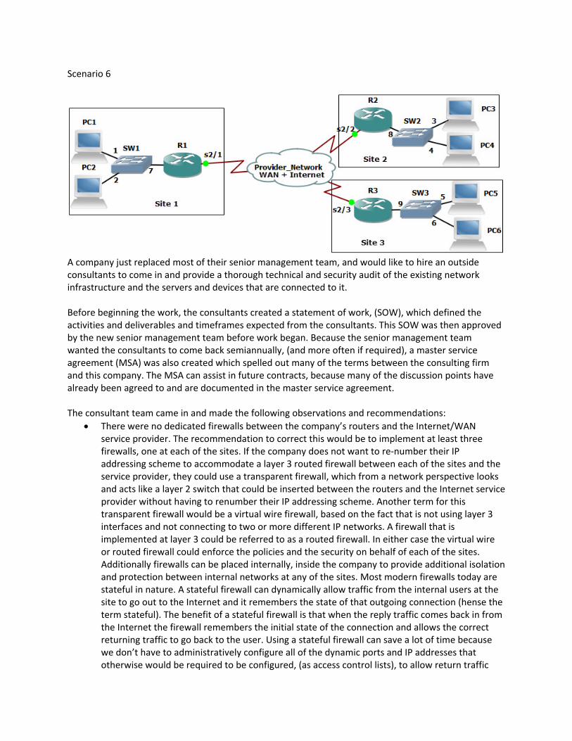
A company just replaced most of their senior management team, and would like to hire an outside consultants to come in and provide a thorough technical and security audit of the existing network infrastructure and the servers and devices that are connected to it. Before beginning the work, the consultants created a statement of work, (SOW), which defined the activities and deliverables and timeframes expected from the consultants. This SOW was then approved by the new senior management team before work began. Because the senior management team wanted the consultants to come back semiannually, (and more often if required), a master service agreement (MSA) was also created which spelled out many of the terms between the consulting firm and this company. The MSA can assist in future contracts, because many of the discussion points have already been agreed to and are documented in the master service agreement. The consultant team came in and made the following observations and recommendations:
There were no dedicated firewalls between the company’s routers and the Internet/WAN service provider. The recommendation to correct this would be to implement at least three firewalls, one at each of the sites. If the company does not want to re‐number their IP addressing scheme to accommodate a layer 3 routed firewall between each of the sites and the service provider, they could use a transparent firewall, which from a network perspective looks and acts like a layer 2 switch that could be inserted between the routers and the Internet service provider without having to renumber their IP addressing scheme. Another term for this transparent firewall would be a virtual wire firewall, based on the fact that is not using layer 3 interfaces and not connecting to two or more different IP networks. A firewall that is implemented at layer 3 could be referred to as a routed firewall. In either case the virtual wire or routed firewall could enforce the policies and the security on behalf of each of the sites. Additionally firewalls can be placed internally, inside the company to provide additional isolation and protection between internal networks at any of the sites. Most modern firewalls today are stateful in nature. A stateful firewall can dynamically allow traffic from the internal users at the site to go out to the Internet and it remembers the state of that outgoing connection (hense the term stateful). The benefit of a stateful firewall is that when the reply traffic comes back in from the Internet the firewall remembers the initial state of the connection and allows the correct returning traffic to go back to the user. Using a stateful firewall can save a lot of time because we don’t have to administratively configure all of the dynamic ports and IP addresses that otherwise would be required to be configured, (as access control lists), to allow return traffic
from the Internet to come back to the internal users. This process is often referred to as stateful inspection or stateful filtering. A device such as a firewall that does not do stateful inspection, would be limited to stateless inspection or stateless filtering, which is usually done by the implementation of access control lists that specifically identify what traffic is allowed to go through the firewall. Another benefit that many firewalls offer is application inspection. This is often referred to as being context aware. An example of this would be filtering traffic that is attempting to go through the firewall based on the type or content that is being carried at the application layer. Limitations can be put in place based on the type of website the user is trying to go to or the type of content that the user is trying to retrieve while going through the firewall. Current firewalls that integrate many of these features including stateful filtering, application awareness and intrusion detection systems are referred to as unified threat management (UTM) firewalls.
The consulting company scheduled authorized downtime, using proper change control, to use a Ethernet cable tester to verify the cabling between mission‐critical systems and the switches and routers that connect those devices to the network. They used a line tester to verify the circuit that was being used between the routers and the Internet service provider. For the Ethernet connections, although the cables being used were functional, they were using non‐standard pairs for the termination of these cables on both ends at the UTP cables as they connected to the RJ45 connectors. The consultant recommends re‐crimping (through a certified third party) using EIA/TIA 568A standards for the UTP to RJ45 connector. The incorrect crimping, though functional, was resulting in cross‐talk. Cross‐talk is an unwanted condition where signals that are going through adjacent pairs of wire in twisted‐pair cabling interfere with each other. Near end crosstalk (NEXT) is crosstalk that’s occurring at the near end of the cable, while far end cross‐talk is the interference at the far end of the cable or circuit. The consultants also noticed that most of the crossover cables between the switches in the same wiring closets, were also incorrectly crimped. These were functional however because pin 1 on one end of the cable went to pin 3 on the far side, and pin 2 on one end of the cable connected to pin 6 on the other side. The proper crimping would have the same pinouts for a crossover cable, but should use EIA/TIA 568A on one end, and EIA/TIA 568B on the other end. If the company intends to deploy gigabit Ethernet (1000baseT, Gigabit Ethernet), they will want to use Cat6 cabling and connectors.
The interconnection of the switches between floors was being done with fiber, but the cable management of the UTP that when out to the cubes on the same floor, as well as the fiber that went up and down between floors was a mess, and reminded the consultants of cooked spaghetti. The consultants recommended cable trays to be used to organize and protect the cables from being excessively pulled or bent or stepped on. They also recommended better security for the wiring closet access as they were able to enter the wiring closet on each floor without any type of a key or passcode.
The consultants also interviewed, (with permission from management), several employees and discovered that several outages happened over the previous six months, including Wi‐Fi access. It was further documented that the disruption service was due to updates that had been applied to the access points, which had a bug and caused the APs to not work correctly. The downtime associated with the bug could have been avoided by having a test environment, avoiding untested updates as well is using proper change control procedures including verification and a rollback procedure when needed. The consultants are recommending a structured and clearly
laid out change control plan which includes documentation regarding the reason for change, change requests that include configuration procedures, rollback processes, potential impact analysis, and notification. The change control should also include a formal approval process, a well communicated maintenance window and authorize downtime, as well as notification and documentation regarding the changes that took place.
The consultants identified plans the company had to connect to a third‐party network, as they anticipated working on a joint project with that third‐party. The consultants recommended implementing a memorandum of understanding (MOU) between the two companies to identify and confirm in writing the intentions and agreements between the companies. It’s also recommended by the consultants that minimum security requirements for both companies must be in place for any systems or networks that will be connected between the two companies, because a security flaw or weakness in one of the companies, could impact the security of the other.
The contractors discovered that wide‐area network connectivity between the sites as well as Internet connectivity has had several outages over the past six months, causing downtime and loss of revenue. The consultants recommended that the company get a written service level agreement (SLA) from the Internet/wide‐area network provider regarding service levels that are guaranteed from that provider. If a service‐level agreement cannot be provided, the company is encouraged to investigate other providers as well as secondary providers that can provide SLA’s. It is also recommended that the company acquire a backup provider to have fault tolerance for their Internet and wide‐area network connectivity. Regarding Internet and wide‐area network access, the consultants recommended implementing the throttling of traffic, if it is above that level which is needed for general business. That way if an attack is launched from one of the company’s sites, there will be a limited amount of volume that can be sent due to the throttling. Filtering and blocking of certain types of traffic should also be implemented across the wide‐area network and out to the Internet, to help mitigate the risk of content such as company sensitive information, being leaked out or sent over the Internet. The consultants also recommended getting a written fair access policy regarding Internet and WAN access from the service provider. This way with a periodic audit, the company can verify that they are within acceptable utilization limits regarding their use of the Internet and wide‐area network.
The consultants identified that there was no intrusion detection system (IDS) or intrusion prevention system (IPS) in place. They recommended a network‐based intrusion prevention system that could identify many types of attacks. An attack example would be sending multiple TCP synchronization request to a server but using a bogus source IP address in an attempt to implement a denial of service syn‐flood attack against the server. This would be an example of protocol abuse. An IDS/IPS could identify this behavior and issue warnings to the administrator that this attack is underway, and potentially prevent the attack from making it all the way to the victim. Another example of an attack that can be identified with an IDS/IPS would be flooding, where an attacker (or multiple attackers) send an inordinate number of packets to either consume all the network bandwidth or resources on a given device. This packet flooding would also be considered an abuse of the system by the attacker, and an IDS/IPS would be able to identify that this type attack is happening.

The consultants also documented that switch port security was not enabled on each of the access switches in the network. By using the features of DHCP snooping and ARP inspection along with the switch port security, issues such as ARP poisoning, where an attacker is attempting to redirect traffic that is intended to go to a server or router and divert that traffic so that hacker or attacker can see it, can be prevented from happening. It was recommended that in addition to port security, additional user VLANs should be created, which are separate from the VLANs where the servers and other critical resources are kept. By setting up isolation, access control lists can be used on router interfaces to limit and protect against traffic that should not go between these server networks and the user networks. This is an example of network segmentation and isolation.

Scenario 7
A user at PC3 (in site 2) has called the helpdesk, stating that PC6 (in site 3) can’t be accessed over the WAN. The technician has been called in to identify the problem, establish a theory of probable cause, test the theory, establish a plan of action to resolve the problem, and then implement the solution or escalate as necessary. The technician is also been asked to verify full system functionality and to document his findings actions and outcomes. The technician used SSH to securely connect to a VTY line on SW2, and issued some show commands to see the configuration details regarding port number 3 on SW2, which is being used to connect PC3 to the network. A partial output is shown below: interface GigabitEthernet0/3 switchport mode access switchport access vlan 20 PC33 is supposed to be in VLAN 20, and based on the configuration of the switch the correct VLAN assignment is currently configured. If the PC could not ping its default Gateway, or failed get an IP address from DHCP, it would be possible that there was an incorrect VLAN assignment on the switch for the sport. Next the technician issued a show command on SW2 to see the status of that port 3. A partial output is shown below: FastEthernet0/3 is up, line protocol is up (connected) Hardware is Fast Ethernet, address is 001c.b1a8.6783 MTU 1504 bytes, BW 100000 Kbit/sec, DLY 100 usec, reliability 255/255, txload 1/255, rxload 1/255 Encapsulation ARPA, loopback not set Keepalive set (10 sec) Full-duplex, 100Mb/s, media type is 10/100BaseTX input flow-control is off, output flow-control is unsupported ARP type: ARPA, ARP Timeout 04:00:00 Last input 00:00:00, output 00:00:00, output hang never Last clearing of "show interface" counters never
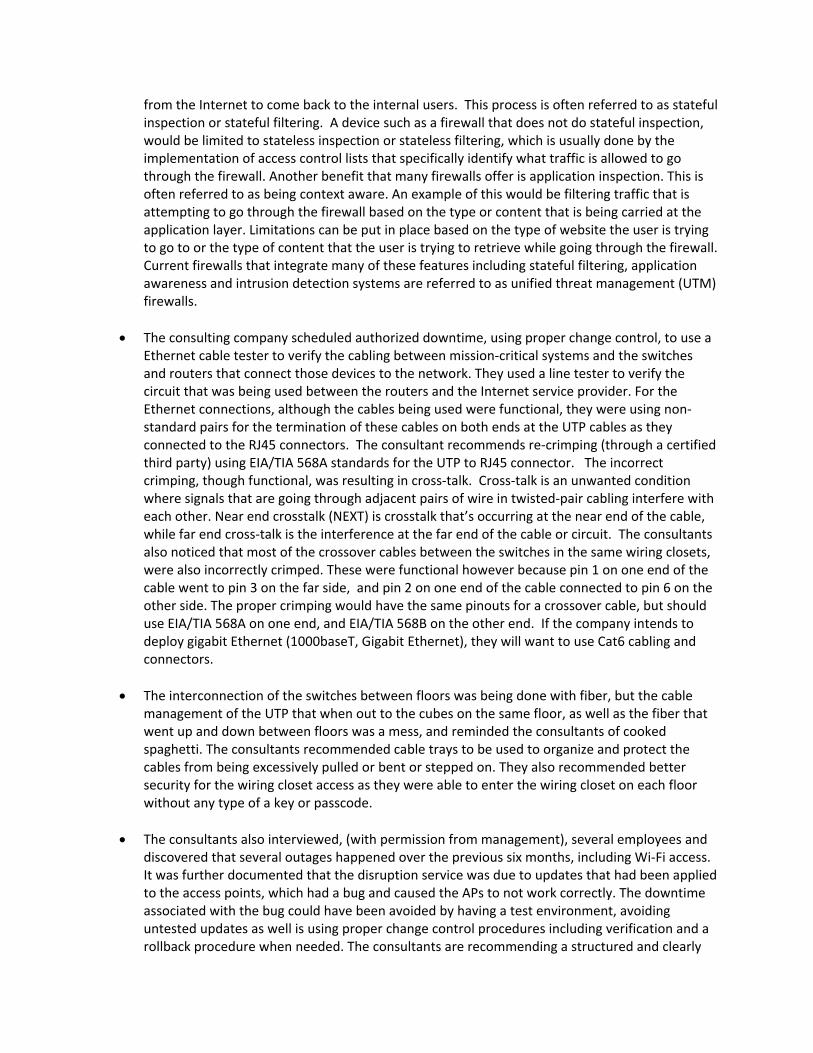
Input queue: 0/75/0 (size/max/drops); Total output drops: 0 Queueing strategy: fifo Output queue: 0/40 (size/max) 5 minute input rate 1000 bits/sec, 2 packets/sec 5 minute output rate 3000 bits/sec, 2 packets/sec 69 packets input, 4496 bytes, 0 no buffer Received 0 broadcasts (0 IP multicasts) 0 runts, 0 giants, 0 throttles 0 input errors, 0 CRC, 0 frame, 0 overrun, 0 ignored 72 packets output, 10710 bytes, 0 underruns 0 output errors, 0 collisions, 0 interface resets 0 output buffer failures, 0 output buffers swapped out Based on this output, there don’t appear to be any interface errors on this port of the switch, and it is also up and shows as connected. Then the technician went to PC3 and issued the command ipconfig /all, which revealed the following. FastEthernet adapter 1: Description . . . . . . . . . . . : Intel(R) Network Adapter Physical Address. . . . . . . . . : 68-17-29-17-75-85 DHCP Enabled. . . . . . . . . . . : Yes IPv4 Address. . . . . . . . . . . : 10.35.1.99 Subnet Mask . . . . . . . . . . . : 255.255.255.0 Lease Obtained. . . . . . . . . . : Monday, March 11, 6:16:33 PM Lease Expires . . . . . . . . . . : Tuesday, March 12, 6:16:36 PM Default Gateway . . . . . . . . . : 10.35.1.1 DHCP Server . . . . . . . . . . . : 10.35.1.254 DNS Servers . . . . . . . . . . . : 10.35.1.254 If in the output of the ipconfig command, the computer did not show a default Gateway or if the default Gateway was on a different network, (which would mean that the default Gateway was not reachable and as a result would not be functional for the client to use), then it could be a configuration issue on the local PC 3. That would be an example of an unreachable default Gateway. The technician then proceeded to verify that the computer could ping its default Gateway at 10.35.1.1, and the results were successful. It was also noticed in the output that there is only one DNS server being handed out as an option in DHCP, and that is an internal DNS server’s address. If the internal DNS server fails, that could cause a lack of connectivity, due to the lack of name resolution, so the technician is going to recommend that a second DNS server be added as an option to the DHCP scope, pointing to an Internet DNS server, such as the service provider or a public DNS server. If the client supported link level discovery protocol (LLDP) the technician could verify based on those layer 2 messages that are sent by LLDP, whether or not this PC is really connected to port number 3 on SW2. In the absence of LLDP, one way to verify that PC33 really is connected to switch port 3 is to look at the MAC address table on the switch to see if the layer 2 address of PC 3 has been associated (learned) by the switch on port 3 of the switch. This would be a method of discovering neighboring devices or nodes on the network. Since the ping was successful to PC3’s default gateway, that implies that the PC is in the correct VLAN and is very likely connected to port 3.
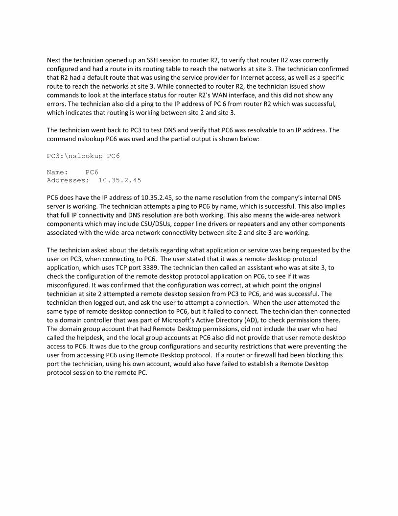
Next the technician opened up an SSH session to router R2, to verify that router R2 was correctly configured and had a route in its routing table to reach the networks at site 3. The technician confirmed that R2 had a default route that was using the service provider for Internet access, as well as a specific route to reach the networks at site 3. While connected to router R2, the technician issued show commands to look at the interface status for router R2’s WAN interface, and this did not show any errors. The technician also did a ping to the IP address of PC 6 from router R2 which was successful, which indicates that routing is working between site 2 and site 3. The technician went back to PC3 to test DNS and verify that PC6 was resolvable to an IP address. The command nslookup PC6 was used and the partial output is shown below: PC3:\nslookup PC6 Name: PC6 Addresses: 10.35.2.45 PC6 does have the IP address of 10.35.2.45, so the name resolution from the company’s internal DNS server is working. The technician attempts a ping to PC6 by name, which is successful. This also implies that full IP connectivity and DNS resolution are both working. This also means the wide‐area network components which may include CSU/DSUs, copper line drivers or repeaters and any other components associated with the wide‐area network connectivity between site 2 and site 3 are working. The technician asked about the details regarding what application or service was being requested by the user on PC3, when connecting to PC6. The user stated that it was a remote desktop protocol application, which uses TCP port 3389. The technician then called an assistant who was at site 3, to check the configuration of the remote desktop protocol application on PC6, to see if it was misconfigured. It was confirmed that the configuration was correct, at which point the original technician at site 2 attempted a remote desktop session from PC3 to PC6, and was successful. The technician then logged out, and ask the user to attempt a connection. When the user attempted the same type of remote desktop connection to PC6, but it failed to connect. The technician then connected to a domain controller that was part of Microsoft’s Active Directory (AD), to check permissions there. The domain group account that had Remote Desktop permissions, did not include the user who had called the helpdesk, and the local group accounts at PC6 also did not provide that user remote desktop access to PC6. It was due to the group configurations and security restrictions that were preventing the user from accessing PC6 using Remote Desktop protocol. If a router or firewall had been blocking this port the technician, using his own account, would also have failed to establish a Remote Desktop protocol session to the remote PC.
Scenario 8 The manager of one of the departments, is being asked to contribute part of his budget towards the WAN costs, including Internet access for a new Software as a Service (SaaS) application that his staff needs to use. Before committing the money, the manager has asked about a separate connection for Internet access, along with options for that. The technician from the networking department has met with the manager and shared the following information:
There are different technologies that can be used to access the Internet and WAN services, including DSL, Cable Modem, leased digital lines, packet switched networks (such as frame relay), Ethernet, Wireless and even legacy analog connections using modems, which convert digital signals from the computer or router, into analog signals that the old telephone system has made available for many years (and is the slowest option).
The rate at which bits are encoded on the line can be referred to as the bit rate, for example 1,000 bps. On older modem technology, another term called baud rate, represents the number of symbols or characters being sent per second. The baud rate will be less than the bit rate, as a symbol can take multiple bits to represent a single symbol.
The process of taking data and formatting it with the correct addressing and headers at layers 4, 3, and 2 is called encapsulation as data is being prepared to be sent over the network. The process of taking that data that is being received over the network and extracting the information at layers 2, 3, 4 and higher (in that order) is referred to as de‐encapsulation.
Multiplexing is the concept of taking multiple sets of data (such as Voice traffic and Email traffic), and sending them simultaneously (or virtually simultaneously) over a link on a network, such as a T1 leased line between 2 sites. This process is often referred to as multiplexing, and at the receiving side, the process of separating out the data streams (separating the Voice traffic from the Email traffic) is referred to as de‐multiplexing.
The data that is being sent and received at its lowest level are using a binary (base 2) numbering system, which means they use the numbers 1 and 0, (to represent on or off, like a light switch). Many times we represent these binary numbers using other numbering systems, such as decimal or hexadecimal to make them more manageable to write down and work with. Binary is base 2, decimal is base 10, and hexadecimal is base 16. There are other numbering systems as well, including octal, which is a base 8 numbering system. When working with IP addressing, we use decimal to represent IPv4 addresses, and hexadecimal to represent IPv6 addresses.
If using Wireless for Internet access, there are several options to choose from, but the reliability may be less than when using a wired connection. Higher wavelengths (which correspond to higher frequencies) tend to not travel as far (distance wise) as lower wavelengths.
A baseline should be created that can assist in determining the amount of bandwidth needed, along with acceptable latency values. A sampling size for this baseline should be big enough, so that it accurately represents (or estimates) the amount of traffic that will be needed over a period of time, such as a week or month.
It may be less expensive to use the existing company connection to the internet, and pay for a portion of that service, instead of putting in a separate internet connection.
Related Documents


