Neodent ® Control System Surgical Manual

Welcome message from author
This document is posted to help you gain knowledge. Please leave a comment to let me know what you think about it! Share it to your friends and learn new things together.
Transcript

Neodent®
Control SystemSurgical Manual
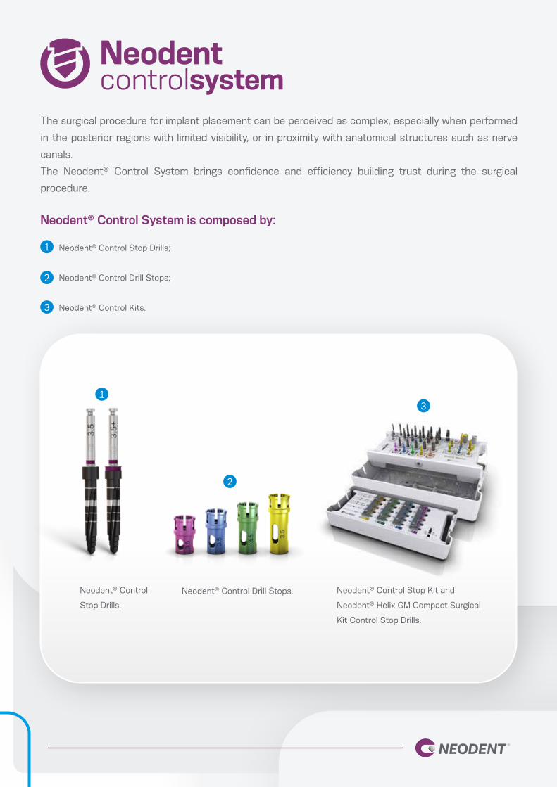
The surgical procedure for implant placement can be perceived as complex, especially when performed
in the posterior regions with limited visibility, or in proximity with anatomical structures such as nerve
canals.
The Neodent® Control System brings confidence and efficiency building trust during the surgical
procedure.
Neodent® Control Stop Drills;
Neodent® Control Drill Stops;
Neodent® Control Kits.
Neodent® Control
Stop Drills.
Neodent® Control Drill Stops. Neodent® Control Stop Kit and
Neodent® Helix GM Compact Surgical
Kit Control Stop Drills.
Neodent® Control System is composed by:
1
1
2
2
3
3

NEODENT® CONTROL STOP DRILLS
Neodent® Tapered Control Stop Drills are available for bed preparation for Helix GM® implants in all bone
types, from Ø 2.0 to Ø 7.0 mm. They were designed to be used with stops, but the laser marks on the
drills also enable their use without them. The drills are connected to the contra-angle handpiece, with a
rotation speed of approximately 500-800 rpm in bone types III-IV and 800-1200 rpm in bone types I-II.
They have a color code according to the diameter, as shown below, and a total length of 35 mm. For
diameters Ø 6.0 and Ø 7.0, the drills are available with 32 mm in length.
Neodent® Tapered + Control Stop Drills
are especially indicated as supplementary
instruments for osteotomy when implanting Helix
GM® in bone types I and II. This step is intended
to keep the insertion torque at a desirable level
in harder bones. They follow the same color
code as the Neodent® Tapered Control Stop
Drills and have two stripes of color, and the “+“
laser-marked.
Ø 3.5 Ø 3.75 Ø 4.0 Ø 4.3 Ø 5.0 Ø 6.0 Ø 7.0
Differentiation for Tapered + drills:
“+” sign laser-marked
Two colored stripes
18 mm16 mm
13 mm
10 mm8 mm
11.5 mm
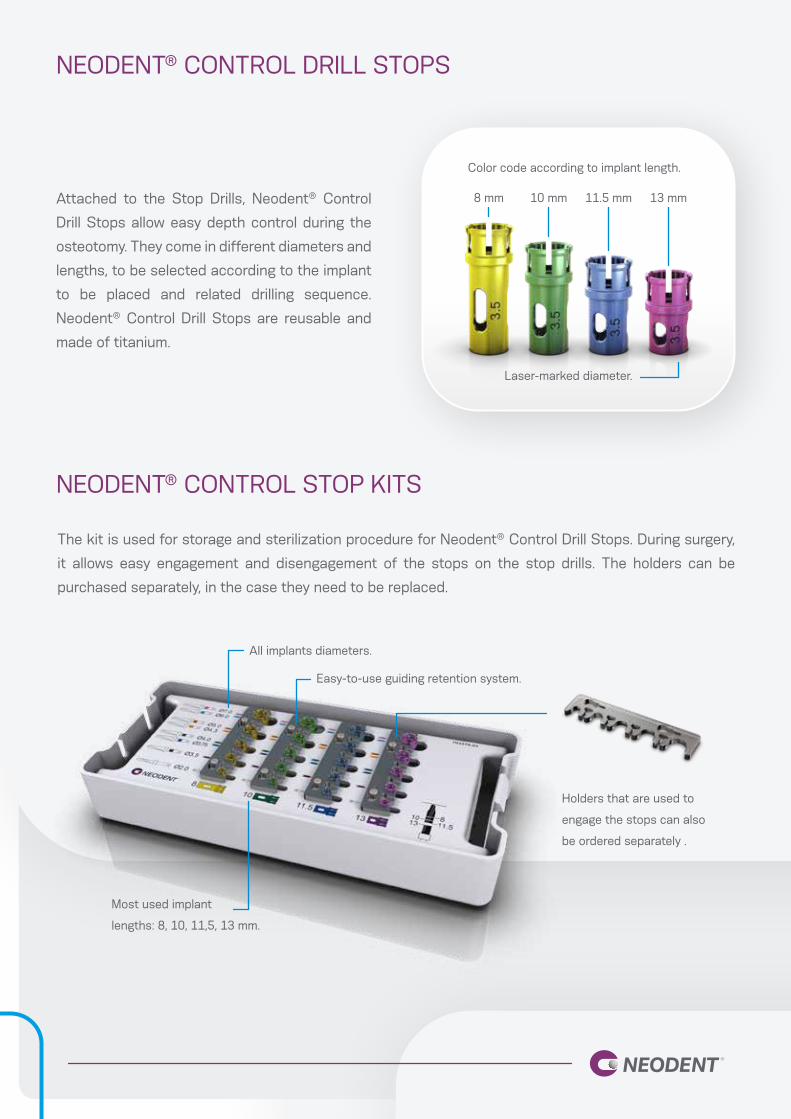
NEODENT® CONTROL DRILL STOPS
NEODENT® CONTROL STOP KITS
Attached to the Stop Drills, Neodent® Control
Drill Stops allow easy depth control during the
osteotomy. They come in different diameters and
lengths, to be selected according to the implant
to be placed and related drilling sequence.
Neodent® Control Drill Stops are reusable and
made of titanium.
The kit is used for storage and sterilization procedure for Neodent® Control Drill Stops. During surgery,
it allows easy engagement and disengagement of the stops on the stop drills. The holders can be
purchased separately, in the case they need to be replaced.
8 mm 10 mm 11.5 mm 13 mm
Color code according to implant length.
Laser-marked diameter.
All implants diameters.
Easy-to-use guiding retention system.
Most used implant
lengths: 8, 10, 11,5, 13 mm.
Holders that are used to
engage the stops can also
be ordered separately .

NEODENT® CONTROL SYSTEM PROTOCOL
To capture the stop in the Control Drill Stop Kit, follow the steps below:
Initially position the Tapered
Control Stop Drill inside the
Stop.
Slide it to the right. Remove the set Tapered Control
Stop Drill and Stop from the
case.
To remove the stop in the Control Drill Stop Kit, follow the steps below:
Initially position the set Tapered
Control Stop Drill and Stop on
the right.
Slide to the left. Pull the Drill so that it can be
removed from the Stop.
1
1
2
2
3
3
3 mm below bone level2 mm below bone level
1 mm below bone levelbone level
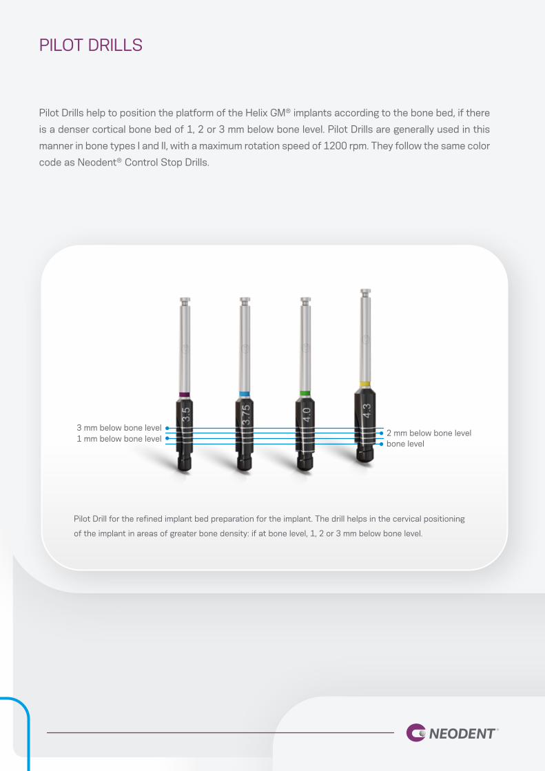
PILOT DRILLS
Pilot Drills help to position the platform of the Helix GM® implants according to the bone bed, if there
is a denser cortical bone bed of 1, 2 or 3 mm below bone level. Pilot Drills are generally used in this
manner in bone types I and II, with a maximum rotation speed of 1200 rpm. They follow the same color
code as Neodent® Control Stop Drills.
Pilot Drill for the refined implant bed preparation for the implant. The drill helps in the cervical positioning
of the implant in areas of greater bone density: if at bone level, 1, 2 or 3 mm below bone level.

103.170
103.513
103.515
103.493
103.495
103.501
103.503
103.492
103.494
103.496
103.500
103.502
103.514
103.516
103.504
103.517
Initial
Ø 2.8/3.5
Ø 3.3/4.0
Ø 3.5
Ø 4.0
Ø 3.75+
Ø 4.3+
Ø 2.0
Ø 3.75
Ø 4.3
Ø 3.5+
Ø 4.0+
Ø 3.0/3.75
Ø 3.6/4.3
Ø 5.0+
Ø 4.3/5.0
Ø 3.5Implant
Drill Ø 5.0Ø 3.75 Ø 4.0 Ø 4.3
Bone types I and II
Optional Optional Optional Optional Optional
Optional
IMPLANT BED PREPARATION FOR HELIX GM® IMPLANTS
single stripe represents a tapered drill
double stripe represents a tapered + drill
square represents a pilot drill

103.170
103.493
103.495
103.492
103.494
103.496
103.497
103.498
103.499
Initial
Ø 3.5
Ø 4.0
Ø 2.0
Ø 3.75
Ø 4.3
Ø 5.0
Ø 6.0
Ø 7.0
Ø 3.5Implant
Drill Ø 5.0Ø 3.75 Ø 6.0Ø 4.0 Ø 7.0Ø 4.3
Bone types III and IV
Optional Optional Optional Optional Optional Optional
Optional
Optional
Optional
Optional
Optional
Optional
IMPLANT BED PREPARATION FOR HELIX GM® IMPLANTS
single stripe represents a tapered drill
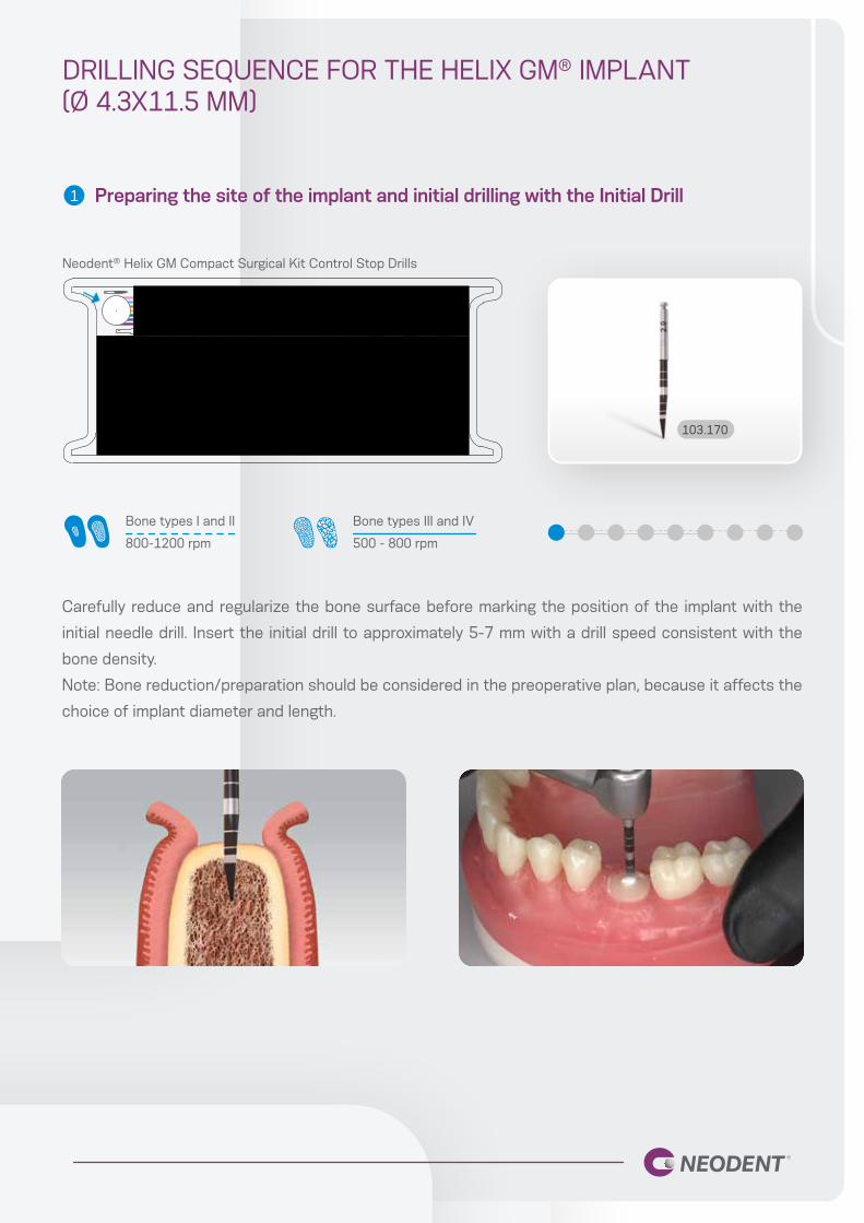
DRILLING SEQUENCE FOR THE HELIX GM® IMPLANT (Ø 4.3X11.5 MM)
Preparing the site of the implant and initial drilling with the Initial Drill
Carefully reduce and regularize the bone surface before marking the position of the implant with the
initial needle drill. Insert the initial drill to approximately 5-7 mm with a drill speed consistent with the
bone density.
Note: Bone reduction/preparation should be considered in the preoperative plan, because it affects the
choice of implant diameter and length.
1
103.170
Bone types I and II
800-1200 rpm
Bone types III and IV
500 - 800 rpm
Neodent® Helix GM Compact Surgical Kit Control Stop Drills
8 10 11.5 13
Ø3.5
Ø2.0
Ø7.0Ø6.0
Ø5.0Ø4.3
Ø4.0Ø3.75
810 11.513
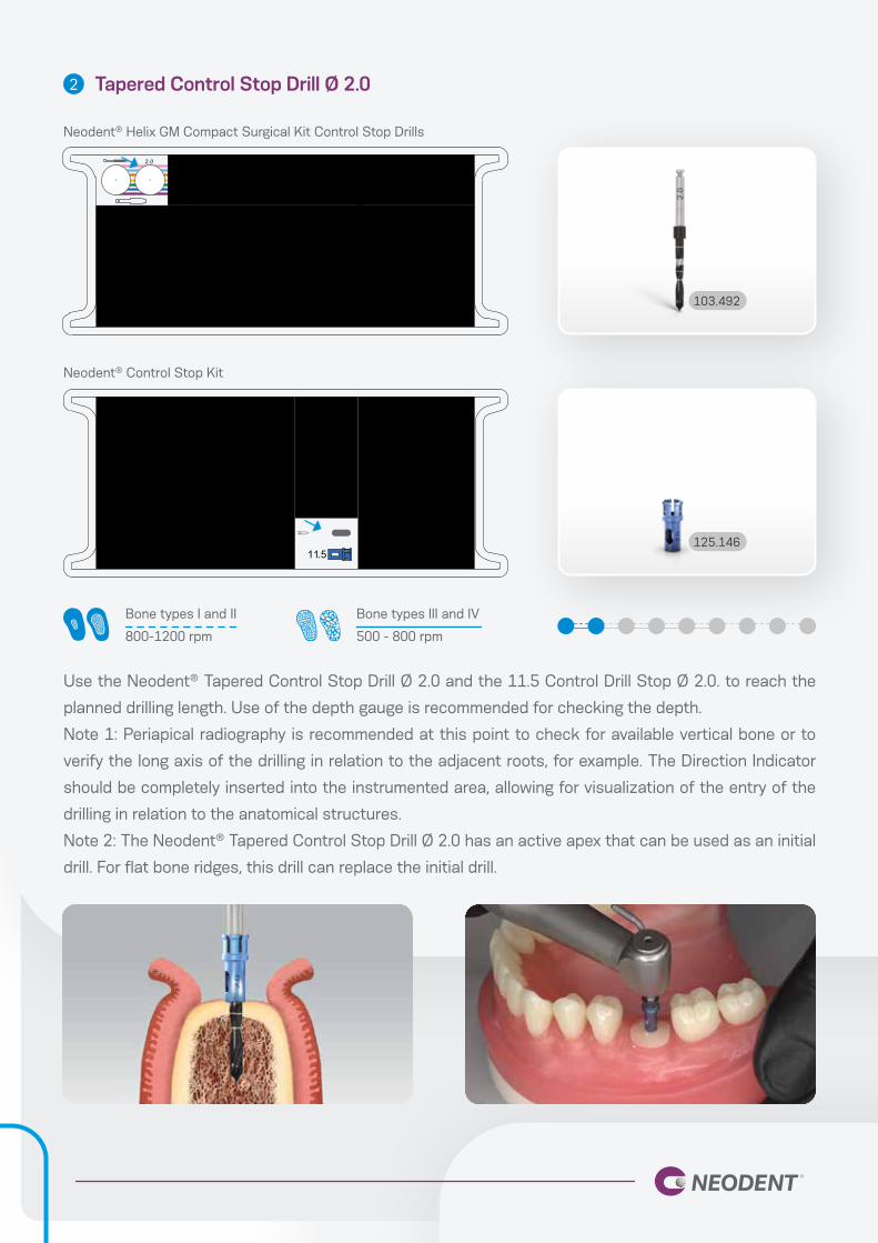
Tapered Control Stop Drill Ø 2.0
Use the Neodent® Tapered Control Stop Drill Ø 2.0 and the 11.5 Control Drill Stop Ø 2.0. to reach the
planned drilling length. Use of the depth gauge is recommended for checking the depth.
Note 1: Periapical radiography is recommended at this point to check for available vertical bone or to
verify the long axis of the drilling in relation to the adjacent roots, for example. The Direction Indicator
should be completely inserted into the instrumented area, allowing for visualization of the entry of the
drilling in relation to the anatomical structures.
Note 2: The Neodent® Tapered Control Stop Drill Ø 2.0 has an active apex that can be used as an initial
drill. For flat bone ridges, this drill can replace the initial drill.
2
Bone types I and II
800-1200 rpm
Bone types III and IV
500 - 800 rpm
103.492
125.146
Neodent® Helix GM Compact Surgical Kit Control Stop Drills
Neodent® Control Stop Kit

Checking the long axis of the implant
After using the initial drills, check the long axis of the implant using the direction indicator.
3
128.022
Bone types I and II Bone types III and IV
Neodent® Helix GM Compact Surgical Kit Control Stop Drills
8 10 11.5 13
Ø3.5
Ø2.0
Ø7.0Ø6.0
Ø5.0Ø4.3
Ø4.0Ø3.75
810 11.513
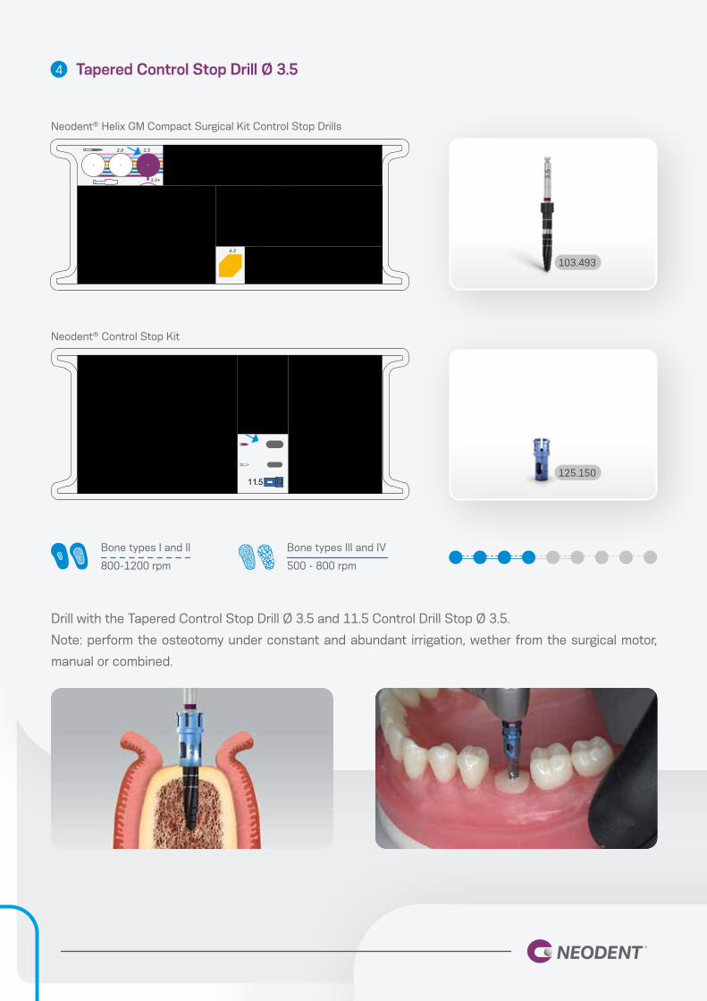
Tapered Control Stop Drill Ø 3.5
Drill with the Tapered Control Stop Drill Ø 3.5 and 11.5 Control Drill Stop Ø 3.5.
Note: perform the osteotomy under constant and abundant irrigation, wether from the surgical motor,
manual or combined.
4
Bone types I and II
800-1200 rpm
Bone types III and IV
500 - 800 rpm
103.493
125.150
Neodent® Helix GM Compact Surgical Kit Control Stop Drills
Neodent® Control Stop Kit

8 10 11.5 13
Ø3.5
Ø2.0
Ø7.0Ø6.0
Ø5.0Ø4.3
Ø4.0Ø3.75
810 11.513
Tapered Control Stop Drill Ø 3.75
Drill with the Tapered Control Stop Drill Ø 3.75 and 11.5 Control Drill Stop Ø 3.75/4.0.
Note: perform the osteotomy under constant and abundant irrigation, wether from the surgical motor,
manual or combined.
5
103.494
125.154
Bone types I and II
800-1200 rpm
Bone types III and IV
500 - 800 rpm
Neodent® Helix GM Compact Surgical Kit Control Stop Drills
Neodent® Control Stop Kit
8 10 11.5 13
Ø3.5
Ø2.0
Ø7.0Ø6.0
Ø5.0Ø4.3
Ø4.0Ø3.75
810 11.513
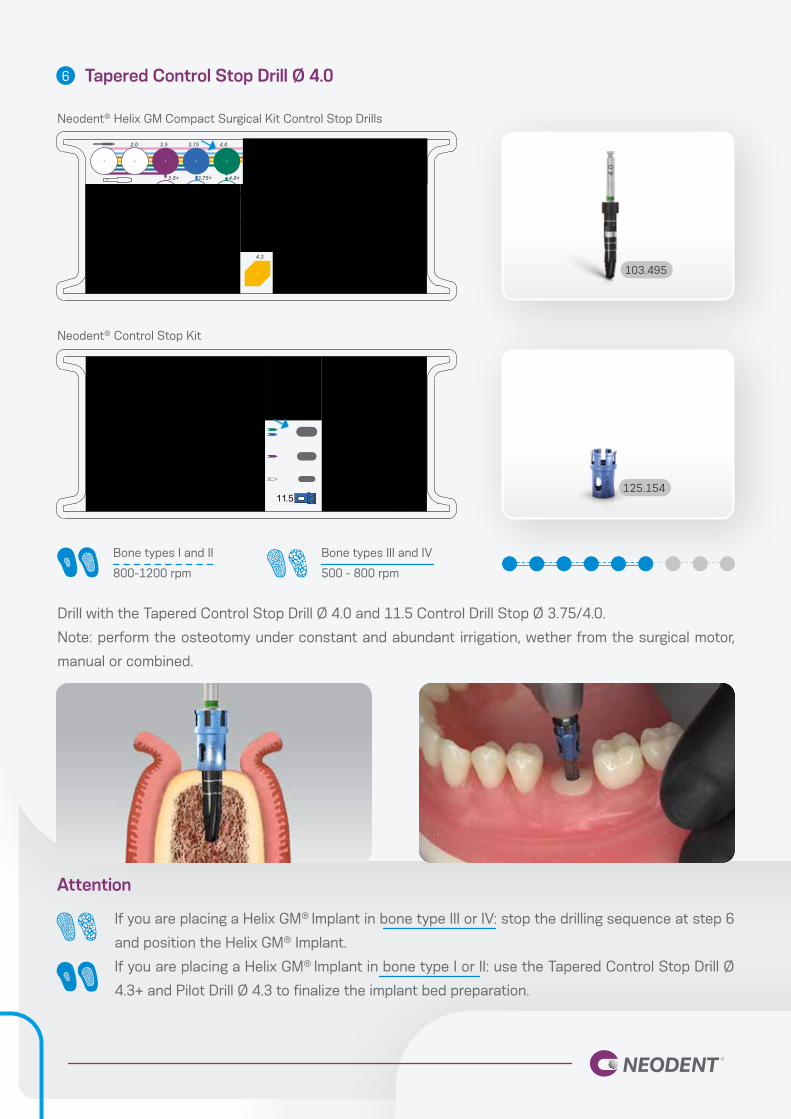
If you are placing a Helix GM® Implant in bone type III or IV: stop the drilling sequence at step 6
and position the Helix GM® Implant.
If you are placing a Helix GM® Implant in bone type I or II: use the Tapered Control Stop Drill Ø
4.3+ and Pilot Drill Ø 4.3 to finalize the implant bed preparation.
125.154
Bone types I and II
800-1200 rpm
Bone types III and IV
500 - 800 rpm
Tapered Control Stop Drill Ø 4.0
Drill with the Tapered Control Stop Drill Ø 4.0 and 11.5 Control Drill Stop Ø 3.75/4.0.
Note: perform the osteotomy under constant and abundant irrigation, wether from the surgical motor,
manual or combined.
6
103.495
Attention
Neodent® Helix GM Compact Surgical Kit Control Stop Drills
Neodent® Control Stop Kit
8 10 11.5 13
Ø3.5
Ø2.0
Ø7.0Ø6.0
Ø5.0Ø4.3
Ø4.0Ø3.75
810 11.513
Tapered Control Stop Drill Ø 4.3+7
103.503
125.158
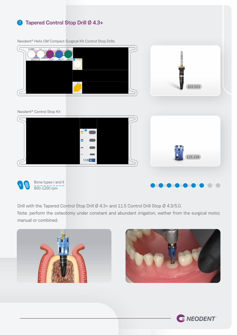
Drill with the Tapered Control Stop Drill Ø 4.3+ and 11.5 Control Drill Stop Ø 4.3/5.0.
Note: perform the osteotomy under constant and abundant irrigation, wether from the surgical motor,
manual or combined.
Bone types I and II
800-1200 rpm
Neodent® Helix GM Compact Surgical Kit Control Stop Drills
Neodent® Control Stop Kit

Bone types I and II
Checking the long axis of the implant
Position the Ø 3.6/4.3 Direction Indicator.
8
128.022
Neodent® Helix GM Compact Surgical Kit Control Stop Drills

Pilot Drill Ø 4.3
Drill with Pilot Drill Ø 4.3, according to the level planned for the implant.
Note: perform the osteotomy under constant and abundant irrigation, wether from the surgical motor,
manual or combined.
9
103.516
Bone types I and II
800-1200 rpm
Neodent® Helix GM Compact Surgical Kit Control Stop Drills

NEODENT® IMPLANT PACKAGING
After breaking the sterility seal
on the blister, hold the primary
package (vial) and twist the lid
to open it.
To secure the implant, grip both
sides of the implant carrier.
To capture the implant with
the contra-angle handpiece
attachment, grip the implant
carrier while placing the
attachment into the implant
chamber.
To remove the implant from the
vial lift the cap up, which has the
stand and implant attached to it.
While gripping the implant
carrirer, remove the lid.
The implant can now be
transported to the surgical site.
Neodent® implant packaging has been updated to a concept that provides convenience and safety
through all steps of the procedure, from storage to the placement of the implant.
The new packaging aids in identification of both the implant model as well as its diameter and length,
regardless of its storage position.
1
4
2
5
3
6
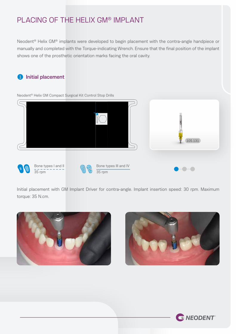
PLACING OF THE HELIX GM® IMPLANT
Neodent® Helix GM® implants were developed to begin placement with the contra-angle handpiece or
manually and completed with the Torque-indicating Wrench. Ensure that the final position of the implant
shows one of the prosthetic orientation marks facing the oral cavity.
Initial placement
Initial placement with GM Implant Driver for contra-angle. Implant insertion speed: 30 rpm. Maximum
torque: 35 N.cm.
1
105.131
Bone types I and II
35 rpm
Bone types III and IV
35 rpm
Neodent® Helix GM Compact Surgical Kit Control Stop Drills
Bone types I and II Bone types III and IV
Neodent® Helix GM Compact Surgical Kit Control Stop Drills
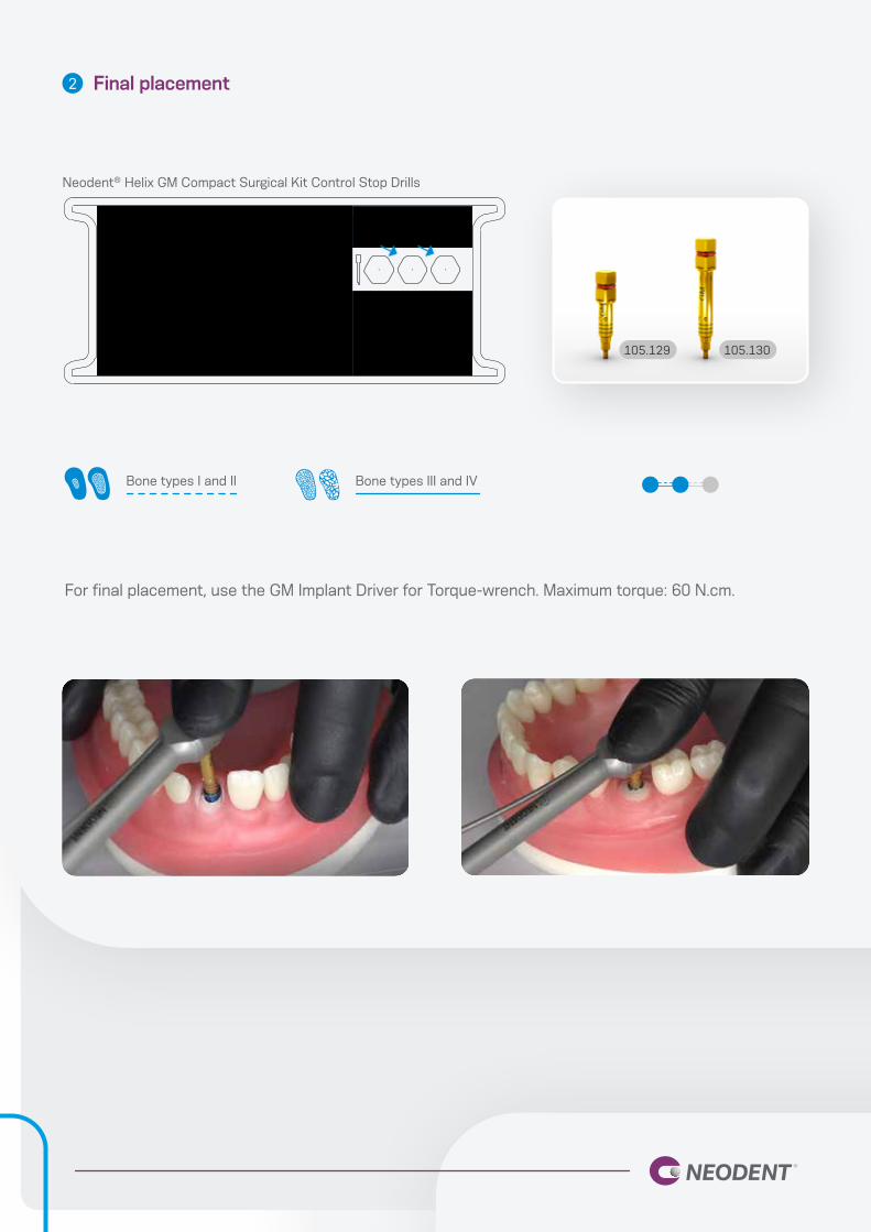
Final placement
For final placement, use the GM Implant Driver for Torque-wrench. Maximum torque: 60 N.cm.
2
105.129 105.130

Manual placement of the implant
The entire sequence described can be repeated manually, using the Manual Implant Driver -
Contra-angle instead of the contra-angle handpiece.
104.028 105.131
All instruments for contra-angle handpieces can be fitted to the Manual Implant Driver - Contra-angle.
Manual Implant Driver -
Contra-angle.
GM Implant Driver for
Contra-angle Handpiece
Bone types I and II Bone types III and IV
Neodent® Helix GM Compact Surgical Kit Control Stop Drills
Final position of the implant3
105.129 105.130


© 2020 – JJGC Indústria e Comércio de Materiais Dentários S.A. All rights reserved. All brands listed in this
material, registered or not, are the property of JJGC Indústria e Comércio de Materiais Dentários S.A. The
reproduction of this material without prior authorization is prohibited. Some products
may not be available for purchase yet. For more informations, please contact your local distributor.
10221_neodent_controlsystem_manual_en_eU_A00_lr_031120
Related Documents