Welcome message from author
This document is posted to help you gain knowledge. Please leave a comment to let me know what you think about it! Share it to your friends and learn new things together.
Transcript
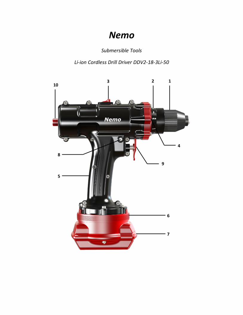
Nemo
Submersible Tools
Li-ion Cordless Drill Driver DDV2-18-3Li-50
1 2 3
4
5
6
7
8
9
10
1
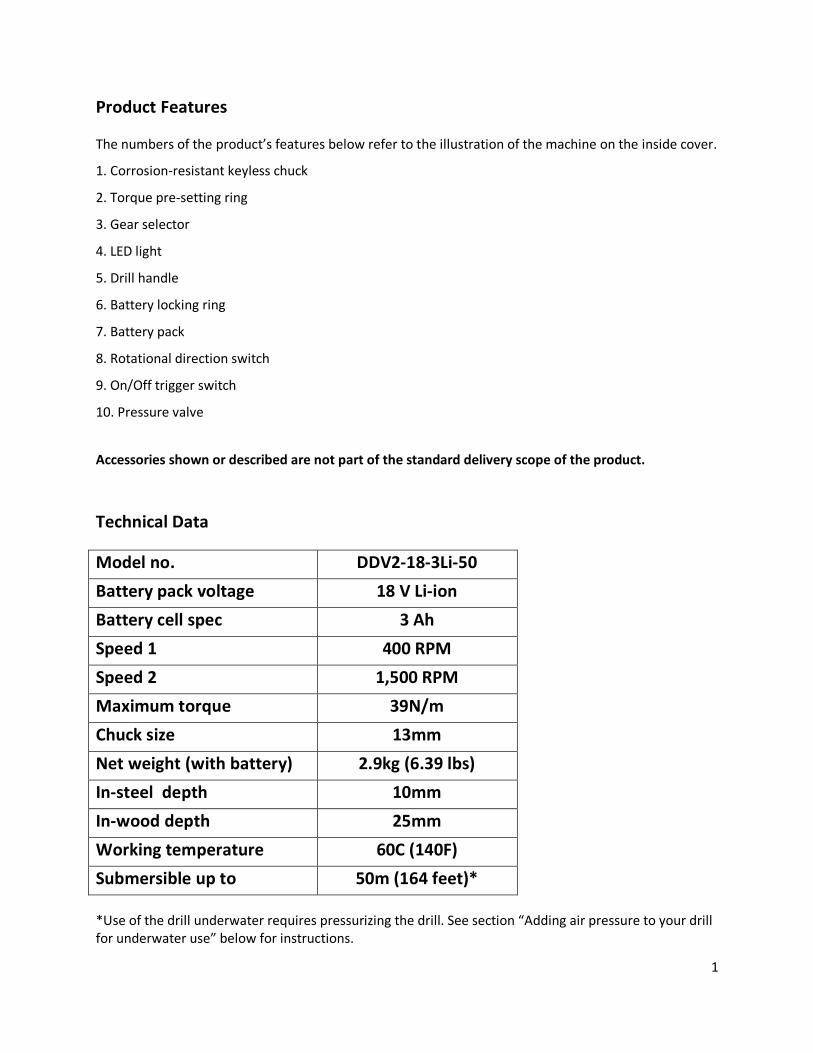
Product Features
The numbers of the product’s features below refer to the illustration of the machine on the inside cover.
1. Corrosion-resistant keyless chuck
2. Torque pre-setting ring
3. Gear selector
4. LED light
5. Drill handle
6. Battery locking ring
7. Battery pack
8. Rotational direction switch
9. On/Off trigger switch
10. Pressure valve
Accessories shown or described are not part of the standard delivery scope of the product.
Technical Data
Model no. DDV2-18-3Li-50
Battery pack voltage 18 V Li-ion
Battery cell spec 3 Ah
Speed 1 400 RPM
Speed 2 1,500 RPM
Maximum torque 39N/m
Chuck size 13mm
Net weight (with battery) 2.9kg (6.39 lbs)
In-steel depth 10mm
In-wood depth 25mm
Working temperature 60C (140F)
Submersible up to 50m (164 feet)*
*Use of the drill underwater requires pressurizing the drill. See section “Adding air pressure to your drill for underwater use” below for instructions.
2
FUNCTIONAL DESCRIPTION AND SPECIFICATIONS
Read all safety warnings and instructions. Standard safety precautions should be taken when operating
the Nemo drill and handling any of its accessories.
Intended Use
This machine is intended for working underwater but may also be used above water. This tool is a valuable asset to any professional who works in and around water. The drill should under no circumstances be opened for repairs or any other purpose by anyone other than an after-sales service technician authorized by Nemo Power Tools. Opening the drill invalidates the manufacturer warranty.
Treatment to Obtain Maximum Serviceable Life of the Nemo Drill Please read carefully.
1. Do not exceed the maximum operational depth as recommended by the manufacturer. Use of the drill underwater requires pressurizing the drill. See section “Adding air pressure to your drill for underwater use” below for instructions.
2. The Nemo drill is hi-tech piece of equipment and should be treated with care. The drill’s watertight seals may be damaged if the drill is dropped.
3. When moving about or working underwater, the Nemo drill should be secured by a lanyard/cord at all times, if it is not in the carrying case.
4. The Nemo drill was specifically designed for operation underwater. However, it may be operated out of the water.
5. This Nemo drill (DDV2-18-3Li-50) may be used in salt water. Please rinse the drill in fresh water immediately after use in salt water to help ensure a long life for your drill’s paint job.
6. When packing the drill in the carrying case after use in water, flush the drill with fresh water and dry off prior to placing it in the case.
7. Treat the high quality battery with care to gain maximum serviceable life. Keep the battery fully charged and dry, ready for use and always store in the carrying case when not in use.
3
SAFETY NOTES
General Power Tool Safety Warnings
SAVE ALL WARNINGS AND INSTRUCTIONS FOR FUTURE REFERENCE
The term “power tool” in all of the warnings refers to your battery-operated (cordless) Nemo drill.
1) Work-area safety
a) All work carried out should be done in accordance with the local, state, and government occupational
safety and health guidelines.
b) Keep work area clean and well lit.
c) Do not operate power tools in explosive atmospheres, such as in the presence of flammable liquids,
gases or dust.
d) Keep children and bystanders away while operating a power tool.
2) Personal safety
a) Stay alert, watch what you are doing and use common sense when operating a power tool. Do not use
a power tool while you are tired or under the influence of drugs, alcohol or medication.
b) Use personal protective equipment. Always wear eye protection.
3) Power tool use and care
a) Store idle power tools out of the reach of children and do not allow persons unfamiliar with the
power tool or these instructions to operate the power tool.
b) Maintain power tools. Check for misalignment or binding of moving parts, breakage of parts and any
other condition that may affect the power tools operation. If damaged, have the power tool repaired by
an authorized service technician before use.
c) Use the power tool, accessories and tool bits, etc. in accordance with these instructions and in the
manner intended for the particular type of power tool, taking into account the working conditions and
the work to be performed. Consult local, state, and government occupational safety and health
guidelines before operating the power tool.
4) Battery tool use and care
a) Recharge only with the charger specified by the manufacturer.
b) Use power tools only with specifically designated battery packs.

4
c) When battery pack is not in use, keep it away from other metal objects, like paper clips, coins, keys,
nails, screws or other small metal objects, that can make a connection from one terminal to another.
d) Protect the battery charger from rain and moisture.
f) Do not charge other batteries. The battery charger is suitable only for charging batteries supplied by
the manufacturer of the Nemo drill.
g) Before using, always check the battery charger, cable and plug. If defects are detected, do not use the
battery charger. Never open the battery charger; instead, have it opened and repaired only by qualified
personnel who will use original spare parts.
Safety Warnings for Cordless Drills / Screwdrivers
a) Switch off the power immediately when the tool inserts jams. Be prepared for high reaction torque
than can cause kickback. The tool inserts jam when the power tool is subject to overload or it becomes
wedged/jammed in the workpiece.
b) Hold the machine with a firm grip. High reaction torque can briefly occur while driving in and
loosening screws.
c) Work only on secured, stable items. Do not hold in one’s hand any item to be drilled or worked on by
the Nemo drill. Secure the workpiece, clamped with clamping devices or in a vice, to ensure safety.
d) Always wait until the machine has come to complete stop before placing it down. The tool insert can
jam and lead to loss of control over the power tool.
e) Do not open the battery.
f) Protect the battery against heat, e.g., also against continuous sun irradiation and fire.
g) When the battery is defective, liquid can escape and come into contact with adjacent components.
h) Use only original batteries with the voltage listed on the nameplate of your power tools. When using
other batteries, e.g. imitations, reconditioned batteries or other brands, there is danger of injury as well
as property damage through exploding batteries.
5
ASSEMBLY
1. Battery charging
Use only the battery charger provided with the drill. Only this battery charger is matched to the
lithium-ion battery of your power tool. Please use the charger in a dry environment. The charger is not
waterproof.
Note: The battery is supplied partially charged. To ensure full capacity of battery, completely charge the
battery in the battery charger before using your power tool for the first time. The lithium-ion (Li-ion)
battery can be charged at any time without reducing its service life. Interrupting the charging procedure
does not damage the battery.
The Li-ion battery is protected against deep discharging by “electric cell protection” (ECP). When the
battery is empty, the machine is switched off by means of a protective circuit. The connected tool no
longer rotates.
Do not continue to press the On/Off switch after the machine has been automatically switched off.
The battery can be damaged. The battery is equipped with a NTC temperature control which allows
charging only within a temperature range of 0˚C- 45˚C (32˚ F - 113˚ F), ensuring a long battery service
life. Please see the “Disposal” section below for instructions on the proper disposal of the battery.
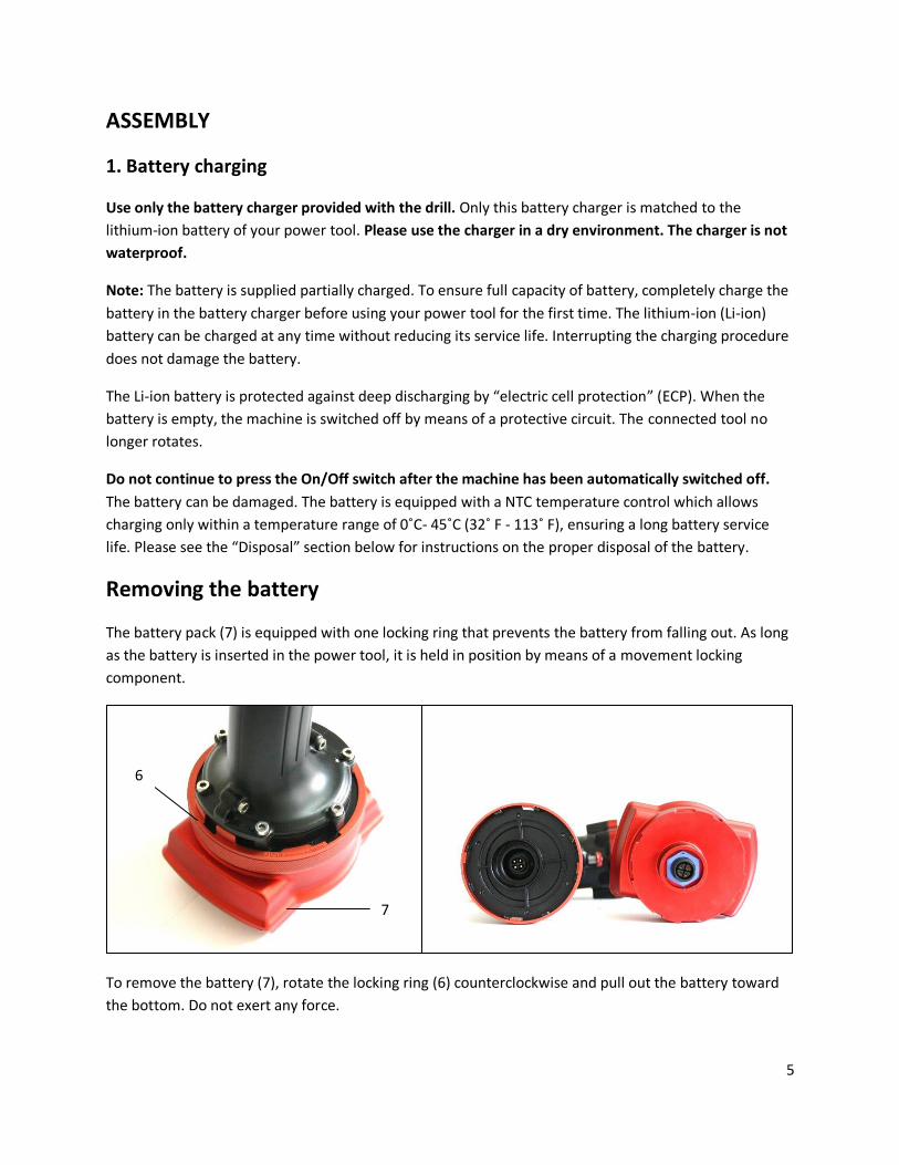
Removing the battery
The battery pack (7) is equipped with one locking ring that prevents the battery from falling out. As long
as the battery is inserted in the power tool, it is held in position by means of a movement locking
component.
To remove the battery (7), rotate the locking ring (6) counterclockwise and pull out the battery toward
the bottom. Do not exert any force.
7
6
6
Before any work on the machine (e.g., maintenance, tool change, etc.) as well as during
transportation and storage, set the rotational direction trigger to the center position. Unintentional
activation of the On/Off switch can lead to injuries.
2. Changing the tool
The drill spindle is locked when the On/Off switch (9) is not pressed. This ensures quick, convenient and
easy changing of the tool in the drill chuck. Open the keyless chuck (1) by rotating clockwise, until the
tool can be inserted. Insert the tool.
Firmly tighten the collar of the keyless chuck (1) by hand in rotational direction until the locking action
“click” is no longer heard. This automatically locks the chuck. The lock is released in order to remove the
tool when the collar is turned in the opposite direction.
3. Replacing the drill chuck
Removing the securing screw
The keyless chuck (1) is secured with a securing screw against unintentional loosening from the drill
spindle. Completely open the keyless chuck (1) and unscrew the securing screw in clockwise direction.
Please note that the securing screw has a left-handed thread.
Removing the drill chucks
Clamp the short end of an Allen key into the keyless chuck (1). Place the machine on a stable surface
(e.g., a workbench). Hold the machine firmly and loosen the keyless chuck (1) by turning the Allen key
counter-clockwise. Remove the Allen key from the keyless chuck and completely unscrew the keyless
chuck.
Mounting the drill chuck
The keyless chuck is mounted in reverse order. The drill chuck must be tightened with a tightening
torque of approx. 20 – 25 N.m. Screwing the securing screw in a counter-clockwise direction into the
opened keyless chuck, tightening torque approx. 4 – 5 N.m.
4. Dust/Chip Extraction
Dusts from materials such as lead-containing coating, some wood types, minerals and metal can be
harmful to one’s health. Touching or inhaling dust can cause allergic reactions and/or lead to respiratory
infections of the user or bystanders.
Certain dusts, such as oak or beech dust, are considered carcinogenic, especially in connection with
wood-treatment additives (chromate, wood preservative). Materials containing asbestos may only be
worked by specialists.
7
It is recommended to wear a P2 filter-class respirator. Observe the relevant regulations in your country
for the materials to be worked.
OPERATION
1. Inserting the battery
Use only the lithium-ion battery from the original factory with the voltage listed on the nameplate of
your power tool. Using other batteries can lead to injuries and pose a fire hazard.
Note: Use of batteries not suitable for the machine can lead to malfunctions of or cause damage to the
power tool.
Set the rotational direction switch (8) to the center position in order to avoid unintentional starting.
Insert the charged batteries (7) from the bottom of the base of the power tool. Push the battery
completely vertical to the base until the battery is pushed to the limit, then rotate the locking ring until
it is securely locked.
Attention: Make sure that the battery is inserted correctly into the power tool.
2. Reversing the rotational direction
The rotational direction switch (8) is used to reverse the rotational direction of the machine. However,
this is not possible with the On/Off switch (9) activated.
Right rotation: For drilling and driving in screws, push the rotational direction switch (8) left to the stop.
Left rotation: For loosening and unscrewing screws and nuts, press the rotational direction switch (8)
through to the right stop.
Middle option: There is an option to place the rotational direction switch (8) in the middle; this option
operates only the LED flashlight, without any rotation of the drill.
3. Setting the torque
With the torque presetting ring (2), the required torque setting can be pre-selected to 16 settings. With
the correct setting, the insert tool is stopped as soon as the screw is screwed flush into the material or
when the adjusted torque is reached. The safety clutch is deactivated in the “ ” position, e.g. for
drilling. Select a higher setting or switch to the “ ” symbol when unscrewing screws.
8
4. Gear speed selection
The gear speed selector (3) can be activated at a standstill.
Two speed ranges can be pre-selected with the gear speed selector (3).
If the gear speed selector (3) cannot be pushed through to stop, lightly turn the drill chuck with the drill.
This is a normal occurrence. This tool has a speed gear clutch, and sometimes the gear teeth hit
together, resulting in the gear speed selector sticking.
Do not push the gear speed selector forcefully when in this condition, as it may break the gears.
5. Switch On and Off
To start the machine, press the On/Off switch (9) and keep it pressed. To switch off the machine,
release the On/Off switch (9).
6. Adjusting the speed
The speed of the switch on power tool can be variably adjusted, depending on how far the On/Off
switch (9) is pressed.
Light pressure on the On/Off switch (9) results in a low rotational speed. Further pressure on the switch
results in an increase in speed.
7. Fully automatic spindle lock (Auto-lock)
When the On/Off switch (9) is not pressed, the drill spindle and the tool holder are locked. This enables
screws to be screwed in, even when the battery is dead, and allows for the machine to be used as a
screwdriver.
8. Motor braking (Dynamic braking)
When the On/Off switch (9) is off, the drill motor brakes to a stop, thus preventing the over spinning of
the tool. When driving in screws wait until the screw is screwed in flush with the material and then
release the On/Off switch (9). By doing so, the head of the screw does not penetrate the material.
9. Temperature dependent overload protection
When using the drill as intended, the power tool cannot be subject to overload.
9
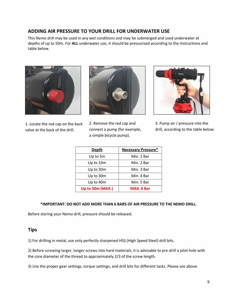
ADDING AIR PRESSURE TO YOUR DRILL FOR UNDERWATER USE This Nemo drill may be used in any wet conditions and may be submerged and used underwater at depths of up to 50m. For ALL underwater use, it should be pressurized according to the instructions and table below.
*IMPORTANT: DO NOT ADD MORE THAN 6 BARS OF AIR PRESSURE TO THE NEMO DRILL.
Before storing your Nemo drill, pressure should be released.
Tips
1) For drilling in metal, use only perfectly sharpened HSS (High Speed Steel) drill bits.
2) Before screwing larger, longer screws into hard materials, it is advisable to pre-drill a pilot hole with
the core diameter of the thread to approximately 2/3 of the screw length.
3) Use the proper gear settings, torque settings, and drill bits for different tasks. Please see above.
Depth Necessary Pressure*
Up to 5m Min. 1 Bar
Up to 10m Min. 2 Bar
Up to 20m Min. 3 Bar
Up to 30m Min. 4 Bar
Up to 40m Min. 5 Bar
Up to 50m (MAX.) MAX. 6 Bar
1. Locate the red cap on the back
valve at the back of the drill.
2. Remove the red cap and
connect a pump (for example,
a simple bicycle pump).
3. Pump air / pressure into the
drill, according to the table below:
1. Locate the red cap on the back
valve at the back of the drill.
10
Belt clip
With the belt clip (5), the machine can be attached to a belt. The user has both hands free and the
machine is always on hand.
Recommendations for optimal handling of the battery
Store the battery only within a temperature range of 0˚C - 45˚C (32˚ F - 113˚ F).
Please see notes below on the proper disposal of the battery.
MAINTENANCE AND SERVICE
Maintenance and cleaning
Before any work on the machine itself (e.g., maintenance, tool change, etc.) as well as during
transportation and storage, remove the battery from the power tool. There is danger of injury
when unintentionally activating the On/Off switch.
When the battery is no longer operative, please refer to an authorized after-sales service
agent.
Should the machine fail despite the care taken in manufacturing and testing procedures, repairs should
be carried out by an authorized after-sales service center.
TRANSPORT
The battery has effective protection against internal over-pressure and short-circuiting as well as devices
preventing violent rupture and dangerous reverse current flow.
The lithium-equivalent content in the battery is below applicable limit values. Therefore, the battery is
not subject to national or international regulations pertaining to dangerous mediums, either as an
individual component or when inserted into a machine. However, the regulations governing dangerous
goods may be relevant when transporting several batteries. In this case, it might be necessary to
comply with special conditions (e.g., concerning packaging).
DISPOSAL
The machine, accessories, and packing should be sorted for environmentally friendly recycling.
Do not dispose of battery pack/batteries in household waste, fire or water. Battery packs/batteries
should be collected, recycled or disposed of in an environmentally friendly manner.

11
3
1
1
1
2
1
4
1
FUNCTIONAL DESCRIPTION OF CHARGER
Product features: The numbering of the product features refers to the illustration of the battery
charger below.
1. Battery
2. Green/Red battery charging indicator
3. CHOGORI Connector
4. Battery socket
Technical data:
MODEL NO. DSS-220200
Charging time approx. 55 minutes
Charging output voltage 21V
Charging input voltage 100V – 240V
Operation
Observe the mains voltage! The voltage of the power supply must correspond with the data given on
the nameplate of the battery charger.
The charging procedure starts as soon as the mains plug of the battery charger is plugged into the socket
outlet and the battery is connected to the charging cable. Due to the intelligent charging method, the
charging condition of the battery is automatically detected and the battery is charged with the optimum
charging current, depending on battery temperature and voltage. This gives longer life to the battery
and always leaves it fully charged when kept in the charger for storage.
Note: The charging procedure is only possible when the battery temperature is within the allowable
charging temperature range. See “Technical data” section above.

12
Connecting the battery to the charger In order to connect the CHOGORI connector to the battery, press it into the socket located on its upper
shell. Notice that there is an overlap between the connector and the battery socket, and there is only
one way to insert the CHOGORI connector into the battery socket.
To release the CHOGORI connector, rotate its plastic cap counterclockwise and pull it out vertically.
Meaning of Indicator Lights
When the battery is not connected
Steady green indicator light: When the battery is not inserted, a steady green light on the battery
charger indicates that the mains plug is inserted into the socket and the battery is ready for operation.
When the battery is connected
Steady red indicator light: When the battery is connected to the charger, a steady red light on the
battery charger indicates that the battery is charging.
Steady green indicator light: When the battery is connected to the charger, a steady green light on the
battery charger indicates that the battery is fully charged.
Working advice Continuous or repetitive charging cycles without a break may cause the charger to warm up. This is not
problematic and does not indicate a technical defect of the battery charger.
A significantly reduced operation time after fully charging the battery indicates that the battery should
be replaced.

13
MAINTENANCE AND SERVICE OF CHARGER
Maintenance and cleaning If the battery charger should fail despite the care taken in manufacturing and testing procedures, repairs
should be carried out by an authorized after-sales service agent.
TROUBLE AND SOLUTIONS FOR CHARGER
Problem Possible reason Solution
No charging procedure Blinking red light on charger
Battery not inserted properly Properly insert battery into charger
Battery contacts contaminated Clean the battery contacts (e.g., by inserting and removing the battery several times) or replace the battery
Battery defective Replace the battery
Charger indicator does not light up
Mains plug of battery charger is not plugged into socket properly
Insert mains plug (fully) into the socket outlet
Socket outlets, mains cable or battery charger defective
Check the mains voltage; have the battery charger checked by an authorized after-service agent
Drill does not rotate The rotational direction switch is in a neutral position, which operates only the LED light.
The rotational direction switch must be pushed all the way to one side or the other for the drill to rotate.

Nemo Power Tools Ltd
www.nemopowertools.com
Related Documents