NEMA Standards Publication Condensed MG 1-2007 Information Guide for General Purpose Industrial AC Small and Medium Squirrel-Cage Induction Motor Standards Published by National Electrical Manufacturers Association 1300 North 17th Street, Suite 1752 Rosslyn, Virginia 22209 www.nema.org © Copyright 2007 by the National Electrical Manufacturers Association. All rights including translation into other languages, reserved under the Universal Copyright Convention, the Berne Convention for the Protection of Literary and Artistic Works, and the International and Pan American Copyright Conventions.

Welcome message from author
This document is posted to help you gain knowledge. Please leave a comment to let me know what you think about it! Share it to your friends and learn new things together.
Transcript

NEMA Standards Publication Condensed MG 1-2007
Information Guide for General Purpose Industrial AC Small and
Medium Squirrel-Cage Induction Motor Standards
Published by
National Electrical Manufacturers Association 1300 North 17th Street, Suite 1752 Rosslyn, Virginia 22209
www.nema.org
© Copyright 2007 by the National Electrical Manufacturers Association. All rights including translation into other languages, reserved under the Universal Copyright Convention, the Berne Convention for the Protection of Literary and Artistic Works, and the International and Pan American Copyright Conventions.
NOTICE AND DISCLAIMER
The information in this publication was considered technically sound by the consensus of persons engaged in the development and approval of the document at the time it was developed. Consensus does not necessarily mean that there is unanimous agreement among every person participating in the development of this document.
The National Electrical Manufacturers Association (NEMA) standards and guideline publications, of which the document contained herein is one, are developed through a voluntary consensus standards development process. This process brings together volunteers and/or seeks out the views of persons who have an interest in the topic covered by this publication. While NEMA administers the process and establishes rules to promote fairness in the development of consensus, it does not write the document and it does not independently test, evaluate, or verify the accuracy or completeness of any information or the soundness of any judgments contained in its standards and guideline publications.
NEMA disclaims liability for any personal injury, property, or other damages of any nature whatsoever, whether special, indirect, consequential, or compensatory, directly or indirectly resulting from the publication, use of, application, or reliance on this document. NEMA disclaims and makes no guaranty or warranty, expressed or implied, as to the accuracy or completeness of any information published herein, and disclaims and makes no warranty that the information in this document will fulfill any of your particular purposes or needs. NEMA does not undertake to guarantee the performance of any individual manufacturer’s or seller’s products or services by virtue of this standard or guide.
In publishing and making this document available, NEMA is not undertaking to render professional or other services for or on behalf of any person or entity, nor is NEMA undertaking to perform any duty owed by any person or entity to someone else. Anyone using this document should rely on his or her own independent judgment or, as appropriate, seek the advice of a competent professional in determining the exercise of reasonable care in any given circumstances. Information and other standards on the topic covered by this publication may be available from other sources, which the user may wish to consult for additional views or information not covered by this publication.
NEMA has no power, nor does it undertake to police or enforce compliance with the contents of this document. NEMA does not certify, test, or inspect products, designs, or installations for safety or health purposes. Any certification or other statement of compliance with any health or safety–related information in this document shall not be attributable to NEMA and is solely the responsibility of the certifier or maker of the statement.
Condensed MG 1-2007 Page i
© Copyright 2007 by the National Electrical Manufacturers Association.
CONTENTS Page
Foreword ..................................................................................................................................................vii 1 PURPOSE ........................................................................................................................................1 2 SCOPE .............................................................................................................................................1 3 DEFINITIONS...................................................................................................................................1 4 CLASSIFICATION OF DEGREES OF PROTECTION PROVIDED FOR ENCLOSURES FOR
ROTATING MOTORS......................................................................................................................3 4.1 Single Characteristic Numeral ............................................................................................3 4.2 Supplementary Letters ........................................................................................................3 4.3 Letters Following Numerals.................................................................................................3 4.4 Letters Placed Immediately after the Letters IP ..................................................................3 4.5 Degrees of Protection—First Characteristic Numeral.........................................................3 4.6 Degrees of Protection—Second Characteristic Numeral ...................................................4
5 METHODS OF COOLING ...............................................................................................................4 5.1 Arrangement of the IC Code ...............................................................................................4
6 MECHANICAL VIBRATION—MEASUREMENT, EVALUATION, AND LIMITS OF AC MEDIUM MOTORS..........................................................................................................................................4
7 SMALL (FRACTIONAL) AND MEDIUM (INTEGRAL) MOTORS RATINGS .................................4 7.1 Voltages ..............................................................................................................................4 7.2 Frequencies.........................................................................................................................5 7.3 Horsepower and Speed Ratings .........................................................................................5
7.3.1 Small Induction Motors...........................................................................................5 7.3.2 Single-Phase Medium Motors................................................................................5 7.3.3 Polyphase Medium Induction Motors.....................................................................5 7.3.4 Basis of Single-Phase Horsepower Rating............................................................5
7.4 Horsepower Ratings of Multispeed Motors .........................................................................5 7.4.1 Constant Horsepower ............................................................................................5 7.4.2 Constant Torque ....................................................................................................5 7.4.3 Variable Torque......................................................................................................5
7.5 Rating of 60-Hertz Motors Operated on 50-Hertz Power....................................................5 7.6 Time Ratings for Single-Phase and Polyphase Induction Motors ......................................5 7.7 Code Letters (for Locked-Rotor kVA)—Nameplate Marking ..............................................6 7.8 Nameplate Temperature Ratings for Alternating-Current Small Motors.............................6 7.9 Nameplate Marking for Small Single-Phase and Polyphase Motors ..................................6
7.9.1 Dual Voltage, Dual Frequency, and Dual Speed Motors .......................................6 7.10 Nameplate Marking for Medium Single-Phase and Polyphase Induction Motors ..............7 7.11 Additional Nameplate Information for All Motors.................................................................7
8 DIMENSIONS—AC SMALL (FRACTIONAL) AND MEDIUM (INTEGRAL) MOTORS..................8 8.1 System for Designating Frames..........................................................................................8
8.1.1 Small Motors ..........................................................................................................8 8.1.2 Medium Motors ......................................................................................................8
8.2 Frame Assignments ............................................................................................................9 8.3 Lettering of Dimension Sheets ............................................................................................9 8.4 Tolerances for Shaft Runout ...............................................................................................9

Condensed MG 1-2007 Page ii
© Copyright 2007 by the National Electrical Manufacturers Association.
8.5 Grounding Means for Field Wiring ......................................................................................9 9 TESTS AND PERFORMANCE—AC SMALL AND MEDIUM MOTORS........................................9
9.1 Routine Tests for Polyphase Medium Induction Motors .....................................................9 9.2 High-Potential Test Voltages for Induction Motors [MG 1-12.3] .........................................9 9.3 Test Methods.....................................................................................................................10 9.4 Performance Characteristics.............................................................................................10 9.5 Torque Characteristics of Single-Phase General-Purpose Induction Motors...................10
9.5.1 Breakdown Torque of Single-Phase Motors ........................................................10 9.5.2 Locked-Rotor Torque of Single-Phase Small Motors ..........................................10 9.5.3 Locked-Rotor Torque of Single-Phase Medium Motors ......................................10 9.5.4 Pull-Up Torque of Single-Phase Medium Motors ................................................10
9.6 Locked-Rotor Current Characteristics of Single-Phase and Polyphase General-Purpose Induction Motors................................................................................................................10 9.6.1 Locked-Rotor Current of Single-Phase Small Motors, Designs N, O,and
General Purpose. .................................................................................................10 9.6.2 Locked-Rotor Current of Single-Phase Medium Motors, Designs L and M.........10 9.6.3 Locked-Rotor Current of 3-Phase 60-Hertz Small and Medium Squirrel-Cage
Induction Motors Rated at 230 Volts .....................................................................11 9.7 Torque Characteristics of Polyphase General-Purpose Induction Motors .......................11
9.7.1 Breakdown Torque Characteristics of Polyphase Small Motors..........................11 9.7.2 Locked-Rotor Torque of Single-Speed Polyphase Squirrel-Cage Medium
Motors with Continuous Rating ............................................................................11 9.7.3 Breakdown Torque of Single-Speed Polyphase Squirrel-Cage Medium Motors
with Continuous Ratings ......................................................................................11 9.7.4 Pull-Up Torque of Single-Speed Polyphase Squirrel-Cage Medium Motors with
Continuous Ratings..............................................................................................11 9.8 Temperature Rise for Small and Medium Single-Phase and Polyphase Induction
Motors ...............................................................................................................................11 9.9 Variations from Rated Voltage and Rated Frequency ......................................................12
9.9.1 Running ................................................................................................................12 9.9.2 Starting .................................................................................................................12
9.10 Voltage Unbalance............................................................................................................12 9.11 Variation from Rated Speed..............................................................................................12 9.12 Variation from Nameplate Amperes—Alternating-Current Medium Motors......................12 9.13 Occasional Excess Current...............................................................................................12 9.14 Stall Time ..........................................................................................................................13 9.15 Service Factor of Alternating-Current Motors ...................................................................13
9.15.1 General-Purpose Alternating-Current Motors of the Open Type .........................13 9.16 Overspeeds for Squirrel-Cage Motors ..............................................................................13
9.16.1 General Purpose Squirrel-Cage Induction Motors...............................................13 9.16.2 General-Purpose Design A and B Direct-Coupled Squirrel-Cage Induction
Motors ................................................................................................................13 9.17 Machine Sound (Medium Induction Motors) .....................................................................14
9.17.1 General ................................................................................................................14 9.17.2 Sound Measurement............................................................................................14 9.17.3 Sound Power Levels of Polyphase Squirrel-Cage Induction Motors at No Load 14 9.17.4 Sound Power Levels of Polyphase Squirrel-Cage Induction Motors at Rated
Load ................................................................................................................14

Condensed MG 1-2007 Page iii
© Copyright 2007 by the National Electrical Manufacturers Association.
9.18 Number of Starts ...............................................................................................................14 9.19 Thermal Protection of Medium Motors..............................................................................15
9.19.1 Winding Temperature...........................................................................................15 9.20 Overtemperature Protection of Medium Motors Not Meeting the Definition of “Thermally
Protected”..........................................................................................................................15 9.20.1 Type 1—Winding Running and Locked Rotor Overtemperature Protection........15 9.20.2 Type 2—Winding Running Overtemperature Protection .....................................16 9.20.3 Type 3—Winding Overtemperature Protection, Nonspecific Type ......................16
9.21 Efficiency ...........................................................................................................................16 9.21.1 Determination of Motor Efficiency and Losses ....................................................16 9.21.2 Efficiency of Polyphase Squirrel-Cage Medium Motors with Continuous Ratings17 9.21.3 Efficiency Levels of Energy Efficient Polyphase Squirrel-Cage Induction Motors17 9.21.4 Efficiency Levels of NEMA Premium® Efficiency Electric Motors .......................17 9.21.5 Effects of Load on Motor Efficiency .....................................................................17
10 APPLICATION DATA—AC SMALL AND MEDIUM MOTORS ....................................................18 10.1 Service Conditions ............................................................................................................18
11 APPLICATION CONSIDERATIONS FOR CONSTANT SPEED DESIGN A AND B INDUCTION MOTORS USED ON A SINUSOIDAL BUS WITH HARMONIC CONTENT.................................18 11.1 Efficiency ...........................................................................................................................18 11.2 Derating for Harmonic Content .........................................................................................18
11.2.1 Harmonic Voltage Factor (HVF) Defined .............................................................18 11.3 Power Factor Correction ...................................................................................................19
12 APPLICATION CONSIDERATIONS FOR GENERAL PURPOSE DESIGN a AND b INDUCTION MOTORS USED WITH ADJUSTABLE-VOLTAGE OR ADJUSTABLE-FREQUENCY CONTROLS OR BOTH..........................................................................................19 12.1 Torque ...............................................................................................................................19
12.1.1 Motor Torque During Operation Below Base Speed ...........................................19 12.1.2 Torque Derating at Reduced Speeds ..................................................................19 12.1.3 Motor Torque During Operation Above Base Speed ...........................................19
12.2 Current ..............................................................................................................................20 12.2.1 Running Current...................................................................................................20 12.2.2 Starting Current....................................................................................................20
12.3 Efficiency ...........................................................................................................................20 12.4 Maximum Safe Operating Speeds ....................................................................................20 12.5 Sound ................................................................................................................................20 12.6 Resonances, Sound, Vibration .........................................................................................21 12.7 Voltage Stress ...................................................................................................................21 12.8 Power Factor Correction ...................................................................................................21 12.9 Operation in Hazardous (Classified) Locations ................................................................21
Condensed MG 1-2007 Page iv
Tables 1 MOTORS COVERED BY THIS GUIDE......................................................................................... 22 2 ALTERNATING CURRENT MEDIUM MOTOR ............................................................................. 22 3 DEGREES OF PROTECTION INDICATED BY THE FIRST AND SECOND
CHARACTERISTIC NUMERALS .................................................................................................. 23 4 TYPICAL METHODS OF COOLING (IC CODE)........................................................................... 24 5 UNFILTERED VIBRATION LIMITS ............................................................................................... 24 6 HORSEPOWER AND SPEED RATINGS, SMALL INDUCTION MOTORS.................................. 24 7 HORSEPOWER AND SPEED RATINGS, SINGLE-PHASE MEDIUM MOTORS ........................ 25 8 HORSEPOWER AND SPEED RATINGS, POLYPHASE MEDIUM INDUCTION MOTORS ........ 26 9 BREAKDOWN TORQUE FOR INDUCTION MOTORS ................................................................ 27 10 BREAKDOWN TORQUE FOR PERMANENT-SPLIT CAPACITOR MOTORS ............................ 28 11 TYPICAL CHARACTERISTICS AND APPLICATIONS OF FIXED FREQUENCY SMALL
AND MEDIUM AC SQUIRREL-CAGE INDUCTION MOTORS..................................................... 29 12 CODE LETTERS (FOR LOCKED-ROTOR KVA)—NAMEPLATE MARKING............................... 30 13 MEDIUM MACHINE FRAME NUMBERING .................................................................................. 30 14 FRAME DESIGNATIONS FOR SINGLE-PHASE, DESIGN L, HORIZONTAL AND
VERTICAL MOTORS, 60 HERTZ, CLASS B INSULATION SYSTEM, OPEN TYPE, 1.15 SERVICE FACTOR, 230 VOLTS AND LESS................................................................................ 31
15 FRAME DESIGNATIONS FOR POLYPHASE, SQUIRREL-CAGE, DESIGNS A AND B HORIZONTAL AND VERTICAL MOTORS, 60 HERTZ, CLASS B INSULATION SYSTEM, OPEN TYPE, 1.15 SERVICE FACTOR, 575 VOLTS AND LESS................................ 31
16 FRAME DESIGNATIONS FOR POLYPHASE, SQUIRREL-CAGE, DESIGNS A AND B HORIZONTAL AND VERTICAL MOTORS, 60 HERTZ, CLASS B INSULATION SYSTEM, TOTALLY-ENCLOSED FAN-COOLED TYPE, 1.00 SERVICE FACTOR, 575 VOLTS AND LESS......................................................................................................................... 32
17 FRAME DESIGNATIONS FOR POLYPHASE, SQUIRREL-CAGE, DESIGN C, HORIZONTAL AND VERTICAL MOTORS, 60 HERTZ, CLASS B INSULATION SYSTEM, OPEN TYPE, 1.15 SERVICE FACTOR, 575 VOLTS AND LESS................................ 32
18 FRAME DESIGNATIONS FOR POLYPHASE, SQUIRREL-CAGE, DESIGN C, HORIZONTAL AND VERTICAL MOTORS, 60 HERTZ, CLASS B INSULATION SYSTEM, TOTALLY ENCLOSED FAN-COOLED TYPE, 1.0 SERVICE FACTOR, 575 VOLTS AND LESS......................................................................................................................... 33
19 LETTERING OF DIMENSION SHEETS........................................................................................ 34 20 DIMENSIONS FOR ALTERNATING-CURRENT FOOT-MOUNTED MOTORS WITH
SINGLE STRAIGHT-SHAFT EXTENSION.................................................................................... 35 21 SHAFT EXTENSIONS AND KEY DIMENSIONS FOR ALTERNATING-CURRENT FOOT-
MOUNTED MOTORS WITH SINGLE TAPERED OR DOUBLE STRAIGHT/TAPERED SHAFT EXTENSION [MG 1-4.4.2] ................................................................................................ 37
23 DIMENSIONS FOR TYPE D FLANGE-MOUNTING FOOT OR FOOTLESS ALTERNATING-CURRENT MOTORS .......................................................................................... 39
24 DIMENSIONS FOR TYPE FC FACE MOUNTING FOR ACCESSORIES ON END OPPOSITE DRIVE END OF ALTERNATING-CURRENT MOTORS............................................ 40
25 TOLERANCES FOR TYPE C FACE FACE-MOUNTING AND TYPE D FLANGE-MOUNTING MOTORS, MAXIMUM ECCENTRICITY OF MOUNTING RABBET ......................... 40
26 MINIMUM SIZE GROUNDING CONDUCTOR TERMINATION.................................................... 40 27 LOCKED-ROTOR TORQUE OF SINGLE-PHASE SMALL MOTORS .......................................... 41 28 LOCKED-ROTOR TORQUE OF SINGLE-PHASE MEDIUM MOTORS ....................................... 41 29 LOCKED-ROTOR CURRENT OF SINGLE-PHASE SMALL MOTORS, DESIGNS O AND N ..... 41
© Copyright 2007 by the National Electrical Manufacturers Association.
Condensed MG 1-2007 Page v
30 LOCKED-ROTOR CURRENT OF SINGLE-PHASE MEDIUM MOTORS, DESIGNS L AND M... 42 31 LOCKED-ROTOR CURRENT OF 3-PHASE 60-HERTZ SMALL AND MEDIUM
SQUIRREL-CAGE INDUCTION MOTORS RATED AT 230 VOLTS ............................................ 42 32 LOCKED-ROTOR TORQUE OF DESIGN A AND B MOTORS .................................................... 43 33 LOCKED-ROTOR TORQUE OF DESIGN C MOTORS ................................................................ 43 34 BREAKDOWN TORQUE OF DESIGN A AND B MOTORS.......................................................... 44 35 BREAKDOWN TORQUE OF DESIGN C MOTORS...................................................................... 45 36 PULL-UP TORQUE OF DESIGN A AND B MOTORS .................................................................. 45 37 PULL-UP TORQUE OF DESIGN C MOTORS .............................................................................. 46 38 TEMPERATURE RISE FOR SMALL AND MEDIUM SINGLE-PHASE AND POLYPHASE
INDUCTION MOTORS .................................................................................................................. 47 39 SERVICE FACTORS OF GENERAL-PURPOSE ALTERNATING-CURRENT MOTORS
OF THE OPEN TYPE .................................................................................................................... 48 40 OVERSPEEDS FOR SQUIRREL-CAGE MOTORS...................................................................... 48 41 CONTINUOUS SPEED CAPABILITY FOR GENERAL-PURPOSE SQUIRREL-CAGE
INDUCTION MOTORS IN DIRECT COUPLED APPLICATIONS, EXCEPT THOSE MOTORS IN 9.16.2........................................................................................................................ 49
42 CONTINUOUS SPEED CAPABILITY FOR GENERAL-PURPOSE DESIGN A AND B DIRECT COUPLED (TS SHAFT FOR MOTORS ABOVE THE 250 FRAME SIZE) SQUIRREL-CAGE INDUCTION MOTORS ................................................................................... 50
43 MAXIMUM A-WEIGHTED SOUND POWER LEVELS, Lwa (dB), AT NO-LOAD ........................... 51 44 INCREMENTAL EXPECTED INCREASE OVER NO-LOAD CONDITION, IN A-
WEIGHTED SOUND POWER LEVELS ∆Lwa (dB), FOR RATED LOAD CONDITION FOR SINGLE-SPEED, THREE-PHASE, SQUIRREL-CAGE, INDUCTION MOTORS.......................... 52
45 REFERENCE LOAD WK 2 FOR NUMBER OF STARTS OF SQUIRREL-CAGE INDUCTION MOTORS .................................................................................................................. 52
46 WINDING TEMPERATURES UNDER RUNNING LOAD CONDITIONS ...................................... 53 47 WINDING TEMPERATURE UNDER LOCKED-ROTOR CONDITIONS ....................................... 53 48 WINDING TEMPERATURES UNDER RUNNING LOAD CONDITIONS ...................................... 53 49 SPECIFIED TEMPERATURE FOR WINDING RESISTANCE CORRECTION WHEN
RATED LOAD TEMPERATURE IS NOT MEASURED ................................................................. 53 50 EFFICIENCY LEVELS ................................................................................................................... 54 51 FULL-LOAD EFFICIENCIES OF ENERGY EFFICIENT MOTORS............................................... 55 52 FULL-LOAD EFFICIENCIES FOR 60 Hz NEMA PREMIUM® EFFICIENCY ELECTRIC
MOTORS RATED 600 VOLTS OR LESS (RANDOM WOUND)................................................... 56 53 FULL-LOAD EFFICIENCIES FOR 60HZ NEMA PREMIUM® EFFICIENCY ELECTRIC
MOTORS RATED 5000 VOLTS OR LESS (FORM WOUND........................................................ 57 54 FULL-LOAD EFFICIENCIES FOR 50 HZ NEMA PREMIUM® EFFICIENCY ELECTRIC
MOTORS RATED 600 VOLTS OR LESS (RANDOM WOUND)................................................... 58 55-4 MAXIMUM SAFE OPERATING SPEED FOR STANDARD DESIGN A AND B DIRECT
DRIVE (TS SHAFT FOR FRAMES OVER 250) SQUIRREL-CAGE INDUCTION MOTORS .................................................................................................................................... 60
© Copyright 2007 by the National Electrical Manufacturers Association.
Condensed MG 1-2007 Page vi
Figures
1 [MG 1 Figure 1-1] PROBE ............................................................................................................. 61 2 [MG 1 Figure 1-2] PROBE ............................................................................................................. 61 3 [MG 1 Figure 4-2] LETTER SYMBOLS FOR FOOT-MOUNTED MACHINES—DRIVE
END VIEW .................................................................................................................................... 62 4 [MG 1 Figure 4-1] LETTERING OF DIMENSION SHEETS FOR FOOT-MOUNTED
MACHINES, SIDE VIEW................................................................................................................ 63 5 [MG 1 Figure 4-3] LETTERING OF DIMENSION SHEETS FOR TYPE C FACE-
MOUNTING FOOT OR FOOTLESS MACHINES.......................................................................... 64 6 [MG 1-4.4.5] ................................................................................................................................... 65 7 [MG 1 Figure 14-1] MEDIUM MOTOR DERATING FACTOR DUE TO UNBALANCED
VOLTAGE .................................................................................................................................... 65 8 [MG 1 Figure 14-2] TYPICAL EFFICIENCY VERSUS LOAD CURVES FOR 1800 RPM
THREE-PHASE 60-HERTZ DESIGN B SQUIRREL-CAGE INDUCTION MOTORS.................... 66 9 [MG 1 Figure 30-1] DERATING CURVE FOR HARMONIC VOLTAGES...................................... 66
© Copyright 2007 by the National Electrical Manufacturers Association.
Condensed MG 1-2007 Page vii
Foreword
In the preparation of this Publication, input of users and other interested parties has been sought and evaluated. Inquiries, comments, and proposed or recommended revisions should be submitted to the concerned NEMA product Subdivision by contacting the:
Vice President, Engineering National Electrical Manufacturers Association 1300 North 17th Street, Suite 1752 Rosslyn, VA 22209
This Publication was developed by the Motors and Generators Section. Section approval of the document does not necessarily imply that all section members voted for its approval or participated in its development. At the time it was approved, the Section was composed of the following members:
A.O. Smith Electrical Products Company—Tipp City, OHBaldor Electric Company—Fort Smith, ARBrook Crompton North America—Toronto, Canada Cummins, Incorporated—Minneapolis, MN Emerson Electric Company—St. Louis, MO GE Industrial Systems—Fort Wayne, IN Howell Electric Motors—Plainfield, NJ Peerless-Winsmith, Incorporated—Warren, OH RAM Industries—Leesport, PA Regal-Beloit Corporation—Beloit, WI
Leeson Electric—Grafton, WI Lincoln Electric—Cleveland, OH Marathon Electric—Wausau, WI
SEW-Eurodrive, Incorporated—Lyman, SC Siemens Energy & Automation, Incorporated—Norwood, OH Sterling Electric, Incorporated—Irvine, CA TECO-Westinghouse Motor Company—Round Rock, TX The Imperial Electric Company—Akron, OH Toshiba International Corporation—Houston, TX WEG Electric Motor Corporation—Suwanee, GA
© Copyright 2007 by the National Electrical Manufacturers Association.

Condensed MG 1-2007 Page viii
<This page is intentionally left blank.>
© Copyright 2007 by the National Electrical Manufacturers Association.

Condensed MG 1-2007 Page 1
1 PURPOSE
This is a condensation of the standards on motors included in NEMA Standards Publication Motors and Generators, MG 1-2006. Some standards are reprinted in their entirety while others have been combined or abbreviated. The numbers placed at the end of many of the paragraphs in this condensation (e.g. MG 1 Part 6) refer to the complete standard in MG 1.
2 SCOPE
The standards in this guide cover alternating-current squirrel-cage motors up to and including the ratings built in frames corresponding to the continuous open-type ratings given in Table 1.
3 DEFINITIONS
ambient temperature: The temperature of the surrounding air which comes into contact with the heated parts of the apparatus. [MG 1-1.56]
capacitor motor: A single-phase induction motor with main winding arranged for direct connection to power source and auxiliary winding connected in series with a capacitor. There are three types of capacitor motors: capacitor start, in which capacitor phase is in circuit only during starting; permanent-split capacitor which has the same capacitance for both starting and running; two-value capacitor motor in which there are different values of effective capacitance for starting and running. [MG 1-1.20.3.3]
current:
locked-rotor current: The steady-state current taken from the line, with the rotor locked and with rated voltage and rated frequency applied to the motor. [MG 1-1.53]
no-load current: The current flowing through a line terminal of a winding when rated voltage is applied at a rated frequency with no connected load. [MG 1-1.54]
design letters: Identifies specific performance requirements for starting and operating characteristics. See Table 8. [MG 1-1.19.1]
dimensions: Dimension are indicated by the NEMA letters given in Table 19. [MG 1-4.1]
dripproof motor: An open motor in which the ventilating openings are so constructed that successful operation is not interfered with when drops of liquid or solid particles strike or enter the enclosure at any angle from 0 to 15 degrees downward from the vertical. [MG 1-1.25.1]
dripproof guarded motor: A dripproof motor whose ventilating openings are guarded. [MG 1-1.25.5]
energy efficient polyphase squirrel-cage induction motor: An induction motor having an efficiency in accordance with 9.21.3. [MG 1-1.41.2]
frame number: The frame number for small motors is the "D" dimension in inches multiplied by 16. The frame number for medium motors consists of three or four digits. The first two digits are equal to four times the "D" dimension in inches. When this product is not a whole number, the first two digits of the frame number are the next higher whole number. The third and, when required, fourth digit of the frame number is obtained from the value of the "2F" dimension in inches as shown in the columns headed 1 to 15, inclusive, in the Table 13. [MG 1-4.2]
general-purpose motor: A squirrel-cage induction motor, rated 500 horsepower and less, open or enclosed construction. It is designed in standard ratings with standard operating characteristics and mechanical construction for use under usual service conditions without restriction to a particular application or type of application. [MG 1-1.6]
guarded motor: An open motor in which all openings giving direct access to live metal or rotating parts (except smooth rotating surfaces) are limited in size by the structural parts or by screens, baffles, grilles, expanded metal, or other means to prevent accidental contact with hazardous parts. Openings giving direct access to such live or rotating parts shall not permit the passage of a cylindrical rod 0.75 inch in diameter.
© Copyright 2007 by the National Electrical Manufacturers Association.
Condensed MG 1-2007 Page 2
The openings in the motor enclosure shall be such that (1) a probe such as that illustrated in Figure 1, when inserted through the openings, will not touch an uninsulated live metal part or a hazardous rotating part and (2) a probe such as that illustrated in Figure 1, when inserted through the openings, will not touch film coated wire. [MG 1-1.25.4]
high-potential tests: High-potential tests are tests which consist of the application of a voltage higher than the rated voltage for a specified time for the purpose of determining the adequacy against breakdown of insulating materials and spacings under normal conditions. [MG 1 Part 3]
IC code: Acronym for "International Cooling.” See Clause 5 Methods of Cooling. [MG 1 Part 6]
IP code: Acronym for "International Protection." See Clause 4 Classification of Degrees of Protection. [MG 1 Part 5]
medium (integral) motor: An alternating-current medium motor is (1) built in a three-or four-digit frame series (or equivalent for motors without feet); and (2) having a continuous rating up to and including the information in Table 2. [MG 1-1.4.1]
NEMA Premium® efficiency electric motor: A continuous rated, single-speed, polyphase, squirrel-cage induction motor of 2, 4, or 6 pole design meeting the performance requirements of Design A or Design B and having a nominal full load efficiency not less than that shown in 9.21.4. [MG 1-1.16]
open motor: One having ventilating openings which permit passage of external cooling air over and around the windings of the motor. [MG 1-1.25]
service factor: A multiplier which, when applied to the rated horsepower, indicates a permissible horsepower loading which may be carried under the conditions specified for the service factor. [MG 1-1.42]
small (fractional) motor: A small motor is either (1) built in a two digit frame number series (or equivalent for motors without feet); or (2) a motor built in a frame smaller than that frame of a medium motor which has a continuous rating at 1700-1800 rpm of 1 horsepower; or (3) a motor rated less than 1/3 horsepower and less than 800 rpm. [MG 1-1.3]
squirrel-cage induction motor: An alternating-current motor composed of a primary winding connected to a power source and a squirrel-cage secondary winding which carries induced current. [MG 1-1.18.1.1]
starting capacitance for a capacitor motor: The total effective capacitance in series with the starting winding under locked-rotor conditions. [MG 1-1.58]
temperature tests: Tests taken to determine the temperature rise of certain parts of the motor above the ambient temperature, when running under a specified load. [MG 1-1.55]
torque:
breakdown torque: The maximum torque developed by the motor with rated voltage applied at rated frequency, without an abrupt drop in speed. [MG 1-1.50]
locked-rotor torque: The minimum torque developed by the motor at rest for all angular positions of the rotor, with rated voltage applied at rated frequency. [MG 1-1.47]
pull-up torque: The minimum torque developed by the motor during the period of acceleration from rest to the speed at which breakdown torque occurs. For motors which do not have a definite breakdown torque, the pull-up torque is the minimum torque developed up to rated speed. [MG 1-1.48]
totally enclosed motor: A motor enclosed to prevent the free exchange of air between the inside and the outside of the case but not sufficiently enclosed to be termed air-tight. [MG 1-1.26]
totally enclosed fan-cooled motor: A totally enclosed motor equipped for exterior cooling by means of a fan or fans integral with the motor but external to the enclosing parts. [MG 1-1.26.2]
totally enclosed fan-cooled guarded motor: A totally enclosed fan-cooled motor in which all openings giving direct access to the fan are limited in size by the design of the structural parts or by screens, grills, expanded metal, etc., to prevent accidental contact with the fan. Such openings shall not permit the passage of a cylindrical rod 0.75 inch in diameter, and a probe such as that shown in Figure 1 and Figure 2 shall not contact the blades, spokes, or other irregular surfaces of the fan. [MG 1-1.26.3]
© Copyright 2007 by the National Electrical Manufacturers Association.

Condensed MG 1-2007 Page 3
totally enclosed nonventilated motor: A totally enclosed motor which is not equipped for cooling by means external to the enclosing parts. [MG 1-1.26.1]
voltage unbalance: The voltage unbalance in percent may be defined as follows:
percent voltage unbalance = 100 x maximum voltage deviation from average voltage ÷ average voltage
Example—With voltages of 460, 467, and 450, the average is 459, the maximum deviation from average is 9, and the percent unbalance = 100 x 9/459 = 1.96 percent. [MG 1-14.36.2]
4 CLASSIFICATION OF DEGREES OF PROTECTION PROVIDED FOR ENCLOSURES FOR ROTATING MOTORS
The designation used for the degree of protection consists of the letters IP followed by two characteristic numerals signifying conformity with the conditions indicated in Table 3. [MG 1-5.2]
4.1 Single Characteristic Numeral When it is required to indicate degree of protection by only one characteristic numeral, the omitted numeral shall be replaced by the letter X. For example, IPX5 or IP2X. [MG 1-5.2.1]
4.2 Supplementary Letters Additional information may be indicated by a supplementary letter following the second characteristic numeral. If more than one letter is used, the alphabetic sequence shall apply. [MG 1-5.2.2]
4.3 Letters Following Numerals In special application (such as motors with open circuit cooling for ship deck installation with air inlet and outlet openings closed during standstill) numerals may be followed by a letter indicating whether the protection against harmful effects due to ingress of water was verified or tested for the machine not running (letter S) or the machine running (letter M). In this case the degree of protection in either state of the machine shall be indicated, for example IP55S/IP20M. The absence of the letters S and M shall imply that the intended degree of protection will be provided under all normal conditions of use. [MG 1-5.2.2.1]
4.4 Letters Placed Immediately after the Letters IP For open internally air-cooled motors suitable under specific weather conditions and provided with additional protective features or processes, such as those required for open water-protected motors, the letter W may be used. [MG 1-5.2.2.2]
Example of Designation IP 4 4
Characteristic letters 1st characteristic numeral
(see Table 3) 2nd characteristic numeral
(see Table 3)
4.5 Degrees of Protection—First Characteristic Numeral The first characteristic numeral indicates the degree of protection provided by the enclosure with respect to persons and also to the parts of the machine inside the enclosure. Table 3 gives brief details of objects which will be excluded from the enclosure for each of the degrees of protection represented by the first characteristic numeral. [MG 1-5.3.1]
The term “excluded” implies that a part of the body, or a tool or wire held by a person, either will not enter the machine or, if it enters, that adequate clearance will be maintained between it and the live or dangerous moving parts (smooth rotating shafts and the like are not considered dangerous). Table 3 also indicates the minimum size of foreign objects which will be excluded. [MG 1-5.3.1]
© Copyright 2007 by the National Electrical Manufacturers Association.
Condensed MG 1-2007 Page 4
Compliance of an enclosure with an indicated degree of protection implies that the enclosure will also comply with all lower degrees of protection. In consequence, the tests establishing these lower degrees of protection are not required, except in cases of doubt. [MG 1-5.3.2]
4.6 Degrees of Protection—Second Characteristic Numeral The second characteristic numeral indicates the degree of protection provided by the enclosure with respect to harmful effect due to ingress of water. Table 3 gives brief details of the type of protection provided by the enclosure for each of the degrees of protection represented by the second characteristic numeral.
A machine is weather-protected when its design reduces the ingress of rain, snow, and airborne particles, under specified conditions, to an amount consistent with correct operation. This degree of protection is designated by the letter W placed after the two characteristic numerals. [MG 1-5.4.1]
5 METHODS OF COOLING
The designation used for the method of cooling consists of the letters IC, followed by numerals and letters representing the circuit arrangement, the coolant and the method of movement of the coolant. A complete designation and a simplified designation are defined. The complete designation system is intended for use mainly when the simplified system is not applicable. [MG 1-6.1]
5.1 Arrangement of the IC Code The designation system is demonstrated in Table 4. The simplified designations should preferably be used, that is, the complete designation system is intended for use mainly when the simplified system is not applicable.
6 MECHANICAL VIBRATION—MEASUREMENT, EVALUATION, AND LIMITS OF AC MEDIUM MOTORS
This standard is applicable to polyphase alternating current motors tested with sinusoidal power. The standard is not applicable to motors mounted in situ, single-phase motors, or three-phase motors operated on single-phase systems. [MG 1-7.1]
The criterion for bearing housing vibration is the peak value of unfiltered vibration velocity in the vertical, horizontal and axial directions. Unfiltered vibration limits for standard motors, when tested on resilient mounts, are shown in Table 5. [MG 1-7.4.1]
7 SMALL (FRACTIONAL) AND MEDIUM (INTEGRAL) MOTORS RATINGS
7.1 Voltages
Single-phase motors Polyphase motors
60 hertz—115, 200, and 230 volts 60 hertz—1151 , 200, 230, 460, and 575 volts
50 hertz—110 and 220 volts 50 hertz—220 and 380 volts
NOTES—
1. It is not practical to build motors of all horsepower ratings for all the standard voltages. [MG 1-10.30]
2. Operation of a motor rated 230 volts on a 208-volt system is not recommended. Such operation will generally result in excessive overheating and serious reduction in torques. Induction motors intended for operation on 208-volt systems should be rated for 200 volts. [MG 1-14.35]
1 Applies only to motors rated 15 horsepower and smaller.
© Copyright 2007 by the National Electrical Manufacturers Association.

Condensed MG 1-2007 Page 5
7.2 Frequencies The frequency shall be 50 and 60 hertz. [MG 1-10.31]
7.3 Horsepower and Speed Ratings
7.3.1 Small Induction Motors
The horsepower and speed ratings for small induction motors are shown in Table 6. [MG 1-10.32.1]
7.3.2 Single-Phase Medium Motors
The horsepower and synchronous speed ratings of single-phase medium motors rated 115, 200, and 230 volts are shown in Table 7. [MG 1-10.32.3]
7.3.3 Polyphase Medium Induction Motors
The horsepower and synchronous speed ratings of polyphase medium induction motors are shown in Table 8. [MG 1-10.32.4]
7.3.4 Basis of Single-Phase Horsepower Rating
The horsepower rating of a small or medium single-phase induction motor is based upon the breakdown torque. The value of breakdown torque to be expected by the user for any horsepower and speed shall fall within the range given in Table 9 and Table 10. [MG 1-10.34.1]
7.4 Horsepower Ratings of Multispeed Motors
7.4.1 Constant Horsepower
The horsepower rating for each rated speed shall be selected from Table 6 and Table 7. [MG 1-10.33.1]
7.4.2 Constant Torque
The horsepower rating for the highest rated speed is selected from Table 6 and Table 7. The horsepower rating for each lower speed shall be determined by multiplying the horsepower rating at the highest speed by the ratio of the lower synchronous speed to the highest synchronous speed. [MG 1-10.33.2]
7.4.3 Variable Torque
The horsepower ratings at the highest rated speed is selected from Table 6 and Table 7. The horsepower rating for each lower speed shall be determined by multiplying the horsepower rating at the highest speed by the square of the ratio of the lower synchronous speed to the highest synchronous speed. [MG 1-10.33.3]
7.5 Rating of 60-Hertz Motors Operated on 50-Hertz Power General-purpose alternating-current polyphase 2-, 4-, 6- and 8-pole, 60-hertz medium induction motors, although not designed to operate at their 60-hertz ratings on 50-hertz circuits, can be operated satisfactorily at 50-hertz if voltage and horsepower ratings are appropriately reduced (see MG 1 Part 14). [MG 1-14.34]
7.6 Time Ratings for Single-Phase and Polyphase Induction Motors The time rating for single-phase and polyphase induction motors shall be 5, 15, 30, and 60 minutes or continuous.
All short-time ratings are based upon a corresponding short-time load test which shall commence only when the winding and other parts of the machine are within 5°C of the ambient temperature at the time of the starting of the test. [MG 1-10.36]
© Copyright 2007 by the National Electrical Manufacturers Association.

Condensed MG 1-2007 Page 6
7.7 Code Letters (for Locked-Rotor kVA)—Nameplate Marking The nameplate of an alternating-current motor rated 1/2 horsepower and larger may be marked with the caption “Code” followed by a letter selected from the table below to show the locked-rotor kVA per horsepower.
The letter designations for locked-rotor kVA per horsepower as measured at full voltage and rated frequency are as shown in Table 12. [MG 1-10.37]
Broad- or dual-voltage motors which have a different locked-rotor kVA per horsepower on the different voltages shall be marked with the code letter for the voltage giving the highest locked-rotor kVA per horsepower.
Motors with 60- and 50-hertz ratings shall be marked with a code letter designating the locked-rotor kVA per horsepower on 60-hertz. [MG 1-10.37.6]
7.8 Nameplate Temperature Ratings for Alternating-Current Small Motors Alternating-current small motors shall be rated on the basis of a maximum ambient temperature and the insulation system class.
The rated value of the maximum ambient temperature shall be 40°C unless otherwise specified, and the insulation system shall be Class A, B, F, or H. [MG 1-10.38]
7.9 Nameplate Marking for Small Single-Phase and Polyphase Motors The following information shall be given on all nameplates. For motors with dual ratings see 7.9.1 [MG 1-10.39.1]
a) Manufacturer’s type and frame designation b) horsepower output c) Time rating d) Maximum ambient temperature for which motor is designed e) Insulation system designation. (If stator and rotor use different classes of insulation systems, both
insulation system designations shall be given on the nameplate, that for the stator being given first.)
f) Rpm at full load g) Frequency h) Number of phases i) Full-load amperes j) Voltage k) Code letter for locked-rotor kVA or locked-rotor amperes for motors 1/2 horsepower or larger l) For motors equipped with thermal protectors, the words “thermally protected” and for motors
rated more than 1 horsepower, a type number. 7.9.1 Dual Voltage, Dual Frequency, and Dual Speed Motors
[MG 1-10.39.5]
a) Broad Voltage (no reconnection of motor leads) Use dash between voltages (i.e., 200-300)
b) Dual Voltage (reconnection of motor leads) Use slash between voltages (i.e., 230/460) Use slash between amperes (i.e., 4.6/2.3)
c) Dual Frequency and Single Voltage Use ampersand (&) between values for each frequency Hz (i.e., 60&50) Volt (i.e., 115&110) Rpm (i.e., 1725&1450) Amp (i.e., 5.0&6.0)
© Copyright 2007 by the National Electrical Manufacturers Association.
Condensed MG 1-2007 Page 7
NOTE—If spacing in standard location on nameplate is not adequate, the values of alternative frequency and associated volts, rpm, and amps shall be permitted to be specified at a different location on the nameplate.
d) Dual Frequency and Dual Voltage Use slash between voltages for one frequency and ampersand (&) between values for each frequency.
Hz (i.e., 60&50) Volt (i.e., 115/230&110/220) Rpm (i.e., 1725&1450) Amp (i.e., 5.0/2.5&6.0/3.0)
NOTE—If spacing in standard location on nameplate is not adequate, the values of alternative frequency and associated volts, rpm, and amps shall be permitted to be specified at a different location on the nameplate.
e) Dual Pole-Changing, Single Frequency and Single voltage Use slash between values of hp, rpm and amps Hp (i.e., 1/4 / 1/12) Rpm (i.e., 1725/1140) Amp (i.e., 4.2/2.6)
NOTE—Horsepower shall be permitted to be designated in decimals rather than fractions for clarity.
7.10 Nameplate Marking for Medium Single-Phase and Polyphase Induction Motors The following information shall be given on all nameplates of medium single-phase and polyphase induction motors. For motors with broad range or dual voltage, see the above information. [MG 1-10.40.1]
a) Manufacturer’s type and frame designation b) Horsepower output c) Time rating d) Maximum ambient temperature for which motor is designed. (As an alternative to items d. and e.,
the temperature rise by resistance shall be permitted to be given.) e) Insulation system designation f) Rpm at full load g) Frequency h) Number of phases i) Rated-load amperes j) Voltage k) Code letter for locked-rotor kVA or locked-rotor amperes for motors 1/2 horsepower or larger l) Design letter for medium motors m) NEMA nominal efficiency, when required n) Service factor, if other than 1.0 o) Service factor amps when service factor exceeds 1.15 p) For motors equipped with thermal protectors, the words “thermally protected” if the motor
provides all the protection described 9.19 q) For motors rated above 1 horsepower equipped with over-temperature devices or systems, the
words ‘OVER TEMP PROT-” followed by a type number. (See 9.20)
7.11 Additional Nameplate Information for All Motors Some examples of additional nameplate information [MG 1-10.39.. 10.40,,1.70.2]
a) Enclosure or IP code b) Manufacturer’s name, mark, or logo c) Manufacturer’s plant location d) Serial number or date of manufacture e) Method of cooling or IC code
© Copyright 2007 by the National Electrical Manufacturers Association.
Condensed MG 1-2007 Page 8
8 DIMENSIONS—AC SMALL (FRACTIONAL) AND MEDIUM (INTEGRAL) MOTORS
8.1 System for Designating Frames The system for designating frames of motors consist of a series of numbers in combination with letters, defined as follows: [MG 1-4.2]
8.1.1 Small Motors
The frame number for small motors is the D dimension in inches multiplied by 16. The letters C, H, Y, and Z immediately follow the frame number to denote variations, for general purpose motors, as follows: [MG 1-4.2.2]
C –Type C face-mounting H – Indicates a frame having an F dimension larger than that of the same frame without the suffix
letter H Y – Special mounting dimensions (dimensional diagram must be obtained from the manufacturer) Z – All mounting dimensions are standard except the shaft extension NOTE—Other letters are also used to denote other motor types.
8.1.2 Medium Motors
The system for numbering the frames of medium motors is as follows (See also Table 13, Figure 3,Figure 4, Figure 5, and Figure 6.) [MG 1-4.2]
a) The first two digits of the frame number are equal to four times the D dimension in inches. When this product is not a whole number, the first two digits of the frame number is the next higher whole number.
b) The third and, when required, the fourth digit of the frame number is obtained from the value of 2F in inches by referring to the columns headed 1 to 15, inclusive, in Table 13.
The letters C, CH, D, R, S, T, U, V, Y, or Z immediately following the frame number are used to denote variations as follows:
C – Type C face mounting on drive end. (When the face mounting is at the end opposite the drive, the prefix F shall be used, making the suffix letters FC.)
CH – Type C face-mounting dimensions are different from those for the frame designation having the suffix letter C. The letters CH are to be considered as one suffix and shall not be separated.)
D – Type D flange-mounting on drive end. (When the flange mounting is at the end opposite the drive, the prefix F shall be used, making the suffix letters FD.)
R – Drive end tapered shaft extension having dimensions in accordance with Table 21.
S – Standard short shaft for direct connection (see Table 20, Table 21, Table 22, Table 23, and Table 24).
T – Included as part of a frame designation for which standard dimensions have been established (see Table 20, Table 21, Table 22, Table 23, and Table 24).
U – Previously used as part of a frame designation for which standard dimensions had been established (no longer included in MG 1).
V – Vertical mounting only.
Y – Special mounting dimensions (dimensional diagram must be obtained from the manufacturer).
Z – All mounting dimensions are standard except the shaft extension(s). Also used to designate motor with double shaft extension.
© Copyright 2007 by the National Electrical Manufacturers Association.
Condensed MG 1-2007 Page 9
8.2 Frame Assignments Frame assignments for alternating current single-phase, Design L, horizontal and vertical, open type motors are given in Table 14. Frame assignments for alternating current, polyphase, squirrel-cage, Designs A, B, and C, horizontal and vertical motors, open type and totally enclosed fan-cooled type are given in Table 15, Table 16, Table 17, and Table 18. [MG 1, Part 13]
8.3 Lettering of Dimension Sheets Dimensions on dimension sheets shall be lettered in accordance with Table 19. [MG 1-4.1]
8.4 Tolerances for Shaft Runout The tolerance for the permissible shaft runout, when measured at the end of the shaft extension, shall be: [MG 1-4.9.7]
a) For 0.1875 to 1.625-inch diameter shafts, inclusive—0.002-inch indicator reading. b) For over 1.625 to 6.500-inch diameter shafts, inclusive—0.003-inch indicator reading.
NOTE—Standards have not been established for shaft runouts where the shaft extension length exceeds the standard. However, runouts for shafts longer than standard are usually greater than those indicated above.
8.5 Grounding Means for Field Wiring When motors are provided with terminal housings for wire-to-wire connections or fixed terminal connections, a means for attachment of an equipment grounding conductor termination shall be provided inside, or adjacent to, with accessibility from, the terminal housing. [MG 1-4.20]
9 TESTS AND PERFORMANCE—AC SMALL AND MEDIUM MOTORS
9.1 Routine Tests for Polyphase Medium Induction Motors The method of testing polyphase induction motors shall be in accordance with IEEE Standard 112.
Typical tests which may be made on motors completely assembled in the factory and furnished with shaft and complete set of bearings are as follows: [MG 1 12.55.2]
a) Measurement of winding resistance b) No-load readings of current and speed at normal voltage and frequency. On 50 hertz motors,
these readings may be taken at 60 hertz. c) Current input at rated frequency with rotor at stand-still for squirrel-cage motors. This may be
taken single-phase or polyphase at rated or reduced voltage. (When this test is made single-phase, the polyphase values of a duplicate machine should be given in any report.) On 50 hertz motors, these readings may be taken at 60 hertz.
d) High-potential test
9.2 High-Potential Test Voltages for Induction Motors [MG 1-12.3]
Category Effective Test Voltage Duration
A. At-the-factory tests 1. Motors rated 1/2 horsepower or less and 250
volts or less 1000 volts 1 minute
2. Motors rated 1/2 horsepower or less and greater than 250 volts
1000 volts + 2 times the rated voltage of the motor 1 minute
3. Motors rated larger than 1/2 horsepower 1000 volts + 2 times the rated voltage of the motor 1 minute
B. After-factory tests 1. Initial test of stator assembled at destination Use factory test voltages (A) 2. Test of an assembled group of motors and
apparatus Use factory test value of the lowest of the group test value (A) times .80
3. Additional tests made after installation Use factory test values (A times .75)
© Copyright 2007 by the National Electrical Manufacturers Association.
Condensed MG 1-2007 Page 10
9.3 Test Methods Tests to determine performance characteristics shall be made in accordance with the following: [MG 1-12.30]
a) For single-phase motors—IEEE Standard 114 b) For polyphase induction motors—IEEE Standard 112
9.4 Performance Characteristics When performance characteristics are provided, they should be expressed as follows: [MG 1-12.31]
a) Current in amperes or percent of rated current. b) Torque in pound-feet, pound-inches, ounce-feet, ounce-inches, or percent of full-load torque. c) Output in horsepower or percent of rated horsepower. d) Speed in revolutions per minute or percent of synchronous speed. e) Efficiency in percent. f) Power factor in percent. g) Voltage in volts or percent of rated voltage. h) Input power in watts or kilowatts.
NOTE—If SI units are used, they should be in accordance with ISO Publication No. R.-1000.
9.5 Torque Characteristics of Single-Phase General-Purpose Induction Motors
9.5.1 Breakdown Torque of Single-Phase Motors
The breakdown torque of single-phase general-purpose small and medium induction motors shall be the higher figure in each torque range as given in Table 9, subject to tolerances in manufacturing and other conditions (MG 1-10.34) [MG 1-12.32.1].
9.5.2 Locked-Rotor Torque of Single-Phase Small Motors
The locked-rotor torque of single-phase general-purpose small motors, with rated voltage and frequency applied, shall be not less than shown in Table 27. [MG 1-12.32.2]
9.5.3 Locked-Rotor Torque of Single-Phase Medium Motors
The locked-rotor torque of single-phase general-purpose medium motors, with rated voltage and frequency applied, shall be not less than shown in Table 28. [MG 1-12.32.3] 9.5.4 Pull-Up Torque of Single-Phase Medium Motors
The pull-up torque of single-phase general-purpose alternating-current medium motors, with rated voltage and frequency applied, shall be not less than the rated load torque. [MG 1-12.32.4]
9.6 Locked-Rotor Current Characteristics of Single-Phase and Polyphase General-Purpose Induction Motors
9.6.1 Locked-Rotor Current of Single-Phase Small Motors, Designs N, O,and General Purpose.
The locked-rotor current of 60-Hertz, single-phase motors shall not exceed the values given in Table 29. [MG 1-12.33.1]
The locked-rotor currents of single-phase general-purpose motors shall not exceed the values for Design N motors. [MG 1-12.33.2]
9.6.2 Locked-Rotor Current of Single-Phase Medium Motors, Designs L and M
The locked-rotor current of single-phase, 60-Hertz, Design L and M motors of all types, when measured with rated voltage and frequency impressed and with the rotor locked, shall not exceed the values shown in Table 30. [MG 1-12.34]
© Copyright 2007 by the National Electrical Manufacturers Association.
Condensed MG 1-2007 Page 11
9.6.3 Locked-Rotor Current of 3-Phase 60-Hertz Small and Medium Squirrel-Cage Induction Motors Rated at 230 Volts
The locked-rotor current of single-speed, 3-phase, constant-speed induction motors rated 230 volts, when measured with rated voltage and frequency impressed and with rotor locked, shall not exceed the values listed in Table 31. [MG 1-12.35.1]
The values in the above table are rms symmetrical values, i.e., average of the three phases. There will be a one-half cycle instantaneous peak value which may range from 1.8 to 2.8 times the above values as a function of the motor design and switching angle. This is based upon an ambient temperature of 25°C. [MG 1-12.36]
9.7 Torque Characteristics of Polyphase General-Purpose Induction Motors
9.7.1 Breakdown Torque Characteristics of Polyphase Small Motors
The breakdown torque of a general-purpose polyphase squirrel-cage small motor, with rated voltage and frequency applied, shall be not less than 140 percent of the breakdown torque of a single-phase general purpose small motor of the same horsepower and speed rating given in 9.5. [MG 1-12.37] NOTE—The speed at breakdown torque is ordinarily much lower in small polyphase motors than in small single-phase motors. Higher breakdown torques are required for polyphase motors so that polyphase and single-phase motors will have interchangeable running characteristics, rating for rating, when applied to normal single-phase motor loads.
9.7.2 Locked-Rotor Torque of Single-Speed Polyphase Squirrel-Cage Medium Motors with Continuous Rating
The locked-rotor torque of Design A, B, and C single-speed polyphase squirrel-cage medium motors, with rated voltage and frequency applied, shall be not less than the values shown in Table 32 and Table 33 which are expressed in percent of full-load torque. [MG 1-12.38]
The locked-rotor torque of Design D, 60- and 50-hertz, 4-, 6-, and 8-pole, single-speed polyphase squirrel-cage medium motors rated 150 horsepower and smaller, with rated voltage and frequency applied, shall be not less than 275 percent, expressed in percent of full-load torque. [MG 1-12.38.3]
9.7.3 Breakdown Torque of Single-Speed Polyphase Squirrel-Cage Medium Motors with Continuous Ratings
The breakdown torque of Design A, B, and C 60- and 50-hertz, single-speed polyphase squirrel-cage medium motors, with rated voltage and frequency applied, shall be not less than the values shown in Table 34 and Table 35 which are expressed in percent of full-load torque. [MG 1-12.39]
9.7.4 Pull-Up Torque of Single-Speed Polyphase Squirrel-Cage Medium Motors with Continuous Ratings
The pull-up torque of Design A, B, and C 60- and 50-hertz, single-speed, polyphase squirrel-cage medium motors, with rated voltage and frequency applied, shall be not less than the values shown in Table 36 and Table 37 which are expressed in percent of full-load torque. [MG 1-12.40]
9.8 Temperature Rise for Small and Medium Single-Phase and Polyphase Induction Motors The temperature rise, above the temperature of the cooling medium, for each of the various parts of the motor shall not exceed the values given in Table 38 when tested in accordance with the rating. The temperature rise for motors having a service factor greater than 1.0 shall not exceed the values given in Table 38 when tested at the service factor load. Temperatures shall be determined in accordance with the following: [MG 1-12.42.1 and 1-12.43]
a) For single-phase motors—IEEE Std 114 b) For polyphase induction motors—IEEE Std 112
© Copyright 2007 by the National Electrical Manufacturers Association.

Condensed MG 1-2007 Page 12
9.9 Variations from Rated Voltage and Rated Frequency
9.9.1 Running
Alternating-current motors shall operate successfully under running conditions at rated load with a variation in the voltage or the frequency up to the following:
a) Plus or minus 10 percent of rated voltage, with rated frequency for induction motors. b) Plus or minus 5 percent of rated frequency, with rated voltage. c) A combined variation in voltage and frequency of 10 percent (sum of absolute values) of the
rated values, provided the frequency variation does not exceed plus or minus 5 percent of rated frequency.
Performance within these voltage and frequency variations will not necessarily be in accordance with the standards established for operation at rated voltage and frequency. [MG 1-12.44.1]
9.9.2 Starting
Medium motors shall start and accelerate to running speed a load which has a torque characteristic and an inertia value not exceeding that listed in 9.18, with the voltage and frequency variations specified in 9.9.1.
The limiting values of voltage and frequency under which a motor will successfully start and accelerate to running speed depend on the margin between the speed-torque curve of the motor at rated voltage and frequency and the speed-torque curve of the load under starting conditions. Since the torque developed by the motor at any speed is approximately proportional to the square of the voltage and inversely proportional to the square of the frequency, it is generally desirable to determine what voltage and frequency variations will actually occur at each installation, taking into account any voltage drop resulting from the starting current drawn by the motor. This information and the torque requirements of the driven machine define the motor-speed-torque curve, at rated voltage and frequency, which is adequate for the application. [MG 1-12.44.2]
9.10 Voltage Unbalance Alternating-current polyphase motors shall operate successfully under running conditions at rated load when the voltage unbalance at the motor terminals does not exceed 1 percent. Performance will not necessarily be the same as when the motor is operating with a balanced voltage at the motor terminals. [MG 1-12.45]
Unbalanced currents resulting from unequal line voltages applied to an induction motor produces an elevated temperature rise compared to a motor operating with balanced voltages. Should voltages be unbalanced, the motor horsepower rating should be derated in accordance with MG 1 Part 14. (See Figure 7.) [MG 1-14.36]
9.11 Variation from Rated Speed The variation from the nameplate or published data speed of alternating-current, single-phase and polyphase, medium motors shall not exceed 20 percent of the difference between synchronous speed and rated speed when measured at rated voltage, frequency, and load and with an ambient temperature of 25oC. [MG 1-12.46]
9.12 Variation from Nameplate Amperes—Alternating-Current Medium Motors When operated at rated voltage, rated frequency, and rated horsepower output, the input in amperes shall not vary from the nameplate value by more than 10 percent. [MG 1-12.47]
9.13 Occasional Excess Current Polyphase motors having outputs not exceeding 500 horsepower and rated voltages not exceeding 1kV shall be capable of withstanding a current equal to 1.5 times the full load rated current for not less than two minutes when the motor is initially at normal operating temperature.
© Copyright 2007 by the National Electrical Manufacturers Association.
Condensed MG 1-2007 Page 13
Repeated overloads resulting in prolonged operation at winding temperatures above the maximum values given in 9.8 will result in reduced insulation life. [MG 1-12.48]
9.14 Stall Time Polyphase motors having outputs not exceeding 500 horsepower and rated voltage not exceeding 1kV shall be capable of withstanding locked-rotor current for not less than 12 seconds when the motor is initially at normal operating temperatures.
Motors specially designed for inertia loads greater than those in Table 45 shall be marked on the nameplate with the permissible stall time in seconds (see 7.10). [MG 1-12.49]
9.15 Service Factor of Alternating-Current Motors
9.15.1 General-Purpose Alternating-Current Motors of the Open Type
When operated at rated voltage and frequency, general purpose alternating-current motors of the open type shall have a service factor in accordance with Table 39. [MG 1-12.51.1 and MG 1-14.37]
When an induction motor is operated at any service factor greater than 1.0, it may have efficiency, power factor, and speed different from those at rated load. Locked-rotor torque and current and breakdown torque will remain unchanged. A motor operating continuously at any service factor greater than 1.0 will have a reduced life expectancy compared to operating at its rated nameplate horsepower. [MG 1-14.37]
In those applications requiring an overload capacity, the use of a higher horsepower rating is recommended to avoid exceeding the temperature rises for the class of insulation system used and to provide adequate torque capacity. [MG 1-12.51.2]
9.16 Overspeeds for Squirrel-Cage Motors Squirrel-cage induction motors, except crane motors, shall be so constructed that, in an emergency not to exceed 2 minutes, they will withstand without mechanical damage overspeeds above synchronous speed in accordance with Table 40. [MG 1-12.52.1]
9.16.1 General Purpose Squirrel-Cage Induction Motors
General purpose squirrel-cage induction motors for the ratings specified in Table 41, except those described in 9.16.2 and horsepower per frame assignments in accordance with Table 14, Table 15, Table 16, Table 17, and Table 18 shall be mechanically constructed so as to be capable of operating continuously at the rated load at speeds not less than the speed indicated in Table 41. Those motors for which this speed is greater than synchronous speed at 60 Hz shall be capable of withstanding overspeeds, not to exceed 2 minutes, of 10 percent above the speed indicated in Table 41 without mechanical damage. For motors where the speed in Table 41 is equal to synchronous speed at 60 Hz, the overspeed limits in 9.16 shall apply. [MG 1-12.52.2]
Table 41 does not apply to motors used in belted applications. For belted applications consult the motor manufacturer.
9.16.2 General-Purpose Design A and B Direct-Coupled Squirrel-Cage Induction Motors
General-purpose Design A and B (TS shaft for motors above the 250 frame size) squirrel-cage induction motors for the ratings specified in Table 42 and horsepower per frame assignments in accordance with Table 15 and Table 16 be mechanically constructed so as to be capable of operating continuously at the rated load at speeds not less than the speed indicated in Table 42 when directly coupled. Those motors for which this speed is greater than the synchronous speed at 60 Hz shall be capable of withstanding overspeeds, not to exceed 2 minutes, of 10 percent above the speed indicated in Table 42 without mechanical damage. For motors where the speed in Table 42 is equal to synchronous speed at 60 Hz, the overspeed limits in 9.16 shall apply. [MG 1-12.52.3]
Table 42 does not apply to motors used in belted applications. For belted applications consult the motor manufacturer.
© Copyright 2007 by the National Electrical Manufacturers Association.

Condensed MG 1-2007 Page 14
9.17 Machine Sound (Medium Induction Motors)
9.17.1 General
Acoustic quantities can be expressed in sound pressure terms or sound power terms. The use of a sound power level, which can be specified independently of the measurement surface and environmental conditions, avoids the complications associated with sound pressure levels which require additional data to be specified. Sound power levels provide a measure of radiated energy and have advantages in acoustic analysis and design. [MG 1-9.2]
9.17.2 Sound Measurement
Sound level measurements and calculation of sound power level produced by the motor shall be in accordance with either ANSI S12.12, S12.51, S12.53, S12.54, or S12.35, unless otherwise specified. [MG 1-9.4.1]
The standard load condition shall be no-load. [MG 1-9.5.2]
It should be recognized that decibel readings are not exact and are subject to many external influences. For further information see NEMA Standards Publication Sound Level Prediction for Installed Rotating Electrical Machines, MG 3 R2000.
9.17.3 Sound Power Levels of Polyphase Squirrel-Cage Induction Motors at No Load
When a motor is tested under the conditions specified in MG 1-9.5.2, the sound power level of the TEFC, ODP, and WPII motors shall not exceed the relevant value(s) specified in Table 43 when operating at no-load. [MG 1-9.6.2]
9.17.4 Sound Power Levels of Polyphase Squirrel-Cage Induction Motors at Rated Load
When a single-speed, three-phase, squirrel-cage, induction motor of ODP, TEFC, or WPII construction, with outputs from 0.5 HP through 500 HP is tested under rated load the sound power level should not exceed the sum of the values specified in Table 43 and Table 44. [MG 1-9.6.3] NOTES—
1 The limits of the tables recognize class 2 accuracy grade levels of measurement uncertainty and production variations. 2 Sound power levels under load conditions are normally higher than those at no-load. Generally, if ventilation noise is
predominant the change may be small, but if the electromagnetic noise is predominant the change may be significant.
9.18 Number of Starts Squirrel-cage induction motors having horsepower ratings given in Table 8 and performance characteristics in accordance with MG 1 Part 121 shall be capable of accelerating without injurious heating load Wk2 referred to the motor shaft equal to or less than the values listed in Table 45 under the following conditions:
a) Applied voltage and frequency in accordance with 9.9. b) During the accelerating period, the connected load torque is equal to or less than a torque which
varies as the square of the speed and is equal to 100 percent of rated-load torque at rated speed. c) Two starts in succession (coasting to rest between starts) with the motor initially at the ambient
temperature or one start with the motor initially at a temperature not exceeding its rated load operating temperature.
If the starting conditions are other than those stated above, the motor manufacturer should be consulted.
When additional starts are required, it is recommended that none be made until all conditions affecting operation have been thoroughly investigated and the apparatus examined for evidence of excessive
1 Locked-rotor torque in accordance with the paragraph on Locked-Rotor Torque of Single-Speed Polyphase Squirrel-Cage
Medium Motors with Continuous Rating (0), breakdown torque in accordance with the paragraph on Breakdown Torque of Single-Speed Polyphase Squirrel-Cage Medium Motors with Continuous Rating (0), Class A or B insulation system with temperature rise in accordance with the paragraph titled Temperature Rise for Medium Single-Phase and Polyphase Induction Motors (0), and service factor in accordance with the paragraph titled Service Factor of Alternating-Current Motors (0).
© Copyright 2007 by the National Electrical Manufacturers Association.

Condensed MG 1-2007 Page 15
heating. It should be recognized that the number of starts should be kept to a minimum since the life of the motor is affected by the number of starts. [MG 1-12.54]
9.19 Thermal Protection of Medium Motors The protector in a thermally-protected motor shall limit the winding temperature and the ultimate trip current as follows: [MG 1-12.56]
9.19.1 Winding Temperature
9.19.1.1 Running Load
When a motor marked “Thermally Protected” is running at the maximum continuous load which it can carry without causing the protector to open the circuit, the temperature of the windings shall not exceed that in Table 46.
Tests shall be conducted at any ambient temperature within the range of 10oC to 40oC.
The temperature of the windings shall be measured by the resistance method except that, for motors rated 15 horsepower and smaller, the temperature shall alternatively be permitted to be measured by the thermocouple method.
Short-time rated motors and motors for intermittent duty shall be permitted to be run at no load and reduced voltage, if necessary, for a continuous running test to verify that the protector limits the temperatures to those given in the foregoing table. [MG 1-12.56.1.1]
9.19.1.2 Locked-Rotor
When a motor marked “Thermally Protected” is under locked-rotor conditions, the thermal protector shall cycle to limit the winding temperature to the values given in Table 47.
The test for motors with automatic-reset thermal protectors shall be run until temperature peaks are constant or for 72 hours, whichever is shorter.
The test for motors with manual-reset thermal protectors shall be 10 cycles, the protector being reclosed as quickly as possible after it opens. If ten cycles are completed in less than 1 hour, only the “during first hour” limits given in Table 47 apply. [MG 1-12.56.1.2]
9.19.1.3 Trip Current
A motor rated more than 1 horsepower and marked “Thermally Protected” shall have an ultimate trip current, based on a 40oC ambient temperature, not in excess of the percentages of motor full-load currents in Table 48.
Dual-voltage motors shall comply with the ultimate trip current requirements for both voltages. [MG 1-12.56.2]
9.20 Overtemperature Protection of Medium Motors Not Meeting the Definition of “Thermally Protected”
Motors rated above 1 horsepower and marked “OVER TEMP PROT-” are provided with winding overtemperature protection devices or systems which do not meet the definition of “Thermally Protected.”
The motors marked “OVER TEMP PROT-” shall be followed by the numeral 1, 2, or 3 stamped in the blank space to indicate the type of winding overtemperature protection provided. For each type, the winding overtemperature protector shall limit the temperature of the winding as follows. [MG 1-12.57]
9.20.1 Type 1—Winding Running and Locked Rotor Overtemperature Protection
9.20.1.1 Winding Running Temperature
When the motor is marked “OVER TEMP PROT-1” and is running at the maximum continuous load which it can carry without causing the winding overtemperature protector to operate, the temperature of the windings shall not exceed the temperature shown in Table 46.
© Copyright 2007 by the National Electrical Manufacturers Association.
Condensed MG 1-2007 Page 16
The temperature of the windings shall be measured by the resistance method except that, for motors rated 15 horsepower and smaller, the temperature shall be permitted to be measured by the thermocouple method. [MG 1-12.57.1.1]
9.20.1.2 Winding Locked-Rotor Temperature
In addition, when the motor is marked “OVER TEMP PROT 1” and is under locked-rotor conditions, the winding overtemperature protector shall limit the temperature of the windings to the values shown in Table 47. [MG 1-12.57.1.2]
9.20.2 Type 2—Winding Running Overtemperature Protection
When the motor is marked “OVER TEMP PROT 2” and is running at the maximum continuous load which it can carry without causing the winding overtemperature protector to operate, the temperature of the windings shall not exceed the temperature shown in Table 46.
When the motor is so marked, locked-rotor protection is not provided by the winding overtemperature protector. [MG 1-12.57.2]
9.20.3 Type 3—Winding Overtemperature Protection, Nonspecific Type
When the motor is marked “OVER TEMP PROT 3,” the motor manufacturer shall be consulted for details of protected conditions or winding temperatures, or both. [MG 1-12.57.3]
9.21 Efficiency
9.21.1 Determination of Motor Efficiency and Losses
Efficiency and losses shall be determined in accordance with IEEE Std 112 or Canadian Standards Association Standard C390. The efficiency shall be determined at rated output, voltage, and frequency.
Unless otherwise specified, horizontal polyphase, squirrel-cage medium motors rated 1 to 500 horsepower shall be tested by dynamometer (Method B)1 as described in Section 6.4 of IEEE Std 112. Motor efficiency shall be calculated using Form B of IEEE Std 112 or the equivalent C390 calculation procedure. Vertical motors of this horsepower range shall also be tested by Method B if bearing construction permits; otherwise they shall be tested by segregated losses (Method E)2 as described in Section 6.6 of IEEE Std 112, including direct measurement of stray-loss load.
The following losses shall be included in determining the efficiency.
a) Stator 12R b) Rotor 12R c) Core loss d) Stray load loss e) Friction and windage loss3
Power required for auxiliary items, such as external pumps or fans, that are necessary for the operation of the motor shall be stated separately.
In determining I2R losses at all loads, the resistance of each winding shall be corrected to a temperature equal to an ambient temperature of 25oC plus the observed rated load temperature rise measured by resistance. When the rated load temperature rise has not been measured, the resistance of the winding shall be corrected to that in Table 49 for the class of insulation system. If the rated temperature rise is specified as that of a lower class of insulation system, the temperature for resistance correction shall be that of the lowest insulation class. [MG 1-12.58.1]
1 CSA Std C390 Method 1. 2 CSA Std C390 Method 2. 3 In the case of motors which are furnished with thrust bearings, only that portion of the thrust bearing loss produced by the motor
itself shall be included in the efficiency calculation. Alternatively, a calculated value of efficiency, including bearing loss due to external thrust load, shall be permitted to be specified. In the case of motors which are furnished with less than a full set of bearings, friction and windage losses which are representative of the actual installation shall be determined by (1) calculation or (2) experience with shop test bearings and shall be included in the efficiency calculations.
© Copyright 2007 by the National Electrical Manufacturers Association.

Condensed MG 1-2007 Page 17
9.21.2 Efficiency of Polyphase Squirrel-Cage Medium Motors with Continuous Ratings
The full-load efficiency of Design A and B single-speed polyphase squirrel-cage medium motors in the range of 1 through 350 horsepower for frames assigned in accordance with Table 15 or 16, above 350 horsepower up to and including 500 horsepower, and equivalent Design C ratings shall be identified on the nameplate by a nominal efficiency selected from the Nominal Efficiency column in Table 50 which shall be not greater than the average efficiency of a large population of motors of the same design.
The efficiency shall be identified on the nameplate by the caption “NEMA Nominal Efficiency” or “NEMA Nom. Eff.”
The full-load efficiency, when operating at rated voltage and frequency, shall be not less than the minimum value indicated in Column B of Table 50 associated with the nominal value in Column A.
Variations in materials, manufacturing processes, and tests result in motor-to-motor efficiency variations for a given motor design; the full-load efficiency for a large population of motors of a single design is not a unique efficiency but rather a band of efficiency. Therefore, Table 50 has been established to indicate a logical series of nominal motor efficiencies and the minimum associated with each nominal. The nominal efficiency represents a value which should be used to compute the energy consumption of a motor or group of motors. [MG 1-12.58.2]
9.21.3 Efficiency Levels of Energy Efficient Polyphase Squirrel-Cage Induction Motors
The nominal full-load efficiency of polyphase squirrel-cage induction motors rated 600 volts or less determined in accordance with 9.21.1, identified on the nameplate in accordance with 9.21.2, and having a corresponding minimum efficiency in accordance with Column B of Table 50, shall equal or exceed the values listed in Table 51 for the motor to be classified as “energy efficient.” [MG 1-12.59]
9.21.4 Efficiency Levels of NEMA Premium® Efficiency Electric Motors
9.21.4.1 60 Hz Motors Rated 600 Volts or Less (Random Wound)
The nominal full-load efficiency of random wound NEMA Premium® Efficiency electric motors rated 600 volts or less determined in accordance with 9.21.1, identified on the nameplate in accordance with 9.21.2, and having a minimum efficiency in accordance with Column B of Table 50, shall equal or exceed the values listed in Table 52. [MG 1-12.60.1]
9.21.4.2 60 Hz Motors Rated Medium Voltage, 5000 Volts or Less (Form Wound)
The nominal full-load efficiency of form wound NEMA Premium® Efficiency electric motors rated at a medium voltage of 5000 volts or less determined in accordance with 9.21.1, identified on the nameplate in accordance with 9.21.2, and having a minimum efficiency in accordance with Column B of Table 50, shall equal or exceed the values listed in Table 53. [MG 1-12.60.2]
9.21.4.3 50 Hz Motors Rated 400 Volts or Less (Random Wound)
The nominal full-load efficiency of random wound NEMA Premium® Efficiency electric motors rated 400 volts or less determined in accordance with 9.21.1, identified on the nameplate in accordance with 9.21.2, and having a minimum efficiency in accordance with Column B of Table 50, shall equal or exceed the values listed in Table 54. [MG 1-12.60.3]
9.21.5 Effects of Load on Motor Efficiency
The efficiency of polyphase induction motors varies from zero at no load to a maximum value near rated load and then decreases as load increases further. The efficiency versus load curves in Figure 8 illustrate the typical profile of efficiency variation for various motor ratings. Actual values of motor efficiencies at various load levels can be obtained from the motor manufacturer. [MG 1-14.47]
© Copyright 2007 by the National Electrical Manufacturers Association.

Condensed MG 1-2007 Page 18
10 APPLICATION DATA—AC SMALL AND MEDIUM MOTORS
10.1 Service Conditions The following service conditions are defined as “usual”:
a) An ambient temperature in the range of -15°C to 40°C or, when water cooling is used, 5°C to 40°C.
b) Exposure to an altitude not exceeding 3300 feet (1000 meters). c) Installation on a rigid mounting surface. d) Installation in areas or supplementary enclosures which do not seriously interfere with the
ventilation of the machine. e) Voltage variation within 10% of rated voltage at rated frequency (see 9.9). f) Frequency variation within 5% of rated frequency at rated voltage (see 9.9). g) Unbalance of the voltages of the alternating-current supply does not exceed 1% (see 9.10). h) V-belt drive in accordance with MG 1 Part 14. i) Flat-belt, chain, and gear drives in accordance with MG 1 Part 14.
The manufacturer should be consulted if any unusual service conditions exist which may affect the construction or operation of the machine. [MG 1-14.3]
Examples of typical applications for general purpose small and medium ac squirrel-cage induction motors are shown in Table 11.
11 APPLICATION CONSIDERATIONS FOR CONSTANT SPEED DESIGN A AND B INDUCTION MOTORS USED ON A SINUSOIDAL BUS WITH HARMONIC CONTENT
11.1 Efficiency Efficiency will be reduced when a motor is operated on a bus with harmonic content. The harmonics present will increase the electrical losses which decrease efficiency. This increase in losses will also result in an increase in motor temperature, which further reduces efficiency. [MG 1-30.1.1]
11.2 Derating for Harmonic Content Harmonic currents are introduced when the line voltages applied to a polyphase induction motor include voltage components at frequencies other than nominal (fundamental) frequency of the supply. Consequently, the temperature rise of the motor operating at a particular load and per unit voltage harmonic factor will be greater than that for the motor operating under the same conditions with only voltage at the fundamental frequency applied.
When a motor is operated at its rated conditions and the voltage applied to the motor consists of components at frequencies other than the nominal frequency, the rated horsepower of the motor should be multiplied by the factor shown in Figure 9 to reduce the possibility of damage to the motor. This curve is developed under the assumption that only harmonics equal to odd multiples (except those divisible by three) of the fundamental frequency are present. It is assumed that any voltage unbalance or any even harmonics, or both, present in the voltage are negligible. This derating curve is not intended to apply when the motor is operated at other than its rated frequency nor when operated from a variable voltage or a variable frequency power supply, or both. [MG 1-30.1.2]
11.2.1 Harmonic Voltage Factor (HVF) Defined
The harmonic voltage factor (HVF) is defined as follows:
nV 2
nn
5n∑∞=
=
Where:
n = order of odd harmonic, not including those divisible by three
Vn = the per-unit magnitude of the voltage at the nth harmonic frequency
© Copyright 2007 by the National Electrical Manufacturers Association.

Condensed MG 1-2007 Page 19
Example: With per-unit voltages of 0.10, 0.07, 0.045, and 0.036 occurring at the 5, 7, 11, and 13th harmonics, respectively, the value of the HVF is:
0546.013036.0
11045.0
707.0
510.0 2222
=+++
[MG 1-30.1.2.1]
11.3 Power Factor Correction The proper application of power capacitors to a bus with harmonic currents requires an analysis of the power system to avoid potential harmonic resonance of the power capacitors in combination with transformer and circuit inductance. For power distribution systems which have several motors connected to a bus, power capacitors connected to the bus rather than switched with individual motors are recommended to minimize potentially resonant combinations of capacitance and inductance, and to simplify the application of any tuning filters that may be required. This requires that such bus-connected capacitor banks be sized so that proper bus voltage limits are maintained. [MG 1-30.1.3] (See MG 1 Part 14.)
12 APPLICATION CONSIDERATIONS FOR GENERAL PURPOSE DESIGN A AND B INDUCTION MOTORS USED WITH ADJUSTABLE-VOLTAGE OR ADJUSTABLE-FREQUENCY CONTROLS OR BOTH
12.1 Torque
12.1.1 Motor Torque During Operation below Base Speed
To develop constant torque below base speed by maintaining constant air-gap flux the motor input voltage should be varied to maintain approximately rated volts per hertz. At frequencies below approximately 30 hertz an increase in the volts per hertz ratio (boost voltage) may be required to maintain air-gap flux (i.e., constant torque). For applications that require less than rated torque below base speed, system economics may be improved by operation at a reduced volts per hertz ratio. [MG 1-30.2.2.2.1]
12.1.2 Torque Derating at Reduced Speeds
Induction motors to be operated in adjustable-speed drive applications should be derated as a result of the reduction in cooling of the motor resulting from the reduction in operating speed and the effect of the additional losses introduced by harmonics in the power source. The effect of derating must be evaluated on an application-by-application basis. [MG 1-30.2.2.2.2 and MG 1-30.2.2.2.3]
12.1.3 Motor Torque During Operation Above Base Speed
Above base speed, a motor input voltage having a fundamental component equal to rated motor voltage (which may be limited by the control and its input power) as frequency increases will result in constant horsepower operation (torque reducing with reduced volts per hertz). The maximum (breakdown) torque capability of the motor within this speed range will limit the maximum frequency (and speed) at which constant horsepower operation is possible.
General purpose motors are capable of constant horsepower above base speed up to 90 Hz. The maximum frequency of 90 hertz is established based on the approximate peak torque capability of greater than 175 percent for NEMA Design A and B motors assuming operation at a constant level of voltage equal to rated voltage from 60 to 90 hertz. For the capability of motors for which the minimum breakdown torque is less than 175 percent, consult the motor manufacturer.
For operation above 90 hertz at a required horsepower level, it may be necessary to utilize a motor with a greater horsepower rating at 60 hertz.
However, the maximum speed at which a motor can safely operate may be limited to some speed below the maximum speed related to its load carrying capability because of mechanical considerations. (See 12.4.) [MG 1-30.2.2.2.4]
© Copyright 2007 by the National Electrical Manufacturers Association.

Condensed MG 1-2007 Page 20
12.2 Current
12.2.1 Running Current
Controls are generally rated in terms of a continuous output current capability, a short term output current, and a peak output current. To properly choose the size of control required in an application, consideration should be given to the peak and transient values in addition to the rms value of motor current, and the manner in which the system is to be operated. Because some level of current will exist at each of the harmonic frequencies characteristic of the particular type of control, the total rms sum of current required at full load may be from 5 percent to 10 percent greater than that level of current corresponding to operation on a sinusoidal power source. The magnitude of the peak values of the current waveform may vary from 1.3 to 2.5 times the rms value of the current, depending on the type of control considered and the motor characteristics. An additional margin from 10 percent to 50 percent in the current rating of the control should be considered to allow for possible overload conditions on the motor so as not to trip the control on such short time overcurrent demand. When the motor and control are used in a system where sudden changes in load torque or frequency might occur, the control should be sized based on the peak value of the transient current which results from the sudden change. Also, when changing from one operating speed to another, if the rate of change in frequency is greater than the possible rate of change in motor speed and if the slip increases beyond the value of slip at rated load, then the amount of rms current or peak current required from the control may exceed that of the steady state requirements. [MG 1-30.2.2.4.1]
12.2.2 Starting Current
In a stall condition, the amount of current drawn by an induction motor is primarily determined by the magnitude and frequency of the applied voltage and the impedance of the motor. Under variable frequency control, motors are normally started by applying voltage to the motor at a low frequency (less than 3 hertz). The current drawn by the motor under this condition is mainly a function of the equivalent stator and rotor resistances since the reactive impedance is small because of the low frequency. In order to provide sufficient starting torque, it is necessary to provide an increase in voltage (voltage boost) at low frequencies in order to overcome this resistive drop in the motor. This voltage boost is the product of the required phase current (for the level of breakaway torque needed) and the stator phase resistance and the square root of 3 (to convert phase quantity to line-to-line value). A wye connection is assumed. For rated torque at start it will be necessary to adjust the voltage boost to have at least rated current. Since stator and rotor resistances vary with temperature, the actual starting current will be a function of the machine temperature. [MG 1-30.2.2.4.2]
12.3 Efficiency Motor efficiency will be reduced when it is operated on a control. The harmonics present will increase the electrical losses, which decrease efficiency. This increase in losses will also result in an increase in motor temperature, which further reduces efficiency. [MG 1-30.2.2.5]
12.4 Maximum Safe Operating Speeds The maximum safe operating speed capability of a typical standard general-purpose Design A or B motor, direct-coupled, at 0–40°C ambient temperature should not exceed the values given in Table 55. For possible operation at speeds greater than those given in the table or conditions other than those stated consult the motor manufacturer. For motors not covered by the table, refer to 9.16 or consult the motor manufacturer if required. [MG 1-30.2.2.3]
12.5 Sound Sound levels should be considered when using induction motors with an adjustable frequency and voltage power supply. Sound levels produced thus will be higher than published values when operated above rated speed.
Experience has shown that typically an increase in the A-weighted noise level by up to 6 dB can occur at rated frequency when motors are used with non-PWM (pulse width modulated) controls, in comparison with operation at sinusoidal supply voltage and frequency. An increase of up to 5 dB to 15 dB can occur
© Copyright 2007 by the National Electrical Manufacturers Association.
Condensed MG 1-2007 Page 21
at rated frequency in the case when motors are used with pulse-width-modulated PWM controls. For other frequencies the noise levels may be higher. [MG 1-30.2.2.6]
12.6 Resonances, Sound, Vibration When an induction motor is operated from a control, torque ripple at various frequencies may exist over the operating speed range. Consideration should be given to identifying the frequency and amplitude of these torques and determining the possible effect upon the motor and the driven equipment. It is of particular importance that the equipment not be operated longer than momentarily at a speed where a resonant condition exists between the torsional system and the electrical system (i.e., the motor electrical torque). For example, if the inverter is of the six-step type then a sixth harmonic torque ripple is created which would vary from 36 to 360 hertz when the motor is operated over the frequency range of 6 to 60 hertz. At low speeds, such torque ripple may be apparent as observable oscillations of the shaft speed or as torque and speed pulsations (usually termed “cogging”). It is also possible that some speeds within the operating range may correspond to the natural mechanical frequencies of the load or support structure and operation other than momentarily could be damaging to the motor and or load and should be avoided at those speeds. [MG 1-30.2.2.7]
12.7 Voltage Stress When operated under usual service conditions the following voltage limit values at the motor terminals should be observed. [MG 1-30.2.2.8]
Vpeak ≤ 1kV
Rise time ≥ 2µs
12.8 Power Factor Correction The use of power capacitors for power factor correction on the load side of an electronic control connected to an induction motor is not recommended. [MG 1-30.2.2.9]
12.9 Operation in Hazardous (Classified) Locations WARNING—Motors operated from adjustable frequency or adjustable voltage power supplies or both, should not be used in any Division 1 hazardous (classified) locations unless the motor is identified on the nameplate as acceptable for such operation when used in Division 1 hazardous (classified) locations.
For motors to be used in any Division 2 hazardous (classified) locations, the motor manufacturer should be consulted.
Failure to comply with this warning could result in an unsafe installation that could cause damage to property or serious injury or death to personnel, or both. [MG 1-30.2.2.10]
© Copyright 2007 by the National Electrical Manufacturers Association.
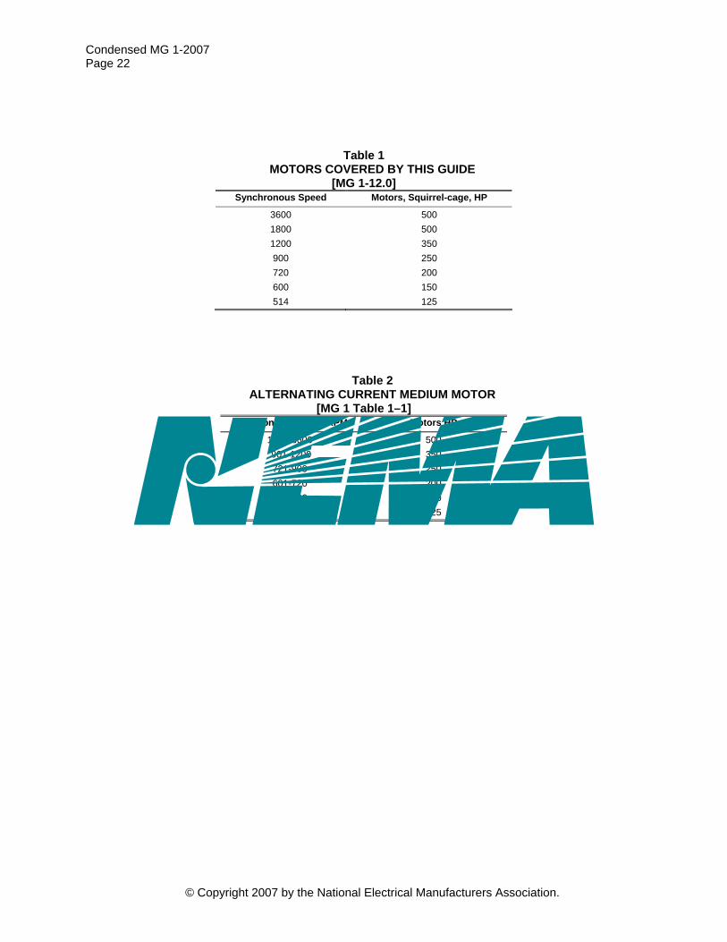
Condensed MG 1-2007 Page 22
Table 1 MOTORS COVERED BY THIS GUIDE
[MG 1-12.0] Synchronous Speed Motors, Squirrel-cage, HP
3600 500 1800 500 1200 350 900 250 720 200 600 150 514 125
Table 2 ALTERNATING CURRENT MEDIUM MOTOR
[MG 1 Table 1–1] Synchronous Speed, RPM Motors HP
1201-3600 500 901-1200 350 721-900 250 601-720 200 515-600 150 451-514 125
© Copyright 2007 by the National Electrical Manufacturers Association.
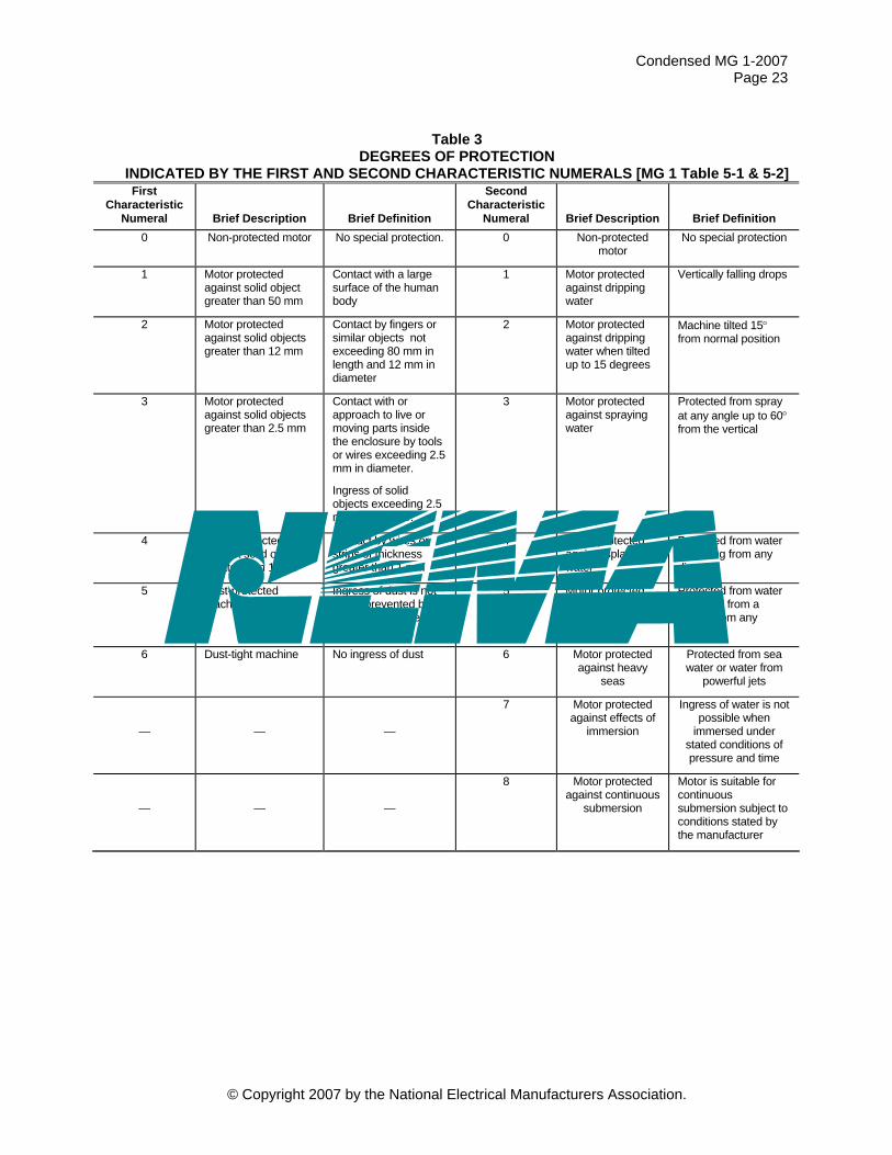
Condensed MG 1-2007 Page 23
Table 3 DEGREES OF PROTECTION
INDICATED BY THE FIRST AND SECOND CHARACTERISTIC NUMERALS [MG 1 Table 5-1 & 5-2] First
Characteristic Numeral Brief Description Brief Definition
Second Characteristic
Numeral Brief Description Brief Definition 0 Non-protected motor No special protection. 0 Non-protected
motor No special protection
1 Motor protected against solid object greater than 50 mm
Contact with a large surface of the human body
1 Motor protected against dripping water
Vertically falling drops
2 Motor protected against solid objects greater than 12 mm
Contact by fingers or similar objects not exceeding 80 mm in length and 12 mm in diameter
2 Motor protected against dripping water when tilted up to 15 degrees
Machine tilted 15° from normal position
3 Motor protected against solid objects greater than 2.5 mm
Contact with or approach to live or moving parts inside the enclosure by tools or wires exceeding 2.5 mm in diameter.
Ingress of solid objects exceeding 2.5 mm in diameter.
3 Motor protected against spraying water
Protected from spray at any angle up to 60° from the vertical
4 Motor protected against solid objects greater than 1 mm
Contact by wires or strips of thickness greater than 1 mm
4 Motor protected against splashing water
Protected from water splashing from any direction
5 Dust-protected machine
Ingress of dust is not totally prevented but does not interfere with operation
5 Motor protected against water jets
Protected from water projected from a nozzle from any direction
6 Dust-tight machine No ingress of dust 6 Motor protected against heavy
seas
Protected from sea water or water from
powerful jets
— — —
7 Motor protected against effects of
immersion
Ingress of water is not possible when
immersed under stated conditions of pressure and time
— — —
8 Motor protected against continuous
submersion
Motor is suitable for continuous submersion subject to conditions stated by the manufacturer
© Copyright 2007 by the National Electrical Manufacturers Association.

Condensed MG 1-2007 Page 24
Table 4 TYPICAL METHODS OF COOLING (IC CODE)
NEMA IC Circuit
Arrangement Primary Coolant
Method of Movement
Secondary Coolant
Method of Movement
WP-I IC 0 A 1 WP-II IC 0 A 1 ODP IC 0 A 1
TEFC (guarded) IC 4 A 1 A 1 TEBC IC 4 A 1 A 6 TENV IC 4 A 1 A 0 TEAO IC 4 A 1 A 7
Complete designation — full description (3 or 5 numerals or letters {numeral letter numeral [letter numeral]} Simplified designation — 2 or 3 numerals or letters in the final position {numeral numeral numeral or numeral numeral letter}. Example: The COMPLETE designation of TEFC guarded would be IC4A1A1; the SIMPLIFIED designation would be IC 411.
Table 5 UNFILTERED VIBRATION LIMITS [MG 1-7.8.2]
Speed, rpm Rotational Frequency, Hz Velocity, in/s peak (mm/s)
3600 60 0.15 (3.8) 1800 30 0.15 (3.8) 1200 20 0.15 (3.8) 900 15 0.12 (3.0) 720 12 0.09 (2.3) 600 10 0.08 (2.0)
Table 6 HORSEPOWER AND SPEED RATINGS, SMALL INDUCTION MOTORS [MG 1 Tables 10-1 & 10-2]
All Motors Except Permanent-Split
Capacitor
Permanent-Split Capacitor
Motors
All Motors Except
Permanent-Split Capacitor
Permanent-Split Capacitor
Motors
Hp
60-Hz Synchronous
Rpm Approximate Rpm at Rated Load
50-Hz Synchronous
Rpm Approximate Rpm at Rated Load
1/4 and 1/3 3600 3450 3250 3000 2850 2700 1800 1725 1625 1500 1425 1350 1200 1140 1075 1000 950 900 900 850 825 — — —
1/2 3600 3450 3250 3000 2850 2700 1800 1725 1625 1500 1425 1350 1200 1140 1075 1000 950 900
3/4 3600 3450 3250 3000 2850 2700 1800 1725 1625 1550 1425 1350
1 3600 3450 3250 3000 2850 2700
© Copyright 2007 by the National Electrical Manufacturers Association.
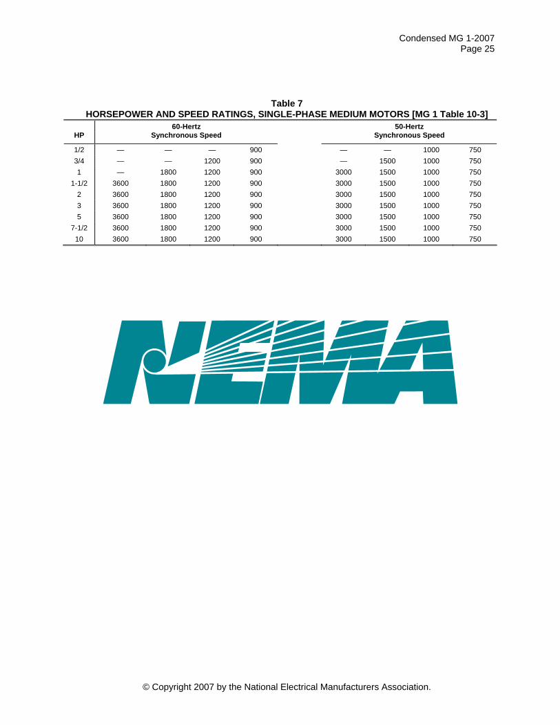
Condensed MG 1-2007 Page 25
Table 7 HORSEPOWER AND SPEED RATINGS, SINGLE-PHASE MEDIUM MOTORS [MG 1 Table 10-3]
HP
60-Hertz Synchronous Speed
50-Hertz Synchronous Speed
1/2 — — — 900 — — 1000 750 3/4 — — 1200 900 — 1500 1000 750 1 — 1800 1200 900 3000 1500 1000 750
1-1/2 3600 1800 1200 900 3000 1500 1000 750 2 3600 1800 1200 900 3000 1500 1000 750 3 3600 1800 1200 900 3000 1500 1000 750 5 3600 1800 1200 900 3000 1500 1000 750
7-1/2 3600 1800 1200 900 3000 1500 1000 750 10 3600 1800 1200 900 3000 1500 1000 750
© Copyright 2007 by the National Electrical Manufacturers Association.
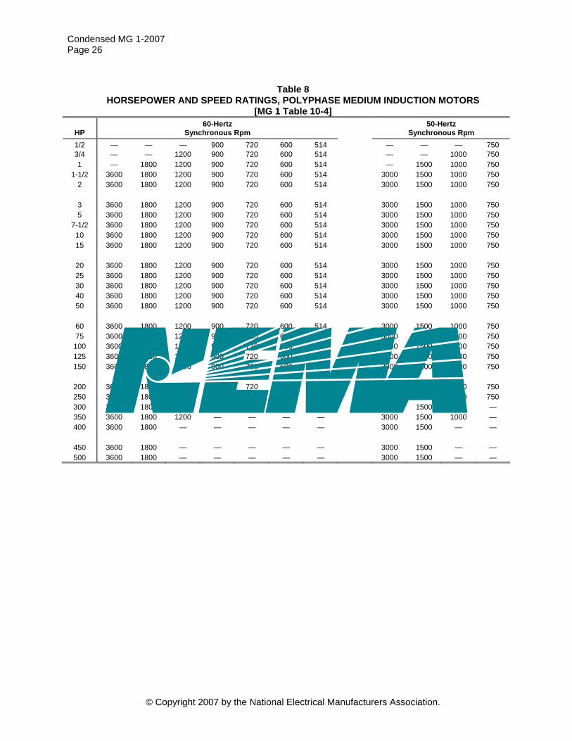
Condensed MG 1-2007 Page 26
Table 8 HORSEPOWER AND SPEED RATINGS, POLYPHASE MEDIUM INDUCTION MOTORS
[MG 1 Table 10-4]
HP 60-Hertz
Synchronous Rpm 50-Hertz
Synchronous Rpm 1/2 — — — 900 720 600 514 — — — 7503/4 — — 1200 900 720 600 514 — — 1000 750 1 — 1800 1200 900 720 600 514 — 1500 1000 750
1-1/2 3600 1800 1200 900 720 600 514 3000 1500 1000 750 2 3600 1800 1200 900 720 600 514 3000 1500 1000 750
3 3600 1800 1200 900 720 600 514 3000 1500 1000 750 5 3600 1800 1200 900 720 600 514 3000 1500 1000 750
7-1/2 3600 1800 1200 900 720 600 514 3000 1500 1000 750 10 3600 1800 1200 900 720 600 514 3000 1500 1000 750 15 3600 1800 1200 900 720 600 514 3000 1500 1000 750
20 3600 1800 1200 900 720 600 514 3000 1500 1000 750 25 3600 1800 1200 900 720 600 514 3000 1500 1000 750 30 3600 1800 1200 900 720 600 514 3000 1500 1000 750 40 3600 1800 1200 900 720 600 514 3000 1500 1000 750 50 3600 1800 1200 900 720 600 514 3000 1500 1000 750
60 3600 1800 1200 900 720 600 514 3000 1500 1000 750 75 3600 1800 1200 900 720 600 514 3000 1500 1000 750
100 3600 1800 1200 900 720 600 514 3000 1500 1000 750 125 3600 1800 1200 900 720 600 514 3000 1500 1000 750 150 3600 1800 1200 900 720 600 — 3000 1500 1000 750
200 3600 1800 1200 900 720 — — 3000 1500 1000 750 250 3600 1800 1200 900 — — — 3000 1500 1000 750 300 3600 1800 1200 — — — — 3000 1500 1000 — 350 3600 1800 1200 — — — — 3000 1500 1000 — 400 3600 1800 — — — — — 3000 1500 — —
450 3600 1800 — — — — — 3000 1500 — — 500 3600 1800 — — — — — 3000 1500 — —
© Copyright 2007 by the National Electrical Manufacturers Association.

Condensed MG 1-2007 Page 27
Table 9 BREAKDOWN TORQUE FOR INDUCTION MOTORS,
EXCEPT PERMANENT-SPLIT CAPACITOR MOTORS*† [MG 1 TABLE 10-5]
60 50 60 50 60 50 60 50 Frequencies, Hertz 3600 3000 1800 1500 1200 1000 900 750 Synchronous
Speeds, Rpm
3450**
2850**
1725**
1425**
1140**
950**
850**
...
Hp
Small Motors, Nominal Speeds,
Rpm
0.35-0.55 0.55-0.7 0.7-1.1 1.1-1.8 1.8-2.7 2.7-3.6 3.6-5.5 5.5-9.5 9.5-15 15-24
0.42-0.66 0.66-0.85 0.85-1.3 1.3-2.2 2.2-3.2 3.2-4.3 4.3-6.6
6.6-11.4 11.4-18 18-28.8
0.7-1.1
1.1-1.45 1.45-2.2 2.2-3.6 3.6-5.4 5.4-7.2 7.2-11 11-19 19-30 30-48
0.85-1.3 1.3-1.75 1.75-2.6 2.6-4.3 4.3-6.6 6.6-8.6 8.6-13 13-23 23-36
36-57.6
1.1-1.65 1.65-2.2 2.2-3.3 3.3-5.4 5.4-8.1 8.1-11 11-17 17-29 29-46 46-72
... ... ... ... ... ... ... ... ... ...
... ... ... ... ... ... ... ... ... ...
... ... ... ... ... ... ... ... ... ...
Millihp 1
1.5 2 3 5
7.5 10 15 25 35
The figures at the left are for motors rated
less than 1/20 horsepower.
Breakdown torques in oz-in.
2.0-3.7 3.7-6.0 6.0-8.7
8.7-11.5 11.5-16.5 16.5-21.5 21.5-31.5 31.5-44.0 44.0-58.0
2.4-4.4 4.4-7.2
7.2-10.5 10.5-13.8 13.8-19.8 19.8-25.8 25.8-37.8 37.8-53.0 53.0-69.5
4.0-7.1
7.1-11.5 11.5-16.5 16.5-21.5 21.5-31.5 31.5-40.5 40.5-58.0 58.0-82.5 5.16-6.8
4.8-8.5
8.5-13.8 13.8-19.8 19.8-25.8 25.8-37.8 37.8-48.5 48.5-69.5 69.5-99.0 6.19-8.2
6.0-10.4 10.4-16.5 16.5-24.1 24.1-31.5 31.5-44.0 44.0-58.0 58.0-82.5 5.16-6.9 6.9-9.2
7.2-12.4 12.4-19.8 19.8-28.9 28.9-37.8 37.8-53.0 53.0-69.5 69.5-99.0
†† ††
8.0-13.5 13.5-21.5 21.5-31.5 31.5-40.5 40.5-58.0 58.0-77.0
†† †† ††
... ... ... ... ... ... †† †† ††
Hp 1/20 1/12 1/8 1/6 1/4 1/3 1/2 3/4 1
The figures at left are for small motors.
Breakdown torques in oz-ft.
The figures at left are for medium motors.
Breakdown torques in 3.6-4.6 4.6-6.0 6.0-8.6
8.6-13.5 13.5-20.0 20.0-27.0
4.3-5.5 5.5-7.2
7.2-10.2 10.2-16.2 16.2-24.0 24.0-32.4
6.8-10.1 10.1-13.0 13.0-19.0 19.0-30.0 30.0-45.0 45.0-60.0
8.2-12.1 12.1-15.6 15.6-22.8 22.8-36.0 36.0-54.0 54.0-72.0
9.2-13.8 13.8-18.0 18.0-25.8 25.8-40.5 40.5-60.0
††
†† †† †† †† †† ††
†† †† †† †† †† ††
†† †† †† †† †† ††
1-1/2 2 3 5
7-1/2 10
lb-ft.
*The breakdown torque range includes the higher figure down to, but not including, the lower figure. **These approximate full-load speeds apply only for small motor ratings. †The horsepower ratings of motors designed to operate on two or more frequencies shall be determined by the torque at the highest rated frequency. ††These are ratings for which no torque values have been established.
© Copyright 2007 by the National Electrical Manufacturers Association.
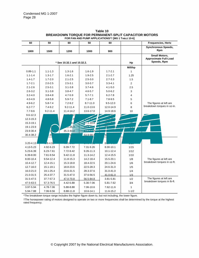
Condensed MG 1-2007 Page 28
Table 10 BREAKDOWN TORQUE FOR PERMANENT-SPLIT CAPACITOR MOTORS
FOR FAN AND PUMP APPLICATIONS*† [MG 1 TABLE 10-6]
60 50 60 50 60 Frequencies, Hertz
1800
1500
1200
1000
900 Synchronous Speeds,
Rpm
* See 10.32.1 and 10.32.2.
Hp
Small Motors, Approximate Full-Load
Speeds, Rpm
0.89-1.1 1.1-1.4 1.4-1.7 1.7-2.1 2.1-2.6 2.6-3.2 3.2-4.0 4.0-4.9 4.9-6.2 6.2-7.7 7.7-9.6
9.6-12.3 12.3-15.3 15.3-19.1 19.1-23.9 23.9-30.4 30.4-38.2
1.1-1.3 1.3-1.7 1.7-2.0 2.0-2.5 2.5-3.1 3.1-3.8 3.8-4.8 4.8-5.8 5.8-7.4 7.4-9.2
9.2-11.4 11.4-14.7 14.7-18.2 18.2-22.8 22.8-28.5 28.5-36.3 36.3-45.6
1.3-1.6 1.6-2.1 2.1-2.5 2.5-3.1 3.1-3.8 3.8-4.7 4.7-5.9 5.9-7.2 7.2-9.2
9.2-11.4 11.4-14.2 14.2-18.2 18.2-22.6 22.6-28.2 28.2-35.3 35.3-44.9 44.9-56.4
1.6-1.9 1.9-2.5 2.5-3.0 3.0-3.7 3.7-4.6 4.6-5.7 5.7-7.1 7.1-8.7
8.7-11.0 11.0-13.6 13.6-17.0 17.0-21.8 21.8-27.1 27.1-33.8 33.8-42.3 42.3-53.9 53.9-68.4
1.7-2.1 2.1-2.7 2.7-3.3 3.3-4.1 4.1-5.0 5.0-6.2 6.2-7.8 7.8-9.5
9.5-12.0 12.0-14.9 14.9-18.6 18.6-23.8 23.8-29.6 29.6-37.0 37.0-46.3 46.3-58.9 58.9-74.4
Millihp 1
1.25 1.5 2
2.5 3 4 5 6 8
10 12.5 16 20 25 30 40
The figures at left are breakdown torques in oz-in.
3.20-4.13 4.13-5.23 5.23-6.39 6.39-8.00 8.00-10.4 10.4-12.7 12.7-16.0 16.0-21.0 21.0-31.5 31.5-47.5 47.5-63.5
3.8-4.92
4.92-6.23 6.23-7.61 7.61-9.54 9.54-12.4 12.4-15.1 15.1-19.1 19.1-25.4 25.4-37.7 37.7-57.3 57.3-76.5
4.70-6.09 6.09-7.72 7.72-9.42 9.42-11.8 11.8-15.3 15.3-18.8 18.8-23.6 23.6-31.5 31.5-47.0 47.0-70.8 4.42-5.88
5.70-7.31 7.31-9.26 9.26-11.3 11.3-14.2 14.2-18.4 18.4-22.5 22.5-28.3 28.3-37.6 37.6-56.5 56.5-84.8 5.30-7.06
6.20-8.00 8.00-10.1 10.1-12.4 12.4-15.5 15.5-20.1 20.1-24.6 24.6-31.0 31.0-41.0 41.0-61.0 3.81-5.81 5.81-7.62
Hp 1/20 1/15 1/12 1/10 1/8 1/6 1/5 1/4 1/3 1/2 3/4
The figures at left are breakdown torques in oz-ft.
The figures at left are breakdown torques in lb-ft.
3.97-5.94 5.94-7.88
4.78-7.06 7.06-9.56
5.88-8.88 8.88-11.8
7.06-10.6 10.6-14.1
7.62-11.6 11.6-15.2
1 1-1/2
*The breakdown torque range includes the higher figure down to, but not including, the lower figure. †The horsepower rating of motors designed to operate on two or more frequencies shall be determined by the torque at the highest rated frequency.
© Copyright 2007 by the National Electrical Manufacturers Association.

Condensed MG 1-2007 Page 29
Table 11 TYPICAL CHARACTERISTICS AND APPLICATIONS
OF FIXED FREQUENCY SMALL AND MEDIUM AC SQUIRREL-CAGE INDUCTION MOTORS
Polyphase Characteristics
Locked Rotor
Torque (Percent
Rated Load Torque
Pull-Up Torque
(Percent Rated Load
Torque)
Breakdown Torque
(Percent Rated Load
Torque)
Locked Rotor
Current (Percent
Rated Load Current) Slip Typical Applications
Relative Efficiency
Design A High locked rotor torque and high
locked rotor current
70-275* 65-190 175-300* Not defined 0.5-5%
Fans, blowers, centrifugal pumps and compressors, motor-generator sets, etc., where starting torque
requirements are relatively low
Medium or high
Design B Normal locked
rotor torque and normal locked rotor current
70-275* 65-190 175-300* 600-700 0.5-5%
Fans, blowers, centrifugal pumps and compressors, motor-generator sets, etc., where starting torque
requirements are relatively low
Medium or high
Design C High locked rotor
torque and normal locked rotor current
200-285* 140-195 190-225* 600-700 1-5%
Conveyors, crushers, stirring motors,
agitators, reciprocating pumps and
compressors, etc., where starting under
load is required
Medium
Design D High locked rotor torque and high
slip
275 NA 275 600-700 5-8%
High peak loads with or without flywheels such
as punch presses, shears, elevators,
extractors, winches, hoists, oil-well pumping
and wire-drawing motors
Low
Design N Small motor
— NA — — NA
Centrifugal loads where starting torque
requirements are relatively low
Low
Design O Small motor
— NA — — NA
Design L Medium motor
— 100% — — NA
Fans, blowers, centrifugal pumps and compressors, motor-generator sets, etc., where starting torque
requirements are relatively low
Medium or Low
Design M Medium motor
— 100% — — NA
Fans, blowers, centrifugal pumps and compressors, motor-generator sets, etc., where starting torque
requirements are relatively low
Medium or high
*Higher values are for motors having lower horsepower ratings.
© Copyright 2007 by the National Electrical Manufacturers Association.

Condensed MG 1-2007 Page 30
Table 12 CODE LETTERS (FOR LOCKED-ROTOR KVA)—NAMEPLATE MARKING [MG 1-10.37.2]
Letter Designation kVA per Horsepower* Letter Designation kVA per Horsepower*
A 0-3.15 K 8.0-9.0B 3.15-3.55 L 9.0-10.0 C 3.55-4.0 M 10.0-11.2 D 4.0-4.5 N 11.2-12.5 E 4.5-5.0 P 12.5-14.0 F 5.0-5.6 R 14.0-16.0 G 5.6-6.3 S 16.0-18.0 H 6.3-7.1 T 18.0-20.0 J 7.1-8.0 U 20.0-22.4 V 22.4-and up
*Locked kVA per horsepower range includes the lower figure up to, but not including, the higher figure. For example, 3.14 is designated by letter A and 3.15 by letter B.
Table 13 MEDIUM MACHINE FRAME NUMBERING [MG 1 Table 4-2]
Third/Fourth Digit in Frame Number Frame Number Series D 1 2 3 4 5 6 7
2 F Dimensions
140 3.50 3.00 3.50 4.00 4.50 5.00 5.50 6.25 160 4.00 3.50 4.00 4.50 5.00 5.50 6.25 7.00 180 4.50 4.00 4.50 5.00 5.50 6.25 7.00 8.00 200 5.00 4.50 5.00 5.50 6.50 7.00 8.00 9.00 210 5.25 4.50 5.00 5.50 6.25 7.00 8.00 9.00 220 5.50 5.00 5.50 6.25 6.75 7.50 9.00 10.00 250 6.25 5.50 6.25 7.00 8.25 9.00 10.00 11.00 280 7.00 6.25 7.00 8.00 9.50 10.00 11.00 12.50 320 8.00 7.00 8.00 9.00 10.50 11.00 12.00 14.00 360 9.00 8.00 9.00 10.00 11.25 12.25 14.00 16.00 400 10.00 9.00 10.00 11.00 12.25 13.75 16.00 18.00 440 11.00 10.00 11.00 12.50 14.50 16.50 18.00 20.00 500 12.50 11.00 12.50 14.00 16.00 18.00 10.00 22.00 580 14.50 12.50 14.00 16.00 18.00 20.00 22.00 25.00 680 17.00 16.00 18.00 20.00 22.00 25.00 28.00 32.00
Third/Fourth Digit in Frame Number Frame Number Series D 8 9 10 11 12 13 14 15
2F Dimensions
140 3.50 7.00 8.00 9.00 10.00 11.00 12.50 14.00 16.00
160 4.00 8.00 9.00 10.00 11.00 12.50 14.00 16.00 18.00180 4.50 9.00 10.00 11.00 12.50 14.00 16.00 18.00 20.00200 5.00 10.00 11.00 ... ... ... ... ... ...210 5.25 10.00 11.00 12.50 14.00 16.00 18.00 20.00 22.00220 5.50 11.00 12.50 ... ... ... ... ... ...250 6.25 12.50 14.00 16.00 18.00 20.00 22.00 25.00 28.00280 7.00 14.00 16.00 18.00 20.00 22.00 25.00 28.00 32.00320 8.00 16.00 18.00 20.00 22.00 25.00 28.00 32.00 36.00360 9.00 18.00 20.00 22.00 25.00 28.00 32.00 36.00 40.00400 10.00 20.00 22.00 25.00 28.00 32.00 36.00 40.00 45.00440 11.00 22.00 25.00 28.00 32.00 36.00 40.00 45.00 50.00500 12.50 25.00 28.00 32.00 36.00 40.00 45.00 50.00 56.00580 14.50 28.00 32.00 36.00 40.00 45.00 50.00 56.00 63.00680 17.00 36.00 40.00 45.00 50.00 56.00 63.00 71.00 80.00
All dimensions in inches.
© Copyright 2007 by the National Electrical Manufacturers Association.
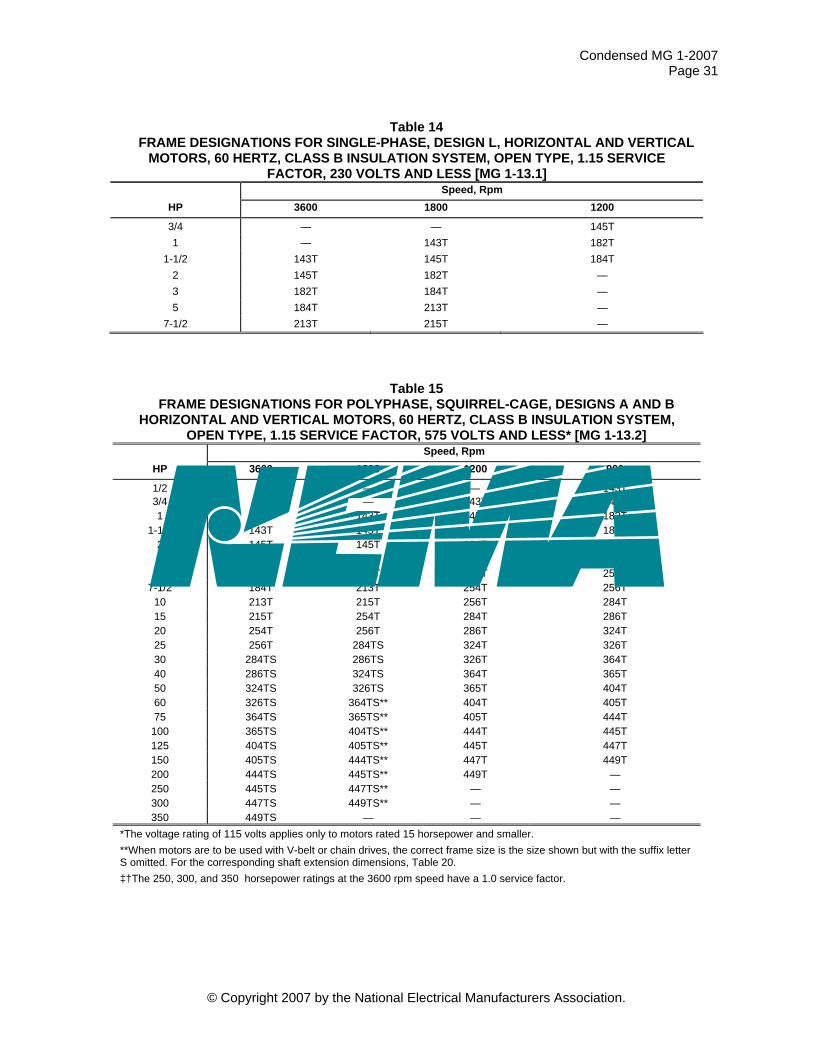
Condensed MG 1-2007 Page 31
Table 14 FRAME DESIGNATIONS FOR SINGLE-PHASE, DESIGN L, HORIZONTAL AND VERTICAL
MOTORS, 60 HERTZ, CLASS B INSULATION SYSTEM, OPEN TYPE, 1.15 SERVICE FACTOR, 230 VOLTS AND LESS [MG 1-13.1]
Speed, Rpm HP 3600 1800 1200
3/4 — — 145T 1 — 143T 182T
1-1/2 143T 145T 184T 2 145T 182T — 3 182T 184T — 5 184T 213T —
7-1/2 213T 215T —
Table 15 FRAME DESIGNATIONS FOR POLYPHASE, SQUIRREL-CAGE, DESIGNS A AND B
HORIZONTAL AND VERTICAL MOTORS, 60 HERTZ, CLASS B INSULATION SYSTEM, OPEN TYPE, 1.15 SERVICE FACTOR, 575 VOLTS AND LESS* [MG 1-13.2]
Speed, Rpm HP 3600 1800 1200 900
1/2 — — — 143T 3/4 — — 143T 145T 1 — 143T 145T 182T
1-1/2 143T 145T 182T 184T 2 145T 145T 184T 213T 3 145T 182T 213T 215T 5 182T 184T 215T 254T
7-1/2 184T 213T 254T 256T 10 213T 215T 256T 284T 15 215T 254T 284T 286T 20 254T 256T 286T 324T 25 256T 284TS 324T 326T 30 284TS 286TS 326T 364T 40 286TS 324TS 364T 365T 50 324TS 326TS 365T 404T 60 326TS 364TS** 404T 405T 75 364TS 365TS** 405T 444T
100 365TS 404TS** 444T 445T 125 404TS 405TS** 445T 447T 150 405TS 444TS** 447T 449T 200 444TS 445TS** 449T — 250 445TS 447TS** — — 300 447TS 449TS** — — 350 449TS — — —
*The voltage rating of 115 volts applies only to motors rated 15 horsepower and smaller. **When motors are to be used with V-belt or chain drives, the correct frame size is the size shown but with the suffix letter S omitted. For the corresponding shaft extension dimensions, Table 20. ‡†The 250, 300, and 350 horsepower ratings at the 3600 rpm speed have a 1.0 service factor.
© Copyright 2007 by the National Electrical Manufacturers Association.
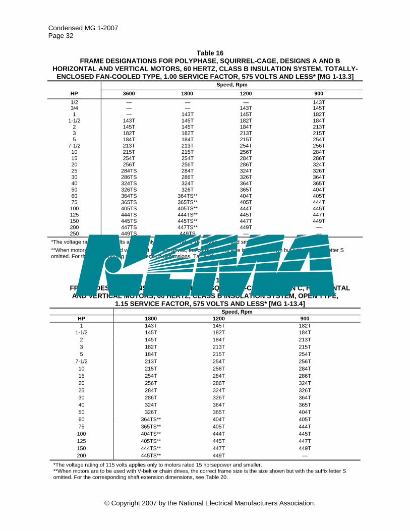
Condensed MG 1-2007 Page 32
Table 16 FRAME DESIGNATIONS FOR POLYPHASE, SQUIRREL-CAGE, DESIGNS A AND B
HORIZONTAL AND VERTICAL MOTORS, 60 HERTZ, CLASS B INSULATION SYSTEM, TOTALLY-ENCLOSED FAN-COOLED TYPE, 1.00 SERVICE FACTOR, 575 VOLTS AND LESS* [MG 1-13.3]
Speed, Rpm HP 3600 1800 1200 900 1/2 — — — 143T 3/4 — — 143T 145T 1 — 143T 145T 182T
1-1/2 143T 145T 182T 184T 2 145T 145T 184T 213T 3 182T 182T 213T 215T 5 184T 184T 215T 254T
7-1/2 213T 213T 254T 256T 10 215T 215T 256T 284T 15 254T 254T 284T 286T 20 256T 256T 286T 324T 25 284TS 284T 324T 326T 30 286TS 286T 326T 364T 40 324TS 324T 364T 365T 50 326TS 326T 365T 404T 60 364TS 364TS** 404T 405T 75 365TS 365TS** 405T 444T
100 405TS 405TS** 444T 445T 125 444TS 444TS** 445T 447T 150 445TS 445TS** 447T 449T 200 447TS 447TS** 449T — 250 449TS 449TS — —
*The voltage rating of 115 volts applies only to motors rated 15 horsepower and smaller. **When motors are to be used with V-belt or chain drives, the correct frame size is the size shown but with the suffix letter S omitted. For the corresponding shaft extension dimensions, Table 20.
Table 17 FRAME DESIGNATIONS FOR POLYPHASE, SQUIRREL-CAGE, DESIGN C, HORIZONTAL AND VERTICAL MOTORS, 60 HERTZ, CLASS B INSULATION SYSTEM, OPEN TYPE,
1.15 SERVICE FACTOR, 575 VOLTS AND LESS* [MG 1-13.4] Speed, Rpm
HP 1800 1200 900 1 143T 145T 182T
1-1/2 145T 182T 184T 2 145T 184T 213T 3 182T 213T 215T 5 184T 215T 254T
7-1/2 213T 254T 256T 10 215T 256T 284T 15 254T 284T 286T 20 256T 286T 324T 25 284T 324T 326T 30 286T 326T 364T 40 324T 364T 365T 50 326T 365T 404T 60 364TS** 404T 405T 75 365TS** 405T 444T
100 404TS** 444T 445T 125 405TS** 445T 447T 150 444TS** 447T 449T 200 445TS** 449T —
*The voltage rating of 115 volts applies only to motors rated 15 horsepower and smaller. **When motors are to be used with V-belt or chain drives, the correct frame size is the size shown but with the suffix letter S omitted. For the corresponding shaft extension dimensions, see Table 20.
© Copyright 2007 by the National Electrical Manufacturers Association.
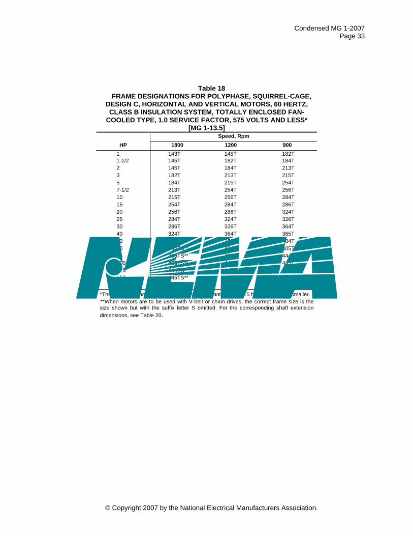
Condensed MG 1-2007 Page 33
Table 18 FRAME DESIGNATIONS FOR POLYPHASE, SQUIRREL-CAGE,
DESIGN C, HORIZONTAL AND VERTICAL MOTORS, 60 HERTZ, CLASS B INSULATION SYSTEM, TOTALLY ENCLOSED FAN-
COOLED TYPE, 1.0 SERVICE FACTOR, 575 VOLTS AND LESS* [MG 1-13.5]
Speed, Rpm HP 1800 1200 900
1 143T 145T 182T 1-1/2 145T 182T 184T 2 145T 184T 213T 3 182T 213T 215T 5 184T 215T 254T 7-1/2 213T 254T 256T 10 215T 256T 284T 15 254T 284T 286T 20 256T 286T 324T 25 284T 324T 326T 30 286T 326T 364T 40 324T 364T 365T 50 326T 365T 404T 60 364TS** 404T 405T 75 365TS** 405T 444T 100 405TS** 444T 445T 125 444TS** 445T 447T 150 445TS** 447T 449T 200 447TS** 449T —
*The voltage rating of 115 volts applies only to motors rated 15 horsepower and smaller. **When motors are to be used with V-belt or chain drives, the correct frame size is the size shown but with the suffix letter S omitted. For the corresponding shaft extension dimensions, see Table 20.
© Copyright 2007 by the National Electrical Manufacturers Association.
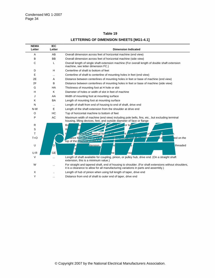
Condensed MG 1-2007 Page 34
© Copyright 2007 by the National Electrical Manufacturers Association.
Table 19
LETTERING OF DIMENSION SHEETS [MG1-4.1] NEMA Letter
IEC Letter
Dimension Indicated
A AB Overall dimension across feet of horizontal machine (end view) B BB Overall dimension across feet of horizontal machine (side view) C L Overall length of single shaft extension machine (For overall length of double shaft extension
machine, see letter dimension FC.) D H Centerline of shaft to bottom of feet E ... Centerline of shaft to centerline of mounting holes in feet (end view)
2E A Distance between centerlines of mounting holes in feet or base of machine (end view) 2F B Distance between centerlines of mounting holes in feet or base of machine (side view) G HA Thickness of mounting foot at H hole or slot H K Diameter of holes or width of slot in feet of machine J AA Width of mounting foot at mounting surface K BA Length of mounting foot at mounting surface N ... Length of shaft from end of housing to end of shaft, drive end
N-W E Length of the shaft extension from the shoulder at drive end O HC Top of horizontal machine to bottom of feet P AC Maximum width of machine (end view) including pole bells, fins, etc., but excluding terminal
housing, lifting devices, feet, and outside diameter of face or flange R G Bottom of keyseat or flat to bottom side of shaft or bore S F Width of keyseat T HD-HC Height of lifting eye, terminal box, or other salient part above the surface of the machine.
T+O HD Distance from the top of the lifting eye, the terminal box or other most salient part mounted on the top of the machine to the bottom of the feet
U D Diameter of shaft extension. (For tapered shaft, this is diameter at a distance V from the threaded portion of the shaft.)
U-R GE Depth of the keyway at the crown of the shaft extension at drive end V ... Length of shaft available for coupling, pinion, or pulley hub, drive end. (On a straight shaft
extension, this is a minimum value.) W ... For straight and tapered shaft, end of housing to shoulder. (For shaft extensions without shoulders,
it is a clearance to allow for all manufacturing variations in parts and assembly.) X .. Length of hub of pinion when using full length of taper, drive end Y ... Distance from end of shaft to outer end of taper, drive end

Table 20 DIMENSIONS FOR ALTERNATING-CURRENT FOOT-MOUNTED MOTORS WITH SINGLE STRAIGHT-SHAFT EXTENSION 1, 2, [MG 1-4.4.1]
Keyseat Frame Designation A Max D* E† 2F† BA*** H† U N-W V Min R ES Min S AA Min††
42 — 2.62 1.75 1.69 2.06 0.28 slot 0.3750 1.12 ... 0.328 ... flat ...48
— 3.00 2.12 2.75 2.50 0.34 slot 0.5000 1.50 ... 0.453 ... flat ...48H — 3.00 2.12 4.75 2.50 0.34 slot 0.5000 1.50 ... 0.453 ... flat ...56 — 3.50 2.44 3.00 2.75 0.34 slot 0.6250 1.88 ... 0.517 1.41 0.188 ...
56H — 3.50 2.44 5.00 2.75 0.34 slot 0.6250 1.88 ... 0.517 1.41 0.188 ...143T 7.0 3.50 2.75 4.00 2.25 0.34 hole 0.8750 2.25 2.00 0.771 1.41 0.188 3/4145T 7.0 3.50 2.75 5.00 2.25 0.34 hole 0.8750 2.25 2.00 0.771 1.41 0.188 3/4182T 9.0 4.50 3.75 4.50 2.75 0.41 hole 1.1250 2.75 2.50 0.986 1.78 0.250 3/4184T 9.0 4.50 3.75 5.50 2.75 0.41 hole 1.1250 2.75 2.50 0.986 1.78 0.250 3/4213T 10.5 5.25 4.25 5.50 3.50 0.41 hole 1.3750 3.38 3.12 1.201 2.41 0.312 1215T 10.5 5.25 4.25 7.00 3.50 0.41 hole 1.3750 3.38 3.12 1.201 2.41 0.312 1254T 12.5 6.25 5.00 8.25 4.25 0.53 hole 1.625 4.00 3.75 1.416 2.91 0.375 1-1/4256T 12.5 6.25 5.00 10.00 4.25 0.53 hole 1.625 4.00 3.75 1.416 2.91 0.375 1-1/4284T 14.0 7.00 5.50 9.50 4.75 0.53 hole 1.875 4.62 4.38 1.591 3.28 0.500 1-1/2
284TS 14.0 7.00 5.50 9.50 4.75 0.53 hole 1.625 3.25 3.00 1.416 1.91 0.375 1-1/2286T 14.0 7.00 5.50 11.00 4.75 0.53 hole 1.875 4.62 4.38 1.591 3.28 0.500 1-1/2
286TS 14.0 7.00 5.50 11.00 4.75 0.53 hole 1.625 3.25 3.00 1.416 1.91 0.375 1-1/2324T 16.0 8.00 6.25 10.50 5.25 0.66 hole 2.125 5.25 5.00 1.845 3.91 0.500 2
324TS 16.0 8.00 6.25 10,50 5.25 0.66 hole 1.875 3.75 3.50 1.591 2.03 0.500 2326T 16.0 8.00 6.25 12.00 5.25 0.66 hole 2.125 5.25 5.00 1.845 3.91 0.500 2
326TS 16.0 8.00 6.25 12.00 5.25 0.66 hole 1.875 3.75 3.50 1.591 2.03 0.500 2364T 18.0 9.00 7.00 11.25 5.88 0.66 hole 2.375 5.88 5.62 2.021 4.28 0.625 3
364TS 18.0 9.00 7.00 11.25 5.88 0.66 hole 1.875 3.75 3.50 1.591 2.03 0.500 3365T 18.0 9.00 7.00 12.25 5.88 0.66 hole 2.375 5.88 5.62 2.021 4.28 0.625 3
365TS 18.0 9.00 7.00 12.25 5.88 0.66 hole 1.875 3.75 3.50 1.591 2.03 0.500 3404T 20.0 10.00 8.00 12.25 6.62 0.81 hole 2.875 7.25 7.00 2.450 5.65 0.750 3
404TS 20.0 10.00 8.00 12.25 6.62 0.81 hole 2.125 4.25 4.00 1.845 2.78 0.500 3405T 20.0 10.00 8.00 13.75 6.62 0.81 hole 2.875 7.25 7.00 2.450 5.65 0.750 3
405TS 20.0 10.00 8.00 13.75 6.62 0.81 hole 2.125 4.25 4.00 1.845 2.78 0.500 3444T 22.0 11.00 9.00 14.50 7.50 0.81 hole 3.375 8.50 8.25 2.880 6.91 0.875 3
444TS 22.0 11.00 9.00 14.50 7.50 0.81 hole 2.375 4.75 4.50 2.021 3.03 0.625 3445T 22.0 11.00 9.00 16.50 7.50 0.81 hole 3.375 8.50 8.25 2.880 6.91 0.875 3
445TS 22.0 11.00 9.00 16.50 7.50 0.81 hole 2.375 4.75 4.50 2.021 3.03 0.625 3447T 22.0 11.00 9.00 20.00 7.50 0.81 hole 3.375 8.50 8.25 2.880 6.91 0.875 3
447TS 22.0 11.00 9.00 20.00 7.50 0.81 hole 2.375 4.75 4.50 2.021 3.03 0.625 3449T 22.0 11.00 9.00 25.00 7.50 0.81 hole 3.375 8.50 8.25 2.880 6.91 0.875 3
449TS 22.0 11.00 9.00 25.00 7.50 0.81 hole 2.375 4.75 4.50 2.021 3.03 0.625 3440 ... 11.00 9.00 ** 7.50 ... ... ... ... ... ... ...500 ... 12.50 10.00 ** 8.50 ... ... ... ... ... ... ...
(Table 20 Continued on following page.)
© Copyright 2007 by the National Electrical Manufacturers Associa
C
ondensed MG
1-2007 P
age 35
© C
opyright 2007 by the National E
lectrical Manufacturers A
ssociation.
tion.

(Table 20 Continued.) All dimensions in inches. *The tolerances on the D dimension for rigid base motors shall be +0.00 inch, -0.06 inch. No tolerance has been established for the D dimension of resilient mounted motors. †Frames 42 to 56H, inclusive—The tolerance for the 2F dimension shall be ±0.03 inch and for the H dimension (width of slot) shall be +0.02 inch, -0 inch. Frames 143T to 500, inclusive—The tolerance for the 2E and 2F dimensions shall be ±0.03 inch and for the H dimension shall be +0.05 inch, -0 inch. The values of the H dimension represent standard bolt sizes plus dimensional clearances. H dimension:; Frames 143T to 365T inclusive—The clearance of the std. bolt to hole size is 0.03. The tolerance is +0.05, -0.00 inch. Frames 404T to 449T inclusive—The clearance of std. bolt to hole size is 0.06 inch. The tolerance is =0.020 inch, -0.00 inch. ††For dimensions of clearance holes see MG 1 4.8 **For the 2F dimension and corresponding third (and when required the fourth) digit in the frame series, see MG 1 8.1 and Table 13. ***BA tolerance: ±0.09 inch. NOTES 1—It is recommended that all motors with keyseats cut in the shaft extension pulley, coupling, pinion, and so forth, be furnished with a key unless otherwise 2—Frames 42 to 56H, inclusive,—If the shaft extension length of the motor is not suitable for the application, it is recommended that deviations from this length be in 0.25-inch increments. 3— For cast-iron products, bottom of feet coplanar: 0.015 inch. 4— For cast-iron products, foot top parallel to foot bottom: 1.5 degree 5— For cast-iron products, shaft parallel to foot plane: 0.015 inch 1For the meaning of the letter dimensions, see Table 19 and Figures 3 through 5. 2For tolerances on shaft extension diameters and key seats see MG 1 4.9
© Copyright 2007 by the National Electrical Manufacturers Association.
Condensed M
G 1-2008
Page 36
© C
opyright 2007 by the National E
lectrical Manufacturers A
ssociation.

Table 21 SHAFT EXTENSIONS AND KEY DIMENSIONS FOR ALTERNATING-CURRENT FOOT-MOUNTED MOTORS WITH SINGLE TAPERED
OR DOUBLE STRAIGHT/TAPERED SHAFT EXTENSION1, 2 [MG 1-4.4.2] Drive End—Tapered Shaft Extension*
Shaft KeyseatFrame Designation BA U N-W V X Y Z Max Threads Width Depth
Key Length**
143TR and 145TR 2.25 0.8750 2.62 1.75 1.88 0.75 1.38 5/8-18 0.188 0.094 1.50182TR and 184TR 2.75 1.1250 3.38 2.25 2.38 1.88 1.50 3/4-16 0.250 0.125 2.00 213TR and 215TR 3.50 1.3750 4.12 2.62 2.75 1.25 2.00 1-14 0.312 0.156 2.38 254TR and 256TR 4.25 1.625 4.50 2.88 3.00 1.25 2.00 1-14 0.375 0.188 2.62 284TR and 286TR 4.75 1.875 4.75 3.12 3.25 1.25 2.38 1-1/4-12 0.500 0.250 2.88 324TR and 326TR 5.25 2.125 5.25 3.50 3.62 1.38 2.75 1-1/2-8 0.500 0.250 3.25 364TR and 365TR 5.88 2.375 5.75 3.75 3.88 1.50 3.25 1-3/4-8 0.625 0.312 3.50 404TR and 405TR 6.62 2.875 6.62 4.38 4.50 1.75 3.62 2-8 0.750 0.375 4.12 444TR and 445TR 7.50 3.375 7.50 5.00 5.12 2.00 4.12 2-1/4-8 0.875 0.438 4.75
OPPOSITE DRIVE END—TAPERED SHAFT EXTENSION*† OPPOSITE DRIVE END—STRAIGHT SHAFT EXTENSION† Keyseat Keyseat
Frame Number Series FU
FN-FW FV FX FY
FZ Max
Shaft Threads Width Depth
Key Length FU
FN-FW FV Min R
ES Min S
140 0.6250 2.00 1.38 1.50 0.50 1.12 3/8-24 0.188 0.094 1.12 0.6250 1.62 1.38 0.517 0.91 0.188180 0.8750 2.62 1.75 1.88 0.75 1.38 5/8-18 0.188 0.094 1.50 0.8750 2.25 2.00 0.771 1.41 0.188210 1.1250 3.38 2.25 2.38 0.88 1.50 3/4-16 0.250 0.125 2.00 1.1250 2.75 2.50 0.986 1.78 0.250250 1.3750 4.12 2.62 2.75 1.25 2.00 1-14 0.312 0.156 2.38 1.3750 3.38 3.12 1.201 2.41 0.312280 1.6250 4.50 2.88 3.00 1.25 2.00 1-14 0.375 0.188 2.62 1.625 4.00 3.75 1.416 2.91 0.375
280 Short Shaft 1.625 3.25 3.00 1.416 1.91 0.375 320 1.8750 4.75 3.12 3.25 1.25 2.38 1-1/4-12 0.500 0.250 2.88 1.875 4.62 4.38 1.591 3.28 0.500
320 Short Shaft 1.875 3.75 3.50 1.591 2.03 0.500 360 1.8750 4.75 3.12 3.25 1.25 2.38 1-1/4-12 0.500 0.250 2.88 1.875 4.62. 4.38 1.591 2.03 0.500
360 Short Shaft 1.875 3.75 3.50 1.591 2.03 0.500 400 2.1250 5.25 3.50 3.62 1.38 2.75 1-1/2-8 0.500 0.250 3.25 2.125 5.25 5.00 1.845 3.91 0.500
400 Short Shaft 2.125 4.25 4.00 1.845 2.78 0.500 440 2.3750 5.75 3.75 3.88 1.50 3.25 1-3/4-8 0.625 0.312 3.50 2.375 5.88 5.62 2.021 4.28 0.625
440 Short Shaft 2.375 4.75 4.50 2.021 3.03 0.625 All dimensions in inches. *The standard taper of shafts shall be at the rate of 1.25 inch in diameter per foot of length. The thread at the end of the tapered shaft shall be provided with a nut and a suitable locking device. **Tolerance on the length of the key is ±0.03 inch. †For drive applications other than direct connect, the motor manufacturer should be consulted. NOTE—It is recommended that all motors with keyseats cut in the shaft extension for pulley, coupling, pinion, etc., be furnished with a key unless otherwise specified by the purchaser. 1For the meaning of the letter dimensions, see Table 19 and Figures 3 through 5. 2For tolerances on shaft extension diameters and keyseats see MG 1 4.9
© Copyright 2007 by the National Electrical Manufacturers Association.
Condensed M
G 1-2007
Page 37
© C
opyright 2007 by the National E
lectrical Manufacturers A
ssociation.

Table 22 DIMENSIONS FOR TYPE C FACE-MOUNTING FOOT OR FOOTLESS ALTERNATING-CURRENT MOTORS1, 2, 3 [MG 1-4.4.4]
Frame Designation* BF Hole
Bolt
Penetration Keyseat AJ** AK BA BB Min BC BD Max Number Tap Size Allowance U AH R ES Min S
42C 3.750 3.000 2.062 0.16† -0.19 5.00†† 4 1/4-20 ... 0.3750 1.312 0.328 ... flat48C
3.750 3.000 2.50 0.16† -0.19 5.625 4 1/4-20 ... 0.500 1.69 0.453 ... flat56C 5.875 4.500 2.75 0.16† -0.19 6.50†† 4 3/8-16 ... 0.6250 2.06 0.517 1.41 0.188
143TC and 145TC 5.875 4.500 2.75 0.16† +0.12 6.50†† 4 3/8-16 0.56 0.8750 2.12 0.771 1.41 0.188 182TC and 184TC
7.250 8.500 3.50 0.25 +0.12 9.00 4 1/2-13 0.75 1.1250 2.62 0.986 1.78 0.250
182TC and 184TCH 5.875 4.500 3.50 0.16† +0.12 6.50†† 4 3/8-16 0.56 1.1250 2.62 0.986 1.78 0.250 213TC and 215TC 7.250 8.500 4.25 0.25 +0.25 9.00 4 1/2-13 0.75 1.3750 3.12 1.201 2.41 0.312 254TC and 256TC 7.250 8.500 4.75 0.25 +0.25 10.00 4 1/2-13 0.75 1.625 3.75 1.416 2.91 0.375 284TC and 286TC 9.000 10.500 4.75 0.25 +0.25 11.25 4 1/2-13 0.75 1.875 4.38 1.591 3.28 0.500
284TSC and 286TSC
9.000 10.500 4.75 0.25 +0.25 11.25 4 1/2-13 0.75 1.625 3.00 1.416 1.91 0.375
324TC and 326TC 11.000 12.500 5.25 0.25 +0.25 14.00 4 5/8-11 0.94 2.125 5.00 1.845 3.91 0.500 324TSC and 326TSC 11.000 12.500 5.25 0.25 +0.25 14.00 4 5/8-11 0.94 1.875 3.50 1.591 2.03 0.500
364TC and 365TC 11.000 12.500 5.88 0.25 +0.25 14.00 8 5/8-11 0.94 2.375 5.62 2.021 4.28 0.625 364TSC and 365TSC 11.000 12.500 5.88 0.25 +0.25 14.00 8 5/8-11 0.94 1.875 3.50 1.591 2.03 0.500
404TC and 405TC
11.000 12.500 6.62 0.25 +0.25 15.50 8 5/8-11 0.94 2.875 7.00 2.450 5.65 0.750
404TSC and 405TSC 11.000 12.500 6.62 0.25 +0.25 15.50 8 5/8-11 0.94 2.125 4.00 1.845 2.78 0.500 444TC and 445TC 14.000 16.000 7.50 0.25 +0.25 18.00 8 5/8-11 0.94 3.375 8.25 2.880 6.91 0.875
444TSC and 445TSC 14.000 16.000 7.50 0.25 +0.25 18.00 8 5/8-11 0.94 2.375 4.50 2.021 3.03 0.625 447TC and 449TC 14.000 16.000 7.50 0.25 +0.25 18.00 8 5/8-11 0.94 3.375 8.25 2.880 6.91 0.875
447TSC and 449TSC 14.000 16.000 7.50 0.25 +0.25 18.00 8 5/8-11 0.94 2.375 4.50 2.021 3.03 0.625 500 frame series 14.500 16.500 ... 0.25 +0.25 18.00 4 5/8-11 0.94 ... ... ... ... ...
All dimensions in inches. *For frames 42C to 445TSC, see Table 20 for dimensions A,D,E, 2F and H. **For frames 182TC, 184TC, and 213TC through 500TC, the centerline of the bolt holes shall be within 0.025 inch of true location. True location is defined as angular and diametrical location with reference to the centerline of the AK dimension. †The tolerance on this BB dimension shall be +0.00 inch, -0.06 inch. ††These BD dimensions are nominal dimensions. NOTES— 1 It is recommended that all motors with keyseats cut in the shaft extension for pulley, pinion, etc., be furnished with a key unless otherwise 2 If the shaft extension length of the motor is not suitable for the application, it is recommended that deviations from this length be in 0.25-inch increments. ______________________ 1For the meaning of the letter dimensions see Table 19 and Figure 5. 2For tolerances on shaft extension diameters and keyseats see MG 1 4.9 3For tolerances on AK dimensions, face runout, and permissible eccentricity of mounting rabbet, see MG 1 4.1.2 and Table 25
© Copyright 2007 by the National Electrical Manufacturers Association.
Condensed M
G 1-2007
Page 38
© C
opyright 2007 by the National E
lectrical Manufacturers A
ssociation.
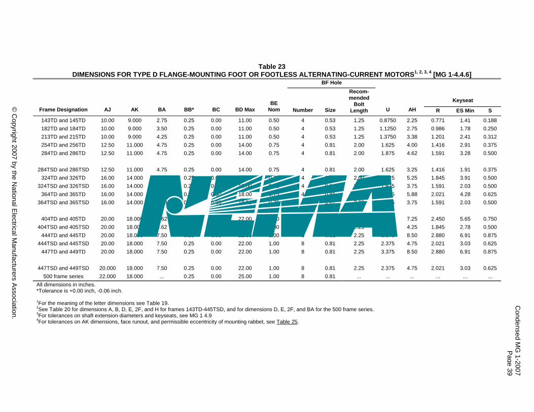
© Copyright 2007 by the National Electrical Manufacturers Association.
Table 23 DIMENSIONS FOR TYPE D FLANGE-MOUNTING FOOT OR FOOTLESS ALTERNATING-CURRENT MOTORS1, 2, 3, 4 [MG 1-4.4.6]
BF Hole
Keyseat Frame Designation AJ AK BA BB* BC BD Max
BE Nom Number Size
Recom-mended
Bolt Length U AH R ES Min S
143TD and 145TD 10.00 9.000 2.75 0.25 0.00 11.00 0.50 4 0.53 1.25 0.8750 2.25 0.771 1.41 0.188 182TD and 184TD 10.00 9.000 3.50 0.25 0.00 11.00 0.50 4 0.53 1.25 1.1250 2.75 0.986 1.78 0.250 213TD and 215TD 10.00 9.000 4.25 0.25 0.00 11.00 0.50 4 0.53 1.25 1.3750 3.38 1.201 2.41 0.312 254TD and 256TD 12.50 11.000 4.75 0.25 0.00 14.00 0.75 4 0.81 2.00 1.625 4.00 1.416 2.91 0.375 284TD and 286TD 12.50 11.000 4.75 0.25 0.00 14.00 0.75 4 0.81 2.00 1.875 4.62 1.591 3.28 0.500
284TSD and 286TSD 12.50 11.000 4.75 0.25 0.00 14.00 0.75 4 0.81 2.00 1.625 3.25 1.416 1.91 0.375 324TD and 326TD 16.00 14.000 5.25 0.25 0.00 18.00 0.75 4 0.81 2.00 2.125 5.25 1.845 3.91 0.500
324TSD and 326TSD 16.00 14.000 5.25 0.25 0.00 18.00 0.75 4 0.81 2.00 1.875 3.75 1.591 2.03 0.500 364TD and 365TD 16.00 14.000 5.88 0.25 0.00 18.00 0.75 4 0.81 2.00 2.375 5.88 2.021 4.28 0.625
364TSD and 365TSD 16.00 14.000 5.88 0.25 0.00 18.00 0.75 4 0.81 2.00 1.875 3.75 1.591 2.03 0.500
404TD and 405TD 20.00 18.000 6.62 0.25 0.00 22.00 1.00 8 0.81 2.25 2.875 7.25 2.450 5.65 0.750 404TSD and 405TSD 20.00 18.000 6.62 0.25 0.00 22.00 1.00 8 0.81 2.25 2.125 4.25 1.845 2.78 0.500
444TD and 445TD 20.00 18.000 7.50 0.25 0.00 22.00 1.00 8 0.81 2.25 3.375 8.50 2.880 6.91 0.875 444TSD and 445TSD 20.00 18.000 7.50 0.25 0.00 22.00 1.00 8 0.81 2.25 2.375 4.75 2.021 3.03 0.625
447TD and 449TD 20.00 18.000 7.50 0.25 0.00 22.00 1.00 8 0.81 2.25 3.375 8.50 2.880 6.91 0.875
447TSD and 449TSD 20.000 18.000 7.50 0.25 0.00 22.00 1.00 8 0.81 2.25 2.375 4.75 2.021 3.03 0.625 500 frame series 22.000 18.000 ... 0.25 0.00 25.00 1.00 8 0.81 ... ... ... ... ... ...
All dimensions in inches. *Tolerance is +0.00 inch, -0.06 inch. 1For the meaning of the letter dimensions see Table 19. 2See Table 20 for dimensions A, B, D, E, 2F, and H for frames 143TD-445TSD, and for dimensions D, E, 2F, and BA for the 500 frame series. 3For tolerances on shaft extension diameters and keyseats, see MG 1 4.9 4For tolerances on AK dimensions, face runout, and permissible eccentricity of mounting rabbet, see Table 25.
Condensed M
G 1-2007
Page 39
© C
opyright 2007 by the National E
lectrical Manufacturers A
ssociation.
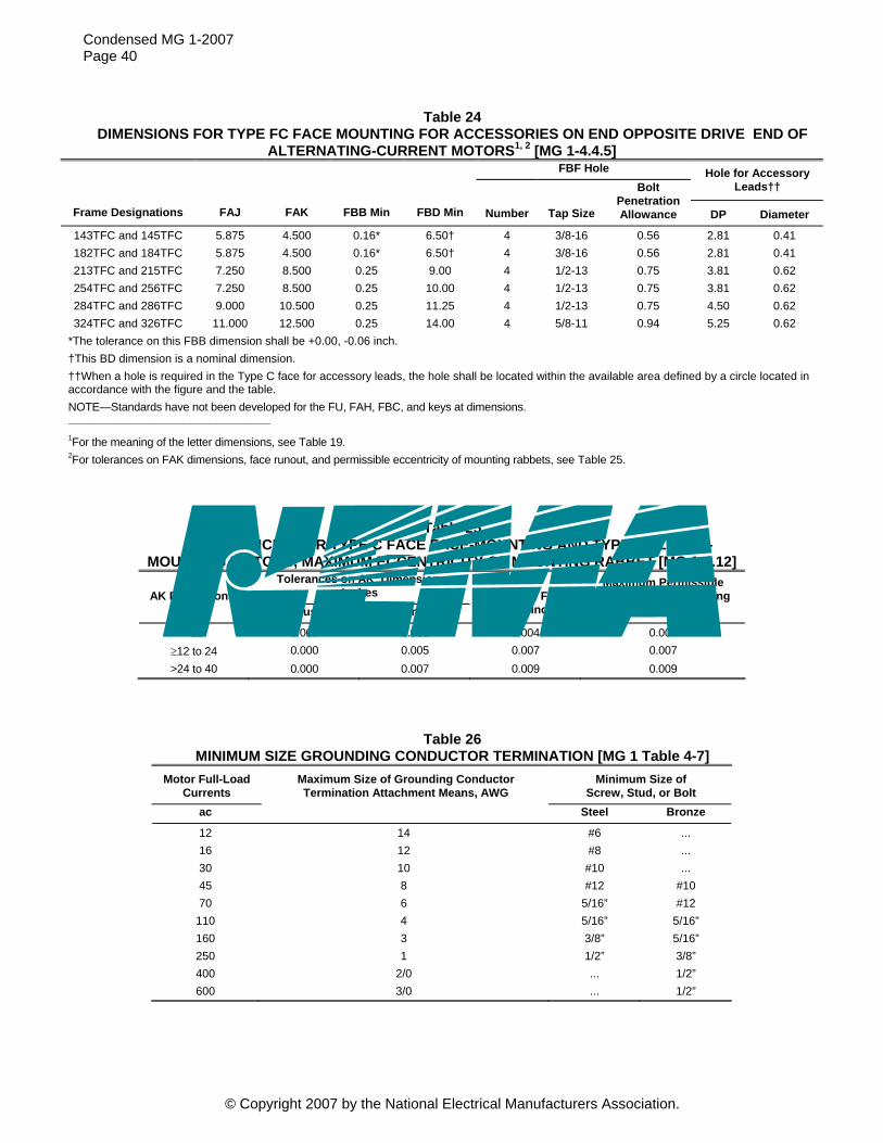
Condensed MG 1-2007 Page 40
Table 24 DIMENSIONS FOR TYPE FC FACE MOUNTING FOR ACCESSORIES ON END OPPOSITE DRIVE END OF
ALTERNATING-CURRENT MOTORS1, 2 [MG 1-4.4.5] FBF Hole Hole for Accessory
Leads††
Frame Designations FAJ FAK FBB Min FBD Min Number Tap Size
Bolt Penetration Allowance DP Diameter
143TFC and 145TFC 5.875 4.500 0.16* 6.50† 4 3/8-16 0.56 2.81 0.41 182TFC and 184TFC 5.875 4.500 0.16* 6.50† 4 3/8-16 0.56 2.81 0.41 213TFC and 215TFC 7.250 8.500 0.25 9.00 4 1/2-13 0.75 3.81 0.62 254TFC and 256TFC 7.250 8.500 0.25 10.00 4 1/2-13 0.75 3.81 0.62 284TFC and 286TFC 9.000 10.500 0.25 11.25 4 1/2-13 0.75 4.50 0.62 324TFC and 326TFC 11.000 12.500 0.25 14.00 4 5/8-11 0.94 5.25 0.62
*The tolerance on this FBB dimension shall be +0.00, -0.06 inch. †This BD dimension is a nominal dimension. ††When a hole is required in the Type C face for accessory leads, the hole shall be located within the available area defined by a circle located in accordance with the figure and the table. NOTE—Standards have not been developed for the FU, FAH, FBC, and keys at dimensions. _____________________________________________________
1For the meaning of the letter dimensions, see Table 19. 2For tolerances on FAK dimensions, face runout, and permissible eccentricity of mounting rabbets, see Table 25.
Table 25 TOLERANCES FOR TYPE C FACE FACE-MOUNTING AND TYPE D FLANGE-
MOUNTING MOTORS, MAXIMUM ECCENTRICITY OF MOUNTING RABBET [MG 1-4.12] Tolerances on AK Dimension,
Inches AK Dimensions, Inches Plus Minus
Maximum Face Runout, Inches
Maximum Permissible Eccentricity of Mounting
Rabbet, Inches
<12 0.000 0.003 0.004 0.004 ≥12 to 24 0.000 0.005 0.007 0.007 >24 to 40 0.000 0.007 0.009 0.009
Table 26 MINIMUM SIZE GROUNDING CONDUCTOR TERMINATION [MG 1 Table 4-7]
Motor Full-Load Currents
Maximum Size of Grounding Conductor Termination Attachment Means, AWG
Minimum Size of Screw, Stud, or Bolt
ac Steel Bronze
12 14 #6 ... 16 12 #8 ... 30 10 #10 ... 45 8 #12 #10 70 6 5/16” #12
110 4 5/16” 5/16” 160 3 3/8” 5/16” 250 1 1/2” 3/8” 400 2/0 ... 1/2” 600 3/0 ... 1/2”
© Copyright 2007 by the National Electrical Manufacturers Association.

Condensed MG 1-2007 Page 41
Table 27 LOCKED-ROTOR TORQUE OF SINGLE-PHASE SMALL MOTORS [MG 1-12.32.2]
MINIMUM LOCKED-ROTOR TORQUE, OUNCE-FEET* 60-Hertz Synchronous Speed, RPM 50-Hertz Synchronous Speed, RPM
HP 3600 1800 1200 3000 1500 1000
1/4 21 46 59 25 55 70 1/3 26 57 73 31 69 88 1/2 37 85 100 44 102 120 3/4 50 119 — 60 143 — 1 61 — — 73 — —
*On the high voltage connection of dual voltage motors, minimum locked-rotor torques up to 10% less than these values may be expected.
Table 28 LOCKED-ROTOR TORQUE OF SINGLE-PHASE MEDIUM
MOTORS [MG 1-12.32.3] MINIMUM LOCKED-ROTOR TORQUE, POUND FEET
Synchronous Speed, RPM HP 3600 1800 1200
3/4 — — 8.0 1 — 9.0 9.5
1-1/2 4.5 12.5 13.0 2 5.5 16.0 16.0 3 7.5 22.0 23.0 5 11.0 33.0 —
7-1/2 16.0 45.0 — 10 21.0 52.0 —
Table 29 LOCKED-ROTOR CURRENT OF SINGLE-PHASE SMALL MOTORS, DESIGNS O AND N
[MG 1-12.33.1] 2-, 4-, 6-, AND 8-POLE, 60-HERTZ MOTORS, SINGLE-PHASE
Locked-Rotor Current, Amperes 115 Volts 230 Volts
HP Design O Design N Design O Design N
1/4 50 26 25 15 1/3 50 31 25 18 1/2 50 45 25 25 3/4 — 61 — 35 1 — 80 — 45
© Copyright 2007 by the National Electrical Manufacturers Association.

Condensed MG 1-2007 Page 42
Table 30 LOCKED-ROTOR CURRENT OF SINGLE-PHASE MEDIUM MOTORS,
DESIGNS L AND M [MG 1-12.34] Locked-Rotor Current, Amperes
Design L Motors Design M Motors HP 115 Volts 230 Volts 230 Volts
1/2 45 25 — 3/4 61 35 — 1 80 45 —
1-1/2 — 50 40 2 — 65 50 3 — 90 70 5 — 135 100
7-1/2 -- 200 150 10 — 260 200
Table 31 LOCKED-ROTOR CURRENT OF 3-PHASE 60-HERTZ SMALL AND
MEDIUM SQUIRREL-CAGE INDUCTION MOTORS RATED AT 230 VOLTS [MG 1-12.35.1]
HP
LOCKED-ROTOR CURRENT, AMPERES
DESIGN LETTERS HP
LOCKED-ROTOR CURRENT, AMPERES
DESIGN LETTERS
1/2 20 B, D 60 870 B, C, D 3/4 25 B, D 75 1085 B, C, D 1 30 B, C, D 100 1450 B, C, D
1-1/2 40 B, C, D 125 1815 B, C, D 2 50 B, C, D 150 2170 B, C, D
3 64 B, C, D 200 2900 B, C, 5 92 B, C, D 250 3650 B
7-1/2 127 B, C, D 300 4400 B 10 162 B, C, D 350 5100 B 15 232 B, C, D 400 5800 B
20 290 B, C, D 450 6500 B 25 365 B, C, D 500 7250 B 30 435 B, C, D 40 580 B, C, D 50 725 B, C, D
NOTE—The locked-rotor current of motors designed for voltages other than 230 volts shall be inversely proportional to the voltages.
© Copyright 2007 by the National Electrical Manufacturers Association.
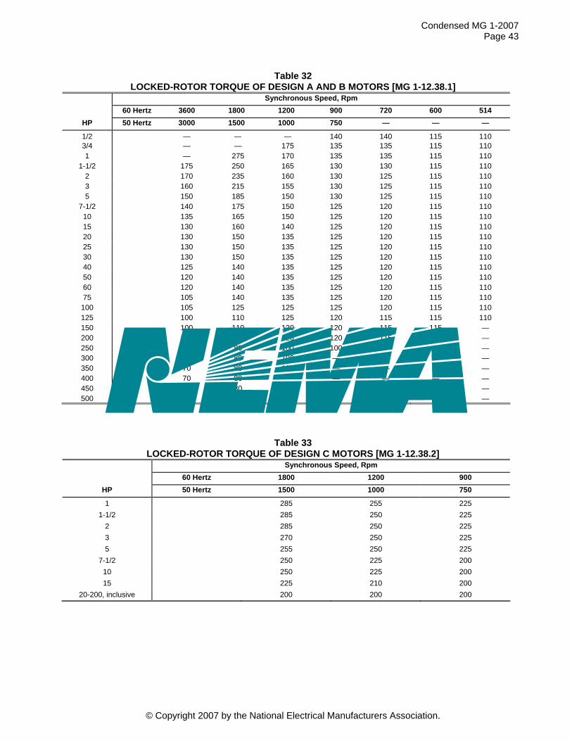
Condensed MG 1-2007 Page 43
Table 32 LOCKED-ROTOR TORQUE OF DESIGN A AND B MOTORS [MG 1-12.38.1]
Synchronous Speed, Rpm 60 Hertz 3600 1800 1200 900 720 600 514
HP 50 Hertz 3000 1500 1000 750 — — —
1/2 — — — 140 140 115 1103/4 — — 175 135 135 115 110 1 — 275 170 135 135 115 110
1-1/2 175 250 165 130 130 115 110 2 170 235 160 130 125 115 110 3 160 215 155 130 125 115 110 5 150 185 150 130 125 115 110
7-1/2 140 175 150 125 120 115 110 10 135 165 150 125 120 115 110 15 130 160 140 125 120 115 110 20 130 150 135 125 120 115 110 25 130 150 135 125 120 115 110 30 130 150 135 125 120 115 110 40 125 140 135 125 120 115 110 50 120 140 135 125 120 115 110 60 120 140 135 125 120 115 110 75 105 140 135 125 120 115 110
100 105 125 125 125 120 115 110 125 100 110 125 120 115 115 110 150 100 110 120 120 115 115 — 200 100 100 120 120 115 — — 250 70 80 100 100 — — — 300 70 80 100 — — — — 350 70 80 100 — — — — 400 70 80 — — — — — 450 70 80 — — — — — 500 70 80 — — — — —
Table 33 LOCKED-ROTOR TORQUE OF DESIGN C MOTORS [MG 1-12.38.2]
Synchronous Speed, Rpm 60 Hertz 1800 1200 900
HP 50 Hertz 1500 1000 750
1 285 255 225 1-1/2 285 250 225
2 285 250 225 3 270 250 225 5 255 250 225
7-1/2 250 225 200 10 250 225 200 15 225 210 200
20-200, inclusive 200 200 200
© Copyright 2007 by the National Electrical Manufacturers Association.

Condensed MG 1-2007 Page 44
Table 34 BREAKDOWN TORQUE OF DESIGN A AND B MOTORS [MG 1-12.39.1]
Synchronous Speed, Rpm 60 Hertz 3600 1800 1200 900 720 600 514
HP 50 Hertz 3000 1500 1000 750 — — —
1/2 — — — 225 200 200 200 3/4 — — 275 220 200 200 200 1 — 300 265 215 200 200 200
1-1/2 250 280 250 210 200 200 200 2 240 270 240 210 200 200 200 3 230 250 230 205 200 200 200 5 215 225 215 205 200 200 200
7-1/2 200 215 205 200 200 200 200 10-125, inclusive
200 200 200 200 200 200 200
150 200 200 200 200 200 200 — 200 200 200 200 200 200 — — 250 175 175 175 175 — — —
300-350 175 175 175 — — — — 400-500, inclusive
175 175 — — — — —
Table 35 BREAKDOWN TORQUE OF DESIGN C MOTORS [MG 1-12.39.2]
Synchronous Speed, Rpm 60 Hertz 1800 1200 900
HP 50 Hertz 1500 1000 750 1 200 225 200
1-1/2 200 225 200
2 200 225 200
3 200 225 200
5 200 200 200
7-1/2–20 200 190 190
25–200, incl. 190 190 190`
© Copyright 2007 by the National Electrical Manufacturers Association.

Condensed MG 1-2007 Page 45
Table 36 PULL-UP TORQUE OF DESIGN A AND B MOTORS [MG 1-12.40.1]
Synchronous Speed, Rpm 60 Hertz 3600 1800 1200 900 720 600 514
HP 750 — 50 Hertz 3000 1500 1000 — —
1/2 — — — 100 100 100 100 3/4 — — 120 100 100 100 100 1 — 190 120 100 100 100 100
1-1/2 120 175 115 100 100 100 100 2 120 165 110 100 100 100 100 3 110 150 110 100 100 100 100 5 105 130 105 100 100 100 100
7-1/2 100 120 105 100 100 100 100 10 100 115 105 100 100 100 100 15 100 110 100 100 100 100 100 20 100 105 100 100 100 100 100 25 100 105 100 100 100 100 100 30 100 105 100 100 100 100 100 40 100 100 100 100 100 100 100 50 100 100 100 100 100 100 100 60 100 100 100 100 100 100 100 75 95 100 100 100 100 100 100
100 95 100 100 100 100 100 100 125 90 100 100 100 100 100 100 150 90 100 100 100 100 100 — 200 90 90 100 100 100 — — 250 65 75 90 90 — — — 300 65 75 90 — — — — 350 65 75 90 — — — — 400 65 75 — — — — — 450 65 75 — — — — — 500 65 75 — — — — —
© Copyright 2007 by the National Electrical Manufacturers Association.
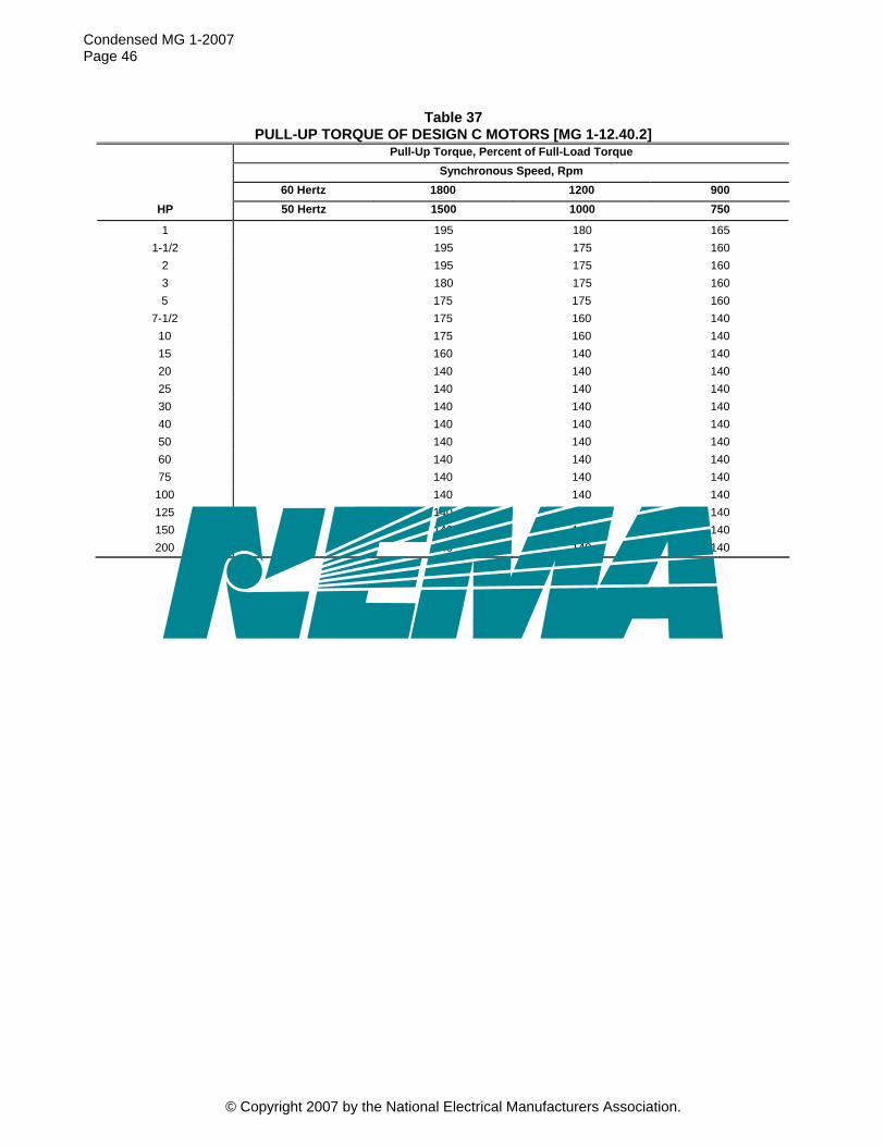
Condensed MG 1-2007 Page 46
Table 37 PULL-UP TORQUE OF DESIGN C MOTORS [MG 1-12.40.2]
Pull-Up Torque, Percent of Full-Load Torque Synchronous Speed, Rpm 60 Hertz 1800 1200 900
HP 50 Hertz 1500 1000 750
1 195 180 165 1-1/2 195 175 160
2 195 175 160 3 180 175 160 5 175 175 160
7-1/2 175 160 140 10 175 160 140 15 160 140 140 20 140 140 140 25 140 140 140 30 140 140 140 40 140 140 140 50 140 140 140 60 140 140 140 75 140 140 140
100 140 140 140 125 140 140 140 150 140 140 140 200 140 140 140
© Copyright 2007 by the National Electrical Manufacturers Association.

Condensed MG 1-2007 Page 47
Table 38 TEMPERATURE RISE FOR SMALL AND MEDIUM SINGLE-PHASE
AND POLYPHASE INDUCTION MOTORS Alternating-Current Small Motors—Motor Nameplates Marked with Insulation System Designation and Ambient Temperature [MG 1-12.42.1]
Class of Insulation System (see MG 1 Part 1) A B F* H* Time Rating (See page 9.)
125
Temperature Rise (based on a maximum ambient temperature of 40°C), Degrees C a. Windings
1. Open motors other than those given in items a.2 and a.5—resistance or thermocouple ....……… 60 80 105 2. Open motors with 1.15 or higher service factor—resistance or thermocouple..…………………...... 70 90 115 — 3. Totally-enclosed nonventilated motors, including variations thereof—resistance or thermocouple . 65 85 110 130 4. Totally-enclosed fan-cooled motors, including variation thereof—resistance or thermocouple …… 65 85 110 135 5. Any motor in a frame smaller than the 42 frame—resistance or thermocouple. ............................. 65 85 110 135
Medium Single-Phase and Polyphase Motors [MG 1-12.43] Class of Insulation System (see MG 1 Part 1) A B F H*† Time Rating (shall be continuous or any short-time rating given in Time Ratings for Single-Phase and Polyphase Induction Motors )
Temperature Rise (based on a maximum ambient temperature of 40°C), Degrees C a. Windings, by resistance method
1. Motors with 1.0 service factor other than those given in items a.3 and a.4 60 80 105 125 2. All motors with 1.15 or higher service factor 70 90 115 — 3. Totally-enclosed nonventilated motors with 1.0 service factor 65 85 110 130 4. Motors with encapsulated windings and with service 1.0 factor, all enclosures 65 85 110 —
b. The temperatures attained by cores, squirrel-cage windings, and miscellaneous parts, (such as brushholders, brushes, pole tips, etc.) shall not injure the insulation or the machine in any respect.
*Where a Class F or H insulation system is used, special consideration should be given to bearing temperatures, lubrication, etc. †This column applies only to polyphase induction motors. NOTES 1—Abnormal deterioration of insulation may be expected if the ambient temperature of 40°C is exceeded in regular operation. See Note 3. 2—The foregoing values of temperature rise are based upon operation at altitudes of 3300 feet (1000 meters) or less. For temperature rises for motors intended for operation at altitudes above 3300 feet (1000 meters) see MG 1 Part 14. 3—The temperature rises given above are based upon a reference ambient temperature of 40°C. However, it is recognized that induction motors may be required to operate in an ambient temperature higher than 40°C. For successful operation of induction motors in ambient temperatures higher than 40°C, the temperature rises of the motors given in the forgoing tables shall be reduced by the number of degrees that the ambient temperature exceeds 40°C. When a higher ambient temperature than 40°C is required, preferred values of ambient temperatures are 50°C, 65°C, 90°C, and 115°C.
© Copyright 2007 by the National Electrical Manufacturers Association.

Condensed MG 1-2007 Page 48
Table 39 SERVICE FACTORS OF GENERAL-PURPOSE ALTERNATING-CURRENT MOTORS
OF THE OPEN TYPE [MG 1 Table 12-4] Synchronous Speed, Rpm
HP 3600 1800 1200 900 720 600 514
1/4 1.35 1.35 1.35 1.35 — — — 1/3 1.35 1.35 1.35 1.35 — — —
Small Motors
1/2 1.25 1.25 1.25 1.15* — — — 3/4 1.25 1.25 1.15* 1.15* — — —
1 1.25 1.15* 1.15* 1.15* — — — 1-1/2-125 1.15* 1.15* 1.15* 1.15* 1.15* 1.15* 1.15*
150 1.15* 1.15* 1.15* 1.15* 1.15* 1.15* — 200 1.15* 1.15* 1.15* 1.15* 1.15* — — 250 1.0 1.15* 1.15* 1.15* — — — 300 1.0 1.15* 1.15* — — — — 350 1.0 1.15* 1.15* — — — — 400 1.0 1.15* — — — — — 450 1.0 1.15* — — — — — 500 1.0 1.15* — — — — —
Medium Motors
*In the case of polyphase squirrel-cage motors, these service factors apply to Design A, B, and C motors.
Table 40 OVERSPEEDS FOR SQUIRREL-CAGE MOTORS [MG 1-12.52.1]
HP Synchronous Speed,
Rpm Overspeed, Percent of Synchronous Speed
200 and smaller 1801 and over 25 1201 to 1800 25 1200 and below 50
250-500, inclusive 1801 and over 20 1800 and below 25
© Copyright 2007 by the National Electrical Manufacturers Association.

Condensed MG 1-2007 Page 49
Table 41 CONTINUOUS SPEED CAPABILITY FOR GENERAL-PURPOSE SQUIRREL-CAGE INDUCTION
MOTORS IN DIRECT COUPLED APPLICATIONS, EXCEPT THOSE MOTORS IN 9.16.2 [MG 1 Table 12-5]
Totally Enclosed Fan-Cooled Open Dripproof Synchronous Speed at 60 Hz Synchronous Speed at 60 Hz 3600 1800 1200 3600 1800 1200
Horsepower Minimum Design Speed Minimum Design Speed
1/4 5200 3600 2400 5200 3600 2400 1/3 5200 3600 2400 5200 3600 2400 1/2 5200 3600 2400 5200 3600 2400 3/4 5200 3600 2400 5200 3600 2400 1 5200 3600 2400 5200 3600 2400
1.5 5200 3600 2400 5200 3600 2400 2 5200 3600 2400 5200 3600 2400 3 5200 3600 2400 5200 3600 2400 5 5200 3600 2400 5200 3600 2400
7.5 4500 2700 2400 5200 2700 2400 10 4500 2700 2400 4500 2700 2400 15 4500 2700 2400 4500 2700 2400 20 4500 2700 2400 4500 2700 2400 25 4500 2700 1800 4500 2700 1800 30 4500 2700 1800 4500 2700 1800 40 3600 2300 1800 4500 2300 1800 50 3600 2300 1800 3600 2300 1800 60 3600 2300 1800 3600 2300 1800 75 3600 2300 1800 3600 2300 1800
100 3600 2300 1800 3600 2300 1800 125 3600 2300 1800 3600 2300 1800 150 3600 2300 1800 3600 2300 1800 200 3600 2300 1800 3600 2300 1800 250 3600 2300 1200 3600 2300 1200 300 3600 1800 1200 3600 2300 1200 350 3600 1800 1200 3600 1800 1200 400 3600 1800 - 3600 1800 - 450 3600 1800 - 3600 1800 - 500 3600 1800 - 3600 1800 -
© Copyright 2007 by the National Electrical Manufacturers Association.

Condensed MG 1-2007 Page 50
© Copyright 2007 by the National Electrical Manufacturers Association.
Table 42 CONTINUOUS SPEED CAPABILITY FOR GENERAL-PURPOSE DESIGN A AND B
DIRECT COUPLED (TS SHAFT FOR MOTORS ABOVE THE 250 FRAME SIZE) SQUIRREL-CAGE INDUCTION MOTORS [MG 1 Table 12-6]
Totally Enclosed Fan-Cooled Open Dripproof Synchronous Speed at 60 Hz 3600 1800 1200 3600 1800 1200
Horsepower Minimum Design Speed 1/4 1/3 1/2 3/4 1
1.5
7200 7200 7200 7200 7200 7200
3600 3600 3600 3600 3600 3600
2400 2400 2400 2400 2400 2400
7200 7200 7200 7200 7200 7200
3600 3600 3600 3600 3600 3600
2400 2400 2400 2400 2400 2400
2 3 5
7.5
7200 7200 7200 5400
3600 3600 3600 3600
2400
3600
3600 2300
2400 2400 2400 2400
7200 7200 7200 7200
3600 3600 3600 3600
2400 2400 2400 2400
10 15 20 25 30
5400 5400 5400 5400 5400
3600 3600 3600 2700 2700
2400 2400 2400
2400
5400 5400 5400 5400 5400
3600 3600 3600 2700 2700
2400 2400 2400 2400 2400
40 50 60 75
100
4500 4500 3600 3600 3600
2700 2700 2700 2700 2700
2400 2400 2400 2400 1800
5400 4500 4500 3600 3600
2700 2700 2700 2700 2700
2400 2400 2400 2400 1800
125 150 200 250 300
3600 3600 3600 3600
2700 2700 2300 2300 2300
1800 1800 1800 1800 1800
3600 3600 3600
3600
2700 2700 2700 2300
1800 1800 1800 1800 1800
350 400 450 500
3600 3600 3600 3600
1800 1800 1800 1800
1800 - - -
3600 3600 3600 3600
1800 1800 1800 1800
1800 - - -

Table 43 MAXIMUM A-WEIGHTED SOUND POWER LEVELS, Lwa (dB), AT NO-LOAD [MG 1 Table 9-1]
Rated Speed Rated Power, 1801- 3600 RPM 1201- 1800 RPM 901 - 1200 RPM 900 RPM or less
Motor HP ODP TEFC WP II ODP TEFC WP II ODP TEFC WP II ODP TEFC WP II.5 67 67
.75 65 64 67 67
1 7 0 70 65 64 69 691.5 7 6 85 70 70 67 67 69 692 76 85 70 70 67 67 70 723 76 88 72 74 72 71 70 725 80 88 72 74 72 71 73 76
7.5 80 91 76 79 76 75 73 7610 82 91 76 79 76 75 76 8015 82 94 80 84 81 80 76 8020 84 94 80 84 81 80 79 8325 84 94 80 88 83 83 79 83
30 86 94 80 88 83 83 81 8640 86 100 84 89 86 86 81 8650 89 100 84 89 86 86 84 8960 89 101 86 95 88 90 84 8975 94 101 86 95 88 90 87 93
100 94 102 89 98 91 94 87 93125 98 104 89 100 91 94 93 96 92150 98 104 93 100 96 98 95 97 92200 101 107 93 103 99 100 97 95 97 92250 101 107 103 105 99 99 100 97 95 97 92
300 107 110 102 103 105 99 99 100 97 98 100 96350 99 107 110 102 103 105 99 100 97 98 100 96400 107 110 102 103 105 99 102 103 99 98 100 96450 107 110 102 106 108 102 102 103 99 99 102 98500 110 113 105 106 108 102 102 103 99 99 102 98
Condensed M
G 1-2007
Page 51
© C
opyright 2007 by the National E
lectrical Manufacturers A
ssociation.

Condensed MG 1-2007 Page 52
Table 44 INCREMENTAL EXPECTED INCREASE OVER NO-LOAD CONDITION, IN A-WEIGHTED
SOUND POWER LEVELS ∆Lwa (dB) , FOR RATED LOAD CONDITION FOR SINGLE-SPEED, THREE-PHASE, SQUIRREL-CAGE, INDUCTION MOTORS [MG 1 Table 9-3]
Rated Output, PN HP 2 Pole 4 Pole 6 Pole 8 Pole
1.0 < PN ≤ 15 2 5 7 8
15 < PN ≤ 50 2 4 6 7
50 < PN ≤ 150 2 3 5 6
150 < PN ≤ 500 2 3 4 5
Table 45 REFERENCE LOAD WK 2 FOR NUMBER OF STARTS
OF SQUIRREL-CAGE INDUCTION MOTORS [MG 1 Table 12-7] Synchronous Speed, Rpm 3600 1800 1200 900 720 600 514
HP Load Wk2 (Exclusive of Motor Wk2), Lb-Ft2
1 — 5.8 15 31 53 82 118 1-1/2 1.8 8.6 23 45 77 120 174
2 2.4 11 30 60 102 158 228 3 3.5 17 44 87 149 231 335 5 5.7 27 71 142 242 375 544
7-1/2 8.3 39 104 208 356 551 798 10 11 51 137 273 467 723 1048 15 16 75 200 400 685 1061 1538 20 21 99 262 525 898 1393 2018 25 26 122 324 647 1108 1719 2491 30 31 144 384 769 1316 2042 2959 40 40 189 503 1007 1725 2677 3881 50 49 232 620 1241 2127 3302 4788 60 58 275 735 1473 2524 3819 5680 75 71 338 904 1814 3111 4831 7010
100 92 441 1181 2372 4070 6320 9180 125 113 542 1452 2919 5010 7790 11310 150 133 640 1719 3456 5940 9230 — 200 172 831 2238 4508 7750 — — 250 210 1017 2744 5540 — — — 300 246 1197 3239 — — — — 350 281 1373 3723 — — — — 400 315 1546 — — — — — 450 349 1714 — — — — — 500 381 1880 — — — — —
© Copyright 2007 by the National Electrical Manufacturers Association.

Condensed MG 1-2007 Page 53
Table 46 WINDING TEMPERATURES UNDER RUNNING LOAD
CONDITIONS [MG 1 Table 12-8] Insulation Maximum Winding Temperature,
System Class Degrees C
A 140 B 165 F 190 H 215
Table 47 WINDING TEMPERATURE UNDER LOCKED-ROTOR CONDITIONS [MG 1 Table 12-9]
Maximum Temperature, Degrees C* Average Temperature, ** Degrees C* Insulation System Class Insulation System Class
Type of Protector A B F H A B F H
Automatic reset During first hour 200 225 250 275 — — — — After first hour 175 200 225 250 150 275 200 225
Manual reset During first hour 200 225 250 275 — — — — After first hour 175 200 225 250 — — — —
*Test shall be permitted to be conducted at any ambient temperature within the range of 10oC to 40oC. **The average temperature is the average of the average peak and average reset winding temperatures. The average temperature shall be within limits during both the second and last hours of the test.
Table 48 WINDING TEMPERATURES UNDER RUNNING LOAD
CONDITIONS [MG 1-12.56.2] Motor Full-load
Amperes Trip Current as a Percent of
Motor Full-load Current
9.0 and less 170 Over 9.0 but not over 20.0 156
Over 20.0 140
Table 49 Specified Temperature for Winding Resistance
Correction When Rated Load Temperature Is Not Measured
[MG 1-12.58.1] Class of Insulation System Temperature, Degrees C
A 75 B 95 F 115 H 130
© Copyright 2007 by the National Electrical Manufacturers Association.
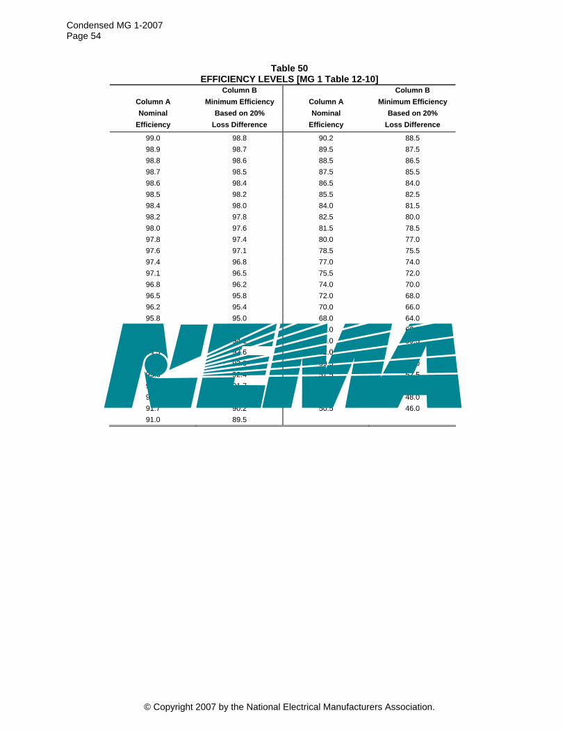
Condensed MG 1-2007 Page 54
Table 50 EFFICIENCY LEVELS [MG 1 Table 12-10]
Column B Column B Column A Minimum Efficiency Column A Minimum Efficiency Nominal Based on 20% Nominal Based on 20%
Efficiency Loss Difference Efficiency Loss Difference
99.0 98.8 90.2 88.5 98.9 98.7 89.5 87.5 98.8 98.6 88.5 86.5 98.7 98.5 87.5 85.5 98.6 98.4 86.5 84.0 98.5 98.2 85.5 82.5 98.4 98.0 84.0 81.5 98.2 97.8 82.5 80.0 98.0 97.6 81.5 78.5 97.8 97.4 80.0 77.0 97.6 97.1 78.5 75.5 97.4 96.8 77.0 74.0 97.1 96.5 75.5 72.0 96.8 96.2 74.0 70.0 96.5 95.8 72.0 68.0 96.2 95.4 70.0 66.0 95.8 95.0 68.0 64.0 95.4 94.5 66.0 62.0 95.0 94.1 64.0 59.5 94.5 93.6 62.0 57.5 94.1 93.0 59.5 55.0 93.6 92.4 57.5 52.5 93.0 91.7 55.0 50.5 92.4 91.0 52.5 48.0 91.7 90.2 50.5 46.0 91.0 89.5
© Copyright 2007 by the National Electrical Manufacturers Association.
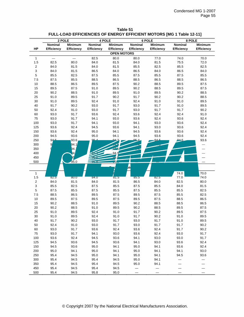
Condensed MG 1-2007 Page 55
Table 51 FULL-LOAD EFFICIENCIES OF ENERGY EFFICIENT MOTORS [MG 1 Table 12-11]
2 POLE 4 POLE 6 POLE 8 POLE Nominal Minimum Nominal Minimum Nominal Minimum Nominal Minimum
HP Efficiency Efficiency Efficiency Efficiency Efficiency Efficiency Efficiency Efficiency OPEN MOTORS
1 — — 82.5 80.0 80.0 77.0 74.0 70.01.5 82.5 80.0 84.0 81.5 84.0 81.5 75.5
91.7 30 91.0 92.4 91.0
93.6
150 93.6 95.0
94.5
94.5
95.0
72.0 2 84.0 81.5 84.0 81.5 85.5 82.5 85.5 82.5 3 84.0 81.5 86.5 84.0 86.5 84.0 86.5 84.0 5 85.5 82.5 87.5 85.5 87.5 85.5 87.5 85.5
7.5 87.5 85.5 88.5 86.5 88.5 86.5 88.5 86.5 10 88.5 86.5 89.5 87.5 90.2 88.5 89.5 87.5 15 89.5 87.5 91.0 89.5 90.2 88.5 89.5 87.5 20 90.2 88.5 91.0 89.5 91.0 89.5 90.2 88.5 25 91.0 89.5 91.7 90.2 90.2 90.2 88.5
89.5 92.4 91.0 91.0 89.5 40 91.7 90.2 93.0 91.7 93.0 91.7 91.0 89.5 50 92.4 91.0 93.0 91.7 93.0 91.7 91.7 90.2 60 93.0 91.7 93.6 92.4 93.6 92.4 92.4 91.0 75 93.0 91.7 94.1 93.0 93.6 92.4 93.6 92.4
100 93.0 91.7 94.1 93.0 94.1 93.0 92.4 125 93.6 92.4 94.5 93.6 94.1 93.0 93.6 92.4
92.4 95.0 94.1 94.5 93.6 93.6 92.4 200 94.5 93.6 94.1 94.5 93.6 93.6 92.4 250 94.5 93.6 95.4 94.3 95.4 94.5 93.6 300 95.0 94.1 95.4 94.5 95.4 94.5 — — 350 95.0 94.1 95.4 94.5 95.4 94.5 — — 400 95.4 95.4 94.5 — — — — 450 95.8 95.0 95.8 95.0 — — — — 500 95.8 95.0 95.8 — — — —
Enclosed Motors
1 75.5 72.0 82.5 80.0 80.0 77.0 74.0 70.01.5 82.5 80.0 84.0 81.5 85.5 82.5 77.0 74.0 2 84.0 81.5 84.0 81.5 86.5 84.0 82.5 80.0 3 85.5 82.5 87.5 85.5 87.5 85.5 84.0 81.5 5 87.5 85.5 87.5 85.5 87.5 85.5 85.5 82.5
7.5 88.5 86.5 89.5 87.5 89.5 87.5 85.5 82.5 10 89.5 87.5 89.5 87.5 89.5 87.5 88.5 86.5 15 90.2 88.5 91.0 89.5 90.2 88.5 88.5 86.5 20 90.2 88.5 91.0 89.5 90.2 88.5 89.5 87.5 25 91.0 89.5 92.4 91.0 91.7 90.2 89.5 87.5 30 91.0 89.5 92.4 91.0 91.7 90.2 91.0 89.5 40 91.7 90.2 93.0 91.7 93.0 91.7 91.0 89.5 50 92.4 91.0 93.0 91.7 93.0 91.7 91.7 90.2 60 93.0 91.7 93.6 92.4 93.6 92.4 91.7 90.2 75 93.0 91.7 94.1 93.0 93.6 92.4 93.0 91.7
100 93.6 92.4 94.5 93.6 94.1 93.0 93.0 91.7 125 94.5 93.6 94.5 93.6 94.1 93.0 93.6 92.4 150 94.5 93.6 95.0 94.1 95.0 94.1 93.6 92.4 200 95.0 94.1 95.0 94.1 95.0 94.1 94.1 93.0 250 95.4 94.5 95.0 94.1 95.0 94.1 94.5 93.6 300 95.4 94.5 95.4 94.5 95.0 94.1 — — 350 95.4 94.5 95.4 94.5 95.0 94.1 — — 450 95.4 — — 94.5 95.4 94.5 — — 500 95.4 94.5 95.8 95.0 — — — —
© Copyright 2007 by the National Electrical Manufacturers Association.
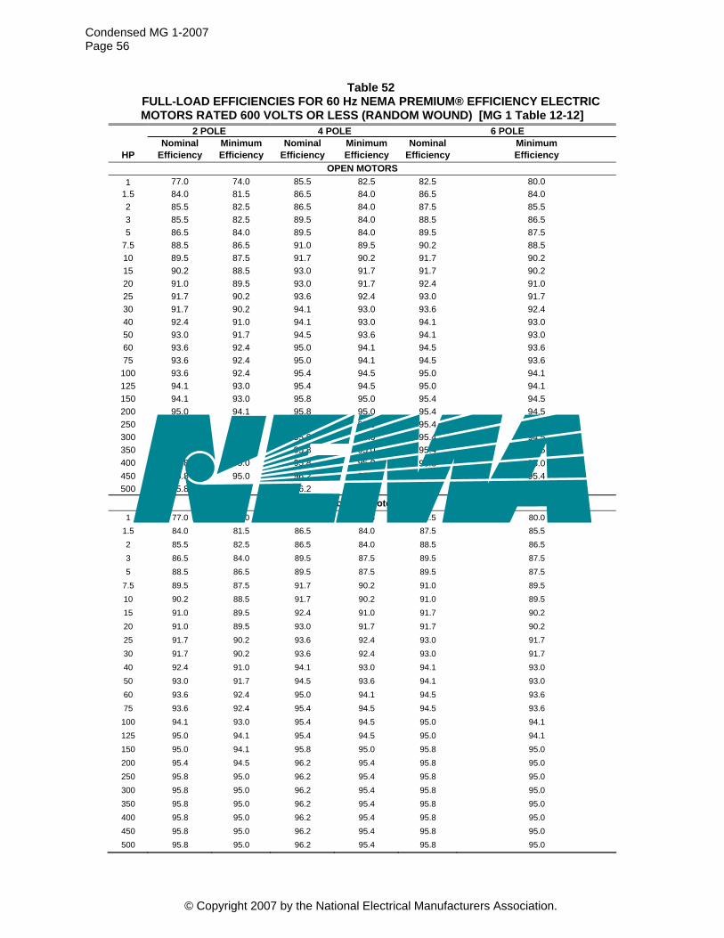
Condensed MG 1-2007 Page 56
Table 52 FULL-LOAD EFFICIENCIES FOR 60 Hz NEMA PREMIUM® EFFICIENCY ELECTRIC MOTORS RATED 600 VOLTS OR LESS (RANDOM WOUND) [MG 1 Table 12-12]
2 POLE 4 POLE 6 POLE Nominal Minimum Nominal Minimum Nominal Minimum
HP Efficiency Efficiency Efficiency Efficiency Efficiency Efficiency OPEN MOTORS
1 77.0 74.0 85.5 82.5 82.5 80.0 1.5 84.0 81.5 86.5 84.0 86.5 84.0 2 85.5
84.0
91.0
95.8
82.5 86.5 84.0 87.5 85.5 3 85.5 82.5 89.5 84.0 88.5 86.5 5 86.5 89.5 84.0 89.5 87.5
7.5 88.5 86.5 91.0 89.5 90.2 88.5 10 89.5 87.5 91.7 90.2 91.7 90.2 15 90.2 88.5 93.0 91.7 91.7 90.2 20 91.0 89.5 93.0 91.7 92.4 91.0 25 91.7 90.2 93.6 92.4 93.0 91.7 30 91.7 90.2 94.1 93.0 93.6 92.4 40 92.4 94.1 93.0 94.1 93.0 50 93.0 91.7 94.5 93.6 94.1 93.0 60 93.6 92.4 95.0 94.1 94.5 93.6 75 93.6 92.4 95.0 94.1 94.5 93.6
100 93.6 92.4 95.4 94.5 95.0 94.1 125 94.1 93.0 95.4 94.5 95.0 94.1 150 94.1 93.0 95.8 95.0 95.4 94.5 200 95.0 94.1 95.0 95.4 94.5 250 95.0 94.1 95.8 95.0 95.4 94.5 300 95.4 94.5 95.8 95.0 95.4 94.5 350 95.4 94.5 95.8 95.0 95.4 94.5 400 95.8 95.0 95.8 95.0 95.8 95.0 450 95.8 95.0 96.2 95.4 96.2 95.4 500 95.8 95.0 96.2 95.4 96.2 95.4
Enclosed Motors 1 77.0 74.0 85.5 82.5 82.5 80.0
1.5 84.0 81.5 86.5 84.0 87.5 85.5 2 85.5 82.5 86.5 84.0 88.5 86.5 3 86.5 84.0 89.5 87.5 89.5 87.5 5 88.5 86.5 89.5 87.5 89.5 87.5
7.5 89.5
30 91.7
50 93.0
125 95.0 95.0 94.1
300 95.8
400 95.8
87.5 91.7 90.2 91.0 89.5 10 90.2 88.5 91.7 90.2 91.0 89.5 15 91.0 89.5 92.4 91.0 91.7 90.2 20 91.0 89.5 93.0 91.7 91.7 90.2 25 91.7 90.2 93.6 92.4 93.0 91.7
90.2 93.6 92.4 93.0 91.7 40 92.4 91.0 94.1 93.0 94.1 93.0
91.7 94.5 93.6 94.1 93.0 60 93.6 92.4 95.0 94.1 94.5 93.6 75 93.6 92.4 95.4 94.5 94.5 93.6 100 94.1 93.0 95.4 94.5 95.0 94.1
94.1 95.4 94.5 94.1 150 95.0 95.8 95.0 95.8 95.0 200 95.4 94.5 96.2 95.4 95.8 95.0 250 95.8 95.0 96.2 95.4 95.8 95.0
95.0 96.2 95.4 95.8 95.0 350 95.8 95.0 96.2 95.4 95.8 95.0
95.0 96.2 95.4 95.8 95.0 450 95.8 95.0 96.2 95.4 95.8 95.0 500 95.8 95.0 96.2 95.4 95.8 95.0
© Copyright 2007 by the National Electrical Manufacturers Association.
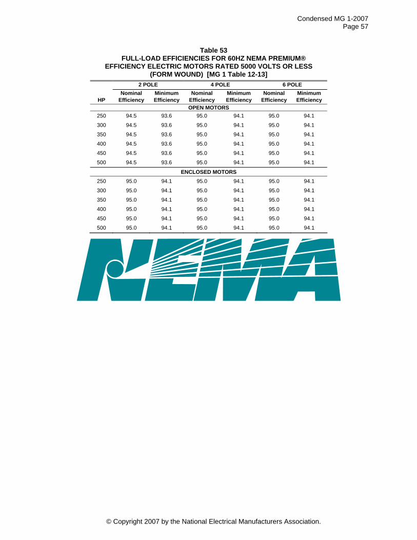
Condensed MG 1-2007 Page 57
Table 53 FULL-LOAD EFFICIENCIES FOR 60HZ NEMA PREMIUM®
EFFICIENCY ELECTRIC MOTORS RATED 5000 VOLTS OR LESS (FORM WOUND) [MG 1 Table 12-13]
2 POLE 4 POLE 6 POLE Nominal Minimum Nominal Minimum Nominal Minimum
HP Efficiency Efficiency Efficiency Efficiency Efficiency Efficiency OPEN MOTORS
250 94.5 93.6 95.0 94.1 95.0 94.1
300 94.5 93.6 95.0 94.1 95.0 94.1
350 94.5 93.6 95.0 94.1 95.0 94.1
400 94.5 93.6 95.0 94.1 95.0 94.1
450 94.5 93.6 95.0 94.1 95.0 94.1
500 94.5 93.6 95.0 94.1 95.0 94.1
ENCLOSED MOTORS 250 95.0 94.1 95.0 94.1 95.0 94.1
300 95.0 94.1
94.1 95.0
450
95.0 94.1 95.0 94.1
350 95.0 94.1 95.0 94.1
400 95.0 94.1 95.0 94.1 95.0 94.1
95.0 94.1 95.0 94.1 95.0 94.1
500 95.0 94.1 95.0 94.1 95.0 94.1
© Copyright 2007 by the National Electrical Manufacturers Association.

Condensed MG 1-2007 Page 58
TABLE 54 FULL-LOAD EFFICIENCIES FOR 50 HZ NEMA PREMIUM® EFFICIENCY ELECTRIC MOTORS
RATED 600 VOLTS OR LESS (RANDOM WOUND) [MG1-TABLE 12-14]
OPEN MOTORS
2 POLE 4 POLE 6 POLE
HP Nominal
Efficiency Minimum Efficiency
Nominal Efficiency
Minimum Efficiency
Nominal Efficiency
Minimum Efficiency
1 75.5 72.0 84.0 81.5 81.5 78.5
1.5 82.5 80.0 85.5 82.5 85.5 82.5
2 84.0 81.5 85.5 82.5 86.5 84.0
3 84.0 81.5 88.5 86.5 87.5 85.5
5 85.5 82.5 88.5
93.6
94.5
86.5 88.5 86.5
7.5 87.5 85.5 90.2 88.5 89.5 87.5
10 88.5 86.5 91.0 89.5 91.0 89.5
15 89.5 87.5 92.4 91.0 91.0 89.5
20 90.2 88.5 92.4 91.0 91.7 90.2
25 91.0 89.5 93.0 91.7 92.4 91.0
30 91.0 89.5 92.4 93.0 91.7
40 91.7 90.2 93.6 92.4 93.6 92.4
50 92.4 91.0 94.1 93.0 93.6 92.4
60 93.0 91.7 94.5 93.6 94.1 93.0
75 93.0 91.7 94.5 93.6 94.1 93.0
100 93.0 91.7 95.0 94.1 94.5 93.6
125 93.6 92.4 95.0 94.1 94.5 93.6
150 93.6 92.4 95.4 94.5 95.0 94.1
200 94.5 93.6 95.4 94.5 95.0 94.1
250 94.5 93.6 95.4 94.5 95.0 94.1
300 95.0 94.1 95.4 94.5 95.0 94.1
350 95.0 94.1 95.4 94.5 95.0 94.1
400 95.4 94.5 95.4 94.5 95.4 94.5
450 95.4 94.5 95.8 95.0 95.8 95.0
500 95.4 95.8 95.0 95.8 95.0 Continued on next page
© Copyright 2007 by the National Electrical Manufacturers Association.
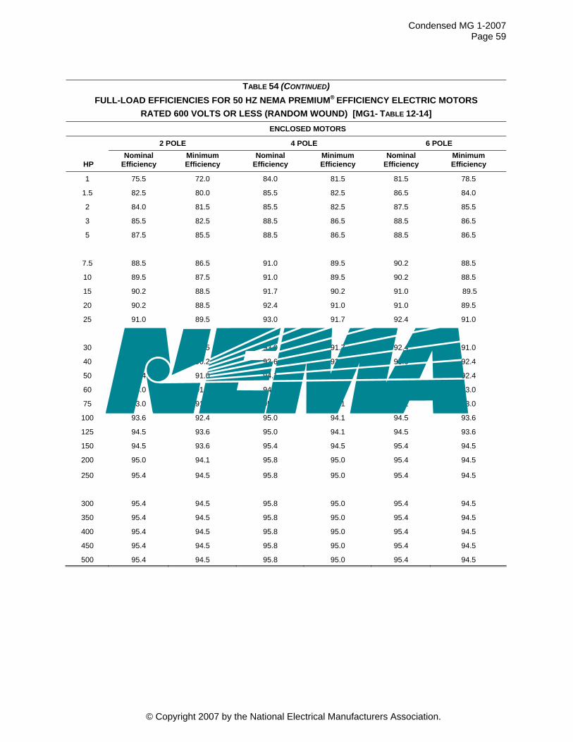
Condensed MG 1-2007 Page 59
TABLE 54 (CONTINUED) FULL-LOAD EFFICIENCIES FOR 50 HZ NEMA PREMIUM® EFFICIENCY ELECTRIC MOTORS
RATED 600 VOLTS OR LESS (RANDOM WOUND) [MG1- TABLE 12-14] ENCLOSED MOTORS
2 POLE 4 POLE 6 POLE
HP Nominal
Efficiency Minimum Efficiency
Nominal Efficiency
Minimum Efficiency
Nominal Efficiency
Minimum Efficiency
1 75.5 72.0 84.0 81.5 81.5 78.5
1.5 82.5 80.0 85.5 82.5 86.5 84.0
2 84.0 81.5 85.5 82.5 87.5 85.5
3 85.5 82.5 88.5 86.5 88.5 86.5
5 87.5 85.5 88.5 86.5 88.5 86.5
7.5 88.5
90.2 88.5
90.2
94.1
93.0
94.5
350
500
86.5 91.0 89.5 90.2 88.5
10 89.5 87.5 91.0 89.5
15 90.2 88.5 91.7 90.2 91.0 89.5
20 88.5 92.4 91.0 91.0 89.5
25 91.0 89.5 93.0 91.7 92.4 91.0
30 91.0 89.5 93.0 91.7 92.4 91.0
40 91.7 90.2 93.6 92.4 93.6 92.4
50 92.4 91.0 93.0 93.6 92.4
60 93.0 91.7 94.5 93.6 94.1
75 93.0 91.7 95.0 94.1 94.1 93.0
100 93.6 92.4 95.0 94.1 94.5 93.6
125 94.5 93.6 95.0 94.1 94.5 93.6
150 94.5 93.6 95.4 95.4 94.5
200 95.0 94.1 95.8 95.0 95.4 94.5
250 95.4 94.5 95.8 95.0 95.4 94.5
300 95.4 94.5 95.8 95.0 95.4 94.5
95.4 94.5 95.8 95.0 95.4 94.5
400 95.4 94.5 95.8 95.0 95.4 94.5
450 95.4 94.5 95.8 95.0 95.4 94.5
95.4 94.5 95.8 95.0 95.4 94.5
© Copyright 2007 by the National Electrical Manufacturers Association.
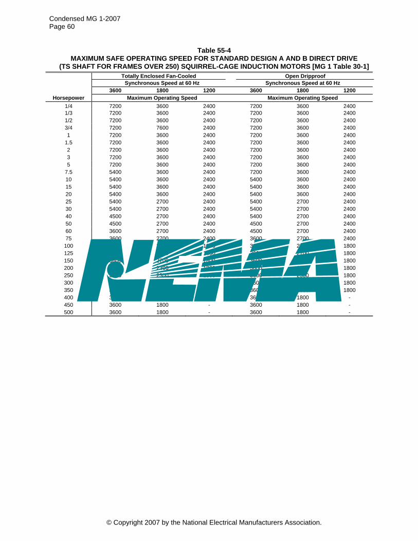
Condensed MG 1-2007 Page 60
Table 55-4 MAXIMUM SAFE OPERATING SPEED FOR STANDARD DESIGN A AND B DIRECT DRIVE
(TS SHAFT FOR FRAMES OVER 250) SQUIRREL-CAGE INDUCTION MOTORS [MG 1 Table 30-1] Totally Enclosed Fan-Cooled Open Dripproof Synchronous Speed at 60 Hz Synchronous Speed at 60 Hz 3600 1800 1200 3600 1800 1200
Horsepower Maximum Operating Speed Maximum Operating Speed 1/4 24007200 3600 2400 7200 3600 1/3 7200 3600 2400 7200 3600 2400 1/2 7200 3600 2400 7200 3600 2400 3/4 7200 7600 2400 7200 3600 2400 1 7200 3600 2400 7200 3600 2400
1.5 7200 3600 2400 7200 3600 2400 2 7200 3600 2400 7200 3600 2400 3 7200 3600 2400 7200 3600 2400 5 7200 3600 2400 7200 3600 2400
7.5 5400 3600 2400 7200 3600 2400 10 5400 3600 2400 5400 3600 2400 15 5400 3600 2400 5400 3600 2400 20 5400 3600 2400 5400 3600 2400 25 5400 2700 2400 5400 2700 2400 30 5400 2700 2400 5400 2700 2400 40 4500 2700 2400 5400 2700 2400 50 4500 2700 2400 4500 2700 2400 60 3600 2700 2400 4500 2700 2400 75 3600 2700 2400 3600 2700 2400
100 3600 2700 1800 3600 2700 1800 125 3600 2700 1800 3600 2700 1800 150 3600 2700 1800 3600 2700 1800 200 3600 2300 1800 3600 2700 1800 250 3600 2300 1800 3600 2300 1800 300 3600 2300 1800 3600 2300 1800 350 3600 1800 1800 3600 1800 1800 400 3600 1800 - 3600 1800 - 450 3600 1800 - 3600 1800 - 500 3600 1800 - 3600 1800 -
© Copyright 2007 by the National Electrical Manufacturers Association.
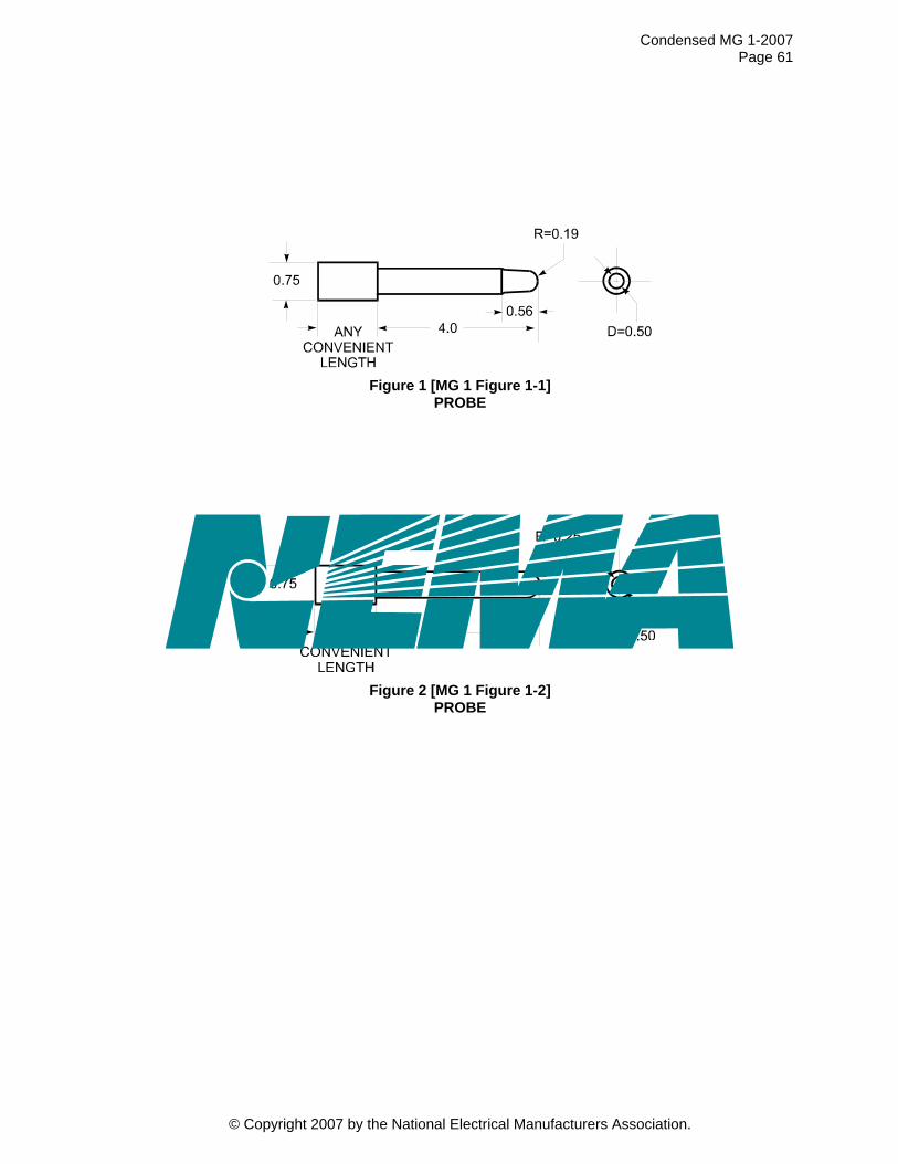
Condensed MG 1-2007 Page 61
Figure 1 [MG 1 Figure 1-1]
PROBE
Figure 2 [MG 1 Figure 1-2]
PROBE
© Copyright 2007 by the National Electrical Manufacturers Association.
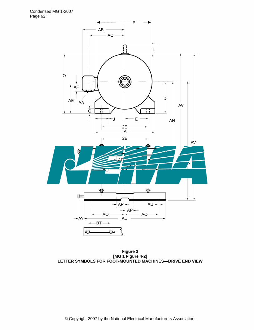
Condensed MG 1-2007 Page 62
Figure 3 [MG 1 Figure 4-2]
LETTER SYMBOLS FOR FOOT-MOUNTED MACHINES—DRIVE END VIEW
© Copyright 2007 by the National Electrical Manufacturers Association.

Condensed MG 1-2007 Page 63
© Copyright 2007 by the National Electrical Manufacturers Association.
Figure 4 [MG 1 Figure 4-1]
LETTERING OF DIMENSION SHEETS FOR FOOT-MOUNTED MACHINES, SIDE VIEW
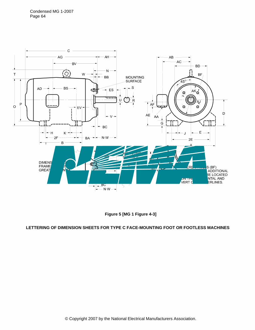
Condensed MG 1-2007 Page 64
© Copyright 2007 by the National Electrical Manufacturers Association.
Figure 5 [MG 1 Figure 4-3]
LETTERING OF DIMENSION SHEETS FOR TYPE C FACE-MOUNTING FOOT OR FOOTLESS MACHINES
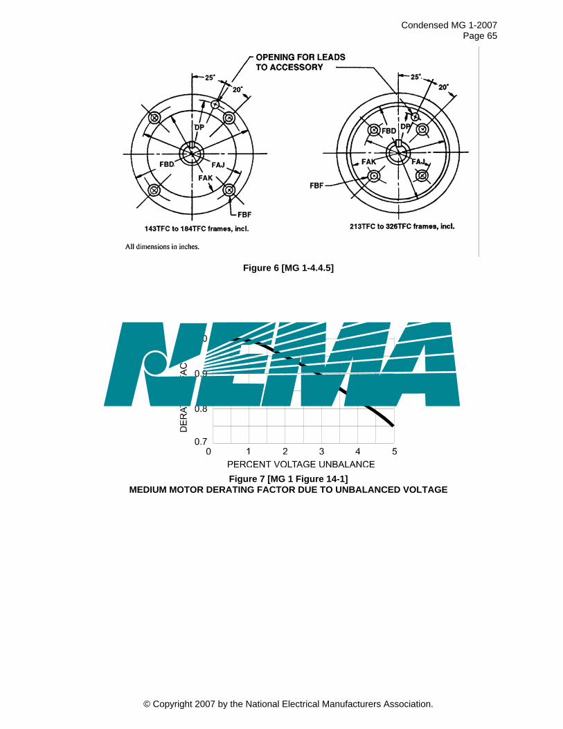
Condensed MG 1-2007 Page 65
Figure 6 [MG 1-4.4.5]
Figure 7 [MG 1 Figure 14-1] MEDIUM MOTOR DERATING FACTOR DUE TO UNBALANCED VOLTAGE
© Copyright 2007 by the National Electrical Manufacturers Association.
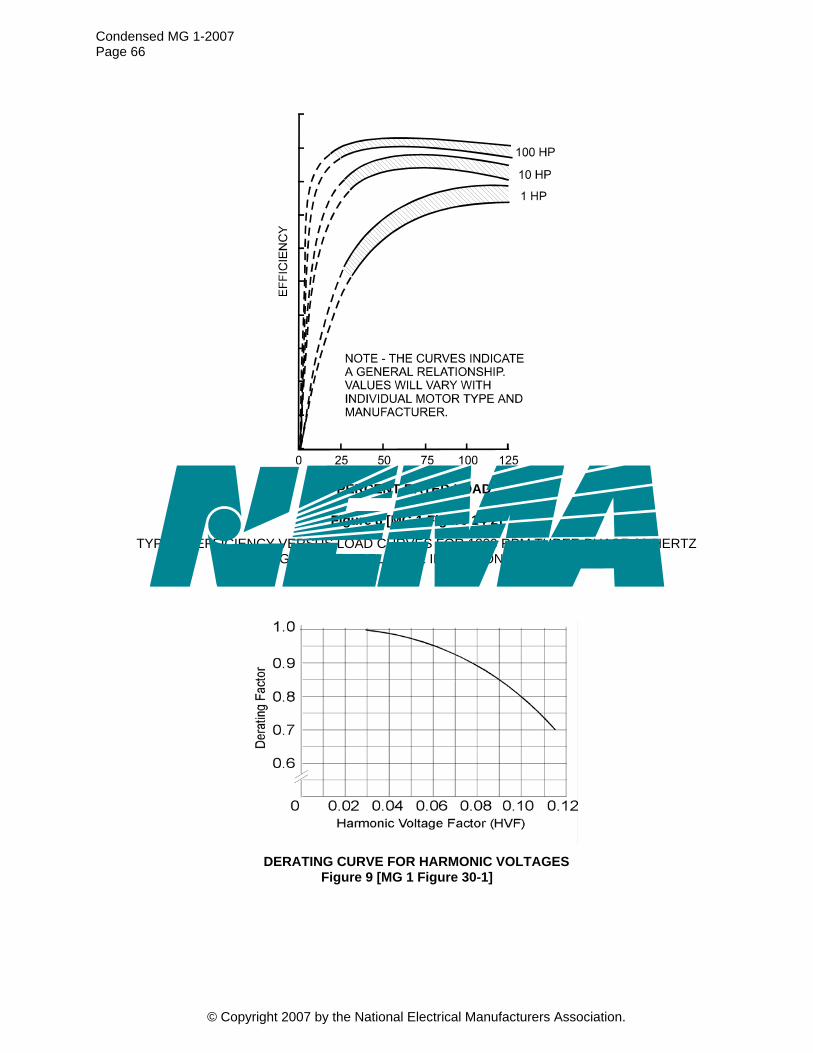
Condensed MG 1-2007 Page 66
© Copyright 2007 by the National Electrical Manufacturers Association.
Figure 8 [MG 1 Figure 14-2]
TYPICAL EFFICIENCY VERSUS LOAD CURVES FOR 1800 RPM THREE-PHASE 60-HERTZ DESIGN B SQUIRREL-CAGE INDUCTION MOTORS
DERATING CURVE FOR HARMONIC VOLTAGES
Figure 9 [MG 1 Figure 30-1]
PERCENT RATED LOAD
Related Documents


