Needle Bearings WL 101 E Linear and Motion Solutions Linear and Motion Solutio www.bergab.ru Берг АБ [email protected] Тел.(495)-228-06-21,факс (495) 223-3071 Берг АБ [email protected] Тел.(495)-228-06-21,факс (495) 223-3071 Берг АБ [email protected] Тел.(495)-228-06-21,факс (495) 223-3071

Welcome message from author
This document is posted to help you gain knowledge. Please leave a comment to let me know what you think about it! Share it to your friends and learn new things together.
Transcript

Needle Bearings
WL 101 E
Linear and Motion SolutionsLinear and Motion Solutio
www.bergab.ru Берг АБ [email protected] Тел.(495)-228-06-21,факс (495) 223-3071 Берг АБ [email protected] Тел.(495)-228-06-21,факс (495) 223-3071 Берг АБ [email protected] Тел.(495)-228-06-21,факс (495) 223-3071

NEEDLE BEARINGSGeneral Catalogue
www.bergab.ru Берг АБ [email protected] Тел.(495)-228-06-21,факс (495) 223-3071 Берг АБ [email protected] Тел.(495)-228-06-21,факс (495) 223-3071 Берг АБ [email protected] Тел.(495)-228-06-21,факс (495) 223-3071

www.bergab.ru Берг АБ [email protected] Тел.(495)-228-06-21,факс (495) 223-3071 Берг АБ [email protected] Тел.(495)-228-06-21,факс (495) 223-3071 Берг АБ [email protected] Тел.(495)-228-06-21,факс (495) 223-3071

CommentsThe information given in this catalogue can be subject to modification and deletions.
Nadella does not accept any responsibility for errors or omissions.
1
Information and advice contained herein may be insufficient given the conditions of individual applications. Consult our Technical Department.
Certain products mentioned in this catalogue involve proprietary rights of manufacture, Trademarks and Patents.
Principal units
UnitS.I. System Multiple or part
Equivalenttitle symbol title symbol
length metre m
millimeter mm 1 mm = 10-3 m
micron μm 1 μm = 10-6 m
time second s
hour h 1 h = 3600 s
minute min 1 min = 60 s
speed metre per second m/s
accelerationmetre per second per
secondm/s2
speed (rotational) revolutions per minute min-1
mass kilogramme kg gramme g 1 g = 10-3 kg
force newton N kilonewton kN 1 N = 10-3 kN
moment of force newton metre Nm
stress pascal Pa megapascal Mpa 1 Mpa = 1N/mm2
kinematic viscositysquare metreper second
m2/s square millimetres
per secondmm2/s 1 mm2/s = 1 cSt
temperature degrees centigrade C°
www.bergab.ru Берг АБ [email protected] Тел.(495)-228-06-21,факс (495) 223-3071 Берг АБ [email protected] Тел.(495)-228-06-21,факс (495) 223-3071 Берг АБ [email protected] Тел.(495)-228-06-21,факс (495) 223-3071

List of contents
2
K K..ZW
DLFDLHK.2RS
FCBL-K, FCBN-K
NKJ-NKJS
NA
RNA 11000
ARZ CP CPN
AXNBT - ARNBT
DH
BP
JR, JR..JS1
BR
RAXPZ 400RAXZ 500RAXNPZ 400RAXPZ 500
FCS, FCL-K, FC-K FCB
NK-NKS
RNA
FGU, FGUL, NUTR
AXZ
RAX 400RAX 500RAXN 400RAXN 500
AR
AXNB - ARNB
AX
RAX 700RAXF 700
FG, FP, FPL, FGLGC, GCLGCU, NKUR.2SK
FC
BK.RSHK.RSBKHK
www.bergab.ru Берг АБ [email protected] Тел.(495)-228-06-21,факс (495) 223-3071 Берг АБ [email protected] Тел.(495)-228-06-21,факс (495) 223-3071 Берг АБ [email protected] Тел.(495)-228-06-21,факс (495) 223-3071
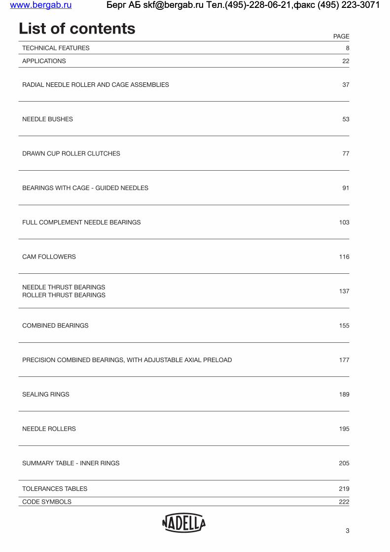
TECHNICAL FEATURES 8
APPLICATIONS 22
RADIAL NEEDLE ROLLER AND CAGE ASSEMBLIES 37
NEEDLE BUSHES 53
DRAWN CUP ROLLER CLUTCHES 77
BEARINGS WITH CAGE - GUIDED NEEDLES 91
FULL COMPLEMENT NEEDLE BEARINGS 103
CAM FOLLOWERS 116
NEEDLE THRUST BEARINGS ROLLER THRUST BEARINGS
137
COMBINED BEARINGS 155
PRECISION COMBINED BEARINGS, WITH ADJUSTABLE AXIAL PRELOAD 177
SEALING RINGS 189
NEEDLE ROLLERS 195
SUMMARY TABLE - INNER RINGS 205
TOLERANCES TABLES 219
CODE SYMBOLS 222
List of contents
3
PAGE
www.bergab.ru Берг АБ [email protected] Тел.(495)-228-06-21,факс (495) 223-3071 Берг АБ [email protected] Тел.(495)-228-06-21,факс (495) 223-3071 Берг АБ [email protected] Тел.(495)-228-06-21,факс (495) 223-3071

www.bergab.ru Берг АБ [email protected] Тел.(495)-228-06-21,факс (495) 223-3071 Берг АБ [email protected] Тел.(495)-228-06-21,факс (495) 223-3071 Берг АБ [email protected] Тел.(495)-228-06-21,факс (495) 223-3071

TECHNICAL FEATURES TE
CH
NIC
AL
FE
ATU
RE
Swww.bergab.ru Берг АБ [email protected] Тел.(495)-228-06-21,факс (495) 223-3071 Берг АБ [email protected] Тел.(495)-228-06-21,факс (495) 223-3071 Берг АБ [email protected] Тел.(495)-228-06-21,факс (495) 223-3071

1. GENERAL
2. BEARING TYPE SELECTION
3. CALCULATIONS FOR RADIAL AND THRUST BEARINGS 3.1. BEARING LIFETIME
3.1.1. Dynamic capacity C
3.1.2. Nominal life L10
3.1.3. Modified life Lna
3.1.4. Variable loads and speeds
3.1.5. Oscillating motion
3.1.6. Application criteria
3.2. MINIMUM LOAD
3.3. STATIC CAPACITY Co AND LIMIT LOAD Po
3.4. COEFFICIENT OF FRICTION
3.5. LIMITING SPEED
4. MOUNTING 4.1. SHAFT FOR BEARINGS WITHOUT INNER RING
4.1.1. Heat treatment of raceways
4.1.2. Surface finish
4.1.3. Tolerances and form deviations
4.1.4. End chamfer
4.1.5. Surface in contact with seals
4.2. SHAFT FOR BEARINGS WITH INNER RING
4.2.1. Surface finish of the shaft
4.2.2. Tolerances and form deviations
4.2.3. End chamfer
4.3. HOUSING FOR BEARINGS WITH OUTER RING
4.3.1. Surface finish of the shaft
4.3.2. Tolerances and form deviations
4.3.3. End chamfer
4.3.4. Alignment between hole housing
4.4. HOUSING FOR CAGES AND NEEDLES
4.4.1. Requirements for materials, processing and finishing
4.4.2. Alignment between hole housing
6
Technical featureswww.bergab.ru Берг АБ [email protected] Тел.(495)-228-06-21,факс (495) 223-3071 Берг АБ [email protected] Тел.(495)-228-06-21,факс (495) 223-3071 Берг АБ [email protected] Тел.(495)-228-06-21,факс (495) 223-3071

7
Technical features
5. LUBRICATION 5.1. LUBRICANT FEATURES
5.1.1. Base oil
5.1.2. Additives
5.2. GREASE LUBRICATION
5.2.1. Main types of grease
5.2.2. Consistency
5.2.3. Special grease
5.2.4. Compatibility of greases
5.2.5. Application
5.2.6. Quantity of grease
5.2.7. Re-lubrication
5.3. OIL LUBRICATION
5.3.1. Viscosity
5.3.2. Application of the lubricant
6. BEARINGS STORAGE
www.bergab.ru Берг АБ [email protected] Тел.(495)-228-06-21,факс (495) 223-3071 Берг АБ [email protected] Тел.(495)-228-06-21,факс (495) 223-3071 Берг АБ [email protected] Тел.(495)-228-06-21,факс (495) 223-3071

1. GENERAL The choice of a bearing depends on many factors that need to be examined in order to obtain the most successful results at the lowest cost.In most cases the selection should be made when the overall design of the machine has been decided. Dimensional limits are then known, also the speeds and loads. At this stage the choice can be made from the many types of bearings offered from the standard ranges. The notes given in this section will generally permit one to select the most suitable bearing for each application.As for all other types of bearing, the results obtained with needle bearing products depend to a large extent on the design and method of assembly, loading, and alignment between inner and outer rings.Bearing alignment depends first of all on the geometry of the parts involved and secondly on the deflection of the shaft under load. The shaft diameter should therefore be sufficient to prevent large deflections. This is easier to achieve using needle bearings because they occupy a small radial area.
8
2. BEARING TYPE SELECTIONBearing type selection is made after the general design concept of the mechanism has been established and the application requirements carefully evaluated.
The ability of a bearing to support radial or axial loads, tolerate misalignments, be suitable for high speeds or loads are the main criteria for guiding the selection in the correct way. To navigate the families of bearings in this catalogue an initial assessment can be made on the basis of the table below. Further details are specified in the relevant chapters.
Technical features
Radial needle roller cage
Caged needle bushes
Full complement
needle bushes
Caged needle
bearings
Full complement
needle bearings
Needle rollers
Thrust bearings
Combined bearings 1)
Radial load High Moderate High High Very high Very high None High
Axial load None None None None None None Very high Very high
Speed Very high High Moderate Very high Moderate Moderate Moderate Moderate
Misalignmenttolerance
Moderate Moderate Low Moderate Moderate Very low Low Low
Grease life High High Moderate High Moderate Moderate Low Low
Friction Very low Low High Very low High High High Moderate
Precision Very high Moderate Moderate High High Very high High Very high
Cross section Very low Low Low Moderate Moderate Very low Moderate Moderate
Cost Low Low Low Moderate Moderate Low High High
1) RAX 700 series not included
www.bergab.ru Берг АБ [email protected] Тел.(495)-228-06-21,факс (495) 223-3071 Берг АБ [email protected] Тел.(495)-228-06-21,факс (495) 223-3071 Берг АБ [email protected] Тел.(495)-228-06-21,факс (495) 223-3071

3. CALCULATIONS FOR RADIAL AND THRUST BEARINGS The details following enable one to evaluate lifetime of radial bearings and thrust bearings and also combined bearings which comprise a radial and a thrust component. These are calculated separately without transforming the axial load into an equivalent radial load. The calculation for a radial or thrust bearing must take account of the following principal factors:
Other features such as lubrication, sealing and alignment must be considered in order to avoid introducing unfavourable factors.The formulas for lifetime calculations here reported are considered valid under standard conditions, generally useful for first-sizing or product comparison.For further details on correction factors for bearing lifetime in applications, please refer to ISO281 and ISO16281 standards and to Nadella Technical Service.The life calculation of a radial bearing or a thrust bearing under rotation is established from the dynamic capacity C indicated in the tables of dimensions. The static capacity Co enables one to determine the maximum load under certain operating conditions (see table on page 8).
3.1. BEARING LIFETIME
3.1.1. Dynamic capacity C The dynamic capacity of a bearing is the constant radial load which it can support during one million revolutions before the first signs of fatigue appear on a ring or rolling element. For a thrust bearing, the capacity for one million revolutions assumes a constant axial load centred in line with the axis of rotation.The dynamic capacity is a reference value only; the base value of one million revolutions has been chosen for ease of calculation. Since applied loading as great as the dynamic capacity tends to cause local plastic deformations of the rolling surfaces that may affect their operations.The dynamic capacity C for bearings shown in the tables of dimensions has been established in conformance with the ISO Standard 281.
9
3.1.2. Nominal life L10
The life of a (or thrust bearing) is the number of revolutions (or the number of hours at constant speed) that it will maintain before showing the first signs of material fatigue.The relationship between the life in millions of revolutions L10, the dynamic capacity C and the supported load P, is given by the formula:
in this expression p is equal to 10/3 for needle or roller bearings. In order to assess the importance of the influence of load on the life expectancy, one should note for example that, if the load on a bearing is doubled, its life is reduced by a factor of 10. The formula above is independent of speed of rotation which must not exceed the recommended limit in respect of the radial bearing or the thrust bearing used an d the method of lubrication. lf the speed of rotation n (r.p.m.) is constant, the life is given in hours by the function:
The above formula will ensure that 90% of the bearings operating under the same conditions will attain at least the calculated L10 life, known as the nominal life (the figure 10 being the percentage of bearings which may not attain this life). The formulae are based on the use of standard quality bearing steel and assume a satisfactory method of lubrication.The formulas for life calculation are effective for an applied load smaller than 0.5 C.
Technical featureswww.bergab.ru Берг АБ [email protected] Тел.(495)-228-06-21,факс (495) 223-3071 Берг АБ [email protected] Тел.(495)-228-06-21,факс (495) 223-3071 Берг АБ [email protected] Тел.(495)-228-06-21,факс (495) 223-3071

3.1.3. Modified life Lna In conditions different from the mentioned above, a modified life Lna can be determined (in millions of revolutions) following the general formula:
Lna = a1 . aISO . L10
in which a1 and aISO are correction factors linked respectively to reliability, contamination and lubrication.
Reliability correction factor a1 A reliability factor in excess of 90% may be required in certain industries fields, such as aviation, for reasons of security and to reduce the risk of a very costly immobilisation. The table below indicates the values of the correction factor a1 as a function of reliability:
Reliability%
Factor a1
Modified lifeLna1
90 95 96 97 98 99
99,599,9
1 0,64 0,55 0,47 0,37 0,25
0,175 0,093
L10L5 L4L3L2L1
L0,5L0,1
In order to select as an example a bearing of life L4 (reliability 96%) it is necessary to estimate life L10 with the formula L10 = (C/P)10/3 starting from the dynamic capacity C given in this catalogue:
L4 = 0.55 . L10
Correction factor aISO
The factors that affect bearing life are numerous, and their analysis is not one in this catalogue. The effects of temperature, misalignment, bearing clearance, cleaning and lubrication conditions, which require a detailed discussion is beyond the scope of the product catalogue. For a more detailed discussion, please refer to Standards:ISO 281:2007 introducing the coefficient aISO to take into account the effects of lubrication and cleanliness of the lubricant.ISO 16281, which introduces in the calculation the effect of clearance and misalignments in the bearing.Nadella technical service is available for advice on the choices to be made in special cases.
10
3.1.4. Variable loads and speeds When the loads and speeds are variable, the life calculation can only be made by first establishing an assumed constant load and constant speed equivalent in their effect on the fatigue life.This type of operating condition is frequently met and the possible variations although cyclical are numerous. One encounters this feature in particular, in variable speed drives on some supports, but constant on each support for an interval of time referring to the total operating time (example: change of speed). The equivalent load P and the equivalent speed n are obtained from the following formulae:
in which: m1, m2 ..., mn: interval of operating time under
constant load and speed (by definition: m1 + m2 + ... + mn =1).
n1, n2, ..., nn: constant speed corresponding respectively to intervals of time
m1, m2, ..., mn. P1, P2, Pn: constant loads corresponding
respectively to intervals of time m1, m2, ..., mn. For needles and rollers bearings and thrust bearings, p is equal to 10/3.
Whilst at constant speed, the load varies linearly during a given time, between a minimum Pmin and a maximum Pmax. the equivalent load is given by:
Technical featureswww.bergab.ru Берг АБ [email protected] Тел.(495)-228-06-21,факс (495) 223-3071 Берг АБ [email protected] Тел.(495)-228-06-21,факс (495) 223-3071 Берг АБ [email protected] Тел.(495)-228-06-21,факс (495) 223-3071

3.1.5. Oscillating motion In order to calculate the life during oscillating motion it is necessary to determine an equivalent speed n in revolutions per minute from the formula:
nosc: number of oscillations "Forward and Return" per minute
α: amplitude of oscillation "Forward" in degrees.
However, this formula risks being in error and giving inaccurate lives for oscillations at small amplitudes. It is therefore recommended not to apply it for angles of oscillation below 15°.When the angle of oscillation is very small fretting corrosion is likely to be produced and a suitable lubricant must be chosen in consequence. Experience confirms that full complement needle bearings provide better results under this phenomenon in view of their better load sharing capability.
3.1.6. Application criteriaThe life calculation may be unreliable when values for speed and load reach the ultimate limits. A low speed and/or load can yield an extremely long calculated life but this will be limited in practice by other operating factors such as sealing, lubrication and maintenance, all of which have a decisive influence on the life of the product in such cases.
3.2. MINIMUM LOADSlippage can occur if loads are too light and, if accompanied by inadequate lubrication, cause damage to the bearings. The minimum load for bearings with cage must be
For radial bearings- Fr min = 0,04 C (C is the Dynamic Capacity for lifetime calculation)
For thrust bearings are correct the formulas- Needle bearings Fa min = 0,005 Co - Roller bearings Fa min = 0,001 Co (Co is the Static Capacity)
11
3.3. STATIC CAPACITY Co AND LIMIT LOAD Po The static capacity Co given in the tables of dimensions has been established in conformance with ISO Specification 76. This takes into consideration the maximum admissible contact stress (Hertzian stress). The value currently being adopted in 4000 MPa.Since permanent deformation is produced as readily in a bearing rotating as in one that is stationary, the static capacity Co determines the limit load Po which depends on the type ofbearing and the operating conditions. When the limit load Po is given within the "min-max" range, the load applied may attain the indicated maximum provided it is applied continuously without sudden repeated variations. Alternatively, in the case of shock loads and vibrations, the load applied should not exceed the minimum value of limit load Po.The relationship between the static capacity and the limit load defines the safety static factor fo:
fo = Co/Po
The suggested values for the safety factor, depend on the type of application and product
Solid rail bearingsfo = 1,5 … 2,5 Important requirements for smoothness
of function, silent operation or accuracy of rotation
fo = 1 … 1,5 General applicationsfo = 0,7 … 1 Slow rotation or oscillatory motion.
Drawn bearingsfo > 4 Important requirements for smoothness
of function, silent operation or accuracy of rotation
fo > 3 General applications and oscillatory motion
Cam followers: the allowable load for cam followers depends on the static load of the bearing and from the strength of the stud and of the outer ring. Authorised values are listed in the tables of dimensions.
Technical featureswww.bergab.ru Берг АБ [email protected] Тел.(495)-228-06-21,факс (495) 223-3071 Берг АБ [email protected] Тел.(495)-228-06-21,факс (495) 223-3071 Берг АБ [email protected] Тел.(495)-228-06-21,факс (495) 223-3071

3.4. COEFFICIENT OF FRICTIONThe resistance torque M of a bearing supporting a load P is given by the following relationships:
.P. Fw
2
(with Fw is the diameter of the inner raceway of the bearing)
.P. dm with dm = Eb+ Ea
2 2
(Eb and Ea being the internal and external raceway diameters given in table of dimensions).The coefficient of friction f depends on a number of factors, amongst which are:
The mean values shown below are for oil lubrication
f = 0,002 ÷ 0,003 for caged needle bearingsf = 0,003 ÷ 0,004 for full complement bearings and needle thrust bearingsf = 0,004 ÷ 0,005 for roller thrust bearings.
These coefficients are applicable for values of C/P between 2 and 6 approximately. For values less than or in excess of these limits the coefficient of friction f can be increased by 10 to 50%. Under starting conditions from rest, the values of f may be up to 1.5 times higher than those shown above.To evaluate the losses of the entire bearing assembly, account must also be taken of the friction due to the seals which can be significant, especially during "running-in".
12
3.5. LIMITING SPEEDThe tabular pages list the limiting speed values calculated under normal operating conditions, properly mounting tolerances and clearance, absence of misalignments, low loads. For speed calculated with oil lubrication it is considered a normal flow of lubricant. A bearing may operate at a speed higher than the listed limiting speed with use of a clean, with good quality oil and correct flow to remove the heat generated in the table. Consult Nadella Technical Service for further details.In case of high speed and acceleration to avoid internal slippage between the rolling elements and the raceways the relationship between the applied load P and the base load of the bearing C must be at least P/C > 0.02.The wheels are supplied normally lubricated with grease suitable for general use, so the limit speed given in the dimension tables take account of such lubrication. For wheels without seals, lubricated with oil, the indicated speed limit may be increased by about 30% for continuous rotation (about 50% for intermittent rotation).
Technical featureswww.bergab.ru Берг АБ [email protected] Тел.(495)-228-06-21,факс (495) 223-3071 Берг АБ [email protected] Тел.(495)-228-06-21,факс (495) 223-3071 Берг АБ [email protected] Тел.(495)-228-06-21,факс (495) 223-3071

4. MOUNTING
4.1. SHAFT FOR BEARINGS WITHOUT INNER RING4.1.1. Heat treatment of raceways The minimum hardness of 58-64 HRC required to apply the calculations without reducing the basic capacities may be obtained with a through-hardened bearing steel or with a case-hardened and tempered steel. In the latter case, the hardened case must be homogeneous and regular over the entire surface of the raceway: the case depth is the thickness between the surface and the core having a hardness value of Vickers HV1 of 550 (see Standard NF A 04 202). The minimum effective case depth of hardening depends on the applied load, the size of the rolling elements and the core strength of the steel used. To calculate the approximate case depth minimum depth can be used the following formula
Minimum case depth = (0,07÷0,12) x DwDw = diameter of the rolling element
In any case the minimum suggested case depth is of 0.4 mm.The load capacities shown in the tables of dimensions apply to raceways with a hardness of between 58 and 64 HRC.The dynamic and static capacities are reduced when hardness values are lower than 58 and 54 HRC respectively according to the following table:
HardnessHRC 60 58 56 54 52 50 48 45 40 35 30 25
HV* 697 653 613 577 545 512 485 447 392 346 302 267
Coefficients for load reduction
Dyn. 1 1 0.93 0,84 0,73 0,63 0,52 0,43 0,31 0,23 0,15 0,11
Stat. 1 1 1 1 0,96 0,86 0,77 0,65 0,50 0,39 0,30 0,25
4.1.2. Surface finish The shafts or housing used directly as raceways for needles must have a surface finish acceptable for the operating conditions and the precision requirements:
- applications with high speeds and loads: Ra = 0,2 μm - general applications: Ra = 0,35 μm
13
4.1.3. Tolerances and form deviationsThe suggested tolerances for the mean shaft diameter are indicated in the appropriate chapters specific for every product.The suggested tolerance for deviation from the cylindrical raceways form (radial bearings).- Variation of mean shaft diameter within the length of
the bearing raceway should not exceed 0.008 mm or one-half the diameter tolerance. The profile should never be concave (the core diameter must protrude to the diameter at the ends)
- Deviation from circular form: the minimum between 0.0025 mm and one quarter of diameter tolerance
For thrust bearings and combined bearings refer to the specific chapter prescriptions.
4.1.4. End chamferFor the most effective assembly and preventing damage to the roller complements or needles, provide a chamfer to the ends of the raceway.
4.1.5. Surface in contact with sealsThe surface in contact with the sealing lips must be finished with plunge cut grinding. The propeller subsequent to the grinding process without centers can create a pumping effect of the lubricant through the seal.
4.2. SHAFT FOR BEARINGS WITH INNER RING
4.2.1. Surface finish of the shaftMaximum roughness suggested: Ra = 1,6 μm
4.2.2. Tolerances and form deviationsThe suggested tolerances for the mean shaft diameter are indicated in the appropriate chapters specific for every product.
The suggested tolerance for deviation from the cylindrical raceways form (radial bearings)- Variation of mean shaft diameter within the length
of the bearing raceway: one-half of the diameter tolerance
- Deviation from circular form: one-half of the diameter tolerance
4.2.3. End chamferFor the most effective assembly provide a chamfer to the ends of the shaft on which the inner ring must be inserted.
Technical featureswww.bergab.ru Берг АБ [email protected] Тел.(495)-228-06-21,факс (495) 223-3071 Берг АБ [email protected] Тел.(495)-228-06-21,факс (495) 223-3071 Берг АБ [email protected] Тел.(495)-228-06-21,факс (495) 223-3071

4.3. HOUSING FOR BEARINGS WITH OUTER RING
4.3.1. Surface finish of the shaftMaximum roughness suggested: Ra = 1,6 μm
4.3.2. Tolerances and form deviationsThe suggested tolerances for the housing is indicated in the appropriate chapters specific for every product.The suggested tolerance for deviation of form is- Variation of mean housing diameter within the length
in contact with needle: 0.013 mm- Deviation from circular form: one-half of the diameter
tolerance of the housing
4.3.3. End chamferFor the most effective assembly provide a chamfer to the ends of the shaft on which the inner ring must be inserted.
4.3.4. Alignment between hole housingWhen possible ream the housing of the same shaft with a single placement on the machine tool.
4.4. HOUSING FOR CAGES AND NEEDLES
4.4.1 Requirements for materials, processing and finishingObserve the rules for the shafts, paragraph 4.1.
4.4.2. Alignment between hole housingWhen possible ream the housing of the same shaft with a single placement on the machine tool.
14
5. LUBRICATIONBearings are protected against oxidation with a corrosion protection, but normally supplied unlubricated. Pleasedon't forget to lubricate them when mounting.
5.1. LUBRICANT FEATURESLubrication of a bearing provides a viscous film between the rolling elements in order to reduce heat and wear caused by friction. The lubricant can also assist in preventing corrosion and help to seal the bearing from the introduction of dirt and impurities; it reduces friction between the shaft and seals and lowers the noise level generated within the bearing.Wherever the operating conditions permit, grease should be chosen in preference to oil, as it is more convenient to use and more economic. Furthermore, it acts as an efficient seal against the effects of dust and humidity. On account of its consistency, grease can improve the effectiveness of sealing rings and can be used on its own as a seal, when it is used to fill grooves or labyrinths provided for this purpose.Alternatively, oil is necessary for high rotational speeds in excess of the limits advised for grease lubrication and in cases where there is a problem of heat dissipation. Oil can also remove moisture and impurities from the bearing and is usually easily controlled to monitor the state of lubrication. Oil lubrication is also necessary where it is used already in the function of the equipment, such as hydraulic motors and pumps, speed variators and gear boxes etc.Oil and grease lubricants must be free of all impurities which could cause premature failure of the bearing and removal from service. Sand and metal particles are particularly injurious to bearings. Every precaution must be taken to assure the cleanliness of gear casings, pipes, grease nipples, couplings, as well as lubricant containers. The efficiency of a lubricant decreases in service both by age and by the continuous mixing to which it is submitted. Therefore replenishment must take place at regular intervals, taking account of operating and environmental conditions (humidity, dirt, temperature) except for applications where the bearing has been lubricated for life with a suitable grease.
Technical featureswww.bergab.ru Берг АБ [email protected] Тел.(495)-228-06-21,факс (495) 223-3071 Берг АБ [email protected] Тел.(495)-228-06-21,факс (495) 223-3071 Берг АБ [email protected] Тел.(495)-228-06-21,факс (495) 223-3071

5.1.1. Base oil It is the main constituent of a lubricant, being it an oil (obtained by adding base oil to chemical additives) or a grease (which is obtained by adding the thickener to the oil). Technically base oils differ between them for their chemical/physical properties and for their ability to work in particular conditions such as high temperatures or low temperatures or even in oxidizing environments, and so on.The following table shows the main base oils and their main physical features distinguishing its capabilities.
ParameterMineral oil
Ester based oil
Polyglycol oil
Silicone oil
Fluoro-carbon oil
Density [g/ml] 0.9 0.9 0.9-1.1 0.9-1.05 1.9
Viscosity index VI (1) 100 150 >200 200/500 50/150
Pour Point [°C] (2) -10/-40 -30/-70 -20/-50 -30/80 -30/-70
Flash point [°C] (3) 200/250 230/300 150/300 150/300 No one
Oxidation resistance Sufficient Good Good Excellent Excellent
Temperature stability Sufficient Good Good Excellent Excellent
Lubricating ability (4) Good Good Excellent Low Good
Compatibility with seals Good Low Sufficient Good Good
(1) The viscosity index represents the ability of the lubricant to maintain constant its viscosity with changes in temperature; An high value of index VI means good ability to maintain a constant viscosity (key parameter for oils).
(2) The pour point is the lowest temperature at which the lubricant loses the ability to scroll (solidification), so it is an index for the utilization of the lubricant at low temperatures.
(3) Minimum temperature at which the air / gas mixture above the lubricant will ignite if it gets too close to a heat source.
(4) The lubricating ability indicates the ability of the lubricant to withstand large loads applied.
The mineral oils are used in most applications. Synthetic oils (such as esters, polyglycols, silicon) and finally the fluorocarbon that are special oils as chemically inert (due to the presence of fluoride) in the case of specific needs.
It is important to note the general rules on the viscosity of the oils:- fluid oil = excellent refrigerant;- thick oil = excellent lubricant;never use a lubricant with a viscosity greater than necessary.
15
5.1.2. Additives The addition of additives to the base oil, allows to obtain an oil with performance features clearly higher than the base oil itself. The additives allow to reduce some negative sides of base oils, although a silicone oil (particularly weak to support applied loads) suitabley additiveted (eg with EP additives) will never be as a synthetic oil or polyglycol .The following table shows the main technological characteristics related with additives.
Additives Features
Anti-oxidantsThey slow down the oxidation that creates deposits on the surfaces in contact with detriment to the lubricating fluid that deteriorates
Anti-corrosionSlow chemical reactions with materials such as copper, aluminum and sulfur
Anti-rustSlow down the chemical reactions with ferrous materials that give life to rust
Anti-wearSlow down the wear phenomena of materials in contact with the lubricant
EPExtreme Pressure it allows to increase the ability of the lubricant to withstand the applied load thereby reducing the danger of seizure
DetergentsClean the metal surfaces from debris or oxidation products by emulsion
DispersantsMaintain the oxidation and emulsion products in suspension, preventing their deposit on metal surfaces
Pour PointLower the flow temperature of a lubricant allowing its use at low temperatures
Enhancers of VIIncrease the viscosity index allowing to obtain a lubricant constant in a wide range of temperature. Used mainly to the extreme temperatures temperature
Anti-foamingReduce the danger of the formation of foam in the lubricant
Adhesiveness enhancersIncrease the adhesion of the lubricant to the surface with which it is in contact
Compatibility with seals Good
Technical featureswww.bergab.ru Берг АБ [email protected] Тел.(495)-228-06-21,факс (495) 223-3071 Берг АБ [email protected] Тел.(495)-228-06-21,факс (495) 223-3071 Берг АБ [email protected] Тел.(495)-228-06-21,факс (495) 223-3071

5.2. GREASE LUBRICATIONGreases for bearings must possess high lubricity power, good mechanical stability, an effective oxidation resistance and good anti-rust features, especially for parts operating in humid environment or subjected to splashing water. Their consistency, generally of grade 1, 2 or 3 of the NLGI scale, must remain as stable as possible within the temperature limits allowed by their composition.
5.2.1. Main types of grease The grease is a thick lubricant, it consists of the base oil, plus additives and a thickener which is very often composed of a soap.Greases based on lithium soap are particularly suitable for the lubrication of needle and rollers bearings and thrust bearings. They can be used at operating temperatures between -30 and +120°C, and even up to 150°C if they are of good quality. They are generally fitted with anti-rust additives and offer a good protection against corrosion.Greases based on sodium soap are suitable for the lubrication of the bearings up to approximately 100°C (minimum temperature -30°C) and ensure a good seal against dust. They can absorb small amounts of water without losing their lubricating properties, but high amounts of water will dissolve and cancel all their effectiveness.Greases based on calcium soap are stable to water and can be used only up to 50 or 60°C. Their mechanical stability and their power anti-rust are weak. Their use as lubricants for bearings is therefore not recommended, but may be used in labyrinth seals. However, some grease calcium based, with increased mechanical stability and anti-rust power, can be used up to 100°C to lubricate bearings in a humid atmosphere.
Lithium soap
Sodium soap
Calcium soap
Polyurea
Lithium aluminium complex soap
Temperature range 120 110 60 160 160
Drop point 190 260 100 230 260
Water resistance Good Low Excellent Excellent Good
EP capacity Good Good Good Low Excellent
16
5.2.2. ConsistencyThe parameter that determines the softness or hardness of the grease is the consistency, that is, the penetration of the lubricant. It is defined by the NLGI consistency scale of measurement, according to eight levels which corresponds to a range of values of the Worked Penetration, expressed in tenths of millimeter.
The following table shows the classes defined by the NLGI consistency.
NLGI classWorked
PenetrationTexture
000 445 – 475 Liquid
00 400 – 430 Semi-liquid
0 355 – 385 Very very soft
1 310 – 340 Very soft
2 265 – 295 Soft
3 220 – 250 Medium
4 175 – 205 Hard
5 130 – 160 Very hard
6 85 - 115 Extremely hard (as softwood)
5.2.3. Special grease Greases with EP additives (high pressure) can be useful when bearings or thrust bearings must work with heavy loads. These greases generally offer a good lubricating power and have good anti-rust properties even in the presence of moisture. EP additives are used in the case of bearings with high load and low rotation speed, insufficient to create a meatus of lubricant sufficient to separate the metal parts.Greases for low temperatures. The starting torque at low temperatures can be problematic. Suitable acids are commercially available.Greases for high temperatures. The stability and duration of the grease is strongly influenced by temperature. In general the standard greases can be used up to 120°C-150°C. Further should be provide specific products. For high temperatures can be used lubricating pastes.
Technical featureswww.bergab.ru Берг АБ [email protected] Тел.(495)-228-06-21,факс (495) 223-3071 Берг АБ [email protected] Тел.(495)-228-06-21,факс (495) 223-3071 Берг АБ [email protected] Тел.(495)-228-06-21,факс (495) 223-3071

5.2.4. Compatibility of greases Certain greases are incompatible with others and, if they are mixed, their function will be impaired.With greases considered as compatible, account should be taken of the reduction in their consistency when mixed and the maximum permissible temperature should be reduced accordingly.
5.2.5. Application Grease can be introduced into the bearings at the time of assembly, care being taken to distribute it around the crown of the needles (see below "Quantity of grease").The free space found in the bearing which is filled with grease, constitutes a reservoir and a reinforced seal. This method is possible if replenishments of grease are necessary at regular maintenance periods, during the course of which one can dismount the bearings, clean and examine them. Otherwise one has to use a hand pump which forces grease into the bearing by means of valves and replenishes the adjacent reservoir and also the channels and labyrinth seals.The entry passage for the grease must directly abut the bearing or be in close proximity to it, in order that new fresh grease pushes out the used grease through the seals. For this reason the lip of the sealing ring must be oriented towards the outside of the bearing for it to rise under the force of the grease being ejected. This method has the advantage of removing impuritieswhich could be introduced into the seals, particularly in the case of a highly contaminated atmosphere.
17
5.2.6. Quantity of greaseThe amount of grease that should be contained in a bearing can be established by considering the relationship of the limiting speed permissible for the grease nG to the speed of rotation n:
G/n < 1,25 minimum quantity; bearing must be lubricated with a small quantity of grease and the adjacent parts packed with grease
G/n < 5 1/3 to 2/3 of the available volume G/n >5 bearing must totally filled with grease.
Technical features
= Best Choice= Compatible= Borderline= Incompatible
Aluminum Complex
Barium Complex
Calcium Stearate
Calcium 12 Hydroxy
Calcium Complex
Calcium Sulfonate
Clay Non-Soap
Lithium Stearate
Lithium 12 Hydroxy
Lithium Complex
Polyurea Conventional
Polyurea Shear Stable
Hydr
oxy
Non
-Soa
p
Al C
ompl
ex
Ba C
ompl
ex
Ca S
tear
ate
Ca 1
2
Ca C
ompl
ex
Ca S
ulfo
nate
Clay
Li S
tear
ate
Li 1
2 Hy
drox
y
Li C
ompl
ex
Poly
urea
Poly
urea
S S
www.bergab.ru Берг АБ [email protected] Тел.(495)-228-06-21,факс (495) 223-3071 Берг АБ [email protected] Тел.(495)-228-06-21,факс (495) 223-3071 Берг АБ [email protected] Тел.(495)-228-06-21,факс (495) 223-3071

18
5.3. OIL LUBRICATION5.3.1. Viscosity The essential characteristic of an oil is its basic kinematic viscosity in mm2/sec. at a reference temperature of 40°C according to ISO 3448. The base viscosity V40 should be increased proportionately as the operating temperature increases but decreased as the speed increases, without however reaching a lower limit below which the film strength of the oil is impaired. For applications under moderate load without shocks up to about 1/5 of the dynamic capacity of the bearing, the viscosity VF at the operating temperature should not be lower than 12 mm2/sec. For higher loads greater than 1/5 of the dynamic capacity the min. viscosity VF can be about 18 mm2/sec. The variation in viscosity of an oil as a function of temperature is reduced as the number measuring its index of viscosity is increased. A viscosity index of 85 to 95 is generally satisfactory for the lubrication of bearings.Diagram 1 below gives the viscosity VF required at the operating temperature from the ratio nH/n (nH: permitted speed limit for oil lubrication - n: speed rotation) and of the applied load (ratio C/P).For the viscosity VF required in operation and from operating temperature, diagram 2 gives the base viscosity V40 at the reference temperature of 40°C.Example: A bearing supporting a load P>C/5 and having a speed limit for oil lubrication of 10000 r.p.m., must rotate at 2000 r.p.m. at temperature up to 60°C.
The ratio nH
= 10.000
= 5 n 2.000
indicates a viscosity in operation VF = 60 mm2/sec. (diagram 1 ). For an operating temperature of 60°C, the horizontal VF = 60 cuts the vertical of 60°C (diagram 2) in the 150 zone, which is therefore the base viscosity required at 40°C.
Technical features
5.2.7. Re-lubrication The frequency of grease re-lubrication depends on a number of factors, amongst which are the type of bearing and its dimensions, the speed and load, the temperature and ambient atmospheric conditions (humidity, acidity, pollution), the type of grease and sealing. Only after controlled trials can the re-lubrication period be defined exactly and particular importance should be given to the effects of temperature, speed and humidity. Under normal conditions of function without unfavourable factors using an appropriate grease with a maximum temperature of 70°C, the re-lubrication interval TG in hours can be determined approximately from the formula:
n: speed of rotation nG: permissible speed limit for grease lubrication (see
page 14) Fw: diameter of inner raceway of bearing in mm K: coefficient according to the type of bearing: K = 32 for caged needle bearings K = 28 for full
complement needle bearings K = 15 for needle or roller thrust bearings.
For the bearings below, the diameter Fw is replaced by the following dimensions, given in the table of dimensions:
Cam followers type FG and derivatives: dimension dA Needle or roller thrust bearings: dimension Eb
Cam followers type GC and derivatives:
average dimension d+dA
2
lf the operating temperature exceeds 70°C, the interval TG determined from the formula above should, for each increase of 10°C, be reduced by 50%. However, this adjustment is not applicable beyond 115°C; for temperatures above this level trials should be made to determine the acceptable re-lubrication interval.In the case of very slow speed rotation, which would give interval TG in excess of 35000 hours corresponding to 8 years operation at a rate of 12 hours per day, it is recommended to limit the period to a maximum of 3 years.For oscillating motion, the speed to be considered is the equivalent speed given by the formula on page 11. For very small amplitudes of oscillation it is recommended to reduce by half the calculated re-lubrication period TG.
Fw
www.bergab.ru Берг АБ [email protected] Тел.(495)-228-06-21,факс (495) 223-3071 Берг АБ [email protected] Тел.(495)-228-06-21,факс (495) 223-3071 Берг АБ [email protected] Тел.(495)-228-06-21,факс (495) 223-3071

5.3.2. Application of the lubricantOil must be supplied to the bearings regularly and in sufficient quantity but not abundantly, otherwise an abnormal increase in temperature can occur. According to the speed of rotation, the following general lubrication methods can be applied:
Lubrication by oil bath: is suitable for assemblies with the shaft horizontal and average speeds up to about half the values shown in the tables of dimensions. The level of oil in the bath at rest must reach the lowest point of the inner raceway of the bearing, though the movement of oil caused by the immersion of parts in the oil bath may be sufficient to feed bearings situated above this level, providing there are pipes and collectors to ensure sufficient oil reserve when starting.
Forced lubrication: the circuit is typically composed of the tank, the circulation pump, hoses and fittings, filter, possibly the radiator. Allows to effectively lubricate the bearings even in case of high speed, remove dirt and moisture from the bearing, if necessary to remove the heat generated in the bearing.For the thrust bearing, the arrival of the oil must be made, if possible, from the shaft to use the effect of centrifugation in the sense of movement.
Oil mist lubrication: consists of applying to the bearings oil finely atomised in suspension in a current of clean compressed air. The pressure created within the bearing
19
effectively protects it from the introduction of dust, humid vapours and noxious gases. This procedure, which allows a substantial flow from a small quantity of oil, is used particularly for ultra-high speed applications in excess of speed limits given in the tables of dimensions.
6. BEARINGS STORAGEWith the exception of cam followers which are delivered lubricated with grease, all other needle or roller bearing products are supplied without grease, though protected against oxydation by an oil film compatible with most greases and mineral oil lubricants. Bearings should be stocked in a clean dry environment and retained in their original wrapping until the last moment before assembly. Even when assembling the bearing, care should be taken to prevent contamination from dirt or metallic particles and humidity.In case of doubt concerning cleanliness of the bearing, it may be necessary to wash it in filtered petroleum. In so doing the bearing must be rotated and then suitably drained and dried. Smear the bearing with a suitable oil or grease to protect it against oxydation at the time of assembly.Avoid the use of compressed air to clean or dry the bearing.And to avoid the risk that a needle roller can be removed from its place and launched (danger for the operator and the people close to him), and because the air introduces moisture into the component.
Technical features
Diagram 1 Diagram 2
www.bergab.ru Берг АБ [email protected] Тел.(495)-228-06-21,факс (495) 223-3071 Берг АБ [email protected] Тел.(495)-228-06-21,факс (495) 223-3071 Берг АБ [email protected] Тел.(495)-228-06-21,факс (495) 223-3071

www.bergab.ru Берг АБ [email protected] Тел.(495)-228-06-21,факс (495) 223-3071 Берг АБ [email protected] Тел.(495)-228-06-21,факс (495) 223-3071 Берг АБ [email protected] Тел.(495)-228-06-21,факс (495) 223-3071

APPLICATIONS
AP
PLI
CAT
ION
S
www.bergab.ru Берг АБ [email protected] Тел.(495)-228-06-21,факс (495) 223-3071 Берг АБ [email protected] Тел.(495)-228-06-21,факс (495) 223-3071 Берг АБ [email protected] Тел.(495)-228-06-21,факс (495) 223-3071

22
Lateral location of the rod is ensured by the crankshaft webs, giving adequate clearance between the little end and the internal bosses of the piston.
The crankshaft runs in two RAX 714 combined bearings to carry the radial loads and provide axial location the least possible space. They are sealed by two DH lip seals. In the disengaged position, the pulley is supported by a HK 10 12 caged Needle Bushes. All faces and shafts acting as needle raceways are case hardened to 58 – 60 HRC.
Appliations
The high speeds attained by these engines subject the connecting rod bearings to extremely arduous working conditions, made worse by doubtful lubrication and high operating temperatures. Needle cages provide the solution to these difficulties, by virtue of their small size and special manufacturing methods. In the big end of the connecting rod, the steel cage is specially treated and is centred on its outside diameter.
In the little end, on the other hand, the needle cage is centred internally on the gudgeon pin. The cage extends beyond the width of the rod, thereby allowing the maximum possible length of needle to be utilised with consequent reduction of unit load.
TWO STROKE ENGINE FOR PORTABLE SAW
www.bergab.ru Берг АБ [email protected] Тел.(495)-228-06-21,факс (495) 223-3071 Берг АБ [email protected] Тел.(495)-228-06-21,факс (495) 223-3071 Берг АБ [email protected] Тел.(495)-228-06-21,факс (495) 223-3071

The pinion shaft is supported at one end, by two RAX 730 thin wall combined bearings, which ensure lateral location in both directions. The other end of the shaft runs in a HK 30 20 caged needle bushes.
23
The use of inner race avoids the necessity for hardening the shaft journals.
Appliations
OFFSET PRESS- PAPER FEEDING MECHANISM
www.bergab.ru Берг АБ [email protected] Тел.(495)-228-06-21,факс (495) 223-3071 Берг АБ [email protected] Тел.(495)-228-06-21,факс (495) 223-3071 Берг АБ [email protected] Тел.(495)-228-06-21,факс (495) 223-3071

24
Lubrication is by grease introduced via a nipple on the end of the shaft. Sealing is effected by sealing rings type DH28x35x4.
Appliations
The common spindle carrying the two rollers turns between two RAX 718 combined bearings (with thrust plates) which ensures lateral location in both directions. The bearing surfaces of the shaft are hardened to 58 HRC.
FOLLOWERS FOR OVERHEAD CONVEYOR
www.bergab.ru Берг АБ [email protected] Тел.(495)-228-06-21,факс (495) 223-3071 Берг АБ [email protected] Тел.(495)-228-06-21,факс (495) 223-3071 Берг АБ [email protected] Тел.(495)-228-06-21,факс (495) 223-3071

For this application, Nadella has introduced a special precision combined bearing type ARNB ensuring the axial rigidity of the screw, permanently without play, by virtue of the behaviour of thrust races under controlled
25
preload. This preload, by the lock ring at the end of the pinion, is adjusted precisely to the desired value, whilst assembled, by measuring the torque required to turn the screw, this being a function of the axial loading.
Appliations
LEAD SCREW BEARING FOR AUTOMATIC LATHE
www.bergab.ru Берг АБ [email protected] Тел.(495)-228-06-21,факс (495) 223-3071 Берг АБ [email protected] Тел.(495)-228-06-21,факс (495) 223-3071 Берг АБ [email protected] Тел.(495)-228-06-21,факс (495) 223-3071

26
proximity, ensure adequate support. Of equal interest is the RAX 700 thin wall combined bearing whose closed end ensures perfect shaft sealing.
Appliations
This assembly is particularly interesting in the method of radial and axial location of gears and spindles, by means of two RAX 400 combined bearings mounted in opposition which, even though located in close
MILLER/BORER - GEAR BOX
www.bergab.ru Берг АБ [email protected] Тел.(495)-228-06-21,факс (495) 223-3071 Берг АБ [email protected] Тел.(495)-228-06-21,факс (495) 223-3071 Берг АБ [email protected] Тел.(495)-228-06-21,факс (495) 223-3071

Case hardening the ends of the shaft to 60 HRC allows the use of bearings without inner rings. The front journal is fitted with an RAXZ 520 combined bearing with roller thrust and integral thrust washer. The inside diameter of the radial part of the bearing is held to tolerance F6, and the shaft to k5, giving the necessary low play for this precision application.
The thrust rollers of the combined bearing withstand the main axial loading. lt is shielded from ingress of foreign
27
bodies by the cover which retains the thrust washer and by a sleeve over the assembly. The rear housing incorporates an RAX 417 combined bearing (with thrust washer CP 2 17 30) on a k5 shaft. the needle thrust taking the axial loadings in the opposite direction to the main working load. A speed of 1 500 r.p.m. allows the use of grease for lubrication.
Appliations
BORER SPINDLE
www.bergab.ru Берг АБ [email protected] Тел.(495)-228-06-21,факс (495) 223-3071 Берг АБ [email protected] Тел.(495)-228-06-21,факс (495) 223-3071 Берг АБ [email protected] Тел.(495)-228-06-21,факс (495) 223-3071

28
outer bearing of the output shaft is supported by a HK sealed, caged needle bush. Axial drilling loads are carried by a needle thrust bearing type AX.
Appliations
This example shows the use, on a hardened shaft, of type HK caged needle bushes, whose small radial thickness is particularly suitable for this type of application. The
HAND DRILL
www.bergab.ru Берг АБ [email protected] Тел.(495)-228-06-21,факс (495) 223-3071 Берг АБ [email protected] Тел.(495)-228-06-21,факс (495) 223-3071 Берг АБ [email protected] Тел.(495)-228-06-21,факс (495) 223-3071

This roller guides hot rolled steel products whose temperature is around 100°C. A cooling spray limits the temperature of the roller to 50°C. Two NA 3 080 full complement bearing support the radial load which may be as high as 28 000 daN at a speed of 100 r.p.m.
29
Axial location of the rollers is by two AX needle thrust bearings of 90 mm bore, mounted either side of a CPR intermediate plate. Lip seals an d grease filled labyrinths effectively prevent the ingress of coolant into the bearing
Appliations
ROLLING MILL FOLLOWER
www.bergab.ru Берг АБ [email protected] Тел.(495)-228-06-21,факс (495) 223-3071 Берг АБ [email protected] Тел.(495)-228-06-21,факс (495) 223-3071 Берг АБ [email protected] Тел.(495)-228-06-21,факс (495) 223-3071

30
needle bushes ensure the sealing of the bores in the bottom plate. The trunnions, acting as raceways under the needles, are hardened to 58 HRC.
Appliations
The operating conditions of this gear pump allow the use of DL and DLF full complement needle bushes bearings on the pinion journals. The DLF closed end
GEAR PUMP
www.bergab.ru Берг АБ [email protected] Тел.(495)-228-06-21,факс (495) 223-3071 Берг АБ [email protected] Тел.(495)-228-06-21,факс (495) 223-3071 Берг АБ [email protected] Тел.(495)-228-06-21,факс (495) 223-3071

The minimal space requirement of the RAX 700 combined bearings has led to the conception of an extremely compact speed reducer with outside dimensions only sightly greater than the size of the gears. As well as achieving economy in the casting, this arrangement also allows minimal bearing span, thereby affording greater rigidity and resistance to possible deflection of the worm.
31
The imput and output shafts are sealed by type DH sealing rings of the same radial dimensions as the corresponding bearings and the opposite ends of the same shaft by means of RAXF 700 closed end combined bearings. The shaft journals serving as bearing raceways are hardened to 58 HRC.
Appliations
WORM AND WHEEL SPEED REDUCER
www.bergab.ru Берг АБ [email protected] Тел.(495)-228-06-21,факс (495) 223-3071 Берг АБ [email protected] Тел.(495)-228-06-21,факс (495) 223-3071 Берг АБ [email protected] Тел.(495)-228-06-21,факс (495) 223-3071

32
The sealing of all shafts is ensured by type DH 20 26 sealing rings.
Appliations
The driving shaft runs in two combined bearings types RAX 718 and RAX 720 with separate thrust plates. The driven shaft is mounted on two RAX 720 combined bearings of which one only has a separate thrust plate. The shaft journals and gear faces serving as bearing raceways are hardened to 58 HRC.
RIGHT-ANGLE GEAR BOX
www.bergab.ru Берг АБ [email protected] Тел.(495)-228-06-21,факс (495) 223-3071 Берг АБ [email protected] Тел.(495)-228-06-21,факс (495) 223-3071 Берг АБ [email protected] Тел.(495)-228-06-21,факс (495) 223-3071

33
On this type of weaving machine, the shuttles are replaced by "spears" or "rapiers" whose function is to project the weft thread through the warp threads to produce larger widths of cloth. The fore and aft operation of these "rapiers" is by means of a system of connecting rods whose arms are fitted with NA 22 030 full complement needle bearings (with inner races) which fully cater for the shock loadings occasioned by reversals of directions. either rotationally or under oscillating movement.
Appliations
"RAPIER" WEAVING MACHINE
www.bergab.ru Берг АБ [email protected] Тел.(495)-228-06-21,факс (495) 223-3071 Берг АБ [email protected] Тел.(495)-228-06-21,факс (495) 223-3071 Берг АБ [email protected] Тел.(495)-228-06-21,факс (495) 223-3071

34
- When the drum is heated internally, only a small amount of heat is transferred to the bearings via the outside diameter and the bearings do not have to have specially increased play to allow for expansion of the inner rings, as would be the case with a large bearing mounted on the trunnion.
- Finally the coefficient of friction is much reduced and less power is required to turn the cylinder.
Appliations
These rollers are each fitted with two NK 42/20 caged needle bearings with inner rings. A GC52EE sealed cam follower with stud mounted vertically between the flan-ges of the sleeve, ensures lateral location of the cylinder in both directions.
This arrangement offers the following advantages:- The bearings are determined by the load to be carried rather than by the diameter of the trunnion. It is clearly preferable to sue four small bearings, rather than one of unnecessarily large diameter.
DRUM SUPPORT ROLLERS
www.bergab.ru Берг АБ [email protected] Тел.(495)-228-06-21,факс (495) 223-3071 Берг АБ [email protected] Тел.(495)-228-06-21,факс (495) 223-3071 Берг АБ [email protected] Тел.(495)-228-06-21,факс (495) 223-3071

35
Threaded spindle support mounted between two needle thrust bearings, i.e. AX 45 65 (with matching thrust ra-ces) ensures .low frictional characteristics and easy ma-nual operation.
Appliations
HAND OPERATED VALVE
www.bergab.ru Берг АБ [email protected] Тел.(495)-228-06-21,факс (495) 223-3071 Берг АБ [email protected] Тел.(495)-228-06-21,факс (495) 223-3071 Берг АБ [email protected] Тел.(495)-228-06-21,факс (495) 223-3071

www.bergab.ru Берг АБ [email protected] Тел.(495)-228-06-21,факс (495) 223-3071 Берг АБ [email protected] Тел.(495)-228-06-21,факс (495) 223-3071 Берг АБ [email protected] Тел.(495)-228-06-21,факс (495) 223-3071

RADIAL NEEDLE ROLLER AND CAGE ASSEMBLIES
www.bergab.ru Берг АБ [email protected] Тел.(495)-228-06-21,факс (495) 223-3071 Берг АБ [email protected] Тел.(495)-228-06-21,факс (495) 223-3071 Берг АБ [email protected] Тел.(495)-228-06-21,факс (495) 223-3071

TYPES OF RADIAL NEEDLE ROLLER AND CAGE ASSEMLIIES
WZ ... KK
SUFFIXES
TN molded cage of reinforced engineered polymer
ZW double-row
TNZW molded cage of reinforced engineered polymer - double-row
H hardened steel cage
F machined cage
FH machined cage, case hardened
FV machined cage, hardened and tempered
38
Radial needle roller and cage assemblies have a steel cage that provides both inward and outward retention for the needle rollers. The designs provide maximum cage strength consistent with the inherent high load-ratings of needle roller bearings. Accurate guidance of the needle rollers by the cage bars allows for operation at high speeds. Needle roller and cage assemblies have either one or two rows of needle rollers.Also listed are needle roller and cage assemblies using molded, one-piece glass-reinforced engineered polymer cages (suffix TN). These operate well at temperatures up to 120° C over extended periods. However, care should be exercised when these assemblies are lubricated with oils containing additives as service life may be reduced if the operating temperature exceeds 100° C. At such high temperatures oil can deteriorate with time and it is suggested that oil change intervals are observed.
Needle rollers with relieved ends used in these assemblies are made of high-carbon chrome steel, through-hardened, ground and lapped to close tolerances for diameter and roundness.
Reference standards are:ISO 3030 - needle roller bearings - radial needle roller and cage assemblies - boundary dimensions and tolerances.DIN 5405 Section 1 - rolling bearings - needle roller bearings - radial needle roller and cage assemblies.ANSI/ABMA 18.1- needle roller bearings – radial, metric design.
DIMENSIONAL ACCURACYNeedle roller groupsRadial needle roller and cage assemblies are supplied with needle roller complements subdivided into groups. The groups are decided by Nadella if not differently decided during the order and with Grade G2 specified in ISO 3096 standard (see needle rollers, page 195). The needle roller and cage assemblies of one shipment usually contain needle rollers with group limits of between 0 … to -2, and -5 … -7 μm. For needle roller and cage assemblies with needle rollers of different group limits contact Technical Service Nadella.
Technical features
Radial needle rollers and cage assemblies
www.bergab.ru Берг АБ [email protected] Тел.(495)-228-06-21,факс (495) 223-3071 Берг АБ [email protected] Тел.(495)-228-06-21,факс (495) 223-3071 Берг АБ [email protected] Тел.(495)-228-06-21,факс (495) 223-3071

Technical features
Radial needle rollers and cage assemblies
MOUNTING DIMENSIONSDesign of racewaysRadial needle roller and cage assemblies use the housing bore as the outer raceway and the shaft as the inner raceway. To realize full bearing load rating and life, the housing bore and the shaft raceways must have the correct geometric and metallurgical characteristics.The housing should be of sufficient cross section to maintain adequate roundness and running clearance under load. Additional design details for housings and shafts used as outer and inner raceways can be found in the “MOUNTING” section of this catalogue. The only limit to precision of the radial clearance of a mounted assembly is the capability of the user to hold close tolerances on the inner and outer raceways. The suggested shaft tolerances are based on housing bore tolerance G6 and apply to metric series radial needle roller and cage assemblies with needle rollers of group limits between 0.000 and -0.007.
Suggested shaft tolerances for housing bores machined to G6
Nominal shaft diameter in mm ≤80 >80
Radial clearanceShaft tolerance
Smaller than normal j5 h5
Normal h5 g5
Larger than normal g6 f6
Axial guidance requirementsRadial needle roller and cage assembly must be axially guided by shoulders or other suitable means. The end guiding surfaces should be hardened to minimize wear and must provide sufficient axial clearance to prevent end-locking of the assembly. Length tolerance H11 is suggested on dimension BC.If end guidance is provided by a housing shoulder at one end and by a shaft shoulder at the other end, the shaft must be axially positioned to prevent end-locking of needle roller and cage assembly.
The housing and shaft shoulder heights should be 70 percent to 90 percent of the needle roller diameter to provide proper axial guidance.
BcH11 Bc
H11
Guidance in the housing Guidance in the shaft
Mounting in setsRadial needle roller and cage assemblies that are mounted side by side must have needle rollers of the same group limits to ensureuniform load distribution.
LUBRICATIONOil is the preferred lubricant for most applications. In critical applications involving high speeds, ample oil flow must be provided. Where assemblies are subjected to high centrifugal forces – such as in epicyclic gearing, or inertia forces, as in the small end of a connecting rod – the contact pressure between the cage and the raceway guiding surface becomes critical. The allowable contact pressure depends on a combination of the induced force and the relative velocity between the cage and raceway and the rate of lubricant flow. Consult the Nadella Technical Service when cages will be subjected to high induced forces.
SPECIAL DESIGNSRadial needle roller and cage assemblies made to special dimensions or configurations – such as those which are split to assemble around a one-piece crankshaft – can be made available on special order. Special coated or plated cages to enhance life, under conditions of marginal lubrication and high induced forces, also can be made available.
39
www.bergab.ru Берг АБ [email protected] Тел.(495)-228-06-21,факс (495) 223-3071 Берг АБ [email protected] Тел.(495)-228-06-21,факс (495) 223-3071 Берг АБ [email protected] Тел.(495)-228-06-21,факс (495) 223-3071

40
Radial needle rollers and cage assembliessingle-row, double-row assemblies
FW EW
BC BC
FWEW HS
raceway surfaces to be 58 HRC or equivalent
K KZW
Shaft∅
mmDesignation
Fwmm
Ewmm
Bc-0.20 -0.55mm
Load ratings kN Speed rating min-1
S H
Wt.kg
Mounting dimensions
Dynamic Static Max.mm
Min.mm
Max.mm
Min.mmC C0 Grease Oil
4 K4x7x7TN 4 7 7 1.83 1.32 34000 52000 4.000 3.995 7.014 7.005 0.0005
5
K5x8x8TN 5 8 8 2.18 1.71 31000 47000 5.000 4.995 8.014 8.005 0.0007
K5x8x10TN 5 8 10 3.04 2.63 31000 47000 5.000 4.995 8.014 8.005 0.0008
K5x9x13TN 5 9 13 4.29 3.55 26000 40000 5.000 4.995 9.014 9.005 0.002
6
K6x9x8H 6 9 8 3.19 2.90 29000 44000 6.000 5.995 9.014 9.005 0.0008
K6x9x8TN 6 9 8 2.47 2.07 29000 44000 6.000 5.995 9.014 9.005 0.001
K6x9x10TN 6 9 10 3.07 2.74 29000 44000 6.000 5.995 9.014 9.005 0.001
7
K7x10x8TN 7 10 8 2.74 2.44 28000 42000 7.000 6.994 10.014 10.005 0.001
K7x10x10TN 7 10 10 3.40 3.22 28000 42000 7.000 6.994 10.014 10.005 0.001
K7x11x15TN 7 11 15 6.44 6.24 23000 35000 7.000 6.994 11.017 11.006 0.003
8
K8x11x8FV 8 11 8 3.23 3.11 26000 41000 8.000 7.994 11.017 11.006 0.002
K8x11x8TN 8 11 8 2.34 2.05 26000 41000 8.000 7.994 11.017 11.006 0.001
K8x11x10H 8 11 10 4.57 4.89 26000 41000 8.000 7.994 11.017 11.006 0.002
K8x11x10FV 8 11 10 4.01 4.11 26000 41000 8.000 7.994 11.017 11.006 0.002
K8x11x10TN 8 11 10 3.84 3.91 26000 41000 8.000 7.994 11.017 11.006 0.001
K8x11x13TN 8 11 13 5.18 5.75 26000 41000 8.000 7.994 11.017 11.006 0.002
K8x11x13H 8 11 13 5.22 5.78 26000 41000 8.000 7.994 11.017 11.006 0.003
9
K9x12x10FH 9 12 10 4.27 4.60 26000 40000 9.000 8.994 12.017 12.006 0.003
K9x12x10FV 9 12 10 4.27 4.60 26000 40000 9.000 8.994 12.017 12.006 0.002
K9x12x13FH 9 12 13 5.57 6.47 26000 40000 9.000 8.994 12.017 12.006 0.003
K9x12x13FV 9 12 13 5.57 6.47 26000 40000 9.000 8.994 12.017 12.006 0.003
K9x13x8H 9 13 8 3.96 3.50 21000 32000 9.000 8.994 13.017 13.006 0.003
10
K10x13x10H 10 13 10 5.40 6.43 25000 39000 10.000 9.994 13.017 13.006 0.002
K10x13x10TN 10 13 10 4.29 4.77 25000 39000 10.000 9.994 13.017 13.006 0.002
K10x13x13 10 13 13 5.90 7.16 25000 39000 10.000 9.994 13.017 13.006 0.003
K10x13x16 10 13 16 7.43 9.64 25000 39000 10.000 9.994 13.017 13.006 0.004
K10x14x10H 10 14 10 6.12 6.29 20000 31000 10.000 9.994 14.017 14.006 0.003
K10x14x13H 10 14 13 7.88 8.71 20000 31000 10.000 9.994 14.017 14.006 0.004
K10x16x12F 10 16 12 8.39 7.47 15000 24000 10.000 9.994 16.017 16.006 0.006
K10x16x12TN 10 16 12 7.50 6.40 15000 24000 10.000 9.994 16.017 16.006 0.005
www.bergab.ru Берг АБ [email protected] Тел.(495)-228-06-21,факс (495) 223-3071 Берг АБ [email protected] Тел.(495)-228-06-21,факс (495) 223-3071 Берг АБ [email protected] Тел.(495)-228-06-21,факс (495) 223-3071

41
Radial needle rollers and cage assembliessingle-row, double-row assemblies
FW EW
BC BC
FWEW HS
raceway surfaces to be 58 HRC or equivalent
K KZW
Shaft∅
mmDesignation
Fwmm
Ewmm
Bc-0.20 -0.55mm
Load ratings kN Speed rating min-1
S H
Wt.kg
Mounting dimensions
Dynamic Static Max.mm
Min.mm
Max.mm
Min.mmC C0 Grease Oil
12
K12x15x10H 12 15 10 5.85 7.51 24000 37000 12.000 11.992 15.017 15.006 0.003
K12x15x13H 12 15 13 6.78 9.03 24000 37000 12.000 11.992 15.017 15.006 0.004
K12x16x13H 12 16 13 7.49 8.51 19000 30000 12.000 11.992 16.017 16.006 0.006
K12x17x13 12 17 13 8.93 9.29 16000 25000 12.000 11.992 17.017 17.006 0.008
K12x18x12H 12 18 12 9.76 9.40 14000 22000 12.000 11.992 18.017 18.006 0.009
13K13x17x10 13 17 10 7.22 8.33 19000 29000 13.000 12.992 17.017 17.006 0.004
K13x18x15F 13 18 15 10.8 12.1 16000 25000 13.000 12.992 18.017 18.006 0.008
14
K14x18x8 14 18 8 5.39 5.82 19000 29000 14.000 13.992 18.017 18.006 0.004
K14x18x10 14 18 10 7.17 8.41 19000 29000 14.000 13.992 18.017 18.006 0.005
K14x18x13 14 18 13 9.73 12.5 19000 29000 14.000 13.992 18.017 18.006 0.006
K14x18x15 14 18 15 10.5 13.8 19000 29000 14.000 13.992 18.017 18.006 0.007
K14x18x17H 14 18 17 12.4 17.1 19000 29000 14.000 13.992 18.017 18.006 0.008
K14x19x13H 14 19 13 10.2 11.4 16000 24000 14.000 13.992 19.020 19.007 0.008
K14x19x18F 14 19 18 13.2 16.0 16000 24000 14.000 13.992 19.020 19.007 0.011
K14x20x12 14 20 12 10.5 10.6 14000 21000 14.000 13.992 20.020 20.007 0.009
15
K15x18x14TN 15 18 14 7.92 11.9 13000 23000 15.000 14.992 18.017 18.006 0.003
K15x18x16F 15 18 16 8.36 12.6 13000 23000 15.000 14.992 18.017 18.006 0.005
K15x18x17 15 18 17 8.08 12.1 23000 36000 15.000 14.992 18.017 18.006 0.005
K15x19x10 15 19 10 7.87 9.69 18000 28000 15.000 14.992 19.020 19.007 0.005
K15x19x13 15 19 13 9.66 12.6 18000 28000 15.000 14.992 19.020 19.007 0.007
K15x19x17H 15 19 17 12.3 17.2 18000 28000 15.000 14.992 19.020 19.007 0.009
K15x19x22ZW 15 19 22 12.2 17.0 18000 28000 15.000 14.992 19.020 19.007 0.010
K15x20x13H 15 20 13 9.93 11.3 16000 24000 15.000 14.992 20.020 20.007 0.008
K15x21x15 15 21 15 13.4 14.8 14000 21000 15.000 14.992 21.020 21.007 0.013
K15x21x21H 15 21 21 18.0 21.7 14000 21000 15.000 14.992 21.020 21.007 0.018
www.bergab.ru Берг АБ [email protected] Тел.(495)-228-06-21,факс (495) 223-3071 Берг АБ [email protected] Тел.(495)-228-06-21,факс (495) 223-3071 Берг АБ [email protected] Тел.(495)-228-06-21,факс (495) 223-3071

42
Radial needle rollers and cage assembliessingle-row, double-row assemblies
FW EW
BC BC
FWEW HS
raceway surfaces to be 58 HRC or equivalent
K KZW
Shaft∅
mmDesignation
Fwmm
Ewmm
Bc-0.20 -0.55mm
Load ratings kN Speed rating min-1
S H
Wt.kg
Mounting dimensions
Dynamic Static Max.mm
Min.mm
Max.mm
Min.mmC C0 Grease Oil
16
K16x20x8F 16 20 8 6.37 7.51 18000 28000 16.000 15.992 20.020 20.007 0.005
K16x20x10H 16 20 10 7.82 9.76 18000 28000 16.000 15.992 20.020 20.007 0.006
K16x20x13 16 20 13 10.1 13.5 18000 28000 16.000 15.992 20.020 20.007 0.007
K16x20x14 16 20 14 10.8 14.8 18000 28000 16.000 15.992 20.020 20.007 0.007
K16x20x17H 16 20 17 12.9 18.5 18000 28000 16.000 15.992 20.020 20.007 0.008
K16x20x20 16 20 20 13.4 19.5 18000 28000 16.000 15.992 20.020 20.007 0.011
K16x22x12 16 22 12 11.2 11.9 19000 29000 16.000 15.992 22.020 22.007 0.010
K16x22x16H 16 22 16 14.9 17.2 19000 29000 16.000 15.992 22.020 22.007 0.014
K16x22x20 16 22 20 18.6 22.9 19000 29000 16.000 15.992 22.020 22.007 0.017
K16x24x20 16 24 20 20.2 21.4 20000 30000 16.000 15.992 24.020 24.007 0.025
17
K17x20x10 17 20 10 5.96 8.53 16000 25000 17.000 16.992 20.020 20.007 0.004
K17x21x10 17 21 10 8.12 10.4 17000 26000 17.000 16.992 21.020 21.007 0.006
K17x21x13H 17 21 12.8 10.5 14.5 17000 26000 17.000 16.992 21.020 21.007 0.008
K17x21x15 17 21 15 11.4 16.1 17000 26000 17.000 16.992 21.020 21.007 0.008
K17x21x17H 17 21 17 13.4 19.8 17000 26000 17.000 16.992 21.020 21.007 0.011
K17x22x20FH 17 22 20 17.0 23.3 17000 27000 17.000 16.992 22.020 22.007 0.015
K17x23x15F 17 23 15 14.1 16.3 18000 27000 17.000 16.992 23.020 23.007 0.010
18
K18x22x8F 18 22 8 6.32 7.70 16000 24000 18.000 17.992 22.020 22.007 0.005
K18x22x10H 18 22 10 8.41 11.1 16000 24000 18.000 17.992 22.020 22.007 0.006
K18x22x13H 18 22 13 10.8 15.4 16000 24000 18.000 17.992 22.020 22.007 0.008
K18x22x14 18 22 14 11.6 16.8 16000 24000 18.000 17.992 22.020 22.007 0.009
K18x22x14FV 18 22 14 11.3 16.3 16000 24000 18.000 17.992 22.020 22.007 0.009
K18x22x17H 18 22 17 13.3 19.9 16000 24000 18.000 17.992 22.020 22.007 0.009
K18x22x20F 18 22 20 15.0 23.4 16000 24000 18.000 17.992 22.020 22.007 0.011
K18x24x12 18 24 12 11.8 13.1 17000 25000 18.000 17.992 24.020 24.007 0.011
K18x24x20H 18 24 20 19.4 24.9 16000 25000 18.000 17.992 24.020 24.007 0.019
K18x25x22H 18 25 22 23.3 28.6 17000 26000 18.000 17.992 25.020 25.007 0.025
K18x26x12FV 18 26 12 13.8 13.5 11000 17000 18.000 17.992 26.020 26.007 0.020
K18x26x20F 18 26 20 21.7 24.1 17000 26000 18.000 17.992 26.020 26.007 0.027
www.bergab.ru Берг АБ [email protected] Тел.(495)-228-06-21,факс (495) 223-3071 Берг АБ [email protected] Тел.(495)-228-06-21,факс (495) 223-3071 Берг АБ [email protected] Тел.(495)-228-06-21,факс (495) 223-3071
43
Radial needle rollers and cage assembliessingle-row, double-row assemblies
FW EW
BC BC
FWEW HS
raceway surfaces to be 58 HRC or equivalent
K KZW
Shaft∅
mmDesignation
Fwmm
Ewmm
Bc-0.20 -0.55mm
Load ratings kN Speed rating min-1
S H
Wt.kg
Mounting dimensions
Dynamic Static Max.mm
Min.mm
Max.mm
Min.mmC C0 Grease Oil
19K19x23x13 19 23 13 10.8 15.5 15000 23000 19.000 18.991 23.020 23.007 0.008
K19x23x17 19 23 17 13.4 20.6 15000 23000 19.000 18.991 23.020 23.007 0.011
20
K20x24x8F 20 24 8 7.31 9.60 14000 22000 20.000 19.991 24.020 24.007 0.005
K20x24x10H 20 24 10 8.97 12.5 14000 22000 20.000 19.991 24.020 24.007 0.006
K20x24x12 20 24 12 10.7 15.7 14000 22000 20.000 19.991 24.020 24.007 0.008
K20x24x13H 20 24 13 11.5 17.3 14000 22000 20.000 19.991 24.020 24.007 0.009
K20x24x14 20 24 14 12.4 18.9 14000 22000 20.000 19.991 24.020 24.007 0.009
K20x24x17H 20 24 17 14.8 23.7 14000 22000 20.000 19.991 24.020 24.007 0.011
K20x26x12 20 26 12 13.0 15.3 15000 23000 20.000 19.991 26.020 26.007 0.012
K20x26x13H 20 26 13 13.4 15.9 15000 23000 20.000 19.991 26.020 26.007 0.014
K20x26x17H 20 26 17 19.3 25.5 15000 23000 20.000 19.991 26.020 26.007 0.017
K20x26x20 20 26 20 20.3 27.2 15000 23000 20.000 19.991 26.020 26.007 0.020
K20x28x20H 20 28 20 24.6 29.0 15000 23000 20.000 19.991 28.020 28.007 0.028
K20x28x25H 20 28 25 29.7 37.0 15000 23000 20.000 19.991 28.020 28.007 0.036
K20x30x30H 20 30 30 38.9 45.8 16000 24000 20.000 19.991 30.020 30.007 0.055
K20x32x36H 20 32 36 49.9 57.0 16000 25000 20.000 19.991 32.025 32.009 0.082
21 K21x25x17H 21 25 17 14.3 23.1 14000 21000 21.000 20.991 25.020 25.007 0.013
22
K22x26x10H 22 26 10 9.81 14.5 13000 20000 22.000 21.991 26.020 26.007 0.007
K22x26x13H 22 26 13 11.8 18.3 13000 20000 22.000 21.991 26.020 26.007 0.012
K22x26x17H 22 26 17 15.6 26.3 13000 20000 22.000 21.991 26.020 26.007 0.012
K22x26x18H 22 26 18 15.3 25.5 13000 20000 22.000 21.991 26.020 26.007 0.017
K22x28x13 22 28 13 13.9 17.1 13000 20000 22.000 21.991 28.020 28.007 0.015
K22x28x17H 22 28 17 18.2 24.2 13000 20000 22.000 21.991 28.020 28.007 0.020
K22x30x15H 22 30 15 19.7 22.3 14000 21000 22.000 21.991 30.020 30.007 0.023
K22x30x20FV 22 30 20 24.4 29.4 14000 21000 22.000 21.991 30.020 30.007 0.031
K22x32x24F 22 32 24 33.1 37.9 14000 22000 22.000 21.991 32.025 32.009 0.046
K22x32x30H 22 32 30 41.8 51.3 14000 22000 22.000 21.991 32.025 32.009 0.057
www.bergab.ru Берг АБ [email protected] Тел.(495)-228-06-21,факс (495) 223-3071 Берг АБ [email protected] Тел.(495)-228-06-21,факс (495) 223-3071 Берг АБ [email protected] Тел.(495)-228-06-21,факс (495) 223-3071

44
Radial needle rollers and cage assembliessingle-row, double-row assemblies
FW EW
BC BC
FWEW HS
raceway surfaces to be 58 HRC or equivalent
K KZW
Shaft∅
mmDesignation
Fwmm
Ewmm
Bc-0.20 -0.55mm
Load ratings kN Speed rating min-1
S H
Wt.kg
Mounting dimensions
Dynamic Static Max.mm
Min.mm
Max.mm
Min.mmC C0 Grease Oil
23K23x28x24F 23 28 24 22.4 36.2 12000 19000 23.000 22.991 28.020 28.007 0.023
K23x35x16H 23 35 16 25.9 25.1 14000 21000 23.000 22.991 35.025 35.009 0.040
24
K24x28x10H 24 28 10 9.67 14.6 12000 18000 24.000 23.991 28.020 28.007 0.027
K24x28x13H 24 28 13 12.5 20.2 12000 18000 24.000 23.991 28.020 28.007 0.010
K24x28x16F 24 28 16 24.000 23.991 28.020 28.007
K24x28x17H 24 28 17 15.4 26.4 12000 18000 24.000 23.991 28.020 28.007 0.013
K24x30x10TN 24 30 10 11.3 13.5 12000 19000 24.000 23.991 30.020 30.007 0.008
K24x30x17H 24 30 17 19.8 27.7 12000 19000 24.000 23.991 30.020 30.007 0.020
K24x30x22 24 30 22 25.0 37.3 12000 19000 24.000 23.991 30.020 30.007 0.024
K24x36x23H 24 36 23 37.1 40.1 13000 20000 24.000 23.991 36.025 36.009 0.070
25
K25x29x10H 25 29 10 9.61 14.6 11000 17000 25.000 24.991 29.020 29.007 0.008
K25x29x13H 25 29 13 12.8 21.1 11000 17000 25.000 24.991 29.020 29.007 0.010
K25x29x17H 25 29 17 15.1 26.2 11000 17000 25.000 24.991 29.020 29.007 0.016
K25x30x13 25 30 13 14.6 21.4 11000 17000 25.000 24.991 30.020 30.007 0.012
K25x30x17H 25 30 17 18.8 29.8 11000 17000 25.000 24.991 30.020 30.007 0.016
K25x30x18 25 30 18 20.6 33.4 11000 17000 25.000 24.991 30.020 30.007 0.017
K25x30x20H 25 30 20 21.9 36.1 11000 17000 25.000 24.991 30.020 30.007 0.019
K25x30x24H 25 30 24 24.8 42.4 11000 17000 25.000 24.991 30.020 30.007 0.024
K25x30x26ZW 25 30 26 23.0 38.6 11000 17000 25.000 24.991 30.020 30.007 0.027
K25x31x14H 25 31 14 16.8 22.7 12000 18000 25.000 24.991 31.025 31.009 0.017
K25x31x17H 25 31 17 19.7 27.8 12000 18000 25.000 24.991 31.025 31.009 0.020
K25x31x21H 25 31 21 25.1 38.0 12000 18000 25.000 24.991 31.025 31.009 0.026
K25x31x24H 25 31 24 25.3 38.5 12000 18000 25.000 24.991 31.025 31.009 0.031
K25x32x16 25 32 16 19.8 25.3 12000 18000 25.000 24.991 32.025 32.009 0.027
K25x33x20H 25 33 20 28.8 37.6 12000 18000 25.000 24.991 33.025 33.009 0.035
K25x33x24H 25 33 24 32.3 43.5 12000 18000 25.000 24.991 33.025 33.009 0.038
K25x33x25H 25 33 25 33.0 44.6 12000 18000 25.000 24.991 33.025 33.009 0.041
K25x35x23,7H 25 35 23.7 35.9 42.3 12000 19000 25.000 24.991 35.025 35.009 0.050
K25x35x25H 25 35 25 37.8 46.2 12000 19000 25.000 24.991 35.025 35.009 0.054
K25x35x30H 25 35 30 44.6 57.2 12000 19000 25.000 24.991 35.025 35.009 0.060
K25x35x36H 25 35 36 52.4 70.4 12000 19000 25.000 24.991 35.025 35.009 0.074
K25x37x20H 25 37 20 32.5 34.1 12000 19000 25.000 24.991 37.025 37.009 0.055
www.bergab.ru Берг АБ [email protected] Тел.(495)-228-06-21,факс (495) 223-3071 Берг АБ [email protected] Тел.(495)-228-06-21,факс (495) 223-3071 Берг АБ [email protected] Тел.(495)-228-06-21,факс (495) 223-3071

45
Radial needle rollers and cage assembliessingle-row, double-row assemblies
FW EW
BC BC
FWEW HS
raceway surfaces to be 58 HRC or equivalent
K KZW
Shaft∅
mmDesignation
Fwmm
Ewmm
Bc-0.20 -0.55mm
Load ratings kN Speed rating min-1
S H
Wt.kg
Mounting dimensions
Dynamic Static Max.mm
Min.mm
Max.mm
Min.mmC C0 Grease Oil
26
K26x30x10F 26 30 10 9.46 14.5 11000 16000 26.000 25.991 30.020 30.007 0.007
K26x30x13 26 30 13 12.3 20.4 10000 16000 26.000 25.991 30.020 30.007 0.011
K26x30x17 26 30 17 15.0 26.3 10000 16000 26.000 25.991 30.020 30.007 0.014
K26x30x22ZW 26 30 22 16.7 30.2 10000 16000 26.000 25.991 30.020 30.007 0.018
28
K28x32x21F 28 32 21 18.7 35.7 9900 15000 28.000 27.991 32.025 32.009 0.018
K28x33x13F 28 33 13 14.1 21.4 10000 15000 28.000 27.991 33.025 33.009 0.015
K28x33x13F 28 33 13 14.1 21.4 10000 15000 28.000 27.991 33.025 33.009 0.015
K28x33x17H 28 33 17 19.8 33.0 10000 15000 28.000 27.991 33.025 33.009 0.018
K28x33x27 28 33 27 29.0 53.8 10000 15000 28.000 27.991 33.025 33.009 0.027
K28x34x17 28 34 17 21.1 31.5 10000 16000 28.000 27.991 34.025 34.009 0.022
K28x34x20H 28 34 20 24.4 37.8 10000 16000 28.000 27.991 34.025 34.009 0.025
K28x35x15H 28 35 15 19.5 25.6 10000 16000 28.000 27.991 35.025 35.009 0.025
K28x35x16H 28 35 16 21.5 29.1 10000 16000 28.000 27.991 35.025 35.009 0.026
K28x35x27H 28 35 27 35.2 54.7 10000 16000 28.000 27.991 35.025 35.009 0.042
K28x36x20FV 28 36 20 27.8 37.0 10000 16000 28.000 27.991 36.025 36.009 0.039
K28x38x25,5 28 38 25 40.9 52.7 11000 16000 28.000 27.991 38.025 38.009 0.059
K28x40x18H 28 40 18 33.6 36.5 11000 17000 28.000 27.991 40.025 40.009 0.060
K28x40x25H 28 40 25 45.5 54.0 11000 17000 28.000 27.991 40.025 40.009 0.072
K28x40x30H 28 40 30 54.3 67.8 11000 17000 28.000 27.991 40.025 40.009 0.100
K28x41x25H 28 41 25 49.2 57.1 11000 17000 28.000 27.991 41.025 41.009 0.082
29 K29x34x27F 29 34 27 28.9 54.0 9700 15000 29.000 28.991 34.025 34.009 0.033
30
K30x34x13 30 34 13 13.5 24.1 9200 14000 30.000 29.991 34.025 34.009 0.011
K30x35x13H 30 35 13 15.6 24.9 9300 14000 30.000 29.991 35.025 35.009 0.017
K30x35x17H 30 35 17 20.2 34.6 9300 14000 30.000 29.991 35.025 35.009 0.022
K30x35x20H 30 35 20 23.5 41.9 9300 14000 30.000 29.991 35.025 35.009 0.023
K30x35x23F 30 35 22.8 25.6 46.8 9300 14000 30.000 29.991 35.025 35.009 0.028
K30x35x27H 30 35 27 30.6 59.0 9300 14000 30.000 29.991 35.025 35.009 0.032
K30x35x27HZW 30 35 27 19.9 33.6 9300 14000 30.000 29.991 35.025 35.009 0.033
K30x36x14 30 36 14 18.0 26.2 9500 15000 30.000 29.991 36.025 36.009 0.020
www.bergab.ru Берг АБ [email protected] Тел.(495)-228-06-21,факс (495) 223-3071 Берг АБ [email protected] Тел.(495)-228-06-21,факс (495) 223-3071 Берг АБ [email protected] Тел.(495)-228-06-21,факс (495) 223-3071

46
Radial needle rollers and cage assembliessingle-row, double-row assemblies
FW EW
BC BC
FWEW HS
raceway surfaces to be 58 HRC or equivalent
K KZW
Shaft∅
mmDesignation
Fwmm
Ewmm
Bc-0.20 -0.55mm
Load ratings kN Speed rating min-1
S H
Wt.kg
Mounting dimensions
Dynamic Static Max.mm
Min.mm
Max.mm
Min.mmC C0 Grease Oil
30
K30x37x18 30 37 17.8 24.3 34.8 9600 15000 30.000 29.991 37.025 37.009 0.033
K30x40x30H 30 40 30 49.2 67.8 9900 15000 30.000 29.991 40.025 40.009 0.077
K30x42x30H 30 42 30 54.2 68.6 10000 16000 30.000 29.991 42.025 42.009 0.096
K30x44x26H 30 44 26 52.4 59.9 10000 16000 30.000 29.991 44.025 44.009 0.095
32
K32x36x15F 32 36 15 11.6 20.2 8600 13000 32.000 31.989 36.025 36.009 0.015
K32x37x13 32 37 13 15.2 24.4 8700 13000 32.000 31.989 37.025 37.009 0.018
K32x37x17H 32 37 17 20.0 34.8 8700 13000 32.000 31.989 37.025 37.009 0.020
K32x37x27 32 37 27 29.3 56.8 8700 13000 32.000 31.989 37.025 37.009 0.035
K32x38x20H 32 38 20 27.3 45.7 8800 14000 32.000 31.989 38.025 38.009 0.030
K32x38x26H 32 38 26 33.2 58.8 8800 14000 32.000 31.989 38.025 38.009 0.037
K32x39x16H 32 39 16 23.0 33.0 8900 14000 32.000 31.989 39.025 39.009 0.030
K32x39x18H 32 39 18 25.8 38.2 8900 14000 32.000 31.989 39.025 39.009 0.033
K32x40x25H 32 40 25 37.9 57.2 9000 14000 32.000 31.989 40.025 40.009 0.052
K32x40x36H 32 40 36 52.3 86.4 9000 14000 32.000 31.989 40.025 40.009 0.080
K32x42x42H 32 42 42 69.2 108 9200 14000 32.000 31.989 42.025 42.009 0.110
K32x46x18H 32 46 18 39.2 41.9 9600 15000 32.000 31.989 46.025 46.009 0.075
K32x46x32H 32 46 32 67.0 83.4 9600 15000 32.000 31.989 46.025 46.009 0.140
K32x46x40H 32 46 40 81.7 108 9600 15000 32.000 31.989 46.025 46.009 0.158
33 K33x51x23H 33 51 23 55.9 57.6 9600 15000 33.000 32.989 51.029 51.010 0.140
34K34x38x11 34 38 11 12.2 21.9 8100 12000 34.000 33.989 38.025 38.009 0.011
K34x44x26FH 34 44 26 42.9 58.9 8600 13000 34.000 33.989 44.025 44.009 0.080
35
K35x40x13H 35 40 13 16.2 27.2 7900 12000 35.000 34.989 40.025 40.009 0.018
K35x40x17H 35 40 17 22.1 40.8 7900 12000 35.000 34.989 40.025 40.009 0.025
K35x40x19F 35 40 19 23.2 43.2 7900 12000 35.000 34.989 40.025 40.009 0.025
K35x40x19H 35 40 19 23.2 43.2 7900 12000 35.000 34.989 40.025 40.009 0.025
K35x40x25H 35 40 25 28.4 56.2 7900 12000 35.000 34.989 40.025 40.009 0.035
K35x40x27H 35 40 27 29.8 59.6 7900 12000 35.000 34.989 40.025 40.009 0.037
K35x42x16H 35 42 16 24.5 36.8 8100 12000 35.000 34.989 42.025 42.009 0.032
K35x42x18 35 42 18 27.5 42.6 8100 12000 35.000 34.989 42.025 42.009 0.035
www.bergab.ru Берг АБ [email protected] Тел.(495)-228-06-21,факс (495) 223-3071 Берг АБ [email protected] Тел.(495)-228-06-21,факс (495) 223-3071 Берг АБ [email protected] Тел.(495)-228-06-21,факс (495) 223-3071

47
Radial needle rollers and cage assembliessingle-row, double-row assemblies
FW EW
BC BC
FWEW HS
raceway surfaces to be 58 HRC or equivalent
K KZW
Shaft∅
mmDesignation
Fwmm
Ewmm
Bc-0.20 -0.55mm
Load ratings kN Speed rating min-1
S H
Wt.kg
Mounting dimensions
Dynamic Static Max.mm
Min.mm
Max.mm
Min.mmC C0 Grease Oil
35
K35x42x20H 35 42 20 30.4 48.5 8100 12000 35.000 34.989 42.025 42.009 0.037
K35x42x30FH 35 42 30 40.5 70.0 8100 12000 35.000 34.989 42.025 42.009 0.061
K35x45x20FH 35 45 20 36.5 49.9 8400 13000 35.000 34.989 45.025 45.009 0.059
K35x45x30F 35 45 30 51.2 74.5 8400 13000 35.000 34.989 45.025 45.009 0.100
K35x45x35H 35 45 35 62.1 95.5 8400 13000 35.000 34.989 45.025 45.009 0.085
K35x45x41 35 45 41 70.8 113 8400 13000 35.000 34.989 45.025 45.009 0.120
K35x45x49H 35 45 49 82.5 138 8400 13000 35.000 34.989 45.025 45.009 0.143
K35x45x49HZW 35 45 49 71.8 115 8400 13000 35.000 34.989 45.025 45.009 0.143
K35x50x40F 35 50 40 79.7 102 8700 13000 35.000 34.989 50.025 50.009 0.200
36K36x40x29TN 36 40 29 21.2 45.2 7600 12000 36.000 35.989 40.025 40.009 0.029
K36x42x16 36 42 16 22.8 37.7 7800 12000 36.000 35.989 42.025 42.009 0.027
37
K37x42x13H 37 42 13 16.9 29.4 7500 11000 37.000 36.989 42.025 42.009 0.017
K37x42x17H 37 42 17 21.9 41.0 7500 11000 37.000 36.989 42.025 42.009 0.025
K37x42x27F 37 42 27 32.1 66.9 7500 11000 37.000 36.989 42.025 42.009 0.039
K37x44x19H 37 44 19 29.7 48.0 7600 12000 37.000 36.989 44.025 44.009 0.039
38
K38x41x9TN 38 41 9 5.93 11.0 7100 11000 38.000 37.989 41.025 41.009 0.004
K38x43x17H 38 43 17 21.8 41.0 7300 11000 38.000 37.989 43.025 43.009 0.032
K38x43x27 38 43 27 31.9 67.0 7300 11000 38.000 37.989 43.025 43.009 0.041
K38x46x20H 38 46 19.8 33.3 51.0 7500 12000 38.000 37.989 46.025 46.009 0.055
K38x46x32H 38 46 32 55.2 98.1 7500 12000 38.000 37.989 46.025 46.009 0.090
K38x50x25 38 50 25 53.0 70.8 7800 12000 38.000 37.989 50.025 50.009 0.100
K38x50x33H 38 50 33 68.3 98.2 7800 12000 38.000 37.989 50.025 50.009 0.126
K38x50x40FH 38 50 40 76.2 113 7800 12000 38.000 37.989 50.025 50.009 0.170
40
K40x45x13H 40 45 13 17.6 31.7 6900 11000 40.000 39.989 45.025 45.009 0.022
K40x45x18H 40 45 18 25.1 50.4 6900 11000 40.000 39.989 45.025 45.009 0.031
K40x45x21H 40 45 21 23.3 45.2 6900 11000 40.000 39.989 45.025 45.009 0.033
K40x45x27H 40 45 27 32.7 70.2 6900 11000 40.000 39.989 45.025 45.009 0.040
K40x45x27TN 40 45 27 33.3 72.1 6900 11000 40.000 39.989 45.025 45.009 0.030
K40x45x29H 40 45 29 34.7 75.9 6900 11000 40.000 39.989 45.025 45.009 0.050
www.bergab.ru Берг АБ [email protected] Тел.(495)-228-06-21,факс (495) 223-3071 Берг АБ [email protected] Тел.(495)-228-06-21,факс (495) 223-3071 Берг АБ [email protected] Тел.(495)-228-06-21,факс (495) 223-3071

48
Radial needle rollers and cage assembliessingle-row, double-row assemblies
FW EW
BC BC
FWEW HS
raceway surfaces to be 58 HRC or equivalent
K KZW
Shaft∅
mmDesignation
Fwmm
Ewmm
Bc-0.20 -0.55mm
Load ratings kN Speed rating min-1
S H
Wt.kg
Mounting dimensions
Dynamic Static Max.mm
Min.mm
Max.mm
Min.mmC C0 Grease Oil
40
K40x46x17 40 46 17 25.2 44.0 7000 11000 40.000 39.989 46.025 46.009 0.033
K40x47x18 40 47 18 28.0 45.6 7000 11000 40.000 39.989 47.025 47.009 0.041
K40x47x20 40 47 20 31.1 52.1 7000 11000 40.000 39.989 47.025 47.009 0.042
K40x48x20FV1 40 48 20 35.5 56.3 7100 11000 40.000 39.989 48.025 48.009 0.052
K40x48x20H 40 48 20 35.5 56.3 7100 11000 40.000 39.989 48.025 48.009 0.050
K40x48x35H 40 48 35 57.3 104 7100 11000 40.000 39.989 48.025 48.009 0.098
K40x50x27H 40 50 27 53.0 81.0 7200 11000 40.000 39.989 50.025 50.009 0.084
K40x55x45H 40 55 45 103 146 7500 12000 40.000 39.989 55.029 55.010 0.221
K40x56x26H 40 56 26 63.7 75.7 7600 12000 40.000 39.989 56.029 56.010 0.138
41 K41x48x31HZW 41 48 31 38.0 68.1 6800 11000 41.000 40.989 48.025 48.009 0.067
42
K42x47x13H 42 47 13 18.7 34.9 6500 10000 42.000 41.989 47.025 47.009 0.027
K42x47x17H 42 47 17 22.8 45.2 6500 10000 42.000 41.989 47.025 47.009 0.028
K42x47x27H 42 47 27 33.8 74.7 6500 10000 42.000 41.989 47.025 47.009 0.041
K42x48x24F 42 48 24 33.1 63.9 6600 10000 42.000 41.989 48.025 48.009 0.046
K42x50x13H 42 50 13 20.9 28.9 6700 10000 42.000 41.989 50.025 50.009 0.035
K42x50x20H 42 50 20 35.2 56.6 6700 10000 42.000 41.989 50.025 50.009 0.054
K42x50x30H 42 50 30 51.3 91.9 6700 10000 42.000 41.989 50.025 50.009 0.080
43K43x48x17FH 43 48 17 23.0 45.8 6400 9800 43.000 42.989 48.025 48.009 0.036
K43x48x27H 43 48 27 34.8 78.0 6400 9800 43.000 42.989 48.025 48.009 0.050
K44x50x22H 44 50 22 31.6 60.6 6400 9900 44.000 43.989 50.025 50.009 0.046
K44x50x30,5HZW 44 50 30 35.5 70.5 6400 9900 44.000 43.989 50.025 50.009 0.068
45
K45x50x13H 45 50 13 18.4 35.1 6100 9400 45.000 44.989 50.025 50.009 0.022
K45x50x15H 45 50 15 19.4 37.3 6100 9400 45.000 44.989 50.025 50.009 0.028
K45x50x17H 45 50 17 24.9 51.8 6100 9400 45.000 44.989 50.025 50.009 0.030
K45x50x20F 45 50 20 27.0 57.4 6100 9400 45.000 44.989 50.025 50.009 0.040
K45x50x21CH 45 50 21 24.6 50.4 6100 9400 45.000 44.989 50.025 50.009 0.036
K45x50x27FH 45 50 27 34.2 77.4 6100 9400 45.000 44.989 50.025 50.009 0.043
K45x50x27TN 45 50 27 31.8 70.7 6100 9400 45.000 44.989 50.025 50.009 0.048
K45x52x18H 45 52 18 30.1 52.0 6200 9500 45.000 44.989 52.029 52.010 0.045
www.bergab.ru Берг АБ [email protected] Тел.(495)-228-06-21,факс (495) 223-3071 Берг АБ [email protected] Тел.(495)-228-06-21,факс (495) 223-3071 Берг АБ [email protected] Тел.(495)-228-06-21,факс (495) 223-3071

49
Radial needle rollers and cage assembliessingle-row, double-row assemblies
FW EW
BC BC
FWEW HS
raceway surfaces to be 58 HRC or equivalent
K KZW
Shaft∅
mmDesignation
Fwmm
Ewmm
Bc-0.20 -0.55mm
Load ratings kN Speed rating min-1
S H
Wt.kg
Mounting dimensions
Dynamic Static Max.mm
Min.mm
Max.mm
Min.mmC C0 Grease Oil
45
K45x52x21F 45 52 21 35.0 63.2 6200 9500 45.000 44.989 52.029 52.010 0.055
K45x53x20H 45 53 20 36.0 59.5 6200 9600 45.000 44.989 53.029 53.010 0.054
K45x53x25H 45 53 24.8 45.9 81.5 6200 9600 45.000 44.989 53.029 53.010 0.072
K45x53x25F 45 53 25 42.5 73.7 6200 9600 45.000 44.989 53.029 53.010 0.075
K45x53x28H 45 53 28 49.3 89.2 6200 9600 45.000 44.989 53.029 53.010 0.078
K45x55x20H 45 55 20 42.0 62.2 6400 9800 45.000 44.989 55.029 55.010 0.074
K45x59x18H 45 59 18 47.8 58.9 6600 10000 45.000 44.989 59.029 59.010 0.107
K45x59x18TN 45 59 18 45.7 55.4 6600 10000 45.000 44.989 59.029 59.010 0.097
K45x59x36H 45 59 36 82.4 118 6600 10000 45.000 44.989 59.029 59.010 0.181
K45x60x30H 45 60 30 75.5 101 6600 10000 45.000 44.989 60.029 60.010 0.171
K45x60x45H 45 60 45 108 160 6600 10000 45.000 44.989 60.029 60.010 0.280
46 K46x53x36HZW 46 53 36 48.6 96.7 6100 9300 46.000 45.989 53.029 53.010 0.100
47
K47x52x15FH 47 52 15 20.1 39.8 5800 8900 47.000 46.989 52.029 52.010 0.030
K47x52x17H 47 52 17 24.2 50.4 5800 8900 47.000 46.989 52.029 52.010 0.032
K47x52x27H 47 52 27 36.6 85.9 5800 8900 47.000 46.989 52.029 52.010 0.045
K47x55x28FV1 47 55 28 48.9 89.5 6000 9200 47.000 46.989 55.029 55.010 0.092
48K48x53x17H 48 53 17 25.7 54.9 5700 8700 48.000 47.989 53.029 53.010 0.032
K48x54x19H 48 54 19 30.9 61.2 5700 8800 48.000 47.989 54.029 54.010 0.042
49K49x55x32HZW 49 55 32 40.2 86.4 5600 8600 49.000 48.989 55.029 55.010 0.080
K49x65x38H 49 65 38 100 142 6100 9300 49.000 48.989 65.029 65.010 0.244
50
K50x55x17H 50 55 17 25.5 55.0 5400 8400 50.000 49.989 55.029 55.010 0.032
K50x55x20H 50 55 20 30.2 68.5 5400 8400 50.000 49.989 55.029 55.010 0.038
K50x55x30 50 55 30 38.2 92.4 5400 8400 50.000 49.989 55.029 55.010 0.057
K50x55x30FV1 50 55 30 38.2 92.4 5400 8400 50.000 49.989 55.029 55.010 0.057
K50x56x23 50 56 23 35.5 74.1 5500 8500 50.000 49.989 56.029 56.010 0.051
K50x57x18FH 50 57 18 31.3 56.4 5500 8500 50.000 49.989 57.029 57.010 0.050
K50x58x20H 50 58 20 38.8 67.8 5600 8600 50.000 49.989 58.029 58.010 0.065
K50x58x25H 50 58 25 46.5 85.6 5600 8600 50.000 49.989 58.029 58.010 0.081
www.bergab.ru Берг АБ [email protected] Тел.(495)-228-06-21,факс (495) 223-3071 Берг АБ [email protected] Тел.(495)-228-06-21,факс (495) 223-3071 Берг АБ [email protected] Тел.(495)-228-06-21,факс (495) 223-3071

50
Radial needle rollers and cage assembliessingle-row, double-row assemblies
FW EW
BC BC
FWEW HS
raceway surfaces to be 58 HRC or equivalent
K KZW
Shaft∅
mmDesignation
Fwmm
Ewmm
Bc-0.20 -0.55mm
Load ratings kN Speed rating min-1
S H
Wt.kg
Mounting dimensions
Dynamic Static Max.mm
Min.mm
Max.mm
Min.mmC C0 Grease Oil
50
K50x58x35H 50 58 35 64.9 131 5600 8600 50.000 49.989 58.029 58.010 0.105
K50x62x30H 50 62 30 64.6 98.1 5800 8900 50.000 49.989 62.029 62.010 0.136
K50x66x30H 50 66 30 80.9 109 5900 9100 50.000 49.989 66.029 66.010 0.192
K50x70x32H 50 70 32 103 129 6100 9300 50.000 49.989 70.029 70.010 0.224
52
K52x57x12 52 57 12 18.4 36.7 5200 8000 52.000 51.987 57.029 57.010 0.022
K52x57x17H 52 57 17 21.4 44.3 5200 8000 52.000 51.987 57.029 57.010 0.035
K52x60x24 52 60 24 47.1 88.3 5400 8200 52.000 51.987 60.029 60.010 0.078
55
K55x60x17 55 60 17 26.0 58.3 4900 7600 55.000 54.987 60.029 60.010 0.037
K55x60x20H 55 60 20 30.7 72.4 4900 7600 55.000 54.987 60.029 60.010 0.042
K55x60x27H 55 60 27 40.1 102 4900 7600 55.000 54.987 60.029 60.010 0.055
K55x60x30FH 55 60 30 40.6 103 4900 7600 55.000 54.987 60.029 60.010 0.068
K55x61x26H 55 61 26 44.3 102 5000 7600 55.000 54.987 61.029 61.010 0.063
K55x62x18H 55 62 18 33.2 62.8 5000 7700 55.000 54.987 62.029 62.010 0.055
K55x63x15F 55 63 15 30.5 51.5 5000 7800 55.000 54.987 63.029 63.010 0.054
K55x63x20 55 63 20 40.3 73.5 5000 7800 55.000 54.987 63.029 63.010 0.072
K55x63x25 55 63 25 49.8 96.5 5000 7800 55.000 54.987 63.029 63.010 0.080
K55x63x32 55 63 32 62.3 129 5000 7800 55.000 54.987 63.029 63.010 0.108
K50x55x30 50 55 30 38.2 92.4 5400 8400 50.000 49.989 55.029 55.010 0.057
58
K58x63x17F 58 63 17 27.0 62.6 4700 7200 58.000 57.987 63.029 63.010 0.037
K58x64x19H 58 64 19 32.9 70.6 4700 7200 58.000 57.987 64.029 64.010 0.037
K58x65x18H 58 65 18 34.3 67.1 4700 7300 58.000 57.987 65.029 65.010 0.058
60
K60x65x20H 60 65 20 31.9 78.1 4500 6900 60.000 59.987 65.029 65.010 0.046
K60x65x27FH 60 65 26.8 39.5 103 4500 6900 60.000 59.987 65.029 65.010 0.059
K60x65x30FH 60 65 29.8 42.9 114 4500 6900 60.000 59.987 65.029 65.010 0.085
K60x65x30 60 65 30 42.9 114 4500 6900 60.000 59.987 65.029 65.010 0.070
K60x68x17F 60 68 17 34.2 61.4 4600 7100 60.000 59.987 68.029 68.010 0.066
K60x68x20H 60 68 20 41.8 79.2 4600 7100 60.000 59.987 68.029 68.010 0.066
K60x68x23H 60 68 23 49.0 97.2 4600 7100 60.000 59.987 68.029 68.010 0.089
K60x68x25 60 68 25 51.6 104 4600 7100 60.000 59.987 68.029 68.010 0.091
K60x68x30ZW 60 68 30 46.4 90.1 4600 7100 60.000 59.987 68.029 68.010 0.119
www.bergab.ru Берг АБ [email protected] Тел.(495)-228-06-21,факс (495) 223-3071 Берг АБ [email protected] Тел.(495)-228-06-21,факс (495) 223-3071 Берг АБ [email protected] Тел.(495)-228-06-21,факс (495) 223-3071

51
Radial needle rollers and cage assembliessingle-row, double-row assemblies
FW EW
BC BC
FWEW HS
raceway surfaces to be 58 HRC or equivalent
K KZW
Shaft∅
mmDesignation
Fwmm
Ewmm
Bc-0.20 -0.55mm
Load ratings kN Speed rating min-1
S H
Wt.kg
Mounting dimensions
Dynamic Static Max.mm
Min.mm
Max.mm
Min.mmC C0 Grease Oil
63 K63x71x20 63 71 20 41.4 79.4 4400 6700 63.000 62.987 71.029 71.010 0.070
64 K64x70x16 64 70 16 26.4 55.1 4200 6500 64.000 63.987 70.029 70.010 0.049
65
K65x70x20CH 65 70 20 28.6 69.2 4100 6400 65.000 64.987 70.029 70.010 0.050
K65x70x30 65 70 30 44.4 123 4100 6400 65.000 64.987 70.029 70.010 0.075
K65x73x23H 65 73 23 48.2 97.7 4200 6500 65.000 64.987 73.029 73.010 0.091
K65x73x30H 65 73 30 60.1 129 4200 6500 65.000 64.987 73.029 73.010 0.116
68
K68x74x20FH 68 74 20 37.5 88.1 4000 6100 68.000 67.987 74.029 74.010 0.062
K68x74x28CH 68 74 28 44.8 110 4000 6100 68.000 67.987 74.029 74.010 0.082
K68x74x30H 68 74 30 47.6 119 4000 6100 68.000 67.987 74.029 74.010 0.098
K68x74x35HZW 68 74 35 45.1 111 4000 6100 68.000 67.987 74.029 74.010 0.120
K68x76x20 68 76 20 43.8 87.8 4000 6200 68.000 67.987 76.029 76.010 0.086
K68x82x38,5H 68 82 38.5 117 209 4200 6400 68.000 67.987 82.034 82.012 0.320
70
K70x76x20 70 76 20 36.1 84.7 3900 5900 70.000 69.987 76.029 76.010 0.065
K70x76x30 70 76 30 51.6 134.0 3900 5900 70.000 69.987 76.029 76.010 0.097
K70x78x20H 70 78 20 43.6 87.9 3900 6000 70.000 69.987 78.029 78.010 0.090
K70x78x23F 70 78 23 49.8 104.0 3900 6000 70.000 69.987 78.029 78.010 0.115
K70x78x25F 70 78 24.8 49.8 104.0 3900 6000 70.000 69.987 78.029 78.010 0.115
K70x78x30H 70 78 30 62.2 139.0 3900 6000 70.000 69.987 78.029 78.010 0.140
K70x78x46ZW 70 78 46 78.4 187.0 3900 6000 70.000 69.987 78.029 78.010 0.188
K70x85x40F 70 85 40 118 203 4100 6300 70.000 69.987 85.034 85.012 0.338
K70x88x30H 70 88 30 115 175 4100 6400 70.000 69.987 88.034 88.012 0.205
72 K72x80x20 72 80 20 44.4 90.7 3800 5800 72.000 71.987 80.029 80.010 0.084
73 K73x79x20 73 79 20 37.0 88.7 3700 5700 73.000 72.987 79.029 79.010 0.068
75
K75x81x20F 75 81 20 37.4 90.7 3600 5500 75.000 74.987 81.034 81.012 0.075
K75x83x23 75 83 23 52.5 114.0 3600 5600 75.000 74.987 83.034 83.012 0.104
K75x83x30 75 83 30 60.9 138 3600 5600 75.000 74.987 83.034 83.012 0.141
K75x83x30FH 75 83 30 60.9 138 3600 5600 75.000 74.987 83.034 83.012 0.141
80
K80x86x20H 80 86 20 38.6 96.7 3400 5200 80.000 79.987 86.034 86.012 0.072
K80x88x25FV1 80 88 25 54.0 121 3400 5200 80.000 79.987 88.034 88.012 0.134
K80x88x30 80 88 30 67.5 161 3400 5200 80.000 79.987 88.034 88.012 0.153
www.bergab.ru Берг АБ [email protected] Тел.(495)-228-06-21,факс (495) 223-3071 Берг АБ [email protected] Тел.(495)-228-06-21,факс (495) 223-3071 Берг АБ [email protected] Тел.(495)-228-06-21,факс (495) 223-3071

52
Radial needle rollers and cage assembliessingle-row, double-row assemblies
FW EW
BC BC
FWEW HS
raceway surfaces to be 58 HRC or equivalent
K KZW
Shaft∅
mmDesignation
Fwmm
Ewmm
Bc-0.20 -0.55mm
Load ratings kN Speed rating min-1
S H
Wt.kg
Mounting dimensions
Dynamic Static Max.mm
Min.mm
Max.mm
Min.mmC C0 Grease Oil
85
K85x92x20H 85 92 20 39.9 91.7 3200 4900 84.988 84.973 92.034 92.012 0.085
K85x93x25F 85 93 25 58.8 138 3200 4900 84.988 84.973 93.034 93.012 0.000
K85x93x30H 85 93 30 31024" 3200 4900 4900 84.988 84.973 93.034 93.012 0.166
90
K90x97x20 90 97 20 46.3 114 3000 4600 89.988 89.973 97.034 97.012 0.095
K90x98x25F 90 98 25 54.8 128 3000 4600 89.988 89.973 98.034 98.012 0.134
K90x98x30 90 98 30 63.6 155 3000 4600 89.988 89.973 98.034 98.012 0.168
95K95x103x20 95 103 20 49.3 114 2800 4400 94.988 94.973 103.034 103.012 0.130
K95x103x30F 95 103 30 71.0 183 2800 4400 94.988 94.973 103.034 103.012 0.180
100 K100x108x30 100 108 30 72.4 191 2700 4200 99.988 99.973 108.034 108.012 0.210
110K110x118x24 110 118 24 64.0 168 2400 3800 109.988 109.973 118.034 118.012 0.165
K110x118x30H 110 118 30 75.3 207 2400 3800 109.988 109.973 118.034 118.012 0.200
www.bergab.ru Берг АБ [email protected] Тел.(495)-228-06-21,факс (495) 223-3071 Берг АБ [email protected] Тел.(495)-228-06-21,факс (495) 223-3071 Берг АБ [email protected] Тел.(495)-228-06-21,факс (495) 223-3071

NEEDLE BUSHESwww.bergab.ru Берг АБ [email protected] Тел.(495)-228-06-21,факс (495) 223-3071 Берг АБ [email protected] Тел.(495)-228-06-21,факс (495) 223-3071 Берг АБ [email protected] Тел.(495)-228-06-21,факс (495) 223-3071

TYPES OF NEEDLE BUSHES
HK HKRS BKRS HK.2RS DL DLFBK
Full complement needle bushes
Caged needle bushes
Retained needles
openclosed
endopen with
seals closed end with seals
openclosed
end
DL DLF HK BKHK..RSHK..2RS
BK..RS
54
Needle bushes consist of a thin, heat treated outer ring formed from accurately controlled sheet steel encasing a set of needles. Bushes may have a full complement of needles retained in the outer ring by their ends or by grease; others have the needles retained in a cage which is prevented from moving laterally in the outer ring.These bearings which occupy very little radial space are particularly economical to use and possess a high load capacity, relative to their size. They should be selected in preference to other bearings when conditions of mounting and operation permit.When needle bushes are used without an inner ring and the needles rotate on a shaft of suitable hardness, they occupy minimum space and therefore provide a very satisfactory solution.Maximum load capacity is obtained with a shaft hardness under the needles of at least 58 HRC. A lower hardness is acceptable if loads and required life permit. Hardened inner rings can be supplied for most Nadella needle bushes. They remove the necessity to harden the shaft and enable the bearings to accept full load capacity.All needle bushes are normally supplied unlubricated (except where a special grease has been requested). However, they are coated with a thin film of grease to prevent corrosion.
Suffixes
AS1 lubricating hole
RS seal on one side
.2RS seal on each side
Technical features
Needle Bushes
www.bergab.ru Берг АБ [email protected] Тел.(495)-228-06-21,факс (495) 223-3071 Берг АБ [email protected] Тел.(495)-228-06-21,факс (495) 223-3071 Берг АБ [email protected] Тел.(495)-228-06-21,факс (495) 223-3071

55
Technical features
Needle Bushes
CONSTRACTIONThe outer ring, in the form of a cup, is accurately drawn and no subsequent machining is performed. Needle bushes of series HK and DL have open ends. The HK series also are available with one seal, HKRS, and with two seals, HK.2RS. The stamped lip of a needle bush of series HKRS is at the seal end.
Needle bushes of series BK and DLF are closed at one end. They are used for shaft-end mounting. The open end is typically not sealed. Needle bushes may be made available on request with a lubricating hole, indicated by suffix AS1.The one-piece steel cage used in most cases of needle bushes is designed to provide rigidity and minimize wear. This cage design separates the needle roller guiding and retention functions.
Caged needle bushes incorporating sealsCaged needle bushes type HK…RS and HK…2RS have a seal incorporated on the inside of the face marked with the bearing part number. To this face should be applied the force necessary for installation or two seals version 2RS. Thus, after fitting, the seal will normally be situated towards the outside of the bearing to prevent loss of lubricant and the entry of dirt, etc. (fig. 4).
lf sealing is also necessary on the opposite side, a separate sealing ring type DH (see page 189), of the same internal and external diameters as the needle bush may be used or, if available, a needle bush HK…2RS. The bearing seal which is made of synthetic rubber permits operation up to 120°C (minimum running temperature -20°C).
The shaft to be introduced into the needle bush on assembly must be chamfered at its end or at its shoulder (fig. 4). When carrying out this operation the surface passing through the seal must be greased, in order to avoid damages.
INNER RINGSlnner rings for needle bushes are normally supplied without oil hole and have a cylindrical needle track. In those infrequent cases where lubrication is provided through the shaft, inner rings can be supplied on request with an oil hole (series JR...JS1).
JR JR...JS1
Inner rings series JRZ...JS1 are without installation chamfers, allowing for maximum possible raceway contact. See section “Inner rings” on pag. 68 for further details.
LOAD RATING FACTORSDynamic loadsNeedle bushes can accommodate only radialloads.
P= The maximum dynamic radial load that may be applied to a needle bush based on the dynamic load rating C, given in the bearing tables. This load should be ≤ C/3.
Static loads C0f0 = P0f0 = static load safety factorC0 = basic static load rating (kN)P0 = maximum applied static load (kN) To ensure satisfactory operation of needle bushes,
under all types of conditions, the static load safety factor f0 should be ≥ 3.
www.bergab.ru Берг АБ [email protected] Тел.(495)-228-06-21,факс (495) 223-3071 Берг АБ [email protected] Тел.(495)-228-06-21,факс (495) 223-3071 Берг АБ [email protected] Тел.(495)-228-06-21,факс (495) 223-3071

INSTALLATIONFor needle bushes one must accept that the thin outer ring is interference fitted to the housing bore and will correspond closely to the shape of the housing. A housing with localised imperfections and thickness variations may cause deformation of the bush, which is detrimental to smooth operation. Best results are obtained with a geometrically uniform shape and even load distribution. A mounting with interference of needle bushes in the housing obviates any lateral sealing device. The side of the bush not marked must remain moved away from any shoulder, seal, cover, spacer or edge of another bush. If for machining required there is a housing with shoulders, the latter must be sufficiently moved away from the bush to avoid deforming the edge during mounting.The force required to insert the needle bush must be applied without shock to the side marked with the bearing part number. Thus it is advisable to use a small press fitted with a suitable mandrel to apply uniform force to the bush centred in the housing (fig. 1). The axial movement of the mandrel should be limited by a shoulder coming against the face of the housing. Bushes having one closed end should preferably have the open end presented to the housing bore (fig. 2). lf this is not possible, the force may be applied to the inside face of the closed end in the case of bushes type DLF (fig. 3) (this must not be done in the case of bushes type BK).
56
Technical features
Needle Bushes
1 D-0.2/0.3
Fw (h8)
-2.3D
15°
(1) Marked face
Fig.1
D-0.2/0.3
-2.3D
1
15°
(1) Bore of ring D + 0.3 mm
Fig.2
30°
0.5
min
0.5
min
30°
Fig.4
15°
Fw-3
(h8)Fw
A
C3m
in
A min = C3 min + 1 mm
Fig.3
www.bergab.ru Берг АБ [email protected] Тел.(495)-228-06-21,факс (495) 223-3071 Берг АБ [email protected] Тел.(495)-228-06-21,факс (495) 223-3071 Берг АБ [email protected] Тел.(495)-228-06-21,факс (495) 223-3071

57
Technical features
Needle Bushes
RADIAL PLAYThe fit of a bush in its housing determines to a large extent the dimension under the needles after fitting and consequently the radial play during operation. The recommended shaft and housing tolerances give a radial play the limits of which are suitable for most normal applications. To obtain a closer clearance, it is possible to match the shaft diameters with the diameters under the needles of the bushes after the latter have been fitted into their housings. The possible differences in the rigidity of housings and the variations of clamping force resulting from the tolerance build up do not permit one to establish a range of dimensions under the needles for every application. The radial play limits should also take into account the tolerance of the shaft used directly as a raceway or the outer diameter of the inner ring after it has been fitted on to the shaft.
It is suggested that when inner rings are used with needle bushes, they should be mounted with a loose transition fit on the shaft using g6 (g5) shaft diameter tolerance. The inner ring should be end-clamped against a shoulder. If a tight transition fit must be used [shaft diameter tolerance h6 (h5)] to keep the inner ring from rotating relative to the shaft, the inner ring outer diameter, as mounted, must not exceed the raceway diameter required by the needle bush for the particular application. In case the outer diameter of the inner ring, when mounted on the shaft, exceeds the required raceway diameter for the matching needle bush, it should be ground to proper diameter while mounted on the shaft.
SHAFT TOLERANCES
Types of bush Operating conditions
Shaft tolerance, needle bushes without inner ring (recommended internal radial play)
Shaft tolerance, needle bushes with inner ring
(recommended internal radial play)
Housing tolerance (recommended internal
radial play)
HK, BK, HKRS, HK.2RS
One piece heavy section steelor cast iron housing
h5 (h6) h6 (h5) N6 (N7)
DL,DLFOne piece heavy section steelor cast iron housing
h5 (h6) h6 (h5) H6 (H7)
HK, BK, HKRS, HK.2RS
Housing material of low rigidity (Non-ferrous metal (1) or thin casings in steel)
h5 (h6) h6 (h5) R6 (R7)
DL,DLFHousing material of low rigidity (Non-ferrous metal (1) or thin casings in steel)
h5 (h6) h6 (h5) M6 (M7)
HK, BK, HKRS, HK.2RS
Outer ring rotation (one piece heavy section steel or cast iron housing)
f5 (f6) g6 (g5) R6 (R7)
DL,DLFOuter ring rotation (one piece heavy section steel or cast iron housing)
f5 (f6) g6 (g5) M6 (M7)
HK, BK, HKRS, HK.2RS
Oscillating motion j5 (j6) h6 (h5) (2)
DL,DLF Oscillating motion j5 (j6) h6 (h5) (2)
(1) lf a housing of non-ferrous metal reaches temperatures considerably higher (or lower) than 20°C, account should be taken of the difference in expansion (or contraction) of the bush and suitable adjustments to the fits should be made.
The cylindrical tolerance defined as the difference in radii of two coaxial cylinders (Standard ISO 1101) must normally be less than a quarter of the machining tolerance on the defined diameter. However, far precision applications or high speeds, it is recommended that the cylindrical tolerance is reduced to one eighth of the machining tolerance.
(2) The tolerance depends on the shape of the housing.
www.bergab.ru Берг АБ [email protected] Тел.(495)-228-06-21,факс (495) 223-3071 Берг АБ [email protected] Тел.(495)-228-06-21,факс (495) 223-3071 Берг АБ [email protected] Тел.(495)-228-06-21,факс (495) 223-3071

58
Technical features
Needle Bushes
INSPECTION OF NEEDLE BUSHESAlthough the bush is accurately drawn from strip steel,because of its fairly thin section, it may go out-of-round during heat treatment. When the bearing is pressed into a true round housing, or ring gage of correct size and wall thickness, it becomes round and is sized properly. For this reason, it is incorrect to inspect an unmounted drawn cup bearing by measuring the outer diameter. The correct method for inspecting the needle bush size is to:1. Press the needle bush into a ring gage of proper size.2. Plug the needle bush bore with the appropriate “GO”
and “NO GO” gages, or measure it with a tapered arbor (lathe mandrel).
The “GO” gage size is the minimum needle roller complement bore diameter. The “NO GO” gage size is larger than the maximum needle roller complement bore diameter.
FULL COMPLEMENT NEEDLE BUSHES Type DL, DLF
Nominal bore diameter
Ring gage*Needle roller complement bore
diameter
Max. Min.
mm mm mm mm
5.000 9.000 5.036 5.009
6.000 12.000 6.034 6.009
8.000 14.000 8.034 8.009
9.000 14.000 9.034 9.009
10.000 16.000 10.034 10.009
12.000 18.000 12.035 12.009
13.000 19.000 13.035 13.009
14.000 23.000 14.035 14.009
15.000 24.000 15.035 15.009
16.000 26.000 16.035 16.009
17.000 23.000 17.035 17.009
18.000 24.000 18.035 18.009
20.000 26.000 20.035 20.009
22.000 28.000 22.035 22.009
25.000 33.000 25.041 25.015
28.000 36.000 28.041 28.015
30.000 38.000 30.041 30.015
35.000 43.000 35.041 35.015
40.000 48.000 40.041 40.015
44.000 52.000 44.041 44.015
45.000 52.000 45.041 45.015
47.000 55.000 47.041 47.015
50.000 58.000 50.041 50.015
55.000 63.000 55.041 55.015
* The ring gage sizes are in accordance with ISO N6 lower limit.
CAGED NEEDLE BUSHES Type HK, BK, HK...RS, BK...RS, HK...2RS
Nominal bore diameter
Ring gage*Needle roller complement bore
diameter
Max. Min.
mm mm mm mm
3.000 6.484 3.024 3.006
4.000 7.984 4.028 4.010
5.000 8.984 5.028 5.010
6.000 9.984 6.028 6.010
7.000 10.980 7.031 7.013
8.000 11.980 8.031 8.013
9.000 12.980 9.031 9.013
10.000 13.980 10.031 10.013
12.000 15.980 12.034 12.016
12.000 17.980 12.034 12.016
13.000 18.976 13.034 13.016
14.000 19.976 14.034 14.016
15.000 20.976 15.034 15.016
16.000 21.976 16.034 16.016
17.000 22.976 17.034 17.016
18.000 23.976 18.034 18.016
20.000 25.976 20.041 20.020
22.000 27.976 22.041 22.020
25.000 31.972 25.041 25.020
28.000 34.972 28.041 28.020
30.000 36.972 30.041 30.020
35.000 41.972 35.050 35.025
40.000 46.972 40.050 40.025
45.000 51.967 45.050 45.025
50.000 57.967 50.050 50.025
60.000 67.967 60.060 60.030
www.bergab.ru Берг АБ [email protected] Тел.(495)-228-06-21,факс (495) 223-3071 Берг АБ [email protected] Тел.(495)-228-06-21,факс (495) 223-3071 Берг АБ [email protected] Тел.(495)-228-06-21,факс (495) 223-3071

59
Needle bushes, full complement, retainedopen series DLclosed end series DLF
Shaft∅
mmDesignation
Fwmm
Dmm
Cmm
C3 min.mm
Load Ratings kN Speed limit min-1 Weight
kgInternal ringDynamic Static
C C0 Grease Oil
6DL 6 10 6 12 10 – 2.90 3.80 33000 50000 0.004
DLF 6 10 6 12 10 7.7 2.90 3.80 33000 50000 0.004
8DL 8 10 8 14 10 – 4.50 6.50 24000 37500 0.005
DLF 8 10 8 14 10 7.7 4.50 6.50 24000 37500 0.006
10DL 10 12 10 16 12 – 7.00 10.9 20000 30000 0.008
DLF 10 12 10 16 12 9.7 7.00 10.9 20000 30000 0.009
12
DL 12 10 12 18 10 – 6.00 9.7 16000 25000 0.008 JR8x12x10.5
DLF 12 10 12 18 10 7.7 6.00 9.7 16000 25000 0.008 JR8x12x12.5
DL 12 12 12 18 12 – 7.00 11.5 16000 25000 0.009 JR8x12x12.5
DLF 12 12 12 18 12 9.7 7.00 11.5 16000 25000 0.010 JR8x12x12.5
13DL 13 12 13 19 12 – 8.50 14.2 15000 23000 0.010 JR10x13x12.5
DLF 13 12 13 19 12 9.7 8.50 14.2 15000 23000 0.011 JR10x13x12.5
14DL 14 12 14 20 12 – 7.90 13.5 14000 21500 0.011 JR10x14x12.5
DLF 14 12 14 20 12 9.7 7.90 13.5 14000 21500 0.012 JR10x14x12.5
15DL 15 12 15 21 12 – 9.40 16.4 13000 20000 0.011 JR12x15x12.5
DLF 15 12 15 21 12 9.7 9.40 16.4 13000 20000 0.012 JR12x15x12.5
16DL 16 12 16 22 12 – 8.70 15.5 12000 18500 0.012 JR12x16x12.5
DLF 16 12 16 22 12 9.7 8.70 15.5 12000 18500 0.013 JR12x16x12.5
17DL 17 12 17 23 12 – 9.00 16.2 11000 17500 0.013 JR13x17x12.5
DLF 17 12 17 23 12 9.7 9.00 16.2 11000 17500 0.014 JR13x17x12.5
18
DL 18 12 18 24 12 – 10.7 19.5 11000 16500 0.014 JR13x18x12.5
DLF 18 12 18 24 12 9.7 10.7 19.5 11000 16500 0.016 JR13x18x12.5
DL 18 16 18 24 16 – 16.0 29.5 11000 16500 0.019 JR15x18x16.5
DLF 18 16 18 24 16 13.7 16.0 29.5 11000 16500 0.021 JR15x18x16.5
DL DLF
D
C
FW
C3
D
C
FW
C3
www.bergab.ru Берг АБ [email protected] Тел.(495)-228-06-21,факс (495) 223-3071 Берг АБ [email protected] Тел.(495)-228-06-21,факс (495) 223-3071 Берг АБ [email protected] Тел.(495)-228-06-21,факс (495) 223-3071

60
Shaft∅
mmDesignation
Fwmm
Dmm
Cmm
C3 min.mm
Load Ratings kN Speed limit min-1 Weight
kgInternal ringDynamic Static
C C0 Grease Oil
20
DL 20 12 20 26 12 – 10.2 19.5 10000 15000 0.015 JR15x20x12
DLF 20 12 20 26 12 9.7 10.2 19.5 10000 15000 0.017 JR15x20x12
DL 20 16 20 26 16 – 16.0 30.5 10000 15000 0.020 JR17x20x16
DLF 20 16 20 26 16 13.7 16.0 30.5 10000 15000 0.022 JR17x20x16
22DL 22 16 22 28 16 – 17.0 33.0 8800 13500 0.022 JR17x22x16
DLF 22 16 22 28 16 13.7 17.0 33.0 8800 13500 0.025 JR17x22x16
25
DL 25 16 25 33 16 – 16.0 32.5 7800 12000 0.035 JR20x25x17
DLF 25 16 25 33 16 13.7 16.0 32.5 7800 12000 0.039 JR20x25x17
DL 25 20 25 33 20 – 22.8 46.0 7800 12000 0.043 JR20x25x20.5
DLF 25 20 25 33 20 17.7 22.8 46.0 7800 12000 0.047 JR20x25x20.5
28DL 28 20 28 36 20 – 24.5 52.0 7200 11000 0.047 JR22x28x20.5
DLF 28 20 28 36 20 17.7 24.5 52.0 7200 11000 0.051 JR22x28x20.5
30
DL 30 16 30 38 16 – 21.7 46.5 6500 10000 0.040 JR25x30x17
DLF 30 16 30 38 16 13.7 21.7 46.5 6500 10000 0.045 JR25x30x17
DL 30 20 30 38 20 – 26.0 56.0 6500 10000 0.050 JR25x30x20.5
DLF 30 20 30 38 20 17.7 26.0 56.0 6500 10000 0.055 JR25x30x20.5
DL 30 25 30 38 25 – 35.5 76.0 6500 10000 0.063 JR25x30x26
DLF 30 25 30 38 25 22.7 35.5 76.0 6500 10000 0.068 JR25x30x26
35
DL 35 16 35 43 16 – 24.0 54.0 5500 8500 0.046 JR30x35x17
DLF 35 16 35 43 16 13.7 24.0 54.0 5500 8500 0.053 JR30x35x17
DL 35 20 35 43 20 – 29.0 65.0 5500 8500 0.057 JR30x35x20.5
DLF 35 20 35 43 20 17.7 29.0 65.0 5500 8500 0.064 JR30x35x20.5
40
DL 40 16 40 48 16 – 26.5 62.0 4900 7500 0.051 JR35x40x17
DLF 40 16 40 48 16 13.7 26.50 62.0 4900 7500 0.061 JR35x40x17
DL 40 20 40 48 20 – 36.0 84.0 4900 7500 0.064 JR35x40x20.5
DLF 40 20 40 48 20 17.7 36.0 84.0 4900 7500 0.074 JR35x40x20.5
DL DLF
D
C
FW
C3
D
C
FW
C3
Needle bushes, full complement, retainedopen series DLclosed end series DLF
www.bergab.ru Берг АБ [email protected] Тел.(495)-228-06-21,факс (495) 223-3071 Берг АБ [email protected] Тел.(495)-228-06-21,факс (495) 223-3071 Берг АБ [email protected] Тел.(495)-228-06-21,факс (495) 223-3071

61
Shaft∅
mmDesignation
Fwmm
Dmm
Cmm
C3 min.mm
Load Ratings kN Speed limit min-1 Weight
kgInternal ringDynamic Static
C C0 Grease Oil
44DL 44 16 44 52 16 – 23.80 57.00 4400 6800 0.056
DLF 44 16 44 52 16 13.7 23.80 57.00 4400 6800 0.066
47DL 47 16 47 55 16 – 25.00 61.00 4200 6400 0.060
DLF 47 16 47 55 16 13.7 25.00 61.00 4200 6400 0.071
50
DL 50 12 50 58 12 – 20.00 50.00 3900 6000 0.047
DLF 50 12 50 58 12 9.7 20.00 50.00 3900 6000 0.061
DL 50 18 50 58 18 – 36.50 92.00 3900 6000 0.071
DLF 50 18 50 58 18 15.7 36.50 92.00 3900 6000 0.085
DL 50 20 50 58 20 – 37.00 93.00 3900 6000 0.077 JR45x50x20
DLF 50 20 50 58 20 17.7 37.00 93.00 3900 6000 0.091 JR45x50x20
55DL 55 20 55 63 20 – 39.5 102.0 3600 5500 0.086 JR50x55x20
DLF 55 20 55 63 20 17.7 39.5 102.0 3600 5500 0.102 JR50x55x20
DL DLF
D
C
FW
C3
D
C
FW
C3
Needle bushes, full complement, retainedopen series DLclosed end series DLF
www.bergab.ru Берг АБ [email protected] Тел.(495)-228-06-21,факс (495) 223-3071 Берг АБ [email protected] Тел.(495)-228-06-21,факс (495) 223-3071 Берг АБ [email protected] Тел.(495)-228-06-21,факс (495) 223-3071

62
Caged needle bushesopen series HKclosed end series BK
Shaft∅
mmDesignation
Fwmm
Dmm
Cmm
C3 min.mm
rs min.mm
Load Ratings kN Speed limit min-1 Weight
kgInternal ringDynamic Static
C C0 Grease Oil
3BK0306 3 6.5 6 5.2 0.30 1.20 0.78 30000 46000 0.001
HK0306 3 6.5 6 – 0.30 1.60 1.14 30000 46000 0.001
4BK0408 4 8 8 6.4 0.40 1.83 1.32 25000 39000 0.002
HK0408 4 8 8 – 0.40 1.88 1.38 25000 39000 0.002
5BK0509 5 9 9 7.4 0.40 2.52 2.07 23000 36000 0.002
HK0509 5 9 9 – 0.40 2.52 2.07 23000 36000 0.002
6
BK0608 6 10 8 6.4 0.40 2.34 1.95 22000 33000 0.002
HK0608 6 10 8 – 0.40 2.34 1.95 22000 33000 0.002
BK0609 6 10 9 7.4 0.40 3.14 2.85 22000 33000 0.003
HK0609 6 10 9 – 0.40 3.14 2.85 22000 33000 0.002
7BK0709 7 11 9 7.4 0.40 3.24 3.10 21000 32000 0.003
HK0709 7 11 9 – 0.40 3.23 3.05 21000 32000 0.003
8
BK0808 8 12 8 6.4 0.40 2.90 2.73 20000 31000 0.003
HK0808 8 12 8 – 0.40 2.90 2.73 20000 31000 0.003
BK0810 8 12 10 8.4 0.40 3.93 4.14 20000 31000 0.004 JR5x8x12
HK0810 8 12 10 – 0.40 3.95 4.07 20000 31000 0.004 JR5x8x12
9
BK0910 9 13 10 8.4 0.40 4.57 5.07 19000 30000 0.004 JR6x9x12
HK0910 9 13 10 – 0.40 4.57 5.07 19000 30000 0.004 JR6x9x12
BK0912 9 13 12 10.4 0.40 5.65 6.65 19000 30000 0.005 JR6x9x12
HK0912 9 13 12 – 0.40 5.65 6.65 19000 30000 0.005 JR6x9x12
10
BK1010 10 14 10 8.4 0.40 4.78 5.51 19000 29000 0.004 JR7x10x10.5
HK1010 10 14 10 – 0.40 4.78 5.51 19000 29000 0.004 JR7x10x10.5
BK1012 10 14 12 10.4 0.40 5.90 7.23 19000 29000 0.006 JR7x10x12
HK1012 10 14 12 – 0.40 5.90 7.23 19000 29000 0.005 JR7x10x12
BK1015 10 14 15 13.4 0.40 7.49 9.81 19000 29000 0.006 JR7x10x16
HK1015 10 14 15 – 0.40 7.49 9.81 19000 29000 0.006 JR7x10x16
HK BK
D
rs
C
FW
C3
D
rs
C
FW
www.bergab.ru Берг АБ [email protected] Тел.(495)-228-06-21,факс (495) 223-3071 Берг АБ [email protected] Тел.(495)-228-06-21,факс (495) 223-3071 Берг АБ [email protected] Тел.(495)-228-06-21,факс (495) 223-3071
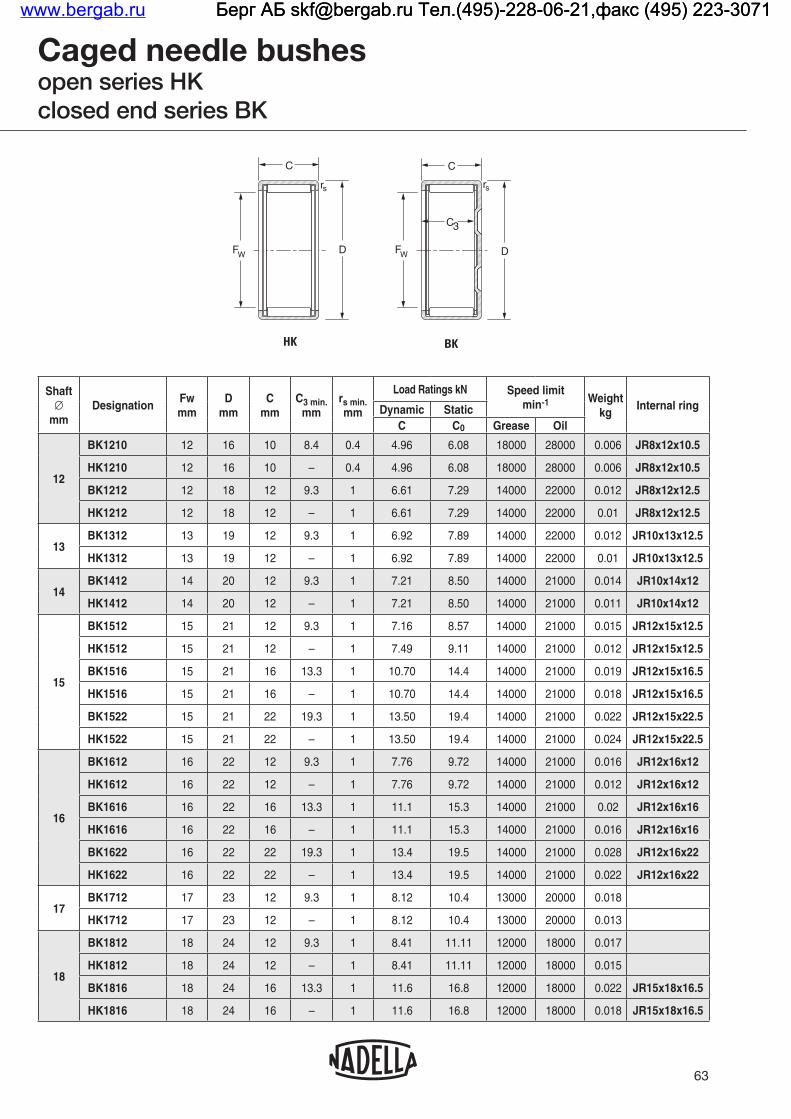
63
Caged needle bushesopen series HKclosed end series BK
Shaft∅
mmDesignation
Fwmm
Dmm
Cmm
C3 min.mm
rs min.mm
Load Ratings kN Speed limit min-1 Weight
kgInternal ringDynamic Static
C C0 Grease Oil
12
BK1210 12 16 10 8.4 0.4 4.96 6.08 18000 28000 0.006 JR8x12x10.5
HK1210 12 16 10 – 0.4 4.96 6.08 18000 28000 0.006 JR8x12x10.5
BK1212 12 18 12 9.3 1 6.61 7.29 14000 22000 0.012 JR8x12x12.5
HK1212 12 18 12 – 1 6.61 7.29 14000 22000 0.01 JR8x12x12.5
13BK1312 13 19 12 9.3 1 6.92 7.89 14000 22000 0.012 JR10x13x12.5
HK1312 13 19 12 – 1 6.92 7.89 14000 22000 0.01 JR10x13x12.5
14BK1412 14 20 12 9.3 1 7.21 8.50 14000 21000 0.014 JR10x14x12
HK1412 14 20 12 – 1 7.21 8.50 14000 21000 0.011 JR10x14x12
15
BK1512 15 21 12 9.3 1 7.16 8.57 14000 21000 0.015 JR12x15x12.5
HK1512 15 21 12 – 1 7.49 9.11 14000 21000 0.012 JR12x15x12.5
BK1516 15 21 16 13.3 1 10.70 14.4 14000 21000 0.019 JR12x15x16.5
HK1516 15 21 16 – 1 10.70 14.4 14000 21000 0.018 JR12x15x16.5
BK1522 15 21 22 19.3 1 13.50 19.4 14000 21000 0.022 JR12x15x22.5
HK1522 15 21 22 – 1 13.50 19.4 14000 21000 0.024 JR12x15x22.5
16
BK1612 16 22 12 9.3 1 7.76 9.72 14000 21000 0.016 JR12x16x12
HK1612 16 22 12 – 1 7.76 9.72 14000 21000 0.012 JR12x16x12
BK1616 16 22 16 13.3 1 11.1 15.3 14000 21000 0.02 JR12x16x16
HK1616 16 22 16 – 1 11.1 15.3 14000 21000 0.016 JR12x16x16
BK1622 16 22 22 19.3 1 13.4 19.5 14000 21000 0.028 JR12x16x22
HK1622 16 22 22 – 1 13.4 19.5 14000 21000 0.022 JR12x16x22
17BK1712 17 23 12 9.3 1 8.12 10.4 13000 20000 0.018
HK1712 17 23 12 – 1 8.12 10.4 13000 20000 0.013
18
BK1812 18 24 12 9.3 1 8.41 11.11 12000 18000 0.017
HK1812 18 24 12 – 1 8.41 11.11 12000 18000 0.015
BK1816 18 24 16 13.3 1 11.6 16.8 12000 18000 0.022 JR15x18x16.5
HK1816 18 24 16 – 1 11.6 16.8 12000 18000 0.018 JR15x18x16.5
HK BK
D
rs
C
FW
C3
D
rs
C
FW
www.bergab.ru Берг АБ [email protected] Тел.(495)-228-06-21,факс (495) 223-3071 Берг АБ [email protected] Тел.(495)-228-06-21,факс (495) 223-3071 Берг АБ [email protected] Тел.(495)-228-06-21,факс (495) 223-3071

64
Caged needle bushesopen series HKclosed end series BK
Shaft∅
mmDesignation
Fwmm
Dmm
Cmm
C3 min.mm
rs min.mm
Load Ratings kN Speed limit min-1 Weight
kgInternal ringDynamic Static
C C0 Grease Oil
20
BK2012 20 26 12 9.3 1 8.97 12.5 11000 16000 0.017 JR15x20x12
HK2012 20 26 12 – 1 8.97 12.5 11000 16000 0.015 JR15x20x12
BK2016 20 26 16 13.3 1 12.40 18.90 11000 16000 0.024 JR17x20x16.5
HK2016 20 26 16 – 1 12.40 18.90 11000 16000 0.022 JR17x20x16.5
BK2020 20 26 20 17.3 1 15.50 25.30 11000 16000 0.027 JR17x20x20.5
HK2020 20 26 20 – 1 15.90 26.20 11000 16000 0.025 JR17x20x20.5
BK2030 20 26 30 27.3 1 21.20 37.80 11000 16000 0.043 JR17x20x30.5
HK2030 20 26 30 – 1 21.20 37.80 11000 16000 0.041 JR17x20x30.5
22
BK2210 22 28 10 9.3 1 7.06 9.49 9600 15000 0.013
HK2210 22 28 10 – 1 7.06 9.49 9600 15000 0.013
BK2212 22 28 12 9.3 1 9.81 14.50 9600 15000 0.02 JR17x22x13
HK2212 22 28 12 – 1 9.81 14.50 9600 15000 0.015 JR17x22x13
BK2216 22 28 16 13.3 1 13.10 20.90 9600 15000 0.027 JR17x22x16
HK2216 22 28 16 – 1 13.10 20.90 9600 15000 0.022 JR17x22x16
BK2220 22 28 20 17.3 1 15.30 25.50 9600 15000 0.028 JR17x22x23
HK2220 22 28 20 – 1 15.30 25.50 9600 15000 0.026 JR17x22x23
25
BK2512 25 32 12 9.3 1 10.90 14.70 8500 13000 0.025
HK2512 25 32 12 — 1 10.90 14.70 8500 13000 0.021
BK2516 25 32 16 13.3 1 15.60 23.50 8500 13000 0.031 JR20x25x17
HK2516 25 32 16 — 1 15.60 23.50 8500 13000 0.028 JR20x25x17
BK2520 25 32 20 17.3 1 20.60 33.40 8500 13000 0.043 JR20x25x20.5
HK2520 25 32 20 – 1 20.60 33.40 8500 13000 0.040 JR20x25x20.5
BK2526 25 32 26 23.3 1 25.70 44.40 8500 13000 0.051 JR20x25x26.5
HK2526 25 32 26 – 1 25.70 44.40 8500 13000 0.046 JR20x25x26.5
BK2538 25 32 38 35.3 1 35.30 66.90 8500 13000 0.077 JR20x25x38.5
HK2538 25 32 38 – 1 35.30 66.90 8500 13000 0.068 JR20x25x38.5
28
BK2816 28 35 16 13.3 1 15.9 24.9 7500 12000 0.038 JR22x28x17
HK2816 28 35 16 – 1 15.9 24.9 7500 12000 0.032 JR22x28x17
BK2820 28 35 20 17.3 1 20.9 35.3 7500 12000 0.047 JR22x28x20.5
HK2820 28 35 20 – 1 20.9 35.3 7500 12000 0.040 JR22x28x20.5
HK BK
D
rs
C
FW
C3
D
rs
C
FW
www.bergab.ru Берг АБ [email protected] Тел.(495)-228-06-21,факс (495) 223-3071 Берг АБ [email protected] Тел.(495)-228-06-21,факс (495) 223-3071 Берг АБ [email protected] Тел.(495)-228-06-21,факс (495) 223-3071

65
Caged needle bushesopen series HKclosed end series BK
Shaft∅
mmDesignation
Fwmm
Dmm
Cmm
C3 min.mm
rs min.mm
Load Ratings kN Speed limit min-1 Weight
kgInternal ringDynamic Static
C C0 Grease Oil
30
BK3012 30 37 12 9.3 1 11.6 16.8 7000 11000 0.031
HK3012 30 37 12 — 1 12.0 17.7 7000 11000 0.024
BK3016 30 37 16 13.30 1 16.8 27.3 7000 11000 0.041 JR25x30x17
HK3016 30 37 16 — 1 16.8 27.3 7000 11000 0.032 JR25x30x17
BK3020 30 37 20 17.3 1 22.4 39.6 7000 11000 0.053 JR25x30x20.5
HK3020 30 37 20 — 1 22.4 39.6 7000 11000 0.042 JR25x30x20.5
BK3026 30 37 26 23.3 1 27.4 51.2 7000 11000 0.067 JR25x30x26.5
HK3026 30 37 26 — 1 27.4 51.2 7000 11000 0.054 JR25x30x26.5
BK3038 30 37 38 35.3 1 38.4 79.2 7000 11000 0.093 JR25x30x38.5
HK3038 30 37 38 — 1 38.4 79.2 7000 11000 0.075 JR25x30x38.5
35
HK3512 35 42 12 — 1 13.0 20.6 5900 9100 0.028
HK3516 35 42 16 — 1 17.4 29.9 5900 9100 0.037 JR30x35x17
BK3520 35 42 20 17.3 1 24.5 46.8 5900 9100 0.065 JR30x35x20.5
HK3520 35 42 20 — 1 24.5 46.8 5900 9100 0.049 JR30x35x20.5
40
HK4012 40 47 12 — 1 14.7 25.3 5200 7900 0.033
HK4016 40 47 16 — 1 18.9 34.8 5200 7900 0.042 JR35x40x17
BK4020 40 47 20 17.3 1 25.1 50.4 5200 7900 0.070 JR35x40x20.5
HK4020 40 47 20 — 1 25.1 50.4 5200 7900 0.060 JR35x40x20.5
45
HK4512 45 52 12 — 1 14.1 24.8 4600 7000 0.036
HK4516 45 52 16 — 1 19.8 38.5 4600 7000 0.048 JR40x45x17
BK4520 45 52 20 17.3 1 26.3 55.4 4600 7000 0.079 JR40x45x20.5
HK4520 45 52 20 — 1 27.2 58.2 4600 7000 0.059 JR40x45x20.5
50
HK5012 50 58 12 — 1 17.0 28.7 4100 6300 0.045
HK5020 50 58 20 — 1 30.9 62.2 4100 6300 0.072 JR45x50x20
HK5025 50 58 25 — 1 35.5 74.1 4100 6300 0.092 JR45x50x25.5
55 HK5520 55 63 20 — 1 31.0 64.4 3700 5700 0.079 JR45x55x20
60HK6012 60 68 12 — 1 17.2 31.2 3400 5200 0.060
HK6020 60 68 20 — 1 35.6 79,5 3400 5200 0.090 JR50x60x20
HK BK
D
rs
C
FW
C3
D
rs
C
FW
www.bergab.ru Берг АБ [email protected] Тел.(495)-228-06-21,факс (495) 223-3071 Берг АБ [email protected] Тел.(495)-228-06-21,факс (495) 223-3071 Берг АБ [email protected] Тел.(495)-228-06-21,факс (495) 223-3071

66
Caged needle bushes with sealseries HK...RS, BK...RS, HK...2RS
Shaftmm
DesignationFwmm
Dmm
Cmm
C3 min.mm
rs min.mm
Load Ratings kN Speed limit min-1 Weight
kgInternal ringDynamic Static
C C0 Grease
8 HK0810RS 8 12 10 – 0.4 2.90 2.73 20000 0.004
10 HK1012RS 10 14 12 – 0.4 4.78 5.51 19000 0.006
12HK1214RS 12 18 14 – 1 6.61 7.29 14000 0.013
HK1216.2RS 12 18 16 – 1 6.87 7.65 14000 0.016
14
BK1414RS 14 20 14 11.6 1 7.17 8.41 14000 0.014
HK1414RS 14 20 14 – 1 7.17 8.41 14000 0.015 JR10x14x16
HK1416.2RS 14 20 16 – 1 7.17 8.41 14000 0.014 JR10x14x20
15
BK1514RS 15 21 14 11.3 1 7.87 9.69 13000 0.017 JR12x15x16.5
HK1514RS 15 21 14 – 1 7.87 9.69 13000 0.016 JR12x15x16.5
HK1516.2RS 15 21 16 – 1 7.87 9.69 13000 0.019 JR12x15x16.5
16HK1614RS 16 22 14 – 1 7.82 9.76 12000 0.014 JR12x16x16
HK1616.2RS 16 22 16 – 1 7.82 9.76 12000 0.015 JR12x16x20
18HK1814RS 18 24 14 – 1 8.41 11.10 11000 0.018 JR15x18x16.5
HK1816.2RS 18 24 16 – 1 8.41 11.10 11000 0.017 JR15x18x16.5
20
HK2016.2RS 20 26 16 – 1 8.97 12.50 9700 0.023 JR17x20x16.5
HK2018RS 20 26 18 – 1 12.40 18.90 9700 0.025 JR17x20x20.5
HK2020.2RS 20 26 20 – 1 12.40 18.90 9700 0.028 JR17x20x20.5
22
HK2216.2RS 22 28 16 – 1 9.81 14.50 8800 0.025
HK2218RS 22 28 18 – 1 13.10 20.90 8800 0.027 JR17x22x23
HK2220.2RS 22 28 20 – 1 13.10 20.90 8800 0.026 JR17x22x23
25
HK2516.2RS 25 32 16 – 1 11.10 15.10 7800 0.030 JR20x25x17
HK2518RS 25 32 18 – 1 16.20 24.60 7800 0.034 JR20x25x20.5
HK2520.2RS 25 32 20 – 1 16.20 24.60 7800 0.033 JR20x25x20.5
HK2522RS 25 32 22 – 1 20.60 33.40 7800 0.042 JR20x25x26
HK2524.2RS 25 32 24 – 1 20.6 33.4 7800 0.047 JR20x25x26
HK RS HK.2RS
D
C
rs
FWD
C
rs
FW
C3
D
C
FW
rs
BK RS
www.bergab.ru Берг АБ [email protected] Тел.(495)-228-06-21,факс (495) 223-3071 Берг АБ [email protected] Тел.(495)-228-06-21,факс (495) 223-3071 Берг АБ [email protected] Тел.(495)-228-06-21,факс (495) 223-3071

67
Caged needle bushes with sealseries HK...RS, BK...RS, HK...2RS
Shaftmm
DesignationFwmm
Dmm
Cmm
C3 min.mm
rs min.mm
Load Ratings kN Speed limit min-1 Weight
kgInternal ringDynamic Static
C C0 Grease
28 HK2820.2RS 28 35 20 – 1 15.9 24.9 6900 0.042 JR22x28x20.5
30
HK3016.2RS 30 37 16 – 1 11.6 16.8 6500 0.030 JR25x30x17
HK3018RS 30 37 18 – 1 16.8 27.3 6500 0.042 JR25x30x20.5
HK3020.2RS 30 37 20 – 1 16.8 27.3 6500 0.040 JR25x30x20.5
HK3022RS 30 37 22 – 1 22.4 39.6 6500 0.051 JR25x30x26
HK3024.2RS 30 37 24 – 1 22.4 39.6 6500 0.057 JR25x30x26
35
HK3516.2RS 35 42 16 – 1 14.2 23.2 5500 0.047 JR30x35x17
HK3518RS 35 42 18 – 1 17.4 29.9 5500 0.054 JR30x35x20.5
HK3520.2RS 35 42 20 – 1 17.4 29.9 5500 0.044 JR30x35x20.5
40
HK4016.2RS 40 47 16 – 1 13.4 22.4 4900 0.037 JR35x40x20
HK4018RS 40 47 18 – 1 18.9 34.8 4900 0.057 JR35x40x20.5
HK4020.2RS 40 47 20 – 1 18.9 34.8 4900 0.053 JR35x40x20.5
45HK4518RS 45 52 18 – 1 19.8 38.5 4300 0.064 JR40x45x20.5
HK4520.2RS 45 52 20 – 1 19.8 38.5 4300 0.055 JR40x45x20.5
50HK5022RS 50 58 22 – 1 28.8 56.6 3900 0.097 JR45x50x25.5
HK5024.2RS 50 58 24 – 1 28.8 56.6 3900 0.083 JR45x50x25.5
HK RS HK.2RS
D
C
rs
FWD
C
rs
FW
C3
D
C
FW
rs
BK RS
www.bergab.ru Берг АБ [email protected] Тел.(495)-228-06-21,факс (495) 223-3071 Берг АБ [email protected] Тел.(495)-228-06-21,факс (495) 223-3071 Берг АБ [email protected] Тел.(495)-228-06-21,факс (495) 223-3071

When it is impractical to meet the shaft raceway designrequirements (hardness, surface finish, case depth, etc.) outlined in the engineering section of this catalogue, standard inner rings may be used.Inner rings are made of rolling bearing steel and after hardening, their bores, raceways and end surfaces are ground. Inner rings may be used to provide inner raceway surfaces for radial needle roller and cage assemblies, needle roller bearings and needle bushes. The extended inner rings are suitable for use with bearings containing lip contact seals and for applications in which axial movement may be present.
CONSTRUCTIONInner rings are available in four basic designs and differ only by the chamfers at the ends of the raceway surfaces, the lubricant access holes and the raceway profile. Inner rings of series JR have chamfers to assist in bearing installation but are without lubricating holes. Inner rings of series JR.JS1 have bearing installation chamfers and lubricating holes (bore diameters 5 to 50 mm). Inner rings of series JRZ.JS1 are without installation chamfers, allowing for maximum possible raceway contact.
DIMENSIONAL ACCURACYThe tolerances of size, form, and runout for inner rings meet the requirements of ISO normal tolerance class for radial bearings (see tables at the end of the catalogue). Most inner rings are produced with outside diameter raceway tolerance in accordance with h5 which, in most cases, is suitable for combining the needle roller bearings to give the normal clearance class, and for use with needle bushes.Other raceway tolerances may also be found on inner rings for combining with needle roller bearings to give one of the clearance requirement.
MOUNTING OF INNER RINGSInner rings may be mounted on the shaft with either a loose transition fit or an interference fit.
68
These fits used in conjunction with the proper fit of the bearing outer ring, will provide the correct operating clearances for most applications.Regardless of the fit of the inner ring on the shaft, the inner ring should be axially located by shaft shoulders or other positive means. The shaft shoulder diameter adjacent to the inner ring must not exceed the inner ring outside diameter.When inner rings are to be used with the needle roller bearings, appropriate shaft tolerances should be selected from table 3 on page 94 in the needle bearing section. When inner rings are to be used with needle bushes the suggested shaft tolerances are given in the “Radial play” paragraph on page 57 of the “Needle bushes” section of this catalogue.
SEALING RINGSSealing rings series DH, tabulated on pages 191 to 193 are of a small cross section suitable for use with needle bushes. They provide a cost effective and compact construction in applications using grease lubrication.
CONSTRUCTIONSealing rings series DH comprise of a steel angle casing on the outside and a molded nitrile rubber sealing element containing the sealing lip.These seals have an operating temperature range of -20°C to + 120°C.
MOUNTING OF LIP CONTACT SEALSIt is generally sufficient to press the seal into its predetermined position. Axial locating devices are not required for the seals in normal circumstances.The shaft surface on which the seal is to run must be hardened and preferably plunge ground to a smooth finish, free from burrs, nicks or scratches which may damage the sealing lip. The end of the shaft should be chamfered or rounded to prevent lip damage and to ease installation. It is also recommended to apply a coating of a suitable lubricant on the shaft before mounting the seal.
Internal rings for needle busheswww.bergab.ru Берг АБ [email protected] Тел.(495)-228-06-21,факс (495) 223-3071 Берг АБ [email protected] Тел.(495)-228-06-21,факс (495) 223-3071 Берг АБ [email protected] Тел.(495)-228-06-21,факс (495) 223-3071

69
Internal rings for needle bushes
Shaft∅
mmDesignation
dmm
Fmm
Bmm
rs min.mm
Weightkg
5
JR5x8x8JS1 5 8 8 0.3 0.002
JR5x8x12 5 8 12 0.3 0.003
JR5x8x16 5 8 16 0.3 0.004
6
JR6x9x8JS1 6 9 8 0.3 0.002
JR6x9x12 6 9 12 0.3 0.003
JR6x9x16 6 9 16 0.3 0.004
JR6x10x10 6 10 10 0.3 0.004
JR6x10x10JS1 6 10 10 0.3 0.004
JRZ6x10x12JS1 6 10 12 0.3 0.005
7
JR7x10x10.5 7 10 10.5 0.3 0.003
JR7x10x12 7 10 12 0.3 0.004
JR7x10x16 7 10 16 0.3 0.005
8
JR8x12x10 8 12 10 0.3 0.005
JR8x12x10JS1 8 12 10 0.3 0.005
JR8x12x10.5 8 12 10.5 0.3 0.005
JRZ8xl2x12JS1 8 12 12 0.3 0.006
JR8x12x12.5 8 12 12.5 0.3 0.006
JR8x12x16 8 12 16 0.3 0.007
9JR9x12x12 9 12 12 0.3 0.005
JR9x12x16 9 12 16 0.3 0.006
10
JR10x13x12.5 10 13 12.5 0.3 0.005
JR10x14x11JS1 10 14 11 0.3 0.007
JR10x14x12 10 14 12 0.3 0.007
JR10x14x12JS1 10 14 12 0.3 0.007
JR10x14x13 10 14 13 0.3 0.007
JRZ10x14x14JS1 10 14 14 0.3 0.008
JR10x14x16 10 14 16 0.3 0.009
JR10x14x20 10 14 20 0.3 0.012
JRZ.JS1JR JR.JS1
B
Fd
r
B
Fd
r
B
Fd
r
www.bergab.ru Берг АБ [email protected] Тел.(495)-228-06-21,факс (495) 223-3071 Берг АБ [email protected] Тел.(495)-228-06-21,факс (495) 223-3071 Берг АБ [email protected] Тел.(495)-228-06-21,факс (495) 223-3071

70
Internal rings for needle bushes
Shaft∅
mmDesignation
dmm
Fmm
Bmm
rs min.mm
Weightkg
12
JR12x15x12.5 12 15 12.5 0.3 0.006
JR12x15x16 12 15 16 0.3 0.008
JR12x15x16.5 12 15 16.5 0.3 0.008
JR12x15x18.5 12 15 18.5 0.3 0.009
JR12x15x22.5 12 15 22.5 0.3 0.011
JR12x16x12 12 16 12 0.3 0.008
JR12x16x12JS1 12 16 12 0.3 0.008
JR12x16x13 12 16 13 0.3 0.008
JRZ12x16x14JS1 12 16 14 0.3 0.010
JR12x16x16 12 16 16 0.3 0.011
JR12x16x20 12 16 20 0.3 0.014
JR12x16x22 12 16 22 0.3 0.015
14 JR14x17x17 14 17 17 0.3 0.009
15
JR15x18x16.5 15 18 16.5 0.3 0.010
JR15x19x16 15 19 16 0.3 0.013
JR15x19x20 15 19 20 0.3 0.017
JR15x20x12 15 20 12 0.3 0.012
JR15x20x12JS1 15 20 12 0.3 0.012
JR15x20x13 15 20 13 0.3 0.014
JRZ15x20x14JS1 15 20 14 0.3 0.015
JR15x20x16 15 20 16 0.3 0.017
JR15x20x20 15 20 20 0.35 0.021
JR15x20x23 15 20 23 0.3 0.025
JR15x20x26 15 20 26 0.3 0.028
JRZ.JS1JR JR.JS1
B
Fd
r
B
Fd
r
B
Fd
r
www.bergab.ru Берг АБ [email protected] Тел.(495)-228-06-21,факс (495) 223-3071 Берг АБ [email protected] Тел.(495)-228-06-21,факс (495) 223-3071 Берг АБ [email protected] Тел.(495)-228-06-21,факс (495) 223-3071
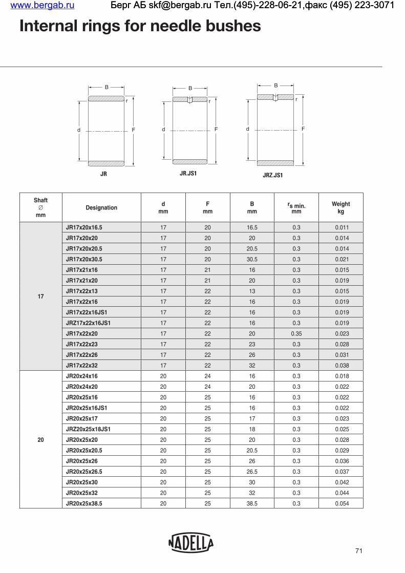
71
Internal rings for needle bushes
Shaft∅
mmDesignation
dmm
Fmm
Bmm
rs min.mm
Weightkg
17
JR17x20x16.5 17 20 16.5 0.3 0.011
JR17x20x20 17 20 20 0.3 0.014
JR17x20x20.5 17 20 20.5 0.3 0.014
JR17x20x30.5 17 20 30.5 0.3 0.021
JR17x21x16 17 21 16 0.3 0.015
JR17x21x20 17 21 20 0.3 0.019
JR17x22x13 17 22 13 0.3 0.015
JR17x22x16 17 22 16 0.3 0.019
JR17x22x16JS1 17 22 16 0.3 0.019
JRZ17x22x16JS1 17 22 16 0.3 0.019
JR17x22x20 17 22 20 0.35 0.023
JR17x22x23 17 22 23 0.3 0.028
JR17x22x26 17 22 26 0.3 0.031
JR17x22x32 17 22 32 0.3 0.038
20
JR20x24x16 20 24 16 0.3 0.018
JR20x24x20 20 24 20 0.3 0.022
JR20x25x16 20 25 16 0.3 0.022
JR20x25x16JS1 20 25 16 0.3 0.022
JR20x25x17 20 25 17 0.3 0.023
JRZ20x25x18JS1 20 25 18 0.3 0.025
JR20x25x20 20 25 20 0.3 0.028
JR20x25x20.5 20 25 20.5 0.3 0.029
JR20x25x26 20 25 26 0.3 0.036
JR20x25x26.5 20 25 26.5 0.3 0.037
JR20x25x30 20 25 30 0.3 0.042
JR20x25x32 20 25 32 0.3 0.044
JR20x25x38.5 20 25 38.5 0.3 0.054
JRZ.JS1JR JR.JS1
B
Fd
r
B
Fd
r
B
Fd
r
www.bergab.ru Берг АБ [email protected] Тел.(495)-228-06-21,факс (495) 223-3071 Берг АБ [email protected] Тел.(495)-228-06-21,факс (495) 223-3071 Берг АБ [email protected] Тел.(495)-228-06-21,факс (495) 223-3071

72
Internal rings for needle bushes
Shaft∅
mmDesignation
dmm
Fmm
Bmm
rs min.mm
Weightkg
22
JR22x26x16 22 26 16 0.3 0.019
JR22x26x20 22 26 20 0.3 0.023
JR22x28x17 22 28 17 0.3 0.030
JR22x28x20.5 22 28 20.5 0.3 0.038
JR22x28x30 22 28 30 0.3 0.056
25
JR25x29x20 25 29 20 0.3 0.027
JR25x29x30 25 29 30 0.3 0.040
JR25x30x16 25 30 16 0.3 0.027
JR25x30x16JS1 25 30 16 0.3 0.027
JR25x30x17 25 30 17 0.3 0.028
JRZ25x30x18JS1 25 30 18 0.3 0.031
JR25x30x20 25 30 20 0.3 0.034
JR25x30x20.5 25 30 20.5 0.3 0.035
JR25x30x26 25 30 26 0.3 0.044
JR25x30x26.5 25 30 26.5 0.3 0.045
JR25x30x30 25 30 30 0.3 0.051
JR25x30x32 25 30 32 0.3 0.054
JR25x30x38.5 25 30 38.5 0.3 0.066
28
JR28x32x17 28 32 17 0.3 0.028
JR28x32x20 28 32 20 0.3 0.030
JR28x32x30 28 32 30 0.3 0.044
JRZ.JS1JR JR.JS1
B
Fd
r
B
Fd
r
B
Fd
r
www.bergab.ru Берг АБ [email protected] Тел.(495)-228-06-21,факс (495) 223-3071 Берг АБ [email protected] Тел.(495)-228-06-21,факс (495) 223-3071 Берг АБ [email protected] Тел.(495)-228-06-21,факс (495) 223-3071

73
Internal rings for needle bushes
Shaft∅
mmDesignation
dmm
Fmm
Bmm
rs min.mm
Weightkg
30
JR30x35x16 30 35 16 0.3 0.031
JR30x35x17 30 35 17 0.3 0.033
JRZ30x35x18JS1 30 35 18 0.3 0.036
JR30x35x20 30 35 20 0.3 0.039
JRZ30x35x20JS1 30 35 20 0.3 0.039
JR30x35x20.5 30 35 20.5 0.3 0.040
JR30x35x26 30 35 26 0.3 0.054
JR30x35x30 30 35 30 0.3 0.057
JR30x35x32 30 35 32 0.3 0.062
JR30x38x20JS1 30 38 20 0.6 0.067
32
JR32x37x20 32 37 20 0.3 0.043
JR32x37x30 32 37 30 0.3 0.064
JR32x40x20 32 40 20 0.6 0.069
JR32x40x36 32 40 36 0.6 0.128
35
JR35x40x17 35 40 17 0.3 0.040
JR35x40x20 35 40 20 0.3 0.046
JR35x40x20.5 35 40 20.5 0.3 0.049
JR35x40x22 35 40 22 0.3 0.052
JR35x40x30 35 40 30 0.3 0.071
JR35x40x34 35 40 34 0.3 0.080
JR35x40x40 35 40 40 0.3 0.094
JR35x42x20 35 42 20 0.6 0.065
JR35x42x20JS1 35 42 20 0.6 0.065
JRZ35x42x23JS1 35 42 23 0.6 0.074
JR35x42x36 35 42 36 0.6 0.122
JR35x44x22 35 44 22 0.6 0.097
JRZ.JS1JR JR.JS1
B
Fd
r
B
Fd
r
B
Fd
r
www.bergab.ru Берг АБ [email protected] Тел.(495)-228-06-21,факс (495) 223-3071 Берг АБ [email protected] Тел.(495)-228-06-21,факс (495) 223-3071 Берг АБ [email protected] Тел.(495)-228-06-21,факс (495) 223-3071

74
Internal rings for needle bushes
Shaft∅
mmDesignation
dmm
Fmm
Bmm
rs min.mm
Weightkg
37 JR37x42x20 37 42 20 0.35 0.046
38JR38x43x20 38 43 20 0.3 0.050
JR38x43x30 38 43 30 0.3 0.075
40
JR40x45x17 40 45 17 0.3 0.044
JR40x45x20 40 45 20 0.3 0.052
JR40x45x20.5 40 45 20.5 0.3 0.054
JR40x45x25 40 45 25 0.35 0.062
JR40x45x30 40 45 30 0.3 0.078
JR40x45x34 40 45 34 0.3 0.089
JR40x45x40 40 45 40 0.3 0.115
JR40x48x22 40 48 22 0.6 0.094
JRZ40x48x23JS1 40 48 23 0.6 0.100
JR40x48x40 40 48 40 0.6 0.173
JR40x50x20 40 50 20 1 0.110
42JR42x47x20 42 47 20 0.3 0.055
JR42x47x30 42 47 30 0.3 0.083
45
JR45x50x20 45 50 20 0.3 0.058
JR45x50x25 45 50 25 0.6 0.073
JR45x50x25.5 45 50 25.5 0.3 0.075
JR45x50x35 45 50 35 0.6 0.103
JR45x50x40 45 50 40 0.3 0.117
JR45x52x22 45 52 22 0.6 0.090
JR45x52x23 45 52 23 0.6 0.096
JRZ45x52x23JS1 45 52 23 0.6 0.096
JR45x52x40 45 52 40 0.6 0.167
JR45x55x20 45 55 20 1 0.133
JR45x55x20JS1 45 55 20 1 0.133
JR45x55x22 45 55 22 1 0.135
JR45x55x40 45 55 40 1 0.247
JRZ.JS1JR JR.JS1
B
Fd
r
B
Fd
r
B
Fd
r
www.bergab.ru Берг АБ [email protected] Тел.(495)-228-06-21,факс (495) 223-3071 Берг АБ [email protected] Тел.(495)-228-06-21,факс (495) 223-3071 Берг АБ [email protected] Тел.(495)-228-06-21,факс (495) 223-3071

75
Internal rings for needle bushes
Shaft∅
mmDesignation
dmm
Fmm
Bmm
rs min.mm
Weightkg
50
JR50x55x20 50 55 20 0.3 0.065
JR50x55x25 50 55 25 0.6 0.081
JR50x55x35 50 55 35 0.6 0.113
JR50x55x40 50 55 40 0.3 0.130
JR50x58x22 50 58 22 0.6 0.117
JRZ50x58x23JS1 50 58 23 0.6 0.122
JR50x58x40 50 58 40 0.6 0.213
JR50x60x20 50 60 20 1 0.155
JR50x60x20JS1 50 60 20 1 0.155
JR50x60x25 50 60 25 1 0.170
JR50x60x40 50 60 40 1 0.310
55JR55x60x25 55 60 25 0.6 0.088
JR55x60x35 55 60 35 0.6 0.124
JRZ.JS1JR JR.JS1
B
Fd
r
B
Fd
r
B
Fd
r
www.bergab.ru Берг АБ [email protected] Тел.(495)-228-06-21,факс (495) 223-3071 Берг АБ [email protected] Тел.(495)-228-06-21,факс (495) 223-3071 Берг АБ [email protected] Тел.(495)-228-06-21,факс (495) 223-3071

www.bergab.ru Берг АБ [email protected] Тел.(495)-228-06-21,факс (495) 223-3071 Берг АБ [email protected] Тел.(495)-228-06-21,факс (495) 223-3071 Берг АБ [email protected] Тел.(495)-228-06-21,факс (495) 223-3071

DRAWN CUP ROLLER CLUTCHESwww.bergab.ru Берг АБ [email protected] Тел.(495)-228-06-21,факс (495) 223-3071 Берг АБ [email protected] Тел.(495)-228-06-21,факс (495) 223-3071 Берг АБ [email protected] Тел.(495)-228-06-21,факс (495) 223-3071

www.bergab.ru Берг АБ [email protected] Тел.(495)-228-06-21,факс (495) 223-3071 Берг АБ [email protected] Тел.(495)-228-06-21,факс (495) 223-3071 Берг АБ [email protected] Тел.(495)-228-06-21,факс (495) 223-3071

Lock functionShaft drives gear clockwise (white arrows) or gear can drive shaft counter clockwise (black arrows)
CLUTCH
LO
C
K
Overrun function Shaft overruns in gear counterclockwise(white arrows) or gear overruns on shaftclockwise (black arrow)
CLUTCH
LO
C
K
IDENTIFICATIONThe basic types of clutches and clutch and bearing assemblies are listed below:
FCS, FC-K Regular clutch, single roller per stainless steel spring.
FC Regular clutch, multi-roller per stainless steel spring.
FCB Regular clutch and bearing assembly, multi-roller per stainless steel spring.
FCL-K Light series clutch, single roller per stainless steel spring.FCBL-K, FCBN-K Light series clutch and bearing
assembly. Single roller per stainless steel spring.
Drawn cup roller clutch transmits torque between shaft and housing in one direction and allows free overrun in the opposite direction.When transmitting torque, either the shaft or the housing can be the input member. Applications are generally described as indexing, backstopping or overrunning.
TYPES OF CLUTCHES AND CLUTCH AND BEARING ASSEMBLIES
Drawn cup roller clutch type FC with
stainless steel springs
Drawn cup clutch and bearing assembly
type FCB with stainless steel springs
79
Drawn cup roller clutch, types FCS, FC-K, FCL-K with
stainless steel springs
Drawn cup clutch and bearing assembly types FCBL-K, FCBN-K with stainless steel springs
Technical features
Drawn cup roller clutches
www.bergab.ru Берг АБ [email protected] Тел.(495)-228-06-21,факс (495) 223-3071 Берг АБ [email protected] Тел.(495)-228-06-21,факс (495) 223-3071 Берг АБ [email protected] Тел.(495)-228-06-21,факс (495) 223-3071

Technical features
Drawn cup roller clutches
OPERATIONOperation is in two modes: the overrun mode and the lock mode. Operational mode is controlled by the direction of the clutch or shaft rotation with respect to the locking ramps.
In the overrun mode, shown in the drawings below (a), the relative rotation between the housed clutch and the shaft causes the rollers to move away from their locking position against the locking ramps in the needle bush. The housing and the clutch are then free to overrun in one direction, or the shaft is free to overrun in the other direction.
In the lock mode, shown in the drawings below (b), the relative rotation between the housed clutch and the shaft is opposite to that in the overrun mode. The rollers, assisted by the leaf-type springs, become wedged between the locking ramps and the shaft to transmit torque between the two members. Either the member housing the clutch drives the shaft in one direction, or the shaft can drive the clutch and its housing member in the other direction.
OVERRUNS CLOCKWISE
HOUSING
SHAFTIS STATIONARYLO
CK
LOCK
CLUTCH
ROTATION
IS STATIONARY
HOUSING
SHAFT CLUTCHOVERRUNSCOUNTER CLOCKWISE
STATIONARY
CLUTCH
ROTATESLOCK
LOCK
HOUSING(DRIVEN)
SHAFT(DRIVER)
CLUTCH
ROTATES
SHAFT(DRIVEN)
HOUSING(DRIVER)
Clearance between the rollers and cup ramps is exaggerated in these drawings
80
CONSTRUCTIONIn many respects, construction is similar to that of needle bushes. The well-established design utilizes the same low-profile radial section as needle bushes.The precisely formed interior ramps provide surfaces against which the needle rollers wedge. These positively lock the clutch with the shaft when rotated in the proper direction. These ramps, formed during the operation of drawing the cup, are case hardened for wear resistance.
Two designs of precision molded clutch cages are employed. Clutch and clutch and bearing assembly types – FC, FC-K, FCS, FCL-K, FCB, FCBN-K, FCBL-K – use a glass fiber, reinforced nylon cage, equipped with inserted stainless steel leaf springs. The stainless steel springs permit higher rates of clutch engagement and achieve greater spring life. The nylon cage permits operation at higher temperatures.
Types FCB, FCBL-K, FCBN-K, clutch and bearing assemblies have cages, for retention and guidance of the needle rollers in the bearings, located on both sides of the clutch unit.
Clutch and bearing assembly
Types FC, FC-K, FCS, FCL-K are of clutch-only configurations for use with external radial support (usually two needle bushes). Separate bearings position the shaft and housing concentrically and carry the radial load during overrun.
Clutch only
(a)
(b)
www.bergab.ru Берг АБ [email protected] Тел.(495)-228-06-21,факс (495) 223-3071 Берг АБ [email protected] Тел.(495)-228-06-21,факс (495) 223-3071 Берг АБ [email protected] Тел.(495)-228-06-21,факс (495) 223-3071

In any application where our clutch may be considered, it will be part of a system in which the operating conditions and the clutch mounting will affect its function.Before any clutch selection is made, it is important that the following catalog section be carefully studied to understand the effects of these factors.
Consideration should be given to operating conditions such as:
inertial torque.
the clutch during engagement.
stainless steel or plastic leaf springs.
can affect clutch performance.
motion).
Consideration should be given to the shaft and housing design requirements such as:
approaching torque rating limits.
to ensure sufficient fatigue life and torque-carrying ability.
support the applied torque loads.
to ensure uniform torque and load distribution.
A test program under all expected operating conditions should be carried out before putting a new application into production. Customer engineers are constantly working with and testing new applications, and their experience can be of great help to the designer considering the use of a drawn cup roller clutch.
81
Technical features
Drawn cup roller clutches
APPLICATIONSClutches and clutch and bearing assemblies are successfully applied in a wide range of commercial products where indexing, backstopping and overrunning operations must be performed reliably. The sketches on these pages illustrate some of the many possible uses.When applying the clutch-only unit, separate bearings on each side of the clutch are required to position the shaft concentrically with the housing, and to carry the radial loads during overrun. Needle bushes, with the same radial section as the clutch, should be used in the through-bored housings for simplicity and economy. Two clutches can be used side by side for greatertorque capacity.Where the radial loads are light, the clutch and bearing assembly can be used without additional support bearings. This reduces the overall assembly width, the number of stocked and ordered parts and assembly costs, as well.
Clutch and bearing arrangement for heavy loads
Clutch and bearing assembly for light loads
Drawn cup roller clutches are manufactured to commercial hardware standards and are used extensively in appliances, business machines, industrial and recreation equipment and a wide range of other applications.
www.bergab.ru Берг АБ [email protected] Тел.(495)-228-06-21,факс (495) 223-3071 Берг АБ [email protected] Тел.(495)-228-06-21,факс (495) 223-3071 Берг АБ [email protected] Тел.(495)-228-06-21,факс (495) 223-3071

Technical features
Drawn cup roller clutches
Paper feed rolls inbusiness machines
Paper feed rolls in business machines
Rack indexing drive
Motor backstops
Two speed Gearbox with reversing input
Two-speed gearboxwith reversing input
Two speed Gearbox with reversing input
Timing motorfreewheels
Washing machinetransmission
Stair steppers andother athletic equipment
St
Lawnmowerdifferential
Towel dispensersand similar web roll feedmechanisms
Conveyor rollersConveyor rollers
Chainsaw starters
Conveyor rollers
Chainsaw starters
82
www.bergab.ru Берг АБ [email protected] Тел.(495)-228-06-21,факс (495) 223-3071 Берг АБ [email protected] Тел.(495)-228-06-21,факс (495) 223-3071 Берг АБ [email protected] Тел.(495)-228-06-21,факс (495) 223-3071

HOUSING DESIGNDrawn cup clutches and clutch and bearing assemblies are mounted with a simple press fit in their housings. Through-bored and chamfered housings are preferred. A 30 degree angle is suggested and care should be taken to round the edge where the chamfer meets the housing bore. A sharp edge at this location can greatly
such as shoulders or snap rings, are not required. The case hardened cups must be properly supported. Steel housings are preferred and must be used for applications involving high-torque loads to prevent radial expansion of the clutch cups. The suggested minimum housing outer diameters in the tables of dimensions are for steel.The housing bore should be round within one-half of the diameter tolerance.The taper within the length of the outer ring should not exceed 0.013 mm. The surface finish of the housing bore should not exceed 1.6 μm Ra.The torque ratings, given in the clutch tables, are based on a steel housing of a large section. When other housing material must be used (such as aluminium, powdered metal and plastics), the torque rating of the clutch will be reduced. Such housings may be satisfactory for lightly torqued applications. But, the Technical Service should be consulted for appropriate housing and shaft suggestions. Otherwise, an insufficient press fit and use of a lower strength housing material can result in more internal clearance and reduced performance of the clutch.When using non-steel housings, thorough testing of the design is suggested. Adhesive compounds can be used to prevent creeping rotation of the clutch in plastic housings with low friction properties. Adhesives will not provide proper support in oversized metal housings. When using adhesives, care must be taken to keep the adhesive out of the clutches and bearings.
SHAFT DESIGNThe clutch or clutch and bearing assembly operates directly on the shaft whose specifications of dimension, hardness and surface finish are well within standard manufacturing limits.
83
Either case-hardening or through-hardening grades of good bearing quality steel are satisfactory for raceways. Steels modified for free machining, such as those high in sulfur content and particularly those containing lead, are seldom satisfactory for raceways. For long fatigue life, the shaft raceway must have a
ground to the suggested diameter shown in the tables of dimensions. It may be through hardened, or it may be case hardened with an effective case depth of 0.40 mm. Effective case depth is defined as the distance from the
level after grinding.Taper within the length of the raceway should not exceed 0.008 mm, or one-half the diameter tolerance – whichever is smaller. The radial deviation from true circular form of the raceway should not exceed 0.0025 mm for diameters up to and including 25 mm. For raceways greater than 25 mm, the allowable radial deviation should not exceed 0.0025 mm multiplied by a factor of the raceway diameter divided by 25. Surface finish on the raceway should not exceed 0.4 μm Ra. Deviations will reduce the load capacity and fatigue life of the shaft.
INSTALLATIONSimplicity of installation promotes additional cost savings. The drawn cup roller clutch or the clutch and bearing
are virtually identical with those for installing needle bushes. The unit is pressed into the bore of a gear or pulley hub or housing of the proper size. No shoulders, splines, keys, screws or snap rings are required. Installation procedures are summarized in the followingsketches on page 84.
Use an arbor press or hydraulic ram press (fig. 1) to exert steady pressure. Never use a hammer, or other tool requiring pounding to drive the clutch into its housing.
Technical features
Drawn cup roller clutches
www.bergab.ru Берг АБ [email protected] Тел.(495)-228-06-21,факс (495) 223-3071 Берг АБ [email protected] Тел.(495)-228-06-21,факс (495) 223-3071 Берг АБ [email protected] Тел.(495)-228-06-21,факс (495) 223-3071

Technical features
Drawn cup roller clutches
easy introduction of the clutch and bearing or the clutch unit (fig. 3).
bore to assure full seating. Through-bored housings are always preferred. If the housing has a shoulder, never seat the clutch against the shoulder.
Amount of Recess
Chamfer
IMPORTANT: The mounted clutch engages when the housing is rotated relative to the shaft in the direction of the arrow and lock marking ( LOCK) stamped on the
pressing it into its housing.
When assembling the shaft, it should be rotated in the overrun direction during insertion. The end of the shaft should have a large chamfer or rounding (fig. 4).
Use an installation tool as shown in fig. 2. If the clutch isstraddled by needle roller bearings, press units into position – in proper sequence – and preferably leave a small clearance between units.
Amount of recess
Use “O-Ring“ on pilot
Long lead on pilot
Pilot dia. is0.5 mm less than
nom. shaft dia.
15º
“O-Ring” holds uniton Pilot during
installation
APPLIED LOADSThe clutch-only unit is designed to transmit purely torque loads. Applied torque should not exceed the catalog ratings, which are based on the compressive strength of well-aligned clutch components. Bearings on either side of the clutch are to assure concentricity between the shaft and the housing to support radial loads during clutch overrun. Integral clutch and bearing assemblies are available for this purpose, especially where the radial loads are light. The total maximum dynamic radial load that may be shared by the two needle roller and cage radial bearing assemblies should not be greater than C/3.In determining the total torque load on a clutch, it is essential to consider the torque, due to inertial forces developed in the mechanism, in addition to the externally applied torque. The larger the clutch, and the greater the mass of the mechanism controlled by it, the more important this consideration becomes.Clutch lockup depends on friction. For this reason, applications involving severe vibrations or axial motion of the shaft within the clutch are to be avoided. Applications where overhanging or overturning loads occur should incorporate bearings that will maintain alignment between the shaft and the clutch housing.Consult Technical Service for suggestions.
84
fig. 1
fig. 2
fig. 3
fig. 4
www.bergab.ru Берг АБ [email protected] Тел.(495)-228-06-21,факс (495) 223-3071 Берг АБ [email protected] Тел.(495)-228-06-21,факс (495) 223-3071 Берг АБ [email protected] Тел.(495)-228-06-21,факс (495) 223-3071

LUBRICATIONOil is the preferred lubricant; it minimizes wear and heat generation. For those applications where oil is not practical, clutches are packed with a soft grease containing mineral oil. Thick grease will retard roller engagement and can cause individual rollers to slip, possibly overloading any engaged rollers.
TEMPERATURETemperature extremes can cause clutch malfunctions and failure. The molded plastic cage with integral springs holds its necessary resiliency and strength when the operating temperature within the clutch is kept below 90° C. The clutch with reinforced nylon cage and separate steel springs operates well at temperatures up to 120° C continuously and to 150° C intermittently. Excessive thickening of the lubricant at low temperatures may prevent some, or all, of the rollers from engaging. New applications should be tested under expected operating conditions to determine whether or not temperature problems exist.
BACKLASHBacklash, or lost motion, prior to engagement is minimal. The variation in backlash from one cycle to another is extremely low. Grease lubrication, or improper fit (housing bore and shaft diameter), may increase backlash. Angular displacement between the shaft and housing increases as an applied torque load is increased.
RATE OF ENGAGEMENTClutch lockup depends upon static friction. Axial motion between shaft and clutch rollers prevents lockup.Clutches with integral springs engage satisfactorily at cyclic rates up to 200 engagements per minute. Intermittent operation at higher rates has been successful. The steel spring type clutches have proven dependability at rates up to 6000 or 7000 engagements per minute. Even higher cyclic rates may be practical. Because grease may impair engagement at high cyclic rates, a light oil should beused.
85
OVERRUN LIMIT SPEED RATINGExact limiting speed ratings are not easily predictable. The value for each clutch given in the bearing tables is not absolute but serves as a guide for the designer. Oil lubrication is absolutely necessary for high speed operations. Consult Technical Service when overrunning speeds are high.
INSPECTIONAlthough the outer cup of the clutch is accurately drawn from strip steel, it can go slightly out of round during heat treat. When the assembly is pressed into a ring gage, or properly prepared housing of correct size and wall thickness, it becomes round and properly sized. Direct measurement of the outer diameter of a drawn cup assembly is an incorrect procedure.
The proper inspection procedure is as follows:
size, as given in the tables.
2. Gage the bore with the specified plug gages of the proper size, as given in the tables of dimensions.
a. The locking plug is rotated to ensure lockup when the
clutch is operated on a low-limit shaft and is mounted in a high-limit housing, strong enough to properly size the clutch.
b. The overrun plug is rotated to ensure free overrunning
when the clutch is operated on a high-limit shaft and is mounted in a low-limit housing.
c. The “go” plug and “no go” plug ensure proper size of the bearings in the clutch and bearing assemblies.
gage sizes reflect adjustment for the loose and tight conditions resulting from high or low housings or shafts.
Technical features
Drawn cup roller clutches
www.bergab.ru Берг АБ [email protected] Тел.(495)-228-06-21,факс (495) 223-3071 Берг АБ [email protected] Тел.(495)-228-06-21,факс (495) 223-3071 Берг АБ [email protected] Тел.(495)-228-06-21,факс (495) 223-3071

86
Drawn cup roller clutches
Shaft∅
mmDesignation
Fwmm
Dmm
Cmm
TorqueNm
Overrun limiting speed
rating for rotating shaft
min-1
Suitable needle bush
4 FC-4-K 4 8 6 0.349 26000 HK0408
6FCS-6 6 10 12 2.15 22000 HK0608
FC-6 6 10 12 2.63 22000 HK0608
8FCL-8-K 8 12 12 3.39 21000 HK0808
FC-8 8 14 12 4.42 21000 DL810
10FCL-10-K 10 14 12 4.60 19000 HK1010
FC-10 10 16 12 5.82 19000 DL1012
12 FC-12 12 18 16 14.0 19000 HK1212
16 FC-16 16 22 16 21.7 14000 HK1612
20FC-20 20 26 16 32.6 11000 HK2012
FC-20-K 20 26 16 30.0 11000 HK2012
25FC-25-K 25 32 20 66.4 8700 HK2512
FC-25 25 32 20 71.0 8700 HK2512
30 FC-30 30 37 20 99.1 7300 HK3012
35 FCS-35 35 42 20 107.0 6100 HK3512
C
DFw
C
DFw
FC FCS, FCL-K e FC-K
Shaft raceway and housing bore diameters that are necessary for proper mounting and operation are listed on the opposite page. Types FC, FC-K, FCS and FCL-K clutches have stainless steel springs inserted in molded cage to position rollers for lockup.
www.bergab.ru Берг АБ [email protected] Тел.(495)-228-06-21,факс (495) 223-3071 Берг АБ [email protected] Тел.(495)-228-06-21,факс (495) 223-3071 Берг АБ [email protected] Тел.(495)-228-06-21,факс (495) 223-3071

87
Drawn cup roller clutches
Shaft∅
mm
Gaging
ZMinimum
outer diameter of
steel housing for Torque
mm
S - Shaft raceway diameter
H - Housing bore
Weightkg
Mounting
Ring gagemm
Clutch locking plug
mm
Clutch overrun plug
mm
Max. mm
Min. mm
Max. mm
Min. mm
4 7.984 3.980 4.004 11 4.000 3.995 7.993 7.984 0.001
69.984 5.980 6.004 14 6.000 5.995 9.993 9.984 0.003
9.984 5.980 6.004 14 6.000 5.995 9.993 9.984 0.004
811.980 7.976 8.005 17 8.000 7.994 11.991 11.980 0.003
13.980 7.976 8.005 20 8.000 7.994 13.991 13.980 0.007
1013.980 9.976 10.005 20 10.000 9.994 13.991 13.980 0.004
15.980 9.976 10.005 25 10.000 9.994 15.991 15.980 0.009
12 17.980 11.974 12.006 27 12.000 11.992 17.991 17.980 0.012
16 21.976 15.972 16.006 31 16.000 15.992 21.989 21.976 0.018
2025.976 19.970 20.007 38 20.000 19.991 25.989 25.976 0.021
25.976 19.970 20.007 38 20.000 19.991 25.989 25.976 0.016
2531.972 24.967 25.007 46 25.000 24.991 31.988 31.972 0.026
31.972 24.967 25.007 46 25.000 24.991 31.988 31.972 0.034
30 36.972 29.967 30.007 51 30.000 29.991 36.988 36.972 0.042
35 41.972 34.964 35.009 56 35.000 34.989 41.988 41.972 0.048
and then checking the bore with the appropriate plug gauges.
When applying these clutches, it is important that separate bearings be used adjacent to the clutches to carry radial loads and assure concentricity between the shaft and housing.For full details on “INSTALLATION” see page 83.
The mounted clutch engageswhen the housing is rotatedrelative to the shaft in thedirection of the arrow marking( LOCK) stamped on the cup.
Shaft surface to be58 HRC or equivalent
Z S H
www.bergab.ru Берг АБ [email protected] Тел.(495)-228-06-21,факс (495) 223-3071 Берг АБ [email protected] Тел.(495)-228-06-21,факс (495) 223-3071 Берг АБ [email protected] Тел.(495)-228-06-21,факс (495) 223-3071

88
Drawn cup roller clutches
Shaft∅
mmDesignation
Fwmm
Dmm
Cmm
TorqueNm
Load ratings 1) Overrun limiting
speed rating for rotating
shaft min-1
DynamicC
kN
StaticCOkN
4 FCBN-4-K 4 10 9 0.19 1.86 0.99 26000
6 FCBN-6-K 6 12 10 0.56 2.48 1.48 22000
8FCBL-8-K 8 12 22 3.39 3.62 3.28 21000
FCB-8 8 14 20 4.42 4.22 3.04 21000
10 FCB-10 10 16 20 5.82 4.84 3.80 19000
12 FCB-12 12 18 26 14.0 6.30 5.84 19000
16 FCB-16 16 22 26 21.7 6.64 7.12 14000
20 FCB-20 20 26 26 32.6 8.16 9.46 11000
25 FCB-25 25 32 30 71.0 11.3 13.1 8700
30 FCB-30 30 37 30 99.1 11.5 14.9 7300
C
DFw
C
DFw
FCBL-K, FCBN-KFCB
Shaft raceway and housing bore diameters that are necessary for proper mounting and operation are listed on the opposite page. Types FCB and FCBL clutch and bearing assemblies have stainless steel springs inserted in the molded cage to position rollers for instantaneous lockup.
www.bergab.ru Берг АБ [email protected] Тел.(495)-228-06-21,факс (495) 223-3071 Берг АБ [email protected] Тел.(495)-228-06-21,факс (495) 223-3071 Берг АБ [email protected] Тел.(495)-228-06-21,факс (495) 223-3071

89
Drawn cup roller clutches
Shaft∅
mm
Gaging ZMinimum
outer diameter of
steel housing for Torque
mm
S - Shaft raceway diameter
H - Housing bore
Weight kgRing
gagemm
Clutchlocking plug
mm
Clutch overrun and bearing go
plugmm
Bearing no go plugmm
Mounting
Max. mm
Min. mm
Max. mm
Min. mm
4 9.984 3.980 4.004 4.030 16 4.000 3.995 9.993 9.984 0.003
6 11.980 5.977 6.004 6.030 18 6.000 5.995 11.991 11.980 0.004
811.980 7.976 8.005 8.033 17 8.000 7.994 11.991 11.980 0.005
13.980 7.976 8.005 8.033 20 8.000 7.994 13.991 13.980 0.011
10 15.980 9.976 10.005 10.033 25 10.000 9.994 15.991 15.980 0.013
12 17.980 11.974 12.006 12.036 27 12.000 11.992 17.991 17.980 0.018
16 21.976 15.972 16.006 16.036 31 16.000 15.992 21.989 21.976 0.024
20 25.976 19.970 20.007 20.043 38 20.000 19.991 25.989 25.976 0.028
25 31.972 24.967 25.007 25.043 46 25.000 24.991 31.988 31.972 0.048
30 36.972 29.967 30.007 30.043 51 30.000 29.991 36.988 36.972 0.054
assembly in a ring gauge and then checking the bore with the
on the page 85.
For full details on “INSTALLATION” see page 83.
Shaft surface to be58 HRC or equivalent
Z S H
The mounted clutch engageswhen the housing is rotatedrelative to the shaft in thedirection of the arrow marking( LOCK) stamped on the cup.
www.bergab.ru Берг АБ [email protected] Тел.(495)-228-06-21,факс (495) 223-3071 Берг АБ [email protected] Тел.(495)-228-06-21,факс (495) 223-3071 Берг АБ [email protected] Тел.(495)-228-06-21,факс (495) 223-3071

www.bergab.ru Берг АБ [email protected] Тел.(495)-228-06-21,факс (495) 223-3071 Берг АБ [email protected] Тел.(495)-228-06-21,факс (495) 223-3071 Берг АБ [email protected] Тел.(495)-228-06-21,факс (495) 223-3071

BEARINGS WITH CAGE - GUIDED NEEDLESwww.bergab.ru Берг АБ [email protected] Тел.(495)-228-06-21,факс (495) 223-3071 Берг АБ [email protected] Тел.(495)-228-06-21,факс (495) 223-3071 Берг АБ [email protected] Тел.(495)-228-06-21,факс (495) 223-3071

Caged needle bearings possess an outer ring made from through- hardened bearing steel. The cage guides the needles and retains them in the outer ring. The bearings may be used without an inner ring if the shaft journal serving as a raceway is of sufficient hardness and has the correct surface finish. To ensure that the full load capacity of these bearings is achieved, a hardness of 58-64 HRC is required. A lower hardness will entail a reduction in the load capacities (both dynamic and static) as shown in the table of dimensions (see Technical Section).
92
CONSTRUCTIONThe basic constructions of needle roller bearings are:
≥ 12 mm)
≤ 10 mm).
Needle roller bearings with integral flanges
NKJ ≤ 7 mm) and NK ≤or a lubricating hole.
Reference standards are:
SUFFIXES
TN
Technical features
Bearings with cage - guided needles
TYPES OF BEARINGSNeedle roller bearings with inner rings
NKJ(d ≤ 7 mm)
NKJ, NKJS (d ≥ 9 mm)
Needle roller bearings without inner rings
NK (Fw ≤ 10 mm)
NK, NKS (Fw ≥ 12 mm)
www.bergab.ru Берг АБ [email protected] Тел.(495)-228-06-21,факс (495) 223-3071 Берг АБ [email protected] Тел.(495)-228-06-21,факс (495) 223-3071 Берг АБ [email protected] Тел.(495)-228-06-21,факс (495) 223-3071
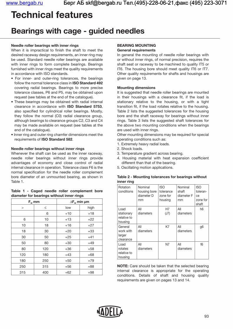
Technical features
Bearings with cage - guided needles
Needle roller bearings with inner rings
ISO Standard 5753
end of the catalogue).
.
Needle roller bearings without inner rings
Table 1.
Fw ΔFw
> ≤ high
+10 +18
10 +22
10 18 +27
18 +20
80
80 120
120 180
180 +79
+88
+98
BEARING MOUNTING
Table 2 lists the suggested tolerances for the housing
2. Shock loads.
different than that of the bearing.
inner ring
Rotationconditions
Nominalhousing bore
mm
tolerancezone forhousing
Nominal shaft
mm
tolerancezone forshaft
housing
Alldiameters
H7 Alldiameters
General
larger clearance
Alldiameters
K7 Alldiameters
rotates
housing
Alldiameters
N7 Alldiameters
NOTE:
www.bergab.ru Берг АБ [email protected] Тел.(495)-228-06-21,факс (495) 223-3071 Берг АБ [email protected] Тел.(495)-228-06-21,факс (495) 223-3071 Берг АБ [email protected] Тел.(495)-228-06-21,факс (495) 223-3071

Table 3 - Shaft tolerances for bearings with inner
Rotation conditionsNominal shaft
diameterd1 mm
zone for shaft
All diameters
> ≤
100
100
NOTE:
Fillet
rsra
r
r
h
DFw 1
h
rs ra
Undercut
rs
rs
t
t
ra2
r h
r h
b
bD1Fw
ra2
Table 4 - Fillets, undercuts, and shoulder heights
rs min mm
ras t ra2 min b h min
12
1 11 2
2
2
2 2
should be no greater than the minimum bearing chamfer rs min as
Needle roller
mentbore
diameter
> 20 100
≤ 20 100
LOAD RATING FACTORS
loads.
≤
Static loads
loads.
a needle roller bearing is based on the static load rating
0
Mounting in sets
Technical features
Bearings with cage - guided needles
www.bergab.ru Берг АБ [email protected] Тел.(495)-228-06-21,факс (495) 223-3071 Берг АБ [email protected] Тел.(495)-228-06-21,факс (495) 223-3071 Берг АБ [email protected] Тел.(495)-228-06-21,факс (495) 223-3071

Bearings with cage - guided needleswith inner ring
Shaft∅
mmDesignation
dmm
Dmm
Bmm
Fwmm
rs min.mm
s(1)
mm
Load Ratings kN Speed rating min-1 Weight
kgDynamic StaticC C0 Oil Grease
5NKJ5/12 5 15 12 8 0.3 1.5 4.57 4.89 41000 26000 0.014
NKJ5/16 5 15 16 8 0.3 1.5 5.22 5.78 41000 26000 0.017
6NKJ6/12 6 16 12 9 0.3 1.5 4.27 4.60 40000 26000 0.015
NKJ6/16 6 16 16 9 0.3 1.5 5.57 6.47 40000 26000 0.019
7NKJ7/12 7 17 12 11.5 0.3 1.5 5.40 6.43 39000 25000 0.017
NKJ7/16TN 7 17 16 11.5 0.3 1.5 5.30 6.27 39000 25000 0.021
9NKJ9/12 9 19 12 12 0.3 1.5 6.86 7.60 30000 19000 0.018
NKJ9/16 9 19 16 12 0.3 1.5 6.78 9.03 30000 19000 0.024
10NKJ10/16 10 22 16 14 0.6 1.5 12.4 14.8 24000 16000 0.032
NKJ10/20 10 22 20 14 0.3 1.5 14.7 18.4 24000 16000 0.040
12NKJ12/16 12 24 16 16 0.3 1.5 13.0 16.2 28000 18000 0.036
NKJ12/20 12 24 20 16 0.3 1.5 15.4 20.2 28000 18000 0.046
15NKJ15/16 15 27 16 19 0.3 1.5 14.1 19.0 24000 15000 0.042
NKJ15/20 15 27 20 19 0.3 1.5 16.8 23.6 24000 15000 0.054
17
NKJ17/16 17 29 16 21 0.3 2.0 15.3 21.6 21000 14000 0.047
NKJ17/20 17 29 20 21 0.3 1.5 18.1 23.9 21000 14000 0.059
NKJS17 17 37 20 24 0.6 1.0 29.1 32.8 20000 13000 0.108
20
NKJ20/16 20 32 16 24 0.3 1.5 16.2 24.3 18000 12000 0.053
NKJ20/20 20 32 20 24 0.3 1.5 19.3 30.3 18000 12000 0.067
NKJS20 20 42 20 28 0.6 1.0 30.3 38.4 16000 11000 0.130
22NKJ22/16 22 34 16 26 0.3 1.5 16.6 25.7 17000 11000 0.058
NKJ22/20 22 34 20 26 0.3 2.0 19.7 32.0 17000 11000 0.071
25
NKJ25/20 25 38 20 29 0.3 2.0 23.4 36.4 15000 9800 0.086
NKJ25/30 25 38 30 29 0.3 2.0 29.8 56.4 15000 9800 0.130
NKJS25 25 47 22 32 0.6 1.5 36.0 36.2 14000 9200 0.174
28NKJ28/20 28 42 20 32 0.3 2.0 24.8 40.4 14000 8800 0.104
NKJ28/30 28 42 30 32 0.3 2.0 35.6 64.3 14000 8800 0.156
(1) maximum axial movement
NKJ, NKJSNKJ (d ≤ 7)
rs rs
rsrs
Fw d D
B
Fw
B
s
Dd
www.bergab.ru Берг АБ [email protected] Тел.(495)-228-06-21,факс (495) 223-3071 Берг АБ [email protected] Тел.(495)-228-06-21,факс (495) 223-3071 Берг АБ [email protected] Тел.(495)-228-06-21,факс (495) 223-3071

Bearings with cage - guided needleswith inner ring
Shaft∅
mmDesignation
dmm
Dmm
Bmm
Fwmm
rs min.mm
s(1)
mm
Load Ratings kN Speed rating min-1 Weight
kgDynamic StaticC C0 Oil Grease
30
NKJ30/20 30 45 20 35 0.3 1.5 26.1 44.4 12000 8000 0.120
NKJ30/30 30 45 30 35 0.3 1.5 37.4 70.6 12000 8000 0.179
NKJS30 30 52 22 37 0.6 1.5 39.0 53.4 12000 7900 0.198
32NKJ32/20 32 47 20 37 0.3 2.0 26.6 46.4 12000 7600 0.127
NKJ32/30 32 47 30 37 0.3 1.5 38.2 73.9 12000 7600 0.192
35
NKJ35/20 35 50 20 40 0.3 2.0 27.8 50.4 11000 7000 0.135
NKJ35/30 35 50 30 40 0.3 1.5 40.0 80.2 11000 7000 0.208
NKJS35 35 58 22 43 0.6 1.0 41.6 60.7 10000 6700 0.235
38NKJ38/20 38 53 20 43 0.3 2.0 29.0 54.4 9900 6400 0.146
NKJ38/30 38 53 30 43 0.3 1.5 41.6 86.6 9900 6400 0.196
40
NKJ40/20 40 55 20 45 0.3 2.0 29.5 56.4 9400 6100 0.152
NKJ40/30 40 55 30 45 0.3 1.5 42.3 89.8 9400 6100 0.229
NKJS40 40 65 22 50 1.0 1.0 45.5 71.3 8700 5700 0.292
42NKJ42/20 42 57 20 47 0.3 2.0 30.0 58.5 9000 5900 0.159
NKJ42/30 42 57 30 47 0.3 1.5 39.9 84.1 9000 5900 0.241
45
NKJ45/25 45 62 25 50 0.6 3.0 40.7 79.3 8500 5500 0.223
NKJ45/35 45 62 35 50 0.6 3.0 55.0 117 8500 5500 0.345
NKJS45 45 72 22 55 1.0 1.0 47.9 78.4 7900 5100 0.360
50
NKJ50/25 50 68 25 55 0.6 3.0 46.1 87.3 7800 5000 0.288
NKJ50/35 50 68 35 55 0.6 3.0 62.3 129 7800 5000 0.406
NKJS50 50 80 28 60 1.1 1.5 66.9 103 7300 4800 0.523
55
NKJ55/25 55 72 25 60 0.6 3.0 44.3 94.0 7000 4600 0.290
NKJ55/35 55 72 35 60 0.6 3.0 59.9 139 7000 4600 0.410
NKJS55 55 85 28 65 1.1 1.5 71.0 114 6700 4400 0.569
60
NKJ60/25 60 82 25 68 0.6 2.0 49.0 101 6200 4000 0.440
NKJ60/35 60 82 35 68 0.6 2.5 66.2 149 6200 4000 0.520
NKJS60 60 90 28 70 1.1 1.5 72.6 120 6200 4000 0.607
(1) maximum axial movement
NKJ, NKJSNKJ (d ≤ 7)
rs rs
rsrs
Fw d D
B
Fw
B
s
Dd
www.bergab.ru Берг АБ [email protected] Тел.(495)-228-06-21,факс (495) 223-3071 Берг АБ [email protected] Тел.(495)-228-06-21,факс (495) 223-3071 Берг АБ [email protected] Тел.(495)-228-06-21,факс (495) 223-3071

97
Bearings with cage - guided needleswith inner ring
Shaft∅
mmDesignation
dmm
Dmm
Bmm
Fwmm
rs min.mm
s(1)
mm
Load Ratings kN Speed rating min-1 Weight
kgDynamic StaticC C0 Oil Grease
65
NKJ65/25 65 90 25 73 0.6 2.0 61.5 119 5800 3800 0.500
NKJ65/35 65 90 35 73 0.6 2.0 82.5 173 5800 3800 0.690
NKJS65 65 95 28 75 1.1 1.5 76.5 132 5800 3700 0.655
70
NKJ70/25 70 95 25 80 1.0 2.0 65.0 131 5300 3400 0.561
NKJ70/35 70 95 35 80 1.0 3.5 79.7 184 5300 3400 0.779
NKJS70 70 100 28 80 1.1 1.5 80.1 143 5400 3500 0.772
75
NKJ75/25 75 105 25 85 1.0 2.0 76.4 137 5000 3300 0.640
NKJS75 75 105 32 90 1.1 1.5 91.5 176 4700 3100 1.060
NKJ75/35 75 105 35 85 1.0 2.0 108 214 5000 3300 1.050
80
NKJ80/25 80 110 25 90 1.0 2.0 79.5 147 4700 3100 0.790
NKJS80 80 110 32 95 1.1 2.0 95.1 188 4500 2900 1.140
NKJ80/35 80 110 35 90 1.0 2.0 113 230 4700 3100 0.980
85NKJ85/26 85 115 26 95 1.0 3.0 49.3 114 4400 2800 0.862
NKJ85/36 85 115 36 95 1.0 2.0 114 238 4400 2800 1.040
90NKJ90/26 90 120 26 100 1.0 3.0 83.6 163 4200 2800 0.780
NKJ90/36 90 120 36 100 1.0 2.5 118 254 4200 2800 1.080
95NKJ95/26 95 125 26 105 1.0 2.5 52.2 127 3900 2600 0.935
NKJ95/36 95 125 36 105 1.0 3.5 72.8 195 3900 2600 1.300
100
NKJ100/30 100 130 30 110 1.1 2.0 103 220 3800 2500 0.984
NKJ100/40 100 130 40 110 1.1 2.0 132 301 3800 2500 1.410
NKJS100 100 135 32 115 1.1 2.0 104 226 3700 2400 2.010
(1) maximum axial movement
NKJ, NKJSNKJ (d ≤ 7)
rs rs
rsrs
Fw d D
B
Fw
B
s
Dd
www.bergab.ru Берг АБ [email protected] Тел.(495)-228-06-21,факс (495) 223-3071 Берг АБ [email protected] Тел.(495)-228-06-21,факс (495) 223-3071 Берг АБ [email protected] Тел.(495)-228-06-21,факс (495) 223-3071

98
Bearings with cage - guided needleswithout inner ring
Shaft∅
mmDesignation
Fwmm
Dmm
Cmm
rs min.mm
Load Ratings kN Speed rating min-1 Weight
kgDynamic StaticC C0 Oil Grease
5NK5/10TN 5 10 10 0.2 2.18 1.71 47000 31000 0.004
NK5/12TN 5 10 12 0.2 3.04 2.63 47000 31000 0.004
6NK6/10 6 12 10 0.2 3.19 2.90 44000 29000 0.005
NK6/12TN 6 12 12 0.2 3.07 2.74 44000 29000 0.006
7NK7/10TN 7 14 10 0.3 2.74 2.44 42000 28000 0.007
NK7/12TN 7 14 12 0.3 3.40 3.22 42000 28000 0.009
8NK8/12 8 15 12 0.3 4.57 4.89 41000 26000 0.011
NK8/16 8 15 16 0.3 5.22 5.78 41000 26000 0.013
9NK9/12 9 16 12 0.3 4.27 4.60 40000 26000 0.012
NK9/16 9 16 16 0.3 5.57 6.47 40000 26000 0.015
10NK10/12 10 17 12 0.3 5.40 6.43 39000 25000 0.013
NK10/16TN 10 17 16 0.3 5.30 6.27 39000 25000 0.015
12NK12/12 12 19 12 0.3 6.86 7.60 30000 19000 0.013
NK12/16 12 19 16 0.3 6.78 9.03 37000 24000 0.018
14NK14/16 14 22 16 0.3 12.4 14.8 24000 16000 0.023
NK14/20 14 22 20 0.3 14.7 18.4 24000 16000 0.028
15NK15/16 15 23 16 0.3 12.4 15.0 24000 15000 0.024
NK15/20 15 23 20 0.3 14.7 18.6 24000 15000 0.031
16NK16/16 16 24 16 0.3 15.4 20.2 28000 18000 0.025
NK16/20 16 24 20 0.3 16.1 21.3 28000 18000 0.036
17NK17/16 17 25 16 0.3 13.6 17.5 27000 17000 0.027
NK17/20 17 25 20 0.3 15.4 20.4 27000 17000 0.034
18NK18/16 18 26 16 0.3 13.6 17.7 25000 16000 0.028
NK18/20 18 26 20 0.3 16.1 22.0 25000 16000 0.035
19
NK19/16 19 27 16 0.3 14.1 19.0 24000 15000 0.029
NK19/20 19 27 20 0.3 18.8 23.6 24000 15000 0.037
NKS18 19 30 16 0.3 15.9 16.2 26000 17000 0.045
NK (Fw ≤ 10) NK, NKS NKTN
D
C
Fw Fw FwD
C rsrsrs
D
C
www.bergab.ru Берг АБ [email protected] Тел.(495)-228-06-21,факс (495) 223-3071 Берг АБ [email protected] Тел.(495)-228-06-21,факс (495) 223-3071 Берг АБ [email protected] Тел.(495)-228-06-21,факс (495) 223-3071

99
Bearings with cage - guided needleswithout inner ring
Shaft∅
mmDesignation
Fwmm
Dmm
Cmm
rs min.mm
Load Ratings kN Speed rating min-1 Weight
kgDynamic StaticC C0 Oil Grease
20
NK20/16 20 28 16 0.3 14.1 19.1 22000 14000 0.030
NK20/20 20 28 20 0.3 17.5 25.3 22000 14000 0.038
NKS20 20 32 20 0.6 24.4 26.7 24000 15000 0.058
21NK21/16 21 29 16 0.3 15.3 21.6 21000 14000 0.032
NK21/20 21 29 20 0.3 18.1 26.9 21000 14000 0.040
22
NK22/16 22 30 16 0.3 15.2 21.7 20000 13000 0.033
NK22/20 22 30 20 0.3 18.0 27.0 20000 13000 0.041
NKS22 22 35 20 0.6 22.9 27.1 21000 14000 0.069
24
NK24/16 24 32 16 0.3 16.2 24.3 18000 12000 0.035
NK24/20 24 32 20 0.3 19.3 30.3 18000 12000 0.045
NKS24 24 37 20 0.6 29.1 32.8 20000 13000 0.073
25
NK25/16 25 33 16 0.3 16.1 24.4 17000 11000 0.037
NK25/20 25 33 20 0.3 19.1 30.4 17000 11000 0.047
NKS25 25 38 20 0.6 29.1 33.0 19000 12000 0.076
26NK26/16 26 34 16 0.3 16.6 25.7 17000 11000 0.039
NK26/20 26 34 20 0.3 19.7 32.0 17000 11000 0.048
28
NK28/20 28 37 20 0.3 22.6 34.4 16000 10000 0.057
NK28/30 28 37 30 0.3 29.0 53.8 16000 10000 0.088
NKS28 28 42 20 0.6 30.3 38.4 16000 11000 0.094
29NK29/20 29 38 20 0.3 23.4 36.4 15000 9800 0.059
NK29/30 29 38 30 0.3 29.8 56.4 15000 9700 0.090
30
NK30/20 30 40 20 0.3 24.2 38.3 15000 9500 0.071
NK30/30 30 40 30 0.3 34.7 61.0 15000 9500 0.107
NKS30 30 45 20 0.6 34.3 42.8 15000 9900 0.114
32
NK32/20 32 42 20 0.3 24.8 40.4 14000 8800 0.074
NK32/30 32 42 30 0.3 35.6 64.3 14000 8800 0.112
NKS32 32 47 22 0.6 36.0 46.2 14000 9200 0.120
35
NK35/20 35 45 20 0.3 26.1 44.4 12000 8000 0.081
NK35/30 35 45 30 0.3 37.4 70.6 12000 8000 0.122
NKS35 35 50 22 0.6 37.5 49.9 13000 8400 0.130
NK (Fw ≤ 10) NK, NKS
D
C
Fw FwD
C rsrs
www.bergab.ru Берг АБ [email protected] Тел.(495)-228-06-21,факс (495) 223-3071 Берг АБ [email protected] Тел.(495)-228-06-21,факс (495) 223-3071 Берг АБ [email protected] Тел.(495)-228-06-21,факс (495) 223-3071

100
Bearings with cage - guided needleswithout inner ring
Shaft∅
mmDesignation
Fwmm
Dmm
Cmm
rs min.mm
Load Ratings kN Speed rating min-1 Weight
kgDynamic StaticC C0 Oil Grease
37
NK37/20 37 47 20 0.3 26.6 46.4 12000 7600 0.084
NK37/30 37 47 30 0.3 38.2 73.9 12000 7600 0.128
NKS37 37 52 22 0.6 39.0 53.4 12000 7900 0.134
38NK38/20 38 48 20 0.3 21.7 40.9 11000 7300 0.087
NK38/30 38 48 30 0.3 31.9 67.0 11000 7300 0.131
40
NK40/20 40 50 20 0.3 27.8 50.4 11000 7000 0.089
NK40/30 40 50 30 0.3 40.0 80.2 11000 7000 0.137
NKS40 40 55 22 0.6 40.3 57.0 11000 7200 0.140
42NK42/20 42 52 20 0.3 28.3 52.4 10000 6600 0.085
NK42/30 42 52 30 0.3 40.7 83.5 10000 6600 0.141
43
NK43/20 43 53 20 0.3 29.0 54.4 9900 6400 0.096
NK43/30 43 53 30 0.3 41.6 86.6 9900 6400 0.134
NKS43 43 58 22 0.6 41.6 60.7 10000 6700 0.150
45
NK45/20 45 55 20 0.3 29.5 56.4 9400 6100 0.100
NK45/30 45 55 30 0.3 42.3 89.8 9400 6100 0.151
NKS45 45 60 22 0.6 43.0 64.2 9800 6400 0.156
47NK47/20 47 57 20 0.3 30.0 58.5 9000 5900 0.104
NK47/30 47 57 30 0.3 43.0 93.1 9000 5900 0.158
50
NK50/25 50 62 25 0.3 40.7 79.3 8500 5500 0.171
NK50/35 50 62 35 0.6 55.0 117 8500 5500 0.242
NKS50 50 65 22 1.0 45.5 71.3 8700 5700 0.170
55
NK55/25 55 68 25 0.6 46.1 87.3 7800 5000 0.207
NK55/35 55 68 35 0.6 62.3 129 7800 5000 0.293
NKS55 55 72 22 1.0 47.9 78.4 7900 5100 0.225
60
NK60/25 60 72 25 0.6 44.3 94.0 7000 4400 0.202
NK60/35 60 72 35 0.6 59.9 139 7000 4400 0.286
NKS60 60 80 28 1.1 66.9 103 7300 4800 0.337
65
NK65/25 65 78 25 0.6 48.2 97.7 6500 4200 0.257
NK65/35 65 78 35 0.6 65.2 144 6500 4200 0.298
NKS65 65 85 28 1.1 71.0 114 6700 4200 0.362
NK (Fw ≤ 10) NK, NKS
D
C
Fw FwD
C rsrs
www.bergab.ru Берг АБ [email protected] Тел.(495)-228-06-21,факс (495) 223-3071 Берг АБ [email protected] Тел.(495)-228-06-21,факс (495) 223-3071 Берг АБ [email protected] Тел.(495)-228-06-21,факс (495) 223-3071

101
Bearings with cage - guided needleswithout inner ring
Shaft∅
mmDesignation
Fwmm
Dmm
Cmm
rs min.mm
Load Ratings kN Speed rating min-1 Weight
kgDynamic StaticC C0 Oil Grease
68NK68/25 68 82 25 0.6 49.0 101 6200 4000 0.287
NK68/35 68 82 35 0.6 66.2 149 6200 4000 0.350
70
NK70/25 70 85 25 0.6 43.6 87.9 6000 3900 0.298
NK70/35 70 85 35 0.6 62.2 139 6000 3900 0.411
NKS70 70 90 28 1.1 72.6 120 6200 4000 0.383
73NK73/25 73 90 25 0.6 61.5 119 5800 3800 0.320
NK73/35 73 90 35 0.6 82.5 173 5800 3800 0.450
75
NK75/25 75 92 25 0.6 43.7 90.2 5600 3600 0.364
NK75/35 75 92 35 0.6 60.9 138 5600 3600 0.518
NKS75 75 95 28 1.1 76.5 132 5800 3700 0.413
80NK80/25 80 95 25 1.0 65.0 131 5300 3400 0.331
NK80/35 80 95 35 1.0 79.7 184 5300 3400 0.380
85NK85/25 85 105 25 1.0 76.4 137 5000 3300 0.506
NK85/35 85 105 35 1.0 108 214 5000 3300 0.610
90NK90/25 90 110 25 1.0 79.5 147 4700 3100 0.450
NK90/35 90 110 35 1.0 113 230 4700 3100 0.745
95NK95/26 95 115 26 1.0 49.3 114 4400 2800 0.572
NK95/36 95 115 36 1.0 114 238 4500 2900 0.803
100NK100/26 100 120 26 1.0 83.6 163 4200 2800 0.530
NK100/36 100 120 36 1.0 118 254 4200 2800 0.658
105 NK105/26 105 125 26 1.0 52.2 127 3900 2600 0.595
110NK110/30 110 130 30 1.1 103 220 3800 2500 0.660
NK110/40 110 130 40 1.1 132 301 3800 2500 0.900
NK (Fw ≤ 10) NK, NKS
D
C
Fw FwD
C rsrs
www.bergab.ru Берг АБ [email protected] Тел.(495)-228-06-21,факс (495) 223-3071 Берг АБ [email protected] Тел.(495)-228-06-21,факс (495) 223-3071 Берг АБ [email protected] Тел.(495)-228-06-21,факс (495) 223-3071

www.bergab.ru Берг АБ [email protected] Тел.(495)-228-06-21,факс (495) 223-3071 Берг АБ [email protected] Тел.(495)-228-06-21,факс (495) 223-3071 Берг АБ [email protected] Тел.(495)-228-06-21,факс (495) 223-3071

FULL COMPLEMENT NEEDLE BEARINGSwww.bergab.ru Берг АБ [email protected] Тел.(495)-228-06-21,факс (495) 223-3071 Берг АБ [email protected] Тел.(495)-228-06-21,факс (495) 223-3071 Берг АБ [email protected] Тел.(495)-228-06-21,факс (495) 223-3071

Full complement needle bearings have a through-hardened outer ring which results in high static and dynamic load capacities and an ability to withstand overloading, shocks and vibration.They are particularly suitable for operations involving oscillating motion but may also accept high speed conditions where good alignment is necessary. This can more easily be achieved using a convex inner ring raceway (inner rings with suffix R6). The retention of the needles in the outer ring enables the bearing to be installed easily during assembly.The difference between the needle bearings with integral end flanges series 3000 and the others is explained in the Chapter of the Bearings with cages.
TYPES OF BEARINGSNeedle roller bearings with inner rings
NA Series 1000,2000, 22000
NA Series 3000
Needle roller bearings without inner rings
RNA Series 1000,2000, 22000
RNA Series 3000
104
These bearings are available with or without an inner ring from 12 mm bore size. Standard complete bearings type NA have an inner ring with convex raceway form. lf extra wide inner rings or rings with lubrication hole are required, they should be ordered separately for use with the corresponding RNA series.
Reference standards are:ISO 1206 - Needle roller bearings – Light and medium series – Dimensions and tolerances.
FULL COMPLEMENT BEARINGS WITHOUT INNER RINGThe shaft journal which is used directly as the inner ring raceway of the bearing should have adequate hardness and satisfactory surface finish. A hardness of 58-64 HRC will ensure full load capacity for the bearing. Lower hardness figures will entail a reduction in both static and dynamic capacities as shown in the table of dimensions (see Technical Section).In cases of misalignment, a convex inner ring raceway can be machined directly at the shaft journal position by grinding, using a concave profile and inclining the diamond impregnated grinding wheel. A convex inner ring raceway calculated to permit misalignment of 1 in 1000 does not affect bearing load capacity. A larger convex radius is necessary for a greater degree of misalignment but this will reduce the effective bearing load capacity.
Technical features
Full complement needle bearings
www.bergab.ru Берг АБ [email protected] Тел.(495)-228-06-21,факс (495) 223-3071 Берг АБ [email protected] Тел.(495)-228-06-21,факс (495) 223-3071 Берг АБ [email protected] Тел.(495)-228-06-21,факс (495) 223-3071

Technical features
Full complement needle bearings
INNER RINGSlnner rings made from high quality bearing steel heat treated and through-hardened avoid any necessity for heat treatment of the shaft and enable the bearings to operate within their full load capacity. lnner rings with convex raceway “R6”These inner rings without lubrication hole are of the same width as the outer ring and are supplied with series NA complete, types 1000, 2000, 22000 and 3000. They can accept a misalignment of 1 in 1000 in continuous operation and up to 2 in 1000 temporarily, as in the case of sudden deflection due to overload conditions. The inner and outer rings may be displaced axially from one to the other by up to 5% of the ring width. The designation of the inner ring separated from the complete needle bearing is BI number R6. For example BI 2020 R6. The designation of the needle bearings complete of inner ring BI…R6 is NA number. For example NA 2035.
lnner rings with cylindrical racewayCylindrical inner rings of the same bore as those with convex raceway may be supplied on request in the following versions:- with oil hole permitting lubrication through the shaft
(BIC).- wider than corresponding outer ring (BICG), to enable
a displacement in position of one ring relative to the other (e.g. expansion of the shaft) or lateral shaft movement. In the latter case, which can occur with or without simultaneous rotation of the shaft, please consult Nadella Technical Service.
BIC BICG
The use of cylindrical inner rings with standard bearings type RNA series 1000, 2000, 22000 and 3000 requires that the housing and shaft be correctly aligned at assembly with due regard to the application under load lf it is not essential to use these inner rings, it is always preferable to use complete bearings type NA with convex inner rings type “R6”, without oil hole, of the same width as the outer ring. In particular cases where lubrication is provided through the shaft, the inner ring with oil hole may be replaced by a lubrication hole at the face of the inner ring.
RING TOLERANCESlnner and outer rings for full complement standard needle bearings are manufactured in accordance with the tolerance class of ISO Standard 492 (class zero according to DIN 620). Closer tolerances, corresponding to classes 6, 5 and 4 may be necessary for special high precision applications (symbols P6, P5, P4). See table at the end of the catalogue.
RADIALPLAYBearings without inner ringThe radial play of a bearing without inner ring results from the difference in diameter beneath the needles and the size of the shaft. The standard diameter beneath the needles for RNA bearings with the recommended shaft tolerances should provide suitable radial play for most normal applications.For special applications (high precision, close fits, etc.), we can offer the diameter beneath the needles selected as follows:- in the bottom half of the normal tolerance (RNA ... TB)- in the upper half of the normal tolerance (RNA...TC).Bearings without inner ring tolerance Class TB mounted on a shaft with k5 tolerance will have a reduced radiai play suitable for certain applications.
Nominal dimensionFwmm
Tolerance of diameter under needles
normal μm
SelectedTB μm
SelectedTC μm
above
5
15
25
30
35
60
80
115
180
220
270
to
15
25
30
35
60
80
115
180
220
270
350
+20 + 40
+20 + 43
+25 + 48
+30 + 53
+35 + 58
+45 + 73
+50 + 78
+60 + 88
+70 +103
+80 +113
+90 +128
+20 + 31
+20 + 33
+25 + 38
+30 + 43
+35 + 48
+45 + 60
+50 + 65
+60 + 75
+70 + 88
+80 + 98
+90 +110
+ 29 + 40
+ 30 + 43
+ 35 + 48
+ 40 + 53
+ 45 + 58
+ 58 + 73
+ 63 + 78
+ 73 + 88
+ 85 +103
+ 95 +113
+108 +128
Examples of bearing
RNA 1020 RNA 1020 TB RNA 1020 TC
A nominal diameter under the needles further reduced may be required for certain precision.Should a larger clearance than normal be necessary, the shaft diameter must be controlled nearer to the nominal size than the tolerances h5 or g5 would normally provide.
105
www.bergab.ru Берг АБ [email protected] Тел.(495)-228-06-21,факс (495) 223-3071 Берг АБ [email protected] Тел.(495)-228-06-21,факс (495) 223-3071 Берг АБ [email protected] Тел.(495)-228-06-21,факс (495) 223-3071

Standard complete bearings with inner ringComplete bearings type NA are offered with a radial play that is suitable for the majority of applications. They can be supplied if necessary:- with the radial play selected from the bottom half of the normal tolerance (NA...TB)- with the radial play selected from the upper half of the normal tolerance (NA…TC).For bore dimensions d > 130 mm, bearings NA…TB or NA…TC are supplied only on special request.
Radial play of full complement bearings with convex inner ring "R6".
Series 1 000, 2 000, 22 000
Inner ring dimension d mm
Standard play μm
Selected TB μm
Selected TCμm
above to min. max. min. max. min. max.
12
20
25
30
50
55
65
70
105
120
140
170
190
210
230
260
290
20
25
30
50
55
65
70
105
125
140
170
190
210
230
260
290
310
20
25
30
35
45
45
45
50
60
80
100
120
130
130
160
180
180
50
60
65
70
85
90
95
100
115
145
165
185
200
205
235
260
265
20
25
30
35
45
45
45
50
60
80
35
43
48
53
65
68
70
75
88
113
35
42
47
52
65
67
70
75
87
112
50
60
65
70
85
90
95
100
115
145
Series 3 000
Inner ring dimension d mm
Standard play μm
Selected TB μm
Selected TCμm
above to min. max. min. max. min. max.
30
45
55
65
70
100
105
130
140
170
190
210
230
260
290
45
55
65
70
100
105
130
140
170
190
210
230
260
290
310
35
45
45
50
50
60
60
80
100
120
130
130
160
180
180
70
85
90
95
100
110
115
145
165
185
200
200
235
260
265
35
45
45
50
50
60
60
80
53
65
68
73
75
85
88
113
52
65
67
72
75
85
87
112
70
85
90
95
100
110
115
145
106
Radial play of full complement bearings with cylindrical inner ring (not R6).
Series 1 000, 22 000
Inner ring dimension d mm
Standard play μm
Selected TB μm
Selected TCμm
above to min. max. min. max. mini. max.
12
17
20
25
30
35
50
55
65
70
17
20
25
30
35
50
55
65
70
90
20
30
35
40
45
50
60
60
60
65
50
60
70
75
80
85
100
105
110
115
20
30
35
40
45
50
60
60
60
65
35
45
53
58
63
68
80
83
85
90
35
45
52
57
62
67
80
82
85
90
50
60
70
75
80
85
100
105
110
115
Technical features
Full complement needle bearings
Series 2 000
Inner ring dimension d mm
Standard play μm
Selected TB μm
Selected TCμm
above to mini. maxi. min. max. min. max.
15
20
25
30
35
50
55
65
70
105
125
140
170
190
210
20
25
30
35
50
55
65
70
105
125
140
170
190
210
230
30
35
40
45
50
60
60
60
65
75
95
125
145
160
160
60
70
75
80
85
100
105
110
115
130
160
190
210
230
235
30
35
40
45
50
60
60
60
65
75
95
45
53
58
63
68
80
83
85
90
103
128
45
52
57
62
67
80
82
85
90
102
127
60
70
75
80
85
100
105
110
115
130
160
Series 3 000
Inner ring dimension d mm
Standard play μm
Selected TB μm
Selected TCμm
above to min. max. min. max. min. max.
30
45
55
65
70
100
105
130
140
170
190
210
230
260
290
45
55
65
70
100
105
130
140
170
190
210
230
260
290
310
50
60
60
65
65
75
75
95
125
145
160
160
190
210
210
85
100
105
110
115
125
130
160
190
210
230
235
265
290
295
50
60
60
65
65
75
75
95
68
80
83
88
90
100
103
128
67
80
82
87
90
100
102
127
85
100
105
110
115
125
130
160
www.bergab.ru Берг АБ [email protected] Тел.(495)-228-06-21,факс (495) 223-3071 Берг АБ [email protected] Тел.(495)-228-06-21,факс (495) 223-3071 Берг АБ [email protected] Тел.(495)-228-06-21,факс (495) 223-3071

BEARING MOUNTINGGeneral requirementsIn general, the mounting of needle roller bearings with or without inner rings, of normal precision, requires the shaft seat or raceway to be machined to quality IT5 or IT6. The housing bore should meet quality IT6 or IT7. Other quality requirements for shaft and housings are given on page 13.
MOUNTING DIMENSIONSIt is recommended that needle roller bearings are mounted in their housings with a clearance fit if the load is stationary relative to the housing, and with a tight transition fit if the load rotates relative to the housing.
Technical features
Full complement needle bearings
107
Table 2 lists the recommended tolerances for the housing bore and the shaft raceway for bearings without inner rings. Table 3 lists the recommended shaft tolerances for the above two mounting conditions when the bearings are used with inner rings.
Other mounting dimensions may be required for special operating conditions such as:1. Extremely heavy radial loads2. Shock loads3. Temperature gradient across bearing4. Housing material with heat expansion coefficient
different to that of the bearing5. Oscillating movements
Table 3- Shaft tolerances for bearings with inner rings
Rotation conditionsNominal shaft
diameter d mm
ISO tolerance zone for
shaft
Nominal housing
bore diameter
D mm
ISO tolerance zone for housing
Load stationary relative to housing
All diametersh5(h6)
All diameters
J6
Load rotates relative to housing
> ≤
All diameters
M6
40 k5
40 100 m5
100 140 m5
140 – n6
NOTE: Care should be taken that the selected bearing internal clearance is appropriate for the operating conditions. Details of shaft and housing quality requirements are given on pages 13 and 14.
Table 2- Mounting tolerances for bearings without inner ring
Rotation conditions
Nominal housing bore diameter
D mm
ISO tolerance zone for housing
Nominal shaft
diameter F mm
ISO tolerance zone for
shaft
Load stationary relative to housing
All diameters J6 All diameters
h5
Load rotates relative to housing
All diameters M6 All diameters
g5
NOTE: Care should be taken that the selected bearing internal clearance is appropriate for the operating conditions. Details of shaft and housing quality requirements are given on pages 13 and 14.
www.bergab.ru Берг АБ [email protected] Тел.(495)-228-06-21,факс (495) 223-3071 Берг АБ [email protected] Тел.(495)-228-06-21,факс (495) 223-3071 Берг АБ [email protected] Тел.(495)-228-06-21,факс (495) 223-3071

108
Full complement needle bearings with inner ring - NA 1 000, 2 000, 22 000, 3 000 series
Dd
B
Fw
rs
rs
NA series 1000, 2000, 22000
NA series 3000
B
sr
rs
d DFw
Shaft∅
mmDesignation
dmm
Dmm
Bmm
Fwmm
rs min.mm
Load Ratings kN Speed ratingmin-1 Weight
kgDynamic StaticC C0 Oil Grease
12 NA 1012 (1) 12 28 15 17.6 0.35 11.0 16.5 22000 14000 0.050
15NA 1015 (1) 15 32 15 20.8 0.65 12.4 19.5 18000 12000 0.044
NA 2015 (1) 15 35 22 22.1 0.65 23.5 37.5 17000 11000 0.082
17 NA 1017 (1) 17 35 15 23.9 0.65 13.7 22.5 16000 10000 0.047
20NA 1020 20 42 18 28.7 0.65 19.3 33.5 13000 8600 0.084
NA 2020 20 42 22 28.7 0.65 28.5 49.0 13000 8600 0.104
25
NA 1025 25 47 18 33.5 0.65 21.5 39.0 11000 7200 0.097
NA 2025 25 47 22 33.5 0.65 33.0 60.0 11000 7200 0.122
NA 22025 25 47 30 33.5 0.65 52.0 94.0 11000 7200 0.170
30
NA 1030 30 52 18 38.2 0.65 23.5 44.5 10000 6500 0.107
NA 2030 30 52 22 38.2 0.65 34.5 66.0 10000 6500 0.139
NA 22030 30 52 30 38.2 0.65 57.0 108 10000 6500 0.193
NA 3030 30 62 30 44.0 0.65 64.0 125 8600 5600 0.309
35
NA 1035 35 58 18 44.0 0.65 26.0 51.0 8600 5600 0.127
NA 2035 35 58 22 44.0 0.65 38.0 75.0 8600 5600 0.160
NA 22035 35 58 30 44.0 0.65 63.0 124 8600 5600 0.225
NA 3035 35 72 36 49.7 0.65 90.0 183 7600 4900 0.545
40
NA 1040 40 65 18 49.7 0.85 28.5 58.0 7600 4900 0.160
NA 2040 40 65 22 49.7 0.85 41.5 85.0 7600 4900 0.200
NA 22040 40 65 30 49.7 0.85 68.0 140 7600 4900 0.278
NA 3040 40 80 36 55.4 0.85 97.0 204 6900 4500 0.672
45
NA 1045 45 72 18 55.4 0.85 30.5 65.0 6900 4500 0.193
NA 2045 45 72 22 55.4 0.85 45.0 95.0 6900 4500 0.242
NA 3045 45 85 38 62.1 0.85 105.0 230 6100 4000 0.710
50
NA 1050 50 80 20 62.1 0.85 33.0 73.0 6100 4000 0.418
NA 2050 50 80 28 62.1 0.85 64.0 142 6100 4000 0.603
NA 3050 50 90 38 68.8 0.85 113.0 255 5500 3600 1.22
(1) without holes and lubrication groove
www.bergab.ru Берг АБ [email protected] Тел.(495)-228-06-21,факс (495) 223-3071 Берг АБ [email protected] Тел.(495)-228-06-21,факс (495) 223-3071 Берг АБ [email protected] Тел.(495)-228-06-21,факс (495) 223-3071

109
Full complement needle bearings with inner ring - NA 1 000, 2 000, 22 000, 3 000 series
Shaft∅
mmDesignation
dmm
Dmm
Bmm
Fwmm
rs min.mm
Load Ratings kN Speed ratingmin-1 Weight
kgDynamic StaticC C0 Oil Grease
55
NA 1055 55 85 20 68.8 0.85 35.5 80.0 5500 3600 0.258
NA 2055 55 85 28 68.8 0.85 69.0 157 5500 3600 0.361
NA 3055 55 95 38 72.6 0.85 117.0 268 5200 3400 0.782
60
NA 1060 60 90 20 72.6 0.85 37.0 85.0 5200 3400 0.283
NA 2060 60 90 28 72.6 0.85 72.0 165 5200 3400 0.413
NA 3060 60 100 38 78.3 0.85 123.0 290 4900 3200 0.810
65NA 2065 65 95 28 78.3 0.85 78.0 184 4900 3200 0.433
NA 3065 65 105 38 83.1 0.85 129.0 308 4500 2900 0.865
70
NA 1070 70 100 20 83.1 0.85 43.0 103 4500 2900 0.322
NA 2070 70 100 28 83.1 0.85 81.0 195 4500 2900 0.470
NA 3070 70 110 38 88.0 0.85 134.0 325 4300 2800 0.906
75NA 2075 75 110 32 88.0 0.85 104.0 253 4300 2800 0.767
NA 3075 75 120 38 96.0 0.85 142.0 355 4000 2600 1.098
80
NA 1080 80 115 24 96.0 0.85 68.0 170 4000 2600 0.510
NA 2080 80 115 32 96.0 0.85 110.0 275 4000 2600 0.694
NA 3080 80 125 38 99.5 0.85 145.0 365 3800 2500 1.220
85NA 2085 85 120 32 99.5 1.35 113.0 285 3800 2500 0.787
NA 3085 85 130 38 104.7 1.35 150.0 390 3600 2300 1.252
90NA 2090 90 125 32 104.7 1.35 117.0 300 3600 2300 0.837
NA 3090 90 135 43 109.7 1.35 185.0 480 3500 2300 1.522
95NA 2095 95 130 32 109.1 1.35 120.0 315 3500 2300 0.882
NA 3095 95 140 43 114.7 1.35 190.0 505 3300 2100 1.551
100NA 2100 100 135 32 114.7 1.35 125.0 330 3300 2100 0.677
NA 3100 100 145 43 119.2 1.35 195.0 520 3200 2100 1.645
105NA 2105 105 140 32 119.2 1.35 129.0 340 3200 2100 0.941
NA 3105 105 150 45 124.7 1.35 203.0 550 3000 2000 1.762
Dd
B
Fw
rs
rs
NA series 1000, 2000, 22000
NA series 3000
B
sr
rs
d DFw
www.bergab.ru Берг АБ [email protected] Тел.(495)-228-06-21,факс (495) 223-3071 Берг АБ [email protected] Тел.(495)-228-06-21,факс (495) 223-3071 Берг АБ [email protected] Тел.(495)-228-06-21,факс (495) 223-3071

110
Full complement needle bearings with inner ring - NA 1 000, 2 000, 22 000, 3 000 series
Shaft∅
mmDesignation
dmm
Dmm
Bmm
Fwmm
rs min.mm
Load Ratings kN Speed ratingmin-1 Weight
kgDynamic StaticC C0 Oil Grease
110NA 2110 110 145 34 124.7 1.35 133.0 360 3000 2000 1.015
NA 3110 110 160 45 132.5 1.35 210.0 580 2900 1900 2.037
115NA 2115 115 155 34 132.5 1.35 139.0 380 2900 1900 1.205
NA 3115 115 165 45 137.0 1.35 215.0 600 2800 1800 2.140
120NA 2120 120 160 34 137.0 1.35 142.0 395 2800 1800 1.265
NA 3120 120 170 45 143.5 1.35 224.0 630 2700 1800 2.107
125 NA 2125 125 165 34 143.5 1.35 145.0 410 2700 1800 1.218
130 NA 2130 130 170 34 148.0 1.35 150.0 425 2600 1700 1.292
140NA 2140 140 180 36 158.0 1.35 157.0 455 2400 1600 1.478
NA 3140 140 205 52 170.5 1.35 290.0 860 2200 1400 3.840
150 NA 2150 150 195 36 170.5 1.35 165.0 490 2200 1400 1.790
160 NA 2160 160 205 36 179.3 1.35 170.0 515 2100 1400 1.970
170 NA 2170 170 220 42 193.8 1.35 233.0 720 2000 1300 2.570
180 NA 2180 180 230 42 202.6 1.35 240.0 750 1900 1200 2.835
190 NA 2190 190 245 42 216.0 1.35 250.0 800 1800 1200 3.210
200 NA 2200 200 255 42 224.1 1.35 257.0 830 1700 1100 3.560
190 NA 2190 190 245 42 216.0 1.35 250.0 800 1800 1200 3.210
200 NA 2200 200 255 42 224.1 1.35 257.0 830 1700 1100 3.560
190 NA 2190 190 245 42 216.0 1.35 250.0 800 1800 1200 3.210
200 NA 2200 200 255 42 224.1 1.35 257.0 830 1700 1100 3.560
Dd
B
Fw
rs
rs
NA series 1000, 2000, 22000
NA series 3000
B
sr
rs
d DFw
www.bergab.ru Берг АБ [email protected] Тел.(495)-228-06-21,факс (495) 223-3071 Берг АБ [email protected] Тел.(495)-228-06-21,факс (495) 223-3071 Берг АБ [email protected] Тел.(495)-228-06-21,факс (495) 223-3071

111
Full complement needle bearings without inner ring - RNA 1 000, 2 000, 22 000, 3 000 series
Ew Fw
rs
D
C
RNA series 1000,2000, 22000
RNA series 3000
Crs
Ew Fw D
Shaft∅
mmDesignation
Fwmm
Dmm
Cmm
Ewmm
rs min.mm
Load Ratings kN Speed ratingmin-1 Weight
kgDynamic StaticC C0 Oil Grease
7.3 RNA 1005 (1) 7.3 16 12 12.3 0.35 3.95 4.45 52000 34000 0.010
9.7 RNA 1007 (1) 9.7 19 12 14.7 0.35 4.80 5.90 39000 25000 0.013
12.1 RNA 1009 (1) 12.1 22 12 17.1 0.35 5.60 7.40 31000 20000 0.018
14.4 RNA 1010 (1) 14.4 24 12 19.4 0.35 6.35 8.90 26000 17000 0.020
17.6 RNA 1012 (1) 17.6 28 15 22.6 0.35 11.0 16.5 22000 14000 0.034
20.8 RNA 1015 (1) 20.8 32 15 25.8 0.65 12.4 19.5 18000 12000 0.044
22.1 RNA 2015 (1) 22.1 35 22 28.1 0.65 23.5 37.5 17000 11000 0.082
23.9 RNA 1017 (1) 23.9 35 15 28.9 0.65 13.7 22.5 16000 10000 0.047
28.7RNA 1020 28.7 42 18 34.7 0.65 19.3 33.5 13000 8600 0.084
RNA 2020 28.7 42 22 34.7 0.65 28.5 49.0 13000 8600 0.104
33.5
RNA 1025 33.5 47 18 39.5 0.65 21.5 39.0 11000 7200 0.097
RNA 2025 33.5 47 22 39.5 0.65 33.0 60.0 11000 7200 0.122
RNA 22025 33.5 47 30 39.5 0.65 52.0 94.0 11000 7200 0.170
38.2
RNA 1030 38.2 52 18 44.2 0.65 23.5 44.5 10000 6500 0.107
RNA 2030 38.2 52 22 44.2 0.65 34.5 66.0 10000 6500 0.139
RNA 22030 38.2 52 30 44.2 0.65 57.0 108 10000 6500 0.193
44
RNA 1035 44 58 18 50.0 0.65 26.0 51.0 8600 5600 0.127
RNA 2035 44 58 22 50.0 0.65 38.0 75.0 8600 5600 0.160
RNA 22035 44 58 30 50.0 0.65 63.0 124 8600 5600 0.225
RNA 3030 44 62 30 51.0 0.65 64.0 125 8600 5600 0.309
49.7
RNA 1040 49.7 65 18 55.7 0.85 28.5 58.0 7600 4900 0.160
RNA 2040 49.7 65 22 55.7 0.65 41.5 85.0 7600 4900 0.200
RNA 22040 49.7 65 30 55.7 0.65 68.0 140 7600 4900 0.278
RNA 3035 49.7 72 36 56.8 0.65 90.0 183 7600 4900 0.545
55.4
RNA 1045 55.4 72 18 61.4 0.85 30.5 65.0 6900 4500 0.193
RNA 2045 55.4 72 22 61.4 0.85 45.0 95.0 6900 4500 0.242
RNA 3040 55.4 80 36 62.5 0.85 97.0 204 6900 4500 0.672
(1) without holes and lubrication groove
www.bergab.ru Берг АБ [email protected] Тел.(495)-228-06-21,факс (495) 223-3071 Берг АБ [email protected] Тел.(495)-228-06-21,факс (495) 223-3071 Берг АБ [email protected] Тел.(495)-228-06-21,факс (495) 223-3071

112
Full complement needle bearings without inner ring - RNA 1 000, 2 000, 22 000, 3 000 series
Shaft∅
mmDesignation
Fwmm
Dmm
Cmm
Ewmm
rs min.mm
Load Ratings kN Speed ratingmin-1 Weight
kgDynamic StaticC C0 Oil Grease
62.1
RNA 1050 62.1 80 20 68.1 0.85 33.0 73.0 6100 4000 0.255
RNA 2050 62.1 80 28 68.1 0.85 64.0 142 6100 4000 0.375
RNA 3045 62.1 85 38 69.2 0.85 105 230 6100 4000 0.710
68.8
RNA 1055 68.8 85 20 74.8 0.85 35.5 80.0 5500 3600 0.258
RNA 2055 68.8 85 28 74.8 0.85 69.0 157 5500 3600 0.361
RNA 3050 68.8 90 38 75.9 0.85 113 255 5500 3600 0.705
72.6
RNA 1060 72.6 90 20 78.6 0.85 37.0 85.0 5200 3400 0.283
RNA 2060 72.6 90 28 78.6 0.85 72.0 165 5200 3400 0.413
RNA 3055 72.6 95 38 79.6 0.85 117 268 5200 3400 0.782
78.3
RNA 1065 78.3 95 20 84.3 0.85 41.5 97.0 4900 3200 0.306
RNA 2065 78.3 95 28 84.3 0.85 78.0 184 4900 3200 0.433
RNA 3060 78.3 100 38 85.3 0.85 123.0 290 4900 3200 0.810
83.1
RNA 1070 83.1 100 20 89.1 0.85 43.0 103 4500 2900 0.322
RNA 2070 83.1 100 28 89.1 0.85 81.0 195 4500 2900 0.470
RNA 3065 83.1 105 38 90.2 0.85 129 308 4500 2900 0.865
88
RNA 1075 88 110 24 95.0 0.85 64.0 155 4300 2800 0.577
RNA 2075 88 110 32 95.0 0.85 104 253 4300 2800 0.767
RNA 3070 88 110 38 95.0 0.85 134 325 4300 2800 0.906
96
RNA 1080 96 115 24 103.0 0.85 68.0 170 4000 2600 0.510
RNA 2080 96 115 32 103.0 0.85 110 275 4000 2600 0.694
RNA 3075 96 120 38 103.0 0.85 142 355 4000 2600 1.098
99.5RNA 2085 99.5 120 32 106.5 1.35 113 285 3800 2500 0.787
RNA 3080 99.5 125 38 106.5 0.85 145 365 3800 2500 1.220
104.7RNA 2090 104.7 125 32 111.7 1.35 117 300 3600 2300 0.837
RNA 3085 104.7 130 38 111.7 1.35 150 390 3600 2300 1.252
109.1RNA 2095 109.1 130 32 116.1 1.35 120 315 3500 2300 0.882
RNA 3090 109.1 135 43 116.1 1.35 185 480 3500 2300 1.522
Ew Fw
rs
D
C
RNA series 1000,2000, 22000
RNA series 3000
Crs
Ew Fw D
www.bergab.ru Берг АБ [email protected] Тел.(495)-228-06-21,факс (495) 223-3071 Берг АБ [email protected] Тел.(495)-228-06-21,факс (495) 223-3071 Берг АБ [email protected] Тел.(495)-228-06-21,факс (495) 223-3071

113
Full complement needle bearings without inner ring - RNA 1 000, 2 000, 22 000, 3 000 series
Shaft∅
mmDesignation
Fwmm
Dmm
Cmm
Ewmm
rs min.mm
Load Ratings kN Speed ratingmin-1 Weight
kgDynamic StaticC C0 Oil Grease
114.7RNA 2100 114.7 135 32 121.7 1.35 125 330 3300 2100 0.677
RNA 3095 114.7 140 43 121.7 1.35 190 505 3300 2100 1.551
119.2RNA 2105 119.2 140 32 126.2 1.35 129 340 3200 2100 0.941
RNA 3100 119.2 145 43 126.2 1.35 195 520 3200 2100 1.645
124.5RNA 2110 124.5 145 34 131.5 1.35 133 360 3000 2000 1.015
RNA 3105 124.5 150 45 131.5 1.35 203 550 3000 2000 1.762
132.5RNA 2115 132.5 155 34 139.5 1.35 139 380 2900 1900 1.205
RNA 3110 132.5 160 45 139.5 1.35 210 580 2900 1900 2.037
137RNA 2120 137 160 34 144.0 1.35 142 395 2800 1800 1.265
RNA 3115 137 165 45 144.0 1.35 215 600 2800 1800 2.140
143.5RNA 2125 143.5 165 34 150.5 1.35 145 410 2700 1800 1.218
RNA 3120 143.5 170 45 150.5 1.35 224 630 2700 1800 2.107
148 RNA 2130 148 170 34 155.0 1.35 150 425 2600 1700 1.292
158RNA 2140 158 180 36 165.0 1.35 157 455 2400 1600 1.478
RNA 3130 158 190 52 166.0 1.35 275 790 2400 1600 3.285
170.5RNA 2150 170.5 195 36 177.5 1.35 165 490 2200 1400 1.790
RNA 3140 170.5 205 52 178.5 1.35 290 860 2200 1400 3.840
179.3RNA 2160 179.3 205 36 186.3 1.35 170 515 2100 1400 1.970
RNA 3150 179.3 215 52 187.3 1.35 300 900 2100 1400 4.185
193.8RNA 2170 193.8 220 42 200.8 1.85 233 720 2000 1300 2.570
RNA 3160 193.8 230 57 201.9 1.35 360 1110 2000 1300 4.955
202.6 RNA 2180 202.6 230 42 209.6 1.85 240 750 1900 1200 2.835
216RNA 2190 216 245 42 223.0 1.85 250 800 1800 1200 3.210
RNA 3180 216 255 57 224.1 1.85 385 1240 1800 1200 6.040
224.1 RNA 2200 224.1 255 42 231.1 1.85 257 830 1700 1100 3.560
236 RNA 2210 236 265 42 243.1 1.85 279 910 1600 1000 3.470
258.4 RNA 3220 258.4 300 64 268.4 1.85 490 1650 1500 980 8.570
269.6 RNA 2240 269.6 300 49 276.6 1.85 345 1190 1400 910 4.985
281.9 RNA 3240 281.9 325 64 291.9 1.85 520 1800 1300 850 9.480
335 RNA 2300 335 375 54 343.0 1.85 460 1690 1100 720 8.600
Ew Fw
rs
D
C
RNA series 1000,2000, 22000
RNA series 3000
Crs
Ew Fw D
www.bergab.ru Берг АБ [email protected] Тел.(495)-228-06-21,факс (495) 223-3071 Берг АБ [email protected] Тел.(495)-228-06-21,факс (495) 223-3071 Берг АБ [email protected] Тел.(495)-228-06-21,факс (495) 223-3071

www.bergab.ru Берг АБ [email protected] Тел.(495)-228-06-21,факс (495) 223-3071 Берг АБ [email protected] Тел.(495)-228-06-21,факс (495) 223-3071 Берг АБ [email protected] Тел.(495)-228-06-21,факс (495) 223-3071

CAM FOLLOWERSwww.bergab.ru Берг АБ [email protected] Тел.(495)-228-06-21,факс (495) 223-3071 Берг АБ [email protected] Тел.(495)-228-06-21,факс (495) 223-3071 Берг АБ [email protected] Тел.(495)-228-06-21,факс (495) 223-3071

www.bergab.ru Берг АБ [email protected] Тел.(495)-228-06-21,факс (495) 223-3071 Берг АБ [email protected] Тел.(495)-228-06-21,факс (495) 223-3071 Берг АБ [email protected] Тел.(495)-228-06-21,факс (495) 223-3071

Nadella cam followers are designed to run directly on various types of surface such as cams, ramps and slideways.In order to satisfy the operating conditions imposed on this type of bearing - heavy radial loads usually accompanied by substantial and repeated shocks, the various Nadella cam followers have these common advantages:
deformations that reduce the load capacity of the bearing
contact surfaces or cylindrical outer ring for reducing contact pressure
replenishment through the shaft
Cam followers can be equipped with an eccentric stud in order to allow setting the preload during the mounting.Cam followers can be equipped with plastic seals or metallic shields for retaining lubricant.Besides the standard products in the catalogue, Nadella manufactures several variations for specific conditions of use.
Reference standards are:ISO 7063 – Needle roller bearings – Track rollers – boundary dimensions.
117
TO USE AS FOLLOWERSWhen the cam followers or the wheels are used for running on a rail or a cam, under the load there is a plastic deformation of the outer ring that reduces the load distribution between the rolling elements of the bearings. The tables in the following pages list two different values of the basic load of the bearing depending from the use and mounting.
C valued according to standard ISO 281 for bearings, for lifetime calculations when mounting with the cylindrical outer ring in a hole.
Cw, for lifetime calculations when mounting with the cylindrical outer ring running in contact with a cam or plain guide rail.
In addition to the load capacity of the bearing you must consider the strength of the outer ring and of the stud in the cam followers.Dynamic limit load Fr: it is the load which should not be
Static limit load For
In case of use like a wheel the strength of the raceway must be considered. For more details, please ask to Technical Service Nadella.
Technical features
Cam followers
www.bergab.ru Берг АБ [email protected] Тел.(495)-228-06-21,факс (495) 223-3071 Берг АБ [email protected] Тел.(495)-228-06-21,факс (495) 223-3071 Берг АБ [email protected] Тел.(495)-228-06-21,факс (495) 223-3071

TYPES AND OPERATING CONDITIONSFull complement needle followers types GCThese followers are recommended under following conditions:- low speeds- high radial loads- oscillating motions
GC GCL)GCR or GCRL)
Starting from dimension 16 can be equipped with EE) or contact metallic
EEM)
Single-row full complement roller followers types GCUTheir installation is especially recommended for:- high speeds
- heavy radial loadsGCU GCUL)
GCUR or GCURL)MM)
118
Double-row full complement roller followers types NUKR.2SKTheir installation is especially recommended for:- high speeds
- heavy radial loads Outer ring with optimised profile with decreasing curvature from middle of the wheel
NUKRE)MM)
Small single-row full complement needle followers type FPTheir installation is especially recommended for:- low speeds- heavy radial loads- oscillating motions
FP FPL)
Single-row full complement needle followers type FGTheir installation is especially recommended for:- low speeds- heavy radial loads- oscillating motions
FG, FP FGL, FPL).Cam followers FG can be equipped with contact plastic
EE EEM).
Technical features
Cam followers
www.bergab.ru Берг АБ [email protected] Тел.(495)-228-06-21,факс (495) 223-3071 Берг АБ [email protected] Тел.(495)-228-06-21,факс (495) 223-3071 Берг АБ [email protected] Тел.(495)-228-06-21,факс (495) 223-3071
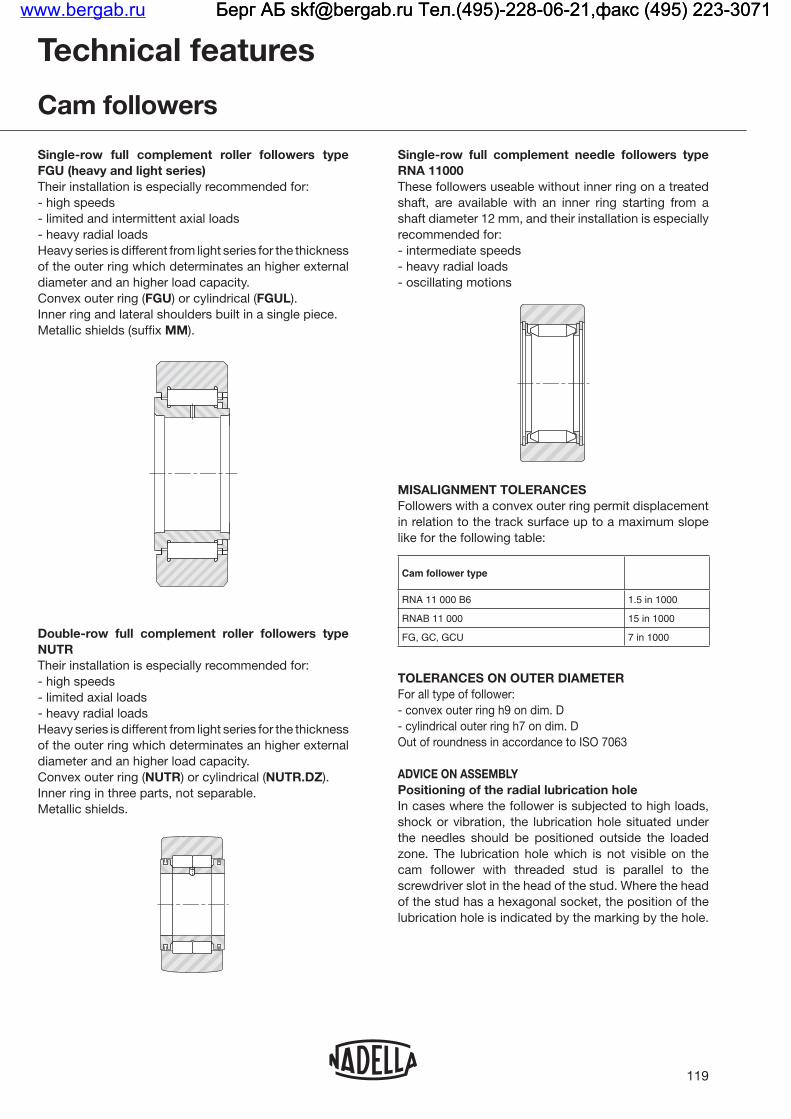
Single-row full complement roller followers type FGU (heavy and light series) Their installation is especially recommended for:- high speeds
- heavy radial loadsHeavy series is different from light series for the thickness
diameter and an higher load capacity.FGU FGUL).
Inner ring and lateral shoulders built in a single piece.MM).
Double-row full complement roller followers type NUTR Their installation is especially recommended for:- high speeds
- heavy radial loadsHeavy series is different from light series for the thickness
diameter and an higher load capacity.NUTR NUTR.DZ).
Inner ring in three parts, not separable.Metallic shields.
119
Single-row full complement needle followers type RNA 11000 These followers useable without inner ring on a treated shaft, are available with an inner ring starting from a shaft diameter 12 mm, and their installation is especially recommended for:- intermediate speeds- heavy radial loads- oscillating motions
MISALIGNMENT TOLERANCES
like for the following table:
Cam follower type
RNA 11 000 B6 1.5 in 1000
RNAB 11 000 15 in 1000
FG, GC, GCU 7 in 1000
TOLERANCES ON OUTER DIAMETER For all type of follower:
- cylindrical outer ring h7 on dim. DOut of roundness in accordance to ISO 7063
ADVICE ON ASSEMBLY Positioning of the radial lubrication hole
shock or vibration, the lubrication hole situated under the needles should be positioned outside the loaded zone. The lubrication hole which is not visible on the cam follower with threaded stud is parallel to the screwdriver slot in the head of the stud. Where the head
lubrication hole is indicated by the marking by the hole.
Technical features
Cam followers
www.bergab.ru Берг АБ [email protected] Тел.(495)-228-06-21,факс (495) 223-3071 Берг АБ [email protected] Тел.(495)-228-06-21,факс (495) 223-3071 Берг АБ [email protected] Тел.(495)-228-06-21,факс (495) 223-3071

Lateral support of followersFor followers type FGU shoulders on the shaft or other parts serving to retain the follower on the faces of the inner ring should have an outer diameter not less than dimensions dA
should be equal at least to dimension dA listed in the tables.For followers of FG series shoulders on the shaft should be equal at least to dimension dA.For the correct mounting of followers of NUKR series
advised for locking is dA listed in the tables.
CAM FOLLOWERS GC, GCU AND NUKR SERIESTolerance on hole housingThe stud should fit easily into the hole in the mating member having a bore of tolerance H7. To ensure contact over the entire surface area of the yoke, the supporting face of the mating member should have a diameter of at least equal to dimension dA. The locking torque applied to the nuts, as shown in the table of
the follower.
Cam followers GC GCU NUKR series Dimension d
Without eccentric stud d H7
With eccentric stud d1 H7
CAM FOLLOWERS FG FGU RNA1000 NUTR Shaft tolerances
Cam followers NUTR FP FG FGU series Dimension d
Load fixed in relation to the inner ring h5 / h6
Load rotating in relation to the inner ring k5 / j6
Load fixed in relation to the inner ring, moderate loads, high strength shaft
g6
Load fixed in relation to the inner ring, light loads, unhardened shaft, loose transition fit
f6
120
For RNA 11000 fitted with inner ring Dimension d
Load fixed in relation to the inner ring h5 / h6
Load rotating in relation to the inner ring k5 / j6
For RNA 11000 without inner ring Dimension Fw
Hardened and ground steel shaft h5
The cylindrical tolerance, defined as the difference in
normally be less than a quarter of the manufacturing tolerance. However, for high precision or high speed applications it is advised to restrict this tolerance to one eighth of the manufacturing tolerance.
LUBRICATION - OPERATING TEMPERATUREType RNA 11000 followers are supplied with a coating of protective grease compatible with a lithium base grease.As for the bearings the protective grease is not suitable for lubrication of the wheels.All types of wheels and cam followers, with or without seals are supplied lubricated with a grease permitting operation in temperatures from -20 to +120°C. In the versions with metallic shields or in synthetic material EE-Teflonlubricant. On request, these followers can be supplied with greases for high or low temperatures, or without
In any case, at temperatures of 150°C and above, cam followers must be specially heat treated and calculation of life should take account of reduced load capacity
Use of a special grease for high temperatures may reduce the limiting speeds shown in the tables of dimensions.The metallic shields ...EEM …MM enables operation up to 200°C with a suitable lubricant.
Technical features
Cam followers
www.bergab.ru Берг АБ [email protected] Тел.(495)-228-06-21,факс (495) 223-3071 Берг АБ [email protected] Тел.(495)-228-06-21,факс (495) 223-3071 Берг АБ [email protected] Тел.(495)-228-06-21,факс (495) 223-3071
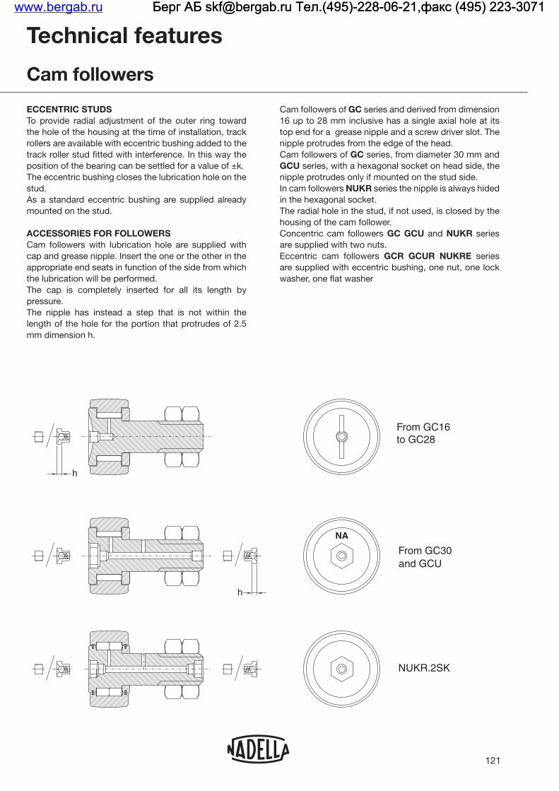
ECCENTRIC STUDS
the hole of the housing at the time of installation, track rollers are available with eccentric bushing added to the track roller stud fitted with interference. In this way the position of the bearing can be settled for a value of ±k.The eccentric bushing closes the lubrication hole on the stud.As a standard eccentric bushing are supplied already mounted on the stud.
ACCESSORIES FOR FOLLOWERS Cam followers with lubrication hole are supplied with cap and grease nipple. Insert the one or the other in the appropriate end seats in function of the side from which the lubrication will be performed.The cap is completely inserted for all its length by pressure.The nipple has instead a step that is not within the length of the hole for the portion that protrudes of 2.5 mm dimension h.
121
Cam followers of GC series and derived from dimension
top end for a grease nipple and a screw driver slot. The nipple protrudes from the edge of the head.Cam followers of GC series, from diameter 30 mm and GCUnipple protrudes only if mounted on the stud side. In cam followers NUKR series the nipple is always hided
The radial hole in the stud, if not used, is closed by the housing of the cam follower.Concentric cam followers GC GCU and NUKR series are supplied with two nuts.Eccentric cam followers GCR GCUR NUKRE series are supplied with eccentric bushing, one nut, one lock washer, one flat washer
Technical features
Cam followers
NUKR.2SK
From GC16 to GC28
From GC30 and GCU
NA
h
h
www.bergab.ru Берг АБ [email protected] Тел.(495)-228-06-21,факс (495) 223-3071 Берг АБ [email protected] Тел.(495)-228-06-21,факс (495) 223-3071 Берг АБ [email protected] Тел.(495)-228-06-21,факс (495) 223-3071

122
Cam followers GC
GC..., GCL...
D
C
B1
C1
Gd
B2
G1
B4
dA
∅outer
Dmm
Designation 1)C
mmd
mmB1
mmB2
mmB4
mmG1
mmThreadG mm
rs min.
mmdA 2)
mmC1
mmGCGCL
10 10 8 4 19.5 11 8.5 6 M4x0.7 0.2 8.4 0.25
11 11 8 4 19.5 11 8.5 6 M4x0.7 0.2 8.4 0.25
12 12 9 5 22.5 13 9.5 7 M5x0.8 0.2 10.3 0.25
13 13 9 5 22.5 13 9.5 7 M5x0.8 0.2 10.3 0.25
14 14 9 6 26 16 10 8 M6x1 0.3 11.8 0.25
15 15 9 6 26 16 10 8 M6x1 0.3 11.8 0.25
1) Designation for cam followers GC... Concentric cam followers with convex outer ring without seal GCL... Concentric cam followers with cylindrical outer ring without seal 2) Minimum recommended abutment diameter in case of heavy axial loads or vibrations
GC, GCL series without seals
www.bergab.ru Берг АБ [email protected] Тел.(495)-228-06-21,факс (495) 223-3071 Берг АБ [email protected] Тел.(495)-228-06-21,факс (495) 223-3071 Берг АБ [email protected] Тел.(495)-228-06-21,факс (495) 223-3071

123
Clamping torque
Nm
Basic capacities kN Speed limits grease
lubrication min-1
Weight kg
∅outer
Dmm
as a bearing as a follower
Dyn. C Stat. Co Dyn. Cw Dyn. Fr Stat. For
0.9 2.8 3.09 1.92 1.01 1.82 8500 0.006 10
0.9 2.8 3.09 2.12 1.43 2.58 8500 0.007 11
1.8 3.74 4.74 2.54 1.63 2.94 6600 0.011 12
1.8 3.74 4.74 2.16 2.75 3.89 6600 0.011 13
3.0 4.05 5.44 2.86 2.26 4.07 5700 0.016 14
3.0 4.05 5.44 3.04 2.83 4.65 5700 0.018 15
www.bergab.ru Берг АБ [email protected] Тел.(495)-228-06-21,факс (495) 223-3071 Берг АБ [email protected] Тел.(495)-228-06-21,факс (495) 223-3071 Берг АБ [email protected] Тел.(495)-228-06-21,факс (495) 223-3071

124
Needle cam followers GC..
from GCR62.. to GCR90..
2
Holes 1 and 2 from D=30 mm
1
from GCR16.. to GCR52..
GC..
k
d1
Be4
k
d1
Be
D
C
r
B1
C1
G
B3
d1
B2
G1
B4
d4 d4
dA
M
r r
S S
∅outer
D mm
Designation 1) C
mmd 2)
mmd1 2) 3)
mmk 3)
mmM 3)
mmBe 3)
mmB1
mmB2
mmB3 7)
mmB4
mmG1
mm
ThreadG
mm
dA 4)
mmGC..., GC...EEGC...EEM
16 16 11 6 9 0.5 8 28.7 16.5 12.2 8 M6x1 13.3
19 19 11 8 11 0.5 10 32.7 20.5 12.2 10 M8x1.25 15.3
22 22 12 10 14 1 11 36.7 23.5 13.2 12 M10x1.25 18.2
24 24 12 10 14 1 11 36.7 23.5 13.2 12 M10x1.25 18.2
26 26 12 10 14 1 11 36.7 23.5 13.2 12 M10x1.25 20.8
28 28 12 10 14 1 11 36.7 23.5 13.2 12 M10x1.25 20.8
30 30 14 12 16 1 11 40.7 25.5 6 15.2 13 M12x1.5 24.8
32 32 14 12 16 1 11 40.7 25.5 6 15.2 13 M12x1.5 24.8
35 35 18 16 21 1.5 14 52.6 33 8 19.6 17 M16x1.5 28.8
40 40 20 18 24 1.5 16 58.6 37 8 21.6 19 M18x1.5 33.8
47 47 24 20 27 2 17.5 66.6 41 9 25.6 21 M20x1.5 38.7
52 52 24 20 27 2 17.5 66.6 41 9 25.6 21 M20x1.5 38.7
62 62 29 24 36 3 44 18 80.6 50 11 30.6 25 M24x1.5 52
72 72 29 24 36 3 44 18 80.6 50 11 30.6 25 M24x1.5 52
80 80 35 30 42 3 50 27 100.5 63.5 15 37 32 M30x1.5 68
85 85 35 30 42 3 50 27 100.5 63.5 15 37 32 M30x1.5 68
90 90 35 30 42 3 50 27 100.5 63.5 15 37 32 M30x1.5 68
1) Cam follower designation GC.. Concentric cam followers with convex outer ring GCL.. Concentric cam followers with cylindrical outer ring GCR.. Eccentric cam followers with convex outer ring GCRL.. Eccentric cam followers with cylindrical outer ring Without suffix: without seals Suffix ..EE: with plastic seals Suffix ..EEM: with metallic shields
www.bergab.ru Берг АБ [email protected] Тел.(495)-228-06-21,факс (495) 223-3071 Берг АБ [email protected] Тел.(495)-228-06-21,факс (495) 223-3071 Берг АБ [email protected] Тел.(495)-228-06-21,факс (495) 223-3071

125
C1
mmr min.
mmP
mmd4
mmS 6) Clamping
torque Nm
Basic capacities KN Speed limits grease
lubrication min-1
Weight with nut and
washer kg
∅outer
D mm
as a bearing as a follower
min. max. Dyn. C Stat. Co Dyn. Cw Dyn. Fr Stat. For
0.6 0.3 4 8.5 10 3 5.66 6.51 4.19 2.79 5.02 5700 0.024 16
0.6 0.3 4 10.5 13 8 6.44 8.15 4.65 3 6.28 4400 0.039 19
0.6 0.3 4 11.5 14 20 7.3 10.2 5.05 4.07 7.33 3500 0.057 22
0.6 0.3 4 11.5 14 20 7.3 10.2 5.45 5.42 8.63 3500 0.072 24
0.6 0.3 4 11.5 14 20 9.92 12.9 7.09 5.43 9.77 3200 0.080 26
0.6 0.3 4 11.5 14 20 9.92 12.9 7.57 6.95 11.4 3200 0.088 28
0.6 0.6 8 4 11.5 14.5 26 15.5 20.4 11.2 8.48 15.3 2900 0.118 30
0.6 0.6 8 4 11.5 14.5 26 15.5 20.4 11.8 10.6 18.1 2900 0.126 32
0.8 0.6 10 6 14.5 19 64 23.6 33.1 15.7 10.8 19.4 2200 0.220 35
0.8 1 12 6 16.5 22 90 29.9 48 18.5 13.8 24.8 1800 0.321 40
0.8 1 14 6 18 25 120 36.5 65.5 22.5 20.2 36.4 1400 0.500 47
0.8 1 14 6 18 25 120 36.5 65.5 25.2 28 47.5 1400 0.568 52
0.8 1 12 6 18.5 25.5 220 43.3 85.6 30.5 42.9 64.7 1200 1.035 62
0.8 1 12 6 18.5 25.5 220 43.3 85.6 33.9 65.8 79.5 1200 1.278 72
1 1 14 8 27.5 36 450 65.1 144 42.7 62.9 95.3 870 2.074 80
1 1 14 8 27.5 36 450 65.1 144 45.1 75.3 106 870 2.235 85
1 1 14 8 27.5 36 450 65.1 144 47.1 88.8 115 870 2.435 90
Needle cam followers GC..
GC..EE, GC..EEM
head side view
up to diameter D=28 from diameter D=30
NA
P
2) Hole diameter for mounting the concentric follower: d H7 Hole diameter for mounting the eccentric follower: d1 H73) Dimension of the stud with eccentric bushing4) Minimum recommended abutment diameter in case of axial loads or vibrations5) On request cam followers can be produced with screw driver slot on the end of the threaded stud (suffix AK)6) Mounting plate thickness7) For concentric rollers only (without eccentric bushing)
www.bergab.ru Берг АБ [email protected] Тел.(495)-228-06-21,факс (495) 223-3071 Берг АБ [email protected] Тел.(495)-228-06-21,факс (495) 223-3071 Берг АБ [email protected] Тел.(495)-228-06-21,факс (495) 223-3071

126
Roller cam followers GCU..
from GCUR62.. to GCUR130..from GCUR35.. to GCUR52..GCU..
D
C
B1
C1
G
B3
d
B2
G1
B4
d4d4
kd1
Be
k
Be4
d1 M
dA
r
S S
∅outer
D mm
Designation 1) C
mmd 2)
mmd1 2) 3)
mmk 3)
mmM 3)
mmBe 3)
mmB1
mmB2
mmB3 7)
mmB4
mmG1
mm
ThreadG
mm
dA 4)
mmGCURGCUR...M M
35 35 18 16 21 1.5 14 52.5 32.8 8 19.7 17 M16x1.5 26
40 40 20 18 24 1.5 16 58.5 36.8 8 21.7 19 M18x1.5 28.6
47 47 24 20 27 2 17.5 66.5 40.8 9 25.7 21 M20x1.5 33.6
52 52 24 20 27 2 17.5 66.5 40.8 9 25.7 21 M20x1.5 33.6
62 62 29 24 36 3 44 18 80.5 49.8 11 30.7 25 M24x1.5 38.9
72 72 29 24 36 3 44 18 80.5 49.8 11 30.7 25 M24x1.5 38.9
80 80 35 30 42 3 50 27 100.5 63.3 15 37.2 32 M30x1.5 51.8
85 85 35 30 42 3 50 27 100.5 63.3 15 37.2 32 M30x1.5 51.8
90 90 35 30 42 3 50 27 100.5 63.3 15 37.2 32 M30x1.5 51.8
100 100 40 36 48 3 56 32 117.5 75.3 20 42.2 38 M36x3 61
110 110 40 36 48 3 56 32 117.5 75.3 20 42.2 38 M36x3 61
120 120 46 42 54 3 62 39 136.5 88.3 24 48.2 44 M42x3 71
130 130 46 42 54 3 62 39 136.5 88.3 24 48.2 44 M42x3 71
1) Cam followers designation GCU.. Concentric cam follower with convex outer ring GCUL.. Concentric cam follower with cylindrical outer ring GCUR.. Eccentric cam follower with convex outer ring GCURL.. Eccentric cam follower with cylindrical outer ring Without suffix: without seals Suffix ..MM: with metallic shields
www.bergab.ru Берг АБ [email protected] Тел.(495)-228-06-21,факс (495) 223-3071 Берг АБ [email protected] Тел.(495)-228-06-21,факс (495) 223-3071 Берг АБ [email protected] Тел.(495)-228-06-21,факс (495) 223-3071

127
C1
mmr min.
mmP
mmd4
mmS 6) Clamping
torque Nm
Basic capacities KN Speed limits grease
lubrication min-1
Weight with nut
and washer kg
∅outer
D mm
as a bearing as a follower
min. max. Dyn. C Stat. Co Dyn. Cw Dyn. Fr Stat. For
0.85 0.6 10 6 14.5 19 64 26.4 32.4 15.4 7.25 13.1 2200 0.215 35
0.85 1 12 6 16.5 22 90 26.4 32.4 18.7 12.1 21.8 2200 0.313 40
0.85 1 14 6 18 25 120 43.8 57.9 30.6 21.2 38.2 1600 0.500 47
0.85 1 14 6 18 25 120 43.8 57.9 30.6 21.2 38.2 1600 0.555 52
0.85 1 12 6 18.5 25.5 220 63.7 87.4 44.1 30.9 55.6 1400 1.035 62
0.85 1.1 12 6 18.5 25.5 220 63.7 87.4 50.8 52.7 84.1 1400 1.278 72
1.1 1.1 14 8 27.5 36 450 100 140 66.8 43.8 78.8 1000 2.070 80
1.1 1.1 14 8 27.5 36 450 100 140 75.8 68.1 122 1000 2.230 85
1.1 1.1 14 8 27.5 36 450 100 140 75.8 68.1 122 1000 2.470 90
1.1 2 17 8 32.5 41 740 115 175 82.1 76.6 135 840 3.380 100
1.1 2 17 8 32.5 41 740 115 175 89.7 107 161 840 3.860 110
1.1 2 19 8 39.5 48 1200 167 240 124 107 193 740 5.100 120
1.1 2 19 8 39.5 48 1200 167 240 133 142 228 740 5.590 130
head side view
NA
P
2) Hole diameter for mounting the concentric follower: d H7 Hole diameter for mounting the eccentric follower: d1 H73) Dimension of the stud with eccentric bushing4) Minimum recommended abutment diameter in case of axial loads or vibrations5) On request cam followers can be produced with screw driver slot on the end of the threaded stud (suffix AK)6) Mounting plate thickness7) For concentric rollers only (without eccentric bushing)
www.bergab.ru Берг АБ [email protected] Тел.(495)-228-06-21,факс (495) 223-3071 Берг АБ [email protected] Тел.(495)-228-06-21,факс (495) 223-3071 Берг АБ [email protected] Тел.(495)-228-06-21,факс (495) 223-3071

128
Roller cam followers NUKR..2SK
NUKR..2SK NUKRE35..2SK
D
C
r
B1
C1
G
B3
d
B2
G1
d4d4
dA
k
d1
Be
∅outer
D mm
Designation 1) C
mmd 2)
mmd1 2) 3)
mmk 3)
mmM 3)
mmBe 3)
mmB1
mmB2
mmB3
mmG1
mmd3
mm
ThreadG
mm
dA 4)
mmNUKR..2SKNUKRE..2SK
35 35 18 16 20 1 - 14 52 32.5 8 17 3 M16x1.5 23,6
40 40 20 18 22 1 - 16 58 36.5 8 19 3 M18x1.5 26,4
47 47 24 20 24 1 - 18 66 40.5 9 21 4 M20x1.5 31
52 52 24 20 24 1 - 18 66 40.5 9 21 4 M20x1.5 36,4
62 62 29 24 28 1 44 22 80 49.5 11 25 4 M24x1.5 44,4
72 72 29 24 28 1 44 22 80 49.5 11 25 4 M24x1.5 50,4
80 80 35 30 35 1.5 50 29 100 63 15 32 4 M30x1.5 52,9
90 90 35 30 35 1.5 50 29 100 63 15 32 4 M30x1.5 52,9
1) Designation for cam followers NUKR..2SK Concentric cam follower with profiled outer ring NUKRE..2SK Eccentric cam follower with profiled outer ring2) Hole diameter for mounting the concentric follower: d H7 Hole diameter for mounting the eccentric follower: d1 H73) Dimension of the stud with eccentric bushing4) Minimum recommended abutment diameter in case of axial loads or vibrations5) For concentric rollers only (without eccentric bushing)
www.bergab.ru Берг АБ [email protected] Тел.(495)-228-06-21,факс (495) 223-3071 Берг АБ [email protected] Тел.(495)-228-06-21,факс (495) 223-3071 Берг АБ [email protected] Тел.(495)-228-06-21,факс (495) 223-3071

129
C1
mmr min.
mmP
mmd4
mm
Clamping torqueNm 4)
Basic capacities kN Speed limits grease
lubrication min-1
Weight with nut and
washer kg
∅outer
D mm
as a bearing as a follower
Dyn. C Stat. Co Dyn. Cw Dyn. Fr Stat. For
0.8 0.6 8 6 53.2 24.7 29.4 16.2 10.1 16.1 2300 0.215 35
0.8 1 8 6 77.5 26.6 33.3 18.7 15.0 23.9 2000 0.310 40
0.8 1 10 6 109 41.4 53.2 28.1 20.5 32.7 1700 0.500 47
0.8 1 10 6 109 45.8 63.1 29.6 22.2 35.4 1400 0.580 52
0.8 1 14 8 193 62.7 83.1 40.9 29.6 47.2 1200 1.050 62
0.8 1.1 14 8 193 68.9 97.8 46.1 39.6 63.1 1100 1.280 72
1.0 1.1 14 8 390 95.4 130 69.7 63.2 101 1000 2.080 80
1.0 1.1 14 8 390 95.4 130 77.8 97.8 128 1000 2.400 90
Roller cam followers NUKR..2SK
head side view
NA
P
www.bergab.ru Берг АБ [email protected] Тел.(495)-228-06-21,факс (495) 223-3071 Берг АБ [email protected] Тел.(495)-228-06-21,факс (495) 223-3071 Берг АБ [email protected] Тел.(495)-228-06-21,факс (495) 223-3071

130
Small needle cam follower FP
FP, FPL
B
D
C
d
rs
r1s
∅outer
Dmm
Designation 1) D
mmd
mmB
mmC
mmrs min.
mmr1s min.
mm
Basic capacities kN Speed limits grease lubrication
min-1
Weight kgFP, FPL
as a bearing as a cam follower
Dyn. C Stat. Co Dyn. Cw Dyn. Fr Stat. For
10 3 10 10 3 8.7 8 0.2 0.15 2.8 3.09 2.12 1.43 2.58 8500 0.004
11 3 11 11 3 8.7 8 0.2 0.15 2.8 3.09 2.12 1.43 2.58 8500 0.005
12 4 12 12 4 9.7 9 0.2 0.15 3.74 4.74 2.54 1.63 2.94 6600 0.006
13 4 13 13 4 9.7 9 0.2 0.15 3.74 4.74 2.16 2.75 3.89 6600 0.008
14 4 14 14 4 10.2 9 0.3 0.15 4.05 5.44 2.86 2.26 4.07 5700 0.010
15 4 15 15 4 10.2 9 0.3 0.15 4.05 5.44 3.04 2.83 4.65 5700 0.011
FP, FPL serieswithout seals
1) Designation FP Convex outer ring FPL Cylindrical outer ring
www.bergab.ru Берг АБ [email protected] Тел.(495)-228-06-21,факс (495) 223-3071 Берг АБ [email protected] Тел.(495)-228-06-21,факс (495) 223-3071 Берг АБ [email protected] Тел.(495)-228-06-21,факс (495) 223-3071

131
Needle cam follower FG
FG, FGL
D
B
dAd
r1s
rs
FG..EE, FG..EEMFGL..EE, FGL..EEM
C
∅outer
D mm
Designation 1) D
mmd
mmB
mmC
mmdA2) mm
rs min.
mm
r1s min.
mm
Basic capacities kN Speed limits grease
lubrication min-1
Weight kgFG, FGL
as a bearing as a follower
Dyn. C Stat. Co Dyn. Cw Dyn. Fr Stat. For
16 5 16 16 5 12 11 10 0.3 0.3 5.66 6.51 4.19 2.79 5.02 5700 0.016
19 6 19 19 6 12 11 12 0.3 0.3 6.44 8.15 4.65 3.49 6.28 4400 0.019
248 24 24 8 13 12 14.5 0.3 0.3 7.3 10.2 5.45 5.42 8.63 3500 0.037
8 24 15 24 8 15 14 14.5 0.3 0.3 9.08 13.5 6.76 7.05 11.4 3500 0.044
30 10 30 30 10 15 14 19.5 0.6 0.3 14.2 18.3 10.3 7.67 13.8 2900 0.066
32 12 32 32 12 15 14 21.5 0.6 0.3 15.5 21.2 10.5 7.52 13.5 2400 0.077
35 15 35 35 15 19 18 24 0.6 0.3 22.5 35.4 14.6 11.6 20.9 2100 0.103
40 17 40 40 17 21 20 28 0.6 0.3 29.9 48.0 18.5 13.8 24.8 1800 0.155
47 20 47 47 20 25 24 32.5 1.0 0.3 36.5 65.5 22.5 20.2 36.4 1400 0.295
52 25 52 52 25 25 24 37 1.0 0.3 39.7 76.4 23.1 22.6 40.3 1200 0.310
62 30 62 62 30 29 28 44 1.0 0.3 46.5 97.9 28.9 35.5 58.2 1100 0.490
72 35 72 72 35 29 28 50 1.0 0.6 50.0 113 31.4 45.6 68.4 920 0.670
80 40 80 80 40 32 30 56 1.0 0.6 62.1 155 38.3 63.7 90.6 810 0.890
85 45 85 85 45 32 30 62 1.0 0.6 65.7 173 38.4 67.2 91.1 720 0.970
90 50 90 90 50 32 30 69 1.0 0.6 69.7 194 37.8 74.3 88.7 640 1.04
100 55 100 100 55 36 34 75 1.5 0.6 85.0 233 45.2 87.9 103 570 1.35
110 60 110 110 60 36 34 82 1.5 0.6 88.6 251 48.9 99.6 119 530 1.65
120 65 120 120 65 42 40 90 1.5 0.6 103 310 58.1 131 154 490 2.35
125 70 125 125 70 42 40 92 1.5 0.6 106 332 58.7 142 157 460 2.50
130 75 130 130 75 42 40 96 1.5 0.6 110 354 59.2 155 159 440 2.65
140 80 140 140 80 48 46 105 2.0 1.0 140 455 72.4 202 189 390 3.40
150 85 150 150 85 48 46 112 2.0 1.0 146 490 75.3 227 203 370 4.00
160 90 160 160 90 54 52 120 2.0 1.0 168 603 85.7 299 244 340 5.30
170 95 170 170 95 54 52 125 2.0 1.0 172 629 89.8 308 267 330 6.00
180 100 180 180 100 65 63 135 2.0 1.5 238 828 126 358 363 310 8.05
200 110 200 200 110 65 63 150 2.0 1.5 252 922 133 427 401 280 10.00
215 120 215 215 120 65 63 160 2.0 1.5 261 985 138 476 430 260 11.50
270 150 270 270 150 78 75 195 3.0 1.5 372 1470 200 721 658 210 22.00
FG serieswithout sealFG..EE serieswith plastic sealsFG..EEM serieswith metallic shields
1) Designation FG..EE series with plastic seals are available up to type FG 50 90 FG convex outer ring FGL cylindrical outer ring2) Minimum recommended abutment diameter in case of axial loads or vibrations
www.bergab.ru Берг АБ [email protected] Тел.(495)-228-06-21,факс (495) 223-3071 Берг АБ [email protected] Тел.(495)-228-06-21,факс (495) 223-3071 Берг АБ [email protected] Тел.(495)-228-06-21,факс (495) 223-3071

132
Full complement roller cam followers FGU
FGU, FGUL
BC
dd DA
rs
r1S
∅outer
D mm
Designation 1) D
mmd
mmC
mmB
mmdA2)
mmrs min.
mm
r1s min.
mm
Basic capacities kN Speed limits grease
lubrication min-1
Weight kgFGU, FGUL
light series
Dynamic Static
C Fr For
35 15 35 35 15 18 19 20.4 0.6 0.3 7.80 17.0 17.0 5700 0.096
40 17 40 40 17 20 21 23 0.6 0.3 11.5 20.0 21.5 5200 0.142
47 20 47 47 20 24 25 27.1 1.0 0.3 15.5 29.5 32.3 4400 0.235
52 25 52 52 25 24 25 31.8 1.0 0.3 17.3 31.5 36.0 3800 0.268
62 30 62 62 30 28 29 38.2 1.0 0.3 24.5 44.5 54.00 3200 0.454
72 35 72 72 35 28 29 45.9 1.0 0.6 31.3 50.0 66.0 2700 0.611
80 40 80 80 40 30 32 51.6 1.0 0.6 40.6 59.0 84.0 2400 0.822
110 60 110 110 60 34 36 71.2 1.5 0.6 64.0 88.0 129 1800 1.625
120 65 120 120 65 40 42 76.4 1.5 0.6 89.0 110 174 1700 2.300
125 70 125 125 70 40 42 81.5 1.5 0.6 93.0 110 180 1600 2.070
140 80 140 140 80 46 48 91.7 2.0 1.0 130 138 250 1400 3.450
160 90 160 160 90 52 54 101.8 2.0 1.0 166 188 327 1300 5.185
170 95 170 170 95 52 54 108.2 2.0 1.0 184 198 356 1200 5.925
200 110 200 200 110 63 65 124.1 2.0 1.5 310 280 590 1100 10.200
215 120 215 215 120 63 65 133.6 2.0 1.5 310 310 600 960 11.560
Light seriesFGU.. without seals FGU..MM with metallic shield
1) Designation FGU convex outer ring FGUL cylindrical outer ring2) Minimum recommended abutment diameter in case of axial loads or vibrations
www.bergab.ru Берг АБ [email protected] Тел.(495)-228-06-21,факс (495) 223-3071 Берг АБ [email protected] Тел.(495)-228-06-21,факс (495) 223-3071 Берг АБ [email protected] Тел.(495)-228-06-21,факс (495) 223-3071

133
Full complement roller cam followers FGU
∅outer
D mm
Designation1)
Dmm
dmm
Cmm
Bmm
dA2)
mmrs min.
mm
r1s min.
mm
Basic capacities kN Speed limits grease
lubrication min-1
Weight kgFGU, FGUL
heavy series
as a bearing as a follower
Dyn. C Stat. Co Dyn. Cw Dyn. Fr Stat. For
42 15 42 42 15 18 19 20.4 1.0 0.3 26.4 32.4 19.7 14.7 26.4 2200 0.153
47 17 47 47 17 20 21 23 1.0 0.3 28.3 36.5 21.5 18.8 31.9 1900 0.214
52 20 52 52 20 24 25 27.1 1.0 0.3 43.8 57.9 30.7 21.3 38.3 1600 0.268
62 25 62 62 25 24 25 31.8 1.0 0.3 48.2 68.2 35.1 30.7 55.1 1400 0.435
72 30 72 72 30 28 29 38.2 1.0 0.3 70 103 49 40 72 1100 0.681
80 35 80 80 35 28 29 45.9 1.0 0.6 77.5 124 51 42.4 76.3 920 0.82
90 40 90 90 40 30 32 51.6 1.0 0.6 89.2 153 60.2 59.3 107 810 1.125
100 45 100 100 45 30 32 55.4 1.5 0.6 92.7 165 64.5 73.6 122 750 1.395
110 50 110 110 50 30 32 61.1 1.5 0.6 97.8 182 68.1 85.9 135 680 1.683
120 55 120 120 55 34 36 66.1 1.5 0.6 128 215 88.7 91.8 159 640 2.235
130 60 130 130 60 34 36 71.2 1.5 0.6 133 232 93.4 106 175 590 2.62
140 65 140 140 65 40 42 76.4 2.0 0.6 156 290 110 142 222 540 3.56
150 70 150 150 70 40 42 81.5 2.0 0.6 161 310 115 160 240 510 4.09
160 75 160 160 75 40 42 86.6 2.0 0.6 166 329 119 178 257 480 4.65
170 80 170 170 80 46 48 91.7 2.0 1.0 195 412 140 229 322 450 6.07
180 85 180 180 85 46 48 95.5 2.0 1.0 224 426 162 225 340 440 6.724
190 90 190 190 90 52 54 101.8 2.0 1.0 259 524 186 277 412 410 8.515
260 120 260 260 120 63 65 133.6 3.0 1.5 396 875 293 540 730 300 19.750
300 140 300 300 140 75 78 152.6 3.0 1.5 493 1210 367 818 1020 260 31.265
Heavy seriesFGU.. without seals FGU..MM with metallic shields
1) Designation FGU convex outer ring FGUL cylindrical outer ring2) Minimum recommended abutment diameter in case of axial loads or vibrations
FGU, FGUL
BC
dd DA
rs
r1S
www.bergab.ru Берг АБ [email protected] Тел.(495)-228-06-21,факс (495) 223-3071 Берг АБ [email protected] Тел.(495)-228-06-21,факс (495) 223-3071 Берг АБ [email protected] Тел.(495)-228-06-21,факс (495) 223-3071

134
Cam followers without inner ring RNA
RNA...B6
DEw Fw
rsC
∅outer
D mm
Designation1)
D3)
mmC
mmFw
mmEw
mmrs min.
mm
Basic capacities KN2)
RNA B6 RNA B RNAL as a bearing as a follower
Dyn. C Stat. Co Dyn. Cw Dyn. Fr Stat. For
19 RNA 11005 B6 RNAB 11005 19 12 7.3 12.3 0.35 5.31 4.44 4.82 4.44 4.82
22 RNA 11007 B6 RNAB 11007 RNAL 11007 22 12 9.7 14.7 0.35 6.42 5.93 5.5 5.26 6.55
28 RNA 11009 B6 RNAB 11009 RNAL 11009 28 12 12.1 17.1 0.35 7.37 7.42 6.66 7.42 9.06
32 RNA 11012 B6 RNAB 11012 RNAL 11012 32 15 17.6 22.6 0.35 12.7 16.4 9.38 9.48 13.7
35 RNA 11015 B6 RNAB 11015 35 15 20.8 25.8 0.65 13.9 19.4 9.60 9.47 14.1
42 RNA 11017 B6 RNAB 11017 RNAL 11017 42 15 23.9 28.9 0.65 15.0 22.4 11.0 14.4 18.4
47 RNA 11020 B6 RNAB 11020 RNAL 11020 47 18 28.7 34.7 0.65 21.7 33.5 14.6 16.0 23.3
52 RNA 11025 B6 RNAB 11025 52 18 33.5 39.5 0.65 23.6 39.1 15.0 17.1 24.4
62 RNA 11030 B6 RNAB 11030 62 22 38.2 44.2 0.65 34.2 65.8 22.6 32.8 44.3
72 RNA 11035 B6 72 22 44.0 50.0 0.65 36.7 75.7 24.6 42.4 52.2
90 RNA 11050 B6 90 24 62.1 68.1 0.85 44.0 107 25.8 53.1 57.0
1) Designation RNA..B6 Convex outer ring with maximum inclination 0.15% RNAB Convex outer ring with maximum inclination 1,5% RNAL Cylindrical outer ring2) Basic capacities refer to RNAL type only when mounted forced in a housing3) Tolerances on dimension D: h9 for RNA..B6 and RNAB, h7 for RNAL
www.bergab.ru Берг АБ [email protected] Тел.(495)-228-06-21,факс (495) 223-3071 Берг АБ [email protected] Тел.(495)-228-06-21,факс (495) 223-3071 Берг АБ [email protected] Тел.(495)-228-06-21,факс (495) 223-3071

135
Inner ring BIC
Speed limits grease
lubrication min-1
Weightkg
Shaftd
mm
Designation F
mmB
mmFw
mmD
mmr1s min.
mm
∅outer
D mm
BIC
6500 0.019 19
4700 0.022 22
3700 0.028 28
2400 0.032 12 BIC 1012 17.6 15 12 0.35 0.35 32
2000 0.035 15 BIC 1015 20.8 15 15 0.65 0.65 35
1700 0.042 17 BIC 1017 23.9 15 17 0.68 0.65 42
1400 0.047 20 BIC 2020 28.7 18 20 0.65 0.65 47
1200 0.052 25 BIC 1025 33.5 18 25 0.65 0.65 52
1100 0.062 30 BIC 2030 38.2 22 30 0.65 0.65 62
920 0.072 35 BIC 2035 44 22 35 0.65 0.65 72
640 0.090 50 BIC 11050 62.1 24 50 0.85 0.85 90
BIC
B
Fd
r1s
www.bergab.ru Берг АБ [email protected] Тел.(495)-228-06-21,факс (495) 223-3071 Берг АБ [email protected] Тел.(495)-228-06-21,факс (495) 223-3071 Берг АБ [email protected] Тел.(495)-228-06-21,факс (495) 223-3071

136
Full complement roller cam follower NUTR
NUTR.DZ NUTR
rs
r1sR500
D
C
dA
B
d
rs
r1s
D
C
dA
B
d
∅outer
D mm
Designation1) D
mmd
mmB
mmC
mmdA
mm
rs min.
mm
r1s min.
mm
Basic capacities kN Speed limits
grease lubrication
min-1
Weight kgNUTR, NUTR.DZ
as a bearing as a follower
Dyn. C Stat. Co Dyn. Cw Dyn. Fr Stat. For
35 15 35 15 19 18 24 0.6 0.3 24.7 29.3 16.2 10.1 16.1 6100 0.105
40 17 40 17 21 20 27 1.0 0.3 26.6 33.4 18.7 15.0 23.9 5300 0.154
42 1542 42 15 19 18 24 0.6 0.3 22.8 29.4 20.0 21.2 28.4 6100 0.166
471747 47 17 21 20 27 1.0 0.3 24.5 33.3 22.0 28.1 33.6 5300 0.230
20 47 20 25 24 32 1.0 0.3 39.0 53.2 28.1 20.5 32.7 4500 0.254
522052 52 20 25 24 32 1.0 0.3 39.0 53.2 31.6 31.0 45.9 4500 0.326
25 52 25 25 24 37 1.0 0.3 43.0 63.1 29.6 22.2 35.4 3700 0.291
622562 62 25 25 24 37 1.0 0.3 43.0 63.1 36.0 43.9 57.8 3700 0.460
30 62 30 29 28 44 1.0 0.3 60.0 83.1 40.8 29.0 46.2 3200 0.480
723072 72 30 29 28 44 1.0 0.3 60.0 83.1 48.6 53.2 74.2 3200 0.711
35 72 35 29 28 50 1.1 0.6 65.5 97.8 45.9 38.7 61.7 2600 0.655
803580 80 35 29 28 50 1.1 0.6 65.5 97.8 51.7 58.7 81.9 2600 0.865
40 80 40 32 30 55 1.1 0.6 88.0 132 60.6 48.0 76.5 2500 0.848
85 45 85 45 32 30 60 1.1 0.6 93.0 146 62.0 50.2 80.0 2200 0.917
904090 90 40 32 30 55 1.1 0.6 88.0 132 69.1 75.4 111 2500 1.162
50 90 50 32 30 65 1.1 0.6 98.0 160 63.3 52.9 84.3 2000 0.988
100 45100 100 45 32 30 60 1.1 0.6 93.0 146 74.3 92.2 127 2200 1.412
110 50110 110 50 32 30 65 1.1 0.6 98.0 160 79.0 110 141 2000 1.727
1) Designation NUTR Convex outer ring NUTR.DZ Cylindrical outer ring
www.bergab.ru Берг АБ [email protected] Тел.(495)-228-06-21,факс (495) 223-3071 Берг АБ [email protected] Тел.(495)-228-06-21,факс (495) 223-3071 Берг АБ [email protected] Тел.(495)-228-06-21,факс (495) 223-3071

NEEDLE THRUST BEARINGSROLLER THRUST BEARINGS
www.bergab.ru Берг АБ [email protected] Тел.(495)-228-06-21,факс (495) 223-3071 Берг АБ [email protected] Тел.(495)-228-06-21,факс (495) 223-3071 Берг АБ [email protected] Тел.(495)-228-06-21,факс (495) 223-3071

The rolling elements of a thrust bearing are retained and guided in radial pockets within the cage (1). The latter is itself retained in relation to the plate (2) by means of a steel ring (3). This assembly of parts is easy to handle and install and provides a high axial load capacity whilst occupying minimal space. The design of Nadella thrust bearings serves to reduce to a minimum the friction between the rolling elements and the cage that guides them. Given correct installation and adequate oil lubrication, the coefficient of friction will be between 0.003 and 0.004 for needle thrust bearings and between 0.004 and 0.005 for roller thrust bearings. This result is due principally to the design of the one-piece steel cage (1) which has a special curvature that guides the rolling elements by their ends along their centre-lines. Thus, the loads imposed on the cage by the rollers cannot create components parallel to the axis of rotation and therefore no increase in internal friction is generated, and correct operation without wear or overheating is ensured. In addition, this special curvature gives the steel cage great rigidity and being relatively thin provides maximum space for the lubricant.
TYPES OF THRUST BEARINGS
AX AR AXZ ARZ
1
2
3
138
THRUST PLATESThe plate incorporated in the thrust bearing is made from hardened bearing steel and forms one of the raceways for the rolling elements. The opposing raceway is generally provided by a separate thrust plate of similar design supplied by Nadella. When the thrust bearing iscentred by the revolving part, the thrust plate must be centred by the stationary part and vice versa. lf the revolving part and the stationary part are noticeably eccentric to each other, the thrust bearing with integral plate must without exception be centred by the revolving part (see mounting examples on pages 140 and 141).The second raceway for the rolling elements may also be formed by the face of a shoulder or an inserted ring, provided these have the correct geometrical dimensions and hardness.
THRUST BEARINGS WITH THRUST PLATEThrust bearings type AXZ and ARZ have two thrust plates retained by a steel ring giving protection against the entry of dirt and metal particles whilst at the same time assisting retention of the lubricant. OPERATIONWhen the ring of rolling elements begins to rotate, it is automatically centred in relation to the shaft axis. Thus the thrust bearing does not need to be precisely centred by the incorporated plate. Hence it is possible to align the bearing (on the shaft or in the housing) allowing wide tolerances to be used and without surface hardening. This enables costs to be reduced. The same feature applies to centring of the thrust plate.
Thrust bearings with incorporated plate
Separate thrust plates
Thrust bearings with plate and thrust plate
incorporated
Needle thrust bearings
AX thin seriesAX thick series CP thin series
CP thick series
Needle thrust bearingsAXZ thick series
Roller thrust bearings AR light
series
Roller thrust bearingsARZ light series
AR heavy series CPR heavy series ARZ heavy series
Needle thrust bearings with a thin plate are of minimal thickness and are particularly economic to use. They should be considered whenever the degree of support and rotational accuracy permits.
Technical features
Needle thrust bearings-Roller thrust bearings
www.bergab.ru Берг АБ [email protected] Тел.(495)-228-06-21,факс (495) 223-3071 Берг АБ [email protected] Тел.(495)-228-06-21,факс (495) 223-3071 Берг АБ [email protected] Тел.(495)-228-06-21,факс (495) 223-3071

THICKNESS AND AXIAL RUN-OUT TOLERANCES
Internal ∅Dc1 mm
Thickness tolerance μm
Axial run-out max
Needle thrust bearings (thin) Dc1 ≤ 60 60 < Dc1 ≤ 90 90 < Dc1 ≤ 120
+ 30/- 40 1)
+ 50/- 60 2)
+ 50/- 60 2)
20 1)
25 2)
30 2)
Thrust plates (thin) Dc1 ≤ 60 60 < Dc1 ≤ 90 90 < Dc1 ≤ 120
+ 30/- 40 1)
+ 50/- 50 2)
+ 50/- 50 2)
20 1)
25 2)
30 2)
Needle thrust bearings (thick) Roller thrust bearings
Dc1 ≤ 120120 < Dc1 ≤ 180180 < Dc1 ≤ 250
+ 50/- 60+ 50/- 110+ 50/- 160
5 * 7 *10 *
Thrust plates (thick) Dc1 ≤ 120120 < Dc1 ≤ 180180 < Dc1 ≤ 250
+ 50/- 50+ 50/- 100+ 50/- 150
5 * 7 *10 *
(1) Under min. load of 150 N
(2) Under min. load of 250 N
SUPPORTING FACESFor smooth running operation of needle or roller thrust bearings, it is necessary that their supporting faces should be parallel.For a thrust bearing with intermediate thrust plate, the permissible degree of deviation from true parallelism between the two supporting faces should be no more than 1 min. (or approx. 0.3 per 1000).For a thrust bearing without intermediate thrust plate, the deviation must be no more than 1 min. 30 sec. (or approx. 0.45 per 1000).Thin needle thrust bearings and thin thrust plates must be supported on a flat, rigid and continuous face throughout the area of circulation of the needles bounded by dimensions Eb and Ea.Thick needle thrust bearings and thick thrust plates can be supported on a more restricted or discontinuous shoulder, provided that the deflection of the plate under load does not endanger the smooth operation of the thrust bearing or the axial run-out required.Since roller thrust bearings generally run under considerable loads, their incorporated plate and thrust plate should be supported on a shoulder covering the whole area of circulation of the rollers bounded by dimensions Eb and Ea.Where an application does not involve the use of a thrust plate, the surface forming the second raceway must:- extend at least across the whole area of circulation of
the rolling elements between dimensions Eb and Ea; - possess a suitable surface finish (≤0.5 μm C.L.A.)
and sufficient hardness in relation to the load to be supported.
A hardness of 58-64 HRC enables thrust bearings to carry their full load capacity. Lower hardness values reduce the capacities shown in the tables of dimensions (see Technical Section).
139
TOLERANCES FOR CENTRING SUPPORTSCentring on the shaft: h10 on dimension Dc1 for thrust bearings or thrust plates.Centring in the housing: H10 on dimension D for thrust bearings and dimension d1 for thrust plates.
LOAD RATINGSMinimum axial loadSlippage can occur if the applied axial load is too light and the operating speed of the needle thrust bearings is high – particularly if accompanied by inadequate lubrication. For satisfactory operation, a certain minimum load must be applied to a needle thrust bearing which can be calculated from:Fa min = C0/2200 [kN]
Where:C0 static load rating [kN]Fa min minimum axial load [kN]
COEFFICIENT OF FRICTIONIn general, the coefficient of friction of a thrust bearing (consisting of a needle thrust bearing and thrust plate) is defined as the friction torque, divided by the product of the applied load and the bearing pitch radius. This coefficient of friction is not a constant value, but will vary considerably with load, speed and lubricant. Generally, the coefficient of friction becomes smaller as the load is increased, and larger as the speed is increased. It is suggested that a value of 0.008 as a conservative estimate.
LUBRICATIONOil is the preferred lubricant for needle thrust bearings and an ample oil flow is absolutely necessary for high speeds or for moderate speeds when the load is relatively high.When the application must utilize grease lubrication, the needle thrust bearing should be ordered pre-greased.When the speeds are low and rotation is not continuous, the initial charge of grease may be suitable for the life of the application.When the speeds are moderate, the designer must provide for frequent re-greasing. Because the needle rollers tend to expel the lubricant radially outward, re-lubrication passages should be directed to the bore of the cage whether oil or grease is used as the lubricant.
SPECIAL DESIGNSNeedle thrust bearings and thrust plates are made to special dimensions and configurations, as well as from special materials – when quantities permit economical manufacture.
Technical features
Needle thrust bearings-Roller thrust bearing
www.bergab.ru Берг АБ [email protected] Тел.(495)-228-06-21,факс (495) 223-3071 Берг АБ [email protected] Тел.(495)-228-06-21,факс (495) 223-3071 Берг АБ [email protected] Тел.(495)-228-06-21,факс (495) 223-3071

140
Mounting arrangements
Needle thrust bearings with thin thrust plate
Mounting for eccentric operation
Needle thrust bearings with thick plate or light series roller thrust bearings
With thick thrust plateWith thin thrust plateWithout thrust plate
Dc1
(h1
0)
Eb
max
Ea
min
Recess = B1
Ea
min
Ø D
(H
10)
Ø D
(H
10)
Ea
min
Dc1
(h1
0)
Recess = B1
Eb
max
Dc1
(h1
0)
Ø d
1 (H
10)
Max. Recess = h
Max. Recess = B1 -0.2
Max. Recess = h+0.2
Max. Recess = B1 -0.2
Max. Recess = h
Ø d
1 (H
10)
Dc1
-0.5
m
ax
Dc1
(h1
0)
Max. Recess = h+0.2
Recess = B1
Dc1
(h1
0)
Ø D
(H
10)
Dc1
-0.5
max
Dc1
-0.5
max
Dc1
-0.5
max
Dc1
-0.5
max
Ea
min
Ea
min
Eb
max
Dc1
(h1
0)
Eb
max
Ea
min
Depth = B1
Ø
(H10
)D
Without thrust plate With thin thrust plate With thick thrust plate
Dc1
(h1
0)
Ea
min
Max. Recess = h
Eb
max
Ø d
1 (H
10)
Depth = B1
Dc1
(h1
0)
Ea
min
Ø D
(H
10)
Eb
max
Max. Recess = h +0.2
Ø d
1 (H
10)
Max. Recess = h
Ea
min
Dc1
(h1
0)
Max. Recess = B1-0.2
Max. Recess = h +0.2
Eb
max
Ø D
(H
10)
Dc1
(h1
0)
Depth = B1
Dc1
-0.5
max
Dc1
-0.5
max
Dc1
-0.5
max
Dc1
-0.5
m
ax
Dc1
-0.5
m
ax
Shaft revolving
Housing fixed
Thrust bearing
Thrust plate
Housing revolving
Thrust plate
Thrust bearing
Shaft fixed
www.bergab.ru Берг АБ [email protected] Тел.(495)-228-06-21,факс (495) 223-3071 Берг АБ [email protected] Тел.(495)-228-06-21,факс (495) 223-3071 Берг АБ [email protected] Тел.(495)-228-06-21,факс (495) 223-3071

141
Mounting arrangements
Roller thrust bearings AR heavy series
Needle thrust bearings AXZ or roller thrust bearings ARZ
With thick thrust plateWithout thrust plate
Ea
min
Eb
max
Ea
min
Dc1
(h1
0)
Ø D
(H
10)
Eb
max
Dc1
-0.5
max
Ea
min
Max. Recess = B1
Dc1
(h1
0)
Ea
min
Ø d
1 (H
10)
Eb
max
Dc1
-0.5
max
Max. Recess = B1-0.2
Max. Recess = h
Max. Recess = B1E
a m
in
Dc1
-0.5
max
Eb
max
Ø D
(H
10)
Max. Recess = h+0.2D
c1
(h10
)
Dc1
(h1
0)
Dc1
-0.5
max
Ø D
(H
10)
Max. Recess = h+0.2
Max. Recess = T
Mounting for high speed rotation Mounting for slow speed rotation or oscillating motion
Dc1
(h1
0)
Ø D
+0,
5 m
in.
www.bergab.ru Берг АБ [email protected] Тел.(495)-228-06-21,факс (495) 223-3071 Берг АБ [email protected] Тел.(495)-228-06-21,факс (495) 223-3071 Берг АБ [email protected] Тел.(495)-228-06-21,факс (495) 223-3071

142
Needle thrust bearings
AX thin and thick series
Shaft∅
mm
DesignationDC1
mmD
mmB1
mmEb
mmEa
mm
Load ratings Speed rating
oil min-1
Weight kg
AX thin series AX thick seriesDyn. C
kNStat. Co
kN
5AX 5 13 5 13 2.3 6.3 10.9 3.00 5.70 25000 0.001
AX 3.5 5 13 5 13 3.5 6.3 10.9 3.00 5.70 25000 0.002
6AX 6 14 6 14 2.3 7.3 11.9 3.15 6.35 22000 0.001
AX 3.5 6 14 6 14 3.5 7.3 11.9 3.15 6.35 22000 0.002
7AX 7 15 7 15 2.3 8.3 12.9 3.55 7.60 22000 0.002
AX 3.5 7 15 7 15 3.5 8.3 12.9 3.55 7.60 22000 0.003
8AX 8 16 8 16 2.3 9.3 13.9 3.70 8.30 22000 0.002
AX 3.5 8 16 8 16 3.5 9.3 13.9 3.70 8.30 22000 0.003
9AX 9 17 9 17 2.3 10.3 14.9 4.05 9.50 19000 0.002
AX 3.5 9 17 9 17 3.5 10.3 14.9 4.05 9.50 19000 0.004
10AX 10 22 10 22 2.8 12.0 18.6 5.00 10.90 15500 0.004
AX 4 10 22 10 22 4.0 12.0 18.6 5.00 10.90 15500 0.007
12AX 12 26 12 26 2.8 15.0 22.6 6.90 17.70 13000 0.006
AX 4 12 26 12 26 4.0 15.0 22.6 6.90 17.70 13000 0.010
13AX 13 26 13 26 2.8 15.0 22.6 6.90 17.70 13000 0.006
AX 4 13 26 13 26 4.0 15.0 22.6 6.90 17.70 13000 0.010
15AX 15 28 15 28 2.8 17.0 24.6 7.40 20.00 11500 0.007
AX 4 15 28 15 28 4.0 17.0 24.6 7.40 20.00 11500 0.009
17AX 17 30 17 30 2.8 19.0 26.6 7.80 22.00 10500 0.008
AX 4 17 30 17 30 4.0 19.0 26.6 7.80 22.00 10500 0.010
19AX 19 32 19 32 2.8 21.0 28.6 8.00 23.30 10000 0.009
AX 4 19 32 19 32 4.0 21.0 28.6 8.00 23.30 10000 0.013
20AX 20 35 20 35 2.8 22.0 31.6 11.80 39.00 9000 0.010
AX 5 20 35 20 35 5.0 22.0 31.6 11.80 39.00 9000 0.018
25AX 25 42 25 42 2.8 27.7 37.4 13.30 49.00 7500 0.012
AX 5 25 42 25 42 5.0 27.7 37.4 13.30 49.00 7500 0.025
27 AX 27 44 27 44 2.8 30.0 39.6 13.70 52.00 7200 0.012
30AX 30 47 30 47 2.8 32.7 42.4 14.50 57.00 6500 0.014
AX 5 30 47 30 47 5.0 32.7 42.4 14.50 57.00 6500 0.029
35
AX 35 52 35 52 2.8 37.2 49.0 18.90 84.00 5500 0.019
AX 5 35 52 35 52 5.0 37.2 49.0 18.90 84.00 5500 0.035
AX 35 53 35 53 2.8 37.2 49.0 18.90 84.00 5500 0.019
AX 5 35 53 35 53 5.0 37.2 49.0 18.90 84.00 5500 0.036
AX thick AX thin
D D DC1
B1
Eb Ea
B1
DC1 Eb Ea
www.bergab.ru Берг АБ [email protected] Тел.(495)-228-06-21,факс (495) 223-3071 Берг АБ [email protected] Тел.(495)-228-06-21,факс (495) 223-3071 Берг АБ [email protected] Тел.(495)-228-06-21,факс (495) 223-3071

143
Thrust plates
CP thin and thick series
Shaft∅
mm
Designationd
mmd1
mmh
mmWeight
kg
Thrust bearings
CP thin series CP thick series AX thin series AX thick serie
5CP 5 13 5 12.4 0.8 0.001 AX 5 13
CP 2 5 13 5 12.4 2.0 0.002 AX 3.5 5 13
6CP 6 14 6 13.4 0.8 0.001 AX 6 14
CP 2 6 14 6 13.4 2.0 0.002 AX 3.5 6 14
7CP 7 15 7 14.4 0.8 0.001 AX 7 15
CP 2 7 15 7 14.4 2.0 0.002 AX 3.5 7 15
8CP 8 16 8 15.4 0.8 0.001 AX 8 16
CP 2 8 16 8 15.4 2.0 0.002 AX 3.5 8 16
9CP 9 17 9 16.4 0.8 0.001 AX 9 17
CP 2 9 17 9 16.4 2.0 0.002 AX 3.5 9 17
10CP 10 22 10 21.5 0.8 0.002 AX 10 22
CP 2 10 22 10 21.5 2.0 0.002 AX 4 10 22
12CP 12 26 12 25.5 0.8 0.003 AX 12 26
CP 2 12 26 12 25.5 2.0 0.006 AX 4 12 26
13CP 13 26 13 25.5 0.8 0.002 AX 13 26
CP 2 13 26 13 25.5 2.0 0.006 AX 4 13 26
15CP 15 28 15 27.5 0.8 0.003 AX 15 28
CP 2 15 28 15 27.5 2.0 0.006 AX 4 15 28
17CP 17 30 17 29.5 0.8 0.003 AX 17 30
CP 2 17 30 17 29.5 2.0 0.007 AX 4 17 30
19CP 19 32 19 31.5 0.8 0.004 AX 19 32
CP 2 19 32 19 31.5 2.0 0.009 AX 4 19 32
20CP 20 35 20 34.5 0.8 0.004 AX 20 35
CP 3 20 35 20 34.5 3.0 0.013 AX 5 20 35
25CP 25 42 25 41.5 0.8 0.005 AX 25 42
CP 3 25 42 25 41.5 3.0 0.019 AX 5 25 4227 CP 27 44 27 43.7 0.8 0.006 AX 27 44
30CP 30 47 30 46.5 0.8 0.006 AX 30 47
CP 3 30 47 30 46.5 3.0 0.022 AX 5 30 47
35
CP 35 52 35 51.5 0.8 0.007 AX 35 52CP 3 35 52 35 51.5 3.0 0.026 AX 5 35 52
CP 35 53 35 52.5 0.8 0.007 AX 35 53CP 3 35 53 35 52.5 3.0 0.027 AX 5 35 53
CP thickCP thin
d1
h
d
h
d1 d
www.bergab.ru Берг АБ [email protected] Тел.(495)-228-06-21,факс (495) 223-3071 Берг АБ [email protected] Тел.(495)-228-06-21,факс (495) 223-3071 Берг АБ [email protected] Тел.(495)-228-06-21,факс (495) 223-3071
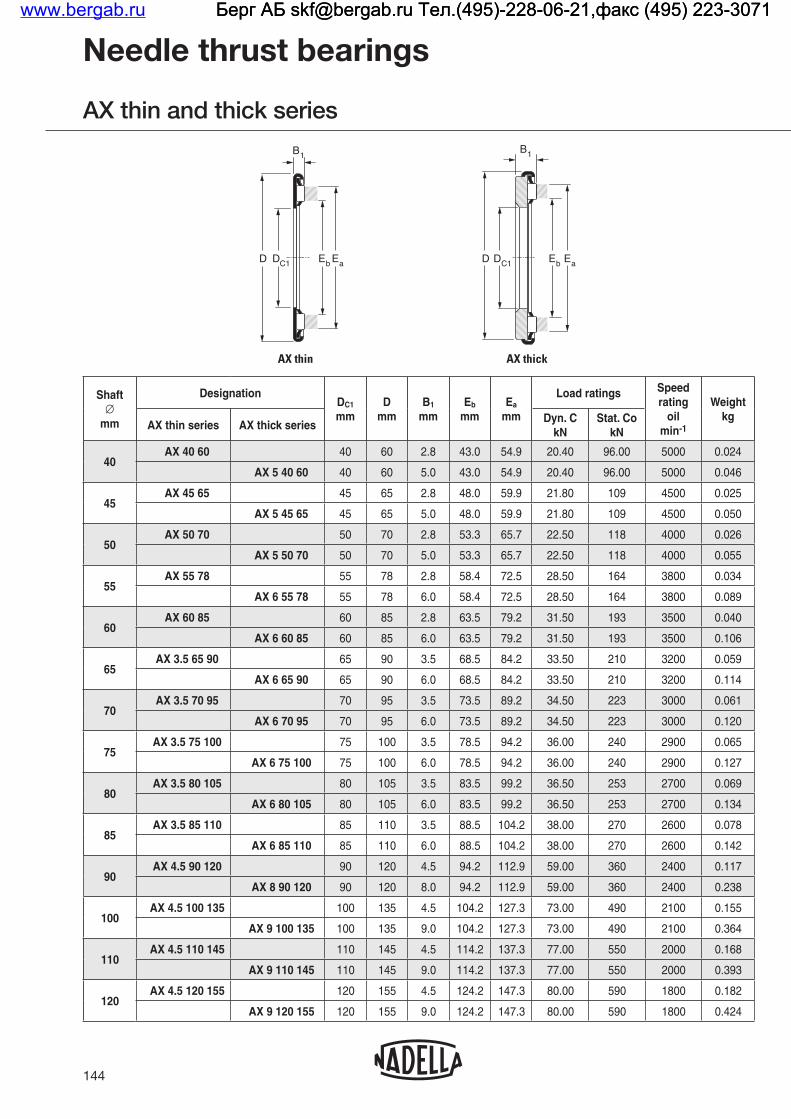
144
Needle thrust bearings
AX thin and thick series
Shaft∅
mm
DesignationDC1
mmD
mmB1
mmEb
mmEa
mm
Load ratings Speed rating
oil min-1
Weight kg
AX thin series AX thick seriesDyn. C
kNStat. Co
kN
40AX 40 60 40 60 2.8 43.0 54.9 20.40 96.00 5000 0.024
AX 5 40 60 40 60 5.0 43.0 54.9 20.40 96.00 5000 0.046
45AX 45 65 45 65 2.8 48.0 59.9 21.80 109 4500 0.025
AX 5 45 65 45 65 5.0 48.0 59.9 21.80 109 4500 0.050
50AX 50 70 50 70 2.8 53.3 65.7 22.50 118 4000 0.026
AX 5 50 70 50 70 5.0 53.3 65.7 22.50 118 4000 0.055
55AX 55 78 55 78 2.8 58.4 72.5 28.50 164 3800 0.034
AX 6 55 78 55 78 6.0 58.4 72.5 28.50 164 3800 0.089
60AX 60 85 60 85 2.8 63.5 79.2 31.50 193 3500 0.040
AX 6 60 85 60 85 6.0 63.5 79.2 31.50 193 3500 0.106
65AX 3.5 65 90 65 90 3.5 68.5 84.2 33.50 210 3200 0.059
AX 6 65 90 65 90 6.0 68.5 84.2 33.50 210 3200 0.114
70AX 3.5 70 95 70 95 3.5 73.5 89.2 34.50 223 3000 0.061
AX 6 70 95 70 95 6.0 73.5 89.2 34.50 223 3000 0.120
75AX 3.5 75 100 75 100 3.5 78.5 94.2 36.00 240 2900 0.065
AX 6 75 100 75 100 6.0 78.5 94.2 36.00 240 2900 0.127
80AX 3.5 80 105 80 105 3.5 83.5 99.2 36.50 253 2700 0.069
AX 6 80 105 80 105 6.0 83.5 99.2 36.50 253 2700 0.134
85AX 3.5 85 110 85 110 3.5 88.5 104.2 38.00 270 2600 0.078
AX 6 85 110 85 110 6.0 88.5 104.2 38.00 270 2600 0.142
90AX 4.5 90 120 90 120 4.5 94.2 112.9 59.00 360 2400 0.117
AX 8 90 120 90 120 8.0 94.2 112.9 59.00 360 2400 0.238
100AX 4.5 100 135 100 135 4.5 104.2 127.3 73.00 490 2100 0.155
AX 9 100 135 100 135 9.0 104.2 127.3 73.00 490 2100 0.364
110AX 4.5 110 145 110 145 4.5 114.2 137.3 77.00 550 2000 0.168
AX 9 110 145 110 145 9.0 114.2 137.3 77.00 550 2000 0.393
120AX 4.5 120 155 120 155 4.5 124.2 147.3 80.00 590 1800 0.182
AX 9 120 155 120 155 9.0 124.2 147.3 80.00 590 1800 0.424
AX thick AX thin
D D DC1
B1
Eb Ea
B1
DC1 Eb Ea
www.bergab.ru Берг АБ [email protected] Тел.(495)-228-06-21,факс (495) 223-3071 Берг АБ [email protected] Тел.(495)-228-06-21,факс (495) 223-3071 Берг АБ [email protected] Тел.(495)-228-06-21,факс (495) 223-3071

145
Thrust plates
CP thin and thick series
Shaft∅
mm
Designationd
mmd1
mmh
mmWeight
kg
Thrust bearings
CP thin series CP thick series AX thin series AX thick serie
40CP 40 60 40 59.5 0.8 0.009 AX 40 60
CP 3 40 60 40 59.5 3.0 0.034 AX 5 40 60
45CP 45 65 45 64.4 0.8 0.010 AX 45 65
CP 3 45 65 45 64.4 3.0 0.037 AX 5 45 65
50CP 50 70 50 69.4 0.8 0.011 AX 50 70
CP 3 50 70 50 69.4 3.0 0.040 AX 5 50 70
55CP 55 78 55 77.4 0.8 0.014 AX 55 78
CP 4 55 78 55 77.4 4.0 0.069 AX 6 55 78
60CP 60 85 60 84.3 0.8 0.017 AX 60 85
CP 4 60 85 60 84.3 4.0 0.083 AX 6 60 85
65CP 1.5 65 90 65 89.3 1.5 0.033 AX 3.5 65 90
CP 4 65 90 65 89.3 4.0 0.088 AX 6 65 90
70CP 1.5 70 95 70 94.3 1.5 0.034 AX 3.5 70 95
CP 4 70 95 70 94.3 4.0 0.093 AX 6 70 95
75CP 1.5 75 100 75 99.3 1.5 0.037 AX 3.5 75 100
CP 4 75 100 75 99.3 4.0 0.099 AX 6 75 100
80CP 1.5 80 105 80 104.3 1.5 0.039 AX 3.5 80 105
CP 4 80 105 80 104.3 4.0 0.104 AX 6 80 105
85CP 1.5 85 110 85 109.3 1.5 0.047 AX 3.5 85 110
CP 4 85 110 85 109.3 4.0 0.111 AX 6 85 110
90CP 1.5 90 120 90 118.8 1.5 0.052 AX 4.5 90 120
CP 5 90 120 90 118.8 5.0 0.173 AX 8 90 120
100CP 1.5 100 135 100 133.8 1.5 0.068 AX 4.5 100 135
CP 6 100 135 100 133.8 6.0 0.277 AX 9 100 135
110CP 1.5 110 145 110 143.8 1.5 0.075 AX 4.5 110 145
CP 6 110 145 110 143.8 6.0 0.300 AX 9 110 145
120CP 1.5 120 155 120 153.8 1.5 0.081 AX 4.5 120 155
CP 6 120 155 120 153.8 6.0 0.323 AX 9 120 155
CP thickCP thin
d1
h
d
h
d1 d
www.bergab.ru Берг АБ [email protected] Тел.(495)-228-06-21,факс (495) 223-3071 Берг АБ [email protected] Тел.(495)-228-06-21,факс (495) 223-3071 Берг АБ [email protected] Тел.(495)-228-06-21,факс (495) 223-3071

146
Needle thrust bearings
AX thick series
Shaft∅
mm
DesignationDC1
mmD
mmB1
mmEb
mmEa
mm
Load ratings Speed rating
oil min-1
Weight kg
AX thick seriesDyn. C
kNStat. Co
kN
130 AX 11 130 170 130 170 11 135 161 106 710 1700 0.660
140 AX 11 140 180 140 180 11 145 171 111 770 1600 0.670
150 AX 11 150 190 150 190 11 155 181 115 830 1500 0.710
160 AX 11 160 200 160 200 11 165 191 118 870 1400 0.760
170 AX 12 170 215 170 215 12 175 207 165 1160 1300 1.000
180 AX 12 180 225 180 225 12 185 217 173 1250 1200 1.050
190 AX 14 190 240 190 240 14 196 232 230 1650 1200 1.400
200 AX 14 200 250 200 250 14 206 242 239 1730 1100 1.500
220 AX 14 220 270 220 270 14 226 262 248 1850 1000 1.600
240 AX 15 240 300 240 300 15 246 286 280 2240 900 2.300
AX thick
D DC1
B1
Eb Ea
www.bergab.ru Берг АБ [email protected] Тел.(495)-228-06-21,факс (495) 223-3071 Берг АБ [email protected] Тел.(495)-228-06-21,факс (495) 223-3071 Берг АБ [email protected] Тел.(495)-228-06-21,факс (495) 223-3071
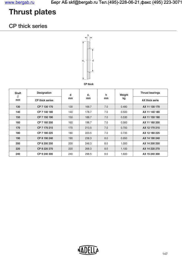
147
Thrust plates
CP thick series
Shaft∅
mm
Designationd
mmd1
mmh
mmWeight
kg
Thrust bearings
CP thick series AX thick serie
130 CP 7 130 170 130 168.7 7.0 0.480 AX 11 130 170
140 CP 7 140 180 140 178.7 7.0 0.500 AX 11 140 180
150 CP 7 150 190 150 188.7 7.0 0.530 AX 11 150 190
160 CP 7 160 200 160 198.7 7.0 0.560 AX 11 160 200
170 CP 7 170 215 170 213.5 7.0 0.700 AX 12 170 215
180 CP 7 180 225 180 223.5 7.0 0.735 AX 12 180 225
190 CP 8 190 240 190 238.3 8.0 0.950 AX 14 190 240
200 CP 8 200 250 200 248.3 8.0 1.000 AX 14 200 250
220 CP 8 220 270 220 268.3 8.0 1.100 AX 14 220 270
240 CP 9 240 300 240 298.5 9.0 1.600 AX 15 240 300
CP thick
h
d1 d
www.bergab.ru Берг АБ [email protected] Тел.(495)-228-06-21,факс (495) 223-3071 Берг АБ [email protected] Тел.(495)-228-06-21,факс (495) 223-3071 Берг АБ [email protected] Тел.(495)-228-06-21,факс (495) 223-3071

148
Roller thrust bearings
AR light and heavy series
Shaft∅
mm
DesignationDC1
mmD
mmB1
mmEb
mmEa
mm
Load ratings Speed rating
oil min-1
Weight kg
AR light series AR heavy seriesDyn. C
kNStat. Co
kN
10 AR 4.5 10 22 10 22 4.5 12.2 18.5 8.2 17.9 15500 0.007
12 AR 5 12 26 12 26 5 14.8 22.9 12.7 29.5 13000 0.011
15 AR 5 15 28 15 28 5 16.8 24.9 14.0 34.0 11500 0.011
17 AR 5 17 30 17 30 5 18.8 26.9 15.0 39.0 10500 0.013
20 AR 7 20 35 20 35 7 22.0 31.6 22.0 54.0 9000 0.022
25AR 7 25 42 25 42 7 27.7 37.3 25.5 70.0 7500 0.031
AR 7 25 52 25 52 7 29.0 47.0 32.5 122.0 6500 0.070
30AR 7 30 47 30 47 7 32.7 42.3 26.5 77.0 6500 0.036
AR 9 30 60 30 60 9 33.5 53.5 46.0 162.0 5600 0.113
35AR 8 35 53.4 35 53.4 8 37.8 47.8 33.8 94.0 5500 0.052
AR 9 35 68 35 68 9 39.0 60.6 51.0 194.0 4900 0.144
40AR 9 40 60.4 40 60.4 9 42.8 54.8 46.0 129.0 5000 0.070
AR 11 40 78 40 78 11 44.0 70.0 71.0 265.0 4200 0.225
45AR 9 45 65.4 45 65.4 9 47.8 59.8 49.0 143.0 4500 0.077
AR 14 45 85 45 85 14 49.0 77.0 92.0 340.0 3800 0.350
50AR 9 50 70.4 50 70.4 9 52.8 64.8 51.0 157.0 4000 0.082
AR 14 50 95 50 95 14 54.0 86.0 108.0 430.0 3400 0.448
55AR 10 55 78.4 55 78.4 10 58.5 72.5 61.0 203.0 3800 0.125
AR 14 55 105 55 105 14 60.2 96.2 125.0 530.0 3100 0.537
60AR 10 60 85.4 60 85.4 10 63.5 79.5 71.0 255.0 3500 0.150
AR 14 60 110 60 110 14 65.2 101.2 130.0 580.0 2900 0.572
65AR 10 65 90.4 65 90.4 10 68.5 84.5 74.0 275.0 3200 0.160
AR 14 65 115 65 115 14 70.2 106.2 135.0 620.0 2800 0.610
70AR 10 70 95.4 70 95.4 10 73.5 89.5 77.0 295.0 3000 0.170
AR 16 70 125 70 125 16 76.0 116.0 174.0 710.0 2600 0.775
B1
D DC1Eb Ea
B1
D DC1 Eb Ea
AR heavy seriesAR light series
www.bergab.ru Берг АБ [email protected] Тел.(495)-228-06-21,факс (495) 223-3071 Берг АБ [email protected] Тел.(495)-228-06-21,факс (495) 223-3071 Берг АБ [email protected] Тел.(495)-228-06-21,факс (495) 223-3071

149
Thrust plates
CP thin and thick series, CPR heavy series
Shaft∅
mm
dmm
d1
mm
Designationh
mmWeight
kg
Designationh
mmWeight
kg
Designationh
mmWeight
kgCP Thin series
CP Thick series
CPR Heavy series
10 10 21.5 CP 10 22 0.8 0.002 CP 2 10 22 2 0.004
12 12 25.5 CP 12 26 0.8 0.003 CP 2 12 26 2 0.006
15 15 27.5 CP 15 28 0.8 0.003 CP 2 15 28 2 0.006
17 17 29.5 CP 17 30 0.8 0.003 CP 2 17 30 2 0.007
20 20 34.5 CP 20 35 0.8 0.004 CP 3 20 35 3 0.013
2525 41.5 CP 25 42 0.8 0.005 CP 3 25 42 3 0.019
25 52 CPR 4 25 52 4 0.052
3030 46.5 CP 30 47 0.8 0.006 CP 3 30 47 3 0.022
30 60 CPR 5 30 60 5 0.083
3535 51.5 CP 35 52 0.8 0.007 CP 3 35 52 3 0.026
35 68 CPR 5 35 68 5 0.102
4040 59.5 CP 40 60 0.8 0.009 CP 3 40 60 3 0.034
40 78 CPR 6 40 78 6 0.162
4545 64.4 CP 45 65 0.8 0.010 CP 3 45 65 3 0.037
45 85 CPR 8 45 85 8 0.245
5050 69.4 CP 50 70 0.8 0.011 CP 3 50 70 3 0.040
50 95 CPR 8 50 95 8 0.308
5555 77.4 CP 55 78 0.8 0.014 CP 4 55 78 4 0.069
55 105 CPR 8 55 105 8 0.380
6060 84.3 CP 60 85 0.8 0.017 CP 4 60 85 4 0.083
60 110 CPR 8 60 110 8 0.405
6565 89.3 CP 1.5 65 90 1.5 0.033 CP 4 65 90 4 0.088
65 115 CPR 8 65 115 8 0.430
7070 94.3 CP 1.5 70 95 1.5 0.034 CP 4 70 95 4 0.093
70 125 CPR 8 70 125 8 0.510
h
d d 1
h
d d1
h
d d1
CP thin series CP thick series CPR heavy series
www.bergab.ru Берг АБ [email protected] Тел.(495)-228-06-21,факс (495) 223-3071 Берг АБ [email protected] Тел.(495)-228-06-21,факс (495) 223-3071 Берг АБ [email protected] Тел.(495)-228-06-21,факс (495) 223-3071

150
Roller thrust bearings
AR light and heavy series
Shaft∅
mm
DesignationDC1
mmD
mmB1
mmEb
mmEa
mm
Load ratings Speed rating
oil min-1
Weight kg
AR light series AR heavy seriesDyn. C
kNStat. Co
kN
75AR 10 75 100.4 75 100 10 78.5 94.5 80.0 313.0 2800 0.180
AR 16 75 135 75 135 16 82.0 126.0 198.0 860.0 2400 0.893
80AR 10 80 105.4 80 105 10 83.5 99.5 82.0 330.0 2700 0.190
AR 16 80 140 80 140 16 87.0 131.0 208.0 940.0 2300 0.960
85 AR 18 85 150 85 150 18 92.0 138.0 230.0 1010.0 2100 1.256
90 AR 18 90 155 90 155 18 97.0 143.0 245.0 1090.0 2000 1.330
100 AR 20 100 170 100 170 20 109.0 157.0 280.0 1250.0 1800 1.740
110 AR 24 110 190 110 190 24 118.0 178.0 365.0 1600.0 1700 2.500
120 AR 24 120 210 120 210 24 127.0 199.0 470.0 2300.0 1500 3.200
130 AR 24 130 225 130 225 24 138.0 214.0 510.0 2640.0 1400 3.600
140 AR 28 140 240 140 240 28 149.0 229.0 600.0 2980.0 1300 4.800
B1
D DC1Eb Ea
B1
D DC1 Eb Ea
AR heavy seriesAR light series
www.bergab.ru Берг АБ [email protected] Тел.(495)-228-06-21,факс (495) 223-3071 Берг АБ [email protected] Тел.(495)-228-06-21,факс (495) 223-3071 Берг АБ [email protected] Тел.(495)-228-06-21,факс (495) 223-3071

151
Thrust plates
CP thin and thick series, CPR heavy series
Shaft∅
mm
dmm
d1
mm
Designationh
mmWeight
kg
Designationh
mmWeight
kg
Designationh
mmWeight
kgCP Thin series
CP Thick series
CPR Heavy series
7575 99.3 CP 1.5 75 100 1.5 0.037 CP 4 75 100 4 0.099
75 135 CPR 8 75 135 8 0.595
8080 104.3 CP 1.5 80 105 1.5 0.039 CP 4 80 105 4 0.104
80 140 CPR 8 80 140 8 0.630
85 85 150 CPR 9 85 150 9 0.815
90 90 155 CPR 9 90 155 9 0.840
100 100 170 CPR 10 100 170 10 1.13
110 110 190 CPR 12 110 190 12 1.70
120 120 210 CPR 12 120 210 12 2.10
130 130 225 CPR 12 130 225 12 2.40
140 140 240 CPR 14 140 240 14 3.20
h
d d 1
h
d d1
h
d d1
CP thin series CP thick series CPR heavy series
www.bergab.ru Берг АБ [email protected] Тел.(495)-228-06-21,факс (495) 223-3071 Берг АБ [email protected] Тел.(495)-228-06-21,факс (495) 223-3071 Берг АБ [email protected] Тел.(495)-228-06-21,факс (495) 223-3071

152
Roller and needle thrust bearings with thrust plate - AXZ and ARZ light and heavy series
Shaft∅
mm
Designationd
mmD
mmT
mm
Load ratings Speed rating
oil min-1
Weight kg
AXZARZ
light seriesARZ
heavy seriesDyn. C
kNStat. Co
kN
5 AXZ 5.5 5 13 5 13 5.5 3.00 5.70 25000 0.004
6 AXZ 5.5 6 14 6 14 5.5 3.15 6.35 22000 0.004
7 AXZ 5.5 7 15 7 15 5.5 3.55 7.60 22000 0.005
8 AXZ 5.5 8 16 8 16 5.5 3.70 8.30 22000 0.005
9 AXZ 5.5 9 17 9 17 5.5 4.05 9.50 19000 0.005
10AXZ 6 10 22.4 10 22.4 6 5.00 10.9 15500 0.011
ARZ 6.5 10 22.4 10 22.4 6.5 8.20 17.9 15500 0.012
12AXZ 6 12 26.4 12 26.4 6 6.90 17.7 13000 0.017
ARZ 7 12 26.4 12 26.4 7 12.7 29.5 13000 0.017
15AXZ 6 15 28.4 15 28.4 6 7.40 20.0 11500 0.016
ARZ 7 15 28.4 15 28.4 7 14.0 34.0 11500 0.019
17AXZ 6 17 30.4 17 30.4 6 7.80 22.0 10500 0.018
ARZ 7 17 30.4 17 30.4 7 15.0 39.0 10500 0.022
20AXZ 8 20 35.4 20 35.4 8 11.80 39.0 9000 0.033
ARZ 10 20 35.4 20 35.4 10 22.0 54.0 9000 0.038
25
AXZ 8 25 43 25 43 8 13.30 49.0 7500 0.047
ARZ 10 25 43 25 43 10 25.5 70.0 7500 0.057
ARZ 11 25 53 25 53 11 32.5 122 6500 0.122
30
AXZ 8 30 48 30 48 8 14.50 57.0 6500 0.054
ARZ 10 30 48 30 48 10 26.5 77.0 6500 0.065
ARZ 14 30 61 30 61 14 46.0 162 5600 0.196
35
AXZ 8 35 54 35 54 8 18.90 84.0 5500 0.066
ARZ 11 35 54 35 54 11 33.8 94.0 5500 0.087
ARZ 14 35 69 35 69 14 51.0 194.0 4900 0.246
T
DDc1 DDc1
TT
Dc1
AXZ ARZ light series ARZ heavy series
www.bergab.ru Берг АБ [email protected] Тел.(495)-228-06-21,факс (495) 223-3071 Берг АБ [email protected] Тел.(495)-228-06-21,факс (495) 223-3071 Берг АБ [email protected] Тел.(495)-228-06-21,факс (495) 223-3071

153
Roller and needle thrust bearings with thrust plate - AXZ and ARZ light and heavy series
Shaft∅
mm
Designationd
mmD
mmT
mm
Load ratings Speed rating
oil min-1
Weight kg
AXZARZ
light seriesARZ
heavy seriesDyn. C
kNStat. Co
kN
40
AXZ 8 40 61 40 61 8 20.40 96.0 5000 0.084
ARZ 12 40 61 40 61 12 46.0 129 5000 0.114
ARZ 17 40 79 40 79 17 71.0 265 4200 0.387
45
AXZ 8 45 66 45 66 8 21.80 109 4500 0.092
ARZ 12 45 66 45 66 12 49.0 143 4500 0.126
ARZ 22 45 86 45 86 22 92.0 340 3800 0.595
50
AXZ 8 50 71 50 71 8 22.50 118 4000 0.100
ARZ 12 50 71 50 71 12 51.0 157 4000 0.137
ARZ 22 50 96 50 96 22 108.0 430 3400 0.756
55 ARZ 22 55 106 55 106 22 125.0 530 3100 0.917
60
AXZ 10 60 86 60 86 10 31.50 193 3500 0.194
ARZ 14 60 86 60 86 14 71.0 255 3500 0.246
ARZ 22 60 111 60 111 22 130.0 580 2900 0.977
65 ARZ 22 65 116 65 116 22 135.0 620 2800 1.040
70AXZ 10 70 96 70 96 10 34.50 223 3000 0.220
ARZ 14 70 96 70 96 14 77.0 295 3000 0.279
80AXZ 10 80 106 80 106 10 36.50 253 2700 0.256
ARZ 14 80 106 80 106 14 82.0 330 2700 0.312
T
DDc1 DDc1
TT
Dc1
AXZ ARZ light series ARZ heavy series
www.bergab.ru Берг АБ [email protected] Тел.(495)-228-06-21,факс (495) 223-3071 Берг АБ [email protected] Тел.(495)-228-06-21,факс (495) 223-3071 Берг АБ [email protected] Тел.(495)-228-06-21,факс (495) 223-3071

www.bergab.ru Берг АБ [email protected] Тел.(495)-228-06-21,факс (495) 223-3071 Берг АБ [email protected] Тел.(495)-228-06-21,факс (495) 223-3071 Берг АБ [email protected] Тел.(495)-228-06-21,факс (495) 223-3071

COMBINED BEARINGSwww.bergab.ru Берг АБ [email protected] Тел.(495)-228-06-21,факс (495) 223-3071 Берг АБ [email protected] Тел.(495)-228-06-21,факс (495) 223-3071 Берг АБ [email protected] Тел.(495)-228-06-21,факс (495) 223-3071

Nadella combined needle bearings type RAX and derivatives are designed to support simultaneously both a radial and an axial load.They comprise a needle thrust bearing (or roller thrust bearing) and needle cage retained in a common outer ring.The technical characteristics of the thrust bearing and the needle cage are set out in the appropriate sections.These bearings form one integral unit permitting easy storage, handling and fitting. Their high radial and axial load capacities and small space requirement enable cost effective solutions to be achieved.Calculations for combined bearings are carried out taking the axial component and the radial component separately without transforming the axial load into an equivalent radial load.
156
The operation of the thrust bearing and the needle cage independent of one another precludes any interaction harmful to precise axial and radial rotation. Axial expansion of the shaft, for example, will have no effect on the accuracy of the radial component.The bearings can be used without inner rings or thrust plates, if the shaft journals serving as raceways are of sufficient hardness and possess a suitable surface finish. Hardness of 58-64 HRC will ensure that the full capacity of these bearings is attained. Lower hardness figures will entail a reduction in the static and dynamic capacities (both axial and radial) as shown in the tables of dimensions (see Technical Section).
Technical features
Types of combined bearings
RAXF700 RAXZ500RAXPZ400
RAX700 RAX400 RAX500
TYPES OF BEARINGSStandard combined bearings
www.bergab.ru Берг АБ [email protected] Тел.(495)-228-06-21,факс (495) 223-3071 Берг АБ [email protected] Тел.(495)-228-06-21,факс (495) 223-3071 Берг АБ [email protected] Тел.(495)-228-06-21,факс (495) 223-3071

Combined bearings type RAX 700 and RAXF 700Combined bearings type RAX 700 possess a one-piece outer ring formed from thin sheet steel accurately controlled and hardened by suitable heat treatment. The shape of this outer ring prevents weakness in the area between the axial component and the radial component, even after the latter has been tightly fitted into a housing.This type of combined bearing is inexpensive and occupies little space, thus providing a very economical solution. Because they are easy to use and can be fitted rapidly, they are often employed in preference to an arrangement with two separate needle bearings. Closed-end combined bearings type RAXF 700 ensure perfect sealing at the end of a shaft and do not require the use of blind housings or end caps. Standard combined bearings type RAX 400 and RAX 500Combined needle bearings type RAX 400 and RAX 500 comprise a thrust plate and an outer ring machined separately and joined by a strong metal insert. This arrangement prevents localised stresses and weakness in the area between the two components, thus eliminating the risk of damage during mounting or operation.
Although combined bearings type RAX 700 should be considered first on grounds of economy, combined bearings with thick outer ring type RAX 400 or RAX 500 should be used when operating conditions require higher limit loads or greater rotational accuracy. Moreover, they can be supplied in machine-tool quality type RAXN.
Standard combined bearings type RAXPZ 400 and RAXZ 500These bearings have an incorporated thrust plate retained by a steel ring set on the thrust plate. They are better protected against the introduction of dust and metal particles and are therefore recommended for spindles of drilling machines.
157
With needle thrust bearingWith roller thrust
bearing
Thin outer ring Thick outer ring Thick outer ring
openClosed-
end
Without retained
thrust Plate
With retained
thrust plate
Without retained
thrust plate
With retained
thrust plate
BearingsRAX 700
RAXF 700
RAX 400
RAXPZ 400
RAX 500
RAXZ 500
Separate thrust plates
CP thick or thinCP thickor thin
CP thick or thin
Inner rings (1) JR JR JR
(1) lnner rings with oil hole type JR...JS1 on request.
Machine-tool quality combined bearings types RAXN 400, RAXN 500, and derivatives The combined bearings in the RAXN 400 and RAXN 500 series are manufactured to the same dimensions as the RAX 400 and RAX 500 series in higher precision with respect to out-of- roundness and thickness of the rings and axial run-out of the thrust bearing. Thesebearings, which are also available with retained thrust plate RAXNPZ 400 and RAXNZ 500, are particularly recommended for use in drilling machine spindles.
With needle thrust bearing With roller thrust bearing
Without thrust plate
With retained
thrust plate
Without thrust plate
With retained
thrust plate
Bearings RAXN 400 RAXNPZ 400 RAXN 500 RAXNZ 500
Separate thrust plates
CPN CPN
Inner ring IM 19 000IM 20 600
IM 20 600
Technical features
Types of combined bearings
www.bergab.ru Берг АБ [email protected] Тел.(495)-228-06-21,факс (495) 223-3071 Берг АБ [email protected] Тел.(495)-228-06-21,факс (495) 223-3071 Берг АБ [email protected] Тел.(495)-228-06-21,факс (495) 223-3071

TOLERANCES OF COMBINED BEARINGSCombined bearings types RAX 700 and RAXF 700Because types RAX 700 and RAXF 700 have an outer ring formed from thin sheet steel, the radial component of these bearings can only be inspected using a ring-gauge having sufficient thickness to withstand deformation and with a bore ground with great accuracy. The diameters of the ring-gauge and the "GO" and "NO-GO" plug-gauges are identical to those given on page 58 in the inspection table for caged needle bushes type DL having identical inner and outer diameters.
Thickness tolerance of the axial component C1: ± 0,1 mm
Standard combined bearings type RAX 400, RAX 500 and derivatives
Diameter under the needles Fw: tolerance F6 (ISO Standard 1206).
Outer diameter D Out-of-roundnesslnner rings JR
Normal tolerance class according to ISO Standard 1206 (see table on page 219).
Thickness C1: + 0,05/ - 0,06 mmAxial run-out max: 0,01 mm
Tolerance
Thin thrust plates Thick thrust plates mm
Intermal ∅d ≤ 60 mm
Intermal ∅d > 60 mm
Thickness h ± 0,030 (1) h ± 0,050 (2) h ± 0,050
Max axial run-out
0,020 (1) 0,025 (2) 0,005
(1) Under minimum load of 150 N - (2) Under minimum load of 250 N
Machine-tool quality combined bearings types RAXN 400, RAXN 500 and derivatives
Diameter under the needles FW: tolerance F6 (ISO Standard 1206).
Outer diameter D: Normal tolerance class according to
158
ISO Standard 1206 (see table on page 219).Out-of-roundness: Precision class 5 according to ISO Standard 492 (DIN 620) (see table on page 219).
lnner rings IM 19000 and IM 20600:inner diameter d: 0/-0,010mm outer diameter F: 0/ -0,005 mm width B: 01/ -0,130 mm up to d = 40 mm 0/ -0,160 mm for d > 40 mm
out-of-roundness: 0.005 mm.
Thickness C1: 0/ -0,012 mmAxial run-out: 0,005 mm
Thickness h: selected to obtain tolerance h8 on total thickness (h + C1) Axial run-out: 0,005 mm.
RADIAL PLAYCombined bearings types RAX 700, RAXF 700The fit of a combined bearing with thin outer ring in the housing determines, to a large extent, the dimension under the needles and consequently the radial play during operation.The recommended shaft and housing tolerances give a radial play whose limits are suitable tor most normal applications. To obtain a closer clearance, it is possible to match the shaft diameters with the diameters under the needles of the bearings, after the latter have been fitted into their housings.The possible differences in the stiffness of housings and the variations of clamping force resulting from the tolerance build up do not permit to establish a range of dimensions under the needles for every application.However, for housings of very thick steel, taking into account the probable restraining force, the variations of the dimensions under the needles after installation will be within the tolerancesgiven below:+ 15/ + 50 μm up to Fw 20 mm+ 20/ + 60 μm up to Fw = 25 a Fw = 40 mm+ 20/ + 65 μm up to Fw = 45 mm
Technical features
Types of combined bearings
www.bergab.ru Берг АБ [email protected] Тел.(495)-228-06-21,факс (495) 223-3071 Берг АБ [email protected] Тел.(495)-228-06-21,факс (495) 223-3071 Берг АБ [email protected] Тел.(495)-228-06-21,факс (495) 223-3071

The limits of radial play should also take into account the tolerance of the shaft used directly as a raceway or of the outer diameter of the inner ring after it has been fitted on to the shaft.Where an inner ring is used on a shaft of recommended tolerance k5 (or m5), the minimum play may be slightly lower and the maximum play slightly higher than for the case of an assembly without inner ring on a shaft with tolerance h5.
Standard combined bearings type RAX 400, 500 and derivatives
The radial play of these bearings when used without inner rings is the difference between the diameter under the needles, which is kept within tolerance F6, and the diameter of the shaft which is machined to the recommended tolerances.This type of combined bearing without inner ring can be supplied having a diameter under the needles selected in the lower half of tolerance F6 (suffix TB) or in the upper half (suffix TC) according to the table below.
Nominal dimension
Fwmm
Tolerance of diameter under the needles
Normal F6μm
TBμm
TCμm
above da 6da 10da 18da 30da 50
toa 10a 18a 30a 50a 80
+13/+22+16/+27+20/+33+25/+41+30/+49
+13/+18+16/+22+20/+27+25/+33+30/+40
+ 17/+22+21/+27+26/+33+33/+41+39/+49
The radial play prior to installation of standard combined bearings with inner ring is in conformance with the normal group of ISO Standard 5753. The closely controlled play provided by this standard can be provided on request.
Machine-tool quality combined bearings types RAXN 400, 500 and derivatives
The radial play prior to installation of machine-tool quality combined bearings results from tolerance F5 on the diameter under the needles, possibly in selection TB or TC, and tolerances k5 on the diameter of the shaft.
159
Nominal dimension
Fwmm
Tolerance of diameter under the needles
F5μm
above da 6da 10da 18da 30da 50
toa 10a 18a 30a 50a 80
+13/+19+16/+24+20/+29+25/+36+30/+43
The radial play prior to installation of machine-tool quality combined bearings results from tolerance F5 on the diameter under the needles and tolerance 0/-0.005 mm on the outer diameter Fw of inner ring IM 19000 or IM 20600.
SHAFT AND HOUSING TOLERANCES
Combined bearings
Shaft Housing
Quota Fw per cuscinetti senza
anello interno
Dimension d for bearings with
inner ring
Dimension D
Steel or cast-iron
Non-ferrous metal (1) or
thin castings in steelRotation Oscillation Rotation Oscillation
RAX, RAXF 700
RAX, RAXPZ, RAXZ series400 and 500
RAXN, RAXNPZRAXNZ series400 and 500
h5 (h6)
h5
k5
j5 (j6)
j5
k5
k5 (k6)
k5
k5
m5 (m6)
m5
m5
H6 (H7)
K6
K6
M6 (M7)
M6
M6
1) lf a housing of non-ferrous metal reaches temperatures considerably higher (or lower) than 20°C, account should be taken of the difference in expansion (or contraction) of the outer race of the bearing and suitable adjustments to the fits should be made.
The cylindrical tolerance defined as the difference in radii of two coaxial cylinders (ISO Standard 1101) should normally be less than a quarter of the manufacturing tolerance. However, for high precision or high speed applications, it is advisableto restrict this tolerance to the one-eighth of the manufacturing tolerance.
Technical features
Types of combined bearings
www.bergab.ru Берг АБ [email protected] Тел.(495)-228-06-21,факс (495) 223-3071 Берг АБ [email protected] Тел.(495)-228-06-21,факс (495) 223-3071 Берг АБ [email protected] Тел.(495)-228-06-21,факс (495) 223-3071

SUPPORTING FACES- RACEWAYS
The bearing shoulder must be a flat face at right angles to the housing axis, otherwise axial precision will be affected and the smooth running characteristics of the thrust bearing will be diminished.Similarly, the shaft shoulder, on which the needles of the thrust bearing rotate or on which the thrust plate is supported, must be flat and square to the axis.The deviation from true parallelism between the two supporting faces must be no more than:
a combined bearing with thrust plate.
a combined bearing without thrust plate.In the case of an assembly where neither thrust plate nor inner ring is used, the shaft journal on which the needle rotate must have sufficient hardness, i.e. 58-64 HRC to ensure maximum load capacities are attained.lf the shaft shoulder is used directly as a raceway for the needles of the thrust bearing or, if it supports a thin thrust plate (thickness 0.8 or 1.5 mm), it must be rigid and continuous throughout the area of circulation of the needles bounded by dimensions Eb and Ea.A thick thrust plate can be supported on a smaller shaft shoulder or on one that is discontinuous (as in the case of splines), provided the deflection of the plate does not affect the smooth running or required accuracy of the thrust bearing.
INSTALLATIONThe bearing must be correctly aligned with the housing. lt is wise to use a small press fitted with a mandrel having a supporting face square to the axis and covering the whole area bounded by dimensions Eb and Ea. This method prevents the thrust component from undergoing shock load which might damage the bearing. When RAX or RAXF 700 bearings are placed in position during installation care must be taken to ensure that the force exerted by the press does not exceed the axial limit load shown in the table of dimensions.The fitting of inner rings on shafts manufactured to the recommended tolerances is usually sufficient to render the use of retaining rings unnecessary. However, if it is necessary to employ a ring to support an adjacent pinion, this ring must have an outer diameter slightly smaller than dimension Fw to enable it to pass smoothly into the bearing when the shaft is introduced.
160
TYPICAL ARRANGEMENTS USING COMBINED BEARINGS
RAX and RAXF 700: see page 162.RAX 400 (or 500) and RAXPZ 400 (or RAXZ 500): see page 163.RAXN 400 (or 500) and RAXNPZ 400 (or RAXNZ 500): the typical applications for these machine-tool quality combined bearings used without inner ring and with or without thick thrust plate are identical to those for the corresponding standard combined bearings (see page 163).
The special inner rings (series 19000 or 20600) designed for machine-tool quality combined bearings are of sufficient width to permit centring of the thrust plate and thus eliminate the need for a shaft shoulder.
Fw(h8)
L-2mm
min=Ea
Technical features
Types of combined bearings
www.bergab.ru Берг АБ [email protected] Тел.(495)-228-06-21,факс (495) 223-3071 Берг АБ [email protected] Тел.(495)-228-06-21,факс (495) 223-3071 Берг АБ [email protected] Тел.(495)-228-06-21,факс (495) 223-3071

LUBRICATIONWhen the applied axial loads are relatively high and the application allows the use of oil as the desired method of lubrication, bearing types RAX 500 should be given consideration. Combined bearings with a dust cap may use oil lubrication, although their design makes them better suited for use with grease lubrication.Combined bearings are typically shipped protected with a corrosion preventive compound that is not a lubricant. The bearings may be used in oil or grease lubricated applications, without removal of the corrosion-preventive compound. However, it may be advisable to remove the corrosion-preventive compound before packing the bearings (with a suitable grease) to obtain optimum grease performance and to minimize the possibility of confusing grease bearings with bearings containing corrosion preventive.
161
LOAD RATINGSCalculations for combined bearings are carried out taking the axial component and the radial component separately without transforming the axial load into an equivalent radial load.For the meaning of the Load Ratings in the tables of combined bearings RAX 400, RAX 500 and derivatives, see the Technical Section.Combined bearings type RAX700 and RAXF700 has a limitation for the maximum axial permissible load, both axial and radial, because are made in thin outer ring. Limit loads are in the table on page 165.
Technical features
Types of combined bearings
www.bergab.ru Берг АБ [email protected] Тел.(495)-228-06-21,факс (495) 223-3071 Берг АБ [email protected] Тел.(495)-228-06-21,факс (495) 223-3071 Берг АБ [email protected] Тел.(495)-228-06-21,факс (495) 223-3071

162
Methods of installation for combinedbearings RAX and RAXF 700
Da-
3.5
D
Da+
1
D
11r C-2
C
Fw
Ea
min
D
Ch
C+h-2
Ea
min DFw DF
w
h C
C+h-2
h C
Ea Fw
(h10
)
B
Dd
C+h-2
1max
Fw
(h10
)
h C
Dd
B
C+h-2
h-0.2 max
(1) Chamfer: 0,5 to 1 mm up to RAX (or RAXF) 720 0,7 to 1,5 mm from RAX (or RAXF) 725
RAXRAXF
712 714 715 718 720 725 730 735 740 745
r max.mm
0.75 1 1.8 1 0.5 1.8 1.8 1.8 0.5 0.5
www.bergab.ru Берг АБ [email protected] Тел.(495)-228-06-21,факс (495) 223-3071 Берг АБ [email protected] Тел.(495)-228-06-21,факс (495) 223-3071 Берг АБ [email protected] Тел.(495)-228-06-21,факс (495) 223-3071
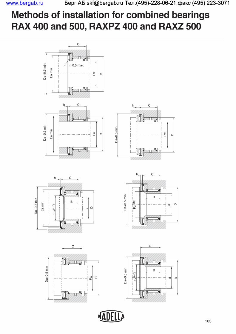
163
Methods of installation for combined bearings RAX 400 and 500, RAXPZ 400 and RAXZ 500
CD
a+0.
5 m
in
Ea
min
r: 0.5 max
DFw
Ch
Fw D
Ea
min
Da+
0.5
min
h C
Da+
0.5
min
DFw
Ch
B
Dd
Da+
0.5
min
Ea
min
Fw
(h10
)
h C
d D
B
Fw
(h10
)
Da+
0.5
min
DFw
C
Da+
0.5
min
C
Da+
0.5
min
Fw
(h10
) B
d D
www.bergab.ru Берг АБ [email protected] Тел.(495)-228-06-21,факс (495) 223-3071 Берг АБ [email protected] Тел.(495)-228-06-21,факс (495) 223-3071 Берг АБ [email protected] Тел.(495)-228-06-21,факс (495) 223-3071

164
Combined bearings RAX 700
Shaft∅
mm
DesignationsFw
mmD
mmC
mm Da
mmEb
mmEa
mmC1
mmL
mm
Load ratings kN
RAX 700series
RAXF 700series
Radial Axial
Dyn. C Stat. Co Dyn. C Stat. Co
5 RAX 705 5 9 11 15.5 7.2 11.2 3.3 – 2.15 1.95 3.15 6.35
12 RAX 712 RAXF 712 12 18 14.2 27.5 15 22.6 4.2 13.2 6.30 7.20 6.90 17.7
14 RAX 714 RAXF 714 14 20 14.2 29.5 17 24.6 4.2 13.2 6.90 8.50 7.40 20.0
15 RAX 715 RAXF 715 15 21 14.2 31.5 19 26.6 4.2 13.2 7.40 9.30 7.80 22.0
18 RAX 718 RAXF 718 18 24 18.2 33.5 21 28.6 4.2 17.2 11.5 17.7 8.00 23.0
20 RAX 720 RAXF 720 20 26 18.2 36.5 22 31.6 4.2 17.2 12.2 19.5 11.8 39.0
25 RAX 725 RAXF 725 25 33 22.2 45.5 30 39.6 4.2 21.2 20.5 32.0 13.7 52.0
30 RAX 730 RAXF 730 30 38 22.2 50.5 35 44.7 4.2 21.2 22.3 37.5 14.9 60.0
35 RAX 735 35 43 22.2 56.5 39 50.9 4.2 21.2 24.5 45.0 19.4 88.0
40 RAX 740 RAXF 740 40 48 22.2 61.5 43 54.9 4.2 21.2 26.2 51.0 20.4 96.0
45 RAX 745 45 52 22.2 66.5 48 59.9 4.2 21.2 24.8 55.0 21.8 109
CC1
Fw DDa E bEa
CC1
Fw D
L
Da EbEa
RAX 700 RAXF 700
series
RAXF 700 series
www.bergab.ru Берг АБ [email protected] Тел.(495)-228-06-21,факс (495) 223-3071 Берг АБ [email protected] Тел.(495)-228-06-21,факс (495) 223-3071 Берг АБ [email protected] Тел.(495)-228-06-21,факс (495) 223-3071

165
Limit Loads kNSpeed rating min-1
Weight Inspection
Inner ringThrust plate Shaft
∅mmRadial Axial
RAXKg
RAXFKg
Housing∅
mm
GO plug-gauges
mm
NO-GO plug-gauges
mmThin Thick
0.74 3.5 25000 0.005 9.000 5.009 5.036 5
2.5 11 13000 0.017 0.018 18.000 12.009 12.035 JR 8x12x12.5 CP 12 26 CP 2 12 26 12
2.9 12.5 11500 0.018 0.020 20.000 14.009 14.035 JR 10x14x12 CP 14 26 CP 2 14 26 14
3.1 14 10500 0.020 0.022 21.000 15.009 15.035 JR 12x15x12.5 CP 15 28 CP 2 15 28 15
5.8 16 10000 0.027 0.030 24.000 18.009 18.035 JR 15x18x16.5 CP 18 30 CP 2 18 30 18
6.4 18 9000 0.031 0.035 26.000 20.009 20.035 JR 15x20x16 CP 20 35 CP 3 20 35 20
10.5 22 7200 0.055 0.060 33.000 25.015 25.041 JR 20x25x20.5 CP 25 42 CP 3 25 42 25
12 25 6300 0.063 0.070 38.000 30.015 30.041 JR 25x30x20.5 CP 30 47 CP 3 30 47 30
14.3 27 5500 0.075 0.084 43.000 35.015 35.041 JR 30x35x20.5 CP 35 52 CP 3 35 52 35
16 30 5000 0.086 0.096 48.000 40.015 40.041 JR 35x40x20.5 CP 40 60 CP 3 40 60 40
17 32 4500 0.088 0.099 52.000 45.015 45.041 JR 40x45x20.5 CP 45 65 CP 3 45 65 45
CC1
Fw DDa E bEa
CC1
Fw D
L
Da EbEa
RAX 700 RAXF 700
www.bergab.ru Берг АБ [email protected] Тел.(495)-228-06-21,факс (495) 223-3071 Берг АБ [email protected] Тел.(495)-228-06-21,факс (495) 223-3071 Берг АБ [email protected] Тел.(495)-228-06-21,факс (495) 223-3071

166
Combined bearings RAX 400 – RAX 500
RAX 400 - RAXN 400
C
C2 rs
C1
Da Ea Eb Fw D
rs
Fw DDa EaEb
C
C2C1
RAX 500 - RAXN 500
Shaft∅
mm
DesignationsFw
mmC
mmD
mmDa
mmEb
mmEa
mmC1
mmC2
mmrs min
mmRAX 400 series
RAX 500 series
10RAX 410 10 19 19 22 12 18.6 5 6 0.35
RAX 510 10 19.5 19 22 12.2 18.5 5.5 6 0.35
12RAX 412 12 19 21 26 15 22.6 5 6 0. 35
RAX 512 12 20 21 26 22.9 14.8 6 6 0.35
15RAX 415 15 19 24 28 17 24.6 5 6 0.35
RAX 515 15 20 24 28 16.8 24.9 6 6 0.35
17RAX 417 17 21 26 30 19 26.6 5 8 0.65
RAX 517 17 22 26 30 18.8 26.9 6 8 0.65
20RAX 420 20 24 30 35 22 31.6 6 9 0.85
RAX 520 20 26 30 35 22 31.6 8 9 0.85
25RAX 425 25 24 37 42 27.7 37.4 6 9 0.85
RAX 525 25 26 37 42 27.7 37.4 8 9 0.85
30RAX 430 30 24 42 47 32.7 42.4 6 9 0.85
RAX 530 30 26 42 47 32.7 42.3 8 9 0.85
35RAX 435 35 24 47 53 37.2 49 6 9 0.85
RAX 535 35 27 47 53.4 37.8 47.8 9 9 0.85
40RAX 440 40 24 52 60 43 54.9 6 9 0.85
RAX 540 40 28 52 60.4 54.8 42.8 10 9 0.85
45RAX 445 45 24 58 65 48 59.9 6 9 0.85
RAX 545 45 28 58 65.4 47.8 59.8 10 9 0.85
50RAX 450 50 27 62 70 53.3 65.7 6 11 1.3
RAX 550 50 31 62 70.4 52.8 64.8 10 11 1.3
60RAX 460 60 28 72 85 63.5 79.2 7 11 1.3
RAX 560 60 32 72 85.4 63.5 79.5 11 11 1.3
70RAX 470 70 28 85 95 73.5 89.2 7 11 1.3
RAX 570 70 32 85 95.4 73.5 89.5 11 11 1.3
Machine-tool quality combined bearings RAXN 400, RAXN 500 series
www.bergab.ru Берг АБ [email protected] Тел.(495)-228-06-21,факс (495) 223-3071 Берг АБ [email protected] Тел.(495)-228-06-21,факс (495) 223-3071 Берг АБ [email protected] Тел.(495)-228-06-21,факс (495) 223-3071

167
Load Ratings kN Speed Rating min-1
Weight kg
Inner ring
Thrust plate Shaft∅
mmRadial Axial
Thin ThickDyn. C Stat. Co Dyn. C Stat. Co
5.90 7.16 5.00 10.9 15500 0.025 JR 7x10x16 CP 10 22 CP 2 10 2210
5.90 7.16 8.20 17.9 15500 0.026 JR 7x10x16 CP 10 22 CP 2 10 22
6.78 9.03 7.10 18.5 13000 0.032 JR 9x12x16 CP 12 26 CP 2 12 2612
6.78 9.03 12.7 29.5 13000 0.033 JR 9x12x16 CP 12 26 CP 2 12 26
9.66 12.6 7.60 20.8 11500 0.034 JR 12x15x16 CP 15 28 CP 2 15 2815
9.66 12.6 14.0 34.0 11500 0.036 JR 12x15x16 CP 15 28 CP 2 15 28
11.8 16.3 8.10 23.0 10500 0.041 JR 14x17x17 CP 17 30 CP 2 17 3017
11.8 16.3 15.0 39.0 10500 0.044 JR 14x17x17 CP 17 30 CP 2 17 30
14.8 23.7 11.8 39.0 9000 0.066 JR 17x20x20 CP 20 35 CP 3 20 3520
14.8 23.7 22.0 54.0 9000 0.070 JR 17x20x20 CP 20 35 CP 3 20 35
15.1 26.2 13.3 49.0 7500 0.099 JR 20x25x20 CP 25 42 CP 3 25 4225
15.1 26.2 25.5 70.0 7500 0.105 JR 20x25x20 CP 25 42 CP 3 25 42
20.2 34.6 14.5 57.0 6500 0.111 JR 25x30x20 CP 30 47 CP 3 30 4730
20.2 34.6 26.5 77.0 6500 0.118 JR 25x30x20 CP 30 47 CP 3 30 47
22.1 40.8 18.9 84.0 5500 0.130 JR 30x35x20 CP 35 52 CP 3 35 5235
22.1 40.8 33.8 94.0 5500 0.146 JR 30x35x20 CP 35 52 CP 3 35 52
23.8 47.0 20.4 96.0 5000 0.150 JR 35x40x20 CP 40 60 CP 3 40 6040
23.8 47.0 46.0 129.0 5000 0.174 JR 35x40x20 CP 40 60 CP 3 40 60
24.9 51.8 21.8 109.0 4500 0.179 JR 40x45x20 CP 45 65 CP 3 45 6545
24.9 51.8 49.0 143.0 4500 0.206 JR 40x45x20 CP 45 65 CP 3 45 65
30.2 68.5 22.5 118.0 4000 0.205 JR 45x50x25 CP 50 70 CP 3 50 7050
30.2 68.5 51.0 157.0 4000 0.232 JR 45x50x25 CP 50 70 CP 3 50 70
31.9 78.1 31.5 193.0 3500 0.282 JR 55x60x25 CP 60 85 CP 4 60 8560
31.9 78.1 71.0 255.0 3500 0.327 JR 55x60x25 CP 60 85 CP 4 60 85
36.1 84.7 34.5 223.0 3000 0.386 JR 60x70x25 CP 1.5 70 95 CP 4 70 9570
36.1 84.7 77.0 295.0 3000 0.435 JR 60x70x25 CP 1.5 70 95 CP 4 70 95
RAX 400 - RAXN 400
C
C2 rs
C1
Da Ea Eb Fw D
rs
Fw DDa EaEb
C
C2C1
RAX 500 - RAXN 500
www.bergab.ru Берг АБ [email protected] Тел.(495)-228-06-21,факс (495) 223-3071 Берг АБ [email protected] Тел.(495)-228-06-21,факс (495) 223-3071 Берг АБ [email protected] Тел.(495)-228-06-21,факс (495) 223-3071

168
Combined bearings with incorporated thrust plate RAXPZ 400 – RAXZ 500
Shaft∅
mm
DesignationsFw
mmD
mm C
mmda
mmDa
mmC1
mmC2
mmrs min
mmRAXPZ 400 series
RAXZ 500 series
10RAXPZ 410 10 19 21 10 22.4 7 6 0.35
RAXZ 510 10 19 21.5 10 22.4 7.5 6 0.35
12RAXPZ 412 12 21 21 12 26.4 7 6 0.35
RAXZ 512 12 21 22 12 26.4 8 6 0.35
15RAXPZ 415 15 24 21 15 28.4 7 6 0.35
RAXZ 515 15 24 22 15 28.4 8 6 0.35
17RAXPZ 417 17 26 23 17 30.4 7 8 0.65
RAXZ 517 17 26 24 17 30.4 8 8 0.65
20RAXPZ 420 20 30 27 20 35.4 9 9 0.85
RAXZ 520 20 30 29 20 35.4 11 9 0.85
25RAXPZ 425 25 37 27 25 43 9 9 0.85
RAXZ 525 25 37 29 25 43 11 9 0.85
30RAXPZ 430 30 42 27 30 48 9 9 0.85
RAXZ 530 30 42 29 30 48 11 9 0.85
35RAXPZ 435 35 71 27 35 54 9 9 0.85
RAXZ 535 35 47 30 35 54 12 9 0.85
40RAXPZ 440 40 52 27 40 61 9 9 0.85
RAXZ 540 40 52 31 40 61 13 9 0.85
45RAXPZ 445 45 58 27 45 66 9 9 0.85
RAXZ 545 45 58 31 45 66 13 9 0.85
50RAXPZ 450 50 62 30 50 71 9 11 1.3
RAXZ 550 50 62 34 50 71 13 11 1.3
60RAXPZ 460 60 72 32 60 86 11 11 1.3
RAXZ 560 60 72 36 60 86 15 11 1.3
70RAXPZ 470 70 85 32 70 96 11 11 1.3
RAXZ 570 70 85 36 70 96 15 11 1.3
C1
Fw D
C2
C
rs
Da dw
RAXZ 500 - RAXNZ 500RAXPZ400 - RAXNPZ 400
C
C2
dwDa Fw D
C1
rs
Machine-tool quality combined bearings RAXNPZ 400, RAXNZ 500 series
www.bergab.ru Берг АБ [email protected] Тел.(495)-228-06-21,факс (495) 223-3071 Берг АБ [email protected] Тел.(495)-228-06-21,факс (495) 223-3071 Берг АБ [email protected] Тел.(495)-228-06-21,факс (495) 223-3071

169
Load Ratings kN Speed rating min-1
Weightkg
Shaft∅
mmRadial Axial
Dyn. C Stat. Co Dyn. C Stat. Co
5.9 7.2 5 10.9 15500 0.02910
5.9 7.2 8.2 17.9 15500 0.031
6.8 9 7.1 18.5 13000 0.03812
6.8 9 12.7 29.5 13000 0.039
9.66 12.6 7.6 20.8 11500 0.04015
9.66 12.6 14 34 11500 0.044
11.8 16.3 8.1 23 10500 0.04817
11.8 16.3 15 39 10500 0.053
14.8 23.7 11.8 39 9000 0.07920
14.8 23.7 22 54 9000 0.086
15.1 26.2 13.3 49 7500 0.11825
15.1 26.2 25.5 70 7500 0.131
20.2 34.6 14.5 57 6.500 0.13330
20.2 34.6 26.5 77 6.500 0.147
22.1 40.8 18.9 84 5.500 0.15735
22.1 40.8 33.8 94 5.500 0.181
23.8 47 20.4 96 5.000 0.18440
23.8 47 46 129 5.000 0.218
24.9 51.8 21.8 109 4.500 0.21645
24.9 51.8 49 143 4.500 0.255
30.2 68.5 22.5 118 4.000 0.24550
30.2 68.5 51 157 4.000 0.287
31.9 78.1 31.5 193 3.500 0.36560
31.9 78.1 71 255 3.500 0.423
36.1 84.7 34.5 223 3.000 0.47970
36.1 84.7 77 295 3.000 0.545
C1
Fw D
C2
C
rs
Da dw
RAXZ 500 - RAXNZ 500RAXPZ400 - RAXNPZ 400
C
C2
dwDa Fw D
C1
rs
www.bergab.ru Берг АБ [email protected] Тел.(495)-228-06-21,факс (495) 223-3071 Берг АБ [email protected] Тел.(495)-228-06-21,факс (495) 223-3071 Берг АБ [email protected] Тел.(495)-228-06-21,факс (495) 223-3071

170
Thrust plates for standard combined bearings
Shaft∅
mm
Designationsd
mmd1
mmh
mmWeight
g
For combined bearings
CPThin series
CFThick series
RAX 700RAXF 700
RAX 400 RAX 500
10CP 10 22 10 21.5 0.8 1.7
RAX 410 RAX 510CP 2 10 22 10 21.5 2 4.3
12CP 12 26 12 25.5 0.8 2.5
RAX, RAXF 712 RAX 412 RAX 512CP 2 12 26 12 25.5 2 6.2
14CP 14 26 14 25.5 0.8 2.3
RAX, RAXF 714CP 2 14 26 14 25.5 2 5.6
15CP 15 28 15 27.5 0.8 2.8
RAX, RAXF 715 RAX 415 RAX 515CP 2 15 28 15 27.5 2 6
17CP 17 30 17 29.5 0.8 2.5
RAX 417 RAX 517CP 2 17 30 17 29.5 2 7
18CP 18 30 18 29.5 0.8 2.3
RAX, RAXF 718CP 2 18 30 18 29.5 2 5.7
20CP 20 35 20 34.5 0.8 3.8
RAX, RAXF 720 RAX 420 RAX 520CP 3 20 35 20 34.5 3 13
25CP 25 42 25 41.5 0.8 5.3
RAX, RAXF725 RAX425 RAX 525CP 3 25 42 25 41.5 3 19
30CP 30 47 30 46.5 0.8 6
RAX, RAXF 730 RAX 430 RAX 530CP 3 30 47 30 46.5 3 22
35CP 35 52 35 51.5 0.8 7
RAX, RAXF 735 RAX 435 RAX 535CP 3 35 52 35 51.5 3 26
40CP 40 60 40 59.5 0.8 9.3
RAX, RAXF 740 RAX 440 RAX 540CP 3 40 60 40 59.5 3 34
45CP 45 65 45 64.4 0.8 10
RAX, RAXF 745 RAX 445 RAX 545CP 3 45 65 45 64.4 3 37
50CP 50 70 50 69.4 0.8 11
RAX 450 RAX 550CP 3 50 70 50 69.4 3 40
60CP 60 85 60 84.3 0.8 17
RAX 460 RAX 560CP 4 60 85 60 84.3 4 83
70CP 1.5 70 95 70 94.3 1.5 32
RAX 470 RAX 570CP 4 70 95 70 94.3 4 93
CP thickCP thin
d1
h
d
h
d1 d
CP thin and thick series
www.bergab.ru Берг АБ [email protected] Тел.(495)-228-06-21,факс (495) 223-3071 Берг АБ [email protected] Тел.(495)-228-06-21,факс (495) 223-3071 Берг АБ [email protected] Тел.(495)-228-06-21,факс (495) 223-3071

171
Inner rings for standard combined bearings
JR
B
Fd
r
Shaft∅
mm
Designations d
mmF
mmB
mmr
mmWeight
g
For combined bearings
JR series JR seriesRAX 700
RAXF 700RAX 400
RAXPZ 400RAX 500
RAXZ 500
7 JR 7x10x16 7 10 16 0.2 4.8 RAX 410 RAX 510
8 JR 8x12x12,5 8 12 12.5 0.3 5.8 RAX 712
9 JR 9x12x16 9 12 16 0.2 5.9 RAX 412 RAX 512
10 JR 10x14x12 10 14 12 0.3 7 RAX 714
12JR 12x15x12,5 12 15 12.5 0.2 5.8 RAX 715
JR 12x15x16 12 15 16 0.2 7.6 RAX 415 RAX 515
13 JR 15x18x16,5 13 18 16.5 0.35 15 RAX 718
14 JR 14x17x17 14 17 17 0.2 9.3 RAX 417 RAX 517
15JR 15x20 16 15 20 16 0.35 17 RAX 720
JR 17x20x20 15 20 20 0.35 20.5 RAX 420 RAX 520
20JR 20x25x20 20 25 20 0.35 32 RAX 425 RAX 525
JR 20x25x20,5 20 25 20.5 0.35 33 RAX 725
25JR 25x30x20 25 30 20 0.35 32 RAX 430 RAX 530
JR 25x30x20,5 25 30 20.5 0.35 33 RAX 730
30JR 30x35x20 30 35 20 0.35 38 RAX 435 RAX 535
JR 30x35x20,5 30 35 20.5 0.35 39 RAX 735
35JR 35x40x20 35 40 20 0.35 44 RAX 440 RAX 540
JR 35x40x20,5 35 40 20.5 0.35 45 RAX 740
40JR 40x45x20 40 45 20 0.35 50 RAX 445 RAX 545
JR 40x45x20,5 40 45 20.5 0.35 51 RAX 745
45 JR 45x50x25 45 50 25 0.65 69 RAX 450 RAX 550
55 JR 55x60x25 55 60 25 0.65 84 RAX 460 RAX 560
60 JR 60x70x25 60 70 25 0.85 190 RAX 470 RAX 570
JR standard series
www.bergab.ru Берг АБ [email protected] Тел.(495)-228-06-21,факс (495) 223-3071 Берг АБ [email protected] Тел.(495)-228-06-21,факс (495) 223-3071 Берг АБ [email protected] Тел.(495)-228-06-21,факс (495) 223-3071

172
Thrust plates for machine-tool quality combined bearings
CPN
h
d1 d
Centred Designations d
mmd1
mmh
mmWeight
kgOn shaft∅ mm
On inner ring
∅ mm
CPNStandard series
CPNSupplementary series
10
CPN 2 10 22 10 21.5 2 0.0043
CPN 2,5 10 22 10 21.7 2.5 0.005
CPN 4 10 22 10 21.7 4 0.009
12
CPN 2 12 26 12 25.5 2 0.0062
CPN 3 12 26 12 25.7 3 0.0095
CPN 4 12 26 12 25.7 4 0.012
15
CPN 2 15 28 15 27.5 2 0.006
CPN 4 15 28 15 27.7 4 0.013
CPN 7 15 28 15 27.7 7 0.024
17
CPN 2 17 30 17 29.5 2 0.007
CPN 4 17 30 17 29.7 4 0.014
CPN 7 17 30 17 29.7 7 0.025
20CPN 3 20 35 20 34.5 3 0.013
CPN 5 20 35 20 34.7 5 0.024
25CPN 3 25 42 25 41.5 3 0.019
CPN 5 25 42 25 41.77 5 0.033
30CPN 3 30 47 30 46.5 3 0.022
CPN 5 30 47 30 46.7 5 0.037
35CPN 3 35 52 35 51.5 3 0.026
CPN 4 35 52 35 52 4 0.034
40 CPN 3 40 60 40 59.5 3 0.034
45 CPN 3 45 65 45 64.4 3 0.037
50 CPN 3 50 70 50 69.4 3 0.040
60 CPN 4 60 85 60 84.3 4 0.083
70 CPN 4 70 95 70 94.3 4 0.093
CPN series forRAXN 400 and RAXN 500
www.bergab.ru Берг АБ [email protected] Тел.(495)-228-06-21,факс (495) 223-3071 Берг АБ [email protected] Тел.(495)-228-06-21,факс (495) 223-3071 Берг АБ [email protected] Тел.(495)-228-06-21,факс (495) 223-3071

173
Inner ring for machine-tool quality combined bearings
Shaft∅
mm
Designationsd
mmF
mmB
mmWeight
kgIM 19 000 series
IM 20 600 series
17IM 19 017 17 20 27.5 0.019
IM 20 617 17 20 31.5 0.021
20IM 19 020 20 25 27.5 0.038
IM 20 620 20 25 31.5 0.044
25IM 19 025 25 30 27.5 0.042
IM 20 625 25 30 31.5 0.048
30IM 19 030 30 35 27.5 0.055
IM 20 630 30 35 31.5 0.063
35IM 19 035 35 40 27.5 0.063
IM 20 635 35 40 31.5 0.072
40IM 19 040 40 45 27.5 0.069
IM 20 640 40 45 31.5 0.08
45IM 19 045 45 50 30.5 0.085
IM 20 645 45 50 34.5 0.096
50IM 19 050 50 60 32.5 0.208
IM 20 650 50 60 38.5 0.25
60IM 19 060 60 70 32.5 0.247
IM 20 660 60 70 39.5 0.30
IM
B
Fd
r
IM 19000 and IM 20600 series forRAXN 400 and RAXN 500
www.bergab.ru Берг АБ [email protected] Тел.(495)-228-06-21,факс (495) 223-3071 Берг АБ [email protected] Тел.(495)-228-06-21,факс (495) 223-3071 Берг АБ [email protected] Тел.(495)-228-06-21,факс (495) 223-3071

174
Bearing assemblies
Combined bearings andseparate thrust plates
Combined bearings with retained thrust plates
Inner ringsa
mm
RAXN 420 + CPN 3 20 35 RAXNPZ 420IM 19 017 0.5
IM 20 617 4.5
RAXN 420 + CPN 5 20 35 IM 20 617 2.5
RAXN 520 + CPN 3 20 35RAXNZ 520
IM 20 617 2.5
RAXN 520 + CPN 5 20 35 IM 20 617 0.5
RAXN 425 + CPN 3 25 42 RAXNPZ 425IM 19 020 0.5
IM 20 620 4.5
RAXN 425 + CPN 5 25 42 IM 20 620 2.5
RAXN 525 + CPN 3 25 42RAXNZ 525
IM 20 620 2.5
RAXN 525 + CPN 5 25 42 IM 20 620 0.5
RAXN 430 + CPN 3 30 47 RAXNPZ 430IM 19 025 0.5
IM 20 625 4.5
RAXN 430 + CPN 5 30 47 IM 20 625 2.5
RAXN 530 + CPN 3 30 47RAXNZ 530
IM 20 625 2.5
RAXN 530 + CPN 5 30 47 IM 20 625 0.5
RAXN 435 + CPN 3 35 52 RAXNPZ 435IM 19 030 0.5
IM 20 630 4.5
RAXN 435 + CPN 4 35 52 IM 20 630 3.5
RAXN 535 + CPN 3 35 52RAXNZ 535
IM 20 630 1.5
RAXN 535 + CPN 4 35 52 IM 20 630 0.5
a a
a a
Combined bearings, thrust plates, inner rings machine-tool quality seriesRAXN, RAXNPZ 400,RAXN, RAXNZ 500
www.bergab.ru Берг АБ [email protected] Тел.(495)-228-06-21,факс (495) 223-3071 Берг АБ [email protected] Тел.(495)-228-06-21,факс (495) 223-3071 Берг АБ [email protected] Тел.(495)-228-06-21,факс (495) 223-3071

175
Bearing assemblies
Combined bearings andseparate thrust plates
Combined bearings with retained thrust plates
Inner ringsa
mm
RAXN 440 + CPN 3 40 60 RAXNPZ 440IM 19 035 0.5
IM 20 635 4.5
RAXN 540 + CPN 3 40 60 RAXNZ 540 IM 20 635 0.5
RAXN 445 + CPN 3 45 65 RAXNPZ 445IM 19 040 0.5
IM 20 640 4.5
RAXN 545 + CPN 3 45 65 RAXNZ 545 IM 20 640 0.5
RAXN 450 + CPN 3 50 70 RAXNPZ 450IM 19 045 0.5
IM 20 645 4.5
RAXN 550 + CPN 3 50 70 RAXNZ 550 IM 20 645 0.5
RAXN 460 + CPN 4 60 85 RAXNPZ 460IM 19 050 0.5
IM 20 650 6.5
RAXN 560 + CPN 4 60 85 RAXNZ 560 IM 20 650 2.5
RAXN 470 + CPN 4 70 95 RAXNPZ 470IM 19 060 0.5
IM 20 660 7.5
RAXN 570 + CPN 4 70 95 RAXNZ 570 IM 20 660 3.5
a a
a a
Combined bearings, thrust plates, inner rings machine-tool quality seriesRAXN, RAXNPZ 400, RAXN, RAXNZ 500
www.bergab.ru Берг АБ [email protected] Тел.(495)-228-06-21,факс (495) 223-3071 Берг АБ [email protected] Тел.(495)-228-06-21,факс (495) 223-3071 Берг АБ [email protected] Тел.(495)-228-06-21,факс (495) 223-3071

www.bergab.ru Берг АБ [email protected] Тел.(495)-228-06-21,факс (495) 223-3071 Берг АБ [email protected] Тел.(495)-228-06-21,факс (495) 223-3071 Берг АБ [email protected] Тел.(495)-228-06-21,факс (495) 223-3071

PRECISION COMBINED BEARINGS, WITH ADJUSTABLE AXIAL PRELOAD
www.bergab.ru Берг АБ [email protected] Тел.(495)-228-06-21,факс (495) 223-3071 Берг АБ [email protected] Тел.(495)-228-06-21,факс (495) 223-3071 Берг АБ [email protected] Тел.(495)-228-06-21,факс (495) 223-3071

TYPES OF PRECISION COMBINED BEARINGS
178
Types AXNB and ARNB combined bearings and their derivatives consist of a radial needle bearing with cage, in an outer race, with a high radial thickness, each face of which acts as a raceway for a needle or roller thrust bearing. The inner ring, secured laterally between the thrust plates, acts as the inner radial raceway. Combined bearings type AXNA, have the same features of previous, but the radial needle bearing is without cage. These bearings which take up very little space, are particularly recommended tor shafts requiring very precise axial positioning, operating under high load, such as leading spindles, ballscrews for numerically-controlled machine tools, drive shafts on control apparatus, etc.
Technical features
Precision combined bearings
AXNB AXNBT ARNB ARNBTAXNATAXNA
DESIGNATIONS
With attachment
holes
Radial caged
bearings
Thrust bearing
needle roller
AXNAAXNAT
AXNBAXNBT
ARNBARNBT
www.bergab.ru Берг АБ [email protected] Тел.(495)-228-06-21,факс (495) 223-3071 Берг АБ [email protected] Тел.(495)-228-06-21,факс (495) 223-3071 Берг АБ [email protected] Тел.(495)-228-06-21,факс (495) 223-3071

SELECTION OF BEARING TYPESubject to calculations made tor each application, the following general classifications can be made:
AXNB and AXNBT bearings tor slow speed assemblies with low operating loads; the particularly high axial rigidity of needle thrust bearings, together with the advantages of preloading, ensure a very high axial precision and satisfactory working life.For example: displacement drive shafts on control apparatus.
ARNB and ARNBT, series 1 and 2 bearings generally enable preloading to be chosen which suit the precision and working life required of production machine tools.
ARNB series 3 bearings for machine tools, machining units or special equipment requiring very high axial rigidity with high loads and slow speeds.
PRELOADThis technique consists in subjecting the thrust bearings to controlled preload during assembly, using an adjusting nut, in order to eliminate play and reduce the axial displacement caused by the operating stress regardless of the direction or the axial load.In an assembly with an axial preload of Fo, an operating stress F1 overloads one of the thrust bearings and frees the other of a load approximately equal to F1 /2. In an assembly without preload, the loaded thrust bearing must carry the entire stress F1.
In a preloaded assembly, the axial rigidity is therefore approximately twice that of an assembly without preload. This result is obtained as long as the operating stress F1 remains less than about twice the preload stress Fo. When F1 > 2 Fo, one of the thrust bearings is total freed and the other thrust bearing completely carries the load F1; in this case, the axial run-out remains less than it would have been for an assembly without preload (see figure).
179
Axial working load
(1) thrust bearing without preload(2) thrust bearing under a preload Fo
Axi
al d
ispl
acem
ent u
nder
load
DETERMINING OF PRELOADPreload Fo should be determined according to the axial precision required under maximum load and the working life required.The working life of the thrust bearing carrying the greater load depends on the resulting stress applied (i.e. Fo + F1 /2 when F1 < 2 Fo or when F1 > 2 Fo). Since these two cases can both occur on the same machine according to the type of machining carried out, the calculations must take into account the running time ratios under the various loads and speeds.For more usual assemblies, a preload stress of 5 to 10% of the axial dynamical load carrying capacity of the thrust bearing, is usually suitable.For certain applications, with slow rotating speeds, for example, the preload stress can be increased to allow for a higher operating load while remaining within the limit of the preload effect, and achieving a satisfactory working life. ADJUSTMENT OF PRELOADFor a given assembly, the shaft torque is defined first, which corresponds to the preload required.Series adjustments can then be made on each machine by simply checking the torque.lf, as a result of assembly, this is not possible, the nut tightening torque needed to obtain preload is determined separately on the test assemblies. The torque must then be respected for series adjustments. The torque must be measured after starting up the thrust bearing, since it can be up to 50% higher at the beginning of rotation.
Technical features
Precision combined bearings
F1Fo 2Fo
www.bergab.ru Берг АБ [email protected] Тел.(495)-228-06-21,факс (495) 223-3071 Берг АБ [email protected] Тел.(495)-228-06-21,факс (495) 223-3071 Берг АБ [email protected] Тел.(495)-228-06-21,факс (495) 223-3071

BEARING TOLERANCESThe outer and inner rings of the combined bearings are manufactured with class 6 tolerances according to ISO Standard 492 (class P6 of standard DIN 620).The radial play before assembly is kept within the limits of group 2 given for inner and outer paired rings according to ISO Standard R 5753 (class C2 "paired rings" of standard DIN 620).The axial run-out of the thrust bearing plates is in accordance with tolerance class 4 according to ISO Standard 199 (class P4 of standard DIN 620). ASSEMBLY RECOMMENDATIONSShaft tolerance: g5 on dimension Di.Tolerance of outer ring housing: J6 on dimension De.The bearing parts of the thrust bearings must be rigid, with plane faces, perpendicular to the rotation axis and of very good surface quality to avoid crushing during use as this decreases the preloading. Their outside diameter must be at least equal to the average diameter of the race, dimension Dm. The outer ring of the combined bearings should be blocked against a shoulder in order to avoid any axial displacement under load.In type AXNA, AXNB and ARNB bearings, they are usually blocked by a spacer positioned lengthways during assembly. A flange attached by screws to the frame is located against the spacer (flange and spacer can be in a single piece). The outer ring of type AXNBT and ARNBT bearings has three attachment screw holes for direct attachment to the frame.The surface finish of the outer diameter of the thrust bearing plates (dimension DA) allows the sliding of the seal rings.
0.4
0.4
0.004
0.005
A
A
0.005
B0.005
0.4
0.8B
DeJ6D
180
Technical features
Precision combined bearings
LUBRICATIONThe oil used to lubricate the other parts of the assembly is generally suitable for combined bearings whose outer ring has three 120° holes connected by a groove. Grease can generally be used if the rotating speed is in the order of 50% of the maximum speeds given in the dimensional tables. However, special top quality greases enable higher speeds to be reached. By way of information, oils with viscosities of 30 to 150 cSt are recommended.
EXAMPLES OF CALCULATIONSChoice of bearingP= stress under which precision is needed P<2 x PreloadingIn this field of preloading, the axial rigidity is equal to 2K
The interference is 1 P 2K
Example: lf P = 7000 N, ARNB 50 90 will be chosen, since the preloading value is 3800 N and 2 x 3.800 = 7.600N > P Rigidity in this field k = 2 K = 3900 Nμm-1
Under P, the interference will be 1 x 7.000 =1,79 μm3.900
WORKING LIFEThe hypotheses given in the table below enable the equivalent speed and an equivalent load to be determined according to the maximum load and maximum speed, which enables a rapid calculation of the theoretical working life to be made under average operating conditions.
1 2 3 4
Loads Pmax 0,8 x Pmax 0,5 x Pmax 0,2 x Pmax
Speeds 0,05 Vmax 0,2 Vmax 0,5 Vmax Vmax
Time % 0,15 0,40 0,30 0,15
Calculation of equivalent speed:
Veq. = (0,15x0,05+0,40x0,2+0,30x0,5+0,15) Vmax=0,39xVmax
Calculation of the equivalent load: p
Peq � ppmax x Vmax (0,0075+0,08x0,8p+0,15x0,5p+0,15x0,2p)
0,39 x Vmax
Peq � 0,575 x Pmaxp = 10/3
www.bergab.ru Берг АБ [email protected] Тел.(495)-228-06-21,факс (495) 223-3071 Берг АБ [email protected] Тел.(495)-228-06-21,факс (495) 223-3071 Берг АБ [email protected] Тел.(495)-228-06-21,факс (495) 223-3071

ROTATION TORQUE IN FUNCTION OF PRELOAD
181
Technical features
Precision combined bearings
Rotation torque(Nm)
Preload (N)
AXNB
Rotation torque(Nm)
ARNB serie 3
Preload (N)
Rotation torque (Nm)
Preload (N)
ARNB serie 1
Rotation torque(Nm)
Preload (N)
ARNB serie 2
Rotation torque(Nm)
Preload (N)
AXNBT
Rotation torque(Nm)
ARNBT serie 2
Preload (N)
Rotation torque(Nm)
ARNBT serie 1
Preload (N)
www.bergab.ru Берг АБ [email protected] Тел.(495)-228-06-21,факс (495) 223-3071 Берг АБ [email protected] Тел.(495)-228-06-21,факс (495) 223-3071 Берг АБ [email protected] Тел.(495)-228-06-21,факс (495) 223-3071

182
Precision combined bearings, with adjustable axial preload
AXNA
B
D DA d Fw Dm
B1 C B1
±0.15
r
rr
r
±0.03
Shaft∅
mm
Designationd
mmD
mmFw
mmDAmm
Dmmm
Bmm
Cmm
B1mm
rmin.
Mounting
AXNA AXNATScrew TCEI 4)
class 12.9N°
screwsE
mmTorque Nm
5 5 22 5 22 7.3 17 12.5 12 4 4 0.35
5 32 5 32 7.3 17 12.5 12 4 4 0.35 3 x 10 4 24 1.4
6 6 28 6 28 8.7 22 15.3 16 6 5 0.35
6 38 6 38 8.7 22 15.3 16 6 5 0.35 4 x 12 4 30 3
7 7 32 7 32 11.1 26 18.8 18 6 6 0.35
7 42 7 42 11.1 26 18.8 18 6 6 0.35 4 x 12 6 34 3
8 8 32 8 32 11.1 26 18.8 18 6 6 0.35
8 42 8 42 11.1 26 18.8 18 6 6 0.35 4 x 12 6 34 3
9 9 35 9 35 12.8 28 20.8 20 8 6 0.35
9 45 9 45 12.8 28 20.8 20 8 6 0.35 4 x 16 6 37 3
1010 37 10 37 14.1 30 22.8 22 8 7 0.35
10 48 10 48 14.1 30 22.8 22 8 7 0.35 5 x 16 6 39 6
1212 40 12 40 16.6 32 24.8 22 8 7 0.35
12 50 12 50 16.6 32 24.8 22 8 7 0.35 5 x 16 6 41 6
AXNA and AXNAT series
www.bergab.ru Берг АБ [email protected] Тел.(495)-228-06-21,факс (495) 223-3071 Берг АБ [email protected] Тел.(495)-228-06-21,факс (495) 223-3071 Берг АБ [email protected] Тел.(495)-228-06-21,факс (495) 223-3071

183
AXNAT
B1CB1
±0.15B
D E DA d Fw Dm
r
r
r
r
±0.03
Load Ratings kN Speed Ratingsmin-1
Preload 1)
N
Rotation 2) torqueNmm
Rigidity K 3)
N/μmShaft
threadingWeight
kgDesignationradial axial
Dyn. C Stat. Co Dyn. C Stat. Co
2.35 2.65 4.0 9.4 19 000 252 55 32 5 x 0,8 0.021 AXNA 5 22
2.35 2.65 4.0 9.4 19 000 252 55 32 5 x 0,8 0.032 AXNAT 5 32
4.9 5.8 7.2 17.5 15 500 340 70 50 6 x 1 0.045 AXNA 6 28
4.9 5.8 7.2 17.5 15 500 340 70 50 6 x 1 0.064 AXNAT 6 38
5.8 7.4 7.9 21.0 13 000 469 130 100 7 x 1 0.070 AXNA 7 32
5.8 7.4 7.9 21.0 13 000 469 130 100 7 x 1 0.090 AXNAT 7 42
5.8 7.4 7.9 21.0 13 000 469 130 100 7 x 1 0.067 AXNA 8 32
5.8 7.4 7.9 21.0 13 000 469 130 100 7 x 1 0.090 AXNAT 8 42
9.0 11.9 8.5 23.8 11 500 497 190 116 9 x 1 0.096 AXNA 9 35
9.0 11.9 8.5 23.8 11 500 497 190 116 9 x 1 0.120 AXNAT 9 45
9.7 13.1 9.0 26.5 10 500 525 180 119 10 x 1 0.109 AXNA 10 37
9.7 13.1 9.0 26.5 10 500 525 180 119 10 x 1 0.151 AXNAT 10 48
10.9 15.5 9.2 27.8 10 000 532 220 120 12 x 1,5 0.133 AXNA 12 40
10.9 15.5 9.2 27.8 10 000 532 220 120 12 x 1,5 0.160 AXNAT 12 50
1) 6% of dynamic axial load2) with axial load equal to preload3) rigidity of a single thrust bearing with load equal to preload4) hexagon socket shallow head cap screw DIN 91
www.bergab.ru Берг АБ [email protected] Тел.(495)-228-06-21,факс (495) 223-3071 Берг АБ [email protected] Тел.(495)-228-06-21,факс (495) 223-3071 Берг АБ [email protected] Тел.(495)-228-06-21,факс (495) 223-3071

184
Precision combined bearings, with adjustable axial preload
AXNB
B1CB1
±0.15B
±0.03
D DA d Fw Dm
r1
r r
r1
Shaft∅
mm
Designationd
mmD
mmFw
mmDAmm
Dmmm
Bmm
Cmm
B1mm
rmin.
r1min.AXNB ARNB
series 1ARNB
series 2ARNB
series 3
1515 45 15 45 20 35 26.8 40 16 12 0.85 0.85
15 45 15 45 20 35 26.8 46 16 15 0.85 0.85
20
20 52 20 52 25 42 32.5 40 16 12 0.85 0.8520 52 20 52 25 42 32.5 46 16 15 0.85 0.85
20 62 20 62 30 52 39.9 60 20 20 1.3 0.8520 72 20 72 30 60 43.5 60 20 20 1.3 0.85
25
25 57 25 57 30 47 37.5 44 20 12 0.85 0.8525 57 25 57 30 47 37.5 50 20 15 0.85 0.85
25 72 25 72 35 62 46.7 60 20 20 1.3 0.8525 80 25 80 35 68 49.8 60 20 20 1.3 0.85
30
30 62 30 62 35 53 43.1 44 20 12 0.85 0.8530 62 30 62 35 53.4 42.8 50 20 15 0.85 0.85
30 80 30 80 40 68 52.7 66 20 23 1.3 0.8530 90 30 90 40 78 57 66 20 23 1.3 0.85
35
35 70 35 70 40 60 48.9 48 20 14 1.3 0.8535 70 35 70 40 60.4 48.8 54 20 17 1.3 0.85
35 85 35 85 45 73 57.7 66 20 23 1.3 0.8535 100 35 100 45 85 63 66 20 23 1.3 0.85
40
40 75 40 75 45 65 53.9 48 20 14 1.3 0.8540 75 40 75 45 65.4 53.8 54 20 17 1.3 0.85
40 90 40 90 50 78 62.7 75 25 25 1.3 0.8540 110 40 110 50 95 70 75 25 25 1.3 0.85
45
45 80 45 80 50 70 59.5 54 25 14.5 1.3 0.8545 80 45 80 50 70.4 58.8 60 25 17.5 1.3 0.85
45 105 45 105 55 90 70.9 82 25 28.5 1.3 0.8545 120 45 120 55 105 78.2 82 25 28.5 1.3 0.85
50
50 90 50 90 55 78 65.5 54 25 14.5 1.3 0.8550 90 50 90 55 78.4 65.5 60 25 17.5 1.3 0.85
50 110 50 110 60 95 75.9 82 25 28.5 1.3 0.8550 125 50 125 60 110 83.2 82 25 28.5 1.3 0.85
5555 115 55 115 65 100 80.9 82 25 28.5 1.75 0.85
55 130 55 130 65 115 88.2 82 25 28.5 1.75 0.85
6060 120 60 120 70 105 85.9 82 25 28.5 1.75 0.85
60 120 60 140 70 125 96 82 25 28.5 1.75 0.8565 65 125 65 125 75 110 90.9 82 25 28.5 1.75 0.8570 70 130 70 130 80 115 95.9 82 25 28.5 1.75 0.8575 75 155 75 155 90 135 109.9 100 30 35 1.75 0.8590 90 180 90 180 110 160 132.9 110 35 37.5 1.75 0.85
AXNB and ARNB series
www.bergab.ru Берг АБ [email protected] Тел.(495)-228-06-21,факс (495) 223-3071 Берг АБ [email protected] Тел.(495)-228-06-21,факс (495) 223-3071 Берг АБ [email protected] Тел.(495)-228-06-21,факс (495) 223-3071

185
ARNB
B1 ±0.03C
B±0.15
D DA d Fw Dm
r r
r1 r1
B1
Load Ratings kN Speed ratingmin-1
Preload 1)
N
Rotation 2)
torqueNmm
Rigidity K 3)
N/μm
Weight
kgDesignationradial axial
Dyn. C Stat. Co Dyn. C Stat. Co16.2 22.0 12.0 40.0 9 000 735 120 1 250 0.296 AXNB 15 4516.2 22.0 20.5 49.0 9 000 1 340 350 780 0.316 ARNB 15 4518.9 28.8 13.5 50.0 7 500 820 160 1 480 0.392 AXNB 20 5218.9 28.8 23.5 63.0 7 500 1 550 500 950 0.418 ARNB 20 5228.0 44.5 48.0 115.0 6 300 3 010 1 200 1 130 0.875 ARNB 20 6228.0 44.5 42.5 148.0 5 600 2 765 800 1 700 1.300 ARNB 20 7228.0 44.5 14.8 58.5 6500 880 200 1 780 0.515 AXNB 25 5728.0 44.5 24.8 70.0 6 500 1 620 550 1 090 0.543 ARNB 25 5730.5 53.0 66.0 165.0 5 300 4 130 1 900 1 270 1.180 ARNB 25 7230.5 53.0 48.0 179.0 4 900 3 060 1 000 1 900 1.565 ARNB 25 8030.5 53.0 19.0 85.0 5 500 1 130 300 1 880 0.585 AXNB 30 6230.5 53.0 32.0 88.0 5 500 2 100 850 1 070 0.620 ARNB 30 6232.5 59.0 83.0 210.0 4 800 5 040 2 600 1 450 1.520 ARNB 30 8032.5 59.0 68.0 250.0 4 200 4 340 1 600 2 300 2.145 ARNB 30 9032.5 59.0 20 500 97.0 5 000 1 210 350 2 250 0.787 AXNB 35 7032.5 59.0 45 000 124.0 5 000 2 910 1 350 1 300 0.815 ARNB 35 7034.5 67.0 86 000 228.0 4 300 5 250 2 900 1 520 1.642 ARNB 35 8534.5 67.0 90 000 328.0 3 800 5 770 2 400 2 500 2.535 ARNB 35 10034.5 67.0 22.0 110.0 4 500 1 300 400 2 630 0.860 AXNB 40 7534.5 67.0 47.5 138.0 4 500 3 070 1 550 1 470 0.908 ARNB 40 7544.0 95.0 93.0 260.0 4 000 5 740 3 500 1 620 2.110 ARNB 40 9044.0 95.0 106.0 420.0 3 400 6 750 3 200 3 000 3.570 ARNB 40 11044.0 95.0 22.7 119.0 4 000 1 340 450 2 980 1.100 AXNB 45 8044.0 95.0 50.0 150.0 4 000 3 230 1 750 1 480 1.232 ARNB 45 8044.0 98.0 127.0 345.0 3 600 7 770 5 300 1 930 3.060 ARNB 45 10544.0 98.0 122.0 520.0 3 100 7 700 4 100 3 400 4.700 ARNB 45 12044.0 98.0 28.5 164.0 3 800 1 680 650 3 500 1.385 AXNB 50 9044 .0 98.0 60.0 197.0 3 800 3 800 2 350 1 950 1.440 ARNB 50 9048.0 113.0 131.0 370.0 3 300 8 120 5 900 2 020 3.320 ARNB 50 11048.0 113.0 128.0 560.0 2 900 8 050 4 600 3 450 4.945 ARNB 50 12553.5 119.0 135.0 395.0 3 100 8 400 6 500 2 170 3.535 ARNB 55 11553.5 119.0 134.0 610.0 2 800 8 330 4 900 3 750 5.256 ARNB 55 13056.0 128.0 147.0 445.0 2 900 9 100 7 500 2 500 3.717 ARNB 60 12056.0 128.0 174.0 710.0 2 600 10 640 6 800 4 100 5.976 ARNB 60 14064.0 143.0 150.0 470.0 2 800 9 310 8 100 2 550 3.960 ARNB 65 12573.0 148.0 155.0 495.0 2 600 9 520 8 800 2 720 4.136 ARNB 70 1307.0 165.0 230.0 730.0 2 300 14 140 14 800 3 050 7.700 ARNB 75 155
118.0 268.0 288.0 990.0 1 900 17 640 22 200 3 700 11.654 ARNB 90 180
1) 6% of dynamic axial load - 2) with axial load equal to preload - 3) rigidity of a single thrust bearing with load equal to preload
www.bergab.ru Берг АБ [email protected] Тел.(495)-228-06-21,факс (495) 223-3071 Берг АБ [email protected] Тел.(495)-228-06-21,факс (495) 223-3071 Берг АБ [email protected] Тел.(495)-228-06-21,факс (495) 223-3071

186
Precision combined bearings, with adjustable axial preload
AXNBT
D E DAd Fw Dm
e
B1 B1
B ±0.15
r1
±0.03C
r r
r1
Shaft∅
mm
Designationd
mmD
mmFw
mmDAmm
Dmmm
Bmm
Cmm
B1mm
rmin.
r1min.
Screw TCEI 4)
class 12,9
MountingTorque
NmAXNBT ARNBTseries 1
ARNBTseries 2
N°viti
Emm
emm
1515 60 15 60 20 35 26.8 40 16 12 0.85 0.85 6x20 6 46 9 10
15 60 15 60 20 35 26.8 46 16 15 0.85 0.85 6x20 6 46 9 10
20
20 68 20 68 25 42 32.5 40 16 12 0.85 0.85 6x20 8 53 9 10
20 68 20 68 25 42 32.5 46 16 15 0.85 0.85 6x20 8 53 9 10
20 80 20 80 30 52 39.9 60 20 20 1.30 0.85 6x25 12 63 13 10
25
25 75 25 75 30 47 37.5 44 20 12 0.85 0.85 6x25 8 58 13 10
25 75 25 75 30 47 37.5 50 20 15 0.85 0.85 6x25 8 58 13 10
25 90 25 90 35 62 46.7 60 20 20 1.30 0.85 6x25 12 73 13 10
30
30 80 30 80 35 53 43.1 44 20 12 0.85 0.85 6x25 12 63 13 10
30 80 30 80 35 53.4 42.8 50 20 15 0.85 0.85 6x25 12 63 13 10
30 105 30 105 40 68 52.7 66 20 23 1.30 0.85 8x25 12 85 11 24
35
35 90 35 90 40 60 48.9 48 20 14 1.30 0.85 6x25 12 73 13 10
35 90 35 90 40 60.4 48.8 54 20 17 1.30 0.85 6x25 12 73 13 10
35 110 35 110 45 73 57.7 66 20 23 1.30 0.85 8x25 12 88 11 24
40
40 100 40 100 45 65 53.9 48 20 14 1.30 0.85 8x25 8 80 11 24
40 100 40 100 45 65.4 53.8 54 20 17 1.30 0.85 8x25 8 80 11 24
40 115 40 115 50 78 62.7 75 25 25 1.30 0.85 8x30 12 94 16 24
45
45 105 45 105 50 70 59.5 54 25 14.5 1.30 0.85 8x30 8 85 16 24
45 105 45 105 50 70.4 58.8 60 25 17.5 1.30 0.85 8x30 8 85 16 24
45 130 45 130 55 90 70.9 82 25 28.5 1.30 0.85 8x30 12 105 16 24
50
50 115 50 115 55 78 65.5 54 25 14.5 1.30 0.85 8x30 12 94 16 24
50 115 50 115 55 78.4 65.5 60 25 17.5 1.30 0.85 8x30 12 94 16 24
50 140 50 140 60 95 75.9 82 25 28.5 1.75 0.85 10x30 12 113 14 48
55 55 145 55 145 65 100 80.9 82 25 28.5 1.75 0.85 10x30 12 118 14 48
60 60 150 60 150 70 105 85.9 82 25 28.5 1.75 0.85 10x30 12 123 14 48
65 65 155 65 155 75 110 90.9 82 25 28.5 1.75 0.85 10x30 12 128 14 48
70 70 160 70 160 80 115 95.9 82 25 28.5 1.75 0.85 10x30 12 133 14 48
75 75 185 75 185 90 135 109.9 100 30 35 1.75 1.30 12x35 12 155 17 80
90 90 210 90 210 110 160 132.9 110 35 37.5 1.75 1.30 12x40 16 180 22 80
AXNBT and ARNBT series
www.bergab.ru Берг АБ [email protected] Тел.(495)-228-06-21,факс (495) 223-3071 Берг АБ [email protected] Тел.(495)-228-06-21,факс (495) 223-3071 Берг АБ [email protected] Тел.(495)-228-06-21,факс (495) 223-3071

187
ARNBT
eB±0.15
±0.03C
D
r1
r
r1
rE DA
dFw Dm
B1 B1
Load Ratings kNSpeed rating
min-1Preload 1)
N
Rotation 2)
torqueNmm
Rigidity K 3)
N/μm
Weight
kgDesignationradial axial
Dyn. C Stat. Co Dyn. C Stat. Co
16.2 22.0 12.0 40.0 9 000 735 120 1 250 0.406 AXNBT 15 60
16.2 22.0 20.5 49.0 9 000 1 340 350 780 0.427 ARNBT 15 60
18.9 28.8 13.5 50.0 7 500 820 160 1 480 0.521 AXNBT 20 68
18.9 28.8 23.5 63.0 7 500 1 550 500 950 0.548 ARNBT 20 68
28.0 44.5 48.0 115.0 6 300 3 010 1 200 1 130 1.088 ARNBT 20 80
28.0 44.5 14.8 58.5 6 500 880 200 1 780 0.740 AXNBT 25 75
28.0 44.5 24.8 70.0 6 500 1 620 550 1 090 0.768 ARNBT 25 75
30.5 53.0 66.0 165.0 5 300 4 130 1 900 1 270 1.438 ARNBT 25 90
30.5 53.0 19.0 85.0 5 500 1 130 300 1 880 0.798 AXNBT 30 80
30.5 53.0 32.0 88.0 5 500 2 100 850 1 070 0.833 ARNBT 30 80
32.5 59.0 83.0 210.0 4 800 5 040 2 600 1 450 1.876 ARNBT 30 105
32.5 59.0 20.5 97.0 5 000 1 210 350 2 250 1.079 AXNBT 35 90
32.5 59.0 45.0 124.0 5 000 2 910 1 350 1 300 1.108 ARNBT 35 90
34.5 67.0 86.0 228.0 4 300 5 250 2 900 1 520 2.029 ARNBT 35 110
34.5 67.0 22.0 110.0 4 500 1 300 400 2 630 1.257 AXNBT 40 100
34.5 67.0 47.5 138.0 4 500 3 070 1 550 1 470 1.306 ARNBT 40 100
44.0 95.0 93.0 260.0 4 000 5 740 3 500 1 620 2.657 ARNBT 40 115
44.0 95.0 22.7 119.0 4 000 1 340 450 2 980 1.652 AXNBT 45 105
44.0 95.0 50.0 150.0 4 000 3 230 1 750 1 480 1.684 ARNBT 45 105
44.0 98.0 127.0 345.0 3 600 7 770 5 300 1 930 3.723 ARNBT 45 130
44.0 98.0 28.5 164.0 3 800 1 680 650 3 500 1.932 AXNBT 50 115
44.0 98.0 60.0 197.0 3 800 3 800 2 350 1 950 1.987 ARNBT 50 115
48.0 113.0 131.0 370.0 3 300 8 120 5 900 2 020 4.091 ARNBT 50 140
53.5 119.0 135.0 395.0 3 100 8 400 6 500 2170 4.353 ARNBT 55 145
56.0 128.0 147.0 445.0 2 900 91 00 7 500 2 500 4.581 ARNBT 60 150
64.0 143.0 150.0 470.0 2 800 9 310 8 100 2 550 4.871 ARNBT 65 155
73.0 148.0 155.0 495.0 2 600 9 520 8 800 2 720 5.093 ARNBT 70 160
77.0 165.0 230.0 730.0 2 300 14 140 14 800 3 050 8.915 ARNBT 75 185
118.0 268.0 288.0 990.0 1 900 17 640 22 200 3 700 13.200 ARNBT 90 210
1) 6% of dynamic axial load2) with axial load equal to preload3) rigidity of a single thrust bearing with load equal to preload4) hexagon socket shallow head cap screw DIN 91
www.bergab.ru Берг АБ [email protected] Тел.(495)-228-06-21,факс (495) 223-3071 Берг АБ [email protected] Тел.(495)-228-06-21,факс (495) 223-3071 Берг АБ [email protected] Тел.(495)-228-06-21,факс (495) 223-3071

www.bergab.ru Берг АБ [email protected] Тел.(495)-228-06-21,факс (495) 223-3071 Берг АБ [email protected] Тел.(495)-228-06-21,факс (495) 223-3071 Берг АБ [email protected] Тел.(495)-228-06-21,факс (495) 223-3071

SEALING RINGSwww.bergab.ru Берг АБ [email protected] Тел.(495)-228-06-21,факс (495) 223-3071 Берг АБ [email protected] Тел.(495)-228-06-21,факс (495) 223-3071 Берг АБ [email protected] Тел.(495)-228-06-21,факс (495) 223-3071

Nadella sealing rings type DH, made in synthetic rubber and incorporating a metal insert, have the same inner and outer dimensions as Nadella needle bushes and the radial portion of the combined bearings type RAX 700. The recommended housing and shaft tolerances for these bearings ensure a tight fit of the sealing ring in the housing bore and the optimum friction between lip and shaft. The simple installation of this seal, requiring no special machining, provides a very economical seal within a minimum space. In the case of grease lubrication, the seal should be in-stalled with the lip facing away from the bearing (fig. 1) to enable expulsion of old grease when replenishing by means of a pump.For oil lubrication, installation the opposite way is recom-mended (fig. 2). lf the prevailing conditions are particu-larly dirty, it may be necessary to protect the seal additio-nally by means of a labyrinth.
1 2
Sealing rings may also be used with needle cages ha-ving the same shaft and housing diameters (fig. 3) or with those having larger or smaller housing diameters than that of the seal (fig. 4 and fig. 5).The hardness and surface finish required for the race-way on the shaft enable these sealing rings to operate at circumferential speeds of 10-12 m/s, providing lubri-cation is adequate.Standard type DH sealing rings will operate satisfac-torily at temperatures from -20°C to + 120°C. For con-ditions outside this temperature range, please consult Nadella Technical Department.
3 4
190
5
INSTALLATIONType DH sealing rings should be smeared with grease before mounting- on the outside diameter to facilitate as-sembly and avoid damage and on the inside to prevent dry operation when starting from rest.The edge of the housing bore should be chamfered to pre-vent damage to the seal and to facilitate assembly. A small press should be used for this purpose - such as that used to install needle bushes, in order to guide the sealing ring parallel to the axis of the housing bore. The needle bush and the sealing ring must be installed separately in two distinct operations. The same mandrel (fig. 6) may be used for both operations: the seal instal-lation being effected by limiting the mandrel stroke with a spacer (fig. 7). In order to prevent the risk of damage to the seal lip, the shaft end must be chamfered.
D
6
15°
-0.3
30°
-2,3D
d(h8)
1.2 min
A=b+1.2 ÷ 1.4
A
B=b+ (0.3 ÷ 0.5)C=0.5 ÷ 0.7
7
b
BC
30°
Technical features
Sealing rings
www.bergab.ru Берг АБ [email protected] Тел.(495)-228-06-21,факс (495) 223-3071 Берг АБ [email protected] Тел.(495)-228-06-21,факс (495) 223-3071 Берг АБ [email protected] Тел.(495)-228-06-21,факс (495) 223-3071

191
Sealing rings
Shaft∅
mmDesignation
dmm
Dmm
bmm
Speed rating min-1
Weightg
5 DH 5x9x2 5 9 2 22500 0.21
6DH 6x10x2 6 10 2 20000 0.3
DH 6x12x2 6 12 2 20000 0.5
7DH 7x11x2 7 11 2 15000 0.34
DH 7x14x2 7 14 2 15000 0.55
8DH 8x12x3 8 12 3 15000 0.55
DH 8x15x3 8 15 3 15000 1.1
9 DH 9x13x3 9 13 3 12500 0.69
10 DH 10x14x3 10 14 3 12500 0.74
12
DH 12x16x3 12 16 3 10000 0.8
DH 12x18x3 12 18 3 10000 1.29
DH 12x19x3 12 19 3 10000 1.61
13 DH 13x19x3 13 19 3 10000 1.37
14
DH 14x18x2.5 14 18 2.5 9000 1.03
DH 14x20x3 14 20 3 9000 1.4
DH 14x22x3 14 22 3 9000 1.98
15DH 15x21x3 15 21 3 9000 1.5
DH 15x23x3 15 23 3 9000 1.54
16
DH 16x20x2.5 16 20 2.5 8500 1.22
DH 16x22x3 16 22 3 8500 1.52
DH 16x24x3 16 24 3 8500 1.56
b
d D
www.bergab.ru Берг АБ [email protected] Тел.(495)-228-06-21,факс (495) 223-3071 Берг АБ [email protected] Тел.(495)-228-06-21,факс (495) 223-3071 Берг АБ [email protected] Тел.(495)-228-06-21,факс (495) 223-3071

192
Sealing rings
Shaft∅
mmDesignation
dmm
Dmm
bmm
Speed rating min-1
Weightg
17DH 17x23x3 17 23 3 8000 1.54
DH 17x25x3 17 25 3 8000 1.61
18DH 18x24x3 18 24 3 8000 1.55
DH 18x26x4 18 26 4 8000 1.7
19 DH 19x27x4 19 27 4 7500 1.8
20
DH 20x24x2.5 20 24 2.5 7500 1.48
DH 20x26x4 20 26 4 7500 1.59
DH 20x28x4 20 28 4 7500 1.99
21 DH 21x29x4 21 29 4 7000 2.18
22
DH 22x26x2.5 22 26 2.5 7000 1.52
DH 22x28x4 22 28 4 7000 1.65
DH 22x30x4 22 30 4 7000 2.8
24 DH 24x32x4 24 32 4 6500 3.8
25
DH 25x31x2.5 25 31 2.5 6500 1.84
DH 25x32x4 25 32 4 6500 2.15
DH 25x33x4 25 33 4 6500 4.2
26 DH 26x34x4 26 34 4 6000 4.3
28DH 28x35x4 28 35 4 6000 4
DH 28x37x4 28 37 4 6000 4.64
29 DH 29x38x4 29 38 4 6000 4.95
30
DH 30x36x2.5 30 36 2.5 5500 2
DH 30x37x4 30 37 4 5500 4.57
DH 30x40x4 30 40 4 5500 5.15
b
d D
www.bergab.ru Берг АБ [email protected] Тел.(495)-228-06-21,факс (495) 223-3071 Берг АБ [email protected] Тел.(495)-228-06-21,факс (495) 223-3071 Берг АБ [email protected] Тел.(495)-228-06-21,факс (495) 223-3071

193
Sealing rings
Shaft∅
mmDesignation
dmm
Dmm
bmm
Speed rating min-1
Weightg
32DH 32x42x4 32 42 4 5500 5.5
DH 32x45x4 32 45 4 5500 6.15
35
DH 35x41x2.5 35 41 2.5 5000 2.16
DH 35x42x4 35 42 4 5000 5.3
DH 35x45x4 35 45 4 5000 5.65
37 DH 37x47x4 37 47 4 5000 7.5
38 DH 38x48x4 38 48 4 5000 7.6
40DH 40x47x4 40 47 4 4700 6.2
DH 40x50x4 40 50 4 4700 8.01
42DH 42x49x5 42 49 5 4500 5
DH 42x52x4 42 52 4 4500 8.4
45DH 45x52x4 45 52 4 4500 6.7
DH 45x55x4 45 55 4 4500 8.9
48 DH 48x55x3.5 48 55 3.5 4200 6.8
50DH 50x58x4 50 58 4 4000 6.95
DH 50x62x5 50 62 5 4000 10.9
52 DH 52x59x3.5 52 59 3.5 4000 7.1
58 DH 58x65x3.5 58 65 3.5 3700 7.8
b
d D
www.bergab.ru Берг АБ [email protected] Тел.(495)-228-06-21,факс (495) 223-3071 Берг АБ [email protected] Тел.(495)-228-06-21,факс (495) 223-3071 Берг АБ [email protected] Тел.(495)-228-06-21,факс (495) 223-3071

www.bergab.ru Берг АБ [email protected] Тел.(495)-228-06-21,факс (495) 223-3071 Берг АБ [email protected] Тел.(495)-228-06-21,факс (495) 223-3071 Берг АБ [email protected] Тел.(495)-228-06-21,факс (495) 223-3071

NEEDLE ROLLERSwww.bergab.ru Берг АБ [email protected] Тел.(495)-228-06-21,факс (495) 223-3071 Берг АБ [email protected] Тел.(495)-228-06-21,факс (495) 223-3071 Берг АБ [email protected] Тел.(495)-228-06-21,факс (495) 223-3071

In certain applications, the limited amount of space available for bearings and the loads to be supported require the use of a full complement of needles independent of any system of retention. The dimensions of the needle, diameter and length, are determined in relation to the load capacity required. The needles are placed directly between shaft and housing without the use of inner or outer rings. Thus a shaft of maximum diameter is permissible to increase rigidity and load capacity.In rotating applications where the load capacity requires the use of needles that are long in relation to the shaft diameter, it is preferable to employ two rows of needles of equal length separated by a spacer ring. In such cases, the needles must be selected with diameters in the same tolerance class. This arrangement is particularly recommended for mounting parts such as long idler wheels, especially where they are subjected to rotational torque.
RACEWAYSMaximum load capacity is obtained with hardened inner and outer raceways of surface hardness 58-64 HRC. Parts used for the lateral retention of needles at their ends should be of equivalent hardness.The inner and outer raceways should both be aligned on installation and before operation under load. In the case of parts fitted with a single row of needles, the inner raceway may be ground convex to allow misalignment. A convexity permitting misalignment of 1 in 1000 (or up to 2 in 1000 in cases of instantaneous overloading) does not reduce the calculated load capacity. This convexity, which also depends on the length of the needles, may be produced on a separate inner ring or directly on the shaft journal using a grinding wheel with concave profile obtained by inclining the diamond impregnated cutting wheel. Further technical information is available, consult Nadella Technical Department.
TYPES AND DIMENSIONSThe standard needle type BR, of increased use, has rounded ends. On request, can also be supplied needles with flat ends, type BP.The standard dimensions of the BR type needles are given in the table following (pages 198, 199 and 200). Needles of special dimensions may be manufactured on request.
CHARACTERISTICSNadella standard needles are made in through-hardened bearing steel of hardness 58-65 HRC.
196
Needles in heat treated corrosion resistant steel (hardness 57-62 HRC) may be produced on request, the preferred diameters being 1.5, 2, 2.5, 3 and 4 mm.The surface finish is 0.2 micron according to Ra system.The profile of a needle is not cylindrical along its whole length as there is a very slight tape towards the ends. Therefore, precise measurement of the diameter can only be carried out in the central area of the needle. Needles having a greater taper at the ends may be supplied on request (suffix ... DTN).
MANUFACTURING TOLERANCESIn general, the diameter of standard needles with rounded ends type BR and with flat ends type BP is produced to a tolerance up to 10 micron less from the nominal dimension. However, the maximum variation on any one production lot is 5 μm according to one of the classes of grade G5 in the table below. On request, a variation of 3 μm may be obtained according to the classes of grade G3, and a variation of 2 μm according to the classes of grade G2.Unless specified otherwise, quantities supplied are divided by Nadella into different classes of each grade G2, G3 or G5. However the current supply are generally available in grade G2 according to the classes printed in bold type. The colour codes shown for class G2 are only used by agreement. The length of needles type BR and BP is kept within tolerance h13.
TOLERANCES ON NEEDLE DIAMETER
GradeG
Variation in diameter
μmStandard classes
Deviation from true circularity
μm
2 20-2 -1-3 -2-4 -3-5 -4-6
5-7 -6-8 -7-9 -8-10 1
3 3 0-3 -15-4,5 -3-6 -4,5-7,5 -6-9 -7-10 1,5
5 5 0-5 -3-8 -5-10 2,5
Example of designation: ∅ 2,5 x 15,8 BR/G2-2-4
COLOUR CODES FOR THE CLASSES OF GRADE G2
0-2red
1-3pink
2-4blue
3-5sky blue
4-6white
5-7grey
6-8green
7-9orange
8-10yellow
Technical features
Needle rollers
www.bergab.ru Берг АБ [email protected] Тел.(495)-228-06-21,факс (495) 223-3071 Берг АБ [email protected] Тел.(495)-228-06-21,факс (495) 223-3071 Берг АБ [email protected] Тел.(495)-228-06-21,факс (495) 223-3071

Technical features
Needle rollers
SHAFT AND HOUSING TOLERANCES
Operating conditions Shaft FwHousing
Quota D Quota B (1)
Rotation on a convex inner raceway
j 5 F 6
H12Rotation on a cylindrical inner raceway
h 5 F 6
Oscillatory motion h 5 G 6
(1) Nominal dimension B = length of needle Lw +0,2 mmThe cylindrical tolerance, defined as the difference in radii of two coaxial cylinders (ISO Standard 1101 ), should normally be less than a quarter of the manufacturing tolerance. However, far high precision or high speed applications, it is recommended to restrict this tolerance to one-eighth of the manufacturing tolerance.
LIMITING SPEED With effective oil lubrication and good alignment between shaft and housing, limiting speed may reach:
n (min-1) = 380 000 Fw
(Fw: diameter of inner raceway in mm) up to a maximum speed of 70 000 mm-1. For grease lubrication, use approximately half these values.
DYNAMIC AND STATIC CAPACITIESThe dynamic capacity CR, in Newton (N), is given by the formula: 1) CR = K LuK: variable factor relating to diameter of inner raceway Fw, according to tables on pages 201, 202 and 203.Lu (mm): effective needle length, as shown in the table of dimensions.
The static capacity COR in Newton (N), is given by the formula:2) COR = 44 ( 1 - ∅ ) ∅ Lu Z Fw+∅∅ (mm): diameter of needlesLu (mm): effective needle length, as shown in the table of dimensions.Z: number of needlesFw: diameter of inner raceway in mm.
NUMBER OF NEEDLES- CIRCUMFERENTIAL PLAYThe number of needles Z is given, as a function of the proposed shaft diameter Fw and the needle diameter ∅, by the formula:
3) Z = π (Fw + ∅)
∅adjusted to the nearest whole number.
To ensure the circumferential play jc, which should normally be between 0.3 and 1 mm, the shaft diameter Fw is corrected with the following formula:
4) Fw = γ ∅ + jc
π
is a variable factor shown in the tables on pages 201, 202 and 203 in respect to the number of needles Z.
Example: needles of diameter d = 2. 5 mm on a shaft of diameter Fw = approx. 30 mm.
Number of needle Z =
π (30 + 2,5)
2,5
To ensure circumferential play jc = 0,3 mm the shaft diameter Fw planned is corrected with the formula 4) with γ = 12.06 for 41 needles (tables on pages 201, 202 and 203), thus:
Fw = 12,06 x 2,5+ 0,3
= 30,25 mm (adjusted up) π
The shaft diameter Fw can therefore be designed at the nominal dimension adjusted up to 30.3 mm to take 41 needles of diameter 2.5 mm, with a circumferential play of approx. 0.3 mm. Note: Having established the number of needles Z, reference may then be made to the table on pages 201, 202 and 203, giving the corresponding Fw dimensions according to needle diameter and for a circumferential play between 0.3 and 0.6 mm. Thus, for 41 needles of diameter 2.5 mm, diameter Fw is 30.3 mm.
INSTALLATION OF LOOSE NEEDLEBecause of the large number of shaft diameters possible, depending on the number of needles chosen and their diameter, needles cannot be packed in rings ready for installation.The needles, which are supplied loose, should therefore be arranged in a ring around the inner or outer raceway, which must be pregreased to ensure their retention during installation of the parts that will retain them.In cases where the shaft has to be introduced blind into a ring of needles, it may be useful to retain the needles in their housing by means of a mounting shaft of the same length as the needles. This can then be withdrawn when the shaft is introduced.Arrangement of the needles in a ring may be carried out by hand where the number of installations is small. The use of automatic machines with high-speed rotary loading should be considered only for production quantities large enough to ensure that the high cost of investment can be absorbed.
197
www.bergab.ru Берг АБ [email protected] Тел.(495)-228-06-21,факс (495) 223-3071 Берг АБ [email protected] Тел.(495)-228-06-21,факс (495) 223-3071 Берг АБ [email protected] Тел.(495)-228-06-21,факс (495) 223-3071

198
Standard needles with rounded ends type BR and BP
∅mm
BP
Lwmm
BRWeight
‰g
Lw mm
Lumm
15.8 5 34
7.8 7 46
1.5
5.8 5.8 4.9 76
6.8 6.8 5.9 90
7.8 6.9 103
9.8 9.8 8.9 130
11.8 10.9 157
13.8 12.9 185
15.8 14.9 210
2
3.8 2.8 87
5.8 4.8 135
7.8 7.8 6.8 182
8.8
9.8 9.8 8.8 230
11.8 10.8 280
12.8
13.8 13.8 12.8 325
15.8 15.8 14.8 375
17.8 16.8 420
19.8 19.8 18.8 470
2.5
7.8 7.8 6.7 285
9.8 8.7 360
11.8 10.7 430
13.8 12.7 510
14
15.8 15.8 14.7 580
17.8 16.7 660
19.8 18.7 730
21.8 20.7 800
27.8 23.8 22.7 880
∅ in mm> ≤ r min. r max.
-13
135
0,10,1 0,1
0,30,40,6
Example of designation:∅ 3 x 23,8 BR
Example of designation:∅ 3 x 23,8 BP
∅
∅
Lu
Lw
R
Lu = Lw - 0,1 ∅
BP
BR
www.bergab.ru Берг АБ [email protected] Тел.(495)-228-06-21,факс (495) 223-3071 Берг АБ [email protected] Тел.(495)-228-06-21,факс (495) 223-3071 Берг АБ [email protected] Тел.(495)-228-06-21,факс (495) 223-3071

199
Standard needles with rounded ends type BR and BP
∅mm
BP
Lwmm
BRWeight
‰g
Lw mm
Lumm
3
9.8 9.8 8.5 510
11.8 11.8 10.5 620
12.8
13.8 13.8 12.5 730
15.8 15.8 14.5 840
17.8 17.8 16.5 940
19.8 19.8 18.5 1 050
21.8 21.8 20.5 1 150
23.8 23.8 22.5 1 260
25.4
25.8 25.8 24.5 1 370
26.8
27.8 27.8 26.5 1 480
29.8 29.8 28.5 1 600
3.5
8.8
11.8 10.3 840
13.8 12.3 990
15.8 14.3 1 130
17.8 16.3 1 280
19.8 18.3 1 430
21.8 20.3 1 510
23.8 22.3 1 720
25.8 24.3 1 850
27.8 26.3 2 000
29.8 28.3 2 150
34.8 33.3 2 500
∅ in mm> ≤ r min. r max.
-13
135
0,10,1 0,1
0,30,40,6
Example of designation:∅ 3 x 23,8 BR
Example of designation:∅ 3 x 23,8 BP
∅
∅
Lu
Lw
R
Lu = Lw - 0,1 ∅
BP
BR
www.bergab.ru Берг АБ [email protected] Тел.(495)-228-06-21,факс (495) 223-3071 Берг АБ [email protected] Тел.(495)-228-06-21,факс (495) 223-3071 Берг АБ [email protected] Тел.(495)-228-06-21,факс (495) 223-3071

200
Standard needles with rounded ends type BR and BP
∅mm
BP
Lwmm
BRWeight
‰g
Lw mm
Lumm
4
8.8 13.8 12.1 1 280
15.8 14.1 1 480
17.8 16.1 1 650
19.8 18.1 1 850
21.8 20.1 2 050
23.8 22.1 2 250
25.8 24.1 2 450
27.8 26.1 2 600
29.8 28.1 2 800
34.8 33.1 3 300
39.8 38.1 3 800
44.8 43.1 4 200
5
8.8
19.8 17.5 2 900
21.8 19.5 3 200
23.8 21.5 3 500
25.8 23.5 3 800
27.8 25.5 4 100
29.8 27.5 4 400
34.8 32.5 5 100
39.8 37.5 5 900
49.8 47.5 7 400
Unit weight g
6
29.8 27.6 6.3
39.8 37.6 8.4
59.8 57.2 12.7
7 69.8 66.9 20.2
8 79.8 76.7 30
∅ in mm> ≤ r min. r max.
-13
135
0,10,1 0,1
0,30,40,6
Example of designation:∅ 3 x 23,8 BR
Example of designation:∅ 3 x 23,8 BP
∅
∅
Lu
Lw
R
Lu = Lw - 0,1 ∅
BP
BR
www.bergab.ru Берг АБ [email protected] Тел.(495)-228-06-21,факс (495) 223-3071 Берг АБ [email protected] Тел.(495)-228-06-21,факс (495) 223-3071 Берг АБ [email protected] Тел.(495)-228-06-21,факс (495) 223-3071

201
∅ mm 1 1.5 2 2.5 3 3.5 4 5
Z γ Fwmm
KFwmm
KFwmm
KFwmm
KFwmm
KFwmm
KFwmm
KFwmm
K
10 2.24 2.3 531 3.5 823 4.6 1 119 5.7 1 420 6.9 1 730 8.0 2 040 9.1 2 351 11.3 2 985
11 2.55 2.7 586 4 905 5.2 1 228 6.5 1 561 7.8 1 898 9.1 2 241 10.3 2 583 12.9 3 283
12 2.86 3 635 4.4 978 5.9 1 334 7.3 1 693 8.7 2 058 10.2 2 429 11.6 2 803 14.5 3 562
13 3.18 3.3 680 4.9 1 050 6.5 1 430 8.1 1 817 9.7 2 210 11.3 2 608 12.9 3 010 16 3 822
14 3.49 3.6 723 5.4 1 118 7.1 1 522 8.9 1 935 10.6 2 352 12.4 2 776 14.1 3 203 17.6 4 070
15 3.81 3.9 765 5.9 1 182 7.8 1 609 9.7 2 045 11.6 2 488 13.5 2 936 15.4 3 388 19.2 4 306
16 4.13 4.2 804 6.3 1 242 8.4 1 693 10.5 2 151 12.5 2 617 14.6 3 088 16.6 3 564 20.8 4 530
17 4.44 4.5 841 6.8 1 301 9 1 772 11.2 2 253 13.5 2 740 15.7 3 233 17.9 3 732 22.3 4 743
18 4.76 4.9 878 7.3 1 356 9.7 1 849 12.0 2 349 14.4 2 858 16.8 3 372 19.2 3 893 23.9 4 948
19 5.08 5.2 913 7.8 1 411 10.3 1 921 12.8 2 443 15.4 2 971 17.9 3 507 20.4 4 048 25.5 5 144
20 5.39 5.5 945 8.2 1 463 10.9 1 992 13.6 2 532 16.3 3 080 19 3 635 21.7 4 196 27.1 5 333
21 5.71 5.8 978 8.7 1 512 11.6 2 059 14.4 2 618 17.3 3 185 20.1 3 758 23 43 39 28.7 5 515
22 6.03 6.1 1 010 9.2 1 560 12.2 2 125 15.2 2 701 18.2 3 286 21.2 3 879 24.3 4 477 30.3 5 690
23 6.34 6.4 1 039 9.6 1 607 12.8 2 189 16 2 783 19.2 3 385 22.3 3 996 25.5 4 611 31.8 5 861
24 6.66 6.8 1 067 10.1 1 652 13.5 2 250 16.8 2 861 20.1 3 481 23.4 4 107 26.8 4 741 33.4 6 026
25 6.98 7.1 1 097 106 1 695 14.1 2 311 17.6 2 936 21.1 3 572 24.6 4 216 28.1 4 866 35 6 187
26 7.30 7.4 1 124 11.1 1 738 14.7 2 369 18.4 3 011 22 3 664 25.7 4 322 29.3 4 991 36.6 6 342
27 7.61 7.7 1 151 11.6 1 779 15.4 2 425 19.2 3 082 23 3 751 26.8 4 426 30.6 5 109 38.2 6 494
28 7.93 8 1 178 12 1 822 16 2 481 20 3 153 23.9 3 836 27.9 4 528 31.9 5 225 39.8 6 642
29 8.25 8.4 1 202 12.5 1 860 16.6 2 535 20.8 3 221 24.9 3 919 29 4 626 33.1 5 341 41.4 6 786
30 8.57 8.7 1 228 13 1 898 17.3 2 587 21.6 3 289 25.8 4 002 30.1 4 723 34.4 5 451 43 6 927
31 8.88 9 1 252 13.5 1 936 17.9 2 639 22.3 3 356 26.8 4 081 31.2 4 818 35.7 5 560 44.5 7 069
32 9.20 9.3 1 277 13.9 1 975 18.5 2 691 23.1 3 420 27.7 4 161 32.3 4 910 36.9 5 668 46.1 7 204
33 9.52 9.6 1 301 14.4 2 011 19.2 2 739 23.9 3 483 28.7 4 236 33.5 4 998 38.2 5 772 47.7 7 336
34 9.84 9.9 1 325 14.9 2 046 19.8 2 788 24.7 3 545 29.7 4 311 34.6 5 088 39.5 5 874 49.3 7 466
35 10.16 10.3 1 345 15.4 2 081 20.5 2 835 25.5 3 606 30.6 4 386 35.7 5 176 40.8 5 974 50.9 7 595
36 10.47 10.6 1 368 15.8 2 118 21.1 2 883 26.3 3 666 31.5 4 460 36.8 5 262 42 6 075 52.5 7 720
37 10.79 10.9 1 390 16.3 2 150 21.7 2 930 27.1 3 725 32.5 4 530 37.9 5 346 43.3 6 172 54.1 7 843
38 11.11 11.2 1 413 16.8 2 183 22.4 2 974 27.9 3 782 33.5 4 600 39 5 430 44.6 6 267 55.7 7 965
39 11.43 11.5 1 434 17.3 2 216 23 3 020 28.7 3 839 34.4 4 670 40.1 5 512 45.9 6 360 57.3 8 085
40 11.75 21.9 1 453 17.8 2 247 23.6 3 065 29.5 3 895 35.4 4 738 41.3 5 590 47.1 6 455 58.9 8 202
Shaft diameter Fw for Z needles of diameter ∅ and a circumferential clearance jc between 0.3 and 0.6 mmCoefficient γ : formula 4)Coefficient Κ: formula 1)
Standard needleswww.bergab.ru Берг АБ [email protected] Тел.(495)-228-06-21,факс (495) 223-3071 Берг АБ [email protected] Тел.(495)-228-06-21,факс (495) 223-3071 Берг АБ [email protected] Тел.(495)-228-06-21,факс (495) 223-3071

202
∅ mm 1 1.5 2 2.5 3 3.5 4 5
Z γ Fwmm
KFwmm
KFwmm
KFwmm
KFwmm
KFwmm
KFwmm
KFwmm
K
41 12.06 24.3 3 107 30.3 3 949 36.3 4 805 42.3 5 673 48.4 6 546 60.4 8 321
42 12.38 24.9 3 150 31.1 4 005 37.3 4 871 43.5 5 748 49.7 6 635 62 8 435
43 12.70 25.5 3 194 31.9 4 058 38.2 4 938 44.6 5 826 50.9 6 726 63.6 8 548
44 13.02 26.2 3 233 32.7 4 111 39.2 5 001 45.7 5 902 52.2 6 813 65.2 8 660
45 13.34 26.8 3 275 33.5 4 163 40.2 5 064 46.8 5 978 53.5 6 899 66.8 8 769
46 13.65 27.4 3 317 34.3 4 215 41.1 5 127 47.9 6 052 54.7 6 986 68.4 8 879
47 13.97 28.1 3 356 35.1 4 266 42 5 190 49 6 126 56 7 071 70 8 986
48 14.29 28.7 3 396 35.9 4 316 43 5 251 50.2 6 197 57.3 7 153 71.6 9 091
49 14.61 29.4 3 434 36.7 4 366 44 5 311 51.3 6 286 58.6 7 236 73.2 9 196
50 14.93 30 3 474 37.5 4 415 44.9 5 372 52.4 6 339 59.9 7 317 74.8 9 300
51 15.24 30.6 3 513 38.2 4 465 45.9 5 430 53.5 6 409 61.1 7 399 76.3 9 405
52 15.56 31.3 3 550 39 4 514 46.8 5 490 54.6 6 479 62.4 7 479 77.9 9 506
53 15.88 31.9 3 588 39.8 4 561 47.8 5 547 55.7 6 548 63.7 7 556 79.5 9 606
54 16.20 32.5 3 626 40.6 4 609 48.7 5 606 56.8 6 616 64.9 7 637 81.1 9 706
55 16.52 33.2 3 661 41.4 4 655 49.7 5 661 58 6 681 66.2 7 713 82.7 9 804
56 16.83 33.8 3 699 42.2 4 701 50.6 5 719 59 6 750 67.5 7 789 84.3 9 901
57 17.15 34.4 3 736 43 4 747 51.6 5 774 60.2 6 814 68.7 7 867 85.9 9 997
58 17.47 35.1 3 770 43.8 4 793 52.5 5 831 61.3 6 880 70 7 942 87.5 10 093
59 17.79 35.7 3 806 44.6 4 837 53.5 5 884 62.4 6 944 71.3 8 016 89.1 10 188
60 18.11 36.4 3 840 45.4 4 882 54.5 5 938 63.5 7 009 72.6 8 090 90.7 10 282
61 18.43 46.2 4 926 55.4 5 992 64.6 7 073 73.9 8 162 92.3 10 374
62 18.74 47 4 970 56.4 6 045 65.7 7 136 75.1 8 236 93.8 10 468
63 19.06 47.8 5 013 57.3 6 100 66.8 7 198 76.4 8 307 95.4 10 559
64 19.38 48.6 5 056 58.3 6 150 68 7 258 77.7 8 379 97 10 651
65 19.70 49.4 5 099 59.2 6 204 69.1 7 320 78.9 8 451 98.6 10 740
66 20.02 50.2 5 141 60.2 6 254 70.2 7 381 80.2 8 521 100.2 10 829
67 20.33 51 5 184 61.1 6 306 71.3 7 442 81.5 8 590 101.8 10 917
68 20.65 51.8 5 225 62.1 6 357 72.4 7 502 82.7 8 660 103.4 11 005
69 20.97 52.6 5 266 63 6 408 73.5 7 562 84 8 729 105 11 092
70 21.29 53.4 5 308 64 6 458 74.7 7 620 85.3 8 796 106.6 11 179
Shaft diameter Fw for Z needles of diameter ∅ and a circumferential clearance jc between 0.3 and 0.6 mmCoefficient γ : formula 4)Coefficient Κ: formula 1)
Standard needleswww.bergab.ru Берг АБ [email protected] Тел.(495)-228-06-21,факс (495) 223-3071 Берг АБ [email protected] Тел.(495)-228-06-21,факс (495) 223-3071 Берг АБ [email protected] Тел.(495)-228-06-21,факс (495) 223-3071

203
∅ mm 1 1.5 2 2.5 3 3.5 4 5
Z γ Fwmm
KFwmm
KFwmm
KFwmm
KFwmm
KFwmm
KFwmm
KFwmm
K
71 21.61 54.2 5 349 65 6 506 75.8 7 678 86.6 8 863 108.2 11 265
72 21.93 55 5 389 65.9 6 557 76.9 7 737 87.9 8 930 109.8 11 350
73 22.24 55.7 5 431 66.9 6 604 78 7 795 89.1 8 998 111.3 11 437
74 22.56 56.5 5 471 67.8 6 654 79.1 7 852 90.4 9 064 112.9 11 520
75 22.88 57.3 5 510 68.8 6 702 80.2 7 910 91.7 9 129 114.5 11 604
76 23.20 58.1 5 550 69.7 6 751 81.3 7 966 92.9 9 195 116.1 11 686
77 23.52 58.9 5 589 70.7 6 798 82.5 8 022 94.2 9 260 117.7 11 769
78 23.83 59.7 5 628 71.6 6 846 83.5 8 079 95.5 9 324 119.3 11 851
79 24.15 60.5 5 666 72.6 6 892 84.7 8 134 96.7 9 389 120.9 11 933
80 24.47 61.3 5 704 73.5 6 940 85.8 8 189 98 9 453 122.5 12 013
81 24.79 74.5 6 985 86.9 8 243 99.3 9 516 124.1 12 093
82 25.11 75.5 7 030 88 8 298 100.6 9 578 125.7 12 173
83 25.43 76.4 7 078 89.1 8 353 101.9 9 640 127.3 12 252
84 25.74 77.4 7 123 90.2 8 407 103.1 9 703 128.8 12 332
85 26.06 78.3 7 169 91.3 8 461 104.4 9 764 130.4 12 410
86 26.38 79.3 7 213 92.5 8 512 105.7 9 825 132 12 488
87 26.70 80.2 7 258 93.6 8 565 106.9 9 887 133.6 12 566
88 27.07 81.2 7 302 94.7 8 618 108.2 9 947 135.2 12 643
89 27.34 82.2 7 345 95.8 8 670 109.5 10 007 136.8 12 720
90 27.65 83.1 7 390 96.9 8 723 110.7 10 069 138.4 12 796
91 27.97 84 7 436 98 8 775 112 10 128 140 12 871
92 28.29 85 7 479 99.2 8 825 113.3 10 187 141.6 12 947
93 28.61 86 7 520 100.3 8 876 114.6 10 245 143.2 13 021
94 28.93 86.9 7 565 101.4 8 927 115.9 10 303 144.8 13 096
95 29.24 87.9 7 607 102.5 8 978 117.1 10 363 146.3 13 172
96 29.56 88.8 7 650 103.6 9 028 118.4 10 420 147.9 13 245
97 29.88 89.8 7 692 104.7 9 079 119.7 10 478 149.5 13 318
98 30.20 90.7 7 735 105.8 9 129 120.9 10 537 151.1 13 391
99 30.52 91.7 7 777 107 9 177 122.2 10 593 152.7 13 464
100 30.84 92.7 7 817 108.1 9 227 123.5 10 650 154.3 13 536
Shaft diameter Fw for Z needles of diameter ∅ and a circumferential clearance jc between 0.3 and 0.6 mmCoefficient γ : formula 4)Coefficient Κ: formula 1)
Standard needleswww.bergab.ru Берг АБ [email protected] Тел.(495)-228-06-21,факс (495) 223-3071 Берг АБ [email protected] Тел.(495)-228-06-21,факс (495) 223-3071 Берг АБ [email protected] Тел.(495)-228-06-21,факс (495) 223-3071

www.bergab.ru Берг АБ [email protected] Тел.(495)-228-06-21,факс (495) 223-3071 Берг АБ [email protected] Тел.(495)-228-06-21,факс (495) 223-3071 Берг АБ [email protected] Тел.(495)-228-06-21,факс (495) 223-3071

INNER RINGSwww.bergab.ru Берг АБ [email protected] Тел.(495)-228-06-21,факс (495) 223-3071 Берг АБ [email protected] Тел.(495)-228-06-21,факс (495) 223-3071 Берг АБ [email protected] Тел.(495)-228-06-21,факс (495) 223-3071

When it is impractical to meet the shaft raceway designrequirements (hardness, surface finish, case depth, etc.) standard inner rings may be used.Inner rings are made of rolling bearing steel and after hardening, their bores, raceways and end surfaces are ground.
Inner rings may be used to provide inner raceway sur-faces for radial needle roller bearings, needle roller be-arings and needle bushes with opened and closed end. For a generic bearing with a given internal diameter, there is a choice of inner rings with the same diameter F but of different widths. Normally, the width of the inner ring should never be less than that of the bearing. Alter-natively, a cylindrical inner ring wider than the bearing may be used to permit the fitting of a sealing ring, which would locate on the extended portion at one end of the bearing. In this case, if the inner ring has an oil hole, care should be taken to ensure that the hole does not coincide with the ends of the needles
CONSTRUCTIONInner rings are available in four basic designs and differ only by the chamfers at the ends of the raceway surfa-ces, the lubricant access holes and the raceway profile. Inner rings of series JR have chamfers to assist in bea-ring installation but are without lubricating holes.
Inner rings of series JR.JS1 have bearing installation chamfers and lubricating holes (bore diameters 5 to 50 mm). Inner rings of series JRZ.JS1 are without installa-tion chamfers, allowing for maximum possible raceway contact. Inner rings series BIC and BICG are also represented, to completion of the bearings series NA, in addition to the IM 19000 and IM 20600 for use with combined bearings RAXN and RAXNPZ.
206
Inner rings features
Series Lubrication hole Chamfer
JR X
JR.JS1 X X
JRZ.JS1 X
Nominal diameter of lubrication hole
Series
Internal diameter of the inner ring mm
Nominal diameter of the lubrication hole
mm> ≤
JR.JS1JRZ.JS1
20 2
20 40 2,5
40 80 3
80 3,5
Construction tolerances of inner rings
SeriesTolerance on
external diameter FOther tolerances
JRWith suffix P
h5 According ISO 492
IM 19000 and IM 20600
+0.000 /- 0.005 mmContact Technical
Service
In the following tables are listed all the inner rings for needle bushes, cages, needle bearings with cages, with full complement and combined bearings that are show-ed in this catalogue.
Technical features
Inner rings
www.bergab.ru Берг АБ [email protected] Тел.(495)-228-06-21,факс (495) 223-3071 Берг АБ [email protected] Тел.(495)-228-06-21,факс (495) 223-3071 Берг АБ [email protected] Тел.(495)-228-06-21,факс (495) 223-3071

207
Inner ringsSummary table
Shaft∅
mm
Designation d
mmF
mmB
mmrs min
mmWeight
kg
5
JR5x8x8JS1 5 8 8 0.3 0.002
JR5x8x12 5 8 12 0.3 0.003
JR5x8x16 5 8 16 0.3 0.004
6
JR6x9x8JS1 6 9 8 0.3 0.002
JR6x9x12 6 9 12 0.3 0.003
JR6x9x16 6 9 16 0.3 0.004
JR6x10x10 6 10 10 0.3 0.004
JR6x10x10JS1 6 10 10 0.3 0.004
JRZ6x10x12JS1 6 10 12 0.3 0.005
7
JR7x10x10.5 7 10 10.5 0.3 0.003
JR7x10x12 7 10 12 0.3 0.004
JR7x10x16 7 10 16 0.3 0.005
8
JR8x12x10 8 12 10 0.3 0.005
JR8x12x10JS1 8 12 10 0.3 0.005
JR8x12x10.5 8 12 10.5 0.3 0.005
JRZ8xl2x12JS1 8 12 12 0.3 0.006
JR8x12x12.5 8 12 12.5 0.3 0.006
JR 8x12x16 8 12 16 0.3 0.007
9JR9x12x12 9 12 12 0.3 0.005
JR9x12x16 9 12 16 0.3 0.006
10
JR10x13x12.5 10 13 12.5 0.3 0.005
JR10x14x11JS1 10 14 11 0.3 0.007
JR10x14x12 10 14 12 0.3 0.007
JR10x14x12JS1 10 14 12 0.3 0.007
JR10x14x13 10 14 13 0.3 0.007
JRZ10x14x14JS1 10 14 14 0.3 0.008
JR10x14x16 10 14 16 0.3 0.009
JR10x14x20 10 14 20 0.3 0.012
JRZ.JS1JR JR.JS1
B
Fd
r
B
Fd
r
B
Fd
r
www.bergab.ru Берг АБ [email protected] Тел.(495)-228-06-21,факс (495) 223-3071 Берг АБ [email protected] Тел.(495)-228-06-21,факс (495) 223-3071 Берг АБ [email protected] Тел.(495)-228-06-21,факс (495) 223-3071

208
Inner ringsSummary table
Shaft∅
mm
Designation d
mmF
mmB
mmrs min
mmWeight
kg
12
JR12x15x12.5 12 15 12.5 0.3 0.006
JR12x15x16 12 15 16 0.3 0.008
JR12x15x16.5 12 15 16.5 0.3 0.008
JR12x15x18.5 12 15 18.5 0.3 0.009
JR12x15x22.5 12 15 22.5 0.3 0.011
JR12x16x12 12 16 12 0.3 0.008
JR12x16x12JS1 12 16 12 0.3 0.008
JR12x16x13 12 16 13 0.3 0.008
JRZ12x16x14JS1 12 16 14 0.3 0.010
JR12x16x16 12 16 16 0.3 0.011
JR12x16x20 12 16 20 0.3 0.014
JR12x16x22 12 16 22 0.3 0.015
14 JR14x17x17 14 17 17 0.3 0.009
15
JR15x18x16.5 15 18 16.5 0.3 0.010
JR15x19x16 15 19 16 0.3 0.013
JR15x19x20 15 19 20 0.3 0.017
JR15x20x12 15 20 12 0.3 0.012
JR15x20x12JS1 15 20 12 0.3 0.012
JR15x20x13 15 20 13 0.3 0.014
JRZ15x20x14JS1 15 20 14 0.3 0.015
JR15x20x16 15 20 16 0.3 0.017
JR 15x20x20 15 20 20 0.35 0.021
JR15x20x23 15 20 23 0.3 0.025
JR15x20x26 15 20 26 0.3 0.028
JRZ.JS1JR JR.JS1
B
Fd
r
B
Fd
r
B
Fd
r
www.bergab.ru Берг АБ [email protected] Тел.(495)-228-06-21,факс (495) 223-3071 Берг АБ [email protected] Тел.(495)-228-06-21,факс (495) 223-3071 Берг АБ [email protected] Тел.(495)-228-06-21,факс (495) 223-3071

209
Inner ringsSummary table
Shaft∅
mm
Designation d
mmF
mmB
mmrs min
mmWeight
kg
17
JR17x20x16.5 17 20 16.5 0.3 0.011
JR17x20x20 17 20 20 0.3 0.014
JR17x20x20.5 17 20 20.5 0.3 0.014
JR17x20x30.5 17 20 30.5 0.3 0.021
JR17x21x16 17 21 16 0.3 0.015
JR17x21x20 17 21 20 0.3 0.019
JR17x22x13 17 22 13 0.3 0.015
JR17x22x16 17 22 16 0.3 0.019
JR17x22x16JS1 17 22 16 0.3 0.019
JRZ17x22x16JS1 17 22 16 0.3 0.019
JR17x22x20 17 22 20 0.35 0.023
JR17x22x23 17 22 23 0.3 0.028
JR17x22x26 17 22 26 0.3 0.031
JR17x22x32 17 22 32 0.3 0.038
20
JR20x24x16 20 24 16 0.3 0.018
JR20x24x20 20 24 20 0.3 0.022
JR20x25x16 20 25 16 0.3 0.022
JR20x25x16JS1 20 25 16 0.3 0.022
JR20x25x17 20 25 17 0.3 0.023
JRZ20x25x18JS1 20 25 18 0.3 0.025
JR20x25x20 20 25 20 0.3 0.028
JR20x25x20.5 20 25 20.5 0.3 0.029
JR20x25x26 20 25 26 0.3 0.036
JR20x25x26.5 20 25 26.5 0.3 0.037
JR20x25x30 20 25 30 0.3 0.042
JR20x25x32 20 25 32 0.3 0.044
JR20x25x38.5 20 25 38.5 0.3 0.054
JRZ.JS1JR JR.JS1
B
Fd
r
B
Fd
r
B
Fd
r
www.bergab.ru Берг АБ [email protected] Тел.(495)-228-06-21,факс (495) 223-3071 Берг АБ [email protected] Тел.(495)-228-06-21,факс (495) 223-3071 Берг АБ [email protected] Тел.(495)-228-06-21,факс (495) 223-3071

210
Inner ringsSummary table
Shaft∅
mm
Designation d
mmF
mmB
mmrs min
mmWeight
kg
22
JR22x26x16 22 26 16 0.3 0.019
JR22x26x20 22 26 20 0.3 0.023
JR22x28x17 22 28 17 0.3 0.030
JR22x28x20.5 22 28 20.5 0.3 0.038
JR22x28x30 22 28 30 0.3 0.056
23 JR23x28x20 23 28 20 0.35 0.030
25
JR25x29x20 25 29 20 0.3 0.027
JR25x29x30 25 29 30 0.3 0.040
JR25x30x16 25 30 16 0.3 0.027
JR25x30x16JS1 25 30 16 0.3 0.027
JR25x30x17 25 30 17 0.3 0.028
JRZ25x30x18JS1 25 30 18 0.3 0.031
JR25x30x20 25 30 20 0.3 0.034
JR25x30x20.5 25 30 20.5 0.3 0.035
JR25x30x26 25 30 26 0.3 0.044
JR25x30x26.5 25 30 26.5 0.3 0.045
JR25x30x30 25 30 30 0.3 0.051
JR25x30x32 25 30 32 0.3 0.054
JR25x30x38.5 25 30 38.5 0.3 0.066
28
JR28x32x17 28 32 17 0.3 0.028
JR28x32x20 28 32 20 0.3 0.030
JR28x32x30 28 32 30 0.3 0.044
30
JR30x35x16 30 35 16 0.3 0.031
JR30x35x17 30 35 17 0.3 0.033
JRZ30x35x18JS1 30 35 18 0.3 0.036
JR30x35x20 30 35 20 0.3 0.039
JRZ30x35x20JS1 30 35 20 0.3 0.039
JRZ.JS1JR JR.JS1
B
Fd
r
B
Fd
r
B
Fd
r
www.bergab.ru Берг АБ [email protected] Тел.(495)-228-06-21,факс (495) 223-3071 Берг АБ [email protected] Тел.(495)-228-06-21,факс (495) 223-3071 Берг АБ [email protected] Тел.(495)-228-06-21,факс (495) 223-3071

211
Inner ringsSummary table
Shaft∅
mm
Designation d
mmF
mmB
mmrs min
mmWeight
kg
30
JR30x35x20.5 30 35 20.5 0.3 0.040
JR30x35x26 30 35 26 0.3 0.054
JR30x35x30 30 35 30 0.3 0.057
JR30x35x32 30 35 32 0.3 0.062
JR30x38x20JS1 30 38 20 0.6 0.067
32
JR32x37x20 32 37 20 0.3 0.043
JR32x37x30 32 37 30 0.3 0.064
JR32x40x20 32 40 20 0.6 0.069
JR32x40x36 32 40 36 0.6 0.128
35
JR35x40x17 35 40 17 0.3 0.040
JR35x40x20 35 40 20 0.3 0.046
JR35x40x20.5 35 40 20.5 0.3 0.049
JR35x40x22 35 40 22 0.3 0.052
JR35x40x30 35 40 30 0.3 0.071
JR35x40x34 35 40 34 0.3 0.080
JR35x40x40 35 40 40 0.3 0.094
JR35x42x20 35 42 20 0.6 0.065
JR35x42x20JS1 35 42 20 0.6 0.065
JRZ35x42x23JS1 35 42 23 0.6 0.074
JR35x42x36 35 42 36 0.6 0.122
JR35x44x22 35 44 22 0.6 0.097
37 JR37x42x20 37 42 20 0.35 0.046
38JR38x43x20 38 43 20 0.3 0.050
JR38x43x30 38 43 30 0.3 0.075
JRZ.JS1JR JR.JS1
B
Fd
r
B
Fd
r
B
Fd
r
www.bergab.ru Берг АБ [email protected] Тел.(495)-228-06-21,факс (495) 223-3071 Берг АБ [email protected] Тел.(495)-228-06-21,факс (495) 223-3071 Берг АБ [email protected] Тел.(495)-228-06-21,факс (495) 223-3071

212
Inner ringsSummary table
Shaft∅
mm
Designation d
mmF
mmB
mmrs min
mmWeight
kg
40
JR40x45x17 40 45 17 0.3 0.044
JR40x45x20 40 45 20 0.3 0.052
JR40x45x20.5 40 45 20.5 0.3 0.054
JR40x45x25 40 45 25 0.35 0.062
JR40x45x30 40 45 30 0.3 0.078
JR40x45x34 40 45 34 0.3 0.089
JR40x45x40 40 45 40 0.3 0.115
JR40x48x22 40 48 22 0.6 0.094
JRZ40x48x23JS1 40 48 23 0.6 0.100
JR40x48x40 40 48 40 0.6 0.173
JR40x50x20 40 50 20 1 0.110
42JR42x47x20 42 47 20 0.3 0.055
JR42x47x30 42 47 30 0.3 0.083
45
JR45x50x20 45 50 20 0.3 0.058
JR45x50x25 45 50 25 0.6 0.073
JR45x50x25.5 45 50 25.5 0.3 0.075
JR45x50x35 45 50 35 0.6 0.103
JR45x50x40 45 50 40 0.3 0.117
JR45x52x22 45 52 22 0.6 0.090
JR45x52x23 45 52 23 0.6 0.096
JRZ45x52x23JS1 45 52 23 0.6 0.096
JR45x52x40 45 52 40 0.6 0.167
JR45x55x20 45 55 20 1 0.133
JR45x55x20JS1 45 55 20 1 0.133
JR45x55x22 45 55 22 1 0.135
JR45x55x40 45 55 40 1 0.247
JRZ.JS1JR JR.JS1
B
Fd
r
B
Fd
r
B
Fd
r
www.bergab.ru Берг АБ [email protected] Тел.(495)-228-06-21,факс (495) 223-3071 Берг АБ [email protected] Тел.(495)-228-06-21,факс (495) 223-3071 Берг АБ [email protected] Тел.(495)-228-06-21,факс (495) 223-3071

213
Inner ringsSummary table
Shaft∅
mm
Designation d
mmF
mmB
mmrs min
mmWeight
kg
50
JR50x55x20 50 55 20 0.3 0.065
JR50x55x25 50 55 25 0.6 0.081
JR50x55x35 50 55 35 0.6 0.113
JR50x55x40 50 55 40 0.3 0.130
JR50x58x22 50 58 22 0.6 0.117
JRZ50x58x23JS1 50 58 23 0.6 0.122
JR50x58x40 50 58 40 0.6 0.213
JR50x60x20 50 60 20 1 0.155
JR50x60x20JS1 50 60 20 1 0.155
JR50x60x25 50 60 25 1 0.170
JR50x60x40 50 60 40 1 0.310
55
JR55x60x25 55 60 25 0.6 0.088
JR55x60x35 55 60 35 0.6 0.124
JR55x63x25 55 63 25 1 0.141
JR55x63x45 55 63 45 1 0.286
JR55x65x30 55 65 30 1 0.222
JR55x65x60 55 65 60 1 0.444
60
JR60x68x25 60 68 25 0.6 0.153
JR60x68x35 60 68 35 0.6 0.220
JR60x68x45 60 68 45 1 0.284
JR60x70x25 60 70 25 1 0.200
JR60x70x30 60 70 30 1 0.240
JR60x70x60 60 70 60 1 0.480
JRZ.JS1JR JR.JS1
B
Fd
r
B
Fd
r
B
Fd
r
www.bergab.ru Берг АБ [email protected] Тел.(495)-228-06-21,факс (495) 223-3071 Берг АБ [email protected] Тел.(495)-228-06-21,факс (495) 223-3071 Берг АБ [email protected] Тел.(495)-228-06-21,факс (495) 223-3071

214
Inner ringsSummary table
Shaft∅
mm
Designation d
mmF
mmB
mmrs min
mmWeight
kg
65
JR65x72x25 65 72 25 1 0.143
JR65x72x45 65 72 45 1 0.266
JR65x73x25 65 73 25 0.6 0.170
JR65x73x35 65 73 35 0.6 0.240
JR65x75x28 65 75 28 1 0.240
JR65x75x30 65 75 30 1 0.260
JR65x75x60 65 75 60 1 0.520
70
JR70x80x25 70 80 25 1 0.230
JR70x80x30 70 80 30 1 0.270
JR70x80x35 70 80 35 1 0.320
JR70x80x54 70 80 54 1 0.500
JR70x80x60 70 80 60 1 0.556
75
JR75x85x25 75 85 25 1 0.240
JR75x85x30 75 85 30 1 0.289
JR75x85x35 75 85 35 1 0.338
JR75x85x54 75 85 54 1 0.530
80
JR80x90x25 80 90 25 1 0.260
JR80x90x30 80 90 30 1 0.306
JR80x90x35 80 90 35 1 0.355
JR80x90x54 80 90 54 1 0.565
85
JR85x95x26 85 95 26 1 0.290
JR85x95x30 85 95 30 1 0.334
JR85x95x36 85 95 36 1 0.397
JR85x100x35 85 100 35 1.1 0.595
JR85x100x63 85 100 63 1.1 1.080
JRZ.JS1JR JR.JS1
B
Fd
r
B
Fd
r
B
Fd
r
www.bergab.ru Берг АБ [email protected] Тел.(495)-228-06-21,факс (495) 223-3071 Берг АБ [email protected] Тел.(495)-228-06-21,факс (495) 223-3071 Берг АБ [email protected] Тел.(495)-228-06-21,факс (495) 223-3071

215
Inner ringsSummary table
Shaft∅
mm
Designation d
mmF
mmB
mmrs min
mmWeight
kg
90
JR90x100x26 90 100 26 1 0.300
JR90x100x30 90 100 30 1 0.350
JR90x100x36 90 100 36 1 0.422
JR90x105x32 90 105 32 1.1 0.580
JR90x105x35 90 105 35 1.1 0.624
JR90x105x63 90 105 63 1.1 1.140
95
JR95x105x26 95 105 26 1 0.310
JR95x105x36 95 105 36 1 0.430
JR95x110x35 95 110 35 1.1 0.653
JR95x110x63 95 110 63 1.1 1.200
100
JR100x110x30 100 110 30 1.1 0.384
JR100x110x40 100 110 40 1.1 0.510
JR100x115x40 100 115 40 1.1 0.790
110JR110x120x30 110 120 30 1 0.425
JR110x125x40 110 125 40 1.1 0.870
120JR120x130x30 120 130 30 1 0.460
JR120x135x45 120 135 45 1.1 1.060
130JR130x145x35 130 145 35 1.1 0.890
JR130x150x50 130 150 50 1.5 1.730
140JR140x155x35 140 155 35 1.1 0.955
JR140x160x50 140 160 50 1.5 1.860
150 JR150x165x40 150 165 40 1.1 1.170
160 JR160x175x40 160 175 40 1.1 1.240
170 JR170x185x45 170 185 45 1.1 1.480
180 JR180x195x45 180 195 45 1.1 1.560
JRZ.JS1JR JR.JS1
B
Fd
r
B
Fd
r
B
Fd
r
www.bergab.ru Берг АБ [email protected] Тел.(495)-228-06-21,факс (495) 223-3071 Берг АБ [email protected] Тел.(495)-228-06-21,факс (495) 223-3071 Берг АБ [email protected] Тел.(495)-228-06-21,факс (495) 223-3071

216
Inner rings for machine-tool quality combined bearings - Summary table
Shaft∅
mm
Designation d
mmF
mmB
mmr
mmWeight
kg
17IM 19017 17 20 27.5 0.2 0.019
IM 20617 17 20 32 0.2 0.021
20IM 19020 20 25 27.5 0.35 0.038
IM 20620 20 25 32 0.35 0.044
25IM 19025 25 30 27.5 0.35 0.042
IM 20625 25 30 32 0.35 0.052
30IM 19030 30 35 27.5 0.35 0.053
IM 20630 30 35 32 0.35 0.061
35IM 19035 35 40 27.5 0.35 0.063
IM 20635 35 40 32 0.35 0.072
40IM 19040 40 45 27.5 0.35 0.069
IM 20640 40 45 32 0.35 0.080
45IM 19045 45 50 30.5 0.65 0.085
IM 20645 45 50 35 0.65 0.096
IM
B
Fd
r
IM 19000 Band IM 20600 series
www.bergab.ru Берг АБ [email protected] Тел.(495)-228-06-21,факс (495) 223-3071 Берг АБ [email protected] Тел.(495)-228-06-21,факс (495) 223-3071 Берг АБ [email protected] Тел.(495)-228-06-21,факс (495) 223-3071

217
Cylindrical inner rings with hole for RNA bearings - Summary table
Shaft∅
mmDesignation
dmm
Fmm
Bmm
rs minmm
Weight kg
12 BIC 1012 12 17.6 15 1 0.016
15BIC 1015 15 20.8 15 1 0.018
BIC 2015 15 22.1 22 1 0.035
17 BIC 1017 17 23.9 15 1 0.026
20BIC 1020 20 28.7 18 1 0.046
BIC 2020 20 28.7 22 1 0.056
25
BIC 1025 25 33.5 18 1 0.054
BIC 2025 25 33.5 22 1 0.065
BIC 22025 25 33.5 30 1 0.500
30
BIC 1030 30 38.2 18 1 0.060
BIC 2030 30 38.2 22 1 0.074
BIC 3030 30 44.0 30 1 0.188
35BIC 1035 35 44.0 18 1 0.077
BIC 2035 35 44.0 22 1 0.093
40
BIC 1040 40 49.7 18 1.5 0.094
BIC 2040 40 49.7 22 1.5 0.115
BIC 3040 40 55.4 36 1.5 0.321
45
BIC 1045 45 55.4 18 1.5 0.113
BIC 2045 45 55.4 22 1.5 0.139
BIC 3045 45 62.1 38 1.5 0.422
B
BICG
Fd
rs
B
BIC
Fd
rs
BIC and BICG series
www.bergab.ru Берг АБ [email protected] Тел.(495)-228-06-21,факс (495) 223-3071 Берг АБ [email protected] Тел.(495)-228-06-21,факс (495) 223-3071 Берг АБ [email protected] Тел.(495)-228-06-21,факс (495) 223-3071

218
Cylindrical inner rings with hole for RNA bearings - Summary table
Shaft∅
mmDesignation
dmm
Fmm
Bmm
rs minmm
Weight kg
50
BIC 1050 50 62.1 20 2 0.163
BIC 11050 50 62.1 24 2 0.196
BIC 2050 50 62.1 28 2 0.228
BIC 3050 50 68.8 38 2 0.515
55
BIC 1055 55 68.8 20 2 0.205
BIC 3055 55 72.6 38 2 0.525
BICG 3055 55 72.6 48 2 0.660
60
BIC 2060 60 72.6 28 2 0.282
BIC 3060 60 78.3 38 2 0.583
BICG 2060 60 72.6 38 2 0.385
65 BIC 3065 65 83.1 38 2 0.623
70 BIC 3070 70 88.0 38 2 0.662
75 BIC 2075 75 88.0 32 2 0.410
80
BIC 1080 80 96.0 24 2 0.410
BIC 2080 80 96.0 32 2 0.545
BIC 3080 80 99.5 38 2 0.805
90BIC 2090 90 104.7 32 2 0.531
BIC 3090 90 109.1 43 2 0.990
95BIC 2095 95 109.1 32 2 0.548
BIC 3095 95 114.7 43 2 1.075
100 BIC 3100 100 119.2 43 2 1.090
105 BIC 2105 105 119.2 32 2 0.615
110 BIC 2110 110 124.7 34 2 0.705
125 BICG 2125 125 142.5 44 2 1.340
130 BIC 3130 130 158.0 52 2 2.530
B
BICG
Fd
rs
B
BIC
Fd
rs
BIC and BICG series
www.bergab.ru Берг АБ [email protected] Тел.(495)-228-06-21,факс (495) 223-3071 Берг АБ [email protected] Тел.(495)-228-06-21,факс (495) 223-3071 Берг АБ [email protected] Тел.(495)-228-06-21,факс (495) 223-3071

219
MANUFACTURING TOLERANCES OF BEARING RINGSStandard tolerance class P0 (1)
∅ bore nominal
dmm
dm
(d min. + d max.)2μm
Out of round
μmmax.
Width
tolerance μm
Max variation on a ring
μmfrom to max. min. max. min.
2,5 10 18
10 18 30
000
-8 -8-10
101013
000
-120-120-120
152020
30 50 80
50 80120
000
-12-15-20
152025
000
-120-150-200
202525
120180250
180250315
000
-25-30-35
304050
000
-250-300-350
303035
315 400 0 -40 60 0 -400 40
(1) According to ISO 1206 (DIN 620 Class 0).
∅ external diameter
nominal Dmm
Dm
(D min. + D max.)2μm
Out of
round μm
max.
Width
from to max. min.
6 18 30
18 30 50
000
-8 -9-11
151520
Tole
ranc
e va
riatio
ns o
n a
ring
are
iden
tical
to th
ose
of th
e in
ner
ring
for
the
corr
espo
ndin
g be
arin
g
50 80120
80120150
000
-13-15-18
253540
150180250
180250315
000
-25-30-35
455060
315 400 0 -40 70
Inner ring Outer ring
Tolerance class P6 (2)
∅ bore nominal
dmm
dm
(d min. + d max.)2μm
Out of round
μmmax.
Width
tolerance μm
Max variation on a ring
μmfrom to max. min. max. min.
2,5 10 18
10 18 30
000
-7 -7 -8
6 7 8
000
-120-120-120
152020
30 50 80
50 80120
000
-10-12-15
101013
000
-120-150-200
202525
120180250
180250315
000
-18-22-25
182025
000
-250-300-350
303035
315 400 0 -30 30 0 -400 40
∅ external diameter
nominal Dmm
Dm
(D min. + D max.)2μm
Out of
round μm
max.
Width
from to max. min.
6 18 30
18 30 50
000
-7 -8 -9
9 910
Tole
ranc
e va
riatio
ns o
n a
ring
are
iden
tical
to th
ose
of th
e in
ner
ring
for
the
corr
espo
ndin
g be
arin
g
50 80120
80120150
000
-11-13-15
131820
150180250
180250315
000
-18-20-25
232530
315 400 0 -28 35
Inner ring Outer ring
Tolerance class P5 (2)
∅ bore nominal
dmm
dm
(d min. + d max.)2μm
Out of round
μmmax.
Width
tolerance μm
Max variation on a ring
μmfrom to max. min. max. min.
2,5 10 18
10 18 30
000
-5 -5 -6
3,5 3,5 4
000
-40 -80-120
5 5 5
30 50 80
50 80120
000
-8 -9-10
5 5 6
000
-120-150-200
5 6 7
120180250
180250315
000
-13-15-18
81013
000
-250-300-350
81013
315 400 0 -23 15 0 -400 15
∅ external diameter
nominal Dmm
Dm
(D min. + D max.)2μm
Out of
round μm
max.
Width
from to max. min.
6 18 30
18 30 50
000
-5 -6 -7
5 6 7
Tole
ranc
e va
riatio
ns o
n a
ring
are
iden
tical
to th
ose
of th
e in
ner
ring
for
the
corr
espo
ndin
g be
arin
g
50 80120
80120150
000
-9-10-11
81011
150180250
180250315
000
-13-15-18
131518
315 400 0 -20 20
Inner ring Outer ring
(2) According to ISO/R 492 (DIN 620). For tolerances of class 4 information on request. NOTE- For the particular tolerances of a bearing type, please consult the corresponding chapter. In view of the relative thinness of inner and outer rings of needlebearings, their circularity (or ovality) is of little significance, because it is influenced by the shape of the appropriate shafts and housings after installation.This characteristic does not figure in the tables above.
TOLE
RA
NC
ES
A
ND
SY
MB
OLS
www.bergab.ru Берг АБ [email protected] Тел.(495)-228-06-21,факс (495) 223-3071 Берг АБ [email protected] Тел.(495)-228-06-21,факс (495) 223-3071 Берг АБ [email protected] Тел.(495)-228-06-21,факс (495) 223-3071

220
Nominal diameter
mm
F G H J K M N P R
F6 F7 F8 G6 H6 H7 H8 H10 H11 H12 J6 J7 Js12 K6 M6 M7 N6 N7 N11 P7 R6 R7from to
6 10 +22+13
+ 28+13
+35+13
+14+ 5
+ 9 0
+15 0
+22 0
+ 58 0
+ 90 0
+150+ 0
+ 5– 4
+ 8– 7
±75+ 2– 7
– 3–12
0–15
– 7–16
– 4–19
0–90
– 9–24
–16–25
–13–28
10 18 +27+16
+34+16
+43+16
+17+ 6
+11 0
+18 0
+27 0
+ 70 0
+110 0
+180 0
+6–5
+10– 8
±90+2–9
– 4–15
0–18
– 9–20
– 5–23
0–110
–11–29
–20–31
–16–34
18 30 +33+20
+41 + 20
+53+20
+20+ 7
+13 0
+21 0
+33 0
+ 64 0
+130 0
+210 0
+ 8– 5
+12– 9
±105+ 2–11
– 4–17
0–21
–11–24
– 7–26
0–130
–14–35
–24–37
–20–41
30 50 +41+25
+50 +25
+64+25
+25+ 9
+16 0
+25 0
+39 0
+100 0
+160 0
+250 0
+10– 6
+14–11
±125+ 3–13
– 4–20
0–25
–12–28
– 8–33
0–160
–17–42
–29–45
–25–50
50 65 +49+30
+60 +30
+ 76+ 30
+29+10
+19 0
+30 0
+46 0
+120 0
+190 0
+300 0
+13– 6
+18–12
±150+ 4–15
– 5–24
0–30
–14–33
– 9–39
0–190
–21–51
–35 –54
–30–60
65 80 +49+30
+60 +30
+76+30
+29+10
+19 0
+30 0
+46 0
+120 0
+190 0
+300 0
+13– 6
+18–12
±150+ 4–15
– 5–24
0–30
–14–33
– 9–39
0–190
–21–51
–37–56
–32–62
80 100 +58+36
+71+36
+90+36
+34+12
+22 0
+35 0
+54 0
+140 0
+220 0
+350 0
+16– 6
+22–13
±175+ 4–18
– 6–28
0–35
–16–38
–10–45
0–220
–24–59
–44–66
–38–73
100 120 +58+36
+71+36
+90+36
+34+12
+22 0
+35 0
+54 0
+140 0
+220 0
+350 0
+16– 6
+22–13
±175 –18– 6–28
0–35
–16–38
–10 –45
0–220
–24–59
–47–69
–41–76
120 140 +68+43
+83 +43
+106+ 43
+39+14
+25 0
+40 0
+63 0
+160 0
+250 0
+400 0
+18– 7
+26–14
±200+ 4–21
– 8–33
0–40
–20–45
–12–52
0–250
–28–68
–56–81
–48–88
140 160 +68+43
+83+43
+106+ 43
+39+14
+25 0
+40 0
+63 0
+160 0
+250 0
+400 0
+18– 7
+26–14
±200+ 4–21
– 8–33
0–40
–20–45
–12–52
0–250
–28–68
–58 –83
–50–90
160 80 +68+43
+83+43
+106+ 43
+39+14
+25 0
+40 0
+63 0
+160 0
+250 0
+400 0
+18– 7
+26–14
±200+ 4–21
– 8–33
0–40
–20–45
–12–52
0–250
–28–68
–61–86
–53–93
180 200 +79+50
+96+50
+122+ 50
+44+15
+29 0
+46 0
+72 0
+185 0
+290 0
+460 0
+22–7
+30–16
±230+ 5–24
– 8–37
0–46
–22–51
–14–60
0–290
–33–79
–68 –97
– 60–106
200 225 +79+50
+96+50
+122+ 50
+44+15
+29 0
+46 0
+72 0
+185 0
+290 0
+460 0
+22– 7
+30–16
±230+ 5–24
– 8–37
0–46
–22–51
–14–60
0–290
–33–79
– 71–100
– 63–109
225 250 +79+50
+ 96 + 50
+122+ 50
+44+15
+28 0
+46 0
+72 0
+185 0
+290 0
+460 0
+22– 7
+30–16
±230+ 5–24
– 8–37
0–46
–22–51
–14–60
0–290
–33–79
– 75–104
– 67–113
250 280 +88+56
+108 + 56
+137+ 56
+49+17
+32 0
+52 0
+81 0
+210 0
+320 0
+520 0
+25– 7
+36–16
±260+ 5–27
– 9–41
0–52
–25–57
–14–66
0–320
–36–88
– 85–117
– 74–126
280 315 +88+56
+108 + 56
+137+ 56
+49+17
+32 0
+52 0
+81 0
+210 0
+320 0
+520 0
+25– 7
+36–16
±260+ 5–27
– 9–41
0–52
–25–57
–14–66
0–320
–36–88
– 89–121
– 76–130
315 355 +98+62
+119+ 62
+151+ 62
+54+18
+36 0
+57 0
+89 0
+230 0
+360 0
+570 0
+29– 7
+39–18
±285+ 7–29
–10–46
0–57
–26–62
–16–73
0–360
–41–98
– 97–133
– 87–144
355 400 +98+62
+119 + 62
+151+ 62
+54+18
+36 0
+57 0
+89 0
+230 0
+360 0
+570 0
+29– 7
+39–18
±285+ 7–29
–10–46
0–57
–26–62
–16–73
0–360
–41–98
–103 –139
– 93–150
ISO HOUSING TOLERANCES, in μm
Nominal diameter
mm
f g h j k m n p
f6 g5 g6 h5 h6 h7 h8 h10 h13 j5 j6 k5 k6 m5 m6 n6 p6from to
3 6 –10–18
– 4– 9
– 4–12
0–5
0–8
0–12
0–18
0–48
0–180
+ 3– 2
+ 6– 2
+ 8+ 1
+ 9+ 1
+ 9+ 4
+12+ 4
+16+ 8
+20+12
6 10 –13–22
– 5–11
– 5–14
0–6
0–9
0–15
0–22
0–58
0–220
+ 4– 2
+ 7– 2
+ 7+ 1
+10+ 1
+12+ 6
+15+ 6
+19+10
+24+15
10 18 –16–27
– 6–14
– 6–17
0–8
0–11
0–18
0–27
0–70
0–270
+ 5– 3
+ 8– 3
+ 9+ 1
+12+ 1
+15+ 7
+18+ 7
+23+12
+29+19
18 30 –20–33
– 7–16
– 7–20
0–9
0–13
0–21
0–33
0–84
0–330
+ 5– 4
+ 9– 4
+11+ 2
+15+ 2
+17+ 9
+21+ 9
+29 +15
+35+22
30 50 –25–41
– 9–20
– 9–25
0–11
0–18
0–25
0–39
0–100
0–390
+ 6– 5
+11– 5
+13+ 2
+19+ 2
+20+ 9
+25+ 9
+33+17
+42+28
50 80 –30–49
–10–23
–10–29
0–13
0–19
0–30
0–46
0–120
0–460
+ 6– 7
+12– 7
+15+ 2
+21+ 2
+24+11
+30+11
+39+20
+51+32
80 120 –36–58
–12–27
–12–34
0–15
0–22
0–35
0–54
0–140
0–540
+ 6– 9
+13– 9
+18+ 3
+25+ 3
+28+13
+35+13
+45+23
+59+37
120 180 –43–99
–14–32
–14–39
0–19
0–25
0–40
0–63
0–160
0–630
+ 7–11
+14–11
+21+ 3
+28+ 3
+33+15
+40+15
+52+27
+68+43
180 250 –50–79
–15–39
–15–44
0–20
0–29
0–46
0–72
0–188
0–720
+ 7–13
+16–13
+24+ 4
+33+ 4
+37+17
+45+17
+50+31
+79+80
250 315 –56–88
–17–40
–17–49
0–23
0–32
0–52
0–81
0–210
0–610
+ 7–18
+15–15
+27+ 4
+35+ 4
+43+20
+52+20
+66+34
+88+55
315 400 –62–99
–18–43
–16–54
0–25
0–38
0–87
0–89
0–230
0–890
+ 7–19
+19–16
+29+ 4
+40+ 4
+46+21
+57+21
+73+37
+99+92
ISO SHAFT TOLERANCES, in μm
www.bergab.ru Берг АБ [email protected] Тел.(495)-228-06-21,факс (495) 223-3071 Берг АБ [email protected] Тел.(495)-228-06-21,факс (495) 223-3071 Берг АБ [email protected] Тел.(495)-228-06-21,факс (495) 223-3071

221
Nominal dimension of the hole mm
Class of play C2mm
Class of play C0 (standard) mm
Class of play C3mm
Class of play C4 mm
> ≥ min max min max min max min max
– 30.000 – 0.025 0.020 0.045 0.035 0.060 0.050 0.075
30.000 40.000 0.005 0.030 0.025 0.050 0.045 0.070 0.060 0.085
40.000 50.000 0.005 0.035 0.030 0.060 0.050 0.080 0.070 0.100
50.000 65.000 0.010 0.040 0.040 0.070 0.060 0.090 0.080 0.110
65.000 80.000 0.010 0.045 0.040 0.075 0.065 0.100 0.090 0.125
80.000 100.000 0.015 0.050 0.050 0.085 0.075 0.110 0.105 0.140
100.000 120.000 0.015 0.055 0.050 0.090 0.085 0.125 0.125 0.165
120.000 140.000 0.015 0.060 0.060 0.105 0.100 0.145 0.145 0.190
140.000 160.000 0.020 0.070 0.070 0.120 0.115 0.165 0.165 0.215
160.000 180.000 0.025 0.075 0.075 0.125 0.120 0.170 0.170 0.220
180.000 200.000 0.035 0.090 0.090 0.145 0.140 0.195 0.195 0.250
200.000 225.000 0.045 0.105 0.105 0.165 0.160 0.220 0.220 0.280
225.000 250.000 0.045 0.110 0.110 0.175 0.170 0.235 0.235 0.300
250.000 280.000 0.055 0.125 0.125 0.195 0.190 0.260 0.260 0.330
280.000 315.000 0.055 0.130 0.130 0.205 0.200 0.275 0.275 0.350
315.000 355.000 0.065 0.145 0.145 0.225 0.225 0.305 0.305 0.385
355.000 400.000 0.100 0.190 0.190 0.280 0.280 0.370 0.370 0.460
400.000 450.000 0.110 0.210 0.210 0.310 0.310 0.410 0.410 0.510
450.000 500.000 0.110 0.220 0.220 0.330 0.330 0.440 0.440 0.550
INTERNAL RADIAL PLAY OF BEARING (1)
(1) According to ISO 5753 only for needle bearings with cage and precision combined bearings with adjustable preload. For internal radial play of other products see the specific chapters.
www.bergab.ru Берг АБ [email protected] Тел.(495)-228-06-21,факс (495) 223-3071 Берг АБ [email protected] Тел.(495)-228-06-21,факс (495) 223-3071 Берг АБ [email protected] Тел.(495)-228-06-21,факс (495) 223-3071

222
CODE SYMBOLS
CODE DESCRIPTION
AAR Roller thrust bearing ARNB Precision combined bearing with adjustable preload using roller thrust bearingsARNBT Combined bearing ARNB with screw locationsARZ Roller thrust bearing with retained plateAX Needle thrust bearingAXNA Precision combined bearing of small dimensions, with adjustable preload using
needle thrust bearingsAXNAT Combined bearing AXNA with screw locationsAXNB Precision combined bearing with adjustable preload using needle thrust bearingsAXNBT Combined bearing AXNB with screw locationsAXZ Needle thrust bearing with retained plate B...B6 Convex outer diameter for RNA 11000 seriesBIC Cylindrical inner ring with lubrication hole for full complement needle bearings RNA series Cylindrical inner ring with lubrication hole for RNAB series BICG Wide cylindrical inner ring with lubrication holes for full complement needle bearings RNA series 2000 and 3000 BK Caged needle bush, closed-end BK...RS Caged needle bush, closed-end with one seal BR Needle roller with round endsBP Needle roller with flat ends
C...C2, C3, C4, C5 Radial play different from standard play for complete bearings with thick inner and
outer ringCP Plate for needle thrust bearing, roller thrust bearing (light series) and combined
bearingCPN Plate for combined bearing machine-tool qualityCPR Plate for roller thrust bearing AR (heavy series)
DDH Sealing ringsDL Full complement needle bush, openDLF Full complement needle bush, closed-end
E...EE Seal incorporated on two sides...EEM Metal seals incorporated on two sides
FFC Drawn cup needle roller clutch, regular series, multi-roller per stainless steel springFCB Drawn cup needle roller clutch and bearing assembly, regular series, multi-roller
per stainless steel springFCL-K Drawn cup needle roller clutch, light series, single roller per stainless steel springFCBL-K Drawn cup needle roller clutch and bearing assembly , light series, single roller per
stainless steel springFCS Drawn cup needle roller clutch, light series, single roller per stainless steel spring FC-K Drawn cup needle roller clutch, light series, single roller per stainless steel spring FCBN-K Drawn cup needle roller clutch and bearing assembly, light series, multi-roller per
stainless steel spring
PAGE
138178178138138178
178178178138
117206135206
54 54196196
221
138
138138
190 54 54
117117
79 79
79 79
79 79 79
www.bergab.ru Берг АБ [email protected] Тел.(495)-228-06-21,факс (495) 223-3071 Берг АБ [email protected] Тел.(495)-228-06-21,факс (495) 223-3071 Берг АБ [email protected] Тел.(495)-228-06-21,факс (495) 223-3071

223
CODE DESCRIPTION
F
FG Needle cam follower with convex outer ringFGL Needle cam follower FG with cylindrical outer ring FG...EE Needle cam follower with convex outer ring with two sealsFGL...EE Needle cam follower FG with cylindrical outer ring with two sealsFG...EEM Needle cam follower with convex outer ring with two metallic shieldsFGL...EEM Needle cam follower FG with cylindrical outer ring with two metallic shieldsFGU Full complement roller cam follower with convex outer ringFGU...MM Full complement roller cam follower with convex outer ring and metallic shieldsFGUL Full complement roller cam follower with cylindrical outer ringFGUL...MM Full complement roller cam follower with cylindrical outer ring and metallic shieldsFP Small needle cam follower with convex outer ringFPL Small needle cam follower with cylindrical outer ring
GGC Needle cam follower with stud, convex outer ringGC...EE Needle cam follower with stud, convex outer ring with two sealsGCL Needle cam follower with stud, cylindrical outer ringGCL...EE Needle cam follower with stud, cylindrical outer ring with two sealsGC...EEM Needle cam follower with stud, convex outer ring with two metallic shieldsGCL...EEM Needle cam follower with stud, cylindrical outer ring with two metallic shieldsGCR Needle cam follower with eccentric stud, convex outer ringGCR...EE Needle cam follower GC...EE with eccentric studGCRL Needle cam follower with eccentric stud and cylindrical outer ringGCRL...EE Needle cam follower GCL..EE with eccentric studGCR...EEM Needle cam follower GC...EEM with eccentric studGCRL...EEM Needle cam follower CGL...EEM with eccentric studGCU Roller cam follower with stud, convex outer ringGCUL Roller cam follower with cylindrical outer ring GCUR Roller cam follower with eccentric stud, convex outer ringGCURL Roller cam follower with eccentric stud, cylindrical outer ring
HHK Caged needle bush, open, according to ISO tolerancesHK...RS Caged needle bush, open, with one sealHK...2RS Caged needle bush, open, with two seals
IIM Inner rings 19000 and 20600 series for machine-tool quality precision combined bearings
JJR Inner ring for bushes and bearings without lubrication hole JR...JS1 Inner ring for bushes and bearings with lubrication holeJRZ...JS1 Inner ring for bushes and bearings with lubrication hole, without chamfer on the raceway
NNA Full complement needle bearings with inner ringNK Caged needle bearings without inner ring NKS Caged needle bearings without inner ring
PAGE
117117117117117117117117117117117117
117117117117117117117117117117117117117117117117
54 54 54
206
206206206
104 92 92
www.bergab.ru Берг АБ [email protected] Тел.(495)-228-06-21,факс (495) 223-3071 Берг АБ [email protected] Тел.(495)-228-06-21,факс (495) 223-3071 Берг АБ [email protected] Тел.(495)-228-06-21,факс (495) 223-3071

CODE DESCRIPTION
NKJ Caged needle bearing with inner ringNKJS Caged needle bearing with inner ringNUKR...2SK Full complement roller cam follower , with shields, profiled outer ringNUKRE...2SK Full complement roller cam follower , with shields, profiled outer ring, with eccentric studNUTR Full complement roller wheels with convex outer ringNUTR...DZ Full complement roller wheels with cylindrical outer ring
P...P6, P5, P4 Precision tolerance codes for thick inner and outer ring
KK Needle cage with single-rowK...ZW Needle cage with double-rowK...TN Molded cage of reinforced engineered polymer, with single-row
R...R6 Convex inner ring racewayRAX 400 Needle combined bearing with needle thrust cageRAX 500 Needle combined bearing with roller thrust cageRAX 700 Needle combined bearing with thin outer ring, openRAXF 700 Needle combined bearing with thin outer ring, closed-endRAXN 400, 500 Needle combined bearing, machine-tool qualityRAXNPZ 400, RAXNZ 500 Needle combined bearing RAXN 400 RAXN 500 with retained thrust plateRAXPZ 400 Needle combined bearing RAX 400 with retained thrust plateRAXZ 500 Needle combined bearing RAX 500 with retained thrust plateRNA Full complement needle bearing without inner ringRNAB Cam follower 11000 series, convex outer diameter greater than B6RNA...B6 Cam follower 11.000 series, convex outer diameterRNAL Cam follower 11.000 series, cylindrical outer diameter...RS Seals for needle bushes HK and BK
T
...TB Radial play or diameter under needles selected from lower half of standard tolerance...TC Radial play or diameter under needles selected from upper half of standard tolerance...TN Molded cage of reinforced engineered polymer
PAGE
9292
117117
117117
219
383838
104156156156156156156156156104117117117
54
104
104
38
224
www.bergab.ru Берг АБ [email protected] Тел.(495)-228-06-21,факс (495) 223-3071 Берг АБ [email protected] Тел.(495)-228-06-21,факс (495) 223-3071 Берг АБ [email protected] Тел.(495)-228-06-21,факс (495) 223-3071

Notes
www.bergab.ru Берг АБ [email protected] Тел.(495)-228-06-21,факс (495) 223-3071 Берг АБ [email protected] Тел.(495)-228-06-21,факс (495) 223-3071 Берг АБ [email protected] Тел.(495)-228-06-21,факс (495) 223-3071

Notes
www.bergab.ru Берг АБ [email protected] Тел.(495)-228-06-21,факс (495) 223-3071 Берг АБ [email protected] Тел.(495)-228-06-21,факс (495) 223-3071 Берг АБ [email protected] Тел.(495)-228-06-21,факс (495) 223-3071

USA
India
Singa-pore
Taiwan
Corea
Brasil
© 2013 NADELLAPrinted in Italy
Nadella GmbHRudolf-Diesel-Straße 28 71154 Nufringen Tel. +49 (0)70 32 95 40-0 Fax +49 (0)70 32 95 [email protected]
Nadella Inc.4884 Hawkins Road Jackson, MI 49201 - USA Toll Free +1 866 828 0611 Fax +1 (517) 764 [email protected]
Nadella S.r.l.Via Melette, 16 20128 Milano Tel. +39 02.27.093.297 Fax +39 [email protected]
Nadella Office Shanghai728 German Centre, 88 Keyuan Road Pudong Shanghai 201203Tel. +86 21 2898 6196 Tel. +86 21 2898 [email protected]
NADELLA WORLDWIDE ORGANISATIONEurope: Austria Czech Republic Denmark Finland France Germany Hungary
Italy Netherlands Norway Poland Romania Slovakia
Slovenia Spain Sweden Switzerland Turkey United Kingdom
China
Head offiche
Branches and distributors
www.bergab.ru Берг АБ [email protected] Тел.(495)-228-06-21,факс (495) 223-3071 Берг АБ [email protected] Тел.(495)-228-06-21,факс (495) 223-3071 Берг АБ [email protected] Тел.(495)-228-06-21,факс (495) 223-3071
Related Documents


