NEC Requirements 218 NEC Requirements Reprinted with permission from NFPA 70HB14, the National Electrical Code ® , Copyright ® 2014, National Fire Protection Association, Quincy, MA 02269. This reprinted material is not the complete and official position of the National Fire Protection Association, on the referenced subject which is represented only by the standard in its entirety. Eaton's B-Line series fasteners www.eaton.com/b-lineseries 90.4 Enforcement. This Code is intended to be suitable for mandatory application by governmental bodies that exercise legal jurisdiction over electrical installations, including signaling and communications systems, and for use by insurance inspectors. The authority having jurisdiction for enforcement of the Code has the responsibility for making interpretations of the rules, for deciding upon the approval of equipment and materials, and for granting the special permission contemplated in a number of the rules. By special permission, the authority having jurisdiction may waive specific requirements in this Code or permit alternate methods where it is assured that equivalent objectives can be achieved by establishing and maintaining effective safety. * This Code may require new products, constructions, or materials that may not yet be available at the time the Code is adopted. In such event, the authority having jurisdiction may permit the use of the products, constructions, or materials that comply with the most recent previous edition of this Code adopted by the jurisdiction. Article 100 - Definitions Listed. Equipment, materials, or services included in a list published by an organization that is acceptable to the authority having jurisdiction and concerned with evaluation of products or services, that maintains periodic inspection of production of listed equipment or materials or periodic evaluation of services, and whose listing states that the equipment, material, or services either meets appropriate designated standards or has been tested and found suitable for a specific purpose. FPN: The means for identifying listed equipment may vary for each organization concerned with product evaluation, some of which do not recognize equipment as listed unless it is labeled. Use of the system employed by the listing organization allows the authority having jurisdiction to identify a listed product. * Note: Local codes may override certain requirements of the National Electrical Code ® . Consult your local inspector for further details.

Welcome message from author
This document is posted to help you gain knowledge. Please leave a comment to let me know what you think about it! Share it to your friends and learn new things together.
Transcript

NEC Requirements
218
NEC Requirem
ents
Reprinted with permission from NFPA 70HB14, the National Electrical Code®, Copyright® 2014, National Fire ProtectionAssociation, Quincy, MA 02269.This reprinted material is not the complete and official position of the National Fire Protection Association, on the referencedsubject which is represented only by the standard in its entirety.
Eaton's B-Line series fasteners www.eaton.com/b-lineseries
90.4 Enforcement. This Code is intended to be suitablefor mandatory application by governmental bodies thatexercise legal jurisdiction over electrical installations,including signaling and communications systems, andfor use by insurance inspectors. The authority havingjurisdiction for enforcement of the Code has the responsibility for making interpretations of the rules, fordeciding upon the approval of equipment and materials,and for granting the special permission contemplated ina number of the rules.
By special permission, the authority having jurisdiction may waive specific requirements in this Code or permit alternate methods where it isassured that equivalent objectives can be achievedby establishing and maintaining effective safety. *
This Code may require new products, constructions, ormaterials that may not yet be available at the time theCode is adopted. In such event, the authority havingjurisdiction may permit the use of the products, constructions, or materials that comply with the mostrecent previous edition of this Code adopted by thejurisdiction.
Article 100 - DefinitionsListed. Equipment, materials, or services included in alist published by an organization that is acceptable to the authority having jurisdiction and concerned with evaluation of products or services, that maintains periodic inspection of production of listed equipment ormaterials or periodic evaluation of services, and whoselisting states that the equipment, material, or serviceseither meets appropriate designated standards or hasbeen tested and found suitable for a specific purpose.
FPN: The means for identifying listed equipment may vary foreach organization concerned with product evaluation, some ofwhich do not recognize equipment as listed unless it is labeled.Use of the system employed by the listing organization allowsthe authority having jurisdiction to identify a listed product.
* Note: Local codes may override certain requirements ofthe National Electrical Code®. Consult your local inspectorfor further details.

NEC Requirements
219
NEC Requirements
Reprinted with permission from NFPA 70HB14, the National Electrical Code®, Copyright® 2014, National Fire ProtectionAssociation, Quincy, MA 02269.This reprinted material is not the complete and official position of the National Fire Protection Association, on the referencedsubject which is represented only by the standard in its entirety.
Eaton's B-Line series fasteners www.eaton.com/b-lineseries
300.4 Protection Against Physical Damage.Where subject to physical damage, conductors shallbe adequately protected.(A) Cables and Raceways through Wood Members.(1) Bored Holes. . . . , holes shall be bored so that theedge of the hole is not less than 32mm (11/4 in.) fromthe nearest edge of the wood member. Where this distance cannot be maintained, the cable or racewayshall be protected from penetration by screws or nailsby a steel plate or bushing, at least 1.6 mm (1/16 in.)thick, and of appropriate length and width installed tocover the area of the wiring.(See Figure 1)
Exception No. 1: Steel plates shall not be required to protect RMC, IMC, RNC, or EMT.
Exception No. 2: A listed and marked steel plate less than 1.6 mm (1/16 in.) thick that provides equal or betterprotection against nail or screw penetration shall be permitted.
(2) Notches in Wood. . . . , cables or raceways shallbe permitted to be laid in notches in wood studs,joists, rafters, or other wood members where thecable or raceway at those points is protectedagainst nails or screws by a steel plate at least 1.6mm (1/16 in.) thick, and of appropriate length andwidth, installed to cover the area of the wiring. Thesteel plate shall be installed before the building finish is applied. (See Figure 1)
Exception: See Exceptions 1 & 2 from (1) Bored Holes
(B) Nonmetallic-Sheathed Cables and ElectricalNonmetallic Tubing through Metal FramingMembers.(1) Nonmetallic-Sheathed Cable. . . . where nonmetallic-sheathed cables pass through eitherfactory or field punched, cut or drilled slots or holesin metal members, the cable shall be protected by listed bushings or listed grommets covering allmetal edges that are securely fastened in the opening prior to installation of the cable. (See Figure 2)
(2) Nonmetallic-Sheathed Cable and ElectricalNonmetallic Tubing. Where nails or screws arelikely to penetrate nonmetallic-sheathed cable orelectrical nonmetallic tubing, a steel sleeve, steelplate, or steel clip not less than 1.6 mm (1/16 in.) in thickness shall be used to protect the cable or tubing. (See Figure 1)
Exception: See Exception 2 from (A)(1) Bored Holes
NEC Requirements

NEC Requirements
220
NEC Requirem
ents
Reprinted with permission from NFPA 70HB14, the National Electrical Code®, Copyright® 2014, National Fire ProtectionAssociation, Quincy, MA 02269.This reprinted material is not the complete and official position of the National Fire Protection Association, on the referencedsubject which is represented only by the standard in its entirety.
Eaton's B-Line series fasteners www.eaton.com/b-lineseries
(D) Cables and Raceways Parallel to Framing Membersand Furring Strips. . . . , the cable or race way shallbe installed and supported so that the nearest outsidesurface of the cable or raceway is not less than 32 mm(11/4 in.) from the nearest edge of the framing member or furring strips where nails or screws arelikely to penetrate. Where this distance cannot bemaintained, the cable or raceway shall be protectedfrom penetration by nails or screws by a steel plate,sleeve, or equivalent at least 1.6 mm (1/16 in.) thick(See Figures 1, 3, 4)
Exception No. 1: See Exception 1 from (A)(1) Bored HolesException No. 2: For concealed work in finished buildings, or finished panels for prefabricated buildingswhere such supporting is impracticable, it shall be permissible to fish the cables between access points.Exception No. 3: See Exception 2 from (A)(1) Bored Holes
(F) Cables and Raceways Installed in Shallow Grooves.. . . , shall be protected by 1.6 mm (1/16 in.) thick steelplate, sleeve, or equivalent or by not less than 32 mm(11/4 in.) free space for the full length of the groove inwhich the cable or raceway is installed.(See Figure 1)
Exception: See Exceptions 1 & 2 from (A)(1) Bored Holes
Figure 1 - BM3 & BM3M
Figure 3 - BRC4 & BRC6M
Figure 2 - BM1/BM2
Figure 4 - BX4

NEC Requirements
221
NEC Requirements
Reprinted with permission from NFPA 70HB14, the National Electrical Code®, Copyright® 2014, National Fire ProtectionAssociation, Quincy, MA 02269.This reprinted material is not the complete and official position of the National Fire Protection Association, on the referencedsubject which is represented only by the standard in its entirety.
Eaton's B-Line series fasteners www.eaton.com/b-lineseries
300.11 Securing and Supporting. (A) Secured in Place. Raceways, cable assemblies,
boxes, cabinets, and fittings shall be securely fastenedin place. Support wires that do not provide secure support shall not be permitted as the sole support. Support wires and associated fittings that provide secure support and that are installed in addition to the ceiling grid support wires shall be permitted as the sole support. Where independent support wires are used, they shall be secured at both ends. Cables and raceways shall not be supported by ceiling grids.
(1) Fire Rated Assemblies. Wiring located within the cavity of a fire-rated floor-ceiling or roof-ceiling assembly shall not be secured to, or supported by, the ceiling assembly, including the ceiling support wires. An independent means of secure support shall be provided and shall be permitted to be attached to the assembly. Where independent support wires are used, they shall be distinguishable by color, tagging, or other effective means from those that are part of the fire-rated design.
Exception: The ceiling support system shall be permitted to support wiring and equipment thathave been tested as part of the fire-rated assembly.
(2) Non-Fire-Rated Assemblies. Wiring located within the cavity of a non-fire-rated floor-ceiling or roof-ceiling assembly shall not be secured to, or supported by, the ceiling assembly, including the ceiling support wires. An independent means of secure support shall be provided.
Exception: The ceiling support system shall be permitted to support branch-circuit wiring and associated equipment where installed in accordance with the ceiling system manufacturer’s instructions.
NEC Requirements
222
NEC Requirem
ents
Reprinted with permission from NFPA 70HB14, the National Electrical Code®, Copyright® 2014, National Fire ProtectionAssociation, Quincy, MA 02269.This reprinted material is not the complete and official position of the National Fire Protection Association, on the referencedsubject which is represented only by the standard in its entirety.
Eaton's B-Line series fasteners www.eaton.com/b-lineseries
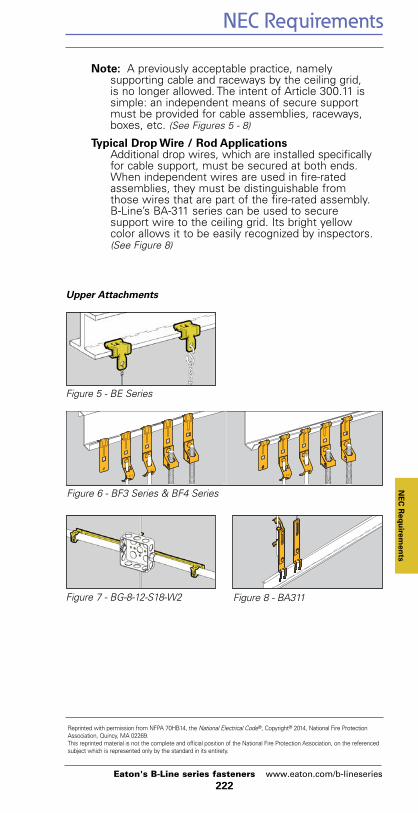
Note: A previously acceptable practice, namely supporting cable and raceways by the ceiling grid, is no longer allowed. The intent of Article 300.11 is simple: an independent means of secure supportmust be provided for cable assemblies, raceways,boxes, etc. (See Figures 5 - 8)
Typical Drop Wire / Rod ApplicationsAdditional drop wires, which are installed specificallyfor cable support, must be secured at both ends.When independent wires are used in fire-ratedassemblies, they must be distinguishable fromthose wires that are part of the fire-rated assembly.B-Line’s BA-311 series can be used to secure support wire to the ceiling grid. Its bright yellowcolor allows it to be easily recognized by inspectors. (See Figure 8)
Figure 5 - BE Series
Upper Attachments
Figure 6 - BF3 Series & BF4 Series
Figure 7 - BG-8-12-S18-W2 Figure 8 - BA311
NEC Requirements
223
NEC Requirements
Reprinted with permission from NFPA 70HB14, the National Electrical Code®, Copyright® 2014, National Fire ProtectionAssociation, Quincy, MA 02269.This reprinted material is not the complete and official position of the National Fire Protection Association, on the referencedsubject which is represented only by the standard in its entirety.
Eaton's B-Line series fasteners www.eaton.com/b-lineseries
310.15 Ampacities For Conductors Rated 0-2000 Volts. (B) Tables . . . . .(3) Adjustment Factors.
(a) More Than Three Current-Carrying Conductors in a Raceway or Cable. Where the number of current-carrying conductors in a raceway or cable exceeds three, or where single conductors or multiconductor cables are stacked or bundled longer than 600 mm (24 in.) without maintaining spacing and are not installed in raceways, the allowable ampacity of each conductor shall be reduced as shown in Table 310.15(B)(2)(a). Each current-carrying conductor of a paralleled set of conductors shall be counted as a current-carrying conductor.
FPN No. 1: See Annex B, Table B.310.11, for adjustment factors for more than three current-carrying conductors in a raceway or cable with load diversity.
FPN No. 2: See 366.23(A), for correction factors for conductors in sheet metal auxiliary gutters and 376.22 for correction factors for conductors in metal raceways.
Exception No. 1: Where conductors of differentsystems, as provided in 300.3, are installed in a common raceway or cable, the derating factors shown in Table 310.15(B)(2)(a) shall apply only to the number of power and lighting conductors (Articles 210, 215, 220, and 230).
Exception No. 2: For conductors installed in cable trays, the provisions of 392.11 shall apply.
Exception No. 3: Derating factors shall not applyto conductors in nipples having a length not exceeding 600 mm (24 in.).
Exception No. 4: Derating factors shall not apply to underground conductors entering or leaving an outdoor trench if those conductors have physical protection in the form of rigid metal conduit, intermediate metal conduit, or rigid nonmetallic conduit having a length not exceeding 3.05 m(10 ft) and if the number of conductors does not exceed four.

NEC Requirements
224
NEC Requirem
ents
Reprinted with permission from NFPA 70HB14, the National Electrical Code®, Copyright® 2014, National Fire ProtectionAssociation, Quincy, MA 02269.This reprinted material is not the complete and official position of the National Fire Protection Association, on the referencedsubject which is represented only by the standard in its entirety.
Eaton's B-Line series fasteners www.eaton.com/b-lineseries
Exception No. 5: Adjustment factors shall not apply to Type AC cable or to Type MC cable without an overall outer jacket under the following conditions:
(1) Each cable has not more than threecurrent-carrying conductors.
(2) The conductors are 12 AWG copper.
(3) Not more than 20 current-carryingconductors are bundled, stacked, or supported on “bridle rings”.(See Figure 9)
A 60 percent adjustment factor shall be applied where current-carrying conductors in these cables that are stacked or bundled longer than 600 mm (24 in.) without maintaining spacing exceeds 20.
(b) More Than One Conduit, Tube, or Raceway Spacing between conduits, tubing, or raceways shall be maintained.
Figure 9 - Bridle Rings Figure 10 - BRC6M

NEC Requirements
225
NEC Requirements
Reprinted with permission from NFPA 70HB14, the National Electrical Code®, Copyright® 2014, National Fire ProtectionAssociation, Quincy, MA 02269.This reprinted material is not the complete and official position of the National Fire Protection Association, on the referencedsubject which is represented only by the standard in its entirety.
Eaton's B-Line series fasteners www.eaton.com/b-lineseries
NEC Requirements
314.23 Supports. Enclosures within the scope of this article shall be supported in accordance with one or more of the provisions in 314.23 (A) through (H).
(C) Mounting in Finished Surfaces. An enclosuremounted in a finished surface shall be rigidly secured thereto by clamps, anchors, or fittingsidentified for the application. (See Figures 11 & 12)
(D) Suspended Ceilings. An enclosure mounted tostructural or supporting elements of a suspended ceiling shall be not more than 1650 cm3 (100 in.3) in size and shall be securely fastened in place in accordance with either (D)(1) or (D)(2).
(1) Framing Members. An enclosure shall be fastened to the framing members by mechanical means such as bolts, screws, or rivets, or by the use of clips or other securing means identified for use with the type of ceiling framing member(s) and enclosure(s) employed. . . . . (See Figure 13)
(2) Support Wires. The installation shall comply withthe provisions of 300.11(A). The enclosure shall besecured, using methods identified for the purpose to ceiling support wire(s), including any additionalsupport wire(s) installed for that purpose. Supportwire(s) used for enclosure support shall be fastenedat each end so as to be taut within the ceiling cavity.(See Figure 14)
(E) Raceway Supported Enclosures, Without Devices, Luminaries (Fixtures), orLampholders.. . . It shall be supported by two or more conduits threaded wrenchtight into the enclosure or hubs. Each conduit shall be secured within 900 mm (3 ft) of the enclosure, or within 450 mm (18 in.) of theenclosure if all conduit entries are on the same side. (See Figure 15)
(F) Raceway Supported Enclosures, With Devices, Luminaries (Fixtures), or Lampholders. . . . It shall be supported by two or more conduitsthreaded wrenchtight into the enclosure or hubs. Each conduit shall be secured within 450 mm (18 in.)of the enclosure. (See Figure 15)
314.27 Outlet Boxes
(A) Maximum Luminaire (Fixture) Weight. Outlet boxes or fitting installed as required by 314.23 shall be permitted to support luminaries (lighting fixtures) weighing 23 kg (50 lbs.) or less. A luminaire (lighting fixture) that weighs more than 23 kg (50 lbs.) shall be supported independently of the outlet box unless the outlet box is listed for the weight to be supported.(See Figure 13)

NEC Requirements
226
Reprinted with permission from NFPA 70HB14, the National Electrical Code®, Copyright® 2014, National Fire ProtectionAssociation, Quincy, MA 02269.This reprinted material is not the complete and official position of the National Fire Protection Association, on the referencedsubject which is represented only by the standard in its entirety.
Eaton's B-Line series fasteners www.eaton.com/b-lineseries
(C) Boxes at Ceiling-Suspended (Paddle) Fan Outlets.Outlet boxes or outlet box systems used as the sole support of a ceiling-suspended (paddle) fan shall be listed, shall be marked by their manufacturer as suitable for this purpose, and shall not support ceiling-suspended (paddle) fans that weigh more than 32 kg (70 lb). For outlet boxes or outlet box systems designed to support of a ceiling-suspended (paddle) fans that weigh more than 16 kg (35 lb), the required marking shall include the maximum weight to be supported.(See Figure 16)
Figure 11 - BB4-23
Figure 12 - BB9 & BB12
Figure 13 - BA50 Figure 14 - BG-8-12-S18-W2
Figure 15 - BG-8-12-S18-U-2-4 Figure 16 - BA50F
NEC Requirem
ents

NEC Requirements
227
NEC Requirements
Reprinted with permission from NFPA 70HB14, the National Electrical Code®, Copyright® 2014, National Fire ProtectionAssociation, Quincy, MA 02269.This reprinted material is not the complete and official position of the National Fire Protection Association, on the referencedsubject which is represented only by the standard in its entirety.
Eaton's B-Line series fasteners www.eaton.com/b-lineseries
Article 320Armored Cable : Type AC
320.17 Through or Parallel to Framing Members. TypeAC cable shall be protected in accordance with 300.4(A), (C), and (D) where installed through or parallel toframing members. (See Figures 17 & 18)
320.30 Securing and Supporting.(A) General. Type AC shall be supported and secured by
staples, cable ties, straps, hangers, or similar fittings,designed and installed so as not to damage the cable.
(B) Securing. Unless otherwise provided, Type AC cableshall be secured within 300 mm (12 in.) of every outletbox, junction box, cabinet, or fitting and at intervals notexceeding 1.4 m (41/2 ft) where installed on or acrossframing members. (See Figures 19 -22)
(C) Supporting. Unless otherwise provided, Type AC cableshall be supported at intervals not exceeding 1.4 m (41/2ft). Horizontal runs of Type AC cable installed in woodenor metal framing members or similar supporting meansshall be considered supported where such support doesnot exceed 1.4 m (41/2 ft) intervals.
Article 330Metal-Clad Cable : Type MC
330.17 Through or Parallel to Framing Members. TypeMC cable shall be protected in accordance with 300.4(A), (C), and (D) where installed through or parallel toframing members. (See Figures 17 & 18)
330.30 Securing and Supporting.(A) General. Type MC shall be supported and secured by
staples, cable ties, straps, hangers, or similar fittingsor other approved means designed and installed so asnot to damage the cable.
(B) Securing. Unless otherwise provided, cablesshall besecured at intervals not exceeding 1.8 m (6 ft). Cablescontaining four or fewer conductors sized no larger than10 AWG shall be secured within 300 mm (12 in.) ofevery box, cabinet, fitting or other cable termination.(See Figure 19 - 22)
(C) Supporting. Unless otherwise provided, cables shallbe supported at intervals not exceeding 1.8 m (6ft).Horizontal runs of Type MC cable installed in wooden ormetal framing members or similar supporting meansshall be considered supported and secured where suchsupport does not exceed 1.8 m (6 ft) intervals.
Article 334Nonmetallic Sheathed Cables
334.17 Through or Parallel to Framing Members.Type NM, NMC, or NMS cable shall be protected inaccordance with 300.4 where installed through or

NEC Requirements
228
Reprinted with permission from NFPA 70HB14, the National Electrical Code®, Copyright® 2014, National Fire ProtectionAssociation, Quincy, MA 02269.This reprinted material is not the complete and official position of the National Fire Protection Association, on the referencedsubject which is represented only by the standard in its entirety.
Eaton's B-Line series fasteners www.eaton.com/b-lineseries
parallel to framing members. Grommets used as requiredin 300.4(B)(1) shall remain in place and be listed for thepurpose of cable protection.(See Figures 17 & 18)
334.30 Securing and Supporting. Nonmetallic-sheathedcable shall be supported and secured by staples, cableties, straps, hangers, or similar fittings designed andinstalled so as not to damage the cable, at intervals notexceeding 1.4 m (41/2 ft) and within 300 mm (12 in.) ofevery outlet box, junction box, cabinet, or fitting. Flatcables shall not be stapled on edge. Sections of cableprotected from physical damage by raceway shall not berequired to be secured within the raceway.(See Figures 19 - 22)
(A) Horizontal Runs Through Holes and Notches. In other than vertical runs, cables installed in accordance with 300.4 shall be considered to be supported and secured where such support does notexceed 1.4 m ( 41/2 ft) intervals and the nonmetallic-sheathed cable is securely fastened in place by anapproved means within 300 mm (12 in.) of each box,cabinet, conduit body, or other nonmetallic-sheathedcable termination.FPN: See 314.17(C) for support where nonmetallic boxesare used.
Figure 17 - BM1/BM2
Figure 19 - BG-8-12-H7
Figure 22 - BX4
Figure 20 - BRC4 & BRC6M
Figure 21 - BX5
Figure 18 - BM3 & BM3M
NEC Requirem
ents
NEC Requirements
229
Reprinted with permission from NFPA 70HB14, the National Electrical Code®, Copyright® 2014, National Fire ProtectionAssociation, Quincy, MA 02269.This reprinted material is not the complete and official position of the National Fire Protection Association, on the referencedsubject which is represented only by the standard in its entirety.
Eaton's B-Line series fasteners www.eaton.com/b-lineseries
Article 344Rigid Metal Conduit : Type RMC
344.30 Securing and Supporting.(A) Securely Fastened. RMC shall be securely fastened
within 900 mm (3 ft) of each outlet box, junction box,device box, cabinet, conduit body, or other conduit termination. Fastening shall be permitted to be increasedto a distance of 1.5 m (5 ft) where structural members donot readily permit fastening within 900 mm (3 ft). Whereapproved, conduit shall not be required to be securelyfastened within 900 mm (3 ft) of the service head forabove-the-roof termination of a mast.(See Figures 23 - 25)
(B) Supports. RMC shall be supported in accordance with one of the following:
(1) Conduit shall be supported at intervals not exceeding 3 m (10 ft).
(2) The distance between supports for straight runs of conduit shall be permitted in accordance with Table 344.30(B)(2), . . . .
(3) Exposed vertical risers from industrial machinery orfixed equipment shall be permitted to be supportedat intervals not exceeding 6 m (20 ft) . . . .
(4) Horizontal runs of RMC supported by openings through framing members at intervals not exceeding 3 m (10 ft) and securely fastened within 900 mm (3 ft) of termination points shall be permitted. (See Figure 26)
Article 348Flexible Metal Conduit: Type FMC
348.30 Securing and Supporting.(A) Securely Fastened. FMC shall be securely fastened in
place by an approved means within 300 mm (12 in.) of each box, cabinet, conduit body, or other conduit termination and shall be supported and secured at intervals not to exceed 1.4 m (41/2 ft).(See Figures 23 - 25)
(B) Supports. Horizontal runs of FMC supported by openings through framing members at intervals notgreater than 1.4 m ( 41/2 ft) and securely fastened within300 mm (12 in) of termination points shall be permitted.(See Figure 26)
* See NFPA 70-2005 for exceptions.
Article 358Electrical Metallic Tubing - Type EMT
358.30 Securing and Supporting.(A) Securely Fastened. EMT shall be securely fastened in
place at least every 3 m (10 ft). In addition, each EMT runbetween termination points shall be securely within 900mm (3 ft) of each outlet box, junction box, device box, cabinet, conduit body, or other tubing termination. (See Figures 23 - 25)
NEC Requirements
NEC Requirements
230
NEC Requirem
ents
Reprinted with permission from NFPA 70HB14, the National Electrical Code®, Copyright® 2014, National Fire ProtectionAssociation, Quincy, MA 02269.This reprinted material is not the complete and official position of the National Fire Protection Association, on the referencedsubject which is represented only by the standard in its entirety.
Eaton's B-Line series fasteners www.eaton.com/b-lineseries
Exception No. 1: Fastening of unbroken lengths shall be permitted to be increased to a distance of 1.5 m (5 ft) where structural members do not readily permit fastening within 900 mm (3 ft).Exception No. 2: For concealed work in finished buildings or prefinished wall panels where such securing is impracticable, unbroken lengths (without coupling) of EMT shall be permitted to be fished.
(B) Supports. Horizontal runs of EMT supported by openings through framing members at intervals not greater than 3 m (10 ft) and securely fastened within 900 mm (3 ft) of termination points shall be permitted.(See Figure 26)
Article 362Electrical Nonmetallic Tubing - Type ENT
362.30 Securing and Supporting.
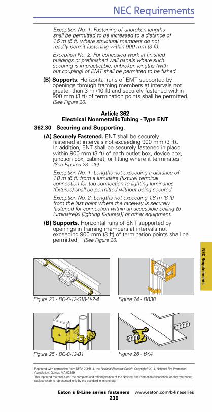
(A) Securely Fastened. ENT shall be securely fastened at intervals not exceeding 900 mm (3 ft). In addition, ENT shall be securely fastened in place within 900 mm (3 ft) of each outlet box, device box, junction box, cabinet, or fitting where it terminates.(See Figures 23 - 25)
Exception No. 1: Lengths not exceeding a distance of 1.8 m (6 ft) from a luminaire (fixture) terminal connection for tap connection to lighting luminaries (fixtures) shall be permitted without being secured.Exception No. 2: Lengths not exceeding 1.8 m (6 ft) from the last point where the raceway is securely fastened for connection within an accessible ceiling to luminaire(s) [lighting fixture(s)] or other equipment.
(B) Supports. Horizontal runs of ENT supported by openings in framing members at intervals not exceeding 900 mm (3 ft) of termination points shall be permitted. (See Figure 26)
Figure 23 - BG-8-12-S18-U-2-4 Figure 24 - BB38
Figure 25 - BG-8-12-B1 Figure 26 - BX4

NEC Requirements
231
NEC Requirements
Reprinted with permission from NFPA 70HB14, the National Electrical Code®, Copyright® 2014, National Fire ProtectionAssociation, Quincy, MA 02269.This reprinted material is not the complete and official position of the National Fire Protection Association, on the referencedsubject which is represented only by the standard in its entirety.
Eaton's B-Line series fasteners www.eaton.com/b-lineseries
Article 410Luminaries (Lighting Fixtures),Lampholders, and Lamps
410.36 Means of Support.
(A) Outlet Boxes. Outlet boxes or fittings installed as required by 314.23 and complying with the provisions of 314.27(A) and 314.27(B) shall be permitted to support luminaries (fixtures).
(B) Suspended Ceilings. Framing members of suspended ceiling systems used to support luminaries (fixtures) shall be securely fastened to each other and shall be securely attached to the building structure at appropriate intervals. Luminaries (fixtures) shall be securely fastened to the ceiling framing member by mechanical means such as bolts, screws, or rivets. Listed clips identified for use with the type of ceiling framing member(s) and luminaire(s) [fixture(s)] shall also be permitted. (See Figures 27 - 31)
410.154 Fastening. Lighting track shall be securely mounted so that each fastening is suitable for supporting themaximum weight of luminaries (fixtures) that can beinstalled. Unless identified for supports at greater intervals,a single section 1.2 m (4 ft.) or shorter in length shall havetwo supports, and, where installed in a continuous row, eachindividual section of not more than 1.2 m (4 ft.) in length shallhave one additional support. (See Figure 30)
422.18 Support of Ceiling-Suspended (Paddle) FansCeiling-suspended (paddle) fans shall be supportedindependently of an outlet box or by listed outletbox or outlet box systems identified for the use and installed in accordance with 314.27(D). (See Figure 32)
Article 800Communication Circuits
800.24 Mechanical Execution of Work.Communications circuits and equipment shall be installed in a neat and workmanlike manner. Cables installed exposedon the surface of ceilings and sidewalls shall be supportedby the building structure in such a manner that the cable willnot be damaged by normal building use. Such cables shall besecured by straps, staples, hangers, or similar fittingsdesigned and installed so as not to damage the cable. Theinstallation shall also conform with 300.4(D) and 300.11.
FPN: Accepted industry practices are described in ANSI/NECA/BICSI 568-2001, Standard for Installing Commercial Building Telecommunications Cabling, and other ANSI-approved installation standards.

NEC Requirements
232
NEC Requirem
ents
Reprinted with permission from NFPA 70HB14, the National Electrical Code®, Copyright® 2014, National Fire ProtectionAssociation, Quincy, MA 02269.This reprinted material is not the complete and official position of the National Fire Protection Association, on the referencedsubject which is represented only by the standard in its entirety.
Eaton's B-Line series fasteners www.eaton.com/b-lineseries
Figure 27 - BA15 Figure 28 - BA1
Figure 29 - BA40 Figure 30 - BA 4-16 Series
Figure 31 - BAX Series Figure 32 - BA50F

TIA/EIA Requirements
233
Reprinted with permission from NFPA 70HB14, the National Electrical Code®, Copyright® 2014, National Fire ProtectionAssociation, Quincy, MA 02269.This reprinted material is not the complete and official position of the National Fire Protection Association, on the referencedsubject which is represented only by the standard in its entirety.
Eaton's B-Line series fasteners www.eaton.com/b-lineseries
TIA/EIA Requirements
ANSI/TIA/EIA-569-A
4. Horizontal pathways and related spaces
4.6 Ceiling pathway
4.6.2 Design guidelines
4.6.2.1 Planning. The design shall provide a suitable means for supporting cable from the telecommunications closet to the work areas to be served. Cable shall not be laid directly on the ceiling tile or rails.
4.6.2.2 Clearance. A minimum of 75 mm (3 in.) clear vertical space shall be available above the ceiling tiles for the horizontal cabling and pathway. (See Figure 33)
4.6.5 Cable support
4.6.5.1 Where zone conduit or cable tray is not available in a suspended ceiling space and where telecommunications cables are allowed to be placed in the ceiling, adequate open-top cable supports, located on 1220-1525 mm (48-60 inch) centers, shall be provided. Where larger quantities of cables (50-75 cables) bunched together in the ceiling at a congested area, such as close to the telecommunications closet, special supports shall be designed and installed to carry the additional weight. (See Figures 33 & 34)
4.6.5.2 A suspended ceiling support rod or wire may be used to mount appropriate cable fasteners loaded with multiple cables up to the total weight for which the fastener is approved. The T-bar rail
of a suspended ceiling may be used to mount appropriate cable fasteners loaded with cable up to a total weight of 0.7 kg/m (0.45 lb/ft). The fastener design shall not interfere with the inserting or removing of the ceiling tile.(See Figures 33 & 34)
NOTES
1) A weight of 1.0 kg (2.2 lbs.) or 0.7 kg/m with spacing of support wire/rod at 1.5 m (5 ft.) is equivalent to a bundle of sixteen 4-pair 24 AWG UTP cables, including fasteners.
2) If any side pull is exerted on the support wire, like a turn in direction of the cables, the level of the ceiling tee rail could be affected.

TIA/EIA Requirements
234
Reprinted with permission from NFPA 70HB14, the National Electrical Code®, Copyright® 2014, National Fire ProtectionAssociation, Quincy, MA 02269.This reprinted material is not the complete and official position of the National Fire Protection Association, on the referencedsubject which is represented only by the standard in its entirety.
Eaton's B-Line series fasteners www.eaton.com/b-lineseries
TIA/EIA Requirem
ents
Figure 33 - BCHxx-A28 Figure 34 - BCHxx-W2

Reference Data
235Eaton's B-Line series fasteners www.eaton.com/b-lineseries
Reference Data
‘A’
‘B’‘C’
‘E’
‘D’
‘F’‘G’
‘H’
.26 Ø
Cable Static Load Capacity (S.F. 3)Hook Galvanized &Size Stainless SteelIn. Lbs.3/4 3015/16 302 304 30
Stated loads are per hook andshould not be exceeded. The loadcapacity of a fastener having morethan one component is equal tothe load capacity of the lowestrated component.
Load Capacity
Hook ‘A’ ‘B’ ‘C’ ‘D’ ‘E’ ‘F’ ‘G’ ‘H’SizeIn. In. In. In. In. In. In. In. In.
3/4 .88 3.18 2.68 1.00 .75 1.69 .94 --15/16 1.62 3.62 2.81 1.69 1.31 2.00 1.37 .202 1.62 4.31 3.50 2.38 2.00 2.69 2.06 .204 2.00 6.81 5.56 4.55 4.00 4.84 4.06 .31
Single-Sided Single-Tier Cable Fasteners
OverallHeight
‘A’
‘B’.32 Ø
.75
OverallWidth
Hook ‘A’ ‘B’ Overall OverallSize Height WidthIn. In. In. In. In.
15/16 1.90 2.50 5.50 3.47
2 1.90 2.50 6.19 4.85
4 2.38 2.94 9.00 9.19
Double-Sided Single-Tier Cable Fasteners
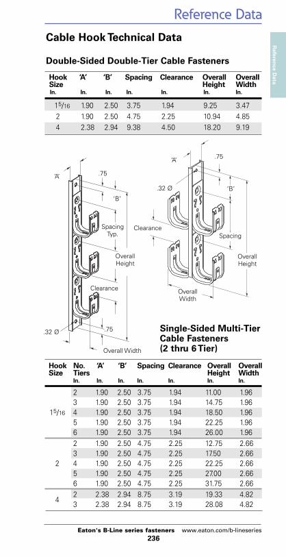
Cable Hook Technical Data
BCH12
Reference DataReferen
ce Data
236Eaton's B-Line series fasteners www.eaton.com/b-lineseries
Cable Hook Technical Data
Hook ‘A’ ‘B’ Spacing Clearance Overall OverallSize Height WidthIn. In. In. In. In. In. In.
15/16 1.90 2.50 3.75 1.94 9.25 3.472 1.90 2.50 4.75 2.25 10.94 4.854 2.38 2.94 9.38 4.50 18.20 9.19
Double-Sided Double-Tier Cable Fasteners
Hook No. ‘A’ ‘B’ Spacing Clearance Overall OverallSize Tiers Height Width
In. In. In. In. In. In. In.
2 1.90 2.50 3.75 1.94 11.00 1.963 1.90 2.50 3.75 1.94 14.75 1.96
15/16 4 1.90 2.50 3.75 1.94 18.50 1.965 1.90 2.50 3.75 1.94 22.25 1.966 1.90 2.50 3.75 1.94 26.00 1.962 1.90 2.50 4.75 2.25 12.75 2.663 1.90 2.50 4.75 2.25 17.50 2.66
2 4 1.90 2.50 4.75 2.25 22.25 2.665 1.90 2.50 4.75 2.25 27.00 2.666 1.90 2.50 4.75 2.25 31.75 2.662 2.38 2.94 8.75 3.19 19.33 4.82
43 2.38 2.94 8.75 3.19 28.08 4.82
Single-Sided Multi-TierCable Fasteners(2 thru 6 Tier)
‘A’
Clearance
Overall Width
.75
.75.32 Ø
‘B’
SpacingTyp.
OverallHeight
‘A’
‘B’
OverallHeight
Clearance
OverallWidth
.75
.32 Ø
Spacing

Reference DataReference Data
237Eaton's B-Line series fasteners www.eaton.com/b-lineseries
Minimum WeightNominal Nominal Weight of ConduitConduit Outside Inside Per 100 Ft. andSize Diameter Diameter With Couplings Conductors
Attached Per 100 Ft.*In. In. In. Lbs. Lbs.
3/8 0.675 0.493 51.5 65.11/2 0.840 0.632 79.0 101.13/4 1.050 0.836 105.0 145.81 1.315 1.063 153.0 219.3
11/4 1.660 1.394 201.0 318.311/2 1.900 1.624 249.0 408.82 2.375 2.083 332.0 593.8
21/2 2.875 2.489 527.0 901.03 3.500 3.090 682.0 1259.0
31/2 4.000 3.570 831.0 1604.04 4.500 4.050 972.0 1967.0
Rigid Steel Conduit (Heavy Wall Conduit)
Minimum WeightNominal Nominal Weight of ConduitConduit Outside Inside Per 100 Ft. andSize Diameter Diameter With Couplings Conductors
Attached Per 100 Ft.*In. In. In. Lbs. Lbs.
1/2 0.815 0.745 60.0 82.13/4 1.029 0.954 82.0 122.81 1.290 1.205 116.0 182.311/4 1.638 1.553 150.0 267.311/2 1.883 1.793 182.0 341.82 2.360 2.266 242.0 503.821/2 2.857 2.727 401.0 775.03 3.476 3.346 493.0 1069.031/2 3.971 3.841 573.0 1346.04 4.466 4.336 638.0 1632.0
Intermediate Metal Conduit (IMC)
Dimensions taken from ANSI C80.3 - 1977.* Conduit plus weight of heaviest conductor combination as specified bythe National Electrical Code.
Reference DataReferen
ce Data
238Eaton's B-Line series fasteners www.eaton.com/b-lineseries
Minimum WeightNominal Nominal Weight of ConduitConduit Outside Inside Per 100 Ft. andSize Diameter Diameter With Couplings Conductors
Attached Per 100 Ft.*In. In. In. Lbs. Lbs.
3/8 0.577 0.493 23.0 36.61/2 0.706 0.622 28.5 50.63/4 0.922 0.824 43.5 84.31 1.163 1.049 64.0 130.311/4 1.510 1.380 95.0 212.311/2 1.740 1.610 110.0 269.82 2.197 2.067 140.0 401.821/2 2.875 2.731 205.0 579.03 3.500 3.356 250.0 826.331/2 4.000 3.834 325.0 1098.04 4.500 4.334 370.0 1364.0
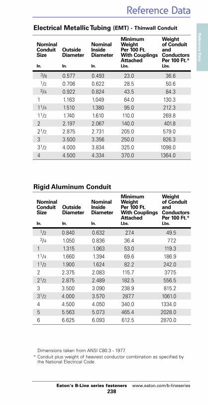
Electrical Metallic Tubing (EMT) - Thinwall Conduit
Minimum WeightNominal Nominal Weight of ConduitConduit Outside Inside Per 100 Ft. andSize Diameter Diameter With Couplings Conductors
Attached Per 100 Ft.*In. In. In. Lbs. Lbs.
1/2 0.840 0.632 27.4 49.53/4 1.050 0.836 36.4 77.21 1.315 1.063 53.0 119.311/4 1.660 1.394 69.6 186.911/2 1.900 1.624 82.2 242.02 2.375 2.083 115.7 377.521/2 2.875 2.489 182.5 556.53 3.500 3.090 238.9 815.231/2 4.000 3.570 287.7 1061.04 4.500 4.050 340.0 1334.05 5.563 5.073 465.4 2028.06 6.625 6.093 612.5 2870.0
Rigid Aluminum Conduit
Dimensions taken from ANSI C80.3 - 1977.* Conduit plus weight of heaviest conductor combination as specified bythe National Electrical Code.
Reference DataReference Data
239Eaton's B-Line series fasteners www.eaton.com/b-lineseries
NominalPipe Outside Wall Weight WeightSize Diameter Thickness of Pipe of WaterIn. In. In. Lbs. Per Ft. Lbs. Per Ft.
1/8 0.405 0.068 0.04 0.021/4 0.540 0.088 0.07 0.043/8 0.675 0.091 0.10 0.081/2 0.840 0.109 0.15 0.103/4 1.050 0.113 0.20 0.201 1.315 0.133 0.30 0.4011/4 1.660 0.140 0.40 0.6011/2 1.900 0.145 0.50 0.902 2.375 0.155 0.60 1.4021/2 2.875 0.203 1.00 2.103 3.500 0.216 1.30 3.2031/2 4.000 0.226 1.60 4.304 4.500 0.237 1.90 5.50
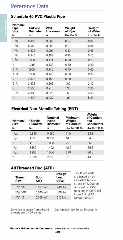
Schedule 40 PVC Plastic Pipe
WeightNominal Minimum of Conduit
Nominal Outside Inside Weight andSize Diameter Diameter of Conduit ConductorsIn. In. In. Lbs. Per 100 Ft. Lbs. Per 100 Ft.
1/2 0.840 0.560 11.0 33.13/4 1.050 0.760 14.0 54.81 1.315 1.000 20.0 86.311/4 1.660 1.402 19.0 136.311/2 1.990 1.554 27.0 186.82 2.375 2.030 32.0 261.8
Electrical Non-Metallic Tubing (ENT)
DesignThread Root LoadSize Area (SF=5)
1/4”-20 0.027 in.2 240 lbs.5/16”-18 0.045 in.2 400 lbs.3/8”-16 0.068 in.2 610 lbs.
All Threaded Rod (ATR)
Dimensions taken from ANSI B1.1 1982 Unified Inch Screw Threads. Allthreads are UNCR series.
Tabulated loadsare based on anallowable tensilestress of 12000 psireduced by 25%resulting in 9000 psi.From ANSI/MSS SP-58, Table 3.

Reference DataReferen
ce Data
240Eaton's B-Line series fasteners www.eaton.com/b-lineseries
Trade Grounding Armor ApproximateSize Conductor AWG O.D. Wt. Per 100 Ft.
In. Lbs.
14-2 Solid 14 0.470 17.514-3 Solid 14 0.480 20.514-4 Solid 14 0.510 23.012-2 Solid 12 0.495 21.512-3 Solid 12 0.530 25.512-4 Solid 12 0.565 29.510-2 Solid 10 0.560 28.510-3 Solid 10 0.600 34.010-4 Solid 10 0.645 39.58-2 Stranded 10 0.710 45.08-3 Stranded 10 0.770 54.58-4 Stranded 10 0.835 64.56-2 Stranded 8 0.795 59.06-3 Stranded 8 0.865 72.06-4 Stranded 8 0.945 86.04-2 Stranded 8 0.945 78.54-3 Stranded 8 1.035 98.54-4 Stranded 8 1.135 119.53-3 Stranded 6 1.025 107.03-4 Stranded 6 1.120 126.02-2 Stranded 6 1.075 104.52-3 Stranded 6 1.180 134.02-4 Stranded 6 1.295 164.0
MC -- Metal Clad Cable Specifications
Pair AWGCount Size O.D. Weight
In. Lbs. Per 100 Ft.
2 24 0.16 1.33 24 0.18 1.74 24 0.20 2.16 24 0.27 3.58 24 0.30 4.225 24 0.50 13.0
Category 5 Cable
Reference DataReference Data
241Eaton's B-Line series fasteners www.eaton.com/b-lineseries
Trade Approximate ApproximateSize O.D. Weight
In. Lbs. Per 100 Ft.
14 AWG 0.11 1.712 AWG 0.13 2.510 AWG 0.16 4.08 AWG 0.22 6.56 AWG 0.25 9.74 AWG 0.32 15.53 AWG 0.35 19.12 AWG 0.38 23.61 AWG 0.45 30.4
1/0 AWG 0.49 37.5
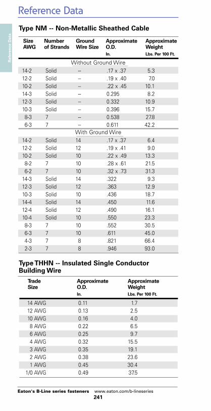
Type THHN -- Insulated Single ConductorBuilding Wire
Size Number Ground Approximate ApproximateAWG of Strands Wire Size O.D. Weight
In. Lbs. Per 100 Ft.
Without Ground Wire14-2 Solid -- .17 x .37 5.312-2 Solid -- .19 x .40 7.010-2 Solid -- .22 x .45 10.114-3 Solid -- 0.295 8.212-3 Solid -- 0.332 10.910-3 Solid -- 0.396 15.78-3 7 -- 0.538 27.86-3 7 -- 0.611 42.2
With Ground Wire14-2 Solid 14 .17 x .37 6.412-2 Solid 12 .19 x .41 9.010-2 Solid 10 .22 x .49 13.38-2 7 10 .28 x .61 21.56-2 7 10 .32 x .73 31.314-3 Solid 14 .322 9.312-3 Solid 12 .363 12.910-3 Solid 10 .436 18.714-4 Solid 14 .450 11.612-4 Solid 12 .490 16.110-4 Solid 10 .550 23.38-3 7 10 .552 30.56-3 7 10 .611 45.04-3 7 8 .821 66.42-3 7 8 .946 93.0
Type NM -- Non-Metallic Sheathed Cable
Reference DataReferen
ce Data
242Eaton's B-Line series fasteners www.eaton.com/b-lineseries
Trade Armor ApproximateSize O.D. Weight
In. Lbs. Per 100 Ft.
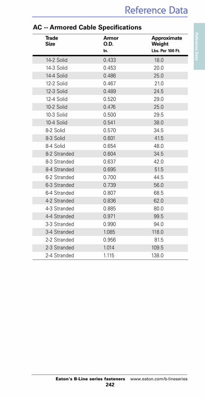
14-2 Solid 0.433 18.014-3 Solid 0.453 20.014-4 Solid 0.486 25.012-2 Solid 0.467 21.012-3 Solid 0.489 24.512-4 Solid 0.520 29.010-2 Solid 0.476 25.010-3 Solid 0.500 29.510-4 Solid 0.541 38.08-2 Solid 0.570 34.58-3 Solid 0.601 41.58-4 Solid 0.654 48.08-2 Stranded 0.604 34.58-3 Stranded 0.637 42.08-4 Stranded 0.695 51.56-2 Stranded 0.700 44.56-3 Stranded 0.739 56.06-4 Stranded 0.807 68.54-2 Stranded 0.836 62.04-3 Stranded 0.885 80.04-4 Stranded 0.971 99.53-3 Stranded 0.990 94.03-4 Stranded 1.085 118.02-2 Stranded 0.956 81.52-3 Stranded 1.014 109.52-4 Stranded 1.115 138.0
AC -- Armored Cable Specifications

Index
243Eaton's B-Line series fasteners www.eaton.com/b-lineseries
Index
Catalog No. Page Catalog No. Page
1314 . . . . . . . . . . . . . . 1921316 . . . . . . . . . . . . . . 1921372 . . . . . . . . . . . . . . 1921380 . . . . . . . . . . . . . . 1922782SD . . . . . . . . . . . . 1942786SD . . . . . . . . . . . . 1942791 . . . . . . . . . . . . . . 1942793 . . . . . . . . . . . . . . 1942796 . . . . . . . . . . . . . . 1945866 . . . . . . . . . . . . . . 1885874 . . . . . . . . . . . . . . 1886305 . . . . . . . . . . . . . . 1896307 . . . . . . . . . . . . . . 1896309 . . . . . . . . . . . . . . 1896311 . . . . . . . . . . . . . . 1896313 . . . . . . . . . . . . . . 1896323 . . . . . . . . . . . . . . 1906336 . . . . . . . . . . . . . . 1906338 . . . . . . . . . . . . . . 1906407SD . . . . . . . . . . . . 2087187 . . . . . . . . . . 186, 1887195 . . . . . . . . . . . . . . 1887197 . . . . . . . . . . . . . . 1887198 . . . . . . . . . . . . . . 1889221 . . . . . . . . . . . . . . 2079231 . . . . . . . . . . . . . . 2079241 . . . . . . . . . . . . . . 2079323 . . . . . . . . . . . . . . 1919343 . . . . . . . . . . . . . . 1919353 . . . . . . . . . . . . . . 191
AACB Series . . . . . . . . . 192ACPD Series . . . . . . . 206ACPW Series . . . . . . . 205ACS Series . . . . . 193-194ADA Series . . . . . 199-200ADI Series . . . . . . . . . 189ADE Series . . . . . . . . . 203ADH Series . . . . . . . . . 191ADM Series . . . . . . . . 190ADN Series . . . . . . . . 209AMS Series . . . . . . . . 207APC Series . . . . . . . . . 215APD Series . . . . . . . . . 214APH Series . . . . . . . . . 213APS Series . . . . . . . . . 212ARC Series . . . . . 187-188
ARS Series . . . . . 185-186ARW Series . . . . . 187-188ASA Series . . . . . 201-202ASE Series . . . . . . . . . 204ATB Series . . . . . . . . . 210ATM Series . . . . . . . . 208AWA Series . . . . .195-196AWS Series . . . . . . . . 211AWSD Series . . . . 197-198AZD Series . . . . . . . . . 214
BB1RRE . . . . . . . . . . . . . 33B1RRP4C . . . . . . . . . . . 33B1RRP5C . . . . . . . . . . . 33B1RRR . . . . . . . . . . . . . 33B2RRE . . . . . . . . . . . . . 33B2RRP4C . . . . . . . . . . . 33B2RRP5C . . . . . . . . . . . 33B2RRR . . . . . . . . . . . . . 33B3RRE . . . . . . . . . . . . . 33B3RRPC . . . . . . . . . . . . 33B3RRR . . . . . . . . . . . . . 33B4RRE . . . . . . . . . . . . . 33B4RRPC . . . . . . . . . . . . 33B4RRR . . . . . . . . . . . . . 33B444-1⁄4 . . . . . . . . . . . . 106B444-5⁄16 . . . . . . . . . . . 106B444-3⁄8 . . . . . . . . . . . . 106B601-62 . . . . . . . . . . . . 181B1506S . . . . . . . . . . . . . 47B1508 . . . . . . . . . . . . . . 47B1508S . . . . . . . . . . . . . 47B1512 . . . . . . . . . . . . . . 47B1512S . . . . . . . . . . . . . 47B1516 . . . . . . . . . . . . . . 47B1516S . . . . . . . . . . . . . 47B1520 . . . . . . . . . . . . . . 47B1520S . . . . . . . . . . . . . 47B1524S . . . . . . . . . . . . . 47B1532S . . . . . . . . . . . . . 47B1534S . . . . . . . . . . . . . 47B1540S . . . . . . . . . . . . . 47B1548S . . . . . . . . . . . . . 47B1556S . . . . . . . . . . . . . 47B1564S . . . . . . . . . . . . . 47B3223-3⁄8 . . . . . . . . . . . 139
Index
244Eaton's B-Line series fasteners www.eaton.com/b-lineseries
Index
Catalog No. Page Catalog No. Page
BABA1 . . . . . . . . . . . . . . . . 83BA1-9 . . . . . . . . . . . . . . 83BA1-24 . . . . . . . . . . . . . 83BA1-32 . . . . . . . . . . . . . 83BA1-95 . . . . . . . . . . . . . 83BA1-T . . . . . . . . . . . . . . 83BA1-T-BN . . . . . . . . . . . 83BA-2-9 . . . . . . . . . . . . . 87BA-2-9-BN . . . . . . . . . . 87BA-2-9-W . . . . . . . . . . . 87BA-2-9-WBN . . . . . . . . 87BA-2-9-7 . . . . . . . . . . . . 87BA-2-9-7-BN . . . . . . . . . 87BA-2-16 . . . . . . . . . . . . 86BA-2-16-BN . . . . . . . . . 86BA-2-16-W . . . . . . . . . . 86BA-2-16-WBN . . . . . . . 86BA-2-16-7 . . . . . . . . . . . 86BA-2-16-7-BN . . . . . . . . 86BA-2-16-7-W . . . . . . . . . 86BA-2-16-7-WBN . . . . . . 86BA-4-9 . . . . . . . . . . . . . 87BA-4-9-W . . . . . . . . . . . 87BA-4-16 . . . . . . . . . . . . 85BA-4-16-24 . . . . . . . . . . 85BA-4-16-32 . . . . . . . . . . 85BA-4-16-48 . . . . . . . . . . 85BA-4-16-H . . . . . . . . . . . 84BA-4-16-H1 . . . . . . . . . . 84BA-4-16-W . . . . . . . . . . 85BA-4-WN . . . . . . . . . . . 85BA-5-4T . . . . . . . . . . . . 73BA-6-4T . . . . . . . . . . . . . 74BA12 . . . . . . . . . . . . . . . 77BA12-12 . . . . . . . . . . . . 77BA12-20 . . . . . . . . . . . . 77BA12-30 . . . . . . . . . . . . 77BA14 . . . . . . . . . . . . . . . 72BA15 . . . . . . . . . . . . . . . 72BA15W . . . . . . . . . . . . . 72BA17 . . . . . . . . . . . . . . . 82BA18 . . . . . . . . . . . . . . . 82BA20 . . . . . . . . . . . . . . . 82BA-21 . . . . . . . . . . . . . . 85BA-21D . . . . . . . . . . . . . 85BA28 . . . . . . . . . . . . . . . 76
BA28B . . . . . . . . . 140, 175BA40 . . . . . . . . . . . . . . . 81BA50 . . . . . . . . . . . . . . . 78BA50A . . . . . . . . . . . . . 79BA50CAN . . . . . . . . . . . 78BA50C3T . . . . . . . . . . . 78BA50C4T . . . . . . . . . . . 78BA50D . . . . . . . . . . . . . 78BA50DCAN . . . . . . . . . 78BA50E . . . . . . . . . . . . . . 78BA50F . . . . . . . . . . . . . . 80BA50-OB-24 . . . . . . . . . 79BA50-OB-34 . . . . . . . . . 79BA50-SB-24 . . . . . . . . . 79BA50-SB-34 . . . . . . . . . 79BA311 . . . . . . . . . . . . . . 88BA311-W2 . . . . . . . . . . 88BA311-W6 . . . . . . . . . . 88BA-SFC . . . . . . . . . . . . . 89BA-SFC-CF . . . . . . . . . . 89BA-SFC-CFS . . . . . . . . . 89BA-SFC-E . . . . . . . . . . . 89BA-SFC-S . . . . . . . . . . . 89BAX-4-16 . . . . . . . . . . . 84BAX-4-16-24 . . . . . . . . . 84BAX-4-16-32 . . . . . . . . . 84BAX-4-16-48 . . . . . . . . . 84
BBBB1 . . . . . . . . . . . . . . . . 16BB2-16T . . . . . . . . . . . . 25BB2-24T . . . . . . . . . . . . 25BB2TCT-050 . . . . . . . . . 26BB2TCT-075 . . . . . . . . . 26BB2TCT-100 . . . . . . . . . 26BB2TPC-038 . . . . . . . . . 26BB2TPC-050 . . . . . . . . . 26BB2TPC-075 . . . . . . . . . 26BB2TPC-100 . . . . . . . . . 26BB2TSC . . . . . . . . . . . . 25BB4-4 . . . . . . . . . . . . . . 21BB4-4D . . . . . . . . . . . . . 21BB4-6 . . . . . . . . . . . . . . 21BB4-6D . . . . . . . . . . . . . 21BB4-23 . . . . . . . . . . . . . 21BB4-23D . . . . . . . . . . . . 21BB7-16 . . . . . . . . . . . . . 27

Index
245Eaton's B-Line series fasteners www.eaton.com/b-lineseries
Catalog No. Page Catalog No. Page
BB cont'd.B7-24 . . . . . . . . . . . . . . 27BB7AP . . . . . . . . . . . . . 27BB8-16 . . . . . . . . . . . . . 28BB8-24 . . . . . . . . . . . . . 28BB9 . . . . . . . . . . . . . . . . 17BB10 . . . . . . . . . . . . . . 147BB10-2 . . . . . . . . . . . . 147BB10-3 . . . . . . . . . . . . 147BB10-4 . . . . . . . . . . . . 147BB10L . . . . . . . . . . . . . 148BB10P . . . . . . . . . . . . . 148BB12 . . . . . . . . . . . . . . . 17BB12-6 . . . . . . . . . . . . . 17BB15 . . . . . . . . . . . 32, 150BB-18 . . . . . . . . . . . . . . 31BB20 . . . . . . . . . . . . . . 147BB20L . . . . . . . . . . . . . 148BB27 . . . . . . . . . . . . . . . 77BB32 . . . . . . . . . . . . . . . 20BB33 . . . . . . . . . . . . . . . 20BB33L . . . . . . . . . . . . . . 20BB38 . . . . . . . . . . . . . . . 40BB38D . . . . . . . . . . . . . 40BB40-08 . . . . . . . . 32, 149BB40-10 . . . . . . . . 32, 149BB40-12 . . . . . . . . 32, 149BB45-08 . . . . . . . . 32, 149BB45-10 . . . . . . . . 32, 149BB45-12 . . . . . . . . 32, 149BB70 . . . . . . . . . . . . . . . 23BB70E . . . . . . . . . . . . . . 23BB73 . . . . . . . . . . . . . . . 22BB74 . . . . . . . . . . . . . . . 22BB76 . . . . . . . . . . . . . . . 22BBF15 . . . . . . . . . . . . . . 30BBF15C . . . . . . . . . . . . 30BBF18 . . . . . . . . . . . . . . 30BBF18C . . . . . . . . . . . . . 30BBF24 . . . . . . . . . . . . . . 30BBF24C . . . . . . . . . . . . 30BBFC . . . . . . . . . . . . . . 30BBFS-18 . . . . . . . . . . . . 29
BCBC1 . . . . . . . . . . . . . . . 107BC442 . . . . . . . . . . . . . 105BC442-6 . . . . . . . . . . . 105BCH12 . . . . . . . . . 151-152BCH12-A28 . . . . . . . . . 162BCH12-C1 . . . . . . . . . . 158BCH12-C2 . . . . . . . . . . 158BCH12-C442 . . . . . . . . 157BCH12-C442A . . . . . . 157BCH12-E-2-4 . . . . . . . . 155BCH12-E-5-8 . . . . . . . . 155BCH12-E-9-12 . . . . . . . 155BCH12-F3 . . . . . . . . . . 160BCH12-F4 . . . . . . . . . . 160BCH12-G-8-12 . . . . . . 163BCH12-L1410 . . . . . . . 163BCH12-PNA . . . . . . . . 135BCH12-RB . . . . . . . . . 154BCH12-SC4 . . . . . . . . 159BCH12-U-2-4 . . . . . . . 156BCH12-U-5-8 . . . . . . . 156BCH12-U-9-12 . . . . . . 156BCH12-W2 . . . . . . . . . 161BCH12-W6 . . . . . . . . . 161BCH21 . . . . . . . . . 151-152BCH21-1D . . . . . . . . . . 164BCH21-2D . . . . . . . . . . 164BCH21-2S . . . . . . . . . . 165BCH21-3S . . . . . . . . . . 165BCH21-4S . . . . . . . . . . 166BCH21-5S . . . . . . . . . . 166BCH21-6S . . . . . . . . . . 166BCH21-A28 . . . . . . . . . 162BCH21-AB . . . . . . . . . 154BCH21-C1 . . . . . . . . . . 158BCH21-C2 . . . . . . . . . . 158BCH21-C442 . . . . . . . . 157BCH21-C442A . . . . . . 157BCH21-E-2-4 . . . . . . . . 155BCH21-E-5-8 . . . . . . . . 155BCH21-E-9-12 . . . . . . . 155BCH21-F3 . . . . . . . . . . 160BCH21-F4 . . . . . . . . . . 160BCH21-G-8-12 . . . . . . 163BCH21-L1410 . . . . . . . 163
Index

Index
246Eaton's B-Line series fasteners www.eaton.com/b-lineseries
Catalog No. Page Catalog No. Page
BC cont'd.BCH21-PNA . . . . . . . . 135BCH21-RB . . . . . . . . . . 154BCH21-SC4 . . . . . . . . . 159BCH21-U-2-4 . . . . . . . 160BCH21-U-5-8 . . . . . . . 156BCH21-U-9-12 . . . . . . 160BCH21-W2 . . . . . . . . . 161BCH21-W6 . . . . . . . . . 161BCH21X . . . . . . . . . . . 153BCH32 . . . . . . . . . 151-152BCH32-1D . . . . . . . . . . 164BCH32-2D . . . . . . . . . . 164BCH32-2S . . . . . . . . . . 165BCH32-3S . . . . . . . . . . 165BCH32-4S . . . . . . . . . . 166BCH32-5S . . . . . . . . . . 166BCH32-6S . . . . . . . . . . 166BCH32-A28 . . . . . . . . . 162BCH32-AB . . . . . . . . . 154BCH32-C1 . . . . . . . . . . 158BCH32-C2 . . . . . . . . . . 158BCH32-C442 . . . . . . . . 157BCH32-C442A . . . . . . 157BCH32-E-2-4 . . . . . . . . 155BCH32-E-5-8 . . . . . . . . 155BCH32-E-9-12 . . . . . . . 155BCH32-F3 . . . . . . . . . . 160BCH32-F4 . . . . . . . . . . 160BCH32-G-8-12 . . . . . . 163BCH32-L1410 . . . . . . . 163BCH32-PNA . . . . . . . . 135BCH32-RB . . . . . . . . . 154BCH32-SC4 . . . . . . . . 159BCH32-U-2-4 . . . . . . . 156BCH32-U-5-8 . . . . . . . 156BCH32-U-9-12 . . . . . . 156BCH32-W2 . . . . . . . . . 161BCH32-W6 . . . . . . . . . 161BCH32X . . . . . . . . . . . 153BCH64 . . . . . . . . . 151-152BCH64-1D . . . . . . . . . . 164BCH64-2D . . . . . . . . . . 164BCH64-2S . . . . . . . . . . 165BCH64-3S . . . . . . . . . . 165BCH64-4S . . . . . . . . . . 166
BCH64-AB . . . . . . . . . 154BCH64-C1 . . . . . . . . . . 158BCH64-C2 . . . . . . . . . . 158BCH64-C442 . . . . . . . . 157BCH64-C442A . . . . . . 157BCH64-F3 . . . . . . . . . . 160BCH64-F4 . . . . . . . . . . 160BCH64-G-8-12 . . . . . . 163BCH64-L1410 . . . . . . . 163BCH64-PNA . . . . . . . . 135BCH64-RB . . . . . . . . . 154BCH64-SC4 . . . . . . . . 159BCH64-U-2-4 . . . . . . . 156BCH64-U-5-8 . . . . . . . 156BCH64-U-9-12 . . . . . . 156BCH64X . . . . . . . . . . . 153BCH-HBA . . . . . . . . . . 167BCH-HB21 . . . . . . . . . 167BCH-HB64 . . . . . . . . . 167BCHID-__12 . . . . . . . . 152BCHID-__21 . . . . . . . . 152BCHID-__32 . . . . . . . . 152BCHID-__64 . . . . . . . . 152BCHK1 . . . . . . . . . . . . 168BCHK2 . . . . . . . . . . . . 168BCHK3 . . . . . . . . . . . . 168BCHR21 . . . . . . . . . . . 150BCHR32 . . . . . . . . . . . 150BCHR64 . . . . . . . . . . . 150BCS-8 . . . . . . . . . . . . . . 63BCS-8C . . . . . . . . . . . . . 63BCS-12 . . . . . . . . . . . . . 63BCS-12AS . . . . . . . . . . 63BCS-12C . . . . . . . . . . . . 63BCS-16 . . . . . . . . . . . . . 63BCS-16AS . . . . . . . . . . 63BCS-16C . . . . . . . . . . . . 63BCS-18 . . . . . . . . . . . . . 63BCS-18C . . . . . . . . . . . . 63BCS-20 . . . . . . . . . . . . . 63BCS-20C . . . . . . . . . . . . 63
BDBD2 . . . . . . . . . . . 140, 175BD4 . . . . . . . . . . . 140, 175BD40 . . . . . . . . . . . . . . 174
Index
Index
247Eaton's B-Line series fasteners www.eaton.com/b-lineseries
Catalog No. Page Catalog No. Page
BEBE-1-2 . . . . . . . . . . . . . . 92BE-2-4 . . . . . . . . . . . . . . 92BE-2-4-CT2 . . . . . . . . . 146BE-5-8 . . . . . . . . . . . . . . 92BE-5-8-CT2 . . . . . . . . . 146BE-9-12 . . . . . . . . . . . . . 92BE-9-12-CT2 . . . . . . . . 146BES-8 . . . . . . . . . . . . . . . 63BES-8C . . . . . . . . . . . . . 63BES-12 . . . . . . . . . . . . . . 63BES-12C . . . . . . . . . . . . 63BES-16 . . . . . . . . . . . . . . 63BES-16C . . . . . . . . . . . . 63
BFBF1 . . . . . . . . . . . . . . . 129BF1-40 . . . . . . . . . . . . . . 18BF1-56 . . . . . . . . . . . . . 18BF1-64 . . . . . . . . . . . . . . 18BF1-96 . . . . . . . . . . . . . 18BF1-CT2 . . . . . . . . . . . . 146BF2 . . . . . . . . . . . . . . . 129BF2-CT2 . . . . . . . . . . . . 146BF3 . . . . . . . . . . . . . . . 125BF4 . . . . . . . . . . . . . . . 121BF12 . . . . . . . . . . . . . . 119BF13 . . . . . . . . . . . . . . 119BFA-1215 . . . . . . . . . . . 62BFA-1520 . . . . . . . . . . . 62
BGBG-6 . . . . . . . . . . . . . . . 43BG-6-4T . . . . . . . . . . . . 43BG-6-A5 . . . . . . . . . . . . 73BG-6-A6 . . . . . . . . . . . . 74BG-6-B1 . . . . . . . . . . . . 16BG-6-B5 . . . . . . . . . . . . 19BG-6-E-2-4 . . . . . . . . . . 94BG-6-E-5-8 . . . . . . . . . . 94BG-6-E-9-12 . . . . . . . . . 94BG-6-F1 . . . . . . . . . . . 131BG-6-F2 . . . . . . . . . . . 131BG-6-F13 . . . . . . . . . . . 119BG-6-H7 . . . . . . . . . . . . 34BG6-PNA . . . . . . . . . . 136BG6-S18 . . . . . . . . . . . . 65
BG6-S18-MC3 . . . . . . . 65BG6-S18-S . . . . . . . . . . 65BG6-S18S-MC3 . . . . . . 65BG6-S18-U24 . . . . . . . 112BG6-S18-U24-MC3 . . . 112BG6-S18-U58 . . . . . . . 112BG6-S18-U58-MC3 . . . 112BG6-S18-W2 . . . . . . . . 66BG6-S18-W2-MC3 . . . . 66BG6-S18-W6 . . . . . . . . 66BG6-S18-W6-MC3 . . . . 66BG6-SC4 . . . . . . . . . . . 134BG-6-U-2-4 . . . . . . . . . 100BG-6-U-5-8 . . . . . . . . . 100BG-6-U-9-12 . . . . . . . . 100BG-8-12 . . . . . . . . . . . . 43BG-8-12-4T . . . . . . . . . . 43BG-8-12-A5 . . . . . . . . . 73BG-8-12-A6 . . . . . . . . . . 74BG-8-12-B1 . . . . . . . . . . 16BG-8-12-B5 . . . . . . . . . . 19BG-8-12-C1 . . . . . . . . . 108BG-8-12-C2 . . . . . . . . . 107BG-8-12-D3 . . . . . . . . . 64BG-8-12-D4 . . . . . . . . . 64BG-8-12-E-2-4 . . . . . . . 94BG-8-12-E-2-4-AS . . . 102BG-8-12-E-5-8 . . . . . . . 94BG-8-12-E-5-8-AS . . . 102BG-8-12-E-9-12 . . . . . . 94BG-8-12-E-9-12-AS . . 102BG-8-12-F1 . . . . . . . . . 131BG-8-12-F2 . . . . . . . . . 131BG-8-12-F13 . . . . . . . . 119BG-8-12-G6 . . . . . . . . . 51BG-8-12-G20 . . . . . . . . 51BG-8-12-G24 . . . . . . . . 51BG-8-12-G32 . . . . . . . . 51BG-8-12-G812 . . . . . . . 51BG-8-12-H7 . . . . . . . . . 34BG8-12-PNA . . . . . . . . 136BG812-S18 . . . . . . . . . . 65BG812-S18-MC3 . . . . . 65BG812-S18S . . . . . . . . . 65BG812-S18S-MC3 . . . . 65BG812-S18-U24 . . . . . 112BG812-S18-U24-MC3 . 112
Index

Index
248Eaton's B-Line series fasteners www.eaton.com/b-lineseries
Catalog No. Page Catalog No. Page
BG cont'd.BG812-S18-U58 . . . . . 112BG812-S18-U58-MC3 . 112BG812-S18-W2 . . . . . . 66BG812-S18-W2-MC3 . . 66BG812-S18-W6 . . . . . . 66BG812-S18-W6-MC3 . . 66BG812-SC4 . . . . . . . . . 134BG-8-12-U-2-4 . . . . . . 100BG-8-12-U-2-4-AS . . . 102BG-8-12-U-5-8 . . . . . . 100BG-8-12-U-5-8-AS . . . 102BG-8-12-U-9-12 . . . . . 100BG-8-12-U-9-12-AS . . 102BG-8-12-W2 . . . . . . . . . 55BG-8-12-W6 . . . . . . . . . 55BG-16 . . . . . . . . . . . . . . 43BG-16-4T . . . . . . . . . . . 43BG-16-A5 . . . . . . . . . . . 73BG-16-A6 . . . . . . . . . . . 74BG-16-B1 . . . . . . . . . . . 16BG-16-B5 . . . . . . . . . . . 19BG-16-C1 . . . . . . . . . . 108BG-16-C2 . . . . . . . . . . 107BG-16-E-2-4 . . . . . . . . . 94BG-16-E-2-4-AS . . . . . 102BG-16-E-5-8 . . . . . . . . . 94BG-16-E-5-8-AS . . . . . 102BG-16-E-9-12 . . . . . . . . 94BG-16-E-9-12-AS . . . . 102BG-16-F1 . . . . . . . . . . 131BG-16-F2 . . . . . . . . . . 131BG-16-F13 . . . . . . . . . . 119BG-16-G-6 . . . . . . . . . . 45BG-16-G-8-12 . . . . . 45, 51BG-16-G-16 . . . . . . . . . 45BG-16-G-20 . . . . . . . . . 45BG-16-G-24 . . . . . . . . . 45BG-16-G-32 . . . . . . . . . 45BG16-PNA . . . . . . . . . 136BG-16-S18 . . . . . . . . . . 65BG16-S18-MC3 . . . . . . 65BG16-S18-S . . . . . . . . . 65BG16-S18S-MC3 . . . . . 65BG16-S18-U24 . . . . . . 112BG16-S18-U24-MC3 . . 112
BG16-S18-U58 . . . . . . 112BG16-S18-U58-MC3 . . 112BG16-S18-W2 . . . . . . . 66BG16-S18-W2-MC3 . . . 66BG16-S18-W6 . . . . . . . 66BG16-S18-W6-MC3 . . . 66BG-16-U-2-4 . . . . . . . . 100BG-16-U-2-4-AS . . . . . 102BG-16-U-5-8 . . . . . . . . 100BG-16-U-5-8-AS . . . . . 102BG-16-U-9-12 . . . . . . . 100BG-16-U-9-12-AS . . . . 102BG-16-W2 . . . . . . . . . . . 55BG-16-W6 . . . . . . . . . . . 55BG-20 . . . . . . . . . . . . . . 43BG-20-4T . . . . . . . . . . . 43BG-20-B5 . . . . . . . . . . . 19BG-20-C1 . . . . . . . . . . 108BG-20-C2 . . . . . . . . . . 107BG-20-E-2-4 . . . . . . . . . 94BG-20-E-5-8 . . . . . . . . . 94BG-20-E-9-12 . . . . . . . . 94BG-20-F13 . . . . . . . . . . 119BG-20-U-2-4 . . . . . . . . 100BG-20-U-5-8 . . . . . . . . 100BG-20-U-9-12 . . . . . . . 100BG-24 . . . . . . . . . . . . . . 43BG-24-4T . . . . . . . . . . . 43BG-24-C1 . . . . . . . . . . 108BG-24-C2 . . . . . . . . . . 107BG-24-E-2-4 . . . . . . . . . 94BG-24-E-5-8 . . . . . . . . . 94BG-24-E-9-12 . . . . . . . . 94BG-24-U-2-4 . . . . . . . . 100BG-24-U-5-8 . . . . . . . . 100BG-24-U-9-12 . . . . . . . 100BG-32 . . . . . . . . . . . . . . 43BG-32-4T . . . . . . . . . . . 43BG-32-C1 . . . . . . . . . . 108BG-32-C2 . . . . . . . . . . 107BG-32-E-2-4 . . . . . . . . . 94BG-32-E-5-8 . . . . . . . . . 94BG-32-E-9-12 . . . . . . . . 94BG-32-U-2-4 . . . . . . . . 100BG-32-U-5-8 . . . . . . . . 100BG-32-U-9-12 . . . . . . . 100
Index
Index
249Eaton's B-Line series fasteners www.eaton.com/b-lineseries
Catalog No. Page Catalog No. Page
BHBH1 . . . . . . . . . . . . . . . 132BH1-E-2-4 . . . . . . . . . . 117BH1-E-5-8 . . . . . . . . . . 117BH1-E-9-12 . . . . . . . . . 117BH1-F1 . . . . . . . . . . . . 129BH1-F2 . . . . . . . . . . . . 129BH1-F3 . . . . . . . . . . . . 126BH1-F4 . . . . . . . . . . . . 122BH1-F12 . . . . . . . . . . . 120BH1-H7 . . . . . . . . . . . . 137BH1-H8 . . . . . . . . . . . . 138BH1-PNA . . . . . . . . . . 135BH-1-2-R . . . . . . . . . . . 116BH2 . . . . . . . . . . . . . . . 132BH2-E-2-4 . . . . . . . . . . 117BH2-E-5-8 . . . . . . . . . . 117BH2-E-9-12 . . . . . . . . . 117BH2-F1 . . . . . . . . . . . . 130BH2-F2 . . . . . . . . . . . . 130BH2-F3 . . . . . . . . . . . . 126BH2-F4 . . . . . . . . . . . . 122BH2-F12 . . . . . . . . . . . 120BH2-H7 . . . . . . . . . . . . 137BH2-H8 . . . . . . . . . . . . 138BH2-PNA . . . . . . . . . . 135BH-2-4 . . . . . . . . . . . . . 116BH-2-4-R . . . . . . . . . . . 116BH4 . . . . . . . . . . . . . . . 132BH4-E-2-4 . . . . . . . . . . 118BH4-E-2-4-AS . . . . . . . 101BH4-E-5-8 . . . . . . . . . . 118BH4-E-5-8-AS . . . . . . . 101BH4-E-9-12 . . . . . . . . . 118BH4-E-9-12-AS . . . . . . 101BH4-F1 . . . . . . . . . . . . 130BH4-F2 . . . . . . . . . . . . 130BH4-F3 . . . . . . . . . . . . 126BH4-F4 . . . . . . . . . . . . 122BH4-F12 . . . . . . . . . . . 120BH4-H7 . . . . . . . . . . . . 137BH4-H8 . . . . . . . . . . . . 138BH4-PNA . . . . . . . . . . 136BH4-SC4 . . . . . . . . . . . 133BH5 . . . . . . . . . . . . . . . 132BH5-E-2-4 . . . . . . . . . . 118BH5-E-5-8 . . . . . . . . . . 118
BH5-E-9-12 . . . . . . . . . 118BH5-F1 . . . . . . . . . . . . 130BH5-F2 . . . . . . . . . . . . 130BH5-F3 . . . . . . . . . . . . 126BH5-F4 . . . . . . . . . . . . 122BH5-F12 . . . . . . . . . . . 120BH5-H7 . . . . . . . . . . . . 137BH5-H8 . . . . . . . . . . . . 138BH5-PNA . . . . . . . . . . 136BH-5-8 . . . . . . . . . . . . . 116BH-5-8-R . . . . . . . . . . . 116BH6 . . . . . . . . . . . . . . . 132BH6-E-2-4 . . . . . . . . . . 118BH6-E-2-4-AS . . . . . . . 101BH6-E-5-8 . . . . . . . . . . 118BH6-E-5-8-AS . . . . . . . 101BH6-E-9-12 . . . . . . . . . 118BH6-E-9-12-AS . . . . . . 101BH6-F1 . . . . . . . . . . . . 130BH6-F2 . . . . . . . . . . . . 130BH6-F3 . . . . . . . . . . . . 126BH6-F4 . . . . . . . . . . . . 122BH6-F12 . . . . . . . . . . . 120BH6-H7 . . . . . . . . . . . . 137BH6-H8 . . . . . . . . . . . . 138BH6-PNA . . . . . . . . . . 136BH6-SC4 . . . . . . . . . . . 133BH7 . . . . . . . . . . . . . . . 132BH7-6 . . . . . . . . . . . . . 132BH8 . . . . . . . . . . . . . . . 132BH8-6 . . . . . . . . . . . . . 132BH9 . . . . . . . . . . . . . . . 176BH9-10 . . . . . . . . . . . . 176BH-9-12 . . . . . . . . . . . . 116BH-9-12-R . . . . . . . . . . 116BH10 . . . . . . . . . . . . . . 176BH11 . . . . . . . . . . . . . . 139BH12 . . . . . . . . . . . . . . 139BH15 . . . . . . . . . . . . . . 176BH16 . . . . . . . . . . . . . . 176BHE-1-2 . . . . . . . . . . . . 116BH-F12 . . . . . . . . . . . . 116BH-F12-R . . . . . . . . . . 116BH-H7 . . . . . . . . . . . . . 116BH-PNA . . . . . . . . . . . 135
Index
Index
250Eaton's B-Line series fasteners www.eaton.com/b-lineseries
Catalog No. Page Catalog No. Page
BKBKA Series . . . . . . . . . 180BKB Series . . . . . . . . . 180BKC100 . . . . . . . . . . . . 177BKC200 . . . . . . . . . . . . 177BKCC . . . . . . . . . . . . . 181BKCP . . . . . . . . . . . . . 181BKF100-4 . . . . . . . . . . 179BKF100-6 . . . . . . . . . . 179BKH Series . . . . . . . . . 180BKL Series . . . . . . . . . 180BKP10063 . . . . . . . . . . 178BKP10094 . . . . . . . . . . 178BKP20125 . . . . . . . . . . 178BKP20188 . . . . . . . . . . 178BKT Series . . . . . . . . . 180BKW063 . . . . . . . . . . . 178BKW094 . . . . . . . . . . . 178BKW125 . . . . . . . . . . . 178BKW188 . . . . . . . . . . . 178BKYH Series . . . . . . . 180BKYT Series . . . . . . . . 180
BLBL050 & BL050SS6 . . . 48BL075 & BL075SS6 . . . 48BL100 & BL100SS6 . . . 48BL125 & BL125SS6 . . . 48BL150 & BL150SS6 . . . 48BL200 & BL200SS6 . . . 48BL250 & BL250SS6 . . . 48BL300 & BL300SS6 . . . 48BL350 & BL350SS6 . . . 48BL400 & BL400SS6 . . . 48BL1 . . . . . . . . . . . . . . . 143BL2 . . . . . . . . . . . . . . . 143BL3-8 . . . . . . . . . . . . . 144BL3-12 . . . . . . . . . . . . 144BL3-16 . . . . . . . . . . . . 144BL3-20 . . . . . . . . . . . . 144BL-24-2 . . . . . . . . . . . . 142BL-24-4 . . . . . . . . . . . . 142BL-24-4C . . . . . . . . . . . 142BL-32-4 . . . . . . . . . . . . 142BL1400 . . . . . . . . . . 49, 50BL1400-C442 . . . . . . . 105BL1400-PNA . . . . . . . . 136
BL1400-SC4 . . . . . . . . 134BL1410 . . . . . . . . . . 49, 50BL1410-C442 . . . . . . . 105BL1410-L1400 . . . . . . . 52BL1410-L1410 . . . . . . . . 52BL1410-L1420 . . . . . . . 52BL1410-L1425 . . . . . . . 52BL1410-L1430 . . . . . . . 52BL1410-L1440 . . . . . . . 52BL1410-L1450 . . . . . . . 52BL1410-L1460 . . . . . . . 52BL1410-L1470 . . . . . . . 52BL1410-L1480 . . . . . . . 52BL1410-PNA . . . . . . . . 136BL1410-SC4 . . . . . . . . 134BL1420 . . . . . . . . . . 49, 50BL1420-C442 . . . . . . . 105BL1420-PNA . . . . . . . . 136BL1420-SC4 . . . . . . . . 134BL1425 . . . . . . . . . . 49, 50BL1425-C442 . . . . . . . 105BL1430 . . . . . . . . . . 49, 50BL1430-C442 . . . . . . . 105BL1440 . . . . . . . . . . 49, 50BL1440-C442 . . . . . . . 105BL1450 . . . . . . . . . . 49, 50BL1450-C442 . . . . . . . 105BL1460 . . . . . . . . . . 49, 50BL1470 . . . . . . . . . . 49, 50BL1480 . . . . . . . . . . 49, 50BL1490 . . . . . . . . . . 49, 50
BM
BM1 . . . . . . . . . . . . . . . 41BM1M . . . . . . . . . . . . . . 41BM2 . . . . . . . . . . . . . . . 41BM3 . . . . . . . . . . . . . . . 39BM3M . . . . . . . . . . . . . . 39BM5 . . . . . . . . . . . . . . 175BMB1 . . . . . . . . . . . . . . 31
BNBN1 . . . . . . . . . . . . . . . 174BN-2 . . . . . . . . . . . . . . 174BN-4 . . . . . . . . . . . . . . 174BN-6 . . . . . . . . . . . . . . 174
Index

Index
251Eaton's B-Line series fasteners www.eaton.com/b-lineseries
Catalog No. Page Catalog No. Page
BPBP-8 . . . . . . . . . . . . . . . 44BP-8-4T . . . . . . . . . . . . . 44BP-8-A28 . . . . . . . . . . . . 76BP-8-A5 . . . . . . . . . . . . 73BP-8-A6 . . . . . . . . . . . . . 74BP-8-B1 . . . . . . . . . . . . . 16BP-8-B5 . . . . . . . . . . . . . 19BP-8-C1 . . . . . . . . . . . . 108BP-8-C2 . . . . . . . . . . . . 108BP-8-D3 . . . . . . . . . . . . 64BP-8-D4 . . . . . . . . . . . . 64BP-8-E-2-4 . . . . . . . . . . 93BP-8-E-5-8 . . . . . . . . . . 93BP-8-E-9-12 . . . . . . . . . 93BP-8-F13 . . . . . . . . . . . 119BP-8-H7 . . . . . . . . . . . . 34BP-8-P-8 . . . . . . . . . . . . 45BP-8-P-12 . . . . . . . . . . . 45BP-8-P-16 . . . . . . . . . . . 45BP-8-PNA . . . . . . . . . . 136BP8-S18 . . . . . . . . . . . . 67BP8-S18-MC3 . . . . . . . . 67BP8-S18S . . . . . . . . . . . 67BP8-S18S-MC3 . . . . . . 67BP8-S18-U24 . . . . . . . 113BP8-S18-U24-MC3 . . . 113BP8-S18-U58 . . . . . . . 113BP8-S18-U58-MC3 . . . 113BP8-S18-W2 . . . . . . . . . 68BP8-S18-W2-MC3 . . . . 68BP8-S18-W6 . . . . . . . . . 68BP8-S18-W6-MC3 . . . . 68BP8-SC4 . . . . . . . . . . . 134BP-8-U-2-4 . . . . . . . . . . 99BP-8-U-5-8 . . . . . . . . . . 99BP-8-U-9-12 . . . . . . . . . 99BP-8-W2 . . . . . . . . . . . . 56BP-8-W6 . . . . . . . . . . . . 56BP-12 . . . . . . . . . . . . . . 44BP-12-4T . . . . . . . . . . . . 44BP-12-A28 . . . . . . . . . . . 76BP-12-A5 . . . . . . . . . . . 73BP-12-A6 . . . . . . . . . . . . 74BP-12-B1 . . . . . . . . . . . . 16BP-12-B5 . . . . . . . . . . . . 19
BP-12-C1 . . . . . . . . . . . 108BP-12-C2 . . . . . . . . . . . 108BP-12-D3 . . . . . . . . . . . 64BP-12-D4 . . . . . . . . . . . 64BP-12-E-2-4 . . . . . . . . . 93BP-12-E-5-8 . . . . . . . . . 93BP-12-E-9-12 . . . . . . . . 93BP-12-F13 . . . . . . . . . . 119BP-12-H7 . . . . . . . . . . . 34BP-12-P-12 . . . . . . . . . . 45BP-12-P-16 . . . . . . . . . . 45BP-12-PNA . . . . . . . . . 136BP12-S18 . . . . . . . . . . . 67BP12-S18-MC3 . . . . . . . 67BP12-S18S . . . . . . . . . . 67BP12-S18S-MC3 . . . . . 67BP12-S18-U24 . . . . . . 113BP12-S18-U24-MC3 . . 113BP12-S18-U58 . . . . . . 113BP12-S18-U58-MC3 . . 113BP12-S18-W2 . . . . . . . . 68BP12-S18-W2-MC3 . . . 68BP12-S18-W6 . . . . . . . . 68BP12-S18-W6-MC3 . . . 68BP12-SC4 . . . . . . . . . . 134BP-12-U-2-4 . . . . . . . . . 99BP-12-U-5-8 . . . . . . . . . 99BP-12-U-9-12 . . . . . . . . 99BP-12-W2 . . . . . . . . . . . 56BP-12-W6 . . . . . . . . . . . 56BP-16 . . . . . . . . . . . . . . 44BP-16-4T . . . . . . . . . . . . 44BP-16-A28 . . . . . . . . . . . 76BP-16-A5 . . . . . . . . . . . 73BP-16-A6 . . . . . . . . . . . . 74BP-16-B1 . . . . . . . . . . . . 16BP-16-B5 . . . . . . . . . . . . 19BP-16-C1 . . . . . . . . . . . 108BP-16-C2 . . . . . . . . . . . 108BP-16-D4 . . . . . . . . . . . 64BP-16-E-2-4 . . . . . . . . . 93BP-16-E-5-8 . . . . . . . . . 93BP-16-E-9-12 . . . . . . . . 93BP-16-F13 . . . . . . . . . . 119BP-16-P-16 . . . . . . . . . . 45BP-16-PNA . . . . . . . . . 136
Index

Index
252Eaton's B-Line series fasteners www.eaton.com/b-lineseries
Index
BP cont'd.BP-16-S18 . . . . . . . . . . . 67BP16-S18-MC3 . . . . . . . 67BP16-S18S . . . . . . . . . . 67BP16-S18S-MC3 . . . . . 67BP16-S18-U24 . . . . . . 113BP16-S18-U24-MC3 . . 113BP16-S18-U58 . . . . . . 113BP16-S18-U58-MC3 . . 113BP16-S18-W2 . . . . . . . . 68BP16-S18-W2-MC3 . . . 68BP16-S18-W6 . . . . . . . . 68BP16-S18-W6-MC3 . . . 68BP-16-U-2-4 . . . . . . . . . 99BP-16-U-5-8 . . . . . . . . . 99BP-16-U-9-12 . . . . . . . . 99BP-16-W2 . . . . . . . . . . . 56BP-16-W6 . . . . . . . . . . . 56BPC-8 . . . . . . . . . . . . . . 46BPC-12 . . . . . . . . . . . . . 46BPC-16 . . . . . . . . . . . . . 46BPC-20 . . . . . . . . . . . . . 46BPC-24 . . . . . . . . . . . . . 46BPC-32 . . . . . . . . . . . . . 46BPC-40 . . . . . . . . . . . . . 46BPC-48 . . . . . . . . . . . . . 46BPC-56 . . . . . . . . . . . . . 46BPC-64 . . . . . . . . . . . . . 46BPNA . . . . . . . . . . . . . 135
BRBR-8-T . . . . . . . . . . . . 169BR-12-T . . . . . . . . . . . 169BR-16-3W . . . . . . . . . . 169BR-20-4T . . . . . . . . . . 169BR-20-T . . . . . . . . . . . 169BR-24-4W . . . . . . . . . . 169BR-32-4T . . . . . . . . . . 169BR-32-4T-A6 . . . . . . . . 172BR-32-4T-C1 . . . . . . . . 172BR-32-4T-U-2-4 . . . . . . 171BR-32-4T-U-5-8 . . . . . . 171BR-32-4T-U-9-12 . . . . . 171BR-32-4T-W2 . . . . . . . 171BR-32-4W . . . . . . . . . . 169BR-32-T . . . . . . . . . . . 169BR-64-4T . . . . . . . . . . 169
BRC1 . . . . . . . . . . . . . . . 38BRC2 . . . . . . . . . . . . . . . 38BRC3 . . . . . . . . . . . . . . . 58BRC3-E-2-4 . . . . . . . . . 111BRC3-E-5-8 . . . . . . . . . 111BRC3-E-9-12 . . . . . . . . 111BRC3-F1 . . . . . . . . . . . 131BRC3-F2 . . . . . . . . . . . 131BRC3-W2 . . . . . . . . . . . 58BRC3-W6 . . . . . . . . . . . 58BRC4 . . . . . . . . . . . . . . . 37BRC5-1 . . . . . . . . . . . . . 59BRC51-C2 . . . . . . . . . . 110BRC51-C442 . . . . . . . . 104BRC51-E12 . . . . . . . . . . 96BRC51-E24 . . . . . . . . . . 96BRC51-E58 . . . . . . . . . . 96BRC51-E912 . . . . . . . . . 96BRC51-F3 . . . . . . . . . . 128BRC51-F4 . . . . . . . . . . 124BRC51-S18 . . . . . . . . . . 69BRC51-S18S . . . . . . . . . 69BRC51-S18-U24 . . . . . 114BRC51-S18-U58 . . . . . 114BRC51-S18-W2 . . . . . . 70BRC51-S18-W6 . . . . . . 70BRC51-SC4 . . . . . . . . . 134BRC51-U24 . . . . . . . . . . 98BRC51-U58 . . . . . . . . . . 98BRC51-U912 . . . . . . . . . 98BRC51-W2 . . . . . . . . . . 60BRC51-W6 . . . . . . . . . . 60BRC5-2 . . . . . . . . . . . . . 59BRC52-C2 . . . . . . . . . . 110BRC52-C442 . . . . . . . . 104BRC52-E12 . . . . . . . . . . 96BRC52-E24 . . . . . . . . . . 96BRC52-E58 . . . . . . . . . . 96BRC52-E912 . . . . . . . . . 96BRC52-F3 . . . . . . . . . . 128BRC52-F4 . . . . . . . . . . 124BRC52-SC4 . . . . . . . . . 134BRC52-U24 . . . . . . . . . . 98BRC52-U58 . . . . . . . . . . 98BRC52-U912 . . . . . . . . . 98BRC52-W2 . . . . . . . . . . 60BRC52-W6 . . . . . . . . . . 60
Catalog No. Page Catalog No. Page

Index
253Eaton's B-Line series fasteners www.eaton.com/b-lineseries
Index
BR cont'd.BRC5-3 . . . . . . . . . . . . . 59BRC53-C2 . . . . . . . . . . 110BRC53-C442 . . . . . . . . 104BRC53-E12 . . . . . . . . . . 96BRC53-E24 . . . . . . . . . . 96BRC53-E58 . . . . . . . . . . 96BRC53-E912 . . . . . . . . . 96BRC53-F3 . . . . . . . . . . 128BRC53-F4 . . . . . . . . . . 124BRC53-S18 . . . . . . . . . . 69BRC53-S18S . . . . . . . . . 69BRC53-S18-U24 . . . . . 114BRC53-S18-U58 . . . . . 114BRC53-S18-W2 . . . . . . 70BRC53-S18-W6 . . . . . . 70BRC53-SC4 . . . . . . . . . 134BRC53-U24 . . . . . . . . . . 98BRC53-U58 . . . . . . . . . . 98BRC53-U912 . . . . . . . . . 98BRC53-W2 . . . . . . . . . . 60BRC53-W6 . . . . . . . . . . 60BRC6M . . . . . . . . . . . . . 36BRC6M-1 . . . . . . . . . . . 36BRCJ . . . . . . . . . . . . . . . 36BRS-32 . . . . . . . . . . . . 170BRS-32A . . . . . . . . . . . 170BRS-64A . . . . . . . . . . . 170
BSBSC4 . . . . . . . . . . . . . . 133
BUBU-2-4 . . . . . . . . . . . . . 97BU-2-4-S . . . . . . . . . . . . 97BU-2-4-S-AS . . . . . . . . 101BU-5-8 . . . . . . . . . . . . . 97BU-5-8-S . . . . . . . . . . . . 97BU-5-8-S-AS . . . . . . . . 101BU-9-12 . . . . . . . . . . . . 97BU-9-12-S . . . . . . . . . . . 97BU-9-12-S-AS . . . . . . . 101
BWBW2 . . . . . . . . . . . . . . . 53BW2-CT2 . . . . . . . . . . 146BW2S . . . . . . . . . . . . . . 53
BW4 . . . . . . . . . . . . . . . 53BW6 . . . . . . . . . . . . . . . 53BW6-CT2 . . . . . . . . . . 146BW6S . . . . . . . . . . . . . . 53BW-8 . . . . . . . . . . . . . . . 54BW-12 . . . . . . . . . . . . . . 54BW-16 . . . . . . . . . . . . . . 54BW-20 . . . . . . . . . . . . . . 54BWHS-9 . . . . . . . . 26, 182BWHS-9D . . . . . . . 26, 182
BXBX2 . . . . . . . . . . . . . . . . 61BX4 . . . . . . . . . . . . . . . . 35BX4-A5 . . . . . . . . . . . . . 75BX4-A6 . . . . . . . . . . . . . 75BX4-C1 . . . . . . . . . . . . 109BX4-C2 . . . . . . . . . . . . 109BX4-E-2-4 . . . . . . . . . . . 95BX4-E-5-8 . . . . . . . . . . . 95BX4-E-9-12 . . . . . . . . . . 95BX4-F3 . . . . . . . . . . . . 127BX4-F4 . . . . . . . . . . . . 123BX4-F13 . . . . . . . . . . . 120BX4-H7 . . . . . . . . . . . . . 34BX4-PNA . . . . . . . . . . 136BX4-U-2-4 . . . . . . . . . . 103BX4-U-5-8 . . . . . . . . . . 103BX4-U-9-12 . . . . . . . . . 103BX4-W2 . . . . . . . . . . . . 57BX4-W6 . . . . . . . . . . . . 57BX4M . . . . . . . . . . . . . . 35BX4M-A5 . . . . . . . . . . . 75BX4M-A6 . . . . . . . . . . . 75BX4M-A28 . . . . . . . . . . 76BX4M-C1 . . . . . . . . . . 109BX4M-C2 . . . . . . . . . . 109BX4MD . . . . . . . . . . . . . 35BX4M-E-2-4 . . . . . . . . . 95BX4M-E-5-8 . . . . . . . . . 95BX4M-E-9-12 . . . . . . . . 95BX4M-F3 . . . . . . . . . . 127BX4M-F4 . . . . . . . . . . 123BX4M-F13 . . . . . . . . . 120BX4M-H7 . . . . . . . . . . . 34BX4M-PNA . . . . . . . . . 136BX4M-SC4 . . . . . . . . . 134
Catalog No. Page Catalog No. Page

Index
254Eaton's B-Line series fasteners www.eaton.com/b-lineseries
Index
BX cont'd.BX4M-U-2-4 . . . . . . . . 103BX4M-U-5-8 . . . . . . . . 103BX4M-U-9-12 . . . . . . . 103BX4M-W2 . . . . . . . . . . . 57BX4M-W6 . . . . . . . . . . . 57BX5 . . . . . . . . . . . . . . . . 40BX6 . . . . . . . . . . . . . . . . 61BX-8 . . . . . . . . . . . . . . . 57BX-8B . . . . . . . . . . . . . . 57BX9 . . . . . . . . . . . . . . . . 61BX-18 . . . . . . . . . . . . . . 57BX24 . . . . . . . . . . . . . . . 61BX82 . . . . . . . . . . . . . . . 38BXL-67 . . . . . . . . . . . . . 62BXL-89 . . . . . . . . . . . . . 62BXL-1011 . . . . . . . . . . . . 62BXL-1214 . . . . . . . . . . . 62BXL-1519 . . . . . . . . . . . 62BXL-2024 . . . . . . . . . . . 62BXL-2530 . . . . . . . . . . . 62
BXM-67 . . . . . . . . . . . . 62BXM-89 . . . . . . . . . . . . 62BXM-1011 . . . . . . . . . . . 62BXM-1214 . . . . . . . . . . 62BXM-1519 . . . . . . . . . . 62BXM-2024 . . . . . . . . . . 62BXM-2530 . . . . . . . . . . 62BXS-67 . . . . . . . . . . . . . 62BXS-89 . . . . . . . . . . . . . 62BXS-1011 . . . . . . . . . . . 62BXS-1214 . . . . . . . . . . . 62BXS-1519 . . . . . . . . . . . 62BXS-2024 . . . . . . . . . . . 62BXS-2530 . . . . . . . . . . . 62
MMSQN 1⁄4 . . . . . . . . . . 182
SSHHMS 1⁄4 x 1⁄2 . . . . . 182SRHMS 1⁄4 x 3⁄8 . . . . . . 77
Catalog No. Page Catalog No. Page

Notes
255Eaton's B-Line series fasteners www.eaton.com/b-lineseries
Related Documents