MAY, 2000 NEC America, Inc. NDA-24288 ISSUE 1 STOCK # 200875 Hotel Office Data Specification ®

Welcome message from author
This document is posted to help you gain knowledge. Please leave a comment to let me know what you think about it! Share it to your friends and learn new things together.
Transcript
MAY, 2000
NEC America, Inc.
NDA-24288ISSUE 1
STOCK # 200875
Hotel Office Data Specification
®
LIABILITY DISCLAIMER
NEC America, Inc. reserves the right to change the specifications,functions, or features, at any time, without notice.
NEC America, Inc. has prepared this document for use by itsemployees and customers. The information contained herein isthe property of NEC America, Inc. and shall not be reproducedwithout prior written approval from NEC America, Inc.
NEAX and Dterm are registered trademarks of NEC Corporation.
All other brand or product names are or may be trademarks orregistered trademarks of, and are used to identify products orservices of, their respective owners.
MS-DOS and Microsoft are registered trademarks of MicrosoftCorporation. Microsoft Windows 95 and Windows NT aretrademarks of Microsoft Corporation.
Copyright 1998, 1999, 2000
NEC America, Inc.
Printed in U.S.A.

ISSUE 1 ISSUE 2 ISSUE 3 ISSUE 4
DATE MAY, 2000 DATE DATE DATE
ISSUE 5 ISSUE 6 ISSUE 7 ISSUE 8
DATE DATE DATE DATE
NEAX2400 IMXHotel Office Data Specification Revision Sheet 1/4
NDA-24288
PAGE No.1 2 3 4 5 6 7 8
i 1
ii 1
iii 1
iv 1
v 1
vi 1
1 1
2 1
3 1
4 1
5 1
6 1
7 1
8 1
9 1
10 1
11 1
12 1
13 1
14 1
15 1
16 1
17 1
18 1
19 1
20 1
21 1
22 1
23 1
24 1
25 1
26 1
27 1
28 1
29 1
30 1
31 1
32 1
33 1
34 1
35 1
36 1
37 1
38 1
39 1
40 1
41 1
42 1
43 1
44 1
45 1
46 1
47 1
48 1
49 1
50 1
51 1
52 1
53 1
54 1
55 1
56 1
57 1
58 1
59 1
60 1
61 1
62 1
63 1
64 1
65 1
66 1
67 1
68 1
69 1
70 1
PAGE No.1 2 3 4 5 6 7 8

ISSUE 1 ISSUE 2 ISSUE 3 ISSUE 4
DATE MAY, 2000 DATE DATE DATE
ISSUE 5 ISSUE 6 ISSUE 7 ISSUE 8
DATE DATE DATE DATE
NEAX2400 IMXHotel Office Data Specification Revision Sheet 2/4
NDA-24288
71 1
72 1
73 1
74 1
75 1
76 1
77 1
78 1
79 1
80 1
81 1
82 1
83 1
84 1
85 1
86 1
87 1
88 1
89 1
90 1
91 1
92 1
93 1
94 1
95 1
96 1
97 1
98 1
99 1
100 1
101 1
102 1
103 1
104 1
105 1
106 1
107 1
108 1
PAGE No.1 2 3 4 5 6 7 8
109 1
110 1
111 1
112 1
113 1
114 1
115 1
116 1
117 1
118 1
119 1
120 1
121 1
122 1
123 1
124 1
125 1
126 1
127 1
128 1
129 1
130 1
131 1
132 1
133 1
134 1
135 1
136 1
137 1
138 1
139 1
140 1
141 1
142 1
143 1
144 1
145 1
146 1
PAGE No.1 2 3 4 5 6 7 8

ISSUE 1 ISSUE 2 ISSUE 3 ISSUE 4
DATE MAY, 2000 DATE DATE DATE
ISSUE 5 ISSUE 6 ISSUE 7 ISSUE 8
DATE DATE DATE DATE
NEAX2400 IMXHotel Office Data Specification Revision Sheet 3/4
NDA-24288
147 1
148 1
149 1
150 1
151 1
152 1
153 1
154 1
155 1
156 1
157 1
158 1
159 1
160 1
161 1
162 1
163 1
164 1
165 1
166 1
167 1
168 1
169 1
170 1
171 1
172 1
173 1
174 1
175 1
176 1
177 1
178 1
179 1
180 1
181 1
182 1
183 1
184 1
PAGE No.1 2 3 4 5 6 7 8
185 1
186 1
187 1
188 1
189 1
190 1
191 1
192 1
193 1
194 1
195 1
196 1
197 1
198 1
199 1
200 1
201 1
202 1
203 1
204 1
205 1
206 1
207 1
208 1
209 1
210 1
211 1
212 1
213 1
214 1
215 1
216 1
217 1
218 1
219 1
220 1
221 1
222 1
PAGE No.1 2 3 4 5 6 7 8
ISSUE 1 ISSUE 2 ISSUE 3 ISSUE 4
DATE MAY, 2000 DATE DATE DATE
ISSUE 5 ISSUE 6 ISSUE 7 ISSUE 8
DATE DATE DATE DATE
NEAX2400 IMXHotel Office Data Specification Revision Sheet 4/4
NDA-24288
223 1
224 1
225 1
226 1
227 1
228 1
229 1
230 1
231 1
232 1
233 1
234 1
235 1
236 1
237 1
238 1
239 1
240 1
241 1
242 1
243 1
244 1
245 1
246 1
247 1
248 1
249 1
250 1
251 1
252 1
253 1
254 1
255 1
256 1
PAGE No.1 2 3 4 5 6 7 8
PAGE No.1 2 3 4 5 6 7 8

NDA-24288ISSUE 1
MAY, 2000
NEAX2400 IMXHotel Office Data Specification
TABLE OF CONTENTS
PageList of Figures . . . . . . . . . . . . . . . . . . . . . . . . . . . . . . . . . . . . . . . . . . . . . . . . . . . . . . . . . . . . . . . . . . . . . . iiiList of Tables . . . . . . . . . . . . . . . . . . . . . . . . . . . . . . . . . . . . . . . . . . . . . . . . . . . . . . . . . . . . . . . . . . . . . . . iv
NDA-24288 TABLE OF CONTENTSPage i
Revision 1.0
Hotel Command List in Alphanumeric Order . . . . . . . . . . . . . . . . . . . . . . . . . . . . . . . . . . . . . . . . . . . . . . . v
CHAPTER 1 INTRODUCTION . . . . . . . . . . . . . . . . . . . . . . . . . . . . . . . . . . . . . . . . . . . . . . . . . . . . . . . . . . 11. General . . . . . . . . . . . . . . . . . . . . . . . . . . . . . . . . . . . . . . . . . . . . . . . . . . . . . . . . . . . . . . . . . . . . . . . . 12. How to Follow This Manual . . . . . . . . . . . . . . . . . . . . . . . . . . . . . . . . . . . . . . . . . . . . . . . . . . . . . . . . . 13. Reference Manuals . . . . . . . . . . . . . . . . . . . . . . . . . . . . . . . . . . . . . . . . . . . . . . . . . . . . . . . . . . . . . . . 1
CHAPTER 2 ASSIGNMENT . . . . . . . . . . . . . . . . . . . . . . . . . . . . . . . . . . . . . . . . . . . . . . . . . . . . . . . . . . . . 31. General . . . . . . . . . . . . . . . . . . . . . . . . . . . . . . . . . . . . . . . . . . . . . . . . . . . . . . . . . . . . . . . . . . . . . . . . 32. Getting Started-Hardware . . . . . . . . . . . . . . . . . . . . . . . . . . . . . . . . . . . . . . . . . . . . . . . . . . . . . . . . . . 3
2.1 PC Specifications . . . . . . . . . . . . . . . . . . . . . . . . . . . . . . . . . . . . . . . . . . . . . . . . . . . . . . . . . . . . 32.2 IMX MAT and IMX Connection . . . . . . . . . . . . . . . . . . . . . . . . . . . . . . . . . . . . . . . . . . . . . . . . . . 42.3 Serial/Dialup Connection to IMX . . . . . . . . . . . . . . . . . . . . . . . . . . . . . . . . . . . . . . . . . . . . . . . . . 5
3. TCP/IP Considerations . . . . . . . . . . . . . . . . . . . . . . . . . . . . . . . . . . . . . . . . . . . . . . . . . . . . . . . . . . . . 64. Installing IMX MAT Software . . . . . . . . . . . . . . . . . . . . . . . . . . . . . . . . . . . . . . . . . . . . . . . . . . . . . . . . 75. IMX MAT Commands . . . . . . . . . . . . . . . . . . . . . . . . . . . . . . . . . . . . . . . . . . . . . . . . . . . . . . . . . . . . . 156. Configuring IMX MAT . . . . . . . . . . . . . . . . . . . . . . . . . . . . . . . . . . . . . . . . . . . . . . . . . . . . . . . . . . . . . 15
6.1 Serial/Direct Connection . . . . . . . . . . . . . . . . . . . . . . . . . . . . . . . . . . . . . . . . . . . . . . . . . . . . . . . 166.2 TCP/IP Connection . . . . . . . . . . . . . . . . . . . . . . . . . . . . . . . . . . . . . . . . . . . . . . . . . . . . . . . . . . . 18
6.2.1 Modifying or Adding a PBX Alias . . . . . . . . . . . . . . . . . . . . . . . . . . . . . . . . . . . . . . . . . . . 186.2.2 Assigning Network Information in Windows . . . . . . . . . . . . . . . . . . . . . . . . . . . . . . . . . . . 196.2.3 Starting the PBX System . . . . . . . . . . . . . . . . . . . . . . . . . . . . . . . . . . . . . . . . . . . . . . . . . 196.2.4 Logging in to IMX . . . . . . . . . . . . . . . . . . . . . . . . . . . . . . . . . . . . . . . . . . . . . . . . . . . . . . . 206.2.5 Assigning System Data . . . . . . . . . . . . . . . . . . . . . . . . . . . . . . . . . . . . . . . . . . . . . . . . . . . 206.2.6 IMX MAT File Operations . . . . . . . . . . . . . . . . . . . . . . . . . . . . . . . . . . . . . . . . . . . . . . . . . 22
7. Data Assignment Flow Chart . . . . . . . . . . . . . . . . . . . . . . . . . . . . . . . . . . . . . . . . . . . . . . . . . . . . . . . 267.1 Local Node/Stand Alone . . . . . . . . . . . . . . . . . . . . . . . . . . . . . . . . . . . . . . . . . . . . . . . . . . . . . . . 26
CHAPTER 3 OFFICE DATA DESIGN SHEET . . . . . . . . . . . . . . . . . . . . . . . . . . . . . . . . . . . . . . . . . . . . . . 311. Trunking Diagram . . . . . . . . . . . . . . . . . . . . . . . . . . . . . . . . . . . . . . . . . . . . . . . . . . . . . . . . . . . . . . . . 312. Bay Face Layout . . . . . . . . . . . . . . . . . . . . . . . . . . . . . . . . . . . . . . . . . . . . . . . . . . . . . . . . . . . . . . . . . 313. Port Location Table . . . . . . . . . . . . . . . . . . . . . . . . . . . . . . . . . . . . . . . . . . . . . . . . . . . . . . . . . . . . . . . 314. Numbering Plan Table . . . . . . . . . . . . . . . . . . . . . . . . . . . . . . . . . . . . . . . . . . . . . . . . . . . . . . . . . . . . 315. Restriction Tables . . . . . . . . . . . . . . . . . . . . . . . . . . . . . . . . . . . . . . . . . . . . . . . . . . . . . . . . . . . . . . . . 316. Numbering Plan Table . . . . . . . . . . . . . . . . . . . . . . . . . . . . . . . . . . . . . . . . . . . . . . . . . . . . . . . . . . . . 46
TABLE OF CONTENTS NDA-24288Page iiRevision 1.0
TABLE OF CONTENTS (CONTINUED)
Page
CHAPTER 4 HOTEL SYSTEM COMMAND DESCRIPTIONS AND DATA SHEETS . . . . . . . . . . . . . . . . . 51AHSY . . . . . . . . . . . . . . . . . . . . . . . . . . . . . . . . . . . . . . . . . . . . . . . . . . . . . . . . . . . . . . . . . . . . . . . . . . . . . 52AANP . . . . . . . . . . . . . . . . . . . . . . . . . . . . . . . . . . . . . . . . . . . . . . . . . . . . . . . . . . . . . . . . . . . . . . . . . . . . . 91AGNP . . . . . . . . . . . . . . . . . . . . . . . . . . . . . . . . . . . . . . . . . . . . . . . . . . . . . . . . . . . . . . . . . . . . . . . . . . . . 94AGNPL . . . . . . . . . . . . . . . . . . . . . . . . . . . . . . . . . . . . . . . . . . . . . . . . . . . . . . . . . . . . . . . . . . . . . . . . . . . 96AGNPN . . . . . . . . . . . . . . . . . . . . . . . . . . . . . . . . . . . . . . . . . . . . . . . . . . . . . . . . . . . . . . . . . . . . . . . . . . . 99AASP . . . . . . . . . . . . . . . . . . . . . . . . . . . . . . . . . . . . . . . . . . . . . . . . . . . . . . . . . . . . . . . . . . . . . . . . . . . . . 101AGSP . . . . . . . . . . . . . . . . . . . . . . . . . . . . . . . . . . . . . . . . . . . . . . . . . . . . . . . . . . . . . . . . . . . . . . . . . . . . . 129AGSPL . . . . . . . . . . . . . . . . . . . . . . . . . . . . . . . . . . . . . . . . . . . . . . . . . . . . . . . . . . . . . . . . . . . . . . . . . . . . 155AGSPN . . . . . . . . . . . . . . . . . . . . . . . . . . . . . . . . . . . . . . . . . . . . . . . . . . . . . . . . . . . . . . . . . . . . . . . . . . . 180ASPS . . . . . . . . . . . . . . . . . . . . . . . . . . . . . . . . . . . . . . . . . . . . . . . . . . . . . . . . . . . . . . . . . . . . . . . . . . . . . 205ASCR . . . . . . . . . . . . . . . . . . . . . . . . . . . . . . . . . . . . . . . . . . . . . . . . . . . . . . . . . . . . . . . . . . . . . . . . . . . . . 231ATCR . . . . . . . . . . . . . . . . . . . . . . . . . . . . . . . . . . . . . . . . . . . . . . . . . . . . . . . . . . . . . . . . . . . . . . . . . . . . . 233ADNR . . . . . . . . . . . . . . . . . . . . . . . . . . . . . . . . . . . . . . . . . . . . . . . . . . . . . . . . . . . . . . . . . . . . . . . . . . . . 235AAST . . . . . . . . . . . . . . . . . . . . . . . . . . . . . . . . . . . . . . . . . . . . . . . . . . . . . . . . . . . . . . . . . . . . . . . . . . . . . 237AGST . . . . . . . . . . . . . . . . . . . . . . . . . . . . . . . . . . . . . . . . . . . . . . . . . . . . . . . . . . . . . . . . . . . . . . . . . . . . . 240AASN . . . . . . . . . . . . . . . . . . . . . . . . . . . . . . . . . . . . . . . . . . . . . . . . . . . . . . . . . . . . . . . . . . . . . . . . . . . . . 243AACL . . . . . . . . . . . . . . . . . . . . . . . . . . . . . . . . . . . . . . . . . . . . . . . . . . . . . . . . . . . . . . . . . . . . . . . . . . . . . 244AGSN . . . . . . . . . . . . . . . . . . . . . . . . . . . . . . . . . . . . . . . . . . . . . . . . . . . . . . . . . . . . . . . . . . . . . . . . . . . . 246AGCL . . . . . . . . . . . . . . . . . . . . . . . . . . . . . . . . . . . . . . . . . . . . . . . . . . . . . . . . . . . . . . . . . . . . . . . . . . . . . 247AHSU . . . . . . . . . . . . . . . . . . . . . . . . . . . . . . . . . . . . . . . . . . . . . . . . . . . . . . . . . . . . . . . . . . . . . . . . . . . . . 249ADSS . . . . . . . . . . . . . . . . . . . . . . . . . . . . . . . . . . . . . . . . . . . . . . . . . . . . . . . . . . . . . . . . . . . . . . . . . . . . . 253ASPF . . . . . . . . . . . . . . . . . . . . . . . . . . . . . . . . . . . . . . . . . . . . . . . . . . . . . . . . . . . . . . . . . . . . . . . . . . . . . 255

LIST OF FIGURES
Figure Title Page
NDA-24288 LIST OF FIGURESPage iii
Revision 1.0
Figure 2-1 Serial/Direct Connection to IMX. . . . . . . . . . . . . . . . . . . . . . . . . . . . . . . . . . . . . . . . . . . . . . . . 4Figure 2-2 Serial/Dialup Connection to IMX . . . . . . . . . . . . . . . . . . . . . . . . . . . . . . . . . . . . . . . . . . . . . . . 5Figure 2-3 TCP/IP Connection to Dual CPR of IMX . . . . . . . . . . . . . . . . . . . . . . . . . . . . . . . . . . . . . . . . . 5Figure 2-4 TCP/IP Connection (IP Address over the External LAN) . . . . . . . . . . . . . . . . . . . . . . . . . . . . . 6Figure 2-5 IMX MAT Welcome Screen . . . . . . . . . . . . . . . . . . . . . . . . . . . . . . . . . . . . . . . . . . . . . . . . . . . 7Figure 2-6 IMX MAT User Information Dialog . . . . . . . . . . . . . . . . . . . . . . . . . . . . . . . . . . . . . . . . . . . . . . 8Figure 2-7 Choose Location Destination Screen. . . . . . . . . . . . . . . . . . . . . . . . . . . . . . . . . . . . . . . . . . . . 8Figure 2-8 Winsock 2 Setup Message Dialog Box . . . . . . . . . . . . . . . . . . . . . . . . . . . . . . . . . . . . . . . . . . 9Figure 2-9 IMX MAT Installation Screen . . . . . . . . . . . . . . . . . . . . . . . . . . . . . . . . . . . . . . . . . . . . . . . . . . 9Figure 2-10 IMX MAT Setup Complete Dialog . . . . . . . . . . . . . . . . . . . . . . . . . . . . . . . . . . . . . . . . . . . . . . 10Figure 2-11 IMX MAT Installing Winsock2 Message Box . . . . . . . . . . . . . . . . . . . . . . . . . . . . . . . . . . . . . . 11Figure 2-12 Winsock2 Setup Message Dialog Box . . . . . . . . . . . . . . . . . . . . . . . . . . . . . . . . . . . . . . . . . . . 11Figure 2-13 DAO Welcome Screen . . . . . . . . . . . . . . . . . . . . . . . . . . . . . . . . . . . . . . . . . . . . . . . . . . . . . . . 11Figure 2-14 DAO Select Components Screen. . . . . . . . . . . . . . . . . . . . . . . . . . . . . . . . . . . . . . . . . . . . . . . 12Figure 2-15 Select Components Screen . . . . . . . . . . . . . . . . . . . . . . . . . . . . . . . . . . . . . . . . . . . . . . . . . . . 12Figure 2-16 DAO Setup Screen. . . . . . . . . . . . . . . . . . . . . . . . . . . . . . . . . . . . . . . . . . . . . . . . . . . . . . . . . . 13Figure 2-17 DAO Information Message . . . . . . . . . . . . . . . . . . . . . . . . . . . . . . . . . . . . . . . . . . . . . . . . . . . . 13Figure 2-18 IMX MAT Main Menu . . . . . . . . . . . . . . . . . . . . . . . . . . . . . . . . . . . . . . . . . . . . . . . . . . . . . . . . 14Figure 2-19 IMX MAT Tool Bar . . . . . . . . . . . . . . . . . . . . . . . . . . . . . . . . . . . . . . . . . . . . . . . . . . . . . . . . . . 14Figure 2-20 PBX Administration . . . . . . . . . . . . . . . . . . . . . . . . . . . . . . . . . . . . . . . . . . . . . . . . . . . . . . . . . 17Figure 2-21 Local Node/Stand Alone Data Flow Assignment Flow Chart (1/2). . . . . . . . . . . . . . . . . . . . . . 26Figure 2-22 Network Control Node Data Assignment Flow Chart (1/2). . . . . . . . . . . . . . . . . . . . . . . . . . . . 28Figure 2-23 Hotel Command Data Assignment Flow Chart (1/2) . . . . . . . . . . . . . . . . . . . . . . . . . . . . . . . . 30Figure 3-1 Trunking Diagram. . . . . . . . . . . . . . . . . . . . . . . . . . . . . . . . . . . . . . . . . . . . . . . . . . . . . . . . . . . 32Figure 3-2 Card Mounting Slot . . . . . . . . . . . . . . . . . . . . . . . . . . . . . . . . . . . . . . . . . . . . . . . . . . . . . . . . . 34Figure 3-3 Card Mounting Slot for 4-IMG System (1/4). . . . . . . . . . . . . . . . . . . . . . . . . . . . . . . . . . . . . . . 35Figure 3-4 Card Mounting Slot for IMX-U System (1/5). . . . . . . . . . . . . . . . . . . . . . . . . . . . . . . . . . . . . . . 39Figure 3-5 Port Location Table (1/2) . . . . . . . . . . . . . . . . . . . . . . . . . . . . . . . . . . . . . . . . . . . . . . . . . . . . . 44

LIST OF TABLES
Table Title Page
LIST OF TABLES NDA-24288Page ivRevision 1.0
Table 2-1 PC Requirements to Run IMX MAT . . . . . . . . . . . . . . . . . . . . . . . . . . . . . . . . . . . . . . . . . . . . . 3Table 2-2 IMX MAT Commands. . . . . . . . . . . . . . . . . . . . . . . . . . . . . . . . . . . . . . . . . . . . . . . . . . . . . . . . 15Table 2-3 PBX Administration Default Values . . . . . . . . . . . . . . . . . . . . . . . . . . . . . . . . . . . . . . . . . . . . . 16Table 3-1 Circuit Card Function Name. . . . . . . . . . . . . . . . . . . . . . . . . . . . . . . . . . . . . . . . . . . . . . . . . . . 33Table 3-2 Service Feature Restriction Class . . . . . . . . . . . . . . . . . . . . . . . . . . . . . . . . . . . . . . . . . . . . . . 46Table 4-1 SIDA (AGSPN). . . . . . . . . . . . . . . . . . . . . . . . . . . . . . . . . . . . . . . . . . . . . . . . . . . . . . . . . . . . . 184

NDA-24288 COMMAND LISTPage v
Revision 1.0
HOTEL COMMAND LIST IN ALPHANUMERIC ORDER
COMMAND NAME
FULL COMMAND NAME PAGE
AACL Assignment of Administration Station Class 244
AANP Assignment of Administration Numbering Plan 91
AASN Assignment of Alternated Administration Station Number 243
AASP Assignment of Administration Special Access Code 101
AAST Assignment of Administration Station Data 237
ADNR Assignment of Day/Night Restriction 235
ADSS Assignment of Direct Station Select 253
AGCL Assignment of Guest Station Class 247
AGNP Assignment of Guest Numbering Plan 94
AGNPL Assignment of Guest Numbering Plan for LDM 96
AGNPN Assignment of Guest Numbering Plan for NDM 99
AGSN Assignment of Alternated Guest Station Number 246
AGSP Assignment of Guest Special Access Code 129
AGSPL Assignment of Guest Special Access Code for LDM 155
AGSPN Assignment of Guest Special Access Code for NDM 180
AGST Assignment of Guest Station Data 240
AHSU Assignment of Suite Room Station Number 249
AHSY Assignment of Hotel System Parameter 52
ASCR Assignment of Station Connection Restriction 231
ASPF Assignment of Special Access Code Floor 255
ASPS Assignment of Special Access Code for Split Access 205
ATCR Assignment of Telephone Class Restriction 233

COMMAND LIST NDA-24288Page viRevision 1.0
This page is for your notes.
NDA-24288 CHAPTER 1Page 1
Revision 1.0
CHAPTER 1 INTRODUCTION
1. General
This manual describes how to operate the Maintenance Administration Terminal (MAT) and plan the officedata. It also contains descriptions of the parameters for the NEAX2400 IMX.
2. How to Follow This Manual
The contents of this manual are:
• CHAPTER 1 INTRODUCTION
This chapter explains how to use this manual.
• CHAPTER 2 ASSIGNMENT
This chapter explains the system configuration and system specifications required to install and run theMAT. It contains installation instructions and information about accelerator keys and navigation keys usedby MAT.
• CHAPTER 3 OFFICE DATA DESIGN SHEET
This chapter contains the office design sheets used to design the configuration and specification of IMX.
• CHAPTER 4 HOTEL SYSTEM COMMAND DESCRIPTIONS AND DATA SHEETS
This chapter explains the Hotel system command parameters of the NEAX2400 IMX.
3. Reference Manuals
When installing MAT and assigning the relevant system data, refer to the following manuals in addition to thismanual:
• Feature Programming Manual
• Fusion Network System Manual
• Office Data Specification (for Business system commands)
Note: The NEAX2400 IMX Office Data Specification for Business systems contains Hotel system-relatedcommand information in the following sections:
• AAED • AKYD • ASPA
• AAKP • ALRNN • ASPAL
• AASP • ANPN • ASPAN
• AAST • ARTD • ASYD
• AGST • ARTDN • ATIM
• AIOC • ASFC • ATIMN

CHAPTER 1 NDA-24288Page 2Revision 1.0
This page is for your notes.

NDA-24288 CHAPTER 2Page 3
Revision 1.0
ASSIGNMENT
CHAPTER 2 ASSIGNMENT
1. General
This chapter describes the information needed to install and operate the Maintenance Administration Terminal(MAT) software.
The IMX MAT software has the following functions:
• Allows user-friendly Graphical User Interface (GUI) with Microsoft Windows 95/NT.
• Provides both an Ethernet interface and a RS232C interface.
• Allows access to a node within the Fusion Link network using a simple Login operation,
• Supports remote maintenance capabilities through a dialup connection.
• Dumps the PBX data into a data file using of the LIST UP command.
Note: The recorded log file is a simple text file that can be printed or edited using any Windows application thatsupports text file editing.
Since the IMX MAT runs on Microsoft’s 32 bit Windows plug-and-play operating system, peripheral hardware(network, remote access, modems, printers, etc.) is easy to configure. IMX MAT does not require a dedicatedprinter. Any printer supported by the operating system, including shared LAN printers, can be used.
2. Getting Started-Hardware
The IMX MAT PC should conform to the specifications explained in this section. The cables, modems, andHUBs required depend on the connection type.
The IMX MAT allows you to access IMX using the following connection types:
• Serial/direct
• Serial/dialup
• TCP/IP
2.1 PC Specifications
The IMX MAT software requires a PC with the following minimum specifications:
Table 2-1 PC Requirements to Run IMX MAT
CPU TYPE Pentium 166 or higher
Memory 32 MB or more for WIN 95 and NT
Hard Disk 500 MB of free space
Video Card and MonitorAny Microsoft Windows compatible video card(256 colors or more, screen size 800 X 600 resolution
Modem Any OS supported device; Required when IMX MAT is used for remote dialup access

CHAPTER 2 NDA-24288Page 4Revision 1.0
ASSIGNMENT
2.2 IMX MAT and IMX Connection
Figure 2-1 shows a serial/direct connection to the IOC card of IMX. The serial/direct connection allowsyou to access the IMX and the different nodes via the Fusion Link.
Figure 2-1 Serial/Direct Connection to IMX
IMX MAT software supports serial/direct connection to the target IMX. As seen in Figure 2-2, a modem isrequired at both the remote maintenance center and the IMX site. The LINE port of the modem located atthe IMX site should be connected to the dedicated Line Circuit (LC), and the DATA port should be directlyconnected to the IOC card. The serial/dialup connection allows you to access both the first node (IMX) ofthe Fusion Link network and all other nodes within the Fusion Link network.
CD-ROM Drive Any OS supported device
Network Any 10 BASE-T Network Interface Card when IMX MAT is connected across TCP/IP
Communication Port COM1-COM4 when IMX MAT is connected across serial RS-232C port.
Mouse Any Microsoft compatible mouse.
Operating SystemMicrosoft Windows 95 or Microsoft Windows NTBe sure to set “small fonts” in the property of the screen.
Table 2-1 PC Requirements to Run IMX MAT (Continued)
FUSION LINK
IMX
IMX
NEAX 2400 TTY CABLE 1
IMX MAT IMX MAT PRINTER
IOC
68PH S 2 PORTS CA - A

NDA-24288 CHAPTER 2Page 5
Revision 1.0
ASSIGNMENT
2.3 Serial/Dialup Connection to IMX
Figure 2-2 Serial/Dialup Connection to IMX
The IMX MAT software provides an advanced communication software for IMX. IMX is maintained viathe LAN, WAN, or TCP/IP network on which it is running. Figure 2-3 shows the simple configuration ofthe TCP/IP connection. Using this connection, any node within the Fusion Link network can be accessedfrom IMX MAT.
Figure 2-3 TCP/IP Connection to Dual CPR of IMX
FUSION LINK
IMX
IMX
IMX MAT IMX MAT PRINTER
IOC
NEAX2400 TTY CABLE 3
68PH S 2 PORTS CA - A
LC
TRK
MODEMMODEM
TELECOMMUNICATION
NETWORK
FUSION LINK
10 BASE -T straight cable
HUB
IMX MAT IMX MAT PRINTER
LANI
LANI
IMX
IMX

CHAPTER 2 NDA-24288Page 6Revision 1.0
ASSIGNMENT
Figure 2-4 shows the configuration of the PBX and IMX MAT when connecting to an existing LAN. Inmost cases you should use a network device such as a HUB or bridge to provide isolation from excessivenetwork traffic.
Figure 2-4 TCP/IP Connection (IP Address over the External LAN)
3. TCP/IP Considerations
The IMX MAT can communicate with the IMX via an Ethernet TCP/IP connection. In order for the IMX MATto communicate via TCP/IP, the PC must have its network software, including the TCP/IP drivers, installed andin operation prior to installing the IMX MAT software.
SERVERPC
LAN
MAT
HUB
MAT PRINTER
10BASE-T straight cable
PC
IMX
LANI
LANI
NDA-24288 CHAPTER 2Page 7
Revision 1.0
ASSIGNMENT
If the PC does not have the network software installed and configured, a message indicating that the WINSOCK2 setup has failed displays during the IMX MAT installation. This message is an expected response since theIMX MAT installation program attempts to upgrade the TCP/IP WINSOCK drivers to the latest version. If thesedrivers are not already installed, the upgrade process fails. The failure does not affect the successful installationand operation of the IMX MAT, but the TCP/IP interface cannot be used.
It is always best to install the IMX MAT software after all network software is installed. Although it is notrecommended, it is possible to install the PC’s standard network software after the IMX MAT software has beeninstalled. If the IMX MAT software is installed prior to installing the network software, it will be necessary torun the WINSOCK setup program from the IMX MAT CD after installing the network software.
To run the WINSOCK setup program:
1. Insert the IMX MAT CD into the CD-ROM drive.
2. The IMX MAT setup program starts automatically.
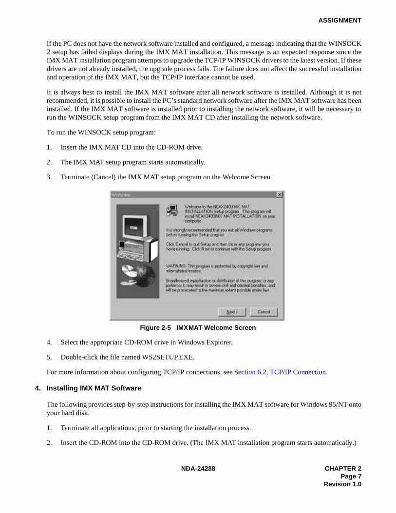
3. Terminate (Cancel) the IMX MAT setup program on the Welcome Screen.
Figure 2-5 IMX MAT Welcome Screen
4. Select the appropriate CD-ROM drive in Windows Explorer.
5. Double-click the file named WS2SETUP.EXE.
For more information about configuring TCP/IP connections, see Section 6.2, TCP/IP Connection.
4. Installing IMX MAT Software
The following provides step-by-step instructions for installing the IMX MAT software for Windows 95/NT ontoyour hard disk.
1. Terminate all applications, prior to starting the installation process.
2. Insert the CD-ROM into the CD-ROM drive. (The IMX MAT installation program starts automatically.)

CHAPTER 2 NDA-24288Page 8Revision 1.0
ASSIGNMENT
3. Enter your name and your company name on the User Information dialog box. Then, click Next.
Figure 2-6 IMX MAT User Information Dialog
4. Click Next on the Choose Destination Location dialog box to install the IMX MAT software in the defaultdirectory.
Note: If you wish to install the software in another directory, you can click Browse to display a dialog box thatallows you to select or create another directory.
Figure 2-7 Choose Location Destination Screen

NDA-24288 CHAPTER 2Page 9
Revision 1.0
ASSIGNMENT
5. The dialog box, shown in Figure 2-8 (information on WINSOCK setup), appears. Click OK.
Figure 2-8 Winsock 2 Setup Message Dialog Box
6. File copy starts automatically, while the displayed dialog boxes (See Figure 2-9) show the on-goingsituation.
Figure 2-9 IMX MAT Installation Screen
7. If the Setup Complete dialog box appears on the screen, the file copies have finished successfully. ClickFinish to complete the IMX MAT software installation and restart your computer.

CHAPTER 2 NDA-24288Page 10Revision 1.0
ASSIGNMENT
Note: You should always reboot your PC after installing the IMX MAT software. Any change made during theinstallation process does not take effect until the computer has been rebooted.
Figure 2-10 IMX MAT Setup Complete Dialog

NDA-24288 CHAPTER 2 Page 11
Revision 1.0
ASSIGNMENT
8. Review the settings you have chosen, and then click Next. The Winsock2 Setup message box displays.
Note: If you are installing IMX MAT on an NT 4.0 workstation, the Winsock2 Setup message box does not display.NT 4.0 does not require Winsock2 in order to run.
Figure 2-11 IMX MAT Installing Winsock2 Message Box
9. After Winsock2 is installed, the Winsock2 Setup dialog box displays. This is an informational messageonly. Click OK to continue installing the Data Access Objects (DAO) required to run IMX MAT.
Figure 2-12 Winsock2 Setup Message Dialog Box
10. Click OK. The DAO Welcome Screen displays.
Figure 2-13 DAO Welcome Screen

CHAPTER 2 NDA-24288Page 12Revision 1.0
ASSIGNMENT
11. Click Next. The Select Components dialog box displays.
Figure 2-14 DAO Select Components Screen
12. Uncheck the ODBCDirect box and click Next. The Select Components dialog box displays.
Note: If you do not uncheck the ODBCDirect box, error messages display once the DAO Setup programcompletes. IMX MAT will run properly even though these messages display.
Figure 2-15 Select Components Screen

NDA-24288 CHAPTER 2 Page 13
Revision 1.0
ASSIGNMENT
13. Click Next. The DAO Setup Screen displays.
Figure 2-16 DAO Setup Screen
14. After the DAO files are installed, the DAO Information message box displays. Click OK. The IMX MATInstallation screen displays.
Figure 2-17 DAO Information Message

CHAPTER 2 NDA-24288Page 14Revision 1.0
ASSIGNMENT
15. To run the IMX MAT software, click the IMX MAT icon on the desktop or select it from the Start/Program menu. The IMX MAT menu displays as shown in Figure 2-18.
Figure 2-18 IMX MAT Main Menu
16. To configure the PBX Alias, use the instructions in Section 6.2, TCP/IP Connection.
Note: Once you have configured the IMX MAT, you can use the Run Command line to enter task commands, oryou can select the command from the Command Folders. You can also perform IMX MAT tasks using eitherthe menu items, or the icons equivalent to the menu items.
Figure 2-19 IMX MAT Tool Bar
Command Folders
Tool Bar
Title Bar
Enter commands here
Status Bar
Menu Bar
Collect New Traffic
Scan New Alarms/Traffic
Collect New Alarms Abort Data Collection
View Scanning Log
Processes About
Log OnConfigure
Log Out
Log Manager

NDA-24288 CHAPTER 2Page 15
Revision 1.0
ASSIGNMENT
5. IMX MAT Commands
The IMX MAT’s operation is very similar to that of the NEAX2400 MS-DOS MAT, so you will find that manyof the key stroke operations have been carried over into IMX MAT. In addition, some standard MS Windowsoperations and key strokes are used. Use the following keys, or in some instances the mouse, to select or enterdata.
6. Configuring IMX MAT
This section explains the PBX Alias parameters you may configure using the PBX Administration dialogwindow. It also lists the default values of NEAX-IMX, the default PBX Alias delivered with the IMX MATsoftware. Prior to running the IMX MAT, you should either define a new PBX Alias, configure the default PBXto work with your system, or plan to use the NEAX-IMX default Alias. NEAX-IMX is ready for use once theIMX MAT software has been successfully installed. Table 2-3 lists the default values displayed in the PBXAdministration dialog box when you select NEAX-IMX as your PBX Alias.
Table 2-2 IMX MAT Commands
Enter and TabThis key has two functions:Writes the data to the IMX MAT memory and moves the cursor to the next text control on the dialog window.
Y (y) Enter Y in the WRT? text control to write the data to the IMX.
N (n) Enter N in the WRT? text control if you do not want to write the data to the IMX.
Delete Deletes the selected characters in a text control.
Backspace Deletes the character immediately to the left of the cursor in a text control.
Right Arrow Moves the cursor to the right in the text control.
Left Arrow Moves the cursor to the left in the text control.
Up Arrow Moves the cursor to the left in the text control.
Down Arrow Moves the cursor to the right in the text control.
Alt + F4 Closes the screen without saving the changes.
Shift + Enter and Shift + Tab Moves the cursor from a text control to the previous text control.
Ctrl + C Copies selected text to Windows Clipboard.
Ctrl + V Pastes Windows Clipboard contents at the current cursor position.
Ctrl + Home (When viewing the log file).
Moves the cursor to the top of the log data file.
Ctrl + End (When viewing the log file).
Moves the cursor to the bottom of the log data file.
Page Up(When viewing the log file).
Moves the log file up one page at a time.
Page Down (When viewing the log file).
Moves the log file down one page at a time.
? or F1 Displays the Help text.

CHAPTER 2 NDA-24288Page 16Revision 1.0
ASSIGNMENT
6.1 Serial/Direct Connection
The following steps explain how to configure the PBX Alias for a serial/direct connection using therecommended default data.
Note 1: The PBX Alias cannot have spaces in the name.
Note 2: You can use other data when configuring IMX MAT. However, it is recommended that you use the defaultdata as previously described when configuring a new PBX Alias.
Table 2-3 PBX Administration Default Values
PBX Alias NEAX-IMX
Connection Type Serial/Direct
FPC 1
Connect 120000
Response Timeout 120000
Pacing Timer 10000
Link Data Log Path blank
COM Port COM 1
Baud Rate 4800
Ignore CTR blank
Ignore DSR blank
Modem Name blank
Phone Number blank
Host Name blank
IP Address 172.16.253.0
TCP Port 60000
Inter-App Resource blank
NDA-24288 CHAPTER 2Page 17
Revision 1.0
ASSIGNMENT
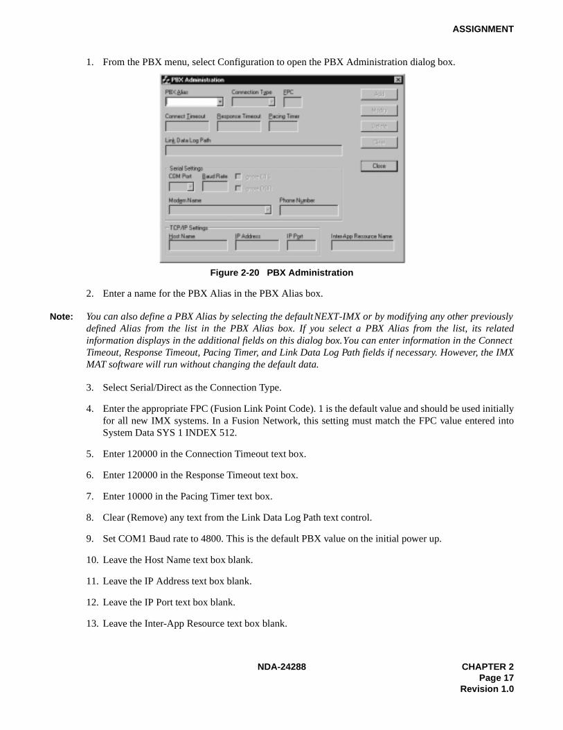
1. From the PBX menu, select Configuration to open the PBX Administration dialog box.
Figure 2-20 PBX Administration
2. Enter a name for the PBX Alias in the PBX Alias box.
Note: You can also define a PBX Alias by selecting the default NEXT-IMX or by modifying any other previouslydefined Alias from the list in the PBX Alias box. If you select a PBX Alias from the list, its relatedinformation displays in the additional fields on this dialog box. You can enter information in the ConnectTimeout, Response Timeout, Pacing Timer, and Link Data Log Path fields if necessary. However, the IMXMAT software will run without changing the default data.
3. Select Serial/Direct as the Connection Type.
4. Enter the appropriate FPC (Fusion Link Point Code). 1 is the default value and should be used initiallyfor all new IMX systems. In a Fusion Network, this setting must match the FPC value entered intoSystem Data SYS 1 INDEX 512.
5. Enter 120000 in the Connection Timeout text box.
6. Enter 120000 in the Response Timeout text box.
7. Enter 10000 in the Pacing Timer text box.
8. Clear (Remove) any text from the Link Data Log Path text control.
9. Set COM1 Baud rate to 4800. This is the default PBX value on the initial power up.
10. Leave the Host Name text box blank.
11. Leave the IP Address text box blank.
12. Leave the IP Port text box blank.
13. Leave the Inter-App Resource text box blank.

CHAPTER 2 NDA-24288Page 18Revision 1.0
ASSIGNMENT
14. Click Add to write the data.
15. Click Close.
Note: The PBX Administration dialog box changes adapting to EX-FCCS Network. Enter the Fusion GroupNumber (FUG) which the PBX to be logged-in belongs. “Connection Timeout”, “Response Timeout”, and“Pacing Timer” text box is not provided. Others are the same as previous one. The PBX dialog box is asshown below.
6.2 TCP/IP Connection
This section explains how to add or modify a PBX Alias in IMX MAT when it is connected to a PBX usinga TCP/IP connection through a Local Area Network (LAN).
Procedure Overview
1. Modify or add a PBX Alias.
2. Assign the network information in Windows.
3. Start the PBX system.
4. Log in to IMX MAT.
5. Assign the system data.
6. Set up the IMX MAT file operations for logging purposes.
Note: If your IMX is to reside on your existing LAN, you will need to obtain an available IP address from yourSystem Administrator before you configure the PBX Alias.
6.2.1 Modifying or Adding a PBX Alias
Note: The PBX Alias cannot have spaces in its name.
PBX Administration
AddAdd
ModifyModify
Clear
Close
PBX Alias Connection Type
FUG
COM Port Baud Rate
Modem Name Phone Number
Host Name IP Address TCP Port
TCP/IP Settings
Serial Settings
TCP/IP
bsc7200 10.41.207.207 60000
3
FPC
1 Delete
TCP-IP134

NDA-24288 CHAPTER 2Page 19
Revision 1.0
ASSIGNMENT
The following steps explain how to create a PBX Alias in IMX MAT.
1. From the PBX menu, select Configuration to open the PBX Administration dialog box.
2. Enter a name for the PBX Alias in the PBX Alias box.
Note: You can also define a PBX Alias by selecting the default NEXT-PBX or by modifying any other previouslydefined Alias from the list in the PBX Alias box. If you select a PBX Alias from the list, its relatedinformation displays in the additional fields on this dialog box. You can enter information in the ConnectTimeout, Response Timeout, Pacing Timer, and Link Data Log Path fields if necessary.
3. Select TCP/IP as the Connection Type.
4. Enter the appropriate FPC (Fusion Link Point Code). 1 is the default value and should be usedinitially for all new IMX systems. In a Fusion Network, this setting must follow the FPC valueentered into System Data SYS 1 INDEX 512.
5. Enter 120000 in the Connection Timeout text box.
6. Enter 120000 in the Response Timeout text box.
7. Enter 10000 in the Pacing Timer text box.
8. Leave the Link Data Log Path text box blank.
9. Enter the name of the host your system is using in the Host Name text box.
10. Enter 172.16.253.0 in the IP Address text box, or enter the IP Address supplied by your networkadministrator.
11. Enter 60000 in the IP Port text box.
12. Leave the Inter-App Resource text box blank.
13. Click Add to write the data.
14. Click Close.
15. Exit IMX MAT.
6.2.2 Assigning Network Information in Windows
Before you can run the IMX MAT software, you have to configure your network information in theWindows operating system. For information on configuring network information, see the Network CircuitCard Installation Manual or talk to your network administrator. After configuring the network information,you must restart the PC before you can log in to the IMX via the IMX MAT TCP/IP connection.
6.2.3 Starting the PBX System
Before you can log in to the PBX with your IMX MAT, you must start the PBX system. To start the PBXsystem, please see the NEAX2400 IMX Installation Manual.

CHAPTER 2 NDA-24288Page 20Revision 1.0
ASSIGNMENT
If you start up the system when the PBX is in DM Clear Restart mode, (the SENSE Switch is set to thedefault value “1”), you must verify that the IMX MAT baud rate is set to 4800 to ensure that the systemruns properly.
6.2.4 Logging in to IMX
After you have defined the PBX Alias in IMX MAT and the TCP/IP network connection in Windows,you are ready to Log in to IMX. The Login operation allows you to select the target IMX (node) withwhich you are attempting to communicate. Once you log in to IMX, you may assign or delete officedata, monitor the status of IMX, obtain System Messages through the IMX’s self-diagnosis function,and monitor the IMX traffic and Peg count data. Once you have completed the tasks you intended toperform, you should log out to prevent accidental changes to the data. The following steps explain howto log in to IMX.
Note: The maximum number of concurrent connections for the IMX is four.
1. From the IMX menu, select Log In.
2. Select the PBX you want to connect to by choosing the appropriate PBX Alias from the PBX Aliasbox.
Note: When the User ID data is programmed in AUIDN command after the required office data assignment, enterthe proper user name and password to login to the NCN.
3. Click Login.
4. A successful log in displays the successful Login message box.
Note: If the Login message box does not display, the login process has failed. If the login process fails, you shouldreopen the PBX Configuration dialog box and verify the PBX Alias configuration information. If the PBXAlias has been correctly configured, you should then test the physical connections to the PBX.
5. Click OK on the Login message box.
6.2.5 Assigning System Data
This section explains how to assign the IP Address and the SubNet Mask using the default IP Address172.16.253.0 and the default SubNet Mask 00.00.00.00. Both fields must be entered using theirhexadecimal equivalents.
Note: You may find it convenient to use the Calculator in the Windows Accessories to find the hexadecimalequivalent of the IP Address and the SubNet Mask. To convert from decimal to hexadecimal:
1. Select Calculator from the Accessories menu.
2. From the View menu, select Scientific.
3. Verify that Dec is selected.
4. Click the first three numbers of the IP Address on the Calculator key pad.
5. Select Hex.
6. The hexadecimal equivalent of the first three numbers of the IP Address display.

NDA-24288 CHAPTER 2Page 21
Revision 1.0
ASSIGNMENT
7. To perform additional decimal to hexadecimal conversions, make sure that Dec is selected and repeat the previous steps.
1. Type ASYDL in the Run Command text box.
2. Press Enter.
3. Type 1 in the SYS text box and press Enter.
4. Type 513 in the INDEX text box and press Enter.
5. Type 01H in the DATA text box and press Enter.
6. Type Y in the WRT? text box and press Enter.
7. Type 1 in the SYS text box and press Enter.
8. Type 514 in the INDEX text box and press Enter.
9. Type 01H in the DATA text box and press Enter.
10. Type Y in the WRT? text box and press Enter.
Note: The following steps explain how to assign the default IP Address.
11. Type 1 in the SYS text box and press Enter.
12. Type 515 in the INDEX text box and press Enter.
13. Type AC (hexadecimal equivalent of 172) in the DATA text box and press Enter.
14. Type Y in the WRT? text box and press Enter.
15. Type 1 in the SYS text box and press Enter.
16. Type 516 in the INDEX text box and press Enter.
17. Type 10 (hexadecimal equivalent of 16) in the DATA text box and press Enter.
18. Type Y in the WRT? text box and press Enter.
19. Type 1 in the SYS text box and press Enter.
20. Type 517 in the INDEX text box and press Enter.
21. Type FD (hexadecimal equivalent of 253) in the DATA text box and press Enter.
22. Type Y in the WRT? text box and press Enter.
23. Type 1 in the SYS text box and press Enter.
24. Type 518 in the INDEX text box and press Enter.
25. Type 0 (hexadecimal equivalent of 0) in the DATA text box and press Enter.

CHAPTER 2 NDA-24288Page 22Revision 1.0
ASSIGNMENT
26. Type Y in the WRT? text box and press Enter.
Note: The following steps explain how to assign the default SubNet Mask.
27. Type 1 in the SYS text box and press Enter.
28. Type 519 in the INDEX text box and press Enter.
29. Type FF in the DATA text box and press Enter.
30. Type Y in the WRT? text box and press Enter.
31. Type 1 in the SYS text box and press Enter.
32. Type 520 in the INDEX text box and press Enter.
33. Type FF in the DATA text box and press Enter.
34. Type Y in the WRT? text box and press Enter.
35. Type 1 in the SYS text box and press Enter.
36. Type 521 in the INDEX text box and press Enter.
37. Type 00 in the DATA text box and press Enter.
38. Type Y in the WRT? text box and press Enter.
39. Type 1 in the SYS text box and press Enter.
40. Type 522 in the INDEX text box and press Enter.
41. Type 00 in the DATA text box and press Enter.
42. Type Y in the WRT? text box and press Enter.
6.2.6 IMX MAT File Operations
The IMX MAT creates three types of files; Command Log files, Office Data Backup files, and List-upCommand Report data tables. Command Log files and List-up Command Report data tables are the onlyfiles a user needs to view. The Office Data Backup files are used strictly for saving and storing the PBXOffice Data.
6.2.6.1 Office Data Backup
It is always a good idea to routinely backup the data from the IMX memory to its internal hard disk.This data should then be saved from the IMX internal hard disk to the IMX MAT hard disk to ensurethat no data is lost.

NDA-24288 CHAPTER 2Page 23
Revision 1.0
ASSIGNMENT
Once the data has been saved from the IMX internal hard disk to the IMX MAT’s hard disk, you can usestandard operating functions to copy the saved data to floppy disks, zip drive disks, writable CD-ROMdrives, or any other type of external storage devices supported by the operating system. Doing a threephase backup (save) ensures the IMX Office data is safe and always available for restoration in case ofan IMX data memory loss, hard disk failure, or any other IMX-related catastrophic failure that requiresdata memory to be reloaded.
MEM_HDD and HDD_MAT are the two commands used for this three-phase backup. Once the data issaved to the IMX MAT, you can use Explorer to copy the appropriate files to the external mass storagedevice. To use Explorer, you must first determine where the IMX MAT copy of the numerous IMXOffice Data backup files resides.
As an example, assume the default drive and directory C:\IMXMAT were used when IMX MAT wasinstalled. Also assume that a PBX Alias was configured using the PBX Configuration dialog andassigned the PBX Alias name MY_PBX.
The IMX MAT always uses the same data directory structure when backing up data from the IMX. Itcreates a sub-directory under the IMX MAT home directory called DATA. Under the DATA directoryanother sub-directory using the PBX Alias name is created. In our example, this sub-directory is namedMY_PBX. Under the PBX Alias directory, another sub-directory is created. The name of this directoryis BACKUP. This directory structure always holds true. The only variables are the name of the IMXMAT home directory (default C:\IMXMAT) and the PBX Alias directory (in our example, MY_PBX).The complete directory structure for our example is as follows: C:\IMXMAT\DATA\MY_PBX\BACK-UP. The bottom sub-directory (BACKUP) contains all files that have been backed up from the IMX us-ing the HDD_MAT command.
To save these files to an external storage device, open Explorer, navigate to the appropriate backupdirectory (C:\IMXMAT\DATA\MY_PBX\BACKUP) and select ALL files and/or sub-directories andcopy them to your external device. You now have a safe backup of your IMX data memory that can bestored at an offsite location.
6.2.6.2 MEM_HDD
The following steps explain how to perform the backup and restore of PBX data to the PBX hard drive.
1. Enter MEM_HDD in the Run Command field on the IMX MAT main menu.
2. Press Enter.
3. The Backup and Restore dialog box displays.
4. Select Memory to Hard Disk in the Direction Select list.
5. Select Data Memory in the Data Type Selection list.
6. Select Auto Verify if you want to verify the data. This is an optional step.
7. Click Start.

CHAPTER 2 NDA-24288Page 24Revision 1.0
ASSIGNMENT
Once you have made the appropriate selections and clicked Start, you can scroll down and view the databeing saved in the Processing Status Log window. This section of the window is divided into the sectionsAction/Information, Direction, Data Type, and Time Stamp. The Action/Information column shows theAction being taken (saving or restoring), or the Information being saved. The Direction column showswhere the data is being saved or restored (in this case, memory to PBX Hard Disk). The Data Typecolumn shows the type of data you selected in the Data Type Selection list. The Time Stamp columnshows the day, month, year, hour, minute, and second the data was backed up or restored.
6.2.6.3 HDD_MAT
The following steps explain how to backup and restore PBX data to the IMX MAT hard disk.
1. Enter HDD_MAT in the Run Command field on the IMX MAT main menu.
2. Press Enter.
3. The Backup and Restore dialog box displays.
4. Select PBX Hard Disk to MAT in the Direction Select list.
5. Select Data Memory in the Data Type Selection list.
6. Select Auto Verify if you want to verify the data. This is an optional step.
7. Click Start.
Once you have made the appropriate selections and clicked Start, you can scroll down and view the databeing saved in the Processing Status Log window. This section of the window is divided into the sectionsAction/Information, Direction, Data Type, and Time Stamp. The Action/Information column shows theAction being taken (saving or restoring), or the Information being saved. The Direction column showswhere the data is being saved or restored (in this case PBX Hard Disk to IMX MAT). The Data Typecolumn shows the type of data you selected in the Data Type Selection list. The Time Stamp columnshows the day, month, year, hour, minute, and second the data was backed up or restored.
6.2.6.4 List-up Command Report Data Tables
These data files are tables assembled into an MS-Access Database format. The List-up commands createthe database and tables, populating them based on the information specified by the user. After thedatabase and tables are created, the report that automatically finds the correct data table and presents thestored data in a format suitable for viewing is launched. These data tables are cleared and repopulatedeach time the corresponding List-up command is run. These data tables require no user intervention.
6.2.6.5 Command Log Files
These files are simple text files that capture the results of the operations performed by every IMX MATcommand. These log files are functionally equivalent to the printed output log created by the old MS-DOS MAT. The only difference is that these text files can easily be viewed from within any IMX MATcommand at any time so it is not necessary to have a printer available. These log files are also easy toprint if a printer is available.

NDA-24288 CHAPTER 2Page 25
Revision 1.0
ASSIGNMENT
The log file maintains a history trail of operations and actions requested by the user. This log filecontinues to grow as each command is run and interactions with the IMX PBX are transacted. It doesn’tmatter whether the operation is a query, a change, a create, or a delete, the operation, its data, and itsstatus will always be logged (added to this log file).
The log file can be viewed any time by selecting it from the command’s view menu selection. Once thelog file viewing window is opened, the log file can be printed by selecting the print option from its Filemenu selection. Pressing the CTRL+END key combination will quickly take you to the end of the filewhere the latest changes have been appended.
Since the log file continually grows, you should regularly delete this file to conserve disk space. It alsomakes the file much more manageable and useful if it is not full of log entries that are no longer ofinterest. To delete and otherwise manage this file, the IMX MAT main menu contains menu selectionsthat will present a log file maintenance dialog. From here, the log file can be easily deleted.
6.2.6.6 Viewing the Log Data File
To view the log data file:
1. Display the Backup and Restore dialog box.
2. Select Operation Log from the View menu.
3. The log file FileViewer window displays.
6.2.6.7 Printing the Log Data File
To print the log data file:
1. Display the log file in the FileViewer window.
2. Select Print from the File menu.
6.2.6.8 Copying Data from the Log File
To copy data from the log file:
1. Display the log file in the FileViewer window.
2. Highlight the data you want to copy.
3. Select Copy from the Edit menu.
6.2.6.9 Pasting Log File Data
To paste log file data into another text editing tool:
1. Open the text editing tool you want to paste the data into.
2. Select paste from the Edit menu.
Note: You cannot paste copied data from one location to another in the log file. The log file is a Read-Only file.

CHAPTER 2 NDA-24288Page 26Revision 1.0
ASSIGNMENT
7. Data Assignment Flow Chart
This section shows the data assignment flow chart for IMX. The standard data assignment is illustrated on thefollowing flow charts.
• Local Node/Stand Alone
• Network Control Node
• Hotel Command
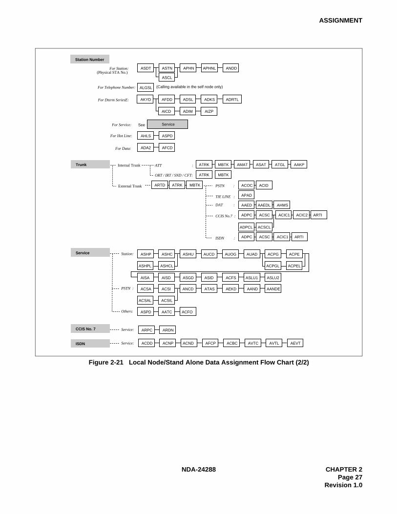
7.1 Local Node/Stand Alone
The following flow chart shows the data assignment for MAT when operated in a Local Node/Stand Aloneenvironment.
1. Local Node/Stand Alone
Figure 2-21 Local Node/Stand Alone Data Flow Assignment Flow Chart (1/2)
ATIMSystem Base ASYD ASYDL AUNT AIOC ASTD AOFC
AMND ARNP
ANND ASTP AOSP ARNP
ACMO ATCP AFRS AOPR AADC
AFRSL AOPRL AADCL
ASDC
AMND ARNP
AUNE AMND
ARSC ARRC ATDP AARP APCR AEFR
ATDPL AARPL
ASFC ACFR ATNR AABD
ANPD ASPA
ANPDL ASPAL
SRV
SRV
STN
SSC/SSCA, etc.
SSC
TELN
Sys1 Index 512 - 1535
Sys1 Index 0 - 511 , Sys2 Index 0 - 15 & Sys3 Index 0 - 31
Station Number
Service / Network
Telephone Number available in the Self node onlyTiming Start is available
Numbering Plan
Network Numbering
Restriction
2nd DT :
Sender
LCR / LCRS :
Uniform Numbering :
AUNEL
ALDN ASTP AISP ARACIncoming :
Trunk:
Service:
:
Operator Call / OGQ / Priority CallOGC(A)/LCR(S) Outgoing Call
ASTPL AOSPL
ASTPL AISPL
NDA-24288 CHAPTER 2Page 27
Revision 1.0
ASSIGNMENT
Figure 2-21 Local Node/Stand Alone Data Assignment Flow Chart (2/2)
Trunk ATRK MBTK AMAT ASAT ATGL AAKP
ATRK MBTK
Service
CCIS No. 7
ISDN
ASHP ASHC ASHU AUCD AUOG AUAD ACPG ACPE
AISA AISD ASGD ASID ACFS ASLU1 ASLU2
ACSA ACSI ANCD ATAS AEKD AAND AANDE
ASPD AATC ACFO
ARPC ARDN
ACDD ACNP ACND AFCP ACBC AVTC AVTL
ATT :Internal Trunk
External Trunk
ORT / IRT / SND / CFT:
ACOC
APAD
AAED
ADPC
ADPC ACSC
ACSC
AAEDL
ACIC1
ACIC1
ARTI
ACIC2 ARTI
ARTD ATRK MBTK PSTN :
TIE LINE :
DAT :
CCIS No.7 :
ISDN :
Station:
PSTN :
Others:
Service:
Service:
AHMS
ACID
AEVT
ADPCL ACSCL
ASDT ASTN APHN APHNL ANDD
ASCL
AKYD AFDD ADSL ADKS ADRTL
AIZPAICD ADIM
AHLS ASPD
ADA2 AFCD
ALGSL
Station Number
Service
For Station:(Physical STA No.)
For Telephone Number:
For Dterm SeriesE:
For Service:
For Hot Line:
For Data:
See
(Calling available in the self node only)
ASHPL ASHCL
ACSAL ACSIL
ACPGL ACPEL

CHAPTER 2 NDA-24288Page 28Revision 1.0
ASSIGNMENT
2. Network Control Node
Figure 2-22 Network Control Node Data Assignment Flow Chart (1/2)
ATIMSystem Base ASYD ASYDL ASYDN AUNT AIOC ASTD AOFC AFMU ALRTN
AMND ARNP
ANND ASTP AOSP ARNP
ASTPL AOSPL
ASTPN AOSPN
ACMO ATCP AFRS AOPR AADC ASDC
AFRSN AOPRN AADCN
AMND ARNP
AUNE
AUNEL
AMND
ALDN ASTP AISP ARAC
ARSC ARRC ATDP
ATDPN
AARP
ATDPL AARPL
AARPN
APCR AEFR
ASFC
ARSCN ARRCN
ACFR ATNR AABD
ANPD ASPA
ANPDL ASPAL
SRV
SRV
STN
SSC
SSC/SSCA, etc.
TELN
Sys1 Index 512 - 1535
Sys1 Index 0 - 511 , Sys2 Index 0 - 15 & Sys3 Index 0 - 31
Station Number
OGC(A)/LCR(S) Outgoing Call
Service / Network
Telephone Number available in theSelf node only
ANPDN ASPAN SRV
TELNTelephone Number available in allnodes of Fusion Network
Timing Start is available
Numbering Plan
Network Numbering
Restriction
2nd DT :
Sender :
LCR / LCRS :
Uniform Numbering :
Incoming :
Trunk:
Service:
Sys1 Index 0 - 1535
Fusion NetworkNumbering Plan:
Operator Call / OGQ / Priority Call
OGC(A)/LCR(S)
SSCA
Outgoing Call
Call Pickup Expand / UCD BUSY OUT
SSC Operator Call / Call Pickup Group / OGQ / Priority Call
ASTPL AISPL
ASTPN AISPN
AFRSL AOPRL AADCL
AUIDN

NDA-24288 CHAPTER 2Page 29
Revision 1.0
ASSIGNMENT
Figure 2-22 Network Control Data Assignment Flow Chart (2/2)
Trunk ATRK MBTK AMAT ASAT ATGL AAKP
ATRK MBTK
Service
CCIS No. 7
ISDN
ASHP ASHC ASHU AUCD AUOG AUAD ACPG ACPE
AISA AISD ASGD ASID ACFS ASLU1 ASLU2
ACSA ACSI ANCD ATAS AEKD AAND AANDE
ASPD AATC ACFO
ARPC ARDN
ACDD ACNP ACND AFCP ACBC AVTC AVTL
ACNPN ACNDN
AEVT
Internal Trunk ATT
External Trunk
ORT / IRT / SND / CFT:
ACOC
APAD
AAED
ADPC
ADPC ACSC
ACSC
AAEDL
ACIC1
ACIC1
ARTI
ACIC2
ARTD ATRK MBTK PSTN :
TIE LINE :
DAT :
CCIS No.7 :
ISDN :
Station:
PSTN :
Others:
Service:
Service:
ACRD ACTK MBCT AFCH AFRT AFPC ACAN ATDF
ATDFACRD ACTK MBCT AFPC ACAN
Fusion Link FCCH:
Ether:
AAEDN AHMS
ACID
APADN
ADPCL ACSCL
ARTIN
:
ASDT ASTN APHN APHNL APHNN ANDD
ASCL
AKYD AFDD ADSL ADKS ADRTN
AIZPAICD ADIM
AHLS ASPD
ADA2 AFCD
ALGSL
Station Number
Service
For Station:
(Physical STA No.)For Telephone Number:
For Dterm SeriesE:
ALGSN ATSTN
For Service:
For Hot Line:
For Data:
See
(Available in the self node only)
(Available in all nodes of the Fusion network.)
ASHPN ASHCN ASHUN AUCDN AUOGN AUADN ACPGN ACPEN
ASHPL ASHCL ACPGL ACPEL
ADPCL
CHAPTER 2 NDA-24288Page 30Revision 1.0
ASSIGNMENT
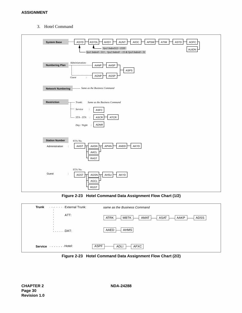
3. Hotel Command
Figure 2-23 Hotel Command Data Assignment Flow Chart (1/2)
Figure 2-23 Hotel Command Data Assignment Flow Chart (2/2)
ASYDSystem Base ASYDL AHSY AUNT AIOC APSW ATIM ASTD AOFC
AUIDN
AAST AASN APHN ANDD AKYD
RAST
AACL
Sys1 Index512 - 1535
Sys1 Index0 - 511 , Sys2 Index0 - 15 & Sys3 Index0 - 31
Numbering Plan
Network Numbering
Restriction
Station Number
Trunk: Same as the Business Command
Service :
STA - STA :
Day / Night :
AGST AGSN AHSU
RGST
AKYD
AGCL
AANP AASP
AGNP AGSP
ASPS
ASFC
ASCR ATCR
ADNR
Administration:
Guest :
Same as the Business Command
Administration :
Guest :
STA No.
STA No.
ATRK MBTK AMAT ASAT AAKP ADSS
AAED AHMS
ASPF ADLI AFXC
Trunk
Service
same as the Business CommandExternal Trunk:
ATT:
DAT:
Hotel:

NDA-24288 CHAPTER 3Page 31
Revision 1.0
CHAPTER 3 OFFICE DATA DESIGN SHEET
Office data design sheets are used to design the configuration and specification of IMX.
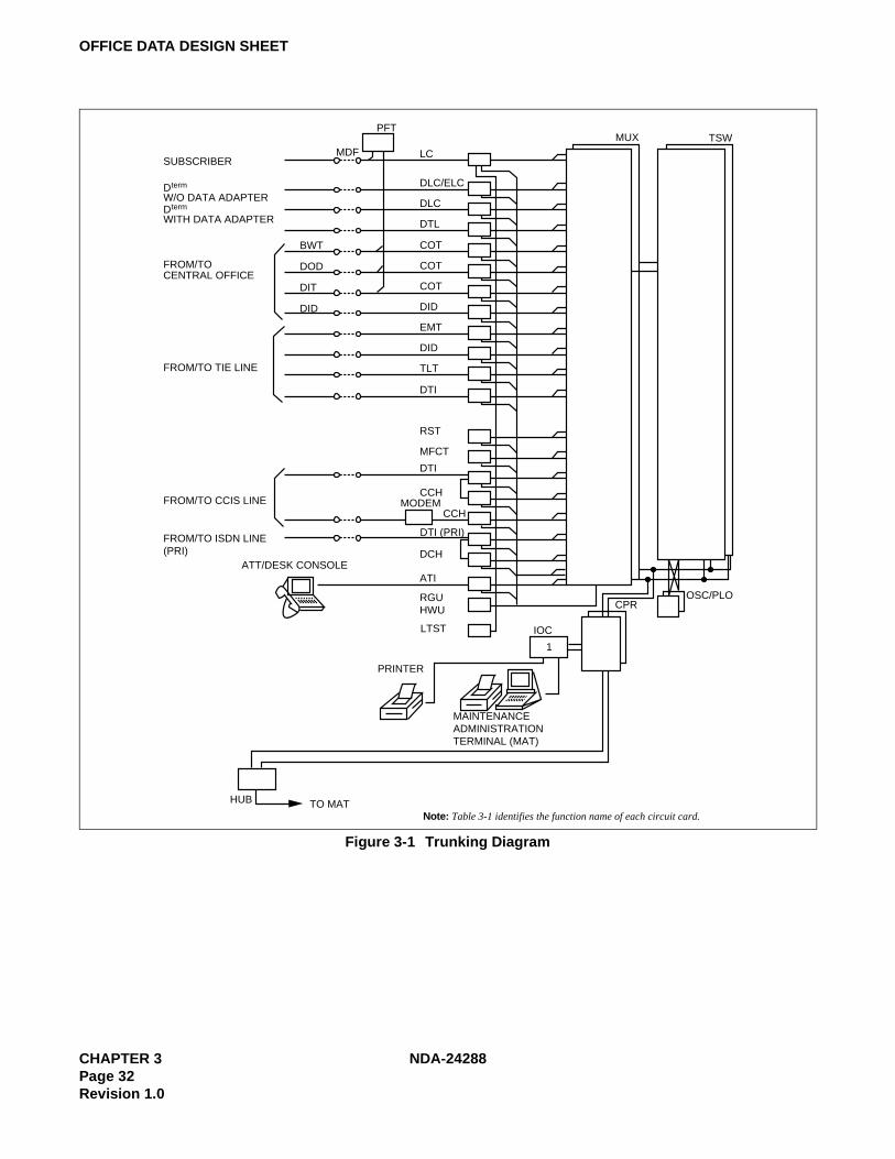
1. Trunking Diagram
The Trunking diagram shows the system configuration and the number of lines.
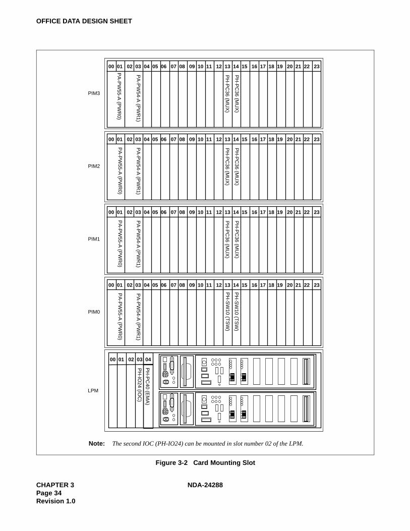
2. Bay Face Layout
The Bay Face layout shows the circuit card mounting slots.
3. Port Location Table
A Port Location table denotes the Line/Trunk circuit cards located in each Universal Slot of PIM.
4. Numbering Plan Table
Area Codes for various service features are determined according to the Dial Access Numbering Plan. There arethree types of Dial Access Numbers.
• Station Access Numbers
• Special Service Access Numbers
• Trunk Access Numbers
5. Restriction Tables
1. Service Feature Restriction Class
2. Trunk Restriction Class Table
3. Tenant Restriction Tables
CHAPTER 3 NDA-24288Page 32Revision 1.0
OFFICE DATA DESIGN SHEET
Figure 3-1 Trunking Diagram
PFT
LCMDF
DLC/ELC
DLC
DTL
COT
COT
COT
DID
EMT
DID
TLT
DTI
RST
MFCT
DTI
CCHMODEM
DTI (PRI)
DCH
ATI
RGUHWU
LTST
1
HUB TO MAT
CCH
PRINTER
ATT/DESK CONSOLE
IOC
CPROSC/PLO
MAINTENANCEADMINISTRATIONTERMINAL (MAT)
SUBSCRIBER
Dterm
W/O DATA ADAPTERDterm
WITH DATA ADAPTER
FROM/TOCENTRAL OFFICE
FROM/TO TIE LINE
FROM/TO CCIS LINE
FROM/TO ISDN LINE(PRI)
Note: Table 3-1 identifies the function name of each circuit card.
BWT
DOD
DIT
DID
MUX TSW

NDA-24288 CHAPTER 3Page 33
Revision 1.0
OFFICE DATA DESIGN SHEET
Table 3-1 identifies the function name of each circuit card used for the system.
Table 3-1 Circuit Card Function Name
SYMBOL DESCRIPTION
ATI Attendant Console Interface
BWT Bothway Trunk
CCH Common Channel Handler
CFT Conference Trunk
COT Central Office Trunk
CPR Central Processing Rack
DCH D Channel Handler
DID Direct Inward Dialing
DIT Direct-In Termination
DLC Digital Line Circuit
DOD Direct Outward Dialing
Dterm Digital Multi-Function Telephone
DTI Digital Interface
DTL Data Terminal Line Circuit
ELC Electronic Line Circuit
EMT Equipment & Maintenance Trunk
HWU Howler Tone Unit
IOC Input/Output Controller
LC Line Circuit
LTST Line Test
MDF Main Distribution Frame
MFCT Multi-frequency Trunk
MUX Multiplexer
ODT Office Data Trunk
OSC Oscillator for 1-IMG
PFT Power Failure Transfer
PLO Phase Lock Oscillator for 4-IMG/IMX-U
RGU Ringing Generator Unit
RST Register Sender Trunk
TLT Tie Line Trunk
TSW Time Switch
CHAPTER 3 NDA-24288Page 34Revision 1.0
OFFICE DATA DESIGN SHEET
Figure 3-2 Card Mounting Slot
00 01 02 03 04 05 06 07 08 09 10 11 12 13 14 15 16 17 18 19 20 21 22 23
PA
-PW
55-A (P
WR
0)
PA
-PW
54-A (P
WR
1)
PH
-PC
36 (MU
X)
PH
-PC
36 (MU
X)
PH
-SW
10 (TS
W)
PH
-SW
10 (TS
W)
PIM3
00 01 02 03 04 05 06 07 08 09 10 11 12 13 14 15 16 17 18 19 20 21 22 23
PA
-PW
55-A (P
WR
0)
PA
-PW
54-A (P
WR
1)
PH
-PC
36 (MU
X)
PH
-PC
36 (MU
X)
PIM2
00 01 02 03 04 05 06 07 08 09 10 11 12 13 14 15 16 17 18 19 20 21 22 23
PA
-PW
55-A (P
WR
0)
PA
-PW
54-A (P
WR
1)
PH
-PC
36 (MU
X)
PH
-PC
36 (MU
X)
PIM1
00 01 02 03 04 05 06 07 08 09 10 11 12 13 14 15 16 17 18 19 20 21 22 23P
A-P
W55-A
(PW
R0)
PA
-PW
54-A (P
WR
1)
PIM0
LPM
PH
-IO24 (IO
C)
PH
-PC
40 (EM
A)
00 01 02 03 04
Note: The second IOC (PH-IO24) can be mounted in slot number 02 of the LPM.

NDA-24288 CHAPTER 3Page 35
Revision 1.0
OFFICE DATA DESIGN SHEET
Figure 3-3 Card Mounting Slot for 4-IMG System (1/4)
00 01 02 03 04 05 06 07 08 09 10 11 12 13 14 15 16 17 18 19 20 21 22 23
PA
-PW
55-A(P
WR
0)
PA
-PW
54-A(P
WR
1)
PH
-PC
36(MU
X)
PH
-PC
36(MU
X)
PH
-PC
36(MU
X)
PH
-PC
36(MU
X)
PIM3
00 01 02 03 04 05 06 07 08 09 10 11 12 13 14 15 16 17 18 19 20 21 22 23
PA
-PW
55-A(P
WR
0)
PA
-PW
54-A(P
WR
1)
PH
-PC
36(MU
X)
PH
-PC
36(MU
X)
PIM2
00 01 02 03 04 05 06 07 08 09 10 11 12 13 14 15 16 17 18 19 20 21 22 23
PA
-PW
55-A(P
WR
0)
PA
-PW
54-A(P
WR
1)
PH
-PC
36(MU
X)
PH
-PC
36(MU
X)
PIM1
00 01 02 03 04 05 06 07 08 09 10 11 12 13 14 15 16 17 18 19 20 21 22 23
PA
-PW
55-A(P
WR
0)
PA
-PW
54-A(P
WR
1)
PIM0
BSCM
LPM
PH
-IO24(IO
C)
PH
-PC
40(EM
A)
00 01 02 03 04
(IOC
/MIS
C)
(MIS
C)
(MIS
C)
PIM
PIM
PIM
PIM
IMG3
Dummy
PIM
PIM
PIM
PIM
IMG2
Dummy
PIM
PIM
PIM
PIM
IMG1
TSWM
PIM
PIM
PIM
PIM
IMG0
LPM
BSCM
IMG0
4-IMG SYSTEM

CHAPTER 3 NDA-24288Page 36Revision 1.0
OFFICE DATA DESIGN SHEET
Figure 3-3 Card Mounting Slot for 4-IMG System (2/4)
00 01 02 03 04 05 06 07 08 09 10 11 12 13 14 15 16 17 18 19 20 21 22 23
PA
-PW
55-A(P
WR
0)
PA
-PW
54-A(P
WR
1)
PH
-PC
36(MU
X)
PH
-PC
36(MU
X)
PH
-PC
36(MU
X)
PH
-PC
36(MU
X)
PIM3
00 01 02 03 04 05 06 07 08 09 10 11 12 13 14 15 16 17 18 19 20 21 22 23
PA
-PW
55-A(P
WR
0)
PA
-PW
54-A(P
WR
1)
PH
-PC
36(MU
X)
PH
-PC
36(MU
X)
PIM2
00 01 02 03 04 05 06 07 08 09 10 11 12 13 14 15 16 17 18 19 20 21 22 23
PA
-PW
55-A(P
WR
0)
PA
-PW
54-A(P
WR
1)
PH
-PC
36(MU
X)
PH
-PC
36(MU
X)
PIM1
00 01 02 03 04 05 06 07 08 09 10 11 12 13 14 15 16 17 18 19 20 21 22 23
PA
-PW
55-A(P
WR
0)
PA
-PW
54-A(P
WR
1)
PIM0
00 01 02 03 04 05 06 07 08 09 10 11 12 13 14 15 16 17 18 19 20 21 22 23
PH
-PW
14(PW
RS
W)
PH
-PW
14(PW
RS
W)
PH
-PC
20(DLK
C0)
PH
-PC
20(DLK
C1)
PH
-GT
09(GT
0)
PH
-GT
09(GT
1)
PH
-SW
12(TS
W00)
PH
-SW
12(TS
W01)
PH
-SW
12(TS
W02)
PH
-SW
12(TS
W03)
PH
-SW
12(TS
W10)
PH
-SW
12(TS
W11)
PH
-SW
12(TS
W12)
PH
-SW
12(TS
W13)
PH
-CK
16/17(PLO
0)
PH
-CK
16/17(PLO
1)
(MIS
C)
(MIS
C)
(MIS
C)
(MIS
C)
(MIS
C)
(MIS
C)
TSWM
PIM
PIM
PIM
PIM
IMG3
Dummy
PIM
PIM
PIM
PIM
IMG2
Dummy
PIM
PIM
PIM
PIM
IMG1
TSWM
PIM
PIM
PIM
PIM
IMG0
LPM
BSCM
IMG1
4-IMG SYSTEM

NDA-24288 CHAPTER 3Page 37
Revision 1.0
OFFICE DATA DESIGN SHEET
Figure 3-3 Card Mounting Slot for 4-IMG System (3/4)
00 01 02 03 04 05 06 07 08 09 10 11 12 13 14 15 16 17 18 19 20 21 22 23
PA
-PW
55-A(P
WR
0)
PA
-PW
54-A(P
WR
1)
PH
-PC
36(MU
X)
PH
-PC
36(MU
X)
PH
-PC
36(MU
X)
PH
-PC
36(MU
X)
PIM3
00 01 02 03 04 05 06 07 08 09 10 11 12 13 14 15 16 17 18 19 20 21 22 23
PA
-PW
55-A(P
WR
0)
PA
-PW
54-A(P
WR
1)
PH
-PC
36(MU
X)
PH
-PC
36(MU
X)
PIM2
00 01 02 03 04 05 06 07 08 09 10 11 12 13 14 15 16 17 18 19 20 21 22 23
PA
-PW
55-A(P
WR
0)
PA
-PW
54-A(P
WR
1)
PH
-PC
36(MU
X)
PH
-PC
36(MU
X)
PIM1
00 01 02 03 04 05 06 07 08 09 10 11 12 13 14 15 16 17 18 19 20 21 22 23
PA
-PW
55-A(P
WR
0)
PA
-PW
54-A(P
WR
1)
PIM0
00 01 02 03 04 05 06 07 08 09 10 11 12 13 14 15 16 17 18 19 20 21 22 23
Dummy
PIM
PIM
PIM
PIM
IMG3
Dummy
PIM
PIM
PIM
PIM
IMG2
Dummy
PIM
PIM
PIM
PIM
IMG1
TSWM
PIM
PIM
PIM
PIM
IMG0
LPM
BSCM
IMG2
4-IMG SYSTEM

CHAPTER 3 NDA-24288Page 38Revision 1.0
OFFICE DATA DESIGN SHEET
Figure 3-3 Card Mounting Slot for 4-IMG System (4/4)
00 01 02 03 04 05 06 07 08 09 10 11 12 13 14 15 16 17 18 19 20 21 22 23
PA
-PW
55-A(P
WR
0)
PA
-PW
54-A(P
WR
1)
PH
-PC
36(MU
X)
PH
-PC
36(MU
X)
PH
-PC
36(MU
X)
PH
-PC
36(MU
X)
PIM3
00 01 02 03 04 05 06 07 08 09 10 11 12 13 14 15 16 17 18 19 20 21 22 23
PA
-PW
55-A(P
WR
0)
PA
-PW
54-A(P
WR
1)
PH
-PC
36(MU
X)
PH
-PC
36(MU
X)
PIM2
00 01 02 03 04 05 06 07 08 09 10 11 12 13 14 15 16 17 18 19 20 21 22 23
PA
-PW
55-A(P
WR
0)
PA
-PW
54-A(P
WR
1)
PH
-PC
36(MU
X)
PH
-PC
36(MU
X)
PIM1
00 01 02 03 04 05 06 07 08 09 10 11 12 13 14 15 16 17 18 19 20 21 22 23
PA
-PW
55-A(P
WR
0)
PA
-PW
54-A(P
WR
1)
PIM0
00 01 02 03 04 05 06 07 08 09 10 11 12 13 14 15 16 17 18 19 20 21 22 23
Dummy
PIM
PIM
PIM
PIM
IMG3
Dummy
PIM
PIM
PIM
PIM
IMG2
Dummy
PIM
PIM
PIM
PIM
IMG1
TSWM
PIM
PIM
PIM
PIM
IMG0
LPM
BSCM
IMG3
4-IMG SYSTEM

NDA-24288 CHAPTER 3Page 39
Revision 1.0
OFFICE DATA DESIGN SHEET
Figure 3-4 Card Mounting Slot for IMX-U System (1/5)
PWR
1 (PH-PW
14)
PWR
0 (PH-PW
14)
HSW
00 (PU-SW
01)(RES)
HSW
01 (PU-SW
01)
HSW
10 (PU-SW
01)
HSW
11 (PU-SW
01)(RES)
TSW00 (PU
-SW00)
TSW01 (PU
-SW00)
IOG
T0 (PH-G
T10)
IOG
T1 (PH-G
T10)
TSW02 (PU
-SW00)
TSW03 (PU
-SW00)
TSW10 (PU
-SW00)
TSW11 (PU
-SW00)
TSW12 (PU
-SW00)
TSW13 (PU
-SW00)
PLO0
(PH-C
K16-A/17-A)
PLO1
(PH-C
K16-A/17-A)
TOPU
ISWM
BASEU PWR HFD DSP
ISW
LPM
IOC
(PH
-IO24)
No
te 1
MM
C(P
H-M
22)
EM
A(P
H-P
C40)
LAN
I(PZ
-PC
19)LA
NI(P
Z-P
C19)
LAN
I(PZ
-PC
19)LA
NI(P
Z-P
C19)
PW
R(P
Z-PW
106)P
WR
(PZ-P
W106)
LAN
I(PZ
-PC
19)LA
NI(P
Z-P
C19)
ISA
GT(P
Z-GT13)
ISA
GT(P
Z-GT13)
I
O
00 01 02 03 04 05 06 07 08 09 10 11 12 13 14 15 16 17 18 19
00 01 02 03 04
PIM
PIM
PIM
PIM
IMG3
Dummy
PIM
PIM
PIM
PIM
IMG2
TSWM1
PIM
PIM
PIM
PIM
IMG1
TSWM0
PIM
PIM
PIM
PIM
IMG0
LPMISW
IMX-U SYSTEM
ISWM
ISW
LPM
LN × 4 (0~3)
I
O
PWR
1 (PH-PW
14)
PWR
0 (PH-PW
14)
HSW
00 (PU-SW
01)(RES)
HSW
01 (PU-SW
01)
HSW
10 (PU-SW
01)
HSW
11 (PU-SW
01)(RES)
TSW00 (PU
-SW00)
TSW01 (PU
-SW00)
IOG
T0 (PH-G
T10)
IOG
T1 (PH-G
T10)
TSW02 (PU
-SW00)
TSW03 (PU
-SW00)
TSW10 (PU
-SW00)
TSW11 (PU
-SW00)
TSW12 (PU
-SW00)
TSW13 (PU
-SW00)
PLO0
(PH-C
K16-A/17-A)
PLO1
(PH-C
K16-A/17-A)
TOPU
ISWM
BASEU PWR HFD DSP
ISW
LPM
IOC
(PH
-IO24)
No
te 1
MM
C(P
H-M
22)
EM
A(P
H-P
C40)
LAN
I(PZ
-PC
19)LA
NI(P
Z-P
C19)
LAN
I(PZ
-PC
19)LA
NI(P
Z-P
C19)
PW
R(P
Z-PW
106)P
WR
(PZ-P
W106)
LAN
I(PZ
-PC
19)LA
NI(P
Z-P
C19)
ISA
GT(P
Z-GT13)
ISA
GT(P
Z-GT13)
I
O
00 01 02 03 04 05 06 07 08 09 10 11 12 13 14 15 16 17 18 19
00 01 02 03 04
PIM
PIM
PIM
PIM
IMG3
Dummy
PIM
PIM
PIM
PIM
IMG2
TSWM1
PIM
PIM
PIM
PIM
IMG1
TSWM0
PIM
PIM
PIM
PIM
IMG0
LPMISW
IMX-U SYSTEM
ISWM
ISW
LPM
LN × 4 (0~3)
I
O
The 2nd IOC card (optional) may be mounted in the slot.
This system accommodates four LNs at the maximum.

CHAPTER 3 NDA-24288Page 40Revision 1.0
OFFICE DATA DESIGN SHEET
Figure 3-4 Card Mounting Slot for IMX-U System (2/5)
PA
-PW
55-A (P
WR
0)
PA
-PW
54-A (P
WR
1)
PH
-PC
36 (MU
X)
PH
-PC
36 (MU
X)
PH
-PC
36 (MU
X)
PH
-PC
36 (MU
X)
PIM3
PA
-PW
55-A (P
WR
0)
PA
-PW
54-A (P
WR
1)
PH
-PC
36 (MU
X)
PH
-PC
36 (MU
X)
PIM2
PA
-PW
55-A (P
WR
0)
PA
-PW
54-A (P
WR
1)
PH
-PC
36 (MU
X)
PH
-PC
36 (MU
X)
PIM1P
A-P
W55-A
(PW
R0)
PA
-PW
54-A (P
WR
1)
PIM0
BSCM
LPM
PH
-IO24(IO
C)
PH
-M22(M
MC
)
PH
-PC
40(EM
A)
(IOC
/MIS
C)
(MIS
C)
00 01 02 03 04 05 06 07 08 09 10 11 12 13 14 15 16 17 18 19 20 21 22 23
00 01 02 03 04 05 06 07 08 09 10 11 12 13 14 15 16 17 18 19 20 21 22 23
00 01 02 03 04 05 06 07 08 09 10 11 12 13 14 15 16 17 18 19 20 21 22 23
00 01 02 03 04 05 06 07 08 09 10 11 12 13 14 15 16 17 18 19 20 21 22 23
00 01 02 03 04
PIM
PIM
PIM
PIM
IMG3
Dummy
PIM
PIM
PIM
PIM
IMG2
TSWM1
PIM
PIM
PIM
PIM
IMG1
TSWM0
PIM
PIM
PIM
PIM
IMG0
LPMIMG0
IMX-U SYSTEM
ISWM
ISW
LPM
LN × 4 (0~3)

NDA-24288 CHAPTER 3Page 41
Revision 1.0
OFFICE DATA DESIGN SHEET
Figure 3-4 Card Mounting Slot for IMX-U System (3/5)
PA
-PW
55-A (P
WR
0)
PA
-PW
54-A (P
WR
1)
PH
-PC
36 (MU
X)
PH
-PC
36 (MU
X)
PH
-PC
36 (MU
X)
PH
-PC
36 (MU
X)
PIM3
PA
-PW
55-A (P
WR
0)
PA
-PW
54-A (P
WR
1)
PH
-PC
36 (MU
X)
PH
-PC
36 (MU
X)
PIM2
PA
-PW
55-A (P
WR
0)
PA
-PW
54-A (P
WR
1)
PH
-PC
36 (MU
X)
PH
-PC
36 (MU
X)
PIM1P
A-P
W55-A
(PW
R0)
PA
-PW
54-A (P
WR
1)
PIM0
PH
-PW
14 (PW
RS
W)
PH
-PW
14 (PW
RS
W)
PH
-PC
20 (DLK
C0)
PH
-PC
20 (DLK
C1)
PH
-GT
09 (GT
0)
PH
-GT
09 (GT
1)
PH
-SW
12 (TS
W00)
PH
-SW
12 (TS
W01)
PH
-SW
12 (TS
W02)
PH
-SW
12 (TS
W03)
PH
-SW
12 (TS
W10)
PH
-SW
12 (TS
W11)
PH
-SW
12 (TS
W12)
PH
-SW
12 (TS
W13)
PH
-CK
16-A/17-A
(PLO
1)
(MIS
C)
(MIS
C)
(MIS
C)
(MIS
C)
(MIS
C)
(MIS
C)
TSWM0
PIM
PIM
PIM
PIM
IMG3
Dummy
PIM
PIM
PIM
PIM
IMG2
TSWM1
PIM
PIM
PIM
PIM
IMG1
TSWM0
PIM
PIM
PIM
PIM
IMG0
LPMIMG1
IMX-U SYSTEM
ISWM
ISW
LPM
PH
-CK
16-A/17-A
(PLO
0)
21 22 23201918171615141312111009080706050403020100
21 22 23201918171615141312111009080706050403020100
21 22 23201918171615141312111009080706050403020100
21 22 23201918171615141312111009080706050403020100
21 22 23201918171615141312111009080706050403020100
LN × 4 (0~3)

CHAPTER 3 NDA-24288Page 42Revision 1.0
OFFICE DATA DESIGN SHEET
Figure 3-4 Card Mounting Slot for IMX-U System (4/5)
PA
-PW
55-A(P
WR
0)
PA
-PW
54-A(P
WR
1)
PH
-PC
36(MU
X)
PH
-PC
36(MU
X)
PH
-PC
36(MU
X)
PH
-PC
36(MU
X)
PIM3
PA
-PW
55-A(P
WR
0)
PA
-PW
54-A(P
WR
1)
PH
-PC
36(MU
X)
PH
-PC
36(MU
X)
PIM2
PA
-PW
55-A(P
WR
0)
PA
-PW
54-A(P
WR
1)
PH
-PC
36(MU
X)
PH
-PC
36(MU
X)
PIM1P
A-P
W55-A
(PW
R0)
PA
-PW
54-A(P
WR
1)
PIM0
PIM
PIM
PIM
PIM
IMG3
Dummy
PIM
PIM
PIM
PIM
IMG2
TSWM1
PIM
PIM
PIM
PIM
IMG1
TSWM0
PIM
PIM
PIM
PIM
IMG0
LPMIMG2
IMX-U SYSTEM
PH
-PW
14 (PW
RS
W0)
PH
-PW
14 (PW
RS
W1)
PH
-GT
09 (GT
0)
PH
-GT
09 (GT
1)
PH
-SW
12 (TS
W00)
PH
-SW
12 (TS
W01)
PH
-SW
12 (TS
W02)
PH
-SW
12 (TS
W03)
PH
-SW
12 (TS
W10)
PH
-SW
12 (TS
W11)
PH
-SW
12 (TS
W12)
PH
-SW
12 (TS
W13)
PH
-CK
18 (CLK
0)
PH
-CK
18 (CLK
1)
TSWM1
ISWM
ISW
LPM
21 22 23201918171615141312111009080706050403020100
21 22 23201918171615141312111009080706050403020100
21 22 23201918171615141312111009080706050403020100
21 22 23201918171615141312111009080706050403020100
21 22 23201918171615141312111009080706050403020100
LN × 4 (0~3)

NDA-24288 CHAPTER 3Page 43
Revision 1.0
OFFICE DATA DESIGN SHEET
Figure 3-4 Card Mounting Slot for IMX-U System (5/5)
PA
-PW
55-A(P
WR
0)
PA
-PW
54-A(P
WR
1)
PH
-PC
36(MU
X)
PH
-PC
36(MU
X)
PH
-PC
36(MU
X)
PH
-PC
36(MU
X)
PIM3
PA
-PW
55-A(P
WR
0)
PA
-PW
54-A(P
WR
1)
PH
-PC
36(MU
X)
PH
-PC
36(MU
X)
PIM2
PA
-PW
55-A(P
WR
0)
PA
-PW
54-A(P
WR
1)
PH
-PC
36(MU
X)
PH
-PC
36(MU
X)
PIM1P
A-P
W55-A
(PW
R0)
PA
-PW
54-A(P
WR
1)
PIM0
Dummy
PIM
PIM
PIM
PIM
IMG3
Dummy
PIM
PIM
PIM
PIM
IMG2
TSWM1
PIM
PIM
PIM
PIM
IMG1
TSWM0
PIM
PIM
PIM
PIM
IMG0
LPMIMG3
IMX-U SYSTEM
ISWM
ISW
LPM
21 22 23201918171615141312111009080706050403020100
21 22 23201918171615141312111009080706050403020100
21 22 23201918171615141312111009080706050403020100
21 22 23201918171615141312111009080706050403020100
LN × 4 (0~3)

CHAPTER 3 NDA-24288Page 44Revision 1.0
OFFICE DATA DESIGN SHEET
Figure 3-5 Port Location Table (1/2)
09 11 13 15 17 19 21 23
7
6
5
4
3
2
1
0
LVG 01 03 05 31 09 11 13 15 17 19 21 23
7
6
5
4
3
2
1
0
LVG 00 02 04 28 30 10 12 14 16 18 20 22
PIM
SLOT
CARD
Access Code
CIC for CCIS/DC for C.O
Tenant Number (TN)
Trunk Number (TRC)
Route Number (RT)
Destination
Station Number (STN)
User Name / Telephone Number
Service Class (SFC)
Restriction Class (RSC)
Telephone Class (TEC)
Tenant Number (TN)
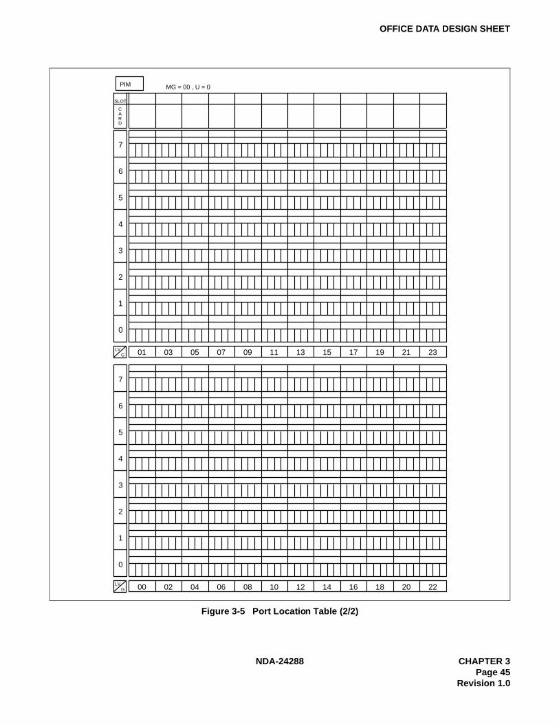
NDA-24288 CHAPTER 3Page 45
Revision 1.0
OFFICE DATA DESIGN SHEET
Figure 3-5 Port Location Table (2/2)
7
6
5
4
3
2
1
0
01 03 05 07 09 11 13 15 17 19 21 23
7
6
5
4
3
2
1
0
LVG 00 02 04 06 08 10 12 14 16 18 20 22
PIM MG = 00 , U = 0
SLOT
CARD
LVG
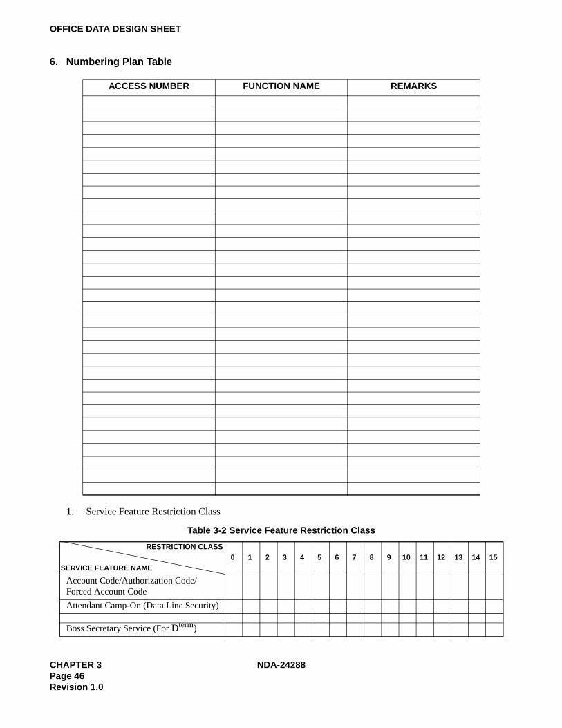
CHAPTER 3 NDA-24288Page 46Revision 1.0
OFFICE DATA DESIGN SHEET
6. Numbering Plan Table
1. Service Feature Restriction Class
ACCESS NUMBER FUNCTION NAME REMARKS
Table 3-2 Service Feature Restriction Class
0 1 2 3 4 5 6 7 8 9 10 11 12 13 14 15
Account Code/Authorization Code/Forced Account Code
Attendant Camp-On (Data Line Security)
Boss Secretary Service (For Dterm)
RESTRICTION CLASS
SERVICE FEATURE NAME

NDA-24288 CHAPTER 3Page 47
Revision 1.0
OFFICE DATA DESIGN SHEET
Call Back Call
Forwarding-All Calls
Call Forwarding-Busy Line
Call Forwarding-Don’t Answer
Call Hold
Call Park Access & Answer
Call Park Called
Call Pickup-Direct
Call Waiting-Originating/Terminating (Called)
Call Waiting-Originating/Terminating (Calling)
Data Privacy on Demand; Cancel
Data Privacy on Demand; Set
Distinctive Ringing (FAX, OPX)
Executive Right of Way (Called Party)
Executive Right of Way (Calling Party)
Faulty Trunk Report
Intercom Group Individual Trunk Access
Line Circuit Reverse Relay Control(Station)
Line Load Control
Meet-Me Paging
Message Reminder (Dterm)
Message Waiting Lamp Setting fromATTCON or Station (Called Party)
Message Waiting Lamp Setting fromStation (Calling Party)
Off-Hook Alarm
Off-Hook Queuing
OG Queuing Override
OG Trunk Queuing
OG Trunk Queuing-Deluxe
Periodic Time Indication Time
Table 3-2 Service Feature Restriction Class (Continued)
0 1 2 3 4 5 6 7 8 9 10 11 12 13 14 15RESTRICTION CLASS
SERVICE FEATURE NAME

CHAPTER 3 NDA-24288Page 48Revision 1.0
OFFICE DATA DESIGN SHEET
2. Trunk Restriction Class Table
Priority Call 1
Priority Call 2
Priority Call 3
Priority Paging
Radio Paging Answer
Special Common Battery Telephone
Special Calling-Station/Group
Speed Calling-System
Station Message Detail System(SMDS) for Station to Station Calls
TAS
Voice Call
DESTINATION [ACCESS NUMBER]
RT No.
No. OF TRK
ROUTE RESTRICTION
INDEX
RESTRICTION CLASS NUMBER
0 1 2 3 4 5 6 7 8 9 10 11 12 13 14 15
IC Via ATT
IC By DID
OG Via ATT
ACC: OG By DOD
IC Via ATT
IC By DID
OG Via ATT
ACC: OG By DOD
IC Via ATT
IC By DID
OG Via ATT
ACC: OG By DOD
IC Via ATT
IC By DID
OG Via ATT
ACC: OG By DOD
IC Via ATT
IC By DID
OG Via ATT
ACC: OG By DOD
Table 3-2 Service Feature Restriction Class (Continued)
0 1 2 3 4 5 6 7 8 9 10 11 12 13 14 15RESTRICTION CLASS
SERVICE FEATURE NAME

NDA-24288 CHAPTER 3Page 49
Revision 1.0
OFFICE DATA DESIGN SHEET
3. Tenant Restriction Table
IC Via ATT
IC By DID
OG Via ATT
ACC: OG By DOD
IC Via ATT
IC By DID
OG Via ATT
ACC: OG By DOD
IC Via ATT
IC By DID
OG Via ATT
ACC: OG By DOD
IC Via ATT
IC By DID
OG Via ATT
ACC: OG By DOD
DESTINATION [ACCESS NUMBER]
RT No.
No. OF TRK
ROUTE RESTRICTION
INDEX
RESTRICTION CLASS NUMBER
0 1 2 3 4 5 6 7 8 9 10 11 12 13 14 15
123456789
101112131415
1 2 3 4 5 6 7 8 9 10 11 12 13 14 15
(TMTN)
(OGTN)
Station-to-Station Call
123456789
101112131415
1 2 3 4 5 6 7 8 9 10 11 12 13 14 15
(TMTN)
(OGTN)
Assignment of C.F.-All Calls from a Station
123456789
101112131415
1 2 3 4 5 6 7 8 9 10 11 12 13 14 15
(TMTN)
(OGTN)
123456789
101112131415
1 2 3 4 5 6 7 8 9 10 11 12 13 14 15
(TMTN)
(OGTN)
Incoming Connection toNight Attendant Console
Assignment of C.F.-All Calls from an Attendant Console

CHAPTER 3 NDA-24288Page 50Revision 1.0
OFFICE DATA DESIGN SHEET
123456789
101112131415
1 2 3 4 5 6 7 8 9 10 11 12 13 14 15
(TMTN)
(OGTN)
Incoming Connection to Attendant Console
123456789
101112131415
1 2 3 4 5 6 7 8 9 10 11 12 13 14 15
(TMTN)
(OGTN)
Day and Night Mode Change
123456789
101112131415
1 2 3 4 5 6 7 8 9 10 11 12 13 14 15
(TMTN)
(OGTN)
Connection of Incoming Trunk Call to Station
NDA-24288 CHAPTER 4Page 51
Revision 1.0
CHAPTER 4 HOTEL SYSTEM COMMAND DESCRIPTIONS AND DATA SHEETS
This chapter explains the specific commands for the Hotel System of the NEAX2400 IMX. A data sheet isprovided for each command. The commands are listed in standard programming order as illustrated in the DataAssignment Flow Chart.
If you know a command name, and you want quick access to the command’s description, you can refer to theHotel Command List in Alphabetic Order at the beginning of this manual to find the page on which thecommand is described.
The data sheet for each command follows the command description.

CHAPTER 4 NDA-24288Page 52Revision 1.0
AHSY
AHSY: Assignment of Hotel System Parameter
1. General
This command assigns and displays the Hotel System parameters.
2. Precautions
1. This command is used for the Hotel Application only.
2. Data for Hotel System parameters should be entered using hexadecimal numbers.

NDA-24288 CHAPTER 4Page 53
Revision 1.0
AHSY
3. Data Entry Instructions
Define each bit's correspondingdata by referring to the HotelSYSTEM DATA CONTENTS
DATA(DATA)00-FF(Hex)
INDEX(INDEX)
0-511
BIT CORRE-SPONDING
DATA
DATA0/1
BIT
HOTEL SYSTEM DATA CONTENTS
DATADATA BIT
BIT
DATA
Hex
1 b0
b1
b2
b3
b4
b5
b6
b7
1
0
0
0
0
0
0
n
n+1 FF
03
1
1
0
0
0
0
0
0
b0
b1
b2 Not used
Not used
Not used
Not used
Not used
Not used
Number of zzz
b3
b4
b5
b6
b7
xxx service 0/1=Not provided/To provide
yyy service 0/1=Not provided/To provide
Convert from Binary DATA
to Hexadecimal, and enter the
Hex. value at DATA text box.
0 0 0 0 0 0 1 1
b7 b6 b5 b4 b3 b2 b1 b0
0 3

CHAPTER 4 NDA-24288Page 54Revision 1.0
AHSY
4. Data Sheet
INDEX(0 – 1023)
DATA(DATA)00 – FF(Hex)
BITCORRESPONDING
DATA CONTENTS
DATA0/1
BIT
0 00 Not used
1For displaying the kind of language information, assign the data by 2 or 4 characters of ASCII code (INDEXes 1 through 32).
Note: Number of characters (4 characters/2 characters) of languageinformation display is determined by the data assigned to INDEX100, b2.
When data is not assigned, the kind of language information displays as follows:Language = 0 : No displayLanguage = 1 : JPNLanguage = 2 : ENGLanguage = 3 : GERLanguage = 4 : FRLanguage = 5 : SPLanguage = 6 : CHINLanguage = 7 : RUSS
2
3
4
5
6
7
8
9
10
11
12
13
14
15
16
17
18
19
20
21
22
23
24
25
26
27
28
29
30
31
32
ASCII Code Table
Hex Char Hex Char Hex Char Hex Char Hex Char Hex Char
20 30 0 40 @ 50 P 60 ‘ 70 p21 ! 31 1 41 A 51 Q 61 a 71 q22 !! 32 2 42 B 52 R 62 b 72 r23 # 33 3 43 C 53 S 63 c 73 s24 $ 34 4 44 D 54 T 64 d 74 t25 % 35 5 45 E 55 U 65 e 75 u26 & 36 6 46 F 56 V 66 f 76 v27 ‘ 37 7 47 G 57 W 67 g 77 w28 ( 38 8 48 H 58 X 68 h 78 x29 ) 39 9 49 I 59 Y 69 i 79 y2A * 3A : 4A J 5A Z 6A j 7A z2B + 3B ; 4B K 5B [ 6B k 7B2C , 3C < 4C L 5C 6C l 7C2D - 3D = 4D M 5D ] 6D m 7D2E . 3E > 4E N 5E 6E n 7E2F / 3F ? 4F O 5F _ 6F o 7F

NDA-24288 CHAPTER 4Page 55
Revision 1.0
AHSY
When displaying the language information by 4 characters (INDEX 100, b2 = 0)
When displaying the language information by 2 characters (INDEX 100, b2 = 1)
Language = 0: Index 1~4(Assign 00 Hex)
Language = 1: Index 5~8Language = 2: Index 9~12Language = 3: Index 13~16Language = 4: Index 17~20Language = 5: Index 21~24Language = 6: Index 25~28Language = 7: Index 29~32
Language = 0: Index 1 and 2(Assign 00 Hex)
Language = 1: Index 3 and 4Language = 2: Index 5 and 6Language = 3: Index 7 and 8Language = 4: Index 9 and 10Language = 5: Index 11 and 12Language = 6: Index 13 and 14Language = 7: Index 15 and 16Language = 8: Index 17 and 18Language = 9: Index 19 and 20Language = 10: Index 21 and 22Language = 11: Index 23 and 24Language = 12: Index 25 and 26Language = 13: Index 27 and 28Language = 14: Index 29 and 30Language = 15: Index 31 and 32
INDEX(0 – 1023)
DATA(DATA)00 – FF(Hex)
BITCORRESPONDING
DATA CONTENTS
DATA0/1
BIT
33
For information display at the time of Checkout, assign the related data by two characters of ASCII code.
Checkout : Index 33–34Cleaning : Index 35–36Inspection : Index 37–38Inspection has been completed : Index 39–40Out of Order : Index 41–42
34
35
36
37
38
39
40
41
42
43 00 Not used
44 00 Not used
45 00 Not used
46 00 Not used
47 00 Not used
48 00 Not used

CHAPTER 4 NDA-24288Page 56Revision 1.0
AHSY
49For information display at the time of Stay, assign the related data by two characters of ASCII code.
Stay : Index 49–50Stay Cleaning : Index 51–52Stay Inspection : Index 53–54
50
51
52
53
54
55 00 Not used
56 00 Not used
57For information display at the time of Departure Day, assign the related data by two characters of ASCII code.
Departure Day – Index 57–58Dep. Day-Cleaning – Index 59–60Dep. Day-Inspection – Index 61–62
58
59
60
61
62
63 00 Not used
64 00 Not used
65 00 Not used
66 00 Not used
67 00 Not used
68 00 Not used
69 00 Not used
70 00 Not used
71 00 Not used
72 00 Not used
73 00 Not used
74 00 Not used
75 00 Not used
76 00 Not used
INDEX(0 – 1023)
DATA(DATA)00 – FF(Hex)
BITCORRESPONDING
DATA CONTENTS
DATA0/1
BIT

NDA-24288 CHAPTER 4Page 57
Revision 1.0
AHSY
Note: Use b7 to allow the Function Key Feature. 0/1 = Not Available/Available. Use b6 through b0 to assign the KeyNumber. These assignments are valid when AHSY, Index 109, b6 = 1.
77
b0
LCD Indication of Wake Up time on the Dterm
0/1 = –/Remains lit
b1
LCD Indication of “DND” (Do Not Disturb) on the Dterm
0/1 = –/Remains lit
b2
LCD Indication of “RC” (Room Cut Off) on the Dterm
0/1 = –/Remains lit
b3
LCD Indication of 2nd Wake Up time on the Dterm
0/1 = –/Remains lit
b4~b7 Not used
78 00 Not used
79 00 Not used
80 Note b7 Wakeup Set
81 Note b7 Wakeup Reset
82 Note b7 Do Not Disturb Set
83 Note b7 Do Not Disturb Reset
INDEX(0 – 1023)
DATA(DATA)00 – FF(Hex)
BITCORRESPONDING
DATA CONTENTS
DATA0/1
BIT
84 Note b7 Room Cut off Set
85 Note b7 Room Cut off Reset
86 Note b7 Message Waiting Set
87 Note b7 Message Waiting Reset
88 Note b7 Check In
89 Note b7 Checkout
90 Note b7 Status
91 Note b7 Audit
92 Note b7 (Reserved)
93 Note b7 (Reserved)
94 Note b7 (Reserved)
95 Note b7 (Reserved)
INDEX(0 – 1023)
DATA(DATA)00 – FF(Hex)
BITCORRESPONDING
DATA CONTENTS
DATA0/1
BIT

CHAPTER 4 NDA-24288Page 58Revision 1.0
AHSY
Note: Use b7 to allow the Function Key Feature. 0/1 = Not Available/Available. Use b6 through b0 to assign the KeyNumber. These assignments are valid when AHSY, Index 109, b6 = 1.
96 Note b7 (Reserved)
97 Note b7 ENT
98 Note b7 CE
99 Note b7 END
INDEX(0 – 1023)
DATA(DATA)00 – FF(Hex)
BITCORRESPONDING
DATA CONTENTS
DATA0/1
BIT
100
b0
Number of times of Wake-Up Answer Retry.b1 b0
0 0 = No Answer Retry 0 times0 1 = No Answer Retry 1 time1 0 = No Answer Retry 2 times1 1 = No Answer Retry 3 times
b1
b2
Number of characters in language information display
0/1 = 4 characters/2 characters
b3
Restriction for hooking when a guest station has originated an outgoing C.O. line call.
0/1 = Not Required/Required
0 b4 Not used0 b5
b6
Overtime Call when a station user places a C.O. trunk call
0 = Admin. & Gst. go to Attendant Console1 = Gst. only goes to Attendant Console
b7
Key that means the P.M. in a case where Wake-Up time is set by the 12-hour system. (For Automatic Wake-Up Service)
0/1 = *Key/#Key
INDEX(0 – 1023)
DATA(DATA)00 – FF(Hex)
BITCORRESPONDING
DATA CONTENTS
DATA0/1
BIT

NDA-24288 CHAPTER 4Page 59
Revision 1.0
AHSY
101
b0 LANG = 0Incoming calls terminating to the Attendant Console from a guest station of the language category correspond to each bit.
The key to which the call terminates:0: GST1 Key1: GST2 Key
Language data is assigned to each guest station based on information from the PMS.
b1 LANG = 1
b2 LANG = 2
b3 LANG = 3
b4 LANG = 4
b5 LANG = 5
b6 LANG = 6
b7 LANG = 7
102
b0 LANG = 8 When an incoming call terminates to the Attendant Console from a guest station of the language category corresponding to each bit. The key to which the call terminates:
0: GST1 Key1: GST2 Key
Language data is assigned on each guest station basis as per the information from the PMS.
b1 LANG = 9
b2 LANG = 10
b3 LANG = 11
b4 LANG = 12
b5 LANG = 13
b6 LANG = 14
b7 LANG = 15
103Tenant Number of Paging Console(2~63/255 = 02~FF Hex)
104
b0
Miscellaneous Timer Counter (MTC) is to be assigned a value from 0 Hex to F Hex (0–15).
Paging Console Auto-matic Recall Timer:Timer Value Setting is MTC × TC sec.
Note: When this datais 00 Hex,ROM data isautomaticallyset to 3 min.
b1
b2
b3
b4 Timer Class (TC) is to be assigned one of the fol-lowing values:b6 b5 b4 b6 b5 b4
0 0 0 = – 1 0 0 = 64 sec.0 0 1 = 8 sec. 1 0 1 = –
0 1 0 = 16 sec. 1 1 0 = –
0 1 1 = 32 sec. 1 1 1 = –
b5
b6
b7
Paging Console Automatic Recall Timer value
0/1 = Ineffective/Effective
INDEX(0 – 1023)
DATA(DATA)00 – FF(Hex)
BITCORRESPONDING
DATA CONTENTS
DATA0/1
BIT

CHAPTER 4 NDA-24288Page 60Revision 1.0
AHSY
— AHSY INDEX 105 b7 —
Display Pattern A: b7 = 0 (For Interface Type Model 60/90/120)
Display Pattern B: b7 = 1 (For Interface Type Model 90/120)
105
0 b0 Not used0 b1
b2
Maid Dial service from Attendant Console
0/1 = Not Required/Required
0 b3
Office Name Display on Attendant Console assigned at AOFC command or ASYD command SYS 1, INDEX 96 through 115.
0/1 = In/Out of Service
b4
Pattern of Wake-Up Time Indication on the Attendant Console
0/1 = 24-Hour/12-Hour System
0 b5 Not used0 b6
b7
Guest Name Display on Attendant Console
0/1 = Interface Type Model 60, 90, 120/Model 90, 120
106 00 Not used
INDEX(0 – 1023)
DATA(DATA)00 – FF(Hex)
BITCORRESPONDING
DATA CONTENTS
DATA0/1
BIT
5 6 7 8 9 10 11 12 13 14 15 16 17 18 19 201 2 3 4
Guest Name Display Area (15 characters)
SPA
CE
SPA
CE
SPA
CEWake-Up Time
(4 characters)Language
(4 characters)Room Class
(3 characters)
Room Status(4 characters)
Station Number(Max. 6 digits)
5 6 7 8 9 10 11 12 13 14 15 16 17 18 19 201 2 3 4
Guest Name Display Area (16 characters)
SPA
CE
SPA
CEStation Number
(Max. 6 digits) Wake-Up Time Option Data (8 characters)
Room Status(3 characters)

NDA-24288 CHAPTER 4Page 61
Revision 1.0
AHSY
Display Pattern when “0” is assigned in b7
Note: b7 = 0: When PMS Model 60/90/120.
b7 = 1: When PMS Model 90, 120.
INDEX(0 – 1023)
DATA(DATA)00 – FF(Hex)
BITCORRESPONDING
DATA CONTENTS
DATA0/1
BIT
107
b0 Display Pattern for terminationb1 b0 b1 b0
0 0 = Pattern 1 1 00 1 = Pattern 2 1 1 Designation of
Display Pattern of Dterm (Special Administration Station) for Guest Name Display Dterm service.
b1
b2 Display Pattern for call originationb3 b2 b3 b2
0 0 0 1 = Pattern 51 1 1 0 = Pattern 6
b3
b4 Display Pattern for answering a call, or the caller an-swers a call originated by Dterm.b5 b4 b5 b4
0 0 0 1 = Pattern 80 1 1 1 = Pattern 9
b5
b6 Tenant of Dterm that displays Guest Name
0/1 = All Tenants/Only Tenant No. 1
b7 Guest Name Display on Dterm
1: Display pattern is determined as per the contents of b0 through b6 Option A and B
0: VIP and LANG Note
= Pattern 3
= Pattern 4
= Pattern 7
× ×
GUEST NAME
(a)
× ×
GUEST NAME
(b) × × ×× ×
STATION NUMBER
Guest Name is displayed first:(pattern (a)) and after a predetermined timing the pattern is automatically changed to pattern (b).
ROOMSTATUS

CHAPTER 4 NDA-24288Page 62Revision 1.0
AHSY
INDEX(0 – 1023)
DATA(DATA)00 – FF(Hex)
BITCORRESPONDING
DATA CONTENTS
DATA0/1
BIT
108
b0 Display Change Timer for the Display Pattern of the Answering station (assigned INDEX 107 b4 and b5)
0 Hex: Standard Timer Value = 8 to 10 sec.1 Hex ~ F Hex: Timer Value = (1–15) × 1 sec.
b1
b2
b3
b4 Display Change Timer for the Display Pattern of the Originating station(assigned INDEX 107 b3 and b2)
0 Hex: Standard Timer Value = 2–4 sec.1 Hex ~ F Hex: Timer Value = (1–15) × 1 sec.
b5
b6
b7
109
0 b0 Not used
b1
Charging Method of Attendant Console (If No. 7 CCIS service is provided, “1” must be assigned)
0 = 9 + Trunk Number1 = Specific Attendant Number
b2
When Admin. or GST STA dials the unused number of the Dead level number
0/1 = –/The call is transferred to the Hotel Console automatically
b3 Not used
b4
Emergency Call Monitor
0/1 = Out/In Service
b5
Busy Status Display – Hotel Attendant Console
0/1 = Out/In Service
b6
Front Desk Terminal (FDT) function keys
0/1 = Fixed/Flexible
0 b7 Not used
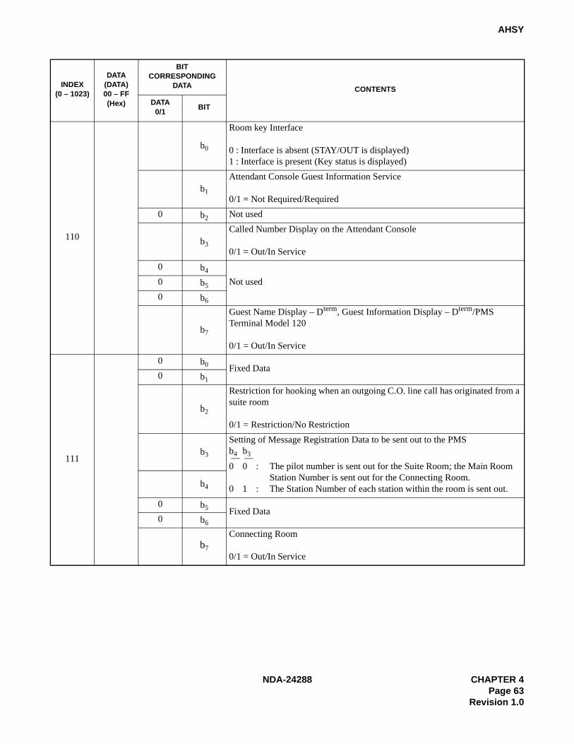
NDA-24288 CHAPTER 4Page 63
Revision 1.0
AHSY
110
b0
Room key Interface
0 : Interface is absent (STAY/OUT is displayed)1 : Interface is present (Key status is displayed)
b1
Attendant Console Guest Information Service
0/1 = Not Required/Required
0 b2 Not used
b3
Called Number Display on the Attendant Console
0/1 = Out/In Service
0 b4
Not used0 b5
0 b6
b7
Guest Name Display – Dterm, Guest Information Display – Dterm/PMS Terminal Model 120
0/1 = Out/In Service
111
0 b0 Fixed Data0 b1
b2
Restriction for hooking when an outgoing C.O. line call has originated from a suite room
0/1 = Restriction/No Restriction
b3
Setting of Message Registration Data to be sent out to the PMSb4 b3
0 0 : The pilot number is sent out for the Suite Room; the Main Room Station Number is sent out for the Connecting Room.
0 1 : The Station Number of each station within the room is sent out.b4
0 b5 Fixed Data0 b6
b7
Connecting Room
0/1 = Out/In Service
INDEX(0 – 1023)
DATA(DATA)00 – FF(Hex)
BITCORRESPONDING
DATA CONTENTS
DATA0/1
BIT

CHAPTER 4 NDA-24288Page 64Revision 1.0
AHSY
112 00
b0
Not used
b1
b2
b3
b4
b5
Wake-Up - Head Start Operation
0/1 = Out/In Service
b6Not used
b7
113 00 Not used
114
0 b0
Not used
0 b1
0 b2
0 b3
0 b4
b5
Hotel Console key designation
0/1 = Depending on SYS-1, INDEX 160, Bits 3 and 4 (ASYD)/PI 115-126 (AHSY)
0 b6 Not used
b7
Consecutive Dialing from Attendant Console (for service such as VMM)
0/1 = Not Required/Required
If “1” (Required) is assigned, switch settings for the ATI card are necessary.
INDEX(0 – 1023)
DATA(DATA)00 – FF(Hex)
BITCORRESPONDING
DATA CONTENTS
DATA0/1
BIT

NDA-24288 CHAPTER 4Page 65
Revision 1.0
AHSY
115 Attendant Console Key Data
116
117
118
119
120
121
122
123
124
125
126
127 00 Not used
128 00 Not used
129 00 Not used
130 00 Not used
131 00 Not used
132 00 Not used
133 00 Not used
134 00 Not used
135 00 Not used
136 00 Not used
137 00 Not used
138 00 Not used
INDEX(0 – 1023)
DATA(DATA)00 – FF(Hex)
BITCORRESPONDING
DATA CONTENTS
DATA0/1
BIT
121 122 123 124 125 126
7 8 9 11 1210
115 116 117 118 119 120
1 2 3 5 64
INDEX
INDEX
Operation Key
Operation Key
ENT CE END
81H — — WU SET 91H — — CHECK IN82H — — WU RESET 92H — — CHECKOUT83H — — MW SET 93H — — — —84H — — MW RESET 94H — — — —85H — — DD SET 95H — — C.O. CHANGE86H — — DD RESET 96H — — BOSS/SEC ENT87H — — RC SET 97H — — BOSS/SEC RESET88H — — RC RESET 98H — — — —89H — — STATUS 99H — — — —8AH — — AUDIT 9AH — — — —8BH — — — — 9BH — — — —8CH — — — — 9CH — — — —8DH — — — — 9DH — — — —8EH — — — — 9EH — — — —8FH — — — — 9FH — — GRP DND RESET90H — — — — A0H — — GRP RESTRICTION SET
A1H — — GRP RESTRICTION RESET
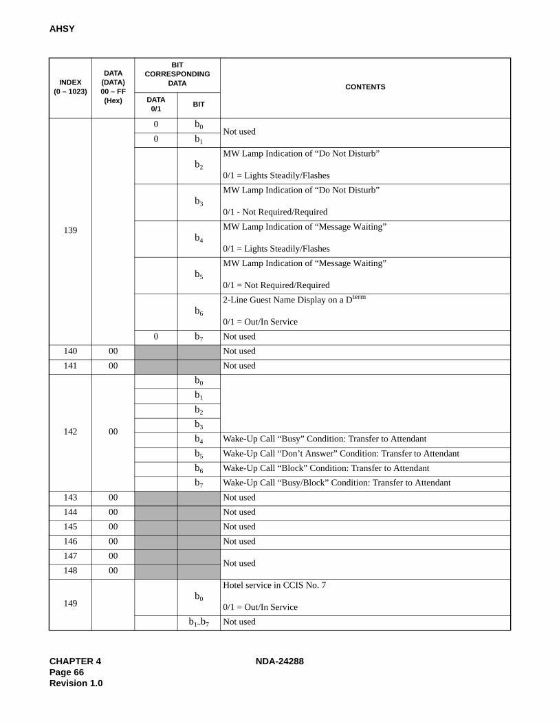
CHAPTER 4 NDA-24288Page 66Revision 1.0
AHSY
139
0 b0Not used
0 b1
b2
MW Lamp Indication of “Do Not Disturb”
0/1 = Lights Steadily/Flashes
b3
MW Lamp Indication of “Do Not Disturb”
0/1 - Not Required/Required
b4
MW Lamp Indication of “Message Waiting”
0/1 = Lights Steadily/Flashes
b5
MW Lamp Indication of “Message Waiting”
0/1 = Not Required/Required
b6
2-Line Guest Name Display on a Dterm
0/1 = Out/In Service
0 b7 Not used
140 00 Not used
141 00 Not used
142 00
b0
b1
b2
b3
b4 Wake-Up Call “Busy” Condition: Transfer to Attendant
b5 Wake-Up Call “Don’t Answer” Condition: Transfer to Attendant
b6 Wake-Up Call “Block” Condition: Transfer to Attendant
b7 Wake-Up Call “Busy/Block” Condition: Transfer to Attendant
143 00 Not used
144 00 Not used
145 00 Not used
146 00 Not used
147 00Not used
148 00
149b0
Hotel service in CCIS No. 7
0/1 = Out/In Service
b1~b7 Not used
INDEX(0 – 1023)
DATA(DATA)00 – FF(Hex)
BITCORRESPONDING
DATA CONTENTS
DATA0/1
BIT

NDA-24288 CHAPTER 4Page 67
Revision 1.0
AHSY
150
b0 b2 b1 b0 b2 b1 b0
0 0 0 = – 1 0 0 = Model 1200 0 1 = – 1 0 1 = –
0 1 0 = Model 60 1 1 0 = –
0 1 1 = Model 90 1 1 1 = –
b1
b2
0 b3~b7 Not used
151 00
Not used
152 00
153 00
154 00
155 00
156 00
157 00
158 00
159 00
160 00
161 00
162 00
163
b0
2nd Wake-Up Call Service
0/1 = Out/In Service
b1
2nd Wake-Up Call Timer Indication on Hotel Console
0/1 = Out/In Service
b2
2nd Wake-Up Call Cancel while Hotel Console is connected to the target station
0/1 = Out/In Service
b3 Not used
b4 The number of calls for Automatic Wake-Up at the same time (per LP)b5 b4 b5 b4
0 0 = 512 Calls 1 0 = 128 Calls0 1 = 64 Calls 1 1 = 256 Calls
b5
b6 The number or Retry when a Wake-Up Call encounters busy status.b7 b6 b7 b6
0 0 = 3 times 1 0 = Once0 1 = Twice 1 1 = No Retry
b7
164 00 Not used
INDEX(0 – 1023)
DATA(DATA)00 – FF(Hex)
BITCORRESPONDING
DATA CONTENTS
DATA0/1
BIT

CHAPTER 4 NDA-24288Page 68Revision 1.0
AHSY
165
b0EQP Type for Maid Status (0~15)
0: EQP161~F: EQP1~EQP15
b1
b2
b3
b4
Tone Type when Maid Status “To be cleaned” has been set:
0/1 = Tone designated in ASYD (SYS-1 INDEX 163, b5, b6)/SST
b5
Tone Type when Maid Status “Cleaned” has been set:
0/1 = Tone designated in ASYD (SYS-1 INDEX 163, b5, b6)/SST
b6
Tone Type when Maid Status “Ready for Occupancy” has been set:
0/1 = Tone designated in ASYD (SYS-1 INDEX 163, b5, b6)/SST
0 b7 Not used
166
b0 TN = 2 Whether “C.O. Incoming Call Answer Station Manual Change” service is provided or not is set on the basis of each TN (Tenant) corresponding to each bit.
0/1 = Out/In Service
b1 TN = 3
b2 TN = 4
b3 TN = 5
b4 TN = 6
b5 TN = 7
0 b6Not used
0 b7
167 00 Not used
168 00 Not used
169 00 Not used
170 00 Not used
171 00 Not used
172 00 Not used
173 00 Not used
174 00 Not used
175 00 Not used
176 00 Not used
177 00 Not used
178 00 Not used
INDEX(0 – 1023)
DATA(DATA)00 – FF(Hex)
BITCORRESPONDING
DATA CONTENTS
DATA0/1
BIT

NDA-24288 CHAPTER 4Page 69
Revision 1.0
AHSY
179
b0
Not usedb1
b2
b3
b4 Designation of Guest Access Codeb7 b6 b5 b4 ACC - CODE b7 b6 b5 b4 ACC - CODE
0 0 0 0 Out of Service 0 1 1 1 70 0 0 1 1 1 0 0 0 80 0 1 0 2 1 0 0 1 90 0 1 1 3 1 0 1 0 00 1 0 0 4 1 0 1 1 *0 1 0 1 5 1 1 0 0 #0 1 1 0 6
b5
b6
b7
180 00 Not used
181 00 Not used
182
0 b0 Not used
b1
Called # printout (Alert Service)
0/1 = No/Yes
b2
When a guest station has been called out by Alert Service, if that guest station is Busy, Locked Out, or under Make-Busy status, that information is printed out.
0/1 = Not Required/Required
9 b3
STA # Answers = Printout
0/1 = No/Yes
b4
When a guest station has been called out by Alert Service, if that guest station does not answer, the information is printed out.
0/1 = Not Required/Required
0 b5
Not used0 b6
0 b7
INDEX(0 – 1023)
DATA(DATA)00 – FF(Hex)
BITCORRESPONDING
DATA CONTENTS
DATA0/1
BIT

CHAPTER 4 NDA-24288Page 70Revision 1.0
AHSY
183
b0 Setting of Attendant Console that sets Alert Service
0 Hex: Service can be set from any of the Attendant Consoles1 - F Hex: Service can be set only from the Attendant Console of the
designated Console Number
b1
b2
b3
b4
Classifying the call termination indicating keys based on the Language category of the guest at the time an incoming call from the guest station terminated to the Attendant Console.
0/1 = Not Required/Required
b5 Not used
b6
In the case of “All Event No Printout,” the Hotel printer prints out only the information pertaining to outgoing calls.
0/1 = Out/In Service (The outgoing call data is assigned by INDEXes 360 through 367.)
0 b7 Not used
184
0 b0
Not used
0 b1
0 b2
0 b3
0 b4
0 b5
b6 Processing for “No Answer” at the Attendant Console in the case where Automatic Wake-Up Attendant - Assistance service is provided.b7 b6
0 0 : Changeover to Automatic Wake-Up0 1 : No processing for “No Answer”1 0 : Call termination to Attendant Console is canceled.1 1 : All Wake-Up calls are terminated to the Attendant Console
(including Automatic Wake-Up Call).
b7
INDEX(0 – 1023)
DATA(DATA)00 – FF(Hex)
BITCORRESPONDING
DATA CONTENTS
DATA0/1
BIT

NDA-24288 CHAPTER 4Page 71
Revision 1.0
AHSY
185
0 b0 Not used
b1
Guest Room Calling - Attendant Console Service
0/1 = Out/In Service
0 b2
Not used
0 b3
0 b4
0 b5
0 b6
0 b7
186
b0
Not used
b1
b2
b3
b4
b5
b6
b7
Double Suite Room Service
0/1 = Out/In Service
187
0 b0Not used
0 b1
b2
Processing for the case where there is any busy station among the Suite Room stations generally called by Suite Room Calling - Attendant Console service
0/1 = Sending Busy Tone/Idle Station Calling
0 b3
Not used
0 b4
0 b5
0 b6
0 b7
INDEX(0 – 1023)
DATA(DATA)00 – FF(Hex)
BITCORRESPONDING
DATA CONTENTS
DATA0/1
BIT

CHAPTER 4 NDA-24288Page 72Revision 1.0
AHSY
188
b0 Processing for Suite Room Station/Connecting Room Station Busyb1 b0
0 0 : Busy Tone0 1 : An idle station within the room is called1 0 : From a station, the call is transferred to the Attendant Console if the
caller is not the console operator.
b1
0 b2Fixed Data
0 b3
0 b4 Not used
b5
When a call terminates to the Double Suite Room:
0/1 = All stations ring simultaneously/Alternately between Primary Suite and Secondary Suite
1 b6 Fixed Data
b7
Suite Room Service
0/1 = Out/In Service
189
b0
Not used
b1
b2
b3
b4
b5
Calling an Individual Suite Room Station Calling
0: An individual Suite Room station can be called from a Guest Station, Administration Station, and Attendant Console.
1: An individual Suite Room station can be called from a Special Administration and Attendant Console.
b6
Ringing at the time of general calling in the Connecting Room or Suite Room stations.
0: Ringing all stations.
1: Ringing the station in the main room for the Connecting Room; ringing the Primary station for a Suite Room
b7
Number to be dialed for general calling of the station in the Suite Room
0: Primary Station Number or Pilot (Phantom) Number1: Only Pilot (Phantom) Number
190 00 Not used
INDEX(0 – 1023)
DATA(DATA)00 – FF(Hex)
BITCORRESPONDING
DATA CONTENTS
DATA0/1
BIT

NDA-24288 CHAPTER 4Page 73
Revision 1.0
AHSY
191 00 Not used
192 00 Not used
193 00 Not used
194 00 Not used
195 00 Not used
196 00 Not used
197 00 Not used
198 00 Not used
199 00 Not used
200 00 Not used
201 00 Not used
202 00 Not used
203 00 Not used
204 00 Not used
205 00 Not used
206 00 Not used
207 00 Not used
208 00 Not used
209 00 Not used
210 00 Not used
211 00 Not used
212 00 Not used
213 00 Not used
214 00 Not used
215 00 Not used
216 00 Not used
217 00 Not used
218 00 Not used
219 00 Not used
220 00 Not used
221 00 Not used
222 00 Not used
223 00 Not used
224 00 Not used
225 00 Not used
INDEX(0 – 1023)
DATA(DATA)00 – FF(Hex)
BITCORRESPONDING
DATA CONTENTS
DATA0/1
BIT

CHAPTER 4 NDA-24288Page 74Revision 1.0
AHSY
226 00 Not used
227 00 Not used
228 00 Not used
229 00 Not used
230 00 Not used
231 00 Not used
232 00 Not used
233 00 Not used
234 00 Not used
235 00 Not used
236 00 Not used
237 00 Not used
238 00 Not used
239 00 Not used
240 00 Not used
241 00 Not used
242 00 Not used
243 00 Not used
244 00 Not used
245 00 Not used
246 00 Not used
247 00 Not used
248 00 Not used
249 00 Not used
250 00 Not used
251 00 Not used
252b0
Room Key Information
0/1 = Key Rack Type/Card Rack Type
0 b1~b7 Not used
253 00 Not used
254 00 Not used
255 00 Not used
256 00 Not used
257 00 Not used
INDEX(0 – 1023)
DATA(DATA)00 – FF(Hex)
BITCORRESPONDING
DATA CONTENTS
DATA0/1
BIT

NDA-24288 CHAPTER 4Page 75
Revision 1.0
AHSY
258
0 b0 Not used
b1
Maid Status - Cleaning Start via Guest Station
(Feature Code = 11, Function Code = 1)Sending Service Feature Text (Information) to PMS
0/1 = In Service/Out Service
When the text is not to be sent to PMS, “1” is assigned to the corresponding bit.
b2
Maid Status - Cleaning End via Guest Station
(Feature Code = 11, Function Code = 2)
b3
Maid Status - Inspection End via Guest Station
(Feature Code = 11, Function Code = 3)
0 b4
Not used0 b5
0 b6
0 b7
259 Not used
260
b0 Not used
b1
Maid Status - Cleaning Start via Special Admin. Station
(Feature Code = 12, Function Code = 1)
Sending Service Feature Text (Information) to PMS
0/1 = In Service/Out Service
When the text is not to be sent to PMS, “1” is assigned to the corresponding bit.
b2
Maid Status - Cleaning End via Special Admin. Station
(Feature Code = 12, Function Code = 2)
b3
Maid Status - Inspection End via Special Admin. Station
(Feature Code = 12, Function Code = 3)
b4
Not usedb5
b6
b7
261 00 Not used
INDEX(0 – 1023)
DATA(DATA)00 – FF(Hex)
BITCORRESPONDING
DATA CONTENTS
DATA0/1
BIT

CHAPTER 4 NDA-24288Page 76Revision 1.0
AHSY
262
0 b0
Not used
Sending Service Feature Text (Information) to PMS
0/1 = In Service/Out Service
When the text is not to be sent to PMS, “1” is assigned to the corresponding bit.
0 b1
0 b2
b3
Message Waiting Lamp - On
(Feature Code = 13, Function Code = 3)
b4
Message Waiting Lamp - Off
(Feature Code = 13, Function Code = 4)
0 b5
Not used0 b6
0 b7
263 00 Not used
264
0 b0Not used
Sending Service Feature Text (Information) to PMS
0/1 = In Service/Out of Service
When the text is not to be sent to PMS, “1” assigned to the corresponding bit.
0 b1
b2
Call Detail Data
(Feature Code = 14, Function Code = 2)
b3
Not used
0 b4
0 b5
0 b6
0 b7
265 00 Not used
INDEX(0 – 1023)
DATA(DATA)00 – FF(Hex)
BITCORRESPONDING
DATA CONTENTS
DATA0/1
BIT

NDA-24288 CHAPTER 4Page 77
Revision 1.0
AHSY
266
0 b0Not used
Sending a Service Feature Text (Information) to PMS.
0/1 = In Service/Out Service
When the text is not to be sent to PMS, “1” assigned to the corresponding bit.
0 b1
b2
Room Cutoff and Do Not Disturb
(Feature Code = 15, Function Code = 2)
b3
Not used
0 b4
0 b5
0 b6
0 b7
267 00 Not used
268
0 b0
Not used0 b1
0 b2
0 b3
b4
Checkout - C.O. line Outgoing Call Report
(Feature Code = 16, Function Code = 5)
b5
Checkout - Message Off Report
(Feature Code = 16, Function Code = 6)
0 b6
Checkout - Message On Report
(Feature Code = 16, Function Code = 6)
0 b7 Not used
269
0 b0
Not used0 b1
0 b2
0 b3
b4
Checkout - C.O. line Outgoing Call Report
(Feature Code = 16, Function Code = C)
b5
Checkout - Message Waiting Report
(Feature Code = 16, Function Code = D)
0 b6Not used
0 b7
INDEX(0 – 1023)
DATA(DATA)00 – FF(Hex)
BITCORRESPONDING
DATA CONTENTS
DATA0/1
BIT

CHAPTER 4 NDA-24288Page 78Revision 1.0
AHSY
270
0 b0Not used
Sending a Service Feature Text (Information) to PMS
0/1 = In Service/Out of Service
When the text is not to be sent to PMS, “1” is assigned to the corresponding bit.
0 b1
b2
Room Data Image - Room Data Report
(Feature Code = 17, Function Code = 2)
0 b3 Not used
b4
Room Data Image - Room Data Exchange
(Feature Code = 17, Function Code = 4)
0 b5 Not used
b6
Room Data Image - Room Data Report
(Feature Code = 17, Function Code = 6)
0 b7 Not used
271
b0
Room Data Image - Room Data Exchange
(Feature Code = 17, Function Code = 8)
0 b1 Not used
b2
Room Data Image - Room Data Report
(Feature Code = 17, Function Code = A)
0 b3 Not used
b4
Room Data Image - Room Data Exchange
(Feature Code = 17, Function Code = C)
0 b5 Not used
b6
Station Delete Report
(Feature Code = 17, Function Code = E)
b7
Station Delete Report
(Feature Code = 17, Function Code = F)
272 00 Not used
273 00 Not used
INDEX(0 – 1023)
DATA(DATA)00 – FF(Hex)
BITCORRESPONDING
DATA CONTENTS
DATA0/1
BIT

NDA-24288 CHAPTER 4Page 79
Revision 1.0
AHSY
274
0 b0 Not used
Sending a Service Feature Text (Information) to PMS
0/1 = In Service/Out of Service
When the text is not to be sent to PMS, “1” is assigned to the corresponding bit.
b1
Automatic Wake-Up is set
(Feature Code = 19, Function Code = 1)
b2
Automatic Wake-Up is canceled
(Feature Code = 19, Function Code = 2)
b3
Automatic Wake-Up Result
(Feature Code = 19, Function Code = 3)
0 b4Not used
0 b5
b6
Automatic Wake-Up (Group Announcement) is set
(Feature Code = 19, Function Code = 6)
b7
Automatic Wake-up (Group Announcement) is set
(Feature Code = 19, Function Code = 7)
275
b0
Automatic Wake-Up (Group Announcement) is set
(Feature Code = 19, Function Code = 8)
0 b1
Not used
0 b2
0 b3
0 b4
0 b5
0 b6
0 b7
276 00 Not used
277 00 Not used
278 00 Not used
279 00 Not used
280 00 Not used
281 00 Not used
282 00 Not used
283 00 Not used
INDEX(0 – 1023)
DATA(DATA)00 – FF(Hex)
BITCORRESPONDING
DATA CONTENTS
DATA0/1
BIT

CHAPTER 4 NDA-24288Page 80Revision 1.0
AHSY
284 00 Not used
285 00 Not used
286 00 Not used
287 00 Not used
288 00 Not used
289 00 Not used
290 00 Not used
291 00 Not used
292
0 b0 Not used
Sending Service Feature Text (Information) to PMS
0/1 = In Service/Out Service
When the text is not to be sent to PMS, “1” is assigned to the corresponding bit.
b1
Check-In via a Dterm
(Feature Code = 46, Function Code = 1)
0 b2 Not used
b3
Bill Inquiry via a Dterm
(Feature Code = 46, Function Code = 3)
0 b4 Not used
0 b5
Checkout via a Dterm
(Feature Code = 46, Function Code = 5)
0 b6Not used
0 b7
293 00 Not used
294 00 Not used
295 00 Not used
296 00 Not used
297 00 Not used
298 00 Not used
299 00 Not used
300 00 Not used
301 00 Not used
INDEX(0 – 1023)
DATA(DATA)00 – FF(Hex)
BITCORRESPONDING
DATA CONTENTS
DATA0/1
BIT

NDA-24288 CHAPTER 4Page 81
Revision 1.0
AHSY
302
b0 Not used
b1
Maid Status - Guest Room 1
(Feature Code = 51, Function Code = 1)
Sending Service Feature Text (Information) to PMS
0/1 = In Service/Out of Service
When the text is not to be sent to PMS, “1” is assigned to the corresponding bit.
Note: These Texts are used for Maid Status Answer Back System.
b2
Maid Status - Guest Room 2
(Feature Code = 51, Function Code = 2)
b3
Maid Status - Guest Room 3
(Feature Code = 51, Function Code = 3)
b4
Maid Status - Guest Room 4
(Feature Code = 51, Function Code = 4)
b5
Maid Status - Guest Room 5
(Feature Code = 51, Function Code = 5)
b6
Maid Status - Guest Room 6
(Feature Code = 51, Function Code = 6)
0 b7 Not used
303 00 Not used
304
0 b0
b1
Maid Status - Admin. 1
(Feature Code = 52, Function Code = 1)Sending Service Feature Text (Information) to PMS
0/1 = In Service/Out of Service
When the text is not to be sent to PMS, “1” is assigned to the corresponding bit.
Note: These Texts are used for Maid Dial Answer Back System.
b2
Maid Status - Admin. 2
(Feature Code = 52, Function Code = 2)
b3
Maid Status - Admin. 3
(Feature Code = 52, Function Code = 3)
b4
Maid Status - Admin. 4
(Feature Code = 52, Function Code = 4)
0 b5
Not used0 b6
0 b7
305 00 Not used
INDEX(0 – 1023)
DATA(DATA)00 – FF(Hex)
BITCORRESPONDING
DATA CONTENTS
DATA0/1
BIT

CHAPTER 4 NDA-24288Page 82Revision 1.0
AHSY
306
b0Not used
Sending Service Feature Text (Information) to PMS
0/1 = In Service/Out of Service
When the text is not to be sent to PMS, “1” is assigned to the corresponding bit.
b1
b2
Message Waiting Lamp On via a Dterm
(Feature Code = 53, Function Code = 2)
b3
Message Waiting Lamp On via a Dterm
(Feature Code = 53, Function Code = 3)
b4
Not usedb5
b6
b7
307 00
308
0 b0 Not used
b1
Call Detail Data
(Feature Code = 54, Function Code = 1)Sending Service Feature Text (Information) to PMS
0/1 = In Service/Out of Service
When the text is not to be sent to PMS, “1” is assigned to the corresponding bit.
0 b2
Not used
0 b3
0 b4
0 b5
0 b6
0 b7
309 00 Not used
310 00 Not used
311 00 Not used
INDEX(0 – 1023)
DATA(DATA)00 – FF(Hex)
BITCORRESPONDING
DATA CONTENTS
DATA0/1
BIT
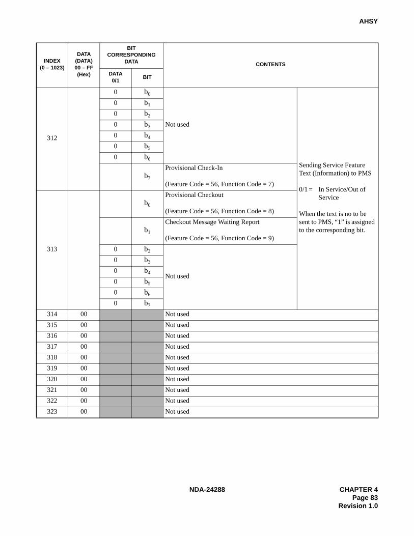
NDA-24288 CHAPTER 4Page 83
Revision 1.0
AHSY
312
0 b0
Not used
Sending Service Feature Text (Information) to PMS
0/1 = In Service/Out of Service
When the text is no to be sent to PMS, “1” is assigned to the corresponding bit.
0 b1
0 b2
0 b3
0 b4
0 b5
0 b6
b7
Provisional Check-In
(Feature Code = 56, Function Code = 7)
313
b0
Provisional Checkout
(Feature Code = 56, Function Code = 8)
b1
Checkout Message Waiting Report
(Feature Code = 56, Function Code = 9)
0 b2
Not used
0 b3
0 b4
0 b5
0 b6
0 b7
314 00 Not used
315 00 Not used
316 00 Not used
317 00 Not used
318 00 Not used
319 00 Not used
320 00 Not used
321 00 Not used
322 00 Not used
323 00 Not used
INDEX(0 – 1023)
DATA(DATA)00 – FF(Hex)
BITCORRESPONDING
DATA CONTENTS
DATA0/1
BIT

CHAPTER 4 NDA-24288Page 84Revision 1.0
AHSY
324
0 b0Not used
Sending Service Feature Text (Information) to PMS
0/1 = In Service/Out of Service
When the text is not to be sent to PMS, “1” is assigned to the corresponding bit.
0 b1
b2
Guest Room Secretary Telephone Setting/Cancellation
(Feature Code = 62, Function Code = 2)
0 b3
Not used
0 b4
0 b5
0 b6
0 b7
325 00 Not used
326 00 Not used
327 00 Not used
328 00 Not used
329 00 Not used
330 00 Not used
331 00 Not used
332 00 Not used
333 00 Not used
334 00 Not used
335 00 Not used
336 00 Not used
337 00 Not used
338 00 Not used
339 00 Not used
340 00 Not used
341 00 Not used
342 00 Not used
343 00 Not used
344 00 Not used
345 00 Not used
346 00 Not used
347 00 Not used
348 00 Not used
349 00 Not used
INDEX(0 – 1023)
DATA(DATA)00 – FF(Hex)
BITCORRESPONDING
DATA CONTENTS
DATA0/1
BIT

NDA-24288 CHAPTER 4Page 85
Revision 1.0
AHSY
350 00 Not used
351 00 Not used
352 00 Not used
353 00 Not used
354 00 Not used
355 00 Not used
356 00 Not used
357 00 Not used
358 00 Not used
359 00 Not used
360
b0
Digits Code 0
Outgoing Call Access Code No. 1
Note: When the dial access code contains “0,” enter “A” for “0.”
Example: When the dial access code is “9-202”.
b1
b2
b3
b4
Digits Code 1b5
b6
b7
361
b0
Digits Code 2b1
b2
b3
b4
Digits Code 3b5
b6
b7
INDEX(0 – 1023)
DATA(DATA)00 – FF(Hex)
BITCORRESPONDING
DATA CONTENTS
DATA0/1
BIT
2 92 A

CHAPTER 4 NDA-24288Page 86Revision 1.0
AHSY
362
b0
Digits Code 0
Outgoing Call Access Code No. 2
Note: When the dial access code contains “0,” enter “A” for “0.”
Example: When the dial access code is “9-202”.
b1
b2
b3
b4
Digits Code 1b5
b6
b7
363
b0
Digits Code 2b1
b2
b3
b4
Digits Code 3b5
b6
b7
364
b0
Digits Code 0
Outgoing Call Access Code No. 3
Note: When the dial access code contains “0,” enter “A” for “0.”
Example: When the dial access code is “9-202”.
b1
b2
b3
b4
Digits Code 1b5
b6
b7
365
b0
Digits Code 2b1
b2
b3
b4
Digits Code 3b5
b6
b7
INDEX(0 – 1023)
DATA(DATA)00 – FF(Hex)
BITCORRESPONDING
DATA CONTENTS
DATA0/1
BIT
2 92 A
2 92 A

NDA-24288 CHAPTER 4Page 87
Revision 1.0
AHSY
366
b0
Digits Code 0
Outgoing Call Access Code No. 4
Note: When the dial access code contains “0,” enter “A” for “0.”
Example: When the dial access code is “9-202”.
b1
b2
b3
b4
Digits Code 1b5
b6
b7
367
b0
Digits Code 2b1
b2
b3
b4
Digits Code 3b5
b6
b7
368 00 Not used
369 00 Not used
370 00 Not used
371 00 Not used
372 00 b0~b7 Not used
375 00 b0~b7 Not used
INDEX(0 – 1023)
DATA(DATA)00 – FF(Hex)
BITCORRESPONDING
DATA CONTENTS
DATA0/1
BIT
2 92 A
~

CHAPTER 4 NDA-24288Page 88Revision 1.0
AHSY
376
0 b0 Not used
Text sent to PMS printout
0/1 = Not Required/Required
If “1” assigned to the corresponding bit, the text is output to the Hotel printer.
Note: When a failure occurs in a data link between the NEAX2400 IMX and the PMS, the error information is printed.
b1 Maid Status - Guest (Feature Code = 11)
b2 Maid Status - Admin. (Feature Code = 12)
b3
Message Waiting Lamp
(Feature Code = 13)
0 b4 Not used
b5
Room Cut Off and Do Not Disturb
(Feature Code = 15)
b6
Check In/Checkout
(Feature Code = 16)
b7
Room Data Image
(Feature Code = 17)
377 00 Not used
378
b0
Room Change and Room Swap
(Feature Code = 20)
Text sent to PMS printout
0/1 = Not Required/Required
If “1” is assigned to the corresponding bit, the text is output to the Hotel printer.
Note: When a failure occurs in a data link between the NEAX2400 IMX and the PMS, the error information is printed.
b1
Room Data Change
(Feature Code = 21)
0 b2
Not used
0 b3
0 b4
0 b5
0 b6
0 b7
379 00 Not used
380 00 Not used
381 00 Not used
382 00 Not used
383 00 Not used
384 00 Not used
385 00 Not used
386 00 Not used
INDEX(0 – 1023)
DATA(DATA)00 – FF(Hex)
BITCORRESPONDING
DATA CONTENTS
DATA0/1
BIT

NDA-24288 CHAPTER 4Page 89
Revision 1.0
AHSY
387 00 Not used
388 00 Not used
389 00 Not used
390 00 Not used
391 00 Not used
392 00 Not used
393 00 Not used
394 00 Not used
395 00 Not used
396 00 Not used
397 00 Not used
398 00 Not used
399 00 Not used
400
Hour data is assigned using a decimal number (Military Time)
Example 1: 2:00 a.m. - This data is entered as 02.
Example 2: 2:30 a.m. - This data is entered as 14.
The time at which the printer periodically prints out the setting status of such Service Features as Automatic Wake-Up, Group Announcement, etc.
401
Minute data is assigned using a decimal number (Military Time)
Example 1: 2:00 a.m. - This data is entered as 00.
Example 2: 2:30 a.m. - This data is entered as 30.
402
0 b0 Not used
b1
Wake-Up Result (Answer) Printout
0/1 = Out/In Service
0 b2
Not used
0 b3
0 b4
0 b5
0 b6
0 b7
INDEX(0 – 1023)
DATA(DATA)00 – FF(Hex)
BITCORRESPONDING
DATA CONTENTS
DATA0/1
BIT
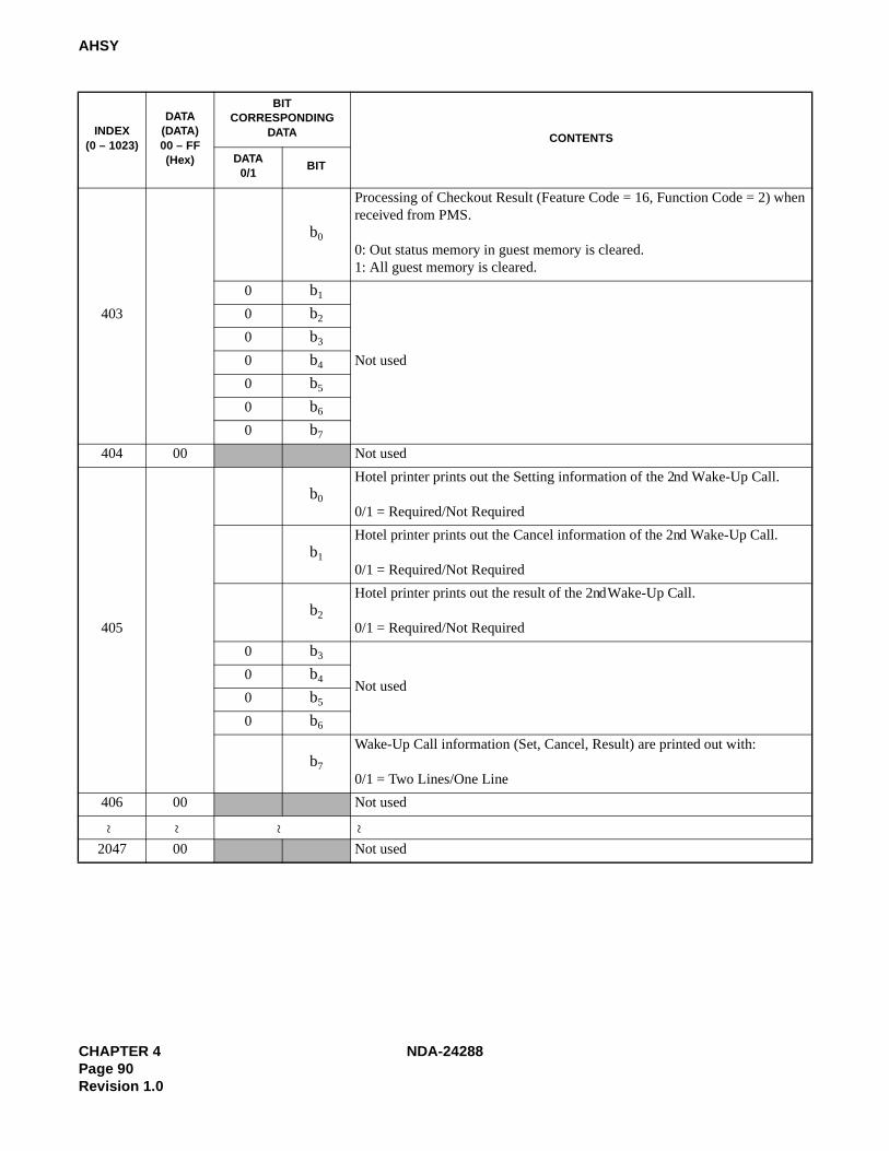
CHAPTER 4 NDA-24288Page 90Revision 1.0
AHSY
403
b0
Processing of Checkout Result (Feature Code = 16, Function Code = 2) when received from PMS.
0: Out status memory in guest memory is cleared.1: All guest memory is cleared.
0 b1
Not used
0 b2
0 b3
0 b4
0 b5
0 b6
0 b7
404 00 Not used
405
b0
Hotel printer prints out the Setting information of the 2nd Wake-Up Call.
0/1 = Required/Not Required
b1
Hotel printer prints out the Cancel information of the 2nd Wake-Up Call.
0/1 = Required/Not Required
b2
Hotel printer prints out the result of the 2nd Wake-Up Call.
0/1 = Required/Not Required
0 b3
Not used0 b4
0 b5
0 b6
b7
Wake-Up Call information (Set, Cancel, Result) are printed out with:
0/1 = Two Lines/One Line
406 00 Not used
2047 00 Not used
INDEX(0 – 1023)
DATA(DATA)00 – FF(Hex)
BITCORRESPONDING
DATA CONTENTS
DATA0/1
BIT
~ ~ ~ ~

NDA-24288 CHAPTER 4Page 91
Revision 1.0
AANP
AANP: Assignment of Administration Numbering Plan
1. General
This command assigns the minimum number of digits needed to determine the service that is required for thefirst digit received (pre-translation).
2. Precautions
1. This command is used for the Hotel Application only.
2. If the Guest and Admin. Numbering are separated (the ASYD command, SYS1, INDEX 160, bit6=0), usethis command for the Admin. Numbering plan. For the Guest numbering plan, use the AGNP command.
Note: Hotel features are available in TN1 only. If the numbering plans are separated by tenants, the purpose foreach tenant is completely separated.
Admin. Station required of the guest room call must be allocated in TN1.
3. The applicable Tenant Number (TN) range is designated by the ASYD command, SYS1, INDEX 8. Enterthe tenant number this command affects.
4. If data of this command is common for all tenants (ASYD command, SYS1, INDEX 92, bit2=1), assignTN parameter as data “1” for all tenants.
5. When changing any of the numbering plan data, the old data must be deleted before new data is assigned.
3. Data Entry Instructions
The first digit of station number, serviceaccess code and/or trunk access code, etc.(0-9, *, #)
1st DC
CIBLF
1st DIGIT CODE(1st DC)
TENANTNUMBER
(TN)
Whether the station busy status is monitored by the system or not.In Hotel system, assign “0” for this parameter.
NND
CONNECTION STATUS INDEX(CI)
N/H/B
NUMBER OF NECESSARY DIGITS(NND)
MAXIMUM 6 DIGITS
BUSY LAMP FIELD(BLF)
0/1
N = Normal (Idle)H = HookingB = Busy
0 = Out of Service 1 = In service
The status of the “1st DC” dialed
The primarily analyzed digits, prior to the AASP command.To assign different number of digits for this, assign minimum number of digits in this parameter.
0
0

CHAPTER 4 NDA-24288Page 92Revision 1.0
AANP
4. Data Sheet
TENANTNUMBER
(TN)
1ST DIGIT(1ST DC)
CONNECTION STATUS INDEX(CI)
NUMBER OF NECESSARY DIGITS
(NND) MAXIMUM 6 DIGITS
BUSY LAMPFIELD(BLF)
0/1
000000000000000000000000000000
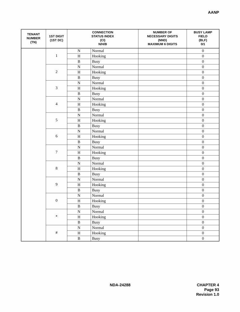
NDA-24288 CHAPTER 4Page 93
Revision 1.0
AANP
TENANTNUMBER
(TN)
1ST DIGIT(1ST DC)
CONNECTION STATUS INDEX
(CI) N/H/B
NUMBER OF NECESSARY DIGITS
(NND) MAXIMUM 6 DIGITS
BUSY LAMPFIELD(BLF)
0/1
1N Normal 0H Hooking 0B Busy 0
2N Normal 0H Hooking 0B Busy 0
3N Normal 0H Hooking 0B Busy 0
4N Normal 0H Hooking 0B Busy 0
5N Normal 0H Hooking 0B Busy 0
6N Normal 0H Hooking 0B Busy 0
7N Normal 0H Hooking 0B Busy 0
8N Normal 0H Hooking 0B Busy 0
9N Normal 0H Hooking 0B Busy 0
0N Normal 0H Hooking 0B Busy 0
*N Normal 0H Hooking 0B Busy 0
#N Normal 0H Hooking 0B Busy 0
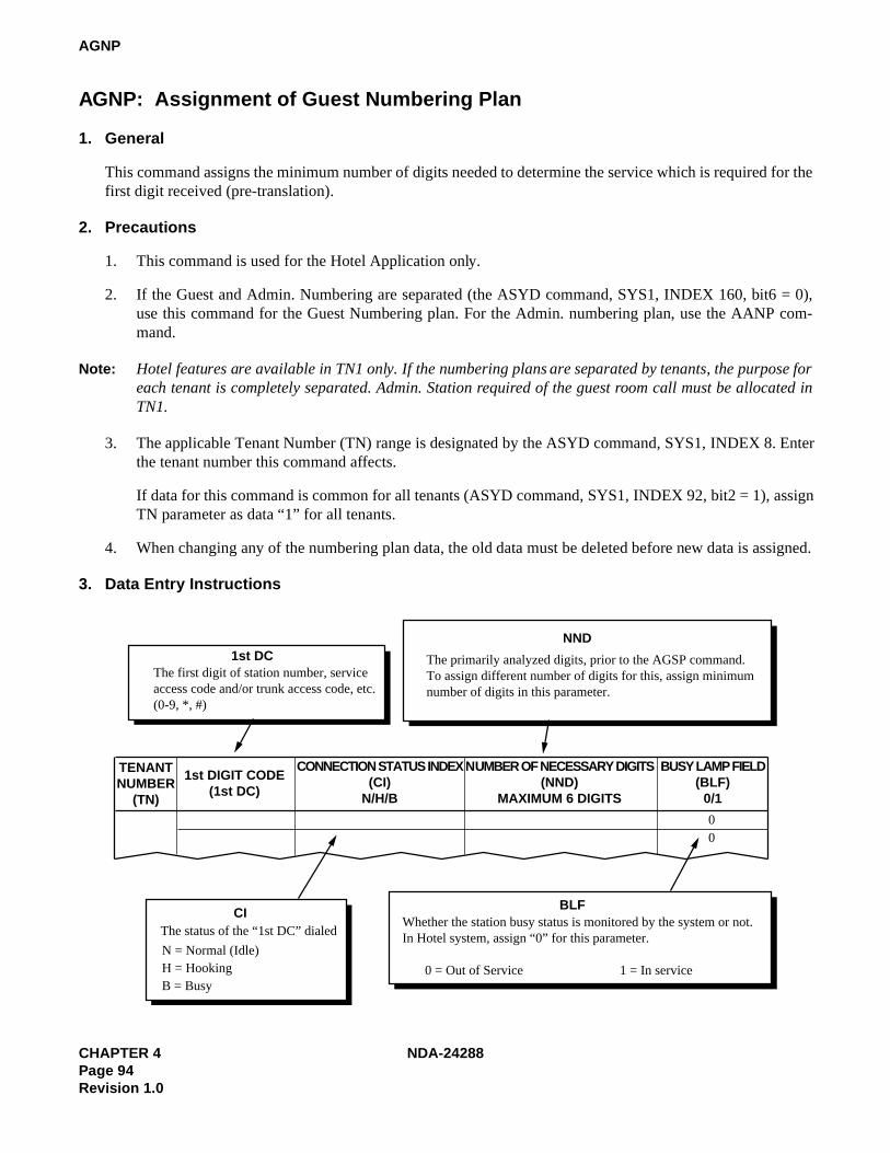
CHAPTER 4 NDA-24288Page 94Revision 1.0
AGNP
AGNP: Assignment of Guest Numbering Plan
1. General
This command assigns the minimum number of digits needed to determine the service which is required for thefirst digit received (pre-translation).
2. Precautions
1. This command is used for the Hotel Application only.
2. If the Guest and Admin. Numbering are separated (the ASYD command, SYS1, INDEX 160, bit6 = 0),use this command for the Guest Numbering plan. For the Admin. numbering plan, use the AANP com-mand.
Note: Hotel features are available in TN1 only. If the numbering plans are separated by tenants, the purpose foreach tenant is completely separated. Admin. Station required of the guest room call must be allocated inTN1.
3. The applicable Tenant Number (TN) range is designated by the ASYD command, SYS1, INDEX 8. Enterthe tenant number this command affects.
If data for this command is common for all tenants (ASYD command, SYS1, INDEX 92, bit2 = 1), assignTN parameter as data “1” for all tenants.
4. When changing any of the numbering plan data, the old data must be deleted before new data is assigned.
3. Data Entry Instructions
The first digit of station number, serviceaccess code and/or trunk access code, etc.(0-9, *, #)
1st DC
CIBLF
1st DIGIT CODE(1st DC)
TENANTNUMBER
(TN)
Whether the station busy status is monitored by the system or not.In Hotel system, assign “0” for this parameter.
NND
CONNECTION STATUS INDEX(CI)
N/H/B
NUMBER OF NECESSARY DIGITS(NND)
MAXIMUM 6 DIGITS
BUSY LAMP FIELD(BLF)
0/1
N = Normal (Idle)H = HookingB = Busy
0 = Out of Service 1 = In service
The status of the “1st DC” dialed
The primarily analyzed digits, prior to the AGSP command.To assign different number of digits for this, assign minimum number of digits in this parameter.
00

NDA-24288 CHAPTER 4Page 95
Revision 1.0
AGNP
4. Data Sheet
TENANTNUMBER
(TN)
1ST DIGIT(1ST DC)
CONNECTION STATUS INDEX
(CI) N/H/B
NUMBER OF NECESSARY DIGITS
(NND) MAXIMUM 6 DIGITS
BUSY LAMPFIELD(BLF)
0/1
1N Normal 0H Hooking 0B Busy 0
2N Normal 0H Hooking 0B Busy 0
3N Normal 0H Hooking 0B Busy 0
4N Normal 0H Hooking 0B Busy 0
5N Normal 0H Hooking 0B Busy 0
6N Normal 0H Hooking 0B Busy 0
7N Normal 0H Hooking 0B Busy 0
8N Normal 0H Hooking 0B Busy 0
9N Normal 0H Hooking 0B Busy 0
0N Normal 0H Hooking 0B Busy 0
*N Normal 0H Hooking 0B Busy 0
#N Normal 0H Hooking 0B Busy 0
CHAPTER 4 NDA-24288Page 96Revision 1.0
AGNPL
AGNPL: Assignment of Guest Numbering Plan for LDM
1. General
This command assigns the minimum number of digits needed to determine the service required for the first digitreceived (pre-translation).
2. Precautions
1. This command is used for the Hotel Application.
2. If the Guest and Admin. Numbering are separated (the ASYD command, SYS1, INDEX 160, bit6 = 0),use this command for the Guest Numbering plan. For the admin. numbering plan, use the ANPDL com-mand.
Note: Hotel features are available in TN1 only. If the numbering plans are separated by tenants, the purpose foreach tenant is completely separated. Admin. Station required of the guest room call must be allocated inTN1.
3. Use this command to assign the numbering data for the operator call and the priority call (terminating toATT) in the Fusion network.
4. The numbering data for Telephone numbers may be programmed by this command; however, thoseTelephone numbers are available in the self node only.
Telephone numbers available within the Fusion network are to be programmed at Network Control Node(NCN) using the AGNPN and AGSPN commands.
5. The system data assignment (ASYDL, SYS1, INDEX 513, bit0 = 1) is needed to use the AGNPLcommand.

NDA-24288 CHAPTER 4Page 97
Revision 1.0
AGNPL
3. Data Entry Instructions
TENANTNUMBER
(TN)
1st DIGIT CODE(1st DC)
CONNECTION STATUS INDEX
(CI)N/H/B
NUMBER OF NECESSARY DIGITS
(NND)MAXIMUM 16 DIGITS
BUSY LAMP FIELD (BLF)
0/1
1st DCThe first digit of service access code, etc., (0-9, *, #)
NNDThe first digits analyzed prior to the ASPAL command.
Assign the minimum number of digits for each Access Code.
To assign a different number of digits, such as Timing Start for Telephone numbers, assign the maximum number of digits in this parameter.
CIThe status of the 1st DC dialed:N = NormalH = HookingB = Busy
BLFWhether the station busy status is monitored by the system or not. For Hotel system, assign “0” for this parameter.
0 = Out of Service 1 - In service

CHAPTER 4 NDA-24288Page 98Revision 1.0
AGNPL
4. Data Sheet
TENANTNUMBER
(TN)
1ST DIGIT(1ST DC)
CONNECTIONSTATUS INDEX
(CI)
NUMBER OFNECESSARY DIGITS
(NND)
BUSY LAMPFIELD(BLF)
REMARKS
1N Normal
H Hooking
B Busy
2N Normal
H Hooking
B Busy
3N Normal
H Hooking
B Busy
4N Normal
H Hooking
B Busy
5N Normal
H Hooking
B Busy
6N Normal
H Hooking
B Busy
7N Normal
H Hooking
B Busy
8N Normal
H Hooking
B Busy
9N Normal
H Hooking
B Busy
0N Normal
H Hooking
B Busy
N Normal
H Hooking
B Busy
#
N Normal
H Hooking
B Busy

NDA-24288 CHAPTER 4Page 99
Revision 1.0
AGNPN
AGNPN: Assignment of Guest Numbering Plan for NDM
1. General
This command assigns the minimum number of digits needed to determine the service required by the first digitreceived (pre-translation). The data assigned on this command is written in the Network Data Memory (NDM)of the Network Control Node (NCN), updating the NDM at each Local Node (LN).
2. Precautions
1. This command is used for the Hotel Application.
2. If the Guest and Admin. Numbering are separated (the ASYD command, SYS1, INDEX160, bit6 = 0),use this command for the Guest Numbering plan. For the Admin. numbering plan, use the ANPDN com-mand.
Note: Hotel features are available in TN1 only. If the AGNPN command is not common for all tenants, tenantsare restricted from calling between each other. Hotel Admin phones must be in tenant 1.
3. The system data assignment (ASYDN, SYS 1, INDEX 514, bit0 = 1) provides the Network Data Memory(NDM).
3. Data Entry Instructions
TENANTNUMBER
(TN)
1st DIGIT CODE(1st DC)
CONNECTION STATUS INDEX
(CI)N/H/B
NUMBER OF NECESSARY DIGITS
(NND)MAXIMUM 6 DIGITS
BUSY LAMP FIELD DISPLAY (BLF)
0/1
0
NNDThe first digits analyzed, prior to the ASPAN command. To assign adifferent number of digits for this, assign the minimum number of dig-its to be used in this parameter.
1st DCThe first digit of access code for Tele-phone Number.(0-9,*,#)
CIThe status of the “1st DC” dialedN = Normal (Idle)H = HookingB = Busy
BLFNot used (Fixed to 0)

CHAPTER 4 NDA-24288Page 100Revision 1.0
AGNPN
4. Data Sheet
TENANTNUMBER
(TN)
1ST DIGIT(1ST DC)
CONNECTIONSTATUS INDEX (CI)
NUMBER OF NECESSARY DIGITS
(NND)
BUSY LAMP FIELD(BLF)
REMARKS
1N Normal
H Hooking
B Busy
2N Normal
H Hooking
B Busy
3N Normal
H Hooking
B Busy
4N Normal
H Hooking
B Busy
5N Normal
H Hooking
B Busy
6N Normal
H Hooking
B Busy
7N Normal
H Hooking
B Busy
8N Normal
H Hooking
B Busy
9N Normal
H Hooking
B Busy
0N Normal
H Hooking
B Busy
N Normal
H Hooking
B Busy
#N Normal
H Hooking
B Busy
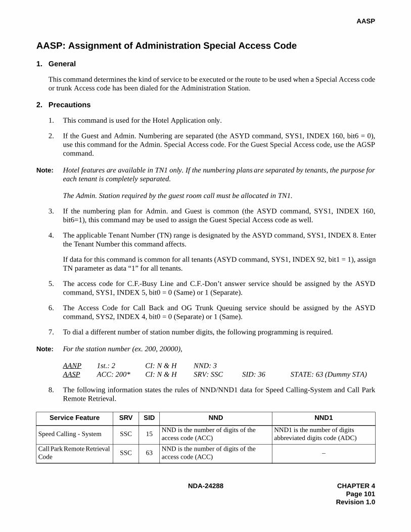
NDA-24288 CHAPTER 4Page 101
Revision 1.0
AASP
AASP: Assignment of Administration Special Access Code
1. General
This command determines the kind of service to be executed or the route to be used when a Special Access codeor trunk Access code has been dialed for the Administration Station.
2. Precautions
1. This command is used for the Hotel Application only.
2. If the Guest and Admin. Numbering are separated (the ASYD command, SYS1, INDEX 160, bit6 = 0),use this command for the Admin. Special Access code. For the Guest Special Access code, use the AGSPcommand.
Note: Hotel features are available in TN1 only. If the numbering plans are separated by tenants, the purpose foreach tenant is completely separated.
The Admin. Station required by the guest room call must be allocated in TN1.
3. If the numbering plan for Admin. and Guest is common (the ASYD command, SYS1, INDEX 160,bit6=1), this command may be used to assign the Guest Special Access code as well.
4. The applicable Tenant Number (TN) range is designated by the ASYD command, SYS1, INDEX 8. Enterthe Tenant Number this command affects.
If data for this command is common for all tenants (ASYD command, SYS1, INDEX 92, bit1 = 1), assignTN parameter as data “1” for all tenants.
5. The access code for C.F.-Busy Line and C.F.-Don’t answer service should be assigned by the ASYDcommand, SYS1, INDEX 5, bit0 = 0 (Same) or 1 (Separate).
6. The Access Code for Call Back and OG Trunk Queuing service should be assigned by the ASYDcommand, SYS2, INDEX 4, bit0 = 0 (Separate) or 1 (Same).
7. To dial a different number of station number digits, the following programming is required.
Note: For the station number (ex. 200, 20000),
AANP 1st.: 2 CI: N & H NND: 3AASP ACC: 200* CI: N & H SRV: SSC SID: 36 STATE: 63 (Dummy STA)
8. The following information states the rules of NND/NND1 data for Speed Calling-System and Call ParkRemote Retrieval.
Service Feature SRV SID NND NND1
Speed Calling - System SSC 15NND is the number of digits of the access code (ACC)
NND1 is the number of digits abbreviated digits code (ADC)
Call Park Remote Retrieval Code
SSC 63NND is the number of digits of the access code (ACC)
–

CHAPTER 4 NDA-24288Page 102Revision 1.0
AASP
9. For the following service features, the maximum number of digits is to be assigned in the parameter NND.
10. The variable parameter appears on the MAT depending on the data in the parameter SRV.
3. Data Entry Instructions
SERVICE FEATURE SRV SID MAX. NND
Account Code Dial SSC 41 15
Authorization Code/Forced Account Code SSC 42 15
Attendant Manual Override SSC 60 5
Access code (Max. 6 digits)
NND1 appears when SID = 15. The number of ADC(Abbreviation Digit Code) digits should be assigned in NND1.
TENANTNUMBER
(TN)
ACCESS CODE(ACC)
MAX. 6 DIGITS
CONNECTION STATUS INDEX
(CI) N/H/B
KIND OFSERVICE (SRV)
0-16
ACC
CI
SRV
NND1
SERVICE INDEX(SID) 1-63
NECESSARY DIGIT(NND)
NECESSARY DIGIT FOR SPEEDCALLING (NND1) 1-24
N = Normal serviceH = Hooking serviceB = Busy service
When SRV = SSC (Service code except SID36, 56 and 57) is assigned
15 (Speed Calling-System; Access)
41 (Account Code Dial)
15 (Authorization Code/Forced Account Code/Pad Lock)60 (Attendant Manual Override)63 (Call Park; Retrieve)
NND appears when the following SID is entered.NND data is variable depending on SID.
NND
SID Number of digits for NNDAccess Code (1-24)
Access Code (1-3)Access Code (1-5)
Access Code+ID(1-15)
Access Code+Account code(1-15)
SSC = Service Code SSCA = Service code appendixOGC = Outgoing callOGCA = Outgoing call with route advanceLCR = Least cost routing LCRS = Register sender LCRUNIF = Office terminationANNC = Announcement service-single announcementANNCM = Announcement service-multiple announcementPAGA = Paging Answer PAGC = Paging cancel

NDA-24288 CHAPTER 4Page 103
Revision 1.0
AASP
STATE(Hotel Service Code)
1 To be cleaned without ID code2 Cleaning Completed without ID code3 Ready for Occupancy without ID code4 Use Not Allowed without ID code
5-8 -9 Maid Dial Answer Back without ID code-1
10 Maid Dial Answer Back without ID code-211 Maid Dial Answer Back without ID code-312 Maid Dial Answer Back without ID code-413 Maid Dial Answer Back without ID code-514 Maid Dial Answer Back without ID code-615 Maid Dial Answer Back without ID code-716 -17 To be cleaned with ID code18 Cleaning Completed with ID code19 Ready for Occupancy with ID code20 Use Not Allowed with ID code
21-24 -25 Maid Dial Answer Back with ID code-126 Maid Dial Answer Back with ID code-227 Maid Dial Answer Back with ID code-328 Maid Dial Answer Back with ID code-429 Maid Dial Answer Back with ID code-530 Maid Dial Answer Back with ID code-631 Maid Dial Answer Back with ID code-7 32 -33 Automatic Wake Up Setting, Cancel; Same Special code34 For Guest Station Secretary Telephone; Boss/Secretary Calling35 Boss/Secretary Busy out; Set36 Boss/Secretary Busy out; Cancel 37 -38 Automatic Wake-Up-Hotel Attendant Assistance Stop39 Automatic Wake-Up-Hotel Attendant Assistance Stop Cancel40 Alert Service Start (Hotel ATT)41 Alert Service Stop (Hotel ATT)42 Guest Service Telephone Screen Initialized43 Guest Service Telephone Guest Room Information Retrieval44 Direct Data Entry-Station (via Guest Station)45 Alert Service Start (Special Admin. Station)46 Alert Service Stop (Special Admin. Station)47 -48 2nd Wake-Up Call (Automatic) Set49 2nd Wake-Up Call (Semi-Automatic) Set50 2nd Wake-Up Call Cancel51 Same Special Code Time Zone Connection Change52 Same Special Code Time Zone Connection Change53 Same Special Code Time Zone Connection Change54 Same Special Code Time Zone Connection Change55 Same Special Code Time Zone Connection Change
56-62 -63 Dummy Number
Note: STATE=1-15 are used at the time of Maid ID Code Service is not provided; (ASYD SYS1 INDEX 164, bit3=0) STATE=17-31 are used at the time of Maid ID Code Service is provided; (ASYD SYS1 INDEX 164, bit3=1)
SERVICE INDEX (SID) 1-63
STATE
36

CHAPTER 4 NDA-24288Page 104Revision 1.0
AASP
SERVICE INDEX (SID) 1-63 NO.1
56
NO.1(Kind of Assignment Number)
Available numbers are 0-15. This data is used to assign Floor Service data by the ASPF command. Note: When programming Floor Service data, ASYD SYS1 INDEX 165, bit7=1 must have been assigned.
SERVICE INDEX (SID) 1-63
NO.2 KIND
57
NO.2This parameter specifies the number (0-63) of theaccess code being assigned for mutual access.This parameter serves as a counter for the accesscodes being assigned.
Note: This parameter is used when assigning the details of the service by the ASPS command.
KIND: (0-3)This parameter specifies the Split Access Parameter Classification. The data tobe assigned here depends on how the Guest and Administration stations aredifferentiated.The Guest and Administration stations may be assigned to separate TNs, RSCs,and/or SFCs, or they may only be differentiated by their respective designationsas Administration or Guest. 0: Administration/Guest (Assign this if the access code is to be shared between Guest and Administration with no correspondence to TN, RSC or SFC.) 1: TN (Assign this if the access code is to be shared among specified TNs) 2: RSC (Assign this if the access code is to be shared among specified RSCs) 3: SFC (Assign this if the access code is to be shared among specified SFCs)
When SRV = SSC (Service code), SID56 (Floor Service) is assigned
When SRV = SSC (Service code), SID57 (Split Access) is assigned
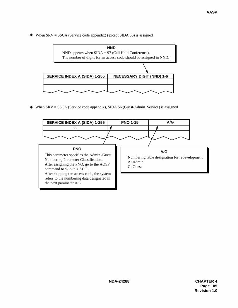
NDA-24288 CHAPTER 4Page 105
Revision 1.0
AASP
NNDNND appears when SIDA = 97 (Call Hold Conference).The number of digits for an access code should be assigned in NND.
SERVICE INDEX A (SIDA) 1-255 PNO 1-15 A/G56
PNO
This parameter specifies the Admin./GuestNumbering Parameter Classification.After assigning the PNO, go to the AOSPcommand to skip this ACC.After skipping the access code, the systemrefers to the numbering data designated inthe next parameter A/G.
A/GNumbering table designation for redevelopmentA: Admin.G: Guest
When SRV = SSCA (Service code appendix) (except SIDA 56) is assigned
When SRV = SSCA (Service code appendix), SIDA 56 (Guest/Admin. Service) is assigned
SERVICE INDEX A (SIDA) 1-255 NECESSARY DIGIT (NND) 1-6

CHAPTER 4 NDA-24288Page 106Revision 1.0
AASP
Assign the number of advanced trunk routes.
ROUTE NUMBER(RT)
COUNT
Assign a dummy route number.RT
2nd DT
Authorization code after dialingACC (LCR) + Destination number0 = Out of Service1 = In Service
AH
ISDN-Sub Address Dialing0 = Out of Service1 = In Service
SUB
ROUTE NUMBER(RT)
SECOND DIAL TONE(2nd DT) 0/1
AUTHORIZATION CODE(AH) 0/1
SUB ADDRESS DIALING(SUB) 0/1
INDEX COUNTER (COUNT) INDEX ROUTE NUMBER (RT)
When SRV = OGC (Outgoing call) is assigned
When SRV = PAGA (Paging answer) is assigned
When SRV = PAGC (Paging cancel) is assigned
When SRV = OGCA (Outgoing call with route advance) is assigned
When SRV = LCR (Least cost routing) is assignedWhen SRV = LCRS (Register sender LCR) is assigned
INDEX
INDEX is the route advance order.
12
3
Second dial tone sending (which is sent when a station hasdialed the digits specified in NND of the AANP command)0 = Second DT is not send1 = Second DT is sent

NDA-24288 CHAPTER 4Page 107
Revision 1.0
AASP
SKIP DIGITS(SKIP) 0-5
When SRV = UNIF (Office termination) is assigned
When SRV = ANNC (Announcement service-Single announcement) is assigned
SKIP
ANNOUNCEMENT EQUIPMENT NUMBER(EQP) 0-127
EQP
Note: This data is available for ACIS only. For CCIS, use the AUNE command.
Assign the skip digits to terminate the call.
Assign the announcement equipment number.EQP3 and 5-14 can be used for SRV = ANNC (Single announcement).
Assign the tenant number ofthe announcement trunk.
When SRV = ANNCM (Announcement service-Multiple announcement) is assigned
TN
TENANT NUMBER(TN) 1-255
ANNOUNCEMENT EQUIPMENT NUMBER(EQP) 122-125
Assign the announcement equipment number range from 122 to 125 (Multi announcement).
EQP
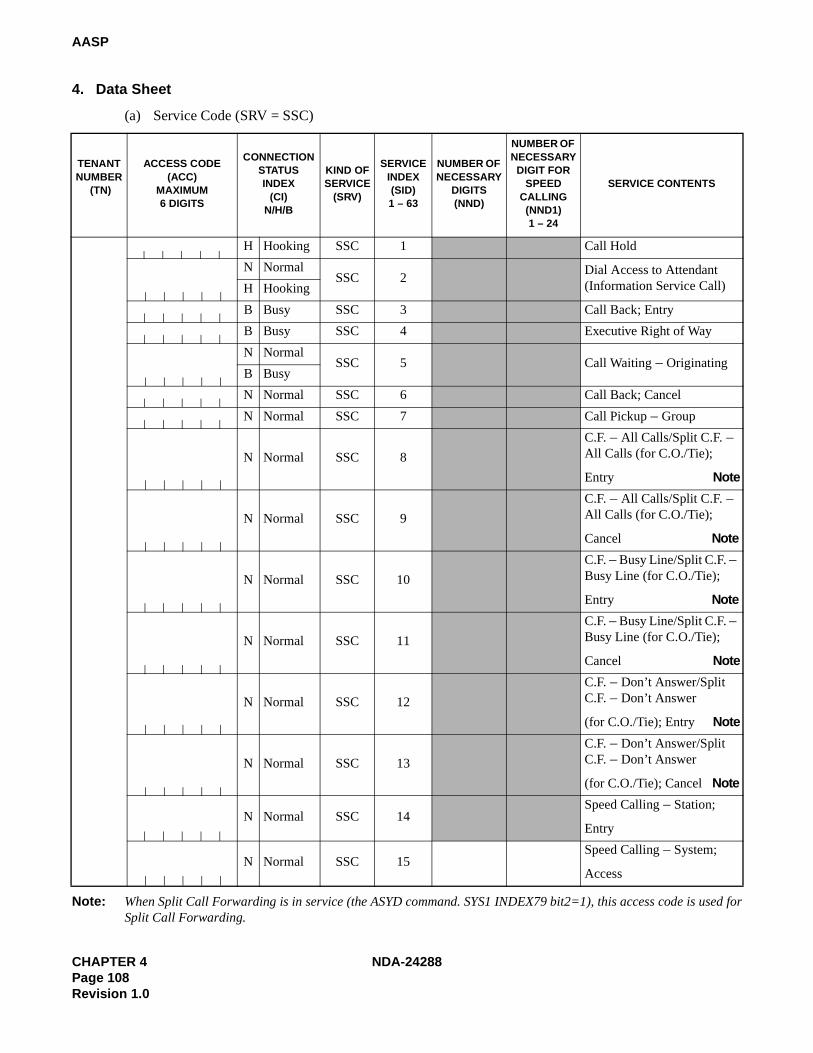
CHAPTER 4 NDA-24288Page 108Revision 1.0
AASP
4. Data Sheet
(a) Service Code (SRV = SSC)
Note: When Split Call Forwarding is in service (the ASYD command. SYS1 INDEX79 bit2=1), this access code is used forSplit Call Forwarding.
TENANT NUMBER
(TN)
ACCESS CODE(ACC)
MAXIMUM6 DIGITS
CONNECTION STATUS INDEX
(CI) N/H/B
KIND OFSERVICE
(SRV)
SERVICEINDEX(SID)1 – 63
NUMBER OF NECESSARY
DIGITS (NND)
NUMBER OF NECESSARY
DIGIT FOR SPEED
CALLING(NND1)1 – 24
SERVICE CONTENTS
H Hooking SSC 1 Call Hold
N NormalSSC 2
Dial Access to Attendant (Information Service Call)H Hooking
B Busy SSC 3 Call Back; Entry
B Busy SSC 4 Executive Right of Way
N NormalSSC 5 Call Waiting – Originating
B Busy
N Normal SSC 6 Call Back; Cancel
N Normal SSC 7 Call Pickup – Group
N Normal SSC 8
C.F. – All Calls/Split C.F. – All Calls (for C.O./Tie);
Entry Note
N Normal SSC 9
C.F. – All Calls/Split C.F. – All Calls (for C.O./Tie);
Cancel Note
N Normal SSC 10
C.F. – Busy Line/Split C.F. – Busy Line (for C.O./Tie);
Entry Note
N Normal SSC 11
C.F. – Busy Line/Split C.F. – Busy Line (for C.O./Tie);
Cancel Note
N Normal SSC 12
C.F. – Don’t Answer/Split C.F. – Don’t Answer
(for C.O./Tie); Entry Note
N Normal SSC 13
C.F. – Don’t Answer/Split C.F. – Don’t Answer
(for C.O./Tie); Cancel Note
N Normal SSC 14Speed Calling – Station;
Entry
N Normal SSC 15Speed Calling – System;
Access

NDA-24288 CHAPTER 4Page 109
Revision 1.0
AASP
(a) Service Code (SRV = SSC) (Continued)
TENANTNUMBER
(TN)
ACCESS CODE(ACC)
MAXIMUM6 DIGITS
CONNECTION STATUS INDEX
(CI) N/H/B
KIND OFSERVICE
(SRV)
SERVICEINDEX(SID)1 – 63
NUMBER OF NECESSARY
DIGITS(NND)
SERVICE CONTENTS
N Normal SSC 16 TAS Answer
N Normal SSC 17 Individual Trunk Access
18 Not Used
B Busy SSC 19 OG Trunk Queuing; Entry
N Normal SSC 20 OG Trunk Queuing; Cancel
N Normal SSC 21Speed Calling – Station, Group – Access
22
27Not used
N Normal SSC 28Call Forwarding – I’m Here;
Entry
N Normal SSC 29Call Forwarding – I’m Here; Cancel
30
34Not used
N Normal SSC 35 Call Pickup – Direct
N Normal SSC 36 Hotel Service
~~
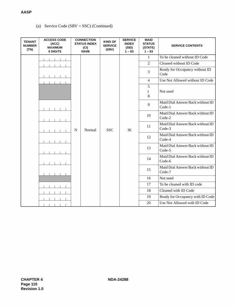
CHAPTER 4 NDA-24288Page 110Revision 1.0
AASP
(a) Service Code (SRV = SSC) (Continued)
TENANT NUMBER
(TN)
ACCESS CODE(ACC)
MAXIMUM6 DIGITS
CONNECTION STATUS INDEX
(CI) N/H/B
KIND OF SERVICE
(SRV)
SERVICE INDEX(SID)1 – 63
MAIDSTATUS (STATE)1 – 63
SERVICE CONTENTS
N Normal SSC 36
1 To be cleaned without ID Code
2 Cleaned without ID Code
3Ready for Occupancy without ID Code
4 Use Not Allowed without ID Code
5
8Not used
9Maid Dial Answer Back without ID Code-1
10Maid Dial Answer Back without ID Code-2
11Maid Dial Answer Back without ID Code-3
12Maid Dial Answer Back without ID Code-4
13Maid Dial Answer Back without ID Code-5
14Maid Dial Answer Back without ID Code-6
15Maid Dial Answer Back without ID Code-7
16 Not used
17 To be cleaned with ID code
18 Cleaned with ID Code
19 Ready for Occupancy with ID Code
20 Use Not Allowed with ID Code
~

NDA-24288 CHAPTER 4Page 111
Revision 1.0
AASP
(a) Service Code (SRV = SSC) (Continued)
TENANT NUMBER
(TN)
ACCESS CODE(ACC)
MAXIMUM6 DIGITS
CONNECTION STATUS INDEX
(CI) N/H/B
KIND OF SERVICE
(SRV)
SERVICE INDEX(SID)1 – 63
MAIDSTATUS (STATE)1 – 63
SERVICE CONTENTS
N Normal SSC 36
21
24Not used
25Maid Dial Answer Back with ID Code-1
26Maid Dial Answer Back with ID Code-2
27Maid Dial Answer Back with ID Code-3
28Maid Dial Answer Back with ID Code-4
29Maid Dial Answer Back with ID Code-5
30Maid Dial Answer Back with ID Code-6
31Maid Dial Answer Back with ID Code-7
32 Not used
33Automatic Wake-Up Setting,
Cancel; Same Special Code
34For Guest Station Secretary
Telephone; Boss/Secretary
35
Not used36
37
38Automatic Wake-Up – Hotel
Attendant Assistance Stop; Set
39Automatic Wake-Up – Hotel
Attendant Assistance Stop; Cancel
~
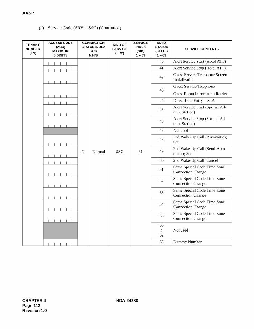
CHAPTER 4 NDA-24288Page 112Revision 1.0
AASP
(a) Service Code (SRV = SSC) (Continued)
TENANT NUMBER
(TN)
ACCESS CODE (ACC)
MAXIMUM6 DIGITS
CONNECTION STATUS INDEX
(CI) N/H/B
KIND OF SERVICE
(SRV)
SERVICE INDEX(SID)1 – 63
MAIDSTATUS (STATE)1 – 63
SERVICE CONTENTS
N Normal SSC 36
40 Alert Service Start (Hotel ATT)
41 Alert Service Stop (Hotel ATT)
42Guest Service Telephone Screen Initialization
43Guest Service Telephone
Guest Room Information Retrieval
44 Direct Data Entry – STA
45Alert Service Start (Special Ad-min. Station)
46Alert Service Stop (Special Ad-min. Station)
47 Not used
482nd Wake-Up Call (Automatic); Set
492nd Wake-Up Call (Semi-Auto-matic); Set
50 2nd Wake-Up Call; Cancel
51Same Special Code Time Zone Connection Change
52Same Special Code Time Zone Connection Change
53Same Special Code Time Zone Connection Change
54Same Special Code Time Zone Connection Change
55Same Special Code Time Zone Connection Change
56
62Not used
63 Dummy Number
~
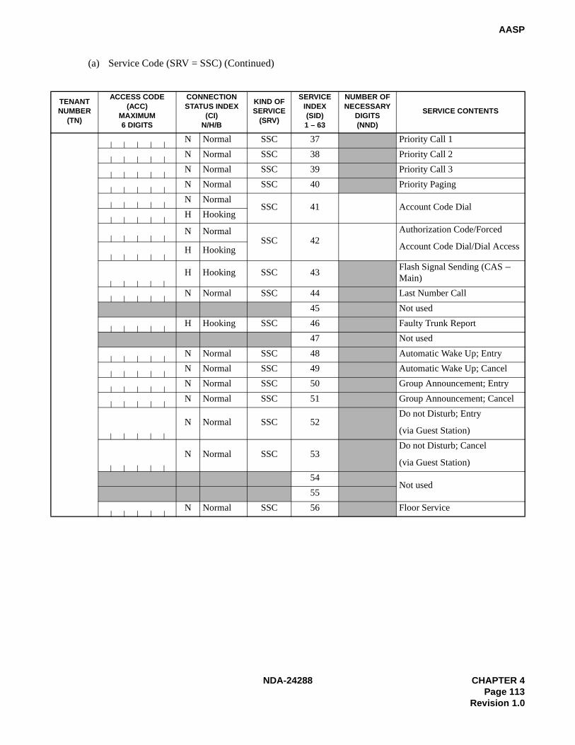
NDA-24288 CHAPTER 4Page 113
Revision 1.0
AASP
(a) Service Code (SRV = SSC) (Continued)
TENANT NUMBER
(TN)
ACCESS CODE(ACC)
MAXIMUM6 DIGITS
CONNECTION STATUS INDEX
(CI) N/H/B
KIND OF SERVICE
(SRV)
SERVICEINDEX(SID)1 – 63
NUMBER OF NECESSARY
DIGITS(NND)
SERVICE CONTENTS
N Normal SSC 37 Priority Call 1
N Normal SSC 38 Priority Call 2
N Normal SSC 39 Priority Call 3
N Normal SSC 40 Priority Paging
N NormalSSC 41 Account Code Dial
H Hooking
N NormalSSC 42
Authorization Code/Forced
Account Code Dial/Dial AccessH Hooking
H Hooking SSC 43Flash Signal Sending (CAS – Main)
N Normal SSC 44 Last Number Call
45 Not used
H Hooking SSC 46 Faulty Trunk Report
47 Not used
N Normal SSC 48 Automatic Wake Up; Entry
N Normal SSC 49 Automatic Wake Up; Cancel
N Normal SSC 50 Group Announcement; Entry
N Normal SSC 51 Group Announcement; Cancel
N Normal SSC 52Do not Disturb; Entry
(via Guest Station)
N Normal SSC 53Do not Disturb; Cancel
(via Guest Station)
54Not used
55
N Normal SSC 56 Floor Service

CHAPTER 4 NDA-24288Page 114Revision 1.0
AASP
(a) Service Code (SRV = SSC) (Continued)
TENANT NUMBER
(TN)
ACCESS CODE(ACC)
MAXIMUM6 DIGITS
CONNECTION STATUS INDEX
(CI) N/H/B
KIND OF SERVICE
(SRV)
SERVICE INDEX(SID)
SERVICEINDEX
NUMBER (No.1)0 – 15
SERVICE CONTENTS
N Normal SSC 56 0
N Normal SSC 56 1
N Normal SSC 56 2
N Normal SSC 56 3
N Normal SSC 56 4
N Normal SSC 56 5
N Normal SSC 56 6
N Normal SSC 56 7
N Normal SSC 56 8
N Normal SSC 56 9
N Normal SSC 56 10
N Normal SSC 56 11
N Normal SSC 56 12
N Normal SSC 56 13
N Normal SSC 56 14
N Normal SSC 56 15

NDA-24288 CHAPTER 4Page 115
Revision 1.0
AASP
(a) Service Code (SRV = SSC) (Continued)
TENANT NUMBER
(TN)
ACCESS CODE(ACC)
MAXIMUM6 DIGITS
CONNECTION STATUS INDEX
(CI)N/H/B
KIND OF SERVICE
(SRV)
SERVICE INDEX(SID)1 – 63
NUMBEROF NECES-
SARYDIGITS(NND)
SERVICE CONTENTS
N Normal SSC 57Split Access (Same NumberAccess)
58
59Not used
N Normal SSC 60 Attendant Manual Override
H Hooking SSC 61 Call Park Access Code
N Normal SSC 62 Call Park Local Retrieval Code
N Normal SSC 63 Call Park Remote Retrieval Code
~

CHAPTER 4 NDA-24288Page 116Revision 1.0
AASP
(a) Service Code (SRV = SSC) (Continued)
Note: Split Access (Same Number Access) (SID = 57)
TENANT NUMBER
(TN)
ACCESS CODE(ACC)
MAXIMUM6 DIGITS
CONNECTION STATUS INDEX
(CI) N/H/B
KIND OF SERVICE
(SRV)
SERVICE INDEX(SID)
ASSIGN NUMBER
(NO.2)0 – 63
KIND OFFUNCTION
(KIND)0 – 3
SERVICECONTENTS
N Normal SSC 57

NDA-24288 CHAPTER 4Page 117
Revision 1.0
AASP
(b) Service Code Appendix (SRV = SSCA)
TENANT NUMBER
(TN)
ACCESS CODE(ACC)
MAXIMUM6 DIGITS
CONNECTION STATUS INDEX
(CI) N/H/B
KIND OF SERVICE
(SRV)
SERVICE INDEX(SIDA)1 – 255
SERVICE CONTENTS
1
40Not used
H Hooking SSCA 41 Voice Call (Dterm)
B BusySSCA 42 Message Reminder (Dterm)
H Hooking
43
45Not used
N Normal SSCA 46 Line Load Control; Entry
N Normal SSCA 47 Line Load Control; Cancel
H Hooking SSCA 48 Data Privacy on Demand; Entry
H Hooking SSCA 49 Data Privacy on Demand; Cancel
N Normal SSCA 50 Busy Out (UCD); Entry
N Normal SSCA 51 Busy Out (UCD); Cancel
52 Not used
N Normal SSCA 53 Boss-Secretary Override
N Normal SSCA 54 Message Waiting Lamp Setting from ATT; Set
N Normal SSCA 55Message Waiting Lamp Setting from ATT;
Cancel
N Normal
SSCA 56Guest/Admin. Service
Note: Guest/Admin. Service (SIDA = 56)H Hooking
B Busy
57
65Not used
N Normal SSCA 66 Multi-Channel Recording <RECORD>
67 Not used
N Normal SSCA 68 Multi-Channel Recording <REPLAY>
69
84Not used
N Normal SSCA 85 Dial Access to Unlock
~~
~~

CHAPTER 4 NDA-24288Page 118Revision 1.0
AASP
(b) Service Code Appendix (SRV = SSCA) (Continued)
Note: Guest/Admin. Service (SIDA = 56)
TENANTNUMBER
(TN)
ACCESS CODE(ACC)
MAX. 6 DIGITS
CONNECTION STATUS INDEX
(CI) N/H/B
KIND OFSERVICE
(SRV)
SERVICEINDEX A(SIDA)
PATTERN NUMBER
FOR AOSP COMMAND
(PNO) 1 – 15
ADMIN./GUEST (A/G)
0/1
SERVICE CONTENTS
N Normal
SSCA 56H Hooking
B Busy
N Normal
SSCA 56H Hooking
B Busy
N Normal
SSCA 56H Hooking
B Busy
N Normal
SSCA 56H Hooking
B Busy
N Normal
SSCA 56H Hooking
B Busy
N Normal
SSCA 56H Hooking
B Busy
N Normal
SSCA 56H Hooking
B Busy
N Normal
SSCA 56H Hooking
B Busy
N Normal
SSCA 56H Hooking
B Busy
N Normal
SSCA 56H Hooking
B Busy

NDA-24288 CHAPTER 4Page 119
Revision 1.0
AASP
(b) Service Code Appendix (SRV = SSCA) (Continued)
Note: When Split Call Forwarding is in service (the ASYD command. SYS1 INDEX79 bit2=1), this access code is used forCall Forwarding.
TENANT NUMBER
(TN)
ACCESS CODE(ACC)
MAXIMUM6 DIGITS
CONNECTION STATUS
INDEX (CI)N/H/B
KIND OF SERVICE
(SRV)
SERVICE INDEX A (SIDA)1 – 255
NECESSARYDIGIT (NND)1 – 6
SERVICE CONTENTS
N Normal SSCA 86Split C.F.–All Calls (for Station);
Entry Note
N Normal SSCA 87Split C.F.–Busy Line (for Station);
Entry Note
N Normal SSCA 88Split C.F.–Don’t Answer (for Station);
Entry Note
N Normal SSCA 89Split C.F.–All Calls (for Station);
Cancel Note
N Normal SSCA 90Split C.F.–Busy Line (for Station);
Cancel Note
N Normal SSCA 91Split C.F.–Don’t Answer (for Station);
Cancel Note
92
95Not used
N Normal SSCA 96 Follow Phone (Swap)
H Hooking SSCA 97 Call Hold Conference
98
105Not used
N Normal SSCA 106 Call Return
107
255Not used
~~
~

CHAPTER 4 NDA-24288Page 120Revision 1.0
AASP
(c) Outgoing Call (Without Route Advance) (SRV = OGC)
TENANT NUMBER
(TN)
ACCESS CODE (ACC)
MAXIMUM 6 DIGITS
CONNECTIONSTATUS INDEX
(CI) N/H
KIND OF SERVICE (SRV)
ROUTENUMBER
(RT)
N NormalOGC
H Hooking
N NormalOGC
H Hooking
N NormalOGC
H Hooking
N NormalOGC
H Hooking
N NormalOGC
H Hooking
N NormalOGC
H Hooking
N NormalOGC
H Hooking
N NormalOGC
H Hooking
N NormalOGC
H Hooking
N NormalOGC
H Hooking
N NormalOGC
H Hooking
N NormalOGC
H Hooking
N NormalOGC
H Hooking
N NormalOGC
H Hooking
N NormalOGC
H Hooking
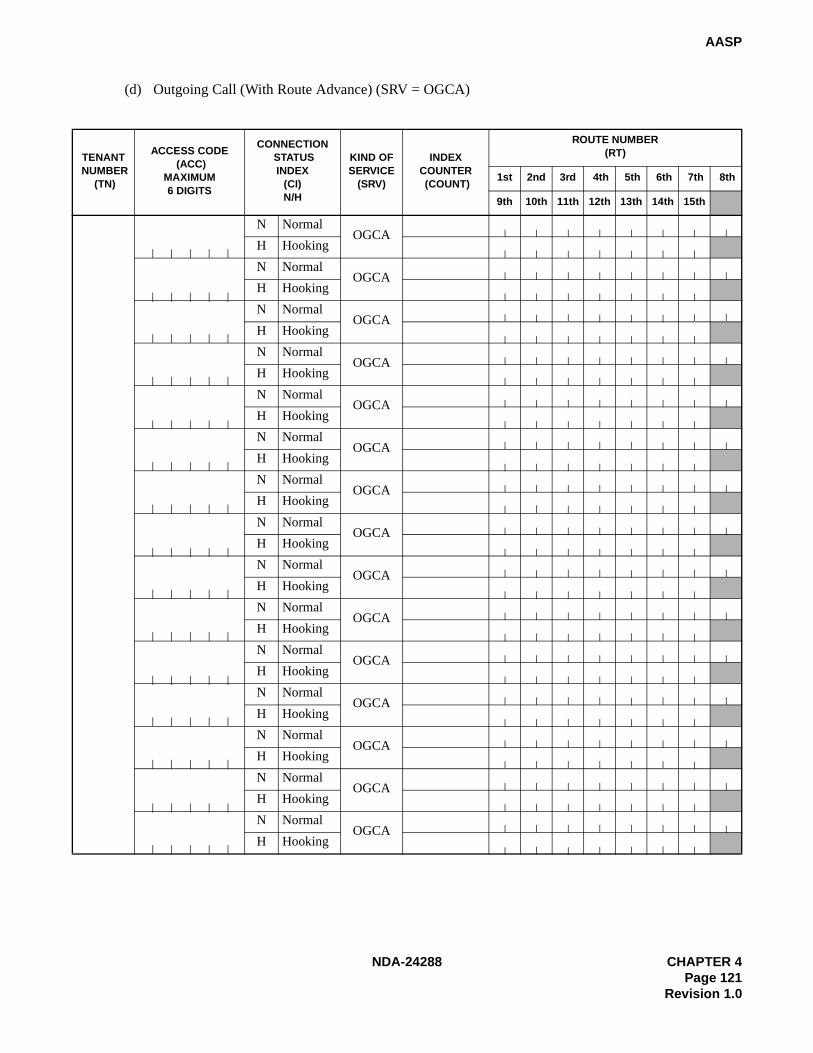
NDA-24288 CHAPTER 4Page 121
Revision 1.0
AASP
(d) Outgoing Call (With Route Advance) (SRV = OGCA)
TENANT NUMBER
(TN)
ACCESS CODE (ACC)
MAXIMUM6 DIGITS
CONNECTION STATUS INDEX
(CI)N/H
KIND OFSERVICE
(SRV)
INDEXCOUNTER (COUNT)
ROUTE NUMBER (RT)
1st 2nd 3rd 4th 5th 6th 7th 8th
9th 10th 11th 12th 13th 14th 15th
N NormalOGCA
H Hooking
N NormalOGCA
H Hooking
N NormalOGCA
H Hooking
N NormalOGCA
H Hooking
N NormalOGCA
H Hooking
N NormalOGCA
H Hooking
N NormalOGCA
H Hooking
N NormalOGCA
H Hooking
N NormalOGCA
H Hooking
N NormalOGCA
H Hooking
N NormalOGCA
H Hooking
N NormalOGCA
H Hooking
N NormalOGCA
H Hooking
N NormalOGCA
H Hooking
N NormalOGCA
H Hooking

CHAPTER 4 NDA-24288Page 122Revision 1.0
AASP
(e) Least Cost Routing Access Code (SRV = LCR)
TENANT NUMBER
(TN)
ACCESS CODE (ACC)
MAXIMUM6 DIGITS
CONNECTION STATUS INDEX
(CI) N/H
KIND OFSERVICE
(SRV)
FLEXIBLE ROUTE
NUMBER(RT)
SECOND DIALTONE
(2nd DT)0/1
AUTHORIZATIONCODE DIALING
(AH) 0/1
SUB ADDRESSDIALING
(SUB) 0/1
N NormalLCR
H HookingN Normal
LCRH HookingN Normal LCRH HookingN Normal
LCRH HookingN Normal
LCRH HookingN Normal
LCRH HookingN Normal
LCRH HookingN Normal LCRH HookingN Normal
LCRH HookingN Normal
LCRH HookingN Normal
LCRH HookingN Normal LCRH HookingN Normal LCRH HookingN Normal
LCRH HookingN Normal
LCRH Hooking

NDA-24288 CHAPTER 4Page 123
Revision 1.0
AASP
(f) Register Sender Least Cost Routing Access Code (SRV = LCRS)
TENANTNUMBER
(TN)
ACCESS CODE (ACC)
MAXIMUM6 DIGITS
CONNECTIONSTATUS INDEX
(CI) N/H
KIND OFSERVICE
(SRV)
FLEXIBLE ROUTE
NUMBER(RT)
SECOND DIAL TONE
(2nd DT)0/1
AUTHORIZATION CODE DIALING
(AH) 0/1
SUB ADDRESSDIALING(SUB) 0/1
N NormalLCRS
H Hooking
N NormalLCRS
H Hooking
N NormalLCRS
H Hooking
N NormalLCRS
H Hooking
N NormalLCRS
H Hooking
N NormalLCRS
H Hooking
N NormalLCRS
H Hooking
N NormalLCRS
H Hooking
N NormalLCRS
H Hooking
N NormalLCRS
H Hooking
N NormalLCRS
H Hooking
N NormalLCRS
H Hooking
N NormalLCRS
H Hooking
N NormalLCRS
H Hooking
N NormalLCRS
H Hooking

CHAPTER 4 NDA-24288Page 124Revision 1.0
AASP
(g) Office Termination Code (SRV = UNIF)
TENANTNUMBER
(TN)
ACCESS CODE (ACC)
MAXIMUM6 DIGITS
CONNECTION STATUS INDEX
(CI) N/H
KIND OFSERVICE
(SRV)
SKIP DIGIT(SKIP)0 – 5
N NormalUNIF
H HookingN Normal UNIFH HookingN Normal
UNIFH HookingN Normal
UNIFH HookingN Normal
UNIFH HookingN Normal UNIFH HookingN Normal
UNIFH HookingN Normal
UNIFH HookingN Normal
UNIFH HookingN Normal
UNIFH HookingN Normal UNIFH HookingN Normal
UNIFH HookingN Normal
UNIFH HookingN Normal
UNIFH HookingN Normal UNIFH Hooking

NDA-24288 CHAPTER 4Page 125
Revision 1.0
AASP
(h) Announcement Service-Single Announcement (SRV = ANNC)
TENANTNUMBER
(TN)
ACCESS CODE (ACC)
MAXIMUM6 DIGITS
CONNECTION STATUS INDEX
(CI) N/H
KIND OFSERVICE
(SRV)
ANNOUNCEMENTEQUIPMENT
NUMBER (EQP)
1 – 127
N NormalANNC
H HookingN Normal ANNCH HookingN Normal ANNCH HookingN Normal
ANNCH HookingN Normal
ANNCH HookingN Normal
ANNCH HookingN Normal ANNCH HookingN Normal
ANNCH HookingN Normal
ANNCH HookingN Normal
ANNCH HookingN Normal ANNCH HookingN Normal ANNCH HookingN Normal
ANNCH HookingN Normal
ANNCH HookingN Normal
ANNCH Hooking

CHAPTER 4 NDA-24288Page 126Revision 1.0
AASP
(i) Announcement Service-Multiple Announcement (SRV = ANNCM)
TENANTNUMBER
(TN)
ACCESS CODE (ACC)
MAX. 6 DIGITS
CONNECTION STATUS INDEX
(CI) N/H
KIND OFSERVICE
(SRV)
ANNOUNCEMENTTENANTNUMBER
(TN)1 – 125
ANNOUNCEMENTEQUIPMENT
NUMBER (EQP)
122 – 125
N NormalANNCM
H HookingN Normal
ANNCMH HookingN Normal ANNCMH HookingN Normal
ANNCMH HookingN Normal
ANNCMH HookingN Normal
ANNCMH HookingN Normal
ANNCMH HookingN Normal ANNCMH HookingN Normal
ANNCMH HookingN Normal
ANNCMH HookingN Normal
ANNCMH HookingN Normal ANNCMH HookingN Normal ANNCMH HookingN Normal
ANNCMH HookingN Normal
ANNCMH HookingN Normal
ANNCMH HookingN Normal ANNCMH HookingN Normal
ANNCMH HookingN Normal
ANNCMH Hooking

NDA-24288 CHAPTER 4Page 127
Revision 1.0
AASP
(j) Paging Answer Code (SRV = PAGA)
TENANTNUMBER
(TN)
ACCESS CODE (ACC)
MAXIMUM6 DIGITS
CONNECTION STATUS INDEX
(CI) N/H
KIND OFSERVICE
(SRV)
ROUTENUMBER
(RT)
N NormalPAGA
H HookingN Normal
PAGAH HookingN Normal
PAGAH HookingN Normal PAGAH HookingN Normal
PAGAH HookingN Normal
PAGAH HookingN Normal
PAGAH HookingN Normal PAGAH HookingN Normal PAGAH HookingN Normal
PAGAH HookingN Normal
PAGAH HookingN Normal
PAGAH HookingN Normal PAGAH HookingN Normal
PAGAH HookingN Normal
PAGAH Hooking

CHAPTER 4 NDA-24288Page 128Revision 1.0
AASP
(k) Paging Cancel Code (SRV = PAGC)
TENANTNUMBER
(TN)
ACCESS CODE (ACC)
MAXIMUM6 DIGITS
CONNECTION STATUS INDEX
(CI) N/H
KIND OFSERVICE
(SRV)
ROUTENUMBER
(RT)
N NormalPAGC
H HookingN Normal
PAGCH HookingN Normal
PAGCH HookingN Normal
PAGCH HookingN Normal PAGCH HookingN Normal
PAGCH HookingN Normal
PAGCH HookingN Normal
PAGCH HookingN Normal PAGCH HookingN Normal
PAGCH HookingN Normal
PAGCH HookingN Normal
PAGCH HookingN Normal
PAGCH HookingN Normal PAGCH HookingN Normal
PAGCH Hooking

NDA-24288 CHAPTER 4Page 129
Revision 1.0
AGSP
AGSP: Assignment of Guest Special Access Code
1. General
This command determines the Kind of Service to be executed or the route to be used when a Special Accesscode or trunk Access code has been dialed for the Guest Station.
2. Precautions
1. This command is used for the Hotel Application only.
2. If the Guest and Admin. Numbering are separated (the ASYD command, SYS1, INDEX 160, bit6=0), usethis command for the Guest Special Access code. For the Admin. Special Access code, use the AASPcommand.
Note: Hotel features are available in TN1 only. If the numbering plans are separated by tenants, the purpose foreach tenant is completely separated. Admin. Station required of the guest room call must be allocated inTN1.
3. If the numbering plan for Admin. and Guest is common (the ASYD command, SYS1, INDEX 160,bit6=1), this command may be used to assign the Admin. Special Access code as well.
4. The applicable Tenant Number (TN) range is designated by the ASYD command, SYS1, INDEX 8. Enterthe tenant number this command affects.
If data for this command is common for all tenants (ASYD command, SYS1, INDEX 92, bit1=1), assignTN parameter as data “1” for all tenants.
5. To dial a different number of station number digits, the following programming is required.
Note: For the station number (ex. 200, 20000),
AANP 1st.: 2 CI: N & H NND: 3AASP ACC: 200* CI: N & H SRV: SSC SID: 36 STATE: 63 (Dummy STA)
6. The following information states the rules of NND/NND1 data for Speed Calling-System and Call ParkRemote Retrieval.
7. The variable parameter appears on the MAT depending on the data in the parameter SRV.
Service Feature SRV SID NND NND1
Speed Calling - System SSC 15NND is the number of digits of the ac-cess code (ACC)
NND1 is the number of digits abbre-viated digits code (ADC)
Call Park Remote Retrieval Code
SSC 63NND is the number of digits of the ac-cess code (ACC)
-

CHAPTER 4 NDA-24288Page 130Revision 1.0
AGSP
3. Data Entry Instructions
Access code (Max. 6 digits)
15 (Speed Calling-System; Access)63 (Call Park ; Retrieve)
NND appears when the following SID is entered.NND data is variable depending on SID.
NND1 appears when SID = 15. The number of ADC(Abbreviation Digit Code) digits should be assigned in NND1.
TENANTNUMBER
(TN)
ACCESS CODE(ACC)
MAX. 6 DIGITS
CONNECTION STATUS INDEX
(CI) N/H/B
KIND OFSERVICE (SRV)
ACC
CI
SRV
NND1
SERVICE INDEX(SID) 1-63
NECESSARY DIGIT(NND)
NECESSARY DIGIT FOR SPEEDCALLING (NND1) 1-24
NND
SID Number of digits for NND
N = Normal serviceH = Hooking serviceB = Busy service
Access Code (1-24)
Access Code (1-3)
When SRV = SSC (Service code except SID36, 56 and 57) is assigned
SSC = Service code SSCA = Service code appendixOGC = Outgoing callOGCA = Outgoing call with route advanceLCR = Least cost routing LCRS = Register sending LCRUNIF = Office terminationANNC = Announcement service-single announcementANNCM = Announcement service-multiple announcementPAGA = Paging answer PAGC = Paging cancel

NDA-24288 CHAPTER 4Page 131
Revision 1.0
AGSP
STATE(Hotel Service Code)
1 To be cleaned without ID code 2 Cleaning Completed without ID code 3 Ready for Occupancy without ID code 4 Use Not Allowed without ID code
5 - 8 - 9 Maid Dial Answer Back without ID code-110 Maid Dial Answer Back without ID code-211 Maid Dial Answer Back without ID code-312 Maid Dial Answer Back without ID code-413 Maid Dial Answer Back without ID code-514 Maid Dial Answer Back without ID code-615 Maid Dial Answer Back without ID code-716 -17 To be cleaned with ID code18 Cleaning Completed with ID code19 Ready for Occupancy with ID code20 Use Not Allowed with ID code
21 - 24 -25 Maid Dial Answer Back with ID code-126 Maid Dial Answer Back with ID code-227 Maid Dial Answer Back with ID code-328 Maid Dial Answer Back with ID code-429 Maid Dial Answer Back with ID code-530 Maid Dial Answer Back with ID code-631 Maid Dial Answer Back with ID code-7 32 Access code for Administration Station Call33 Automatic Wake Up Setting, Cancel; Same Special code34 For Guest Station Secretary Telephone; Boss/Secretary Calling
35 - 43 -44 Direct Data Entry-Station (via Guest Station)
45 - 50 -51 Same Special Code Time Zone Connection Change52 Same Special Code Time Zone Connection Change53 Same Special Code Time Zone Connection Change54 Same Special Code Time Zone Connection Change55 Same Special Code Time Zone Connection Change
56 - 62 -63 Dummy Number
Note: STATE=1-15 are used at the time of Maid ID Code Service is not provided; (ASYD SYS1 INDEX 164, bit3=0) STSTE=17-31 are used at the time of Maid ID Code Service is provided; (ASYD SYS1 INDEX 164, bit3=1)
SERVICE INDEX (SID) 1-63 STATE
36
When SRV=SSC (Service code). SID36 (Hotel Service) is assigned

CHAPTER 4 NDA-24288Page 132Revision 1.0
AGSP
SERVICE INDEX (SID) 1-63
NO.1
56
NO.1(Kind of Assignment Number)
Available numbers are 0-15. This data is used to assign Floor Service data by the ASPF command.Note: When programming Floor Service data,
ASYD SYS1 INDEX 165, bit7=1 must have been assigned.
SERVICE INDEX (SID) 1-63
NO.2 KIND
57
NO.2This parameter specifies the number (0-63) of theaccess code being assigned for mutual Access.This parameter serves as a counter for the accesscodes being assigned.
Note: This parameter is used when assigning the details of the service by the ASPS command.
KIND: (0-3)This parameter specifies the Split Access Parameter Classification. The data tobe assigned here depends on how the Guest and Administration stations aredifferentiated.The Guest and Administration stations may be assigned to separate TNs, RSCs,and/or SFCs, or they may only be differentiated by their respective designationsas Administration or Guest. 0: Administration/Guest (Assign this if the access code is to be shared between Guest and Administration with no correspondence to TN, RSC or SFC.) 1: TN (Assign this if the access code is to be shared among specified TNs) 2: RSC (Assign this if the access code is to be shared among specified RSCs) 3: SFC (Assign this if the access code is to be shared among specified SFCs)
When SRV = SSC (Service code), SID 56 (Floor Service) is assigned
When SRV = SSC (Service code), SID 57 (Split Access) is assigned

NDA-24288 CHAPTER 4Page 133
Revision 1.0
AGSP
SERVICE INDEX A (SIDA) 1-255 PNO 1-15 A/G56
PNO
This parameter specifies the Admin./GuestNumbering Parameter Classification.After assigning the PNO, go to the AOSPcommand to skip this ACC.After skipping the access code, the systemrefers to the numbering data designated inthe next parameter A/G.
A/GNumbering table designation for redevelopmentA: Admin.G: Guest
When SRV = SSCA (Service code appendix), SIDA 56 (Guest/Admin. Service) is assigned

CHAPTER 4 NDA-24288Page 134Revision 1.0
AGSP
Assign the number of advanced trunk routes.
ROUTE NUMBER(RT)
COUNT
Assign a dummy route number.RT
Second dial tone sending (which is sent when a station hasdialed the digits specified in NND of the AGNP command)0 = Second DT is not send1 = Second DT is sent
2nd DT
Authorization code after dialingACC (LCR)+Destination number0 = Out of Service1 = In Service
AH
ISDN-Sub Address Dialing0 = Out of Service1 = In Service
SUB
ROUTE NUMBER(RT)
SECOND DIAL TONE(2nd DT) 0/1
AUTHORIZATION CODE(AH) 0/1
SUB ADDRESS DIALING(SUB) 0/1
INDEX COUNTER (COUNT) INDEX ROUTE NUMBER (RT)
When SRV = OGC (Outgoing call) is assigned
When SRV = PAGA (Paging answer) is assigned
When SRV = PAGC (Paging cancel) is assigned
When SRV = OGCA (Outgoing call with route advance) is assigned
When SRV = LCR (Least cost routing) is assignedWhen SRV = LCRS (Register sender LCR) is assigned
INDEX
INDEX is the route advance order.
12
3
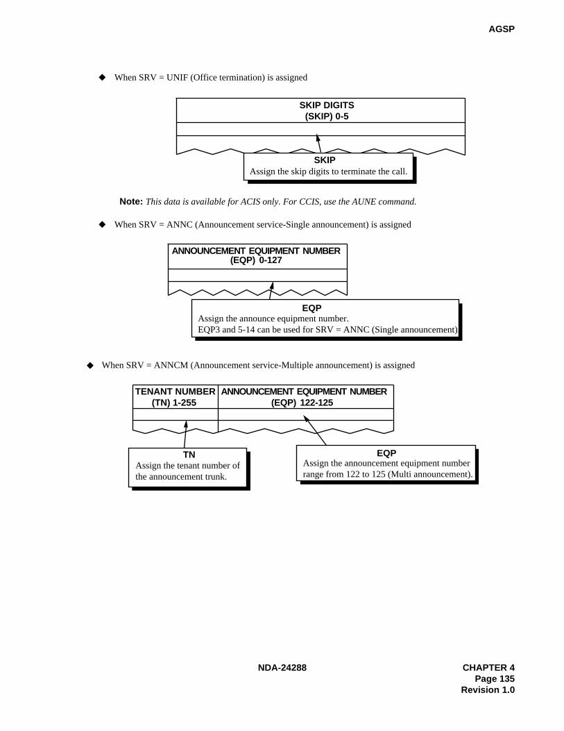
NDA-24288 CHAPTER 4Page 135
Revision 1.0
AGSP
Assign the skip digits to terminate the call.
Assign the announce equipment number.EQP3 and 5-14 can be used for SRV = ANNC (Single announcement).
SKIP DIGITS(SKIP) 0-5
When SRV = UNIF (Office termination) is assigned
When SRV = ANNC (Announcement service-Single announcement) is assigned
SKIP
ANNOUNCEMENT EQUIPMENT NUMBER(EQP) 0-127
EQP
Note: This data is available for ACIS only. For CCIS, use the AUNE command.
Assign the tenant number ofthe announcement trunk.
When SRV = ANNCM (Announcement service-Multiple announcement) is assigned
TN
TENANT NUMBER(TN) 1-255
ANNOUNCEMENT EQUIPMENT NUMBER(EQP) 122-125
Assign the announcement equipment number range from 122 to 125 (Multi announcement).
EQP
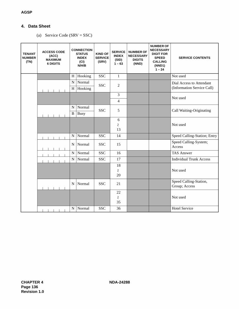
CHAPTER 4 NDA-24288Page 136Revision 1.0
AGSP
4. Data Sheet
(a) Service Code (SRV = SSC)
TENANT NUMBER
(TN)
ACCESS CODE(ACC)
MAXIMUM6 DIGITS
CONNECTION STATUS INDEX
(CI) N/H/B
KIND OFSERVICE
(SRV)
SERVICEINDEX(SID)1 – 63
NUMBER OF NECESSARY
DIGITS (NND)
NUMBER OF NECESSARY
DIGIT FOR SPEED
CALLING(NND1)1 – 24
SERVICE CONTENTS
H Hooking SSC 1 Not used
N NormalSSC 2
Dial Access to Attendant (Information Service Call)H Hooking
3Not used
4
N NormalSSC 5 Call Waiting-Originating
B Busy
6
13Not used
N Normal SSC 14 Speed Calling-Station; Entry
N Normal SSC 15Speed Calling-System; Access
N Normal SSC 16 TAS Answer
N Normal SSC 17 Individual Trunk Access
18
20Not used
N Normal SSC 21Speed Calling-Station, Group; Access
22
35Not used
N Normal SSC 36 Hotel Service
~~
~

NDA-24288 CHAPTER 4Page 137
Revision 1.0
AGSP
(a) Service Code (SRV = SSC) (Continued)
TENANT NUMBER
(TN)
ACCESS CODE(ACC)
MAXIMUM6 DIGITS
CONNECTION STATUS INDEX
(CI) N/H/B
KIND OF SERVICE
(SRV)
SERVICE INDEX(SID)
MAIDSTATUS (STATE)1 – 63
SERVICE CONTENTS
N Normal SSC 36
1 To be cleaned without ID Code
2 Cleaned without ID Code
3Ready for Occupancy without ID Code
4 Use Not Allowed without ID Code
5
8Not used
9Maid Dial Answer Back without ID Code 1
10Maid Dial Answer Back without ID Code 2
11Maid Dial Answer Back without ID Code 3
12Maid Dial Answer Back without ID Code 4
13Maid Dial Answer Back without ID Code 5
14Maid Dial Answer Back without ID Code 6
15Maid Dial Answer Back without ID Code 7
16 Not used
17 To be cleaned with ID code
18 Cleaned with ID Code
19 Ready for Occupancy with ID Code
20 Use Not Allowed with ID Code
~

CHAPTER 4 NDA-24288Page 138Revision 1.0
AGSP
(a) Service Code (SRV = SSC) (Continued)
TENANT NUMBER
(TN)
ACCESS CODE(ACC)
MAXIMUM6 DIGITS
CONNECTION STATUS INDEX
(CI) N/H/B
KIND OF SERVICE
(SRV)
SERVICE INDEX(SID)
MAIDSTATUS (STATE)1 – 63
SERVICE CONTENTS
N Normal SSC 36
21
24Not used
25Maid Dial Answer Back with ID Code 1
26Maid Dial Answer Back with ID Code 2
27Maid Dial Answer Back with ID Code 3
28Maid Dial Answer Back with ID Code 4
29Maid Dial Answer Back with ID Code 5
30Maid Dial Answer Back with ID Code 6
31Maid Dial Answer Back with ID Code 7
32 Not used
33Automatic Wake-Up Setting, Cancel; Same Special Code
34For Guest Station Secretary Telephone; Boss/Secretary
35
43Not used
44 Direct Data Entry – STA
45
50Not used
51Same Special Code Time Zone Connection Change
~~
~

NDA-24288 CHAPTER 4Page 139
Revision 1.0
AGSP
(a) Service Code (SRV = SSC) (Continued)
TENANT NUMBER
(TN)
ACCESS CODE(ACC)
MAXIMUM6 DIGITS
CONNECTION STATUS INDEX
(CI) N/H/B
KIND OF SERVICE
(SRV)
SERVICE INDEX(SID)
MAIDSTATUS (STATE)1 – 63
SERVICE CONTENTS
N Normal SSC 36
52Same Special Code Time Zone Connection Change
53Same Special Code Time Zone Connection Change
54Same Special Code Time Zone Connection Change
55Same Special Code Time Zone Connection Change
56
62Not used
63 Dummy Number
~

CHAPTER 4 NDA-24288Page 140Revision 1.0
AGSP
(a) Service Code (SRV = SSC) (Continued)
TENANT NUMBER
(TN)
ACCESS CODE(ACC)
MAXIMUM6 DIGITS
CONNECTION STATUS INDEX
(CI) N/H/B
KIND OF SERVICE
(SRV)
SERVICEINDEX(SID)1 – 63
NUMBER OF NECESSARY
DIGITS(NND)
SERVICE CONTENTS
N Normal SSC 37 Priority Call 1
N Normal SSC 38 Priority Call 2
N Normal SSC 39 Priority Call 3
N Normal SSC 40 Priority Paging
41 Not used
42 Not used
H Hooking SSC 43Flash Signal Sending (CAS – Main)
44
47Not used
N Normal SSC 48 Automatic Wake Up; Entry
N Normal SSC 49 Automatic Wake Up; Cancel
50 Not used
51 Not used
N Normal SSC 52 Do not Disturb; Entry
N Normal SSC 53 Do not Disturb; Cancel
54Not used
55
N Normal SSC 56
Floor Service
Note: When programmingFloor Service data,ASYD SYS1 INDEX165, bit 1=1 musthave been assigned.
~

NDA-24288 CHAPTER 4Page 141
Revision 1.0
AGSP
(a) Service Code (SRV = SSC) (Continued)
TENANT NUMBER
(TN)
ACCESS CODE(ACC)
MAXIMUM6 DIGITS
CONNECTION STATUS INDEX
(CI) N/H/B
KIND OF SERVICE
(SRV)
SERVICE INDEX(SID)
SERVICEINDEX
NUMBER (No.1)0 – 15
SERVICE CONTENTS
N Normal SSC 56 0
N Normal SSC 56 1
N Normal SSC 56 2
N Normal SSC 56 3
N Normal SSC 56 4
N Normal SSC 56 5
N Normal SSC 56 6
N Normal SSC 56 7
N Normal SSC 56 8
N Normal SSC 56 9
N Normal SSC 56 10
N Normal SSC 56 11
N Normal SSC 56 12
N Normal SSC 56 13
N Normal SSC 56 14
N Normal SSC 56 15

CHAPTER 4 NDA-24288Page 142Revision 1.0
AGSP
(a) Service Code (SRV = SSC) (Continued)
TENANT NUMBER
(TN)
ACCESS CODE(ACC)
MAXIMUM6 DIGITS
CONNECTION STATUS INDEX
(CI) N/H/B
KIND OF SERVICE
(SRV)
SERVICE INDEX(SID)1 – 63
NUMBER OF NECESSARY
DIGITS(NND)
SERVICE CONTENTS
N Normal SSC 57Split Access (Same Number Ac-cess)
58
59Not used
N Normal SSC 60 Attendant Manual Override
H Hooking SSC 61 Call Park Access Code
N Normal SSC 62 Call Park Local Retrieval Code
N Normal SSC 63 Call Park Remote Retrieval Code
~

NDA-24288 CHAPTER 4Page 143
Revision 1.0
AGSP
(a) Service Code (SRV = SSC) (Continued)
TENANT NUMBER
(TN)
ACCESS CODE(ACC)
MAXIMUM6 DIGITS
CONNECTION STATUS INDEX
(CI) N/H/B
KIND OF SERVICE
(SRV)
SERVICE INDEX(SID)
ASSIGN NUMBER
(No.2)0 – 63
KIND OFFUNCTION
(KIND)0 – 3
SERVICECONTENTS
N Normal SSC 57
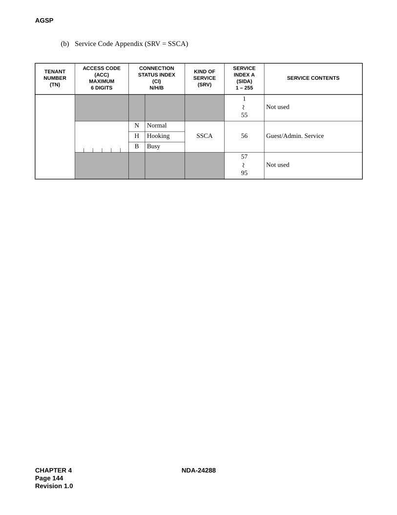
CHAPTER 4 NDA-24288Page 144Revision 1.0
AGSP
(b) Service Code Appendix (SRV = SSCA)
TENANTNUMBER
(TN)
ACCESS CODE(ACC)
MAXIMUM6 DIGITS
CONNECTIONSTATUS INDEX
(CI) N/H/B
KIND OFSERVICE
(SRV)
SERVICEINDEX A(SIDA)1 – 255
SERVICE CONTENTS
1
55Not used
N Normal
SSCA 56 Guest/Admin. ServiceH Hooking
B Busy
57
95Not used
~~

NDA-24288 CHAPTER 4Page 145
Revision 1.0
AGSP
(b) Service Code Appendix (SRV = SSCA) (Continued)
TENANTNUMBER
(TN)
ACCESS CODE(ACC)
MAX. 6 DIGITS
CONNECTION STATUS INDEX
(CI) N/H/B
KIND OFSERVICE
(SRV)
SERVICEINDEX A(SIDA)
PATTERN NUMBER FOR AOSP COMMAND
(PNO) 1 – 15
ADMIN./GUEST (A/G)
0/1
SERVICE CONTENTS
N Normal
SSCA 56H Hooking
B Busy
N Normal
SSCA 56H Hooking
B Busy
N Normal
SSCA 56H Hooking
B Busy
N Normal
SSCA 56H Hooking
B Busy
N Normal
SSCA 56H Hooking
B Busy
N Normal
SSCA 56H Hooking
B Busy
N Normal
SSCA 56H Hooking
B Busy
N Normal
SSCA 56H Hooking
B Busy
N Normal
SSCA 56H Hooking
B Busy
N Normal
SSCA 56H Hooking
B Busy

CHAPTER 4 NDA-24288Page 146Revision 1.0
AGSP
(c) Outgoing Call (Without Route Advance) (SRV = OGC)
TENANT NUMBER
(TN)
ACCESS CODE (ACC)
MAXIMUM 6 DIGITS
CONNECTIONSTATUS INDEX
(CI) N/H
KIND OF SERVICE
(SRV)
ROUTENUMBER
(RT)REMARKS
N NormalOGC
H Hooking
N NormalOGC
H Hooking
N NormalOGC
H Hooking
N NormalOGC
H Hooking
N NormalOGC
H Hooking
N NormalOGC
H Hooking
N NormalOGC
H Hooking
N NormalOGC
H Hooking
N NormalOGC
H Hooking
N NormalOGC
H Hooking
N NormalOGC
H Hooking
N NormalOGC
H Hooking
N NormalOGC
H Hooking
N NormalOGC
H Hooking
N NormalOGC
H Hooking

NDA-24288 CHAPTER 4Page 147
Revision 1.0
AGSP
(d) Outgoing Call (With Route Advance) (SRV = OGCA)
TENANT NUMBER
(TN)
ACCESS CODE (ACC)
MAXIMUM6 DIGITS
CONNECTION STATUS INDEX
(CI)N/H
KIND OFSERVICE
(SRV)
INDEXCOUNTER (COUNT)
ROUTE NUMBER (RT)
1st 2nd 3rd 4th 5th 6th 7th 8th
9th 10th 11th 12th 13th 14th 15th
N NormalOGCA
H Hooking
N NormalOGCA
H Hooking
N NormalOGCA
H Hooking
N NormalOGCA
H Hooking
N NormalOGCA
H Hooking
N NormalOGCA
H Hooking
N NormalOGCA
H Hooking
N NormalOGCA
H Hooking
N NormalOGCA
H Hooking
N NormalOGCA
H Hooking
N NormalOGCA
H Hooking
N NormalOGCA
H Hooking
N NormalOGCA
H Hooking
N NormalOGCA
H Hooking
N NormalOGCA
H Hooking

CHAPTER 4 NDA-24288Page 148Revision 1.0
AGSP
(e) Least Cost Routing Access Code (SRV = LCR)
TENANT NUMBER
(TN)
ACCESS CODE (ACC)
MAXIMUM6 DIGITS
CONNECTION STATUS INDEX
(CI) N/H
KIND OFSERVICE
(SRV)
FLEXIBLEROUTE
NUMBER(RT)
1 – 255
SECONDDIALTONE
(2nd DT)0/1
AUTHORIZATIONCODE
DIALING(AH) 0/1
SUBADDRESSDIALING
(SUB) 0/1
N NormalLCR
H HookingN Normal
LCRH HookingN Normal LCRH HookingN Normal
LCRH HookingN Normal
LCRH HookingN Normal
LCRH HookingN Normal
LCRH HookingN Normal LCRH HookingN Normal
LCRH HookingN Normal
LCRH HookingN Normal
LCRH HookingN Normal LCRH HookingN Normal LCRH HookingN Normal
LCRH HookingN Normal
LCRH Hooking

NDA-24288 CHAPTER 4Page 149
Revision 1.0
AGSP
(f) Register Sender Least Cost Routing Access Code (SRV = LCRS)
TENANTNUMBER
(TN)
ACCESS CODE(ACC)
MAXIMUM6 DIGITS
CONNECTIONSTATUS INDEX
(CI) N/H
KIND OFSERVICE
(SRV)
FLEXIBLEROUTE
NUMBER(RT)
1 – 255
SECONDDIAL TONE
(2nd DT)0/1
AUTHORIZATIONCODE DIALING
(AH) 0/1
SUBADDRESSDIALING
(SUB) 0/1
N NormalLCRS
H Hooking
N NormalLCRS
H Hooking
N NormalLCRS
H Hooking
N NormalLCRS
H Hooking
N NormalLCRS
H Hooking
N NormalLCRS
H Hooking
N NormalLCRS
H Hooking
N NormalLCRS
H Hooking
N NormalLCRS
H Hooking
N NormalLCRS
H Hooking
N NormalLCRS
H Hooking
N NormalLCRS
H Hooking
N NormalLCRS
H Hooking
N NormalLCRS
H Hooking
N NormalLCRS
H Hooking

CHAPTER 4 NDA-24288Page 150Revision 1.0
AGSP
(g) Office Termination Code (SRV = UNIF)
TENANTNUMBER
(TN)
ACCESS CODE (ACC)
MAXIMUM6 DIGITS
CONNECTION STATUS INDEX
(CI) N/H
KIND OFSERVICE
(SRV)
SKIP DIGIT(SKIP)0 – 5
N NormalUNIF
H HookingN Normal UNIFH HookingN Normal
UNIFH HookingN Normal
UNIFH HookingN Normal
UNIFH HookingN Normal UNIFH HookingN Normal
UNIFH HookingN Normal
UNIFH HookingN Normal
UNIFH HookingN Normal
UNIFH HookingN Normal UNIFH HookingN Normal
UNIFH HookingN Normal
UNIFH HookingN Normal
UNIFH HookingN Normal UNIFH Hooking

NDA-24288 CHAPTER 4Page 151
Revision 1.0
AGSP
(h) Announcement Service-Single Announcement (SRV = ANNC)
TENANTNUMBER
(TN)
ACCESS CODE (ACC)
MAXIMUM6 DIGITS
CONNECTION STATUS INDEX
(CI) N/H
KIND OFSERVICE
(SRV)
ANNOUNCEMENTEQUIPMENT
NUMBER (EQP)
1 – 127
N NormalANNC
H HookingN Normal ANNCH HookingN Normal ANNCH HookingN Normal
ANNCH HookingN Normal
ANNCH HookingN Normal
ANNCH HookingN Normal ANNCH HookingN Normal
ANNCH HookingN Normal
ANNCH HookingN Normal
ANNCH HookingN Normal ANNCH HookingN Normal ANNCH HookingN Normal
ANNCH HookingN Normal
ANNCH HookingN Normal
ANNCH Hooking

CHAPTER 4 NDA-24288Page 152Revision 1.0
AGSP
(i) Announcement Service-Multiple Announcement (SRV = ANNCM)
TENANTNUMBER
(TN)
ACCESS CODE (ACC)
MAXIMUM6 DIGITS
CONNECTION STATUS INDEX
(CI) N/H
KIND OFSERVICE
(SRV)
ANNOUNCEMENTTENANTNUMBER
(TN)1 – 125
ANNOUNCEMENTEQUIPMENT
NUMBER (EQP)
122 – 125
N NormalANNCM
H HookingN Normal
ANNCMH HookingN Normal ANNCMH HookingN Normal
ANNCMH HookingN Normal
ANNCMH HookingN Normal
ANNCMH HookingN Normal
ANNCMH HookingN Normal ANNCMH HookingN Normal
ANNCMH HookingN Normal
ANNCMH HookingN Normal
ANNCMH HookingN Normal ANNCMH HookingN Normal ANNCMH HookingN Normal
ANNCMH HookingN Normal
ANNCMH HookingN Normal
ANNCMH HookingN Normal ANNCMH HookingN Normal
ANNCMH HookingN Normal
ANNCMH Hooking
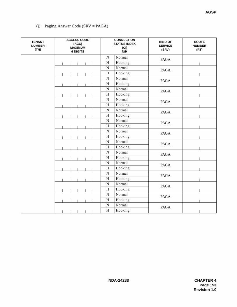
NDA-24288 CHAPTER 4Page 153
Revision 1.0
AGSP
(j) Paging Answer Code (SRV = PAGA)
TENANTNUMBER
(TN)
ACCESS CODE (ACC)
MAXIMUM6 DIGITS
CONNECTION STATUS INDEX
(CI)N/H
KIND OFSERVICE
(SRV)
ROUTENUMBER
(RT)
N NormalPAGA
H HookingN Normal
PAGAH HookingN Normal
PAGAH HookingN Normal PAGAH HookingN Normal
PAGAH HookingN Normal
PAGAH HookingN Normal
PAGAH HookingN Normal PAGAH HookingN Normal PAGAH HookingN Normal
PAGAH HookingN Normal
PAGAH HookingN Normal
PAGAH HookingN Normal PAGAH HookingN Normal
PAGAH HookingN Normal
PAGAH Hooking

CHAPTER 4 NDA-24288Page 154Revision 1.0
AGSP
(k) Paging Cancel Code (SRV = PAGC)
TENANTNUMBER
(TN)
ACCESS CODE (ACC)
MAXIMUM6 DIGITS
CONNECTION STATUS INDEX
(CI) N/H
KIND OFSERVICE
(SRV)
ROUTENUMBER
(RT)
N NormalPAGC
H HookingN Normal PAGCH HookingN Normal
PAGCH HookingN Normal
PAGCH HookingN Normal
PAGCH HookingN Normal PAGCH HookingN Normal
PAGCH HookingN Normal
PAGCH HookingN Normal
PAGCH HookingN Normal
PAGCH HookingN Normal PAGCH HookingN Normal
PAGCH HookingN Normal
PAGCH HookingN Normal
PAGCH HookingN Normal PAGCH Hooking

NDA-24288 CHAPTER 4Page 155
Revision 1.0
AGSPL
AGSPL: Assignment of Guest Special Access Code for LDM
1. General
This command determines the Kind of Service and the service Access Code to be executed in the Local Node(LN) on the Fusion Network.
2. Precautions
1. This command is used for the Hotel Application only.
2. If the Guest and Admin. Numbering are separated (the ASYD command, SYS1, INDEX 160, bit6 = 0),use this command for the Guest Special Access code. For the Admin. Special Access code, use theASPAL command.
Note: Hotel features are available in TN1 only. If the numbering plans are separated by tenants, the purpose foreach tenant is completely separated. Admin. Station required of the guest room call must be allocated inTN1.
3. If the numbering plan for Admin. and Guest is common (the ASYD command, SYS1, INDEX 160,bit6=1), this command may be used to assign the Admin. Special Access code as well.
4. Access Code for Telephone numbers may be programmed by this command; however, those Telephonenumbers are available in the self node only.
Telephone numbers available on the Fusion network are to be programmed at Network Control Node(NCN) using the AGNPN and AGSPN commands.
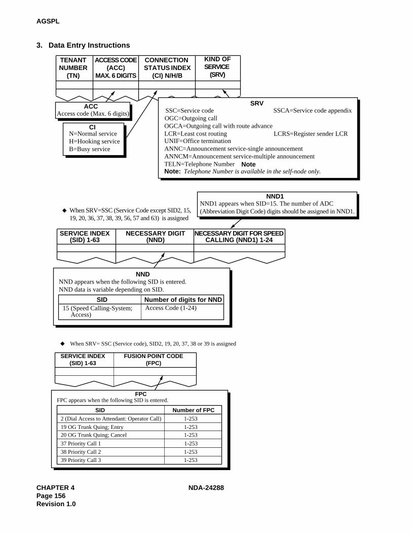
CHAPTER 4 NDA-24288Page 156Revision 1.0
AGSPL
3. Data Entry Instructions
Access code (Max. 6 digits)
TENANTNUMBER
(TN)
ACCESS CODE(ACC)
MAX. 6 DIGITS
CONNECTION STATUS INDEX
(CI) N/H/B
KIND OFSERVICE
(SRV)
ACC
CI
SRVSSCA=Service code appendix
OGCA=Outgoing call with route advance LCR=Least cost routingN=Normal service
H=Hooking serviceB=Busy service
SSC=Service codeOGC=Outgoing call
UNIF=Office terminationANNC=Announcement service-single announcementANNCM=Announcement service-multiple announcementTELN=Telephone NumberNote:
LCRS=Register sender LCR
Note
15 (Speed Calling-System; Access)
NND appears when the following SID is entered.NND data is variable depending on SID.
NND1 appears when SID=15. The number of ADC(Abbreviation Digit Code) digits should be assigned in NND1.
NND1
SERVICE INDEX(SID) 1-63
NECESSARY DIGIT(NND)
NECESSARY DIGIT FOR SPEEDCALLING (NND1) 1-24
NND
SID Number of digits for NNDAccess Code (1-24)
When SRV=SSC (Service Code except SID2, 15, 19, 20, 36, 37, 38, 39, 56, 57 and 63) is assigned
Telephone Number is available in the self-node only.
2 (Dial Access to Attendant: Operator Call)
38 Priority Call 2
37 Priority Call 1
39 Priority Call 3
FPC appears when the following SID is entered.
SERVICE INDEX(SID) 1-63
FUSION POINT CODE(FPC)
FPC
SID Number of FPC1-253
19 OG Trunk Quing; Entry20 OG Trunk Quing; Cancel
1-2531-253
1-253
1-253
1-253
When SRV= SSC (Service code), SID2, 19, 20, 37, 38 or 39 is assigned

NDA-24288 CHAPTER 4Page 157
Revision 1.0
AGSPL
STATE(Hotel Service Code)
1 To be cleaned without ID code 2 Cleaning Completed without ID code 3 Ready for Occupancy without ID code 4 Use Not Allowed without ID code5-8 - 9 Maid Dial Answer Back without ID code-110 Maid Dial Answer Back without ID code-211 Maid Dial Answer Back without ID code-312 Maid Dial Answer Back without ID code-413 Maid Dial Answer Back without ID code-514 Maid Dial Answer Back without ID code-615 Maid Dial Answer Back without ID code-716 -17 To be cleaned with ID code18 Cleaning Completed with ID code19 Ready for Occupancy with ID code20 Use Not Allowed with ID code21-24 -25 Maid Dial Answer Back with ID code-126 Maid Dial Answer Back with ID code-227 Maid Dial Answer Back with ID code-328 Maid Dial Answer Back with ID code-429 Maid Dial Answer Back with ID code-530 Maid Dial Answer Back with ID code-631 Maid Dial Answer Back with ID code-7 32 Access Code for Administration Station Call33 Automatic Wake Up Setting, Cancel; Same Special code34 For Guest Station Secretary Telephone; Boss/Secretary Calling35-43 -44 Direct Data Entry-Station (via Guest Station)45-50 -51 Same Special Code Time Zone Connection Change52 Same Special Code Time Zone Connection Change53 Same Special Code Time Zone Connection Change54 Same Special Code Time Zone Connection Change55 Same Special Code Time Zone Connection Change56-62 -63 Dummy Number
Note: STATE=1-15 are used at the time of Maid ID Code Service is not provided; (ASYD SYS1 INDEX 164, bit3=0) STATE=17-31 are used at the time of Maid ID Code Service is provided; (ASYD SYS1 INDEX 164, bit3=1)
SERVICE INDEX (SID) 1-63 STATE
36
When SRV=SSC (Service code), SID36 (Hotel Service) is assigned

CHAPTER 4 NDA-24288Page 158Revision 1.0
AGSPL
SERVICE INDEX (SID) 1-63
NO.1
56
NO.1(Kind of Assignment Number)
Available numbers are 0-15. This data is used to assign “Floor Service” data by the ASPF command.Note: When programming “Floor Service” data,
ASYD SYS1 INDEX 165, bit7=1 must have been assigned.
SERVICE INDEX (SID) 1-63
NO.2 KIND
57
NO.2This parameter specifies the number (0-63) of theaccess code being assigned for mutual Access.This parameter serves as a counter for the accesscodes being assigned.
Note: This parameter is used when assigning the details of the service by the ASPS command.
KIND: (0-3)This parameter specifies the Split Access Parameter Classification. The data tobe assigned here depends on how the Guest and Administration stations aredifferentiated.The Guest and Administration stations may be assigned to separate TNs, RSCs,and/or SFCs, or they may only be differentiated by their respective designationsas Administration or Guest. 0: Administration/Guest (Assign this if the access code is to be shared between Guest and Administration with no correspondence to TN, RSC or SFC.) 1: TN (Assign this if the access code is to be shared among specified TNs) 2: RSC (Assign this if the access code is to be shared among specified RSCs) 3: SFC (Assign this if the access code is to be shared among specified SFCs)
When SRV=SSC (Service code) , SID56 (Floor Service) is assigned
When SRV=SSC (Service code), SID57 (Split Access) is assigned
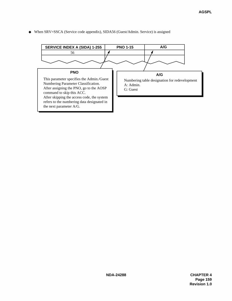
NDA-24288 CHAPTER 4Page 159
Revision 1.0
AGSPL
SERVICE INDEX A (SIDA) 1-255 PNO 1-15 A/G56
PNO
This parameter specifies the Admin./GuestNumbering Parameter Classification.After assigning the PNO, go to the AOSPcommand to skip this ACC.After skipping the access code, the systemrefers to the numbering data designated inthe next parameter A/G.
A/GNumbering table designation for redevelopmentA: Admin.G: Guest
When SRV=SSCA (Service code appendix), SIDA56 (Guest/Admin. Service) is assigned

CHAPTER 4 NDA-24288Page 160Revision 1.0
AGSPL
Assign the number of advanced trunk routes.
LOGICAL ROUTE NUMBER(LGRT)
Count
Assign a dummy route number.LGRT
Second dial tone sending (which is sent when a station hasdialed the digits specified in NND of the AGNPL command)0=Second DT is not sent1=Second DT is sent
2nd DT
Authorization code after dialingACC (LCR)+Destination number0=Out of Service1=In Service
AH
ISDN-Sub Address Dialing0=Out of Service1=In Service
SUB
LOGICAL ROUTE NUMBER(LGRT)
SECOND DIAL TONE(2nd DT) 0/1
AUTHORIZATION CODE(AH) 0/1
SUB ADDRESS DIALING(SUB) 0/1
Index Counter (Count) INDEX LOGICAL ROUTE NUMBER (LGRT)
When SRV=OGC (Outgoing call) is assigned
When SRV=OGCA (Outgoing call with route advance) is assigned
When SRV=LCR (Least cost routing) is assignedWhen SRV=LCRS (Register sender LCR) is assigned
INDEX
INDEX is the route advance order.
12
3

NDA-24288 CHAPTER 4Page 161
Revision 1.0
AGSPL
Note: This Telephone Number is available to make a call and receive a call within the self node only.
If the Telephone Number is to be used within the Fusion Network, assign it at Network Control Node (NCN)using the ASPAN command.
Assign the skip digits to terminate the call.
Assign the announce equipment number.EQP3 and 5-14 can be used for SRV=ANNC (Single announcement).
SKIP DIGITS(SKIP) 0-5
When SRV=UNIF (Office termination) is assigned
When SRV=ANNC (Announcement service-Single announcement) is assigned
SKIP
ANNOUNCEMENT EQUIPMENT NUMBER(EQP) 0-127
EQP
Note: This data is available for ACIS only. For CCIS, use the AUNE command.
Assign the tenant number ofthe announcement trunk.
When SRV=ANNCM (Announcement service-Multiple announcement) is assigned
TN
TENANT NUMBER(TN) 1-255
ANNOUNCEMENT EQUIPMENT NUMBER(EQP) 122-125
Assign the announcement equipment number range from 122 to 125 (Multi announcement).
EQP
When SRV=TELN (Telephone Number)
NECESSARY DIGIT(NND) 1-16

CHAPTER 4 NDA-24288Page 162Revision 1.0
AGSPL
4. Data Sheet
(a) Service Code (SRV = SSC)
TENANT NUMBER
(TN)
ACCESS CODE(ACC)
MAXIMUM6 DIGITS
CONNECTION STATUS INDEX
(CI) N/H/B
KIND OFSERVICE
(SRV)
SERVICEINDEX(SID)1 – 63
NUMBER OF NECESSARY
DIGITS (NND)
NUMBER OF NECESSARY
DIGIT FOR SPEED
CALLING(NND1)1 – 24
FUSION POINTCODE (FPC)1-253
SERVICE CONTENTS
H Hooking SSC 1 Not used
N NormalSSC 2
Dial Access to Attendant
(Operator Call)H Hooking
3Not used
4
N NormalSSC 5 Call Waiting-Originating
B Busy
6
13Not used
N Normal SSC 14Speed Calling-Station;
Entry
N Normal SSC 15Speed Calling-System;
Access
16 Not used
N Normal SSC 17 Individual Trunk Access
18 Not used
B Busy SSC 19OG Trunk Queueing;
Entry
N Normal SSC 20OG Trunk Queueing;
Cancel
N Normal SSC 21Speed Calling-Station,
Group; Access
22
35Not used
N Normal SSC 36
Hotel Service
Note: Use the sheetson the next pagefor the actualdata entry.
~~

NDA-24288 CHAPTER 4Page 163
Revision 1.0
AGSPL
(a) Service Code (SRV = SSC) (Continued)
• SID = 36 (Hotel Service)
TENANT NUMBER
(TN)
ACCESS CODE(ACC)
MAXIMUM6 DIGITS
CONNECTION STATUS INDEX
(CI) N/H/B
KIND OF SERVICE
(SRV)
SERVICE INDEX(SID)
MAIDSTATUS (STATE)1 – 63
SERVICE CONTENTS
N Normal SSC 36
1 To be cleaned without ID Code
2 Cleaned without ID Code
3Ready for Occupancy without ID Code
4 Use Not Allowed without ID Code
5
8Not used
9Maid Dial Answer Back without ID Code 1
10Maid Dial Answer Back without ID Code 2
11Maid Dial Answer Back without ID Code 3
12Maid Dial Answer Back without ID Code 4
13Maid Dial Answer Back without ID Code 5
14Maid Dial Answer Back without ID Code 6
15Maid Dial Answer Back without ID Code 7
16 Not used
17 To be cleaned with ID code
18 Cleaned with ID Code
19 Ready for Occupancy with ID Code
20 Use Not Allowed with ID Code
~

CHAPTER 4 NDA-24288Page 164Revision 1.0
AGSPL
(a) Service Code (SRV = SSC) (Continued)
• SID = 36 (Hotel Service)
TENANT NUMBER
(TN)
ACCESS CODE(ACC)
MAXIMUM6 DIGITS
CONNECTION STATUS INDEX
(CI) N/H/B
KIND OF SERVICE
(SRV)
SERVICE INDEX(SID)
MAIDSTATUS (STATE)1 – 63
SERVICE CONTENTS
N Normal SSC 36
21
24Not used
25Maid Dial Answer Back with ID Code 1
26Maid Dial Answer Back with ID Code 2
27Maid Dial Answer Back with ID Code 3
28Maid Dial Answer Back with ID Code 4
29Maid Dial Answer Back with ID Code 5
30Maid Dial Answer Back with ID Code 6
31Maid Dial Answer Back with ID Code 7
32 Not used
33Automatic Wake-Up Setting, Cancel; Same Special Code
34For Guest Station Secretary Telephone; Boss/Secretary
35
43Not used
44 Direct Data Entry – STA
45
50Not used
51Same Special Code Time Zone Connection Change
~~
~

NDA-24288 CHAPTER 4Page 165
Revision 1.0
AGSPL
(a) Service Code (SRV = SSC) (Continued)
• SID = 36 (Hotel Service)
TENANT NUMBER
(TN)
ACCESS CODE(ACC)
MAXIMUM6 DIGITS
CONNECTION STATUS INDEX
(CI) N/H/B
KIND OF SERVICE
(SRV)
SERVICE INDEX(SID)
MAIDSTATUS (STATE)1 – 63
SERVICE CONTENTS
N Normal SSC 36
52Same Special Code Time Zone Connection Change
53Same Special Code Time Zone Connection Change
54Same Special Code Time Zone Connection Change
55Same Special Code Time Zone Connection Change
56
62Not used
63 Dummy Number
~
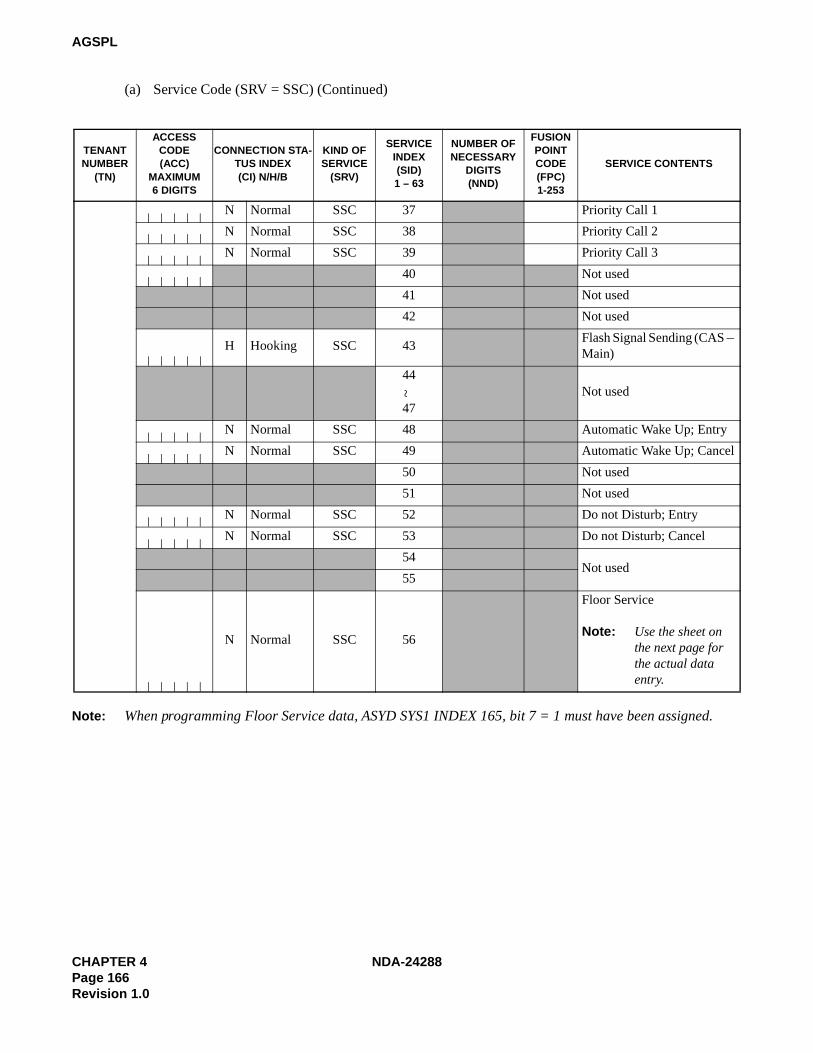
CHAPTER 4 NDA-24288Page 166Revision 1.0
AGSPL
(a) Service Code (SRV = SSC) (Continued)
Note: When programming Floor Service data, ASYD SYS1 INDEX 165, bit 7 = 1 must have been assigned.
TENANT NUMBER
(TN)
ACCESS CODE(ACC)
MAXIMUM6 DIGITS
CONNECTION STA-TUS INDEX(CI) N/H/B
KIND OF SERVICE
(SRV)
SERVICEINDEX(SID)1 – 63
NUMBER OF NECESSARY
DIGITS(NND)
FUSION POINTCODE(FPC)1-253
SERVICE CONTENTS
N Normal SSC 37 Priority Call 1
N Normal SSC 38 Priority Call 2
N Normal SSC 39 Priority Call 3
40 Not used
41 Not used
42 Not used
H Hooking SSC 43Flash Signal Sending (CAS – Main)
44
47Not used
N Normal SSC 48 Automatic Wake Up; Entry
N Normal SSC 49 Automatic Wake Up; Cancel
50 Not used
51 Not used
N Normal SSC 52 Do not Disturb; Entry
N Normal SSC 53 Do not Disturb; Cancel
54Not used
55
N Normal SSC 56
Floor Service
Note: Use the sheet on the next page for the actual data entry.
~

NDA-24288 CHAPTER 4Page 167
Revision 1.0
AGSPL
(a) Service Code (SRV = SSC) (Continued)
• SID = 56 (Floor Service)
TENANT NUMBER
(TN)
ACCESS CODE(ACC)
MAXIMUM6 DIGITS
CONNECTION STATUS INDEX
(CI) N/H/B
KIND OF SERVICE
(SRV)
SERVICE INDEX(SID)
SERVICEINDEX
NUMBER (No.1)0 – 15
SERVICE CONTENTS
N Normal SSC 56 0
N Normal SSC 56 1
N Normal SSC 56 2
N Normal SSC 56 3
N Normal SSC 56 4
N Normal SSC 56 5
N Normal SSC 56 6
N Normal SSC 56 7
N Normal SSC 56 8
N Normal SSC 56 9
N Normal SSC 56 10
N Normal SSC 56 11
N Normal SSC 56 12
N Normal SSC 56 13
N Normal SSC 56 14
N Normal SSC 56 15

CHAPTER 4 NDA-24288Page 168Revision 1.0
AGSPL
(a) Service Code (SRV = SSC) (Continued)
TENANT NUMBER
(TN)
ACCESS CODE(ACC)
MAXIMUM6 DIGITS
CONNECTION STATUS INDEX
(CI)N/H/B
KIND OF SERVICE
(SRV)
SERVICE INDEX(SID
1 – 63
NUMBER OF NECESSARY
DIGITS(NND)
SERVICE CONTENTS
N Normal SSC 57
Split Access (Same Number Access)
Note: Use the sheet on the next page for the actual data entry.
58
59Not used
N Normal SSC 60 Attendant Manual Override
H Hooking SSC 61 Call Park Access Code
N Normal SSC 62 Call Park Local Retrieval Code
N Normal SSC 63 Call Park Remote Retrieval Code
~

NDA-24288 CHAPTER 4Page 169
Revision 1.0
AGSPL
(a) Service Code (SRV = SSC) (Continued)
• SID = 57 (Split Access)
TENANTNUMBER
(TN)
ACCESS CODE(ACC)
MAXIMUM6 DIGITS
CONNECTIONSTATUS INDEX
(CI) N/H/B
KIND OF SERVICE
(SRV)
SERVICEINDEX(SID)
ASSIGN NUMBER
(No.2)0 – 63
KIND OFFUNCTION
(KIND)0 – 3
SERVICECONTENTS
N Normal SSC 57

CHAPTER 4 NDA-24288Page 170Revision 1.0
AGSPL
(b) Service Code Appendix (SRV = SSCA)
TENANTNUMBER (TN)
ACCESS CODE(ACC)
MAXIMUM6 DIGITS
CONNECTIONSTATUS INDEX
(CI) N/H/B
KIND OFSERVICE
(SRV)
SERVICEINDEX A(SIDA)1 – 255
SERVICE CONTENTS
1
55Not used
N Normal
SSCA 56 Guest/Admin. ServiceH Hooking
B Busy
57
95Not used
~~

NDA-24288 CHAPTER 4Page 171
Revision 1.0
AGSPL
(b) Service Code Appendix (SRV = SSCA) (Continued)
• SIDA = 56 (Guest/Admin. Service)
TENANTNUMBER
(TN)
ACCESS CODE(ACC)
MAX. 6 DIGITS
CONNECTION STATUS INDEX
(CI) N/H/B
KIND OFSERVICE
(SRV)
SERVICEINDEX A(SIDA)
PATTERNNUMBER
FOR AOSPCOMMAND
(PNO) 1 – 15
ADMIN./GUEST (A/G)
0/1
SERVICE CONTENTS
N Normal
SSCA 56H Hooking
B Busy
N Normal
SSCA 56H Hooking
B Busy
N Normal
SSCA 56H Hooking
B Busy
N Normal
SSCA 56H Hooking
B Busy
N Normal
SSCA 56H Hooking
B Busy
N Normal
SSCA 56H Hooking
B Busy
N Normal
SSCA 56H Hooking
B Busy
N Normal
SSCA 56H Hooking
B Busy
N Normal
SSCA 56H Hooking
B Busy
N Normal
SSCA 56H Hooking
B Busy

CHAPTER 4 NDA-24288Page 172Revision 1.0
AGSPL
(c) Outgoing Call (Without Route Advance) (SRV = OGC)
TENANTNUMBER
(TN)
ACCESS CODE(ACC)
MAXIMUM 6DIGITS
CONNECTIONSTATUS INDEX
(CI) N/H
KIND OF SERVICE
(SRV)
LOGICAL ROUTENUMBER (LGRT)
REMARKS
N NormalOGC
H Hooking
N NormalOGC
H Hooking
N NormalOGC
H Hooking
N NormalOGC
H Hooking
N NormalOGC
H Hooking
N NormalOGC
H Hooking
N NormalOGC
H Hooking
N NormalOGC
H Hooking
N NormalOGC
H Hooking
N NormalOGC
H Hooking
N NormalOGC
H Hooking
N NormalOGC
H Hooking
N NormalOGC
H Hooking
N NormalOGC
H Hooking
N NormalOGC
H Hooking

NDA-24288 CHAPTER 4Page 173
Revision 1.0
AGSPL
(d) Outgoing Call (With Route Advance) (SRV = OGCA)
TENANTNUMBER
(TN)
ACCESS CODE(ACC)
MAXIMUM6 DIGITS
CONNECTIONSTATUS INDEX
(CI)N/H
KIND OFSERVICE
(SRV)
INDEXCOUNTER(COUNT)
LOGICAL ROUTE NUMBER (LGRT)
1st 2nd 3rd 4th 5th 6th 7th 8th
9th 10th 11th 12th 13th 14th 15th
N NormalOGCA
H Hooking
N NormalOGCA
H Hooking
N NormalOGCA
H Hooking
N NormalOGCA
H Hooking
N NormalOGCA
H Hooking
N NormalOGCA
H Hooking
N NormalOGCA
H Hooking
N NormalOGCA
H Hooking
N NormalOGCA
H Hooking
N NormalOGCA
H Hooking
N NormalOGCA
H Hooking
N NormalOGCA
H Hooking
N NormalOGCA
H Hooking
N NormalOGCA
H Hooking
N NormalOGCA
H Hooking
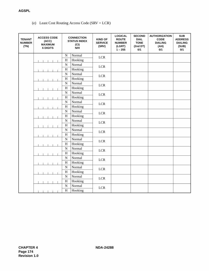
CHAPTER 4 NDA-24288Page 174Revision 1.0
AGSPL
(e) Least Cost Routing Access Code (SRV = LCR)
TENANTNUMBER
(TN)
ACCESS CODE(ACC)
MAXIMUM6 DIGITS
CONNECTIONSTATUS INDEX
(CI) N/H
KIND OFSERVICE
(SRV)
LOGICALROUTE
NUMBER(LGRT)1 – 255
SECONDDIALTONE
(2nd DT)0/1
AUTHORIZATIONCODE
DIALING(AH) 0/1
SUBADDRESSDIALING
(SUB) 0/1
N NormalLCR
H HookingN Normal
LCRH HookingN Normal LCRH HookingN Normal
LCRH HookingN Normal
LCRH HookingN Normal
LCRH HookingN Normal
LCRH HookingN Normal LCRH HookingN Normal
LCRH HookingN Normal
LCRH HookingN Normal
LCRH HookingN Normal LCRH HookingN Normal LCRH HookingN Normal
LCRH HookingN Normal
LCRH Hooking

NDA-24288 CHAPTER 4Page 175
Revision 1.0
AGSPL
(f) Register Sender Least Cost Routing Access Code (SRV = LCRS)
TENANTNUMBER
(TN)
ACCESS CODE(ACC)
MAXIMUM6 DIGITS
CONNECTIONSTATUS INDEX
(CI) N/H
KIND OFSERVICE
(SRV)
LOGICALROUTE
NUMBER(LGRT)1 – 255
SECONDDIAL TONE
(2nd DT)0/1
AUTHORIZATIONCODE
DIALING(AH) 0/1
SUBADDRESSDIALING
(SUB) 0/1
N NormalLCRS
H Hooking
N NormalLCRS
H Hooking
N NormalLCRS
H Hooking
N NormalLCRS
H Hooking
N NormalLCRS
H Hooking
N NormalLCRS
H Hooking
N NormalLCRS
H Hooking
N NormalLCRS
H Hooking
N NormalLCRS
H Hooking
N NormalLCRS
H Hooking
N NormalLCRS
H Hooking
N NormalLCRS
H Hooking
N NormalLCRS
H Hooking
N NormalLCRS
H Hooking
N NormalLCRS
H Hooking

CHAPTER 4 NDA-24288Page 176Revision 1.0
AGSPL
(g) Office Termination Code (SRV = UNIF)
TENANTNUMBER
(TN)
ACCESS CODE (ACC)
MAXIMUM6 DIGITS
CONNECTION STATUS INDEX
(CI) N/H
KIND OFSERVICE
(SRV)
SKIP DIGIT(SKIP)0 – 5
N NormalUNIF
H HookingN Normal
UNIFH HookingN Normal
UNIFH HookingN Normal
UNIFH HookingN Normal
UNIFH HookingN Normal
UNIFH HookingN Normal
UNIFH HookingN Normal
UNIFH HookingN Normal
UNIFH HookingN Normal
UNIFH HookingN Normal
UNIFH HookingN Normal
UNIFH HookingN Normal
UNIFH HookingN Normal
UNIFH HookingN Normal
UNIFH Hooking

NDA-24288 CHAPTER 4Page 177
Revision 1.0
AGSPL
(h) Announcement Service-Single Announcement (SRV = ANNC)
TENANTNUMBER
(TN)
ACCESS CODE (ACC)MAXIMUM6 DIGITS
CONNECTION STATUS INDEX
(CI) N/H
KIND OFSERVICE
(SRV)
ANNOUNCEMENTEQUIPMENT
NUMBER (EQP)
1 – 127
N NormalANNC
H HookingN Normal ANNCH HookingN Normal ANNCH HookingN Normal
ANNCH HookingN Normal
ANNCH HookingN Normal
ANNCH HookingN Normal ANNCH HookingN Normal
ANNCH HookingN Normal
ANNCH HookingN Normal
ANNCH HookingN Normal ANNCH HookingN Normal ANNCH HookingN Normal
ANNCH HookingN Normal
ANNCH HookingN Normal
ANNCH Hooking
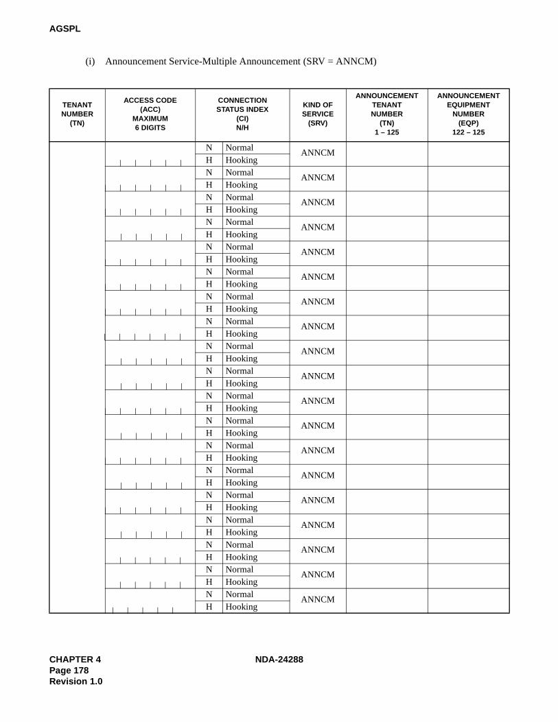
CHAPTER 4 NDA-24288Page 178Revision 1.0
AGSPL
(i) Announcement Service-Multiple Announcement (SRV = ANNCM)
TENANTNUMBER
(TN)
ACCESS CODE (ACC)
MAXIMUM6 DIGITS
CONNECTION STATUS INDEX
(CI) N/H
KIND OFSERVICE
(SRV)
ANNOUNCEMENTTENANTNUMBER
(TN)1 – 125
ANNOUNCEMENTEQUIPMENT
NUMBER (EQP)
122 – 125
N NormalANNCM
H HookingN Normal
ANNCMH HookingN Normal ANNCMH HookingN Normal
ANNCMH HookingN Normal
ANNCMH HookingN Normal
ANNCMH HookingN Normal
ANNCMH HookingN Normal ANNCMH HookingN Normal
ANNCMH HookingN Normal
ANNCMH HookingN Normal
ANNCMH HookingN Normal ANNCMH HookingN Normal ANNCMH HookingN Normal
ANNCMH HookingN Normal
ANNCMH HookingN Normal
ANNCMH HookingN Normal ANNCMH HookingN Normal
ANNCMH HookingN Normal
ANNCMH Hooking
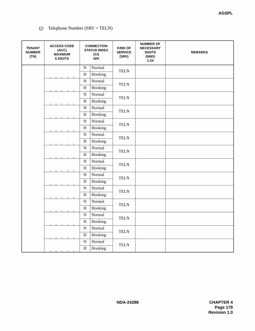
NDA-24288 CHAPTER 4Page 179
Revision 1.0
AGSPL
(j) Telephone Number (SRV = TELN)
TENANTNUMBER
(TN)
ACCESS CODE (ACC)
MAXIMUM6 DIGITS
CONNECTIONSTATUS INDEX
(CI) N/H
KIND OFSERVICE
(SRV)
NUMBER OF NECESSARY
DIGITS(NND) 1-24
REMARKS
N NormalTELN
H Hooking
N NormalTELN
H Hooking
N NormalTELN
H Hooking
N NormalTELN
H Hooking
N NormalTELN
H Hooking
N NormalTELN
H Hooking
N NormalTELN
H Hooking
N NormalTELN
H Hooking
N NormalTELN
H Hooking
N NormalTELN
H Hooking
N NormalTELN
H Hooking
N NormalTELN
H Hooking
N NormalTELN
H Hooking
N NormalTELN
H Hooking

CHAPTER 4 NDA-24288Page 180Revision 1.0
AGSPN
AGSPN: Assignment of Guest Special Access Code for NDM
1. General
This command assigns the numbering plan data for the Network Control Node (NCN). The data assigned in thiscommand is written in the Network Data Memory (NDM) of the Network Control Node (NCN), updating theNDM at each Local Node (LN).
2. Precautions
1. This command is used for the Hotel Application only.
2. If the Guest and Admin. Numbering are separated (the ASYD command, SYS1, INDEX 160, bit6 = 0),use this command for the Guest Special Access code. For the Admin. Special Access code, use theASPAN command.
Note: Hotel features are available in TN1 only. If the numbering plans are separated by tenants, the purpose foreach tenant is completely separated. Admin. Station required of the guest room call must be allocated inTN1.
3. If the numbering plan for Admin. and Guest is common (the ASYD command, SYS1, INDEX 160, bit6 =1), this command may be used to assign the Admin. Special Access code as well.

NDA-24288 CHAPTER 4Page 181
Revision 1.0
AGSPN
3. Data Entry Instructions
Access code (Max. 6 digits)
TENANTNUMBER
(TN)
ACCESS CODE(ACC)
MAX. 6 DIGITS
CONNECTION STATUS INDEX
(CI) N/H/B
KIND OFSERVICE
(SRV)
ACC
CI
SRVSSCA=Service code appendix
OGCA=Outgoing call with route advance LCR=Least cost routing
N=Normal serviceH=Hooking serviceB=Busy service
SSC=Service codeOGC=Outgoing call
UNIF=Office terminationANNC=Announcement service-single announcementANNCM=Announcement service-multiple announcementTELN=Telephone Number
LCRS=Register sender LCR
15 (Speed Calling-System; Access)63 (Call Park ; Retrieve)
NND appears when the following SID is entered.NND data is variable depending on SID.
NND1 appears when SID=15. The number of ADC(Abbreviation Digit Code) digits should be assigned in NND1.
NND1
SERVICE INDEX(SID) 1-63
NECESSARY DIGIT(NND)
NECESSARY DIGIT FOR SPEEDCALLING (NND1) 1-24
NND
SID Number of digits for NNDAccess Code (1-24)
Access Code (1-3)
When SRV=SSC (Service code except SID2, 36,37, 38, 39, 56 and 57) is assigned
2 (Dial Access to Attendant: Operator Call)
FPC appears when the following SID is entered.
SERVICE INDEX(SID) 1-63
FUSION POINT CODE(FPC)
FPC
SID Number of FPC
7 (Call Pickup-Group)
19 (OG Trunk Quing; Entry)
1-253
1-253
1-253
20 (OG Trunk Quing; Cancel) 1-253
37 (Priority Call 1)
38 (Priority Call 2)
1-253
1-253
39 (Priority Call 3) 1-253
When SRV=SSC (Service code), SID2, 37, 38 or 39 is assigned

CHAPTER 4 NDA-24288Page 182Revision 1.0
AGSPN
STATE(Hotel Service Code)
1 To be cleaned without ID code 2 Cleaning Completed without ID code 3 Ready for Occupancy without ID code 4 Use Not Allowed without ID code5-8 - 9 Maid Dial Answer Back without ID code-110 Maid Dial Answer Back without ID code-211 Maid Dial Answer Back without ID code-312 Maid Dial Answer Back without ID code-413 Maid Dial Answer Back without ID code-514 Maid Dial Answer Back without ID code-615 Maid Dial Answer Back without ID code-716 -17 To be cleaned with ID code18 Cleaning Completed with ID code19 Ready for Occupancy with ID code20 Use Not Allowed with ID code21-24 -25 Maid Dial Answer Back with ID code-126 Maid Dial Answer Back with ID code-227 Maid Dial Answer Back with ID code-328 Maid Dial Answer Back with ID code-429 Maid Dial Answer Back with ID code-530 Maid Dial Answer Back with ID code-631 Maid Dial Answer Back with ID code-7 32 Access Code for Administration Station Call33 Automatic Wake Up Setting, Cancel; Same Special code34 For Guest Station Secretary Telephone; Boss/Secretary Calling35-43 -44 Direct Data Entry-Station (via Guest Station)45-50 -51 Same Special Code Time Zone Connection Change52 Same Special Code Time Zone Connection Change53 Same Special Code Time Zone Connection Change54 Same Special Code Time Zone Connection Change55 Same Special Code Time Zone Connection Change56-62 -63 Dummy Number
Note: STATE=1-15 are used at the time of Maid ID Code Service is not provided; (ASYD SYS1 INDEX 164, bit3=0) STATE=17-31 are used at the time of Maid ID Code Service is provided; (ASYD SYS1 INDEX 164, bit3=1)
SERVICE INDEX (SID) 1-63 STATE
36
When SRV=SSC (Service code). SID36 (Hotel Service) is assigned
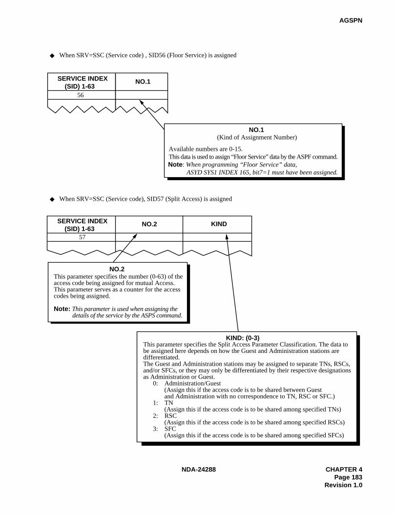
NDA-24288 CHAPTER 4Page 183
Revision 1.0
AGSPN
SERVICE INDEX (SID) 1-63
NO.1
56
NO.1(Kind of Assignment Number)
Available numbers are 0-15. This data is used to assign “Floor Service” data by the ASPF command.Note: When programming “Floor Service” data,
ASYD SYS1 INDEX 165, bit7=1 must have been assigned.
SERVICE INDEX (SID) 1-63
NO.2 KIND
57
NO.2This parameter specifies the number (0-63) of theaccess code being assigned for mutual Access.This parameter serves as a counter for the accesscodes being assigned.
Note: This parameter is used when assigning the details of the service by the ASPS command.
KIND: (0-3)This parameter specifies the Split Access Parameter Classification. The data tobe assigned here depends on how the Guest and Administration stations aredifferentiated.The Guest and Administration stations may be assigned to separate TNs, RSCs,and/or SFCs, or they may only be differentiated by their respective designationsas Administration or Guest. 0: Administration/Guest (Assign this if the access code is to be shared between Guest and Administration with no correspondence to TN, RSC or SFC.) 1: TN (Assign this if the access code is to be shared among specified TNs) 2: RSC (Assign this if the access code is to be shared among specified RSCs) 3: SFC (Assign this if the access code is to be shared among specified SFCs)
When SRV=SSC (Service code) , SID56 (Floor Service) is assigned
When SRV=SSC (Service code), SID57 (Split Access) is assigned

CHAPTER 4 NDA-24288Page 184Revision 1.0
AGSPN
Table 4-1 SIDA (AGSPN)
SIDA SERVICE NAME SIDA SERVICE NAME
1-49 – 56 Guest/Admin. Service
50 UCD Busy Out; Entry 56-62 –
51 UCD Busy Out; Cancel 63 Call Pickup Expand
52-55 – 64-255 –
SERVICE INDEX A (SIDA) 1-255 PNO 1-15 A/G56
PNO
This parameter specifies the Admin./GuestNumbering Parameter Classification.After assigning the PNO, go to the AOSPcommand to skip this ACC.After skipping the access code, the systemrefers to the numbering data designated inthe next parameter A/G.
A/GNumbering table designation for redevelopmentA: Admin.G: Guest
When SRV=SSCA (Service code appendix), SIDA56 (Guest/Admin. Service) is assigned
SERVICE INDEX A (SIDA) 1-255
When SRV=SSCA (Service code appendix), SIDA50, 51 or 63 is assigned
SIDARefer to Table SIDA (AGSPN).

NDA-24288 CHAPTER 4Page 185
Revision 1.0
AGSPN
LOGICAL ROUTE NUMBER(LGRT)
Assign a dummy route number.LGRT
Second dial tone sending (which is sent when a station hasdialed the digits specified in NND of the AGNP command)0=Second DT is not sent1=Second DT is sent
2nd DT
Authorization code after dialingACC (LCR)+Destination number0=Out of Service1=In Service
AH
ISDN-Sub Address Dialing0=Out of Service1=In Service
SUB
LOGICAL ROUTE NUMBER(LGRT)
SECOND DIAL TONE(2nd DT) 0/1
AUTHORIZATION CODE(AH) 0/1
SUB ADDRESS DIALING(SUB) 0/1
CNT (1-15) LOGICAL ROUTE NUMBER (LGRT)
When SRV=OGC (Outgoing call) is assigned
When SRV=OGCA (Outgoing call with route advance) is assigned
When SRV=LCR (Least cost routing) is assignedWhen SRV=LCRS (Register sender LCR) is assigned
CNT
CNT is the route advance order.
12
3

CHAPTER 4 NDA-24288Page 186Revision 1.0
AGSPN
Assign the skip digits to terminate the call.
Assign the announce equipment number.EQP3 and 5-14 can be used for SRV=ANNC (Single announcement).
SKIP DIGITS(SKIP) 0-5
When SRV=UNIF (Office termination) is assigned
When SRV=ANNC (Announcement service-Single announcement) is assigned
SKIP
ANNOUNCEMENT EQUIPMENT NUMBER(EQP) 0-127
EQP
Note: This data is available for ACIS only. For CCIS, use the AUNE command.
Assign the tenant number ofthe announcement trunk.
When SRV=ANNCM (Announcement service-Multiple announcement) is assigned
TN
TENANT NUMBER(TN) 1-255
ANNOUNCEMENT EQUIPMENT NUMBER(EQP) 122-125
Assign the announcement equipment number range from 122 to 125 (Multi announcement).
EQP
When SRV=TELN (Telephone Number)
NECESSARY DIGIT(NND) 1-16

NDA-24288 CHAPTER 4Page 187
Revision 1.0
AGSPN
4. Data Sheet
(a) Service Code (SRV = SSC)
TENANT NUMBER
(TN)
ACCESS CODE(ACC)
MAXIMUM6 DIGITS
CONNECTION STATUSINDEX
(CI) N/H/B
KIND OFSERVICE
(SRV)
SERVICEINDEX(SID)1 – 63
NUMBER OF NECESSARY
DIGITS(NND)
NUMBER OF NECESSARY
DIGIT FORSPEED
CALLING(NND1)1 – 24
FUSIONPOINTCODEFPC)1-253
SERVICE CONTENTS
H Hooking SSC 1 Not used
N NormalSSC 2
Dial Access to Attendant
(Operator Call)H Hooking
3Not used
4
N NormalSSC 5 Call Waiting-Originating
B Busy
6 Not used
N Normal SSC 7 Call Pickup-Group
8
13Not used
N Normal SSC 14Speed Calling-Station;
Entry
N Normal SSC 15Speed Calling-System;
Access
N Normal SSC 16 TAS Answer
N Normal SSC 17 Individual Trunk Access
18 Not used
B Busy SSC 19OG Trunk Queueing:
Entry
N Normal SSC 20OG Trunk Queueing:
Cancel
N Normal SSC 21Speed Calling-Station,
Group; Access
22
35Not used
N Normal SSC 36
Hotel Service
Note: Use the sheets on the next page for the actual data entry.
~~

CHAPTER 4 NDA-24288Page 188Revision 1.0
AGSPN
(a) Service Code (SRV = SSC) (Continued)
SID = 36 (Hotel Service)
TENANTNUMBER
(TN)
ACCESS CODE(ACC)
MAXIMUM6 DIGITS
CONNECTIONSTATUS INDEX
(CI)N/H/B
KIND OFSERVICE
(SRV)
SERVICEINDEX(SID)
MAIDSTATUS(STATE)1 – 63
SERVICE CONTENTS
N Normal SSC 36
1 To be cleaned without ID Code
2 Cleaned without ID Code
3Ready for Occupancy without ID Code
4 Use Not Allowed without ID Code
5
8Not used
9Maid Dial Answer Back without ID Code 1
10Maid Dial Answer Back without ID Code 2
11Maid Dial Answer Back without ID Code 3
12Maid Dial Answer Back without ID Code 4
13Maid Dial Answer Back without ID Code 5
14Maid Dial Answer Back without ID Code 6
15Maid Dial Answer Back without ID Code 7
16 Not used
17 To be cleaned with ID code
18 Cleaned with ID Code
19 Ready for Occupancy with ID Code
20 Use Not Allowed with ID Code
~

NDA-24288 CHAPTER 4Page 189
Revision 1.0
AGSPN
(a) Service Code (SRV = SSC) (Continued)
SID = 36 (Hotel Service)
TENANT NUMBER
(TN)
ACCESS CODE(ACC)
MAXIMUM6 DIGITS
CONNECTION STATUS INDEX
(CI) N/H/B
KIND OF SERVICE
(SRV)
SERVICE INDEX(SID)
MAIDSTATUS (STATE)
1 – 63
SERVICE CONTENTS
N Normal SSC 36
21
24Not used
25Maid Dial Answer Back with ID Code 1
26Maid Dial Answer Back with ID Code 2
27Maid Dial Answer Back with ID Code 3
28Maid Dial Answer Back with ID Code 4
29Maid Dial Answer Back with ID Code 5
30Maid Dial Answer Back with ID Code 6
31Maid Dial Answer Back with ID Code 7
32 Not used
33Automatic Wake-Up Setting, Cancel; Same Special Code
34For Guest Station Secretary Telephone; Boss/Secretary
35
43Not used
44 Direct Data Entry – STA
45
50Not used
51Same Special Code Time Zone Connection Change
~~
~

CHAPTER 4 NDA-24288Page 190Revision 1.0
AGSPN
(a) Service Code (SRV = SSC) (Continued)
SID = 36 (Hotel Service)
TENANT NUMBER
(TN)
ACCESS CODE(ACC)
MAXIMUM6 DIGITS
CONNECTION STATUS INDEX
(CI) N/H/B
KIND OF SERVICE
(SRV)
SERVICE INDEX(SID)
MAIDSTATUS (STATE)
1 – 63
SERVICE CONTENTS
N Normal SSC 36
52Same Special Code Time Zone Connection Change
53Same Special Code Time Zone Connection Change
54Same Special Code Time Zone Connection Change
55Same Special Code Time Zone Connection Change
56
62Not used
63 Dummy Number
~
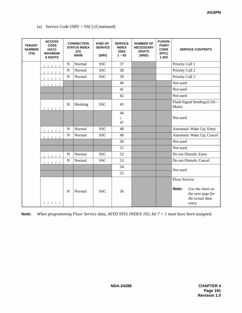
NDA-24288 CHAPTER 4Page 191
Revision 1.0
AGSPN
(a) Service Code (SRV = SSC) (Continued)
Note: When programming Floor Service data, ASYD SYS1 INDEX 165, bit 7 = 1 must have been assigned.
TENANT NUMBER
(TN)
ACCESS CODE(ACC)
MAXIMUM6 DIGITS
CONNECTIONSTATUS INDEX
(CI) N/H/B
KIND OF SERVICE
(SRV)
SERVICEINDEX(SID)1 – 63
NUMBER OFNECESSARY
DIGITS(NND)
FUSION POINTCODE(FPC)1-253
SERVICE CONTENTS
N Normal SSC 37 Priority Call 1
N Normal SSC 38 Priority Call 2
N Normal SSC 39 Priority Call 3
40 Not used
41 Not used
42 Not used
H Hooking SSC 43Flash Signal Sending (CAS – Main)
44
47Not used
N Normal SSC 48 Automatic Wake Up; Entry
N Normal SSC 49 Automatic Wake Up; Cancel
50 Not used
51 Not used
N Normal SSC 52 Do not Disturb; Entry
N Normal SSC 53 Do not Disturb; Cancel
54Not used
55
N Normal SSC 56
Floor Service
Note: Use the sheet on the next page for the actual data entry.
~
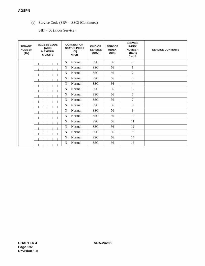
CHAPTER 4 NDA-24288Page 192Revision 1.0
AGSPN
(a) Service Code (SRV = SSC) (Continued)
SID = 56 (Floor Service)
TENANT NUMBER
(TN)
ACCESS CODE(ACC)
MAXIMUM6 DIGITS
CONNECTION STATUS INDEX
(CI) N/H/B
KIND OF SERVICE
(SRV)
SERVICEINDEX(SID)
SERVICEINDEX
NUMBER (No.1)0 – 15
SERVICE CONTENTS
N Normal SSC 56 0
N Normal SSC 56 1
N Normal SSC 56 2
N Normal SSC 56 3
N Normal SSC 56 4
N Normal SSC 56 5
N Normal SSC 56 6
N Normal SSC 56 7
N Normal SSC 56 8
N Normal SSC 56 9
N Normal SSC 56 10
N Normal SSC 56 11
N Normal SSC 56 12
N Normal SSC 56 13
N Normal SSC 56 14
N Normal SSC 56 15
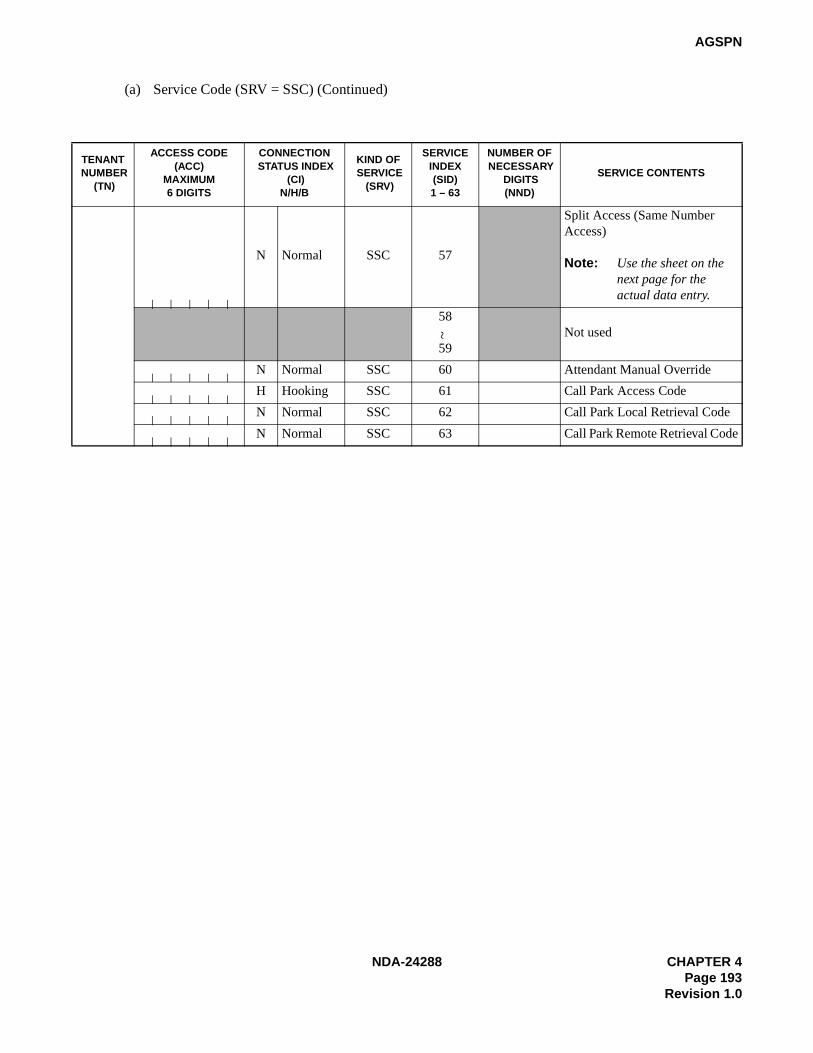
NDA-24288 CHAPTER 4Page 193
Revision 1.0
AGSPN
(a) Service Code (SRV = SSC) (Continued)
TENANT NUMBER
(TN)
ACCESS CODE(ACC)
MAXIMUM6 DIGITS
CONNECTION STATUS INDEX
(CI) N/H/B
KIND OF SERVICE
(SRV)
SERVICEINDEX(SID)1 – 63
NUMBER OF NECESSARY
DIGITS(NND)
SERVICE CONTENTS
N Normal SSC 57
Split Access (Same Number Access)
Note: Use the sheet on the next page for the actual data entry.
58
59Not used
N Normal SSC 60 Attendant Manual Override
H Hooking SSC 61 Call Park Access Code
N Normal SSC 62 Call Park Local Retrieval Code
N Normal SSC 63 Call Park Remote Retrieval Code~

CHAPTER 4 NDA-24288Page 194Revision 1.0
AGSPN
(a) Service Code (SRV = SSC) (Continued)
SID = 57 (Split Access)
TENANT NUMBER
(TN)
ACCESS CODE(ACC)
MAXIMUM6 DIGITS
CONNECTION STATUS INDEX
(CI) N/H/B
KIND OF SERVICE
(SRV)
SERVICEINDEX(SID)
ASSIGN NUMBER
(No.2)0 – 63
KIND OFFUNCTION
(KIND)0 – 3
SERVICECONTENTS
N Normal SSC 57

NDA-24288 CHAPTER 4Page 195
Revision 1.0
AGSPN
(b) Service Code Appendix (SRV = SSCA)
TENANTNUMBER
(TN)
ACCESS CODE(ACC)
MAXIMUM6 DIGITS
CONNECTIONSTATUS INDEX
(CI) N/H/B
KIND OFSERVICE
(SRV)
SERVICEINDEX A(SIDA)1 – 255
SERVICE CONTENTS
1
55Not used
N Normal
SSCA 56 Guest/Admin. ServiceH Hooking
B Busy
57
95Not used
~~
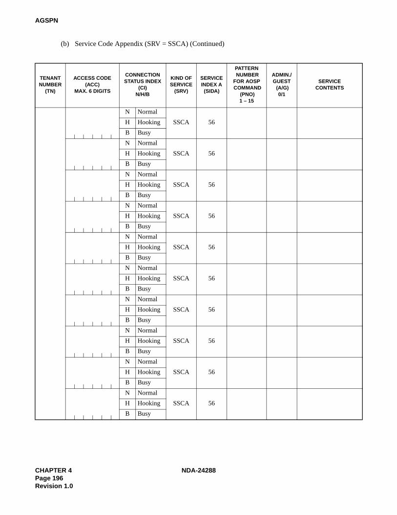
CHAPTER 4 NDA-24288Page 196Revision 1.0
AGSPN
(b) Service Code Appendix (SRV = SSCA) (Continued)
TENANTNUMBER
(TN)
ACCESS CODE(ACC)
MAX. 6 DIGITS
CONNECTIONSTATUS INDEX
(CI) N/H/B
KIND OFSERVICE
(SRV)
SERVICEINDEX A(SIDA)
PATTERN NUMBERFOR AOSP COMMAND
(PNO) 1 – 15
ADMIN./GUEST (A/G)
0/1
SERVICECONTENTS
N Normal
SSCA 56H Hooking
B Busy
N Normal
SSCA 56H Hooking
B Busy
N Normal
SSCA 56H Hooking
B Busy
N Normal
SSCA 56H Hooking
B Busy
N Normal
SSCA 56H Hooking
B Busy
N Normal
SSCA 56H Hooking
B Busy
N Normal
SSCA 56H Hooking
B Busy
N Normal
SSCA 56H Hooking
B Busy
N Normal
SSCA 56H Hooking
B Busy
N Normal
SSCA 56H Hooking
B Busy

NDA-24288 CHAPTER 4Page 197
Revision 1.0
AGSPN
(c) Outgoing Call (Without Route Advance) (SRV = OGC)
TENANT NUMBER
(TN)
ACCESS CODE (ACC) MAXIMUM
6 DIGITS
CONNECTIONSTATUS INDEX
(CI) N/H
KIND OF SERVICE
(SRV)
LOGICAL ROUTENUMBER(LGRT)
REMARKS
N NormalOGC
H Hooking
N NormalOGC
H Hooking
N NormalOGC
H Hooking
N NormalOGC
H Hooking
N NormalOGC
H Hooking
N NormalOGC
H Hooking
N NormalOGC
H Hooking
N NormalOGC
H Hooking
N NormalOGC
H Hooking
N NormalOGC
H Hooking
N NormalOGC
H Hooking
N NormalOGC
H Hooking
N NormalOGC
H Hooking
N NormalOGC
H Hooking
N NormalOGC
H Hooking

CHAPTER 4 NDA-24288Page 198Revision 1.0
AGSPN
(d) Outgoing Call (With Route Advance) (SRV = OGCA)
TENANTNUMBER
(TN)
ACCESS CODE (ACC)
MAXIMUM6 DIGITS
CONNECTION STATUS
INDEX(CI)N/H
KIND OFSERVICE
(SRV)
INDEXCOUNTER (COUNT)
LOGICAL ROUTE NUMBER (LGRT)
1st 2nd 3rd 4th 5th 6th 7th 8th
9th 10th 11th 12th 13th 14th 15th
N NormalOGCA
H Hooking
N NormalOGCA
H Hooking
N NormalOGCA
H Hooking
N NormalOGCA
H Hooking
N NormalOGCA
H Hooking
N NormalOGCA
H Hooking
N NormalOGCA
H Hooking
N NormalOGCA
H Hooking
N NormalOGCA
H Hooking
N NormalOGCA
H Hooking
N NormalOGCA
H Hooking
N NormalOGCA
H Hooking
N NormalOGCA
H Hooking
N NormalOGCA
H Hooking
N NormalOGCA
H Hooking

NDA-24288 CHAPTER 4Page 199
Revision 1.0
AGSPN
(e) Least Cost Routing Access Code (SRV = LCR)
TENANT NUMBER
(TN)
ACCESS CODE(ACC)
MAXIMUM6 DIGITS
CONNECTIONSTATUS INDEX
(CI) N/H
KIND OFSERVICE
(SRV)
LOGICAL ROUTE
NUMBER(LGRT)1 – 255
SECOND DIALTONE
(2nd DT)0/1
AUTHORIZATIONCODE
DIALING(AH) 0/1
SUBADDRESSDIALING
(SUB) 0/1
N NormalLCR
H HookingN Normal LCRH HookingN Normal LCRH HookingN Normal
LCRH HookingN Normal
LCRH HookingN Normal
LCRH HookingN Normal LCRH HookingN Normal
LCRH HookingN Normal
LCRH HookingN Normal
LCRH HookingN Normal LCRH HookingN Normal LCRH HookingN Normal
LCRH HookingN Normal
LCRH HookingN Normal
LCRH Hooking

CHAPTER 4 NDA-24288Page 200Revision 1.0
AGSPN
(f) Register Sender Least Cost Routing Access Code (SRV = LCRS)
TENANTNUMBER
(TN)
ACCESS CODE(ACC)
MAXIMUM6 DIGITS
CONNECTIONSTATUS INDEX
(CI) N/H
KIND OFSERVICE
(SRV)
LOGICALROUTE
NUMBER(LGRT)1 – 255
SECOND DIALTONE
(2nd DT)0/1
AUTHORIZATIONCODE
DIALING(AH) 0/1
SUB ADDRESSDIALING
(SUB) 0/1
N NormalLCRS
H Hooking
N NormalLCRS
H Hooking
N NormalLCRS
H Hooking
N NormalLCRS
H Hooking
N NormalLCRS
H Hooking
N NormalLCRS
H Hooking
N NormalLCRS
H Hooking
N NormalLCRS
H Hooking
N NormalLCRS
H Hooking
N NormalLCRS
H Hooking
N NormalLCRS
H Hooking
N NormalLCRS
H Hooking
N NormalLCRS
H Hooking
N NormalLCRS
H Hooking
N NormalLCRS
H Hooking

NDA-24288 CHAPTER 4Page 201
Revision 1.0
AGSPN
(g) Office Termination Code (SRV = UNIF)
TENANTNUMBER
(TN)
ACCESS CODE(ACC)
MAXIMUM6 DIGITS
CONNECTIONSTATUS INDEX
(CI)N/H
KIND OFSERVICE
(SRV)
SKIP DIGIT(SKIP)0 – 5
N Normal UNIFH HookingN Normal
UNIFH HookingN Normal
UNIFH HookingN Normal
UNIFH HookingN Normal UNIFH HookingN Normal UNIFH HookingN Normal
UNIFH HookingN Normal
UNIFH HookingN Normal
UNIFH HookingN Normal UNIFH HookingN Normal
UNIFH HookingN Normal
UNIFH HookingN Normal
UNIFH HookingN Normal UNIFH HookingN Normal UNIFH Hooking
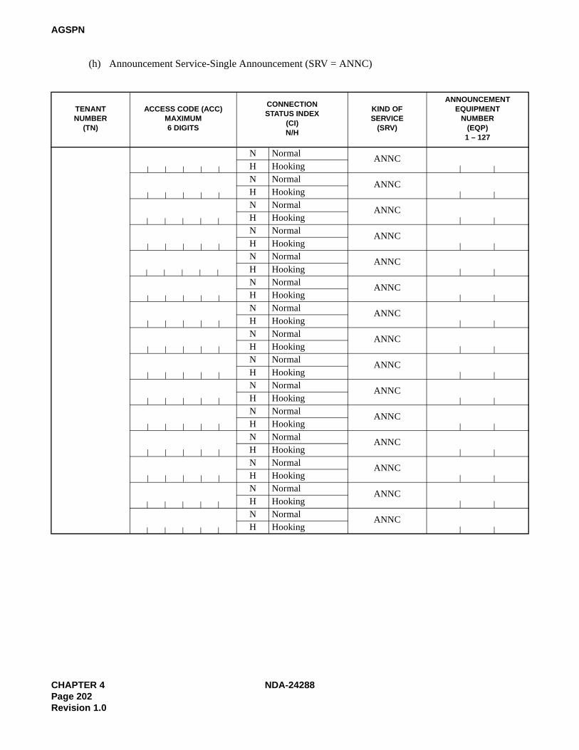
CHAPTER 4 NDA-24288Page 202Revision 1.0
AGSPN
(h) Announcement Service-Single Announcement (SRV = ANNC)
TENANTNUMBER
(TN)
ACCESS CODE (ACC)MAXIMUM6 DIGITS
CONNECTION STATUS INDEX
(CI) N/H
KIND OFSERVICE
(SRV)
ANNOUNCEMENTEQUIPMENT
NUMBER (EQP)
1 – 127
N NormalANNC
H HookingN Normal
ANNCH HookingN Normal ANNCH HookingN Normal
ANNCH HookingN Normal
ANNCH HookingN Normal
ANNCH HookingN Normal
ANNCH HookingN Normal ANNCH HookingN Normal
ANNCH HookingN Normal
ANNCH HookingN Normal
ANNCH HookingN Normal ANNCH HookingN Normal ANNCH HookingN Normal
ANNCH HookingN Normal
ANNCH Hooking
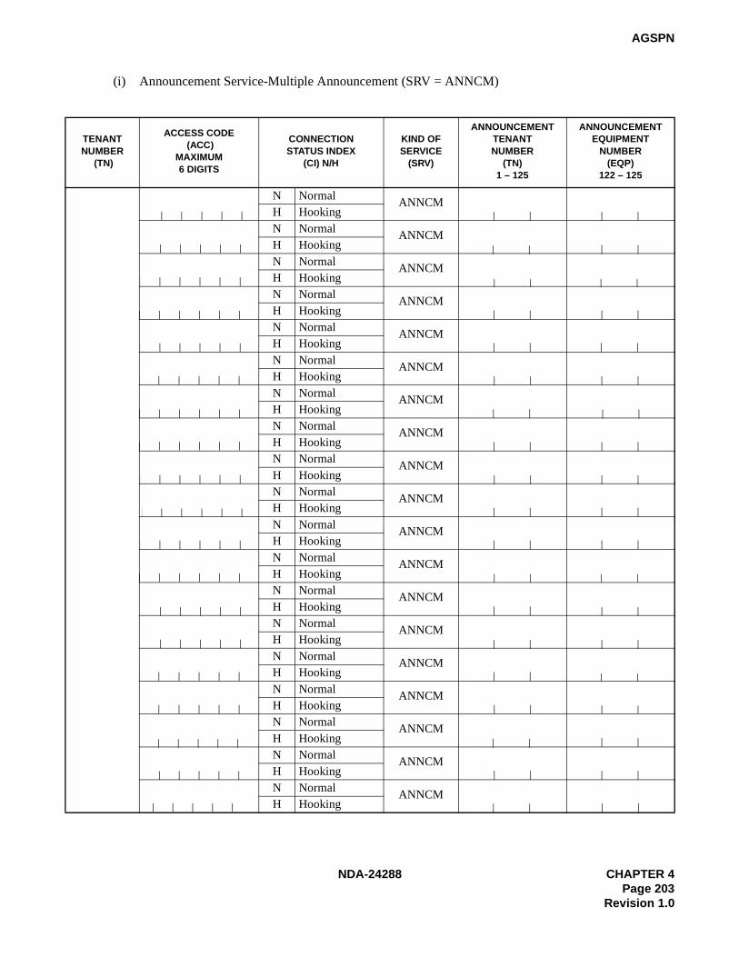
NDA-24288 CHAPTER 4Page 203
Revision 1.0
AGSPN
(i) Announcement Service-Multiple Announcement (SRV = ANNCM)
TENANTNUMBER
(TN)
ACCESS CODE (ACC)
MAXIMUM6 DIGITS
CONNECTIONSTATUS INDEX
(CI) N/H
KIND OFSERVICE
(SRV)
ANNOUNCEMENTTENANTNUMBER
(TN)1 – 125
ANNOUNCEMENTEQUIPMENT
NUMBER(EQP)
122 – 125
N NormalANNCM
H HookingN Normal ANNCMH HookingN Normal ANNCMH HookingN Normal
ANNCMH HookingN Normal
ANNCMH HookingN Normal
ANNCMH HookingN Normal ANNCMH HookingN Normal
ANNCMH HookingN Normal
ANNCMH HookingN Normal
ANNCMH HookingN Normal ANNCMH HookingN Normal ANNCMH HookingN Normal
ANNCMH HookingN Normal
ANNCMH HookingN Normal
ANNCMH HookingN Normal ANNCMH HookingN Normal
ANNCMH HookingN Normal
ANNCMH HookingN Normal
ANNCMH Hooking

CHAPTER 4 NDA-24288Page 204Revision 1.0
AGSPN
(j) Telephone Number (SRV = TELN)
TENANTNUMBER
(TN)
ACCESS CODE (ACC)
MAXIMUM6 DIGITS
CONNECTIONSTATUS INDEX
(CI)N/H
KIND OFSERVICE
(SRV)
NECESSARY DIGITS(NND) 1-16
REMARKS
N NormalTELN
H Hooking
N NormalTELN
H Hooking
N NormalTELN
H Hooking
N NormalTELN
H Hooking
N NormalTELN
H Hooking
N NormalTELN
H Hooking
N NormalTELN
H Hooking
N NormalTELN
H Hooking
N NormalTELN
H Hooking
N NormalTELN
H Hooking
N NormalTELN
H Hooking
N NormalTELN
H Hooking
N NormalTELN
H Hooking
N NormalTELN
H Hooking
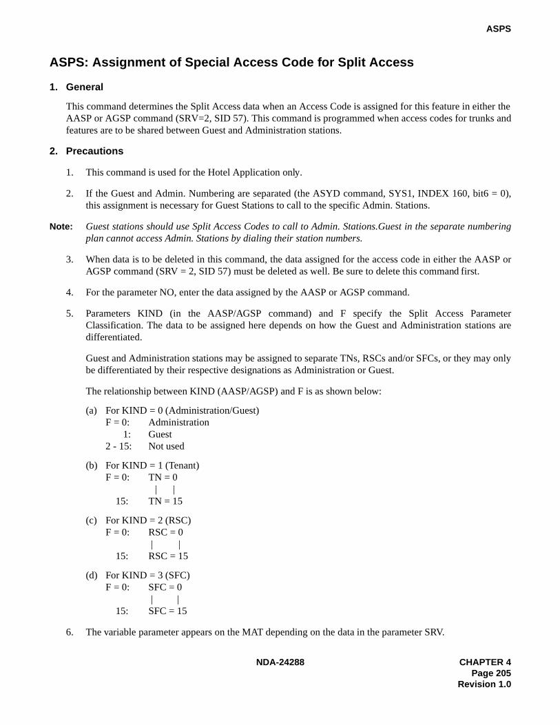
NDA-24288 CHAPTER 4Page 205
Revision 1.0
ASPS
ASPS: Assignment of Special Access Code for Split Access
1. General
This command determines the Split Access data when an Access Code is assigned for this feature in either theAASP or AGSP command (SRV=2, SID 57). This command is programmed when access codes for trunks andfeatures are to be shared between Guest and Administration stations.
2. Precautions
1. This command is used for the Hotel Application only.
2. If the Guest and Admin. Numbering are separated (the ASYD command, SYS1, INDEX 160, bit6 = 0),this assignment is necessary for Guest Stations to call to the specific Admin. Stations.
Note: Guest stations should use Split Access Codes to call to Admin. Stations.Guest in the separate numberingplan cannot access Admin. Stations by dialing their station numbers.
3. When data is to be deleted in this command, the data assigned for the access code in either the AASP orAGSP command (SRV = 2, SID 57) must be deleted as well. Be sure to delete this command first.
4. For the parameter NO, enter the data assigned by the AASP or AGSP command.
5. Parameters KIND (in the AASP/AGSP command) and F specify the Split Access ParameterClassification. The data to be assigned here depends on how the Guest and Administration stations aredifferentiated.
Guest and Administration stations may be assigned to separate TNs, RSCs and/or SFCs, or they may onlybe differentiated by their respective designations as Administration or Guest.
The relationship between KIND (AASP/AGSP) and F is as shown below:
(a) For KIND = 0 (Administration/Guest)F = 0: Administration 1: Guest2 - 15: Not used
(b) For KIND = 1 (Tenant)F = 0: TN = 0
| | 15: TN = 15
(c) For KIND = 2 (RSC)F = 0: RSC = 0
| | 15: RSC = 15
(d) For KIND = 3 (SFC)F = 0: SFC = 0
| | 15: SFC = 15
6. The variable parameter appears on the MAT depending on the data in the parameter SRV.
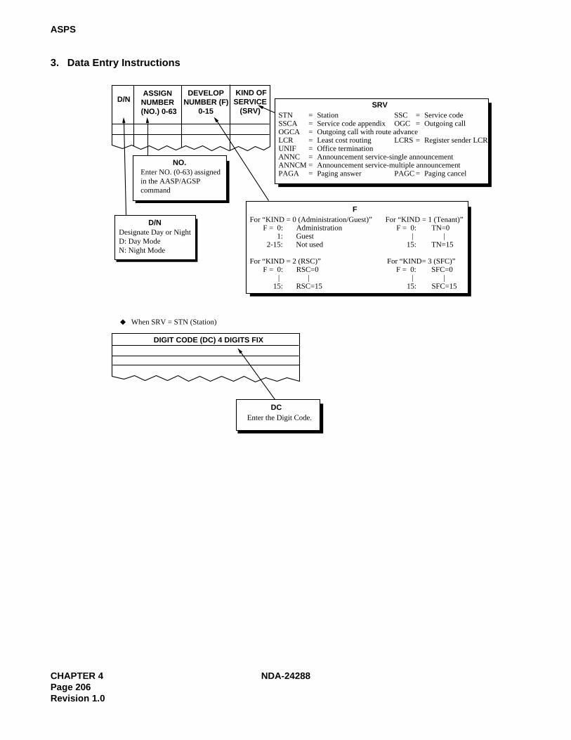
CHAPTER 4 NDA-24288Page 206Revision 1.0
ASPS
3. Data Entry Instructions
D/N ASSIGNNUMBER(NO.) 0-63
DEVELOPNUMBER (F) 0-15
KIND OFSERVICE (SRV)
SRVSTN = Station SSC = Service codeSSCA = Service code appendix OGC = Outgoing callOGCA = Outgoing call with route advanceLCR = Least cost routing LCRS = Register sender LCRUNIF = Office terminationANNC = Announcement service-single announcementANNCM = Announcement service-multiple announcementPAGA = Paging answer PAGC = Paging cancel
FFor “KIND = 0 (Administration/Guest)” For “KIND = 1 (Tenant)” F = 0: Administration F = 0: TN=0 1: Guest | | 2-15: Not used 15: TN=15
For “KIND = 2 (RSC)” For “KIND= 3 (SFC)” F = 0: RSC=0 F = 0: SFC=0 | | | | 15: RSC=15 15: SFC=15
NO.
D/N
Enter NO. (0-63) assignedin the AASP/AGSPcommand
Designate Day or NightD: Day ModeN: Night Mode
DIGIT CODE (DC) 4 DIGITS FIX
DCEnter the Digit Code.
When SRV = STN (Station)

NDA-24288 CHAPTER 4Page 207
Revision 1.0
ASPS
15 (Speed Calling-System; Access)
42 (Authorization Code/Forced Account Code/Pad Lock)
41 (Account Code Dial)
60 (Attendant Manual Override)63 (Call Park ; Retrieve)
NND appears when the following SID is entered.NND data is variable depending on SID.
NND1 appears when SID=15. The number of ADC(Abbreviation Digit Code) digits should be assigned in NND1.
NND1
SERVICE INDEX(SID) 1-63
NECESSARY DIGIT(NND)
NECESSARY DIGIT FOR SPEEDCALLING (NND1) 1-24
NND
SID Number of digits for NNDAccess Code (1-24)
Access Code+Account code(1-15)
Access Code+ID (1-15)
Access Code (1-5)Access Code (1-3)
When SRV=SSC (Service code except SID36 and 56) is assigned

CHAPTER 4 NDA-24288Page 208Revision 1.0
ASPS
STATE(Hotel Service Code)
1 To be cleaned without ID code 2 Cleaning Completed without ID code 3 Ready for Occupancy without ID code 4 Use Not Allowed without ID code
5 - 8 - 9 Maid Dial Answer Back without ID code-110 Maid Dial Answer Back without ID code-211 Maid Dial Answer Back without ID code-312 Maid Dial Answer Back without ID code-413 Maid Dial Answer Back without ID code-514 Maid Dial Answer Back without ID code-615 Maid Dial Answer Back without ID code-716 -17 To be cleaned with ID code18 Cleaning Completed with ID code19 Ready for Occupancy with ID code20 Use Not Allowed with ID code
21 - 24 -25 Maid Dial Answer Back with ID code-126 Maid Dial Answer Back with ID code-227 Maid Dial Answer Back with ID code-328 Maid Dial Answer Back with ID code-429 Maid Dial Answer Back with ID code-530 Maid Dial Answer Back with ID code-631 Maid Dial Answer Back with ID code-7 32 -33 Automatic Wake Up Setting, Cancel; Same Special code34 For Guest Station Secretary Telephone; Boss/Secretary Calling
35 - 37 -38 Automatic Wake-Up-Hotel Attendant Assistance Stop39 Automatic Wake-Up-Hotel Attendant Assistance Stop Cancel40 Alert Service Start (Hotel ATT)41 Alert Service Stop (Hotel ATT)42 Guest Service Telephone Screen Initialized43 Guest Service Telephone Guest Room Information Retrieval44 Direct Data Entry-Station (via Guest Station)45 Alert Service Start (Special Admin. Station)46 Alert Service Stop (Special Admin. Station)47 -48 2nd Wake-Up Call (Automatic) Set49 2nd Wake-Up Call (Semi-Automatic) Set50 2nd Wake-Up Call Cancel51 Same Special Code Time Zone Connection Change52 Same Special Code Time Zone Connection Change53 Same Special Code Time Zone Connection Change54 Same Special Code Time Zone Connection Change55 Same Special Code Time Zone Connection Change
56 - 62 -63 Dummy Number
Note: STATE=1-15 are used at the time of Maid ID Code Service is not provided; (ASYD SYS1 INDEX 164, bit3=0) STATE=17-31 are used at the time of Maid ID Code Service is provided; (ASYD SYS1 INDEX 164, bit3=1)
SERVICE INDEX (SID) 1-63
STATE
36
When SRV=SSC (Service code), SID36 (Hotel Service) is assigned
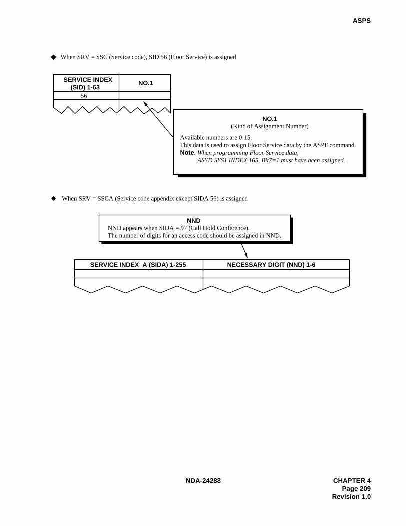
NDA-24288 CHAPTER 4Page 209
Revision 1.0
ASPS
SERVICE INDEX (SID) 1-63 NO.1
56
NO.1(Kind of Assignment Number)
Available numbers are 0-15.This data is used to assign Floor Service data by the ASPF command.Note: When programming Floor Service data, ASYD SYS1 INDEX 165, Bit7=1 must have been assigned.
When SRV = SSC (Service code), SID 56 (Floor Service) is assigned
NND appears when SIDA = 97 (Call Hold Conference).The number of digits for an access code should be assigned in NND.
NND
SERVICE INDEX A (SIDA) 1-255 NECESSARY DIGIT (NND) 1-6
When SRV = SSCA (Service code appendix except SIDA 56) is assigned

CHAPTER 4 NDA-24288Page 210Revision 1.0
ASPS
Assign the number of advanced trunk routes.
ROUTE NUMBER(RT)
COUNT
INDEX COUNTER (COUNT) INDEX ROUTE NUMBER (RT)
When SRV = OGC (Outgoing call) is assigned
When SRV = PAGA (Paging answer) is assigned
When SRV = PAGC (Paging cancel) is assigned
When SRV = OGCA (Outgoing call with route advance) is assigned
INDEX
INDEX is the route advance order.
12
3
SERVICE INDEX A (SIDA) 1-255 PNO 1-15 A/G56
PNO
This parameter specifies the Admin./GuestNumbering Parameter Classification.After assigning the PNO, go to the AOSPcommand to skip this ACC.After skipping the access code, the systemrefers to the numbering data designated inthe next parameter A/G.
A/GNumbering table designation for redevelopmentA : Admin.G : Guest
When SRV = SSCA (Service code appendix), SIDA 56 (Guest/Admin. Service) is assigned

NDA-24288 CHAPTER 4Page 211
Revision 1.0
ASPS
Assign a dummy route number.RT
Second dial tone sending (which is sent when a station has dialedthe digits specified in NND of the AANP/AGNP command)0 = Second DT is not send1 = Second DT is sent
2nd DT
Authorization code after dialingACC (LCR) + Destination number0 = Out of Service1 = In Service
AH
ISDN-Sub Address Dialing0 = Out of Service1 = In Service
SUB
ROUTE NUMBER(RT)
SECOND DIAL TONE(2nd DT) 0/1
AUTHORIZATION CODE(AH) 0/1
SUB ADDRESS DIALING(SUB) 0/1
When SRV = LCR (Least cost routing) is assignedWhen SRV = LCRS (Register sender LCR) is assigned
Assign the skip digits to terminate the call.
Assign the announce equipment number.EQP3 and 5-14 can be used for SRV = ANNC (Single announcement).
SKIP DIGITS(SKIP) 0-5
When SRV = UNIF (Office termination) is assigned
When SRV = ANNC (Announcement service-Single announcement) is assigned
SKIP
ANNOUNCEMENT EQUIPMENT NUMBER(EQP) 0-127
EQP
Note: This data is available for ACIS only. For CCIS, use the AUNE command.
Assign the tenant number ofthe announcement trunk.
When SRV = ANNCM (Announcement service-Multiple announcement) is assigned
TN
TENANT NUMBER(TN) 1-255
ANNOUNCEMENT EQUIPMENT NUMBER(EQP) 122-125
Assign the announcement equipment number range from 122 to 125 (Multi announcement).
EQP

CHAPTER 4 NDA-24288Page 212Revision 1.0
ASPS
4. Data Sheet
(a) Station Call (SRV = STN)
DAY/NIGHT(D/N)D/N
ASSIGN NUMBER
(No.)0 – 63
DEVELOP NUMBER
(F) 0 – 15
KIND OF SERVICE (SRV)
DIGIT CODE(DC)
4 DIGITS FIX
STN
STN
STN
STN
STN
STN
STN
STN
STN
STN
STN
STN
STN

NDA-24288 CHAPTER 4Page 213
Revision 1.0
ASPS
(b) Service Code (SRV = SSC)
Note: When Split Call Forwarding is in service (the ASYD command, SYS1, INDEX79, bit2 = 1), this access code is usedfor Split Call Forwarding.
DAY/NIGHT(D/N)D/N
ASSIGN NUMBER
(No.) 0 – 63
DEVELOP NUMBER
(F)0 – 15
KIND OFSERVICE
(SRV)
SERVICEINDEX (SID) 1 – 63
NUMBER OF NECESSARY
DIGITS(NND)
NUMBER OF NECESSARY
DIGIT FORSPEED CALLING
(NND1)1 – 24
SERVICE CONTENTS
SSC 1 Call Hold
SSC 2Dial Access to Attendant (Information Service Call)
SSC 3 Call Back; Entry
SSC 4 Executive Right of Way
SSC 5 Call Waiting – Originating
SSC 6 Call Back; Cancel
SSC 7 Call Pickup – Group
SSC 8C.F. – All Calls/Split C.F. – All Calls (for C.O./Tie); Entry Note
SSC 9C.F. – All Calls/Split C.F. – All Calls (for C.O./Tie); Cancel Note
SSC 10C.F. – Busy Line/Split C.F. – Busy Line (for C.O./Tie); Entry Note
SSC 11C.F. – Busy Line/Split C.F. – Busy Line (for C.O./Tie); Cancel Note
SSC 12C.F. – Don’t Answer/Split C.F. – Don’t Answer (for C.O./Tie); EntryNote
SSC 13C.F. – Don’t Answer/Split C.F. – Don’t Answer (for C.O./Tie); CancelNote
SSC 14 Speed Calling – Station; Entry
SSC 15 Speed Calling – System; Access
SSC 16 TAS Answer
SSC 17 Individual Trunk Access
18 Not used
SSC 19 OG Trunk Queuing; Entry

CHAPTER 4 NDA-24288Page 214Revision 1.0
ASPS
(b) Service Code (SRV = SSC) (Continued)
DAY/NIGHT(D/N)D/N
ASSIGNNUMBER
(No.) 0 – 63
DEVELOPNUMBER
(F) 0 – 15
KIND OFSERVICE
(SRV)
SERVICEINDEX
(SID) 1– 63
NUMBER OFNECESSARY
DIGITS(NND)
SERVICE CONTENTS
SSC 20 OG Trunk Queuing; Cancel
SSC 21Speed Calling – Station, Group;
Access
22
27Not used
SSC 28 Call Forwarding I’m Here; Set
SSC 29 Call Forwarding I’m Here; Cancel
30
34Not used
SSC 35 Call Pickup – Direct
SSC 36 Hotel Service
~~

NDA-24288 CHAPTER 4Page 215
Revision 1.0
ASPS
(b) Service Code (SRV = SSC) (Continued)
DAY/NIGHT(D/N)D/N
ASSIGNNUMBER
(No.) 0 – 63
DEVELOPNUMBER
(F) 0 – 15
KIND OFSERVICE
(SRV)
SERVICEINDEX (SID)1 – 63
MAIDSTATUS (STATE1 – 63
SERVICE CONTENTS
SSC 36
1 To be cleaned without ID Code
2 Cleaned without ID Code
3 Ready for Occupancy without ID Code
4 Use Not Allowed without ID Code
5
8Not used
9 Maid Dial Answer Back without ID Code 1
10 Maid Dial Answer Back without ID Code 2
11 Maid Dial Answer Back without ID Code 3
12 Maid Dial Answer Back without ID Code 4
13 Maid Dial Answer Back without ID Code 5
14 Maid Dial Answer Back without ID Code 6
15 Maid Dial Answer Back without ID Code 7
16 Not used
17 To be cleaned with ID Code
18 Cleaned with ID Code
19 Ready for Occupancy with ID Code
20 Use Not Allowed with ID Code
21
24Not used
25 Maid Dial Answer Back with ID Code 1
26 Maid Dial Answer Back with ID Code 2
27 Maid Dial Answer Back with ID Code 3
28 Maid Dial Answer Back with ID Code 4
29 Maid Dial Answer Back with ID Code 5
30 Maid Dial Answer Back with ID Code 6
31 Maid Dial Answer Back with ID Code 7
32 Not used
33Automatic Wake-Up Setting, Cancel; Same Special Code
~~

CHAPTER 4 NDA-24288Page 216Revision 1.0
ASPS
(b) Service Code (SRV = SSC) (Continued)
DAY/NIGHT(D/N)D/N
ASSIGNNUMBER
(No.) 0 – 63
DEVELOPNUMBER
(F) 0 – 15
KIND OFSERVICE
(SRV)
SERVICEINDEX(SID)1 – 63
MAIDSTATUS(STATE)1 – 63
SERVICE CONTENTS
SSC 36
34For Guest Station Secretary Telephone; Boss/Secretary
35
Not used36
37
38Automatic Wake-Up – Hotel Attendant Assistance Stop
39Automatic Wake Stop – Up – Hotel Attendant Assistance Cancel
40 Alert Service Start (Hotel ATT)
41 Alert Service Stop (Hotel ATT)
42 Guest Service Telephone Screen Initialization
43Guest Service Telephone Guest Room Information Retrieval
44 Direct Data Entry – STA
45 Alert Service Start (Special Adman. Station)
46 Alert Service Stop (Special Admin. Station)
47 Not used
48 2nd Wake-Up Call (Automatic); Set
49 2nd Wake-Up Call (Semi-Automatic); Set
50 2nd Wake-Up Call; Cancel
51 Same Special Code Time Zone Connection Change
52 Same Special Code Time Zone Connection Change
53 Same Special Code Time Zone Connection Change
54 Same Special Code Time Zone Connection Change
55 Same Special Code Time Zone Connection Change
56
62Not used
63 Dummy Number
~

NDA-24288 CHAPTER 4Page 217
Revision 1.0
ASPS
(b) Service Code (SRV = SSC) (Continued)
DAY/NIGHT(D/N)D/N
ASSIGNNUMBER
(No.)00 – 63
DEVELOPNUMBER
(F)0 – 15
KIND OFSERVICE
(SRV)
SERVICEINDEX(SID)1 – 63
NUMBER OFNECESSARY
DIGITS(NND)
SERVICE CONTENTS
SSC 37 Priority Call 1
SSC 38 Priority Call 2
SSC 39 Priority Call 3
SSC 40 Priority Paging
SSC 41 Account Code Dial
SSC 42Authorization Code/Forced Account Code Dial/Dial Access to Lock
SSC 43 Flash Signal Sending (CAS – Main)
SSC 44 Last Number Call
45 Not used
SSC 46 Faulty Trunk Report
47 Not used
SSC 48 Automatic Wake Up: Entry
SSC 49 Automatic Wake Up: Cancel
SSC 50 Group Announcement; Entry
SSC 51 Group Announcement; Cancel
SSC 52Do not Disturb; Entry
(via Guest Station)
SSC 53Do not Disturb; Cancel
(via Guest Station)
54Not used
55
SSC 56 Floor Service
57
59Not used
SSC 60 Attendant Manual Override
SSC 61 Call Park Access Code
SSC 62 Call Park Local Retrieval Code
SSC 63 Call Park Remote Retrieval Code
~

CHAPTER 4 NDA-24288Page 218Revision 1.0
ASPS
(b) Service Code (SRV = SSC) (Continued)
DAY/NIGHT(D/N)D/N
ASSIGNNUMBER
(No.) 00 – 63
DEVELOPNUMBER
(F) 0 – 15
KIND OFSERVICE
(SRV)
SERVICEINDEX (SID)
SERVICE INDEXNUMBER
(No.1)0 – 15
SERVICE CONTENTS
SSC 56 0
SSC 56 1
SSC 56 2
SSC 56 3
SSC 56 4
SSC 56 5
SSC 56 6
SSC 56 7
SSC 56 8
SSC 56 9
SSC 56 10
SSC 56 11
SSC 56 12
SSC 56 13
SSC 56 14
SSC 56 15
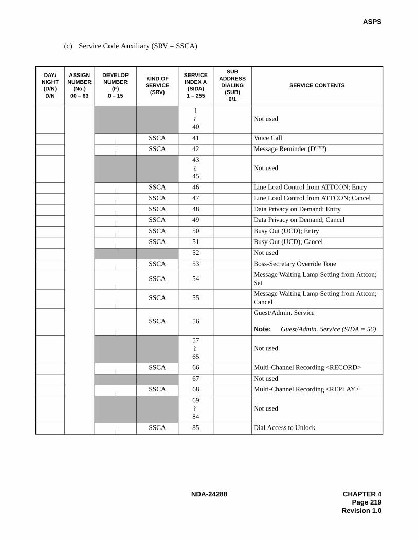
NDA-24288 CHAPTER 4Page 219
Revision 1.0
ASPS
(c) Service Code Auxiliary (SRV = SSCA)
DAY/NIGHT(D/N)D/N
ASSIGNNUMBER
(No.)00 – 63
DEVELOPNUMBER
(F) 0 – 15
KIND OFSERVICE
(SRV)
SERVICEINDEX A(SIDA)1 – 255
SUBADDRESSDIALING
(SUB)0/1
SERVICE CONTENTS
1
40Not used
SSCA 41 Voice Call
SSCA 42 Message Reminder (Dterm)
43
45Not used
SSCA 46 Line Load Control from ATTCON; Entry
SSCA 47 Line Load Control from ATTCON; Cancel
SSCA 48 Data Privacy on Demand; Entry
SSCA 49 Data Privacy on Demand; Cancel
SSCA 50 Busy Out (UCD); Entry
SSCA 51 Busy Out (UCD); Cancel
52 Not used
SSCA 53 Boss-Secretary Override Tone
SSCA 54Message Waiting Lamp Setting from Attcon; Set
SSCA 55Message Waiting Lamp Setting from Attcon; Cancel
SSCA 56Guest/Admin. Service
Note: Guest/Admin. Service (SIDA = 56)
57
65Not used
SSCA 66 Multi-Channel Recording <RECORD>
67 Not used
SSCA 68 Multi-Channel Recording <REPLAY>
69
84Not used
SSCA 85 Dial Access to Unlock
~~
~~

CHAPTER 4 NDA-24288Page 220Revision 1.0
ASPS
(c) Service Code Auxiliary (SRV = SSCA) (Continued)
DAY/NIGHT(D/N)D/N
ASSIGNNUMBER
(No.)00 – 63
DEVELOPNUMBER
(F) 0 – 15
KIND OFSERVICE
(SRV)
SERVICEINDEX A(SIDA) 1 – 255
PATTERNNUMBER FOR
AOSPCOMMAND
(PNO) 1 – 15
ADMIN./GUEST(A/G)A/G
SERVICE CONTENTS
SSCA 56
SSCA 56
SSCA 56
SSCA 56
SSCA 56
SSCA 56
SSCA 56
SSCA 56
SSCA 56
SSCA 56

NDA-24288 CHAPTER 4Page 221
Revision 1.0
ASPS
(c) Service Code Auxiliary (SRV = SSCA) (Continued)
DAY/NIGHT(D/N)D/N
ASSIGNNUMBER
(No.)00 – 63
DEVELOPNUMBER
(F)0 – 15
KIND OFSERVICE
(SRV)
SERVICE INDEX A(SIDA)1 – 255
NECESSARYDIGIT(NND)1– 6
SERVICE CONTENTS
SSCA 86 Split C.F. – All Calls (for Station); Entry
SSCA 87Split C.F. – Busy Line (for Station); Entry
SSCA 88Split C.F. – Don’t Answer (for Station); Entry
SSCA 89Split C.F. – All Calls (for Station); Cancel
SSCA 90Split C.F. – Busy Line (for Station); Cancel
SSCA 91Split C.F. – Don’t Answer (for Station); Cancel
92
95Not used
SSCA 96 Follow Phone
SSCA 97 Call Hold Conference
98
105Not used
SSCA 106 Call Return
107
255Not used
~~
~

CHAPTER 4 NDA-24288Page 222Revision 1.0
ASPS
(d) Outgoing Call Without Route Advance (SRV = OGC)
DAY/NIGHT(D/N)D/N
ASSIGNNUMBER
(No.)00 – 63
DEVELOPNUMBER
(F)0 – 15
KIND OFSERVICE
(SRV)
ROUTE NUMBER(RT)
1 – 255
OGC
OGC
OGC
OGC
OGC
OGC
OGC
OGC
OGC
OGC
OGC
OGC
OGC
OGC
OGC

NDA-24288 CHAPTER 4Page 223
Revision 1.0
ASPS
(e) Outgoing Call With Route Advance (SRV = OGCA) (Continued)
DAY/NIGHT(D/N)D/N
ASSIGN NUMBER
(No.)00 – 63
DEVELOPNUMBER
(F) 0 – 15
KIND OFSERVICE
(SRV)
INDEX COUNT(COUNT)
ROUTE NUMBER(RT)
1st 2nd 3rd 4th 5th 6th 7th 8th
9th 10th 11th 12th 13th 14th 15th
OGCA
OGCA
OGCA
OGCA
OGCA
OGCA
OGCA
OGCA
OGCA
OGCA
OGCA
OGCA
OGCA
OGCA
OGCA
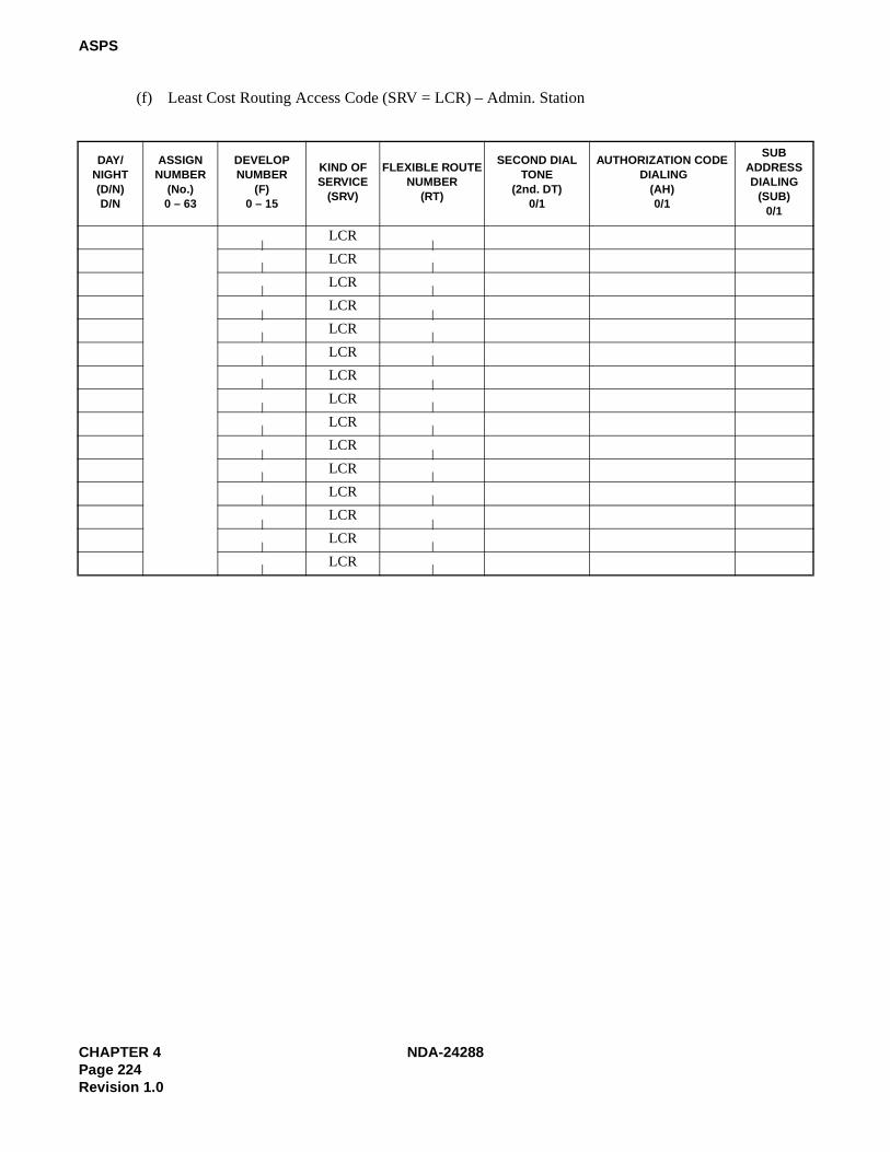
CHAPTER 4 NDA-24288Page 224Revision 1.0
ASPS
(f) Least Cost Routing Access Code (SRV = LCR) – Admin. Station
DAY/NIGHT(D/N)D/N
ASSIGNNUMBER
(No.) 0 – 63
DEVELOPNUMBER
(F)0 – 15
KIND OFSERVICE
(SRV)
FLEXIBLE ROUTENUMBER
(RT)
SECOND DIALTONE
(2nd. DT) 0/1
AUTHORIZATION CODE DIALING
(AH)0/1
SUBADDRESSDIALING
(SUB) 0/1
LCR
LCR
LCR
LCR
LCR
LCR
LCR
LCR
LCR
LCR
LCR
LCR
LCR
LCR
LCR

NDA-24288 CHAPTER 4Page 225
Revision 1.0
ASPS
(g) Register Sender Least Cost Routing Access Code (SRV = LCRS)
DAY/NIGHT(D/N)D/N
ASSIGN NUMBER
(No.)0 – 63
DEVELOP NUMBER
(F)0 – 15
KIND OF SERVICE
(SRV)
FLEXIBLEROUTE
NUMBER(RT)
SECOND DIALTONE(2nd. DT)
0/1
AUTHORIZATION CODE DIALING
(AH) 0/1
SUB ADDRESS DIALING
(SUB) 0/1
LCRS
LCRS
LCRS
LCRS
LCRS
LCRS
LCRS
LCRS
LCRS
LCRS
LCRS
LCRS
LCRS
LCRS
LCRS

CHAPTER 4 NDA-24288Page 226Revision 1.0
ASPS
(h) Office Termination Code (SRV = UNIF)
DAY/NIGHT(D/N)D/N
ASSIGN NUMBER(No.) 0 – 63
DEVELOP NUMBER
(F) 0 – 15
KIND OF SERVICE(SRV)
SKIP DIGITS(SKIP) 0 – 5
UNIF
UNIF
UNIF
UNIF
UNIF
UNIF
UNIF
UNIF
UNIF
UNIF
UNIF
UNIF
UNIF
UNIF
UNIF
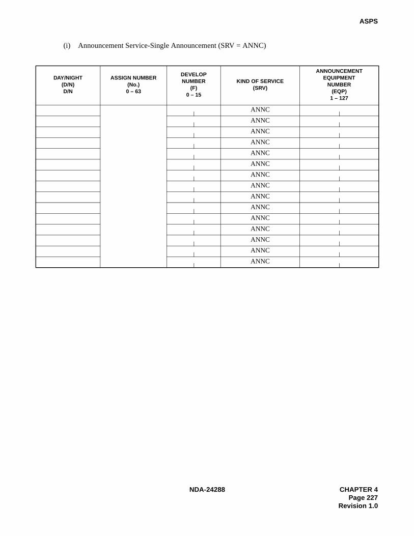
NDA-24288 CHAPTER 4Page 227
Revision 1.0
ASPS
(i) Announcement Service-Single Announcement (SRV = ANNC)
DAY/NIGHT(D/N)D/N
ASSIGN NUMBER (No.) 0 – 63
DEVELOPNUMBER
(F) 0 – 15
KIND OF SERVICE (SRV)
ANNOUNCEMENT EQUIPMENT
NUMBER(EQP)
1 – 127
ANNC
ANNC
ANNC
ANNC
ANNC
ANNC
ANNC
ANNC
ANNC
ANNC
ANNC
ANNC
ANNC
ANNC
ANNC

CHAPTER 4 NDA-24288Page 228Revision 1.0
ASPS
(j) Announcement Service-Multiple Announcement (SRV = ANNCM)
DAY/NIGHT(D/N)D/N
ASSIGN NUMBER (No.) 0 – 63
DEVELOPNUMBER
(F) 0 – 15
KIND OFSERVICE
(SRV)
ANNOUNCEMENT TENANT NUMBER
(TN)1 – 125
ANNOUNCEMENT EQUIPMENT
NUMBER(EQP)
122 – 125
ANNCM
ANNCM
ANNCM
ANNCM
ANNCM
ANNCM
ANNCM
ANNCM
ANNCM
ANNCM
ANNCM
ANNCM
ANNCM
ANNCM
ANNCM
ANNCM
ANNCM
ANNCM
ANNCM
ANNCM
ANNCM
ANNCM
ANNCM
ANNCM
ANNCM
ANNCM
ANNCM
ANNCM
ANNCM

NDA-24288 CHAPTER 4Page 229
Revision 1.0
ASPS
(k) Paging Answer Code (SRV = PAGA)
DAY/NIGHT(D/N)D/N
ASSIGN NUMBER(No.)0 – 63
DEVELOPNUMBER
(F)0 – 15
KIND OF SERVICE(SRV)
ROUTE NUMBER(RT)
PAGA
PAGA
PAGA
PAGA
PAGA
PAGA
PAGA
PAGA
PAGA
PAGA
PAGA
PAGA
PAGA
PAGA
PAGA

CHAPTER 4 NDA-24288Page 230Revision 1.0
ASPS
(l) Paging Cancel Code (SRV = PAGC)
DAY/NIGHT(D/N)D/N
ASSIGN NUMBER(No.) 0 – 63
DEVELOPNUMBER
(F) 0 – 15
KIND OF SERVICE(SRV)
ROUTE NUMBER(RT)
PAGC
PAGC
PAGC
PAGC
PAGC
PAGC
PAGC
PAGC
PAGC
PAGC
PAGC
PAGC
PAGC
PAGC
PAGC

NDA-24288 CHAPTER 4Page 231
Revision 1.0
ASCR
ASCR: Assignment of Station Connection Restriction
1. General
This command assigns and displays the station-to-station connection restriction data based on the RouteRestriction Class (RSC) of respective tenants.
2. Precautions
1. This command is used for the Hotel Application only.
2. Station-to-station connections will be allowed for each RSC until they are restricted by this command.
3. Data Entry Instructions
CALLING TN RSC
Calling Tenant Number respective Route Restriction Class
DIAL/ATTDesignate whether restriction appliesto stations or attendant0/1 = Dial/Attendant
CALLING TENANT NUMBER(CALLING TN)
CALLINGRESTRICTION CLASS (RSC) 0-15
CALLEDRESTRICTION CLASS (RSC) 0-15
DAY/NIGHT MODE (D/N) D/N
DIRECTDIAL FROM STA/ATT (DIAL/ATT) 0/1
RESTRICTION RESTRICTED /ALLOWED (RES) 0/1
CALLED TN RSC
Called Tenant Number respective Route Restriction Class
D/N RESD : Day ModeN : Night Mode
0 : Restricted1 : Connection is allowed
CALLED TENANT NUMBER(CALLED TN)
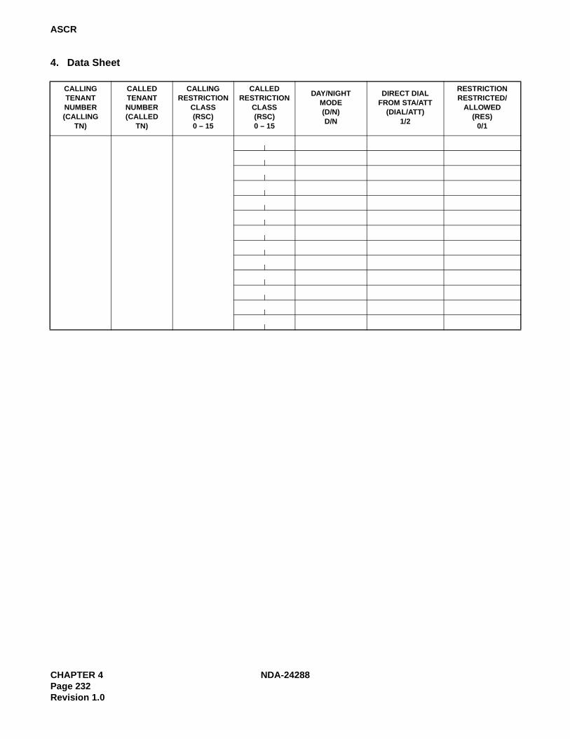
CHAPTER 4 NDA-24288Page 232Revision 1.0
ASCR
4. Data Sheet
CALLINGTENANTNUMBER(CALLING
TN)
CALLEDTENANTNUMBER(CALLED
TN)
CALLINGRESTRICTION
CLASS(RSC)0 – 15
CALLEDRESTRICTION
CLASS(RSC)0 – 15
DAY/NIGHTMODE(D/N)D/N
DIRECT DIALFROM STA/ATT
(DIAL/ATT)1/2
RESTRICTIONRESTRICTED/
ALLOWED(RES)
0/1

NDA-24288 CHAPTER 4Page 233
Revision 1.0
ATCR
ATCR: Assignment of Telephone Class Restriction
1. General
This command assigns and displays the restriction data for connections between Telephone Equipment Classes(TECs).
2. Precautions
1. This command is used for the Hotel Application only.
2. Connection between TECs will be allowed for each RSC until they are restricted by this command.
3. TEC 31 is used for ATT in this command.
3. Data Entry Instructions
CALLING TECCalling Telephone Equipment Class
1: DP (10 pps) 2: PB3: DP/PB 4: DP (20 pps)5: DP (10 pps) : Guest 6: PS : Guest7: DP/PB : Guest 8: DP (20 pps) : Guest9: House Phone 10: House Phone : Guest11: Not Used 12: Dterm 13: Data Terminal via Dterm 14: Hot Line15: CAS Line 16: Data Terminal via Data Module17: Not Used 18: Virtual Line Appearance (for Dterm Multi-Line)
19-22: Not Used 23: ISDN Terminal24-25: Not Used 26: Not Used
27: Eight Conference Equipment28-30: Not Used 31:ATT
CALLED TEC
Called Telephone Equipment Class1 : DP (10 pps) 2 : PB3 : DP/PB 4 : DP (20 pps)5 : DP (10 pps) : Guest 6 : PS : Guest7 : DP/PB : Guest 8 : DP (20 pps) : Guest9 : House Phone 10 : House Phone : Guest11 : Not Used 12 : Dterm 13 : Data Terminal via Dterm 14 : Hot Line15 : CAS Line1 6 : Data Terminal via Data Module17 : Not Used 18 : Virtual Line Appearance (for Dterm Multi-Line)19-22 : Not Used 23 : ISDN Terminal24-25 : Not Used 26 : Not Used27 : Eight Conference Equipment28-30 : Not Used 31 : ATT
CALLING TELEPHONE EQUIP. CLASS(CALLING TEC) 1-31
CALLED TELEPHONE EQUIP. CLASS(CALLED TEC) 1-31
DAY/NIGHT MODE (D/N) D/N
RESTRICTION
(RES) 0/1
RES
0 : Restricted1 : Connection is allowed
D/ND : Day ModeN : Night Mode

CHAPTER 4 NDA-24288Page 234Revision 1.0
ATCR
4. Data Sheet
CALLING TELEPHONE
EQUIP. CLASS(CALLING TEC)
1 – 31
CALLED TELEPHONE
EQUIP. CLASS(CALLED TEC)
1 – 31
DAY/NIGHT MODE(D/N)D/N
RESTRICTION(RES)
0/1

NDA-24288 CHAPTER 4Page 235
Revision 1.0
ADNR
ADNR: Assignment of Day/Night Restriction
1. General
This command assigns and displays the specific Start and End times pertaining to Day/Night Restriction or todisplay the Day/Night Restriction classification of a specific time.
2. Precautions
1. This command is used for the Hotel Application only.
2. When Data “1” is assigned for bit6 of the ASYD command, SYS1, INDEX 170, Day/Night ConnectionRestriction will be executed regardless of ATT night mode changeover.
3. The ARSC command may be affected if the day and night tables are used.
4. For time designation, use military time (24 hour cycle) in units of 10 minutes.
5. End time must be later than Start time. If the same time is specified for both Start and End, the restrictionperiod will be 10 minutes.
6. Night time assignment should be input twice; once for the period before midnight, and once for the periodafter midnight because midnight is assigned as hour 00:00. Refer to the example below for clarification:
Example: If the time period from 9:00 p.m. to 7:00 a.m. is to be assigned as Night,
00:00 - 07:00 = Night07:10 - 20:50 = Day21:00 - 23:50 = Night
7. RSC 11 through 15 may be used in the Same Special Code Time Zone Connection Change service (TheAASP/AGSP command, SRV = 2, SID 36, STATE 51- 55).
3. Data Entry Instructions
D/N RSC
TENANTNUMBER (TN)
DAY/NIGHT MODE (D/N) D/N
ROUTERESTRICTION CLASS (RSC) 0-15
RESTRICTION START TIME (START TIME) 00:00-23:50
RESTRICTION END TIME (END TIME) 00:00-23:50
START TIME END TIME
D : Day ModeN : Night Mode
RSC 0 : ATTRSC 1-15 : Station
Assign in military time (24 hour cycle)in units of 10 minutes.
Assign in military time (24 hour cycle)in units of 10 minutes.
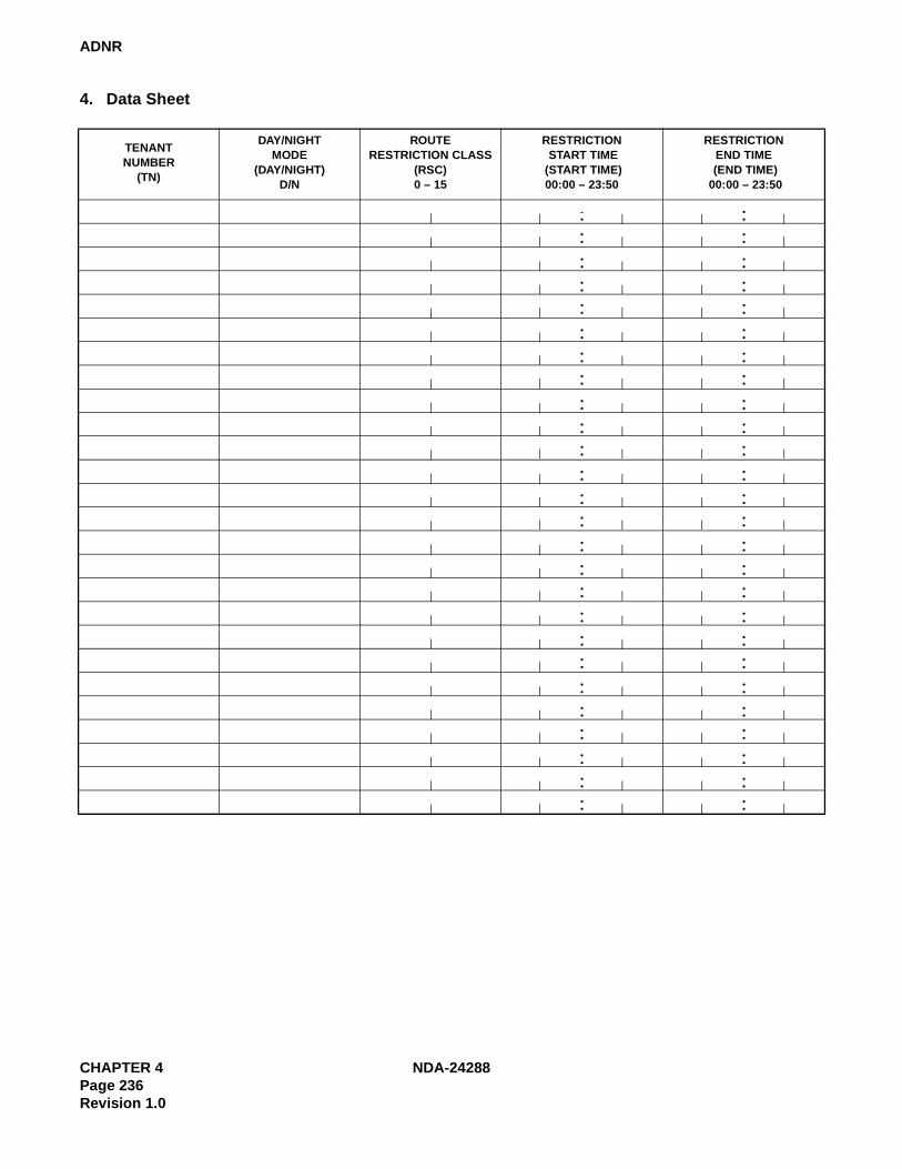
CHAPTER 4 NDA-24288Page 236Revision 1.0
ADNR
4. Data Sheet
TENANTNUMBER
(TN)
DAY/NIGHTMODE
(DAY/NIGHT)D/N
ROUTERESTRICTION CLASS
(RSC)0 – 15
RESTRICTION START TIME
(START TIME)00:00 – 23:50
RESTRICTIONEND TIME
(END TIME) 00:00 – 23:50
: :: :: :: :: :: :: :: :: :: :: :: :: :: :: :: :: :: :: :: :: :: :: :: :: :: :

NDA-24288 CHAPTER 4Page 237
Revision 1.0
AAST
AAST: Assignment of Administration Station Data
1. General
This command assigns the administration station data.
2. Precautions
1. This command is used for the Hotel Application only.
2. When deleting station data, use the RAST command.
3. The AASN command is used to change the station number, and the AACL command is used to change theClass data (TEC, RSC, SFC etc.).
4. Assignment of Room Class 15 is not available.
5. The number of digits for a station number are designated by the ASYD command, SYS1, INDEX 16. Themaximum number of digits for a station is 6.
6. The first digit of the station number is designated by the AANP command.
7. The RSC and SFC data work in conjunction with ARSC/ASCR/ADNR and ASFC commands.

CHAPTER 4 NDA-24288Page 238Revision 1.0
AAST
3. Data Entry Instructions
1 : DP (10 pps) 2 : PB 3 : DP/PB 4 : DP (20 pps) 5-8 : Not Used 9 : House Phone 10-11 : Not Used 12 : Dterm
13 : Data Terminal via Dterm 14 : Hot Line1 5 : CAS Line 16 : Data Terminal via Data Module 17 : Not Used 18 : Virtual Line Appearance (for Dterm Multi-Line) 19-22 : Not Used 23 : ISDN Terminal 24-25 : Not Used 26 : Not Used 27 : Eight Conference Equipment 28-31 : Not Used
TEC
LENS
Enter the LENSXX X XX X Level No. (0-7) Group No. (00-31) Unit No. (0-3) Module Group No. (00-31)
G0 : Ground1 : Underground
TENANTNUMBER (TN)
STATION NUMBER (STN)Max.6 digits
TELEPHONEEQUIPMENT CLASS (TEC) 1-31
ROUTERESTRICTION CLASS (RSC) 0-15
SERVICEFEATURE CLASS (SFC) 0-15
ROOMCLASS 0-15
ANNEX (ANX) 0-3
GROUND/UNDERGROUND (G) 0/1
FLOOR (FLR) 1-127
LINE EQUIPMENT NUMBER (LENS)
MG U G LV
ANNEX0 : Main Building1 : Annex 12 : Annex 23 : Annex 3
RSCEnter the RSC defined by the ARSC command. Since RSC = 0 ispreserved for ATTCON, a station can use the RSC range from 1 to 15.
SFCEnter the SFC defined by the ASFC command. Since SFC = 0 ispreserved for ATTCON, a station can use the SFC range from 1 to 15.
0 : General Administration (Ordinary Telephone, Dterm) 1-5 : Not used6 : Guest Service Telephone (Dterm and External Equipment)7-15: Not Used
Room Class
STNEnter the station number with regard to the following:• The number of station number (STN) digits is designated by the ASYD command, SYS1, INDEX 16.

NDA-24288 CHAPTER 4Page 239
Revision 1.0
AAST
4. Data Sheet
TENANT NUMBER
(TN)
STATION NUMBER(STN)
MAXIMUM6 DIGITS
LINE EQUIPMENT NUMBER (LENS)TELEHONE EQUIPMENT
CLASS (TEC)1 – 31
ROUTE RESTRICTION
CLASS (RSC)0 – 15
SERVICE FEATURE
CLASS (SFC)0 – 15
ROOM CLASS (ROOM CLASS)0 – 15
ANNEX(ANX)0 – 3
GROUND/UNDERGROUND
(G)0/1
FLOOR (FLR)
1 – 127MG U G LV

CHAPTER 4 NDA-24288Page 240Revision 1.0
AGST
AGST: Assignment of Guest Station Data
1. General
This command assigns and deletes Guest Room Data.
2. Precautions
1. This command is used for the Hotel Application only.
2. The AGSN command changes the station number, and the AGCL command changes the Class data (TEC,RSC, SFC, etc.).
3. Only Telephone Equipment Classes (TECs) 5-8, 10, and 12 may be assigned Guest station.
4. The number of digits for a station number are designated by the ASYD command, SYS1, INDEX 16.
5. The maximum number of digits for a station is 6.
6. The first digit of a station number is designated by the AGNP command.
7. The RSC and SFC data work in conjunction with ARSC/ASCR/ADNR and ASFC commands.
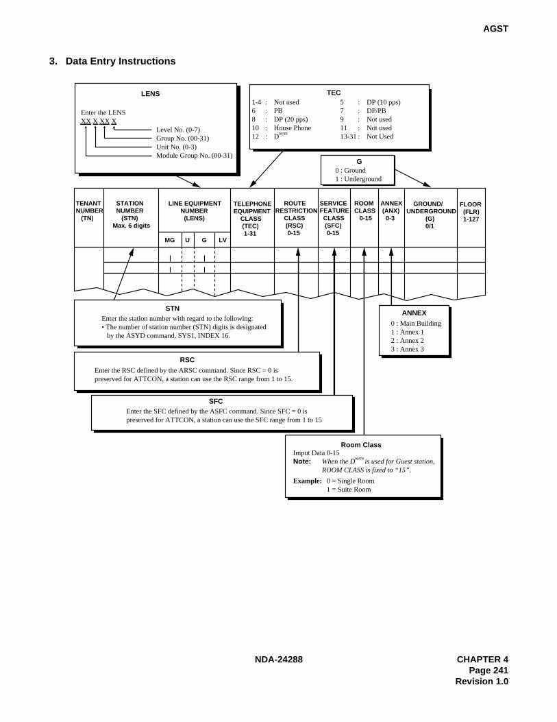
NDA-24288 CHAPTER 4Page 241
Revision 1.0
AGST
3. Data Entry Instructions
TECLENS
Enter the LENSXX X XX X Level No. (0-7) Group No. (00-31) Unit No. (0-3) Module Group No. (00-31)
G0 : Ground1 : Underground
TENANTNUMBER (TN)
STATION NUMBER (STN)Max. 6 digits
TELEPHONEEQUIPMENT CLASS (TEC) 1-31
ROUTERESTRICTION CLASS (RSC) 0-15
SERVICEFEATURE CLASS (SFC) 0-15
ROOMCLASS 0-15
ANNEX (ANX) 0-3
GROUND/UNDERGROUND (G) 0/1
FLOOR (FLR) 1-127
LINE EQUIPMENT NUMBER (LENS)
MG U G LV
ANNEX0 : Main Building1 : Annex 12 : Annex 23 : Annex 3
RSCEnter the RSC defined by the ARSC command. Since RSC = 0 ispreserved for ATTCON, a station can use the RSC range from 1 to 15.
SFCEnter the SFC defined by the ASFC command. Since SFC = 0 ispreserved for ATTCON, a station can use the SFC range from 1 to 15
Imput Data 0-15Note: When the D
term is used for Guest station,
ROOM CLASS is fixed to “15”.
Room Class
STNEnter the station number with regard to the following:• The number of station number (STN) digits is designated by the ASYD command, SYS1, INDEX 16.
Example: 0 = Single Room1 = Suite Room
1-4 : Not used 5 : DP (10 pps)6 : PB 7 : DP/PB8 : DP (20 pps) 9 : Not used10 : House Phone 11 : Not used 12 : Dterm 13-31 : Not Used

CHAPTER 4 NDA-24288Page 242Revision 1.0
AGST
4. Data Sheet
TENANT NUMBER
(TN)
STATION NUMBER(STN)
MAXIMUM6 DIGITS
LINE EQUIPMENT NUMBER (LENS)
TELEPHONEEQUIPMENT
CLASS (TEC)1 – 31
ROUTERESTRICTION CLASS (RSC)
0 – 15
SERVICEFEATURE
CLASS(SFC)0 – 15
ROOMCLASS(ROOM CLASS)0 – 15
ANNEX(ANX)0 – 3
GROUND/UNDER-GROUND
(G)0/1
FLOOR(FLR)
1 – 127MG U G LV

NDA-24288 CHAPTER 4Page 243
Revision 1.0
AASN
AASN: Assignment of Alternated Administration Station Number
1. General
This command changes a currently assigned Administration Station Number.
2. Precautions
1. This command is used for the Hotel Application only.
2. Input a number which is not currently assigned. If a station number currently being used is to be assignedas a new number, delete the station first via the RAST command.
3. When the “PKG CHECK” message is displayed during assignment, confirm the LENS location of thecircuit card (PA-16LC, etc.) accommodating the station, then press the ENTRY key.
4. When you have changed the station number, update the data sheet for the AAST command.
3. Data Entry Instructions
OLD STNEnter the currentstation number to be changed.
TNEnter the tenant number of the station.
NEW STNEnter the new station number according tothe numbering plan. Update the data sheet forthe AAST command.
TENANT NUMBER (TN) NEW STATION NUMBER (NEW STN)OLD STATION NUMBER (OLD STN)
CHAPTER 4 NDA-24288Page 244Revision 1.0
AACL
AACL: Assignment of Administration Station Class
1. General
This command changes the data assigned to an Administration Station: Telephone Equipment Class (TEC),Service Feature Class (SFC), Route Restriction Class (RSC), ROOM CLASS and Floor Service Data.
2. Precautions
1. This command is used for the Hotel Application only.
2. Only Telephone Equipment Classes (TECs) 1-4, 12-15, 18-20 and 13 may be assigned via this command.
3. Floor Service Data is displayed only in the case of the ASYD command, SYS1 INDEX 165, b7 = 1 (FloorService is provided).
4. When you have changed the station class, update the data sheet for the AAST command.

NDA-24288 CHAPTER 4Page 245
Revision 1.0
AACL
3. Data Entry Instructions
TEC
RSC
ANNEX
G
NOTESTN
SFC
TENANTNUMBER (TN)
STATION NUMBER (STN)Max. 6 digits
TELEPHONE EQUIPMENT CLASS (TEC) 1-31
ROUTERESTRICTION CLASS (RSC) 0-15
SERVICEFEATURE CLASS (SFC) 0-15
ROOMCLASS 0-15
ANNEX (ANX) 0-3
GROUND/UNDERGROUND (G) 0/1
FLOOR (FLR) 1-127
1 12 1 1
1 : DP (10 pps) 2 : PB 3 : DP/PB 4 : DP (20 pps)5-8 : Not Used 9 : House Phone 10-11 : Not Used 12 : Dterm
13 : Data Terminal via Dterm 14 : Hot Line 15 : CAS Line16 : Data Terminal via Data Module 17 : Not Used18 : Virtual Line Appearance (for Dterm Multi-Line)19-22 : Not Used 23 : ISDN Terminal 24-25 : Not Used 26 : Not Used27 : Eight Conference Equipment 28-31 : Not Used
Enter the RSC defined by the ARSC/ASCR/ADNR command. Since RSC = 0 ispreserved for ATTCON, a station can use the RSC range from 1 to 15.
0 : Main Building1 : Annex 12 : Annex 23 : Annex 3
0 : Ground1 : Underground
Enter the station number with regard to the following:• The number of station number (STN) digits is designated by the ASYD command, SYS1, INDEX 16.
Enter the SFC defined by the ASFC command. Since SFC = 0 ispreserved for ATTCON, a station can use the SFC range from 1 to 15.
When you have changed the station class, updatethe data sheet for the AAST command.
0 : General Administration (Ordinary Telephone, Dterm) 1-5 : Not Used6 : Guest Service Telephone (Dterm and External Equipment)7-14 : Not Used 15 : Guest Service Telephone (Dterm)
ROOM CLASS

CHAPTER 4 NDA-24288Page 246Revision 1.0
AGSN
AGSN: Assignment of Alternated Guest Station Number
1. General
This command changes a currently assigned Guest Station Number.
2. Precautions
1. This command is used for the Hotel Application only.
2. Input a number which is not currently assigned. If a station number currently being used is to be assignedas a new number, delete the station first via the RGST command.
3. When the “PKG CHECK” message is displayed during assignment, confirm the LENS location of thecircuit card (PA-16LC, etc.) accommodating the station, then press the ENTER key.
4. When you have changed the station number, update the data sheet for the AGST command.
3. Data Entry Instructions
OLD STNEnter the currentstation number to be changed.
NEW STNEnter the new station number according tothe numbering plan. Update the data sheet forthe AGST command.
TENANT NUMBER (TN) NEW STATION NUMBER (NEW STN)OLD STATION NUMBER (OLD STN)
TNEnter the tenant number of the station.
NDA-24288 CHAPTER 4Page 247
Revision 1.0
AGCL
AGCL: Assignment of Guest Station Class
1. General
This command changes the data assigned to a Guest Station: Telephone Equipment Class (TEC), ServiceFeature Class (SFC), Route Restriction Class (RSC), ROOM CLASS and Floor Service Data [Annex (ANX),Ground/Underground (G), Floor (FLR)].
2. Precautions
1. This command is used for the Hotel Application only.
2. Only Telephone Equipment Classes (TECs) 5-8, 10 and 12 may be assigned via this command.
3. Floor Service Data is displayed only in the case of the ASYD command, SYS1, INDEX 165, b7 = 1(Floor Service is provided).
4. When you have changed the station class, update the data sheet for the AGST command.

CHAPTER 4 NDA-24288Page 248Revision 1.0
AGCL
3. Data Entry Instructions
TEC
RSC
ANNEX
G
NOTESTN
SFC
TENANTNUMBER (TN)
STATION NUMBER (STN)Max. 6 digits
TELEPHONE EQUIPMENT CLASS (TEC) 1-31
ROUTERESTRICTION CLASS (RSC) 0-15
SERVICEFEATURE CLASS (SFC) 0-15
ROOMCLASS 0-15
ANNEX (ANX) 0-3
GROUND/UNDERGROUND (G) 0/1
FLOOR (FLR) 1-127
1 12 1 1
Enter the RSC defined by the ARSC/ASCR/ADNR command. Since RSC = 0 ispreserved for ATTCON, a station can use the RSC range from 1 to 15.
0 : Main Building1 : Annex 12 : Annex 23 : Annex 3
0 : Ground1 : Underground
Enter the station number with regard to the following:• The number of station number (STN) digits is designated by the ASYD command, SYS1, INDEX 16.
Enter the SFC defined by the ASFC command. Since SFC = 0 ispreserved for ATTCON, a station can use the SFC range from 1 to 15.
When you have changed the station class, updatethe data sheet for the AAST command.
ROOM CLASS
1-4 : Not Used 5 : DP (10 pps) 6 : PB 7 : DP/PB 8 : DP (20pps) 9 : Not Used 10 : House Phone 11: Not Used 12 : Dterm 13 : Data Terminal via Dterm 14-31: Not Used
0-15Note: When the D
term is used for Guest station,
ROOM CLASS is fixed to “15”.

NDA-24288 CHAPTER 4Page 249
Revision 1.0
AHSU
AHSU: Assignment of Suite Room Station Number
1. General
When the system provides Suite Room Service and/or Double Suite Room Service, this command assigns aspecific guest station as a suite room station.
2. Precautions
1. This command is used for the Hotel Application only.
2. Before assigning Suite Room Service or Double Suite Room Service, ensure the system data in AHSYcommand, INDEX=187, 188, 189 has been properly assigned.
3. The station to be assigned as a suite room station must have already been assigned as a guest room.
4. A phantom number can be assigned to the primary guest station of a suite room.
5. Branch stations are not included in the number of suite room stations.
6. The primary guest station of a suite room must be assigned without exception.

CHAPTER 4 NDA-24288Page 250Revision 1.0
AHSU
3. Data Entry Instructions
TENANT NUMBER (TN)
TYPE
PHANTOM NUMBER (PHANTOM)MAX. 6 DIGITS
SUITE ROOM PRIMARY STATION (PRIMARY STN)
SUITE ROOM SECONDARY STATION 1 (SECONDARY STN 1)
SUITE ROOM SECONDARY STATION 2 (SECONDARY STN 2)
SUITE ROOM SECONDARY STATION 3 (SECONDARY STN 3)
PHANTOM SECONDARY 1/2/3
PRIMARY STATION NUMBER 1 (PRIMARY STN 1) PRIMARY STATION NUMBER 2 (PRIMARY STN 2)
PRIMARY STN 1 PRIMARY STN 2Primary station numberof Primary Suite Room
Primary station numberof Secondary Suite Room
When phantom number is not assigned, enter return key. When secondary number is not assigned, enter return key.
0 = Single Suite Room1 = Double Suite Room Note
Note: When assigning Double Suite Room, Single Suite Room data assignment is necessary in advance.
When TYPE=0 (Single Suite Room)
When TYPE = 1 (Double Suite Room)
STATION NUMBER (STN) TYPE (TYPE) 0/1

NDA-24288 CHAPTER 4Page 251
Revision 1.0
AHSU
4. Data Sheet
(a) When TYPE = 0 (Single Suite Room)
TENANTNUMBER
(TN)
TYPE(TYPE)
0/1
STATIONNUMBER
(STN)
PHANTOM NUMBER
(PHANTOM)Max. 6 DIGITS
SUITE ROOMPRIMARYSTATION
(PRIMARY)
SUITE ROOMSECONDARY
STATION 1(SECONDARY
STN 1)
SUITE ROOMSECONDARY
STATION 2(SECONDARY
STN 2)
SUITE ROOMSECONDARY
STATION 3(SECONDARY
STN 3)
00000000000000000000000000000000000000000

CHAPTER 4 NDA-24288Page 252Revision 1.0
AHSU
(b) When TYPE = 1 (Double Suite Room)
TENANTNUMBER
(TN)
TYPE(TYPE)
0/1
STATION NUMBER (STN)
PRIMARY STATION NUMBER 1
(PRIMARY STN 1)
PRIMARY STATION NUMBER 2
(PRIMARY STN 2)
1111111111111111111111111111111111111111111111

NDA-24288 CHAPTER 4Page 253
Revision 1.0
ADSS
ADSS: Assignment of Direct Station Select
1. General
This command assigns the called number data corresponding to the Hotel Attendant Console’s Direct StationSelect (DSS) key.
2. Precautions
1. This command is used for the Hotel Application only.
2. The DSS function is only valid for the Hotel Attendant Console and may not be assigned for BusinessSystem Console.
3. DSS Function Key Numbers are 1 to 10. These ten numbers correspond to values 1 to 10 for the DSSparameter of this command.
4. This feature must be enabled in ASYD, SYS1, INDEX 161, bit5 in order to operate.
3. Data Entry Instructions
ATTEnter the Attendant number.
DCDestination number to be called frequently station number, the specific outside party number (including the originating ACC).
DSSEnter DSS Key number (1-10)
ATTENDANT NUMBER (ATT) DIRECT STATION SELECT KEY NUMBER (DSS)
DIGIT CODE (DC) Max. 14 DIGITS

CHAPTER 4 NDA-24288Page 254Revision 1.0
ADSS
4. Data Sheet
ATTCON No. (ATN)
DSS KEY No.(DSS)1 – 10
DIGIT CODE(DC)
MAX. 14 DIGITS
1
2
3
4
5
6
7
8
9
10
1
2
3
4
5
6
7
8
9
10
1
2
3
4
5
6
7
8
9
10
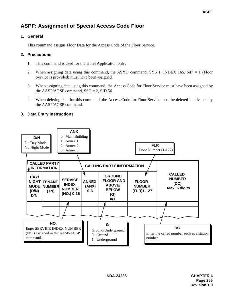
NDA-24288 CHAPTER 4Page 255
Revision 1.0
ASPF
ASPF: Assignment of Special Access Code Floor
1. General
This command assigns Floor Data for the Access Code of the Floor Service.
2. Precautions
1. This command is used for the Hotel Application only.
2. When assigning data using this command, the ASYD command, SYS 1, INDEX 165, bit7 = 1 (FloorService is provided) must have been assigned.
3. When assigning data using this command, the Access Code for Floor Service must have been assigned bythe AASP/AGSP command, SSC = 2, SID 56.
4. When deleting data for this command, the Access Code for Floor Service must be deleted in advance bythe AASP/AGSP command.
3. Data Entry Instructions
D/N
ANX
FLR
NO. GDC
D : Day ModeN : Night Mode
CALLED PARTY INFORMATION CALLING PARTY INFORMATION
CALLED NUMBER (DC)Max. 6 digits
DAY/NIGHTMODE (D/N) D/N
TENANTNUMBER (TN)
SERVICE INDEXNUMBER(NO.) 0-15
ANNEX (ANX) 0-3
GROUNDFLOOR AND ABOVE/ BELOW (G) 0/1
FLOOR NUMBER (FLR)1-127
0 : Main Building1 : Annex 12 : Annex 23 : Annex 3 Floor Number (1-127)
Enter SERVICE INDEX NUMBER(NO.) assigned in the AASP/AGSPcommand.
Ground/Underground0 : Ground1 : Underground
Enter the called number such as a stationnumber.

CHAPTER 4 NDA-24288Page 256Revision 1.0
ASPF
4. Data Sheet
CALLED PARTYINFORMATION
CALLING PARTY INFORMATION
CALLEDSTATIONNUMBER
(DC)MAX. 6 DIGITS
DAY/NIGHTMODE(D/N)D/N
TENANTNUMBER
(TN)
SERVICE INDEXNUMBER (No.)
0 – 15
ANNEX(ANX)0 – 3
GROUNDFLOOR
ANDABOVE/BELOW
GROUP(G)0/1
FLOORNUMBER
(FLR)1 – 127
Related Documents