Nearus VISCA Protocol via Sony This Nearus Video Conference Camera may be controlled by using Sony VISCA protocol commands. Use the attached Sony VISCA protocol document as a reference for controlling Nearus cameras connected to your control system. Read and follow all instructions included in the document below. If you require additional assistance setting up these commands, please feel free to call Tech Support. Tech Support: [email protected] 1 (800) 838-5052 www.snapav.com Notes: • All commands shown are HEX. • ‘8x’ is ‘81’ where 1 represents the default address of the camera. • No carriage return or line feed commands are needed; ‘FF’ completes the VISCA command. Rev: 140911-1400

Welcome message from author
This document is posted to help you gain knowledge. Please leave a comment to let me know what you think about it! Share it to your friends and learn new things together.
Transcript

Nearus VISCA Protocol via SonyThis Nearus Video Conference Camera may be controlled by using Sony VISCA protocol commands. Use the
attached Sony VISCA protocol document as a reference for controlling Nearus cameras connected to your control system. Read and follow all instructions included in the document below.
If you require additional assistance setting up these commands, please feel free to call Tech Support.
Tech Support: [email protected]
1 (800) 838-5052www.snapav.com
Notes: • All commands shown are HEX.
• ‘8x’ is ‘81’ where 1 represents the default address of the camera.• No carriage return or line feed commands are needed; ‘FF’ completes the VISCA command.
Rev: 140911-1400

2004 Sony Corporation
3CCDColor Video Camera
BRC-300/300P
A-C1Z-100-13 (1)
Command List
Version 1.20

2
Table of Contents
VISCA RS-232C/RS-422 Commands ........................ 3Overview of VISCA ..................................................... 3VISCA Communication Specifications ....................... 4VISCA Device Setting Command ............................... 6VISCA Command/ACK Protocol ................................ 7VISCA Camera-Issued Messages.............................. 8
BRC-300/P Commands ............................................. 9BRC-300/P Command List (1/4)................................. 9BRC-300/P Command List (2/4)............................... 10BRC-300/P Command List (3/4)............................... 11BRC-300/P Command List (4/4)............................... 12BRC-300/P Inquiry Command List (1/2) ................... 13BRC-300/P Inquiry Command List (2/2) ................... 14BRC-300/P Block Inquiry Command List ................. 15VISCA Command Setting Values ............................. 19
Revision History ...................................................... 24
3
VISCA1) RS-232C/RS-422 CommandsUse of RS-232C/RS-422 control software based uponthis command list may cause malfunction or damage tohardware and software. Sony Corporation is not liablefor any such damage.
Overview of VISCA
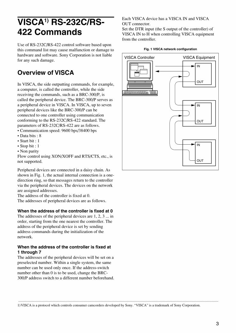
In VISCA, the side outputting commands, for example,a computer, is called the controller, while the sidereceiving the commands, such as a BRC-300/P, iscalled the peripheral device. The BRC-300/P serves asa peripheral device in VISCA. In VISCA, up to sevenperipheral devices like the BRC-300/P can beconnected to one controller using communicationconforming to the RS-232C/RS-422 standard. Theparameters of RS-232C/RS-422 are as follows.• Communication speed: 9600 bps/38400 bps• Data bits : 8• Start bit : 1• Stop bit : 1• Non parityFlow control using XON/XOFF and RTS/CTS, etc., isnot supported.
Peripheral devices are connected in a daisy chain. Asshown in Fig. 1, the actual internal connection is a one-direction ring, so that messages return to the controllervia the peripheral devices. The devices on the networkare assigned addresses.The address of the controller is fixed at 0.The addresses of peripheral devices are as follows.
When the address of the controller is fixed at 0The addresses of the peripheral devices are 1, 2, 3 ... inorder, starting from the one nearest the controller. Theaddress of the peripheral device is set by sendingaddress commands during the initialization of thenetwork.
When the address of the controller is fixed at1 through 7The addresses of the peripheral devices will be set on apreselected number. Within a single system, the samenumber can be used only once. If the address-switchnumber other than 0 is to be used, change the BRC-300/P address switch to a different number beforehand.
................................................................................................................................................................................................................................1)VISCA is a protocol which controls consumer camcorders developed by Sony. “VISCA” is a trademark of Sony Corporation.
VISCA Equipment
IN
OUT
IN
OUT
IN
OUT
VISCA Controller
Fig. 1 VISCA network configuration
Each VISCA device has a VISCA IN and VISCAOUT connector.Set the DTR input (the S output of the controller) ofVISCA IN to H when controlling VISCA equipmentfrom the controller.
4
VISCA CommunicationSpecifications
VISCA packet structure
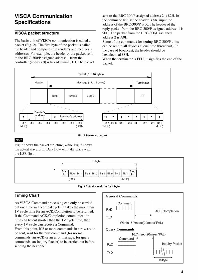
The basic unit of VISCA communication is called apacket (Fig. 2). The first byte of the packet is calledthe header and comprises the sender’s and receiver’saddresses. For example, the header of the packet sentto the BRC-300/P assigned address 1 from thecontroller (address 0) is hexadecimal 81H. The packet
sent to the BRC-300/P assigned address 2 is 82H. Inthe command list, as the header is 8X, input theaddress of the BRC-300/P at X. The header of thereply packet from the BRC-300/P assigned address 1 is90H. The packet from the BRC-300/P assignedaddress 2 is A0H.Some of the commands for setting BRC-300/P unitscan be sent to all devices at one time (broadcast). Inthe case of broadcast, the header should behexadecimal 88H.When the terminator is FFH, it signifies the end of thepacket.
Timing Chart
As VISCA Command processing can only be carriedout one time in a Vertical cycle, it takes the maximum1V cycle time for an ACK/Completion to be returned.If the Command ACK/Completion communicationtime can be cut shorter than the 1V cycle time, thenevery 1V cycle can receive a Command.From this point, if 2 or more commands in a row are tobe sent, wait for the first command (for normalcommands, an ACK or an error message, for querycommands, an Inquiry Packet) to be carried out beforesending the next one.
Query Commands
Command
Within16.7msec(20msec*PAL)
RxD
TxD
ACK Completion
16.7msec(20msec*PAL)
RxD
TxD
Inquiry Pocket
Command
General Commands
16 Byte
Fig. 2 Packet structure
Bit 7(MSB)
Bit 6 Bit 5 Bit 4 Bit 3 Bit 2 Bit 1 Bit 0(LSB)
1 0
FF
Bit 7(MSB)
Bit 6 Bit 5 Bit 4 Bit 3 Bit 2 Bit 1 Bit 0(LSB)
1 1 1 1 1 1 1 1
Packet (3 to 16 bytes)
Message (1 to 14 bytes)Header Terminator
Byte 1 Byte 2 Byte 3
Sender’saddress Receiver’s address
Note
Fig. 2 shows the packet structure, while Fig. 3 showsthe actual waveform. Data flow will take place withthe LSB first.
Bit 0 Bit 1 Bit 2 Bit 3 Bit 4 Bit 5
(LSB) (MSB)
Bit 6 Bit 7
Fig. 3 Actual waveform for 1 byte.
Startbit
Stopbit.
1 byte
5
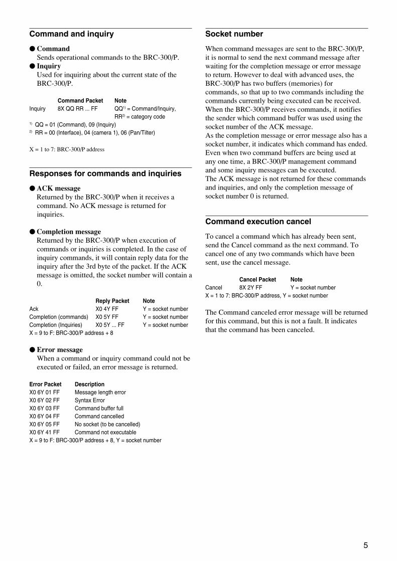
Command and inquiry
z CommandSends operational commands to the BRC-300/P.
z InquiryUsed for inquiring about the current state of theBRC-300/P.
Command Packet NoteInquiry 8X QQ RR ... FF QQ1) = Command/Inquiry,
RR2) = category code1) QQ = 01 (Command), 09 (Inquiry)2) RR = 00 (Interface), 04 (camera 1), 06 (Pan/Tilter)
X = 1 to 7: BRC-300/P address
Responses for commands and inquiries
zACK messageReturned by the BRC-300/P when it receives acommand. No ACK message is returned forinquiries.
zCompletion messageReturned by the BRC-300/P when execution ofcommands or inquiries is completed. In the case ofinquiry commands, it will contain reply data for theinquiry after the 3rd byte of the packet. If the ACKmessage is omitted, the socket number will contain a0.
Reply Packet NoteAck X0 4Y FF Y = socket numberCompletion (commands) X0 5Y FF Y = socket numberCompletion (Inquiries) X0 5Y ... FF Y = socket numberX = 9 to F: BRC-300/P address + 8
z Error messageWhen a command or inquiry command could not beexecuted or failed, an error message is returned.
Error Packet DescriptionX0 6Y 01 FF Message length errorX0 6Y 02 FF Syntax ErrorX0 6Y 03 FF Command buffer fullX0 6Y 04 FF Command cancelledX0 6Y 05 FF No socket (to be cancelled)X0 6Y 41 FF Command not executableX = 9 to F: BRC-300/P address + 8, Y = socket number
Socket number
When command messages are sent to the BRC-300/P,it is normal to send the next command message afterwaiting for the completion message or error messageto return. However to deal with advanced uses, theBRC-300/P has two buffers (memories) forcommands, so that up to two commands including thecommands currently being executed can be received.When the BRC-300/P receives commands, it notifiesthe sender which command buffer was used using thesocket number of the ACK message.As the completion message or error message also has asocket number, it indicates which command has ended.Even when two command buffers are being used atany one time, a BRC-300/P management commandand some inquiry messages can be executed.The ACK message is not returned for these commandsand inquiries, and only the completion message ofsocket number 0 is returned.
Command execution cancel
To cancel a command which has already been sent,send the Cancel command as the next command. Tocancel one of any two commands which have beensent, use the cancel message.
Cancel Packet NoteCancel 8X 2Y FF Y = socket numberX = 1 to 7: BRC-300/P address, Y = socket number
The Command canceled error message will be returnedfor this command, but this is not a fault. It indicatesthat the command has been canceled.

6
VISCA Device SettingCommand
Before starting control of the BRC-300/P, be sure tosend the Address command and the IF_Clearcommand using the broadcast function.
For VISCA network administration
z AddressSets an address of a peripheral device. Use wheninitializing the network, and receiving the followingnetwork change message.
z Network ChangeSent from the peripheral device to the controllerwhen a device is removed from or added to thenetwork. The address must be re-set when thismessage is received.
Packet NoteAddress 88 30 01 FF Always broadcasted.Network Change X0 38 FFX = 9 to F: BRC-300/P address + 8
VISCA interface command
z IF_ClearClears the command buffers in the BRC-300/P andcancels the command currently being executed.
Command Packet Reply Packet NoteIF_Clear 8X 01 00 01FF X0 50 FFIF_Clear (broadcast) 88 01 00 01 FF 88 01 00 01 FFX = 1 to 7: BRC-300/P address (For inquiry packet)X = 9 to F: BRC-300/P address +8 (For reply packet)
VISCA interface and inquiry
zCAM_VersionInqReturns information on the VISCA interface.
Inquiry Inquiry Packet Reply Packet DescriptionCAM_VersionInq 8X 09 00 02 FF Y0 50 GG GG HH HH JJ JJ KK FF GGGG = Vender ID
(0001: Sony)HHHH = Model ID040F: BRC-300/P0410: BRU-300/PJJJJ = ROM revisionKK = Maximum socket # (02)
X = 1 to 7: BRC-300/P address (For inquiry packet)X = 9 to F: BRC-300/P address +8 (For reply packet)

7
Command Command Message Reply Message
General Command 81 01 04 38 02 FF 90 41 FF (ACK)+90 51 FF
(Example) (Completion)
90 42 FF 90 52 FF
81 01 04 38 FF 90 60 02 FF (Syntax Error)
(Example)
81 01 04 38 02 FF 90 60 03 FF
(Example) (Command Buffer Full)
81 01 04 08 02 FF 90 61 41 FF
(Example) (Command Not Executable)
90 62 41FF
Inquiry Command 81 09 04 38 FF 90 50 02 FF (Completion)
(Example)
81 09 05 38 FF 90 60 02 FF (Syntax Error)
(Example)
Address Set 88 30 01 FF 88 30 02 FF
IF_Clear (Broadcast) 88 01 00 01 FF 88 01 00 01 FF
IF_Clear (For x) 8x 01 00 01 FF z0 50 FF (Completion)
Command Cancel 8x 2y FF z0 6y 04 FF
(Command Canceled)
z0 6y 05 FF (No Socket)
Comments
Returns ACK when a command has been accepted, and
Completion when a command has been executed.
Accepted a command which is not supported or a command
lacking parameters.
There are two commands currently being executed, and the
command could not be accepted.
Could not execute the command in the current mode.
ACK is not returned for the inquiry command.
Accepted an incompatible command.
Returned the device address to +1.*
Returned the same command.
ACK is not returned for this command.
Returned when the command of the socket specified is canceled.
Completion for the command canceled is not returned.
Returned when the command of the specified socket has already
been completed or when the socket number specified is wrong.
VISCA Command/ACK Protocol
* When the address-switch is fixed at 0, the value x in 88 30 0x FF will be indeterminate.
Do not transmit the command (except Address Set,IF_Clear, Command Cancel, CAM_Power), whenmenu panel shows on the screen. In that case, clear themenu panel first using CAM_Menu Command, andthen proceed.

8
VISCA Camera-Issued Messages
ACK/Completion Messages
Command Command Message
ACK z0 4y FF
(y:Socket No.)
Completion z0 5y FF
(y:Socket No.)
Comments
Returned when the command is accepted.
Returned when the command has been executed.
z = Device address + 8
Command Command Message
Syntax Error z0 60 02 FF
Command Buffer Full z0 60 03 FF
Command Canceled z0 6y 04 FF
(y:Socket No.)
No Socket z0 6y 05 FF
(y:Socket No.)
Command Not Executable z0 6y 41 FF
(y:Socket No.)
Comments
Returned when the command format is different or when a command with illegal
command parameters is accepted.
Indicates that two sockets are already being used (executing two commands) and the
command could not be accepted when received.
Returned when a command which is being executed in a socket specified by the
cancel command is canceled. The completion message for the command is not
returned.
Returned when no command is executed in a socket specified by the cancel
command, or when an invalid socket number is specified.
Returned when a command cannot be executed due to current conditions. For
example, when commands controlling the focus manually are received during auto
focus.
Command Command Message
Network Change z0 38 FF
Comments
Issued when power is supplied to the camera.
Error Messages
Network Change Message

9
Command Set Command Command Packet Comments
AddressSet Broadcast 88 30 01 FF Address Set
IF_Clear Broadcast 88 01 00 01 FF I/F Clear
CommandCancel 8x 2p FF p: Socket No (=1 to 2)
CAM_Power On 8x 01 04 00 02 FF Power On/Off
Off 8x 01 04 00 03 FF
CAM_Zoom Stop 8x 01 04 07 00 FF
Tele(Standard) 8x 01 04 07 02 FF
Wide(Standard) 8x 01 04 07 03 FF
Tele(Variable) 8x 01 04 07 2p FF p (=0:Slow to 7:Fast)
Wide(Variable) 8x 01 04 07 3p FF p (=0:Slow to 7:Fast)
Direct 8x 01 04 47 0p 0q 0r 0s FF pqrs: Zoom Position*
CAM_DZoom On 8x 01 04 06 02 FF Digital Zoom On/Off
Off 8x 01 04 06 03 FF
Combine Mode 8x 01 04 36 00 FF OPT/Digital Zoom Combined
Separate Mode 8x 01 04 36 01 FF OPT/Digital Zoom Separate
Stop 8x 01 04 06 00 FF
Tele(Variable) 8x 01 04 06 2p FF p (=0:Slow to 7:Fast)
Wide(Variable) 8x 01 04 06 3p FF p (=0:Slow to 7:Fast)
Direct 8x 01 04 46 00 00 0p 0q FF pq: Digital Zoom Position*
CAM_Focus Stop 8x 01 04 08 00 FF
Far(Standard) 8x 01 04 08 02 FF
Near(Standard) 8x 01 04 08 03 FF
Far(Variable) 8x 01 04 08 2p FF p (=0:Low to 7:High)
Near(Variable) 8x 01 04 08 3p FF p (=0:Low to 7:High)
Direct 8x 01 04 48 0p 0q 0r 0s FF pqrs: Focus Position*
Auto Focus 8x 01 04 38 02 FF AF ON/OFF
Manual Focus 8x 01 04 38 03 FF
Auto/Manual 8x 01 04 38 10 FF
One Push Trigger 8x 01 04 18 01 FF One Push AF Trigger
Infinity 8x 01 04 18 02 FF Forced Infinity
CAM_AFMode Normal AF 8x 01 04 57 00 FF Normal AF Mode
Interval AF 8x 01 04 57 01 FF Interval AF Mode
Zoom Trigger AF 8x 01 04 57 02 FF Zoom Trigger Mode
Active/Interval Time 8x 01 04 27 0p 0p 0q 0q FF pp: Active Time qq: Interval Time
CAM_ZoomFocus Direct 8x 01 04 47 0p 0q 0r 0s pqrs: Zoom Position*
0t 0u 0v 0w FF tuvw: Focus Position*
CAM_WB Auto 8x 01 04 35 00 FF Normal Auto
Indoor 8x 01 04 35 01 FF Indoor Mode
Outdoor 8x 01 04 35 02 FF Outdoor Mode
One Push WB 8x 01 04 35 03 FF One Push WB Mode
Manual 8x 01 04 35 05 FF Manual Control Mode
One Push Trigger 8x 01 04 10 05 FF One Push WB trigger
BRC-300/P Commands
BRC-300/P Command List (1/4)
* See the section under VISCA Command Setting Values.

10
BRC-300/P Command List (2/4)
Command Set Command Command Packet Comments
CAM_RGain Reset 8x 01 04 03 00 FF Default R Gain setting
Up 8x 01 04 03 02 FF
Down 8x 01 04 03 03 FF
Direct 8x 01 04 43 00 00 0p 0q FF R Gain Direct pq (=00 to FF)
CAM_BGain Reset 8x 01 04 04 00 FF Default B Gain setting
Up 8x 01 04 04 02 FF
Down 8x 01 04 04 03 FF
Direct 8x 01 04 44 00 00 0p 0q FF B Gain Direct pq (=00 to FF)
CAM_AE Full Auto 8x 01 04 39 00 FF Automatic exposure mode
Manual 8x 01 04 39 03 FF Manual control mode
Shutter Priority 8x 01 04 39 0A FF Shutter priority automatic exposure mode
Iris Priority 8x 01 04 39 0B FF Iris priority automatic exposure mode
Bright 8x 01 04 39 0D FF Bright mode (Manual)
CAM_SlowShutter Auto 8x 01 04 5A 02 FF Auto Slow Shutter ON/OFF
Manual 8x 01 04 5A 03 FF
CAM_Shutter Reset 8x 01 04 0A 00 FF Default Shutter setting
Up 8x 01 04 0A 02 FF
Down 8x 01 04 0A 03 FF
Direct 8x 01 04 4A 00 00 0p 0q FF pq: Shutter Position*
CAM_Iris Reset 8x 01 04 0B 00 FF Default Iris Setting
Up 8x 01 04 0B 02 FF
Down 8x 01 04 0B 03 FF
Direct 8x 01 04 4B 00 00 0p 0q FF pq: Iris Position*
CAM_Gain Reset 8x 01 04 0C 00 FF Default Gain setting
Up 8x 01 04 0C 02 FF
Down 8x 01 04 0C 03 FF
Direct 8x 01 04 4C 00 00 0p 0q FF pqrs: Gain Position*
CAM_Bright Reset 8x 01 04 0D 00 FF Default Bright setting
Up 8x 01 04 0D 02 FF
Down 8x 01 04 0D 03 FF
Direct 8x 01 04 4D 00 00 0p 0q FF pqrs: Bright Position*
CAM_ExpComp On 8x 01 04 3E 02 FF Exposure Compensation ON/OFF
Off 8x 01 04 3E 03 FF
Reset 8x 01 04 0E 00 FF Default Exposure Compensation setting
Up 8x 01 04 0E 02 FF
Down 8x 01 04 0E 03 FF
Direct 8x 01 04 4E 00 00 0p 0q FF pqrs: Exposure Compensation Position*
CAM_BackLight On 8x 01 04 33 02 FF Back Light ON/OFF
Off 8x 01 04 33 03 FF
CAM_SpotAE On 8x 01 04 59 02 FF Setting for AE
Off 8x 01 04 59 03 FF
Position 8x 01 04 29 0p 0q 0r 0s FF pq: x (=00 to 0F) rs: y (=00 to 0F)
CAM_Aperture Reset 8x 01 04 02 00 FF Default Aperture setting
Up 8x 01 04 02 02 FF
Down 8x 01 04 02 03 FF
Direct 8x 01 04 42 00 00 00 0q FF Aperture Gain q (=0 to F)
* See the section under VISCA Command Setting Values.
11
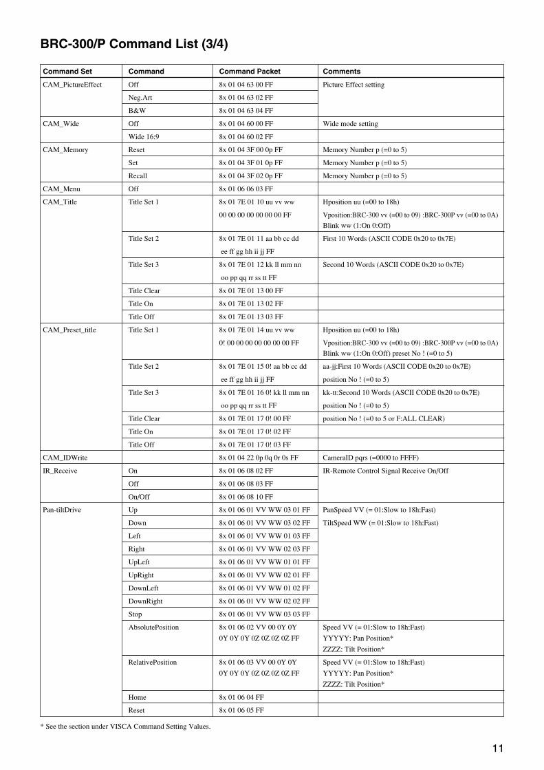
BRC-300/P Command List (3/4)
Command Set Command Command Packet Comments
CAM_PictureEffect Off 8x 01 04 63 00 FF Picture Effect setting
Neg.Art 8x 01 04 63 02 FF
B&W 8x 01 04 63 04 FF
CAM_Wide Off 8x 01 04 60 00 FF Wide mode setting
Wide 16:9 8x 01 04 60 02 FF
CAM_Memory Reset 8x 01 04 3F 00 0p FF Memory Number p (=0 to 5)
Set 8x 01 04 3F 01 0p FF Memory Number p (=0 to 5)
Recall 8x 01 04 3F 02 0p FF Memory Number p (=0 to 5)
CAM_Menu Off 8x 01 06 06 03 FF
CAM_Title Title Set 1 8x 01 7E 01 10 uu vv ww Hposition uu (=00 to 18h)
00 00 00 00 00 00 00 FF Vposition:BRC-300 vv (=00 to 09) :BRC-300P vv (=00 to 0A)
Blink ww (1:On 0:Off)
Title Set 2 8x 01 7E 01 11 aa bb cc dd First 10 Words (ASCII CODE 0x20 to 0x7E)
ee ff gg hh ii jj FF
Title Set 3 8x 01 7E 01 12 kk ll mm nn Second 10 Words (ASCII CODE 0x20 to 0x7E)
oo pp qq rr ss tt FF
Title Clear 8x 01 7E 01 13 00 FF
Title On 8x 01 7E 01 13 02 FF
Title Off 8x 01 7E 01 13 03 FF
CAM_Preset_title Title Set 1 8x 01 7E 01 14 uu vv ww Hposition uu (=00 to 18h)
0! 00 00 00 00 00 00 00 FF Vposition:BRC-300 vv (=00 to 09) :BRC-300P vv (=00 to 0A)
Blink ww (1:On 0:Off) preset No ! (=0 to 5)
Title Set 2 8x 01 7E 01 15 0! aa bb cc dd aa-jj:First 10 Words (ASCII CODE 0x20 to 0x7E)
ee ff gg hh ii jj FF position No ! (=0 to 5)
Title Set 3 8x 01 7E 01 16 0! kk ll mm nn kk-tt:Second 10 Words (ASCII CODE 0x20 to 0x7E)
oo pp qq rr ss tt FF position No ! (=0 to 5)
Title Clear 8x 01 7E 01 17 0! 00 FF position No ! (=0 to 5 or F:ALL CLEAR)
Title On 8x 01 7E 01 17 0! 02 FF
Title Off 8x 01 7E 01 17 0! 03 FF
CAM_IDWrite 8x 01 04 22 0p 0q 0r 0s FF CameraID pqrs (=0000 to FFFF)
IR_Receive On 8x 01 06 08 02 FF IR-Remote Control Signal Receive On/Off
Off 8x 01 06 08 03 FF
On/Off 8x 01 06 08 10 FF
Pan-tiltDrive Up 8x 01 06 01 VV WW 03 01 FF PanSpeed VV (= 01:Slow to 18h:Fast)
Down 8x 01 06 01 VV WW 03 02 FF TiltSpeed WW (= 01:Slow to 18h:Fast)
Left 8x 01 06 01 VV WW 01 03 FF
Right 8x 01 06 01 VV WW 02 03 FF
UpLeft 8x 01 06 01 VV WW 01 01 FF
UpRight 8x 01 06 01 VV WW 02 01 FF
DownLeft 8x 01 06 01 VV WW 01 02 FF
DownRight 8x 01 06 01 VV WW 02 02 FF
Stop 8x 01 06 01 VV WW 03 03 FF
AbsolutePosition 8x 01 06 02 VV 00 0Y 0Y Speed VV (= 01:Slow to 18h:Fast)
0Y 0Y 0Y 0Z 0Z 0Z 0Z FF YYYYY: Pan Position*
ZZZZ: Tilt Position*
RelativePosition 8x 01 06 03 VV 00 0Y 0Y Speed VV (= 01:Slow to 18h:Fast)
0Y 0Y 0Y 0Z 0Z 0Z 0Z FF YYYYY: Pan Position*
ZZZZ: Tilt Position*
Home 8x 01 06 04 FF
Reset 8x 01 06 05 FF
* See the section under VISCA Command Setting Values.
12
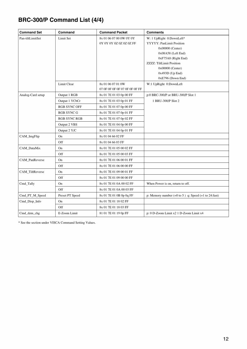
BRC-300/P Command List (4/4)
Command Set Command Command Packet Comments
Pan-tiltLimitSet Limit Set 8x 01 06 07 00 0W 0Y 0Y W: 1 UpRight 0:DownLeft*
0Y 0Y 0Y 0Z 0Z 0Z 0Z FF YYYYY: PanLimit Position
0x00000 (Center)
0x08A58 (Left End)
0xF75A8 (Right End)
ZZZZ: TiltLimit Position
0x00000 (Center)
0x493D (Up End)
0xE796 (Down End)
Limit Clear 8x 01 06 07 01 0W W:1 UpRight 0:DownLeft
07 0F 0F 0F 0F 07 0F 0F 0F FF
Analog-Card setup Output 1 RGB 8x 01 7E 01 03 0p 00 FF p:0 BRC-300/P or BRU-300/P Slot 1
Output 1 YCbCr 8x 01 7E 01 03 0p 01 FF 1 BRU-300/P Slot 2
RGB SYNC OFF 8x 01 7E 01 07 0p 00 FF
RGB SYNC G 8x 01 7E 01 07 0p 01 FF
RGB SYNC RGB 8x 01 7E 01 07 0p 02 FF
Output 2 VBS 8x 01 7E 01 04 0p 00 FF
Output 2 Y/C 8x 01 7E 01 04 0p 01 FF
CAM_ImgFlip On 8x 01 04 66 02 FF
Off 8x 01 04 66 03 FF
CAM_DataMix On 8x 01 7E 01 05 00 02 FF
Off 8x 01 7E 01 05 00 03 FF
CAM_PanReverse On 8x 01 7E 01 06 00 01 FF
Off 8x 01 7E 01 06 00 00 FF
CAM_TiltReverse On 8x 01 7E 01 09 00 01 FF
Off 8x 01 7E 01 09 00 00 FF
Cmd_Tally On 8x 01 7E 01 0A 00 02 FF When Power is on, return to off.
Off 8x 01 7E 01 0A 00 03 FF
Cmd_PT_M_Speed Preset PT Speed 8x 01 7E 01 0B 0p 0q FF p: Memory number (=0 to 5 ) q: Speed (=1 to 24:fast)
Cmd_Disp_Info On 8x 01 7E 01 18 02 FF
Off 8x 01 7E 01 18 03 FF
Cmd_dzm_chg E-Zoom Limit 81 01 7E 01 19 0p FF p: 0 D-Zoom Limit x2 1 D-Zoom Limit x4
* See the section under VISCA Command Setting Values.

13
BRC-300/P Inquiry Command List (1/2)
Inquiry Command Command Packet Inquiry Packet Comments
CAM_PowerInq 8x 09 04 00 FF y0 50 02 FF On
y0 50 03 FF Off (Standby)
CAM_ZoomPosInq 8x 09 04 47 FF y0 50 0p 0q 0r 0s FF pqr: Zoom Position
CAM_DZoomModeInq 8x 09 04 06 FF y0 50 02 FF D-Zoom On
y0 50 03 FF D-Zoom Off
CAM_DZoomC/SModeInq 8x 09 04 36 FF y0 50 00 FF Combine Mode
y0 50 01 FF Separate Mode
CAM_DZoomPosInq 8x 09 04 46 FF y0 50 00 0 0p 0q FF pq: Digital Zoom Position
CAM_FocusModeInq 8x 09 04 38 FF y0 50 02 FF Auto Focus
y0 50 03 FF Manual Focus
CAM_FocusPosInq 8x 09 04 48 FF y0 50 0p 0q 0r 0s FF pqr: Focus Position
CAM_AFModeInq 8x 09 04 57 FF y0 50 00 FF Normal AF
y0 50 01 FF Interval AF
y0 50 02 FF Zoom Trigger AF
CAM_AFTimeSettingInq 8x 09 04 27 FF y0 50 0p 0q 0r 0s FF pq: Active Time rs:Interval Time
CAM_WBModeInq 8x 09 04 35 FF y0 50 00 FF Auto
y0 50 01 FF Indoor
y0 50 02 FF Outdoor
y0 50 03 FF One Push WB
y0 50 05 FF Manual
CAM_RGainInq 8x 09 04 43 FF y0 50 00 00 0p 0q FF pq: R Gain
CAM_BGainInq 8x 09 04 44 FF y0 50 00 00 0p 0q FF pq: B Gain
CAM_AEModeInq 8x 09 04 39 FF y0 50 00 FF Full Auto
y0 50 03 FF Manual
y0 50 0A FF Shutter Priority
y0 50 0B FF Iris Priority
y0 50 0D FF Bright
CAM_SlowShutterModeInq 8x 09 04 5A FF y0 50 02 FF Auto
y0 50 03 FF Manual
CAM_ShutterPosInq 8x 09 04 4A FF y0 50 00 00 0p 0q FF pq: Shutter Position
CAM_IrisPosInq 8x 09 04 4B FF y0 50 00 00 0p 0q FF pq: Iris Position
CAM_GainPosInq 8x 09 04 4C FF y0 50 00 00 0p 0q FF pq: Gain Position
CAM_BrightPosInq 8x 09 04 4D FF y0 50 00 00 0p 0q FF pq: Bright Position
CAM_ExpCompModeInq 8x 09 04 3E FF y0 50 02 FF On
y0 50 03 FF Off
CAM_ExpCompPosInq 8x 09 04 4E FF y0 50 00 00 0p 0q FF pq: ExpComp Position
CAM_BackLightModeInq 8x 09 04 33 FF y0 50 02 FF On
y0 50 03 FF Off
CAM_SpotAEModeInq 8x 09 04 59 FF y0 50 02 FF On
y0 50 03 FF Off
CAM_SpotAEPosInq 8x 09 04 29 FF y0 50 0p 0q 0r 0s FF pq: X position, rs: Y position
CAM_ApertureInq 8x 09 04 42 FF y0 50 00 00 0p 0q FF pq: Aperture Gain
CAM_WideModeInq 8x 09 04 60 FF y0 50 00 FF Off
y0 50 02 FF 16:9 Wide
CAM_PictureEffectModeInq 8x 09 04 63 FF y0 50 00 FF Off
y0 50 02 FF Neg.Art
y0 50 04 FF B&W

14
BRC-300/P Inquiry Command List (2/2)
Inquiry Command Command Packet Inquiry Packet Comments
CAM_MemoryInq 8x 09 04 3F FF y0 50 pp FF pp: Memory number last operated*
CAM_MENUInq 8x 09 06 06 FF y0 50 02 FF On
y0 50 03 FF Off
CAM_IDInq 8x 09 04 22 FF y0 50 0p 0q 0r 0s FF pqrs: Camera ID
CAM_VersionInq 8x 09 00 02 FF y0 50 00 01 mnpq: Model Code (04xx)
mn pq rs tu vw FF rstu: ROM version
vw: Socket Number (02)
CAM_TitleModeInq 8x 09 7E 01 13 FF y0 50 02 FF On
y0 50 03 FF Off
CAM_PresetTitleModeInq 8x 09 7E 01 17 FF y0 50 02 FF On
y0 50 03 FF Off
CAM_ReceiveInq 8x 09 06 08 FF y0 50 02 FF On
y0 50 03 FF Off
Analog_Card Output1Inq 8x 09 7E 01 03 FF y0 50 0p FF p=0 RGB 1:YCbCr
Analog_Card Output2Inq 8x 09 7E 01 04 FF y0 50 0p FF p=0 VBS 1:Y/C
Analog_Card RGB_SYNCInq 8x 09 7E 01 07 FF y0 50 0p FF p=0 OFF 1:G 2:RGB
CAM_ImgFlipInq 8x 09 04 66 FF y0 50 02 FF On
y0 50 03 FF Off
CAM_DataMixInq 8x 09 7E 01 05 FF y0 50 02 FF On
y0 50 03 FF Off
CAM_PanReverseInq 8x 09 7E 01 06 FF y0 50 01 FF On
y0 50 00 FF Off
CAM_TiltReverseInq 8x 09 7E 01 09 FF y0 50 01 FF On
y0 50 00 FF Off
PanTilt_Status 8x 09 06 10 FF y0 50 pq rs FF pqrs: PanTilt Status
PanTilt_Max_Speed 8x 09 06 11 FF y0 50 pq rs FF pq: Pan Max Speed rs: Tilt Max Speed
PanTilt_Position 8x 09 06 12 FF y0 50 0p 0q 0r 0s 0t 0u 0v 0w 0x FF pqrst: Pan Position
uvwx: Tilt Position
Tally 8x 09 7E 01 0A FF y0 50 02 FF On
y0 50 03 FF Off
PanTilt_Memory_Speed 8x 09 7E 01 0B 0p FF y0 50 0q FF p: Preset No. 0 to 5 q: Speed 1 to 24
* See the section under VISCA Command Setting Values.

15
Byte Bit Comments
7
6Destination Address
5
04
3
2Source Address
1
0
7 0 Completion Message (50h)
6 1
5 0
14 1
3 0
2 0
1 0
0 0
7 0
6 0
5 0
24 0
3
2Zoom Position (HH)
1
0
7 0
6 0
5 0
34 0
3
2Zoom Position (HL)
1
0
7 0
6 0
5 0
44 0
3
2Zoom Position (LH)
1
0
7 0
6 0
5 0
54 0
3
2Zoom Position (LL)
1
0
7 0
6 0
5 0
64 0
3 0
2 0
1 0
0 0
7 0
6 0
5 0
74 0
3 0
2 0
1 0
0 0
7 0
6 0
5 0
84 0
3
2Focus Position (HH)
1
0
7 0
6 0
5 0
94 0
3
2Focus Position (HL)
1
0
7 0
6 0
5 0
104 0
3
2Focus Position (LH)
1
0
7 0
6 0
5 0
114 0
3
2Focus Position (LL)
1
0
BRC-300/P Block Inquiry Command List
Lens control system inquiry ........................... Command Packet 8x 09 7E 7E 00 FF
Byte Bit Comments
7 0
6 0
5 0
124 0
3 0
2 0
1 0
0 0
7 0
6 0
5DZoomMode 1: Separate
0: Combine
13 4 AF Mode 0: Normal
3 1: Interval 2: Zoom Trigger
2 0
1 Digital Zoom 1:On 0:Off
0 Focus Mode 1:Auto 0:Manual
7 0
6 0
5 0
4 0
3 014
2Camera Memory Recall
1: Executing 0: Stopped
1Focus Command
1: Executing 0: Stopped
0Zoom Command
1: Executing 0: Stopped
7 1 Terminator (FFh)
6 1
5 1
154 1
3 1
2 1
1 1
0 1
Byte Bit Comments
16
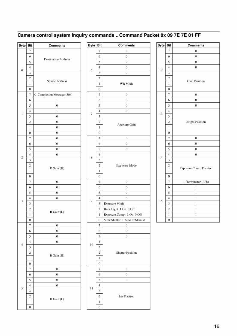
Camera control system inquiry commands .. Command Packet 8x 09 7E 7E 01 FF
Byte Bit Comments
7
6Destination Address
5
04
3
2Source Address
1
0
7 0 Completion Message (50h)
6 1
5 0
14 1
3 0
2 0
1 0
0 0
7 0
6 0
5 0
24 0
3
2R Gain (H)
1
0
7 0
6 0
5 0
34 0
3
2R Gain (L)
1
0
7 0
6 0
5 0
44 0
3
2B Gain (H)
1
0
7 0
6 0
5 0
54 0
3
2B Gain (L)
1
0
Byte Bit Comments
7 0
6 0
5 0
64 0
3 0
2
1 WB Mode
0
7 0
6 0
5 0
74 0
3
2Aperture Gain
1
0
7 0
6 0
5 0
84
3
2 Exposure Mode
1
0
7 0
6 0
5 0
94 0
3 Exposure Mode
2 Back Light 1:On 0:Off
1 Exposure Comp. 1:On 0:Off
0 Slow Shutter 1:Auto 0:Manual
7 0
6 0
5 0
104
3
2 Shutter Position
1
0
7 0
6 0
5 0
114
3
2 Iris Position
1
0
7 0
6 0
5 0
124 0
3
2Gain Position
1
0
7 0
6 0
5 0
134
3
2 Bright Position
1
0
7 0
6 0
5 0
144 0
3
2Exposure Comp. Position
1
0
7 1 Terminator (FFh)
6 1
5 1
154 1
3 1
2 1
1 1
0 1
Byte Bit Comments

17
Byte Bit Comments
7
6Destination Address
5
04
3
2Source Address
1
0
7 0 Completion Message (50h)
6 1
5 0
14 1
3 0
2 0
1 0
0 0
7 0
6 0
5 0
24 0
3 0
2 0
1 0
0 Power 1: On 0: Off
7 0
6 0
5 0
34 0
3 0
2 0
1 Wide Mode 1:Wide 0:Off
0 0
7 0
6 0
5 0
44 0
3 0
2 0
1 0
0 0
7 0
6 0
5 0
54 0
3
2Picture Effect Mode
1
0
7 0
6 0
5 0
64 0
3 0
2 0
1 0
0 0
7 0
6 0
5 0
74 0
3 0
2 0
1 0
0 0
7 0
6 0
5 0
8 4 0
3
2Camera ID (HH)
1
0
7 0
6 0
5 0
94 0
3
2Camera ID (HL)
1
0
7 0
6 0
5 0
104 0
3
2Camera ID (LH)
1
0
7 0
6 0
5 0
114 0
3
2Camera ID (LL)
1
0
Byte Bit Comments
Other inquiry commands......................................... Command Packet 8x 09 7E 7E 02 FF
7 0
6 0
5 0
124 Memory 1:Yes 0:No
3 0
2 0
1 0
0 System 1:PAL 0:NTSC
7 0
6 0
5 0
134 0
3 0
2 0
1 0
0 0
7 0
6 0
5 0
144 0
3 0
2 0
1 0
0 0
7 1 Terminator (FFh)
6 1
5 1
154 1
3 1
2 1
1 1
0 1
Byte Bit Comments

18
Enlargement Function Query Command ............... Command Packet 8x 09 7E 7E 03 FF
Byte Bit Comments
7
6Destination Address
5
04
3
2Source Address
1
0
7 0 Completion Message (50h)
6 1
5 0
14 1
3 0
2 0
1 0
0 0
7 0
6 0
5 0
24 0
3
2Digital Zoom Position (H)
1
0
7 0
6 0
5 0
34 0
3
2Digital Zoom Position (L)
1
0
7 0
6 0
5 0
44 0
3
2AF Activation Time (H)
1
0
7 0
6 0
5 0
54 0
3
2AF Activation Time (L)
1
0
Byte Bit Comments
7 0
6 0
5 0
64 0
3
2AF Interval Time (H)
1
0
7 0
6 0
5 0
74 0
3
2AF Interval Time (L)
1
0
7 0
6 0
5 0
84 0
3
2SpotAE Position (X)
1
0
7 0
6 0
5 0
94 0
3
2SpotAE Position (Y)
1
0
7 0
6 0
5 0
104 0
3 0
2 0
1 0
0 0
7 0
6 0
5 0
114 0
3 0
2 0
1 0
0 0
Byte Bit Comments
7 0
6 0
5 0
124 0
3 0
2 0
1 0
0 0
7 0
6 0
5 0
134 0
3 0
2 0
1 0
0 0
7 0
6 0
5 0
144 0
3 0
2 0
1 0
0 0
7 1 Terminator (FFh)
6 1
5 1
154 1
3 1
2 1
1 1
0 1
19
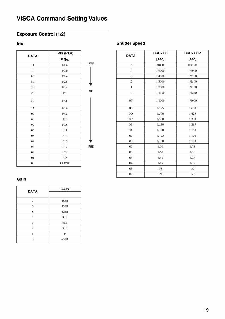
VISCA Command Setting Values
Exposure Control (1/2)
DATAIRIS (F1.6)
F No.
11 F1.6
10 F2.0
0F F2.4
0E F2.8
0D F3.4
0C F4
0B F4.8
0A F5.6
09 F6.8
08 F8
07 F9.6
06 F11
05 F14
04 F16
03 F19
02 F22
01 F28
00 CLOSE
Iris
DATAGAIN
7 18dB
6 15dB
5 12dB
4 9dB
3 6dB
2 3dB
1 0
0 –3dB
Gain
DATABRC-300 BRC-300P
[sec] [sec]
15 1/10000 1/10000
14 1/6000 1/6000
13 1/4000 1/3500
12 1/3000 1/2500
11 1/2000 1/1750
10 1/1500 1/1250
0F 1/1000 1/1000
0E 1/725 1/600
0D 1/500 1/425
0C 1/350 1/300
0B 1/250 1/215
0A 1/180 1/150
09 1/125 1/120
08 1/100 1/100
07 1/90 1/75
06 1/60 1/50
05 1/30 1/25
04 1/15 1/12
03 1/8 1/6
02 1/4 1/3
Shutter Speed
IRIS
ND
IRIS
20
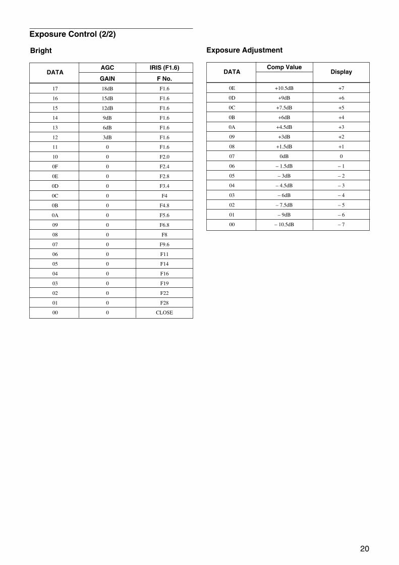
Exposure Control (2/2)
DATAAGC IRIS (F1.6)
GAIN F No.
17 18dB F1.6
16 15dB F1.6
15 12dB F1.6
14 9dB F1.6
13 6dB F1.6
12 3dB F1.6
11 0 F1.6
10 0 F2.0
0F 0 F2.4
0E 0 F2.8
0D 0 F3.4
0C 0 F4
0B 0 F4.8
0A 0 F5.6
09 0 F6.8
08 0 F8
07 0 F9.6
06 0 F11
05 0 F14
04 0 F16
03 0 F19
02 0 F22
01 0 F28
00 0 CLOSE
Bright Exposure Adjustment
DATAComp Value
Display
0E +10.5dB +7
0D +9dB +6
0C +7.5dB +5
0B +6dB +4
0A +4.5dB +3
09 +3dB +2
08 +1.5dB +1
07 0dB 0
06 – 1.5dB – 1
05 – 3dB – 2
04 – 4.5dB – 3
03 – 6dB – 4
02 – 7.5dB – 5
01 – 9dB – 6
00 – 10.5dB – 7

21
Zoom Ratio and Zoom Position(for reference)
Optical Zoom
Position Zoom RatioDATA ××××× 12 Lens
0000 ×1
1982 ×2
24E2 ×3
2BC9 ×4
3099 ×5
343D ×6
3724 ×7
3988 ×8
3B8B ×9
3D43 ×10
3EBB ×11
4000 ×12
Digital Zoom
Position Zoom RatioDATA ××××× 12 Lens
4000 ×1
6A00 ×2
7800 ×3
7F00 ×4
Focus Ratio and Focus Position(for reference)
Optical Zoom
Focus Ratio Focus Distance
1000 Over Inf
2000 5m
3000 2m
4000 1.2m
5000 80cm
6000 50cm
7000 20cm
8000 11cm
9000 6cm
A000 3.5cm
B000 2cm
C000 1cm
Pan/Tilt Position (for reference)
Angle Left Right
(Degree) YYYYY YYYYY
0 00000 00000
10 00823 FF7DD
20 01046 FEFBA
30 01869 FE797
40 0208C FDF74
50 028AF FD751
60 030D2 FCF2E
70 038F5 FC70B
80 04118 FBEE8
90 0493B FB6C5
100 0515E FAEA2
110 05981 FA67F
120 061A4 F9E5C
130 069C7 F9639
140 071EA F8E16
150 07A0D F85F3
160 08230 F7DD0
170 08A58 F75A8
Pan
1 degree: est. 0xD0
Angle Up Down
(Degree) ZZZZ ZZZZ
0 0000 0000
10 0823 F7DD
20 1046 EFBA
30 1869 E796
40 208C
50 28AF
60 30D2
70 38F5
80 4118
90 493D
Tilt

22
Pan/Tilt Status Code List
P Q R S
0 - - - - - - - 0 - - - - - - 1 Pan direction turns to left side
0 - - - - - - - 0 - - - - - 1 - Pan direction turns to right side
0 - - - - - - - 0 - - - - 1 - - Tilt direction turns to upper side
0 - - - - - - - 0 - - - 1 - - - Tilt direction turns to lower side
0 - - - - - - - - - 0 0 - - - - Pan direction operates normal
0 - - - - - - - - - 1 0 - - - - Pan mechanism operates defective
0 - - - - - 0 0 0 - - - - - - - Tilt direction operates normal
0 - - - - - 1 0 0 - - - - - - - Tilt mechanism operates defective
0 - - - 0 1 - - 0 - - - - - - - Pan/Tilt operating
0 - - - 1 0 - - 0 - - - - - - - Pan/Tilt complete operation
0 - 0 0 - - - - 0 - - - - - - - Not initializing
0 - 0 1 - - - - 0 - - - - - - - Initializing
0 - 1 0 - - - - 0 - - - - - - - Complete initializing
( - : optional)

23
Memory function (Inquiry commands)
Preset No. pp: Memory numberComments
last operated last operated
– 00 When no Recall command is used after the power
has been turned on
1 7F 00 (or =00 for Reset, Set and Recall commands)
2 01
3 02
4 03
5 04
6 05

24
Revision History
Version Item Description
1.00 New Edition
1.10 BRC-300/P Command List (3/4) AbsolutePosition parameter changed
RelativePosition parameter changed
1.20 BRC-300/P Inquiry Command Footnote “See the section under VISCAList (2/2) Command Setting Values.” added to
CAM_MemoryInq
Inquiry Packet for CAM_VersionInqchanged
Related Documents