NDT – Magnetic Particle Examination Date : July 2008 Peter Yang

Welcome message from author
This document is posted to help you gain knowledge. Please leave a comment to let me know what you think about it! Share it to your friends and learn new things together.
Transcript
NDT – Magnetic Particle Examination
Date : July 2008
Peter Yang
2Bureau Veritas NC Training Date July 2008
NDT Introduction
► Magnetic Particle Testing (MT)
This NDE method is accomplished by inducing a magnetic field in a ferromagnetic material and then dusting the surface with iron particles (either dry or suspended in liquid).
Surface and near-surface imperfections distort the magnetic field and concentrate iron particles near imperfections, previewing a visual indication of the flaw.
3Bureau Veritas NC Training Date July 2008
Introduction to Magnetic Particle Examination
► Introduction
Magnetic particle examination (MT) is a nondestructive testing method used for defect detection. MT is fast and relatively easy to apply, and part surface preparation is not as critical as it is for some other NDT methods. These characteristics make MT one of the most widely utilized nondestructive testing methods.
MT uses magnetic fields and small magnetic particles (i.e. iron filings) to detect flaws in components. The only requirement from an inspectability standpoint is that the component being inspected must be made of a ferromagnetic material such as iron, nickel, cobalt, or some of their alloys. Ferromagnetic materials are materials that can be magnetized to a level that will allow the inspection to be effective.
The method is used to inspect a variety of product forms including castings, forgings, and weldments. Many different industries use magnetic particle inspection for determining a component's fitness-for-use. Some examples of industries that use magnetic particle inspection are the structural steel, automotive, petrochemical, power generation, and aerospace industries.
4Bureau Veritas NC Training Date July 2008
Introduction to Magnetic Particle Inspection
► Basic Principal:
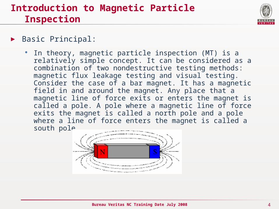
In theory, magnetic particle inspection (MT) is a relatively simple concept. It can be considered as a combination of two nondestructive testing methods: magnetic flux leakage testing and visual testing. Consider the case of a bar magnet. It has a magnetic field in and around the magnet. Any place that a magnetic line of force exits or enters the magnet is called a pole. A pole where a magnetic line of force exits the magnet is called a north pole and a pole where a line of force enters the magnet is called a south pole.
5Bureau Veritas NC Training Date July 2008
Introduction to Magnetic Particle Inspection
► Basic Principal:
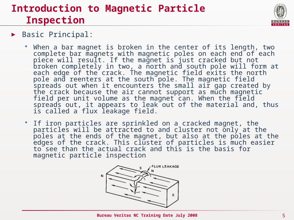
When a bar magnet is broken in the center of its length, two complete bar magnets with magnetic poles on each end of each piece will result. If the magnet is just cracked but not broken completely in two, a north and south pole will form at each edge of the crack. The magnetic field exits the north pole and reenters at the south pole. The magnetic field spreads out when it encounters the small air gap created by the crack because the air cannot support as much magnetic field per unit volume as the magnet can. When the field spreads out, it appears to leak out of the material and, thus is called a flux leakage field.
If iron particles are sprinkled on a cracked magnet, the particles will be attracted to and cluster not only at the poles at the ends of the magnet, but also at the poles at the edges of the crack. This cluster of particles is much easier to see than the actual crack and this is the basis for magnetic particle inspection
6Bureau Veritas NC Training Date July 2008
Introduction to Magnetic Particle Inspection
► Basic Principal:
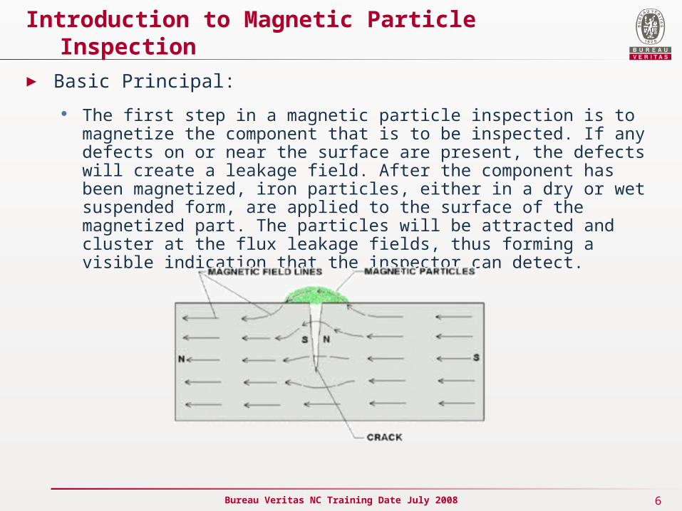
The first step in a magnetic particle inspection is to magnetize the component that is to be inspected. If any defects on or near the surface are present, the defects will create a leakage field. After the component has been magnetized, iron particles, either in a dry or wet suspended form, are applied to the surface of the magnetized part. The particles will be attracted and cluster at the flux leakage fields, thus forming a visible indication that the inspector can detect.
7Bureau Veritas NC Training Date July 2008
Introduction to Magnetic Particle Inspection
► Magnetic Field Characteristics
Magnetic Field In and Around a Bar Magnet
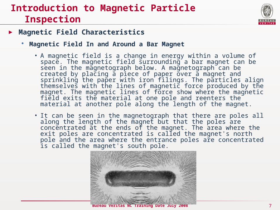
• A magnetic field is a change in energy within a volume of space. The magnetic field surrounding a bar magnet can be seen in the magnetograph below. A magnetograph can be created by placing a piece of paper over a magnet and sprinkling the paper with iron filings. The particles align themselves with the lines of magnetic force produced by the magnet. The magnetic lines of force show where the magnetic field exits the material at one pole and reenters the material at another pole along the length of the magnet.
• It can be seen in the magnetograph that there are poles all along the length of the magnet but that the poles are concentrated at the ends of the magnet. The area where the exit poles are concentrated is called the magnet's north pole and the area where the entrance poles are concentrated is called the magnet's south pole.
8Bureau Veritas NC Training Date July 2008
Introduction to Magnetic Particle Inspection
► Magnetic Field Characteristics
Magnetic Fields in and around Horseshoe and Ring Magnets
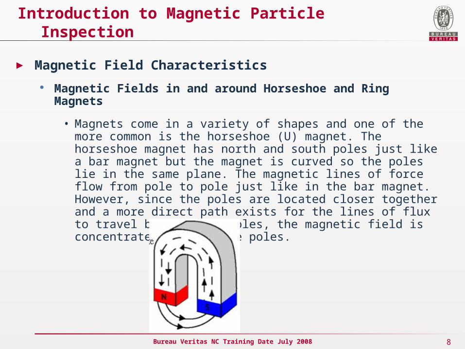
• Magnets come in a variety of shapes and one of the more common is the horseshoe (U) magnet. The horseshoe magnet has north and south poles just like a bar magnet but the magnet is curved so the poles lie in the same plane. The magnetic lines of force flow from pole to pole just like in the bar magnet. However, since the poles are located closer together and a more direct path exists for the lines of flux to travel between the poles, the magnetic field is concentrated between the poles.
9Bureau Veritas NC Training Date July 2008
Introduction to Magnetic Particle Inspection
► Magnetic Field Characteristics
Magnetic Fields in and around Horseshoe and Ring Magnets
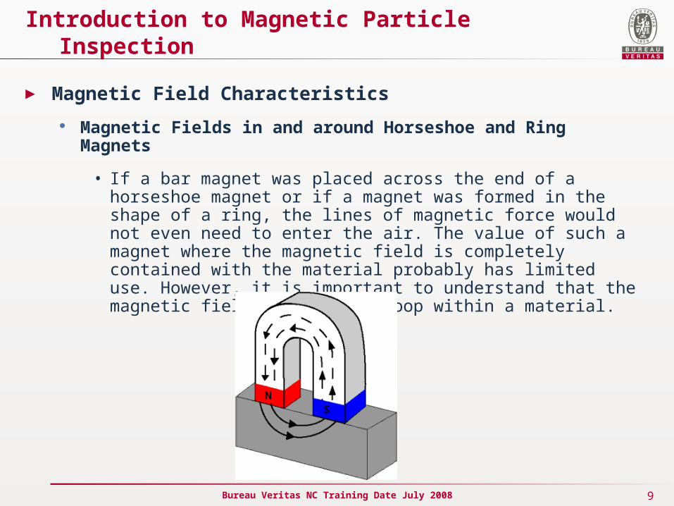
• If a bar magnet was placed across the end of a horseshoe magnet or if a magnet was formed in the shape of a ring, the lines of magnetic force would not even need to enter the air. The value of such a magnet where the magnetic field is completely contained with the material probably has limited use. However, it is important to understand that the magnetic field can flow in loop within a material.

10Bureau Veritas NC Training Date July 2008
Introduction to Magnetic Particle Inspection
► Magnetic Field Orientation and Flaw Detectability
To properly inspect a component for cracks or other defects, it is important to understand that the orientation between the magnetic lines of force and the flaw is very important. There are two general types of magnetic fields that can be established within a component.
A longitudinal magnetic field has magnetic lines of force that run parallel to the long axis of the part. Longitudinal magnetization of a component can be accomplished using the longitudinal field set up by a coil or solenoid. It can also be accomplished using permanent magnets or electromagnets.
A circular magnetic field has magnetic lines of force that run circumferentially around the perimeter of a part. A circular magnetic field is induced in an article by either passing current through the component or by passing current through a conductor surrounded by the component.
11Bureau Veritas NC Training Date July 2008
Introduction to Magnetic Particle Inspection
► Magnetic Field Orientation and Flaw Detectability
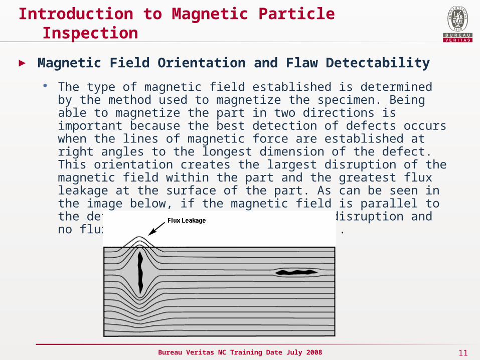
The type of magnetic field established is determined by the method used to magnetize the specimen. Being able to magnetize the part in two directions is important because the best detection of defects occurs when the lines of magnetic force are established at right angles to the longest dimension of the defect. This orientation creates the largest disruption of the magnetic field within the part and the greatest flux leakage at the surface of the part. As can be seen in the image below, if the magnetic field is parallel to the defect, the field will see little disruption and no flux leakage field will be produced..
12Bureau Veritas NC Training Date July 2008
Introduction to Magnetic Particle Inspection
► Magnetic Field Orientation and Flaw Detectability
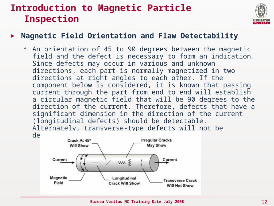
An orientation of 45 to 90 degrees between the magnetic field and the defect is necessary to form an indication. Since defects may occur in various and unknown directions, each part is normally magnetized in two directions at right angles to each other. If the component below is considered, it is known that passing current through the part from end to end will establish a circular magnetic field that will be 90 degrees to the direction of the current. Therefore, defects that have a significant dimension in the direction of the current (longitudinal defects) should be detectable. Alternately, transverse-type defects will not be detectable with circular magnetization. ..
13Bureau Veritas NC Training Date July 2008
EQUIPMENTS - Magnetization of Ferromagnetic Materials
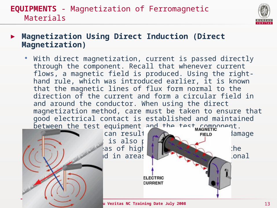
► Magnetization Using Direct Induction (Direct Magnetization)
With direct magnetization, current is passed directly through the component. Recall that whenever current flows, a magnetic field is produced. Using the right-hand rule, which was introduced earlier, it is known that the magnetic lines of flux form normal to the direction of the current and form a circular field in and around the conductor. When using the direct magnetization method, care must be taken to ensure that good electrical contact is established and maintained between the test equipment and the test component. Improper contact can result in arcing that may damage the component. It is also possible to overheat components in areas of high resistance such as the contact points and in areas of small cross-sectional area.
14Bureau Veritas NC Training Date July 2008
EQUIPMENTS - Magnetization of Ferromagnetic Materials
► Magnetization Using Indirect Induction (Indirect Magnetization)
Indirect magnetization is accomplished by using a strong external magnetic field to establish a magnetic field within the component. As with direct magnetization, there are several ways that indirect magnetization can be accomplished.
The use of permanent magnets is a low cost method of establishing a magnetic field. However, their use is limited due to lack of control of the field strength and the difficulty of placing and removing strong permanent magnets from the component.
15Bureau Veritas NC Training Date July 2008
EQUIPMENTS - Magnetization of Ferromagnetic Materials
► Magnetization Using Indirect Induction (Indirect Magnetization)
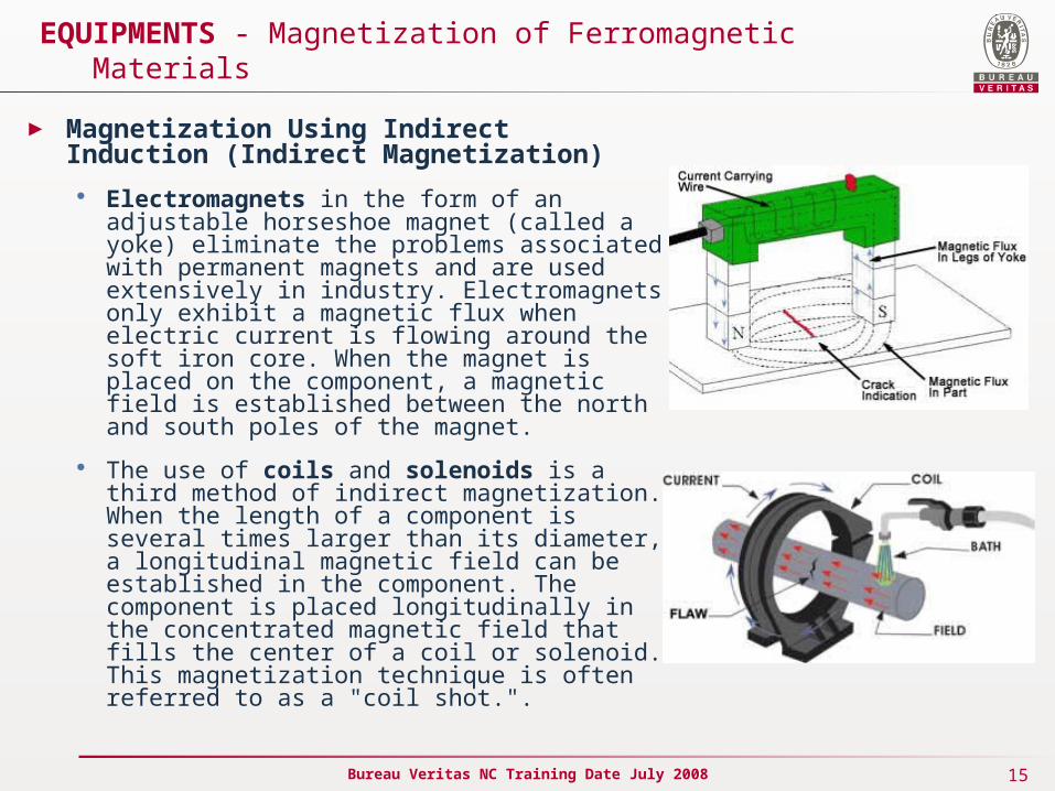
Electromagnets in the form of an adjustable horseshoe magnet (called a yoke) eliminate the problems associated with permanent magnets and are used extensively in industry. Electromagnets only exhibit a magnetic flux when electric current is flowing around the soft iron core. When the magnet is placed on the component, a magnetic field is established between the north and south poles of the magnet.
The use of coils and solenoids is a third method of indirect magnetization. When the length of a component is several times larger than its diameter, a longitudinal magnetic field can be established in the component. The component is placed longitudinally in the concentrated magnetic field that fills the center of a coil or solenoid. This magnetization technique is often referred to as a "coil shot.".
16Bureau Veritas NC Training Date July 2008
Introduction to Magnetic Particle Inspection
► Magnetic Particle Examination – Two directions check
To properly inspect a part for cracks or other defects, it is important to become familiar with the different types of magnetic fields and the equipment used to generate them. As discussed previously, one of the primary requirements for detecting a defect in a ferromagnetic material is that the magnetic field induced in the part must intercept the defect at a 45 to 90 degree angle. Flaws that are normal (90 degrees) to the magnetic field will produce the strongest indications because they disrupt more of the magnet flux.
Therefore, for proper inspection of a component, it is important to be able to establish a magnetic field in at least two directions. A variety of equipment exists to establish the magnetic field for MPI. One way to classify equipment is based on its portability. Some equipment is designed to be portable so that inspections can be made in the field and some is designed to be stationary for ease of inspection in the laboratory or manufacturing facility. Portable equipment will be discussed first.
17Bureau Veritas NC Training Date July 2008
EQUIPMENT AND MATERIALS
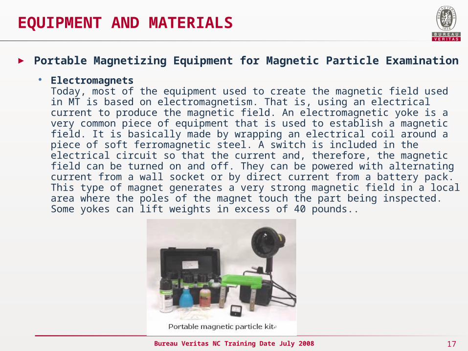
► Portable Magnetizing Equipment for Magnetic Particle Examination
ElectromagnetsToday, most of the equipment used to create the magnetic field used in MT is based on electromagnetism. That is, using an electrical current to produce the magnetic field. An electromagnetic yoke is a very common piece of equipment that is used to establish a magnetic field. It is basically made by wrapping an electrical coil around a piece of soft ferromagnetic steel. A switch is included in the electrical circuit so that the current and, therefore, the magnetic field can be turned on and off. They can be powered with alternating current from a wall socket or by direct current from a battery pack. This type of magnet generates a very strong magnetic field in a local area where the poles of the magnet touch the part being inspected. Some yokes can lift weights in excess of 40 pounds..
18Bureau Veritas NC Training Date July 2008
EQUIPMENT AND MATERIALS
► Lights for Magnetic Particle Examination
Magnetic particle inspection can be performed using particles that are highly visible under white light conditions or particles that are highly visible under ultraviolet light conditions. When an inspection is being performed using the visible color contrast particles, no special lighting is required as long as the area of inspection is well lit. A light intensity of at least 1000 lux is recommended when visible particles are used, but a variety of light sources can be used.
When fluorescent particles are used, special ultraviolet light must be used. Fluorescence is defined as the property of emitting radiation as a result of and during exposure to radiation. Particles used in fluorescent magnetic particle inspections are coated with a material that produces light in the visible spectrum when exposed to near-ultraviolet light. This "particle glow" provides high contrast indications on the component anywhere particles collect. Particles that fluoresce yellow-green are most common because this color matches the peak sensitivity of the human eye under dark conditions. However, particles that fluoresce red, blue, yellow, and green colors are available.
19Bureau Veritas NC Training Date July 2008
EQUIPMENT AND MATERIALS
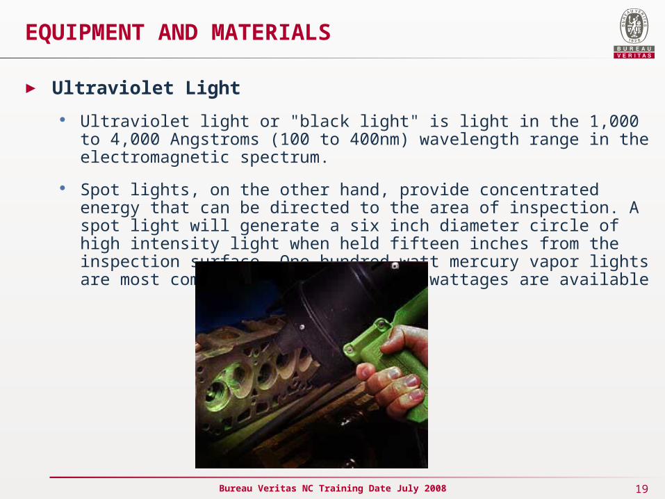
► Ultraviolet Light
Ultraviolet light or "black light" is light in the 1,000 to 4,000 Angstroms (100 to 400nm) wavelength range in the electromagnetic spectrum.
Spot lights, on the other hand, provide concentrated energy that can be directed to the area of inspection. A spot light will generate a six inch diameter circle of high intensity light when held fifteen inches from the inspection surface. One hundred watt mercury vapor lights are most commonly used, but higher wattages are available
20Bureau Veritas NC Training Date July 2008
Magnetic Field Indicators
► Quantitative Quality Indicator (QQI)
The Quantitative Quality Indicator (QQI) or Artificial Flaw Standard is often the preferred method of assuring proper field direction and adequate field strength. The use of a QQI is also the only practical way of ensuring balanced field intensity and direction in multiple-direction magnetization equipment. QQIs are often used in conjunction with a Gauss meter to establish the inspection procedure for a particular component. They are used with the wet method only, and like other flux sharing devices, can only be used with continuous magnetization.
The QQI is a thin strip of either 0.002 or 0.004 inch thick AISI 1005 steel. A photoetch process is used to inscribe a specific pattern, such as concentric circles or a plus sign. QQIs are nominally 3/4 inch square, but miniature shims are also available. QQIs must be in intimate contact with the part being evaluated. This is accomplished by placing the shim on a part etched side down, and taping or gluing it to the surface. The component is then magnetized and particles applied. When the field strength is adequate, the particles will adhere over the engraved pattern and provide information about the field direction. When a multidirectional technique is used, a balance of the fields is noted when all areas of the QQI produce indications.

21Bureau Veritas NC Training Date July 2008
Magnetic Field Indicators
► Quantitative Quality Indicator (QQI)
22Bureau Veritas NC Training Date July 2008
Magnetic Field Indicators
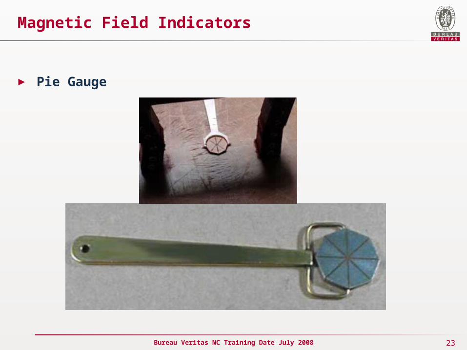
► Pie Gage
The pie gage is a disk of highly permeable material divided into four, six, or eight sections by nonferromagnetic material. The divisions serve as artificial defects that radiate out in different directions from the center. The diameter of the gage is 3/4 to 1 inch. The divisions between the low carbon steel pie sections are to be no greater than 1/32 inch. The sections are furnace brazed and copper plated. The gage is placed on the test piece copper side up and the test piece is magnetized. After particles are applied and the excess removed, the indications provide the inspector the orientation of the magnetic field.
The principal application is on flat surfaces such as weldments or steel castings where dry powder is used with a yoke or prods. The pie gage is not recommended for precision parts with complex shapes, for wet-method applications, or for proving field magnitude. The gage should be demagnetized between readings.
Several of the main advantages of the pie gage are that it is easy to use and it can be used indefinitely without deterioration. The pie gage has several disadvantages, which include: it retains some residual magnetism so indications will prevail after removal of the source of magnetization, it can only be used in relatively flat areas, and it cannot be reliably used for determination of balanced fields in multidirectional magnetization.
23Bureau Veritas NC Training Date July 2008
Magnetic Field Indicators
► Pie Gauge
24Bureau Veritas NC Training Date July 2008
Magnetic Particles
► The particles that are used for magnetic particle inspection are a key ingredient as they form the indications that alert the inspector to defects.
Dry Magnetic Particles
• Dry magnetic particles can typically be purchased in red, black, gray, yellow and several other colors so that a high level of contrast between the particles and the part being inspected can be achieved. The size of the magnetic particles is also very important. Dry magnetic particle products are produced to include a range of particle sizes. The fine particles are around 50 mm (0.002 inch) in size, and are about three times smaller in diameter and more than 20 times lighter than the coarse particles (150 mm or 0.006 inch). This make them more sensitive to the leakage fields from very small discontinuities.
• However, dry testing particles cannot be made exclusively of the fine particles. Coarser particles are needed to bridge large discontinuities and to reduce the powder's dusty nature. Additionally, small particles easily adhere to surface contamination, such as remnant dirt or moisture, and get trapped in surface roughness features. It should also be recognized that finer particles will be more easily blown away by the wind; therefore, windy conditions can reduce the sensitivity of an inspection. Also, reclaiming the dry particles is not recommended because the small particles are less likely to be recaptured and the "once used" mix will result in less sensitive inspections.
25Bureau Veritas NC Training Date July 2008
Magnetic Particles
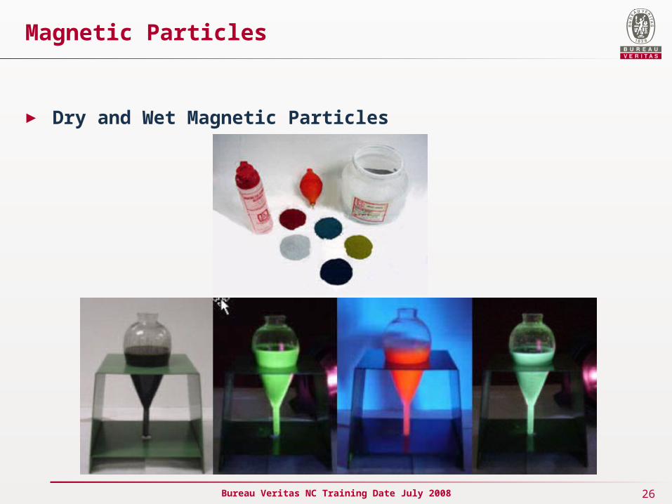
► Wet Magnetic Particles
The wet magnetic particle testing method is generally more sensitive than the dry because the suspension provides the particles with more mobility and makes it possible for smaller particles to be used since dust and adherence to surface contamination is reduced or eliminated. The wet method also makes it easy to apply the particles uniformly to a relatively large area.
Wet method magnetic particles products differ from dry powder products in a number of ways. One way is that both visible and fluorescent particles are available. Most nonfluorescent particles are ferromagnetic iron oxides, which are either black or brown in color. Fluorescent particles are coated with pigments that fluoresce when exposed to ultraviolet light. Particles that fluoresce green-yellow are most common to take advantage of the peak color sensitivity of the eye but other fluorescent colors are also available.
The particles used with the wet method are smaller in size than those used in the dry method for the reasons mentioned above. The particles are typically 10 µm and smaller and the synthetic iron oxides have particle diameters around 0.1 µm.
26Bureau Veritas NC Training Date July 2008
Magnetic Particles
► Dry and Wet Magnetic Particles
27Bureau Veritas NC Training Date July 2008
TESTING PRACTICAL
► Dry Particle Examination
Dry particle inspection is well suited for the inspections conducted on rough surfaces. When an electromagnetic yoke is used, the AC or half wave DC current creates a pulsating magnetic field that provides mobility to the powder. The primary applications for dry powders are unground welds and rough as-cast surfaces.
Dry particle inspection is also used to detect shallow subsurface cracks. Dry particles with half wave DC is the best approach when inspecting for lack of root penetration in welds of thin materials. Half wave DC with prods and dry particles is commonly used when inspecting large castings for hot tears and cracks.
28Bureau Veritas NC Training Date July 2008
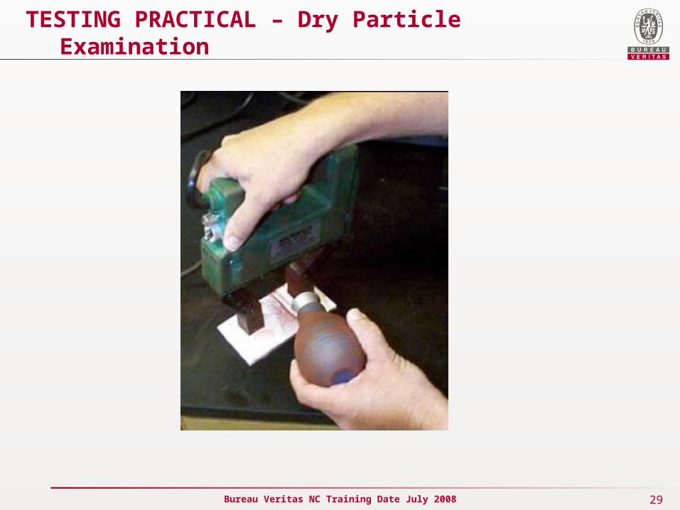
TESTING PRACTICAL – Dry Particle Examination
► Steps in performing an inspection using dry particles
Prepare the part surface - the surface should be relatively clean but this is not as critical as it is with liquid penetrant inspection. The surface must be free of grease, oil or other moisture that could keep particles from moving freely. A thin layer of paint, rust or scale will reduce test sensitivity but can sometimes be left in place with adequate results. Any loose dirt, paint, rust or scale must be removed.
Apply the magnetizing force - Use permanent magnets, an electromagnetic yoke, prods, a coil or other means to establish the necessary magnetic flux.
Dust on the dry magnetic particles - Dust on a light layer of magnetic particles.
Gently blow off the excess powder - With the magnetizing force still applied, remove the excess powder from the surface with a few gentle puffs of dry air. The force of the air needs to be strong enough to remove the excess particles but not strong enough to dislodge particles held by a magnetic flux leakage field.
Terminate the magnetizing force - If the magnetic flux is being generated with an electromagnet or an electromagnetic field, the magnetizing force should be terminated. If permanent magnets are being used, they can be left in place.
Inspect for indications - Look for areas where the magnetic particles are clustered.
29Bureau Veritas NC Training Date July 2008
TESTING PRACTICAL – Dry Particle Examination
30Bureau Veritas NC Training Date July 2008
TESTING PRACTICAL
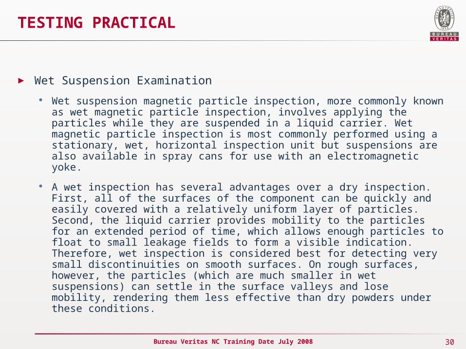
► Wet Suspension Examination
Wet suspension magnetic particle inspection, more commonly known as wet magnetic particle inspection, involves applying the particles while they are suspended in a liquid carrier. Wet magnetic particle inspection is most commonly performed using a stationary, wet, horizontal inspection unit but suspensions are also available in spray cans for use with an electromagnetic yoke.
A wet inspection has several advantages over a dry inspection. First, all of the surfaces of the component can be quickly and easily covered with a relatively uniform layer of particles. Second, the liquid carrier provides mobility to the particles for an extended period of time, which allows enough particles to float to small leakage fields to form a visible indication. Therefore, wet inspection is considered best for detecting very small discontinuities on smooth surfaces. On rough surfaces, however, the particles (which are much smaller in wet suspensions) can settle in the surface valleys and lose mobility, rendering them less effective than dry powders under these conditions.
31Bureau Veritas NC Training Date July 2008
TESTING PRACTICAL – Wet Suspension Examination
► Steps in performing an inspection using wet suspensions
Prepare the part surface - Just as is required with dry particle inspections, the surface should be relatively clean. The surface must be free of grease, oil and other moisture that could prevent the suspension from wetting the surface and preventing the particles from moving freely. A thin layer of paint, rust or scale will reduce test sensitivity, but can sometimes be left in place with adequate results. Any loose dirt, paint, rust or scale must be removed.
Apply the suspension - The suspension is gently sprayed or flowed over the surface of the part. Usually, the stream of suspension is diverted from the part just before the magnetizing field is applied.
Apply the magnetizing force - The magnetizing force should be applied immediately after applying the suspension of magnetic particles. When using a wet horizontal inspection unit, the current is applied in two or three short busts (1/2 second) which helps to improve particle mobility.
Inspect for indications - Look for areas where the magnetic particles are clustered. Surface discontinuities will produce a sharp indication. The indications from subsurface flaws will be less defined and lose definition as depth increases.
32Bureau Veritas NC Training Date July 2008
TESTING PRACTICAL – Wet Suspension Examination
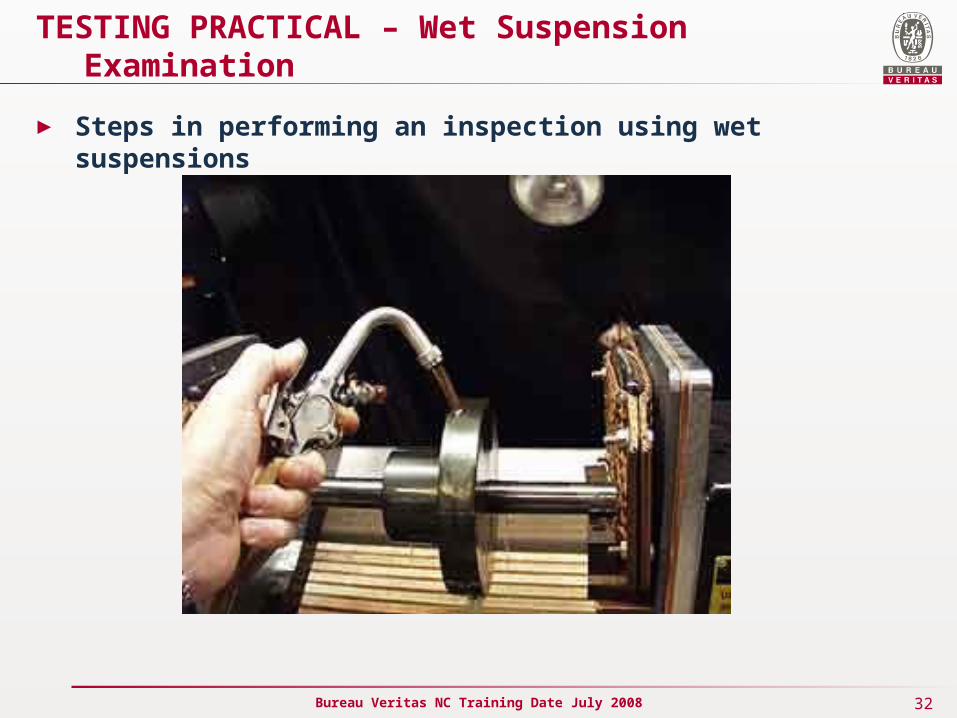
► Steps in performing an inspection using wet suspensions
33Bureau Veritas NC Training Date July 2008
TESTING PRACTICAL – Lighting
► Light Requirements When Using Visible Particles
Magnetic particle inspections that use visible particles can be conducted using natural or artificial lighting. Inspector must constantly stay aware of the lighting conditions and make adjustments when needed. To improve the uniformity of lighting from one inspection to the next, the use of artificial lighting is recommended. Artificial lighting should be white whenever possible and white flood or halogen lamps are most commonly used. The light intensity is required to be 100 foot-candles at the surface being inspected. It is advisable to choose a white light wattage that will provide sufficient light, but avoid excessive reflected light that could distract from the inspection.

34Bureau Veritas NC Training Date July 2008
TESTING PRACTICAL – Lighting
► Light Requirements When Using Fluorescent Particles - Ultraviolet Lighting
When performing a magnetic particle inspection using fluorescent particles, the condition of the ultraviolet light and the ambient white light must be monitored. Standards and procedures require verification of lens condition and light intensity. Black lights should never be used with a cracked filter as the output of white light and harmful black light will be increased. The cleanliness of the filter should be checked visually and cleaned as necessary before warming-up the light.
35Bureau Veritas NC Training Date July 2008
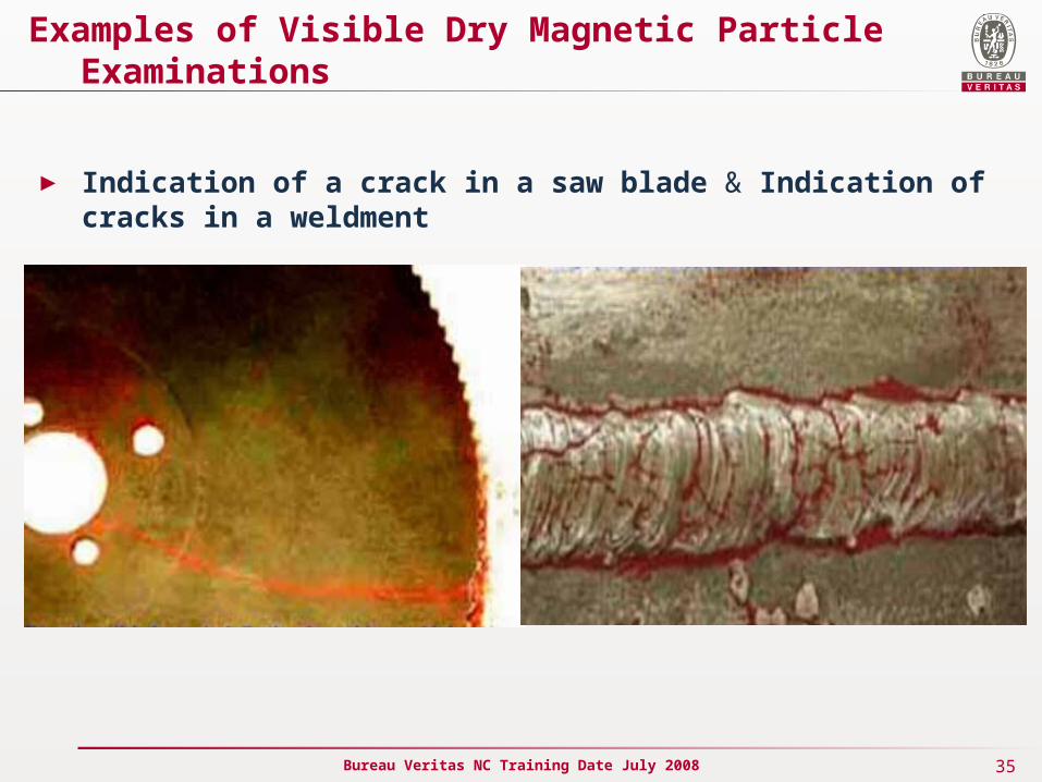
Examples of Visible Dry Magnetic Particle Examinations
► Indication of a crack in a saw blade & Indication of cracks in a weldment
36Bureau Veritas NC Training Date July 2008
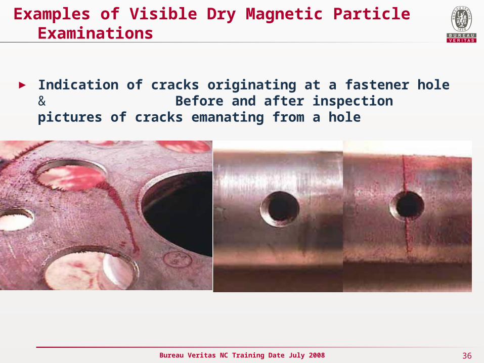
Examples of Visible Dry Magnetic Particle Examinations
► Indication of cracks originating at a fastener hole & Before and after inspection pictures of cracks emanating from a hole
37Bureau Veritas NC Training Date July 2008
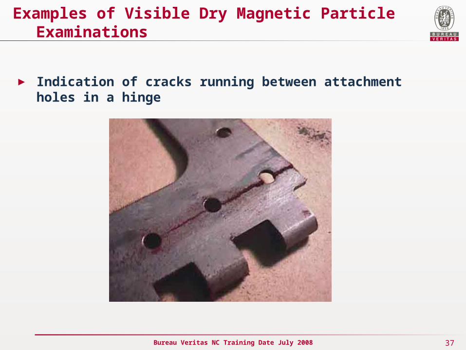
Examples of Visible Dry Magnetic Particle Examinations
► Indication of cracks running between attachment holes in a hinge
38Bureau Veritas NC Training Date July 2008
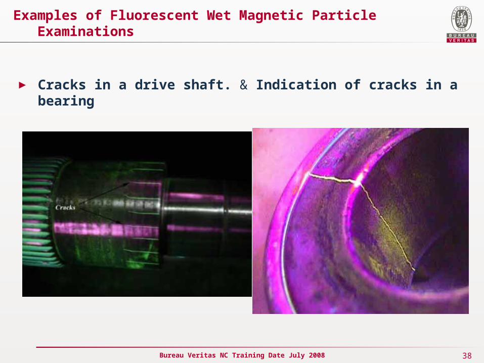
Examples of Fluorescent Wet Magnetic Particle Examinations
► Cracks in a drive shaft. & Indication of cracks in a bearing
39Bureau Veritas NC Training Date July 2008
Examples of Fluorescent Wet Magnetic Particle Examinations
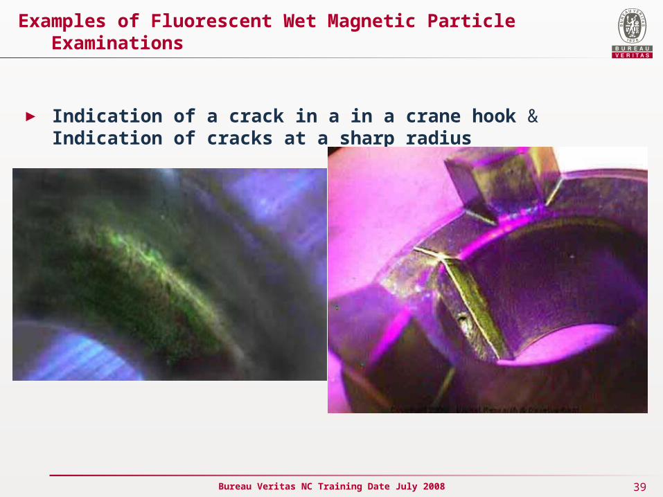
► Indication of a crack in a in a crane hook & Indication of cracks at a sharp radius

Related Documents