Web-Only Document 157: Volume I: Evaluation of Existing Roadside Safety Hardware Using Updated Criteria—Technical Report National Cooperative Highway Research Program D. Lance Bullard, Jr. Roger P. Bligh Wanda L. Menges Rebecca R. Haug Texas Transportation Institute College Station, TX Contractor’s Final Report for NCHRP Project 22-14(03) Submitted March 2010 NCHRP

Welcome message from author
This document is posted to help you gain knowledge. Please leave a comment to let me know what you think about it! Share it to your friends and learn new things together.
Transcript
Web-Only Document 157:
Volume I: Evaluation of Existing Roadside Safety Hardware Using Updated
Criteria—Technical Report
National Cooperative Highway Research Program
D. Lance Bullard, Jr. Roger P. Bligh
Wanda L. Menges Rebecca R. Haug
Texas Transportation Institute
College Station, TX
Contractor’s Final Report for NCHRP Project 22-14(03) Submitted March 2010
NCHRP

ACKNOWLEDGMENT This work was sponsored by the American Association of State Highway and Transportation Officials (AASHTO), in cooperation with the Federal Highway Administration, and was conducted in the National Cooperative Highway Research Program (NCHRP), which is administered by the Transportation Research Board (TRB) of the National Academies.
COPYRIGHT INFORMATION Authors herein are responsible for the authenticity of their materials and for obtaining written permissions from publishers or persons who own the copyright to any previously published or copyrighted material used herein. Cooperative Research Programs (CRP) grants permission to reproduce material in this publication for classroom and not-for-profit purposes. Permission is given with the understanding that none of the material will be used to imply TRB, AASHTO, FAA, FHWA, FMCSA, FTA, Transit Development Corporation, or AOC endorsement of a particular product, method, or practice. It is expected that those reproducing the material in this document for educational and not-for-profit uses will give appropriate acknowledgment of the source of any reprinted or reproduced material. For other uses of the material, request permission from CRP.
DISCLAIMER The opinions and conclusions expressed or implied in this report are those of the researchers who performed the research. They are not necessarily those of the Transportation Research Board, the National Research Council, or the program sponsors. The information contained in this document was taken directly from the submission of the author(s). This material has not been edited by TRB.

TABLE OF CONTENTS Section Page LIST OF FIGURES ..................................................................................................................... viii LIST OF TABLES ......................................................................................................................... xi I. INTRODUCTION .......................................................................................................................1
RESEARCH PROBLEM STATEMENT ............................................................................1 RESEARCH OBJECTIVE ..................................................................................................1
II. STATE OF THE PRACTICE ....................................................................................................3 III. ASSESSMENT OF ROADSIDE SAFETY HARDWARE ...................................................12
GENERAL PERFORMANCE CONSIDERATIONS .......................................................12 Structural Adequacy .......................................................................................................14 Vehicle Stability .............................................................................................................17 Occupant Compartment Deformation .............................................................................18
GUARDRAILS ..................................................................................................................20 Strong-Post W-Beam Guardrail [modified G4(1S) and G4(2W)] ..................................21 Thrie-Beam Guardrail (G9) ............................................................................................22 Thrie-Beam Guardrail (steel posts and routed wood blockouts) ....................................23 Thrie-Beam Guardrail on Strong Wood Posts ................................................................23 Modified Thrie-Beam Guardrail .....................................................................................24 Weak-Post W-Beam Guardrail (G2) ...............................................................................25 Low-Tension Cable Guardrail (G1) ................................................................................26 Weak-Post Box-Beam Guardrail (G3) ............................................................................27
AESTHETIC BARRIERS .................................................................................................28 Test Level 3 ....................................................................................................................29
Rough Stone Masonry Guardwall ................................................................................29 Type A Steel-Backed Timber Guardrail ......................................................................29 Merritt Parkway Steel-Backed Timber Guardrail ........................................................30
Test Level 2 ....................................................................................................................32 Type B Steel-Backed Timber Guardrail ......................................................................32 Round Steel-Backed Timber Guardrail .......................................................................32 Deception Pass State Park Log Rail .............................................................................33
Test Level 1 ....................................................................................................................35 Glacier Park Removable Timber Guardrail .................................................................35 Glacier Park Round Removable Timber Guardrail .....................................................36
MEDIAN BARRIERS .......................................................................................................37 Cable Median Barrier......................................................................................................38 Concrete Median Barrier ................................................................................................39 Portable and Precast Concrete Median Barrier ...............................................................44 Low-Profile Barrier – Test Level 2 .................................................................................44

TABLE OF CONTENTS (CONTINUED) Section Page
Portable and Precast Median Barrier Connections .........................................................46
F-Shape Type X Connection ........................................................................................49 Portable and Precast Median Barrier Connections Summary ......................................51
TRANSITIONS .................................................................................................................51 TL-3 Transition ...............................................................................................................52 TL-2 Transition ...............................................................................................................59 General Transition Discussion ........................................................................................60
END TERMINALS AND CRASH CUSHIONS ..............................................................61 End Terminals .................................................................................................................62
Test Level 3 Guardrail Terminals ................................................................................62 Test Level 2 Guardrail Terminals ................................................................................66
Crash Cushions ...............................................................................................................69 Connecticut Impact Attenuator System .......................................................................69 Narrow Connecticut Impact Attenuator System ..........................................................71 Thrie-Beam Bullnose Guardrail System (Bullnose Attenuator) ..................................72
BREAKAWAY HARDWARE - SIGN SUPPORTS AND LUMINAIRES .....................74 Wedge Anchor Sign Support ..........................................................................................80
Summary of Wedge Anchor Results ............................................................................83 Discussion of Test 2 of Wedge Anchor System ..........................................................83
Texas Triangular Slip Base .............................................................................................85 Summary of Texas Slip Base Test Results ..................................................................88 Discussion of Texas Slip Base System ........................................................................88
CONCLUSIONS................................................................................................................88 IV. CRASH TESTING MATRIX AND EVALUATION PLAN ................................................89
SMALL SIGN SUPPORTS AND LUMINAIRE BASES ................................................95 THRIE-BEAM LONGITUDINAL BARRIER .................................................................96 W-BEAM TRANSITIONS TO SAFETY AND F-SHAPE BARRIER ............................96 BURIED-IN-BACKSLOPE TERMINAL .........................................................................96 CABLE GUARDRAIL ......................................................................................................96 OTHER GUARDRAILS ...................................................................................................97 SUMMARY .......................................................................................................................97
V. FULL-SCALE CRASH TESTING ..........................................................................................99
32-INCH NEW JERSEY SHAPE BARRIER – SGM11a .................................................99 Test Installation Description ...........................................................................................99 Test Number 476460-1b (MASH Test 4-12).................................................................100
Test Description .........................................................................................................100 Summary of Test Results ...........................................................................................103
Test Number 476460-1-4 (MASH Test 4-11) ..............................................................106 Test Description .........................................................................................................106
TABLE OF CONTENTS (CONTINUED) Section Page
Summary of Test Results ...........................................................................................108
W-BEAM GUARDRAIL – G4(2W) ...............................................................................111 Test Installation Description .........................................................................................111 Test Number 476460-1-5 (MASH Test 3-11) ...............................................................112
Test Description .........................................................................................................112 Summary of Test Results ...........................................................................................114
W-BEAM GUARDRAIL – G4(1S) MEDIAN BARRIER .............................................118 Test Installation Description .........................................................................................118 Test Number 476460-1-10 (MASH Test 3-10) .............................................................120
Test Description .........................................................................................................120 Summary of Test Results ...........................................................................................122
Test Number 476460-1-9 (MASH Test 3-11) ...............................................................125 Test Description .........................................................................................................125 Summary of Test Results ...........................................................................................127
PENNDOT W-BEAM TRANSITION ............................................................................130 Test Installation Description .........................................................................................130 Test Number 476460-1-3 (MASH TEST 3-21).............................................................133
Test Description .........................................................................................................133 Summary of Test Results ...........................................................................................135
SMALL SIGN SUPPORTS .............................................................................................138 Test Installation Description .........................................................................................138
Steel U-Channel Support ...........................................................................................138 Perforated Square Steel Tube Support .......................................................................139 Soil Conditions...........................................................................................................139
Test Number 476460-1-2 (Mash Test 3-62) .................................................................141 Test Description .........................................................................................................141 Summary of Test Results ...........................................................................................148
G3 WEAK POST BOX-BEAM GUARDRAIL ..............................................................151 Test Installation.............................................................................................................151 Test Number 476460-1-6 (MASH Test 3-11) ...............................................................152
Test Description .........................................................................................................152 Summary of Test Results ...........................................................................................155
MODIFIED G2 WEAK POST W-BEAM GUARDRAIL ..............................................158 Test Installation Description .........................................................................................158 Test Number 476460-1-7 (MASH Test 3-11) ...............................................................160
Test Description .........................................................................................................160 Summary of Test Results ...........................................................................................162
G9 THRIE BEAM GUARDRAIL ...................................................................................165 Test Installation Desciption ..........................................................................................165 Test Number 476460-1-8 (MASH Test 3-11) ...............................................................166
Test Description .........................................................................................................166

TABLE OF CONTENTS (CONTINUED)
Section Page
Summary of Test Results ...........................................................................................169 VI. SUMMARY AND CONCLUSIONS ...................................................................................173
PHASE I...........................................................................................................................173 PHASE II – FULL-SCALE CRASH TESTING .............................................................175
New Jersey Safety Shape Barrier ..................................................................................175 Test 4-12 ....................................................................................................................175 Test 3-11 ....................................................................................................................176
G4(2W) W-Beam Guardrail .........................................................................................176 G4(1S) W-Beam Median Barrier ..................................................................................177
Test-3-10 ....................................................................................................................177 Test-3-11 ....................................................................................................................177
W-Beam Transition.......................................................................................................178 Sign Supports ................................................................................................................178 G3 Weak Post Box-Beam Guardrail .............................................................................180 Modified G2 Weak Post W-Beam Guardrail ................................................................180 G9 Thrie Beam Guardrail .............................................................................................181
CONCLUSIONS..............................................................................................................181 VII. REFERENCES ....................................................................................................................185

LIST OF FIGURES Figure Page Figure 1. Yield Line Failure Analysis for Concrete Parapet(9). ................................................ 14 Figure 2. Typical Cross-Section of Strong-Post W-Beam Guardrail. ...................................... 21 Figure 3. Typical Cross-Section of Thrie-Beam Guardrail. ..................................................... 23 Figure 4. Typical Cross-Section of Modified Thrie-Beam Guardrail System. ......................... 24 Figure 5. Typical Cross-Section of Weak Post W-Beam Guardrail System. ........................... 25 Figure 6. Typical Cross-Section of Low-Tension Cable Guardrail System. ............................ 26 Figure 7. Typical Cross-Section of Weak-Post Box-Beam Guardrail System. ........................ 28 Figure 8. Rough Stone Masonry Guardwall System. ............................................................... 29 Figure 9. Type A Steel-Backed Timber Guardrail System. ...................................................... 30 Figure 10. Merritt Parkway Steel-Backed Timber Guardrail System. ....................................... 31 Figure 11. Type B Steel-Backed Timber Guardrail System. ...................................................... 32 Figure 12. Round Steel-Backed Timber Guardrail System. ....................................................... 33 Figure 13. Deception Pass State Park Log Rail System. ............................................................ 34 Figure 14. Glacier Park Removable Timber Guardrail System. ................................................. 35 Figure 15. Glacier Park Round Removable Timber Guardrail System. ..................................... 36 Figure 16. Typical Cross-Section of a Low-Tension Cable Median Barrier System. ................ 39 Figure 17. Typical Cross-Section of New Jersey Shape Concrete Safety Barrier. ..................... 40 Figure 18. Typical Cross-Section of F-Shape Concrete Safety Barrier. ..................................... 41 Figure 19. Typical Cross-Section of Single Slope Concrete Barrier. ......................................... 41 Figure 20. Typical Cross-Section of Low-Profile Barrier Segment. .......................................... 45 Figure 21. F-Shape Concrete Safety Barrier with X-Bolt Connection. ...................................... 50 Figure 22. Elevation of Texas TL-3 Guardrail-to-Concrete Bridge Rail Transition. ................. 59 Figure 23. Texas TL-2 Guardrail-to-Concrete Bridge Rail Transition. ...................................... 60 Figure 24. Buried-in-Backslope Guardrail Terminal. ................................................................. 62 Figure 25. Eccentric Loader Terminal. ....................................................................................... 64 Figure 26. New York Cable Guardrail Terminal. ....................................................................... 65 Figure 27. Vermont Low-Speed Guardrail Terminal. ................................................................ 66 Figure 28. Modified Eccentric Loader Terminal. ....................................................................... 68 Figure 29. Connecticut Impact Attenuator System. .................................................................... 69 Figure 30. Narrow Connecticut Impact Attenuator System. ...................................................... 71 Figure 31. Bullnose Attenuator. .................................................................................................. 73 Figure 32. Sign Support and Luminaire Bases. .......................................................................... 78 Figure 33. Photographs of Wedge Anchor Sign Support. .......................................................... 81 Figure 34. Details of Wedge Anchor Sign Support. ................................................................... 82 Figure 35. Vehicle/Installation Geometrics for Wedge Anchor
& Triangular Slip Base Test. ..................................................................................... 84 Figure 36. Photographs of Texas Triangular Slip Base. ............................................................. 86 Figure 37. Details of the Texas Triangular Slip Base. ................................................................ 87 Figure 38. Cross Section of the 32-inch New Jersey Shape Barrier. .......................................... 99 Figure 39. 32-inch New Jersey Shape Barrier Prior to Testing. ............................................... 100 Figure 40. 32-inch New Jersey Shape Barrier after MASH Test 4-12. ..................................... 101

LIST OF FIGURES Figure Page Figure 41. Test Vehicle after MASH test 4-12
on the 32-inch New Jersey Safety Shape Barrier. ................................................... 102 Figure 42. Summary of Results for MASH Test 4-12
on the 32-inch New Jersey Shape Barrier. .............................................................. 104 Figure 43. 32-inch New Jersey Shape Barrier after MASH Test 3-11. ..................................... 107 Figure 44. Test vehicle after MASH Test 3-11
on the 32-inch New Jersey Shape Barrier. .............................................................. 107 Figure 45. Summary of Results for MASH Test 3-11
on the 32-inch New Jersey Shape Barrier. .............................................................. 109 Figure 46. Cross-Section of the G4(2W) W-Beam Guardrail. ................................................. 111 Figure 47. G4(2W) W-Beam Guardrail Prior to Testing. ......................................................... 112 Figure 48. G4(2W) W-Beam Guardrail after MASH Test 3-11. ............................................... 113 Figure 49. Test Vehicle and G4(2W) W-Beam Guardrail after MASH Test 3-11. ................... 114 Figure 50. Summary of Results for MASH Test 3-11 on the G4(2W) W-Beam Guardrail. ..... 116 Figure 51. Cross Section of the G4(1S) W-Beam Median Barrier. .......................................... 119 Figure 52. G4(1S) W-Beam Median Barrier Prior to Testing. ................................................. 119 Figure 53. G4(1S) W-Beam Median Barrier after MASH Test 3-10. ....................................... 121 Figure 54. Test Vehicle after MASH Test 3-10 on the G4(1S) W-Beam Median Barrier. ....... 121 Figure 55. Summary of Results for MASH Test 3-10
on the G4(1S) W-Beam Median Barrier. ................................................................ 123 Figure 56. G4(1S) W-Beam Median Barrier after MASH Test 3-11. ....................................... 126 Figure 57. Test Vehicle after MASH Test 3-11 on the G4(1S) W-Beam Median Barrier. ....... 126 Figure 58. Summary of Results for MASH Test 3-11
on the G4(1S) W-Beam Median Barrier. ................................................................ 128 Figure 59. Details of the Pennsylvania W-Beam Transition. ................................................... 132 Figure 60. W-Beam Transition prior to Testing. ...................................................................... 132 Figure 61. PennDOT W-Beam Transition after MASH Test 3-21. ........................................... 134 Figure 62. Test Vehicle after MASH Test 3-21 on the PennDOT W-Beam Transition. .......... 134 Figure 63. Summary of rResults for MASH Test 3-21
on the PennDOT W-Beam Transition. .................................................................... 136 Figure 66. Details of the Perforated Square Steel Tubing Sign Support. ................................. 140 Figure 67. Perforated Square Steel Tubing Sign Support prior to Testing. .............................. 140 Figure 68. U-Channel Installation after MASH Test 3-62. ....................................................... 142 Figure 69. PSST Sign Support after MASH Test 3-62. ............................................................. 144 Figure 70. Vehicle after MASH Test 3-62 with Small Sign Supports. ..................................... 145 Figure 71. Summary of Results for MASH Test 3-62 on U-Channel Small Sign Support. ...... 146 Figure 72. Summary of Results for MASH Test 3-62 on PSST Small Sign Support. .............. 147 Figure 72. Cross-section of the G3 Weak Post Box-Beam guardrail. ...................................... 151 Figure 74. G3 Weak Post Box-Beam Guardrail after MASH Test 3-11. .................................. 154 Figure 75. Test vehicle after MASH test 3-11 on the G3 weak post box-beam guardrail. ....... 155

LIST OF FIGURES Figure Page Figure 76. Summary of results for MASH test 3-11
on the G3 Weak Post Box-Beam guardrail. ............................................................ 156 Figure 77. Cross-Section of the Modified G2 Weak Post W-Beam Guardrail. ........................ 159 Figure 78. Modified G2 Weak Post W-Beam Guardrail prior to Testing. ............................... 159 Figure 79. G2 Weak Post W-Beam Guardrail after MASH Test 3-11. ..................................... 161 Figure 80. Test Vehicle after MASH Test 3-11 on the G2 Weak Post W-Beam Guardrail. ..... 162 Figure 81. Summary of Results for MASH Test 3-11
on the Modified G2 Weak Post W-Beam Guardrail. .............................................. 163 Figure 84. G9 Thrie Beam Guardrail after MASH Test 3-11. ................................................... 168 Figure 85. Test Vehicle after MASH Test 3-11 on the G9 Thire Beam Guardrail. .................. 168 Figure 86. Summary of Results for MASH Test 3-11 on the G9 Thrie Beam Guardrail. ......... 170
LIST OF TABLES Table No. Page Table 1. Weighted Prioritization by Hardware Category. .......................................................... 5 Table 2. Aggregate Ranking of Roadside Safety Hardware by Frequency of Use. .................... 9 Table 3. Summary of Crash Tests Conducted under NCHRP Project 22-14(02). .................... 13 Table 4. Comparison of Critical Test Vehicle Dimensions. ..................................................... 18 Table 5. FHWA Accepted Temporary Concrete Median Barriers with Pin Connection ......... 47 Table 6. FHWA Accepted Temporary Concrete Median Barriers
with Miscellaneous Connections ................................................................................ 48 Table 7. Summary of NCHRP Report 350 Transition Tests ..................................................... 53 Table 8. Summary of FHWA-Accepted Breakaway Hardware. ............................................... 77 Table 9. Compiled Prioritization, Ranking, and Probability
for Successfully Complying with MASH Criteria. ...................................................... 90 Table 10. Performance Evaluation Summary for MASH Test 4-12
on the 32-inch New Jersey Shape Barrier. ................................................................ 105 Table 11. Performance Evaluation Summary for MASH Test 4-11
on the 32-inch New Jersey Shape Barrier. ................................................................ 110 Table 12. Performance Evaluation Summary for MASH Test 3-11
on the G4(2W) W-Beam Guardrail. .......................................................................... 117 Table 13. Performance Evaluation Summary for MASH Test 3-10
on the G4(1S) W-Beam Median Barrier. .................................................................. 124 Table 14. Performance Evaluation Summary for MASH Test 3-11
on the G4(1S) W-Beam Median Barrier. .................................................................. 129 Table 15. Performance Evaluation Summary for MASH Test 3-21
on the PennDOT W-Beam Transition. ...................................................................... 137 Table 16. Performance Evaluation Summary for MASH Test 3-62
on the 4 lb/ft U-Channel Small Sign Support. .......................................................... 149 Table 17. Performance Evaluation Summary for MASH Test 3-62
on the PSST Small Sign Support. ............................................................................. 150 Table 18. Performance Evaluation Summary for MASH Test 3-11
on the G2 Weak Post Box-Beam Guardrail. ............................................................. 157 Table 19. Performance Evaluation Summary for MASH Test 3-11
on the G2 Weak Post W-Beam Guardrail. ................................................................ 164 Table 20. Performance Evaluation Summary for MASH Test 3-11
on the G9 Thrie Beam Guardrail. ............................................................................. 171 Table 21. Crash Tests Performed Under NCHRP Project 22-14
That Meet MASH (Passed). ...................................................................................... 181 Table 22. Crash Tests Performed Under NCHRP Project 22-14
That Did Not Meet MASH (Failed). ......................................................................... 183
1
I. INTRODUCTION
RESEARCH PROBLEM STATEMENT
National Cooperative Highway Research Program (NCHRP) Report 350 “Recommended Procedures for the Safety Performance Evaluation of Highway Features” contains guidelines for evaluating the safety performance of roadside features, such as longitudinal barriers, terminals, crash cushions, and breakaway structures.(1) This document was published in 1993 and was formally adopted as the national standard by the Federal Highway Administration (FHWA) later that year with an implementation date for late 1998. In 1998, the American Association of State Highway and Transportation Officials (AASHTO) and Federal Highway Administration (FHWA) agreed that most types of safety features installed along the National Highway System (NHS) must meet NCHRP Report 350 safety-performance evaluation criteria.
An update to NCHRP Report 350 was developed under NCHRP Project 22-14(02),
“Improvement of Procedures for the Safety-Performance Evaluation of Roadside Features.” This document, Manual for Assessing Safety Hardware (MASH) published by AASHTO, contains revised criteria for safety-performance evaluation of virtually all roadside safety features.(2) For example, MASH recommends testing with heavier light truck vehicles to better represent the current fleet of vehicles in the pickup/van/sport-utility vehicle class. Further, MASH increases the impact angle for most small car crash tests to the same angle as the light truck test conditions. These changes place greater safety-performance demands on many of the current roadside safety features.
State DOTs make considerable use of non-proprietary systems (such as weak-post
W-beam, low-tension three-strand cable barrier, and box-beam). Although some barrier testing was performed during the development of the updated criteria, many barrier systems and other roadside safety features had yet to be evaluated under the proposed guidelines. Therefore, evaluation of the remaining widely used roadside safety features using the safety-performance evaluation guidelines included in the update to NCHRP Report 350 (MASH) was needed.
RESEARCH OBJECTIVE
The objective of this project was to evaluate the safety performance of widely used non-proprietary roadside safety features by using MASH. Features recommended for evaluation included longitudinal barriers (excluding bridge railings); terminals and crash cushions; transitions; and breakaway supports. Evaluation methods included, but were not limited to, engineering assessment, simulation, full-scale crash testing, pendulum testing, and component testing. Where practical, cost-effective modifications to systems that do not meet the new criteria were recommended for future evaluation.

2
Accomplishment of the project objective required the following tasks.
Task Description
1 Identify Non-Proprietary Roadside-Safety Features & Frequency of Use by State DOTs
2 Review All Applicable Information & Create Matrix
3 Prepare & Submit Interim Report
4 Meet with Project Panel
5 Execute Work Plan
6 Submit Final Report
This Final Report documents the performance of Tasks 1 through 6.
3
II. STATE OF THE PRACTICE
Task 1 – Identify Non-Proprietary Roadside-Safety Features & Frequency of Use by State DOTs
Identify non-proprietary roadside-safety features and their frequency of use by state DOTs. This may include review of the FHWA safety hardware website (safety.fhwa.dot.gov/report350hardware) and/or a survey of state DOTs. Results of this task will be a list of roadside-safety features and an indication of how frequently (e.g., high, medium, or low usage) the devices are used by state DOTs.
TTI researchers identified the use and frequency of specific non-proprietary roadside-
safety features such as longitudinal barriers (guardrails and median barriers); transitions; crash cushions; terminals; and breakaway hardware (i.e. sign and luminaire supports) by: 1) querying FHWA’s web site (http://safety.fhwa.dot.gov/roadway_dept/road_hardware/index.htm) for all pertinent acceptance letters; 2) performing a survey of State Department of Transportation officials; and 3) identifying and reviewing crash test reports that have been performed by the crash testing laboratories to the MASH testing criteria.
TTI researchers examined all FHWA acceptance letters and memorandums posted on
their web site to identify non-proprietary NCHRP Report 350 safety hardware. Each FHWA acceptance letter or memorandum identified as pertinent to this research effort is not specifically identified herein. However, all the letters are identified in the list of references(3-29). TTI researchers prepared a list of and reviewed non-proprietary hardware from the FHWA acceptance letters issued to date. Applicable crash test reports for the list of non-proprietary hardware were obtained and reviewed, when readily available. In some instances, hardware was accepted by FHWA as being NCHRP Report 350 compliant based on testing performed in accordance with NCHRP Report 230 and the 1985 AASHTO Standard Specifications for Structural Supports for Highway Signs, Luminaires and Traffic Signals.(30, 31). This was the case for most small ground-mounted sign supports due to the fact the testing and evaluation criteria for these devices were essentially unchanged in NCHRP Report 350. However, MASH requires small ground-mounted signs be tested with the pickup truck test vehicle to evaluate the potential for penetration of the sign panel and/or support(s) into the occupant compartment through the windshield.
FHWA Dwight A. Horne’s memorandum (B-64)(5), dated February 14, 2000 on the
subject “Report 350 Nonproprietary Guardrails and Median Barriers” was used to aid in identifying non-proprietary longitudinal roadside and median barriers that have met NCHRP Report 350 requirements at one or more test levels or are considered equivalent to barriers that have been tested and demonstrated acceptable performance. Additionally, a total of eight FHWA letters now exist, identified as B-64 with an alpha character following, that address non-proprietary hardware accepted for use on the NHS. FHWA memorandums SS-25(26) and SS-36(27), dated June 4, 1991 and September 3, 1993, respectively, were used to aid in developing a list of commonly used sign and luminaire supports. The FHWA acceptance letters were used to generate the material in the survey of the State DOTs. No attempt was made to
4
specifically identify in the survey every state that may have some variation of wood sign support accepted for use.
A survey of the crash tests performed by the testing laboratories to the MASH conditions
was performed. A list of 13 crash test reports performed under NCHRP Project 22-14(02), eleven tests performed by Midwest Roadside Safety Facility (MwRSF) and two crash tests performed by TTI for Texas Department of Transportation (TXDOT) research project FHWA/TX-07/0-5526-1, were obtained. The safety hardware associated with the MASH tests performed was included in the survey.
Following identification of non-proprietary safety hardware accepted for use on the NHS,
TTI researchers compiled a list of the hardware for use in a survey of the State DOTs. The purpose of the survey was to query appropriate State DOT personnel on the type and frequency of use of non-proprietary roadside-safety features used in their respective state.
An internet web-based survey was developed and posted. As necessary, telephone and
e-mail interviews were conducted for purposes of clarifying answers. Survey participants were identified through FHWA, the Pooled Fund studies at TTI and Midwest Roadside Safety Facility, panel member participants of previous NCHRP projects, and AASHTO Task Force 13 and Transportation Research Board AFB20 committee members. The survey included a list of non-proprietary roadside safety features, grouped by type. Five check boxes were provided for each device to indicate associated percentages of use: [Never; Rarely (1-25 percent); Somewhat Frequently (26-50 percent); Frequently (51-75 percent); and Very Frequently (76-100 percent)]. Each device name listed on the survey was hyperlinked to the device’s respective FHWA acceptance letter. This enabled the respondent to view the FHWA letter and any associated engineering drawings for clarification of system details. A total of 51 responses were received, representing 44 states. The survey and a summary of participant responses are presented in Appendix A (available on the National Crash Analysis Center [NCAC] website, www.ncac.gwu.edu/).
Task 2 – Review All Applicable Information & Create Matrix
Review information, such as results of crash tests and finite element modeling, that may be applicable. Create a framework (or matrix) for identifying the roadside hardware features that may need evaluation using the proposed new criteria by test level. Include in this framework, information on judgment of expected performance, results of prior crash tests, and findings of crash simulations.
In conjunction with the performance of Task 1, TTI researchers: 1) compiled and
reviewed the survey results of the State DOTs use and frequency rates for non-proprietary hardware; and 2) reviewed the test reports of the 13 crash tests performed under NCHRP Project 22-14(02) and TXDOT project FHWA/TX-07/0-5526-1. A prioritized crash testing matrix was developed from the performance of Tasks 1 and 2.

5
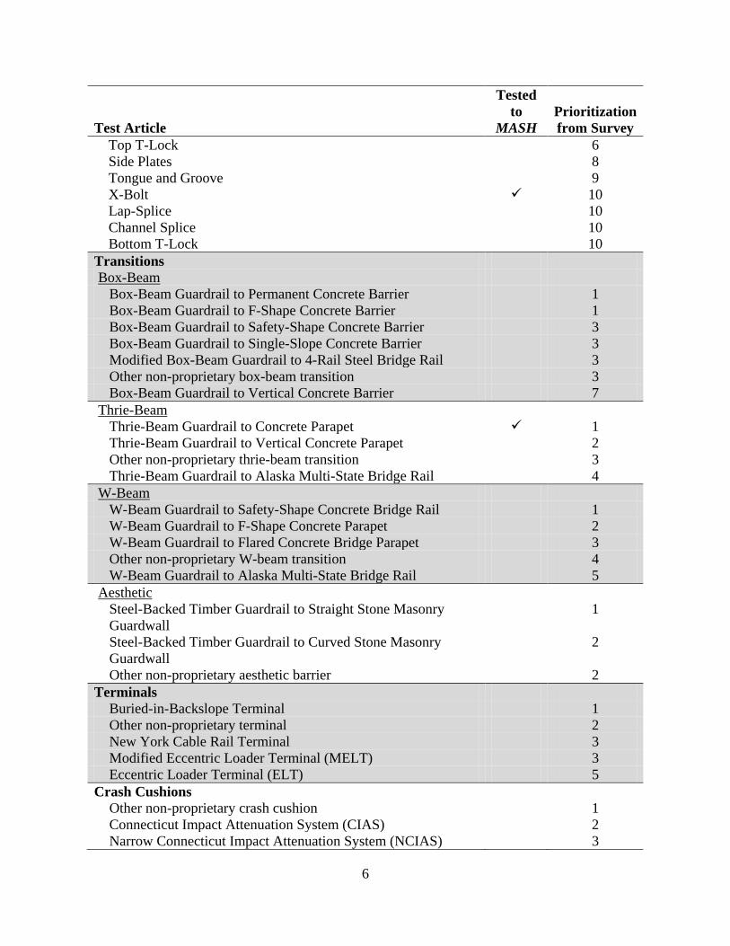
Table 1. Weighted Prioritization by Hardware Category.
Test Article
Tested to
MASH Prioritization from Survey
Guardrails Strong-Post (Steel) W-Beam 1 Strong-Post (Wood) W-Beam 2 Strong-Post (Steel) Thrie-Beam 3 Strong-Post (Wood) Thrie-Beam 4 Low-Tension Cable (3-Strand) 5 Midwest Guardrail System (MGS) 6 Weak-Post Box-Beam 7 Strong-Post Modified Thrie-Beam 7 Weak-Post W-Beam 9 Other non-proprietary guardrail 10
Aesthetic Barriers Type A Steel-Backed Timber Guardrail (with offset block) 1 Smooth Stone Masonry Guardwall 2 Other non-proprietary aesthetic barrier 3 Merritt Parkway Steel-Backed Timber Guiderail 4 Rough Stone Masonry Guardwall 4 Steel-Backed Timber Round Log Rail 6 Type B Steel-Backed Timber Guardrail (without offset block) 7 Deception Pass State Park Log Rail 8
Median Barriers Safety-Shape (New Jersey) 1 Strong-Post (Steel) W-Beam 2 F-Shape 3 Strong-Post (Wood) W-Beam 4 Constant Slope (Single-Slope) Barrier (TX & CA designs) 5 Strong-Post (Steel) Thrie-Beam 6 Strong-Post (Wood) Thrie-Beam 7 Low-Tension Cable (3-Strand) 8 Vertical Concrete Barrier 8 Strong-Post Modified Thrie-Beam 10 Weak-Post W-Beam 11 Weak-Post Box-Beam 11 Other non-proprietary median barrier 13
Median Barrier Connections Pin and Loop 1 Steel Dowel 2 Other non-proprietary connection 3 Grid-Slot 4 Vertical I-Beam 5 Plate Insert 6
6
Test Article
Tested to
MASH Prioritization from Survey
Top T-Lock 6 Side Plates 8 Tongue and Groove 9 X-Bolt 10 Lap-Splice 10 Channel Splice 10 Bottom T-Lock 10
Transitions Box-Beam
Box-Beam Guardrail to Permanent Concrete Barrier 1 Box-Beam Guardrail to F-Shape Concrete Barrier 1 Box-Beam Guardrail to Safety-Shape Concrete Barrier 3 Box-Beam Guardrail to Single-Slope Concrete Barrier 3 Modified Box-Beam Guardrail to 4-Rail Steel Bridge Rail 3 Other non-proprietary box-beam transition 3 Box-Beam Guardrail to Vertical Concrete Barrier 7
Thrie-Beam Thrie-Beam Guardrail to Concrete Parapet 1 Thrie-Beam Guardrail to Vertical Concrete Parapet 2 Other non-proprietary thrie-beam transition 3 Thrie-Beam Guardrail to Alaska Multi-State Bridge Rail 4
W-Beam W-Beam Guardrail to Safety-Shape Concrete Bridge Rail 1 W-Beam Guardrail to F-Shape Concrete Parapet 2 W-Beam Guardrail to Flared Concrete Bridge Parapet 3 Other non-proprietary W-beam transition 4 W-Beam Guardrail to Alaska Multi-State Bridge Rail 5
Aesthetic Steel-Backed Timber Guardrail to Straight Stone Masonry Guardwall
1
Steel-Backed Timber Guardrail to Curved Stone Masonry Guardwall
2
Other non-proprietary aesthetic barrier 2 Terminals
Buried-in-Backslope Terminal 1 Other non-proprietary terminal 2 New York Cable Rail Terminal 3 Modified Eccentric Loader Terminal (MELT) 3 Eccentric Loader Terminal (ELT) 5
Crash Cushions Other non-proprietary crash cushion 1 Connecticut Impact Attenuation System (CIAS) 2 Narrow Connecticut Impact Attenuation System (NCIAS) 3

7
Test Article
Tested to
MASH Prioritization from Survey
Breakaway Hardware Small Sign Supports
Steel U-Channel 1 Perforated Square Steel Tube 2 Wood Post 3 Rectangular, Uni-Directional Slip Base 4 Triangular, Omni-Directional Slip Base 5 Thin-Walled Aluminum Pipe 6 Fiber Reinforced Plastic (FRP) Post (3”) 7 Other non-proprietary sign support 7
Steel U-Channel 3 lb/ft 1 2 ½ lb/ft 2 4 lb/ft 3
Perforated Square Steel Tube 2-inch 1 2 ½-inch 2 2 ¼-inch 3 1 ¾-inch 4
Wood Post 4-inch x 4-inch 1 Modified 6-inch x 6-inch (2, 2-inch diameter holes) 2 Modified 4-inch x 6-inch (2, 1 ½-inch diameter holes) 3 4-inch x 6-inch 4 Modified 6-inch x 8-inch (2, 3-inch diameter holes) 5 5-inch round 6 5-inch x 5-inch 7
Wood Post Species Southern Yellow Pine 1 Douglas Fir 2 Other species of wood post 3
Installation in Weak Soil Yes 1 No 2
Large Sign Supports Other 1 Dual, W6x12 2 Single, W12x45 3
Fuse Plates Yes 1 No 2
Configuration of Slip Base Rectangular, Uni-Directional 1

8
Test Article
Tested to
MASH Prioritization from Survey
Triangular, Omni-Directional Texas 2 Other 3
Orientation of Slip Plates Level 1 Inclined 2 Other 3
Luminaire Supports Transformer Base 1 Slip Base 2 Other non-proprietary luminaire support 3

9
Table 2. Aggregate Ranking of Roadside Safety Hardware by Frequency of Use.
Device Rank Precast CMB with Pin and Loop Connection 1 Strong-Post (Steel) W-Beam Guardrail 2 Strong-Post (Wood) W-Beam Guardrail 3 Transformer Base Luminaire Support 4 Safety-Shape (New Jersey) Median Barrier 5 Steel U-Channel Sign Support 6 Strong-Post (Steel) W-Beam Median Barrier 7 W-Beam Guardrail to Safety-Shape Concrete Bridge Rail Transition 8 F-Shape Median Barrier 9 Perforated Square Steel Tube Sign Support 10 Wood Post Sign Support 11 Slip Base Luminaire Support 12 Thrie-Beam Guardrail to Concrete Parapet Transition 13 Thrie-Beam Guardrail to Vertical Concrete Parapet Transition 14 Rectangular, Uni-Directional Slip Base Sign Support 15 Strong-Post (Wood) W-Beam Median Barrier 16 Strong-Post (Steel) Thrie-Beam Guardrail 17 Buried-in-Backslope Terminal 18 W-Beam Guardrail to F-Shape Concrete Parapet Transition 19 Triangular, Omni-Directional Slip Base Sign Support 20 Strong-Post (Wood) Thrie-Beam Guardrail 21 Constant Slope (Single-Slope) Barrier (TX & CA designs) Median Barrier 22 Low-Tension Cable (3-Strand) Guardrail 23 Strong-Post (Steel) Thrie-Beam Median Barrier 24 Strong-Post (Wood) Thrie-Beam Median Barrier 25 W-Beam Guardrail to Flared Concrete Bridge Parapet Transition 26 Other non-proprietary terminal 27 Low-Tension Cable (3-Strand) Median Barrier 28 Vertical Concrete Barrier Median Barrier 29 Midwest Guardrail System (MGS) Guardrail 30 Precast CMB with Steel Dowel Connection 31 New York Cable Rail Terminal 32 Modified Eccentric Loader Terminal (MELT) 33 Thin-Walled Aluminum Pipe Sign Support 34 Eccentric Loader Terminal (ELT) 35 Other non-proprietary thrie-beam transition 36 Strong-Post Modified Thrie-Beam Guardrail 37 Weak-Post Box-Beam Guardrail 38 Strong-Post Modified Thrie-Beam Median Barrier 39 Weak-Post W-Beam Guardrail 40

10
Device Rank Other non-proprietary guardrail 41 Other non-proprietary luminaire support 42 Type A Steel-Backed Timber Guardrail (with offset block) 43 Smooth Stone Masonry Guardwall 44 Other non-proprietary precast CMB connection 45 Weak-Post W-Beam Median Barrier 46 Weak-Post Box-Beam Median Barrier 46 Other non-proprietary aesthetic barrier 48 Thrie-Beam Guardrail to Alaska Multi-State Bridge Rail Transition 49 Other non-proprietary crash cushion 50 Other non-proprietary median barrier 51 Merritt Parkway Steel-Backed Timber Guiderail 52 Rough Stone Masonry Guardwall 52 Other non-proprietary W-beam transition 54 Precast CMB with Grid-Slot Connection 55 Box-Beam Guardrail to F-Shape Concrete Barrier Transition 56 Box-Beam Guardrail to Permanent Concrete Barrier Transition 57 Steel-Backed Timber Round Log Rail 58 Modified Box-Beam Guardrail to 4-Rail Steel Bridge Rail Transition 59 Precast CMB with Vertical I-Beam Connection 60 Other non-proprietary box-beam transition 61 Box-Beam Guardrail to Single-Slope Concrete Barrier Transition 62 Box-Beam Guardrail to Safety-Shape Concrete Barrier Transition 63 Steel-Backed Timber Guardrail to Straight Stone Masonry Guardwall Transition 64 W-Beam Guardrail to Alaska Multi-State Bridge Rail Transition 65 Precast CMB with Plate Insert Connection 65 Precast CMB with Top T-Lock Connection 65 Type B Steel-Backed Timber Guardrail (without offset block) 68 Other non-proprietary sign support 69 Other non-proprietary aesthetic transition 70 Fiber Reinforced Plastic (FRP) Post (3") Sign Support 70 Steel-Backed Timber Guardrail to Curved Stone Masonry Guardwall Transition 72 Connecticut Impact Attenuation System (CIAS) 73 Precast CMB with Side Plates Connection 74 Box-Beam Guardrail to Vertical Concrete Barrier Transition 75 Precast CMB with Tongue and Groove Connection 75 Precast CMB with X-Bolt Connection 77 Precast CMB with Lap-Splice Connection 77 Precast CMB with Channel Splice Connection 77 Precast CMB with Bottom T-Lock Connection 77 Narrow Connecticut Impact Attenuation System (NCIAS) 81 Deception Pass State Park Log Rail 82
Note: Devices with a tied rank had the exact number of responses for each answer category.

11
Once all of the survey responses were received, TTI researchers analyzed the information and determined those features which are most frequently used and would, therefore, potentially be highest priority for evaluation to the MASH criteria. The results of the survey were weighted by individual hardware item, ranked among the hardware category, and aggregately ranked across all categories. The survey responses were a series of five check boxes for each device to indicate associated percentages of use: [Never; Rarely (1-25 percent); Somewhat Frequently (26-50 percent); Frequently (51-75 percent); and Very Frequently (76-100 percent)]. Each response was weighted based on frequency of use. A response of “Never” was not weighted. The remaining responses of Rarely, Somewhat Frequently, Frequently, and Very Frequently were given weights of 1, 2, 3, and 4, respectively. Table 1 illustrates a weighted prioritization of the hardware by category and shows hardware that has already had one test performed to the MASH test conditions. A weighted prioritization of the aggregate of all hardware is shown in Table 2.
As identified from the survey, the top ten most frequently used safety hardware are:
1. Precast concrete median barrier using a pin and loop connection
2. Strong steel post W-beam guardrail
3. Strong wood post W-beam guardrail
4. Transformer base luminaire support
5. Concrete safety shape median barrier
6. Steel u-channel sign support
7. Strong steel post W-beam median guardrail
8. W-beam guardrail to safety shape concrete barrier transition
9. F-shape concrete median barrier
10. Perforated square steel tube sign support
Of the above-listed safety hardware, the New Jersey Safety Shape concrete barrier,
F-shape concrete barrier, and strong steel post W-beam guardrail have been tested to the most critical MASH condition.

12
III. ASSESSMENT OF ROADSIDE SAFETY HARDWARE
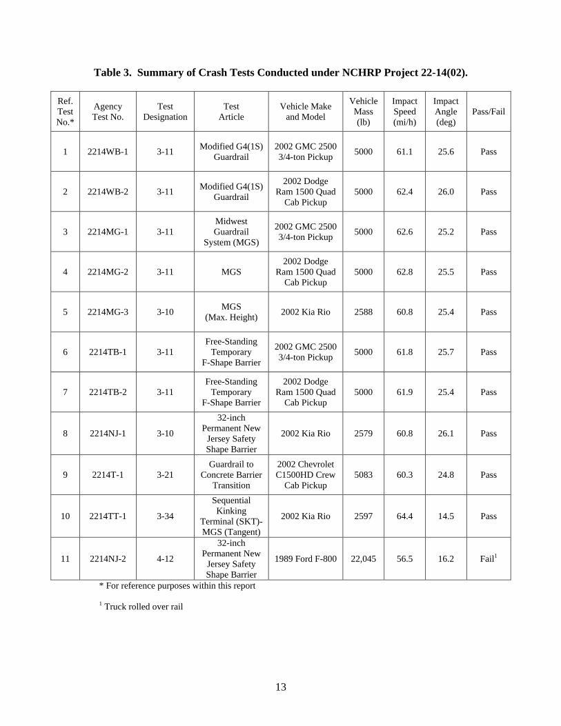
A limited number of full-scale crash tests were performed under NCHRP Project
22-14(02) to help understand and evaluate the consequences of adopting the recommended changes on current hardware. A summary of these tests is presented in Table 3. It should be noted that several of the tests listed in Table 3 involve a 5000-lb, 3/4-ton, standard cab pickup. This vehicle was initially selected as the new design vehicle for MASH. The heavy design test vehicle was later changed to a 5000-lb, 1/2-ton, 4-door pickup to be more representative of large sport-utility vehicles (SUVs) in terms of center-of-gravity (C.G.) height and body torsional stiffness. Several barrier systems that had previously been tested with the 3/4-ton, standard cab pickup were retested with the 1/2-ton, 4-door pickup.
In the subsequent sections of this chapter, the results of these and other tests performed to
date in accordance with MASH are used in combination with engineering analysis and engineering judgment to provide an initial assessment of the ability of other non-proprietary roadside safety hardware to comply with MASH. This initial evaluation is intended to help prioritize future research and testing needs to demonstrate compliance of these devices with MASH and to provide information that would assist understanding of the implications of adopting MASH as it progressed through the AASHTO review and publication process. For ease of reference, the review is divided by category or application of roadside safety hardware (e.g., guardrail, median barrier, transitions, etc.).
GENERAL PERFORMANCE CONSIDERATIONS
The criteria used to assess the impact performance of roadside safety hardware in regard to MASH are those recommended for evaluation of full-scale crash tests under both NCHRP Report 350 and MASH. The assessment of a given device may include various qualitative and quantitative factors depending on the nature of the device and the availability of data. Experience testing under NCHRP Report 350 has identified three primary concerns or modes of failure: structural adequacy, vehicle stability, and occupant risk. The evaluation criteria for occupant impact velocity and occupant ridedown accelerations remain consistent with NCHRP Report 350 and will not be addressed herein. However, occupant risk in the form of occupant compartment deformation has changed and will be addressed. Discussion of these three evaluation criteria will be helpful prior to assessing individual roadside safety devices.
13
Table 3. Summary of Crash Tests Conducted under NCHRP Project 22-14(02).
Ref. TestNo.*
Agency Test No.
Test Designation
Test Article
Vehicle Make and Model
Vehicle Mass (lb)
Impact Speed (mi/h)
Impact Angle (deg)
Pass/Fail
1 2214WB-1 3-11 Modified G4(1S) Guardrail
2002 GMC 2500 3/4-ton Pickup 5000 61.1 25.6 Pass
2 2214WB-2 3-11 Modified G4(1S) Guardrail
2002 Dodge Ram 1500 Quad
Cab Pickup 5000 62.4 26.0 Pass
3 2214MG-1 3-11 Midwest Guardrail
System (MGS)
2002 GMC 2500 3/4-ton Pickup 5000 62.6 25.2 Pass
4 2214MG-2 3-11 MGS 2002 Dodge
Ram 1500 Quad Cab Pickup
5000 62.8 25.5 Pass
5 2214MG-3 3-10 MGS (Max. Height) 2002 Kia Rio 2588 60.8 25.4 Pass
6 2214TB-1 3-11 Free-Standing
Temporary F-Shape Barrier
2002 GMC 2500 3/4-ton Pickup 5000 61.8 25.7 Pass
7 2214TB-2 3-11 Free-Standing
Temporary F-Shape Barrier
2002 Dodge Ram 1500 Quad
Cab Pickup 5000 61.9 25.4 Pass
8 2214NJ-1 3-10
32-inch Permanent New
Jersey Safety Shape Barrier
2002 Kia Rio 2579 60.8 26.1 Pass
9 2214T-1 3-21 Guardrail to
Concrete Barrier Transition
2002 Chevrolet C1500HD Crew
Cab Pickup 5083 60.3 24.8 Pass
10 2214TT-1 3-34
Sequential Kinking
Terminal (SKT)-MGS (Tangent)
2002 Kia Rio 2597 64.4 14.5 Pass
11 2214NJ-2 4-12
32-inch Permanent New
Jersey Safety Shape Barrier
1989 Ford F-800 22,045 56.5 16.2 Fail1
* For reference purposes within this report
1 Truck rolled over rail
14
Structural Adequacy
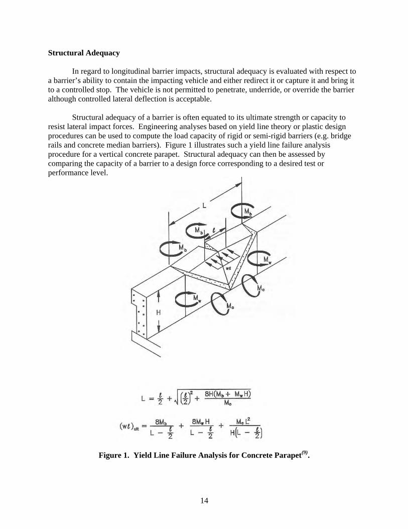
In regard to longitudinal barrier impacts, structural adequacy is evaluated with respect to a barrier’s ability to contain the impacting vehicle and either redirect it or capture it and bring it to a controlled stop. The vehicle is not permitted to penetrate, underride, or override the barrier although controlled lateral deflection is acceptable. Structural adequacy of a barrier is often equated to its ultimate strength or capacity to resist lateral impact forces. Engineering analyses based on yield line theory or plastic design procedures can be used to compute the load capacity of rigid or semi-rigid barriers (e.g. bridge rails and concrete median barriers). Figure 1 illustrates such a yield line failure analysis procedure for a vertical concrete parapet. Structural adequacy can then be assessed by comparing the capacity of a barrier to a design force corresponding to a desired test or performance level.
Figure 1. Yield Line Failure Analysis for Concrete Parapet(9).

15
Data from two instrumented wall studies(32, 33) were used to derive barrier design loads for various test or performance levels included in the AASHTO LRFD Bridge Design Specifications: Section 13 – Railings. The test levels correspond to those contained in NCHRP Report 350. In these research studies, instrumented concrete walls were designed to measure the magnitude and location of vehicle impact forces. In this first study(32), eight full-scale crash tests were conducted using various sizes of passenger cars and buses. The wall consisted of four 10-ft long panels laterally supported by four load cells. Each of the 42-inch tall x 24-inch thick panels was also instrumented with an accelerometer to account for inertia effects. Surfaces in contact with the supporting foundation and adjacent panels were Teflon coated to minimize friction. In the second such study(33), a new wall with a height of 90 inches was constructed using similar design details; crash tests with a variety of trucks (up to and including an 80,000-lb tractor with tank-type trailer) were conducted. Speeds in these tests ranged from 50 mi/h to 60 mi/h, and the impact angles ranged from 15 degrees to 25 degrees.
The design load calculated for both TL-3 and TL-4 is 54 kips. Note that this design force
is derived from an impact with a nearly rigid instrumented wall barrier and, therefore, is considered to represent the upper bound of forces that would be expected on actual barriers. The design loads established for TL-5 and TL-6, which include consideration of 80,000-lb tractor trailers, are 124 kips and 175 kips, respectively.
During the course of the instrumented wall work, the researchers derived relationships
that use a measured lateral impact force resulting from a vehicle-barrier collision to estimate the impact force associated with a collision involving a different vehicle and/or impact conditions. The relationship is given as:
=
1
2
1
2
2
1
1
2
2
1
212 sin
sinWW
KK
LL
VVFF
θθ
Where:
F = impact force,
V = impact velocity,
θ = impact angle
L = longitudinal distance from front of vehicle to C.G.
K = barrier contact area or stiffness
W = vehicle weight
Using 54 kips as the design impact force for NCHRP Report 350 test 3-11, the impact
force corresponding to MASH test 3-11 with the 1/2-ton, 4-door pickup truck can be estimated. The impact speed and angle used in MASH test 3-11 are the same as those prescribed under NCHRP Report 350 and, therefore, will not influence the impact force. Assuming the contact area associated with impacts by both pickup trucks is essentially the same for a given longitudinal barrier system, the change in impact force becomes a function of vehicle weight and
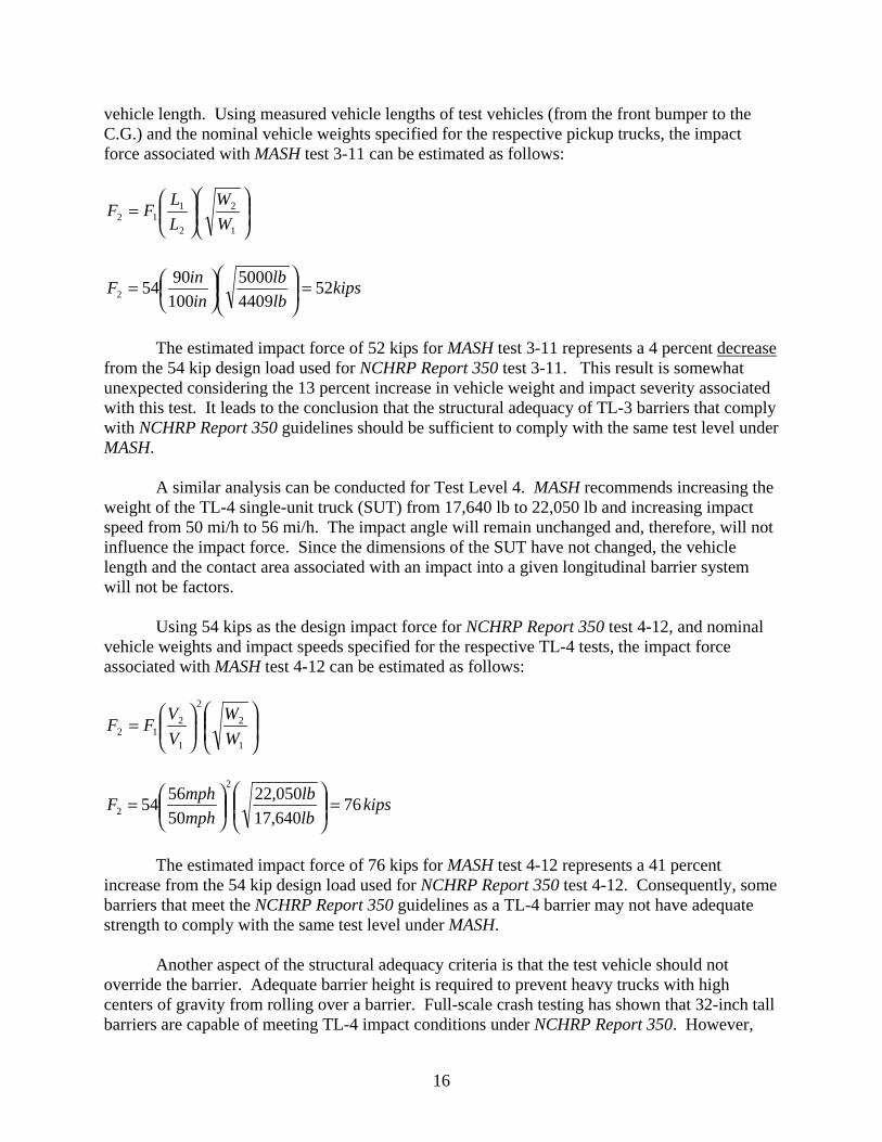
16
vehicle length. Using measured vehicle lengths of test vehicles (from the front bumper to the C.G.) and the nominal vehicle weights specified for the respective pickup trucks, the impact force associated with MASH test 3-11 can be estimated as follows:
=
1
2
2
112 W
WLLFF
kipslblb
ininF 52
44095000
10090542 =
=
The estimated impact force of 52 kips for MASH test 3-11 represents a 4 percent decrease from the 54 kip design load used for NCHRP Report 350 test 3-11. This result is somewhat unexpected considering the 13 percent increase in vehicle weight and impact severity associated with this test. It leads to the conclusion that the structural adequacy of TL-3 barriers that comply with NCHRP Report 350 guidelines should be sufficient to comply with the same test level under MASH.
A similar analysis can be conducted for Test Level 4. MASH recommends increasing the
weight of the TL-4 single-unit truck (SUT) from 17,640 lb to 22,050 lb and increasing impact speed from 50 mi/h to 56 mi/h. The impact angle will remain unchanged and, therefore, will not influence the impact force. Since the dimensions of the SUT have not changed, the vehicle length and the contact area associated with an impact into a given longitudinal barrier system will not be factors.
Using 54 kips as the design impact force for NCHRP Report 350 test 4-12, and nominal
vehicle weights and impact speeds specified for the respective TL-4 tests, the impact force associated with MASH test 4-12 can be estimated as follows:
=
1
2
2
1
212 W
WVVFF
kipslblb
mphmphF 76
640,17050,22
505654
2
2 =
=
The estimated impact force of 76 kips for MASH test 4-12 represents a 41 percent increase from the 54 kip design load used for NCHRP Report 350 test 4-12. Consequently, some barriers that meet the NCHRP Report 350 guidelines as a TL-4 barrier may not have adequate strength to comply with the same test level under MASH.
Another aspect of the structural adequacy criteria is that the test vehicle should not
override the barrier. Adequate barrier height is required to prevent heavy trucks with high centers of gravity from rolling over a barrier. Full-scale crash testing has shown that 32-inch tall barriers are capable of meeting TL-4 impact conditions under NCHRP Report 350. However,

17
when MASH Test 4-12 was conducted on a 32-inch tall New Jersey safety-shape concrete barrier (see Test 11 in Table 3), the SUT rolled over the top of the barrier.
After the unsatisfactory outcome of this test, it was proposed to reduce the C.G. height of
the ballast of the SUT from 67 inches to 63 inches. This effectively decreases the overturning moment by decreasing the moment arm between the C.G. of the truck and the reactive force applied by the barrier. A test conducted under this project with the reduced ballast height failed due to roll of the truck over the barrier. Additional testing is required to determine what barrier height is required to contain the SUT under MASH test conditions.
Vehicle Stability
For all tests involving passenger vehicles, a key requirement for the safety of vehicle occupants is for the impacting vehicle to remain upright during and after the collision. Criterion F of NCHRP Report 350 states that moderate roll, pitching, and yawing are acceptable. The commentary in Section A5.2 further explains that “Violent roll or rollover, pitching, or spinout of the vehicle reveal unstable and unpredictable dynamic interaction, behavior that is unacceptable.” However, the term “moderate” used in Criterion F is not defined, thereby leaving evaluation of this criterion somewhat subjective.
MASH retains language that the impacting vehicle should remain upright during and after an impact. However, to provide a further indication of vehicle stability, and to make evaluation of Criterion F more quantitative, the maximum roll and pitch angles are not to exceed a threshold of 75 degrees.
Since the adoption of a 3/4-ton pickup truck as the design test vehicle for structural
adequacy tests, vehicle instability and rollover has been a common failure mode associated with longitudinal barrier impacts including guardrails, bridge rails, and transitions. Compared to passenger cars, pickup trucks have a higher C.G., a shorter front overhang, and greater bumper height (see Table 4). All of these factors combine to make the pickup truck a more critical vehicle than a passenger car in regard to impact performance with roadside safety features. The propensity for wheel snagging, occupant compartment deformation, and vehicle instability (i.e., rollover) are greater for the pickup truck than most passenger cars.
National Highway Traffic Safety Administration (NHTSA) officials believe that the static
stability factor (SSF) is one of the most reliable indicators of rollover risk in single-vehicle crashes. The formula for calculating SSF is:
SSF = T/2h, where T = track width and h = C.G. height
A statistical study using data from six states showed that there is a strong correlation between a vehicle’s SSF and its likelihood of being involved in a rollover. A higher SSF indicates a more stable vehicle with less propensity for rollover. As expected, the pickup truck design vehicles have a lower SSF than the passenger sedan previously used under NCHRP Report 230 (see Table 4). More interesting is that although the new 2270P has a slightly greater
18
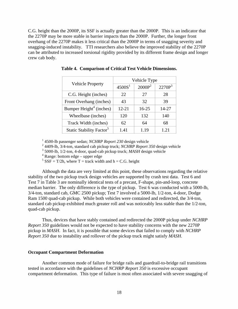
C.G. height than the 2000P, its SSF is actually greater than the 2000P. This is an indicator that the 2270P may be more stable in barrier impacts than the 2000P. Further, the longer front overhang of the 2270P makes it less critical than the 2000P in terms of snagging severity and snagging-induced instability. TTI researchers also believe the improved stability of the 2270P can be attributed to increased torsional rigidity provided by its different frame design and longer crew cab body.
Table 4. Comparison of Critical Test Vehicle Dimensions.
Vehicle Property Vehicle Type
4500S1 2000P2 2270P3
C.G. Height (inches) 22 27 28 Front Overhang (inches) 43 32 39 Bumper Height4 (inches) 12-21 16-25 14-27
Wheelbase (inches) 120 132 140 Track Width (inches) 62 64 68
Static Stability Factor5 1.41 1.19 1.21
1 4500-lb passenger sedan; NCHRP Report 230 design vehicle 2 4409-lb, 3/4-ton, standard cab pickup truck; NCHRP Report 350 design vehicle 3 5000-lb, 1/2-ton, 4-door, quad-cab pickup truck; MASH design vehicle 4 Range: bottom edge – upper edge 5 SSF = T/2h, where T = track width and h = C.G. height Although the data are very limited at this point, these observations regarding the relative
stability of the two pickup truck design vehicles are supported by crash test data. Test 6 and Test 7 in Table 3 are nominally identical tests of a precast, F-shape, pin-and-loop, concrete median barrier. The only difference is the type of pickup. Test 6 was conducted with a 5000-lb, 3/4-ton, standard cab, GMC 2500 pickup; Test 7 involved a 5000-lb, 1/2-ton, 4-door, Dodge Ram 1500 quad-cab pickup. While both vehicles were contained and redirected, the 3/4-ton, standard cab pickup exhibited much greater roll and was noticeably less stable than the 1/2-ton, quad-cab pickup.
Thus, devices that have stably contained and redirected the 2000P pickup under NCHRP
Report 350 guidelines would not be expected to have stability concerns with the new 2270P pickup in MASH. In fact, it is possible that some devices that failed to comply with NCHRP Report 350 due to instability and rollover of the pickup truck might satisfy MASH.
Occupant Compartment Deformation
Another common mode of failure for bridge rails and guardrail-to-bridge rail transitions tested in accordance with the guidelines of NCHRP Report 350 is excessive occupant compartment deformation. This type of failure is most often associated with severe snagging of

19
the front, impact-side wheel at a joint, splice, or transition that results in the wheel being pushed into the fire wall and toe pan area of the occupant compartment. While such behavior was rarely observed when testing with large passenger sedans under NCHRP Report 230, the short front overhang of the pickup truck exposed the wheel and made snagging contact between the wheel and structural components of barriers a common occurrence.
Evaluation Criterion D of NCHRP Report 350 states that “Deformations of, or intrusions
into, the occupant compartment that could cause serious injuries should not be permitted.” Because the extent of deformation that can cause serious injury was not defined, this criterion was subjective in nature. Testing houses routinely had internal and external discussions regarding the magnitude and location of deformation that should constitute a pass or fail. To reduce the level of subjectivity associated with evaluating this criterion, the FHWA established a 6-inch threshold for occupant compartment deformation or intrusion. This threshold subsequently became the standard by which testing houses evaluated occupant compartment deformation.
While MASH adopts a similar quantitative approach, it significantly relaxes the failure
threshold established by FHWA. The revised criteria are founded largely on work performed by the Insurance Institute for Highway Safety and the National Highway Traffic Safety Administration (NHTSA). NCHRP study 22-14(02) documents the establishment of these criteria. The limiting extent of deformation varies by area of the vehicle damaged as follows:
• roof < 3.9 inches,
• windshield < 3.0 inches,
• side windows – no shattering resulting from direct contact with structural member of test article,
• wheel/foot well/toe pan < 8.9 inches,
• side front panel (forward of A-pillar) < 11.8 inches,
• front side door area (above seat) < 8.9 inches,
• front side door (below seat) < 11.8 inches,
• floor pan and transmission tunnel area < 11.8 inches.
In addition to establishing maximum acceptable deformation thresholds to establish pass/fail criteria, a damage rating scale was introduced for further indication of vehicle damage and barrier performance. The damage scale has the following ratings and associated ranges of intrusion/deformation:
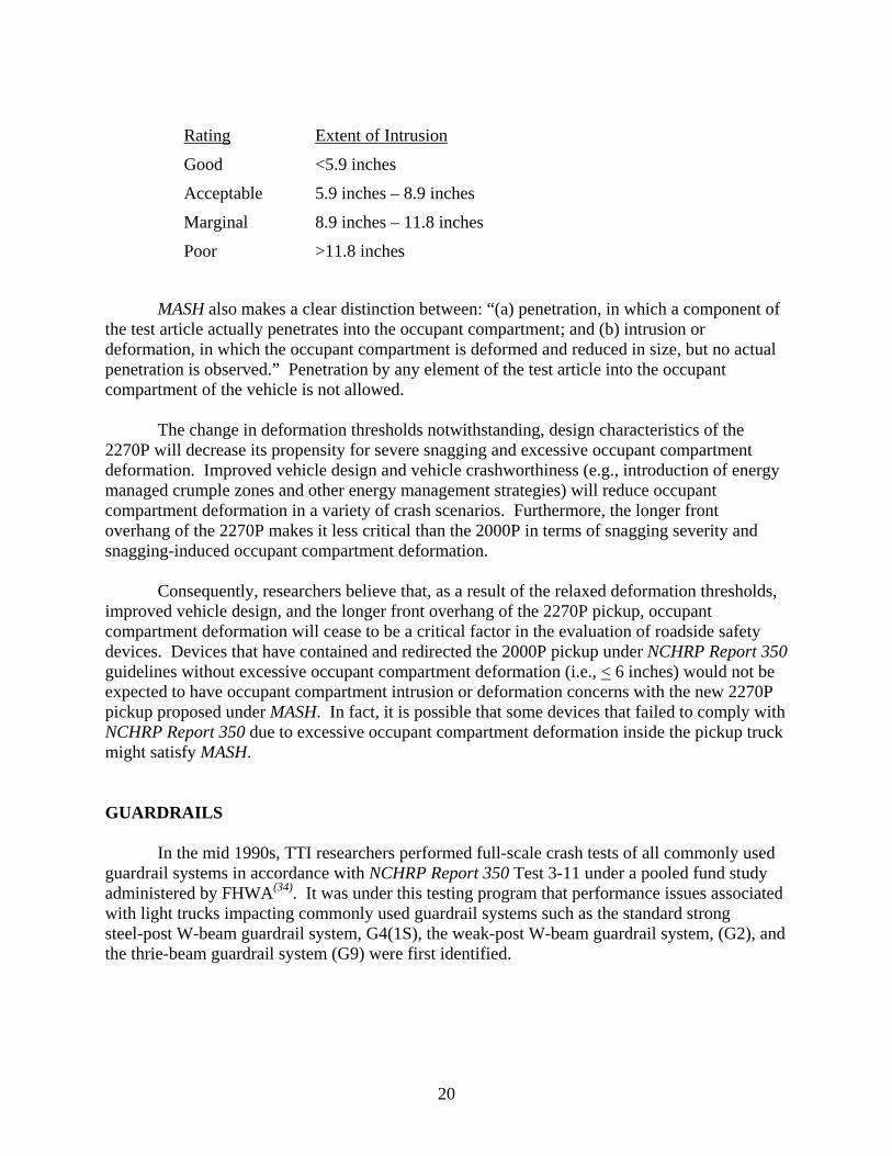
20
Rating Extent of Intrusion
Good <5.9 inches
Acceptable 5.9 inches – 8.9 inches
Marginal 8.9 inches – 11.8 inches
Poor >11.8 inches
MASH also makes a clear distinction between: “(a) penetration, in which a component of
the test article actually penetrates into the occupant compartment; and (b) intrusion or deformation, in which the occupant compartment is deformed and reduced in size, but no actual penetration is observed.” Penetration by any element of the test article into the occupant compartment of the vehicle is not allowed.
The change in deformation thresholds notwithstanding, design characteristics of the
2270P will decrease its propensity for severe snagging and excessive occupant compartment deformation. Improved vehicle design and vehicle crashworthiness (e.g., introduction of energy managed crumple zones and other energy management strategies) will reduce occupant compartment deformation in a variety of crash scenarios. Furthermore, the longer front overhang of the 2270P makes it less critical than the 2000P in terms of snagging severity and snagging-induced occupant compartment deformation.
Consequently, researchers believe that, as a result of the relaxed deformation thresholds,
improved vehicle design, and the longer front overhang of the 2270P pickup, occupant compartment deformation will cease to be a critical factor in the evaluation of roadside safety devices. Devices that have contained and redirected the 2000P pickup under NCHRP Report 350 guidelines without excessive occupant compartment deformation (i.e., < 6 inches) would not be expected to have occupant compartment intrusion or deformation concerns with the new 2270P pickup proposed under MASH. In fact, it is possible that some devices that failed to comply with NCHRP Report 350 due to excessive occupant compartment deformation inside the pickup truck might satisfy MASH.
GUARDRAILS
In the mid 1990s, TTI researchers performed full-scale crash tests of all commonly used guardrail systems in accordance with NCHRP Report 350 Test 3-11 under a pooled fund study administered by FHWA(34). It was under this testing program that performance issues associated with light trucks impacting commonly used guardrail systems such as the standard strong steel-post W-beam guardrail system, G4(1S), the weak-post W-beam guardrail system, (G2), and the thrie-beam guardrail system (G9) were first identified.
21
Strong-Post W-Beam Guardrail [modified G4(1S) and G4(2W)]
The strong steel post W-beam guardrail system, G4(1S), failed due to snagging of the pickup truck’s wheel on the steel support posts. The snagging was aggravated by the collapse of the W6x9 steel offset blocks, which precipitated rollover of the truck as it exited the barrier. Subsequent testing demonstrated that a modified G4(1S) system with 8-inch deep wood or structural plastic offset blocks between the W-beam rail element and W6x9 steel posts in lieu of the original W6x9 steel offset block was able to accommodate the 3/4-ton, 2-door, pickup truck design vehicle (denoted 2000P) and comply with NCHRP Report 350 guidelines(34-36).
The strong wood post W-beam guardrail system, G4(2W), which utilizes 6 inch x 8 inch
wood posts and offset blocks, contained and redirected the 2000P pickup(34). However, instability of the pickup truck resulted in the test being classified as marginally acceptable.
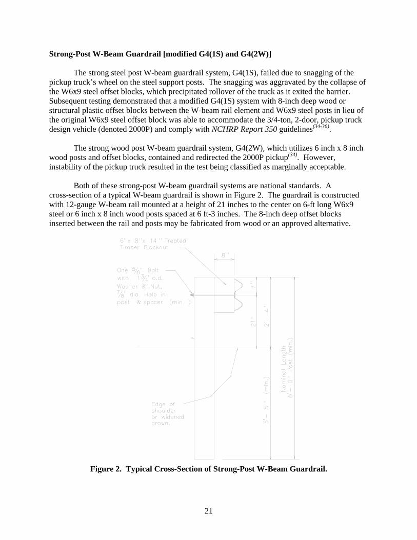
Both of these strong-post W-beam guardrail systems are national standards. A
cross-section of a typical W-beam guardrail is shown in Figure 2. The guardrail is constructed with 12-gauge W-beam rail mounted at a height of 21 inches to the center on 6-ft long W6x9 steel or 6 inch x 8 inch wood posts spaced at 6 ft-3 inches. The 8-inch deep offset blocks inserted between the rail and posts may be fabricated from wood or an approved alternative.
Figure 2. Typical Cross-Section of Strong-Post W-Beam Guardrail.
22
These strong-post W-beam guardrail systems are at or near their performance limits
under NCHRP Report 350 impact conditions. The increase in the weight of the proposed ½-ton, 4-door, pickup truck (designated 2270P) increases the impact severity of the structural adequacy test (Test 3-11) for longitudinal barriers by 13 percent. Under NCHRP Project 22-14(02), a series of crash tests were performed to assess the impact performance of strong-post W-beam guardrail when subjected to the revised impact conditions.
As indicated in Test 1 of Table 3, a standard 27-inch tall, modified G4(1S) steel post
W-beam guardrail failed due to rail rupture when impacted by a 5000-lb, 3/4-ton pickup truck(37). In a subsequent test of the same system with the 5000-lb, 1/2-ton, four door pickup truck that is currently proposed as the design test vehicle for MASH, the guardrail successfully contained and redirected the vehicle(38). However, the rail was torn through approximately half of its cross-section, indicating that the modified G4(1S) guardrail is at its performance limits with no factor of safety.
The same sequence of tests with the two different pickup trucks was performed on a
modified guardrail design known as the Midwest Guardrail System (MGS)(39,40). This modified guardrail increases the W-beam rail height from 27 inches to 31 inches, increases the depth of the offset blocks between the rail and posts from 8 inches to 12 inches, and moves the rail splice locations from the posts to mid-span between posts. In both tests, the pickup truck was successfully contained and redirected. The MGS guardrail was also successfully tested under modified Test 3-10 impact conditions with the proposed 2425-lb small car (designated 1100C) at a speed of 62 mi/h and a modified angle of 25 degrees (41).
Thrie-Beam Guardrail (G9)
The thrie-beam (G9) guardrail system is constructed of 6 ft-6-inch long W6x9 steel posts spaced 6 ft-3 inches on center and W6x9 offset blocks. The blockouts are 6 inches long x 18 inches deep and 4 inches wide at the flanges. A cross-section of a typical thrie-beam guardrail system (G9) is shown in Figure 3.
The thrie-beam guardrail (G9) system contained and redirected the 2000P vehicle when
tested in accordance with NCHRP Report 350(34). However, upon exiting the test installation at a high roll angle, the pickup truck subsequently rolled two and a quarter revolutions. During the impact event, the left front wheel severely caught the flanges of two posts and had direct contact with as many as five posts total. The post-to-wheel interaction severely twisted five posts and caused severe damage to the left front of the pickup truck. These events caused the pickup truck to subsequently rollover. This system does not meet NCHRP Report 350 and no additional work is warranted on this version of the thrie-beam guardrail system.

23
Figure 3. Typical Cross-Section of Thrie-Beam Guardrail.
Thrie-Beam Guardrail (steel posts and routed wood blockouts)
Following the failure of the standard G9 thrie-beam guardrail system described above, a steel post thrie-beam guardrail system with routed wood blocks was tested and evaluated. The 6 inch x 8 inch x 22 inch wood offset blocks were routed 4 inches wide x 3/8 inches deep to fit over the flange of the W6x9 steel posts. The steel post thrie-beam guardrail system with routed wood blocks successfully contained and redirected the 2000P vehicle in accordance with NCHRP Report 350 Test 3-11(42).
Thrie-Beam Guardrail on Strong Wood Posts
The strong wood post thrie-beam guardrail system with wood blocks is constructed of 6 ft-9-1/4-inch long x 6 inch x 8 inch wood posts spaced 6 ft-3 inches on center and using 6 inch x 8 inch x 22 inch wood offset blocks. The strong wood post thrie-beam guardrail system with wood blocks successfully contained and redirected the 2000P vehicle in accordance with NCHRP Report 350 Test 3-11(42).
24
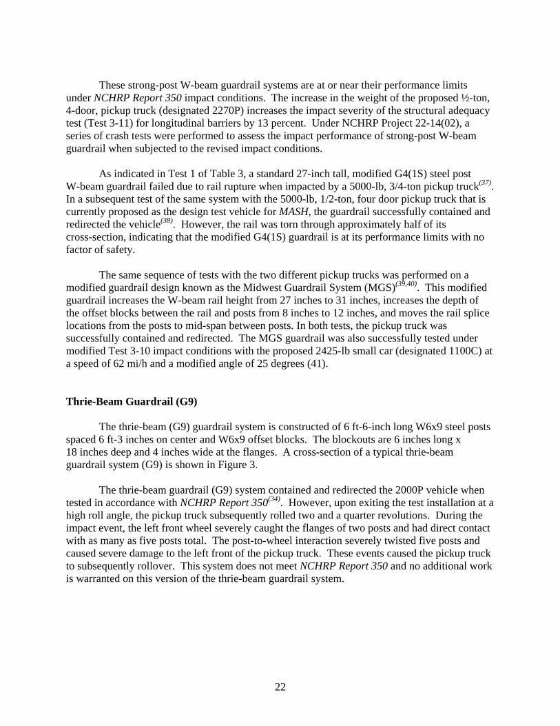
Modified Thrie-Beam Guardrail
The modified thrie-beam guardrail system was originally developed by TTI researchers in the mid-1980s to contain buses(43). Changes that increase the capacity of the modified thrie-beam include raising the rail height to 34 inches and incorporating different blockouts. The M14x18 offset blocks are 17 inches long x 14 inches deep and 6 inches wide at the flanges. The blockouts are modified by cutting a section out of the blockout web measuring 6 inches at the bottom and angling up at 40 degrees to the flange upon which the thrie-beam is attached. A cross-section of a typical modified thrie-beam guardrail system is shown in Figure 4.
Figure 4. Typical Cross-Section of Modified Thrie-Beam Guardrail System.
This system successfully contained and redirected a 20,000-lb bus impacting at a speed of
60 mi/h and an angle of 15 degrees(43). The modified thrie-beam guardrail was subsequently successfully crash tested in accordance with NCHRP Report 350 Test Level 4 (TL-4) impact conditions with both the 2000P pickup(34) and the 8000S single-unit truck(42).
As described above, an NCHRP Report 350 Test 3-11 thrie-beam guardrail system is
available using either strong wood or steel posts. The modified thrie-beam guardrail system has been successfully tested to NCHRP Report 350 Test 4-12. All tests involving the final design versions of these systems performed successfully and the test vehicles were contained and redirected in a stable manner. No further testing for Test Level 3 performance is anticipated for compliance with MASH. However, MASH requirements for Test Level 4 are much more severe than those in NCHRP Report 350. The increase in the weight of the proposed SUT (designated 10000S) and increase in impact speed from 50 mi/h to 56 mi/h increases the impact severity of the TL-4 structural adequacy test (Test 4-12) for longitudinal barriers by 58 percent. Therefore,

25
the researchers recommend performing MASH test 4-12 on the modified thrie-beam guardrail system if a TL-4 guardrail system is desired.
Weak-Post W-Beam Guardrail (G2)
The weak-post W-beam guardrail system (G2) failed to contain and redirect the 2000P vehicle at Test Level 3 due to the guardrail dropping ahead of the test vehicle and allowing the vehicle to override the guardrail. Subsequent testing demonstrated the same weak-post W-beam guardrail system (G2) could successfully contain and redirect the 2000P vehicle at Test Level 2 conditions(34).
A cross-section of a typical weak-post W-beam guardrail system (G2) is shown in Figure 5. The guardrail is constructed with 12-gauge, W-beam rail mounted at a height of 30 inches to the top and supported on 5 ft-3 inch long S3x5.7 steel posts spaced at 12 ft-6 inches. The rail is attached to the posts with 5/16-inch diameter bolts. Additionally, a 1/2-inch diameter shelf bolt is used as a rail rest during construction and to provide some vertical support to the rail.
Figure 5. Typical Cross-Section of Weak Post W-Beam Guardrail System.
Pennsylvania Department of Transportation (PDOT) developed a variation of the weak
post guardrail system (G2) that they refer to as their Type 2 system. This modified G2 guardrail successfully met NCHRP Report 350 test conditions 3-10 and 3-11(44, 45), thus fully qualifying it as a TL-3 rail system.
The primary differences between the PDOT Type 2 guardrail system and the G2 include
an increase in the W-beam rail mounting height to 32.3 inches, the use of W-beam backup plates at the posts, and the relocation of the rail splices from the posts to mid-span between posts. Additionally, the rail mounting bolts and washers and the post shelf bolt details differ from the G2 system.

26
The MASH 2270P test vehicle has demonstrated sensitivity to rail height. In addition, previous testing has shown that the impact performance of this system and other weak-post guardrail systems is sensitive to the post-to-rail attachment detail. TTI researchers believe the weak-post W-beam guardrail system (G2) may warrant consideration for re-evaluation with the MASH 2270P vehicle due to the height of the system and the opportunity for the weak-post systems to drop the rail off the posts in advance of the impacting vehicle, thus allowing the vehicle to travel over the rail element and behind the installation. MASH test 3-11 is recommended for the weak-post W-beam guardrail system (G2).
Low-Tension Cable Guardrail (G1)
High-tension cable roadside and median barrier systems have rapidly gained in popularity. The median application of cable barrier has gained exceptional attention as a cost-effective alternative for shielding motorists from crossover crashes. The relatively low cost makes cable barrier appealing for treating long expanses of highway. Additionally, the flexibility of these systems results in lower decelerations to an impacting vehicle, which lowers the probability of injury to occupants. However, sufficient space must be available to accommodate the greater design deflections associated with these systems and more maintenance may be required initially to keep the cables appropriately tensioned.
The low-tension cable guardrail system (G1) successfully contained and smoothly
redirected the 2000P vehicle at Test Level 3(34). The maximum dynamic deflection was 7.8 ft. A cross-section of the low-tension cable guardrail system (G1) is shown in Figure 6. The cable guardrail is constructed with three 3/4-inch diameter 3x7 wire ropes mounted on S3x5.7 steel posts. The mounting heights of the three cables were 23-1/2 inches, 26-1/2 inches, and 29-1/2 inches. The cables were attached to the posts with 5/16-inch diameter hook bolts. A New York cable anchor was used to terminate the system on each end.
Figure 6. Typical Cross-Section of Low-Tension Cable Guardrail System.
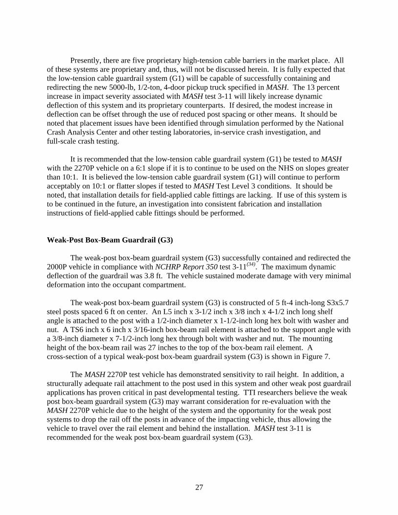
27
Presently, there are five proprietary high-tension cable barriers in the market place. All
of these systems are proprietary and, thus, will not be discussed herein. It is fully expected that the low-tension cable guardrail system (G1) will be capable of successfully containing and redirecting the new 5000-lb, 1/2-ton, 4-door pickup truck specified in MASH. The 13 percent increase in impact severity associated with MASH test 3-11 will likely increase dynamic deflection of this system and its proprietary counterparts. If desired, the modest increase in deflection can be offset through the use of reduced post spacing or other means. It should be noted that placement issues have been identified through simulation performed by the National Crash Analysis Center and other testing laboratories, in-service crash investigation, and full-scale crash testing.
It is recommended that the low-tension cable guardrail system (G1) be tested to MASH
with the 2270P vehicle on a 6:1 slope if it is to continue to be used on the NHS on slopes greater than 10:1. It is believed the low-tension cable guardrail system (G1) will continue to perform acceptably on 10:1 or flatter slopes if tested to MASH Test Level 3 conditions. It should be noted, that installation details for field-applied cable fittings are lacking. If use of this system is to be continued in the future, an investigation into consistent fabrication and installation instructions of field-applied cable fittings should be performed.
Weak-Post Box-Beam Guardrail (G3)
The weak-post box-beam guardrail system (G3) successfully contained and redirected the 2000P vehicle in compliance with NCHRP Report 350 test 3-11(34). The maximum dynamic deflection of the guardrail was 3.8 ft. The vehicle sustained moderate damage with very minimal deformation into the occupant compartment.
The weak-post box-beam guardrail system (G3) is constructed of 5 ft-4 inch-long S3x5.7
steel posts spaced 6 ft on center. An L5 inch x 3-1/2 inch x 3/8 inch x 4-1/2 inch long shelf angle is attached to the post with a 1/2-inch diameter x 1-1/2-inch long hex bolt with washer and nut. A TS6 inch x 6 inch x 3/16-inch box-beam rail element is attached to the support angle with a 3/8-inch diameter x 7-1/2-inch long hex through bolt with washer and nut. The mounting height of the box-beam rail was 27 inches to the top of the box-beam rail element. A cross-section of a typical weak-post box-beam guardrail system (G3) is shown in Figure 7.
The MASH 2270P test vehicle has demonstrated sensitivity to rail height. In addition, a
structurally adequate rail attachment to the post used in this system and other weak post guardrail applications has proven critical in past developmental testing. TTI researchers believe the weak post box-beam guardrail system (G3) may warrant consideration for re-evaluation with the MASH 2270P vehicle due to the height of the system and the opportunity for the weak post systems to drop the rail off the posts in advance of the impacting vehicle, thus allowing the vehicle to travel over the rail element and behind the installation. MASH test 3-11 is recommended for the weak post box-beam guardrail system (G3).
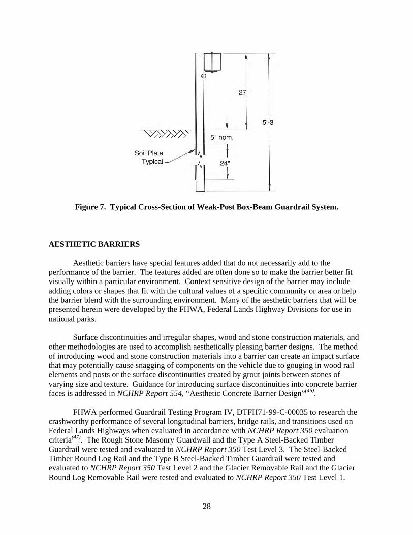
28
Figure 7. Typical Cross-Section of Weak-Post Box-Beam Guardrail System.
AESTHETIC BARRIERS
Aesthetic barriers have special features added that do not necessarily add to the performance of the barrier. The features added are often done so to make the barrier better fit visually within a particular environment. Context sensitive design of the barrier may include adding colors or shapes that fit with the cultural values of a specific community or area or help the barrier blend with the surrounding environment. Many of the aesthetic barriers that will be presented herein were developed by the FHWA, Federal Lands Highway Divisions for use in national parks.
Surface discontinuities and irregular shapes, wood and stone construction materials, and
other methodologies are used to accomplish aesthetically pleasing barrier designs. The method of introducing wood and stone construction materials into a barrier can create an impact surface that may potentially cause snagging of components on the vehicle due to gouging in wood rail elements and posts or the surface discontinuities created by grout joints between stones of varying size and texture. Guidance for introducing surface discontinuities into concrete barrier faces is addressed in NCHRP Report 554, “Aesthetic Concrete Barrier Design”(46).
FHWA performed Guardrail Testing Program IV, DTFH71-99-C-00035 to research the
crashworthy performance of several longitudinal barriers, bridge rails, and transitions used on Federal Lands Highways when evaluated in accordance with NCHRP Report 350 evaluation criteria(47). The Rough Stone Masonry Guardwall and the Type A Steel-Backed Timber Guardrail were tested and evaluated to NCHRP Report 350 Test Level 3. The Steel-Backed Timber Round Log Rail and the Type B Steel-Backed Timber Guardrail were tested and evaluated to NCHRP Report 350 Test Level 2 and the Glacier Removable Rail and the Glacier Round Log Removable Rail were tested and evaluated to NCHRP Report 350 Test Level 1.
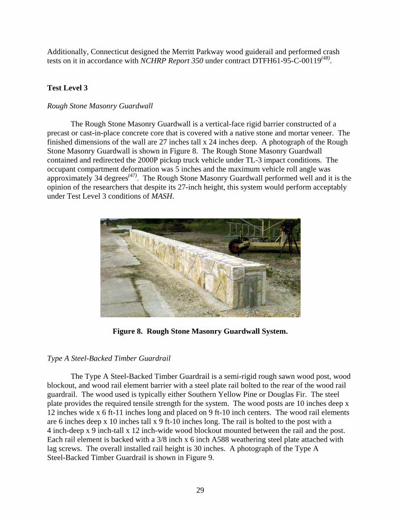
29
Additionally, Connecticut designed the Merritt Parkway wood guiderail and performed crash tests on it in accordance with NCHRP Report 350 under contract DTFH61-95-C-00119(48).
Test Level 3
Rough Stone Masonry Guardwall
The Rough Stone Masonry Guardwall is a vertical-face rigid barrier constructed of a precast or cast-in-place concrete core that is covered with a native stone and mortar veneer. The finished dimensions of the wall are 27 inches tall x 24 inches deep. A photograph of the Rough Stone Masonry Guardwall is shown in Figure 8. The Rough Stone Masonry Guardwall contained and redirected the 2000P pickup truck vehicle under TL-3 impact conditions. The occupant compartment deformation was 5 inches and the maximum vehicle roll angle was approximately 34 degrees(47). The Rough Stone Masonry Guardwall performed well and it is the opinion of the researchers that despite its 27-inch height, this system would perform acceptably under Test Level 3 conditions of MASH.
Figure 8. Rough Stone Masonry Guardwall System.
Type A Steel-Backed Timber Guardrail
The Type A Steel-Backed Timber Guardrail is a semi-rigid rough sawn wood post, wood blockout, and wood rail element barrier with a steel plate rail bolted to the rear of the wood rail guardrail. The wood used is typically either Southern Yellow Pine or Douglas Fir. The steel plate provides the required tensile strength for the system. The wood posts are 10 inches deep x 12 inches wide x 6 ft-11 inches long and placed on 9 ft-10 inch centers. The wood rail elements are 6 inches deep x 10 inches tall x 9 ft-10 inches long. The rail is bolted to the post with a 4 inch-deep x 9 inch-tall x 12 inch-wide wood blockout mounted between the rail and the post. Each rail element is backed with a 3/8 inch x 6 inch A588 weathering steel plate attached with lag screws. The overall installed rail height is 30 inches. A photograph of the Type A Steel-Backed Timber Guardrail is shown in Figure 9.

30
Figure 9. Type A Steel-Backed Timber Guardrail System.
The Type A Steel-Backed Timber Guardrail contained and redirected the 2000P vehicle under TL-3 impact conditions. Maximum dynamic deflection of the rail was 22.8 inches and maximum permanent deflection was 12.4 inches. The occupant compartment deformation was 3.5 inches and the vehicle maximum roll and pitch angles were minor. The vehicle was very stable throughout the event(47). The Type A Steel-Backed Timber Guardrail performed well and it is the opinion of the researchers that this system would perform acceptably under TL-3 conditions of MASH.
Merritt Parkway Steel-Backed Timber Guardrail
The Merritt Parkway Steel-Backed Timber Guardrail is a semi-rigid rough sawn steel post, wood blockout, and wood rail element barrier with a steel plate rail bolted to the rear of the wood rail guardrail. The wood used is typically either Southern Yellow Pine or Douglas Fir. The steel plate provides the required tensile strength for the system. The steel posts in the length of need section are W6x15 x 6 ft-6 inches long and placed on 10 ft centers. The wood rail elements are 6 inches deep x 12 inches tall x 9 ft-11-1/2 inches long. The rail is bolted to the post with a 4 inch-deep x 8 inch-wide x 11-inch tall wood blockout mounted between the rail and the post. Each rail element is backed with a 3/8 inch x 6 inch x 9 ft-6 inch A588 weathering steel plate attached with lag screws. The overall installed rail height is 30 inches. A photograph of the Merritt Parkway Steel-Backed Timber Guardrail is shown in Figure 10.

31
Figure 10. Merritt Parkway Steel-Backed Timber Guardrail System.
NCHRP Report 350 Tests 3-10, 3-11, and 3-21 were performed on the Merritt Parkway
Steel-Backed Timber. In addition, test 3-11 was performed both with a 4 inch x 6 inch wide concrete curb placed 12 inches forward of the face of the rail and without the curb. The Merritt Parkway Steel-Backed Timber Guardrail contained and redirected the 820C passenger car and the 2000P pickup truck vehicle in all tests. Test 3-11 without the curb produced the greatest damage to the occupant compartment and the maximum deflected rail distance of the three length-of-need tests performed. Maximum dynamic deflection of the rail was 45.3 inches and maximum permanent deflection was 33.1 inches. The occupant compartment deformation was 1.9 inches and the vehicle maximum roll and pitch angles were minor. The vehicle was very stable throughout the event. Test 3-21 of the transition to a concrete safety shape barrier produced a maximum dynamic deflection of the rail of 5.9 inches and maximum permanent deflection was 2.0 inches. The occupant compartment deformation was 2.2 inches and the vehicle maximum roll and pitch angles were minor. The vehicle was stable throughout the event(48).
The Merritt Parkway Steel-Backed Timber Guardrail performed well and it is the opinion
of the researchers that this system would perform acceptably under Test Level 3 conditions of MASH.
32
Test Level 2
Type B Steel-Backed Timber Guardrail
The Type B Steel-Backed Timber Guardrail is a semi-rigid rough sawn wood post and wood rail element barrier with a steel plate rail bolted to the rear of the wood rail guardrail. The Type A and Type B Steel-Backed Timber Guardrails only differ in the inclusion or omission of the wood blockout. A photograph of the Type B Steel-Backed Timber Guardrail is shown in Figure 11.
Figure 11. Type B Steel-Backed Timber Guardrail System.
The Type B Steel-Backed Timber Guardrail contained and redirected the 2000P pickup
truck vehicle under TL-2 impact conditions. Maximum dynamic deflection of the rail was 9.8 inches and maximum permanent deflection was 8.5 inches. There was no measurable occupant compartment deformation. The vehicle maximum roll and pitch angles were minor and the vehicle was very stable throughout the event(47). The Type B Steel-Backed Timber Guardrail performed well and it is the opinion of the researchers that this system would perform acceptably under Test Level 2 conditions of MASH. The omission of the blockout will likely produce more occupant compartment deformation than the Type A version. However, with the relaxed occupant compartment deformation evaluation criterion, the Type B Steel-Backed Timber Guardrail would be a candidate for evaluating to the higher Test Level 3 conditions.
Round Steel-Backed Timber Guardrail
The Round Steel-Backed Timber Guardrail is a semi-rigid rough sawn round wood post, wood blockout, and round (uniform diameter) wood rail element barrier with a steel plate rail
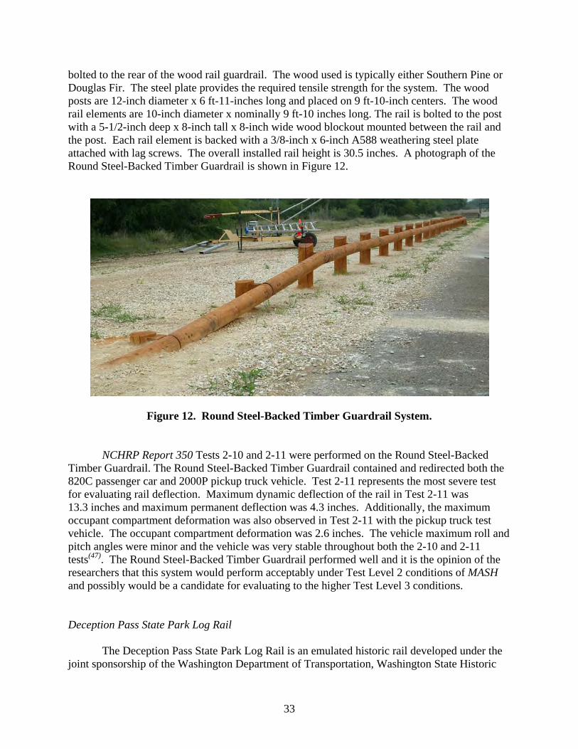
33
bolted to the rear of the wood rail guardrail. The wood used is typically either Southern Pine or Douglas Fir. The steel plate provides the required tensile strength for the system. The wood posts are 12-inch diameter x 6 ft-11-inches long and placed on 9 ft-10-inch centers. The wood rail elements are 10-inch diameter x nominally 9 ft-10 inches long. The rail is bolted to the post with a 5-1/2-inch deep x 8-inch tall x 8-inch wide wood blockout mounted between the rail and the post. Each rail element is backed with a 3/8-inch x 6-inch A588 weathering steel plate attached with lag screws. The overall installed rail height is 30.5 inches. A photograph of the Round Steel-Backed Timber Guardrail is shown in Figure 12.
Figure 12. Round Steel-Backed Timber Guardrail System.
NCHRP Report 350 Tests 2-10 and 2-11 were performed on the Round Steel-Backed
Timber Guardrail. The Round Steel-Backed Timber Guardrail contained and redirected both the 820C passenger car and 2000P pickup truck vehicle. Test 2-11 represents the most severe test for evaluating rail deflection. Maximum dynamic deflection of the rail in Test 2-11 was 13.3 inches and maximum permanent deflection was 4.3 inches. Additionally, the maximum occupant compartment deformation was also observed in Test 2-11 with the pickup truck test vehicle. The occupant compartment deformation was 2.6 inches. The vehicle maximum roll and pitch angles were minor and the vehicle was very stable throughout both the 2-10 and 2-11 tests(47). The Round Steel-Backed Timber Guardrail performed well and it is the opinion of the researchers that this system would perform acceptably under Test Level 2 conditions of MASH and possibly would be a candidate for evaluating to the higher Test Level 3 conditions.
Deception Pass State Park Log Rail
The Deception Pass State Park Log Rail is an emulated historic rail developed under the joint sponsorship of the Washington Department of Transportation, Washington State Historic

34
Preservation Office, and Washington State Parks and Recreation. The rail was developed to emulate the appearance of the original 1935 Civilian Conservation Corps (CCC) constructed log rail supported on stone and mortar bollards. This rail was specially designed for the Deception Pass State Park area in Washington.
The Deception Pass State Park Log Rail is a steel-backed, round turned wood log rail
supported by concrete bollards faced with native stone veneer and mortar and intermediate steel pipe posts. The wood used is Douglas Fir. The steel plate provides the required tensile strength for the system. The finished veneer face of the stone bollards are nominally 4 ft-6inches wide x 2 ft-4 inches deep x 2 ft-10-1/2 inches tall and placed on 18-ft centers. One intermediate 8-inch diameter extra strong steel pipe support is used between the stone and mortar bollards to provide additional capacity to the rail. The wood log rail elements are nominally 12 inches in diameter x 17 ft-11-1/2 inches long. The rail is bolted to the bollards and intermediate support posts without the need for a wood blockout. Each rail element is backed with a 3/8-inch x 6-inch A588 weathering steel plate attached with lag screws. The overall installed rail height is 27 inches. A photograph of the Deception Pass State Park Log Rail is shown in Figure 13.
Figure 13. Deception Pass State Park Log Rail System.
The Deception Pass State Park Log Rail contained and redirected the 2000P pickup truck
vehicle. Maximum dynamic deflection of the rail was unobtainable and maximum permanent deflection was 0.4 inch. The occupant compartment deformation was 2.3 inch and the vehicle maximum roll and pitch angles were minor. The vehicle was stable throughout the event. There was significant gouging of the log rail in the region of impact and minor wheel snagging on the leading edge of the stone bollard(49). The Deception Pass State Park Log Rail performed well and it is the opinion of the researchers that this system would perform acceptably under Test Level 2 conditions of MASH.
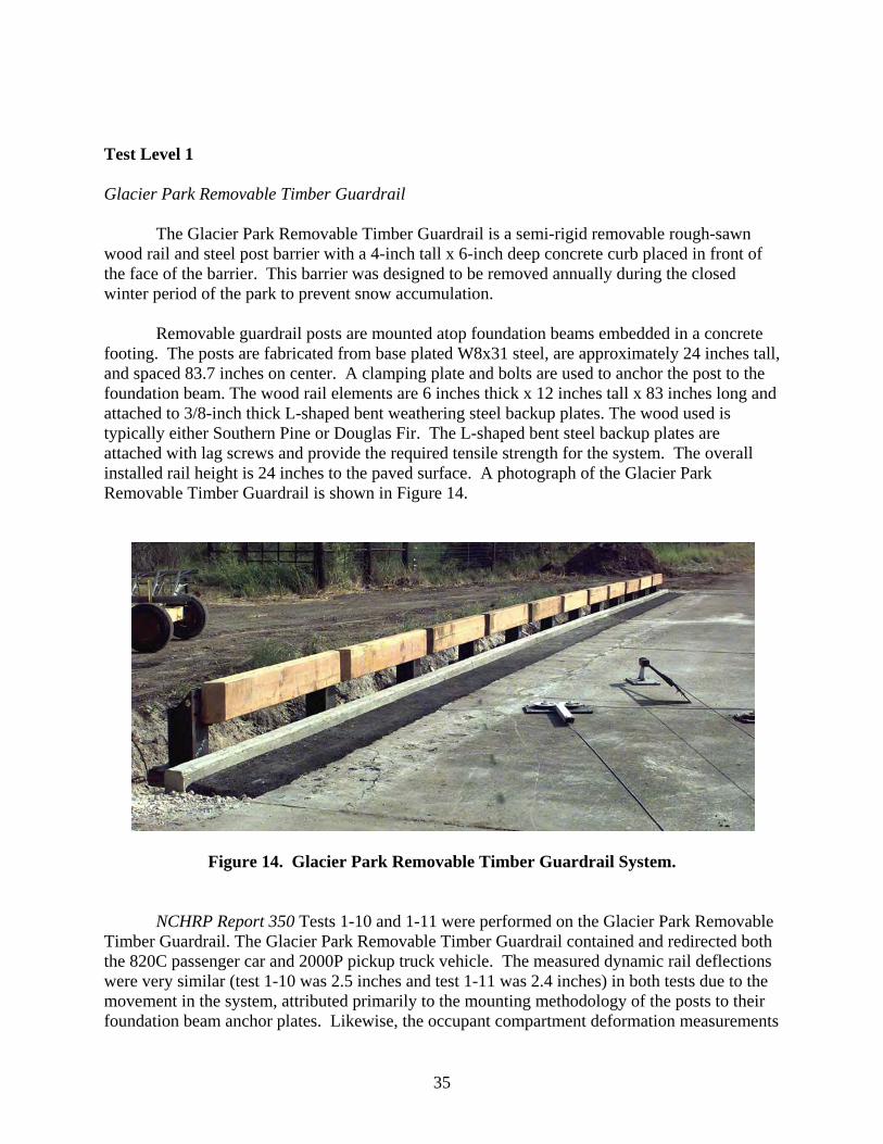
35
Test Level 1
Glacier Park Removable Timber Guardrail
The Glacier Park Removable Timber Guardrail is a semi-rigid removable rough-sawn wood rail and steel post barrier with a 4-inch tall x 6-inch deep concrete curb placed in front of the face of the barrier. This barrier was designed to be removed annually during the closed winter period of the park to prevent snow accumulation.
Removable guardrail posts are mounted atop foundation beams embedded in a concrete
footing. The posts are fabricated from base plated W8x31 steel, are approximately 24 inches tall, and spaced 83.7 inches on center. A clamping plate and bolts are used to anchor the post to the foundation beam. The wood rail elements are 6 inches thick x 12 inches tall x 83 inches long and attached to 3/8-inch thick L-shaped bent weathering steel backup plates. The wood used is typically either Southern Pine or Douglas Fir. The L-shaped bent steel backup plates are attached with lag screws and provide the required tensile strength for the system. The overall installed rail height is 24 inches to the paved surface. A photograph of the Glacier Park Removable Timber Guardrail is shown in Figure 14.
Figure 14. Glacier Park Removable Timber Guardrail System.
NCHRP Report 350 Tests 1-10 and 1-11 were performed on the Glacier Park Removable
Timber Guardrail. The Glacier Park Removable Timber Guardrail contained and redirected both the 820C passenger car and 2000P pickup truck vehicle. The measured dynamic rail deflections were very similar (test 1-10 was 2.5 inches and test 1-11 was 2.4 inches) in both tests due to the movement in the system, attributed primarily to the mounting methodology of the posts to their foundation beam anchor plates. Likewise, the occupant compartment deformation measurements
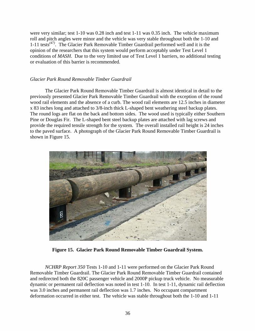
36
were very similar; test 1-10 was 0.28 inch and test 1-11 was 0.35 inch. The vehicle maximum roll and pitch angles were minor and the vehicle was very stable throughout both the 1-10 and 1-11 tests(47). The Glacier Park Removable Timber Guardrail performed well and it is the opinion of the researchers that this system would perform acceptably under Test Level 1 conditions of MASH. Due to the very limited use of Test Level 1 barriers, no additional testing or evaluation of this barrier is recommended.
Glacier Park Round Removable Timber Guardrail
The Glacier Park Round Removable Timber Guardrail is almost identical in detail to the previously presented Glacier Park Removable Timber Guardrail with the exception of the round wood rail elements and the absence of a curb. The wood rail elements are 12.5 inches in diameter x 83 inches long and attached to 3/8-inch thick L-shaped bent weathering steel backup plates. The round logs are flat on the back and bottom sides. The wood used is typically either Southern Pine or Douglas Fir. The L-shaped bent steel backup plates are attached with lag screws and provide the required tensile strength for the system. The overall installed rail height is 24 inches to the paved surface. A photograph of the Glacier Park Round Removable Timber Guardrail is shown in Figure 15.
Figure 15. Glacier Park Round Removable Timber Guardrail System.
NCHRP Report 350 Tests 1-10 and 1-11 were performed on the Glacier Park Round
Removable Timber Guardrail. The Glacier Park Round Removable Timber Guardrail contained and redirected both the 820C passenger vehicle and 2000P pickup truck vehicle. No measurable dynamic or permanent rail deflection was noted in test 1-10. In test 1-11, dynamic rail deflection was 3.0 inches and permanent rail deflection was 1.7 inches. No occupant compartment deformation occurred in either test. The vehicle was stable throughout both the 1-10 and 1-11

37
tests(47). The Glacier Park Round Removable Timber Guardrail performed well and it is the opinion of the researchers that this system would perform acceptably under Test Level 1 conditions of MASH. Due to the very limited use of Test Level 1 barriers, no additional testing or evaluation of this barrier is recommended.
MEDIAN BARRIERS
Many of the roadside barriers previously discussed are also acceptable for use in median applications and therefore will not be repeated. The following roadside barriers are accepted for use as NCHRP Report 350 accepted median barriers by FHWA as outlined in Horne’s memorandum B64(5):
Test Level 3 (TL-3)
• Weak Steel Post Cable (3-strand) Guardrail and Median Barrier (G1;SGRO1a-b tested with New York Terminal by Washington State)
• Weak-Post Box-Beam Median Guardrail and Barrier (SGRO3 and SGMO3)
• Strong-Post (Wood) W-Beam Guardrail and Median Barrier with wood or approved plastic blockout (SGRO4b,SGMO4b, and SGMO6b)
• Strong-Post (Steel) W-Beam Guardrail and Median Barrier with routed wood or approved plastic blockout (SGRO4a and SGMO4a with non-steel blocks, and SGMO6a with steel, wood or plastic blocks)
• Strong-Post (Wood) Thrie-Beam Guardrail and Median Barrier with wood or approved plastic block (SGRO9c and SGMO9c)
• Strong-Post (Steel) Thrie-Beam Guardrail and Median Barrier with routed wood or approved routed plastic block (SGRO9a and SGMO9a with non-steel blocks)
• Merritt Parkway (CT) Steel-backed Timber Guiderail (Acceptance Letter B-45)
Test Level 4 (TL-4)
• Strong-Post Modified Thrie-Beam Guardrail and Median Barrier (SGRO9b and SGMO9b). Note: the correct length of the modified spacer block is 17 inches and not the 22 inches shown on PWBO3 in the AASHTO Roadside Design Guide.
• 32-inch tall Safety Shape (New Jersey) Median Barrier (SGM11a)
• 32-inch tall F-shape Median Barrier (SGM10a)
• 32-inch tall Vertical Concrete Barrier*
• 32-inch tall Constant Slope Barrier (TX and CA designs – see Acceptance Letters B17 and B-45)
38
Test Level 5 (TL-5)
• 42-inch tall Safety Shape (New Jersey) Median Barrier (SGM11b)
• 42-inch tall F-shape Median Barrier (SGM10b)
• 42-inch tall Vertical Concrete Barrier*
• 42-inch tall Constant Slope Barrier (TX and CA designs)**
• 42-inch tall Ontario Tall Wall Median Barrier (SGM12 and Acceptance Letter B-19)
* These two designs were tested as bridge railings. They may be used as roadside or median barriers if reinforcing and foundation details are equivalent to the crash tested installations.
** The Constant Slope Barriers were not tested to the TL-5 level, but may be considered TL-5 barriers when cast in place or slip formed if the dimensions, reinforcing, and foundation details are equivalent to designs that have been successfully tested.
Cable Median Barrier
As previously presented, high-tension cable median barrier systems have rapidly gained popularity as a cost-effective alternative for shielding motorists from crossover crashes. The relatively low cost makes cable median barrier appealing for treating long expanses of highway. Additionally, the flexibility of these systems results in lower decelerations to an impacting vehicle, which lowers the probability of injury to occupants. However, sufficient space must be available to accommodate the greater design deflections associated with these systems. A cross-section of a typical low-tension cable median barrier is shown in Figure 16.
Presently, there are five high-tension cable barriers in the market place. All of these
systems are proprietary and, thus, will not be discussed herein. However, it is fully expected that these and the G1 system will be capable of successfully containing and redirecting the new 5000-lb, 1/2-ton, 4-door pickup truck specified in MASH. The 13 percent increase in impact severity associated with MASH test 3-11 will likely increase dynamic deflections of these systems. If desired, the modest increase in deflection can be offset through the use of reduced post spacing or other means.
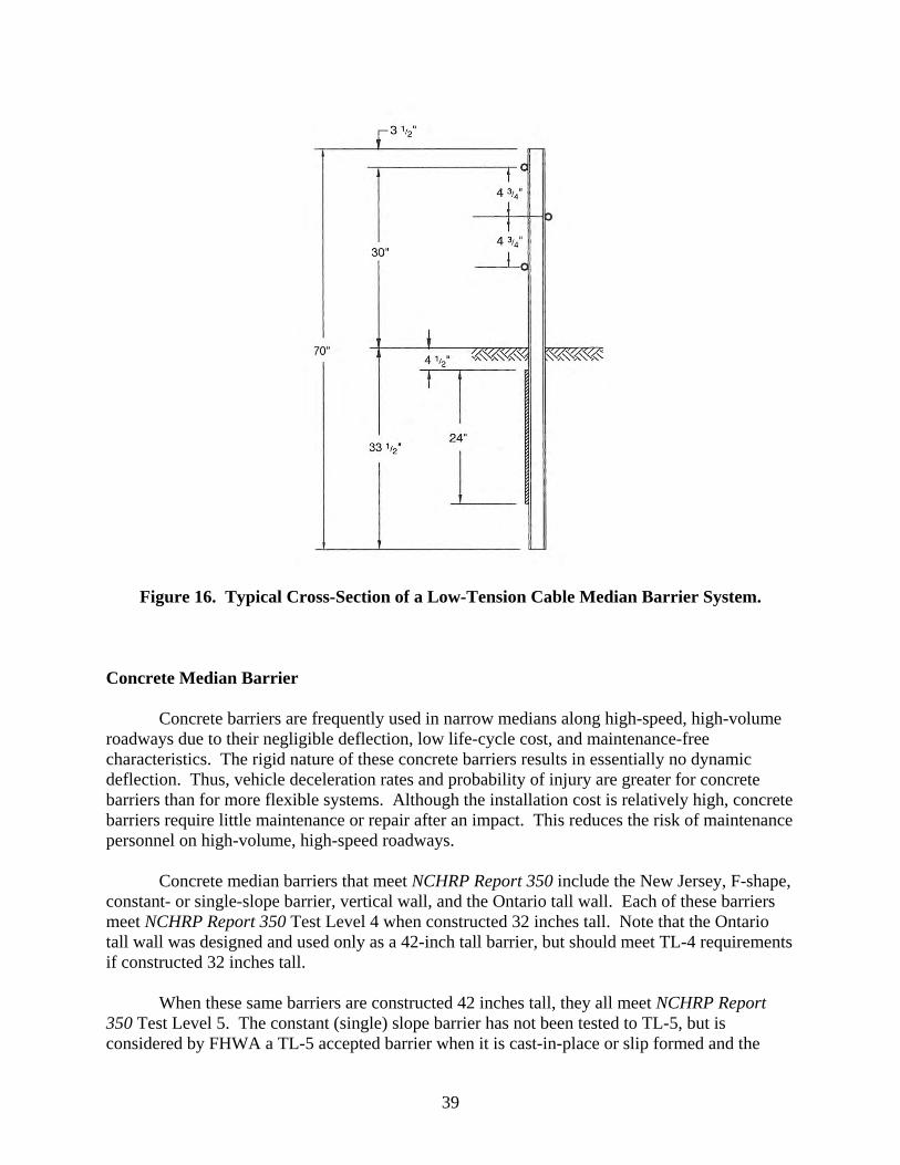
39
Figure 16. Typical Cross-Section of a Low-Tension Cable Median Barrier System.
Concrete Median Barrier
Concrete barriers are frequently used in narrow medians along high-speed, high-volume roadways due to their negligible deflection, low life-cycle cost, and maintenance-free characteristics. The rigid nature of these concrete barriers results in essentially no dynamic deflection. Thus, vehicle deceleration rates and probability of injury are greater for concrete barriers than for more flexible systems. Although the installation cost is relatively high, concrete barriers require little maintenance or repair after an impact. This reduces the risk of maintenance personnel on high-volume, high-speed roadways.
Concrete median barriers that meet NCHRP Report 350 include the New Jersey, F-shape,
constant- or single-slope barrier, vertical wall, and the Ontario tall wall. Each of these barriers meet NCHRP Report 350 Test Level 4 when constructed 32 inches tall. Note that the Ontario tall wall was designed and used only as a 42-inch tall barrier, but should meet TL-4 requirements if constructed 32 inches tall.
When these same barriers are constructed 42 inches tall, they all meet NCHRP Report
350 Test Level 5. The constant (single) slope barrier has not been tested to TL-5, but is considered by FHWA a TL-5 accepted barrier when it is cast-in-place or slip formed and the
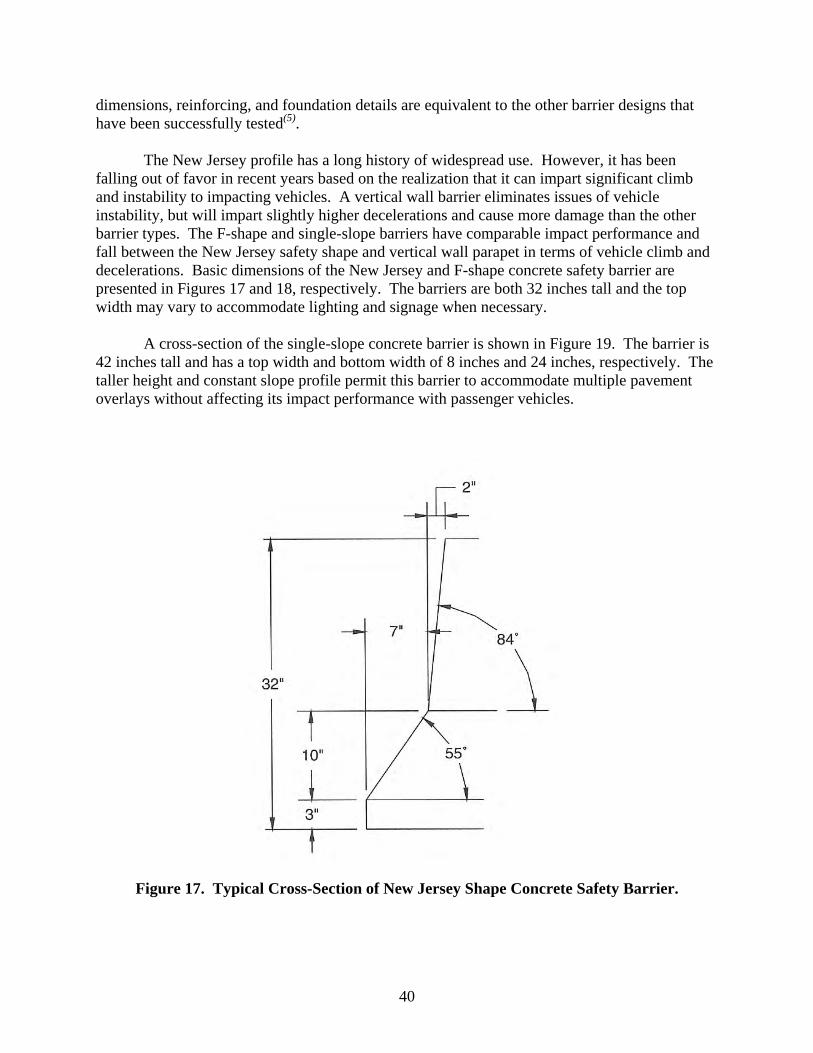
40
dimensions, reinforcing, and foundation details are equivalent to the other barrier designs that have been successfully tested(5).
The New Jersey profile has a long history of widespread use. However, it has been
falling out of favor in recent years based on the realization that it can impart significant climb and instability to impacting vehicles. A vertical wall barrier eliminates issues of vehicle instability, but will impart slightly higher decelerations and cause more damage than the other barrier types. The F-shape and single-slope barriers have comparable impact performance and fall between the New Jersey safety shape and vertical wall parapet in terms of vehicle climb and decelerations. Basic dimensions of the New Jersey and F-shape concrete safety barrier are presented in Figures 17 and 18, respectively. The barriers are both 32 inches tall and the top width may vary to accommodate lighting and signage when necessary.
A cross-section of the single-slope concrete barrier is shown in Figure 19. The barrier is
42 inches tall and has a top width and bottom width of 8 inches and 24 inches, respectively. The taller height and constant slope profile permit this barrier to accommodate multiple pavement overlays without affecting its impact performance with passenger vehicles.
Figure 17. Typical Cross-Section of New Jersey Shape Concrete Safety Barrier.

41
Figure 18. Typical Cross-Section of F-Shape Concrete Safety Barrier.
Figure 19. Typical Cross-Section of Single Slope Concrete Barrier.

42
Given the estimated impact force associated with MASH test 3-11 with the new pickup
truck is comparable to the design impact force used for NCHRP Report 350 test 3-11, the New Jersey, F-shape, constant- or single-slope barrier, vertical wall, and the Ontario tall wall barrier should all easily meet the structural adequacy requirements for the MASH Test Level 3 (TL-3) impact conditions.
The only possible problem that might exist with the “safety-shape” concrete median
barriers is in regard to the stability of the new 5000-lb, 1/2-ton, 4-door, quad-cab pickup. However, as discussed earlier in this chapter, the new pickup truck design vehicle has a greater static stability factor (SSF) than the 3/4-ton, 2-door, standard cab pickup and limited full-scale crash testing conducted under NCHRP Project 22-14(02) with both vehicle types indicates that the 1/2-ton, 4-door quad-cab pickup is more stable than the 3/4-ton, 2-door standard cab pickup.
Crash test data further supports the argument that instability of the pickup truck should
not be an issue with any of the concrete barriers discussed. Under NCHRP Project 22-14(02), two tests (Test 6 and Test 7 in Table 3) were performed on a precast, F-shape, pin-and-loop, concrete median barrier. Test 6 was conducted with a 5000-lb, 3/4-ton, standard cab, GMC 2500 pickup(50) and Test 7 involved a 5000-lb, 1/2-ton, 4-door, Dodge Ram 1500 quad-cab pickup(51). In both tests, the vehicles were successfully contained and redirected. In another test, a 5000-lb, 3/4-ton, standard cab pickup was successfully contained and redirected after impacting a precast, Texas F-shape concrete maintenance barrier with X-bolt connection and 10-ft long segments(52).
Testing has shown that a precast barrier system will impart more motion and instability to
an impacting vehicle than a rigid, permanent barrier with the same profile. This is due to the increased deflection of the precast barrier system, which increases the effective impact angle between the pickup and the precast barrier segments downstream from the initial point of contact. Therefore, given that two different versions of precast, F-shape barriers successfully contained and redirected the more critical 5000-lb, 3/4-ton, standard cab, pickup, it can be concluded that the permanent F-shape concrete safety barrier will successfully contain and redirect a 5000-lb, 1/2-ton, 4-door, quad-cab pickup in an upright and even more stable manner. Further, the single slope concrete barrier, which previous testing has shown to have comparable dynamic vehicle behavior to the F-shape profile, should also demonstrate satisfactory impact performance for MASH test 3-11.
Although the focus of the discussion has been the pickup truck redirection test (test 3-11),
consideration must also be given to the small car redirection test (test 3-10). As previously discussed, MASH test 3-10 has been revised to include a heavier 2425-lb passenger car (denoted 1100C) and a higher 25 degree impact angle. This is compared to NCHRP Report 350 test 3-10, which involves an 1800-lb vehicle impacting the barrier at an angle of 20 degrees. Considering both the increase in weight and impact angle, the impact severity of the revised small car redirection test (MASH Test 3-10) has increased by 206 percent. Since the impact severity of the pickup truck redirection test is still twice that of the small car redirection test, the revised small car redirection test will not pose a problem in terms of structural adequacy. However, the effect of the increase in angle and impact severity on vehicle stability and occupant risk was a concern, particularly for shaped rigid barriers such as the New Jersey profile.

43
MASH test 3-10 was conducted on a permanent New Jersey profile barrier under NCHRP
Project 22-14(02) to investigate this impact performance concern (see Test 8 of Table 3). In this test, a 2002 Kia Rio was successfully contained and redirected in an upright and stable manner and occupant risk measures were within acceptable limits(53). The New Jersey profile is known to impart more vehicle climb than the more stable F-shape, single-slope, and vertical profiles. Therefore, the success of this test can be used to conclude that the impact performance of the F-shape concrete safety barrier, the single slope barrier, and the vertical barrier will be satisfactory for MASH test 3-10.
The performance of concrete barriers under MASH Test Level 4 (TL-4) impact conditions
merits discussion. The change in the weight and vertical C.G. height of the single-unit truck (SUT), and impact speed associated with MASH TL-4 can adversely affect the performance of 32-inch tall concrete barriers that currently comply with TL-4 under NCHRP Report 350. As previously discussed, MASH recommends increasing the weight of the TL-4 single-unit truck from 17,640 lb to 22,050 lb and increasing the impact speed from 50 mi/h to 56 mi/h. The estimated impact force of 76 kips for MASH test 4-12 represents a 41 percent increase from the 54 kip design load used for NCHRP Report 350 test 4-12. Consequently, some barriers that meet the NCHRP Report 350 guidelines as a TL-4 barrier may not have adequate strength to comply with the same test level under MASH. Further, the increase in height of the SUT vertical C.G. may contribute to the SUT rolling over the top of the barrier.
Historically, full-scale crash testing has shown that 32-inch tall barriers are capable of
meeting TL-4 impact conditions under NCHRP Report 350. However, when MASH Test 4-12 was performed on a 32-inch tall New Jersey safety-shape concrete barrier (see Test 11 in Table 3), the 22,045-lb SUT, traveling 56 mi/h and impacting the barrier at a nominal 15 degrees rolled over the top of the barrier(54).
After the unsatisfactory outcome of this test, it was proposed to reduce the C.G. height of
the ballast of the SUT from 67 inches to 63 inches. This effectively decreases the overturning moment by decreasing the moment arm between the C.G. of the truck and the reactive force applied by the barrier. In a retest of the New Jersey safety shape performed under this project, the SUT with reduced ballast height still rolled over the top of the 32-inch tall barrier. Additional testing is required to determine what minimum barrier height is required to contain the SUT under the impact conditions specified for MASH test 4-12.
In summary, concrete median barriers should readily comply with MASH Test Level 3
conditions. Further testing and evaluation does not appear necessary at this time to satisfy the MASH Test Level 3 conditions and, consequently, is given a low priority. However, testing has shown that the MASH Test Level 4 conditions are problematic for 32-inch tall barriers with regard to containment of the SUT vehicle. Additional testing is necessary to determine the minimum barrier height required to satisfy MASH test 4-12 impact conditions. No change in performance is expected with regard to the MASH Test Level 5 conditions for 42-inch tall barriers, as the test conditions remain unchanged.
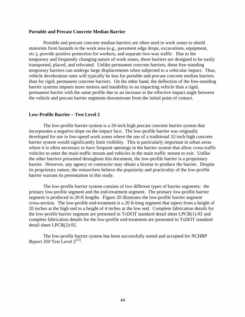
44
Portable and Precast Concrete Median Barrier
Portable and precast concrete median barriers are often used in work zones to shield motorists from hazards in the work area (e.g., pavement edge drops, excavations, equipment, etc.), provide positive protection for workers, and separate two-way traffic. Due to the temporary and frequently changing nature of work zones, these barriers are designed to be easily transported, placed, and relocated. Unlike permanent concrete barriers, these free-standing temporary barriers can undergo large displacements when subjected to a vehicular impact. Thus, vehicle deceleration rates will typically be less for portable and precast concrete median barriers than for rigid, permanent concrete barriers. On the other hand, the deflection of the free-standing barrier systems imparts more motion and instability to an impacting vehicle than a rigid, permanent barrier with the same profile due to an increase in the effective impact angle between the vehicle and precast barrier segments downstream from the initial point of contact.
Low-Profile Barrier – Test Level 2
The low-profile barrier system is a 20-inch high precast concrete barrier system that incorporates a negative slope on the impact face. The low-profile barrier was originally developed for use in low-speed work zones where the use of a traditional 32-inch high concrete barrier system would significantly limit visibility. This is particularly important in urban areas where it is often necessary to have frequent openings in the barrier system that allow cross-traffic vehicles to enter the main traffic stream and vehicles in the main traffic stream to exit. Unlike the other barriers presented throughout this document, the low-profile barrier is a proprietary barrier. However, any agency or contractor may obtain a license to produce the barrier. Despite its proprietary nature, the researchers believe the popularity and practicality of the low-profile barrier warrant its presentation in this study.
The low-profile barrier system consists of two different types of barrier segments: the
primary low-profile segment and the end-treatment segment. The primary low-profile barrier segment is produced in 20-ft lengths. Figure 20 illustrates the low-profile barrier segment cross-section. The low-profile end-treatment is a 20 ft-long segment that tapers from a height of 20 inches at the high end to a height of 4 inches at the low end. Complete fabrication details for the low-profile barrier segment are presented in TxDOT standard detail sheet LPCB(1)-92 and complete fabrication details for the low-profile end-treatment are presented in TxDOT standard detail sheet LPCB(2)-92.
The low-profile barrier system has been successfully tested and accepted for NCHRP
Report 350 Test Level 2(55).
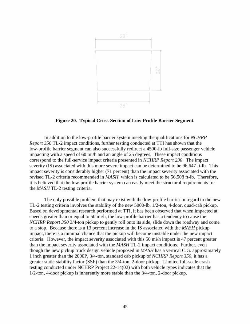
45
Figure 20. Typical Cross-Section of Low-Profile Barrier Segment.
In addition to the low-profile barrier system meeting the qualifications for NCHRP
Report 350 TL-2 impact conditions, further testing conducted at TTI has shown that the low-profile barrier segment can also successfully redirect a 4500-lb full-size passenger vehicle impacting with a speed of 60 mi/h and an angle of 25 degrees. These impact conditions correspond to the full-service impact criteria presented in NCHRP Report 230. The impact severity (IS) associated with this more severe impact can be determined to be 96,647 ft-lb. This impact severity is considerably higher (71 percent) than the impact severity associated with the revised TL-2 criteria recommended in MASH, which is calculated to be 56,508 ft-lb. Therefore, it is believed that the low-profile barrier system can easily meet the structural requirements for the MASH TL-2 testing criteria.
The only possible problem that may exist with the low-profile barrier in regard to the new
TL-2 testing criteria involves the stability of the new 5000-lb, 1/2-ton, 4-door, quad-cab pickup. Based on developmental research performed at TTI, it has been observed that when impacted at speeds greater than or equal to 50 mi/h, the low-profile barrier has a tendency to cause the NCHRP Report 350 3/4-ton pickup to gently roll onto its side, slide down the roadway and come to a stop. Because there is a 13 percent increase in the IS associated with the MASH pickup impact, there is a minimal chance that the pickup will become unstable under the new impact criteria. However, the impact severity associated with this 50 mi/h impact is 47 percent greater than the impact severity associated with the MASH TL-2 impact conditions. Further, even though the new pickup truck design vehicle proposed in MASH has a vertical C.G. approximately 1 inch greater than the 2000P, 3/4-ton, standard cab pickup of NCHRP Report 350, it has a greater static stability factor (SSF) than the 3/4-ton, 2-door pickup. Limited full-scale crash testing conducted under NCHRP Project 22-14(02) with both vehicle types indicates that the 1/2-ton, 4-door pickup is inherently more stable than the 3/4-ton, 2-door pickup.

46
For these reasons, it is the opinion of the researchers that the low-profile barrier system should be able to successfully redirect the new pickup under TL-2 impact conditions. However, this assertion may ultimately have to be demonstrated through full-scale crash testing.
Based on the above discussion, the researchers have assigned a low priority to the
retesting of the low-profile barrier system based on safety considerations alone. However, in light of the increasing popularity of this barrier system and its growing use, the testing priority of the low-profile barrier should perhaps be given consideration.
Portable and Precast Median Barrier Connections
Portable and precast barriers, such as the safety shape, F-shape, and single-slope barrier are connected to one another in work zones and other temporary application environments using one of a wide variety of end connections. Tables 5 and 6 show the non-proprietary portable concrete barrier connections that have been crash tested in accordance with NCHRP Report 350 and have received FHWA acceptance. Only NCHRP Report 350 non-proprietary connections are shown.
Unlike permanent concrete barriers, these free-standing temporary barriers can undergo
large displacements when subjected to a vehicular impact. Thus, vehicle deceleration rates will typically be less for portable and precast concrete median barriers than for rigid, permanent concrete barriers. However, the deflection of the free-standing barrier system imparts more motion and instability to an impacting vehicle than a rigid, permanent barrier with the same profile. This is due to the increase in the effective impact angle that arises between the vehicle and downstream barrier segments as the barrier segments displace during impact. In addition, in the case of pin-and-loop connections, the barriers not only displace laterally relative to one another but also rotate about the longitudinal axis relative to one another. The rotation of the barrier allows the impacting vehicle to more readily mount and climb the face of the barrier, thus sometimes resulting in very high vehicular pitch and roll angles. It is common for portable and precast barrier connections to be strong in shear but be weak in moment and/or torsional strength.
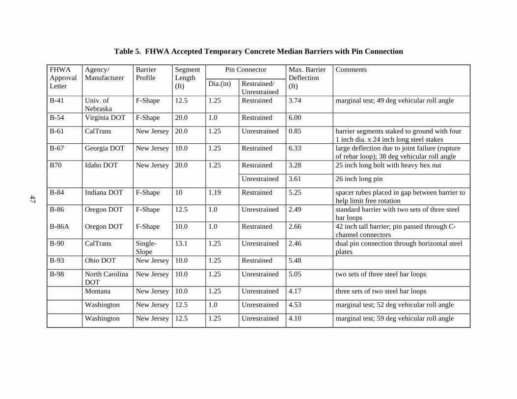
47
Table 5. FHWA Accepted Temporary Concrete Median Barriers with Pin Connection
FHWA Approval Letter
Agency/ Manufacturer
Barrier Profile
Segment Length (ft)
Pin Connector Max. Barrier Deflection (ft)
Comments
Dia.(in) Restrained/ Unrestrained
B-41 Univ. of Nebraska
F-Shape 12.5 1.25 Restrained 3.74 marginal test; 49 deg vehicular roll angle
B-54 Virginia DOT F-Shape 20.0 1.0 Restrained 6.00
B-61 CalTrans New Jersey 20.0 1.25 Unrestrained 0.85 barrier segments staked to ground with four 1 inch dia. x 24 inch long steel stakes
B-67 Georgia DOT New Jersey 10.0 1.25 Restrained 6.33 large deflection due to joint failure (rupture of rebar loop); 38 deg vehicular roll angle
B70 Idaho DOT New Jersey 20.0 1.25 Restrained 3.28 25 inch long bolt with heavy hex nut
Unrestrained 3.61 26 inch long pin
B-84 Indiana DOT F-Shape 10 1.19 Restrained 5.25 spacer tubes placed in gap between barrier to help limit free rotation
B-86 Oregon DOT F-Shape 12.5 1.0 Unrestrained 2.49 standard barrier with two sets of three steel bar loops
B-86A Oregon DOT F-Shape 10.0 1.0 Restrained 2.66 42 inch tall barrier; pin passed through C-channel connectors
B-90 CalTrans Single-Slope
13.1 1.25 Unrestrained 2.46 dual pin connection through horizontal steel plates
B-93 Ohio DOT New Jersey 10.0 1.25 Restrained 5.48
B-98 North Carolina DOT
New Jersey 10.0 1.25 Unrestrained 5.05 two sets of three steel bar loops
Montana New Jersey 10.0 1.25 Unrestrained 4.17 three sets of two steel bar loops
Washington New Jersey 12.5 1.0 Unrestrained 4.53 marginal test; 52 deg vehicular roll angle
Washington New Jersey 12.5 1.25 Unrestrained 4.10 marginal test; 59 deg vehicular roll angle
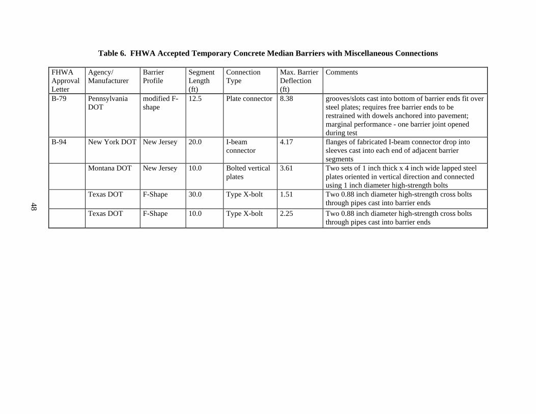
48
Table 6. FHWA Accepted Temporary Concrete Median Barriers with Miscellaneous Connections
FHWA Approval Letter
Agency/ Manufacturer
Barrier Profile
Segment Length (ft)
Connection Type
Max. Barrier Deflection (ft)
Comments
B-79 Pennsylvania DOT
modified F-shape
12.5 Plate connector 8.38 grooves/slots cast into bottom of barrier ends fit over steel plates; requires free barrier ends to be restrained with dowels anchored into pavement; marginal performance - one barrier joint opened during test
B-94 New York DOT New Jersey 20.0 I-beam connector
4.17 flanges of fabricated I-beam connector drop into sleeves cast into each end of adjacent barrier segments
Montana DOT New Jersey 10.0 Bolted vertical plates
3.61 Two sets of 1 inch thick x 4 inch wide lapped steel plates oriented in vertical direction and connected using 1 inch diameter high-strength bolts
Texas DOT F-Shape 30.0 Type X-bolt 1.51 Two 0.88 inch diameter high-strength cross bolts through pipes cast into barrier ends
Texas DOT F-Shape 10.0 Type X-bolt 2.25 Two 0.88 inch diameter high-strength cross bolts through pipes cast into barrier ends

49
F-Shape Type X Connection
As is noted in Table 6, the most recently developed portable concrete barrier connection and also the lowest deflection connection type is the TxDOT F-shape Type X or “cross-bolted” connection. The Type X connection utilizes two threaded rods/bolts to form the connection. The bolts are placed in different horizontal planes in the barrier at a prescribed angle with respect to the longitudinal axis of the barrier. The bolts pass through guide pipes cast into the ends of the barrier segments. The bolts exit one barrier segment and enter the adjacent barrier segment at the vertical center line of the barrier section. In plan view, the two connection rods/bolts form an “X” across the joint between adjacent barrier segments. Triangular wedges are cast into the barrier to permit the exposed ends of the cross bolts to be recessed and, thus, prevent vehicle snagging. The guide pipes through which the cross bolts pass are oversized to provide connection tolerance for barrier fabrication, installation, and placement of the barrier on horizontal and vertical curves. The tight moment connection provided by the cross-bolted design minimizes barrier deflections while maintaining constructability.
Standard 32-inch height F-shape profile precast segments constructed with the Type X
connection have been crash tested to NCHRP Report 350 in both 10-ft and 30-ft length segments. The F-shape segments were 24 inches wide at the base and 9-1/2 inches wide at the top(52). A photograph of the F-shape concrete safety barrier with Type X connections is shown in Figure 21. For complete fabrication details of this precast barrier system, the reader is referred to TxDOT standard detail sheets CSB(1)-04, CSB(2)-04, and CSB(8)-04.
As previously mentioned, 10-ft and 30-ft segments of the F-shape concrete median
barrier with Type X connection were successfully tested to NCHRP Report 350(51). Occupant risk measures were below desirable levels, and the maximum roll angle was 30 degrees for the 10-ft long segments and 23.3 degrees for the 30-ft long segments. Maximum dynamic deflection of the barrier was only 27 inches for the 10-ft long segments and 19 inches for the 30-ft long segments, which is the lowest deflection of any free-standing, unanchored concrete barrier system accepted under NCHRP Report 350 guidelines. It should also be noted, in anticipation of the MASH test conditions, the 10-ft long barrier segment test installation was impacted with a 5000-lb single cab pickup truck with a 27-inch C.G. Recall from previous discussions, this vehicle is more critical than the 5000-lb, 1/2-ton, 4-door, quad-cab pickup truck currently proposed under MASH in terms of both structural adequacy and stability. Thus, the F-shape barrier with Type X connection and 10-ft long segments is considered to have met the requirements of MASH. Further, since the F-shape barrier with Type X connection and 30-ft long segments offers improved vehicle stability compared to the version of the barrier, the successful MASH test of the F-shape barrier with 10-ft long segments can be used to infer compliance of the F-shape barrier with 30-ft long segments with MASH.
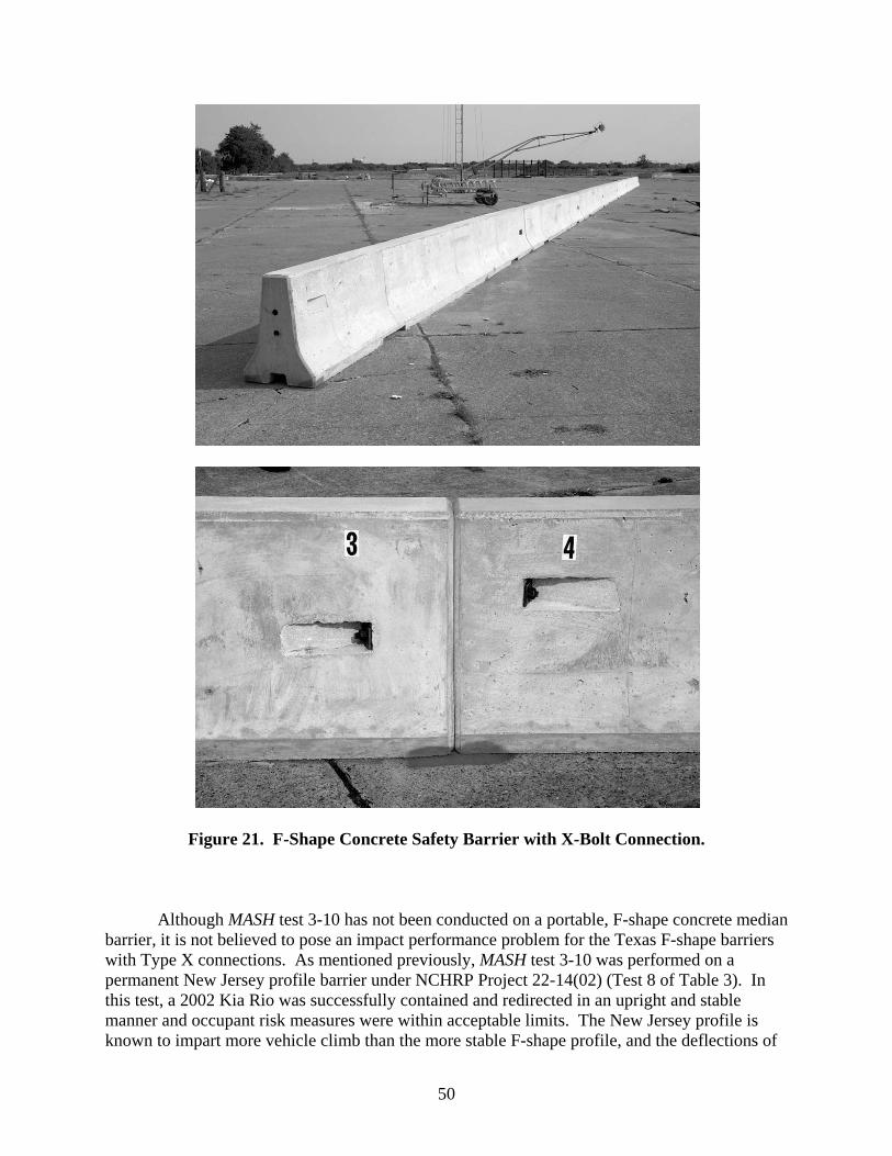
50
Figure 21. F-Shape Concrete Safety Barrier with X-Bolt Connection.
Although MASH test 3-10 has not been conducted on a portable, F-shape concrete median
barrier, it is not believed to pose an impact performance problem for the Texas F-shape barriers with Type X connections. As mentioned previously, MASH test 3-10 was performed on a permanent New Jersey profile barrier under NCHRP Project 22-14(02) (Test 8 of Table 3). In this test, a 2002 Kia Rio was successfully contained and redirected in an upright and stable manner and occupant risk measures were within acceptable limits. The New Jersey profile is known to impart more vehicle climb than the more stable F-shape profile, and the deflections of
51
the F-shape barriers with Type X connections for impacts with the small car under MASH test 3-10 impact conditions will be small. Therefore, both F-shape barriers with Type X connections should meet the impact performance requirements for MASH test 3-10.
Portable and Precast Median Barrier Connections Summary
Although portable and precast median barriers inherently can produce more vehicle instability than their permanently mounted counterparts, the MASH pickup truck vehicle has demonstrated improved stability over the 2000P pickup truck vehicle and is not believed to impose any additional load on the barrier. As presented in Tables 5 and 6, the current selection of NCHRP Report 350 tested portable and precast median barrier connections should comply with the revised impact performance guidelines proposed under the MASH conditions. Further testing and evaluation does not appear necessary at this time and, consequently, is given a low priority.
TRANSITIONS
Bridge rails are longitudinal barriers designed to keep vehicles from encroaching off bridge structures and encountering underlying hazards. Bridge rails are typically rigid in nature due to the lack of space on bridge structures to accommodate barrier deflection. Common types of bridge rails include continuous concrete barriers, metal rails mounted on concrete parapets, and both concrete and metal beam and post systems.
Transition sections are commonly used to connect a flexible approach guardrail to a more
rigid bridge rail. The purpose of the transition is to gradually change the stiffness of the rail section so a vehicle impacting the flexible approach rail does not pocket or snag severely on the end of the stiffer bridge rail. The change in stiffness is generally accomplished through a combination of increased post strength, reduced post spacing, and/or increased rail strength.
Many of the guardrail-to-bridge rail transition designs tested and accepted under NCHRP
Report 230 were unable to accommodate the 2000P pickup truck adopted as the design test vehicle for structural adequacy tests in NCHRP Report 350. The most common failure modes observed in full-scale crash tests of transitions with the pickup truck were excessive occupant compartment deformation and vehicle instability (i.e., rollover). It was found that the transition systems needed to be further stiffened to limit vehicle snagging to tolerable levels and avoid vehicle overturn. Snagging on one or more posts or the end of the bridge parapet frequently contributed to the front wheel being displaced into the floor and toe pan area thus causing excessive occupant compartment deformation and, in some instances, loss of the front wheel assembly which also contributed to vehicle instability.
It was further determined that the clear opening beneath the transition rail element had to
be reduced through the addition of a rub rail or curb to prevent the wheel of the pickup from intruding underneath the transition rail and snagging on the stiff transition posts or end of the bridge rail parapet. The use of 10-gauge or nested 12-gauge thrie-beam guardrail also sometimes accomplished the objective of minimizing the open space under the rail without the use of a rub
52
rail or curb. However, this was not always a definitive solution. As an example, a full-scale crash test was conducted to determine if the curb detail could be eliminated from TxDOT’s Test Level 3 (TL-3) nested 12-gauge thrie-beam transition system without adversely affecting impact performance. Test Designation 3-21 was performed in accordance with NCHRP Report 350. This test consisted of a 2000P pickup truck impacting the transition at a speed of 62.2 mi/h and an angle of 25 degrees. The test vehicle rolled over while exiting the test installation and, as a result, the nested thrie-beam transition system without curb failed to meet the impact performance criteria of NCHRP Report 350. Therefore, the curb had to be retained as part of the overall transition system(56).
A few states use two different transition designs: a Test Level 3 (TL-3) system which is
used on high-speed roadways (i.e., speeds > 50 mi/h), and a TL-2 system which is used on roadways with speeds of 45 mi/h or less.
At the time of the writing of this report, 21 acceptance letters related to transitions had been
posted to FHWA’s Roadway Departure Safety web site (keyword: bridge rail transitions) (http://safety.fhwa.dot.gov/roadway_dept/policy_guide/road_hardware/barriers). Table 7 outlines some general characteristics of the transitions referred to in the FHWA acceptance letters. Additionally, other transition designs may have been successfully crash tested but do not appear because a formal FHWA acceptance letter was not requested by the user agency. Table 7 also contains a few miscellaneous transitions the researchers are aware of that have been successfully crash tested but do not have a formal FHWA acceptance letter.
A detailed discussion will not be presented for each of the transitions listed in Table 7.
However, for purposes of general transition discussion, the transition system tested as part of NCHRP Project 22-14(02) is presented. A Test Level 2 transition is also presented.
TL-3 Transition
A schematic of TxDOT’s TL-3 transition is shown in Figure 22. This guardrail-to-concrete bridge rail transition consists of a nested thrie-beam rail supported on 7-ft long steel or wood posts spaced at 18-3/4 inches. A 4-inch tall curb runs along the length of the nested thrie-beam section. The front face of the curb is aligned with the traffic face of the wood blockout that offsets the thrie-beam from the support posts. A thrie-beam terminal connector is used to attach the downstream end of the transition to the concrete bridge rail parapet. On the upstream end, a 6 ft-3 inch, 10-gauge, thrie-beam-to-W-beam transition element is used to transition the thrie-beam to the W-beam rail element of the approach guardrail. Additional details of the TL-3 transition are presented in TxDOT standard detail sheet MBGF (TR)-02.
This transition system was originally designed and tested at the Midwest Roadside Safety Facility (MwRSF) at the University of Nebraska under sponsorship of the Midwest State’s Regional Pooled Fund Program(57). Both steel post and wood post versions of the transition were successfully tested with a 3/4-ton pickup truck following NCHRP Report 350 test 3-21 impact conditions.
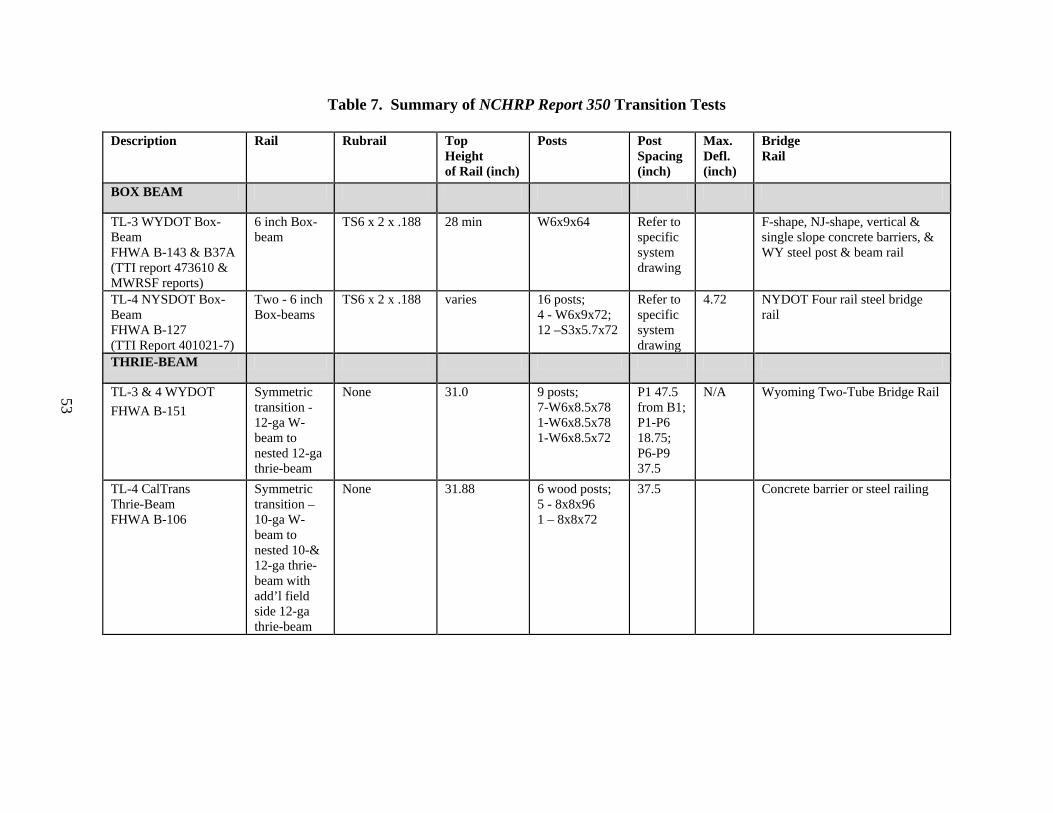
53
Table 7. Summary of NCHRP Report 350 Transition Tests
Description Rail Rubrail Top Height of Rail (inch)
Posts Post Spacing (inch)
Max. Defl. (inch)
Bridge Rail
BOX BEAM
TL-3 WYDOT Box-Beam FHWA B-143 & B37A (TTI report 473610 & MWRSF reports)
6 inch Box-beam
TS6 x 2 x .188 28 min W6x9x64 Refer to specific system drawing
F-shape, NJ-shape, vertical & single slope concrete barriers, & WY steel post & beam rail
TL-4 NYSDOT Box-Beam FHWA B-127 (TTI Report 401021-7)
Two - 6 inch Box-beams
TS6 x 2 x .188 varies 16 posts; 4 - W6x9x72; 12 –S3x5.7x72
Refer to specific system drawing
4.72 NYDOT Four rail steel bridge rail
THRIE-BEAM
TL-3 & 4 WYDOT FHWA B-151
Symmetric transition -12-ga W-beam to nested 12-ga thrie-beam
None 31.0 9 posts; 7-W6x8.5x78 1-W6x8.5x78 1-W6x8.5x72
P1 47.5 from B1; P1-P6 18.75; P6-P9 37.5
N/A Wyoming Two-Tube Bridge Rail
TL-4 CalTrans Thrie-Beam FHWA B-106
Symmetric transition –10-ga W-beam to nested 10-& 12-ga thrie-beam with add’l field side 12-ga thrie-beam
None 31.88 6 wood posts; 5 - 8x8x96 1 – 8x8x72
37.5 Concrete barrier or steel railing

54
Description Rail Rubrail Top Height of Rail (inch)
Posts Post Spacing (inch)
Max. Defl. (inch)
Bridge Rail
TL-3 NDOT Thrie-Beam FHWA B-105 TTI Report 404211-7
Symmetric transition –12-ga W-beam to nested 12-ga thrie-beam
None 31.65 6 posts; 2 – W6x25x102 4 - W6x25x84
48 37.5 37.5 (last space is 75)
3.15 Vertical face concrete barrier
TL-4 ODOT Thrie-Beam FHWA B-99 TTI Report 401021-2a TTI Report 401021-5
Symmetric transition - W-beam to 10-ga thrie-beam
4 inch curb 31.60 6 posts; 2 - W8x24x96 1 - W6x25x96 3 - W6x25x72
49.6 37.5 37.5 75
21.65 (TL3) 7.08 (TL-4)
Vertical face concrete barrier
TL-4 MWRSF Report No. TRP-03-71-01- MWRSF Test TRBR-3
Symmetric transition – 12-ga W-beam to 10-ga thrie-beam
Tapered 6.75 inch wood
31.65 10 posts; 4-8x8x78 6-8x8x72
48 to P1 P1-P7 @18.75;[email protected]
6.42 Wood rail on wood posts on transverse glue laminated timber decks
TL-4 MWRSF Report No. TRP-03-71-01- MWRSF-STTR-3
Symmetric transition – 12-ga W-beam to 10-ga thrie-beam
None (TS8x3x3/16 transition cap rail at bridge rail used)
31.65 7 posts; 5-W6x15x84 2-W6x9x78
48 to P1 P1-P7 @37.5
5.63 Thrie beam on steel posts on transverse glue laminated timber decks
TL-3 ITRANS MWRSF Report No. TRP-03-69-98 FHWA B-47 & B47A MWRSF-ITNJ-2
Symmetric transition – 12-ga W-beam to nested 12-ga thrie-beam -
4 inch triangular concrete curb
31.45 8 posts; 6-W6x9x80 2-W6x9x72
11.5 to P1; P1-P6@ 18.75; [email protected]
5.24 Safety shape w/ toe cut & Vertical wall parapet transition to New Jersey shape concrete

55
Description Rail Rubrail Top Height of Rail (inch)
Posts Post Spacing (inch)
Max. Defl. (inch)
Bridge Rail
TL-3 ITRANS MWRSF Report No. TRP-03-69-98 FHWA B-47, B47A & B47B MWRSF-ITNJ-4
Symmetric transition -12-ga W-beam to nested 12-ga thrie-beam -
4 inch triangular concrete curb
31.45 8 posts; 6-6x8x84 2-6x8x72 or 7 inch diameter post may be used in place of 6x8 wood posts
11.5 to P1; P1-P6@ 18.75; [email protected]
3.90 Safety shape w/ toe cut & Vertical wall parapet transition to New Jersey shape concrete
TL-3 MoDOT MWRSF Report TRP-03-47-95 MWRSF-MTSS-2
Symmetric transition – 12-ga W-beam to 10-ga thrie-beam (both sides)
None 31.0 9 posts; W6x9x72
11.5 to P1; P1-P6 @18.75; [email protected]
7.52 42 inch single slope median barrier
TL-3 MoDOT FHWA letter 06/04/1999 to Ron Faller, MWRSF
Symmetric transition – 12-ga W-beam to 10-ga thrie-beam or nested 12-ga thrie-beam
None (C8x11.5 transition cap rail at bridge rail used)
31.65 8 posts; 5-W6x15x84 3-W6x9x78
48 to P1 P1-P8 @37.5
5.63 Thrie beam on steel posts
TL-3 Nebraska FHWA B105 TTI Report 404211-7
Symmetric transition – 12-ga W-beam to nested 12-ga thrie-beam - TS4x4x5/16 behind first span
None 31.65 5 posts; 2- W6x25x102 4- W6x15x84
49.25 to P1;P1-P5@ 37.5
3.15 Vertical concrete wall with bevel

56
Description Rail Rubrail Top Height of Rail (inch)
Posts Post Spacing (inch)
Max. Defl. (inch)
Bridge Rail
TL-4 AKDOT FHWA B-55A TTI Report 404311-5
Symmetric transition -12-ga W-beam to nested 12-ga thrie-beam
None 31.0 9 posts; 7-W6x8.5x78 2-W6x8.5x78
P1 45 from B1; P1-P6 18.75; P6-P9 37.5
5.15 Alaska Two-Rail Bridge Rail
W-BEAM
TL-3 ODOT GR3.4 FHWA B-127
Nested 12-ga W-beam
None 27.75 6x8x72 wood 4 posts @ 18.75 and 4 posts @ 37.5
TL-3 MNDOT FHWA B-83 TTI Report 473390-3
Nested 12-ga W-beam with 4 inch curb
Curb 27.0 11 posts; 2-10x10x96 (or W8x21x96) 4-6x8x84 3-6x8x72 2-6x8x72 (may substitute W6x8.5 for all 6x8 wood posts)
11.40 18.75 18.75 37.5 75
4.09 F-shape concrete
TL-3 MNDOT FHWA B-83 TTI Report 473390-3
Nested 12-ga W-beam with 6 inch curb
C6x8.2 Tapers from 32 to 27
11 posts; 2-10x10x96 (or W8x21x96) 3-6x8x84 6-6x8x72 (may substitute W6x8.5 for all 6x8 wood posts)
7.68 18.75 18.75 37.5
6.93 New Jersey shape concrete
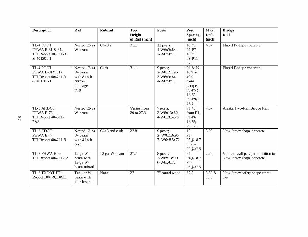
57
Description Rail Rubrail Top Height of Rail (inch)
Posts Post Spacing (inch)
Max. Defl. (inch)
Bridge Rail
TL-4 PDOT FHWA B-81 & 81a TTI Report 404211-3 & 401301-1
Nested 12-ga W-beam
C6x8.2 31.1 11 posts; 4-W6x9x84 7-W6x9x72
10.35 P1-P7 18.75 P8-P11 37.5
6.97 Flared F-shape concrete
TL-4 PDOT FHWA B-81& 81a TTI Report 404211-3 & 401301-1
Nested 12-ga W-beam with 8 inch curb & drainage inlet
Curb 31.1 9 posts; 2-W8x21x96 3-W6x9x84 4-W6x9x72
P1 & P2 16.9 & 49.0 from parapet P3-P5 @ 18.75 P6-P9@ 37.5
Flared F-shape concrete
TL-3 AKDOT FHWA B-78 TTI Report 404311-7&8
Nested 12-ga W-beam
Varies from 29 to 27.8
7 posts; 3-W8x13x82 4-W6x8.5x78
P1 45 from B1; P1-P6 18.75; P7 37.5
4.57 Alaska Two-Rail Bridge Rail
TL-3 CDOT FHWA B-77 TTI Report 404211-9
Nested 12-ga W-beam with 4 inch curb
C6x8 and curb 27.8 9 posts; 2- W8x13x90 7- W6x8.5x72
12 [email protected]; [email protected]
3.03 New Jersey shape concrete
TL-3 FHWA B-65 TTI Report 404211-12
12-ga W-beam with 12-ga W-beam rubrail
12 ga. W-beam 27.7 8 posts; 2-W8x13x90 6-W6x9x72
[email protected]@37.5
2.76 Vertical wall parapet transition to New Jersey shape concrete
TL-3 TXDOT TTI Report 1804-9,10&11
Tubular W-beam with pipe inserts
None 27 7" round wood 37.5 5.52 & 13.8
New Jersey safety shape w/ cut toe

58
Description Rail Rubrail Top Height of Rail (inch)
Posts Post Spacing (inch)
Max. Defl. (inch)
Bridge Rail
AESTHETIC
TL-3 FHWA B-64D2 TTI Report 405181-22
6 x 10 Steel-backed timber guardrail with TS4x4x.25 backup
None 27 6 posts; W6x20x78
B1-P1&[email protected];P4-P6@59
5.5 Tubular Steel-Backed Timber Bridge Rail
TL-3 FHWA B-64D2 TTI Report 405181-18&5a (TL-2)
6 x 10 Steel-backed timber guardrail
6x6 timber 27 7 posts; 4-10x12x96 3-10x12x84
P1-P4@30;P4-P7@60
1.18 Straight Stone Masonry Guardwall with Tapered End
TL-2 FHWA B-64D2 6 x 10 Steel-backed timber guardrail
6x6 timber 27 7 posts; 4-10x12x96 3-10x12x84
P1-P4@30;P4-P7@60
Curved Stone Masonry Guardwall
TL-3 FHWA B-64D2 TTI Report 405501-4
6 x 12 Steel-backed timber guardrail
Tapered curb 30 7 posts; W6x15x68
P1-P4@30;P4-P7@60
5.9 New Jersey shaped concrete
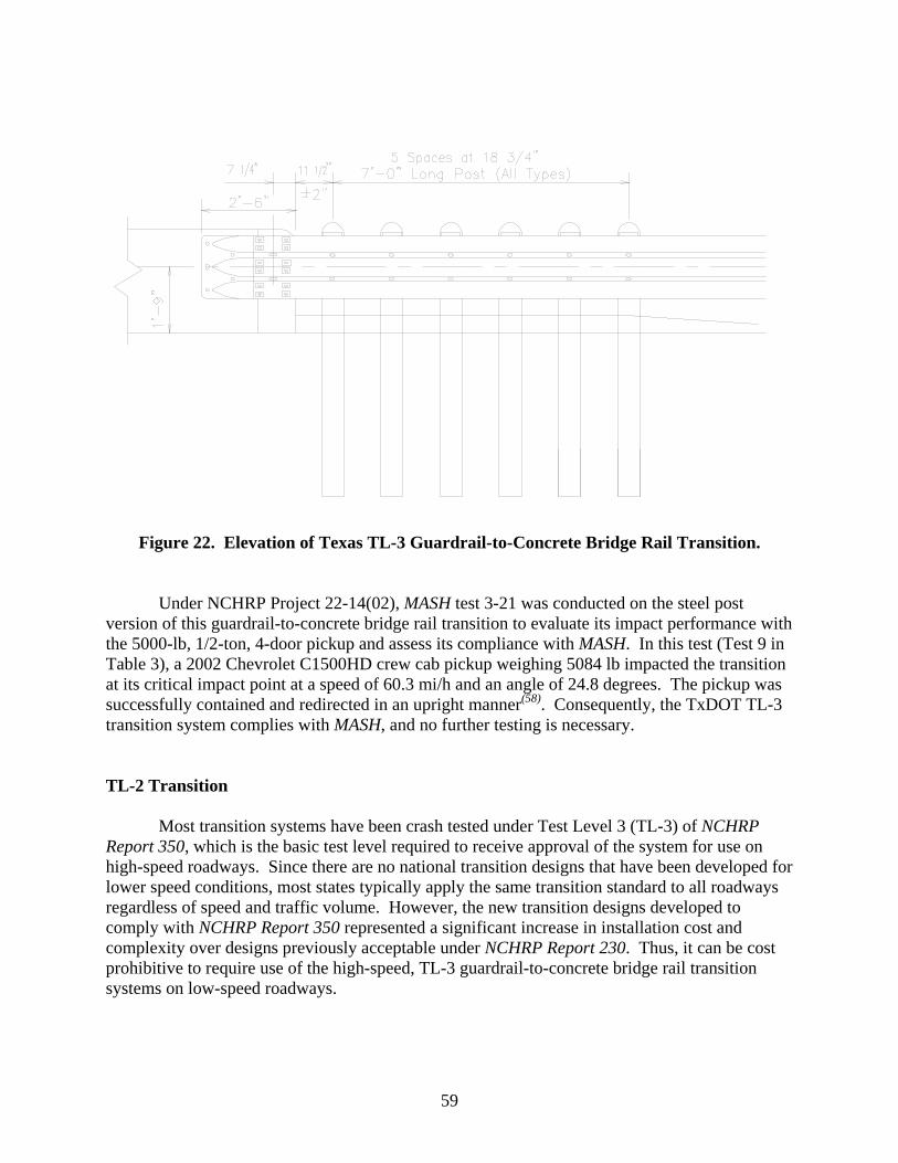
59
Figure 22. Elevation of Texas TL-3 Guardrail-to-Concrete Bridge Rail Transition.
Under NCHRP Project 22-14(02), MASH test 3-21 was conducted on the steel post version of this guardrail-to-concrete bridge rail transition to evaluate its impact performance with the 5000-lb, 1/2-ton, 4-door pickup and assess its compliance with MASH. In this test (Test 9 in Table 3), a 2002 Chevrolet C1500HD crew cab pickup weighing 5084 lb impacted the transition at its critical impact point at a speed of 60.3 mi/h and an angle of 24.8 degrees. The pickup was successfully contained and redirected in an upright manner(58). Consequently, the TxDOT TL-3 transition system complies with MASH, and no further testing is necessary.
TL-2 Transition
Most transition systems have been crash tested under Test Level 3 (TL-3) of NCHRP Report 350, which is the basic test level required to receive approval of the system for use on high-speed roadways. Since there are no national transition designs that have been developed for lower speed conditions, most states typically apply the same transition standard to all roadways regardless of speed and traffic volume. However, the new transition designs developed to comply with NCHRP Report 350 represented a significant increase in installation cost and complexity over designs previously acceptable under NCHRP Report 230. Thus, it can be cost prohibitive to require use of the high-speed, TL-3 guardrail-to-concrete bridge rail transition systems on low-speed roadways.

60
For these reasons, TxDOT developed a cost-effective TL-2 transition for use on low-speed roadways. The TL-2 transition, shown in Figure 23, is entirely comprised of standard hardware components and is significantly less expensive and complex to install than the high-speed, TL-3 transition system. This transition consists of 12 ft-6 inches of nested W-beam rail supported on 6-ft long steel or wood posts spaced at 37-1/2 inches. The 27-inch mounting height greatly simplifies the ability to connect the transition to some existing bridge rails. A W-beam terminal connector is used to attach the downstream end of the transition to the concrete bridge rail parapet. Additional details of the TL-2 transition are presented in TxDOT standard detail sheet MBGF (TL2)-05.
Figure 23. Texas TL-2 Guardrail-to-Concrete Bridge Rail Transition.
Test Designation 2-21 was performed in accordance with the guidelines and procedures
set forth in NCHRP Report 350(56). This test consisted of a 4409-lb, 3/4-ton pickup truck impacting the critical impact point of the transition at a speed of 43.5 mi/h and an angle of 25 degrees. The test vehicle was successfully contained and redirected in a stable manner and the TL-2 transition system met all applicable NCHRP Report 350 evaluation criteria. The maximum dynamic deflection of the transition rail was only 2.6 inches. The maximum roll angle of the pickup truck was 13.4 degrees, and the maximum occupant compartment deformation was only 0.4 inch. Based on the performance of this transition system, the researchers believe it will also perform acceptably to the MASH test conditions. Additional discussion of the general performance of transitions to the MASH conditions follows.
General Transition Discussion
The researchers believe the propensity for wheel snagging, excessive occupant compartment deformation, and vehicle instability (i.e., rollover) are greater for the 3/4-ton

61
pickup truck of NCHRP Report 350 than the 1/2-ton, 4-door pickup truck designated in MASH. Although the 13 percent increase in vehicle weight and impact severity may slightly increase dynamic deflections, increases, if any, in vehicle roll angles and occupant compartment deformations resulting from NCHRP Report 350 test 3-21 should be minimal. Most transition systems should be capable of safely accommodating the increase in impact severity without imparting excessive occupant compartment deformation (OCD) or vehicle instability. Additionally, even if the OCD were to modestly increase, it would unquestionably be below the 9- to 12-inch threshold established in MASH.
With these factors in mind, it is the opinion of the researchers that most NCHRP Report
350 transition designs will comply with MASH test 3-21. Further testing and evaluation does not appear necessary at this time and, consequently, is given a low priority.
END TERMINALS AND CRASH CUSHIONS
Crashworthy end terminals and crash cushions are installed to shield some discrete hazard or the terminus of something rigid installed within the clear zone, such as the end of a flexible W-beam guardrail, the end of a rigid concrete barrier, a bridge pier, overhead sign structure, or a gore area. End terminals reduce the impact severity of an errant vehicle striking the terminus of a longitudinal barrier. If the terminal is struck along its side, the terminal may act to contain and redirect the striking vehicle or permit the vehicle to pass behind or through in a controlled manner if struck near its end at an angle.
Crash cushions when impacted head-on reduce the impact severity by attenuating the
energy of the errant vehicle by various means, such as, momentum transfer, material deformation, and friction. When a crash cushion is struck along its side, it may also contain/capture and/or redirect the striking vehicle or permit the vehicle to pass behind or through in a controlled manner. When a crash cushion is impacted along its nose and contains/captures or redirects the vehicle, it is referred to as a “non-gating” crash cushion. If the crash cushion allows a vehicle impacting at or near the nose of the crash cushion to pass through and travel behind, it is referred to as a “gating” crash cushion.
Crashworthy end terminals are required to safely terminate guardrail ends. Currently, all
but four W-beam guardrail end terminals that satisfy the safety evaluation criteria of NCHRP Report 350 are proprietary. Of the four W-beam guardrail end terminals that are non-proprietary, only two satisfy NCHRP Report 350 Test Level 3; the buried-in-backslope and the eccentric loader terminal.
The crash cushions and guardrail end treatments that are proprietary in nature will not be
discussed herein. The manufacturers of these devices will be required to assess the impact performance of their devices and ultimately demonstrate compliance of their devices with the new test and evaluation guidelines as determined necessary by the user agencies and FHWA. However, the researchers do note that the dramatic increase in impact severity of the pickup truck redirection tests and other changes in the test matrices for terminals and crash cushions will likely necessitate the modification of some of these systems.

62
End Terminals
Test Level 3 Guardrail Terminals
Buried-in-Backslope Guardrail Terminal (G4 System Guardrail). The W-beam guardrail buried-in-backslope terminal is used where the natural terrain backslope is in close proximity to the point where the barrier is introduced. This terminal was tested to NCHRP Report 350 3-35 on a 1:10 foreslope (with and without a flat-bottomed ditch), and on a 1:6 foreslope and a 1:4 foreslope forming a v-ditch with a 1:4 backslope. This terminal eliminates the possibility of an end-on impact with the end of the rail and reduces the likelihood of the vehicle traversing behind the rail.
The W-beam guardrail buried-in-backslope terminal is used to terminate the G4(2W) or modified G4(1S) guardrail systems. The guardrail is flared across the ditch with its end anchored to a concrete anchor block buried in the backslope. The post height varies the last 50 ft of the installation as the rail tapers into the backslope. A W-beam rubrail is used where the bottom height of the guardrail beam exceeds 18 inches. Depending on the guardrail system it is attached to, the terminal posts are either 6 inch x 8 inch wood or W6x8.5 steel posts. A photograph of the Buried-in-Backslope Guardrail Terminal is shown in Figure 24.
Figure 24. Buried-in-Backslope Guardrail Terminal.

63
As noted in FHWA acceptance letter CC53A(17):
Key elements common to all buried-in-backslope include: 1) using a flare rate that is appropriate for the design speed until the flow line is reached; 2) keeping the W-beam rail height constant relative to the roadway grade until the barrier crosses the ditch flow line (and beyond where practical); 3) adding a rubrail whenever the clearance from the bottom of the W-beam to the ground line exceeds approximately 450 mm; 4) providing at least 22 m of barrier upstream from the beginning of the area of concern to the point where the barrier crosses the ditch flow line (to allow some recovery area for an impacting vehicle that may ride up a relatively flat backslope and get behind the barrier); and 5) using an anchor (concrete block or steel posts) that is capable of developing the full tensile strength of the W-beam rail.
The buried-in-backslope G4 guardrail terminal contained and redirected the 2000P pickup truck vehicle in each of the three tests. Maximum dynamic deflections of the rail were 29.5 inches, 31.4 inches, and 26.4 inches and maximum permanent deflections were 9.4 inches, 19.7 inches, and 16.1 inches. The occupant compartment deformations were 2.6 inches, 1.3 inches, and 8.1 inches, and the vehicles were very stable throughout each impact event(59, 42). The buried-in-backslope G4 guardrail terminal performed well and is it is the opinion of the researchers that this system would perform acceptably under Test Level 3 conditions of MASH.
Eccentric Loader Terminal (ELT). The Minnesota Department of Transportation sponsored crash testing the Eccentric Loader Terminal (ELT) to NCHRP Report 350 test conditions in 1998(60). In consultation with FHWA, only NCHRP Report 350 tests 3-31 (pickup head-on) and 3-35 (pickup redirect) tests were performed. The other tests were waived or were considered to be adequately addressed in prior tests performed when the ELT was evaluated in accordance with NCHRP Report 230.
The ELT is a 37 ft-6-inch long flared W-beam guardrail terminal. The terminal head has
a lateral offset of 4 ft. Attached to the end of the W-beam, at the nose of the terminal, is a vertically oriented corrugated pipe section with a fabricated structural steel loader mounted inside of the pipe section. The ELT is fabricated from three 12 ft-6-inch sections of 12-gauge W-beam mounted to two 6 inch x 8 inch Breakaway Cable Terminal (BCT) posts mounted in foundation tubes, interconnected with a ground channel strut, and 6 inch x 8 inch wood Controlled Releasing Terminal (CRT) posts in post locations 3 through 7. Posts 3 through 6 are spaced 50 inches on center. All other posts are spaced the standard 6 ft-3 inches. All posts, except the first post, are blocked out with 6 inch x 8 inch wood blocks. A photograph of the ELT is shown in Figure 25.

64
Figure 25. Eccentric Loader Terminal.
The ELT marginally met the safety performance evaluation criteria for NCHRP Report
350 tests 3-31 and 3-35. The ELT contained and redirected the 2000P pickup truck vehicle in test 3-35. However, the rail partially tore at the splice located at post 6. Maximum dynamic deflection of the rail was 39.0 inches and the maximum permanent deflection was 25.2 inches. The occupant compartment deformation was 2.4 inches. The vehicle was very stable throughout the event.
In test 3-31, the ELT brought the 2000P pickup truck vehicle to a stop. However, the
pickup truck mounted and rode on top of the guardrail a distance of 149.2 ft from the point of impact. There was no occupant compartment deformation. The vehicle exhibited moderate roll and pitch as it mounted and rode the rail.
As noted in FHWA acceptance letter CC56(19), the NCHRP Report 350 ELT differs from
the NCHRP Report 230 version in that: 1) a steel post equivalent version of the ELT is not permitted; 2) post 7 is a CRT post (before it was a standard line post); and 3) post 2 offset distance changes from 25 inches to 26 inches. In addition, the pickup truck rode the rail for 147.6 ft. Each barrier installation terminated with an ELT should have a length-of-need sufficiently long to prevent an impacting vehicle from reaching a shielded fixed-object hazard that is directly behind the guardrail.
In summary, the ELT guardrail terminal performed marginally in the tests performed to
evaluate its compliance with NCHRP Report 350. The guardrail partially ruptured at a splice during the redirect test and rode on top of the guardrail installation a distance of 149.2 ft before coming to a stop in the end-on impact test. In consideration of other guardrail tests performed using the MASH pickup truck vehicle, it is the opinion of the researchers that this system has a high probability of rail rupture in the terminal redirection test with the MASH pickup truck. The end-on test resulted in a very long stopping distance and will likely not improve with the heavier and higher C.G. 5000-lb MASH pickup truck. The researchers do not recommend testing the
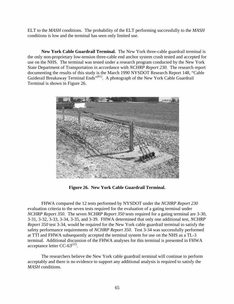
65
ELT to the MASH conditions. The probability of the ELT performing successfully to the MASH conditions is low and the terminal has seen only limited use.
New York Cable Guardrail Terminal. The New York three-cable guardrail terminal is the only non-proprietary low-tension three-cable end anchor system crash tested and accepted for use on the NHS. The terminal was tested under a research program conducted by the New York State Department of Transportation in accordance with NCHRP Report 230. The research report documenting the results of this study is the March 1990 NYSDOT Research Report 148, “Cable Guiderail Breakaway Terminal Ends”(61). A photograph of the New York Cable Guardrail Terminal is shown in Figure 26.
Figure 26. New York Cable Guardrail Terminal.
FHWA compared the 12 tests performed by NYSDOT under the NCHRP Report 230
evaluation criteria to the seven tests required for the evaluation of a gating terminal under NCHRP Report 350. The seven NCHRP Report 350 tests required for a gating terminal are 3-30, 3-31, 3-32, 3-33, 3-34, 3-35, and 3-39. FHWA determined that only one additional test, NCHRP Report 350 test 3-34, would be required for the New York cable guardrail terminal to satisfy the safety performance requirements of NCHRP Report 350. Test 3-34 was successfully performed at TTI and FHWA subsequently accepted the terminal system for use on the NHS as a TL-3 terminal. Additional discussion of the FHWA analyses for this terminal is presented in FHWA acceptance letter CC-63(22).
The researchers believe the New York cable guardrail terminal will continue to perform
acceptably and there is no evidence to support any additional analysis is required to satisfy the MASH conditions.

66
Test Level 2 Guardrail Terminals
Vermont Low-Speed Strong Post W-Beam Guardrail Terminal – (G-1d). The Vermont Department of Transportation sponsored crash testing the Vermont G1-d terminal to NCHRP Report 350 TL-2 test conditions. The Vermont G1-d terminal had not previously been crash tested and initially NCHRP Report 350 test 1-30 was performed. Upon successful completion of this test, Vermont DOT decided to evaluate the terminal to TL-2. Three additional tests were performed at TTI, tests 2-30, 2-34, and 2-35(62). Upon successful completion of these tests, FHWA accepted the Vermont G1-d terminal for use on the NHS where the speeds are 44 mi/h or less(21).
The Vermont G1-d terminal is a 12 ft-6 inch-long flared strong post W-beam guardrail
terminal. The terminal end has a lateral offset of 5 ft. The first W-beam rail section is shop bent to a 16-ft radius. Post 2 is positioned at the midpoint of the curved guardrail section. The terminal is anchored using a steel rod attached to the guardrail at post 3 and anchored to a concrete block in the ground between posts 2 and 3. The W-beam terminal is supported on W6x8.5 x 72-inch steel posts. All posts are spaced the standard 6 ft-3 inches apart and blocked out with W6x8.5 x 14-inch standard G4(1S) guardrail blockouts. A photograph of the Vermont Low-Speed Guardrail Terminal is shown in Figure 27.
Figure 27. Vermont Low-Speed Guardrail Terminal.
The Vermont G1-d terminal successfully met the safety performance evaluation criteria
for NCHRP Report 350 tests 1-30, 2-30, 2-34, and 2-35. In test 1-30 (end-on impact), the Vermont G1-d terminal stopped the 820C vehicle with the vehicle still in contact with the terminal end. Maximum dynamic deflection of the rail was 46.1 inches and the maximum permanent deflection was 12.6 inches. There was no occupant compartment deformation. The vehicle was relatively stable throughout the event.
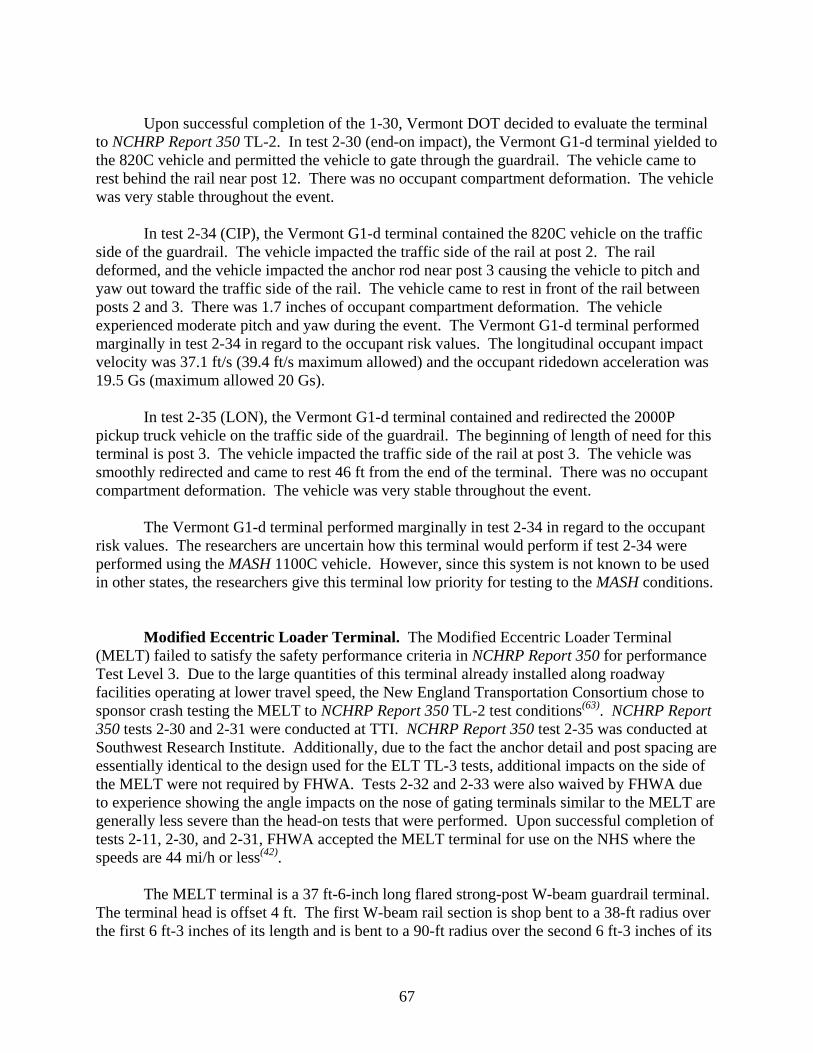
67
Upon successful completion of the 1-30, Vermont DOT decided to evaluate the terminal
to NCHRP Report 350 TL-2. In test 2-30 (end-on impact), the Vermont G1-d terminal yielded to the 820C vehicle and permitted the vehicle to gate through the guardrail. The vehicle came to rest behind the rail near post 12. There was no occupant compartment deformation. The vehicle was very stable throughout the event.
In test 2-34 (CIP), the Vermont G1-d terminal contained the 820C vehicle on the traffic
side of the guardrail. The vehicle impacted the traffic side of the rail at post 2. The rail deformed, and the vehicle impacted the anchor rod near post 3 causing the vehicle to pitch and yaw out toward the traffic side of the rail. The vehicle came to rest in front of the rail between posts 2 and 3. There was 1.7 inches of occupant compartment deformation. The vehicle experienced moderate pitch and yaw during the event. The Vermont G1-d terminal performed marginally in test 2-34 in regard to the occupant risk values. The longitudinal occupant impact velocity was 37.1 ft/s (39.4 ft/s maximum allowed) and the occupant ridedown acceleration was 19.5 Gs (maximum allowed 20 Gs).
In test 2-35 (LON), the Vermont G1-d terminal contained and redirected the 2000P
pickup truck vehicle on the traffic side of the guardrail. The beginning of length of need for this terminal is post 3. The vehicle impacted the traffic side of the rail at post 3. The vehicle was smoothly redirected and came to rest 46 ft from the end of the terminal. There was no occupant compartment deformation. The vehicle was very stable throughout the event.
The Vermont G1-d terminal performed marginally in test 2-34 in regard to the occupant
risk values. The researchers are uncertain how this terminal would perform if test 2-34 were performed using the MASH 1100C vehicle. However, since this system is not known to be used in other states, the researchers give this terminal low priority for testing to the MASH conditions.
Modified Eccentric Loader Terminal. The Modified Eccentric Loader Terminal (MELT) failed to satisfy the safety performance criteria in NCHRP Report 350 for performance Test Level 3. Due to the large quantities of this terminal already installed along roadway facilities operating at lower travel speed, the New England Transportation Consortium chose to sponsor crash testing the MELT to NCHRP Report 350 TL-2 test conditions(63). NCHRP Report 350 tests 2-30 and 2-31 were conducted at TTI. NCHRP Report 350 test 2-35 was conducted at Southwest Research Institute. Additionally, due to the fact the anchor detail and post spacing are essentially identical to the design used for the ELT TL-3 tests, additional impacts on the side of the MELT were not required by FHWA. Tests 2-32 and 2-33 were also waived by FHWA due to experience showing the angle impacts on the nose of gating terminals similar to the MELT are generally less severe than the head-on tests that were performed. Upon successful completion of tests 2-11, 2-30, and 2-31, FHWA accepted the MELT terminal for use on the NHS where the speeds are 44 mi/h or less(42).
The MELT terminal is a 37 ft-6-inch long flared strong-post W-beam guardrail terminal.
The terminal head is offset 4 ft. The first W-beam rail section is shop bent to a 38-ft radius over the first 6 ft-3 inches of its length and is bent to a 90-ft radius over the second 6 ft-3 inches of its
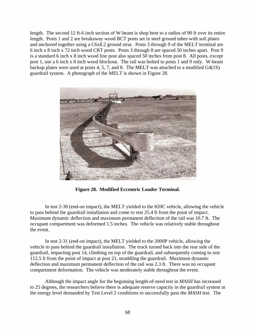
68
length. The second 12 ft-6 inch section of W-beam is shop bent to a radius of 90 ft over its entire length. Posts 1 and 2 are breakaway wood BCT posts set in steel ground tubes with soil plates and anchored together using a C6x8.2 ground strut. Posts 3 through 9 of the MELT terminal are 6 inch x 8 inch x 72 inch wood CRT posts. Posts 3 through 8 are spaced 50 inches apart. Post 9 is a standard 6 inch x 8 inch wood line post also spaced 50 inches from post 8. All posts, except post 1, use a 6 inch x 8 inch wood blockout. The rail was bolted to posts 1 and 9 only. W-beam backup plates were used at posts 4, 5, 7, and 8. The MELT was attached to a modified G4(1S) guardrail system. A photograph of the MELT is shown in Figure 28.
Figure 28. Modified Eccentric Loader Terminal.
In test 2-30 (end-on impact), the MELT yielded to the 820C vehicle, allowing the vehicle
to pass behind the guardrail installation and come to rest 25.4 ft from the point of impact. Maximum dynamic deflection and maximum permanent deflection of the rail was 10.7 ft. The occupant compartment was deformed 1.5 inches. The vehicle was relatively stable throughout the event.
In test 2-31 (end-on impact), the MELT yielded to the 2000P vehicle, allowing the
vehicle to pass behind the guardrail installation. The truck turned back into the rear side of the guardrail, impacting post 14, climbing on top of the guardrail, and subsequently coming to rest 112.5 ft from the point of impact at post 21, straddling the guardrail. Maximum dynamic deflection and maximum permanent deflection of the rail was 2.3 ft. There was no occupant compartment deformation. The vehicle was moderately stable throughout the event.
Although the impact angle for the beginning length-of-need test in MASH has increased
to 25 degrees, the researchers believe there is adequate reserve capacity in the guardrail system at the energy level demanded by Test Level 2 conditions to successfully pass the MASH test. The

69
MELT should perform satisfactorily to the MASH conditions for Test Level 2. However, the researchers give this terminal a low priority for testing to the MASH conditions given the limited number of states that currently use the MELT.
Crash Cushions
Connecticut Impact Attenuator System
The Connecticut Impact Attenuator System (CIAS) was developed in the early 1980’s and tested in accordance with Transportation Research Circular 191 and NCHRP Report 230. Additionally, an in-service performance evaluation of the CIAS was performed up through 1987. The CIAS is the only NCHRP Report 350 non-proprietary crash cushion used on the NHS.
The CIAS consists of 14 steel cylinders arranged in a seven row matrix of cylinders affixed to a rigid backup structure that crush upon impact, thus attenuating the energy of an errant vehicle. Twelve of the steel cylinders are 4.0 ft in diameter and the two cylinders in the second row of the crash cushion are 3.0 ft in diameter. All the cylinders are 4.0 ft tall.
The CIAS is constructed so that the wall thickness of the three cylinders anchored to the backup structure is 1/4 inch. The next two cylinders have a wall thickness of 3/8 inch followed by six cylinders (three rows of two cylinders each) with a 3/16-inch wall. The second row cylinders are 8-gauge steel and the single nose cylinder is 3/16 inch. Stiffening members constructed of 0.125 x 5.0 steel straps are placed in the rear most seven cylinders. Additionally, 1.5-inch diameter schedule 40 pipe is placed transversely in the four cylinders in front of the last row of three cylinders. All the cylinder contact points are interconnected with 7/8-inch diameter x 2-inch long A307 bolts, washers, and nuts. A photograph of the CIAS is shown in Figure 29. The CDOT standard drawings should be referred to for additional construction and anchoring details.
Figure 29. Connecticut Impact Attenuator System.

70
To evaluate the CIAS in accordance with NCHRP Report 350, two crash tests were initially performed, 3-32 and 3-38(64). In test 3-32, an 1808-lb passenger car traveling 62.1 mi/h impacted the nose of the CIAS at 15.8 degrees and deformed the cushion 12.1 ft. In test 3-38, a 4409-lb pickup truck traveling 62.6 mi/h impacted near the midpoint of the side of the cushion at 19.9 degrees. The critical impact point was selected so that the centerline of the impacting vehicle was aligned with the center-rear of the cushion. The change in longitudinal occupant impact velocity was 37.0 ft/s and the occupant compartment was deformed 7.3 inches. The test was considered unsuccessful due to excessive deformation of the occupant compartment. CDOT modified the CIAS by placing the steel cylinder array on top of two steel skid rails anchored to the pavement surface and offsetting the rear-most outside cylinders 33 inches from the edge of the backup structure using steel L-brackets. The L-brackets allowed the cylinder to be extended out past the backup structure edge an additional 6 inches. Other changes were in the classification of the CIAS. The CIAS was originally tested as a “non-gating” crash cushion, in consultation with FHWA the classification was changed to a “redirective/gating” crash cushion. Thereafter, NCHRP Report 350 tests 3-33 (15 degree impact on the nose) and 3-35 (impact at the beginning of length-of-need) were performed(65). In test 3-35, a 4409-lb pickup truck traveling 61.8 mi/h impacted near the midpoint of the side of the cushion at 20.5 degrees. The change in longitudinal occupant impact velocity was 35.7 ft/s, the 10-millisecond longitudinal ridedown acceleration was -18.8 Gs, and the occupant compartment was deformed 4.3 inches. The test performance was considered acceptable.
In test 3-33, a 4409-lb pickup truck traveling 62.1 mi/h impacted the nose of the cushion at 14.7 degrees. The cushion deformed 13.7 ft and the pickup passed through the cushion while yawing minimally. The change in longitudinal occupant impact velocity was 24.7 ft/s, the 10-millisecond longitudinal ridedown acceleration was -6.1 Gs, and the occupant compartment was deformed 0.3 inches. The test performance was considered acceptable.
One additional test, test 3-34, was performed to demonstrate satisfactory performance of
the 1808-lb passenger car when an impact occurred between the nose of the cushion and the beginning length-of–need along the side of the cushion(66). In test 3-34, an 1808-lb passenger car traveling 61.3 mi/h impacted the side of the cushion at the third row cylinder at 15.4 degrees. The cushion deformed laterally 3.1 ft and the car came to rest alongside the cushion. The change in longitudinal occupant impact velocity was 35.1 ft/s, the 10-millisecond longitudinal ridedown acceleration was -20.5 Gs, and the occupant compartment was deformed 1.3 inches. The test performance was considered marginal due the 10-millisecond longitudinal ridedown acceleration being -20.5 Gs.
MASH is changing the impact angle for test designation 3-35 and 3-38 from 20 degrees to
25 degrees. The combination of the increase in the impact angle from 20 to 25 degrees and the increase in the weight of the pickup truck from 4409 to 5000 lb warrants the conduct of test 3-35 to evaluate compliance of the CIAS. The combination of the increase in test vehicle weight and impact angle increases the lateral impact severity approximately 73 percent. The researchers
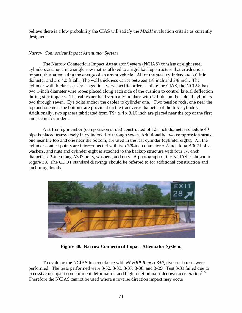
71
believe there is a low probability the CIAS will satisfy the MASH evaluation criteria as currently designed.
Narrow Connecticut Impact Attenuator System
The Narrow Connecticut Impact Attenuator System (NCIAS) consists of eight steel cylinders arranged in a single row matrix affixed to a rigid backup structure that crush upon impact, thus attenuating the energy of an errant vehicle. All of the steel cylinders are 3.0 ft in diameter and are 4.0 ft tall. The wall thickness varies between 1/8 inch and 3/8 inch. The cylinder wall thicknesses are staged in a very specific order. Unlike the CIAS, the NCIAS has two 1-inch diameter wire ropes placed along each side of the cushion to control lateral deflection during side impacts. The cables are held vertically in place with U-bolts on the side of cylinders two through seven. Eye bolts anchor the cables to cylinder one. Two tension rods, one near the top and one near the bottom, are provided on the transverse diameter of the first cylinder. Additionally, two spacers fabricated from TS4 x 4 x 3/16 inch are placed near the top of the first and second cylinders.
A stiffening member (compression struts) constructed of 1.5-inch diameter schedule 40 pipe is placed transversely in cylinders five through seven. Additionally, two compression struts, one near the top and one near the bottom, are used in the last cylinder (cylinder eight). All the cylinder contact points are interconnected with two 7/8-inch diameter x 2-inch long A307 bolts, washers, and nuts and cylinder eight is attached to the backup structure with four 7/8-inch diameter x 2-inch long A307 bolts, washers, and nuts. A photograph of the NCIAS is shown in Figure 30. The CDOT standard drawings should be referred to for additional construction and anchoring details.
Figure 30. Narrow Connecticut Impact Attenuator System.
To evaluate the NCIAS in accordance with NCHRP Report 350, five crash tests were performed. The tests performed were 3-32, 3-33, 3-37, 3-38, and 3-39. Test 3-39 failed due to excessive occupant compartment deformation and high longitudinal ridedown acceleration(67). Therefore the NCIAS cannot be used where a reverse direction impact may occur.
72
In test 3-32, an 1808-lb passenger car traveling 61.5 mi/h impacted the nose of the
NCIAS at 14.4 degrees and deformed the cushion 12.9 ft. The vehicle yawed 109 degrees and came to rest 14.8 ft laterally from the cushion. All the occupant risk criteria were satisfied.
In test 3-33, a 4409-lb pickup truck traveling 61.7 mi/h impacted the nose of the cushion
at 14.7 degrees and deformed the cushion 7.4 ft. The vehicle yawed 72 degrees and came to rest 15.0 ft laterally from the cushion. All the occupant risk criteria were satisfied.
In test 3-37, a 4409-lb pickup truck traveling 60.4 mi/h impacted the beginning length-of-
need (BLON) along the side of the cushion at 20.2 degrees and deformed the cushion 2.1 ft. The BLON was approximately the mating interface of cylinders one and two. The vehicle was contained and redirected. All the occupant risk criteria were satisfied. The maximum occupant compartment deformation was 1.5 inches. The lateral ridedown accelerations were was -19.5 Gs, which approached the maximum value of 20 Gs.
In test 3-38, a 4409-lb pickup truck traveling 62.2 mi/h impacted the critical impact point
along the side of the cushion at 19.6 degrees and deformed the cushion 0.8 ft. The critical impact point was selected so that the centerline of the impacting vehicle was aligned with the center-rear of the cushion. The change in longitudinal occupant impact velocity was 24.9 ft/s and the occupant compartment was deformed 6.6 inches. The vehicle was contained and redirected. Although the occupant compartment deformation was marginal, all occupant risk criteria nonetheless were satisfied.
MASH is changing the impact angle for test designation 3-38 from 20 degrees to
25 degrees. The combination of the increase in the impact angle from 20 to 25 degrees and the increase in the weight of the pickup truck from 4409 to 5000 lb warrants the conduct of test 3-38 to evaluate impact performance in accordance with MASH. The combination of the increase in test vehicle weight and impact angle increases the lateral impact severity approximately 73 percent. The researchers believe there is a low probability the NCIAS will satisfy the MASH evaluation criteria.
Thrie-Beam Bullnose Guardrail System (Bullnose Attenuator)
The Thrie-Beam Bullnose Guardrail System (Bullnose Attenuator) is the last type of median hazard protection that will be discussed herein. The Bullnose is a hybrid of a guardrail terminal and a crash attenuator. The Bullnose is an enclosed guardrail envelope that wraps the hazard being protected with a thrie-beam guardrail system. A length-of-need of thrie-beam guardrail is placed parallel to each of two roadways along a divided roadway median and is terminated by joining the separate guardrail runs together with a pseudo-elliptical section of thrie-beam.
Thrie-beam guardrail has long been acceptable for use on the NHS. However, the
terminus (the bullnose) of connecting two thrie-beam guardrails together did not meet NCHRP Report 350. The Midwest State’s Regional Pooled Fund Program sponsored a very in-depth
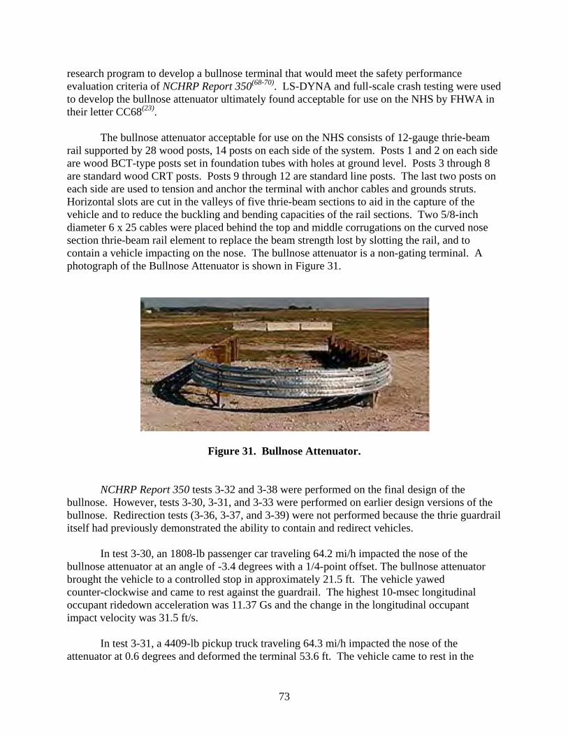
73
research program to develop a bullnose terminal that would meet the safety performance evaluation criteria of NCHRP Report 350(68-70). LS-DYNA and full-scale crash testing were used to develop the bullnose attenuator ultimately found acceptable for use on the NHS by FHWA in their letter CC68(23).
The bullnose attenuator acceptable for use on the NHS consists of 12-gauge thrie-beam
rail supported by 28 wood posts, 14 posts on each side of the system. Posts 1 and 2 on each side are wood BCT-type posts set in foundation tubes with holes at ground level. Posts 3 through 8 are standard wood CRT posts. Posts 9 through 12 are standard line posts. The last two posts on each side are used to tension and anchor the terminal with anchor cables and grounds struts. Horizontal slots are cut in the valleys of five thrie-beam sections to aid in the capture of the vehicle and to reduce the buckling and bending capacities of the rail sections. Two 5/8-inch diameter 6 x 25 cables were placed behind the top and middle corrugations on the curved nose section thrie-beam rail element to replace the beam strength lost by slotting the rail, and to contain a vehicle impacting on the nose. The bullnose attenuator is a non-gating terminal. A photograph of the Bullnose Attenuator is shown in Figure 31.
Figure 31. Bullnose Attenuator.
NCHRP Report 350 tests 3-32 and 3-38 were performed on the final design of the
bullnose. However, tests 3-30, 3-31, and 3-33 were performed on earlier design versions of the bullnose. Redirection tests (3-36, 3-37, and 3-39) were not performed because the thrie guardrail itself had previously demonstrated the ability to contain and redirect vehicles.
In test 3-30, an 1808-lb passenger car traveling 64.2 mi/h impacted the nose of the
bullnose attenuator at an angle of -3.4 degrees with a 1/4-point offset. The bullnose attenuator brought the vehicle to a controlled stop in approximately 21.5 ft. The vehicle yawed counter-clockwise and came to rest against the guardrail. The highest 10-msec longitudinal occupant ridedown acceleration was 11.37 Gs and the change in the longitudinal occupant impact velocity was 31.5 ft/s.
In test 3-31, a 4409-lb pickup truck traveling 64.3 mi/h impacted the nose of the
attenuator at 0.6 degrees and deformed the terminal 53.6 ft. The vehicle came to rest in the

74
terminal system. The highest 10-msec longitudinal occupant ridedown acceleration was 9.2 Gs and the change in the longitudinal occupant impact velocity was 17.7 ft/s.
In test 3-32, an 1808-lb passenger car traveling 65.3 mi/h impacted the nose of the
bullnose at 15.7 degrees, deformed the attenuator 21.3 ft, the vehicle yawed counter-clockwise, and the vehicle came to rest in the attenuator. The highest 10-msec longitudinal occupant ridedown acceleration was 13.9 Gs and the change in the longitudinal occupant impact velocity was 32.6 ft/s.
In test 3-33, a 4409-lb pickup truck traveling 64.0 mi/h impacted the nose of the
attenuator at 13.4 degrees and deformed the terminal 36.9 ft. The vehicle came to rest in the terminal system. The highest 10-msec longitudinal occupant ridedown acceleration was 10.5 Gs and the change in the longitudinal occupant impact velocity was 20.4 ft/s.
In test 3-38, a 4409-lb pickup truck traveling 62.0 mi/h impacted midway between posts
one and two, along the side of the attenuator, at 21.5 degrees. The vehicle came to rest in the terminal system. The highest 10-msec longitudinal occupant ridedown acceleration was 10.9 Gs and the change in the longitudinal occupant impact velocity was 29.2 ft/s.
As has previously been discussed, MASH is changing the impact angle for test
designation 3-38 from 20 degrees to 25 degrees. The combination of the increase in the impact angle from 20 to 25 degrees and the increase in the weight of the pickup truck from 4409 to 5000 lb warrants the conduct of test 3-38 to evaluate the impact performance of the bullnose attenuator in accordance with MASH. In addition, test 3-31 should also be conducted with the MASH pickup truck vehicle. The combination of the increase in test vehicle weight and impact angle increases the impact severity approximately 73 percent for test 3-38 and 13 percent for test 3-31. The researchers believe there is a possibility the bullnose attenuator may fail to satisfy the MASH evaluation criteria for these tests.
BREAKAWAY HARDWARE - SIGN SUPPORTS AND LUMINAIRES
NCHRP Report 350 and MASH each address support structures, work zone traffic control devices, and breakaway utility poles in a chapter together. Additionally, MASH has added longitudinal channelizers to the group of hardware. Longitudinal channelizers, to date, are generally comprised of proprietary water-filled plastic barrier systems, and as such, will not be discussed. Likewise, numerous types of proprietary and non-proprietary work zone traffic control devices ranging from two-piece cones, channelizing drums, vertical panels, delineators, barricades, and temporary sign supports exist. The list is far too extensive to cite and discuss each device individually. Other than temporary sign supports, it should suffice to say that there are no new or additional impact performance concerns for any of these devices with the MASH pickup truck or small car. The discussions that follow will pertain to small and large sign supports and luminaire supports only.
The NCHRP Report 350 test matrix for support structures, which includes sign supports
and luminaires, specifies two crash tests with an 1808-lb passenger car: a low-speed test and a

75
high speed test. For TL-3, the relevant test designations are 3-60 and 3-61, which have design impact speeds of 21.8 mi/h and 62.2 mi/h, respectively. NCHRP Report 350 allowed for the use of a lighter weight (1543-lb) passenger car. However, the lighter vehicle was never really used in practice. In addition, the 4408-lb pickup truck, although not designated by a specific test number, could be used if the primary concern regarding the impact behavior of the support system is penetration of the test installation into the occupant compartment rather than excessive occupant impact velocity or ridedown acceleration and/or vehicle instability. NCHRP Report 350 test numbers 3-60 and 3-61 specified a critical impact angle (CIA) be determined and selected from a 0 to 20 degree impact envelope, as measured from the normal traffic travel direction. If the support structure is installed at or near an intersection, then the CIA could be tested at some angle other than 0 to 20 degrees (i.e. 90 degrees for example).
The NCHRP Report 350 performance evaluation criteria for support structures consist of several evaluation factors. The evaluation factors as described in NCHRP Report 350 are:
B. The test article should readily activate in a predictable manner by breaking away, fracturing, or yielding.
D. Detached elements, fragments or other debris from the test article should not penetrate or show potential for penetrating the occupant compartment, or present an undue hazard to other traffic, pedestrians, or personnel in a work zone. Deformations of, or intrusions into, the occupant compartment that could cause serious injuries should not be permitted.
F. The vehicle should remain upright during and after collision although moderate roll, pitching, and yawing are acceptable.
H. Longitudinal occupant impact velocity is preferred to be less than or equal to 9.8 ft/s and should not exceed a maximum of 16.4 ft/s.
I. Longitudinal and lateral occupant ridedown accelerations are preferred to be less than or equal to 15 Gs and the maximum is 20 Gs.
K. After the collision it is preferable that the vehicle’s trajectory not intrude into adjacent traffic lanes.
N. Vehicle trajectory behind the test article is acceptable.
Of primary concern regarding the impact behavior of a support structure is preserving the integrity of the occupant compartment. To minimize the potential for injury during impact, penetration of the test article or parts of the test article into the occupant compartment is not permitted. However, NCHRP Report 350 does not specify a quantitative threshold for permissible deformation to the occupant compartment. FHWA drafted guidance for occupant compartment deformation and windshield damage in 1999 to supplement the evaluation criteria presented in NCHRP Report 350. These documents were titled: “Draft Guidance for Analysis of Passenger Compartment Intrusion”(71) and “Windshield Damage for Category II Work Zone Traffic Control Devices: Draft Guidance for Pass/Fail”(72). However, the windshield damage criteria were only for Category II work zone devices and never used for evaluating sign supports and luminaires. From the “Draft Guidance for Analysis of Passenger Compartment Intrusion”
76
document came additional performance evaluation criteria for small sign supports and luminaires. In general, deformation to the occupant compartment in the area of the roof could not exceed 6 inches.
In MASH, the 1800-lb passenger car is replaced by a heavier 2425-lb passenger car
(denoted 1100C). The impact speed for the low-speed test (test 3-60) has been decreased from 22 mi/h to 18.6 mi/h. The purpose of the speed reduction in MASH test 3-60 was to maintain the same nominal kinetic energy as NCHRP Report 350 test 3-60. The kinetic energy in MASH for test 3-60 is nominally 1.5 percent lower. This low-speed test evaluates the kinetic energy required to activate the breakaway, fracture, or yield the support mechanism. In addition, the effect the support has on the occupant impact velocity is normally most profound in test 3-60. The impact speed for the high-speed test (test 3-61) remains unchanged. A third test, test 3-62, was added to the MASH matrix for evaluating breakaway support structures. Test 3-62 involves a 5000-lb pickup truck vehicle impacting the test article at 62.2 mi/h at the CIA.
In NCHRP Report 350, a specified CIA was to be determined and selected from a 0 to
20 degree impact envelope, as measured from the normal traffic travel direction. In MASH, the CIA envelope range was increased to 0 to 25 degrees. As before, if the support structure is installed at or near an intersection, then the CIA could be tested at some angle other than 0 to 25 degrees (i.e. 90 degrees for example).
MASH adopts evaluation criteria language similar to NCHRP Report 350 but additionally
establishes deformation thresholds to make assessment of Criterion D more quantitative and objective. The language adopted is largely a result of the 1999 FHWA guidance memorandums(71, 72). Key to the evaluation of support structures is a roof deformation limit of 3.9 inches and a windshield deformation limit of 3 inches. Further, no tearing of the interior plastic liner of the laminated windshield glass is permitted. Additional verbiage regarding side windows was added: “no shattering of a side window resulting from the direct contact with a structural member of the test article” is permitted. If the side windows are laminate glass then the windshield evaluation criteria applies.
Table 8 lists the non-proprietary small and large sign supports and the breakaway
luminaires accepted by FHWA to date. A discussion of their performance and the affect MASH may have on their future use follows the table.
Sign supports may be generally divided into three general categories in the manner in
which they yield to an impacting vehicle: flexible/bending, fracturing, and controlled release. Examples of these types of sign supports and luminaire bases are illustrated in Figure 32.
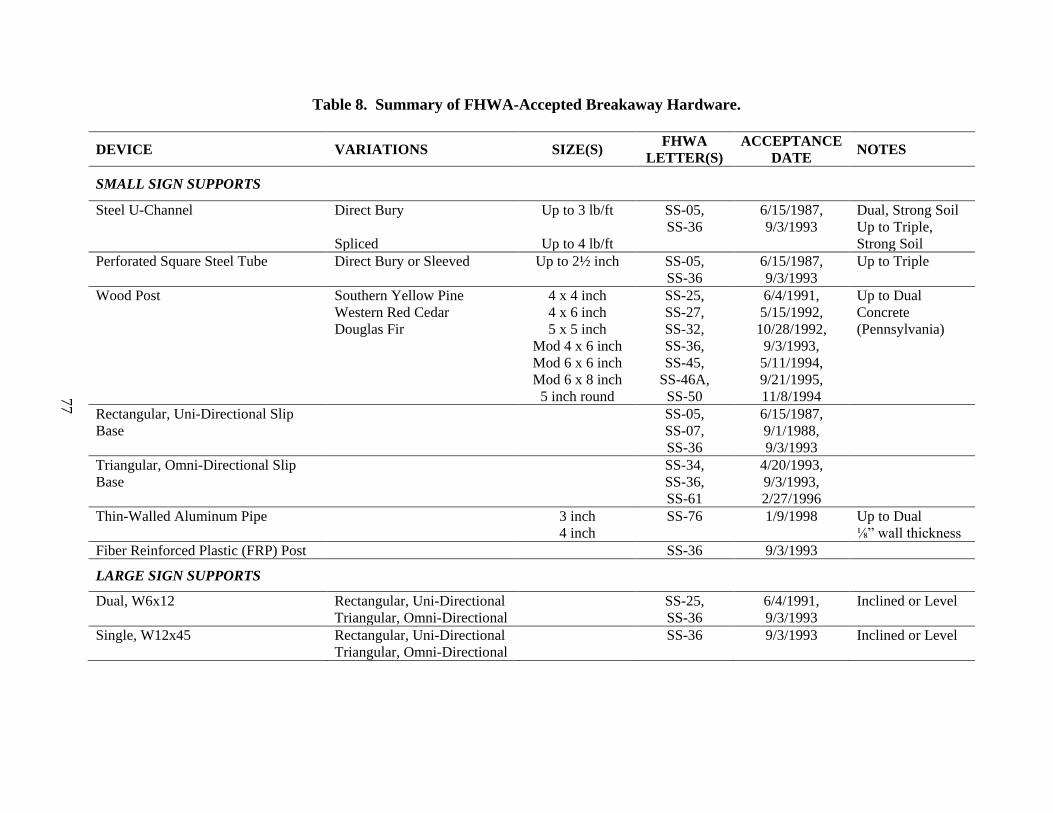
77
Table 8. Summary of FHWA-Accepted Breakaway Hardware.
DEVICE VARIATIONS SIZE(S) FHWA LETTER(S)
ACCEPTANCE DATE NOTES
SMALL SIGN SUPPORTS
Steel U-Channel Direct Bury Spliced
Up to 3 lb/ft
Up to 4 lb/ft
SS-05, SS-36
6/15/1987, 9/3/1993
Dual, Strong Soil Up to Triple, Strong Soil
Perforated Square Steel Tube Direct Bury or Sleeved Up to 2½ inch SS-05, SS-36
6/15/1987, 9/3/1993
Up to Triple
Wood Post Southern Yellow Pine Western Red Cedar Douglas Fir
4 x 4 inch 4 x 6 inch 5 x 5 inch
Mod 4 x 6 inch Mod 6 x 6 inch Mod 6 x 8 inch
5 inch round
SS-25, SS-27, SS-32, SS-36, SS-45,
SS-46A, SS-50
6/4/1991, 5/15/1992,
10/28/1992, 9/3/1993, 5/11/1994, 9/21/1995, 11/8/1994
Up to Dual Concrete (Pennsylvania)
Rectangular, Uni-Directional Slip Base
SS-05, SS-07, SS-36
6/15/1987, 9/1/1988, 9/3/1993
Triangular, Omni-Directional Slip Base
SS-34, SS-36, SS-61
4/20/1993, 9/3/1993, 2/27/1996
Thin-Walled Aluminum Pipe 3 inch 4 inch
SS-76 1/9/1998 Up to Dual ⅛” wall thickness
Fiber Reinforced Plastic (FRP) Post SS-36 9/3/1993
LARGE SIGN SUPPORTS
Dual, W6x12 Rectangular, Uni-Directional Triangular, Omni-Directional
SS-25, SS-36
6/4/1991, 9/3/1993
Inclined or Level
Single, W12x45 Rectangular, Uni-Directional Triangular, Omni-Directional
SS-36 9/3/1993 Inclined or Level

78
Flexible/Bending Sign Support
Fracturing Sign Support
Controlled Release Sign Support
Cast Aluminum Luminaire Support
Figure 32. Sign Support and Luminaire Bases.

79
Flexible/bending supports may or may not ultimately release from their mounted position. If the support yields to the vehicle in crash testing by pulling completely out of the soil, careful attention should be paid when changing the founding method of anchoring the sign installation. For example, placing the same support in a concrete footing may defeat its ability to perform satisfactorily when impacted. When struck, bending supports yield by collapsing and lying down ahead of the vehicle. Fracturing supports yield by failure of the support cross-section. The failure may be controlled by the chemical/material properties of the support or by introducing a discontinuity in the support, for example in the form of a hole or saw cut in the support at a specific point. Additionally, other proprietary couplings are made frangible or have the ability to fracture by creating a shape discontinuity. Some proprietary luminaire bases are fabricated of cast aluminum and these bases rely on the material properties of the aluminum base to function properly. An aluminum alloy is selected that allows a frangible failure of the base structure when impacted by an automobile. Some large wood sign supports are fabricated with a hole in the neutral axis of the support near ground level to decrease the shear strength of the support and thus allow the support to more easily fracture.
Controlled release supports intentionally construct a release point in the support(s).
Examples of controlled release supports are slip base supports, support splice joints, and fuse plates. Some supports may use more than one method of breakaway activation depending on the size of the support. For example, steel U-channel supports may either yield by bending, fracturing, and/or controlled release. Additionally, it has been demonstrated in crash testing, a support type may behave in a ductile or flexible manner in low-speed impacts but behave in a brittle manner when struck at high-speed. Light gauge steel U-channel will yield by deforming and laying over in front of the vehicle. One manufacturer of steel U-channel uses high-strength steel in their posts, which make them perform and behave in a brittle manner when impacted. Likewise, as steel U-channel gets heavier per foot of cross-section, it also gets stronger and requires a joint or splice in the support to permit it to release or yield when impacted. Likewise, large structural steel supports may use a slip base at the lower attachment point where the support(s) meets with a ground anchor stub or foundation and use a fuse plate(s) to attach the lower portion of the support(s) to the upper portion of the support and sign panel. Typically, the fuse plate joins the upper and lower portions of the support together near the lower edge of the sign panel. The fuse plate(s) permit the release of the lower portion of the support from the upper portion of the support during impact. This behavior effectively: 1) permits a vehicle impacting a multi-support sign installation to pass beneath the installation when impacted; 2) reduces the effective inertial mass of the struck support; and 3) restricts the opportunity for the sign panel to impact the roof of the vehicle.
Key parameters of the two small passenger cars (NCHRP Report 350 and MASH vehicle)
such as bumper height, hood height, front overhang, and “wrap-around” distance are comparable. The “wrap-around” distance is the distance from the ground, up around the front of the hood, and rearward across the hood to the base of the windshield. It is a strong indicator of whether or not a sign support will contact the windshield of the impacting vehicle. This is especially important with flexible or bending sign supports. In addition, because the kinetic energy of the small passenger car test is nominally the same for MASH, the occupant impact velocity (OIV) should not increase. Due to the MASH small passenger vehicle going up in weight, the ridedown accelerations and OIV should actually be less if tested to the MASH conditions. However, the

80
level of windshield damage associated with some breakaway supports accepted under NCHRP Report 350 may not meet the more stringent criteria adopted in MASH. Further, careful consideration should be given to two new impact criteria in MASH, 1) increasing the impact angle envelope to 25 degrees, and 2) use of the pickup truck as a design test vehicle.
Generally speaking, low-mounting height sign stands, such as portable work zone signs,
should not pose a safety concern for the new pickup truck design vehicle. As an example, the wrap-around distance of a Dodge Ram 1500 quad-cab pickup is approximately 100 inches. Taller (i.e., high-mounting height) sign stands pose more of a concern. These systems are typically fabricated with larger support members to accommodate larger service loads (e.g., wind). If the supports do not readily fracture or release upon impact, they may deform around the front of the impacting vehicle and carry either the sign panel and/or top of supports into the windshield and/or roof of the pickup. During small car impacts with the sign support oriented 90 degrees to the travel path of the vehicle, the rigid substrate on some systems have penetrated the windshield and/or roof sheet metal.
With the exception of the work performed by the Texas Department of Transportation
(TxDOT)(73), the research community has very little real impact experience with regard to the pickup truck vehicle impacting sign and luminaire installations. TxDOT elected to perform MASH test 3-62 on their standard permanent small sign installations using the pickup truck vehicle. TxDOT uses two types of generic small sign support systems; a wedge anchor system and a triangular slip base system.
Wedge Anchor Sign Support
The wedge anchor sign support system uses a 2-7/8-inch outside diameter (O.D.) galvanized steel tubular socket cast inside a 12-inch diameter x 2 ft-6 inch deep non-reinforced concrete footing. The flattened edge of the 27-inch long socket is aligned parallel to the sign blank or perpendicular to the direction of impact. A 13 British Wire Gauge (BWG) galvanized steel tube having an outside diameter of 2-3/8-inch and a nominal wall thickness of 0.095 inches is inserted into the socket to a depth of 12 inches. An 8-1/2-inch long, 11-gauge galvanized steel wedge is driven between the socket and support post to a depth of 5-1/2 inches to secure the post in position. For the tests, a 3-ft x 3-ft x 5/8-inch thick plywood sign panel was attached to the 2-3/8-inch O.D. vertical support using two mounting clamps spaced 6 inches from the top and bottom edges of the sign panel. The mounting height from the ground to the bottom of the sign blank was 7 ft. Figures 33 and 34 show photographs and details of the wedge anchor sign support system crash tested.
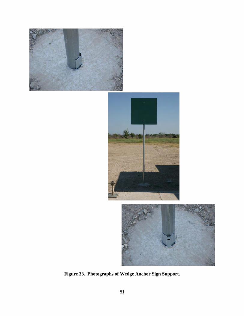
81
Figure 33. Photographs of Wedge Anchor Sign Support.
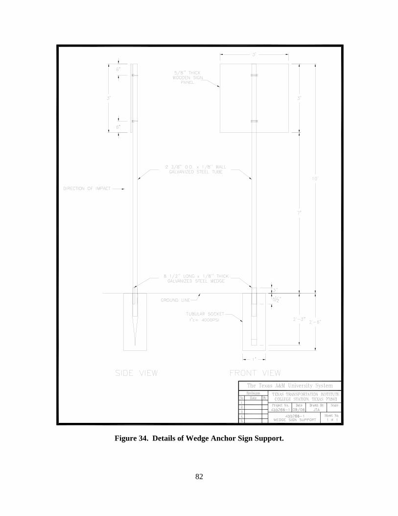
82
Figure 34. Details of Wedge Anchor Sign Support.
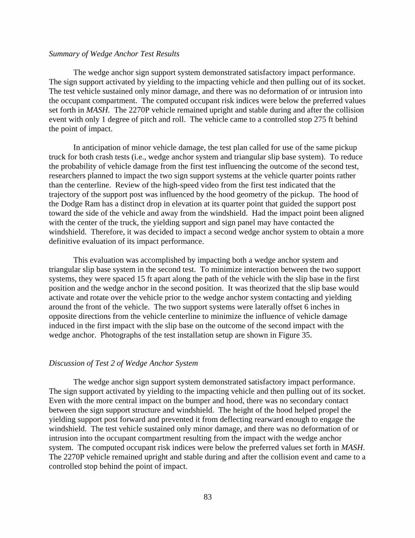
83
Summary of Wedge Anchor Test Results
The wedge anchor sign support system demonstrated satisfactory impact performance. The sign support activated by yielding to the impacting vehicle and then pulling out of its socket. The test vehicle sustained only minor damage, and there was no deformation of or intrusion into the occupant compartment. The computed occupant risk indices were below the preferred values set forth in MASH. The 2270P vehicle remained upright and stable during and after the collision event with only 1 degree of pitch and roll. The vehicle came to a controlled stop 275 ft behind the point of impact.
In anticipation of minor vehicle damage, the test plan called for use of the same pickup
truck for both crash tests (i.e., wedge anchor system and triangular slip base system). To reduce the probability of vehicle damage from the first test influencing the outcome of the second test, researchers planned to impact the two sign support systems at the vehicle quarter points rather than the centerline. Review of the high-speed video from the first test indicated that the trajectory of the support post was influenced by the hood geometry of the pickup. The hood of the Dodge Ram has a distinct drop in elevation at its quarter point that guided the support post toward the side of the vehicle and away from the windshield. Had the impact point been aligned with the center of the truck, the yielding support and sign panel may have contacted the windshield. Therefore, it was decided to impact a second wedge anchor system to obtain a more definitive evaluation of its impact performance.
This evaluation was accomplished by impacting both a wedge anchor system and
triangular slip base system in the second test. To minimize interaction between the two support systems, they were spaced 15 ft apart along the path of the vehicle with the slip base in the first position and the wedge anchor in the second position. It was theorized that the slip base would activate and rotate over the vehicle prior to the wedge anchor system contacting and yielding around the front of the vehicle. The two support systems were laterally offset 6 inches in opposite directions from the vehicle centerline to minimize the influence of vehicle damage induced in the first impact with the slip base on the outcome of the second impact with the wedge anchor. Photographs of the test installation setup are shown in Figure 35.
Discussion of Test 2 of Wedge Anchor System
The wedge anchor sign support system demonstrated satisfactory impact performance. The sign support activated by yielding to the impacting vehicle and then pulling out of its socket. Even with the more central impact on the bumper and hood, there was no secondary contact between the sign support structure and windshield. The height of the hood helped propel the yielding support post forward and prevented it from deflecting rearward enough to engage the windshield. The test vehicle sustained only minor damage, and there was no deformation of or intrusion into the occupant compartment resulting from the impact with the wedge anchor system. The computed occupant risk indices were below the preferred values set forth in MASH. The 2270P vehicle remained upright and stable during and after the collision event and came to a controlled stop behind the point of impact.
84
Figure 35. Vehicle/Installation Geometrics for Wedge Anchor & Triangular Slip Base Test.
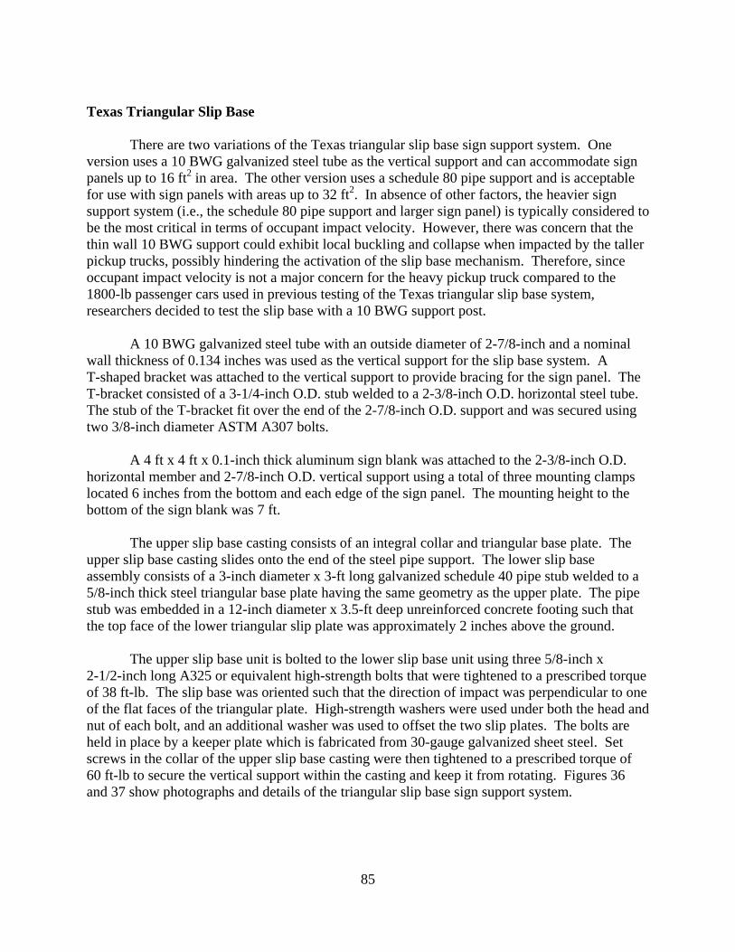
85
Texas Triangular Slip Base
There are two variations of the Texas triangular slip base sign support system. One version uses a 10 BWG galvanized steel tube as the vertical support and can accommodate sign panels up to 16 ft2 in area. The other version uses a schedule 80 pipe support and is acceptable for use with sign panels with areas up to 32 ft2. In absence of other factors, the heavier sign support system (i.e., the schedule 80 pipe support and larger sign panel) is typically considered to be the most critical in terms of occupant impact velocity. However, there was concern that the thin wall 10 BWG support could exhibit local buckling and collapse when impacted by the taller pickup trucks, possibly hindering the activation of the slip base mechanism. Therefore, since occupant impact velocity is not a major concern for the heavy pickup truck compared to the 1800-lb passenger cars used in previous testing of the Texas triangular slip base system, researchers decided to test the slip base with a 10 BWG support post.
A 10 BWG galvanized steel tube with an outside diameter of 2-7/8-inch and a nominal
wall thickness of 0.134 inches was used as the vertical support for the slip base system. A T-shaped bracket was attached to the vertical support to provide bracing for the sign panel. The T-bracket consisted of a 3-1/4-inch O.D. stub welded to a 2-3/8-inch O.D. horizontal steel tube. The stub of the T-bracket fit over the end of the 2-7/8-inch O.D. support and was secured using two 3/8-inch diameter ASTM A307 bolts.
A 4 ft x 4 ft x 0.1-inch thick aluminum sign blank was attached to the 2-3/8-inch O.D. horizontal member and 2-7/8-inch O.D. vertical support using a total of three mounting clamps located 6 inches from the bottom and each edge of the sign panel. The mounting height to the bottom of the sign blank was 7 ft. The upper slip base casting consists of an integral collar and triangular base plate. The upper slip base casting slides onto the end of the steel pipe support. The lower slip base assembly consists of a 3-inch diameter x 3-ft long galvanized schedule 40 pipe stub welded to a 5/8-inch thick steel triangular base plate having the same geometry as the upper plate. The pipe stub was embedded in a 12-inch diameter x 3.5-ft deep unreinforced concrete footing such that the top face of the lower triangular slip plate was approximately 2 inches above the ground.
The upper slip base unit is bolted to the lower slip base unit using three 5/8-inch x 2-1/2-inch long A325 or equivalent high-strength bolts that were tightened to a prescribed torque of 38 ft-lb. The slip base was oriented such that the direction of impact was perpendicular to one of the flat faces of the triangular plate. High-strength washers were used under both the head and nut of each bolt, and an additional washer was used to offset the two slip plates. The bolts are held in place by a keeper plate which is fabricated from 30-gauge galvanized sheet steel. Set screws in the collar of the upper slip base casting were then tightened to a prescribed torque of 60 ft-lb to secure the vertical support within the casting and keep it from rotating. Figures 36 and 37 show photographs and details of the triangular slip base sign support system.
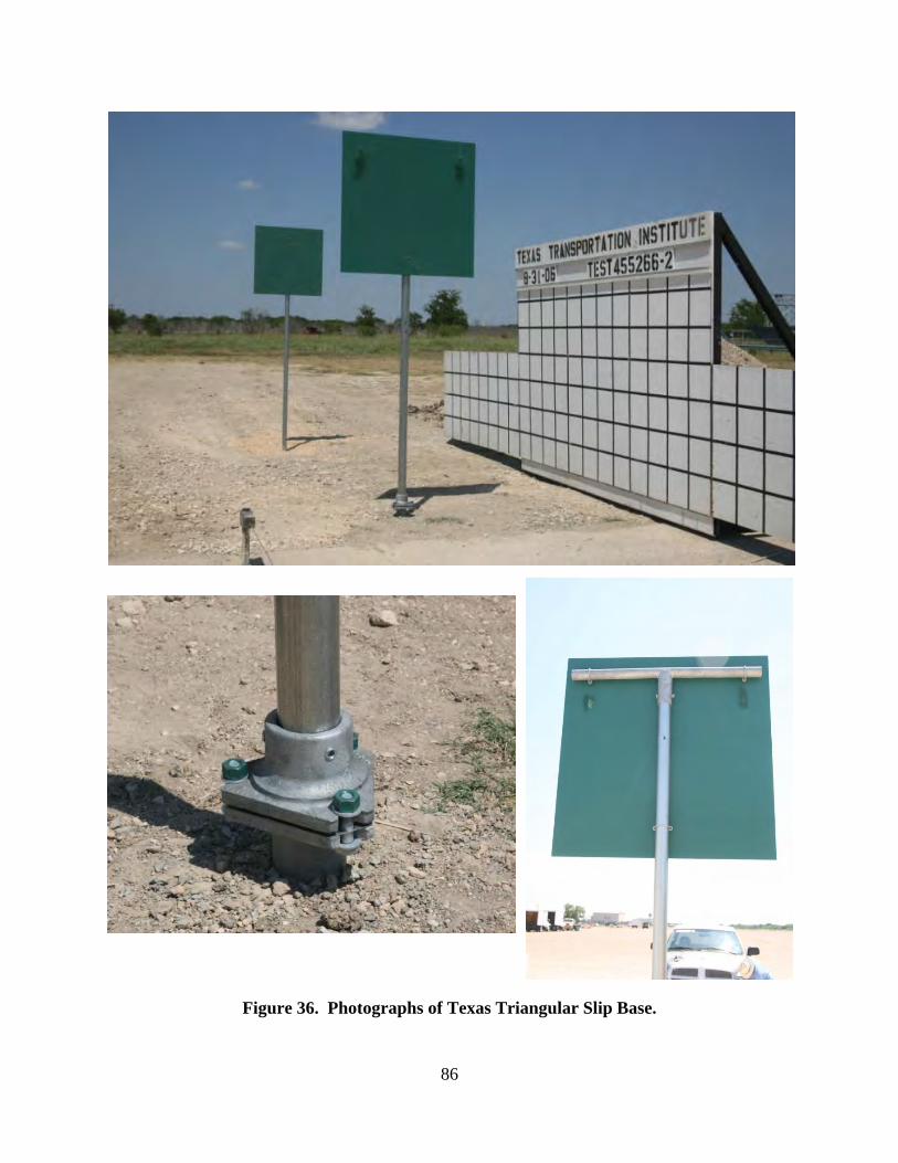
86
Figure 36. Photographs of Texas Triangular Slip Base.
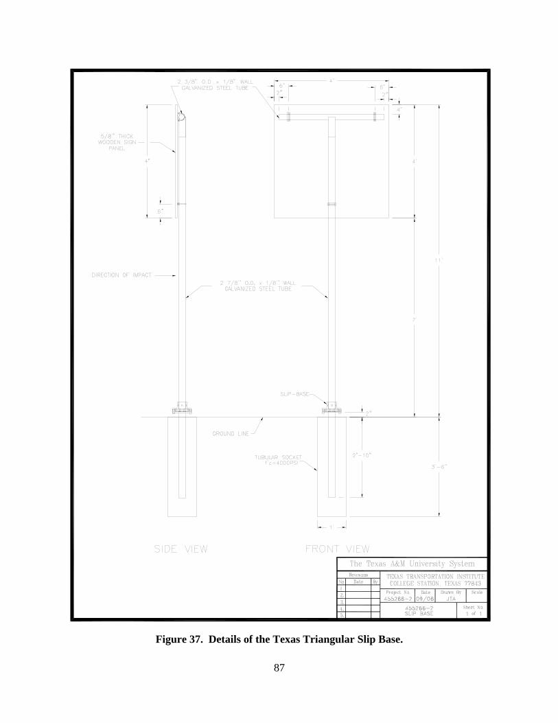
87
Figure 37. Details of the Texas Triangular Slip Base.
88
Summary of Texas Slip Base Test Results
The triangular slip base sign support system demonstrated satisfactory impact performance when evaluated in accordance with MASH criteria. The slip base mechanism activated as designed. The detached supports and sign panels did not penetrate, or show potential for penetrating the occupant compartment, or to present undue hazard to others in the area. Maximum occupant compartment deformation was 3.0 inches in the roof area on the passenger side resulting from secondary contact with the sign support and sign panel. The computed occupant risk indices were below the preferred values set forth in MASH. The 2270P vehicle remained upright and stable during and after the collision event and came to a controlled stop behind the point of impact.
Discussion of Texas Slip Base System
Given that the triangular slip base with a 10 BWG support post was found to comply with MASH, what can be inferred regarding the impact performance of the slip base with a schedule 80 pipe support? It could be argued that the heavier mass of the schedule 80 support and its larger sign panel will produce greater occupant compartment deformation than that measured in the crash test of the lighter-weight slip base system with 10 BWG support. However, the heavier mass also increases the inertial resistance of the schedule 80 support system, which can reduce the rotational velocity imparted to the support during impact. Decreased rotational velocity will tend to shift the point of contact on the roof further rearward and decrease the deformation resulting from that contact. Furthermore, the larger sign panels typically associated with the schedule 80 support are likely to span the width of the roof and engage the door headers. The door headers are much stiffer than the central portion of the roof, and engaging them will tend to reduce the overall deformation resulting from contact with the sign panel. For these reasons, the researchers believe that the triangular slip base with a schedule 80 support post will comply with MASH. However, further testing of the system may be warranted to verify this assumption.
CONCLUSIONS
The researchers recommend performing engineering analysis and/or computer simulation of existing NCHRP Report 350 accepted sign and luminaire installations to evaluate their performance with regard to risk of occupant compartment deformation and intrusion when struck with the pickup truck test vehicle. Engineering analysis and/or computer simulation can be used to help predict whether or not secondary contact between a support system and an impacting vehicle will occur, and the probable location of the contact. However, the only way to reliably determine the extent of windshield damage and roof deformation from secondary contact is through full-scale testing. Sign and luminaire installations that, through engineering analysis and/or computer simulation, are found to have suspect performance would require full-scale crash testing with the pickup truck test vehicle.

89
IV. CRASH TESTING MATRIX AND EVALUATION PLAN
In review, TTI researchers surveyed the State DOTs for use and frequency rates for
non-proprietary hardware; and reviewed the test reports of the crash tests performed under NCHRP Project 22-14(02), TxDOT project FHWA/TX-07/0-5526-1, and other NCHRP Report 350 crash tests performed. In the performance of these tasks, a weighted ranking of highway roadside safety hardware categorized by device type was presented in Table 1. An aggregate ranking of highway roadside safety hardware by frequency of use was performed for all categories and presented in Table 2. Table 3 presented the crash tests performed in NCHRP Project 22-14(02).
The researchers compiled the aforementioned information and developed a suggested crash testing matrix with an assigned probability of passing the MASH testing and evaluation criteria. Table 9 shows the compiled data from Tables 1 through 3 and provides a probability of the device meeting the evaluation criteria if tested and evaluated to MASH. In lieu of assigning a numerical value to the probability of any particular piece of hardware passing or failing a crash test, a qualitative measure of “poor”, “fair”, “good”, and “excellent” is used to indicate the hardware’s projected ability to meet the MASH test level that the device currently satisfies under NCHRP Report 350.
In addition to the material presented in Table 9, the top ten most frequently used roadside safety hardware were identified previously in Table 2. Of the top ten identified, the New Jersey Safety Shape concrete barrier, F-shape concrete barrier, and strong steel post W-beam guardrail, have been tested to the most critical MASH conditions. Expanding this list further to include the top 25 prioritized roadside safety hardware yielded the following:
1. Precast concrete median barrier using a pin and Tested
loop (P&L) connection
2. Strong steel post W-beam guardrail Tested
3. Strong wood post W-beam guardrail Testing not considered necessary
4. Transformer base luminaire support
5. Concrete safety shape median barrier Tested
6. Steel u-channel sign support – 3 lb/ft
7. Strong steel post W-beam median guardrail Testing not considered necessary
8. W-beam guardrail to safety shape concrete barrier transition
9. F-shape concrete median barrier Tested in temporary (P&L) configuration
10. Perforated square steel tube sign support – 2 inch

90
Table 9. Compiled Prioritization, Ranking, and Probability for Successfully Complying with MASH Criteria.
Test Article Discussion in Report
Tested to MASH
Prioritization to Survey
Aggregate Ranking
Probability of Passing MASH
Guardrails Pg 20-28 Strong-Post (Steel) W-Beam Pg 21 1 2 N/A Strong-Post (Wood) W-Beam Pg 21&111 * 2 3 N/A*
Strong-Post (Steel) Thrie-Beam Pg 22&165 3 17 Good Strong-Post (Wood) Thrie-Beam Pg 23 4 21 Good Low-Tension Cable (3-Strand) Pg 26 5 23 Good Midwest Guardrail System (MGS) Pg 22 6 30 N/A Weak-Post Box-Beam Pg 27&151 7 38 Good Strong-Post Modified Thrie-Beam Pg 24 7 37 Excellent Weak-Post W-Beam Pg 25&158 9 40 Fair – Good Other non-proprietary guardrail 10 41 N/A
Aesthetic Barriers Pg 28-37 Type A Steel-Backed Timber Guardrail (with offset block) Pg 29 1 43 Good Smooth Stone Masonry Guardwall 2 44 Good Other non-proprietary aesthetic barrier Pg 28 3 48 Good Merritt Parkway Steel-Backed Timber Guiderail Pg 30 4 52 Good Rough Stone Masonry Guardwall Pg 29 4 52 Good Steel-Backed Timber Round Log Rail Pg 32 6 58 Good Type B Steel-Backed Timber Guardrail (without offset block) Pg 32 7 68 Good Deception Pass State Park Log Rail Pg 33 8 82 Good
Median Barriers Pg 37-46 Safety-Shape (New Jersey) Pg 39&99 1 5 N/A – TL-3 Strong-Post (Steel) W-Beam Pg 37&118 * 2 7 N/A* F-Shape Pg 39 3 9 N/A Strong-Post (Wood) W-Beam Pg 37 * 4 16 N/A* Constant Slope (Single-Slope) Barrier (TX & CA designs) Pg 39 * 5 22 N/A* Strong-Post (Steel) Thrie-Beam Pg 37 6 24 Good

91
Test Article Discussion in Report
Tested to MASH
Prioritization to Survey
Aggregate Ranking
Probability of Passing MASH
Median Barriers (continued) Strong-Post (Wood) Thrie-Beam Pg 37 7 25 Good Low-Tension Cable (3-Strand) Pg 38 8 28 Good Vertical Concrete Barrier Pg 39 * 8 29 N/A* Strong-Post Modified Thrie-Beam Pg 37 10 39 Excellent Weak-Post W-Beam Pg 37 11 46 Fair – Good Weak-Post Box-Beam Pg 37 11 46 Good Other non-proprietary median barrier Pg 44 13 51 System
Dependent Median Barrier Connections Pg 46-51
Pin and Loop Pg 47 1 1 N/A Steel Dowel Pg 47 2 31 Fair – Good Other non-proprietary connection Pg 47 &
51 3 45 System
Dependent Grid-Slot Pg 48 4 55 Fair – Good Vertical I-Beam Pg 48 5 60 Good Plate Insert Pg 48 6 65 Fair – Good Top T-Lock Pg 48 6 65 Good Side Plates Pg 48 8 74 Good Tongue and Groove Pg 48 9 75 Good X-Bolt Pg 48&49 10 77 N/A Lap-Splice Pg 48 10 77 Good Channel Splice Pg 48 10 77 Good Bottom T-Lock Pg 48 10 77 Good
Transitions Pg 51-61 Box-Beam
Box-Beam Guardrail to Permanent Concrete Barrier Pg53 1 57 Good Box-Beam Guardrail to F-Shape Concrete Barrier Pg53 1 56 Good Box-Beam Guardrail to Safety-Shape Concrete Barrier Pg53 3 63 Good Box-Beam Guardrail to Single-Slope Concrete Barrier Pg53 3 62 Good Modified Box-Beam Guardrail to 4-Rail Steel Bridge Rail Pg53 3 59 Good
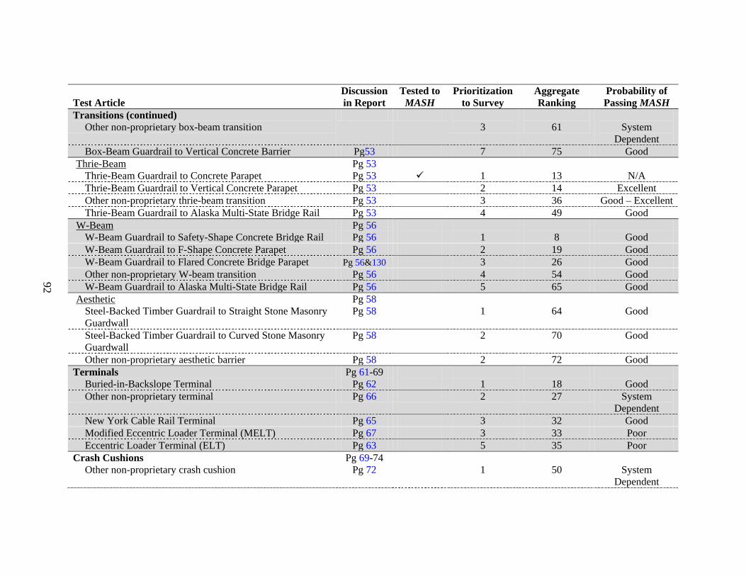
92
Test Article Discussion in Report
Tested to MASH
Prioritization to Survey
Aggregate Ranking
Probability of Passing MASH
Transitions (continued) Other non-proprietary box-beam transition
3
61
System
Dependent Box-Beam Guardrail to Vertical Concrete Barrier Pg53 7 75 Good
Thrie-Beam Pg 53 Thrie-Beam Guardrail to Concrete Parapet Pg 53 1 13 N/A Thrie-Beam Guardrail to Vertical Concrete Parapet Pg 53 2 14 Excellent Other non-proprietary thrie-beam transition Pg 53 3 36 Good – Excellent Thrie-Beam Guardrail to Alaska Multi-State Bridge Rail Pg 53 4 49 Good
W-Beam Pg 56 W-Beam Guardrail to Safety-Shape Concrete Bridge Rail Pg 56 1 8 Good W-Beam Guardrail to F-Shape Concrete Parapet Pg 56 2 19 Good
W-Beam Guardrail to Flared Concrete Bridge Parapet Pg 56&130 3 26 Good Other non-proprietary W-beam transition Pg 56 4 54 Good W-Beam Guardrail to Alaska Multi-State Bridge Rail Pg 56 5 65 Good
Aesthetic Pg 58 Steel-Backed Timber Guardrail to Straight Stone Masonry Guardwall
Pg 58 1 64 Good
Steel-Backed Timber Guardrail to Curved Stone Masonry Guardwall
Pg 58 2 70 Good
Other non-proprietary aesthetic barrier Pg 58 2 72 Good Terminals Pg 61-69
Buried-in-Backslope Terminal Pg 62 1 18 Good Other non-proprietary terminal Pg 66 2 27 System
Dependent New York Cable Rail Terminal Pg 65 3 32 Good Modified Eccentric Loader Terminal (MELT) Pg 67 3 33 Poor Eccentric Loader Terminal (ELT) Pg 63 5 35 Poor
Crash Cushions Pg 69-74 Other non-proprietary crash cushion Pg 72 1 50 System
Dependent
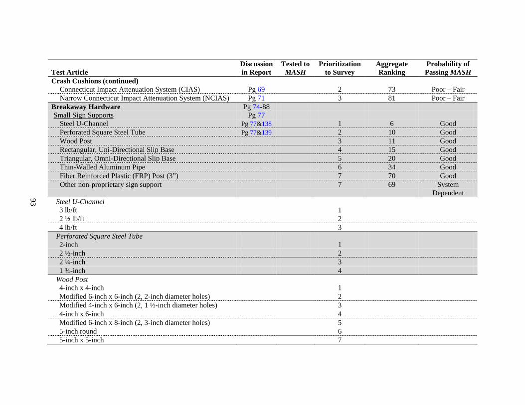
93
Test Article Discussion in Report
Tested to MASH
Prioritization to Survey
Aggregate Ranking
Probability of Passing MASH
Crash Cushions (continued) Connecticut Impact Attenuation System (CIAS) Pg 69 2 73 Poor – Fair Narrow Connecticut Impact Attenuation System (NCIAS) Pg 71 3 81 Poor – Fair
Breakaway Hardware Pg 74-88 Small Sign Supports Pg 77
Steel U-Channel Pg 77&138 1 6 Good Perforated Square Steel Tube Pg 77&139 2 10 Good Wood Post 3 11 Good Rectangular, Uni-Directional Slip Base 4 15 Good Triangular, Omni-Directional Slip Base 5 20 Good Thin-Walled Aluminum Pipe 6 34 Good Fiber Reinforced Plastic (FRP) Post (3”) 7 70 Good Other non-proprietary sign support 7 69 System
Dependent Steel U-Channel 3 lb/ft 1 2 ½ lb/ft 2 4 lb/ft 3
Perforated Square Steel Tube 2-inch 1 2 ½-inch 2 2 ¼-inch 3 1 ¾-inch 4
Wood Post 4-inch x 4-inch 1 Modified 6-inch x 6-inch (2, 2-inch diameter holes) 2 Modified 4-inch x 6-inch (2, 1 ½-inch diameter holes) 3 4-inch x 6-inch 4 Modified 6-inch x 8-inch (2, 3-inch diameter holes) 5 5-inch round 6 5-inch x 5-inch 7

94
Test Article Discussion in Report
Tested to MASH
Prioritization to Survey
Aggregate Ranking
Probability of Passing MASH
Wood Post Species Southern Yellow Pine 1 Douglas Fir 2 Other species of wood post 3
Installation in Weak Soil Yes 1 No 2
Large Sign Supports Pg 77 Other 1 Dual, W6x12 2 Single, W12x45 3
Fuse Plates Yes 1 No 2
Configuration of Slip Base Rectangular, Uni-Directional 1 Triangular, Omni-Directional Pg 85 Texas 2 N/A – Excellent Other 3
Orientation of Slip Plates Level 1 Inclined 2 Other 3
Luminaire Supports Transformer Base 1 4 Good Slip Base 2 12 Good Other non-proprietary luminaire support 3 42 System
Dependent *Prior testing of similar hardware will likely satisfy the testing requirements for this device and no additional testing would be
required.
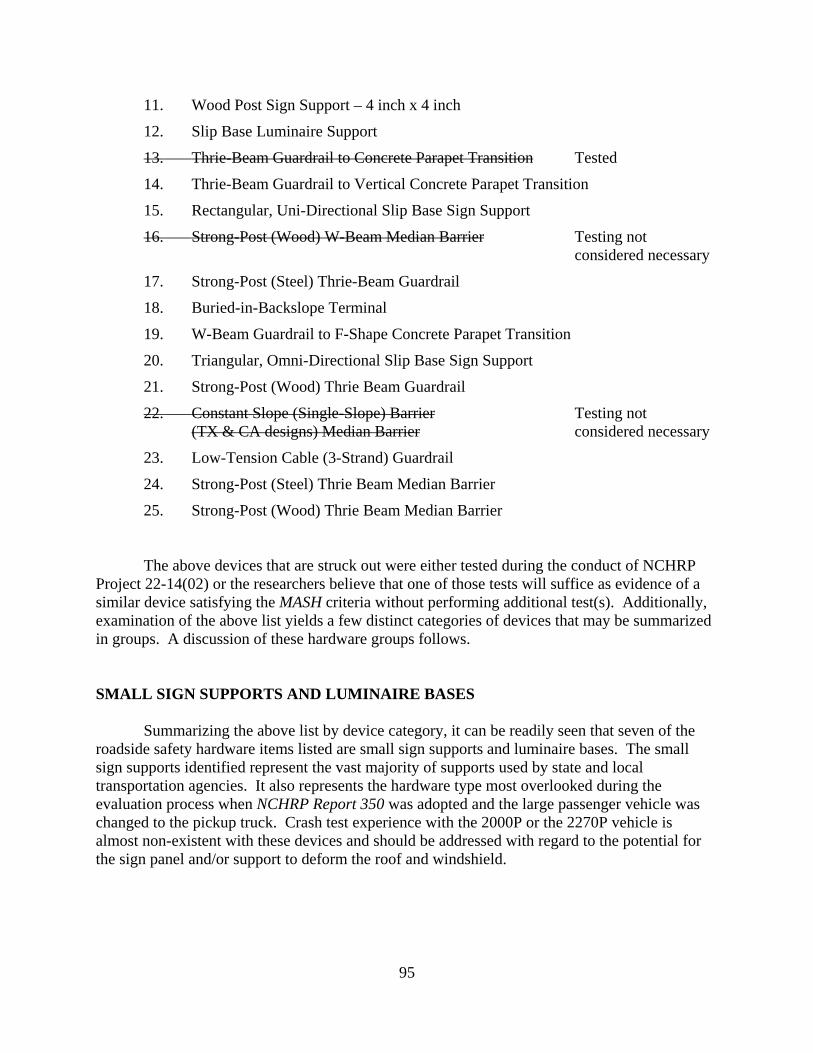
95
11. Wood Post Sign Support – 4 inch x 4 inch
12. Slip Base Luminaire Support
13. Thrie-Beam Guardrail to Concrete Parapet Transition Tested
14. Thrie-Beam Guardrail to Vertical Concrete Parapet Transition
15. Rectangular, Uni-Directional Slip Base Sign Support
16. Strong-Post (Wood) W-Beam Median Barrier Testing not considered necessary
17. Strong-Post (Steel) Thrie-Beam Guardrail
18. Buried-in-Backslope Terminal
19. W-Beam Guardrail to F-Shape Concrete Parapet Transition
20. Triangular, Omni-Directional Slip Base Sign Support
21. Strong-Post (Wood) Thrie Beam Guardrail
22. Constant Slope (Single-Slope) Barrier Testing not (TX & CA designs) Median Barrier considered necessary
23. Low-Tension Cable (3-Strand) Guardrail
24. Strong-Post (Steel) Thrie Beam Median Barrier
25. Strong-Post (Wood) Thrie Beam Median Barrier The above devices that are struck out were either tested during the conduct of NCHRP
Project 22-14(02) or the researchers believe that one of those tests will suffice as evidence of a similar device satisfying the MASH criteria without performing additional test(s). Additionally, examination of the above list yields a few distinct categories of devices that may be summarized in groups. A discussion of these hardware groups follows.
SMALL SIGN SUPPORTS AND LUMINAIRE BASES
Summarizing the above list by device category, it can be readily seen that seven of the roadside safety hardware items listed are small sign supports and luminaire bases. The small sign supports identified represent the vast majority of supports used by state and local transportation agencies. It also represents the hardware type most overlooked during the evaluation process when NCHRP Report 350 was adopted and the large passenger vehicle was changed to the pickup truck. Crash test experience with the 2000P or the 2270P vehicle is almost non-existent with these devices and should be addressed with regard to the potential for the sign panel and/or support to deform the roof and windshield.
96
THRIE-BEAM LONGITUDINAL BARRIER
Four of the safety hardware devices ranked above are thrie-beam longitudinal barriers; wood and steel post, roadside and median barrier guardrail. In addition, a thrie-beam guardrail transition to a vertical concrete parapet is listed. The researchers would recommend giving high-priority to testing the modified thrie-beam guardrail to TL-4 using the MASH 10000S vehicle. Depending on the fabrication details, the thrie-beam to safety shape concrete barrier transition test previously performed in NCHRP Project 22-14(02) may suffice for an appropriately designed vertical concrete parapet.
W-BEAM TRANSITIONS TO SAFETY AND F-SHAPE BARRIER
Two of the above ranked safety hardware devices are W-beam guardrail transitions to safety and F-shape barriers. Successful transition designs proved very challenging during the adoption of NCHRP Report 350. Many W-beam to concrete parapet transition designs were found to perform inadequately with regard to vehicle stability and/or occupant compartment deformation when crash tested. It is anticipated that the NCHRP Report 350 designed W-beam transitions will perform acceptably when evaluated to the MASH conditions. The occupant compartment deformation evaluation criteria have been relaxed from NCHRP Report 350 and the MASH 2270P test vehicle is a more stable test vehicle platform. However, the affect of the 13 percent increase in kinetic energy for the 2270P vehicle has not been evaluated on a W-beam transition and warrants consideration when developing the test matrix for this project.
BURIED-IN-BACKSLOPE TERMINAL
The buried-in-back slope terminal is the most predominately used terminal for aesthetic guardrails such as the steel-backed timber rail. In addition, many states use it where the edge of the right-of-way and/or roadside backslopes are close to the travel way. The buried-in-backslope type of terminal has proven to be a safe and cost-effective means of terminating a guardrail installation. However, the researchers have concern regarding the performance of this terminal in regard to MASH due to the increase in the impact angle to 25 degrees for the beginning of length of need test with the pickup. It is recommended that testing of this terminal in the W-beam and steel-backed timber configuration with the 2270P vehicle be considered.
CABLE GUARDRAIL
Low-tension cable (strand) guardrail ranked number 23 in the list of hardware to be tested out of 25. The low-tension guardrail has a high probability of performing well to MASH on slopes of 10:1 or flatter. However, deflections will likely increase marginally due to the increase in weight of the 2270P test vehicle. The widespread use of this barrier in several states may warrant test consideration. However, it should be noted that a high-tension, non-proprietary cable guardrail is currently under development by the Midwest States Regional Pooled Fund program. The Pooled Fund cable system, when completed, will be tested to the MASH

97
conditions and should be capable of being installed on slopes of 4:1 or flatter. This new system may negate the need to test the 3-rope, low-tension cable guardrail system.
OTHER GUARDRAILS
Although the weak-post W-beam and weak-post box beam guardrails were not ranked in the top 25 hardware devices based on the survey, they both warrant some consideration for testing under this project. The weak-post box beam ranked 38, while the weak-post W-beam ranked 40. These guardrails are widely used in a few states and provide alternatives to the strong-post guardrail systems. Both systems have a “good” probability of passing the testing and evaluation criteria of MASH.
SUMMARY
The researchers reviewed a total of 90 different types or configurations of non-proprietary roadside safety hardware. Of the initial top 25 prioritized roadside safety hardware devices, 16 remained under consideration for testing and evaluation to MASH after eliminating those that had been previously tested or were considered to be equivalent to systems already tested. During the review process, the researchers noted that G3 box-beam guardrail, modified G2 weak-post W-beam guardrail, and G9 thrie-beam guardrail ranked relatively low in the survey (numbers 37, 38, and 40, respectively). Despite their low ranking, it was noted that they are used very extensively in some states. Therefore, the researchers elected to add G3 box-beam guardrail, modified G2 weak-post W-beam guardrail, and G9 thrie-beam guardrail to the list of hardware devices presented to the project panel for consideration of testing and evaluation to MASH.
The NCHRP panel reviewed the researchers’ recommended top 19 prioritized roadside
safety hardware items. After discussions between the NCHRP panel members and the researchers, the panel members decided the G4(2W) W-beam guardrail and the G4(1S) median barrier (ranked number 3 and 16, respectively) warranted evaluation and testing to MASH. Historically, both of these systems received acceptance based on a successful test of the “more critical” G4(1S) guardrail system. However, given the marginal performance of the G4(1S) guardrail system when tested under NCHRP study 22-14(02), the panel decided that these assumptions should be verified through testing. Test 3-11 was requested by the NCHRP panel for the G4(2W) guardrail to assess its performance equivalency to the modified G4(1S) guardrail.
The additional constraint of the posts imposed by the double-sided G4(1S) W-beam
median barrier raised concerns regarding barrier override by the 2270P and excessive occupant risk when impacted by the small passenger vehicle (1100C). The added post constraint delays release of the post from the rail, which can potentially result in vehicle climb and vaulting due to a localized drop in rail height. The delayed post release can also result in more severe wheel-post interaction and a higher level of occupant risk during the small car impact. Thus, both Test 3-10 and 3-11 were programmed for this median barrier system.
98
In addition, the panel wished to complete the evaluation of the 32 inch permanent
New Jersey shape barrier (ranked number 5). Given its widespread use by the States, a complete and up-to-date evaluation was warranted. The permanent New Jersey shape barrier was tested under NCHRP study 22-14(02) with the 1100C passenger car (test 3-10). A test with the 2270P pickup truck (test 3-11) would complete the test matrix. Further, previous testing has shown that the New Jersey profile is a more critical shape than the F-shape or single slope profiles in terms of vehicle climb and instability. Therefore, a successful test sequence on the New Jersey profile would assert that the F-shape and single slope concrete barriers are also MASH compliant.
The panel members re-ranked the list of highway safety hardware prioritized by the
survey and expanded by the researchers to establish the final test matrix. As determined by the NCHRP panel in consultation with the researchers, the final test matrix for this study is shown below in priority order:
1. 32 inch permanent concrete New Jersey safety shape median barrier
2. G4(2W) W-beam guardrail
3. G4(1S) W-Beam Median Barrier
4. W-beam guardrail to safety shape concrete barrier transition – Pennsylvania design
5. Steel u-channel sign support – 4 lb/ft
6. Perforated square steel tube sign support – 2 inch
7. G3 Box beam guardrail
8. Modified G2 W-beam guardrail
9. G9 Thrie Beam Guardrail
*Note: The steel u-channel sign support and perforated square steel tube sign support were ranked equivalently.
Furthermore, for the pickup truck tests on the longitudinal barriers and transitions, the NCHRP project panel requested a 2007 Chevrolet Silverado be used, instead of the MASH Dodge 1500 Quad-Cab pickup, to assist with the validation of a finite element model of a 2007 Chevrolet Silverado pickup developed at the National Crash Analysis Center (NCAC) under the sponsorship of FHWA and NHTSA. The Dodge 1500 Quad-Cab pickup was used in the pickup truck test on the sign supports.
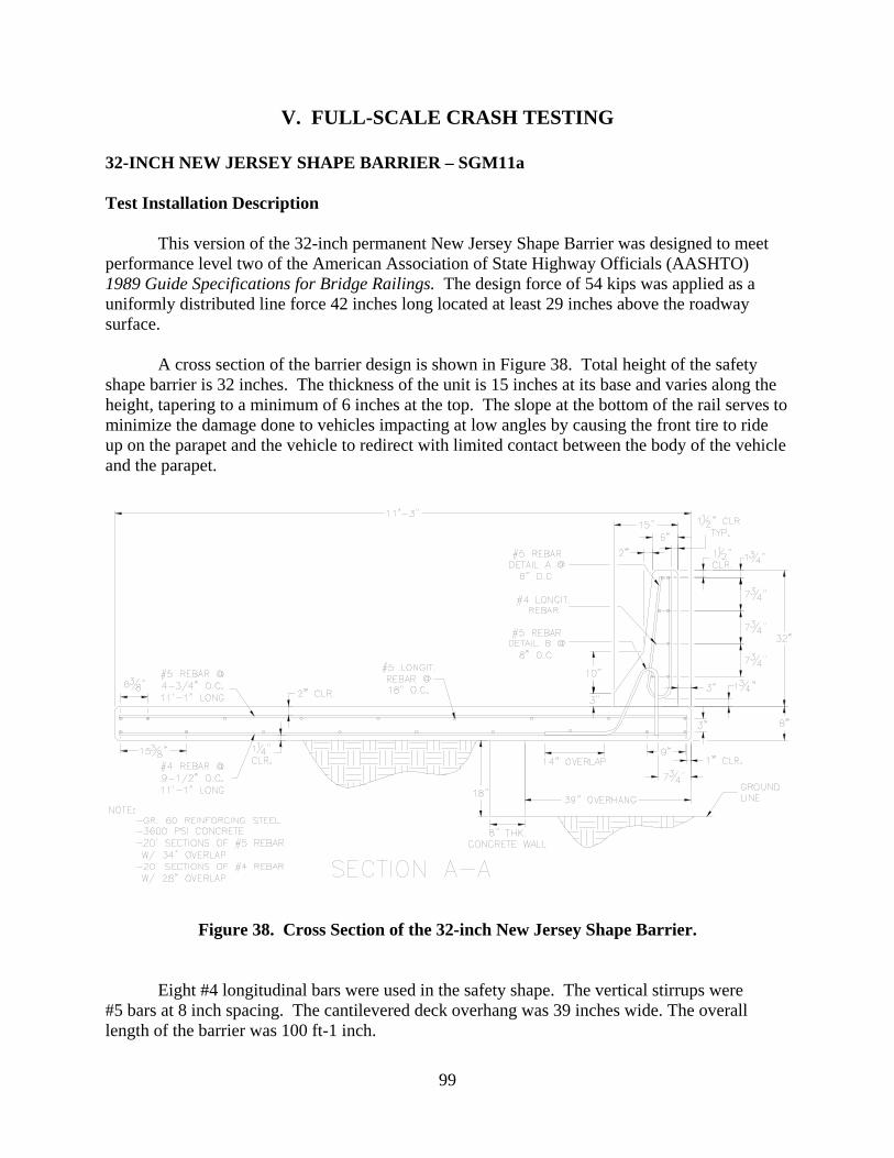
99
V. FULL-SCALE CRASH TESTING
32-INCH NEW JERSEY SHAPE BARRIER – SGM11a
Test Installation Description
This version of the 32-inch permanent New Jersey Shape Barrier was designed to meet performance level two of the American Association of State Highway Officials (AASHTO) 1989 Guide Specifications for Bridge Railings. The design force of 54 kips was applied as a uniformly distributed line force 42 inches long located at least 29 inches above the roadway surface. A cross section of the barrier design is shown in Figure 38. Total height of the safety shape barrier is 32 inches. The thickness of the unit is 15 inches at its base and varies along the height, tapering to a minimum of 6 inches at the top. The slope at the bottom of the rail serves to minimize the damage done to vehicles impacting at low angles by causing the front tire to ride up on the parapet and the vehicle to redirect with limited contact between the body of the vehicle and the parapet.
Figure 38. Cross Section of the 32-inch New Jersey Shape Barrier.
Eight #4 longitudinal bars were used in the safety shape. The vertical stirrups were #5 bars at 8 inch spacing. The cantilevered deck overhang was 39 inches wide. The overall length of the barrier was 100 ft-1 inch.

100
The strength of the railing was computed using yieldline analysis procedures. The strength computations predict the length of the failure mechanism to be 8.1 ft and the total ultimate load capacity to be 74 kips. The analysis also shows the yieldline are confined to the upper wall portion of the parapet and do to extend into the bridge deck.
The same barrier installation was used for both 4-12 and 4-11 crash tests since the barrier only sustained cosmetic damage during the 4-12 test. Photographs of the completed installation are shown in Figure 39. More detailed information on the barrier and the two crash tests is in Appendixes B and C (available on the NCAC website, www.ncac.gwu.edu/).
Figure 39. 32-inch New Jersey Shape Barrier Prior to Testing.
Test Number 476460-1b (MASH Test 4-12)
Test Description
Test Vehicle: 1999 Ford F-800 single-unit truck Test Inertia Weight: 22,090 lb Gross Static Weight: 22,090 lb Impact Speed: 57.4 mi/h Impact Angle: 14.4 degrees
The 1999 Ford F-800 single-unit truck, traveling at an impact speed of 57.4 mi/h, impacted the 32-inch New Jersey Shape Barrier 20 ft from the upstream end at an impact angle of 14.4 degrees. Immediately upon impact, the right front tire began to climb the face of the barrier and lost contact with the ground surface. At 0.044 s, the left front tire and wheel assembly abruptly steered toward the barrier. At 0.151 s, the vehicle began to redirect, and at 0.166 s, the left front tire lost contact with the ground surface. The right rear outer tire blew out at 0.223 s, and the left rear tires became airborne at 0.252 s. At 0.263 s, the right rear edge of the

101
box van went over the top of the barrier. The vehicle began to travel parallel with the barrier at 0.433 s, and was traveling at a speed of 56.6 mi/h. The vehicle exited the view of the overhead camera at 0.779 s. At 1.132 s, the vehicle reached the end of the barrier oriented at 90 degrees of roll. By 3.325 s, the vehicle righted itself and came to rest upright 69 ft downstream of the end of the barrier and 10 ft behind the traffic face of the barrier.
The 32-inch New Jersey Shape Barrier sustained cosmetic damage only, as shown in
Figure 40. There were tire marks and gouges in the traffic face, and then about halfway down, along the top edge of the barrier and off the end of the barrier.
Figure 40. 32-inch New Jersey Shape Barrier after MASH Test 4-12.
As shown in Figure 41, the SUT cargo box and truck cab sustained extensive damage due to rollover. Both right and left frame rails were deformed, the right front U-bolts broke, the front axle was deformed, the drive shaft broke, and the right rear U-bolts broke. Both front tires and rims and the right rear inner and outer tires and rims were damaged. The right A-post was deformed and the windshield was broken. Also damaged were the front bumper, hood, right door and glass, cab, and roof. The right fuel tank was deformed (but not punctured), and the right side floor pan was also deformed. Maximum exterior crush to the right front corner of the bumper was 12.0 inches, and maximum occupant compartment deformation was 4.0 inches in the right floor pan area.
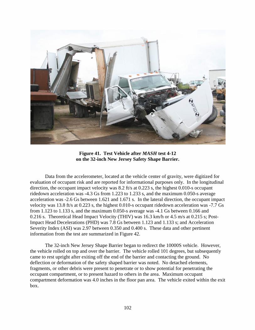
102
Figure 41. Test Vehicle after MASH test 4-12
on the 32-inch New Jersey Safety Shape Barrier.
Data from the accelerometer, located at the vehicle center of gravity, were digitized for evaluation of occupant risk and are reported for informational purposes only. In the longitudinal direction, the occupant impact velocity was 8.2 ft/s at 0.223 s, the highest 0.010-s occupant ridedown acceleration was -4.3 Gs from 1.223 to 1.233 s, and the maximum 0.050-s average acceleration was -2.6 Gs between 1.621 and 1.671 s. In the lateral direction, the occupant impact velocity was 13.8 ft/s at 0.223 s, the highest 0.010-s occupant ridedown acceleration was -7.7 Gs from 1.123 to 1.133 s, and the maximum 0.050-s average was -4.1 Gs between 0.166 and 0.216 s. Theoretical Head Impact Velocity (THIV) was 16.3 km/h or 4.5 m/s at 0.215 s; Post-Impact Head Decelerations (PHD) was 7.8 Gs between 1.123 and 1.133 s; and Acceleration Severity Index (ASI) was 2.97 between 0.350 and 0.400 s. These data and other pertinent information from the test are summarized in Figure 42.
The 32-inch New Jersey Shape Barrier began to redirect the 10000S vehicle. However,
the vehicle rolled on top and over the barrier. The vehicle rolled 101 degrees, but subsequently came to rest upright after exiting off the end of the barrier and contacting the ground. No deflection or deformation of the safety shaped barrier was noted. No detached elements, fragments, or other debris were present to penetrate or to show potential for penetrating the occupant compartment, or to present hazard to others in the area. Maximum occupant compartment deformation was 4.0 inches in the floor pan area. The vehicle exited within the exit box.

103
Summary of Test Results
The 32-inch New Jersey Shape Barrier failed to contain and redirect the SUT vehicle. The SUT rolled 101 degrees before exiting the end of the barrier. Subsequent contact with the ground enabled the vehicle to right itself as it came to rest. Had the test installation length been longer, the SUT would have continued to roll over the top of the rail. The 32-inch New Jersey Shape Barrier failed to demonstrate satisfactory performance in the MASH08 Test 4-12 crash test, as shown in Table 10.

104
0.000 s
0.246 s
0.489 s
0.735 s
General Information Test Agency ......................... Test No. .............................. Date ..................................... Test Article Type ..................................... Name ................................... Installation Length .............. Material or Key Elements .... Soil Type and Condition ....... Test Vehicle Type/Designation ................. Make and Model .................. Mass
Curb .................................. Test Inertial ....................... Gross Static ......................
Texas Transportation Institute RF476460-1 2008-02-19 Concrete Barrier 32-inch New Jersey Shape Barrier 100 ft-1 in Reinforced Concrete Concrete Deck, Dry 10000S 1999 Ford F-800 SUT 12,200 lb 22,090 lb 22,090 lb
Impact Conditions Speed .................................... Angle ..................................... Exit Conditions Speed .................................... Angle ..................................... Occupant Risk Values Impact Velocity Longitudinal ........................ Lateral ................................
Ridedown Accelerations Longitudinal ........................ Lateral ................................ THIV ...................................... PHD ....................................... Max. 0.050-s Average Longitudinal ........................ Lateral ................................ Vertical ...............................
57.4 mi/h 14.4 degrees Out of View 8.2 ft/s 13.8 ft/s -4.3 Gs 7.7 Gs 16.3 km/h 7.8 Gs -2.6 Gs -4.1 Gs 29.7 Gs
Post-Impact Trajectory Stopping Distance ......................... Vehicle Stability
Maximum Yaw Angle ..................... Maximum Pitch Angle .................... Maximum Roll Angle ...................... Vehicle Snagging ........................... Vehicle Pocketing .......................... Test Article Deflections Dynamic ......................................... Permanent ..................................... Working Width ............................... Vehicle Damage VDS ............................................ CDC ............................................ Max. Exterior Vehicle Crush (inches) ............ Max. Occupant Compartment Deformation (inches) ...............
139 ft downstream 10.0 ft behind -17 degrees -8 degrees 101 degrees No No 0 0 12.1 ft N/A 01RFEW4 12.0 inches 4.0 inches
Figure 42. Summary of Results for MASH Test 4-12 on the 32-inch New Jersey Shape Barrier.
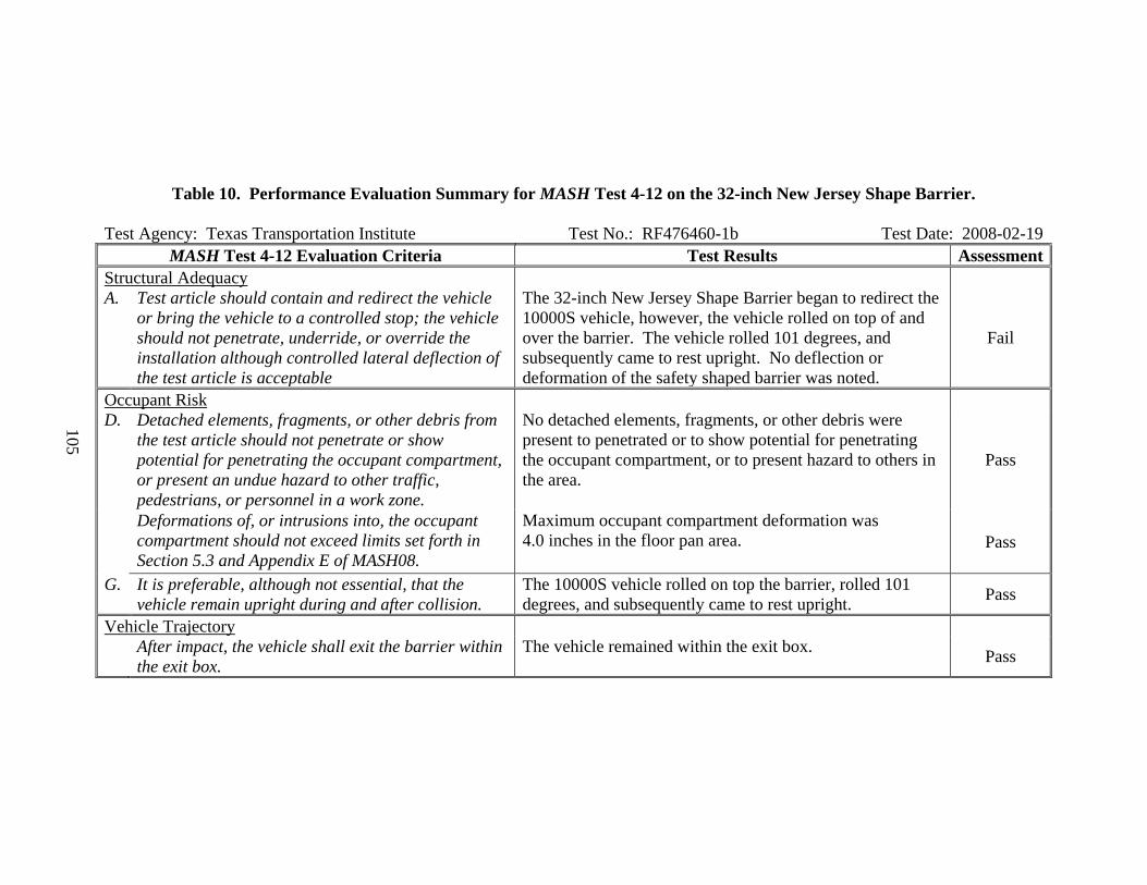
105
Table 10. Performance Evaluation Summary for MASH Test 4-12 on the 32-inch New Jersey Shape Barrier. Test Agency: Texas Transportation Institute Test No.: RF476460-1b Test Date: 2008-02-19
MASH Test 4-12 Evaluation Criteria Test Results Assessment Structural Adequacy A. Test article should contain and redirect the vehicle
or bring the vehicle to a controlled stop; the vehicle should not penetrate, underride, or override the installation although controlled lateral deflection of the test article is acceptable
The 32-inch New Jersey Shape Barrier began to redirect the 10000S vehicle, however, the vehicle rolled on top of and over the barrier. The vehicle rolled 101 degrees, and subsequently came to rest upright. No deflection or deformation of the safety shaped barrier was noted.
Fail
Occupant Risk D. Detached elements, fragments, or other debris from
the test article should not penetrate or show potential for penetrating the occupant compartment, or present an undue hazard to other traffic, pedestrians, or personnel in a work zone.
No detached elements, fragments, or other debris were present to penetrated or to show potential for penetrating the occupant compartment, or to present hazard to others in the area.
Pass
Deformations of, or intrusions into, the occupant compartment should not exceed limits set forth in Section 5.3 and Appendix E of MASH08.
Maximum occupant compartment deformation was 4.0 inches in the floor pan area. Pass
G. It is preferable, although not essential, that the vehicle remain upright during and after collision.
The 10000S vehicle rolled on top the barrier, rolled 101 degrees, and subsequently came to rest upright. Pass
Vehicle Trajectory After impact, the vehicle shall exit the barrier within
the exit box. The vehicle remained within the exit box. Pass
106
Test Number 476460-1-4 (MASH Test 4-11)
Test Description
Test Vehicle: 2007 Chevrolet Silverado 4-door pickup Test Inertia Weight: 5049 lb Gross Static Weight: 5049 lb Impact Speed: 62.6 mi/h Impact Angle: 25.2 degrees
Of note, the same barrier installation was used for both 4-12 and 4-11 crash tests since the barrier only sustained cosmetic damage during the 4-12 test.
The 2007 Chevrolet Silverado pickup, traveling at an impact speed of 62.6 mi/h,
impacted the 32-inch New Jersey Shape Barrier near the one-third point of the barrier at an impact angle of 25.2 degrees. At 0.039 s after impact, the right front tire began climbing the barrier face and deflated, and at 0.066 s, the left front tire became airborne. The vehicle began to redirect at 0.088 s, and the left rear tire becomes airborne. At 0.165 s, the right rear of the vehicle contacted the barrier, and the vehicle began traveling parallel with the barrier at 0.199 s and was traveling at a speed of 54.6 mi/h. The left rear of the vehicle began to rise at 0.277 s, and the right front tire contacted the ground surface at 0.282 s. At 0.339 s, the front bumper bottomed out on the ground surface. The vehicle lost contact with the barrier at 0.471 s, and the vehicle was traveling at an exit speed of 52.6 mi/h at an exit angle of 4.0 degrees. At 0.534 s, the left front tire contacts the ground surface. Brakes on the vehicle were applied at 1.47 s after impact, and the vehicle subsequently came to rest facing the barrier 204 ft downstream of impact and 84 inches behind the traffic face. Damage to the 32-inch New Jersey Shape Barrier is shown in Figure 43. Tire marks on the barrier began 12 inches upstream from the point of impact and continued for a distance of 148 inches. No measurable deflection or deformation of the barrier occurred.
The vehicle sustained damage to the right side, as shown in Figure 44. Damaged were the right lower A-arm, right tie rod end, right sway bar mount, right upper shock mount and shock. Also damaged were the front bumper, grill, right front tire and rim, right front fender, hood, right front and rear doors, right rear cab corner, right rear exterior bed, right rear tire and rim, rear bumper and tail gate. Maximum exterior crush to the vehicle was 14 inches in the side plane at the right front corner at bumper height. Maximum occupant compartment deformation was 2.0 inches in the lateral area across the cab at the right kickpanel.

107
Figure 43. 32-inch New Jersey Shape Barrier after MASH Test 3-11.
Figure 44. Test vehicle after MASH Test 3-11 on the 32-inch New Jersey Shape Barrier.
108
Data from the accelerometer, located at the vehicle center of gravity, were digitized for evaluation of occupant risk. In the longitudinal direction, the occupant impact velocity was 14.1 ft/s (4.3 m/s) at 0.086 s, the highest 0.010-s occupant ridedown acceleration was -5.6 G from 0.185 to 0.195 s, and the maximum 0.050-s average acceleration was -6.8 G between 0.020 and 0.070 s. In the lateral direction, the occupant impact velocity was 30.2 ft/s (9.2 m/s) at 0.086 s, the highest 0.010-s occupant ridedown acceleration was -9.6 G from 0.171 to 0.181 s, and the maximum 0.050-s average was -15.7 Gs between 0.032 and 0.082 s. THIV was 36.0 km/h or 10.0 m/s at 0.085 s; PHD was 10.2 G between 0.171 and 0.181 s; and ASI was 1.85 between 0.032 and 0.082 s. These data and other pertinent information from the test are summarized in Figure 45.
Summary of Test Results The 32-inch New Jersey Shape Barrier contained and redirected the 2270P vehicle. The
vehicle did not penetrate, underride, or override the installation. No measurable deflection of the barrier occurred. No detached elements, fragments, or other debris were present to penetrate or to show potential for penetrating the occupant compartment, or to present hazard to others in the area. Maximum occupant compartment deformation was 2.0 inches at the right kickpanel. The 2270P vehicle remained upright during and after the collision event. Maximum roll and pitch angles were 29 and -16 degrees, respectively. Occupant risk factors were within the limits specified in MASH. The 2270P exited the barrier within the exit box.
The 32-inch New Jersey Shape Barrier performed acceptably when impacted by the
2270P vehicle (2007 Chevrolet Silverado pickup) and evaluated in accordance with the safety performance evaluation criteria presented in MASH, as shown in Table 11.
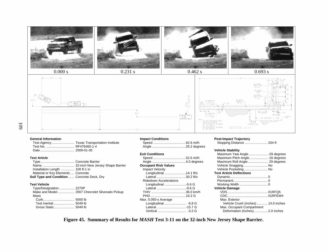
109
0.000 s
0.231 s
0.462 s
0.693 s
General Information Test Agency ......................... Test No. .............................. Date ..................................... Test Article Type ..................................... Name ................................... Installation Length .............. Material or Key Elements .... Soil Type and Condition ....... Test Vehicle Type/Designation ................. Make and Model .................. Mass
Curb .................................. Test Inertial ....................... Gross Static ......................
Texas Transportation Institute RF476460-1-4 2009-01-30 Concrete Barrier 32-inch New Jersey Shape Barrier 100 ft-1 in Concrete Concrete Deck, Dry 2270P 2007 Chevrolet Silverado Pickup 5000 lb 5049 lb 5049 lb
Impact Conditions Speed .................................... Angle ..................................... Exit Conditions Speed .................................... Angle ..................................... Occupant Risk Values Impact Velocity Longitudinal ........................ Lateral ................................
Ridedown Accelerations Longitudinal ........................ Lateral ................................ THIV ...................................... PHD ....................................... Max. 0.050-s Average Longitudinal ........................ Lateral ................................ Vertical ...............................
62.6 mi/h 25.2 degrees 52.6 mi/h 4.0 degrees 14.1 ft/s 30.2 ft/s -5.6 G -9.6 G 36.0 km/h 10.2 G -6.8 G -15.7 G -3.2 G
Post-Impact Trajectory Stopping Distance ......................... Vehicle Stability
Maximum Yaw Angle ..................... Maximum Pitch Angle .................... Maximum Roll Angle ...................... Vehicle Snagging ........................... Vehicle Pocketing .......................... Test Article Deflections Dynamic ......................................... Permanent ..................................... Working Width ............................... Vehicle Damage VDS ............................................ CDC ............................................ Max. Exterior Vehicle Crush (inches) ............ Max. Occupant Compartment Deformation (inches) ...............
204 ft -29 degrees -16 degrees 29 degrees No No 0 0 0 01RFQ5 01RFEW4 14.0 inches 2.0 inches
Figure 45. Summary of Results for MASH Test 3-11 on the 32-inch New Jersey Shape Barrier.

110
Table 11. Performance Evaluation Summary for MASH Test 4-11 on the 32-inch New Jersey Shape Barrier.
Test Agency: Texas Transportation Institute Test No.: RF 476460-1-4 Test Date: 2009-01-30
MASH Test 4-11 Evaluation Criteria Test Results Assessment Structural Adequacy A. Test article should contain and redirect the vehicle or
bring the vehicle to a controlled stop; the vehicle should not penetrate, underride, or override the installation although controlled lateral deflection of the test article is acceptable
The 32-inch New Jersey Shape Barrier contained and redirected the 2270P vehicle. The vehicle did not penetrate, underride, or override the installation. No measurable deflection of the barrier occurred.
Pass
Occupant Risk D. Detached elements, fragments, or other debris from
the test article should not penetrate or show potential for penetrating the occupant compartment, or present an undue hazard to other traffic, pedestrians, or personnel in a work zone.
No detached elements, fragment, or other debris was present to penetrate or to show potential for penetrating the occupant compartment, or to present hazard to others in the area.
Pass
Deformations of, or intrusions into, the occupant compartment should not exceed limits set forth in Section 5.3 and Appendix E of MASH.
Maximum occupant compartment deformation was 2.0 inches at the right kickpanel. Pass
F. The vehicle should remain upright during and after collision. The maximum roll and pitch angles are not to exceed 75 degrees.
The 2270P vehicle remained upright during and after the collision event. Maximum roll and pitch were 29 and -16 degrees, respectively.
Pass
H. Longitudinal and lateral occupant impact velocities should fall below the preferred value of 30 ft/s (9.1 m/s), or at least below the maximum allowable value of 40 ft/s (12.2 m/s).
Longitudinal occupant impact velocity was 14.1 ft/s, and lateral occupant impact velocity was 30.2 ft/s. Pass
I. Longitudinal and lateral occupant ridedown accelerations should fall below the preferred value of 15.0 G, or at least below the maximum allowable value of 20.49 G.
Longitudinal ridedown acceleration was -5.6 G, and lateral ridedown acceleration was -9.6 G. Pass
Vehicle Trajectory For redirective devices, the vehicle shall exit the
barrier within the exit box. The 2270P exited the barrier within the exit box. Pass

111
W-BEAM GUARDRAIL – G4(2W)
Test Installation Description
The G4(2W) W-beam guardrail system consists of 12 gauge W-beam rail elements attached to nominal 6 in x 8 in x 72 in wood posts spaced 6 ft-3 inches on center apart. The rail is offset from the posts using nominal 6 in x 8 in x 14-inch long wood block-outs. The rail and block-outs are attached to the post with A307 5/8-inch diameter bolts and nuts. The rail splice joints occurred at the posts and were lapped in the travel direction of traffic. The mounting height of the guardrail was 27-5/8 inches to the top of the W-beam element. The posts were installed 44 inches below grade in standard test soil, backfilled in lifts and mechanically compacted. The overall length of the test installation was 175.0 ft. Figure 46 shows a cross-section of the G4(2W) W-beam guardrail. Figure 47 shows photos of the completed installation. Appendix D (available on the NCAC website, www.ncac.gwu.edu/) shows drawings of the test installation and more detailed information on the barrier and crash test.
According to Appendix B of MASH, soil strength was measured the day of the crash test. The minimum post loads required for post deflections of 5 inches, 10 inches, and 15 inches, measured at a height of 25 inches above ground, is 3940 lb, 5500 lb, and 6540 lb, respectively (90 percent of static load for the initial standard installation). On the day of the test, March 4, 2009, loads on the post at deflections of 5 inches and 10 inches were 8030 lb and 9727 lb, respectively. The load on the post as the post deflection reached 15 inches exceeded 9000 lb, at which point the load test was stopped. Thus, the strength of the backfill material met minimum requirements.
Figure 46. Cross-Section of the G4(2W) W-Beam Guardrail.

112
Figure 47. G4(2W) W-Beam Guardrail Prior to Testing. Test Number 476460-1-5 (MASH Test 3-11)
Test Description
Test Vehicle: 2007 Chevrolet Silverado 4-door pickup Test Inertia Weight: 5009 lb Gross Static Weight: 5009 lb Impact Speed: 64.4 mi/h Impact Angle: 26.1 degrees
The 2007 Chevrolet Silverado pickup, traveling at an impact speed of 64.4 mi/h, impacted the G4(2W) W-beam guardrail 10 ft-0 inches upstream of post 13 at an impact angle of 26.1 degrees. At 0.034 s after impact, the left front corner of the vehicle contacted post 12, which began to rotate in the soil. The left front tire and wheel rim contacted post 13, and the post fractured below ground at 0.053 s. The vehicle contacted post 14 at 0.065 s, and the vehicle just slightly redirected at 0.078 s, after which time the vehicle pocketed in the guardrail. At 0.122 s, the W-beam rail element ruptured, and at 0.129 s, the vehicle began to yaw clockwise. The vehicle contacted posts 15, 16 and 17 at 0.173 s, 0.252 s, and 0.378 s, respectively. At 0.630 s, the vehicle lost contact with the W-beam guardrail and was traveling at an exit speed and angle of 33.8 mi/h and 4.3 degrees, respectively, toward the field side of the installation. At 0.824 s, the left front area of the vehicle became visible and it was noted that the left front tire and wheel assembly had

113
separated from the vehicle. The vehicle began to roll at 1.263 s as the wheel rims on the left side dug into the soil. The vehicle rolled counterclockwise 180 degrees, and the vehicle subsequently came to rest upside down, facing the field side of the barrier, 16 ft toward the field side between posts 21 and 22 (69 ft downstream).
Damage to the G4(2W) W-beam guardrail is shown in Figures 48 and 49. Post 1 was
displaced laterally downstream 0.4 inch, and the W-beam rail element separated from post 8. Post 10 split vertically through the rail bolt hole and the soil around the post was disturbed. Post 11 was pushed toward the field side 1.0 inch at ground level and was leaning 3 degrees. Post 12 was pushed toward field side 2 inches at ground level, and was leaning 9 degrees. The W-beam rail element ruptured at the splice on the upstream side of the bolts at post 13 and the ruptured end deformed around post 15. Posts 13 through 15 fractured below ground level, and due to fracturing and splintering, specific post resting places were not identifiable. However, all debris was on the field side of the test installation. Post 16 was pushed toward the field side and downstream 0.5 inch at ground level and the W-beam rail element separated from the post. There were tire marks on the field side of post 16. Post 17 was pushed toward the field side and downstream 0.5 inch. The soil around post 18 and 19 was disturbed. Post 21 was split vertically at the rail bolt hole. The length of contact of the vehicle with the guardrail was 24.0 ft.
Figure 48. G4(2W) W-Beam Guardrail after MASH Test 3-11.
The vehicle sustained damage to the left side and top, as shown in Figure 49. The left upper and lower A-arms and the left frame rail were deformed. The left upper ball joint separated, the lower ball joint pulled out of the mount, and the steering knuckle sheared. Also damaged were the front bumper, grill, radiator, left front fender, left doors, left rear wheel rim (no loss of air in the

114
tire), left rear exterior bed, rear bumper and tailgate. The windshield, roof, right doors, and right rear exterior of the bed were deformed from the rollover. Maximum exterior crush to the vehicle was 6.5 inches in the side plane at the left front corner at bumper height. Maximum occupant compartment deformation was 2.88 inches in the vertical measurement from floor to roof in the driver’s side area.
Figure 49. Test Vehicle and G4(2W) W-Beam Guardrail after MASH Test 3-11.
Data from the accelerometer, located at the vehicle center of gravity, were digitized for evaluation of occupant risk. In the longitudinal direction, the occupant impact velocity was 21.6 ft/s (6.6 m/s) at 0.143 s, the highest 0.010-s occupant ridedown acceleration was -10.2 G from 0.240 to 0. 250 s, and the maximum 0.050-s average acceleration was -8.2 G between 0.066 and 0.116 s. In the lateral direction, the occupant impact velocity was 14.1 ft/s (4.3 m/s) at 0.143 s, the highest 0.010-s occupant ridedown acceleration was 9.6 G from 1.411 to 1.421 s, and the maximum 0.050-s average was 6.3 Gs between 0.036 and 0.086 s. THIV was 27.6 km/h or 7.7 m/s at 0.138 s; PHD was 10.5 G between 0.305 and 0.315 s; and the ASI was 0.97 between 0.037 and 0.087 s. These data and other pertinent information from the test are summarized in Figure 50.
Summary of Test Results The G4(2W) W-beam guardrail did not contain the 2270P vehicle. The vehicle penetrated
the guardrail after the rail element ruptured. Posts 13 through 15 fractured below ground level. However, all debris was on the field side of the test installation and did not penetrate or show potential for penetrating the occupant compartment, or to present hazard to others in the area. Maximum occupant compartment deformation was 2.88 inches in the left front cab area. The 2270P

115
vehicle remained upright during the collision event. However, the 2270P vehicle rolled after penetrating the guardrail. Maximum roll angle was 180 degrees. Occupant risk factors were within the limits specified in MASH. The 2270P vehicle came to rest behind the guardrail installation. It should be noted, the impact speed and angle for this test were 64.4 mph and 26.1 degrees, respectively. The impact speed and angle were within the acceptable limits prescribed in MASH. However, the impact condition represented an impact severity 16.4 percent greater than the target MASH condition (62.2 mph and 25 degrees).
The G4(2W) W-beam guardrail did not perform acceptably when impacted by the 2270P
vehicle (2007 Chevrolet Silverado pickup), as shown in Table 12. The 2270P Silverado pickup penetrated the rail element and then rolled 180 degrees.

116
0.000 s
0.234 s
0.469 s
0.820 s
General Information Test Agency ......................... Test No. .............................. Date ..................................... Test Article Type ..................................... Name ................................... Installation Length .............. Material or Key Elements .... Soil Type and Condition ....... Test Vehicle Type/Designation ................. Make and Model .................. Mass
Curb .................................. Test Inertial ....................... Gross Static ......................
Texas Transportation Institute RF476460-1-5 2009-03-04 Longitudinal Barrier G4(2W) W-beam guardrail 175 ft W-beam rail element on 6x8x72-inch long timber posts spaced 6 ft-3 inches apart with 6x8x14-inch long timber blockouts Crushed Limestone, Dry 2270P 2007 Chevrolet Silverado Pickup 5079 lb 5009 lb 5009 lb
Impact Conditions Speed .................................... Angle ..................................... Exit Conditions Speed .................................... Angle ..................................... Occupant Risk Values Impact Velocity Longitudinal ........................ Lateral ................................
Ridedown Accelerations Longitudinal ........................ Lateral ................................ THIV ...................................... PHD ....................................... Max. 0.050-s Average Longitudinal ........................ Lateral ................................ Vertical ...............................
64.4 mi/h 26.1 degrees 33.8 mi/h 4.3 deg behind 21.6 ft/s 14.1 ft/s -10.2 G 9.6 G 27.6 km/h 10.5 G -8.2 G 6.3 G -3.7 G
Post-Impact Trajectory Stopping Distance ......................... Vehicle Stability
Maximum Yaw Angle ..................... Maximum Pitch Angle .................... Maximum Roll Angle ...................... Vehicle Snagging ........................... Vehicle Pocketing .......................... Test Article Deflections Dynamic ......................................... Permanent ..................................... Working Width ............................... Vehicle Damage VDS ............................................ CDC ............................................ Max. Exterior Vehicle Crush ....... Max. Occupant Compartment Deformation .............................
69 ft downstream; 16 ft behind rail 87 degrees -18 degrees -180 degrees No Yes Ruptured Ruptured Ruptured 01LFQ5 01LFEW4 13.0 inches 2.88 inches
Figure 50. Summary of Results for MASH Test 3-11 on the G4(2W) W-Beam Guardrail.

117
Table 12. Performance Evaluation Summary for MASH Test 3-11 on the G4(2W) W-Beam Guardrail. Test Agency: Texas Transportation Institute Test No.: RF 476460-1-5 Test Date: 2009-03-04
MASH Test 3-11 Evaluation Criteria Test Results Assessment Structural Adequacy A. Test article should contain and redirect the vehicle or bring
the vehicle to a controlled stop; the vehicle should not penetrate, underride, or override the installation although controlled lateral deflection of the test article is acceptable
The G4(2W) W-beam guardrail did not contain the 2270P vehicle. The vehicle penetrated the W-beam rail element. Fail
Occupant Risk D. Detached elements, fragments, or other debris from the test
article should not penetrate or show potential for penetrating the occupant compartment, or present an undue hazard to other traffic, pedestrians, or personnel in a work zone.
No detached elements, fragments, or other debris were present to penetrate or to show potential for penetrating the occupant compartment, or to present hazard to others in the area.
Pass
Deformations of, or intrusions into, the occupant compartment should not exceed limits set forth in Section 5.3 and Appendix E of MASH.
Maximum occupant compartment deformation was 2.88 inches at the vertical area of the left front cab area.
Pass
F. The vehicle should remain upright during and after collision. The maximum roll and pitch angles are not to exceed 75 degrees.
The 2270P vehicle remained upright during the collision event. However, vehicle rolled after penetrating the guardrail. Maximum roll angle was 118 degrees.
Fail
H. Longitudinal and lateral occupant impact velocities should fall below the preferred value of 30 ft/s (9.1 m/s), or at least below the maximum allowable value of 40 ft/s (12.2 m/s).
Longitudinal occupant impact velocity was 21.6 ft/s, and lateral occupant impact velocity was 14.1 ft/s. Pass
I. Longitudinal and lateral occupant ridedown accelerations should fall below the preferred value of 15.0 G, or at least below the maximum allowable value of 20.49 G.
Longitudinal ridedown acceleration was -10.2 G, and lateral ridedown acceleration was 9.6 G. Pass
Vehicle Trajectory For redirective devices, the vehicle shall exit the barrier
within the exit box. The 2270P penetrated behind the installation. N/A
118
W-BEAM GUARDRAIL – G4(1S) MEDIAN BARRIER
Test Installation Description
The G4(1S) W-Beam Median Barrier (American Association of State Highway and Transportation Officials (AASHTO) Designation SGM04a with non-steel blocks) is a 27 inch tall, strong steel post, W-beam median barrier. The median barrier is constructed using 12-gauge W-beam guardrails attached to 6 ft long W6x8.5 steel posts spaced 6 ft-3 inch on center. The W-beam guardrails are offset from the posts using non-steel blockouts nominally 6 inch x 8 inch x 14 inch long. Either wood or an FHWA accepted plastic blockout may be used. For the test presented herein, wood blockouts were used.
The height of the G4(1S) W-beam median barrier test installation was 27 inches. The
length of need for the installation was 100 ft. The median barrier was terminated with ET-PLUS guardrail terminals. The front (impacted) rail was constructed with 37 ft-6 inch long terminals on each end and the rear rail was constructed with 50 ft long terminals on each end. The total overall test installation length was 200 ft.
A cross section of the G4(1S) W-beam median barrier is shown in Figure 51.
Photographs of the completed installation are shown in Figure 52. More detailed information of the barrier and the two crash tests can be found in Appendixes E and F (available on the NCAC website, www.ncac.gwu.edu/).
The first test on the median barrier was with the small car (1100C vehicle). The installation was then repaired and used for the test with the 2270P vehicle.
The test installation was installed in standard soil meeting AASHTO standard specifications for “Materials for Aggregate and Soil Aggregate Subbase, Base and Surface Courses,” designated M147-65(2004), grading B. In addition, in compliance with MASH, standard soil strength static tests were performed at the installation site the day of each crash test.
According to Appendix B of MASH, soil strength was measured the day of the crash test. The minimum post load required for deflections at 5 inches, 10 inches, and 15 inches, measured at a height of 25 inches above ground, is 3940 lb, 5500 lb, and 6540 lb, respectively (90 percent of static load for the initial standard installation). On the day of the small car test, April 8, 2009, load on the post at deflections of 5 inches, 10 inches, and 15 inches was 7636 lb, 8697 lb, and 9303 lb, respectively. Thus, the strength of the backfill material met minimum requirements.
On the day of the pickup test, April 14, 2009, load on the post at deflections of 5 inches
and 10 inches was 8758 lb and 9606 lb, respectively. As the load approached 9800 lb, the winch truck lost traction and started slipping. Therefore, testing was halted. However, the strength of the backfill material met minimum requirements.
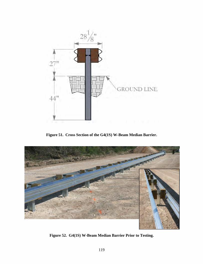
119
Figure 51. Cross Section of the G4(1S) W-Beam Median Barrier.
Figure 52. G4(1S) W-Beam Median Barrier Prior to Testing.
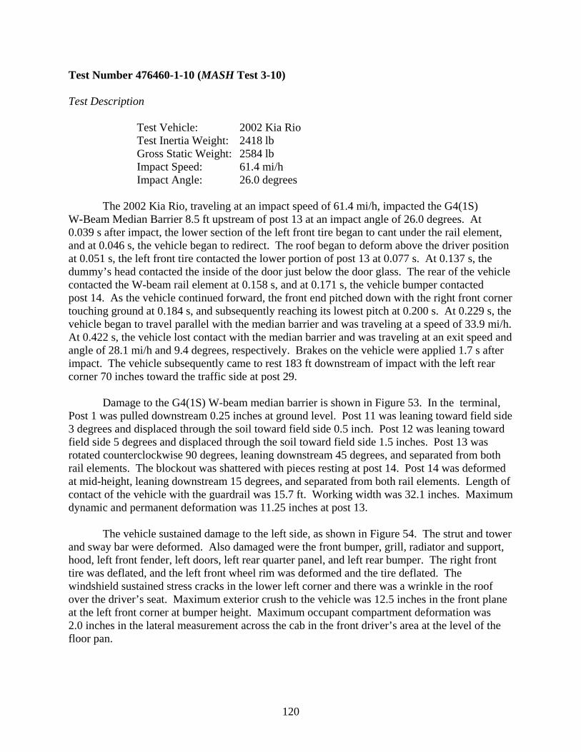
120
Test Number 476460-1-10 (MASH Test 3-10)
Test Description
Test Vehicle: 2002 Kia Rio Test Inertia Weight: 2418 lb Gross Static Weight: 2584 lb Impact Speed: 61.4 mi/h Impact Angle: 26.0 degrees
The 2002 Kia Rio, traveling at an impact speed of 61.4 mi/h, impacted the G4(1S) W-Beam Median Barrier 8.5 ft upstream of post 13 at an impact angle of 26.0 degrees. At 0.039 s after impact, the lower section of the left front tire began to cant under the rail element, and at 0.046 s, the vehicle began to redirect. The roof began to deform above the driver position at 0.051 s, the left front tire contacted the lower portion of post 13 at 0.077 s. At 0.137 s, the dummy’s head contacted the inside of the door just below the door glass. The rear of the vehicle contacted the W-beam rail element at 0.158 s, and at 0.171 s, the vehicle bumper contacted post 14. As the vehicle continued forward, the front end pitched down with the right front corner touching ground at 0.184 s, and subsequently reaching its lowest pitch at 0.200 s. At 0.229 s, the vehicle began to travel parallel with the median barrier and was traveling at a speed of 33.9 mi/h. At 0.422 s, the vehicle lost contact with the median barrier and was traveling at an exit speed and angle of 28.1 mi/h and 9.4 degrees, respectively. Brakes on the vehicle were applied 1.7 s after impact. The vehicle subsequently came to rest 183 ft downstream of impact with the left rear corner 70 inches toward the traffic side at post 29.
Damage to the G4(1S) W-beam median barrier is shown in Figure 53. In the terminal,
Post 1 was pulled downstream 0.25 inches at ground level. Post 11 was leaning toward field side 3 degrees and displaced through the soil toward field side 0.5 inch. Post 12 was leaning toward field side 5 degrees and displaced through the soil toward field side 1.5 inches. Post 13 was rotated counterclockwise 90 degrees, leaning downstream 45 degrees, and separated from both rail elements. The blockout was shattered with pieces resting at post 14. Post 14 was deformed at mid-height, leaning downstream 15 degrees, and separated from both rail elements. Length of contact of the vehicle with the guardrail was 15.7 ft. Working width was 32.1 inches. Maximum dynamic and permanent deformation was 11.25 inches at post 13.
The vehicle sustained damage to the left side, as shown in Figure 54. The strut and tower
and sway bar were deformed. Also damaged were the front bumper, grill, radiator and support, hood, left front fender, left doors, left rear quarter panel, and left rear bumper. The right front tire was deflated, and the left front wheel rim was deformed and the tire deflated. The windshield sustained stress cracks in the lower left corner and there was a wrinkle in the roof over the driver’s seat. Maximum exterior crush to the vehicle was 12.5 inches in the front plane at the left front corner at bumper height. Maximum occupant compartment deformation was 2.0 inches in the lateral measurement across the cab in the front driver’s area at the level of the floor pan.

121
Figure 53. G4(1S) W-Beam Median Barrier after MASH Test 3-10.
Figure 54. Test Vehicle after MASH Test 3-10 on the G4(1S) W-Beam Median Barrier.
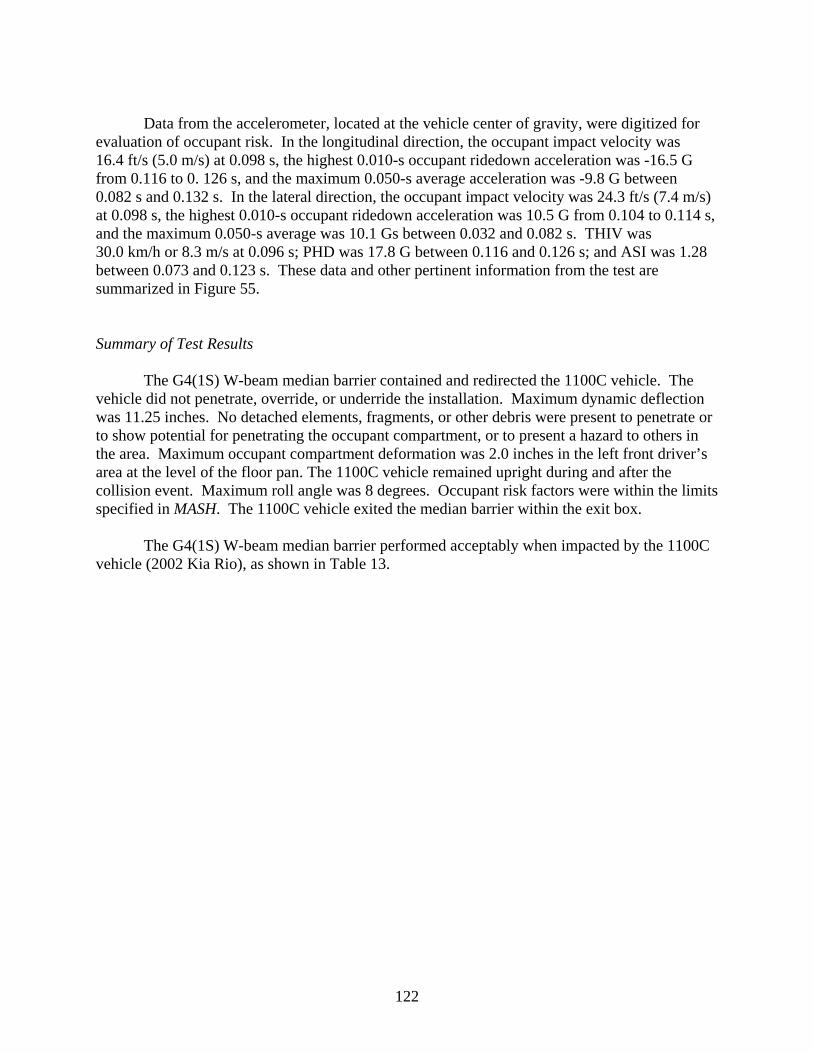
122
Data from the accelerometer, located at the vehicle center of gravity, were digitized for
evaluation of occupant risk. In the longitudinal direction, the occupant impact velocity was 16.4 ft/s (5.0 m/s) at 0.098 s, the highest 0.010-s occupant ridedown acceleration was -16.5 G from 0.116 to 0. 126 s, and the maximum 0.050-s average acceleration was -9.8 G between 0.082 s and 0.132 s. In the lateral direction, the occupant impact velocity was 24.3 ft/s (7.4 m/s) at 0.098 s, the highest 0.010-s occupant ridedown acceleration was 10.5 G from 0.104 to 0.114 s, and the maximum 0.050-s average was 10.1 Gs between 0.032 and 0.082 s. THIV was 30.0 km/h or 8.3 m/s at 0.096 s; PHD was 17.8 G between 0.116 and 0.126 s; and ASI was 1.28 between 0.073 and 0.123 s. These data and other pertinent information from the test are summarized in Figure 55.
Summary of Test Results The G4(1S) W-beam median barrier contained and redirected the 1100C vehicle. The
vehicle did not penetrate, override, or underride the installation. Maximum dynamic deflection was 11.25 inches. No detached elements, fragments, or other debris were present to penetrate or to show potential for penetrating the occupant compartment, or to present a hazard to others in the area. Maximum occupant compartment deformation was 2.0 inches in the left front driver’s area at the level of the floor pan. The 1100C vehicle remained upright during and after the collision event. Maximum roll angle was 8 degrees. Occupant risk factors were within the limits specified in MASH. The 1100C vehicle exited the median barrier within the exit box.
The G4(1S) W-beam median barrier performed acceptably when impacted by the 1100C vehicle (2002 Kia Rio), as shown in Table 13.

123
0.000 s
0.119 s
0.236 s
0.475 s
General Information Test Agency ......................... Test No. .............................. Date ..................................... Test Article Type ..................................... Name ................................... Installation Length .............. Material or Key Elements .... Soil Type and Condition ....... Test Vehicle Type/Designation ................. Make and Model .................. Mass
Curb .................................. Test Inertial ....................... Dummy ............................. Gross Static ......................
Texas Transportation Institute RF476460-1-10 2009-04-08 Median Barrier G4(1S) W-Beam Median Barrier 200 ft W-beam rail elements on steel posts with wood blockouts Crushed Limestone, Dry 1100C 2002 Kia Rio 2396 lb 2418 lb 166 lb 2584 lb
Impact Conditions Speed .................................... Angle ..................................... Exit Conditions Speed .................................... Angle ..................................... Occupant Risk Values Impact Velocity Longitudinal ........................ Lateral ................................
Ridedown Accelerations Longitudinal ........................ Lateral ................................ THIV ...................................... PHD ....................................... Max. 0.050-s Average Longitudinal ........................ Lateral ................................ Vertical ...............................
61.4 mi/h 26.0 degrees 45.3 mi/h 9.4 degrees 16.4 ft/s 24.3 ft/s -16.5 G 10.5 G 30.0 km/h 17.8 G -9.8 G 10.1 G 1.6 G
Post-Impact Trajectory Stopping Distance ......................... Vehicle Stability
Maximum Yaw Angle ..................... Maximum Pitch Angle .................... Maximum Roll Angle ...................... Vehicle Snagging ........................... Vehicle Pocketing .......................... Test Article Deflections Dynamic ......................................... Permanent ..................................... Working Width ............................... Vehicle Damage VDS ............................................ CDC ............................................ Max. Exterior Vehicle Crush ....... Max. Occupant Compartment Deformation .............................
183 ft dwnstrm 23 ft twd traffic 35 degrees -5 degrees 8 degrees No No 11.25 inches 11.25 inches 32.1 inches 11LFQ5 11FLEW4 12.5 inches 2.0 inches
Figure 55. Summary of Results for MASH Test 3-10 on the G4(1S) W-Beam Median Barrier.

124
Table 13. Performance Evaluation Summary for MASH Test 3-10 on the G4(1S) W-Beam Median Barrier. Test Agency: Texas Transportation Institute Test No.: RF 476460-1-10 Test Date: 2009-04-08
MASH Test 3-10 Evaluation Criteria Test Results Assessment Structural Adequacy A. Test article should contain and redirect the vehicle or
bring the vehicle to a controlled stop; the vehicle should not penetrate, underride, or override the installation although controlled lateral deflection of the test article is acceptable
The G4(1S) W-beam median barrier contained and redirected the 1100C vehicle. The vehicle did not penetrate, override, or underride the installation. Maximum dynamic deflection during the test was 11.25 inches.
Pass
Occupant Risk D. Detached elements, fragments, or other debris from
the test article should not penetrate or show potential for penetrating the occupant compartment, or present an undue hazard to other traffic, pedestrians, or personnel in a work zone.
No detached elements, fragments, or other debris were present to penetrate or to show potential for penetrating the occupant compartment, or to a present hazard to others in the area.
Pass
Deformations of, or intrusions into, the occupant compartment should not exceed limits set forth in Section 5.3 and Appendix E of MASH.
Maximum occupant compartment deformation was 2.0 inches in the driver’s side area at the level of the floor pan.
Pass
F. The vehicle should remain upright during and after collision. The maximum roll and pitch angles are not to exceed 75 degrees.
The 1100C vehicle remained upright during and after the collision event. Maximum roll angle was 8 degrees.
Pass
H. Longitudinal and lateral occupant impact velocities should fall below the preferred value of 30 ft/s (9.1 m/s), or at least below the maximum allowable value of 40 ft/s (12.2 m/s).
Longitudinal occupant impact velocity was 16.4 ft/s, and lateral occupant impact velocity was 24.3 ft/s. Pass
I. Longitudinal and lateral occupant ridedown accelerations should fall below the preferred value of 15.0 G, or at least below the maximum allowable value of 20.49 G.
Longitudinal ridedown acceleration was -16.5 G, and lateral ridedown acceleration was 10.5 G. Pass
Vehicle Trajectory For redirective devices, the vehicle shall exit the
barrier within the exit box. The 1100C exited the median barrier within the exit box. Pass

125
Test Number 476460-1-9 (MASH Test 3-11)
Test Description
Test Vehicle: 2007 Chevrolet Silverado 4-door pickup Test Inertia Weight: 5029 lb Gross Static Weight: 5029 lb Impact Speed: 64.0 mi/h Impact Angle: 25.1 degrees The installation used in the test with the small car (1100C vehicle) was repaired and used for this test with the 2270P vehicle.
The 2007 Chevrolet Silverado pickup, traveling at an impact speed of 64.0 mi/h, impacted the G4(1S) W-beam median barrier 2 inches downstream of post 11 at an impact angle of 25.1 degrees. At 0.054 s after impact, the left front bumper contacted post 12, and at 0.059 s, the W-beam rail element buckled. Post 13 separated from the w-beam rail element at 0.082 s, and the vehicle bumper contacted post 13 at 0.118 s. At 0.124 s, post 14 separated from the W-beam rail element, and the front of the vehicle began to rise up on the W-beam rail element at 0.184 s. The left front tire and wheel began to ride up on post 14 at 0.189 s and the bumper of the vehicle contacted post 14 at 0.198 s. By 0.215 s, the front of the vehicle was airborne above the median barrier, and at 0.239 s, the vehicle lost contact with the barrier as it was airborne over the median barrier.
The rear differential of the vehicle contacted the top of the rail at 0.284 s, and the left rear
tire and wheel contacted the “field side” of the median barrier at 0.424 s. At 0.597 s, the right front tire contacted the top of the median barrier, and at 0.929 s, the tire blew out. The left front and rear tires contacted the ground surface on the “field side” of the median barrier at 1.221 s and 1.268 s, respectively, and the front bumper contacted the ground surface at 1.289 s. At 1.526 s, the right rear tire and wheel contacted the top of the median barrier and at 1.771 s, the tire blew out. The vehicle subsequently came to rest 40 ft downstream of the end terminal, and 24 ft toward “field side.”
Damage to the G4(1S) W-beam median barrier is shown in Figure 56. In the terminal,
post W was pulled downstream 0.13 inch, and post 1 was pulled downstream 1.0 inch. The soil around posts 2-9 was disturbed. Post 10 was pushed toward field side 0.38 inch at ground level and was leaning 4 degrees. Post 11 was pushed toward field side 2.25 inches at ground level and leaning 6 degrees. Posts 12 and 13 were deformed and separated from both rail elements, rotated clockwise 85 degrees, and leaning toward the field side 30 degrees. Post 14 separated from the rail element, pushed toward field side 1.13 inches, and leaning toward field side 5 degrees. Post 15 was pushed toward field side 0.38 inch, and leaning toward field side 5 degrees. Post 29 was pulled upstream 0.25 inch at ground level. Maximum permanent deformation of the W-beam rail element was 22.0 inches at a point 12 inches upstream of post 13. Length of contact of the vehicle with the guardrail during the initial contact was 18.92 feet. As the vehicle vaulted over the barrier and came down on top of the barrier, the vehicle was in contact with the barrier from post 18 to post 28. Dynamic deflection of the guardrail during the test was 23.2 inches.

126
Figure 56. G4(1S) W-Beam Median Barrier after MASH Test 3-11. The vehicle sustained damage to the left side, as shown in Figure 57. The front bumper,
grill, left front fender, and left front tire and wheel rims were damaged in the initial contact. The left doors and exterior of the bed were scuffed. The drive shaft, left rear tire and wheel rim and rear bumper were damaged as the vehicle vaulted over the barrier. Maximum exterior crush to the vehicle was 12 inches in the side plane at the left front corner at bumper height. No deformation of the occupant compartment occurred.
Figure 57. Test Vehicle after MASH Test 3-11 on the G4(1S) W-Beam Median Barrier.

127
Data from the accelerometer, located at the vehicle center of gravity, were digitized for evaluation of occupant risk. In the longitudinal direction, the occupant impact velocity was 17.2 ft/s (5.2 m/s) at 0.138 s, the highest 0.010-s occupant ridedown acceleration was -5.2 G from 1.280 to 1.290 s, and the maximum 0.050-s average acceleration was -5.4 G between 0.049 and 0.099 s. In the lateral direction, the occupant impact velocity was 17.1 ft/s (5.0 m/s) at 0.138 s, the highest 0.010-s occupant ridedown acceleration was 5.3 G from 0.139 to 0.149 s, and the maximum 0.050-s average was 6.0 Gs between 0.219 and 0.259 s. THIV was 24.3 km/h or 6.8 m/s at 0.135 s; PHD was 6.7 G between 0.139 and 0.149 s; and ASI was 0.68 between 0.048 and 0.098 s. These data and other pertinent information from the test are summarized in Figure 58.
Summary of Test Results The G4(1S) W-beam median barrier did not contain or redirect the 2270P vehicle. The
vehicle overrode the installation. Maximum dynamic deflection of the W-beam during the test was 23.2 inches. No detached elements, fragments, or other debris were present to penetrate or to show potential for penetrating the occupant compartment, or to present a hazard to others in the area. No occupant compartment deformation occurred. The 2270P vehicle remained upright during and after the collision event. Maximum roll angle was 32 degrees. Occupant risk factors were within the limits specified in MASH. It should be noted, the impact speed and angle for this test were 64.0 mph and 25.1 degrees, respectively. The impact speed and angle were within the acceptable limits prescribed in MASH. However, the impact condition represented an impact severity 15.3 percent greater than the target MASH condition (62.2 mph and 25 degrees).
The G4(1S) W-beam median barrier did not perform acceptably when impacted by the
2270P vehicle (2007 Chevrolet Silverado pickup), as shown in Table 14. The 2270P Silverado pickup truck overrode the installation.
Typically, when the G4(1S) W-beam barrier is impacted in a roadside application, the
W-beam rail element deforms, the support posts are displaced through the soil, and the vehicle is redirected. During the impact sequence, the rail becomes detached from the post by means of the post bolt pulling out of the rail slot as the post displaces rearward. However, in the G4(1S) W-beam median barrier, the addition of the rear W-beam rail element provides additional stiffness, which restrains the lateral displacement of the posts. This rail is unable to detach from the posts, and therefore, is pushed down in height as the posts are displaced. In the test presented herein, a guardrail post was impacted by the left front tire and the vehicle climbed the post and w-beam rail element.
A 30 inch tall version of the G4(1S) W-beam median barrier (AASHTO Designation
SGM06a&b) incorporates a C6x8.2 rub-rail channel that is mounted 12 inches above the ground to the center of the rub-rail. The addition of the rub-rail will prevent the wheel from contacting the face of the posts, thus help mitigate vehicle-post snagging. The rub-rail will also increase the barrier stiffness, which should reduce post displacement and rail deflection. However, the rub-rail may still permit the pickup to climb the barrier.
The researchers recommend evaluating the 30 inch tall G4(1S) W-beam median barrier
(AASHTO Designation SGM06a) with MASH test 3-11.
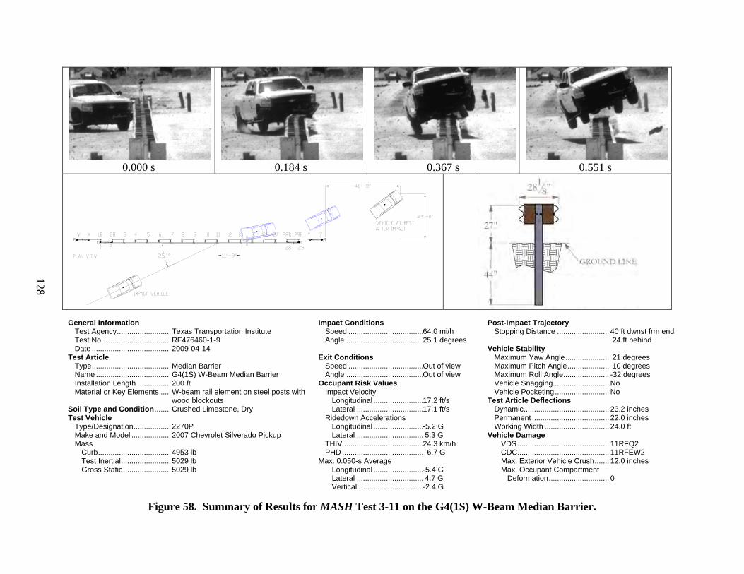
128
0.000 s
0.184 s
0.367 s
0.551 s
General Information Test Agency ......................... Test No. .............................. Date ..................................... Test Article Type ..................................... Name ................................... Installation Length .............. Material or Key Elements .... Soil Type and Condition ....... Test Vehicle Type/Designation ................. Make and Model .................. Mass
Curb .................................. Test Inertial ....................... Gross Static ......................
Texas Transportation Institute RF476460-1-9 2009-04-14 Median Barrier G4(1S) W-Beam Median Barrier 200 ft W-beam rail element on steel posts with wood blockouts Crushed Limestone, Dry 2270P 2007 Chevrolet Silverado Pickup 4953 lb 5029 lb 5029 lb
Impact Conditions Speed .................................... Angle ..................................... Exit Conditions Speed .................................... Angle ..................................... Occupant Risk Values Impact Velocity Longitudinal ........................ Lateral ................................
Ridedown Accelerations Longitudinal ........................ Lateral ................................ THIV ...................................... PHD ....................................... Max. 0.050-s Average Longitudinal ........................ Lateral ................................ Vertical ...............................
64.0 mi/h 25.1 degrees Out of view Out of view 17.2 ft/s 17.1 ft/s -5.2 G 5.3 G 24.3 km/h 6.7 G -5.4 G 4.7 G -2.4 G
Post-Impact Trajectory Stopping Distance ......................... Vehicle Stability
Maximum Yaw Angle ..................... Maximum Pitch Angle .................... Maximum Roll Angle ...................... Vehicle Snagging ........................... Vehicle Pocketing .......................... Test Article Deflections Dynamic ......................................... Permanent ..................................... Working Width ............................... Vehicle Damage VDS ............................................ CDC ............................................ Max. Exterior Vehicle Crush ....... Max. Occupant Compartment Deformation .............................
40 ft dwnst frm end 24 ft behind 21 degrees 10 degrees -32 degrees No No 23.2 inches 22.0 inches 24.0 ft 11RFQ2 11RFEW2 12.0 inches 0
Figure 58. Summary of Results for MASH Test 3-11 on the G4(1S) W-Beam Median Barrier.

129
Table 14. Performance Evaluation Summary for MASH Test 3-11 on the G4(1S) W-Beam Median Barrier. Test Agency: Texas Transportation Institute Test No.: RF 476460-1-9 Test Date: 2009-04-14
MASH Test 3-11 Evaluation Criteria Test Results Assessment Structural Adequacy A. Test article should contain and redirect the vehicle or
bring the vehicle to a controlled stop; the vehicle should not penetrate, underride, or override the installation although controlled lateral deflection of the test article is acceptable
The G4(1S) W-beam median barrier did not contain or redirected the 2270P vehicle. The vehicle overrode the installation. Maximum dynamic deflection of the guardrail during the test was 23.2 inches.
Fail
Occupant Risk D. Detached elements, fragments, or other debris from
the test article should not penetrate or show potential for penetrating the occupant compartment, or present an undue hazard to other traffic, pedestrians, or personnel in a work zone.
No detached elements, fragments, or other debris were present to penetrate or to show potential for penetrating the occupant compartment, or to present hazard to others in the area.
Pass
Deformations of, or intrusions into, the occupant compartment should not exceed limits set forth in Section 5.3 and Appendix E of MASH.
No occupant compartment deformation occurred. Pass
F. The vehicle should remain upright during and after collision. The maximum roll and pitch angles are not to exceed 75 degrees.
The 2270P vehicle remained upright during and after the collision event. Maximum roll angle was 32 degrees.
Pass
H. Longitudinal and lateral occupant impact velocities should fall below the preferred value of 30 ft/s (9.1 m/s), or at least below the maximum allowable value of 40 ft/s (12.2 m/s).
Longitudinal occupant impact velocity was 17.2 ft/s, and lateral occupant impact velocity was 17.1 ft/s. Pass
I. Longitudinal and lateral occupant ridedown accelerations should fall below the preferred value of 15.0 G, or at least below the maximum allowable value of 20.49 G.
Longitudinal ridedown acceleration was -5.2 G, and lateral ridedown acceleration was 5.3 G. Pass
Vehicle Trajectory For redirective devices, the vehicle shall exit the
barrier within the exit box. The 2270P vehicle exited behind the barrier. N/A

130
PENNDOT W-BEAM TRANSITION
Test Installation Description
The W-beam transition (without drainage inlet) consists of 12.5 ft of two nested 12-gauge W-beam guardrails blocked out from the end of a concrete parapet using a 6-inch-diameter spacer tube followed by 12.5 ft of single W-beam guardrail. In addition, the transition incorporates a “flared-back” C6x8.2 rub rail. The height of the W-beam guardrail used in this transition was approximately 31 inches from the pavement surface. The centerline height of the rub rail from the pavement surface was approximately 13 inches. Texas Transportation Institute (TTI) received drawings from Pennsylvania DOT entitled “Standard Bridge Parapet to Guide Rail Transition, BC-739M, Sheet 1 of 2,” dated December 24, 1999, and “Type 2 Strong Post Guide Rail, RC52M,” dated September 30, 1998. Details for the moment slab to support the concrete parapet were also received. TTI used the details from these drawings to construct the test installation.
TTI constructed 16.4 ft of Pennsylvania standard bridge parapet from details provided by
Pennsylvania DOT. The standard parapet constructed was 42 inches in height and 18 inches in width at the base on the downstream end. At approximately 71 inches from the end of the parapet, the parapet flared back 10 degrees away from the traffic side and transitioned to a height and width of 32 inches and 12 inches, respectively, at the end of the parapet. The parapet was supported by a 13-inch-thick concrete moment slab. Vertical reinforcement in the parapet consisted of #5 enclosed stirrup bars located approximately 6 inches on centers. Longitudinal reinforcement in the parapet consisted of six #5 bars located in the lower portion of the parapet and four #6 bars located in the upper portion of the parapet. All reinforcement in the parapet was epoxy coated. A Type “B” insert was purchased from Brocker Rebar Company, York, Pennsylvania, and was installed in the parapet approximately 50-5/8 inches from the end of the parapet and at a centerline height of approximately 25 inches for anchoring the terminal connector to the parapet. Three 1-inch pipe sleeves were cast in the parapet approximately 50-3/8 inches from the end of the parapet (centerline distance) and at a centerline height of approximately 13 inches. These pipe sleeves were used for anchoring the rub rail to the parapet with three 7/8 inch diameter A325 bolts. The rub rail bolts fastened completely through the parapet. A 7 inch x 7 inch x 1/4-inch thick plate was used beneath the nuts on the field side of the parapet.
The moment slab constructed for the project was approximately 15-ft-5-1/4 inches by 21-ft-8-3/8-inches x 13 inches thick. The slab was connected to an existing concrete runway located at the testing facility with 30-inch-long dowels located approximately 18 inches on centers. The parapet and slab were constructed so the parapet was oriented approximately 10 degrees with the existing edge of the runway. Top transverse reinforcement in the slab consisted of #6 hooked bars located approximately 6 inches on centers. Bottom transverse reinforcement in the slab consisted of #5 straight bars located approximately 12 inches on centers. Longitudinal reinforcement in the slab consisted of #4 straight bars located approximately 12 inches on centers in both the top and bottom layers in the slab with the exception of the second and third bars located from the field side edge of the slab. These bars were spaced approximately 6 inches apart. The parapet was anchored to the slab by #5
131
“V-shaped” bars that were cast in the slab and extended from the bottom layer of reinforcement in the slab upwards into the parapet. These bars were located approximately 6 inches on centers from the end of the parapet to a distance of approximately 14 ft from the end. Beyond this distance these bars were spaced 12 inches on centers.
The transition was attached to the concrete parapet with a 10-gauge W-beam terminal connector welded to a steel plate. The connector attached to the parapet using four 7/8-inch-diameter ASTM A307 bolts in the Type B Insert. The rub rails were attached to the parapet with three A325 bolts. All posts used in the transitions and length of need W-beam guardrail were W6x8.5 steel posts. The posts nearest the concrete parapet (posts 16 through 19) used in the transition were 84 inches in length and embedded approximately 52 inches below grade. The remaining posts (posts 1 through 15) were 72 inches in length. Posts 9-13 were embedded approximately 40 inches below grade and posts 1 through 6 were embedded 43-3/8 inches below grade. The centerline of post 19 was located approximately 10-3/8 from the end of the concrete parapet. A 6-inch-diameter by 12-inch-long schedule 40 steel spacer tube attached to the nested W-beam guardrail was located approximately 18-3/4 inches toward the terminal connector from post 19. From post 19 to post 13, the post spacing was 18-3/4 inches. Posts were spaced 37-1/2 inches apart from post 13 to 9. From post 9 to 7 (W-beam guardrail length of need), the post spacing was 6 ft-3 inches. A LET end treatment was used beyond the length of need to anchor the W-beam guardrail. The rub rail used for this project consisted of a two-piece rub rail mounted 13 inches from the pavement surface to its centerline. Both pieces of the rub rail were fabricated from C6x8.2 steel channel. The pieces of the rub rail were spliced together at post 19 with a 1/2-inch-thick steel splice plate. From post 19, the rub rail was connected on each post and flared back at post 13 to the web of post 12 and was not attached.
The nested W-beam guardrail and the rub rail (at post 19 through 13) were blocked out
from the posts approximately 8 inches. Routed wood blockouts (nominally 6 inches x 8 inches x 22 inches) were used at posts 19 through 13. Standard routed wood blockouts (nominally 6 inches x 8 inches x 14 inches) were used at posts 12 through 1. The rub rail and the nested W-beam guardrail were attached to each post using 5/8-inch-diameter A307 “button head” bolts.
A drawing of the transition are provided in Figure 59. Photographs of the completed
installation are shown in Figure 60. More detailed information of the barrier and the crash test can be found in Appendix G (available on the NCAC website, www.ncac.gwu.edu/).
In accordance with Appendix B of MASH, soil strength was measured the day of the
crash test. The minimum post load required for deflections at 5 inches, 10 inches, and 15 inches, measured at a height of 25 inches above ground, is 3940 lb, 5500 lb, and 6540 lb, respectively (90 percent of static load for the initial standard installation). On the day of the test, March 31, 2009, load on the post at deflections of 5 inches, 10 inches, and 15 inches was 7090 lb, 7575 lb, and 7666 lb, respectively. Thus, the strength of the backfill material met minimum requirements.

132
Figure 59. Details of the Pennsylvania W-Beam Transition.
Figure 60. W-Beam Transition prior to Testing.

133
Test Number 476460-1-3 (MASH TEST 3-21)
Test Description
Test Vehicle: 2007 Chevrolet Silverado 4-door pickup Test Inertia Weight: 5029 lb Gross Static Weight: 5029 lb Impact Speed: 62.8 mi/h Impact Angle: 25.7 degrees
The 2007 Chevrolet Silverado pickup, traveling at an impact speed of 62.8 mi/h, impacted the W-beam transition 8.6 ft upstream from the end of the concrete parapet at an impact angle of 25.7 degrees. At 0.036 s after impact, the vehicle began to redirect, and at 0.071 s, the right front tire and wheel assembly began to rise. The vehicle began to travel parallel with the transition at 0.166 s, and was traveling at a speed of 55.8 mi/h. At 0.184 s, the left front tire and wheel assembly began to rise, and at 0.203 s, the left front tire touched ground. The vehicle lost contact with the transition at 0.295 s, and was traveling at an exit speed of 52.7 mi/h and an exit angle of 13.8 degrees toward the traffic side of the installation. Brakes on the vehicle were applied at 1.35 s after impact. The vehicle subsequently came to rest 183 ft downstream and 23 ft toward traffic lanes.
Damage to the W-beam transition is shown in Figure 61. Post 12 was leaning toward
field side 2 degrees from vertical, and post 13 was pushed toward field side 1.5 inches and leaning toward field side 4 degrees from vertical. Post 14 was leaning toward field side 5 degrees from vertical, and post 15 was pushed toward field side 1.5 inches and leaning toward field side 7 degrees from vertical. Posts 16 through 19 were leaning toward field side between 5-7 degrees from vertical, respectively. The vehicle snagged on the rubrail bolts on posts 14-18. The pipe spacer was deformed 0.25 inch. Length of contact of the vehicle with the guardrail was 13.0 ft. Maximum permanent deformation was 5.5 inches at post 17. Working area was 12.1 inches. Maximum dynamic deflection during the test was 3.8 inches.
The vehicle sustained damage to the left side and top, as shown in Figure 62. The left
A-arm pulled out of the front inner A-arm mount. The left front wheel rim was deformed and the tire deflated. Also damaged were the front bumper, grill, radiator and support, left front fender, left doors, left rear wheel rim (no loss of air in the tire), left rear exterior bed, and left rear bumper. Maximum exterior crush to the vehicle was 15.0 inches in the front plane at the left front corner at bumper height. Maximum occupant compartment deformation was 0.6 inches in the lateral measurement across the cab in the right rear passenger area at hip height.

134
Figure 61. PennDOT W-Beam Transition after MASH Test 3-21.
Figure 62. Test Vehicle after MASH Test 3-21 on the PennDOT W-Beam Transition.

135
Data from the accelerometer, located at the vehicle center of gravity, were digitized for evaluation of occupant risk. In the longitudinal direction, the occupant impact velocity was 16.4 ft/s (5.0 m/s) at 0.092 s, the highest 0.010-s occupant ridedown acceleration was -8.1 G from 0.100 to 0. 110 s, and the maximum 0.050-s average acceleration was -7.7 G between 0.044 s and 0.094 s. In the lateral direction, the occupant impact velocity was 28.5 ft/s (8.7 m/s) at 0.092 s, the highest 0.010-s occupant ridedown acceleration was 16.4 G from 0.187 to 0.197 s, and the maximum 0.050-s average was 13.5 Gs between 0.044 and 0.094 s. THIV was 34.8 km/h or 9.7 m/s at 0.091 s; PHD was 16.4 G between 0.187 and 0.197 s; and ASI was 1.64 between 0.044 and 0.094 s. These data and other pertinent information from the test are summarized in Figure 63.
Summary of Test Results The W-beam transition contained and redirected the 2270P vehicle. The vehicle did not
penetrate, override, or underride the installation. Maximum dynamic deflection was 3.8 inches. No detached elements, fragments, or other debris were present to penetrate or to show potential for penetrating the occupant compartment, or to present a hazard to others in the area. Maximum occupant compartment deformation was 0.6 inches in the left rear area at hip height. The 2270P vehicle remained upright during and after the collision event. Maximum roll angle was 54 degrees. Occupant risk factors were within the limits specified in MASH. The 2270P vehicle exited the W-beam transition within the exit box.
When impacted by the 2270P vehicle (2007 Chevrolet Silverado four-door pickup), the W-beam transition performed acceptably, as shown in Table 15.
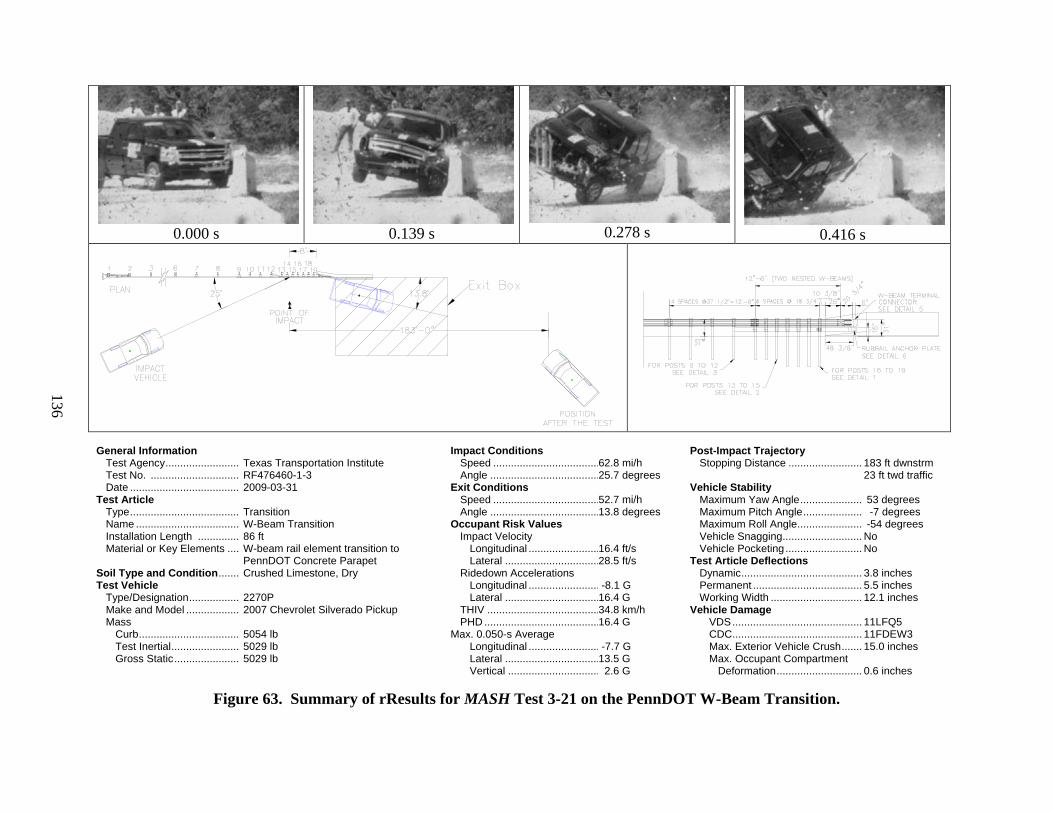
136
0.000 s
0.139 s
0.278 s
0.416 s
General Information Test Agency ......................... Test No. .............................. Date ..................................... Test Article Type ..................................... Name ................................... Installation Length .............. Material or Key Elements .... Soil Type and Condition ....... Test Vehicle Type/Designation ................. Make and Model .................. Mass
Curb .................................. Test Inertial ....................... Gross Static ......................
Texas Transportation Institute RF476460-1-3 2009-03-31 Transition W-Beam Transition 86 ft W-beam rail element transition to PennDOT Concrete Parapet Crushed Limestone, Dry 2270P 2007 Chevrolet Silverado Pickup 5054 lb 5029 lb 5029 lb
Impact Conditions Speed .................................... Angle ..................................... Exit Conditions Speed .................................... Angle ..................................... Occupant Risk Values Impact Velocity Longitudinal ........................ Lateral ................................
Ridedown Accelerations Longitudinal ........................ Lateral ................................ THIV ...................................... PHD ....................................... Max. 0.050-s Average Longitudinal ........................ Lateral ................................ Vertical ...............................
62.8 mi/h 25.7 degrees 52.7 mi/h 13.8 degrees 16.4 ft/s 28.5 ft/s -8.1 G 16.4 G 34.8 km/h 16.4 G -7.7 G 13.5 G 2.6 G
Post-Impact Trajectory Stopping Distance ......................... Vehicle Stability
Maximum Yaw Angle ..................... Maximum Pitch Angle .................... Maximum Roll Angle ...................... Vehicle Snagging ........................... Vehicle Pocketing .......................... Test Article Deflections Dynamic ......................................... Permanent ..................................... Working Width ............................... Vehicle Damage VDS ............................................ CDC ............................................ Max. Exterior Vehicle Crush ....... Max. Occupant Compartment Deformation .............................
183 ft dwnstrm 23 ft twd traffic 53 degrees -7 degrees -54 degrees No No 3.8 inches 5.5 inches 12.1 inches 11LFQ5 11FDEW3 15.0 inches 0.6 inches
Figure 63. Summary of rResults for MASH Test 3-21 on the PennDOT W-Beam Transition.
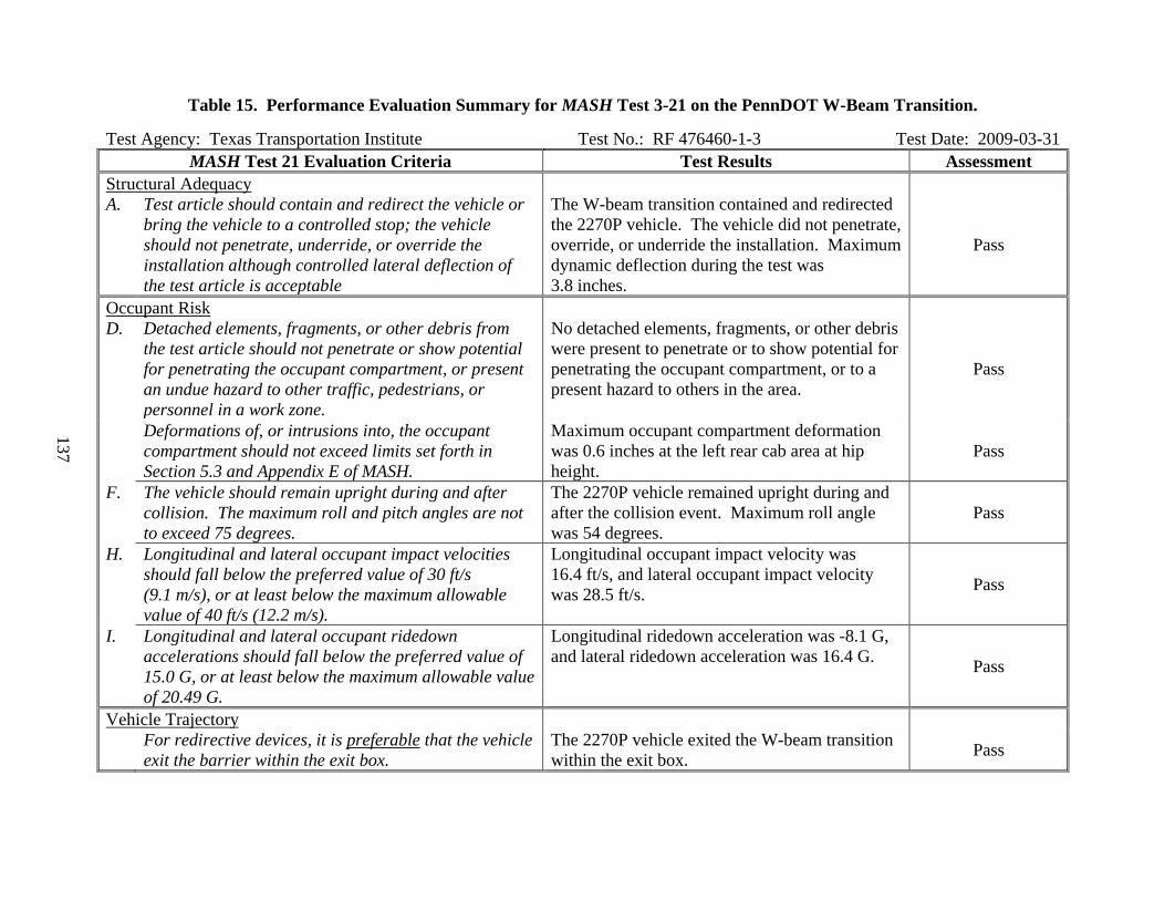
137
Table 15. Performance Evaluation Summary for MASH Test 3-21 on the PennDOT W-Beam Transition.
Test Agency: Texas Transportation Institute Test No.: RF 476460-1-3 Test Date: 2009-03-31 MASH Test 21 Evaluation Criteria Test Results Assessment
Structural Adequacy A. Test article should contain and redirect the vehicle or
bring the vehicle to a controlled stop; the vehicle should not penetrate, underride, or override the installation although controlled lateral deflection of the test article is acceptable
The W-beam transition contained and redirected the 2270P vehicle. The vehicle did not penetrate, override, or underride the installation. Maximum dynamic deflection during the test was 3.8 inches.
Pass
Occupant Risk D. Detached elements, fragments, or other debris from
the test article should not penetrate or show potential for penetrating the occupant compartment, or present an undue hazard to other traffic, pedestrians, or personnel in a work zone.
No detached elements, fragments, or other debris were present to penetrate or to show potential for penetrating the occupant compartment, or to a present hazard to others in the area.
Pass
Deformations of, or intrusions into, the occupant compartment should not exceed limits set forth in Section 5.3 and Appendix E of MASH.
Maximum occupant compartment deformation was 0.6 inches at the left rear cab area at hip height.
Pass
F. The vehicle should remain upright during and after collision. The maximum roll and pitch angles are not to exceed 75 degrees.
The 2270P vehicle remained upright during and after the collision event. Maximum roll angle was 54 degrees.
Pass
H. Longitudinal and lateral occupant impact velocities should fall below the preferred value of 30 ft/s (9.1 m/s), or at least below the maximum allowable value of 40 ft/s (12.2 m/s).
Longitudinal occupant impact velocity was 16.4 ft/s, and lateral occupant impact velocity was 28.5 ft/s. Pass
I. Longitudinal and lateral occupant ridedown accelerations should fall below the preferred value of 15.0 G, or at least below the maximum allowable value of 20.49 G.
Longitudinal ridedown acceleration was -8.1 G, and lateral ridedown acceleration was 16.4 G. Pass
Vehicle Trajectory For redirective devices, it is preferable that the vehicle
exit the barrier within the exit box. The 2270P vehicle exited the W-beam transition within the exit box. Pass

138
SMALL SIGN SUPPORTS
Test Installation Description
Steel U-Channel Support
A 4 lb/ft steel U-channel support manufactured by NuCor Steel Marion was erected in standard soil. The overall length of the sign support was 9 ft-8¾ inches. The sign support was attached to a 41 inches long 4 lb/ft steel U-channel ground stub. The sign support and ground stub were joined together using a 5 inch lap splice. Two 5/16 inch x 1½ inch grade 9 bolts were used in the lap splice and spaced 4 inch on-center. To prevent the U-channel sign support and ground stub from being over-nested or too firmly clamped together, two ½ inch long, ¾ inch diameter schedule 40 pipe spacers were placed between the ground stub and sign support at each of the two lap splice bolt locations. The overall lap splice length was 5 inches. A 36 inch x 36 inch x 5/8 inch plywood sign was attached to the support using two - 5/16 inch diameter x 3½ inch long grade 5 bolts with flat washers and nuts. The sign mounting bolts were spaced 6 inches from the edge of the sign blank. The bottom of sign mounting height was 84 inches.
Figure 64 shows a cross section of the steel U-channel support. Figure 65 shows photos
of the completed installations. More detailed information on the sign support system and crash test can be found in Appendix H (available on the NCAC website, www.ncac.gwu.edu/).
Figure 64. Details of the U-Channel Sign Support.
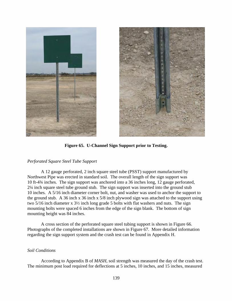
139
Figure 65. U-Channel Sign Support prior to Testing.
Perforated Square Steel Tube Support
A 12 gauge perforated, 2 inch square steel tube (PSST) support manufactured by Northwest Pipe was erected in standard soil. The overall length of the sign support was 10 ft-4¾ inches. The sign support was anchored into a 36 inches long, 12 gauge perforated, 2¼ inch square steel tube ground stub. The sign support was inserted into the ground stub 10 inches. A 5/16 inch diameter corner bolt, nut, and washer was used to anchor the support to the ground stub. A 36 inch x 36 inch x 5/8 inch plywood sign was attached to the support using two 5/16 inch diameter x 3½ inch long grade 5 bolts with flat washers and nuts. The sign mounting bolts were spaced 6 inches from the edge of the sign blank. The bottom of sign mounting height was 84 inches.
A cross section of the perforated square steel tubing support is shown in Figure 66. Photographs of the completed installations are shown in Figure 67. More detailed information regarding the sign support system and the crash test can be found in Appendix H. Soil Conditions
According to Appendix B of MASH, soil strength was measured the day of the crash test.
The minimum post load required for deflections at 5 inches, 10 inches, and 15 inches, measured
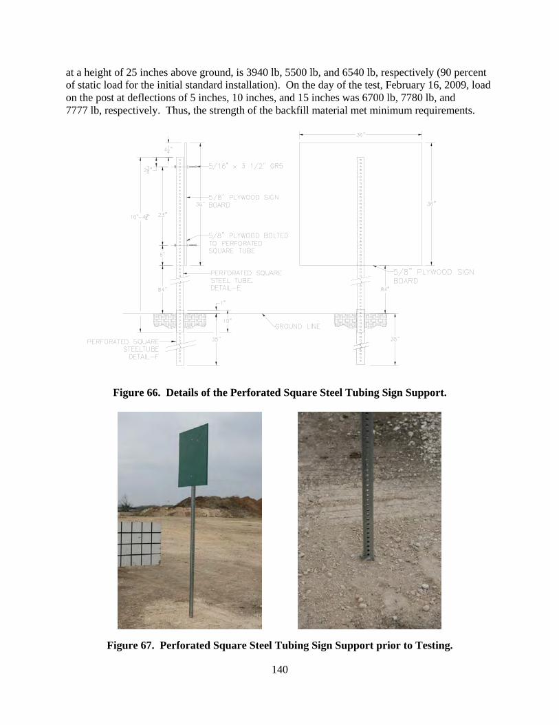
140
at a height of 25 inches above ground, is 3940 lb, 5500 lb, and 6540 lb, respectively (90 percent of static load for the initial standard installation). On the day of the test, February 16, 2009, load on the post at deflections of 5 inches, 10 inches, and 15 inches was 6700 lb, 7780 lb, and 7777 lb, respectively. Thus, the strength of the backfill material met minimum requirements.
Figure 66. Details of the Perforated Square Steel Tubing Sign Support.
Figure 67. Perforated Square Steel Tubing Sign Support prior to Testing.

141
Test Number 476460-1-2 (Mash Test 3-62)
Test Description
Test Vehicle: 2003 Dodge Ram 1500 quad-cab pickup Test Inertia Weight: 4958 lb Gross Static Weight: 4958 lb Impact Speed: 63.3 mi/h Impact Angle: 0 degrees
The 2003 Dodge Ram 1500 quad-cab pickup, traveling at an impact speed of 63.3 mi/h, impacted the U-channel sign support at 0 degrees with the left quarter-point of the pickup aligned with the centerline of the support. At 0.012 s, the sign support fractured at the lower edge of the front bumper, and the support installation began to rotate around the front of the vehicle. Loss of contact with the support and the top front edge of the hood occurred at 0.038 s. The sign panel struck the roof near the top of the windshield at 0.086 s. Shortly after impact with the roof, at approximately 0.100 s, the lower sign panel mounting bolt failed as the sign and support rotated and slid off the rear of the pickup truck cab. Loss of contact with the sign support and panel occurs at 0.170 s while the vehicle was traveling at an exit speed of approximately 62.5 mi/h.
After impacting the U-channel sign support, the pickup truck impacted the PSST sign
support at an impact speed and angle of 61.7 mi/h and 0 degrees, respectively, with the right quarter point of the pickup aligned with the centerline of the support. The vehicle contacted the PSST sign support at 0.177 s. Tthe PSST began to fracture at the lower edge of the front bumper at 0.182 s and was fully separated by 0.208 s. As the post was fracturing, the sign panel attachment bolts also began to fail and the sign panel separated from the support. At 0.249 s, the sign panel contacted the roof and windshield. The support remained in front of and displaced forward of the pickup truck. As the vehicle exited view of the high-speed cameras, the sign panel was traveling atop the vehicle and the support in front of the vehicle. The vehicle came to rest 266 ft downstream of impact near the PSST support and 5 ft left of centerline.
Damage to the U-Channel Sign Support is shown in Figure 68. The soil around the U-
channel sign support ground stub was disturbed. The U-channel support fractured in two pieces, one 19-inch piece was resting 15 ft downstream of impact and 1 ft to the left of centerline, and the second piece, 98 inches long, was resting 111 ft downstream of impact and 14 ft to the left of centerline. Also, the sign panel separated from the U-channel and came to rest 37 ft downstream of impact and 2 ft to the right of centerline.

142
Figure 68. U-Channel Installation after MASH Test 3-62.

143
Damage to the PSST Sign Support is shown in Figure 69. The stub of the PSST sign support was displaced toward the field side 3 inches at ground level. The sleeve fractured across the impact side and field side, was deformed toward the field side 80 degrees, and pulled up out of the ground 1 inch. The PSST support traveled with the vehicle and came to rest in front of the vehicle, 271 ft downstream of impact and 11 ft to the left of centerline. The support was deformed 6.5 inches from the end to 27 inches. Also, the sign panel separated from the PSST support and came to rest 172 ft downstream of impact and 35 ft to the left of centerline.
The vehicle sustained damage to the front, as shown in Figure 70. The front bumper,
grill, hood, roof, right front door and left front door were deformed. The windshield was shattered in an area measuring 36 inches x 32 inches with a maximum deformation of 3.5 inches (from contact with the PSST sign support). The roof was crushed over the driver side in an area measuring 24 inches x 39 inches with a maximum deformation of 0.75 inches. Maximum exterior crush to the vehicle was 3.5 inches in the windshield, and 0.5 inches to the right front quarter point. Maximum occupant compartment deformation was 2.1 inches in the roof over the driver side rear passenger area from contact with the U-channel sign support, and 3.5 inches in the windshield from contact with the PSST sign support.
Data from the accelerometer, located at the vehicle center of gravity, were digitized for
evaluation of occupant risk. The impacts were separated and the values for each devise were computed.
The time period for contact with the U-channel sign was between 0.000 s to 0.176 s. In the longitudinal direction, no occupant contact occurred, and the maximum 0.050-s average acceleration was -0.4 G between 0.051 and 0.101 s. In the lateral direction, no occupant contact occurred, and the maximum 0.050-s average was -0.3 Gs between 0.097 and 0.147 s. No THIV or PHD occurred; and ASI was 0.11 between 0.058 and 0.108 s. These data and other pertinent information from the test are summarized in Figure 71.
The time period for contact with the PSST was between 0.177 s to 1.0 s. In the
longitudinal direction, the occupant impact velocity was 4.3 ft/s (1.3 m/s) at 0.643 s, the highest 0.010-s occupant ridedown acceleration was -0.8 G from 0.813 to 0.823 s, and the maximum 0.050-s average acceleration was -0.2 G between 0.177 and 0.227 s. In the lateral direction, the occupant impact velocity was 2.3 ft/s (0.7 m/s) at 0.643 s, the highest 0.010-s occupant ridedown acceleration was -0.4 G from 0.648 to 0.658 s, and the maximum 0.050-s average was 0.1 Gs between 0.177 and 0.227 s. THIV was 5.3 km/h or 1.5 m/s at 0.642 s; PHD was 0.8 G between 0.813 and 0.823 s; and ASI was 0.10 between 0.161 and 0.211 s. These data and other pertinent information from the test are summarized in Figure 72.

144
Figure 69. PSST Sign Support after MASH Test 3-62.

145
Figure 70. Vehicle after MASH Test 3-62 with Small Sign Supports.

146
0.000 s
0.062 s
0.124 s
0.187 s
General Information Test Agency ......................... Test No. ............................... Date ...................................... Test Article Type ..................................... Name .................................... Installation Height ................ Material or Key Elements ..... Soil Type and Condition ....... Test Vehicle Type/Designation ................. Make and Model................... Mass
Curb .................................. Test Inertial ....................... Gross Static ......................
Texas Transportation Institute RF476460-1-2 2009-02-16 Sign Support 4 lb/ft U-Channel Sign Support 84 inches to Bottom of Sign Panel 4 lb/ft U-Channel, NuCor Steel Marion Crushed Limestone, Dry 2270P 2003 Dodge Ram 1500 Quad-Cab Pickup 4525 4958 4958
Impact Conditions Speed .................................... Angle ..................................... Exit Conditions Speed .................................... Angle ..................................... Occupant Risk Values Impact Velocity Longitudinal ....................... Lateral ................................
Ridedown Accelerations Longitudinal ....................... Lateral ................................ THIV ...................................... PHD ....................................... Max. 0.050-s Average Longitudinal ....................... Lateral ................................ Vertical ...............................
63.3 mi/h 0 degrees 62.5 mi/h 0 degrees No Contact No Contact N/A N/A No Contact No Contact -0.4 G -0.3 G 1.1 G
Post-Impact Trajectory Stopping Distance .......................... Vehicle Stability
Maximum Yaw Angle ..................... Maximum Pitch Angle .................... Maximum Roll Angle ...................... Vehicle Snagging ........................... Vehicle Pocketing .......................... Test Article Deflections Longitudinal Distance ..................... Lateral Distance ............................. Vehicle Damage VDS ............................................ CDC ............................................ Max. Exterior Vehicle Crush ....... Max. Occupant Compartment Deformation (inches) ...............
266 ft 0 degrees -1 degrees 1 degrees No No 98 ft 14 ft 12FL1 12FLEN1 0.75 inches 2.1 inches
Figure 71. Summary of Results for MASH Test 3-62 on U-Channel Small Sign Support.
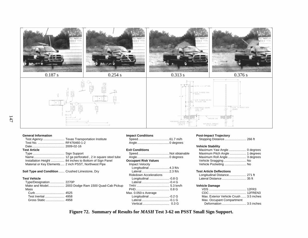
147
0.187 s
0.254 s
0.313 s
0.376 s
General Information Test Agency ......................... Test No. ............................... Date ...................................... Test Article Type ..................................... Name .................................... Installation Height ................ Material or Key Elements ..... Soil Type and Condition ....... Test Vehicle Type/Designation ................. Make and Model................... Mass
Curb .................................. Test Inertial ....................... Gross Static ......................
Texas Transportation Institute RF476460-1-2 2009-02-16 Sign Support 12 ga perforated , 2 in square steel tube 84 inches to Bottom of Sign Panel 2 inch PSST, Northwest Pipe Crushed Limestone, Dry 2270P 2003 Dodge Ram 1500 Quad-Cab Pickup 4525 4958 4958
Impact Conditions Speed .................................... Angle ..................................... Exit Conditions Speed .................................... Angle ..................................... Occupant Risk Values Impact Velocity Longitudinal ....................... Lateral ................................
Ridedown Accelerations Longitudinal ....................... Lateral ................................ THIV ...................................... PHD ....................................... Max. 0.050-s Average Longitudinal ....................... Lateral ................................ Vertical ...............................
61.7 mi/h 0 degrees Not obtainable 0 degrees 4.3 ft/s 2.3 ft/s -0.8 G -0.4 G 5.3 km/h 0.8 G -0.2 G -0.1 G 0.3 G
Post-Impact Trajectory Stopping Distance .......................... Vehicle Stability
Maximum Yaw Angle ..................... Maximum Pitch Angle .................... Maximum Roll Angle ...................... Vehicle Snagging ........................... Vehicle Pocketing .......................... Test Article Deflections Longitudinal Distance ..................... Lateral Distance ............................. Vehicle Damage VDS ............................................ CDC ............................................ Max. Exterior Vehicle Crush ....... Max. Occupant Compartment Deformation .............................
266 ft 0 degrees 1 degrees 3 degrees No No 271 ft 35 ft 12FR3 12FREN3 3.5 inches 3.5 inches
Figure 72. Summary of Results for MASH Test 3-62 on PSST Small Sign Support.

148
Summary of Test Results
Both the U-channel and PSST small sign supports readily activated upon impact by the 2270P vehicle by fracturing at bumper height and at the ground stub interface. The detached sign supports rotated around the front of the vehicle, and the sign panels struck near or at the windshield and roof area and traveled with the vehicle.
Contact of the U-channel support with the windshield and roof was minimal, and therefore
the support did not penetrate nor show potential for penetrating the occupant compartment. The largest piece of this support weighed 33.6 lb, but the trajectory was relatively low, and should not cause undue hazard to others in the area. No occupant compartment deformation related to impact with the U-channel support occurred.
The upper section of the PSST support and sign panel contacted and shattered the
windshield which shattered. No tear of the windshield plastic lining occurred. However, the windshield was deformed inward 3.5 inches. MASH Section 5.3 and Appendix E limits deformation of the windshield to 3 inches.
The 2270P vehicle remained upright during and after both collision events. Minimal roll
and pitch were noted. Occupant risk factors were within acceptable limits. The 2270P vehicle came to rest behind the test articles.
The 4 lb/ft steel U-channel support manufactured by NuCor Steel Marion successfully met
the MASH evaluation criteria for test 3-62, as shown in Table 16. The 12 gauge perforated, 2 inch square, steel tube (PSST) support manufactured by Northwest Pipe failed to meet the MASH evaluation criteria for test 3-62 due to excessive occupant compartment deformation at the windshield, as shown in Table 17.
The primary observed difference in the performance of the two sign support types is the
manner in which the sign panel reacted during the impact sequence. Both sign support types fractured at bumper height and near the ground stub interface. The U-channel sign support installation kept the sign panel attached to the support for much of the impact event. The sign panel remained attached until the support and panel impacted the roof of the truck as an assembly. Upon separation, both the sign and support passed over the cab of the pickup truck.
The PSST sign support installation released the sign panel from the support at approximately
the same time the support failed at bumper height. The failure of the sign attachment changed the dynamics of the impact and permitted the sign panel to impact the windshield more directly. The PSST sign support stayed in the front of the vehicle and displaced forward with the vehicle with very little angular momentum. It is the belief of the researchers that had the sign panel remained attached to the support, the PSST sign support installation performance would have been similar to the U-channel performance and the PSST would have likely met the MASH performance evaluation criteria.

149
Table 16. Performance Evaluation Summary for MASH Test 3-62 on the 4 lb/ft U-Channel Small Sign Support. Test Agency: Texas Transportation Institute Test No.: RF476460-1-2 (U-channel) Test Date: 2009-02-16
MASH Test 3-62 Evaluation Criteria Test Results Assessment Structural Adequacy B. The test article should readily activate in a predictable
manner by breaking away, fracturing, or yielding. The 4 lb/ft U-channel sign support readily activated upon impact by the 2270P vehicle by fracturing at the ground stub and bumper height.
Pass
Occupant Risk D. Detached elements, fragments, or other debris from
the test article should not penetrate or show potential for penetrating the occupant compartment, or present an undue hazard to other traffic, pedestrians, or personnel in a work zone.
The upper portion of the fractured sign support traveled with the vehicle. Contact of the U-channel support with the windshield and roof was minimal and the support did not penetrate or show potential for penetrating the occupant compartment. The largest piece of this support weighed 33.6 lb, but the trajectory was relatively low, and should not cause undue hazard to others in the area.
Pass
Deformations of, or intrusions into, the occupant compartment should not exceed limits set forth in Section 5.3 and Appendix E of MASH.
No occupant compartment deformation related to impact with the U-channel support occurred. Pass
F. The vehicle should remain upright during and after collision. The maximum roll and pitch angles are not to exceed 75 degrees.
The 2270P vehicle remained upright during and after the collision event. Minimal roll and pitch were noted.
Pass
H. Longitudinal and lateral occupant impact velocities should fall below the preferred value of 3.0 m/s (10 ft/s), or at least below the maximum allowable value of 5.0 m/s (16.4 ft/s).
No contact occurred.
Pass
I. Longitudinal and lateral occupant ridedown accelerations should fall below the preferred value of 15.0 Gs, or at least below the maximum allowable value of 20.49 Gs.
No contact occurred.
Pass
Vehicle Trajectory N. Vehicle trajectory behind the test article is acceptable. The vehicle came to rest behind the test article. Pass

150
Table 17. Performance Evaluation Summary for MASH Test 3-62 on the PSST Small Sign Support. Test Agency: Texas Transportation Institute Test No.: RF476460-1-2 (PSST) Test Date: 2009-02-16
MASH Test 3-62 Evaluation Criteria Test Results Assessment Structural Adequacy B. The test article should readily activate in a predictable
manner by breaking away, fracturing, or yielding. The Perforated Square Steel Tubing sign support readily activated upon impact by the 2270P vehicle by fracturing at the ground stub and at bumper height.
Pass
Occupant Risk D. Detached elements, fragments, or other debris from
the test article should not penetrate or show potential for penetrating the occupant compartment, or present an undue hazard to other traffic, pedestrians, or personnel in a work zone.
The upper portion of the sign support traveled with the vehicle. The upper section of the support and sign panel contacted the windshield near the roof line.
Pass
Deformations of, or intrusions into, the occupant compartment should not exceed limits set forth in Section 5.3 and Appendix E of MASH.
No tear of the plastic lining of the windshield occurred, however, the windshield was deformed inward 3.5 inches. MASH Section 5.3 and Appendix E limits deformation of the windshield to 3 inches.
Fail
F. The vehicle should remain upright during and after collision. The maximum roll and pitch angles are not to exceed 75 degrees.
The 2270P vehicle remained upright during and after the collision events. Minimal roll and pitch were noted.
Pass
H. Longitudinal and lateral occupant impact velocities should fall below the preferred value of 3.0 m/s (10 ft/s), or at least below the maximum allowable value of 5.0 m/s (16.4 ft/s).
Longitudinal occupant impact velocity was 4.9 ft/s (1.5 m/s), and lateral occupant impact velocity was 2.0 ft/s (0.6 m/s) at 0.660 s after impact.
Pass
I. Longitudinal and lateral occupant ridedown accelerations should fall below the preferred value of 15.0 Gs, or at least below the maximum allowable value of 20.49 Gs.
Longitudinal occupant ridedown acceleration was -1.5 G, and lateral occupant ridedown acceleration was 0.5 G. Pass
Vehicle Trajectory N. Vehicle trajectory behind the test article is acceptable. Vehicle came to rest behind the test article. Pass

151
G3 WEAK POST BOX-BEAM GUARDRAIL
Test Installation
The G3 Weak Post Box-Beam guardrail system is a 27-inch tall, weak steel post, box-beam barrier. The barrier is constructed using tubular steel (TS6 inch x 6 inch x 3/16 inch) rails attached to 5 ft-3 inch long S3 x 5.7 steel posts (PSE08) spaced 6 ft on center. The individual line posts are each fitted with a ¼ inch x 8 inch x 24 inch soil plate (PLS01). Post embedment depth is 36 inches. The tubular steel rails (herein referred to as box-beam) are attached directly to the post and do not use an offset block. The length of need of the Modified G2 barrier test installation was 144 ft. The barrier was terminated with Wyoming Box End Terminals (WYBET). The total overall test installation length was 240 ft. The box-beam rail elements were attached to each post with a L5 inch x 3-1/2 inch x 3/8 inch x 4-1/2 inch long shelf angle attached to the post with a 1/2 inch diameter x 1-1/2 inch long hex bolt with washer and nut. The box-beam rail was attached to the shelf angle with a 3/8 inch diameter x 7-1/2 inch long hex bolt with washer and nut. All bolts were ASTM A307 and the hex nuts were ASTM A563. A cross-section of the G3 Weak Post Box-Beam guardrail is shown in Figure 72. Photographs of the completed installation are shown in Figure 73. Drawings of the test installation and more detailed information of the barrier and crash test can be found in Appendix I (available on the NCAC website, http://www.ncac.gwu.edu/).
Figure 72. Cross-section of the G3 Weak Post Box-Beam guardrail.

152
Figure 73. G3 Weak Post Box-Beam Guardrail prior to Testing.
The test installation was installed in standard soil meeting AASHTO standard
specifications for “Materials for Aggregate and Soil Aggregate Subbase, Base and Surface Courses”, designated M147-65(2004), grading B.
According to Appendix B of MASH, soil strength was measured the day of the crash test.
The minimum post loads required for post deflections of 5 inches, 10 inches, and 15 inches, measured at a height of 25 inches above ground, is 3940 lb, 5500 lb, and 6540 lb, respectively (90 percent of static load for the initial standard installation). On the day of the test, May 15, 2009, loads on the post at deflections of 5 inches, 10 inches, and 15 inches were 7818 lb, 8545 lb, and 9242 lb, respectively. Thus, the strength of the backfill material met minimum requirements.
Test Number 476460-1-6 (MASH Test 3-11)
Test Description
Test Vehicle: 2007 Chevrolet Silverado 4-door pickup Test Inertia Weight: 5004 lb Gross Static Weight: 5004 lb Impact Speed: 63.2 mi/h Impact Angle: 25.4 degrees
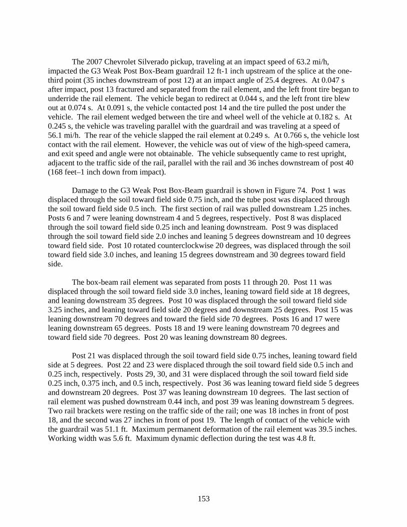
153
The 2007 Chevrolet Silverado pickup, traveling at an impact speed of 63.2 mi/h,
impacted the G3 Weak Post Box-Beam guardrail 12 ft-1 inch upstream of the splice at the one-third point (35 inches downstream of post 12) at an impact angle of 25.4 degrees. At 0.047 s after impact, post 13 fractured and separated from the rail element, and the left front tire began to underride the rail element. The vehicle began to redirect at 0.044 s, and the left front tire blew out at 0.074 s. At 0.091 s, the vehicle contacted post 14 and the tire pulled the post under the vehicle. The rail element wedged between the tire and wheel well of the vehicle at 0.182 s. At 0.245 s, the vehicle was traveling parallel with the guardrail and was traveling at a speed of 56.1 mi/h. The rear of the vehicle slapped the rail element at 0.249 s. At 0.766 s, the vehicle lost contact with the rail element. However, the vehicle was out of view of the high-speed camera, and exit speed and angle were not obtainable. The vehicle subsequently came to rest upright, adjacent to the traffic side of the rail, parallel with the rail and 36 inches downstream of post 40 (168 feet–1 inch down from impact).
Damage to the G3 Weak Post Box-Beam guardrail is shown in Figure 74. Post 1 was
displaced through the soil toward field side 0.75 inch, and the tube post was displaced through the soil toward field side 0.5 inch. The first section of rail was pulled downstream 1.25 inches. Posts 6 and 7 were leaning downstream 4 and 5 degrees, respectively. Post 8 was displaced through the soil toward field side 0.25 inch and leaning downstream. Post 9 was displaced through the soil toward field side 2.0 inches and leaning 5 degrees downstream and 10 degrees toward field side. Post 10 rotated counterclockwise 20 degrees, was displaced through the soil toward field side 3.0 inches, and leaning 15 degrees downstream and 30 degrees toward field side.
The box-beam rail element was separated from posts 11 through 20. Post 11 was displaced through the soil toward field side 3.0 inches, leaning toward field side at 18 degrees, and leaning downstream 35 degrees. Post 10 was displaced through the soil toward field side 3.25 inches, and leaning toward field side 20 degrees and downstream 25 degrees. Post 15 was leaning downstream 70 degrees and toward the field side 70 degrees. Posts 16 and 17 were leaning downstream 65 degrees. Posts 18 and 19 were leaning downstream 70 degrees and toward field side 70 degrees. Post 20 was leaning downstream 80 degrees.
Post 21 was displaced through the soil toward field side 0.75 inches, leaning toward field
side at 5 degrees. Post 22 and 23 were displaced through the soil toward field side 0.5 inch and 0.25 inch, respectively. Posts 29, 30, and 31 were displaced through the soil toward field side 0.25 inch, 0.375 inch, and 0.5 inch, respectively. Post 36 was leaning toward field side 5 degrees and downstream 20 degrees. Post 37 was leaning downstream 10 degrees. The last section of rail element was pushed downstream 0.44 inch, and post 39 was leaning downstream 5 degrees. Two rail brackets were resting on the traffic side of the rail; one was 18 inches in front of post 18, and the second was 27 inches in front of post 19. The length of contact of the vehicle with the guardrail was 51.1 ft. Maximum permanent deformation of the rail element was 39.5 inches. Working width was 5.6 ft. Maximum dynamic deflection during the test was 4.8 ft.
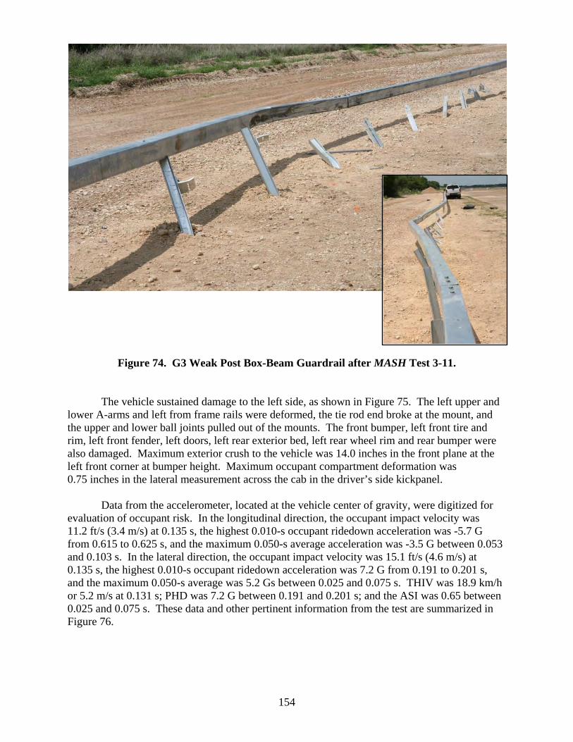
154
Figure 74. G3 Weak Post Box-Beam Guardrail after MASH Test 3-11.
The vehicle sustained damage to the left side, as shown in Figure 75. The left upper and lower A-arms and left from frame rails were deformed, the tie rod end broke at the mount, and the upper and lower ball joints pulled out of the mounts. The front bumper, left front tire and rim, left front fender, left doors, left rear exterior bed, left rear wheel rim and rear bumper were also damaged. Maximum exterior crush to the vehicle was 14.0 inches in the front plane at the left front corner at bumper height. Maximum occupant compartment deformation was 0.75 inches in the lateral measurement across the cab in the driver’s side kickpanel.
Data from the accelerometer, located at the vehicle center of gravity, were digitized for
evaluation of occupant risk. In the longitudinal direction, the occupant impact velocity was 11.2 ft/s (3.4 m/s) at 0.135 s, the highest 0.010-s occupant ridedown acceleration was -5.7 G from 0.615 to 0.625 s, and the maximum 0.050-s average acceleration was -3.5 G between 0.053 and 0.103 s. In the lateral direction, the occupant impact velocity was 15.1 ft/s (4.6 m/s) at 0.135 s, the highest 0.010-s occupant ridedown acceleration was 7.2 G from 0.191 to 0.201 s, and the maximum 0.050-s average was 5.2 Gs between 0.025 and 0.075 s. THIV was 18.9 km/h or 5.2 m/s at 0.131 s; PHD was 7.2 G between 0.191 and 0.201 s; and the ASI was 0.65 between 0.025 and 0.075 s. These data and other pertinent information from the test are summarized in Figure 76.
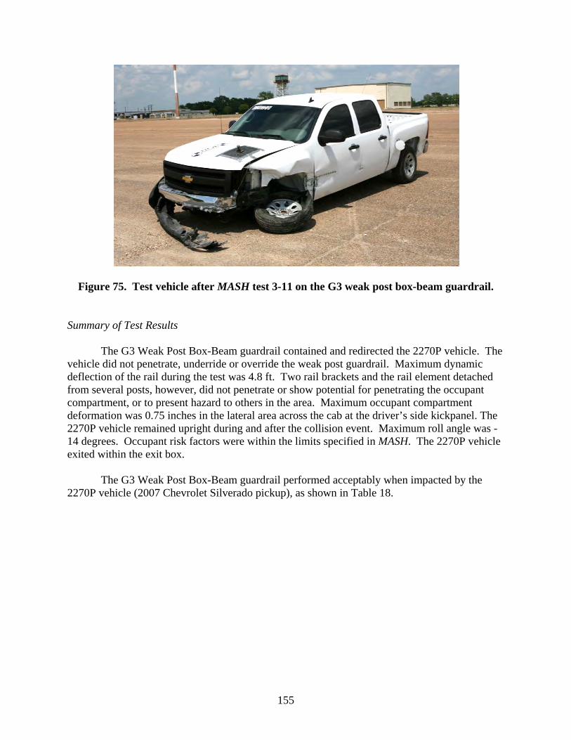
155
Figure 75. Test vehicle after MASH test 3-11 on the G3 weak post box-beam guardrail.
Summary of Test Results
The G3 Weak Post Box-Beam guardrail contained and redirected the 2270P vehicle. The
vehicle did not penetrate, underride or override the weak post guardrail. Maximum dynamic deflection of the rail during the test was 4.8 ft. Two rail brackets and the rail element detached from several posts, however, did not penetrate or show potential for penetrating the occupant compartment, or to present hazard to others in the area. Maximum occupant compartment deformation was 0.75 inches in the lateral area across the cab at the driver’s side kickpanel. The 2270P vehicle remained upright during and after the collision event. Maximum roll angle was -14 degrees. Occupant risk factors were within the limits specified in MASH. The 2270P vehicle exited within the exit box.
The G3 Weak Post Box-Beam guardrail performed acceptably when impacted by the
2270P vehicle (2007 Chevrolet Silverado pickup), as shown in Table 18.
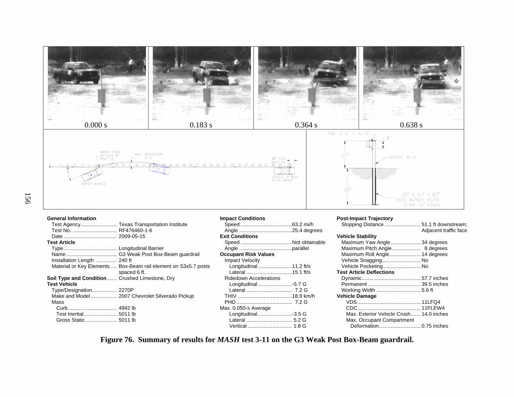
156
0.000 s
0.183 s
0.364 s
0.638 s
General Information Test Agency ......................... Test No. .............................. Date ..................................... Test Article Type ..................................... Name ................................... Installation Length .............. Material or Key Elements .... Soil Type and Condition ....... Test Vehicle Type/Designation ................. Make and Model .................. Mass
Curb .................................. Test Inertial ....................... Gross Static ......................
Texas Transportation Institute RF476460-1-6 2009-05-15 Longitudinal Barrier G3 Weak Post Box-Beam guardrail 240 ft Box-Beam rail element on S3x5.7 posts spaced 6 ft. Crushed Limestone, Dry 2270P 2007 Chevrolet Silverado Pickup 4942 lb 5011 lb 5011 lb
Impact Conditions Speed .................................... Angle ..................................... Exit Conditions Speed .................................... Angle ..................................... Occupant Risk Values Impact Velocity Longitudinal ........................ Lateral ................................
Ridedown Accelerations Longitudinal ........................ Lateral ................................ THIV ...................................... PHD ....................................... Max. 0.050-s Average Longitudinal ........................ Lateral ................................ Vertical ...............................
63.2 mi/h 25.4 degrees Not obtainable parallel 11.2 ft/s 15.1 ft/s -5.7 G 7.2 G 18.9 km/h 7.2 G -3.5 G 5.2 G 1.8 G
Post-Impact Trajectory Stopping Distance ......................... Vehicle Stability
Maximum Yaw Angle ..................... Maximum Pitch Angle .................... Maximum Roll Angle ...................... Vehicle Snagging ........................... Vehicle Pocketing .......................... Test Article Deflections Dynamic ......................................... Permanent ..................................... Working Width ............................... Vehicle Damage VDS ............................................ CDC ............................................ Max. Exterior Vehicle Crush ....... Max. Occupant Compartment Deformation .............................
51.1 ft downstream; Adjacent traffic face 34 degrees 8 degrees 14 degrees No No 57.7 inches 39.5 inches 5.6 ft 11LFQ4 11FLEW4 14.0 inches 0.75 inches
Figure 76. Summary of results for MASH test 3-11 on the G3 Weak Post Box-Beam guardrail.

157
Table 18. Performance Evaluation Summary for MASH Test 3-11 on the G2 Weak Post Box-Beam Guardrail. Test Agency: Texas Transportation Institute Test No.: RF 476460-1-7 Test Date: 2009-05-15
MASH Evaluation Criteria Test Results Assessment Structural Adequacy A. Test article should contain and redirect the vehicle or
bring the vehicle to a controlled stop; the vehicle should not penetrate, underride, or override the installation although controlled lateral deflection of the test article is acceptable
The G2 Weak Post Box-Beam guardrail contained and redirected the 2270P vehicle. The vehicle did not penetrate, underride, or override the installation. Maximum dynamic deflection of the rail was 4.8 ft.
Pass
Occupant Risk D. Detached elements, fragments, or other debris from
the test article should not penetrate or show potential for penetrating the occupant compartment, or present an undue hazard to other traffic, pedestrians, or personnel in a work zone.
Two rail brackets and the box-beam rail element detached from several posts, however, did not penetrate or show potential for penetrating the occupant compartment, or to present hazard to others in the area.
Pass
Deformations of, or intrusions into, the occupant compartment should not exceed limits set forth in Section 5.3 and Appendix E of MASH.
Maximum occupant compartment deformation was 0.75 inches in the lateral area across the cab at the driver’s side kickpanel..
Pass
F. The vehicle should remain upright during and after collision. The maximum roll and pitch angles are not to exceed 75 degrees.
The 2270P vehicle remained upright during and after the collision event. Maximum roll angle was -14 degrees.
Pass
H. Longitudinal and lateral occupant impact velocities should fall below the preferred value of 30 ft/s (9.1 m/s), or at least below the maximum allowable value of 40 ft/s (12.2 m/s).
Longitudinal occupant impact velocity was 11.2 ft/s, and lateral occupant impact velocity was 15.1 ft/s. Pass
I. Longitudinal and lateral occupant ridedown accelerations should fall below the preferred value of 15.0 G, or at least below the maximum allowable value of 20.49 G.
Longitudinal ridedown acceleration was -5.7 G, and lateral ridedown acceleration was 7.2 G. Pass
Vehicle Trajectory For redirective devices, the vehicle shall exit the
barrier within the exit box. The 2270P exited within the exit box. Pass

158
MODIFIED G2 WEAK POST W-BEAM GUARDRAIL
Test Installation Description
The Modified G2 Weak Post W-Beam guardrail is a 32-inch tall, weak steel post, W-beam barrier with rail splices mid-span between the posts. This barrier was successfully crash tested in accordance with NCHRP Report 350 and is the same barrier referred to in TTI Project Number RF473750-3 as the PennDOT Type 2 guiderail that was modified for that study.(14,15) The barrier is constructed using 12-gauge W-beam guardrails attached to 5 ft - 3 inch long S3 x 5.7 steel posts (PSE03) spaced 12 ft on center. The individual line posts are each fitted with a 1/4-inch x 8-inch x 24-inch soil plate (PLS01). Post embedment depth is 30 inches. The W-beam guardrails are attached directly to the post and do not use an offset block. The length of need of the modified G2 barrier test installation was 262 ft – 6 inches. The barrier was terminated with ET Plus guardrail terminals. The total overall test installation length was 325 ft.
The W-beam rail elements were attached to each post with a 5/16 inch diameter ASTM F568, Class 4.6, 2-3/8 inch long, fully threaded bolt, with two 1-3/4 inch square washers between the traffic face of the rail element and bolt head, a 12-gauge W-beam backup plate is placed between the W-beam and post flange, and a round flat washer is placed on the web side of the post flange with two ASTM A563M hex nuts completing the anchoring assembly. In addition, a 9/16 inch diameter x 1-5/8 inch long ASTM F568, Class 4.6 shelf bolt with two ASTM A563M hex nuts are placed in the flange of the post to support the bottom edge of the guardrail. The purpose of the shelf bolt is to provide support for the guardrail and reduce the load placed on the 5/16-inch diameter post bolt.
The test installation was installed in standard soil meeting AASHTO standard
specifications for “Materials for Aggregate and Soil Aggregate Subbase, Base and Surface Courses”, designated M147-65(2004), grading B. In addition, in compliance with MASH, standard soil strength static tests were performed the day of the crash test at the installation site.
A cross-section of the Modified G2 Weak Post W-Beam guardrail is shown in Figure 77.
Photographs of the completed installation are shown in Figure 78. Drawings of the test installation and more detailed information of the barrier can be found in Appendix J (available on the NCAC website, www.ncac.gwu.edu/).
According to Appendix B of MASH, soil strength was measured the day of the crash test. The minimum post loads required for post deflections of 5 inches, 10 inches, and 15 inches, measured at a height of 25 inches above ground, is 3940 lb, 5500 lb, and 6540 lb, respectively (90 percent of static load for the initial standard installation). On the day of the test, May 1, 2009, loads on the post at deflections of 5 inches, 10 inches, and 15 inches were 5424 lb, 6303 lb, and 7151 lb respectively. Thus, the strength of the backfill material met minimum requirements.

159
Figure 77. Cross-Section of the Modified G2 Weak Post W-Beam Guardrail.
Figure 78. Modified G2 Weak Post W-Beam Guardrail prior to Testing.

160
Test Number 476460-1-7 (MASH Test 3-11)
Test Description
Test Vehicle: 2007 Chevrolet Silverado 4-door pickup Test Inertia Weight: 5004 lb Gross Static Weight: 5004 lb Impact Speed: 62.4 mi/h Impact Angle: 24.6 degrees
The 2007 Chevrolet Silverado pickup, traveling at an impact speed of 62.4 mi/h, impacted the Modified G2 Weak Post W-Beam guardrail 21 ft-4 inches upstream of the splice at the one-third point (31 inches upstream of post 12) at an impact angle of 24.6 degrees. At 0.011 s after impact, the vehicle contacted post 12, which began to deform and rotate in the soil, at 0.036 s, the left front tire contacted post 12 under the rail element. At 0.049 s, the W-beam rail element separated from post 12. The vehicle began to redirect at 0.064 s, and the back-up plate from post 12 separated from the installation. At 0.103 s, the vehicle contacted post 13, and at 0.107 s, the left front tire blew out. The back-up plate from post 13 separated from the installation at 0.147 s, and the vehicle contacted post 14 at 0.155 s. At 0.177 s, the vehicle wheels steered sharply to the right, and at 0.213 s, the W-beam rail element separated from post 14. The vehicle contacted post 15 at 0.237 s, and the right front tire lost contact with the ground surface at 0.326 s. At 0.344 s, the vehicle was traveling parallel with the guardrail and was traveling at a speed of 52.7 mi/h. The vehicle continued to travel along the traffic face of the guardrail. The vehicle subsequently came to rest upright, adjacent to the traffic side of the rail, 12 inches upstream of post 27 (176 feet-5 inches downstream of impact).
Damage to the Modified G2 Weak Post W-Beam guardrail is shown in Figure 79. Post 1
was pulled up from ground level 3 inches, displaced through the soil toward field side 6.5 inches and leaning downstream 6 degrees. Posts 2 was displaced through the soil toward field side 4.75 inches and leaning downstream 11 degrees. Post 3 was displaced through the soil toward field side 0.75 inches and leaning downstream 19 inches. Posts 3 through 8 were disturbed in the soil and leaning 16-20 degrees downstream.
The W-beam rail element was separated from posts 8 through 19, with the rail element
toward the field side of posts 10 through 18. Post 8 was displaced through the soil toward field side 1.25 inches, leaning toward field side at 4 degrees, and leaning downstream 17 degrees. Post 9 rotated counterclockwise 60 degrees and leaning toward field side 35 degrees and downstream 25 degrees. Post 10 rotated counterclockwise 45 degrees, and leaning toward field side 20 degrees and downstream 22 degrees. Post 11 was leaning toward field side 23 degrees and downstream 5 degrees. Post 12 was leaning 80 degrees downstream and toward field side. Post 13 rotated clockwise 120 degrees and leaning 75 degrees downstream and toward field side. Post 14 was leaning toward field side and downstream at 80 degrees. Post 15 rotated clockwise 180 degrees and leaning downstream and toward the field side 90 degrees. Post 16 rotated clockwise 90 degrees, and leaning downstream and toward field side 80 degrees.

161
Figure 79. G2 Weak Post W-Beam Guardrail after MASH Test 3-11.
Post 17 rotated clockwise 90 degrees, and leaning downstream 80 degrees. Post 18 was leaning toward field side 5 degrees and downstream 60 degrees, and post 19 was leaning downstream 80 degrees. Post 20 was displaced through the soil 0.25 inch and leaning toward field side 1 degree. The soil around posts 21 and 22 was disturbed. The vehicle contacted the rail element again 40 inches downstream of post 23, and the rail element was separated from posts 24 through 26. Post 23 was displaced through the soil toward the field side 0.5 inch and leaning toward field side 5 degrees. Post 24 was leaning toward field side 10 degrees and downstream 60 degrees. Post 25 rotated counterclockwise 50 degrees and was leaning toward field side 15 degrees and downstream 40 degrees. Post 26 rotated counterclockwise 45 degrees and leaning toward field side 15 degrees and downstream 25 degrees. The length of contact of the vehicle with the guardrail was 83.5 ft. Maximum permanent deformation of the rail element was 5.8 ft. Working width was 9.0 ft. Maximum dynamic deflection during the test was 8.6 ft.
The vehicle sustained damage to the left side, as shown in Figure 80. The front bumper,
left front fender, left doors, left rear exterior bed, and rear bumper were damaged. The left front tire was cut and deflated. Maximum exterior crush to the vehicle was 5.5 inches in the side plane

162
at the left front corner at bumper height. Maximum occupant compartment deformation was 0.25 inches in the lateral measurement across the cab in the driver’s side hip area.
Figure 80. Test Vehicle after MASH Test 3-11 on the G2 Weak Post W-Beam Guardrail.
Data from the accelerometer, located at the vehicle center of gravity, were digitized for
evaluation of occupant risk. In the longitudinal direction, the occupant impact velocity was 9.5 ft/s (2.9 m/s) at 0.206 s, the highest 0.010-s occupant ridedown acceleration was -3.4 G from 0.925 to 0. 935 s, and the maximum 0.050-s average acceleration was -2.2 G between 0.162 and 0.212 s. In the lateral direction, the occupant impact velocity was 10.5 ft/s (3.2 m/s) at 0.206 s, the highest 0.010-s occupant ridedown acceleration was 4.5 G from 0.307 to 0.317 s, and the maximum 0.050-s average was 3.1 Gs between 0.304 and 0.354 s. THIV was 13.9 km/h or 3.9 m/s at 0.199 s; PHD was 4.6 G between 0.307 and 0.317 s; and the ASI was 0.35 between 0.037 and 0.087 s. These data and other pertinent information from the test are summarized in Figure 81. Summary of Test Results
The Modified G2 Weak Post W-Beam guardrail contained and redirected the 2270P vehicle. The vehicle did not penetrate, underride or override the weak post guardrail. Maximum dynamic deflection of the rail during the test was 8.6 ft. The rail element detached from several posts, however, did not penetrate or show potential for penetrating the occupant compartment, or to present hazard to others in the area. Maximum occupant compartment deformation was 0.25 inches in the lateral area across the cab at the driver’s side hip area. The 2270P vehicle remained upright during and after the collision event. Maximum roll angle was -12 degrees. Occupant risk factors were within the limits specified in MASH. The 2270P vehicle remained within the exit box.
The Modified G2 Weak Post W-Beam guardrail performed acceptably when impacted by
the 2270P vehicle (2007 Chevrolet Silverado pickup), as shown in Table 19.

163
0.000 s
0.183 s
0.364 s
0.638 s
General Information Test Agency ....................... Test No. ............................ Date ................................... Test Article Type ................................... Name ................................. Installation Length ............ Material or Key Elements .. Soil Type and Condition ..... Test Vehicle Type/Designation ............... Make and Model ................ Mass
Curb ................................ Test Inertial ..................... Gross Static ....................
Texas Transportation Institute RF476460-1-7 2009-05-01 Longitudinal Barrier Modified G2 Weak Post W-Beam guardrail 325 ft W-beam rail element on S3x5.7 posts spaced 12 ft apart Crushed Limestone, Dry 2270P 2007 Chevrolet Silverado Pickup 4868 lb 5004 lb 5004 lb
Impact Conditions Speed .................................... Angle ..................................... Exit Conditions Speed .................................... Angle ..................................... Occupant Risk Values Impact Velocity Longitudinal ........................ Lateral ................................
Ridedown Accelerations Longitudinal ........................ Lateral ................................ THIV ...................................... PHD ....................................... Max. 0.050-s Average Longitudinal ........................ Lateral ................................ Vertical ...............................
62.4 mi/h 24.6 degrees Stopped 0 degrees 9.5 ft/s 10.5 ft/s -3.4 G 4.5 G 13.9 km/h 4.6 G -2.2 G 3.1 G 1.6 G
Post-Impact Trajectory Stopping Distance ......................... Vehicle Stability
Maximum Yaw Angle ..................... Maximum Pitch Angle .................... Maximum Roll Angle ...................... Vehicle Snagging ........................... Vehicle Pocketing .......................... Test Article Deflections Dynamic ......................................... Permanent ..................................... Working Width ............................... Vehicle Damage VDS ............................................ CDC ............................................ Max. Exterior Vehicle Crush ....... Max. Occupant Compartment Deformation .............................
83.5 ft downstream; Adjacent traffic face 43 degrees -4 degrees -12 degrees No No 8.6 ft 5.8 ft 9.0 ft 11LFQ3 11FLEW3 5.5 inches 0.25 inches
Figure 81. Summary of Results for MASH Test 3-11 on the Modified G2 Weak Post W-Beam Guardrail.

164
Table 19. Performance Evaluation Summary for MASH Test 3-11 on the G2 Weak Post W-Beam Guardrail. Test Agency: Texas Transportation Institute Test No.: RF 476460-1-7 Test Date: 2009-05-01
MASH Test 3-11 Evaluation Criteria Test Results Assessment Structural Adequacy A. Test article should contain and redirect the vehicle or
bring the vehicle to a controlled stop; the vehicle should not penetrate, underride, or override the installation although controlled lateral deflection of the test article is acceptable
The G2 Weak Post W-Beam guardrail contained and redirected the 2270P vehicle. The vehicle did not penetrate, underride, or override the installation. Maximum dynamic deflection of the rail was 8.6 ft.
Pass
Occupant Risk D. Detached elements, fragments, or other debris from
the test article should not penetrate or show potential for penetrating the occupant compartment, or present an undue hazard to other traffic, pedestrians, or personnel in a work zone.
The W-beam rail element detached from several posts, however, did not penetrate or show potential for penetrating the occupant compartment, or to present hazard to others in the area.
Pass
Deformations of, or intrusions into, the occupant compartment should not exceed limits set forth in Section 5.3 and Appendix E of MASH.
Maximum occupant compartment deformation was 0.25 inches in the lateral area across the cab at the driver’s side hip area..
Pass
F. The vehicle should remain upright during and after collision. The maximum roll and pitch angles are not to exceed 75 degrees.
The 2270P vehicle remained upright during and after the collision event. Maximum roll angle was -12 degrees.
Pass
H. Longitudinal and lateral occupant impact velocities should fall below the preferred value of 30 ft/s (9.1 m/s), or at least below the maximum allowable value of 40 ft/s (12.2 m/s).
Longitudinal occupant impact velocity was 9.5 ft/s, and lateral occupant impact velocity was 10.5 ft/s. Pass
I. Longitudinal and lateral occupant ridedown accelerations should fall below the preferred value of 15.0 G, or at least below the maximum allowable value of 20.49 G.
Longitudinal ridedown acceleration was -3.4 G, and lateral ridedown acceleration was 4.5 G. Pass
Vehicle Trajectory For redirective devices, the vehicle shall exit the
barrier within the exit box. The 2270P remained in the exit box. Pass

165
G9 THRIE BEAM GUARDRAIL
Test Installation Desciption
The G9 thrie beam guardrail system consisted of a 12 gauge thrie beam rail mounted on 6 ft-6 inch long W6x8.5 steel posts spaced 6 ft-3 inches apart with 6 inch x 8 inch x 22-inch long routed wood blockouts. The blockout was attached to the post with 5/8-inch diameter bolts without washers. The mounting height of the thrie beam rail element was 31.625 inches to the top of the thrie beam element. The thrie beam guardrail length-of-need was 100 ft long and transitioned to 37 ft-6 inch ET W-beam terminals attached to each end. The total installation length was 187 ft–6 inch. A cross section of the G9 thrie beam guardrail is shown in Figure 82. Photographs of the completed installation are shown in Figure 83. More detailed information of the barrier and crash test can be found in Appendix K (available on the NCAC website, www.ncac.gwu.edu/).
Figure 82. Cross-Section of the G9 Thrie Beam Guardrail.

166
Figure 83. G9 Thrie Beam Guardrail prior to Testing.
According to Appendix B of MASH, soil strength was measured the day of the crash test. The minimum post load required for deflections at 5 inches, 10 inches, and 15 inches, measured at a height of 25 inches above ground, is 3940 lb, 5500 lb, and 6540 lb, respectively (90 percent of static load for the initial standard installation). On the day of the test, February 26, 2009, load on the post at deflections of 5 inches, 10 inches, and 15 inches was 5000 lb, 6100 lb, and 6700 lb, respectively. Thus, the strength of the backfill material met minimum requirements.
Test Number 476460-1-8 (MASH Test 3-11)
Test Description
Test Vehicle: 2007 Chevrolet Silverado 4-door pickup Test Inertia Weight: 5019 lb Gross Static Weight: 5019 lb Impact Speed: 63.3 mi/h Impact Angle: 26.4 degrees
The 2007 Chevrolet Silverado pickup, traveling at an impact speed of 63.3 mi/h, impacted the G9 thrie beam guardrail 11 ft-9 inches upstream of post 14 at an impact angle of 26.4 degrees. At 0.046 s after impact, the left front tire contacted post 13, which fractured. Post 14 fractured at 0.066 s, and the vehicle began to redirect at 0.076 s. At 0.127 s, post 15 rotated
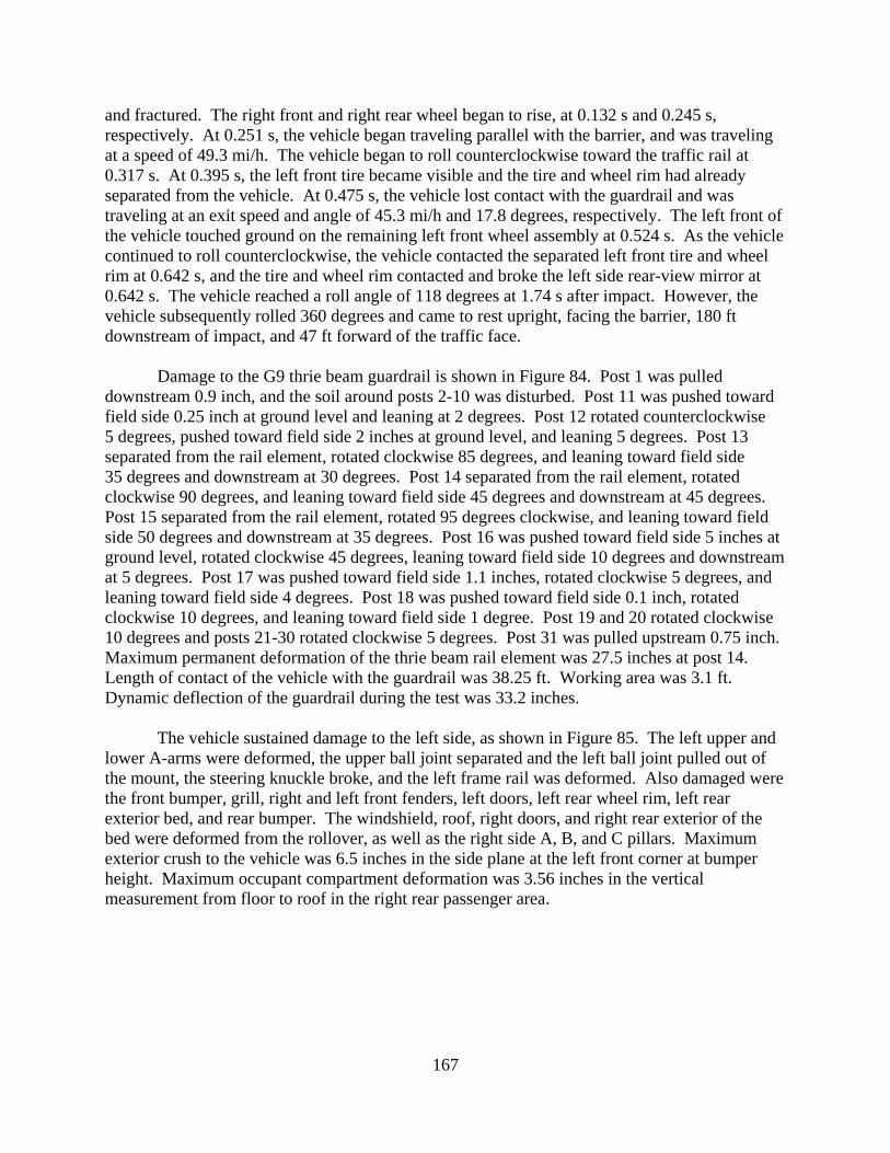
167
and fractured. The right front and right rear wheel began to rise, at 0.132 s and 0.245 s, respectively. At 0.251 s, the vehicle began traveling parallel with the barrier, and was traveling at a speed of 49.3 mi/h. The vehicle began to roll counterclockwise toward the traffic rail at 0.317 s. At 0.395 s, the left front tire became visible and the tire and wheel rim had already separated from the vehicle. At 0.475 s, the vehicle lost contact with the guardrail and was traveling at an exit speed and angle of 45.3 mi/h and 17.8 degrees, respectively. The left front of the vehicle touched ground on the remaining left front wheel assembly at 0.524 s. As the vehicle continued to roll counterclockwise, the vehicle contacted the separated left front tire and wheel rim at 0.642 s, and the tire and wheel rim contacted and broke the left side rear-view mirror at 0.642 s. The vehicle reached a roll angle of 118 degrees at 1.74 s after impact. However, the vehicle subsequently rolled 360 degrees and came to rest upright, facing the barrier, 180 ft downstream of impact, and 47 ft forward of the traffic face.
Damage to the G9 thrie beam guardrail is shown in Figure 84. Post 1 was pulled
downstream 0.9 inch, and the soil around posts 2-10 was disturbed. Post 11 was pushed toward field side 0.25 inch at ground level and leaning at 2 degrees. Post 12 rotated counterclockwise 5 degrees, pushed toward field side 2 inches at ground level, and leaning 5 degrees. Post 13 separated from the rail element, rotated clockwise 85 degrees, and leaning toward field side 35 degrees and downstream at 30 degrees. Post 14 separated from the rail element, rotated clockwise 90 degrees, and leaning toward field side 45 degrees and downstream at 45 degrees. Post 15 separated from the rail element, rotated 95 degrees clockwise, and leaning toward field side 50 degrees and downstream at 35 degrees. Post 16 was pushed toward field side 5 inches at ground level, rotated clockwise 45 degrees, leaning toward field side 10 degrees and downstream at 5 degrees. Post 17 was pushed toward field side 1.1 inches, rotated clockwise 5 degrees, and leaning toward field side 4 degrees. Post 18 was pushed toward field side 0.1 inch, rotated clockwise 10 degrees, and leaning toward field side 1 degree. Post 19 and 20 rotated clockwise 10 degrees and posts 21-30 rotated clockwise 5 degrees. Post 31 was pulled upstream 0.75 inch. Maximum permanent deformation of the thrie beam rail element was 27.5 inches at post 14. Length of contact of the vehicle with the guardrail was 38.25 ft. Working area was 3.1 ft. Dynamic deflection of the guardrail during the test was 33.2 inches.
The vehicle sustained damage to the left side, as shown in Figure 85. The left upper and lower A-arms were deformed, the upper ball joint separated and the left ball joint pulled out of the mount, the steering knuckle broke, and the left frame rail was deformed. Also damaged were the front bumper, grill, right and left front fenders, left doors, left rear wheel rim, left rear exterior bed, and rear bumper. The windshield, roof, right doors, and right rear exterior of the bed were deformed from the rollover, as well as the right side A, B, and C pillars. Maximum exterior crush to the vehicle was 6.5 inches in the side plane at the left front corner at bumper height. Maximum occupant compartment deformation was 3.56 inches in the vertical measurement from floor to roof in the right rear passenger area.

168
Figure 84. G9 Thrie Beam Guardrail after MASH Test 3-11.
Figure 85. Test Vehicle after MASH Test 3-11 on the G9 Thrie Beam Guardrail.

169
Data from the accelerometer, located at the vehicle center of gravity, were digitized for evaluation of occupant risk and were computed as follows. In the longitudinal direction, the occupant impact velocity was 17.1 ft/s (5.2 m/s) at 0.134 s, the highest 0.010-s occupant ridedown acceleration was -6.9 G from 0.944 to 0. 954 s, and the maximum 0.050-s average acceleration was -5.1 G between 0.024 and 0.074 s. In the lateral direction, the occupant impact velocity was 17.4 ft/s (5.3 m/s) at 0.134 s, the highest 0.010-s occupant ridedown acceleration was 7.7 G from 0.136 to 0.146 s, and the maximum 0.050-s average was 6.0 Gs between 0.219 and 0.259 s. THIV was 24.3 km/h or 6.7 m/s at 0.130 s; PHD was 11.0 G between 0.131 and 0.141 s; and ASI was 0.77 between 0.101 and 0.151 s. These data and other pertinent information from the test are summarized in Figure 86.
Summary of Test Results The G9 thrie beam guardrail contained and redirected the 2270P vehicle. The vehicle did
not penetrate, underride, or override the installation. Maximum dynamic deflection of the thrie beam during the test was 33.2 inches. No detached elements, fragments, or other debris were present to penetrate or to show potential for penetrating the occupant compartment, or to present a hazard to others in the area. Maximum occupant compartment deformation was 3.56 inches in the right rear passenger area. The 2270P vehicle remained upright during the collision event. However, the 2270P vehicle rolled after losing contact with the guardrail. Maximum roll angle was 360 degrees. Occupant risk factors were within the limits specified in MASH. The 2270P vehicle exited within the exit box. It should be noted, the impact speed and angle for this test were 63.3 mph and 26.4 degrees, respectively. The impact speed and angle were within the acceptable limits prescribed in MASH. However, the impact condition represented an impact severity 15.3 percent greater than the target MASH condition (62.2 mph and 25 degrees).
The G9 thrie beam guardrail did not perform acceptably when impacted by the 2270P
vehicle (2007 Chevrolet Silverado pickup), as shown in Table 20. The 2270P Silverado pickup rolled 360 degrees.
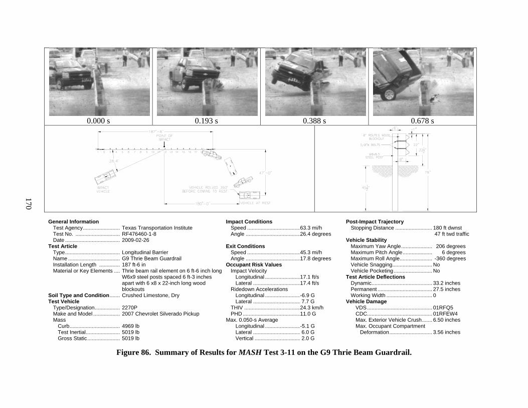
170
0.000 s
0.193 s
0.388 s
0.678 s
General Information Test Agency ......................... Test No. .............................. Date ..................................... Test Article Type ..................................... Name ................................... Installation Length .............. Material or Key Elements .... Soil Type and Condition ....... Test Vehicle Type/Designation ................. Make and Model .................. Mass
Curb .................................. Test Inertial ....................... Gross Static ......................
Texas Transportation Institute RF476460-1-8 2009-02-26 Longitudinal Barrier G9 Thrie Beam Guardrail 187 ft-6 in Thrie beam rail element on 6 ft-6 inch long W6x9 steel posts spaced 6 ft-3 inches apart with 6 x8 x 22-inch long wood blockouts Crushed Limestone, Dry 2270P 2007 Chevrolet Silverado Pickup 4969 lb 5019 lb 5019 lb
Impact Conditions Speed .................................... Angle ..................................... Exit Conditions Speed .................................... Angle ..................................... Occupant Risk Values Impact Velocity Longitudinal ........................ Lateral ................................
Ridedown Accelerations Longitudinal ........................ Lateral ................................ THIV ...................................... PHD ....................................... Max. 0.050-s Average Longitudinal ........................ Lateral ................................ Vertical ...............................
63.3 mi/h 26.4 degrees 45.3 mi/h 17.8 degrees 17.1 ft/s 17.4 ft/s -6.9 G 7.7 G 24.3 km/h 11.0 G -5.1 G 6.0 G 2.0 G
Post-Impact Trajectory Stopping Distance ......................... Vehicle Stability
Maximum Yaw Angle ..................... Maximum Pitch Angle .................... Maximum Roll Angle ...................... Vehicle Snagging ........................... Vehicle Pocketing .......................... Test Article Deflections Dynamic ......................................... Permanent ..................................... Working Width ............................... Vehicle Damage VDS ............................................ CDC ............................................ Max. Exterior Vehicle Crush ....... Max. Occupant Compartment Deformation .............................
180 ft dwnst 47 ft twd traffic 206 degrees 6 degrees -360 degrees No No 33.2 inches 27.5 inches 0 01RFQ5 01RFEW4 6.50 inches 3.56 inches
Figure 86. Summary of Results for MASH Test 3-11 on the G9 Thrie Beam Guardrail.
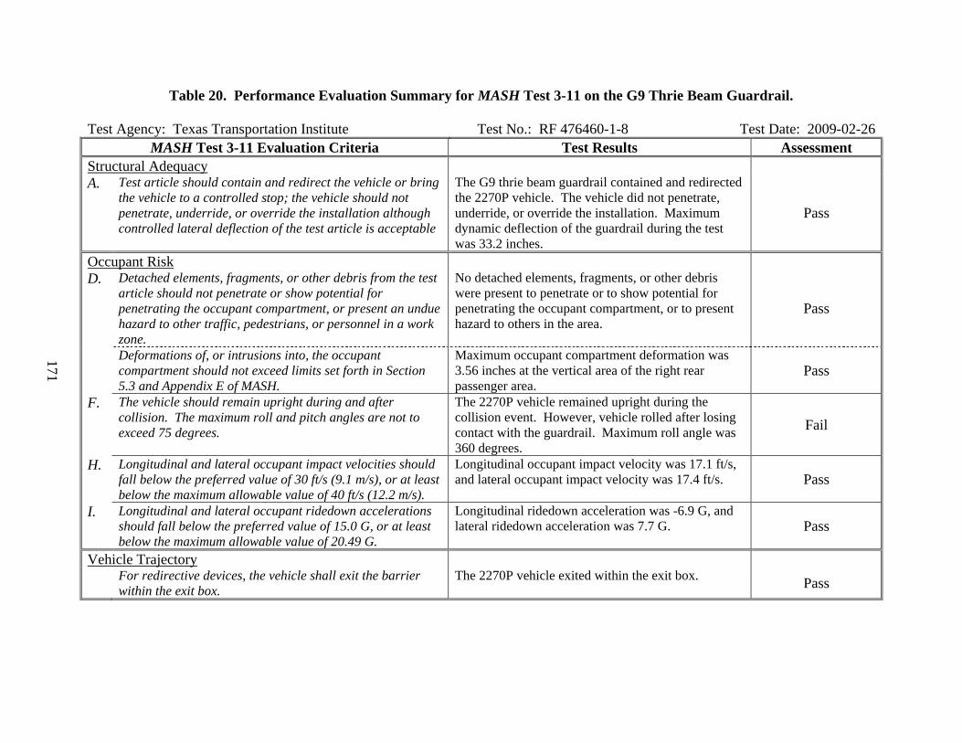
171
Table 20. Performance Evaluation Summary for MASH Test 3-11 on the G9 Thrie Beam Guardrail. Test Agency: Texas Transportation Institute Test No.: RF 476460-1-8 Test Date: 2009-02-26
MASH Test 3-11 Evaluation Criteria Test Results Assessment Structural Adequacy A. Test article should contain and redirect the vehicle or bring
the vehicle to a controlled stop; the vehicle should not penetrate, underride, or override the installation although controlled lateral deflection of the test article is acceptable
The G9 thrie beam guardrail contained and redirected the 2270P vehicle. The vehicle did not penetrate, underride, or override the installation. Maximum dynamic deflection of the guardrail during the test was 33.2 inches.
Pass
Occupant Risk D. Detached elements, fragments, or other debris from the test
article should not penetrate or show potential for penetrating the occupant compartment, or present an undue hazard to other traffic, pedestrians, or personnel in a work zone.
No detached elements, fragments, or other debris were present to penetrate or to show potential for penetrating the occupant compartment, or to present hazard to others in the area.
Pass
Deformations of, or intrusions into, the occupant compartment should not exceed limits set forth in Section 5.3 and Appendix E of MASH.
Maximum occupant compartment deformation was 3.56 inches at the vertical area of the right rear passenger area.
Pass
F. The vehicle should remain upright during and after collision. The maximum roll and pitch angles are not to exceed 75 degrees.
The 2270P vehicle remained upright during the collision event. However, vehicle rolled after losing contact with the guardrail. Maximum roll angle was 360 degrees.
Fail
H. Longitudinal and lateral occupant impact velocities should fall below the preferred value of 30 ft/s (9.1 m/s), or at least below the maximum allowable value of 40 ft/s (12.2 m/s).
Longitudinal occupant impact velocity was 17.1 ft/s, and lateral occupant impact velocity was 17.4 ft/s. Pass
I. Longitudinal and lateral occupant ridedown accelerations should fall below the preferred value of 15.0 G, or at least below the maximum allowable value of 20.49 G.
Longitudinal ridedown acceleration was -6.9 G, and lateral ridedown acceleration was 7.7 G. Pass
Vehicle Trajectory For redirective devices, the vehicle shall exit the barrier
within the exit box. The 2270P vehicle exited within the exit box. Pass


173
VI. SUMMARY AND CONCLUSIONS
PHASE I
Since its publication in 1993, NCHRP Report 350 “Recommended Procedures for the Safety Performance Evaluation of Highway Features” established guidance for evaluating the safety performance of roadside features, such as longitudinal barriers, terminals, crash cushions, and breakaway structures. This document was formally adopted as the national standard by FHWA later that year with an implementation date of late 1998.
An update to NCHRP Report 350, now known as the Manual for Assessing Safety
Hardware (MASH), was developed under NCHRP Project 22-14(02), “Improvement of Procedures for the Safety-Performance Evaluation of Roadside Features.” This document contains revised criteria for safety-performance evaluation of virtually all roadside safety features. Changes to the design test vehicles and impact conditions will place greater impact performance demands on many current roadside safety features.
It may be of interest to note that as the development of MASH progressed, it appeared
that the new design test vehicle for structural adequacy tests would be a 5000-lb, 3/4-ton, standard cab pickup. The rationale was to keep the same body style pickup used under NCHRP Report 350 with a test inertial weight adjusted to reflect the upsizing trend indicated in sales of new passenger vehicles. Previous research had concluded that the 3/4-ton, standard cab pickup was a reasonable surrogate for light truck vehicles, and there was a tremendous amount of experience and investment in designing for and testing with this truck.
The implications of specifying the heavier, 5000-lb, 3/4-ton pickup truck as the new
design test vehicle were not completely understood, but it was known that it would be more critical than the existing 4409-lb, 3/4-ton pickup used under NCHRP Report 350. The 13 percent increase in weight and impact severity would place more demand on the structural adequacy of barrier systems, and would aggravate problems with vehicle stability and occupant compartment deformation. As an example, it was demonstrated in a full-scale crash test that standard strong steel post W-beam guardrail would not accommodate the new vehicle under TL-3 impact conditions.
It was not until well into the development of MASH that the design test vehicle changed
to a 5000-lb, 1/2-ton, 4-door pickup truck. The rationale for this change is that this body style pickup has characteristics that more closely resemble large SUVs than the 3/4-ton, standard cab pickup. Subsequent crash testing and analyses conducted under NCHRP Project 22-14(02) and other projects indicate that the 5000-lb, 1/2-ton, 4-door, pickup truck will impart impact loads that are comparable to those of the 4409-lb, 3/4-ton, standard cab pickup. Further, the 1/2-ton, 4-door, pickup truck appears to be more stable and have less propensity for occupant compartment intrusion than the 3/4-ton pickup.
When these vehicle factors are combined with much more liberal thresholds for occupant
compartment deformation, the need for revising existing hardware to comply with MASH does not appear to be as extensive as once anticipated. This fact is reflected in the performance

174
assessment ratings assigned to the hardware assessed. The researchers do note that the dramatic increase in impact severity of the pickup truck redirection tests and other changes in the test matrices for terminals and crash cushions will likely necessitate the modification of some of these systems. However, most of these devices are proprietary in nature and therefore, an assessment of their performance has not been addressed under this project.
In addition to changes in the pickup truck vehicle, the test conditions for Test Level 4
(TL-4) have changed significantly. Most notably, the weight for the single-unit truck (SUT) vehicle increased from 17,640 lb to 22,050 lb and the impact speed increased from 50 mi/h to 56 mi/h. The increased weight and speed of the SUT vehicle increase the impact severity of longitudinal redirection test 4-12 by 56 percent. In addition, the estimated impact force of 76 kips for MASH test 4-12 represents a 41 percent increase from the 54-kip design load used for NCHRP Report 350 test 4-12. Consequently, some barriers that meet the NCHRP Report 350 guidelines as a TL-4 barrier may not have adequate strength to comply with the same test level under MASH.
Another aspect of the structural adequacy criteria is that the test vehicle should not
override the barrier. Adequate barrier height is required to prevent heavy trucks with high centers of gravity from rolling over a barrier. Full-scale crash testing has shown that 32-inch tall barriers are capable of meeting TL-4 impact conditions under NCHRP Report 350. However, when MASH test 4-12 was conducted on a 32-inch tall New Jersey safety shape concrete barrier, the SUT rolled over the top of the barrier.
After the unsatisfactory outcome of the test performed under project 22-14(02), it was
proposed to reduce the center-of-gravity (C.G.) height of the ballast of the SUT from 67 inches to 63 inches. This effectively decreases the overturning moment by decreasing the moment arm between the C.G. of the truck and the reactive force applied by the barrier. Additional testing was performed under this project to determine if the decrease in C.G. height was sufficient to permit 32-inch tall barriers to contain the SUT or if taller barriers will be needed to comply with MASH. Testing under this project demonstrated that the decrease in ballast C.G. height was not sufficient to prevent the SUT from rolling over a 32-inch tall New Jersey safety shape barrier.
State DOTs make considerable use of non-proprietary roadside safety systems. Although
some barrier testing was conducted under NCHRP Project 22-14(02) during the development of the MASH criteria, many barrier systems and other roadside safety features have yet to be evaluated under the proposed guidelines. Therefore, evaluation of the remaining widely used roadside safety features following the impact performance requirements of MASH is needed.
Under this research project, researchers conducted a survey of the State DOTs for use and
frequency rates for non-proprietary hardware; and reviewed the test reports of the crash tests performed under NCHRP Project 22-14(02) and TXDOT project FHWA/TX-07/0-5526-1, as well as numerous tests performed under NCHRP Report 350 guidelines. A performance assessment of existing roadside safety devices was performed to help evaluate the impact of adopting MASH. Crash test results, engineering analyses, and engineering judgment were used to assist with the hardware evaluation. Categories of roadside features that were considered under the project include guardrail, median barriers, transitions from approach guard fence to
175
barriers, breakaway sign supports, and precast and permanent concrete barriers. Proprietary devices were not considered. The manufacturers of these devices will be required to assess the impact performance of their devices and ultimately demonstrate compliance of their devices with the new test and evaluation guidelines.
Results of the performance assessment were used to develop a prioritization scheme for
further testing and evaluation required to bring roadside safety features into compliance with the new impact performance guidelines.
PHASE II – FULL-SCALE CRASH TESTING
The objective of Phase II of this project was to evaluate the safety performance of widely used non-proprietary roadside safety hardware using MASH performance and evaluation criteria. Highway safety hardware proposed for evaluation included longitudinal barriers (excluding bridge railings); terminals and crash cushions; transitions; and breakaway sign supports that had previously been accepted under NCHRP Report 350.
Researchers identified use and frequency of specific non-proprietary roadside-safety
hardware by surveying the State DOTs. In conjunction with the NCHRP project panel, a final test matrix consisting of nine roadside safety hardware features was chosen from 89 identified non-proprietary roadside safety hardware features. Researchers performed a total of 11 full-scale crash tests on nine different types of roadside safety hardware.
New Jersey Safety Shape Barrier
Test 4-12
Test Vehicle: 1999 Ford F-800 single-unit truck Test Inertia Weight: 22,090 lb Gross Static Weight: 22,090 lb Impact Speed: 57.4 mi/h Impact Angle: 14.4 degrees The 32-inch New Jersey Safety Shape bridge rail failed to contain and redirect the SUT vehicle under the new TL-4 impact conditions with a ballast center-of-gravity height of 63 inches. The SUT rolled 101 degrees before exiting the end of the barrier. Although subsequent contact with the ground enabled the vehicle to right itself as it came to rest, there is no question that the SUT would have continued to roll over the top of the rail had the barrier test installation length been longer. The 32-inch New Jersey Safety Shape bridge rail failed to demonstrate satisfactory performance according to the TL-4 evaluation criteria in MASH.

176
Test 3-11
Test Vehicle: 2007 Chevrolet Silverado 4-door pickup Test Inertia Weight: 5049 lb Gross Static Weight: 5049 lb Impact Speed: 62.6 mi/h Impact Angle: 25.2 degrees
The New Jersey safety shape barrier contained and redirected the 2270P vehicle under TL-3 impact conditions. The vehicle did not penetrate, underride, or override the installation. No measurable deflection of the barrier occurred. No detached elements, fragments, or other debris were present to penetrate or to show potential for penetrating the occupant compartment, or to present hazard to others in the area. Maximum occupant compartment deformation was 2.0 inches at the right kickpanel. The 2270P vehicle remained upright during and after the collision event. Maximum roll and pitch angles were 29 and -16 degrees, respectively. Occupant risk factors were within the limits specified in MASH. The 2270P exited the barrier within the exit box.
The New Jersey safety shape barrier performed acceptably when impacted by the 2270P vehicle (2007 Chevrolet Silverado pickup) and evaluated in accordance with the safety performance evaluation criteria presented in MASH. G4(2W) W-Beam Guardrail
Test Vehicle: 2007 Chevrolet Silverado 4-door pickup Test Inertia Weight: 5009 lb Gross Static Weight: 5009 lb Impact Speed: 64.4 mi/h Impact Angle: 26.1 degrees
The G4(2W) W-beam guardrail did not perform acceptably when impacted by the 2270P
vehicle (2007 Chevrolet Silverado pickup). The vehicle penetrated the guardrail after the W-beam rail element ruptured and then subsequently rolled 180 degrees. It should be noted, the impact speed and angle for this test were 64.4 mph and 26.1 degrees, respectively. The impact speed and angle were within the acceptable limits prescribed in MASH. However, the impact condition represented an impact severity 16.4 percent greater than the target MASH condition (62.2 mph and 25 degrees).
Various modifications to W-beam guardrail have demonstrated improved performance. Modifications that have demonstrated improved performance in crash tests include increasing the rail height to 31 inches, moving the rail splices to mid-span of the posts, and using 12 inch deep block-outs. It is believed any one or more of these changes will improve the performance of the G4(2W) W-beam guardrail. Additionally, it is known that W-beam guardrail has historically been performing at or very near 100 percent of structural design capacity. If the speed and angle in the test were nearer to target impact conditions, the rail may not have ruptured.
177
G4(1S) W-Beam Median Barrier
Test-3-10
Test Vehicle: 2002 Kia Rio Test Inertia Weight: 2418 lb Gross Static Weight: 2584 lb Impact Speed: 61.4 mi/h Impact Angle: 26.0 degrees
The G4(1S) W-beam median barrier contained and redirected the 1100C vehicle. The
vehicle did not penetrate, override, or underride the installation. Maximum dynamic deflection was 11.25 inches. No detached elements, fragments, or other debris were present to penetrate or to show potential for penetrating the occupant compartment, or to present a hazard to others in the area. Maximum occupant compartment deformation was 2.0 inches in the left front driver’s area at the level of the floor pan. The 1100C vehicle remained upright during and after the collision event. Maximum roll angle was 8 degrees. Occupant risk factors were within the limits specified in MASH. The 1100C vehicle exited the median barrier within the exit box.
The G4(1S) W-beam median barrier performed acceptably when impacted by the 1100C vehicle (2002 Kia Rio). Test-3-11
Test Vehicle: 2007 Chevrolet Silverado 4-door pickup Test Inertia Weight: 5029 lb Gross Static Weight: 5029 lb Impact Speed: 64.0 mi/h Impact Angle: 25.1 degrees
The G4(1S) W-beam median barrier did not perform acceptably when impacted by the
2270P vehicle (2007 Chevrolet Silverado pickup). The 2270P Silverado pickup truck overrode the installation. It should be noted, the impact speed and angle for this test were 64.0 mph and 25.1 degrees, respectively. The impact speed and angle were within the acceptable limits prescribed in MASH. However, the impact condition represented an impact severity 7.5 percent greater than the target MASH condition (62.2 mph and 25 degrees). If the speed and angle in the test were nearer to target impact conditions, the vehicle may not have vaulted over the test installation.
Typically, when the G4(1S) W-beam barrier is impacted in a roadside application, the support posts displace through the soil and help dissipate the energy of the impacting vehicle. When the displacement or deformation of the post becomes large enough, the rail detaches from the post by means of the post bolt pulling out of the rail slot. However, in the G4(1S) W-beam

178
median barrier, the addition of the rear W-beam rail element provides additional stiffness and constrains the lateral displacement of the posts. Because the rail cannot readily detach from the posts, the rail is pulled down by the posts and the effective rail height is reduced in the region of impact. In the test presented herein, a guardrail post was impacted by the left front tire and the vehicle climbed the post and w-beam rail element.
A 30 inch tall version of the G4(1S) W-beam median barrier (AASHTO Designation SGM06a&b) incorporates a C6x8.2 rub-rail channel that is mounted 12 inches above the ground to the center of the rub-rail. The addition of the rub-rail will prevent the wheel from contacting the face of the posts and thus help mitigate vehicle-post snagging. The rub-rail will also increase the barrier stiffness, which should reduce post displacement and rail deflection. However, the rub-rail may still permit the pickup to climb the barrier. The researchers recommend evaluating the 30 inch tall G4(1S) W-beam median barrier (AASHTO Designation SGM06a) with MASH Test 3-11. W-Beam Transition
Test Vehicle: 2007 Chevrolet Silverado 4-door pickup Test Inertia Weight: 5029 lb Gross Static Weight: 5029 lb Impact Speed: 62.8 mi/h Impact Angle: 25.7 degrees
The W-beam transition to concrete bridge parapet successfully contained and redirected
the 2270P vehicle. The vehicle did not penetrate, override, or underride the installation. Maximum dynamic deflection was 3.8 inches. No detached elements, fragments, or other debris were present to penetrate or to show potential for penetrating the occupant compartment, or to present a hazard to others in the area. Maximum occupant compartment deformation was 0.6 inches in the left rear area at hip height. The 2270P vehicle remained upright during and after the collision event. Maximum roll angle was 54 degrees. Occupant risk factors were within the limits specified in MASH. The 2270P vehicle exited the W-beam transition within the exit box.
The W-beam transition to concrete parapet performed acceptably when impacted by the 2270P vehicle (2007 Chevrolet Silverado four-door pickup). Sign Supports
Test Vehicle: 2003 Dodge Ram 1500 quad-cab pickup Test Inertia Weight: 4958 lb Gross Static Weight: 4958 lb Impact Speed: 63.3 mi/h Impact Angle: 0 degrees

179
The U-channel and perforated square steel tube (PSST) small sign supports both readily activated upon impact by the 2270P vehicle by fracturing at bumper height and at the ground stub interface. The detached sign supports rotated around the front of the vehicle, and the sign panels struck near or at the windshield and roof area and subsequently traveled with the vehicle. The 2270P vehicle remained upright during and after both collision events. Minimal roll and pitch were noted. Occupant risk factors were within acceptable limits. The 2270P vehicle came to rest behind the test articles.
Contact of the U-channel support with the windshield and roof was minimal, and the
support did not penetrate nor show potential for penetrating the occupant compartment. The largest detached piece of this support weighed 33.6 lb, but the trajectory was relatively low, and should not cause undue hazard to others in the area. No occupant compartment deformation related to impact with the U-channel support was measured.
The upper section of the PSST support and sign panel contacted and shattered the
windshield. No tear of the windshield plastic lining occurred. However, the windshield was deformed inward 3.5 inches. MASH Section 5.3 and Appendix E limits deformation of the windshield to 3 inches.
The 4 lb/ft steel U-channel support manufactured by NuCor Steel Marion successfully
met the MASH evaluation criteria for test 3-62. The 12 gauge perforated, 2 inch square, steel tube (PSST) support manufactured by Northwest Pipe failed to meet the MASH evaluation criteria for test 3-62 due to excessive occupant compartment deformation at the windshield.
The primary observed difference in the performance of the two sign support types is the
manner in which the sign panel reacted during the impact sequence. Both sign support types fractured at bumper height and near the ground stub interface. The U-channel sign support installation kept the sign panel attached to the support for much of the impact event. The sign panel remained attached until the support and panel impacted the roof of the truck as an assembly. Upon separation, both the sign and support passed over the cab of the pickup truck.
During the test of the PSST sign support, the sign panel released from the support at
approximately the same time the support failed at bumper height. The failure of the sign attachment and release of the sign panel changed the dynamics of the impact and permitted the sign panel to impact the windshield more directly. The PSST sign support stayed in the front of the vehicle and displaced forward with the vehicle with very little angular momentum. It is the opinion of the researchers that had the sign panel remained attached to the support, the PSST sign support installation performance would have been similar to the U-channel performance and the PSST would have likely met the MASH performance evaluation criteria. Further testing with enhanced sign panel-to-post connection can be performed to verify this opinion.

180
G3 Weak Post Box-Beam Guardrail
Test Vehicle: 2007 Chevrolet Silverado 4-door pickup Test Inertia Weight: 5004 lb Gross Static Weight: 5004 lb Impact Speed: 63.2 mi/h Impact Angle: 25.4 degrees
The G3 Weak Post Box-Beam guardrail contained and redirected the 2270P vehicle. The vehicle did not penetrate, underride or override the weak post guardrail. Maximum dynamic deflection of the rail during the test was 4.8 ft. Two rail brackets detached from their posts, but they did not penetrate or show potential for penetrating the occupant compartment, or present a hazard to others in the area. Maximum occupant compartment deformation was 0.75 inches in the lateral area across the cab at the driver’s side kickpanel. The 2270P vehicle remained upright during and after the collision event. Maximum roll angle was -14 degrees. Occupant risk factors were within the limits specified in MASH. The 2270P vehicle exited within the exit box.
The G3 Weak Post Box-Beam guardrail performed acceptably when impacted by the 2270P vehicle (2007 Chevrolet Silverado pickup). Modified G2 Weak Post W-Beam Guardrail
Test Vehicle: 2007 Chevrolet Silverado 4-door pickup Test Inertia Weight: 5004 lb Gross Static Weight: 5004 lb Impact Speed: 62.4 mi/h Impact Angle: 24.6 degrees
The Modified G2 Weak Post W-Beam guardrail contained and redirected the 2270P vehicle. The vehicle did not penetrate, underride or override the weak post W-beam guardrail. Maximum dynamic deflection of the rail during the test was 8.6 ft. There was no debris from the test installation that penetrated or show potential for penetrating the occupant compartment, or presented a hazard to others in the area. Maximum occupant compartment deformation was 0.25 inches in the lateral area across the cab at the driver’s side hip area. The 2270P vehicle remained upright during and after the collision event. Maximum roll angle was -12 degrees. Occupant risk factors were within the limits specified in MASH. The 2270P vehicle remained within the exit box.
The Modified G2 Weak Post W-Beam guardrail performed acceptably when impacted by the 2270P vehicle (2007 Chevrolet Silverado pickup).

181
G9 Thrie Beam Guardrail
Test Vehicle: 2007 Chevrolet Silverado 4-door pickup Test Inertia Weight: 5019 lb Gross Static Weight: 5019 lb Impact Speed: 63.3 mi/h Impact Angle: 26.4 degrees
The G9 thrie beam guardrail did not perform acceptably when impacted by the 2270P vehicle (2007 Chevrolet Silverado pickup). After being contained and redirected, the 2270P Silverado pickup rolled 360 degrees. Maximum dynamic deflection of the thrie beam during the test was 33.2 inches. Maximum occupant compartment deformation was 3.56 inches in the right rear passenger area. It should be noted, the impact speed and angle for this test were 63.3 mph and 26.4 degrees, respectively. The impact speed and angle were within the acceptable limits prescribed in MASH. However, the impact condition represented an impact severity 15.3 percent greater than the target MASH condition (62.2 mph and 25 degrees). If the speed and angle in the test were nearer to target impact conditions, the vehicle may not have rolled over.
CONCLUSIONS
Nine different types of roadside safety hardware were crash tested and evaluated in accordance with MASH. Six of the 11 crash tests performed on these nine safety devices successfully met the MASH evaluation criteria. Table 21 summarizes the non-proprietary roadside safety hardware tested under the NCHRP projects 22-14(2) and 22-14(3) that successfully meet the MASH evaluation criteria. Table 22 identifies the non-proprietary roadside safety hardware tested under these projects that failed to meet the MASH evaluation criteria.

182
Table 21. Crash Tests Performed Under NCHRP Project 22-14 That Meet MASH (Passed).
Ref. Test No.*
Agency Test No.
Test Designation
Test Article
Vehicle Make and Model
Vehicle Mass (lb)
Impact Speed (mph)
Impact Angle (deg)
OIV (ft/s)
Ridedown (G)
1
2214WB-11 Pg 22 & Ref 37
3-11 Modified G4(1S) Guardrail
2002 GMC 2500 ¾-ton Pickup 5000 61.1 25.6 X=17.3
Y=16.2 X=-19.7 Y= -8.5
2 2214WB-2
Pg 22 & Ref 38 3-11 Modified G4(1S)
Guardrail
2002 Dodge Ram 1500 Quad Cab
Pickup 5000 62.4 26.0 X=17.6
Y=13.1 X= 6.9 Y=-6.6
3 2214MG-1
Pg 22 & Ref 39 3-11 Midwest Guardrail
System (MGS) 2002 GMC 2500
¾-ton Pickup 5000 62.6 25.2 X=17.1 Y=14.8
X=-8.8 Y=-5.3
4 2214MG-2
Pg 22 & Ref 40 3-11 MGS
2002 Dodge Ram 1500 Quad Cab
Pickup 5000 62.8 25.5 X=15.3
Y=15.6 X=-8.2 Y=-6.9
5 2214MG-3
Pg 22 & Ref 41 3-10 MGS
(Max. Height) 2002 Kia Rio 2588 60.8 25.4 X=14.8 Y=17.1
X=-16.1 Y= -8.4
6 2214TB-1
Pg 42 & Ref 50 3-11
Free-Standing Temporary
F-Shape Barrier
2002 GMC 2500 ¾-ton Pickup 5000 61.8 25.7 X=18.5
Y=18.9 X=-11.9 Y= -6.5
7 2214TB-2
Pg 42 & Ref 51 3-11
Free-Standing Temporary
F-Shape Barrier
2002 Dodge Ram 1500 Quad Cab
Pickup 5000 61.9 25.4 X=17/0
Y=17/3 X= -7.2 Y=-11.4
8 2214NJ-1
Pg 43 & Ref 53 3-10
32-inch Permanent New Jersey Safety
Shape Barrier 2002 Kia Rio 2579 60.8 26.1 X=16.5
Y=35.0 X=-5.5 Y=-8.1
9 2214T-1
Pg 59 & Ref 58 3-21
Guardrail to Concrete Barrier
Transition
2002 Chevrolet C1500HD Crew
Cab Pickup 5083 60.3 24.8 X=24.4
Y=25.0 X=12.7 Y= 8.7

183
Ref. Test No.*
Agency Test No.
Test Designation
Test Article
Vehicle Make and Model
Vehicle Mass (lb)
Impact Speed (mph)
Impact Angle (deg)
OIV (ft/s)
Ridedown (G)
10 2214TT-1
Ref 74 3-34
Sequential Kinking Terminal (SKT)-MGS (Tangent)
2002 Kia Rio 2597 64.4 14.5 X=17.8 Y=13.4
X=-7.5 Y=-9.1
(13) 476460-1-4
Pg 106 & App C 3-11
32-inch Permanent New Jersey Safety
Shape Barrier
2007 Chevrolet Silverado Pickup 5049 62.6 25.2 X=14.1
Y=30.2 X=-5.6 Y=-9.6
(14) 476460-1-2
Pg 138 & App H 3-62 4lb/ft U-Channel
Sign Support
2003 Dodge Ram 1500 Quad Cab
Pickup 4958 63.3 0 No
contact N/A
(15) 476460-1-3
Pg 130 & App G 3-21 W-Beam
Transition 2007 Chevrolet
Silverado Pickup 5029 62.8 25.7 X=16.4 Y=28.5
X= -8.1 Y=16.4
(16) 476460-1-6
Pg 151 & App I 3-11
G3 Weak Post Box-Beam Guardrail
2007 Chevrolet Silverado Pickup 5011 63.2 25.4 X=11.2
Y=15.1 X=-5.7 Y=7.2
(17) 476460-1-7
Pg 158 & App J 3-11 G2 Weak Post W-
Beam Guardrail 2007 Chevrolet
Silverado Pickup 5004 62.4 24.6 X= 9.5 Y=10.5
X=-3.4 Y= 4.5
(18) 476460-1-10 Pg 118 & App E
3-10 G4(1S) W-Beam Median Barrier 2002 Kia Rio 2584 61.4 26.0 X=16.4
Y=24.3 X=-16.5 Y= 10.5
* For reference purposes within this report
1 Rail ruptured. Passed by FHWA
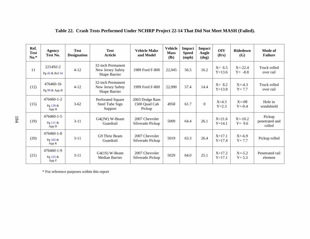
184
Table 22. Crash Tests Performed Under NCHRP Project 22-14 That Did Not Meet MASH (Failed).
Ref. Test No.*
Agency Test No.
Test Designation
Test Article
Vehicle Make and Model
Vehicle Mass (lb)
Impact Speed (mph)
Impact Angle (deg)
OIV (ft/s)
Ridedown (G)
Mode of Failure
11 2214NJ-2
Pg 43 & Ref 54 4-12
32-inch Permanent New Jersey Safety
Shape Barrier 1989 Ford F-800 22,045 56.5 16.2 X= 6.5
Y=13.6 X=-22.4 Y= -8.8
Truck rolled over rail
(12) 476460-1b
Pg 99 & App B 4-12
32-inch Permanent New Jersey Safety
Shape Barrier 1999 Ford F-800 22,090 57.4 14.4 X= 8.2
Y=13.8 X=-4.3 Y= 7.7
Truck rolled over rail
(15) 476460-1-2
Pg 139 & App H
3-62 Perforated Square Steel Tube Sign
Support
2003 Dodge Ram 1500 Quad Cab
Pickup 4958 61.7 0 X=4.3
Y=2.3 X=-08 Y=-0.4
Hole in windshield
(19) 476460-1-5
Pg 111 & App D
3-11 G4(2W) W-Beam Guardrail
2007 Chevrolet Silverado Pickup 5009 64.4 26.1 X=21.6
Y=14.1 X=-10.2 Y= 9.6
Pickup penetrated and
rolled
(20) 476460-1-8
Pg 165 & App K
3-11 G9 Thrie Beam Guardrail
2007 Chevrolet Silverado Pickup 5019 63.3 26.4 X=17.1
Y=17.4 X=-6.9 Y= 7.7 Pickup rolled
(21) 476460-1-9
Pg 125 & App F
3-11 G4(1S) W-Beam Median Barrier
2007 Chevrolet Silverado Pickup 5029 64.0 25.1 X=17.2
Y=17.1 X=-5.2 Y= 5.3
Penetrated rail element
* For reference purposes within this report
185
VII. REFERENCES
1. H. E. Ross, D. L. Sicking, R. A. Zimmer, and J. D. Michie, Recommended Procedures
for the Safety Performance Evaluation of Highway Features, National Cooperative Highway Research Program Report 350, Transportation Research Board, National Research Council, Washington, D.C., 1993.
2. American Association of State Highway and Transportation Officials, Manual for Assessing Safety Hardware, AASHTO Subcommittee on Bridges and Structures, Washington, D.C., 2009.
3. Federal Highway Administration. Acceptance Letter B38. Washington, D.C., August 29, 1996.
4. Federal Highway Administration. Acceptance Letter B55A. Washington, D.C., September 2, 1999.
5. Federal Highway Administration. Acceptance Letter B64. Washington, D.C., February 14, 2000.
6. Federal Highway Administration. Acceptance Letter B64D. Washington, D.C., April 9, 2003.
7. Federal Highway Administration. Acceptance Letter B64D2. Washington, D.C., February 12, 2004.
8. Federal Highway Administration. Acceptance Letter B77. Washington, D.C., December 6, 2000.
9. Federal Highway Administration. Acceptance Letter B78. Washington, D.C., December 6, 2000.
10. Federal Highway Administration. Acceptance Letter B81. Washington, D.C., June 26, 2001.
11. Federal Highway Administration. Acceptance Letter B83. Washington, D.C., April 24, 2001.
12. Federal Highway Administration. Acceptance Letter B99. Washington, D.C., April 30, 2002.
13. Federal Highway Administration. Acceptance Letter B105. Washington, D.C., September 5, 2002.
14. Federal Highway Administration. Acceptance Letter B127. Washington, D.C., June 18, 2004.
15. Federal Highway Administration. Acceptance Letter B133. Washington, D.C., March 1, 2005.
16. Federal Highway Administration. Acceptance Letter B143. Washington, D.C., February 9, 2006.
186
17. Federal Highway Administration. Acceptance Letter CC53. Washington, D.C., July 10, 1998.
18. Federal Highway Administration. Acceptance Letter CC53A. Washington, D.C., April 27, 2001.
19. Federal Highway Administration. Acceptance Letter CC56. Washington, D.C., December 24, 1998.
20. Federal Highway Administration. Acceptance Letter CC58. Washington, D.C., March 26, 1999.
21. Federal Highway Administration. Acceptance Letter CC62. Washington, D.C., December 21, 1999.
22. Federal Highway Administration. Acceptance Letter CC63. Washington, D.C., February 14, 2000.
23. Federal Highway Administration. Acceptance Letter CC68. Washington, D.C., November 8, 2000.
24. Federal Highway Administration. Acceptance Letter CC77. Washington, D.C., April 9, 2002.
25. Federal Highway Administration. Acceptance Letter CC84. Washington, D.C., December 9, 2003.
26. Federal Highway Administration. Acceptance Letter SS25. Washington, D.C., June 4, 1991.
27. Federal Highway Administration. Acceptance Letter SS36. Washington, D.C., September 3, 1993.
28. Federal Highway Administration. Acceptance Letter SS50. Washington, D.C., November 8, 1994.
29. Federal Highway Administration. Acceptance Letter SS76. Washington, D.C., January 9, 1998.
30. J. D. Michie, Recommended Procedures for the Safety Performance Evaluation of Highway Appurtenances, National Cooperative Highway Research Program Report 230, Transportation Research Board, National Research Council, Washington, D.C., 1981.
31. American Association of State Highway and Transportation Officials, Standard Specifications for Structural Supports for Highway Signs, Luminaires and Traffic Signals, AASHTO Subcommittee on Bridges and Structures, Washington, D.C., 1985.
32. C. E. Buth, et.al., “Safer Bridge Railings, Volume 4: Appendix C – Part II,” Research Report 3451, Texas Transportation Institute, College Station, TX, May 1983.
33. W. L. Beason, T. J. Hirsch, “Measurement of Heavy Vehicle Impact Forces and Inertia Properties,” Research Report 7046, Texas Transportation Institute, College Station, TX, May 1989.

187
34. K. K. Mak, R. P. Bligh, W. L. Menges, “Volume I: Technical Report, Testing of State Roadside Safety Systems,” Research Report 471470, Texas Transportation Institute, College Station, TX, September 1996.
35. D. L. Bullard, W. L. Menges, D. C. Alberson, “NCHRP Report 350 Compliance Test 3-11 of the Modified G4(1S) Guardrail with Timber Blockouts,” Research Report 405421-1, Texas Transportation Institute, College Station, TX, September 1996.
36. C. E. Buth, R. A. Zimmer, W. L. Menges, “Testing and Evaluation of a Modified G4(1S) Guardrail with W150x17.9 Steel Blockouts,” Research Report 405421-2, Texas Transportation Institute, College Station, TX, January 1999.
37. K. A. Polivka, R. K. Faller, D. L. Sicking, J. R. Rohde, B. W. Bielenberg, J. D. Reid, “Performance Evaluation of the Modified G4(1S) Guardrail – Update to NCHRP 350 Test No. 3-11 (2214WB-1),” Research Report TRP-03-168-06, Midwest Roadside Safety Facility, Lincoln, NE, October 2006.
38. K. A. Polivka, R. K. Faller, D. L. Sicking, J. R. Rohde, B. W. Bielenberg, J. D. Reid, “Performance Evaluation of the Modified G4(1S) Guardrail – Update to NCHRP 350 Test No. 3-11 with 28” C.G. Height (2214-WB-2),” Research Report TRP-03-169-06, Midwest Roadside Safety Facility, Lincoln, NE, October 2006.
39. K. A. Polivka, R. K. Faller, D. L. Sicking, J. R. Rohde, B. W. Bielenberg, J. D. Reid, “Performance Evaluation of the Midwest Guardrail System – Update to NCHRP 350 Test No. 3-11 (2214MG-1),” Research Report TRP-03-171-06, Midwest Roadside Safety Facility, Lincoln, NE, October 2006.
40. K. A. Polivka, R. K. Faller, D. L. Sicking, J. R. Rohde, B. W. Bielenberg, J. D. Reid, “Performance Evaluation of the Midwest Guardrail System – Update to NCHRP 350 Test No. 3-11 with 28” C.G. Height (2214MG-2),” Research Report TRP-03-171-06, Midwest Roadside Safety Facility, Lincoln, NE, October 2006.
41. K. A. Polivka, R. K. Faller, D. L. Sicking, J. R. Rohde, B. W. Bielenberg, J. D. Reid, “Performance Evaluation of the Midwest Guardrail System – Update to NCHRP 350 Test No. 3-10 (2214MG-3),” Research Report TRP-03-172-06, Midwest Roadside Safety Facility, Lincoln, NE, October 2006.
42. C. E. Buth, W. L. Menges, S. K. Schoeneman, “NCHRP Report 350 Assessment of Existing Roadside Safety Hardware,” Research Report 404211-F, Texas Transportation Institute, College Station, TX, November 2000.
43. D. L. Ivey, R. Robertson, C. E. Buth, “Test and Evaluation of W-Beam and Thrie-Beam Guardrails,” Research Report 4098, Texas Transportation Institute, College Station, TX, March 1982.
44. C. E. Buth, W. L. Menges, W. F. Williams, S. K. Schoeneman, “NCHRP Report 350 Test 3-10 on the Modified PennDOT Type 2 Guide Rail – Test 4,” Research Report 473750-4, Texas Transportation Institute, College Station, TX, July 2000.
45. C. E. Buth, W. L. Menges, W. F. Williams, S. K. Schoeneman, “NCHRP Report 350 Test 3-11 on the Modified PennDOT Type 2 Guide Rail – Test 3,” Research Report 473750-3, Texas Transportation Institute, College Station, TX, June 2000.
188
46. D. L. Bullard, N. M. Sheikh, R. P. Bligh, R. R. Haug, J. R. Schutt, B. J. Storey, Aesthetic Concrete Barrier Design, National Cooperative Highway Research Program Report 554, Transportation Research Board, National Research Council, Washington, D.C., 2006.
47. D. L. Bullard, W. L. Menges, C. E. Buth, R. R. Haug, “Guardrail Testing Program IV, Volume I: Technical Report,” Research Report 405181-F, Texas Transportation Institute, College Station, TX, September 2004.
48. D. L. Bullard, W. L. Menges, D. C. Alberson, “Testing and Evaluation of the Merritt Parkway Guiderail,” Research Report 405501, Texas Transportation Institute, College Station, TX, April 1996.
49. D. L. Bullard, W. F. Williams, W. L. Menges, R. R. Haug, “Development, Testing and Evaluation of the Deception Pass State Park Log Rail,” Research Report 400561, Texas Transportation Institute, College Station, TX, September 2003.
50. K. A. Polivka, R. K. Faller, D. L. Sicking, J. R. Rohde, B. W. Bielenberg, J. D. Reid, B. A. Coon, “Performance Evaluation of the Free-Standing Temporary Barrier – Update to NCHRP 350 Test No. 3-11 (2214TB-1),” Research Report TRP-03-173-06, Midwest Roadside Safety Facility, Lincoln, NE, October 2006.
51. K. A. Polivka, R. K. Faller, D. L. Sicking, J. R. Rohde, B. W. Bielenberg, J. D. Reid, B. A. Coon, “Performance Evaluation of the Free-Standing Temporary Barrier – Update to NCHRP 350 Test No. 3-11 with 28” C.G. Height (2214TB-2),” Research Report TRP-03-174-06, Midwest Roadside Safety Facility, Lincoln, NE, October 2006.
52. R. P. Bligh, N. M. Sheikh, W. L. Menges, R. R. Haug, “Development of Low-Deflection Precast Concrete Barrier,” Research Report 0-4162-3, Texas Transportation Institute, College Station, TX, January 2005.
53. K. A. Polivka, R. K. Faller, D. L. Sicking, J. R. Rohde, B. W. Bielenberg, J. D. Reid, B. A. Coon, “Performance Evaluation of the Permanent New Jersey Safety Shape Barrier – Update to NCHRP 350 Test No. 3-10 (2214NJ-1),” Research Report TRP-03-177-06, Midwest Roadside Safety Facility, Lincoln, NE, October 2006.
54. K. A. Polivka, R. K. Faller, D. L. Sicking, J. R. Rohde, B. W. Bielenberg, J. D. Reid, B. A. Coon, “Performance Evaluation of the Permanent New Jersey Safety Shape Barrier – Update to NCHRP 350 Test No. 4-12 (2214NJ-2),” Research Report TRP-03-178-06, Midwest Roadside Safety Facility, Lincoln, NE, October 2006.
55. T. R. Guidry, W. L. Beason, “Development of a Low-Profile Portable Concrete Barrier,” Research Report 990-4F, Texas Transportation Institute, College Station, TX, November 1991.
56. R. P. Bligh, W. L. Menges, R. R. Haug, “Evaluation of Guardrail to Concrete Bridge Rail Transitions,” Research Report 4564-1, Texas Transportation Institute, College Station, TX, October 2003.
57. R. K. Faller, J. D. Reid, J. R. Rohde, D. L. Sicking, E. A. Keller, “Two Approach Guardrail Transitions for Concrete Safety Shape Barriers,” Research Report TRP-03-69-98, Midwest Roadside Safety Facility, Lincoln, NE, May 1998.
189
58. K. A. Polivka, R. K. Faller, D. L. Sicking, J. R. Rohde, B. W. Bielenberg, J. D. Reid, B. A. Coon, “Performance Evaluation of the Guardrail to Concrete Barrier Transition – Update to NCHRP 350 Test No. 3-21 with 28” C.G. Height (2214T-1),” Research Report TRP-03-175-06, Midwest Roadside Safety Facility, Lincoln, NE, October 2006.
59. A. G. Arnold, C. E. Buth, W. L. Menges, “Testing and Evaluation of W-Beam Guardrails Buried-in-Backslope,” Research Report 405521, Texas Transportation Institute, College Station, TX, January 1999.
60. K. K. Mak, R. P. bligh, W. L. Menges, “Crash Testing and Evaluation of the Eccentric Loader Terminal (ELT),” Research Report 473390-01, Texas Transportation Institute, College Station, TX, March 1999.
61. R. G. Phillips, A. B. Tyrell, J. E. Bryden, J. S. Fortuniewicz, “Cable Guiderail Breakaway Terminal Ends – Final Report,” Research Report 148, New York State Department of Transportation, Albany, NY, March 1990.
62. A. G. Arnold, W. L. Menges, B. G. Butler, “Testing and Evaluation of the Vermont W-Beam Guardrail Terminal for Low Speed Areas,” Research Report 473080-01, Texas Transportation Institute, College Station, TX, May 1998.
63. D. C. Alberson, W. L. Menges, R. R. Haug, “Guardrail Testing – Modified Eccentric Loader Terminal (MELT) at NCHRP 350 TL-2,” Research Report 400401-1&2, Texas Transportation Institute, College Station, TX, July 2002.
64. D. C. Alberson, W. L. Menges, “Testing and Evaluation of the Connecticut Impact Attenuation System (CIAS),” Research Report 405651-1&2, Texas Transportation Institute, College Station, TX, August 1996.
65. C. E. Buth, W. L. Menges, “Testing and Evaluation of the Modified Connecticut Impact Attenuation System (CIAS),” Research Report 405651-3&4, Texas Transportation Institute, College Station, TX, November 1997.
66. W. L. Menges, C. E. Buth, S. K. Schoeneman, “NCHRP Report 350 Test 3-34 of the Modified Connecticut Impact Attenuation System (CIAS),” Research Report 404231-7, Texas Transportation Institute, College Station, TX, May 1999.
67. W. L. Menges, C. E. Buth, “NCHRP Report 350 Testing of the Narrow Connecticut Impact Attenuation System (NCIAS),” Research Report 404231-1-6 (Draft), Texas Transportation Institute, College Station, TX, May 1999.
68. B. W. Bielenberg, R. K. Faller, J. D. Reid, J. R. Rohde, D. L. Sicking, E. A. Keller, “Concept Development of a Bullnose Guardrail System for Median Applications,” Research Report TRP-03-73-98, Midwest Roadside Safety Facility, Lincoln, NE, May 1998.
69. B. W. Bielenberg, J. D. Reid, R. K. Faller, J. R. Rohde, D. L. Sicking, E. A. Keller, J. C. Holloway, “Phase II Development of a Bullnose Guardrail System for Median Applications,” Research Report TRP-03-78-98, Midwest Roadside Safety Facility, Lincoln, NE, December 1998.
70. B. W. Bielenberg, J. D. Reid, R. K. Faller, J. R. Rohde, D. L. Sicking, E. A. Keller, J. C. Holloway, L. Supencheck, “Phase III Development of a Bullnose Guardrail System for
190
Median Applications,” Research Report TRP-03-95-00, Midwest Roadside Safety Facility, Lincoln, NE, June 2000.
71. Federal Highway Administration. “Draft Guidelines for Analysis of Passenger Compartment Intrusion,” Washington, D.C., 1999.
72. Federal Highway Administration. “Windshield Damage for Category II Work Zone Traffic Control Devices,” Washington, D.C., August 1999.
73. R. P. Bligh, W. L. Menges, “Initial Assessment of Compliance of Texas Roadside Safety Hardware with Proposed Update to NCHRP Report 350,” Research Report 0-5526-1, Texas Transportation Institute, College Station, TX, September 2007.
74. K. A. Polivka, R. K. Faller, D. L. Sicking, J. R. Rohde, B. W. Bielenberg, J. D. Reid, B. A. Coon, “Performance Evaluation of the SKT-MGS Tangent End Terminal – Update to NCHRP 350 Test No. 3-34 (2214TT-1),” Research Report TRP-03-175-06, Midwest Roadside Safety Facility, Lincoln, NE, October 2006.