Full Length Article An empirical approach for predicting burden velocities in rock blasting Zong-Xian Zhang a, * , Li-Yuan Chi b , Changping Yi c a Oulu Mining School, University of Oulu, Oulu, FI-90014, Finland b State Key Laboratory of Explosion Science and Technology, Beijing Institute of Technology, Beijing, China c Division of Mining and Geotechnical Engineering, Luleå University of Technology, Luleå, Sweden article info Article history: Received 24 September 2020 Received in revised form 14 April 2021 Accepted 14 April 2021 Available online 14 May 2021 Keywords: Burden velocity Rock blasting Kinetic energy Delay time Tunnelling Mining abstract An analytical relation between burden velocity and ratio of burden to blasthole diameter is developed in this paper. This relation is found to be consistent with the measured burden velocities of all 37 full-scale blasts found from published articles. These blasts include single-hole blasts, multi-hole blasts, and simultaneously-initiated blasts with various borehole diameters such as 64 mm, 76 mm, 92 mm,115 mm, 142 mm and 310 mm. All boreholes were fully charged. The agreement between measured and calcu- lated burden velocities demonstrates that this relation can be used to predict the burden velocity of a wide range of full-scale blast with fully-coupled explosive charge and help to determine a correct delay time between adjacent holes or rows in various full-scale blasts involved in tunnelling (or drifting), surface and underground mining production blasts and underground opening slot blasts. In addition, this theoretical relation is found to agree with the measured burden velocities of 9 laboratory small-scale blasts to a certain extent. To predict the burden velocity of a small-scale blast, a further study or modification to the relation is necessary by using more small-scale blasts in the future. Ó 2021 Institute of Rock and Soil Mechanics, Chinese Academy of Sciences. Production and hosting by Elsevier B.V. This is an open access article under the CC BY-NC-ND license (http://creativecommons.org/ licenses/by-nc-nd/4.0/). 1. Introduction In most engineering blasts, one blast consists of multiholes in one row or multi-rows. In such a multihole blast, a free surface approximately parallel to the blastholes and a void space nearby are two necessary prerequisites for a desirable result such as good fragmentation (Zhang, 2016a). To create a free surface and a void space in a multihole blast, it is necessary to know the movement velocity of fragments, often called burden velocity (Young et al., 1983), so that correct delay times between holes and between rows can be determined. For example, a cut blast in tunnelling (or an opening slot blast in underground mining) with a too short delay time was found to often result in cut failure and high vibrations (Zhang, 2012, 2016a, b), because the fragments were squeezed in a too small void space and they could not be thrown out of the cut due to too short delay time. Similarly, small-scale blasts with a very short delay time and simultaneous blasting usually gave rise to poor rock fragmentation (Bergmann, 1983; Stagg and Rholl, 1987; Katsabanis et al., 2006; Johansson and Ouchterlony, 2013). In addition, burden velocity plays an important role in burden determination, vibration control, fly rock prediction (Raina et al., 2015), prediction of fragment sizes (Yan et al., 2016), prediction of spalling and rock movement (Tilert et al., 2007), muckpile forma- tion (Chiappetta and Mammele, 1987; Yang et al., 1989), and frag- mentation improvement by utilising the kinetic energy carried by moving fragments (Zhang, 2016a, 2017). Up till now, a number of measurements have been done con- cerning burden velocity or burden rock movement (Noren, 1956; Bergmann et al., 1973, 1974; Chiappetta and Borg, 1983; Young et al., 1983; Chiappetta and Mammele, 1987; Yang et al., 1989; Yang and Kavetsky, 1990; Katsuyama et al., 1993; Armstrong, 1994; Segarra et al., 2003; Olsson et al., 2009; Wimmer et al., 2013; Huang et al., 2014; Chandra et al., 2018; Petropoulos et al., 2018; Chi et al., 2019a, b). The measured burden velocity varied from 1.8 m/ s to 94 m/s, and the diameter of blastholes ranged from 10 mm to 310 mm. Most of the above measurements were carried out in fully- coupled charge condition, except for the measurements in Noren (1956) and Chi et al. (2019a, b) where a decoupled explosive charge was employed. In the above investigations, the measure- ments in Noren (1956) showed that burden velocity decreased with an increasing burden, but a quantitative relation between burden and burden velocity was not given. An empirical relation between burden velocity v B and burden B was obtained by Chiappetta and * Corresponding author. E-mail address: Zongxian.zhang@oulu.fi (Z.-X. Zhang). Peer review under responsibility of Institute of Rock and Soil Mechanics, Chi- nese Academy of Sciences. Contents lists available at ScienceDirect Journal of Rock Mechanics and Geotechnical Engineering journal homepage: www.jrmge.cn Journal of Rock Mechanics and Geotechnical Engineering 13 (2021) 767e773 https://doi.org/10.1016/j.jrmge.2021.04.004 1674-7755 Ó 2021 Institute of Rock and Soil Mechanics, Chinese Academy of Sciences. Production and hosting by Elsevier B.V. This is an open access article under the CC BY- NC-ND license (http://creativecommons.org/licenses/by-nc-nd/4.0/).

Welcome message from author
This document is posted to help you gain knowledge. Please leave a comment to let me know what you think about it! Share it to your friends and learn new things together.
Transcript
lable at ScienceDirect
Journal of Rock Mechanics and Geotechnical Engineering 13 (2021) 767e773
Contents lists avai
Journal of Rock Mechanics andGeotechnical Engineeringjournal homepage: www.jrmge.cn
Full Length Article
An empirical approach for predicting burden velocities in rock blasting
Zong-Xian Zhang a,*, Li-Yuan Chi b, Changping Yi c
aOulu Mining School, University of Oulu, Oulu, FI-90014, Finlandb State Key Laboratory of Explosion Science and Technology, Beijing Institute of Technology, Beijing, ChinacDivision of Mining and Geotechnical Engineering, Luleå University of Technology, Luleå, Sweden
a r t i c l e i n f o
Article history:Received 24 September 2020Received in revised form14 April 2021Accepted 14 April 2021Available online 14 May 2021
Keywords:Burden velocityRock blastingKinetic energyDelay timeTunnellingMining
* Corresponding author.E-mail address: [email protected] (Z.-X. ZhaPeer review under responsibility of Institute of R
nese Academy of Sciences.
https://doi.org/10.1016/j.jrmge.2021.04.0041674-7755 � 2021 Institute of Rock and Soil MechanicNC-ND license (http://creativecommons.org/licenses/b
a b s t r a c t
An analytical relation between burden velocity and ratio of burden to blasthole diameter is developed inthis paper. This relation is found to be consistent with the measured burden velocities of all 37 full-scaleblasts found from published articles. These blasts include single-hole blasts, multi-hole blasts, andsimultaneously-initiated blasts with various borehole diameters such as 64 mm, 76 mm, 92 mm, 115 mm,142 mm and 310 mm. All boreholes were fully charged. The agreement between measured and calcu-lated burden velocities demonstrates that this relation can be used to predict the burden velocity of awide range of full-scale blast with fully-coupled explosive charge and help to determine a correct delaytime between adjacent holes or rows in various full-scale blasts involved in tunnelling (or drifting),surface and underground mining production blasts and underground opening slot blasts. In addition, thistheoretical relation is found to agree with the measured burden velocities of 9 laboratory small-scaleblasts to a certain extent. To predict the burden velocity of a small-scale blast, a further study ormodification to the relation is necessary by using more small-scale blasts in the future.� 2021 Institute of Rock and Soil Mechanics, Chinese Academy of Sciences. Production and hosting byElsevier B.V. This is an open access article under the CC BY-NC-ND license (http://creativecommons.org/
licenses/by-nc-nd/4.0/).
1. Introduction
In most engineering blasts, one blast consists of multiholes inone row or multi-rows. In such a multihole blast, a free surfaceapproximately parallel to the blastholes and a void space nearby aretwo necessary prerequisites for a desirable result such as goodfragmentation (Zhang, 2016a). To create a free surface and a voidspace in a multihole blast, it is necessary to know the movementvelocity of fragments, often called burden velocity (Young et al.,1983), so that correct delay times between holes and betweenrows can be determined. For example, a cut blast in tunnelling (oran opening slot blast in undergroundmining) with a too short delaytime was found to often result in cut failure and high vibrations(Zhang, 2012, 2016a, b), because the fragments were squeezed in atoo small void space and they could not be thrown out of the cutdue to too short delay time. Similarly, small-scale blasts with a veryshort delay time and simultaneous blasting usually gave rise topoor rock fragmentation (Bergmann, 1983; Stagg and Rholl, 1987;Katsabanis et al., 2006; Johansson and Ouchterlony, 2013). In
ng).ock and Soil Mechanics, Chi-
s, Chinese Academy of Sciences. Pry-nc-nd/4.0/).
addition, burden velocity plays an important role in burdendetermination, vibration control, fly rock prediction (Raina et al.,2015), prediction of fragment sizes (Yan et al., 2016), prediction ofspalling and rock movement (Tilert et al., 2007), muckpile forma-tion (Chiappetta and Mammele, 1987; Yang et al., 1989), and frag-mentation improvement by utilising the kinetic energy carried bymoving fragments (Zhang, 2016a, 2017).
Up till now, a number of measurements have been done con-cerning burden velocity or burden rock movement (Noren, 1956;Bergmann et al., 1973,1974; Chiappetta and Borg,1983; Young et al.,1983; Chiappetta and Mammele, 1987; Yang et al., 1989; Yang andKavetsky, 1990; Katsuyama et al., 1993; Armstrong, 1994; Segarraet al., 2003; Olsson et al., 2009; Wimmer et al., 2013; Huanget al., 2014; Chandra et al., 2018; Petropoulos et al., 2018; Chiet al., 2019a, b). The measured burden velocity varied from 1.8 m/s to 94 m/s, and the diameter of blastholes ranged from 10 mm to310mm.Most of the abovemeasurements were carried out in fully-coupled charge condition, except for the measurements in Noren(1956) and Chi et al. (2019a, b) where a decoupled explosivecharge was employed. In the above investigations, the measure-ments in Noren (1956) showed that burden velocity decreased withan increasing burden, but a quantitative relation between burdenand burden velocity was not given. An empirical relation betweenburden velocity vB and burden B was obtained by Chiappetta and
oduction and hosting by Elsevier B.V. This is an open access article under the CC BY-

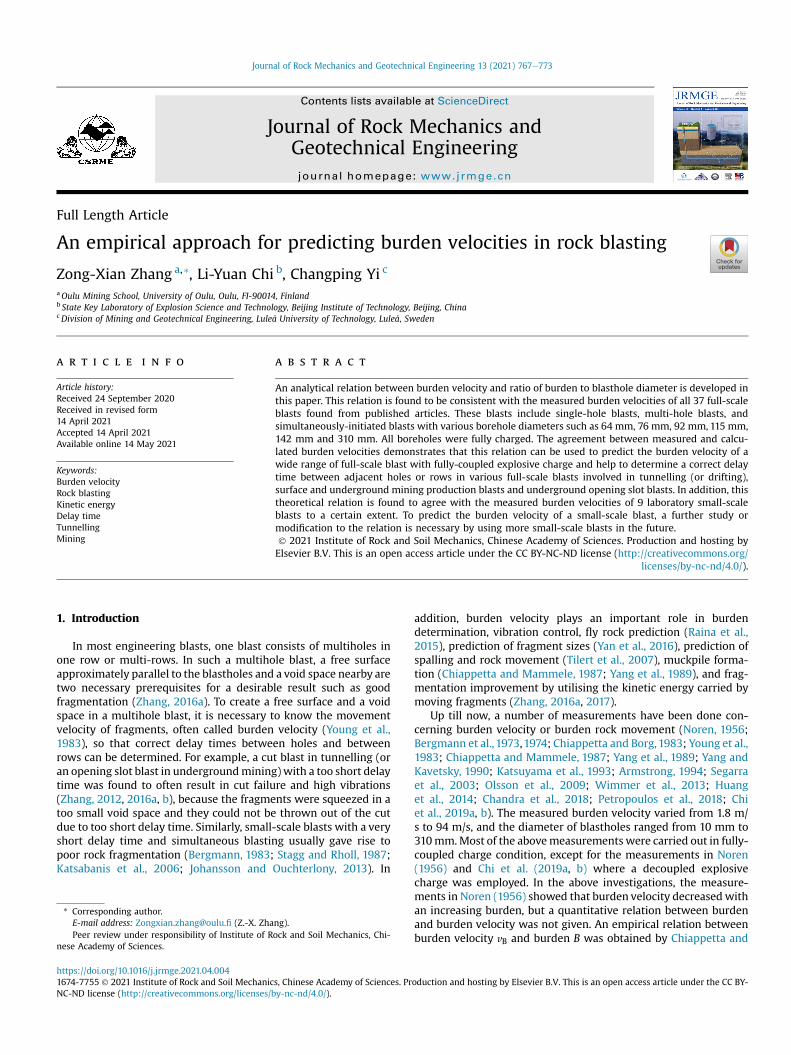
Fig. 1. Blasted rock volume B1CKJ by a single-hole blast (or first hole in a multiholeblast) in which the angle of breakage is 2q.
Z.-X. Zhang et al. / Journal of Rock Mechanics and Geotechnical Engineering 13 (2021) 767e773768
Borg (1983) and Chiappetta and Mammele (1987), which is vB ¼aB�1:17, where a is the coefficient related to explosive energy andother factors. Yang et al. (1989) and Yang and Kavetsky (1990)developed two simple kinematic models to study muckpile for-mation. The models can be used to calculate the particle velocity ofan arbitrary point in the overburden rock, but two (for two-dimensional model) or three (for three-dimensional model)complicated integrals must be solved by numerical methods. Arelation between burden and burden velocity was developed byZhang (2016a) in the form of vB ¼ bB�1=2; where coefficient b in-cludes the breakage angle and the properties of the explosive androck. Unsatisfactorily, the regression analysis of two groups of un-derground blasting from Olsson et al. (2009) and Wimmer et al.(2013) indicated that the powers of B were �0.61 and �0.72,much different from �1/2, indicating that the relation in Zhang(2016a) is not well consistent with the result from the productionblasts. On the basis of the above background, this paper is todevelop a new empirical relation between burden and burden ve-locity. This new relation will be verified by the measured burdenvelocities collected from various publications.
2. Theoretical relation between burden and burden velocity
It is assumed that the kinetic energy Ek carried by a movingburden is directly proportional to the explosion energy Ee of theexplosive in a blast (Zhang, 2016a), i.e.
Ek ¼ 12mv2B ¼ cBEe (1)
where m is the mass of the moving burden, and cB is a coefficient.Take a single-hole blast (or the first hole in a multihole blast)
shown in Fig.1 as an example. Consider a simple case inwhichm ¼rrLHB=2, where rr is the density of rock; and L, H and B are the
length, height and burden of the blasted volume, respectively. InFig. 1, L¼ jBCj, H¼ jBJj, and the burden is also shown. Thus, from Eq.(1), we have
v2B ¼ 4cBEerrLH
1B
(2)
The explosion energy Ee (MJ) of the explosive charged in a singlehole of the blast is
Ee ¼ reVeee ¼ pd2
4reLeee (3)
where re is the density of the explosive (kg/m3); d is the diameter of
the explosive charge (m); Ve is the volume of the explosive charge(m3); ee is the explosion energy per unit weight of the explosive(MJ/kg); and Le is the length of the explosive charge in the hole (m),equal to the borehole length minus the length of the stemming.Here, Le can be expressed by bench heightH, i.e. Le ¼ ceH, inwhichce is a coefficient. Note that only a fully-coupled charge is consid-ered here, thus the diameters of the explosive charge and theblasthole are equal to d. Substituting Eq. (3) into Eq. (2), we have
v2B ¼ pd2cBreeecerrL
1B
(4)
Assuming that the cross-section of the blasted rock (a prism) isan isosceles triangle, then we have
L ¼ 2Btanq (5)
Substituting Eq. (5) into Eq. (4), we have
vB ¼ffiffiffiffiffiffiffiffiffiffiffiffiffiffiffiffiffiffiffiffiffiffipcBreeece2rrtanq
r1Bd
(6)
Eq. (6) is the new theoretical relation between burden velocityand the ratio of burden to borehole diameter. This equation in-dicates that the burden velocity decreases with an increasing ratioof B/d. As this ratio is close to zero, i.e. the burden is very small,compared with the diameter of blasthole, the burden velocity be-comes infinitive. In this case, fly rocksmay occur. As the ratio is verylarge, the burden velocity approaches zero. In addition, the burdenvelocity is dependent on other parameters such as the densities ofthe rock and explosive, the explosion energy of the explosive, theratio of explosive length to bench height (or length of blasthole innon-bench blasts), the angle of breakage, and the coefficient cB.
3. Verification of the theoretical relation by practical blasts
To verify the theoretical relation (Eq. (6)), the measured burdenvelocities were collected from various publications. Table 1 sum-marizes the results under the condition of fully-coupled explosivecharge. In the following, the burden velocity vB calculated from Eq.(6) and the burden velocity v*B measured from practical blasts willbe compared with each other.
3.1. Small-scale laboratory blasts with a blasthole diameter of10 mm
Nine model blasts with a blasthole diameter of 10 mm are listedas numbers 1e9 in Table 1. Numbers 1e4were carried out as single-hole blasting (Bergmann et al., 1973), while numbers 5e9 per-formed as multihole blasting (Bergmann et al., 1974). The blastparameters and the properties of both rock and explosive listed inTable 1 were presented by Bergmann et al. (1973, 1974), but theexplosion energy ee of explosivewas not given in the original report(Bergmann et al., 1974). In this case, it is assumed thatee ¼ 5:81 MJ=kg is suitable for the explosive PETN used in theblasts. For small model blasts, it is assumed that cB ¼ 0:04, andq ¼ 60�, which will be explained later. By inputting these two andother parameters given in Table 1 into Eq. (6), we can obtain thecalculated burden velocity vB in Table 1, where the measuredburden velocity v*B is also listed. Since either blasts 1e4 or 5e9 havethe same parameters cB; q, re, ee, ce and rr; there are only two
Z.-X. Zhang et al. / Journal of Rock Mechanics and Geotechnical Engineering 13 (2021) 767e773 769
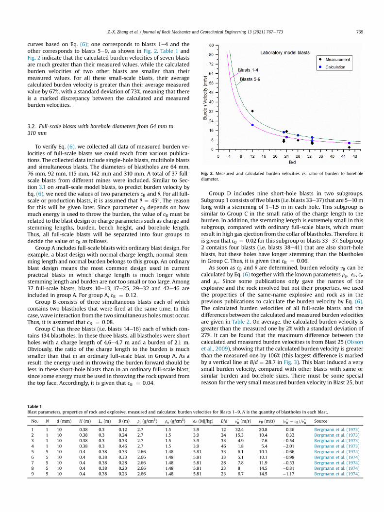
curves based on Eq. (6); one corresponds to blasts 1e4 and theother corresponds to blasts 5e9, as shown in Fig. 2. Table 1 andFig. 2 indicate that the calculated burden velocities of seven blastsare much greater than their measured values, while the calculatedburden velocities of two other blasts are smaller than theirmeasured values. For all these small-scale blasts, their averagecalculated burden velocity is greater than their average measuredvalue by 67%, with a standard deviation of 73%, meaning that thereis a marked discrepancy between the calculated and measuredburden velocities.
Fig. 2. Measured and calculated burden velocities vs. ratio of burden to boreholediameter.
3.2. Full-scale blasts with borehole diameters from 64 mm to310 mm
To verify Eq. (6), we collected all data of measured burden ve-locities of full-scale blasts we could reach from various publica-tions. The collected data include single-hole blasts, multihole blastsand simultaneous blasts. The diameters of blastholes are 64 mm,76 mm, 92 mm, 115 mm, 142 mm and 310 mm. A total of 37 full-scale blasts from different mines were included. Similar to Sec-tion 3.1 on small-scale model blasts, to predict burden velocity byEq. (6), we need the values of two parameters cB and q. For all full-scale or production blasts, it is assumed that q ¼ 45�. The reasonfor this will be given later. Since parameter cB depends on howmuch energy is used to throw the burden, the value of cB must berelated to the blast design or charge parameters such as charge andstemming lengths, burden, bench height, and borehole length.Thus, all full-scale blasts will be separated into four groups todecide the value of cB as follows.
Group A includes full-scale blasts with ordinary blast design. Forexample, a blast design with normal charge length, normal stem-ming length and normal burden belongs to this group. An ordinaryblast design means the most common design used in currentpractical blasts in which charge length is much longer whilestemming length and burden are not too small or too large. Among37 full-scale blasts, blasts 10e13, 17e25, 29e32 and 42e46 areincluded in group A. For group A, cB ¼ 0:12:
Group B consists of three simultaneous blasts each of whichcontains two blastholes that were fired at the same time. In thiscase, wave interaction from the two simultaneous holesmust occur.Thus, it is assumed that cB ¼ 0:08:
Group C has three blasts (i.e. blasts 14e16) each of which con-tains 134 blastholes. In these three blasts, all blastholes were shortholes with a charge length of 4.6e4.7 m and a burden of 2.1 m.Obviously, the ratio of the charge length to the burden is muchsmaller than that in an ordinary full-scale blast in Group A. As aresult, the energy used in throwing the burden forward should beless in these short-hole blasts than in an ordinary full-scale blast,since some energy must be used in throwing the rock upward fromthe top face. Accordingly, it is given that cB ¼ 0:04:
Table 1Blast parameters, properties of rock and explosive, measured and calculated burden velo
No. N d (mm) H (m) Le (m) B (m) rr (g/cm3) re (g/cm3) ee (
1 1 10 0.38 0.3 0.12 2.7 1.5 3.92 1 10 0.38 0.3 0.24 2.7 1.5 3.93 1 10 0.38 0.3 0.33 2.7 1.5 3.94 1 10 0.38 0.3 0.46 2.7 1.5 3.95 5 10 0.4 0.38 0.33 2.66 1.48 5.816 5 10 0.4 0.38 0.33 2.66 1.48 5.817 5 10 0.4 0.38 0.28 2.66 1.48 5.818 5 10 0.4 0.38 0.23 2.66 1.48 5.819 5 10 0.4 0.38 0.23 2.66 1.48 5.81
Group D includes nine short-hole blasts in two subgroups.Subgroup 1 consists of five blasts (i.e. blasts 33e37) that are 5e10mlong with a stemming of 1e1.5 m in each hole. This subgroup issimilar to Group C in the small ratio of the charge length to theburden. In addition, the stemming length is extremely small in thissubgroup, compared with ordinary full-scale blasts, which mustresult in high gas ejection from the collar of blastholes. Therefore, itis given that cB ¼ 0:02 for this subgroup or blasts 33e37. Subgroup2 contains four blasts (i.e. blasts 38e41) that are also short-holeblasts, but these holes have longer stemming than the blastholesin Group C. Thus, it is given that cB ¼ 0:06:
As soon as cB and q are determined, burden velocity vB can becalculated by Eq. (6) together with the known parameters re, ee, ceand rr. Since some publications only gave the names of theexplosive and the rock involved but not their properties, we usedthe properties of the same-name explosive and rock as in theprevious publications to calculate the burden velocity by Eq. (6).The calculated burden velocities of all full-scale blasts and thedifferences between the calculated andmeasured burden velocitiesare given in Table 2. On average, the calculated burden velocity isgreater than the measured one by 2% with a standard deviation of27%. It can be found that the maximum difference between thecalculated and measured burden velocities is from Blast 25 (Olssonet al., 2009), showing that the calculated burden velocity is greaterthan the measured one by 106% (this largest difference is markedby a vertical line at B/d ¼ 28.7 in Fig. 3). This blast induced a verysmall burden velocity, compared with other blasts with same orsimilar burden and borehole sizes. There must be some specialreason for the very small measured burden velocity in Blast 25, but
cities for Blasts 1e9. N is the quantity of blastholes in each blast.
MJ/kg) B/d v*B (m/s) vB (m/s) ðv*B � vBÞ=v*B Source
12 32.4 20.8 0.36 Bergmann et al. (1973)24 15.3 10.4 0.32 Bergmann et al. (1973)33 4.9 7.6 �0.54 Bergmann et al. (1973)46 1.8 5.4 �2.01 Bergmann et al. (1973)33 6.1 10.1 �0.66 Bergmann et al. (1974)33 5.1 10.1 �0.98 Bergmann et al. (1974)28 7.8 11.9 �0.53 Bergmann et al. (1974)23 8 14.5 �0.81 Bergmann et al. (1974)23 6.7 14.5 �1.17 Bergmann et al. (1974)
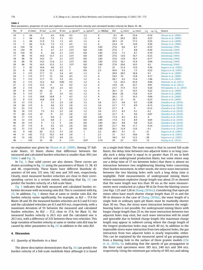
Table 2Blast parameters, properties of rock and explosive, measured burden velocity and calculated burden velocity for Blasts 10e46.
No. N d (mm) H (m) Le (m) B (m) rr (g/cm3) re (g/cm3) ee (MJ/kg) B/d v*B (m/s) vB (m/s) ðv*B � vBÞ=v*B Source
10 1 64 5 4.5 0.52 4.5 1.2 4 8.1 45 52.4 �0.16 Olsson et al. (2009)11 1 64 11.9 7.2 1.1 4.5 1.2 4 17.2 26.5 20.3 0.23 Olsson et al. (2009)12 1 64 11.9 7.2 1.3 4.5 1.2 4 20.3 23 17.2 0.25 Olsson et al. (2009)13 1 64 11.9 7.2 1.5 4.5 1.2 4 23.4 21 14.9 0.29 Olsson et al. (2009)14 134 76 6 4.6 2.1 2.57 0.8 3.85 27.6 6.6 8.7 �0.32 Armstrong (1994)15 134 76 6 4.7 2.1 2.57 0.8 3.85 27.6 7 8.8 �0.26 Armstrong (1994)16 134 76 6 4.6 2.1 2.57 0.8 3.85 27.6 7.3 8.7 �0.19 Armstrong (1994)17 96 76 14.5 13.7 2.1 2.57 0.8 3.85 27.6 13.6 16.7 �0.23 Armstrong (1994)18 96 76 14.5 13 2.1 2.57 0.8 3.85 27.6 13.9 16.3 �0.17 Armstrong (1994)19 96 76 14.5 11.6 2.1 2.57 0.8 3.85 27.6 16.1 15.4 0.04 Armstrong (1994)20 96 76 14.5 13.3 2.1 2.57 0.8 3.85 27.6 20.6 16.5 0.2 Armstrong (1994)21 3 92 10.4 9.6 2.3 3 0.8 2.5 25 21.4 13.6 0.36 Segarra et al. (2003)22 6 92 12.8 11.3 4.2 3 0.8 2.5 45.6 9.3 7.3 0.22 Segarra et al. (2003)23 1 115 17.7 13 2.4 4.5 1.2 4 20.9 20.5 18.4 0.1 Olsson et al. (2009)24 1 115 17.7 13 2.8 4.5 1.2 4 24.3 19 15.8 0.17 Olsson et al. (2009)25 1 115 17.7 13 3.3 4.5 1.2 4 28.7 6.5 13.4 �1.06 Olsson et al. (2009)26 2 115 12.2 8.6 0.85 4.5 1.2 4 7.4 43.5 41.6 0.04 Wimmer et al. (2013)27 2 115 13.5 11 1.6 4.5 1.2 4 13.9 24 23.7 0.01 Wimmer et al. (2013)28 2 115 9.5 6.5 2.5 4.5 1.1 4 21.7 17.5 13.3 0.24 Petropoulos et al. (2018)29 8 115 24 22 3 4.5 1.2 4 26.1 21 16.5 0.22 Olsson et al. (2009)30 5 115 17 15 3.5 4.5 1.2 4 30.4 20 13.8 0.31 Olsson et al. (2009)31 3 115 18.8 16.8 3 4.5 1.2 4 26.1 17 16.3 0.04 Olsson et al. (2009)32 8 115 14.8 12.8 3 4.5 1.2 4 26.1 13 16 �0.23 Olsson et al. (2009)33 13 115 5 3.5 2.5 2.8 1.2 3.6 21.7 6.6 8.5 �0.28 Chandra et al. (2018)34 24 115 6 4.6 2.5 2.8 1.2 3.6 21.7 7.7 8.9 �0.15 Chandra et al. (2018)35 23 115 7 5.5 2.5 2.8 1.2 3.6 21.7 8 9 �0.12 Chandra et al. (2018)36 18 115 7.5 6.1 2.5 2.8 1.2 3.6 21.7 8.3 9.1 �0.1 Chandra et al. (2018)37 20 115 10 9 2.5 2.8 1.2 3.6 21.7 9 9.6 �0.07 Chandra et al. (2018)38 17 115 2 0.4 2 2.8 0.8 3.85 17.4 8.3 8.3 0 Chandra et al. (2018)39 12 115 3.5 0.8 2 2.8 0.8 3.85 17.4 9.3 8.9 0.05 Chandra et al. (2018)40 10 115 5 1.5 3 2.8 0.8 3.85 26.1 8.8 6.8 0.23 Chandra et al. (2018)41 27 115 8 4.5 2.5 2.8 0.8 3.85 21.7 9.6 11.1 �0.16 Chandra et al. (2018)42 15 115 9.5 5.8 3 2.8 0.8 3.85 26.1 12.4 13.6 �0.1 Chandra et al. (2018)43 9 142 20 21.5 5.7 2.6 1 2.5 40.1 9.1 11 �21 Segarra et al. (2003)44 11 142 17.2 10.3 4.4 2.6 1 2.5 31 13.1 10.6 19 Segarra et al. (2003)45 15 142 17.2 16.7 4.9 2.6 1 2.5 34.5 9.5 12.2 �28 Segarra et al. (2003)46 e 310 35 28 9 1.71 0.97 3.74 29 23 19.5 15 Huang et al. (2014)
Z.-X. Zhang et al. / Journal of Rock Mechanics and Geotechnical Engineering 13 (2021) 767e773770
no explanation was given by Olsson et al. (2009). Among 37 full-scale blasts, 33 blasts shows that difference between themeasured and calculated burden velocities is smaller than 30% (seeTable 2 and Fig. 3).
In Fig. 3, four solid curves are also shown. These curves aredrawn according to Eq. (6) using the parameters of blasts 11, 38, 43and 46, respectively. These blasts have different blasthole di-ameters of 64 mm, 115 mm, 142 mm and 310 mm, respectively.Clearly, most measured burden velocities are close to their corre-sponding curves to a certain extent, indicating that Eq. (6) canpredict the burden velocity of a full-scale blast.
Fig. 3 indicates that both measured and calculated burden ve-locities decrease with increasing ratio B/d. This is consistent with Eq.(6). In addition, Fig. 3 shows that at same or similar ratio B/d, theburden velocity varies significantly. For example, as B/d ¼ 17.4 forBlasts 38 and 39, the measured burden velocities are 8.3 and 9.3 m/sand the calculated velocities are 8.3 and 8.9 m/s, respectively, with amaximum deviation of 5% between the measured and calculatedburden velocities. As B/d ¼ 17.2, close to 17.4, for Blast 11, themeasured burden velocity is 26.5 m/s and the calculated one is20.3 m/s, with a difference of 23% between these two velocities. Thislarge variation of burden velocity at same or similar ratio B/dmay becaused by other parameters in Eq. (6) in addition to the ratio B/d.
4. Discussion
4.1. Quantity of blastholes in a blast
The above description demonstrates that Eq. (6) can predict theburden velocity of a full-scale multihole blast although it is based
on a single-hole blast. The main reason is that in current full-scaleblasts, the delay time between two adjacent holes is so long (usu-ally such a delay time is equal to or greater than 25 ms in bothsurface and underground production blasts, but some mines mayuse a delay time of 17 ms between holes) that there is almost nointeraction between two neighbouring blasting holes concerningtheir burdenmovement. In other words, the stress wave interactionbetween the two blasting holes with such a long delay time isnegligible. Field measurements of underground mining blastswhose maximum explosive charge length was about 25 m showedthat the wave length was less than 30 ms as the wave measure-ments were conducted at a place 90 m far from the blasting source(see Figs. 1.25 and 1.26 in Zhang (2016a)). Considering that open pitmines often have much shorter charge length than 25 m and the90 m distance in the case of Zhang (2016a), the wave length of asingle hole in ordinary open pit blasts must be markedly shorterthan 30 ms. Thus, the stress wave interaction between the neigh-bouring holes is not possible. For underground mining blasts withlonger charge length than 25 m, the wave interaction between twoadjacent holes may exist, but such wave interaction will be smalland ignorable due to limited charge length (the maximum chargelength may appear in sublevel caving where the charge length ofthe longest production holes may reach 40 m). In addition to theimpossible stress wave interaction from two adjacent holes, the gasinteraction from two adjacent holes is nearly impossible, either.This can be explained by the measured speed of gas propagationfrom a blasting hole to the surface of three granite models (Chiet al., 2019a, b), indicating that the speeds of gas propagation inthe three rock specimens were 185 m/s, 240 m/s and 304 m/s,respectively. Using the minimum gas velocity of 185m/s and taking
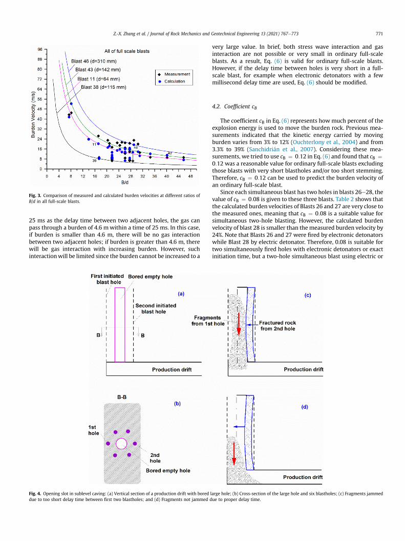
Fig. 3. Comparison of measured and calculated burden velocities at different ratios ofB/d in all full-scale blasts.
Z.-X. Zhang et al. / Journal of Rock Mechanics and Geotechnical Engineering 13 (2021) 767e773 771
25 ms as the delay time between two adjacent holes, the gas canpass through a burden of 4.6 mwithin a time of 25 ms. In this case,if burden is smaller than 4.6 m, there will be no gas interactionbetween two adjacent holes; if burden is greater than 4.6 m, therewill be gas interaction with increasing burden. However, suchinteractionwill be limited since the burden cannot be increased to a
Fig. 4. Opening slot in sublevel caving: (a) Vertical section of a production drift with bored ldue to too short delay time between first two blastholes; and (d) Fragments not jammed d
very large value. In brief, both stress wave interaction and gasinteraction are not possible or very small in ordinary full-scaleblasts. As a result, Eq. (6) is valid for ordinary full-scale blasts.However, if the delay time between holes is very short in a full-scale blast, for example when electronic detonators with a fewmillisecond delay time are used, Eq. (6) should be modified.
4.2. Coefficient cB
The coefficient cB in Eq. (6) represents howmuch percent of theexplosion energy is used to move the burden rock. Previous mea-surements indicated that the kinetic energy carried by movingburden varies from 3% to 12% (Ouchterlony et al., 2004) and from3.3% to 39% (Sanchidrián et al., 2007). Considering these mea-surements, we tried to use cB ¼ 0:12 in Eq. (6) and found that cB ¼0:12 was a reasonable value for ordinary full-scale blasts excludingthose blasts with very short blastholes and/or too short stemming.Therefore, cB ¼ 0:12 can be used to predict the burden velocity ofan ordinary full-scale blast.
Since each simultaneous blast has two holes in blasts 26e28, thevalue of cB ¼ 0:08 is given to these three blasts. Table 2 shows thatthe calculated burden velocities of Blasts 26 and 27 are very close tothe measured ones, meaning that cB ¼ 0:08 is a suitable value forsimultaneous two-hole blasting. However, the calculated burdenvelocity of blast 28 is smaller than the measured burden velocity by24%. Note that Blasts 26 and 27 were fired by electronic detonatorswhile Blast 28 by electric detonator. Therefore, 0.08 is suitable fortwo simultaneously fired holes with electronic detonators or exactinitiation time, but a two-hole simultaneous blast using electric or
arge hole; (b) Cross-section of the large hole and six blastholes; (c) Fragments jammedue to proper delay time.

Z.-X. Zhang et al. / Journal of Rock Mechanics and Geotechnical Engineering 13 (2021) 767e773772
non-electric detonators should use a value greater than 0.08 andless than 0.12 for cB:
For those short-hole blasts either with too short stemming orwith small ratio of charge length to burdenmentioned in Section 3.2,different cB values are given to different blasts. As a result, thecalculated burden velocities are basically consistent with themeasured velocities, meaning that these different cB values aresuitable. Take stemming as an example, we can explainwhy differentcB values are used for those blasts. As too short stemming is appliedto a blasthole, all stemming is ejected out of the hole much earlier(compared with a normal size stemming), and then gases areescaping as the ejection occurs. This latter stage is similar to ablastholewithout stemming. Laboratorymodel blasts showed that atleast 25% explosion energy was wasted as blastholes were notstemmed concerning rock fragmentation, compared with the blastswith (partial) stemming (Zhang et al., 2020a). Underground mineblasts indicated that gas ejection fromunstemmed blastholes was upto 50% explosive energy based on air pressure measurement close tothe collars (Brinkmann, 1990). Since a certain amount of explosiveenergy is wasted as ejected gases, the parameter cB should besmaller than 0.12 if less stemming than that in ordinary blasts isused.
Since laboratory model blasts have more free surfaces than full-scale blasts, fragment throw may occur in more directions, inparticular if the boreholes are very short. Accordingly, it is assumedthat cB ¼ 0:04 is appropriate to the model blasts. However, thediscrepancy between the burden velocity calculated by Eq. (6) andthatmeasured in themodel blasts shown inTable 1 and Fig. 2 is quitelarge, implying that cB ¼ 0:04may not be an apt value for themodelblasts. In otherwords, the empirical formula being proposedmay notbe applicable to small-scale blasts because the mechanism in thesmall-scale blasts is different from that in the large-scale blasts.
4.3. Breakage angle q
A simple spalling analysis indicated that the angle of breakage isequal to 2q¼ 120� in rock blasting (Zhang, 2016a). In various modelblasts, this angle was reported to be 2q ¼ 100�e160� (Ouchterlonyand Moser, 2013), and in small-scale field blasts, 2q ¼ 90�e120�
(Noren, 1956). Concerning full-scale blasts, it was stated that thevalue 2q ¼ 90� was reasonable for engineering rock blasts(Olofsson, 1999). Based on the above description, this study em-ploys 2q ¼ 90� for ordinary full-scale blasts and 2q ¼ 120
�for
laboratory model blasts. According to the calculated burden ve-locities using Eq. (6) and the measured burden velocities presentedin Table 2 and Fig. 3, we can conclude that 2q ¼ 90� is suitable forordinary full-scale blasts. Therefore, we recommend 2q ¼ 90� forordinary full-scale blasts.
4.4. Applications and limitation
Prediction of burden velocity has many applications in tunnel-ling, mining and rock construction. In brief, burden velocity isnecessary for determining (1) the delay time between adjacentholes or rows in an ordinary full-scale blast, (2) the delay time inthe cut blast of tunnelling or drifting, (3) the delay time in theopening slot of underground mining, and (4) the delay time as ahanging roof is broken down in underground mining.
Let us take the opening slot in the Malmberget undergroundmine as an example (Fig. 4). The bored empty hole has a diameter of0.7 m and a total of six blastholes with a diameter of 115 mmsurround the empty hole with a burden of 0.8 m. The other pa-rameters concerning the blast design and properties of the oremass and the explosive are: cB ¼ 0:12; q ¼ 45�, re ¼ 1:2 g= cm3,ee ¼ 4 MJ=kg, ce ¼ 0:8 and rr ¼ 4:5 g=cm3. Through inputting
the values of these parameters into Eq. (6), we can obtain burdenvelocity vB ¼ 57:6 m=s as B ¼ 0.8 m and d ¼ 115 mm. According tothis burden velocity and the diameter of the empty hole, the frag-ments from the first-fired hole needs a time of 12ms to collide withthe wall of the empty hole. After the collision with the wall, thefragments will fall down. Only when all the fragments have fall outof the empty hole, the second hole can be fired. Theminimum delaytime between the first hole and the second hole should be 12 msplus the falling time of the fragments from the first hole. If a delaytime smaller than the minimum delay time is given between thefirst and the second holes, all or most of the fragments from the firsthole will be jammed in the empty hole. As a result, the opening slotwill fail and the blast-caused shock wave and stress waves will passthrough the jammed fragments, resulting in high ground vibra-tions. This did occur in undergroundmining such as sublevel caving(see Fig. 24.15 in Zhang (2016a)) where an opening slot was faileddue to too short delay time between first several holes.
In addition to the delay time discussed above, burden velocitycan be used to estimate the kinetic energy carried with a movingburden. It has been found that the boulders from the first row aremuch more and greater than those from other rows in multirowblasting in open pit mines (Winzer et al., 1983; Olofsson, 1999). Oneof the main reasons is that the fragments from the first row can flyfreely (Zhang, 2016a, 2017). This free flight consumes much kineticenergy, which is one kind of energy waste, since during their flight,the kinetic energy contributes nothing to fragmentation. The aboveexplanation is consistent with the production blasts by Aler et al.(1996) who reported that fragmentation had been improved withan increasing number of rows. Since the kinetic energy of flyingfragments from any row except for the first one can be partly usedin their secondary fragmentation via collision with the fragmentsfrom the nearest row, a blast with more rows will utilize more ki-netic energy than a blast with fewer rows in the secondary frag-mentation, resulting in better fragmentation in the former. Tomakefull use of this kind of kinetic energy in a multirow blast, Zhang(2016a, 2017) recommended that a barrier to the first row in amultirow blast should be used. Recent model blasts demonstratedthat a steel barrier to the free face of a number of rock blastingmodels had greatly enhanced their fragmentation, compared witheither a blast without such a barrier to the free surface or a blastwith a constrained surface (Chi et al., 2019b; Zhang et al., 2020b).Obviously, it was the barrier that made part of flying fragmentsbroken again via their collision to the barrier in the model blasts. Byusing Eq. (6), we can estimate the kinetic energy carried with amoving burden so that a correct burden is chosen. For example, if abarrier is available, a relatively smaller burdenmay be employed, atleast for the first row in a multirow blast. If so, the boulders can bereduced and the fragmentation can be improved in the blast.
As discussed earlier, Eq. (6) is developed under the condition offull explosive charge. Accordingly, Eq. (6) can be used to predict theburden velocity of a full-scale blast. However, this equation is notvalid for a blast with a decoupled charge. To predict burden velocityin a blast with decoupled charge, Eq. (6) must be modified or a newformula should be developed. In addition, there is a greatdiscrepancy between measured burden velocity and calculated oneusing Eq. (6) for small-scale model blasts, meaning that Eq. (6) isnot suitable for small-scale model blasts.
For full-scale blasts, how to choose values of coefficient cB andbreakage angle q in Eq. (6) has been described and discussed inSections 3.2, 4.2 and 4.3 in detail. The users can decide these twovalues by following the procedure there, and then they can esti-mate the burden velocity by using the values and other parametersin Eq. (6). If possible or necessary, the users may also perform backanalysis based on a few trial blasts andmodify the coefficient cB andbreakage angle q as suggested in this paper.

Z.-X. Zhang et al. / Journal of Rock Mechanics and Geotechnical Engineering 13 (2021) 767e773 773
5. Conclusions
A theoretical relation between the burden velocity vB and theratio of burden B to borehole diameter d is developed, in the form ofvBfðB=dÞ�1. This relation is consistent with the measurement re-sults from full-scale or production blasts in both surface and un-dergroundmines. Therefore, this relation is suitable for full-scale orproduction blasts with fully-coupled explosive charge. To estimatethe burden velocity of an ordinary production blast, the values ofcB ¼ 0:12 and q¼ 45� are recommended. For other full-scale blasts,for example with too short blastholes or too small stemminglength, q ¼ 45� is recommended but the value of cB should bedetermined according to the actual blast design by referencing theprocedure in Section 3.2.
This theoretical relation is not developed under the condition ofa decoupled explosive charge, thus it should not be valid for a blastwith decoupled explosive charge. To be valid for decoupled charge,further study is necessary. In addition, this relation is not wellsuitable for laboratory small-scale blasts. To be suitable for small-scale blasts, this relation needs more model blasts to modify.
Declaration of competing interest
The authors declare that they have no known competingfinancial interests or personal relationships that could haveappeared to influence the work reported in this paper.
Acknowledgments
The authors are grateful to Dr. Ruilin Yang for providing relevantpublications.
References
Aler, J., Mouza, J.D., Arnould, M., 1996. Measurement of the fragmentation efficiencyof rock mass blasting and its mining. Int. J. Rock Mech. Min. Sci. Geomech. Abstr.33 (2), 125e139.
Armstrong, L.W., 1994. The Quality of Stemming in Assessing Blasting Efficiency.PhD Thesis. University of New South Wales, Sydney, Australia.
Bergman, O.R., Riggle, J.W., Wu, F.C., 1973. Model rock blasting-effect of explosivesproperties and other variables on blasting results. Int. J. Rock Mech. Min. Sci.Geomech. Abstr. 10 (6), 585e612.
Bergmann, O.R., Wu, F.C., Edl, J.W., 1974. Model rock blasting measures effect ofdelays and hole patterns on rock fragmentation. Eng. Min. J. 175 (6), 124e127.
Bergmann, O.R., 1983. Effect of explosive properties, rock type and delays on frag-mentation in large model blasts. In: Proceedings of the 1st InternationalSymposium on Rock Fragmentation by Blasting. Luleå, Sweden, pp. 71e78.
Brinkmann, J.R., 1990. An experimental study of the effects of shock and gaspenetration in blasting. In: Proceedings of the 3rd International Symposium onRock Fragmentation by Blasting, Brisbane, Australia, pp. 55e66.
Chandra, G.R., Nagesha, K.V., Sastry, V.R., 2018. Image processing based assessmentof blast performance in opencast mines - case studies. In: Proceedings of the8th International Conference on Advances in Computer Engineering, pp. 21e28.
Chi, L.Y., Zhang, Z.X., Aalberg, A., Yang, J., Li, C.C., 2019a. Fracture processes in graniteblocks under blast loading. Rock Mech. Rock Eng. 52 (3), 853e868.
Chi, L.Y., Zhang, Z.X., Aalberg, A., Li, C.C., 2019b. Experimental investigation of blast-induced fractures in rock cylinders. Rock Mech. Rock Eng. 52 (8), 2569e2584.
Chiappetta, R.F., Borg, D.G., 1983. Increasing productivity through field control andhigh-speed photography. In: Proceedings of the 1st International Symposiumon Rock Fragmentation by Blasting, vol. 1. Luleå, Sweden, pp. 301e331.
Chiappetta, R.F., Mammele, M.E., 1987. Use of high-speed motion picture photog-raphy in blast evaluation and design. In: High Speed Photography, Videography,and Photonics V, SPIE Proceedings, vol. 832, pp. 319e336.
Huang, Y.H., Liu, D.S., Li, S.L., Li, X.L., Wang, J.L., 2014. Numerical simulation on pin-point blasting of slope surface. Explos. Shock Waves 34, 495e500 (in Chinese).
Johansson, D., Ouchterlony, F., 2013. Shock wave interactions in rock blasting: theuse of short delays to improve fragmentation in model-scale. Rock Mech. RockEng. 46, 1e18.
Katsabanis, P.D., Tawadrous, A., Braun, C., Kennedy, C., 2006. Timing effects on thefragmentation of small scale blocks of granodiorite. Fragblast 10, 83e93.
Katsuyama, K., Ogata, Y., Wada, Y., 1993. Dynamic photoelastic experiment and 3-Ddynamic stress analysis of the fracture caused by blasting. In: Rossmanith, H.P.(Ed.), Rock Fragmentation by Blasting. A.A. Balkema, Rotterdam, pp. 55e61.
Noren, C.H., 1956. Blasting experiments in granite rock. In: Proceedings of the 1stU.S. Symposium on Rock Mechanics (USRMS). American Rock Mechanics As-sociation, Golden, Colorado, pp. 210e225.
Olofsson, S.O., 1999. Modern Blasting Technique. APPLEX, Sweden (in Swedish).Olsson, M., Nyberg, U., Fjellborg, S., 2009. Controlled fragmentation in sublevel
caving-first tests. Swebrec Rapport 2009, 2 (in Swedish).Ouchterlony, F., Moser, P., 2013. Lessons from single-hole blasting in motar, concrete
and rocks. In: Proceedings of the 10th International Symposium on RockFragmentation by Blasting, New Delhi, India, pp. 3e14.
Ouchterlony, F., Nyberg, U., Olsson, M., Bergqvist, I., Granlund, L., Grind, H., 2004.Where does the explosive energy in rock blasting rounds go? Sci. Technol.Energetic Mater. 65 (2), 54e63.
Petropoulos, N., Wimmer, M., Johansson, D., Nordlund, E., 2018. Compaction ofconfining materials in pillar blast tests. Rock Mech. Rock Eng. 51, 1907e1919.
Raina, A.K., Murthy, V., Soni, A.K., Soni, A.K., 2015. Estimating flyrock distance inbench blasting through blast induced pressure measurements in rock. Int. J.Rock Mech. Min. Sci. 76, 209e216.
Sanchidrián, J.A., Pablo, S., López, L.M., 2007. Energy components in rock blasting.Int. J. Rock Mech. Min. Sci. 44, 130e147.
Segarra, P., Sanchidrián, J.A., López, L.M., 2003. Analysis of bench face movement inquarry blasting. In: Proceedings of the 2ndWorld Conference on Explosives andBlasting Technique. Liss, pp. 485e495.
Stagg, M.S., Rholl, S.A., 1987. Effects on accurate delays on fragmentation for single-row blasting in a 6.7-m bench. In: Proceedings of the 2nd International Sym-posium on Rock Fragmentation by Blasting, Keystone, Colorado, pp. 210e223.
Tilert, D., Svedbjörk, G., Ouchterlony, F., Nilsson, B., Temun, A., Mattsson, L., 2007.Measurement of explosively induced movement and spalling of granite modelblocks. Int. J. Impact Eng. 34, 1936e1952.
Wimmer, M., Nordqvist, A., Ouchterlony, F., Nyberg, U., Furtney, J.K., 2013. Burdenmovement in confined drift wall blasting tests studied at the LKAB Kiruna SLCmine. In: Proceedings of the 10th International Symposium on Rock Frag-mentation by Blasting, New Delhi, India, pp. 373e383.
Winzer, S.R., Anderson, D.A., Ritter, A.P., 1983. Rock fragmentation by explosives. In:Proceedings of 1st International Symposium on Rock Fragmentation by Blast-ing. Luleå, Sweden, pp. 225e249.
Yan, P., Zhou, W., Lu, W., Chen, M., Zhou, C., 2016. Simulation of bench blastingconsidering fragmentation size distribution. Int. J. Impact Eng. 90, 132e145.
Yang, R.L., Kavetsky, A., McKenzie, C.K., 1989. A two-dimensional kinematic modelfor predicting muckpile shape in bench blasting. Int. J. Min. Geol. Eng. 7, 209e226.
Yang, R.L., Kavetsky, A., 1990. A three dimensional model of muckpile formation andgrade boundary movement in open pit blasting. Int. J. Min. Geol. Eng. 8 (1), 13e34.
Young, C., Fourney, W.L., Patti, N.C., Trent, B.C., 1983. Electromagnetic velocity gaugemeasurement of rock mass motion during blasting. In: Proceedings of the 1stInternational Symposium on Rock Fragmentation by Blasting, vol. 1. Luleå,Sweden, pp. 289e300.
Zhang, Z.X., 2012. Controlling vibrations caused by underground blasts in LKABMalmberget mine. Blast. Fragm. 6 (2), 63e72.
Zhang, Z.X., 2016a. Rock Fracture and Blasting: Theory and Applications. Butter-worth-Heinemann/Elsevier, Oxford, UK.
Zhang, Z.X., 2016b. Failure of hanging roofs in sublevel caving by shock collision andstress superposition. J. Rock Mech. Geotech. Eng. 8 (6), 886e895.
Zhang, Z.X., 2017. Kinetic energy and its applications in mining engineering. Int. J.Min. Sci. Tech. 27 (2), 237e244.
Zhang, Z.X., Hou, D.F., Guo, Z., He, Z., 2020a. Laboratory experiment of stemmingimpact on rock fragmentation by a high Explosive. Tunn. Undergr. SpaceTechnol. 97, 103257.
Zhang, Z.X., Hou, D.F., Guo, Z., He, Z., Zhang, Q.B., 2020b. Experimental study ofsurface constraint effect on rock fragmentation by blasting. Int. J. Rock Mech.Min. Sci. 128, 104278.
Dr. Zong-Xian Zhang is a Professor at the University ofOulu, Finland. He received his PhD degree from the LuleåUniversity of Technology, Sweden in 2001, MSc degreefrom the University of Science and Technology Beijing in1986 and BSc degree from Xi’an University of Architectureand Technology in China in 1982. Since the 1990s, he hasconducted a series of laboratory studies on the effects ofloading rate and high temperature on rock fracture, per-formed field measurements on excavation-caused cracksin rock mass and on cutter forces and cutter temperatureof a boring machine, and carried out a number of small-scale rock blasts aiming to understand the mechanism ofrock fracture and fragmentation by blasting. From 2002 to2013, he worked at a mining company LKAB and devel-
oped several technical methods for increasing ore recovery ratio, improving miningsafety and reducing blast-induced ground vibrations. All the methods have beenproved to be successful not only in the LKAB’s Malmberget mine but also in othermines outside the LKAB. In recent years, his research has been expanded to rock massevaluation, deep mining technology and muography’s applications to mining and rockengineering.
Related Documents