UTRAN Installation Node B IMN:NB-440/NB-880 A50016-G5000-E229-4-7631 ND-57356-703(E)-04

Welcome message from author
This document is posted to help you gain knowledge. Please leave a comment to let me know what you think about it! Share it to your friends and learn new things together.
Transcript

UTRAN
Installation
Node B
IMN:NB-440/NB-880
A50016-G5000-E229-4-7631ND-57356-703(E)-04

2Siemens AG:A50016-G5000-E229-4-7631NEC Corporation:ND-57356-703(E)-04
IMN:NB-440/NB-880 InstallationNode B
f Important Notice on Product Safety
DANGER - RISK OF ELECTRICAL SHOCK OR DEATH - FOLLOW ALL INSTALLATION INSTRUCTIONS.
The system complies with the standard EN 60950 / IEC 60950. All equipment connected to the system mustcomply with the applicable safety standards.Hazardous voltages are present at the AC power supply lines in this electrical equipment. Some components mayalso have high operating temperatures.Failure to observe and follow all installation and safety instructions can result in serious personal injuryor property damage.Therefore, only trained and qualified personnel may install and maintain the system.
The same text in German:
Wichtiger Hinweis zur Produktsicherheit
LEBENSGEFAHR - BEACHTEN SIE ALLE INSTALLATIONSHINWEISE.
Das System entspricht den Anforderungen der EN 60950 / IEC 60950. Alle an das System angeschlossenenGeräte müssen die zutreffenden Sicherheitsbestimmungen erfüllen.In diesen Anlagen stehen die Netzversorgungsleitungen unter gefährlicher Spannung. Einige Komponentenkönnen auch eine hohe Betriebstemperatur aufweisen.Nichtbeachtung der Installations- und Sicherheitshinweise kann zu schweren Körperverletzungen oderSachschäden führen.Deshalb darf nur geschultes und qualifiziertes Personal das System installieren und warten.
Caution:This equipment has been tested and found to comply with EN 301489. Its class of conformity is defined in tableA30808-X3247-X910-*-7618, which is shipped with each product. This class also corresponds to the limits for aClass A digital device, pursuant to part 15 of the FCC Rules.These limits are designed to provide reasonable protection against harmful interference when the equipment isoperated in a commercial environment.This equipment generates, uses and can radiate radio frequency energy and, if not installed and used in accor-dance with the relevant standards referenced in the manual “Guide to Documentation”, may cause harmful inter-ference to radio communications.For system installations it is strictly required to choose all installation sites according to national and local require-ments concerning construction rules and static load capacities of buildings and roofs.For all sites, in particular in residential areas it is mandatory to observe all respectively applicable electromagneticfield / force (EMF) limits. Otherwise harmful personal interference is possible.
Trademarks:
All designations used in this document can be trademarks, the use of which by third parties for their own purposescould violate the rights of their owners.
Copyright (C) Siemens AG / NEC Corporation 2005.
Issued by:Siemens AG, Communications, Hofmannstraße 51, 81359 München, Germany andNEC Corporation, 7-1, Shiba 5-chome, Minato-ku, Tokyo, Japan
Technical modifications possible.Technical specifications and features are binding only insofar as they are specifically and expressly agreed upon in a written contract.

InstallationNode B
IMN:NB-440/NB-880
Siemens AG: A50016-G5000-E229-4-7631NEC Corporation: ND-57356-703(E)-04 3
Reason for UpdateSummary:Security advice for working on poles, modified graphics, editorial changes
Details:
Chapter/Section Reason for Update
1.7 Modified section “Installation Tools”
(Security equipment for working on poles added)
2.6.10 Security advices for working on poles added
2.6.13 Modified graphics
Issue HistoryIssue
Number
Date of issue Reason for Update
1 01/2005 Installation of NB-880 and Update of NB-440
2 05/2005 Anglo-american units and hints for coaxial cable
connections added
3 07/2005 Insertion of review comments, old equipment
disposal regulations added, modified Tab.1.1 and
section “Installation Tools”
4 09/2005 Security advice for working on poles
Modified graphics, Editorial changes

IMN:NB-440/NB-880 InstallationNode B
4Siemens AG:A50016-G5000-E229-4-7631NEC Corporation:ND-57356-703(E)-04

InstallationNode B
IMN:NB-440/NB-880
Siemens AG: A50016-G5000-E229-4-7631NEC Corporation: ND-57356-703(E)-04 5
This document consists of a total of 73 pages. All pages are issue 4.
Contents
1 Introduction . . . . . . . . . . . . . . . . . . . . . . . . . . . . . . . . . . . . . . . . . . . . . . . . . 111.1 Disposal of Electrical and Electronic Equipment. . . . . . . . . . . . . . . . . . . . . 111.2 Purpose of the Manual . . . . . . . . . . . . . . . . . . . . . . . . . . . . . . . . . . . . . . . . 121.3 Tasks of the Node B Stations . . . . . . . . . . . . . . . . . . . . . . . . . . . . . . . . . . . 121.4 Installation Prerequisites. . . . . . . . . . . . . . . . . . . . . . . . . . . . . . . . . . . . . . . 121.5 Handling of the Modules . . . . . . . . . . . . . . . . . . . . . . . . . . . . . . . . . . . . . . . 131.6 Safety Instructions . . . . . . . . . . . . . . . . . . . . . . . . . . . . . . . . . . . . . . . . . . . 141.7 Installation Tools . . . . . . . . . . . . . . . . . . . . . . . . . . . . . . . . . . . . . . . . . . . . . 141.8 Ancillary Material. . . . . . . . . . . . . . . . . . . . . . . . . . . . . . . . . . . . . . . . . . . . . 151.9 Technical Data . . . . . . . . . . . . . . . . . . . . . . . . . . . . . . . . . . . . . . . . . . . . . . 151.10 External Interfaces of the NB-440/NB-880 . . . . . . . . . . . . . . . . . . . . . . . . . 15
2 NB-440/NB-880 Installation . . . . . . . . . . . . . . . . . . . . . . . . . . . . . . . . . . . . 162.1 Position in the System . . . . . . . . . . . . . . . . . . . . . . . . . . . . . . . . . . . . . . . . 162.2 Site Requirements . . . . . . . . . . . . . . . . . . . . . . . . . . . . . . . . . . . . . . . . . . . 162.3 Site Configuration . . . . . . . . . . . . . . . . . . . . . . . . . . . . . . . . . . . . . . . . . . . . 172.4 Construction View of NB-440/NB-880. . . . . . . . . . . . . . . . . . . . . . . . . . . . . 172.4.1 Rack Layout NB-440. . . . . . . . . . . . . . . . . . . . . . . . . . . . . . . . . . . . . . . . . . 202.4.2 Rack Layout NB-880 and upgrated NB-440 . . . . . . . . . . . . . . . . . . . . . . . . 202.5 Equipment Delivery. . . . . . . . . . . . . . . . . . . . . . . . . . . . . . . . . . . . . . . . . . . 222.5.1 Preliminary Checks . . . . . . . . . . . . . . . . . . . . . . . . . . . . . . . . . . . . . . . . . . . 222.5.2 Unpacking the Rack . . . . . . . . . . . . . . . . . . . . . . . . . . . . . . . . . . . . . . . . . . 232.5.2.1 Unpacking the Rack (Crate) . . . . . . . . . . . . . . . . . . . . . . . . . . . . . . . . . . . . 232.5.2.2 Unpacking the Rack (Pallet) . . . . . . . . . . . . . . . . . . . . . . . . . . . . . . . . . . . . 252.5.3 Devices Unpacking . . . . . . . . . . . . . . . . . . . . . . . . . . . . . . . . . . . . . . . . . . . 252.5.4 Rack Installation . . . . . . . . . . . . . . . . . . . . . . . . . . . . . . . . . . . . . . . . . . . . . 262.5.5 Setup of Earthquake Mounting Kit . . . . . . . . . . . . . . . . . . . . . . . . . . . . . . . 302.6 External Cabling Activities . . . . . . . . . . . . . . . . . . . . . . . . . . . . . . . . . . . . . 322.6.1 Overview . . . . . . . . . . . . . . . . . . . . . . . . . . . . . . . . . . . . . . . . . . . . . . . . . . . 322.6.2 Ground and Power Supply Connections -48 V DC . . . . . . . . . . . . . . . . . . . 342.6.3 Iub-Interface - Link Equipment . . . . . . . . . . . . . . . . . . . . . . . . . . . . . . . . . . 362.6.3.1 Iub-Interface for 100/120 Ohm Cable Impedance. . . . . . . . . . . . . . . . . . . . 362.6.3.2 Iub-Interface for 75 Ohm Cable Impedance . . . . . . . . . . . . . . . . . . . . . . . . 382.6.3.3 Monitoring Interfaces of the Iub interfaces . . . . . . . . . . . . . . . . . . . . . . . . . 392.6.4 Alarm Collection Terminal - external Signal Sensors . . . . . . . . . . . . . . . . . 412.6.5 Installation of the Mounting Kit OPEXAL . . . . . . . . . . . . . . . . . . . . . . . . . . 442.6.6 Alarm Collection Terminal ACTCBF - internal Alarms . . . . . . . . . . . . . . . . 462.6.7 Local Maintenance Terminal (LMT) Interface . . . . . . . . . . . . . . . . . . . . . . . 472.6.8 Connection of the External Reset Line . . . . . . . . . . . . . . . . . . . . . . . . . . . . 482.6.9 Antenna Connections . . . . . . . . . . . . . . . . . . . . . . . . . . . . . . . . . . . . . . . . . 492.6.9.1 Preparation of Antenna Jumper Cables . . . . . . . . . . . . . . . . . . . . . . . . . . . 492.6.10 Installation of the Tower Mounted Amplifiers . . . . . . . . . . . . . . . . . . . . . . . 552.6.10.1 Pole Mounting with Hose Clips . . . . . . . . . . . . . . . . . . . . . . . . . . . . . . . . . . 602.6.10.2 Wall Mounting of DTMAF and DTMARETF . . . . . . . . . . . . . . . . . . . . . . . . 62

IMN:NB-440/NB-880 InstallationNode B
6Siemens AG:A50016-G5000-E229-4-7631NEC Corporation:ND-57356-703(E)-04
2.6.11 Preparation of the Top Cover. . . . . . . . . . . . . . . . . . . . . . . . . . . . . . . . . . . . 622.6.12 Setup of the System Cabling . . . . . . . . . . . . . . . . . . . . . . . . . . . . . . . . . . . . 632.6.13 Installation of the Interrack Cabling . . . . . . . . . . . . . . . . . . . . . . . . . . . . . . . 652.6.13.1 SYNC-Cable. . . . . . . . . . . . . . . . . . . . . . . . . . . . . . . . . . . . . . . . . . . . . . . . . 652.6.13.2 Ethernet Cabling . . . . . . . . . . . . . . . . . . . . . . . . . . . . . . . . . . . . . . . . . . . . . 662.6.13.3 Optical Interface Cabling with LSH-Adapters. . . . . . . . . . . . . . . . . . . . . . . . 672.6.13.4 Optical Interface Cabling with SCPC-Adapters . . . . . . . . . . . . . . . . . . . . . . 682.6.13.5 Optical Interface with SCPC-Adapter and Splitter . . . . . . . . . . . . . . . . . . . . 692.7 Post Installation Notes . . . . . . . . . . . . . . . . . . . . . . . . . . . . . . . . . . . . . . . . . 722.7.1 Fitting of the Profile Cylinder . . . . . . . . . . . . . . . . . . . . . . . . . . . . . . . . . . . . 722.7.2 Leaving the Site . . . . . . . . . . . . . . . . . . . . . . . . . . . . . . . . . . . . . . . . . . . . . . 72
3 Appendix . . . . . . . . . . . . . . . . . . . . . . . . . . . . . . . . . . . . . . . . . . . . . . . . . . . 733.1 Checklist for NB-440/NB-880 Installation. . . . . . . . . . . . . . . . . . . . . . . . . . . 73

InstallationNode B
IMN:NB-440/NB-880
Siemens AG: A50016-G5000-E229-4-7631NEC Corporation: ND-57356-703(E)-04 7
IllustrationsFig. 1.1 ESD Symbol. . . . . . . . . . . . . . . . . . . . . . . . . . . . . . . . . . . . . . . . . . . . . . 13
Fig. 1.2 Press-stud for ESD wrist-strap connection . . . . . . . . . . . . . . . . . . . . . . 13
Fig. 2.1 Position of a Node B within the System. . . . . . . . . . . . . . . . . . . . . . . . . 16
Fig. 2.2 Site configuration NB-440/NB-880. . . . . . . . . . . . . . . . . . . . . . . . . . . . . 17
Fig. 2.3 Fully equipped NB-440 rack. . . . . . . . . . . . . . . . . . . . . . . . . . . . . . . . . . 20
Fig. 2.4 Rack Layout for NB-880 and upgrated NB-440 . . . . . . . . . . . . . . . . . . . 21
Fig. 2.5 ShockwatchTM-label and TIP (N) TELLTM-label . . . . . . . . . . . . . . . . . . 23
Fig. 2.6 Removal of the straps, opening of the top cover . . . . . . . . . . . . . . . . . . 23
Fig. 2.7 Removal of the packing material . . . . . . . . . . . . . . . . . . . . . . . . . . . . . . 24
Fig. 2.8 Opening of the PE-wrap, lifting straps around the rack . . . . . . . . . . . . . 24
Fig. 2.9 Foil- transportation packing of NB-440/NB-880 . . . . . . . . . . . . . . . . . . . 25
Fig. 2.10 Opening of the Rack door . . . . . . . . . . . . . . . . . . . . . . . . . . . . . . . . . . . 26
Fig. 2.11 Removal of top cover . . . . . . . . . . . . . . . . . . . . . . . . . . . . . . . . . . . . . . . 26
Fig. 2.12 Guideline for crane transport . . . . . . . . . . . . . . . . . . . . . . . . . . . . . . . . . 27
Fig. 2.13 Space necessary for installation of NB-440/NB-880 . . . . . . . . . . . . . . . 27
Fig. 2.14 Removal of fastening claws . . . . . . . . . . . . . . . . . . . . . . . . . . . . . . . . . . 28
Fig. 2.15 Adjusting of the rack foot . . . . . . . . . . . . . . . . . . . . . . . . . . . . . . . . . . . 28
Fig. 2.16 Mounting bracket for wall fixing . . . . . . . . . . . . . . . . . . . . . . . . . . . . . . . 29
Fig. 2.17 Wall fixing of the NodeB. . . . . . . . . . . . . . . . . . . . . . . . . . . . . . . . . . . . . 29
Fig. 2.18 Parts of the earthquake kit S3086-K4138-X . . . . . . . . . . . . . . . . . . . . . 30
Fig. 2.19 Double claw for the rear foot in mounted position . . . . . . . . . . . . . . . . . 31
Fig. 2.20 Claws for the front foot before fixing . . . . . . . . . . . . . . . . . . . . . . . . . . . 31
Fig. 2.21 Drilling sketch for earthquake mounting kit . . . . . . . . . . . . . . . . . . . . . . 31
Fig. 2.22 Interfaces on EMI Panel of the NB-440/NB-880 . . . . . . . . . . . . . . . . . . 32
Fig. 2.23 Locations of connection points for external cables . . . . . . . . . . . . . . . . 33
Fig. 2.24 Ground and DC mains connections of the NB-440/NB-880. . . . . . . . . . 34
Fig. 2.25 Preparation of DC power supply wires. . . . . . . . . . . . . . . . . . . . . . . . . . 35
Fig. 2.26 Connection and fastening of the DC supply wires . . . . . . . . . . . . . . . . . 35
Fig. 2.27 Preparation of twisted pair cables, 120 Ohm impedance . . . . . . . . . . . 36
Fig. 2.28 Routing of Iub-cable (example with OVPTE1J1SF). . . . . . . . . . . . . . . . 37
Fig. 2.29 Pinning Iub interface at OVPTE1J1SF / IUBCONSFV1. . . . . . . . . . . . . 38
Fig. 2.30 Iub interface with coaxial connectors (example with OVPTE1CF). . . . . 38
Fig. 2.31 Iub line connectors of OVPTE1CF / IUBCONCFV1. . . . . . . . . . . . . . . . 39
Fig. 2.32 Pinning of the monitoring interfaces. . . . . . . . . . . . . . . . . . . . . . . . . . . . 39
Fig. 2.33 Terminal numbering of the ACTMF . . . . . . . . . . . . . . . . . . . . . . . . . . . . 41
Fig. 2.34 Contents of the MK:OPEXAL. . . . . . . . . . . . . . . . . . . . . . . . . . . . . . . . . 44
Fig. 2.35 Drilling sketch for MK:OPEXAL . . . . . . . . . . . . . . . . . . . . . . . . . . . . . . . 45
Fig. 2.36 Wall mounted MK:OPEXAL . . . . . . . . . . . . . . . . . . . . . . . . . . . . . . . . . . 45
Fig. 2.37 Connector arrangement at ACTCBF . . . . . . . . . . . . . . . . . . . . . . . . . . . 46
Fig. 2.38 Connection of external reset line . . . . . . . . . . . . . . . . . . . . . . . . . . . . . . 48
Fig. 2.39 Example for cell numbering (top view from the antenna pole). . . . . . . . 49
Fig. 2.40 Tools for jumper fabrication . . . . . . . . . . . . . . . . . . . . . . . . . . . . . . . . . . 50
Fig. 2.41 Parts of the connector unit kit (example) . . . . . . . . . . . . . . . . . . . . . . . . 50

IMN:NB-440/NB-880 InstallationNode B
8Siemens AG:A50016-G5000-E229-4-7631NEC Corporation:ND-57356-703(E)-04
Fig. 2.42 Using the trimming tool . . . . . . . . . . . . . . . . . . . . . . . . . . . . . . . . . . . . . . 51
Fig. 2.43 Removal of isolation and deburring of the inner conductor. . . . . . . . . . . 51
Fig. 2.44 Removal of metal particles . . . . . . . . . . . . . . . . . . . . . . . . . . . . . . . . . . . 51
Fig. 2.45 Assembly of the connector unit . . . . . . . . . . . . . . . . . . . . . . . . . . . . . . . . 52
Fig. 2.46 Fixing of connector unit, removal of outer insulation. . . . . . . . . . . . . . . . 52
Fig. 2.47 Handling of heat protection tape and shrink sleeve . . . . . . . . . . . . . . . . 52
Fig. 2.48 Shrinkage and removal of the visible heat protection tape . . . . . . . . . . . 53
Fig. 2.49 Max. dimensions of antenna connectors . . . . . . . . . . . . . . . . . . . . . . . . 53
Fig. 2.50 Routing of antenna jumper cables . . . . . . . . . . . . . . . . . . . . . . . . . . . . . 54
Fig. 2.51 Position of DTMAF / DTMARETF in the system . . . . . . . . . . . . . . . . . . . 55
Fig. 2.52 Bottom view of the DTMAFV3. . . . . . . . . . . . . . . . . . . . . . . . . . . . . . . . . 56
Fig. 2.53 Top view of the DTMAFV3 . . . . . . . . . . . . . . . . . . . . . . . . . . . . . . . . . . . 56
Fig. 2.54 Rear view of the DTMAFV3 . . . . . . . . . . . . . . . . . . . . . . . . . . . . . . . . . . 57
Fig. 2.55 Bottom view of the DTMARETFV3 . . . . . . . . . . . . . . . . . . . . . . . . . . . . 57
Fig. 2.56 Bottom view of the DTMAFV4. . . . . . . . . . . . . . . . . . . . . . . . . . . . . . . . . 57
Fig. 2.57 Top view of the DTMAFV4 . . . . . . . . . . . . . . . . . . . . . . . . . . . . . . . . . . . 58
Fig. 2.58 Rear view of the DTMAFV4 . . . . . . . . . . . . . . . . . . . . . . . . . . . . . . . . . . 58
Fig. 2.59 Top view of the DTMARETFV4. . . . . . . . . . . . . . . . . . . . . . . . . . . . . . . . 58
Fig. 2.60 Bottom view of the DTMARETFV1 . . . . . . . . . . . . . . . . . . . . . . . . . . . . . 59
Fig. 2.61 Top view of the DTMARETFV1. . . . . . . . . . . . . . . . . . . . . . . . . . . . . . . . 59
Fig. 2.62 Rear view of the DTMARETFV1 . . . . . . . . . . . . . . . . . . . . . . . . . . . . . . . 59
Fig. 2.63 Pole mounting of the DTMAF . . . . . . . . . . . . . . . . . . . . . . . . . . . . . . . . . 61
Fig. 2.64 Removable pieces and paint retouch of the top cover . . . . . . . . . . . . . . 62
Fig. 2.65 Cabling between TRX, LPA and DUAMCOF (2 Carrier, 1 Cell) . . . . . . . 63
Fig. 2.66 LPA / CAT - DUAMCOXF cabling. . . . . . . . . . . . . . . . . . . . . . . . . . . . . . 64
Fig. 2.67 SYNC-Cable Connection . . . . . . . . . . . . . . . . . . . . . . . . . . . . . . . . . . . . 65
Fig. 2.68 Overview of Ethernet Cabling . . . . . . . . . . . . . . . . . . . . . . . . . . . . . . . . . 66
Fig. 2.69 Routing of the patch-cables . . . . . . . . . . . . . . . . . . . . . . . . . . . . . . . . . . 67
Fig. 2.70 Routing of patch-cables . . . . . . . . . . . . . . . . . . . . . . . . . . . . . . . . . . . . . 69
Fig. 2.71 Cabling with splitter for 1 STM-1 lines . . . . . . . . . . . . . . . . . . . . . . . . . . 70
Fig. 2.72 Cabling with splitter for 2 STM-1 lines . . . . . . . . . . . . . . . . . . . . . . . . . . 71
Fig. 2.73 Dimensions of the key cylinder according to DIN 18252 . . . . . . . . . . . . 72

InstallationNode B
IMN:NB-440/NB-880
Siemens AG: A50016-G5000-E229-4-7631NEC Corporation: ND-57356-703(E)-04 9
TablesTab. 1.1 External Interfaces of the NB-440/NB-880. . . . . . . . . . . . . . . . . . . . . . . 15
Tab. 2.1 Pinning of monitoring interfaces OVPTE1CF / IUBCONCFV1 . . . . . . . 39
Tab. 2.2 Pinning of monitoring interfaces OVPTE1J1SF / IUBCONSFV1. . . . . . 40
Tab. 2.3 Pinning ACTMF Connector X4. . . . . . . . . . . . . . . . . . . . . . . . . . . . . . . . 42
Tab. 2.4 Pinning ACTMF Connector X3. . . . . . . . . . . . . . . . . . . . . . . . . . . . . . . . 42
Tab. 2.5 Pinning ACTMF Connector X2. . . . . . . . . . . . . . . . . . . . . . . . . . . . . . . . 42
Tab. 2.6 Pinning ACTMF Connector X1. . . . . . . . . . . . . . . . . . . . . . . . . . . . . . . . 43
Tab. 2.7 Pinning ACTMF Connectors X10 and X9 . . . . . . . . . . . . . . . . . . . . . . . 43
Tab. 2.8 Pinning ACTCBF Connector X12 and X8 . . . . . . . . . . . . . . . . . . . . . . . 46
Tab. 2.9 Pinning ACTCBF Connector X21. . . . . . . . . . . . . . . . . . . . . . . . . . . . . . 47
Tab. 2.10 Dimensions of the TMA family . . . . . . . . . . . . . . . . . . . . . . . . . . . . . . . . 56
Tab. 2.11 Functionality of system cables . . . . . . . . . . . . . . . . . . . . . . . . . . . . . . . . 64
Tab. 2.12 Types of Ethernet Cables . . . . . . . . . . . . . . . . . . . . . . . . . . . . . . . . . . . 66
Tab. 2.13 Adapter types for patch cables . . . . . . . . . . . . . . . . . . . . . . . . . . . . . . . 68
Tab. 2.14 Part List for optical interface cabling (SCPC-Adapter). . . . . . . . . . . . . . 68
Tab. 2.15 Part List for cabling with optical splitter (SCPC-Adapter). . . . . . . . . . . . 70
Tab. 3.1 Checklist for NB-440/NB-880 Installation. . . . . . . . . . . . . . . . . . . . . . . . 73

IMN:NB-440/NB-880 InstallationNode B
10Siemens AG:A50016-G5000-E229-4-7631NEC Corporation:ND-57356-703(E)-04

InstallationNode B
IMN:NB-440/NB-880
Siemens AG: A50016-G5000-E229-4-7631NEC Corporation: ND-57356-703(E)-04 11
1 Introduction
1.1 Disposal of Electrical and Electronic Equipment
All electrical and electronic products should be disposed of separately from the munici-pal waste stream via designated collection facilities appointed by the government or thelocal authorities.
The correct disposal and separate collection of your old appliance will help prevent po-tential negative consequences for the environment and human health. It is a precondi-tion for reuse and recycling of used electrical and electronic equipment.
For more detailed information about disposal of your old appliance, please contact yoursales representative.
The statements quoted above are only fully valid for equipment which is installed in thecountries of the European Union and is covered by the directive 2002/96/EC.
Countries outside the European Union may have other regulations regarding the dispos-al of electrical and electronic equipment.
i NOTEThis document is prepared as a standard edition that may include descriptions notapplying to your system.
!Important!The declaration of CE conformity for the product is fulfilled if the setup and wiring arecarried out as described in the manual and the documents contained therein, such asinstallation instructions, cable lists, etc. Project-specific documentation should be takeninto account as appropriate. Deviations from specifications or unauthorized changes inthe setup, such as the use of cable types with less shielding, can lead to a violation ofCE safety requirements. In such cases, the declaration of conformity is rendered void.The responsibility for the resulting problems passes to the individual who causedthe deviation.
IMN:NB-440/NB-880 InstallationNode B
12Siemens AG:A50016-G5000-E229-4-7631NEC Corporation:ND-57356-703(E)-04
1.2 Purpose of the ManualThis document is intended to give the information necessary for the installation of theNode B station in the Radio Network Subsystem (RNS).
It contains a description of all the necessary steps to install the Node B on site and in-tegrate it into the required infrastructure:– Power supply– E1 and T1/J1 - Network– Grounding– Receive / transmit antenna system– Alarm connections– Base constructions
For installation of equipment not supplied by Siemens (battery chargers, antennas,power supplies, microwave etc.) refer to site specific documentation or vendorinstructions provided with other equipment.
1.3 Tasks of the Node B StationsThe Node B Station performs the following main tasks in accordance with therequirements of the UMTS standards:– Provides the RF-link connection to the User Equipment (UE).– Supports various cell types (omni and sector cells).– Provides the E1, T1/J1 link connection (symmetrical twisted pair or coaxial cable is
used) and/or the STM-1 optical link connection to the Radio Network Controller(RNC).
1.4 Installation PrerequisitesIt is required that the installer pays attention to all relevant national EMC standards.– EMF (electromagnetic fields) standard relevant for the choice of the antenna, the
placement of the antennas and the max. output power of the Node B (cell coverage).– Use the correct material as described in this manual.– Installation according to the standards EN 50310 or ETS 300253, EN 50174 and the
statements in this manual.– The other equipment on site have to fulfill the relevant safety- and EMC standards
and must provide interfaces for connecting of external cables conformable to EMCinstructions.
The installation staff must have a basic knowledge of the relevant standards. The instal-lation manual should be available for staff on site.

InstallationNode B
IMN:NB-440/NB-880
Siemens AG: A50016-G5000-E229-4-7631NEC Corporation: ND-57356-703(E)-04 13
1.5 Handling of the ModulesAll boards and modules must be handled with extreme care as each one containselectrostatically sensitive devices (ESD). The modules are marked with the ESD-label.
Fig. 1.1 ESD Symbol
The modules are sensitive to static discharge.
Note:– Avoid handling the modules in a high-static environment.– When handling the modules, do not touch connector contacts.– An earthed high-impedance wrist strap must be worn when handling modules.– Use the socket at the racks for wrist strap connection.– The modules must be transported in appropriate packaging.
Fig. 1.2 Press-stud for ESD wrist-strap connection
Earth Bonding Point

IMN:NB-440/NB-880 InstallationNode B
14Siemens AG:A50016-G5000-E229-4-7631NEC Corporation:ND-57356-703(E)-04
1.6 Safety Instructions
Persons other than the maintenance personnel must not touch the devices inside theAC-Distribution. The AC-Distribution involves a high voltage and high current. Touchingit can lead to an electrical shock or accident.
Make sure not to touch parts of the Node B that contains components with high voltageor current. An inadvertent contact with any of these components can cause injury, death,and/or damage to the system.
Be sure to provide grounding where required. A failure to do so can lead to a systemfailure or electrical shock at the time of lightning.
When measuring voltage or current, take adequate insulating measures, such ascovering or winding the superfluous parts of the measuring terminal and tools with insu-lating tape. Allowing the measuring terminal to touch another terminal or a short-circuitcaused by a tool can lead to an electrical shock or accident.
Before making a connection with the DC-PDB, ensure that the power to the main andbattery circuit breaker is OFF. Making a connection with the DC-PDB when the poweris ON can lead to an electrical shock or accident.
Before making a cable connection, be sure to turn the switch on the power distributionboard to OFF. Otherwise, an electrical shock or accident can result.
Before making a cable connection, confirm the electric polarity. If the cable is connectedwith wrong polarity, an electrical shock or accident can result.
Make sure to follow the additional safety instructions in this manual.
1.7 Installation ToolsThe correct installation has to be carried out with the aid of the following tools:– Standard toolkit for BSS-installation H89999-B633– ESD security set H89999-B635-V1– Torque spanner for SMA connectors (wrench size 8 mm, 1.00 Nm / 0.75 ft Ib)– Torque spanner for SMC connectors (wrench size 6 mm, 0.35 Nm / 0.26 ft Ib)– Torque wrench for 7/16 connectors (wrench size 27/32 mm, 25 Nm / 18.5 ft lb)– Torque wrench for N connectors (wrench size 18/19 mm, 1.00 Nm / 0.75 ft lb)– Insulated torque wrench for Torx T30 (6 Nm / 4.4 ft Ib) and an open ended 17mm
(20 Nm / 15 ft Ib)– Screw driver for torx screws T8, T10, T20, T25, T30, T40– Security torx bit (tamper resistant) TR20, TR30, TR40– Security torx bit (Torx Plus, tamper resistant) IPR25– 90˚ offset screw driver for torx screws T20– Screw driver for slotted screw 0,4x2,5 / 0,6x3,5 / 0,8x4,0 /1,0x5,5 / 1,2x6,5– Screw drivers for hexagonal socket screw or hexagonal socket screw key (wrench
size 4 mm)– Screw driver for pozi drive screws PZ 0...PZ 4– Long screw driver for torx screws T30 (length 400 mm /1.6”)– Spanner open ended for M12 (wrench size 19 mm)– Ratchet with inserts for nuts M4, M5, M6, M8, M10, M12 (wrench size 7,8, 10, 13,
17, 19mm)
!WARNINGPay attention to the following safety instructions on high voltage and high current:
InstallationNode B
IMN:NB-440/NB-880
Siemens AG: A50016-G5000-E229-4-7631NEC Corporation: ND-57356-703(E)-04 15
– Stripping knife for RF cables– Levelling-tool for rack feet (wrench size 50)– 4 crane eye bolts M12– Tensioning belt (for TMA mounting)– Security equipment for working on poles S42025-Z159-A4 (e.g. TMA mounting)– Crimping tool for 16 mm2 (AWG 6) and 35 mm2 (AWG 2) wires
For installation of the power supply, transmission equipment, antennas, cableways andother infrastructure equipment, additional tools may be necessary.
1.8 Ancillary MaterialThe following ancillary materials are needed:– Cable ties in different length/– Wire end sleeves for 16 mm2 (AWG 6) and 35 mm2 (AWG 2) copper wires– Cable lugs M8– Paint retouch kit (Siemens Serial No. A500-C101-B261)– Self-vulcanizing tape
1.9 Technical DataFor detailed information about the technical data of the Node B (e.g. mechanical andelectrical specifications) refer to the TED:UTRAN NB-440/441.
1.10 External Interfaces of the NB-440/NB-880
Connection Interface
TX/RX antenna 7/16, female
IuB lines (100 Ω / 120 Ω) terminal block for conductor cross section0,08 mm2 - 2,5 mm2 (AWG 28 - 12)
Iub lines (75 Ω) 1.0/2.3 coaxial connectors female
mains input DC terminal block for conductor cross sectionmax. 95 mm2 (AWG 000)
ground bolt M8, copper conductor 16 mm2 (AWG 6)
external alarms spring terminal blocks for wires with a cross sec-tion of 0,08 mm2 - 0.5 mm2 (AWG 28 - 20)
LMT RJ45 at CC module and Hub (DC panel) orOVPT/IUBCON
System Reset line 2-pole spring terminal block for wires 0.5 mm(AWG 24)
Tab. 1.1 External Interfaces of the NB-440/NB-880

IMN:NB-440/NB-880 InstallationNode B
16Siemens AG:A50016-G5000-E229-4-7631NEC Corporation:ND-57356-703(E)-04
2 NB-440/NB-880 Installation
2.1 Position in the SystemNB-440/NB-880 interconnects the mobile User Equipment (UE) via the Uu interface withthe radio network subsystem (RNS).
Fig. 2.1 Position of a Node B within the System
2.2 Site RequirementsThe NB-440/NB-880 is intended to be installed in a restricted access area.The installa-tion site must fulfill installation rules according to ETS 300253 or EN 50310 andEN 50174.
The lightning protection measures must be in accordance with IEC 61312, IEC 61024and IEC 61663 (in the feature series IEC62305-3 to 62305-5) to achieve a lightning pro-tection zone 1 interface to the communication equipment.
Prior to the commencement of installation, the construction of the room in which theNodeB is to be housed should be complete and in good condition. If necessary, dryheaters should be installed in the room.– Doors and windows must already have been installed and must be lockable.– Openings in wall or ceiling or floor - if required - must be complete.– The floor coverings must have been laid.– Room lighting and wall sockets must have been installed.– Heating or air-conditioning systems should be ready for operation.– Battery ventilation must be ensured.– Walls and ceilings should have been painted. The room must be clean.– A minimum floor space of 1,10 m x 1,40 m (3’ 7” x 4’ 7”) must be provided. These
are the dimensions for a minimum installation without the possibility for later exten-sion.
– Optional cable runways have to be installed first.– All installation works of -48 V DC power supply equipment should be finished.
External circuit breakers (125 A, medium response time and a contact separation ofat least 3 mm) have to be installed in the DC power supply circuit.
Uu interface
Iubinterface
Iuinterface
Node B RNC Core Network
RNS

InstallationNode B
IMN:NB-440/NB-880
Siemens AG: A50016-G5000-E229-4-7631NEC Corporation: ND-57356-703(E)-04 17
If there is no DC pole grounded, a two-pole disconnect device is necessary. It has to befitted in the power distribution panel for each rack.
To prevent subsequent accumulation of dust and dirt, the parts and equipment units tobe installed should be unpacked outside the room (if possible).
It is advantageous to install the Node B only after all other installation works to createthe required infrastructure are complete.
2.3 Site ConfigurationThe operation of the NB-440/NB-880 requires additional equipment on site:
Fig. 2.2 Site configuration NB-440/NB-880
2.4 Construction View of NB-440/NB-880The modules of the NB-440/NB-880 station are housed in a rack with the dimensions1400 x 600 x 450 mm / (H x W x D). The rack is subdivided in two shelves (sub-racks)and can be equipped with up to 6 TRX.
The necessary space for installation is shown in Fig. 2.13.
TX/RX antennas
external alarms**Iub lines
DC power supply 125 A circuit breakers
microwave outdoor unit
*dependent on type of network integration**optional
-48 V DC
in power distribution box
~
=
ground connection
link equipment(can be NTPM ormicrowave)
AC mains
terrestrial linesto RNC *
ground bar
LE
i NOTEThe NodeB is called NB-440 if the rack is equipped with LPA, TRX and REP modules.The configuration can be updated with DRIC and CAT modules. In this case a fullyNB-880 functionality is provided. Because a re-labelling is not foreseen, the NodeB willcalled in future also NB-440.The NodeB racks delivered from the factory with DRIC /CAT modules will be called NB-880 and a lable with this number is fixed at the rack front.
IMN:NB-440/NB-880 InstallationNode B
18Siemens AG:A50016-G5000-E229-4-7631NEC Corporation:ND-57356-703(E)-04
The NB-440/NB-880 rack contains the following modules:
Core Controller (CC):
The Core Controller is consist of 4 boards: CPU board, ATM board, LIU board and theSTM-1 board.
Channel Coding Card (CHC):
The main function of CHC is the decoding in uplink direction.
Duplexer Amplifier Multi Coupler (DUAMCOF):
A duplexer combines the transmit and receive paths to the common antenna connector.The receive and transmit part of the duplex filter, respectively, provide a substantial partof the transmit and receive band filtering that is required.
Over Voltage Protection and Tracer (OVPT):
Protects the E1 and J1/T1 ports of the Iub interface and the external synchronizationclock input of the Node B from overvoltage and provides interfaces for connection of ex-ternal monitoring equipment without interruption.
The following modules are installed in the NB-440 rack only:
Repeater Card (REP):
The REP card provides a multiplexing function for base band signals. The card sorts thedownlink signals from the CHC cards according to antennas and sends them to the TRXcards. The card also sends the signals from the TRX cards to the CHC cards in uplinkdirection.
Transceiver Card (TRX):
The TRX card features a transceiver base band block (TRX BB) and a radio frequencyblock (RF). The radio frequency block is composed of the transmitter block (TX) and thereceiver block (RX). Both TX and RX have diversity configuration. The transmitter blockconverts baseband signals into RF signals and the receiver block converts RF signalsinto base band signals.
Linear Power Amplifier (LPA):
The LPA is the RF power amplifier. A LPA is capable of supporting one or two carriers.
These modules only used in the NB-880 rack and in the upgrated NB-440:
Digital Radio Interface Card (DRIC):
This card combines the functionality of the REP card (see above) and the spreadingfunctionality of several TRX cards. The DRIC provides 6 digital radio interface for up to6 CAT modules. Optionally, a second DRIC can be installed for redundancy reasons.
Combined Amplifier and Transceiver Module (CAT):
On the downlink path, it receives the digital baseband signal from the DRIC card. TheCAT performs channel filtering and upconverts this signal to the required transmittingfrequency. On the uplink path, the CAT module receives RF signals from the DUAMCO,downconverts the signals and transmits the resulting data stream to the DRIC card.
Tower Mounted Amplifier (TMAF):
The TMAF is an (optional) RF unit (external to the Node B rack) which provides themeans to feed the overall Node B downlink signal to one TX/RX antenna and to amplify,with low noise figure, the overall Node B uplink signal coming from the sameTX/RX antenna.

InstallationNode B
IMN:NB-440/NB-880
Siemens AG: A50016-G5000-E229-4-7631NEC Corporation: ND-57356-703(E)-04 19
The numbers of installed modules (excepted CC) are subject to modification; it dependson the number of TRXs and the cell configuration on site.
NB-440/NB-880 is fed by an external -48 V DC source.
The required link equipment for the fixed link to the fixed public telephone network (canbe microwave or NTPM) must find place in a separate shelf on site. Type and layout ofthe shelf depends on customer requirements.
For further information about the hardware architecture refer to the “Technical Descrip-tion UTRAN NB-440/441 and .Technical Description UTRAN NB-880/881
i NOTEAll empty slots in a partially equipped shelf have to be closed with adequate cover parts,so that the air flow inside the rack will not be affected.The cover parts are available with the dimensions 295 x 20 mm (11.6” x 0.8”), 395 x 40mm (15.55” x 1.6”) and 395 x 60 mm (15.55” x 2.4”); (H x W).

IMN:NB-440/NB-880 InstallationNode B
20Siemens AG:A50016-G5000-E229-4-7631NEC Corporation:ND-57356-703(E)-04
2.4.1 Rack Layout NB-440The rack allows a minimal configuration with 1 TRX and can be equipped with up to 6TRX for different cell configurations.
Fig. 2.3 Fully equipped NB-440 rack
2.4.2 Rack Layout NB-880 and upgrated NB-440The NB-440 can be upgrated to provide the fully NB-880 functionality.
In this case, the REP cards, the TRX cards and the LPA modules have to be removedfirst. This is possible after the disconnection of the system cabling at the front of themodules.
After that the DRIC cards and the CAT modules have to be fitted in the matching slotsof the A-and B-shelf.
At least the modified system cabling has to be re-connected and all unused slots mustclosed with cover plates.
FAN#0 FAN#1
FAN#2 FAN#3
LPA
#0
LPA
#1
LPA
#2
LPA
#3
LPA
#4
LPA
#5
DU
AM
CO
F#0
DU
AM
CO
F#1
DU
AM
CO
F#2
EMI Panel
DC Panel
document tray
top coverC
C#0
CH
#0
CH
#9
CH
#0 ...........
RE
P#0
,1T
RX
#0
TR
X#5...
A-s
helf
B-s
helf

InstallationNode B
IMN:NB-440/NB-880
Siemens AG: A50016-G5000-E229-4-7631NEC Corporation: ND-57356-703(E)-04 21
The rack layout of the NB-880 and the updated NB-440 is shown in Fig. 2.4.
Fig. 2.4 Rack Layout for NB-880 and upgrated NB-440
FAN 0 FAN 1
FAN 2 FAN 3
DC-Panel
DU
AM
CO
XF
CA
T
CA
T
0
10D
UA
MC
OX
F
CA
T
CA
T
1
32
DU
AM
CO
XF
CA
T
CA
T
2
54
CC
CC
RE
D
0_______9 0 1
Cover-PlatesD
RICCHC
i NOTEFor information about the system cables and the termination of unused RF-connectorsrefer to section 2.6.12 "Setup of the System Cabling".

IMN:NB-440/NB-880 InstallationNode B
22Siemens AG:A50016-G5000-E229-4-7631NEC Corporation:ND-57356-703(E)-04
2.5 Equipment DeliveryThe NB-440/NB-880 rack is shipped vertically in a wooden crate or in standing positionon a wooden pallet.
The crate dimensions for the NB-440/NB-880 are 1600 mm x 800 mm x 650 mm (63” x31.5” x 25.6”); (HxWxD).
Depending on the installed modules inside the racks, the crate can weigh up to approx.190 kg (418.8 lbs).
The crate or the packing-foil cover have the following information printed on them foridentification of delivery:– Destination, customer order number– Serial number of rack– Gross and net weight, overall dimensions (cm)– Ssymbol or imprint to identify the "Top" and the "Bottom"– Delivery papers
Use handling aids (for example: fork-lift truck, goods elevator) for transportation of theNB-440/NB-880 from the unloading area into the construction room. A second person isneeded for help. The 4 fastening clamps which are fixing the rack-feet to the transpor-tation pallet should be later used for the floor-mounting of the rack.
2.5.1 Preliminary ChecksThe transportation crate or the rack on a pallet are equipped with a ShockwatchTM -labeland a TIP (N) TELLTM -label. These labels are provide for the indication of fallover orstrong shocks during the transport from factory to the site.
If the TIP (N) TELLTM arrow is blue, the package has been on the side of tipped over intransit. The ShockwatchTM -label red color indicates that the package has been shockedduring the transport.
Check that the delivery packing and labels are in proper condition. If there is obviousdamage due to transportation, unpack the equipment in the presence of an insurancecompany representative and promptly claim any damage. Inform the shipper of thespecific damage. Check whether the package is actually addressed to the site and com-plete.
i NOTEIn the case of horizontal transportation (e.g. by airplane), the fixing claws are not usedbut always part of a delivery. The claws can be used for fixing the rack to the floor.
!CAUTIONThe rack door must be kept closed during transportation.
i NOTEFor dehydrating the rack during transportation and storage, a bag filled with Silica Gelis fitted into the rack by the factory. It is recommended to remove the bag, because aftera certain time the bag lost his function.

InstallationNode B
IMN:NB-440/NB-880
Siemens AG: A50016-G5000-E229-4-7631NEC Corporation: ND-57356-703(E)-04 23
Fig. 2.5 ShockwatchTM-label and TIP (N) TELLTM-label
2.5.2 Unpacking the RackDuring the unpacking, care must be taken to ensure that the rack is not scratched ordamaged in any way.
2.5.2.1 Unpacking the Rack (Crate)
Unpack the rack according to the following instructions.
Fig. 2.6 Removal of the straps, opening of the top cover
ShockwatchTM-label
TIP (N) TELLTM-label
i NOTEImmediately after unpacking the rack, inspect it for damages and report the extent ofany damage to the transportation company.
!CAUTIONSafety gloves and goggles must be worn when cutting the straps.Pay attention to the tension of the straps. Use only plate shears.
cut
unscrew
IMN:NB-440/NB-880 InstallationNode B
24Siemens AG:A50016-G5000-E229-4-7631NEC Corporation:ND-57356-703(E)-04
1. Cut the straps (see Fig. 2.6).2. Unscrew the screws on the top of the crate (see Fig. 2.6).3. Remove the crate‘s top cover.4. Take out the packing material protecting the rack (see Fig. 2.7).5. Open and remove the tubular PE-wrap protecting the rack (see Fig. 2.8).6. Take out the rack from the crate. Use the straps around the rack.7. Lift the rack in vertical position.
Fig. 2.7 Removal of the packing material
Fig. 2.8 Opening of the PE-wrap, lifting straps around the rack
cut
InstallationNode B
IMN:NB-440/NB-880
Siemens AG: A50016-G5000-E229-4-7631NEC Corporation: ND-57356-703(E)-04 25
2.5.2.2 Unpacking the Rack (Pallet)
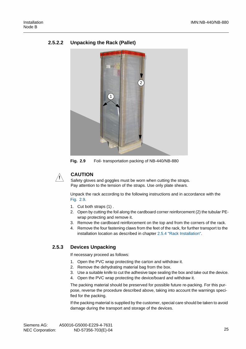
Fig. 2.9 Foil- transportation packing of NB-440/NB-880
Unpack the rack according to the following instructions and in accordance with theFig. 2.9.
1. Cut both straps (1) .2. Open by cutting the foil along the cardboard corner reinforcement (2) the tubular PE-
wrap protecting and remove it.3. Remove the cardboard reinforcement on the top and from the corners of the rack.4. Remove the four fastening claws from the feet of the rack, for further transport to the
installation location as described in chapter 2.5.4 "Rack Installation".
2.5.3 Devices UnpackingIf necessary proceed as follows:
1. Open the PVC wrap protecting the carton and withdraw it.2. Remove the dehydrating material bag from the box.3. Use a suitable knife to cut the adhesive tape sealing the box and take out the device.4. Open the PVC wrap protecting the device/board and withdraw it.
The packing material should be preserved for possible future re-packing. For this pur-pose, reverse the procedure described above, taking into account the warnings speci-fied for the packing.
If the packing material is supplied by the customer, special care should be taken to avoiddamage during the transport and storage of the devices.
2
1
!CAUTIONSafety gloves and goggles must be worn when cutting the straps.Pay attention to the tension of the straps. Use only plate shears.

IMN:NB-440/NB-880 InstallationNode B
26Siemens AG:A50016-G5000-E229-4-7631NEC Corporation:ND-57356-703(E)-04
2.5.4 Rack InstallationPrior to the commencement of rack installation, consult the site documentation to locatethe installation point of the NB-440/NB-880, the link equipment, power supply unit andthe access of the antenna cables into the construction room.
After that, check the proper installation of the ground bar and the necessary cable run-ways.
If the rack must be moved to the final installation position by crane, it is necessary toremove the top cover of the rack.
Fig. 2.10 Opening of the Rack door
To open the door proceed as follows:
1. Move up the little lid (1).2. After unlocking the handle can be moved out (2).3. Turn the handle 90˚ in counterclock direction (3) and open the rack-door.4. Slide the top cover 20 mm (0.8”) to the front and lift it up (see Fig. 2.11).5. Disconnect the green/yellow ground wire from the pin inside the top cover.
Fig. 2.11 Removal of top cover
!CAUTIONBefore opening the rack door, take measures to prevent the rack falling over!Note the accident prevention regulations, when working with a fork lift truck or crane!
i NOTEThe profile cylinder for the locking system of the door will not be delivered with thecabinet together. The installation of a lock must be carried out on site. Install the profilecylinder as described in the chapter 2.7.1 "Fitting of the Profile Cylinder".
1
3
2
1
2

InstallationNode B
IMN:NB-440/NB-880
Siemens AG: A50016-G5000-E229-4-7631NEC Corporation: ND-57356-703(E)-04 27
For the crane transport, two eye bolts (part of the installation tools) must be screwed intothe M12 threaded holes on the top.
Fig. 2.12 Guideline for crane transport
The NB-440/NB-880 are intended for interior installation only so that they should be freefrom possible water ingress, frost, tampering and excessive insect attacks.
The following recommendations should be considered:– In order to install the NB-440/NB-880 below a roof or in a room, a minimum height
of 1700 mm (67”) is required which is also necessary for removing the top.– Installation next to a wall is possible to the left. A minimum distance of 100 mm (4”)
to be maintained at the rear. A clearance of 500 mm (20”) on the right is needed toopen the rack door. In case of back-to-back installation a distance between the rearpanels of the racks of 200 mm (8”) is absolutely required.
– The minimum distance to the opposite wall is 750 mm (30”).– It is recommended that an additional working area be considered with an appropri-
ate emergency exit. The rack has a right hand opening door.
Fig. 2.13 Space necessary for installation of NB-440/NB-880
min. 65˚
100 mm
600 mm
750
mm
500 mm
door
1700 mm (67”)(minimum room height)
min. distancefor proper air radiation
(4”)
(20”)
(30”
)

IMN:NB-440/NB-880 InstallationNode B
28Siemens AG:A50016-G5000-E229-4-7631NEC Corporation:ND-57356-703(E)-04
Fig. 2.14 shows the four fastening claws which fix the rack feet to the crate or woodenpallet during transport. These claws can be used later for fixing the NB-440/NB-880 rackto the floor.
Fig. 2.14 Removal of fastening claws
Fig. 2.15 Adjusting of the rack foot
Proceed as described in the list below:
1. Unscrew the 4 fastening claws from the crate’s base as shown in Fig. 2.14 andmove the rack carefully to the final installation position.
2. Check the correct vertical rack position, using the spirit-level. If the position isincorrect, compensate differences in the floor height by adjusting the rack foot. (seeFig. 2.15).
3. Loose the lock nut (1) and screw down or up the rack foot (2) for proper floor contactby using the adjuster feed wrench.
4. Tighten the lock nut as fast as possible. A tight contact between lock nut and bottomsection is required for proper fixing of the adjusted feet and the stableness ofthe NB-440/NB-880 rack.
5. Push a claw on each of the 4 rack foot and mark the drilling point on the floor.
!CAUTIONTo prevent Racks from tipping over (product safety), they must be fixed either to a wallwith brackets or the floor with claws or in earthquake areas with the suitable earthquakemounting kit.
1
2
levelling range of feet +/- 2,5 mm (1/10”)

InstallationNode B
IMN:NB-440/NB-880
Siemens AG: A50016-G5000-E229-4-7631NEC Corporation: ND-57356-703(E)-04 29
6. Remove the clamps and drill the 4 holes and insert the 4 wall-plugs (e.g., FischerS8GK) into the holes.
7. Push the claws on the rack foot and fix them. Use a ratchet with a 10 mm nut.
In the rack shall be fixed to the wall mounting brackets (Siemens serial no. C50300-A204-C156) should be used for the wall fixing.
Fig. 2.16 Mounting bracket for wall fixing
Fig. 2.17 Wall fixing of the NodeB
i NOTEThe minimum distance from rear of the rack to the wall must be considered. It is recom-mended to prepare the fixings before moving the rack to its final position.
5
20
40
195
100
40
diameter 10length 20
(all measures in mm)
hole for fixing to the wall
hole for fixing at the top of the rack

IMN:NB-440/NB-880 InstallationNode B
30Siemens AG:A50016-G5000-E229-4-7631NEC Corporation:ND-57356-703(E)-04
2.5.5 Setup of Earthquake Mounting Kit
In areas with the possibility of earthquake use the mounting kit for Earthquake Zone 4Rack (MK:EQ4RV3, S30861-K4138-X). The additional brackets improve the robustnessof the rack against earthquake shocks.
The mounting kit consists of the mechanical parts as shown in the figure below.
Fig. 2.18 Parts of the earthquake kit S3086-K4138-X
Fix the rack to the floor in accordance with Fig. 2.21 in steps as follows:– Mark the positions of the drilling holes.– Drill the holes with 18 mm (0.7”) in diameter and a depth of 98 mm (3.9”). Don‘t pre-
drill the holes!– Produce an undercut of the drilling holes: drill the hole to stop and swivel the jack
hammer 3-5 times keeping stop to concrete.– Clean out the drilling holes using a vacuum.– Put dowels (3) (e.g., HILTI - M12*73 / 20) into the inserting tool and hammer into
each hole until the sleeve is flush with surface.– Screw the claw (1) with the dowels on the floor. Tighten the screws to a torque of
60 Nm (44 ft lb), see Fig. 2.19.– Shift the rack to the appropriate position, so that each of the rear rack feet is placed
in a cutout of the double claw.– Insert a claw (2) on each of the front feet and affix them with the M12 bolts to the
steel plugs in front of the rack (see Fig. 2.20). Tighten the connection to a torque of60 Nm (44 ft lb).
See drilling sketch in Fig. 2.21.
!CAUTIONIf the earthquake mounting kit is used, no additional wall mounting of the rack isallowed!
1
2
3 3

InstallationNode B
IMN:NB-440/NB-880
Siemens AG: A50016-G5000-E229-4-7631NEC Corporation: ND-57356-703(E)-04 31
Fig. 2.19 Double claw for the rear foot in mounted position
Fig. 2.20 Claws for the front foot before fixing
Fig. 2.21 Drilling sketch for earthquake mounting kit
shift-direction of the rack
sketch without scale, all dimensions in mm
478
92.5
450
57.5
485
600
20.5

IMN:NB-440/NB-880 InstallationNode B
32Siemens AG:A50016-G5000-E229-4-7631NEC Corporation:ND-57356-703(E)-04
2.6 External Cabling Activities
2.6.1 OverviewThis chapter provides information required for installing the external cables between theNB-440/NB-880 and equipment outside of the rack.
The rack can not function without the following cable connections:– Ground bolt -> ground bar– DC mains terminal block 2 pole -> -48 V DC power supply equipment– Iub interface -> link equipment (can be NTPM or microwave)– Microwave indoor units -> microwave outdoor units (if microwave equipment is used
for transmission)– Transmit / receive antenna connectors -> antenna system– Ground strip of antenna cable shields -> ground bolt
optional:– Alarm collection terminal -> external alarm sensors
All interfaces excepted the antenna connectors are located at the EMI panel below thetop cover.
The top cover needs to be removed for cable installation. For removal of the top coverproceed as described in section 2.5.4 "Rack Installation" of this manual.
Fig. 2.22 Interfaces on EMI Panel of the NB-440/NB-880
Some additional hints for the installation of external cabling:– The first cable that has to be installed is the ground cable between the main ground
stud on top of the rack and the nearest ground bar on site.
1 2
3
4
5
3
1 Iub interface on OVPT 02 Iub interface (OVPT 1)3 ground bolts
4 DC terminal5 ACT
6 lightning protection alarms7 external reset
67

InstallationNode B
IMN:NB-440/NB-880
Siemens AG: A50016-G5000-E229-4-7631NEC Corporation: ND-57356-703(E)-04 33
– After that, all other cables like DC mains, RF cabling or alarm wires can be installed.– The screen of the RF jumpers has to be grounded before entering the rack via the
cable feeding module, see Fig. 2.50.– If cables are fed through coaxial cable access located at the top of the rack at the
front, the screen has to be grounded like all other coaxial cables.
The figure below shows the location of the external interfaces.
Fig. 2.23 Locations of connection points for external cables
-48V DCantenna cables
Iub linesexternal alarms / commandsground cableexternal reset switch
EMI Panel
front of rack
NB-440/NB-880
i NOTEFor later shifting of the NodeB in case of rack extension or to perform maintenanceworks, it can be advantageous to provide an extra length of all external cables.The additional length of the cables (L+, L-, Ground, Iub and external alarms) should bebetween 0,5 m and 1.0 m and can be stored as a loop behind the rack.The alternative solution is the disconnection of all cables.

IMN:NB-440/NB-880 InstallationNode B
34Siemens AG:A50016-G5000-E229-4-7631NEC Corporation:ND-57356-703(E)-04
2.6.2 Ground and Power Supply Connections -48 V DCThe NB-440/NB-880 rack has to be connected to the site specific ground system beforestarting the connection of DC mains cable.
An external ground wire (minimum cross section 16 mm2 (AWG 6), copper conductor)has to be connected on the left or right side ground stud of the rack and must beattached to the ground bar on site.
Connect the NB-440/NB-880 rack and ground system as follows:
1. Use the nearest ground bar on site.2. Ascertain the distances between the connection points of the ground system and the
ground bolt of the rack.3. Cut the cables to the required length.4. Remove the cable insulation at the end to connect to the ground bolt (length approx.
10 mm (0.4”)) and fix a cable lug M8.5. Connect the prepared cable end to the ground bolt.6. Tighten the nut firmly.
Fig. 2.24 Ground and DC mains connections of the NB-440/NB-880
The figure above shows the recommended cabling for the power supply and groundconnections. The recommended cable cross-sections as shown in the figure aboveguarantees the proper function of the NB-440/NB-880, equipped with up to 6 TRX.
The NB-440/NB-880 will be powered by a -48V DC source. The 2-pole terminal block ofthe MSU, located in the top of rack, is the connection point for the DC supply wires.
An easily accessible disconnect device is incorporated into the DC supply wiring. To iso-late the DC mains supply, a 125 A circuit breaker (medium response time and a contactseparation of at least 3 mm) must be installed in the DC distribution box for interruptionof the -48 V conductor. If there no DC pole is grounded, a two-pole disconnect device isnecessary.
To connect the NB-440/NB-880 with the DC mains supply equipment point, proceedwith the following steps:
1. Refer to the site documentation for the required information about type and locationof the DC distribution.
2. Measure the actual distance between terminal block of the MSU and DC distribution.
AC mains
~
=
-48 V + 0 V
125 A
power distributionwith circuit breaker
50 mm2
ground bar
16 mm2
connectionto ground
35 mm2
AWG 6
AWG 2
AWG 1/0

InstallationNode B
IMN:NB-440/NB-880
Siemens AG: A50016-G5000-E229-4-7631NEC Corporation: ND-57356-703(E)-04 35
3. Cut the power supply wires to the required length.4. Cut back the wire insulation at the end of the cables. The length depends on the size
of the wire end sleeves that will be used (1).5. Equip the wire ends with the wire end sleeves (2) as shown Fig. 2.25.6. Press the wire end sleeves with the crimping tool (3) to a quadratic form (4).7. Insert the wires into the terminals and screw down the terminal screws (Fig. 2.26).
Check that all wires are in fixed position. Pay attention to the right polarity.8. Secure both DC wires and the ground wire with the clamp at the rear edge of the
EMI Panel. The distance washers of the clamp should be used for adjusting theclamp for different outer diameters of the wires.
Fig. 2.25 Preparation of DC power supply wires
Fig. 2.26 Connection and fastening of the DC supply wires
(3) crimping tool (4) quadratic crimpform(1) stripped wire end(2) wire end sleeve
1
2
of the cable end
DC mains supply unitconnection of the fastening of thegrounding wireDC supply wires
-48 V
+ 0 V

IMN:NB-440/NB-880 InstallationNode B
36Siemens AG:A50016-G5000-E229-4-7631NEC Corporation:ND-57356-703(E)-04
2.6.3 Iub-Interface - Link EquipmentThe Iub interfaces, located on the EMI Panel, provide the communication links to theneighboring Node B stations or the controlling RNC.
The Iub interfaces can be terminated with Overvoltage Protections (OVPT) which pro-tects the boards inside the NB-440/NB-880 against overvoltage (residual voltage < 1kV). Two types of OVPT exist: OVPTE1CF for 75 Ω and OVPTE1J1SF for 100/120 Ωcables.
If this function is not needed, the Iub interfaces will be terminated with an Iub connector(IUBCON). The IUBCONSFV1 is the termination for 100/120 Ω lines and theIUBCONCFV1 for75 Ω lines.
Depending on the different cable impedances it is recommended to:– use screened cable containing 8/10 shielded twisted pairs 0,25 mm2 for 100/120 Ω
PCM lines, e.g. S-09YS(ST)CY 8x2x0.6/1.2.– use coaxial cables for 75 Ω wiring, e.g. 2YCCY 0.4/2.5.
The maximum cable length depends on the attenuation of the cable, in order to fulfill therequirements of minimum voltage levels to be provided at Iub interface according to Iubstandards. The cable shielding must be connected to the relevant ground pins as closeas possible (in order to avoid EMC/RF interfering effects).
2.6.3.1 Iub-Interface for 100/120 Ohm Cable ImpedanceBefore starting the connection of the cables at the Iub-interface of the OVPTE1J1SF orIUBCONCSFV1, prepare the twisted pair cables as shown in the figure below.
Fig. 2.27 Preparation of twisted pair cables, 120 Ohm impedance
i NOTEIf the connection point for the Iub line (network termination) is outside of the buildingwhere the Node B is installed, an OVPT module has to always be installed.
i NOTEUse only twisted pair or coaxial copper cables with braided shielding!If cables should be used without shielded twisted pairs, do not route up-link and down-link PCM lines in one common cable.
1 5432

InstallationNode B
IMN:NB-440/NB-880
Siemens AG: A50016-G5000-E229-4-7631NEC Corporation: ND-57356-703(E)-04 37
1. Cut the cable to the required length; (1).2. Cut back the outer insulation approx.13 cm (5”); (2).3. Remove approx. 11 cm (4.3”) of the braided shield; (3).4. Cut around the outer insulation and shift the insulation ring to the end of the braided
shield; (4). Remove the foil shield and the additional plastic wire.5. Remove 6 mm (1/4”) of the wires insulation.6. Wrap the exposed cable screen, which will be fixed at the stress relieving bracket.
Fig. 2.28 Routing of Iub-cable (example with OVPTE1J1SF)
1. Use straps to fix the cable at the stress relieving bracket.2. Insert the wires into the terminals of the OVPTE1J1SF / IUBCONSFV1.3. Insert the additional wire (shielding potential) into one of the ground terminals.4. Lead the additional wire and the uplink and downlink wires on the shortest way (with-
out sleeves) between the stress relieving bracket and the spring terminals.5. All unconnected Iub lines (4 wires per line) must be connected to one of the ground
terminals.
- wire cross-section of Iub wires:0.08 mm2 - 2.5 mm2
(AWG 28 - 12)
i NOTEThe OVPT / IUBCON modules are connected via internal cables and the Core Controllerbackplane to the Core Controller (CC).CC2E16 V1 / CC2E16S2V1- can handle up to 16 Iub lines, connected at OVPT / IUB-CON 0 (Iub 0...7) and OVPT / IUBCON 1 (Iub 8...15);CC2E8V1 - can handle up to 8 Iub lines, connected at OVPT / IUBCON 1 (Iub 8...15).If the Node B is equipped with a CC2E8V1 module, always connect the Iub lines at theOVPT / IUBCON 1 module.

IMN:NB-440/NB-880 InstallationNode B
38Siemens AG:A50016-G5000-E229-4-7631NEC Corporation:ND-57356-703(E)-04
Fig. 2.29 Pinning Iub interface at OVPTE1J1SF / IUBCONSFV1
2.6.3.2 Iub-Interface for 75 Ohm Cable ImpedanceThe coaxial interface is realized by use of 16 1.0/2.3 coaxial connectors, located at theOVPTE1CF or IUBCONCFV1.
Fig. 2.30 Iub interface with coaxial connectors (example with OVPTE1CF)
For coaxial cabling with 75 Ω impedance use coaxial cable e.g. 2YCCY 0.4/2.5.
The coaxial cables will be prepared as follows:
1. Fix a 1.0/2.3 female connector for each Iub up- and down-line at the end to beconnected to the OVPTE1CF or IUBCONCSFV1.
2. Plug-on the prepared cable at the matching connectors.3. Screw the wrap nut of the connector to “finger tight”.
IUB
5_ULA
IUB
5_DLA
Ground
IUB
2_ULA
IUB
2_DLA
Ground
IUB
3_ULB
IUB
3_DLB
IUB
3_ULA
IUB
3_DLA
IUB
4_ULB
IUB
4_DLB
Ground
IUB
4_ULA
IUB
4_DLA
IUB
5_ULB
IUB
5_DLB
IUB
0_ULB
IUB
0_DLB
IUB
0_ULA
IUB
0_DLA
IUB
1_ULB
IUB
1_DLB
Ground
IUB
1_ULA
IUB
1_DLA
IUB
2_ULB
IUB
2_DLB
IUB
6_ULB
IUB
6_ULA
IUB
6_DLB
IUB
6_DLA
IUB
7_ULB
IUB
7_ULA
IUB
7_DLB
IUB
7_DLA
front side of rack
upper row
lower row
25 26 27 28 29 30 31 32 33 34 35 36
13 14 15 16 17 18 19 20 21 22 23 24
1 2 3 4 5 6 7 8 9 10 11 12
Note: Iub interface 0 and 1uses the same labels.In case of interface 1 thelabel IUB0 ... IUB7means the physicalinterfaces Iub8 ... Iub15.
holes for stress relieving
i NOTEThe coaxial connectors of the OVPTE1CF and the IUBCONCSFV1 are delicate 1.0/2.3connectors. Make sure that the cable are connected without mechanical tension. Usesuitable stress relieving measures.
InstallationNode B
IMN:NB-440/NB-880
Siemens AG: A50016-G5000-E229-4-7631NEC Corporation: ND-57356-703(E)-04 39
Fig. 2.31 Iub line connectors of OVPTE1CF / IUBCONCFV1
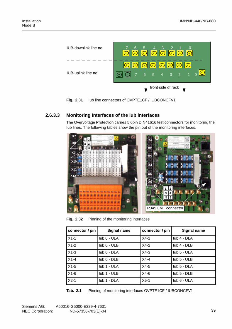
2.6.3.3 Monitoring Interfaces of the Iub interfacesThe Overvoltage Protection carries 5 6pin DIN41616 test connectors for monitoring theIub lines. The following tables show the pin out of the monitoring interfaces.
Fig. 2.32 Pinning of the monitoring interfaces
IUB-uplink line no.
IUB-downlink line no. 1234567 0
1234567 0
front side of rack
connector / pin Signal name connector / pin Signal name
X1-1 Iub 0 - ULA X4-1 Iub 4 - DLA
X1-2 Iub 0 - ULB X4-2 Iub 4 - DLB
X1-3 Iub 0 - DLA X4-3 Iub 5 - ULA
X1-4 Iub 0 - DLB X4-4 Iub 5 - ULB
X1-5 Iub 1 - ULA X4-5 Iub 5 - DLA
X1-6 Iub 1 - ULB X4-6 Iub 5 - DLB
X2-1 Iub 1 - DLA X5-1 Iub 6 - ULA
Tab. 2.1 Pinning of monitoring interfaces OVPTE1CF / IUBCONCFV1
1 23 45 6
X7
X8
X9
X10
X11
X12
X1
X2
X3
X4
X5
X6
1 23 45 6
RJ45 LMT connector

IMN:NB-440/NB-880 InstallationNode B
40Siemens AG:A50016-G5000-E229-4-7631NEC Corporation:ND-57356-703(E)-04
X2-2 Iub 1 - DLB X5-2 Iub 6 - ULB
X2-3 Iub 2 - ULA X5-3 Iub 6 - DLA
X2-4 Iub 2 - ULB X5-4 Iub 6 - DLB
X2-5 Iub 2 - DLA X5-5 Iub 7 - ULA
X2-6 Iub 2 - DLB X5-6 Iub 7 - ULB
X3-1 Iub 3 - ULA X6-1 Iub 7 - DLA
X3-2 Iub 3 - ULB X6-2 Iub 7 - DLB
X3-3 Iub 3 - DLA X6-3 EXTSYNCA
X3-4 Iub 3 - DLB X6-4 EXTSYNCB
X3-5 Iub 4 - ULA X6-5
X3-6 Iub 4 - ULB X6-6
connector / pin Signal name connector / pin Signal name
X7-1 Iub 0 - ULA X10-1 Iub 4 - DLA
X7-2 Iub 0 - ULB X10-2 Iub 4 - DLB
X7-3 Iub 0 - DLA X10-3 Iub 5 - ULA
X7-4 Iub 0 - DLB X10-4 Iub 5 - ULB
X7-5 Iub 1 - ULA X10-5 Iub 5 - DLA
X7-6 Iub 1 - ULB X10-6 Iub 5 - DLB
X8-1 Iub 1 - DLA X11-1 Iub 6 - ULA
X8-2 Iub 1 - DLB X11-2 Iub 6 - ULB
X8-3 Iub 2 - ULA X11-3 Iub 6 - DLA
X8-4 Iub 2 - ULB X11-4 Iub 6 - DLB
X8-5 Iub 2 - DLA X11-5 Iub 7 - ULA
X8-6 Iub 2 - DLB X11-6 Iub 7 - ULB
X9-1 Iub 3 - ULA X12-1 Iub 7 - DLA
X9-2 Iub 3 - ULB X12-2 Iub 7 - DLB
X9-3 Iub 3 - DLA X12-3 EXTSYNCA
X9-4 Iub 3 - DLB X12-4 EXTSYNCB
X9-5 Iub 4 - ULA X12-5
X9-6 Iub 4 - ULB X12-6
Tab. 2.2 Pinning of monitoring interfaces OVPTE1J1SF / IUBCONSFV1
connector / pin Signal name connector / pin Signal name
Tab. 2.1 Pinning of monitoring interfaces OVPTE1CF / IUBCONCFV1

InstallationNode B
IMN:NB-440/NB-880
Siemens AG: A50016-G5000-E229-4-7631NEC Corporation: ND-57356-703(E)-04 41
2.6.4 Alarm Collection Terminal - external Signal SensorsThe access for cables from external signal sensors on site (site inputs) is the Alarm Col-lection Terminal for base cabinet, ACTM.
The ACTMF provides 6 spring terminal blocks for connecting of 24 external input alarmsand 8 output commands.
The max. wire cross section is limited to 0.5 mm2 (AWG 20).
The alarm terminals are labelled X1... X4, the terminal blocks X9 and X10 are used forconnection of output commands. At the terminal blocks X9 and X10 up to 8 differentelectrical consumers can be connected.
The cables will be fixed at the stress relieving bracket with cable ties. The outer insula-tion of the cables have to be cutted back aprrox. 15 mm (0.6”), so that a proper groundcontact between the cable screen and the bracket is provided (see figure below).
The following figure and the tables give information on the terminal assignment.
Fig. 2.33 Terminal numbering of the ACTMF
X1X2
X3 X4
X9
X10
1 121 121
121 12 1
8
18
- wire cross-section of alarm wires: 0.08 mm2 - 0.5 mm2 (AWG 28 - 20)- recommended wire strip length: 5 - 6 mm (0.22”)
!CAUTIONThe signal source of the external alarms (clamping block X1...X4) must be a switchingcontact (relays, open collector for rack internal alarms will be possible).The maximum switched current must not exceed 2 mA.It is not allowed to connect a voltage source to the alarm inputs.

IMN:NB-440/NB-880 InstallationNode B
42Siemens AG:A50016-G5000-E229-4-7631NEC Corporation:ND-57356-703(E)-04
Pin no. Alarm no. Signal Name Alarm Name
2,4,6,8,10,12 AL_GND Alarm ground
1 AL24_P Site input #0 orAC/DC alarm0
Env_Alarm_9
3 AL25_P Site input #1 orAC/DC alarm1
Env_Alarm_10
5 AL26_P Site input #2 orAC/DC alarm2
Env_Alarm_11
7 AL27_P Site input #3 Env_Alarm_12
9 AL28_P Site input #4 Env_Alarm_13
11 AL29_P Site input #5 Env_Alarm_14
Tab. 2.3 Pinning ACTMF Connector X4
Pin no. Alarm no. Signal Name Alarm Name
2,4,6,8,10,12 AL_GND Alarm ground
1 AL30_P Site input #6 Env_Alarm_15
3 AL31_P Site input #7 Env_Alarm_16
5 AL32_P Site input #8 Env_Alarm_17
7 AL33_P Site input #9 Env_Alarm_18
9 AL34_P Site input #10 Env_Alarm_19
11 AL35_P Site input #11 Env_Alarm_20
Tab. 2.4 Pinning ACTMF Connector X3
Pin no. Alarm no. Signal Name Alarm Name
2,4,6,8,10,12 AL_GND Alarm ground
1 AL36_P Site input #12 Env_Alarm_21
3 AL37_P Site input #13 Env_Alarm_22
5 AL38_P Site input #14 Env_Alarm_23
7 AL39_P Site input #15 Env_Alarm_24
9 AL40_P Site input #16 Env_Alarm_25
11 AL41_P Site input #17 Env_Alarm_26
Tab. 2.5 Pinning ACTMF Connector X2
InstallationNode B
IMN:NB-440/NB-880
Siemens AG: A50016-G5000-E229-4-7631NEC Corporation: ND-57356-703(E)-04 43
The ACTMF provides at the connectors X9 and X10 the possibility to switch up to 8 elec-trical consumers via a relay contact (relays are already integrated on ACTMF).
Pin no. Alarm no. Signal Name Alarm Name
2,4,6,8,10,12 AL_GND Alarm ground
1 AL42_P Site input #18 Env_Alarm_27
3 AL43_P Site input #19 Env_Alarm_28
5 AL44_P Site input #20 Env_Alarm_29
7 AL45_P Site input #21 Env_Alarm_30
9 AL46_P Site input #22 Env_Alarm_31
11 AL47_P Site input #23 Env_Alarm_32
Tab. 2.6 Pinning ACTMF Connector X1
Pin no. Signal name - X10 Signal name - X9
1 CMD0_P (Site output #0) CMD4_P (Site output #4)
2 CMD0_M CMD4_M
3 CMD1_P (Site output #1) CMD5_P (Site output #5)
4 CMD1_M CMD5_M
5 CMD2_P (Site output #2) CMD6_P (Site output #6)
6 CMD2_M CMD6_M
7 CMD3_P (Site output #3) CMD7_P (Site output #7)
8 CMD3_M CMD7_M
Tab. 2.7 Pinning ACTMF Connectors X10 and X9
!CAUTIONThe switched current must not exceed 100 mAAC/DC (contact closed) and the maximumswitched voltage is limited to 30 VAC or 30 VDC (contact open). The maximum switchingpower is 3 W.
IMN:NB-440/NB-880 InstallationNode B
44Siemens AG:A50016-G5000-E229-4-7631NEC Corporation:ND-57356-703(E)-04
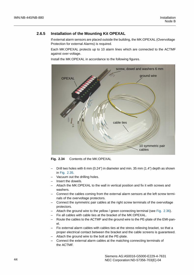
2.6.5 Installation of the Mounting Kit OPEXALIf external alarm sensors are placed outside the building, the MK:OPEXAL (OvervoltageProtection for external Alarms) is required.
Each MK:OPEXAL protects up to 10 alarm lines which are connected to the ACTMFagainst over-voltage.
Install the MK:OPEXAL in accordance to the following figures.
Fig. 2.34 Contents of the MK:OPEXAL
– Drill two holes with 6 mm (0.24”) in diameter and min. 35 mm (1.4”) depth as shownin Fig. 2.35.
– Vacuum out the drilling holes.– Insert the dowels.– Attach the MK:OPEXAL to the wall in vertical position and fix it with screws and
washers.– Connect the cables coming from the external alarm sensors at the left screw termi-
nals of the overvoltage protectors.– Connect the symmetric pair cables at the right screw terminals of the overvoltage
protectors.– Attach the ground wire to the yellow / green connecting terminal (see Fig. 2.36).– Fix all cables with cable ties at the bracket of the MK:OPEXAL.– Route the cables to the ACTMF and the ground wire to the PE-plate of the EMI-pan-
el.– Fix external alarm cables with cables ties at the stress relieving bracket, so that a
proper electrical contact between the bracket and the cable screens is guaranteed.– Attach the ground wire to the bolt at the PE-plate.– Connect the external alarm cables at the matching connecting terminals of
the ACTMF.
screw, dowel and washers 6 mm
ground wire
10 symmetric pair
OPEXAL
cables
cable ties

InstallationNode B
IMN:NB-440/NB-880
Siemens AG: A50016-G5000-E229-4-7631NEC Corporation: ND-57356-703(E)-04 45
Fig. 2.35 Drilling sketch for MK:OPEXAL
Fig. 2.36 Wall mounted MK:OPEXAL
max. 30 mm (1.2”)from the rack edge220 mm
700 mm
diameter 6 mm (0.24”)drill hole depth 35 mm (1.4”)
(27.5”)
(8.7”)
cables fromexternal alarm sensors
symmetric pair cablesto ACTMF
ground wireto PE-plate of EMI Panel
Input side Output side

IMN:NB-440/NB-880 InstallationNode B
46Siemens AG:A50016-G5000-E229-4-7631NEC Corporation:ND-57356-703(E)-04
2.6.6 Alarm Collection Terminal ACTCBF - internal AlarmsIn addition to the site inputs (external alarms) at the ACTMF, the ACTC board can beused for the connection of rack-internal alarm sensors (e.g. FANs, smoke sensor andrack door contact) as shown in Fig. 2.37).
The following table provides information of the connections for environmental alarms atthe ACTCBF.
Fig. 2.37 Connector arrangement at ACTCBF
Pin no. X12 Signal name Pin no. X8 Signal name
1 AL_1P 1 AL0_P
2 AL_GND 2 AL_GND
3 DC_SMOKE_PUE - -
4 DC_SMOKE_MUE - -
Tab. 2.8 Pinning ACTCBF Connector X12 and X8
SMOKE RDO
BB0...BB1
1
meaning of abbrevations:RDO: rack door openSMOKE: smoke sensorBB0...1: battery fuse 0...1
18X12
X10
X21X8
X9
not supported

InstallationNode B
IMN:NB-440/NB-880
Siemens AG: A50016-G5000-E229-4-7631NEC Corporation: ND-57356-703(E)-04 47
2.6.7 Local Maintenance Terminal (LMT) InterfaceA RJ45 connector, located at the front of the Core Controller is the interface for tempo-rary connection of a Local Maintenance Terminal (LMT), used for commissioning andmaintenance purposes.
In case of Core Controller redundancy, connect the LMT cable at the Hub1 board. If anovervoltage-protected connection of the LMT is required, connect the LMT at the RJ45interface of the OVPT / IUBCON as shown in Fig. 2.32.
Refer to section Ethernet Cabling for the installation of the cables between OVPT, Hub0/1, and the Core Controllers.
Pin no. X21 Alarm no. Alarm name Signal name
1, 3, 4, 5, 7,9, 11, 13, 15
AL_GND - -
2 AL15_P Env_Alarm_8 cabinet input
4 AL14_P Env_Alarm_7 cabinet input
6 AL13_P Env_Alarm_6 cabinet input
8 AL12_P Env_Alarm_5 cabinet input
10 AL11_P Env_Alarm_4 cabinet input
12 AL10_P Env_Alarm_3 cabinet input
14 AL9_P Env_Alarm_2 cabinet input
16 AL8_P Env_Alarm_1 cabinet input
17 TEMP_SENSE_GND
18 TEMP_SENSE
Tab. 2.9 Pinning ACTCBF Connector X21
IMN:NB-440/NB-880 InstallationNode B
48Siemens AG:A50016-G5000-E229-4-7631NEC Corporation:ND-57356-703(E)-04
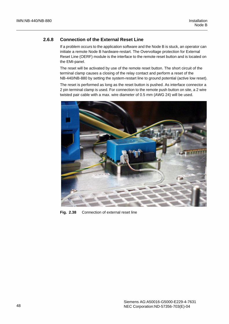
2.6.8 Connection of the External Reset LineIf a problem occurs to the application software and the Node B is stuck, an operator caninitiate a remote Node B hardware-restart. The Overvoltage protection for ExternalReset Line (OERF) module is the interface to the remote reset button and is located onthe EMI-panel.
The reset will be activated by use of the remote reset button. The short circuit of theterminal clamp causes a closing of the relay contact and perform a reset of theNB-440/NB-880 by setting the system-restart line to ground potential (active low reset).
The reset is performed as long as the reset button is pushed. As interface connector a2 pin terminal clamp is used. For connection to the remote push button on site, a 2 wiretwisted pair cable with a max. wire diameter of 0.5 mm (AWG 24) will be used.
Fig. 2.38 Connection of external reset line
InstallationNode B
IMN:NB-440/NB-880
Siemens AG: A50016-G5000-E229-4-7631NEC Corporation: ND-57356-703(E)-04 49
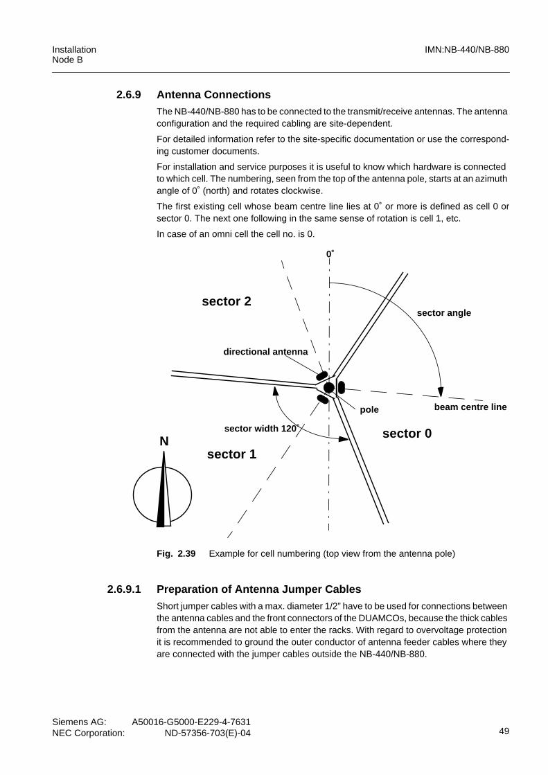
2.6.9 Antenna ConnectionsThe NB-440/NB-880 has to be connected to the transmit/receive antennas. The antennaconfiguration and the required cabling are site-dependent.
For detailed information refer to the site-specific documentation or use the correspond-ing customer documents.
For installation and service purposes it is useful to know which hardware is connectedto which cell. The numbering, seen from the top of the antenna pole, starts at an azimuthangle of 0˚ (north) and rotates clockwise.
The first existing cell whose beam centre line lies at 0˚ or more is defined as cell 0 orsector 0. The next one following in the same sense of rotation is cell 1, etc.
In case of an omni cell the cell no. is 0.
Fig. 2.39 Example for cell numbering (top view from the antenna pole)
2.6.9.1 Preparation of Antenna Jumper CablesShort jumper cables with a max. diameter 1/2” have to be used for connections betweenthe antenna cables and the front connectors of the DUAMCOs, because the thick cablesfrom the antenna are not able to enter the racks. With regard to overvoltage protectionit is recommended to ground the outer conductor of antenna feeder cables where theyare connected with the jumper cables outside the NB-440/NB-880.
sector width 120˚
sector angle
directional antenna
pole
sector 0
sector 1
sector 2
N
0˚
beam centre line

IMN:NB-440/NB-880 InstallationNode B
50Siemens AG:A50016-G5000-E229-4-7631NEC Corporation:ND-57356-703(E)-04
The jumper cables must be fabricated of 1/2” highly flexible coaxial cable on-site, if nopre-fabricated cables should be used.
Fabricate the jumper cables in steps as shown in the following figures.
Fig. 2.40 Tools for jumper fabrication
Fig. 2.41 Parts of the connector unit kit (example)
– Measure the distance between the end of the antenna feeder cable and the frontconnectors of the combiner modules.
– Saw the cable to the required length. Do not deform cable outer conductor, when us-ing too much pressure for sawing!
hot air gun(or propane/ butane blow torch)
cable trimming tool
cable knife
open-ended spanners(jaw opening 21mm and25 mm)
saw: for cable cutting (not shown)
connector head
corrugation nut
fitting ring
emery paper
cleaning tissue
heat protection tape
heatshrink sleeve
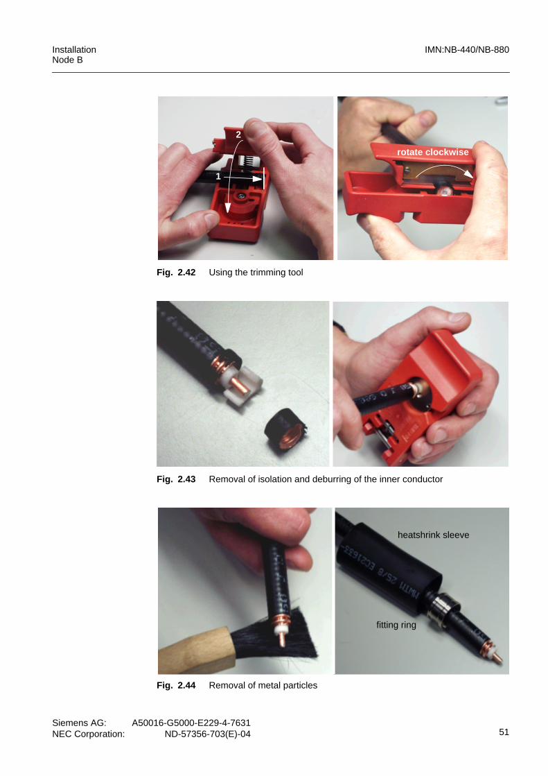
InstallationNode B
IMN:NB-440/NB-880
Siemens AG: A50016-G5000-E229-4-7631NEC Corporation: ND-57356-703(E)-04 51
Fig. 2.42 Using the trimming tool
Fig. 2.43 Removal of isolation and deburring of the inner conductor
Fig. 2.44 Removal of metal particles
1
2
rotate clockwise
heatshrink sleeve
fitting ring

IMN:NB-440/NB-880 InstallationNode B
52Siemens AG:A50016-G5000-E229-4-7631NEC Corporation:ND-57356-703(E)-04
Fig. 2.45 Assembly of the connector unit
Fig. 2.46 Fixing of connector unit, removal of outer insulation
Fig. 2.47 Handling of heat protection tape and shrink sleeve
corrugation nut
fitting ring
connector head
20 mm
heat protection tape
heat shrink sleeve

InstallationNode B
IMN:NB-440/NB-880
Siemens AG: A50016-G5000-E229-4-7631NEC Corporation: ND-57356-703(E)-04 53
Fig. 2.48 Shrinkage and removal of the visible heat protection tape
The antenna cables must be routed through the EMI Panel forward to the 7/16” frontconnectors of DUAMCOF.
Fig. 2.49 Max. dimensions of antenna connectors
Connect the antenna cables to the combining equipment as follows:
1. Unscrew the front part of the cable feeding module.2. Route the antenna jumpers to the DUAMCOF RF-connectors.3. For grounding strip back outer insulation approx. 15 mm (0.6”) for proper contact
with the metal lids of the cable feeding module (see Fig. 2.50).
remove the over lengthof heat protection tape
hot air gun or butane torch
heated air
i NOTEFix the jumper cables at 7/16 connectors with a torque wrench to 25 Nm (18.5 ft lb).Fix the N-type connectors with a torque wrench to 1.0 Nm (0.75 ft lb).
i NOTENote that being able to close the doors means that the depth of the right angle connectoris not allowed to exceed 45 mm (1.8”).
max. 45 mm (1.8”)
max. 1/2” jumper cable (high flexible)width across flats 32

IMN:NB-440/NB-880 InstallationNode B
54Siemens AG:A50016-G5000-E229-4-7631NEC Corporation:ND-57356-703(E)-04
4. Feed the jumpers through the cable feeding module forward to the front connectorsof antenna combiners and fix them at the connectors TX/RX.
5. Bend the jumpers into the correct position for easy closing of cable feeding module.6. Screw the front part of the cable feeding module in its original position.
Fig. 2.50 Routing of antenna jumper cables
i NOTEThe outer insulation of the antenna cables must be removed for proper ground contactat the lids of the cable feeding module (see Fig. 2.50).
unscrew
i NOTEThe installer of the antenna system should collect the following antenna cable parame-ters and document them for the customer:length and type of all antenna feeder cableslength and type of all antenna jumper cables.The same type of antenna feeder cables and jumper cable should be used within thesame sector.The length differences between the main and diversity paths within the same sectorshould be less than < = 1m (40”).A cable length accuracy < = 1/2 m (20”) is recommended.

InstallationNode B
IMN:NB-440/NB-880
Siemens AG: A50016-G5000-E229-4-7631NEC Corporation: ND-57356-703(E)-04 55
2.6.10 Installation of the Tower Mounted Amplifiers
The Tower Mounted Amplifiers (DTMAF) are the RF units (external to the NodeB rack)which provide the means to feed the overall NodeB downlink signal to one TX/RX an-tenna and to amplify, with low noise figure, the overall NodeB uplink signal coming fromthe same TX/RX antenna.
The DTMARET can additional support the remote electrical tilt (RET) of the antennas inrelation with the DUAMCORETF inside the NodeB and adjusting devices (RET mod-ules) at the antennas. The RET feature allows the adjusting of the horizontal antenna tiltwith a remote control via the O&M.
Fig. 2.51 Position of DTMAF / DTMARETF in the system
The DTMAF / DTMARET should be placed as close to the antenna as possible.
!WARNINGThe electromagnetic field (EMF) generated by a NodeB could have detrimental effectson human health in areas very close to the NodeB antenna. Excessive EMF exposureby the installation/service personnel must be avoided. For installation and maintenanceactivities it is important to know the EMF compliance boundaries in antenna areas.For detailed information please refer to the document:” EN 50385 - Compliance Bound-aries”.Use allways the security equipment for working on poles (S42025-Z159-A4).A second person is needed as an accompaniment during the installation works.
i NOTEInstall the components of the RET-System according to the installation manual of therespective manufacturer.
NodeBNodeB
Feeder 1 Feeder 2 Feeder 1 Feeder 2
DTMARET
Antenna
FDDFDD
DTMAF
adjusting device
Antenna
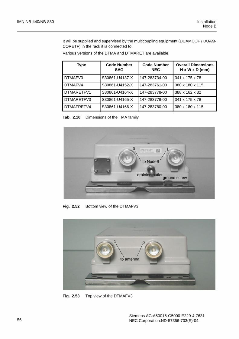
IMN:NB-440/NB-880 InstallationNode B
56Siemens AG:A50016-G5000-E229-4-7631NEC Corporation:ND-57356-703(E)-04
It will be supplied and supervised by the multicoupling equipment (DUAMCOF / DUAM-CORETF) in the rack it is connected to.
Various versions of the DTMA and DTMARET are available.
Fig. 2.52 Bottom view of the DTMAFV3
Fig. 2.53 Top view of the DTMAFV3
Type Code NumberSAG
Code NumberNEC
Overall DimensionsH x W x D (mm)
DTMAFV3 S30861-U4137-X 147-283734-00 341 x 175 x 78
DTMAFV4 S30861-U4152-X 147-283761-00 380 x 180 x 115
DTMARETFV1 S30861-U4164-X 147-283778-00 388 x 162 x 82
DTMARETFV3 S30861-U4165-X 147-283779-00 341 x 175 x 78
DTMAFRETV4 S30861-U4166-X 147-283780-00 380 x 180 x 115
Tab. 2.10 Dimensions of the TMA family
to NodeB
0 1
draining outletground screw
to antenna
1 0

InstallationNode B
IMN:NB-440/NB-880
Siemens AG: A50016-G5000-E229-4-7631NEC Corporation: ND-57356-703(E)-04 57
Fig. 2.54 Rear view of the DTMAFV3
Fig. 2.55 Bottom view of the DTMARETFV3
Fig. 2.56 Bottom view of the DTMAFV4
holes for hose clips
holes for wall mounting
NodeB0 1
draining outlet
RET connector ground screw
draining outlet
ground screw

IMN:NB-440/NB-880 InstallationNode B
58Siemens AG:A50016-G5000-E229-4-7631NEC Corporation:ND-57356-703(E)-04
Fig. 2.57 Top view of the DTMAFV4
Fig. 2.58 Rear view of the DTMAFV4
Fig. 2.59 Top view of the DTMARETFV4
holes for hose clips
holes for wall mounting
RET connector
protection cab

InstallationNode B
IMN:NB-440/NB-880
Siemens AG: A50016-G5000-E229-4-7631NEC Corporation: ND-57356-703(E)-04 59
Fig. 2.60 Bottom view of the DTMARETFV1
Fig. 2.61 Top view of the DTMARETFV1
Fig. 2.62 Rear view of the DTMARETFV1
RET connectorground screw
draining outlet
holes for hose clips
holes for wall mounting

IMN:NB-440/NB-880 InstallationNode B
60Siemens AG:A50016-G5000-E229-4-7631NEC Corporation:ND-57356-703(E)-04
The DTMAF provides two 7/16 female connectors at the bottom for the connection withthe Node B (lettered NodeB 0 and NodeB 1) and on the top both 7/16 connectors forconnecting the jumper cables to the antennas (lettered ANT 0 and ANT 1).
In addition to the RF coaxial connectors, the DTMARETF provides a 8-pole circular con-nector for connecting of the RET module, the tilt adjuster of the antenna.
The DTMAF / DTMARETF shall be grounded to the pole, therefore a grounding wire hasto be prepared for each device on site.
The mounting plate provides a ground screw with a locking washer attached to it and athreaded hole for connection of the grounding wire (see bottom view of the devices). Thegrounding wire cable lug must have the right size for the M8 ground screw. The crosssection of the ground wire must be not less than 16 mm2 (AWG 6).
The other end of the grounding wire should be safely connected to a well grounded pointon the pole.
Care must be taken that the draining pipe (see bottom view of the devices) is pointeddownwards. The draining outlet is factory mounted. If it, for any reason, would be loos-ened, it should be tightened again with a sufficient torque wrench, however not exceed-ing 2.2 Nm (1.6 ft lb).
The draining pipe must never be obstructed or covered with paint which would impedethe venting and draining of the housing.
2.6.10.1 Pole Mounting with Hose ClipsThe hose clips surrounds the pole and are fitted into the corresponding openings of themounting plate (see rear view of the devices). This is the situation just before tighteningthe hose clips.
For the mounting, the following steps can be generally recommended. First connect theDTMAF / DTMARETF to the antenna feeder cable. Take into consideration that the an-tenna feeder often is very stiff and rather heavy. The position of its coaxial connectorstherefore often determines the position of the DTMAF / DTMARETF on the pole.
1. Place the DTMAF / DTMARETF in its final mounting position at the pole.2. Secure the unit with a tensioning belt.3. Open the hose clips by pressing the “button” at the end of the clip lock and then
smoothly pull out the perforated metal band.4. Move the metal band of the hose clip gently into the openings of the mounting plate.5. Close the hose clip loosely around the pole.6. Tighten the hose clip screws carefully, but do not over-tighten (see Fig. 2.63).7. Remove the tensioning belt.8. Connect the DTMAF / DTMARETF first to the antenna feeder cable (NodeB) and
then to the antenna jumper cable (ANT). The torque must be 25 Nm (18.5 ft lb).9. Connect the grounding wire with the DTMAF / DTMARETF ground screw. Tighten
the connection to a torque of 5 Nm (3.7 ft lb).10. The use of self-vulcanizing tape as an environmental protection of the connectors is
recommended.
i NOTEIt is recommended to mount the DTMAF’s and the DTMARETF’s at pole or wall in a ver-tical position, so that the draining outlet of the units is pointing downwards.In certain cases is the mounting in a horizontal position (e.g., on cable runways)possible, it depends on the environmental conditions.

InstallationNode B
IMN:NB-440/NB-880
Siemens AG: A50016-G5000-E229-4-7631NEC Corporation: ND-57356-703(E)-04 61
If the antenna is equipped with a RET module, install the DC power / data cable betweenthe module and the 8 pole circular connector of the DTMARETF. The required cable willbe delivered with the RET module together.
The following figures will illustrate the pole mounting procedure of the tower mountedamplifiers.
Fig. 2.63 Pole mounting of the DTMAF
i NOTEPay attention to the thermal dimensional changes of the antenna feeder cables.
hose clips
tighten
tighten

IMN:NB-440/NB-880 InstallationNode B
62Siemens AG:A50016-G5000-E229-4-7631NEC Corporation:ND-57356-703(E)-04
2.6.10.2 Wall Mounting of DTMAF and DTMARETFThe DTMAF / DTMARET may be mounted on a wall by means of suitable screws anddowels (not supplied with the device).
The corresponding holes in the mounting plate have a diameter of 9 mm (0.35”). Theproper way of mounting the device on a wall varies from case to case. The best methodcan only be decided by the installer. Please note, however, that the wall itself probablydoes not provide adequate grounding, it may be insulated.
2.6.11 Preparation of the Top CoverAfter the connection of external cables, prepare the top cover for setup on the top of therack. The top cover features pre-fractured parts which can be removed in order to routecables through to the infrastructure equipment on site. See figure below.
The required number of pieces can be removed in easy manner by using of a suitablemetal-saw and the following break-out at the perforation. After that refinish the paint coatat all cracks with the paint retouch kit (Siemens Serial No. A500-C101-B261).
Fig. 2.64 Removable pieces and paint retouch of the top cover
!CAUTIONIt is absolutely necessary to prepare and connect an adequate grounding cable to theDTMAF / DTMARET nearest grounding point. The cross section of the ground wiresshould be not less than 16 mm2 (AWG 6).
!CAUTIONPay attention to the thermal dimensional changes of the antenna feeder cables.
paint retouch neccessary

InstallationNode B
IMN:NB-440/NB-880
Siemens AG: A50016-G5000-E229-4-7631NEC Corporation: ND-57356-703(E)-04 63
2.6.12 Setup of the System CablingThe system cabling consists of connections that are installed on the front of the rack.The cabling configurations depends on the different equipping variants and the cell con-figuration of the site.
The system cabling is already installed in the factory. This section provides informationfor setup additional system cables for extension of RF modules or the cell configurationmust be changed.
The list of variant numbers (content of the site specific documentation) is needed for thecorrect setup of the cabling between the modules.
Fig. 2.65 Cabling between TRX, LPA and DUAMCOF (2 Carrier, 1 Cell)
The following table provides an overview of the types and functionality of the prefabri-cated cables.
LPA 0
TX
RF out
DUAMCOF
TX 0RX 0
RX 1
RX 0
RX 1
TX 1
LPA 1
TX
RF out
TRX 0
TX
RX 0
RX 1
TRX 3
TX
RX 0
RX 1
!CAUTIONTo avoid short circuits, do not pack the overlength of system cables in the free spacebetween the fans of the A-shelf and the EMI-filters of the mains supply unit.
!CAUTIONA minimum bending-radius of 35 mm (1.4”) for “RG 142” cables and 3.5 mm (0.2”) for“semi-rigid .86 AI” cables must be ensured.Fix the system cables at SMA connectors with a torque wrench set to 1.0 Nm (0.75 ft lb).Fix the N-type connectors with a torque wrench to 1.0 Nm (0.75 ft lb).Terminate all unused connectors of the antenna combiners with 50 Ohm load resistors!

IMN:NB-440/NB-880 InstallationNode B
64Siemens AG:A50016-G5000-E229-4-7631NEC Corporation:ND-57356-703(E)-04
Here a routing sketch for the DUAMCOF and LPA/CAT left/right hand cabling is given.
Fig. 2.66 LPA / CAT - DUAMCOXF cabling
connection code number length path connector cabletype
DUAMCOXF- LPAleft hand side,DUAMCOXF- CATleft hand side
S30864-X217-A46(ex.C39195-Z80-C221)
160 mm TX N-con. 90˚, male/N-con. 90˚; male
RG 142
DUAMCOXF- LPAright hand side,DUAMCOXF- CATright hand side
C39195-Z80-C222
250 mm TX N-con. 90˚, male/N-con. 90˚; male
RG 142
TRX - LPATRX -DUAMCOXF
C39195-Z80-C219
1800 mmAttenua-tion 1,8 dB
TX/RX
SMA,90˚,male/SMA,90˚,male
semi-rigid.86 Al
TRX - LPATRX -DUAMCOXF
S30864-X217-A20
1700 -2000 mmAttenua-tion 1,8dB
TX/RX
SMA,90˚, male/SMA,90˚, male
flexiblecable
jumper cableCAT -DUAMCOXF
S30864-X217-A35
240 mm RX/TX
SMA,90˚, male/SMA,90˚, male
flexiblecable
Tab. 2.11 Functionality of system cables
i NOTEThe minimum single bending radius of the flexible cables is 20 mm (3/4”). The minimumrepeated bending radius is 40 mm (1.6”). The exceptional length of the cables have tobe stored inside the vertical space between the subracks and the inside rack wall.The horizontal space below each subrack have not to be used to store the extra lengthof the system cables or anything else. This space is used as an air inlet for cooling.
S30864-X217-A46
C39195-Z80-C222
LPA LPADUAMCOXF
TX OUT TX OUTTX IN TX OUT TX OUTTX IN
ETHER
DRIC 0
DRIC 1
ETHER
DRIC 0
DRIC 1
DUAMCOXF CATCAT

InstallationNode B
IMN:NB-440/NB-880
Siemens AG: A50016-G5000-E229-4-7631NEC Corporation: ND-57356-703(E)-04 65
2.6.13 Installation of the Interrack Cabling
2.6.13.1 SYNC-CableThe SYNC-Cable has to be routed from the ExtClk_OUT connector of the OVPT / IUB-CON to the front connector SYNC-IN of the Core Controller. The isolation of the cablehas to be stripped back 15 mm (0.6”) before mounting to ensure a proper contact to theEMC-seal of the cable feeding module.
The connector “SYNC-OUT/TERM” must be terminated. The terminator is part of themontage kit delivered in a separate plastic package.
Fig. 2.67 SYNC-Cable Connection
SYNC-IN
ExtClk_OUTExtClk_OUT
Core Controller
S30864-X217-A28
280 mm (11”)
OVPT CC15 mm (0.6”)
SYNC OUT(to be terminated)
36 36

IMN:NB-440/NB-880 InstallationNode B
66Siemens AG:A50016-G5000-E229-4-7631NEC Corporation:ND-57356-703(E)-04
2.6.13.2 Ethernet CablingFor connection of the Local Maintenance Terminal at the OVPT / IUBCON or at the Hub-module, the cables as shown in the figures below are necessary.
Fig. 2.68 Overview of Ethernet Cabling
From To Serial No. length
Hub #0 CC #0 C39195-Z75-A120 900 mm (35.5”)
Hub #0 CC #1 C39195-Z75-A120 900 mm (35.5”)
Hub #0 OVPT/ IUBCON C39195-Z75-A121 1800 mm (71”)
Hub #0 Hub #1 C39195-Z75-A119 280 mm (11”)
Tab. 2.12 Types of Ethernet Cables
C39195-Z75-A120
OVPT / IUBCON
DC-Panel
CC#0 CC#1
C39195-Z75-A120
C39195-Z75-A119
C39195-Z75-A121

InstallationNode B
IMN:NB-440/NB-880
Siemens AG: A50016-G5000-E229-4-7631NEC Corporation: ND-57356-703(E)-04 67
2.6.13.3 Optical Interface Cabling with LSH-AdaptersIf the optical interfaces of the Core Controller should be used as the IUB interface, 2 pre-fabricated cables have to be routed to the patch-panel on the top of the rack.
Two threaded holes are provided for fixing of the panel (MK:FOCSHF) with torx screws.The patch-panel provides 8 cut-outs for the fixing of the LSH-Adapters, which are usedto change from the E-2000 connector type of the patch cable to the customer specifictype. The patch-cables are equipped with a F-3000 connector (body blue) to the opticalinterface of the Core Controller and 2 E-2000 connectors (body blue / lever blue = RXpath, body blue / lever red = TX path) for fixing at the adapters of the patch panel.
Fig. 2.69 Routing of the patch-cables
Port 0
Port 1
Core Controller
Optical Interface
TX
0
RX
0
Red
unda
ncy
RX
1
RX
1
RX
0
TX
1
TX
0
TX
1
C39195-Z101-C200
i NOTEPay attention to the minimum bending radius of the patch cables!

IMN:NB-440/NB-880 InstallationNode B
68Siemens AG:A50016-G5000-E229-4-7631NEC Corporation:ND-57356-703(E)-04
2.6.13.4 Optical Interface Cabling with SCPC-AdaptersIf the optical interfaces of the Core Controller should be used as the IUB interface, pre-fabricated cables have to be routed to the patch-panel on the top of the rack. The patch-panel provides 8 cut-outs for the fixing of the SCPC-Adapters, which are used to changefrom the SCPC connector type of the patch cable to the customer specific type. Thepatch-cables are equipped with a F-3000 connector (body blue) to the optical interfaceof the Core Controller and 2 SCPC connectors (body black = RX path, body red = TXpath) for fixing at the adapters of the patch panel.
Color Code Serial No. Adapter Type
red C39195-Z100-C77 LSH / LSH
blue C39195-Z100-C76 LSH / LSH
red C39195-Z100-C62 LSH / ST
blue C39195-Z100-C61 LSH / ST
red C39195-Z100-C65 LSH / SCPC
blue C39195-Z100-C58 LSH / SCPC
red C39195-Z100-C64 LSH / FCPC
blue C39195-Z100-C57 LSH / FCPC
red C39195-Z100-C63 LSH / LSA (LSG)
blue C39195-Z100-C56 LSH / LSA (LSG)
Tab. 2.13 Adapter types for patch cables
iPay attention to the minimum bending radius of the patch cables!
Part Name Serial No.
duplex fiber cable S30864-X230-A5
Adapter SCPC / SCPC S30864-X230-A1
Adapter SCPC / LSH (E-2000) S30864-X230-A2
Adapter SCPC / FCPC S30864-X230-A3
Adapter SCPC / LSA (LSG) S30864-X230-A4
Tab. 2.14 Part List for optical interface cabling (SCPC-Adapter)

InstallationNode B
IMN:NB-440/NB-880
Siemens AG: A50016-G5000-E229-4-7631NEC Corporation: ND-57356-703(E)-04 69
Fig. 2.70 Routing of patch-cables
2.6.13.5 Optical Interface with SCPC-Adapter and SplitterIf the optical interfaces of the Core Controller should be used as the IUB interface andan optical splitter is implemented, pre-fabricated cables have to be routed via the splitterto the patch-panel on the top of the rack.
The patch-panel provides 8 cut-outs for the fixing of the SCPC-Adapters, which are usedto change from the SCPC connector type of the patch cable to the customer specifictype. The patch-cables are equipped with a F-3000 connector (body blue) to the opticalinterface of the Core Controller and 2 SCPC connectors (body black = RX path, bodyred = TX path) for connection at the optical splitter. The connection cables between thesplitter and the patch panel are equipped with 2 SCPC connectors at both ends (bodyblack = RX path, body red = TX path)
Port 0
Port 1
Core Controller
Optical Interface
TX
0
RX
0
Red
unda
ncy
RX
1
RX
1
RX
0
TX
1
TX
0
TX
1
S30864-X230-A5

IMN:NB-440/NB-880 InstallationNode B
70Siemens AG:A50016-G5000-E229-4-7631NEC Corporation:ND-57356-703(E)-04
The splitter is to be mounted at the left bar between the A-shelf and the side wall of therack. To mount the optical splitter, turn the screw of the DC-panel approx. 2 mm (0.1”)upwards and bring the splitter in the correct mounting position. Secure the splitter withscrew and washer at the lower fixing hole and tighten the screw of the DC-panel.
Fig. 2.71 Cabling with splitter for 1 STM-1 lines
i NOTEIf the NodeB should be connected with 2 STM-1 lines, two optical splitters are to bemounted inside the rack.
Part Name Serial No.
duplex fiber cable S30864-X230-A5
duplex fiber cable C39195-Z101-U252
Adapter SCPC / SCPC S30864-X230-A1
Adapter SCPC / LSH (E-2000) S30864-X230-A2
Adapter SCPC / FCPC S30864-X230-A3
Adapter SCPC / LSA (LSG) S30864-X230-A4
Tab. 2.15 Part List for cabling with optical splitter (SCPC-Adapter)
Port 0
Port 1
CC#1CC#0
Optical Splitter
Patch Panel
RX
0
TX
0
RX
1
TX
1
RX
TX
RX
1
RX
2
TX
1
TX
2
C39195-Z101-U252
S30864-X230-A5
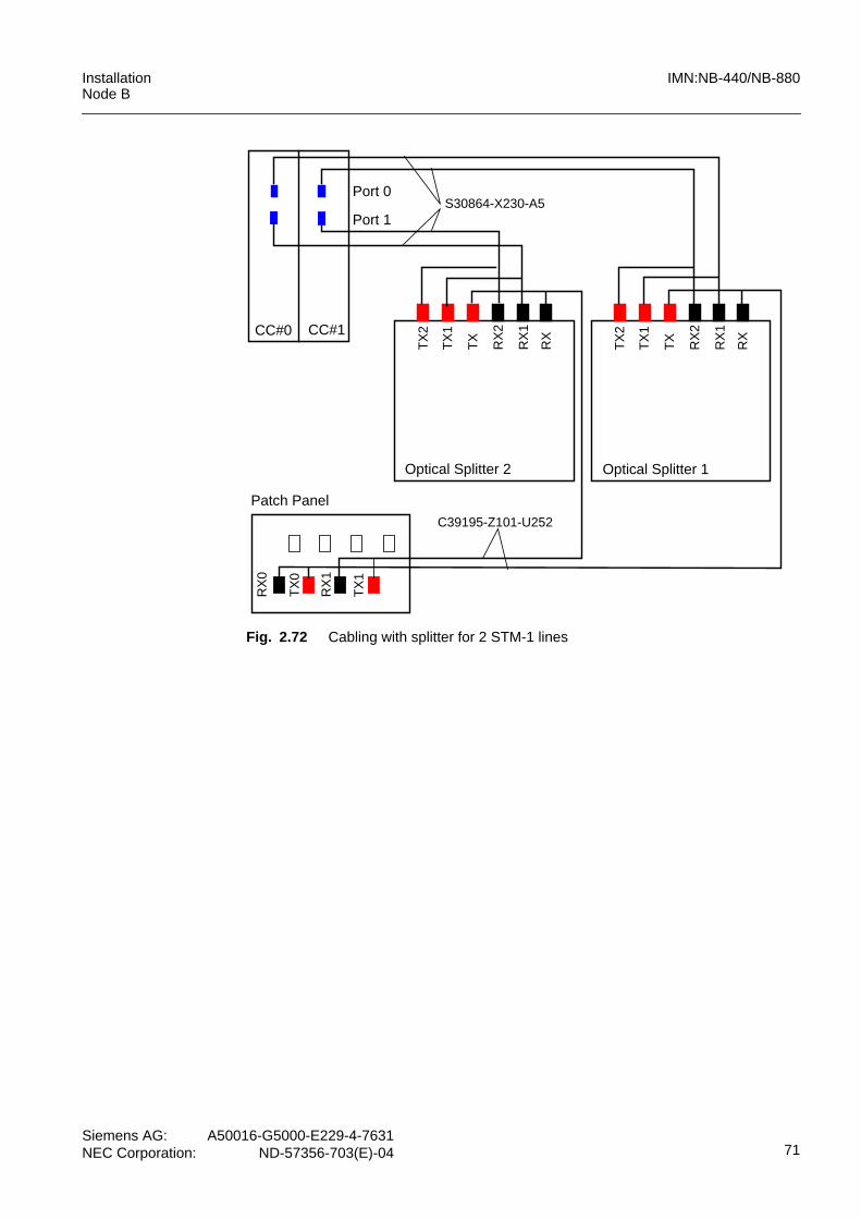
InstallationNode B
IMN:NB-440/NB-880
Siemens AG: A50016-G5000-E229-4-7631NEC Corporation: ND-57356-703(E)-04 71
Fig. 2.72 Cabling with splitter for 2 STM-1 lines
Port 0
Port 1
CC#1CC#0
Optical Splitter 1
Patch Panel
RX
0
TX
0
RX
1
TX
1
RX
TX
RX
1
RX
2
TX
1
TX
2
C39195-Z101-U252
S30864-X230-A5
Optical Splitter 2
RX
TX
RX
1
RX
2
TX
1
TX
2

IMN:NB-440/NB-880 InstallationNode B
72Siemens AG:A50016-G5000-E229-4-7631NEC Corporation:ND-57356-703(E)-04
2.7 Post Installation Notes
2.7.1 Fitting of the Profile CylinderThe door provides a locking system. A profile cylinder lock according to DIN 18252 al-lows the use of keys. The lock can be installed by the customer if a network specific lock-ing system does exist. Pay attention to the following advises for fitting and use of the keycylinders:– install only profile cylinders with a matching length (half cylinder)– open the lock with the original key only– do not turn the key with the aid of tongs– fit and pull out the cylinder without lateral pressure– insert the profile cylinder without any force– the cylinder should be smeared graphite, later in cycles of six month– insert the key completely first before turning– do not use bent keys
In addition follow the installation instructions of the manufacturer.
Fig. 2.73 Dimensions of the key cylinder according to DIN 18252
2.7.2 Leaving the SiteThe following instructions must carried out before leaving the site:– Check the completed installation, fill out the checklist as shown in chapter “Checklist
for NB-440/NB-880 Installation”.– At the end of the working day enable any alarms that should be active.– Contact the Network Control Center to announce your departure.– Close and lock the rack door.– Ensure the site is secure or hand over to the person in charge / caretaker
If all installation activities are finished, any garbage should be cleared from site. Removeall packing material for recycling.
17+/-1 6.6+/-0.2
R1.2 +/-0.2
R15 +0.05/-0.2
5.3 0/-0.5
10 +/-0,1
19+
/-0.
2
33.3
0/-0
.5
A=3010 +/-1
9.5 0/-0.5
M5
half cylinder

InstallationNode B
IMN:NB-440/NB-880
Siemens AG: A50016-G5000-E229-4-7631NEC Corporation: ND-57356-703(E)-04 73
3 Appendix
3.1 Checklist for NB-440/NB-880 Installation
Check Item Yes No
Grounding
Node B connected to ground as described in section “Ground andPower Supply Connections -48V DC”
Power Supply
Cross section of power supply cable sufficient
Proper disconnect and overcurrent device installed
connection correspondent to TNS-or TT Network requirements
Cross section correspondent to cable length
External Alarms
External alarm cables with braided screen
Cable screen contacted to metal lid of cable feeding module
Cable screen contacted to ground at both ends
Overvoltage protection equipment present and correct installed
IuB cables
IuB cables with braided screen
Cable screens connected with EMI panel of rack
Cable screen contacted to ground at both ends
NTPM connector for cable screens correspondent to EMC require-ments
Overvoltage protection equipment present and correct installed
Antenna Cables
Outer conductor of antenna cables connected to ground at anten-na window
Grounding of antenna cables between antenna and antenna win-dow correspondent to grounding guideline
Cable parameters collected and part of the customer documenta-tion (in case of turnkey installation only - input from the subcontrac-tor may be required)
Antenna cable conductor protected against humidity
Tab. 3.1 Checklist for NB-440/NB-880 Installation