Aviation Boatswain's Mate E NAVEDTRA 14310 NONRESIDENT TRAINING COURSE July 2001 DISTRIBUTION STATEMENT A: Approved for public release; distribution is unlimited. Notice: NETPDTC is no longer responsible for the content accuracy of the NRTCs. For content issues, contact the servicing Center of Excellence: Center for Naval Aviation Technical Training (CNATT); (850) 452-9659, Ext. 3247 or DSN: 922- 9659, Ext. 3247.

Welcome message from author
This document is posted to help you gain knowledge. Please leave a comment to let me know what you think about it! Share it to your friends and learn new things together.
Transcript

Aviation Boatswain'sMate ENAVEDTRA 14310
NONRESIDENTTRAININGCOURSE
July 2001
DISTRIBUTION STATEMENT A: Approved for public release; distribution is unlimited.
Notice: NETPDTC is no longer responsible for the content accuracy of the NRTCs. For content issues, contact the servicing Center of Excellence: Center for Naval Aviation Technical Training (CNATT); (850) 452-9659, Ext. 3247 or DSN: 922-9659, Ext. 3247.

Although the words “he,” “him,” and“his” are used sparingly in this course toenhance communication, they are notintended to be gender driven or to affront ordiscriminate against anyone.
DISTRIBUTION STATEMENT A: Approved for public release; distribution is unlimited.
PREFACE
By enrolling in this self-study course, you have demonstrated a desire to improve yourself and theNavy. Remember, however, this self-study course is only one part of the total Navy trainingprogram. Practical experience, schools, selected reading, and your desire to succeed are alsonecessary to successfully round out a fully meaningful training program.
COURSE OVERVIEW: When you complete this course you will be familiar with commonmaintenance tools and their uses, measuring tools and techniques, aircraft recovery equipment,steam catapults, and associated launching equipment. You will also learn about the aircraftlaunch and recovery equipment maintenance program (ALREMP) and maintenance planningand administration.
THE COURSE: This self-study course is organized into subject matter areas, each containinglearning objectives to help you determine what you should learn along with text and illustrationsto help you understand the information. The subject matter reflects day-to-day requirements andexperiences of personnel in the rating or skill area. It also reflects guidance provided by EnlistedCommunity Managers (ECMs) and other senior personnel, technical references, instructions,etc., and either the occupational or naval standards, which are listed in the Manual of NavyEnlisted Manpower Personnel Classifications and Occupational Standards, NAVPERS 18068.
THE QUESTIONS: The questions that appear in this course are designed to help youunderstand the material in the text.
VALUE: In completing this course, you will improve your military and professional knowledge.Importantly, it can also help you study for the Navy-wide advancement in rate examination. Ifyou are studying and discover a reference in the text to another publication for furtherinformation, look it up.
2001 Edition Prepared byABECS(AW) Johnny Eggleston
i
NAVSUP Logistics Tracking Number0504- LP-026-4030

ii
Sailor’s Creed
“I am a United States Sailor.
I will support and defend theConstitution of the United States ofAmerica and I will obey the ordersof those appointed over me.
I represent the fighting spirit of theNavy and those who have gonebefore me to defend freedom anddemocracy around the world.
I proudly serve my country’s Navycombat team with honor, courageand commitment.
I am committed to excellence andthe fair treatment of all.”

TABLE OF CONTENTS
APPENDIX
iii
CHAPTER PAGE
INDEX .................................................................................................................................. INDEX-1
1. Common Maintenance Tools and their Uses.......................................................... 1-1
2. Measuring Tools and Techniques.......................................................................... 2-1
3. Mk 7 Aircraft Recovery Equipment and Emergency Recovery Equipment ............ 3-1
4. Steam Catapults.................................................................................................... 4-1
5. Associated Launching Equipment ......................................................................... 5-1
6. The Aircraft Launch and Recovery Equipment Maintenance Program................... 6-1
7. Maintenance Planning and Administration ............................................................ 7-1
I. Glossary .......................................................................................................... AI-1
II. References....................................................................................................... AII-1
III. Answers to Review Questions ........................................................................ AIII-1

INSTRUCTIONS FOR TAKING THE COURSE
ASSIGNMENTS
The text pages that you are to study are listed at thebeginning of each assignment. Study these pagescarefully before attempting to answer the questions.Pay close attention to tables and illustrations and readthe learning objectives. The learning objectives statewhat you should be able to do after studying thematerial. Answering the questions correctly helps youaccomplish the objectives.
SELECTING YOUR ANSWERS
Read each question carefully, then select the BESTanswer. You may refer freely to the text. The answersmust be the result of your own work and decisions. Youare prohibited from referring to or copying the answersof others and from giving answers to anyone else takingthe course.
SUBMITTING YOUR ASSIGNMENTS
To have your assignments graded, you must be enrolledin the course with the Nonresident Training CourseAdministration Branch at the Naval Education andTraining Professional Development and TechnologyCenter (NETPDTC). Following enrollment, there aretwo ways of having your assignments graded: (1) usethe Internet to submit your assignments as youcomplete them, or (2) send all the assignments at onetime by mail to NETPDTC.
Grading on the Internet: Advantages to Internetgrading are:
you may submit your answers as soon as youcomplete an assignment, andyou get your results faster; usually by the nextworking day (approximately 24 hours).
In addition to receiving grade results for eachassignment, you will receive course completionconfirmation once you have completed all the
assignments. To submit your assignment answers viathe Internet, go to:
https://courses.cnet.navy.mil
COMPLETION TIME
Courses must be completed within 12 months from thedate of enrollment. This includes time required toresubmit failed assignments.
iv
PASS/FAIL ASSIGNMENT PROCEDURES
If your overall course score is 3.2 or higher, you willpass the course and will not be required to resubmitassignments. Once your assignments have been gradedyou will receive course completion confirmation.
If you receive less than a 3.2 on any assignment andyour overall course score is below 3.2, you will begiven the opportunity to resubmit failed assignments.You may resubmit failed assignments only once.Internet students will receive notification when theyhave failed an assignment—they may then resubmitfailed assignments on the web site. Internet studentsmay view and print results for failed assignments fromthe web site. Students who submit by mail will receivea failing result letter and a new answer sheet forresubmission of each failed assignment.
COMPLETION CONFIRMATION
After successfully completing this course, you willreceive a letter of completion.
STUDENT FEEDBACK QUESTIONS
We value your suggestions, questions, and criticismson our courses. If you would like to communicate withus regarding this course, we encourage you, if possible,to use e-mail. If you write or fax, please use a copy ofthe Student Comment form that follows this page.
NAVAL RESERVE RETIREMENT CREDIT
If you are a member of the Naval Reserve, you willreceive retirement points if you are authorized toreceive them under current directives governingretirement of Naval Reserve personnel. For NavalReserve retirement, this course is evaluated at 8points. (Refer to Administrative Procedures for NavalReservists on Inactive Duty, BUPERSINST 1001.39,for more information about retirement points.)
v

vi
(THIS PAGE IS INTENTIONALLY LEFT BLANK.)

Student Comments
NETPDTC 1550/41 (Rev 4-00)
vii
Privacy Act Statement: Under authority of Title 5, USC 301, information regarding your military status isrequested in processing your comments and in preparing a reply. This information will not be divulged withoutwritten authorization to anyone other than those within DOD for official use in determining performance.
Course Title: Aviation Boatswain's Mate E
NAVEDTRA: 14310 Date:
We need some information about you:
Rate/Rank and Name: SSN: Command/Unit
Street Address: City: State/FPO: Zip
Your comments, suggestions, etc.:


CHAPTER 1
COMMON MAINTENANCE TOOLS AND THEIR USES
Tools are designed to make a job easier and enableyou to work more efficiently. If they are not properlyused and cared for, their advantages are lost to you.
Regardless of the type of work to be done, you musthave, choose, and use the correct tools in order to doyour work quickly, accurately, and safely. Without theproper tools and the knowledge of how to use them, youwaste time, reduce your efficiency, and may even injureyourself.
This chapter explains the specific purposes, correctuse, and proper care of the more common tools you willencounter as an ABE. Also discussed briefly are otheraids to maintenance, such as blueprints and schematics.
TOOL WORK HABITS
LEARNING OBJECTIVES: Describe theTool Control Program. List several good toolwork habits.
"A place for everything and everything in its place"is just good common sense. You can't do an efficientrepair job if you have to stop and look around for eachtool you need. The following rules will make your jobeasier and safer.
KEEP EACH TOOL IN ITS PROPER STOWAGEPLACE. All V-2 divisions have incorporated a ToolControl Program as directed by the Aircraft Launchand Recovery Equipment Maintenance Program(ALREMP).
The Tool Control Program is based on the conceptof a family of specialized toolboxes and pouchesconfigured for instant inventory before and after eachmaintenance action. The content and configuration ofeach container is tailored to the task, work center, andequipment maintained. Work center containers areassigned to and maintained within a work center. Otherboxes and specialized tools are checked out from thetool control center (tool room).
KEEP YOUR TOOLS IN GOOD CONDITION.Protect them from rust, nicks, burrs, and breakage.
KEEP YOUR TOOL ALLOWANCE COM-PLETE. When you are issued a toolbox, each toolshould be placed in it when not in use. When the
toolbox is not actually at the work site, it should belocked and stored in a designated area.
NOTE
An inventory list is kept in every toolbox tobe checked before and after each job ormaintenance action, to ensure that all tools areavailable to do your work, and to ensure thatthey are accounted for after you havecompleted your work.
USE EACH TOOL ONLY FOR THE JOB IT WASDESIGNED TO DO. Each particular type of tool has aspecific purpose. If you use the wrong tool whenperforming maintenance or repairs, you may causedamage to the equipment you're working on or damagethe tool itself. Remember, improper use of tools resultsin improper maintenance. Improper maintenanceresults in damage to equipment and possible injury ordeath to you or others.
SAFE MAINTENANCE PRACTICES. Alwaysavoid placing tools on or above machinery or anelectrical apparatus. Never leave tools unattendedwhere machinery or aircraft engines are running.
NEVER USE DAMAGED TOOLS. A batteredscrewdriver may slip and spoil the screw slot, damageother parts, or cause painful injury. A gauge strainedout of shape will result in inaccurate measurements.
Remember, the efficiency of craftsmen and thetools they use are determined to a great extent by theway they keep their tools. Likewise, they are frequentlyjudged by the manner in which they handle and care forthem. Anyone watching skilled craftsmen at worknotices the care and precision with which they use thetools of their trade.
The care of hand tools should follow the samepattern as for personal articles; that is, always keephand tools clean and free from dirt, grease, and foreignmatter. After use, return tools promptly to their properplace in the toolbox. Improve your own efficiency byorganizing your tools so that those used mostfrequently can be reached easily without diggingthrough the entire contents of the box. Avoidaccumulating unnecessary junk.
1-1

REVIEW QUESTIONS
Q1. Describe the Tool Control Program.
Q2. List several good tool work habits.
Q3. What are inspection mirrors used for?
CARE OF HAND TOOLS
LEARNING OBJECTIVES: List severalprinciples that apply to the care of hand tools.
Tools are expensive; tools are vital equipment.When the need for their use arises, common sense plusa little preventive maintenance prolongs theirusefulness. The following precautions for the care oftools should be observed:
• Clean tools after each use. Oily, dirty, and greasytools are slippery and dangerous to use.
• NEVER hammer with a wrench.
• NEVER leave tools scattered about. When theyare not in use, stow them neatly on racks or intoolboxes.
• Apply a light film of oil after cleaning to preventrust on tools.
• INVENTORY tools after use to prevent loss.
REVIEW QUESTION
Q4. List several principles that apply to the careof hand tools.
PERSONAL SAFETY EQUIPMENT
LEARNING OBJECTIVES: Identify thetypes of personal safety equipment.
To protect you from danger, protective equipmentsuch as safety shoes, goggles, hard hats, and gloves areissued. The use of this equipment is mandatory oncertain jobs. Their use is a MUST, and there is noquestion about that. Be sure to USE THEM on any jobWHERE they are REQUIRED. They can protect youfrom a lot of harm.
SAFETY SHOES
Some safety shoes are designed to limit damage toyour toes from falling objects. A steel plate is placed inthe toe area of such shoes so that your toes are notcrushed if an object impacts there.
Other safety shoes are designed for use wheredanger from sparking could cause an explosion. Suchdanger is minimized by elimination of all metallic nailsand eyelets and by the use of soles that do not causestatic electricity.
GOGGLES
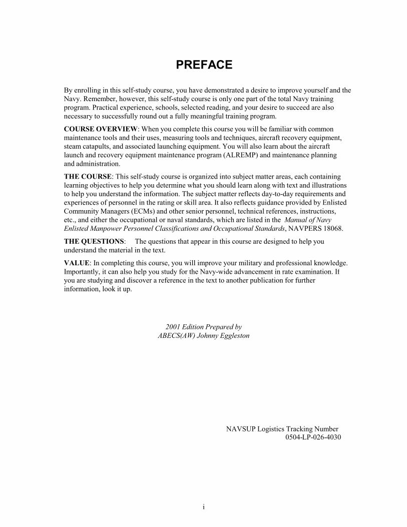
Proper eye protection is of the utmost importancefor all personnel. Eye protection is necessary becauseof hazards posed by infrared and ultraviolet radiation,or by flying objects such as sparks, globules of moltenmetal, or chipped concrete and wood. These hazardsare ever-present during welding, cutting, soldering,chipping, grinding, and a variety of other operations. Itis IMPERATIVE for you to use eye protection devices,such as helmets, face shields, and goggles (fig. 1-1),during eye-hazard operations.
Appropriate use of goggles will limit eye hazards.Some goggles have plastic lenses that resist shatteringupon impact. Others are designed to limit harmfulinfrared and ultraviolet radiation from arcs or flames byuse of appropriate filter lenses.
Remember, eye damage can be excruciatinglypainful. PROTECT YOUR EYES.
GLOVES
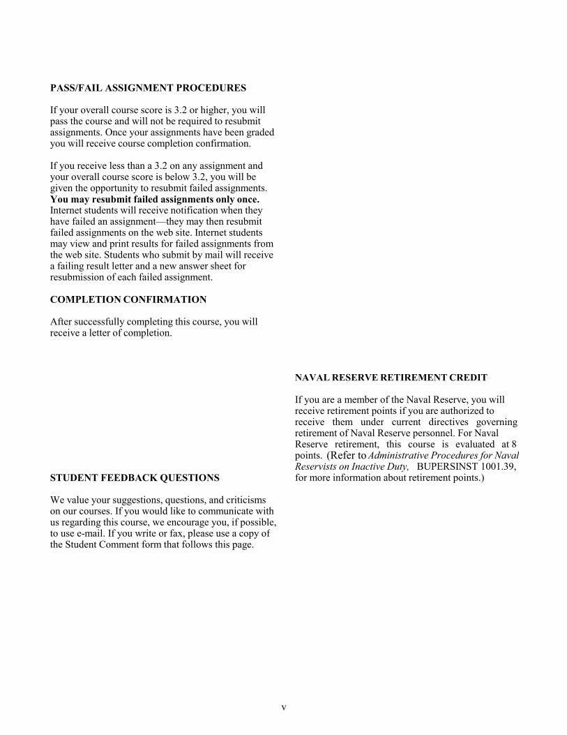
Use gloves whenever you are required to handlerough, scaly, or splintery objects. Special flameproofgloves are designed for gas and electric-arc welding tolimit danger and damage from sparks and other hotflying objects (fig. 1-2). Personnel in the electricalfields are usually required to wear insulating rubbergloves.
Be sure to follow all regulations prescribed for theuse of gloves. Gloves must not be worn around rotatingmachinery unless sharp or rough material is beinghandled. If such is the case, EXTREME CARESHOULD BE EXERCISED to prevent the gloves frombeing caught in the machinery.
SAFETY BELTS AND STRAPS
The safety strap and body belt shown in figure 1-3are what might be called your extra hands when youwork aloft. The body belt, strapped around your waist,contains various pockets for small tools. The safetystrap is a leather or neoprene-impregnated nylon beltwith a tongue-type buckle at each end. While you areclimbing you will have the safety strap hanging by bothends from the left ring (called a D-ring because of its
1-2
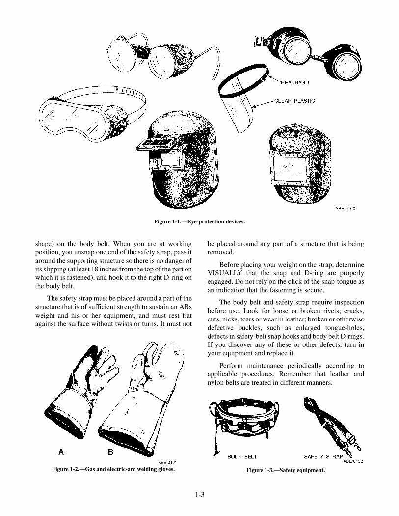
shape) on the body belt. When you are at workingposition, you unsnap one end of the safety strap, pass itaround the supporting structure so there is no danger ofits slipping (at least 18 inches from the top of the part onwhich it is fastened), and hook it to the right D-ring onthe body belt.
The safety strap must be placed around a part of thestructure that is of sufficient strength to sustain an ABsweight and his or her equipment, and must rest flatagainst the surface without twists or turns. It must not
be placed around any part of a structure that is beingremoved.
Before placing your weight on the strap, determineVISUALLY that the snap and D-ring are properlyengaged. Do not rely on the click of the snap-tongue asan indication that the fastening is secure.
The body belt and safety strap require inspectionbefore use. Look for loose or broken rivets; cracks,cuts, nicks, tears or wear in leather; broken or otherwisedefective buckles, such as enlarged tongue-holes,defects in safety-belt snap hooks and body belt D-rings.If you discover any of these or other defects, turn inyour equipment and replace it.
Perform maintenance periodically according toapplicable procedures. Remember that leather andnylon belts are treated in different manners.
1-3
Figure 1-2.—Gas and electric-arc welding gloves.
Figure 1-1.—Eye-protection devices.
Figure 1-3.—Safety equipment.

REVIEW QUESTION
Q5. Identify the different types of personal safetyequipment.
MAINTENANCE AIDS
LEARNING OBJECTIVES: Read andinterpret blueprints, drawings, diagrams, andother maintenance aids.
As an ABE you will be required to read blueprintsand drawings during the performance of manymaintenance actions required to maintain theoperational readiness of the catapults and the arrestinggear engines. As you advance in rating you may also berequired to make sketches and drawings, which willassist you in the training of less-experiencedmaintenance personnel by making it possible for themto visualize the system or object you are explaining.
BLUEPRINTS AND DRAWINGS
Blueprints are exact copies of mechanical or othertypes of drawings and employ a language of their own.It is a form of sign language or shorthand that useslines, graphic symbols, dimensions, and notations toaccurately describe the form size, kind of material,finish, and construction of an object. It can be said thatblueprint reading is largely a matter of translating theselines and symbols into terms of procedure, materials,and other details needed to repair, maintain, or fabricatethe object described on the print.
Usually you can look at a blueprint and recognizethe object if you are familiar with the actual part. Butwhen you are required to make or check on a certainpart, the applicable blueprint must be referred to inorder to get dimensions and other pertinentinformation. The important thing is to know what thedifferent symbols stand for and where to look for theimportant information on a blueprint. Some of theimportant facts listed on all blueprints are discussed inthe following paragraphs.
Title Block
The title block is located in the lower right corner ofall blueprints and drawings prepared according tomilitary standards. The block contains the drawingnumber, the name of the part or assembly that theblueprint represents, and all information required toidentify the part or assembly.
The title block also includes the name and addressof the Government agency or organization preparingthe drawing, the scale, drafting record, authentication,and the date (fig. 1-4).
A space within the title block with a diagonal orslant line drawn across it indicates that the informationusually placed in it is not required or is given elsewhereon the drawing.
Revision Block
The revision block (not shown) is usually located inthe upper right corner of the blueprint and is used forthe recording of changes (revisions) to the print. Allrevisions are noted in this block and are dated andidentified by a letter and a brief description of therevision. A revised drawing is shown by the addition ofa letter to the original number in the title block, asshown in figure 1-4, view A. If the print shown in figure1-4, view A, was again revised, the letter in the revisionblock of the title block would be replaced by theletter B.
Drawing Number
All blueprints are identified by a drawing number(NAVSHIP Systems Command No. in view A of fig.1-4, and FEC Drawing No. in view B), which appears ina block in the lower right corner of the title block. Itmay be shown in other places also; for example, nearthe top border line in an upper corner, or on the reverseside at both ends so that it will be visible when adrawing is rolled up. If a blueprint has more than onesheet, this information is included in the blockindicating the sheet number and the number of sheets inthe series. For example, note that in the title blocksshown in figure 1-4 the blueprint is sheet 1 of 1.
Reference Numbers
Reference numbers that appear in the title blockrefer to numbers of other blueprints. When more thanone detail is shown on a drawing, a dash and a numberare frequently used. For example, if two parts areshown in one detail drawing, both prints would have thesame drawing number, plus a dash and an individualnumber, such as 8117041-1 and 8117041-2.
In addition to appearing in the title block, the dashand number may appear on the face of the drawings,near the parts they identify. Some commercial printsshow the drawing and dash number, and point with aleader line to the part; others use a circle, 3/8 inch in
1-4

diameter, around the dash number, and carry a leaderline to the part.
A dash and number are used to identify modified orimproved parts, and also to identify right-hand andleft-hand parts. Many aircraft parts on the left-hand sideof an aircraft are exactly like the corresponding parts onthe right-hand side but in reverse. The left-hand partsare usually shown in the drawing.
Above the title block on some prints you may see anotation such as "159674 LH shown; 159674-1 RHopposite." Both parts carry the same number. But thepart called for is distinguished by a dash and number.(LH means left-hand, and RH means right-hand.) Somecompanies use odd numbers for right-hand parts andeven numbers for left-hand parts.
Drawing Lines
The lines used in working drawings are more than ameans of showing a picture of an object for the purposeof building or repairing. The way a line is drawn has adefinite meaning.
Thick lines are used for the visible outline of theobject being drawn. Medium lines are used for thedotted lines representing hidden features and forcutting-plane, short-break, adjacent-part, andalternate-position lines. Center lines, dimension lines,long-break lines, ditto lines, extension lines, andsection lines are represented by thin lines.
To understand blueprint reading, you must knowthe different types of lines used in general drawingpractice and the information conveyed by each. Someof the lines of major importance are illustrated in
1-5
Figure 1-4.—Blueprint title blocks. (A) Naval Ship's Systems Command; (B) Naval Facilities Engineering Command.

figures 1-5-A and 1-5-B. The correct uses areillustrated in figure 1-6.
Blueprints make it possible to understand, in acomparatively small space, what is to be made orrepaired. Of the many types of blueprints you will useaboard ship, the simplest one is the plan view. This type
of blueprint shows the position, location, and use of thevarious parts of the ship; for example, to find thebattlestations sickbay, barbershop, or other parts of theship. In addition to plan views, other blueprints, calledassembly prints, unit or subassembly prints, and detailprints, show various kinds of machinery andmechanical equipment.
1-6
Figure 1-5-A.—Standard lines.
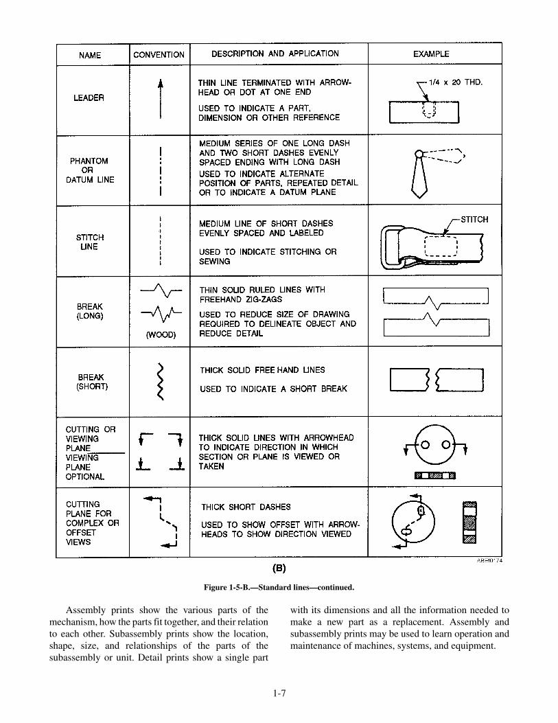
Assembly prints show the various parts of themechanism, how the parts fit together, and their relationto each other. Subassembly prints show the location,shape, size, and relationships of the parts of thesubassembly or unit. Detail prints show a single part
with its dimensions and all the information needed tomake a new part as a replacement. Assembly andsubassembly prints may be used to learn operation andmaintenance of machines, systems, and equipment.
1-7
Figure 1-5-B.—Standard lines—continued.

MICROFILM/APERTURE CARDS
Many prints and drawings are procured in the formof 16- and 35-mm microfilm. Microfilm prints anddrawings are available mounted on aperture (viewer)cards, as well as in roll form. A reader or some type ofprojector is required to enlarge the microfilm forreading. Activities are provided with a microfilmreader-printer, which as its name implies, enlarges themicrofilm for reading and also has the capability ofprinting a working copy in a matter of a few seconds.
Microfilm greatly reduces the size of otherwisebulky files, which is very important aboard ship.
SCHEMATIC DIAGRAMS
Schematic diagrams show by means of single linesand symbols how the parts of a system are connectedfor the operation of the system.
Piping
Piping diagrams are normally used to trace pipingsystems and their functions without actually describingthe shape, size, or location of the components or parts.Each component is represented by a symbol; and oncethese symbols are learned, the piping schematicdiagram is easy to read.
Figure 1-7 is a good example of a piping diagram.As may be seen from this example, diagrams do notindicate the location of individual components withinthe station, but do locate the components with respectto each other within the system.
Electrical
Schematic diagrams are also used to depictelectrical systems. They are basically the same as the
1-8
PHANTOM LINE
CENTER LINEDIMENSION LINE
OUTLINEHIDDEN LINE
CUTTING PLANE LINE
BREAK LINE
EXTENSION LINE
LEADER LINE
SECTIONING LINE
SECTION - AA
ABEf0175
A
A
Figure 1-6.—Use of standard lines.
COOLING PANEL
ABEf0176
8 9
7 10
P
M.C.
CATAPULTCONSOLE
11
12
6
5
P
3 4
2
13
1
FIREMAIN
OVERBOARD
Cutout valve.Reducing valveThrottling valve.Relief valve.Test gauge.
1.2.3.4.5.
Hytrol valve.Pilot valve.Inlet lines.Discharge lines.Pressure gage.
6.7.8.9.
10.
Orifice.Scuppervalve.Hosevalves.
11.12.
13.
Figure 1-7.—Typical piping schematic for saltwater cooling.
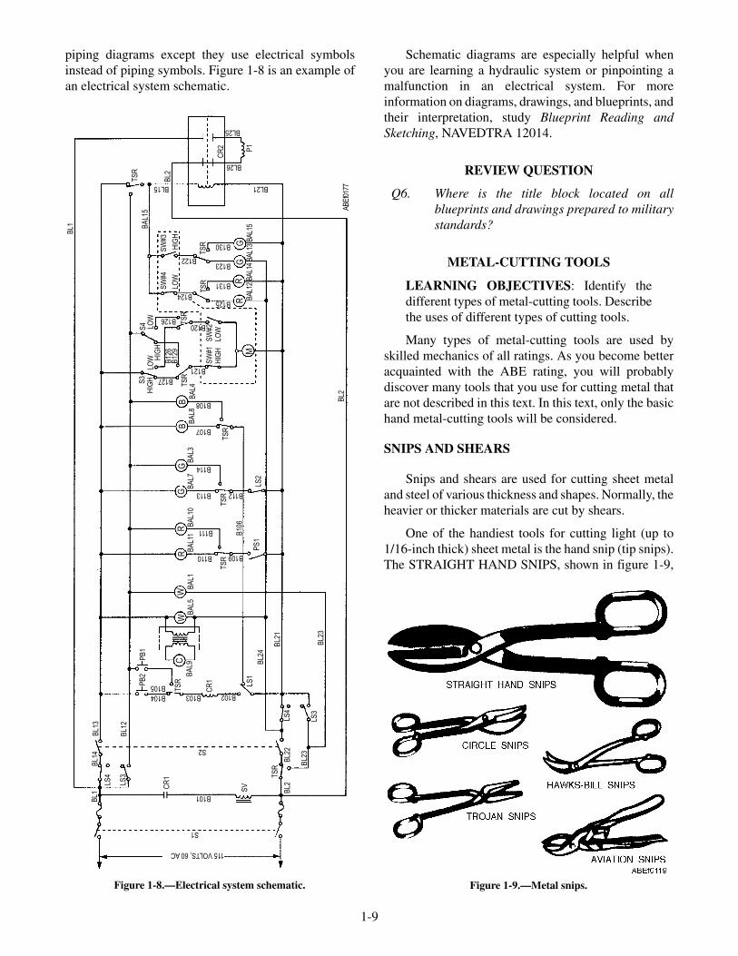
piping diagrams except they use electrical symbolsinstead of piping symbols. Figure 1-8 is an example ofan electrical system schematic.
Schematic diagrams are especially helpful whenyou are learning a hydraulic system or pinpointing amalfunction in an electrical system. For moreinformation on diagrams, drawings, and blueprints, andtheir interpretation, study Blueprint Reading andSketching, NAVEDTRA 12014.
REVIEW QUESTION
Q6. Where is the title block located on allblueprints and drawings prepared to militarystandards?
METAL-CUTTING TOOLS
LEARNING OBJECTIVES: Identify thedifferent types of metal-cutting tools. Describethe uses of different types of cutting tools.
Many types of metal-cutting tools are used byskilled mechanics of all ratings. As you become betteracquainted with the ABE rating, you will probablydiscover many tools that you use for cutting metal thatare not described in this text. In this text, only the basichand metal-cutting tools will be considered.
SNIPS AND SHEARS
Snips and shears are used for cutting sheet metaland steel of various thickness and shapes. Normally, theheavier or thicker materials are cut by shears.
One of the handiest tools for cutting light (up to1/16-inch thick) sheet metal is the hand snip (tip snips).The STRAIGHT HAND SNIPS, shown in figure 1-9,
1-9
BL1
BL1
4B
L13
BL1
2
LS4
LS3
CR
1
B101
S1
115VOLTS,60AC
S2
B104 B103 B102
SV
TS
R
BL2
BL2
2LS
4
LS1
BL2
4
BL2
1
BL2
3LS
3
PS
1
B10
6
LS2
TS
RT
SR
B110
B111
B113
BA
L5B
AL1
BA
L11
BA
L10
B109
B114
B107
B108
B112
TS
R
BA
L7B
AL3
BA
L8B
AL4
B121
SW
#1H
IGH
SW
#2LO
W
MR
RG
G
B120
B125
B131
B123
B130
TS
RT
SR
TS
RT
SR
B122
B124
BA
L12
BA
L14
BA
L13
BA
L15
LOW
HIG
H
SW
#4S
W#3
B126
B127
B12
6B
129
HIG
HLO
WLO
WS
4S
3B
AL1
5H
IGH
BB
GG
TS
R
BL2
CR
2
BL15 BL21
BL26
BL25
P1
BL2
BL2
3
PB
2
TS
RB105
BA
L9
PB
1
CR
1
CW
WR
R
BL1
AB
Ef0
177
Figure 1-8.—Electrical system schematic. Figure 1-9.—Metal snips.

have blades that are straight and cutting edges that aresharpened to an 85-degree angle. Snips like this can beobtained in different sizes, ranging from the small,6-inch, to the large, 14-inch, snip. Tin snips will alsowork on slightly heavier gauges of soft metals, such asaluminum alloys.
Snips will not remove any metal when a cut ismade. There is danger, though, of causing minute metalfractures along the edges of the metal during theshearing process. For this reason, it is better to cut justoutside the layout line. This procedure will allow you todress the cutting edge while keeping the material withinrequired dimensions.
Cutting extremely heavy gauge metal alwayspresents the possibility of springing the blades. Oncethe blades are sprung, hand snips are useless. Whencutting heavy material, use the rear portion of theblades. This procedure not only avoids the possibilityof springing the blades but also gives you greatercutting leverage.
Many snips have small serrations (notches) on thecutting edges of the blades. These serrations tend toprevent the snips from slipping backwards when a cut isbeing made. Although this feature does make the actualcutting easier, it mars the edges of the metal slightly.You can remove these small cutting marks if you allowproper clearance for dressing the metal to size. Thereare many other types of hand snips used for specialjobs, but the snips discussed here can be used for almostany common type of work.
Cutting Sheet Metal with Snips
It is hard to cut circles or small arcs with straightsnips. There are snips especially designed for circularcutting. They are called CIRCLE SNIPS,HAWKS-BILL SNIPS, TROJAN SNIPS, and AVIA-TION SNIPS (fig. 1-9).
To cut large holes in the lighter gauges of sheetmetal, start the cut by punching or otherwise making ahole in the center of the area to be cut out. With anaviation snips, or some other narrow-bladed snips,make a spiral cut from the starting hole out toward thescribed circle, as shown in figure 1-10, and continuecutting until the scrap falls away.
To cut a disk in the lighter gauges of sheet metal,use a combination snips or a straight-blade snips, asshown in figure 1-11. First, cut away any surplusmaterial outside the scribed circle, leaving only anarrow piece to be removed by the final cut. Make the
final cut just outside the layout line. This will permityou to see the scribed line while you are cutting and willcause the scrap to curl up below the blade of the snips,where it will be out of the way while the complete cut isbeing made.
To make straight cuts, place the sheet metal on abench with the marked guideline over the edge of thebench and hold the sheet down with one hand. With theother hand, hold the snips so that the flat sides of theblades are at right angles to the surface of the work. Ifthe blades are not at right angles to the surface of thework, the edges of the cut will be slightly bent andburred. The bench edge will also act as a guide whenyou are cutting with the snips. The snips will force thescrap metal down so that it does not interfere withcutting. Any of the hand snips may be used for straightcuts. When notches are too narrow to be cut out with apair of snips, make the side cuts with the snips and cutthe base of the notch with a cold chisel.
1-10
Figure 1-10.—Cutting an inside hole with snips.
Figure 1-11.—Cutting a disk out of sheet metal.
Safety and Care
Learn to use snips properly. They should always beoiled and adjusted to permit ease of cutting and toproduce a surface that is free from burrs. If the bladesbind or if they are too far apart, the snips should beadjusted. Remember the following safety tips:
• Never use snips as screwdrivers, hammers, orpry bars. They break easily.
• Do not attempt to cut heavier materials than thesnips are designed for. Never use tin snips to cuthardened steel wire or other similar objects.Such use will dent or nick the cutting edges ofthe blades.
• Never toss snips in a toolbox where the cuttingedges can come into contact with other tools.This dulls the cutting edges and may even breakthe blades.
• When snips are not in use, hang them on hooksor lay them on an uncrowded shelf or bench.
HACKSAWS
Hacksaws are used to cut metal that is too heavy forsnips or bolt cutters. Thus, metal bar stock can be cutreadily with hacksaws.
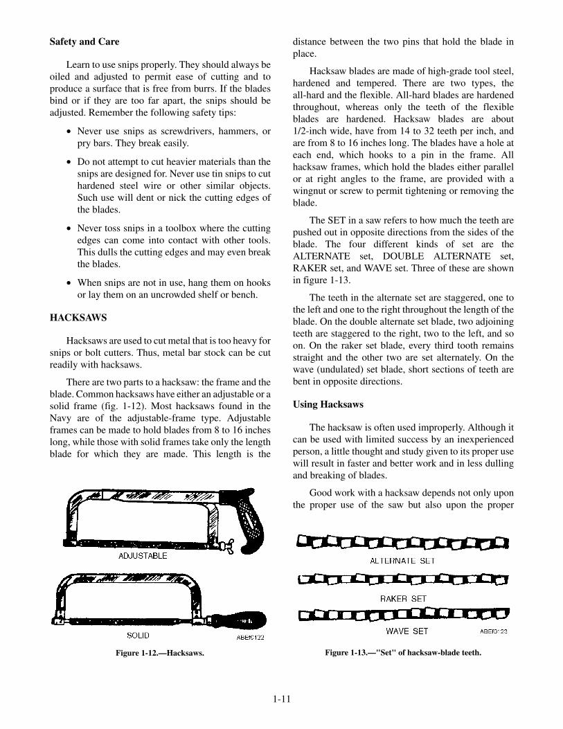
There are two parts to a hacksaw: the frame and theblade. Common hacksaws have either an adjustable or asolid frame (fig. 1-12). Most hacksaws found in theNavy are of the adjustable-frame type. Adjustableframes can be made to hold blades from 8 to 16 incheslong, while those with solid frames take only the lengthblade for which they are made. This length is the
distance between the two pins that hold the blade inplace.
Hacksaw blades are made of high-grade tool steel,hardened and tempered. There are two types, theall-hard and the flexible. All-hard blades are hardenedthroughout, whereas only the teeth of the flexibleblades are hardened. Hacksaw blades are about1/2-inch wide, have from 14 to 32 teeth per inch, andare from 8 to 16 inches long. The blades have a hole ateach end, which hooks to a pin in the frame. Allhacksaw frames, which hold the blades either parallelor at right angles to the frame, are provided with awingnut or screw to permit tightening or removing theblade.
The SET in a saw refers to how much the teeth arepushed out in opposite directions from the sides of theblade. The four different kinds of set are theALTERNATE set, DOUBLE ALTERNATE set,RAKER set, and WAVE set. Three of these are shownin figure 1-13.
The teeth in the alternate set are staggered, one tothe left and one to the right throughout the length of theblade. On the double alternate set blade, two adjoiningteeth are staggered to the right, two to the left, and soon. On the raker set blade, every third tooth remainsstraight and the other two are set alternately. On thewave (undulated) set blade, short sections of teeth arebent in opposite directions.
Using Hacksaws
The hacksaw is often used improperly. Although itcan be used with limited success by an inexperiencedperson, a little thought and study given to its proper usewill result in faster and better work and in less dullingand breaking of blades.
Good work with a hacksaw depends not only uponthe proper use of the saw but also upon the proper
1-11
Figure 1-12.—Hacksaws. Figure 1-13.—"Set" of hacksaw-blade teeth.
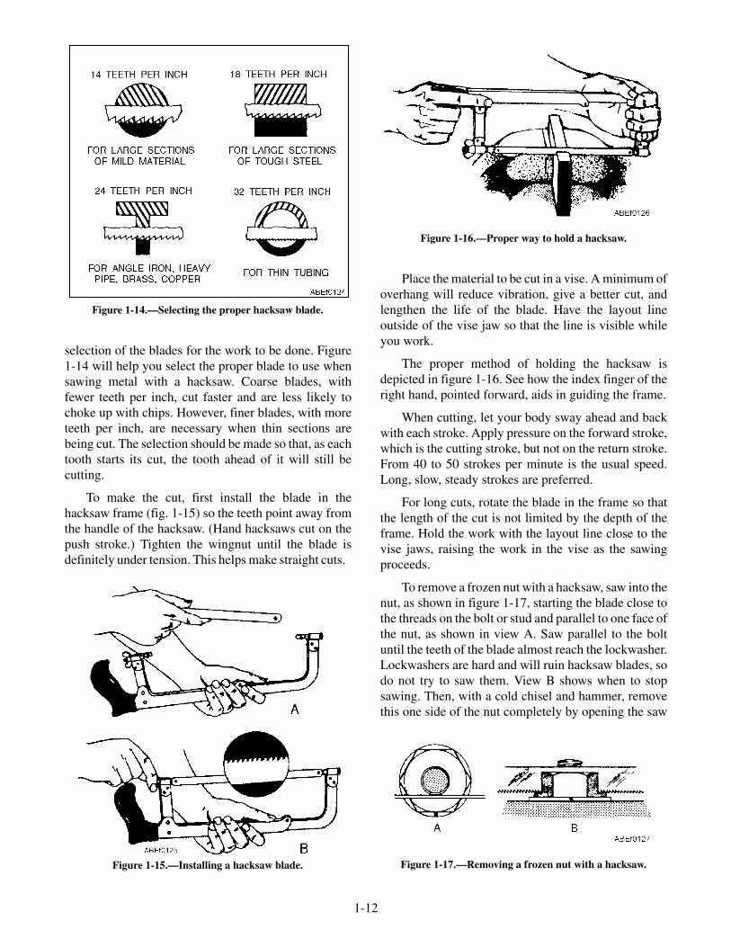
selection of the blades for the work to be done. Figure1-14 will help you select the proper blade to use whensawing metal with a hacksaw. Coarse blades, withfewer teeth per inch, cut faster and are less likely tochoke up with chips. However, finer blades, with moreteeth per inch, are necessary when thin sections arebeing cut. The selection should be made so that, as eachtooth starts its cut, the tooth ahead of it will still becutting.
To make the cut, first install the blade in thehacksaw frame (fig. 1-15) so the teeth point away fromthe handle of the hacksaw. (Hand hacksaws cut on thepush stroke.) Tighten the wingnut until the blade isdefinitely under tension. This helps make straight cuts.
Place the material to be cut in a vise. A minimum ofoverhang will reduce vibration, give a better cut, andlengthen the life of the blade. Have the layout lineoutside of the vise jaw so that the line is visible whileyou work.
The proper method of holding the hacksaw isdepicted in figure 1-16. See how the index finger of theright hand, pointed forward, aids in guiding the frame.
When cutting, let your body sway ahead and backwith each stroke. Apply pressure on the forward stroke,which is the cutting stroke, but not on the return stroke.From 40 to 50 strokes per minute is the usual speed.Long, slow, steady strokes are preferred.
For long cuts, rotate the blade in the frame so thatthe length of the cut is not limited by the depth of theframe. Hold the work with the layout line close to thevise jaws, raising the work in the vise as the sawingproceeds.
To remove a frozen nut with a hacksaw, saw into thenut, as shown in figure 1-17, starting the blade close tothe threads on the bolt or stud and parallel to one face ofthe nut, as shown in view A. Saw parallel to the boltuntil the teeth of the blade almost reach the lockwasher.Lockwashers are hard and will ruin hacksaw blades, sodo not try to saw them. View B shows when to stopsawing. Then, with a cold chisel and hammer, removethis one side of the nut completely by opening the saw
1-12
Figure 1-14.—Selecting the proper hacksaw blade.
Figure 1-15.—Installing a hacksaw blade.
Figure 1-16.—Proper way to hold a hacksaw.
Figure 1-17.—Removing a frozen nut with a hacksaw.

kerf. Put an adjustable wrench across this new flat andthe one opposite, and again try to remove the frozennut. Since very little original metal remains on this oneside of the nut, the nut will either give or break awayentirely and permit its removal.
To saw a wide kerf in the head of a cap screw ormachine bolt, fit the hand hacksaw frame with twoblades side by side, and with teeth lined up in the samedirection. With slow, steady strokes, saw the slotapproximately one-third the thickness of the head of thecap screw, as shown in figure 1-18. Such a slot willpermit subsequent holding or turning with ascrewdriver when it is impossible, due to close quarters,to use a wrench.
Hacksaw Safety
The main danger in using hacksaws is injury toyour hand if the blade breaks. The blade will break iftoo much pressure is applied, when the saw is twisted,when the cutting speed is too fast, or when the bladebecomes loose in the frame. Additionally, if the work isnot tight in the vise, it will sometimes slip, twisting theblade enough to break it.
CHISELS
Chisels are tools that can be used for chipping orcutting metal. They are made from a good grade of toolsteel and have a hardened cutting edge and beveledhead. Chisels are classified according to the shape oftheir points, and the width of the cutting edge denotestheir size. The most common shapes of chisels are theflat (cold chisel), cape, round nose, and diamond point(fig. 1-19).
The type of chisel most commonly used is the flatcold chisel, which serves to cut rivets, split nuts, chipcastings, and cut thin metal sheets. The cape chisel isused for special jobs like cutting keyways, narrowgrooves, and square corners. Round-nose chisels makecircular grooves and chip inside corners. Finally, thediamond-point is used for cutting V-grooves and sharpcorners.
As with other tools, there is a correct technique forusing a chisel. Select a chisel that is large enough forthe job. Be sure to use a hammer that matches thechisel; that is, the larger the chisel, the heavier thehammer. A heavy chisel will absorb the blows of a lighthammer and will do virtually no cutting.
When using a chisel for chipping, always weargoggles to protect your eyes. If others are working closeby, see that they are protected from flying chips byerecting a screen or shield to contain the chips.Remember that the time to take these precautions isbefore you start the job.
FILES
There are a number of different types of files incommon use, and each type may range in length from3 to 18 inches.
1-13
Figure 1-18.—Cutting a wide kerf in the head of a cap screw orbolt.
Figure 1-19.—Types of points on metal-cutting chisels.

Grades
Files are graded according to the degree of finenessand whether they have single- or double-cut teeth. Thedifference is apparent when you compare the files infigure 1-20, view A.
Single-cut files have rows of teeth cut parallel toeach other. These teeth are set at an angle of about 65degrees with the centerline. You will use single-cut filesfor sharpening tools, finish filing, and drawfiling. Theyare also the best tools for smoothing the edges of sheetmetal.
Files with crisscrossed rows of teeth are double-cutfiles. The double cut forms teeth that arediamond-shaped and fast cutting. You will usedouble-cut files for quick removal of metal and forrough work.
Files are also graded according to the spacing andsize of their teeth, or their coarseness and fineness.Some of these grades are pictured in view B. In additionto the three grades shown, you may use some DEADSMOOTH files, which have very fine teeth, and someROUGH files, with very coarse teeth. The fineness orcoarseness of file teeth is also influenced by the lengthof the file. (The length of a file is the distance from thetip to the heel, and does not include the tang view C.)When you have a chance, compare the actual size of theteeth of a 6-inch, single-cut smooth file and a 12-inch,single-cut smooth file; you will notice the 6-inch filehas more teeth per inch than the 12-inch file.
Shapes
Files come in different shapes. Therefore, inselecting a file for a job, consider the shape of thefinished work. Some of the cross-sectional shapes areshown in figure 1-20, view D.
TRIANGULAR files are tapered on all three sides.They are used to file acute internal angles and to clearout square corners. Special triangular files are used tofile saw teeth.
MILL files are tapered in both width and thickness.One edge has no teeth and is known as a SAFE EDGE.Mill files are used for smoothing lathe work,drawfiling, and other fine, precision work. Mill files arealways single-cut.
FLAT files are general-purpose files and may beeither single- or double-cut. They are tapered in widthand thickness. HARD files, not shown, are somewhat
thicker than flat files. They taper slightly in thickness,but their edges are parallel.
The flat or hard files most often used are thedouble-cut for rough work and the single-cut smoothfile for finish work.
1-14
Figure 1-20.—File information.

SQUARE files are tapered on all four sides and areused to enlarge rectangular-shaped holes and slots.ROUND files serve the same purpose for roundopenings. Small round files are often called "rattail"files.
The HALF ROUND file is a general-purpose tool.The rounded side is used for curved surfaces, and theflat face on flat surfaces. When you file an inside curve,use a round or half-round file whose curve most nearlymatches the curve of the work.
Kits of small files, often called "swiss pattern" or"jewelers'" files, are used to fit parts of delicatemechanisms and for filing work on instruments. Handlethese small files carefully because they break easily.
Filing Operations
Using a file is an operation that is nearlyindispensable when working with metal. You may becrossfiling, drawfiling, using a file card, or evenpolishing metal. Let's examine these operations.
When you have finished using a file, it may benecessary to use an abrasive cloth or paper to finish theproduct. Whether this is necessary depends on how finea finish you want on the work.
CROSSFILING.—Figure 1-21, view A, shows apiece of mild steel being crossfiled. This means that thefile is being moved across the surface of the work inapproximately a crosswise direction. For best results,keep your feet spread apart to steady yourself as youfile with slow, full-length, steady strokes. The file cutsas you push it—ease up on the return stroke to keepfrom dulling the teeth. Keep your file clean.
View B shows the alternate positions of the filewhen an exceptionally flat surface is required. Usingeither position first, file across the entire length of thestock. Then, using the other position, file across theentire length of the stock again. Because the teeth of thefile pass over the surface of the stock from twodirections, the high spots and low spots will readily bevisible after filing in both positions. Continue filingfirst in one position or direction and then the other until
1-15
Figure 1-21.—Filing operations.
the surface has been filed flat. Test the flatness with astraightedge or with prussian blue and a surface plate.
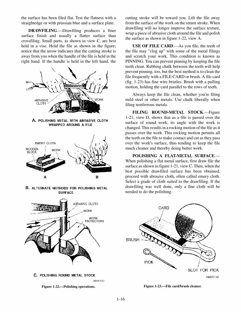
DRAWFILING.—Drawfiling produces a finersurface finish and usually a flatter surface thancrossfiling. Small parts, as shown in view C, are bestheld in a vise. Hold the file as shown in the figure;notice that the arrow indicates that the cutting stroke isaway from you when the handle of the file is held in theright hand. If the handle is held in the left hand, the
cutting stroke will be toward you. Lift the file awayfrom the surface of the work on the return stroke. Whendrawfiling will no longer improve the surface texture,wrap a piece of abrasive cloth around the file and polishthe surface as shown in figure 1-22, view A.
USE OF FILE CARD.—As you file, the teeth ofthe file may "clog up" with some of the metal filingsand scratch your work. This condition is known asPINNING. You can prevent pinning by keeping the fileteeth clean. Rubbing chalk between the teeth will helpprevent pinning, too, but the best method is to clean thefile frequently with a FILE CARD or brush. A file card(fig. 1-23) has fine wire bristles. Brush with a pullingmotion, holding the card parallel to the rows of teeth.
Always keep the file clean, whether you're filingmild steel or other metals. Use chalk liberally whenfiling nonferrous metals.
FILING ROUND-METAL STOCK.—Figure1-21, view D, shows that as a file is passed over thesurface of round work, its angle with the work ischanged. This results in a rocking motion of the file as itpasses over the work. This rocking motion permits allthe teeth on the file to make contact and cut as they passover the work's surface, thus tending to keep the filemuch cleaner and thereby doing better work.
POLISHING A FLAT-METAL SURFACE.—When polishing a flat metal surface, first draw file thesurface as shown in figure 1-21, view C. Then, when thebest possible drawfiled surface has been obtained,proceed with abrasive cloth, often called emery cloth.Select a grade of cloth suited to the drawfiling. If thedrawfiling was well done, only a fine cloth will beneeded to do the polishing.
1-16
Figure 1-22.—Polishing operations. Figure 1-23.—File card/brush cleaner.

If your cloth is in a roll and if the job you arepolishing is the size that would be held in a vise, tear offa 6- or 8-inch length of the 1- or 2-inch width. If you areusing sheets of abrasive cloth, tear off a strip from thelong edge of the 8- by 11-inch sheet.
Wrap the cloth around the file (fig. 1-22, view A)and hold the file as you would for drawfiling. Hold theend of the cloth in place with your thumb. In polishing,apply a thin film of lubricating oil on the surface beingpolished and use a double stroke with pressure on boththe forward and the backward strokes. Note that this isdifferent from the drawfiling stroke in which you cutwith the file in only one direction.
When further polishing does not appear to improvethe surface, you are ready to use the next finer grade ofcloth. Before changing to the finer grade, however,reverse the cloth so that its back is toward the surfacebeing polished.
Work the reversed cloth back and forth in theabrasive-laden oil as an intermediate step betweengrades of abrasive cloth. Then, with the solventavailable in your ship, clean the job thoroughly beforeproceeding with the next finer grade of cloth. Carefulcleaning between grades helps to ensure freedom fromscratches.
For the final polish, use a strip of crocuscloth—first the face and then the back—with plenty ofoil. When polishing is complete, again carefully cleanthe job with a solvent and protect it with oil or othermeans, from rusting.
In figure 1-22, A of view B shows another way topolish, in which the abrasive cloth is wrapped around ablock of wood. In B of view B, the cloth has simplybeen folded to form a pad, from which a worn, dullsurface can be removed by simply tearing it off toexpose a new surface.
POLISHING ROUND-METAL STOCK.—Infigure 1-22, view C, a piece of round stock is beingpolished with a strip of abrasive cloth, which is"seesawed" back and forth as it is guided over thesurface being polished.
Remember that the selection of grades of abrasivecloth, the application of oil, and the cleaning betweengrades applies to polishing, regardless of how the clothis held or used.
Care of Files
A new file should be broken in carefully by using itfirst on brass, bronze, or smooth cast iron. Just a few ofthe teeth will cut at first, so use a light pressure toprevent tooth breakage. Do not break in a new file byusing it first on a narrow surface.
Protect the file teeth by hanging your files in a rackwhen they are not in use or by placing them in drawerswith wooden partitions. Your files should not beallowed to rust—keep them away from water andmoisture. Avoid getting the files oily. Oil causes a file toslide across the work and prevents fast, clean cutting.Files that you keep in your toolbox should be wrappedin paper or cloth to protect their teeth and preventdamage to other tools.
Never use a file for prying or pounding. The tang issoft and bends easily. The body is hard and extremelybrittle. Even a slight bend or a fall to the deck maycause a file to snap in two. Do not strike a file againstthe bench or vise to clean it—use a file card.
Safety
Never use a file unless it is equipped with atight-fitting handle. If you use a file without the handleand it bumps something or jams to a sudden stop, thetang may be driven into your hand. To put a handle on afile tang, drill a hole in the handle, slightly smaller thanthe tang. Insert the tang end, and then tap the end of thehandle to seat it firmly. Make sure you get the handle onstraight.
TWIST DRILLS
Making a hole in a piece of metal is generally asimple operation, but in most cases an important,precise job. A large number of different tools andmachines have been designed so that holes may bemade speedily, economically, and accurately in allkinds of material.
To be able to use these tools efficiently, it isimportant that you become acquainted with them. Themost common tool for making holes in metal is thetwist drill. It consists of a cylindrical piece of steel withspiral grooves. One end of the cylinder is pointed, whilethe other end is shaped so that it may be attached to adrilling machine. The grooves, usually called FLUTES,may be cut into the steel cylinder, or the flutes may beformed by twisting a flat piece of steel into a cylindricalshape.
1-17

The principal parts of a twist drill are the body, theshank, and the point (fig. 1-24). The dead center of adrill is the sharp edge at the extreme tip end of the drill.It is formed by the intersection of the cone-shapedsurfaces of the point and should always be the exactcenter of the axis of the drill. The point of the drillshould not be confused with the dead center. The pointis the entire cone-shaped surface at the end of the drill.
The lip or cutting edge of a drill is that part of thepoint that actually cuts away the metal when drilling ahole. It is ordinarily as sharp as the edge of a knife.There is a cutting edge for each flute of the drill.
The shank is the part of the drill that fits into thesocket, spindle, or chuck of the drill press. Severaltypes exist (fig. 1-25).
The maintenance of twist drills and more abouthow to use them on specific jobs are discussed later.
REVIEW QUESTIONS
Q7. Identify the different types of metal-cuttingtools.
Q8. What are hawks-bill snips used for?
Q9. What are hacksaws used for?
Q10. What are taps and dies used for?
WRENCHES
LEARNING OBJECTIVES: Identify thedifferent types of wrenches. Describe the usesof different types of wrenches. List the safetyprecautions that apply to wrenches.
A wrench is a basic tool that is used to exert atwisting force on bolt heads, nuts, studs, and pipes. Thespecial wrenches designed to do certain jobs are, inmost cases, variations of the basic wrenches that aredescribed in this section.
The best wrenches are made of chrome vanadiumsteel. Wrenches made of this material are lightweightand almost unbreakable. This is an expensive material,however, so the most common wrenches found in theNavy are made of forged carbon steel or molybdenumsteel. These latter materials make good wrenches, butthey are generally built a little heavier and bulkier toachieve the same degree of strength as chromevanadium steel.
1-18
Figure 1-24.—Twist drill nomenclature.
Figure 1-25.—Representative shanks.
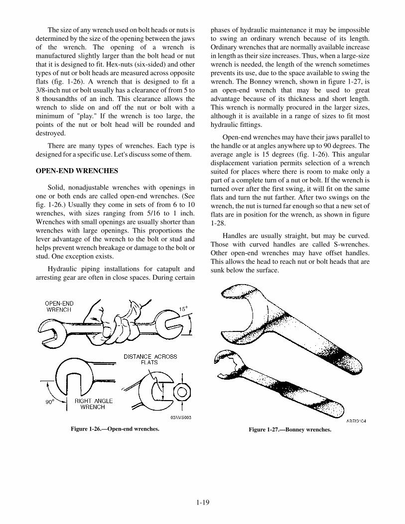
The size of any wrench used on bolt heads or nuts isdetermined by the size of the opening between the jawsof the wrench. The opening of a wrench ismanufactured slightly larger than the bolt head or nutthat it is designed to fit. Hex-nuts (six-sided) and othertypes of nut or bolt heads are measured across oppositeflats (fig. 1-26). A wrench that is designed to fit a3/8-inch nut or bolt usually has a clearance of from 5 to8 thousandths of an inch. This clearance allows thewrench to slide on and off the nut or bolt with aminimum of "play." If the wrench is too large, thepoints of the nut or bolt head will be rounded anddestroyed.
There are many types of wrenches. Each type isdesigned for a specific use. Let's discuss some of them.
OPEN-END WRENCHES
Solid, nonadjustable wrenches with openings inone or both ends are called open-end wrenches. (Seefig. 1-26.) Usually they come in sets of from 6 to 10wrenches, with sizes ranging from 5/16 to 1 inch.Wrenches with small openings are usually shorter thanwrenches with large openings. This proportions thelever advantage of the wrench to the bolt or stud andhelps prevent wrench breakage or damage to the bolt orstud. One exception exists.
Hydraulic piping installations for catapult andarresting gear are often in close spaces. During certain
phases of hydraulic maintenance it may be impossibleto swing an ordinary wrench because of its length.Ordinary wrenches that are normally available increasein length as their size increases. Thus, when a large-sizewrench is needed, the length of the wrench sometimesprevents its use, due to the space available to swing thewrench. The Bonney wrench, shown in figure 1-27, isan open-end wrench that may be used to greatadvantage because of its thickness and short length.This wrench is normally procured in the larger sizes,although it is available in a range of sizes to fit mosthydraulic fittings.
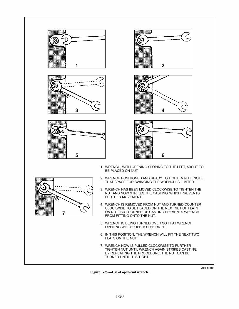
Open-end wrenches may have their jaws parallel tothe handle or at angles anywhere up to 90 degrees. Theaverage angle is 15 degrees (fig. 1-26). This angulardisplacement variation permits selection of a wrenchsuited for places where there is room to make only apart of a complete turn of a nut or bolt. If the wrench isturned over after the first swing, it will fit on the sameflats and turn the nut farther. After two swings on thewrench, the nut is turned far enough so that a new set offlats are in position for the wrench, as shown in figure1-28.
Handles are usually straight, but may be curved.Those with curved handles are called S-wrenches.Other open-end wrenches may have offset handles.This allows the head to reach nut or bolt heads that aresunk below the surface.
1-19
Figure 1-26.—Open-end wrenches. Figure 1-27.—Bonney wrenches.
1-20
1. WRENCH, WITH OPENING SLOPING TO THE LEFT, ABOUT TOBE PLACED ON NUT.
2. WRENCH POSITIONED AND READY TO TIGHTEN NUT. NOTETHAT SPACE FOR SWINGING THE WRENCH IS LIMITED.
3. WRENCH HAS BEEN MOVED CLOCKWISE TO TIGHTEN THENUT AND NOW STRIKES THE CASTING, WHICH PREVENTSFURTHER MOVEMENT.
4. WRENCH IS REMOVED FROM NUT AND TURNED COUNTERCLOCKWISE TO BE PLACED ON THE NEXT SET OF FLATSON NUT. BUT CORNER OF CASTING PREVENTS WRENCHFROM FITTING ONTO THE NUT.
5. WRENCH IS BEING TURNED OVER SO THAT WRENCHOPENING WILL SLOPE TO THE RIGHT.
6. IN THIS POSITION, THE WRENCH WILL FIT THE NEXT TWOFLATS ON THE NUT.
7. WRENCH NOW IS PULLED CLOCKWISE TO FURTHERTIGHTEN NUT UNTIL WRENCH AGAIN STRIKES CASTING.BY REPEATING THE PROCEDURE, THE NUT CAN BETURNED UNTIL IT IS TIGHT.
1 2
3 4
5 6
7
ABEf0105
Figure 1-28.—Use of open-end wrench.

The non-adjustable union nut wrench (fig. 1-29) isused to assemble and disassemble launch valve pipingunion nuts. These special open-end wrenches aredesigned to pass over the piping and then slide onto theunion nut to fully engage five of the six flats, thusreducing the probability of damaging the nuts.
NOTE
These non-adjustable union nut wrenchesare the preferred type for launch valve piping.Under no circumstances should any other typeof adjustable or open-end wrench be used onlaunch valve piping fittings.
BOX WRENCHES
Box wrenches (fig. 1-30) are safer than open-endwrenches since there is less likelihood they will slip offthe work. They completely surround, or box, a nut orbolt head.
The most frequently used box wrench has 12 pointsor notches arranged in a circle in the head and can beused with a minimum swing angle of 30 degrees. Six-and eight-point wrenches are used for heavy duty;twelve-point for medium, and sixteen for light-dutyonly.
One advantage of the 12-point construction is thethin wall. It is more suitable for turning nuts that arehard to get at with an open-end wrench. Anotheradvantage is that the wrench will operate betweenobstructions where the space for handle swing islimited. A very short swing of the handle will turn thenut far enough to allow the wrench to be lifted and thenext set of points fitted to the corners of the nut.
One disadvantage of the box-end wrench is thetime loss that occurs whenever a craftsman has to liftthe wrench off and place it back on the nut in another
position when there is insufficient clearance to spin thewrench in a full circle.
COMBINATION WRENCH
After a tight nut is broken loose, it can beunscrewed much more quickly with an open-endwrench than with a box-wrench. A combinationbox-open end wrench (fig. 1-31) comes in handy in asituation of the type. You can use the box-end forbreaking nuts loose or for snuggling them down, andthe open-end for faster turning.
The box-end portion of the wrench can be designedwith an offset in the handle. Notice in figure 1-31 howthe 15-degree offset allows clearance over nearby parts.
The correct use of open-end and box-end wrenchescan be summed up in a few simple rules, mostimportant of which is to be sure that the wrenchproperly fits the nut or bolt head.
When you have to pull hard on the wrench, as inloosening a tight nut, make sure the wrench is seatedsquarely on the flats of the nut.
Pull on the wrench—DO NOT PUSH. Pushing awrench is a good way to skin your knuckles if thewrench slips or the nut breaks loose unexpectedly. If itis impossible to pull the wrench and you must push, doit with the palm of your hand and hold your palm open.
Only actual practice will tell you if you are usingthe right amount of force on the wrench. The best wayto tighten a nut is to turn it until the wrench has a firm,solid "feel." This will turn the nut to proper tightnesswithout stripping the threads or twisting off the bolt.This "feel" is developed by experience alone. Practiceuntil you have mastered the "feel."
1-21
ABEf0106
Figure 1-29.—Nonadjustable union nut wrench.
Figure 1-30.—12-point box-end wrench.
Figure 1-31.—Offset combination wrench.

SOCKET WRENCH
The socket wrench is one of the most versatilewrenches in the toolbox. Basically, it consists of ahandle and a socket-type wrench that can be attached tothe handle.
The "Spintite" wrench, shown in figure 1-32, is aspecial type of socket wrench. It has a hollow shaft toaccommodate a bolt protruding through a nut, has ahexagonal head, and is used like a screwdriver. It issupplied in small sizes only and is useful for assembly
and electrical work. When used for the latter purpose, itmust have an insulated handle.
A complete socket wrench set consists of severaltypes of handles along with bar extensions, adapters,and a variety of sockets (fig. 1-32).
Sockets
A socket (fig. 1-33) has a square opening cut in oneend to fit a square drive lug on a detachable handle. Inthe other end of the socket is a 6-point or 12-point
1-22
Figure 1-32.—Socket set components.
Figure 1-33.—12-point sockets.

opening, very much like the opening in the box-endwrench. The 12-point socket needs to be swung onlyhalf as far as the 6-point socket before it has to be liftedand fitted on the nut for a new grip. It can therefore beused in closer quarters where there is less room to movethe handle. (A ratchet handle eliminates the necessity oflifting the socket and refitting it on the nut again andagain.)
Sockets are classified by size according to twofactors. One is the size of the square opening, which fitson the square drive lug of the handle. This size is knownas the drive size. The other is the size of the opening inthe opposite end, which fits the nut or bolt. Thestandard toolbox can be outfitted with sockets having1/4-, 3/8-, and 1/2-inch-square drive lugs. Larger setsare usually available in the tool room for temporarycheckout. The openings that fit onto the bolt or nut areusually graduated in 1/16-inch sizes. Sockets are alsomade in deep lengths to fit over spark plugs and longbolt ends.
Socket Handles
There are four types of handles used with thesesockets. (See fig. 1-32.) Each type has specialadvantages, and the experienced worker chooses theone best suited for the job at hand. The square drivinglug on the socket wrench handles has a spring-loadedball that fits into a recess in the socket receptacle. Thismated ball-recess feature keeps the socket engagedwith the drive lug during normal usage. A slight pull onthe socket, however, disassembles the connection.
RATCHET.—The ratchet handle has a reversinglever that operates a pawl (or dog) inside the head of thetool. Pulling the handle in one direction causes the pawlto engage the ratchet teeth and turn the socket. Movingthe handle in the opposite direction causes the pawl toslide over the teeth, permitting the handle to back upwithout moving the socket. This allows rapid turning ofthe nut or bolt after each partial turn of the handle. Withthe reversing lever in one position, the handle can beused for tightening. In the other position, it can be usedfor loosening.
HINGED HANDLE.—The hinged handle is alsovery convenient. To loosen tight nuts, swing the handle
at right angles to the socket. This gives the greatestpossible leverage. After loosening the nut to the pointwhere it turns easily, move the handle into the verticalposition and then turn the handle with the fingers.
SLIDING T-BAR HANDLE.—When you areusing the sliding bar or T-handle, the head can bepositioned anywhere along the sliding bar. Select theposition that is needed for the job at hand.
SPEED HANDLE.—The speed handle is workedlike the woodworker's brace. After the nuts are firstloosened with the sliding bar handle or the ratchethandle, the speed handle can be used to remove the nutsmore quickly. In many instances the speed handle is notstrong enough to be used for breaking loose ortightening the nut. The speed socket wrench should beused carefully to avoid damaging the nut threads.
Accessories
Several accessory items complete the socketwrench set. Extension bars of different lengths aremade to extend the distance from the socket to thehandle. A universal joint allows the nut to be turnedwith the wrench handle at an angle. Universal socketsare also available. The use of universal joints, barextensions, and universal sockets in combination withappropriate handles makes it possible to form a varietyof tools that will reach otherwise inaccessible nuts andbolts.
Another accessory item is an adapter, which allowsyou to use a handle having one size of drive and a sockethaving a different size drive. For example, a 3/8- by1/4-inch adapter makes it possible to turn all1/4-inch-square drive sockets with any 3/8-inch-squaredrive handle.
TORQUE WRENCHES
There are times when, for engineering reasons, adefinite force must be applied to a nut or bolt head. Insuch cases a torque wrench must be used. For example,equal force must be applied to all the head bolts of anengine. Otherwise, one bolt may bear the brunt of theforce of internal combustion and ultimately causeengine failure.
1-23
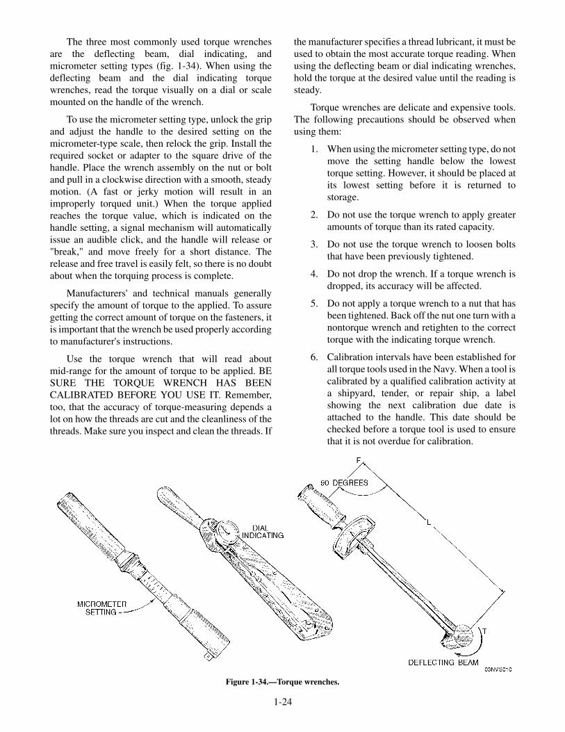
The three most commonly used torque wrenchesare the deflecting beam, dial indicating, andmicrometer setting types (fig. 1-34). When using thedeflecting beam and the dial indicating torquewrenches, read the torque visually on a dial or scalemounted on the handle of the wrench.
To use the micrometer setting type, unlock the gripand adjust the handle to the desired setting on themicrometer-type scale, then relock the grip. Install therequired socket or adapter to the square drive of thehandle. Place the wrench assembly on the nut or boltand pull in a clockwise direction with a smooth, steadymotion. (A fast or jerky motion will result in animproperly torqued unit.) When the torque appliedreaches the torque value, which is indicated on thehandle setting, a signal mechanism will automaticallyissue an audible click, and the handle will release or"break," and move freely for a short distance. Therelease and free travel is easily felt, so there is no doubtabout when the torquing process is complete.
Manufacturers' and technical manuals generallyspecify the amount of torque to the applied. To assuregetting the correct amount of torque on the fasteners, itis important that the wrench be used properly accordingto manufacturer's instructions.
Use the torque wrench that will read aboutmid-range for the amount of torque to be applied. BESURE THE TORQUE WRENCH HAS BEENCALIBRATED BEFORE YOU USE IT. Remember,too, that the accuracy of torque-measuring depends alot on how the threads are cut and the cleanliness of thethreads. Make sure you inspect and clean the threads. If
the manufacturer specifies a thread lubricant, it must beused to obtain the most accurate torque reading. Whenusing the deflecting beam or dial indicating wrenches,hold the torque at the desired value until the reading issteady.
Torque wrenches are delicate and expensive tools.The following precautions should be observed whenusing them:
1. When using the micrometer setting type, do notmove the setting handle below the lowesttorque setting. However, it should be placed atits lowest setting before it is returned tostorage.
2. Do not use the torque wrench to apply greateramounts of torque than its rated capacity.
3. Do not use the torque wrench to loosen boltsthat have been previously tightened.
4. Do not drop the wrench. If a torque wrench isdropped, its accuracy will be affected.
5. Do not apply a torque wrench to a nut that hasbeen tightened. Back off the nut one turn with anontorque wrench and retighten to the correcttorque with the indicating torque wrench.
6. Calibration intervals have been established forall torque tools used in the Navy. When a tool iscalibrated by a qualified calibration activity ata shipyard, tender, or repair ship, a labelshowing the next calibration due date isattached to the handle. This date should bechecked before a torque tool is used to ensurethat it is not overdue for calibration.
1-24
Figure 1-34.—Torque wrenches.
ADJUSTABLE WRENCHES
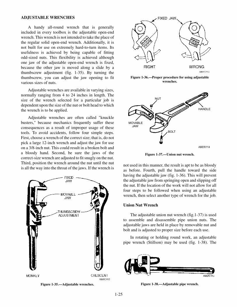
A handy all-round wrench that is generallyincluded in every toolbox is the adjustable open-endwrench. This wrench is not intended to take the place ofthe regular solid open-end wrench. Additionally, it isnot built for use on extremely hard-to-turn items. Itsusefulness is achieved by being capable of fittingodd-sized nuts. This flexibility is achieved althoughone jaw of the adjustable open-end wrench is fixed,because the other jaw is moved along a slide by athumbscrew adjustment (fig. 1-35). By turning thethumbscrew, you can adjust the jaw opening to fitvarious sizes of nuts.
Adjustable wrenches are available in varying sizes,normally ranging from 4 to 24 inches in length. Thesize of the wrench selected for a particular job isdependent upon the size of the nut or bolt head to whichthe wrench is to be applied.
Adjustable wrenches are often called "knucklebusters," because mechanics frequently suffer theseconsequences as a result of improper usage of thesetools. To avoid accidents, follow four simple steps.First, choose a wrench of the correct size; that is, do notpick a large 12-inch wrench and adjust the jaw for useon a 3/8-inch nut. This could result in a broken bolt anda bloody hand. Second, be sure the jaws of thecorrect-size wrench are adjusted to fit snugly on the nut.Third, position the wrench around the nut until the nutis all the way into the throat of the jaws. If the wrench is
not used in this manner, the result is apt to be as bloodyas before. Fourth, pull the handle toward the sidehaving the adjustable jaw (fig. 1-36). This will preventthe adjustable jaw from springing open and slipping offthe nut. If the location of the work will not allow for allfour steps to be followed when using an adjustablewrench, then select another type of wrench for the job.
Union Nut Wrench
The adjustable union nut wrench (fig.1-37) is usedto assemble and disassemble pipe union nuts. Theadjustable jaws are held in place by removable nut andbolt and is adjusted to proper size before each use.
In rotating or holding round work, an adjustablepipe wrench (Stillson) may be used (fig. 1-38). The
1-25
Figure 1-36.—Proper procedure for using adjustablewrenches.
Figure 1-35.—Adjustable wrenches.
HANDLE
MOVABLEJAW
BOLT
NUT
ABEf0114
Figure 1-37.—Union nut wrench.
Figure 1-38.—Adjustable pipe wrench.
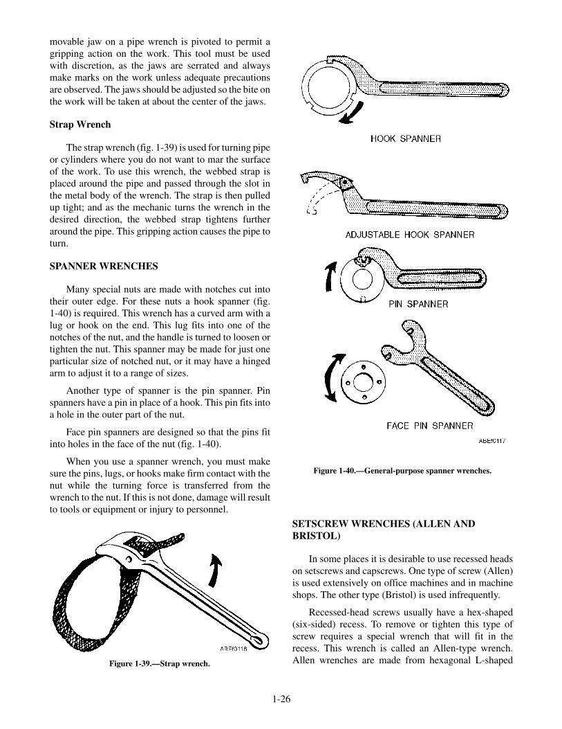
movable jaw on a pipe wrench is pivoted to permit agripping action on the work. This tool must be usedwith discretion, as the jaws are serrated and alwaysmake marks on the work unless adequate precautionsare observed. The jaws should be adjusted so the bite onthe work will be taken at about the center of the jaws.
Strap Wrench
The strap wrench (fig. 1-39) is used for turning pipeor cylinders where you do not want to mar the surfaceof the work. To use this wrench, the webbed strap isplaced around the pipe and passed through the slot inthe metal body of the wrench. The strap is then pulledup tight; and as the mechanic turns the wrench in thedesired direction, the webbed strap tightens furtheraround the pipe. This gripping action causes the pipe toturn.
SPANNER WRENCHES
Many special nuts are made with notches cut intotheir outer edge. For these nuts a hook spanner (fig.1-40) is required. This wrench has a curved arm with alug or hook on the end. This lug fits into one of thenotches of the nut, and the handle is turned to loosen ortighten the nut. This spanner may be made for just oneparticular size of notched nut, or it may have a hingedarm to adjust it to a range of sizes.
Another type of spanner is the pin spanner. Pinspanners have a pin in place of a hook. This pin fits intoa hole in the outer part of the nut.
Face pin spanners are designed so that the pins fitinto holes in the face of the nut (fig. 1-40).
When you use a spanner wrench, you must makesure the pins, lugs, or hooks make firm contact with thenut while the turning force is transferred from thewrench to the nut. If this is not done, damage will resultto tools or equipment or injury to personnel.
SETSCREW WRENCHES (ALLEN ANDBRISTOL)
In some places it is desirable to use recessed headson setscrews and capscrews. One type of screw (Allen)is used extensively on office machines and in machineshops. The other type (Bristol) is used infrequently.
Recessed-head screws usually have a hex-shaped(six-sided) recess. To remove or tighten this type ofscrew requires a special wrench that will fit in therecess. This wrench is called an Allen-type wrench.Allen wrenches are made from hexagonal L-shaped
1-26
Figure 1-39.—Strap wrench.
Figure 1-40.—General-purpose spanner wrenches.

bars of tool steel (fig. 1-41). They generally range insize up to 3/4 inch. When using the Allen-type wrench,make sure you use the correct size to prevent roundingor spreading the head of the screw. A snug fit within therecessed head of the screw is an indication that youhave the correct size.
The Bristol wrench is made from round stock. It isalso L-shaped, but one end is fluted to fit the flutes orlittle splines in the Bristol setscrew (fig. 1-41).
SAFETY RULES FOR WRENCHES
There are a few basic rules that you should keep inmind when using wrenches. They are as follows:
• Always use a wrench that fits the nut properly.
• Keep wrenches clean and free from oil.Otherwise they may slip, resulting in possibleserious injury to you or damage to the work.
• Do not increase the leverage of a wrench byplacing a pipe over the handle. Increasedleverage may damage the wrench or the work.
• Provide some sort of kit or case for all wrenches.Return them to the case at the completion ofeach job. This saves time and trouble and aidsselection of tools for the next job. Most
important, it eliminates the possibility of leavingthem where they can cause injury to personnel ordamage to equipment.
• Determine which way a nut should be turnedbefore trying to loosen it. Most nuts are turnedcounterclockwise for removal. This may seemobvious, but even experienced people have beenobserved straining at the wrench in thetightening direction when they wanted to loosenthe nut.
• Learn to select your wrenches to fit the type ofwork you are doing. If you are not familiar withthese wrenches, make arrangements to visit ashop that has most of them, and get acquainted.
REVIEW QUESTIONS
Q11. Identify the different types of wrenches.
Q12. Describe the uses of different types ofwrenches.
Q13. List the safety precautions that apply towrenches.
PLIERS
LEARNING OBJECTIVES: Identify thedifferent types of pliers. Describe the uses ofdifferent types of pliers. Describe the propercare of pliers.
Pliers are made in many styles and sizes and areused to perform many different operations. Pliers areused for cutting purposes, as well as holding andgripping small articles in situations where it may beinconvenient or impossible to use hands. Figure 1-42shows several different kinds.
1-27
Figure 1-41.—Allen- and Bristol-type wrenches.
Figure 1-42.—Pliers.

The combination pliers are handy for holding orbending flat or round stock. The long-nosed pliers areless rugged, and break easily if you use them on heavyjobs. Long-nosed pliers, commonly called needle-nosepliers, are especially useful for holding small objects intight places and for making delicate adjustments. Theround-nosed kind are handy when you need to crimpsheet metal or form a loop in a wire. The diagonalcutting pliers, commonly called "diagonals" or "dikes,"are designed for cutting wire and cotter pins close to aflat surface and are especially useful in the electronicand electrical fields. The duckbill pliers are usedextensively in aviation areas.
Here are two important rules for using pliers:
1. Do not make pliers work beyond their capacity.The long-nosed kind is especially delicate. It iseasy to spring or break them, or nick theiredges. After that, they are practically useless.
2. Do not use pliers to turn nuts. In just a fewseconds, a pair of pliers can damage a nut.Pliers must not be substituted for wrenches.
SLIP-JOINT PLIERS
Slip-joint pliers (fig. 1-43) are pliers with straight,serrated (grooved) jaws, and pivot where the jaws arefastened together to move to either of two positions tograsp small- or large-sized objects better.
Slip-joint combination pliers are pliers similar tothe slip-joint pliers just described but with the
additional feature of a side cutter at the junction of thejaws. This cutter consists of a pair of square-cutnotches, one on each jaw, which act like a pair of shearswhen an object is placed between them and the jawsclosed.
WRENCH PLIERS
Wrench pliers (visegrips) (fig. 1-44), can be usedfor holding objects regardless of their shape. A screwadjustment in one of the handles makes them suitablefor several different sizes. The jaws of wrench pliersmay have standard serrations such as the pliers justdescribed, or they may have a clamp-type jaw. Theclamp-type jaws are generally wide and smooth and areused primarily when working with sheet metal.
Wrench pliers have an advantage over other typesof pliers in that you can clamp them on an object andthey will stay. This will leave your hands free for otherwork.
A craftsman uses this tool a number of ways. It maybe used as a clamp, speed wrench, portable vise, and formany other uses where a locking, plier-type jaw may beused. These pliers can be adjusted to various jawopenings by turning the knurled, adjusting screw at theend of the handle (fig. 1-44). Wrench pliers can beclamped and locked in position by pulling the levertoward the handle.
CAUTION
Wrench pliers should be used with care,since the teeth in the jaws tend to damage theobject on which they are clamped. They shouldnot be used on nuts, bolts, tube fittings, or otherobjects that must be reused.
WATER-PUMP PLIERS
Water-pump pliers were originally designed fortightening or removing water-pump packing nuts. Theywere excellent for this job because they have a jawadjustable to seven different positions. Water-pumppliers (fig. 1-45) are easily identified by their size, jawteeth, and adjustable slip joint. The inner surface of thejaws consists of a series of coarse teeth formed by deep
1-28
Figure 1-43.—Slip-joint pliers.
Figure 1-44.—Wrench pliers. Figure 1-45.—Water-pump pliers.

grooves, a surface adapted to grasping cylindricalobjects.
GROOVE-JOINT PLIERS
Groove-joint pliers (fig. 1-46) are another versionof water-pump pliers and are easily identified by theextra-long handles, which make them a very powerfulgripping tool. They are shaped approximately the sameas the pliers just described, but the jaw openingadjustment is effected differently. Groove-joint pliershave grooves on one jaw and lands on the other. Theadjustment is effected by changing the position of thegrooves and lands. The groove-joint pliers are lesslikely to slip from the adjustment setting when grippingan object. The groove-joint pliers will only be usedwhere it is impossible to use a more adapted wrench orholding device. Many nuts and bolts and surroundingparts have been damaged by improper use ofgroove-joint pliers.
DIAGONAL PLIERS
Diagonal cutting pliers (fig. 1-42) are used forcutting small, light material, such as wire and cotterpins in areas that are inaccessible to the larger cuttingtools. Also, since they are designed for cutting only,larger objects can be cut than with the slip-joint pliers.
Because the cutting edges are diagonally offsetapproximately 15 degrees, diagonal pliers are adaptedto cutting small objects flush with a surface. The innerjaw surface is a diagonal straight cutting edge.Diagonal pliers should never be used to hold objects,because they exert a greater shearing force than othertypes of pliers of a similar size. The sizes of thediagonal cutting pliers are designated by the overalllength of the pliers.
SIDE-CUTTING PLIERS
Side-cutting pliers (sidecutters) are principallyused for holding, bending, and cutting thin materials orsmall gauge wire. Sidecutters vary in size and aredesignated by their overall length. The jaws arehollowed out on one side just forward of the pivot pointof the pliers. Opposite the hollowed out portion of thejaws are the cutting edges (fig. 1-42).
When holding or bending light metal surfaces, thejaw tips are used to grasp the object. When holdingwire, grasp it as near one end as possible because thejaws will mar the wire. To cut small-diameter wire, theside-cutting edge of the jaws near the pivot is used.Never use sidecutters to grasp large objects, tightennuts, or bend heavy gauge metal, since such operationswill spring the jaws.
Sidecutters are often called electrician or linemanpliers. They are used extensively for strippinginsulation from wire and for twisting wire whenmaking a splice.
DUCKBILL PLIERS
Duckbill pliers (fig. 1-47, view A) have long widejaws and slender handles. Duckbills are used inconfined areas where the fingers cannot be used. Thejaw faces of the pliers are scored to aid in holding anitem securely. Duckbills are ideal for twisting the safetywire used in securing nuts, bolts, and screws.
1-29
Figure 1-46.—Groove-joint pliers.Figure 1-47.—Pliers; (A) duckbill, (B) needle-nose, and
(C) wire twister.
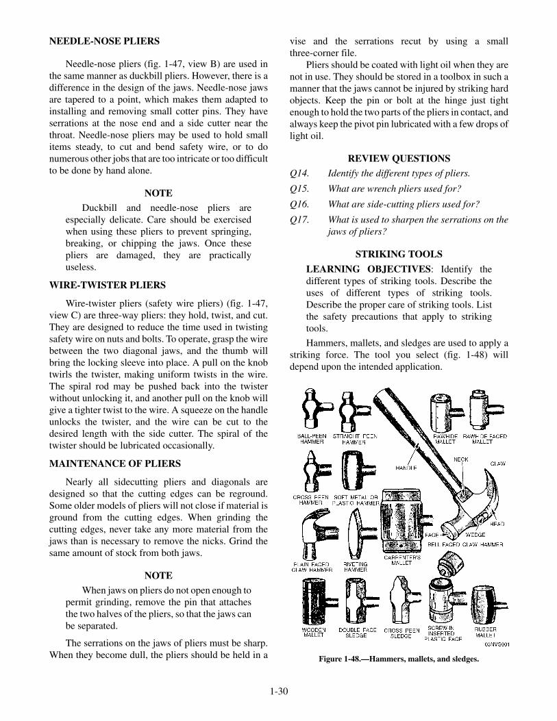
NEEDLE-NOSE PLIERS
Needle-nose pliers (fig. 1-47, view B) are used inthe same manner as duckbill pliers. However, there is adifference in the design of the jaws. Needle-nose jawsare tapered to a point, which makes them adapted toinstalling and removing small cotter pins. They haveserrations at the nose end and a side cutter near thethroat. Needle-nose pliers may be used to hold smallitems steady, to cut and bend safety wire, or to donumerous other jobs that are too intricate or too difficultto be done by hand alone.
NOTE
Duckbill and needle-nose pliers areespecially delicate. Care should be exercisedwhen using these pliers to prevent springing,breaking, or chipping the jaws. Once thesepliers are damaged, they are practicallyuseless.
WIRE-TWISTER PLIERS
Wire-twister pliers (safety wire pliers) (fig. 1-47,view C) are three-way pliers: they hold, twist, and cut.They are designed to reduce the time used in twistingsafety wire on nuts and bolts. To operate, grasp the wirebetween the two diagonal jaws, and the thumb willbring the locking sleeve into place. A pull on the knobtwirls the twister, making uniform twists in the wire.The spiral rod may be pushed back into the twisterwithout unlocking it, and another pull on the knob willgive a tighter twist to the wire. A squeeze on the handleunlocks the twister, and the wire can be cut to thedesired length with the side cutter. The spiral of thetwister should be lubricated occasionally.
MAINTENANCE OF PLIERS
Nearly all sidecutting pliers and diagonals aredesigned so that the cutting edges can be reground.Some older models of pliers will not close if material isground from the cutting edges. When grinding thecutting edges, never take any more material from thejaws than is necessary to remove the nicks. Grind thesame amount of stock from both jaws.
NOTE
When jaws on pliers do not open enough topermit grinding, remove the pin that attachesthe two halves of the pliers, so that the jaws canbe separated.
The serrations on the jaws of pliers must be sharp.When they become dull, the pliers should be held in a
vise and the serrations recut by using a smallthree-corner file.
Pliers should be coated with light oil when they arenot in use. They should be stored in a toolbox in such amanner that the jaws cannot be injured by striking hardobjects. Keep the pin or bolt at the hinge just tightenough to hold the two parts of the pliers in contact, andalways keep the pivot pin lubricated with a few drops oflight oil.
REVIEW QUESTIONS
Q14. Identify the different types of pliers.
Q15. What are wrench pliers used for?
Q16. What are side-cutting pliers used for?
Q17. What is used to sharpen the serrations on thejaws of pliers?
STRIKING TOOLS
LEARNING OBJECTIVES: Identify thedifferent types of striking tools. Describe theuses of different types of striking tools.Describe the proper care of striking tools. Listthe safety precautions that apply to strikingtools.
Hammers, mallets, and sledges are used to apply astriking force. The tool you select (fig. 1-48) willdepend upon the intended application.
1-30
Figure 1-48.—Hammers, mallets, and sledges.

HAMMERS
A toolkit for nearly every rating in the Navy wouldnot be complete without at least one hammer. In mostcases, two or three are included, since they aredesignated according to weight (without the handle)and style or shape. The shape will vary according to theintended work.
Machinists' Hammers
Machinists' hammers are mostly used by peoplewho work with metal or around machinery. Thesehammers are distinguished from carpenter hammers bya variable-shaped peen, rather than a claw, at theopposite end of the face (fig. 1-48). The ball-peenhammer is probably most familiar to you.
The ball-peen hammer, as its name implies, has aball that is smaller in diameter than the face. It istherefore useful for striking areas that are too small forthe face to enter.
Ball-peen hammers are made in different weights,usually 4, 6, 8, and 12 ounces and 1, 1 1/2, and 2pounds. For most work a 1 1/2 pound and a 12-ouncehammer will suffice. However, a 4- or 6-inch hammerwill often be used for light work such as tapping apunch to cut gaskets out of sheet gasket material.
Machinists' hammers may be further divided intohard-face and soft-face classifications. The hard-facedhammer is made of forged tool steel, while thesoft-faced hammers have a head made of brass, lead, ora tightly rolled strip of rawhide. Plastic-faced hammersor solid plastic hammers with a lead core for addedweight are becoming increasingly popular.
Soft-faced hammers (fig. 1-48) should be usedwhen there is danger of damaging the surface of thework, as when pounding on a machined surface. Mostsoft-faced hammers have heads that can be replaced asthe need arises. Lead-faced hammers, for instance,quickly become battered and must be replaced, but havethe advantage of striking a solid, heavy nonreboundingblow that is useful for such jobs as driving shafts into orout of tight holes. If a soft-faced hammer is notavailable, the surface to be hammered may be protectedby covering it with a piece of soft brass, copper, or hardwood.
Using Hammers
Simple as the hammer is, there is a right and awrong way of using it. (See fig. 1-49.) The most
common fault is holding the handle too close to thehead. This is known as choking the hammer, andreduces the force of the blow. It also makes it harder tohold the head in an upright position. Except for lightblows, hold the handle close to the end to increaseleverage and produce a more effective blow. Hold thehandle with the fingers underneath and the thumb alongside or on top of the handle. The thumb should rest onthe handle and never overlap the fingers. Try to hit theobject with the full force of the hammer. Hold thehammer at such an angle that the face of the hammerand the surface of the object being hit will be parallel.This distributes the force of the blow over the full faceand prevents damage to both the surface being struckand the face of the hammer.
MALLETS AND SLEDGES
The mallet is a short-handled tool used to drivewooden-handled chisels, gouges, and wooden pins, orto form or shape sheet metal where hard-facedhammers would mar or damage the finished work.Mallet heads are made from a soft material, usuallywood, rawhide, or rubber. For example, a rubber-facedmallet is used for knocking out dents in an automobile.It is cylindrically shaped with two flat driving faces thatare reinforced with iron bands. (See fig. 1-48.) Neveruse a mallet to drive nails, screws, or any other objectthat can damage the face of the mallet.
1-31
Figure 1-49.—Striking a surface.
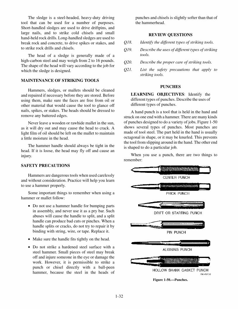
The sledge is a steel-headed, heavy-duty drivingtool that can be used for a number of purposes.Short-handled sledges are used to drive driftpins, andlarge nails, and to strike cold chisels and smallhand-held rock drills. Long-handled sledges are used tobreak rock and concrete, to drive spikes or stakes, andto strike rock drills and chisels.
The head of a sledge is generally made of ahigh-carbon steel and may weigh from 2 to 16 pounds.The shape of the head will vary according to the job forwhich the sledge is designed.
MAINTENANCE OF STRIKING TOOLS
Hammers, sledges, or mallets should be cleanedand repaired if necessary before they are stored. Beforeusing them, make sure the faces are free from oil orother material that would cause the tool to glance offnails, spikes, or stakes. The heads should be dressed toremove any battered edges.
Never leave a wooden or rawhide mallet in the sun,as it will dry out and may cause the head to crack. Alight film of oil should be left on the mallet to maintaina little moisture in the head.
The hammer handle should always be tight in thehead. If it is loose, the head may fly off and cause aninjury.
SAFETY PRECAUTIONS
Hammers are dangerous tools when used carelesslyand without consideration. Practice will help you learnto use a hammer properly.
Some important things to remember when using ahammer or mallet follow:
• Do not use a hammer handle for bumping partsin assembly, and never use it as a pry bar. Suchabuses will cause the handle to split, and a splithandle can produce bad cuts or pinches. When ahandle splits or cracks, do not try to repair it bybinding with string, wire, or tape. Replace it.
• Make sure the handle fits tightly on the head.
• Do not strike a hardened steel surface with asteel hammer. Small pieces of steel may breakoff and injure someone in the eye or damage thework. However, it is permissible to strike apunch or chisel directly with a ball-peenhammer, because the steel in the heads of
punches and chisels is slightly softer than that ofthe hammerhead.
REVIEW QUESTIONS
Q18. Identify the different types of striking tools.
Q19. Describe the uses of different types of strikingtools.
Q20. Describe the proper care of striking tools.
Q21. List the safety precautions that apply tostriking tools.
PUNCHES
LEARNING OBJECTIVES: Identify thedifferent types of punches. Describe the uses ofdifferent types of punches.
A hand punch is a tool that is held in the hand andstruck on one end with a hammer. There are many kindsof punches designed to do a variety of jobs. Figure 1-50shows several types of punches. Most punches aremade of tool steel. The part held in the hand is usuallyoctagonal in shape, or it may be knurled. This preventsthe tool from slipping around in the hand. The other endis shaped to do a particular job.
When you use a punch, there are two things toremember:
1-32
Figure 1-50.—Punches.

1. When you hit the punch, you do not want it toslip sideways over your work.
2. You do not want the hammer to slip off thepunch and strike your fingers. You caneliminate both of these troubles by holding thepunch at right angles to the work and strikingthe punch squarely with your hammer.
The center punch, as the name implies, is used formarking the center of a hole to be drilled. If you try todrill a hole without first punching the center, the drillwill "wander" or "walk away" from the desired center.
Another use of the center punch is to makecorresponding marks on two pieces of an assembly topermit reassembling in the original positions. Beforetaking a mechanism apart, make a pair of centerpunchmarks in one or more places to help inreassembly. To do this, select places, staggered asshown in figure 1-51, where matching pieces arejoined. First, clean the places selected. Then, scribe aline across the joint, and center punch the line on bothsides of the joint, with single and double marks asshown to eliminate possible errors. In reassembly, referfirst to the sets of punchmarks to determine theapproximate position of the parts. Then line up thescribed lines to determine the exact position.
To make the intersection of two layout lines, bringthe point of the prick punch to the exact point ofintersection and tap the punch lightly with a hammer. Ifinspection shows that the exact intersection and thepunchmark do not coincide, as in view A of figure 1-52,slant the punch as shown in view B and strike againwith the hammer, thus enlarging the punchmark andcentering it exactly. When the intersection has beencorrectly punched, finish off with a light blow on thepunch held in an upright position. View C shows thecorrected punchmark.
DRIFT punches, sometimes called "startingpunches," have a long taper from the tip to the body.
They are made that way to withstand the shock of heavyblows. They may be used for knocking out rivets afterthe heads have been chiseled off or for freeing pins thatare "frozen" in their holes.
After a pin has been loosened or partially drivenout, the drift punch may be too large to finish the job.The follow-up tool to use is the PIN PUNCH. It isdesigned to follow through the hole without jamming.Always use the largest drift or pin punch that will fit thehole. These punches usually come in sets of three tofive assorted sizes. Both of these punches will have flatends, never edged or rounded.
To remove a bolt or pin that is extremely tight, startwith a drift punch that has an end diameter that isslightly smaller than the diameter of the object you areremoving. As soon as the bolt or pin loosens, finishdriving it out with a pin punch. Never use a pin punchfor starting a pin, because it has a slim shank and a hardblow may cause it to bend or break.
For assembling units of a machine, an ALIGN-MENT (aligning) punch is invaluable. It is usuallyabout 1-foot long and has a long gradual taper. Itspurpose is to line up holes in mating parts.
Hollow metal-cutting punches are made fromhardened tool steel. They are made in various sizes andare used to cut holes in light gauge sheet metal.
Other punches have been designed for special uses.One of these is the soft-faced drift. It is made of brass orfiber and is used for such jobs as removing shafts,bearings, and wrist pins from engines. It is generallyheavy enough to resist damage to itself, but soft enoughnot to injure the finished surface on the part that is beingdriven.
1-33
Figure 1-51.—Punch marking mating parts.Figure 1-52.—Marking the intersection of lines with a prick
punch.

You may have to make gaskets of rubber, cork,leather, or composition materials. For cutting holes ingasket materials, a hollow shank GASKET PUNCHmay be used (fig. 1-50). Gasket punches come in sets ofvarious sizes to accommodate standard bolts and studs.The cutting end is tapered to a sharp edge to produce aclean uniform hole. To use the gasket punch, place thegasket material to be cut on a piece of hard wood or leadso that the cutting edge of the punch will not bedamaged. Then strike the punch with a hammer, drivingit through the gasket where holes are required.
REVIEW QUESTIONS
Q22. Identify the different types of punches.
Q23. What is a center punch used for?
Q24. What is a prick punch used for?
TAPS AND DIES
LEARNING OBJECTIVES: Identify thedifferent types of taps and dies. Describe theuses of different types of taps and dies.
Taps and dies are used to cut threads in metal,plastics, or hard rubber. The taps are used for cuttinginternal threads, and the dies are used to cut externalthreads. There are many different types of taps.However, the most common are the taper, plug,bottoming, and pipe taps (fig. 1-53).
The taper (starting) hand tap has a chamfer lengthof 8 to 10 threads. These taps are used when starting atapping operation and when tapping through holes.
Plug hand taps have a chamfer length of 3 to 5threads and are designed for use after the taper tap.
Bottoming hand taps are used for threading thebottom of a blind hole. They have a very short chamferlength of only 1 to 1 1/2 threads for this purpose. Thistap is always used after the plug tap has been used. Boththe taper and plug taps should precede the use of thebottoming hand tap.
Pipe taps are used for pipefitting and other placeswhere extremely tight fits are necessary. The tapdiameter, from end to end of the threaded portion,increases at the rate of 3/4 inch per foot. All the threadson this tap do the cutting, as compared to the straighttaps, where only the nonchamfered portion does thecutting.
Dies are made in several different shapes and are ofthe solid or adjustable type. The square pipe die (fig.
1-54) will cut American Standard Pipe thread only. Itcomes in a variety of sizes for cutting threads on pipewith diameters of 1/8 inch to 2 inches.
A rethreading die (fig. 1-54) is used principally fordressing over bruised or rusty threads on screws orbolts. It is available in a variety of sizes for rethreadingAmerican Standard Coarse and Fine threads. Thesedies are usually hexagon in shape and can be turned
1-34
Figure 1-53.—Types of common taps.
Figure 1-54.—Types of solid dies.

with a socket, box, open-end, or any wrench that willfit. Rethreading dies are available in sets of 6, 10, 14,and 28 assorted sizes in a case.
Round split adjustable dies (fig. 1-55) are called"Burton" dies and can be used in either hand diestocksor machine holders. The adjustment in the screwadjusting type is made by a fine-pitch screw, which
forces the sides of the die apart or allows them to springtogether. The adjustment in the open adjusting type ismade by means of three screws in the holder, one forexpanding and two for compressing the dies.
Two piece collet dies (fig. 1-55) are used with acollet cap (fig. 1-56) and collet guide. The die halvesare placed in the cap slot and are held in place by the
1-35
TWO-PIECE RECTANGULAR PIPE DIE INCHES1 2
ADJUSTINGSCREW
TWO-PIECE COLLETDIE
SCREW ADJUSTINGTYPE
OPEN ADJUSTINGTYPE
ABEf0141
Figure 1-55.—Types of adjustable dies.
STRAIGHT HANDLED TAP WRENCH
T-HANDLE TAP WRENCH COLLET DIESTOCK
COLLETCAP
COLLETGUIDE
INCHES
THREE SCREW DIESTOCKSINGLE SCREW DIESTOCK
ABEf0142
Figure 1-56.—Diestocks, diecollet, and tap wrenches.
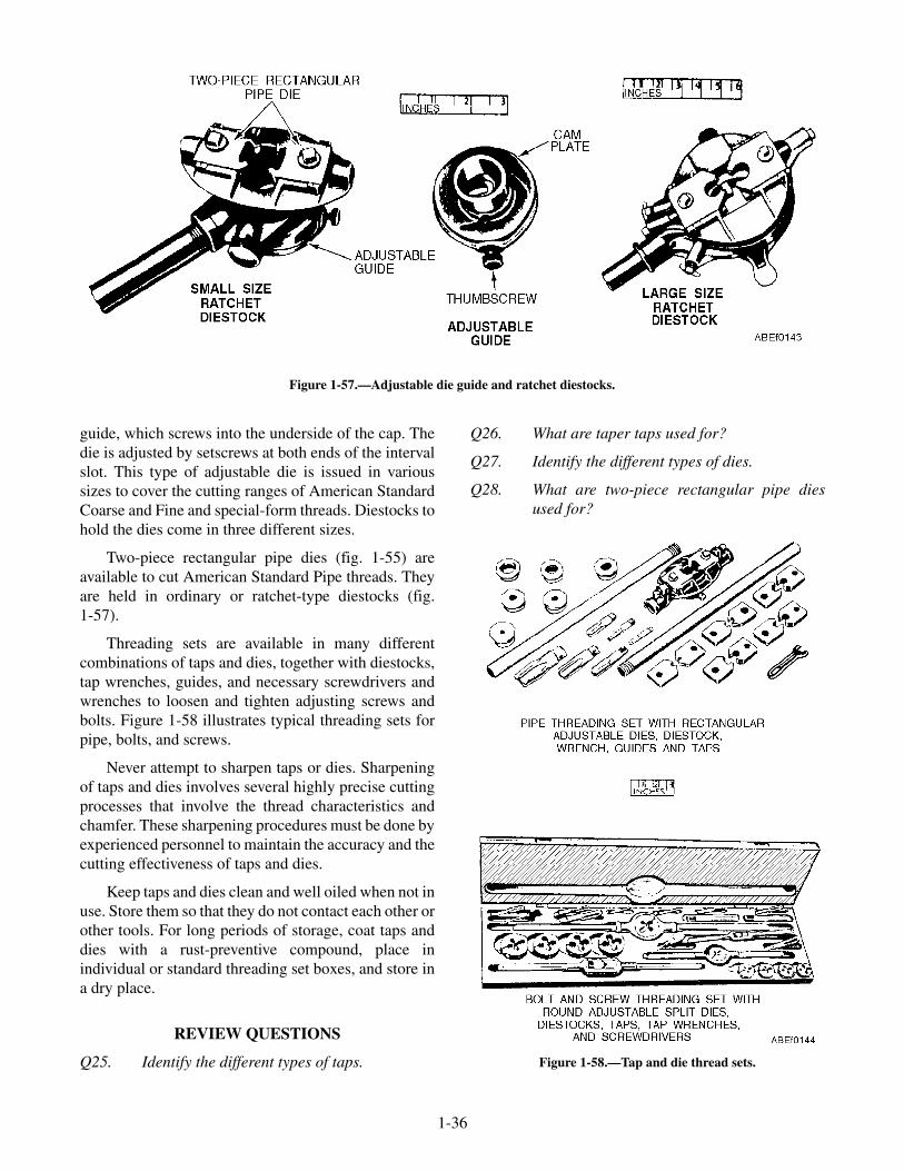
guide, which screws into the underside of the cap. Thedie is adjusted by setscrews at both ends of the intervalslot. This type of adjustable die is issued in varioussizes to cover the cutting ranges of American StandardCoarse and Fine and special-form threads. Diestocks tohold the dies come in three different sizes.
Two-piece rectangular pipe dies (fig. 1-55) areavailable to cut American Standard Pipe threads. Theyare held in ordinary or ratchet-type diestocks (fig.1-57).
Threading sets are available in many differentcombinations of taps and dies, together with diestocks,tap wrenches, guides, and necessary screwdrivers andwrenches to loosen and tighten adjusting screws andbolts. Figure 1-58 illustrates typical threading sets forpipe, bolts, and screws.
Never attempt to sharpen taps or dies. Sharpeningof taps and dies involves several highly precise cuttingprocesses that involve the thread characteristics andchamfer. These sharpening procedures must be done byexperienced personnel to maintain the accuracy and thecutting effectiveness of taps and dies.
Keep taps and dies clean and well oiled when not inuse. Store them so that they do not contact each other orother tools. For long periods of storage, coat taps anddies with a rust-preventive compound, place inindividual or standard threading set boxes, and store ina dry place.
REVIEW QUESTIONS
Q25. Identify the different types of taps.
Q26. What are taper taps used for?
Q27. Identify the different types of dies.
Q28. What are two-piece rectangular pipe diesused for?
1-36
Figure 1-57.—Adjustable die guide and ratchet diestocks.
Figure 1-58.—Tap and die thread sets.

POWER TOOLS
LEARNING OBJECTIVES: Identify thedifferent types of power tools. Describe theuses of different types of power tools. List thesafety precautions that apply to power tools.List the safety precautions that apply toextension cords.
Power tools have become so commonplace in theNavy that all ratings now use them in the performanceof maintenance at one time or another.
The following paragraphs are devoted to theidentification, general-operating practices, and care ofthese tools.
DRILLS
The portable electric drill (fig. 1-59) is probably themost frequently used power tool in the Navy. Althoughit is especially designed for drilling holes, by addingvarious accessories you can adapt it for different jobs.Sanding, sawing, buffing, polishing, screw driving,wire brushing, and paint mixing are examples ofpossible uses.
Portable electric drills commonly used in the Navyhave capacities for drilling holes in steel from 1/16 inchup to 1 inch in diameter. The sizes of portable electricdrills are classified by the maximum size straight shankdrill it will hold. That is, a 1/4-inch electric drill willhold a straight shank drill bit up to and including1/4 inch in diameter.
The revolutions per minute (rpm) and power thedrill will deliver are most important when choosing adrill for a job. You will find that the speed of the drillmotor decreases with an increase in size, primarilybecause the larger units are designed to turn largercutting tools or to drill in heavy materials, and both ofthese factors require slower speed.
If you are going to do heavy work, such as drillingin masonry or steel, then you would probably need touse a drill with a 3/8- or 1/2-inch capacity. If most ofyour drilling will be forming holes in wood or smallholes in sheet metal, then a 1/4-inch drill will probablybe adequate.
The chuck is the clamping device into which thedrill bit is inserted. Nearly all electric drills areequipped with a three-jaw chuck. Some drills have ahand-type chuck that you tighten or loosen by hand, butmost of the drills used in the Navy have gear-type,three-jaw chucks, which are tightened and loosened bya chuck key, shown in figure 1-60. Do not apply furtherpressure with pliers or wrenches after you hand tightenthe chuck with the chuck key.
Always remove the key IMMEDIATELY after youuse it. Otherwise the key will fly loose when the drillmotor is started and may cause serious injury to you orone of your shipmates. The chuck key is generallytaped on the cord of the drill; but if it is not, make sureyou put it in a safe place where it will not get lost.
All portable electric drills used in the Navy havecontrols similar to the ones shown on the 1/4-inch drillin figure 1-59. This drill has a momentary contacttrigger switch located in the handle. The switch issqueezed to start the electric drill and released to stop it.
The trigger latch is a button in the bottom of thedrill handle. It is pushed in while the switch trigger isheld down to lock the trigger switch in the ON position.The trigger latch is released by squeezing and thenreleasing the switch trigger.
1-37
Figure 1-59.—1/4-inch portable electric drill. Figure 1-60.—Three-jaw chuck and chuck key.

DISK SANDER
Electric disk sanders (fig. 1-61) are especiallyuseful on work where a large amount of material is to beremoved quickly, such as in scaling surfaces inpreparation for painting. This machine, however, mustnot be used where a mirror-smooth finish is required.
The disk should be moved smoothly and lightlyover the surface. Never allow the disk to stay in oneplace too long, because it will cut into the metal andleave a large depression.
PORTABLE GRINDERS
Portable grinders are power tools that are used forrough grinding and finishing of metallic surfaces. Theyare made in several sizes; however, the one used most inthe Navy uses a grinding wheel with a maximumdiameter of 6 inches. See figure 1-62.
The abrasive wheels are easily replaceable so thatdifferent grain size and grades of abrasives can be usedfor the various types of surfaces to be ground and thedifferent degrees of finish desired.
A flexible shaft attachment is available for mostportable grinders. This shaft is attached by removingthe grinding wheel, then attaching the shaft to thegrinding wheel drive spindle. The grinding wheel canthen be attached to the end of the flexible shaft. Thisattachment is invaluable for grinding surfaces inhard-to-reach places.
ELECTRIC IMPACT WRENCH
The electric impact wrench (fig. 1-63) is a portable,hand-type reversible wrench. The one shown has a1/2-inch-square impact-driving anvil, over which1/2-inch-square drive sockets can be fitted. Wrenchesalso can be obtained that have impact driving anvilsranging from 3/8 inch to 1 inch. The driving anvils are
not interchangeable, however, from one wrench toanother.
The electric wrench with its accompanyingequipment is primarily intended for applying andremoving nuts, bolts, and screws. It may also be used todrill and tap metal, wood, plastics, and so on, and todrive and remove socket-head, Phillips-head, orslotted-head wood, machine, or self-tapping screws.
Before you use an electric impact wrench, depressthe on-and-off trigger switch and allow the electricwrench to operate a few seconds, noting carefully thedirection of rotation. Release the trigger switch to stopthe wrench. Turn the reversing ring, located at the rearof the tool; it should move easily in one direction(which is determined by the current direction ofrotation). Depress the on-and-off trigger again to startthe electric wrench. The direction of rotation shouldnow be reversed. Continue to operate for a few secondsin each direction to be sure that the wrench and itsreversible features are functioning correctly. When you
1-38
Figure 1-61.—Portable electric sander.
Figure 1-62.—Portable grinder.
Figure 1-63.—Reversible electric impact wrench.

are sure the wrench operates properly, place the suitableequipment on the impact-driving anvil and go aheadwith the job at hand.
SAFETY PRECAUTIONS FOR USE WITHPORTABLE ELECTRICAL TOOLS
When portable electric tools are used, you shoulduse the following procedures:
• Before portable electrical tools are used theymust be inspected and approved for shipboarduse by the ship's electrical safety officer.
• Prior to the use of any portable electric tools, youshould make sure the tools have a current ship'sinspection mark. Additionally, visually examinethe attached cable with the plug and anyextension cords for cracks, breaks, or exposedconductors and damaged plugs. When anydefects are noted, the tools should be turned in tothe ship's electrical shop for repair before use.Before plugging in any tool, be sure the tool isturned off.
• Personnel using portable electric tools arerequired to wear safety glasses/goggles.
• Portable electric tools producing hazardousnoise levels in excess of the limits set forth inOPNAVINST 5100.19 (Series) are required tobe conspicuously labeled. Personnel using toolsdesignated as producing hazardous noise levelsare required to wear proper ear protection, asissued by the medical department.
• Only explosion-proof (class I, group D, orbetter) portable electric tools should be usedwhere flammable vapors, gases, liquids, orexposed explosives are present.
• Hand-held portable electric tools authorized foruse on board ship shall be equipped withON/OFF switches, which must be manually heldin the closed ON position to maintain operation.
• Rubber gloves must be worn when you are usingportable electric tools under hazardousconditions; for example, wet decks, bilge areas,working over the side, in boats, and so forth.
• Leather glove shells should be worn over rubbergloves when the work being done, such as sheetmetal work, could damage the rubber gloves.
SAFETY PRECAUTIONS FOR USE WITHEXTENSION CORDS
You should use the following procedures whenusing extension cords:
• Only three-wire extension cords that havethree-pronged plugs and three-slot receptaclesshould be used.
• Because a metal hull ship is a hazardouslocation, personnel who must use portableelectric devices connected to extension cordsshould take the time to plug the device into theextension cord before the extension cord isinserted into a live bulkhead receptacle.Likewise, the extension cord should beunplugged from the bulkhead receptacle beforethe device is unplugged from the extension cord.
• Electrical cords shall be cared for as follows:
— Cords should not be allowed to come incontact with sharp objects. They should notbe allowed to kink nor should they be leftwhere they might be damaged byvehicle/foot traffic. When it is necessary torun electrical leads through doors andhatches, the cords must be protected toguard against accidental closing of thedoors/hatches.
— Cords must not come in contact with oil,grease, hot surfaces, or chemicals.
— Damaged cords must be replaced. They arenot to be patched with tape.
— Cords must be stored in a clean, dry placewhere they can be loosely coiled.
— Cords extending through walkways shouldbe elevated so they do not become a trippinghazard or interfere with safe passage.
— Extension cords should be no longer than 25feet (except repair locker and CV flight deckcords, which are 100 feet long). No morethan two such cords should be connectedtogether for the operation of portableequipment.
REVIEW QUESTIONS
Q29. Identify the different types of power tools.
Q30. What are electric drills used for?
1-39

Q31. List the safety precautions that apply topower tools.
Q32. List the safety precautions that apply toextension cords.
PORTABLE PNEUMATIC POWERTOOLS
LEARNING OBJECTIVES: Identify dif-ferent types of portable pneumatic power tools.Describe the uses of different types of portablepneumatic power tools. List the safetyprecautions that apply to portable pneumaticpower tools.
Portable pneumatic power tools are tools that lookmuch the same as electric power tools but use theenergy of compressed air instead of electricity. Becauseof the limited outlets for compressed air aboard shipand shore stations, the use of pneumatic power tools isnot as widespread as electric tools. Portable pneumatictools are used most around a shop where compressedair outlets are readily accessible.
PNEUMATIC CHIPPING HAMMER
The pneumatic chipping hammer (fig. 1-64)consists basically of a steel piston that is reciprocated(moved backward and forward alternately) in a steelbarrel by compressed air. On its forward stroke thepiston strikes the end of the chisel, which is a sliding fitin a nozzle pressed into the barrel. The rearward strokeis cushioned by compressed air to prevent anymetal-to-metal contact. Reciprocation of the piston isautomatically controlled by a valve located on the rearend of the barrel. Located on the rear end of the barrel isa grip handle, containing a throttle valve.
The pneumatic hammer may be used for beveling;caulking or beading operations; and for drilling inbrick, concrete, and other masonry.
Chipping hammers should not be operated withoutsafety goggles, and all other persons in the immediatevicinity of the work should wear goggles.
While working, never point the chipping hammerin such a direction that other personnel might be struckby an accidentally ejected tool. When chipping alloysteel or doing other heavy work, it is helpful to dip thetool in engine lubricating oil about every 6 inches of thecut and make sure the cutting edge of the tool is sharpand clean. This will allow faster and easier cutting andwill reduce the possibility of the tool breaking.
When nearing the end of a cut, ease off on thethrottle lever to reduce the intensity of the blows. Thiswill avoid any possibility of the chip or tool flying.
If for any reason you have to lay the chippinghammer down, always remove the attachment tool fromthe nozzle. Should the chipping hammer beaccidentally started when the tool is free, the blow ofthe piston will drive the tool out of the nozzle with greatforce and may damage equipment or injure personnel.
ROTARY AND NEEDLE IMPACTSCALERS
Rotary and needle scalers (figs. 1-65 and 1-66) areused to remove rust, scale, and old paint from metallicand masonry surfaces. You must be especially carefulwhen using these tools since they will "chew" upanything in their path. Avoid getting the power line orany part of your body in their way.
The rotary scaling and chipping tool, sometimescalled a "jitterbug," has a bundle of cutters or chippersfor scaling or chipping (fig. 1-65). In use, the tool ispushed along the surface to be scaled, and the rotatingchippers do the work. Replacement bundles of cuttersare available when the old ones are worn.
1-40
Figure 1-64.—Pneumatic chipping hammer. Figure 1-65.—Rotary impact scaler.
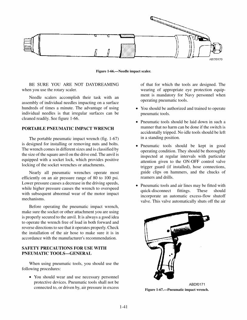
BE SURE YOU ARE NOT DAYDREAMINGwhen you use the rotary scaler.
Needle scalers accomplish their task with anassembly of individual needles impacting on a surfacehundreds of times a minute. The advantage of usingindividual needles is that irregular surfaces can becleaned readily. See figure 1-66.
PORTABLE PNEUMATIC IMPACT WRENCH
The portable pneumatic impact wrench (fig. 1-67)is designed for installing or removing nuts and bolts.The wrench comes in different sizes and is classified bythe size of the square anvil on the drive end. The anvil isequipped with a socket lock, which provides positivelocking of the socket wrenches or attachments.
Nearly all pneumatic wrenches operate mostefficiently on an air pressure range of 80 to 100 psi.Lower pressure causes a decrease in the driving speeds,while higher pressure causes the wrench to overspeedwith subsequent abnormal wear of the motor impactmechanisms.
Before operating the pneumatic impact wrench,make sure the socket or other attachment you are usingis properly secured to the anvil. It is always a good ideato operate the wrench free of load in both forward andreverse directions to see that it operates properly. Checkthe installation of the air hose to make sure it is inaccordance with the manufacturer's recommendation.
SAFETY PRECAUTIONS FOR USE WITHPNEUMATIC TOOLS—GENERAL
When using pneumatic tools, you should use thefollowing procedures:
• You should wear and use necessary personnelprotective devices. Pneumatic tools shall not beconnected to, or driven by, air pressure in excess
of that for which the tools are designed. Thewearing of appropriate eye protection equip-ment is mandatory for Navy personnel whenoperating pneumatic tools.
• You should be authorized and trained to operatepneumatic tools.
• Pneumatic tools should be laid down in such amanner that no harm can be done if the switch isaccidentally tripped. No idle tools should be leftin a standing position.
• Pneumatic tools should be kept in goodoperating condition. They should be thoroughlyinspected at regular intervals with particularattention given to the ON-OFF control valvetrigger guard (if installed), hose connections,guide clips on hammers, and the chucks ofreamers and drills.
• Pneumatic tools and air lines may be fitted withquick-disconnect fittings. These shouldincorporate an automatic excess-flow shutoffvalve. This valve automatically shuts off the air
1-41
Figure 1-66.—Needle impact scaler.
ABDf0171
Figure 1-67.—Pneumatic impact wrench.

at the air lines before changing grinding wheels,needles, chisels, or other cutting or drilling bits.
• The air hose must be suitable to withstand thepressure required for the tool. A leaking ordefective hose should be removed from service.The hose should not be laid over ladders, steps,scaffolds, or walkways in such a manner as tocreate a tripping hazard. Where the hose is runthrough doorways, the hose should be protectedagainst damage by the doors' edges. The air hoseshould generally be elevated over walkways orworking surfaces in a manner to permit clearpassage and to prevent damage to it.
• All portable pneumatic grinders must beequipped with a safety lock-off device. A safetylock-off device is any operating control thatrequires positive action by the operator beforethe tools can be turned on. The lock-off devicemust automatically and positively lock thethrottle in the OFF position when the throttle isreleased. Two consecutive operations by thesame hand are required, first to disengage thelock-off device and then to turn on the throttle.The lock-off device should be integral with thetool. It should not adversely affect the safety oroperating characteristics of the tools, and itshould not be easily removable. Devices, such asa "dead-man control," that do not automaticallyand positively lock the throttle in the OFFposition when the throttle is released are notsafety lock-off devices.
For detailed information on safety precautions, seeNavy Occupational Safety and Health (NAVOSH)Program Manual for Forces Afloat, OPNAVINST5100.19 (latest series).
SAFETY PRECAUTIONS FOR USE WITHPNEUMATIC TOOLS—SPECIFIC
In operating or maintaining air-driven tools, takethe following precautionary measures to protectyourself and others from the damaging effects ofcompressed air:
• Inspect the air hose for cracks or other defects;replace the hose if found defective.
WARNING
Before opening the control valve, see thatnearby personnel are not in the path of theairflow. Never point the hose at another person.
• Open the control valve momentarily beforeconnecting an air hose to the compressed airoutlet. Then, make sure the hose is clear of waterand other foreign material by connecting it to theoutlet and again opening the valve momentarily.
• Stop the flow of air to a pneumatic tool byclosing the control valve at the compressed airoutlet before connecting, disconnecting,adjusting, or repairing a pneumatic tool.
REVIEW QUESTIONS
Q33. Identify different types of portable pneumaticpower tools.
Q34. What are rotary and needle sanders used for?
Q35. List the safety precautions that apply toportable pneumatic power tools.
SCREW AND TAP EXTRACTORS
LEARNING OBJECTIVE: State the purposeof screw and tap extractors.
Screw extractors are used to remove broken screwswithout damaging the surrounding material or thethreaded hole. Tap extractors are used to remove brokentaps (fig. 1-68, view A).
1-42
Figure 1-68.—Screw and tap extractors.
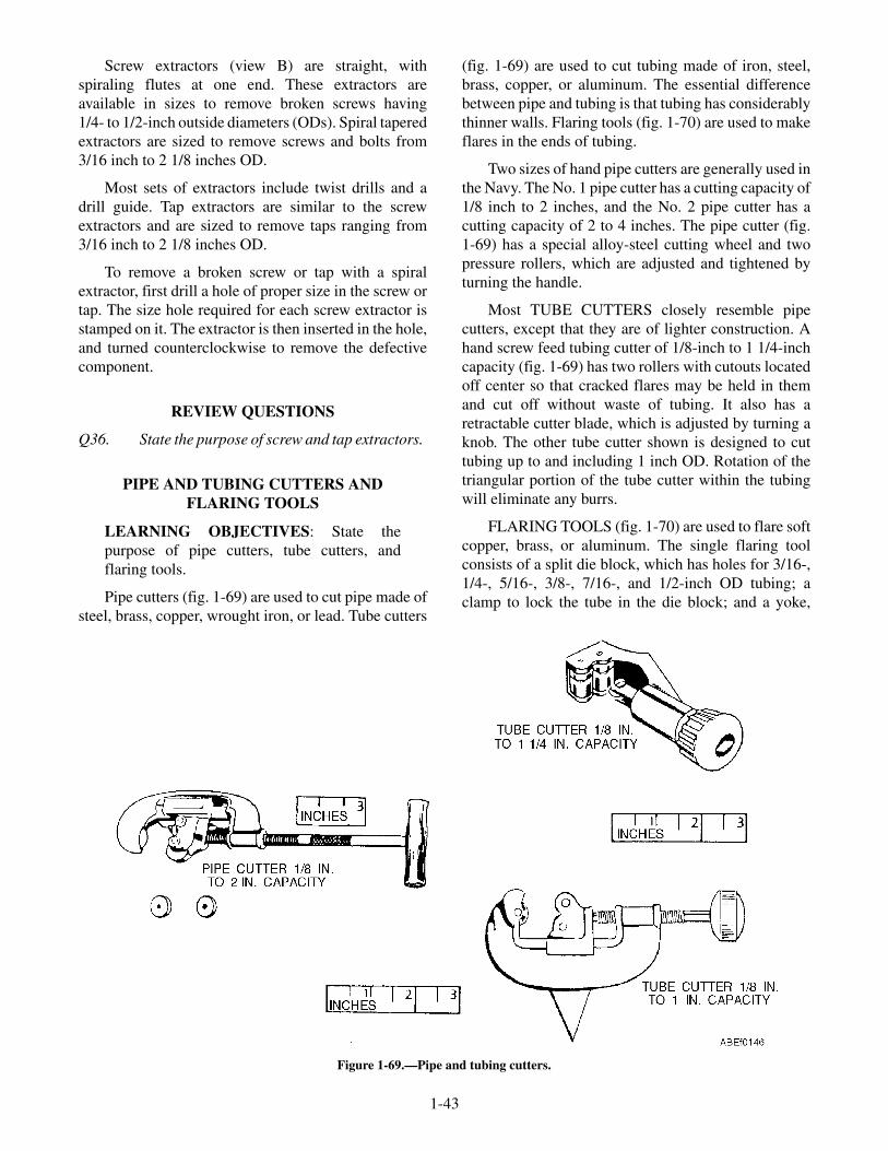
Screw extractors (view B) are straight, withspiraling flutes at one end. These extractors areavailable in sizes to remove broken screws having1/4- to 1/2-inch outside diameters (ODs). Spiral taperedextractors are sized to remove screws and bolts from3/16 inch to 2 1/8 inches OD.
Most sets of extractors include twist drills and adrill guide. Tap extractors are similar to the screwextractors and are sized to remove taps ranging from3/16 inch to 2 1/8 inches OD.
To remove a broken screw or tap with a spiralextractor, first drill a hole of proper size in the screw ortap. The size hole required for each screw extractor isstamped on it. The extractor is then inserted in the hole,and turned counterclockwise to remove the defectivecomponent.
REVIEW QUESTIONS
Q36. State the purpose of screw and tap extractors.
PIPE AND TUBING CUTTERS ANDFLARING TOOLS
LEARNING OBJECTIVES: State thepurpose of pipe cutters, tube cutters, andflaring tools.
Pipe cutters (fig. 1-69) are used to cut pipe made ofsteel, brass, copper, wrought iron, or lead. Tube cutters
(fig. 1-69) are used to cut tubing made of iron, steel,brass, copper, or aluminum. The essential differencebetween pipe and tubing is that tubing has considerablythinner walls. Flaring tools (fig. 1-70) are used to makeflares in the ends of tubing.
Two sizes of hand pipe cutters are generally used inthe Navy. The No. 1 pipe cutter has a cutting capacity of1/8 inch to 2 inches, and the No. 2 pipe cutter has acutting capacity of 2 to 4 inches. The pipe cutter (fig.1-69) has a special alloy-steel cutting wheel and twopressure rollers, which are adjusted and tightened byturning the handle.
Most TUBE CUTTERS closely resemble pipecutters, except that they are of lighter construction. Ahand screw feed tubing cutter of 1/8-inch to 1 1/4-inchcapacity (fig. 1-69) has two rollers with cutouts locatedoff center so that cracked flares may be held in themand cut off without waste of tubing. It also has aretractable cutter blade, which is adjusted by turning aknob. The other tube cutter shown is designed to cuttubing up to and including 1 inch OD. Rotation of thetriangular portion of the tube cutter within the tubingwill eliminate any burrs.
FLARING TOOLS (fig. 1-70) are used to flare softcopper, brass, or aluminum. The single flaring toolconsists of a split die block, which has holes for 3/16-,1/4-, 5/16-, 3/8-, 7/16-, and 1/2-inch OD tubing; aclamp to lock the tube in the die block; and a yoke,
1-43
Figure 1-69.—Pipe and tubing cutters.

which slips over the die block and has a compressorscrew and a cone that forms a 45-degree flare or a bellshape on the end of the tube. The screw has a T-handle.A double flaring tool has the additional feature ofadapters, which turn in the edge of the tube before aregular 45-degree double flare is made. It consists of adie block with holes for 3/16-, 1/4-, 5/16-, 3/8-, and1/2-inch tubing; a yoke with a screw and a flaring cone;plus five adapters for different size tubing, all carried ina metal case.
REVIEW QUESTIONS
Q37. What are pipe cutters used for?
Q38. What are tube cutters used for?
Q39. What are flaring tools used for?
SCREWDRIVERS
LEARNING OBJECTIVES: Identify thedifferent types of screwdrivers. List the safetyprecautions that apply to screwdrivers.
A screwdriver is one of the most basic of handtools.It is also the most frequently abused of all hand tools. Itis designed for one function only—to drive and toremove screws. A screwdriver should not be used as apry bar, a scraper, a chisel, or a punch.
STANDARD
There are three main parts to a standard screw-driver. The portion you grip is called the handle, thesteel portion extending from the handle is the shank,and the end that fits into the screw is called the blade(fig. 1-71).
The steel shank is designed to withstand con-siderable twisting force in proportion to its size, and thetip of the blade is hardened to keep it from wearing.
Standard screwdrivers are classified by size,according to the combined length of the shank andblade. The most common sizes range in length from2 1/2 to 12 inches. There are many screwdrivers smallerand some larger for special purposes. The diameter ofthe shank, and the width and thickness of the blade aregenerally proportionate to the length, but again thereare special screwdrivers with long thin shanks, shortthick shanks, and extra wide or extra narrow blades.
When using a screwdriver, you should select theproper size so that the blade fits the screw slot properly.This prevents burring the slot and reduces the forcerequired to hold the driver in the slot. Keep the shankperpendicular to the screw head (fig. 1-72).
1-44
Figure 1-70.—Flaring tools.

RECESSED
Recessed screws are now available in variousshapes. They have a cavity formed in the head andrequire a specially shaped screwdriver. The clutch tip(fig. 1-71) is one shape, but the more common includethe Phillips, Reed and Prince, and newer Torq-Set types(fig. 1-73). The most common type of screw found isthe Phillips head. This requires a Phillips-typescrewdriver (fig. 1-71).
Phillips Screwdriver
The head of a Phillips-type screw has a four-wayslot into which the screwdriver fits. This prevents thescrewdriver from slipping. Three standard-sizedPhillips screwdrivers handle a wide range of screwsizes. Their ability to hold helps to prevent damagingthe slots or the work surrounding the screw. It is a poorpractice to try to use a standard screwdriver on aPhillips screw, because both the tool and screw slot willbe damaged.
Reed and Prince Screwdriver
Reed and Prince screwdrivers are not inter-changeable with Phillips screwdrivers. Therefore,always use a Reed and Prince screwdriver with Reedand Prince screws, and a Phillips screwdriver withPhillips screws, or a ruined tool or ruined screwheadwill result.
To distinguish between these similar screwdrivers,refer to figure 1-74.
1-45
Figure 1-71.—Types of screwdrivers.
Figure 1-72.—Positioning screwdrivers.
Figure 1-73.—Comparison of Phillips, Reed and Prince, andTorq-Set screwheads.
Figure 1-74.—Matching cross-slot screws and screwdrivers.

The Phillips screwdriver has about 30-degreeflukes and a blunt end, while the Reed and Prince has45-degree flukes and a sharper, pointed end. ThePhillips screw has beveled walls between the slots; theReed and Prince, straight, pointed walls. In addition,the Phillips screw slot is not as deep as the Reed andPrince slot.
Additional ways to identify the right screwdriverare as follows:
1. If the screwdriver tends to stand up unassistedwhen the point is put in the head of a verticalscrew, it is probably the proper one.
2. The outline of the end of a Reed and Princescrewdriver is approximately a right angle, asseen in figure 1-74.
3. In general, Reed and Prince screws are used forairframe structural applications, while Phillipsscrews are found most often in componentassemblies.
Torq-Set Screws
Torq-Set machine screws (offset cross-slot drive)have recently begun to appear in new equipment. Themain advantage of the newer type is that more torquecan be applied to its head while tightening or looseningthan to any other screw of comparable size and materialwithout damaging the head of the screw.
Torq-Set machine screws are similar in appearanceto the more familiar Phillips machine screws.
Since a Phillips driver could easily damage aTorq-Set screwhead, making it difficult if notimpossible to remove the screw even if the proper toolis later used, maintenance personnel should be alert tothe differences (fig. 1-73) and make sure the proper toolis used.
OFFSET SCREWDRIVERS
An offset screwdriver (fig. 1-71) may be usedwhere there is not sufficient vertical space for astandard or recessed screwdriver. Offset screwdriversare constructed with one blade forged in line andanother blade forged at right angles to the shank handle.Both blades are bent 90 degrees to the shank handle. Byalternating ends, most screws can be seated or loosenedeven when the swinging space is very restricted. Offsetscrewdrivers are made for both standard andrecessed-head screws.
RATCHET SCREWDRIVER
For fast, easy work, the ratchet screwdriver (fig.1-71), is extremely convenient, as it can be usedone-handed and does not require the bit to be lifted outof the slot after each turn. It may be fitted with either astandard-type bit or a special bit for recessed heads.The ratchet screwdriver is most commonly used by thewoodworker for driving screws in soft wood.
SAFETY
Screwdrivers, like any other hand tool, aredangerous when not used properly. Therefore, thefollowing safety precautions should always befollowed:
• Never use a screwdriver to check an electricalcircuit.
• Never try to turn a screwdriver with a pair ofpliers.
• Do not hold work in your hand while using ascrewdriver—if the point slips, it can cause a badcut. Hold the work in a vise, with a clamp, or ona solid surface. If that is impossible, you willalways be safe if you follow this rule: NEVERGET ANY PART OF YOUR BODY IN FRONTOF THE SCREWDRIVER BLADE TIP. That isa good safety rule for any sharp or pointed tool.
REVIEW QUESTIONS
Q40. Identify the different types of screwdrivers.
Q41. List the safety precautions that apply toscrewdrivers.
MECHANICAL FINGERS
LEARNING OBJECTIVES: Describe theuse of mechanical fingers.
Small articles that have fallen into places wherethey cannot be reached by hand may be retrieved withmechanical fingers. Mechanical fingers, shown infigure 1-75, have a tube containing flat springs, whichextend from the end of the tube to form clawlikefingers, much like the screw holder. The springs areattached to a rod that extends from the outer end of thetube. A plate is attached to the end of the tube, and asimilar plate to be pressed by the thumb is attached tothe end of the rod. A coil spring placed around the rod
1-46
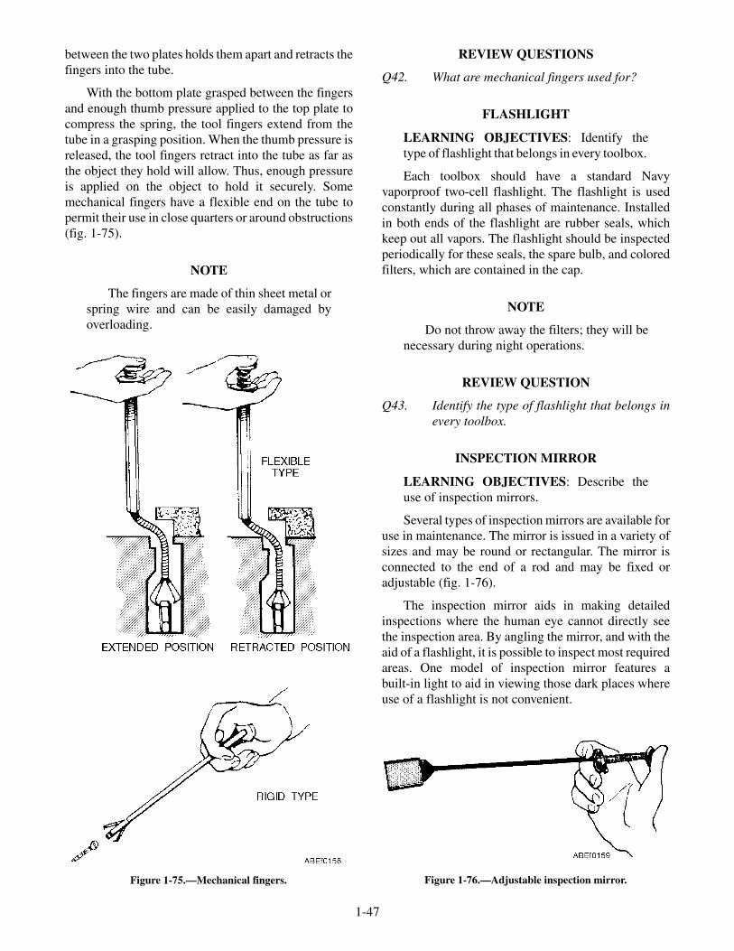
between the two plates holds them apart and retracts thefingers into the tube.
With the bottom plate grasped between the fingersand enough thumb pressure applied to the top plate tocompress the spring, the tool fingers extend from thetube in a grasping position. When the thumb pressure isreleased, the tool fingers retract into the tube as far asthe object they hold will allow. Thus, enough pressureis applied on the object to hold it securely. Somemechanical fingers have a flexible end on the tube topermit their use in close quarters or around obstructions(fig. 1-75).
NOTE
The fingers are made of thin sheet metal orspring wire and can be easily damaged byoverloading.
REVIEW QUESTIONS
Q42. What are mechanical fingers used for?
FLASHLIGHT
LEARNING OBJECTIVES: Identify thetype of flashlight that belongs in every toolbox.
Each toolbox should have a standard Navyvaporproof two-cell flashlight. The flashlight is usedconstantly during all phases of maintenance. Installedin both ends of the flashlight are rubber seals, whichkeep out all vapors. The flashlight should be inspectedperiodically for these seals, the spare bulb, and coloredfilters, which are contained in the cap.
NOTE
Do not throw away the filters; they will benecessary during night operations.
REVIEW QUESTION
Q43. Identify the type of flashlight that belongs inevery toolbox.
INSPECTION MIRROR
LEARNING OBJECTIVES: Describe theuse of inspection mirrors.
Several types of inspection mirrors are available foruse in maintenance. The mirror is issued in a variety ofsizes and may be round or rectangular. The mirror isconnected to the end of a rod and may be fixed oradjustable (fig. 1-76).
The inspection mirror aids in making detailedinspections where the human eye cannot directly seethe inspection area. By angling the mirror, and with theaid of a flashlight, it is possible to inspect most requiredareas. One model of inspection mirror features abuilt-in light to aid in viewing those dark places whereuse of a flashlight is not convenient.
1-47
Figure 1-76.—Adjustable inspection mirror.Figure 1-75.—Mechanical fingers.

SUMMARY
This chapter introduced you to the specificpurposes, correct uses, and proper care of some of thecommon hand tools and power tools that you will use asan ABE. You should be able to select, maintain, andsafely use tools required for maintenance of catapults
and arresting gear. Blueprints, electrical prints, pipingprints, and aperture cards were discussed. Bythoroughly understanding this chapter, you, as an ABE,will be able to perform your daily duties moreefficiently and safely.
1-48

CHAPTER 2
MEASURING TOOLS AND TECHNIQUES
When performing maintenance and repair tasks oncatapults and arresting gear equipment, you must takeaccurate measurements during inspection, to determinethe amount of wear or service life remaining on aparticular item or to make sure replacement parts usedto repair equipment meet established specifications.The accuracy of these measurements, often affectingthe performance and failure rates of the concernedequipment, depends on the measuring tool you use andyour ability to use it correctly.
COMMON MEASURING TOOLS
LEARNING OBJECTIVES: Identify thedifferent types of measuring tools. Describethe uses of different types of measuring tools.Describe the proper care of measuring tools.
You will use many different types of measuringtools in the daily performance of your duties. Whereexact measurements are required, use a micrometercaliper (mike). If you use the micrometer caliperproperly, it will allow you to measure within oneten-thousandth (0.0001) of an inch accuracy. On theother hand, where accuracy is not extremely critical, acommon straightedge rule or tape rule will suffice formost measurements.
RULES AND TAPES
Figure 2-1 illustrates some of the commonly usedstraightedge and tape rules. Of all measuring tools, the
simplest and most common is the steel or woodenstraightedge rule. This rule is usually 6 or 12 incheslong, although other lengths are available. Steel rulesmay be flexible or nonflexible, but the thinner the ruleis, the easier it is to measure accurately with it, becausethe division marks are closer to the work to bemeasured.
Generally, a rule has four sets of graduated divisionmarks, one on each edge of each side of the rule. Thelongest lines represent the inch marks. On one edge,each inch is divided into 8 equal spaces, so each spacerepresents 1/8 inch. The other edge of this side isdivided into sixteenths. The 1/4-inch and 1/2-inchmarks are commonly made longer than the smallerdivision marks to facilitate counting, but thegraduations are not normally numbered individually, asthey are sufficiently far apart to be counted withoutdifficulty. The opposite side of the rule is similarlydivided into 32 and 64 spaces per inch, and it iscommon practice to number every fourth division foreasier reading.
There are many variations of the common rule.Sometimes the graduations are on one side only,sometimes a set of graduations is added across one endfor measuring in narrow spaces, and sometimes onlythe first inch is divided into 64ths, with the remaininginches divided into 32nds and 16ths.
Steel tapes are made from 6 to about 300 feet inlength. The shorter lengths are frequently made with acurved cross section so that they are flexible enough toroll up, but remain rigid when extended. Long, flattapes require support over their full length whenmeasuring, or the natural sag will cause an error inreading.
MEASURING PROCEDURES
To take a measurement with a common rule, holdthe rule with its edge on the surface of the object beingmeasured. This will eliminate parallax and other errorsthat might result because of the thickness of the rule.Read the measurement at the graduation that coincideswith the distance to be measured, and state it as being so
2-1
Figure 2-1.—Some common types of rules.

many inches and fractions of an inch. (See fig. 2-2.)Always reduce fractions to their lowest terms, forexample, 6/8 inch would be called 3/4 inch. A hook oreye at the end of a tape or rule is normally part of thefirst measured inch.
Bolts and Screws
The length of bolts and screws is best measured byholding them up against a rigid rule or tape. Hold boththe rule and the bolt or screw to be measured up to youreye level, so that your line of sight will not be in error inreading the measurement. As shown in figure 2-3, thebolts or screws with countersink-type heads aremeasured from the top of the head to the opposite end,while those with other types of heads are measuredfrom the bottom of the head.
Outside Pipe Diameters
To measure the outside diameter of a pipe, youshould use some kind of rigid rule. A wooden rule or asteel rule is satisfactory for this purpose. As shown infigure 2-4, line up the end of the rule with one side ofthe pipe, using your thumb as a stop. Then, with the oneend held in place with your thumb, swing the rulethrough an arc and take the maximum reading at the
other side of the pipe. For most purposes, themeasurement obtained by using this method issatisfactory. It is necessary that you know how to takethis measurement, as the outside diameter of pipe issometimes the only dimension given on pipespecifications.
Inside Pipe Diameters
To measure the inside diameter of a pipe with arule, as shown in figure 2-5, hold the rule so that onecorner of the rule just rests on the inside of one side ofthe pipe. Then, with one end thus held in place, swingthe rule through an arc and read the diameter across themaximum inside distance. This method is satisfactoryfor an approximate inside measurement.
Pipe Circumferences
To measure the circumference of a pipe, you mustuse a flexible-type rule that will conform to the shape ofthe pipe. A fabric or steel flexible tape rule is adaptableto this job. When measuring the pipe, make sure thetape is wrapped squarely around the axis of the pipe toensure that the measurement will not be more than the
2-2
Figure 2-2.—Measuring with and reading a common rule.
Figure 2-3.—Measuring the length of a bolt or screw.
Figure 2-4.—Measuring the outside diameter of a pipe.
Figure 2-5.—Measuring the inside diameter of a pipe.

actual circumference of the pipe. This is extremelyimportant when you are measuring a large diameterpipe.
Hold the rule or tape as shown in figure 2-6. Takethe reading, using the 2-inch graduation, for example,as the reference point. In this case the correct reading isfound by subtracting 2 inches from the actual reading.In this way the first 2 inches of the tape, serving as ahandle, will enable you to hold the tape securely.
Inside Dimensions
For an inside measurement such as the inside of abox, a folding rule that incorporates a 6- or 7-inchsliding extension is one of the best measuring tools. Totake the inside measurement, first unfold the foldingrule to the approximate dimension. Then, extend theend of the rule and read the length that it extends,adding the length of the extension to the length on the
main body of the rule. See figure 2-7. In this illustrationthe length of the main body of the rule is 13 inches, andthe extension is pulled out 3 3/16 inches; the total insidedimension being measured is 16 3/16 inches.
Notice in the circled inset in figure 2-8 that thehook at the end of the particular rule shown is attachedto the rule so that it is free to move slightly. When anoutside dimension is taken by hooking the end of therule over an edge, the hook will move to locate the endof the rule even with the surface from which themeasurement is being taken. By being free to move, thehook will retract toward the end of the rule when aninside dimension is taken. To measure an insidedimension using a tape rule, extend the rule between thesurfaces as shown, take a reading at the point on thescale where the rule enters the case, and add 2 inches.The 2 inches are the length of the case. The total is theinside dimension being taken.
Outside Dimensions
To measure an outside dimension using a tape rule,hook the rule over the edge of the stock. Pull the tapeout until it projects far enough from the case to permitmeasuring the required distance. The hook at the end ofthe rule is designed so that it will locate the end of therule at the surface from which the measurement is beingtaken. When taking a measurement of length, hold thetape parallel to the lengthwise edge. For measuringwidths, the tape should be at right angles to thelengthwise edge. Read the dimension of the rule exactlyat the edge of the piece being measured.
It may not always be possible to hook the end of thetape over the edge of stock being measured. In this caseit may be necessary to butt the end of the tape againstanother surface or to hold the rule at a starting pointfrom which a measurement is to be taken.
2-3
Figure 2-6.—Measuring the circumference of a pipe with atape rule.
Figure 2-7.—Using a folding rule to measure an insidedimension. Figure 2-8.—Measuring an inside dimension with a tape rule.
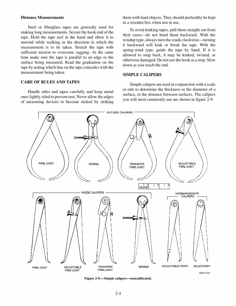
Distance Measurements
Steel or fiberglass tapes are generally used formaking long measurements. Secure the hook end of thetape. Hold the tape reel in the hand and allow it tounwind while walking in the direction in which themeasurement is to be taken. Stretch the tape withsufficient tension to overcome sagging. At the sametime make sure the tape is parallel to an edge or thesurface being measured. Read the graduation on thetape by noting which line on the tape coincides with themeasurement being taken.
CARE OF RULES AND TAPES
Handle rules and tapes carefully and keep metalones lightly oiled to prevent rust. Never allow the edgesof measuring devices to become nicked by striking
them with hard objects. They should preferably be keptin a wooden box when not in use.
To avoid kinking tapes, pull them straight out fromtheir cases—do not bend them backward. With thewindup type, always turn the crank clockwise—turningit backward will kink or break the tape. With thespring-wind type, guide the tape by hand. If it isallowed to snap back, it may be kinked, twisted, orotherwise damaged. Do not use the hook as a stop. Slowdown as you reach the end.
SIMPLE CALIPERS
Simple calipers are used in conjunction with a scaleor rule to determine the thickness or the diameter of asurface, or the distance between surfaces. The calipersyou will most commonly use are shown in figure 2-9.
2-4
Figure 2-9.—Simple calipers—noncalibrated.
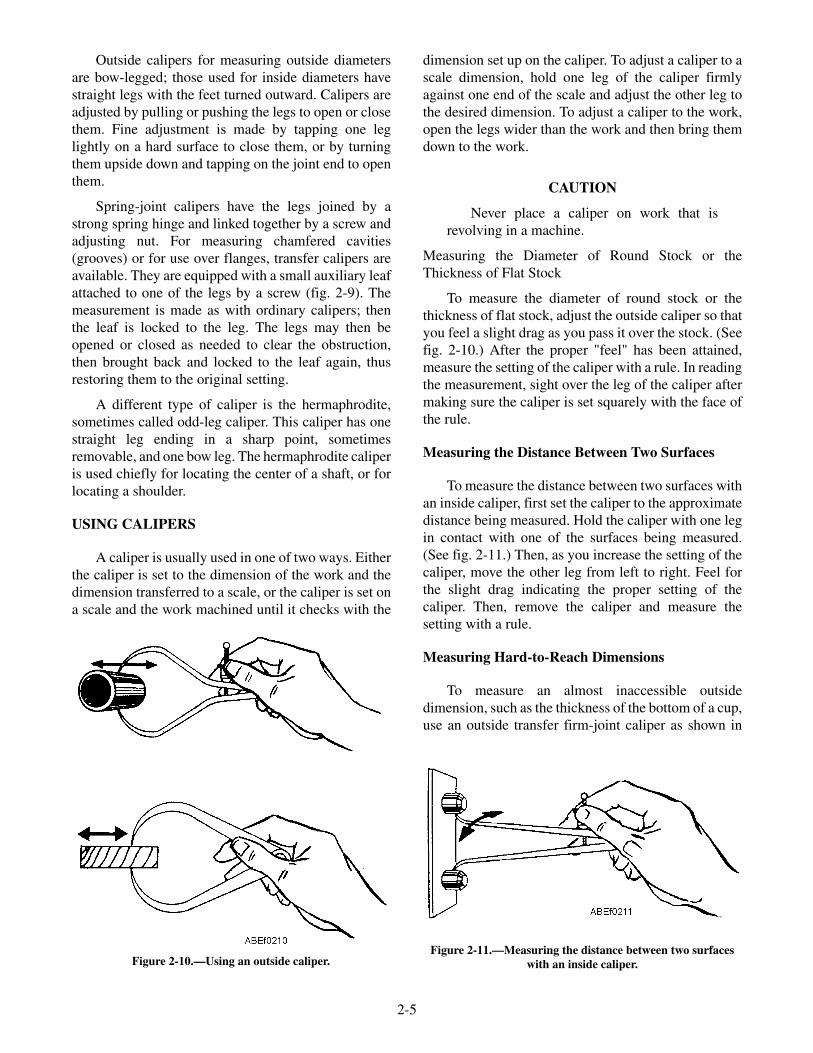
Outside calipers for measuring outside diametersare bow-legged; those used for inside diameters havestraight legs with the feet turned outward. Calipers areadjusted by pulling or pushing the legs to open or closethem. Fine adjustment is made by tapping one leglightly on a hard surface to close them, or by turningthem upside down and tapping on the joint end to openthem.
Spring-joint calipers have the legs joined by astrong spring hinge and linked together by a screw andadjusting nut. For measuring chamfered cavities(grooves) or for use over flanges, transfer calipers areavailable. They are equipped with a small auxiliary leafattached to one of the legs by a screw (fig. 2-9). Themeasurement is made as with ordinary calipers; thenthe leaf is locked to the leg. The legs may then beopened or closed as needed to clear the obstruction,then brought back and locked to the leaf again, thusrestoring them to the original setting.
A different type of caliper is the hermaphrodite,sometimes called odd-leg caliper. This caliper has onestraight leg ending in a sharp point, sometimesremovable, and one bow leg. The hermaphrodite caliperis used chiefly for locating the center of a shaft, or forlocating a shoulder.
USING CALIPERS
A caliper is usually used in one of two ways. Eitherthe caliper is set to the dimension of the work and thedimension transferred to a scale, or the caliper is set ona scale and the work machined until it checks with the
dimension set up on the caliper. To adjust a caliper to ascale dimension, hold one leg of the caliper firmlyagainst one end of the scale and adjust the other leg tothe desired dimension. To adjust a caliper to the work,open the legs wider than the work and then bring themdown to the work.
CAUTION
Never place a caliper on work that isrevolving in a machine.
Measuring the Diameter of Round Stock or theThickness of Flat Stock
To measure the diameter of round stock or thethickness of flat stock, adjust the outside caliper so thatyou feel a slight drag as you pass it over the stock. (Seefig. 2-10.) After the proper "feel" has been attained,measure the setting of the caliper with a rule. In readingthe measurement, sight over the leg of the caliper aftermaking sure the caliper is set squarely with the face ofthe rule.
Measuring the Distance Between Two Surfaces
To measure the distance between two surfaces withan inside caliper, first set the caliper to the approximatedistance being measured. Hold the caliper with one legin contact with one of the surfaces being measured.(See fig. 2-11.) Then, as you increase the setting of thecaliper, move the other leg from left to right. Feel forthe slight drag indicating the proper setting of thecaliper. Then, remove the caliper and measure thesetting with a rule.
Measuring Hard-to-Reach Dimensions
To measure an almost inaccessible outsidedimension, such as the thickness of the bottom of a cup,use an outside transfer firm-joint caliper as shown in
2-5
Figure 2-10.—Using an outside caliper.Figure 2-11.—Measuring the distance between two surfaces
with an inside caliper.

figure 2-12. When the proper "feel" is obtained, tightenthe lock joint. Then, loosen the binding nut and openthe caliper enough to remove it from the cup. Close thecaliper again and tighten the binding nut to seat in theslot at the end of the auxiliary arm. The caliper is now atthe original setting, representing the thickness of thebottom of the cup. The caliper setting can now bemeasured with a rule.
To measure a hard-to-reach inside dimension, suchas the internal groove shown in figure 2-13, use aninside transfer firm-joint caliper. Use the procedure formeasuring a hard-to-reach outside dimension.
Measuring Hole Diameters
To measure the diameter of a hole with an insidecaliper, hold the caliper with one leg in contact with oneside of the hole (fig. 2-14) and, as you increase thesetting, move the other leg from left to right, and in andout of the hole. When you have found the point oflargest diameter, remove the caliper and measure thecaliper setting with a rule.
Setting a Combination Firm-Joint Caliper
To set a combination firm-joint caliper with a rule,when the legs are in position for outside measurements,grasp the caliper with both hands as shown in view A offigure 2-15, and adjust both legs to the approximatesetting. After you adjust both legs, the shape of the tool
will be approximately symmetrical. Thus, it willmaintain its balance and be easier to handle.
Check this approximate setting as shown in figure2-15, view B. Sight squarely across the leg at thegraduations on the rule to get the exact setting required.
If it is necessary to decrease or increase the setting,tap one leg of the caliper as shown in figure 2-16. Thearrow indicates the change in setting that will takeplace.
When the caliper is set for inside measurements,the same directions for adjusting the setting apply.
2-6
Figure 2-12.—Measuring the thickness of the bottom of a cup.
Figure 2-13.—Measuring a hard-to-reach inside dimensionwith an inside caliper.
Figure 2-14.—Measuring an inside diameter with an insidecaliper.
Figure 2-15.—Setting a combination firm-joint caliper.
Figure 2-16.—Decreasing and increasing the setting of afirm-joint caliper.

Figure 2-17 shows how the end of the rule and one legof the caliper are rested on the bench top so that they areexactly even with each other when the reading is taken.
Setting Outside and Inside Spring Calipers
To set a particular reading on an outside springcaliper, first open the caliper to the approximate setting.Then, as shown in figure 2-18, place one leg over theend of the rule, steadying it with the index finger. Makethe final setting by sighting over the other leg of thecaliper squarely with the face of the rule at the reading,and turning the knurled adjusting nut until the desiredsetting is obtained.
To set an inside spring caliper to a particularreading, place both caliper and rule on a flat surface asshown in figure 2-19. The rule must be held squarely ornormal (90E in both directions) to the surface to ensureaccuracy. Adjust the knurled adjusting nut, reading thesetting on the rule with line-of-sight normal to the faceof the rule at the reading.
Transferring Measurements from One Caliper toAnother
To transfer a measurement from one spring caliperto another, hold the calipers as shown in figure 2-20.
Note that one of the man's fingers is extended to steadythe point of contact of the two lower caliper legs. In thisfigure the inside caliper is being adjusted to the size ofthe outside caliper. As careful measurements withcalipers depend on one's sense of touch, which isspoken of as "feel," calipers are best held lightly. Whenyou notice a slight drag, the caliper is at the propersetting.
CARE OF CALIPERS
Keep calipers clean and lightly oiled, but do notover oil the joint of firm-joint calipers or you may havedifficulty in keeping them tight. Do not throw themaround or use them for screwdrivers or pry bars. Even aslight force may spring the legs of a caliper so that othermeasurements made with it are never accurate.Remember that calipers are measuring instruments andmust be used only for the purpose for which they areintended.
2-7
Figure 2-17.—Setting a combination firm-joint caliper forinside measurements.
Figure 2-18.—Setting an outside spring caliper.
Figure 2-19.—Setting an inside spring caliper.
Figure 2-20.—Transferring a measurement from an outside toan inside caliper.

REVIEW QUESTIONS
Q1. Identify the different types of measuring tools.
Q2. Describe the uses of different types ofmeasuring tools.
Q3. Describe the proper care of measuring tools.
PRECISION MEASURING EQUIPMENT
LEARNING OBJECTIVES: Identify thedifferent types of precision measuring tools.Describe the uses of different types ofprecision measuring tools. Describe the propercare of measuring tools. Maintain inventoryand accountability of precision equipment.
In much wider use by ABEs than even commoncalipers are the various types of micrometer calipers.As was stated earlier, you can use micrometer calipersto take accurate measurements to the nearest oneten-thousandth of an inch. However, in mostapplications a measurement to the nearest one-thousandth of an inch is considered acceptableaccuracy. These measurements are expressed or writtenas a decimal (0.0001, 0.001, 0.01), so you must knowhow to read and write decimals.
TYPES OF MICROMETER CALIPERS
There are three types of micrometer calipers,commonly called micrometers or simply mikes, usedthroughout the Navy: the outside micrometer, including
the screw thread micrometer; the inside micrometer;and the depth micrometer. (See fig. 2-21.) The outsidemicrometer is used for measuring outside dimensions,such as the outside diameter of a piece of round stock orthe thickness of a piece of flat stock. The screw threadmicrometer is used to determine the pitch diameter ofscrews. The inside micrometer is used to measure theinside diameter of a cylinder or hole. The depthmicrometer is used for measuring the depth of a hole orrecess.
Outside Micrometer
The nomenclature of an outside micrometer isillustrated in figure 2-22.
The sleeve and thimble scales of a micrometer (fig.2-23) have been enlarged and laid out fordemonstration. To understand these scales, you need toknow that the threaded section on the spindle, whichrevolves, has 40 threads per inch. Therefore, every timethe thimble completes a revolution, the spindleadvances or recedes 1/40 inch, or 0.025 inch.
Note the horizontal line on the sleeve is divided into40 equal parts per inch. Every fourth graduation isnumbered 1, 2, 3, 4, and so on, representing 0.100 inch,0.200 inch, and so on. When you turn the thimble so itsedge is over the first sleeve line past the 0 on the thimblescale, the spindle has opened 0.025 inch. If you turn thespindle to the second mark, it has moved 0.025 inchplus 0.025 inch, or 0.050 inch.
2-8
Figure 2-21.—Common types of micrometers.

When the beveled edge of the thimble stopsbetween graduated lines on the sleeve scale, you mustuse the thimble scale to complete your reading. Thethimble scale is divided into 25 equal parts; each part ormark represents 1/25th of a turn. And, 1/25th of 0.025inch equals 0.001 inch. Note that in figure 2-23 everyfifth line on the thimble scale is marked 5, 10, 15, and soon. The thimble scale permits you to take very accuratereadings to the thousandths of an inch.
The enlarged scale in figure 2-24 can help youunderstand how to take a complete micrometer readingto the nearest thousandth of an inch.
The thimble is turned far enough to expose the 7 onthe sleeve scale but not far enough to expose the firstmark after the 7. Therefore, the measurement must bebetween 0.700 inch and 0.725 inch. Exactly how farbetween 0.700 inch and 0.725 inch must be read on thethimble scale.
As you can see, the thimble has been turnedthrough 12 spaces of its scale, and the 12th graduation
is lined up with the reference line on the sleeve. Whenthe value on the sleeve scale is added to the value on thethimble scale that is lined up with the reference line onthe sleeve scale, the space between the anvil and spindlemust be 0.712 inch (seven hundred and twelvethousandths of an inch).
MICROMETER-READING EXERCISE.—Occasionally you attain a reading in which thehorizontal reference line of the sleeve scale fallsbetween two graduations on the thimble scale, asshown in figure 2-25. Note the horizontal reference lineis closer to the 15 mark than to the 14 mark. To read thismeasurement to THREE decimal places, simply roundoff to the 15 mark, as shown in example A of figure2-25. To read this measurement to FOUR decimalplaces, estimate the number of tenths of the distancebetween thimble scale graduations the horizontalreference line has fallen. Each tenth of this distanceequals one ten-thousandth (0.0001) of an inch. Add theten-thousandths to the reading as shown in example Bof figure 2-25.
2-9
Figure 2-23.—Sleeve and thimble scales of a micrometer.
Figure 2-24.—Enlarged micrometer scale.
Figure 2-22.—Nomenclature of an outside micrometer caliper.
Figure 2-25.—Reading sleeve and thimble scales of amicrometer.

READING THE VERNIER SCALE ON AMICROMETER.—Many times you are required towork to exceptionally precise dimensions. Under theseconditions it is better to use a micrometer that isaccurate to ten-thousandths of an inch. This degree ofaccuracy is obtained by the addition of a vernier scale.
The vernier scale of a micrometer (fig. 2-26)furnishes the fine readings between the lines on thethimble rather than requiring you to estimate thereading. The 10 spaces on the vernier are equivalent to 9spaces on the thimble. Therefore, each unit on thevernier scale is equal to 0.0009 inch, and the differencebetween the sizes of the units on each scale is 0.0001inch.
When a line on the thimble scale does not coincidewith the horizontal reference line on the sleeve, you candetermine the additional spaces beyond the readablethimble mark by finding which vernier mark matchesup with a line on the thimble scale. Add this number, asthat many ten-thousandths of an inch, to the originalreading. In figure 2-27 see how the second line on thevernier scale matches up with a line on the thimblescale.
This means that the 0.011 mark on the thimblescale has been advanced an additional 0.0002beyond the horizontal sleeve line. When you addthis to the other readings, the reading is0.200 + 0.075 + 0.011 + 0.0002, or 0.2862, as shown.
Inside Micrometer
The inside micrometer, as the name implies, is usedfor measuring inside dimensions, such as pump casingwearing rings, cylinder, bearing, and bushing wear.Inside micrometers usually come in a set that includes amicrometer head, various length spindles (or extensionrods) that are interchangeable, and a spacing collar thatis 0.500 inch in length. The spindles (or extension rods)usually graduate in 1-inch increments of range; forexample, 1 to 2 inches, 2 to 3 inches (fig. 2-28).
The 0.500 spacing piece is used between thespindle and the micrometer head so the range of themicrometer can be extended. A knurled extensionhandle is usually furnished for obtaining measurementsin hard-to-reach locations.
Reading the inside micrometer. To read the insidemicrometer, read the micrometer head exactly as youwould an outside micrometer, then add the micrometerreading to the rod length (including spacing collar,when installed) to obtain the total measurement.
Depth Micrometer
The depth micrometer is used to measure theprecise depths of holes, grooves, and recesses by usinginterchangeable rods to accommodate different depthmeasurements (fig. 2-21). When using a depthmicrometer, you must make sure the base of themicrometer has a flat, smooth surface to rest on and thatit is held firmly in place to ensure an accuratemeasurement (fig. 2-29).
2-10
Figure 2-26.—Vernier scale of a micrometer.
Figure 2-27.—Reading a vernier scale micrometer.
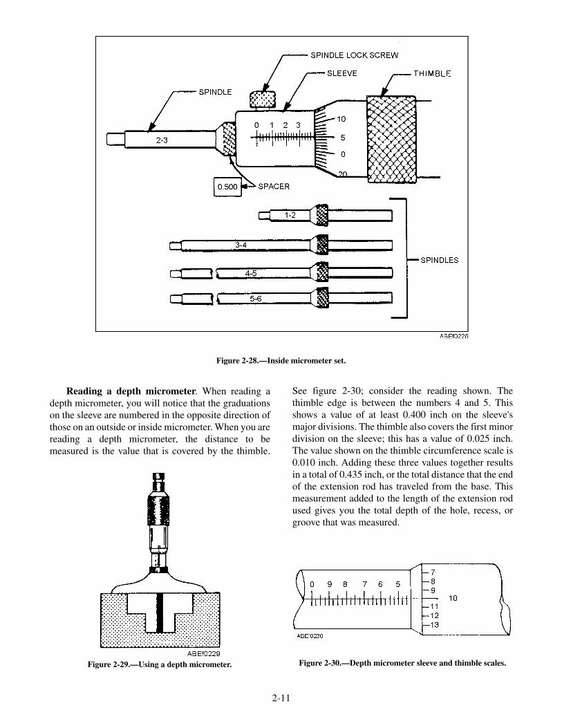
Reading a depth micrometer. When reading adepth micrometer, you will notice that the graduationson the sleeve are numbered in the opposite direction ofthose on an outside or inside micrometer. When you arereading a depth micrometer, the distance to bemeasured is the value that is covered by the thimble.
See figure 2-30; consider the reading shown. Thethimble edge is between the numbers 4 and 5. Thisshows a value of at least 0.400 inch on the sleeve'smajor divisions. The thimble also covers the first minordivision on the sleeve; this has a value of 0.025 inch.The value shown on the thimble circumference scale is0.010 inch. Adding these three values together resultsin a total of 0.435 inch, or the total distance that the endof the extension rod has traveled from the base. Thismeasurement added to the length of the extension rodused gives you the total depth of the hole, recess, orgroove that was measured.
2-11
Figure 2-28.—Inside micrometer set.
Figure 2-29.—Using a depth micrometer. Figure 2-30.—Depth micrometer sleeve and thimble scales.

SELECTING THE PROPER MICROMETER
The types of micrometers commonly used aremade so that the longest movement that the micrometerspindle or rod can make is 1 inch. This movement iscalled the range; for example, a 2-inch micrometer hasa range of from 1 inch to 2 inches, and can only measurework with a thickness or diameter within that range.Therefore, it is necessary to first determine theapproximate size, to the nearest inch, of the work to bemeasured and then select the proper size micrometer.The size of a micrometer indicates the size of the largestwork it can measure.
CARE OF MICROMETERS
Keep micrometers clean and lightly oiled. Makesure they are always stored in a case or box when not inuse, to protect them from damage. Never clean any partof a micrometer with emery cloth or other abrasive. Themeasuring tools that have been described in this chapterare the ones that you, as an ABE, will routinely usewhile performing your assigned duties. You may,however, occasionally be required to use other lesscommonly used measuring tools. Some of these are thedial indicator, telescopic (snap) gauge, the verniercaliper, or screw thread gauge. The description of thesetools and instructions for their use can be found in thetraining manual Use and Care of Hand Tools andMeasuring Tools, NAVEDTRA 12085.
INVENTORY AND ACCOUNTABILITY
All measuring tools will be marked in somemanner, etched, stenciled, etc., to comply with standardinventory instructions. These standard instructionsmay be found in Aircraft Launch and Recovery Equip-ment (ALRE) Tool Control Manual, NAEC-MISC-51-OR732.
Some measuring tools such as tapes and calipersmay be part of a specific toolbox inventory. Otherprecision measuring instruments such as micrometers,
snap gauges and vernier calipers will normally bemaintained in the division's central tool room.Regardless of the tool's permanent location, it is alwaysthe user's responsibility to maintain, care for and usethe tool properly.
Damage, loss, or an improperly working toolshould be reported immediately. Loss of a tool becomesespecially critical when working on or around thecatapult or arresting gear machinery. The tool may be"lost" in the machinery and, if not found, may causecatastrophic damage to the equipment and seriousinjury to personnel. Always double-check the inventoryensuring every tool is accounted for upon jobcompletion. The proper tools will help you maintainyour equipment but only if you maintain your toolsproperly.
REVIEW QUESTIONS
Q4. Identify the different types of precisionmeasuring tools.
Q5. Describe the uses of different types ofprecision measuring tools.
Q6. Describe the proper care of precisionmeasuring tools.
Q7. All precision measuring tools will be________________ in some manner to com-ply with the standard inventory instructionsfound in NAEC-MISC-51OR732.
SUMMARY
This chapter has introduced you to some of themost often used measuring tools and the techniques forusing them. Selecting the proper tool; using andmaintaining the various tools; and inventorying thetools have all been discussed. By thoroughlyunderstanding and comprehending this chapter, you, asan ABE, will be able to perform your daily duties moreefficiently and safely.
2-12
CHAPTER 3
MK 7 AIRCRAFT RECOVERYEQUIPMENT
Present-day aircraft normally require the use ofrunways that are 5,000 to 8,000 feet long in order toland ashore. On an aircraft carrier, these same aircraftare stopped within 350 feet after contacting the deck.This feat is accomplished through the use of aircraftrecovery equipment, including an emergency barricadethat brings a landing aircraft to a controlled stop byabsorbing and dispelling the energy developed by thelanding aircraft. This recovery equipment is commonlycalled arresting gear.
The sole purpose of an aircraft carrier is to providea means of launching a strike against an enemyanywhere in the world. After the aircraft complete theirmission, the carrier must provide a means of safelyrecovering them. The Mk 7 arresting gear provides thismeans.
AIRCRAFT RECOVERY
LEARNING OBJECTIVE: Describe aircraftarrestments aboard aircraft carriers. Describeprerecovery preparations. Describe normalaircraft recovery operations. Describeemergency aircraft recovery operations.
Aircraft arrestments aboard carriers are classifiedas either a normal arrestment or an emergencyarrestment. Simply stated, arrestment is accomplishedin the following manner: the arresting hook of theincoming aircraft engages a wire rope cable, called adeck pendant, that spans the flight deck in the landingarea. The force of the forward motion of the aircraft istransferred to purchase cables that are reeved around amovable crosshead of sheaves and a fixed sheaveassembly of the arresting engine (see fig. 3-1). Themovable crosshead is moved toward the fixed sheaveassembly as the aircraft pulls the purchase cables offthe arresting engine, forcing a ram into the cylinderholding pressurized hydraulic fluid (ethylene glycol).This fluid is forced out of the cylinder through a controlvalve that meters the flow to an accumulator until theaircraft is brought to a smooth, controlled arrestedlanding (see fig. 3-2).
After arrestment, the aircraft's arresting hook isdisengaged from the deck pendant. A retract valve is
then opened, allowing fluid to be forced from theaccumulator back into the engine cylinder, forcing theram out. As the ram moves out of the cylinder, thecrosshead is forced away from the fixed sheaveassembly, pulling the purchase cables back onto theengine until the crosshead is returned to its BATTERYposition and the crossdeck pendant is in its normalposition on the flight deck.
PRERECOVERY PREPARATIONS
Prior to recovery of aircraft, all recovery equipmentand landing area must be made ready and all personnelproperly positioned. The following is a general listingof the events that must be accomplished prior to therecovery of aircraft:
• All operational retractable sheaves raised to thefull up position
• All aft deckedge antennas positioned, asrequired
• Ready barricade, including deck ramps, in aready status with a clear route to the landing areaand a tractor with driver standing by
• All launching accessories clear of the landingarea
• Appropriate catapult shuttle(s) (as applicable)are aft with the grab latch disengaged and theshuttle spreader cover installed
• The catapult centerdeck hatch and any otherhatches in the waist catapult area closed anddogged down
• Jet Blast Deflectors (JBDs) completely loweredand hydraulics secured
• Waist catapult safety light in the down position,if applicable
• Catapult #3 track slot buttons installed
• Waist catapult Integrated Catapult ControlStation (ICCS) fully lowered, if applicable
3-1

3-2
RE
TR
AC
TA
BL
ES
HE
AV
E
WIR
ER
OP
ES
UP
PO
RT
TH
RU
-DE
CK
SH
EA
VE
FA
IRL
EA
DS
HE
AV
ES
AN
CH
OR
DA
MP
ER
FL
UID
CO
OL
ER
CO
NS
TA
NT
RU
NO
UT
CO
NT
RO
LV
ALV
E
MA
INE
NG
INE
CY
LIN
DE
R
CO
NT
RO
LV
ALV
ED
RIV
ES
YS
TE
M
AC
CU
MU
LA
TO
R
SH
EA
VE
DA
MP
ER
AIR
FLA
SK
S
CR
OS
SH
EA
D
AB
Ef0
301
CR
OS
SD
EC
KP
EN
DA
NT
PU
RC
HA
SE
CA
BL
EF
IXE
DS
HE
AV
EA
SS
EM
BLY
Fig
ure
3-1.
—G
ener
alar
rang
emen
tof
Mk
7ar
rest
ing
engi
new
ith
cool
er.

• Landing area clear of aircraft or any otherobstructions
• Aircraft recovery green rotating beacon on
• All stations manned and ready with voicecommunication established and reports made tothe air officer
• Sheave and anchor damper in the batteryposition
• All engines fully retracted and crossdeckpendant at the proper height
• Engine fluid levels in the battery range andaccumulator pressure at 400 psi
• Received from the air officer; aircraft type to berecovered
• Determine proper aircraft weight setting inaccordance with applicable aircraft recoverybulletin
• Direct the engine room operators to set theirrespective engine and verify that correct weighthas been set
• Pickle switch is actuated, lighting the green cleardeck landing status light
NORMAL RECOVERY OPERATIONS
Normal recovery operations involve the recovery ofaircraft with no equipment failure or damage thatprecludes the aircraft from recovering at the prescribedair speed or proper landing configuration.
3-3
DECK SHEAVE
ABEf0302
DAMPER SHEAVEINSTALLATION
ACCUMULATOR
AIR EXPANSIONFLASK
COOLERCONSTANT RUNOUT
CONTROL VALVE
FILTER
CABLE ANCHORDAMPER
CROSSHEAD
RAMCYLINDER
RETRACTION VALVE
FIXED SHEAVE
AIR
FLUIDZERO PRESSURE
750 PSI TO1500 PSI
400 PSI TO650 PSI
750 PSI TO3000 PSI
400 PSI TO10000 PSI
LEGEND
AIR
FLUID
AIR
FLUID
FLUID
FLUID
Figure 3-2.—Mk 7 Mod 3 fluid flow diagram during arrestment.
Prior to commencing aircraft recovery operations,the following considerations apply:
All arresting gear equipment is in normal operatingcondition and all Maintenance Requirement Cards(MRCs) preoperational requirements have been met.
All personnel involved in recovery operations havecompleted the applicable Personnel QualificationStandards (PQS) and are fully qualified to perform theirassigned tasks. Personnel not yet qualified may beutilized, but only if under the direct supervision of afully PQS qualified crewmember.
EMERGENCY RECOVERY OPERATIONS
An emergency arrestment is accomplished in thesame manner as a normal arrestment except that abarricade webbing assembly transmits the aircraft'slanding force to the purchase cable instead of acrossdeck pendant.
ARRESTING ENGINE
LEARNING OBJECTIVE: Describe thecomponents of the arresting engine.
The Mk 7 arresting engine is a hydropneumaticsystem composed of the engine structure, a cylinderand ram assembly, a crosshead and fixed sheaves, acontrol valve system, an accumulator system, air flasks,and a sheave and cable arrangement.
Improvements are continuously being made toincrease the capabilities of carrier-based aircraft. As thecapabilities of the aircraft are increased, the weight andspeed also increase. Therefore, the equipment used torecover the aircraft aboard carriers must also beimproved to keep pace with aircraft advancement. Suchimprovements have brought about the recoveryequipment installed on our carriers in the fleettoday—the Mk 7 Mod 3.
All pendant and barricade engines are Mk 7 Mod 3,except the barricade engines installed on CV-64 andCVN-65, which are Mk 7 Mod 2. For more informationon the Mk 7 Mod 2 refer to Operational andOrganizational/Intermediate Maintenance Manual,NAVAIR 51-5BBA-2.1 and 2.2. Table 3-1 lists theleading particulars of the Mk 7 Mod 3 recoveryequipment.
ENGINE STRUCTURE
The engine structure is a framework for supportingthe engine and most of its components and for securingthe entire assembly to the ship's structure. It iscomposed of a welded steel base made in twolongitudinal box sections with the necessary ties,plates, and other structural members. The two sectionsare bolted together near the center. See figure 3-1.
Two pairs of saddles are mounted on the base forsupporting the engine cylinder. Vertical stands arewelded on these saddles to support the saddles for theaccumulator. Between these two stands is a frame ofwelded channels, angles, and gusset plates to providetrusses and ties for the frame.
On the crosshead end of the welded base supportplates, webs and gussets support the rails for thecrosshead. On this end of the base are weldedlongitudinal guides for the accumulator assembly. Nearthe end of this frame and bolted to it is the crossheadstop, which is removed when the crosshead is installedor removed.
CONSTANT RUNOUT VALVE (CROV)ASSEMBLY
The constant runout valve (CROV) is installed atthe fixed sheave end of the Mk 7 arresting engine, asillustrated in figure 3-1. It is designed to stop all aircraftwith the same amount of runout regardless of theaircraft's weight and speed (within the limits specifiedin current recovery bulletins).
The CROV is the heart of the equipment. It controlsthe flow of fluid from the cylinder of the arrestingengine to the accumulator. The other components of thevalve are used either to adjust the initial opening of thisvalve for aircraft of different weight or to activate thevalve during the arresting stroke.
CONSTANT RUNOUT VALVE (CROV) DRIVESYSTEM
When a landing aircraft engages a deck pendant, orbarricade, it withdraws purchase cable from the arrest-ing engine. This action causes the crosshead to movetoward the fixed sheave end of the engine. In addition tocausing fluid displacement from the engine cylinder,the movement of the crosshead causes the CROV drive
3-4

3-5
MAXIMUM ENERGY ABSORPTION 47,500,000 ft-lb
ENGINE DRIVE SYSTEM CABLES:
Breaking strength/diameterDeck pendant (6 × 30 flat strand hemp core)Purchase cable (6 × 25 round strand hemp core)Deck pendant (6 × 30 flat strand polyester core)Purchase cable (6 × 31 flat strand polyester core)
188,000 lb/1 3/8 in.195,000 lb/1 7/16 in.205,000 lb/1 7/16 in.215,000 lb/1 7/16 in.
Reeving ratio 18 to 1
3312DAMPER SHEAVE INSTALLATION:
Damper sheave service strokeEffective piston area of damper sheave piston
10 ft39.27sq. in.
ARRESTING ENGINE:
Length 50 ft
Weight 43 tons
Engine fluid Ethylene glycol
Engine fluid capacity (without cooler) 380 gal
Engine fluid capacity (with cooler) 560 gal
Type of coolant Sea water
Ram diameter 20.000 in.
Effective ram area 314.16 sq. in.
Length of two-stroke 195 in.
Length of service strokePendant engineBarricade engine
183 in.160 in.
Crosshead battery position
(distance from stop)
1 to 7 in. (new cable)
1 to 6 in. (old cable)
Accumulator operating mediumInitial working pressureMaximum pressure
Hydraulic fluid — Air400psi650 psi
Length of deck pendant runout 344 ft (to tail hook)
Length of barricade runout 388 ft (to nose wheel)
Cable anchor damper piston service stroke 15 ft 8 in.
Effective piston area of cable anchor damper piston 7.85 sq. in.
BARRICADE POWER PACKAGE
Power package fluid Catapult hydraulic fluid
Power package fluid capacity 125 gal
Power package operating mediumInitial working pressurePressure switch minimum pressureRelief valve maximum pressure
Hydraulic fluid — Air1,500 psi1,250 psi1,750 psi
Table 3-1.—Leading Particulars of Mk 7 Mod 3 Recovery Equipment

system (fig. 3-3) to rotate the CROV cam. Rotation ofthis cam forces a plunger down onto a set of levers (fig.3-4), which in turn forces a valve sleeve and valve stemdown to mate with a valve seat to close the valve,shutting off the flow of fluid from the engine cylinder tothe engine accumulator, bringing the aircraft to a stop.
As stated earlier, the CROV is designed to bring allaircraft, regardless of weight, to a controlled stop whileusing approximately the same amount of flight decklanding area. This is accomplished by adjusting theallowable opening of the CROV, a smaller, morerestrictive opening to arrest a heavy aircraft or a largevalve opening to arrest a light aircraft.
CONSTANT RUNOUT VALVE (CROV)WEIGHT SELECTOR
The aircraft weight selector makes it possible toadjust the CROV for aircraft of different weights byvarying the valve opening. See figure 3-4.
The size of the initial valve opening is adjustedwhile the arresting engine is in the BATTERY position.The lead screw receives rotary motion from the motorunit or handwheel and converts it into linear motion.This linear motion positions the upper lever and drivesthe local and remote indicators.
In each of the two levers (upper and lower), thedistance between the fulcrum and roller is constant. Onthe upper lever, the distance between the fulcrum and
the point of application of force from the cam isvariable, its greatest length being twice that of the lowerlever. The lever arm ratio of each lever, therefore, isvariable between 1:1 and 2:1.
When the upper lever is fully extended, the ratio ofeach lever is 1:1. In this setting the initial opening of thecontrol valve upon engagement of an aircraft ismaximum. The resulting rotation of the cam, caused bythe crosshead moving inward, forces the plungerdownward. A plunger movement of 1 inch, actingthrough the upper lever, would move the lower lever 1inch; the lower lever, in turn, would move the valvesleeve and stem 1 inch downward.
The cam is a disc plate type with the desiredcontour machined on its periphery. As the cam rotates,it forces the plunger down. The plunger is fitted withrollers, top and bottom.
The bottom roller on the plunger acts against thetop flat bearing surface of the upper lever. The pivot endof the upper lever has a bushed hole that mates with theclevis end of the lead screw yoke. The upper lever isconnected to the clevis end of the yoke by a pin. Thispin extends beyond the sides of the yoke and acts as ashaft and has a bushed roller mounted on each extendedend. The rollers ride inside the guide attached to thehousing. The block end of the yoke is connected to thelead screw by two dowel pins. This connection providesthe means by which the lead screw adjusts (moves) theupper lever.
3-6
INDICATOR PLATECONTROL
VALVE
CAM
RAM TRAVELAND DECK
RUNOUT DIAL
CONTROL VALVEREF (CROV)
DRIVECHAINS
PULLEY
PULLEYS
CONTROL VALVEDRIVE CABLE
MOVEABLE CROSSHEAD
PULLEYS
ADJUSTABLEANCHOR
ABE3f0303
Figure 3-3.—Constant runout valve drive system.
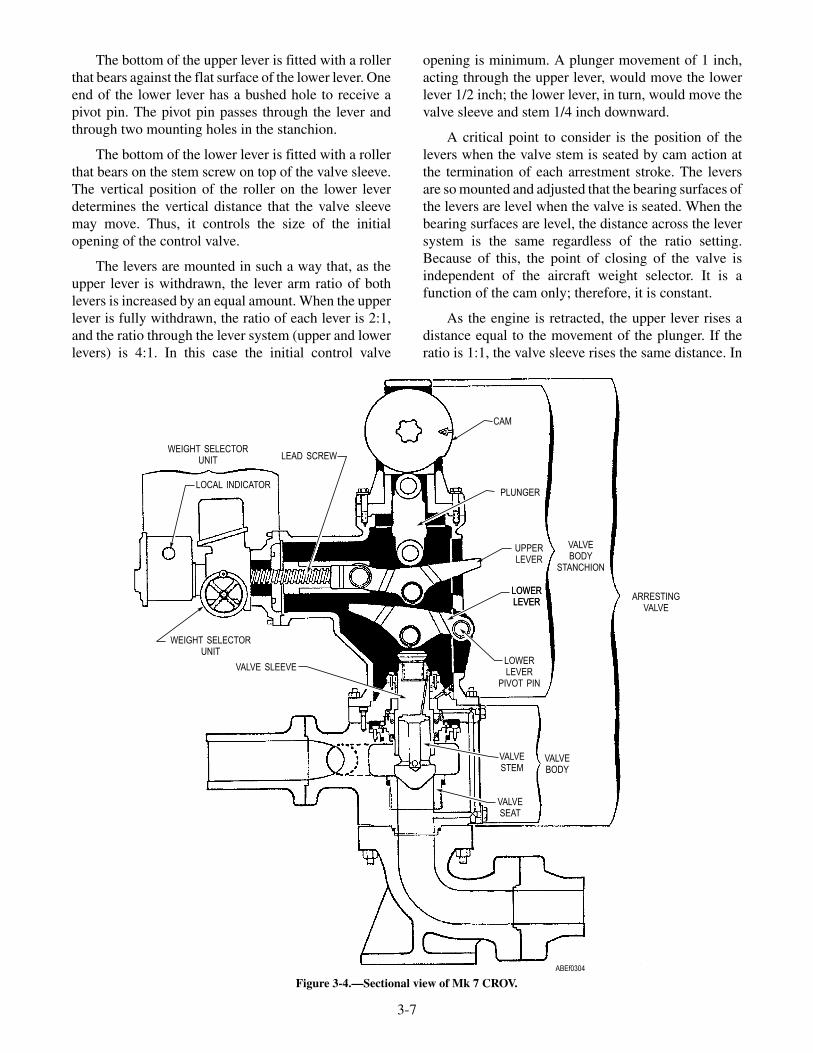
The bottom of the upper lever is fitted with a rollerthat bears against the flat surface of the lower lever. Oneend of the lower lever has a bushed hole to receive apivot pin. The pivot pin passes through the lever andthrough two mounting holes in the stanchion.
The bottom of the lower lever is fitted with a rollerthat bears on the stem screw on top of the valve sleeve.The vertical position of the roller on the lower leverdetermines the vertical distance that the valve sleevemay move. Thus, it controls the size of the initialopening of the control valve.
The levers are mounted in such a way that, as theupper lever is withdrawn, the lever arm ratio of bothlevers is increased by an equal amount. When the upperlever is fully withdrawn, the ratio of each lever is 2:1,and the ratio through the lever system (upper and lowerlevers) is 4:1. In this case the initial control valve
opening is minimum. A plunger movement of 1 inch,acting through the upper lever, would move the lowerlever 1/2 inch; the lower lever, in turn, would move thevalve sleeve and stem 1/4 inch downward.
A critical point to consider is the position of thelevers when the valve stem is seated by cam action atthe termination of each arrestment stroke. The leversare so mounted and adjusted that the bearing surfaces ofthe levers are level when the valve is seated. When thebearing surfaces are level, the distance across the leversystem is the same regardless of the ratio setting.Because of this, the point of closing of the valve isindependent of the aircraft weight selector. It is afunction of the cam only; therefore, it is constant.
As the engine is retracted, the upper lever rises adistance equal to the movement of the plunger. If theratio is 1:1, the valve sleeve rises the same distance. In
3-7
WEIGHT SELECTORUNIT
LOCAL INDICATOR
LEAD SCREW
CAM
PLUNGER
UPPERLEVER
LOWERLEVER
LOWERLEVER
PIVOT PIN
LOWERLEVER
VALVE SLEEVE
WEIGHT SELECTORUNIT
VALVESTEM
VALVEBODY
ARRESTINGVALVE
VALVEBODY
STANCHION
VALVESEAT
ABEf0304
Figure 3-4.—Sectional view of Mk 7 CROV.

this case the initial valve opening is maximum. If theratio is 4:1, however, the valve sleeve rises onlyone-fourth the distance that the plunger moves. In thiscase the initial valve opening is minimum.
The lever setting may be adjusted to any settingwithin the two extremes previously discussed; theparticular setting used is dependent upon the weight ofthe aircraft to be arrested. The weight setting is madewith the engine in battery position prior to landing theaircraft.
Adjustment of the setting determines the positionof the valve sleeve. Therefore, it also sets the amountthe valve will open at the beginning of the arrestmentstroke. Similarly, it determines the rate of closureduring the stroke so that the valve will always seat at thesame runout.
The valve stem sleeve allows a relatively unloadedand cushioned opening at the beginning of the stroke.
The lever system, if set for a heavy aircraft, reducesthe allowable valve stem opening and thus increases theresistance of the valve to the flow of fluid. The energyof the aircraft is dissipated by forcing fluid through therestricted valve opening.
ELECTRICAL SYSTEM
The electrical system provides, controls, andsafeguards the distribution of electrical energy to theweight selector motor and the synchro indicators. The
electrical circuits (fig. 3-5) are the control valve weightselector circuit and the indicator circuit.
AIRCRAFT WEIGHT SELECTOR SYSTEMAND ELECTRICAL CIRCUIT
Due to the varying weights and landing speeds ofcarrier-based aircraft, it is necessary to vary the initialopening of the CROV and have a smaller initial openingfor heavier aircraft than for lighter aircraft. Thevariation of the setting of the CROV is the function ofthe aircraft weight selector motor unit. (See fig. 3-5.)Normally, the settings are made electrically bydepressing an increase or decrease push button locatedat the control valve. The settings can also beaccomplished manually by a handwheel at the controlvalve.
The aircraft weight selector is motor operated fromthe 440-volt, 60-hertz, 3-phase ship's power supply. Afused switch box or breaker is provided to energize orde-energize the control circuit. To increase anddecrease settings, the direction of the aircraft weightselector motor rotation is controlled by the motorcontroller. Should an electrical failure occur, thesettings can be made manually by pulling out on thehandwheel and turning in either the increase or thedecrease direction.
Settings on the aircraft weight selector aremonitored locally at the control valve motor unit dialand remotely by synchro receivers located at Pri-Flyand the deckedge control station.
3-8
FUSED SWITCH BOX
FUSED SWITCH BOX
AWISDECKEDGE
STATION
AWIS ATPRI-FLY
CONTROLSTATION
SYNCHRO
SYNCHRO
MINIMUMSETTING
MAXIMUMSETTING
POINTERASSEMBLY
ENGINE 440VTERMINAL BOX
MOTOR CONTROLLER
AIRCRAFT WEIGHTSELECTOR MOTOR
UNIT , 440V
ABE30305
12
2030
40
50
6070
AIRCRAFT WEIGHTSELECTOR DIAL
INDICATOR CIRCUITPOWER SUPPLY110V, 60 , 10
MOTOR CIRCUITPOWER SUPPLY400V, 60 , 30
ENGINE 110VTERMINAL BOX
AIRCRAFT WEIGHTSELECTOR PUSHBUTTON
STATION
Figure 3-5.—Aircraft weight selector system.

PUSH-BUTTON STATIONS
The function of the push-button station is to selectthe proper contact of the weight selector motorcontroller so as to rotate the shaft of the motor in theproper direction to increase or decrease the weightsetting
DECKEDGE CONTROL STATION
The deckedge control station (fig. 3-6) is located onthe starboard side aft, where the operator has a clear,unobstructed view of the landing area.
The deckedge control station is equipped withcontrol levers to retract each of the pendant engines and
3-9
INDICATOR &MOUNTINGASSEMBLY
RETRACT VALVECONTROL INSTALLATION
(TYP)
ARRESTING GEAROFFICER ENCLOSURE
ASSEMBLY
LIGHT BOXASSEMBLY (TYP)
INDICATOR CIRCUITBREAKER ENCLOSURE
MAIN CIRCUITBREAKER ENCLOSURE
ABE30306
RETRVGP1
ENG I
RETRVGP2
ENG 2
RETRVGP3
ENG3
RETRVGP4
ENG 4
RETRVGB1
ENG 5
RETRACTABLESHEAVE & DIMMER
SWITCH ENCLOSURE
INDICATOR ASSEMBLY (AWIS)(WITHOUT S/C 417, REFER
TO WP 039 00)
Figure 3-6.—Deckedge control station.

the barricade; a pressure gauge for the barricadehydraulic system; a control lever to raise or lower thebarricade stanchions; push buttons to raise, lower, orstop the retractable sheaves; an indicator light toindicate their position; a battery position indicator lightfor the damper sheaves; and synchro receivers tomonitor settings on the aircraft weight selector unit ofeach engine.
The deckedge control operator operates thecontrols from the gallery walkway and is equipped withsound-powered phones to maintain voice com-munications with the engine-room operator andPri-Fly.
RETRACTING VALVE
The retracting valve permits the controlled returnof fluid from the accumulator to the cylinder, therebyreturning the engine to the BATTERY position. Thegeneral location of the retracting valve is shown infigure 3-7.
The retracting valve is a self-containedpoppet-valve assembly composed principally of ahousing, a plunger, an operating lever, a valve stem, anda valve seat.
The retracting valve operates as a check valveagainst the flow of fluid from the accumulator to theengine cylinder. Fluid at accumulator pressure entersthe housing and bears on the stem in the direction thatwould open the valve; however, the pressure also bearsagainst the base of the plunger, which tends to close thevalve. Since the area of the plunger end is greater thanthat of the stem, the differential in force keeps the valveclosed.
The retracting valve has piping that providespassage for engine fluid flow from the arresting engine,by way of the retracting valve, to the cable anchordampers. A discharge port is provided where theretracting valve and pressure valve body are boltedtogether to allow fluid flow from the accumulator orfluid cooler into the main engine cylinder duringretraction.
Retracting Valve Body
The retracting valve body is a hollow steel castingwith an inlet port, connected by piping to the engineaccumulator/fluid cooler manifold, a discharge portthat is flanged and bolted to the engine cylinder outletelbow, and a port connected by piping to the cableanchor dampers.
3-10
TO DECKEDGECONTROL
LOCK NUTS
TO ACCUMULATOR
V-RINGPACKINGS
STEM
TO ENGINECYLINDER
SEAT
SHOCKABSORBER
DECKEDGECONTROL
ABEf0307
Figure 3-7.—General location of the retracting valve.
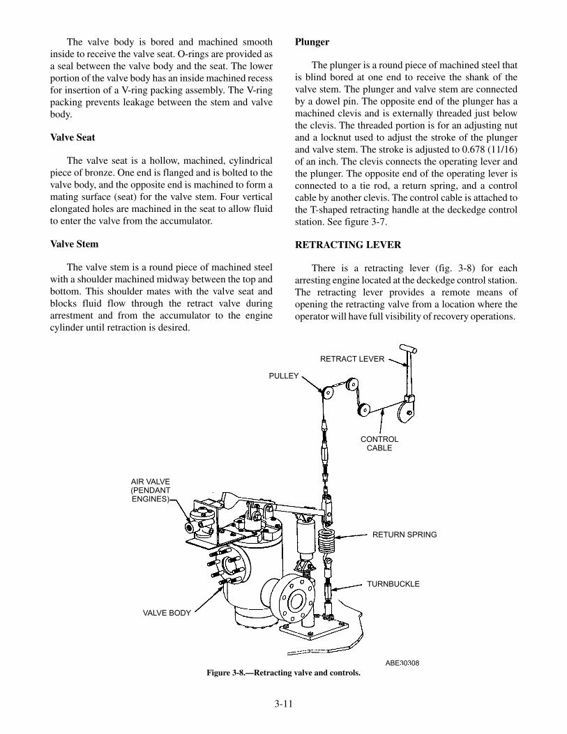
The valve body is bored and machined smoothinside to receive the valve seat. O-rings are provided asa seal between the valve body and the seat. The lowerportion of the valve body has an inside machined recessfor insertion of a V-ring packing assembly. The V-ringpacking prevents leakage between the stem and valvebody.
Valve Seat
The valve seat is a hollow, machined, cylindricalpiece of bronze. One end is flanged and is bolted to thevalve body, and the opposite end is machined to form amating surface (seat) for the valve stem. Four verticalelongated holes are machined in the seat to allow fluidto enter the valve from the accumulator.
Valve Stem
The valve stem is a round piece of machined steelwith a shoulder machined midway between the top andbottom. This shoulder mates with the valve seat andblocks fluid flow through the retract valve duringarrestment and from the accumulator to the enginecylinder until retraction is desired.
Plunger
The plunger is a round piece of machined steel thatis blind bored at one end to receive the shank of thevalve stem. The plunger and valve stem are connectedby a dowel pin. The opposite end of the plunger has amachined clevis and is externally threaded just belowthe clevis. The threaded portion is for an adjusting nutand a locknut used to adjust the stroke of the plungerand valve stem. The stroke is adjusted to 0.678 (11/16)of an inch. The clevis connects the operating lever andthe plunger. The opposite end of the operating lever isconnected to a tie rod, a return spring, and a controlcable by another clevis. The control cable is attached tothe T-shaped retracting handle at the deckedge controlstation. See figure 3-7.
RETRACTING LEVER
There is a retracting lever (fig. 3-8) for eacharresting engine located at the deckedge control station.The retracting lever provides a remote means ofopening the retracting valve from a location where theoperator will have full visibility of recovery operations.
3-11
AIR VALVE(PENDANTENGINES)
ABE30308
RETRACT LEVER
PULLEY
CONTROLCABLE
RETURN SPRING
TURNBUCKLE
VALVE BODY
Figure 3-8.—Retracting valve and controls.

When the operator pulls down on the retractinglever, the force transmitted through the control cablelifts the end of the retracting lever that is attached to thereturn spring and tie rod. The retracting lever has a pivotpoint on the block mounting of the valve. As the oneend of the retracting lever is lifted, the end connected tothe plunger pushes down on the plunger and valve stem,allowing fluid flow through the valve from theaccumulator or fluid cooler to the engine cylinder, thusforcing the ram and crosshead back to their batteryposition. After retraction is complete, the retractinglever is released and the return spring pulls down on theretracting lever, which in turn pulls up on the plungerand valve stem, which closes the valve. See figure 3-7.
The ideal condition is that tension be kept on thepurchase cable from the beginning of the retractingstroke until the ram is in its battery position. Aninterruption of the stroke generally disrupts thiscondition and creates cable backlash, which results incable slack on the engine.
If an emergency arises involving the safety ofpersonnel or equipment, and an interruption offull-speed retraction is necessary, the followingprocedures are recommended to prevent possibledamage, such as a tight kink, to the purchase cable:
1. Resume retracting very slowly at first to rid thecable system of slack.
2. Resume full-speed retraction only after thecable slack has been eliminated and the cablehas tension.
3. Inspect sheave damper sheaves for properseating of the purchase cable on completion ofretraction.
A shock absorber like the one found onautomobiles is installed on the operating lever toeliminate chattering of the retracting valve duringclosing.
ACCUMULATOR SYSTEM
LEARNING OBJECTIVE: Describe theaccumulator system.
The Mk 7 Mod 3 arresting engine has arecirculating-type hydraulic system. During arrest-ment, the hydraulic fluid is forced from the main enginecylinder, through the CRO valve, to the accumulator.An initial air charge of 400 psi in the accumulatorbuilds up to approximately 650 psi during arrestment.This increased pressure is used to force the fluid fromthe accumulator into the fluid cooler, thus forcing fluidfrom the previous arrestment, already cooled by thecooler, out of the cooler, through the retracting valve,and into the main engine cylinder, returning the engineto its BATTERY position.
The accumulator (fig. 3-9) is a long, steel cylindermounted horizontally in saddles on the enginestructure, with the fluid end toward the fixed sheaves.Inside the accumulator is a floating piston thatseparates the air side of the accumulator from the fluidside. The air end of the accumulator is flanged and
3-12
ROD
NOZZLE
SHAFT
FLUID INDICATOR ROD PISTON
RETAINER RING
SLIPPER AND CAGE ASSEMBLY
CYLINDER
A
STOP
LEVEL INDICATOR PLATE
ABEf0309
Figure 3-9.—The Mk 7 accumulator.
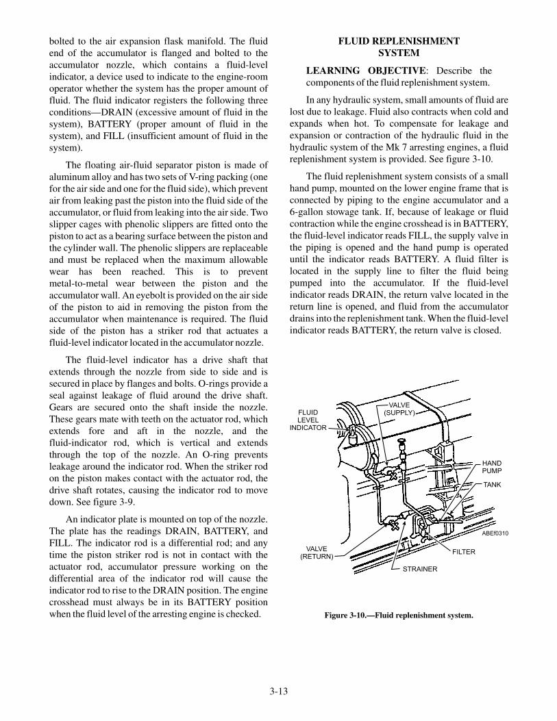
bolted to the air expansion flask manifold. The fluidend of the accumulator is flanged and bolted to theaccumulator nozzle, which contains a fluid-levelindicator, a device used to indicate to the engine-roomoperator whether the system has the proper amount offluid. The fluid indicator registers the following threeconditions—DRAIN (excessive amount of fluid in thesystem), BATTERY (proper amount of fluid in thesystem), and FILL (insufficient amount of fluid in thesystem).
The floating air-fluid separator piston is made ofaluminum alloy and has two sets of V-ring packing (onefor the air side and one for the fluid side), which preventair from leaking past the piston into the fluid side of theaccumulator, or fluid from leaking into the air side. Twoslipper cages with phenolic slippers are fitted onto thepiston to act as a bearing surface between the piston andthe cylinder wall. The phenolic slippers are replaceableand must be replaced when the maximum allowablewear has been reached. This is to preventmetal-to-metal wear between the piston and theaccumulator wall. An eyebolt is provided on the air sideof the piston to aid in removing the piston from theaccumulator when maintenance is required. The fluidside of the piston has a striker rod that actuates afluid-level indicator located in the accumulator nozzle.
The fluid-level indicator has a drive shaft thatextends through the nozzle from side to side and issecured in place by flanges and bolts. O-rings provide aseal against leakage of fluid around the drive shaft.Gears are secured onto the shaft inside the nozzle.These gears mate with teeth on the actuator rod, whichextends fore and aft in the nozzle, and thefluid-indicator rod, which is vertical and extendsthrough the top of the nozzle. An O-ring preventsleakage around the indicator rod. When the striker rodon the piston makes contact with the actuator rod, thedrive shaft rotates, causing the indicator rod to movedown. See figure 3-9.
An indicator plate is mounted on top of the nozzle.The plate has the readings DRAIN, BATTERY, andFILL. The indicator rod is a differential rod; and anytime the piston striker rod is not in contact with theactuator rod, accumulator pressure working on thedifferential area of the indicator rod will cause theindicator rod to rise to the DRAIN position. The enginecrosshead must always be in its BATTERY positionwhen the fluid level of the arresting engine is checked.
FLUID REPLENISHMENTSYSTEM
LEARNING OBJECTIVE: Describe thecomponents of the fluid replenishment system.
In any hydraulic system, small amounts of fluid arelost due to leakage. Fluid also contracts when cold andexpands when hot. To compensate for leakage andexpansion or contraction of the hydraulic fluid in thehydraulic system of the Mk 7 arresting engines, a fluidreplenishment system is provided. See figure 3-10.
The fluid replenishment system consists of a smallhand pump, mounted on the lower engine frame that isconnected by piping to the engine accumulator and a6-gallon stowage tank. If, because of leakage or fluidcontraction while the engine crosshead is in BATTERY,the fluid-level indicator reads FILL, the supply valve inthe piping is opened and the hand pump is operateduntil the indicator reads BATTERY. A fluid filter islocated in the supply line to filter the fluid beingpumped into the accumulator. If the fluid-levelindicator reads DRAIN, the return valve located in thereturn line is opened, and fluid from the accumulatordrains into the replenishment tank. When the fluid-levelindicator reads BATTERY, the return valve is closed.
3-13
VALVE(RETURN)
STRAINER
FILTER
TANK
HANDPUMP
FLUIDLEVEL
INDICATOR
VALVE(SUPPLY)
ABEf0310
Figure 3-10.—Fluid replenishment system.
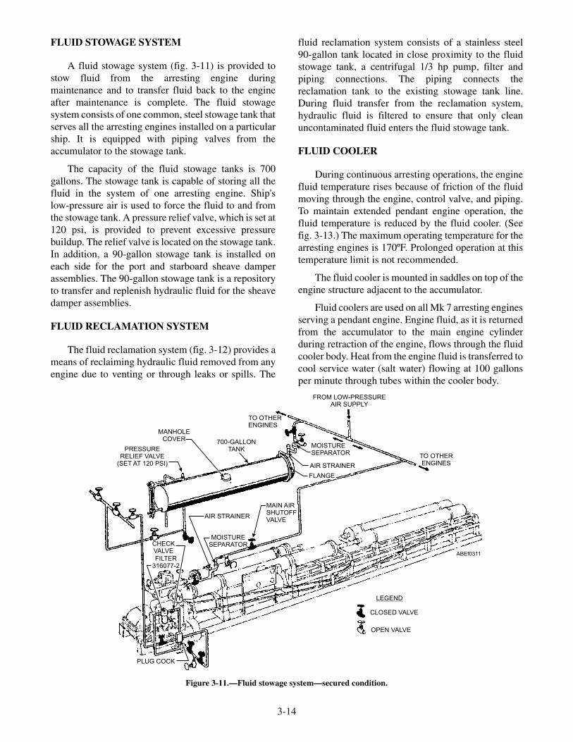
FLUID STOWAGE SYSTEM
A fluid stowage system (fig. 3-11) is provided tostow fluid from the arresting engine duringmaintenance and to transfer fluid back to the engineafter maintenance is complete. The fluid stowagesystem consists of one common, steel stowage tank thatserves all the arresting engines installed on a particularship. It is equipped with piping valves from theaccumulator to the stowage tank.
The capacity of the fluid stowage tanks is 700gallons. The stowage tank is capable of storing all thefluid in the system of one arresting engine. Ship'slow-pressure air is used to force the fluid to and fromthe stowage tank. A pressure relief valve, which is set at120 psi, is provided to prevent excessive pressurebuildup. The relief valve is located on the stowage tank.In addition, a 90-gallon stowage tank is installed oneach side for the port and starboard sheave damperassemblies. The 90-gallon stowage tank is a repositoryto transfer and replenish hydraulic fluid for the sheavedamper assemblies.
FLUID RECLAMATION SYSTEM
The fluid reclamation system (fig. 3-12) provides ameans of reclaiming hydraulic fluid removed from anyengine due to venting or through leaks or spills. The
fluid reclamation system consists of a stainless steel90-gallon tank located in close proximity to the fluidstowage tank, a centrifugal 1/3 hp pump, filter andpiping connections. The piping connects thereclamation tank to the existing stowage tank line.During fluid transfer from the reclamation system,hydraulic fluid is filtered to ensure that only cleanuncontaminated fluid enters the fluid stowage tank.
FLUID COOLER
During continuous arresting operations, the enginefluid temperature rises because of friction of the fluidmoving through the engine, control valve, and piping.To maintain extended pendant engine operation, thefluid temperature is reduced by the fluid cooler. (Seefig. 3-13.) The maximum operating temperature for thearresting engines is 170ºF. Prolonged operation at thistemperature limit is not recommended.
The fluid cooler is mounted in saddles on top of theengine structure adjacent to the accumulator.
Fluid coolers are used on all Mk 7 arresting enginesserving a pendant engine. Engine fluid, as it is returnedfrom the accumulator to the main engine cylinderduring retraction of the engine, flows through the fluidcooler body. Heat from the engine fluid is transferred tocool service water (salt water) flowing at 100 gallonsper minute through tubes within the cooler body.
3-14
PRESSURERELIEF VALVE
(SET AT 120 PSI)
MANHOLECOVER 700-GALLON
TANK
CHECKVALVE
FILTER316077-2
AIR STRAINER
MOISTURESEPARATOR
MAIN AIRSHUTOFFVALVE
TO OTHERENGINES
MOISTURESEPARATOR
AIR STRAINER
TO OTHERENGINES
FROM LOW-PRESSUREAIR SUPPLY
LEGEND
CLOSED VALVE
OPEN VALVE
PLUG COCK
FLANGE
ABEf0311
Figure 3-11.—Fluid stowage system—secured condition.

3-15
RECLAMATIONTANK
SHUTOFFVALVE (TYP)
PUMP CHECK VALVE
DRAIN VALVE(TYP)
FILTER
TO FLUIDSTOWAGE
TANK
FROM FLIGHTDECK FILLOPTIONAL
ABEf0312
Figure 3-12.—Fluid reclamation system
ANODE
FLUID INTAKE VALVE FLUID MANIFOLDFROM ACCUMULATOR
BYPASSVALVE
FLUIDFILTER
FLUID MANIFOLDTO RETRACTING VALVE
LEGEND
FLUID- INTERMEDIATE PRESSURE(400 PSI INCREASING TO 650 PSIDURING ENGAGEMENT)
WATER- LOW PRESSURE (200 PSI)
OPEN VALVE
CLOSED VALVE
SERVICE WATEROUTLET
SERVICE WATERINLET
SERVICE WATERINTAKE VALVE
SERVICE WATERDISCHARGE VALVEOPEN AS NEEDED
(3) FLUID OUTLETVALVE
ABEf0313
Figure 3-13.—Fluid cooler assembly.

The fluid cooler body is a cylindrical steel shellwith two flanged ends. The body of the cooler has fourequally spaced holes in each end to provide a means ofdraining and venting the cooler. These holes arenormally closed with pipe plugs or vent valves. Oneend of the cooler has a cooler head assembly that formsa cap for one end of the body and provides an inlet forengine fluid coming from the accumulator. The coolerhead assembly is a disc-shaped steel casting with anopening in the center, which is flanged to the fluid inletpiping.
A copper annealed gasket is used as a seal betweenthe cooler head and the body to prevent fluid leakage.The head is bolted to the body. The coolant (salt-water)flows through a tube assembly that consists of 107U-shaped copper tubes supported inside the coolerbody by three circular baffle plates. A tube head isbolted to the end of the cooler, opposite of the coolerhead. A copper annealed gasket is used as a seal againstfluid leakage between the tube head and the coolerbody. Cooled fluid passes through the center of the tubehead, through piping, to the retract valve. Twokidney-shaped manifolds (one inlet and one outletmanifold for the coolant to flow) are bolted to the outerface of the tube head.
Saltwater piping leading to and from the inlet andoutlet manifolds has shutoff valves, one intake and one
discharge, that are used to throttle the flow of salt waterand maintain the desired fluid temperature. Shutoffvalves are also provided in the fluid inlet and outletlines to provide a means of isolating the fluid cooler inthe event of cooler leakage, and a bypass valve isprovided to direct the fluid from the accumulator to theretract valve when the cooler is isolated. To preventcorrosion within the cooler, replaceable anodes areinstalled at both the saltwater inlet and outletmanifolds. These anodes are periodically inspected andreplaced according to the applicable maintenancerequirement card (MRC). A fluid temperature indicatoris located on the engine control panel.
AUXILIARY AIR FLASKS
The auxiliary air flask provides a means of storingship's air at 3,000 psi. In the event of a ship's air systemfailure, the air stored in the auxiliary air flask can beused to recharge the arresting engine.
The air flask is a cylindrical container withhemispherical ends. One end of the air flask is providedwith a pipe tap for connecting an air line, which is usedfor charging and venting. A drainage vent is located onthe underside of the air flask to drain condensate water.
Air can be supplied to the air unit of the arrestingengine from the auxiliary air flask by use of thecharging valve mounted on the main control panel.
3-16
FROMAIR
EXPANSIONFLASK
FUSEDSWITCH
BOX
TOVENT
FROMHIGH-PRESSURE
AIR SUPPLY
CABLE ANCHORDAMPER
LIGHT BOX
FROMAUXILIARY
AIRSUPPLY
ABEf0314
Figure 3-14.—Engine control panel.

MAIN CONTROL PANEL
The control panel is the control center for thearresting engine. (See fig. 3-14.) It provides a means forthe operator to centrally regulate the air pressure in thesystem, keep a check on the fluid temperature, andenergize the electrical system. The control panel is alsoequipped with a cable anchor damper light box.
The control panel is a rectangular sheet of steelmounted on the engine structure on the CRO-valve sideof the engine.
Three air manifolds are located on the controlpanel: a main air-charging manifold with high-pressureair piping leading from the ship's high-pressure airsupply system; an air manifold for the auxiliary airflasks; and a manifold for the accumulator. The mainair-charging manifold is equipped with an air-chargingvalve, which is closed except when taking on air fromthe ship's high-pressure air supply system to charge theauxiliary air flasks and accumulator.
High-pressure air piping is provided from the mainair-charging manifold to the auxiliary air flaskmanifold and the accumulator manifold. The auxiliaryair flask and accumulator manifolds each have
air-charging valves, gauge valves, and a pressuregauge. The auxiliary air flask charging valve allows forcharging the auxiliary air flasks or emergency chargingof the accumulator from the air flasks. The auxiliary airflask pressure gauge monitors the air pressure of theauxiliary air flasks. The accumulator charging valveallows for charging of the accumulator and airexpansion flask. The accumulator pressure gaugemonitors the air pressure of the accumulator and airexpansion flask.
A fuse switch box is mounted at the end of thecontrol panel and contains the main switches foractivating the electrical system of the arresting gear.
The cable anchor damper battery position indicatorlight box on the control panel contains a power ON andOFF switch and three indicator lights. A white lightindicates the power switch is on. Two green lights givebattery position indication of the cable anchor dampers.
CYLINDER AND RAM ASSEMBLIES
The cylinder acts as a receiver for the ram and as areservoir for the fluid to be displaced by the ram. Figure3-15 illustrates the cylinder and ram assembly of theMod 3 arresting engine.
3-17
ELBOWASSEMBLY
CYLINDER
CAGE RETAINER
RAM
RAM SLIPPERCAGE
RETAINERWIPERRETAINER
RAM CAGE
SLIPPER
V-RINGPACKING
SPLITWIPER
ABEf0315
Figure 3-15.—Cylinder and ram assembly.
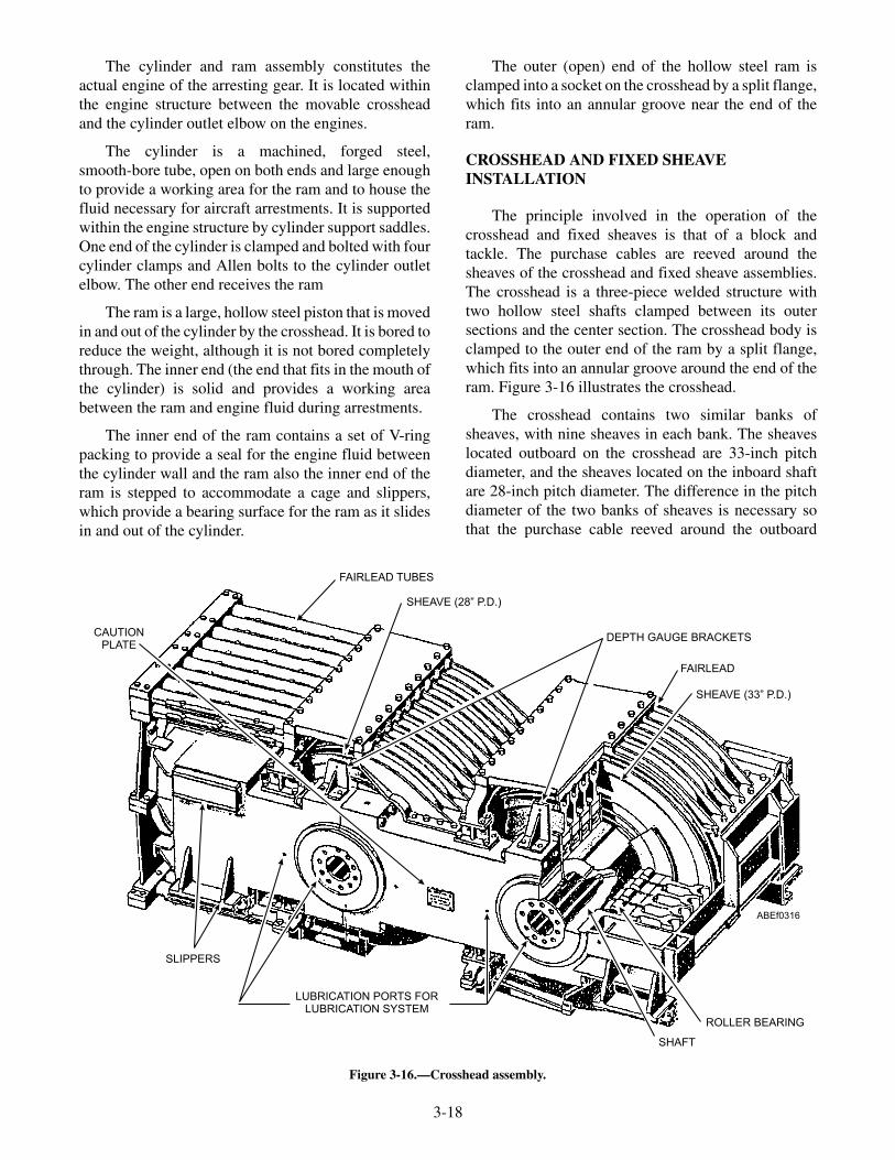
The cylinder and ram assembly constitutes theactual engine of the arresting gear. It is located withinthe engine structure between the movable crossheadand the cylinder outlet elbow on the engines.
The cylinder is a machined, forged steel,smooth-bore tube, open on both ends and large enoughto provide a working area for the ram and to house thefluid necessary for aircraft arrestments. It is supportedwithin the engine structure by cylinder support saddles.One end of the cylinder is clamped and bolted with fourcylinder clamps and Allen bolts to the cylinder outletelbow. The other end receives the ram
The ram is a large, hollow steel piston that is movedin and out of the cylinder by the crosshead. It is bored toreduce the weight, although it is not bored completelythrough. The inner end (the end that fits in the mouth ofthe cylinder) is solid and provides a working areabetween the ram and engine fluid during arrestments.
The inner end of the ram contains a set of V-ringpacking to provide a seal for the engine fluid betweenthe cylinder wall and the ram also the inner end of theram is stepped to accommodate a cage and slippers,which provide a bearing surface for the ram as it slidesin and out of the cylinder.
The outer (open) end of the hollow steel ram isclamped into a socket on the crosshead by a split flange,which fits into an annular groove near the end of theram.
CROSSHEAD AND FIXED SHEAVEINSTALLATION
The principle involved in the operation of thecrosshead and fixed sheaves is that of a block andtackle. The purchase cables are reeved around thesheaves of the crosshead and fixed sheave assemblies.The crosshead is a three-piece welded structure withtwo hollow steel shafts clamped between its outersections and the center section. The crosshead body isclamped to the outer end of the ram by a split flange,which fits into an annular groove around the end of theram. Figure 3-16 illustrates the crosshead.
The crosshead contains two similar banks ofsheaves, with nine sheaves in each bank. The sheaveslocated outboard on the crosshead are 33-inch pitchdiameter, and the sheaves located on the inboard shaftare 28-inch pitch diameter. The difference in the pitchdiameter of the two banks of sheaves is necessary sothat the purchase cable reeved around the outboard
3-18
CAUTIONPLATE
FAIRLEAD TUBES
SHEAVE (28” P.D.)
DEPTH GAUGE BRACKETS
FAIRLEAD
SHEAVE (33” P.D.)
ROLLER BEARING
SHAFT
SLIPPERS
LUBRICATION PORTS FORLUBRICATION SYSTEM
ABEf0316
Figure 3-16.—Crosshead assembly.
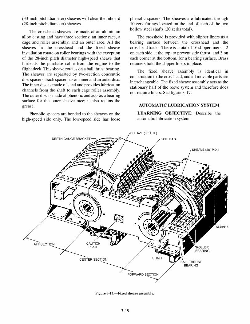
(33-inch pitch diameter) sheaves will clear the inboard(28-inch pitch diameter) sheaves.
The crosshead sheaves are made of an aluminumalloy casting and have three sections: an inner race, acage and roller assembly, and an outer race. All thesheaves in the crosshead and the fixed sheaveinstallation rotate on roller bearings with the exceptionof the 28-inch pitch diameter high-speed sheave thatfairleads the purchase cable from the engine to theflight deck. This sheave rotates on a ball thrust bearing.The sheaves are separated by two-section concentricdisc spacers. Each spacer has an inner and an outer disc.The inner disc is made of steel and provides lubricationchannels from the shaft to each cage roller assembly.The outer disc is made of phenolic and acts as a bearingsurface for the outer sheave race; it also retains thegrease.
Phenolic spacers are bonded to the sheaves on thehigh-speed side only. The low-speed side has loose
phenolic spacers. The sheaves are lubricated through10 zerk fittings located on the end of each of the twohollow steel shafts (20 zerks total).
The crosshead is provided with slipper liners as abearing surface between the crosshead and thecrosshead tracks. There is a total of 16 slipper liners—2on each side at the top, to prevent side thrust, and 3 oneach corner at the bottom, for a bearing surface. Brassretainers hold the slipper liners in place.
The fixed sheave assembly is identical inconstruction to the crosshead, and all movable parts areinterchangeable. The fixed sheave assembly acts as thestationary half of the reeve system and therefore doesnot require liners. See figure 3-17.
AUTOMATIC LUBRICATION SYSTEM
LEARNING OBJECTIVE: Describe theautomatic lubrication system.
3-19
AFT SECTION
CENTER SECTION
FORWARD SECTION
SHAFT
BALL THRUSTBEARING
ROLLERBEARING
SHEAVE (28” P.D.)
FAIRLEAD
SHEAVE (33” P.D.)
DEPTH GAUGE BRACKET
ABEf0317
CAUTIONPLATE
Figure 3-17.—Fixed sheave assembly.

An automatic lubrication system (fig. 3-18) ensuresthat lubricant is automatically provided to the arrestingengine crosshead and fixed sheave assembly duringarrestment operations (pendant engines only). Theship's low-pressure air, is piped to a regulator, whichreduces the air to the required operating pressure ofbetween 75 and 85 psi. Air is fed through a rubber hoseto a pump mounted on top of a 120-pound drum oflubricant. Lubricant is pumped from the drum throughhoses to control valves mounted on the enginestructure. These control valves adjust the rate of flow oflubricant to the high-speed sheaves.
The control valves are operated by plunger rollers,which are cam-actuated at a set position of the enginecrosshead arrestment stroke. An ounce of lubricant ispumped to the high-speed sheaves during thearrestment and the retraction cycles. A hose reel with aflexible rubber hose is mounted on the crosshead end ofthe engine structure, with the hose connected to metaltubing on the engine crosshead. As the crossheadmoves toward the fixed sheaves during arrestment, thehose pays out and spring tension in the hose reel takes
up the hose during retraction. The spring tension on thehose reel must be 9 pounds (±1/2 pound), with the hosefully retracted, at all times.
The automatic lubrication controller (fig. 3-19)allows the engine room operator to set both a pulsecounter and a timer unit which deliver a predeterminedamount of lubricant to every lubrication point. Thecontroller signals when the system is ready, when it isoperation or when a malfunction occurs. The controllercan be operated manually to initiate a lubrication cyclewithout movement of the crosshead and cal reset itselfafter a malfunction has been corrected in the lubricationsystem.
The 28-inch pitch diameter sheave containing theball thrust bearing is not lubricated with the automaticlubricating system. The ball thrust bearing eliminatesthe need for constant lubrication. Lubricating the ballthrust bearing sheave is accomplished with a manuallyoperated grease gun after every 20 to 30 arrestments.(See fig. 3-18 for an illustration of the automaticlubrication system.)
3-20
PRIMARYDISTRIBUTION
BLOCK(HIGH-SPEED)
(FIXED SHEAVE END)
LUBRICANT CONTROLLER
SECONDARYDISTRIBUTION
BLOCKS MASTER DISTRIBUTIONBLOCK ASSEMBLY
LUBRICANTFILTER
LUBRICANTPUMP
LUBRICANTGREASE
DRUM
ISOLATIONSHUTOFF
VALVE
PRESSUREREGULATOR
(CROSSHEAD END)
HOSEREEL
SECONDARYDISTRIBUTION
BLOCKS
PRIMARYDISTRIBUTION BLOCK
(LOW SPEED)
SOLENOIDVALVE
ABEf0318
Figure 3-18.—Automatic lubrication system.

CABLE ANCHOR DAMPER
LEARNING OBJECTIVE: Describe thecomponents of the cable anchor damper.
The cable anchor damper installation consists oftwo identical anchor damper assemblies. In most casesone cable anchor damper assembly is deck mounted
and the second assembly is overhead mounted (fig.3-20). Compartment configuration determines how theunits are installed.
The purpose of the cable anchor damper is toeliminate excessive purchase cable slack between thecrosshead and fixed sheave assembly at the beginningof the arrestment stroke. Through service use andexperimental testing, it was found that when this cableslack was taken up by the landing aircraft, excessivevibrations occurred in the engines. The cable anchordamper removes this slack as it occurs, therebyeliminating vibration of the purchase cable. The cableanchor damper assembly is used with pendant enginesonly.
Referring to figure 3-20, note that each cableanchor damper assembly includes a cylinder thatconnects to an operating end head and a cushioning endhead. Piping connects the engine cylinder to theoperating end head through a manifold tee. Two linesbranch from the manifold tee, one to each damperassembly operating head. Each of these lines contains aflow control valve. A cover is placed over the operatingpiston rod and coupling assembly for safety ofoperation and protection against foreign matter. Eachdamper assembly is mounted on a base beforeinstallation.
A battery positioner, actuated by the retractinglever, is provided to ensure the return of the damperassembly to the BATTERY position after anarrestment. A battery-position indicator is provided toindicate when the cable anchor damper is in theBATTERY position, ready for aircraft engagement.The limit switch and cam actuator for thebattery-position indicator are located on the cableanchor damper assembly, and the indicator lights arelocated on the arresting engine control panel.
The end of the purchase cable is attached to theoperating end piston rod by an anchor damper coupling.When the force on the operating piston, due to enginecylinder pressure, is greater than the tensile force in thepurchase cable, the piston moves away from itsBATTERY position. Movement of the operating pistoninto the cylinder removes the cable slack during the firstportion of the arrestment. When the slack is taken up,the operating piston resists the return of the cable, thuskeeping it taut and preventing excessive cablevibration.
3-21
MONITORTIMER
(DETAIL A)
COUNTER(DETAIL B)
ON/OFFSWITCH
FAULT(RED)
MANUAL RUN
READY(GREEN)
RESET
LUBE(AMBER)
LUBRICANT CONTROLLER
RED CYCLE PROGRESS POINTERREGISTERS COUNTS
REMAINING TRAVELS TO"0" DURING COUNT
ORANGE CYCLE PROGRESSPOINTER REGISTERS TIMEREMAINING TRAVELS TO
"0" DURING COUNT
LOCKINGSCREW
LOCKING SCREW
BLACK TIME SETPOINTER HASFULL SCALE
ADJUSTABILITYTHROUGH 320
o
BLACK SETPOINTER HASFULL SCALE
ADJUSTABILITYTHROUGH 320
o
DETAIL A
DETAIL B
ABEf0319
Figure 3-19.—Automatic lubrication controller.

3-22
TO
RQ
UE
RE
LEA
SE
CO
UP
LIN
G
AB
Ef0
320
KE
YT
RA
CK
OP
ER
AT
ION
PIS
TO
NR
OD
WIN
GN
UT
HIN
GE
DC
OV
ER
GLA
ND
OP
ER
AT
ING
EN
DH
EA
DC
YLI
ND
ER
SA
DD
LE
CY
LIN
DE
R
CU
SH
ION
ING
PIS
TO
N
CU
SH
ION
ING
PIS
TO
NR
OD
CU
SH
ION
ING
EN
DH
EA
DC
OT
TE
RP
IN
AIR
CO
NTA
INE
RGLA
ND
VE
NT
VA
LVE
CLA
MP
SH
EA
RB
LOC
K
VE
NT
VA
LVE
OP
ER
AT
ING
PIS
TO
N
RE
MO
VA
BLE
TR
AC
KS
EC
TIO
N
LIM
ITS
WIT
CH
CA
M
RO
DG
UID
E
Fig
ure
3-20
.—C
able
anch
orda
mpe
rin
stal
lati
on.

Upon engagement of the deck pendant by theaircraft, the engine crosshead is accelerated toward thefixed sheaves. This movement forces the ram into thearresting engine cylinder, increasing the fluid pressurein both the engine cylinder and the operating head ofeach cable anchor damper. See figure 3-21.
Because of the acceleration rate of the enginecrosshead, the tension in the purchase cable (2)between the engine sheaves and the cable anchordampers decreases momentarily. The instant the tensileforce in the cable becomes less than the force on theoperating piston (4), fluid pressure moves the operatingpiston away from its BATTERY position until all slackis removed and the cable tension is again greater thanthe fluid pressure force acting on the operating piston.
The flow control valve is a clapper-type checkvalve that allows free flow of the fluid one way and arestricted flow in the opposite direction. The enginefluid has free flow through the flow control valve (1) to
the operating end of each cable anchor damper. Whenthe tension of the purchase cable is transmitted to thecable anchor ends, the fluid pressure on the operatingpistons is overcome by this cable tension, and theoperating pistons are pulled back toward BATTERYposition. Resistance to their return is furnished by theengine fluid pressure and the controlled flow of fluidthrough the flow control valves back to the enginecylinder.
CUSHIONING PISTON
The sole function of the cushioning piston is toprevent the operating piston from slamming into theopposite end of the cable anchor damper assembly ifthe purchase cable should break or in the event of anextreme off-center landing. In either situation, theoperating piston accelerates away from its BATTERYposition and rams the cushioning piston.
3-23
TO ARRESTING ENGINEHYDRAULIC CYLINDER
TO ACCUMULATORHYDRAULIC SYSTEM
TO
EN
GIN
ES
HE
AV
ES
23456654
1 1
RETRACTING VALVE
TO ACCUMULATORHYDRAULIC SYSTEM
32
TO
EN
GIN
ES
HE
AV
ES
TO 3-WAYAIR VALVE
1. FLOW CONTROL VALVE2. PURCHASE CABLE3. OPERATING HEAD
4. OPERATING PISTON5. CYLINDER6. CUSHIONING PISTON ABEf0321
Figure 3-21.—Cable anchor damper fluid flow (arrestment).

BATTERY POSITIONER
The battery positioner (fig. 3-22) functions toreturn the cable anchor damper piston to its BATTERYposition during the retracting cycle of the arrestingengine.
The battery positioner includes a three-way airvalve (3), which is connected to a 100-psi air supplyand to the air container mounted on the cushioning endof each damper assembly. An air strainer (4) is locatedin the supply line ahead of the three-way valve. Thethree-way air valve is mounted on a base plate (5),secured to the arresting engine retracting valve, andoperated by means of a cam (1) mounted on theretracting valve actuating lever.
When the actuating lever is moved to its retractposition, the cam positions the three-way air valve toadmit 100-psi air to the air containers. From the aircontainer, the 100-psi air passes through a hole in thecushioning piston rod and acts against the operatingpiston, moving it to its fully retracted position. As soonas the actuating lever is released, the air pressure is shutoff, and the air container is vented through an exhaustline (2) at the three-way air valve. A line containing aliquid sight indicator (7) and a drain plug (6) isprovided at each container. The fluid sight indicatorpermits detection of fluid leakage into the air container.
ARRESTING ENGINE DRIVESYSTEM
LEARNING OBJECTIVE: Describe thecomponents of the arresting engine drivesystem.
The function of the drive system is to provide ameans of transferring energy from an arresting aircraftto the arresting engine components that provide themeans of dissipating and absorbing that energy. Thedrive system consists essentially of sheave damper,purchase cable, fairlead and deck sheaves, crossdeckpendants, and wire supports (fig. 3-23).
SHEAVE DAMPER
Because of the high engaging velocities of moderncarrier-based aircraft, cable tension and vibrationwould be excessive unless eased by the shockabsorption provided by the sheave damper. The sheavedamper reduces peak cable tension and lessens cablevibration.
In figure 3-24, a sheave damper assembly ismounted to the ship's structure below each port andstarboard retractable or fixed horizontal deck sheave.The port and starboard assemblies are identical;therefore, only one will be discussed.
3-24
6
AIR CONTAINER
RETRACTINGVALVE
100 PSI AIRSUPPLY
54
3
2
1
7
1. CAM2. EXHAUST3. THREE-WAY AIR VALVE4. STRAINER
5. BASE PLATE6. DRAIN PLUG7. SIGHT INDICATOR
ABEf0322
Figure 3-22.—Battery positioner.

3-25
THRU-DECK SHEAVE
THRU-DECK SHEAVE
FORWARD
PURCHASE CABLE
CROSS-DECK PENDANT
RETRACTABLE SHEAVEINSTALLATION
FAIRLEAD SHEAVE
FAIRLEADSHEAVE
PURCHASE CABLE
RETRACTABLE SHEAVEINSTALLATION
FAIRLEADSHEAVE
FAIRLEADSHEAVES
DAMPER SHEAVEINSTALLATION
DAMPER SHEAVEINSTALLATION
TO OPPOSITEANCHOR DAMPER
ABEf0323
Figure 3-23.—Arresting engine drive system.
CAM
LIMITSWITCH
CROSSHEAD
STOWAGE TANKVENT
750 PSI
FROMHIGH-PRESSUREAIR SUPPLY
AIR
AIR
FLUID
FLUID
AIR
HIGH PRESSURE (3000 PSI)
MEDIUM PRESSURE750 PSI TO ZERO)
ZERO PRESSURE
OPEN VALVE
CLOSED VALVE
FLOW CONTROLVALVE
BUFFERASSEMBLY
FLUID LEVEL RANGE
ACCUMULATOR
LEGEND
ON OFF
POWER SWITCH
POWER ONBATTERY POS
BATTERY POS
STBD SHEAVE
PORT SHEAVE
ABEf0324
AIR SUPPLY VENT VALVE
DAMPING ACCUMULATOR
AIR CHANGING VALVE GAGE VALVE
Figure 3-24.—Sheave damper installation.

Description
Each sheave damper assembly consists of amovable crosshead assembly, damper cylinderassembly, damper piston, damper accumulator andfluid piping, buffer assembly, and charging panel. Thesystem is also equipped with a common fluid stowagetank, which provides a stowage space for fluid in thesheave damper assembly while maintenance is beingperformed. The tank is capable of stowing all the fluidin one sheave damper installation.
The crosshead assembly consists of one rollerbearing sheave mounted between a steel base plate anda side plate that are bolted together. A sheave shaft,mounted through the bottom of the base plate, issecured to the side plate by a cap and setscrew. A yokeis bolted between the side plate and the base plate andprovides a means of connecting the crosshead to aclevis that is screwed onto the end of a piston rod. Thecrosshead rides in a track mounted in a horizontalposition on the bulkhead.
Phenolic slippers, at all four corners of the baseplate, provide a bearing surface between the crossheadand the track. Attached to the crosshead is a cam thatactuates a limit switch when the crosshead is fullyretracted and causes a green light to light at thedeckedge control station. This indicates to thedeckedge operator that the sheave damper is in itsBATTERY position.
The damper cylinder assembly is secured to theship's structure by brackets, which are welded to thebulkhead and bolted to the cylinder. A cylinder cap isscrewed onto the crosshead end of the cylinder and heldin place by setscrews. The cap provides a fluid passagebetween the cylinder and the fluid manifold pipingleading to the damper accumulator. The damper pistonrod extends through the cap at the crosshead end of thecylinder. The damper piston is secured onto theopposite end of the piston rod and held in place by acastle nut and cotter pin.
The fluid manifold is bolted to the top and bottomof the cylinder cap. A reducing tee connects the upperand lower manifold piping and serves to divert fluidflow from the accumulator equally into the upper andlower manifolds. A flow control valve is locatedbetween the reducing tee and the accumulator. The flowcontrol valve has a flapper-type (swing gate) orificeplate, which allows free flow of fluid from the cylinderto the accumulator and a restricted flow through anorifice in the center of the plate from the accumulator tothe cylinder.
The accumulator acts as a fluid stowage tank andhas a high-pressure air connection from the upper headto the charging panel. The charging panel has acharging valve and a gauge valve with a gauge mountedbetween them, a high-pressure air supply valve, and avent valve. The accumulator is charged to 750 psi andmust have a reading of 2 (±1) inches of fluid on the fluidsight indicator when the sheave damper is in itsBATTERY position.
The end of the cylinder opposite the crosshead endhas a flange threaded on it that mate with a flange on thebuffer assembly. The two flanges are bolted together.The buffer assembly consists of a cylinder, buffer ram,spring, and fluid sight indicator. The purpose of thebuffer assembly is to buffer the damper piston whenreturning to its BATTERY position.
Operation
An incoming aircraft engages the deck pendant,causing an increase of tension on the purchase cable.The purchase cable is reeved around the sheave dampercrosshead in a manner that any increased tensionexperienced by the purchase cable will cause the sheavedamper crosshead to move away from its BATTERYposition. As the sheave damper crosshead moves, thedamper piston moves, forcing fluid from the cylinder,through the fluid manifold, flow control valve, andfluid piping, into the accumulator. The resultingpressure buildup in the accumulator will be equal to thepurchase cable pull.
Retraction of the sheave damper is automatic andoccurs when accumulator pressure becomes greaterthan cable tension. Retraction normally occurs prior tofull runout of the aircraft. The pressure buildup in theaccumulator forces the fluid from the accumulator,through the fluid piping, the orifice in the flapper of theflow control valve, the reducing tee, and the fluidmanifold, to the damper cylinder, therefore forcing thedamper piston back to its BATTERY position. Justbefore the damper piston reaches its BATTERYposition, the end of the damper piston rod comes incontact with the buffer ram.
The force of the damper piston rod pushing on thebuffer ram compresses a spring inside the buffercylinder. The spring is held in place by the buffercylinder end plug. The compression of the springbuffers the return of the damper piston to its BATTERYposition.
As the sheave damper crosshead reaches itsBATTERY position, the battery-position indicator limit
3-26

switch is engaged, and lights the battery-positionindicator light at deck edge.
Purchase cable
The purchase cable is the wire rope reeved onto thearresting engine sheaves and fed through fairleadtubing and over the fairlead sheave to the deck gear onthe flight deck. The purchase cable transmits the forceof the landing aircraft from the deck gear to thearresting engine.
The polyester-core purchase cable is 1 7/16-inchdiameter, 6 × 31 die-formed polyester-core construc-tion with no filler wires, all wires are consideredloading bearing, with a minimum breaking strength of215,000 pounds. The die-formed construction is suchthat the outer wires present a relatively flat surface,giving it the appearance of being worn even when new.
As a result Q reading, as performed on the sisal-corepurchase cable, are not possible. Inspection andreplacement will be based on broken wire criteria.
The sisal-core purchase cable is 1 7/16-inchdiameter, 6 × 25 filler wire construction, right-hand lay,lang lay cables with a minimum breaking strength of195,000 pounds. The 6 × 25 filler wire constructionmeans that the cable is made up of 6 strands with 19major wires and 6 filler wires per strand. (See fig. 3-25.)The filler wires provide shape and stability to thestrand. Lang lay denotes cables in which the wires ofthe strand and the strand are twisted in the samedirection so that the outer wires in the lang lay cablesrun diagonally across the longitudinal axis of thecables.
The purchase cable is made from high-strength,uncoated plow steel. A hemp center, made fromresilient oil-impregnated hemp, serves as a foundationfor the strands, keeps the strands evenly spaced, andprevents them from bearing against each other. Thehemp center also aids in lubrication of the inner wires.Within the hemp center is buried a paper or plastic stripbearing the name of the manufacturer. New purchasecables are provided on a double reel with each reelcontaining 1100 feet of cable. The purchase cable usedon a barricade engine is of the same wire ropeconstruction but is provided as a single cable, 2100 feetin length with a poured terminal on one end.
Poured threaded terminals are fitted on each end ofthe purchase cables. A clevis socket is screwed onto thethreaded terminals to connect the purchase cables to thecrossdeck pendants one end, the other end is connectedto a coupling on the cable anchor damper operatingpiston rod (fig. 3-26.)
3-27
MANUFACTURER’SIDENTIFICATION TAPE
6 STRANDSPER CABLE
25 WIRES PER STRAND(19 MAJOR WIRES)
6 FILLER WIRESCORE
(HEMP, FIBER)
INTERFACE
5
4
3
2
1
6
ABEf0325
Figure 3-25.—Cross section of preformed sisal core purchasecable.
ANCHOR SCREW
LOCK RING
CLEVIS PIN
CLEVIS SOCKET
CDP SWAGED TERMINAL
CLEVIS PIN
CLEVISSOCKETANCHOR
SCREW
ANCHOR NUT
ANCHOR DAMPERCOUPLING
ANCHOR NUT
ABEf0326
Figure 3-26.—Purchase cable attachments.
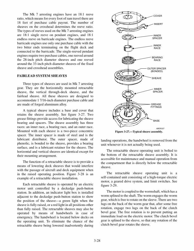
The Mk 7 arresting engines have an 18:1 reeveratio, which means for every foot of ram travel there are18 feet of purchase cable payout. The number ofsheaves on the crosshead determines the reeve ratio.The types of reeves used on the Mk 7 arresting enginesare 18:1 single reeve on pendant engines, and 18:1endless reeve on barricade engines. The endless reevebarricade engines use only one purchase cable with thetwo bitter ends terminating on the flight deck andconnected to the barricade. The single-reeved pendantengines require two purchase cables, one reeved aroundthe 28-inch pitch diameter sheaves and one reevedaround the 33-inch pitch diameter sheaves of the fixedsheave and crosshead assemblies.
FAIRLEAD SYSTEM SHEAVES
Three types of sheaves are used in Mk 7 arrestinggear. They are the horizontally mounted retractablesheave, the vertical through-deck sheave, and thefairlead sheave. All these sheaves are designed toaccommodate 1 7/16-inch diameter purchase cable andare made of forged aluminum alloy.
A typical sheave includes a base and cover thatretains the sheave assembly. See figure 3-27. Twogrease fittings provide access for lubricating the sheavebearing and spacers. The sheave assembly has threeraces: an inner race, a bearing race, and an outer race.Mounted with each sheave is a two-piece concentricspacer. The inner spacer is made of steel and is thelubricant distributor. The outer spacer, made ofphenolic, is bonded to the sheave, provides a bearingsurface, and is a lubricant retainer for the sheave. Thehorizontal and vertical sheaves are identical except fortheir mounting arrangement.
The function of a retractable sheave is to provide ameans of lowering deck sheaves that would interferewith the passage of aircraft and deck equipment whenin the raised operating position. Figure 3-28 is anexample of a retractable sheave installation.
Each retractable sheave is operated by an electricmotor unit controlled by a deckedge push-buttonstation. In addition, an indicator light box is installedadjacent to the deckedge push-button station to showthe position of the sheave—a green light when thesheave is fully raised, or a red light in all positions otherthan fully raised. The retractable sheaves may also beoperated by means of handwheels in case ofemergency. The handwheel is located below decks onthe operating unit. To eliminate the chance of theretractable sheave being lowered inadvertently during
landing operations, the handwheel is removed from theunit whenever it is not actually being used.
The retractable sheave operating unit is bolted tothe bottom of the retractable sheave assembly. It isaccessible for maintenance and manual operation fromthe compartment that is directly below the retractablesheave.
The retractable sheave operating unit is aself-contained unit consisting of a high-torque electricmotor, a geared drive system, and limit switches. Seefigure 3-29.
The motor is coupled to the wormshaft, which has aworm splined to the shaft. The worm engages the wormgear, which is free to rotate on the sleeve. There are twolugs on the back of the worm gear that, after some freerotation, engage two lugs on the back of the clutchbevel gear. The free rotation is to prevent putting animmediate load on the electric motor. The clutch bevelgear is splined to the sleeve, so that any rotation of theclutch bevel gear rotates the sleeve.
3-28
ABEf0327
COVER
INSERT
INNERSPACER
INNERRACE
OUTER SPACER(BONDED)
SHEAVE
INNERSPACER
GREASEFITTINGS
BASE
BEARINGRACE
Figure 3-27.—Typical sheave assembly.

3-29
RETRACTABLESHEAVE
THRU DECKSHEAVE
INDICATOR LIGHTCIRCUIT SWITCH
(OFF-ON)
RED
AMBER
GREEN
PUSHBUTTONSTATION
INDICATORBOX
MOTORCONTROLLER
TO POWERSUPPLY
GREEN LIGHT INDICATESREADY CONDITION
ARRESTING GEAR OFFICER'S SHEAVESSTATUS-UP INDICATOR LIGHT
NOTE: SEE FIGURE 1-3 FORELECTRICAL EQUIPMENTWHICH SERVES AIRCRAFTRECOVERY EQUIPMENT.
ABEf0328
Figure 3-28.—Retractable sheave installation.
5
7
9
1510
13
1211
1718
19
6
25
22
23
21
20
14
DRIVESLEEVE
BUSHING
8
16
ABEf0329
1. Geared limit switch2. Motor3. Housing4. Sleeve
5. Lower bevel gear6. Pinion7. Clutch fork spring8. Clutch bevel gear
9. Tripping plate washer10. Worm gear11. Handwheel12. Wormshaft
13. Torque spring14. Declutch lever15. Worm16. Torque limit switch
Figure 3-29.—Retractable sheave operating unit.

The sleeve is directly keyed to the lead screw of theretractable sheave so that rotation of the sleeve raises orlowers the sheave. The amount of sleeve rotation whilethe sheave is rising is governed by the adjustable gearedlimit switch, which opens the motor circuit when thesheave is fully up. An adjustable torque limit switch,actuated by the tripping plate washer, opens the motorcircuit when the sheave is fully lowered and furtherprovides overload protection for the unit. The worm isnormally held in position with a heavy torque spring. Ifan obstruction under the sheave prevents the sheavefrom lowering, the sleeve cannot turn. Then the torqueexerted by the worm exceeds the normal torque,causing the worm to slide along the wormshaft, pushingthe tripping plate washer, and opening the torqueswitch. A handwheel is provided for manual operation,and a declutch lever is provided to change from motorto hand operation.
It is imperative that the deckedge operator knowswhether the retractable sheave is in the UP positionduring landing operations. During night operations,visual sighting of the retractable sheave is impossible.
An arresting gear SHEAVE-UP and BY-PASSswitch and indicator panel (fig. 3-30) is located aft ofthe arresting gear deckedge control station to indicatethe status of the retractable sheave. The panel is wiredinto the clear/foul deck light and will prevent the
arresting gear officer from giving a clear deck signal ifone or more of the retractable sheaves is not in the fullyup position.
If a retractable sheave cannot be raised, thearresting gear officer directs that the affected deckpendant be removed from the deck. A CLEAR DECKsignal can now be activated by closing the respectiveby-pass switch and thus overriding the shutdownarresting engine. An amber warning light on theby-pass switch and indicator panel visually indicatesthe by-pass condition. In addition, a three-lamp,deckedge indicator panel with red, amber, and greenlenses, mounted aft of the deckedge control station, willindicate the retractable-sheave status. This panel willilluminate red when any of the retractable sheaves aredown and green when all sheaves are up. In case one ormore arresting engine and retractable sheave isbypassed, the deckedge indicator light will display thegreen and amber lights.
SEQUENCE OF OPERATION
Energizing the motor to raise the retractablesheave, by pressing the RAISE push button, causes themotor to rotate a helical gear keyed to its shaft. Thistransmits the motor force to another helical gear on thewormshaft. The wormshaft turns the worm and drives
3-30
ON
OFFBY-PASS SW
PENDANT NO.1
ON
OFFBY-PASS SW
PENDANT NO.2
ON
OFFBY-PASS SW
PENDANT NO.3
ON
OFFBY-PASS SW
PENDANT NO.4
A/G SHEAVE-UP & BY-PASSSWITCH & INDICATOR PANEL
NAEC PART NO. 617488-1MFD BY NAEC, PHILA, PA.
CAUTION: ALL BY-PASS SWITCHES TO REMAIN IN THE"OFF" POSITION UNLESS OTHERWISE
DIRECTED BY THE A/G OFFICER.
ABEf0330
INDICATOR LIGHTS
Figure 3-30.—Sheave-up and by-pass switch and indicator panel.

the worm gear on the sleeve. The worm gear rotatesfreely on the sleeve for part of the rotation, thuspermitting the motor to gain speed before full loading.As the worm gear rotates, the lugs on its face engage thelugs on the face of the clutch bevel gear. Rotation of theclutch bevel gear, which is splined to the sleeve, rotatesthe sleeve, which is directly connected to the screw ofthe retractable sheave, thus raising the sheave. Whenthe sleeve rotates, the limit bevel gear, keyed to thesleeve, rotates to turn the pinion of the geared limitswitch. This is the only function of the limit bevel gear.When a predetermined point is reached by the rotor ofthe geared limit switch, the RAISE circuit is broken andthe raising operation ceases. As the geared limit switchis actuated, the green lamp (sheave UP lamp) will lightin the deckedge light box.
Energizing the motor to lower the retractablesheave, by depressing the LOWER push button, causesthe motor and the drive system to operate in the reversedirection. Again there is free rotation until the lugs onthe worm gear make a complete revolution beforestriking the other side of the lugs on the clutch bevelgear. The sheave lowers until it is completely seated andopens the torque limit switch to break the motor circuit.If an obstruction prevents the sheave from descending,the worm, which is still rotating because of the force ofthe motor, does not turn the worm gear. The worm isdriven axially along the wormshaft until the torquelimit switch is opened by the tripping plate washer. Thetorque limit switch may be adjusted to permit thesheave to seal with a predetermined force before thecircuit is interrupted. The torque spring then absorbsthe remaining inertia of the system after the circuit isbroken. During the time the sheave is lowered andraised up until the time the RAISE geared limit switchis tripped, the red (sheave NOT UP) lamp glows on thedeckedge light box.
For manual operation, the handwheel must bemounted on its shaft and secured to the shaft with asetscrew. The declutch lever must then be thrown in acounterclockwise direction. This movement will slidethe clutch bevel gear along the splined section of thesleeve to engage a gear on the handcrank shaft. Whenthe handcrank is turned, the sleeve turns, rotating thesheave screw to raise or lower the sheave. The declutchlever remains in the clutch position until operationunder motor power is resumed, at which time thehandwheel is disconnected automatically by the clutchtrippers. There is no danger to an operator if he or she isturning the handwheel when the motor is started,because the handwheel is disengaged instantly withoutshock or jolt.
Thru-deck Sheave
The thru-deck sheave (fig 3-23) is mountedvertically and it guides the purchase cable between thesheave damper and the retractable sheave installation.
Fairlead Sheaves
Fairlead sheaves (fig. 3-23) are single sheaves thatare installed at points in the drive system where thepurchase cable require a change of direction. Thenumber of fairlead sheaves varies based on enginelocation in relation to the location of the anchor andsheave dampers.
Crossdeck Pendants
The polyester-core crossdeck pendant are made of1 7/16-inch diameter, 6 × 30 flattened strand polyestercore construction with no filler wires, all wires areconsidered loading bearing with a minimum breakingstrength of 205,000 pounds. To differentiatepolyester-core CDPs from sisal-core CDPs thepolyester-core terminals have a groove around the endwhere the cable enters the terminal. The deck pendantcable ends are equipped with swaged-type terminals.These terminals are pinned to the clevis and socketassembly at the purchase cable coupling for quickdetachment during replacement.
The sisal-core crossdeck pendant are made of1 3/8-inch diameter, 6 × 30 flattened strand construc-tion, preformed, uncoated lang lay wire rope with aminimum breaking strength of 188,000 pounds. Eachwire rope is made up of 6 steel strands, each of which isa bundle of 12 major and 12 intermediate wires twistedaround a triangular core of 3 to 9 wires. (See fig. 3-31.)The strands are twisted about an oiled-hemp center
3-31
TRIANGULARCORE
CORE(HEMP, FIBER)
12 MAJORWIRES
6 STRANDSPER CABLE
12 INTERMEDIATEWIRES
MANUFACTURER'SIDENTIFICATION TAPE
INTERFACE2
1
6
5
4
3
ABEf0331
Figure 3-31.—Cross section of preformed sisal core 6 × 30crossdeck pendant.
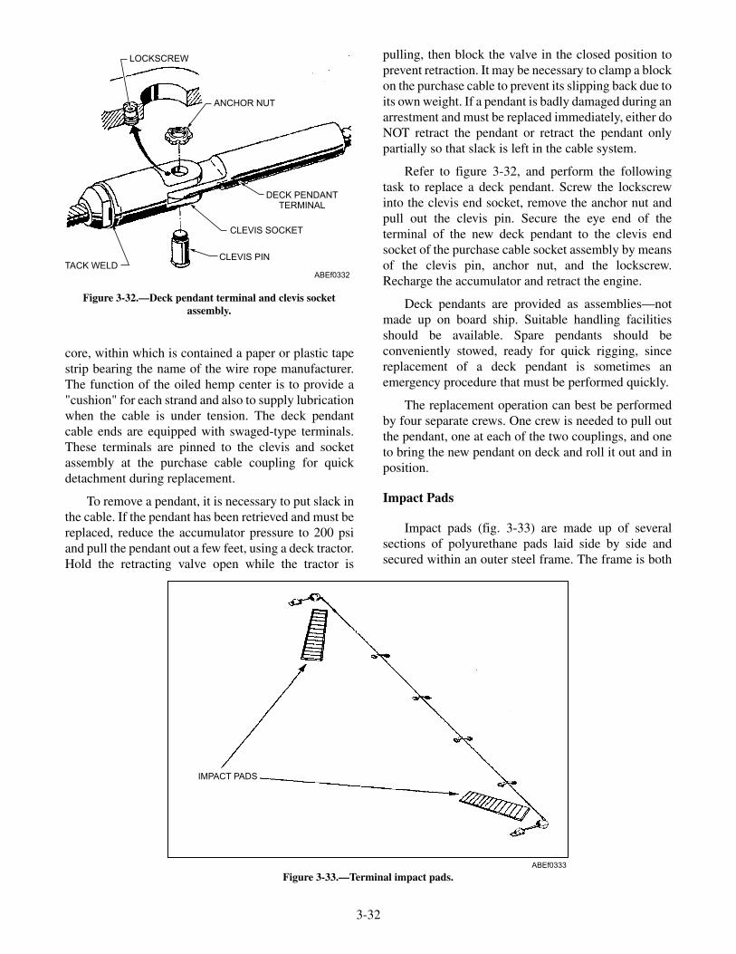
core, within which is contained a paper or plastic tapestrip bearing the name of the wire rope manufacturer.The function of the oiled hemp center is to provide a"cushion" for each strand and also to supply lubricationwhen the cable is under tension. The deck pendantcable ends are equipped with swaged-type terminals.These terminals are pinned to the clevis and socketassembly at the purchase cable coupling for quickdetachment during replacement.
To remove a pendant, it is necessary to put slack inthe cable. If the pendant has been retrieved and must bereplaced, reduce the accumulator pressure to 200 psiand pull the pendant out a few feet, using a deck tractor.Hold the retracting valve open while the tractor is
pulling, then block the valve in the closed position toprevent retraction. It may be necessary to clamp a blockon the purchase cable to prevent its slipping back due toits own weight. If a pendant is badly damaged during anarrestment and must be replaced immediately, either doNOT retract the pendant or retract the pendant onlypartially so that slack is left in the cable system.
Refer to figure 3-32, and perform the followingtask to replace a deck pendant. Screw the lockscrewinto the clevis end socket, remove the anchor nut andpull out the clevis pin. Secure the eye end of theterminal of the new deck pendant to the clevis endsocket of the purchase cable socket assembly by meansof the clevis pin, anchor nut, and the lockscrew.Recharge the accumulator and retract the engine.
Deck pendants are provided as assemblies—notmade up on board ship. Suitable handling facilitiesshould be available. Spare pendants should beconveniently stowed, ready for quick rigging, sincereplacement of a deck pendant is sometimes anemergency procedure that must be performed quickly.
The replacement operation can best be performedby four separate crews. One crew is needed to pull outthe pendant, one at each of the two couplings, and oneto bring the new pendant on deck and roll it out and inposition.
Impact Pads
Impact pads (fig. 3-33) are made up of severalsections of polyurethane pads laid side by side andsecured within an outer steel frame. The frame is both
3-32
LOCKSCREW
ANCHOR NUT
DECK PENDANTTERMINAL
CLEVIS SOCKET
CLEVIS PINTACK WELD
ABEf0332
Figure 3-32.—Deck pendant terminal and clevis socketassembly.
IMPACT PADS
ABEf0333
Figure 3-33.—Terminal impact pads.

welded and bolted to the flight deck inboard of each ofthe deck sheaves at an approximate 45 degrees forwardfacing angle. The bolted section of the frame isremovable in order to replace worn impact pads asneeded. Upon initial arrestment by an aircraft theterminal will impact on the pads instead of the steeldeck, minimizing damage to the fittings, purchasecable, and crossdeck pendants.
Wire Supports
The wire supports provide a method of raising thecrossdeck pendant off the flight deck to ensure arresting(tail) hook engagement of the incoming aircraft.
These wire supports are actually preshaped leafsprings that are designed to maintain a crossdeckpendant height of 2 inches minimum, measured fromthe bottom of the pendant to deck at its lowest point,and 5 1/2 inches maximum, measured from the top ofthe pendant to the deck at its highest point (fig. 3-34).The crossdeck pendant height is regulated by adjustingthe wire support's contour height.
Each wire support is mounted directly to the flightdeck. The forward end of the wire support spring isrigidly secured by use of a cam mounted in a deckrecess and a follower and pin at the end of the wiresupport. The forward end of the spring is then held in
3-33
CABLE HEIGHT GAGE
CHECKING MINIMUM HEIGHT
CABLE HEIGHT GAGE
CHECKING MAXIMUM HEIGHT
2"
ABEf0334
Figure 3-34.—Checking crossdeck pendant height.

the deck recess by the cam-end disc and the cam-endforward stop (fig. 3-35).
Adjustment of the wire support spring height ismade at its aft end. The aft end of the wire support isalso pinned, and set between adjustable forward stopsas required (fig. 3-35).
Wire supports are replaced when they becomedeformed or damaged or when they fail to maintain therequired crossdeck pendant height of 2 inchesminimum and 5 1/2 inches maximum as measuredusing a cable height gauge (fig. 3-34).
REVIEW QUESTIONS
Q1. What is considered the heart of the arrestingengine?
Q2. What permits the return of hydraulic fluidfrom the accumulator to the main enginecylinder?
Q3. What is the capacity of the fluid stowagetank?
Q4. What is the pitch diameter of the sheaves onthe outboard shaft of the crossheadassembly?
Q5. What system transfers energy from anarresting aircraft to the arresting engine?
Q6. What reduces peak cable tension?
EMERGENCY RECOVERYEQUIPMENT
LEARNING OBJECTIVES: Describe thecomponents of the emergency recoveryequipment. Describe the operation of theemergency recovery equipment.
The emergency recovery equipment (barricadeinstallation) is used when an aircraft cannot make anormal (pendant) arrestment. Emergency recoveryequipment consists of the following:
• Barricade power package
• Pendant and anchor installation
• Barricade stanchions and controls
• Barricade webbing assembly
• Deck ramp installation
The arresting engines used for barricadearrestments are identical to those used for deck pendant
3-34
AFT COVER
ABEf0335
PIVOT END BASE
LOCK PLATE
FORWARD ADJUSTING SCREW
SPRINGCAM
CAM-ENDFORWARD STOP
CAM-END DISC
SPRING
FORWARD STOP
FORWARD ADJUSTINGSCREW (TURN
SCREW IN)
AFT STOP
AFT ADJUSTINGSCREW (TURNSCREW OUT)
FORWARD
FORWARD STOP
SPRING
FORWARD ADJUSTINGSCREW (TURNSCREW OUT)
AFT STOP
AFT ADJUSTINGSCREW (TURN
SCREW IN)
TO LOWER SPRING TO RAISE SPRING
FWD
Figure 3-35.—Adjusting the wire support leaf spring height.

arrestment with four exceptions: (1) no fluid coolers areinstalled, (2) barricade engines are endless reeved, (3)no anchor dampers are installed, and (4) a short-strokecontrol valve cam is used on most carriers.
BARRICADE WEBBING ASSEMBLY
Since barricade arrestments are emergencysituations, barricade-rigging operations must be swiftand efficient. The barricade webbing assemblies (fig.3-36) are assembled and stored in an area where thewebbing assemblies will be readily accessible when anemergency situation arises. The barricade storage roomis equipped with a rack designed to stow threebarricades simultaneously:
• READY— Jet Barricade
• STANDBY— Jet Barricade
• PRACTICE— Jet Barricade
The E2/C2 barricade is also stowed in the stowageroom. The storage area for the webbing assembliesmust be dry and must protect the webbing fromexposure to direct sunlight. The effects of water on abarricade webbing assembly will result in the loss ofapproximately 10 to 15 percent of the webbing'sstrength and its weight increases by approximately 40to 45 percent. However the strength loss and increase inweight are not permanent. When the webbing is dry tothe touch the original barricade strength and weight areregained .
3-35
ENGAGING STRAPS
ANCHOR
HOLDDOWN
DECK RAMP
PARALLELPENDANT
SHACKLEASSEMBLY
EXTENSION PENDANT
EXTENSION LOOP
CONNECTINGSTRAP
MULTIPLE RELEASESTRAPS
UPPER TENSIONINGPENDANT(DECK GEAR)
LOWER TENSIONINGPENDANT
(DECK GEAR)
THREE WEBBING ASSEMBLIES(MODIFIED 91' ASSEMBLIES,REGULAR 108' ASSEMBLIES ORA MIXTURE OF EACH)
ABEf0336
FWD
Figure 3-36.—Barricade webbing installation.

Newly constructed barricade webbing assembliesmay be brought out of storage and used as follows:
• If used for three practice rigs, it can still be usedas a "ready" barricade for engagements.
• If used for four or more practice rigs, it cannot beused as a "ready" barricade.
When an aircraft is required to make an emergencylanding, the nose of the aircraft passes through thebarricade and allows the vertical (engaging) straps tocontact the leading edges of the wings and wrap aboutthe aircraft (fig. 3-37). The barricade installation thenpasses the force of arrestment through the purchasecable to the arresting engine. After arrestment, thebarricade and attached hardware are discarded.
Currently, there are two types of barricades (twoconfigurations) available to the fleet. Both types consistof all-nylon webbing assemblies, placed one on top of
the other and bundled together to make up onebarricade installation (see fig. 3-36).
The polyurethane semicoated barricade uses threeseparate webbing systems to make one main webbingassembly
Each semicoated barricade webbing system iscomposed of upper and lower horizontal load straps(see fig. 3-36) joined together at the ends by nylonvelcro tie-down straps. (The rolled edges of the upperand lower load straps are coated with polyurethane toreduce wear and damage caused when the barricade isdragged into position for use.)
Vertical engaging straps, are looped around theupper and lower load strap of each webbing system andsewn.. The spacing between the vertical engagingstraps affords equalized loading of the barricade duringarrestment. One webbing assembly, effects equalizedloading every 4 feet along the wing's leading edge
3-36
ABE3f0337
RELEASE STRAPS
VELCRO TIE-DOWNSTRAPS
THREE WEBBINGASSEMBLIES
ANCHORASSEMBLY
ENGAGING STRAPS
REFER TO VIEW A
LOAD STRAPSEXTENSIONLOOPS
EXTENSIONPENDANT
U-SHACKLE
PARALLELPENDANT
WINCH
DECK RAMP
VIEW A
BOOT
PELICAN HOOKASSEMBLY
Figure 3-37.—Emergency arrestment.
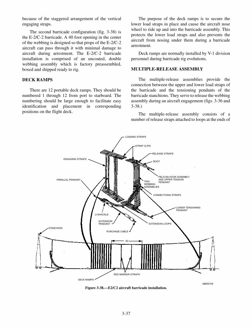
because of the staggered arrangement of the verticalengaging straps.
The second barricade configuration (fig. 3-38) isthe E-2/C-2 barricade. A 40 foot opening in the centerof the webbing is designed so that props of the E-2/C-2aircraft can pass through it with minimal damage toaircraft during arrestment. The E-2/C-2 barricadeinstallation is comprised of an uncoated, doublewebbing assembly which is factory preassembled,boxed and shipped ready to rig.
DECK RAMPS
There are 12 portable deck ramps. They should benumbered 1 through 12 from port to starboard. Thenumbering should be large enough to facilitate easyidentification and placement in correspondingpositions on the flight deck.
The purpose of the deck ramps is to secure thelower load straps in place and cause the aircraft nosewheel to ride up and into the barricade assembly. Thisprotects the lower load straps and also prevents theaircraft from nosing under them during a barricadearrestment.
Deck ramps are normally installed by V-1 divisionpersonnel during barricade rig evolutions.
MULTIPLE-RELEASE ASSEMBLY
The multiple-release assemblies provide theconnection between the upper and lower load straps ofthe barricade and the tensioning pendants of thebarricade stanchions. They serve to release the webbingassembly during an aircraft engagement (figs. 3-36 and3-38.)
The multiple-release assembly consists of anumber of release straps attached to loops at the ends of
3-37
PELICAN HOOK ASSEMBLYAND UPPER TENSIONPENDANTTWO
WEBBINGASSEMBLIES
40'
LOADING STRAPS
STRAP CLIPS
RELEASE STRAPS
ENGAGING STRAPS
PARALLEL PENDANT
U-SHACKLE
EXTENSION LOOPSEXTENSIONPENDANT
PURCHASE CABLE
RED MARKER STRAPS
DECK RAMPS
CONNECTIONS STRAPS
LOWER TENSIONINGPENDANT
BOOT
STANCHION
ABEf0338
Figure 3-38.—E2/C2 aircraft barricade installation.

the load straps. They are then attached to the tensioningpendants by a pelican hook assembly. During anemergency arrestment, the force of the aircraftengaging the barricade breaks the multiple-releasestraps, releasing the barricade from the tensioningpendants allowing it to fall over the aircraft. The energyof the engagement is then transferred from thebarricade through the purchase cable to the arrestingengine.
BARRICADE STANCHIONS
Barricade stanchions house the winches thattension and support the barricades. They furtherprovide the structure on which the barricade is raised orlowered.
Except for differences of location and position ofthe actuating apparatus—deckedge, above or belowdeck—port and starboard stanchions are identical. The
port stanchions with their actuating apparatus aredescribed in this chapter. Barricade stanchions (fig.3-39) are welded steel, tray-shaped assemblies thatconsist essentially of a base on which is hinged theframe. Each barricade frame contains the winches,sheaves, and pendants used to tension the upperbarricade webbing load strap.
Each barricade stanchion is provided with a slot, atthe top of the inboard side, through which passes theupper tensioning pendant. The frame moves as a hingearound the two stanchion shafts, the barrel of the hingebeing the base and the knuckles of the hinge being thehubs of the stanchion frame. The two shafts act as thepins of the hinge. The actuating arm is keyed andpinned on the outer shaft and is pinned to a holder onthe stanchion. Rubber bumper pads are bolted in thedeck recess to cushion the shock of lowering thestanchions.
3-38
STANCHION LATCH ASSEMBLY
COUNTERBALANCESPRING ASSEMBLY
CYLINDERASSEMBLY
DECKEDGECONTROL VALVE
PRESSURE GAUGE
STANCHION
POWERPACKAGE
ABEf0339
Figure 3-39.—Barricade stanchion installation.

PENDANT AND ANCHOR INSTALLATION
The pendant and anchor installation (fig. 3-40) isthe means by which the barricade webbing issuspended and tensioned to maintain its 20-footmidspan height above the flight deck. Componentscomprising the pendant and anchor installation are:four wire rope tensioning pendants, two stanchionmounted winches. A deck mounted winch assembly,and an anchor assembly.
Stanchion mounted winches
One winch is mounted in each barricade stanchionand is attached to the tensioning pendant of the upperloading strap of the barricade.
Deck winch
The deck winch, through the tensioning pendantsprovide a means of tensioning the starboard side lowerloading strap of the barricade webbing (see fig. 3-40).
Anchor assembly
The anchor assembly, through the tensioningpendants provides a means of tensioning the port side
lower loading strap of the barricade webbing (see fig.3-40).
Tensioning pendants
Tensioning pendants provide the link between thewinches, anchor and loading straps to keep the straps inthe correct position when a barricade is rigged (see fig.3-40).
STANCHION HYDRAULIC CYLINDER
The hydraulic cylinder (fig. 3-41) raises and lowersthe barricade stanchion when hydraulic fluid underpressure is introduced into the cylinder on either theraising side of the piston or the lowering side of thepiston. A front cap (3) and a rear cap (4) are eachattached to the cylinder ends by bolts and sealed by anO-ring (13) and backup rings. Contained in the cylinder(2) are a piston (1), a piston rod (5), and two plungers(6), one on each side of the piston. The piston andplungers are held in position on the rod by a castellatednut and secured by a cotter pin. The piston and pistonrod are sealed by an O-ring (13) and backup rings. Thepiston is fitted with two packing followers, two sets ofV-ring packings (12), four rings each, and two piston
3-39
TENSIONING PENDANTS
BARRICADEINSTALLATION
ANCHORFWD
WINCHASSEMBLY
ABEf0340
Figure 3-40.—Pendant and anchor installation.

glands (11) secured by bolts, each safety wired. Shims(14) are provided between the piston face and pistongland to obtain the proper packing float. The piston rodis sealed where it extends through the front cap (3) byfour V-ring packings (12), a spacer, and piston rodgland (10) secured by bolts and washers. Shims (14) areprovided to obtain proper packing float. A terminal isattached to the end of the piston rod and is secured by asetscrew. The front cap and rear face are each fitted witha tailpiece, an adapter, an orifice plate, a union nut, andan elbow to attach hose; joints are sealed by O-rings
and packing. A vent valve assembly (8) and plug (9) arelocated at each end of the hydraulic cylinder to vent airor drain fluid.
COUNTERBALANCING SPRING
The counterbalancing spring supplements the forceof the stanchion cylinder in raising the stanchion, andcushions the contact of the stanchion with the deck.
The counterbalancing spring (fig. 3-42) is a groupof three compression spring units (5) comprising five
3-40
14
129
1313
14
121 13
13
4
7
11
6
2
5
83
10
1. PISTON2. CYLINDER3. FRONT CAP4. REAR CAP5. PISTON ROD6. PLUNGER7. HOSE
8. VENT VALVE ASSEMBLY9. PLUG
10. PISTON ROD GLAND11. PISTON GLAND12. PACKING13. 0-RING14. SHIM
ABEf0341
Figure 3-41.—Hydraulic cylinder assembly.
1 23
4
6
7
5
1. EQUALIZING PLATE2. CLEVIS3. ROD
4. SPRING5. COUNTERBALANCING SPRING UNIT
6. TERMINAL7. CABLE
ABEf0342
Figure 3-42.—Counterbalancing spring assembly.
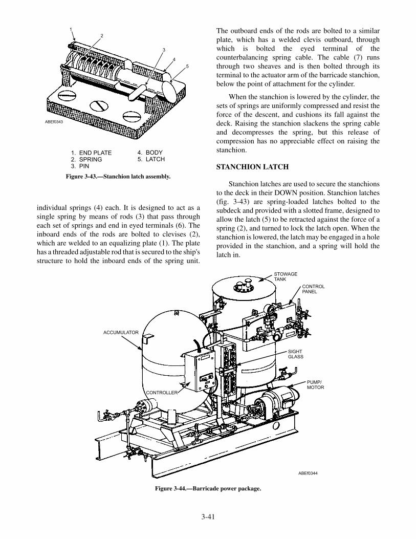
individual springs (4) each. It is designed to act as asingle spring by means of rods (3) that pass througheach set of springs and end in eyed terminals (6). Theinboard ends of the rods are bolted to clevises (2),which are welded to an equalizing plate (1). The platehas a threaded adjustable rod that is secured to the ship'sstructure to hold the inboard ends of the spring unit.
The outboard ends of the rods are bolted to a similarplate, which has a welded clevis outboard, throughwhich is bolted the eyed terminal of thecounterbalancing spring cable. The cable (7) runsthrough two sheaves and is then bolted through itsterminal to the actuator arm of the barricade stanchion,below the point of attachment for the cylinder.
When the stanchion is lowered by the cylinder, thesets of springs are uniformly compressed and resist theforce of the descent, and cushions its fall against thedeck. Raising the stanchion slackens the spring cableand decompresses the spring, but this release ofcompression has no appreciable effect on raising thestanchion.
STANCHION LATCH
Stanchion latches are used to secure the stanchionsto the deck in their DOWN position. Stanchion latches(fig. 3-43) are spring-loaded latches bolted to thesubdeck and provided with a slotted frame, designed toallow the latch (5) to be retracted against the force of aspring (2), and turned to lock the latch open. When thestanchion is lowered, the latch may be engaged in a holeprovided in the stanchion, and a spring will hold thelatch in.
3-41
1. END PLATE2. SPRING3. PIN
4. BODY5. LATCH
1
2
3
4
5
ABEf0343
Figure 3-43.—Stanchion latch assembly.
STOWAGETANK
CONTROLPANEL
SIGHTGLASS
PUMP/MOTOR
CONTROLLER
ACCUMULATOR
ABEf0344
Figure 3-44.—Barricade power package.

POWER PACKAGE
The power package (fig. 3-44) provides andmaintains the fluid pressure required by the hydrauliccylinders to raise and lower the barricade stanchions. Itconsists of a base weldment, gravity tank assembly,control panel assembly, accumulator, motor controller,pump, electric motor, electrical system, and pipingsystem.
The gravity tank assembly has a capacity ofapproximately 125 gallons and is the fluid reservoir inthe power package assembly. Displaced fluid from thecylinder assemblies is returned to the gravity tank, andfrom there it is pumped back to the accumulator. Thegravity tank is welded steel, closed at the top andbottom by flat plates. The top cover plate has an accesshole, which is covered by a cap plate and gasket held inplace by bolts. Tapped bosses welded to the cap plateare for breather vents. A liquid-level gauge is connectedto the side of the gravity tank. An indicator plate isattached to the tank at the level gauge to show theproper fluid level.
The control panel assembly (fig. 3-45) is attachedto the gravity tank by four bolts.
The panel consists of the panel frame (1), twopiping support brackets (9), accumulator pressuregauge (6), pressure sensing switch (7), gauge valve (3),air-charging valve (5), vent valve (2), air supply valve(4), caution plate (8), and operating instruction plate(10). Necessary copper tubing and sil-braze fittingsconnect the panel to the accumulator assembly, to aship's exhaust line, and to the ship's high-pressure airsupply line. The accumulator pressure gauge (6) is usedto indicate pressures ranging from 0 to 2,000 psi in theaccumulator.
The pressure-sensing switch (7) is a piston type,contained in a splashproof housing. It is connected tothe pressure line from the accumulator with a threadedadapter and a coil of tubing between the adapter and teein the pressure line. The function of thepressure-sensing switch is to maintain accumulatorpressure between 1,250 psi and 1,500 psi. It does thisby opening or closing to stop or start the pump motor.
3-42
1 8 2
9
457610
3
AIR SUPPLY
AIR CHARGING VALVE
VENT VALVE
CAUTION
ACCUMULATOR PRESSGAUGE VALVE
1. FRAME2. VENT VALVE3. GAUGE VALVE4. AIR SUPPLY VALVE5. AIR-CHARGING VALVE
6. ACCUMULATOR PRESSURE GAUGE7. PRESSURE-SENSING SWITCH8. CAUTION PLATE9. BRACKET
10. INSTRUCTION PLATE
ABEf0345
Figure 3-45.—Control panel assembly.

The pressure switch operates only when the motorcontroller switch is set at the AUTOMATIC position.The caution plate (8) is located next to the vent valve(2). It cautions all concerned to keep the vent valveopen at all times except when charging theaccumulator, and contains instructions for closing thevent valve when charging the accumulator.
A gauge valve (3) is furnished to maintain pressurein the accumulator when it is necessary to remove thepressure gauge (6). The air-charging valve (5) regulatesthe charging flow. The air supply valve (4) controls theflow intake of air to the control panel and accumulator.The operating instruction plate (10) contains basicoperating instructions and a piping schematic.
The motor controller regulates the starting andstopping of the pump motor in conjunction with thepressure-sensing switch. The controller, operatingmagnetically, provides a switch control for OFF,AUTOMATIC, or RUN positions. The OFF position isused when the power package is secured. TheAUTOMATIC position is used when the powerpackage is to be operated, and the RUN position is usedwhen it is necessary to bypass the pressure-sensingswitch. Protective features of the controller includepilot circuit and motor overload protection andundervoltage release. A white light is mounted on thecontroller to indicate when power is available. Whenthe switch is in the OFF position, the circuits from thecontroller to the motor and the pressure-sensing switchremain open, or dead. In the AUTOMATIC position,the motor starts when the contacts are closed in thepressure-sensing switch, and the motor stops when thecontacts open. The RUN position is spring returned,and the motor runs only as long as the switch ismanually depressed.
In the piping system, manual valves are placed inthe lines to provide for operating and standbyconditions and for maintenance. Each valve is taggedwith a nameplate giving its number and normaloperating position (OPEN or CLOSED). Mis-cellaneous equipment includes a check valve, fluidstrainer, hydraulic pressure relief valve, and an airsafety head. The check valve between the accumulatorand pump prevents fluid pressure from backing up tothe pump. The fluid strainer in the line between thegravity tank and the pump removes foreign matterbefore it enters the pump. The hydraulic relief valveconnected to the line between the check valve andpump provides for pressure relief. The hydraulic reliefvalve is adjusted to crack open at 1,600 psi (minimum)
and open full at 1,750 psi. This line is equipped with aliquid sight indicator for visual checking of fluid flow,which would indicate an open relief valve. The airsafety head, which ruptures at approximately 2,000 psi,is connected to the air line between the accumulator andcontrol panel. It acts as a safety to prevent charging theaccumulator and related components above their designlimits. Two breather vents at the top of the gravity tankprovide for passage of air out of or into the tank as theliquid level rises or lowers. A screen in the breather ventremoves any foreign matter from incoming air.
BARRICADE OPERATION
During normal operations the system is put in theREADY condition. The power package, which islocated below deck and includes an accumulator andgravity tank, is to be placed in a READY condition asfollows:
• Place accumulator pressure at 1,500 psi.
• Fill accumulator and gravity tank liquid tooperating level.
• Open or close proper valves.
• Place motor controller switch on AUTOMATIC.
• Check controls for proper operation.
• Inspect barricade-tensioning pendants for fray-ing.
As shown in figure 3-46, after the latch at the top ofthe stanchion is released, the deckedge control valvelever is placed in the Raise position (No. 1), and thestanchions will raise simultaneously. Raising opera-tions may be stopped and stanchions held in anyposition by placing the deckedge control valve lever inthe Neutral position (No. 2).
To lower the stanchions, place the deckedge controlvalve lever in the Lower position (No. 3). Stanchionswill lower simultaneously. Lowering operations may bestopped and stanchions held in any position by placingthe deckedge control valve lever in mid-position(No. 2).
The deckedge control valve lever in mid-position(No. 2) is the standby position. It blocks all valve ports,and any passage of fluid is stopped when the valve is inthis position. This position should be used to stopstanchions during raising or lowering or to hold thestanchions either up or down.
3-43

CAUTION
The control valve lever must never be held orleft in any position between 1 and 2 or 2 and 3,since this allows fluid to drain from theaccumulator, through the system, to the gravitytank.
The power package accumulator does not containsufficient fluid to raise and lower the stanchions morethan three times without the pump operating.Approximately 20 minutes is required for the pump toreplenish fluid to the operating level in the accumulator,if stanchions are cycled three times without the pumpoperating. The READY CONDITION for normal
operation specifies 1,500 psi accumulator pressure;however, stanchions will raise and lower, taking alonger period of time with a lower pressure, as isexperienced if stanchions are cycled without the pumpoperating. Pressure at the start of the third cycle will beapproximately 850 psi without the pump operating.
If the stanchions are cycled more than three timeswithout the pump operating, air will enter the pipingand cylinders, and fluid will overflow the gravity tank.It is then necessary to fill, vent, and charge the systemas specified in the applicable operating manual.
During the READY and SECURE conditions, thefollowing checks are to be made:
3-44
BARRICADE
UP
BARRICADE
NEUTRAL
BARRICADE
DOWN
CONTROLLEVER
DECKEDGE
CONTROL VALVE(4-WAY)
ABEf0346
Figure 3-46.—Barricade stanchion controls.

During the READY condition at 1-hour intervals,check the accumulator pressure, accumulator andgravity tank liquid levels, controller switch forAUTOMATIC setting, and make sure the pump is notoperating when accumulator pressure is 1,500 psi orabove.
During the SECURE condition, make a daily checkof the accumulator pressure, accumulator and gravitytank liquid level, valves for position (open or closed),and controller switch for OFF setting.
The system must be operated WEEKLY to raiseand lower the stanchions, to vent air from both ends ofthe hydraulic cylinders, and to check the operations ofthe system. It is not necessary to attach the barricadewebbing during this exercise.
REVIEW QUESTIONS
Q7. List the four differences between a pendantengine and a barricade engine.
Q8. What connects the upper and lower loadsstraps to the barricade stanchions?
Q9. When are the counterbalancing springscompressed?
Q10. What secures the barricade stanchions to thedeck?
Q11. What is the barricade power packageaccumulator operating pressure?
Q12. What are three positions of the motorcontroller switch?
MAINTENANCE PROCEDURES
LEARNING OBJECTIVES: Describe theprocedures for replacing purchase cables.Describe the procedures for replacingpackings.
Arresting gear must be kept ready for instant use.There is only one way such a condition may be effected;that is, by constant inspection, repair, and maintenance.Preoperational and postoperational inspection of allcomponents is mandatory, as directed by the applicableMRC. Every section, topside, below deck, engine areas,and ready stowage must be prepared to function oncommand.
Maintenance can be divided into two broadcategories: preventive maintenance and correctivemaintenance. Preventive maintenance consists ofroutine shipboard procedures designed to increase the
effective life of equipment or to forewarn of impendingtroubles. Corrective maintenance includes proceduresdesigned to analyze and correct material defects andtroubles. The main objective of shipboard preventivemaintenance is the prevention of breakdown,deterioration, and malfunction of equipment. If,however, this objective is not reached, the alternativeobjective of repairing or replacing failedequipment—corrective maintenance—must beaccomplished.
Maintenance by the arresting gear crew must gobeyond a wipedown and periodic lubrication. Thearresting gear personnel must be instructed to alert theofficer in charge to any signs of malfunction, wear,looseness, leakage, damage, or any other irregularconditions in the arresting gear equipment. They shouldalso learn the physical location of all operating parts,cable runs, air supply lines, valves, electrical supplylines, switches, fuse boxes, tools, and spare parts.
Engine inspection should be visual, mechanical,and operational. The following general notes apply tomaintenance throughout the arresting gear equipment:
• Mechanical inspection is performed while theengine is at rest. It consists of a security check,exercising the engine, and manipulating thecontrols. This inspection is a check forlooseness, excessive play, improper operation ofhidden parts, lack of lubrication, or anyabnormal resistance to motion.
• Operational inspection consists of running alloperable systems through a full cycle ofoperation, checking for smoothness ofoperation, proper timing, and synchronization.
• All maintenance performed on recoveryequipment should be noted in the maintenancelog for that particular unit.
• Changes in critical measurements should belogged so that they can be used to predict trendsand avoid possible troubles.
• Wipe down all arresting gear equipment daily toremove dirt and grime.
• Remove rust; paint when necessary.
• Do not paint threads or finished machinedsurfaces.
• Check for loose or damaged bolts, nuts, andscrews. Tighten or replace as required.
3-45

Replacement bolts should be of equal or greaterstrength than the original.
• All bolts should be tightened to the propertorque value.
• Check for hydraulic and pneumatic leaks.
• Be alert for any unusual sounds that mayindicate malfunctioning equipment. Reportthese conditions to the officer in charge.
• Check spares on hand against allowable spareslist. Replenish spare parts monthly.
• Maintenance personnel must establish andcarefully maintain the Recovery Wire RopeHistory Chart, recording all wire rope data.
• The replacement of any O-ring, V-ring, or otherpressure seal necessitates a high-pressure test ofthe equipment before resuming arrestingoperations. Before you can pressure test newlyinstalled seals, it is necessary that the unit standfor a period of 1 hour before the seals can beaccepted.
Once each year (or as modified by appropriatetechnical publications), drain the ethylene glycol fromthe system and replace with fresh fluid.
REPLACING PURCHASE CABLES
During recovery operations, malfunctions maydevelop in the engine and cable system, causing thepurchase cable to pull out of the sheave arrangement orbreak below deck, close to or at the engine, resulting inshutdown of the system. Also, conditions occur inwhich initial reeving of the engine is necessary or oldpurchase cable is required to be replaced by newpurchase cable. Any or all of these conditions can occuron single or endless reeved engines.
If the old cable is still reeved, do not pull it out.When possible, the old cable should be used to pull inthe new. Even if the old cable is only partially reeved, itwill prove useful. Reeving is very much simplified ifcable already reeved in the proper way can be used. Adecision must be made for each particular engine as towhether it is easier to feed the new cable from theengine and pull from the flight deck level with a tractor,or feed from the flight deck and pull from the enginewith block and tackle. In either case, the cable shouldbe pulled very slowly, and communication should bemaintained between engine and flight deck, so that thepulling can be stopped quickly if there is danger of
pulling a kink into the line. If the purchase cable issevered below deck but still reeved, isolate the breakand thread a 9/16-inch cable through the system andbutt braze this to the longer length to provide acontinuous line for pulling in the new cable.
The following procedures should be followed inreplacing purchase cables:
1. Initial reeving of an engine is facilitated byhand-threading the complete fairlead systemand engine with a length of 9/16-inch cable.After reeving the 9/16-inch cable, splice andbraze the end to the purchase cable and pull thelarger into the system with the smaller. Thissmaller-diameter cable is easier to pushthrough the fairlead pipes and wrap around thesheaves before pulling in the purchase cable.
2. To thread the cable through the deck andfairlead sheaves, remove the sheave covers andpull out the sheaves. Push the cable through thefairlead pipes from sheave housing to sheavehousing. Then slip the cable into the sheavegroove as the sheave is replaced in the housing.When the cable is fully threaded, replace thecovers.
3. In reeving the engine, use only the original,approved reeving pattern. Study the reevingdiagram in the applicable NAVAIR main-tenance manuals, and be careful to pass thecable over the sheaves in the approvedsequence and through the appropriate fairleadsand guides.
4. After the cable is reeved, the next step is toconnect the anchor end of each length. Thenthe cable must be stretched taut to determinethe correct location for the terminal of theopposite end.
New cables acquire a stretch over the course of thefirst several engagements. This lengthening of cablesdecreases the distance between crosshead andcrosshead stop in the BATTERY position, and this inturn increases the fluid capacity of the hydraulic systemand makes it necessary to add fluid to maintain the fluidlevel. If the distance from crosshead to crosshead stopin the BATTERY position becomes less than theminimum allowable clearance of 1 inch between thecrosshead and the crosshead stop, it becomes necessaryto crop the cable and repour a terminal to readjust theclearance to 6 inches between the crosshead and thestop. The clearance between the crosshead andcrosshead stop with newly installed purchase cables is
3-46

set at 7 inches. New purchase cables will stretch veryrapidly during the first few arrestments. The initial7-inch dimension between the crosshead and the stopallows for this structural stretch, which causes aprogressive narrowing of the gap distance between thecrosshead and crosshead stop. After the purchase cablehas been stretched and reaches the minimum allowableclearance of 1 inch between the crosshead andcrosshead stop, a 6-inch dimension is used thereafter.
When it becomes necessary to rereeve asingle-reeved engine, both purchase cables must bereplaced. Reeving only one purchase cable on asingle-reeved engine result in unequal length of the twocables, because of the initial stretch of the new cable.An offcenter deck pendant is an indication of one cablestretching more than the other. This condition couldcause one of the purchase cable terminals to rest in thedeck sheave. To correct this condition, you will have tocrop the longer cable and repour the terminal.
During arrestment operations, torque builds up inthe purchase cables. Failure to remove this torqueresults in accelerated wear and bird-caging of thecables, with vastly increased susceptibility to failure.Compliance to detorquing methods at specifiedintervals is mandatory. Newly installed purchase cablesshould be detorqued after the initial 50 landings (nomore than 60) and every 200 landings thereafter.
WARNING
Keep hands free of spinning parts whenreleasing torque from cables.
Purchase cable torque can be removed in thefollowing ways. During flight operations, disconnectone side of the crossdeck pendant at the completion ofan arrestment and partially retract the engine. Thisallows the cables to untwist. If time allows, blow theengine down to 200 psi and pull the engine out to its fullstroke; disconnect one side of the crossdeck pendant;and retract the engine slowly to approximately 20 feetout of battery.
If torque buildup is greater than normal, it isrecommended that the crossdeck pendant be discon-
nected from both topside terminals to allow a moreefficient detorque of the cable system.
Preparing Cable and Terminal for Pouring
When working around an arresting gear engine,make sure the arresting engine retracting system isdepressurized before performing any of the followingsteps involving the handling of the wire rope.
Preparing Wire Rope
When it is necessary to cut the wire rope, place twoseizings of approximately 15 or 20 turns of soft steelseizing wire on the cable, approximately 1 inch apart.(See fig. 3-47, view A.) Cut the cable between the twoseizings.
Remove the seizing from the cut end of the cableand, with the use of a marlinespike, unlay three strandsof the cable. Using a pocketknife, cut and remove thehemp center a distance equal to the length of theterminal plus 1 inch. (See view B of fig. 3-47.) Re-laythe strands of the cable.
Make a seizing a distance equal to the length of theterminal plus 1 inch. The seizing should be made withthe use of a serving tool and be 15 or 20 turns of softsteel seizing wire. (See fig. 3-47, view C.) Place twowraps of seizing wire immediately above the largeseizing, as shown in view D.
Loop and tighten one or two turns of0.047-inch-diameter copper wire on the end of allstrands, as shown in view D. Using a marlinespike andtubing, unlay and straighten the strands of the cable tothe top of the seizing. Pull the strands in toward thecenter to ensure a good distribution when the individualwires of each strand are straightened. (See view D offig. 3-47.) After all the strands are straightened, removethe two turns of seizing previously placed at the top ofthe large seizing. Do NOT remove the large seizing;this seizing remains in place until pouring proceduresare completed.
Do NOT use pliers to straighten the wires; pliersmay damage or weaken the wires.
3-47

3-48
CUT BETWEEN SEIZING
1 INCH APPROXIMATE
UNLAY 3 STRANDS
HEMP CENTER
15 TO 20 TURNS3/32 DIA. WIRE
TERMINALLENGTH
PLUS1 INCH
STRANDSTRAIGHTENING
TUBE
1 OR 2 TURNS0.047 DIA. WIREON ALL STRANDS
2 TURNS3/32 DIA.
WIRE
TERMINAL LENGTHPLUS 1 INCH
15 OR 20 TURNS3/32 DIA. WIRE
(A) (B)
( )C (D)
ABEf0347
Figure 3-47.—Wire rope preparation.

Make certain that the large seizing is tight; removethe copper wire seizing from one strand at a time, andstraighten the individual wires, using the powerstraightening device, shown in figure 3-48.
Repeat the straightening procedure on each strand,working on one strand at a time, until all the wires arecompletely broomed out as shown in figure 3-48.
Cleaning Wire Rope and Terminal Pouring
The cleaning and preparation of wire rope andterminals requires the use of chlorinated degreasingsolvents, grit blasting, and the heating and melting ofzinc.
WARNING
Personnel cleaning wire rope and pouringterminals must use chemical respirators and
make sure the area is properly ventilated. Forcomplete safety procedures concerning zincterminal pouring and wire rope preparation,consult the current arresting gear NAVAIRoperation, maintenance, and overhaulinstructions.
In a well-ventilated space, prepare the ultrasonicdegreaser unit by filling it with GRISOLVE PEG-2, towithin 1 inch of the tank top. The ultrasonic degreasermust then be energized for 2 hours before degreasingoperations begin; this degasses and removes oxygenfrom the solvent, which increases its cleaning ability.One hour before the degreasing operation is to start,turn on the ultrasonic unit's heaters to heat theGRISOLVE PEG-2 to a temperature of 90 to 100°F. Astainless steel bucket (14-quart) will also be filled with3 gallons of GRISOLVE PEG-2; this is used to rinse thebroomed cable end after it has been cleaned in theultrasonic degreaser unit.
3-49
SEE DETAIL ASOFTJAWS
WIRE ROPE
SEIZING
BROOMED WIRE ROPE
INSTALL BENT END OF TUBEAWAY FROM DRILL. (SEE NOTE)
443" (LENGTH OF BEND)
BENT TUBE
PUSH TUBE ON AND PULL OFF EACH WIRE(ONE TIME ONLY) WITH DRILL SPEED ATANY RPM BETWEEN 450 RPM MINIMUM TO700 RPM MAXIMUM FOR A PERIOD OF 2 TO5 SECONDS PER STRAND.
DIRECTIONOF DRILL
DETAIL A
NOTE
IF DIFFICULTY IS ENCOUNTEREDIN STRAIGHTENING THE INDIVIDUALWIRES IT IS SUGGESTED THAT THELENGTH OF THE BEND IN THE BENTTUBE BE SHORTENED TO 2 1/4" FROM 3"
ABEf0348
VISE
Figure 3-48.—Straightening individual wires with power straightening device.

To degrease, immerse the broomed end andapproximately 1 inch of the seizing into the solvent inthe ultrasonic degreaser unit tank (see fig. 3-49).
• The cleaning solution must be changed after 10uses.
• Replace the rinsing solution when it becomescloudy.
After cleaning the broomed end, slowly lift it out ofthe solution, allowing it to drain over the tank. Now,rinse the broomed end in the bucket of cleanGRISOLVE PEG-2 then remove it and allow it toair-dry for 5 minutes as shown in figure 3-49. After thebroomed end has dried, inspect it to ensure that all dirt,grease, and all other foreign matter have been removed.If necessary repeat the cleaning/degreasing operation.Following degreasing, the cleaner residues must berinsed from the wire broom. Heat a 3-gallon bucket ofclean, potable water to a temperature of 160º to 200ºF.Immerse the broom in the rinse bucket of hot water untilhalf of the seizing is immersed. Allow the broom torinse for 2 or 3 minutes, gently swirling the terminal toagitate the water. Remove the terminal from the waterand shake off the excess.
Following the rinse, examine the broom for anypreservative remaining on the wires, especially wherewires touch. If preservative accumulations are stillapparent, reimmerse the broom into the degreaser,
repeat this cycle using clean rinse water each time untilthe broom appear clean.
After the broomed out wires have been thoroughlycleaned, wrap the end of the wire rope with twolongitudinal strips of pressure-sensitive tape for adistance of 2 feet, leaving the broomed out wires and1/2 inch of the seizing exposed (fig. 3-50).
The method used in preparing wire rope andterminals for zinc-poured terminals includes a grit blastmethod for etching the cables and terminals prior topouring.
The following steps are used in the grit blast method:
1. Fill the cabinet hopper with loose grit, 100pounds minimum to 200 pounds maximum.
2. Install the applicable inserts in the cabinet,depending on the size of the purchase cablebeing cleaned.
3-50
IMMERSE TOTHIS POINT0NLY
CLEANING SOLUTION
(1) ULTRASONIC DEGREASER (P/N 521566-1).IMMERSE THE BROOMED WIRE ROPE INDEGREASING SOLUTION, GRISOLVE PEG-2OR IMPACT INDUSTRIAL, (REPLACEDEGREASING SOLUTION EVERY 10 USES.)
(2) RINSE BROOMED WIRE ROPE IN 14 QTCONTAINER FILLED WITH 3 GALLONSOF GRISOLVE PEG-2 OR IMPACTINDUSTRIAL DEGREASING SOLUTION.
(3) DRAIN AND AIR DRY FOR FIVEMINUTES IN DOWN POSITION.
CLEANING SOLUTION RINSING SOLUTION
ABEf0349
1"
Figure 3-49.—Cleaning broomed-out wires.
2 FT½ IN.
2 STRIPS 3-INCH WIDE TAPE
ABEf0350
Figure 3-50.—Adhesive cloth tape applied to wire rope.

3. Open the door of the grip blast cabinet byholding two thumbscrews and lifting. Place theprepared end of the wire rope into the grit blastcabinet to a convenient working location.Support the wire rope externally so that itenters horizontally. Secure the door with thewire rope in position. The wire rope should fitsnugly. If the inserts used do not effect a snugfit, apply tape or cloth to that area of the wirerope.
An 80-100 psi dry-air source must beconnected to an air filter located in the grit blastcabinet. Turn on the air source when ready toblast the wire rope.
4. With hands in the gloves of the cabinet, graspthe blasting gun in one hand; and with the otherhand, hold the siphon tube 1 inch or morebelow the surface of the grit. See figure 3-51.
5. Blast the broomed-out wires with the gunnozzle tip 1/4 inch away from the wires. Use aback and forth motion over the entire length ofexposed broomed-out wires, from the top ofthe wires to the bottom of the wires. Continueuntil a dull nonreflective surface appears on thewires. Rotate the wire rope 90°, using theapplicable twisting wrench. See figure 3-52.
NOTE: If during the grit blast operation the gunbecomes clogged, it may be necessary to sift foreignmatter from the grit. This is accomplished by using asieve furnished with the grit blasting cabinet.
6. Repeat the process until the entire exposed areaof wire rope has been grit blasted. Finally,direct the nozzle into the open end of thebroomed-out wires at about 30° from thelongitudinal, and rotate the wire rope slowlythrough 360° while blasting with a circularmotion. See figure 3-53. Remove the wire ropefrom the cabinet and inspect it forcompleteness of grit blasting. Any evidence ofshine will indicate a need for additional gritblasting. After being grit blasted, the wiresshould not be touched with hands, rags, gloves,and so on, or the cleanliness required for soundterminals will be impaired.
3-51
ABEf0351
Figure 3-51.—Grit blasting of wire rope.
ABEf0352
Figure 3-52.—Rotating the cable in the grit blast cabinet.
ABEf0353
Figure 3-53.—Blasting inner wires.
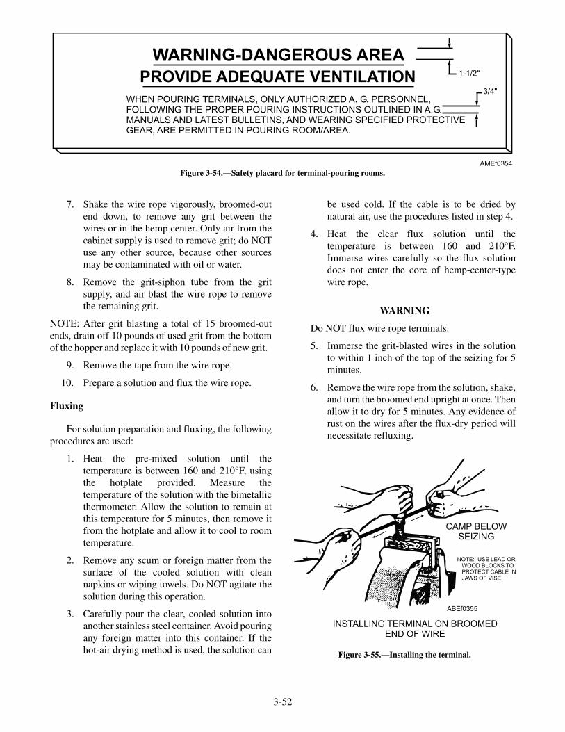
7. Shake the wire rope vigorously, broomed-outend down, to remove any grit between thewires or in the hemp center. Only air from thecabinet supply is used to remove grit; do NOTuse any other source, because other sourcesmay be contaminated with oil or water.
8. Remove the grit-siphon tube from the gritsupply, and air blast the wire rope to removethe remaining grit.
NOTE: After grit blasting a total of 15 broomed-outends, drain off 10 pounds of used grit from the bottomof the hopper and replace it with 10 pounds of new grit.
9. Remove the tape from the wire rope.
10. Prepare a solution and flux the wire rope.
Fluxing
For solution preparation and fluxing, the followingprocedures are used:
1. Heat the pre-mixed solution until thetemperature is between 160 and 210°F, usingthe hotplate provided. Measure thetemperature of the solution with the bimetallicthermometer. Allow the solution to remain atthis temperature for 5 minutes, then remove itfrom the hotplate and allow it to cool to roomtemperature.
2. Remove any scum or foreign matter from thesurface of the cooled solution with cleannapkins or wiping towels. Do NOT agitate thesolution during this operation.
3. Carefully pour the clear, cooled solution intoanother stainless steel container. Avoid pouringany foreign matter into this container. If thehot-air drying method is used, the solution can
be used cold. If the cable is to be dried bynatural air, use the procedures listed in step 4.
4. Heat the clear flux solution until thetemperature is between 160 and 210°F.Immerse wires carefully so the flux solutiondoes not enter the core of hemp-center-typewire rope.
WARNING
Do NOT flux wire rope terminals.
5. Immerse the grit-blasted wires in the solutionto within 1 inch of the top of the seizing for 5minutes.
6. Remove the wire rope from the solution, shake,and turn the broomed end upright at once. Thenallow it to dry for 5 minutes. Any evidence ofrust on the wires after the flux-dry period willnecessitate refluxing.
3-52
WARNING-DANGEROUS AREA
PROVIDE ADEQUATE VENTILATION
WHEN POURING TERMINALS, ONLY AUTHORIZED A. G. PERSONNEL,FOLLOWING THE PROPER POURING INSTRUCTIONS OUTLINED IN A.G.MANUALS AND LATEST BULLETINS, AND WEARING SPECIFIED PROTECTIVEGEAR, ARE PERMITTED IN POURING ROOM/AREA.
1-1/2"
3/4"
AMEf0354
Figure 3-54.—Safety placard for terminal-pouring rooms.
ABEf0355
CAMP BELOWSEIZING
INSTALLING TERMINAL ON BROOMEDEND OF WIRE
NOTE: USE LEAD ORWOOD BLOCKS TOPROTECT CABLE INJAWS OF VISE.
Figure 3-55.—Installing the terminal.
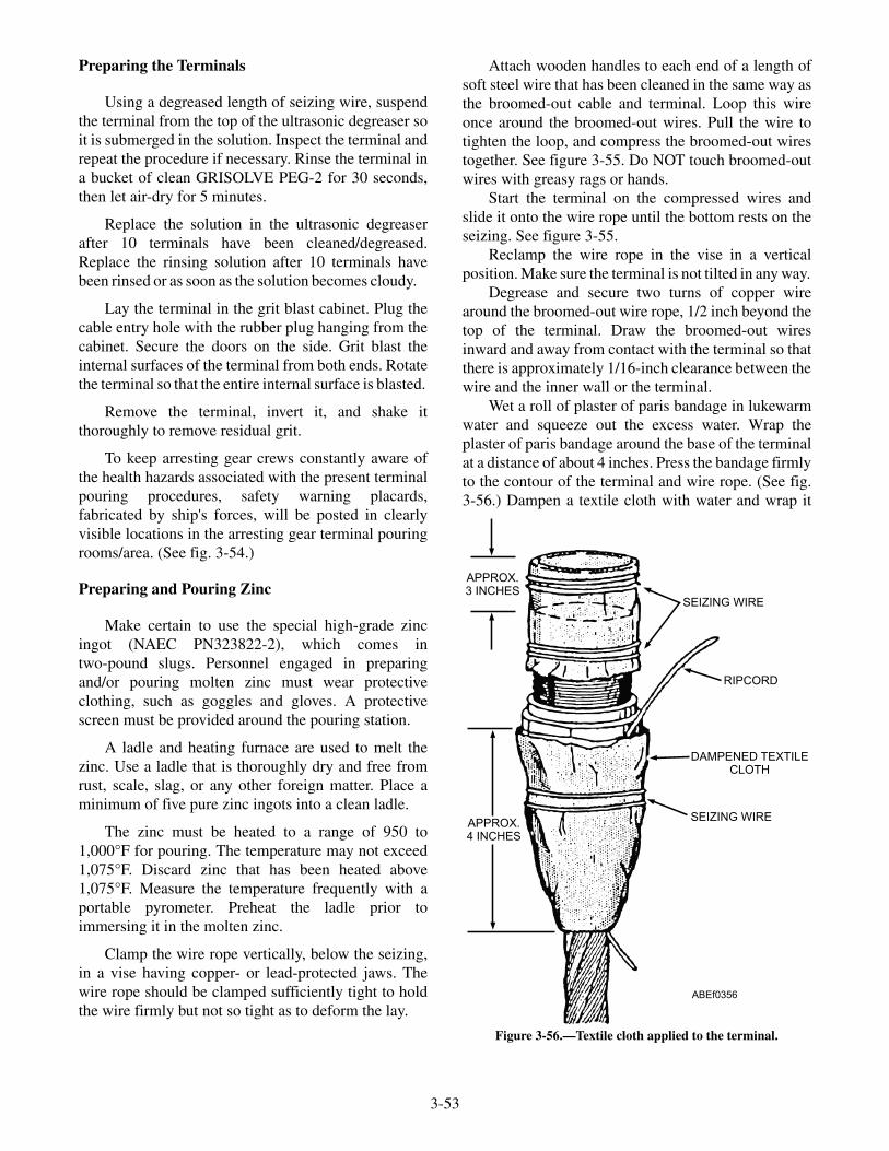
Preparing the Terminals
Using a degreased length of seizing wire, suspendthe terminal from the top of the ultrasonic degreaser soit is submerged in the solution. Inspect the terminal andrepeat the procedure if necessary. Rinse the terminal ina bucket of clean GRISOLVE PEG-2 for 30 seconds,then let air-dry for 5 minutes.
Replace the solution in the ultrasonic degreaserafter 10 terminals have been cleaned/degreased.Replace the rinsing solution after 10 terminals havebeen rinsed or as soon as the solution becomes cloudy.
Lay the terminal in the grit blast cabinet. Plug thecable entry hole with the rubber plug hanging from thecabinet. Secure the doors on the side. Grit blast theinternal surfaces of the terminal from both ends. Rotatethe terminal so that the entire internal surface is blasted.
Remove the terminal, invert it, and shake itthoroughly to remove residual grit.
To keep arresting gear crews constantly aware ofthe health hazards associated with the present terminalpouring procedures, safety warning placards,fabricated by ship's forces, will be posted in clearlyvisible locations in the arresting gear terminal pouringrooms/area. (See fig. 3-54.)
Preparing and Pouring Zinc
Make certain to use the special high-grade zincingot (NAEC PN323822-2), which comes intwo-pound slugs. Personnel engaged in preparingand/or pouring molten zinc must wear protectiveclothing, such as goggles and gloves. A protectivescreen must be provided around the pouring station.
A ladle and heating furnace are used to melt thezinc. Use a ladle that is thoroughly dry and free fromrust, scale, slag, or any other foreign matter. Place aminimum of five pure zinc ingots into a clean ladle.
The zinc must be heated to a range of 950 to1,000°F for pouring. The temperature may not exceed1,075°F. Discard zinc that has been heated above1,075°F. Measure the temperature frequently with aportable pyrometer. Preheat the ladle prior toimmersing it in the molten zinc.
Clamp the wire rope vertically, below the seizing,in a vise having copper- or lead-protected jaws. Thewire rope should be clamped sufficiently tight to holdthe wire firmly but not so tight as to deform the lay.
Attach wooden handles to each end of a length ofsoft steel wire that has been cleaned in the same way asthe broomed-out cable and terminal. Loop this wireonce around the broomed-out wires. Pull the wire totighten the loop, and compress the broomed-out wirestogether. See figure 3-55. Do NOT touch broomed-outwires with greasy rags or hands.
Start the terminal on the compressed wires andslide it onto the wire rope until the bottom rests on theseizing. See figure 3-55.
Reclamp the wire rope in the vise in a verticalposition. Make sure the terminal is not tilted in any way.
Degrease and secure two turns of copper wirearound the broomed-out wire rope, 1/2 inch beyond thetop of the terminal. Draw the broomed-out wiresinward and away from contact with the terminal so thatthere is approximately 1/16-inch clearance between thewire and the inner wall or the terminal.
Wet a roll of plaster of paris bandage in lukewarmwater and squeeze out the excess water. Wrap theplaster of paris bandage around the base of the terminalat a distance of about 4 inches. Press the bandage firmlyto the contour of the terminal and wire rope. (See fig.3-56.) Dampen a textile cloth with water and wrap it
3-53
APPROX.3 INCHES
APPROX.4 INCHES
SEIZING WIRE
RIPCORD
DAMPENED TEXTILECLOTH
SEIZING WIRE
ABEf0356
Figure 3-56.—Textile cloth applied to the terminal.
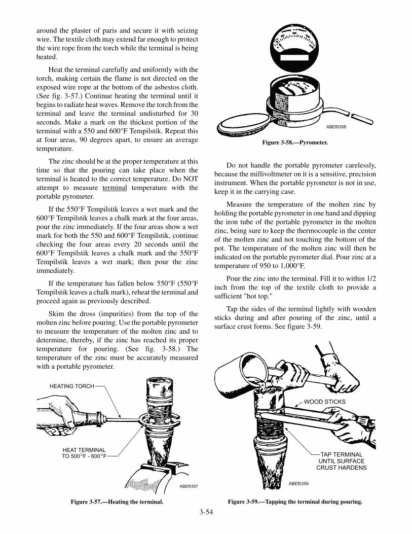
around the plaster of paris and secure it with seizingwire. The textile cloth may extend far enough to protectthe wire rope from the torch while the terminal is beingheated.
Heat the terminal carefully and uniformly with thetorch, making certain the flame is not directed on theexposed wire rope at the bottom of the asbestos cloth.(See fig. 3-57.) Continue heating the terminal until itbegins to radiate heat waves. Remove the torch from theterminal and leave the terminal undisturbed for 30seconds. Make a mark on the thickest portion of theterminal with a 550 and 600°F Tempilstik. Repeat thisat four areas, 90 degrees apart, to ensure an averagetemperature.
The zinc should be at the proper temperature at thistime so that the pouring can take place when theterminal is heated to the correct temperature. Do NOTattempt to measure terminal temperature with theportable pyrometer.
If the 550°F Tempilstik leaves a wet mark and the600°F Tempilstik leaves a chalk mark at the four areas,pour the zinc immediately. If the four areas show a wetmark for both the 550 and 600°F Tempilstik, continuechecking the four areas every 20 seconds until the600°F Tempilstik leaves a chalk mark and the 550°FTempilstik leaves a wet mark; then pour the zincimmediately.
If the temperature has fallen below 550°F (550°FTempilstik leaves a chalk mark), reheat the terminal andproceed again as previously described.
Skim the dross (impurities) from the top of themolten zinc before pouring. Use the portable pyrometerto measure the temperature of the molten zinc and todetermine, thereby, if the zinc has reached its propertemperature for pouring. (See fig. 3-58.) Thetemperature of the zinc must be accurately measuredwith a portable pyrometer.
Do not handle the portable pyrometer carelessly,because the millivoltmeter on it is a sensitive, precisioninstrument. When the portable pyrometer is not in use,keep it in the carrying case.
Measure the temperature of the molten zinc byholding the portable pyrometer in one hand and dippingthe iron tube of the portable pyrometer in the moltenzinc, being sure to keep the thermocouple in the centerof the molten zinc and not touching the bottom of thepot. The temperature of the molten zinc will then beindicated on the portable pyrometer dial. Pour zinc at atemperature of 950 to 1,000°F.
Pour the zinc into the terminal. Fill it to within 1/2inch from the top of the textile cloth to provide asufficient "hot top."
Tap the sides of the terminal lightly with woodensticks during and after pouring of the zinc, until asurface crust forms. See figure 3-59.
3-54
HEATING TORCH
HEAT TERMINALTO 500 F - 600 FO O
ABEf0357
Figure 3-57.—Heating the terminal.
ABEf0358
Figure 3-58.—Pyrometer.
ABEf0359
WOOD STICKS
TAP TERMINALUNTIL SURFACE
CRUST HARDENS
Figure 3-59.—Tapping the terminal during pouring.
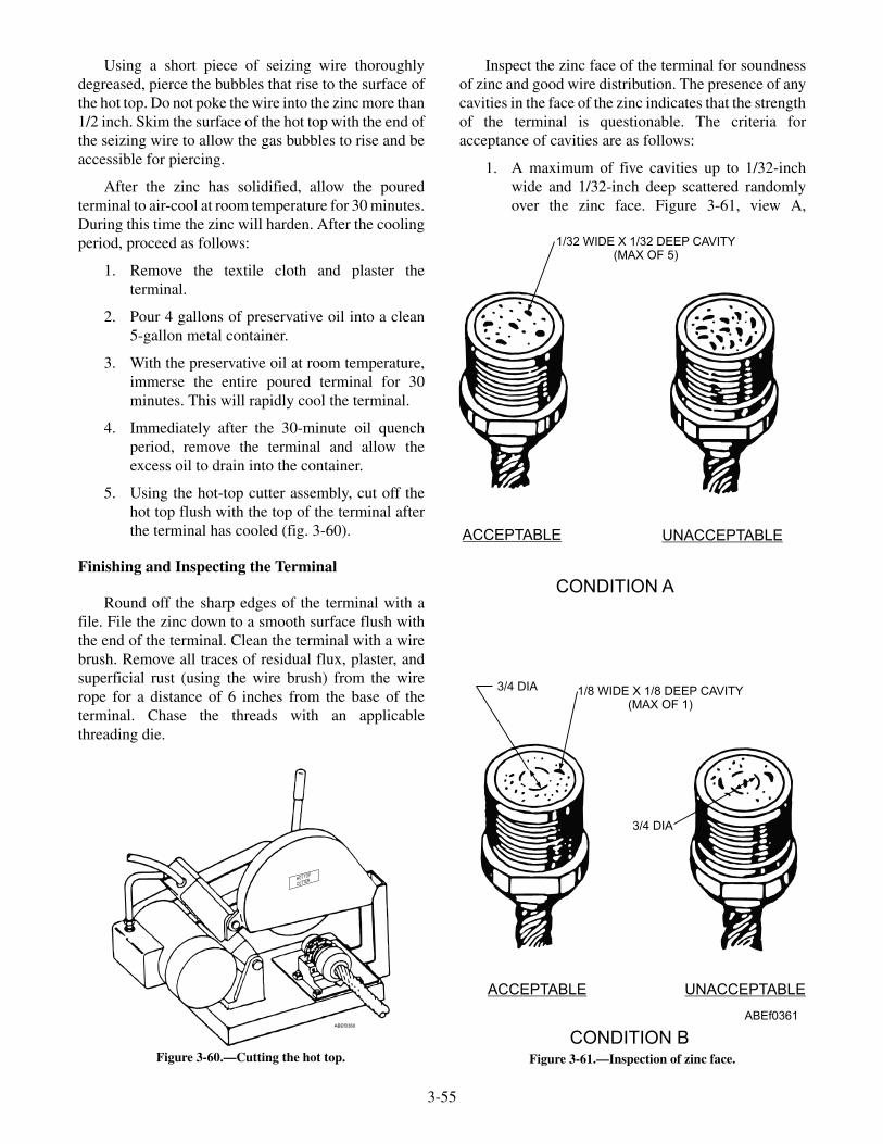
Using a short piece of seizing wire thoroughlydegreased, pierce the bubbles that rise to the surface ofthe hot top. Do not poke the wire into the zinc more than1/2 inch. Skim the surface of the hot top with the end ofthe seizing wire to allow the gas bubbles to rise and beaccessible for piercing.
After the zinc has solidified, allow the pouredterminal to air-cool at room temperature for 30 minutes.During this time the zinc will harden. After the coolingperiod, proceed as follows:
1. Remove the textile cloth and plaster theterminal.
2. Pour 4 gallons of preservative oil into a clean5-gallon metal container.
3. With the preservative oil at room temperature,immerse the entire poured terminal for 30minutes. This will rapidly cool the terminal.
4. Immediately after the 30-minute oil quenchperiod, remove the terminal and allow theexcess oil to drain into the container.
5. Using the hot-top cutter assembly, cut off thehot top flush with the top of the terminal afterthe terminal has cooled (fig. 3-60).
Finishing and Inspecting the Terminal
Round off the sharp edges of the terminal with afile. File the zinc down to a smooth surface flush withthe end of the terminal. Clean the terminal with a wirebrush. Remove all traces of residual flux, plaster, andsuperficial rust (using the wire brush) from the wirerope for a distance of 6 inches from the base of theterminal. Chase the threads with an applicablethreading die.
Inspect the zinc face of the terminal for soundnessof zinc and good wire distribution. The presence of anycavities in the face of the zinc indicates that the strengthof the terminal is questionable. The criteria foracceptance of cavities are as follows:
1. A maximum of five cavities up to 1/32-inchwide and 1/32-inch deep scattered randomlyover the zinc face. Figure 3-61, view A,
3-55
HOT TOP
CUTTER
ABEf0360
Figure 3-60.—Cutting the hot top.
1/32 WIDE X 1/32 DEEP CAVITY(MAX OF 5)
ACCEPTABLE
UNACCEPTABLE
UNACCEPTABLE
ACCEPTABLE
3/4 DIA 1/8 WIDE X 1/8 DEEP CAVITY(MAX OF 1)
3/4 DIA
CONDITION A
CONDITION B
ABEf0361
Figure 3-61.—Inspection of zinc face.
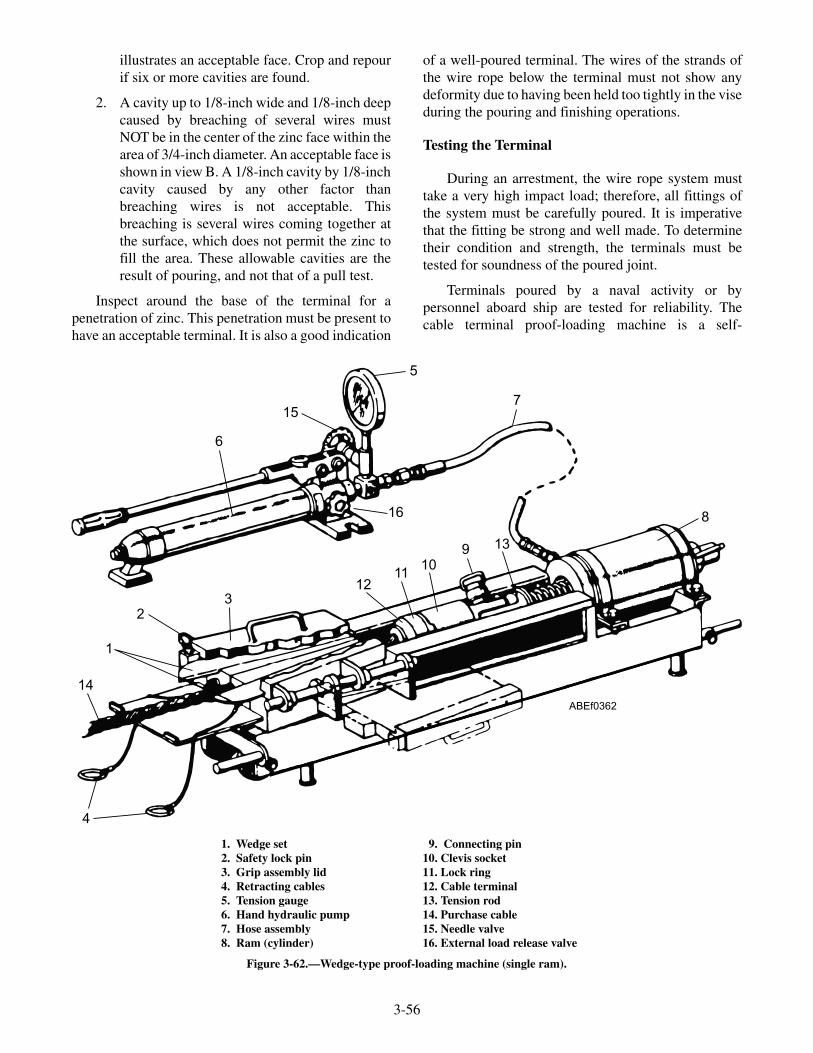
illustrates an acceptable face. Crop and repourif six or more cavities are found.
2. A cavity up to 1/8-inch wide and 1/8-inch deepcaused by breaching of several wires mustNOT be in the center of the zinc face within thearea of 3/4-inch diameter. An acceptable face isshown in view B. A 1/8-inch cavity by 1/8-inchcavity caused by any other factor thanbreaching wires is not acceptable. Thisbreaching is several wires coming together atthe surface, which does not permit the zinc tofill the area. These allowable cavities are theresult of pouring, and not that of a pull test.
Inspect around the base of the terminal for apenetration of zinc. This penetration must be present tohave an acceptable terminal. It is also a good indication
of a well-poured terminal. The wires of the strands ofthe wire rope below the terminal must not show anydeformity due to having been held too tightly in the viseduring the pouring and finishing operations.
Testing the Terminal
During an arrestment, the wire rope system musttake a very high impact load; therefore, all fittings ofthe system must be carefully poured. It is imperativethat the fitting be strong and well made. To determinetheir condition and strength, the terminals must betested for soundness of the poured joint.
Terminals poured by a naval activity or bypersonnel aboard ship are tested for reliability. Thecable terminal proof-loading machine is a self-
3-56
1
23
4
5
6
7
8
910
1112
13
14
15
16
ABEf0362
1. Wedge set2. Safety lock pin3. Grip assembly lid4. Retracting cables5. Tension gauge6. Hand hydraulic pump7. Hose assembly8. Ram (cylinder)
9. Connecting pin10. Clevis socket11. Lock ring12. Cable terminal13. Tension rod14. Purchase cable15. Needle valve16. External load release valve
Figure 3-62.—Wedge-type proof-loading machine (single ram).

contained hand-operated unit designed specifically forproof loading poured terminals on both deck cables andpurchase cables.
Cable Terminal Proof-loading Machine
The cable terminal proof-loading machine iscapable of providing a test load that substantiallyexceeds the test load required for testing the reliabilityof terminals used by ABEs. The test load is read on thetension gauge, which is calibrated in pounds, and ispositioned in the line leading from the pump to the ram(see figs. 3-62 and 3-63).
The machine operating procedure is as follows(refer to fig. 3-63).
1. Thoroughly clean the portion of cable (19) thatwill be in contact with the wedge set (1) duringthe test. Do NOT use solvent for this cleaningoperation.
2. Relieve all pressure in the hydraulic system bycracking open the external load-release valve(21) to slowly release the proof-load on thegauge. Slowly releasing the gauge load willprevent rapid snapback, with resultant possiblebreakage of the gauge pointer.
3. Manually move the crosshead away from ramsand install the crosshead terminal.
4. Remove the safety lock pin and slide the lidtoward the cylinders to open.
5. Install the wedge set, Lucker ManufacturingCompany Part No. 3130-143 (for testing 17/16-inch-diameter purchase cable). Do notlubricate the cable gripping surface or the lidsliding surface.
6. Retract the wedges by pulling on the retractingcables. Lubricate the wedge sliding surfaceswith PRELUB-6 before each test.
3-57
1
2
3
4
4
5
6
7
89
10
11
12
13
14
15
16
171819
20
ABEf0363
1. WEDGE SET2. SAFETY LOCK PIN3. GRIP ASSEMBLY LID4. RETRACTING CABLES5. TENSION GAUGE6. HAND HYDRAULIC PUMP7. HOSE ASSEMBLY8. RAM (CYLINDER)
9. CONNECTING PIN10. CLEVIS SOCKET11. LOCK RING12. CABLE TERMINAL13. TENSION ROD14. PURCHASE CABLE15. NEEDLE VALVE16. EXTERNAL LOAD RELEASE VALVE
Figure 3-63.—Wedge-type proof-loading machine (dual ram).

7. Screw the clevis socket on the cable terminal.
8. Place the cable between the wedges andconnect the clevis socket to the crossheadterminal with the pin.
9. Manually move the crosshead into the rams,making certain that the adapter attached toeach end of the ram engages its respectiveguide hole in the face of the crosshead.
10. Release the wedges, close the lid, and insert thesafety lock pin.
11. Using chalk, masking tape, or some othermeans, mark the cable a measured distancefrom the wedge set. This procedure provides ameans for checking cable slippage while thesystem is being pressurized.
12. Visually inspect the socket tester to makecertain that all components are securelyattached. Do not open the choker valve duringoperation of the hand pump, as this will resultin excessive pressurization of the socket testerafter the desired proof-load has been reached.
13. Open the choker valve (20) on the hand pump,and close the external load-release valve.Never apply proof-loading with the lid open,and keep hands clear of pin and crosshead area.
14. Using the hand pump, pressurize the system toincrease the test load to 120,000 pounds. Holdthe test pressure for 2 minutes.
15. As the pressure is gradually increased, observethe cable for evidence of slippage. If the cablebegins to slip, proceed as follows:
a. Relieve the pressure as in step 2.
b. Remove the safety lock pin and open thelid. It may be necessary to first strike the lidwith a soft mallet before it can be slidforward to open.
c. Retract the wedges.
d. Remove the cable and clean it thoroughly.
e. Clean and inspect the wedge grippingsurfaces. Replace the wedges if necessary.
f. Lubricate the wedge sliding surfaces.
g. Repeat proof-loading procedures
h. Remove the cable from the socket testerand examine the poured terminal.
REPLACING PACKINGS
The efficiency of any hydraulic equipment isdirectly dependent on the proper selection, preparationand installation of its packing. The replacementpacking shall be only those that are called out in theassembly parts list. No substitutes or deviation in sizeor number shall be made. Prior to installation, the age ofnatural or synthetic rubber packing shall be checked todetermine whether these parts are acceptable for use. Apositive identification indicating the source, cure date,and expiration date shall be made. This informationshall be available for all packing used.
The age control of all natural or synthetic packingshall be based upon the “cure date” stamped on themanufacturer’s unit package, intermediate package,and shipping container. The cure date means the date ofmanufacture and is designated by the quarter of the yearand year of manufacture. The cure date forms the basisfor determining the age of the V-ring, O-ring packing,therefore, it becomes important that the cure date benoted on all packages. Packing manufactured duringany given quarter will be considered one quarter old atthe end of the succeeding quarter. For the purposes ofexplaining the coding used by manufacturers todesignate the cure date, each year is divided intoquarters as follows:
• First quarter: January, February, March
• Second quarter: April, May, June
• Third quarter: July, August, September
• Fourth quarter: October, November, December
The shelf-life control of all packing shall be governedby the “expiration date” stamped beside themanufacturer’s cure date on each package. Theexpiration date is the date after which packingCANNOT BE USED IN-SERVICE. Synthetic andnatural rubber packing and V-rings shall have ashelf-life limit of three years (12 quarters). Syntheticand natural rubber O-rings shall have a shelf-life limitof five years (20 quarters). Fluorocarbon O-rings,M83248/1-, have a shelf-life of twenty years (80quarters). Thus, packing and V-rings shall be scrappedif not put into service within three years after the curedate, and O-rings shall be scrapped five years (twentyyears for fluorocarbon O-rings) after the cure date. Allpacking shall be scrapped if not put into use before thetime of the expiration date.
3-58

Removing Old Packings
If practical, remove the shaft, ram, or other sealedmembers from the installation, since this permitsinspection and correction of any defects in the shaft orpacking assembly. Although it is preferable to removethe sealed member, limitations of time, design of theinstallation, or problems of reassembly often make theremoval impractical. After the gland or flange isremoved, the chief problem usually encountered isremoving the female adapter. If this ring is providedwith holes, insert a suitable hoop of bent and flattenedwire, or a threaded rod if the holes are tapped, and pullthe ring back along the shaft. The packing can beremoved using a U-shaped pick made of copper or brasswire. The pick should be small enough to enter thestuffing box, and the ends should be bent and flattened.The pick should be inserted behind the ring, and thering removed. It is usually not necessary to remove themale adapter. If the adapters are not provided with holesor if removal is difficult, they may be removed byalternate methods, such as inserting a wire or piece offlat stock behind the adapter and pulling it out (ifsufficient space exists), or by bumping the shaft orstuffing box to dislodge the adapter. All traces of thepacking must be removed and the stuffing box cleanedand inspected for scratches, burrs, or sharp edges.Rough spots or sharp edges must be honed down with afine Carborundum stone. It is usually not necessary toreplace the metal support rings or adapters whenpackings are replaced unless inspection shows failure,defects, or excessive wear.
Installing New Packings
A V-ring packing housing generally consists ofmale adapters and female adapters. Either or both of theadapters may be designed as part of the gland orstuffing box. The adapters position and support theV-rings and form an efficient seal only when pressurespreads the lips of the rings firmly against the shaft,ram, or piston and against the walls of the stuffing box.To function properly, the female (open) side of the ringsmust face the pressure.
In double-acting installations, two opposing sets ofpackings are used with the open sides of each set facingaway from each other. The female adapter must beinserted into the stuffing box first and seated properly.Each packing ring must then be inserted individually.Each ring must be seated carefully before the next ringis inserted. The rings must be seated with the aid of aflat tool or stick. To eliminate air trapped between the
rings as they are being inserted, collapse a short sectionof the ring by placing a thin rod of brass or other softmetal between the lips and the stuffing box wall. Themale adapter, if used, must then be properly seated.
Extreme care must be exercised on installation toinsure that the rings are not forced over sharp edges. Alight coating of petrolatum conforming to the properspecification may be used if necessary, but excessiveuse must be avoided. Care is also taken that the rings orstuffing box wall is not damaged in any way.
Gland Installation
Some of the packings of the engine may bespring-loaded. No gland adjustment is necessary on thistype, since the springs normally allow sufficient float ofthe packing. If the gland is other than spring-tensioned,insert the gland and apply easy hand pressure until thegland touches the packing. Do not force it. If there isclearance between the flange of the gland and the bodysurface, withdraw the gland and insert one or moregaskets with a total thickness of from 1/64 to 3/64 inchgreater than the distance between the gland flange andbody surface. If there is metal-to-metal contact betweengland flange and body upon application of handpressure, the gland must be removed and the depth ofthe stuffing box must be measured. The length of thegland from the inner face of the flange to the surfacethat contacts the packing must be measured. This lengthmust be subtracted from the depth of the stuffing box; ifthe difference exceeds 3/64 inch, a shim of thethickness of the excess must be removed or the glandflange must be machined to take up the excess. If thegland is the screw-in type, the procedure is the sameexcept that the gland must be screwed in until contactwith the packing is made and then backed offsufficiently to give a minimum of 1/64-inch and amaximum of 3/64-inch clearance between the glandand the packing. The amount of backup may bedetermined by counting the number of gland nutthreads to the inch. For instance, if there are 10 threadsto the inch, one revolution of the gland will give1/10-inch clearance. If possible, the gland nuts shouldbe lock-wired to prevent rotation.
General Precautions Regarding V-Ring Packing
If leakage appears at the V-ring packing joint,check the gland flange for metal-to-metal contact withthe body. Rework or replace parts as necessary, and ifleakage continues, remove and examine the packing fordamage or wear. A small leakage or "weeping"
3-59

generally appears when a V-ring packing has beenreplaced, but it usually ceases after operation. Ifleakage persists after operation, the packing may haveunseated itself and the gland should be readjusted. Ifleakage persists after a reasonable adjustment,disassemble and check the stuffing box walls and thepistons for scoring, and check the packing for damage.Leaking packing must be replaced when adjustmentdoes not stop the leakage. Excessive gland pressuremust not be applied. V-ring packing under pressurefrom the gland not only functions improperly or wearsout faster but also applies uncalculated forces on theram, shaft, or piston, which may cause improperoperation of the machinery. A clearance of 1/64 to 3/64inch must be maintained to allow the packing freedomof movement. When there is clearance between thebody and the gland flange, check the clearance at fourpoints, 90° apart, to ensure that the packing or gland isnot cocked before installing the gasket.
REVIEW QUESTIONS
Q13. What is the minimum allowable clearancebetween the crosshead and the crossheadstop?
Q14. What is the age of all packing based on?
Q15. What is the shelf life of V-ring packing?
Q16. When installing V-ring packing, what sidefaces the pressure?
SAFETY PRECAUTIONS
LEARNING OBJECTIVES: List the safetyprecautions associated with topside anddeckedge areas. List the safety precautionsassociated with the arresting engine belowdecks. List the safety precautions associatedwith maintenance of aircraft recoveryequipment.
Safety is not an accident. Safety is the result oftrained personnel knowing their jobs and doing thosejobs to the utmost of their ability. Attention to everydetail, concern over every function, and awareness ofmalfunction will nullify the possibility of accident fromimproper operational procedures. Mechanical failurecannot be completely neutralized, but trained personnelcan make such a failure a rarity.
Recovering aircraft involves various inherentdangers, due to the complex coordination of personneland machinery. Personnel engaged in the operation ofthe arresting gear equipment must be thoroughly
trained and indoctrinated in the operations. Disregardfor the fundamentals of caution and safety createshazards far in excess of the previously mentionedinherent danger factors.
All operating personnel must understand theimportance of accurate commands, attention tocommands, and proper care of communicationssystems. The system may be phones, synchro signals,or lights, and must be operational at the time of use.Accuracy in making proper settings of gears, indicatorsystems, tension, and pressure tests must beemphatically impressed on all personnel.
The following general safety observations arearranged according to location, and copies should besupplied to all applicable stations.
TOPSIDE AND DECKEDGE AREAS
During arrestment, all topside and deckedgepersonnel should be aware of all movement on andabout the deck, with strict attention paid to the landingaircraft. Deckedge control operators should duck belowdeck level during pendant arrestment in the event ofpendant breakage or failure that would cause cablewhip or the aircraft to go over the deck edge.
Hook Runners
Hook runners should approach aircraft from thefront and side. This will place them away from dangerof jet blast or broken cable backlash.
Overcrowding
Catwalk personnel should be held to a minimum sothey can exit quickly should they be placed in jeopardy.
Barricade Readiness
Rapid fuel consumption by jet aircraft requireshighly trained, responsible crews for rigging thebarricades. Regular drills in rigging should be held toreduce rigging time to a minimum.
Walkback
Air in the main engine cylinder or the CRO valvedoes not seat properly are the major causes ofwalkback. This is an extremely dangerous occurrence,as the pilots have no control over the aircraft in additionto being unable to see where they are going, thus theaircraft may go overboard, endanger deckedge
3-60

personnel, or cause injury to personnel on deck notpaying attention to what is happening around them.
Pendant Retraction
The retracting cycle of the deck pendant isnormally executed at full speed. The operator, prior topulling the retracting lever, must ascertain that nopersonnel or equipment are in a position to be struckduring retraction. If for any reason a suddeninterruption of the retracting cycle occurs, the sameprecaution must be taken prior to the resumption of theretraction cycle.
Wire Supports
Broken or deformed wire supports should bereplaced as soon as practical.
Stanchions
Personnel should stay clear of areas wherestanchions are being raised or lowered, and particularlywhen barricades are being raised or lowered. Whenstanchion repair is to be effected, the stanchions safetybrace must be installed.
Terminals, Fittings, and Cables
Frequent inspection of all cables, terminals, andfittings should be maintained. Any indication (nomatter how slight) of failure should be correctedimmediately. Particular attention should be given toterminals jamming sheaves. Any condition where thisis evident is extremely critical. The unit involvedshould not be operated until correction of the conditionis made.
Sheaves and Winches
Generally all sheaves should be free running, haveno indication of turning of the lips, or indication ofjamming by terminals. No slippage of the sheave onraces should be evident, and any fault of this natureshould be corrected. Winches should be checked forrunning and positioning. Both sheaves and winchesshould be kept clean of debris or foreign matter, and beregularly lubricated.
BELOW DECKS—THE ARRESTING ENGINE
The greatest safety factor in the operation of thearresting engine is constant attention to inspection,maintenance, and overhaul. Preventive maintenance is
particularly necessary. Daily inspection, inspectionafter each arrestment, and depending on the unitinvolved, inspection and maintenance at regularintervals nullify many of the conditions that might ariseto endanger operating and flight personnel. Alwayskeep hands and body clear when engine is operating orin a condition to become operable.
Weight Selector Settings
The safe arrestment of incoming aircraft can bedirectly attributed to proper setting of the aircraftweight selector. Aircraft weight selector settings shouldalways be made according to current aircraft recoverybulletins. Maximum efficiency is obtained from thearresting engine through proper weight settings. Thereis one distinct error in arrestment that can be directlyattributed to improper weight settings or error in thegross weight estimate. This error results inTWO-BLOCKING the engine.
TWO-BLOCKING is a condition in which theweight selector is set too light for the incoming aircraft.This condition causes the ram to ride forward into thecylinder until the crosshead bangs into the mouth of thecylinder. A wooden block assembly, called a ram block,is positioned at the crosshead end of the ram to act as ashock absorber by preventing metal-to-metal contactbetween the crosshead and the mouth of the cylinder.
BOUNCEBACK is the movement of an arrestedaircraft backward and is caused by the stretch inherentin the purchase cables. Bounceback is desirablebecause the hook is disengaged, allowing rapid deckclearance for future landings. Pilots are instructed toallow for bounceback before braking.
Control Valve Failure
Prime failure, with resultant disastrousconsequences, could be failure of the drive system thatwould result in improper opening or closing of the CROvalve. Cam alignment is equally important, as improperalignment would result in fluid flow through the CROvalve at a ratio different from that indicated on theaircraft weight selector indicator. Thus, while theoperator would have an indication of a proper setting,actual flow control would be different.
Drive System Hazards
Much of the cable system is contained behindU-channels to protect personnel during operation. Thiscable, with connections, is subject to wear and fatigue
3-61

and should be checked against failure. Failure of thedrive system could cause serious injury to operatingand aircraft personnel.
Excessive Pressures
The accumulator is built to take a 400-psi initialcharge and such additional pressure as is developedduring arrestment. This capacity provides for anoverloading factor. However, it is most important thatthe accumulator blow-down valve on the chargingpanel be kept open. Should leakage occur fromhigh-pressure piping as the result of inadequatevalving, this, with the additional compression loadingduring arrestment, could cause an extremely dangerousaccumulator pressure. One operating indication ofexcessive accumulator pressure is retraction thatexceeds normal speed. Initial accumulator pressuremust be held at 400 psi. A safety diaphragm is installedon the air side of the accumulator to eliminate thepossibility of an accumulator explosion.
Fluid Level Indicator Safety
When the engine is in BATTERY position, the fluidlevel indicator must read BATTERY. Should any otherreading be indicated, the engine must not be operateduntil a battery indication is effected.
Malfunctions and Safety
Personnel must always be certain that their methodof operation is not responsible for a malfunction.Possible malfunctions, causes, effects, and remedialaction are listed in Operational andOrganizational/Intermediate Maintenance Manualwith Illustrated Parts Breakdown, for all ShipboardAircraft Recovery Equipment, NAVAIR 51-5BBA-2.1and 2.2.
SAFETY IN MAINTENANCE
Any engine not operable or shutdown because ofmalfunctions, breakdown, needed adjustment, or repairshould have the deck pendant removed and alloperating pressures relieved. Leaks indicate poorfittings or bad packing and result in pressure losses andprobable malfunction. Every leak must be immediatelyinvestigated to determine the cause and the correctiveaction to be taken. Cleanliness concerning debris, wastewiping materials, and tools must be very strictlyadhered to, particularly where involvement withoperable parts may occur. A jammed up engine as a
result of carelessness with work materials could resultin injury and/or loss of life. Lubrication tables for allequipment must be strictly adhered to. Venting thevarious lines to remove entrapped air, foam, or wastefluids is a preoperational and operational requirement.Safe operations depend upon strict adherence to theseand all other pertinent safety instructions.
Molten Metal and Heating Methods
A detailed description of heating and using moltenmetal for pouring sockets is contained earlier in thischapter. Particular attention should be given to thewarning notes and instructions regarding personnelsafety. All personnel involved in terminal pouringoperations or in any operations where molten metalsare involved should wear goggles, gloves, aprons, andsuch other protective clothing as is necessary. Ampleventilation must be provided against fumes given off bymolten metals.
Cables, Pendants, and Taut Lines
In running pendants, cables, or taut lines, personnelshould be familiar with procedures so that equipment isplaced without kinking, twisting, or unnaturalpositioning. Improper handling of cables will causestrand breakage and subsequent weakening and failure.Whenever deck tractors are used for pulling outpendants, all personnel must be on guard for cable lash.
Improper Landings
Personnel at deckedge stations or on deck dutymust be alert during landing operations to stay clear ofany aircraft and particularly those making offcenter orexcessive-speed landings. Either type can lead topendant failures, unequal stanchion loading in the eventof barricade landings, and the possibility that suchaircraft will go over the deck edge.
Safety Checklist
The following safety checklist should be posted atapplicable locations:
• Replace broken, worn, or kinked deck pendantsand barricade deck cables as soon as operationspermit.
• Inspect deck pendants after each group oflandings and after each excessive-load landing,such as extreme offcenter landings or extremerunout to two-blocking.
3-62

• Lubricate deck pendants and barricade cablesproperly and frequently.
• Replace broken wire supports.
• Raise the barricade webbing to the properheight.
• Replace loose or damaged cable fittings andcouplings.
• Do not allow terminal jamming of deck sheavehousing.
• Remove debris and dirt from all areas.
• Remove the deck pendants from engines that areinactive.
• Keep stanchion area clear of personnel whenraising and lowering cables and webbingassemblies.
• Do not reuse the barricade webbing system afteran arrestment.
• Hookrunners should approach all arrestedaircraft from the front to avoid jet blast andpossible broken cable backlash.
• Keep flight deck clear of personnel until aircrafthas come to a stop.
• Install barricade stanchion safety brace beforemaking repairs.
REVIEW QUESTIONS
Q17. How should hook runners approach anaircraft?
Q18. What can cause walkback?
Q19. Before making repairs to the barricadestanchions, what must be installed?
Q20. What is the condition that can causetwo-blocking?
Q21. What is an indication of excessive arrestingengine accumulator pressure?
SUMMARY
You should now be able to describe the operationand function of the arresting gear engine systems;various operational and maintenance procedures;procedures to remove and replace crossdeck pendants;the barricade webbing to the stanchions; proceduresused to dereeve and rereeve arresting gear enginepurchase cables and the procedures used to prepare,pour, and conduct proof-load tests on the wire ropeterminals.
As important as the procedures are, you should nowknow to keep safety uppermost in mind. The safetyprecautions in force today have been bought manytimes over through reduction in damaged equipment,personnel injuries, and fatalities.
For complete recovery equipment operation,maintenance, overhaul, and safety instructions refer toOperational and Organizational/IntermediateMaintenance Manual with Illustrated PartsBreakdown, for all Shipboard Aircraft RecoveryEquipment, NAVAIR 51-5BBA-2.1 and 2.2.
3-63

�
�
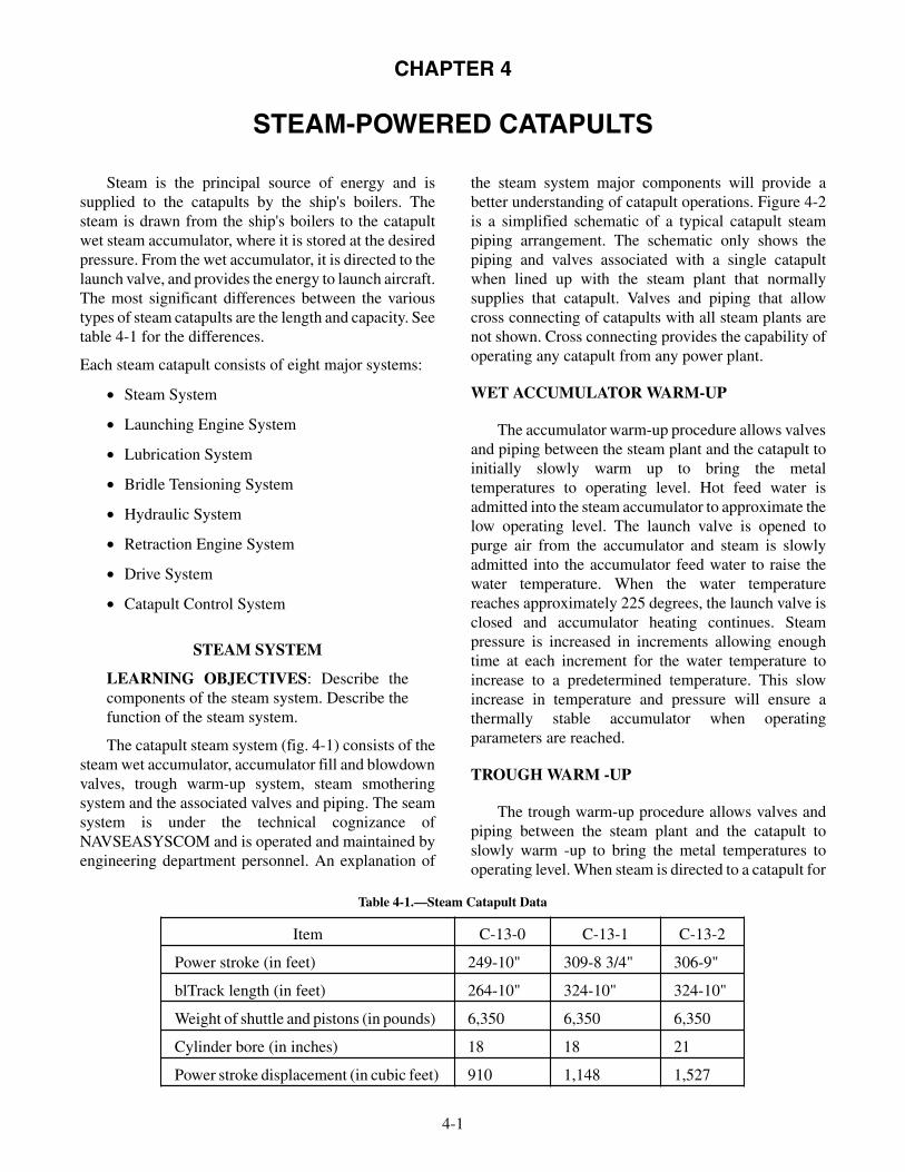
CHAPTER 4
STEAM-POWERED CATAPULTS
Steam is the principal source of energy and issupplied to the catapults by the ship's boilers. Thesteam is drawn from the ship's boilers to the catapultwet steam accumulator, where it is stored at the desiredpressure. From the wet accumulator, it is directed to thelaunch valve, and provides the energy to launch aircraft.The most significant differences between the varioustypes of steam catapults are the length and capacity. Seetable 4-1 for the differences.
Each steam catapult consists of eight major systems:
• Steam System
• Launching Engine System
• Lubrication System
• Bridle Tensioning System
• Hydraulic System
• Retraction Engine System
• Drive System
• Catapult Control System
STEAM SYSTEM
LEARNING OBJECTIVES: Describe thecomponents of the steam system. Describe thefunction of the steam system.
The catapult steam system (fig. 4-1) consists of thesteam wet accumulator, accumulator fill and blowdownvalves, trough warm-up system, steam smotheringsystem and the associated valves and piping. The seamsystem is under the technical cognizance ofNAVSEASYSCOM and is operated and maintained byengineering department personnel. An explanation of
the steam system major components will provide abetter understanding of catapult operations. Figure 4-2is a simplified schematic of a typical catapult steampiping arrangement. The schematic only shows thepiping and valves associated with a single catapultwhen lined up with the steam plant that normallysupplies that catapult. Valves and piping that allowcross connecting of catapults with all steam plants arenot shown. Cross connecting provides the capability ofoperating any catapult from any power plant.
WET ACCUMULATOR WARM-UP
The accumulator warm-up procedure allows valvesand piping between the steam plant and the catapult toinitially slowly warm up to bring the metaltemperatures to operating level. Hot feed water isadmitted into the steam accumulator to approximate thelow operating level. The launch valve is opened topurge air from the accumulator and steam is slowlyadmitted into the accumulator feed water to raise thewater temperature. When the water temperaturereaches approximately 225 degrees, the launch valve isclosed and accumulator heating continues. Steampressure is increased in increments allowing enoughtime at each increment for the water temperature toincrease to a predetermined temperature. This slowincrease in temperature and pressure will ensure athermally stable accumulator when operatingparameters are reached.
TROUGH WARM -UP
The trough warm-up procedure allows valves andpiping between the steam plant and the catapult toslowly warm -up to bring the metal temperatures tooperating level. When steam is directed to a catapult for
4-1
Item C-13-0 C-13-1 C-13-2
Power stroke (in feet) 249-10" 309-8 3/4" 306-9"
blTrack length (in feet) 264-10" 324-10" 324-10"
Weight of shuttle and pistons (in pounds) 6,350 6,350 6,350
Cylinder bore (in inches) 18 18 21
Power stroke displacement (in cubic feet) 910 1,148 1,527
Table 4-1.—Steam Catapult Data

4-2
LAUNCHING VALVEASSEMBLY
PRESSURE-BREAKINGORIFICE ELBOW
EXHAUST VALVE
STEAM CUTOFFPRESSURE SWITCHES
STEAM SUPPLY FROMSHIP'S BOILERS
NAVSHIPSSYSCOM STEAMWET-RECIEVER SYSTEM
WATER-CHARGING VALVEWATER SUPPLY
STEAMFILL
VALVE
ABEf0402
THRUST-EXHAUSTUNIT
Figure 4-1.—Steam system.
DEAERATINGFEED TANK
RELIEFVALVE
STEAM FROM ENGINEERING PLANT
SUPPLYVALVE
(ST
EA
M)
CROSS CONNECTLINE TO OTHERSTEAM PLANTS
MANUALSHUTOFF
VALVEACCUMULATOR FILL VALVES
FEED WATERBLOWDOWN VALVE
CATAPULTWET
ACCUMULATOR
FEED WATERFILL VALVE
STEAMBLOWDOWN
VALVE
ABEf0403
STEAM SMOTHERING LINETO CATAPULT TROUGH
FINNEDTUBING INCATAPULTTROUGHFOREXTERNALPREHEATING
(STEAM) TO CATAPULTLAUNCH VALVE
Figure 4-2.—Steam system schematic.

accumulator warm-up, steam is available through abranch line and valves to the trough warm-up system(fig. 4-3). The launching engine cylinders are heated tooperating temperature by a pair of trough heaterslocated below each row of launching engine cylinders.The rough heaters are installed in two sections referredto as the forward and aft legs. Each trough heaterconsists of a pipe within a larger pipe that is capped atthe forward end. Steam is admitted into the inner pipe,them flows through the inner pipe into the outer pipe,heating the outer pipe. Fins installed on the outer pipeprovide even radiation of heat to the launching enginecylinders, condensation from each outlet pipe isremoved by drains lines which are equipped with fixedorifices. The orifices are sized so that water is removedat a rate that will maintain enough steam flow to heatand maintain the launching engine cylinders atoperating temperature, bypass valves are providedaround each orifice to remove excess water if required.
STEAM SMOTHERING SYSTEM
The steam smothering system (see fig. 4-3)provides a rapid means of extinguishing a fire in thecatapult trough or in the launch valve compartment.The launch valve steam smothering is accomplished byadmitting steam into a pair of lines encircling thelaunch valve area, holes in these lines direct steam tocover the area.
Trough steam smothering is accomplished byadmitting main steam into a pipe located between thelaunching engine cylinders, holes in the pipe directseam to all of the trough area. Trough steam smotheringcan be actuated pneumatically by a valve at deckedge ormanually by a bypass valve located near thepneumatically operated steam supply valve.
WET ACCUMULATOR OPERATION
The steam accumulator provides a volume of steamunder pressure to the launch valve assembly. Atoperating temperatures, when the launch valve opensand steam is released to the launch engine cylinders,steam pressure within the accumulator drops, when thepressure drop in the accumulator occurs, the steam fillvalve open and admit steam into the accumulator bymeans of a perforated manifold submerged in the water,this will rapidly heat the water back to the operatingtemperature. Water level will return its pre-establishedlevel.
LAUNCHING ENGINE SYSTEM
LEARNING OBJECTIVES: Describe thecomponents of the launching engine system.Describe the function of the launching enginesystem.
4-3
ABEf0404
CATSTEAMSUPPLY
COMPTSTEAM
SMOTHER
CONSTANT STEAMHEATING SUPPLY
CAT DKEDGE STA
RESERVOIRNOT ON ALL
INSTALLATIONS
THROUGH HEATFINNED PIPES
(AFT LEGS)
TO FWDLEGS
FROM FWDLEGS
STEAM SMOTHERINGPIPING
ORIFICE
TO SERVICESTM DRAIN
DISCH OVBDTO ATMO
TO HPDRAINS
Figure 4-3.—Trough heat and steam smothering.

The launching engine system (fig. 4-4) consists ofmost of the major components that are used in applyingsteam to the launching engine pistons during launchoperation and stopping the launch engine pistons at thecompletion of a launch. The major components thatcomprise the launching engine system are as follows:
• Launch Valve Assembly
• Thrust/Exhaust Unit
• Launch Valve Control Valve
• Exhaust Valve Assembly
• Pressure Breaking Orifice Elbow Assembly
• Keeper Valve
• Launch Valve Hydraulic Lock valve PanelAssembly
• Exhaust Valve Hydraulic Lock Valve
• Launching Engine Cylinders
• Cylinder Covers
• Sealing Strip
• Sealing Strip Tensioner Installation
• Sealing Strip Anchor and Guide
• Launching Engine Pistons
• Shuttle Assembly
• Water Break Installation
• Water break Piping and Pressure SwitchInstallation
• Steam Cutoff Switch Installation
LAUNCH VALVE ASSEMBLY
The launch valve assembly (fig. 4-5) is locatedbetween the two steam lines from the steamaccumulator and the thrust/exhaust unit. Its consistsmainly of a steam valve assembly, a hydraulic cylinderassembly, an operation control assembly, and thelaunch valve stroke timer electrical installation. Aclosed plate and an open plate are located on theoperation controls frame and an increment plate islocated on the operation controls crosshead. Theposition of the valve can be determined by therelationship of the increment plate to the closed andopen plates.
4-4
SEALING STRIP
CYLINDER COVER
SEALING-STRIPANCHOR
THRUST-EXHAUSTUNIT (REF)
EXHAUST VALVE
PRESSURE-BREAKINGORIFICE ELBOW
LAUNCHING-ENGINECYLINDER
PISTONASSEMBLY
WATERBREAK
SHUTTLE
SHUTTLETRACK
SEALING-STRIPTENSIONER
LAUNCHING VALVEASSEMBLY
ABEf0405
Figure 4-4.—Launching engine system (typical).

4-5
STEAM VALVE
HYDRAULICCYLINDER
LV-STROKE-TIMERSTOP TIMING LIMIT
SWITCH(CLOCK NO. 2)
COLUMN
LV-STROKE-TIMER STOPTIMING LIMIT
SWITCH(CLOCK NO. 1)
OPERATIONCONTROLSASSEMBLY
LV-STROKE-TIMERSTART TIMING PRESSURE
SWITCH
CLOSEDPLATEOPEN
PLATE
INCREMENTPLATE
ABEf0406
Figure 4-5.—Launch valve assembly (rotary).
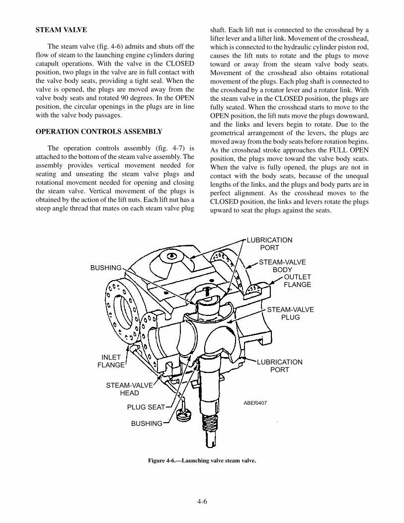
STEAM VALVE
The steam valve (fig. 4-6) admits and shuts off theflow of steam to the launching engine cylinders duringcatapult operations. With the valve in the CLOSEDposition, two plugs in the valve are in full contact withthe valve body seats, providing a tight seal. When thevalve is opened, the plugs are moved away from thevalve body seats and rotated 90 degrees. In the OPENposition, the circular openings in the plugs are in linewith the valve body passages.
OPERATION CONTROLS ASSEMBLY
The operation controls assembly (fig. 4-7) isattached to the bottom of the steam valve assembly. Theassembly provides vertical movement needed forseating and unseating the steam valve plugs androtational movement needed for opening and closingthe steam valve. Vertical movement of the plugs isobtained by the action of the lift nuts. Each lift nut has asteep angle thread that mates on each steam valve plug
shaft. Each lift nut is connected to the crosshead by alifter lever and a lifter link. Movement of the crosshead,which is connected to the hydraulic cylinder piston rod,causes the lift nuts to rotate and the plugs to movetoward or away from the steam valve body seats.Movement of the crosshead also obtains rotationalmovement of the plugs. Each plug shaft is connected tothe crosshead by a rotator lever and a rotator link. Withthe steam valve in the CLOSED position, the plugs arefully seated. When the crosshead starts to move to theOPEN position, the lift nuts move the plugs downward,and the links and levers begin to rotate. Due to thegeometrical arrangement of the levers, the plugs aremoved away from the body seats before rotation begins.As the crosshead stroke approaches the FULL OPENposition, the plugs move toward the valve body seats.When the valve is fully opened, the plugs are not incontact with the body seats, because of the unequallengths of the links, and the plugs and body parts are inperfect alignment. As the crosshead moves to theCLOSED position, the links and levers rotate the plugsupward to seat the plugs against the seats.
4-6
BUSHING
LUBRICATIONPORT
STEAM-VALVEBODY
OUTLETFLANGE
STEAM-VALVEPLUG
LUBRICATIONPORT
BUSHING
PLUG SEAT
STEAM-VALVEHEAD
INLETFLANGE
ABEf0407
Figure 4-6.—Launching valve steam valve.

HYDRAULIC CYLINDER ASSEMBLY
The hydraulic cylinder assembly (fig. 4-8) isconnected to the operation control assembly. Thehydraulic cylinder assembly is actuated by pressurized
hydraulic fluid to open and close the steam valveassembly. When pressurized fluid is applied to port E,the piston moves to the opposite end of the cylinder toopen the steam valve. The rate of movement of thepiston is faster at the beginning of the stroke, because of
4-7
FRAME
LIFTERLINK
LIFTER LEVER
LIFT NUT
THRUST RINGADJUSTING NUT
HEAD-COVERPLATE
ROTATORLEVER
ROTATORLINK
CROSSHEAD
ABEf0408
Figure 4-7.—Launch valve operation control assembly.
ORIFICESNUBBER
PISTON
CYLINDER
FLANGE
PISTON ROD
PORT E(OPENING PORT)
METERING ROD
PORT A(CLOSING PORT)
PORT B
FLANGE
ABEf0409
Figure 4-8.—Launch valve hydraulic cylinder.

the effect of the metering rod. At the beginning of theopening stroke, fluid flows out of port A and port B.When the piston has moved approximately 1 inch intothe cylinder, the metering rod shuts off the flow of fluidfrom within the cylinder to port B. At the end of theopening stroke, the orifice snubber controls the escapeof fluid from the cylinder, this prevents the movingparts from slamming to a stop and possibly beingdamaged.
When pressurized fluid is applied to port A, thepiston moves toward the opposite end of the cylinder toclose the steam valve. At the end of the closing stroke,the tapered end of the piston rod enters the flange. Thisprevents the moving parts from slamming to a stop andpossibly being damaged.
LAUNCH VALVE STROKE TIMERELECTRICAL SYSTEM
The launch valve stroke timer electrical system (seefig. 4-5) provides a means of measuring the launchvalve performance by timing the stroke from fullyclosed position to the point at which the crosshead hasmoved 9 inches. When the catapult is fired, fluidpressure from the hydraulic cylinder opening port Eactuates the start timing pressure switch. This starts two
clocks which measure and displays time in seconds andhundredths of seconds. When the valve opens 3 1/2inches, a limit switch on the crosshead opens and clocknumber one stops and display time elapsed. At the9-inch stroke, a second switch opens, stopping anddisplaying elapsed time.
The timer clocks are located on the main controlconsole for CV-64, CVN-65, and CV-67 and the centralcharging panel for CVN-68 through CVN 76.Variations in the launching valve stroke rates mayseriously affect catapult performance. The launchingvalve stroke timers provide a means of detectingdifferences in the launching valve stroke. Deviations inthe launching valve stroke can be detected bycomparing current timer readings with previouslyestablished timer readings.
THRUST EXHAUST UNIT
The thrust/exhaust units (fig. 4-9) absorbs thethrust of the launch engine pistons and shuttleassembly, connects the launch valve to the powercylinders and to the exhaust valve, anchors the aft endof the launching, engine and prevents aft expansion ofthe launching engine cylinders.
4-8
STEAM FROM
LAUNCHING VALVE
ASSEMBLY
STEAM TO AND FROM
LAUNCHING-ENGINE
CYLINDERS
STEAM TOEXHAUST VALVE
ABEf0410
Figure 4-9.—Thrust exhaust unit.

In ships preceding CV-67, a thrust unit anchors theaft end of the launching engine and connects the steamaccumulator to the launch valve. An exhaust teemounted between the launch valve and the aft powercylinders also provides connection to the exhaust valve.
CAPACITY SELECTOR VALVE (CSV)
The CSV (fig. 4-10) provides the means of varyingthe energy output of the catapult by controlling theopening rate of the launch valve for aircraft of varioustypes and weights. An electric motor unit assembly isused to position the CSV spindle, which meters theflow of fluid from the operating cylinder when thelaunch valve is opening, changing the valve setting fordifferent capacity launchings. A handwheel is providedto change the valve setting should the automatic controlbecome inoperative. For complete informationconcerning the CSV assembly, refer to technicalmanual NAVAIR 51-15ABE-1.
LAUNCH-VALVE CONTROL VALVE
The launching-valve control valve (fig. 4-11)directs pressurized hydraulic fluid to the launch valvehydraulic cylinder to open or close the launch valve.The control valve consists of a valve body enclosed onboth ends by glands. A piston within the valve dividesthe control valve into seven chambers. Piping connectseach chamber of the control valve to other components.As the launching valves go through their opening andclosing cycles, fluid is being directed to the operatingchambers by the action of the sliding piston, lining upthe ports and allowing pressurized fluid to enter onechamber while venting the other chamber to gravity. Atailrod is attached to each end of the piston. The tailrodsextend through the gland and provide a visualindication of the position of the control valve.Pressurized fluid used to shift the control valve issupplied through the launch valve solenoid-operatedhydraulic lock valve.
4-9
ELECTRIC MOTOR
ENCODER
VENT VALVE
INSTRUCTIONPLATE
LUBRICATIONFITTING
REVOLUTIONCOUNTER
CAPACITYSELECTOR
VALVE OUTLET(PORT M)
INLET (PORT L)
DECLUTCH LEVER
MOTOR UNIT
LOCKPINLUBRICATION
FITTING
HANDWHEELABEf0411
ENCODER
Figure 4-10.—Capacity selector valve assembly.

BUTTERFLY EXHAUST VALVE
The butterfly exhaust valve (fig. 4-12) provide themeans to direct spent steam from the launching enginecylinders overboard after the launch valve closes at thecompletion of a launch. The exhaust valve is attached tothe bottom flange of the thrust/exhaust unit or exhausttee; it consists primarily of a valve body, a disc, and ahydraulic actuator. Prior to launch, hydraulic pressureis directed from the exhaust valve hydraulic lock valveto the closing port of the hydraulic actuator causing thepiston to move downward and the disk within the valvebody to move onto its seat. A switch is then actuatedthat energizes a portion of the electrical circuitry thatallows the launch sequence to continue. After a launch,when the launch valve closes, hydraulic pressure isdirected from the exhaust valve hydraulic lock valve tothe opening port of the hydraulic actuator causing thepiston to move upward and the disk within the valvebody to move off its seat and release the spent steamoverboard. The limit switch is released and allows for aportion of the electrical circuitry necessary to allowretraction of the launching engine pistons.
PRESSURE-BREAKING ORIFICE ELBOW
The pressure-breaking orifice elbow (fig. 4-13)prevents a buildup of steam pressure behind the
launching engine pistons when the launch valve isclosed. The pressure breaking orifice elbow is attachedto a flange on the thrust/exhaust unit or exhaust teeabove the exhaust valve assembly and contains anorifice that is large enough to allow the escape of launchvalve steam leakage but small enough to have nodetrimental effect on catapult performance. Any steam,which may leak through the closed launch valve whenthe exhaust valve is closed, is permitted to escapethrough the pressure-breaking orifice. This prevents abuild -up of pressure that could cause premature releaseof an aircraft from its holdback bar restraint.
KEEPER VALVE
The keeper valve (fig. 4-14) prevents the exhaustvalve from opening while the launch valve is open. Thekeeper valve is located in the piping between the launchand exhaust valve lock valves and the closing chamberof the exhaust valve actuator. The valve consists of ablock with an internal cylinder containing a movablepiston. The keeper valve is actuated by hydraulic fluidfrom the launch-valve hydraulic lock valve. When thelaunch valve opens, the piston of the keeper valve shiftsand blocks the flow of hydraulic fluid to the exhaustvalve hydraulic actuator. This prevents the exhaustvalve from opening until the launch valve is closed andthe keeper valve piston is shifted.
4-10
FROM OPERATING CYLINDERCLOSING CHAMBER
(PORT D)
FROM LAUNCHING-VALVEHYDRAULIC-LOCK VALVE
(PORT B)
PISTON
TO OPERATING CYLINDEROPENING CHAMBER
(PORT A)
FROM LAUNCHING-VALVEHYDRAULIC-LOCK VALVE
(PORT C)
PISTON CROSS SECTION
TO OPERATING CYLINDERCLOSING CHAMBER
(PORT E)
FROM MAIN HYDRAULICACCUMULATOR(PORT G)
TO GRAVITY TANK(PORT F)
ABEf0412
Figure 4-11.—Launch-valve control valve.
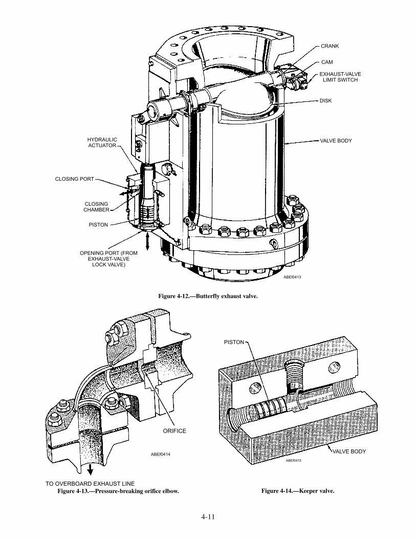
4-11
CRANK
CAM
EXHAUST-VALVELIMIT SWITCH
DISK
VALVE BODY
OPENING PORT (FROMEXHAUST-VALVE
LOCK VALVE)
PISTON
CLOSINGCHAMBER
CLOSING PORT
HYDRAULICACTUATOR
ABEf0413
Figure 4-12.—Butterfly exhaust valve.
ORIFICE
TO OVERBOARD EXHAUST LINE
ABEf0414
Figure 4-13.—Pressure-breaking orifice elbow.
PISTON
VALVE BODY
ABEf0415
Figure 4-14.—Keeper valve.

HYDRAULIC-LOCK-VALVE PANELS
There are two hydraulic-lock-valve panels, one forthe launch valve (fig. 4-15) and one for the exhaustvalve (fig. 4-16). The launch-valve hydraulic-lock-valve panel consists of two air-solenoid valves, ahydraulic lock valve with lock positioner, the launchpilot latch solenoid, and piping connections. Thelaunch-valve hydraulic lock valve (fig. 4-17) provides ahydraulic lock to hold the launch-valve control valve inthe FIRED position until launch is completed or untilthe launch-valve emergency cutout valve is placed inthe EMERGENCY position, by controlling the flow offluid to the launch-valve control valve.
The launch pilot latch solenoid controls a plungerthat prevents the lock valve from being shifted to theFIRED position unless the catapult control system is inthe FINAL READY phase of operation. (A manual lockscrew [fig. 4-17] is provided to secure the valve duringnonoperational periods.) When the catapult FIRE
circuit is energized, the fire air-solenoid valve directsair pressure to shift the lock valve to the fired position.This causes pressurized fluid to be directed from port Athrough port B to the launching-valve control valve, thekeeper valve, and port D via the launch-valveemergency cutout valve. Fluid pressure in port Dhydraulically locks the valve in the fired position.When the catapult LAUNCH COMPLETE circuit isenergized, the close launch valve air-solenoid directsair pressure to again shift the lock valve, venting port Dto gravity and directing pressurized fluid from port Athrough port C to the launch-valve control valve andclosing the launch valves. (During a HANGFIREcondition, port D is vented and port C is pressurizedwhen the launch-valve emergency cutout valve isplaced in its EMERGENCY position, ensuring that thelaunch valves remain closed.)
The exhaust-valve hydraulic-lock-valve panel (seefig. 4-16) consists of the exhaust-valve hydraulic lockvalve, two air-solenoid valves, and piping connections.
4-12
SOLENOID VALVE (FIRE SOLENOID FS)
MANUAL LOCK
LOCK POSITIONER
LAUNCHING-VALVEHYDRAULIC-LOCK-VALVE
HYDRAULIC-LOCK-VALVESOLENOID (LAUNCH-
PILOT-LATCH LPL)
INDICATOR FLAG
CAUTION PLATE
SOLENOID VALVE(CLOSE-LAUNCHING-VALVE
SOLENOID CL)
ABEf0416
Figure 4-15.—Launch-valve hydraulic-lock-valve panel.

4-13
EXHAUST-VALVEHYDRAULIC-LOCK-VALVE
SOLENOID VALVE (OPEN-EXHAUST-VALVE SOLENOID OE)
SOLENOID VALVE (CLOSE-EXHAUST-VALVE SOLENOID CE)
ABEf0417
Figure 4-16.—Exhaust-valve hydraulic-lock-valve panel.
PORT C
PISTON
MANUAL LOCK
LOCK POSITIONER(SHOWN IN UNLOCKED
POSITION)
HOLE FOR PLUNGER(FROM LPL SOLENOID)
FROM CLOSINGSOLENOID (CL)
PORT A
PORT BPORT D
FROM OPENING (FIRE)SOLENOID (FS)
PORT E
ABEf0418
Figure 4-17.—Launch-valve hydraulic lock valve.
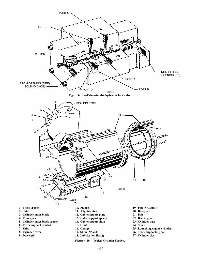
4-14
PORT E
PORT C
FROM CLOSINGSOLENOID (CE)
PORT A
PORT BPORT D
FROM OPENING (FIRE)SOLENOID (OE)
PISTON
ABEf0419
Figure 4-18.—Exhaust-valve hydraulic lock valve.
2
3
4
56
7
8
27
9
101112
13
14
15
16
17
18
19
20
2122
23 24
2526
SEALING STRIP
ABEf0420
1. Thick spacer2. Shim3. Cylinder outer block4. Thin spacer5. Cylinder outer-block spacer6. Cover support bracket7. Shim8. Cylinder cover9. Dowel pin
10. Flange11. Aligning ring12. Cable support plate13. Cable support spacer14. Cable support shim15. Guide16. Clamp17. Shim (NAVSHIP)18. Lubrication fitting
19. Pad (NAVSHIP)20. Baseplate21. Bolt22. Bearing pad23. Cylinder base24. Screw25. Launching engine cylinder26. Track supporting bar27. Cylinder slot
Figure 4-19.—Typical Cylinder Section.

The exhaust-valve hydraulic lock valve (fig. 4-18)opens and closes the exhaust valve by controlling theflow of hydraulic fluid to the exhaust-valve actuator.When the exhaust-valve open solenoid is energized, airpressure is directed to the opening side of the lockvalve, causing it to shift. This allows fluid to flow fromport A, out port B, through the keeper valve, and intothe opening chamber of the actuator. Fluid also flowsfrom port D to lock the valve in the OPEN position.When the exhaust-valve closed solenoid is energized,air pressure shifts the lock valve to the closed position,allowing fluid to flow from port A, out port C, and intothe closing chamber of the exhaust-valve actuator. Thevalve is locked in this position by pressure from port Aacting on the larger working area of the lock valvepiston.
LAUNCHING ENGINE CYLINDERS
Each catapult has two rows of launching enginecylinders (see fig. 4-4) mounted parallel to each other inthe catapult trough. Each row of cylinders is made up ofsections that are slotted on the top and flanged at eachend, with the number of sections determined by theoverall length of the catapult. The cylinder sections arebolted together at their flanges (fig. 4-19) by means oflong stud bolts, spacers, and nuts. The spacers and long
stud bolts are designed to minimize bolt failure due touneven thermal stress within the cylinders during pre-heating and operation. Each cylinder is identified by aserial number stamped on the outer surface of its flange.
Base pads are welded in the bottom of the catapulttrough at specified intervals to match the bearing padsfastened to the cylinder bases. Shims are then used toproperly align each cylinder section, and then thecylinder sections are secured to the trough base pads bybolts and clamps, which prevent the lateral movementof the cylinders while allowing smooth elongation ofthe cylinders due to thermal expansion. Lubricatorfittings are provided for lubrication of the slidingsurfaces.
CYLINDER COVERS
The cylinder cover (fig. 4-20) acts as clampsholding the slotted portion of the cylinder in position toprevent radial spreading when steam pressure isapplied. Space is provided in the cylinder covers for thesealing strip. Lubrication oil is supplied to thelaunching engine cylinders through lubrication portsand lubricators in each cover. Cylinder cover supportbrackets, screwed to the cylinder, hold the cylindercover in place. Cover seals are used to seal and maintainalignment of each cylinder cover section.
4-15
COVER SUPPORTBRACKET
TIE BOLT
PLUGGED PORT
PLUGGED PORT
PLUGGED PORT
LUBRICATOR
LUBRICATOR
LUBRICATOR
REAR COVER
CYLINDERCOVER SEAL
SCREW
67-INCHINTERMEDIATECOVER
FORWARDCOVER
12-FOOTINTERMEDIATECOVER
ABEf0421
Figure 4-20.—Launching engine cylinder covers.

CYLINDER SEALING STRIPS
The sealing strip (fig. 4-21) prevents the loss ofsteam from the cylinders by sealing the space betweenthe cylinder lip and the cylinder cover. As the steampiston assemblies move through the cylinders, the
piston connectors lift the sealing strips and the sealingstrip guides reseat them. Action of the sealing strip isshown in figure 4-22. View A shows the strip positionforward of the piston assembly. View B shows theconnector lifting the strip to permit the piston-shuttleconnector to pass under it. View C shows the guide
4-16
SHUTTLE SEALING STRIP
RIGHT-HANDEDCYLINDER
TROUGH
LEFT-HANDEDCYLINDER
PISTONASSEMBLY
ABEf0422
CYLINDERCOVER
Figure 4-21.—Cross section of launching engine cylinders (typical).
CYLINDER COVER SEAL
GUIDE
CYLINDER COVER
CONNECTOR
SEALING STRIP
CYLINDER SHUTTLE
E D C B A
ABEf0423
Figure 4-22.—Sealing strip action.

re-laying the strip into its sealing position. View Dshows the final step in seating. View E shows the stripfully seated with steam pressure keeping it seated.
SEALING STRIP TENSIONER
The sealing strip tensioner (fig. 4-23) is mountedon the end of the most forward cylinder cover on eachcylinder. It applies constant tension to the sealing stripand holds the forward end of the strip in place. Thetensioning force applied to the sealing strip is provided
by a compressed spring. This force is transmitted to thesealing strip through the tensioner guide, which is freeto slide back and forth on rollers.
SEALING STRIP ANCHOR AND GUIDEINSTALLATION
The sealing strip anchor and guide installation (seefig. 4-24) is mounted on the forward flange of eachthrust/exhaust unit or exhaust tee. It anchors the afterend of the sealing strip by gripping the strip between a
4-17
SPRING ROLLER GUIDE
SEALING STRIP (REF)
SEALING - STRIPCONNECTING LINK
GUIDE LINK
ABEf0424
Figure 4-23.—Sealing strip tensioner.
SEALINGSTRIP (REF)
SLEEVE
CAP
JAWCOVER
ABEf0425
Figure 4-24.—Sealing strip anchor and guide.

set of jaws wedged into a hollow sleeve and held inplace by a threaded cap
STEAM PISTON ASSEMBLY
The launching engine piston assembly (see fig.4-25) consists of left and right hand launching pistonsand attaching parts. The launching engine pistons areinstalled side by side in the launching engine cylindersthe shuttle assembly provides the connection for onelaunching piston to the other along with the connectionto the aircraft. The pressurized steam in the launchingengine cylinders drives the launching engine steampiston assemblies. They, in turn, drive the shuttle.Component parts of each piston assembly are the steampiston, the barrel, the connector, the strip guide, thepiston guide, and the tapered spear
The barrel serves as the chassis for the othercomponents of the assembly. The piston is bolted to theaft end of the barrel; the piston rings installed on thepiston seal the space between the piston and thecylinder wall. The cylinder cover segmented sealassembly acts as an extension of the piston into andthrough the cylinder slot. This seal assembly consists ofa housing, three upper seal segments, and six lower sealsegments. The upper seal segments press against thecylinder covers, and the lower seal segments pressagainst the sides of the cylinder slot to prevent the lossof steam pressure from behind the steam pistons as thepiston assemblies move through the cylinders during
the power stroke. The connector and the strip guide arebolted to the top of the barrel. The connector lifts thesealing strip off its seat to permit passage of the shuttleassembly along the cylinder. The strip guide returns thesealing strip to its seat after the connector passes underit, minimizing loss of steam pressure as the pistonassembly advances through the power stroke. Inaddition, the connector has interlocking "dogs," whichcouple with matching "dogs" on the shuttle assembly toeffect the connection between the connectors and theshuttle assembly.
The tapered spear and bronze piston guide arebolted to the forward end of the barrel. The piston guideacts as a bearing surface for the piston assembly andkeeps it centered with respect to the cylinder walls. Thetapered spear works in conjunction with thewater-brake cylinder assemblies to stop the pistonassemblies and shuttle at the end of the power stroke.
SHUTTLE ASSEMBLY
The shuttle assembly (see fig. 4-26) carries theforward motion of the pistons to the aircraft by meansof a launch bar attached to the aircraft nose gear andconnected to the nose gear launch shuttle spreader. Themeshing of interlocking “dogs” of the piston assemblyconnectors and the shuttle frame connect the shuttleand the piston assemblies.
The shuttle is essentially a frame mounted onrollers. Two pairs of rollers fitted with roller bearings
4-18
NUT
BOLTCOTTER PIN
RUBBINGSTRIP
CONNECTOR
DEFLECTORRING
SPEAR
SUPPORTGUIDE
BOLT
PISTONGUIDE
STUD
BARREL
PISTON
CYLINDERCOVER SEAL
SEALING-STRIPGUIDE
ABEf0426PISTONRINGS
Figure 4-25.—Launching engine steam piston assembly.

are installed on hubs mounted at each end of the shuttleframe. The shuttle is installed in a track between andabove the launching engine cylinders. The troughcovers form the shuttle track, which supports andguides the shuttle.
The bearings of the rollers are lubricated throughfittings, which are accessible through the slot in theshuttle track. The shuttle blade is part of the shuttle
frame and is the only part that protrudes above theshuttle track. The nose gear launch spreader is attachedto the shuttle blade.
WATER-BRAKE CYLINDERS
The water-brake cylinders (fig. 4-27) are installedat the forward end of the launching engine cylinders.
4-19
BRIDLE SPREADER
GUIDESRAMP
PINFRAME
DOGS
RETAINERNUT
ROLLER
REAR SWEEPERPLATE AND CLEVIS
NOSE GEAR LAUNCHSPREADER
ABEf0427
Figure 4-26.—Shuttle assembly.
LAUNCHINGENGINE CYLINDER
JET RINGCHOKE RING
FWD
END PLUG
CHOKE
VANE
ANNULUS RING
STRIKER RINGWATERSUPPLY
ABEf0428
Figure 4-27.—Water-brake cylinder installation.

The water brakes stop the forward motion of the shuttleand pistons at the end of the catapult power stroke. Theafter end of each water-brake cylinder is supported andaligned by the most forward section of each launchingengine cylinder, which telescopes over the after end ofthe water-brake cylinder. The forward end of eachcylinder is anchored in place by an upper bracket andlower support saddle and chock.
The open end of each cylinder holds four rings.They are the choke ring, the annulus ring, the jet ring,and the striker ring.
The choke ring is the innermost ring and is threadedinto the water-brake cylinder. The annulus ring hasangled holes machined in it to direct pressurized waterinto the cylinder and forms a vortex (whirlpool) at theopen end of the cylinder. The jet ring is bolted to the endof the cylinder and holds the annulus ring in place. Thestriker ring, the outermost of the four rings, aredesigned to absorb the impact of any metal-to- contactbetween the launching engine piston assemblies andthe aft end of the water brakes.
WARNING
To prevent damage to the water brakes andpiston assembly components, a water-brakepump must be running any time the shuttle andpiston assemblies are not fully bottomed in thewater brakes.
A vane is keyed to the end plug (see fig. 4-27). Itspurpose is to break up the vortex caused by the annulusring and to create a solid head of water in the cylinder,
which is maintained by the continued vortex action atthe mouth of the cylinder.
Braking action occurs at the end of the power runwhen the tapered spear on the piston assembly entersthe water brake. Water in the brake is displaced by thespear and forced out the after end of the cylinderbetween the choke ring and the spear (fig. 4-28). Sincethe spear is tapered, the space between the choke ringand the spear is gradually decreased as the spear movesinto the brake cylinder. This arrangement provides acontrolled deceleration and energy absorption, whichstops the piston assembly within a distance of about 5feet without damage to the ship's structure.
WATER-BRAKE TANK
The water-brake tank is installed below thewater-brake cylinders to supply water to and reclaimwater spillage from the water brakes during operation.It has a minimum capacity of 3,000 gallons of freshwater. Overflow and oil-skimming funnels and bottomdrains are provided in the tank to maintain proper waterlevel and to remove excess oil used in the lubrication ofthe launching engine cylinders.
WATER-BRAKE PUMPS
Water is supplied to the water-brake cylinders bytwo electric-motor-driven, rotary-vane-type pumpsinstalled in the immediate vicinity of the water-braketank. They are capable of producing 650 gallons ofwater per minute at 80 psi. The pumps are electricallyinterlocked so that if the running pump breaks down,
4-20
PISTON SPEARWATER BRAKE CYLINDER
ABEf0429
Figure 4-28.—Water brakes.

the alternate pump automatically starts running. Agauge board within the pump room contains gauges forpump suction and discharge pressure and for measuringthe water pressure at the connectors (elbow pressure).
WATER-BRAKE WATER SUPPLY PIPING
The suction inlets of the pumps (fig. 4-29) aresubmerged in the water-brake tanks. The pumpdischarges each with appropriate valves and aflow-limiting orifice plate, are tied together andconnected via flexible hoses to strainer flanges at thebottom of the water supply pipes. Hoses and rigidpiping connect the pressure switches to the supplypipes. A pump suction gauge and a pump dischargegauge are located on the gauge panel for each pump.These are in addition to the gauges for the pressuresensing switches. The suction side of the pump consistsof an inlet with a gate type shutoff valve, a gauge valve,and a Macomb strainer immediately ahead of the pumpinlet. A petcock for venting is mounted at the top of thestrainer. The discharge side of each pump includes aflow limiting orifice plate, a check valve, and a gatetype shutoff valve. Two discharge lines merge into a
single line, which later splits into two lines.High-pressure, flexible hoses lead to and connect to thebrake cylinder water supply connectors, which areattached to the water-brake cylinders. A drain valve forthe water-brake tank leads to an overboard discharge.Fresh water from the ship's system is added to the tankvia fill and shutoff valves in the water-brake pumproom.
WATER-BRAKE PRESSURE-SENSINGSWITCHES
Two pressure switches are connected to the pipingleading from the pumps to the brake cylinders (see fig.4-29). They usually are installed on the bulkheadadjacent to the tank. The switches are electrically tiedin with the main control console/ICCS/CCP to preventoperation in case the pressure falls below normal. Waterpressure keeps the switch contacts closed, thuscompleting a circuit. Should the pressure fall belownormal, either one or both of the switches will dropopen, breaking the circuit. There are also two pressuregauges in the lines to give a visual indication of thepressure, commonly referred to as "elbow pressure."
4-21
STRAINER VALVEPRESSURESENSING HOSES
GAUGEPANELPRESSURE
SWITCHES
TO CHARGE PANEL
GATE VALVE MACOMBSTRAINER
MACOMBSTRAINER
CHECK VALVES
GATEVALVE
PUMPNO. 2
PUMPNO. 1
GATE VALVE
DRAIN COCKS
THERMOMETER
ORIFICE FLANGES
MOTORCONTROLLERS
GATEVALVE
BAFFLES
STRAINERS
PLATFORMFLEX HOSES
OVERFLOW FUNNEL
SKIMMING FUNNEL
FLIGHT DECK
OVERBOARD DRAIN
WATER LEVEL
ABEf0430
FILL FUNNEL
Figure 4-29.—Water-brake piping and pressure switch installation.

STEAM CUTOFF PRESSURE-SWITCHINSTALLATION
The steam cutoff switch installation (fig. 4-30)consists of two pressure switches and associated pipingmounted in an intrusion-proof enclosure. The steamcutoff pressure-switch installation is located at a pointin the catapult power stroke determined during thecatapult certification program. Flexible tubing connectsthe steam cutoff pressure switch assembly to a port inone of the launching engine cylinders. After thecatapult is fired, when the launching engine pistonpasses the port that is connected to the cutoff switches,steam pressure actuates each switch. This initiates the
launch complete phase of operation and the subsequentclosing of the launch valve. The pressure switches arepreset to close at an increasing pressure ofapproximately 20 psi and open at decreasing pressureof approximately 10 psi.
CATAPULT TROUGH INSTALLATION
The catapult trough installation (fig. 4-31) providesa means of covering the catapult trough and providing atrack within which the shuttle and grab rollers ride. Inaddition, it covers the launching engine componentsand seals the launch valve area from fluid spills anddebris.
4-22
ADAPTERFLANGE
DISK ORIFICE
INTRUSION-PROOFENCLOSURE (REF)
SWITCH
ABEf0431
Figure 4-30.—Steam cutoff pressure switches.
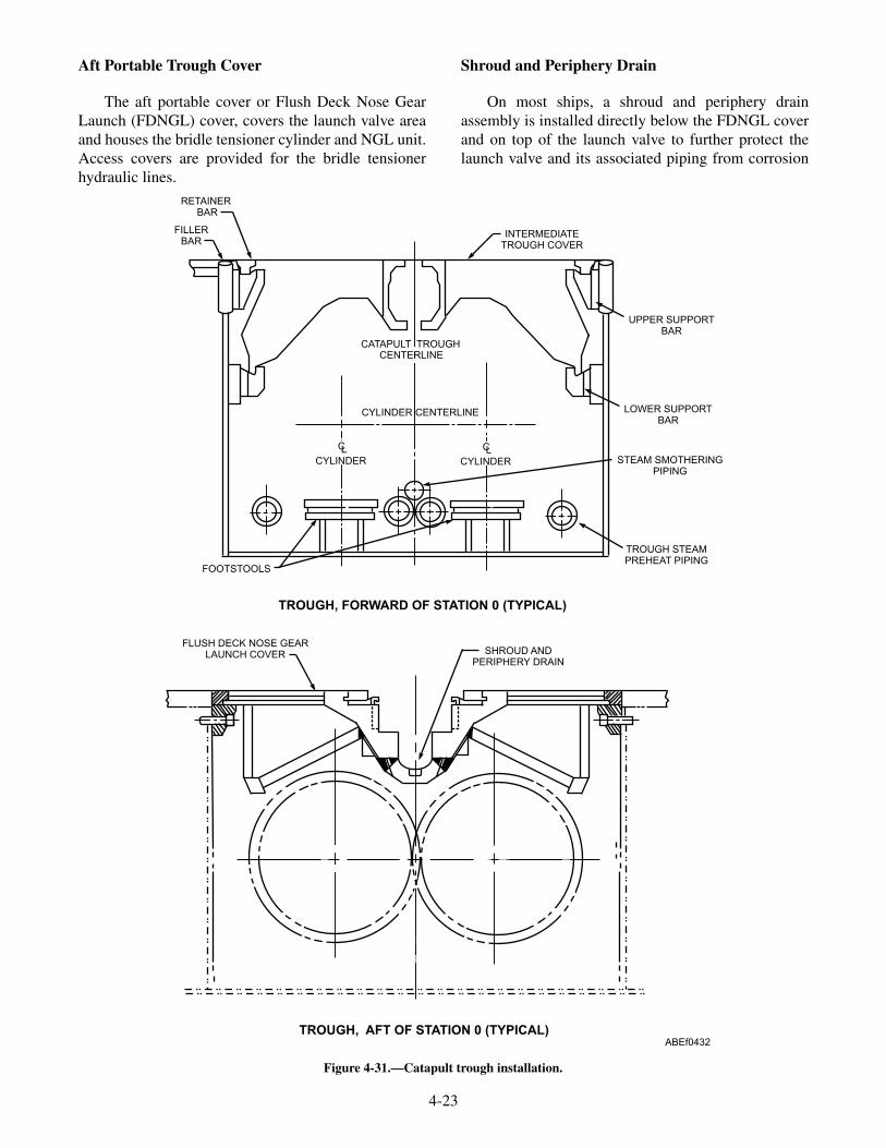
Aft Portable Trough Cover
The aft portable cover or Flush Deck Nose GearLaunch (FDNGL) cover, covers the launch valve areaand houses the bridle tensioner cylinder and NGL unit.Access covers are provided for the bridle tensionerhydraulic lines.
Shroud and Periphery Drain
On most ships, a shroud and periphery drainassembly is installed directly below the FDNGL coverand on top of the launch valve to further protect thelaunch valve and its associated piping from corrosion
4-23
RETAINERBAR
FILLERBAR
INTERMEDIATETROUGH COVER
CATAPULT TROUGHCENTERLINE
CYLINDER CENTERLINE
CLCYLINDER
CLCYLINDER
FOOTSTOOLS
UPPER SUPPORTBAR
LOWER SUPPORTBAR
STEAM SMOTHERINGPIPING
TROUGH STEAMPREHEAT PIPING
TROUGH, FORWARD OF STATION 0 (TYPICAL)
SHROUD ANDPERIPHERY DRAIN
FLUSH DECK NOSE GEARLAUNCH COVER
TROUGH, AFT OF STATION 0 (TYPICAL)ABEf0432
Figure 4-31.—Catapult trough installation.
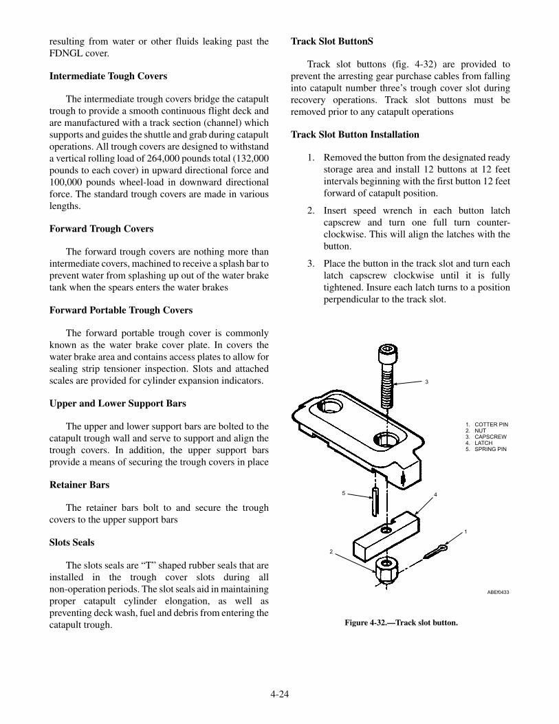
resulting from water or other fluids leaking past theFDNGL cover.
Intermediate Tough Covers
The intermediate trough covers bridge the catapulttrough to provide a smooth continuous flight deck andare manufactured with a track section (channel) whichsupports and guides the shuttle and grab during catapultoperations. All trough covers are designed to withstanda vertical rolling load of 264,000 pounds total (132,000pounds to each cover) in upward directional force and100,000 pounds wheel-load in downward directionalforce. The standard trough covers are made in variouslengths.
Forward Trough Covers
The forward trough covers are nothing more thanintermediate covers, machined to receive a splash bar toprevent water from splashing up out of the water braketank when the spears enters the water brakes
Forward Portable Trough Covers
The forward portable trough cover is commonlyknown as the water brake cover plate. In covers thewater brake area and contains access plates to allow forsealing strip tensioner inspection. Slots and attachedscales are provided for cylinder expansion indicators.
Upper and Lower Support Bars
The upper and lower support bars are bolted to thecatapult trough wall and serve to support and align thetrough covers. In addition, the upper support barsprovide a means of securing the trough covers in place
Retainer Bars
The retainer bars bolt to and secure the troughcovers to the upper support bars
Slots Seals
The slots seals are “T” shaped rubber seals that areinstalled in the trough cover slots during allnon-operation periods. The slot seals aid in maintainingproper catapult cylinder elongation, as well aspreventing deck wash, fuel and debris from entering thecatapult trough.
Track Slot ButtonS
Track slot buttons (fig. 4-32) are provided toprevent the arresting gear purchase cables from fallinginto catapult number three’s trough cover slot duringrecovery operations. Track slot buttons must beremoved prior to any catapult operations
Track Slot Button Installation
1. Removed the button from the designated readystorage area and install 12 buttons at 12 feetintervals beginning with the first button 12 feetforward of catapult position.
2. Insert speed wrench in each button latchcapscrew and turn one full turn counter-clockwise. This will align the latches with thebutton.
3. Place the button in the track slot and turn eachlatch capscrew clockwise until it is fullytightened. Insure each latch turns to a positionperpendicular to the track slot.
4-24
3
1. COTTER PIN2. NUT3. CAPSCREW4. LATCH5. SPRING PIN
5 4
1
2
ABEf0433
Figure 4-32.—Track slot button.

Track Button Removal
1. Turn the latch capscrew of each buttoncounterclockwise until the latches are alignedwith the buttons. The button can then be liftedout of the slot with the speed wrench.
2. Perform a count of the buttons to ensure theyhave all been removed.
3. Return the buttons to their storage cart andreturn the cart to their designated storage area.
4. Any missing or damaged button shall bereported to the catapult officer.
5. After the catapult slot has been cleared ofbuttons, stow the shuttle forward.
Cylinder Expansion Indicator
The cylinder expansion indicators (fig. 4-33)provide a flight deck visual indication of cylinderthermal expansion. There are two expansion indicators,each connected to the forward end of each launchingengine cylinder. The indicator support is fastened to thecylinder cover inner male guide, and supports thepointer assembly. The pointers normally extendthrough slots in the deck, but are spring loaded toprevent damage during deck access cover removal.Recessed in the deck beside each deck slot is a scalewith 0.10-inch graduations. The expansion indicatorsmove with the cylinders, and expansion can bemeasured directly by reading the scale beside thepointer.
4-25
3
2
7
6
5
4
1. Inner male guide2. Deck3. Slot
4. Scale5. Pointer assembly
6. Support7. 9-foot Cylinder
ABEf0434
Figure 4-33.—Expansion indicator.

4-26
MAGNETIC SENSORS
SHUTTLE MAGNETASSEMBLY
DESI CONSOLE
THERMALPRINTER
ABEf0435
CHANNEL 1 ENCODERJUNCTION BOX
DESI REMOTEREADOUT
INTERFACEJUNCTION BOX
2
Figure 4-34.—Digital endspeed indicator system.

Digital Endspeed Indicator System
The Digital Endspeed Indicator System (DESI)(fig. 4-34) provides a means for measuring theendspeed of the steam catapult shuttle during operation.The endspeed is measured when a shuttle-mountedmagnet passes three magnetic sensors mounted in thecatapult track near the water break end. The endspeed isdigitally displayed for visual readout on a consoleassembly. In addition, on CVN-68 through CVN-76, aremote readout is provided in the catapult officerconsole. A thermal printer permanently records thisalong with other information such as Capacity SelectorValve (CSV) setting, date, time, and shot count. Formore detailed information on the DESI installation,refer to technical manual NAVAIR 51-15ABE-2.
LUBRICATION SYSTEM
LEARNING OBJECTIVES: Describe thecomponents of the lubrication system.Describe the function of the lubricationsystem.
The lubrication system (fig. 4-35) provides a meansof lubricating the launching engine cylinder and sealingstrip prior to firing the catapult, by injecting lubricatingoil through the cylinder covers with a spray pattern thatensures even lubrication of the cylinder walls beforepassage of the launching engine pistons. The majorcomponents of the lubrication system consists of thefollowing:
LUBE PUMP MOTOR SET
The lube pump motor set delivers lube oil from thelube tank to the lube side of the metering pumps/injectors. The pump motor is left running continuouslyduring operations.
LUBE STORAGE TANK
The lube storage tank stores lubricating oil for usedduring operations. The lube oil tank holdsapproximately 220 gallons and is located in closeproximity to the lube pump. The lube oil tank is pipedto the ship’s lube oil stowage tank, which enables easyand convenient lube oil replenishment.
4-27
METERINGPUMP
RELIEFVALVE
RELIEFVALVE
CHECKVALVE
LUBE OILSUPPLY
GAUGE LINE
LUBECONTROL
VALVE
TO OTHERMETERING
PUMPS
TO OTHERMETERING
PUMPS
TO OTHERMETERING PUMPS
TO OTHERMETERING PUMPS
LP AIR
LUBE AIRSOLENOID
LUBEPUMP/MOTOR
LUBE TANK
TOGRAVITYTANK
TOOPPOSITEMETERINGPUMP
ABEf0436
FROMHYDACCUM-ULATOR
Figure 4-35.—Lubrication system.
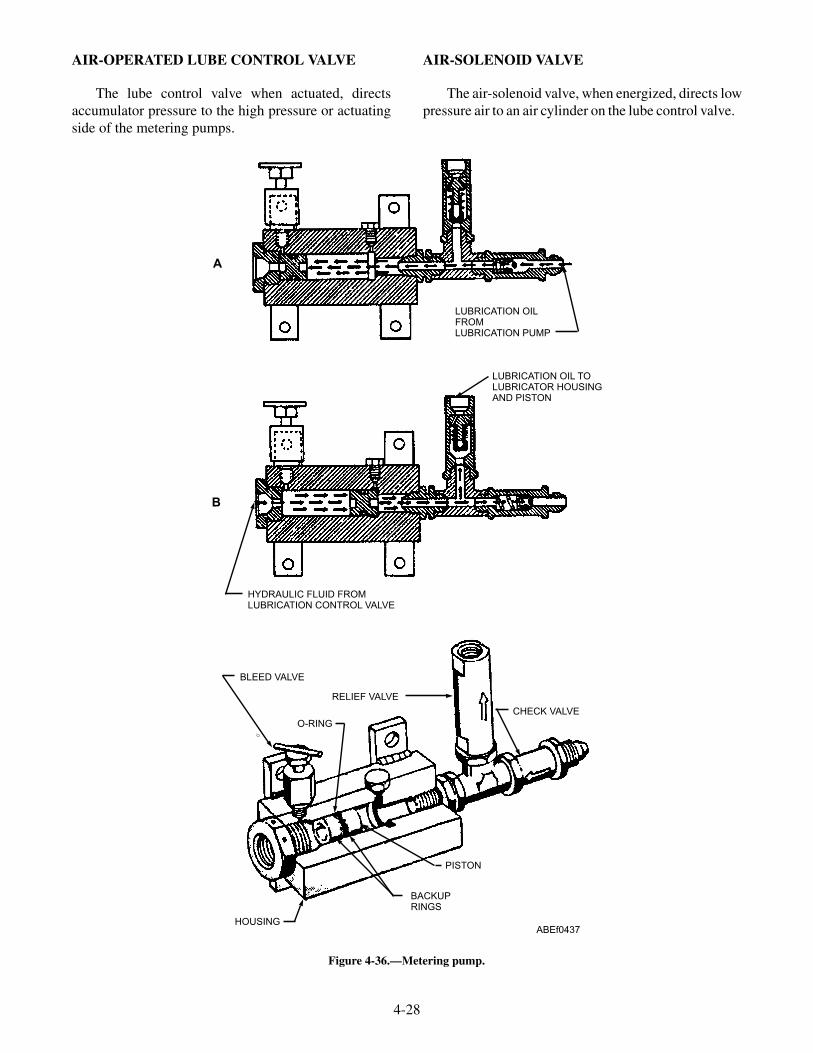
AIR-OPERATED LUBE CONTROL VALVE
The lube control valve when actuated, directsaccumulator pressure to the high pressure or actuatingside of the metering pumps.
AIR-SOLENOID VALVE
The air-solenoid valve, when energized, directs lowpressure air to an air cylinder on the lube control valve.
4-28
LUBRICATION OILFROMLUBRICATION PUMP
LUBRICATION OIL TOLUBRICATOR HOUSINGAND PISTON
HYDRAULIC FLUID FROMLUBRICATION CONTROL VALVE
B
A
BLEED VALVE
RELIEF VALVE
O-RING
CHECK VALVE
PISTON
BACKUPRINGS
HOUSINGABEf0437
Figure 4-36.—Metering pump.

METERING PUMPS
The metering pumps distribute lubricating oil to thelubricator housing located on the cylinder covers. Eachmetering pump contains a piston that separates themetering pump into two chambers, a high-pressurehydraulic chamber and a lube oil chamber.
LUBE OIL SYSTEM OPERATIONS
With the lube air solenoid deenergized, ac-cumulator pressure supplied to the lube control valve,acting on the differential area on the control valvepiston will keep the control valve shifted to the airchamber side of the control valve. This allows thehigh-pressure hydraulic side of the metering pumps(fig. 4-36) to be vented through the control valve to thegravity tank. With the lube pump running, the meteringpumps will fill with lube oil. When all metering pumpsare full, the lube oil pump discharge pressure willincrease to the pump relief valve setting (150-165).Pump discharge will now recirculate to the stowagetank while maintaining relief valve setting pressurethroughout the lube oil side of the system.
When the lube air solenoid is energized, it directslow pressure air to the air chamber of the lube controlvalve, overcoming the unbalanced control valve piston.Low pressure air shifts the control valve allowingaccumulator hydraulic pressure to be directed to thehigh-pressure hydraulic side of all the metering pumps(see fig. 4-36). The lube oil in the metering pumps isforced out through a relief valve and to the two injectorsin each of the cylinder covers. One lube injector directslube oil through the open cylinder slot and the otherinjector is angled to direct lube oil onto the sealingstrip.
BRIDLE TENSIONING SYSTEM
LEARNING OBJECTIVES: Describe thecomponents of the bridle tensioning system.Describe the function of the bridle tensioningsystem.
The bridle tensioning system (fig. 4-37) provides ameans of tightly connecting the aircraft to the shuttleprior to firing the catapult. The bridle tensioning systemis comprised of components that directly apply aforward force to the shuttle (external tension) and other
4-29
VENT VALVE
BRIDLE TENSIONER CYLINDER
BRIDLE TENSIONER FULLY-EXTENDED LIMIT SWITCH
BRIDLE TENSIONER FULL-AFTLIMIT SWITCH
HYDRAULIC FLUID LINE(RETURN TO GRAVITY TANK)
RELIEF VALVE
AIR LINE
PRESSUREREGULATOR
BRIDLE TENSIONER SURGEACCUMULATOR
TO TENSIONER-ACCUMULATORAIR-CHARGING
VALVE ATCHARGING PANEL
FROM MAINHYDRAULIC
ACCUMULATOR
FLUID SUPPLYSHUTOFF
VALVE
ORIFICE
BRIDLE TENSIONER CONTROLVALVE
TO TENSIONER-ACCUMULATOR-HYDRAULIC AND DOME-AIRPRESSURE DUPLEX GAUGE
AT CHARGING PANEL
ABEf0438
Figure 4-37.—Bridle tensioning system.
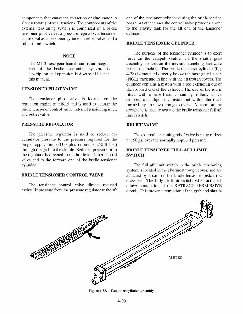
components that cause the retraction engine motor toslowly rotate (internal tension). The components of theexternal tensioning system is comprised of a bridletensioner pilot valve, a pressure regulator, a tensionercontrol valve, a tensioner cylinder, a relief valve, and afull aft limit switch.
NOTE
The Mk 2 nose gear launch unit is an integralpart of the bridle tensioning system. Itsdescription and operation is discussed later inthis manual.
TENSIONER PILOT VALVE
The tensioner pilot valve is located on theretraction engine manifold and is used to actuate thebridle tensioner control valve, internal tensioning inlet,and outlet valve.
PRESSURE REGULATOR
The pressure regulator is used to reduce ac-cumulator pressure to the pressure required for theproper application (4000 plus or minus 250-ft lbs.)through the grab to the shuttle. Reduced pressure fromthe regulator is directed to the bridle tensioner controlvalve and to the forward end of the bridle tensionercylinder.
BRIDLE TENSIONER CONTROL VALVE
The tensioner control valve directs reducedhydraulic pressure from the pressure regulator to the aft
end of the tensioner cylinder during the bridle tensionphase. At other times the control valve provides a ventto the gravity tank for the aft end of the tensionercylinder.
BRIDLE TENSIONER CYLINDER
The purpose of the tensioner cylinder is to exertforce on the catapult shuttle, via the shuttle grabassembly, to tension the aircraft launching hardwareprior to launching. The bridle tensioner cylinder (fig.4-38) is mounted directly below the nose gear launch(NGL) track and in line with the aft trough covers. Thecylinder contains a piston with a rod extending out ofthe forward end of the cylinder. The end of the rod isfitted with a crosshead containing rollers, whichsupports and aligns the piston rod within the trackformed by the two trough covers. A cam on thecrosshead is used to actuate the bridle tensioner full aftlimit switch.
RELIEF VALVE
The external tensioning relief valve is set to relieveat 150 psi over the normally required pressure.
BRIDLE TENSIONER FULL AFT LIMITSWITCH
The full aft limit switch in the bridle tensioningsystem is located in the aftermost trough cover, and areactuated by a cam on the bridle tensioner piston rodcrosshead. The fully aft limit switch, when actuated,allows completion of the RETRACT PERMISSIVEcircuit. This prevents retraction of the grab and shuttle
4-30
ABEf0439
Figure 4-38.—Tensioner cylinder assembly.

into an extended bridle tensioner piston rod. This limitswitch is also part of the MANEUVER AFT circuit.This circuit ensures that the tensioner piston rod is fullyaft, allowing the grab latch to remain locked to theshuttle in an aircraft-launch-abort situation.
Internal Tensioning Components
The internal tensioning is comprised of com-ponents that cause the retraction engine motor to slowlyrotate and consists of a pressure regulator, and a inletand outlet valve.
Pressure Regulator
The pressure regulator is used to reduce ac-cumulator pressure to the pressure required to move thegrab and shuttle forward (creep rate) a distance of sixfeet in 30-50 seconds.
Internal Tensioning Inlet and Outlet Valve
The internal tensioning inlet and outlet valvecontrols the flow of reduced pressure hydraulic fluid toand from the hydraulic motor and orifice bypass pipingduring the tensioning phase. When actuated by the
bridle tensioner pilot valve, reduced pressure hydraulicfluid flows through the inlet valve to the hydraulicmotor and orifice bypass piping. Hydraulic fluid fromthe motor and bypass piping is routed to the gravitytank through the outlet valve. This enables thehydraulic motor to rotate the drum slowly so that staticfriction in the retraction engine and drive system isovercome.
Internal Tension Relief Valve
The relief valve is set to relieve at 225 psi over thenormal internal tension pressure.
HYDRAULIC SYSTEM
LEARNING OBJECTIVES: Describe thecomponents of the hydraulic system. Describethe function of the hydraulic system.
The hydraulic system (fig. 4-39) suppliespressurized fluid to the hydraulic components of thecatapult. The system consists of a main hydraulicaccumulator, an air flask, three main hydraulic pumps,a booster pump and filter unit, a gravity tank, a 90gallon auxiliary tank, and a circulating pump.
4-31
TO MAIN HYDRAULICACCUMULATOR(NOT SHOWN)
DELIVERYCONTROL
UNIT
SUCTION LINESTRAINER
TO FLUID COOLER/GRAVITY TANK
MAIN HYDRAULIC PUMP
GRAVITY TANK
AUXILIARYTANK
FLUIDFILTER
CIRCULATINGPUMP
BOOSTER PUMP
BOOSTER PUMPFILTER
ABEf0440
Figure 4-39.—Retraction engine hydraulic system.

HYDRAULIC FLUID
The hydraulic fluid, MIL-H-22072, is 50 percentwater, which provides its fire resistance. The remaining50 percent is composed of a water-soluble polymer,which increases the viscosity of the water, the freezingpoint depressant, and selected additives that impartlubricant and corrosion protection. The red dye additiveprovides good visibility for leak detection. With use,the fluid loses water and volatile inhibitors. Water lossis indicated by an increase in the fluid viscosity. Loss ofinhibitors is indicated by a change in the pH number ofthe fluid. (External contamination will also cause achange in pH number.) Normal values for the viscosityand pH number of the unused fluid are as follows:
• Viscosity (fluid temp. 100°F): 185 to 210 SSU
• pH number: 8.8 to 9.8
MAIN HYDRAULIC ACCUMULATOR
The main hydraulic accumulator (fig. 4-40)consists of a vertical cylinder and a floating piston. Thepiston separates the accumulator into two chambers, afluid chamber on top and an air chamber on the bottom.
The accumulator provides hydraulic fluid undercontrolled pressure to all hydraulically operatedcatapult components. The bottom chamber of theaccumulator connects by piping to the air flask and thetop chamber is connected by piping to the hydraulicsystem. A stroke control actuator provides the means ofcontrolling main hydraulic pump delivery as required.A volume normal actuator mounted to the top flangeprovides protection from operating the catapult if thefluid volume is low.
STROKE-CONTROL ACTUATOR
The stroke-control actuator is mounted near thebottom of the main hydraulic accumulator cylinder.The actuator is a lever-operated cam that operates twolimit switches. The bottom limit switch controls theoperation of the primary pump, and the top limit switchcontrols the operation of the remaining two pumps.With the accumulator full of fluid, both on stroke camsare in the released position, deenergizing all pumpdelivery control solenoids. As fluid is used, air pressureraises the accumulator piston and the actuator rod moveupward. The on stroke cam for the primary pumpactuates first and that pump will deliver fluid to the
4-32
FLUID SIDE OFACCUMULATOR
VOLUME-NORMALACTUATOR ASSEMBLY
PISTON ASSEMBLYCAM
ARM
HYDRAULIC-ACCUMULATOR
VOLUMELIMIT SWITCH (S130)
CYLINDER
AIR SIDE OFACCUMULATOR
OFF-STROKECAM
ACTUATORROD
ON-STROKECAM
STROKE CONTROLLIMIT SWITCH
(S855) FORSECONDARY
PUMPS
STROKE CONTROLLIMIT SWITCH
(S857) FORPRIMARY PUMP
STROKE CONTROLACTUATOR ASSEMBLY
ABEf0441
Figure 4-40.—Main hydraulic accumulator.
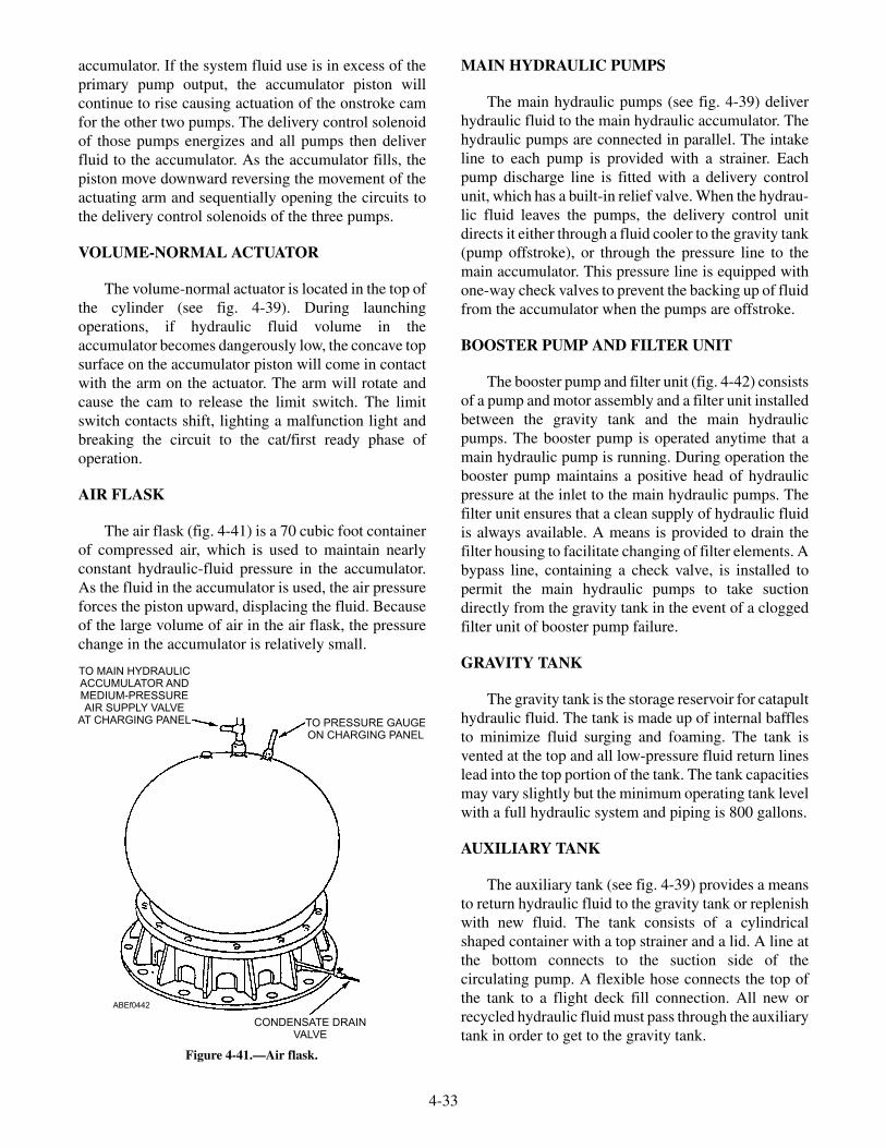
accumulator. If the system fluid use is in excess of theprimary pump output, the accumulator piston willcontinue to rise causing actuation of the onstroke camfor the other two pumps. The delivery control solenoidof those pumps energizes and all pumps then deliverfluid to the accumulator. As the accumulator fills, thepiston move downward reversing the movement of theactuating arm and sequentially opening the circuits tothe delivery control solenoids of the three pumps.
VOLUME-NORMAL ACTUATOR
The volume-normal actuator is located in the top ofthe cylinder (see fig. 4-39). During launchingoperations, if hydraulic fluid volume in theaccumulator becomes dangerously low, the concave topsurface on the accumulator piston will come in contactwith the arm on the actuator. The arm will rotate andcause the cam to release the limit switch. The limitswitch contacts shift, lighting a malfunction light andbreaking the circuit to the cat/first ready phase ofoperation.
AIR FLASK
The air flask (fig. 4-41) is a 70 cubic foot containerof compressed air, which is used to maintain nearlyconstant hydraulic-fluid pressure in the accumulator.As the fluid in the accumulator is used, the air pressureforces the piston upward, displacing the fluid. Becauseof the large volume of air in the air flask, the pressurechange in the accumulator is relatively small.
MAIN HYDRAULIC PUMPS
The main hydraulic pumps (see fig. 4-39) deliverhydraulic fluid to the main hydraulic accumulator. Thehydraulic pumps are connected in parallel. The intakeline to each pump is provided with a strainer. Eachpump discharge line is fitted with a delivery controlunit, which has a built-in relief valve. When the hydrau-lic fluid leaves the pumps, the delivery control unitdirects it either through a fluid cooler to the gravity tank(pump offstroke), or through the pressure line to themain accumulator. This pressure line is equipped withone-way check valves to prevent the backing up of fluidfrom the accumulator when the pumps are offstroke.
BOOSTER PUMP AND FILTER UNIT
The booster pump and filter unit (fig. 4-42) consistsof a pump and motor assembly and a filter unit installedbetween the gravity tank and the main hydraulicpumps. The booster pump is operated anytime that amain hydraulic pump is running. During operation thebooster pump maintains a positive head of hydraulicpressure at the inlet to the main hydraulic pumps. Thefilter unit ensures that a clean supply of hydraulic fluidis always available. A means is provided to drain thefilter housing to facilitate changing of filter elements. Abypass line, containing a check valve, is installed topermit the main hydraulic pumps to take suctiondirectly from the gravity tank in the event of a cloggedfilter unit of booster pump failure.
GRAVITY TANK
The gravity tank is the storage reservoir for catapulthydraulic fluid. The tank is made up of internal bafflesto minimize fluid surging and foaming. The tank isvented at the top and all low-pressure fluid return lineslead into the top portion of the tank. The tank capacitiesmay vary slightly but the minimum operating tank levelwith a full hydraulic system and piping is 800 gallons.
AUXILIARY TANK
The auxiliary tank (see fig. 4-39) provides a meansto return hydraulic fluid to the gravity tank or replenishwith new fluid. The tank consists of a cylindricalshaped container with a top strainer and a lid. A line atthe bottom connects to the suction side of thecirculating pump. A flexible hose connects the top ofthe tank to a flight deck fill connection. All new orrecycled hydraulic fluid must pass through the auxiliarytank in order to get to the gravity tank.
4-33
TO MAIN HYDRAULICACCUMULATOR ANDMEDIUM-PRESSUREAIR SUPPLY VALVE
AT CHARGING PANEL TO PRESSURE GAUGEON CHARGING PANEL
CONDENSATE DRAINVALVE
ABEf0442
Figure 4-41.—Air flask.

CIRCULATING PUMP
The circulating pump (see fig. 4-39) is utilized toreturn hydraulic fluid from the auxiliary tank to thegravity tank. The fluid passes through a filter between
the discharge side of the circulating pump and thegravity tank. This ensures that all new or recycledhydraulic fluid is filtered prior to entering the gravitytank.
4-34
TO MAIN PUMPS
FROMGRAVITY TANK
FILTER UNIT
BOOSTERPUMP
SAMPLEPETCOCK
SAMPLEPETCOCK
VENT VALVE
HANDWHEEL
DUPLEX GAUGE
TO MAINPUMPS
FLEXIBLEHOSE
SHUTOFF VALVE
QUICKDISCONNECT
FILTER UNIT
DRAINLINE
ABEf0443
Figure 4-42.—Booster pump and filter installation.
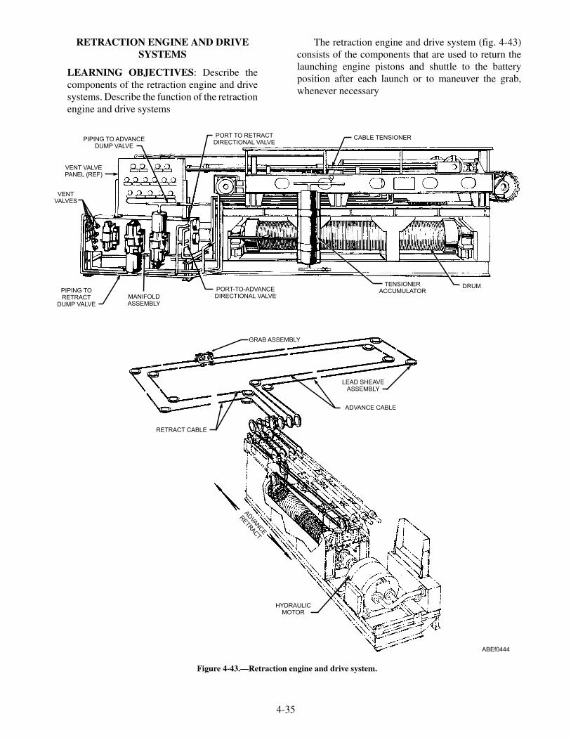
RETRACTION ENGINE AND DRIVESYSTEMS
LEARNING OBJECTIVES: Describe thecomponents of the retraction engine and drivesystems. Describe the function of the retractionengine and drive systems
The retraction engine and drive system (fig. 4-43)consists of the components that are used to return thelaunching engine pistons and shuttle to the batteryposition after each launch or to maneuver the grab,whenever necessary
4-35
PIPING TO ADVANCEDUMP VALVE
PORT TO RETRACTDIRECTIONAL VALVE
CABLE TENSIONER
DRUMTENSIONERACCUMULATORPORT-TO-ADVANCE
DIRECTIONAL VALVEMANIFOLDASSEMBLY
PIPING TORETRACT
DUMP VALVE
VENTVALVES
VENT VALVEPANEL (REF)
ABEf0444
GRAB ASSEMBLY
LEAD SHEAVEASSEMBLY
ADVANCE CABLE
ADVA
NCE
RETR
ACT
RETRACT CABLE
HYDRAULICMOTOR
Figure 4-43.—Retraction engine and drive system.

HYDRAULIC MOTOR
The hydraulic motor (see fig. 4-43) is rotated bypressurized fluid from the main hydraulic accumulator.Various directional valves located on the retractionengine manifold control speed and direction of rotation.The hydraulic motor is coupled directly to the drumassembly, causing the drum to rotate in the samedirection and speed as the motor.
DRUM ASSEMBLY
The drum is a grooved, cylindrical shaped as-sembly which winds and unwinds the drive systemcables to either advance or retract the grab, based ondirectional rotation of the hydraulic motor. The drum isdirectly coupled to the hydraulic motor and is geared tothe screw and traverse carriage installation.
SCREW AND TRAVERSE CARRIAGEINSTALLATION
The screw and traverse carriage installation (fig.4-44) is mounted on the retraction engine frame abovethe drum and is driven by a gear arrangement connectedto the drum. Rotation of the drum causes the traversecarriage to slide along tracks mounted on the engineframe. A sheave and adapter assembly, bolted to thecarriage body, acts as a guide for the advance andretract cables as they wind and unwind on and off thedrum preventing the cables from becoming tangled. Asthe carriage assembly moves along the length of theretraction engine, cams mounted on top of the carriagebody come in contact with valves and switchesmounted within the retraction engine frame. The camsactuate the advance and retract dump valves, advanceand retract cutoff limit switches, grab fully aft limit
4-36
TRACK
SHEAVE AND ADAPTERASSEMBLY
CAMS SCREW
SHEAVE AND ADAPTERASSEMBLY
DRUM
GEARING
ABEf0445
Figure 4-44.—Screw and traverse carriage.
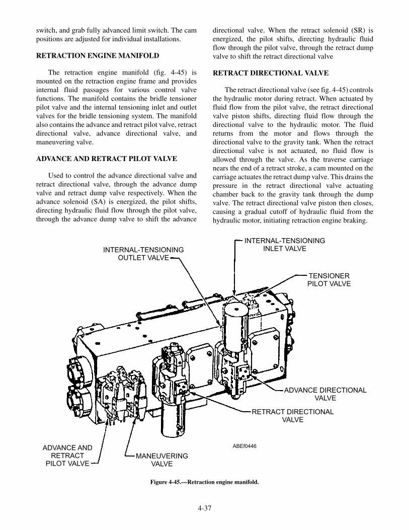
switch, and grab fully advanced limit switch. The campositions are adjusted for individual installations.
RETRACTION ENGINE MANIFOLD
The retraction engine manifold (fig. 4-45) ismounted on the retraction engine frame and providesinternal fluid passages for various control valvefunctions. The manifold contains the bridle tensionerpilot valve and the internal tensioning inlet and outletvalves for the bridle tensioning system. The manifoldalso contains the advance and retract pilot valve, retractdirectional valve, advance directional valve, andmaneuvering valve.
ADVANCE AND RETRACT PILOT VALVE
Used to control the advance directional valve andretract directional valve, through the advance dumpvalve and retract dump valve respectively. When theadvance solenoid (SA) is energized, the pilot shifts,directing hydraulic fluid flow through the pilot valve,through the advance dump valve to shift the advance
directional valve. When the retract solenoid (SR) isenergized, the pilot shifts, directing hydraulic fluidflow through the pilot valve, through the retract dumpvalve to shift the retract directional valve
RETRACT DIRECTIONAL VALVE
The retract directional valve (see fig. 4-45) controlsthe hydraulic motor during retract. When actuated byfluid flow from the pilot valve, the retract directionalvalve piston shifts, directing fluid flow through thedirectional valve to the hydraulic motor. The fluidreturns from the motor and flows through thedirectional valve to the gravity tank. When the retractdirectional valve is not actuated, no fluid flow isallowed through the valve. As the traverse carriagenears the end of a retract stroke, a cam mounted on thecarriage actuates the retract dump valve. This drains thepressure in the retract directional valve actuatingchamber back to the gravity tank through the dumpvalve. The retract directional valve piston then closes,causing a gradual cutoff of hydraulic fluid from thehydraulic motor, initiating retraction engine braking.
4-37
INTERNAL-TENSIONINGOUTLET VALVE
INTERNAL-TENSIONINGINLET VALVE
TENSIONERPILOT VALVE
ADVANCE DIRECTIONALVALVE
RETRACT DIRECTIONALVALVE
MANEUVERINGVALVE
ADVANCE ANDRETRACT
PILOT VALVE
ABEf0446
Figure 4-45.—Retraction engine manifold.
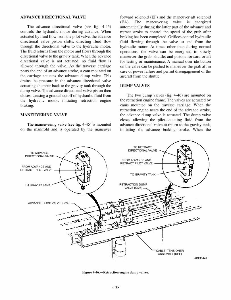
ADVANCE DIRECTIONAL VALVE
The advance directional valve (see fig. 4-45)controls the hydraulic motor during advance. Whenactuated by fluid flow from the pilot valve, the advancedirectional valve piston shifts, directing fluid flowthrough the directional valve to the hydraulic motor.The fluid returns from the motor and flows through thedirectional valve to the gravity tank. When the advancedirectional valve is not actuated, no fluid flow isallowed through the valve. As the traverse carriagenears the end of an advance stroke, a cam mounted onthe carriage actuates the advance dump valve. Thisdrains the pressure in the advance directional valveactuating chamber back to the gravity tank through thedump valve. The advance directional valve piston thencloses, causing a gradual cutoff of hydraulic fluid fromthe hydraulic motor, initiating retraction enginebraking.
MANEUVERING VALVE
The maneuvering valve (see fig. 4-45) is mountedon the manifold and is operated by the maneuver
forward solenoid (EF) and the maneuver aft solenoid(EA). The maneuvering valve is energizedautomatically during the latter part of the advance andretract stroke to control the speed of the grab afterbraking has been completed. Orifices control hydraulicfluid flowing through the valve to and from thehydraulic motor. At times other than during normaloperations, the valve can be energized to slowlymaneuver the grab, shuttle, and pistons forward or aftfor testing or maintenance. A manual override buttonon the valve can be pushed to maneuver the grab aft incase of power failure and permit disengagement of theaircraft from the shuttle.
DUMP VALVES
The two dump valves (fig. 4-46) are mounted onthe retraction engine frame. The valves are actuated bycams mounted on the traverse carriage. When theretraction engine nears the end of the advance stroke,the advance dump valve is actuated. The dump valvecloses allowing the pilot-actuating fluid from theadvance directional valve to return to the gravity tank,initiating the advance braking stroke. When the
4-38
TO ADVANCEDIRECTIONAL VALVE
TO RETRACTDIRECTIONAL VALVE
FROM ADVANCE ANDRETRACT PILOT VALVE
FROM ADVANCE ANDRETRACT PILOT VALVE
RETRACTION DUMPVALVE (C/23)
CABLE TENSIONERASSEMBLY (REF)
ADVANCE DUMP VALVE (C/24)
TO GRAVITY TANK
TO GRAVITY TANK
ABEf0447
Figure 4-46.—Retraction engine dump valves.

retraction engine nears the end of the retract stroke, theretract dump valve is actuated. The dump valve closesallowing the pilot-actuating fluid from the retractdirectional valve to return to the gravity tank, initiatingthe retract braking stroke.
VENT VALVE PANEL
The vent valve panel is located on top of theretraction engine manifold assembly. Vent valves aremounted on the panel and are connected to variouspoints in the retraction engine hydraulic system. Thesevalves are used to bleed (vent) air and air saturatedhydraulic fluid from various retraction enginecomponents. A hydraulic fluid reservoir is located atthe bottom of the vent valve panel. The reservoir is usedto collect vented fluid and provide the outlet to returnvented fluid to the hydraulic system.
CABLE TENSIONER ASSEMBLY
The cable tensioner assembly (fig. 4-47) consists ofthe four cable tensioners required to keep the retractionengine drive system taut. Each cable tensioners consistsof a hydraulic cylinder containing a piston with athreaded rod extending from one end and a rodattaching a clevis/sheave from the other end. Fluidunder pressure from the cable tensioner accumulatorforces the tensioner sheaves toward the cylindersapplying tension to the drive system cables. Thethreaded rods with adjusting nut on the other end ofeach tensioner provide a stop for sheave stroke whenthe pressure in the tensioner cylinders is overcome bythe braking action which occurs during dump valveactuation.
4-39
PISTON ROD
CLEVIS ASSEMBLYSHEAVE ASSEMBLY
RETRACT CYLINDER ASSEMBLY
ADVANCE CYLINDER ASSEMBLY
STOP NUT
LOCKING NUT
TENSIONER ACCUMULATOR (REF)
ABEf0448
Figure 4-47.—Retraction-engine cable tensioners.
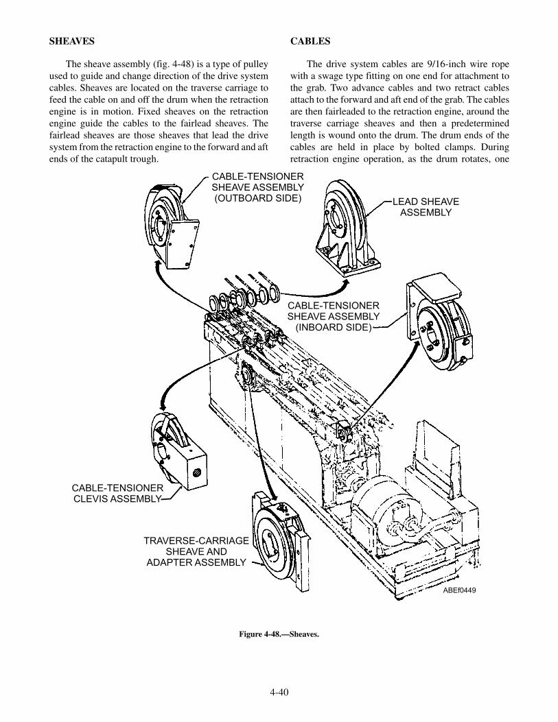
SHEAVES
The sheave assembly (fig. 4-48) is a type of pulleyused to guide and change direction of the drive systemcables. Sheaves are located on the traverse carriage tofeed the cable on and off the drum when the retractionengine is in motion. Fixed sheaves on the retractionengine guide the cables to the fairlead sheaves. Thefairlead sheaves are those sheaves that lead the drivesystem from the retraction engine to the forward and aftends of the catapult trough.
CABLES
The drive system cables are 9/16-inch wire ropewith a swage type fitting on one end for attachment tothe grab. Two advance cables and two retract cablesattach to the forward and aft end of the grab. The cablesare then fairleaded to the retraction engine, around thetraverse carriage sheaves and then a predeterminedlength is wound onto the drum. The drum ends of thecables are held in place by bolted clamps. Duringretraction engine operation, as the drum rotates, one
4-40
CABLE-TENSIONERSHEAVE ASSEMBLY(OUTBOARD SIDE) LEAD SHEAVE
ASSEMBLY
CABLE-TENSIONERSHEAVE ASSEMBLY
(INBOARD SIDE)
TRAVERSE-CARRIAGESHEAVE AND
ADAPTER ASSEMBLY
CABLE-TENSIONERCLEVIS ASSEMBLY
ABEf0449
Figure 4-48.—Sheaves.

pair of cables winds onto the drum while towing thegrab. The other pair of cables is unwound from thedrum by movement of the grab. The traverse carriagemoves in proportion with the drum rotation and feed thecables on and off the drum.
GRAB
The grab (fig. 4-49) is a spring-loaded latch,mounted on a wheel frame and installed within theshuttle track behind the shuttle. The two retract cablesare fastened to the aft end of the grab, and the twoadvance cables to the forward end. After a launch, thegrab is pulled forward the length of the shuttle track bythe drive system, and automatically latches to theshuttle with a positive-locking device. Diagram A offigure 4-50 shows the grab in the UNLOCKEDposition, approaching the shuttle. When the grab latch(5) comes in contact with the shuttle clevis pin (6), thelatch rotates and the latch cam follower (8) moves outof the cam detent (7) in the lock block (9) and continuesupward until it reaches the top surface of the lock block.The spring-loaded lock block then moves under the
cam follower, trapping the latch and locking the grab tothe shuttle clevis pin, as shown in diagram B. The grabwill not release the shuttle until both have been returnedto the BATTERY position and the grab unlockingmechanism is actuated by the bridle tensioner. Whenthe bridle-tensioner piston rod moves forward, thebridle-tensioner buffer cap (11) pushes the grabpushrod (1) inward until the buffer cap contacts thegrab block (2). When the pushrod is pushed inward, thelock block (9) is pulled from under the latch camfollower and the latch is free to rotate and release theshuttle, as shown in diagram C. When the shuttle andbridle tensioner move away from the grab, the grabremains in the UNLOCKED position, as shown indiagram A. During no-load tests, the grab and shuttlemust be unlatched. The grab is manually released fromthe shuttle, as shown in diagram D. A manual-releasedisengaging lever (12) is placed over themanual-release arm (3), which is accessible through thetrack slot, lifted up and pushed forward. This motionpulls the lock block from under the latch cam followerand frees the latch so that the grab and shuttle can beseparated.
4-41
1
23
4 5
67 8
910 11 12 13
14
15
16
17
18
19
20
ABEf0450
1. Pushrod2. Block3. Spring4. Manual-release arm5. Slide shaft
6. Link7. Lubrication fitting8. Spring9. Plate
10. Support
11. Block12. Cam follower13. Upper tie bracket14. Latch15. Buffer plate
16. Bracket17. Shaft18. Wheel assembly19. Link20. Lever
Figure 4-49.—Grab.

CATAPULT CONTROL SYSTEMS
LEARNING OBJECTIVES: Describe thecomponents of the catapult control systems.Describe the function of the catapult controlsystems.
The control system of a steam catapult consists ofthose panels, lights, and switches that are used tooperate a catapult throughout the various operationalphases.
ELECTRICAL CONTROL SYSTEMCOMPONENTS
The electrical control system for a steam catapultconsists of various control panels that govern theoperation of the catapult in conjunction with controlcomponents of other systems.
Included among the components of the catapultelectrical control system are various push buttons,switches, solenoids, relays, circuit breakers, fuses, andlights. The ICCS, CCP, and the main control console isthe focal point of all functions of the catapult electricalcontrol systems.
Electrically operated solenoid valves producemechanical operation of valves throughout the catapult.Buttons actuate some solenoid valves, while others
function automatically during catapult operation.Various changes that occur during catapult operationare sensed by limit switches and pressure switches.Operation of these switches actuates lights at variouscontrol panels. The following paragraphs brieflydescribe some of these components. For information onthe function and interrelationship of the electricalcomponents in a specific system, study the schematicdiagrams in the technical manual for that particulartype of catapult.
Solenoids
A solenoid (fig. 4-51) is an electromagnet formedby a conductor wound in a series of loops in the shapeof a helix (spiral). Inserted within this spiral or coil are asoft-iron core and a movable plunger. The soft-ironcore is pinned or held in position and therefore is notmovable. This movable plunger (also soft iron) is heldaway from the core by a spring in the de-energizedposition.
When current flows through the conductor, amagnetic field is produced. This field acts in everyrespect like a permanent magnet having both a northand south pole.
As shown in figure 4-51, the de-energized positionof the plunger is partially out of the coil, because of the
4-42
1 2 3 4 5
678910
1 2 3 4 5
678910
3 4 5
6910
1 2 3 4 5
67891011
12
DECK LINE DECK LINE
DECK LINE DECK LINE
DIAGRAM A DIAGRAM B
DIAGRAM C DIAGRAM D
UNLOCKED POSITION - APPROACHING SHUTTLE LATCHED & LOCKED TO SHUTTLE
UNLOCKED - SHUTTLE FREE TO MOVE FORWARD MANUALLY UNLOCKED
ABEf0451
1. Pushrod2. Block3. Manual-release arm4. Latch spring
5. Grab latch6. Shuttle clevis pin7. Cam detent8. Cam follower
9. Lock block10. Manual-release-arm stop11. Bridle-tensioner buffer cap12. Manual-release disengaging lever
Figure 4-50.—Grab operation sequence.
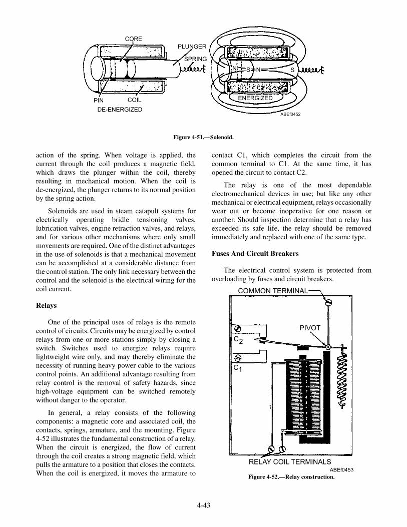
action of the spring. When voltage is applied, thecurrent through the coil produces a magnetic field,which draws the plunger within the coil, therebyresulting in mechanical motion. When the coil isde-energized, the plunger returns to its normal positionby the spring action.
Solenoids are used in steam catapult systems forelectrically operating bridle tensioning valves,lubrication valves, engine retraction valves, and relays,and for various other mechanisms where only smallmovements are required. One of the distinct advantagesin the use of solenoids is that a mechanical movementcan be accomplished at a considerable distance fromthe control station. The only link necessary between thecontrol and the solenoid is the electrical wiring for thecoil current.
Relays
One of the principal uses of relays is the remotecontrol of circuits. Circuits may be energized by controlrelays from one or more stations simply by closing aswitch. Switches used to energize relays requirelightweight wire only, and may thereby eliminate thenecessity of running heavy power cable to the variouscontrol points. An additional advantage resulting fromrelay control is the removal of safety hazards, sincehigh-voltage equipment can be switched remotelywithout danger to the operator.
In general, a relay consists of the followingcomponents: a magnetic core and associated coil, thecontacts, springs, armature, and the mounting. Figure4-52 illustrates the fundamental construction of a relay.When the circuit is energized, the flow of currentthrough the coil creates a strong magnetic field, whichpulls the armature to a position that closes the contacts.When the coil is energized, it moves the armature to
contact C1, which completes the circuit from thecommon terminal to C1. At the same time, it hasopened the circuit to contact C2.
The relay is one of the most dependableelectromechanical devices in use; but like any othermechanical or electrical equipment, relays occasionallywear out or become inoperative for one reason oranother. Should inspection determine that a relay hasexceeded its safe life, the relay should be removedimmediately and replaced with one of the same type.
Fuses And Circuit Breakers
The electrical control system is protected fromoverloading by fuses and circuit breakers.
4-43
CORE
PIN COIL
DE-ENERGIZED
PLUNGER
SPRING
ENERGIZED
S N S
ABEf0452
N
Figure 4-51.—Solenoid.
COMMON TERMINAL
PIVOT
C
C
2
1
RELAY COIL TERMINALSABEf0453
Figure 4-52.—Relay construction.

The fuse is the simplest protective device. A fuse ismerely a short length of wire or metal ribbon within asuitable container. This wire or metal ribbon is usuallymade of an alloy that has a low melting point and isdesigned to carry a given amount of currentindefinitely. A larger current causes the metal to heatand melt, opening the circuit to be protected. Inreplacing a burned-out fuse, you should be sure that thenew fuse is the same size (capacity in amperes) as theoriginal.
The circuit breaker serves the same purpose as thefuse, but it is designed to open the circuit underoverload conditions without injury to itself. Thus, thecircuit breaker can be used again and again after theoverload condition has been corrected.
Limit Switches
Limit switches are used as remote indicators of theposition of various components throughout the system.They are actuated mechanically by the movement of thecomponent. Electrical contacts within the switchchange the mechanical action to an electrical signalindicated by lights on the various operating panels.
Microswitches
Microswitches serve the same function as limitswitches except they are used where a very limitedmechanical movement is required (1/16 inch or less).While the term Microswitch suggests the function ofthe switch, it is nothing more than the brand name of theparticular type of switch.
PUSH BUTTON CONTROLS
The sequence of operations on the C-13-0, C-13-1,and C-13-2 catapults is controlled by push buttons. Thetwo types of push buttons are the momentary-contactand holding-circuit push buttons. The momentary-contact push button has to be held in the depressedposition to keep the particular circuit energized. Themaneuver forward and maneuver aft push buttons, are
examples. The push button used in a holding circuitstays energized once it is depressed until that particularcircuit is de-energized by the normal sequence ofoperations or one of the suspend switches is actuated.All the push buttons associated with the normaloperation of the catapult are incorporated into holdingcircuits.
CATAPULT CONTROL SYSTEM FOR CVN-68THROUGH CVN-76 (INTEGRATEDCATAPULT CONTROL STATION(ICCS))
The controls for the ICCS are mainly dividedbetween the ICCS at the flight deck level and theCentral Charging Panel (CCP) below deck. The ICCS isan enclosure that may be retracted into the deck whennot in use. It contains the catapult-officer controlconsole and the monitor control console, and controlsthe operation of two adjacent catapults. Sound-poweredphones and a system of indicator lights link the ICCS tothe remote panels for individual catapults. In anemergency, the functions of the ICCS can betransferred to the emergency deckedge control panel orthe central charging panel, and the catapult officer candirect operations on the flight deck.
Catapult-Officer Control Console
The catapult-officer control console (fig. 4-53) isused in conjunction with the monitor control consoleand the central charging panel to direct catapultoperations. The control console is of wraparounddesign for ease of operation and located facing aft in theICCS. The console is made up of panels containing allof the lights, switches and other controls necessary forthe operation of two adjacent catapults. The operatingpanels and lower end operating panels contain the lightsand switches for operation of the associated catapult.The remaining panels located between the operatingpanels and lower end operating panels provide thelaunching officer with all of the other information orswitches.
4-44

4-45
LEFT WEDGEOPERATING PANEL
DESI REMOTEREADOUTS
INTERMEDIATE SLOPEWEDGE PANEL
INTERMEDIATE SLOPEWEDGE PANEL
OPERATING PANEL(REFER TO VIEW A) OPERATING PANEL
(REFER TO VIEW A)
LOWER ENDOPERATING PANEL(REFER TO VIEW B)
LOWER ENDOPERATING PANEL(REFER TO VIEW B)
AMBIENT TEMPERATUREREADOUT PANEL
LOWER CENTEROPERATING PANEL
CROSSWIND ANDHEADWIND INDICATOR
ABEf0454
VIEW B
VIEW A
STEAM PRESSURE
CAPACITY SELECTOR VALVENO GOGO
OFF
B/
/A
NGL
COMMAND
CSV MATCH
CSV M3 MATCH
CSVCONF
AUTOP.B.
DEFEATINTERLK
JOGP.B.
HANDWHEEL
BRIDLETENSION
CATREADY
CATAPULTSUSPEND
LOCAL
MILITARYPOWER
FIREFINAL
READY
COMBATPOWER
MANGRABAFT
CAT. SUSPENDMONITORING STA.
CAT. SUSPENDPRE-FLT
CAT. SUSPENDWATER BRAKE
Figure 4-53.—Catapult-officer control console.
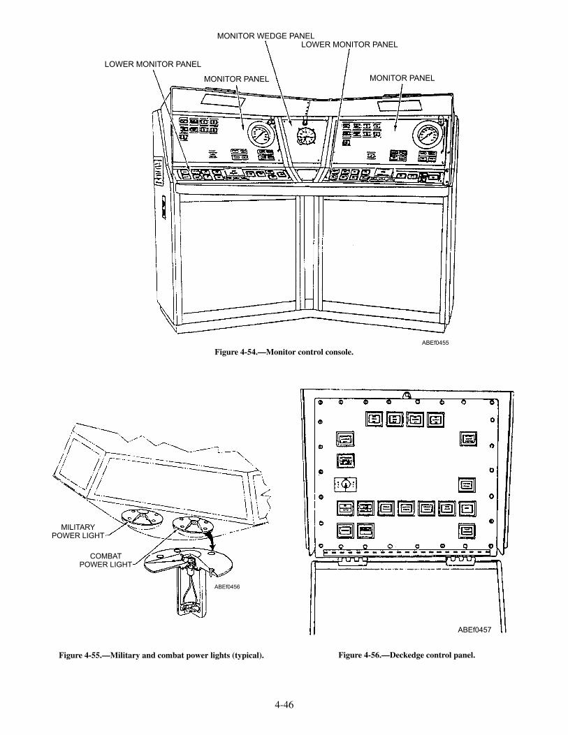
4-46
LOWER MONITOR PANEL
MONITOR WEDGE PANELLOWER MONITOR PANEL
MONITOR PANEL MONITOR PANEL
ABEf0455
Figure 4-54.—Monitor control console.
MILITARYPOWER LIGHT
COMBATPOWER LIGHT
ABEf0456
Figure 4-55.—Military and combat power lights (typical).
ABEf0457
Figure 4-56.—Deckedge control panel.
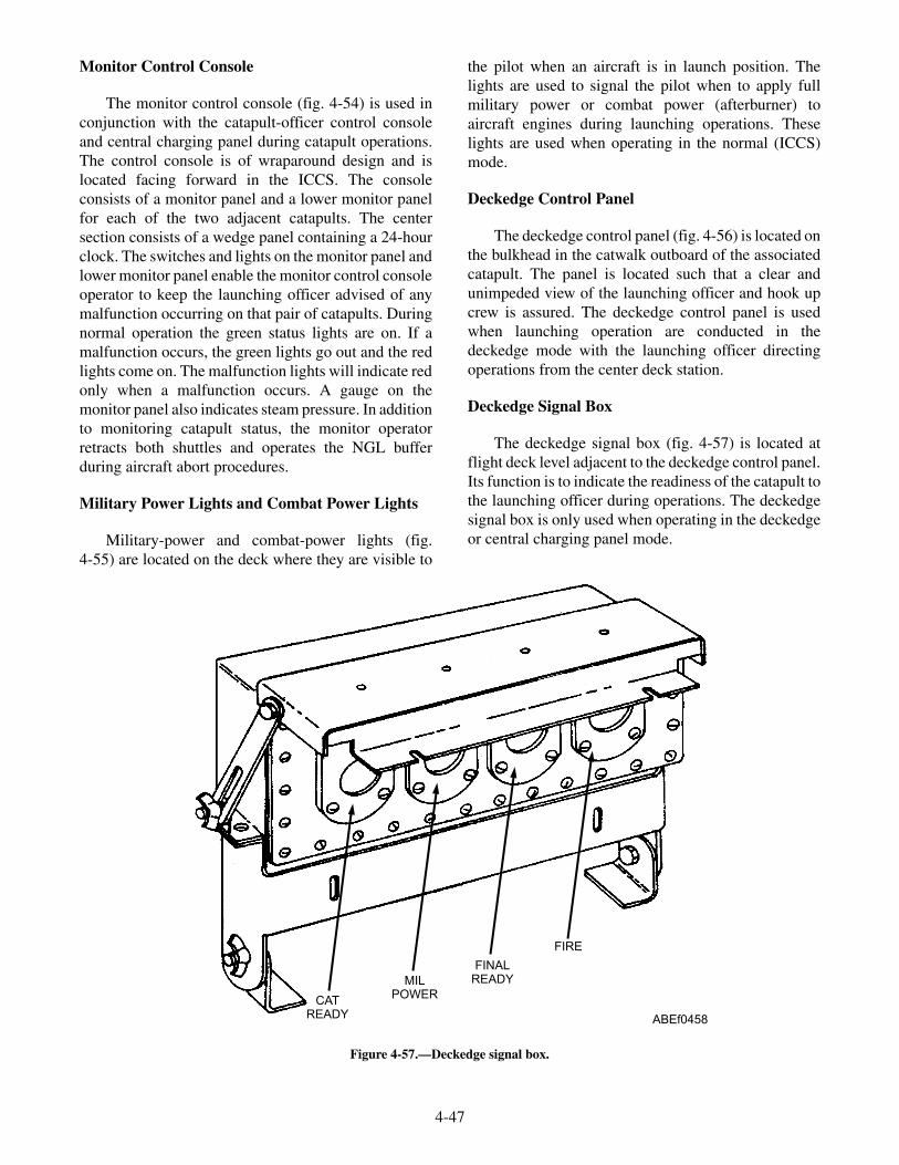
Monitor Control Console
The monitor control console (fig. 4-54) is used inconjunction with the catapult-officer control consoleand central charging panel during catapult operations.The control console is of wraparound design and islocated facing forward in the ICCS. The consoleconsists of a monitor panel and a lower monitor panelfor each of the two adjacent catapults. The centersection consists of a wedge panel containing a 24-hourclock. The switches and lights on the monitor panel andlower monitor panel enable the monitor control consoleoperator to keep the launching officer advised of anymalfunction occurring on that pair of catapults. Duringnormal operation the green status lights are on. If amalfunction occurs, the green lights go out and the redlights come on. The malfunction lights will indicate redonly when a malfunction occurs. A gauge on themonitor panel also indicates steam pressure. In additionto monitoring catapult status, the monitor operatorretracts both shuttles and operates the NGL bufferduring aircraft abort procedures.
Military Power Lights and Combat Power Lights
Military-power and combat-power lights (fig.4-55) are located on the deck where they are visible to
the pilot when an aircraft is in launch position. Thelights are used to signal the pilot when to apply fullmilitary power or combat power (afterburner) toaircraft engines during launching operations. Theselights are used when operating in the normal (ICCS)mode.
Deckedge Control Panel
The deckedge control panel (fig. 4-56) is located onthe bulkhead in the catwalk outboard of the associatedcatapult. The panel is located such that a clear andunimpeded view of the launching officer and hook upcrew is assured. The deckedge control panel is usedwhen launching operation are conducted in thedeckedge mode with the launching officer directingoperations from the center deck station.
Deckedge Signal Box
The deckedge signal box (fig. 4-57) is located atflight deck level adjacent to the deckedge control panel.Its function is to indicate the readiness of the catapult tothe launching officer during operations. The deckedgesignal box is only used when operating in the deckedgeor central charging panel mode.
4-47
CATREADY
MILPOWER
FINALREADY
FIRE
ABEf0458
Figure 4-57.—Deckedge signal box.

Deck Catapult-Suspend Light
The deck catapult-suspend light (fig. 4-58) islocated on the edge of the flight deck outboard of itsassociated catapult and in clear view of all topsidecatapult crew members. The light flashes red during asuspend situation to indicate to personnel on the flightdeck that a catapult-suspend situation exists.
Water Brake Control Panel
The water brake control panel (fig. 4-59) is locatedin the water brake pump room. In the event of anemergency or malfunction of the water brakes, a switchon the panel is used to suspend catapult operations andit further protection for personnel when access to thelaunching engine cylinders or water brake cylinder isrequired.
Central Charging Panel
The central charging panel (CCP) (fig. 4-60)provides a single, centralized station from whichvirtually all below decks catapult functions areaccomplished. The CCP consists of left-front panel,left-intermediate-front panel, right-intermediate-frontpanel, right-front panel, transfer-switch enclosure, andlaunch-valve-emergency-cutout-valve, which aredescribed in the following paragraphs. The deck-signal-light panel is located inside the central chargingpanel, below the left-intermediate front panel. Controlson the deck-signal-light panel are used to adjust the
intensity of the deck signal lights. The panel enclosurealso contains pressure switches, gauge shutoff valves,and other piping components.
LEFT-FRONT PANEL.—The left-front panelcontains the switches and pressure gauges for theoperation and monitoring of the catapult hydraulicsystem. The panel contains pressure gauges andOFF-ON switches for the main hydraulic pumps, thebooster pump, the circulating pump, and the lubricationpump. Also included are a gravity-tank fluidtemperature gauge, three main hydraulic accumulatorhydraulic-pressure gauges, an off-on pump deliverycontrol switch, a primary pump selector switch, aretraction-engine suspend switch, a blowdown valvefor the retraction-engine hydraulic fluid, and deliverycontrol fuses.
LEFT-INTERMEDIATE-FRONT PANEL.—The left-intermediate-front-panel contains the valvesand pressure gauges for charging or blowing downcatapult components that require air pressure for theiroperation. Gauges on the panel indicate the air pressurein the air side of the main hydraulic accumulator, the airflask, the air side of the cable-tensioner accumulator,the low-pressure-air supply, medium-pressure-airsupply, and the air side of the tensioner surgeaccumulator. A dual gauge indicates the air pressure at
4-48
ABEf0459
Figure 4-58.—Deck catapult-suspend light.
BOX
LIGHT
SWITCH
ABEf0460
CATAPULT
SUSPENSION
WATERBRAKE
Figure 4-59.—Water brake control panel.

the dome of the tensioner regulator and the pressure inthe hydraulic fluid side of the tensioner surgeaccumulator. Valves on the panel are used for chargingand blowing down the air flask, the air side of the mainhydraulic accumulator, the air side of thecable-tensioner accumulator, the dome of the tensionerregulator, and the air side of the tensioner surgeaccumulator. There is also a valve to shut off thelow-pressure-air supply. A bank of red and greenindicator lights on the panel indicates go and no-goindication for various catapult functions.
RIGHT-INTERMEDIATE-FRONT PANEL.—The top portion of the right-intermediate-front panelcontains the pressure gauges and valves monitoring,charging, and blowing down the nose gear launchaccumulators. The lower portion of the panel contains a24-hour clock and the CSV setting controls.
RIGHT-FRONT PANEL.—The right-front paneltop portion contains the launch valve timer readout,water brake elbow pressure gauges, the wetaccumulator pressure gauge, the main power (RC)on/off switch and a panel with the steam fill/blowdownvalve selectors. The lower portion of this panel containslights and switches for operating and monitoring
catapult and wet steam accumulator components. Thelowest row of lights and switches provide emergencyoperational capability at the charging panel.
Transfer Switch Enclosure
The transfer switch enclosure is located on thelower right end of the central charging panel. Theswitch enclosure contains switches that provides ameans of transferring catapult control functions foroperating in either the deckedge or central chargingpanel emergency mode. The other switches provide ameans of transferring pri-fly, deck signal lights, centralcontrol station, and the catapult interlock switch out ofthe catapult control circuit.
Launch Valve Emergency Cutout Valve
The launch valve emergency cutout valve is locatedon the lower left end of the central charging panel. Theemergency cutout valve provides the central chargingpanel operator with a positive control to prevent thelaunch valve from opening during a HANGFIREcondition. When placed in the emergency position, thecutout valve electrically and hydraulically shifts thelaunch valve control system to the closed position.
4-49
LEFT-FRONT PANEL
LEFT-INTERMEDIATE-FRONT PANEL
RIGHT-INTERMEDIATE-FRONT PANEL
RIGHT-FRONT PANEL
TRANSFER SWITCHENCLOSURE-BOX
DECK SIGNAL LIGHT CONTROL
ABEf0461
Figure 4-60.—Central charging panel.

Central Junction Box
The central junction box (fig. 4-61) provides asingle location for the catapult control system wiringand relays. The terminal board and all wires are clearlymarked for easy identification. Relay status lights and arelay tester aid in troubleshooting electricalmalfunctions.
CATAPULT CONTROL SYSTEM FOR CV-63,CVN-65, and CV-67
The control system consists of those panels, lights,and switches that are used to operate a catapult
throughout the various operational phases. Thefollowing is a description of the control systemcomponents.
Deckedge Control Panel
The deckedge control panel (figs. 4-62 and 4-63) islocated on the bulkhead in the catwalk outboard of theassociated catapult. The panel is located such that aclear and unimpeded view of the launching officer andhook up crew is assured. The deckedge control panelcontains lights and switches used for catapult controlduring launching, retraction, and bridle tensioningphases.
4-50
FUSE LIGHTUNIT
RELAY LIGHTS
RELAYTESTER
RELAY
TERMINALBOARD
ABEf0462
Figure 4-61.—Central junction box.

4-51
NIGHT LIGHTING
CAT INTERLOCKRELEASE RETRACTION PERMISSIVE
RETRACTION COMPLETE
FIRE
FINAL READY
STANDBY
BRIDLE TENSION
FIRST READYCAT'S INTERLOCKED
CAT SUSPENDDECK
CAT SUSPENDWATER BRAKECAT SUSPEND
PRI-FLY
RET ENG SUSPEND
RETRACT
MANEUVERSHUTTLE FWD
MANEUVERSHUTTLE AFT
ABEf0463
CAT SUSPENDCONSOLE
Figure 4-62.—Deckedge control panel (CVN-65 and CV-67).
CATAPULT
SUSPENSION
WATER BRAKE
CATAPULT
INTERLOCK
RELEASE
FIRST
READY
BRIDLE
TENSION
FINAL
READY
CATAPULT
SUSPENSION
PRI-FLY
CATAPULTS
INTERLOCKED
STANDBY
STANDBY
RETRACT
CATAPULT
SUSPENSION
DECK
CATAPULT
SUSPENSION
FIRE
FIRE
CATAPULT
SUSPENSION
CONSOLE
RETRACTION
COMPLETE
RETRACTION
PERMISSIVE
RETRACTION
ENGINE
SUSPENSION
RETRACTION ENG
SUSPENSION
MANEUVER
ENGINE FWD
MANEUVER
SHUTTLE AFT
ABEf0464
Figure 4-63.—Deckedge control panel (CV-63).

Main Control Console (CVN-65 and CV-67)
The main control console (fig. 4-64) is used inconjunction with the deckedge control panel duringcatapult operation. The control console consists of amonitor panel, operating panel, steam panel, the launchvalve cutout valve, and the transfer switch enclosure.
MONITOR PANEL.—The monitor panel con-sists of a series of status lights on the top right side forvarious catapult system pressures. These lights willindicate green for pressure within safe operating limitsor red for out-of-limit pressures. Malfunction lights arelocated down the right side of the panel. These lightswill indicate red in the event of a malfunction. Theswitches that energize these lights will also interruptthe launching sequence. The monitor panel alsocontains the launch vale stroke timers, and the digitalendspeed indicator.
OPERATING PANEL.—The operating panel isused in conjunction with the deckedge panel duringlaunching operations. It contains the lights,push buttons, and switches that are used for catapultcontrol during launching, retraction, and bridletensioning phases. The operating panel also containsthe CSV setting controls.
STEAM CHARGING PANEL.—The steamcharging panel contains steam pressure and tem-perature gauges, status lights, and setting controls. Thesetting controls provide a means of operating the fillvalves automatically or by a manually set air signal. Innormal operations, the fill valves are operated inautomatic charge. With automatic charge and chargevalve selected, the air signal to the fill valves is preset toclosely control the opening rates of the fill valves. Themanually loading air regulator is used to control the airsignal to the blowdown valve and to the fill valves whenin manual charge.
Transfer Switch Enclosure
The transfer switch enclosure is located on thelower right side of the main control console. Thetransfer switch enclosure provides a means of isolatingremote panels and switching control to the controlconsole. The transfer switches are rotated fromNORMAL to EMERGENCY, as required, to isolate aremote panel that has malfunctioned.
Launch Valve Emergency Cutout Valve
The launch valve emergency cutout valve is locatedon the lower left side of the main control console. The
4-52
MONITOR PANEL(REFER TO VIEW A)
OPERATING PANEL(REFER TO VIEW B)
STEAM CHARGING PANEL(REFER TO VIEW C)
TRANSFER SWITCHENCLOSURE
LAUNCH VALVEEMERGENCY
CUTOUT VALVEABEF0465
Figure 4-64.—Main control console (CVN-65 and CV-67).

emergency cutout valve provides the console operator apositive control to prevent the launch valve fromopening during a HANGFIRE condition. When placedin the emergency position, the cutout valve electricallyand hydraulically shifts the launch valve control systemto the closed position.
Central Junction Box
The central junction provides a single location forthe catapult control system wiring and relays. Theterminal board and all wires are clearly marked for easyidentification. Relay status lights and a relay tester aidin troubleshooting electrical malfunctions.
Deckedge Signal Box
The deckedge signal box (fig. 4-65) is located atflight deck level adjacent to the deckedge control panel.Its function is to indicate the readiness of the catapult tothe launching officer during operations.
Water Brake Control Panel
The water brake control panel (see fig. 4-59) islocated in the water brake pump room. In the event ofan emergency or malfunction of the water brakes, aswitch on the panel is used to suspend catapultoperations and it is further protection for personnelwhen access to the launching engine cylinders or waterbrake cylinder is required.
Main Control Console (CV-63)
The main control console (fig. 4-66) is used inconjunction with the deckedge control panel duringcatapult operation. The control console consists of anoperating panel, an emergency panel, a malfunctionpanel, two gauge panels, a launch valve cutout valve,and the transfer switch enclosure.
OPERATING PANEL.—The operating panel isused in conjunction with the deckedge panel duringlaunching operations. It contains the lights,push buttons, and switches that are used for catapultcontrol during the launching sequence.
EMERGENCY PANEL.—The emergency panelcontains all the lights, push buttons, and switches arerequired to provide complete control during thelaunching, retraction, and bridle tensioning phases.
STEAM GAUGE PANEL.—The steam gaugepanel contains a steam pressure gauge, CSV settingcontrols, digital endspeed indicator and launch valvetimer displays.
GAUGE PANEL.—The gauge panel provides ameans of monitoring steam and hydraulic temperatureand pressures.
MALFUNCTION PANEL.—The malfunctionpanel contains lights that indicate the status of certaincatapult components or systems. The hydraulicpressure and the valve position malfunction lights are
4-53
INTER
LOCK
ON
FIRST
READY
STAND
BY
FINAL
READY
FIRE
ABEf0466
Figure 4-65.—Deckedge signal box.
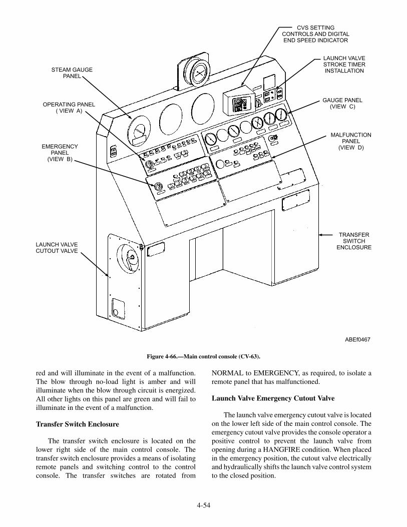
red and will illuminate in the event of a malfunction.The blow through no-load light is amber and willilluminate when the blow through circuit is energized.All other lights on this panel are green and will fail toilluminate in the event of a malfunction.
Transfer Switch Enclosure
The transfer switch enclosure is located on thelower right side of the main control console. Thetransfer switch enclosure provides a means of isolatingremote panels and switching control to the controlconsole. The transfer switches are rotated from
NORMAL to EMERGENCY, as required, to isolate aremote panel that has malfunctioned.
Launch Valve Emergency Cutout Valve
The launch valve emergency cutout valve is locatedon the lower left side of the main control console. Theemergency cutout valve provides the console operator apositive control to prevent the launch valve fromopening during a HANGFIRE condition. When placedin the emergency position, the cutout valve electricallyand hydraulically shifts the launch valve control systemto the closed position.
4-54
CVS SETTINGCONTROLS AND DIGITALEND SPEED INDICATOR
LAUNCH VALVESTROKE TIMERINSTALLATION
GAUGE PANEL(VIEW C)
MALFUNCTIONPANEL
(VIEW D)
TRANSFERSWITCH
ENCLOSURE
STEAM GAUGEPANEL
OPERATING PANEL( VIEW A)
EMERGENCYPANEL
(VIEW B)
LAUNCH VALVECUTOUT VALVE
ABEf0467
Figure 4-66.—Main control console (CV-63).
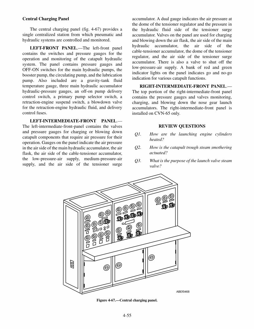
Central Charging Panel
The central charging panel (fig. 4-67) provides asingle centralized station from which pneumatic andhydraulic systems are controlled and monitored.
LEFT-FRONT PANEL.—The left-front panelcontains the switches and pressure gauges for theoperation and monitoring of the catapult hydraulicsystem. The panel contains pressure gauges andOFF-ON switches for the main hydraulic pumps, thebooster pump, the circulating pump, and the lubricationpump. Also included are a gravity-tank fluidtemperature gauge, three main hydraulic accumulatorhydraulic-pressure gauges, an off-on pump deliverycontrol switch, a primary pump selector switch, aretraction-engine suspend switch, a blowdown valvefor the retraction-engine hydraulic fluid, and deliverycontrol fuses.
LEFT-INTERMEDIATE-FRONT PANEL.—The left-intermediate-front-panel contains the valvesand pressure gauges for charging or blowing downcatapult components that require air pressure for theiroperation. Gauges on the panel indicate the air pressurein the air side of the main hydraulic accumulator, the airflask, the air side of the cable-tensioner accumulator,the low-pressure-air supply, medium-pressure-airsupply, and the air side of the tensioner surge
accumulator. A dual gauge indicates the air pressure atthe dome of the tensioner regulator and the pressure inthe hydraulic fluid side of the tensioner surgeaccumulator. Valves on the panel are used for chargingand blowing down the air flask, the air side of the mainhydraulic accumulator, the air side of thecable-tensioner accumulator, the dome of the tensionerregulator, and the air side of the tensioner surgeaccumulator. There is also a valve to shut off thelow-pressure-air supply. A bank of red and greenindicator lights on the panel indicates go and no-goindication for various catapult functions.
RIGHT-INTERMEDIATE-FRONT PANEL.—The top portion of the right-intermediate-front panelcontains the pressure gauges and valves monitoring,charging, and blowing down the nose gear launchaccumulators. The right-intermediate-front panel isinstalled on CVN-65 only.
REVIEW QUESTIONS
Q1. How are the launching engine cylindersheated?
Q2. How is the catapult trough steam smotheringactuated?
Q3. What is the purpose of the launch valve steamvalve?
4-55
ABEf0468
Figure 4-67.—Central charging panel.

Q4. What provides a means of measuring launchvalve performance?
Q5. What is the purpose of the keeper valve?
Q6. What component transfers the forwardmotion of the pistons to the aircraft?
Q7. What system provides a means of lubricatingthe launching engine cylinders?
Q8. The bridle tensioning system full-aft limitswitch is part of what catapult circuit?
Q9. The auxiliary tank of the hydraulic system hasa capacity of how many gallons?
Q10. What is the function of the retraction engineand drive system?
Q11. The controls for the ICCS are dividedbetween what panels?
Q12. During operation, what indicates thereadiness of the catapult to the launchingofficer?
OPERATIONS
LEARNING OBJECTIVE: Describe theoperation of a steam catapult.
A steam fill-valve system controls the amount ofsteam from the ship's boilers to the wet-steamaccumulator. Steam from the steam accumulator is thenreleased into the launching engine cylinders throughthe launch valve (the amount of steam used is varied bya capacity selector valve [CSV] assembly that controlsthe launch valve opening rate).
This surge of steam acts on a set of steam pistonsinside the launching engine cylinders. These pistons areconnected to a shuttle that is attached to an aircraft. Theforce of the steam being released from the steamaccumulator pushes the pistons forward, towing theshuttle and aircraft at an increasing speed until aircrafttake-off is accomplished.
The shuttle and steam pistons are stopped at the endof their "power stroke" as a tapered spear (fig. 4-68)enters a set of water-filled cylinders, forcing the waterto be "metered" out of the cylinders as the tapered spearmoves into them.
After the shuttle and pistons have been stopped, agrab is advanced forward along the catapult troughcovers by means of the retraction engine, and attachesto the shuttle assembly. The retraction engine is thenreversed and returns the grab, shuttle, and piston
assembly to the battery position in preparation for thenext aircraft launch.
A integrated catapult control station (ICCS),central charging panel (CCP), main control console,deckedge control panel, retraction enginecontrol/charging panel, and water brake panel are usedin conjunction to direct and integrate the catapultelectrical and hydraulic systems functions and tocontrol the sequence of operations through a normalcatapult launching cycle.
Preliminary functional tests are performed by alloperating personnel. These tests consist of at least twono-load launchings, during which the control system isoperated through its complete cycle. The functioning ofas many component parts of the catapult as possibleshould be observed by personnel at the various stations
4-56
SHUTTLESHUTTLE TRACK
PISTONGRAB
1. SHUTTLE IN BATTERY POSITION2. AIRCRAFT ATTACHED TO SHUTTLE AND HOLDBACK UNIT3. TENSIONER AND GRAB EXERT FORWARD PRESSURE ON
SHUTTLE FOR TENSIONING. GRAB AND SHUTTLE UNLOCK
A
B
CATAPULT FIRES
1. HOLDBACK UNIT RELEASES2. SHUTTLE TOWS AIRCRAFT FORWARD
WATERBRAKE
REACTIONSYSTEM
PISTONS AND SHUTTLE HALTEDBY WATER BRAKES
C
D
E
GRAB ADVANCES AND LATCHES TO SHUTTLE
GRAB RETRACTS SHUTTLE TO BATTERY POSITION
ABEf0401
AIRCRAFT PREPARED FOR LAUNCH
Figure 4-68.—Catapult operation.

during the preliminary functional tests. Allmalfunctions must be reported to the maintenanceofficer, catapult officer, or catapult captain.
INTEGRATED CATAPULT CONTROLSTATION (ICCS) NO-LOAD LAUNCHINGPROCEDURES
No-load launches are conducted during theaccomplishment of the preoperational MRCs. No-loadlaunches may also be required for post maintenancecatapult checkout.
WARNING
NO-load tests shall be conducted under thesupervision of a qualified launching officer. Toprevent injury to personnel, safety lines shallbe rigged along the deck inboard of the catapultand safety personnel shall be stationed in thecatwalk to keep unauthorized personnel clearof the catapult area.
Perform the following steps for no-load test launchings:
1. With the catapult track clear, the safetyobserver signals the monitor operator toretract.
2. With the grab and shuttle in battery position,the safety observer signals the monitor tomaneuver forward a sufficient distance toallow grab/shuttle separation (one to two feet isadequate).
3. With a crewmember manually releasing thegrab latch, the safety observer signals themonitor operator to maneuver the grab to thefully aft position.
4. The charging panel operator closes the fluidsupply valve to the bridle tensioner pressureregulator and blows off the air pressure in thedome of the bridle tensioner regulator, surgeaccumulator, and from the dome of the internaltensioning pressure regulator.
5. The launching officer shall set the CSVcommand setting to the required value andensure that the CSV is confirmed and that theCSV match lights come on.
6. The charging panel operator shall ensure thatthe CSV command setting is in the no-loadrange, and if in agreement with the commandsetting, depresses the set pushbutton, andensures that command, position, and
mechanical counter all match. If indisagreement with the command setting, thecharging panel operator shall not depress theset pushbutton until the setting discrepancy isresolved.
7. The launching officer notifies pri-fly to make a5MC warning announcement of the impendingno load launches.
8. The launching officer depresses the bridletensioning pushbutton, military power, andfinal ready pushbuttons.
9. The safety observer shall ensure that thecatapult track is clear and all safety personnelare indicating thumbs up and signal thelaunching officer to fire the catapult.
10. The launching officer shall check for a clearlaunching area and depress the fire pushbutton.
11. Repeat the above procedures if necessary forsubsequent no loads.
INTEGRATED CATAPULT CONTROLSTATION (ICCS) LAUNCHING PROCEDURES
Where the ICCS is the primary mode of controllingfixed-wing-aircraft launching operations, the followingprocedures apply:
As the ship approaches the launch course, the airofficer monitors the wind repeater and keeps thelaunching officer(s) advised of the relative windvelocity. When permission to launch aircraft is receivedfrom the bridge, a final check must be made to ensurerelative wind is within the limits prescribed in theapplicable launching bulletin. This is accomplishedbefore changing the rotating beacon(s) from red togreen, which lights the pri-fly "go light" on the catapultofficers ICCS console, thereby clearing the launchingofficer(s) to begin launching.
The following steps must be completed before thelaunching officer assumes control of the aircraft.
1. Before aircraft tension, the topside safety pettyofficer performs the following:
1) Ensures that appropriate jet blastdeflectors are raised.
2) Supervises the attachment of the holdbackto aircraft.
3) Checks the catapult area forward.
4) Gives the tension signal to the director.
4-57

2. The catapult director performs the following:
1) Checks the catapult area forward.
2) Ensures that the appropriate jet blastdeflectors are raised and that all personnelare clear of the jet blast and prop wash.
3) Signals the launching officer in the ICCSto take tension, while signaling the pilot torelease brakes; the pilot in turn appliespower as specified in the NATOPS Manualfor that type of aircraft.
4) After the aircraft is tensioned on thecatapult, signals the pilot, if required, toraise the aircraft launch bar.
5) Turns the aircraft over to the ICCS decksignal lights.
3. After tension is taken, the top side safety pettyofficer performs the following:
1) Inspects for proper aircraft hookup andalignment.
2) Ensures that all personnel are clear of theaircraft on the catapult.
3) Inspects the launch bar to ensure properengagement with the catapult shuttle afterfull power application and catapulttensioning are completed.
4) Signals "thumbs up" to the catapult safetyobserver with a hand or wand signal if allconditions are satisfactory for launch.
4. The squadron aircraft inspector performs thefollowing:
1) Makes a final inspection of the aircraft forproper configuration; flaps; trim settings;leaks; and loose panels, doors, or hatches.
2) Signals "thumbs up" to the catapult safetyobserver with a hand or wand signal if allconditions are satisfactory for launch.
CAUTION
If there is any doubt in the mind of the topsidesafety petty officer, director, or squadronaircraft inspector as to satisfactory hookup oraircraft configuration, he or she must soindicate to the catapult safety observer byinitiating a crossed arm suspend signal (day) ora horizontal wand movement (night). The
catapult safety observer then signals “suspend”to the launching officer in the ICCS.
5. The catapult safety observer performs thefollowing:
1) Visually checks for proper aircraft hookupand alignment.
2) Ensures that the appropriate jet blastdeflectors are raised and that all personnelare clear of the aircraft, jet blast, and propwash.
6. The launching officer signals for final turnupsby lighting the military power (green) light andthe combat power (amber) light, if applicable,in that order. The pilot shall apply full powerand afterburner, if applicable, as these lightsare illuminated. When the pilot is ready forlaunch, he or she signifies by saluting thecatapult safety observer or, at night, by turningthe navigation lights on steady. The pilotensures that no exterior lights are on before themilitary power/combat power (afterburnerlaunch) lights are illuminated.
7. The catapult safety observer, after observingthe pilot's ready to launch signal performs thefollowing:
1) Makes a final scan of the aircraft.
2) Checks for a "thumbs up" signal from thecatapult topside safety petty officer and thesquadron's aircraft inspector.
3) Signals "thumbs up" to the launchingofficer in the ICCS with a hand or greenwand signal if all conditions aresatisfactory for the launch.
8. Upon receiving the catapult safety observer's"thumbs up" signal and before firing thecatapult, the launching officer performs thefollowing:
1) Checks for a pri-fly go light on his or herconsole.
2) Scans the normal area of visibility.
3) Checks the catapult officer console forsatisfactory catapult launch condition.
4) Checks deck and traffic forward.
5) Checks deck pitch.
6) Ensures the catapult safety observer isgiving the "thumbs up" signal.
4-58

9. After ensuring that all conditions aresatisfactory, the launching officer depresses thefire button. If, after coming to full power on thecatapult, the pilot desires to stop the launch, heor she does so by shaking the head negatively,rather than by giving the "thumbs down"signal. At the same time, the pilot transmits"suspend, suspend." At night, the visual signalalso consists of not turning on the navigationlights. The catapult safety observer signalssuspend to the launching officer in the ICCS,using standard hand or wand signals.
NON-INTEGRATED CATAPULT CONTROLSTATION (ICCS) NO-LOAD LAUNCHINGPROCEDURES
No-load launches are conducted during theaccomplishment of the preoperational MRCs. No-Loads launches may also be required for postmaintenance catapult checkout.
WARNING
NO-Loads tests shall be conducted under thesupervision of a qualified launching officer. Toprevent injury to personnel, safety lines shallbe rigged along the deck inboard of the catapultand safety personnel shall be stationed in thecatwalk to keep unauthorized personnel clearof the catapult area.
Perform the following steps for no-load testlaunchings:
1. With the catapult track clear, the launchingofficer signals the deckedge operator to retract.
2. With the grab and shuttle in battery position,the topside safety petty officer signals thedeckedge operator to maneuver forward asufficient distance to allow grab/shuttleseparation (one to two feet is adequate).
3. With a crewmember manually releasing thegrab latch, the topside petty officer signals thedeck edge operator to maneuver the grab to thefully aft position.
4. The retraction engine operator closes the fluidsupply valves to the bridle tensioner pressureregulator and the internal tensioning pressureregulator.
5. The launching officer shall set the CSVcommand setting to the no load value.
WARNING
The main control console operator shall notplace the catapult in first ready until the CSVsetting has been made, verified and the catapultis ready for no load launches.
6. The console operator shall ensure that the CSVcommand setting is in the no-load range anddepress the set pushbutton. The consoleoperator then ensures that command, position,and mechanical counter all matches and placesthe catapult in first ready. If in disagreementwith the command setting, the console operatorshall not depress the set pushbutton and shallleave the catapult in safe until the settingdiscrepancy is resolved.
7. The launching officer shall ensure that the CSVhas been properly set by ensuring a green CSVstatus light.
8. The launching officer notifies pri-fly to make a5MC warning announcement of the impendingno load launches.
9. The launching officer checks that safety linesare properly rigged and safety personnel are onstation. The launching officer then signals thedeckedge operator to place the catapult in finalready.
10. The deckedge operator presses the bridletensioning and standby pushbuttons.
11. The console operator observes the standbylight come on, ensures that all conditions aresatisfactory and depresses the final readypushbutton.
12. The deckedge operator observes the final readylight come on and gives the final ready signal.
13. The launching officer shall check for a clearlaunching area and give the fire signal.
14. The deckedge operator first looks forward andaft to ensure a clear launch area and thenpresses the fire pushbutton.
15. Repeat the above procedures if necessary forsubsequent no loads.
NON-INTEGRATED CATAPULT CONTROLSTATION (ICCS) LAUNCHING PROCEDURES
The following steps must be completed before thelaunching officer assumes control of the aircraft.
4-59

1. Before aircraft tension, the topside safety pettyofficer performs the following:
1) Ensures that appropriate jet blastdeflectors are raised.
2) Checks the catapult area forward.
3) Supervises the attachment of the holdbackto aircraft.
4) Gives the tension signal to the director.
2. The catapult director performs the following:
1) Checks the catapult area forward.
2) Ensures that the appropriate jet blastdeflectors are raised and that all personnelare clear of the jet blast and prop wash.
3) Signals the deckedge operator to taketension, while signaling the pilot toRELEASE BRAKES; the pilot in turnapplies power as specified in the NATOPSManual for that type of aircraft.
3. When the catapult director gives the handsignal that tension is to be taken, the deckedgeoperator immediately presses the BRIDLETENSION button and verbally relays themessage to the console operator via thesound-powered phone by saying the wordsTAKING TENSION. Under normal conditionsthis is the last word spoken until the launch iscomplete. This is to prevent misunderstanding;for example, misfire, hangfire, fire.
4. Only after correct bridle tension has beenapplied is control of the aircraft passed, asfollows: The director, upon completing bridletension, immediately passes control of theaircraft by pointing both hands toward thecatapult officer.
NOTE
Aircraft to be launched receive a preliminaryengine check before being spotted on thecatapult; therefore, normal operationalprocedure is for the catapult officer to godirectly into the full power turnup signal afterthe aircraft has been tensioned.
5. The catapult officer verifies steam pressurereadings on the gauges at the center deck panel.The catapult officer observes the first readysignal from the deckedge operator, andacknowledges the signal by holding twofingers overhead, hesitates, and then rotates the
hand rapidly for full engine turnup of theaircraft.
6. When the catapult officer starts giving the fullpower turnup (two-finger) signal, thelaunching operation proceeds.
7. The deckedge operator, observing the catapultofficer's full power turnup signal, immediatelypresses the standby button. As soon as thestandby (green) light comes on at the deckedgepanel, he or she holds two fingers overhead.The console operator, observing that thestandby (green) light is on at his or her console,immediately checks all gauges and lights. Ifeverything is ok, he or she puts the catapult intofinal ready condition.
8. When the final ready condition is reached, allfinal ready (red) lights come on, and thelaunching operation continues. As soon as thefinal ready (red) light comes on at the deckedgepanel, the deckedge operator immediatelyholds both hands open above his or her head.
9. With the aircraft at full power, the pilot checksall instruments and gauges. If everything is ok,he or she gets set and indicates ready by turninghis or her head slightly toward the catapultofficer, executes a right- or left-hand salute,and then positions his or her head against thecockpit headrest. The pilot may refuse to belaunched by shaking his or her head negatively,in which case the catapult officer gives thesuspension signal.)
10. The launch signal is given only after thecatapult has reached final ready and the pilot ofthe aircraft indicates he or she is ready. Thecatapult officer ensures that the pilot's head isback against the headrest, checks that the deckis clear forward, and then executes the firesignal. Upon receiving the fire signal, thedeckedge operator makes a final check of theflight deck and catwalks. If they are clear, he orshe depresses the fire push button.
CAUTION
The deckedge operator must not anticipate thefire signal; if any discrepancy in aircrafthookup is noted or if the deck and catwalks arenot clear, he or she must NOT fire but mustsuspend and notify the catapult officer of thediscrepancy.
4-60

INTEGRATED CATAPULT CONTROLSTATION (ICCS) SUSPENDPROCEDURES
A catapult launch can be halted at any time up untilthe fire pushbutton has been depressed by actuating acatapult suspend switch. Suspend switches are locatedat pri-fly, launching officer’s console, monitor console,central charging panel, and at the water brake station.
NOTE
If the suspend switch at the water brake stationis actuated during catapult operations,breaking tension by energizing maneuver aftcannot occur. If this switch initiated a suspendaction, the charging panel operator shallactuate suspend and direct the water brakestation to release the water brake suspend.
Actuation of any catapult suspend switch lights ared flashing light mounted at the edge of the flight decknear the battery position for the associated catapult. Theoperator initiating the suspend must immediatelyinform the launching officer of the reason for thesuspend. The launching officer shall determine theaction to be taken for resolution. If the suspend actionoccurs prior to aircraft hookup, the aircraft shall be heldshort of the hookup position until the problem has beenrectified or the catapult is placed in the down status. If asuspend occurs after an aircraft has been tensioned, thefollowing apply:
1. The safety observer signals suspend to the pilotand other members of the aircraft launchingteam.
2. The launching officer shall immediatelydepress the suspend pushbutton.
3. The safety observer shall ensure that the decksuspend light is on and signal the launchingofficer to maneuver aft.
4. The launching officer depresses and holds themaneuver aft pushbutton until the grab andshuttle are moved fully aft.
5. After the shuttle has moved aft, the safetyobserver signals the pilot to raise launch bar.
6. For aircraft with NGL selector switch (F/A 18and S-3):
1) With the launch bar raised, the safetyobserver gives the bridle tension signal tothe launching officer.
2) The launching officer depresses the bridletension pushbutton to position the shuttleforward of the launch bar. When the shuttlehas moved forward of the launch bar, thelaunching officer shall momentarily pressthe maneuver aft pushbutton.
3) The safety observer shall step in front ofthe aircraft and in view of the pilot, give thethrottle back signal.
7. For aircraft with manual launch bar (E-2 andC-2):
1) After the shuttle has moved aft, the safetyobserver shall ensure that the catapult is inthe suspend condition, step in front of theaircraft and in full view of the pilot, givethe throttle back signal.
2) With the aircraft at idle power the safetyobserver directs the topside safety pettyofficer to approach the aircraft andmanually hold the launch bar high enoughto permit shuttle clearance.
3) With the launch bar held clear, the safetyobserver gives the bridle tension signal tothe launching officer.
4) The launching officer depresses the bridletension pushbutton to position the shuttleforward of the launch bar. When the shuttlehas moved forward of the launch bar, thelaunching officer shall momentarilydepress the maneuver aft pushbutton.
8. At this time, if the condition that initiated thesuspend action has been corrected and theaircraft and catapult are both up, the shuttlemay be maneuvered aft, launch bar loweredand the aircraft hooked up to the catapult.
NON-INTEGRATED CATAPULT CONTROLSTATION (ICCS) SUSPEND PROCEDURES
A catapult launch can be halted at any time up untilthe fire pushbutton has been depressed by actuating acatapult suspend switch. Suspend switches are locatedat pri-fly, deckedge, main control console, and thewater brake station.
NOTE
If the suspend switch at the water brake stationis actuated during catapult operations,breaking tension by energizing maneuver aftcannot occur. If this switch initiated a suspendaction, the main control console operator shall
4-61

actuate suspend and direct the water brakestation to release the water brake suspend.
The operator initiating the suspend mustimmediately inform the launching officer of the reasonfor the suspend. The launching officer shall determinethe action to be taken for resolution. If the suspendaction occurs prior to aircraft hookup, the aircraft shallbe held short of the hookup position until the problemhas been rectified or the catapult is placed in the downstatus. If a suspend occurs after an aircraft has beentensioned, the following apply:
1. The launching officer signals suspend to thepilot and other members of the aircraftlaunching team.
2. The deckedge operator shall immediatelyactuate the suspend switch and give thesuspend signal.
3. The launching officer signals the deckedgeoperator to maneuver aft.
4. After the shuttle has moved aft, the launchingofficer signals the pilot to raise launch bar.
5. For aircraft with NGL selector switch (F/A 18and S-3):
1) With the launch bar raised, the launchingofficer gives the bridle tension signal to thedeckedge operator.
2) The deckedge operator depresses thebridle tension pushbutton to position theshuttle forward of the launch bar. When theshuttle has moved forward of the launchbar, the deckedge operator shall momen-tarily press the maneuver aft pushbutton.
3) The launching officer shall step in front ofthe aircraft and in view of the pilot, give thethrottle back signal.
6. For aircraft with manual launch bar (E-2 andC-2):
1) After the shuttle has moved aft, thelaunching officer shall ensure that thecatapult is in the suspend condition, step infront of the aircraft and in full view of thepilot, give the throttle back signal.
2) With the aircraft at idle power thelaunching officer directs the topside safetypetty officer to approach the aircraft andmanually hold the launch bar high enoughto permit shuttle clearance.
3) With the launch bar held clear, thelaunching officer gives the bridle tensionsignal to the deckedge operator.
4) The deckedge operator depresses thebridle tension pushbutton to position theshuttle forward of the launch bar. When theshuttle has moved forward of the launchbar, the deckedge operator shallmomentarily depress the maneuver aftpushbutton.
7. At this time, if the condition that initiated thesuspend action has been corrected and theaircraft and catapult are both up, the shuttlemay be maneuvered aft, launch bar loweredand the aircraft hooked up to the catapult.
INTEGRATED CATAPULT CONTROLSTATION (ICCS) HANGFIREPROCEDURES
In the event the catapult does not fire within 10seconds after the fire pushbutton is depressed, ahangfire exists. At this time, the launch sequence mustbe safety stopped and the aircraft removed from thecatapult. The actions to be taken and the order in whichthey are accomplished are paramount to the success ofthe procedure.
WARNING
If a hangfire occurs, the execution of thehangfire procedure must be accomplished.Even if the cause of the hangfire is quicklydetermined and can be easily resolved, theactions of all topside crew members and pilotare not known and interrupted firing of thecatapult could have catastrophic consequences.The only corrective action authorized is theperformance of the hangfire procedure.
1. The launching officer depresses the suspendswitch and transmits to the charging paneloperator via the monitor operator, “rotate theemergency cutout valve, rotate the emergencycutout valve.” The launching officer shall theninform the safety observer of the hangfirecondition verbally and by hand signals indaytime or the red wand hangfire signal atnight.
2. The safety observer shall remain in thecrouched position and shall not take any actiontoward the removal of the aircraft until the
4-62
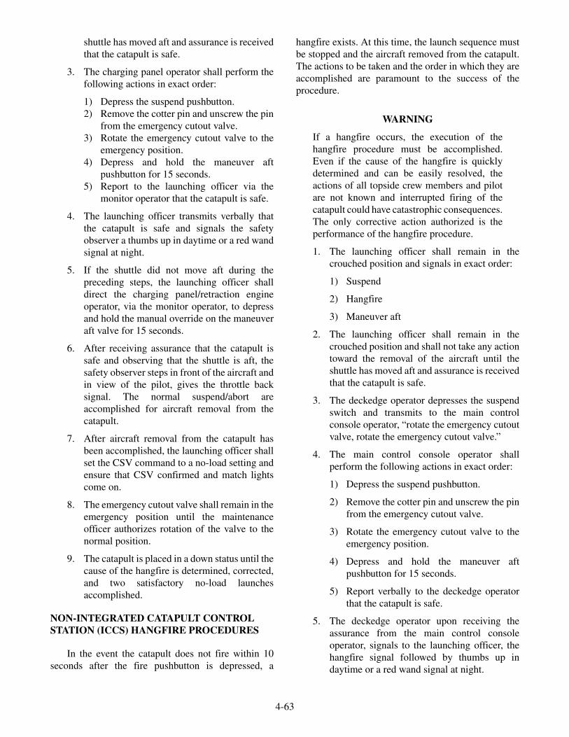
shuttle has moved aft and assurance is receivedthat the catapult is safe.
3. The charging panel operator shall perform thefollowing actions in exact order:
1) Depress the suspend pushbutton.2) Remove the cotter pin and unscrew the pin
from the emergency cutout valve.3) Rotate the emergency cutout valve to the
emergency position.4) Depress and hold the maneuver aft
pushbutton for 15 seconds.5) Report to the launching officer via the
monitor operator that the catapult is safe.
4. The launching officer transmits verbally thatthe catapult is safe and signals the safetyobserver a thumbs up in daytime or a red wandsignal at night.
5. If the shuttle did not move aft during thepreceding steps, the launching officer shalldirect the charging panel/retraction engineoperator, via the monitor operator, to depressand hold the manual override on the maneuveraft valve for 15 seconds.
6. After receiving assurance that the catapult issafe and observing that the shuttle is aft, thesafety observer steps in front of the aircraft andin view of the pilot, gives the throttle backsignal. The normal suspend/abort areaccomplished for aircraft removal from thecatapult.
7. After aircraft removal from the catapult hasbeen accomplished, the launching officer shallset the CSV command to a no-load setting andensure that CSV confirmed and match lightscome on.
8. The emergency cutout valve shall remain in theemergency position until the maintenanceofficer authorizes rotation of the valve to thenormal position.
9. The catapult is placed in a down status until thecause of the hangfire is determined, corrected,and two satisfactory no-load launchesaccomplished.
NON-INTEGRATED CATAPULT CONTROLSTATION (ICCS) HANGFIRE PROCEDURES
In the event the catapult does not fire within 10seconds after the fire pushbutton is depressed, a
hangfire exists. At this time, the launch sequence mustbe stopped and the aircraft removed from the catapult.The actions to be taken and the order in which they areaccomplished are paramount to the success of theprocedure.
WARNING
If a hangfire occurs, the execution of thehangfire procedure must be accomplished.Even if the cause of the hangfire is quicklydetermined and can be easily resolved, theactions of all topside crew members and pilotare not known and interrupted firing of thecatapult could have catastrophic consequences.The only corrective action authorized is theperformance of the hangfire procedure.
1. The launching officer shall remain in thecrouched position and signals in exact order:
1) Suspend
2) Hangfire
3) Maneuver aft
2. The launching officer shall remain in thecrouched position and shall not take any actiontoward the removal of the aircraft until theshuttle has moved aft and assurance is receivedthat the catapult is safe.
3. The deckedge operator depresses the suspendswitch and transmits to the main controlconsole operator, “rotate the emergency cutoutvalve, rotate the emergency cutout valve.”
4. The main control console operator shallperform the following actions in exact order:
1) Depress the suspend pushbutton.
2) Remove the cotter pin and unscrew the pinfrom the emergency cutout valve.
3) Rotate the emergency cutout valve to theemergency position.
4) Depress and hold the maneuver aftpushbutton for 15 seconds.
5) Report verbally to the deckedge operatorthat the catapult is safe.
5. The deckedge operator upon receiving theassurance from the main control consoleoperator, signals to the launching officer, thehangfire signal followed by thumbs up indaytime or a red wand signal at night.
4-63

6. If the shuttle did not move aft during thepreceding steps, the deckedge operator shalldirect the retraction engine operator to depressand hold the manual override on the maneuveraft valve for 15 seconds.
7. After receiving assurance that the catapult issafe and observing that the shuttle is aft, thelaunching officer steps in front of the aircraftand in view of the pilot, gives the throttle backsignal. The normal suspend/abort areaccomplished for aircraft removal from thecatapult.
8. After aircraft removal from the catapult hasbeen accomplished, the launching officer shallset the CSV command to a no-load setting.
9. The main control console operator shalldepress the set pushbutton.
10. The emergency cutout valve shall remain in theemergency position until the maintenanceofficer authorizes rotation of the valve to thenormal position.
11. The catapult is placed in a down status until thecause of the hangfire is determined, corrected,and two satisfactory no-load launchesaccomplished.
SAFETY PRECAUTIONS
There are certain safety precautions that must beobserved by catapult-operating personnel, maintenancepersonnel, deck personnel, pilots, and other personnelstationed in the catapult area.
Flight Deck
Bridle (deck) tensioner pressure, as determined bycalibration, must be precisely adjusted and maintainedat all times. Pressures in excess of those specified maycause premature holdback.
In the event of a malfunction, suspend, or hangfire,the signal for throttle back must NOT be given to thepilot until bridle tension has been released and thelaunch bar is raised.
When attaching the aircraft to the shuttle, extremecare must be taken so that the launch bar properlyengages the shuttle. The catapult officer must ensurethat the aircraft is properly tensioned prior to launching.
Precaution should be taken by the pilot not to taxihard against the holdback unit. This may result in apremature release.
At no time are personnel to walk in front of atensioned aircraft.
If operation of the catapult is suspended for anyreason, bridle tension should be released and theaircraft released from the shuttle.
The shuttle and grab must not be moved along thecatapult track until the track slot has been inspected andfound to be clear of obstructions and all adjacent areasare clear of loose gear. Using the maneuver forward andaft push buttons, slowly move pistons forward and aftwhile all sheaves are visually checked to ensure thecables are not sliding over any locked sheaves.
All personnel must be kept out of areas forward ofan aircraft positioned on the catapult, and clear of theshuttle track area during a no-load firing. All personnelmust be kept clear of the area immediately behind thejet blast deflectors during aircraft turnups andlaunching.
During night operations, do not attempt to speed upthe prelaunch check of catapult components or takeunnecessary chances in an effort to maintain rapidaircraft launching intervals. Sufficient time should betaken to double-check each step to prevent accidentsdue to faulty hookups, misinterpreted signals, and othercauses.
ICCS, CCP, Deckedge and/or Main ControlConsole
Retraction must not be undertaken unless the waterbrakes are operating properly and the grab and shuttleare latched. During preheating and throughoutlaunching operations, the difference in elongationbetween the two launching engine cylinders must NOTexceed 1 inch. The catapult must NOT be fired with theshuttle out of BATTERY.
The shuttle must NOT be retracted with steam inaccumulators unless the water brakes are functioning.
Do not advance the grab with spears out of thewater brakes because possible grab latch damage mayresult, due to impact. Therefore, use the maneuverforward push button to advance the grab until it engagesthe shuttle.
4-64

Water Brakes
If the water-brake cylinder elbow pressure dropsbelow minimum value the water brakes should besuspended and the CCP/main control console operatornotified immediately. The malfunctioning water-brakepump should be secured and the standby pump started.
Do not allow excessive oil to accumulate on top ofthe water in the water-brake reservoir. Skim off the oil,or remove it by adding fresh water and allowing the oilto flow out the overflow drain.
NOTE
During in-port periods, do not skim thewater-brake tanks or allow the water level toreach the overflow pipe. Maintain the waterlevel by use of bottom tank drains. This is toprevent oil from being dumped into harbors.
Retraction Engine
All loose gear and tools must be kept clear of theretraction engine and cable system. Maintain allpressures at predetermined settings.
If any malfunction is observed during the advanceof the grab or the retraction of the shuttle and grab,immediately SUSPEND the retract engine and notifythe CCP/main console operator. All sheaves must beinspected for freedom of motion before beginning aseries of launchings.
General
Operating personnel should wear appropriateprotective clothing to prevent burns from steam or fromcontact with hot metallic surfaces. Earplugs should beworn in areas of high noise level.
The entire hydraulic system must be ventedthoroughly and frequently, particularly after extendedperiods of idleness. Air in the fluid system may causeunpredictable variations in catapult performance anddelays in actuation of operating components.
Combustible and volatile fluids and materials mustbe kept away from heated catapult parts to reduce thehazard of fire and explosion. Adequate ventilation mustbe provided below flight deck level to prevent theaccumulation of explosive vapors.
If a hangfire occurs, personnel must not passforward of the aircraft until all danger of a delayedlaunching has passed.
The catapult must NOT be operated with anyknown broken lockwires, loose or cracked components,major hydraulic leakage, defective reeving, or electricalcontrol malfunction.
During any type of launching, live steam escapesfrom the track and brake areas. As this steam can causesevere scalding of exposed areas of the body, personnelin the area must avoid contact with it. When the catapultis in operating status, exposed metallic parts, such astrack covers, launching and exhaust valves, and steamsupply piping, may be hot enough to burn exposedareas of the body on contact. Therefore, operatingpersonnel with duties in these areas should be equippedwith appropriate protective clothing.
Aircraft launchings must NOT be made if therequired minimum cylinder elongation has not beenattained. An exception to this rule may be made underemergency conditions when wind-over-deckrequirements have been increased as specified inapplicable Aircraft Launching Bulletins.
Aircraft must not be launched at weights and windrequirements other than those specified in applicableAircraft Launching Bulletins. Maximum loading ofaircraft as specified in the NATOPS Manual for eachtype of aircraft, must be adhered to at all times.
Inspect all pumps and their limit switches andsafety valves. Failure of safety devices can result indangerous overpressures if the pump continues tooperate. This condition may result in rupture ofhydraulic pneumatic lines and danger to personnel.
SECURING THE CATAPULT
At the completion of aircraft launching operations,the catapult officer shall decide what state of catapultreadiness will be maintained. Depending onoperational requirements, one of the followingreadiness conditions will be established:
Ready
The order to maintain the catapult in a READYcondition should be given when launching operationsare intermittent or when certain conditions make itnecessary to keep the catapult in a state of preparednessfor launching within seconds after an order is given.
In the READY condition, the catapult is kept in afully operational status, as between launching cycles.
4-65

Standby
If the order for the STANDBY condition ofsecuring is given, it usually comes after the day'slaunching operations are completed and there is nopossibility of additional launching within 12 hours.
The post-launch duties and inspection must beperformed according to the MRCs.
Shutdown
The order for SHUTDOWN condition of securingthe catapult is given when the catapult is placed out ofservice for maintenance or when the ship is in port.
Cold Iron
When the catapult will not be required forlaunching operations for an extended period of time, orthe steam system and preheat system must be securedand the components allowed to cool down.
INSPECTIONS AND MALFUNCTIONS
The entire catapult should be kept as clean aspossible. It should be wiped down daily to removeexcess grease, oil, and dirt. All catapult personnelshould be constantly alert for any unusual sound oraction of the machinery. Report any unusual conditionto the catapult officer for immediate investigation.
Periodic Inspections
Prior to the first launching of each day's operations,execute the PMS preoperational inspection accordingto the MRCs.
After each day's operation, perform the PMSpostoperational inspection according to the MRCs.
Other inspections must be conducted in addition topreoperational and postoperational. These inspectionsare also accomplished through the use of MRCs.
Prior to conducting an inspection or maintenanceon catapult equipment where an injury could occurfrom careless operation, make sure the following safetyprecautions have been accomplished in the orderindicated:
1. Disconnect the grab from the shuttle and moveit fully aft.
2. Close the main steam supply to the steamaccumulator.
3. Reduce steam pressure in the steamaccumulator to atmospheric pressure.
4. Open the retraction-engine accumulatorblowdown valve.
5. Station a safety person at the ICCS, CCP, maincontrol console and deckedge control manningsound-powered telephones to preventtampering with catapult controls.
6. Station a safety person at the retraction engineand the water-brake tank, manningsound-powered telephones.
7. Tag the steam-smothering valve "out ofservice."
8. Station a safety person on the flight deck (in theshuttle area) to prevent accidental movement ofthe shuttle while personnel are in thewater-brake tank.
The preceding safety instructions must be strictlyfollowed. Under any conditions when inspection of thewater brakes area is undertaken, it is imperative that thecontrol system remain in a SAFE position (exhaustvalve open, grab aft).
Malfunctions
This section provides operating personnel with aguide to assist in isolating and correcting causes ofmalfunctions. During aircraft launch operations,malfunctions may occur that can be rapidly corrected ifthe cause is correctly determined. In other cases,corrective action may require extensive repairs, and it isimportant that operating personnel rapidly isolate thecause of the malfunction in order to inform the catapultofficer if the catapult must be placed out of service.
When a malfunction occurs, the catapult must beput in a SAFE condition before corrective action isattempted, to prevent accidental launching of aircraft orinjury to personnel.
To property correct any malfunction(s) all primarycauses should be checked first to quickly isolate themalfunction to a specific system. The secondary causescan then be checked to determine which component(s)within the system caused the malfunction.
All preoperational and post operational inspectionprocedures that apply to a specific system or station ofthe catapult are to be conducted and completed by theperson or persons assigned the duty. For detailedinspection procedures, the ABE must consult theapplicable MRCs or technical manuals.
4-66

REVIEW QUESTIONS
Q13. When are no loads conducted?
Q14. A hangfire exists when the catapult does notfire within what amount of time after the firepushbutton has been pressed?
SUMMARY
We have described functions and operations of themajor catapult systems, descriptions of ICCS, centralcharging panels, main control consoles, and generalmaintenance procedures. For a more detailed study ofthe catapult systems and components, see theapplicable NAVAIR technical manuals with the latestrevisions.
4-67

�
�

CHAPTER 5
ASSOCIATED LAUNCHING EQUIPMENT
The associated launching equipment discussed inthis chapter is used in conjunction with catapults andarresting gear. This equipment includes the jet blastdeflectors and nose gear launch equipment.
JET BLAST DEFLECTORS
LEARNING OBJECTIVES: Identify thecomponents of the jet blast deflectors.Describe the operation of the jet blastdeflectors. Describe the emergency operationsof the jet blast deflectors.
The jet blast deflector (JBD) installation consists ofwater-cooled panels that are mounted flush with theflight deck. The panels are raised and lowered byhydraulic cylinders connected to mechanical operatinggear. When raised, the JBDs serve to protect personnel,equipment and other aircraft from the hot jet exhaustcreated by an aircraft spotted on the catapult. Seawater,supplied from the ship’s firemain, is continuouslycirculated through the modules of each panel assemblyto prevent overheating. Figure 5-1 shows the basicoperation of JBDs.
5-1
WATER IN
WATER RETURN
PRESSURIZEDHYDRAULIC FLUID
HYDRAULIC FLUIDRETURN
ABEF0501
Figure 5-1.—Jet blast deflector operations.

Jet Blast Deflector Assembly
The JBD assembly (fig. 5-2) consists of a series ofwater-cooled panels and operating gear assemblies.The Mk 7 Mod 0/2 JBD assembly is comprised of sixpanel assemblies with three sets of operating gear while
the Mk 7 Mod 1 JBD assembly has four panelassemblies and two sets of operating gear. The Mk 7Mod 2 JBD contain two additional sideplate coolingpanels. The sideplate cooling panels provide additionalcooling which helps to prevent warping of the JBDpanels.
5-2
WATER-COOLED PANEL ASSEMBLY
OPERATING GEAR ASSEMBLY(MK 7 MOD 0/2)
WATER-COOLED PANEL ASSEMBLY
OPERATING GEAR ASSEMBLY(MK 7 MOD 1)
ABEF0502
Figure 5-2.—Jet blast deflector assembly.

Regardless of the JBD installation, the operation isthe same. A pair of JBD panels is connected to a set ofoperating gear. The panel assemblies can be raisedindependently or simultaneously with others in thesame installation. By connecting a pair of panels to a setof operating gear, one cylinder can raise or lower a pairof JBD panels in the event of a failure to the othercylinder.
Operating Gear Assembly
The operating gear assembly (fig. 5-3) provides themeans of physically raising and lowering the JBDpanels. A set of operating gear consists of two hydrauliccylinders, three bearing blocks, one trunnion shaft, twocrank assemblies and four linkage assemblies. Eachlinkage assembly consists of an arm, strut and eye. Thelinkage for two JBD panels is connected to a single
shaft. This method of attachment permits raising andlowering the JBD panels in pairs. The trunnion shaft ismounted and supported by the three bearing blockassemblies. The two hydraulic cylinders are connectedto the to the trunnion shaft by means of the crankassemblies.
Movement of the hydraulic cylinder piston rodsrotates the shaft. Rotation of the trunnion shaft extendsor retracts the linkage to raise or lower the JBD panels.Magnets, attached to the linkage arm and eyeassemblies, actuate limit switches mounted to bracketson the side of the operating gear deck cutouts toindicate position of the panel assemblies. Removablepanel supports can be attached to the operating gear andflight deck to lock panels in the raised position formaintenance, or if access to the area beneath the panelsis required.
5-3
LUBRICATION LINEAND FITTING
LINKAGE(ARM, STRUT, AND EYE
HYDRAULICCYLINDER
EMERGENCYPANEL SUPPORT
FLIGHT DECK(REF)
HYDRAULICCYLINDERSHAFT
CRANK
BEARINGBLOCK
LUBRICATIONFITTINGS
ABEf0503
LUBRICATIONFITTING
Figure 5-3.—Operating gear assembly.
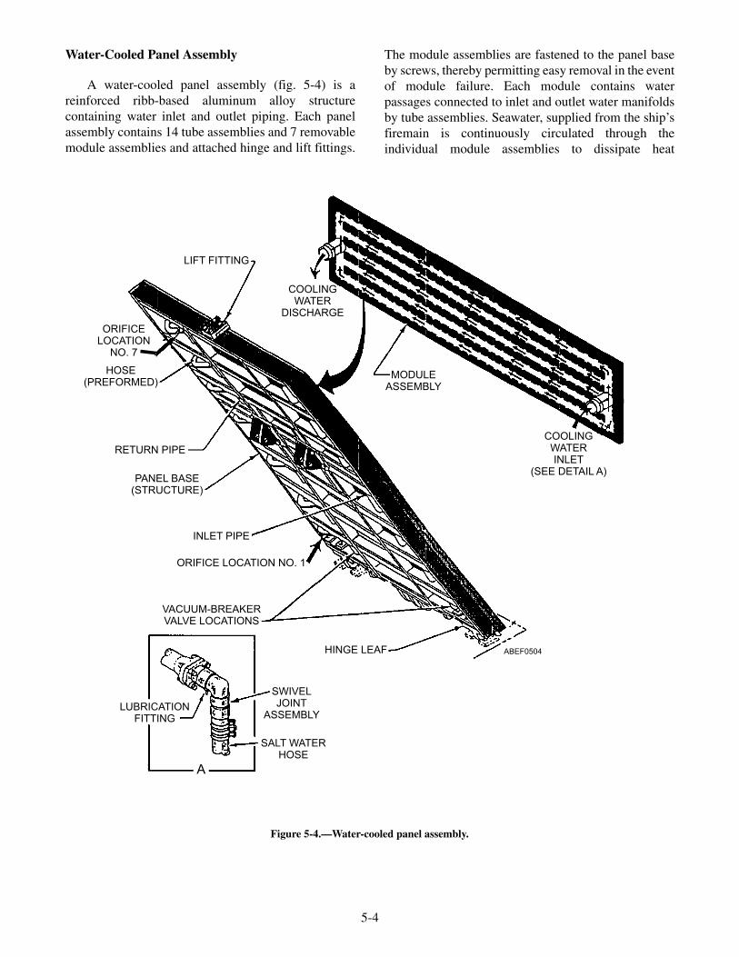
Water-Cooled Panel Assembly
A water-cooled panel assembly (fig. 5-4) is areinforced ribb-based aluminum alloy structurecontaining water inlet and outlet piping. Each panelassembly contains 14 tube assemblies and 7 removablemodule assemblies and attached hinge and lift fittings.
The module assemblies are fastened to the panel baseby screws, thereby permitting easy removal in the eventof module failure. Each module contains waterpassages connected to inlet and outlet water manifoldsby tube assemblies. Seawater, supplied from the ship’sfiremain is continuously circulated through theindividual module assemblies to dissipate heat
5-4
LIFT FITTING
ORIFICELOCATION
NO. 7
HOSE(PREFORMED)
RETURN PIPE
PANEL BASE(STRUCTURE)
INLET PIPE
ORIFICE LOCATION NO. 1
VACUUM-BREAKERVALVE LOCATIONS
SWIVELJOINT
ASSEMBLY
SALT WATERHOSE
LUBRICATIONFITTING
A
HINGE LEAF
COOLINGWATERINLET
(SEE DETAIL A)
MODULEASSEMBLY
COOLINGWATER
DISCHARGE
ABEF0504
Figure 5-4.—Water-cooled panel assembly.

generated by jet exhaust. An orifice located in thereturn line connection of each module controls the flowrate of cooling water within the module assemblies. Aremovable hinge protector plate located below thebottom module of each panel assembly, permits easyaccess to the hinge bearing and fitting for maintenance.
Cooling Water Piping Installation
The cooling water piping installation (fig. 5-5)consists of a strainer, swivel joint assemblies, orificeflange assemblies, temperature switch, pressure switch,pressure gauges and associated piping and connections.Seawater, supplied by the ship’s firemain, iscontinuously circulated through each module assemblyand then discharged overboard. The strainer removesparticles, which could clog water passages in themodules. The swivel joint assemblies provide a meansof connecting the water manifolds, via hoses, to theseawater supply piping. The swivel joint also permitsrotational movement of the piping as the JBD is raisedor lowered. Two orifices flange assemblies are providedto regulate the cooling water flow rate. The inlet orifice
flange is not used and cooling water flow at thatlocation is line sized. The outlet flange assembly orificeis sized to provide a flow rate of approximately 1,200gallons per minute.
A temperature switch, located near the waterdischarge of one of the center JBD panels, will close ifthe cooling water reaches 210°F and alert the JBDoperator by lighting a red temperature light on thecontrol panel. A pressure switch, located in the lineleading to the overboard discharge, will close if thewater pressure drops below the setting that determinedadequate flow rate and alert the JBD operator bylighting a red pressure light on the control panel.Pressure gauges, located on the control panel, providean indication of cooling water pressure being suppliedby the ship’s firemain. The cooling water pressure mustbe maintained at a minimum of 90 psi. An additionalpressure gauge, located upstream of the dischargeorifice, is provided. A drop in pressure at this gaugeindicates blockage within the cooling water system orinadequate firemain pressure. During JBDcertification, the normal discharge pressure andpressure switch setting is determined.
5-5
LUBRICATIONFITTING
SWIVELJOINTASSEMBLYSALT
WATERHOSE
SALT WATERDISCHARGEOVERBOARD
VALVE
OUTLET FLANGE ASSEMBLYWITH ORIFICE PLATE
PRESSURESWITCH
PRESSUREGAUGE PIPING
DECKEDGE CONTROLPANEL (IF USED)
AUXILIARYCONTROL
PANEL (REF)
VALVE
PRESSUREGAUGE
STRAINER (REF)
INLET FLANGE ASSEMBLYWITH ORIFICE PLATE
TEMPERATURESWITCH
VIEW AABEf0505
A
Figure 5-5.—Cooling water piping installation.

Hydraulic Control Piping Assembly
The hydraulic control piping assembly (fig. 5-6)consists of the control valves (stack valves), hoseconnections, and associated piping and fittings.Hydraulic fluid is provided to the JBDs by an inlet lineand shutoff valve connected to the main catapulthydraulic system. The inlet branches off into three lines(Mk 7 Mod 0/2) or two lines (Mk 7 Mod 1) with eachline connecting to a stack valve. The stack valvecontrols the flow of hydraulic fluid to and from thehydraulic cylinders. Emergency-lowering bypass linesand valves are connected to the raising side of each
cylinder and to the gravity tank return lines. The bypasslines permit routing of fluid around the stack valve andare only used during an emergency situation to lowerthe JBD panels.
An orifice assembly is provided in the line to theraising side of the hydraulic cylinders which maintainscontrol of fluid flow for both the raising and loweringsequence. Shutoff valves are located in each line of thehydraulic cylinders for emergency and maintenancepurposes. Hose assemblies provide a flexible con-nection between the hydraulic cylinders and piping tocompensate for movement of the cylinders duringraising and lowering operations.
5-6
PORT B
PORT A
REFER TO VIEW D
TO ATMOSPHEREEMERGENCY LOWERING
BYPASS LINEAUXILIARYCONTROL
PANEL
VIEW A VIEW B VIEW C VIEW D
TO GRAVITY TANK
FROM CATAPULT HYDRAULIC SYSTEM
FOUR-WAY CONTROLVALVE (STACK VALVE)
TO ATMOSPHERE TO ATMOSPHERE
REFER TOVIEW A
REFER TO VIEW C
REFER TOVIEW B
PRESSUREGAUGEPIPING
EMERGENCY LOWERING BYPASSSHUTOFF VALVE
CYLINDER PORTS A AND BSHUTOFF VALVE ORIFICE ASSEMBLY HOSE ASSEMBLY
ABEF0506
DECKEDGECONTROL PANEL
(IF USED)SYSTEM
SHUTOFFVALVE
Figure 5-6.—Hydraulic control piping assembly.
Four-way Control Valve (Stack Valve)
A four-way control valve (stack valve) (fig. 5-7)controls the flow of hydraulic fluid to and from a pair ofhydraulic cylinders. The stack valve is a solenoidcontrolled, pilot-operated valve assembly. The stackvalve consists of a solenoid-operated valve, apilot-operated main valve, and a sequence valve. Allthree valves are secured together to conserve space andsimplify connection to a subplate or manifold. Onestack valve controls fluid flow for a pair of panelassemblies. Three stack valves are required for Mk 7Mod 0/2 and two stack valves for Mk 7 Mod 1 JBDs.Hydraulic fluid at 2,500 psi from the associatedcatapult is supplied to the stack valve with all fluidreturn lines going to that catapult gravity tank. Theoperation of a stack valve is described as follows:
1. With hydraulic fluid at normal operatingpressure and neither solenoid B (raise) norsolenoid A (lower) energized, fluid flowsthrough the sequence valve and pilot valve toboth sides of the slide in the main valve. Thispressure to both sides of the slide keeps itcentered and blocks fluid flow into and out ofboth ends of the hydraulic cylinders.
2. When a raise switch is actuated, solenoid B inthe pilot valve energizes, shifting the spool anddirecting pressure to a pilot port at the main
valve side. The slide shifts and directs fluid toport A of both hydraulic cylinders. Thehydraulic cylinder pistons extend, pushing thecrank assembly of the operating gear aft androtating the shaft. Rotation of the shaft extendsthe operating gear linkage and raises theassociated panel assemblies. During the raisecycle, fluid in the cylinder lower port B vents tothe gravity tank through the main valve. If theraise switch is released during the raise cycle,solenoid B deenergizes, a spring returns thesolenoid spool to the centered position, andpanel movement will stop. Fluid flow will be asdescribed above in step a.
3. When a lower switch is actuated, solenoid A inthe pilot valve energizes, shifting the spool anddirecting pressure to a pilot port at the mainvalve slide. The slide shifts in the opposite(from raising) direction and directs fluid to portB of both hydraulic cylinders. The pistonsretract, pulling the crank assembly of theoperating gear forward and rotating the shaft.The rotation of the shaft retracts the operatinggear linkage and lowers the panels. During thelower cycle, fluid in the raise port A vents tothe gravity tank through the main valve. . If thelower switch is released during the lower cycle,solenoid A deenergizes, a spring returns the
5-7
SOLENOID-OPERATEDPILOT VALVE
SOLENOID B
MANUAL PUSH PIN(BOTH ENDS)
SOLENOID A
THREADED FITTINGFOR CONDUITCONNECTION
PILOT-OPERATEDMAIN VALVE
SEQUENCEVALVE
ABEf0507
Figure 5-7.—Four-way control valve.

5-8
BLEEDVALVE
VENTPIPING
HOSEASSEMBLY
CAPASSEMBLY
BLEEDVALVE
ABEF0508
Figure 5-8.—Cylinder vent piping installation.
TRANSFERSWITCH
TO SALTWATERSHUTOFF VALVES
COOLING WATERPRESSURE SALTWATER (REF)
COOLING WATER TEMPERATURE SALTWATER (REF)
FOUR WAY CONTROL VALVES(STACK VALVES)
MACHINERY ROOMENCLOSURE PANEL
LIMIT SWITCH(REF)
CUTOUTSWITCH
28VDCON/OFFSWITCH
AUXILIARY CONTROLPANEL
RELAYTERMINAL
BOX
SALTWATERVALVE
JUNCTION BOX
(PORTABLE AND AUXILIARY)
ABEf0509
CHESTPACK
Figure 5-9.—Electrical control assembly.
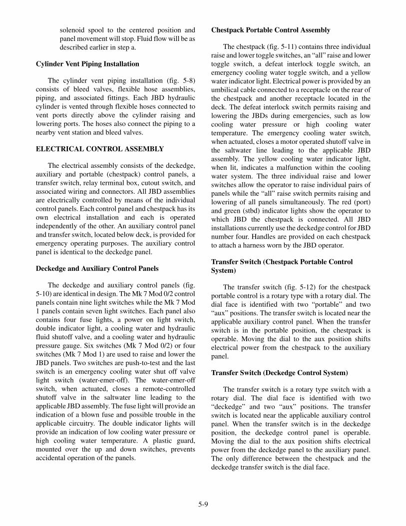
solenoid spool to the centered position andpanel movement will stop. Fluid flow will be asdescribed earlier in step a.
Cylinder Vent Piping Installation
The cylinder vent piping installation (fig. 5-8)consists of bleed valves, flexible hose assemblies,piping, and associated fittings. Each JBD hydrauliccylinder is vented through flexible hoses connected tovent ports directly above the cylinder raising andlowering ports. The hoses also connect the piping to anearby vent station and bleed valves.
ELECTRICAL CONTROL ASSEMBLY
The electrical assembly consists of the deckedge,auxiliary and portable (chestpack) control panels, atransfer switch, relay terminal box, cutout switch, andassociated wiring and connectors. All JBD assembliesare electrically controlled by means of the individualcontrol panels. Each control panel and chestpack has itsown electrical installation and each is operatedindependently of the other. An auxiliary control paneland transfer switch, located below deck, is provided foremergency operating purposes. The auxiliary controlpanel is identical to the deckedge panel.
Deckedge and Auxiliary Control Panels
The deckedge and auxiliary control panels (fig.5-10) are identical in design. The Mk 7 Mod 0/2 controlpanels contain nine light switches while the Mk 7 Mod1 panels contain seven light switches. Each panel alsocontains four fuse lights, a power on light switch,double indicator light, a cooling water and hydraulicfluid shutoff valve, and a cooling water and hydraulicpressure gauge. Six switches (Mk 7 Mod 0/2) or fourswitches (Mk 7 Mod 1) are used to raise and lower theJBD panels. Two switches are push-to-test and the lastswitch is an emergency cooling water shut off valvelight switch (water-emer-off). The water-emer-offswitch, when actuated, closes a remote-controlledshutoff valve in the saltwater line leading to theapplicable JBD assembly. The fuse light will provide anindication of a blown fuse and possible trouble in theapplicable circuitry. The double indicator lights willprovide an indication of low cooling water pressure orhigh cooling water temperature. A plastic guard,mounted over the up and down switches, preventsaccidental operation of the panels.
Chestpack Portable Control Assembly
The chestpack (fig. 5-11) contains three individualraise and lower toggle switches, an “all” raise and lowertoggle switch, a defeat interlock toggle switch, anemergency cooling water toggle switch, and a yellowwater indicator light. Electrical power is provided by anumbilical cable connected to a receptacle on the rear ofthe chestpack and another receptacle located in thedeck. The defeat interlock switch permits raising andlowering the JBDs during emergencies, such as lowcooling water pressure or high cooling watertemperature. The emergency cooling water switch,when actuated, closes a motor operated shutoff valve inthe saltwater line leading to the applicable JBDassembly. The yellow cooling water indicator light,when lit, indicates a malfunction within the coolingwater system. The three individual raise and lowerswitches allow the operator to raise individual pairs ofpanels while the “all” raise switch permits raising andlowering of all panels simultaneously. The red (port)and green (stbd) indicator lights show the operator towhich JBD the chestpack is connected. All JBDinstallations currently use the deckedge control for JBDnumber four. Handles are provided on each chestpackto attach a harness worn by the JBD operator.
Transfer Switch (Chestpack Portable ControlSystem)
The transfer switch (fig. 5-12) for the chestpackportable control is a rotary type with a rotary dial. Thedial face is identified with two “portable” and two“aux” positions. The transfer switch is located near theapplicable auxiliary control panel. When the transferswitch is in the portable position, the chestpack isoperable. Moving the dial to the aux position shiftselectrical power from the chestpack to the auxiliarypanel.
Transfer Switch (Deckedge Control System)
The transfer switch is a rotary type switch with arotary dial. The dial face is identified with two“deckedge” and two “aux” positions. The transferswitch is located near the applicable auxiliary controlpanel. When the transfer switch is in the deckedgeposition, the deckedge control panel is operable.Moving the dial to the aux position shifts electricalpower from the deckedge panel to the auxiliary panel.The only difference between the chestpack and thedeckedge transfer switch is the dial face.
5-9
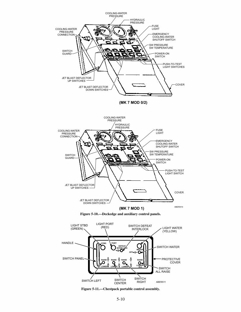
5-10
COOLING-WATERPRESSURE
CONNECTION
SWITCHGUARD
JET BLAST DEFLECTORDOWN SWITCHES
COOLING-WATERPRESSURE
FUSELIGHT
SW PRESSURESW TEMPERATURE
PUSH-TO-TESTLIGHT SWITCHES
COVER
(MK 7 MOD 0/2)
COOLING-WATERPRESSURE
HYDRAULICPRESSURE
FUSELIGHT
EMERGENCYCOOLING-WATERSHUTOFF SWITCH
SW PRESSURESW TEMPERATURE
POWER-ONSWITCH
PUSH-TO-TESTLIGHT SWITCH
COVER
JET BLAST DEFLECTORDOWN SWITCHES
JET BLAST DEFLECTORUP SWITCHES
SWITCHGUARD
COOLING-WATERPRESSURE
CONNECTION
POWER-ONSWITCH
HYDRAULICPRESSURE
EMERGENCYCOOLING-WATERSHUTOFF SWITCH
JET BLAST DEFLECTORUP SWITCHES
ABEf0510(MK 7 MOD 1)
Figure 5-10.—Deckedge and auxiliary control panels.
LIGHT STBD(GREEN)
LIGHT PORT(RED) SWITCH DEFEAT
INTERLOCK LIGHT WATER(YELLOW)
SWITCH WATER
PROTECTIVECOVER
SWITCHALL RAISE
SWITCHRIGHT
SWITCHCENTER
SWITCH LEFT
SWITCH PANEL
HANDLE
ABEf0511
STBD PORT
WATER
OFF
RAISE
LOWER
RAISE
LOWER
RAISE
LOWER
RAISE
LOWER ALL
DEFEATINTERLOCK
Figure 5-11.—Chestpack portable control assembly.

PANEL SUPPORT INSTALLATION ANDEMERGENCY LOWERING DEVICEINSTALLATION
The panel support and emergency lowering deviceinstallation (fig. 5-13) consists of the panel supportstanchions, panel supports, and an emergency loweringdevice. Panel support stanchions are to be used anytimepanel supports are being installed or removed. Thepanel support stanchions are positioned between theraised JBD panel and lip of the flight deck. The panelsupport stanchion is designed to support the weight of apair of fully raised JBD panels; however, the stanchionwill not prevent the lowering of JBDs under pressure.
To provide a total margin of safety, panel supportsmust be property installed prior to any maintenance
5-11
ROTARY DIAL
ABEF0512
Figure 5-12.—Transfer switch (Chestpack control system).
INSTALLQUICK-RELEASE PINTHRU BRACKETAND THRU PANELSUPPORT AS SHOWN
PANELSUPPORT
EYE ON LINKAGE
FLIGHT DECK
SEE VIEW B
PANELSUPPORT
STRUCTURALSTOP PANEL SUPPORT
(SEE VIEW A)
PANEL SUPPORTSTANCHION
JBD PANEL
FLIGHT DECK
OPERATING LINKAGE
VIEW B
VIEW A
ABEf05013
JBD PIT
EMERGENCYLOWERINGBAR
EMERGENCY LOWERING DEVICE
Figure 5-13.—Panel support and emergency lowering installation.

being conducted under JBD panels. The panel supportsattache to the JBD operating linkage arm assembly,with a quick release pin and fit into an indentation in thedepressed deck area (JBD pit) at the forward end. Thepanel supports are used to lock panels in the raisedposition for maintenance purposes or emergencies. Apanel support is provided for each set of operating gear,three supports for Mk 7 Mod 0/2 and two for Mk7 Mod1 JBDs.
The emergency lowering device connects to a towtractor on one end and fits against the operating linkagearm assembly at the other end. This allows the tractor topush the operating linkage “over-center”. With theemergency bypass valves open, the weight of the panelswill then force fluid from the raise end of the hydrauliccylinders through the emergency bypass valvepermitting the panels to slowly lower.
Preparation for Use
When the JBDs are put in operation for the firsttime or after being idle, use the following procedures:
1. Perform the preoperational inspection accord-ing to the applicable maintenance requirementcard (MRC).
2. Ensure that personnel, aircraft, and flight deckequipment are clear of the panel area beforeattempting to raise the JBDs.
CAUTION
Damage by excessive heat can result fromjet engine exhaust if cooling water is notflowing at the correct pressure.
3. Check to ensure salt water supplied from theship's fire main is flowing through thewater-cooled panels.
4. Functionally test the JBD hydraulic andelectrical system for proper operation andleaks.
EMERGENCY OPERATION PROCEDURES
In the event of an emergency or a malfunction, theprocedures discussed in the following paragraphs mustbe followed. The emergency lowering of a JBD willrequire a minimum of eight personnel:
• Topside Safety Petty Officer (overall in charge)
• Topside JBD phone talker
• Below decks phone talker/Valve operator
• Two personnel to install emergency loweringdevice
• Two safety observers (stationed at the port andstarboard sides of the JBD panels)
• Tractor driver
Electrical Control Failure
Should the chestpack, deckedge, and auxiliarycontrol panels become affected by an electrical powerfailure and the hydraulic system is functional, proceedas follows:
1. Station a crewperson to act as a valve operatorat the stack valves. The valve operator shall beequipped with a sound-powered phone set. Thechestpack or JBD deckedge operator shallremain at his or her station and relayinstructions to the valve operator. The JBDdeckedge or auxiliary panel operator shall alsomonitor the pressure gauges.
2. The valve operator, when instructed by thechestpack or JBD deckedge operator, shallraise or lower the JBD panels by the manualpush pins of the A and B solenoids of the stackvalves. The B solenoid controls the raising ofthe panels, and the A solenoid controls thelowering.
Hydraulic Control Failure
Should the JBD hydraulic system fail with theJBDs in the FULL-UP position, the followingprocedures must be used to lower the panels:
1. Establish sound-powered phone communica-tion between the valve operator and thechestpack or deckedge operator.
WARNING
Ensure all tag-out procedures areaccording to current shipboard instructions.
2. Close the main supply valve and attach a safetytag.
3. Open the applicable emergency bypass valvesone-quarter turn or as necessary to control thelowering speed of the panel.
4. Using the panel emergency-lowering device,place the fitted end against the panel linkage
5-12

arm and attach the ring end to a tractor towhook. Push with the tractor until the operatinggear linkage unlocks.
WARNING
Once the emergency lowering device isinstalled, all hands shall stand back at a safedistance from the JBD and around tractor. Asthe JBD begins to lower, the emergencylowering device will be dragged out of the JBDpit by the tractor utilizing reverse gear.
5. Adjust the panel lowering speed byopening/closing the emergency bypass valve.
6. Once the strut is over-center, the JBD panelswill fall under its own weight until it is flushwith the deck.
Inoperative Deckedge Control Panel or PortableElectrical System Control Box
In the event of an emergency where the chestpackor the deckedge control panel cannot be used, theauxiliary control panel becomes operational.
1. Station a crewperson at the flight deck ordeckedge to man the phone and relayinstructions to the auxiliary-control-paneloperator.
WARNING
The crewperson, acting as a safetyobserver, should ensure that the area around theJBD is clear of aircraft, support equipment, andpersonnel.
2. With the transfer switch in the AUX position,the auxiliary-control-panel operator shalloperate the panel by the instructions relayed tohim or her from the flight deck or deck edgepersonnel.
CAUTION
Repair and checkout of the faulty panel orcontrol box operation shall be accomplished attimes when the raising or lowering of the JBDwould not be prohibited by aircraft movementon the flight deck.
3. Continue operation of the auxiliary controlpanel until the faulty chestpack or deckedge
control panel is completely checked out andrestored to proper operating condition.
WARNING
Prior to returning control back to deckoperation, verify with the flight deck safetyobserver that the area around the JBD is clearof aircraft, support equipment, and personnel.
4. Return control of the JBD to the chestpack ordeckedge operator.
MAINTENANCE
This section contains preventive and correctivemaintenance information and procedures, some ofwhich are general and apply to various items of thesystem and others which are specific and apply to aparticular part of the equipment.
Planned Maintenance
The planned maintenance system furnishes allvessels and stations with MRCs containing specificmaintenance instructions. These cards are used atrequired frequencies to maintain JBD equipment inoperating condition and to prevent breakdown andsubsequent shutdown of operations. The plannedmaintenance system and the maintenance datacollection system are described in OPNAVINST4790.4.
Current MRCs include the following inspectionand cleaning procedures:
1. Preoperational inspections
2. Postoperational inspections
3. Cleaning and inspecting hydraulic pipingorifice plate(s)
WARNING
Before performing any maintenanceprocedures behind a JBD panel in the raisedposition, install the panel supports to preventthe panel from lowering. Failure to do thiscould result in serious injury to personnel.
To ensure dependable operation of the JBDequipment, proper lubrication of the mechanicallinkage is essential. Lubrication is part of thepreoperational checks given in the MRC. Extensiontubes are provided on trunnion bearings and hydraulic
5-13

cylinder bracket assemblies so that all lube fittings canbe reached from the deck.
PROTECTING OPEN EQUIPMENT.—Whenremoving a component from the hydraulic system, capor plug all openings to prevent entry of foreign matter.Use tape to protect pipe threads.
CLEANING.—Hydraulic system componentsmust be disassembled, cleaned, repaired, andreassembled as specified in the operation, maintenance,and overhaul instructions manual for the specific typeof JBD installation on your ship.
WARNING
Before repairing or removing anycomponents connected to hydraulic or waterlines, make sure the lines are depressurized.Also, before repairing or removing any elec-trical component, de-energize the electricalcircuit and attach an out-of-service tag.
HOSES, SEALS, AND O-RINGS.—Hoses,seals, and O-rings are selected on the basis of theircompatibility with the hydraulic fluid. Therefore,replacement parts should be of the same material asoriginal parts. O-rings must be removed and replacedwith care to avoid damage to the O-ring and O-ringsealing surfaces of the various parts. O-rings must befree of cuts and not deformed. New O-rings must beinstalled at every reassembly of components. Beforeassembly, all O-rings must be lightly lubricated withthe system hydraulic fluid. Hoses are subject to wearand require periodic replacement. When installinghoses, take care to avoid unnecessary bends andoverstressing.
To restore the JBD system to operating conditionafter a down period that required draining fluid,perform preoperational inspection procedures given inthe applicable MRC.
For most repairs to the hydraulic system, onlyportions of the system need be drained. Isolation valvesin each of the hydraulic cylinder lines and a shutoffvalve between the stack valve and the catapult pumpspermit isolation of portions of the JBD hydraulicsystem.
Troubleshooting
Most problems that occur on JBDs can berecognized as a failure of one of threesystems—namely, hydraulic, electrical, or water.
Information that allows operating and maintenancepersonnel to locate the source of problems orequipment failure is found in the JBD technical manual,in the section covering trouble shooting.
SAFETY PRECAUTIONS
The energy required to operate the JBD is suppliedby fluid under pressure; therefore, when operating withfluid under pressure, observe standard safetyprecautions that apply.
All moving parts and equipment should be checkedfor rags, tools, or other foreign material beforeoperating any of the machinery. Only qualifiedoperators shall be allowed to operate the JBDs.
The parking of aircraft on the deflector panelshould be avoided. The panels are designed towithstand only the temporary weight of the aircrafttaxiing over them.
When you perform maintenance on the JBD,comply with the safety precautions listed on the MRC.
Personnel and equipment shall be clear of the JBDmachinery enclosure and depressed deck when thepanels are being raised or lowered. This includes thetimes when the panels are being operated duringpreoperational inspections and maintenance oroverhaul tests and inspections.
REVIEW QUESTIONS
Q1. What provides the means of physically raisingand lowering the JBD panels?
Q2. Each Mk 7 Mod 0 JBD panel assemblyconsists of how many tube assemblies?
Q3. What permits rotational movement of thepiping as the JBD is raised and lowered?
Q4. What is the maximum temperature of thecooling water?
Q5. What controls the hydraulic fluid to and fromthe hydraulic cylinders?
Q6. What type of valve is the stack valve?
Q7. What is the differences between the deckedgeand the auxiliary control panel?
Q8. The double indicator light will provide whatindication?
Q9. What is the function of the “all” raise switchon the chestpack portable control?
5-14

Q10. What is the function of the panel support?
Q11. List the personnel required to perform a JBDemergency lowering?
MK 2 NOSE-GEAR-LAUNCH (NGL)SYSTEM
LEARNING OBJECTIVES: Describe thecomponents of the Mk 2 nose gear launchsystem. Describe the operations of the Mk 2nose gear launch system.
The nose-gear-launch (NGL) equipment isdesigned to assist in the launching of aircraft byproviding a positive and automatic means of attachingthe aircraft launch bar to the catapult shuttle andspreader. This method of launching permits a positive,automatic engagement of aircraft to catapult.Automatic engagement of the aircraft launch bar to thecatapult reduces the number of personnel required to bein close proximity to the aircraft during catapulthookup.
The major components of the Mk 2 NGL systeminclude the flush-deck guide track, slide assembly,
actuator reset assembly, shuttle spreader, and buffercylinder assembly. These components and theiroperation are discussed in the following paragraphs.
NOSE-GEAR-LAUNCH GUIDE TRACKS
The guide tracks (fig. 5-14), which guides theaircraft launch bar into engagement with the catapultshuttle spreader assembly consists of an approachtrack, buffer-cylinder track, aft slide-access track,forward slide-access track, and a forward track. Theapproach track contains a V-shaped mouth, whichguides the aircraft launch bar into the guide track.Grooves constructed in the individual tracks and topsurface of the buffer cylinder guide the launch bar as theaircraft moves forward. Inserts installed in the forwardslide-access tracks provide a camming surface, whichensures that the launch bar makes positive contact thebuffer hook actuator roller. Inserts installed in theforward track guide the launch bar up and over thespreader assembly for proper launch bar to shuttlehookup.
Wheel guides bars are provided to guide the aircraftnose wheel along the guide track. The inner wheel
5-15
INSERTSSTATION 1
TROUGH COVER(REF)
FWD TRACKFWDSLIDE-ACCESSTRACK
INSERTS
AFTSLIDE-ACCESSTRACK
NOSEWHEEL TIREINNER GUIDE BARS
BUFFER CYLINDERTRACK
AFT PORTABLETROUGH COVER
(REF)
END OF INNERGUIDE BARS
NOSEWHEEL TIREOUTER GUIDE BARS
(REF)
STATION 0(REF)
REMOVABLE INNERWHEEL GUIDE BARS
APPROACH TRACK
ABEf0514
Figure 5-14.—Nose-gear-launch guide tracks.
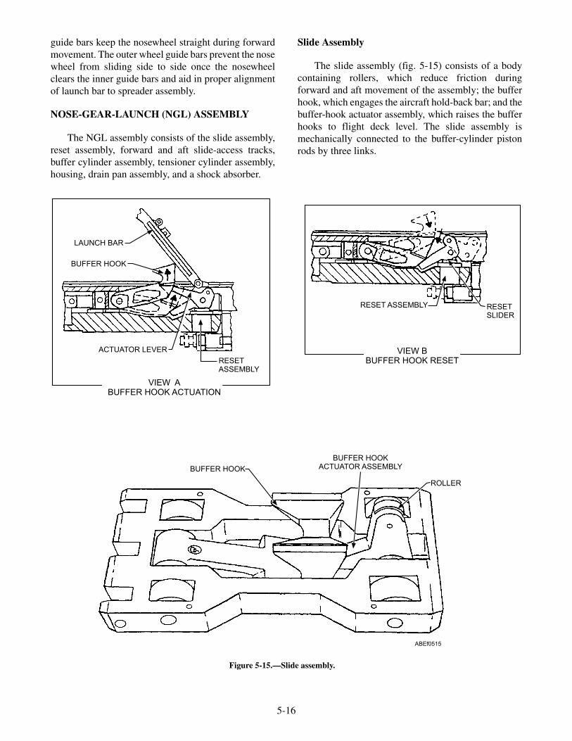
guide bars keep the nosewheel straight during forwardmovement. The outer wheel guide bars prevent the nosewheel from sliding side to side once the nosewheelclears the inner guide bars and aid in proper alignmentof launch bar to spreader assembly.
NOSE-GEAR-LAUNCH (NGL) ASSEMBLY
The NGL assembly consists of the slide assembly,reset assembly, forward and aft slide-access tracks,buffer cylinder assembly, tensioner cylinder assembly,housing, drain pan assembly, and a shock absorber.
Slide Assembly
The slide assembly (fig. 5-15) consists of a bodycontaining rollers, which reduce friction duringforward and aft movement of the assembly; the bufferhook, which engages the aircraft hold-back bar; and thebuffer-hook actuator assembly, which raises the bufferhooks to flight deck level. The slide assembly ismechanically connected to the buffer-cylinder pistonrods by three links.
5-16
LAUNCH BAR
BUFFER HOOK
ACTUATOR LEVER
RESETASSEMBLY
RESETSLIDER
ROLLER
BUFFER HOOKACTUATOR ASSEMBLY
VIEW BBUFFER HOOK RESET
VIEW ABUFFER HOOK ACTUATION
RESET ASSEMBLY
ABEf0515
BUFFER HOOK
Figure 5-15.—Slide assembly.

During operation, (see view A, fig. 5-15) as theaircraft moves forward, the launch bar, sliding in thetrack-guide grooves, contacts the buffer- hook-actuator-assembly roller, forcing it to rotate forwardand down. When the buffer hook actuator is forceddown, its forces against the underside of the buffer hookand raises the hook into position to engage the aircraftholdback bar. As the aircraft continues forward, theholdback bar engages the buffer hook and pulls theslide assembly forward. The slide assembly, connectedto the buffer cylinder piston rods, pulls the three rodsfrom the buffer cylinder assembly. Hydraulic resistancewithin the buffer cylinder assembly decelerates theaircraft. When the aircraft stops, it is in position forcatapult shuttle hookup.
After launch, the piston rods are retracted into thebuffer cylinder assembly automatically. As the slideassembly moves aft, the buffer hook assembly contactsthe reset assembly slider (see view B, fig. 5-15),causing the actuator lever to rotate down. This actionpermits the buffer hook to drop below deck levelthrough an opening in the track into the deck housing.The slide assembly is now ready for the next aircrafthookup.
Reset Assembly
The reset assembly (fig. 5-16), which resets thebuffer hook, causing it to drop below deck at the end ofthe buffer-cylinder-assembly retract stroke, is locatedbelow the slide assembly in the deck housing. The resetassembly consists of a housing, slider, slider actuatingspring, and retainer. The slider contains a stellite
surface that reduces wear due to contact with the bufferhook actuator lever. Grooves machined in the top of theslider provide a path for the flow of lubricant betweenthe slider and the inner walls of the housing. Thehousing is chrome-plated to prevent corrosion. Theactuating spring is housed in a hole in the bottom of theslider. The slider and spring are secured in the housingby means of the retainer.
During operation when the slide assembly isforward, the reset-assembly slider is not restrained bythe actuator assembly but is held above the surface ofthe housing by the slider actuating spring. After launch,as the slide assembly retracts, the buffer hook actuatorcontacts the extended reset slider, causing the actuatorassembly to rotate downward. This action permit thebuffer hook to drop below the deck through the trackopening into the deck housing cavity (see view B, fig.5-15). When the buffer hook is below deck, the actuatorassembly lever holds the reset-assembly slider down inthe reset assembly housing.
Forward and Aft Slide-Access Tracks
The slide-access tracks retain the slide assembly inthe housing. They also serve to guide the aircraft launchbar to ensure proper engagement with the catapultshuttle spreader. Inner and outer guide wheel bars areattached to the aft and forward slide-access track tokeep the aircraft nosewheel straight during forwardmovement of the aircraft. Inserts installed in theforward slide-access tracks provide a camming surface,which ensure that the launch bar contacts the bufferhook actuator roller.
5-17
LUBE FITTING
HOUSING
SLIDER
ACTUATINGSPRING
RETAINER
SLIDER
RETAINER
LUBEFITTING
HOUSING
VIEW AABEF0516
Figure 5-16.—Reset assembly.

Buffer Cylinder Assembly
The NGL buffer cylinder (fig. 5-17) is located inthe deck housing between the approach track and the aftslide-access track. The buffer-cylinder body hasintegral guide tracks on its top surface and containsthree hydraulic cylinders. The two outer cylinderscontain hollow piston rods; the center cylinder pistonrod is solid. The forward end of each piston rod isattached to the slide assembly. Within each outer pistonrod is an orifice tube, which meters fluid flow throughthe outer cylinders to absorb the forward energy of theaircraft during the buffering stroke.
Prior to aircraft holdback bar/buffer hookengagement, the buffer cylinder assembly is in thestandby cycle (fig. 5-18) with the three piston rods fullyretracted into the buffer cylinders. While in the standbycycle, hydraulic fluid is constantly circulated betweenthe hydraulic system and the buffer cylinder assemblythrough two metering orifice screws at a rate ofapproximately 8.5 gpm. This metered flow, which isnonadjustable, is to maintain the hydraulic fluid in thesystem at the proper temperature.
When the aircraft holdback bar engages the bufferhook, the slide assembly moves forward, pulling thethree piston rods from the cylinders. As the piston rodsmove forward, fluid in front of each outer-cylinderpiston is forced through the holes around the peripheryof each outer-cylinder piston and through the meteringholes in the two orifice tubes. As the pistons continueforward, the number of metering holes in the orifice
tubes is progressively reduced, causing an increasingresistance to forward motion of the slide assembly, thusdecelerating and bringing the aircraft to a smooth stopat the end of the buffing stroke.
During the buffing stroke, fluid in front of thecenter-cylinder piston is forced through a port in thecylinder and through the hydraulic line into the NGLvalve-manifold accumulator, which acts as a cushionand fluid reservoir. After launch, the fluid pressureestablished by the valve-manifold reducing valveacting on the forward side of the center cylinder forcesthe center piston aft, thus retracting the three rods intothe cylinders.
Buffer Accumulator Assembly
The buffer accumulator assembly (fig. 5-19) islocated below deck in line with and aft of the buffercylinder assembly. The buffer accumulator consists of ahydraulic accumulator mounted in a support with a teefitting and associated hardware.
During operation, as the buffer cylinder piston rodsare pulled forward, hydraulic fluid flows from theaccumulator, through the tee fitting and associatedpiping into the aft end of the buffer cylinder assemblyfilling the void created as the piston rods move forward.
After the launch, the buffer piston rods retract intothe buffer cylinder forcing fluid from the buffercylinder back to the accumulator. Fluid continues toflow into the accumulator until the pressure buildupexceeds the spring-load of the check valve located
5-18
BLEEDER PLUG
METER SCREW BODY
METER SCREW
PISTON RODS
ABEf0517
Figure 5-17.—Buffer cylinder assembly.

down stream from the accumulator. Opening of thecheck valve permits excess fluid from the buffercylinder to be returned to the catapult gravity tank.
Drain Pan Assembly
The drain pan assembly (fig. 5-20) is located on theunderside of the NGL assembly directly below thetensioner cylinder. The drain pan supports and protectsthe two quick disconnect, self sealing hydraulic
5-19
HLP RETURN
HMP SUPPLY
NORMAL SYS PRESSURE
DRAIN
PILOT PRESSURE
HY
DH
YD
SOL BSOL A
HYDHYD
ABEf0518
Figure 5-18.—Standby cycle.
SUPPORT
AIR FILTER
ACCUMULATOR
PIPE FITTING
ABEf0519
Figure 5-19.—Buffer accumulator assembly.
DRAIN PAN ASSEMBLY
ABEf0520
Figure 5-20.—Drain pan assembly.

coupling which connects the tensioner cylinder to thecatapult hydraulic system. The drain also provides areservoir and drain for all fluids entering the track slot.
Shock Absorber (Soft-Stop) Assembly
The shock absorber assembly (fig. 5-21) ismounted horizontally at the forward end of the NGLassembly. During the catapult retract cycle, the shockabsorber provides uniform deceleration of the shuttle tobring it to a smooth, soft stop, eliminating impact forcesthat could cause damage to the grab assembly or theNGL assembly. The shock absorber is a compact,self-contained, sealed unit consisting of an all steelbody with an inner pressure chamber and an all steelchrome-plated piston rod that requires no maintenanceor adjustments.
Valve Manifold Assembly
The valve manifold assembly (fig. 5-22) controlsthe flow of fluid from the catapult hydraulic system tothe buffer cylinder assembly. The valve manifoldassembly is located below decks and consists of asupport structure, two two-way flow control valves,two four-way solenoid control valves, a reducing valve,a piston-type accumulator, a terminal box to houseelectrical connections, and associated piping.
5-20
ABEf0521
Figure 5-21.—Shock absorber assembly.
PORT RREDUCED PRESSURE
TO BUFFERCYLINDER
CHECK VALVE
PORT TRETURN
TO GRAVITYTANK
PORT SFROM BUFFERACCUMULATOR
CHECKVALVE
FLOWCONTROL
VALVE
SUPPORTSOLENOID A
SOLENOID CONTROLVALVE
ACCUMULATOR
SOLENOID B
DRAIN
FLOWCONTROL
VALVE
PORT PHYDRAULIC
SUPPLY
REDUCINGVALVE
ABEf0522
Figure 5-22.—Valve manifold assembly.

NOSE-GEAR-LAUNCH CONTROL SYSTEM
On ICCS ships the operation of the NGLequipment is automatic under normal operatingconditions. The only controls provided are the bufferfwd and the buffer aft push buttons installed on themonitor control console, deckedge, and the centralcharging panel (CCP).
On non-ICCS ships, the operation of the NGLequipment is automatic under normal operatingconditions. Two control panels (fig. 5-23) are providedfor the operation of the NGL system. One panel islocated adjacent to the catapult deckedge station for useduring normal operations. A second panel is located inclose proximity to the aft end of the catapult trough foremergency operations. The control panels are identicaland houses a relay, terminal board, power on indicatorlight, buffer fwd and buffer aft switches with integralindicator lights and associated wiring. Panel selectionis made by rotating a transfer switch (fig. 5-24) from itsnormal position to its emergency position.
OPERATIONS
Buffer Forward
The buffer forward push button is used during anaircraft launch abort operation to move the buffer hookforward of the holdback bar so that the release elementand holdback bar can be removed from the aircraft.
When the BUFFER FWD push button is pressed,the buffer forward solenoid (A) is energized (fig. 5-25),shifting the buffer forward solenoid valve, allowingmedium-pressure hydraulic fluid to shift the piston ofthe flow control valve. When the piston of the flowcontrol valve shifts, fluid flow from the aft end of thebuffer cylinder assembly to the gravity tank is shut off.This causes a pressure buildup on the aft end of thebuffer cylinder assembly pistons. Since the area on theaft side of the pistons is larger than the area on theforward side, the pistons, piston rods, and attached slideassembly are driven forward.
Buffer Aft
The buffer aft push button is pressed during anabort operation when the aircraft holdback bar isconnected to the buffer hook; the fluid pressure actingon the forward side of the buffer pistons will tow theaircraft aft. When the buffer has moved back 4 to 10inches, the abort force is reduced because hydraulicpressure is bled off through exposed holes in thebuffer-cylinder assembly orifice tubes. Aircraft brakingis required prior to releasing the push button to hold theaircraft against its thrust load. When the NGL BUFFERAFT push button is pressed after the aircraft is removedfrom the catapult and the buffer hook is forward,hydraulic fluid pressure will return the pistons, pistonrods, and slide assembly fully aft. When the slideassembly is retracted, the buffer hook returns to aposition below deck.
When the BUFFER AFT pushbutton is pressed, thebuffer aft solenoid (B) is energized (fig. 5-26), shiftingthe buffer aft solenoid valve, allowing medium-pressure hydraulic fluid to shift the piston of the flowcontrol valve. Medium-pressure hydraulic fluid flowsthrough the flow control valve to the buffer cylinder
5-21
ABEf0523
Figure 5-23.—Deckedge and emergency control panel.
ABEf0524
Figure 5-24.—Transfer switch.
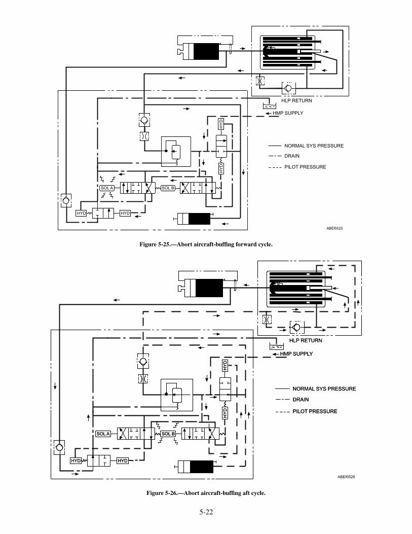
5-22
HLP RETURN
HMP SUPPLY
NORMAL SYS PRESSURE
DRAIN
PILOT PRESSURE
HY
DH
YD
SOL BSOL A
HYDHYD
ABEf0525
Figure 5-25.—Abort aircraft-buffing forward cycle.
HLP RETURN
HMP SUPPLY
NORMAL SYS PRESSURE
DRAIN
PILOT PRESSURE
HY
DH
YD
SOL BSOL A
HYDHYD
ABEf0526
HLP RETURN
HMP SUPPLY
NORMAL SYS PRESSURE
DRAIN
PILOT PRESSURE
HY
DH
YD
SOL BSOL A
HYDHYD
Figure 5-26.—Abort aircraft-buffing aft cycle.

assembly. Fluid pressure is applied to the forward sideof the buffer pistons; and the pistons, piston rods, andslide assembly move aft. As the pistons move aft, fluidis forced out of the aft end of the buffer cylinderassembly, through a check valve and the other flowcontrol valve, to the gravity tank.
REVIEW QUESTIONS
Q12. List the NGL guide tracks.
Q13. The slide is mechanically connected to whatcomponent?
Q14. What component resets the buffer hooks?
Q15. What ensures the launch bar makes contactswith the buffer hook actuator roller?
Q16. The orifice tube is located in which cylinderof the buffer cylinder assembly?
Q17. The void created as the piston rods moveforward is filled with hydraulic fluid fromwhat assembly?
Q18. On ICCS ships, the buffer fwd and buffer aftpushbuttons are installed on what controlpanels?
SUMMARY
In this chapter we have discussed the functions andoperating procedures for the JBDs and Mk 2 NGLequipment. For additional, in-depth descriptions of thisequipment, see the applicable NAVAIR technical man-uals.
5-23

�
�

CHAPTER 6
THE AIRCRAFT LAUNCH AND RECOVERYEQUIPMENT MAINTENANCE PROGRAM (ALREMP)
As an ABE, you will find that most of your dutieswill be performing preventive maintenance, or thesupervision of maintenance, on catapults, arrestinggear, visual landing aid (VLA) and their associatedequipment. At times you may also be assigned to one ofthe support branches of V-2 division, such asmaintenance control, maintenance support, or materialcontrol. Regardless of your assignment and specificduties, you will need a working knowledge of theAircraft Launch and Recovery Equipment Main-tenance Program (ALREMP).
The primary objective of the ALREMP is toachieve and sustain maximum operational readiness ofaircraft launch and recovery equipment in support ofcarrier flight operations and to achieve and maintain azero maintenance error rate through the use ofstandardized procedures, a dynamic quality assuranceprogram, and analytical review of maintenancedocumentation and records.
MAINTENANCE, LEVELS,RESPONSIBILITIES, AND TYPES
LEARNING OBJECTIVES: Identifyorganizational, intermediate, and depot levelmaintenance. Identify the maintenanceconcepts peculiar to each of the three levels ofmaintenance. Recognize upkeep and overhaulmaintenance.
The term maintenance has a very general meaning.It could mean maintenance that can be performed inminutes at the work center, or organizational level, or itcould mean maintenance that requires months ofoverhaul in an industrial-type facility at the depot level.We need more than the word maintenance to indicatethat a specific type of maintenance must be ac-complished.
MAINTENANCE LEVELS
All aircraft launch and recovery equipment(ALRE) maintenance functions are divided into one ofthree distinct maintenance levels: organizational,intermediate, or depot. To determine at which level
maintenance tasks must be accomplished, you mustrefer to the appropriate technical manual. Maintenancetasks are assigned according to the complexity, scope,and range of the work to be performed. This allowsmaintenance to be performed at the lowest practicallevel in order to maintain required readiness andmaterial condition. The three levels of maintenance areexplained in the following paragraphs.
Organizational Maintenance
Organizational or O-level maintenance is themaintenance that is normally done by the catapult andarresting gear crews. In some cases organizationalmaintenance may be done by intermediate or depotactivities. O-level maintenance tasks are grouped underthe following categories:
• Inspection, operation, and servicing as definedand required by PMS
• Corrective and preventive maintenance, in-cluding on-equipment repair and removal/replacement of defective parts
• Incorporation of technical directives (TDs)within prescribed limitations
• Record keeping and report writing
Intermediate Maintenance
Intermediate or I-level maintenance is done bydesignated maintenance activities in support of fleetunits. The aircraft intermediate maintenance depart-ment (AIMD) on aircraft carriers is an example of suchactivities. I-level maintenance includes the followingfunctions and services:
• Repair, test, inspection, and modification ofALRE components and related equipment
• Manufacture of selected and nonavailable parts
• Incorporation of technical directives withinprescribed limitations
• Calibration of designated equipment
6-1

Depot Maintenance
Depot or D-level maintenance is maintenance thatrequires skills and facilities beyond the O- and I-levelsof maintenance. It is performed by naval shipyards,commercial shipyards, Naval Ship Repair Facilities,contractor repair, the Naval Air Warfare Center(NAWC), and by voyage repair teams (VRTs) fromspecified naval aviation depots. D-level maintenancesupports the lower I- and O-levels of maintenance byproviding engineering assistance and performingmaintenance beyond the capability of lower levelmaintenance activities. D-level maintenance functionsare grouped as follows:
• Major overhaul and repair to ALRE
• Modernization, modification, or conversion ofsystem components
• Calibration (type III) by Navy CalibrationLaboratories
• Incorporation of TDs and service changes
• Manufacture of parts and/or accessory items
• Technical and engineering assistance
MAINTENANCE TYPES
There are two general types of ALRE maintenanceperformed without distinction as to levels of main-tenance. They are upkeep and overhaul.
Upkeep Maintenance
Upkeep maintenance is preventive, corrective, oradditive maintenance performed by catapult andarresting gear crewmembers. It includes servicing,periodic inspection, functional and bench testing,replacement, preservation, and repair of catapult andarresting gear equipment.
Overhaul Maintenance
Overhaul maintenance is the process ofdisassembly sufficient to inspect all the operatingcomponents. It includes the repair, replacement, orservicing as necessary followed by reassembly andfunctional testing. Upon completion of the overhaulprocess the equipment will be capable of performing itsintended service. Much of this work is normally done atnaval overhaul and depot facilities, contractor plants,and other industrial facilities.
REVIEW QUESTIONS
Q1. List the three levels of maintenance.
Q2. What is the concept of each level of main-tenance?
Q3. What are the general types of maintenance?
V-2 MAINTENANCE ORGANIZATIONSTRUCTURE AND RESPONSIBILITY
LEARNING OBJECTIVES: Describe theduties of maintenance control, qualityassurance, and maintenance support branchesof V-2 division. Describe the procedures usedto complete the ALRE maintenance actionform (MAF). Describe the operation of thevisual information display system (VIDS)board.
Aircraft launch and recovery equipment (ALRE)includes catapults, arresting gear and visual landingaids (VLA). Since ALRE is utilized by highperformance aircraft, safety must always be paramountto the personnel who operate and maintain theequipment. A properly implemented maintenanceprogram will improve safety, maintenance integrity,performance, training of personnel, management, andevaluation of maintenance performed. The aircraftlaunch and recovery maintenance program (ALREMP)is designed to maximize the effective utilization ofmanpower and material to accomplish this goal.
The ALREMP provides standard maintenanceorganization and procedures to be used by all V-2divisions. This standardization relies heavily on themaintenance control (MC), quality assurance (QA),and maintenance support (MS) branches of the divisionto establish good management practices and preventionof maintenance defects. Figure 6-1 depicts the ALREmaintenance organizations for aircraft carriers. Youwill notice that in each of the divisions illustrated, threedistinct types of organization are identified. They are(1) the operational organization, which depicts the linesof authority delegated in the daily functions of a V-2division; (2) the maintenance group, which includes thelines of authority to be observed by all personnelinvolved in the actual performance of any maintenanceaction; and (3) the maintenance organization.
The maintenance organization has the res-ponsibility of managing the maintenance effort. Thisincludes the planning and performance of maintenance,compliance with all maintenance policies and technicaldirectives, continued training of all maintenance
6-2

personnel, maintenance administration, andverification of actual maintenance performance.
MAINTENANCE CONTROL (MC)
Maintenance control is the nerve center of V-2division's maintenance effort. It is the center of allmaintenance activity, directing and receivingup-to-date information in order to properly assesscourses of action to be taken when any maintenanceaction is performed. In every situation the maintenanceofficer, assisted by the maintenance control chief, willbe the controlling agent, acting as the event manager inall maintenance actions. Only the ALRE maintenanceofficer or the maintenance control chief has theauthority to certify that maintenance actions have beencompleted and that equipment can be returned to anoperational status.
The maintenance officer, with the assistance of themaintenance control chief, is specifically responsiblefor the following:
• Upkeep maintenance performed on a day-to-daybasis, including scheduled and unscheduledmaintenance, on-equipment repair, and theremoval/replacement of defective parts andcomponents
• Incorporation of TDs, service changes (SCs),interim rapid action changes (IRACs), rapidaction changes (RACs), service bulletins, andrepair procedures
• Documentation of all maintenance actions
• Administration of the Maintenance Data System(MDS)
6-3
CATAPULT & ARRESTINGGEAR OFFICER
V-2 DIVISION OFFICER
WAIST CATAPULTSOFFICER
BOW CATAPULTSOFFICER
ARRESTING GEAROFFICER
LANDING AIDSOFFICER
MATERIALCONTROLOFFICER
ALREMAINTENANCE
OFFICER
QUALITYASSURANCE
CPO
VB-21
DENOTES MAINTENANCE GROUP
DENOTES OPERATINAL/ADMINISTRATIVE ORGANIZATION
DENOTES MAINTENANCE ORGANIZATION
MAINTENANCESUPERVISOR
MAINTENANCE CONTROL
VB-20
MAINTENANCESUPPORT
CPO
VB-22
LANDING AIDSLEADING
PETTY OFFICER
TOPSIDEPETTY OFFICER
ARRESTING GEARCHIEF
PETTY OFFICER
BELOW DECKPETTY OFFICER
WAIST CATAPULTSCHIEF
PETTY OFFICER
BOW CATAPULTSCHIEF
PETTY OFFICER
NO 1CATAPULTCAPTAIN
NO 2CATAPULTCAPTAIN
NO 3CATAPULTCAPTAIN
NO 4CATAPULTCAPTAIN
VB-01 VB-02 VB-03 VB-04 VB-05 VB-06 VB-07 VB-08 VB-09 VB-10 VB-11 VB-12
NO 1ENGINEPETTY
OFFICER
NO 2ENGINEPETTY
OFFICER
NO 3ENGINEPETTY
OFFICER
NO 4ENGINEPETTY
OFFICER
BARRICADEENGINEPETTY
OFFICER
LENSPETTY
OFFICER
ILARTSPETTY
OFFICER
FLIGHTDECK
LIGHTINGPETTY
OFFICER
ABEf601
Figure 6-1.—ALRE maintenance organization (CV/CVN).

• Maintenance of an active QA program to includethe inspection of all critical areas of eachmaintenance action performed, the availabilityof qualified quality assurance inspectors (QAIs),work center collateral duty inspectors (CDIs),and when necessary, collateral duty qualityassurance inspectors (CDQAIs), and theoperation and maintenance of an ALREtechnical publications library (TPL) to supportall equipment and maintenance in the division
• Ensuring liaison and coordination with anddocumentation of maintenance from shoreintermediate maintenance activities (SIMAs),VRTs, naval shipyards (NSYs), and localmaintenance support activities
• Planning and submitting budget requests for thefunding of tools, spare parts, and materialsnecessary for the proper operation and main-tenance of ALRE
• Maintaining OPTAR expenditure logs andrecords
• Requisitioning parts and materials to supportALRE operations and maintenance
• Establishing and maintaining an effective toolcontrol program
All personnel in the maintenance organization aresubordinate and responsible to the maintenance officer.As work center group supervisors and work centersupervisors, they are responsible for the maintenance ofall systems and equipment assigned to their workcenters. Both the group and the work center supervisorsdirect and manage the maintenance program in theirwork centers, supervise the day-to-day ALREoperations, ensure proper documentation of preventiveand corrective maintenance, and maintain effectivecommunications between the work centers and MC toensure an up-to-date maintenance profile of thedivision. They also direct assigned work centerpersonnel in the performance of their duties and thedaily operation of ALRE. Group and work centersupervisors are also responsible for the following:
• Keeping MC informed of all problems andequipment status in the work center.
• Updating and validating information on theVisual Information Display System (VIDS)board with MC daily.
• Ensuring that all maintenance documentation iscomplete and correct.
• Being knowledgeable of procedures for orderingrepair parts, from initial identification throughmaterial receipt.
• Being knowledgeable of operating space item(OSI) operations and listings. (Stocking of OSIsis a Supply Department function, but inputs forstocking originate with the work center.)
• Maintaining strict tool control accountabilitywithin the work center.
• Recommending qualified and responsiblepersonnel to be CDIs for the work center.
• Ensuring that QAIs/CDQAIs or CDIs areavailable for all tasks requiring QA inspection.
• Assisting the QA Branch in implementing andmaintaining support for the division safetyprogram by conducting safety training in thework center, using and promoting practices toenhance safety, and reporting all accidents andunsafe practices, procedures, or conditions.
• Assisting work center branch officers inmaintaining the training program by ensuringoptimum use of personnel through jobassignments based on prior training andexperience, that formal in-service training isconducted, that on-the-job training (OJT) isconducted under the supervision of qualifiedwork center personnel, and that PersonnelQualification Standards are administeredaccording to established procedures.
• Maintaining required reading files and ensuringthat all assigned work center personnel read andinitial the information contained in them on amonthly basis.
• Ensuring that all work center requiredpublications are available and maintained withcurrent changes.
VISUAL INFORMATION DISPLAY SYSTEM(VIDS)
The division overall maintenance status is providedby a visual display of current maintenance information,located in maintenance control and maintained by themaintenance control chief, through the use of the visualinformation display system (VIDS) and themaintenance requirement (MR) status boards. Theseare important management tools in the maintenance
6-4
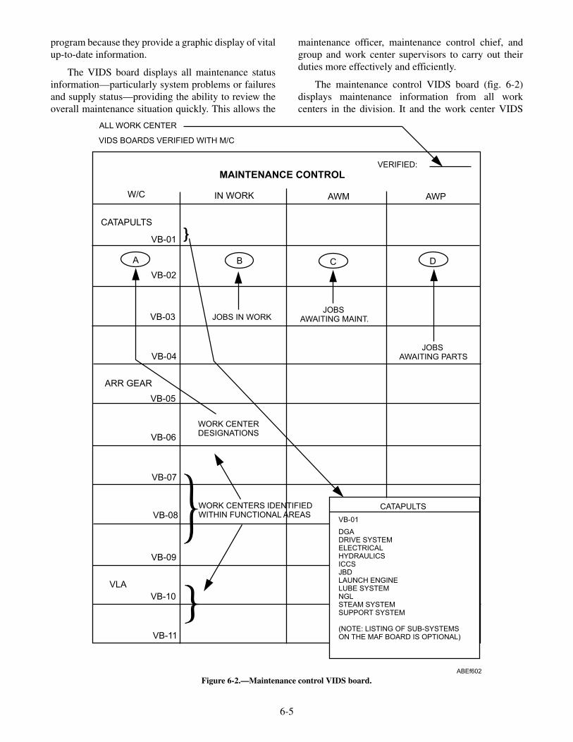
program because they provide a graphic display of vitalup-to-date information.
The VIDS board displays all maintenance statusinformation—particularly system problems or failuresand supply status—providing the ability to review theoverall maintenance situation quickly. This allows the
maintenance officer, maintenance control chief, andgroup and work center supervisors to carry out theirduties more effectively and efficiently.
The maintenance control VIDS board (fig. 6-2)displays maintenance information from all workcenters in the division. It and the work center VIDS
6-5
CATAPULTS
VB-01
DGADRIVE SYSTEMELECTRICALHYDRAULICSICCSJBDLAUNCH ENGINELUBE SYSTEMNGLSTEAM SYSTEMSUPPORT SYSTEM
(NOTE: LISTING OF SUB-SYSTEMSON THE MAF BOARD IS OPTIONAL)
MAINTENANCE CONTROL
ALL WORK CENTER
VIDS BOARDS VERIFIED WITH M/C
VERIFIED:
W/C IN WORK AWM AWP
CATAPULTS
A B C D
JOBS IN WORKJOBS
AWAITING MAINT.
JOBSAWAITING PARTS
ARR GEAR
WORK CENTERDESIGNATIONS
VB-01
VB-02
VB-03
VB-04
VB-05
VB-06
VB-07
VB-08
VB-09
VB-10
VB-11
VLA
WORK CENTERS IDENTIFIEDWITHIN FUNCTIONAL AREAS
ABEf602
Figure 6-2.—Maintenance control VIDS board.

boards (fig. 6-3) are divided into sections representingeach work center. Each work center section is identifiedby a standard work center designation, identification ofthe work center systems within the work centermaintenance areas are optional on the maintenancecontrol VIDS board. Four columns are mandatory onthe maintenance control and all work center boards.They are (1) the column displaying the work center
designation, as already mentioned; (2) the In-Workcolumn, which is used to display in-progressmaintenance actions; (3) the AWM or AwaitingMaintenance column, to display maintenance actionsthat have been deferred; and (4), the AWP or AwaitingParts column, to display maintenance actions thatcannot be completed because of a lack of parts ormaterial.
6-6
W/C VB - 01
SYSTEMEQUIPMENT IN WORK AWM AWP
DECK GEAR &ACCESSORIES
DRIVESYSTEM
ELECTRICALSYSTEM
HYDRAULICS
ICCS
JET BLASTDEFLECTORS
LAUNCHENGINE
LUBESYSTEMS
NOSE GEARLAUNCH
MAFCARD
MAF1
MAF2
MAFCARD
2
FILE
STEAMSYSTEM
SUPPORTSYSTEM
FROM M/C
TO MAINT CONTROL
1. PROBLEM DISCOVERED. M/C NOTIFIED.AND PLACED ON VIDS BOARD.MAF INITIATED. MAF CARD INITIATED
2. JOB GOES AWP. MAF CARD MOVED TOAWP COLUMN. M/C NOTIFIED. PARTSRECEIVED AND CHECKED AGAINST I/DPLJOB TO "IN WORK" WHEN DIRECTED BY M/C
3. WHEN JOB IS COMPLETED, M/C NOTIFIED. 2-PARTMAF COMPLETED AND FORWARDED TO M/C.MAF CARD REVERSED INDICATING "AWAITING MAF".
4. MAF COPY 2 RETURNED FOR W/CHISTORY FILE. MAF CARD DISCARDED.
ABEf603
Figure 6-3.—Work center VIDS board.

Aircraft Launch and Recovery Equipment(ALRE) Maintenance Action Form (MAF) Cards
ALRE MAF cards (fig. 6-4) are used on the VIDSboards to track all outstanding work centermaintenance actions, both on the work center andmaintenance control VIDS boards. Before anymaintenance action is started, the responsible workcenter must notify maintenance control. At this time,work center and maintenance control MAF cards areinitiated, each card will reflect identical informationconsisting of a job control number (JCN) and a briefdescription of the maintenance action to be performed;the work center also initiates a MAF at this time. ThePRIORITY section of the card will also be color coded,as required, to indicate the system and maintenancestatus concerning equipment operational capability.These color codes are standardized as follows:
Blue is used in the LIM block to indicate limitedcapability.
Red is used in the DN block to indicate that theequipment is out of commission.
No Color is used or required if maintenance isroutine and does not affect equipment operability.
Black is used when a maintenance action has beencompleted and inspected at the proper level and only afunctional check remains to return the equipment toservice; a black line is drawn across all four blocks ofthe PRIORITY section.
Similarly, the MS and QA blocks are provided onthe MAF card to indicate requirements for maintenancesupport augmentation of the work center and/orQAI/CDQAI (not CDI) level inspection of the job. Jobsrequiring QAI/CDQAI (not CDI) inspection will bereflected with a MAF card on the quality assurance(QA) VIDS board and job requiring maintenancesupport (MS) participation will be reflected on the MSVIDS board.
The MAF card is then placed in the appropriatecolumns of the maintenance control, quality assurance,maintenance support, and work center VIDS boards, toindicate the maintenance action's current status:in-work, awaiting maintenance, or awaiting parts.Upon completion of the maintenance action, the MAFcard is inverted to indicate that maintenance control isnow awaiting a completed MAF from the responsiblework center.
6-7
***AWAITINGMAF***
JCN
JCN
W/C
W/C
JSN
JSN
MRG QA MS DN LIM
PRIORITYJULIANDATE
JULIANDATE
DISCREPANCY/PMS
The MAF Card is locally produced and is used to monitor and manage the workload.Outstanding maintenance actions will be indicated by a MAF Card on both the M/Cand w/c VIDS boards, as well as in QA and MS, when applicable. When the job iscompleted and reported to M/C, the MAF Card is simply reversed on the board toindicate "AWAITING MAF" until the 2-part MAF is completed, delivered to M/C, andsigned off by the maintenance officer/maintenance control supervisor. M/C thendiscards the MAF Card and the w/c discards it upon receipt of the copy 2 MAF fromM/C. QA will discard its MAF Card upon receipt of MAF copy 1. MS discards its MAFCard upon job completion and transfer of manhours to summary sheet.
NOTE: The large, unused central portion of the front of the MAF Card may bemodified locally to help track supply data, manhours, work start/stop, etc, If desired.
ABEf604
Figure 6-4.—ALRE MAF card.

Aircraft Launch and Recovery Equipment(ALRE) Maintenance Action Form (MAF)
The ALRE MAF (fig. 6-5) is the major divisionalrecord of all maintenance performed and provideshistorical data for future references. The ALRE MAFalso supplements the OPNAV 4790/2K, Ship's
Maintenance Action Form, used in support of theCurrent Ships' Maintenance Project (CSMP). Allequipment inspections and maintenance actions(scheduled/unscheduled and corrective maintenance)are documented on the ALRE MAF.
The ALRE MAF (see fig. 6-5) is divided into sevenareas as follows:
6-8
AIRCRAFT LAUNCH AND RECOVERY EQUIPMENT (ALRE)MAINTENANCE ACTION FORM (FOR SNAP I OMMS)
SECTION I INFORMATION
SECTION II DEFERRAL ACTION
SECTION IV REMARKS/DESCRIPTION
ADDITIONAL ALREMP INFORMATION
SECTION III COMPLETED ACTION
1. SHIPS UIC 9. DFR8. CAS7. STAT6. WND5. EQUIPMENT NOUN NAME4. APL/AEL3. JSN2. W/C
14. EIC 15. SAFETY 16. LOCATION 17. WND DATE
22. U21. SUFFIX 23. S 24. P/F18. ALTERATIONS (SERVICE CHANGE - SHIPALT)
TIME TIME TIME TIME TIME TIMEDATE DATE DATE DATE DATE
25. S/F MHRS EXP.
35. REMARKS/DESCRIPTION
HAZARD
20. INSURV NUMBER19. "/"
27. S/F MHRS REM26. DEFER DATE 28. DEADLINE DATE
10.
32. ACT MAINT TIME 33. TI 34. METER READING29. ACTION TKN 30. S/F MHRS 31. COMPLETION DATE
37. CSMP SUMMARY
38. FIRST CONTACT/MAINT MAN (PRINT/SIGN) 39. RATE
EXT DAMAGEWND
P/C/OSUBMIT 4790/CK?
YES
YES
NO
NO
40. SECOND CONTACT/SUPERVISOR (PRINT/SIGN) 41. PRI
CORROSION CODES
TYPE MALF TYPE ACT. TKN.
36. CONT. SHEET
43. INTEGR. PRI42. T/A 44. IUC
SAFETY TAG INFORMATION
SAFETY TAGS REQUIRED?
IF YES,HOW MANY?
RED TAG SER. NO.
45. TYCOM
SHOT/HIT/VLA
MRC CODE
V-2 MAINT. OFFICER (PRINT/SIGN)
MIP CONTROL NO. (MIP#)
FINAL QA INSP. BY (PRINT/SIGN)
COMPONENT PART NUMBER
2ND QA INSP. BY (PRINT/SIGN)1ST QA INSP. BY (PRINT/SIGN)Q
A
QTY
VIDS/MAF JCN:
YES NO
CENTRAL TOOL PO (PRINT/SIGN)
NOTE: A LOST/MISSING/BROKEN TOOLREPORT MUST ACCOMPANY THIS MAF IFTHE "NO" BLOCK IS CHECKED
NOMENCLATURE PART NUMBER
ABEf605
MATERIAL CONTROL
ALRE TOOL CONTROL
PAGE OF
11. 12. 13. IDENT/EQUIPMENT SERIAL NUMBER
DATE
START
STOP
ALRE MALF CODES
VIDS/MAF JCN:
CONTRACT NUMBER
ARE ALL TOOLS ACOUNTED FOR?
YES NO
W/C TOOL PO (PRINT/SIGN)
Figure 6-5.—Aircraft Launch and Recovery Equipment (ALRE) Maintenance Action Form (MAF).

1. Information: contains the job control number,consisting of the work center designation andthe job sequence number (JSN), equipmentconfiguration data, and discrepancy descrip-tion codes.
2. Deferral Action: contains deferral dates andmanhours expended information (totalmanhours expended by personnel involved inthe maintenance action up to the time ofdeferral), manhours remaining (estimatednumber of manhours remaining to completethe maintenance action).
3. Completed Action: contains action taken,completion date and total manhours expended.
4. Remarks/Description: contains a narrativedescription of the discrepancy and the workdone to correct it.
5. Additional ALREMP Information: containsALRE specific codes, safety tag data,shot/hit/VLA data, PMS data and QA/ALREMO signatures.
6. Material Control: contains quantity, nomen-clature, part number and contract number forrequisitioned items also contains two blocksfor AIMD-assistance VIDS MAF JCNs.
7. ALRE Tool Control: contains lines for thework center and central tool room PettyOfficers signature.
When a maintenance action is completed, theappropriate work center will complete a MAF, this willprovide a comprehensive record of the maintenanceaction performed and establish historical data for futurereference. Therefore MAFs will be retained as follows:
• Corrective maintenance action MAFs will beretained for a period of 1 year. The QA branchwill retain copy 1. Copy 2 of the MAF will beretained by the maintenance responsible workcenter.
• Preventive maintenance action MAFs must beretained by QA and the work center for the mostrecent PMS action performed only.
MAINTENANCE REQUIREMENT STATUSBOARDS
Maintenance requirement (MR) status boards aretools used to track critical scheduled/situationalmaintenance and inspections required on catapults,
arresting gear, and VLA equipment. These re-quirements are based on calendar periods (daily,weekly, monthly, and so on) and the total number ofcatapult shots or arresting gear arrestments (hits)accumulated. Documentation of shots and hits istherefore mandatory to ensure that prescribedmaintenance and inspection requirements are per-formed on time.
Maintenance requirement status boards (figs. 6-6and 6-7) are locally produced or procured. As aminimum these boards will contain information oneach shot- or hit-related maintenance task specified inthe PMS system. The minimum information elementsrequired are the following:
• Maintenance requirement periodicity code(M-1R, Q-1R, 24M-2R, and so forth)
• Description of the task and the frequency ofrequirement
• Shot or hit number that the maintenance require-ment is due to be performed on
• Total number of shots or hits to date
As with the maintenance control VIDS board, themaintenance control MR status board will reflect therequired maintenance tasks of each work center in thedivision. The maintenance control MR status board ismaintained and updated only by the maintenanceofficer, the maintenance control chief, or a personspecifically designated by the maintenance officer.
Each work center will also have a MR status boardthat reflects the exact information contained on themaintenance control board. The work center supervisoror his designated assistant will maintain and update thework center's MR status board.
A continuous audit and daily validations of the MRstatus boards between maintenance control and thework centers are required to ensure accuracy andcontinuity of shot/hit numbers and inspectionrequirements.
REVIEW QUESTIONS
Q4. What is the nerve center of V-2 divisionmaintenance effort?
Q5. What are the difference types of distinctorganizations within V-2 division?
Q6. What are the mandatory columns required onthe VIDS board?
6-9

6-10
PMSMAINTENANCE REQUIREMENT
R-3
PMSMAINTENANCE REQUIREMENT
R-5
PMSMAINTENANCE REQUIREMENT
R-6
PMSMAINTENANCE REQUIREMENT
R-2
VB01
VB02
VB03
VB04
WORKCENTER
REPLACE DRIVE SYSTEMCABLE BETWEEN 3000/3500 SHOTS
OR 24 MONTHS SERVICE
DATE OFLAST MR
REPLACEMENTDATE MR
SHOT NO.LAST MR
SHOT NO.DUE MR
TOTAL SHOTSTO DATE
TOTAL SHOTSLEFT TO MR
DATE OFLAST MR
REPLACEMENTDATE MR
SHOT NO.LAST MR
SHOT NO.DUE MR
TOTAL SHOTSTO DATE
TOTAL SHOTSLEFT TO MR
24 MONTHS CABLE REPLACEMENT
DATE OFLAST MR
REPLACEMENTDATE MR
SHOT NO.LAST MR
SHOT NO.DUE MR
TOTAL SHOTSTO DATE
TOTAL SHOTSLEFT TO MR
DATE OFLAST MR
REPLACEMENTDATE MR
SHOT NO.LAST MR
SHOT NO.DUE MR
TOTAL SHOTSTO DATE
TOTAL SHOTSLEFT TO MR
DATE OFLAST MR
REPLACEMENTDATE MR
SHOT NO.LAST MR
SHOT NO.DUE MR
TOTAL SHOTSTO DATE
TOTAL SHOTSLEFT TO MR
DATE OFLAST MR
REPLACEMENTDATE MR
SHOT NO.LAST MR
SHOT NO.DUE MR
TOTAL SHOTSTO DATE
TOTAL SHOTSLEFT TO MR
24 MONTHS CABLE REPLACEMENT
DATE OFLAST MR
REPLACEMENTDATE MR
SHOT NO.LAST MR
SHOT NO.DUE MR
TOTAL SHOTSTO DATE
TOTAL SHOTSLEFT TO MR
DATE OFLAST MR
REPLACEMENTDATE MR
SHOT NO.LAST MR
SHOT NO.DUE MR
TOTAL SHOTSTO DATE
TOTAL SHOTSLEFT TO MR
REQUEST CYLINDER SLOTMEASUREMENTS FROM TYPE
COMMANDERNOTE: ACCOMPLISH THIS MRWHEN DICTATED BY TABLE 1
OF MRC
INSPECT SHUTTLE, CONNECTORGUIDES, WATERBRAKE AND
LAUNCH PISTON ASSEMBLIESFOR ALIGNMENT AFTER EVERY2600 AND BEFORE 2800 SHOTS,REPLACE CYLINDER GAP SEALS
INSPECT AND LUBRICATE WATER-BRAKE AND LAUNCH PISTON
ASSEMBLIES. NOTE: ACCOMPLISHBETWEEN 1300-1400, 2500-2800,
AND EVERY 500 SHOTSTHEREAFTER.
ABEf606
Figure 6-6.—Maintenance requirement status board (maintenance control).

6-11
PM
SM
AIN
TE
NA
NC
ER
EQ
UIR
EM
EN
TR
-3
PM
SM
AIN
TE
NA
NC
ER
EQ
UIR
EM
EN
TR
-11
PM
SM
AIN
TE
NA
NC
ER
EQ
UIR
EM
EN
TR
-5
PM
SM
AIN
TE
NA
NC
ER
EQ
UIR
EM
EN
TR
-6
PM
SM
AIN
TE
NA
NC
ER
EQ
UIR
EM
EN
TR
-13
PM
SM
AIN
TE
NA
NC
ER
EQ
UIR
EM
EN
TR
-15
PM
SM
AIN
TE
NA
NC
ER
EQ
UIR
EM
EN
TR
-2
PM
SM
AIN
TE
NA
NC
ER
EQ
UIR
EM
EN
TR
-7
RE
PL
AC
ED
RIV
ES
YS
TE
MC
AB
LE
BE
TW
EE
N3
00
0/3
50
0S
HO
TS
OR
24
MO
NT
HS
SE
RV
ICE
IN-P
LA
CE
SH
UT
TL
EIN
SP
EC
TIO
N.
INS
PE
CT,L
UB
RIC
AT
E&
TE
ST
CO
M-
PO
NE
NT
SIN
CA
TA
PU
LT
TR
OU
GH
.N
OT
E:A
CC
OM
PL
ISH
AF
TE
RE
VE
RY
40
0A
ND
BE
FO
RE
50
0S
HO
TS
.
DA
TE
OF
LA
ST
MR
RE
PL
AC
EM
EN
TD
AT
EM
R
SH
OT
NO
.L
AS
TM
R
SH
OT
NO
.D
UE
MR
TO
TA
LS
HO
TS
TO
DA
TE
TO
TA
LS
HO
TS
LE
FT
TO
MR
DA
TE
OF
LA
ST
MR
SH
OT
NO
.L
AS
TM
R
SH
OT
NO
.D
UE
MR
TO
TA
LS
HO
TS
TO
DA
TE
TO
TA
LS
HO
TS
LE
FT
TO
MR
24
MO
NT
HS
CA
BL
ER
EP
LA
CE
ME
NT
DA
TE
OF
LA
ST
MR
RE
PL
AC
EM
EN
TD
AT
EM
R
SH
OT
NO
.L
AS
TM
R
SH
OT
NO
.D
UE
MR
TO
TA
LS
HO
TS
TO
DA
TE
TO
TA
LS
HO
TS
LE
FT
TO
MR
DA
TE
OF
LA
ST
MR
SH
OT
NO
.L
AS
TM
R
SH
OT
NO
.D
UE
MR
TO
TA
LS
HO
TS
TO
DA
TE
TO
TA
LS
HO
TS
LE
FT
TO
MR
DA
TE
OF
LA
ST
MR
DA
TE
OF
LA
ST
MR
DA
TE
OF
LA
ST
MR
DA
TE
OF
LA
ST
MR
RE
PL
AC
EM
EN
TD
AT
EM
R
SH
OT
INS
PE
CT
ION
INT
ER
VA
L
SH
OT
NO
.L
AS
TM
R
SH
OT
NO
.L
AS
TM
R
SH
OT
NO
.L
AS
TM
R
SH
OT
NO
.L
AS
TM
R
SH
OT
NO
.D
UE
MR
SH
OT
NO
.D
UE
MR
SH
OT
NO
.D
UE
MR
SH
OT
NO
.D
UE
MR
TO
TA
LS
HO
TS
TO
DA
TE
TO
TA
LS
HO
TS
TO
DA
TE
TO
TA
LS
HO
TS
TO
DA
TE
TO
TA
LS
HO
TS
TO
DA
TE
TO
TA
LS
HO
TS
LE
FT
TO
MR
TO
TA
LS
HO
TS
LE
FT
TO
MR
TO
TA
LS
HO
TS
LE
FT
TO
MR
TO
TA
LS
HO
TS
LE
FT
TO
MR
RE
QU
ES
TC
YL
IND
ER
SL
OT
ME
AS
UR
EM
EN
TS
FR
OM
TY
PE
CO
MM
AN
DE
RN
OT
E:A
CC
OM
PL
ISH
TH
ISM
RW
HE
ND
ICTA
TE
DB
YTA
BL
E1
OF
MR
C
INS
PE
CT
TR
AV
ER
SE
CA
RR
IAG
ES
LIP
PE
RS
FO
RW
EA
R&
SE
CU
RIT
Y.
NO
TE
:A
CC
OM
PL
ISH
AF
TE
RE
VE
RY
30
00
AN
DB
EF
OR
E3
50
0S
HO
TS
.
INS
PE
CT
SH
UT
TL
E,C
ON
NE
CT
OR
GU
IDE
S,W
AT
ER
BR
AK
EA
ND
LA
UN
CH
PIS
TO
NA
SS
EM
BL
IES
FO
RA
LIG
NM
EN
TA
FT
ER
EV
ER
Y2
60
0A
ND
BE
FO
RE
28
00
SH
OT
S,
RE
PL
AC
EC
YL
IND
ER
GA
PS
EA
LS
INS
PE
CT
AN
DL
UB
RIC
AT
EW
AT
ER
-B
RA
KE
AN
DL
AU
NC
HP
IST
ON
AS
SE
MB
LIE
S.
NO
TE
:A
CC
OM
PL
ISH
BE
TW
EE
N1
30
0-1
40
0,2
50
0-2
80
0,A
ND
EV
ER
Y5
00
SH
OT
ST
HE
RE
AF
TE
R.
CL
EA
N&
INS
PE
CT
RE
TR
AC
TIO
NE
NG
INE
HY
DR
AU
LIC
PIP
ING
ST
RA
INE
RS
&O
RIF
ICE
S.
NO
TE
:A
CC
OM
PL
ISH
AF
TE
RE
VE
RY
20
00
AN
DB
EF
OR
E2
20
0S
HO
TS
.
1.LU
BR
ICA
TE
CO
MP
ON
EN
TS
OF
RO
T-
AR
YR
ET
RA
CT
ION
EN
GIN
EA
SS
EM
BLY
.2.LU
BR
ICA
TE
ALL
RE
TR
AC
TIO
NE
NG
INE
AN
DFA
IRLE
AD
SH
EA
VE
S.
NO
TE
:A
CC
OM
PLIS
HA
FT
ER
EV
ER
Y100
AN
DB
EF
OR
E200
SH
OT
S.
AB
Ef6
07
Fig
ure
6-7.
—M
aint
enan
cere
quir
emen
tst
atus
boar
d(c
atap
ult)
.

Q7. What is used to track all outstandingmaintenance actions?
Q8. How is the priority section of the ALRE MAFcard annotated?
Q9. The ALRE MAF is divided into how manyareas?
Q10. What copy of the ALRE MAF is retained byQA?
ALRE MAINTENANCE SUPPORT
LEARNING OBJECTIVE: Describe the roleof maintenance support pertaining to main-tenance.
The maintenance support branch is a key elementin the day-to-day operation of V-2 division; itestablishes a single point of maintenance expertise andcapability in the division. The maintenance supportbranch is manned by senior, experienced ABEs andEMs (catapult/arresting gear electricians) whosetraining and background provide the necessary skillsand knowledge to maintain ALRE equipment in a fullyoperational and safe status.
The primary role of the maintenance support (MS)branch is to assist cognizant operating work centers byproviding technical expertise in performingmaintenance or repairs on certain critical equipment.The designated critical equipment includes systems,components, assemblies, subassemblies, and parts thatthe failure or improper operation of can result in aircraftloss, equipment loss, or personnel injury.
Since MS personnel are assigned to assist inmaintenance performed by an operating work center,the cognizant work center supervisor, who has theresponsibility for the operation and upkeep of theequipment, also retains the overall responsibility formaintenance performed on the critical equipmentpreviously mentioned.
For this reason, the cognizant operating workcenter must document the maintenance action on the2-part MAF, including all maintenance supportman-hours. In addition to this documentation, the MSsupervisor will independently track all man-hoursexpended by maintenance support personnel on theMAF card placed in the maintenance support VIDSboard. Following completion of the maintenanceaction, the MS supervisor transcribes the number ofman-hours expended on a particular job and otherpertinent information onto a maintenance summary
sheet, which will be retained for 2 years for local use inmanpower accounting. The information on thesummary sheet will include, as a minimum, thefollowing:
• JCN
• Equipment/system name
• Description of discrepancy
• Description of corrective action
• Total number of man-hours expended
REVIEW QUESTIONS
Q11. What is the primary role of maintenancesupport?
Q12. How long must the maintenance summerysheet be retained by maintenance support?
TOOL CONTROL PROGRAM (TCP)
LEARNING OBJECTIVE: Describe somebenefits of the tool control program.
The maintenance support supervisor is alsoresponsible for the management of the division's toolcontrol program (TCP), under the direction of themaintenance officer. The TCP was established toreduce the potential of tool-related foreign objectdamage (FOD) mishaps and to reduce the cost of toolreplacement. This program allows you to rapidlyaccount for all tools before, during, and aftercompleting a maintenance task.
The TCP is based on the instant inventory conceptthrough the use of a family of specialized toolcontainers. All tools have individual silhouettedlocations to highlight a missing tool. An inventory listis also included in each container. On containers or toolpouches that cannot be silhouetted, an inventory list isattached, providing a means for the tool room operatorand the maintenance man to inventory tools upon issuefrom and return to the tool room. This inventory systemallows you to quickly determine that all tools have beenissued to perform a specific maintenance task and allhave been returned to the tool room upon completion ofthe maintenance. Additional benefits of the TCP are thefollowing:
• Reduced initial outfitting and tool replacementcosts
• Reduced tool pilferage
6-12

• Reduced man-hours required to complete eachmaintenance task
• Assurance that the proper tools are available toperform specific maintenance tasks
Detailed information concerning the ALRE TCPcan be found in NAEC Miscellaneous Report 51/OR732, the ALRE Tool Control Manual.
REVIEW QUESTIONS
Q13. List benefits of the tool control program?
QUALITY ASSURANCE (QA)
LEARNING OBJECTIVES: Describe thequality assurance branch organization.Describe the quality assurance branchresponsibilities. Describe quality assuranceaudits.
QA is the planned and systematic pattern of actionsnecessary to prevent defects from occurring from thestart of a maintenance operation to its finish. QA is theresponsibility of all personnel involved in theoperation, upkeep, and maintenance of ALRE.
The achievement of QA depends on prevention,knowledge, and special skills as they are described.
• Prevention is the power to regulate events ratherthan being regulated by them. This extends tothe safety of personnel, the maintenance ofequipment, the training of personnel, and allaspects of the total maintenance effort.
• Knowledge is derived from factual information.Knowledge is acquired through data collectionand analysis as a means of identifying, tracking,and preventing defects.
• Special skills are those skills possessed by thepersonnel trained in the technique of dataanalysis and supervision of the QA program.
The QA program provides an efficient method ofgathering and maintaining information on the quality,characteristics of repair parts, maintenance procedures,training, and on the source and nature of defects andtheir impact. The QA program permits maintenanceand operational decisions to be made based on factsrather than intuition or memory, by providingcomparative data that is useful long after the details of aparticular event has been forgotten.
A properly functioning QA program points outproblem areas to maintenance managers so thatappropriate action can be taken to accomplish thefollowing:
• Improve the quality, uniformity, and reliabilityof the total maintenance effort
• Improve the work environment and the tools andequipment used in the performance ofmaintenance
• Eliminate unnecessary man-hour and dollarexpenses
• Improve the training, work habits, and pro-cedures of maintenance personnel
• Increase the accuracy and value of reports andcorrespondence originated by the division
• Distribute required technical information moreeffectively
• Establish realistic material and equipmentrequirements in support of the maintenanceeffort
• Support safety and FOD prevention and report-ing programs
QUALITY ASSURANCE BRANCHORGANIZATION
The QA branch is comprised of a small group ofskilled personnel who are permanently assigned to thebranch. The personnel assigned to the QA branch areknown as quality assurance inspectors (QAIs). They areresponsible for conducting QAI-level inspections andthe management and monitoring of QA programs in thedivision. Additionally, personnel assigned to otherbranches and work centers will be designated toperform certain inspection functions NOT requiringQAI-level involvement. These personnel are collateralduty inspectors (CDIs), who are assigned to inspectspecific steps of a maintenance procedure performed bytheir respective work center. They are responsible to theQA branch supervisor while performing QA functions.CDIs are NOT permitted to inspect their own workunder any circumstance.
It may also be necessary to augment the QA branchwith collateral duty quality assurance inspectors(CDQAIs) to temporarily alleviate given skill ormanpower shortages. CDQAIs must meet the samecriteria as QAIs, including designation in writing by thecommanding officer, and will have the same authority
6-13

as QAIs but remain part of their respective workcenters. Should it become necessary to assign anindividual below the paygrade of E-6 as a CDQAI, aletter must be submitted informing the cognizant typecommander (TYCOM) of this decision and theassignment must not exceed a period of 90 days withoutthe approval of the cognizant TYCOM. In no case anindividual below the paygrade of E-5 be appointed as aCDQAI.
RESPONSIBILITY FOR QUALITY OFMAINTENANCE
To establish a successful QA program, everyone inthe maintenance organization must fully support it. It isnot the training, maintenance instructions, or otherfacilities that determine the success or failure of a QAprogram, it is the frame of mind of all assignedpersonnel.
Each person must know that quality work is vital tothe effective operation of the maintenance organization.Each must know the specifications required to achievequality work, as well as the purpose of thosespecifications.
The person most directly concerned with andresponsible for quality workmanship is the work centersupervisor. This stems from his responsibility for theproper professional performance of assignedpersonnel. It is the direct responsibility of the workcenter supervisor to ensure that the proper level of QAinspection is assigned to the job when the job isassigned to maintenance personnel. This procedureallows the inspector to make a progressive inspection asrequired. This also ensures that an inspector is notconfronted with a job that has been completed before hecould inspect it.
Direct communication between the QA branch andthe maintenance branch is a necessity and must beenergetically exercised. Although the maintenanceofficer is responsible for the overall quality of themaintenance in the division, branch officers, branchsupervisors, and work center supervisors areresponsible for ensuring that required inspections areconducted and that quality workmanship is attained.
QUALITY ASSURANCE BRANCHRESPONSIBILITIES AND FUNCTIONS
The QA branch is responsible for theimplementation, management, and monitoring ofspecific programs designed to improve the quality ofmaintenance, the training of personnel, adherence to
general and specific safety rules, and the analysis ofmaintenance deficiencies, while minimizing man-hourand material expenditures.
To carry out these responsibilities, personnelassigned to the QA branch perform the followingduties:
• Maintain the central TPL for the division.Review incoming technical publications anddirectives to determine their application toindividual maintenance branches, and monitorthe management of the dispersed TPLs in themaintenance branches.
• Ensure that all work guides, equipment guidelists, and maintenance requirement cards, andother information used to define or controlmaintenance are complete and current beforeissuing to work centers.
• Prepare or assist in the preparation of main-tenance instructions (MIs) to ensure that QAobjectives and requirements are defined.
• Provide a continuous training program in thetechniques and procedures used to conductinspections. Participate as members of taskforces to study trouble areas and submitrecommendations for corrective action.
• Establish requirements and qualifications forQAI/CDQAIs and CDIs; review thequalifications of personnel nominated for thesepositions; and develop and administer writtenexaminations to test the knowledge of personnelnominated for QA positions.
• Provide technical assistance to CDIs andperiodically accompany CDIs on assignedinspections and evaluate their performance.
• Monitor and review all requests for departuresfrom specifications, requests for engineeringinformation (REIs), hazardous material reports(HMRs), fast-action discrepancy reports(FADRs), feedback reports (FBRs), technicalpublications deficiency reports (TPDRs),quality deficiency reports (QDRs), and technicalmanual deficiency/evaluation reports(TMDERs) to ensure that they are clear, concise,and comprehensive prior to submission.
• Monitor the use of precision measuringequipment (PME) to ensure compliance withcalibration intervals and safety instructions.
6-14

• Inspect all maintenance equipment and facilitiesto ensure compliance with fire and safetyregulations and existence of satisfactoryenvironmental conditions.
• Monitor training, qualification, and licensing ofequipment operators and drivers.
• Maintain a Trend Analysis Program, eitherthrough the periodic review of inspectionrecords, noting any recurring discrepanciesrequiring special attention, or at the request ofthe work center supervisor for a particularproblem area on a one-time or continuing basis.
• Develop checklists for auditing work centersand specific maintenance programs.
Billet descriptions are to be prepared for QApersonnel to ensure that all QA functions andresponsibilities are assigned to individual QAIsassigned to the QA branch.
QUALITY ASSURANCE INSPECTORQUALIFICATIONS
All personnel being considered for selection as aQAI or CDQAI, should meet the followingqualifications:
QAI/CDQAIs
1. Be senior in grade and experience. This isdefined to mean a first class petty officer orabove with a well-rounded maintenancebackground. It is recognized though, thatunusual circumstances may temporarilyrequire the use of other than E-6 or abovepersonnel. Under these circumstances, themost experienced personnel available, asdetermined by the maintenance officer, may betemporarily designated as a QAI or CDQAI asrequired.
2. Have fully developed skills and experiencerelated to the technical fields under theircognizance.
3. Be able to research, read, and interpretdrawings, technical manuals, and directives.
4. Be able to write with clarity and technicalaccuracy.
5. Be stable and excellent in performance.
6. Be observant, alert, and inquisitive.
QAI/CDQAIs are designated in writing by thecommanding officer after recommendation by the V-2maintenance officer, the V-2 division officer, and the airdepartment officer on the ALRE Quality AssuranceInspector Recommendation/Designation form (fig.6-8).
CDIs
As stated earlier in this chapter, CDIs are assignedto the work centers and are to inspect all work andcomply with all QA objectives and requirements duringall maintenance actions performed by their respectivework centers. They will also be familiar with theprovisions of the various QA and maintenancemanagement programs managed and monitored by theQA branch.
QA will establish minimum qualifications forpersonnel recommended for CDI. All CDIs must bePQS qualified on the particular type of equipment thatthey are assigned to inspect during maintenance. Inaddition, while CDIs are performing QA duties, theyare responsible to the QA branch supervisor, ensuringthat all maintenance, safety, and QA requirements aremet by the work center by performing spot checks of allin-progress maintenance and work.
CDIs are designated in writing by the airdepartment officer after recommendation by the V-2maintenance officer and the V-2 division officer (seefig. 6-8).
All QA inspectors (QAI/CDQAIs and CDIs) willbe required to demonstrate their knowledge and abilityby passing a written test administered by the QAbranch. Personnel assigned to perform QA functions(QAI/CDQAIs and CDIs) will receive continuoustraining in inspecting, testing, and quality controlmethods specifically applicable to their area ofresponsibility. They will also receive cross training inthe performance of duties outside their area ofresponsibility. This training will include local trainingcourses, OJT, rotation of assignments, and requiredformal equipment and QA training schools.
QUALITY ASSURANCE AUDITS
QA audits are essential elements of an effective QAprogram. They provide an evaluation of performanceand program compliance throughout the division byserving in an orderly method of identifying,investigating, and correcting program deficiencies on aregular basis. Audits are used to evaluate specific
6-15

6-16
ALRE QUALITY ASSURANCE INSPECTOR RECOMMENDATION/DESIGNATION
CANDIDATE NAME
I. WORK CENTER SUPERVISOR RECOMMENDATIONIn accordance with OPNAVINST 4790.15 the above named person is recommended for:
QAI CDQAI CDI
RATE
FOR: (SYSTEM/SUBSYSTEM, ETC.)
W/C SUPERVISOR SIGNATURE
II. QUALITY ASSURANCE ENDORSEMENTThe candidate has been examined in accordance with OPNAVINST 4790.15 and has passed all requirements
satisfactorily. Recommended approval.
DATE
QA SUPERVISOR TYPED NAME AND RANK SIGNATURE DATE
III. ALRE MAINTENANCE OFFICER ENDORSEMENTAPPROVAL DISAPPROVALRECOMMENDED
MAINTENANCE OFFICER TYPED NAME AND RANK SIGNATURE DATE
IV. V-2 DIVISION OFFICER ENDORSEMENTAPPROVAL DISAPPROVALRECOMMENDED
V-2 OFFICER TYPED NAME AND RANK SIGNATURE DATE
V. AIR OFFICER ENDORSEMENT/ACTIONAPPROVAL DISAPPROVAL DESIGNATED NOT DESIGNATED
AIR OFFICER TYPED NAME AND RANK SIGNATURE DATE
VI. COMMANDING OFFICER ACTIONDESIGNATED NOT DESIGNATED
COMMANDING OFFICER TYPED NAME AND RANK SIGNATURE DATE
VII. DESIGNEE RESPONSIBILITY
I understand my responsibility as set forth herein:
"When performing inspections, I am considered to be the direct representative of the Commanding Officer for ensuring
operational safety of the item concerned. I will not permit factors, such as operational desires, maintenance
consideration, personal relations or the approach of liberty to modify my judgement. By signing an inspection report, I
am certifying upon my own individual responsibility that the work involved has been personally inspected by me; that it
has been properly completed and is in accordance with current instructions and directives; that it is satisfactory; that any
related parts or components which may have been removed by the work are properly replaced and all parts are secure;
and that the work has been performed in such a manner that the item is completely safe for use."
CANDIDATE TYPED NAME SIGNATURE DATE
Original to: Quality AssuranceCopy to: Branch Officer
OPNAVINST 4790.15B
1 FEBRUARY 1995
ABEf608
Figure 6-8.—ALRE Quality Assurance Inspector Recommendation/Designation form.

maintenance programs assigned to the QA branch foreither management or monitoring.
Audits fall into three categories:
1. Work center audit—These audits are con-ducted quarterly to evaluate the overall qualityperformance of each work center. As a minimum thefollowing areas and items will be evaluated:
• Personnel and skills
• Technical publications
• Maintenance instructions
• Adherence to directives, procedures, andinspections
• Adequacy and availability of process, test, andinspection procedures
• Availability and calibration status of PME
• Proper use of PME
• Certification of personnel performing specialprocesses such as welding and operating yellowgear
• Handling, packaging, protecting, and storing ofmaterial and parts
• Cleanliness and condition of spaces
• Compliance with fire and safety regulations
• Configuration of components and equipment,and accuracy of associated logs and records
• Equipment logs and records
• Material condition of equipment
• FOD prevention program compliance
• TCP compliance
• Corrosion control program compliance
• Tag-out program compliance
• General and electrical safety programscompliance
2. Special audits—These are conducted toevaluate specific maintenance tasks, processes,procedures, or programs. They provide a systematic,coordinated method of investigating knowndeficiencies, evaluating the quality of workmanship,and determining the adequacy of and adherence toapplicable technical publications/instructions. Specialaudits are also used by QA to monitor those programs
specifically assigned to the QA branch for monitoring.Special audits are conducted at the direction of themaintenance officer or QA supervisor on an as requiredbasis.
Audit forms, with appropriate checklists, for eachwork center is developed by QA. Upon completion ofan audit, the findings are reviewed with the branch andwork center supervisors; and a report of the findings,with recommendations when required, is submitted tothe maintenance officer. Records of audits aremaintained for 2 years.
Adequate follow-up procedures must also beestablished to ensure that discrepancies found during aQA audit are resolved. Attention from all levels withinthe V-2 division organization is essential.
3. Annual type commander audit—The cognizanttype commander maintenance management teamconducts an annual audit of each carrier's ALRE QAprogram.
The Aircraft Launch and Recovery EquipmentMaintenance Program (ALREMP), OPNAVINST4790.15, establishes the maintenance policies, pro-cedures, and responsibilities required to provide anintegrated system for performing maintenance andsupporting related functions on ship's installed aircraftlaunch and recovery systems and associated supportsystems and equipment.
To obtain the full benefits of the QA program,teamwork must first be achieved. Blending QAfunctions with the interests of the entire division createsa more effective program. Every maintenance personand supervisor must be permitted to use an optimumdegree of judgment in the course of daily operationsand the performance of daily work assignments. Aperson's judgment plays an important part in the qualityof the work he performs. QA techniques supply eachperson with information on actual quality, whichprovides a challenge to improve the quality of his work.The resulting knowledge encourages the best efforts ofall maintenance personnel.
REVIEW QUESTIONS
Q14. True or False: CDIs are permanentlyassigned to the QA branch?
Q15. Who is responsible to ensure that the properlevel of QA inspection is assigned to amaintenance action?
Q16. Who designates QAIs and CDQAIs?
6-17

Q17. What are the categories of QA audits?
SUMMARY
You should now know that overhaul maintenance isrestorative or additive work on catapults, arresting gear,VLA, and their associated equipment that is usuallyperformed at a naval overhaul and depot facility,contractor plant, or industrial facility.
You should know that maintenance tasks areassigned according to the complexity, scope, and rangeof the work to be performed. You have read about theduties of the maintenance control, quality assurance,and maintenance support branches of V-2 division. Youshould now know the purposes of the maintenanceaction forms and the procedures for their completion.
You should know that V-2 divisions support navaloperations through the upkeep and operation ofcatapult and arresting gear equipment and that theAircraft Launch and Recovery EquipmentMaintenance Program (ALREMP) makes this type ofsupport possible.
You should also know that the ALREMP programdepends heavily on the quality assurance concept andthat quality assurance in maintenance is a responsibilityof all hands.
Should you not fully understand this chapter, youshould thoroughly study it again. You, as an ABE, willbe responsible for supporting ALREMP through yourknowledge and experience.
6-18

CHAPTER 7
MAINTENANCE PLANNING AND ADMINISTRATION
As the workcenter or branch supervisor, you aredirectly responsible for the maintenance effort of yourworkcenter. The planning, scheduling, control andparts ordering are essential to its accomplishment.
The factors that you must consider in maintenanceplanning are equipment status, operationalrequirements, the workload, and the personnel assetsavailable to perform the job.
PLANNED MAINTENANCE SYSTEM
LEARNING OBJECTIVES: State who hasthe responsibility for managing PMS programsfor equipment aboard ship. Identify threeconsiderations used to determine PMSprocedures.
The Planned Maintenance System (PMS) is asimplified, yet thorough means of accomplishingpreventive maintenance aboard ship. It identifiesmaintenance requirements, and schedules maintenanceactions to make the best use of your resources. Itincreases economy and simplifies records. It improvesmanagement, workload planning, equipmentreliability, and on-the-job training of shipboardpersonnel. As a system, however, it is neitherself-starting nor self-sustained, and careful supervisionat all levels is required.
PMS procedures and how frequently the actionsshould be done are developed for each piece ofequipment based on good engineering practices,practical experience, and technical standards. Thesestep-by-step procedures are published on maintenancerequirement cards (MRCs). The cards contain detailedinformation on each maintenance requirement, such aswho (specific rate) should perform the maintenance,and when, how, and with what resources. Some MRCshave equipment guide lists (EGLs) to identify thelocations of various pieces of the same type ofequipment, such as motors, controllers, valves, liferafts, deck fittings, and hatches that are serviced at thesame time.
Keep in mind that PMS actions, as preventivemaintenance actions, are the minimum maintenanceactions required to maintain the equipment in a fullyoperable condition. If PMS actions are performed
according to schedule, they will allow equipmentoperators and maintenance personnel to identifypossible problems before equipment failure. Properlyperformed PMS actions will help prevent failures thatcould result in repeated corrective maintenance actions.
PMS procedures are developed by the activities andoffices of the systems commands responsible for thedevelopment and procurement of the systems andequipment they control. PMS maintenance index pages(MIPs) and MRCs are developed as part of theIntegrated Logistics Support effort for all newprocurements, alterations, and modifications ofsystems and equipment.
Management tools provided by PMS for each ship,department, and supervisor include the following:
• Comprehensive procedures for planned main-tenance of systems and equipment
• Minimum requirements for planned main-tenance
• Scheduling and control of maintenance
• Description of the methods, materials, tools, andpersonnel needed to perform maintenance
• Prevention or detection of hidden failures ormalfunctions
• Test procedures to determine material readiness
PMS, though standard in concept and procedures,is flexible enough to be adjusted by the ship to becompatible with operational and other types ofschedules.
DEPARTMENTAL MASTER PMS MANUAL
A Departmental Master PMS Manual is maintainedin each departmental office for use in planning,scheduling, and supervising required maintenance. Theinformation contained in this manual pertains only toequipment for which the department is responsible. TheDepartmental Master PMS Manual contains thefollowing:
1. Supplementary Information: Additionalinstructions, information, and data provided to
7-1

assist in implementation and accomplishmentof PMS.
2. List of Effective Pages (LOEP): TheDepartmental LOEP (fig. 7-1) provides alisting of the MIPs assigned to each
department, divided by workcenters, andcontains the following information:
a. Report date (date LOEP was produced).
b. FR (Force Revision).
7-2
Date: 08/23/00Time: 14:37:51
Planned Maintenance SystemList of Effective Pages (PMS 5)
Page: 1FR: 2-94
Unit: DDG 0053 UIC: R21313 Work Center: EA01 USS JOHN PAUL JONES
Adds/Changes MIP
1631/004-A22560/006-244431/002-635000/005-A25000/007-825140/011-C35161/001-C35312/002-325331/002-335332/001/C05511/010-445515/009-445600/016-445713/006-B15721/009-315811/020-445821/016-445831/013-935832/005-245833/047-835833/201-245833/202-245833/309-835931/016-436300/001-446331/002-446512/002-346512/027-636514/NMR6515/003-166517/006-34
SEA CHESTSCRCLT AND COOLING SW SYSVISUAL/AUDIO COMM SYSTEMSVALVES & VALVE OPERATORSENG REPAIR PROCEDURESAIR CONDTN SYSTEM (R-114)REFRD, SHIP SERVICE (R-12)DISTILLING PLANT VPR CPRSNWATER, POTABLE SERVICEDISTILLED WATER SERVICEAIR SYSTEM, HIGH PRESSURECOMPRESSORS, AIRSHIP CONTROL SYSTEMSRAS TRANSFER HEAD & SLIDINGSHIPS STORES HDLG EQPTANCHOR HANDLING & STOWAGEMOORING AND TOWING SYSTEMBOAT HANDLING & STOWAGELIFE SAVING EQUIP PRESVSMALL BOATS (ENGINE(CUMN))SMALL BOATS (EQUIPMENT)SMALL BOATS (STEERING SYS)SMALL BOAT (WILLARDRIB)SEW/WST WTR POLL CONT SYSPRESERVATION & COVERINGSZINCS (SACRIFICIAL ANODES)DISHWASHING MACHINEDISHWASHING MACHINEVEGETABLE PEELING MACHINEMEAT SLICING MACHINEGARBAGE DISPOSAL
Nomenclature
-
-
--
-
-
---
-
---
-
ABEf0701
-
-
Figure 7-1.—Departmental LOEP.
c. Type Commander (TYCOM).
d. Unit (ship's hull number, UIC, and name).Shore activity (UIC number).
e. Workcenter.
f. MIP number.
g. Nomenclature (brief description of thesystem/equipment).
h. Equipment status code.
3. Maintenance Index Pages (MIP): MIPs areprepared and issued for each installed systemor piece of equipment for which PMS supporthas been established. MIPs are basic PMSreference documents. Each MIP is an index ofa complete set of MRCs applicable to a shipsystem, subsystem, and equipment. MIPs (fig.7-2) contain the following information:
7-3
SHIP SYSTEM, SYSTEM, SUBSYSTEM, OR EQUIPMENT
Fire Extinguishing System, Fog, Foam, and AFFF5551
REFERENCE PUBLICATIONS
NAVSEA S8225-GY-MMA-010NAVSEA S9555-AN-MMO-010
DATEMay 2000
A scheduling aid; Review maintenance requirements. OmitMRC(s) which do not apply; no feedback report required.
# Mandatory scheduling required.
1. Inspect high-capacity AFFF injection station.
1. Inspect proportioner station FP-180.
1. Turn AFFF proportioner shaft by hand.2. Inspect oil level in AFFF proportioner.
1. Inspect high capacity AFFF injection station operation.2. Test AFFF concentrate for seawater contamination.
1. Test operate, inspect, and clean 1000 gpm AFFFproportioner station.
1. Test AFFF concentrate for seawater contamination atFP-180 station.
1. Clean and inspect hose reel stations.
1. Lubricate AFFF injection pump bearings.
1. Test operate, inspect, and clean AFFF FP-180 station.2. Lubricate FP-180 proportioner.NOTE: Accomplish quarterly or after each use,
whichever occurs first.
1. Accomplish liquid foam quantitative analysis at FP-180stations.
1. Change oil in AFFF injection station reducer.
1. Inspect AFFF bilge sprinkling system nozzles.
1. Accomplish AFFF concentration analysis
1. Lubricate high-capacity AFFF injection station flexiblecouplings.
1. Inspect and hydrostatically test AFFF station hose(s)..
46 6UMU N
42 8UNR N
42 8UNQ N
B4 6UMV N
80 6DAA N
16 6DAD N
88 8DRU N
44 6UMW N
54 C1TH N
97 8GMG N
44 6UMY N
38 8HQR N
39 6UMZ N
44 6UNA N
10 8NPR N
D-1
D-2
W-1
Q-1
Q-2
Q-3
Q-4
Q-5
Q-6R
S-2
S-3
S-4
A-1
A-2
A-3
HT2
HT2
HT/DC3
HT3FN
HT/DC3FN
HT3
HT/DC3
HT3EM3
HT/DC3FN
DCAHT1HG3
HT3
HT/DCHTFN/DCFN
HT/DCHG/DC2
HT3
HT/DC22FN
0.2
0.2
0.4
2.00.5
2.00.5
2.0
0.5
0.30.3
2.00.5
0.70.4
0.4
1.01.0
0.70.4
0.8
0.30.6
None
None
None
None
None
None
None
Q-1
None
D-2#Q-3#Q-4#orR-1#
None
None
D-1#Q-1#Q-4#orR-1#
None
None
4
4
4
4
MAINTENANCE REQUIREMENT DESCRIPTIONSYSCOM MRCCONTROL NO
OTHER
TEST
PERIO-DICITYCODE
RATESMAN
HOURS
RELATEDMAINT-
ENANCE
DISTRIBUTION STATEMENT DDistribution authorized to DOD components and DOD contractors only; critical technology; May 1994. Other requests for thisdocument shall be referred to Naval Sea Systems Command (SEA 04TD). Destroy by any method that will prevent disclosure ofcontents or reconstruction of the document.
MAINTENANCE INDEX PAGE (MIP)OPNAV 4790/85 (REV.2-82) PAGE 1 OF 2 SYSCOM MIP CONTROL NUMBER 5551/011-54
ABEf0702
Figure 7-2.—Maintenance Index Page (MIP).

a. Ship system, subsystem, or equipmentdescription of noun name.
b. Reference publications about the system,subsystem, or equipment.
c. Date: Preparation date of the MIP bymonth and year.
d. Test, Other, and SYSCOM MRC controlnumber columns.
7-4
Date: 08/23/00Time: 14:29:20
Planned Maintenance SystemMIP to Work Center by Dept (PMS 4A)
Page: 1FR: 2-94
Unit: DDG 0053 UIC: R21313 USS JOHN PAUL JONESDepartment: ENGINEERING
MIP Nomenclature
1230/001-54
1501/001-32
1631/004-A2
1671/003-33
1671/005-B1
1672/001-32
1681/002-32
1921/001-A9
2000/001-A2
2340/004-44
2400/013/-44
2411/015-44
2421/002-C2
2451/006-33
2513/007-34
2521/051-54
2560/006-24
2591/001-44
2610/059-54
2620/013-44
2640/012-44
3000/001-14
3001/002-C2
3002/001-24
3113/004-44
3131/005-24
3201/002-34
3241/051-34
3301/002-34
3431/002-44
Work CenterDistribution
TANKS, VOIDS, AND TRUNKS
SUPERSTRUCTURE & FITTINGS
SEA CHESTS
ARMORED DOORS & HATCHES
WTRTT, DR, TORPEDO MAGAZINE
ARMORED DOORS & HATCHES
DECKHOUSE STRUCT CLOSURES
COMPARTMENT TESTING
MACHINERY LUBRICATING OIL
MAIN PROPULSION GAS TURBIN
XMSN & PROPULSOR SYSTEMS
PRPLN REDUCTION GEARS
PROPULSION CLUTCH COUPLING
PROPELLERS AND PROPULSORS
COMBUSTION AIR SYSTEM
AUTO PROPULSION CTRL SYS
CRCLT AND COOLING SW SYS
UPTAKES AND BAFFLES
FUEL SERVICE SYSTEM
MAIN PROPULSION L O SYSTEM
L O FILLXFR PURIFICATION
MISC SHIPBOARD ELECT EQUIP
MISC CONTROLLERS
MISC AC/DC MOTORS
S/S GAS TURBINE GEN SET
BATTERY/SERV FACILITIES
POWER CABLES (CASUALTY)
SWITCHGEAR AND PANELS
LIGHTING AND DISTRIBUTION
SSGTG SUPPORT SYSTEMS
EM04
ER01
EA01
ER09
ER09
ER09
ER09
ER01
EM01
EM01
EM01
EM01
EM01
EM01
EM01
EM03
EA01
EM01
EM01
EM01
EM01
EE01
EE01
EE01
EM01
EE01
EE01
EE01
EE01
EM01
EM01
EM02
EM02
EM02
EM02
EM02
EM02
EM02
EM01
EM02
EM02
EM02
EM02
EM03
EM03
EM03
EM03
EM03
EM03
EM02
EM04
EM02
EM04
EM03
EM03
EM03
ABEf0703
Figure 7-3.—Example of an MIP to Workcenter File.

e. Maintenance requirement: A briefdescription of each maintenance require-ment.
f. Periodicity code: Shows how frequentlythe maintenance is to be performed.
g. Rate (skill level): Identifies therecommended skill level of the person(s)considered capable of performing themaintenance requirement. Qualifiedpersonnel other than the rate/ratingspecified may be assigned. When a NavyEnlisted Classification (NEC) is assigned,substitution of other personnel is notallowed.
h. Man-hours (MH): Total time required todo the maintenance.
i. Related maintenance.
(1) Mandatory
(2) Convenience
(3) None
j. Scheduling aids: Amplifying instructions,if needed, are located in the maintenancerequirement description block.
k. SYSCOM MIP control number.
l. Inactive equipment maintenance (IEM):Maintenance performed when specificequipment will remain inactive for 30 daysor longer and is not scheduled for repair,maintenance, or overhaul by either theship's force or an external repair activity.
4. The Departmental Master PMS Manual alsoincludes a MIP to Workcenter File (fig. 7-3).
WORKCENTER PMS MANUAL
The Workcenter PMS Manual contains only theplanned maintenance requirements applicable to aparticular workcenter. It is designed to provide a readyreference of planned maintenance requirements for theworkcenter supervisor and should be retained in theworking area, near the Weekly PMS Schedule, in theholder provided.
Maintenance Requirement Cards (MRCs)
Maintenance Requirement Cards (MRCs) (fig. 7-4)provide the detailed procedures used to perform a
maintenance action and state who is to perform themaintenance and what is to be done, and when, how,and with what resources a specific requirement is to beaccomplished. MRCs contain the followinginformation and instructions:
SHIP SYSTEM, SYSTEM, SUBSYSTEM,EQUIPMENT.—These blocks contains theidentification of the ship system (functional group),system, subsystem, or equipment involved.
MRC CODE.—The MRC code consists of twoparts. The first part of the MRC code is the MIP seriescode. MRCs applicable to more than one MIP serieswill have each MIP series entered in this block. If morethan four MIP series apply, reference will be made to anote in the Procedure block. The second part is themaintenance requirement periodicity code. The onlyauthorized periodicities are listed in Table 7-1.
The periodicity code also includes a number forspecific identification. When more than one MRC ofthe same periodicity exists in the same MRC set, theMRCs, in most cases, will be numbered consecutively;for example, D-1, D-2, D-3, or M-1, M-2, M-3. Anexisting MRC may be reapplied to a revised MIP eventhough the periodicity code of the reapplied MRC maynot fall within the normally sequential numericperiodicity codes. For example, W-1, W-2, W-3, andW-6 may appear on a MIP, since W-6 was an existingMRC that was reapplied to this equipment. Technically,valid MRCs will not be reprinted merely to change theperiodicity code number. Nonsequential numbers willnot affect scheduling or management control.
Dual periodicity codes are used when con-figurations or utility differences of a permanent natureexist between installations of the samesystem/equipment. A dual periodicity may be assignedif no other aspect of the MRC requires modification tofit both periodicities. For example, equipment installedin an SSN or in a surface unit may see daily use, whilethe same equipment installed in an SSBN may be idlefor long periods of time because of the nature of theship's mission. This long period of idleness may resultin less frequently performed maintenancerequirements. In this case a dual periodicity, such asM-1/Q-I or Q-1/S-2, may be assigned. When dualperiodicities are assigned a note on the MIP and theMRC will specify the frequency of maintenance, forexample, "NOTE: SSBN, schedule quarterly; all othersschedule monthly." The unrequired periodicity shouldbe deleted by having a line drawn through it.
7-5

7-6
SHIP SYSTEM
Miscellaneous ShipboardElectrical Equip and InstalledReceptacles 3000
SUBSYSTEM
Miscellaneous Shipboard Electrical Equipand Installed Receptacles 3000
MRC CODE
3000 M-4/Q-2R
SYSTEM
Miscellaneous ShipboardElectrical Equip and InstalledReceptacles 3000
EQUIPMENT
Miscellaneous Shipboard ElectricalEquip and Installed Receptacles3000XY
MAINTENANCE REQUIREMENT DESCRIPTION
1. Inspect portable electrical tool/device equipped with two-prong plug.2. Measure Insulation resistance.
SAFETY PRECAUTIONS
1. Forces afloat comply with Navy Safety Precautions for Forces Afloat, OPNAVINST 5100 series.2. Ensure all tag-out procedures are in accordance with current shipboard instructions.3. Tool test set (SCAT 4547) can produce voltages dangerous to life. Wear rubber gloves.
TOOLS, PARTS, MATERIALS, TEST EQUIPMENT
1. [0399] Electrical tool testers, SCAT-4547,07239-235000
2. [0883] Megger, 500V, 100MOhm, SCAT-44523. [0901] Multimeter, AC/DC, SCAT-4245
TEST EQUIPMENT MISCELLANEOUS
1. [0526] Gloves, electrical workers,7500 volt maximum safeuse, size 9,rubber
1. [0096] Pen, ball-point2. [1144] Tag, safety3. [1657] Tag, safety check4. [2277] Pad, writing paper
MATERIALS
NOTE: Numbers in brackets can be referenced to Standard PMS Materials Identification Guide (SPMIC) for stocknumber identification.
PROCEDURE
NOTE 1: For equipment issued on permanent or semi-permanent loan to work centers,accomplish monthly, all other accomplish quarterly or before each issue. For repairlocker equipment, accomplish quarterly or after each use, whichever occurs first.
DISTRIBUTION STATEMENT DDistribution authorized to DOD components and DOD contractors only; critical technology; February 1994.Other requests for this document shall be referred to Naval Sea Systems Command (SEA 04TD). Destroy by anymethod that will prevent disclosure of contents or reconstruction of the document.
LOCATIONEquipment Guide List Recommended
DATEFebruary 2000
RATES
EM2EMFN
M/H
0.10.1
TOTAL M/H0.2
ELAPSED TIME0.1
PA
GE
1O
F3
244A
BG
N
MAINTENANCE REQUIREMENT CARD (MRC)OPNAV 4790 (REV. 2-82) ABEf0704
Figure 7-4.—Maintenance Requirement Card (MRC).
Situation requirement codes may be used with acalendar periodicity code in certain circumstances.These situations fall within two general categories:
• When the situation governs the scheduling of therequirement
• When the calendar periodicity governs thescheduling of the requirement
For example, consider the occasion of weeklymeasurement of values when a certain system is inoperation. The measurement of these values will not berequired when the equipment is not being operated,regardless of how prolonged the idle period may be.There are cases in which requirements must bescheduled with regard to the situation rather than thecalendar timing. The periodicity code will state the Rfor situation first, and after the hyphen and a uniquenumber, a letter will recognize the calendarcontingency. An example of a situation-calendarperiodicity code is that an R-IW requires you to
schedule equipment lubrication weekly when at sea.That means that the R-IW is entered into a daily columnof the weekly schedule only when the ship is at sea.During in-port times the R-IW will remain in theOutstanding Repairs and PM Checks Due In Next 4Weeks column.
When the periodicity code is of thecalendar-situation combination, the calendar controlsthe scheduling and is only occasionally overtaken bythe situation. The calendar periodicity is referred to firstin the code, for example, 18M-2R. In the example, the18M indicates that the longest time betweenaccomplishment is every 18 months, and the 2Rindicates that a situation could arise which wouldrequire it to be done more often. An explanation of suchsituations will appear on the MRC. When the situationno longer exists, scheduling reverts to the 18-monthperiod. Some examples of the combined calendar andsituation requirements are as follows:
7-7
PERIODICITY CODES
D - Daily S - Semiannually
2D - Every 2nd day 8M- - Every 8th month
3D - Every 3rd day A - Annually
W - Weekly 18M - Every 18 months
2W - Every 2nd week 24M - Every 24 months
3W - Every 3rd week 30M - Every 30 months
M - Monthly 36M - Every 36 months
2M - Every 2d month 48M - Every 48 months
Q - Quarterly 54M - Every 54 months
4M - Every 4th month 60M - Every 60 months
NON-CALENDAR PERIODICITY
R - Situation requirement
U - Unscheduled maintenance
INACTIVE EQUIPMENT MAINTENANCE (IEM)
LU - Lay-up
PM - Periodic maintenance
SU - Start-up
OT - Operational test
Table 7-1.—Periodicity Codes

M-1R: Monthly or every 600 hours, whicheveroccurs first.
W-3R: Weekly or after each use, whichever occursfirst.
S-1R: Semiannually or during each upkeep period,whichever occurs first.
Q1-1R: Quarterly or prior to getting underway,whichever occurs first.
When the periodicity code includes a situationrequirement (such as R-1 or Q-1R), a note ofexplanation is required in addition to the basic code.This note is the first entry in the Procedure block.
MAINTENANCE REQUIREMENT DE-SCRIPTION.—The maintenance requirementdescription is a brief definition of the PMS action to beperformed.
RATES.—The rate is the recommended skill levelof the person who should be qualified to do the work,identified by rate or NEC (Navy EnlistedClassification). Qualified personnel other than thosespecified may be assigned. When more than one personin the same rate is required, the appropriate number ofpersons precedes the rate. When more than one personin the same rate is required and time requirements arenot equal, each person is listed separately.
MAN-HOURS (M/H).—Man-hours is theaverage amount of time required of each rate listed inthe Rates block to perform the maintenance, on eachpiece of identical equipment, listed in hours and tenthsof an hour. When more than one person in the same rateis required and time requirements are equal, man-hourslisted are the sum of their requirements. When morethan one person in the same rate is required and timerequirements are not equal, man-hours are listed foreach person separately. Total man-hours are the sum ofall entries in the M/H block. Make ready and put awaytime, including removal and/or replacement ofanything that interferes with the maintenance (covers,other equipment, and so on) is not included.
SAFETY PRECAUTIONS.—This section of theMRC provides a listing of precautions and publicationsthat direct attention to possible hazards to personnel orequipment during maintenance. The word “NOTE”will precede procedural advisories. Specific categoriesof direction are as follows:
• Warning: Explains operating procedures,practices, and so forth, that, if not followed
correctly, may lead to injury or death. Warningsare listed in the Safety Precautions block and arerepeated preceding the procedure involved.
• Caution: Explains operating procedures,practices, and so forth that, if not correctlyfollowed, may lead to damage to equipment.Cautions are not listed in the Safety Precautionsblock; however, they do precede the instructionsfor the procedure involved.
TOOLS, PARTS, MATERIALS, TESTEQUIPMENT.—This section lists the test equipment,materials, parts, tools, and miscellaneous requirementsnecessary to perform the maintenance action. Each ofthe above categories may include both Standard PMSItem Name (SPIN) and non-SPIN items. Entries in thisblock can be cross-referenced to the Standard PMSMaterials Identification Guide (SPMIG) for stocknumber identification.
Equipment Guide List (EGL)
The EGL (OPNAV Form 4790/81) (fig. 7-5) is a5x8-inch card that is used with a controlling MRCwhen the MRC applies to a number of identical items,such as motors, controllers, life rafts, valves, testequipment, and small arms. Each ship prepares its ownEGLs.
The number of items included on an EGL isdirectly related to the time to do the maintenance oneach item. Each EGL normally contains no more than asingle day's work. If more than 1 day is required,separate EGL pages are prepared for each day and arenumbered consecutively.
In some instances it may be unnecessary orimpractical to list the equipment on EGLs. Forinstance, if the equipment is listed on aTYCOM-directed checklist or if an AutomatedCalibration Recall Program is in effect, a notation of theapplicable instruction in the Location block of theMRC is all that is required.
Tag Guide List (TGL)
The TGL (OPNAV Form 4790/107) (fig. 7-6)contains the information necessary for equipmenttag-out required during PMS actions. The TGLcontains the number of tags required, locations of thetags, position of each tagged item (open, shut, off, on,and so on) and permission or notification requirements.Each ship prepares its own TGLs.
7-8

7-9
EQUIPMENT GUIDE LISTOPNAV 4790/81 (2-76)S/N 0107-LF-047-9405
MIIP NO. (Less last 2 characters)
EQUIPMENT NAME NOMENCLATURESERIAL NO.QUANTITY
LOCATION APPLICABLE DATA AS REQUIRED BY MRC
PAGE OF
MRC PERIODICITY
ABEf0705
Figure 7-5.—Equipment Guide List (EGL).
TAG GUIDE LIST
ABEf0706
OPNAV 4790/107 (10-80) S/N 0107-LF-047-9545
MIP & MRC NO.
EQUIPMENT
EQUIPMENTSERIAL NO.
SERIAL NO.SWITCH / VALVE
LOCATION OFSWITCH / VALVE
POSITION OFTAGGED ITEM
AMPLIFICATION DATA
COLD IRONINPORT
STEAMING
NOTIFICATION DATA
UNDERWAY
NUMBER OF TAGS PER EQUIP
VERIFICATION / APPROVAL SIGNATURES
WCS DIV OFF DEPT HEAD CO
Figure 7-6.—Tag Guide List (TGL).

Location of MRCs, EGLs, and TGLs
A master MRC deck is maintained at thedepartmental level. Each departmental master deckcontains only one copy of applicable MRCs filed bySYSCOM control number. Applicable master EGLs
and TGLs are attached to related master MRCs. Inaddition, a complete working deck of applicableMRCs, EGLs, and TGLs is located in MRC holders ineach workcenter. Maintenance personnel use these toperform assigned planned maintenance.
7-10
FROM (SHIP NAME AND HULL NUMBER)
SEE INSTRUCTIONS ON BACK OF GREEN PAGE
USS NEVERWAS
FFG 999
TONAVAL SEA SUPPORT CENTER (Category A)PACIFIC
TYPE COMMANDER (Category B)
X
SYSTEM, SUB-SYSTEM, OR COMPONENTSONAR RECEIVING SET
SYSCOM MIP CONTROL NUMBER4621/23-23
APL/CID/AN NO./MK. MODAN/SQR-18A (V) 1
SYSCOM MRC CONTROL NUMBERVARIOUS
MIP/MRC REPLACEMENTX TECHNICAL
TYCOM ASSISTANCE
OTHER (Specify)
CATEGORY A CATEGORY B
DESCRIPTION OF PROBLEM
REMARKS
REQUEST TWO COPIES EACH OF FOLLOWING CLASSIFIED MRCs:
72 EZV9 N
12 EZV0 N
20 EZW5 N
TOTAL OF 6 MRCs REQUESTED. ADEQUATE SECURE STORAGE PER OPNAVINST
5110.1H IS AVAILABLE.
ORIGINATOR & WORK CENTER CODE
DEPT. HEAD
DIV. OFFICER
3-M COORDINATOR
ET (SW) Boat EE01
I. M. Daboss, CDR, USN
LT Jay Gee
GMC (SW) Jack Frost
TYCOM CONCURDO NOTCONCUR
TAKESACTION
PASSES FORACTION
Originator do not write below. For TYCOM use only.
TYCOM REP SIGNATURE
OPNAV 4790/7B (Rev. 9-89)S/N 0107-LF-007-8000
DATE
ACTION COPYEDITION OF 3-84 MAY BE USED UNTIL EXHAUSTED
PAGE OF1 1
SUBJECT: PLANNED MAINTENANCE SYSTEM FEEDBACK REPORT
SERIAL #
DATE
1074-94
09 MAR 94
REPORT SYMBOL OPNAV 4790-4
ABEf0707
Figure 7-7.—PMS Feedback Report, category A.

PMS Feedback Report (FBR)
The PMS Feedback Report (FBR) (OPNAV4790/2B) is a form used by maintenance personnel tonotify NAVSEACEN, NAVAIRENGCEN, and
TYCOM, as applicable, of technical and nontechnicalmatters related to PMS. The FBR is a five-part formcomposed of an original and four copies. Figures 7-7and 7-8 provide examples of FBRs. Instructions for
7-11
FROM (SHIP NAME AND HULL NUMBER)
SEE INSTRUCTIONS ON BACK OF GREEN PAGE
USS NEVERWAS
FFG 999
TONAVAL SEA SUPPORT CENTER (Category A)
TYPE COMMANDER (Category B)X
SYSTEM, SUB-SYSTEM, OR COMPONENTAuto Ballast Comp Sys
SYSCOM MIP CONTROL NUMBERF-37/2-67
APL/CID/AN NO./MK. MOD
SYSCOM MRC CONTROL NUMBERT 44 E12F N
MIP/MRC REPLACEMENTX TECHNICAL
TYCOM ASSISTANCE
OTHER (Specify)
CATEGORY A CATEGORY B
DESCRIPTION OF PROBLEM
REMARKS
Before testing setting on relief valve, we need calibration steps
for Leslie-Matic controller. This step is not contained on the
present MRC. This ship does not have any pub or tech manual showing
the steps that should be taken in checking the Leslie-Matic
controller for accuracy.
ORIGINATOR & WORK CENTER CODE
DEPT. HEAD
DIV. OFFICER
3-M COORDINATOR
ET (SW) Boat EE01
I.M. Daboss, CDR, USN
Lt Jay Gee
GMC (SW) Jack Frost
TYCOM CONCURDO NOTCONCUR
TAKESACTION
PASSES FORACTION
Originator do not write below. For TYCOM use only.
TYCOM REP SIGNATURE
OPNAV 4790/7B (Rev. 9-89)S/N 0107-LF-007-8000
DATE
ACTION COPYEDITION OF 3-84 MAY BE USED UNTIL EXHAUSTED
PAGE OF1 1
SUBJECT: PLANNED MAINTENANCE SYSTEM FEEDBACK REPORT
SERIAL #
DATE
1074-94
04 MAR 94
REPORT SYMBOL OPNAV 4790-4
ABEf0708
Figure 7-8.—PMS Feedback Report, category B.

preparation and submission of the form are printed onthe back of the last copy (fig. 7-9).
PMS FBR Categories
There are two categories of FBRs-category A andcategory B-defined as follows:
1. Category A—This category (fig. 7-7) isnontechnical in nature and is intended to meetPMS needs that do not require technicalreview. Category A FBRs are submitted torequest classified or other PMS documentationwhich cannot be obtained locally. With theship’s master PMS requirements on compact
7-12
1. ORIGINATOR
a. Typewritten copies are preferred, however, handprinted copies are acceptable. Use ballpoint pen and ensure all copies are legible.
b. EQUIPMENT IDENTIFICATION: Fill in titled blocks that apply. Give as much information that can be determined. Ensure thatcorrect APL number is used for hull, mechanical or electrical equipment or electronic/weapons equipment which does not haveany Army-Navy number or mark/mod designation.
c. DESCRIPTION OF PROBLEM: Check the appropriate box.
Category A
(1) MIP/MRC REPLACEMENT: Ensure that PMS documentation request is current in accordance with latest SFR. For missingMIPs/MRCs, give SYSCOM control numbers when they can be determined. If SYSCOM control numbers cannot bedetermined, provide as much nameplate data as can be obtained. When ordering a variety of missing/worn MIPs/MRCs, thesubject section shall be left blank.
Category B
(2) TECHNICAL:
(a) Identify specific discrepancy discovered in PMS by MRC control number, step number, etc.
(b) For publication discrepancies identify publication by number, volume, revision date/number, change number, page,paragraph and or figure as appropriate.
(3) TYCOM ASSISTANCE: Includes clarification of 3-M instructions and other matters related to PMSadministration.
(4) OTHER: Identify in detail any problem not covered by (1) through (3) above. Shifts of maintenanceresponsibility will be reported under this item. Ensure that all work centers involved in the change areidentified by work center code. Approval by the Executive Officer will be shown in the "Remarks".
d. REMARKS: Provide brief, but complete, description of problem or requirement. Executive Officer indicateapproval of maintenance responsibility shift by endorsement. Use additional forms if more space is required.Mark additional forms, "page 2 of 2", "page 2 of 3", etc. Staple additional forms behind basic form.
e. ORIGINATOR IDENTIFICATION: Sign and insert work center code in appropriate space.
2.. DIVISION OFFICER: Review for accuracy and completeness and sign in the space provided.
3. DEPARTMENT HEAD: Review for accuracy and completeness and sign in the space provided.
4. 3-M COORDINATOR:
a. Serialize, date and sign in the appropriate spaces.
b. ROUTING INSTRUCTIONS: For Category "A" FBRs, forward the white and yellow copies to the appropriateNAVSEACEN and the pink copy to the TYCOM. For Category "B" FBRs, forward the white, yellow and pinkcopies to the TYCOM. Retain blue copy in suspense file. Return green copy to the originator.
THIS FORM WILL NOT BE USED TO ORDER PUBLICATIONS.
ABEf0709 OPNAVINST 4790/7B (BACK)
Figure 7-9.—Instructions for preparation of PMS Feedback Report.
disk, replacement copies will be generatedwith the print-on-demand capability.
2. Category B—This category (fig. 7-8) istechnical in nature. These FBRs are submittedby the ship's 3-M coordinator to the applicableTYCOM and pertain to the following:
a. Technical discrepancies that inhibit PMSperformance. These discrepancies canexist in documentation, equipment design,maintainability, reliability, or safetyprocedures as well as operationaldeficiencies in PMS support (parts, tools,and test equipment).
b. Shift of maintenance responsibilities.Individual ships sometimes desire or needto shift maintenance responsibility fromone workcenter to another, combine two ormore existing workcenters, or split anexisting workcenter. Such changes canonly be made with the approval of the typecommander. When changes inmaintenance responsibility are considerednecessary, ship's personnel should submit aPMS FBR (category B) via the applicableTYCOM, indicating from which work-center(s) equipment is to be deleted and towhich workcenter(s) it is to be transferred.All such FBRs are signed by the executiveofficer.
Preparation of the PMS FBR
The FBR is prepared and submitted according tothe instructions contained on its reverse side (fig. 7-9).
REVIEW QUESTIONS
Q1. What is Inactive Equipment Maintenance(IEM)?
Q2. The workcenter PMS manual contains whatrequirements?
Q3. What provide the detailed procedures used toperform a maintenance action?
PMS SCHEDULES
LEARNING OBJECTIVE: Describe thetypes of information displayed on each of thefollowing PMS schedules: Cycle, Quarterly,and Weekly. State the purpose of eachschedule.
PMS schedules are categorized as Cycle,Quarterly, and Weekly Schedules.
CYCLE PMS SCHEDULE
The Cycle PMS Schedule (fig. 7-10) displays theplanned maintenance requirements to be performedduring the period between major overhauls of the ship;that is, from the first quarter after overhaul to the nextfirst quarter after a ship's overhaul. For ships in phasedmaintenance or similar incremental overhaul programsand other short industrial availability programs, the firstquarter after overhaul is the quarter immediatelyfollowing completion of the docking availability. Cycleand multi-month requirements need to be scheduledduring this time period. Any checks that have not beenaccommodated in this cycle period are front loaded intothe new cycle schedule period.
Content of the Cycle PMS Schedule
The following information is found in theblock/column indicated in figure 3-10:
• Ship-The ship's name and hull number
• Workcenter-The applicable workcenter de-signator
• Schedule Quarter After Overhaul AsIndicated-The annual, semiannual, multiple-month (4M and greater) maintenancerequirements, and any related maintenancechecks to be completed during the quarterindicated
• Approval Signature/Date-The departmenthead's signature and the date the Cycle Schedulewas approved
• Each Quarter-Maintenance that is performedevery 2 weeks, monthly, every 2 months,quarterly maintenance requirements, and anyrelated maintenance checks and situationrequirements regardless of periodicity to becompleted during each quarter are listed in thiscolumn.
Preparation of the Cycle PMS Schedule
Cycle PMS Schedules are used to plan andschedule maintenance requirements to be conductedduring each calendar quarter. Department heads devoteconsiderable attention to the preparation of the CycleSchedule since these efforts directly affect long range
7-13

PMS scheduling. The materials required and theprocedures followed in schedule preparation aredetailed in the paragraphs that follow.
MATERIALS REQUIRED FOR PREPARA-TION.—The following materials are required:
• Blank Cycle Schedules (OPNAV 4790/13 orapproved automated form). Use of automatedforms generated from PMS schedulingprograms that have been approved by CNO andthe TYCOM are authorized for use in lieu ofpaper forms
• Workcenter PMS Manuals (List Of EffectivePages) (LOEP)
• Applicable MRCs (for general reference)
PROCEDURES.—The following are basicinstructions for filling out the cycle schedule (refer tofigure 7-10):
1. Neatly enter initial entries, either typed or inblack ink, on the Cycle Schedules. Changes
will be made in ink and initialed by thedepartment head.
2. From the LOEP (Report PMS 5), list each itemof equipment in MIP sequence. It is notnecessary for the Cycle Schedule to match theLOEP line for line.
a. Use the MIP column to list the MIP codewithout the date coding; for example,E-1/55, EL-2/80, and 4411/1.
b. Use the Component column to list thename of each system, subsystem, orequipment. Enter the item's serial numberor ship's numbering system number in theComponent column if more than one of theitems is located within a workcenter. Alsoenter EGL in this column when an EGL isapplicable. When multiple EGLs are used,they can either be scheduled on separatelines or be scheduled on the same line (orgroup of lines) using the EGL number asthe prefix to the scheduling code; that is, aquarterly check for MRC Q-1 would be
7-14
SHIP WORK CENTER SCHEDULE QUARTER AFTER OVERHAUL AS INDICATED
USS ROOSEVELTCVN-71
MACHINERY LUB OILNO. 1 AMR2000/001
MIP COMPONENT
MISC SHIPBOARDELECT EQUIPMENT3000/001
RECEPTACLES EGL-1
RUBBER GLOVES EGL-1
FIREMAIN & FLUSHING5210/009
COMPRESSED AIRSYSTEM EA07-0015510/018
02N2 SYSTEMFWD 1-30-65530/001
PUMP 27345
VALVES EGL-1
VALVES EGL-2
18M-1 (6) (18)
S-4R
A-2
EA07(pg 1 of 1)
S-3R
131721
159
141822
2610
151923
3711
162024
4812
APPROVAL SIGNATURE
DATEEACH QUARTER
B. A . Ol s o n LCDR, USN30 JA N 94
S-2
A-11
S-1#
A-13R
A-1
A-13R
S-2
A-5R#
S-1#
18M-1 (12) (24)
S-4R
S-3R
A-14#
2M-6, R-1
S-4RM-1, M-2, M-4R, R-2
2W-1, 3W-2
S-3R, R-1
Q-1, Q-5R#
A-5R#M-1, M-2, R-1, R-5W
M-1, M-2, Q-2#BA 0
Q-3, R-16D, R-17W
A-13R, R-11M, D-1R, W-1R
D-1R, W-1R, A-13R, R-11M
CYCLE PMS SCHEDULE (CONVENTIONAL)OPNAV FORM 4790/13 S/N 0107-LF-3220
ABEf0710
Figure 7-10.—Cycle PMS Schedule.

scheduled as 1-Q-1 on the same line with2-Q-1, 3-Q-1, and so on. These techniquespermit the use of a reasonably compactschedule for MIPs with large quantities ofEGLs that are normally found on largeships, such as aircraft carriers.
3. From the applicable MIP, list the periodicitycodes in the Schedule Quarter After OverhaulAs Indicated and Each Quarter columns asdescribed in the sections that follow. From theRelated Maintenance column of the MIPschedule all mandatory related maintenancerequirements which are to be completed duringthe quarter are indicated by the pound signsymbol “#”. The pound sign placed next to aprimary check, indicates that there ismandatory related maintenance associatedwith that maintenance requirement (e.g. S-1#).
a. In the Schedule Quarter After Overhaul AsIndicated column:
(1) List each semiannual (S) maintenancerequirement in one of the four col-umns, and then list it again 6 monthslater. For example, an S-1 requirementscheduled to occur in the 1st, 5th, and9th quarters is also scheduled in the 3d,7th, and 11th quarters.
(2) List each annual (A) maintenancerequirement in one of the fourcolumns.
(3) List each multiple month periodicityMR (18M, 24M, 30M, 36M, and soon). The quarter after overhaul must beindicated in parentheses. (Forexample, 18M-1(6) indicates an"every 18 months" periodicity MRscheduled to be accomplished in thesixth quarter after overhaul.) Table 7-2serves as an example for determiningthe quarter after overhaul. To use the
7-15
(NUMBERS INDICATE QUARTER AFTER OVERHAUL)
18M Scheduling Table
First Scheduling 1 2 3 4 5 6
Second Scheduling 7 8 9 10 11 12
Third Scheduling 13 14 15 16 17 18
Fourth Scheduling 19 20 21 22 23 24
24M Scheduling Table
First Scheduling 1 2 3 4 5 6 7 8
Second Scheduling 9 10 11 12 13 14 15 16
Third Scheduling 17 18 19 20 21 22 23 24
30M Scheduling Table
First Scheduling 1 2 3 4 5 6 7 8 9 10
Second Scheduling 11 12 13 14 15 16 17 18 19 20
Third Scheduling 21 22 23 24 25 26 27 28 29 30
36M Scheduling Table
First Scheduling 1 2 3 4 5 6 7 8 9 10 11 12
Second Scheduling 13 14 15 16 17 18 19 20 21 22 23 24
48M Scheduling
First scheduling in first 16 quarters and second scheduling 16 quarters later.
60M Scheduling
First scheduling in first 20 quarters and second scheduling 20 quarters later.
Table 7-2.—Multiple Month Periodicity Scheduling Table

table, first determine in which quarterafter overhaul the MR will be firstscheduled. Go to this quarter in thefirst row of the table. Then schedulethe MR for the quarters in that columnas applicable. For example, if an18M-1 is scheduled for the 4th quarterafter overhaul, it must also bescheduled for the 10th, l6th, and 22d,as applicable.
NOTE
Prior to scheduling 30M, 36M, 48M, or60M, review the MRC to see if a specificquarter after overhaul is indicated.
(4) Ships with overhaul cycles of less than24 quarters must schedule cyclerequirements within this operationaltime frame. Ships delayed beyond 24quarters must extend their Cycle PMSSchedule by adding quarter numbersin the Schedule Quarter After Over-haul As Indicated column. (Multiplemonth requirements needed beforeentering overhaul must be reviewedand rescheduled as necessary.)
b. In the Each Quarter column, list every 2weeks, monthly, every 2 months, andquarterly maintenance requirements(2W-1, M-1, 2M-1, Q-1, and so on), andsituation requirements (M-IR, Q-IR, S-IR,A-IR, 18M-IR, R-1, and so on). Daily,every 2d day, every 3d day, and weeklymaintenance requirements are not listedhere.
4. Have the completed Cycle PMS Schedulereviewed, signed, and dated by the departmenthead.
5. Once the Cycle Schedule has been completed,maintenance requirements listed are not to bemoved from one quarter to another. Ifrescheduling becomes necessary, reflect it onthe Quarterly PMS Schedules.
6. All superseded cycle schedules will be retainedfor 12 months.
QUARTERLY PMS SCHEDULE
The Quarterly PMS Schedule (OPNAV Form4790/14) (fig. 7-11) displays each workcenter's PMS
requirements to be performed during a specific3-month period. This schedule, when updated weekly,provides a ready reference to the current status of PMSfor each workcenter. This schedule represents adepartmental directive and, once completed, may bechanged only at the department head's discretion.Responsibility for changes is sometimes delegated todivision officers on carriers and cruisers.
Contents of the Quarterly PMS Schedule
The Quarterly PMS Schedule contains thefollowing:
• Space is provided for entering the workcenter,year, quarter after overhaul, department head'ssignature, date prepared, and months covered.
• Thirteen columns, one for each week in thequarter, are available to permit scheduling ofmaintenance requirements on a weekly basisthroughout the quarter. Additional columnsprovide space to enter the complete MIP codesand any PMS requirements that may be requiredto be rescheduled into the next quarter. Take careto ensure that rescheduling changes conform tothe periodicity specified for the requirement.
Preparation of the Quarterly PMS Schedule
Prepare OPNAV Forms 4790/14 or approvedautomated forms, in ink as follows:
1. Enter the workcenter code.
2. Enter the calendar year of the current quarter.
3. Enter the number of the quarter after overhaulas reflected on the Cycle PMS Schedule.
4. Enter the calendar months of the quarter asfollows:
JAN/FEB/MAR
APR/MAY/JUN
JUL/AUG/SEP
OCT/NOV/DEC
a. A ship ending a major overhaul,conversion, or construction in Augustwould use the months of July, August, andSeptember as the first quarter afteroverhaul. If the ship finished a majoroverhaul, conversion, or constructionduring the last 2 weeks in September, thefirst Quarterly PMS Schedule prepared
7-16
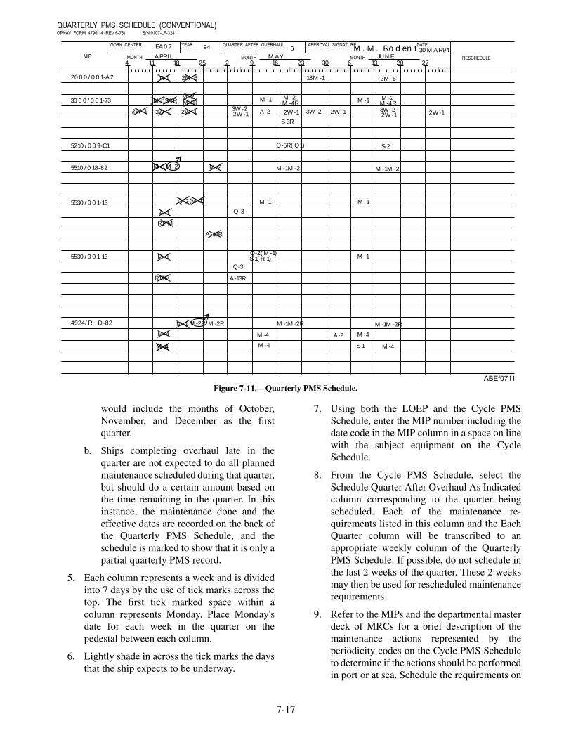
would include the months of October,November, and December as the firstquarter.
b. Ships completing overhaul late in thequarter are not expected to do all plannedmaintenance scheduled during that quarter,but should do a certain amount based onthe time remaining in the quarter. In thisinstance, the maintenance done and theeffective dates are recorded on the back ofthe Quarterly PMS Schedule, and theschedule is marked to show that it is only apartial quarterly PMS record.
5. Each column represents a week and is dividedinto 7 days by the use of tick marks across thetop. The first tick marked space within acolumn represents Monday. Place Monday'sdate for each week in the quarter on thepedestal between each column.
6. Lightly shade in across the tick marks the daysthat the ship expects to be underway.
7. Using both the LOEP and the Cycle PMSSchedule, enter the MIP number including thedate code in the MIP column in a space on linewith the subject equipment on the CycleSchedule.
8. From the Cycle PMS Schedule, select theSchedule Quarter After Overhaul As Indicatedcolumn corresponding to the quarter beingscheduled. Each of the maintenance re-quirements listed in this column and the EachQuarter column will be transcribed to anappropriate weekly column of the QuarterlyPMS Schedule. If possible, do not schedule inthe last 2 weeks of the quarter. These 2 weeksmay then be used for rescheduled maintenancerequirements.
9. Refer to the MIPs and the departmental masterdeck of MRCs for a brief description of themaintenance actions represented by theperiodicity codes on the Cycle PMS Scheduleto determine if the actions should be performedin port or at sea. Schedule the requirements on
7-17
2000/001-A2
QUARTERLY PMS SCHEDULE (CONVENTIONAL)OPNAV FORM 4790/14 (REV 6-73) S/N 0107-LF-3241
WORK CENTER YEAR QUARTER AFTER OVERHAUL APPROVAL SIGNATURE DATE
RESCHEDULEMONTH
3000/001-73
5210/009-C1
5510/018-82
5530/001-13
5530/001-13
4924/RHD-82
R-1 2M-6
M-1SAR
2W-1 3W-1 2W-1
M4RM-2
3W-22W-1
M-1
A-2
M-2M-4R
2W-1
S-3R
18M-1
3W-2 2W-1
M-1
2M-6
M-2M-4R3W-22W-1
S-2Q-5R( Q1)
M-1M-2M-1M-2
2W-1
M-1M-1
M-1
Q-3A-1
Q-2
M-2 M-2M-1
(M-1)
M-1
R1TM
R1TM
M-4
M-2R
M-4M-4
M-2RM-1
M-4
M-4
M-1M-2R
A-13R
Q-3
Q-2( M-1)S-1( R-1)
4 11 18 25 2 9 16 23 30 6 13 20 27
30MAR94JUNE
M. M. RodentMONTHMAYMONTH
6APRIL
94EA07
MIP
A-13R
M-4
M-4
A-2
S-1
M-1M-2R
ABEf0711
Figure 7-11.—Quarterly PMS Schedule.

the Quarterly PMS Schedule in the week mostappropriate for accomplishment. With theexception of related daily and weekly PMSrequirements, ensure that all mandatory relatedmaintenance are scheduled within parentheseson the same line and during the same week asthe primary maintenance requirement.
10. From the Cycle PMS Schedule column titledEach Quarter, schedule monthly, quarterly, andapplicable situation requirements into theappropriate weeks of the Quarterly PMSSchedule. All calendar situation requirements(24M-2R, A-2R, S-IR, Q-3R, M-IR) must beaccomplished at least once during theperiodicity specified and also each additionaltime the situation arises. Schedule 2M( )periodicity as indicated by a number inparentheses. For example, 2M(2) occur twicein the quarter (7 to 10 weeks apart).
11. From the Cycle PMS Schedule column, titledSchedule Quarter After Overhaul As Indicated,schedule the annual, semiannual, and multiplemonth requirements. Schedule the cyclerequirements for which the number inparentheses matches the quarter after overhaulbeing scheduled.
12. Be sure that any PMS requirement listed in theReschedule column of the previous QuarterlyPMS Schedule is brought forward to theQuarterly PMS Schedule you are preparing.
13. The complete Quarterly PMS Schedule shouldbe reviewed and then signed and dated by thedepartment head in the appropriate block. If theship's operating schedule changessignificantly, PMS requirements scheduled inthe affected periods may need to be reviewedand rescheduled as necessary to coincide withthe new operating schedule.
Use of the Quarterly PMS Schedule
The Quarterly PMS Schedule serves as a directiveto workcenter supervisors for scheduling weeklymaintenance. Quarterly PMS Schedules are used asfollows:
1. Each Monday, the division officer updates theprevious week's column of the Quarterly PMSSchedule, using the following symbols:
X = Completed maintenance. The symbol Xindicates completion of a maintenance
requirement. Fully accomplished MRs areaddressed and X'd off separately on theQuarterly Schedule. Pay particular attention tomake sure situation requirements that wereaccomplished are added and X'd off separately.
0 = Maintenance not completed. A circledrequirement indicates a requirement that wasnot accomplished according to the applicableMRC.
¢ = Satisfied by higher authority test. Thissymbol is used to mark scheduled equipmentmaintenance or lower level MRC requirementsthat have been satisfied by the completion ofthe parent system test. A brief explanation ofthe parent system test (including the MIP, whoperformed the maintenance, and when) isrequired on the reverse side of the QuarterlySchedule. An X marked over the higher leveltest symbol indicates that the lower level testrequirement annotated with the ¢ has beensatisfied. (MRCs that are so satisfied areidentified on the applicable system level testMIP.)
2. The division officer is responsible forrescheduling circled requirements still withinperiodicity and for determining the reason fornonaccomplishment.
3. From the Quarterly PMS Schedule, theworkcenter supervisor schedules therequirements for the following week on theWeekly PMS Schedule and updates theinformation in the Outstanding Repairs andPMS Requirements Due In The Next 4 Weekscolumn.
4. Any requirement that was not completed instrict accordance with the applicable MRCwithin its periodicity during the quarter must(in addition to being circled on the front of theQuarterly PMS Schedule) be identified on theback of the schedule by the complete MIPnumber and MRC code, followed by a briefreason for noncompletion. Example:
C-2/1 - 11 M-1 Unable to accomplish step I.J.,"Test operate transmitter," due to antennacasualty. (This is an indication of a partialcompletion.) G-58/3-72 Q-1 Heavy seaspreclude accomplishment as scheduled.
Unaccomplished S, A, or multiple-monthperiodicity requirements should be added to
7-18

the Reschedule column for accomplishment inthe next quarter, if they are within theirassigned periodicities. At the end of the quarterthe department head should indicate awarenessof the maintenance actions which were notaccomplished by reviewing, signing, anddating the back of the schedule for the quarterjust completed. The department head shouldalso take positive steps to ensure that priority isgiven to completing maintenance requirementsrescheduled from the previous quarter andthose not accomplished within their assignedperiodicities.
5. The completed Quarterly PMS Schedule isremoved from the holder after the close of eachquarter and retained as a planned maintenancerecord. The four previously completedquarterly schedules will be retained.
6. The recopying of Quarterly Schedules tofacilitate legibility is discouraged, and shouldonly be done with the division officer's writtenapproval.
WEEKLY PMS SCHEDULE
The Weekly PMS Schedule (fig. 7-12) displays theplanned maintenance scheduled for accomplishment in
7-19
Figure 7-12.—Weekly PMS Schedule.

a given workcenter during a specific week. A WeeklyPMS Schedule is posted in each workcenter and usedby the workcenter supervisor to assign and monitor theaccomplishment of required PMS tasks by workcenterpersonnel.
Content of the Weekly PMS Schedule
The Weekly PMS Schedule contains the followinginformation:
1. Workcenter code
2. Date of current week
3. Division officer's approval signature
4. MIP number (minus the date code)
5. A list of applicable components/equipment
6. Maintenance responsibilities assigned, byname, to each line item of equipment
7. The periodicity codes of maintenancerequirements to be performed, listed bycolumns for each day
8. Outstanding major repairs, applicable PMSrequirements, and all situation requirements
Preparation of Weekly PMS Schedule
Prepare the Weekly PMS Schedule as follows:
1. Using OPNAV Form 4790/15 or approvedautomated form, type in or neatly enter in inkthe following basic (permanent) informationfrom the Cycle PMS Schedule, the LOEP, andapplicable MIPs:
a. Workcenter identification.
b. MIP codes and component nomenclature,line for line, to match the Cycle PMSSchedule. (Include serial or identifyingnumbers and EGL information ifapplicable.)
c. Daily and weekly PMS requirements asindicated in the MIPs for each workcenter.List all weekly requirements in theMONDAY column and daily requirementsonce in each day of the week column andtwice in the SAT.-SUN. column. Schedule2D periodicity on Monday, Wednesday,
Friday, and once in the SAT.-SUN. period.Schedule 3D periodicity on Monday,Thursday, and once in the SAT.-SUN.period.
d. List all situation requirements in the NextFour Weeks column, and schedule them, asthe situation requires. Also list the 2Wperiodicity requirements in the Next FourWeeks column.
e. Now, either laminated or covered withplastic so that it can be cleared and updatedeach week.
2. The following information is not permanent innature and is written in after the schedule islaminated.
a. Using the Quarterly PMS Schedule, theworkcenter supervisor transposes all PMSrequirements from the column for theweek being scheduled to the Weekly PMSSchedule. MIPs/MRCs must be reviewedto ensure that related maintenance actionsare scheduled for the same day and thatappropriate consideration is given to theweek's operating schedule.
b. Using information from the QuarterlyPMS Schedule, the workcenter supervisorlists in the Next Four Weeks column of theWeekly PMS Schedule all PMSrequirements due in the next 4 weeks.
c. The workcenter supervisor assignspersonnel, by name, to specific line entries.
d. The Weekly PMS Schedule is signed anddated by the division officer prior to itsposting in the holder in the workcenter.
Use of the Weekly PMS Schedule
The Weekly PMS Schedule is used by theworkcenter as follows:
1. Maintenance personnel obtain PMSassignments from the Weekly PMS Scheduleand report completed and uncompletedmaintenance actions to the workcentersupervisor.
7-20
2. When satisfied that the work has been properlycompleted, the workcenter supervisor crossesoff, with an X, the maintenance requirement. Ifthe maintenance is not completed, themaintenance requirement is circled andrescheduled. However, if material deficienciesor casualties that are unrelated to themaintenance requirement are discovered, themaintenance requirement can be X'd off, butthe discrepancy must be reported to theworkcenter supervisor. PMS requirements(other than daily checks) accomplished duringthe prescribed week but not on the dayspecified are considered completed onschedule and X'd off.
3. Each Monday morning, the division officercompares the preceding week's Weekly PMSSchedule with the Quarterly Schedule andensures that the Quarterly Schedule is properlyupdated as follows:
a. Scheduled requirements that werecompleted are X'd out.
b. Scheduled requirements that were notcompleted are circled.
c. Situation requirements that occurred andwere completed are entered and X'd off.
d. Requirements that were completed aheadof schedule are circled, back scheduled andX'd out.
4. Each Monday morning, the division officerreviews the current week's Weekly PMSSchedule, ensures that it is properly made outaccording to the Quarterly Schedule, and signsand dates the Weekly Schedule in theappropriate block.
REVIEW QUESTIONS
Q4. What maintenance requirements do the cycleschedules display?
Q5. All superseded cycle schedules are retainedfor how many months?
Q6. How often is the quarterly schedule updated?
THE MAINTENANCE DATA SYSTEM
LEARNING OBJECTIVES: State thepurpose of the Maintenance Data System anddescribe the types of maintenance actionsreported on the following OPNAV forms:4790/2K, 4790/CK, 4790/2P.
The Maintenance Data System is used to recordinformation considered necessary for workloadplanning and coordination and to provide a data basefor evaluating and improving equipment installed in thefleet. Much of the data collected by MDS returns to theship in the form of a material history known as theCurrent Ship's Maintenance Project (CSMP).
Nearly all the reporting of maintenance actionsother than normal PMS actions is done on a singlemultipurpose form, the Ship's Maintenance ActionForm, OPNAV 4790/2K. Personnel completing amaintenance action fill out the appropriate sections ofthe form and send it via the ship's data collection centerto an ADP (automatic data processing) facility to beprocessed. The 4790/2K contain information on thereporter's ship, workcenter, equipment worked on, andinitial symptoms observed. In other sections, space isprovided to record completion information, deferral ofthe work for various reasons, remarks, and specialinformation for work requests. A space also exists forrecording time meter and counter readings where theyare required.
Normally, the following types of maintenanceactions will be reported on the 4790/2K: system orequipment repairs or improvements; maintenanceactions that require the use of parts or materialsspecifically requisitioned for the job; actions thatcannot be completed in the usual amount of time due tothe ship's operations; requirements for outsideassistance, or unavailability of parts or material;assistance received from nonreporting activities, suchas mobile technical training units (MOTUs) ortechnical representatives; major work associated withcorrosion control and preservation of the ship; andcertain PMS actions listed in the 3-M Manual,OPNAVINST 4790.4.
7-21

To prevent the loss of significant data when it isrecorded on several forms, each maintenance actionmust be assigned a unique identifier. Under MDS, thisidentifier is known as the job control number (JCN). Itconsists of a five-character unit identification code(UIC), a four-character workcenter code, and afour-character serial number called the job sequencenumber (JSN). Figure 7-13 shows an example of a JCNlog used to record the JSNs. This system gives aworkcenter at least 9,999 JCNs. If additional JCNs aredesired, letters can be substituted for the first numeral.In any event, take care to make sure that two differentjobs are not assigned the same JCN.
There are many different situations that could becovered by the MDS documents. This text will coveronly the basic actions.
SHIP'S MAINTENANCE ACTION FORM(OPNAV 4790/2K)
The ship's maintenance action form (OPNAV4790/2k) (fig. 7-14), printed on a single sheet of"no-carbon-required" paper, is the basic MDSdocument. If multiple copies are needed, the necessarynumber of forms may be fastened together and filled inat one time. The form may also be reproduced onelectrostatic (Xerox-type) copying machines.
This form contains six sections that require entriesto describe the type of maintenance action beingreported. Entries should be printed in capital letters. Allentries must be legible and should be inserted withinthe tic marks. If an error is made, it should be lined outusing a single line, and the correct information entered.
7-22
Figure 7-13.—Example of an job control number log.

7-23
Figure 7-14.—Ship's Maintenance Action Form (OPNAV 4790/2K).
The OPNAV 4790/2K is used to report all deferredmaintenance actions and the completion ofmaintenance actions that do not result in configurationchanges. Partially completed maintenance actions thatwill result in configuration changes and complete orpartial accomplishment of alterations are reported onOPNAV 4790/CK. A description of the OPNAV4790/2K information sections is presented in thefollowing paragraphs.
Section I-Identification
This section identifies the equipment or system onwhich maintenance actions are being performed.
Section II-Deferral Action
This section filled in when reporting the deferral ofa maintenance action. Indicates ship's force man-hoursexpended up to the time of deferral, the date of thedeferral, ship's force man-hours remaining, and if thework must be completed by a certain date.
Section III-Completed Action
This section is filled in to report the completion of amaintenance action.
Section IV-Remarks/Description
This section must be filled in when the deferral of amaintenance action is reported. It is filled in when thecompletion of a maintenance action is reported, onlywhen such remarks are considered important to themaintenance action. This section must also be filled into report maintenance actions on selected equipmentrequiring second level reporting, and to describesituations that are safety related.
Section V-Supplementary Information
This section contains helpful information aboutdeferred maintenance actions, such as what technicalmanuals and blueprints are available and whether or notthey are retained on board the requesting ship.
Section VI-Repair Activity Planning Action
The repair activity may use this section for internalplanning and scheduling of the workload.
Block G, Completed By
This block contains the signature and rate/rank ofthe senior person actively engaged on the job in the leadworkcenter. For maintenance actions not requiringassistance from an outside workcenter, the seniorperson working on the job signs this block and indicateshis or her rate.
Block H, Accepted By
This block contains the signature and rate/rank ofthe individual authorized by the tended ship to verifythe acceptability of the work performed. Completion ofthis block is mandatory when an OPNAV 4790/2K isused to report completion of a previously deferredmaintenance action. For maintenance actions notrequiring assistance from an outside workcenter, theworkcenter supervisor will sign this block and indicatehis or her rate/rank.
The commanding officer, or his/her authorizedrepresentative, places his/her signature on all originaldeferrals in block E. Two copies are held in a deferralsuspense file in the workcenter until the JCN appears onthe automated CSMP report, at which time the copiesare transferred to the active suspense file held in theworkcenter
MAINTENANCE PLANNING ANDESTIMATING FORM (OPNAV4790/2P)
The maintenance planning and estimating form(OPNAV 4790/2P) (fig. 7-15) is used along with theOPNAV 4790/2K form for deferring maintenance to bedone by an intermediate maintenance activity (IMA).Attached to the original 2K at the intermediatemaintenance activity, it is used by the IMA to screenand plan the job in detail.
7-24

7-25
Figure 7-15.—Maintenance Planning and Estimating Form (OPNAV 4790/2P).

SUPPLEMENTAL FORM (OPNAV 4790/2L)
The supplemental form (OPNAV 4790/2L) (fig.7-16) is used by maintenance personnel to provideamplifying information (such as drawings and listings)related to a maintenance action reported on an OPNAV4790/2K. The information on this form will never beentered into the computer. The form is prepared in thefollowing manner:
1. The ship's name and hull number are entered inblocks A and B.
2. If the form is a continuation of a maintenancedata form or another supplemental report form,the appropriate form is checked in block F andthe JCN assigned to the basic form is entered inblocks C, D, and E.
3. Section II will contain comments, sketches, orother supplemental information.
7-26
Figure 7-16.—Supplemental Form (OPNAV 4790/2L).

4. Section III (blocks H, I, J, and K) will containthe names of the person and the supervisorsubmitting the report.
REPORTING CHANGES TO EQUIPMENTCONFIGURATION
One of the major objectives of the MDS is toprovide the capability for reporting configurationchanges. The importance of configuration change
reporting cannot be overemphasized. Whenever anysystem, equipment, component, or unit within the shipis installed, removed, modified, or relocated, thechange must be reported. This action will ensure properaccounting of configuration changes, and will improvesupply and maintenance support such as technicalmanuals, PMS coverage, and COSAL to the fleet. TheConfiguration Change Form (ONNAV 4790/CK) (fig.7-17) is used to provide this service.
7-27
Figure 7-17.—Ship's Configuration Change Form (OPNAV 4790/CK).

The OPNAV 4790/CK form is completed to themaximum extent possible by the accomplishingactivity and provided to the ship or activity 3-Mcoordinator.
The 3-M coordinator then reviews the forms forlegibility (all copies) and ompleteness and provides theforms to the applicable workcenter supervisor, whoensures that the proper documentation is completed andprocessed when a configuration change isaccomplished, including required signatures to indicateverification of all reported configuration changes.
The ship is also responsible for reporting andmonitoring all changes accomplished by ship's forceduring any type of availability, and for providing theConfiguration Change Form to the overhauling activity.The ship is not responsible for reporting configurationchanges accomplished by an overhauling activityduring availabilities.
A configuration change is either (1) theaccomplishment of any action prescribed by analteration directive (SHIPALT or equipment alteration)or (2) the installation, removal, or modification of anysystem, equipment, component, or unit. Thereplacement of repair parts (such as nuts, bolts, wires,0-rings, gaskets, resistors, and capacitors) with likeparts, does not constitute a configuration change.
The OPNAV 4790/CK form is used to report aconfiguration change or to report the completion of aprevious deferral that resulted in a configurationchange. Deferred maintenance actions and completedmaintenance actions that do not result in configurationchanges are reported on OPNAV 4790/2K. TheOPNAV 4790/2K form will never be used to reportaccomplishment of any maintenance action that resultsin configuration changes.
A configuration change occurs whenever theaccomplishment of a maintenance action results in thefollowing:
• Addition or installation of any new equipment.
• Deletion, removal, or turn-in of any installedequipment.
• Replacement or exchange of any equipment. Areplacement or exchange is reported as theremoval of an installed item of equipment andthe installation of a new item of equipment.
• Modification of any installed or in-useequipment. A modification occurs when amaintenance action alters the design oroperating characteristics of the equipment orwhen nonstandard replacement parts (notidentified on the APL or in the technical manual)are used.
• Relocation of any equipment to a new deck, newframe, or new compartment.
• Accomplishment of any alteration directive,such as a field change or SHIPALT.
CAUTIONS ON ERRORS
Since the data entered on the MDS forms is used bydata processing equipment to provide information to aship in the form of the CSMP report, it is essential thateach form be filled in completely and accurately. Acomputer cannot recognize anything that it is told doesnot exist. It will reject incorrect and incomplete entriesand the data will not be available for use. To prevent thisfrom happening, it is important that the completedforms be reviewed at all levels. Some of the commonerrors that workcenter supervisors, division officers,department heads, and 3-M coordinators should be alertfor are
• omission of slash marks through zeros and Z's;
• incorrect EICs;
• use of improper codes for alterations and fieldchanges;
• too many or not enough spaces between wordsin the Remarks section;
• incorrect dates; and
• incorrect entries.
These are only a few of the many errors detectedeach day by a typical TYCOM 3-M staff section.
Some areas on the 4790/2K require specialmention. Alterations and field changes are identified inblock 18 by a two-letter code in the first two spaces,followed by the identification number of the change. Atitle code, such as A, D, F, or K may be shown in theauthorizing directive of SHIPALTs. This title code, ifassigned, must be entered in the extreme right handposition of the block.
7-28

In block 18, the first two letters identify SHIPALT(SA), ORDALT (OA), field change (FC), or any otherappropriate instruction. Electronic equipment is alwaysidentified by serial number, and only one piece ofequipment may be reported under a given JCN. Ifseveral pieces of the same type of equipment are alteredby field changes, there must be one document for eachpiece of equipment. Example:
A ship has four C-13 Mod 1 catapults, and field change17 is to be installed in all of them. Each catapult will bechanged, and the changes will be reported on separatedocuments showing a specific JSN and equipmentserial number. This will enable the computers toidentify which items of equipment have been changedand which have not. It also will be reflected on thereadouts returned to the ship as part of its materialhistory.
Another problem is the use of the noun name inblock 5. For electronic equipment the "AN"designation is the best entry for the noun name. If thereis no "AN" designation, the name from the nameplateshould be used. Up to 16 characters of a name may beentered.
In block 35, a space follows each word, and wordsthat cannot be completed on a line are continued on thenext line with no spaces or hyphens inserted. Ondeferred actions, the XXX's used to separate the troublefrom the desired corrective action must not beseparated. If they cannot be fitted in on one line, extraspaces will be left blank on that line and the XXX's willbe put in the first spaces of the next line.
REVIEW QUESTIONS
Q7. Maintenance Data System is used to recordwhat type of information?
Q8. Under the maintenance Data System, what isa Job Control Number?
Q9. What is the OPNAV 4790/2K used to report?
Q10. The OPNAV 4790/2P provide what type ofinformation?
SUPPLY
LEARNING OBJECTIVES: Recognize thedifferent types of stock and control numbers.Recall the purpose of cognizance symbols.Recognize sources of identifying materialwhen a stock number is not available.Recognize the uses of the following supply
publications: FED LOG, ML–C, MCRL,MRIL, ASG, and GSA.
One of the duties of an ABE is to identify andrequisition material. This section provides basicinformation to help you develop the knowledge youneed to perform these duties. Proper materialidentification is essential to the requisitioning andreceipt of the correct item. You must understand theterminology used in material identification.
GENERAL INFORMATION
Material is managed according to category(Federal Supply Classification) and its intended use.An inventory manager is assigned for each category ofmaterial, and has overall responsibility for all itemswithin the category. All items in the supply system havean assigned two-position cognizance symbol code.This code identifies the inventory manager and thestores account in which the material is carried. Theitems assigned to bureau, office, or systems commandfor inventory management includes the followingmaterial:
• Material in the research and development stage
• Material that requires continuing logistics,engineering, or fiscal administration and controlat the department level.
• Material recognized as a onetime installationthat was bought and issued for a specific use
Naval Supply System Command (NAVSUP)Inventory Control point (ICP) items are those for whichbureau, office, or systems command management is notessential. The NAVSUP ICP provides stocks of theseitems to its segment of the supply system. This group ofitems includes equipment, repair parts, andconsumables. It also includes those items for whichstocking determination, quality control, funding, andissue control can be accomplished by the ICP ifrequired, the ICP ensure that these items are availablefrom commercial sources and other governmentagencies. NAVSUP selects the items assigned to ICPfor inventory management with the advice of theappropriate bureau, office, or systems command.
The Navy Retail Office items are items for whichjoint military supply management responsibility isvested to the Defense Logistics Agency (DLA). Theseitems include components, repair parts, consumables,and other material. The requirement determination andprocurement of these items can be accomplished by the
7-29

defense supply center on a combined basis for allmilitary services.
MATERIAL CATALOGING ANDCLASSIFICATION
LEARNING OBJECTIVE: Recognize thedifferent types of stock and control numbers.Recall the purpose of cognizance symbols.Recognize sources of identifying materialwhen a stock number is not available.Recognize the uses of the following supplypublications: MCRL, ML-C, MRIL, ASG, andGSA.
This will help you understand the information usedin material identification. There are ore than 4 millionsupply items in the Department of Defense (DOD)supply system. The Navy supply system alone stocksmore than 1 million items. Each item must be identifiedto make buying, stocking, and issuing easier. Toaccomplish this, each item must be listed in differentgroups or categories.
FEDERAL CATALOG SYSTEM
The Federal Catalog System encompasses thenaming, description, and numbering of all items carriedunder centralized inventory control by the Departmentof Defense (DOD) and civil agencies of the FederalGovernment as well as the publication of relatedidentification data. Only one identification may be usedfor each item in all supply functions from purchase tofinal disposal. The North Atlantic Treaty Organization(NATO) countries also use the Federal Catalog System.The Defense Logistics Agency (DLA) administers theFederal Cataloging System under the direction of theAssistant Secretary of Defense (Installation andLogistics).
FEDERAL SUPPLY CLASSIFICATIONSYSTEM
The Federal Supply Classification (FSC) Systemwas designed to permit the classification of all items ofsupply used by the Federal Government. Each item ofsupply is classified in only one four-digit FederalSupply Classification class. The first two digits denotethe group or major division of commodities within thegroup. Currently, there are 76 groups assigned. Groupnumbers start from 10 and end at 99. Table 7-3 is anexample list of federal supply groups and titles.
Table 7-3.—Example List of Federal Supply Groups
GROUP TITLE
17 Aircraft launching, land-ing, and ground handlingequipment
48 Valves
53 Hardware and abrasives
The number of classes within each group varies.Each class covers a particular area of commoditiesaccording to physical or performance characteristics.The items in the class are usually requisitioned orissued together. This is used as a basis for includingitems in the same area of commodities. Examples ofhow classes are used to divide types of material within astock group are shown in figure 7-18. The stock groupand class together make the Federal SupplyClassification (FSC).
GROUPS CLASSES
Group 17
Aircraft launching,landing, and groundhandling equipment
1710 Arresting gear andbarricade equipment
1720 Catapult launchingequipment
Group 48
Valves
4810 Valve solenoid
4820 Valve angle
Group 53
Hardware andabrasives
5305 Screws
5306 Bolts
5307 Studs
5310 Nuts and washers
5320 Rivets
Figure 7-18.—Examples of supply classes within a stockgroup.
The Navy uses groups 01 through 09 for forms andpublications that are not included in the FederalCatalog System. The forms and publications arenumbered according to the following system:
01 Navy Department forms
02-08 Publications
09 District and fleet forms
7-30

NATIONAL STOCK NUMBER (NSN)
All items of supply that are centrally managed orbought for system stock are required to have a NationalStock Number (NSN) assigned to them. National StockNumbers are used in all supply management functionsand publications that mention the items. The NSN is a13-digit number assigned by Defense LogisticsInformation Service (DLIS) to identify an item ofmaterial in the supply distribution system. Thefollowing paragraph discusses the breakdown of anNSN. Figure 7-19 is an example of an NSN.
Federal Supply Classification (FSC)
The Federal Supply Classification (FSC) is afour-digit number that occupies the first part of anNSN. The Defense Logistics Agency CatalogingHandbook H2 (in book form) lists the groups andclasses in use today.
National Codification Bureau (NCB) Code
The National Codification Bureau (NCB) code is atwo-digit code that occupies the fifth and sixth positionof a NATO stock number. These code identities theNATO country that originally cataloged the item ofsupply. The NCB codes currently assigned are listed inAfloat Supply Procedures, NAVSUP P-485. The NSNassigned by United States uses NCB codes “00” and“01.”
National Item Identification Number (NIIN)
The National Item Identification Number (NIIN)consists of a two digit National Codification Bureau(NCB) code and seven digits which in conjunction withthe NCB code, uniquely identify each NSN item in thefederal supply distribution system. In the examplegiven in figure 3-2, the “00-1234567” is the NIIN.Although part of the NSN, NIINs are usedindependently for material identification. Except foridentification list, most federal supply catalogs arearranged in NIIN order.
In addition to the 13-digit NSN, the Navy usesother codes for material identification. These codesmay be prefixes or suffixes to the NSN. The followingparagraphs describe these codes.
Cognizant (COG) Symbol
The cognizant (COG) symbol consists of atwo-character code that identifies the stores accountand cognizant inventory manager of an item. Thecognizant symbols are listed in table 7-4. To understandcognizant symbols, you must understand the followingterms:
Stores Account: This is an account reflecting thevalue of material, supplies, and similar property onhand. The accounts are the Appropriation StoresAccount (APA) and the Navy Stock Account (NSA).
Appropriations Purchase Account (APA): Thisaccount is for all stock material paid for out ofappropriations. This material is not charged to theuser’s operating funds. If the material was ought for apurpose other than its original appropriation, thematerial is chargeable to the user’s fund.
Navy Stock Account (NSA): The NSA consists ofall material paid from the Defense Business OperatingFund (DBOF). NSA material is always charged to theuser’s allotment, operating budget, or operating targetfunds.
Inventory manager: This is an organizational unitor activity within the Department of Defense. Theinventory manager has the primary responsibility forcontrolling the functions of cataloging, identification,determination of requirements, procurement,inspection, storage, and distribution of categories ofmaterial.
Technical responsibility: This is the systemscommand or office that determines the technicalcharacteristics of equipment. For example, theelectronics equipment characteristics include itemssuch as circuitry and the types and arrangement ofcomponents.
7-31
1710 00 1234567
Federal Supply ClassificationCode Number
National Codification BureauCode
National Item IdentificationNumber
Figure 7-19.—Example of an NSN.

Expense type item: This term identifies stock itemsthat are financed by the Defense Business OperatingFund, and is the same as NSA items.
Consumable: Consumable material is material thatis consumed in normal use. Some of the examples ofthese materials are paints, cleaning supplies, officesupplies, and common tools.
7-32
COGSYMBOL
COGNIZANTINVENTORYMANAGER
STORESACCOUNT
TECHNICALRESPONSIBILITY
DEFINITION
0I Naval Publication andForms Directorate
None Navy Publication andPrinting Service
Publications
1I Naval Publication andForms Directorate
NSA Navy Publication andPrinting Service
Forms
1R Naval InventoryControl PointPhiladelphia(NAVICP PHIL)
NSA Naval Air SystemCommand
Aeronautical,photographic, andmeteorological 1material(consumable orexpense typematerial).
4R Naval InventoryControl PointPhiladelphia(NAVICP PHIL)
APA Naval Air SystemCommand
Catapult andarresting gearmaterial (repairableor investment typematerial).
4V Naval Air SystemCommand
APA Naval Air SystemCommand
Aircraft engines.
4Z Naval InventoryControl PointPhiladelphia(NAVICP PHIL)
APA Naval Air SystemCommand
Airbornearmament.
5R Naval InventoryControl PointPhiladelphia(NAVICP PHIL)
NSA Naval Air SystemCommand
Catapult andarresting gearmaterial(consumable orexpense typematerial).
6R Naval InventoryControl PointPhiladelphia(NAVICP PHIL)
APA Naval Air SystemCommand
Aviation groundsupport equipment(repairable orinvestment typematerial.
6V Naval Air SystemCommand
APA Naval Air SystemCommand
Technical directivechange kits.
7R Naval InventoryControl PointPhiladelphia(NAVICP PHIL)
NSA Naval Air SystemCommand
Depot-levelrepairable aviationmaterial.
Table 7-4.—Cognizance (COG) Symbols

Cognizance symbols are two-character,alphanumeric codes prefixed to national stocknumbers. Cognizance symbols are listed in Table 7-4.The first character of the cognizance symbol identifiesthe stores account. The following information refers tothe first character of the cognizance symbol:
• Cognizance symbols 0 (zero), 2A and 8A is notcarried in the stores account and is issuedwithout charge to the requisitioner.
• Even numbers 2, 4, 6, and 8 are carried in theAppropriation Stores Account (APA).
• Odd numbers 1, 3, 5, and 7 are carried in theNavy Stock Account (NSA).
• Number 9 is Navy-owned material carried inNSA and managed-by the Naval InventoryControl Point Mechanicsburg.
The second position of the cognizance symbolidentifies the item manager. The item managerexercises supply management over specified categoriesof material.
Material Control Codes
A Material Control Code (MCC) is a singlealphabetic character assigned by the inventorymanager. It is used to segregate items into manageablegroupings (fast, medium, or slow movers) or to relate tofield activities special reporting and control
requirements. Table 7-5 contains a list of MCCscommonly encountered.
NAVY ITEM CONTROL NUMBER (NICN)
As we have discussed in a previous paragraph,NSNs are required for all items centrally managed orbought for supply system stock. With changes ofequipment and products, the Navy buys new items fromthe suppliers. New items entering the Navy supplysystem are identified in time to permit assignment ofNSNs before shipment. In numerous instances, theNavy Item Control Number (NICN) is used to identifythe items before an NSN can be assigned. Some itemsare permanently identified by the NICN because of thenature of the items. The NICN designation includes thefollowing:
• Inventory Control Point ICP control numbers
• Kit numbers
• Publications and forms ordering numbers
• Local Navy Activity Control (NAC) numbers
• Other locally assigned numbers
The NICN is a 13-digit number that identifies anitem of supply. It is composed of the following parts:
• Federal Supply Classification (FSC) code(numbers that occupy the first four digits of theNICN)
7-33
CODE DEFINITION
D Field level repairable.
E (1) Depot-level repairables.
(2) Material (expendable ordnance) requiring lot and serialnumber control, but is reported by serial number only.
H Depot-level repairables.
L Items of local stock or items pending NSN assignment.
M Medium demand velocity items (consumables).
S Slow demand velocity items.
T Terminal items.
W Ground support equipment.
X Special program repairables.
Z Special program consumables.
Table 7-5.—Material Control Codes

• Navy Item Control Number (NICN) code(letters that occupy the 5th and 6th position)
• Serial number (alphanumeric and occupies the7th through the 13th position)
The NIC numbers that you must be familiar withare listed in Table 7-6. These codes differentiate thetypes of NICN.
Permanent LL Coded NICNs
The NICNs with “LL” in the 5th and 6th positionsand a “C” in the 7th position mean that the ICPs or otherNavy item managers (including field activities)assigned them. Its purpose is to identify and monitornonstocked items that are not expected to have enoughdemand to qualify for NSN assignment. The NICNs areassigned to permit the maintenance of a complete anduniform inventory control point weapons system file. Itis also used to ensure that selected items are consideredfor inclusion in future allowance lists. Stock pointsmust purchase items identified by this type of NICN.Stock points currently do not have the capability totranslate permanent LL coded NICNs to applicableCAGES and part numbers. The items are requisitioned
by using the DD 1348-6 format (part numberrequisition).
Temporary LL Coded NICNs
The NICNs with “LL” in the 5th and 6th positionsand any letter except “C” in the 7th position areassigned by ICPs or other Navy inventory managers fortemporary identification. These NICNs enables theitem manager to establish and maintain automated filerecords, to ease procurement action, and to maximizeautomated processing of requisitions. The cognizantitem managers review the temporary NICNsperiodically to convert them to NSN or to delete theones that are no longer required. When a requisitionidentifies an item by a temporary NICN that has beenconverted to an NSN the status card will include thenew NSN. A NICN to NIIN cross-reference list ispublished monthly by the Defense LogisticsInformation Service (DLIS) on the FED LOGCD-ROM.
LOCAL ITEM CONTROL NUMBER (LICN)
The LICN (fig. 7-20) is an identification numberassigned by an activity for its own use. However,
7-34
NIC NUMBERCODES
USED TO DESIGNATE
LD Directive ordering number (COG 0I).
Example:1234-LD-123-4567
LF Form ordering number (COG 1I).
Example:1234-LF-123-4567
LK Aircraft change kit number.
Example:1234-LK-123-4567
LP Publication ordering number (COG 0I and 0P).
Example:1234-LP-123-4567
LX Control number assigned by NAVICO PHIL field activities tocertain items under their inventory control.
Example:1234-LX-123-4567
Table 7-6.—Navy Item Control Codes
1710 LL 0000123
Appropriate Federal SupplyClassification Code Number
Designation for locally assignedidentification number
Serially assignedidentification number
Figure 7-20.—Example of an LICN.

LICNs are not authorized in supply transactiondocuments. LICNs are for local use only and may beassigned to shipboard stocked consumable items thatare not identified by and NSN or another type of NICN.A LICN consists of 13 characters. The first four will benumbers corresponding to the federal supplyclassification (FSC) of a similar NSN items, the fifthand sixth will be LL and the remaining seven alphanumeric.
SOURCES OF MATERIAL IDENTIFICATION
This chapter presents different sources ofinformation that is needed in performing technicalresearch. Material identification does not end with theassignment of the NSN. Some means of identifyingother particular needs by the stock number must beprovided to the customers. This includes the means ofdetermining the correct quantities of these items tocarry in stock. Identification of needs maybedetermined by using the lists described in the followingparagraphs.
FEDERAL LOGISTICS (FED LOG)
The FED LOG on Compact Disc Read-OnlyMemory (CD-ROM) (fig.7-21) is the access to DODlogistics data. The FED LOG includes the basicmanagement data necessary for preparing requisitionsand it includes an integrated historical record of deletedand superseded NIINs with appropriate codes toindicate disposition action.
PART NUMBER
The part number, also called reference number, isan identification number assigned to an item by themanufacture. It is made up of letters, numbers, orcombinations of both. When used with the CommercialAnd Government Entity (CAGE) code, it identifies theitem. It is used with other technical data (for example,model, series, and end-use application) to requisitionan item when an NSN is not assigned. Part number toNSN cross-reference is provided in FED-LOG.
7-35
Figure 7-21.—Example of FED LOG query.

COMMERCIAL AND GOVERNMENT ENTITYCODE
The Commercial And Government Entity (CAGE)(fig. 7-22) Code is a five-digit, numeric identificationcode assigned to manufacturers which have previouslyor are currently producing items used by the FederalGovernment. The CAGE is used in conjunction withpart number, item number, symbol, or trade nameassigned by the manufacturer to his product. TheCAGE catalog handbook is published the DefenseLogistics Information Service (DLIS) on the FED LOGCD-ROM.
MANAGEMENT LIST-CONSOLIDATED (ML-C)
The Management-List Consolidated (ML-C) is aconsolidated, cumulative listing of National StockNumbers for all branches of the armed services. EachNSN is listed one time only. The integrated materialmanager and service or agency is listed separately. TheML-C is a tool used for determining management dataapplicable to items used or managed by other militaryactivities.
MASTER CROSS-REFERENCE LIST(MCRL)
The Master Cross-Reference List (MCRL) (fig.7-23) Part I, provides a cross-reference from areference number (manufacturer’s part number,drawing number, design control number, etc.) to itsassigned National Stock Numbers (NSN). The MCRL,Part II, provides a cross-reference from an NSN to areference number. The MCRL is published on the FEDLOG CD-ROM.
MASTER REPAIRABLE ITEM LIST(MRIL)
The Master Repairable Item List (MRIL) (fig. 7-24and 7-25) is a catalog of selected Navy-managed itemswhich, when are unserviceable and not locallyrepairable, are required to be turned in to a DesignatedOverhaul Point (DOP) for repair and return to systemstock. The MRIL is part of the FED LOG that isdistributed in compact disc format. The MRIL ispublished on the FED LOG CD-ROM and is made upof two parts as shown in figures 7-24 and 7-25.
7-36
Figure 7-22.—Example of CAGE from FED LOG.

7-37
Figure 7-23.—MCRL from FED LOG.
Figure 7-24.—MRIL Part I from FED LOG.

AFLOAT SHOPPING GUIDE
The Afloat Shopping Guide (ASG) (fig. 7-26) isdesigned to assist the fleet personnel in identifying theNSNs for items that are frequently requested by ships.It includes a detailed description of each item, and(when applicable) the stock number for substituteitems. The ASG is distributed in CD-ROM format andin printed form.
GENERAL SERVICES ADMINISTRATIONFEDERAL SUPPLY CATALOG
The General Services Administration (GSA)Federal Supply Catalog lists approximately 20,000 lineitems that are stocked in GSA supply distributionfacilities. The items listed in this catalog are assignedcognizance 9Q. The GSA supply catalog series servesas the major merchandising instrument of the FederalSupply Service (FSS) Stock Program. Since they areprepared for civilian agencies, the FED LOG must be
referred to for supply management data. The GSAsupply catalog series consists of the following:
The GSA Supply Catalog Guide containsconsolidated alphabetical and NSN indexes to all stockitems. These are items listed in the four commoditycatalogs and other items available through the FSSprogram. It provides detailed information concerningthe program and requisitioning procedures.
The GSA Supply Catalog (Tools) contains listingsof common and special use tools. It includesalphabetical and numerical indexes and a price list.
The GSA Supply Catalog (Office Products) lists awide variety of items for office use, including papersupplies, standard and optional forms, and many itemsof equipment. It includes alphabetical and numericalindexes and a price list.
The GSA Supply Catalog (Industrial Products)contains descriptive listings of a broad range of items,such as hardware, paints, adhesives, and cleaning
7-38
Figure 7-25.—MRIL Part II from FED LOG.

7-39
Figure 7-26.—Page from Afloat Shopping Guide.

equipment and supplies. It includes alphabetical andnumerical indexes and a price list.
The GSA Supply Catalog (Furniture) provides asingle source of information for all furniture itemsstocked by the FSS.
NAVY STOCK LIST OF PUBLICATIONS,FORMS, AND DIRECTIVES
The Navy Stock List of Publications, Forms, andDirectives, NAVSUP P-2002, contains requisitioningprocedures and sources of supply to assist in thedetermination of how and where material may beobtained.
HAZARDOUS MATERIAL INFORMATIONSYSTEM
The DOD Hazardous Material Information System(HMIS) provides information concerning the use,procurement, receipt, storage, and expenditure ofhazardous material. The NAVSUPSYSCOM maintainsand distributes the HMIS hazardous item list. This listincludes information concerning hazardousingredients, use of hazardous material, protectiveclothing, and emergency treatment.
ILLUSTRATED PARTS BREAKDOWN
An illustrated Parts Breakdown (IPB) is preparedby the manufacturer for each model aircraft, engine,accessory, electronic equipment, support equipment, orother equipment considered advisable by NAVAIR.The IPB is printed and issued by the authority ofNAVAIR. It is used as reference for identifying andordering replacement items. Each item of equipment islisted in assembly breakdown order, with theillustration placed as close as possible to its appropriatelisting. Some IPBs have a different format from others
The TABLE OF CONTENTS shows thebreakdown of publication into sections. It alsofurnishes an alphabetical listing of the variousassemblies and lists the page, work package, or figureswhere they are illustrated.
The GROUP ASSEMBLY PARTS LIST is themain text of the publication. It consists of series ofillustrations and parts list in which parts of the aircraftor equipment are shown in assembly breakdown order.The items in the illustration pages are identified byindex numbers. These index numbers match thenumbers listed in the parts list of the assemblybreakdown. The parts list is arranged in numerical
sequence by index number to make it easier to use. Theinformation in the parts list include index number, partnumber, description, units per assembly, Usable Oncode, and the Source, Maintenance, and Recoverability(SM&R) code. Each major assembly in the parts list isfollowed immediately by its component parts orsubassemblies. Component parts listed in thedescription column may be prefixed with a dot orindented to show their relationship. You should use thisinformation to identify and obtain the required materialin accordance with the SM&R code. The numericalindex of the IPB lists all parts in reference/part numbersequence. Each reference/part number iscross-referenced to the figure and index number or thework package where the item is listed in the text.
SOURCE, MAINTENANCE, ANDRECOVERABILITY CODES
The SM&R code consists of two-position sourcecode, two single-position maintenance codes,single-position recoverability code, and if applicable, asingle-position service option code. Table 7-7 breaksdown the SM&R code by position and defines thesource, maintenance level, and reparability level of thecomponent.
Source Code: The source code is a two-charactercode that occupies the first two positions of the SM&Rcode format. This code shows the manner of getting thematerial needed for maintenance, repair, or rework ofitems.
Maintenance Code: The maintenance codes areindicated in the third and fourth positions of the SM&Rcode. Levels of maintenance authorized to replace andrepair an assembly or part are given. The code shown inthe third position provides the lowest level ofmaintenance authorized to remove or replace theassembly or part. The fourth position indicates if theitem is to e repaired and identifies the lowestmaintenance level authorized to perform the repair.
Recoverability Code: The Recoverability Code isindicated in the fifth position, this code defines theapproved disposition of unserviceable items.
CASUALTY REPORTING (CASREP)
The casualty report (CASREP) us designed tosupport the Chief of Naval Operations (CNO) and fleetcommanders in the management of assigned forces.The effective use and support of Navy forces requiresan up-to-date, accurate operational status for each unit.An important part of operational status is casualty
7-40

information. The CASREP system contains four typesof reports: Initial, Update, Correct, and Cancel. Thesereports are described in general in the followingparagraphs.
Initial Casualty Report (INITIAL)
An initial casrep identifies the status of the casualtyand any parts or assistance needed. Operational andstaff authorities use this information to set priorities forthe use of resources.
Update Casualty Report (UPDATE)
An update casrep is used to submit changes topreviously submitted information.
Correction Casualty Report (CORRECT)
A correct casrep is submitted when equipment thathas been the subject of casualty reporting is repairedand is back in operational condition.
Cancellation Casualty Report (CANCEL)
A cancel casrep is submitted when equipment thathas been the subject of casualty reporting is scheduledto be repaired during an overhaul or some otheravailability. Outstanding casualties that will not berepaired during such availability will not be canceledand will be subject to normal follow-up casualtyreporting procedures as specified.
REVIEW QUESTIONS
Q11. National Stock Numbers are made up of howmany digits?
Q12. What occupies the first part of a NationalStock Number?
Q13. What does the Cognizant Symbol identify?
Q14. The Afloat Shopping Guide is designed forwhat purpose?
Q15. List the different types of casualty reports.
7-41
Table 7-7.—SM&R Code Format
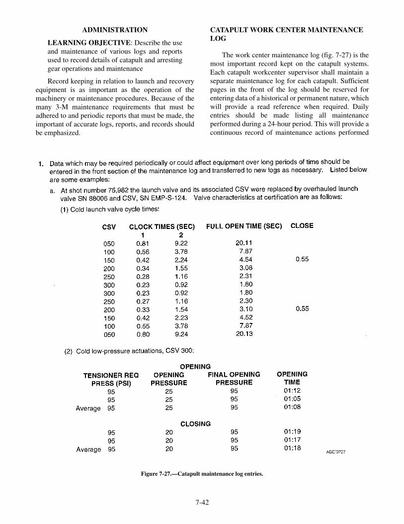
ADMINISTRATION
LEARNING OBJECTIVE: Describe the useand maintenance of various logs and reportsused to record details of catapult and arrestinggear operations and maintenance
Record keeping in relation to launch and recoveryequipment is as important as the operation of themachinery or maintenance procedures. Because of themany 3-M maintenance requirements that must beadhered to and periodic reports that must be made, theimportant of accurate logs, reports, and records shouldbe emphasized.
CATAPULT WORK CENTER MAINTENANCELOG
The work center maintenance log (fig. 7-27) is themost important record kept on the catapult systems.Each catapult workcenter supervisor shall maintain aseparate maintenance log for each catapult. Sufficientpages in the front of the log should be reserved forentering data of a historical or permanent nature, whichwill provide a read reference when required. Dailyentries should be made listing all maintenanceperformed during a 24-hour period. This will provide acontinuous record of maintenance actions performed
7-42
Figure 7-27.—Catapult maintenance log entries.

on each catapult. When a logbook is filled, thehistorical or permanent data shall be transferred into anew maintenance log and the completed log retainedfor a minimum of two years.
STEAM CATAPULT LOG
The steam catapult log (fig. 7-28) is maintainedduring all catapult operations by a catapult recorderstationed at the central charging panel (CCP) or maincontrol console (MCC).
ARRESTING GEAR WORK CENTERMAINTENANCE LOG
The work center maintenance log (fig. 7-29) is themost important record kept on the arresting gear
system. The arresting gear supervisor shall maintain aseparate maintenance log for each arresting engine.Sufficient pages in the front of the log should bereserved for entering data of a historical or permanentnature. Daily entries should be made listing allmaintenance performed during a 24-hour period. Whena log is filled, the historical or permanent data shall betransferred into a new maintenance log and thecompleted log retained for a minimum of two years.
RECOVERY LOG
The Recovery Log (fig. 7-30) is maintained duringall aircraft recovery operations by the Pri-fly controlpane operator to provide a uniform system of recordingpertinent arresting gear data.
7-43
Figure 7-28.—Steam catapult log.

7-44
Figure 7-29.—Arresting gear maintenance log entries.
Figure 7-30.—Recovery Log sheet (NAVAIR Form 13810/4).

WIRE ROPE HISTORY REPORT
The wire rope history chart (fig. 7-31) provides auniform system for recording arresting gear wire ropedata. Engine operators shall maintain this for eachspecific engine, with the last recovery number beingobtained from pri-fly. A new sheet shall be used at thebeginning of each month.
FLIGHT DECK OPERATIONS (NAVAIR FORM13810/1 AND 138/1A)
The flight operation report (fig. 7-32) and (fig. -33)is a two part form and is compiled from informationcontained in the catapult shot logs and the arrestinggear recovery logs.
ALRE AUTO SHOT RECOVERY LOGPROGRAM
The Auto shot and recovery log program provides acomputerized program for the collection anddissemination of launch and recovery log data. Theautomated program has been developed to record theShot Log, Recovery Log, and the Wire Rope History
Report on computer disc. These discs would then besent to NAWC Lakehurst vice the paper forms.
REVIEW QUESTIONS
Q16. The work center maintenance logs areretained for what minimum period of time?
SUMMARY
In this chapter, you learned that the PlannedMaintenance System is a means for accomplishingpreventive maintenance aboard ship. You also learnedthat PMS procedures for a specific piece of equipmentare based on good engineering practices, practicalexperience, and technical standards. You studied therole the Maintenance Data System has in planningworkloads and providing a database for evaluating andimproving equipment installed in the fleet. The supplyinformation in this chapter is not intended to make youan expert in supply matters. Rather, this section wasdeveloped to give you a basic understanding andprovide you with some of the information needed forordering supplies. You also studied the maintenancelogs and reports for recording the details of catapult andarresting gear operations and maintenance.
7-45
Figure 7-31.—Recovery Wire Rope History chart (NAVAIR Form 13810/5).

7-46
Figure 7-32.—Flight Deck Operations (Part I) (NAVAIR Form 13810/1).

7-47
Figure 7-33.—Flight Deck Operations (Part II) (NAVAIR Form 13810/1A).

�
�

APPENDIX I
GLOSSARY
ABE—Aviation Boatswain's Mate (Launching andRecovery Equipment).
ABRASION—Wearing away of a surface by friction,either by motion while in contact with another partor by mechanical cleaning or resurfacing withabrasive cloth or compound.
ac—Alternating current.
ACHO—Aircraft Handling Officer.
ACNO—Assistant Chief of Naval Operations.
ACTIVATE—To put into action mechanically.
ACTUATE—To put into action electrically.
ADP—Automated Data Processing.
AEL—Allowance Equipage List.
AIMD—Aircraft Intermediate Maintenance Depart-ment.
ALINEMENT—Parts in correct related positions asspecified on manufacturing drawings.
ALRE—Aircraft Launch and Recovery Equipment.
ALREMP—Aircraft Launch and RecoveryEquipment Maintenance Program.
AMBIENT TEMPERATURE—The surroundingtemperature.
APL—Allowance Parts List.
ASG—Afloat Shopping Guide.
ATMOSPHERIC PRESSURE—The normal pres-sure of the air at sea level (14.7 psi).
AWM—Awaiting Maintenance.
AWP—Awaiting Parts.
AWR—Automated Work Request.
BACK OUT—To remove a screw or other threadedpart from its fully torqued or set position.
BINDING—The stopping or the slowing down ofmotion between two surfaces because of foreignmatter, poor alinement of ports, unequal expansion,or unequal wear between surfaces.
BRAZE—To join two metals by intense heat and theapplication of a hard solder containing brass.
BRINELLING—A displacement or flow of metalrather than a loss of metal due to wear.
BULB SIDE—The side of the launching-enginecylinders that mates directly with the cylindercovers and is opposite the sealing-strip side.
BUR—A sharp projection of metal from an edge,usually the result of drilling, boring, counter-sinking, and so forth, but may also be caused byexcessive wear of one or both surfaces adjacent tothe burred edge.
CAFSU—Carrier and field service unit.
CALIBRATION—To check, fix, or correct thegraduation of a measuring instrument.
CALIPERS—An instrument composed of two curvedhinged legs, used for measuring internal andexternal dimensions.
CASREP—Casualty Report.
CAUTION—An emphatic notice requiring correctoperating or maintenance procedures to preventdamage to equipment.
CDI—Collateral Duty Inspector.
CDP—Cross Deck Pendant.
CDQAI—Collateral Duty Quality Assurance In-spector.
CHAMFER—To bevel to a sharp external edge.
CHARGE—To pressurize a hydraulic or pneumaticsystem with fluid or air.
CHATTER—Vibration caused by uneven motion of amachine, possibly resulting in damage to parts.
CIRCUMFERENCE—A line around a closed figureof area.
CNO—Chief of Naval Operations.
COGNIZANT—Pertaining to the responsible upperauthority who can make a final decision on aspecific matter.
AI-1

COH—Complex Overhaul.
COMCARGRU—Commander Carrier Group.
COME-ALONG—Ratchet hoist.
COMFAIRMED—Commander Fleet Air, Mediter-ranean.
COMFAIRWESTPAC—Commander Fleet Air,Western Pacific.
COMNAVAIRLANT—Commander Naval Air Force,U.S. Atlantic Fleet.
COMNAVAIRPAC—Commander Naval Air Force,U.S. Pacific Fleet.
COMNAVAIRSYSCOM—Commander Naval AirSystems Command.
COMNAVSEASYSCOM—Commander Naval SeaSystems Command.
COMNAVSURFLANT—Commander Naval SurfaceForce, U.S. Atlantic Fleet.
COMNAVSURFPAC—Commander Naval SurfaceForce, U.S. Pacific Fleet.
COMPONENT—A part of an assembly or sub-assembly.
CONCENTRICITY—Having a common axis orcenter. Usually refers to the closeness of tolerancesbetween the common center of two or more circles(bore and outside diameter, bore and bolt circlediameters, and so forth).
CONDENSATE—The liquid that forms when a gas orvapor, such as steam, is cooled.
CONTINUITY—The completeness of an electricalcircuit.
CORROSION—Deterioration of a metal surface,usually caused by moist, salty air.
COSAL—Coordinated Shipboard Allowance List.
CROV—Constant Run Out Valve.
CSMP—Current Ship's Maintenance Project.
CSV—Capacity Selector Valve.
CV—Multi-purpose aircraft carrier.
CVN—Nuclear-powered multi-purpose aircraft car-rier.
DLA—Defense Logistics Agency.
D-LEVEL—Depot level.
DEAD LOAD—A wheeled vehicle used instead of anaircraft during catapult testing.
DEENERGIZE—To remove from operation elec-trically.
DEFORMATION—A change in the shape ordimensions of a body, due to overstressing orrepeated usage.
DEPRESSURIZE—To remove air or hydraulic fluidfrom a system.
DIAMETER—The width or thickness of a part.
DIAMETRAL CLEARANCE—The differencebetween the inside diameter (ID) of one part andthe outside diameter (OD) of another part whenboth parts have the same axis.
DOD—Department of Defense.
DON—Department of the Navy.
DSCC—Defense Supply Center Columbus.
DSCP—Defense Supply Center Philadelphia.
DYNAMOMETER—A device used to measure force.
EI—Engineering Investigation.
EIC—Equipment Identification Code.
ELONGATION—An increase in the length of amaterial due to heating, stretching, hammering,and so forth.
EM—Electrician's Mate.
ENERGIZE—To put into operation electrically.
EROSION—Pitting or eating away of metal due to theaction of steam, chemicals, water, or atmosphere.
ERRATIC—Operating in an unusual manner that mayresult in possible breakdown or failure.
FATIGUE—A major breakdown of the surface metalover a large area, resulting in the surface metal'sbecoming loose and detached from the basematerial.
FBR—Feedback Report.
FED LOG—Federal Logistic.
FLOLS—Fresnel Lens Optical Landing System.
FMSO—Fleet Material Support Office.
FOD—Foreign Object Damage.
FREEZING—Stopping of motion between twocontacting surfaces because of lack of lubrication.
AI-2

GALLING—Tearing away of a metal surface byfriction.
HERTZ—Cycles per second.
HMR—Hazardous Material Report.
HONE—To grind with an abrasive stone to removesurface imperfections.
HUD—Heads-Up Display.
HYDRAULIC—That which is operated or moved bythe use of pressurized fluid.
HYDROSTATIC TEST—A test to determine whethera part can withstand certain hydraulic pressureswithout deforming or leaking.
I-LEVEL—Intermediate level.
IC—Interior Communications.
ICCS—Integrated Catapult Control Station.
ICP—Inventory Control Point.
IEM—Inactive Equipment Maintenance.
ILARTS—Integrated Launch and Recovery TelevisionSurveillance System.
IMA—Intermediate Maintenance Activity.
INSURV—Inspection and survey.
IPB—Illustrated Parts Breakdown.
IRAC—Interim Rapid Action Change.
JBD—Jet Blast Deflector.
JCN—Job Control Number.
JSN—Job Sequence Number.
LAGGING—The material used to insulate steampipes or boilers to prevent the loss of heat byradiation.
LANG LAY—The lay in the strands and the lay in therope are in the same direction.
LAY—That length of rope in which one strand makesone complete revolution about the core.
LOEP—List of Effective Pages.
MC—Maintenance Control.
MAF—Maintenance Action Form.
MAGNETIC PARTICLE INSPECTION—Anondestructive method of inspecting areas on ornear the surface of iron or steel. The part is
magnetized and then sprinkled with iron powder tolocate discontinuities, such as hairline cracks.
MALFUNCTION—Any failure of a system orcomponent that prevents normal operation of thecatapult.
MCRL—Master Cross Reference List.
MDS—Maintenance Data System.
MEGGER—An instrument used for checking theinsulation of electrical cables.
MEGOHM—A unit of electrical resistance equal to amillion ohms.
METCAL—Meteorology and Calibration (program).
MICROINCH—A unit of measurement equal to amillionth of an inch.
MIOCROMETER—A device used for measuringminute distances.
MILSTRIP—Military Standard Requisition and IssueProcedures.
MIP—Maintenance Index Page.
MISALINEMENT—The condition of not beingalong a fixed straight line; cocked to one side withrespect to other parts.
MOVLAS—Manually Operated Visual Landing AidSystem.
MR—Maintenance Requirement.
MRC—Maintenance Requirement Card.
MRIL—Master Repairable Item List.
MS—Maintenance Support.
NATTC—Naval Air Technical Training Center.
NATO—North Atlantic Treaty Organization.
NAVAIRWARCEN—Naval Air Warfare Center.
NAVSHIPYD—Naval Shipyard.
NAVSUP—Naval Supply System Command.
NDI—Non-destructive inspection.
NECKING-DOWN—A reduction in diameter, as in abolt or stud, caused by wear from vibration ofanother part.
NGL—Nose Gear Launch.
NPC—Naval Personnel Command.
AI-3

NSN—National Stock Number.
NTP—Navy Training Plan.
O-LEVEL—Organizational Level.
OHM—A measurement of electrical resistance.
OJT—On-the-job training.
OPNAV—Office of the Chief of Naval Operations.
OPTAR—Operations (or Operating) Target (funding).
OSI—Operating space item.
PARALLEL—Being arranged so that two or morelines, such as centerlines or lines along outsideedges, can all be at right angles to one commonline.
PEB—Pre-Expended Bin.
PEEN—To change the shape of a metal part by strikingwith a hammer.
pH NUMBER—A number used to measure the acidityor alkalinity of a solution; pH values run from 0through 14. A value of 7 indicates neutrality;numbers less than 7 indicate acidity, and numbersgreater than 7 indicate alkalinity.
PICKLE—To clean castings or forgings in a hot weak-sulfuric-acid bath.
PITTING—Small deep cavities with sharp edges.May be caused in metal surfaces by high impacts orby oxidation.
PME—Precision Measuring Equipment.
PMS—Planned Maintenance System.
PNEUMATIC—That which is operated or moved bythe use of pressurized air.
POWER PACKAGE—Provides and maintains thehydraulic pressure to raise and lower the barricadestanchions.
PQS—Personnel Qualification Standards.
PRESSURIZE—To compress air or hydraulic fluid toa pressure greater than normal.
QA—Quality Assurance.
QAI—Quality Assurance Inspector.
QDR—Quality Deficiency Report.
RAC—Rapid Action Change.
REEVE—To pass a cable or rope through a sheave,hole, ring, or similar object.
REMOVAL TORQUE—The minimum torque re-quired to remove an installed screw, measured withno axial load in the screw and while the screw is inmotion.
SATURATED STEAM—Steam that contains mois-ture.
SAYBOLT SECONDS UNIVERSAL—A unit ofmeasurement of fluid viscosity as determined by aSaybolt viscometer. (The higher the SSU number,the more viscous the fluid.)
SCORING—Deep grooves in a surface caused byrubbing when fine, hard particles are forcedbetween moving surfaces (as in a bearing andjournal), or when a moving part is not supplied withlubricant.
SE—Support Equipment.
SECDEF—Secretary of Defense.
SECNAV—Secretary of the Navy.
SECURE—Tighten joints or fasteners.
SEIZING—A wrapping, consisting of several turns oflight line or wire, placed around the cut end of awire rope to prevent the strands of the rope fromunraveling.
SEIZING—The stopping of motion between twocontacting surfaces because of lack of lubrication.
SFOMS—Ship's Force Overhaul Management Sys-tem.
SFWP—Ship's Force Work Package.
SHEAR—A break in a part caused by an externalpressure.
SHIPALT—Ship Alteration.
SI—Ship Installation,
SIMA—Shore Intermediate Maintenance Activity.
SLEP—Service Life Extension Program.
SM&R—Source, Maintenance, and Recovery Code.
SNAP—Shipboard Non-tactical ADP Program.
SPALLING OR FLAKING—A breakdown of thesurface metal over a small area, resulting in thesurface metal's becoming loose and detached fromthe base material.
AI-4

SRA—Selected Restricted Availability.
STAKE—To spread the head of a fastener, while inplace, with a center punch or similar tool to preventrotation of the fastener.
STELLITE—A very hard metal composition used forfacings.
STRAIN—That force within a part that is caused by anexternal pressure.
STRIP SIDE—The side of the launching-enginecylinders on which the sealing strip is located.
SUPERHEATED STEAM—Steam that is hotter thanthe boiling point of water and contains no moisture.
SWAGE—To make a binding between a fitting andwire rope by hammering the fitting until itsdiameter over the wire rope is reduced so that thefitting holds the wire rope tightly.
SWLIN—Ship's Work Line Item Number.
TAV—Technical Availability.
TCP—Tool Control Program.
TD—Technical Directive.
TFBR—Technical Feedback Report.
THERMAL—Relating to or caused by heat.
3-M—Maintenance and Material Management.
TMDER—Technical Manual Deficiency/EvaluationReport.
TOLERANCE—The amount of variation permitted inthe size of a part.
TORQUE—A force applied to a part, using a twistingor rotating motion.
TPDR—Technical Publication Deficiency Report.
TPL—Technical Publications Library.
TYCOM—Type Commander.
UIC—Unit Identification Code.
VENT—To remove air or other gas or vapor from asystem.
VIDS—Visual Information Display System.
V-RING PACKING—Chevron Packing.
VISCOSITY—Measure of resistance of a fluid toflow. (Thick liquids, such as syrup or glue, wouldhave a higher viscosity than water.)
VLA—Visual Landing Aid.
VOLATILE—Passing off readily in the form of avapor.
VR—Voyage Repair.
VRT—Voyage Repair Team.
W/C—Work Center.
WARNING—An emphatic notice requiring correctoperating or maintenance procedures and theensuring of safe conditions to prevent injury or lossof life.
WARPING—Bending or twisting out of shape.
WDC—Work Definition Conference.
WET STEAM—Steam mixed with free water par-ticles.
AI-5

�
�

APPENDIX II
REFERENCES USED TO DEVELOP THISNONRESIDENT TRAINING COURSE
NOTE: Although the following references were current whenthis NONRESIDENT TRAINING COURSE was published, theircontinued currency cannot be assured. Therefore, you need to besure that you are studying the latest revision.
Chapter 1
Blueprint Reading and Sketching, NAVEDTRA 12144, Naval Education andTraining Professional development and Technology Center, Pensacola, Fla.,1994.
Use and Care of Hand Tools and Measuring Tools, NAVEDTRA 12085, NavalEducation and Training Professional development and Technology Center,Pensacola, Fla., 1994.
Aircraft Launch and Recovery Equipment (ALRE) Tool Control Manual,NAEC-51-OR732.
Operational and Organizational/Intermediate Maintenance Manual with IllustratedParts Breakdown, For All Shipboard Steam Catapults, NAVAIR 51-15ABB-4.1.
Chapter 2
Use and Care of Hand Tools and Measuring Tools, NAVEDTRA 12085, NavalEducation and Training Professional development and Technology Center,Pensacola, Fla., 1994.
Aircraft Launch and Recovery Equipment (ALRE) Tool Control Manual,NAEC-51-OR732.
Chapter 3
Operational and Organizational/Intermediate Maintenance Manual with IllustratedParts Breakdown, For All Shipboard Aircraft Recovery Equipment, NAVAIR51-5BBA-2.1.
Operational and Organizational/Intermediate Maintenance Manual with IllustratedParts Breakdown, For All Shipboard Aircraft Recovery Equipment, NAVAIR51-5BBA-2.2.
Chapte r 4
Operational and Organizational/Intermediate Maintenance Manual with IllustratedParts Breakdown, For All Shipboard Steam Catapults, NAVAIR 51-15ABB-4.1.
Operational and Organizational/Intermediate Maintenance Manual with IllustratedParts Breakdown, For All Shipboard Steam Catapults, NAVAIR 51-15ABB-4.2.
AII-1

Operational and Organizational/Intermediate Maintenance Manual with IllustratedParts Breakdown, For All Shipboard Steam Catapults, NAVAIR 51-15ABB-4.3.
Organizational and Intermediate Operation, Service, and Maintenance Instructionswith Illustrated Parts Breakdown, Digital Endspeed Indicator System (DESI),NAVAIR 51-15ABE-2.
Chapter 5
Organizational/Intermediate Maintenance Manual with Illustrated Parts Breakdown,Jet Blast deflector, Mk7 Mod 0, Mk7 Mod 1, Mk7 Mod 2, NAVAIR 51-70-13.
Operational and Organizational/Intermediate Maintenance Manual with IllustratedParts Breakdown, For All Shipboard Steam Catapults, NAVAIR 51-15ABB-4.3.
Operation, Service, Maintenance and Overhaul Instructions with Illustrated PartsBreakdown, Nose Gear Launch Equipment Mark 2 Mod 0 (Flush Deck Type),NAVAIR 51-25-19.
Chapter 6
Aircraft Launch and Recovery Equipment (ALRE) Tool Control Manual,NAEC-51-OR732.
The Aircraft Launch and Recovery Equipment Maintenance Program (ALREMP),OPNAVINST 4790.15 (Series).
Chapter 7
Ships Maintenance Material Management Manual (3-M), OPNAVINST 4790.4(Series).
Naval Supply Procedures, Afloat Supply, Volume I, NAVSUP Publication 485.
Operational and Organizational/Intermediate Maintenance Manual with IllustratedParts Breakdown, For All Shipboard Steam Catapults, NAVAIR 51-15ABB-4.1.
Operational and Organizational/Intermediate Maintenance Manual with IllustratedParts Breakdown, For All Shipboard Aircraft Recovery Equipment, NAVAIR51-5BBA-2.1.
AII-2
APPENDIX III
ANSWERS TO REVIEW QUESTIONS
ANSWERS TO QUESTIONS FOR LESSON 1
A1. The Tool Control Program is based on the concept of a family of specializedtoolboxes and pouches configured for instant inventory before and after eachmaintenance action. The content and configuration of each container istailored to the task, work center, and equipment maintained.
A2. Good tool work habits include:
1. Keep each tool in its proper stowage place2. Keep tools in good condition3. Keep your tool allowance complete4. Use each tool only for the job it was designed to do
A3. Striking tools include:
1. Ball peen hammer2. Cross peen hammer3. Riveting hammer4. Claw hammer5. Mallets and sledges
A4. Machinists' hammers are used on metal and machinery. Soft-faced hammersare used when there is a danger of damaging the surface of the work, such aswhen pounding on a machined surface. Mallets are used to drive wooden-handled chisels, gouges, and wooden pins. Short-handled sledges are used todrive driftpins, large nails, and to strike cold chisels and small hand-held rockdrills. Long-handled sledges are used break rock and concrete, to drive spikesor stakes, and to strike rock drills and chisels. Claw hammers are used forcarpentry work.
A5. Striking tools should be kept clean and free of oil. The heads should be dressedto remove any battered edges. A light film of oil should be kept on mallets tomaintain a little moisture in the head. Hammer handles should be kept tight.
A6. Do not use a hammer handle for bumping parts in assembly, and never use it asa pry bar. Do not strike a hardened steel surface with a steel hammer.
A7. The different types of wrenches are open end, box, combination, socket,ratchet, torque and, adjustable, such as the union nut, pipe, and strapwrenches. There are also spanner and setscrew wrenches.
A8. Wrenches are used to turn nuts, bolts, pipes, and setscrews.
A9. The safety precautions that apply to wrenches are:
1. Always use a wrench that fits the nut properly2. Keep wrenches clean and free from oil3. Do not increase the leverage of a wrench by slipping a pipe over the
handle4. Determine which way a nut should be turned before trying to loosen it
AIII-1

A10. The different types of metal-cutting tools are:
1. Snips and shears
2. Hacksaws3. Chisels4. Files5. Twist drills6. Punches7. Taps and dies
A11. Hawks-bill snips are used for cutting circles
A12. Hacksaws are used to cut metal that is too heavy for snips or boltcutters.
A13. Taps and dies are used to cut threads in metal, plastics, or hard rubber.
A14. The different types of punches are:
1. Center punch2. Prick punch3. Drift or starting punch4. Pin punch5. Aligning punch6. Hollow shank gasket punch
A15. The center punch is used to mark the center of a hole to be drilled.
A16. A prick punch is used to mark the intersection of two layout lines.
A17. The different types of taps are:
1. Taper2. Plug3. Bottoming4. Pipe
A18. Taper taps are used for starting a tapping operation or for tapping throughholes.
A19. The different types of dies are:
1. Rethreading dies2. Round split adjustable dies3. Two piece collet dies4. Two piece rectangular pipe dies
A20. Two-piece rectangular pipe dies are used for cutting internal AmericanStandard Pipe threads.
A21. Screw and tap extractors are used to remove screws and taps withoutdamaging the material being worked on.
A22. Pipe cutters are used to cut pipe made of steel, brass, copper, wrought iron, orlead.
A23. Tube cutters are used to cut tubing made of iron, steel, brass, copper, oraluminum.
A24. Flaring tools are used to make flares in the ends of tubing.
A25. The different types of screwdrivers are the standard, clutch tip, Phillips, Reedand Prince, offset, and ratcheting.
AIII-2

A26. Safety precautions that apply to screwdrivers include:
1. Never use a screwdriver to check electrical circuits.2. Never try to turn a screw driver with a pair of pliers.3. Do not hold work in your hand while using a screwdriver.
A27. The different types of pliers are:
1. Slip-joint2. Wrench3. Water-pump4. Groove-joint5. Diagonal6. Side-cutting7. Duckbill pliers8. Needle-nose9. Wire-twister
A28. Wrench pliers are used for clamping and holding onto objects regardless oftheir shape.
A29. Side-cutting pliers are used for holding, bending, and cutting thin materials orsmall gauge wire.
A30. A small three-corner file is used to sharpen the serrations on the jaws of pliers.
A31. Mechanical fingers are used to retrieve small articles that have fallen intoplaces that cannot be reached by hand.
A32. A standard Navy vaporproof two-cell flashlight belongs in every toolbox.
A33. Inspection mirrors are used to view areas that cannot be seen by a direct line ofsight.
A34. Several principles that apply to the care of handtools are:
1. Clean tools after each use.2. Never hammer with a wrench.3. Never leave tools scattered about.4. Apply a light film of oil after cleaning to prevent rust.5. Inventory tools after each use to prevent loss.
A35. Personal safety equipment includes safety shoes, goggles, Gloves, and safetybelts and straps.
A36. Common power tools include drills, Disk sanders, portable grinders, andelectric impact wrenches.
A37. Although electric drills are designed for drilling holes, by adding accessoriesthey can be adapted for sanding, sawing, buffing, polishing, screw driving,wire brushing, and paint mixing.
A38. Safety precautions that apply to power tools:
1. Ensure electrical tools are inspected and approved for shipboard use.2. Wear safety goggles when using portable electric tools.3. Rubber gloves must be worn when using portable electric tools under
hazardous conditions.
AIII-3

A39. Safety precautions that apply to extension cords:
1. Only use three-wire extension cords with three prong plugs.2. Plug the tool into the extension cord before the extension cord is plugged
in.3. Replace damaged cords.
A40. Portable pneumatic power tools include pneumatic chipping hammers, rotaryand needle impact scalers, and portable pneumatic impact wrenches.
A41. Rotary and needle impact scalers are used for removing rust, scale, and oldpaint from metallic and masonry surfaces.
A42. Safety precautions that apply to pneumatic tools include:
1. Wear the appropriate protective devices.2. Only authorized and trained personnel should use pneumatic tools.3. Pneumatic tools should be laid down in such a way that no harm will be
done if the switch is accidentally turn on.4. Never point the air hose at another person.
A43. The title block is located in the lower right corner on all blueprints anddrawings prepared to military standards.
ANSWERS TO QUESTIONS FOR LESSON 2
A1. The different types of measuring tools are:
1. Rules and tapes2. Calipers3. Micrometer calipers
A2. Steel or wooden straightedge rules are used for short measurements. Tapemeasures are used for longer measurements, up to 300 feet. Calipers are usedin conjunction with a scale to determine the thickness or diameter of asurface, or the difference between surfaces.
A3. Handle rules and tapes carefully, and keep metal rules lightly oiled. Keep cal-ipers clean and lightly oiled.
A4. The different types of micrometers are:
1. Outside micrometers, including screw thread micrometers2. Inside micrometers3. Depth micrometers
A5. Outside micrometers are used to measure outside dimensions, such as the di-ameter of round stock or the thickness of flat stock. Screw threadmicrometers are used to determine the pitch diameter of screws. Insidemicrometers are used to measure the inside diameter of a pipe or hole. Depthmicrometers are used to measure the depth of a hole or recess.
A6. Keep micrometers clean and lightly oiled. Always keep micrometers in a caseor box.
A7. All measuring tools will be marked in some manner to comply with the stan-dard inventory instructions found in OPNAVINST 4790.15.
AIII-4

ANSWERS TO QUESTIONS FOR LESSON 3
A1. The constant runout control valve is considered the heart of the arresting en-gine.
A2. The retract valve permits the return of hydraulic fluid from the accumulator tothe main engine cylinder.
A3. The capacity of the fluid stowage tank is 700 gallons.
A4. The pitch diameter of the sheaves on the outboard shaft of the crosshead is 33inches.
A5. The drive system transfer energy from an arresting aircraft to the arresting en-gine.
A6. The sheave damper reduces peak cable tension.
A7. The differences between the pendant engine and the barricade engine are:
1. No fluid coolers are installed.2. Barricade engines are endless reeved.3. No anchor dampers are installed.4. A short stroke control valve cam is used.
A8. Multiple release straps connects the upper and lower loads straps to the bar-ricade stanchions.
A9. The counterbalancing springs are compressed when the stanchions are low-ered.
A10. The deck latch secures the barricade stanchions to the deck.
A11. The power package accumulator operating pressure is 1500 psi.
A12. Off, Automatic, and Run are the three position of the motor controller switch.
A13. One inch is the minimum allowable clearance between the crosshead and thecrosshead stop.
A14. The age of all packing are based on the cure date.
A15. The shelf life of V-ring packing is three years.
A16. The open side of the packing face the pressure.
A17. Hookrunner should approach the aircraft from the front and side.
A18. Air in the main engine cylinder or the CRO valve not properly seated.
A19. The barricade stanchions safety brace must be installed.
A20. When the weight selector is set to light for the incoming aircraft two-blockingcan occur.
A21. Fast retraction is an indication of excessive accumulator pressure.
ANSWERS TO QUESTIONS FOR LESSON 4
A1. The launching engine cylinders are heated by a pair of trough heaters locatedbelow each row of launching engine cylinders.
A2. The trough steam smothering is actuated pneumatically by a valve located atdeckedge or manually by a bypass located near the pneumatically operatedsteam supply valve.
AIII-5

A3. The launch valve steam valve admits and shuts off the flow of steam to thelaunching engine cylinders during operation.
A4. The launch valve stroke timer electrical system measures launch valve per-formance.
A5. To prevent the exhaust valve from opening while the launch valve is open.
A6. The shuttle assembly by means of a launch bar attached to the aircraft nosegear and connected to the catapult NGL spreader?
A7. The lubrication system provides a means of lubricating the launching enginecylinders?
A8. The retract permissive and maneuver aft circuit.
A9. Capacity of 90 gallons.
A10. The retraction engine and drive system is used to return the launching enginepistons and shuttle assembly to the battery position after each launch.
A11. Control is divided between the ICCS and the CCP.
A12. The deck edge signal box indicates the readiness of the catapult.
A13. No loads are conducted during the accomplishment of preoperational MRCsand may also be required during post maintenance check out.
A14. After 10 seconds.
ANSWERS TO QUESTIONS FOR LESSON 5
A1. The operating gear assembly provides the means of physically raising andlowering the JBD panels.
A2. The Mk 7 Mod 0 JBD consists of 14 tube assemblies.
A3. The swivel joint permits rotational movement of the piping during raising andlowering of the JBDs.
A4. The maximum temperature of the cooling water is 210°F.
A5. The four-way control valve (stack valve) controls the hydraulic fluid to andfrom the hydraulic cylinders.
A6. The stack valve is a four-way, solenoid controlled pilot operated valve.
A7. The difference between the deckedge and the auxiliary panels is none, becausethey are identical.
A8. The double indicator light indicates low cooling water pressure and high cool-ing water temperature.
A9. The “all” raise switch permits raising and lowering of all JBD panels simul-taneously.
A10. The panel support is used to lock the JBD panels in the raised position formaintenance or emergencies.
A11. The personnel required for an JBD emergency lowering are:
1. Topside safety Petty Officer (overall in charge)2. Topside JBD phone talker3. Below decks phone talker/valve operator4. Two personnel to install emergency lowering device
AIII-6

5. Two safety observers (station at the port and starboard sides of the JBDpanels
6. Tractor driver
A12. The NGL guide tracks are:
1. Approach track2. Buffer cylinder track3. Aft slide-access track4. Forward slide-access track5. Forward track
A13. The slide is mechanically connected to the buffer cylinder piston rods by threelinks.
A14. The reset assembly resets the buffer hook.
A15. Inserts installed in the forward slide-access track ensures the launch bar makescontact with the buffer hook actuator roller.
A16. The orifice tube is located in the two outer cylinders.
A17. Fluid from the buffer accumulator assembly fills the void created as the pistonrods move forward.
A18. The buffer fwd and buffer fwd pushbuttons are installed in the monitor controlconsole, deckedge, and the central charging panel.
ANSWERS TO QUESTIONS FOR LESSON 6
A1. The three levels of maintenance are:
1. Organizational2. Intermediate3. Depot
A2. The concept of each level of maintenance is:
1. O-level: done by catapult and arresting gear personnel2. I-level: done by designated maintenance activities in support of fleets
units3. Depot-level: maintenance that require the skills and facilities beyond O-
and I- level maintenance
A3. The general types of maintenance are upkeep and overhaul.
A4. Maintenance control is the nerve center of the division maintenance effort.
A5. The distinct organizations within V-2 division are:
1. Operational2. Maintenance group3. Maintenance organization
A6. The columns that are required on the VIDS board are:
1. Work center designation2. Inwork3. AWM (awaiting maintenance)4. AWP (awaiting parts)
A7. The ALRE MAF card is used to track all outstanding maintenance actions.
AIII-7

A8. Color codes are used to annotate the priority section of the ALRE MAF card.
A9. The ALRE MAF is divided into seven areas.
A10. Copy 1 of the ALRE MAF is retained by QA.
A11. The primary role of maintenance support is to assist operating work centers byproviding technical expertise in performing maintenance and repairs oncritical equipment.
A12. The maintenance summary sheets must be retained for 2 years.
A13. Benefits of the tool control program are:
1. Reduced initial outfitting and tool replacement costs2. Reduced tool pilferage3. Reduced man-hours required to complete each maintenance task
4. Assurance that the proper tools are available to perform specific main-tenance tasks
A14. False: CDIs are assigned to their respective work centers.
A15. The work center supervisor is responsible for ensuring that the proper level ofQA inspection is assigned to a maintenance action.
A16. QAIs and CDQAIs are designated in writing by the commanding officer.
A17. The categories of QA audits are:
1. Work center2. Special3. Annual TYCOM
ANSWERS TO QUESTIONS FOR LESSON 7
A1. Inactive Equipment Maintenance is maintenance performed when specificequipment will remain inactive for 30 days or longer and is not scheduled forrepair, maintenance, or overhaul by either ship’s force or an external repairactivity.
A2. The workcenter PMS manual contains only the planned maintenance require-ments applicable to a particular workcenter.
A3. The maintenance requirement card provides detailed procedure used to per-form maintenance.
A4. The cycle schedule displays the planned maintenance requirements to be per-formed during the period between major overhauls of the ship; that is, fromthe first quarter after overhaul to the next first quarter after a ship's overhaul.
A5. All superseded cycle schedules are retained for 12 months.
A6. The quarterly schedule is updated weekly.
A7. The Maintenance Data System is used to record information considered nec-essary for workload planning and coordination and to provide a data base forevaluating and improving equipment installed in the fleet.
A8. Under MDS, The job control number (JCN) consists of a five-character unitidentification code (UIC), a four-character workcenter code, and a four-character serial number called the job sequence number (JSN).
AIII-8

A9. The OPNAV 4790/2K is used to report all deferred maintenance actions andthe completion of maintenance actions that do not result in configurationchanges.
A10. The maintenance planning and estimating form (OPNAV 4790/2P) is usedalong with the OPNAV 4790/2K form for deferring maintenance to be doneby an intermediate maintenance activity (IMA).
A11. The national stock number is made up of 13 digits.
A12. The Federal Supply Classification number occupies the first part of thenational stock number.
A13. The cognizant (COG) symbol identifies the stores account and cognizantinventory manager of an item.
A14. The Afloat Shopping Guide (ASG) is designed to assist the fleet personnel inidentifying the NSNs for items that are frequently requested by ships.
A15. The casualty report (CASREP) system contains four types of reports: Initial,Update, Correct, and Cancel.
A16. The workcenter maintenance logs are retained for a minimum of two years.
AIII-9

�
�

INDEX
A
Accumulator and air flasks, 4-32Accumulator system, 3-12Adjustable wrenches, 1-25
pipe, 1-26strap, 1-26
Aircraft launch and recovery equipment (ALRE)Arresting engine, 3-4
constant runout (CRO) control valve assembly,3-4
control valve weight selector, 3-6electrical system, 3-8engine structure, 3-4the CRO drive system, 3-4
Arresting gear logs and reports, 7-43automated shot and recovery logs program, 7-45maintenance log, 7-43wire rope history report, 7-45
Automatic lubrication system, 3-19Auxiliary air flasks, 3-16
B
Blueprints and drawings, 1-4lines, 1-5revision block, 1-4title block, 1-4
Bridle tensioning system, 4-29Butterfly exhaust valve, 4-10
pressure-breaking orifice elbow, 4-10
C
Cable anchor damper, 3-21battery positioner, 3-24cushioning piston, 3-23
Cable terminal proof-loading machine, 3-57Calipers, 2-4
combination firm-joint caliper, 2-6hermaphrodite, 2-5inside transfer firm-joint, 2-5outside calipers, 2-5spring-joint, 2-5transfer calipers, 2-5
Casualty reporting, 7-40Catapult control systems, 4-44Catapult trough covers, 4-23Cognizant Symbol, 7-31Configuration change, 7-27Crosshead and fixed sheave installation, 3-18Cycle schedule, 7-13Cylinder and ram assemblies, 3-17
D
Deck gear, 3-28deck pendants, 3-31fairlead system sheaves, 3-28impact pads, 3-32retractable sheave, 3-28wire supports, 3-33
Dies, 1-34rethreading, 1-34square pipe, 1-34two piece collet, 1-35
E
Emergency recovery equipment, 3-34barricade power package, 3-42barricade stanchion winches, 3-39barricade webbing assembly, 3-35counterbalancing spring, 3-40deck ramp installation, 3-37deck winches, 3-39pendant and anchor installation, 3-39stanchion hydraulic cylinder, 3-39tensioning pendants, 3-39
Extractors, 1-42screw, 1-42tap, 1-42
F
Federal Catalog System, 7-30Feedback report, 7-11Flaring tools, 1-43Fluid replenishment system, 3-13Fluid stowage system, 3-14
fluid cooler, 3-14
H
Hydraulic system, 4-31Hydraulic-lock-valve panels, 4-12
I
Inspection mirror, 1-47
J
Jet blast deflectors, 5-1comparison, 5-2
INDEX-1

L
Launching engine system, 4-3cylinder covers, 4-15cylinder expansion and elongation indicators,
4-25cylinder sealing strips, 4-16launching cylinders, 4-15sealing strip anchor and guide, 4-17sealing strip tensioner, 4-17shuttle, 4-18steam piston assembly, 4-18water-brake cylinders, 4-19water-brake pressure-sensing switches, 4-21water-brake pumps, 4-20
List of Effective Pages, 7-2force revision, 7-2maintenance index page, 7-3
Lubrication system, 4-27
M
Maintenance log, 7-42Maintenance requirement description, 7-8Main hydraulic pumps, 4-33
rotary retraction engine, 4-35Maintain JBD equipment, 5-13
cleaning, 5-14hoses, seals, and o-rings, 5-14standard safety precautions, 5-14
Maintenance procedures, 3-45Maintenance types, levels, and responsibilities, 6-1
depot maintenance, 6-2intermediate maintenance, 6-1organizational maintenance, 6-2
Material control codes, 7-33Measuring tools, 2-1
rules and tapes, 2-1Mechanical fingers, 1-46Metal-cutting tools, 1-9
files, 1-13hacksaws, 1-11snips and shears, 1-9
Microfilm/aperture cards, 1-8MK 2 nose-gear-launch system, 5-15
actuator reset assembly, 5-17buffer accumulator, 5-18buffer cylinder, 5-18guide track, 5-15shock absorber assembly, 5-20
MK 7 MOD 0 jet blast deflector, 5-2control system, 5-9emergency procedures, 5-12water-cooled panel assembly, 5-4
P
Part number, 7-35Personal safety equipment, 1-2
belts and straps, 1-2goggles, 1-2safety shoes, 1-2
Pipe cutter, 1-43Pliers, 1-18
duckbill, 1-29needle-nose, 1-30side-cutting, 1-29slipjoint, 1-28wire-twister, 1-30wrench, 1-18
PMS maintenance requirement status boards, 6-9Pneumatic tools, 1-40
clipping hammer, 1-40impact wrench, 1-41
Power tools, 1-37disk sander, 1-38drills, 1-37impact scalers, 1-40portable grinders, 1-38
Punches, 1-32aligning, 1-33drift, 1-33hollow shank gasket punch, 1-34prick, 1-33
Purchase cable, 3-27Push-button station, 3-9
control valve weight selector indictor circuit, 3-9deckedge control, 3-9
Q
Quality assurance, 6-13audits, 6-16inspector qualifications, 6-15
Quarterly schedule, 7-16
R
Recovery log, 7-43Repairables, 7-36Replacing packings, 3-63
general precautions, 3-64gland installation, 3-59installing new packings, 3-59
Replacing purchase cable, 3-46inspecting the terminal, 3-55preparing and pouring zinc, 3-53testing the terminal, 3-56
Retracting valve, 3-10plunger, 3-11retracting lever, 3-11valve body, 3-10valve seat, 3-11valve stem, 3-11
Retraction system, 4-35drum assembly, 4-36screw and traverse carriage, 4-36
S
Schematic diagrams, 1-8electrical systems, 1-8piping systems, 1-8
INDEX-2

Screwdrivers, 1-44offset, 1-46reed and prince, 1-45standard, 1-44
Setscrew wrenches, 1-26allen, 1-26bristol, 1-26
Sheave damper, 3-24Socket handles, 1-23
sliding t-bar, 1-23speedhandle, 1-23
Spanner wrenches, 1-26hook spanner, 1-26pin spanner, 1-26
Steam catapults, 4-1description, 4-1launching valve assemblies, 4-4
Steam cutoff pressure-switch installation, 4-22Steam system, 4-1capacity selector valve, 4-9
launching valve assembly, 4-4launching-valve control valve, 4-9
Striking tools, 1-30ball-peen hammer, 1-31machinists’ hammers, 1-31
T
Taps, 1-34bottoming, 1-34
plug, 1-34Tool Control Program, 1-1,6-13
care of hand tools, 1-2Toolbox flashlight, 1-47Torque wrenches, 1-23
deflecting beam, 1-24dial indicating, 1-24micrometer setting, 1-24
Transfer switches, 4-49integrated catapult control system (ICCS), 4-44
V
V-2 maintenance organization structure andresponsibility, 6-2
ALRE maintenance support, 6-12maintenance control, 6-3quality assurance branch, 6-13
Visual information display system (VIDS), 6-4maintenance action form (MAF) Cards, 6-7
W
Walkback, 3-60Weekly schedule, 7-19Wrenches, 1-18
box, 1-21combination, 1-21open-end, 1-19socket, 1-22
INDEX-3

�
�

Assignment Questions
Information: The text pages that you are to study areprovided at the beginning of the assignment questions.


ASSIGNMENT 1
Textbook Assignment: “Common Maintenance Tools and Their Uses,” Pages 1-1 through 1-48; and “MeasuringTools and Techniques,” Pages 2-1 through 2-12.
1-1. You demonstrate good work habits by doingwhich of the following tasks?
1. Stowing tools in their proper place2. Using handtools for their intended
purposes only3. Protecting tools against damage, breakage,
and rust4. All of the above
1-2. Ball-peen machinist's hammers are made indifferent weights. They are also divided intohard-faced and soft-faced classifications.
1. True2. False
1-3. Which of the following tools is most suitablefor driving a tight fitting shaft into its hole?
1. A hard-faced hammer2. A soft-faced hammer3. A carpenter's hammer4. A sledge hammer
1-4. Which of the following statements best de-scribes the effect of choking up on a hammerhandle?
1. It increases the lever arm2. It reduces the striking force of the blow3. It produces a more effective blow4. It makes it easier to hold the hammer
upright
1-5. Which of the following is a recommendedpractice in the use and care of a rawhidemallet?
1. It may be used to drive nails or strike steelsurfaces
2. The rawhide may be conditioned byexposure to sunlight
3. The handle may be used for prying4. A light film of oil should be applied to the
head before storage
1-6. What characteristic determines the size of anopen-end wrench?
1. The overall length of the wrench2. The width of the opening between the
wrench jaws3. The thickness of the wrench jaws4. The minimum amount of "play" between
the jaws
1-7. The most frequently used box-end wrench hashow many "points" or notches that contact thenut or bolt to be loosened or tightened?
1. 62. 83. 104. 12
1-8. Which of the following wrenches is best suitedfor breaking a nut loose and then unscrewing itquickly?
1. An open-end "5" wrench2. A 15-degree offset open-end wrench3. A box-end wrench4. A combination box open-end wrench
1-9. A box-end wrench with a 15-degree offset haswhat advantage, if any, over a straight-handlebox-end wrench?
1. The offset allows more handle swing2. Increased leverage3. The offset allows clearance over nearby
parts4. None
1-10. Which of the following socket handle is used torapidly tighten or loosen nuts or bolts using aseries of partial turns?
1. Hinged handle2. Speed handle3. Ratchet handle4 Sliding T-bar handle
1

1-11. Which of the following socket handle is usedfor removing nuts or bolts that have beenloosened first with another wrench?
1. Hinged handle2. Speed handle3. Ratchet handle4 Sliding T-bar handle
1-12. Which of the following socket handle is usedfor applying the most leverage to break loosetight nuts?
1. Hinged handle2. Speed handle3. Ratchet handle4 Sliding T-bar handle
1-13. When you are using a micrometer setting typetorque wrench, how is the amount of torqueapplied indicated?
1. By pointer or needle movement2. The socket slips for a short distance3. An audible click and free movement of the
handle for a short distance4. The user depends on a sense of touch or
"feel" acquired through experience
1-14. What advantage is there to using an adjustablewrench instead of a box-end wrench to tightenor loosen a nut?
1. An adjustable wrench can be made to fitodd-sized nuts or bolts
2. An adjustable wrench cannot damage hardto turn nuts
3. An adjustable wrench is less likely to beused improperly
4. Either jaw of an adjustable wrench may beadjusted to fit any size or shape nut or bolt
1-15. How should you guide straight hand tin snipswhen cutting light sheet metal, in relation to thelayout line?
1. Guide snips on the inside of the line2. Guide snips on the outside of the line3. Guide snips directly on the line4. Guide snips either directly on the line or
just inside of it
1-16. How are the teeth arranged on a doublealternate set hacksaw blade?
1. They are arranged in short sections on eachside of the blade
2. They are arranged so that every third toothis in line with the blade
3. They are staggered in pairs, two to the leftand two to the right
4. They are staggered, one to the left and oneto the right
1-17. What term denotes the groove cut through thehead of a cap screw or machine bolt?
1. Guide2. Step3. Kerf4. Set
1-18. What chisel is used for cutting keyways andsquare corners?
1. Round nose2. Cape3. Flat4. Diamond point
1-19. What chisel is used for chipping insidecorners?
1. Round nose2. Cape3. Flat4. Diamond point
1-20. What chisel is used for cutting V-grooves andsharp corners?
1. Round nose2. Cape3. Flat4. Diamond point
1-21. What chisel is used for cutting rivets and thinmedal sheets?
1. Round nose2. Cape3. Flat4. Diamond point
1-22. Which of the following items should you wearwhen chipping metal with a chisel?
1. Canvas gloves2. A shop apron3. Safety goggles4. Rubber gloves
2

1-23. At what angle are the teeth of a single-cut fileset?
1. 40°2. 65°3. 75°4. 90°
1-24. Alternate-position crossfiling is best suited toperform which of the following operations?
1. Filing round stock2. Polishing a flat surface3. Locating high and low spots4. Roughing a smooth surface
1-25. Rubbing chalk into the teeth of a file is the bestmethod used to prevent "pinning" of the file.
1. True2. False
1-26. When polishing a metal surface with emerycloth, what substance should you apply to thesurface?
1. Chalk dust2. Bright work polish3. Prussian blue4. Lubricating oil
1-27. What are the spiral grooves of a twist drillcalled?
1. The body2. The flute3. The shank4. The margin
1-28. What is the function of the lip on a twist drill?
1. To cut away the metal or wood beingdrilled
2. To allow the twist drill to revolve withoutbinding
3. To center the twist drill4. To provide shank clearance
1-29. A center punch is used primarily to performwhich of the following tasks?
1. To mark the center of a hole to be drilled2. To line up holes in mating assembly parts3. To free pins that are stuck or "frozen" in
their holes4. To scribe layout lines
1-30. You have marked the intersection of two layoutlines with a prick punch, but the punch mark isnot at the exact center. How should you nowcenter the punch mark?
1. Draw a new layout2. Select a new center point in the layout3. Make a second punch mark opposite of the
first mark4. Slant the punch toward the intersection of
the lines and enlarge the punch mark
1-31. Taps are used to cut internal threads, and diesare used to cut external threads in metal,plastics, and hard rubber.
1. True2. False
1-32. What sequence of taps should be used to tap ablind hole?
1. Plug, taper, bottoming2. Taper, bottoming, plug3. Plug, bottoming, taper4. Taper, plug, bottoming
1-33. A chamfer length of only 1 to 1 1/2 threads isfound on what type of tap?
1. Taper2. Bottoming3. Plug4. Pipe
1-34. How should you make adjustments to atwo-piece collet die?
1. Turn the collet cap2. Push a release button3. Turn setscrews4. Turn the guide
1-35. What is the cutting capacity of a number 2 pipecutter?
1. 1 to 2 in.2. 1 1/2 to 3 in.3. 2 to 3 in.4. 2 to 4 in.
1-36. The single flaring tool is used to flare tubingranging in what sizes?
1. 3/16 through 3/8 in. only2. 3/16 through 1/2 in.3. 1/4 through 7/16 in. only4. 1/4 through 1/2 in.
3

1-37. Standard screwdrivers are classified by sizeaccording to the combined length of which oftheir following parts?
1. Shank and blade only2. Handle and shank only3. Handle and blade only4. Handle, shank, and blade
1-38. How are combination slip-joint pliersdistinguished from regular slip-joint pliers?
1. They have an adjustable pivot at the jaws2. They are able to hold objects regardless of
their shape3. They have a side cutter at the junction of
the jaws4. They have dual joints allowing a larger
range of adjustment
1-39. Which type of pliers may be used as a clamp orvice?
1. Slip-joint pliers2. Water pump pliers3. Wrench pliers4. Groove-joint pliers
1-40. Of the following operations, which one is bestaccomplished by using diagonal pliers?
1. Grasping cylindrical objects2. Bending light gauge materials3. Cutting small objects flush with the
surface4. Straightening bent cotter pins
1-41. What type of file should be used to sharpen theserrations on the jaws of pliers?
1. A dead smooth file2. A single cut flat file3. A small triangular file4. A small tapered square file
1-42. What is the maximum allowable length of anelectric extension cord used on the flight deck?
1. 25 ft2. 50 ft3. 75 ft4. 100 ft
1-43. Which of the following pneumatic tools is bestsuited for use in scaling an irregular surface?
1. Rotary scaler2. Needle scaler3. Shale scaler4. Jitterbug scaler
1-44. Generally, pneumatic impact wrenches operatemost efficiently when the air supplied is inwhat pressure range?
1. 50 to 80 psi2. 80 to 90 psi3. 80 to 100 psi4. 100 to 120 psi
1-45. The term "blueprint reading" is best defined bywhich of the following statements?
1. The reading aloud of the printed matter inthe legends
2. The reading of related matter to help youunderstand the blueprint symbols
3. The interpretation of the ideas expressedon drawings
4. The interpretation of your ideas comparedto the ideas expressed on the drawing
1-46. In what corner of a blueprint is the revisionblock usually found?
1. Lower left2. Lower right3. Upper left4. Upper right
1-47. Of the following types of blueprints, which onewould show the various parts of a machine andhow the parts fit together?
1. Detail print2. Plan view3. Assembly print4. Unit print
1-48. How should a 12-inch steel rule be held toobtain an accurate measurement of a surface?
1. At a slight angle to the surface2. With the edge at a slight distance from the
surface3. Flat along the surface4. With the edge along the surface
4

1-49. What is the most practical means of measuringthe outside diameter of a pipe?
1. Trace the circumference of the pipe on apiece of paper and measure across thetracing
2. Stop one end of a rule at the pipe edge,swing the rule, and read the maximummeasure
3. Stop one end of the rule at the pipe edge,swing the rule, and read the minimummeasure
4. Wrap a flexible rule around the pipe
1-50. Which of the following measuring tools is bestused to measure the inside of a box frame orfoot locker?
1. A folding rule with a sliding extension2. A carpenter's square3. An inside caliper4. A flexible tape rule
1-51. Which of the following tools should you use totake a measurement over a long distance?
1. A folding rule2. A folding rule with sliding extension3. A hook rule4. A fiberglass tape rule
1-52. Which type of inside calipers should be used tomeasure a chamfered cavity?
1. Transfer firm joint2. Adjustable firm joint3. Spring4. Hermaphrodite
1-53. Which type of calipers should be used to locatethe center of a shaft?
1. Transfer2. Hermaphrodite3. Inside4. Outside
1-54. Which of the following calipers may be used tomake inside and outside measurements?
1. Combination firm joint2. Solid-joint3. Spring4. Adjustable firm joint
1-55. What type of micrometer is used to measurethe diameter of solid round bar?
1. Inside2. Outside3. Depth4. Screw thread
1-56. What type of micrometer is used to measurethe pitch diameter of a screw?
1. Inside2. Outside3. Depth4. Screw thread
1-57. What type of micrometer is used to measurethe bore of a cylinder?
1. Inside2. Outside3. Depth4. Screw thread
1-58. What type of micrometer is used to measurepiston travel in a cylinder?
1. Inside2. Outside3. Depth4. Screw thread
1-59. Each of the 25 marks on the thimble of thestandard outside micrometer represents whatpart of an inch?
1. 0.001 in.2. 0.005 in.3. 0.025 in.4. 0.040 in.
1-60. What characteristic of a micrometer deter-mines its range?
1. The length of its frame2. The distance that the spindle can travel3. The distance that the spindle travels with
each revolution of the thimble4. The length of the work it will measure
5

6
(THIS PAGE IS INTENTIONALLY LEFT BLANK.)

ASSIGNMENT 2
Textbook Assignment: "Mark 7 Aircraft Recovery Equipment and Emergency Recovery Equipment," Pages 3-1throught 3-63.
2-1. The Mk 7 recovery equipment is divided into atotal of how many major systems?
1. Five2. Two3. Three4. Four
2-2. What is the purpose of the Mk 7 arresting en-gine constant runout control (CRO) valve?
1. To control fluid flow from the enginecylinder to the accumulator
2. To control the hydraulic pressuremaintained in the accumulator
3. To reduce peak tension on the purchasecables during arrestment
4. To allow equal payout of both ends of thedeck pendant
2-3. The aircraft weight selector is adjusted whilethe arresting engine is in the battery position.This adjustment causes a change in the positionof what component of the CRO valve?
1. The cam2. The plunger3. The upper lever4. The lower lever
2-4. Which of the following statements is correctconcerning the valve sleeve and stemmovement of the CRO valve?
1. At a 1:1 ratio, the sleeve and stem move 1/4in.
2. At a 1:1 ratio, the sleeve and stem move 1/2in.
3. At a 4:1 ratio, the sleeve and stem move 1/2in.
4. At a 4:1 ratio, the sleeve and stem move 1/4in.
2-5. What controls the variation in the size of theopening of the CRO valve?
1. The drive system2. The aircraft weight selector setting3. The cam rotation4. The plunger movement
2-6. What is the purpose of the four vertical elon-gated holes machined into the retract valveseat?
1. To allow fluid to pass through the valvefrom the main engine cylinder
2. To allow fluid to pass through the valvefrom the accumulator
3. To allow fluid to pass through the valvefrom the anchor dampers
4. To minimize the weight of the valve
2-7. Which of the following statements best de-scribes the action of the return spring of theretract valve retraction lever?
1. The spring pulls up on the retract lever,which in turn pulls down on the plungerand valve stem
2. The spring pulls up on the retract lever,which in turn pulls up on the plunger andvalve stem
3. The spring pulls down on the retract lever,which in turn pulls down on the plungerand valve stem
4. The spring pulls down on the retract lever,which in turn pulls up on the plunger andvalve stem
2-8. What device is installed on the retract valveoperating lever to eliminate chatter?
1. A return spring and tie rod2. A plunger3. A shock absorber4. A 6-inch-square neoprene impact pad
2-9. The Mk 7 Mod 3 arresting engines have what isdescribed as a recirculating type hydraulicsystem.
1. True2. False
7

2-10. The accumulator fluid indicator will indicatewhat reading, if any, if the piston striker rod isNOT in contact with the actuator rod?
1. Drain2. Fill3. Battery4. None; no reading will be indicated
2-11. What position must the arresting enginecrosshead be in when you check the engineaccumulator fluid level?
1. Drain2. Fill3. Off4. Battery
2-12. What is the purpose of the fluid replenishmentsystem?
1. To replace or remove small amounts offluid in the hydraulic system
2. To replace large amounts of fluid lost dueto leakage
3. To provide a means of hydraulically settingthe CRO valve
4. To allow adjustment of the battery positionof the crosshead
2-13. Which of the following statements regardingthe fluid stowage system is INCORRECT?
1. Each arresting engine has its own stowagetank
2. The tank is common to all arrestingengines
3. The tank can stow all the fluid from onearresting engine
4. The capacity of the tank varies dependingon the engine modification
2-14. What devices prevent corrosion of the coolingtubes in the fluid cooler?
1. Copper baffles2. Replaceable anodes3. Replaceable cathodes4. Rust inhibitors
2-15. Which components make up the actual engineof the arresting gear?
1. The crosshead and ram assembly2. The CRO valve and drive system3. The CRO valve, cylinder, and fixed end4. The cylinder and ram assembly
2-16. The outer end of the ram is attached to thecrosshead by what device(s)?
1. A snap ring2. A bearing sleeve and retainer3. A split flange4. Pressure clamps
2-17. Which of the following parts enable lubricantto be retained in the cage and roller bearingassemblies of the crosshead sheaves and thesheaves of the fixed sheave installation?
1. Leather spacers2. Phenolic spacers3. Steel spacers4. Inner steel disc spacers
2-18. What purpose do the crosshead mounted slip-pers serve during arresting engine operation?
1. They absorb shock2. They support the crosshead3. They guide the crosshead4. They act as a bearing surface
2-19. What is the operating pressure of the automaticlubrication system?
1. 70 to 80 psi2. 75 to 85 psi3. 60 to 70 psi4. 40 to 50 psi
2-20. What is the proper amount of spring tension tobe maintained on the hose reel of the automaticlubrication system?
1. 20 lb ± 1/2 lb2. 14 lb ± 1 lb3. 9 lb ± 1/2 lb4. 5 lb ± 1 lb
2-21. What is the function of the cable anchordamper?
1. To reduce vibration in the cable system byeliminating cable slack between thecrosshead and fixed sheave assemblyduring retraction
2. To reduce vibration in the purchase cablesystem by eliminating cable slack betweenthe crosshead and fixed sheave assembly atthe beginning of an arrestment
3. To provide a means of anchoring thepurchase cable in the engine room
4. To indicate that the arresting engine hasreturned to the battery position afterarrestment
8

2-22. What source provides the energy for the batterypositioner to operate?
1. Hydraulics2. Electricity3. Pneumatics4. Electrohydraulics
2-23. Which of the following is NOT a part of thesheave damper assembly?
1. The anchor assembly2. The buffer assembly3. The charging panel4. The damper piston
2-24. What is the purpose of the sheave damper flowcontrol valve?
1. To allow free flow of fluid from the dampercylinder to the damper accumulator and arestricted flow from the damperaccumulator to the damper cylinder
2. To allow restricted flow of fluid from thedamper cylinder to the damperaccumulator and free flow from thedamper accumulator to the dampercylinder
3. To allow free flow of fluid to and from thedamper accumulator only
4. To allow free flow of fluid from the dampercylinder to the accumulator only
2-25. What is the primary function of the purchasecables?
1. To transmit the landing aircraft's force tothe arresting engine
2. To tension the crossdeck pendant3. To drive the control systems of the
arresting engine4. To retract the crossdeck pendant
2-26. If the purchase cable payout is 72 feet, theengine ram will travel a total of how many feet?
1. 52. 23. 34. 4
2-27. What two methods can be used to operate theretractable deck sheaves?
1. Hydraulically and manually2. Pneumatically and manually3. Electrically and manually4. Hydraulically and pneumatically
2-28. The adjustable torque limit switch is actuatedby which of the following components?
1. The worm2. The tripping plate washer3. The torque spring4. The wormshaft
2-29. What is the only function of the retractabledeck sheave limit bevel gear?
1. To transmit the motor force to thewormshaft
2. To engage the lugs of the clutch bevel gear3. To rotate the sleeve4. To turn the pinion of the geared limit
switch
2-30. The crossdeck pendant cable ends are equippedwith what type of terminals?
1. Swaged2. Poured basket3. Fiege4. Clamp
2-31. Wire supports are designed to maintain acrossdeck pendant height of 2 inchesminimum. The maximum height should bemeasured between what two points?
1. From the top of the pendant to the deck atthe pendant's highest point
2. From the top of the pendant to the deck atthe pendant's lowest point
3. From the bottom of the pendant to the deckat the pendant's highest point
4. From the bottom of the pendant to the deckat the pendant's lowest point
2-32. Which of the following components is/areNOT found in a barricade arresting engineinstallation?
1. Crossdeck pendant2. Sheave dampers3. Retractable sheaves4. Fluid cooler
2-33. The polyurethane semicoated barricadewebbing assembly consists of a total of howmany separate webbing systems?
1. Five2. Six3. Three4. Four
9

2-34. What raises and lowers the barricadestanchions?
1. Hydraulic cylinder2. Counterbalancing springs3. Tensioning pendants4. Stanchion latch
2-35. What cushions the barricade stanchions fallagainst the deck?
1. Hydraulic cylinder2. Counterbalancing springs3. Tensioning pendants4. Stanchion latch
2-36. What secures the barricade stanchions in thedown position?
1. Hydraulic cylinder2. Counterbalancing springs3. Tensioning pendants4. Stanchion latch
2-37. What is the approximate fluid capacity of thebarricade power package gravity tank?
1. 75 gal2. 125 gal3. 150 gal4. 200 gal
2-38. Which parts of the barricade power packagehydraulic control system operate inconjunction to maintain accumulator pressurewithin specified limits?
1. Air charging valve and motor controller2. Motor controller and gauge valve3. Pressure sensing switch and motor
controller4. Pressure sensing switch and air charging
valve
2-39. At what approximate pressure will the safetyhead in the power package accumulatorrupture?
1. 1,500 psi2. 1,600 psi3. 1,750 psi4. 2,000 psi
2-40. Of the two broad maintenance categories,corrective maintenance is preferred overpreventive maintenance.
1. True2. False
2-41. Newly installed hydraulic seals should bepressure tested for at least how long beforerecovery operations are resumed?
1. 90 min2. 60 min3. 45 min4. 30 min
2-42. What condition will result from the stretchingof newly installed purchase cables?
1. It causes the crosshead to move away fromthe crosshead stop, increasing the fluidcapacity of the hydraulic system
2. It causes the crosshead to move away fromthe crosshead stop, decreasing the fluidcapacity of the hydraulic system
3. It causes the crosshead to move toward thecrosshead stop, increasing the fluidcapacity of the hydraulic system
4. It causes the crosshead to move toward thecrosshead stop, decreasing the fluidcapacity of the hydraulic system
2-43. When must newly installed purchase cables bedetorqued?
1. Between the first 50 to 60 landings andevery 200 thereafter
2. After the first 60 landings and every 300thereafter
3. Before 50 landings are reached and every150 thereafter
4. At the discretion of the maintenanceofficer
2-44. After the wire rope has been cut, what is thenext step in preparing it for terminal pouring?
1. Clean the end with chlorinated degreasingsolvents
2. Straighten the strands3. Remove the seizing from the cut end4. Remove the appropriate amount of the
hemp center
2-45. What solvent is used to degrease and clean thebroomed out end of the wire rope?
1. GRISOLVE PEG-22. ZINC CHLORIDE3. TRICHLOROETHANE4. AMMONIUM CHLORIDE
10
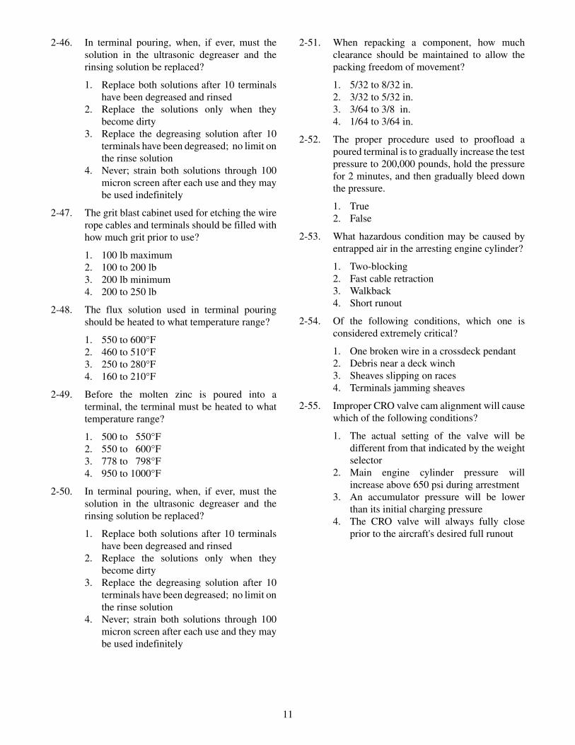
2-46. In terminal pouring, when, if ever, must thesolution in the ultrasonic degreaser and therinsing solution be replaced?
1. Replace both solutions after 10 terminalshave been degreased and rinsed
2. Replace the solutions only when theybecome dirty
3. Replace the degreasing solution after 10terminals have been degreased; no limit onthe rinse solution
4. Never; strain both solutions through 100micron screen after each use and they maybe used indefinitely
2-47. The grit blast cabinet used for etching the wirerope cables and terminals should be filled withhow much grit prior to use?
1. 100 lb maximum2. 100 to 200 lb3. 200 lb minimum4. 200 to 250 lb
2-48. The flux solution used in terminal pouringshould be heated to what temperature range?
1. 550 to 600°F2. 460 to 510°F3. 250 to 280°F4. 160 to 210°F
2-49. Before the molten zinc is poured into aterminal, the terminal must be heated to whattemperature range?
1. 500 to 550°F2. 550 to 600°F3. 778 to 798°F4. 950 to 1000°F
2-50. In terminal pouring, when, if ever, must thesolution in the ultrasonic degreaser and therinsing solution be replaced?
1. Replace both solutions after 10 terminalshave been degreased and rinsed
2. Replace the solutions only when theybecome dirty
3. Replace the degreasing solution after 10terminals have been degreased; no limit onthe rinse solution
4. Never; strain both solutions through 100micron screen after each use and they maybe used indefinitely
2-51. When repacking a component, how muchclearance should be maintained to allow thepacking freedom of movement?
1. 5/32 to 8/32 in.2. 3/32 to 5/32 in.3. 3/64 to 3/8 in.4. 1/64 to 3/64 in.
2-52. The proper procedure used to proofload apoured terminal is to gradually increase the testpressure to 200,000 pounds, hold the pressurefor 2 minutes, and then gradually bleed downthe pressure.
1. True2. False
2-53. What hazardous condition may be caused byentrapped air in the arresting engine cylinder?
1. Two-blocking2. Fast cable retraction3. Walkback4. Short runout
2-54. Of the following conditions, which one isconsidered extremely critical?
1. One broken wire in a crossdeck pendant2. Debris near a deck winch3. Sheaves slipping on races4. Terminals jamming sheaves
2-55. Improper CRO valve cam alignment will causewhich of the following conditions?
1. The actual setting of the valve will bedifferent from that indicated by the weightselector
2. Main engine cylinder pressure willincrease above 650 psi during arrestment
3. An accumulator pressure will be lowerthan its initial charging pressure
4. The CRO valve will always fully closeprior to the aircraft's desired full runout
11

12
(THIS PAGE IS INTENTIONALLY LEFT BLANK.)

ASSIGNMENT 3
Textbook Assignment: “Steam Catapults,” Pages 4-1 through 4-67.
3-1. What are the most significant differencesamong the various types of steam catapults?
1. Power strokes and lengths2. Endspeeds and power strokes3. Endspeeds and launching capacities4. Lengths and launching capacities
3-2. What switch or valve controls the flow ofsteam from the ship's boilers to the catapult'swet-steam accumulator?
1. The steam launching valve2. The capacity selector valve3. The steam fill valve4. The steam pressure cutoff switch
3-3. How far must the launch valve control assem-bly crosshead travel to stop the number 2launch valve stroke timer clock?
1. 3 1/2 in.2. 6 in.3. 9 in.4. 11 1/2 in.
3-4. What device controls the opening rate of thelaunch valves to allow the launching of varioustypes and weights of aircraft?
1. The launch valve control valve2. The capacity selector valve3. The launch valve stroke timers4. The steam pressure cutoff switch
3-5. What mechanism prevents a steam buildup be-hind the launching engine steam pistons?
1. The exhaust valve2. The pressure-breaking orifice elbow3. The exhaust valve keeper valve4. The wet-steam accumulator
3-6. The exhaust valve hydraulic lock valve con-trols the flow of fluid to which of the followingcomponents?
1. The steam pressure cutoff switch2. The pressure breaking elbow3. The exhaust valve limit switch4. The exhaust valve hydraulic actuator
3-7. What determines the number of launching cyl-inders that are mounted in the catapult trough?
1. Overall length of the catapult2. Required amount of elongation for the type
of catapult3. Number of base pads in the trough4. Number of lubricator nozzles required for
the type of catapult
3-8. What function is provided by the cylinder co-vers of the launching engine?
1. Eliminates the need for external bracing ofthe trough covers and track assembly
2. Prevents steam from escaping through thecylinder slots during the power stroke
3. Prevents steam pressure from spreadingthe cylinder in the area of the cylinder slot
4. Provides a means of connecting the shuttleto the piston assemblies
3-9. What force maintains the tension on the cata-pult launching engine cylinder sealing strip?
1. Hydraulic pressure2. Spring tension3. Steam pressure4. Air pressure
3-10. What component serves as the chassis for theother components of the steam pistonassembly?
1. The spear2. The barrel3. The connector4. The support guide
3-11. What prevents the loss of steam from behindthe steam piston assemblies during thecatapult's power stroke?
1. Segmented seals2. Piston rings3. The piston barrel4. Bushings
13

3-12. What component serves as a bearing surfacefor the piston assembly?
1. The rubbing strip2. The barrel3. The piston guide4. The strip guide
3-13. A total of how many rollers are mounted on theshuttle frame?
1. Six2. Two3. Eight4. Four
3-14. What component of the water brake cylinderinstallation forms the vortex at the open end ofthe water brake cylinder?
1. The jet ring2. The striker ring3. The annulus ring4. The choke ring
3-15. The term "elbow pressure" refers to whatspecific pressure?
1. The basket strainer inlet pressure2. The basket strainer outlet pressure3. The water pressure entering the water
brake cylinder4. The pump discharge pressure
3-16. The contacts of the steam cutoff pressureswitches close when the steam pressure in thelaunching engine cylinders reaches whatpressure?
1. 10 psi2. 20 psi3. 30 psi4. 40 psi
3-17. All catapult trough covers are designed towithstand what total amount of vertical rollingshuttle load?
1. 100,000 lb2. 132,000 lb3. 200,000 lb4. 264,000 lb
3-18. Which of the following information is NOTdisplayed on the Digital Endspeed Indicator(DESI)?
1. Time of day2. CSV setting3. Shuttle endspeed4. Catapult number
3-19. The bridle tensioner fully aft limit switch ispart of two catapult electrical circuits. One isthe retract permissive circuit. What is the otherone?
1. The maneuver forward2. The maneuver aft3. The military power4. The suspend circuit
3-20. Which of the following conditions wouldindicate a water loss in the catapult hydraulicfluid?
1. An increase in ph number2. A decrease in ph number3. An increase in viscosity4. A decrease in viscosity
3-21. What is the function of the catapult mainhydraulic pump delivery control unit?
1. To direct fluid to the gravity tank when thepump is on stroke only
2. To direct fluid to the accumulator when thepump is off stroke only
3. To direct fluid to the accumulator when thepump is on stroke and to the gravity tankwhen the pump is off stroke
4. To direct fluid to the accumulator when thepump is off stroke and to the gravity tankwhen the pump is on stroke
3-22. The motion of the rotary retraction enginehydraulic motor is transferred to the drivesystem cables by what assembly?
1. The traverse carriage assembly2. The crosshead assembly3. The sheave and adapter assembly4. The drum assembly
3-23. Which of the following components preventsthe cables from becoming crossed and tangledon the drum?
1. The cable tensioner assembly2. The screw and traverse carriage assembly3. The fairlead sheave assembly4. The cable tensioner sheave assembly
14

3-24. The forward motion of the rotary retractionengine is stopped at the completion of the grabadvance cycle by what force or device?
1. By cable dead weight drag2. By fluid acting on the carriage assembly3. By the advance buffer4. By fluid braking of the hydraulic motor
3-25. What is the function of the rotary retractionengine maneuvering valve?
1. To protect the engine from damage in theevent of a malfunction
2. To control the bridle tensioner controlvalve
3. To control the speed of the grab afteradvance or retract stroke braking has beencompleted
4. To initiate the advance and retract strokebraking
3-26. Which of the following components operateshydraulically to keep the retraction enginecables taut?
1. The cable tensioner assembly2. The screw and traverse carriage assembly3. The lead sheave assembly4. The cable tensioner sheave assembly
3-27. Which of the following components guides thecables between the retraction engine and thecatapult trough?
1. The cable tensioner assembly2. The screw and traverse carriage assembly3. The fairlead sheave assembly4. The cable tensioner sheave assembly
3-28. The retraction engine drive system cables areattached to what component(s)?
1. The shuttle only2. The grab only3. The shuttle and launching engine steam
pistons4. The grab and launching engine steam
pistons
3-29. During normal launching operations, whenwill the grab release the shuttle?
1. When endspeed has been reached and theunlocking mechanism is disengaged
2. When launch complete is reached and thelocking mechanism is actuated
3. When both have returned to batteryposition and the unlocking mechanism isactuated
4. When maximum load drag weight isreached and the unlocking mechanismautomatically disengages
3-30. Which of the following controls is NOT amomentary contact push button?
1. Fire2. Maneuver aft3. Lube4. Maneuver forward
3-31. The controls for the integrated catapult controlsystem (ICCS) are mainly divided between oramong how many control stations?
1. Five2. Two3. Three4. Four
3-32. The malfunction and status lights are locatedon what panel or console of the ICCS?
1. The central panel2. The cat officer control console3. The emergency deckedge control console4. The monitor panel
3-33. What panel controls and monitors thepneumatic system?
1. The left front panel2. The left intermediate front panel3. The right intermediate front panel4. The right front panel
3-34. What panel controls and monitors thehydraulic system?
1. The left front panel2. The left intermediate front panel3. The right intermediate front panel4. The right front panel
15

3-35. What panel provide emergency operationalcapacity?
1. The left front panel2. The left intermediate front panel3. The right intermediate front panel4. The right front panel
QUESTIONS 36 THROUGH 38 APPLY TO NON-ICCS.
3-36. What main control console panel indicates thestatus of various catapult system pressures?
1. The steam panel2. The emergency panel3. The monitor panel4. The operating panel
3-37. What main control console panel is used tocontrol the catapult fill valves?
1. The steam charging panel2. The emergency panel3. The auxiliary deckedge panel4. The operating panel
3-38. What main control console panel contains alllights, switches, and pushbuttons that are foundon the deckedge panel?
1. The gauge panel2. The emergency panel3. The auxiliary deckedge panel4. The operating panel
3-39. What indicates the catapult readiness to thelaunching officer during operations?
1. The gauge box2. The monitor panel3. The deckedge signal box4. The operating panel
3-40. The hydraulic fluid supply is shut off to whatvalve during the firing of no-loads?
1. The bridle tension regulator valve2. The maneuver aft valve3. The lubrication valve4. The advance valve
QUESTIONS 41 THROUGH 44 APPLY TOPROCEDURES FOR ICCS.
3-41. What personnel gives the tension signal to thecatapult director?
1. The launching officer2. The deckedge operator3. The catapult safety observer4. The topside safety petty officer
3-42. What personnel signal the launching officer totake tension?
1. The catapult director2. The deckedge operator3. The catapult safety observer4. The topside safety petty officer
3-43. What personnel signals suspend to thelaunching officer?
1. The launching officer2. The deckedge operator3. The catapult safety observer4. The topside safety petty officer
3-44. On ships where the ICCS is the primary modeof controlling catapult launching operations,who depresses the FIRE push button to launchan aircraft?
1. The launching officer2. The deckedge operator3. The catapult safety observer4. The central charging panel operator
QUESTIONS 45 THROUGH 48 APPLY TOPROCEDURES FOR NON-ICCS.
3-45. Under normal launching conditions, whatshould be the last word(s) spoken over thesound powered phones?
1. FIRST READY2. TAKING TENSION3. FINAL READY4. FIRE
3-46. What signal is used by the deckedge operatorto indicate that the FINAL READY light hascome on at the deckedge panel and the catapultis in the FINAL READY condition?
1. Both hands are held open and above thehead
2. One hand is held open and above the head3. One hand is held above the head with two
fingers extended4. Both hands are held above the head with
only the index fingers extended
16

3-47. Which of the following actions must thedeckedge operator take after receiving theFIRE signal from the catapult officer?
1. Immediately push the FIRE push button2. Hesitate for at least 10 seconds to ensure
that the aircraft is at full power, then pushthe FIRE push button
3. Notify the console operator that he is firingthe catapult, then push the FIRE pushbutton
4. Perform a final safety scan of the flightdeck and catwalks, then push the FIREpush button
3-48. What immediate action must be taken by thedeckedge operator if the catapult officer signalsa hangfire?
1. Push the MANEUVER AFT push buttonto release bridle tension
2. Tell the console operator to actuate theSUSPEND switch
3. Close the EMERGENCY cutout valve andthen actuate the SUSPEND switch
4. Actuate the SUSPEND switch and tell theconsole operator to ROTATE THEEMERGENCY CUTOUT VALVE,ROTATE THE EMERGENCY CUTOUTVALVE
17

18
(THIS PAGE IS INTENTIONALLY LEFT BLANK.)
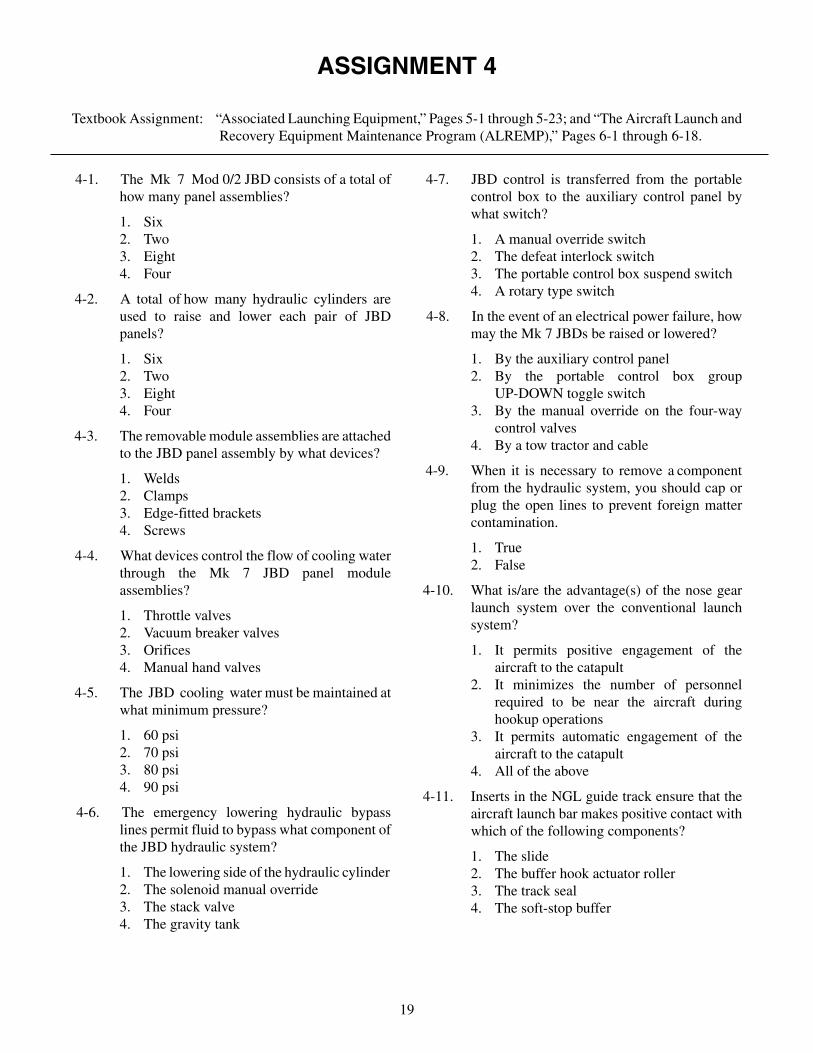
ASSIGNMENT 4
Textbook Assignment: “Associated Launching Equipment,” Pages 5-1 through 5-23; and “The Aircraft Launch andRecovery Equipment Maintenance Program (ALREMP),” Pages 6-1 through 6-18.
4-1. The Mk 7 Mod 0/2 JBD consists of a total ofhow many panel assemblies?
1. Six2. Two3. Eight4. Four
4-2. A total of how many hydraulic cylinders areused to raise and lower each pair of JBDpanels?
1. Six2. Two3. Eight4. Four
4-3. The removable module assemblies are attachedto the JBD panel assembly by what devices?
1. Welds2. Clamps3. Edge-fitted brackets4. Screws
4-4. What devices control the flow of cooling waterthrough the Mk 7 JBD panel moduleassemblies?
1. Throttle valves2. Vacuum breaker valves3. Orifices4. Manual hand valves
4-5. The JBD cooling water must be maintained atwhat minimum pressure?
1. 60 psi2. 70 psi3. 80 psi4. 90 psi
4-6. The emergency lowering hydraulic bypasslines permit fluid to bypass what component ofthe JBD hydraulic system?
1. The lowering side of the hydraulic cylinder2. The solenoid manual override3. The stack valve4. The gravity tank
4-7. JBD control is transferred from the portablecontrol box to the auxiliary control panel bywhat switch?
1. A manual override switch2. The defeat interlock switch3. The portable control box suspend switch4. A rotary type switch
4-8. In the event of an electrical power failure, howmay the Mk 7 JBDs be raised or lowered?
1. By the auxiliary control panel2. By the portable control box group
UP-DOWN toggle switch3. By the manual override on the four-way
control valves4. By a tow tractor and cable
4-9. When it is necessary to remove a componentfrom the hydraulic system, you should cap orplug the open lines to prevent foreign mattercontamination.
1. True2. False
4-10. What is/are the advantage(s) of the nose gearlaunch system over the conventional launchsystem?
1. It permits positive engagement of theaircraft to the catapult
2. It minimizes the number of personnelrequired to be near the aircraft duringhookup operations
3. It permits automatic engagement of theaircraft to the catapult
4. All of the above
4-11. Inserts in the NGL guide track ensure that theaircraft launch bar makes positive contact withwhich of the following components?
1. The slide2. The buffer hook actuator roller3. The track seal4. The soft-stop buffer
19

4-12. What component of the Mk 2 NGL systemengages the aircraft holdback bar as the aircrafttaxis into position for launch?
1. The buffer hook2. The slide3. The launch actuator reset assembly4. The buffer cylinder
4-13. During NGL operation, when the slideassembly is forward, what device holds thereset-assembly slider above the surface of theguide track deck housing cavity?
1. The slider actuating spring2. The actuator assembly3. The buffer hook4. The shuttle spreader
4-14. Which of the following statements bestdescribes the NGL shock absorber assembly?
1. A self-contained, sealed unit that requiresno maintenance or adjustments
2. A hydraulically operated, three-cylinder,buffer unit
3. A hydraulically operated buffer unit thatuses tube orifices to meter fluid flow
4. A piston-type accumulator energyabsorber
4-15. What device controls the flow of hydraulicfluid supplied from the catapult hydraulicsystem to the NGL buffer cylinder?
1. The NGL dump valves2. The NGL pilot valve3. The NGL valve manifold4. The NGL buffer cylinder control valve
4-16. ALRE maintenance functions are divided intowhat total number of maintenance levels?
1. One2. Two3. Three #4. Four
4-17. Maintenance tasks are assigned according tothe complexity, scope, and range of the work tobe performed.
1. True2. False
4-18. Which of the following is NOT a function oforganizational maintenance?
1. Inspection, operation, and servicing asdefined and required by PMS
2. Corrective and preventive maintenance3. Record keeping and report writing4. Type III calibration of designated
equipment
4-19. What maintenance activity performs type IIIcalibration?
1. Organizational maintenance2. Intermediate maintenance3. Depot maintenance4. Navy ASO
4-20. What type of maintenance is normallyaccomplished by the catapult and arrestinggear crew members?
1. Upkeep2. Overhaul3. Intermediate maintenance4. Depot maintenance
4-21. In the V-2 maintenance organization, who hasthe authority to certify that maintenance ac-tions have been completed and that the equip-ment can be returned to an operational status?
1. The division officer or maintenance officer2. The catapult officer or recovery officer3. The maintenance officer or maintenance
control chief4. The maintenance officer only
4-22. Which of the following personnel areresponsible for the day-to-day operations ofthe work center, the nomination of qualifiedpersonnel to be collateral duty inspectors, andthe assignment of work center personnel tospecific maintenance tasks?
1. The maintenance officer, work centergroup supervisors, and work centersupervisors
2. Work center group supervisors and workcenter supervisors only
3. Work center group supervisors, the QAwork center supervisor, and themaintenance support work centersupervisor
4. The maintenance officer, the maintenancecontrol chief, and work center groupsupervisors
20

4-23. Which of the following VIDs boards providesinformation pertaining to the divisions'soverall maintenance status?
1. The maintenance support work centerboard
2. The Quality Assurance work center board3. The maintenance control work center
board4. The material control work center board
4-24. A total of how many information displaycolumns are required on both the maintenancecontrol and all other work center VIDs boards?
1. Seven2. Six3. Five4. Four
4-25. What color is used to indicate limitedcapability on the Maintenance Action Form(MAF) cards?
1. Blue2. Red3. Black4. Yellow
4-26. On the MAF card, what color is used toindicate the equipment is out of commission?
1. Yellow2. Red3. Black4. Blue
4-27. The priority section of the MAF card can becolor coded to indicate the maintenance statusand operational capability of specificequipment. What status is indicated if no colorcode is used in the priority section?
1. The equipment is out of commission
2. The equipment may be used, but has onlylimited capability
3. The maintenance is routine and does notaffect equipment capability
4. The maintenance has been completed andthe equipment only needs a functionalcheck to be returned to full operationalcapability
4-28. On the MAF card, what color is used for acompleted maintenance action awaiting afunctional check?
1. Blue2. Red3. Black4. Yellow
4-29. What copy, if any, of the completed ALREMAF is retained by the maintenanceresponsible work center?
1. One2. Two3. Three4. None
4-30. Who is responsible for updating andmaintaining the work center maintenancerequirement status board?
1. The maintenance control chief2. The work center group supervisor3. The maintenance control officer4. The work center supervisor
4-31. What is the primary role of the V-2maintenance support branch?
1. To manage the division tool controlprogram
2. To provide technical expertise to operatingwork centers
3. To reduce man-hours required to completemaintenance tasks
4. To manage the division man-houraccounting program
4-32. When the Maintenance Support (MS) branchassigns personnel to assist in maintenanceperformed by the operating work center, whodocuments the MS man-hours?
1. Maintenance Control2. Maintenance Support3. The QA branch4. The operating work center
4-33. The tool control program was established toreduce the potential of tool-related foreignobject damage and to reduce the cost of toolreplacement.
1. True2. False
21

4-34. Which of the following is NOT a benefit of thetool control program?
1. Reduced tool replacement costs2. Reduced equipment failures3. Reduced tool pilferage4. Assurance of tool availability to perform
maintenance
4-35. Detailed information concerning the ALRETCP can be found in what publication?
1. NAEC Miscellaneous Report 51/OR7322. NAEC Report No. CD-10253. NAVAIR 80R-144. OPNAVINST 4790.4B
4-36. The achievement of a properly functioningquality assurance program exhibits which ofthe following characteristics?
1. The program is managed by themaintenance control officer, maintenancecontrol chief, and work center groupsupervisors
2. Eliminates unnecessary man-hour anddollar expenses
3. Uses prevention, knowledge, and specialskills
4. Stresses the gathering and maintaining ofinformation on quality assurance
4-37. What is the basis of maintenance andoperational decisions through the QualityAssurance (QA) program?
1. Memory2. Intuition3. Factual data4. The maintenance officer's experience
4-38. When it becomes necessary to augment thequality assurance branch with CDQAIs, theymust be designated in writing by which of thefollowing officers?
1. The commanding officer2. The air department officer3. The V-2 division officer4. The V-2 maintenance officer
4-39. When it is necessary to augment the QA branchwith Collateral Duty QA inspectors (CDQAIs)below the paygrade of E-6 for more than 90days, who must approve the continuedaugmentation?
1. The maintenance officer2. The division officer3. The commanding officer4. The type commander
4-40. Who is most directly concerned with, andresponsible for, quality in workmanship?
1. The maintenance officer2. The assigned quality assurance inspector3. The work center supervisor4. The equipment operator
4-41. Which of the following duties is NOT aresponsibility of the quality assurance branch?
1. To prepare maintenance instructions2. To provide technical assistance to
collateral duty inspectors3. To manage the dispersed technical
publications libraries4. To develop audit checklists
4-42. CDIs are designated in writing by which of thefollowing officers?
1. The air department officer2. The executive officer3. The commanding officer4. The maintenance officer
4-43. How often are work center audits conducted?
1. Weekly2. Monthly3. Quarterly4. Semi-annually
4-44. What type of audit is conducted to evaluate aspecific maintenance task?
1. Work center audit2. Special audit3. Internal audit4. Type commander audit
22

4-45. The quality assurance branch uses specialaudits for which of the following reasons?
1. To evaluate the overall quality ofperformance of each work center
2. To evaluate tool control programcompliance
3. To monitor programs specifically assignedto the QA branch for monitoring
4. To establish follow-up procedures toensure that previous audit discrepancieshave been corrected
23

24
(THIS PAGE IS INTENTIONALLY LEFT BLANK.)

ASSIGNMENT 5
Textbook Assignment: “Maintenance Planning and Administration,” Pages 7-1 through 7-47.
5-1. What factors must be considered in the plan-ning and scheduling of maintenance?
1. Operational requirements2. Available personnel3. Equipment status4. All of the above
5-2. Which of the following statements best definespreventive maintenance?
1. Any action that maintains equipmentwarranties
2. Any action that maintains equipment inoperating condition
3. Any action that is entered in the roughwork log
4. Any action taken in addition to normalworkload
5-3. Which of the following sources provides a list-ing of the MIPs assigned to each department?
1. Workcenter PMS Manual2. Divisional LOEP3. Departmental LOEP4. Ship's cycle schedule
5-4. Which of the following sources contains de-tailed procedures used to perform a mainte-nance action?
1. MIP2. LOEP3. MRC4. PMS Manual
5-5. What does the second part of the MRC coderepresent?
1. Periodicity code2. MIP series code3. Ship's system code4. Equipment code
5-6. An R-1W is an example of what type of period-icity code?
1. Calendar-situation2. Situation-calendar3. Situation4. Calendar
5-7. Entries made in the TOOLS, PARTS, MATE-RIALS, TEST EQUIPMENT block of anMRC can be cross-referenced to the SPMIGfor stock number identification.
1. True2. False
5-8. What information determines the number ofitems to be listed on an Equipment Guide List?
1. Skill level of the maintenance person2. Time allotted to perform maintenance on
each item3. Number of days required to complete
entire maintenance action4. All of the above
5-9. Who must approve a request to combine thePMS maintenance requirements of two or moreworkcenters?
1. Type commander2. Commanding officer3. Department head4. Division officer
5-10. Preparation of a PMS Cycle Schedule requiresuse of all EXCEPT which of the following?
1. Applicable MRCs2. Blank cycle schedules3. Previous quarterly schedule4. Master PMS Manual
5-11. Which of the following schedules is NOT aPMS schedule?
1. Cycle2. Quarterly3. Monthly4. Weekly
5-12. How are mandatory related maintenancechecks indicated on the Cycle Schedule?
1. They are circled in red2. They are circled in blue3. A star sign4. A pound sign
25

5-13. Which of the following information is NOTfound on the quarterly PMS schedule?
1. Workcenter code2. Maintenance person's name3. Quarter after overhaul4. Department head's signature
5-14. How many columns are available on thequarterly schedule for the scheduling ofweekly maintenance?
1. 132. 163. 204. 24
5-15. When a ship's major overhaul is completedduring the last two weeks of May, what monthsare included on the first quarterly scheduleafter overhaul?
1. April, May, and June2. May, June, and July3. June, July, and August4. The first full fiscal quarter after overhaul
5-16. When the quarterly PMS schedule is prepared,how are the ship's underway periods indicated?
1. By writing "underway" on the scheduleduring these periods
2. By shading in the periods on the bottomline of the schedule
3. By shading in the tick marks indicating thedays of the quarter at the top of theschedule
4. By shading in the tick marks indicating thedays of the quarter at the bottom of theschedule
5-17. Any maintenance requirement that cannot becompleted within its periodicity during aquarter must be circled on the front of thequarterly schedule only to explain that it wasnot completed.
1. True2. False
5-18. What PMS schedule is used by the workcentersupervisor to assign and monitor PMSaccomplishments?
1. Cycle2. Quarterly3. Weekly4. Daily
5-19. Which of the following provides informationneeded for workload planning and a means ofevaluating and improving fleet installedequipment?
1. Maintenance Data System2. Planned Maintenance System3. Failed Parts Reporting System4. Configuration Accounting System
5-20. Under MDS, Individual maintenance actionsare identified by what number?
1. Maintenance Action Number2. Job Control Number3. Job Sequence Number4. Job Serial Number
5-21. How is an error corrected when entries aremade on an OPNAV 4790/2K form?
1. "X" out the error and continue2. Make out a new OPNAV 4790/2K3. Draw a single line through the error and
continue4. Put white on the error and continue
5-22. What information is normally found in sectionV of an OPNAV 4790/2K forms?
1. Repair activity planning2. Equipment location3. Availability of blueprints4. Reason for deferring maintenance
5-23. Which of the following forms is used to reporta ship's configuration change?
1. OPNAV 4790/2K2. OPNAV 4790/2P3. OPNAV 4790/2Q4. OPNAV 4790/CK
5-24. What two-character code identifies theinventory manager and the stores account?
1. The Purpose code2. The Special Material Identification code
3. The Cognizance Symbol code4. The Fund code
5-25. What character of a cognizance symbolidentifies the stores account?
1. First2. Second3. Third4. Fourth
26

5-26. Which of the following cognizance symbolsidentifies APA material?
1. 1R2. 3H3. 5R4. 6R
5-27. Which of the following cognizance symbolsidentifies NSA material?
1. 1R2. 4R3. 6R4. 8R
5-28. What activity manages the Federal CatalogingSystem within the DOD?
1. DLA2. DLSC3. ASO4. GSA
5-29. The first two digits of an FSC identifies whichof the following items?
1. The single item, component, or equipment2. The major division of commodities within
a group3. The commodities according to physical or
performance characteristics4. The group/category inventory managers
5-30. What FSC groups are used by the Navy forforms and publications?
1. 90 through 992. 70 through 803. 30 through 404. 01 through 09
5-31. Which of the following FSC groups is NOTincluded in the Federal Cataloging System?
1. 082. 283. 484. 58
5-32. An NSN has what total number of digits?
1. 72. 93. 134. 15
5-33. What activity is responsible for assigning theNSN to material for supply department stock?
1. The Defense Logistics Agency2. The Supply Department3. The Naval Supply Center4. The Defense Logistics Support Center
5-34. Which of the following NSNs was assigned bythe U.S.?
1. 1234-21-012-34562. 1234-11-001-23453. 1234-01-234-56784. 1234-13-234-6543
5-35. To properly identify material, you should knowwhat number of digits of the NIIN?
1. The first four2. The first seven3. The last seven4. The last nine
5-36. What account is paid the required use what forout of appropriations and is NOT chargeable tothe user’s operating funds?
1. APA2. NSA3. TFA4. OPTAR
5-37. Which of the following items are the same asNSA items?
1. APA items2. Repairable items3. Expense type items4. Remain-in-place items
5-38. The forms and publications used by the Navyare under the inventory control of whatactivity?
1. NPFD2. SPCC3. NAVAIR4. ASO
5-39. The technical responsibility for aircraftengines in the Navy belongs to what activity?
1. NAVAIR2. SPCC3. ASO4. NPPS
27

5-40. Aviation depot-level repairable material isassigned what cognizance symbol?
1. 1R2. 4R3. 5R4. 7R
5-41. What activity is the cognizant item manager for7R material?
1. NAVICP PHIL2. NAVAIR3. NAVFAC4. ASO
5-42. The cataloging code assigned to defenseelectronic material is equivalent to whatcognizance symbol of Navy material?
1. 9C2. 9D3. 9G4. 9N
5-43. The Material Control code is assigned by whatperson?
1. The executive officer2. The inventory manager3. The technical advisor for the material4. The commanding officer
5-44. What Material Control code is assigned to anitem that is field-level repairable?
1. D2. E3. H4. L
5-45. Depot-level repairable is assigned whatMaterial Control code?
1. D2. H3. L4. M
5-46. What Material Control code is assigned to anend item of ground support equipment?
1. E2. H3. S4. W
5-47. What does NICN stand for?
1. National Item Control Number2. Navy Item Control Number3. Navy Integrated Control Number4. Navy Item Consolidation Number
5-48. Which of the following items are identified byNICNs?
1. Kit numbers2. Publications and forms3. NAC numbers4. All of the above
5-49. In a 13-digit NICN, what code occupies the 5thand 6th positions?
1. The Navy Item Control Number code2. The Material Control code3. The Supply Classification code4. The Special Material Identification code
5-50. Which of the following NIC codes identifies aform?
1. LD2. LK3. LP4. LF
5-51. What type of material is identified in NICN1234-LK-123-4567?
1. A directive2. A form3. An aircraft change kit4. A publication
5-52. Locally assigned item control numbers containwhat letters in the 5th and 6th positions?
1. LF2. LL3. LQ4. LX
5-53. What format is used to order material identifiedby a NICN?
1. The DD 1348 format2. The DD 1348-6 format3. The DD 1384 format4. The DD 1387 format
28

5-54. A temporary NICN is assigned to material forwhich of the following purposes?
1. To identify the items before the assignmentof an NSN
2. To control the items pending an NSNassignment
3. Both 1 and 2 above4. To release the shipment from the
manufacturer
5-55. What activity is responsible for maintainingthe NICN to NSN cross-reference list?
1. ASO2. DLIS3. SPCC4. NALC
5-56. The cumulative listing of National StockNumbers for all armed services is identified bywhich of the following letters?
1. ML-N2. ML-C3. MRC4. MDC
5-57. Which of the following lists providescross-reference information from referencenumbers to NSNs?
1. ML-N2. ML-C3. MCRL4. MRIL
5-58. What cognizance symbol is assigned to itemslisted in the GSA Federal Supply Catalog?
1. 9C2. 9D3. 9N4. 9Q
5-59. Which of the following lists is a catalog ofNavy-managed repairable items and providesshipping information for unserviceablecomponents?
1. ML-C2. ML-N3. MRIL4. MCRL
5-60. Why is the arresting gear maintenance logconsidered the most important record kept onthe arresting gear equipment?
1. It contains recovery log information2. It contains the names of maintenance
personnel3. It contains wire rope history report
information4. It contains most of the information needed
to complete other reports and records
29

�
�
Related Documents