NAVAL POSTGRADUATE SCHOOL * C Monterey, California TD= THESI ELECT JUL 2 84i9 THESIS DETERMINATION OF GTA WELDING EFFICIENCIES by CANDONINO P. FRANCHE MARCH 1993 Thesis Advisor: YOGENDRA JOSHI Co-Advisor: PRADIP DUTTA Approved for public release; distribution is unlimited 93- 16842

Welcome message from author
This document is posted to help you gain knowledge. Please leave a comment to let me know what you think about it! Share it to your friends and learn new things together.
Transcript

NAVAL POSTGRADUATE SCHOOL* C Monterey, CaliforniaTD=
THESIELECTJUL 2 84i9
THESISDETERMINATION OF GTA
WELDING EFFICIENCIES
by
CANDONINO P. FRANCHEMARCH 1993
Thesis Advisor: YOGENDRA JOSHICo-Advisor: PRADIP DUTTA
Approved for public release; distribution is unlimited
93- 16842
UNCLASSIFIEDSECURITY CLASSIFICATION OF THIS PAGE
REPORT DOCUMENTATION PAGEIs. REPORT SECURITY CLASSIFICATION lb. RESTRICTIVE MARKINGSUNCLASSIFIED
2a. SECURITY CLASSIFICATION AUTHORITY 3. DISTRIBUTION/AVAILABILITY OF REPORTAPPROVED FOR PUBLIC RELEASE;DISTRIBUTION
2b. DECLASSIFICATION/DOWNGRADING SCHEDULE UNLIMITED.
4. PERFORMING ORGANIZATION REPORT NUMBER(S) 5. MONITORING ORGANIZATION REPORT NUMBER(S)
6a. NAME OF PERFORMING ORGANIZATION 6b. OFFICE SYMBOL 7a. NAME OF MONITORING ORGANIZATIONNAVAL POSTGRADUATE SCHOOL (If applicable) NAVAL POSTGRADUATE SCHOOL
ME
6c. ADDRESS (City, State, andZIP Code) 7b. ADDRESS (City, State, andZIP Code)
MONTERY,CA 93943-50 MONTEREY,CA 93943-5000
Ga. NAME OF FUNDING/SPONSORING 8b. OFFICE SYMBOL 9. PROCUREMENT INSTRUMENT IDENTIFICATION NUMBERORGANIZATION Ifff applicable)
8c. ADDRESS (City, State, and ZIP Code) 10. SOURCE OF FUNDING NUMBERSPrOgfaaY Element No Project NO Task No. Work Utwt Acceuon
Numbe•
11. TITLE (Include Security Cassification)
Determination of GTA Welding Efficiencies
12. PERSONAL AUTHOR(S) Franche, Candonino P.
13a. TYPE OF REPORT 13b. TIME COVERED 14. DATE OF REPORT (year, month, day) 15. PAGE COUNTMasters Thesis in M.E. From: March 1992 To: March 1993 1993March25 7416. SUPPLEMENTARY NOTATIONThe views expressed in this thesis are those of the author and do not reflect the official policy or position of the Department of Defense or the U.S.Government.17. COSATI CODES 1B. SUBJECT TERMS (continue on reverse if necessary and identify by block number)
FIELD GROUP SUBGROUP Laser Arc Welding, Solidification Parameters, Numerical Methods, Determining
Welding Efficiencies.
19. ABSTRACT (continue on reverse if ncessary andidentify by block number)
A method is developed for estimating welding efficiencies for moving arc GTAW processes. Under quasi-conditions, the netheat transfer rate from the weld pool to the workpiece is estimated from a 3-D numerical heat transfer conduction model. Thedimensions of the weld pool used in the computational model are obtained experimentally using a laser vision system and bymetallurgical examination. The welding efficiency is then calculated by dividing the net heat transfer rate by the total power inputduring the experiments. Efficiencies are measured for a range of power inputs and torch speeds and then compared with thoseavailable in the literature.
20. DISTRIBUTION/AVAILABILITY OF ABSTRACT 21. ABSTRACT SECURITY CLASSIFICATION
11UNCLASSIFIEI(O/ULMITED 0 SAWEAS REPOfT 03 TI ocUSERS Unclassified22a. NAME OF RESPONSIBLE INDIVIDUAL 22b TELEPHONE (Include Area code) E2c OFFICE SYMBOL-Professor Yoendra Joshi 408-666-3400 ME/Ji
DD FORM 1473.84 MAR 33 APR edition may be used until exhausted SECURITY CLASSIFICATION OF THIS PAGEAll other editions are obsolete Unclassified

Approved for public release; distribution is unlimited.
Determination of GTAWelding Efficiencies
by
Candonino P. FrancheLieutenant, United States Navy
B.S.M.E. FEATI University, Philippines, 1974M.B.A., National University, San Diego, CA., 1990
Submitted in partial fulfillment
of the requirements for the degree of
MASTER OF SCIENCE IN MECHANICAL ENGINEERING
from the
NAVAL POSTGRADUATE SCHOOL
March 1993
Authors:Candonint/P. ?Ynche
Approved by: _ _ _ _ _ _ _ Td'-Yogvenfra Joshi, Thesis Advisor
Pradip Dutta, Co-Advi r
Department of Mechanical Engineering
ii

ABSTRACT
A method is developed for estimating welding efficiencies for moving arc GTAW processes.
Under quasi-steady conditions, the net heat transfer rate from the weld pool to the workpiece is
estimated from a 3-D numerical heat transfer conduction model. The dimensions of the weld pool
used in the computational model are obtained experimentally using a laser vision system and by
metallurgical examination. The welding efficiency is then calculated by dividing the net heat transfer
rate by the total power input during the experiments. Efficiencies are measured for a range of power
inputs and torch speeds and then compared with those available in the literature.
Accesion For
NTIS CRA&IDTIC TAE,U ..al::.Oj; :•d -
By....................... .................
Av,•Y~h!',1y C,,E~s
Dist Ava":; . or
Siii .

TABLE OF CONTENTS
I. INTRODUCTION ................... 1
A. THE NEED FOR WELDING EFFICIENCY ...... ........ 1
B. PREVIOUS DETERMINATIONS OF WELDING EFFICIENCY 2
C. PRESENT METHOD FOR OBTAINING WELDING EFFICIENCY 5
II. EXPERIMENTAL APPARATUS, MATERIALS, AND PROCEDURES 8
A. GAS TUNGSTEN ARC WELDING APPARATUS ..... ...... 8
B. WELD METAL PROPERTIES ............ ............. 8
C. WELD POOL VISUALIZATION ...... ............ 11
1. Laser Unit .......... ................. 12
2. Camera Unit ........... ................ 14
3. System Controller ....... ............. 15
4. TV Monitor and Video Recorder .. ....... 16
5. Welding Equipment ....... ............. 18
D. EXPERIMENTAL PROCEDURE ..... ............ 20
III. COMPUTATIONS OF WELDING EFFICIENCY .. ....... 29
A. FORMULATION OF GOVERNING EQUATIONS .. ...... 30
B. BOUNDARY CONDITIONS ........ .............. 32
C. NUMERICAL SOLUTION ......... .............. 34
IV. RESULTS AND DISCUSSION ........ .............. 38
iv

A. ESTIMATING WELDING EFFICIENCY ........... .. 38
B. TEMPERATURE CONTOURS .... ............. 45
V. CONCLUSIONS AND RECOMMENDATIONS ... .......... .. 59
LIST OF REFERENCES .......... .................. 60
INITIAL DISTRIBUTION LIST ..... ............... 62
V
LIST OF FIGURES
Figure 1. Energy Distribution of the Welding Arc. 2
Figure 2. Double Ellipsoid Heat Source Configuration. 6
Figure 3. Sketch of the Gas Tungsten Arc Welding
Process ............... ................... 9
Figure 4. Laser Augmented Welding Vision System. . . 12
Figure 5. Laser Photonics PRA/Model UV12 Pulsed Nitrogen
Laser ........... .................... ... 13
Figure 6. Vacuum Pump, Manufactured by Bosch, Inc. . 14
Figure 7. Camera Unit ............. ................. 15
Figure 8. Camera Unit, Torch, and Weldpiece Set-up. 16
Figure 9. TV Monitor, System Controller, and VHS
Recorder ......... .................. ... 17
Figure 10. Miller Welding Equipment ............. ... 18
Figure 11. GTAW Torch Setup for Automatic Welding. . 19
Figure 12. NY-80 Steel Plate 2.54 am Thick ......... ... 20
Figure 13. Weld Pool Depth vs Power (Speed 2.127 -u/s). 22
Figure 14. Weld Pool Depth vs Power (Speed - 1.693
mm/). .......... .................... ... 23
Figure 15. Weld Pool Depth vs Power (Speed a 1.269
"im/s) ........... .................... ... 24
Figure 16. Effect of Power vs Weld Pool Depth at
Different Speeds ..... .............. ... 25
vi

Figure 17. Gas Tungsten Arc Welding (GTAW) Process
Showing the Reference and Moving Coordinate
System ........... ................... ... 30
Figure 18. Grid Network used in the Computations.. 35
Figure 19. Specific Beat as a Function of Temperature for
Iron [Ref. 21]3 ...... ............... ... 36
Figure 20. Thermal Conductivity vs Temperature of Iron
Based Alloy [Ref. 22]3 .... ............ ... 37
Figure 21. Effect of Power vs Efficiency at Speed of
2.127 rm/sec ....... ................ ... 42
Figure 22. Effect of Power vs Efficiency at Speed of
1.693 mm/sec ....... ................ ... 43
Figure 23. Effect of Power vs Efficiency at Speed of
1.269 mm/sec ....... ................ ... 44
Figure 24. Power vs Efficiency Comparison at Different
Speeds ........... ................... ... 47
Figure 25. (a) Longitudinal Temperature Contour, (b)
Traverse Temperature Contour, and (c) Metal
Cross Section for Run #i ............. ... 48
Figure 26. (a) Longitudinal Temperature Contour, (b)
Traverse Temperature Contour, and (c) Metal
Cross Section for Run #6 ............. ... 49
Figure 27. (a) Longitudinal Temperature Contour, (b)
Traverse Temperature Contour, and (c) Metal
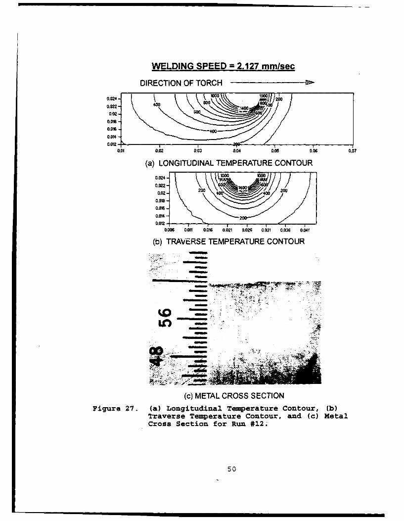
Cross Section for Run #12 .2... .......... .. 50
vii

Figure 28. (a) Longitudinal Temperature Contour, (b)
Traverse Temperature Contour, and (c) Metal
Cross Section for Run *13 ............. ... 51
Figure 29. (a) Longitudinal Temperature Contour, (b)
Traverse Temperature Contour, and (c) Metal
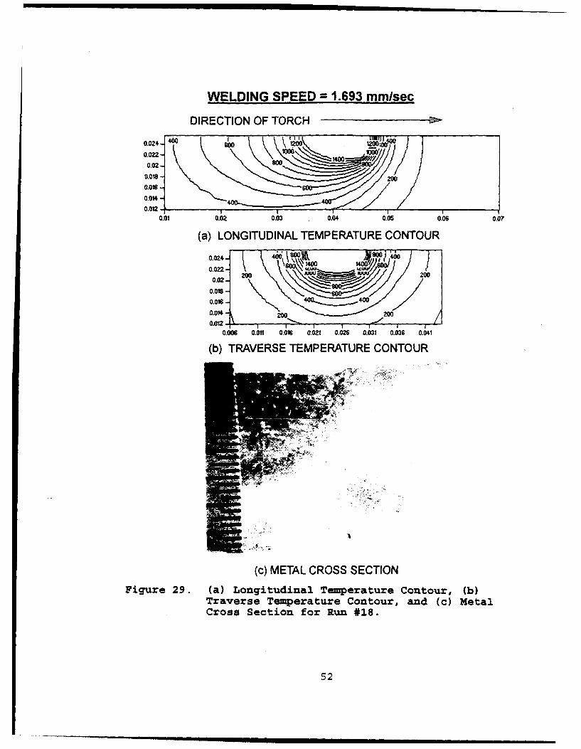
Cross Section for Run #18 ............. ... 52
Figure 30. (a) Longitudinal Temperature Contour, (b)
Traverse Temperature Contour, and (c) Metal
Cross Section for Run #24 ............. ... 53
Figure 31. (a) Longitudinal Temperature Contour, (b)
Traverse Temperature Contour, and (c) Metal
Cross Section for Run #25 ............. ... 54
Figure 32. (a) Longitudinal Temperature Contour, (b)
Traverse Temperature Contour, and (a) Metal
Cross Section for Run #30 ............. ... 55
Figure 33. (a) Longitudinal Temperature Contour, (b)
Traverse Temperature Contour, and (c) Metal
Cross Section for Mun #36 ............. ... 56
Figure 34. Single Digitized Weld Pool Video Frame Showing
the Free Surface ..... .............. ... 57
Figure 35. Weld Pool Development Showing the Transient
Development within a Period of 12 Seconds at
One Second Interval ..... ............. ... 58
viii

LIST OF TABLES
Table I. CHmUICAL COMPOSITION OF BY-80 STEEL ..... .. 10
Table II. SUMMARY OF WELDING SETTINGS AND WELD POOL
MEASUtREMENTS WITH SPEED OF 2.127 mm/sec. 26
Table III. SUMMARY OF WELDING SETTINGS AND WELD POOL
MEASUREMENTS WITH SPEED OF 1.693 ran/sec. 27
Table IV. SUMMARY OF WELDING SETTINGS AND WELD POOL
MEASZURUENTS WITH SPEED OF 1.269 ron/sec. 28
Table V. PHYSICAL PROPERTIES OF HY-80 .......... .. 34
Table VI. SUMMARY OF GTA WELDING EFFICIENCY MEASUREfENTS
WITH SPEED 2.127 mmn/sec .... ........... ... 39
Table VII. SUMMARY OF GTA WELD EFFICIENCY MEASUREMETS
WITH WELDING SPEED OF 1.693 rn/sec. . 40
Table VIII.SUMMARY OF GTA WELD EFFICIENCY MEASURZNTS
WITH WELDING SPEED OF 1.269 ,no/sec .... 41
ix

ACKNOWLEDGEUENTS
The author wishes to extend his sincere appreciation to
those who personally helped him throughout the research and
development of his thesis at the Naval Postgraduate School.
A special thanks is expressed to the following: Mardo
Blanco for helping and assisting in cutting the steels;
Thomas McCord and the staff of the Mechanical Engineering
Machine Shop for their unselfish time to ensure that the
machine shop was ready for my use; and to Doug Shelton for
providing materials for polishing, etching and taking optical
microscopy of the weld metals.
A sincere thanks is also given to the Curricular Officer
Captain Ericson for making me earn my Master's Degree and to
Pam for her helpful administrative matters.
My heartfelt gratitude is given to Professor Yogendra
Joshi and most especially to Dr. Pradip Dutta on their
constant and personal advice, without them the development of
my thesis will be impossible.
Finally, most credit for my accomplishment is passed on to
my wife Gemnma and my wonderful children Marissa, Don Joseph
and Jonathan who gave all the support throughout the duration
of my studies while leaving them behind in San Diego.
x

1. INTRODUCTION
A. THE NEED FOR WELDING EFFICIENCY
Since the inception of gas tungsten arc welding (GTAW)
process was first patented in 1890 by C.L. Coffin [Ref. 11,
there have been significant advances both in theoretical and
experimental research in understanding the numerous factors
affecting arc welding operations. Heat flow in the workpiece
during arc welding strongly affects not only the weld pool
geometry but also the microstructure and mechanical properties
of the resultant weld.
As shown in Figure 1, a fraction of the power dissipation
in the arc is lost to the surroundings and the remaining
thermal energy input to the workpiece causes the formation of
the weld pool. Indeed, knowing the fraction of power
dissipated that is actually absorbed by the workpiece is
essential in any predictions of weld pool geometry and
resulting metallurgical properties. The present study is
directed towards the development of a systematic method for
the determination of the fraction of the net power transferred
to the workpiece as the welding efficiency. A combined
experimental and numerical approach is proposed. The proposed
numerical model along with the data gathered from the
experiments allow the calculation of welding arc efficiencies.
1

tungstenelectrode
losses
losses ,
arc
,•/ Heat
workpiece *"' ý AffectedIZ Zone
Figure 1. Energy Distribution of the Welding Arc.
B. PREVIOUS DETERMINATIONS OF WELDING EFFICIENCY
The existing estimates of welding efficiencies are based
either on analytical/numerical methods or calorimetric
measurements. The former are based on the pioneering work of
Rosenthal. Rosenthal (Ref. 21 obtained the analytical
solution for several idealized welding heat sources. These
included moving point, line and plane heat sources within
solid media. His studies were based on the constant
properties heat conduction equation which transformed to the
Stelmholtz equation under quasi-steady state conditions. The
welding efficiency can be calculated as the ratio of the heat
2

transfer rate to the workpiece and the power dissipation from
the source:
Q/EI
where: Q = heat rate transferred to the
workpiece
E = Voltage across arc welding
I = Current
Q can be estimated by using Rosenthal's [Refs. 3-4] solution
for two dimensional heat distributions for relatively thin
plates as follows:
Ux ( UR /2n (TT) KGO= [x 2a.9K 2as
For thick plates, three-dimensional heat distribution in an
infinitely thick plate yields:
exp -U(R-x)]Q= 2ae
2n (T-TO) KR
where:
T = Temperature of the point in question
To= Initial Temperature at the point in
question
Ks= Thermal conductivity of the
workpiece and assumed constant
G = Thickness of the workpiece
U = Rate of travel of the arc
of,- Thermal diffusivity of the workpiece and
3

assumed to be constant
Ko= Modified Bessel Function of the second
kind and zero order, and
R = Distance from the point in question to the
heat source.
The above equations have been used extensively by researchers
but the methodology has drawbacks because Rosenthal's
solutions assume (1) idealized heat sources, (2) no melting
and negligible heat of fusion, (3) constant thermal
properties, and (4) no heat loss from the workpiece surfaces
[Ref. 5]. Cristensen et al.[Ref. 6] used the Rosenthal's
point source solution and computed welding efficiencies using
the weld pool geometry and welding conditions. For the GTA
welding process a wide range from 21 to 48% was found. Ushio
et al.[Ref. 7] also had used the Rosenthal point source
solution and found similar results. Grosh and Travant, [Ref.
8] investigated experimentally and analytically the quasi-
stationary temperature distributions within a thin and thick
plates. Pavelic et al. [Ref. 9] introduced a finite area
distributed heat source into the welding analysis and carried
out a finite difference solution of the governing equations.
They used a radially symmetric Gaussian distribution as the
heat input from the welding arc. Tsai [Refs. 10-11] extended
the solution by Grosh by using finite heat sources.
A recent effort by Wilkinson and Milner [Ref. 12]
estimates the heat transfer rate from an arc to a workpiece
4

during GTA welding using the cathode-anode theory. They
assumed the electrode to be the cathode and the workpiece
(water cooled) to be the anode. The number of electrons were
postulated to be proportional to the rate of heat transfer to
the anode. Welding efficiencies were computed based on
gathered measurements of heat transfer to the anode for an arc
of zero length. Increasing the arc length decreased overall
efficiency of the arc due to convection and radiation. They
reported efficiencies with this type of technique from 80 to
90%. Malmuth et al. [Ref. 13] and Tsai and Eager [Ref. 141
used the same technique and reported values ranging from 83 to
90% by varying the current input.
Other calorimetric measurements have also been reported by
Giedt et al [Ref. 15). The energy transfer to the workpiece
is determined by immersing the workpiece in liquid nitrogen
immediately after a weld is completed. The amount of liquid
vaporized gives the total thermal energy transferred to the
workpiece. Giedt et al. [Ref. 15] measured a mean welding arc
efficiency of 80%. Smartt et al. [Ref. 16] using the same
equipment measured welding arc efficiencies that ranged from
71-84%.
C. PRESENT METHOD FOR OBTAINING WELDING EFFICIENCY
The technique developed in the present thesis uses a
combined experimental and computational approach for the
determination of the welding efficiency. The shape and size
5
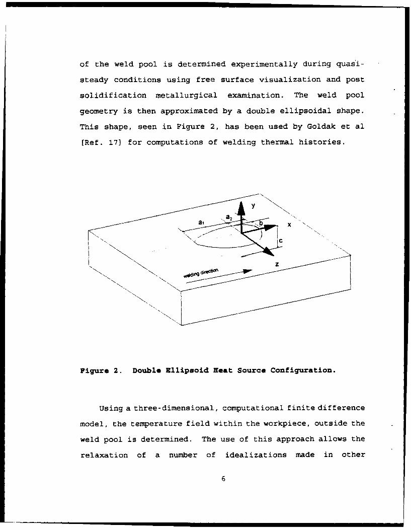
of the weld pool is determined experimentally during quasi-
steady conditions using free surface visualization and post
solidification metallurgical examination. The weld pool
geometry is then approximated by a double ellipsoidal shape.
This shape, seen in Figure 2, has been used by Goldak et al
[Ref. 173 for computations of welding thermal histories.
NY"a X
Figure 2. Double Ellipsoid Beat Source Configuration.
Using a three-dimensional, computational finite difference
model, the temperature field within the workpiece, outside the
weld pool is determined. The use of this approach allows the
relaxation of a number of idealizations made in other
6

estimation of the welding efficiency. The efficiency is
computed by finding the net heat transfer rate into the parent
material from the weld pool boundary. In the following, the
experimental and the numerical techniques employed are
described in detail.
7

II. EXPERIMENTAL APPARATUS, MATERIALS, AND PROCEDURES
A. GAS TUNGSTEN ARC WELDING APPARATUS
Gas tungsten arc welding (GTAW) is an arc welding process
that produces coalescence of metals by heating them with an
arc between a nonconsumable tungsten electrode and the
workpiece. Figure 3 is a sketch of the Direct Current
Straight Polarity (DCSP)GTAW process with all its associated
components as used in the present study. In this arrangement
the electrons emitted from the tungsten electrode are
accelerated to a very high speed while traveling through the
arc. These high speed electrons bombard the workpiece and
provide large surface heat fluxes resulting in a well defined
molten region called the weld pool. A 2W thoriated tungsten
electrode was used in the experiments because it has a higher
electron emissivity and better current carrying capacity than
pure tungsten electrodes (Ref. 18]. Argon gas flow rates of
196 -220 milliliters per second (25 to 28 cubic feet per hour)
were used during the process.
B. WELD METAL PROPERTIES
With a carbon content of 0.12 - 0.18 %, the HY-80 steel is
considered a mild steel. Typical chemical composition of the
HY-80 is shown in Table I. This steel was chosen for the
present experiments because it is widely used in the
8

GAS TUNGSTEN ARC WELDINGPROCESS (SCHEMATIC)
ARGON
POWER SOURCE
WELDING DIRECTION +CONTACT TUBE :
SHIELDING(CATHODE )Il , GAS
TUNGSTENELECTRODE -- ARC
WELD IN\X~"x
POOL
BASE "WELDMETAL (ANODE) DEPOSIT
Figure 3. Sketch of the Gas Tungsten Arc Welding Process.
9

Table I. CMNMACAL COMPOSITION OF HY-80 STEEL.
ELEMKENT PERCENT
Carbon 0.12 - 0.18
Manganese 0.10 - 0.40
Phosphorus 0.025
Sulfur 0.025
Silicon 0.15 - 0.35
Nickel 2.00 - 3.25
Chromium 1.00 - 1.80
Molybdenum 0.20 - 0.60
Residual Elements Percent
Titanium 0.02
Vanadium 0.03
Copper 0.25
construction of naval vessels and ordnance equipment. This
type of steel is intended for service conditions that comprise
dynamic loading. When welded properly, HY-80 joint strength
and toughness approach that of the base metal and the joints
are durable enough to withstand ballistic loading any
10

failure. This steel is manufactured with specification of MIL-
S-16216 (Ships).
C. WELD POOL VISUALIZATION
The arc during the welding process was so bright that
intense external illumination with spectral filtering must be
used to view and record the weld pool free surface. The
purpose of the Model PN-232 Laser Augmented Welding Vision
System (Control Vision, Inc.) is to overcome the undue
variation in scene brightness created by the welding arc. The
pulsed ultra violet laser signal reflected from the workpiece
is much brighter than the direct and reflected light of the
welding arc. The system uses a special purpose video camera
equipped with a CCD video sensor and a very high speed
electronic shutter. The shutter is synchronized with the
laser flash. Each laser flash is triggered once per video
frame and lasts for a duration of approximately 3 ns. The
system is also equipped with a narrow-band optical filter to
match the laser wavelength which further suppresses the arc
lighting. The net combination of both the temporal and
spectral filtering results in a video image that is almost
free of the unfavorable arc lighting effects. The complete
system consists of a pulsed nitrogen laser unit, a camera
unit, a solid state television, and a system controller that
are interconnected by various electrical and fiberoptic cables
[Ref. 19] as shown in Figure 4.
11

COOLING WATEROURCEI
VACUUM PPUMP
LSER
CAMERA
NITROGEN ____
HY-80 PLATE
MONrTOR
"LRECORDER
SYSTEM CONTROLLER
Figure 4. Laser Augmented Welding Vision System.
1. Laser Unit
The pulsed nitrogen laser is a PRA/Model UV12
manufactured by PRA Laser Inc., Ontario, Canada. The optical
laser radiation has an operating wavelength of 337 nm (near-
visible ultraviolet region in the spectrum) with 3 ns duration
pulses, 60 Hz and a power level of 90 mW. For operation, the
12
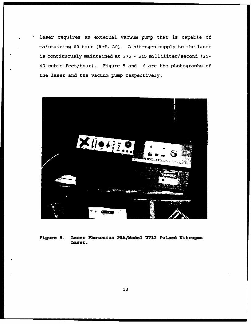
laser requires an external vacuum pump that is capable of
maintaining 60 torr [Ref. 20]. A nitrogen supply to the laser
is continuously maintained at 275 - 315 milliliter/second (35-
40 cubic feet/hour). Figure 5 and 6 are the photographs of
the laser and the vacuum pump respectively.
Figure 5. Laser Photonics PRA/Model UV12 Pulsed NitrogenLaser.
13
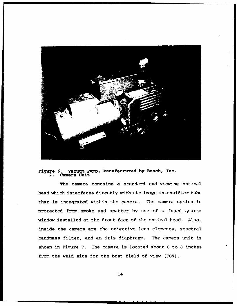
Figure 6. Vacuum Pump, Manufactured by Bosch, Inc.
2. Camera Unit
The camera contains a standard end-viewing optical
head which interfaces directly with the image intensifier tube
that is integrated within the camera. The camera optics is
protected from smoke and spatter by use of a fused quartz
window installed at the front face of the optical head. Also,
inside the camera are the objective lens elements, spectral
bandpass filter, and an iris diaphragm. The camera unit is
shown in Figure 7. The camera is located about 6 to 8 inches
from the weld site for the best field-of-view (FOV).
14
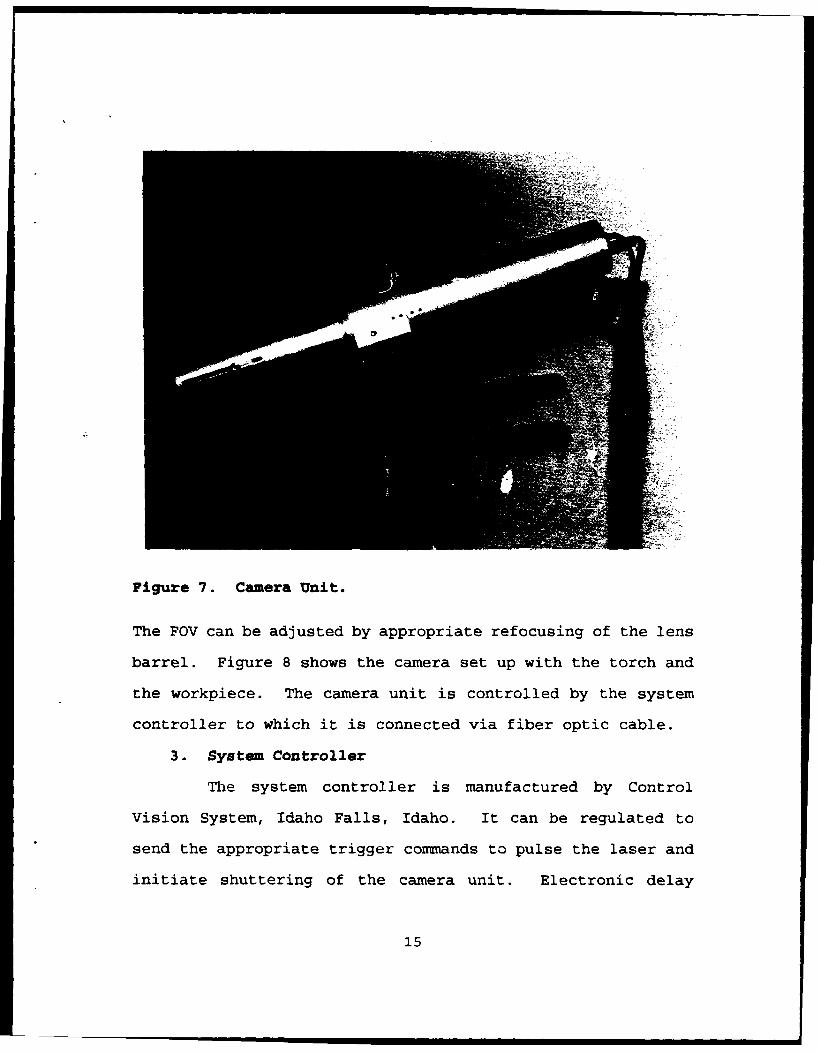
Figure 7. Camera Unit.
The FOV can be adjusted by appropriate refocusing of the lens
barrel. Figure 8 shows the camera set up with the torch and
the workpiece. The camera unit is controlled by the system
controller to which it is connected via fiber optic cable.
3. System Controller
The system controller is manufactured by Control
Vision System, Idaho Falls, Idaho. It can be regulated to
send the appropriate trigger commands to pulse the laser and
initiate shuttering of the camera unit. Electronic delay
15

Figure 8. Camera Unit, Torch, and Weldpiece Set-up.
between the laser and the shutter unit required the setting of
the shutter delay of .38 As. The controller provides power to
the camera unit and serve for manual adjustments of the
shutter speed, video frame rate, and sensitivity.
4. TV Monitor and Video Recorder
The TV monitor mode. TT -•6M was a Panasonic black and
white with a 19-inch screen. Frame by frame playback was done
by a VHS Panasonic Time Lapse Recorder Model AG-6720-P which
was used for the determination of weld pool sizes. Output
16

Figure ).TV Monitor, System Controller, and VHSRecorder.
from the system controller is recorded directly on the
recorder and viewed constantly on the TV monitor. The system
set up is shown in Figure 9.
17

5. Welding Equipment
The power source of the welding arc was a Miller Model
SR600/SCMIA 230/450 Volts. The heart of the welding system,
the power source, can be set at different currents that range
from 50 to 500 amps and a voltage range of 10 to 35 volts.
Figure 10. Miller Welding Equipment.
Figure 10 shows the Miller welding equipment. Part of the
welding system is the torch that is water cooled and capable
of heavy duty welding up to 600 A. The torch is designed to
18

firmly hold the tungsten electrode and to transmit the welding
current to the electrode. A ceraniic nozzle at the end of the
torch is used to shield the inert shielding gas around the
electrode. Argon was used as the shielding gas. Figure 11
is the system set up for the GTAW torch and associated
electric cables and water connection.
Figure 11. GTAW Torch Setup for Automatic Welding.
19
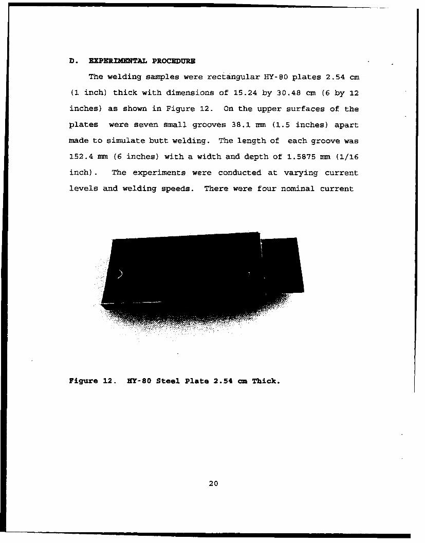
D. EXPERIMENTAL PROCEDURE
The welding samples were rectangular HY-80 plates 2.54 cm
(1 inch) thick with dimensions of 15.24 by 30.48 cm (6 by 12
inches) as shown in Figure 12. On the upper surfaces of the
plates were seven small grooves 38.1 mum (1.5 inches) apart
made to simulate butt welding. The length of each groove was
152.4 mm (6 inches) with a width and depth of 1.5875 mm (1/16
inch). The experiments were conducted at varying current
levels and welding speeds. There were four nominal current
Figure 12. NY-80 Steel Plate 2.54 cm Thick.
20

settings of 240, 200, 175, and 150 Amps and three welding
speeds of 2.117 mm/sec ( 5 in/min), 1.693 mm/sec (4 in/min),
and 1.269 mm/sec (3 in/min). The welding current and voltage
were measured with a Digi-Meter 600 Miller Style No. JK-32.
The current readings during each experiment fluctuated within
± 5 Amps and the voltage varied from ± .2 Volts. The arc
length and electrode tip angle were maintained the same
throughout the experiments at 3 mm and 45 degrees
respectively.
Measurements of the weld pool dimensions were made for
thirty-six runs. The weld pool video image from the vision
system was used to measure the weld pool length ahead and
behind the arc. Solidified weld samples were cross sectioned,
polished, and etched and then analyzed with the help of
optical microscopy to measure the weld pool width and the
depth of the fusion zone. These measurements were then used
as an input to the numerical model described later. A summary
of all the welding settings and weld pool dimensions are
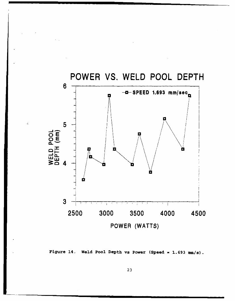
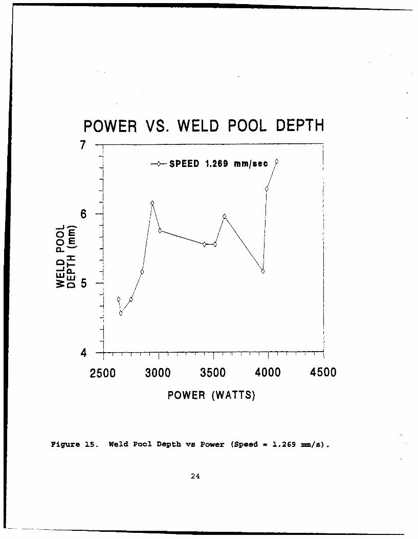
tabulated in Tables II to IV. Figures 13 to 15 show the weld
pool depth as a function of the power input at various speeds.
As expected, at a given speed the higher the power input, the
deeper the weld pool depth. Figure 16 shows the collection of
such data for the various speeds. It can be seen that at the
same power input, increasing weld speed causes a shallower
weld pool.
21

POWER VS. WELD POOL DEPTH
-- _o-SPEED 2.127 mmlsec
1t
-I 5o ~ ~-i ••
4-i 100
I z_
4 h/
3 I
2500 3000 3500 4000
POWER (WATTS)
Figure 13. Weld Pool Depth vs Power (Speed 2.127 ,am/s).
22
POWER VS. WELD POOL DEPTH6 -a-SPEED 1.693 mm/sec 0
5A 0/o-' - / //
0 E
_I
' I N I /
a-a
U-i
3
2500 3000 3500 4000 4500
POWER (WATTS)
Fi.gure 14. Weld Pool Depth vs Power (Speed = 1.693 mu/s).
23
POWER VS. WELD POOL DEPTH7-]
--oSPEED 1.289 mmisec
6+
C E
U-i
-1
4 4 I " I
2500 3000 3500 4000 4500
POWER (WATTS)
Figure 15. Weld Pool Depth vs Power (Speed = 1.269 =mn/s).
24

POWER VS. WELD POOL DEPTH
7 --9- SPEED 2.127 mm/sec-a--SPEED 1.693 mmfsec-o--SPEED 1.269 mm/sec,
6
0 E
S-i yZ'• /
-' /01 E
4 %a
3 I
2500 3000 3500 4000 4500
POWER (WATTS)
Figure 16. Effect of Power vs Weld Pool Depth atDifferent Speeds.
25

Table 11. SMIMARY OF WELDING SETTINGS AND WELD POOLMMURMUMTS WITH SPEND OF 2.127 vm/sec.
Power Amps Volts Weld Pool Weld Pool Weld Pool length(Watts) (:k4) (t.3) Width Depth Ahead Behind
(mm) (mm) (mm) (mm)
4347.0 315 13.8 10.714 5.754 3.830 9.340
4239.0 314 13.5 13.096 4.365 3.300 12.000
3944.6 326 12.1 10.318 5.159 2.980 10.800
3715.2 288 12.9 11.112 3.770 3.000 9.150
3533.2 292 12.1 10.714 4.762 3.000 9.150
3416.4 292 11.7 10.318 3.968 3.150 8.400
3123.6 274 11.4 7.540 4.365 3.000 6.675
3036.0 264 11.5 7.142 5.754 3.375 4.875
2948.0 268 11.0 8.730 3.968 2.625 7.875
2735.9 251 10.9 7.142 4.167 3.150 6.375
2710.4 242 11.3 7.963 4.365 2.625 6.375
2621.5 245 10.7 7.540 3.571 2.475 6.900
26

Table III. ,,URMlARY OF WELDING SETTINGS AND WELD POOLS WITH SPEED OF 1.693 -- /sec.
Power Amps Volts Weld Pool Weld Pool Weld Poollength (Watts) (±4) (±.3) Width Depth AheadBehind (m) (mm) (mm)
(3)
3925.0 314 12.5 7.936 5.556 3.110 8.110
3906.0 315 12.4 9.525 4.762 3.050 .00
3874.5 315 12.3 8.730 4.762 2.560 7.627
3500.0 280 12.5 7.142 4.960 2.810 7.380
3322.8 284 11.7 8.334 5.159 2.740 7.440
3306.0 285 11.6 7.142 4.764 2.680 7.930
3062.4 264 11.6 7.142 4.365 2.440 7.200
3016.0 260 11.6 8.334 3.968 2.560 6.220
2969.0 256 11.6 7.142 4.365 2.800 6.770
2806.0 244 11.5 7.142 4.564 2.620 6.580
2681.4 246 10.9 7.142 3.968 2.440 5.490
2648.7 243 10.9 7.142 3.571 2.500 5.980
27
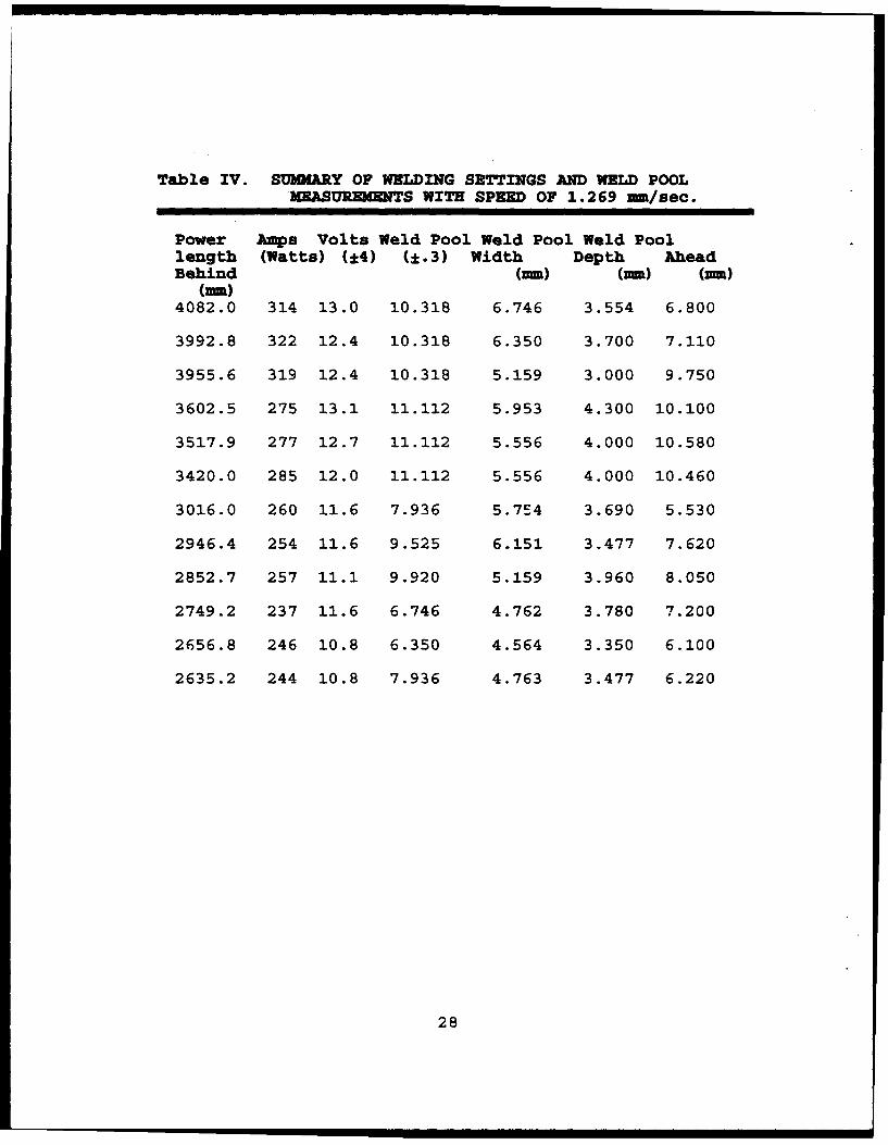
Table IV. SU3AIRY OF WELDING SETTINGS AND WELD POOLMEASUREMEmTS WITH SPEED OF 1.269 mm/sec.
Power Amps Volts Weld Pool Weld Pool Weld Poollength (Watts) (±4) (±.3) Width Depth AheadBehind (mm) (mm) (mm)
(mm)4082.0 314 13.0 10.318 6.746 3.554 6.800
3992.8 322 12.4 10.318 6.350 3.700 7.110
3955.6 319 12.4 10.318 5.159 3.000 9.750
3602.5 275 13.1 11.112 5.953 4.300 10.100
3517.9 277 12.7 11.112 5.556 4.000 10.580
3420.0 285 12.0 11.112 5.556 4.000 10.460
3016.0 260 11.6 7.936 5.7E4 3.690 5.530
2946.4 254 11.6 9.525 6.151 3.477 7.620
2852.7 257 11.1 9.920 5.159 3.960 8.050
2749.2 237 11.6 6.746 4.762 3.780 7.200
2656.8 246 10.8 6.350 4.564 3.350 6.100
2635.2 244 10.8 7.936 4.763 3.477 6.220
28

Ill. COMPUTATIONS OF W;3LDING EFFICIENCY
This chapter describes the numerical method used to
estimate the net heat transfer rate to the workpiece, under
quasi-steady conditions, for a given shape and size of the
weld pool. The formulation and computations are done in a
reference frame that moves with the welding torch. In this
moving coordinate system, the heat transfer is quasi-steady
since the weld pool location, shape, size, and the temperature
distribution in the workpiece, remain invariant with respect
to the torch. Under this assumption, the heat input from the
heat source to the weld pool is equal to the net heat transfer
f rom the weld pool boundary to the workpiece. If we prescribe
the weld pool shape and size (based on experimental data) and
set the weld pool boundary at the melting temperature Tm, the
resulting heat transfer across the weld pool boundary can be
estimated by solving the temperature distribution in the
workpiece due to conduction.
The weld pool shape is assumed to be that of a double
ellipsoid. Such a weld pool shape with a corresponding heat
source distribution was also assumed by Goldak et al. [Ref.
171. As shown in Figure 2 in Chapter 1, the four dimensional
values (i.e., lengths forward (al) and behind the arc (a2),
weld pool width (b), and weld pool depth (c) are needed for
each weld pool. These values are obtained from the
29
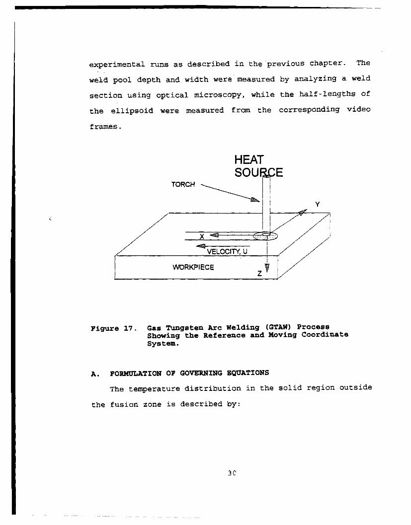
experimental runs as described in the previous chapter. The
weld pool depth and width were measured by analyzing a weld
section using optical microscopy, while the half-lengths of
the ellipsoid were measured from the corresponding video
frames.
HEATSOUIC E
TORCH
Y
SVELOCITY, U
WORKPIECEZ ,
Figure 17. Gas Tungsten Arc Welding (GTAW) ProcessShowing the Reference and Moving CoordinateSystem.
A. FORMULATION OF GOVERNING EQUATIONS
The temperature distribution in the solid region outside
the fusion zone is described by:
30

apT a k aT+ a kaT)a kaT
- p T) --- + ( - - (-)• c - + 2- (-L-- ý) +source Eq (1)ax' C (x' ay C ay az O z
where x',y, z are the coordinates in the stationary reference
frame. We introduce the following coordinate transformation
X=x-Ut:orcht Eq (2)
where Utorch is the velocity of the torch (a constant).
Differentiating Eq (2) with respect to time,
ax _ ax Iat at
or,
U U!'- Ut .. b Eq (3)
where U is the velocity in the x direction in the moving
reference frame. For any general variable $, applying the
chain rule to the x'- directional differential term yields:
ax ax ax (4 (x, y, z, t)a-•(¢x"'Z't))a, x, ax
_ (x,y, Z t)) Eq (4)
ax x YZ(((XIyIzt))) Eq (5)ax' ax ax
31

a 4¢(xtyZ, t) + (U(x,y,z, t) ) q((x,y,z, t))
-a- a_at (4(xf,yz~t))+(lU'UOZCh)_-(O(xY,yz~t)) Eq (6)
Substitution of EQ. (4), (5), and (6) in (1) yields the
transformed equation in the reference frame of the moving
torch:
( d(_ d -pcT T)+cT)(7'
B. BOUNDARY CONDITIONS
The boundary conditions are as follows:
Convective boundary condition on the sides, and top:
z=0; h(T,-) =-k.!Zaz
kaT
x=0; h(Tf-T)=-k-!
32

x~,;h (Tt-T) =k-LXXL; ax
axx
z ZL
Top :
y=yL; h(T-T•) ÷+a (T4-T•)=-kT-s
Bottom (Insulated) :
y=O;ay
At the weld pool boundary and its interior: T = Tm
where :h = heat transfer coefficient
33
="~~~' ay i ilI

Tf= ambient fluid temperature
E = emissivity
a = Stefan Boltzman constant
k = thermal conductivity of the solid
Tm= melting temperature of the solid
C. NUMERICAL SOLUTION
The governing equation (8), together with the boundary
conditions are then solved numerically using a control-volume
based finite difference technique. Since our problem is a
quasi-steady one, and the finite difference code used is a
transient one, iterations were continued until a steady state
Table V. PHYSICAL PROPERTIES OF EY-80.
Density, p 7800 kg/m3
Thermal Conductivity, K 35 W/m-K
Heat Capacity, CP Figure 19
Melting Temperature, Tmelt 14770 C
Ambient Temperature, Tamb 250 C
34

condition was reached. The rectangular domain was discretized
into a fine mesh grading as shown in Figure 18. The grading
near the heat source is on the order of .5 mm by .5 mm by .5
mm. Outside the heat source, a non-uniform grid is employed.
A Silicon Graphics Iris workstation was used for the
computations. The physical dimensions used are shown in
Tables II, III, and IV. In the computations the specific heat
is assumed to vary with temperature as seen in Figure 19. The
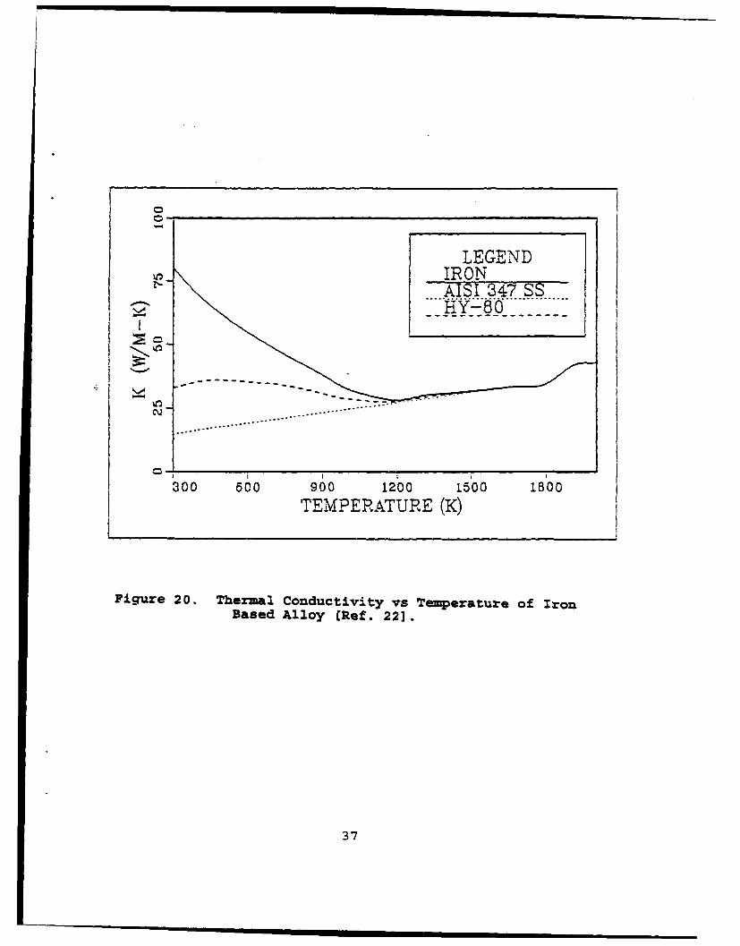
thermal conductivity, as shown in Figure 20,
Figure 18. Grid Network used in the Computations.
does not seem to vary appreciably over the temperature range
of our operation and is therefore assumed to be constant at 35
W/m-k. Other pertinent data used are tabulated in Table V.
35

900....
800
500
S600
Cn1
u rve fitI
500 0 McGannon
4~00 1 .. . 5 .
0 500 1000 1500 2000 2500 3000 3500Temperature [K]
Figure 19. Specific Heat as a Function of Temperature forIron [Ref. 21].
36
LEGENDIRONAISI 347 SSS....H ?-8O...............
•- -- - ------- -- -- - -
------------ - - "
CQ .. ..... .... o..... .. .. .. . .. .. .. .. .
300 o60 900 1200 150 1800TEMPERATURE (K)
Figure 20. Thermal Conductivity vs Temperature of IronBased Alloy [Ref. 22].
37
IV. RESULTS AND DISCUSSION
A. ESTIMATING WELDING EFFICIENCY
Results of the GTAW efficiency made on HY-80 plates were
tabulated to compare the effects of the varying input power
set at high, medium, and low. The power inputs ranged from
4.347 to 2.621 KW. Three different speed settings were used
for the moving arc experiments. Table VI summarizes the
efficiency measurements for the welding speed of 2.12 mm/s,
Table VII for 1.69 mm/s, and Table VIII for 1.269 mm/s.
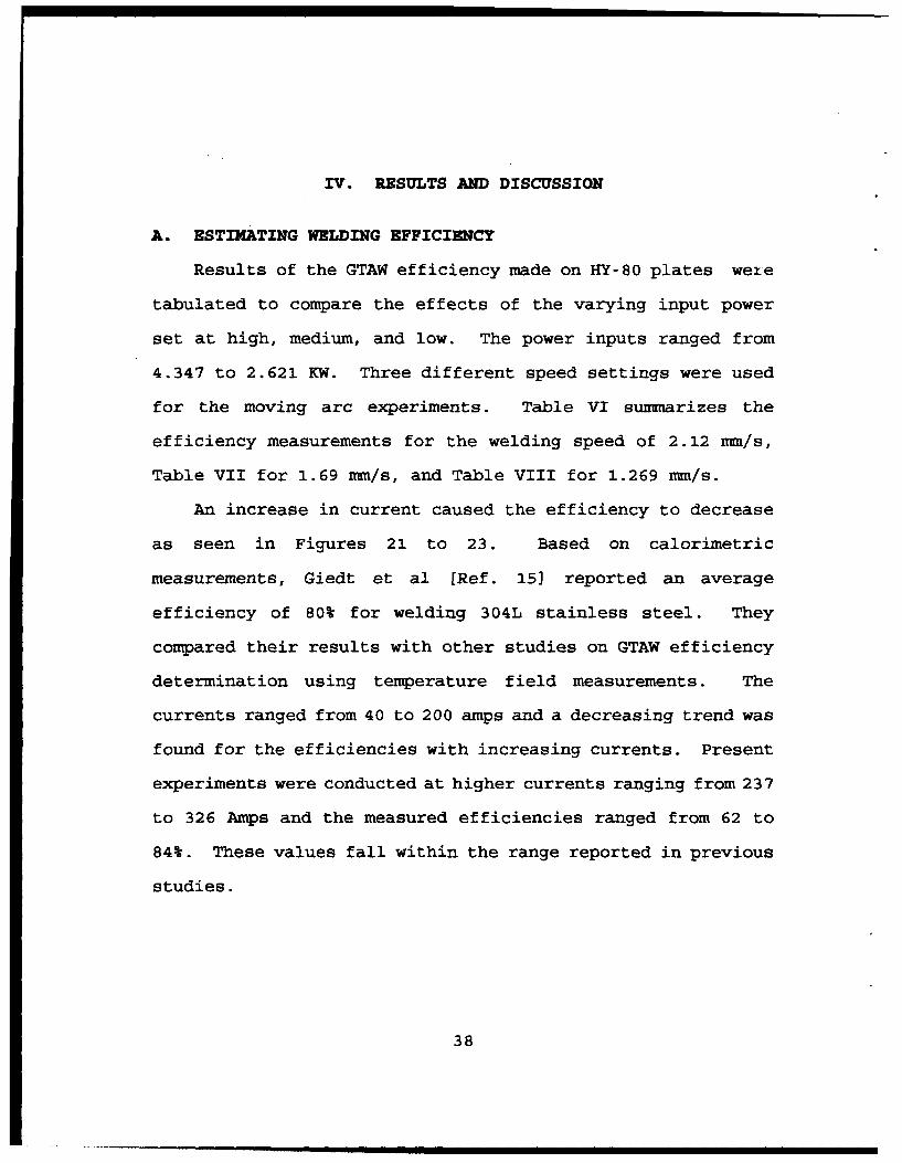
An increase in current caused the efficiency to decrease
as seen in Figures 21 to 23. Based on calorimetric
measurements, Giedt et al [Ref. 15) reported an average
efficiency of 80% for welding 304L stainless steel. They
compared their results with other studies on GTAW efficiency
determination using temperature field measurements. The
currents ranged from 40 to 200 amps and a decreasing trend was
found for the efficiencies with increasing currents. Present
experiments were conducted at higher currents ranging from 237
to 326 Amps and the measured efficiencies ranged from 62 to
84%. These values fall within the range reported in previous
studies.
38

Table VI. SUMMARY OF GTA WELDING EFFICIENCY MEASUREMENTSWITH SPEED 2.127 mm/Sec.
Run # Input Power Total Heat Input Efficiency
(W) (w) (%)
1 3925 2590 66
2 3906 2601 67
3 3875 2407 62
4 3500 2289 65
5 3323 2471 74
6 3306 2241 68
7 3062 2080 68
8 3016 2092 69
9 2969 2115 71
10 2806 2116 75
11 2181 1888 70
12 2649 1864 70
39

Table VII. SMU•ARY OF GTA WELD EFFICIENCY JEASUR•M•NTSWITH WELDING SPEED OF 1.693 mm/sec.
Run # Input Power Total Beat Input Efficiency
(W) (W) (%)
13 4347 2849 66
14 4239 3084 73
15 3945 2846 72
16 3715 2518 68
17 3533 2702 76
18 3416 2448 72
19 3124 2123 68
20 3036 2230 73
21 2948 2191 74
22 2731 2029 74
23 2710 2101 78
24 2622 1894 72
40

Table VIII. SUMMARY OF GTA WELD EFFICIENCY MEASUREMENTSWITH WELDING SPEED OF 1.269 =m/sec.
Run # Input Power Total Heat Input Efficiency
(J) (W) (%)
25 4082 2542 62
26 3993 2525 63
27 3956 2638 67
28 3603 2672 74
29 3518 2716 77
30 3420 2710 79
31 3016 2202 73
32 2946 2503 85
33 2853 2420 85
34 2749 2031 74
35 2657 1923 72
36 2635 2115 80
41

POWER VS. EFFICIENCY80-
-:5--SPEED 2.127 mm/sec
j- /
z_ 7 0
LL.LIU
-i
60
2500 3000 3500 4000
POWER (WATTS)
Figure 21. Effect of Power vs Efficiency at Speed of2.127 um/sec.
42
POWER VS. EFFICIENCY80
-a--SPEED 1.693 mm/sec
70 \
LLI'
6/O%... 707//j,U- //
-ii
44
60-n
2500 3000 3500 4000 4500POWER (WATTS)
Figure 22. Effect of Power vs Efficiency at Speed of1.693 --- /sec.
43

POWER VS. EFFICIENCY90
-- $SEED 1.269 mm/sec
80 -
z ,7
LU. "70-
+\~1
- 1 V.
60
2500 3000 3500 4000 4500POWER (WATTS)
Figure 23. Effect of Power vs Efficiency at Speed of1.269 -- /sec.
44

iI I2 I I I II
Apparently, at higher power inputs more heat loss to the
surroundings due to radiation and convection results in lower
efficiencies. Welding speed also influences the
efficiencies. As noted in Figure 24, the slower the speed,
the higher the efficiencies.
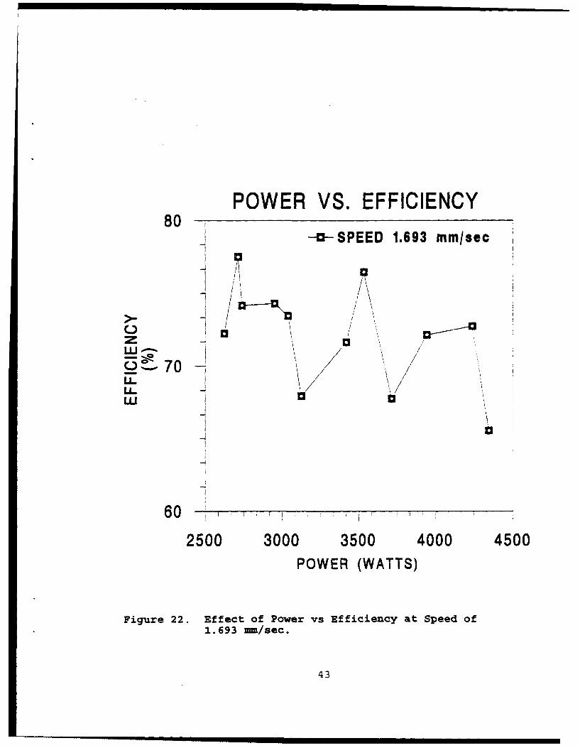
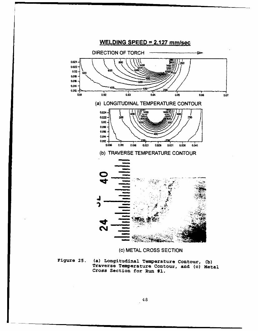
B. TEMPERATURE CONTOURS
Based on the heat conduction model developed, the effects
of the power input and torch speed on the temperature field
outside the weld pool were computed and plotted. Figures 25
to 33 exhibits selected results for nine weld pool geometries.
For each figure, (a) is the calculated temperature field at
longitudinal section of weld pool, (b) calculated temperature
field at traverse section of the weld pool, and (c)
experimental composite section of the HY-80 showing the depth
of the fusion zone. Figure 34 shows the free surface of a
single digitized weld pool video frame, each associated in
Figures 25 to 33 with (a) to (i), respectively. The double
ellipsoid model appears to be satisfactory in prescribing the
weld pool shape.
Figure 35 show the transient development of the weld pool
at one second intervals following the arc initiation for a
period of 12 seconds. After twelve seconds the weld pool is
at quasi-steady state for which the present computational
model is accurate. Notice that initially the weld pool is
elongated compared to the quasi-steady weld pool size. The
45

reason behind this is that near the edge, heat transfer from
the source is not as efficient as when the torch moves further
away, allowing heat conduction in all directions within the
metal.
46

POWER VS. EFFICIENCY90
--5- -SPEED 2.127 mm/secISPEED 1.693 mm/see
-o--SPEED 1.269 mm/sec
80 /
LI. , / \/ .
oD
S00-0v
60
2500 3000 3500 4000 4500
POWER (WATTS)
Figure 24. Power vs Efficiency Comparison at DifferentSpeeds.
47
WELDING SPEED =2.127 mmlsec
DIRECTION OF TORCH
0.024 -2o~o)0
0.022
0.021Go8
0.01240020.01 0.02 0.03 0.04 0.05 0.0600
(a) LONGITUDINAL TEMPERATURE CONTOUR
0.024-
0.022- Ww 0
0.02-
0006 0.01 0.016 0.021 0.028 0.031 0.036 0.041
(b) TRAVERSE TEMPERATURE CONTOUR
o~ t~
48.
WELDING SPEED.= 2.127 mmlsec
DIRECTION OF TORCH
0.024- 140 200
0.022 Nm uv-
0.02-0 -
0.0180.0O-O
0.01640.024
o1~ma ' ---
0.01 0.02 0.03 0.04 0.05 0.06 0.07
(a) LONGITUDINAL TEMPERATURE CONTOUR
0.02 4 -4
0.0n2 4
0.018-0.01 20 20W
0.014
0.006 a."1 0.016 0.02 0.0a6 0.031 0.0X6 0.041
(b) TRAVERSE TEMPERATURE CONTOUR
(c) METAL CROSS SECTION
Figure 26. (a) Longitudinal Temperature Contour, (b)Traverse Temperature contour, and (c) MetalCross Section for Run #6.
49
WELDING SPEED =2.127 mmlsec
DIRECTION OF TORCH
0.024-N; ) 20
0.02-
0.0180.016-
0.0140.0n- - - 26
0.06 0.02 0.03 0&04 0.05 0.08 0.07
(a) LONGITUDINAL TEMPERATURE CONTOUR0.024-
0.01e 4o:Zz2z0.016-
0.014
0.006 0.011 0.016 0.021 0.026 0.0= 0.036 0 041
(b) TRAVERSE TEMPERATURE CONTOUR
44
(c) METAL CROSS SECTIONFigure 27. (a) Longitudinal Temperature Contour, (b)
Traverse Temperature Contour, and (c) MetalCross Section for Run #12.,
50

WELDING SPEED =1.693 mm/sec
DIRECTION OF TORCH
0.024-
00.=24
00.022
0.016-0.0120
0.0.014240020
0.006 000.0 .01 000.0 .2 O.0N 0.056 0 0 0417
(a) LOGTRAVERSE TEMPERATURE CONTOUR
() META CROSS SECTIONFigure~ ~ ~~\VO 28. (ajogtdnlTmeaueCnor b
TraverseU Tepraue oturad(cMelCross- Secio folaw 3
0.02- 4 80wo540
WELDING SPEED-= 1.693 mm/sec
DIRECTION OF TORCH
0.024- 6
0.=014020.02- o
0.018 00.016-
0.014 _____________
0.0120.01 0.02 0.03 0.04 0.OS 0.06 0.07
(a) LONGITUDINAL TEMPERATURE CONTOUR
0.024- I 400 OW I V w0.022-\\so
200. KOM 200
0-w 001 006 0.021 0.026 0.0W1 0.036 0.041
(b)TRVESETEMPERATURE CONTOUR
(c) METAL CROSS SECTION
Figure 29. (a) Longitudinal Temperature Contour, (b)Traverse Temperature Contour, and (c) metalCross Section for Run #18.
52

WELDING SPEED =1.693 mm/sec
DIRECTION OF TORCH
0.022- 00 140 000.02- /0.01e
- 20.016-
0.0140.012.
0.01 0.02 0.;3 0.04 0.05 0.06 0.0'7
(a) LONGITUDINAL TEMPERATURE CONTOUR
3.=2- 400 ~ 14 / 400
M -
0.14
-. 4 t
(c) METAL CROSS SECTION
Figure 30. (a) Longitudinal Temperature Contour, (b)Trave~rse Temperature Contour, and (c) M4etalCross Section for Run #24.
53

WELDING SPEED =1.269 mmlsec
DIRECTION OF TORCH
0.024 -4W o
0.02-10
0.018-
0.016- o0.014
0.012.0.01 0.02 0.03 0.04 0.05 0.06 0.0?
(a) LONGITUDINAL TEMPERATURE CONTOUR
0.024- 460 462002
0.022-
0.02 -6So
0.018-
0.(" 0 0
0.0141
0.012 - -
0.006 0.011 0.016 0021 0.026 00ý31 0036 0.041
(b) TRAVERSE TEMPERATURE CONTOUR
w
(c) METAL CROSS SECTION
Figure 31. (a) Longitudinal Temperature Contour, (b)Traverse Temperature Contour, and (c) MetalCross Section for Run #25.
54

WELDING SPEED =1.269 mmlsec
DIRECTION OF TORCH
0.024- Z 1 6
0.022- 800 4000
0.02-
0.018
0.016
0.014 400
0.012-1 0.200w00 0
0.01 00 .300 050.06 00
(a) LONGITUDINAL TEMPERATURE CONTOUR
0.2 -400 4600
0.016 - w200
0.014 400 4000.012.
0.006 0.011 0.016 0.021 0.02 0.031 0.036 0.041
(b) TRAVERSE TEMPERATURE CONTOUR
74 -
(c) METAL CROSS SECTION
Figure 32. (a) Longitudinal Temperature Contour, (b)Traverse Temperature Contour, and (c) MetalCross Section for Run #30.
55

WELDING SPEED.= 1.269 mmlsec
DIRECTION OF TORCH
0..024 ( 62001
0.022 400 0000.021 o
0.018 -
0.019-~
0.014-0.012 - -
0.01 0.02 0.03 0.04 0.05 0.06 0.07
(a) LONGITUDINAL TEMPERATURE CONTOUR0.24 t ýJýý4.0 1400
004200 w I 2000.022- 400 S k . .4 4000.02-]
0.018-
0.0141
0.006 .0011 0.016 0.021 0.029 0.0m1 0.0= 0.041
(b) TRAVERSE TEMPERATURE CONTOUR
0-
(c) METAL CROSS SECTIONFigure 33. (a-) Longitudinal Temperature Contour, (b)
Traverse Temperature Contour, and (c) MetalCross Section for Run #36.
56
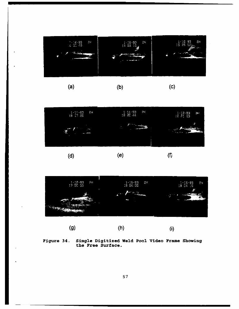
(a) (b) (C)
(d) (e) (f)
(g) (h) (i)
Figure 34. Single Digitized Weld Pool Video Frame Showingthe Free Surface.
57

T= 0 SEC T=1 SEC T=2 SEC
T= 3 SEC T= 4 SEC T=5 SEC
T 7 SEC T= 8 SEC T=9SEC
T = 10 SEC T=11 SEC T=12 SEC
Figure 35. Weld Pool Development Showing the TransientDevelopment within a Period of 12 Seconds atOne Second Interval.
58
V. CONCLUSIONS AND RECOMMEDATIONS
A three dimensional heat conduction model developed based
on a double ellipsoid pool shape approximation has been
presented for GTAW welding. The present computations revealed
a mean value of 72% for the efficiency. The range of present
computed values is consistent with calorimetric type
measurements in the literature. Since the present technique
does not require a calorimetric setup it can be easily
implemented in a variety of applications. Even though the
results obtained here apply to the GTAW process, the technique
is not limited to a particular welding process.
For further research, it is recommended that additional
experiments be conducted with different materials and joining
processes. The effect of the mesh size in the computations
also needs to be investigated further.
59

LIST OF REFERENCES
1. U.S. Patent 419,032, Jan. 7, 1890, "Methods of Welding byElectricity, " Charles Lewis Coffin, Detroit, Mich.
2. Rosenthal, D., and Schmerber, R., "Thermal Study of ArcWelding - Experimental Verification of TheoreticalFormulas," Welding Journal, 17, April 1938, pp.2 -8.
3. Rosenthal, D., "Mathematical Theory of Heat DistributionDuring Welding and Cutting," Welding Journal, 20, May1941, pp. 220s-234s.
4. Rosenthal, D., "The Theory of Moving Sources of Heat andIts Application to Metal Treatments," Trans. ASME, 68,Nov 1946, pp. 849-866.
5. Kou, S., Welding Metallurgy, John Wiley & Sons, 1987.
6. Christensen, N., Davies, V. de L., and Gjermundsen, K.:British Welding Journal, 12: 54, 1965.
7. Ushio, M., Ishimura, T., Matsuda, F., and Arata, Y.:Trans. Japan Weld. Res. Inst.,6: 1, 1977.
8. Grosh, R.J., and Trabant, E.A., "Arc WeldingTemperatures," Welding Journal, 35(8); 1956, pp.396s-400s.
9. Pavelic, V., Tanbakuchi, R., Uyehara, O.A., and Myers,P.S., "Experimental and Computed Temperature Historiesin Gas Tungsten Arc Welding of Thin Plates," WeldingJournal, 48(7); 1969, pp. 295s-305s.
10. Tsai, C.L., "Parametric Study on Cooling Phenomena inUnderwater Welding," PhD Thesis, MIT (1977).
11. Tsai, C.L.,"Modeling of the Thermal Behavior of MetalsDuring Welding," Trends in Welding Research, Edited byS.A. David, American Society of Metals, 1981, pp. 91-108.
12. Wilkinson, J.B., and Milner, D.R., Heat Transfer fromArcs, British Welding Journal, vol. 7(2), 115-128, 1960.
13. Malmuth, N.D., Hall, W.F., Davis, B.I., and Rosen, C.D.,"Transient Thermal Phenomena and Weld Geometry in GTAW,"Welding Journal, vol.53(9), 388s-400s, 1974.
60
14. Tsai, N.S., and Eager, T.W., "Distribution of the Heatand Current Fluxes and Gas Tungsten Arcs," MetallurgicalTransactions B, vol. 16B(4), 841-846, 1985.
15. Giedt, W.H., Tallerico, L.N., and Fuerschbach, P.W., GTAWelding Efficiency: Calometric and Temperature FieldMeasurements, Welding Journal, vol. 68(1), 28-32, 1989.
16. Smartt, H.B., Stewart, J.A., and Einerson, C.J., HeatTransfer in Gas Tungsten Arc Welding, ASMMetals/Materials Series, 8511-011, 1-14, 1986.
17. Goldak, J., Chakravarti, A., and Bibby, M., "A FiniteElement Model for Welding Heat Sources," MetallurgicalTransactions, Volume 15B, June 1984, pp 299-305.
18. Carry,H.B.:Modern Welding Technology, Prentice-Hall,Englewood Cliffs, NJ, 1979.
19. "System Description and Operating Instruction," Model PN-232, Laser Augmented Welding Vision System, ControlVision Inc., Idaho Falls, Idaho.
20. Model UV12 Nitrogen Laser Service Manual, PRA Laser,Inc., November 1987.
21. Mazunder, J., Chen, M.M., Zehr, R., and Voelkel, D.,"Effect of Convection on Weld Pool Shape andMacrostructure: Numerical Modeling Portion," Report toU.S. Navy for Research Conducted under Contract No.N00014-89-J-1473, February 1990.
22. Ule, R.L., "A Study of the Thermal Profiles DuringAutogenous Arc Welding," M.S. and M.E. Thesis, NavalPostgraduate School, Monterey, CA, March 1989.
61
INITIAL DISTRIBUTION LIST
No. Copies1. Defense Technical Information Center 2
Cameron StationAlexandria VA 22304-6145
2. Library, Code 052 2Naval Postgraduate SchoolMonterey CA 93943-5002
3. E.A. Metzbower 1Naval Research LaboratoryWashington, D.C. 20375-5000
4. Department Chairman, Code ME 1Department of Mechanical EngineeringNaval Postgraduate SchoolMonterey, CA 93943-5000
5. Yogendra Joshi, Code ME/Ji 2Naval Postgraduate SchoolMonterey, CA 93943-5000
6. Richard Morris 1CODE 2815David Taylor Research LaboratoryAnnapolis, MD 21402
7. SEA-05 1Naval Sea Systems CommandWashington, D.C. 20362-5101
8. SEA-92R 1Naval Sea Systems CommandWashington, D.C. 20362-5101
9. Naval Engineering Curricular Office 1CODE 34Naval Postgraduate SchoolMonterey, CA 93943-5000
62
10. Dr. Pradip Dutta, Code ME/Da 1Naval Postgraduate SchoolMonterey, CA 93943-5000
11. LCDR(Sel) Candonino P. Franche 3557 Canyon Dr.Bonita, CA 91902
63
Related Documents