Naturally-Clamped Snubberless Current-fed Soft-Switching DC/DC Converters Akshay Kumar Rathore Associate Professor Electrical and Computer Engineering Concordia University, Montreal, Canada [email protected] IEEE IAS Distinguished Lecture 1

Welcome message from author
This document is posted to help you gain knowledge. Please leave a comment to let me know what you think about it! Share it to your friends and learn new things together.
Transcript
Naturally-Clamped Snubberless Current-fed Soft-Switching DC/DC Converters
Akshay Kumar RathoreAssociate Professor
Electrical and Computer EngineeringConcordia University, Montreal, Canada
IEEE IAS Distinguished Lecture
1
© Dr. Akshay K. Rathore, Associate Professor, Electrical and Computer Engineering, Concordia University, Montreal, Canada
2
Major Research Focus
1) High-frequency power converters• Low voltage medium power applications• High device switching frequency• Soft-switching techniques• Compact, low cost, light weight
• Current-fed topologies (high voltage gain)
2) Low-frequency power converters• Multilevel converters• Medium voltage high power applications• Low device switching frequency• High efficiency• Industrial applications
© Dr. Akshay K. Rathore, Associate Professor, Electrical and Computer Engineering, Concordia University, Montreal, Canada
3
Current-Fed DC/DC Converters• Boost derived• Voltage gain
© Dr. Akshay K. Rathore, Associate Professor, Electrical and Computer Engineering, Concordia University, Montreal, Canada
4
Major Research Highlights
1) Naturally-clamped Snubberless Current-fed Topologies
2) Impulse Commutated Current-fed Converters
3) Current-fed direct unfolding inverter
1) Single Reference Six-Pulse Modulation (SRSPM)
2) Dual Three-Pulse Modulation
*to realize capacitorless three-phase inverter with reduced magnetics and device count
1) Fundamental frequency control of medium voltage multilevel inverters
2) Common mode elimination in open-end winding machines
© Dr. Akshay K. Rathore, Associate Professor, Electrical and Computer Engineering, Concordia University, Montreal, Canada
5
First Glance…
• Short circuit protection• Voltage gain (10x with voltage doubler)• Limits peak and circulating current• High Voltage Gain High current applications• Inductor Reliability vs Capacitor• Input inductor vs. output inductor• Low magnetizing to leakage inductance ratio
© Dr. Akshay K. Rathore, Associate Professor, Electrical and Computer Engineering, Concordia University, Montreal, Canada
6
Outline …• High Voltage Gain Applications• Traditional Current-fed Converters• Major issues with Current-fed Converters• Current-fed Converters for low voltage high current
applications requiring high voltage conversion ratio• Advanced Current-fed Converters• Analysis, Results & Conclusion
© Dr. Akshay K. Rathore, Associate Professor, Electrical and Computer Engineering, Concordia University, Montreal, Canada
7
Low Voltage High Current Applications• UPS• Battery/Storage• Renewables• Fuel cells• HEV/FCV
© Dr. Akshay K. Rathore, Associate Professor, Electrical and Computer Engineering, Concordia University, Montreal, Canada
8
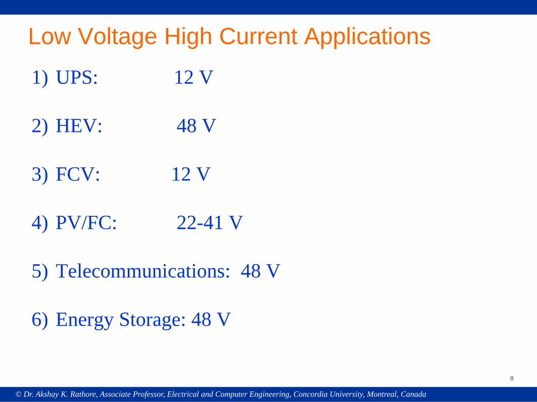
Low Voltage High Current Applications1) UPS: 12 V
2) HEV: 48 V
3) FCV: 12 V
4) PV/FC: 22-41 V
5) Telecommunications: 48 V
6) Energy Storage: 48 V
© Dr. Akshay K. Rathore, Associate Professor, Electrical and Computer Engineering, Concordia University, Montreal, Canada
9
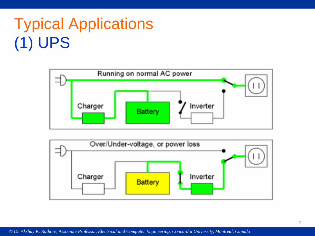
Typical Applications(1) UPS
© Dr. Akshay K. Rathore, Associate Professor, Electrical and Computer Engineering, Concordia University, Montreal, Canada
10
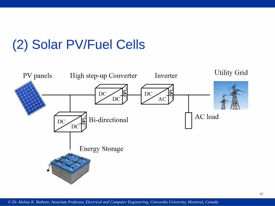
(2) Solar PV/Fuel Cells
© Dr. Akshay K. Rathore, Associate Professor, Electrical and Computer Engineering, Concordia University, Montreal, Canada
11
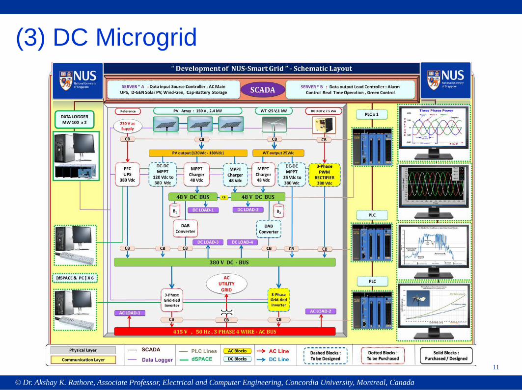
(3) DC Microgrid
© Dr. Akshay K. Rathore, Associate Professor, Electrical and Computer Engineering, Concordia University, Montreal, Canada
12
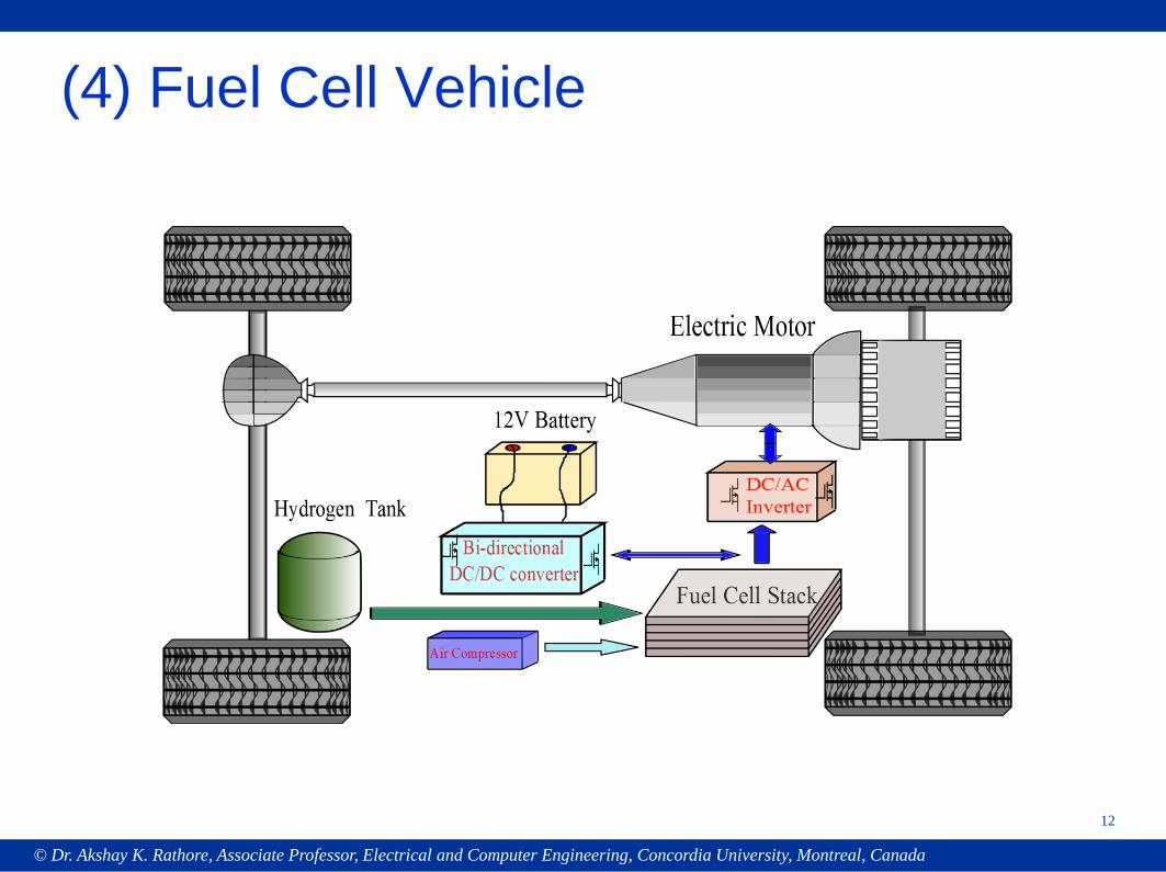
(4) Fuel Cell Vehicle
© Dr. Akshay K. Rathore, Associate Professor, Electrical and Computer Engineering, Concordia University, Montreal, Canada
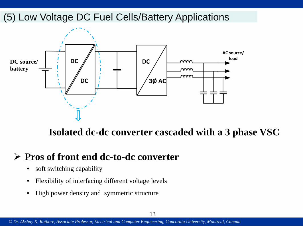
(5) Low Voltage DC Fuel Cells/Battery Applications
DC source/battery
• soft switching capability
• Flexibility of interfacing different voltage levels
• High power density and symmetric structure
Pros of front end dc-to-dc converter
AC source/load DC
3Ø AC
DC
DC
Isolated dc-dc converter cascaded with a 3 phase VSC
13
© Dr. Akshay K. Rathore, Associate Professor, Electrical and Computer Engineering, Concordia University, Montreal, Canada
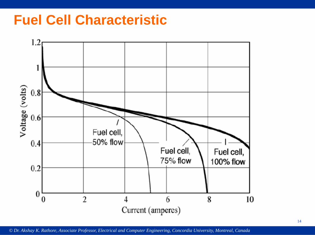
Fuel Cell Characteristic
14
© Dr. Akshay K. Rathore, Associate Professor, Electrical and Computer Engineering, Concordia University, Montreal, Canada
15
High-Frequency Power Converters• Soft-switching• Compact, low cost, light weight
© Dr. Akshay K. Rathore, Associate Professor, Electrical and Computer Engineering, Concordia University, Montreal, Canada
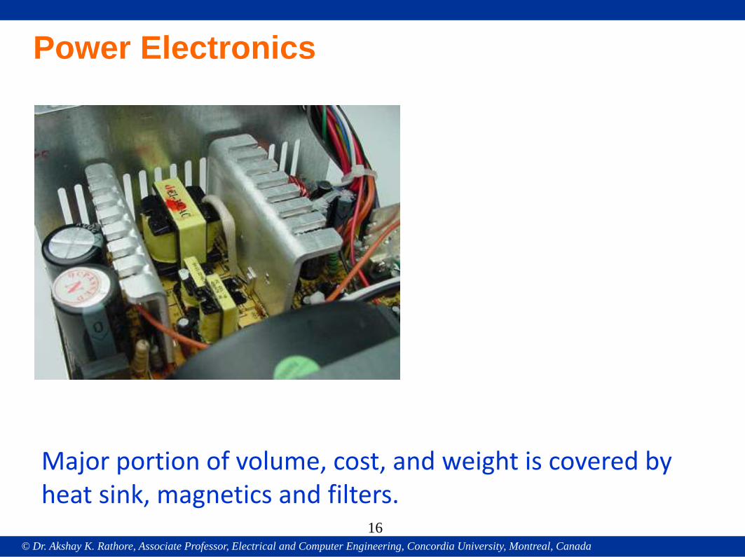
Power Electronics
Major portion of volume, cost, and weight is covered by heat sink, magnetics and filters.
16
© Dr. Akshay K. Rathore, Associate Professor, Electrical and Computer Engineering, Concordia University, Montreal, Canada
17
Reduced size of:
• Magnetics• Filters• Passive Components
© Dr. Akshay K. Rathore, Associate Professor, Electrical and Computer Engineering, Concordia University, Montreal, Canada
18
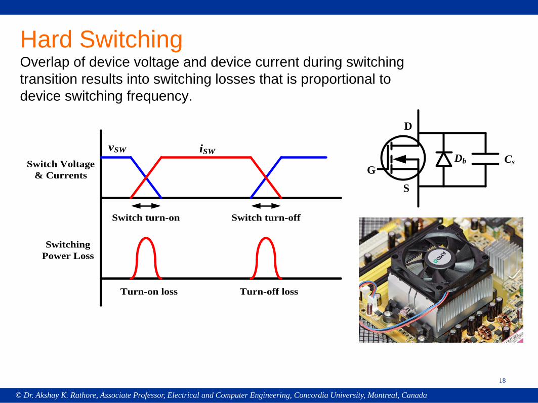
Hard SwitchingOverlap of device voltage and device current during switching transition results into switching losses that is proportional to device switching frequency.
Switch Voltage & Currents
vSW iSW
Switch turn-on Switch turn-off
Switching Power Loss
Turn-on loss Turn-off loss
G
D
S
CsDb
© Dr. Akshay K. Rathore, Associate Professor, Electrical and Computer Engineering, Concordia University, Montreal, Canada19
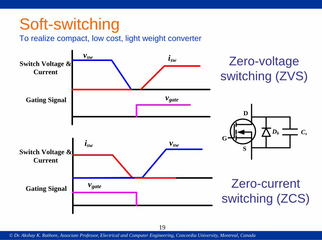
Soft-switchingTo realize compact, low cost, light weight converter
G
D
S
CsDb
vsw isw
vgate
Switch Voltage & Current
Gating Signal
isw vsw
vgate
Switch Voltage & Current
Gating Signal
Zero-voltage switching (ZVS)
Zero-current switching (ZCS)
© Dr. Akshay K. Rathore, Associate Professor, Electrical and Computer Engineering, Concordia University, Montreal, Canada
20
Soft-switching is realized and implemented by:
• Modulation Technique (PWM Converters)• Auxiliary Transition Circuit (ZCT and ZVT)• Resonance (Resonant Converters)
© Dr. Akshay K. Rathore, Associate Professor, Electrical and Computer Engineering, Concordia University, Montreal, Canada
21
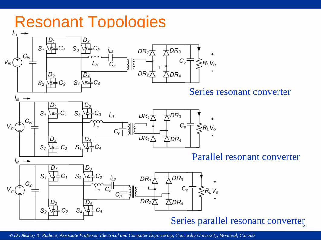
Resonant Topologies
Series resonant converter
Parallel resonant converter
Series parallel resonant converter
© Dr. Akshay K. Rathore, Associate Professor, Electrical and Computer Engineering, Concordia University, Montreal, Canada
22
- Variable Frequency Modulation*makes the design of filters and control circuit difficult. ** variation in switching frequency required is very large due to wide variations in the input voltage and load conditions
- Fixed Frequency Modulation*soft-switching cannot be maintained with the load and source variability.
Source variability is critical than load variability.
© Dr. Akshay K. Rathore, Associate Professor, Electrical and Computer Engineering, Concordia University, Montreal, Canada
23
- Series Resonant Converters (SRC) and Series-Parallel Resonant
Converters (SPRC) can operate with ZVS only for a narrow range
of source (input) voltage.
- For a fixed input voltage value, it is easy to design the converter to
maintain ZVS at light load (35%) or up to 10%.
- In the case of PRC, the inverter peak current does not
decrease much with reduction in load.
© Dr. Akshay K. Rathore, Associate Professor, Electrical and Computer Engineering, Concordia University, Montreal, Canada
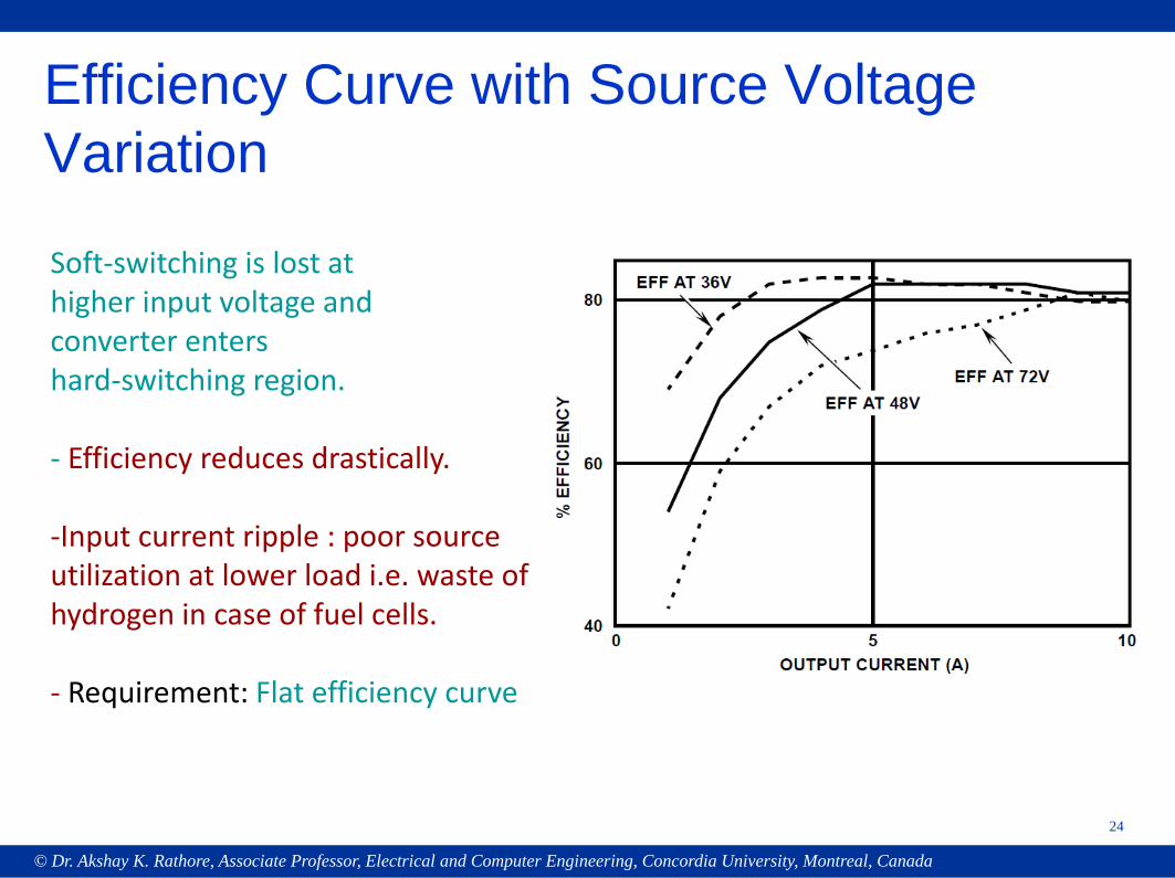
Soft-switching is lost at higher input voltage and converter enters hard-switching region.
- Efficiency reduces drastically.
-Input current ripple : poor source utilization at lower load i.e. waste of hydrogen in case of fuel cells.
- Requirement: Flat efficiency curve
24
Efficiency Curve with Source Voltage Variation
© Dr. Akshay K. Rathore, Associate Professor, Electrical and Computer Engineering, Concordia University, Montreal, Canada
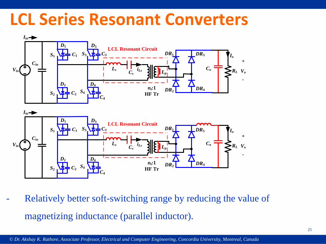
LCL Series Resonant Converters
RLLs
nt:1HF Tr
DR2
Co
Io
Vo
DR1 DR3
DR4
iLsVin
Cin
S2
D2
C2
Iin
+
-
S1
D1
C1 S3
D3
C3
S4
D4
C4
Cs Lp
LCL Resonant Circuit
25
RLLs
nt:1HF Tr
DR2
Co
Io
Vo
DR1 DR3
DR4
iLsVin
Cin
S2
D2
C2
Iin
+
-
S1
D1
C1 S3
D3
C3
S4
D4
C4
Cs Lp
LCL Resonant Circuit
- Relatively better soft-switching range by reducing the value of
magnetizing inductance (parallel inductor).
© Dr. Akshay K. Rathore, Associate Professor, Electrical and Computer Engineering, Concordia University, Montreal, Canada
26
Modulation Technique (PWM Converters)-Simple control to implement
Auxiliary Transition Circuit (ZCT and ZVT)-Additional components including switches and driver
Resonance (Resonant Converters)-Design is tricky-Optimization is needed-Analysis and control is relatively complex- Peak and circulating currents
© Dr. Akshay K. Rathore, Associate Professor, Electrical and Computer Engineering, Concordia University, Montreal, Canada
27
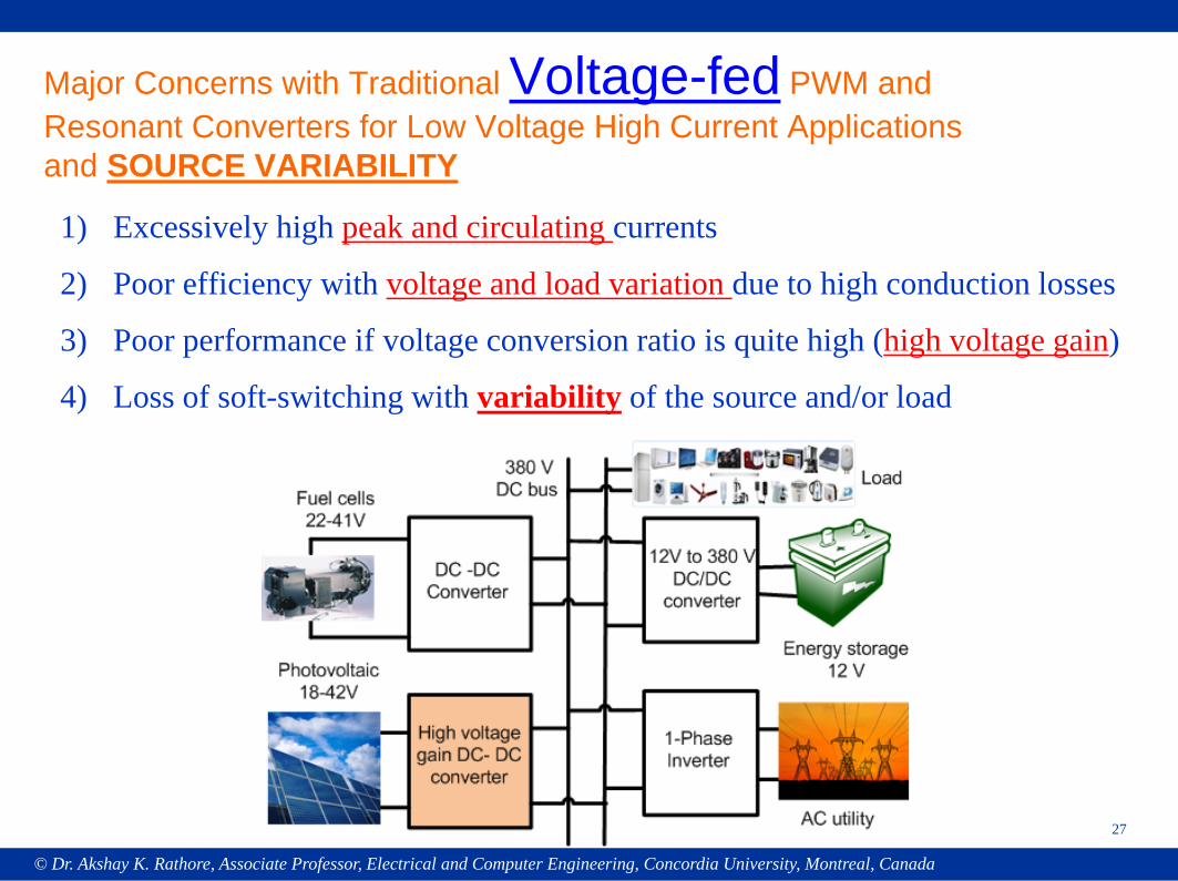
Major Concerns with Traditional Voltage-fed PWM and Resonant Converters for Low Voltage High Current Applicationsand SOURCE VARIABILITY
1) Excessively high peak and circulating currents
2) Poor efficiency with voltage and load variation due to high conduction losses
3) Poor performance if voltage conversion ratio is quite high (high voltage gain)
4) Loss of soft-switching with variability of the source and/or load
© Dr. Akshay K. Rathore, Associate Professor, Electrical and Computer Engineering, Concordia University, Montreal, Canada
28
Low Voltage High Current Applications
1) Excessively high peak currents, circulating currents2) Poor efficiency with voltage and load variation due to high
conduction losses3) Poor performance if voltage conversion ratio is quite high
© Dr. Akshay K. Rathore, Associate Professor, Electrical and Computer Engineering, Concordia University, Montreal, Canada
29
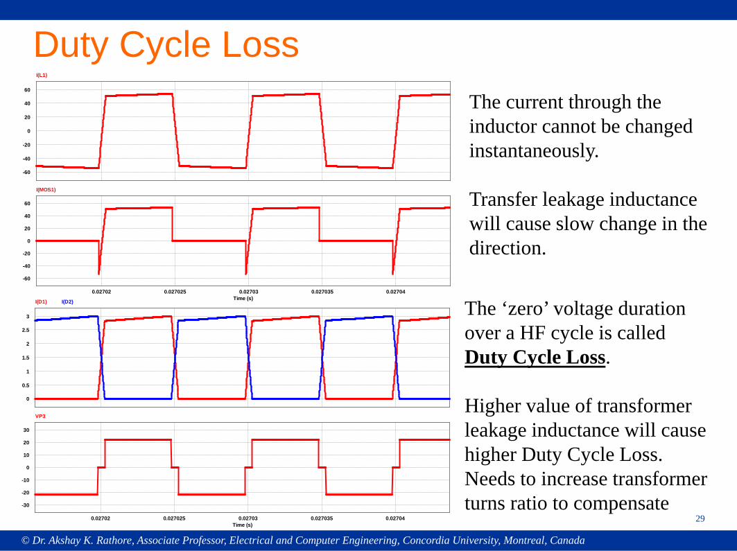
Duty Cycle Loss
0
-20
-40
-60
20
40
60
I(L1)
0.02702 0.027025 0.02703 0.027035 0.02704Time (s)
0
-20
-40
-60
20
40
60
I(MOS1)
0
0.5
1
1.5
2
2.5
3
I(D1) I(D2)
0.02702 0.027025 0.02703 0.027035 0.02704Time (s)
0
-10
-20
-30
10
20
30
VP3
The ‘zero’ voltage duration over a HF cycle is called Duty Cycle Loss.
Higher value of transformer leakage inductance will cause higher Duty Cycle Loss.Needs to increase transformer turns ratio to compensate
The current through the inductor cannot be changed instantaneously.
Transfer leakage inductance will cause slow change in the direction.
© Dr. Akshay K. Rathore, Associate Professor, Electrical and Computer Engineering, Concordia University, Montreal, Canada
30
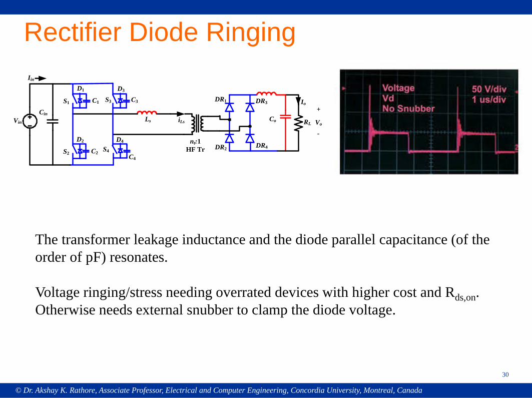
Rectifier Diode Ringing
The transformer leakage inductance and the diode parallel capacitance (of the order of pF) resonates.
Voltage ringing/stress needing overrated devices with higher cost and Rds,on. Otherwise needs external snubber to clamp the diode voltage.
RLLs
nt:1HF Tr DR2
Co
Io
Vo
DR1 DR3
DR4
iLsVin
Cin
S2
D2
C2
Iin
+
-
S1
D1
C1 S3
D3
C3
S4
D4
C4
© Dr. Akshay K. Rathore, Associate Professor, Electrical and Computer Engineering, Concordia University, Montreal, Canada
31
Current-Fed Converters-Issues
© Dr. Akshay K. Rathore, Associate Professor, Electrical and Computer Engineering, Concordia University, Montreal, Canada
32
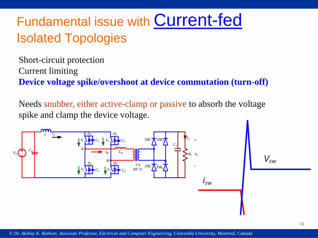
Fundamental issue with Current-fed Isolated TopologiesShort-circuit protectionCurrent limitingDevice voltage spike/overshoot at device commutation (turn-off)
Needs snubber, either active-clamp or passive to absorb the voltage spike and clamp the device voltage.
RL
S4
Llk
1:nHF Tr
DR2
Co
Io
Vo
DR1 DR3
DR4
D4
C4
ilkVinCin
S2
D2
C2
L iin
+
-
A
B
S1
D1
C1 S3
D3
C3
© Dr. Akshay K. Rathore, Associate Professor, Electrical and Computer Engineering, Concordia University, Montreal, Canada
33
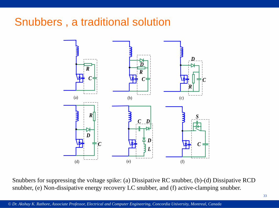
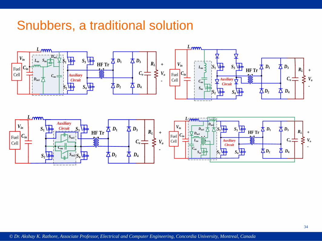
Snubbers , a traditional solution
LD
DC
D
CR
C
R
S
C
CRD
(a) (b) (c)
(e) (f)
DC
(d)
R
Snubbers for suppressing the voltage spike: (a) Dissipative RC snubber, (b)-(d) Dissipative RCD snubber, (e) Non-dissipative energy recovery LC snubber, and (f) active-clamping snubber.
© Dr. Akshay K. Rathore, Associate Professor, Electrical and Computer Engineering, Concordia University, Montreal, Canada
34
Snubbers, a traditional solution
RLHF TrCo Vo
Vin+
-
S1
S2 S4
S3 D1
Fuel Cell
D2
D3
D4
Cin
L
Cau
Lau
Dau1
Sau
Dau2
Auxiliary Circuit
RLHF TrCo Vo
Vin+
-
S1
S2 S4
S3 D1
Fuel Cell
D2
D3
D4
Cin
L
Lau
Cau
Sau
Auxiliary Circuit
RLHF TrCo Vo
Vin+
-
S1
S2 S4
S3 D1
Fuel Cell
D2
D3
D4
Cin
L
Cau
Sau1
Auxiliary Circuit
Sau2
RLHF TrCo Vo
Vin+
-
S1
S2 S4
S3 D1
Fuel Cell
D2
D3
D4
Cin
L
Cau
Lau
Dau1
Sau
Dau2
Dau3
Auxiliary Circuit
© Dr. Akshay K. Rathore, Associate Professor, Electrical and Computer Engineering, Concordia University, Montreal, Canada
35
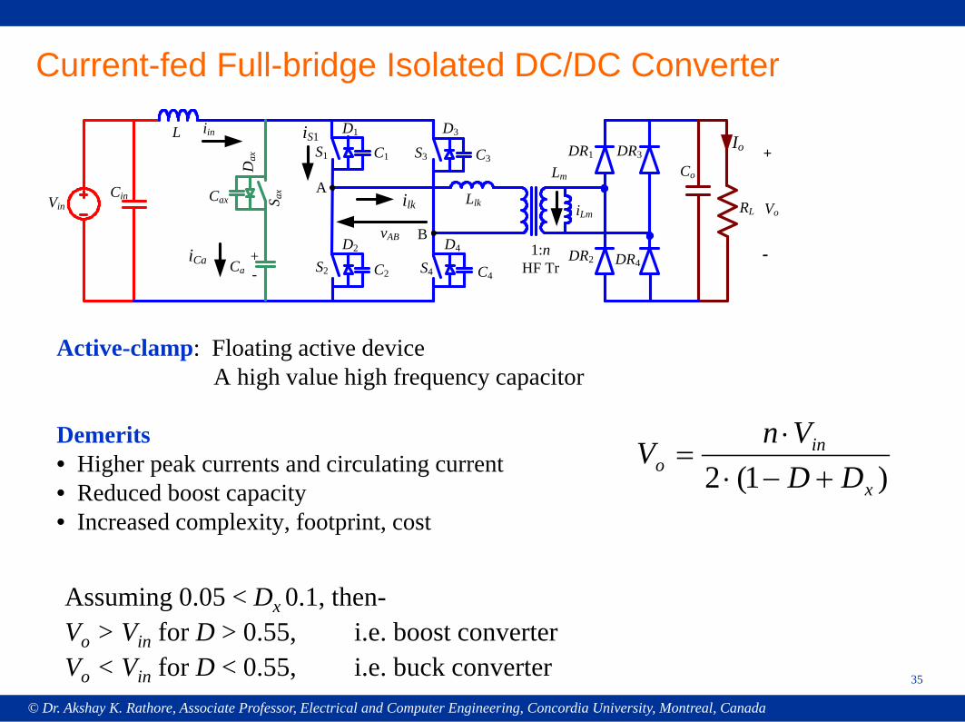
Current-fed Full-bridge Isolated DC/DC Converter
RL
S4
Llk
1:nHF Tr
DR2
Co
Io
Vo
DR1 DR3
DR4
D4
C4
ilkVinCin
S2
D2
C2
L iin
Cax
Ca
+
-S a
x
Dax
+-
Lm
iLm
iS1
A
BvAB
S1
D1
C1 S3
D3
C3
iCa
Assuming 0.05 < Dx 0.1, then-Vo > Vin for D > 0.55, i.e. boost converterVo < Vin for D < 0.55, i.e. buck converter
)1(2 x
ino DD
VnV
+−⋅⋅
=
Active-clamp: Floating active deviceA high value high frequency capacitor
Demerits • Higher peak currents and circulating current • Reduced boost capacity • Increased complexity, footprint, cost
© Dr. Akshay K. Rathore, Associate Professor, Electrical and Computer Engineering, Concordia University, Montreal, Canada
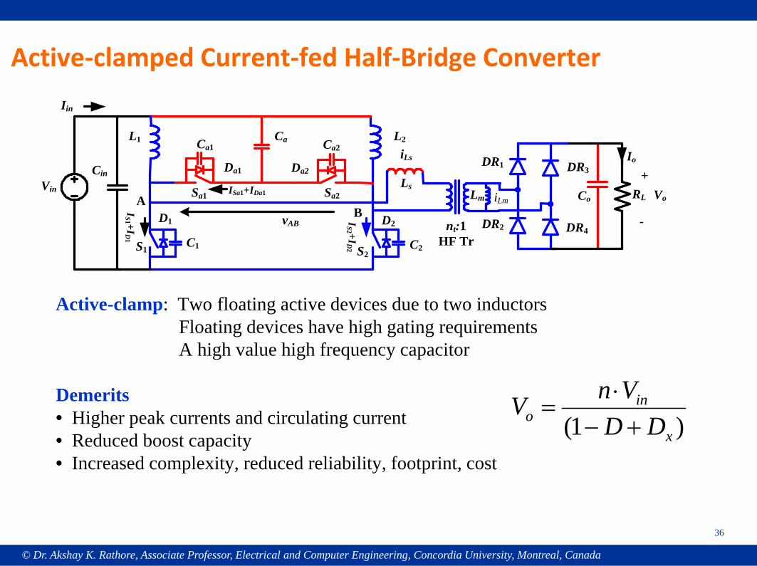
Active-clamped Current-fed Half-Bridge Converter
RL
S2
Ls
nt:1HF Tr
DR2
Co
Io
Vo
DR1 DR3
DR4D2
C2
iLs
Vin
Cin
S1
D1
C1
L1 L2
Iin
Ca1
Sa1
Da1
Ca2
Sa2
Da2
Ca
+
-A
BvAB
IS1 +ID1
IS2 +ID2
ISa1+IDa1 iLmLm
36
Active-clamp: Two floating active devices due to two inductorsFloating devices have high gating requirementsA high value high frequency capacitor
Demerits • Higher peak currents and circulating current • Reduced boost capacity • Increased complexity, reduced reliability, footprint, cost
)1( x
ino DD
VnV+−⋅
=
© Dr. Akshay K. Rathore, Associate Professor, Electrical and Computer Engineering, Concordia University, Montreal, Canada
37
“Naturally Clamped Snubberless” A New Class of Current-fed
Converter Topologies
Dr. Pan XueweiAssociate ProfessorHarbin Institute of Technology, China
Dr. Prasanna RajagopalTexas Instruments, Dallas, USA
© Dr. Akshay K. Rathore, Associate Professor, Electrical and Computer Engineering, Concordia University, Montreal, Canada
38
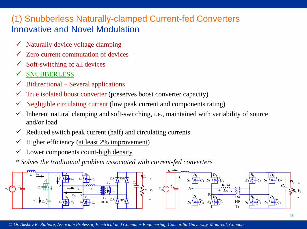
(1) Snubberless Naturally-clamped Current-fed ConvertersInnovative and Novel Modulation Naturally device voltage clamping Zero current commutation of devices Soft-switching of all devices SNUBBERLESS Bidirectional – Several applications True isolated boost converter (preserves boost converter capacity) Negligible circulating current (low peak current and components rating) Inherent natural clamping and soft-switching, i.e., maintained with variability of source
and/or load Reduced switch peak current (half) and circulating currents Higher efficiency (at least 2% improvement) Lower components count-high density* Solves the traditional problem associated with current-fed converters
RL
S4
Llk
1:nHF Tr
DR2
Co
Io
Vo
DR1 DR3
DR4
D4
C4
ilkVinCin
S2
D2
C2
L iin
Cax
Ca
+
-
S ax
Dax
+-
Lm
iLm
iS1
A
BvAB
S1
D1
C1 S3
D3
C3
iCa
© Dr. Akshay K. Rathore, Associate Professor, Electrical and Computer Engineering, Concordia University, Montreal, Canada
39
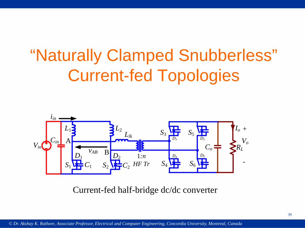
“Naturally Clamped Snubberless” Current-fed Topologies
RL
S2
Llk
1:nHF Tr
Co
Io
Vo
C2
VinCin
S1 C1
L1 L2
iin
+
-
ABvAB
S5
S6
D1 D2
S3
S4
D3
D4
D5
D6
Current-fed half-bridge dc/dc converter
© Dr. Akshay K. Rathore, Associate Professor, Electrical and Computer Engineering, Concordia University, Montreal, Canada
40
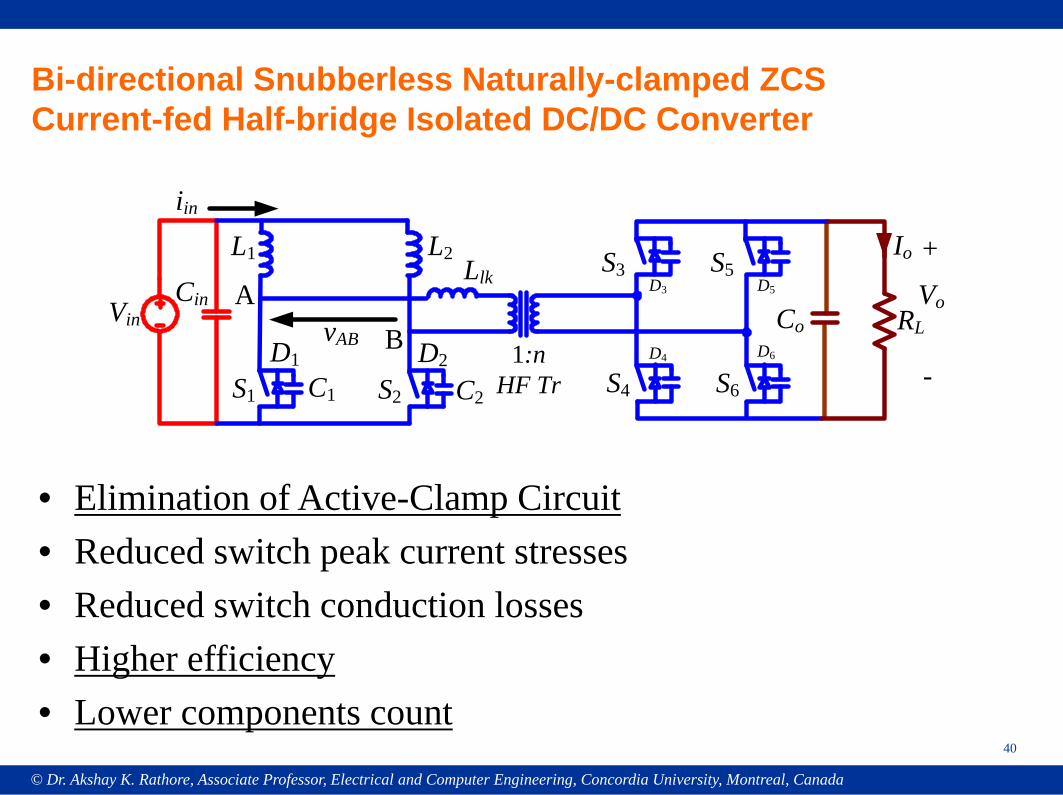
Bi-directional Snubberless Naturally-clamped ZCS Current-fed Half-bridge Isolated DC/DC Converter
RL
S2
Llk
1:nHF Tr
Co
Io
Vo
C2
VinCin
S1 C1
L1 L2
iin
+
-
ABvAB
S5
S6
D1 D2
S3
S4
D3
D4
D5
D6
• Elimination of Active-Clamp Circuit• Reduced switch peak current stresses• Reduced switch conduction losses• Higher efficiency• Lower components count
© Dr. Akshay K. Rathore, Associate Professor, Electrical and Computer Engineering, Concordia University, Montreal, Canada
41
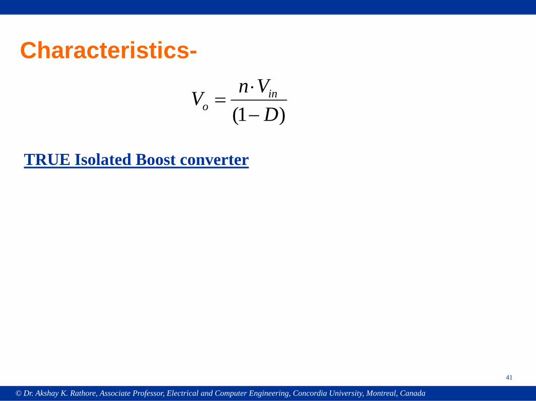
Characteristics-
TRUE Isolated Boost converter
)1( DVnV in
o −⋅
=
© Dr. Akshay K. Rathore, Associate Professor, Electrical and Computer Engineering, Concordia University, Montreal, Canada
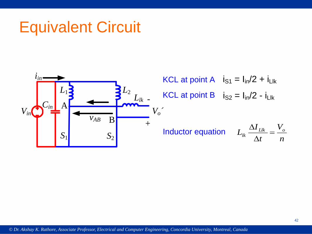
Equivalent Circuit
S2
Llk
Vo´VinCin
S1
L1 L2
iin
+
-A
BvAB
iS1 = Iin/2 + iLlk
iS2 = Iin/2 - iLlk
KCL at point A
KCL at point B
Inductor equationn
Vt
IL oLlklk =
∆∆
42
© Dr. Akshay K. Rathore, Associate Professor, Electrical and Computer Engineering, Concordia University, Montreal, Canada
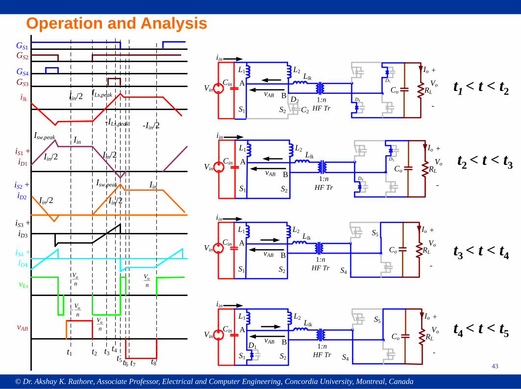
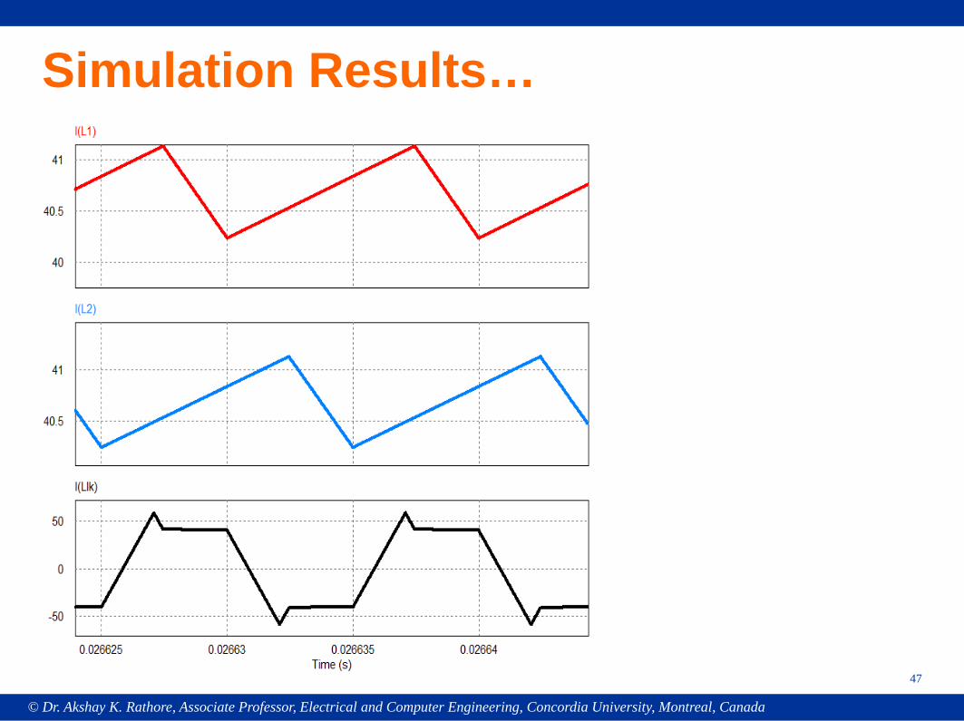
Operation and AnalysisGS1
GS3
GS2
GS4
iS1 + iD1
t1 t2 t3t4
t5 t6 t7 t8
Iin/2
ilk Iin/2
-Iin/2
vAB
vLs
Iin/2
ILs,peak
iS2 + iD2
-ILs,peak
Iin
Iin/2
Iin
Isw,peak
iS3 + iD3
iS4 + iD4
nVo
nVo
nVo−
nVo
Iin/2
Isw,peak
RL
S2
Llk
1:nHF Tr
Co
Io
VoVinCin
S1
L1 L2
iin
+
-
ABvAB
D4
D5
RL
S2
Llk
1:nHF Tr
Co
Io
VoVinCin
S1
L1 L2
iin
+
-
ABvAB
S4
S5
RL
S2
Llk
1:nHF Tr
Co
Io
VoVinCin
S1
L1 L2
iin
+
-
ABvAB
S4
S5
D1
RL
S2
Llk
1:nHF Tr
Co
Io
Vo
C2
VinCin
S1
L1 L2
iin
+
-
ABvAB D2 D4
D5 t1 < t < t2
t2 < t < t3
t3 < t < t4
t4 < t < t5
43

© Dr. Akshay K. Rathore, Associate Professor, Electrical and Computer Engineering, Concordia University, Montreal, Canada
Equivalent Circuit
S2
Llk
Vo´VinCin
S1
L1 L2
iin
+
-A
BvAB
iS1 = Iin/2 + iLlk
iS2 = Iin/2 - iLlk
KCL at point A
KCL at point B
Inductor equationn
Vt
IL oLlklk =
∆∆
44
© Dr. Akshay K. Rathore, Associate Professor, Electrical and Computer Engineering, Concordia University, Montreal, Canada
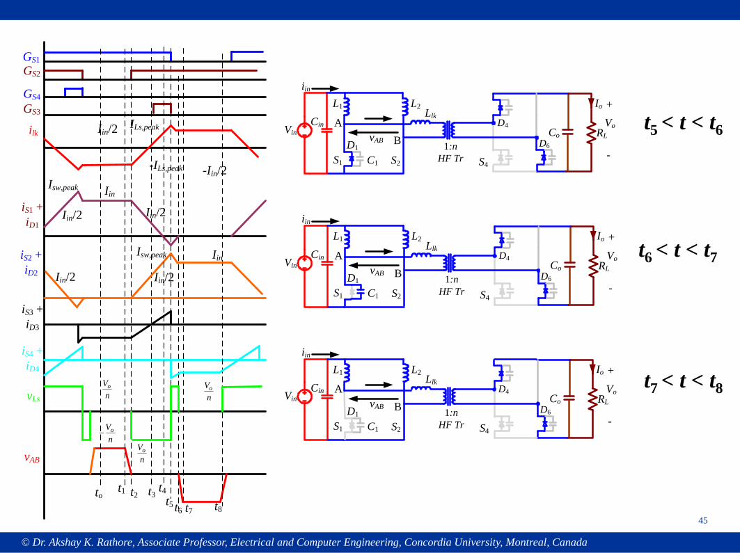
GS1
GS3
GS2
GS4
iS1 + iD1
tot1 t2 t3
t4t5 t6 t7 t8
Iin/2
ilk Iin/2
-Iin/2
vAB
vLs
Iin/2
ILs,peak
iS2 + iD2
-ILs,peak
Iin
Iin/2
Iin
Isw,peak
iS3 + iD3
iS4 + iD4
nVo
nVo
nVo−
nVo
Iin/2
Isw,peak
RL
S2
Llk
1:nHF Tr
Co
Io
VoVinCin
S1
L1 L2
iin
+
-
ABvAB
S4
D1
C1
D6
D4
RL
S2
Llk
1:nHF Tr
Co
Io
VoVinCin
S1
L1 L2
iin
+
-
ABvAB
S4
D1
C1
D6
D4
RL
S2
Llk
1:nHF Tr
Co
Io
VoVinCin
S1
L1 L2
iin
+
-
ABvAB
S4
D1
C1
D6
D4
t5 < t < t6
t6 < t < t7
t7 < t < t8
45
© Dr. Akshay K. Rathore, Associate Professor, Electrical and Computer Engineering, Concordia University, Montreal, Canada
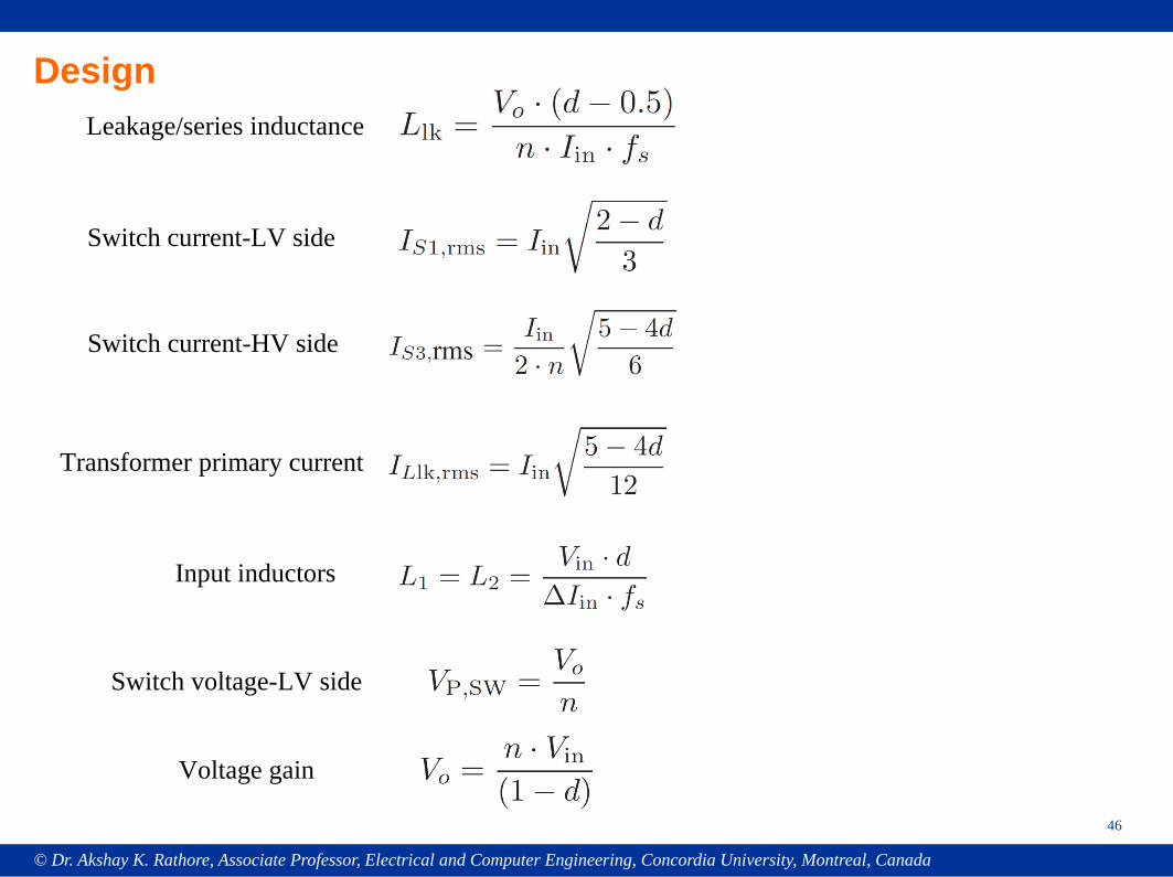
Design
46
Leakage/series inductance
Switch current-LV side
Switch current-HV side
Transformer primary current
Input inductors
Switch voltage-LV side
Voltage gain
© Dr. Akshay K. Rathore, Associate Professor, Electrical and Computer Engineering, Concordia University, Montreal, Canada
Simulation Results…
47
© Dr. Akshay K. Rathore, Associate Professor, Electrical and Computer Engineering, Concordia University, Montreal, Canada
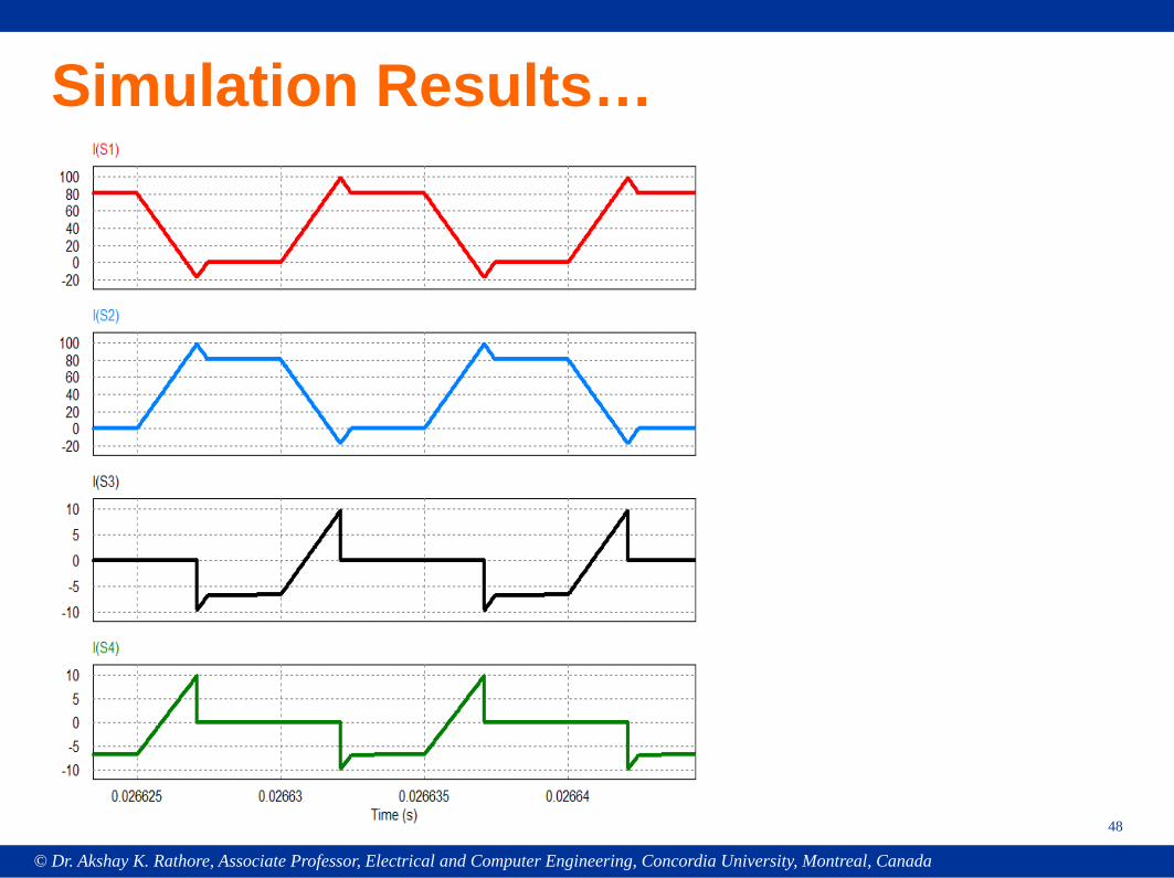
Simulation Results…
48
© Dr. Akshay K. Rathore, Associate Professor, Electrical and Computer Engineering, Concordia University, Montreal, Canada
49
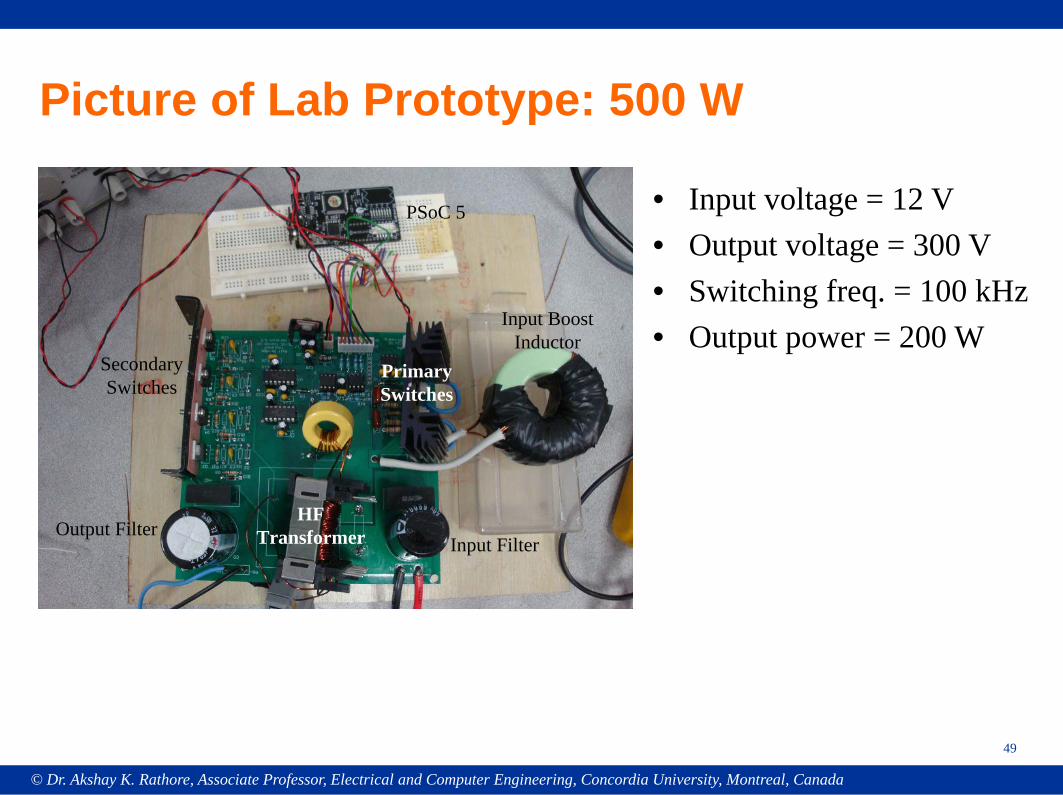
Picture of Lab Prototype: 500 W
Input Boost Inductor
PSoC 5
SecondarySwitches
Input FilterOutput Filter
HF Transformer
Primary Switches
• Input voltage = 12 V• Output voltage = 300 V• Switching freq. = 100 kHz• Output power = 200 W
© Dr. Akshay K. Rathore, Associate Professor, Electrical and Computer Engineering, Concordia University, Montreal, Canada
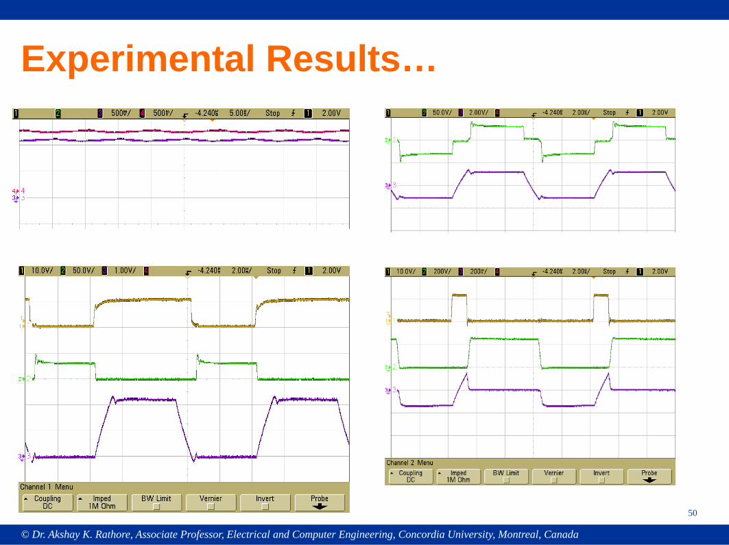
Experimental Results…
50
© Dr. Akshay K. Rathore, Associate Professor, Electrical and Computer Engineering, Concordia University, Montreal, Canada
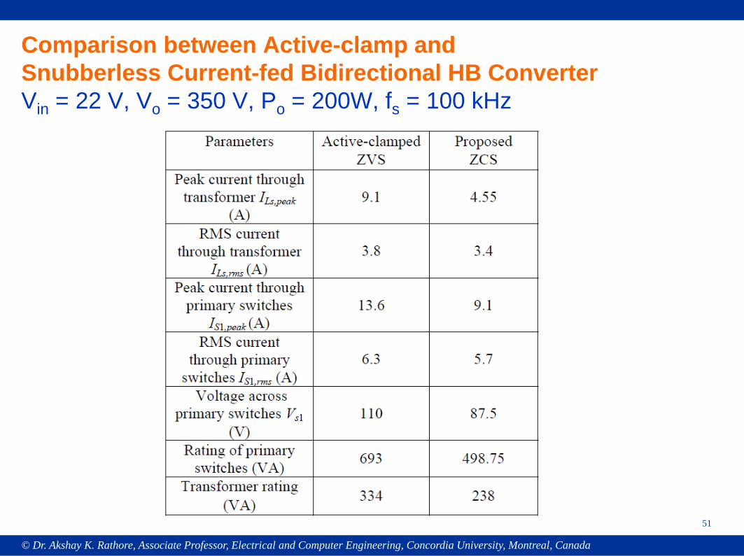
Comparison between Active-clamp and Snubberless Current-fed Bidirectional HB ConverterVin = 22 V, Vo = 350 V, Po = 200W, fs = 100 kHz
51
© Dr. Akshay K. Rathore, Associate Professor, Electrical and Computer Engineering, Concordia University, Montreal, Canada
52
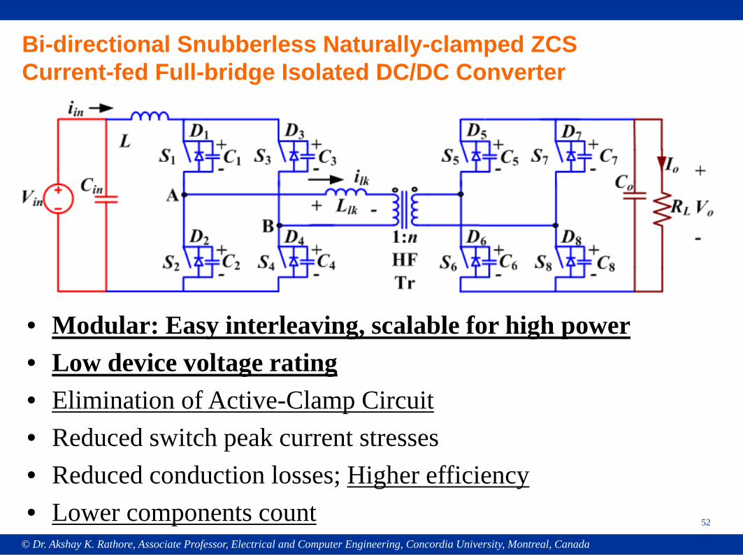
Bi-directional Snubberless Naturally-clamped ZCS Current-fed Full-bridge Isolated DC/DC Converter
• Modular: Easy interleaving, scalable for high power• Low device voltage rating• Elimination of Active-Clamp Circuit• Reduced switch peak current stresses• Reduced conduction losses; Higher efficiency• Lower components count
© Dr. Akshay K. Rathore, Associate Professor, Electrical and Computer Engineering, Concordia University, Montreal, Canada
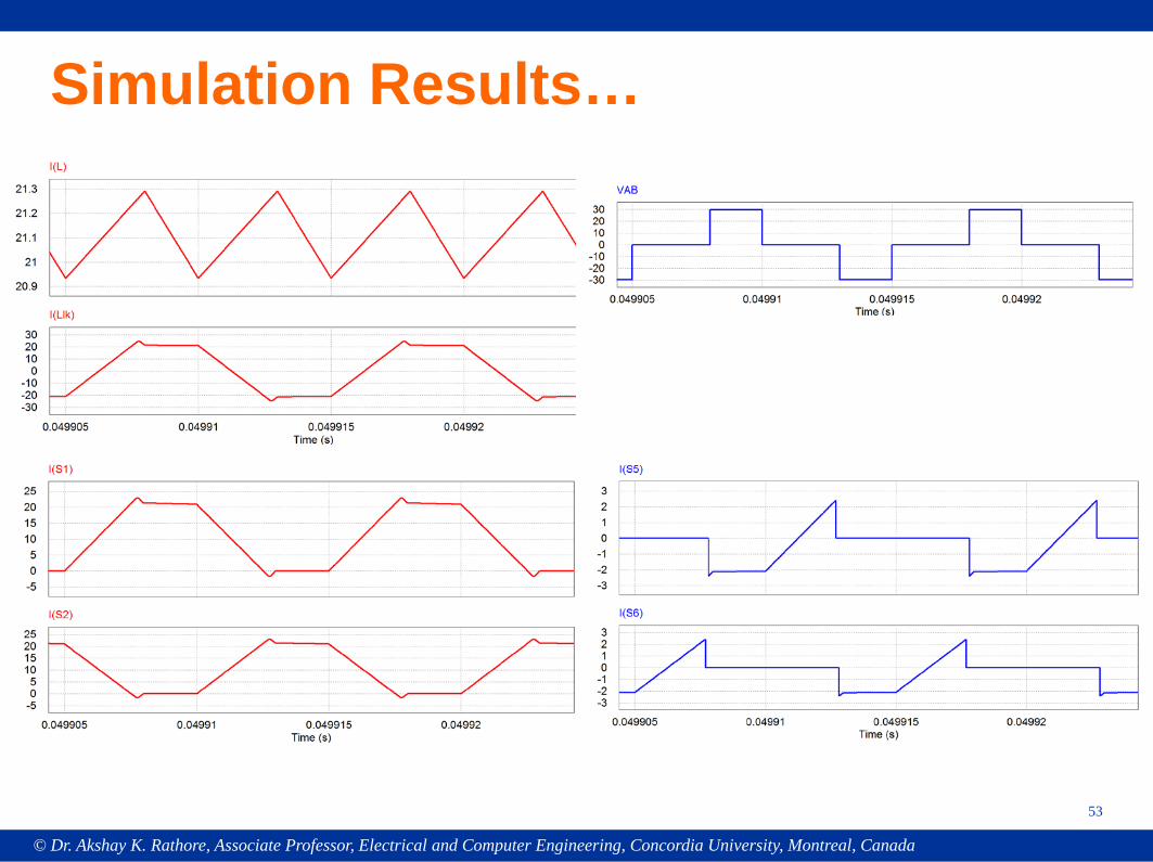
Simulation Results…
53
© Dr. Akshay K. Rathore, Associate Professor, Electrical and Computer Engineering, Concordia University, Montreal, Canada
54
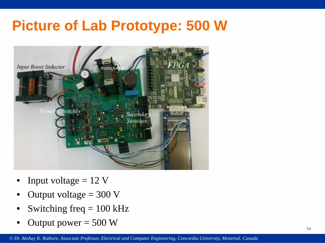
Picture of Lab Prototype: 500 W
• Input voltage = 12 V• Output voltage = 300 V• Switching freq = 100 kHz• Output power = 500 W
© Dr. Akshay K. Rathore, Associate Professor, Electrical and Computer Engineering, Concordia University, Montreal, Canada
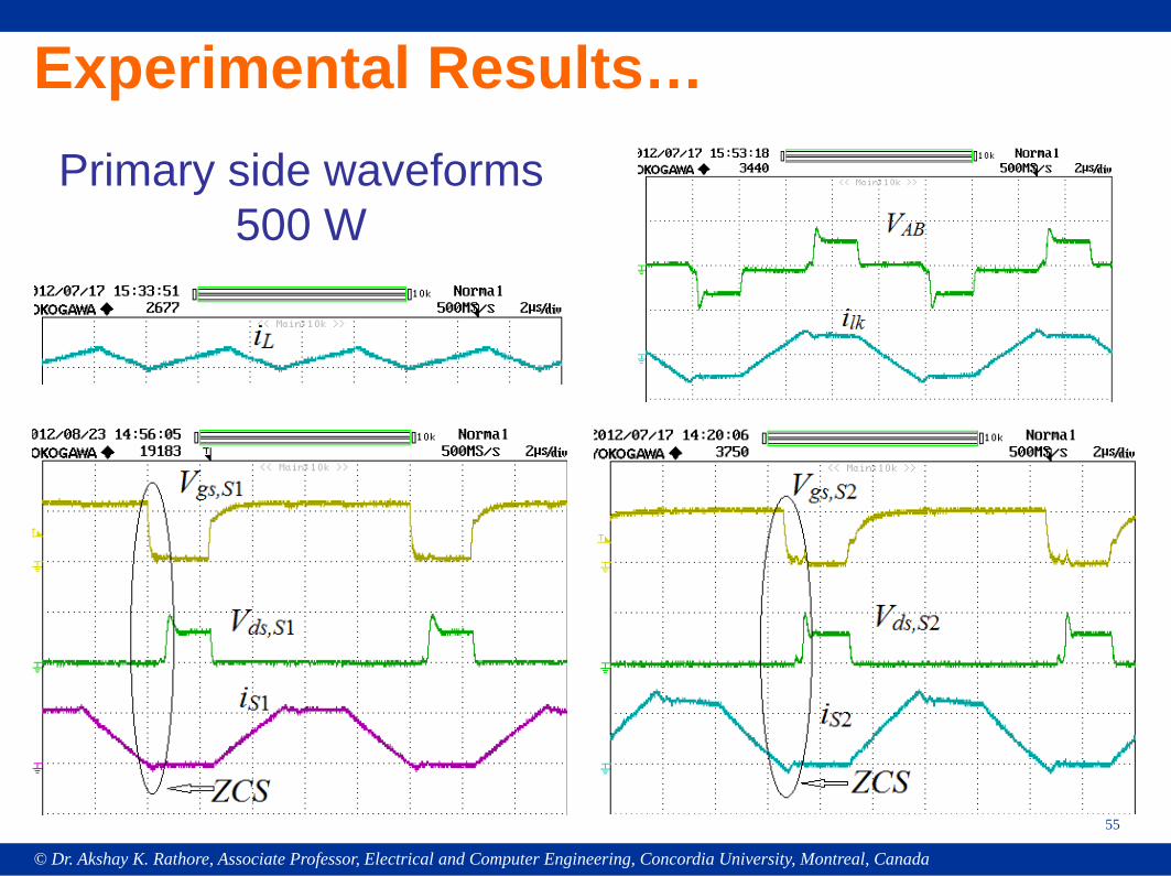
Experimental Results…
55
Primary side waveforms500 W
© Dr. Akshay K. Rathore, Associate Professor, Electrical and Computer Engineering, Concordia University, Montreal, Canada
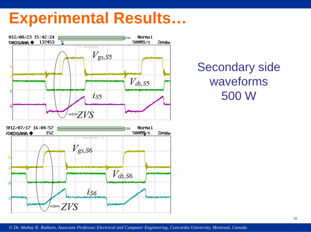
Experimental Results…
56
Secondary side waveforms
500 W
© Dr. Akshay K. Rathore, Associate Professor, Electrical and Computer Engineering, Concordia University, Montreal, Canada
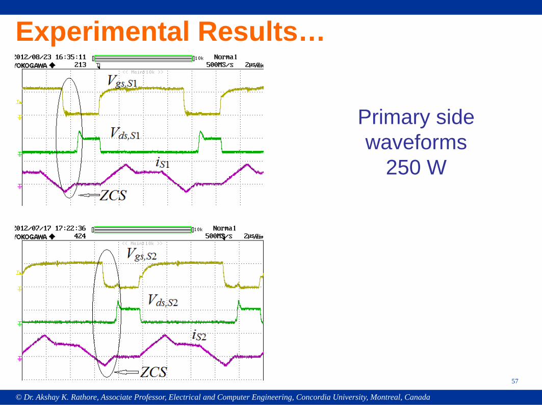
Experimental Results…
57
Primary side waveforms
250 W
© Dr. Akshay K. Rathore, Associate Professor, Electrical and Computer Engineering, Concordia University, Montreal, Canada
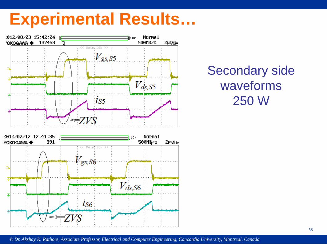
Experimental Results…
58
Secondary side waveforms
250 W
© Dr. Akshay K. Rathore, Associate Professor, Electrical and Computer Engineering, Concordia University, Montreal, Canada
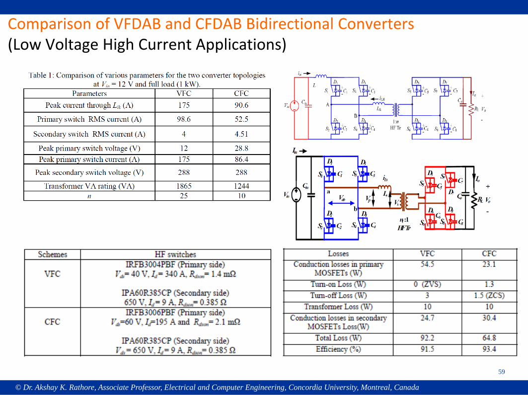
Comparison of VFDAB and CFDAB Bidirectional Converters(Low Voltage High Current Applications)
59
© Dr. Akshay K. Rathore, Associate Professor, Electrical and Computer Engineering, Concordia University, Montreal, Canada
60
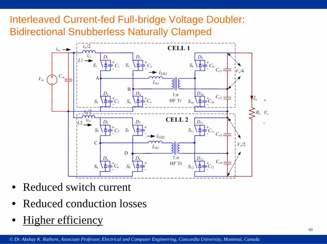
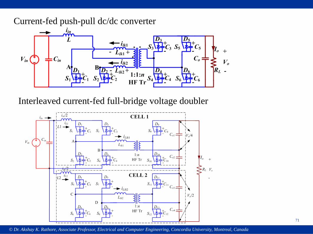
Interleaved Current-fed Full-bridge Voltage Doubler: Bidirectional Snubberless Naturally Clamped
• Reduced switch current • Reduced conduction losses• Higher efficiency
© Dr. Akshay K. Rathore, Associate Professor, Electrical and Computer Engineering, Concordia University, Montreal, Canada
61
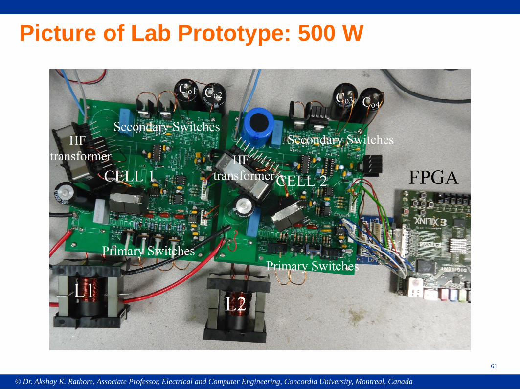
Picture of Lab Prototype: 500 W
© Dr. Akshay K. Rathore, Associate Professor, Electrical and Computer Engineering, Concordia University, Montreal, Canada
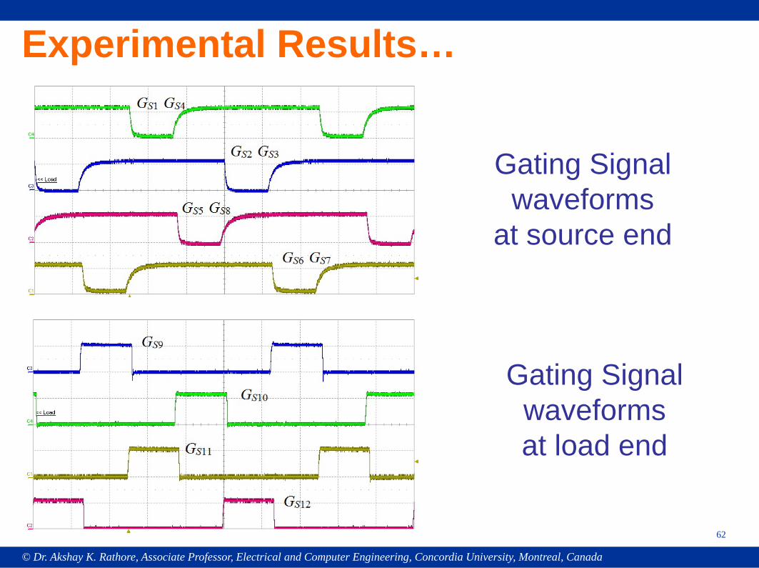
Experimental Results…
62
Gating Signal waveforms
at source end
Gating Signal waveforms at load end
© Dr. Akshay K. Rathore, Associate Professor, Electrical and Computer Engineering, Concordia University, Montreal, Canada
Experimental Results…
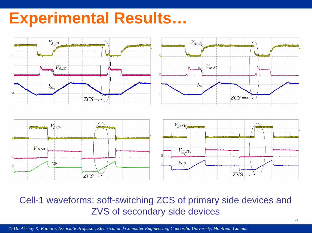
63
Cell-1 waveforms: soft-switching ZCS of primary side devices and ZVS of secondary side devices
© Dr. Akshay K. Rathore, Associate Professor, Electrical and Computer Engineering, Concordia University, Montreal, Canada
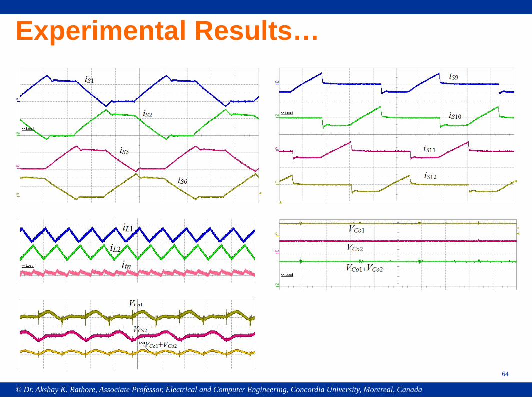
Experimental Results…
64
© Dr. Akshay K. Rathore, Associate Professor, Electrical and Computer Engineering, Concordia University, Montreal, Canada
Experimental Results…
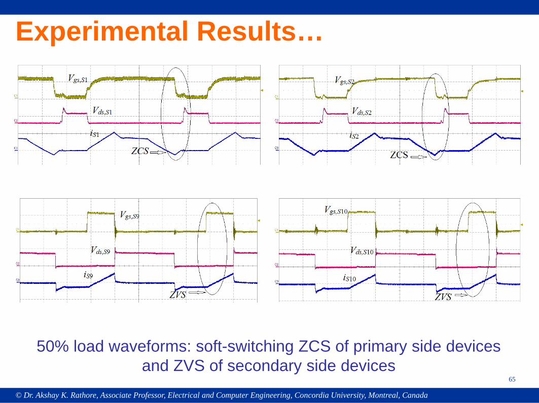
65
50% load waveforms: soft-switching ZCS of primary side devices and ZVS of secondary side devices
© Dr. Akshay K. Rathore, Associate Professor, Electrical and Computer Engineering, Concordia University, Montreal, Canada
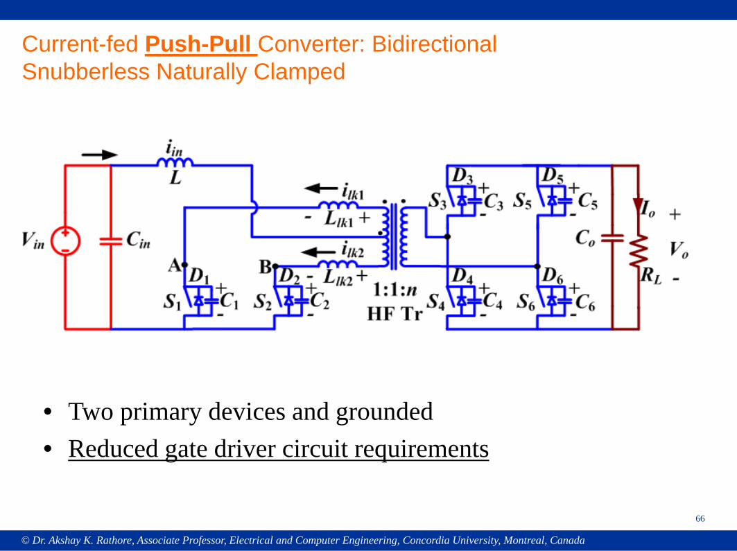
66
Current-fed Push-Pull Converter: Bidirectional Snubberless Naturally Clamped
• Two primary devices and grounded• Reduced gate driver circuit requirements
© Dr. Akshay K. Rathore, Associate Professor, Electrical and Computer Engineering, Concordia University, Montreal, Canada
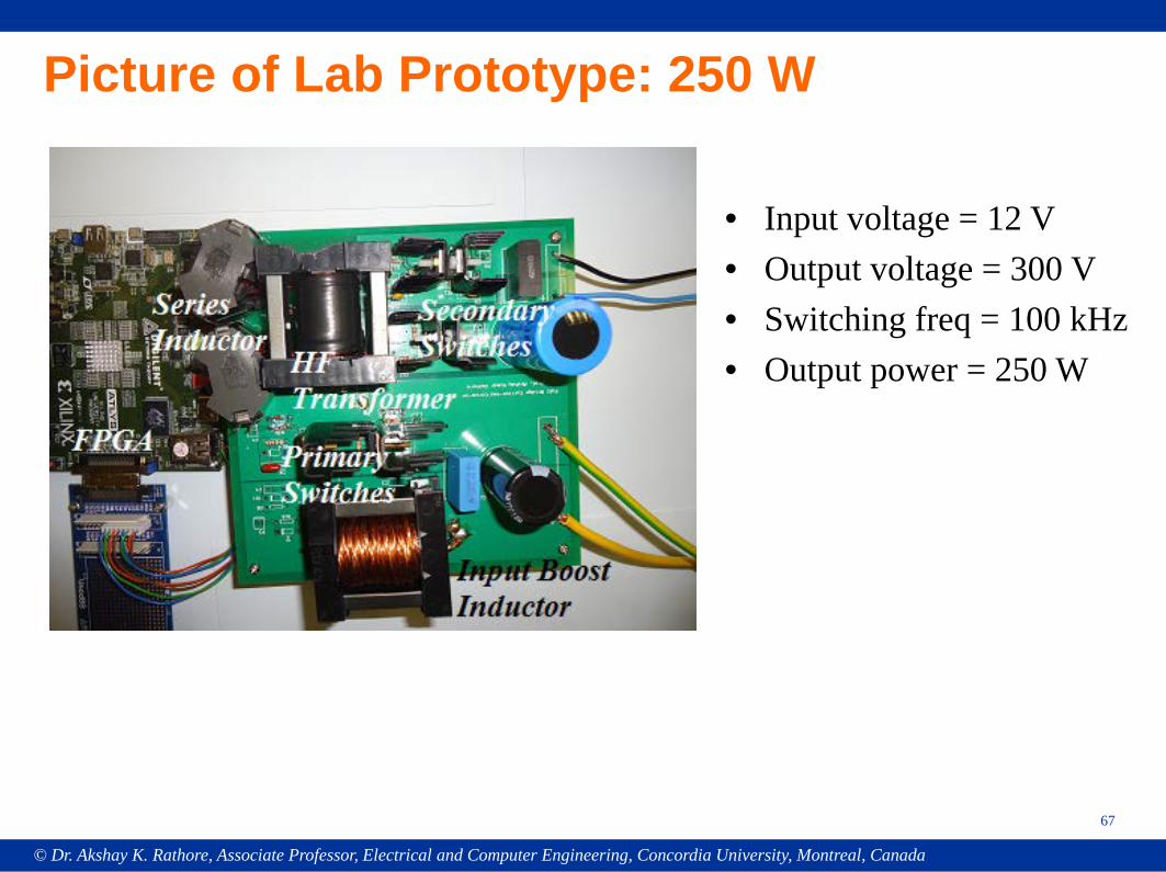
67
Picture of Lab Prototype: 250 W
• Input voltage = 12 V• Output voltage = 300 V• Switching freq = 100 kHz• Output power = 250 W
© Dr. Akshay K. Rathore, Associate Professor, Electrical and Computer Engineering, Concordia University, Montreal, Canada
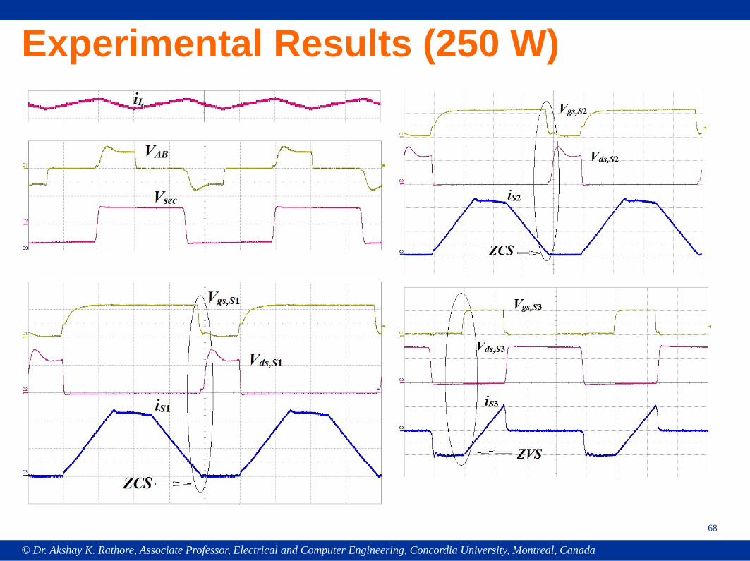
Experimental Results (250 W)
68
© Dr. Akshay K. Rathore, Associate Professor, Electrical and Computer Engineering, Concordia University, Montreal, Canada
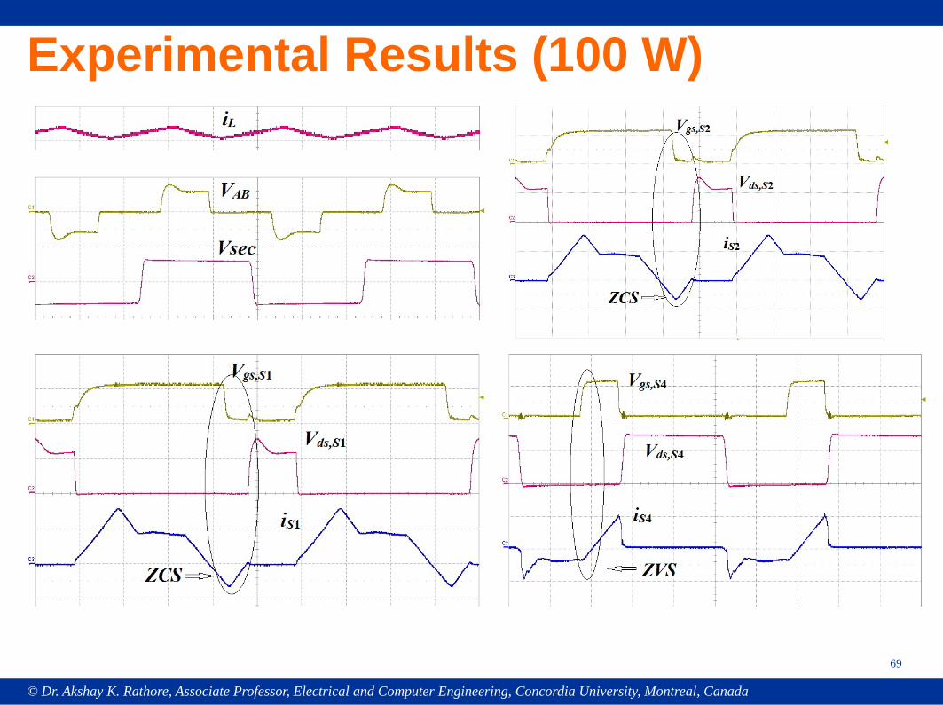
Experimental Results (100 W)
69
© Dr. Akshay K. Rathore, Associate Professor, Electrical and Computer Engineering, Concordia University, Montreal, Canada
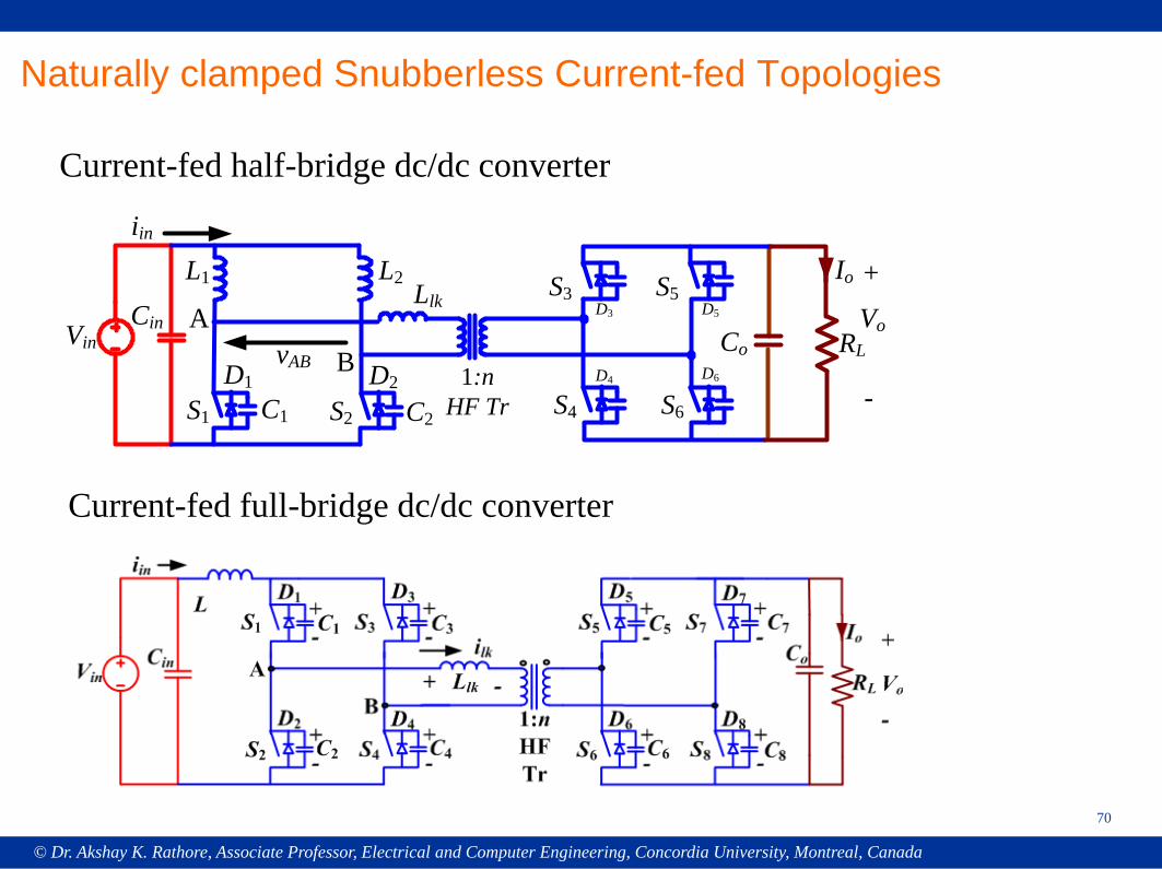
70
Naturally clamped Snubberless Current-fed Topologies
RL
S2
Llk
1:nHF Tr
Co
Io
Vo
C2
VinCin
S1 C1
L1 L2
iin
+
-
ABvAB
S5
S6
D1 D2
S3
S4
D3
D4
D5
D6
Current-fed half-bridge dc/dc converter
Current-fed full-bridge dc/dc converter
© Dr. Akshay K. Rathore, Associate Professor, Electrical and Computer Engineering, Concordia University, Montreal, Canada
71
Current-fed push-pull dc/dc converter
Interleaved current-fed full-bridge voltage doubler
© Dr. Akshay K. Rathore, Associate Professor, Electrical and Computer Engineering, Concordia University, Montreal, Canada
72
S3
Llk1
D3
C3
Vin
S1
D1
C1
L1 L3iin
S2
D2
L2
C2
Llk3
Llk2
+-
+-
+-
A
BC
+ -+ -
+ -RL
Co
Io
Vo
+
-S8
D8
C8+-
D5 +-C5
S9
D9 +-
D6
S6+-S5 C6
C9S7
D7
C7+-
D4 +-C4S4
3-PhaseHF Tr
iLlk1
iLlk2
iLlk3
S1 1:n3- Ph HF transformer
Cin
S2 S3
Iin ILlk1
ILlk2
ILlk3
Lin
Llk1
Llk2
Llk3
S5 S7 S9
S4 S6 S8 Io
Co
Ro VoVin
S6
Llk1Vin
Cin
S2
iin
S4
Llk3
Llk2
+-
+-
+-
A
BC + -
RLCo
Io
Vo
+
-S10+-
+-
S12+-
S11+-S9
S8+-
+-S7
3-PhaseHF Tr
iLlk1
iLlk2
iLlk3
+-
+-
+-S1 S3 S5
+ -+ -
L
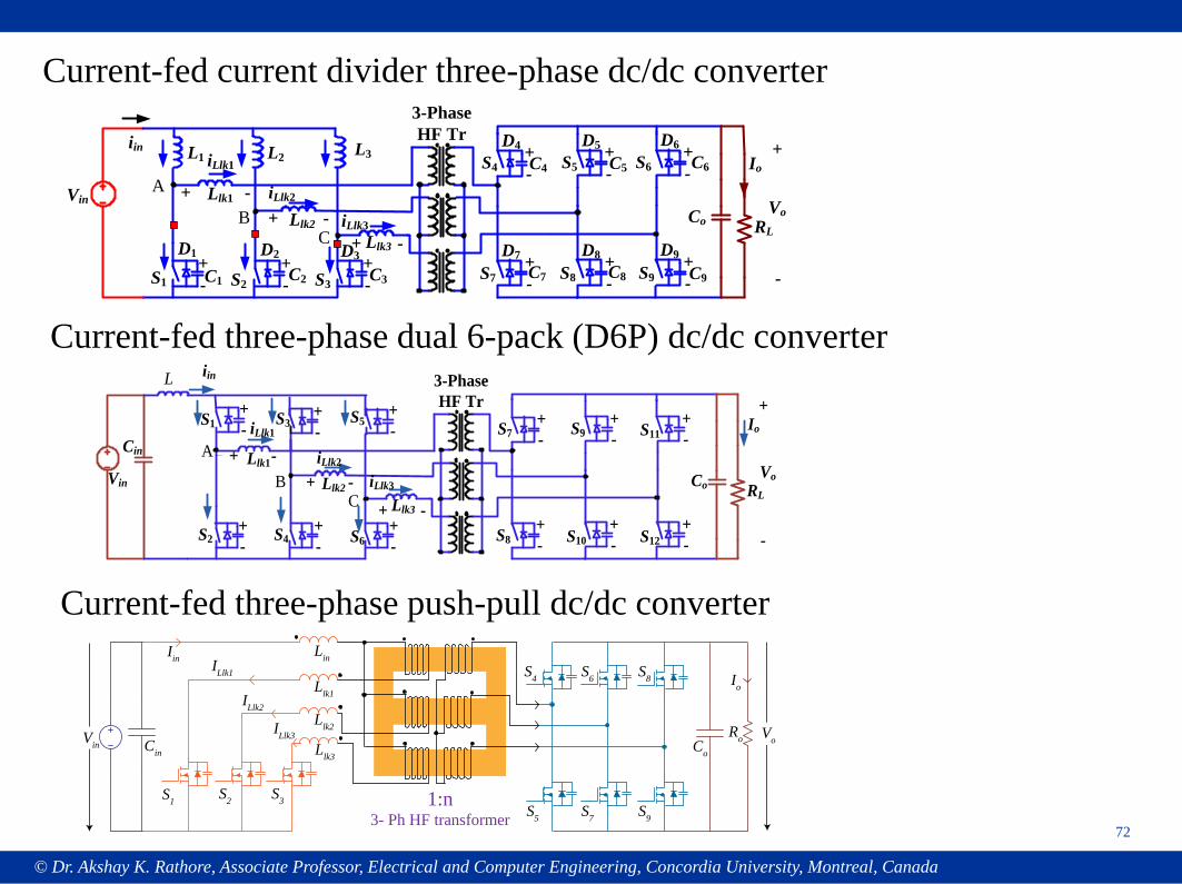
Current-fed current divider three-phase dc/dc converter
Current-fed three-phase dual 6-pack (D6P) dc/dc converter
Current-fed three-phase push-pull dc/dc converter
© Dr. Akshay K. Rathore, Associate Professor, Electrical and Computer Engineering, Concordia University, Montreal, Canada
73
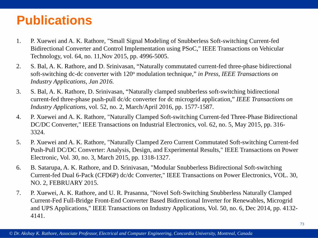
Publications1. P. Xuewei and A. K. Rathore, "Small Signal Modeling of Snubberless Soft-switching Current-fed
Bidirectional Converter and Control Implementation using PSoC," IEEE Transactions on Vehicular Technology, vol. 64, no. 11,Nov 2015, pp. 4996-5005.
2. S. Bal, A. K. Rathore, and D. Srinivasan, “Naturally commutated current-fed three-phase bidirectional soft-switching dc-dc converter with 120o modulation technique,” in Press, IEEE Transactions on Industry Applications, Jan 2016.
3. S. Bal, A. K. Rathore, D. Srinivasan, “Naturally clamped snubberless soft-switching bidirectional current-fed three-phase push-pull dc/dc converter for dc microgrid application,” IEEE Transactions on Industry Applications, vol. 52, no. 2, March/April 2016, pp. 1577-1587.
4. P. Xuewei and A. K. Rathore, "Naturally Clamped Soft-switching Current-fed Three-Phase Bidirectional DC/DC Converter," IEEE Transactions on Industrial Electronics, vol. 62, no. 5, May 2015, pp. 316-3324.
5. P. Xuewei and A. K. Rathore, "Naturally Clamped Zero Current Commutated Soft-switching Current-fed Push-Pull DC/DC Converter: Analysis, Design, and Experimental Results," IEEE Transactions on Power Electronic, Vol. 30, no. 3, March 2015, pp. 1318-1327.
6. B. Satarupa, A. K. Rathore, and D. Srinivasan, "Modular Snubberless Bidirectional Soft-switching Current-fed Dual 6-Pack (CFD6P) dc/dc Converter," IEEE Transactions on Power Electronics, VOL. 30, NO. 2, FEBRUARY 2015.
7. P. Xuewei, A. K. Rathore, and U. R. Prasanna, "Novel Soft-Switching Snubberless Naturally Clamped Current-Fed Full-Bridge Front-End Converter Based Bidirectional Inverter for Renewables, Microgrid and UPS Applications," IEEE Transactions on Industry Applications, Vol. 50, no. 6, Dec 2014, pp. 4132-4141.
© Dr. Akshay K. Rathore, Associate Professor, Electrical and Computer Engineering, Concordia University, Montreal, Canada
74
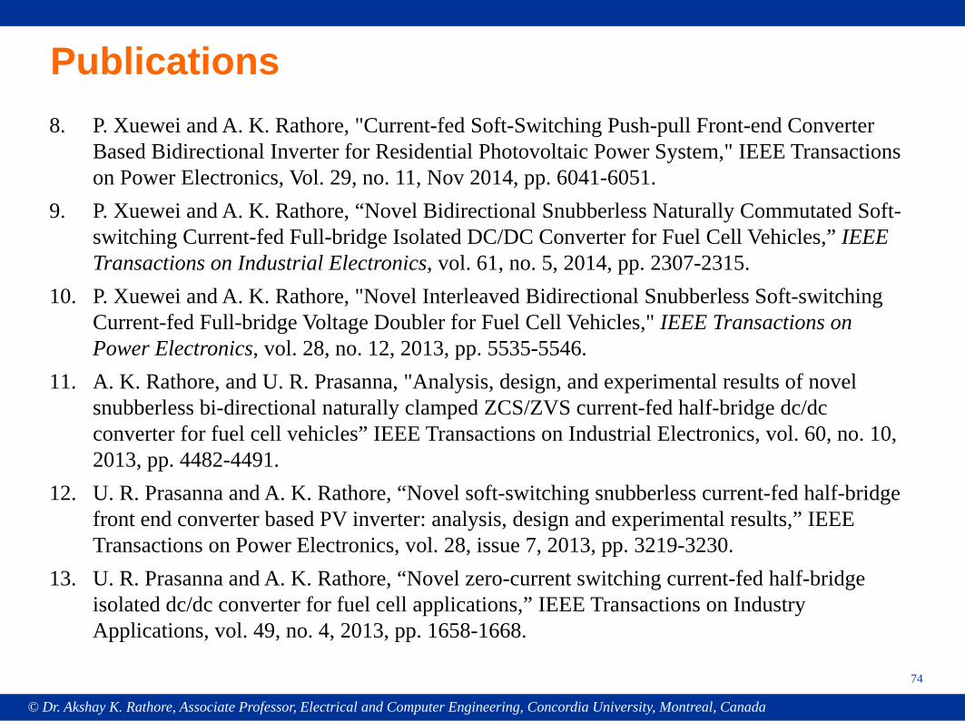
Publications8. P. Xuewei and A. K. Rathore, "Current-fed Soft-Switching Push-pull Front-end Converter
Based Bidirectional Inverter for Residential Photovoltaic Power System," IEEE Transactions on Power Electronics, Vol. 29, no. 11, Nov 2014, pp. 6041-6051.
9. P. Xuewei and A. K. Rathore, “Novel Bidirectional Snubberless Naturally Commutated Soft-switching Current-fed Full-bridge Isolated DC/DC Converter for Fuel Cell Vehicles,” IEEE Transactions on Industrial Electronics, vol. 61, no. 5, 2014, pp. 2307-2315.
10. P. Xuewei and A. K. Rathore, "Novel Interleaved Bidirectional Snubberless Soft-switching Current-fed Full-bridge Voltage Doubler for Fuel Cell Vehicles," IEEE Transactions on Power Electronics, vol. 28, no. 12, 2013, pp. 5535-5546.
11. A. K. Rathore, and U. R. Prasanna, "Analysis, design, and experimental results of novel snubberless bi-directional naturally clamped ZCS/ZVS current-fed half-bridge dc/dc converter for fuel cell vehicles” IEEE Transactions on Industrial Electronics, vol. 60, no. 10, 2013, pp. 4482-4491.
12. U. R. Prasanna and A. K. Rathore, “Novel soft-switching snubberless current-fed half-bridge front end converter based PV inverter: analysis, design and experimental results,” IEEE Transactions on Power Electronics, vol. 28, issue 7, 2013, pp. 3219-3230.
13. U. R. Prasanna and A. K. Rathore, “Novel zero-current switching current-fed half-bridge isolated dc/dc converter for fuel cell applications,” IEEE Transactions on Industry Applications, vol. 49, no. 4, 2013, pp. 1658-1668.
© Dr. Akshay K. Rathore, Associate Professor, Electrical and Computer Engineering, Concordia University, Montreal, Canada
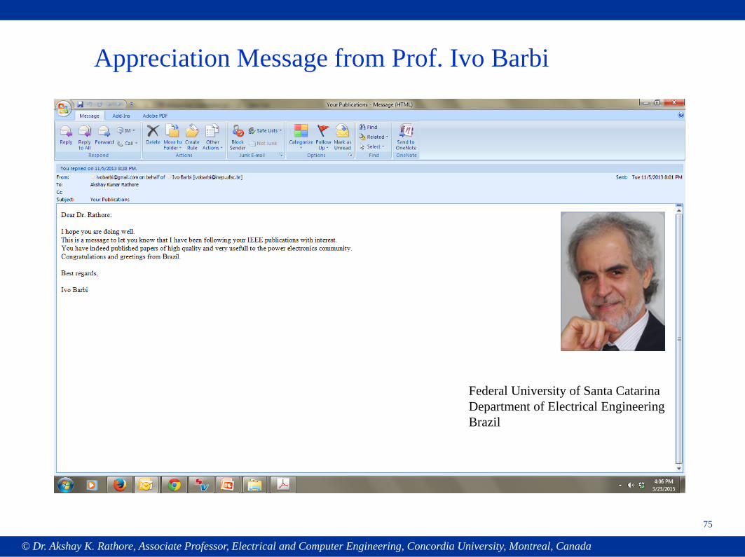
Appreciation Message from Prof. Ivo Barbi
75
Federal University of Santa CatarinaDepartment of Electrical EngineeringBrazil
© Dr. Akshay K. Rathore, Associate Professor, Electrical and Computer Engineering, Concordia University, Montreal, Canada
76
- Current-fed technologyLow voltage higher currents or high voltage gain applications
- Short circuit protection and voltage gain (built-in), and low currentrating devices
- High power density in single cell design for low voltage high currentspecifications
- Higher efficiency (performance) with wide variation in voltage and power,i.e., future deep discharge batteries for transportation, renewable powersystem, energy storage, etc.
- Full Operating Range Soft-Switching with PWM, simplified design,and control
SUMMARY
© Dr. Akshay K. Rathore, Associate Professor, Electrical and Computer Engineering, Concordia University, Montreal, Canada
77
Related Documents