Printed in Malaysia ID V274950 YAMAHA ELECTRONICS CORPORATION, USA 6660 ORANGETHORPE AVE., BUENA PARK, CALIF. 90620, U.S.A. YAMAHA CANADA MUSIC LTD. 135 MILNER AVE., SCARBOROUGH, ONTARIO M1S 3R1, CANADA YAMAHA ELECTRONIK EUROPA G.m.b.H. SIEMENSSTR. 22-34, 25462 RELLINGEN BEI HAMBURG, F.R. OF GERMANY YAMAHA ELECTRONIQUE FRANCE S.A. RUE AMBROISE CROIZAT BP70 CROISSY-BEAUBOURG 77312 MARNE-LA-VALLEE CEDEX02, FRANCE YAMAHA ELECTRONICS (UK) LTD. YAMAHA HOUSE, 200 RICKMANSWORTH ROAD WATFORD, HERTS WD1 7JS, ENGLAND YAMAHA SCANDINAVIA A.B. J A WETTERGRENS GATA 1, BOX 30053, 400 43 VÄSTRA FRÖLUNDA, SWEDEN YAMAHA MUSIC AUSTRALIA PTY, LTD. 17-33 MARKET ST., SOUTH MELBOURNE, 3205 VIC., AUSTRALIA RX-V595 RX-V595 Natural Sound AV Receiver Récepteur audiovisuel OWNER’S MANUAL MODE D’EMPLOI C A 01RX-V595-e/f cv1/4 6/23/99, 4:34 PM 1

Welcome message from author
This document is posted to help you gain knowledge. Please leave a comment to let me know what you think about it! Share it to your friends and learn new things together.
Transcript
Printed in Malaysia ID V274950
YAMAHA ELECTRONICS CORPORATION, USA 6660 ORANGETHORPE AVE., BUENA PARK, CALIF. 90620, U.S.A.YAMAHA CANADA MUSIC LTD. 135 MILNER AVE., SCARBOROUGH, ONTARIO M1S 3R1, CANADAYAMAHA ELECTRONIK EUROPA G.m.b.H. SIEMENSSTR. 22-34, 25462 RELLINGEN BEI HAMBURG, F.R. OF GERMANYYAMAHA ELECTRONIQUE FRANCE S.A. RUE AMBROISE CROIZAT BP70 CROISSY-BEAUBOURG 77312 MARNE-LA-VALLEE CEDEX02, FRANCEYAMAHA ELECTRONICS (UK) LTD. YAMAHA HOUSE, 200 RICKMANSWORTH ROAD WATFORD, HERTS WD1 7JS, ENGLANDYAMAHA SCANDINAVIA A.B. J A WETTERGRENS GATA 1, BOX 30053, 400 43 VÄSTRA FRÖLUNDA, SWEDENYAMAHA MUSIC AUSTRALIA PTY, LTD. 17-33 MARKET ST., SOUTH MELBOURNE, 3205 VIC., AUSTRALIA
RX-V
595 RX-V595
Natural Sound AV Receiver
Récepteur audiovisuel
OWNER’S MANUALMODE D’EMPLOI
C A
01RX-V595-e/f cv1/4 6/23/99, 4:34 PM1
2
SAFETY INSTRUCTIONS
1 Read Instructions – All the safety and operating instructionsshould be read before the unit is operated.
2 Retain Instructions – The safety and operating instructionsshould be retained for future reference.
3 Heed Warnings – All warnings on the unit and in theoperating instructions should be adhered to.
4 Follow Instructions – All operating and other instructionsshould be followed.
5 Water and Moisture – The unit should not be used nearwater – for example, near a bathtub, washbowl, kitchensink, laundry tub, in a wet basement, or near a swimmingpool, etc.
6 Carts and Stands – The unit should be used only with acart or stand that is recommended by themanufacturer.
6A A unit and cart combination should be movedwith care. Quick stops, excessive force, anduneven surfaces may cause the unit and cartcombination to overturn.
7 Wall or Ceiling Mounting – The unit should be mounted to awall or ceiling only as recommended by the manufacturer.
8 Ventilation – The unit should be situated so that its locationor position does not interfere with its proper ventilation. Forexample, the unit should not be situated on a bed, sofa,rug, or similar surface, that may block the ventilationopenings; or placed in a built-in installation, such as abookcase or cabinet that may impede the flow of airthrough the ventilation openings.
9 Heat – The unit should be situated away from heat sourcessuch as radiators, stoves, or other appliances that produceheat.
10 Power Sources – The unit should be connected to a powersupply only of the type described in the operating instruc-tions or as marked on the unit.
11 Power-Cord Protection – Power-supply cords should berouted so that they are not likely to be walked on orpinched by items placed upon or against them, payingparticular attention to cords at plugs, convenience recep-tacles, and the point where they exit from the unit.
12 Cleaning – The unit should be cleaned only as recom-mended by the manufacturer.
13 Nonuse Periods – The power cord of the unit should beunplugged from the outlet when left unused for a longperiod of time.
14 Object and Liquid Entry – Care should be taken so thatobjects do not fall into and liquids are not spilled into theinside of the unit.
15 Damage Requiring Service – The unit should be servicedby qualified service personnel when:A. The power-supply cord or the plug has been
damaged; orB. Objects have fallen, or liquid has been spilled into the
unit; orC. The unit has been exposed to rain; orD. The unit does not appear to operate normally or exhibits
a marked change in performance; orE. The unit has been dropped, or the cabinet damaged.
16 Servicing – The user should not attempt to service the unitbeyond those means described in the operating instruc-tions. All other servicing should be referred to qualifiedservice personnel.
17 Power Lines – An outdoor antenna should be located awayfrom power lines.
18 Grounding or Polarization – Precautions should be takenso that the grounding or polarization is not defeated.
• Explanation of Graphical Symbols
The lightning flash with arrowhead symbol,within an equilateral triangle, is intended to alertyou to the presence of uninsulated “dangerousvoltage” within the product’s enclosure that maybe of sufficient magnitude to constitute a risk ofelectric shock to persons.
The exclamation point within an equilateraltriangle is intended to alert you to the presenceof important operating and maintenance(servicing) instructions in the literatureaccompanying the appliance.
WARNINGTO REDUCE THE RISK OF FIRE ORELECTRIC SHOCK, DO NOT EXPOSE THISUNIT TO RAIN OR MOISTURE.
CAUTION: TO REDUCE THE RISK OFELECTRIC SHOCK, DO NOT REMOVE
COVER (OR BACK). NO USER-SERVICEABLEPARTS INSIDE. REFER SERVICING TO
QUALIFIED SERVICE PERSONNEL.
RISK OF ELECTRIC SHOCKDO NOT OPEN
CAUTION
01RX-V595-e/f1 6/23/99, 4:09 PM2
3
English19 For US customers only:
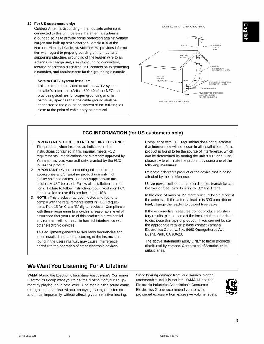
Outdoor Antenna Grounding – If an outside antenna isconnected to this unit, be sure the antenna system isgrounded so as to provide some protection against voltagesurges and built-up static charges. Article 810 of theNational Electrical Code, ANSI/NFPA 70, provides informa-tion with regard to proper grounding of the mast andsupporting structure, grounding of the lead-in wire to anantenna discharge unit, size of grounding conductors,location of antenna discharge unit, connection to groundingelectrodes, and requirements for the grounding electrode.
FCC INFORMATION (for US customers only)
We Want You Listening For A Lifetime
YAMAHA and the Electronic Industries Association’s ConsumerElectronics Group want you to get the most out of your equip-ment by playing it at a safe level. One that lets the sound comethrough loud and clear without annoying blaring or distortion –and, most importantly, without affecting your sensitive hearing.
Since hearing damage from loud sounds is oftenundetectable until it is too late, YAMAHA and theElectronic Industries Association’s ConsumerElectronics Group recommend you to avoidprolonged exposure from excessive volume levels.
Compliance with FCC regulations does not guaranteethat interference will not occur in all installations. If thisproduct is found to be the source of interference, whichcan be determined by turning the unit “OFF” and “ON”,please try to eliminate the problem by using one of thefollowing measures:
Relocate either this product or the device that is beingaffected by the interference.
Utilize power outlets that are on different branch (circuitbreaker or fuse) circuits or install AC line filter/s.
In the case of radio or TV interference, relocate/reorientthe antenna. If the antenna lead-in is 300 ohm ribbonlead, change the lead-in to coaxial type cable.
If these corrective measures do not produce satisfac-tory results, please contact the local retailer authorizedto distribute this type of product. If you can not locatethe appropriate retailer, please contact YamahaElectronics Corp., U.S.A. 6660 Orangethorpe Ave,Buena Park, CA 90620.
The above statements apply ONLY to those productsdistributed by Yamaha Corporation of America or itssubsidiaries.
1. IMPORTANT NOTICE : DO NOT MODIFY THIS UNIT!This product, when installed as indicated in theinstructions contained in this manual, meets FCCrequirements. Modifications not expressly approved byYamaha may void your authority, granted by the FCC,to use the product.
2. IMPORTANT : When connecting this product toaccessories and/or another product use only highquality shielded cables. Cable/s supplied with thisproduct MUST be used. Follow all installation instruc-tions. Failure to follow instructions could void your FCCauthorization to use this product in the USA.
3. NOTE : This product has been tested and found tocomply with the requirements listed in FCC Regula-tions, Part 15 for Class “B” digital devices. Compliancewith these requirements provides a reasonable level ofassurance that your use of this product in a residentialenvironment will not result in harmful interference withother electronic devices.
This equipment generates/uses radio frequencies and,if not installed and used according to the instructionsfound in the users manual, may cause interferenceharmful to the operation of other electronic devices.
Note to CATV system installer:This reminder is provided to call the CATV systeminstaller’s attention to Article 820-40 of the NEC thatprovides guidelines for proper grounding and, inparticular, specifies that the cable ground shall beconnected to the grounding system of the building, asclose to the point of cable entry as practical.
EXAMPLE OF ANTENNA GROUNDING
MAST
GROUNDCLAMP
ANTENNALEAD INWIRE
ANTENNADISCHARGE UNIT(NEC SECTION 810–20)
GROUNDING CONDUCTORS(NEC SECTION 810–21)
GROUND CLAMPS
POWER SERVICE GROUNDINGELECTRODE SYSTEM(NEC ART 250. PART H)
ELECTRICSERVICEEQUIPMENT
NEC – NATIONAL ELECTRICAL CODE
01RX-V595-e/f1 6/23/99, 4:09 PM3
4
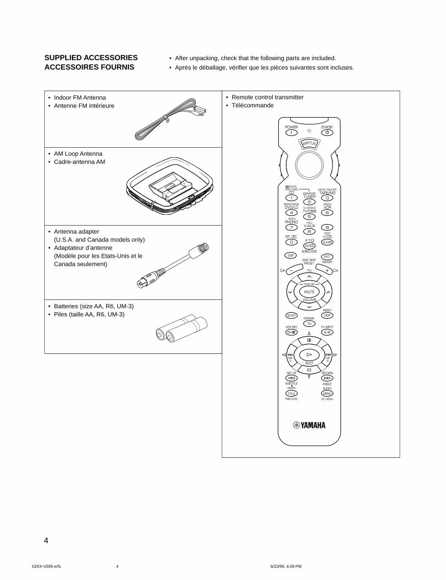
SUPPLIED ACCESSORIESACCESSOIRES FOURNIS
• After unpacking, check that the following parts are included.
• Après le déballage, vérifier que les pièces suivantes sont incluses.
• Indoor FM Antenna• Antenne FM intérieure
• AM Loop Antenna• Cadre-antenna AM
• Antenna adapter(U.S.A. and Canada models only)
• Adaptateur d’antenne(Modèle pour les Etats-Unis et leCanada seulement)
• Batteries (size AA, R6, UM-3)• Piles (taille AA, R6, UM-3)
• Remote control transmitter• Télécommande
01RX-V595-e/f1 6/23/99, 4:09 PM4
5
English
5 Speaker Configuration<Canada model>Main: 70 W + 70 W (8 Ω) RMS Output
Power, 0.04% THD, 20 Hz – 20 kHzCenter: 70 W (8 Ω) RMS Output
Power, 0.04% THD, 20 Hz – 20 kHzRear: 70 W + 70 W (8Ω) RMS Output
Power, 0.04% THD, 20 Hz – 20 kHz<Australia and China models>Main: 65 W + 65 W (8 Ω) RMS Output
Power, 0.04% THD, 20 Hz – 20 kHzCenter: 65 W (8 Ω) RMS Output
Power, 0.04% THD, 20 Hz – 20 kHzRear: 65 W + 65 W (8Ω) RMS Output
Power, 0.04% THD, 20 Hz – 20 kHz
Digital Sound Field Processor
Dolby Digital Decoder
Dolby Pro Logic Surround Decoder
CINEMA DSP: Theater-like SoundExperience by the Combination of DolbySurround and YAMAHA DSP Technology
SUPPLIED ACCESSORIES........................................... 4
FEATURES .................................................................... 5
CAUTION ....................................................................... 6
IntroductionFEATURES ON SOUND EFFECT ................................. 7
CONTROLS AND THEIR FUNCTIONS ......................... 9
PreparationSPEAKER SETUP ....................................................... 12
CONNECTIONS........................................................... 14
ADJUSTMENTS
BEFORE USING THIS UNIT .................................. 22
Basic OparationBASIC OPERATIONS .................................................. 27
TUNING OPERATIONS ............................................... 31
SETTING THE SLEEP TIMER ..................................... 36
Information about DSPUSING DIGITAL SOUND FIELD
PROCESSOR (DSP) .............................................. 37
Advanced InformationADJUSTMENTS
IN THE “SET MENU” MODE................................... 43
Remote Control TransmitterREMOTE CONTROL TRANSMITTER ......................... 45
SETUP CODES ........................................................... 50
NOTES ABOUT THE REMOTE CONTROL
TRANSMITTER ...................................................... 51
TROUBLESHOOTING ................................................. 52
SPECIFICATIONS ....................................................... 54
LIST OF MANUFACTURER’S CODES...................... 108
FEATURES
CONTENTS
6-Channel External Decoder Input for DTSand other future formats
Automatic Input Balance Control forDolby Pro Logic Surround
Test Tone Generator for Easier SpeakerBalance Adjustment
Speaker Output Mode ChangingCapability
40-Station Random Access Preset Tuning
Automatic Preset Tuning
Preset Station Shifting Capability(Preset Editing)
Video Signal Input/Output Capability
SLEEP Timer
Universal Remote ControlTransmitter with Preset ManufacturerCodes
01RX-V595-e/f1 6/23/99, 4:09 PM5
6
CAUTION : READ THIS BEFORE OPERATING YOUR UNIT.1. To assure the finest performance, please read this manual
carefully. Keep it in a safe place for future reference.
2. Install this unit in a cool, dry, clean place – away fromwindows, heat sources, sources of excessive vibration,dust, moisture and cold. Avoid sources of humming(transformers, motors). To prevent fire or electrical shock,do not expose the unit to rain or water.
3. Never open the cabinet. If something drops into the set,contact your dealer.
4. Do not use force on switches, controls or connection wires.When moving the unit, first disconnect the power plug andthe wires connected to other equipment. Never pull thewires themselves.
5. The openings on the unit cover assure proper ventilation ofthe unit. If these openings are obstructed, the temperatureinside the unit will rise rapidly. Therefore, avoid placingobjects against these openings, and install the unit in awell-ventilated area to prevent fire and damage.
<Singapore model only>Be sure to allow a space of at least 20 cm behind, 20 cmon the both sides and 30 cm above the top panel of the unitto prevent fire and damage.
6. The voltage used must be the same as that specified onthis unit. Using this unit with a higher voltage than speci-fied is dangerous and may result in fire or other accidents.YAMAHA will not be held responsible for any damageresulting from use of this unit with a voltage other thanspecified.
7. Digital signals generated by this unit may interfere withother equipment such as tuners, receivers or TVs. Movethis unit farther away from such equipment if interference isobserved.
8. Always set the VOLUME control to “∞” before starting theaudio source play. Increase the volume gradually to anappropriate level after playback has been started.
9. Do not attempt to clean the unit with chemical solvents; thismight damage the finish. Use a clean, dry cloth.
10. Be sure to read the “TROUBLESHOOTING” sectionregarding common operating errors before concluding thatthe unit is faulty.
11. When not planning to use this unit for long periods of time(ie., vacation, etc.), disconnect the AC power plug from thewall outlet.
12. To prevent lightning damage, disconnect the AC powerplug and disconnect the antenna cable when there is anelectrical storm.
13. Grounding or polarization – Precautions should be taken sothat the grounding or polarization of an appliance is notdefeated.
14. AC outletDo not connect audio equipment to the AC outlet on therear panel if that equipment requires more power than theoutlet is rated to provide.
15. Voltage Selector (China and General Models only)The voltage selector on the rear panel of this unit mustbe set for your local main voltage BEFORE plugginginto the AC main supply.Voltages are 110/120/220/240 V AC, 50/60 Hz.
This unit is not disconnected from the AC power source aslong as it is connected to the wall outlet, even if this unititself is turned off. This state is called the standby mode.In this state, this unit is designed to consume a very smallquantity of power.
FREQUENCY STEP switch(China and General Models only)Because the interstation frequency spacing differs indifferent areas, set the FREQUENCY STEP switch (locatedat the rear) according to the frequency spacing in your area.Before setting this switch, disconnect the AC power plug ofthis unit from the AC outlet.
IMPORTANTPlease record the serial number of this unit in the spacebelow.
Serial No.:
The serial number is located on the rear of the unit.Retain this Owner’s Manual in a safe place for futurereference.
WARNINGTO REDUCE THE RISK OF FIRE OR ELECTRIC SHOCK,DO NOT EXPOSE THIS UNIT TO RAIN OR MOISTURE.
FOR CANADIAN CUSTOMERS
TO PREVENT ELECTRIC SHOCK, MATCH WIDE BLADEOF PLUG TO WIDE SLOT AND FULLY INSERT.
THIS CLASS B DIGITAL APPARATUS COMPLIES WITHCANADIAN ICES-003.
01RX-V595-e/f1 6/23/99, 4:09 PM6
7
English
FEATURES ON SOUND EFFECTThis unit incorporates a sophisticated, multi-program digitalsound field processor. The processor allows you to electroni-cally expand and change the shape of the audio sound fieldfrom both audio and video sources, creating a theater-likeexperience in your listening room. This unit has a total of 8digital sound field processor (DSP) modes. You can create anexcellent audio sound field by selecting a suitable sound field(this will, of course, depend on what you will be listening to),and adding desired adjustments.
In addition, this unit incorporates a Dolby Pro Logic Surrounddecoder and Dolby Digital decoder for multi-channel soundreproduction of Dolby Surround encoded video sources. Theoperation of the Dolby Pro Logic Surround or Dolby Digitaldecoder can be controlled by selecting a corresponding DSPprogram including combined operations of the YAMAHA DSPand the Dolby Pro Logic Surround or Dolby Digital decoder.
Digital Sound Field ProcessingWhat is it that makes live music so good? Today’s advancedsound reproduction technology lets you get extremely close tothe sound of a live performance, but chances are you’ll stillnotice something missing, the acoustic environment of the liveconcert hall. Extensive research into the exact nature of thesonic reflections that create the ambience of a large hall hasmade it possible for YAMAHA engineers to bring you this samesound in your listening room, so you’ll feel all the sound of alive concert.
Furthermore, our technicians, armed with sophisticatedmeasuring equipment, have even made it possible to capturethe acoustics of a variety of actual concert halls, theaters, etc.from around the world, to allow you to accurately re-create anyone of these live performance environments, all in your home.
Dolby Pro Logic SurroundThis unit employs a Dolby Pro Logic Surround decoder similarto professional Dolby Stereo decoders used in many movietheaters. By using the Dolby Pro Logic Surround decoder, youcan experience the dramatic realism and impact of DolbySurround movie theater sound in your own home. Dolby ProLogic employs a four channel five speaker system. The ProLogic Surround system divides the input signal into four levels:the left and right main channels, the center channel (used fordialog), and the rear surround sound channels (used for soundeffects, background noise, and other ambient noises). Thecenter channel allows listeners seated in even less-than-idealpositions to hear the dialog originating from the action on thescreen while experiencing good stereo imaging.
Dolby Surround is encoded on the sound track of pre-recordedvideo tapes, laser discs, and some TV/cable broadcasts. Whenyou play a source encoded with Dolby Surround on this unit,the Dolby Pro Logic Surround decoder decodes the signal anddistributes the surround-sound effects.
This Dolby Pro Logic Surround decoder employs a digital signalprocessing system. This system improves the stability of soundat each channel and crosstalk between channels, so thatpositioning of sounds around the room is more accuratecompared with conventional analog signal processing systems.
In addition, this unit features a built-in automatic input balancecontrol. This always assures you the best performance withoutmanual adjustment.
Dolby DigitalThe built-in Dolby Digital decoder leads you into a totally newsound experiences.
Dolby Digital is a new generation of multi-channel digital audiotechnology, or the newest spatial sound processing formatdeveloped for 35 mm film-movies by employing a new kind oflow bit-rate audio coding.
Dolby Digital is a digital surround sound system that providescompletely independent multi-channel audio to consumers. Inmulti-channel form, Dolby Digital provides five full rangechannels in what is sometimes referred to as a “3/2” configura-tion: three front channels (left, center and right), plus twosurround channels. A sixth bass-only effect channel is alsoprovided for output of LFE (low frequency effect), or low basseffects that are independent of other channels. This channel iscounted as 0.1, thus giving rise to the term 5.1 channels intotal.
Compared to Dolby Pro Logic that is referred to a “3/1” system(left front, center, right front and just one surround channel),Dolby Digital features two surround channels, called stereo orsplit surrounds, each offering the same full range fidelity as thethree front channels.
Sound of wide dynamic range reproduced by the five full rangechannels presents listeners much excitement that has neverbeen experienced before. Precise sound orientation by thediscrete digital sound processing expands realism that theoriginal movie possesses.
LD and DVD are home audio formats that could benefit fromDolby Digital. In the near future, Dolby Digital will also beapplied to DBS, CATV and HDTV. The ongoing release ofDolby Stereo Digital theatrical films now underway will providean immediate source of Dolby Digital encoded video software.
01RX-V595-e/f1 6/23/99, 4:09 PM7
8
Manufactured under license from Dolby Laboratories LicensingCorporation. “Dolby”, “Pro Logic”, and the double-D symbol aretrademarks of Dolby Laboratories Licensing Corporation.Copyright 1992 Dolby Laboratories, Inc. All rights reserved.
The following original functions make the surround-sound effectof Dolby Digital become the most suitable for your audiosystem and the listening conditions.
• Dynamic range (sound scale) of source can be changedso that it will be suitable for the listening conditions.
• Output of low bass from any channel can be assigned toeither the MAIN SPEAKERS terminals or SUBWOOFERterminal to maximize system performance.
• Output of LFE can be assigned to either the MAINSPEAKERS terminals or SUBWOOFER terminal tomaximize system performance.
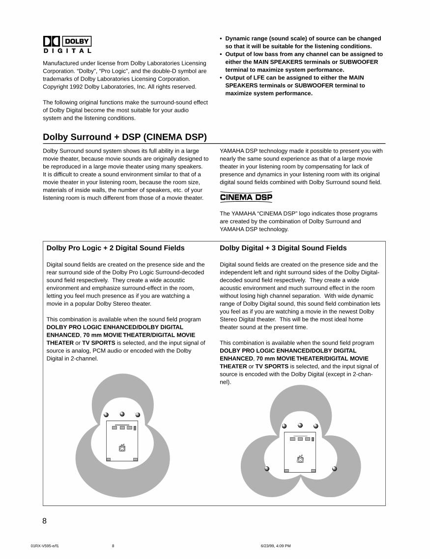
Dolby Surround + DSP (CINEMA DSP)Dolby Surround sound system shows its full ability in a largemovie theater, because movie sounds are originally designed tobe reproduced in a large movie theater using many speakers.It is difficult to create a sound environment similar to that of amovie theater in your listening room, because the room size,materials of inside walls, the number of speakers, etc. of yourlistening room is much different from those of a movie theater.
YAMAHA DSP technology made it possible to present you withnearly the same sound experience as that of a large movietheater in your listening room by compensating for lack ofpresence and dynamics in your listening room with its originaldigital sound fields combined with Dolby Surround sound field.
CINEMA DSP
The YAMAHA “CINEMA DSP” logo indicates those programsare created by the combination of Dolby Surround andYAMAHA DSP technology.
Dolby Pro Logic + 2 Digital Sound Fields
Digital sound fields are created on the presence side and therear surround side of the Dolby Pro Logic Surround-decodedsound field respectively. They create a wide acousticenvironment and emphasize surround-effect in the room,letting you feel much presence as if you are watching amovie in a popular Dolby Stereo theater.
This combination is available when the sound field programDOLBY PRO LOGIC ENHANCED/DOLBY DIGITALENHANCED, 70 mm MOVIE THEATER/DIGITAL MOVIETHEATER or TV SPORTS is selected, and the input signal ofsource is analog, PCM audio or encoded with the DolbyDigital in 2-channel.
Dolby Digital + 3 Digital Sound Fields
Digital sound fields are created on the presence side and theindependent left and right surround sides of the Dolby Digital-decoded sound field respectively. They create a wideacoustic environment and much surround effect in the roomwithout losing high channel separation. With wide dynamicrange of Dolby Digital sound, this sound field combination letsyou feel as if you are watching a movie in the newest DolbyStereo Digital theater. This will be the most ideal hometheater sound at the present time.
This combination is available when the sound field programDOLBY PRO LOGIC ENHANCED/DOLBY DIGITALENHANCED, 70 mm MOVIE THEATER/DIGITAL MOVIETHEATER or TV SPORTS is selected, and the input signal ofsource is encoded with the Dolby Digital (except in 2-chan-nel).
01RX-V595-e/f1 6/23/99, 4:09 PM8
9
English
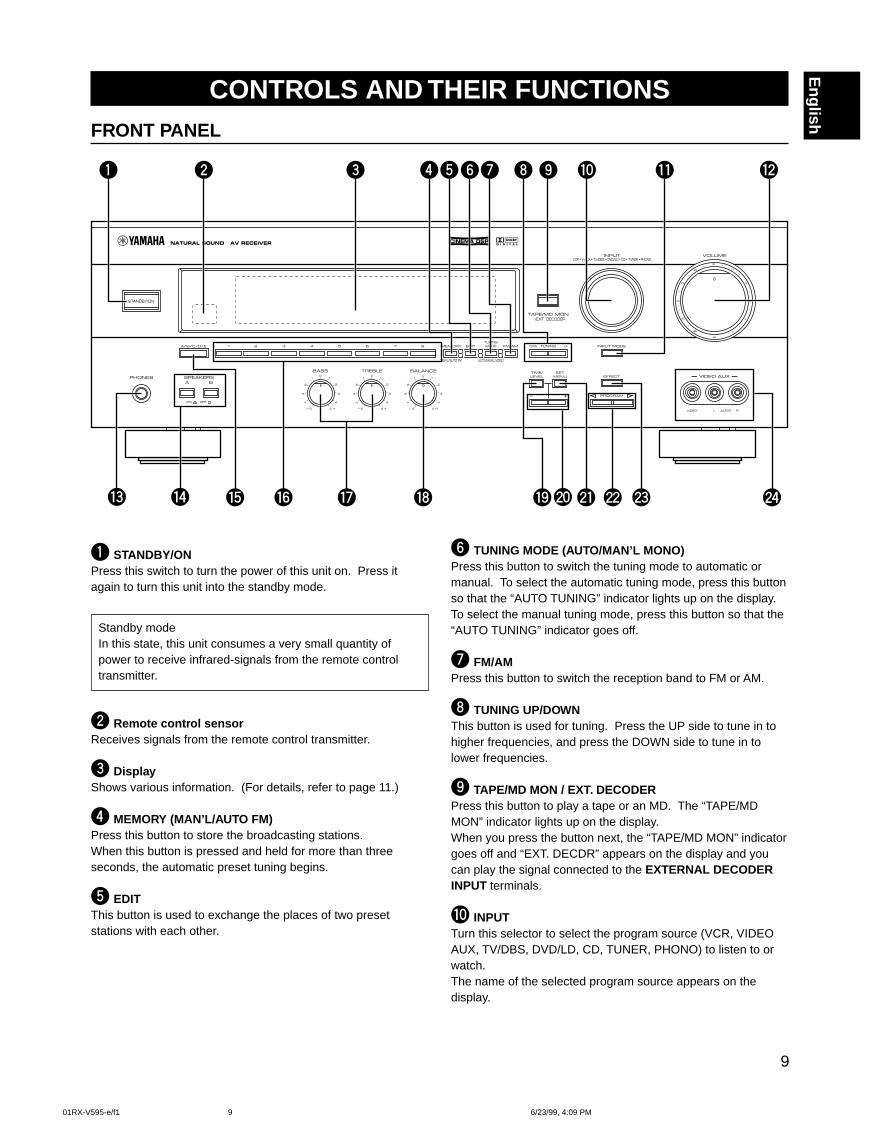
CONTROLS AND THEIR FUNCTIONSFRONT PANEL
1 STANDBY/ONPress this switch to turn the power of this unit on. Press itagain to turn this unit into the standby mode.
Standby modeIn this state, this unit consumes a very small quantity ofpower to receive infrared-signals from the remote controltransmitter.
2 Remote control sensorReceives signals from the remote control transmitter.
3 DisplayShows various information. (For details, refer to page 11.)
4 MEMORY (MAN’L/AUTO FM)Press this button to store the broadcasting stations.When this button is pressed and held for more than threeseconds, the automatic preset tuning begins.
5 EDITThis button is used to exchange the places of two presetstations with each other.
6 TUNING MODE (AUTO/MAN’L MONO)Press this button to switch the tuning mode to automatic ormanual. To select the automatic tuning mode, press this buttonso that the “AUTO TUNING” indicator lights up on the display.To select the manual tuning mode, press this button so that the“AUTO TUNING” indicator goes off.
7 FM/AMPress this button to switch the reception band to FM or AM.
8 TUNING UP/DOWNThis button is used for tuning. Press the UP side to tune in tohigher frequencies, and press the DOWN side to tune in tolower frequencies.
9 TAPE/MD MON / EXT. DECODERPress this button to play a tape or an MD. The “TAPE/MDMON” indicator lights up on the display.When you press the button next, the “TAPE/MD MON” indicatorgoes off and “EXT. DECDR” appears on the display and youcan play the signal connected to the EXTERNAL DECODERINPUT terminals.
0 INPUTTurn this selector to select the program source (VCR, VIDEOAUX, TV/DBS, DVD/LD, CD, TUNER, PHONO) to listen to orwatch.The name of the selected program source appears on thedisplay.
01RX-V595-e/f1 6/23/99, 4:09 PM9
10
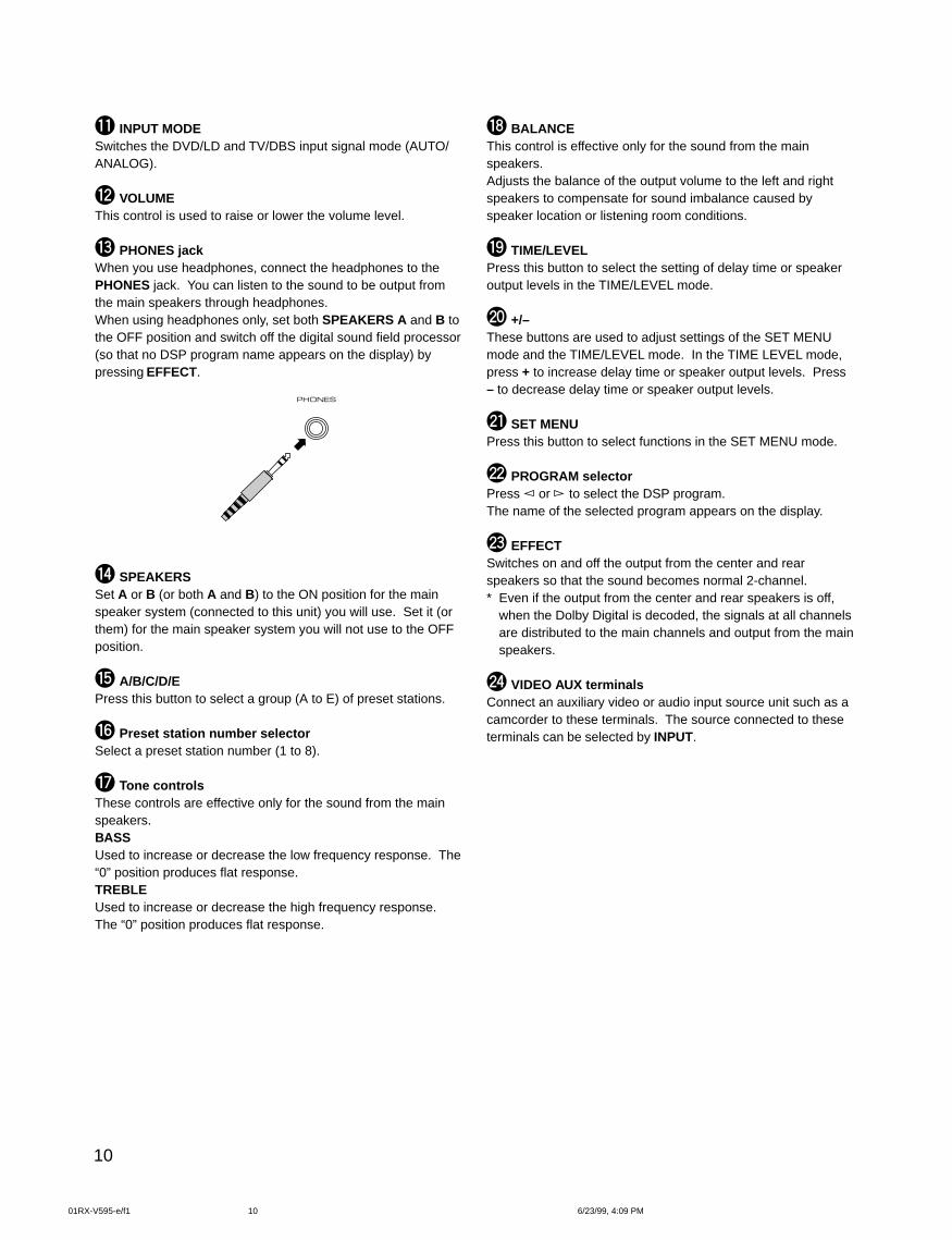
q INPUT MODESwitches the DVD/LD and TV/DBS input signal mode (AUTO/ANALOG).
w VOLUMEThis control is used to raise or lower the volume level.
e PHONES jackWhen you use headphones, connect the headphones to thePHONES jack. You can listen to the sound to be output fromthe main speakers through headphones.When using headphones only, set both SPEAKERS A and B tothe OFF position and switch off the digital sound field processor(so that no DSP program name appears on the display) bypressing EFFECT.
PHONES
r SPEAKERSSet A or B (or both A and B) to the ON position for the mainspeaker system (connected to this unit) you will use. Set it (orthem) for the main speaker system you will not use to the OFFposition.
t A/B/C/D/EPress this button to select a group (A to E) of preset stations.
y Preset station number selectorSelect a preset station number (1 to 8).
u Tone controlsThese controls are effective only for the sound from the mainspeakers.BASSUsed to increase or decrease the low frequency response. The“0” position produces flat response.TREBLEUsed to increase or decrease the high frequency response.The “0” position produces flat response.
i BALANCEThis control is effective only for the sound from the mainspeakers.Adjusts the balance of the output volume to the left and rightspeakers to compensate for sound imbalance caused byspeaker location or listening room conditions.
o TIME/LEVELPress this button to select the setting of delay time or speakeroutput levels in the TIME/LEVEL mode.
p +/–These buttons are used to adjust settings of the SET MENUmode and the TIME/LEVEL mode. In the TIME LEVEL mode,press + to increase delay time or speaker output levels. Press– to decrease delay time or speaker output levels.
a SET MENUPress this button to select functions in the SET MENU mode.
s PROGRAM selectorPress or to select the DSP program.The name of the selected program appears on the display.
d EFFECTSwitches on and off the output from the center and rearspeakers so that the sound becomes normal 2-channel.* Even if the output from the center and rear speakers is off,
when the Dolby Digital is decoded, the signals at all channelsare distributed to the main channels and output from the mainspeakers.
f VIDEO AUX terminalsConnect an auxiliary video or audio input source unit such as acamcorder to these terminals. The source connected to theseterminals can be selected by INPUT.
01RX-V595-e/f1 6/23/99, 4:09 PM10
11
English
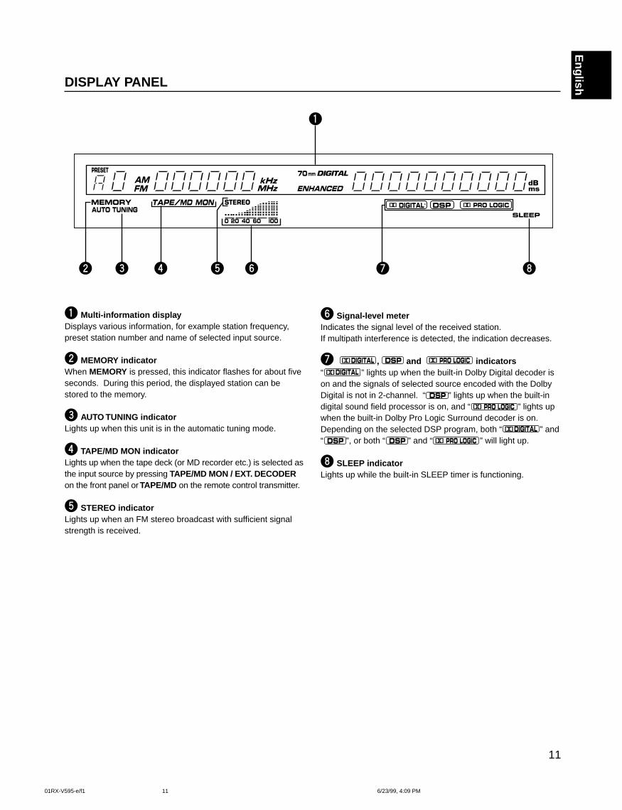
1 Multi-information displayDisplays various information, for example station frequency,preset station number and name of selected input source.
2 MEMORY indicatorWhen MEMORY is pressed, this indicator flashes for about fiveseconds. During this period, the displayed station can bestored to the memory.
3 AUTO TUNING indicatorLights up when this unit is in the automatic tuning mode.
4 TAPE/MD MON indicatorLights up when the tape deck (or MD recorder etc.) is selected asthe input source by pressing TAPE/MD MON / EXT. DECODERon the front panel or TAPE/MD on the remote control transmitter.
5 STEREO indicatorLights up when an FM stereo broadcast with sufficient signalstrength is received.
DISPLAY PANEL
6 Signal-level meterIndicates the signal level of the received station.If multipath interference is detected, the indication decreases.
7 , and indicators“ ” lights up when the built-in Dolby Digital decoder ison and the signals of selected source encoded with the DolbyDigital is not in 2-channel. “ ” lights up when the built-indigital sound field processor is on, and “ ” lights upwhen the built-in Dolby Pro Logic Surround decoder is on.Depending on the selected DSP program, both “ ” and“ ”, or both “ ” and “ ” will light up.
8 SLEEP indicatorLights up while the built-in SLEEP timer is functioning.
01RX-V595-e/f1 6/23/99, 4:09 PM11
12
SPEAKER SETUP
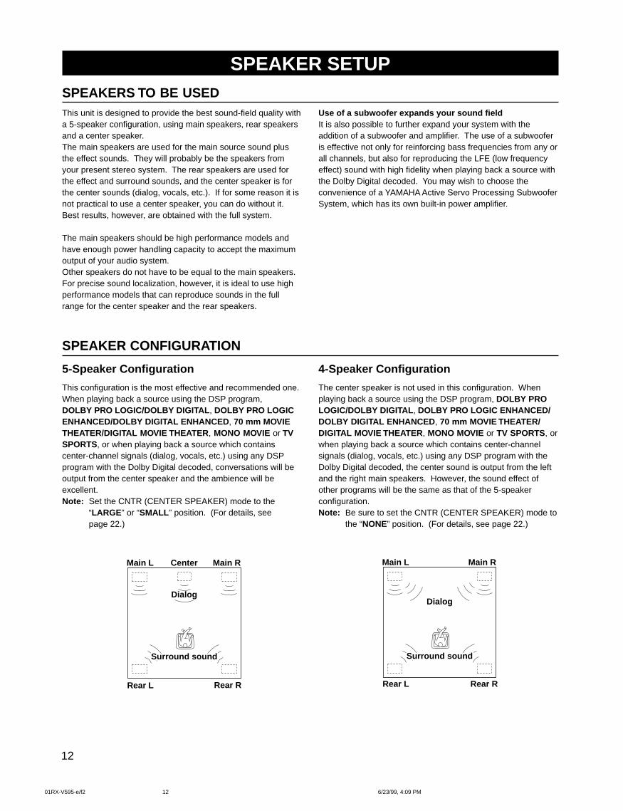
This unit is designed to provide the best sound-field quality witha 5-speaker configuration, using main speakers, rear speakersand a center speaker.The main speakers are used for the main source sound plusthe effect sounds. They will probably be the speakers fromyour present stereo system. The rear speakers are used forthe effect and surround sounds, and the center speaker is forthe center sounds (dialog, vocals, etc.). If for some reason it isnot practical to use a center speaker, you can do without it.Best results, however, are obtained with the full system.
The main speakers should be high performance models andhave enough power handling capacity to accept the maximumoutput of your audio system.Other speakers do not have to be equal to the main speakers.For precise sound localization, however, it is ideal to use highperformance models that can reproduce sounds in the fullrange for the center speaker and the rear speakers.
5-Speaker Configuration
This configuration is the most effective and recommended one.When playing back a source using the DSP program,DOLBY PRO LOGIC/DOLBY DIGITAL , DOLBY PRO LOGICENHANCED/DOLBY DIGITAL ENHANCED , 70 mm MOVIETHEATER/DIGITAL MOVIE THEATER , MONO MOVIE or TVSPORTS, or when playing back a source which containscenter-channel signals (dialog, vocals, etc.) using any DSPprogram with the Dolby Digital decoded, conversations will beoutput from the center speaker and the ambience will beexcellent.Note: Set the CNTR (CENTER SPEAKER) mode to the
“LARGE ” or “SMALL ” position. (For details, seepage 22.)
SPEAKER CONFIGURATION
Use of a subwoofer expands your sound fieldIt is also possible to further expand your system with theaddition of a subwoofer and amplifier. The use of a subwooferis effective not only for reinforcing bass frequencies from any orall channels, but also for reproducing the LFE (low frequencyeffect) sound with high fidelity when playing back a source withthe Dolby Digital decoded. You may wish to choose theconvenience of a YAMAHA Active Servo Processing SubwooferSystem, which has its own built-in power amplifier.
4-Speaker Configuration
The center speaker is not used in this configuration. Whenplaying back a source using the DSP program, DOLBY PROLOGIC/DOLBY DIGITAL , DOLBY PRO LOGIC ENHANCED/DOLBY DIGITAL ENHANCED , 70 mm MOVIE THEATER/DIGITAL MOVIE THEATER , MONO MOVIE or TV SPORTS, orwhen playing back a source which contains center-channelsignals (dialog, vocals, etc.) using any DSP program with theDolby Digital decoded, the center sound is output from the leftand the right main speakers. However, the sound effect ofother programs will be the same as that of the 5-speakerconfiguration.Note: Be sure to set the CNTR (CENTER SPEAKER) mode to
the “NONE” position. (For details, see page 22.)
Main L Center Main R
Surround sound
Dialog
Surround sound
Rear L Rear R
Main L Main R
Surround sound
Dialog
Surround sound
Rear L Rear R
SPEAKERS TO BE USED
01RX-V595-e/f2 6/23/99, 4:09 PM12
13
EnglishSPEAKER PLACEMENT
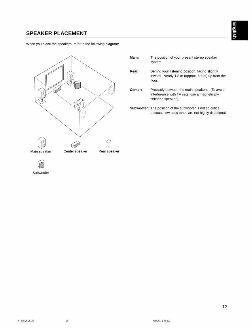
When you place the speakers, refer to the following diagram:
Main: The position of your present stereo speakersystem.
Rear: Behind your listening position, facing slightlyinward. Nearly 1.8 m (approx. 6 feet) up from thefloor.
Center: Precisely between the main speakers. (To avoidinterference with TV sets, use a magneticallyshielded speaker.)
Subwoofer: The position of the subwoofer is not so criticalbecause low bass tones are not highly directional.
Main speaker Center speaker Rear speaker
Subwoofer
01RX-V595-e/f2 6/23/99, 4:09 PM13
14
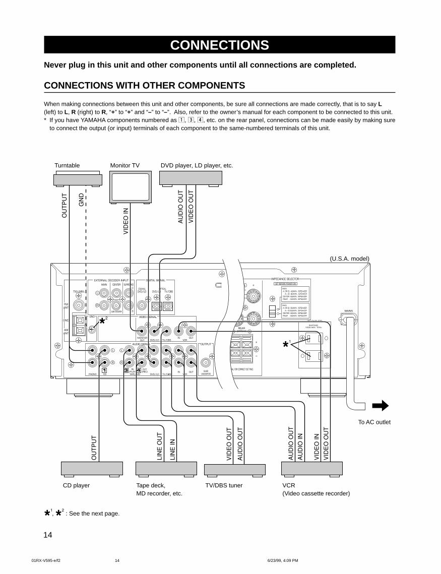
CONNECTIONSNever plug in this unit and other components until all connections are completed.
CONNECTIONS WITH OTHER COMPONENTS
When making connections between this unit and other components, be sure all connections are made correctly, that is to say L(left) to L, R (right) to R, “+” to “+” and “–” to “–”. Also, refer to the owner’s manual for each component to be connected to this unit.* If you have YAMAHA components numbered as !, #, $, etc. on the rear panel, connections can be made easily by making sure
to connect the output (or input) terminals of each component to the same-numbered terminals of this unit.
, : See the next page.
Turntable Monitor TV DVD player, LD player, etc.
CD player Tape deck,MD recorder, etc.
TV/DBS tuner VCR(Video cassette recorder)
To AC outlet
(U.S.A. model)
UAL FOR CORRECT SETTING.
L
R
75Ω UNBAL.
FMANT
AMANT
GND
EXTERNAL DECODER INPUT DIGITAL SIGNAL
MAIN CENTER SURROUND
COAXIALDVD/LD
OPTICALDVD/LD TV/DBS
SUB WOOFER
GND
MONITOROUT DVD/LD TV/DBS
VIDEO SIGNAL
AUDIO SIGNAL OUTPUT
IN OUTVCR
DVD/LDSUB
WOOFERTAPE/MD
IN(PLAY)
OUT(REC)
CDPHONO TV/DBSIN OUT
VCR
R
L
R
L
R
L
REAR(SORROUND) L
MAINS
MAIN A OR B: 4ΩMIN. /SPEAKER A + B: 8ΩMIN. /SPEAKER CENTER: 6ΩMIN. /SPEAKER REAR : 6ΩMIN. /SPEAKER
MAIN A OR B: 8ΩMIN. /SPEAKER A + B:I6ΩMIN. /SPEAKER CENTER: 8ΩMIN. /SPEAKER REAR : 8ΩMIN. /SPEAKER
IMPEDANCE SELECTOR
SET BEFORE POWER ON
AC OUTLETSSWITCHED
100W MAX. TOTAL
01RX-V595-e/f2 6/23/99, 4:09 PM14
15
English
6CH DISCRETE OUTPUT
MAIN CENTER SURROUND
SUB WOOFER
75Ω UNBAL.
EXTERNAL DECODER INPUT DIGITAL SIGNAL
MAIN CENTER SURROUND
COAXIALDVD/LD
OPTICALDVD/LD TV/DBS
SUB WOOFER
GND
MONITOROUT DVD/LD TV/DBS
VIDEO SIGNAL
AUDIO SIGNAL OUTPUT
IN OUTVCR
DVD/LDSUB
WOOFERTAPE/MD
IN(PLAY)
OUT(REC)
CDPHONO TV/DBSIN OUT
VCR
R
L
R
L
R
L
R
L
R
L
FMANT
AMANT
GND
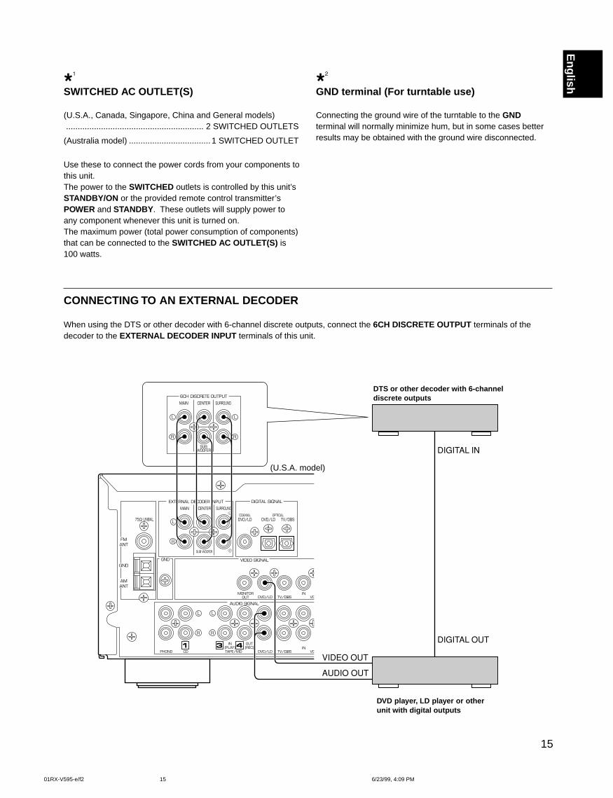
SWITCHED AC OUTLET(S)
(U.S.A., Canada, Singapore, China and General models)........................................................... 2 SWITCHED OUTLETS
(Australia model) ................................... 1 SWITCHED OUTLET
Use these to connect the power cords from your components tothis unit.The power to the SWITCHED outlets is controlled by this unit’sSTANDBY/ON or the provided remote control transmitter’sPOWER and STANDBY . These outlets will supply power toany component whenever this unit is turned on.The maximum power (total power consumption of components)that can be connected to the SWITCHED AC OUTLET(S) is100 watts.
GND terminal (For turntable use)
Connecting the ground wire of the turntable to the GNDterminal will normally minimize hum, but in some cases betterresults may be obtained with the ground wire disconnected.
CONNECTING TO AN EXTERNAL DECODER
When using the DTS or other decoder with 6-channel discrete outputs, connect the 6CH DISCRETE OUTPUT terminals of thedecoder to the EXTERNAL DECODER INPUT terminals of this unit.
DTS or other decoder with 6-channeldiscrete outputs
DVD player, LD player or otherunit with digital outputs
(U.S.A. model)
01RX-V595-e/f2 6/23/99, 4:09 PM15
16
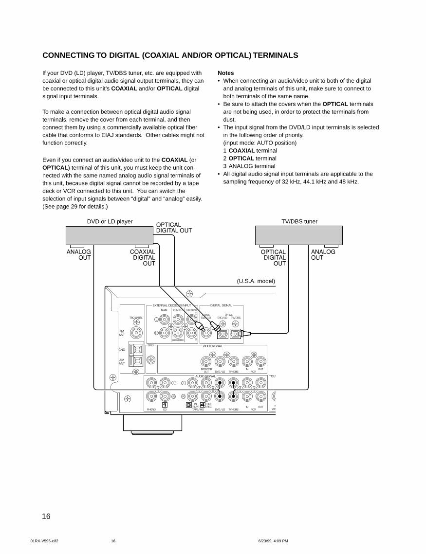
CONNECTING TO DIGITAL (COAXIAL AND/OR OPTICAL) TERMINALS
If your DVD (LD) player, TV/DBS tuner, etc. are equipped withcoaxial or optical digital audio signal output terminals, they canbe connected to this unit’s COAXIAL and/or OPTICAL digitalsignal input terminals.
To make a connection between optical digital audio signalterminals, remove the cover from each terminal, and thenconnect them by using a commercially available optical fibercable that conforms to EIAJ standards. Other cables might notfunction correctly.
Even if you connect an audio/video unit to the COAXIAL (orOPTICAL ) terminal of this unit, you must keep the unit con-nected with the same named analog audio signal terminals ofthis unit, because digital signal cannot be recorded by a tapedeck or VCR connected to this unit. You can switch theselection of input signals between “digital” and “analog” easily.(See page 29 for details.)
Notes• When connecting an audio/video unit to both of the digital
and analog terminals of this unit, make sure to connect toboth terminals of the same name.
• Be sure to attach the covers when the OPTICAL terminalsare not being used, in order to protect the terminals fromdust.
• The input signal from the DVD/LD input terminals is selectedin the following order of priority.(input mode: AUTO position)1 COAXIAL terminal2 OPTICAL terminal3 ANALOG terminal
• All digital audio signal input terminals are applicable to thesampling frequency of 32 kHz, 44.1 kHz and 48 kHz.
DVD or LD player TV/DBS tuner
(U.S.A. model)
75Ω UNBAL.
EXTERNAL DECODER INPUT DIGITAL SIGNAL
MAIN CENTER SURROUND
COAXIALDVD/LD
OPTICALDVD/LD TV/DBS
SUB WOOFER
GND
MONITOROUT DVD/LD TV/DBS
VIDEO SIGNAL
AUDIO SIGNAL OUTPUT
IN OUTVCR
DVD/LDSUB
WOOFERTAPE/MD
IN(PLAY)
OUT(REC)
CDPHONO TV/DBSIN OUT
VCR
R
L
R
L
R
L
FMANT
AMANT
GND
01RX-V595-e/f2 6/23/99, 4:09 PM16
17
English
Camcorder
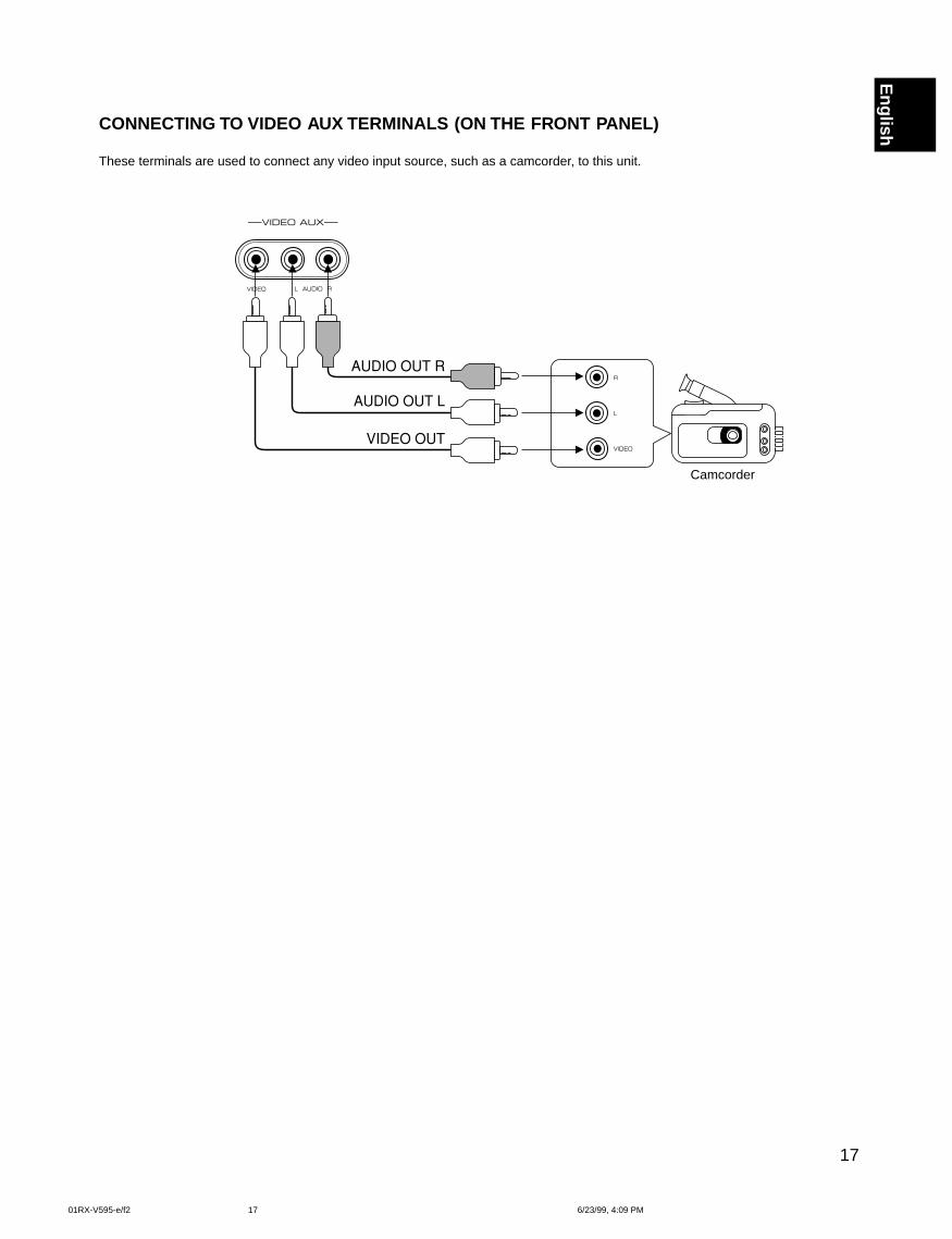
CONNECTING TO VIDEO AUX TERMINALS (ON THE FRONT PANEL)
These terminals are used to connect any video input source, such as a camcorder, to this unit.
LVIDEO AUDIO R
VIDEO AUX
L
VIDEO
R
01RX-V595-e/f2 6/23/99, 4:09 PM17
18
CAUTION SEE INSTRUCTION MANUAL FOR CORRECT SETTING.
R L
REAR(SORROUND)CENTER
MAIN
SUBWOOFER
R L
OUTPUT
SPEAKERS
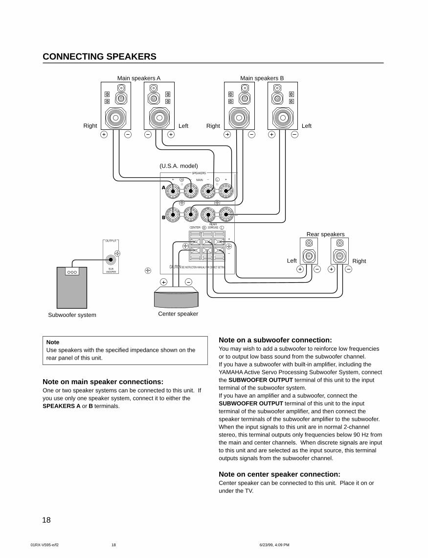
NoteUse speakers with the specified impedance shown on therear panel of this unit.
Note on main speaker connections:One or two speaker systems can be connected to this unit. Ifyou use only one speaker system, connect it to either theSPEAKERS A or B terminals.
Note on a subwoofer connection:You may wish to add a subwoofer to reinforce low frequenciesor to output low bass sound from the subwoofer channel.If you have a subwoofer with built-in amplifier, including theYAMAHA Active Servo Processing Subwoofer System, connectthe SUBWOOFER OUTPUT terminal of this unit to the inputterminal of the subwoofer system.If you have an amplifier and a subwoofer, connect theSUBWOOFER OUTPUT terminal of this unit to the inputterminal of the subwoofer amplifier, and then connect thespeaker terminals of the subwoofer amplifier to the subwoofer.When the input signals to this unit are in normal 2-channelstereo, this terminal outputs only frequencies below 90 Hz fromthe main and center channels. When discrete signals are inputto this unit and are selected as the input source, this terminaloutputs signals from the subwoofer channel.
Note on center speaker connection:Center speaker can be connected to this unit. Place it on orunder the TV.
CONNECTING SPEAKERS
Rear speakers
Subwoofer system Center speaker
Right Left
Main speakers A Main speakers B
RightLeft
Right Left
(U.S.A. model)
01RX-V595-e/f2 6/23/99, 4:09 PM18
19
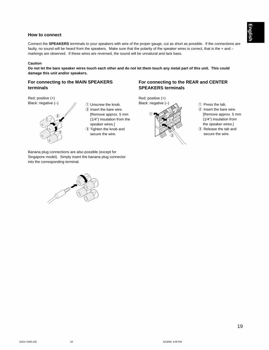
EnglishHow to connect
Connect the SPEAKERS terminals to your speakers with wire of the proper gauge, cut as short as possible. If the connections arefaulty, no sound will be heard from the speakers. Make sure that the polarity of the speaker wires is correct, that is the + and –markings are observed. If these wires are reversed, the sound will be unnatural and lack bass.
CautionDo not let the bare speaker wires touch each other and do not let them touch any metal part of this unit. This coulddamage this unit and/or speakers.
For connecting to the MAIN SPEAKERSterminals
Red: positive (+)Black: negative (–) 1 Unscrew the knob.
2 Insert the bare wire.[Remove approx. 5 mm(1/4”) insulation from thespeaker wires.]
3 Tighten the knob andsecure the wire.
1 Press the tab.2 Insert the bare wire.
[Remove approx. 5 mm(1/4”) insulation fromthe speaker wires.]
3 Release the tab andsecure the wire.
For connecting to the REAR and CENTERSPEAKERS terminals
Red: positive (+)Black: negative (–)
Banana plug connections are also possible (except forSingapore model). Simply insert the banana plug connectorinto the corresponding terminal.
01RX-V595-e/f2 6/23/99, 4:09 PM19
20
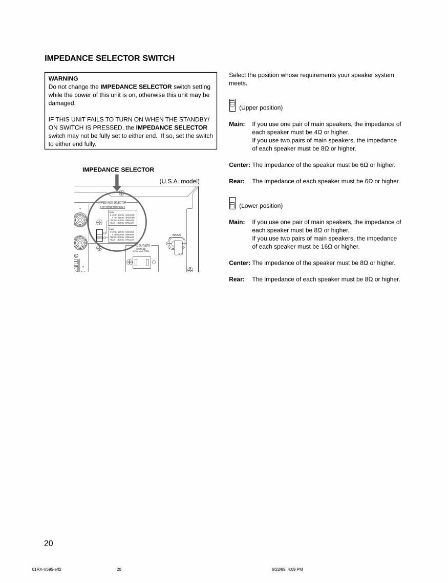
IMPEDANCE SELECTOR SWITCH
Select the position whose requirements your speaker systemmeets.
(Upper position)
Main: If you use one pair of main speakers, the impedance ofeach speaker must be 4Ω or higher.If you use two pairs of main speakers, the impedanceof each speaker must be 8Ω or higher.
Center: The impedance of the speaker must be 6Ω or higher.
Rear: The impedance of each speaker must be 6Ω or higher.
(Lower position)
Main: If you use one pair of main speakers, the impedance ofeach speaker must be 8Ω or higher.If you use two pairs of main speakers, the impedanceof each speaker must be 16Ω or higher.
Center: The impedance of the speaker must be 8Ω or higher.
Rear: The impedance of each speaker must be 8Ω or higher.
WARNINGDo not change the IMPEDANCE SELECTOR switch settingwhile the power of this unit is on, otherwise this unit may bedamaged.
IF THIS UNIT FAILS TO TURN ON WHEN THE STANDBY/ON SWITCH IS PRESSED, the IMPEDANCE SELECTORswitch may not be fully set to either end. If so, set the switchto either end fully.
IMPEDANCE SELECTOR
(U.S.A. model)
SWITCHED100W MAX. TOTAL
MAINS
MAIN A OR B: 4ΩMIN. /SPEAKER A + B: 8ΩMIN. /SPEAKER CENTER: 6ΩMIN. /SPEAKER REAR : 6ΩMIN. /SPEAKER
MAIN A OR B: 8ΩMIN. /SPEAKER A + B:I6ΩMIN. /SPEAKER CENTER: 8ΩMIN. /SPEAKER REAR : 8ΩMIN. /SPEAKER
IMPEDANCE SELECTOR
SET BEFORE POWER ON
AC OUTLETS
L
01RX-V595-e/f2 6/23/99, 4:09 PM20
21
English
1
3
2
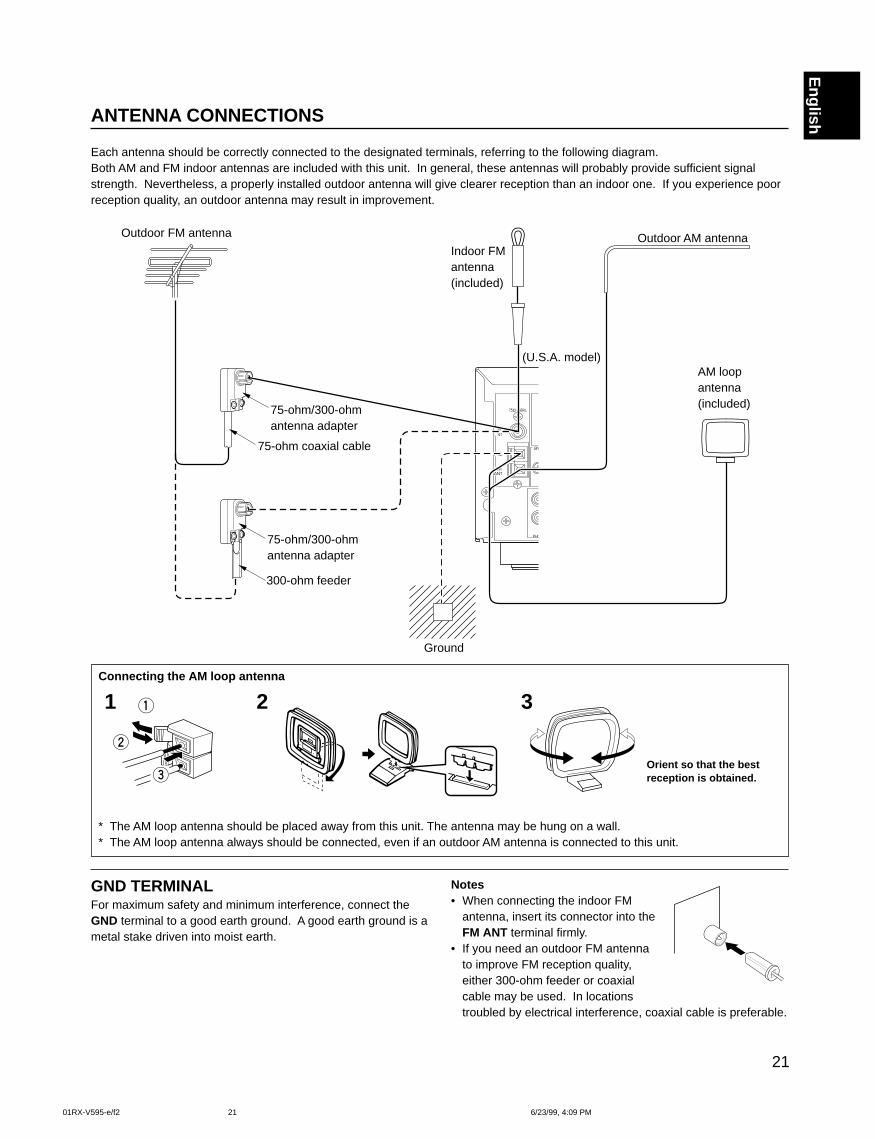
ANTENNA CONNECTIONS
Each antenna should be correctly connected to the designated terminals, referring to the following diagram.Both AM and FM indoor antennas are included with this unit. In general, these antennas will probably provide sufficient signalstrength. Nevertheless, a properly installed outdoor antenna will give clearer reception than an indoor one. If you experience poorreception quality, an outdoor antenna may result in improvement.
Connecting the AM loop antenna
* The AM loop antenna should be placed away from this unit. The antenna may be hung on a wall.* The AM loop antenna always should be connected, even if an outdoor AM antenna is connected to this unit.
GND TERMINALFor maximum safety and minimum interference, connect theGND terminal to a good earth ground. A good earth ground is ametal stake driven into moist earth.
Notes• When connecting the indoor FM
antenna, insert its connector into theFM ANT terminal firmly.
• If you need an outdoor FM antennato improve FM reception quality,either 300-ohm feeder or coaxialcable may be used. In locationstroubled by electrical interference, coaxial cable is preferable.
Orient so that the bestreception is obtained.
1 2 3
Outdoor FM antenna
75-ohm/300-ohmantenna adapter
75-ohm coaxial cable
75-ohm/300-ohmantenna adapter
300-ohm feeder
Ground
AM loopantenna(included)
Outdoor AM antennaIndoor FMantenna(included)
75Ω UNBAL.
FMANT
GND
PHONO
AMANT
GND
(U.S.A. model)
01RX-V595-e/f2 6/23/99, 4:09 PM21
22
ADJUSTMENTS BEFORE USING THIS UNITSELECTING THE OUTPUT MODES
This unit provides you the following five functions to determine the method of distributing output signals to speakers suitable foryour audio system. When speaker connections are all completed, select a proper position on each function to make the best use ofyour speaker system. (See “ADJUSTMENTS IN THE ‘SET MENU’ MODE” on page 43.)
1. CNTR (CENTER SPEAKER) 2. REAR (REAR SPEAKER) 3. MAIN (MAIN SPEAKER)4. BASS (LFE/BASS OUT) 5. M.LVL (MAIN LEVEL)
DESCRIPTION OF EACH FUNCTION
1. CNTR (CENTER SPEAKER)Choices: LARGE/SMALL/NONEPreset position: LARGE
LARGE: Select this position when your center speaker isapproximately the same size as the main speakers.
SMALL: Select this position when you use a center speakerthat is smaller than the main speakers.In this position, low bass signals (below 90 Hz) at thecenter channel are output from the main speakers (orthe SUBWOOFER OUTPUT terminal if the SMALLposition is selected on “3. MAIN” and the SW positionis selected on “4. BASS”).
NONE: Select this position when you do not have a centerspeaker. The center channel sound will be outputfrom the left and right main speakers.
2. REAR (REAR SPEAKER)Choices: LARGE/SMALLPreset position: LARGE
LARGE: Select this position if your rear speakers have a highability for bass reproduction, or a subwoofer isconnected to the rear speaker in parallel.In this position, full range signals are output from therear speakers.
SMALL: Select this position if your rear speakers do not havea high ability for bass reproduction.In this position, low bass signals (below 90 Hz) at therear channels are output from the SUBWOOFEROUTPUT terminal (or the main speakers if the MAINposition is selected on “4. BASS”).
3. MAIN (MAIN SPEAKER)Choices: LARGE/SMALLPreset position: LARGE
LARGE: Select this position if your main speakers have ahigh ability for bass reproduction.In this position, full range signals present at the mainchannels are output from the main speakers.
SMALL: Select this position if your main speakers do nothave a high ability for bass reproduction. However, ifyour system does not include a subwoofer, do notselect this position.In this position, low bass signals (below 90 Hz) at themain channels are output from the SUBWOOFEROUTPUT terminal if the SW or BOTH position isselected on “4. BASS”.
4. BASS (LFE/BASS OUT)Choices: SW/MAIN/BOTHPreset position: SW
MAIN: Select this position if your system does not include asubwoofer.In this position, full range signals present at the mainchannels, signals from the LFE channel and otherlow bass signals that are selected on “1. CNTR” to“3. MAIN” to be distributed from other channels areoutput from the main speakers.
SW/BOTH:Select either the SW or BOTH position if yoursystem includes a subwoofer.In either position, signals at LFE channel and otherlow bass signals that are selected on “1. CNTR” to“3. MAIN” to be distributed from other channels areoutput from the SUBWOOFER OUTPUT terminal.When the LARGE position is selected on “3. MAIN”,in the SW position, no signal is distributed from themain channels to the SUBWOOFER OUTPUTterminal, however in the BOTH position, low basssignals from the main channels are output to both ofthe main speakers and the SUBWOOFER OUTPUTterminal.
5. M.LVL (MAIN LEVEL)Choices: NORMAL (NRML)/–10 dBPreset position: NORMAL (NRML)
NORMAL (NRML):Normally select this position.
–10 dB: Select this position if the sound output from the mainspeakers is too loud and cannot be balanced withthe sound output from the center and rear speakers.In this position, the sound output from the mainspeakers is attenuated.
01RX-V595-e/f2 6/23/99, 4:09 PM22
23
English
1
2
3
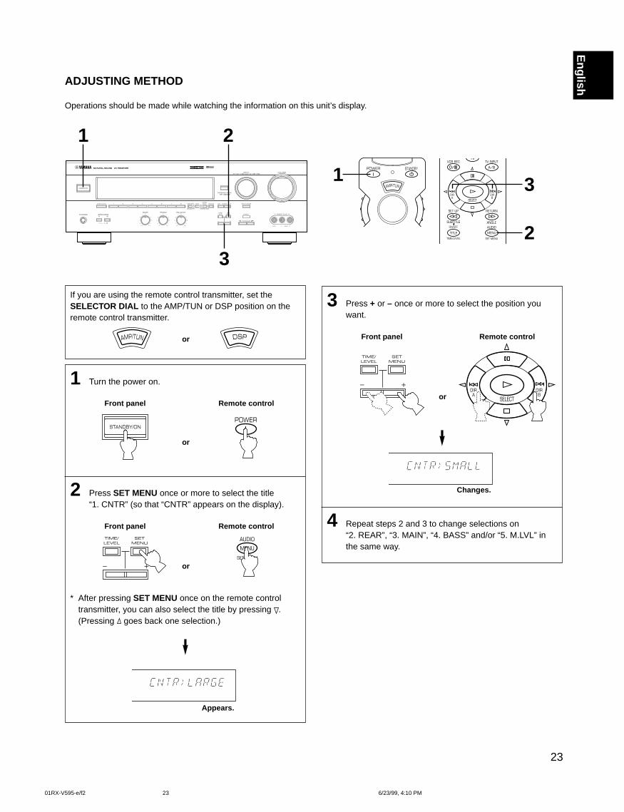
ADJUSTING METHOD
Operations should be made while watching the information on this unit’s display.
If you are using the remote control transmitter, set theSELECTOR DIAL to the AMP/TUN or DSP position on theremote control transmitter.
or
1 Turn the power on.
Front panel Remote control
or
2 Press SET MENU once or more to select the title“1. CNTR” (so that “CNTR” appears on the display).
Front panel Remote control
or
* After pressing SET MENU once on the remote controltransmitter, you can also select the title by pressing .(Pressing goes back one selection.)
Appears.
3 Press + or – once or more to select the position youwant.
Front panel Remote control
or
Changes.
4 Repeat steps 2 and 3 to change selections on“2. REAR”, “3. MAIN”, “4. BASS” and/or “5. M.LVL” inthe same way.
1 2
3
01RX-V595-e/f2 6/23/99, 4:10 PM23
24
SPEAKER BALANCE ADJUSTMENT
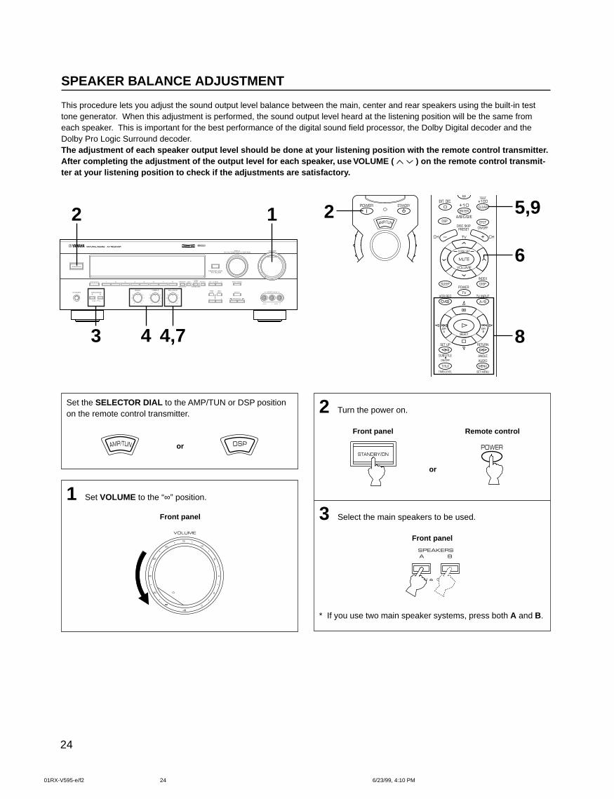
This procedure lets you adjust the sound output level balance between the main, center and rear speakers using the built-in testtone generator. When this adjustment is performed, the sound output level heard at the listening position will be the same fromeach speaker. This is important for the best performance of the digital sound field processor, the Dolby Digital decoder and theDolby Pro Logic Surround decoder.The adjustment of each speaker output level should be done at your listening position with the remote control transmitter.After completing the adjustment of the output level for each speaker, use VOLUME ( ) on the remote control transmit-ter at your listening position to check if the adjustments are satisfactory.
Set the SELECTOR DIAL to the AMP/TUN or DSP positionon the remote control transmitter.
or
1 Set VOLUME to the “∞” position.
Front panel
2 Turn the power on.
Front panel Remote control
or
3 Select the main speakers to be used.
Front panel
* If you use two main speaker systems, press both A and B.
2
8
5,9
6
2 1
4,743
01RX-V595-e/f2 6/23/99, 4:10 PM24
25
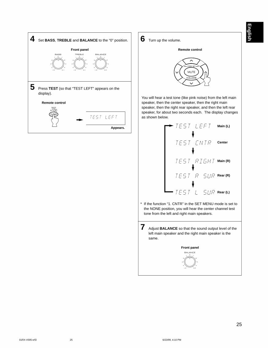
English6 Turn up the volume.
Remote control
You will hear a test tone (like pink noise) from the left mainspeaker, then the center speaker, then the right mainspeaker, then the right rear speaker, and then the left rearspeaker, for about two seconds each. The display changesas shown below.
* If the function “1. CNTR” in the SET MENU mode is set tothe NONE position, you will hear the center channel testtone from the left and right main speakers.
7 Adjust BALANCE so that the sound output level of theleft main speaker and the right main speaker is thesame.
Front panel
Main (L)
Center
Main (R)
Rear (R)
Rear (L)
4 Set BASS , TREBLE and BALANCE to the “0” position.
Front panel
5 Press TEST (so that “TEST LEFT” appears on thedisplay).
Remote control
Appears.
01RX-V595-e/f2 6/23/99, 4:10 PM25
26
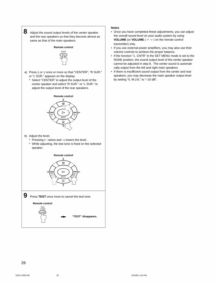
8 Adjust the sound output levels of the center speakerand the rear speakers so that they become almost assame as that of the main speakers.
Remote control
a) Press or once or more so that “CENTER”, “R SUR.”or “L SUR.” appears on the display.* Select “CENTER” to adjust the output level of the
center speaker and select “R SUR.” or “L SUR.” toadjust the output level of the rear speakers.
Remote control
b) Adjust the level.* Pressing raises and lowers the level.* While adjusting, the test tone is fixed on the selected
speaker.
Remote control
9 Press TEST once more to cancel the test tone.
Remote control
“TEST” disappears.
Notes• Once you have completed these adjustments, you can adjust
the overall sound level on your audio system by usingVOLUME (or VOLUME (
) on the remote control
transmitter) only.• If you use external power amplifiers, you may also use their
volume controls to achieve the proper balance.• If the function “1. CNTR” in the SET MENU mode is set to the
NONE position, the sound output level of the center speakercannot be adjusted in step 8. The center sound is automati-cally output from the left and right main speakers.
• If there is insufficient sound output from the center and rearspeakers, you may decrease the main speaker output levelby setting “5. M.LVL” to “–10 dB”.
01RX-V595-e/f2 6/23/99, 4:10 PM26
27
English
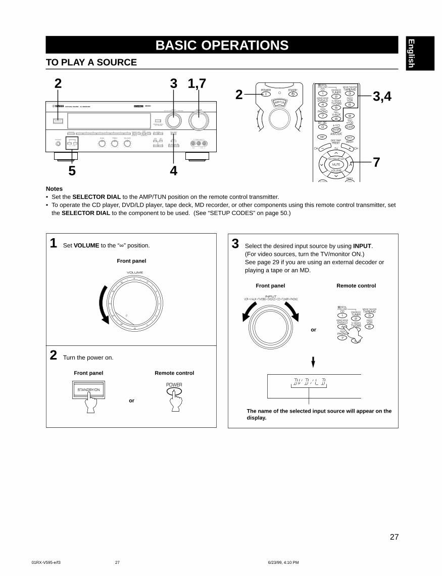
3 Select the desired input source by using INPUT.(For video sources, turn the TV/monitor ON.)See page 29 if you are using an external decoder orplaying a tape or an MD.
Front panel Remote control
or
The name of the selected input source will appear on thedisplay.
BASIC OPERATIONSTO PLAY A SOURCE
Notes• Set the SELECTOR DIAL to the AMP/TUN position on the remote control transmitter.• To operate the CD player, DVD/LD player, tape deck, MD recorder, or other components using this remote control transmitter, set
the SELECTOR DIAL to the component to be used. (See “SETUP CODES” on page 50.)
1 Set VOLUME to the “∞” position.
Front panel
2 Turn the power on.
Front panel Remote control
or
2
5 4
3 1,72
7
3,4
01RX-V595-e/f3 6/23/99, 4:10 PM27
28
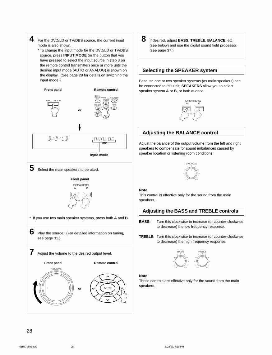
8 If desired, adjust BASS , TREBLE , BALANCE , etc.(see below) and use the digital sound field processor.(see page 37.)
Selecting the SPEAKER system
Because one or two speaker systems (as main speakers) canbe connected to this unit, SPEAKERS allow you to selectspeaker system A or B, or both at once.
Adjusting the BALANCE control
Adjust the balance of the output volume from the left and rightspeakers to compensate for sound imbalances caused byspeaker location or listening room conditions.
NoteThis control is effective only for the sound from the mainspeakers.
Adjusting the BASS and TREBLE controls
BASS: Turn this clockwise to increase (or counter-clockwiseto decrease) the low frequency response.
TREBLE: Turn this clockwise to increase (or counter-clockwiseto decrease) the high frequency response.
NoteThese controls are effective only for the sound from the mainspeakers.
4 For the DVD/LD or TV/DBS source, the current inputmode is also shown.* To change the input mode for the DVD/LD or TV/DBS
source, press INPUT MODE (or the button that youhave pressed to select the input source in step 3 onthe remote control transmitter) once or more until thedesired input mode (AUTO or ANALOG) is shown onthe display. (See page 29 for details on switching theinput mode.)
Front panel Remote control
or
Input mode
5 Select the main speakers to be used.
Front panel
* If you use two main speaker systems, press both A and B.
6 Play the source. (For detailed information on tuning,see page 31.)
7 Adjust the volume to the desired output level.
Front panel Remote control
or
01RX-V595-e/f3 6/23/99, 4:10 PM28
29
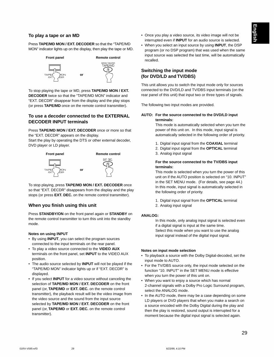
EnglishTo play a tape or an MD
Press TAPE/MD MON / EXT. DECODER so that the “TAPE/MDMON” indicator lights up on the display, then play the tape or MD.
Front panel Remote control
or
To stop playing the tape or MD, press TAPE/MD MON / EXT.DECODER twice so that the “TAPE/MD MON” indicator and“EXT. DECDR” disappear from the display and the play stops(or press TAPE/MD once on the remote control transmitter).
To use a decoder connected to the EXTERNALDECODER INPUT terminals
Press TAPE/MD MON / EXT. DECODER once or more so thatthe “EXT. DECDR” appears on the display.Start the play by operating the DTS or other external decoder,DVD player or LD player.
Front panel Remote control
or
To stop playing, press TAPE/MD MON / EXT. DECODER onceso that “EXT. DECDR” disappears from the display and the playstops (or press EXT. DEC. on the remote control transmitter).
When you finish using this unit
Press STANDBY/ON on the front panel again or STANDBY onthe remote control transmitter to turn this unit into the standbymode.
Notes on using INPUT• By using INPUT, you can select the program sources
connected to the input terminals on the rear panel.• To play a video source connected to the VIDEO AUX
terminals on the front panel, set INPUT to the VIDEO AUXposition.
• The audio source selected by INPUT will not be played if the“TAPE/MD MON” indicator lights up or if “EXT. DECDR” isdisplayed.
• If you select INPUT for a video source without canceling theselection of TAPE/MD MON / EXT. DECODER on the frontpanel (or, TAPE/MD or EXT. DEC. on the remote controltransmitter), the playback result will be the video image fromthe video source and the sound from the input sourceselected by TAPE/MD MON / EXT. DECODER on the frontpanel (or, TAPE/MD or EXT. DEC. on the remote controltransmitter).
• Once you play a video source, its video image will not beinterrupted even if INPUT for an audio source is selected.
• When you select an input source by using INPUT, the DSPprogram (or no DSP program) that was used when the sameinput source was selected the last time, will be automaticallyrecalled.
Switching the input mode(for DVD/LD and TV/DBS)
This unit allows you to switch the input mode only for sourcesconnected to the DVD/LD and TV/DBS input terminals (on therear panel of this unit) that input two or three types of signals.
The following two input modes are provided.
AUTO: For the source connected to the DVD/LD inputterminals:This mode is automatically selected when you turn thepower of this unit on. In this mode, input signal isautomatically selected in the following order of priority.
1. Digital input signal from the COAXIAL terminal2. Digital input signal from the OPTICAL terminal3. Analog input signal
For the source connected to the TV/DBS inputterminals:This mode is selected when you turn the power of thisunit on if the AUTO position is selected on “10. INPUT”in the SET MENU mode. (For details, see page 44.)In this mode, input signal is automatically selected inthe following order of priority.
1. Digital input signal from the OPTICAL terminal2. Analog input signal
ANALOG:In this mode, only analog input signal is selected evenif a digital signal is input at the same time.Select this mode when you want to use the analoginput signal instead of the digital input signal.
Notes on input mode selection• To playback a source with the Dolby Digital-decoded, set the
input mode to AUTO.• For the TV/DBS source only, the input mode selected on the
function “10. INPUT” in the SET MENU mode is effectivewhen you turn the power of this unit on.
• When you want to enjoy a source which has normal2-channel signals with a Dolby Pro Logic Surround program,select the ANALOG mode.
• In the AUTO mode, there may be a case depending on someLD players or DVD players that when you make a search ona source encoded with the Dolby Digital during the play andthen the play is restored, sound output is interrupted for amoment because the digital input signal is selected again.
01RX-V595-e/f3 6/23/99, 4:10 PM29
30
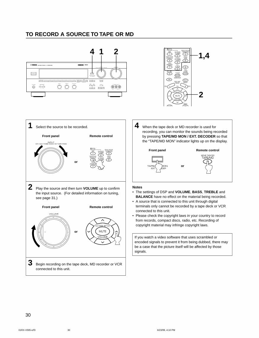
1 Select the source to be recorded.
Front panel Remote control
or
2 Play the source and then turn VOLUME up to confirmthe input source. (For detailed information on tuning,see page 31.)
Front panel Remote control
or
3 Begin recording on the tape deck, MD recorder or VCRconnected to this unit.
TO RECORD A SOURCE TO TAPE OR MD
4 1 2
2
1,4
4 When the tape deck or MD recorder is used forrecording, you can monitor the sounds being recordedby pressing TAPE/MD MON / EXT. DECODER so thatthe “TAPE/MD MON” indicator lights up on the display.
Front panel Remote control
or
Notes• The settings of DSP and VOLUME, BASS , TREBLE and
BALANCE have no effect on the material being recorded.• A source that is connected to this unit through digital
terminals only cannot be recorded by a tape deck or VCRconnected to this unit.
• Please check the copyright laws in your country to recordfrom records, compact discs, radio, etc. Recording ofcopyright material may infringe copyright laws.
If you watch a video software that uses scrambled orencoded signals to prevent it from being dubbed, there maybe a case that the picture itself will be affected by thosesignals.
01RX-V595-e/f3 6/23/99, 4:10 PM30
31
English
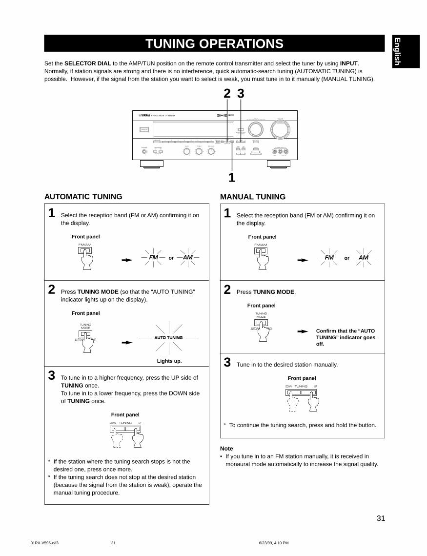
AUTOMATIC TUNING
1 Select the reception band (FM or AM) confirming it onthe display.
Front panel
or
2 Press TUNING MODE (so that the “AUTO TUNING”indicator lights up on the display).
Front panel
Lights up.
3 To tune in to a higher frequency, press the UP side ofTUNING once.To tune in to a lower frequency, press the DOWN sideof TUNING once.
Front panel
* If the station where the tuning search stops is not thedesired one, press once more.
* If the tuning search does not stop at the desired station(because the signal from the station is weak), operate themanual tuning procedure.
TUNING OPERATIONSSet the SELECTOR DIAL to the AMP/TUN position on the remote control transmitter and select the tuner by using INPUT.Normally, if station signals are strong and there is no interference, quick automatic-search tuning (AUTOMATIC TUNING) ispossible. However, if the signal from the station you want to select is weak, you must tune in to it manually (MANUAL TUNING).
MANUAL TUNING
1 Select the reception band (FM or AM) confirming it onthe display.
Front panel
or
2 Press TUNING MODE.
Front panel
3 Tune in to the desired station manually.
Front panel
* To continue the tuning search, press and hold the button.
Note• If you tune in to an FM station manually, it is received in
monaural mode automatically to increase the signal quality.
Confirm that the “AUTOTUNING’’ indicator goesoff.
2 3
1
01RX-V595-e/f3 6/23/99, 4:10 PM31
32
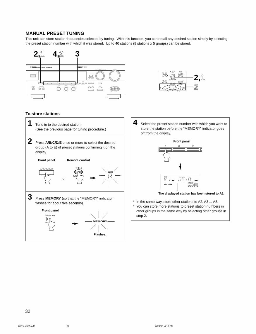
MANUAL PRESET TUNINGThis unit can store station frequencies selected by tuning. With this function, you can recall any desired station simply by selectingthe preset station number with which it was stored. Up to 40 stations (8 stations x 5 groups) can be stored.
4 Select the preset station number with which you want tostore the station before the “MEMORY” indicator goesoff from the display.
Front panel
The displayed station has been stored to A1.
* In the same way, store other stations to A2, A3 ... A8.* You can store more stations to preset station numbers in
other groups in the same way by selecting other groups instep 2.
To store stations
1 Tune in to the desired station.(See the previous page for tuning procedure.)
2 Press A/B/C/D/E once or more to select the desiredgroup (A to E) of preset stations confirming it on thedisplay.
Front panel Remote control
or
3 Press MEMORY (so that the “MEMORY” indicatorflashes for about five seconds).
Front panel
Flashes.
2,1 4,2 3
22,1
01RX-V595-e/f3 6/23/99, 4:10 PM32
33
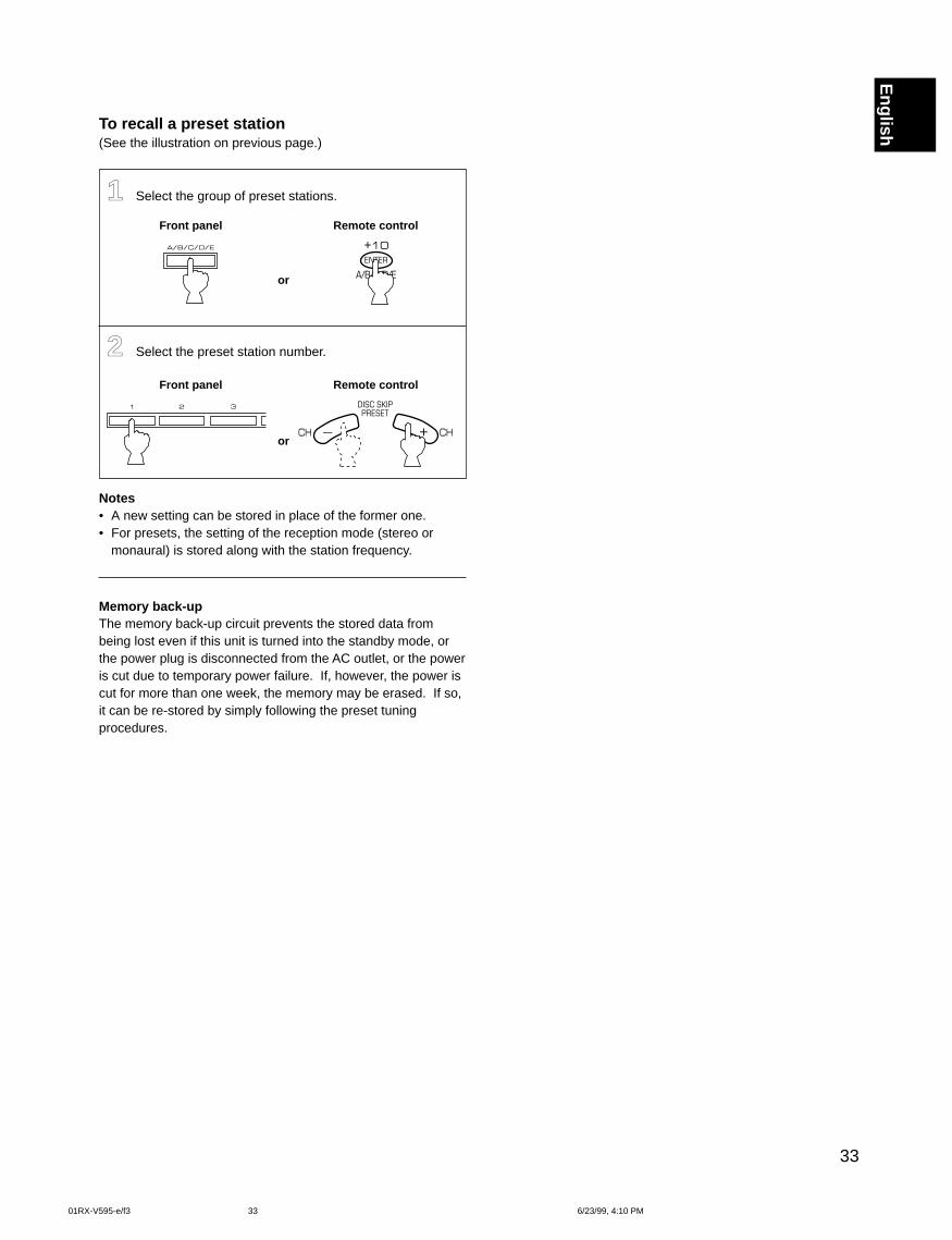
EnglishTo recall a preset station(See the illustration on previous page.)
11 Select the group of preset stations.
Front panel Remote control
or
22 Select the preset station number.
Front panel Remote control
or
Notes• A new setting can be stored in place of the former one.• For presets, the setting of the reception mode (stereo or
monaural) is stored along with the station frequency.
Memory back-upThe memory back-up circuit prevents the stored data frombeing lost even if this unit is turned into the standby mode, orthe power plug is disconnected from the AC outlet, or the poweris cut due to temporary power failure. If, however, the power iscut for more than one week, the memory may be erased. If so,it can be re-stored by simply following the preset tuningprocedures.
01RX-V595-e/f3 6/23/99, 4:10 PM33
34
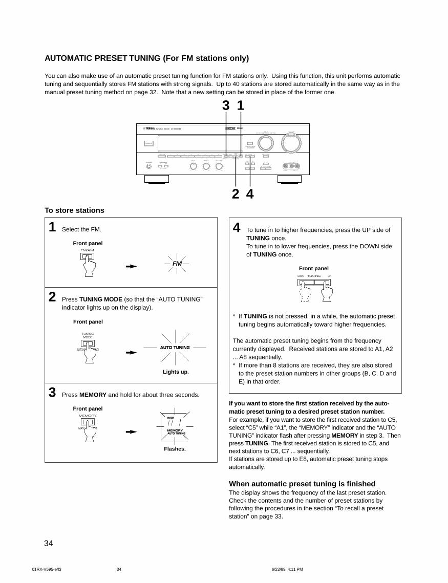
To store stations
1 Select the FM.
Front panel
2 Press TUNING MODE (so that the “AUTO TUNING”indicator lights up on the display).
Front panel
Lights up.
3 Press MEMORY and hold for about three seconds.
Front panel
Flashes.
AUTOMATIC PRESET TUNING (For FM stations only)
You can also make use of an automatic preset tuning function for FM stations only. Using this function, this unit performs automatictuning and sequentially stores FM stations with strong signals. Up to 40 stations are stored automatically in the same way as in themanual preset tuning method on page 32. Note that a new setting can be stored in place of the former one.
4 To tune in to higher frequencies, press the UP side ofTUNING once.To tune in to lower frequencies, press the DOWN sideof TUNING once.
Front panel
* If TUNING is not pressed, in a while, the automatic presettuning begins automatically toward higher frequencies.
The automatic preset tuning begins from the frequencycurrently displayed. Received stations are stored to A1, A2... A8 sequentially.* If more than 8 stations are received, they are also stored
to the preset station numbers in other groups (B, C, D andE) in that order.
If you want to store the first station received by the auto-matic preset tuning to a desired preset station number.For example, if you want to store the first received station to C5,select “C5” while “A1”, the “MEMORY” indicator and the “AUTOTUNING” indicator flash after pressing MEMORY in step 3. Thenpress TUNING. The first received station is stored to C5, andnext stations to C6, C7 ... sequentially.If stations are stored up to E8, automatic preset tuning stopsautomatically.
When automatic preset tuning is finishedThe display shows the frequency of the last preset station.Check the contents and the number of preset stations byfollowing the procedures in the section “To recall a presetstation” on page 33.
3
2 4
1
01RX-V595-e/f3 6/23/99, 4:11 PM34
35
English
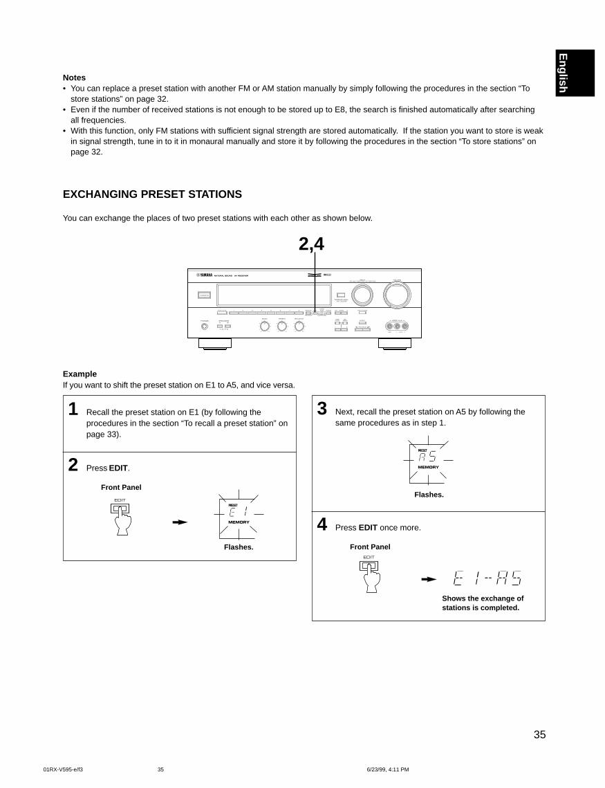
EXCHANGING PRESET STATIONS
You can exchange the places of two preset stations with each other as shown below.
ExampleIf you want to shift the preset station on E1 to A5, and vice versa.
1 Recall the preset station on E1 (by following theprocedures in the section “To recall a preset station” onpage 33).
2 Press EDIT.
Front Panel
Flashes.
3 Next, recall the preset station on A5 by following thesame procedures as in step 1.
Flashes.
4 Press EDIT once more.
Front Panel
Shows the exchange ofstations is completed.
2,4
Notes• You can replace a preset station with another FM or AM station manually by simply following the procedures in the section “To
store stations” on page 32.• Even if the number of received stations is not enough to be stored up to E8, the search is finished automatically after searching
all frequencies.• With this function, only FM stations with sufficient signal strength are stored automatically. If the station you want to store is weak
in signal strength, tune in to it in monaural manually and store it by following the procedures in the section “To store stations” onpage 32.
01RX-V595-e/f3 6/23/99, 4:11 PM35
36
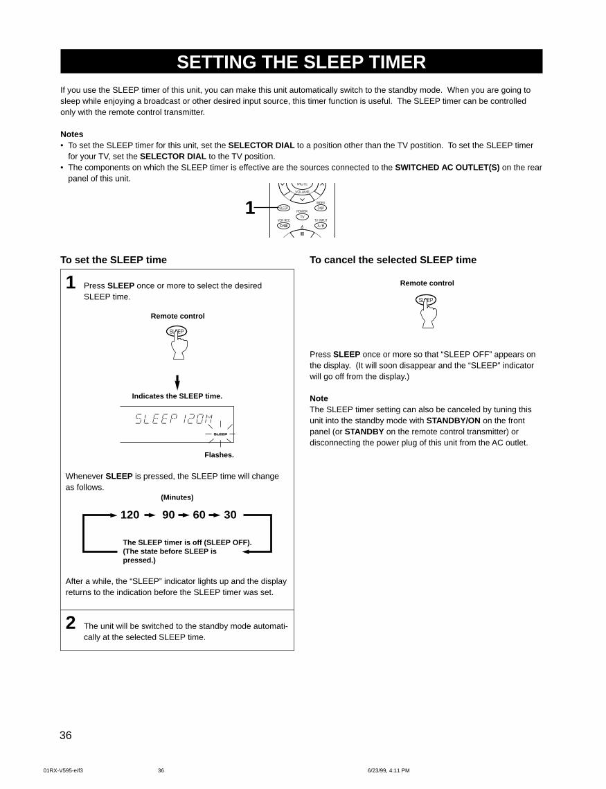
SETTING THE SLEEP TIMERIf you use the SLEEP timer of this unit, you can make this unit automatically switch to the standby mode. When you are going tosleep while enjoying a broadcast or other desired input source, this timer function is useful. The SLEEP timer can be controlledonly with the remote control transmitter.
Notes• To set the SLEEP timer for this unit, set the SELECTOR DIAL to a position other than the TV postition. To set the SLEEP timer
for your TV, set the SELECTOR DIAL to the TV position.• The components on which the SLEEP timer is effective are the sources connected to the SWITCHED AC OUTLET(S) on the rear
panel of this unit.
To set the SLEEP time
1 Press SLEEP once or more to select the desiredSLEEP time.
Remote control
Indicates the SLEEP time.
Flashes.
Whenever SLEEP is pressed, the SLEEP time will changeas follows.
(Minutes)
120 90 60 30
The SLEEP timer is off (SLEEP OFF).(The state before SLEEP ispressed.)
After a while, the “SLEEP” indicator lights up and the displayreturns to the indication before the SLEEP timer was set.
2 The unit will be switched to the standby mode automati-cally at the selected SLEEP time.
To cancel the selected SLEEP time
Remote control
Press SLEEP once or more so that “SLEEP OFF” appears onthe display. (It will soon disappear and the “SLEEP” indicatorwill go off from the display.)
NoteThe SLEEP timer setting can also be canceled by tuning thisunit into the standby mode with STANDBY/ON on the frontpanel (or STANDBY on the remote control transmitter) ordisconnecting the power plug of this unit from the AC outlet.
1
01RX-V595-e/f3 6/23/99, 4:11 PM36
37
English
FEATURE
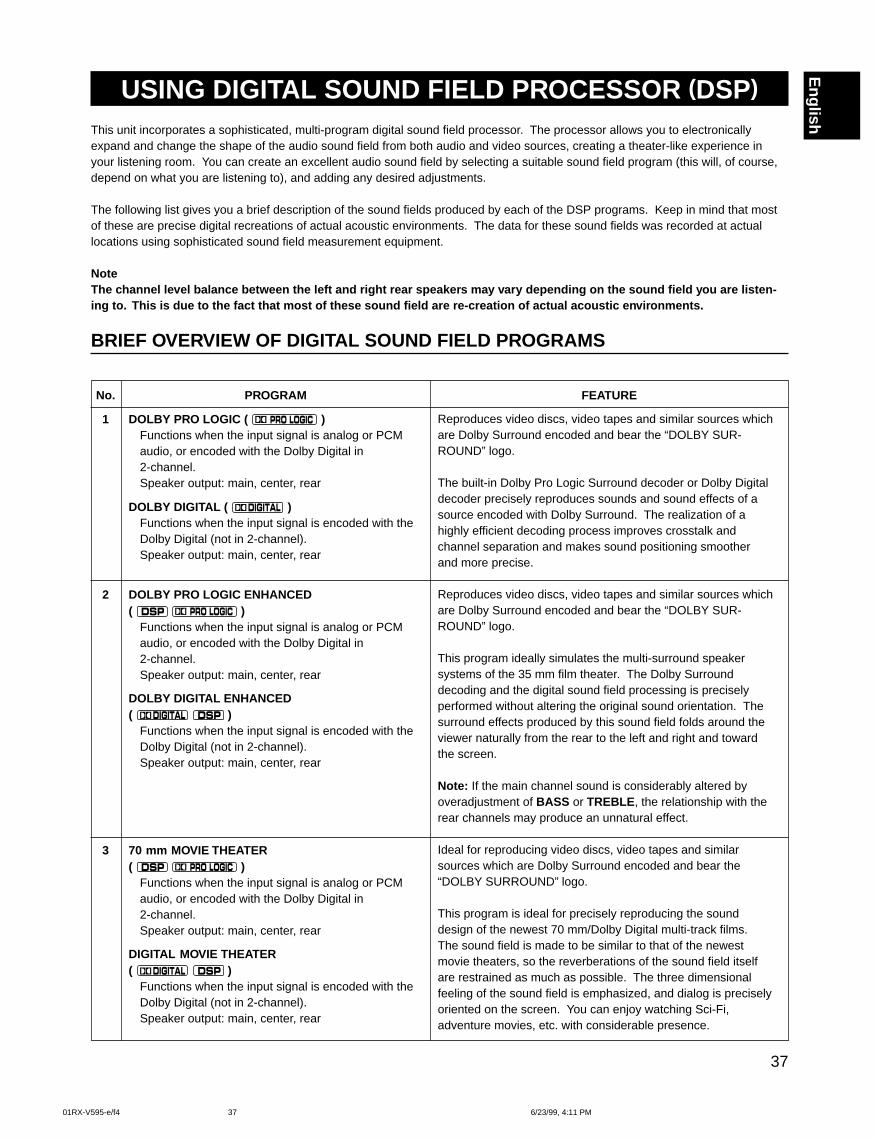
Reproduces video discs, video tapes and similar sources whichare Dolby Surround encoded and bear the “DOLBY SUR-ROUND” logo.
The built-in Dolby Pro Logic Surround decoder or Dolby Digitaldecoder precisely reproduces sounds and sound effects of asource encoded with Dolby Surround. The realization of ahighly efficient decoding process improves crosstalk andchannel separation and makes sound positioning smootherand more precise.
Reproduces video discs, video tapes and similar sources whichare Dolby Surround encoded and bear the “DOLBY SUR-ROUND” logo.
This program ideally simulates the multi-surround speakersystems of the 35 mm film theater. The Dolby Surrounddecoding and the digital sound field processing is preciselyperformed without altering the original sound orientation. Thesurround effects produced by this sound field folds around theviewer naturally from the rear to the left and right and towardthe screen.
Note: If the main channel sound is considerably altered byoveradjustment of BASS or TREBLE , the relationship with therear channels may produce an unnatural effect.
Ideal for reproducing video discs, video tapes and similarsources which are Dolby Surround encoded and bear the“DOLBY SURROUND” logo.
This program is ideal for precisely reproducing the sounddesign of the newest 70 mm/Dolby Digital multi-track films.The sound field is made to be similar to that of the newestmovie theaters, so the reverberations of the sound field itselfare restrained as much as possible. The three dimensionalfeeling of the sound field is emphasized, and dialog is preciselyoriented on the screen. You can enjoy watching Sci-Fi,adventure movies, etc. with considerable presence.
No. PROGRAM
1 DOLBY PRO LOGIC ( )Functions when the input signal is analog or PCMaudio, or encoded with the Dolby Digital in2-channel.Speaker output: main, center, rear
DOLBY DIGITAL ( )Functions when the input signal is encoded with theDolby Digital (not in 2-channel).Speaker output: main, center, rear
2 DOLBY PRO LOGIC ENHANCED( )
Functions when the input signal is analog or PCMaudio, or encoded with the Dolby Digital in2-channel.Speaker output: main, center, rear
DOLBY DIGITAL ENHANCED( )
Functions when the input signal is encoded with theDolby Digital (not in 2-channel).Speaker output: main, center, rear
3 70 mm MOVIE THEATER( )
Functions when the input signal is analog or PCMaudio, or encoded with the Dolby Digital in2-channel.Speaker output: main, center, rear
DIGITAL MOVIE THEATER( )
Functions when the input signal is encoded with theDolby Digital (not in 2-channel).Speaker output: main, center, rear
USING DIGITAL SOUND FIELD PROCESSOR (DSP)
This unit incorporates a sophisticated, multi-program digital sound field processor. The processor allows you to electronicallyexpand and change the shape of the audio sound field from both audio and video sources, creating a theater-like experience inyour listening room. You can create an excellent audio sound field by selecting a suitable sound field program (this will, of course,depend on what you are listening to), and adding any desired adjustments.
The following list gives you a brief description of the sound fields produced by each of the DSP programs. Keep in mind that mostof these are precise digital recreations of actual acoustic environments. The data for these sound fields was recorded at actuallocations using sophisticated sound field measurement equipment.
NoteThe channel level balance between the left and right rear speakers may vary depending on the sound field you are listen-ing to. This is due to the fact that most of these sound field are re-creation of actual acoustic environments.
BRIEF OVERVIEW OF DIGITAL SOUND FIELD PROGRAMS
01RX-V595-e/f4 6/23/99, 4:11 PM37
38
FEATURE
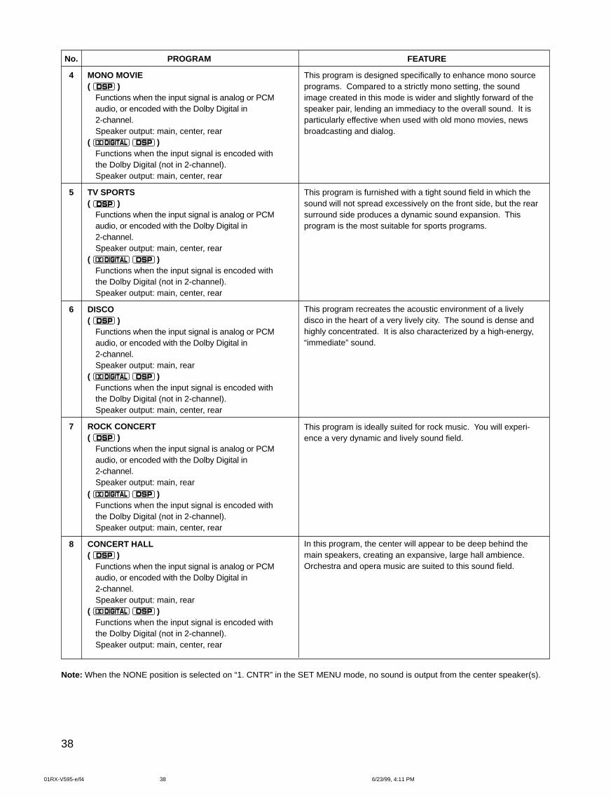
This program is designed specifically to enhance mono sourceprograms. Compared to a strictly mono setting, the soundimage created in this mode is wider and slightly forward of thespeaker pair, lending an immediacy to the overall sound. It isparticularly effective when used with old mono movies, newsbroadcasting and dialog.
This program is furnished with a tight sound field in which thesound will not spread excessively on the front side, but the rearsurround side produces a dynamic sound expansion. Thisprogram is the most suitable for sports programs.
This program recreates the acoustic environment of a livelydisco in the heart of a very lively city. The sound is dense andhighly concentrated. It is also characterized by a high-energy,“immediate” sound.
This program is ideally suited for rock music. You will experi-ence a very dynamic and lively sound field.
In this program, the center will appear to be deep behind themain speakers, creating an expansive, large hall ambience.Orchestra and opera music are suited to this sound field.
No. PROGRAM
4 MONO MOVIE( )
Functions when the input signal is analog or PCMaudio, or encoded with the Dolby Digital in2-channel.Speaker output: main, center, rear
( )Functions when the input signal is encoded withthe Dolby Digital (not in 2-channel).Speaker output: main, center, rear
5 TV SPORTS( )
Functions when the input signal is analog or PCMaudio, or encoded with the Dolby Digital in2-channel.Speaker output: main, center, rear
( )Functions when the input signal is encoded withthe Dolby Digital (not in 2-channel).Speaker output: main, center, rear
6 DISCO( )
Functions when the input signal is analog or PCMaudio, or encoded with the Dolby Digital in2-channel.Speaker output: main, rear
( )Functions when the input signal is encoded withthe Dolby Digital (not in 2-channel).Speaker output: main, center, rear
7 ROCK CONCERT( )
Functions when the input signal is analog or PCMaudio, or encoded with the Dolby Digital in2-channel.Speaker output: main, rear
( )Functions when the input signal is encoded withthe Dolby Digital (not in 2-channel).Speaker output: main, center, rear
8 CONCERT HALL( )
Functions when the input signal is analog or PCMaudio, or encoded with the Dolby Digital in2-channel.Speaker output: main, rear
( )Functions when the input signal is encoded withthe Dolby Digital (not in 2-channel).Speaker output: main, center, rear
Note: When the NONE position is selected on “1. CNTR” in the SET MENU mode, no sound is output from the center speaker(s).
01RX-V595-e/f4 6/23/99, 4:11 PM38
39
English
2
2
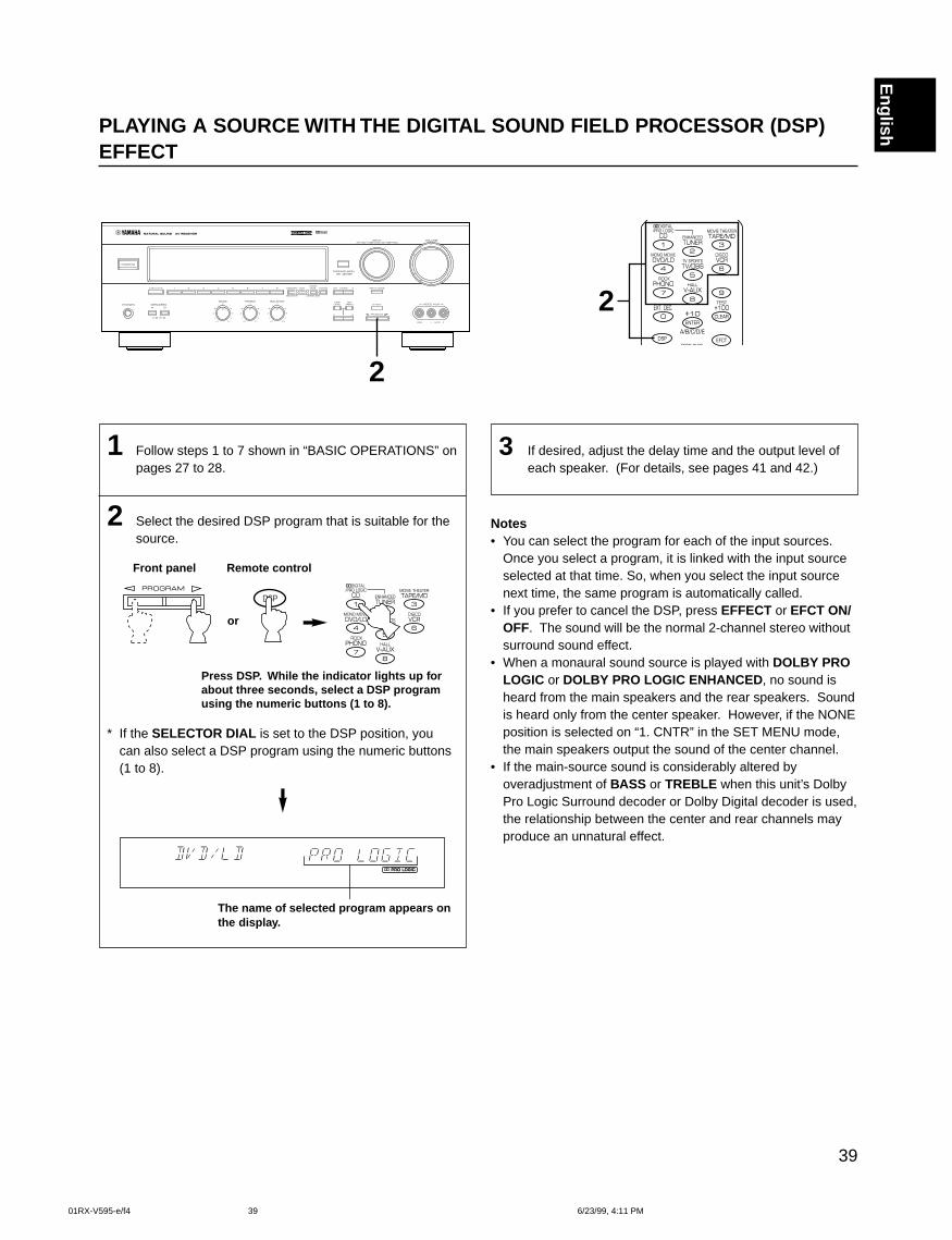
PLAYING A SOURCE WITH THE DIGITAL SOUND FIELD PROCESSOR (DSP)EFFECT
1 Follow steps 1 to 7 shown in “BASIC OPERATIONS” onpages 27 to 28.
2 Select the desired DSP program that is suitable for thesource.
Front panel Remote control
or
Press DSP. While the indicator lights up forabout three seconds, select a DSP programusing the numeric buttons (1 to 8).
* If the SELECTOR DIAL is set to the DSP position, youcan also select a DSP program using the numeric buttons(1 to 8).
The name of selected program appears onthe display.
3 If desired, adjust the delay time and the output level ofeach speaker. (For details, see pages 41 and 42.)
Notes• You can select the program for each of the input sources.
Once you select a program, it is linked with the input sourceselected at that time. So, when you select the input sourcenext time, the same program is automatically called.
• If you prefer to cancel the DSP, press EFFECT or EFCT ON/OFF. The sound will be the normal 2-channel stereo withoutsurround sound effect.
• When a monaural sound source is played with DOLBY PROLOGIC or DOLBY PRO LOGIC ENHANCED , no sound isheard from the main speakers and the rear speakers. Soundis heard only from the center speaker. However, if the NONEposition is selected on “1. CNTR” in the SET MENU mode,the main speakers output the sound of the center channel.
• If the main-source sound is considerably altered byoveradjustment of BASS or TREBLE when this unit’s DolbyPro Logic Surround decoder or Dolby Digital decoder is used,the relationship between the center and rear channels mayproduce an unnatural effect.
01RX-V595-e/f4 6/23/99, 4:11 PM39
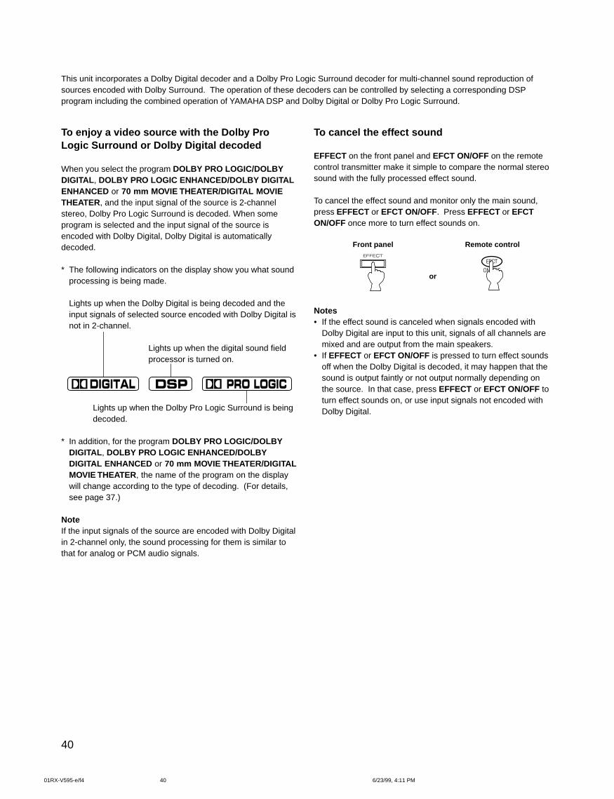
40
To enjoy a video source with the Dolby ProLogic Surround or Dolby Digital decoded
When you select the program DOLBY PRO LOGIC/DOLBYDIGITAL , DOLBY PRO LOGIC ENHANCED/DOLBY DIGITALENHANCED or 70 mm MOVIE THEATER/DIGITAL MOVIETHEATER, and the input signal of the source is 2-channelstereo, Dolby Pro Logic Surround is decoded. When someprogram is selected and the input signal of the source isencoded with Dolby Digital, Dolby Digital is automaticallydecoded.
* The following indicators on the display show you what soundprocessing is being made.
Lights up when the Dolby Digital is being decoded and theinput signals of selected source encoded with Dolby Digital isnot in 2-channel.
Lights up when the digital sound fieldprocessor is turned on.
Lights up when the Dolby Pro Logic Surround is beingdecoded.
* In addition, for the program DOLBY PRO LOGIC/DOLBYDIGITAL , DOLBY PRO LOGIC ENHANCED/DOLBYDIGITAL ENHANCED or 70 mm MOVIE THEATER/DIGITALMOVIE THEATER, the name of the program on the displaywill change according to the type of decoding. (For details,see page 37.)
NoteIf the input signals of the source are encoded with Dolby Digitalin 2-channel only, the sound processing for them is similar tothat for analog or PCM audio signals.
To cancel the effect sound
EFFECT on the front panel and EFCT ON/OFF on the remotecontrol transmitter make it simple to compare the normal stereosound with the fully processed effect sound.
To cancel the effect sound and monitor only the main sound,press EFFECT or EFCT ON/OFF. Press EFFECT or EFCTON/OFF once more to turn effect sounds on.
Front panel Remote control
or
Notes• If the effect sound is canceled when signals encoded with
Dolby Digital are input to this unit, signals of all channels aremixed and are output from the main speakers.
• If EFFECT or EFCT ON/OFF is pressed to turn effect soundsoff when the Dolby Digital is decoded, it may happen that thesound is output faintly or not output normally depending onthe source. In that case, press EFFECT or EFCT ON/OFF toturn effect sounds on, or use input signals not encoded withDolby Digital.
This unit incorporates a Dolby Digital decoder and a Dolby Pro Logic Surround decoder for multi-channel sound reproduction ofsources encoded with Dolby Surround. The operation of these decoders can be controlled by selecting a corresponding DSPprogram including the combined operation of YAMAHA DSP and Dolby Digital or Dolby Pro Logic Surround.
01RX-V595-e/f4 6/23/99, 4:11 PM40
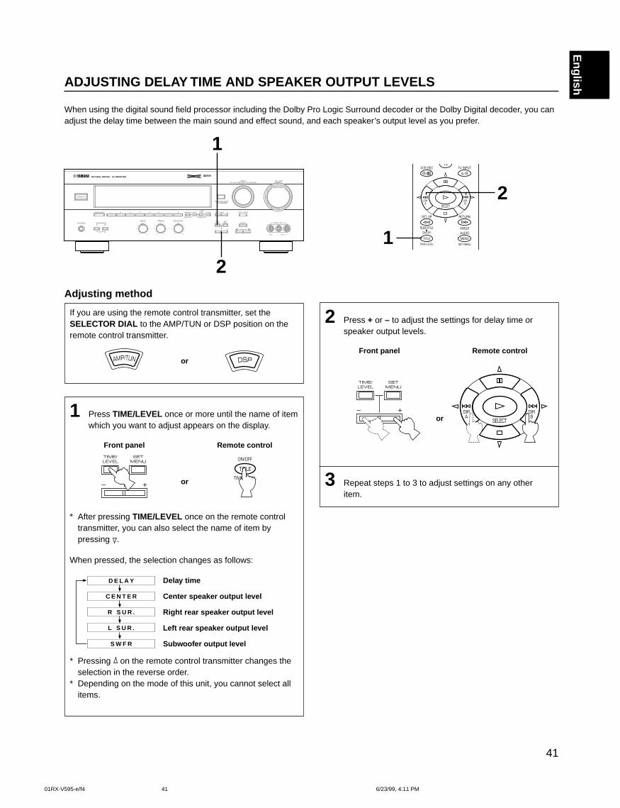
41
English
2 Press + or – to adjust the settings for delay time orspeaker output levels.
Front panel Remote control
or
3 Repeat steps 1 to 3 to adjust settings on any otheritem.
ADJUSTING DELAY TIME AND SPEAKER OUTPUT LEVELS
When using the digital sound field processor including the Dolby Pro Logic Surround decoder or the Dolby Digital decoder, you canadjust the delay time between the main sound and effect sound, and each speaker’s output level as you prefer.
Adjusting method
If you are using the remote control transmitter, set theSELECTOR DIAL to the AMP/TUN or DSP position on theremote control transmitter.
or
1 Press TIME/LEVEL once or more until the name of itemwhich you want to adjust appears on the display.
Front panel Remote control
or
* After pressing TIME/LEVEL once on the remote controltransmitter, you can also select the name of item bypressing .
When pressed, the selection changes as follows:
D E L A Y
C E N T E R
R S U R .
L S U R .
S W F R
* Pressing on the remote control transmitter changes theselection in the reverse order.
* Depending on the mode of this unit, you cannot select allitems.
1
2
2
1
Delay time
Center speaker output level
Right rear speaker output level
Left rear speaker output level
Subwoofer output level
01RX-V595-e/f4 6/23/99, 4:11 PM41
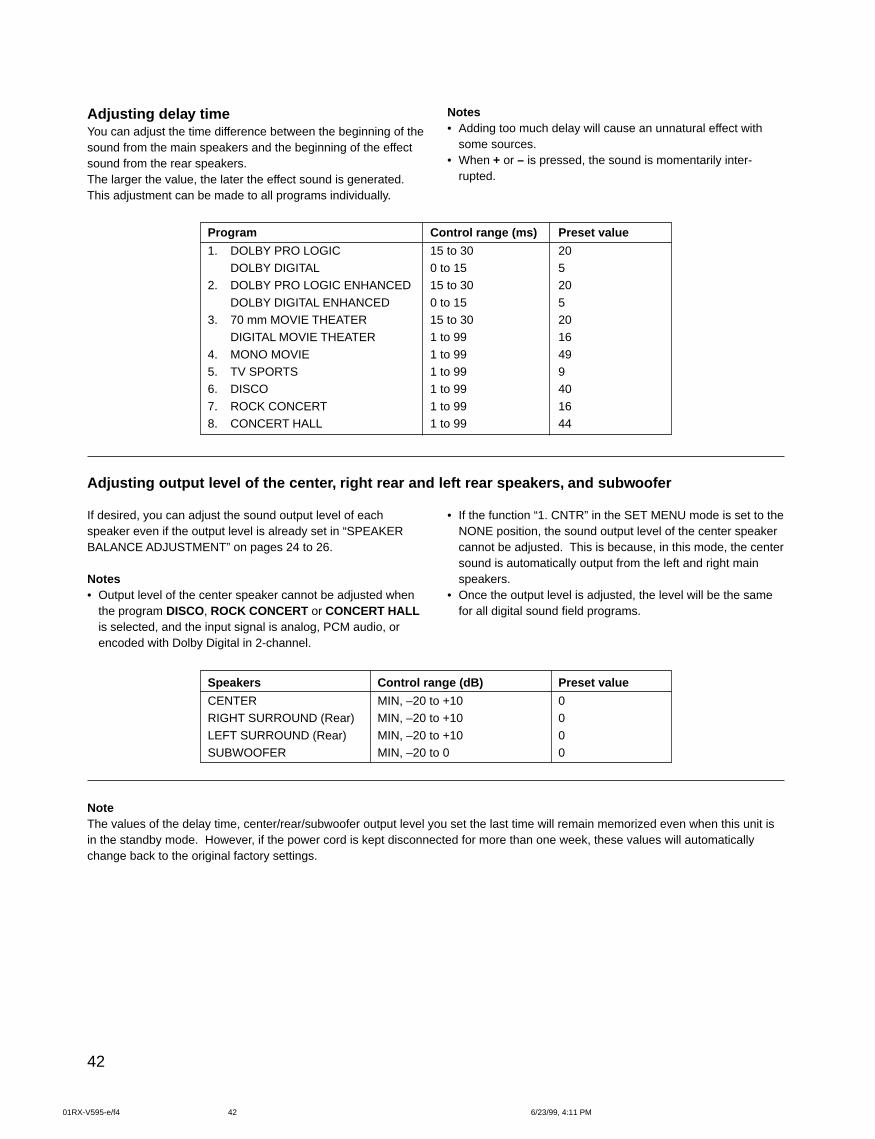
42
Adjusting delay timeYou can adjust the time difference between the beginning of thesound from the main speakers and the beginning of the effectsound from the rear speakers.The larger the value, the later the effect sound is generated.This adjustment can be made to all programs individually.
Notes• Adding too much delay will cause an unnatural effect with
some sources.• When + or – is pressed, the sound is momentarily inter-
rupted.
Adjusting output level of the center, right rear and left rear speakers, and subwoofer
Program
1. DOLBY PRO LOGICDOLBY DIGITAL
2. DOLBY PRO LOGIC ENHANCED
DOLBY DIGITAL ENHANCED3. 70 mm MOVIE THEATER
DIGITAL MOVIE THEATER
4. MONO MOVIE5. TV SPORTS6. DISCO
7. ROCK CONCERT8. CONCERT HALL
If desired, you can adjust the sound output level of eachspeaker even if the output level is already set in “SPEAKERBALANCE ADJUSTMENT” on pages 24 to 26.
Notes• Output level of the center speaker cannot be adjusted when
the program DISCO, ROCK CONCERT or CONCERT HALLis selected, and the input signal is analog, PCM audio, orencoded with Dolby Digital in 2-channel.
• If the function “1. CNTR” in the SET MENU mode is set to theNONE position, the sound output level of the center speakercannot be adjusted. This is because, in this mode, the centersound is automatically output from the left and right mainspeakers.
• Once the output level is adjusted, the level will be the samefor all digital sound field programs.
Speakers
CENTERRIGHT SURROUND (Rear)
LEFT SURROUND (Rear)SUBWOOFER
Control range (dB)
MIN, –20 to +10MIN, –20 to +10
MIN, –20 to +10MIN, –20 to 0
Preset value
00
00
Preset value
20520
52016
49940
1644
Control range (ms)
15 to 300 to 1515 to 30
0 to 1515 to 301 to 99
1 to 991 to 991 to 99
1 to 991 to 99
NoteThe values of the delay time, center/rear/subwoofer output level you set the last time will remain memorized even when this unit isin the standby mode. However, if the power cord is kept disconnected for more than one week, these values will automaticallychange back to the original factory settings.
01RX-V595-e/f4 6/23/99, 4:11 PM42
43
English
7. D.RNG (Adjusting dynamic range)
Choices: MAX/STD/MINPreset position: MAX
* This adjustment is effective only when the Dolby Digital isdecoded.
MAX: “Dynamic range” is the difference between themaximum level and the minimum level of sounds.Sounds on a movie originally designed for movietheaters feature very wide dynamic range.Dolby Digital technology can bring the original soundtrack into a home audio format with this widedynamic range unchanged.In this position, a source encoded with the DolbyDigital is reproduced in the original sound track’swide dynamic range providing you with powerfulsounds just like in a movie theater.Selecting this position will be even better if you canlisten to a source in a high output level in a roomspecially soundproofed for audio/video enjoyment.
STD (Standard):Powerful sounds of extremely wide dynamic rangeare not always suitable for home use. Dependingupon the condition of your listening environment, itmay not be possible to increase the sound outputlevel as high as a movie theater. However, in a levelsuitable for listening to in your room, the low levelparts of source sound often cannot be heard so wellbecause they will be lost among noises in yourenvironment.Dolby Digital technology also made it possible toreduce an original sound track’s dynamic range for ahome audio format by “compressing” the data ofsound.In this position, a source encoded with the DolbyDigital is reproduced in the “compressed” dynamicrange of the source suitable for low level listening.
MIN: In this position, dynamic range is more reduced thanin the STD position.Selecting this position will be effective when youmust listen to a source at lower level.
ADJUSTMENTS IN THE “SET MENU” MODEThe following ten types of functions maximize the performance of your system and expand your enjoyment for audio listening andvideo watching.
1. CNTR (CENTER SPEAKER)2. REAR (REAR SPEAKER)3. MAIN (MAIN SPEAKER)4. BASS (LFE/BASS OUT)5. M.LVL (MAIN LEVEL)
For details on “1. CNTR”, “2. REAR”, “3. MAIN”, “4. BASS” and“5. M.LVL”, see page 22. (Once you have selected theappropriate modes, you do not have to change settings unlessany alteration is made in your speaker system.)
6. LFE [Adjusting the output level of theLFE (low frequency effect) channel]
Control range: –20 dB to 0 dB (in 1 dB step)Preset value: 0 dB
* This adjustment is effective only when the Dolby Digital isdecoded and the signals of selected source encoded with theDolby Digital contain LFE signals.
Adjusts the output level of the LFE (low frequency effect)channel. If the LFE signals are mixed with signals of otherchannels to output them from the same speakers, the ratio ofLFE signal level to the level of other signals are adjusted.(See page 7 for details about the LFE channel.)
6. LFE (LFE LEVEL)7. D.RNG (DYNAMIC RANGE)8. C.DELAY (CENTER DELAY)9. GUARD (MEMORY GUARD)10. INPUT (INPUT MODE)
01RX-V595-e/f5 6/23/99, 4:11 PM43
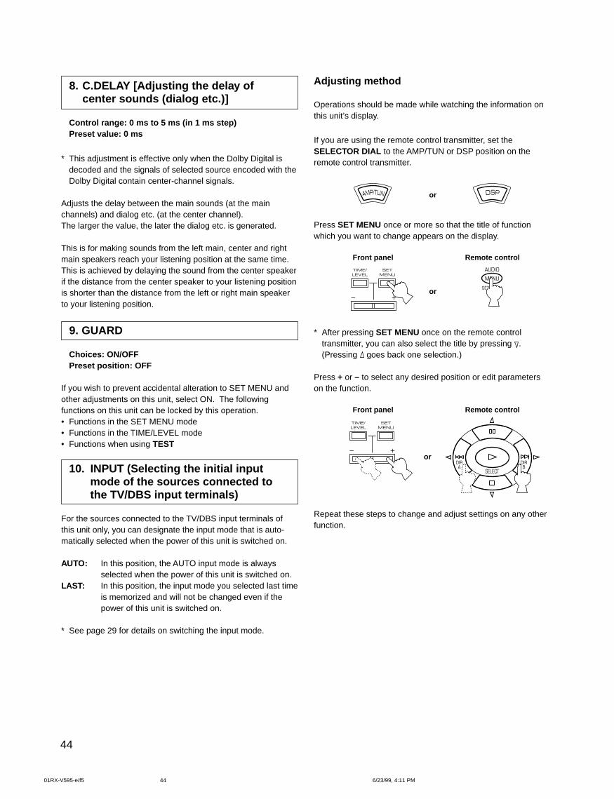
44
8. C.DELAY [Adjusting the delay ofcenter sounds (dialog etc.)]
Control range: 0 ms to 5 ms (in 1 ms step)Preset value: 0 ms
* This adjustment is effective only when the Dolby Digital isdecoded and the signals of selected source encoded with theDolby Digital contain center-channel signals.
Adjusts the delay between the main sounds (at the mainchannels) and dialog etc. (at the center channel).The larger the value, the later the dialog etc. is generated.
This is for making sounds from the left main, center and rightmain speakers reach your listening position at the same time.This is achieved by delaying the sound from the center speakerif the distance from the center speaker to your listening positionis shorter than the distance from the left or right main speakerto your listening position.
9. GUARD
Choices: ON/OFFPreset position: OFF
If you wish to prevent accidental alteration to SET MENU andother adjustments on this unit, select ON. The followingfunctions on this unit can be locked by this operation.• Functions in the SET MENU mode• Functions in the TIME/LEVEL mode• Functions when using TEST
10. INPUT (Selecting the initial inputmode of the sources connected tothe TV/DBS input terminals)
For the sources connected to the TV/DBS input terminals ofthis unit only, you can designate the input mode that is auto-matically selected when the power of this unit is switched on.
AUTO: In this position, the AUTO input mode is alwaysselected when the power of this unit is switched on.
LAST: In this position, the input mode you selected last timeis memorized and will not be changed even if thepower of this unit is switched on.
* See page 29 for details on switching the input mode.
Adjusting method
Operations should be made while watching the information onthis unit’s display.
If you are using the remote control transmitter, set theSELECTOR DIAL to the AMP/TUN or DSP position on theremote control transmitter.
or
Press SET MENU once or more so that the title of functionwhich you want to change appears on the display.
Front panel Remote control
or
* After pressing SET MENU once on the remote controltransmitter, you can also select the title by pressing .(Pressing goes back one selection.)
Press + or – to select any desired position or edit parameterson the function.
Front panel Remote control
or
Repeat these steps to change and adjust settings on any otherfunction.
01RX-V595-e/f5 6/23/99, 4:11 PM44
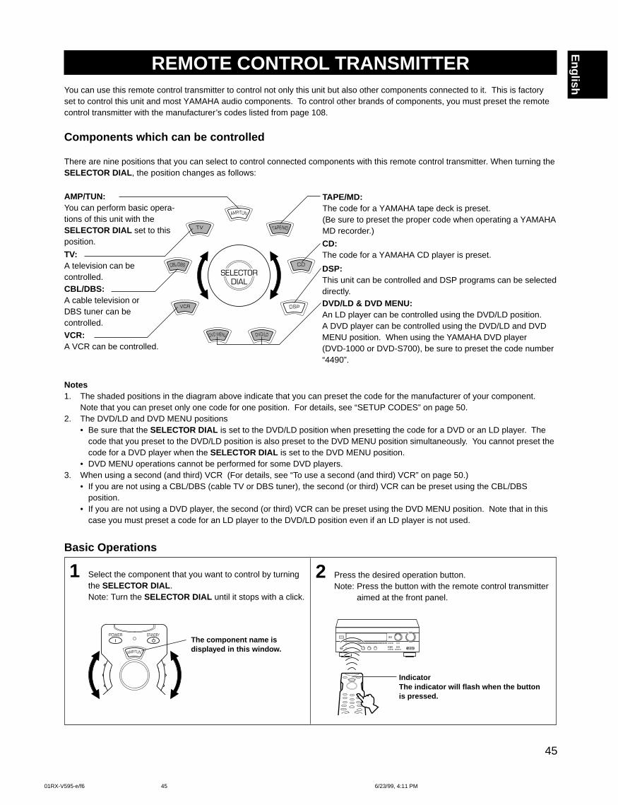
45
English
You can use this remote control transmitter to control not only this unit but also other components connected to it. This is factoryset to control this unit and most YAMAHA audio components. To control other brands of components, you must preset the remotecontrol transmitter with the manufacturer’s codes listed from page 108.
2 Press the desired operation button.Note: Press the button with the remote control transmitter
aimed at the front panel.
REMOTE CONTROL TRANSMITTER
Basic Operations
1 Select the component that you want to control by turningthe SELECTOR DIAL .Note: Turn the SELECTOR DIAL until it stops with a click.
Components which can be controlled
There are nine positions that you can select to control connected components with this remote control transmitter. When turning theSELECTOR DIAL , the position changes as follows:
SELECTOR DIAL
Notes1. The shaded positions in the diagram above indicate that you can preset the code for the manufacturer of your component.
Note that you can preset only one code for one position. For details, see “SETUP CODES” on page 50.2. The DVD/LD and DVD MENU positions
• Be sure that the SELECTOR DIAL is set to the DVD/LD position when presetting the code for a DVD or an LD player. Thecode that you preset to the DVD/LD position is also preset to the DVD MENU position simultaneously. You cannot preset thecode for a DVD player when the SELECTOR DIAL is set to the DVD MENU position.
• DVD MENU operations cannot be performed for some DVD players.3. When using a second (and third) VCR (For details, see “To use a second (and third) VCR” on page 50.)
• If you are not using a CBL/DBS (cable TV or DBS tuner), the second (or third) VCR can be preset using the CBL/DBSposition.
• If you are not using a DVD player, the second (or third) VCR can be preset using the DVD MENU position. Note that in thiscase you must preset a code for an LD player to the DVD/LD position even if an LD player is not used.
DVD/LD & DVD MENU:An LD player can be controlled using the DVD/LD position.A DVD player can be controlled using the DVD/LD and DVDMENU position. When using the YAMAHA DVD player(DVD-1000 or DVD-S700), be sure to preset the code number“4490”.
AMP/TUN:You can perform basic opera-tions of this unit with theSELECTOR DIAL set to thisposition.
TAPE/MD:The code for a YAMAHA tape deck is preset.(Be sure to preset the proper code when operating a YAMAHAMD recorder.)
CD:The code for a YAMAHA CD player is preset.
DSP:This unit can be controlled and DSP programs can be selecteddirectly.
VCR:A VCR can be controlled.
CBL/DBS:A cable television orDBS tuner can becontrolled.
TV:A television can becontrolled.
IndicatorThe indicator will flash when the buttonis pressed.
The component name isdisplayed in this window.
01RX-V595-e/f6 6/23/99, 4:11 PM45
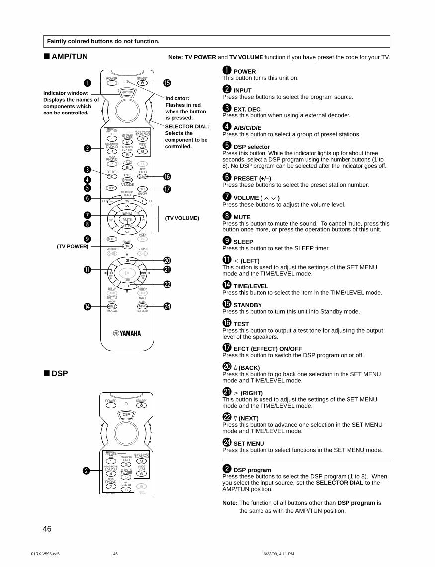
46
AMP/TUN Note: TV POWER and TV VOLUME function if you have preset the code for your TV.
1 POWERThis button turns this unit on.
2 INPUTPress these buttons to select the program source.
3 EXT. DEC.Press this button when using a external decoder.
4 A/B/C/D/EPress this button to select a group of preset stations.
5 DSP selectorPress this button. While the indicator lights up for about threeseconds, select a DSP program using the number buttons (1 to8). No DSP program can be selected after the indicator goes off.
6 PRESET (+/–)Press these buttons to select the preset station number.
7 VOLUME ( )Press these buttons to adjust the volume level.
8 MUTEPress this button to mute the sound. To cancel mute, press thisbutton once more, or press the operation buttons of this unit.
9 SLEEPPress this button to set the SLEEP timer.
q (LEFT)This button is used to adjust the settings of the SET MENUmode and the TIME/LEVEL mode.
r TIME/LEVELPress this button to select the item in the TIME/LEVEL mode.
t STANDBYPress this button to turn this unit into Standby mode.
y TESTPress this button to output a test tone for adjusting the outputlevel of the speakers.
u EFCT (EFFECT) ON/OFFPress this button to switch the DSP program on or off.
p (BACK)Press this button to go back one selection in the SET MENUmode and TIME/LEVEL mode.
a (RIGHT)This button is used to adjust the settings of the SET MENUmode and the TIME/LEVEL mode.
s (NEXT)Press this button to advance one selection in the SET MENUmode and TIME/LEVEL mode.
f SET MENUPress this button to select functions in the SET MENU mode.
2 DSP programPress these buttons to select the DSP program (1 to 8). Whenyou select the input source, set the SELECTOR DIAL to theAMP/TUN position.
Note: The function of all buttons other than DSP program isthe same as with the AMP/TUN position.
t1
2
3
7
54
8
9
u
y
f
s
ap
r
q
6
2
DSP
Indicator:Flashes in redwhen the buttonis pressed.
Indicator window:Displays the names ofcomponents whichcan be controlled.
SELECTOR DIAL:Selects thecomponent to becontrolled.
Faintly colored buttons do not function.
(TV VOLUME)
(TV POWER)
01RX-V595-e/f6 6/23/99, 4:11 PM46
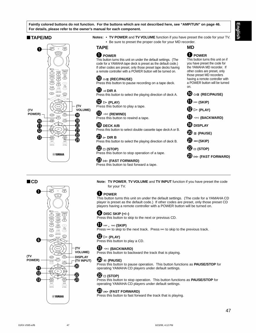
47
English
Faintly colored buttons do not function. For the buttons which are not described here, see “AMP/TUN” on page 46.For details, please refer to the owner’s manual for each component.
1
q
e
w
6
ds
p
CD
TAPE/MD
Note: TV POWER , TV VOLUME and TV INPUT function if you have preset the codefor your TV.
1 POWERThis button turns this unit on under the default settings. (The code for a YAMAHA CDplayer is preset as the default code.) If other codes are preset, only those preset CDplayers having a remote controller with a POWER button will be turned on.
6 DISC SKIP (+/–)Press this button to skip to the next or previous CD.
q , (SKIP)Press to skip to the next track. Press to skip to the previous track.
w (PLAY)Press this button to play a CD.
e (BACKWARD)Press this button to backward the track that is playing.
p (PAUSE)Press this button to pause operation. This button functions as PAUSE/STOP foroperating YAMAHA CD players under default settings.
s (STOP)Press this button to stop operation. This button functions as PAUSE/STOP foroperating YAMAHA CD players under default settings.
d (FAST FORWARD)Press this button to fast forward the track that is playing.
1
0qw
e
poi
asd
Notes: • TV POWER and TV VOLUME function if you have preset the code for your TV.• Be sure to preset the proper code for your MD recorder.
TAPE
1 POWERThis button turns this unit on under the default settings. (Thecode for a YAMAHA tape deck is preset as the default code.)If other codes are preset, only those preset tape decks havinga remote controller with a POWER button will be turned on.
0 (REC/PAUSE)Press this button to pause recording on a tape deck.
q DIR APress this button to select the playing direction of deck A.
w (PLAY)Press this button to play a tape.
e (REWIND)Press this button to rewind a tape.
o DECK A/BPress this button to select double cassette tape deck A or B.
a DIR BPress this button to select the playing direction of deck B.
s (STOP)Press this button to stop operation of a tape.
d (FAST FORWARD)Press this button to fast forward a tape.
MD
1 POWERThis button turns this unit on ifyou have preset the code forthe YAMAHA MD recorder. Ifother codes are preset, onlythose preset MD recordershaving a remote controller witha POWER button will be turnedon.
0 (REC/PAUSE)
q (SKIP)
w (PLAY)
e (BACKWARD)
i DISPLAY
p (PAUSE)
a (SKIP)
s (STOP)
d (FAST FORWARD)
(TVVOLUME)(TV
POWER)
(TVVOLUME)
(TVPOWER) (TV INPUT)
DISPLAY
01RX-V595-e/f6 6/23/99, 4:12 PM47
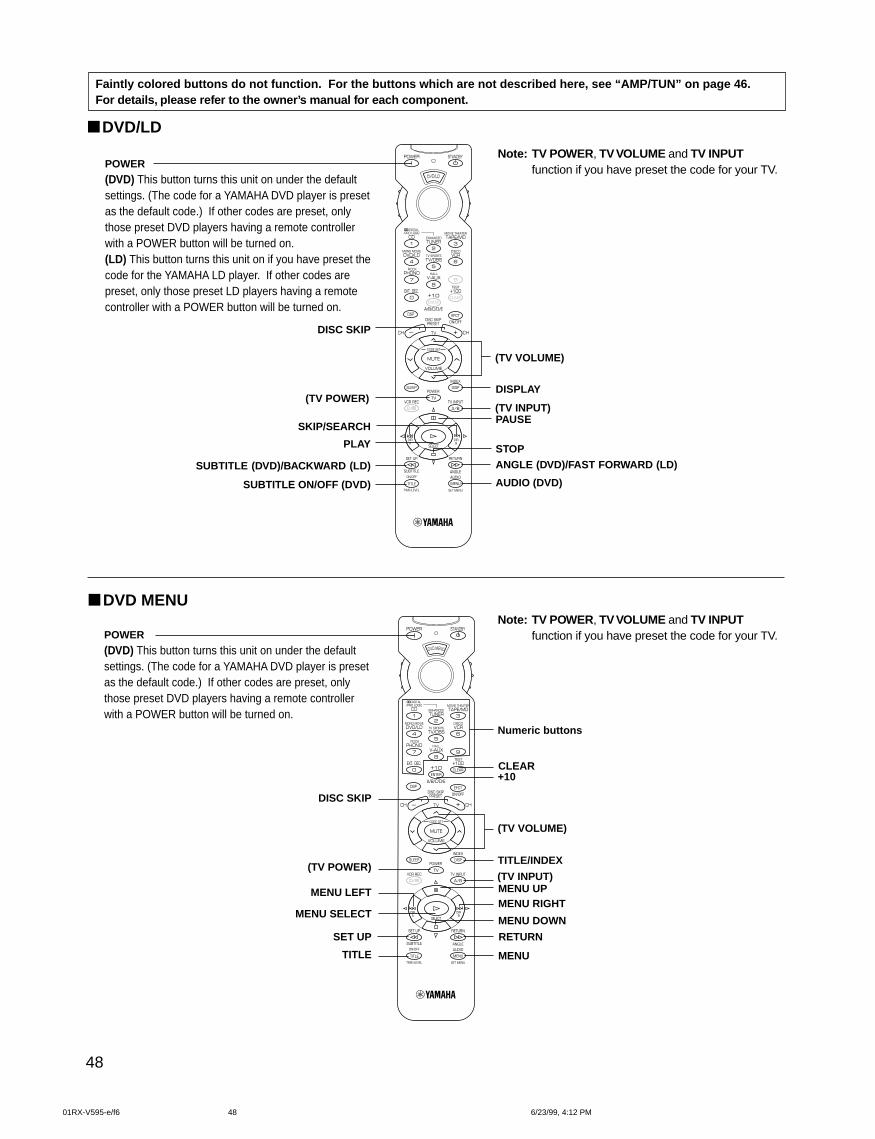
48
DVD MENU
Faintly colored buttons do not function. For the buttons which are not described here, see “AMP/TUN” on page 46.For details, please refer to the owner’s manual for each component.
POWER
(DVD) This button turns this unit on under the defaultsettings. (The code for a YAMAHA DVD player is presetas the default code.) If other codes are preset, onlythose preset DVD players having a remote controllerwith a POWER button will be turned on.(LD) This button turns this unit on if you have preset thecode for the YAMAHA LD player. If other codes arepreset, only those preset LD players having a remotecontroller with a POWER button will be turned on.
DISC SKIP
SKIP/SEARCH
PLAY
SUBTITLE (DVD)/BACKWARD (LD)
SUBTITLE ON/OFF (DVD)
DISPLAY
PAUSE
STOPANGLE (DVD)/FAST FORWARD (LD)
AUDIO (DVD)
POWER
(DVD) This button turns this unit on under the defaultsettings. (The code for a YAMAHA DVD player is presetas the default code.) If other codes are preset, onlythose preset DVD players having a remote controllerwith a POWER button will be turned on.
Numeric buttons
+10
DISC SKIP
MENU LEFT
MENU SELECT
SET UP
TITLE
CLEAR
TITLE/INDEX
MENU UPMENU RIGHT
MENU DOWN
RETURN
MENU
Note: TV POWER , TV VOLUME and TV INPUTfunction if you have preset the code for your TV.
DVD/LD
Note: TV POWER , TV VOLUME and TV INPUTfunction if you have preset the code for your TV.
(TV POWER)
(TV VOLUME)
(TV INPUT)
(TV POWER)
(TV VOLUME)
(TV INPUT)
01RX-V595-e/f6 6/23/99, 4:12 PM48
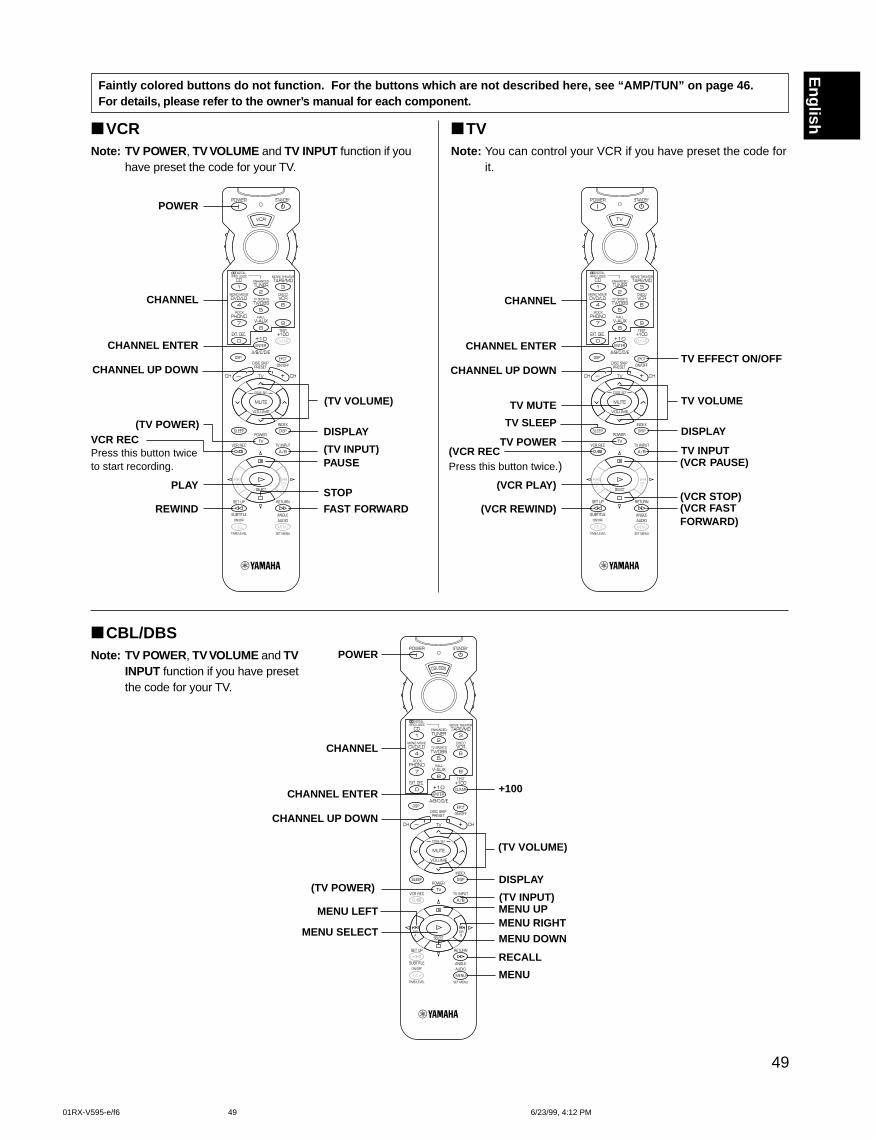
49
English
CBL/DBSNote: TV POWER , TV VOLUME and TV
INPUT function if you have presetthe code for your TV.
VCRNote: TV POWER , TV VOLUME and TV INPUT function if you
have preset the code for your TV.
POWER
DISPLAY
CHANNEL
CHANNEL ENTER
VCR RECPress this button twiceto start recording.
CHANNEL UP DOWN
PLAY
REWIND
PAUSE
STOP
FAST FORWARD
POWER
DISPLAY
CHANNEL
CHANNEL ENTER
MENU LEFT
CHANNEL UP DOWN
MENU SELECT
MENU UPMENU RIGHTMENU DOWN
+100
RECALL
MENU
TVNote: You can control your VCR if you have preset the code for
it.
DISPLAY
CHANNEL
CHANNEL ENTER
TV MUTE
CHANNEL UP DOWN
TV SLEEP
TV POWERTV INPUT
TV EFFECT ON/OFF
TV VOLUME
Faintly colored buttons do not function. For the buttons which are not described here, see “AMP/TUN” on page 46.For details, please refer to the owner’s manual for each component.
(TV VOLUME)
(TV INPUT)
(TV POWER)
(TV VOLUME)
(TV INPUT)
(VCR RECPress this button twice.)
(VCR REWIND)
(VCR PLAY)
(VCR PAUSE)
(VCR STOP)(VCR FASTFORWARD)
(TV POWER)
01RX-V595-e/f6 6/23/99, 4:12 PM49
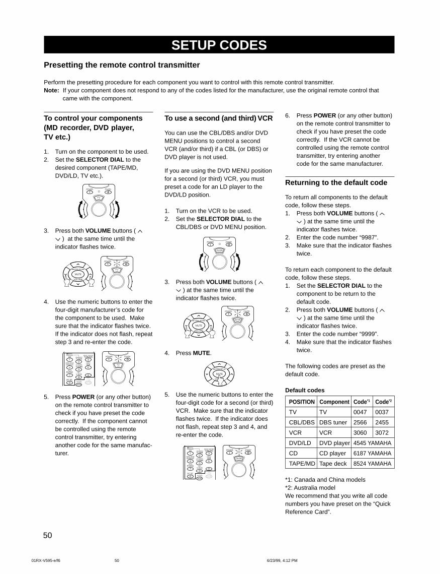
50
SETUP CODES
To use a second (and third) VCR
You can use the CBL/DBS and/or DVDMENU positions to control a secondVCR (and/or third) if a CBL (or DBS) orDVD player is not used.
If you are using the DVD MENU positionfor a second (or third) VCR, you mustpreset a code for an LD player to theDVD/LD position.
1. Turn on the VCR to be used.2. Set the SELECTOR DIAL to the
CBL/DBS or DVD MENU position.
3. Press both VOLUME buttons ( ) at the same time until the
indicator flashes twice.
4. Press MUTE.
5. Use the numeric buttons to enter thefour-digit code for a second (or third)VCR. Make sure that the indicatorflashes twice. If the indicator doesnot flash, repeat step 3 and 4, andre-enter the code.
To control your components(MD recorder, DVD player,TV etc.)
1. Turn on the component to be used.2. Set the SELECTOR DIAL to the
desired component (TAPE/MD,DVD/LD, TV etc.).
3. Press both VOLUME buttons ( ) at the same time until the
indicator flashes twice.
4. Use the numeric buttons to enter thefour-digit manufacturer’s code forthe component to be used. Makesure that the indicator flashes twice.If the indicator does not flash, repeatstep 3 and re-enter the code.
5. Press POWER (or any other button)on the remote control transmitter tocheck if you have preset the codecorrectly. If the component cannotbe controlled using the remotecontrol transmitter, try enteringanother code for the same manufac-turer.
6. Press POWER (or any other button)on the remote control transmitter tocheck if you have preset the codecorrectly. If the VCR cannot becontrolled using the remote controltransmitter, try entering anothercode for the same manufacturer.
Returning to the default code
To return all components to the defaultcode, follow these steps.1. Press both VOLUME buttons (
) at the same time until theindicator flashes twice.
2. Enter the code number “9987”.3. Make sure that the indicator flashes
twice.
To return each component to the defaultcode, follow these steps.1. Set the SELECTOR DIAL to the
component to be return to thedefault code.
2. Press both VOLUME buttons ( ) at the same time until the
indicator flashes twice.3. Enter the code number “9999”.4. Make sure that the indicator flashes
twice.
The following codes are preset as thedefault code.
Default codes
POSITION Component Code *1 Code*2
TV TV 0047 0037
CBL/DBS DBS tuner 2566 2455
VCR VCR 3060 3072
DVD/LD DVD player 4545 YAMAHA
CD CD player 6187 YAMAHA
TAPE/MD Tape deck 8524 YAMAHA
*1: Canada and China models*2: Australia modelWe recommend that you write all codenumbers you have preset on the “QuickReference Card”.
Presetting the remote control transmitter
Perform the presetting procedure for each component you want to control with this remote control transmitter.Note: If your component does not respond to any of the codes listed for the manufacturer, use the original remote control that
came with the component.
01RX-V595-e/f6 6/23/99, 4:12 PM50
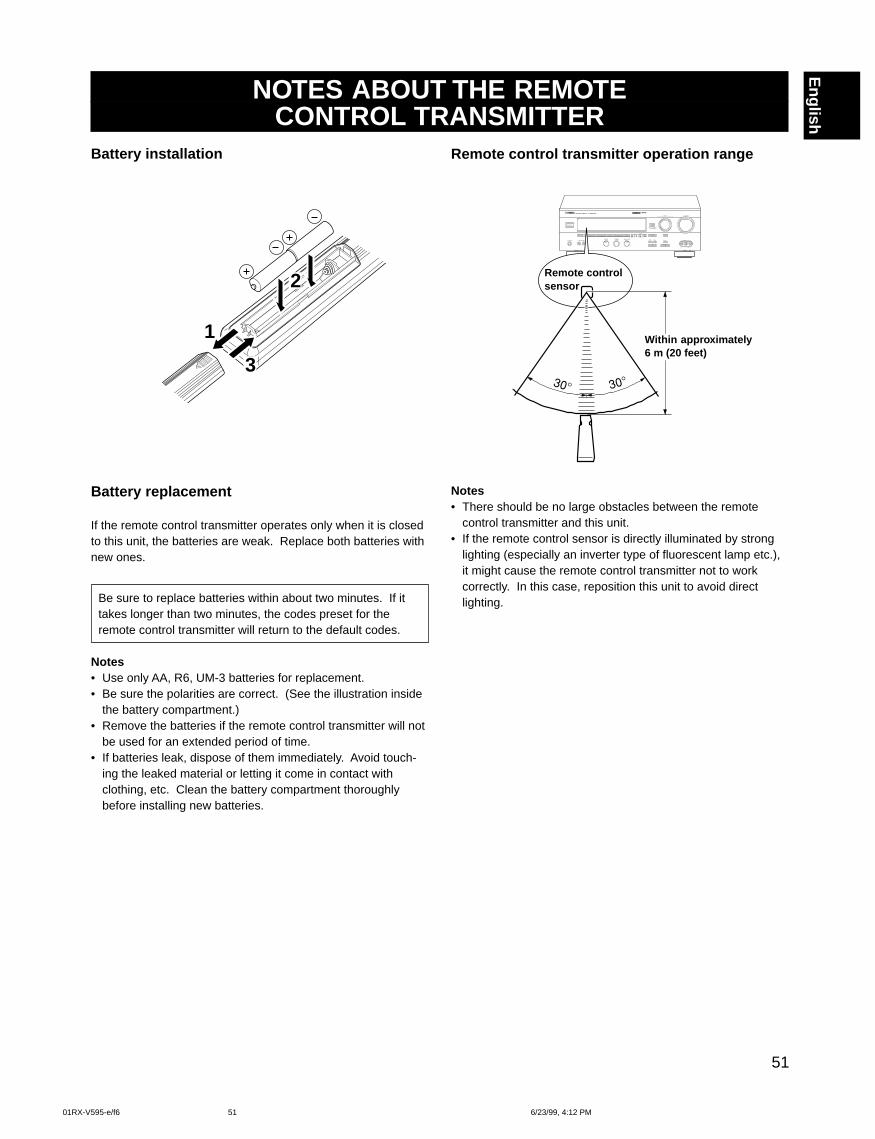
51
English
NOTES ABOUT THE REMOTECONTROL TRANSMITTER
Battery installation
Battery replacement
If the remote control transmitter operates only when it is closedto this unit, the batteries are weak. Replace both batteries withnew ones.
Be sure to replace batteries within about two minutes. If ittakes longer than two minutes, the codes preset for theremote control transmitter will return to the default codes.
Notes• Use only AA, R6, UM-3 batteries for replacement.• Be sure the polarities are correct. (See the illustration inside
the battery compartment.)• Remove the batteries if the remote control transmitter will not
be used for an extended period of time.• If batteries leak, dispose of them immediately. Avoid touch-
ing the leaked material or letting it come in contact withclothing, etc. Clean the battery compartment thoroughlybefore installing new batteries.
Remote control transmitter operation range
Notes• There should be no large obstacles between the remote
control transmitter and this unit.• If the remote control sensor is directly illuminated by strong
lighting (especially an inverter type of fluorescent lamp etc.),it might cause the remote control transmitter not to workcorrectly. In this case, reposition this unit to avoid directlighting.
1
2
3
Remote controlsensor
Within approximately6 m (20 feet)
01RX-V595-e/f6 6/23/99, 4:12 PM51
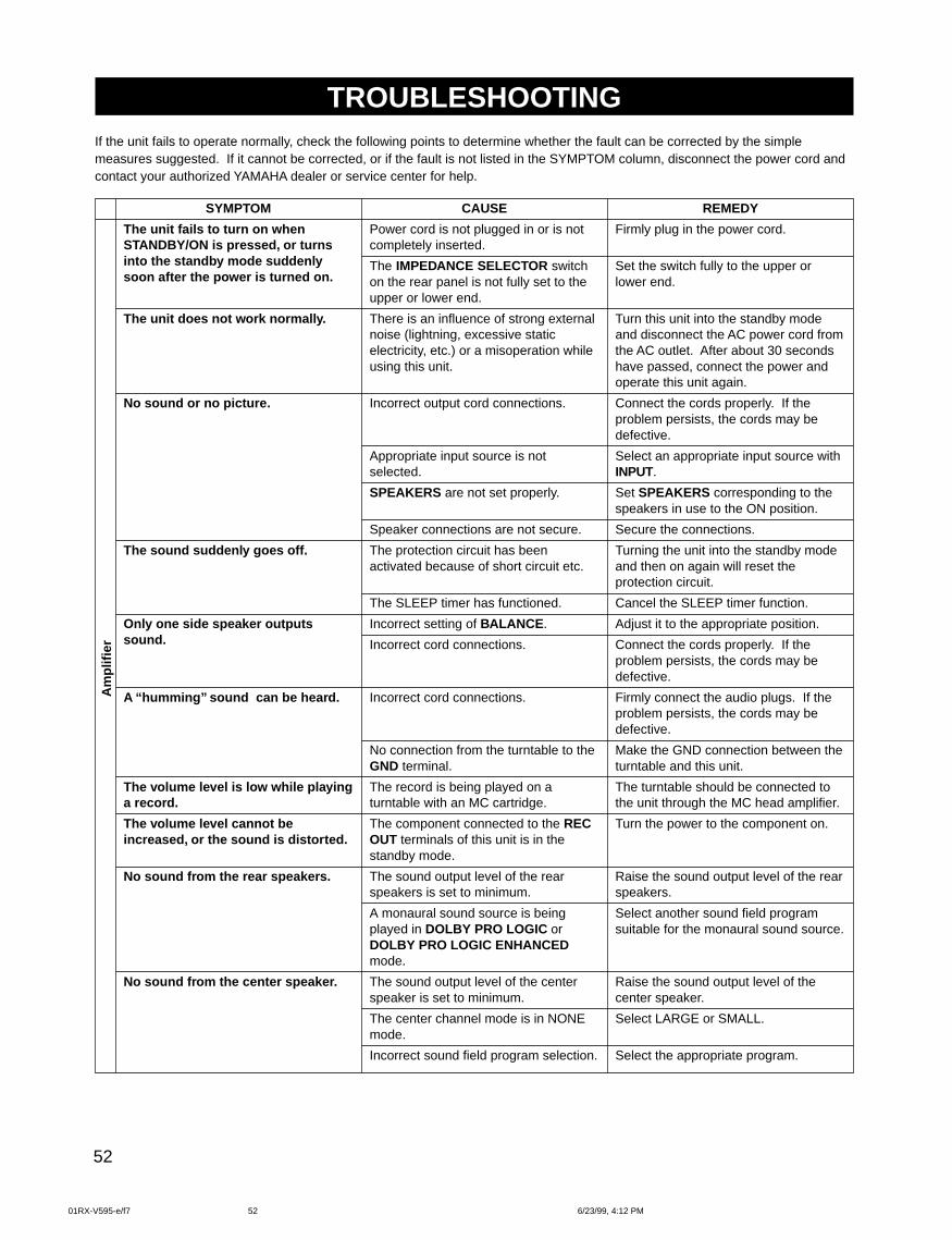
52
SYMPTOM
The unit fails to turn on whenSTANDBY/ON is pressed, or turnsinto the standby mode suddenlysoon after the power is turned on.
The unit does not work normally.
No sound or no picture.
The sound suddenly goes off.
Only one side speaker outputssound.
A “humming” sound can be heard.
The volume level is low while playinga record.
The volume level cannot beincreased, or the sound is distorted.
No sound from the rear speakers.
No sound from the center speaker.
CAUSE
Power cord is not plugged in or is notcompletely inserted.
The IMPEDANCE SELECTOR switchon the rear panel is not fully set to theupper or lower end.
There is an influence of strong externalnoise (lightning, excessive staticelectricity, etc.) or a misoperation whileusing this unit.
Incorrect output cord connections.
Appropriate input source is notselected.
SPEAKERS are not set properly.
Speaker connections are not secure.
The protection circuit has beenactivated because of short circuit etc.
The SLEEP timer has functioned.
Incorrect setting of BALANCE .
Incorrect cord connections.
Incorrect cord connections.
No connection from the turntable to theGND terminal.
The record is being played on aturntable with an MC cartridge.
The component connected to the RECOUT terminals of this unit is in thestandby mode.
The sound output level of the rearspeakers is set to minimum.
A monaural sound source is beingplayed in DOLBY PRO LOGIC orDOLBY PRO LOGIC ENHANCEDmode.
The sound output level of the centerspeaker is set to minimum.
The center channel mode is in NONEmode.
Incorrect sound field program selection.
REMEDY
Firmly plug in the power cord.
Set the switch fully to the upper orlower end.
Turn this unit into the standby modeand disconnect the AC power cord fromthe AC outlet. After about 30 secondshave passed, connect the power andoperate this unit again.
Connect the cords properly. If theproblem persists, the cords may bedefective.
Select an appropriate input source withINPUT.
Set SPEAKERS corresponding to thespeakers in use to the ON position.
Secure the connections.
Turning the unit into the standby modeand then on again will reset theprotection circuit.
Cancel the SLEEP timer function.
Adjust it to the appropriate position.
Connect the cords properly. If theproblem persists, the cords may bedefective.
Firmly connect the audio plugs. If theproblem persists, the cords may bedefective.
Make the GND connection between theturntable and this unit.
The turntable should be connected tothe unit through the MC head amplifier.
Turn the power to the component on.
Raise the sound output level of the rearspeakers.
Select another sound field programsuitable for the monaural sound source.
Raise the sound output level of thecenter speaker.
Select LARGE or SMALL.
Select the appropriate program.
Am
plifi
erTROUBLESHOOTING
If the unit fails to operate normally, check the following points to determine whether the fault can be corrected by the simplemeasures suggested. If it cannot be corrected, or if the fault is not listed in the SYMPTOM column, disconnect the power cord andcontact your authorized YAMAHA dealer or service center for help.
01RX-V595-e/f7 6/23/99, 4:12 PM52
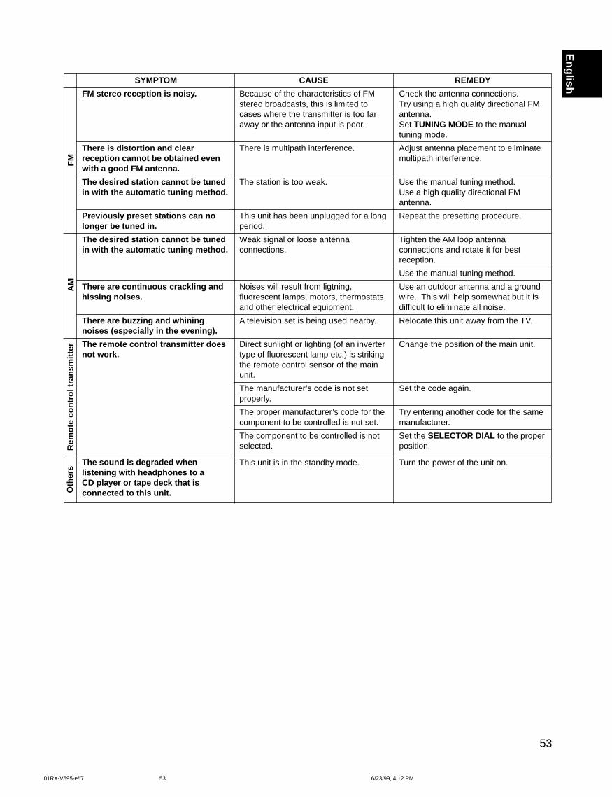
53
EnglishSYMPTOM
FM stereo reception is noisy.
There is distortion and clearreception cannot be obtained evenwith a good FM antenna.
The desired station cannot be tunedin with the automatic tuning method.
Previously preset stations can nolonger be tuned in.
The desired station cannot be tunedin with the automatic tuning method.
There are continuous crackling andhissing noises.
There are buzzing and whiningnoises (especially in the evening).
The remote control transmitter doesnot work.
The sound is degraded whenlistening with headphones to aCD player or tape deck that isconnected to this unit.
CAUSE
Because of the characteristics of FMstereo broadcasts, this is limited tocases where the transmitter is too faraway or the antenna input is poor.
There is multipath interference.
The station is too weak.
This unit has been unplugged for a longperiod.
Weak signal or loose antennaconnections.
Noises will result from ligtning,fluorescent lamps, motors, thermostatsand other electrical equipment.
A television set is being used nearby.
Direct sunlight or lighting (of an invertertype of fluorescent lamp etc.) is strikingthe remote control sensor of the mainunit.
The manufacturer’s code is not setproperly.
The proper manufacturer’s code for thecomponent to be controlled is not set.
The component to be controlled is notselected.
This unit is in the standby mode.
REMEDY
Check the antenna connections.Try using a high quality directional FMantenna.Set TUNING MODE to the manualtuning mode.
Adjust antenna placement to eliminatemultipath interference.
Use the manual tuning method.Use a high quality directional FMantenna.
Repeat the presetting procedure.
Tighten the AM loop antennaconnections and rotate it for bestreception.
Use the manual tuning method.
Use an outdoor antenna and a groundwire. This will help somewhat but it isdifficult to eliminate all noise.
Relocate this unit away from the TV.
Change the position of the main unit.
Set the code again.
Try entering another code for the samemanufacturer.
Set the SELECTOR DIAL to the properposition.
Turn the power of the unit on.
Rem
ote
cont
rol t
rans
mitt
erA
MF
MO
ther
s
01RX-V595-e/f7 6/23/99, 4:12 PM53
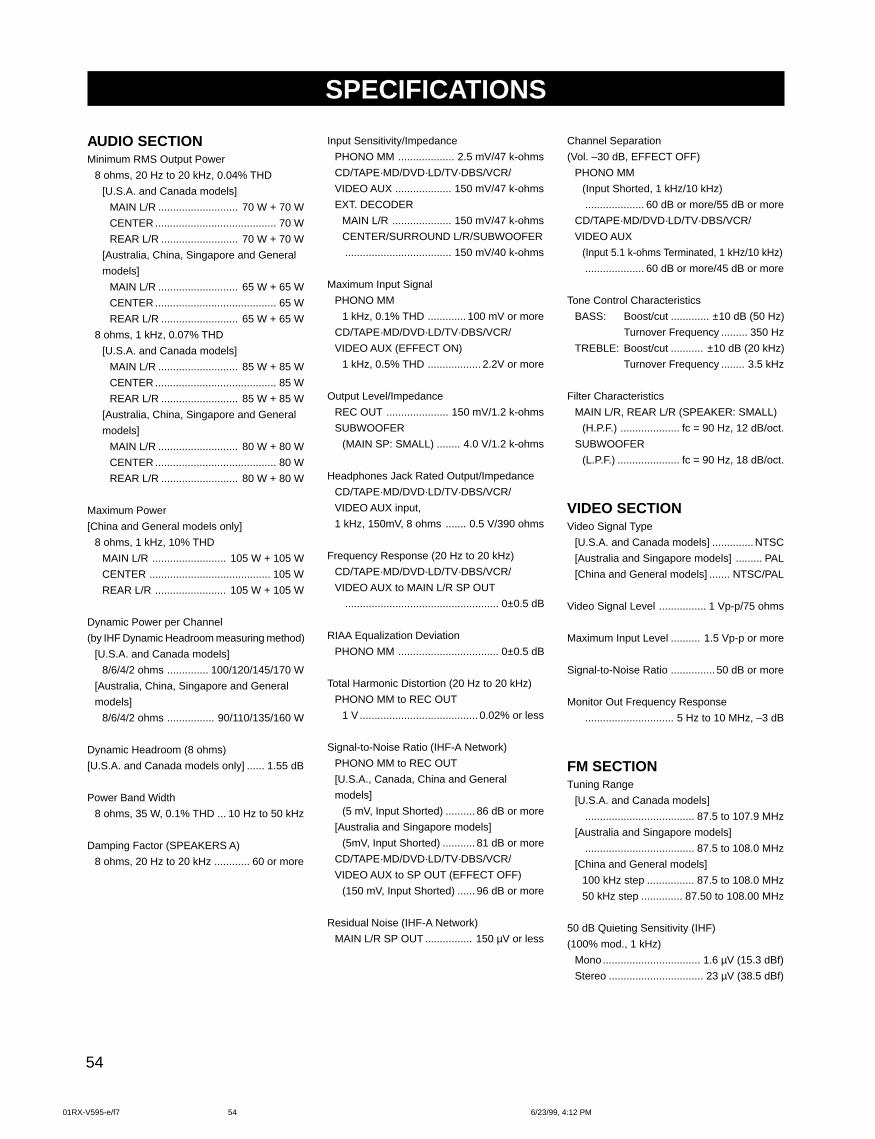
54
AUDIO SECTIONMinimum RMS Output Power
8 ohms, 20 Hz to 20 kHz, 0.04% THD
[U.S.A. and Canada models]
MAIN L/R ........................... 70 W + 70 W
CENTER ......................................... 70 W
REAR L/R .......................... 70 W + 70 W
[Australia, China, Singapore and General
models]
MAIN L/R ........................... 65 W + 65 W
CENTER ......................................... 65 W
REAR L/R .......................... 65 W + 65 W
8 ohms, 1 kHz, 0.07% THD
[U.S.A. and Canada models]
MAIN L/R ........................... 85 W + 85 W
CENTER ......................................... 85 W
REAR L/R .......................... 85 W + 85 W
[Australia, China, Singapore and General
models]
MAIN L/R ........................... 80 W + 80 W
CENTER ......................................... 80 W
REAR L/R .......................... 80 W + 80 W
Maximum Power
[China and General models only]
8 ohms, 1 kHz, 10% THD
MAIN L/R ......................... 105 W + 105 W
CENTER ......................................... 105 W
REAR L/R ........................ 105 W + 105 W
Dynamic Power per Channel
(by IHF Dynamic Headroom measuring method)
[U.S.A. and Canada models]
8/6/4/2 ohms .............. 100/120/145/170 W
[Australia, China, Singapore and General
models]
8/6/4/2 ohms ................ 90/110/135/160 W
Dynamic Headroom (8 ohms)
[U.S.A. and Canada models only] ...... 1.55 dB
Power Band Width
8 ohms, 35 W, 0.1% THD ... 10 Hz to 50 kHz
Damping Factor (SPEAKERS A)
8 ohms, 20 Hz to 20 kHz ............ 60 or more
Input Sensitivity/Impedance
PHONO MM ................... 2.5 mV/47 k-ohms
CD/TAPE·MD/DVD·LD/TV·DBS/VCR/
VIDEO AUX ................... 150 mV/47 k-ohms
EXT. DECODER
MAIN L/R .................... 150 mV/47 k-ohms
CENTER/SURROUND L/R/SUBWOOFER
.................................... 150 mV/40 k-ohms
Maximum Input Signal
PHONO MM
1 kHz, 0.1% THD ............. 100 mV or more
CD/TAPE·MD/DVD·LD/TV·DBS/VCR/
VIDEO AUX (EFFECT ON)
1 kHz, 0.5% THD .................. 2.2V or more
Output Level/Impedance
REC OUT ..................... 150 mV/1.2 k-ohms
SUBWOOFER
(MAIN SP: SMALL) ........ 4.0 V/1.2 k-ohms
Headphones Jack Rated Output/Impedance
CD/TAPE·MD/DVD·LD/TV·DBS/VCR/
VIDEO AUX input,
1 kHz, 150mV, 8 ohms ....... 0.5 V/390 ohms
Frequency Response (20 Hz to 20 kHz)
CD/TAPE·MD/DVD·LD/TV·DBS/VCR/
VIDEO AUX to MAIN L/R SP OUT
.................................................... 0±0.5 dB
RIAA Equalization Deviation
PHONO MM .................................. 0±0.5 dB
Total Harmonic Distortion (20 Hz to 20 kHz)
PHONO MM to REC OUT
1 V ........................................ 0.02% or less
Signal-to-Noise Ratio (IHF-A Network)
PHONO MM to REC OUT
[U.S.A., Canada, China and General
models]
(5 mV, Input Shorted) .......... 86 dB or more
[Australia and Singapore models]
(5mV, Input Shorted) ........... 81 dB or more
CD/TAPE·MD/DVD·LD/TV·DBS/VCR/
VIDEO AUX to SP OUT (EFFECT OFF)
(150 mV, Input Shorted) ...... 96 dB or more
Residual Noise (IHF-A Network)
MAIN L/R SP OUT ................ 150 µV or less
Channel Separation
(Vol. –30 dB, EFFECT OFF)
PHONO MM
(Input Shorted, 1 kHz/10 kHz)
.................... 60 dB or more/55 dB or more
CD/TAPE·MD/DVD·LD/TV·DBS/VCR/
VIDEO AUX
(Input 5.1 k-ohms Terminated, 1 kHz/10 kHz)
.................... 60 dB or more/45 dB or more
Tone Control Characteristics
BASS: Boost/cut ............. ±10 dB (50 Hz)
Turnover Frequency ......... 350 Hz
TREBLE: Boost/cut ........... ±10 dB (20 kHz)
Turnover Frequency ........ 3.5 kHz
Filter Characteristics
MAIN L/R, REAR L/R (SPEAKER: SMALL)
(H.P.F.) .................... fc = 90 Hz, 12 dB/oct.
SUBWOOFER
(L.P.F.) ..................... fc = 90 Hz, 18 dB/oct.
VIDEO SECTIONVideo Signal Type
[U.S.A. and Canada models] .............. NTSC
[Australia and Singapore models] ......... PAL
[China and General models] ....... NTSC/PAL
Video Signal Level ................ 1 Vp-p/75 ohms
Maximum Input Level .......... 1.5 Vp-p or more
Signal-to-Noise Ratio ............... 50 dB or more
Monitor Out Frequency Response
.............................. 5 Hz to 10 MHz, –3 dB
FM SECTIONTuning Range
[U.S.A. and Canada models]
..................................... 87.5 to 107.9 MHz
[Australia and Singapore models]
..................................... 87.5 to 108.0 MHz
[China and General models]
100 kHz step ................ 87.5 to 108.0 MHz
50 kHz step .............. 87.50 to 108.00 MHz
50 dB Quieting Sensitivity (IHF)
(100% mod., 1 kHz)
Mono................................. 1.6 µV (15.3 dBf)
Stereo ................................ 23 µV (38.5 dBf)
SPECIFICATIONS
01RX-V595-e/f7 6/23/99, 4:12 PM54
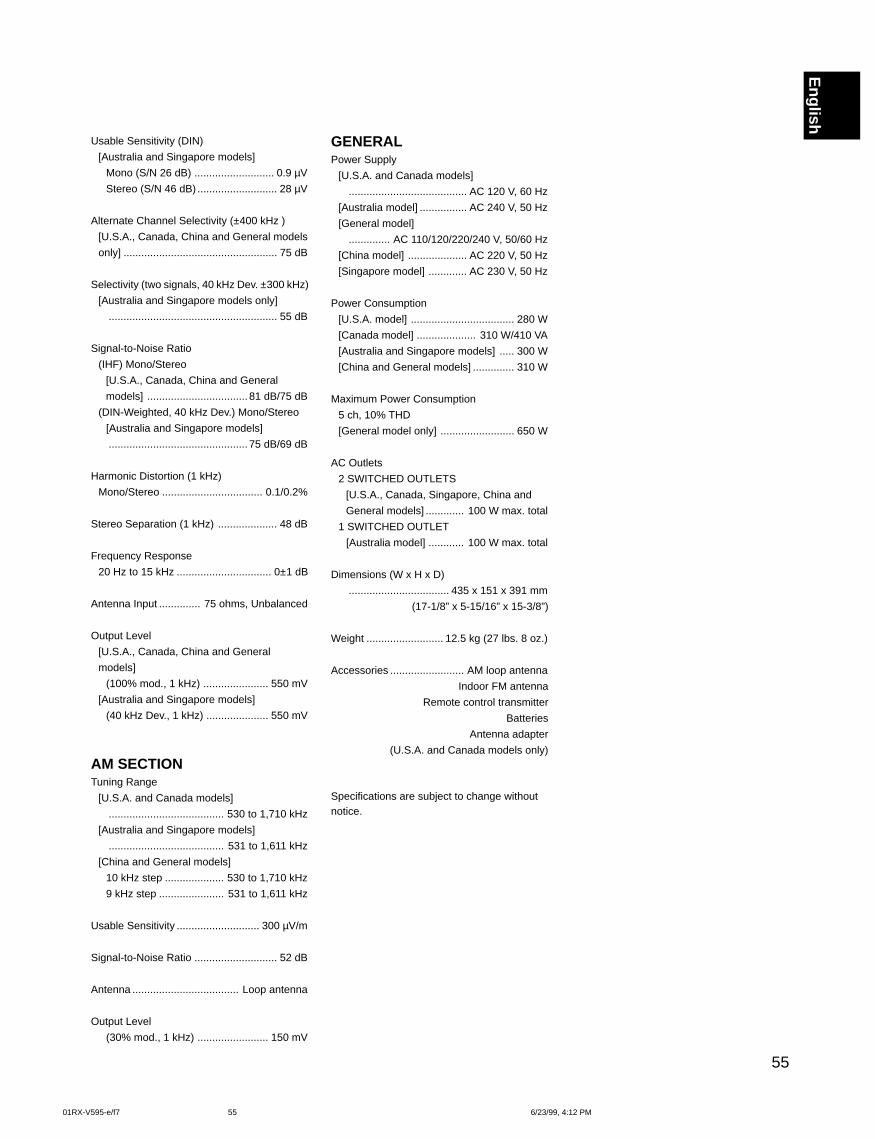
55
English
Usable Sensitivity (DIN)
[Australia and Singapore models]
Mono (S/N 26 dB) ........................... 0.9 µV
Stereo (S/N 46 dB) ........................... 28 µV
Alternate Channel Selectivity (±400 kHz )
[U.S.A., Canada, China and General models
only] .................................................... 75 dB
Selectivity (two signals, 40 kHz Dev. ±300 kHz)
[Australia and Singapore models only]
......................................................... 55 dB
Signal-to-Noise Ratio
(IHF) Mono/Stereo
[U.S.A., Canada, China and General
models] .................................. 81 dB/75 dB
(DIN-Weighted, 40 kHz Dev.) Mono/Stereo
[Australia and Singapore models]
............................................... 75 dB/69 dB
Harmonic Distortion (1 kHz)
Mono/Stereo .................................. 0.1/0.2%
Stereo Separation (1 kHz) .................... 48 dB
Frequency Response
20 Hz to 15 kHz ................................ 0±1 dB
Antenna Input .............. 75 ohms, Unbalanced
Output Level
[U.S.A., Canada, China and General
models]
(100% mod., 1 kHz) ...................... 550 mV
[Australia and Singapore models]
(40 kHz Dev., 1 kHz) ..................... 550 mV
AM SECTIONTuning Range
[U.S.A. and Canada models]
....................................... 530 to 1,710 kHz
[Australia and Singapore models]
....................................... 531 to 1,611 kHz
[China and General models]
10 kHz step .................... 530 to 1,710 kHz
9 kHz step ...................... 531 to 1,611 kHz
Usable Sensitivity ............................ 300 µV/m
Signal-to-Noise Ratio ............................ 52 dB
Antenna .................................... Loop antenna
Output Level
(30% mod., 1 kHz) ........................ 150 mV
GENERALPower Supply
[U.S.A. and Canada models]
........................................ AC 120 V, 60 Hz
[Australia model] ................ AC 240 V, 50 Hz
[General model]
.............. AC 110/120/220/240 V, 50/60 Hz
[China model] .................... AC 220 V, 50 Hz
[Singapore model] ............. AC 230 V, 50 Hz
Power Consumption
[U.S.A. model] ................................... 280 W
[Canada model] .................... 310 W/410 VA
[Australia and Singapore models] ..... 300 W
[China and General models] .............. 310 W
Maximum Power Consumption
5 ch, 10% THD
[General model only] ......................... 650 W
AC Outlets
2 SWITCHED OUTLETS
[U.S.A., Canada, Singapore, China and
General models] ............. 100 W max. total
1 SWITCHED OUTLET
[Australia model] ............ 100 W max. total
Dimensions (W x H x D)
.................................. 435 x 151 x 391 mm
(17-1/8” x 5-15/16” x 15-3/8”)
Weight .......................... 12.5 kg (27 lbs. 8 oz.)
Accessories ......................... AM loop antenna
Indoor FM antenna
Remote control transmitter
Batteries
Antenna adapter
(U.S.A. and Canada models only)
Specifications are subject to change withoutnotice.
01RX-V595-e/f7 6/23/99, 4:12 PM55

01RX-V595-e/f7 6/23/99, 4:12 PM56
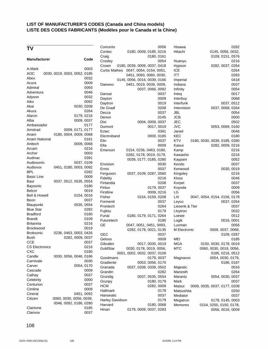
108
TV
Manufacturer Code
A-Mark 0003AOC 0030, 0019, 0003, 0052, 0185Abex 0032Acura 0009Admiral 0093Adventura 0046Adyson 0032Aiko 0092Akai 0030, 0208Akura 0264Alaron 0179, 0216Alba 0009, 0037Ambassador 0177Amstrad 0009, 0171, 0177Anam 0180, 0004, 0009, 0068Anam National 0161Anitech 0009, 0068Arcam 0216Archer 0003Audinac 0391Audiosonic 0037, 0109Audiovox 0451, 0180, 0003, 0092BPL 0282Basic Line 0009Baur 0037, 0512, 0535, 0554Baysonic 0180Belcor 0019Bell & Howell 0154, 0016Beon 0037Blaupunkt 0535, 0554Blue Star 0282Bradford 0180Brandt 0109Britannia 0216Brockwood 0019Broksonic 0236, 0463, 0003, 0426Bush 0282, 0009, 0037CCE 0037CS Electronics 0216CXC 0180Candle 0030, 0056, 0046, 0186Carnivale 0030Carver 0054, 0170Cascade 0009Cathay 0037Celebrity 0000Centurion 0037Cimline 0009Cineral 0451, 0092Citizen 0060, 0030, 0056, 0039,
0046, 0092, 0186, 0280Clairtone 0185Clarivox 0037
Concerto 0056Contec 0180, 0009, 0185, 0216Craig 0180, 0161Crosley 0054Crown 0180, 0039, 0009, 0037, 0418Curtis Mathes 0047, 0054, 0154, 0051,
0451, 0093, 0060, 0030,0145, 0056, 0016, 0039, 0166
Daewoo 0451, 0019, 0039, 0009,0037, 0066, 0092
Dansai 0037Dayton 0009Daytron 0019De Graaf 0208Decca 0037Denon 0145Dixi 0004, 0009, 0037Dumont 0017, 0019Ectec 0391Electroband 0000, 0185Elin 0037Elta 0009Emerson 0154, 0236, 0463, 0180,
0282, 0178, 0019, 0179,0039, 0177, 0185, 0280
Envision 0030Erres 0037Ferguson 0037, 0109, 0287, 0560Fidelity 0216Finlandia 0208Finlux 0179, 0037Firstline 0009, 0216Fisher 0154, 0159, 0208Formenti 0037Frontech 0264Fujitsu 0179Funai 0180, 0179, 0171, 0264Futuretech 0180GE 0047, 0051, 0451, 0093,
0282, 0178, 0021, 0135GEC 0037Geloso 0009Gibralter 0017, 0030, 0019GoldStar 0030, 0178, 0019, 0056,
0001, 0002, 0032, 0037, 0109Goodmans 0179, 0037Gradiente 0053, 0056, 0170Granada 0037, 0208, 0339, 0502Grandin 0282Grundig 0037, 0535, 0554Grunpy 0180, 0179HCM 0282, 0009Hallmark 0178Hanseatic 0037Harley Davidson 0179Harvard 0180, 0068Hinari 0179, 0009, 0037, 0283
Hisawa 0282Hitachi 0145, 0056, 0032,
0109, 0151, 0576Huanyu 0216Hypson 0282, 0037, 0264ICE 0264ITT 0283Imperial 0418Indiana 0037Infinity 0054Inteq 0017Interbuy 0068Interfunk 0037, 0512Intervision 0037, 0068, 0264JBL 0054JCB 0000JEC 0502JVC 0053, 0069, 0160Janeil 0046KEC 0180KTV 0180, 0030, 0039, 0185, 0280Kaisui 0282, 0009, 0216Kamp 0216Kawasho 0216Kaypani 0052Kendo 0037Kenwood 0030, 0019Kingsley 0216Kloss 0046Korpel 0037Koyoda 0009LG 0056LXI 0047, 0054, 0154, 0156, 0178Leyco 0037, 0264Liesenk & Tter 0037Lloytron 0032Loewe 0512Logik 0016, 0001Luxman 0056M Electronic 0009, 0037, 0068,
0109, 0287MEI 0185MGA 0150, 0030, 0178, 0019MTC 0060, 0030, 0019, 0056,
0185, 0216, 0512Magnavox 0054, 0030, 0179,
0186, 0187Majestic 0016Manesth 0264Marantz 0054, 0030, 0037Mark 0037Matsui 0009, 0035, 0037, 0177, 0208Matsushita 0250Mediator 0037Megatron 0178, 0145, 0003Memorex 0154, 0250, 0150, 0178,
0056, 0016, 0009
LIST OF MANUFACTURER’S CODES (Canada and China models)LISTE DES CODES FABRICANTS (Modèles pour le Canada et la Chine)
01RX-V595-e/fCODE(US) 6/23/99, 4:14 PM108
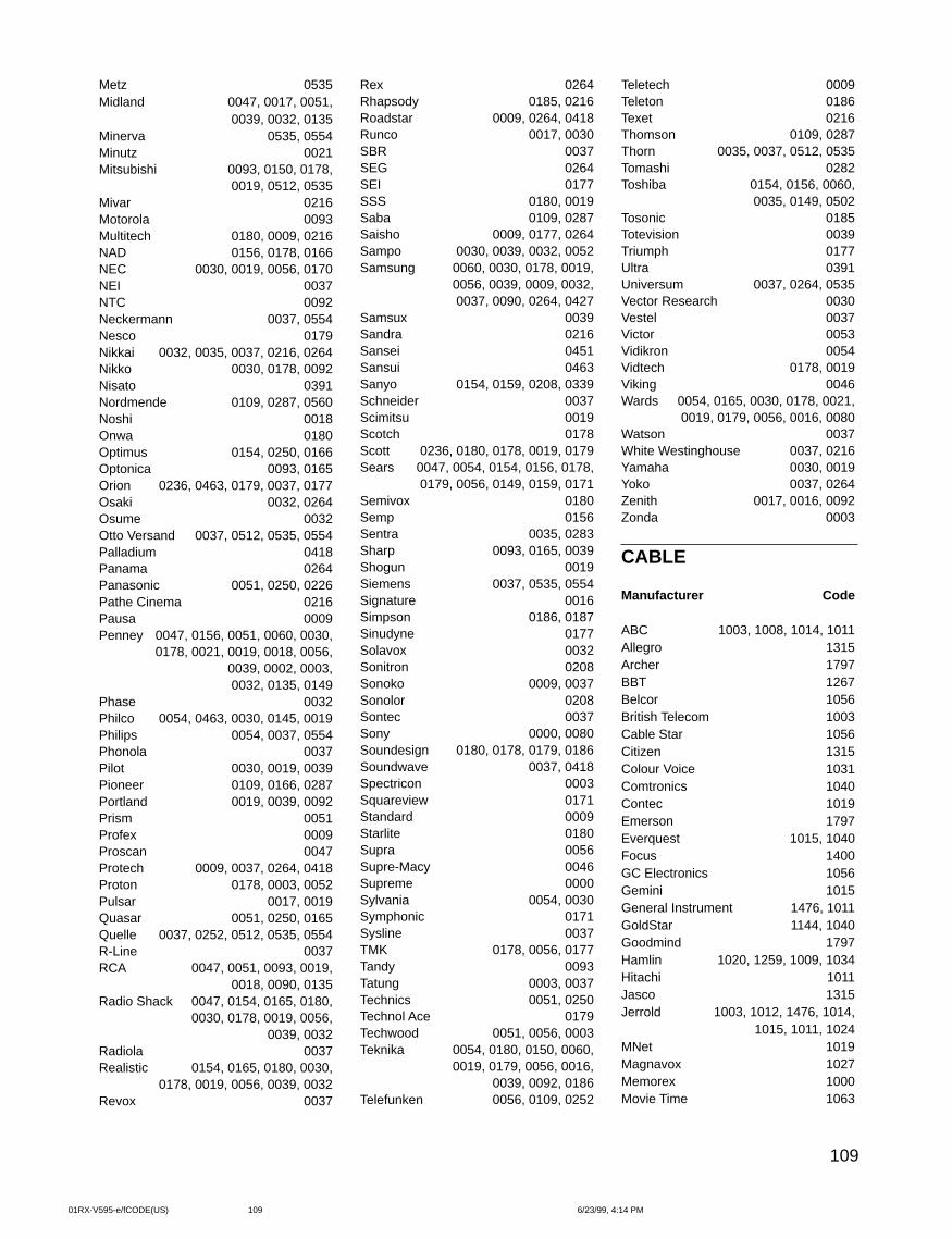
109
Rex 0264Rhapsody 0185, 0216Roadstar 0009, 0264, 0418Runco 0017, 0030SBR 0037SEG 0264SEI 0177SSS 0180, 0019Saba 0109, 0287Saisho 0009, 0177, 0264Sampo 0030, 0039, 0032, 0052Samsung 0060, 0030, 0178, 0019,
0056, 0039, 0009, 0032,0037, 0090, 0264, 0427
Samsux 0039Sandra 0216Sansei 0451Sansui 0463Sanyo 0154, 0159, 0208, 0339Schneider 0037Scimitsu 0019Scotch 0178Scott 0236, 0180, 0178, 0019, 0179Sears 0047, 0054, 0154, 0156, 0178,
0179, 0056, 0149, 0159, 0171Semivox 0180Semp 0156Sentra 0035, 0283Sharp 0093, 0165, 0039Shogun 0019Siemens 0037, 0535, 0554Signature 0016Simpson 0186, 0187Sinudyne 0177Solavox 0032Sonitron 0208Sonoko 0009, 0037Sonolor 0208Sontec 0037Sony 0000, 0080Soundesign 0180, 0178, 0179, 0186Soundwave 0037, 0418Spectricon 0003Squareview 0171Standard 0009Starlite 0180Supra 0056Supre-Macy 0046Supreme 0000Sylvania 0054, 0030Symphonic 0171Sysline 0037TMK 0178, 0056, 0177Tandy 0093Tatung 0003, 0037Technics 0051, 0250Technol Ace 0179Techwood 0051, 0056, 0003Teknika 0054, 0180, 0150, 0060,
0019, 0179, 0056, 0016,0039, 0092, 0186
Telefunken 0056, 0109, 0252
Metz 0535Midland 0047, 0017, 0051,
0039, 0032, 0135Minerva 0535, 0554Minutz 0021Mitsubishi 0093, 0150, 0178,
0019, 0512, 0535Mivar 0216Motorola 0093Multitech 0180, 0009, 0216NAD 0156, 0178, 0166NEC 0030, 0019, 0056, 0170NEI 0037NTC 0092Neckermann 0037, 0554Nesco 0179Nikkai 0032, 0035, 0037, 0216, 0264Nikko 0030, 0178, 0092Nisato 0391Nordmende 0109, 0287, 0560Noshi 0018Onwa 0180Optimus 0154, 0250, 0166Optonica 0093, 0165Orion 0236, 0463, 0179, 0037, 0177Osaki 0032, 0264Osume 0032Otto Versand 0037, 0512, 0535, 0554Palladium 0418Panama 0264Panasonic 0051, 0250, 0226Pathe Cinema 0216Pausa 0009Penney 0047, 0156, 0051, 0060, 0030,
0178, 0021, 0019, 0018, 0056,0039, 0002, 0003,0032, 0135, 0149
Phase 0032Philco 0054, 0463, 0030, 0145, 0019Philips 0054, 0037, 0554Phonola 0037Pilot 0030, 0019, 0039Pioneer 0109, 0166, 0287Portland 0019, 0039, 0092Prism 0051Profex 0009Proscan 0047Protech 0009, 0037, 0264, 0418Proton 0178, 0003, 0052Pulsar 0017, 0019Quasar 0051, 0250, 0165Quelle 0037, 0252, 0512, 0535, 0554R-Line 0037RCA 0047, 0051, 0093, 0019,
0018, 0090, 0135Radio Shack 0047, 0154, 0165, 0180,
0030, 0178, 0019, 0056,0039, 0032
Radiola 0037Realistic 0154, 0165, 0180, 0030,
0178, 0019, 0056, 0039, 0032Revox 0037
Teletech 0009Teleton 0186Texet 0216Thomson 0109, 0287Thorn 0035, 0037, 0512, 0535Tomashi 0282Toshiba 0154, 0156, 0060,
0035, 0149, 0502Tosonic 0185Totevision 0039Triumph 0177Ultra 0391Universum 0037, 0264, 0535Vector Research 0030Vestel 0037Victor 0053Vidikron 0054Vidtech 0178, 0019Viking 0046Wards 0054, 0165, 0030, 0178, 0021,
0019, 0179, 0056, 0016, 0080Watson 0037White Westinghouse 0037, 0216Yamaha 0030, 0019Yoko 0037, 0264Zenith 0017, 0016, 0092Zonda 0003
CABLE
Manufacturer Code
ABC 1003, 1008, 1014, 1011Allegro 1315Archer 1797BBT 1267Belcor 1056British Telecom 1003Cable Star 1056Citizen 1315Colour Voice 1031Comtronics 1040Contec 1019Emerson 1797Everquest 1015, 1040Focus 1400GC Electronics 1056Gemini 1015General Instrument 1476, 1011GoldStar 1144, 1040Goodmind 1797Hamlin 1020, 1259, 1009, 1034Hitachi 1011Jasco 1315Jerrold 1003, 1012, 1476, 1014,
1015, 1011, 1024MNet 1019Magnavox 1027Memorex 1000Movie Time 1063
01RX-V595-e/fCODE(US) 6/23/99, 4:14 PM109
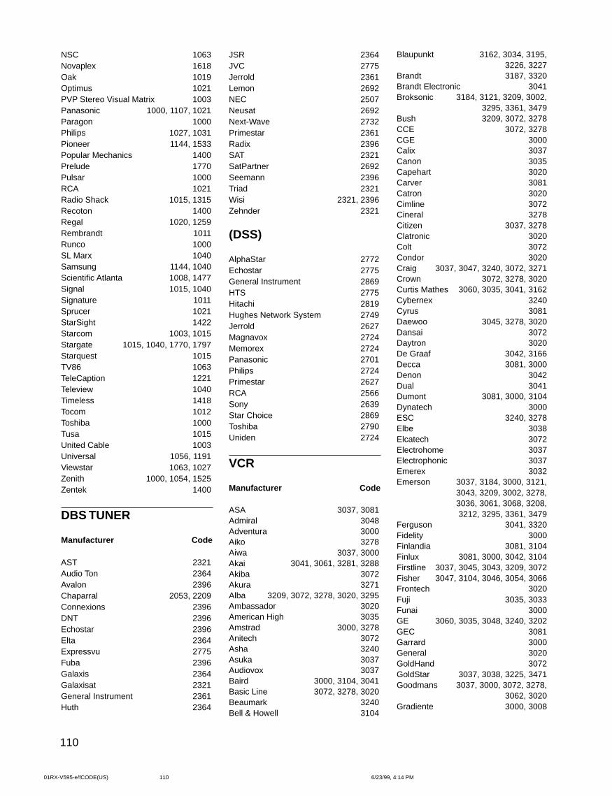
110
NSC 1063Novaplex 1618Oak 1019Optimus 1021PVP Stereo Visual Matrix 1003Panasonic 1000, 1107, 1021Paragon 1000Philips 1027, 1031Pioneer 1144, 1533Popular Mechanics 1400Prelude 1770Pulsar 1000RCA 1021Radio Shack 1015, 1315Recoton 1400Regal 1020, 1259Rembrandt 1011Runco 1000SL Marx 1040Samsung 1144, 1040Scientific Atlanta 1008, 1477Signal 1015, 1040Signature 1011Sprucer 1021StarSight 1422Starcom 1003, 1015Stargate 1015, 1040, 1770, 1797Starquest 1015TV86 1063TeleCaption 1221Teleview 1040Timeless 1418Tocom 1012Toshiba 1000Tusa 1015United Cable 1003Universal 1056, 1191Viewstar 1063, 1027Zenith 1000, 1054, 1525Zentek 1400
DBS TUNER
Manufacturer Code
AST 2321Audio Ton 2364Avalon 2396Chaparral 2053, 2209Connexions 2396DNT 2396Echostar 2396Elta 2364Expressvu 2775Fuba 2396Galaxis 2364Galaxisat 2321General Instrument 2361Huth 2364
JSR 2364JVC 2775Jerrold 2361Lemon 2692NEC 2507Neusat 2692Next-Wave 2732Primestar 2361Radix 2396SAT 2321SatPartner 2692Seemann 2396Triad 2321Wisi 2321, 2396Zehnder 2321
(DSS)
AlphaStar 2772Echostar 2775General Instrument 2869HTS 2775Hitachi 2819Hughes Network System 2749Jerrold 2627Magnavox 2724Memorex 2724Panasonic 2701Philips 2724Primestar 2627RCA 2566Sony 2639Star Choice 2869Toshiba 2790Uniden 2724
VCR
Manufacturer Code
ASA 3037, 3081Admiral 3048Adventura 3000Aiko 3278Aiwa 3037, 3000Akai 3041, 3061, 3281, 3288Akiba 3072Akura 3271Alba 3209, 3072, 3278, 3020, 3295Ambassador 3020American High 3035Amstrad 3000, 3278Anitech 3072Asha 3240Asuka 3037Audiovox 3037Baird 3000, 3104, 3041Basic Line 3072, 3278, 3020Beaumark 3240Bell & Howell 3104
Blaupunkt 3162, 3034, 3195,3226, 3227
Brandt 3187, 3320Brandt Electronic 3041Broksonic 3184, 3121, 3209, 3002,
3295, 3361, 3479Bush 3209, 3072, 3278CCE 3072, 3278CGE 3000Calix 3037Canon 3035Capehart 3020Carver 3081Catron 3020Cimline 3072Cineral 3278Citizen 3037, 3278Clatronic 3020Colt 3072Condor 3020Craig 3037, 3047, 3240, 3072, 3271Crown 3072, 3278, 3020Curtis Mathes 3060, 3035, 3041, 3162Cybernex 3240Cyrus 3081Daewoo 3045, 3278, 3020Dansai 3072Daytron 3020De Graaf 3042, 3166Decca 3081, 3000Denon 3042Dual 3041Dumont 3081, 3000, 3104Dynatech 3000ESC 3240, 3278Elbe 3038Elcatech 3072Electrohome 3037Electrophonic 3037Emerex 3032Emerson 3037, 3184, 3000, 3121,
3043, 3209, 3002, 3278,3036, 3061, 3068, 3208,3212, 3295, 3361, 3479
Ferguson 3041, 3320Fidelity 3000Finlandia 3081, 3104Finlux 3081, 3000, 3042, 3104Firstline 3037, 3045, 3043, 3209, 3072Fisher 3047, 3104, 3046, 3054, 3066Frontech 3020Fuji 3035, 3033Funai 3000GE 3060, 3035, 3048, 3240, 3202GEC 3081Garrard 3000General 3020GoldHand 3072GoldStar 3037, 3038, 3225, 3471Goodmans 3037, 3000, 3072, 3278,
3062, 3020Gradiente 3000, 3008
01RX-V595-e/fCODE(US) 6/23/99, 4:14 PM110
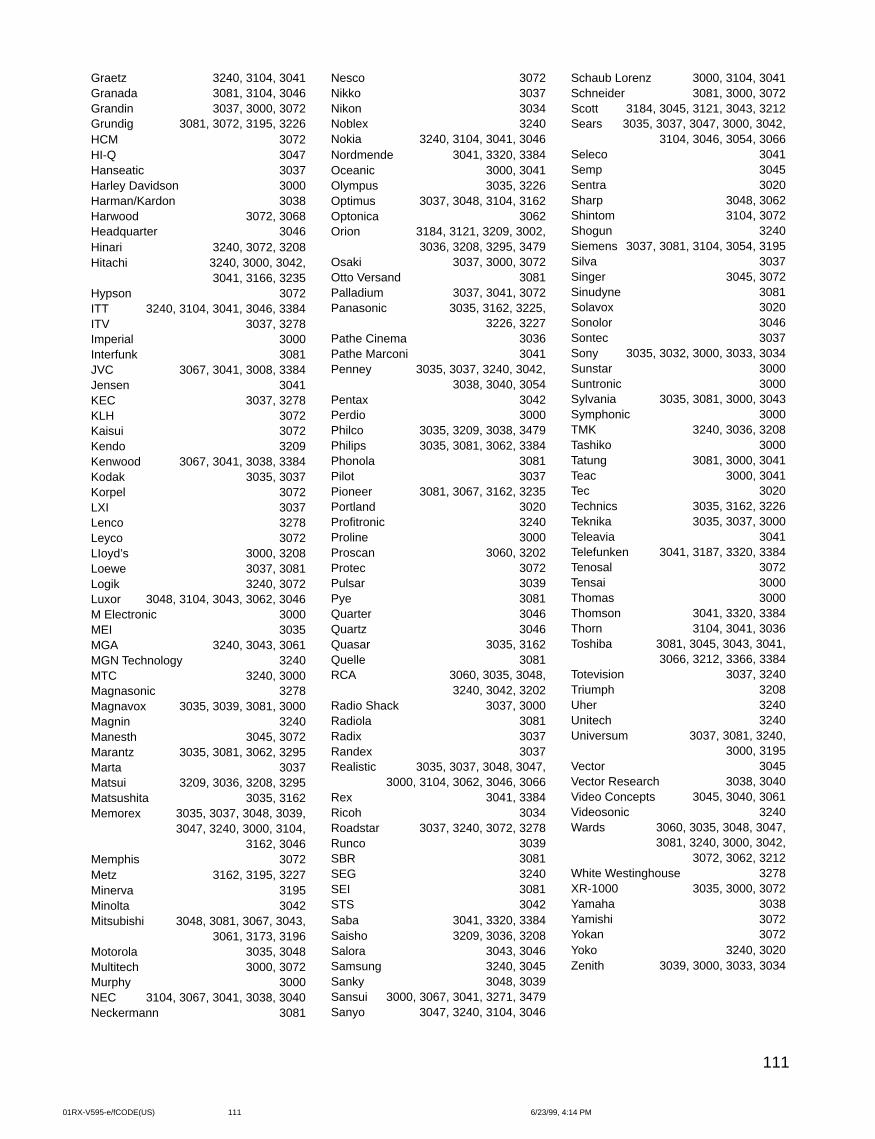
111
Graetz 3240, 3104, 3041Granada 3081, 3104, 3046Grandin 3037, 3000, 3072Grundig 3081, 3072, 3195, 3226HCM 3072HI-Q 3047Hanseatic 3037Harley Davidson 3000Harman/Kardon 3038Harwood 3072, 3068Headquarter 3046Hinari 3240, 3072, 3208Hitachi 3240, 3000, 3042,
3041, 3166, 3235Hypson 3072ITT 3240, 3104, 3041, 3046, 3384ITV 3037, 3278Imperial 3000Interfunk 3081JVC 3067, 3041, 3008, 3384Jensen 3041KEC 3037, 3278KLH 3072Kaisui 3072Kendo 3209Kenwood 3067, 3041, 3038, 3384Kodak 3035, 3037Korpel 3072LXI 3037Lenco 3278Leyco 3072LIoyd’s 3000, 3208Loewe 3037, 3081Logik 3240, 3072Luxor 3048, 3104, 3043, 3062, 3046M Electronic 3000MEI 3035MGA 3240, 3043, 3061MGN Technology 3240MTC 3240, 3000Magnasonic 3278Magnavox 3035, 3039, 3081, 3000Magnin 3240Manesth 3045, 3072Marantz 3035, 3081, 3062, 3295Marta 3037Matsui 3209, 3036, 3208, 3295Matsushita 3035, 3162Memorex 3035, 3037, 3048, 3039,
3047, 3240, 3000, 3104,3162, 3046
Memphis 3072Metz 3162, 3195, 3227Minerva 3195Minolta 3042Mitsubishi 3048, 3081, 3067, 3043,
3061, 3173, 3196Motorola 3035, 3048Multitech 3000, 3072Murphy 3000NEC 3104, 3067, 3041, 3038, 3040Neckermann 3081
Nesco 3072Nikko 3037Nikon 3034Noblex 3240Nokia 3240, 3104, 3041, 3046Nordmende 3041, 3320, 3384Oceanic 3000, 3041Olympus 3035, 3226Optimus 3037, 3048, 3104, 3162Optonica 3062Orion 3184, 3121, 3209, 3002,
3036, 3208, 3295, 3479Osaki 3037, 3000, 3072Otto Versand 3081Palladium 3037, 3041, 3072Panasonic 3035, 3162, 3225,
3226, 3227Pathe Cinema 3036Pathe Marconi 3041Penney 3035, 3037, 3240, 3042,
3038, 3040, 3054Pentax 3042Perdio 3000Philco 3035, 3209, 3038, 3479Philips 3035, 3081, 3062, 3384Phonola 3081Pilot 3037Pioneer 3081, 3067, 3162, 3235Portland 3020Profitronic 3240Proline 3000Proscan 3060, 3202Protec 3072Pulsar 3039Pye 3081Quarter 3046Quartz 3046Quasar 3035, 3162Quelle 3081RCA 3060, 3035, 3048,
3240, 3042, 3202Radio Shack 3037, 3000Radiola 3081Radix 3037Randex 3037Realistic 3035, 3037, 3048, 3047,
3000, 3104, 3062, 3046, 3066Rex 3041, 3384Ricoh 3034Roadstar 3037, 3240, 3072, 3278Runco 3039SBR 3081SEG 3240SEI 3081STS 3042Saba 3041, 3320, 3384Saisho 3209, 3036, 3208Salora 3043, 3046Samsung 3240, 3045Sanky 3048, 3039Sansui 3000, 3067, 3041, 3271, 3479Sanyo 3047, 3240, 3104, 3046
Schaub Lorenz 3000, 3104, 3041Schneider 3081, 3000, 3072Scott 3184, 3045, 3121, 3043, 3212Sears 3035, 3037, 3047, 3000, 3042,
3104, 3046, 3054, 3066Seleco 3041Semp 3045Sentra 3020Sharp 3048, 3062Shintom 3104, 3072Shogun 3240Siemens 3037, 3081, 3104, 3054, 3195Silva 3037Singer 3045, 3072Sinudyne 3081Solavox 3020Sonolor 3046Sontec 3037Sony 3035, 3032, 3000, 3033, 3034Sunstar 3000Suntronic 3000Sylvania 3035, 3081, 3000, 3043Symphonic 3000TMK 3240, 3036, 3208Tashiko 3000Tatung 3081, 3000, 3041Teac 3000, 3041Tec 3020Technics 3035, 3162, 3226Teknika 3035, 3037, 3000Teleavia 3041Telefunken 3041, 3187, 3320, 3384Tenosal 3072Tensai 3000Thomas 3000Thomson 3041, 3320, 3384Thorn 3104, 3041, 3036Toshiba 3081, 3045, 3043, 3041,
3066, 3212, 3366, 3384Totevision 3037, 3240Triumph 3208Uher 3240Unitech 3240Universum 3037, 3081, 3240,
3000, 3195Vector 3045Vector Research 3038, 3040Video Concepts 3045, 3040, 3061Videosonic 3240Wards 3060, 3035, 3048, 3047,
3081, 3240, 3000, 3042,3072, 3062, 3212
White Westinghouse 3278XR-1000 3035, 3000, 3072Yamaha 3038Yamishi 3072Yokan 3072Yoko 3240, 3020Zenith 3039, 3000, 3033, 3034
01RX-V595-e/fCODE(US) 6/23/99, 4:14 PM111
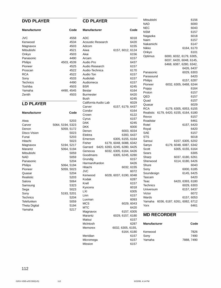
112
DVD PLAYER
Manufacturer Code
JVC 4558Kenwood 4534Magnavox 4503Mitsubishi 4521Onkyo 4503Panasonic 4490Philips 4503, 4539Pioneer 4525Proscan 4522RCA 4522Sony 4533Technics 4490Toshiba 4503Yamaha 4490, 4545Zenith 4503
LD PLAYER
Manufacturer Code
Aiwa 5203Carver 5064, 5194, 5323Denon 5059, 5172Disco Vision 5023Funai 5203Hitachi 5023Magnavox 5194, 5217Marantz 5064, 5194Mitsubishi 5059NAD 5059Panasonic 5204Philips 5064, 5194Pioneer 5059, 5023Quasar 5204Realistic 5203Salora 5064Samsung 5323Sega 5023Sony 5193, 5201Technics 5204Telefunken 5059Theta Digital 5194Yamaha 5217
CD PLAYER
Manufacturer Code
ADC 6018Acoustic Research 6420Adcom 6155Aiwa 6157, 6012, 6124Akai 6156Arcam 6157Audio Pro 6437Audio Research 6157Audio-Technica 6170Audio Ton 6157Audiolab 6157Audiomeca 6157BSR 6245Bestar 6164Burmester 6420Bush 6245California Audio Lab 6029Carver 6157, 6179, 6437Condor 6164Crown 6122Cyrus 6157DAK 6245DKK 6000Denon 6003, 6034Elektra 6393, 6437Emerson 6305, 6155, 6164Fisher 6179, 6048, 6088, 6342Garrard 6420, 6393, 6245, 6280, 6425Genexxa 6032, 6305, 6164, 6426Goodmans 6305, 6245, 6280Grundig 6157Harman/Kardon 6426Hitachi 6032, 6155JVC 6072Kenwood 6028, 6037, 6190, 6048Kodak 6287Krell 6157Kyocera 6018LXI 6305Linn 6157Luxman 6093MCS 6029, 6043MTC 6420Magnavox 6157, 6305Marantz 6029, 6157, 6180Matsui 6157Mclntosh 6287Memorex 6032, 6305, 6155,
6164, 6180Meridian 6157Micromega 6157Mission 6157
Mitsubishi 6156NAD 6000NEC 6043NSM 6157Nagaoka 6018Naim 6157Nakamichi 6147Nikko 6164, 6170Onkyo 6101Optimus 6000, 6032, 6179, 6305,
6037, 6420, 6048, 6145,6468, 6087, 6280, 6342,
6426, 6437Panasonic 6029, 6303Parasound 6420Philips 6157, 6287Pioneer 6032, 6305, 6468, 6244Poppy 6164Proton 6157QED 6157Quad 6157Quasar 6029RCA 6179, 6305, 6053, 6155Realistic 6179, 6420, 6155, 6164, 6180Revox 6157Roadstar 6461Rotel 6157, 6420Royal 6420SAE 6157STS 6018Sansui 6157, 6305, 6202Sanyo 6179, 6048, 6087, 6342Scott 6305, 6155, 6164Sears 6305Sharp 6037, 6180, 6261Sherwood 6114, 6180, 6426Shure 6043Sony 6000, 6185Soundesign 6145, 6425Tascam 6420Teac 6420, 6393, 6180Technics 6029, 6303Universum 6157, 6437Victor 6072Wards 6157, 6053Yamaha 6036, 6187, 6261, 6082, 6712Yorx 6461
MD RECORDER
Manufacturer Code
Kenwood 7826Sony 7490Yamaha 7888, 7490
01RX-V595-e/fCODE(US) 6/23/99, 4:14 PM112
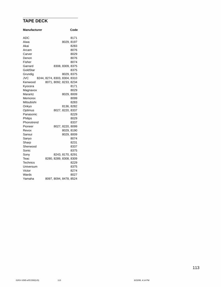
113
TAPE DECK
Manufacturer Code
ADC 8171Aiwa 8029, 8197Akai 8283Arcam 8076Carver 8029Denon 8076Fisher 8074Garrard 8308, 8309, 8375GoldStar 8375Grundig 8029, 8375JVC 8244, 8274, 8303, 8304, 8310Kenwood 8071, 8092, 8233, 8234Kyocera 8171Magnavox 8029Marantz 8029, 8009Memorex 8099Mitsubishi 8283Onkyo 8136, 8282Optimus 8027, 8220, 8337Panasonic 8229Philips 8029Phonotrend 8337Pioneer 8027, 8220, 8099Revox 8029, 8190Sansui 8029, 8009Sanyo 8074Sharp 8231Sherwood 8337Sonic 8375Sony 8243, 8170, 8291Teac 8280, 8289, 8308, 8309Technics 8229Universum 8375Victor 8274Wards 8027Yamaha 8097, 8094, 8478, 8524
01RX-V595-e/fCODE(US) 6/23/99, 4:14 PM113
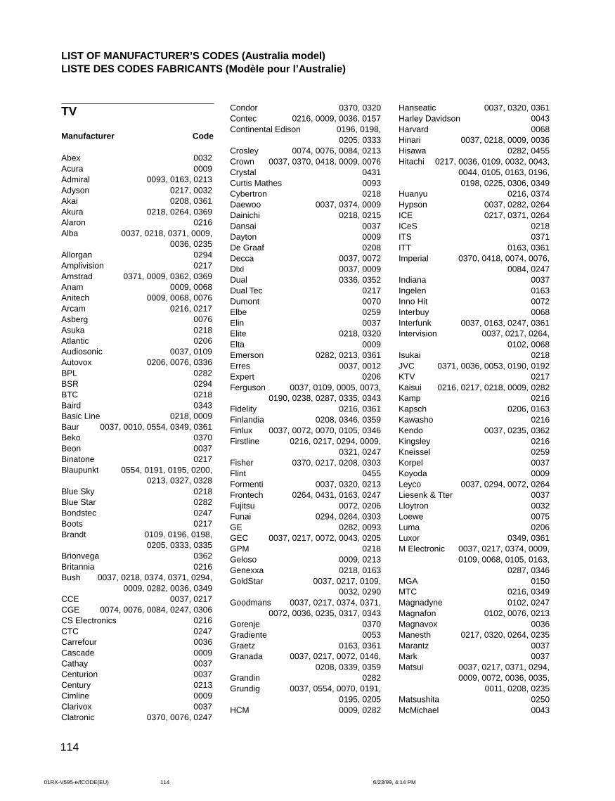
114
TV
Manufacturer Code
Abex 0032Acura 0009Admiral 0093, 0163, 0213Adyson 0217, 0032Akai 0208, 0361Akura 0218, 0264, 0369Alaron 0216Alba 0037, 0218, 0371, 0009,
0036, 0235Allorgan 0294Amplivision 0217Amstrad 0371, 0009, 0362, 0369Anam 0009, 0068Anitech 0009, 0068, 0076Arcam 0216, 0217Asberg 0076Asuka 0218Atlantic 0206Audiosonic 0037, 0109Autovox 0206, 0076, 0336BPL 0282BSR 0294BTC 0218Baird 0343Basic Line 0218, 0009Baur 0037, 0010, 0554, 0349, 0361Beko 0370Beon 0037Binatone 0217Blaupunkt 0554, 0191, 0195, 0200,
0213, 0327, 0328Blue Sky 0218Blue Star 0282Bondstec 0247Boots 0217Brandt 0109, 0196, 0198,
0205, 0333, 0335Brionvega 0362Britannia 0216Bush 0037, 0218, 0374, 0371, 0294,
0009, 0282, 0036, 0349CCE 0037, 0217CGE 0074, 0076, 0084, 0247, 0306CS Electronics 0216CTC 0247Carrefour 0036Cascade 0009Cathay 0037Centurion 0037Century 0213Cimline 0009Clarivox 0037Clatronic 0370, 0076, 0247
Condor 0370, 0320Contec 0216, 0009, 0036, 0157Continental Edison 0196, 0198,
0205, 0333Crosley 0074, 0076, 0084, 0213Crown 0037, 0370, 0418, 0009, 0076Crystal 0431Curtis Mathes 0093Cybertron 0218Daewoo 0037, 0374, 0009Dainichi 0218, 0215Dansai 0037Dayton 0009De Graaf 0208Decca 0037, 0072Dixi 0037, 0009Dual 0336, 0352Dual Tec 0217Dumont 0070Elbe 0259Elin 0037Elite 0218, 0320Elta 0009Emerson 0282, 0213, 0361Erres 0037, 0012Expert 0206Ferguson 0037, 0109, 0005, 0073,
0190, 0238, 0287, 0335, 0343Fidelity 0216, 0361Finlandia 0208, 0346, 0359Finlux 0037, 0072, 0070, 0105, 0346Firstline 0216, 0217, 0294, 0009,
0321, 0247Fisher 0370, 0217, 0208, 0303Flint 0455Formenti 0037, 0320, 0213Frontech 0264, 0431, 0163, 0247Fujitsu 0072, 0206Funai 0294, 0264, 0303GE 0282, 0093GEC 0037, 0217, 0072, 0043, 0205GPM 0218Geloso 0009, 0213Genexxa 0218, 0163GoldStar 0037, 0217, 0109,
0032, 0290Goodmans 0037, 0217, 0374, 0371,
0072, 0036, 0235, 0317, 0343Gorenje 0370Gradiente 0053Graetz 0163, 0361Granada 0037, 0217, 0072, 0146,
0208, 0339, 0359Grandin 0282Grundig 0037, 0554, 0070, 0191,
0195, 0205HCM 0009, 0282
Hanseatic 0037, 0320, 0361Harley Davidson 0043Harvard 0068Hinari 0037, 0218, 0009, 0036Hisawa 0282, 0455Hitachi 0217, 0036, 0109, 0032, 0043,
0044, 0105, 0163, 0196,0198, 0225, 0306, 0349
Huanyu 0216, 0374Hypson 0037, 0282, 0264ICE 0217, 0371, 0264ICeS 0218ITS 0371ITT 0163, 0361Imperial 0370, 0418, 0074, 0076,
0084, 0247Indiana 0037Ingelen 0163Inno Hit 0072Interbuy 0068Interfunk 0037, 0163, 0247, 0361Intervision 0037, 0217, 0264,
0102, 0068Isukai 0218JVC 0371, 0036, 0053, 0190, 0192KTV 0217Kaisui 0216, 0217, 0218, 0009, 0282Kamp 0216Kapsch 0206, 0163Kawasho 0216Kendo 0037, 0235, 0362Kingsley 0216Kneissel 0259Korpel 0037Koyoda 0009Leyco 0037, 0294, 0072, 0264Liesenk & Tter 0037Lloytron 0032Loewe 0075Luma 0206Luxor 0349, 0361M Electronic 0037, 0217, 0374, 0009,
0109, 0068, 0105, 0163,0287, 0346
MGA 0150MTC 0216, 0349Magnadyne 0102, 0247Magnafon 0102, 0076, 0213Magnavox 0036Manesth 0217, 0320, 0264, 0235Marantz 0037Mark 0037Matsui 0037, 0217, 0371, 0294,
0009, 0072, 0036, 0035,0011, 0208, 0235
Matsushita 0250McMichael 0043
LIST OF MANUFACTURER’S CODES (Australia model)LISTE DES CODES FABRICANTS (Modèle pour l’Australie)
01RX-V595-e/fCODE(EU) 6/23/99, 4:14 PM114
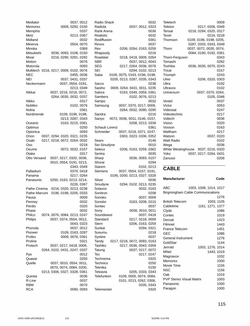
115
Radio Shack 0032Radiola 0037, 0012, 0323Rank Arena 0036Realistic 0032Rediffusion 0361Revox 0037Rex 0206, 0264, 0163, 0259Rhapsody 0216Roadstar 0218, 0418, 0009, 0264SBR 0037, 0012, 0043SEG 0217, 0264, 0036, 0076SEI 0294, 0102, 0213Saba 0109, 0075, 0163, 0196, 0198,
0205, 0213, 0287, 0335, 0343Saccs 0238Saisho 0009, 0264, 0431, 0011, 0235Salora 0163, 0349, 0359, 0361Sambers 0102, 0076, 0213Sampo 0032Samsung 0037, 0370, 0217, 0009,
0264, 0032, 0090, 0290Sandra 0216Sanyo 0072, 0036, 0011, 0146, 0157,
0208, 0213, 0339Schaub Lorenz 0361Schneider 0037, 0218, 0371, 0247,
0303, 0323, 0336, 0352Sears 0146Sei-Sinudyne 0010Seleco 0206, 0163, 0259, 0362Sentra 0035Sharp 0036, 0093, 0157Shorai 0294Siarem 0102, 0213Siemens 0037, 0554, 0157, 0191,
0195, 0200, 0213, 0327, 0328Silver 0036Sinudyne 0294, 0102, 0213, 0235Solavox 0032, 0163Sonitron 0208Sonoko 0037, 0009Sonolor 0163, 0208, 0215Sontec 0037Sony 0036, 0010, 0011Soundwave 0037, 0418Standard 0217, 0218, 0009Stern 0206, 0163, 0259Sunkai 0294, 0321Susumu 0218Sysline 0037Tandy 0217, 0218, 0072, 0093, 0163Tashiko 0217, 0036, 0043, 0359Tatung 0037, 0217, 0072Tec 0217, 0247Technema 0320Technics 0250Teknika 0150Teleavia 0205, 0333, 0343Telefunken 0109, 0005, 0074, 0084,
0101, 0213, 0262, 0306,0335, 0343
Telemeister 0320
Mediator 0037, 0012Memorex 0009, 0250, 0150Memphis 0337Metz 0213, 0367Midland 0032Minerva 0554, 0070Minoka 0369Mitsubishi 0036, 0093, 0108, 0150Mivar 0216, 0290, 0291, 0292Motion 0076Motorola 0093Multitech 0216, 0217, 0009, 0102, 0076NEC 0455, 0036NEI 0037, 0431, 0337Neckermann 0037, 0554, 0191,
0213, 0349Nikkai 0037, 0216, 0218, 0072,
0264, 0035, 0032, 0337Nikko 0317Nobliko 0102, 0076Nokia 0361Nordmende 0109, 0196, 0198,
0213, 0287, 0343Oceanic 0163, 0215, 0361Optimus 0250Optonica 0093Orion 0037, 0294, 0320, 0321, 0235Osaki 0217, 0218, 0072, 0264, 0032Oso 0218Osume 0072, 0032, 0157Otake 0317Otto Versand 0037, 0217, 0320, 0036,
0010, 0554, 0191, 0213,0343, 0349
Palladium 0370, 0418Panama 0217, 0264Panasonic 0250, 0163, 0213, 0214,
0226, 0367Pathe Cinema 0216, 0320, 0213, 0238Pathe Marconi 0196, 0198, 0205, 0333Pausa 0009Penney 0032Perdio 0320Phase 0032Philco 0074, 0076, 0084, 0213, 0247Philips 0037, 0374, 0554, 0012,
0043, 0323Phonola 0037, 0012Pioneer 0109, 0163, 0287Profex 0009, 0076, 0361Proline 0321Protech 0037, 0217, 0418, 0009,
0264, 0102, 0431, 0247, 0337Pye 0012Quasar 0250Quelle 0037, 0010, 0554, 0011,
0070, 0074, 0084, 0200,0213, 0306, 0327, 0328, 0361
Questa 0036R-Line 0037RBM 0070RCA 0090, 0093
Teletech 0009Teleton 0217, 0206, 0349Tensai 0218, 0294, 0320, 0317Texet 0216, 0218Thomson 0109, 0196, 0198, 0205,
0287, 0333, 0343, 0349Thorn 0037, 0072, 0035, 0074,
0084, 0190, 0192, 0361Thorn-Ferguson 0343Tomashi 0282Toshiba 0036, 0035, 0070, 0243Trical 0157Triumph 0243Uher 0206, 0320, 0303Ultra 0192Ultravox 0102Universum 0037, 0370, 0264,
0105, 0346Vestel 0037Victor 0053Videosat 0247Videotechnic 0217Vidtech 0036Vision 0320Voxson 0163Waltham 0217Watson 0037, 0320Watt Radio 0102Wega 0036White Westinghouse 0037, 0216, 0320Yoko 0037, 0217, 0264, 0431Zanussi 0206
CABLE
Manufacturer Code
ABC 1003, 1008, 1014, 1017Birgmingham Cable Communications
1276British Telecom 1003, 1105Cabletime 1161, 1271, 1377Clyde 1086Contec 1019Decsat 1423Filmnet 1443France Telecom 1451GEC 1086General Instrument 1276GoldStar 1144Jerrold 1003, 1276, 1014MNet 1443, 1019Magnavox 1032Memorex 1000Movie Time 1156NSC 1156Oak 1019PVP Stereo Visual Matrix 1003Panasonic 1000Paragon 1000
01RX-V595-e/fCODE(EU) 6/23/99, 4:14 PM115
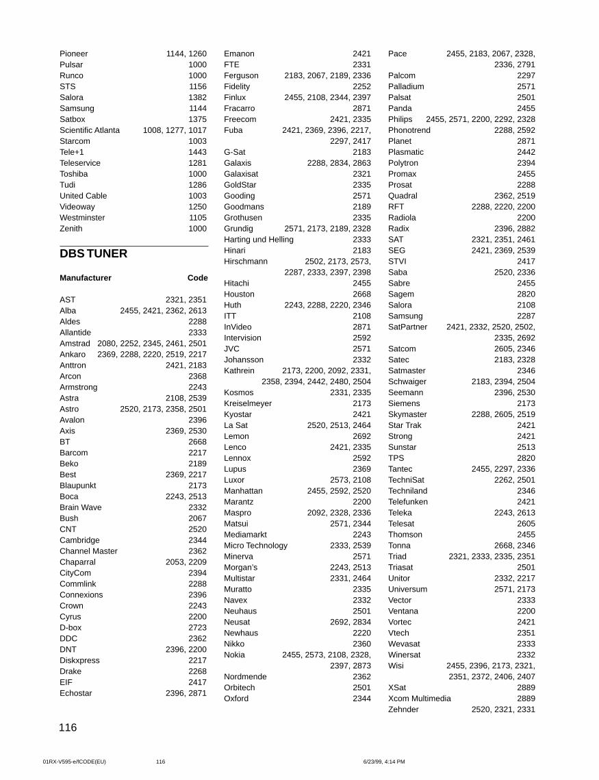
116
Pioneer 1144, 1260Pulsar 1000Runco 1000STS 1156Salora 1382Samsung 1144Satbox 1375Scientific Atlanta 1008, 1277, 1017Starcom 1003Tele+1 1443Teleservice 1281Toshiba 1000Tudi 1286United Cable 1003Videoway 1250Westminster 1105Zenith 1000
DBS TUNER
Manufacturer Code
AST 2321, 2351Alba 2455, 2421, 2362, 2613Aldes 2288Allantide 2333Amstrad 2080, 2252, 2345, 2461, 2501Ankaro 2369, 2288, 2220, 2519, 2217Anttron 2421, 2183Arcon 2368Armstrong 2243Astra 2108, 2539Astro 2520, 2173, 2358, 2501Avalon 2396Axis 2369, 2530BT 2668Barcom 2217Beko 2189Best 2369, 2217Blaupunkt 2173Boca 2243, 2513Brain Wave 2332Bush 2067CNT 2520Cambridge 2344Channel Master 2362Chaparral 2053, 2209CityCom 2394Commlink 2288Connexions 2396Crown 2243Cyrus 2200D-box 2723DDC 2362DNT 2396, 2200Diskxpress 2217Drake 2268EIF 2417Echostar 2396, 2871
Emanon 2421FTE 2331Ferguson 2183, 2067, 2189, 2336Fidelity 2252Finlux 2455, 2108, 2344, 2397Fracarro 2871Freecom 2421, 2335Fuba 2421, 2369, 2396, 2217,
2297, 2417G-Sat 2183Galaxis 2288, 2834, 2863Galaxisat 2321GoldStar 2335Gooding 2571Goodmans 2189Grothusen 2335Grundig 2571, 2173, 2189, 2328Harting und Helling 2333Hinari 2183Hirschmann 2502, 2173, 2573,
2287, 2333, 2397, 2398Hitachi 2455Houston 2668Huth 2243, 2288, 2220, 2346ITT 2108InVideo 2871Intervision 2592JVC 2571Johansson 2332Kathrein 2173, 2200, 2092, 2331,
2358, 2394, 2442, 2480, 2504Kosmos 2331, 2335Kreiselmeyer 2173Kyostar 2421La Sat 2520, 2513, 2464Lemon 2692Lenco 2421, 2335Lennox 2592Lupus 2369Luxor 2573, 2108Manhattan 2455, 2592, 2520Marantz 2200Maspro 2092, 2328, 2336Matsui 2571, 2344Mediamarkt 2243Micro Technology 2333, 2539Minerva 2571Morgan’s 2243, 2513Multistar 2331, 2464Muratto 2335Navex 2332Neuhaus 2501Neusat 2692, 2834Newhaus 2220Nikko 2360Nokia 2455, 2573, 2108, 2328,
2397, 2873Nordmende 2362Orbitech 2501Oxford 2344
Pace 2455, 2183, 2067, 2328,2336, 2791
Palcom 2297Palladium 2571Palsat 2501Panda 2455Philips 2455, 2571, 2200, 2292, 2328Phonotrend 2288, 2592Planet 2871Plasmatic 2442Polytron 2394Promax 2455Prosat 2288Quadral 2362, 2519RFT 2288, 2220, 2200Radiola 2200Radix 2396, 2882SAT 2321, 2351, 2461SEG 2421, 2369, 2539STVI 2417Saba 2520, 2336Sabre 2455Sagem 2820Salora 2108Samsung 2287SatPartner 2421, 2332, 2520, 2502,
2335, 2692Satcom 2605, 2346Satec 2183, 2328Satmaster 2346Schwaiger 2183, 2394, 2504Seemann 2396, 2530Siemens 2173Skymaster 2288, 2605, 2519Star Trak 2421Strong 2421Sunstar 2513TPS 2820Tantec 2455, 2297, 2336TechniSat 2262, 2501Techniland 2346Telefunken 2421Teleka 2243, 2613Telesat 2605Thomson 2455Tonna 2668, 2346Triad 2321, 2333, 2335, 2351Triasat 2501Unitor 2332, 2217Universum 2571, 2173Vector 2333Ventana 2200Vortec 2421Vtech 2351Wevasat 2333Winersat 2332Wisi 2455, 2396, 2173, 2321,
2351, 2372, 2406, 2407XSat 2889Xcom Multimedia 2889Zehnder 2520, 2321, 2331
01RX-V595-e/fCODE(EU) 6/23/99, 4:14 PM116
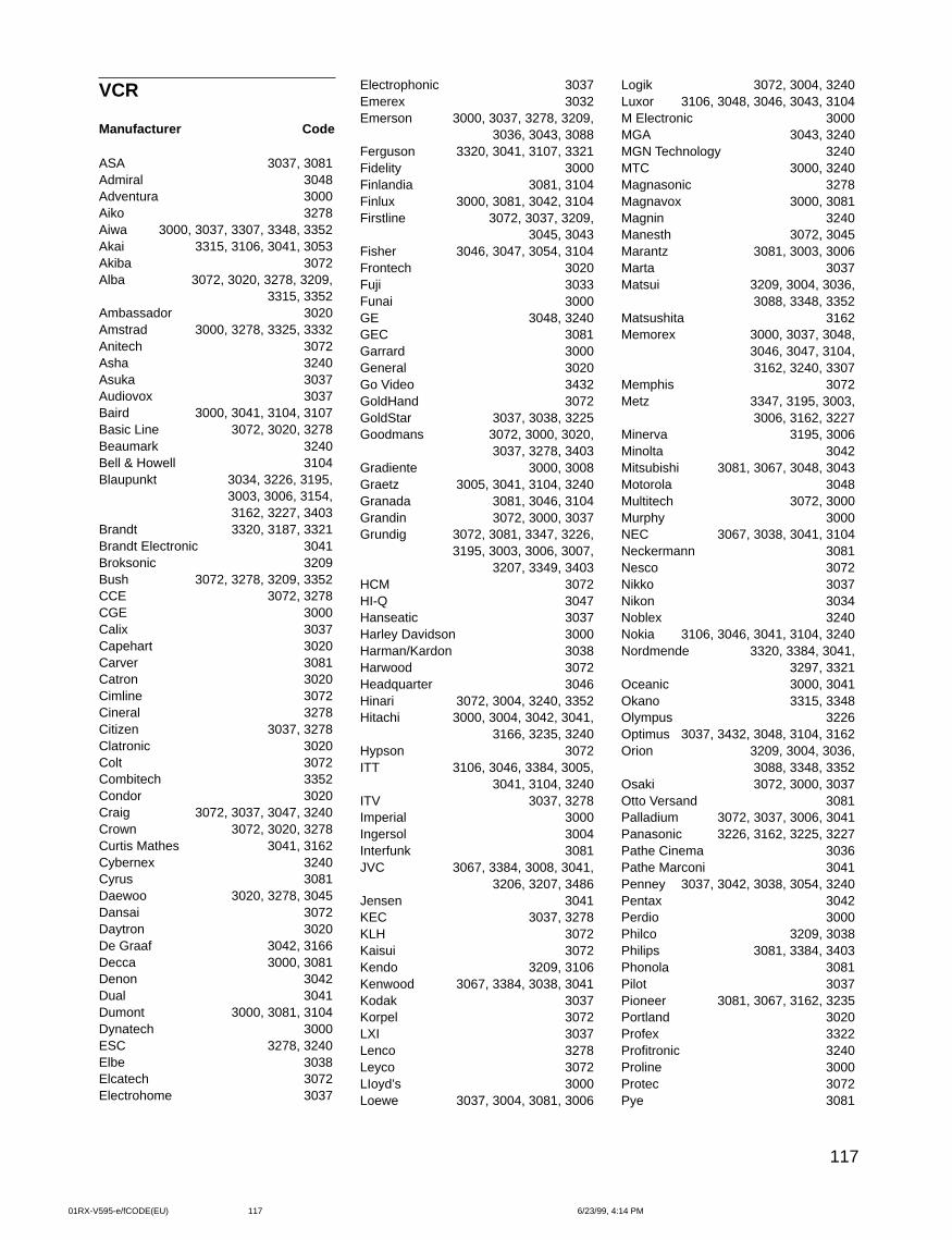
117
VCR
Manufacturer Code
ASA 3037, 3081Admiral 3048Adventura 3000Aiko 3278Aiwa 3000, 3037, 3307, 3348, 3352Akai 3315, 3106, 3041, 3053Akiba 3072Alba 3072, 3020, 3278, 3209,
3315, 3352Ambassador 3020Amstrad 3000, 3278, 3325, 3332Anitech 3072Asha 3240Asuka 3037Audiovox 3037Baird 3000, 3041, 3104, 3107Basic Line 3072, 3020, 3278Beaumark 3240Bell & Howell 3104Blaupunkt 3034, 3226, 3195,
3003, 3006, 3154, 3162, 3227, 3403
Brandt 3320, 3187, 3321Brandt Electronic 3041Broksonic 3209Bush 3072, 3278, 3209, 3352CCE 3072, 3278CGE 3000Calix 3037Capehart 3020Carver 3081Catron 3020Cimline 3072Cineral 3278Citizen 3037, 3278Clatronic 3020Colt 3072Combitech 3352Condor 3020Craig 3072, 3037, 3047, 3240Crown 3072, 3020, 3278Curtis Mathes 3041, 3162Cybernex 3240Cyrus 3081Daewoo 3020, 3278, 3045Dansai 3072Daytron 3020De Graaf 3042, 3166Decca 3000, 3081Denon 3042Dual 3041Dumont 3000, 3081, 3104Dynatech 3000ESC 3278, 3240Elbe 3038Elcatech 3072Electrohome 3037
Electrophonic 3037Emerex 3032Emerson 3000, 3037, 3278, 3209,
3036, 3043, 3088Ferguson 3320, 3041, 3107, 3321Fidelity 3000Finlandia 3081, 3104Finlux 3000, 3081, 3042, 3104Firstline 3072, 3037, 3209,
3045, 3043Fisher 3046, 3047, 3054, 3104Frontech 3020Fuji 3033Funai 3000GE 3048, 3240GEC 3081Garrard 3000General 3020Go Video 3432GoldHand 3072GoldStar 3037, 3038, 3225Goodmans 3072, 3000, 3020,
3037, 3278, 3403Gradiente 3000, 3008Graetz 3005, 3041, 3104, 3240Granada 3081, 3046, 3104Grandin 3072, 3000, 3037Grundig 3072, 3081, 3347, 3226,
3195, 3003, 3006, 3007,3207, 3349, 3403
HCM 3072HI-Q 3047Hanseatic 3037Harley Davidson 3000Harman/Kardon 3038Harwood 3072Headquarter 3046Hinari 3072, 3004, 3240, 3352Hitachi 3000, 3004, 3042, 3041,
3166, 3235, 3240Hypson 3072ITT 3106, 3046, 3384, 3005,
3041, 3104, 3240ITV 3037, 3278Imperial 3000Ingersol 3004Interfunk 3081JVC 3067, 3384, 3008, 3041,
3206, 3207, 3486Jensen 3041KEC 3037, 3278KLH 3072Kaisui 3072Kendo 3209, 3106Kenwood 3067, 3384, 3038, 3041Kodak 3037Korpel 3072LXI 3037Lenco 3278Leyco 3072LIoyd’s 3000Loewe 3037, 3004, 3081, 3006
Logik 3072, 3004, 3240Luxor 3106, 3048, 3046, 3043, 3104M Electronic 3000MGA 3043, 3240MGN Technology 3240MTC 3000, 3240Magnasonic 3278Magnavox 3000, 3081Magnin 3240Manesth 3072, 3045Marantz 3081, 3003, 3006Marta 3037Matsui 3209, 3004, 3036,
3088, 3348, 3352Matsushita 3162Memorex 3000, 3037, 3048,
3046, 3047, 3104,3162, 3240, 3307
Memphis 3072Metz 3347, 3195, 3003,
3006, 3162, 3227Minerva 3195, 3006Minolta 3042Mitsubishi 3081, 3067, 3048, 3043Motorola 3048Multitech 3072, 3000Murphy 3000NEC 3067, 3038, 3041, 3104Neckermann 3081Nesco 3072Nikko 3037Nikon 3034Noblex 3240Nokia 3106, 3046, 3041, 3104, 3240Nordmende 3320, 3384, 3041,
3297, 3321Oceanic 3000, 3041Okano 3315, 3348Olympus 3226Optimus 3037, 3432, 3048, 3104, 3162Orion 3209, 3004, 3036,
3088, 3348, 3352Osaki 3072, 3000, 3037Otto Versand 3081Palladium 3072, 3037, 3006, 3041Panasonic 3226, 3162, 3225, 3227Pathe Cinema 3036Pathe Marconi 3041Penney 3037, 3042, 3038, 3054, 3240Pentax 3042Perdio 3000Philco 3209, 3038Philips 3081, 3384, 3403Phonola 3081Pilot 3037Pioneer 3081, 3067, 3162, 3235Portland 3020Profex 3322Profitronic 3240Proline 3000Protec 3072Pye 3081
01RX-V595-e/fCODE(EU) 6/23/99, 4:14 PM117
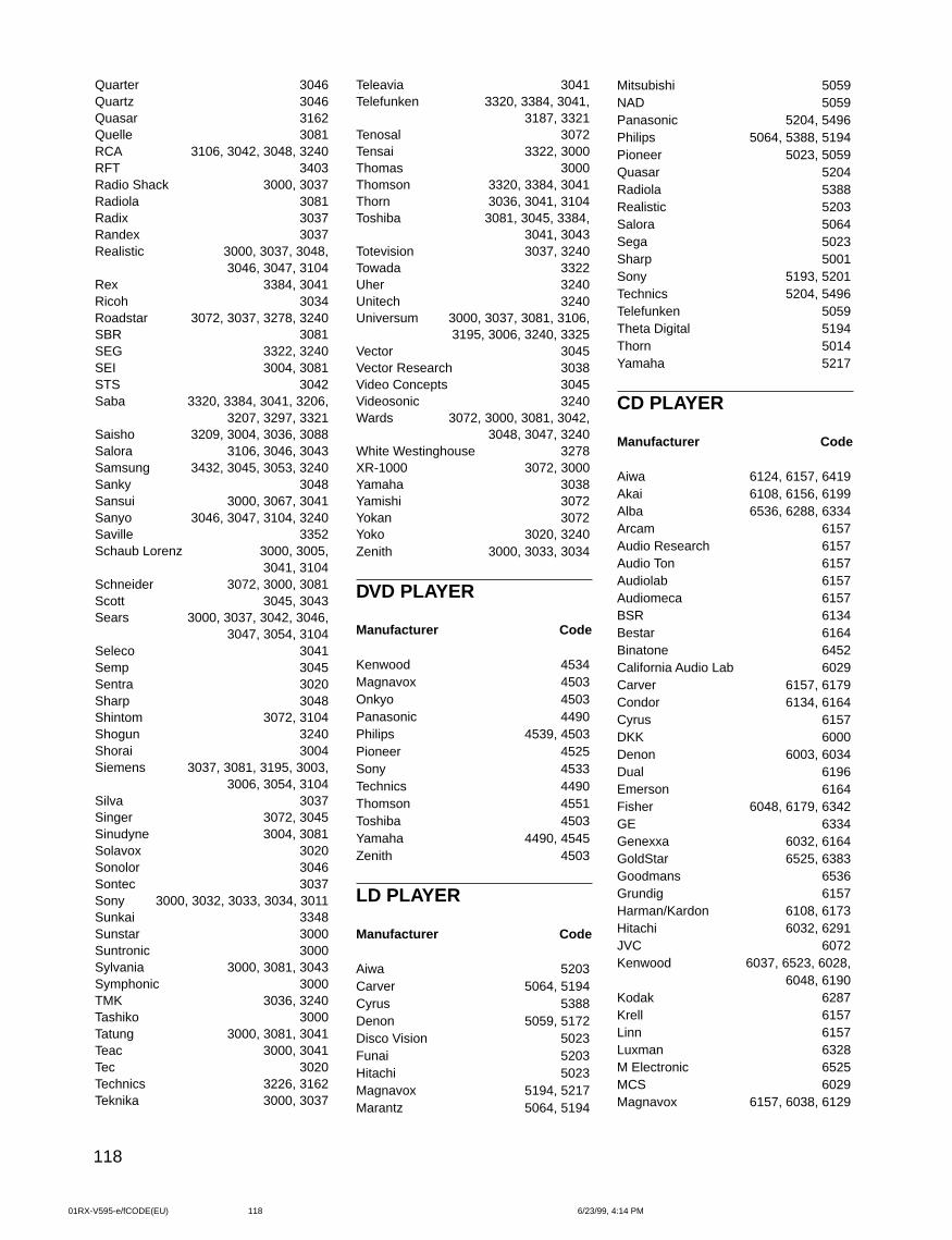
118
Quarter 3046Quartz 3046Quasar 3162Quelle 3081RCA 3106, 3042, 3048, 3240RFT 3403Radio Shack 3000, 3037Radiola 3081Radix 3037Randex 3037Realistic 3000, 3037, 3048,
3046, 3047, 3104Rex 3384, 3041Ricoh 3034Roadstar 3072, 3037, 3278, 3240SBR 3081SEG 3322, 3240SEI 3004, 3081STS 3042Saba 3320, 3384, 3041, 3206,
3207, 3297, 3321Saisho 3209, 3004, 3036, 3088Salora 3106, 3046, 3043Samsung 3432, 3045, 3053, 3240Sanky 3048Sansui 3000, 3067, 3041Sanyo 3046, 3047, 3104, 3240Saville 3352Schaub Lorenz 3000, 3005,
3041, 3104Schneider 3072, 3000, 3081Scott 3045, 3043Sears 3000, 3037, 3042, 3046,
3047, 3054, 3104Seleco 3041Semp 3045Sentra 3020Sharp 3048Shintom 3072, 3104Shogun 3240Shorai 3004Siemens 3037, 3081, 3195, 3003,
3006, 3054, 3104Silva 3037Singer 3072, 3045Sinudyne 3004, 3081Solavox 3020Sonolor 3046Sontec 3037Sony 3000, 3032, 3033, 3034, 3011Sunkai 3348Sunstar 3000Suntronic 3000Sylvania 3000, 3081, 3043Symphonic 3000TMK 3036, 3240Tashiko 3000Tatung 3000, 3081, 3041Teac 3000, 3041Tec 3020Technics 3226, 3162Teknika 3000, 3037
Teleavia 3041Telefunken 3320, 3384, 3041,
3187, 3321Tenosal 3072Tensai 3322, 3000Thomas 3000Thomson 3320, 3384, 3041Thorn 3036, 3041, 3104Toshiba 3081, 3045, 3384,
3041, 3043Totevision 3037, 3240Towada 3322Uher 3240Unitech 3240Universum 3000, 3037, 3081, 3106,
3195, 3006, 3240, 3325Vector 3045Vector Research 3038Video Concepts 3045Videosonic 3240Wards 3072, 3000, 3081, 3042,
3048, 3047, 3240White Westinghouse 3278XR-1000 3072, 3000Yamaha 3038Yamishi 3072Yokan 3072Yoko 3020, 3240Zenith 3000, 3033, 3034
DVD PLAYER
Manufacturer Code
Kenwood 4534Magnavox 4503Onkyo 4503Panasonic 4490Philips 4539, 4503Pioneer 4525Sony 4533Technics 4490Thomson 4551Toshiba 4503Yamaha 4490, 4545Zenith 4503
LD PLAYER
Manufacturer Code
Aiwa 5203Carver 5064, 5194Cyrus 5388Denon 5059, 5172Disco Vision 5023Funai 5203Hitachi 5023Magnavox 5194, 5217Marantz 5064, 5194
Mitsubishi 5059NAD 5059Panasonic 5204, 5496Philips 5064, 5388, 5194Pioneer 5023, 5059Quasar 5204Radiola 5388Realistic 5203Salora 5064Sega 5023Sharp 5001Sony 5193, 5201Technics 5204, 5496Telefunken 5059Theta Digital 5194Thorn 5014Yamaha 5217
CD PLAYER
Manufacturer Code
Aiwa 6124, 6157, 6419Akai 6108, 6156, 6199Alba 6536, 6288, 6334Arcam 6157Audio Research 6157Audio Ton 6157Audiolab 6157Audiomeca 6157BSR 6134Bestar 6164Binatone 6452California Audio Lab 6029Carver 6157, 6179Condor 6134, 6164Cyrus 6157DKK 6000Denon 6003, 6034Dual 6196Emerson 6164Fisher 6048, 6179, 6342GE 6334Genexxa 6032, 6164GoldStar 6525, 6383Goodmans 6536Grundig 6157Harman/Kardon 6108, 6173Hitachi 6032, 6291JVC 6072Kenwood 6037, 6523, 6028,
6048, 6190Kodak 6287Krell 6157Linn 6157Luxman 6328M Electronic 6525MCS 6029Magnavox 6157, 6038, 6129
01RX-V595-e/fCODE(EU) 6/23/99, 4:14 PM118
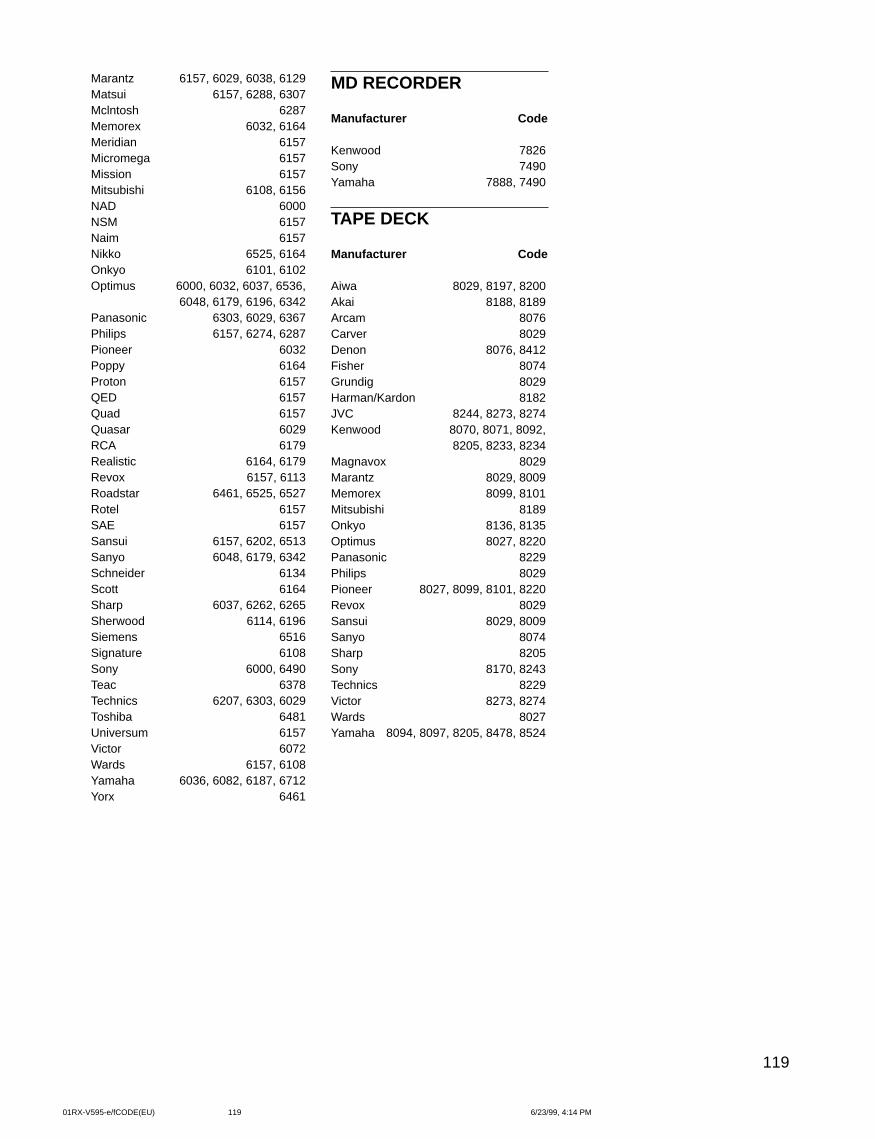
119
Marantz 6157, 6029, 6038, 6129Matsui 6157, 6288, 6307Mclntosh 6287Memorex 6032, 6164Meridian 6157Micromega 6157Mission 6157Mitsubishi 6108, 6156NAD 6000NSM 6157Naim 6157Nikko 6525, 6164Onkyo 6101, 6102Optimus 6000, 6032, 6037, 6536,
6048, 6179, 6196, 6342Panasonic 6303, 6029, 6367Philips 6157, 6274, 6287Pioneer 6032Poppy 6164Proton 6157QED 6157Quad 6157Quasar 6029RCA 6179Realistic 6164, 6179Revox 6157, 6113Roadstar 6461, 6525, 6527Rotel 6157SAE 6157Sansui 6157, 6202, 6513Sanyo 6048, 6179, 6342Schneider 6134Scott 6164Sharp 6037, 6262, 6265Sherwood 6114, 6196Siemens 6516Signature 6108Sony 6000, 6490Teac 6378Technics 6207, 6303, 6029Toshiba 6481Universum 6157Victor 6072Wards 6157, 6108Yamaha 6036, 6082, 6187, 6712Yorx 6461
MD RECORDER
Manufacturer Code
Kenwood 7826Sony 7490Yamaha 7888, 7490
TAPE DECK
Manufacturer Code
Aiwa 8029, 8197, 8200Akai 8188, 8189Arcam 8076Carver 8029Denon 8076, 8412Fisher 8074Grundig 8029Harman/Kardon 8182JVC 8244, 8273, 8274Kenwood 8070, 8071, 8092,
8205, 8233, 8234Magnavox 8029Marantz 8029, 8009Memorex 8099, 8101Mitsubishi 8189Onkyo 8136, 8135Optimus 8027, 8220Panasonic 8229Philips 8029Pioneer 8027, 8099, 8101, 8220Revox 8029Sansui 8029, 8009Sanyo 8074Sharp 8205Sony 8170, 8243Technics 8229Victor 8273, 8274Wards 8027Yamaha 8094, 8097, 8205, 8478, 8524
01RX-V595-e/fCODE(EU) 6/23/99, 4:14 PM119
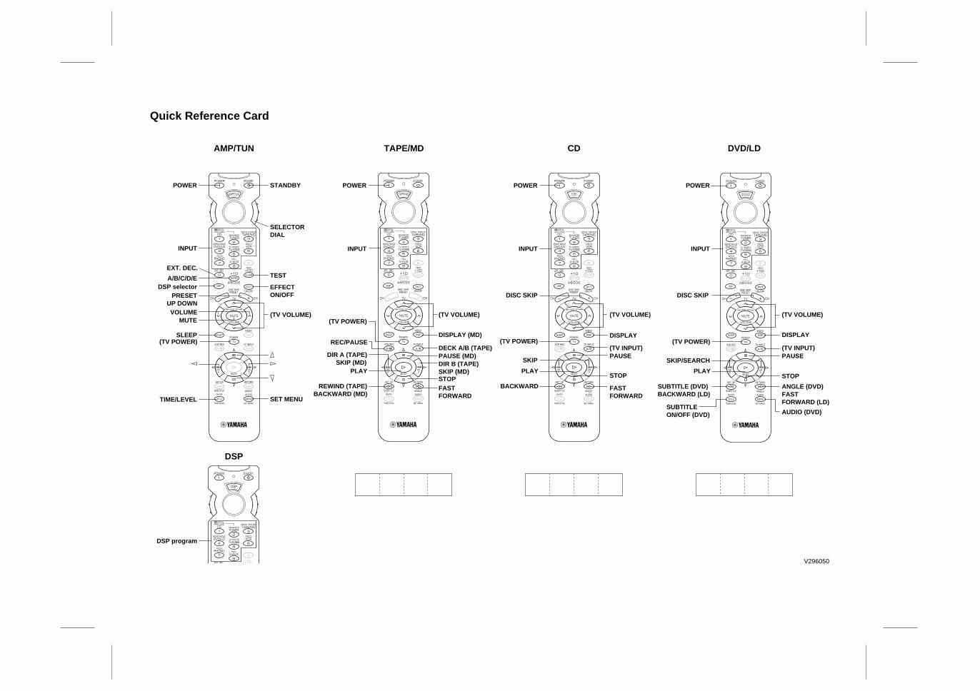
Quick Reference Card
AMP/TUN
DSP
TAPE/MD CD DVD/LD
POWER
INPUT
EXT. DEC.
A/B/C/D/EDSP selector
PRESET UP DOWNVOLUME
MUTE
SLEEP(TV POWER)
TIME/LEVEL
DSP program
STANDBY
SELECTOR DIAL
TEST
EFFECT ON/OFF
(TV VOLUME)
POWER
(TV POWER)
REC/PAUSE
PLAY
DIR A (TAPE)SKIP (MD)
REWIND (TAPE)BACKWARD (MD)
INPUT
(TV VOLUME)
DISPLAY (MD)
PAUSE (MD)DECK A/B (TAPE)
DIR B (TAPE)SKIP (MD)STOPFAST FORWARD
POWER
(TV POWER)
PLAY
SUBTITLE ON/OFF (DVD)
SKIP/SEARCH
SUBTITLE (DVD)BACKWARD (LD)
INPUT
(TV VOLUME)
DISPLAY
PAUSE(TV INPUT)
STOP
ANGLE (DVD)FAST FORWARD (LD)
AUDIO (DVD)
POWER
(TV POWER)
DISC SKIP DISC SKIP
PLAY
SKIP
BACKWARD
INPUT
(TV VOLUME)
PAUSE(TV INPUT)
STOP
FAST FORWARD
DISPLAY
SET MENU
V296050
Related Documents