RX-V520RDS Natural Sound AV Receiver Ampli-tuner audio-vidéo G B OWNER’S MANUAL MODE D’EMPLOI BEDIENUNGSANLEITUNG BRUKSANVISNING MANUALE DI ISTRUZIONI MANUAL DE INSTRUCCIONES GEBRUIKSAANWIJZING 2/1/1, 4:41 PM

Welcome message from author
This document is posted to help you gain knowledge. Please leave a comment to let me know what you think about it! Share it to your friends and learn new things together.
Transcript
YAMAHA ELECTRONICS CORPORATION, USA 6660 ORANGETHORPE AVE., BUENA PARK, CALIF. 90620, U.S.A.YAMAHA CANADA MUSIC LTD. 135 MILNER AVE., SCARBOROUGH, ONTARIO M1S 3R1, CANADAYAMAHA ELECTRONIK EUROPA G.m.b.H. SIEMENSSTR. 22-34, 25462 RELLINGEN BEI HAMBURG, F.R. OF GERMANYYAMAHA ELECTRONIQUE FRANCE S.A. RUE AMBROISE CROIZAT BP70 CROISSY-BEAUBOURG 77312 MARNE-LA-VALLEE CEDEX02, FRANCEYAMAHA ELECTRONICS (UK) LTD. YAMAHA HOUSE, 200 RICKMANSWORTH ROAD WATFORD, HERTS WD1 7JS, ENGLANDYAMAHA SCANDINAVIA A.B. J A WETTERGRENS GATA 1, BOX 30053, 400 43 VÄSTRA FRÖLUNDA, SWEDENYAMAHA MUSIC AUSTRALIA PTY, LTD. 17-33 MARKET ST., SOUTH MELBOURNE, 3205 VIC., AUSTRALIA
RX-V520RDSNatural Sound AV ReceiverAmpli-tuner audio-vidéo
G B
OWNER’S MANUALMODE D’EMPLOI
BEDIENUNGSANLEITUNGBRUKSANVISNING
MANUALE DI ISTRUZIONIMANUAL DE INSTRUCCIONES
GEBRUIKSAANWIJZING
RX
-V5
20
RD
S
Printed in Malaysia ID V723020
00RX-V520RDS(ML)-cv1/4 2/1/1, 4:41 PM1
CAUTION
CAUTION: READ THIS BEFORE OPERATING YOUR UNIT.1 To assure the finest performance, please read this
manual carefully. Keep it in a safe place for futurereference.
2 Install this unit in a well ventilated, cool, dry, cleanplace with at least 30 cm on the top, 20 cm on theright and left, and 10 cm at the back of this unit forventilation space — away from direct sunlight, heatsources, vibration, dust, moisture, and/or cold.
3 Locate this unit away from other electricalappliances, motors, or transformers to avoidhumming sounds. To prevent fire or electrical shock,do not place this unit where it may get exposed torain, water, and/or any type of liquid.
4 Do not expose this unit to sudden temperaturechanges from cold to hot, and do not locate this unitin a environment with high humidity (i.e. a room witha humidifier) to prevent condensation inside this unit,which may cause an electrical shock, fire, damage tothis unit, and/or personal injury.
5 On the top of this unit, do not place:– Other components, as they may cause damage
and/or discoloration on the surface of this unit.– Burning objects (i.e. candles), as they may cause
fire, damage to this unit, and/or personal injury.– Containers with liquid in them, as they may cause
electrical shock to the user and/or damage to thisunit.
6 Do not cover this unit with a newspaper, tablecloth,curtain, etc. in order not to obstruct heat radiation. Ifthe temperature inside this unit rises, it may causefire, damage to this unit, and/or personal injury.
7 Do not plug in this unit to a wall outlet until allconnections are complete.
8 Do not operate this unit upside-down. It mayoverheat, possibly causing damage.
9 Do not use force on switches, knobs and/or cords.
10 When disconnecting the power cord from the walloutlet, grasp the plug; do not pull the cord.
11 Do not clean this unit with chemical solvents; thismight damage the finish. Use a clean, dry cloth.
12 Only voltage specified on this unit must be used.Using this unit with a higher voltage than specified isdangerous and may cause fire, damage to this unit,and/or personal injury. YAMAHA will not be heldresponsible for any damage resulting from use of thisunit with a voltage other than specified.
13 To prevent damage by lightning, disconnect thepower cord from the wall outlet during an electricalstorm.
14 Take care of this unit so that no foreign objects and/or liquid drops inside this unit.
15 Do not attempt to modify or fix this unit. Contactqualified YAMAHA service personnel when anyservice is needed. The cabinet should never beopened for any reasons.
16 When not planning to use this unit for long periods oftime (i.e. vacation), disconnect the AC power plugfrom the wall outlet.
17 Be sure to read the “TROUBLESHOOTING” sectionon common operating errors before concluding thatthis unit is faulty.
18 Before moving this unit, press STANDBY/ON to setthis unit in the standby mode, and disconnect the ACpower plug from the wall outlet.
This unit is not disconnected from the AC power sourceas long as it is connected to the wall outlet, even if thisunit itself is turned off. This state is called the standbymode. In this state, this unit is designed to consume avery small quantity of power.
For U.K. customersIf the socket outlets in the home are not suitable for the plugsupplied with this appliance, it should be cut off and anappropriate 3 pin plug fitted. For details, refer to theinstructions described below.
Note• The plug severed from the mains lead must be destroyed, as a
plug with bared flexible cord is hazardous if engaged in a livesocket outlet.
Special Instructions for U.K. Model
IMPORTANTTHE WIRES IN MAINS LEAD ARE COLOURED INACCORDANCE WITH THE FOLLOWING CODE:
Blue: NEUTRALBrown: LIVE
As the colours of the wires in the mains lead of thisapparatus may not correspond with the colouredmarkings identifying the terminals in your plug, proceedas follows:The wire which is coloured BLUE must be connected tothe terminal which is marked with the letter N orcoloured BLACK. The wire which is coloured BROWNmust be connected to the terminal which is marked withthe letter L or coloured RED.Making sure that neither core is connected to the earthterminal of the three pin plug.
0101V520RDS_caution_EN 1/31/1, 4:20 PM2

11
En
glish
BA
SIC
OP
ER
AT
ION
ADVA
NC
ED O
PERA
TIO
NA
PP
EN
DIX
PR
EPA
RA
TIO
NIN
TR
OD
UC
TIO
NINTRODUCTION
CONTENTS
INTRODUCTION
FEATURES .......................................................... 2GETTING STARTED ......................................... 3
Checking the Package Contents ............................. 3Battery Installation in the Remote Control ............ 3Battery Replacement .............................................. 3
CONTROLS AND FUNCTIONS ....................... 4Front Panel ............................................................. 4Remote Control ...................................................... 6Using the Remote Control ...................................... 7Display ................................................................... 8Rear Panel .............................................................. 9
PREPARATION
SPEAKER SETUP ............................................ 10Speakers to Be Used ............................................ 10Speaker Placement ............................................... 10
CONNECTIONS ............................................... 11Before Connecting Components ........................... 11Connecting Audio Components ........................... 12Connecting an External Decoder ......................... 12Connecting Video Components ............................ 14Connecting Speakers ............................................ 16IMPEDANCE SELECTOR Switch ..................... 18Connecting the Power Supply Cords ................... 18
ADJUSTING THE SPEAKER BALANCE .... 19Before You Start Adjusting .................................. 19Using the Test Tone .............................................. 19
BASIC OPERATION
PLAYING A SOURCE ...................................... 21Input Modes and Indications ................................ 23Selecting a DSP Program ..................................... 24Canceling the Sound Effect (turning off the effect
speakers) ........................................................... 25TUNING ............................................................. 26
Connecting the Antennas ..................................... 26Automatic Tuning ................................................ 27Manual Tuning ..................................................... 27Automatic Preset Tuning
(for RDS stations only) .................................... 28Manual Preset Tuning .......................................... 29To Recall a Preset Station .................................... 29Exchanging Preset Stations .................................. 30
RECEIVING RDS STATIONS ........................ 31Description of RDS Data ..................................... 31Changing the RDS Mode ..................................... 31PTY SEEK Function ............................................ 32EON Function ...................................................... 33
RECORDING A SOURCE ............................... 34
ADVANCED OPERATION
SET MENU ......................................................... 35Adjusting the Items on the SET MENU .............. 351 SPEAKER SET (speaker mode settings) .......... 362 HP TONE CTRL (headphone tone control) ...... 373 I/O ASSIGN ...................................................... 374 INPUT MODE (initial input mode) .................. 385 DOLBY D. SET (Dolby Digital set) ................. 386 DTS SET (DTS LFE level) ............................... 387 SP DLY TIME (center delay) ............................ 398 DISPLAY SET .................................................. 399 MEM. GUARD (memory guard) ...................... 39
DELAY TIME AND SPEAKER OUTPUTLEVELS .......................................................... 40Delay Time ........................................................... 40Sound Output Level of the Center, Right Rear
and Left Rear Speakers, and Subwoofer .......... 40Adjusting Method ................................................ 41
SLEEP TIMER .................................................. 42Setting the SLEEP Timer ..................................... 42Canceling the SLEEP Timer ................................ 42
PRESET REMOTE CONTROL ...................... 43Component Selector Buttons ............................... 43Controlling the Components Connected to
This Unit .......................................................... 43Description of Each Mode ................................... 44Setting the Manufacturer Code ............................ 48Returning to the Factory Setting .......................... 49
SOUND FIELD PROGRAM ............................ 50Hi-Fi DSP Programs ............................................ 50CINEMA DSP Programs ...................................... 50
APPENDIX
TROUBLESHOOTING .................................... 53SPECIFICATIONS............................................ 57GLOSSARY ....................................................... 58INDEX ................................................................ 60
0102V520RDS01-09_EN 1/31/1, 4:20 PM1

2
Manufactured under license from Dolby Laboratories.
“Dolby”, “AC-3”, “Pro Logic” and the double-D symbol aretrademarks of Dolby Laboratories.Confidential Unpublished Works. ©1992-1997 Dolby Laboratories,Inc. All rights reserved.
Manufactured under license from Digital Theater Systems, Inc. USPat. No. 5,451,942 and other world-wide patents issued andpending. “DTS” and “DTS Digital Surround” are trademarks ofDigital Theater Systems, Inc. Copyright 1996 Digital TheaterSystems, Inc. All Rights Reserved.
• y indicates a tip for your operation.• Some operations can be performed by using either the buttons on the main unit or on the remote control. In cases when
the button names differ between the main unit and the remote control, the button name on the remote control is given inparentheses in this manual.
5-Channel Power Amplification Minimum RMS Output
(0.06% THD, 20 Hz – 20 kHz)Main: 70 W + 70 W (8 Ω)Center: 70 W (8 Ω)Rear: 70 W + 70 W (8 Ω)
Multi-mode Digital Sound FieldProcessing DTS Decoder Dolby Pro Logic Decoder Dolby Digital Decoder Hi-Fi DSP CINEMA DSP: Combination of YAMAHA DSP
Technology and Dolby Digital, Dolby Pro Logic orDTS
Virtual CINEMA DSP SILENT CINEMA
Sophisticated FM/AM Tuner 40-Station Random Access Preset Tuning Automatic Preset Tuning Preset Station Shifting Capability (Preset Editing) Multi-Functions for RDS Broadcast Reception
Other Features 96-kHz/24-bit D/A Converter “SET MENU” which Provides You with 9 Items
for Optimizing This Unit for Your Audio/VideoSystem
Test Tone Generator for Easier Speaker BalanceAdjustment
6-Channel External Decoder Input for Other FutureFormats
Video Signal Input and Output Capability(Including S Video Connections)
Optical and Coaxial Digital Signal Input Jacks SLEEP Timer Remote Control with Preset Manufacturer Codes
FEATURES
0102V520RDS01-09_EN 1/31/1, 4:20 PM2
3
En
glish
BA
SIC
OP
ER
AT
ION
ADVA
NC
ED O
PERA
TIO
NA
PP
EN
DIX
INT
RO
DU
CT
ION
PR
EPA
RA
TIO
N
GETTING STARTED
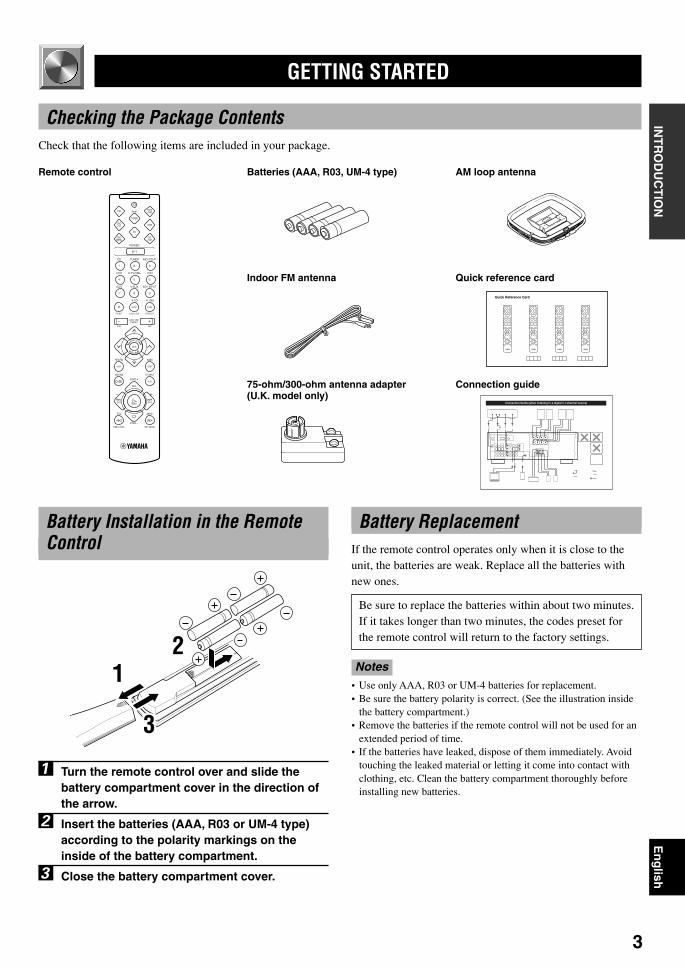
Checking the Package ContentsCheck that the following items are included in your package.
21
3
Remote control Batteries (AAA, R03, UM-4 type) AM loop antenna
Indoor FM antenna
75-ohm/300-ohm antenna adapter(U.K. model only)
Battery Installation in the RemoteControl
1 Turn the remote control over and slide thebattery compartment cover in the direction ofthe arrow.
2 Insert the batteries (AAA, R03 or UM-4 type)according to the polarity markings on theinside of the battery compartment.
3 Close the battery compartment cover.
Battery ReplacementIf the remote control operates only when it is close to theunit, the batteries are weak. Replace all the batteries withnew ones.
Be sure to replace the batteries within about two minutes.If it takes longer than two minutes, the codes preset forthe remote control will return to the factory settings.
Notes• Use only AAA, R03 or UM-4 batteries for replacement.• Be sure the battery polarity is correct. (See the illustration inside
the battery compartment.)• Remove the batteries if the remote control will not be used for an
extended period of time.• If the batteries have leaked, dispose of them immediately. Avoid
touching the leaked material or letting it come into contact withclothing, etc. Clean the battery compartment thoroughly beforeinstalling new batteries.
Quick reference card
Connection guide
0102V520RDS01-09_EN 2/1/1, 2:24 PM3
4
SURROUND
D I G I T A L
SILENT VIDEO AUX
PHONES S VIDEO VIDEO L AUDIO R OPTICAL
6CH INPUTINPUT MODE
INPUT
VOLUME
RDS MODE/FREQ EON
PTY SEEKMODE START
TUNINGMODE
PRESET/TUNING FM/AM
MEMORY
EDIT
BASS BALANCE SPEAKERS
PROGRAM PRESET/TUNINGEFFECT A/B/C/D/EA B
OFFON
STANDBY/ON
D I G I T A L
– + L R
TREBLE
– +MAN'L/AUTO FM AUTO/MAN'L MONO
61 2 3 7 9 08
q w e r t dsp fa gu oiy
54
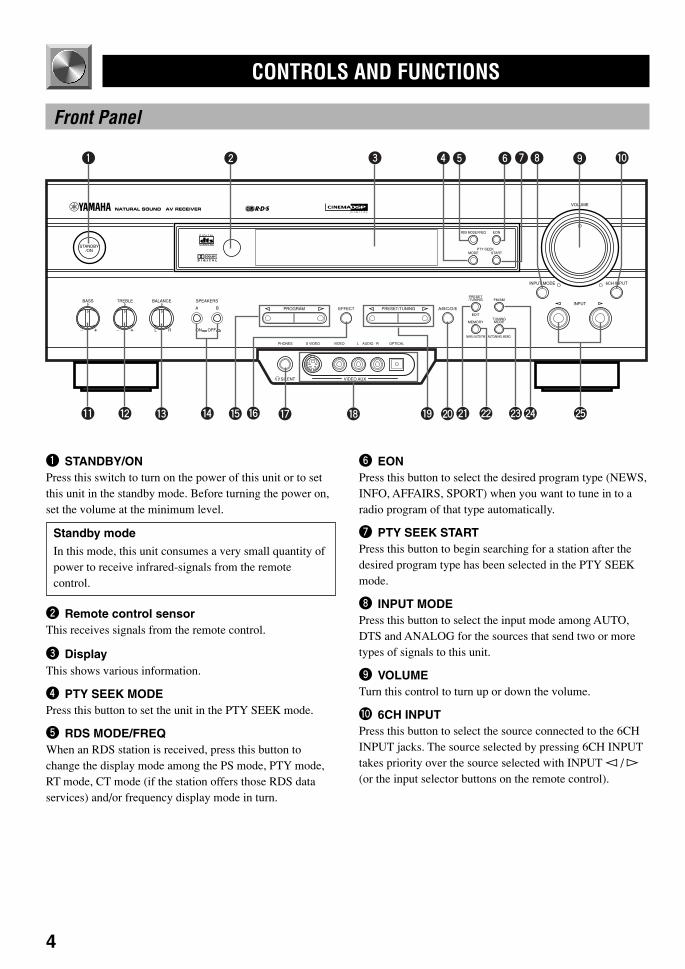
6 EONPress this button to select the desired program type (NEWS,INFO, AFFAIRS, SPORT) when you want to tune in to aradio program of that type automatically.
7 PTY SEEK STARTPress this button to begin searching for a station after thedesired program type has been selected in the PTY SEEKmode.
8 INPUT MODEPress this button to select the input mode among AUTO,DTS and ANALOG for the sources that send two or moretypes of signals to this unit.
9 VOLUMETurn this control to turn up or down the volume.
0 6CH INPUTPress this button to select the source connected to the 6CHINPUT jacks. The source selected by pressing 6CH INPUTtakes priority over the source selected with INPUT l / h(or the input selector buttons on the remote control).
CONTROLS AND FUNCTIONS
Front Panel
1 STANDBY/ONPress this switch to turn on the power of this unit or to setthis unit in the standby mode. Before turning the power on,set the volume at the minimum level.
Standby modeIn this mode, this unit consumes a very small quantity ofpower to receive infrared-signals from the remotecontrol.
2 Remote control sensorThis receives signals from the remote control.
3 DisplayThis shows various information.
4 PTY SEEK MODEPress this button to set the unit in the PTY SEEK mode.
5 RDS MODE/FREQWhen an RDS station is received, press this button tochange the display mode among the PS mode, PTY mode,RT mode, CT mode (if the station offers those RDS dataservices) and/or frequency display mode in turn.
0102V520RDS01-09_EN 1/31/1, 4:20 PM4

5
En
glish
BA
SIC
OP
ER
AT
ION
ADVA
NC
ED O
PERA
TIO
NA
PP
EN
DIX
INT
RO
DU
CT
ION
PR
EPA
RA
TIO
N
q BASSTurn this control clockwise to increase or counterclockwiseto decrease the low-frequency response.
w TREBLETurn this control clockwise to increase or counterclockwiseto decrease the high-frequency response.
Note• If you increase or decrease the high-frequency or the low-
frequency sound to an extreme level, the tonal quality from thecenter and rear speakers may not match that of the left and rightmain speakers.
e BALANCEThis control is only effective for the sound from the mainspeakers.Turn the control to adjust the balance of the output volumefrom the right and left main speakers to compensate forsound imbalance caused by the speaker location or listeningroom conditions.
r SPEAKERS A/BSet A or B (or both A and B) to the ON position for the mainspeaker system (connected to this unit) that you want to use.Set the button(s) to the OFF position for the main speakersystem that you don’t want to use.
t PROGRAM l / hPress l or h to select a DSP program when the effectspeakers (center and rear) are turned on. The name of theselected program appears on the display.
y EFFECTPress this button to turn on or off the effect speakers (centerand rear). If you turn them off, all Dolby Digital and DTSaudio signals except for the LFE channel are directed to theright and left main speakers. In that case, the output levelsof the right and left speakers may not match.
u PHONES jackConnect the headphones to the PHONES jack so that thisunit outputs audio signals for private listening.When listening with headphones privately, set bothSPEAKERS A/B to the OFF position.
i VIDEO AUX jacksConnect an auxiliary audio or video input source such as agame console to these jacks. To reproduce source signalsfrom these jacks, select V-AUX as the input source.
o PRESET/TUNING l / hWhen “ z ” appears on the display:This button is used to select a preset station number (1 to 8).Press l to select a lower and h to select a higher presetstation number.When “ z ” goes off from the display:This button is used for tuning. Press l to tune in to lowerfrequencies, and h to tune in to higher frequencies.When this unit is in the PTY SEEK mode, press this buttonto select a program type.
p A/B/C/D/EPress this button to select one of 5 preset station groups (Ato E).
a PRESET/TUNING (EDIT)Press this button to turn on or off “ z ” on the display andswitch the function between for storing a broadcastingstation (preset tuning) and for tuning. This button is alsoused to exchange the assignment of two preset stations witheach other.
s MEMORY (MAN’L/AUTO FM)Press this button to store the broadcasting stations. Holddown this button for more than 3 seconds to beginautomatic preset tuning (for FM stations only).
d TUNING MODE (AUTO/MAN’L MONO)Press this button to switch the tuning mode betweenautomatic and manual. To use the automatic tuning method,press this button so that the “AUTO” indicator lights up onthe display. To use the manual tuning method, press thisbutton so that the “AUTO” indicator goes off.
f FM/AMPress this button to switch the reception band between FMand AM.
g INPUT l / hPress these buttons to select the input source (DVD, AUX,MD/CD-R, TUNER, CD, V-AUX, VCR, D-TV/CBL) thatyou want to listen to or watch. The name of the selectedinput source appears on the display.
CONTROLS AND FUNCTIONS
0102V520RDS01-09_EN 1/31/1, 4:20 PM5
6
Remote Control
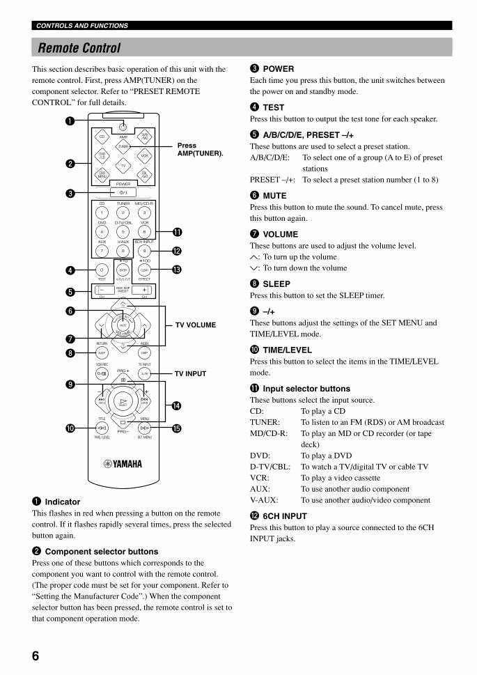
1 IndicatorThis flashes in red when pressing a button on the remotecontrol. If it flashes rapidly several times, press the selectedbutton again.
2 Component selector buttonsPress one of these buttons which corresponds to thecomponent you want to control with the remote control.(The proper code must be set for your component. Refer to“Setting the Manufacturer Code”.) When the componentselector button has been pressed, the remote control is set tothat component operation mode.
3 POWEREach time you press this button, the unit switches betweenthe power on and standby mode.
4 TESTPress this button to output the test tone for each speaker.
5 A/B/C/D/E, PRESET –/+These buttons are used to select a preset station.A/B/C/D/E: To select one of a group (A to E) of preset
stationsPRESET –/+: To select a preset station number (1 to 8)
6 MUTEPress this button to mute the sound. To cancel mute, pressthis button again.
7 VOLUMEThese buttons are used to adjust the volume level.u: To turn up the volumed: To turn down the volume
8 SLEEPPress this button to set the SLEEP timer.
9 –/+These buttons adjust the settings of the SET MENU andTIME/LEVEL mode.
0 TIME/LEVELPress this button to select the items in the TIME/LEVELmode.
q Input selector buttonsThese buttons select the input source.CD: To play a CDTUNER: To listen to an FM (RDS) or AM broadcastMD/CD-R: To play an MD or CD recorder (or tape
deck)DVD: To play a DVDD-TV/CBL: To watch a TV/digital TV or cable TVVCR: To play a video cassetteAUX: To use another audio componentV-AUX: To use another audio/video component
w 6CH INPUTPress this button to play a source connected to the 6CHINPUT jacks.
CONTROLS AND FUNCTIONS
1
2
3
q
e
w
r
t
4
5
6
7
8
9
0
TV VOLUME
TV INPUT
PressAMP(TUNER).
This section describes basic operation of this unit with theremote control. First, press AMP(TUNER) on thecomponent selector. Refer to “PRESET REMOTECONTROL” for full details.
0102V520RDS01-09_EN 1/31/1, 4:20 PM6

7
En
glish
BA
SIC
OP
ER
AT
ION
ADVA
NC
ED O
PERA
TIO
NA
PP
EN
DIX
INT
RO
DU
CT
ION
PR
EPA
RA
TIO
N
Using the Remote Control
Remote controlsensor
Within approximately 6 m(20 feet)
e EFFECTPress this button to turn on or off the effect speakers (centerand rear).
r PRG+, PRG–Press these buttons to select a DSP program.Once you press SET MENU, these buttons are used forselecting the SET MENU item.
t SET MENUPress this button to select the items in the SET MENU.
CONTROLS AND FUNCTIONS
The remote control transmits a directional infrared beam. Besure to aim the remote control directly at the infrared sensorduring operation. When the sensor is covered or there is alarge object between the remote control and the sensor, thesensor cannot receive signals. The sensor may not be able toreceive signals properly when it is exposed to direct sunlightor a strong artificial light (such as a fluorescent or strobelight). In this case, change the direction of the light orreposition the unit to avoid direct lighting.
Notes• Handle the remote control with care.• Do not spill water, tea or other liquids on the remote control.• Do not drop the remote control.• Do not leave or store the remote control in the following
conditions:– high humidity or temperature such as near a heater, stove or
bath;– dusty places; or– extremely low temperature.
0102V520RDS01-09_EN 1/31/1, 4:20 PM7
8
Display
ENHANCED
PS PTY RT CT
MEMORY SLEEP
PCM
DSP
DIGITAL PRO LOGIC
ASP
B
VIRTUAL DOLBY DTSDIGITALPRO LOGIC
DISCO 5CH STEREO
MONO TV SPORTSMOVIE THEATER 1 2ENTERTAINMENT
GAME
CONCERT HALLJAZZ CLUB PTY HOLD
NEWSINFOROCK CONCERTBASS EXT.
AUTOEON STEREO AFFAIRS SPORTTUNED
dBms
K ZH
1 2 3 4 5 6 7 8 9
0 q w re t uy
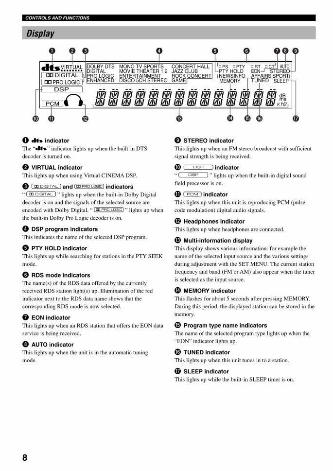
1 t indicatorThe “t” indicator lights up when the built-in DTSdecoder is turned on.
2 VIRTUAL indicatorThis lights up when using Virtual CINEMA DSP.
3 g and o indicators“ g ” lights up when the built-in Dolby Digitaldecoder is on and the signals of the selected source areencoded with Dolby Digital. “ o ” lights up whenthe built-in Dolby Pro Logic decoder is on.
4 DSP program indicatorsThis indicates the name of the selected DSP program.
5 PTY HOLD indicatorThis lights up while searching for stations in the PTY SEEKmode.
6 RDS mode indicatorsThe name(s) of the RDS data offered by the currentlyreceived RDS station light(s) up. Illumination of the redindicator next to the RDS data name shows that thecorresponding RDS mode is now selected.
7 EON indicatorThis lights up when an RDS station that offers the EON dataservice is being received.
8 AUTO indicatorThis lights up when the unit is in the automatic tuningmode.
9 STEREO indicatorThis lights up when an FM stereo broadcast with sufficientsignal strength is being received.
0 x indicator“ x ” lights up when the built-in digital soundfield processor is on.
q v indicatorThis lights up when this unit is reproducing PCM (pulsecode modulation) digital audio signals.
w Headphones indicatorThis lights up when headphones are connected.
e Multi-information displayThis display shows various information: for example thename of the selected input source and the various settingsduring adjustment with the SET MENU. The current stationfrequency and band (FM or AM) also appear when the tuneris selected as the input source.
r MEMORY indicatorThis flashes for about 5 seconds after pressing MEMORY.During this period, the displayed station can be stored in thememory.
t Program type name indicatorsThe name of the selected program type lights up when the“EON” indicator lights up.
y TUNED indicatorThis lights up when this unit tunes in to a station.
u SLEEP indicatorThis lights up while the built-in SLEEP timer is on.
CONTROLS AND FUNCTIONS
0102V520RDS01-09_EN 2/2/1, 5:34 PM8

9
En
glish
BA
SIC
OP
ER
AT
ION
ADVA
NC
ED O
PERA
TIO
NA
PP
EN
DIX
INT
RO
DU
CT
ION
PR
EPA
RA
TIO
N
Rear Panel
1 DIGITAL OUTPUT jacks
2 DIGITAL INPUT jacks
3 6CH INPUT jacksSee pages 12 and 13 for connection information.
4 Antenna input terminalsSee page 26 for connection information.
5 Video component jacksSee pages 14 and 15 for connection information.
6 Speaker terminalsSee pages 16 and 17 for connection information.
7 AC power cordConnect to a power outlet.
CONTROLS AND FUNCTIONS
As this terminal is usedfor an examination in thefactory, do not connectany equipment to thisterminal.
1 2 3 4 5 6 7 8
0 q9
SWITCHED100W MAX. TOTAL
AC OUTLETSIMPEDANCE SELECTORSET BEFORE POWER ON
MAIN A OR B: 4 MIN. /SPEAKER A + B: 8 MIN. /SPEAKERCENTER : 6 MIN. /SPEAKERREAR : 6 MIN. /SPEAKER
SPEAKERS
MAIN
+ –R L
A
– +
B
CENTER REAR (SURROUND)R L
+
–
S VIDEO
VIDEO
MONITOR OUTDVD
DVD
DVD
D-TV/CBL
D-TV/CBL
D-TV/CBL
IN VCR 1OUTVIDEO SIGNAL
AUDIO SIGNAL
SUBWOOFER
OUTPUT
INVCR 1
OUTOUT(REC)IN(PLAY)CDAUX MD/CD-R
MD/CD-R
MD/CD-R
R
L
DIGITAL OUTPUT
OPTICAL
OPTICAL
COAXIAL
AM ANT GND FM ANT
75 UNBAL.
TUNER
MAIN CENTER
SUB WOOFER
SURROUND
DIGITAL INPUT
6CH INPUT
CD
MAIN A OR B: 8 MIN. /SPEAKER A + B:16 MIN. /SPEAKERCENTER : 8 MIN. /SPEAKERREAR : 8 MIN. /SPEAKER
R
L
R
L
MAINS
8 AC OUTLET(S)Use these outlets to supply power to your other audio/videocomponents (see page 18).
9 Audio component jacksSee pages 12 and 13 for connection information.
0 SUBWOOFER jackSee page 17 for connection information.
q IMPEDANCE SELECTOR switchUse this switch to match the amplifier output to yourspeaker impedance. Set this unit in the standby mode beforeyou change the setting of this switch (see page 18).
(Europe model)
0102V520RDS01-09_EN 1/31/1, 4:21 PM9
10
SPEAKER SETUP
Speakers to Be UsedThis unit is designed to provide the best sound-field qualitywith a 5-speaker system, using main speakers, rear speakersand a center speaker. If you use different brands of speakers(with different tonal qualities) in your system, the tone of amoving human voice and other types of sound may not shiftsmoothly. We recommend that you use speakers from thesame manufacture to ensure even tonal quality.
The main speakers are used for the main source sound plusthe effect sounds. They will probably be the speakers fromyour present stereo system. The rear speakers are used forthe effect and surround sounds, and the center speaker is forthe center sounds (dialog, vocals, etc.). If for some reason itis not practical to use a center speaker, you can do withoutit. Best results, however, are obtained with the full system.
The main speakers should be high-performance models andhave enough power-handling capacity to accept themaximum output of your audio system. The other speakersdo not have to be equal to the main speakers. For precisesound localization, however, it is ideal to use high-performance models that can reproduce sounds over the fullrange for the center speaker and the rear speakers.
Use of a subwoofer expands yoursound field
It is also possible to further expand your system with theaddition of a subwoofer. The use of a subwoofer is effectivenot only for reinforcing bass frequencies from any or allchannels, but also for reproducing the LFE (low frequencyeffect) channel with high fidelity when playing back asource encoded with Dolby Digital or DTS. The YAMAHAActive Servo Processing Subwoofer System is ideal fornatural and lively bass reproduction.
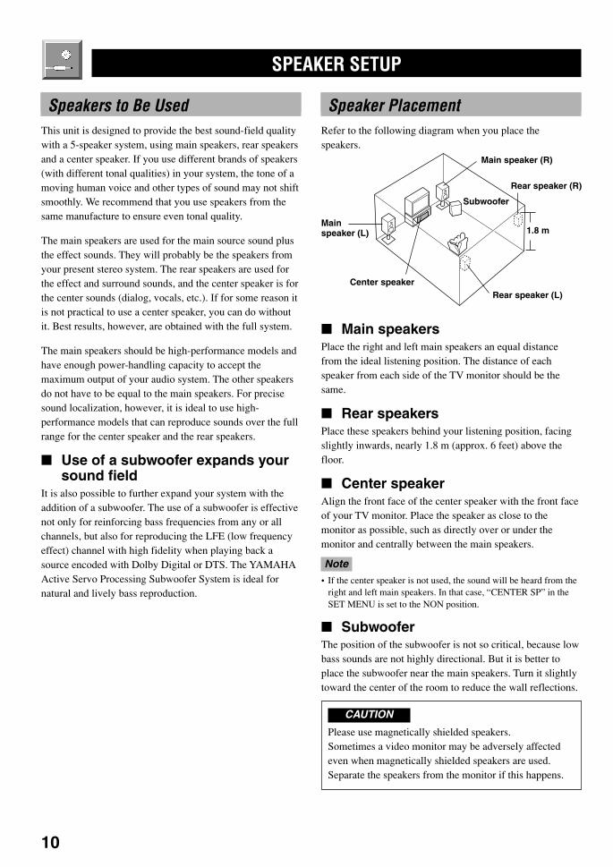
Speaker PlacementRefer to the following diagram when you place thespeakers.
Main speaker (R)
Center speaker
Mainspeaker (L)
Subwoofer
Rear speaker (L)
Rear speaker (R)
1.8 m
Main speakersPlace the right and left main speakers an equal distancefrom the ideal listening position. The distance of eachspeaker from each side of the TV monitor should be thesame.
Rear speakersPlace these speakers behind your listening position, facingslightly inwards, nearly 1.8 m (approx. 6 feet) above thefloor.
Center speakerAlign the front face of the center speaker with the front faceof your TV monitor. Place the speaker as close to themonitor as possible, such as directly over or under themonitor and centrally between the main speakers.
Note• If the center speaker is not used, the sound will be heard from the
right and left main speakers. In that case, “CENTER SP” in theSET MENU is set to the NON position.
SubwooferThe position of the subwoofer is not so critical, because lowbass sounds are not highly directional. But it is better toplace the subwoofer near the main speakers. Turn it slightlytoward the center of the room to reduce the wall reflections.
CAUTION
Please use magnetically shielded speakers.Sometimes a video monitor may be adversely affectedeven when magnetically shielded speakers are used.Separate the speakers from the monitor if this happens.
PREPARATION
0103V520RDS10-20_EN 1/31/1, 4:21 PM10
11
En
glish
BA
SIC
OP
ER
AT
ION
ADVA
NC
ED O
PERA
TIO
NA
PP
EN
DIX
INT
RO
DU
CT
ION
PR
EPA
RA
TIO
N
CONNECTIONS
Before Connecting Components
CAUTION
Never connect this unit and other components to mains power until all connections between components have beencompleted.
Be sure all connections are made correctly, that is to say L (left) to L, R (right) to R, “+” to “+” and “–” to “–”. Somecomponents require different connection methods and have different terminal names. Refer to the instructions for eachcomponent to be connected to this unit.
When you connect other YAMAHA audio components (such as a tape deck, MD recorder and CD player or changer), connectit to the jacks with the same number labels as !, #, $ etc.
Use RCA-type pin plug cables for connecting audio/video components with the exception described later.
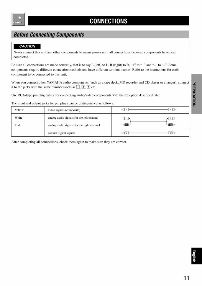
The input and output jacks for pin plugs can be distinguished as follows:
Yellow video signals (composite)
White analog audio signals for the left channel
Red analog audio signals for the right channel
coaxial digital signals
After completing all connections, check them again to make sure they are correct.
V V
C C
L
R
L
R
0103V520RDS10-20_EN 1/31/1, 4:21 PM11
12
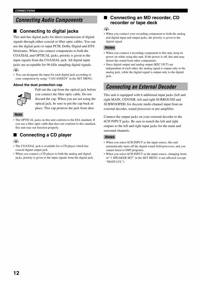
Connecting an MD recorder, CDrecorder or tape deck
y• When you connect your recording component to both the analog
and digital input and output jacks, the priority is given to thedigital signal.
Notes• When you connect a recording component to this unit, keep its
power on while using this unit. If the power is off, this unit maydistort the sound from other components.
• Since digital output and analog output (REC OUT) areindependent of each other, the analog signal is output only to theanalog jack, while the digital signal is output only to the digitaljack.
Connecting an External DecoderThis unit is equipped with 6 additional input jacks (left andright MAIN, CENTER, left and right SURROUND andSUBWOOFER) for discrete multi-channel input from anexternal decoder, sound processor or pre-amplifier.
Connect the output jacks on your external decoder to the6CH INPUT jacks. Be sure to match the left and rightoutputs to the left and right input jacks for the main andsurround channels.
Notes• When you select 6CH INPUT as the input source, this unit
automatically turns off the digital sound field processor, and youcannot listen to DSP programs.
• When you select 6CH INPUT as the input source, changing itemsof “1 SPEAKER SET” in the SET MENU is not affected (except“MAIN LVL”).
CONNECTIONS
Connecting Audio Components
Connecting to digital jacksThis unit has digital jacks for direct transmission of digitalsignals through either coaxial or fiber optic cables. You canuse the digital jacks to input PCM, Dolby Digital and DTSbitstreams. When you connect components to both theCOAXIAL and OPTICAL jacks, priority is given to theinput signals from the COAXIAL jack. All digital inputjacks are acceptable for 96-kHz sampling digital signals.
y• You can designate the input for each digital jack according to
your component by using “3 I/O ASSIGN” in the SET MENU.
About the dust protection capPull out the cap from the optical jack beforeyou connect the fiber optic cable. Do notdiscard the cap. When you are not using theoptical jack, be sure to put the cap back inplace. This cap protects the jack from dust.
Note• The OPTICAL jacks on this unit conform to the EIA standard. If
you use a fiber optic cable that does not conform to this standard,this unit may not function properly.
Connecting a CD playery• The COAXIAL jack is available for a CD player which has
coaxial digital output jack.• When you connect a CD player to both the analog and digital
jacks, priority is given to the input signals from the digital jack.
0103V520RDS10-20_EN 1/31/1, 4:21 PM12
13
En
glish
BA
SIC
OP
ER
AT
ION
ADVA
NC
ED O
PERA
TIO
NA
PP
EN
DIX
INT
RO
DU
CT
ION
PR
EPA
RA
TIO
NS VIDEO
VIDEO
MONITOR OUTDVD
DVD
DVD
D-TV/CBL
D-TV/CBL
D-TV/CBL
IN VCR 1OUTVIDEO SIGNAL
AUDIO SIGNAL
INVCR 1
OUTOUT(REC)IN(PLAY)CDAUX MD/CD-R
MD/CD-R
MD/CD-R
R
L
DIGITAL OUTPUT
OPTICAL
OPTICAL
COAXIAL
AM ANT GND FM ANT
75 UNBAL.
TUNER
MAIN CENTER
SUB WOOFER
SURROUND
DIGITAL INPUT
6CH INPUT
CD
R
L
R
L
L R
L RL R
L R C L R
OO
OUTPUT
COAXIALOUTPUT
SUBWOOFEROUTPUT
CENTER OUTPUT
MAINOUTPUT
SURROUNDOUTPUT
INPUT OUTPUTOUTPUT
OPTICAL OUTPUT
OPTICAL INPUT
L R
L
R
C
O
MD recorder orCD recorder
CD player External decoder
(Europe model)
indicates signal direction
indicates left analog cables
indicates right analog cables
indicates optical cables
indicates coaxial cables
CONNECTIONS
Audio component
0103V520RDS10-20_EN 1/31/1, 4:21 PM13
14
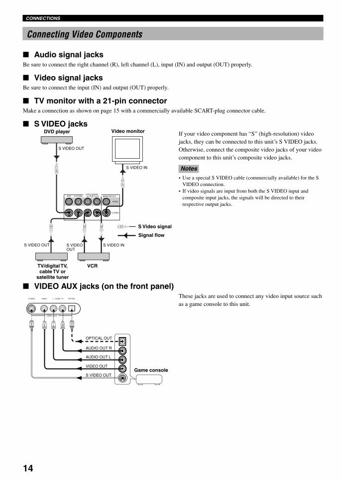
Connecting Video Components
Audio signal jacksBe sure to connect the right channel (R), left channel (L), input (IN) and output (OUT) properly.
Video signal jacksBe sure to connect the input (IN) and output (OUT) properly.
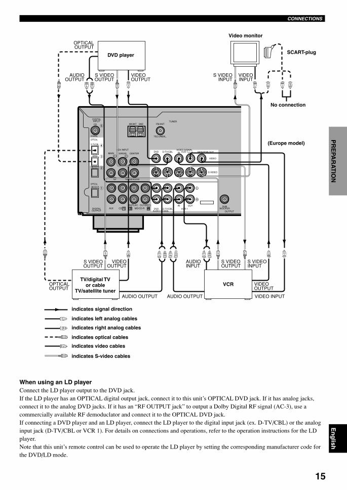
TV monitor with a 21-pin connectorMake a connection as shown on page 15 with a commercially available SCART-plug connector cable.
S VIDEO jacksIf your video component has “S” (high-resolution) videojacks, they can be connected to this unit’s S VIDEO jacks.Otherwise, connect the composite video jacks of your videocomponent to this unit’s composite video jacks.
Notes• Use a special S VIDEO cable (commercially available) for the S
VIDEO connection.• If video signals are input from both the S VIDEO input and
composite input jacks, the signals will be directed to theirrespective output jacks.
AUDIO OUT R
AUDIO OUT L
VIDEO OUT
OPTICAL OUT
S VIDEO OUT
OV L RS
VIDEO AUX
S VIDEO VIDEO L AUDIO R OPTICAL
S VIDEO
VIDEO
MONITOR OUTDVD D-TV/CBL IN VCR 1OUTVIDEO SIGNAL
S VIDEO OUT
S VIDEO OUT
S VIDEO IN
S VIDEO IN
S
SS
S
S
S VIDEO OUT
S
DVD player Video monitor
S Video signal
Signal flow
TV/digital TV,cable TV or
satellite tuner
VCR
Game console
CONNECTIONS
VIDEO AUX jacks (on the front panel)These jacks are used to connect any video input source suchas a game console to this unit.
0103V520RDS10-20_EN 2/1/1, 2:23 PM14
15
En
glish
BA
SIC
OP
ER
AT
ION
ADVA
NC
ED O
PERA
TIO
NA
PP
EN
DIX
INT
RO
DU
CT
ION
PR
EPA
RA
TIO
N
S VIDEO
VIDEO
MONITOR OUTDVD
DVD
DVD
D-TV/CBL
D-TV/CBL
D-TV/CBL
IN VCR 1OUTVIDEO SIGNAL
AUDIO SIGNAL
SUBWOOFER
OUTPUT
INVCR 1
OUTOUT(REC)IN(PLAY)CDAUX MD/CD-R
MD/CD-R
MD/CD-R
R
L
DIGITAL OUTPUT
OPTICAL
OPTICAL
COAXIAL
AM ANT GND FM ANT
75 UNBAL.
TUNER
MAIN CENTER
SUB WOOFER
SURROUND
DIGITAL INPUT
6CH INPUT
CD
R
L
R
L
VV
S VIDEOINPUT
S
S VIDEOOUTPUT
L R SL RL R
OPTICALOUTPUT
VIDEOOUTPUT
AUDIO OUTPUTAUDIO OUTPUT VIDEO INPUT
VIDEOOUTPUT
AUDIO INPUT
VSO
O
OPTICALOUTPUT
L R
S VIDEOOUTPUT
AUDIOOUTPUT
VIDEOOUTPUT
VS S V V RL
S VIDEO INPUT
VIDEOINPUT
S VIDEOOUTPUT
L
S
R
V
O
DVD player
Video monitor
SCART-plug
No connection
TV/digital TVor cable
TV/satellite tunerVCR
indicates signal direction
indicates left analog cables
indicates right analog cables
indicates optical cables
indicates video cables
indicates S-video cables
When using an LD playerConnect the LD player output to the DVD jack.If the LD player has an OPTICAL digital output jack, connect it to this unit’s OPTICAL DVD jack. If it has analog jacks,connect it to the analog DVD jacks. If it has an “RF OUTPUT jack” to output a Dolby Digital RF signal (AC-3), use acommercially available RF demoduclator and connect it to the OPTICAL DVD jack.If connecting a DVD player and an LD player, connect the LD player to the digital input jack (ex. D-TV/CBL) or the analoginput jack (D-TV/CBL or VCR 1). For details on connections and operations, refer to the operation instructions for the LDplayer.Note that this unit’s remote control can be used to operate the LD player by setting the corresponding manufacturer code forthe DVD/LD mode.
CONNECTIONS
(Europe model)
0103V520RDS10-20_EN 1/31/1, 4:21 PM15
16
Connecting SpeakersBe sure to connect the right channel (R), left channel (L), “+” (red) and “–” (black) properly. If the connections are faulty, nosound will be heard from the speakers, and if the polarity of the speaker connections is incorrect, the sound will be unnaturaland lack bass.
CAUTION
• Use speakers with the specified impedance shown on the rear panel of this unit.• Do not let the bare speaker wires touch each other and do not let them touch any metal part of this unit. This could
damage the unit and/or speakers.
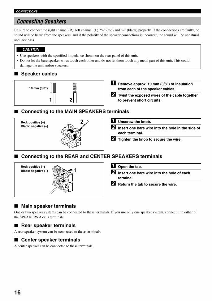
Speaker cables
1 Remove approx. 10 mm (3/8”) of insulationfrom each of the speaker cables.
2 Twist the exposed wires of the cable togetherto prevent short circuits.
Connecting to the MAIN SPEAKERS terminals
1 Unscrew the knob.
2 Insert one bare wire into the hole in the side ofeach terminal.
3 Tighten the knob to secure the wire.
Connecting to the REAR and CENTER SPEAKERS terminals
1 Open the tab.
2 Insert one bare wire into the hole of eachterminal.
3 Return the tab to secure the wire.
1 2
10 mm (3/8”)
2
13
Red: positive (+)Black: negative (–)
Red: positive (+)Black: negative (–)
Main speaker terminalsOne or two speaker systems can be connected to these terminals. If you use only one speaker system, connect it to either ofthe SPEAKERS A or B terminals.
Rear speaker terminalsA rear speaker system can be connected to these terminals.
Center speaker terminalsA center speaker can be connected to these terminals.
CONNECTIONS
21
3
0103V520RDS10-20_EN 1/31/1, 4:21 PM16

17
En
glish
BA
SIC
OP
ER
AT
ION
ADVA
NC
ED O
PERA
TIO
NA
PP
EN
DIX
INT
RO
DU
CT
ION
PR
EPA
RA
TIO
N
Subwoofer connectionWhen using a subwoofer with built-in amplifier, includingthe YAMAHA Active Servo Processing Subwoofer System,connect the input jack of the subwoofer system to this jack.Low bass signals distributed from the main, center and/orrear channels are directed to this jack. (The cut-offfrequency of this jack is 90 Hz.) The LFE (low-frequencyeffect) signals generated when Dolby Digital or DTS isdecoded are also directed if they are assigned to this jack.
Notes• Adjust the subwoofer volume according to the operation
instructions for the subwoofer. (Fine adjustment is possible usingthis unit’s output level control of the effect speakers.)
• Depending on the settings of “1 SPEAKER SET”, “LFE LEVEL(5 DOLBY D. SET)” and “6 DTS SET” in the SET MENU, somesignals may not be output from the SUBWOOFER jack.
SWITCHED100W MAX. TOTAL
AC OUTLETSIMPEDANCE SELECTORSET BEFORE POWER ON
MAIN A OR B: 4 MIN. /SPEAKER A + B: 8 MIN. /SPEAKERCENTER : 6 MIN. /SPEAKERREAR : 6 MIN. /SPEAKER
SPEAKERS
MAIN
+ –R L
A
– +
B
CENTER REAR (SURROUND)R L
+
–
SUBWOOFER
OUTPUT
MAIN A OR B: 8 MIN. /SPEAKER A + B:16 MIN. /SPEAKERCENTER : 8 MIN. /SPEAKERREAR : 8 MIN. /SPEAKER
MAINS
Main speakers A
Right Left
Main speakers B
Right Left
(Europe model)
Center speaker Rear speakers
Right Left
Subwoofersystem
CONNECTIONS
0103V520RDS10-20_EN 1/31/1, 4:21 PM17
18
IMPEDANCE SELECTOR Switch
WARNING
Do not change the IMPEDANCE SELECTOR switch setting while the power to this unit is on, otherwise the unit may bedamaged.If this unit fails to turn on when STANDBY/ON (or POWER) is pressed, the IMPEDANCE SELECTOR switch may notbe fully slid either position. If so, slide the switch to either position fully when this unit is in the standby mode.
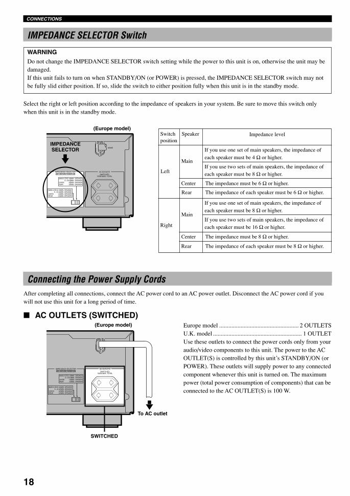
Select the right or left position according to the impedance of speakers in your system. Be sure to move this switch onlywhen this unit is in the standby mode.
SWITCHED100W MAX. TOTAL
AC OUTLETSIMPEDANCE SELECTORSET BEFORE POWER ON
MAIN A OR B: 4 MIN. /SPEAKER A + B: 8 MIN. /SPEAKERCENTER : 6 MIN. /SPEAKERREAR : 6 MIN. /SPEAKER
MAIN A OR B: 8 MIN. /SPEAKER A + B:16 MIN. /SPEAKERCENTER : 8 MIN. /SPEAKERREAR : 8 MIN. /SPEAKER
MAINS
SWITCHED100W MAX. TOTAL
AC OUTLETSIMPEDANCE SELECTORSET BEFORE POWER ON
MAIN A OR B: 4 MIN. /SPEAKER A + B: 8 MIN. /SPEAKERCENTER : 6 MIN. /SPEAKERREAR : 6 MIN. /SPEAKER
MAIN A OR B: 8 MIN. /SPEAKER A + B:16 MIN. /SPEAKERCENTER : 8 MIN. /SPEAKERREAR : 8 MIN. /SPEAKER
MAINS
Switchposition
Speaker Impedance level
Left
Main
If you use one set of main speakers, the impedance ofeach speaker must be 4 Ω or higher.
If you use two sets of main speakers, the impedance ofeach speaker must be 8 Ω or higher.
Center The impedance must be 6 Ω or higher.
Rear The impedance of each speaker must be 6 Ω or higher.
Right
Main
If you use one set of main speakers, the impedance ofeach speaker must be 8 Ω or higher.
If you use two sets of main speakers, the impedance ofeach speaker must be 16 Ω or higher.
Center The impedance must be 8 Ω or higher.
Rear The impedance of each speaker must be 8 Ω or higher.
Connecting the Power Supply CordsAfter completing all connections, connect the AC power cord to an AC power outlet. Disconnect the AC power cord if youwill not use this unit for a long period of time.
AC OUTLETS (SWITCHED)Europe model .................................................... 2 OUTLETSU.K. model .......................................................... 1 OUTLETUse these outlets to connect the power cords only from youraudio/video components to this unit. The power to the ACOUTLET(S) is controlled by this unit’s STANDBY/ON (orPOWER). These outlets will supply power to any connectedcomponent whenever this unit is turned on. The maximumpower (total power consumption of components) that can beconnected to the AC OUTLET(S) is 100 W.
(Europe model)
IMPEDANCESELECTOR
(Europe model)
To AC outlet
SWITCHED
CONNECTIONS
0103V520RDS10-20_EN 1/31/1, 4:21 PM18

19
En
glish
BA
SIC
OP
ER
AT
ION
ADVA
NC
ED O
PERA
TIO
NA
PP
EN
DIX
INT
RO
DU
CT
ION
PR
EPA
RA
TIO
N
ADJUSTING THE SPEAKER BALANCE
Using the Test ToneThe adjustment of each speaker sound output level shouldbe performed at your listening position with the remotecontrol.
1 Press AMP(TUNER) on thecomponent selector.
2 Press TEST.“TEST LEFT” appears on the display.
3 Turn up the volume.You will hear a test tone (like pink noise) from eachspeaker for about two seconds in following order: leftmain speaker, center speaker, right main speaker, rightrear speaker and left rear speaker. The display changesas shown below.
Notes• If the test tone cannot be heard, turn down the volume, set the unit
in the standby mode and check the speaker connections.• If the test tone cannot be heard from the center speaker, check the
setting of “CENTER SP” in the SET MENU.
This procedure lets you adjust the sound output levelbalance between the main, center and rear speakers by usingthe built-in test tone generator. When this adjustment isperformed, the sound output level heard at the listeningposition will be the same from each speaker. This isimportant for the best performance of the digital sound fieldprocessor, the Dolby Pro Logic decoder, Dolby Digitaldecoder and DTS decoder.
Note• Since this unit cannot enter the test mode while headphones are
connected to this unit, be sure to unplug the headphones from thePHONES jack when using the test tone.
Before You Start Adjusting
1 Set the volume at theminimum level.
2 Turn the power on.
3 Press SPEAKERS A or Bto select the mainspeakers to be used.If you use two main speakersystems, press both A and B.
4 Set BASS, TREBLE and BALANCE to thecenter position.
SILENT VIDEO AUX
PHONES S VIDEO VIDEO L AUDIO R OPTICAL
6CH INPUTINPUT MODE
INPUT
VOLUME
RDS MODE/FREQ EON
PTY SEEKMODE START
TUNINGMODE
PRESET/TUNING FM/AM
MEMORY
EDIT
BASS BALANCE SPEAKERS
PROGRAM PRESET/TUNINGEFFECT A/B/C/D/EA B
OFFON
D I G I T A L
– + L R
TREBLE
– +MAN'L/AUTO FM AUTO/MAN'L MONO
SURROUND
D I G I T A L
STANDBY/ON
12
4 3VOLUME
STANDBY/ON
SPEAKERS
A B
OFFON
BASS BALANCE
– + L R
TREBLE
– +
1
2,6
5
3
TEST LEFT
TEST RIGHT
TEST L SUR. TEST R SUR.
TEST CENTER
0103V520RDS10-20_EN 1/31/1, 4:21 PM19
20
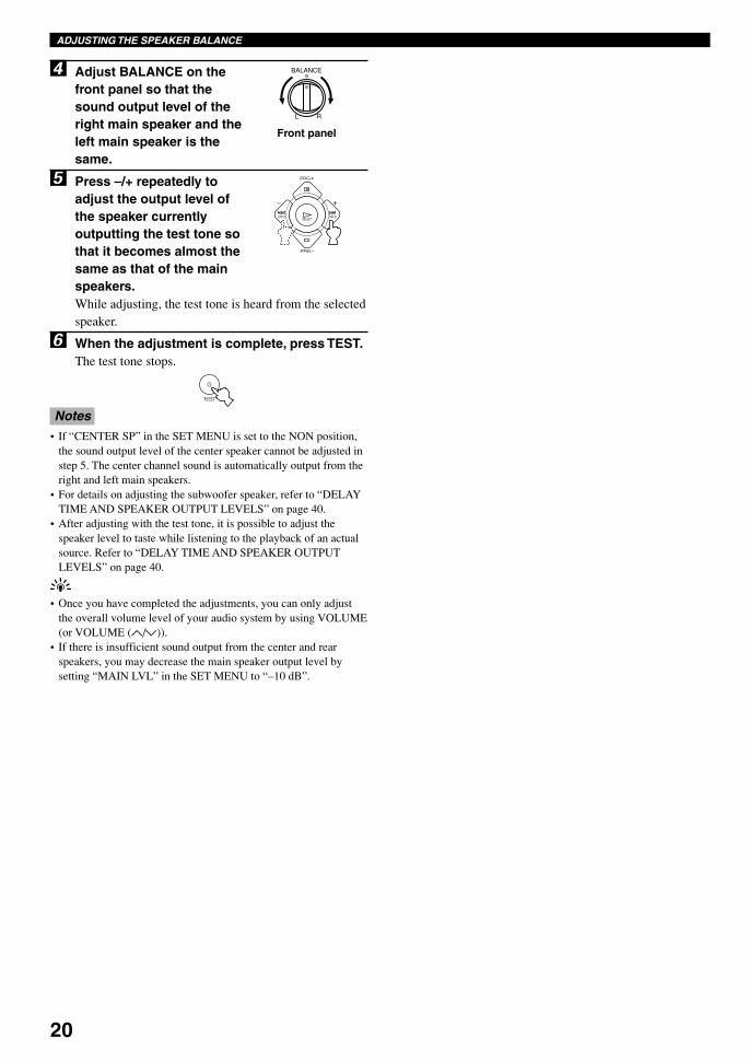
4 Adjust BALANCE on thefront panel so that thesound output level of theright main speaker and theleft main speaker is thesame.
5 Press –/+ repeatedly toadjust the output level ofthe speaker currentlyoutputting the test tone sothat it becomes almost thesame as that of the mainspeakers.While adjusting, the test tone is heard from the selectedspeaker.
6 When the adjustment is complete, press TEST.The test tone stops.
Notes• If “CENTER SP” in the SET MENU is set to the NON position,
the sound output level of the center speaker cannot be adjusted instep 5. The center channel sound is automatically output from theright and left main speakers.
• For details on adjusting the subwoofer speaker, refer to “DELAYTIME AND SPEAKER OUTPUT LEVELS” on page 40.
• After adjusting with the test tone, it is possible to adjust thespeaker level to taste while listening to the playback of an actualsource. Refer to “DELAY TIME AND SPEAKER OUTPUTLEVELS” on page 40.
y• Once you have completed the adjustments, you can only adjust
the overall volume level of your audio system by using VOLUME(or VOLUME (u/d)).
• If there is insufficient sound output from the center and rearspeakers, you may decrease the main speaker output level bysetting “MAIN LVL” in the SET MENU to “–10 dB”.
Front panel
BALANCE
L R
ADJUSTING THE SPEAKER BALANCE
0103V520RDS10-20_EN 1/31/1, 4:21 PM20
21
En
glish
BA
SIC
OP
ER
AT
ION
ADVA
NC
ED O
PERA
TIO
NA
PP
EN
DIX
INT
RO
DU
CT
ION
PR
EPA
RA
TIO
N
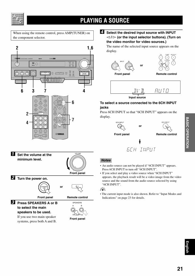
When using the remote control, press AMP(TUNER) onthe component selector.
1 Set the volume at theminimum level.
2 Turn the power on.
3 Press SPEAKERS A or Bto select the mainspeakers to be used.If you use two main speakersystems, press both A and B.
PLAYING A SOURCE
SILENT VIDEO AUX
PHONES S VIDEO VIDEO L AUDIO R OPTICAL
6CH INPUTINPUT MODE
INPUT
VOLUME
RDS MODE/FREQ EON
PTY SEEKMODE START
TUNINGMODE
PRESET/TUNING FM/AM
MEMORY
EDIT
BASS BALANCE SPEAKERS
PROGRAM PRESET/TUNINGEFFECT A/B/C/D/EA B
OFFON
STANDBY/ON
D I G I T A L
– + L R
TREBLE
– +MAN'L/AUTO FM AUTO/MAN'L MONO
SURROUND
D I G I T A L
1,62
6 3 47
27
6
4
4 Select the desired input source with INPUTl /h (or the input selector buttons). (Turn onthe video monitor for video sources.)The name of the selected input source appears on thedisplay.
To select a source connected to the 6CH INPUTjacksPress 6CH INPUT so that “6CH INPUT” appears on thedisplay.
Notes• An audio source can not be played if “6CH INPUT” appears.
Press 6CH INPUT to turn off “6CH INPUT”.• If you select and play a video source when “6CH INPUT”
appears, the playback result will be a video image from the videosource and the sound from the audio source selected by using“6CH INPUT”.
y• The current input mode is also shown. Refer to “Input Modes and
Indications” on page 23 for details.
SPEAKERS
A B
OFFON
Front panel
VOLUME
Front panel
Remote control
6CH INPUT
Front panel
Input source
BASIC OPERATION
STANDBY/ON
Front panel Remote control
or
or
or
Remote control
INPUT
Front panel
0104V520RDS21-25_EN 1/31/1, 4:22 PM21
22
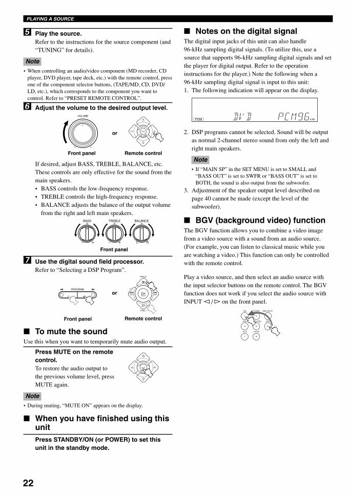
5 Play the source.Refer to the instructions for the source component (and“TUNING” for details).
Note• When controlling an audio/video component (MD recorder, CD
player, DVD player, tape deck, etc.) with the remote control, pressone of the component selector buttons, (TAPE/MD, CD, DVD/LD, etc.), which corresponds to the component you want tocontrol. Refer to “PRESET REMOTE CONTROL”.
6 Adjust the volume to the desired output level.
If desired, adjust BASS, TREBLE, BALANCE, etc.These controls are only effective for the sound from themain speakers.• BASS controls the low-frequency response.• TREBLE controls the high-frequency response.• BALANCE adjusts the balance of the output volume
from the right and left main speakers.
7 Use the digital sound field processor.Refer to “Selecting a DSP Program”.
To mute the soundUse this when you want to temporarily mute audio output.
Press MUTE on the remotecontrol.To restore the audio output tothe previous volume level, pressMUTE again.
Note• During muting, “MUTE ON” appears on the display.
When you have finished using thisunitPress STANDBY/ON (or POWER) to set thisunit in the standby mode.
PLAYING A SOURCE
Notes on the digital signalThe digital input jacks of this unit can also handle96-kHz sampling digital signals. (To utilize this, use asource that supports 96-kHz sampling digital signals and setthe player for digital output. Refer to the operationinstructions for the player.) Note the following when a96-kHz sampling digital signal is input to this unit:1. The following indication will appear on the display.
2. DSP programs cannot be selected. Sound will be outputas normal 2-channel stereo sound from only the left andright main speakers.
Note• If “MAIN SP” in the SET MENU is set to SMALL and
“BASS OUT” is set to SWFR or “BASS OUT” is set toBOTH, the sound is also output from the subwoofer.
3. Adjustment of the speaker output level described onpage 40 cannot be made (except the level of thesubwoofer).
BGV (background video) functionThe BGV function allows you to combine a video imagefrom a video source with a sound from an audio source.(For example, you can listen to classical music while youare watching a video.) This function can only be controlledwith the remote control.
Play a video source, and then select an audio source withthe input selector buttons on the remote control. The BGVfunction does not work if you select the audio source withINPUT l / h on the front panel.
PROGRAM
Front panel Remote control
or
VOLUME
Front panel Remote control
or
BASS BALANCE
– + L R
TREBLE
– +
Front panel
PCM K ZH
0104V520RDS21-25_EN 1/31/1, 4:22 PM22

23
En
glish
BA
SIC
OP
ER
AT
ION
ADVA
NC
ED O
PERA
TIO
NA
PP
EN
DIX
INT
RO
DU
CT
ION
PR
EPA
RA
TIO
N
Notes on playing a sourceencoded with a DTS signal
• If the digital output data of the player has been processedin any way, you may not be able to perform DTSdecoding even if you make a digital connection betweenthis unit and the player.
• If you play a source encoded with a DTS signal and setthe input mode to ANALOG, this unit reproduces thenoise of an unprocessed DTS signal. When you want toplay a DTS source, be sure to connect the source to adigital input jack and set the input mode to AUTO orDTS.
• If you switch the input mode to ANALOG while playinga source encoded with a DTS signal, this unit reproducesno sound.
• The following phenomena may occur if the input modeis set to AUTO when playing back a source encoded withDTS:
– If you continue to play a source encoded with a DTSsignal, this unit automatically switches to the “DTS-decoding” mode to prevent noise from being generatedduring subsequent operation. (The “t” indicatorlights up on the display.) The “t” indicator may flashimmediately after playback of a source encoded with aDTS signal has finished. Only a source encoded with aDTS signal can be played back while this indicator isflashing. (The indicator will flash for less than a minute.)If you want to play a normal PCM source soon, set theinput mode back to AUTO.
– The “t” indicator may flash when a search or skipoperation is performed. If this status continues for acertain length of time, the unit will automatically switchfrom the “DTS-decoding” mode to PCM digital signalinput mode and the “t” indicator will go out.
Input Modes and IndicationsWhen using the remote control, press AMP(TUNER) onthe component selector.
This unit comes with various input jacks. If your componentis connected to more than one type of input jack, you can setthe priority of the input signal.
Press INPUT MODE (or the input selectorbutton that you have pressed to select theinput source on the remote control) repeatedlyuntil the desired input mode is shown on thedisplay.
PLAYING A SOURCE
Front panel
or
Remote control
Input mode
AUTO: In this mode, the input signal isautomatically selected in the followingorder:1) Dolby Digital or DTS signal2) Digital (PCM) signal3) Analog signal
DTS: In this mode, only the digital inputsignal encoded with DTS is selectedeven if another signal is input at thesame time.
ANALOG (ANLG): In this mode, only the analog inputsignal is selected even if a digitalsignal is input at the same time.
Notes• If digital signals are input from both the COAXIAL and
OPTICAL jacks, the digital signal from the COAXIAL jack isselected.
• When AUTO is selected, this unit automatically determines thetype of signal. If this unit detects a Dolby Digital or DTS signal,the decoder automatically switches to the appropriate setting andreproduces 5.1 channel source.
• The sound output may be interrupted for some LD players andDVD players in the following situation:When the input mode has been set to AUTO and a search isperformed while playing the source encoded with a Dolby Digitalor DTS signal, the sound may delay for a moment when playbackis resumed.
• Depending on the LD player, playback may not be made whenplaying an LD that is not digitally recorded with the input modeset to AUTO. If this happens, set the input mode to ANALOG.
INPUT MODE
0104V520RDS21-25_EN 1/31/1, 4:22 PM23
24
Selecting a DSP ProgramYou can enhance your listening experience by selecting aDSP program. Refer to “SOUND FIELD PROGRAM” fordetails about each program.
y• Make sure that the sound effect is turned on (see page 25).
On the remote control
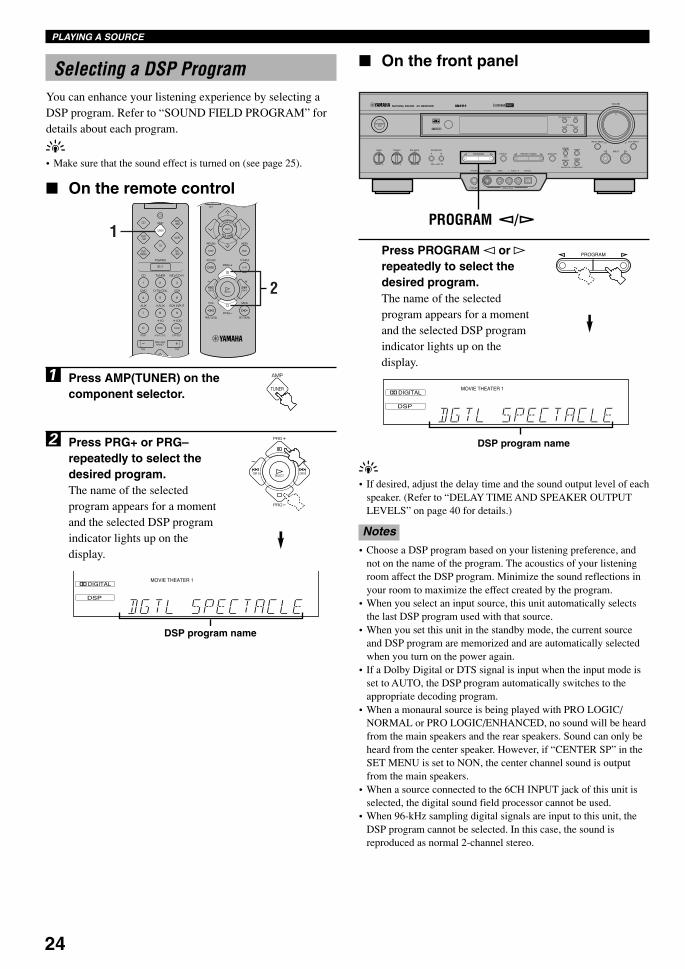
1 Press AMP(TUNER) on thecomponent selector.
2 Press PRG+ or PRG–repeatedly to select thedesired program.The name of the selectedprogram appears for a momentand the selected DSP programindicator lights up on thedisplay.
1
2
PROGRAM
DSP
DIGITALMOVIE THEATER 1
BASS EXT.
PLAYING A SOURCE
DSP program name
On the front panel
Press PROGRAM l or hrepeatedly to select thedesired program.The name of the selectedprogram appears for a momentand the selected DSP programindicator lights up on thedisplay.
SILENT VIDEO AUX
PHONES S VIDEO VIDEO L AUDIO R OPTICAL
6CH INPUTINPUT MODE
INPUT
VOLUME
RDS MODE/FREQ EON
PTY SEEKMODE START
TUNINGMODE
PRESET/TUNING FM/AM
MEMORY
EDIT
BASS BALANCE SPEAKERS
PROGRAM PRESET/TUNINGEFFECT A/B/C/D/EA B
OFFON
STANDBY/ON
D I G I T A L
– + L R
TREBLE
– +MAN'L/AUTO FM AUTO/MAN'L MONO
SURROUND
D I G I T A L
PROGRAM /
DSP program name
y• If desired, adjust the delay time and the sound output level of each
speaker. (Refer to “DELAY TIME AND SPEAKER OUTPUTLEVELS” on page 40 for details.)
Notes• Choose a DSP program based on your listening preference, and
not on the name of the program. The acoustics of your listeningroom affect the DSP program. Minimize the sound reflections inyour room to maximize the effect created by the program.
• When you select an input source, this unit automatically selectsthe last DSP program used with that source.
• When you set this unit in the standby mode, the current sourceand DSP program are memorized and are automatically selectedwhen you turn on the power again.
• If a Dolby Digital or DTS signal is input when the input mode isset to AUTO, the DSP program automatically switches to theappropriate decoding program.
• When a monaural source is being played with PRO LOGIC/NORMAL or PRO LOGIC/ENHANCED, no sound will be heardfrom the main speakers and the rear speakers. Sound can only beheard from the center speaker. However, if “CENTER SP” in theSET MENU is set to NON, the center channel sound is outputfrom the main speakers.
• When a source connected to the 6CH INPUT jack of this unit isselected, the digital sound field processor cannot be used.
• When 96-kHz sampling digital signals are input to this unit, theDSP program cannot be selected. In this case, the sound isreproduced as normal 2-channel stereo.
DSP
DIGITALMOVIE THEATER 1
BASS EXT.
0104V520RDS21-25_EN 1/31/1, 4:22 PM24

25
En
glish
BA
SIC
OP
ER
AT
ION
ADVA
NC
ED O
PERA
TIO
NA
PP
EN
DIX
INT
RO
DU
CT
ION
PR
EPA
RA
TIO
N
Virtual CINEMA DSP and SILENTCINEMA
Virtual CINEMA DSPVirtual CINEMA DSP allows you to enjoy the sound fieldeffects of the DSP program without rear speakers. UsingYAMAHA original technology, natural surroundreproduction is possible through the generation of a virtualspeaker.
The sound field processing is changed to the VirtualCINEMA DSP mode by setting “REAR LR SP” on the SETMENU to NON. Virtual CINEMA DSP is performed byusing the main speakers.
Note• This unit is not set in the Virtual CINEMA DSP mode even if
“REAR LR SP” is set to NON in the following cases:– when the 5CH STEREO, PRO LOGIC/NORMAL, DOLBY
DIGITAL/NORMAL or DTS/NORMAL program is selected;– when the sound effect is turned off;– when 6CH INPUT is selected as the input source;– when 96-kHz sampling digital signals are input to this unit;– when the Dolby Digital KARAOKE source is played;– when using the test tone; or– when connecting the headphones (you will hear SILENT
CINEMA).
SILENT CINEMASILENT CINEMA allows you to enjoy the realistic feel ofthe DSP program while using headphones. This featuredelivers powerful surround reproduction just as if listeningthrough the speakers.
You can listen to SILENT CINEMA by connecting yourheadphones to the PHONES jack while the effect speakersare on.
EFFECT
Front panel
PLAYING A SOURCE
or
Canceling the Sound Effect (turningoff the effect speakers)
Press EFFECT to cancel the sound effect andmonitor only the main sound.Press EFFECT again to turn the sound effect back on.
Notes• If the sound effect is canceled when Dolby Digital or DTS is
decoding, the sounds of the center and rear channels are mixedand output from the main speakers.
• If you turn off the sound effect when Dolby Digital or DTS isdecoding, it may happen that the sound is output faintly or notoutput normally, depending on the source. In that case, turn backon the sound effect.
Remote control
0104V520RDS21-25_EN 1/31/1, 4:22 PM25
26
TUNING
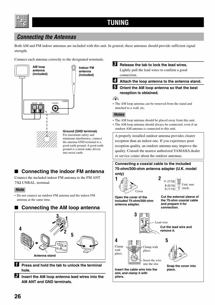
Connecting the AntennasBoth AM and FM indoor antennas are included with this unit. In general, these antennas should provide sufficient signalstrength.
Connect each antenna correctly to the designated terminals.
Indoor FMantenna(included)
AM ANT GND FM ANT
75 UNBAL.
TUNER
54
Antenna stand
Connecting a coaxial cable to the included75-ohm/300-ohm antenna adapter (U.K. modelonly)
11 (7/16)8 (5/16)6 (1/14)
1 2
3
54
Cover
Unit: mm(inch)
Lead wire
Clamp withpliers.
Clampwithpliers.
Insert the wireinto the slot.
Open the cover of theincluded 75-ohm/300-ohmantenna adapter.
Cut the external sleeve ofthe 75-ohm coaxial cableand prepare it forconnection.
Cut the lead wire andremove it.
Insert the cable wire into theslot, and clamp it withpliers.
Snap the cover intoplace.
AM loopantenna(included)
Ground (GND terminal)For maximum safety andminimum interference, connectthe antenna GND terminal to agood earth ground. A good earthground is a metal stake driveninto moist earth.
Connecting the indoor FM antennaConnect the included indoor FM antenna to the FM ANT75Ω UNBAL. terminal.
Note• Do not connect an outdoor FM antenna and the indoor FM
antenna at the same time.
Connecting the AM loop antenna
1 Press and hold the tab to unlock the terminalhole.
2 Insert the AM loop antenna lead wires into theAM ANT and GND terminals.
3 Release the tab to lock the lead wires.Lightly pull the lead wires to confirm a goodconnection.
4 Attach the loop antenna to the antenna stand.
5 Orient the AM loop antenna so that the bestreception is obtained.
y• The AM loop antenna can be removed from the stand and
attached to a wall, etc.
Notes• The AM loop antenna should be placed away from this unit.• The AM loop antenna should always be connected, even if an
outdoor AM antenna is connected to this unit.
A properly installed outdoor antenna provides clearerreception than an indoor one. If you experience poorreception quality, an outdoor antenna may improve thequality. Consult the nearest authorized YAMAHA dealeror service center about the outdoor antennas.
1
2
3
0105V520RDS26-30_EN 1/31/1, 4:22 PM26
27
En
glish
BA
SIC
OP
ER
AT
ION
ADVA
NC
ED O
PERA
TIO
NA
PP
EN
DIX
INT
RO
DU
CT
ION
PR
EPA
RA
TIO
NTUNING
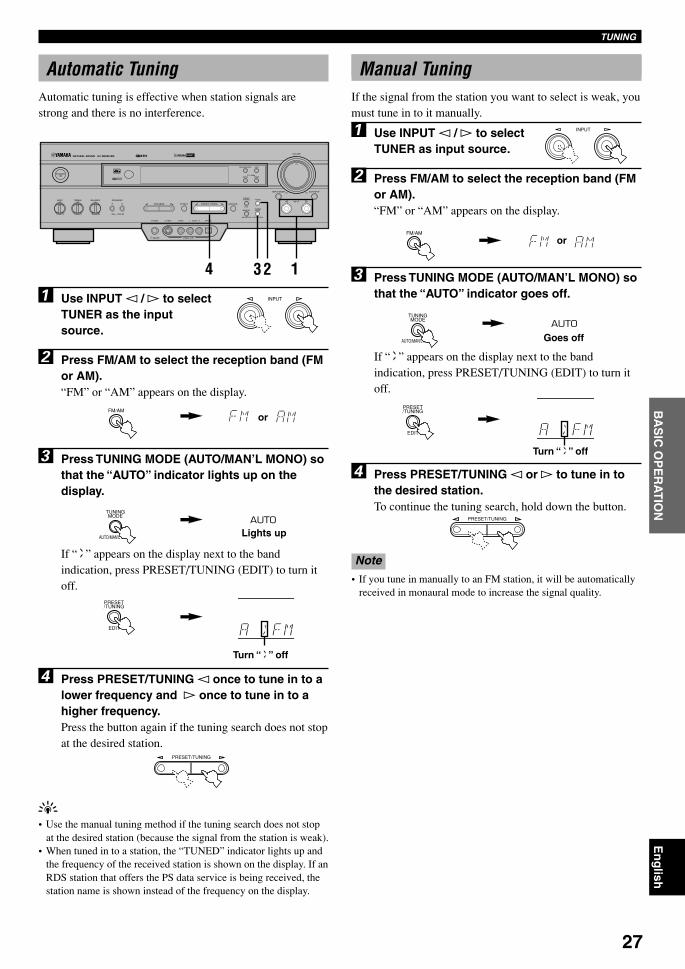
Automatic TuningAutomatic tuning is effective when station signals arestrong and there is no interference.
1 Use INPUT l / h to selectTUNER as the inputsource.
2 Press FM/AM to select the reception band (FMor AM).“FM” or “AM” appears on the display.
3 Press TUNING MODE (AUTO/MAN’L MONO) sothat the “AUTO” indicator lights up on thedisplay.
If “ z ” appears on the display next to the bandindication, press PRESET/TUNING (EDIT) to turn itoff.
SILENT VIDEO AUX
PHONES S VIDEO VIDEO L AUDIO R OPTICAL
6CH INPUTINPUT MODE
INPUT
VOLUME
RDS MODE/FREQ EON
PTY SEEKMODE START
TUNINGMODE
PRESET/TUNING FM/AM
MEMORY
EDIT
BASS BALANCE SPEAKERS
PROGRAM PRESET/TUNINGEFFECT A/B/C/D/EA B
OFFON
STANDBY/ON
D I G I T A L
– + L R
TREBLE
– +MAN'L/AUTO FM AUTO/MAN'L MONO
SURROUND
D I G I T A L
32 14
INPUT
PRESET/TUNING
PRESET/TUNING
INPUT
TUNINGMODE
AUTO/MAN'L MONO
TUNINGMODE
AUTO/MAN'L MONO
PRESET/TUNING
EDIT
PRESET/TUNING
EDIT
FM/AM
FM/AM
4 Press PRESET/TUNING l once to tune in to alower frequency and h once to tune in to ahigher frequency.Press the button again if the tuning search does not stopat the desired station.
y• Use the manual tuning method if the tuning search does not stop
at the desired station (because the signal from the station is weak).• When tuned in to a station, the “TUNED” indicator lights up and
the frequency of the received station is shown on the display. If anRDS station that offers the PS data service is being received, thestation name is shown instead of the frequency on the display.
Manual TuningIf the signal from the station you want to select is weak, youmust tune in to it manually.
1 Use INPUT l / h to selectTUNER as input source.
2 Press FM/AM to select the reception band (FMor AM).“FM” or “AM” appears on the display.
3 Press TUNING MODE (AUTO/MAN’L MONO) sothat the “AUTO” indicator goes off.
If “ z ” appears on the display next to the bandindication, press PRESET/TUNING (EDIT) to turn itoff.
4 Press PRESET/TUNING l or h to tune in tothe desired station.To continue the tuning search, hold down the button.
Note• If you tune in manually to an FM station, it will be automatically
received in monaural mode to increase the signal quality.
or
Lights up
Turn “ z ” off
or
Goes off
Turn “ z ” off
0105V520RDS26-30_EN 1/31/1, 4:22 PM27
28
TUNING
Automatic Preset Tuning (for RDSstations only)
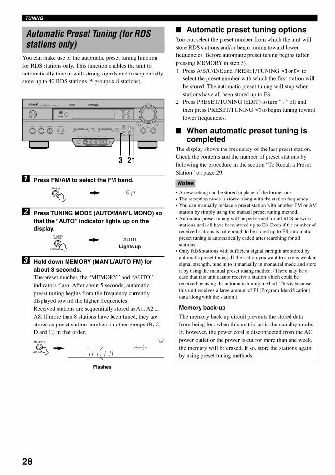
You can make use of the automatic preset tuning functionfor RDS stations only. This function enables the unit toautomatically tune in with strong signals and to sequentiallystore up to 40 RDS stations (5 groups x 8 stations).
1 Press FM/AM to select the FM band.
2 Press TUNING MODE (AUTO/MAN’L MONO) sothat the “AUTO” indicator lights up on thedisplay.
3 Hold down MEMORY (MAN’L/AUTO FM) forabout 3 seconds.The preset number, the “MEMORY” and “AUTO”indicators flash. After about 5 seconds, automaticpreset tuning begins from the frequency currentlydisplayed toward the higher frequencies.Received stations are sequentially stored as A1, A2 ...A8. If more than 8 stations have been tuned, they arestored as preset station numbers in other groups (B, C,D and E) in that order.
Automatic preset tuning optionsYou can select the preset number from which the unit willstore RDS stations and/or begin tuning toward lowerfrequencies. Before automatic preset tuning begins (afterpressing MEMORY in step 3),1. Press A/B/C/D/E and PRESET/TUNING l or h to
select the preset number with which the first station willbe stored. The automatic preset tuning will stop whenstations have all been stored up to E8.
2. Press PRESET/TUNING (EDIT) to turn “ z ” off andthen press PRESET/TUNING l to begin tuning towardlower frequencies.
When automatic preset tuning iscompleted
The display shows the frequency of the last preset station.Check the contents and the number of preset stations byfollowing the procedure in the section “To Recall a PresetStation” on page 29.
Notes• A new setting can be stored in place of the former one.• The reception mode is stored along with the station frequency.• You can manually replace a preset station with another FM or AM
station by simply using the manual preset tuning method.• Automatic preset tuning will be performed for all RDS network
stations until all have been stored up to E8. Even if the number ofreceived stations is not enough to be stored up to E8, automaticpreset tuning is automatically ended after searching for allstations.
• Only RDS stations with sufficient signal strength are stored byautomatic preset tuning. If the station you want to store is weak insignal strength, tune in to it manually in monaural mode and storeit by using the manual preset tuning method. (There may be acase that this unit cannot receive a station which could bereceived by using the automatic tuning method. This is becausethis unit receives a large amount of PI (Program Identification)data along with the station.)
Memory back-upThe memory back-up circuit prevents the stored datafrom being lost when this unit is set in the standby mode.If, however, the power cord is disconnected from the ACpower outlet or the power is cut for more than one week,the memory will be erased. If so, store the stations againby using preset tuning methods.
Lights up
SILENT VIDEO AUX
PHONES S VIDEO VIDEO L AUDIO R OPTICAL
6CH INPUTINPUT MODE
INPUT
VOLUME
RDS MODE/FREQ EON
PTY SEEKMODE START
TUNINGMODE
PRESET/TUNING FM/AM
MEMORY
EDIT
BASS BALANCE SPEAKERS
PROGRAM PRESET/TUNINGEFFECT A/B/C/D/EA B
OFFON
STANDBY/ON
D I G I T A L
– + L R
TREBLE
– +MAN'L/AUTO FM AUTO/MAN'L MONO
SURROUND
D I G I T A L
213
FM/AM
TUNINGMODE
AUTO/MAN'L MONO
MEMORY
MAN'L/AUTO FM
MEMORYBASS EXT.
AUTO
Flashes
0105V520RDS26-30_EN 1/31/1, 4:22 PM28

29
En
glish
BA
SIC
OP
ER
AT
ION
ADVA
NC
ED O
PERA
TIO
NA
PP
EN
DIX
INT
RO
DU
CT
ION
PR
EPA
RA
TIO
NTUNING
Manual Preset TuningYou can also store up to 40 stations (5 groups x 8 stations)manually.
1 Tune in to the desired station.Refer to “Automatic/Manual Tuning” for the tuningprocedure.
2 Press MEMORY (MAN’L/AUTO FM).The “MEMORY” indicator flashes for about 5 seconds.
3 Press A/B/C/D/E repeatedly to select thedesired group (A to E) of preset stationsbefore the “MEMORY” indicator goes off.Make sure that “ z ” appears on the display. Theselected group appears on the display.
4 Press PRESET/TUNING l or h to select apreset station number (1 to 8) with which youwant to store the station before the “MEMORY”indicator goes off.Press l to select a lower presetstation number and h to selecta higher preset station number.
5 Press MEMORY (MAN’L/AUTO FM) before the“MEMORY” indicator goes off.The displayed station has been stored as the presetgroup and number you have selected, and the receptionband and frequency appear and the “TUNED” indicatorlights up on the display.
6 Repeat steps 1 to 5 to store other stations.
Notes• A new setting can be stored in place of the former one.• The reception mode is stored along with the station frequency.
To Recall a Preset StationYou can recall any desired station simply by selecting thepreset station number with which it was stored.
You can also recall a preset station with the remote control.Press AMP(TUNER) on the component selector and pressTUNER on the input selector.
1 Press A/B/C/D/E to select the required groupof preset stations.Make sure that “ z ” appears on the display.
2 Press PRESET/TUNING l or h (or PRESET–/+) to select a preset station number (1 to 8).The preset group and number appear on the displayalong with the reception band, frequency, and the“TUNED” indicator lights up.
PRESET/TUNING
SILENT VIDEO AUX
PHONES S VIDEO VIDEO L AUDIO R OPTICAL
6CH INPUTINPUT MODE
INPUT
VOLUME
RDS MODE/FREQ EON
PTY SEEKMODE START
TUNINGMODE
PRESET/TUNING FM/AM
MEMORY
EDIT
BASS BALANCE SPEAKERS
PROGRAM PRESET/TUNINGEFFECT A/B/C/D/EA B
OFFON
STANDBY/ON
D I G I T A L
– + L R
TREBLE
– +MAN'L/AUTO FM AUTO/MAN'L MONO
SURROUND
D I G I T A L
12
12
AUTOSTEREO
TUNED
MEMORY
MAN'L/AUTO FM
A/B/C/D/E
SILENT VIDEO AUX
PHONES S VIDEO VIDEO L AUDIO R OPTICAL
6CH INPUTINPUT MODE
INPUT
VOLUME
RDS MODE/FREQ EON
PTY SEEKMODE START
TUNINGMODE
PRESET/TUNING FM/AM
MEMORY
EDIT
BASS BALANCE SPEAKERS
PROGRAM PRESET/TUNINGEFFECT A/B/C/D/EA B
OFFON
STANDBY/ON
D I G I T A L
– + L R
TREBLE
– +MAN'L/AUTO FM AUTO/MAN'L MONO
SURROUND
D I G I T A L
3 2,54
MEMORY
MAN'L/AUTO FM
AUTOSTEREO
TUNED
A/B/C/D/E
PRESET/TUNING
Flashes
Front panel
or
Remote control
Front panel
or
Remote control
0105V520RDS26-30_EN 1/31/1, 4:22 PM29

30
TUNING
Exchanging Preset StationsYou can exchange the assignment of two preset stationswith each other.
Example: Exchange preset station “E1” with “A5”
1 Recall preset station “E1”.Refer to the procedure in the section “To Recall aPreset Station” on page 29.
2 Hold down (PRESET/TUNING) EDIT for about3 second.“E1” and the “MEMORY”indicator flash.
3 Recall preset station “A5” by using the buttonson the front panel.“A5” and the “MEMORY” indicator flash.
4 Press (PRESET/TUNING)EDIT again.The display shows theexchange of stations has beencompleted.
SILENT VIDEO AUX
PHONES S VIDEO VIDEO L AUDIO R OPTICAL
6CH INPUTINPUT MODE
INPUT
VOLUME
RDS MODE/FREQ EON
PTY SEEKMODE START
TUNINGMODE
PRESET/TUNING FM/AM
MEMORY
EDIT
BASS BALANCE SPEAKERS
PROGRAM PRESET/TUNINGEFFECT A/B/C/D/EA B
OFFON
STANDBY/ON
D I G I T A L
– + L R
TREBLE
– +MAN'L/AUTO FM AUTO/MAN'L MONO
SURROUND
D I G I T A L
2,4
PRESET/TUNING
EDIT
PRESET/TUNING
EDIT
MEMORYBASS EXT.
MEMORYBASS EXT.
MEMORY
Flashes
Flashes
0105V520RDS26-30_EN 1/31/1, 4:23 PM30

31
En
glish
BA
SIC
OP
ER
AT
ION
ADVA
NC
ED O
PERA
TIO
NA
PP
EN
DIX
INT
RO
DU
CT
ION
PR
EPA
RA
TIO
N
RECEIVING RDS STATIONS
Radio Data System (RDS) is a data transmission system byFM stations in many countries. Stations using this systemtransmit an inaudible stream of data in addition to thenormal radio signal.
RDS data contains various information such as PI (ProgramIdentification), PS (Program Service name), PTY (ProgramType), RT (Radio Text), CT (Clock Time), EON (EnhancedOther Networks), etc. The RDS function is carried outamong the network stations.
Description of RDS DataThis unit can receive PI, PS, PTY, RT, CT, and EON datawhen receiving RDS broadcasting stations.
PS (Program Service name) mode:The name of the RDS station being received is displayed.
PTY (Program Type) mode:The program type on the RDS station being received isdisplayed. There are 15 program types to classify RDSstations. You can make this unit search for a station which isbroadcasting a program of the desired type. Refer to “PTYSEEK Function” for details.
RT (Radio Text) mode:Information about the program (such as the title of the song,name of the singer, etc.) on the RDS station being receivedis displayed by a maximum of 64 alphanumeric characters,including the umlaut symbol. If other characters are used forRT data, they are displayed with under-bars.
CT (Clock Time) mode:The current time is displayed and updated every minute. Ifthe data are accidentally cut off, “CT WAIT” may appear.
EON (Enhanced Other Networks):Refer to “EON Function” on page 33.
Changing the RDS ModeThe four modes are available in this unit for displaying RDSdata. When an RDS station is being received, PS, PTY, RTand/or CT that correspond to the RDS data services offeredby the station light up on the display. Press RDS MODE/FREQ repeatedly to change the display mode among theRDS data offered by the transmitting station in the ordershown below. Illumination of the red indicator next to theRDS mode indicator shows that the corresponding RDSmode is now selected.
Notes• When an RDS station is being received, do not press RDS
MODE/FREQ until one or more RDS mode indicators light up onthe display. If you press the button before the indicators light upon the display, the mode cannot be changed. This is because theunit has not yet received all of the RDS data on the station.
• RDS data not offered by the station cannot be selected.• The RDS data service cannot be utilized by this unit if the
received signal is not strong enough. In particular, the RT moderequires a large amount of data to be received, so it is possiblethat the RT mode may not be displayed even if other RDS modes(PS, PTY, etc.) are displayed.
• RDS data cannot sometimes be received under poor receptionconditions. If so, press TUNING MODE so that the “AUTO”indicator goes off from the display. Although the reception modeis changed to monaural by this operation, when you change thedisplay to RDS mode, RDS data may be displayed.
• If the signal strength is weakened by external interference duringthe reception of an RDS station, the RDS data service may be cutoff suddenly and “...WAIT” will appear on the display.
RDS MODE/FREQ
PS mode
PTY mode
RT mode
CT mode
Frequencydisplay mode
0106V520RDS31-34_EN 1/31/1, 4:23 PM31
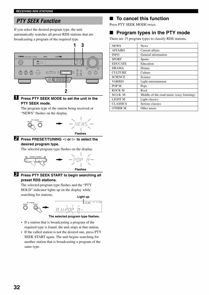
32
PTY SEEK FunctionIf you select the desired program type, the unitautomatically searches all preset RDS stations that arebroadcasting a program of the required type.
1 Press PTY SEEK MODE to set the unit in thePTY SEEK mode.The program type of the station being received or“NEWS” flashes on the display.
2 Press PRESET/TUNING l or h to select thedesired program type.The selected program type flashes on the display.
3 Press PTY SEEK START to begin searching allpreset RDS stations.The selected program type flashes and the “PTYHOLD” indicator lights up on the display whilesearching for stations.
• If a station that is broadcasting a program of therequired type is found, the unit stops at that station.
• If the called station is not the desired one, press PTYSEEK START again. The unit begins searching foranother station that is broadcasting a program of thesame type.
RECEIVING RDS STATIONS
To cancel this functionPress PTY SEEK MODE twice.
Program types in the PTY modeThere are 15 program types to classify RDS stations.
NEWS NewsAFFAIRS Current affairsINFO General informationSPORT SportsEDUCATE EducationDRAMA DramaCULTURE CultureSCIENCE ScienceVARIED Light entertainmentPOP M PopsROCK M RockM.O.R. M Middle-of-the-road music (easy-listening)LIGHT M Light classicsCLASSICS Serious classicsOTHER M Other music
PTY SEEKMODE START
Flashes
PRESET/TUNING
The selected program type flashes.
Light up
PTY SEEKMODE START
PS PTY RT CTPTY HOLD
BASS EXT.
AUTO
SILENT VIDEO AUX
PHONES S VIDEO VIDEO L AUDIO R OPTICAL
6CH INPUTINPUT MODE
INPUT
VOLUME
RDS MODE/FREQ EON
PTY SEEKMODE START
TUNINGMODE
PRESET/TUNING FM/AM
MEMORY
EDIT
BASS BALANCE SPEAKERS
PROGRAM PRESET/TUNINGEFFECT A/B/C/D/EA B
OFFON
STANDBY/ON
D I G I T A L
– + L R
TREBLE
– +MAN'L/AUTO FM AUTO/MAN'L MONO
SURROUND
D I G I T A L
31
2
Flashes
0106V520RDS31-34_EN 2/2/1, 5:35 PM32

33
En
glish
BA
SIC
OP
ER
AT
ION
ADVA
NC
ED O
PERA
TIO
NA
PP
EN
DIX
INT
RO
DU
CT
ION
PR
EPA
RA
TIO
N
EON FunctionThis function uses the EON data service on the RDS stationnetwork. If you simply select the desired program type(NEWS, INFO, AFFAIRS or SPORT), the unitautomatically searches for all preset RDS stations that arescheduled to broadcast a program of the required type andswitches from the station being currently received to thenew station when the broadcasts starts.
Note• This function can only be used when an RDS station that offers
the EON data service is being received. When such a station isbeing received, the “EON” indicator lights up on the display.
1 Make sure that the “EON” indicator lights upon the display.If the “EON” indicator does not light up, tune in toanother RDS station so that the “EON” indicator lightsup.
PS PTY RT CT
AB
BASS EXT.
AUTOEON STEREO
TUNED
SILENT VIDEO AUX
PHONES S VIDEO VIDEO L AUDIO R OPTICAL
6CH INPUTINPUT MODE
INPUT
VOLUME
RDS MODE/FREQ EON
PTY SEEKMODE START
TUNINGMODE
PRESET/TUNING FM/AM
MEMORY
EDIT
BASS BALANCE SPEAKERS
PROGRAM PRESET/TUNINGEFFECT A/B/C/D/EA B
OFFON
STANDBY/ON
D I G I T A L
– + L R
TREBLE
– +MAN'L/AUTO FM AUTO/MAN'L MONO
SURROUND
D I G I T A L
2
2 Press EON repeatedly to select the desiredprogram type (NEWS, INFO, AFFAIRS orSPORT).The selected program type name indicator lights up onthe display.
• If a preset RDS station of the selected program typestarts broadcasting, the unit will automatically switchfrom the program being currently received to thatprogram. The program type name indicator flashes.
• When broadcasting of the required program ends, thepreviously received station (or another program onthe same station) is recalled.
To cancel this functionPress EON repeatedly until no program type name lights upon the display.
RECEIVING RDS STATIONS
EON
PS PTY RT CT
AB
NEWSBASS EXT.
AUTOEON STEREO
TUNED
Lights up
PS PTY RT CT
NEWSBASS EXT.
AUTOEON STEREO
TUNED
Flashes
PS PTY RT CT
AB
BASS EXT.
AUTOEON STEREO
TUNED
Lights up
0106V520RDS31-34_EN 1/31/1, 4:23 PM33

34
RECORDING A SOURCE
SILENT VIDEO AUX
PHONES S VIDEO VIDEO L AUDIO R OPTICAL
6CH INPUTINPUT MODE
INPUT
VOLUME
RDS MODE/FREQ EON
PTY SEEKMODE START
TUNINGMODE
PRESET/TUNING FM/AM
MEMORY
EDIT
BASS BALANCE SPEAKERS
PROGRAM PRESET/TUNINGEFFECT A/B/C/D/EA B
OFFON
STANDBY/ON
D I G I T A L
– + L R
TREBLE
– +MAN'L/AUTO FM AUTO/MAN'L MONO
SURROUND
D I G I T A L
2
1,4
Recording adjustments and other operations are performedfrom the recording component. Refer to the instructions forthese components.
1 Set the volume at theminimum level.
2 Select the source you want to record.
3 Begin recording by the recording componentconnected to this unit.
4 Play the source and then turn up the volume toconfirm the input source.
Notes• Do a test recording before you start an actual recording.• When this unit is set in the standby mode, you cannot record
between other components connected to this unit.• The DSP program and the setting of VOLUME, BASS, TREBLE
and BALANCE have no effect on the material being recorded.• A source connected to the 6CH INPUT jacks of this unit cannot
be recorded.• Composite video and S video signals pass independently through
this unit’s video circuits. Therefore, when recording or dubbingvideo signals, if your video source component is connected toprovide only an S video (or only a composite video) signal, youcan record only an S video (or only a composite video) signal byyour VCR.
• A given input source is not output on the same REC OUTchannel. (For example, the signal input from VCR 1 IN is notoutput on VCR 1 OUT.)
• Check the copyright laws in your country to record from records,CDs, radio, etc. Recording of copyrighted material may infringecopyright laws.
If you play back a video source that uses scrambled orencoded signals to prevent it from being dubbed, thepicture itself may be disturbed due to those signals.
Special considerations whenrecording DTS software
The DTS signal is a digital bitstream. Attempting todigitally record the DTS bitstream will result in noise beingrecorded. Therefore, if you want to use this unit to recordsources that have DTS signals recorded on them, thefollowing considerations and adjustments need to be made.
For DVDs and CDs encoded with DTSOnly 2-channel analog audio signals may be recorded.Set the DVD player (or CD player) as described in theplayer’s operation instructions so that the audio signals areoutput from the player’s analog outputs.
2
4
Remote control
INPUT
Front panel
or
VOLUME
Front panel
VOLUME
Front panel
or
Remote control
0106V520RDS31-34_EN 1/31/1, 4:23 PM34
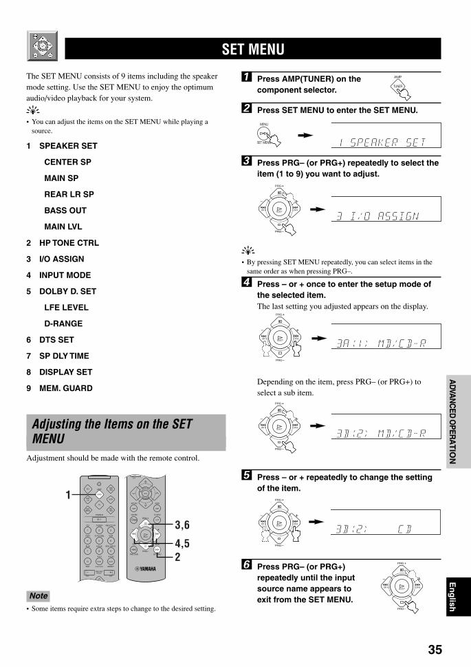
35
En
glish
BA
SIC
OP
ER
AT
ION
ADVA
NC
ED O
PERA
TIO
NA
PP
EN
DIX
INT
RO
DU
CT
ION
PR
EPA
RA
TIO
N
SET MENU
The SET MENU consists of 9 items including the speakermode setting. Use the SET MENU to enjoy the optimumaudio/video playback for your system.
y• You can adjust the items on the SET MENU while playing a
source.
1 SPEAKER SET
CENTER SP
MAIN SP
REAR LR SP
BASS OUT
MAIN LVL
2 HP TONE CTRL
3 I/O ASSIGN
4 INPUT MODE
5 DOLBY D. SET
LFE LEVEL
D-RANGE
6 DTS SET
7 SP DLY TIME
8 DISPLAY SET
9 MEM. GUARD
Adjusting the Items on the SETMENU
Adjustment should be made with the remote control.
Note• Some items require extra steps to change to the desired setting.
1
3,6
4,52
ADVANCED OPERATION
1 Press AMP(TUNER) on thecomponent selector.
2 Press SET MENU to enter the SET MENU.
3 Press PRG– (or PRG+) repeatedly to select theitem (1 to 9) you want to adjust.
y• By pressing SET MENU repeatedly, you can select items in the
same order as when pressing PRG–.
4 Press – or + once to enter the setup mode ofthe selected item.The last setting you adjusted appears on the display.
Depending on the item, press PRG– (or PRG+) toselect a sub item.
5 Press – or + repeatedly to change the settingof the item.
6 Press PRG– (or PRG+)repeatedly until the inputsource name appears toexit from the SET MENU.
0107V520RDS35-42_EN 1/31/1, 4:23 PM35

36
MAIN SP (main speaker mode)Choices: LARGE, SMALLInitial setting: LARGE
LARGESelect this if you have large main speakers. The entire rangeof the left and right main channel signal is directed to theleft and right main speakers.
SMALLSelect this if you have small main speakers. The low-frequency signals (90 Hz and below) of the main channelare directed to the speakers selected with “BASS OUT”.
Note• When you select MAIN for “BASS OUT”, the low-frequency
signals (90 Hz and below) of the main channel are directed to themain speakers even if you select SMALL for the main speakermode.
REAR LR SP (rear speaker mode)Choices: LRG (large), SML (small), NON (none)Initial setting: LRG
LRGSelect this if you have large left and right rear speakers or ifa rear subwoofer is connected to the rear speakers. Theentire range of the rear channel signal is directed to the leftand right rear speakers.
SMLSelect this if you have small left and right rear speakers. Thelow-frequency signals (90 Hz and below) of the rearchannel are directed to the speakers selected with “BASSOUT”.
NONSelect this if you do not have rear speakers.
y• This unit is set in the Virtual CINEMA DSP mode by selecting
NON for “REAR LR SP”.
SET MENU
Memory back-up
The memory back-up circuit prevents the stored datafrom being lost even if this unit is set in the standbymode, the power cord is disconnected from the ACoutlet, or the power supply is temporarily cut due topower failure. However, if the power is cut for more thanone week, the settings of the SET MENU you adjustedwill return to the factory settings. If so, adjust the itemsagain.
1 SPEAKER SET (speaker modesettings)
Use this feature to select suitable output modes for yourspeaker configuration.
Notes• When 96-kHz sampling digital signals are input to this unit, level
adjustments in items “MAIN SP”, “BASS OUT” and “MAINLVL” are possible, but those in items “CENTER SP” and “REARLR SP” are not affected.
• When 6CH INPUT is selected as the input source, leveladjustments in items of “1 SPEAKER SET” are not affected(except “MAIN LVL”).
CENTER SP (center speaker mode)By adding a center speaker to your speaker configuration,the unit can provide good dialog localization for manylisteners and superior synchronization of sound and images.
Choices: LRG (large), SML (small), NON (none)Initial setting: LRG
LRGSelect this if you have a large center speaker. The entirerange of the center channel signal is directed to the centerspeaker.
SMLSelect this if you have a small center speaker. The low-frequency signals (90 Hz and below) of the center channelare directed to the speakers selected with “BASS OUT”.
NONSelect this if you do not have a center speaker. All of thecenter channel signals are directed to the left and right mainspeakers.
0107V520RDS35-42_EN 1/31/1, 4:23 PM36

37
En
glish
BA
SIC
OP
ER
AT
ION
ADVA
NC
ED O
PERA
TIO
NA
PP
EN
DIX
INT
RO
DU
CT
ION
PR
EPA
RA
TIO
N
BASS OUT (bass out mode)LFE signals carry low-frequency effects when this unitdecodes a Dolby Digital or DTS signal. Low-frequencysignals are defined as 90 Hz and below.
Choices: SWFR (subwoofer), MAIN, BOTHInitial setting: BOTH
SWFRSelect this if you use a subwoofer. The LFE signals aredirected to the subwoofer.
MAINSelect this if you do not use a subwoofer. The LFE signalsare directed to the main speakers.
BOTHSelect this if you use a subwoofer and you want to mix themain channel low-frequency signals with the LFE signals.
Notes• When playing a 2-channel source (CD, MD, tape, video cassette
etc.), select BOTH position to direct low bass signals (below90 Hz) to the SUBWOOFER jack.
• When you select SMALL (SML) for items “CENTER SP”,“MAIN SP” and “REAR LR SP”, the low-frequency signals(90 Hz and below) from those channels are added to the LFE andoutput to the subwoofer.
MAIN LVL (main level mode)Change this setting if you cannot match the output level ofthe center and rear speakers with the main speakers becauseof the unusually high-efficiency performance of the mainspeakers.
Choices: NORM (normal), –10 dBInitial setting: NORM
NORM (normal)Normally select this setting.
–10 dBSelect this if you cannot match the output level of youreffect speakers with that of your main speakers when usingthe test tone. This setting decreases the main speaker outputlevel to about one-third of the normal level.
2 HP TONE CTRL (headphone tonecontrol)
Use this feature to adjust the level of the bass and treblewhen you use your headphones.
Control range (dB): –6 to +3Initial setting: 0 dB for both BASS and TRBL (treble)
3 I/O ASSIGNIt is possible to assign jacks according to the component tobe used if this unit’s DIGITAL INPUT/OUTPUT jacksettings (component names for terminals) differ from thatcomponent. This makes it possible to change the jackassignment and effectively connect more component.Once you assign, you can select that component withINPUT l / h (or the input selector buttons).
3A (1) (for the OPTICAL OUTPUTjack)
Initial setting: (1) MD/CD-R
3B (2) to (4) (for the OPTICALINPUT jacks)
Initial settings: (2) MD/CD-R(3) DVD(4) D-TV/CBL
SET MENU
dB
dB
0107V520RDS35-42_EN 1/31/1, 4:23 PM37
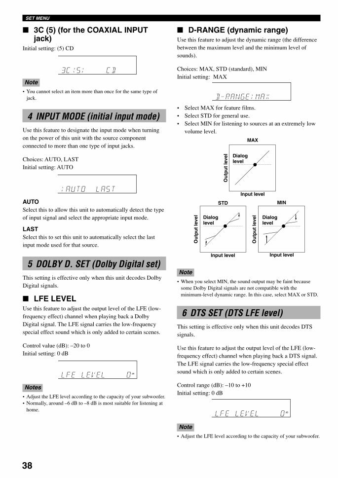
38
3C (5) (for the COAXIAL INPUTjack)
Initial setting: (5) CD
Note• You cannot select an item more than once for the same type of
jack.
4 INPUT MODE (initial input mode)Use this feature to designate the input mode when turningon the power of this unit with the source componentconnected to more than one type of input jacks.
Choices: AUTO, LASTInitial setting: AUTO
AUTOSelect this to allow this unit to automatically detect the typeof input signal and select the appropriate input mode.
LASTSelect this to set this unit to automatically select the lastinput mode used for that source.
5 DOLBY D. SET (Dolby Digital set)This setting is effective only when this unit decodes DolbyDigital signals.
LFE LEVELUse this feature to adjust the output level of the LFE (low-frequency effect) channel when playing back a DolbyDigital signal. The LFE signal carries the low-frequencyspecial effect sound which is only added to certain scenes.
Control value (dB): –20 to 0Initial setting: 0 dB
Notes• Adjust the LFE level according to the capacity of your subwoofer.• Normally, around –6 dB to –8 dB is most suitable for listening at
home.
D-RANGE (dynamic range)Use this feature to adjust the dynamic range (the differencebetween the maximum level and the minimum level ofsounds).
Choices: MAX, STD (standard), MINInitial setting: MAX
• Select MAX for feature films.• Select STD for general use.• Select MIN for listening to sources at an extremely low
volume level.
SET MENU
dB
Input level Input levelL-LEVEL BST
H-LEVEL CUT0.0
0.0
1.0
1.0
MAX
Dialoglevel
Input level
Ou
tpu
t le
vel
STD
Dialoglevel
Ou
tpu
t le
vel
MIN
Dialoglevel
Ou
tpu
t le
vel
dB
Note• When you select MIN, the sound output may be faint because
some Dolby Digital signals are not compatible with theminimum-level dynamic range. In this case, select MAX or STD.
6 DTS SET (DTS LFE level)This setting is effective only when this unit decodes DTSsignals.
Use this feature to adjust the output level of the LFE (low-frequency effect) channel when playing back a DTS signal.The LFE signal carries the low-frequency special effectsound which is only added to certain scenes.
Control range (dB): –10 to +10Initial setting: 0 dB
Note• Adjust the LFE level according to the capacity of your subwoofer.
0107V520RDS35-42_EN 1/31/1, 4:23 PM38
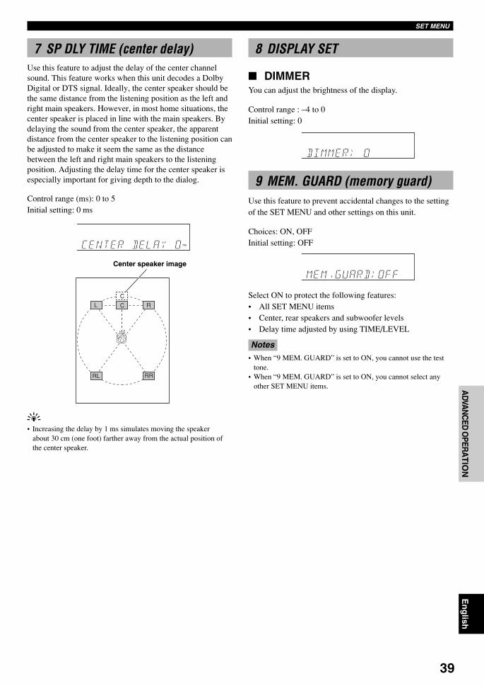
39
En
glish
BA
SIC
OP
ER
AT
ION
ADVA
NC
ED O
PERA
TIO
NA
PP
EN
DIX
INT
RO
DU
CT
ION
PR
EPA
RA
TIO
NSET MENU
ms
7 SP DLY TIME (center delay)Use this feature to adjust the delay of the center channelsound. This feature works when this unit decodes a DolbyDigital or DTS signal. Ideally, the center speaker should bethe same distance from the listening position as the left andright main speakers. However, in most home situations, thecenter speaker is placed in line with the main speakers. Bydelaying the sound from the center speaker, the apparentdistance from the center speaker to the listening position canbe adjusted to make it seem the same as the distancebetween the left and right main speakers to the listeningposition. Adjusting the delay time for the center speaker isespecially important for giving depth to the dialog.
Control range (ms): 0 to 5Initial setting: 0 ms
L C
C
R
RL RR
Center speaker image
y• Increasing the delay by 1 ms simulates moving the speaker
about 30 cm (one foot) farther away from the actual position ofthe center speaker.
8 DISPLAY SET
DIMMERYou can adjust the brightness of the display.
Control range : –4 to 0Initial setting: 0
9 MEM. GUARD (memory guard)Use this feature to prevent accidental changes to the settingof the SET MENU and other settings on this unit.
Choices: ON, OFFInitial setting: OFF
Select ON to protect the following features:• All SET MENU items• Center, rear speakers and subwoofer levels• Delay time adjusted by using TIME/LEVEL
Notes• When “9 MEM. GUARD” is set to ON, you cannot use the test
tone.• When “9 MEM. GUARD” is set to ON, you cannot select any
other SET MENU items.
0107V520RDS35-42_EN 1/31/1, 4:23 PM39
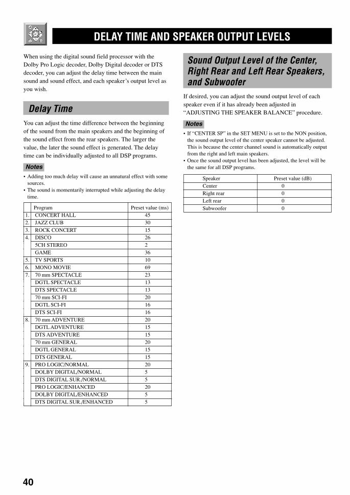
40
DELAY TIME AND SPEAKER OUTPUT LEVELS
When using the digital sound field processor with theDolby Pro Logic decoder, Dolby Digital decoder or DTSdecoder, you can adjust the delay time between the mainsound and sound effect, and each speaker’s output level asyou wish.
Delay TimeYou can adjust the time difference between the beginningof the sound from the main speakers and the beginning ofthe sound effect from the rear speakers. The larger thevalue, the later the sound effect is generated. The delaytime can be individually adjusted to all DSP programs.
Notes• Adding too much delay will cause an unnatural effect with some
sources.• The sound is momentarily interrupted while adjusting the delay
time.
Program Preset value (ms)1. CONCERT HALL 452. JAZZ CLUB 303. ROCK CONCERT 154. DISCO 26
5CH STEREO 2GAME 36
5. TV SPORTS 106. MONO MOVIE 697. 70 mm SPECTACLE 23
DGTL SPECTACLE 13DTS SPECTACLE 1370 mm SCI-FI 20DGTL SCI-FI 16DTS SCI-FI 16
8. 70 mm ADVENTURE 20DGTL ADVENTURE 15DTS ADVENTURE 1570 mm GENERAL 20DGTL GENERAL 15DTS GENERAL 15
9. PRO LOGIC/NORMAL 20DOLBY DIGITAL/NORMAL 5DTS DIGITAL SUR./NORMAL 5PRO LOGIC/ENHANCED 20DOLBY DIGITAL/ENHANCED 5DTS DIGITAL SUR./ENHANCED 5
Sound Output Level of the Center,Right Rear and Left Rear Speakers,and Subwoofer
If desired, you can adjust the sound output level of eachspeaker even if it has already been adjusted in“ADJUSTING THE SPEAKER BALANCE” procedure.
Notes• If “CENTER SP” in the SET MENU is set to the NON position,
the sound output level of the center speaker cannot be adjusted.This is because the center channel sound is automatically outputfrom the right and left main speakers.
• Once the sound output level has been adjusted, the level will bethe same for all DSP programs.
Speaker Preset value (dB)Center 0Right rear 0Left rear 0Subwoofer 0
0107V520RDS35-42_EN 2/2/1, 5:37 PM40
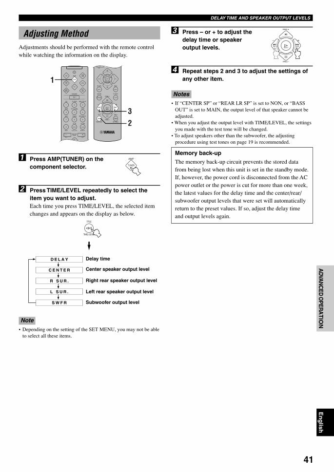
41
En
glish
BA
SIC
OP
ER
AT
ION
ADVA
NC
ED O
PERA
TIO
NA
PP
EN
DIX
INT
RO
DU
CT
ION
PR
EPA
RA
TIO
NDELAY TIME AND SPEAKER OUTPUT LEVELS
1
32
D E L A Y
C E N T E R
R S U R .
L S U R .
S W F R
Adjusting MethodAdjustments should be performed with the remote controlwhile watching the information on the display.
1 Press AMP(TUNER) on thecomponent selector.
2 Press TIME/LEVEL repeatedly to select theitem you want to adjust.Each time you press TIME/LEVEL, the selected itemchanges and appears on the display as below.
Delay time
Center speaker output level
Right rear speaker output level
Left rear speaker output level
Subwoofer output level
Note• Depending on the setting of the SET MENU, you may not be able
to select all these items.
3 Press – or + to adjust thedelay time or speakeroutput levels.
4 Repeat steps 2 and 3 to adjust the settings ofany other item.
Notes• If “CENTER SP” or “REAR LR SP” is set to NON, or “BASS
OUT” is set to MAIN, the output level of that speaker cannot beadjusted.
• When you adjust the output level with TIME/LEVEL, the settingsyou made with the test tone will be changed.
• To adjust speakers other than the subwoofer, the adjustingprocedure using test tones on page 19 is recommended.
Memory back-up
The memory back-up circuit prevents the stored datafrom being lost when this unit is set in the standby mode.If, however, the power cord is disconnected from the ACpower outlet or the power is cut for more than one week,the latest values for the delay time and the center/rear/subwoofer output levels that were set will automaticallyreturn to the preset values. If so, adjust the delay timeand output levels again.
0107V520RDS35-42_EN 1/31/1, 4:23 PM41
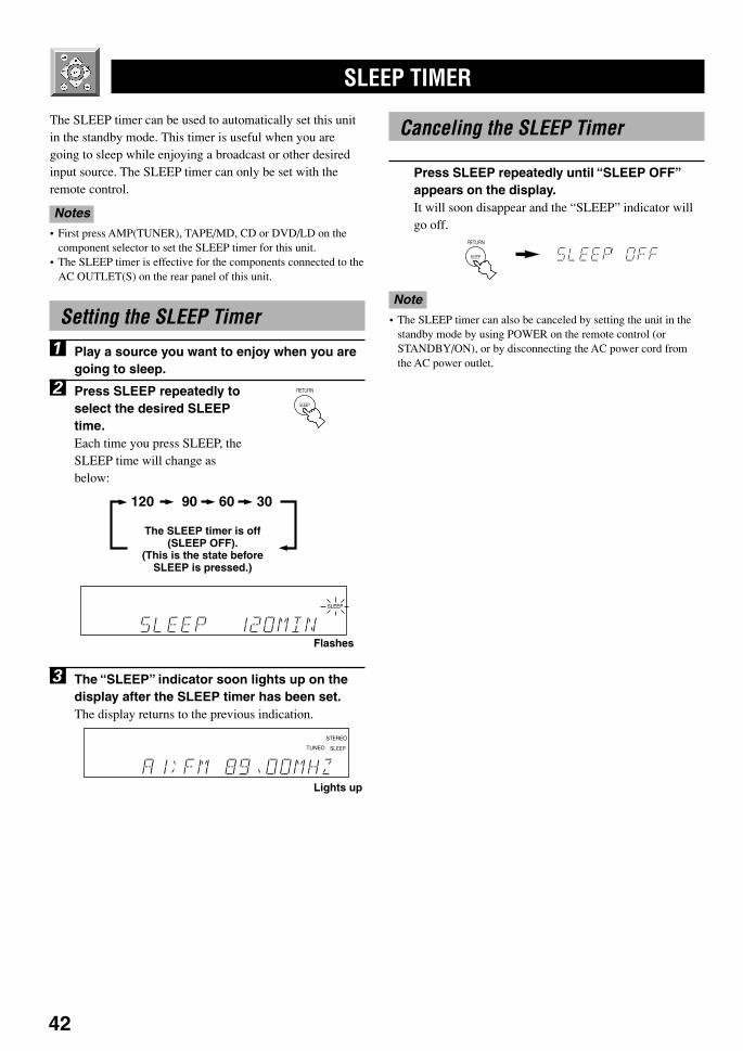
42
SLEEP TIMER
The SLEEP timer can be used to automatically set this unitin the standby mode. This timer is useful when you aregoing to sleep while enjoying a broadcast or other desiredinput source. The SLEEP timer can only be set with theremote control.
Notes• First press AMP(TUNER), TAPE/MD, CD or DVD/LD on the
component selector to set the SLEEP timer for this unit.• The SLEEP timer is effective for the components connected to the
AC OUTLET(S) on the rear panel of this unit.
Setting the SLEEP Timer
1 Play a source you want to enjoy when you aregoing to sleep.
2 Press SLEEP repeatedly toselect the desired SLEEPtime.Each time you press SLEEP, theSLEEP time will change asbelow:
3 The “SLEEP” indicator soon lights up on thedisplay after the SLEEP timer has been set.The display returns to the previous indication.
Canceling the SLEEP Timer
Press SLEEP repeatedly until “SLEEP OFF”appears on the display.It will soon disappear and the “SLEEP” indicator willgo off.
Note• The SLEEP timer can also be canceled by setting the unit in the
standby mode by using POWER on the remote control (orSTANDBY/ON), or by disconnecting the AC power cord fromthe AC power outlet.
120 90 60 30
The SLEEP timer is off(SLEEP OFF).
(This is the state beforeSLEEP is pressed.)
SLEEPBASS EXT.
Flashes
SLEEP
STEREO
TUNED
Lights up
0107V520RDS35-42_EN 1/31/1, 4:23 PM42
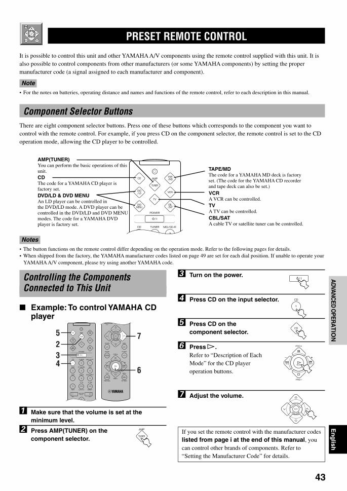
43
En
glish
BA
SIC
OP
ER
AT
ION
ADVA
NC
ED O
PERA
TIO
NA
PP
EN
DIX
INT
RO
DU
CT
ION
PR
EPA
RA
TIO
N
PRESET REMOTE CONTROL
It is possible to control this unit and other YAMAHA A/V components using the remote control supplied with this unit. It isalso possible to control components from other manufacturers (or some YAMAHA components) by setting the propermanufacturer code (a signal assigned to each manufacturer and component).
Note• For the notes on batteries, operating distance and names and functions of the remote control, refer to each description in this manual.
Component Selector ButtonsThere are eight component selector buttons. Press one of these buttons which corresponds to the component you want tocontrol with the remote control. For example, if you press CD on the component selector, the remote control is set to the CDoperation mode, allowing the CD player to be controlled.
5
32
4
7
6
AMP(TUNER)You can perform the basic operations of thisunit.CDThe code for a YAMAHA CD player isfactory set.DVD/LD & DVD MENUAn LD player can be controlled inthe DVD/LD mode. A DVD player can becontrolled in the DVD/LD and DVD MENUmodes. The code for a YAMAHA DVDplayer is factory set.
TAPE/MDThe code for a YAMAHA MD deck is factoryset. (The code for the YAMAHA CD recorderand tape deck can also be set.)VCRA VCR can be controlled.TVA TV can be controlled.CBL/SATA cable TV or satellite tuner can be controlled.
Notes• The button functions on the remote control differ depending on the operation mode. Refer to the following pages for details.• When shipped from the factory, the YAMAHA manufacturer codes listed on page 49 are set for each dial position. If unable to operate your
YAMAHA A/V component, please try using another YAMAHA code.
Controlling the ComponentsConnected to This Unit
Example: To control YAMAHA CDplayer
1 Make sure that the volume is set at theminimum level.
2 Press AMP(TUNER) on thecomponent selector.
3 Turn on the power.
4 Press CD on the input selector.
5 Press CD on thecomponent selector.
6 Press p.Refer to “Description of EachMode” for the CD playeroperation buttons.
7 Adjust the volume.
If you set the remote control with the manufacturer codeslisted from page i at the end of this manual, youcan control other brands of components. Refer to“Setting the Manufacturer Code” for details.
0108V520RDS43-49_EN 1/31/1, 4:23 PM43
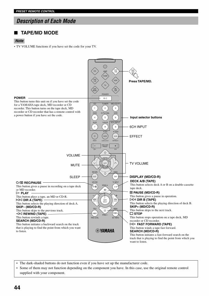
44
Description of Each Mode
TAPE/MD MODE
Note• TV VOLUME functions if you have set the code for your TV.
DISPLAY (MD/CD-R)SLEEP
EFFECT
6CH INPUT
MUTE TV VOLUME
VOLUME
POWERThis button turns this unit on if you have set the codefor a YAMAHA tape deck, MD recorder or CDrecorder. This button turns on the tape deck, MDrecorder or CD recorder that has a remote control witha power button if you have set the code.
r REC/PAUSEThis button gives a pause in recording on a tape deckor MD recorder.p PLAYThis button plays a tape, an MD or CD-R.b DIR A (TAPE)This button selects the playing direction of deck A.SKIP– (MD/CD-R)This button skips to the previous track.w REWIND (TAPE)This button rewinds a tape.SEARCH (MD/CD-R)This button initiates a backward search on the trackthat is playing to find the point from which you wantto listen.
Press TAPE/MD.
Input selector buttons
DECK A/B (TAPE)This button selects deck A or B on a double-cassettetape deck.
e PAUSE (MD/CD-R)This button gives a pause in operation.a DIR B (TAPE)This button selects the playing direction of deck B.SKIP+ (MD/CD-R)This button skips to the next track.s STOPThis button stops operation on a tape deck, MDrecorder or CD recorder.f FAST FORWARD (TAPE)This button winds a tape fast forward.SEARCH (MD/CD-R)This button initiates a fast-forward search on thetrack that is playing to find the point from which youwant to listen.
• The dark-shaded buttons do not function even if you have set up the manufacturer code.• Some of them may not function depending on the component you have. In this case, use the original remote control
supplied with your component.
PRESET REMOTE CONTROL
0108V520RDS43-49_EN 1/31/1, 4:23 PM44
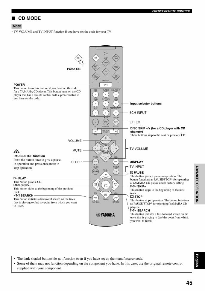
45
En
glish
BA
SIC
OP
ER
AT
ION
ADVA
NC
ED O
PERA
TIO
NA
PP
EN
DIX
INT
RO
DU
CT
ION
PR
EPA
RA
TIO
N
CD MODE
Note• TV VOLUME and TV INPUT function if you have set the code for your TV.
DISPLAYSLEEP
EFFECT
6CH INPUT
MUTE TV VOLUME
VOLUME
TV INPUT
Press CD.
POWERThis button turns this unit on if you have set the codefor a YAMAHA CD player. This button turns on the CDplayer that has a remote control with a power button ifyou have set the code.
p PLAYThis button plays a CD.b SKIP–This button skips to the beginning of the previoustrack.w SEARCHThis button initiates a backward search on the trackthat is playing to find the point from which you wantto listen.
Input selector buttons
DISC SKIP –/+ (for a CD player with CDchanger)These buttons skip to the next or previous CD.
e PAUSEThis button gives a pause in operation. Thebutton functions as PAUSE/STOP* for operatinga YAMAHA CD player under factory setting.a SKIP+This button skips to the beginning of the nexttrack.s STOPThis button stops operation. The button functionsas PAUSE/STOP* for operating YAMAHA CDplayers.f SEARCHThis button initiates a fast-forward search on thetrack that is playing to find the point from whichyou want to listen.
yPAUSE/STOP functionPress the button once to give a pausein operation and press once more tostop operation.
• The dark-shaded buttons do not function even if you have set up the manufacturer code.• Some of them may not function depending on the component you have. In this case, use the original remote control
supplied with your component.
PRESET REMOTE CONTROL
0108V520RDS43-49_EN 1/31/1, 4:23 PM45

46
DVD/LD MODE
Note• TV VOLUME and TV INPUT function if you have set the code for your TV.
CLEAR
TV INPUT
TV VOLUMEVOLUME
RETURN
MENU UP
MUTE
MENU LEFT
MENU DOWN
TITLE
DISC SKIP –/+
INDEX
MENU SELECTMENU
+10
MENU RIGHT
EFFECT
TV INPUT
TV VOLUMEVOLUME
SLEEP
MUTE
SKIP –
STOP
SEARCH
DISC SKIP –/+
6CH INPUT
DISPLAY
PAUSE
PLAYSEARCH
SKIP +
Press DVD/LD.
POWERThis button turns this unit on if you haveset the code for a YAMAHA DVD or LDplayer. This button turns on the DVD orLD player that has a remote control with apower button if you have set the code.
DVD MENU MODE
Notes• TV VOLUME and TV INPUT function if you have set the code for your TV.• DVD MENU operations cannot be performed for some DVD players.
Input selector buttons
Press DVD MENU.
POWERThis button turns this unit on if you haveset the code for a YAMAHA DVD or LDplayer. This button turns on the DVD orLD player that has a remote control witha power button if you have set the code.
Numeric buttons
• The dark-shaded buttons do not function even if you have set up the manufacturer code.• Some of them may not function depending on the component you have. In this case, use the original remote control
supplied with your component.
PRESET REMOTE CONTROL
0108V520RDS43-49_EN 1/31/1, 4:24 PM46
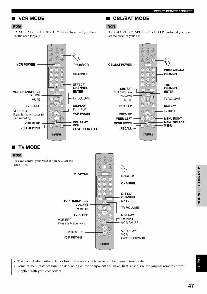
47
En
glish
BA
SIC
OP
ER
AT
ION
ADVA
NC
ED O
PERA
TIO
NA
PP
EN
DIX
INT
RO
DU
CT
ION
PR
EPA
RA
TIO
N
VCR MODE
Note• TV VOLUME, TV INPUT and TV SLEEP function if you have
set the code for your TV.
EFFECT
TV INPUT
TV VOLUMEVOLUME
TV SLEEP
MUTE
VCR STOP
VCR REWIND
VCR CHANNEL –/+
DISPLAY
VCR PAUSE
VCR PLAYVCRFAST FORWARD
CHANNEL ENTER
CHANNEL
VCR POWER
+100
TV INPUT
TV VOLUMEVOLUME
TV SLEEP
MUTE
MENU LEFT
MENU UP
MENU DOWN
RECALL
CBL/SAT CHANNEL –/+
DISPLAY
MENU SELECTMENU
CHANNEL ENTER
MENU RIGHT
CBL/SAT POWER
CHANNEL
EFFECT
TV INPUT
TV VOLUMEVOLUME
TV SLEEP
TV MUTE
VCR STOP
VCR REWIND
TV CHANNEL –/+
DISPLAY
VCR PAUSE
VCR PLAYVCRFAST FORWARD
CHANNEL ENTER
CHANNEL
TV POWER
VCR RECPress this button twice tostart recording.
CBL/SAT MODE
Note• TV VOLUME, TV INPUT and TV SLEEP function if you have
set the code for your TV.
Press VCR.
Press CBL/SAT.
TV MODE
Note• You can control your VCR if you have set the
code for it.
Press TV.
VCR RECPress this button twice.
• The dark-shaded buttons do not function even if you have set up the manufacturer code.• Some of them may not function depending on the component you have. In this case, use the original remote control
supplied with your component.
PRESET REMOTE CONTROL
0108V520RDS43-49_EN 1/31/1, 4:24 PM47
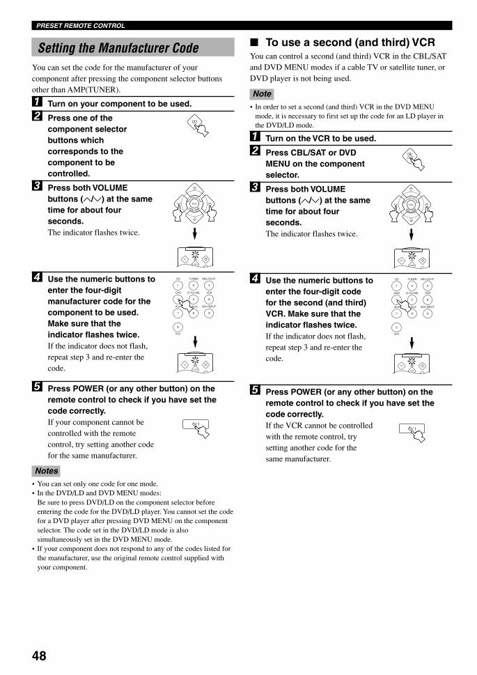
48
Setting the Manufacturer CodeYou can set the code for the manufacturer of yourcomponent after pressing the component selector buttonsother than AMP(TUNER).
1 Turn on your component to be used.
2 Press one of thecomponent selectorbuttons whichcorresponds to thecomponent to becontrolled.
3 Press both VOLUMEbuttons (u/d) at the sametime for about fourseconds.The indicator flashes twice.
4 Use the numeric buttons toenter the four-digitmanufacturer code for thecomponent to be used.Make sure that theindicator flashes twice.If the indicator does not flash,repeat step 3 and re-enter thecode.
5 Press POWER (or any other button) on theremote control to check if you have set thecode correctly.If your component cannot becontrolled with the remotecontrol, try setting another codefor the same manufacturer.
Notes• You can set only one code for one mode.• In the DVD/LD and DVD MENU modes:
Be sure to press DVD/LD on the component selector beforeentering the code for the DVD/LD player. You cannot set the codefor a DVD player after pressing DVD MENU on the componentselector. The code set in the DVD/LD mode is alsosimultaneously set in the DVD MENU mode.
• If your component does not respond to any of the codes listed forthe manufacturer, use the original remote control supplied withyour component.
To use a second (and third) VCRYou can control a second (and third) VCR in the CBL/SATand DVD MENU modes if a cable TV or satellite tuner, orDVD player is not being used.
Note• In order to set a second (and third) VCR in the DVD MENU
mode, it is necessary to first set up the code for an LD player inthe DVD/LD mode.
1 Turn on the VCR to be used.
2 Press CBL/SAT or DVDMENU on the componentselector.
3 Press both VOLUMEbuttons (u/d) at the sametime for about fourseconds.The indicator flashes twice.
4 Use the numeric buttons toenter the four-digit codefor the second (and third)VCR. Make sure that theindicator flashes twice.If the indicator does not flash,repeat step 3 and re-enter thecode.
5 Press POWER (or any other button) on theremote control to check if you have set thecode correctly.If the VCR cannot be controlledwith the remote control, trysetting another code for thesame manufacturer.
PRESET REMOTE CONTROL
0108V520RDS43-49_EN 1/31/1, 4:24 PM48
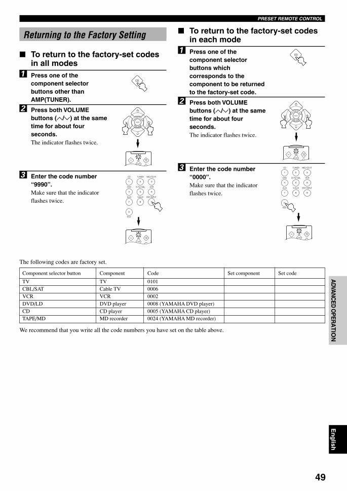
49
En
glish
BA
SIC
OP
ER
AT
ION
ADVA
NC
ED O
PERA
TIO
NA
PP
EN
DIX
INT
RO
DU
CT
ION
PR
EPA
RA
TIO
N
Returning to the Factory Setting
To return to the factory-set codesin all modes
1 Press one of thecomponent selectorbuttons other thanAMP(TUNER).
2 Press both VOLUMEbuttons (u/d) at the sametime for about fourseconds.The indicator flashes twice.
3 Enter the code number“9990”.Make sure that the indicatorflashes twice.
To return to the factory-set codesin each mode
1 Press one of thecomponent selectorbuttons whichcorresponds to thecomponent to be returnedto the factory-set code.
2 Press both VOLUMEbuttons (u/d) at the sametime for about fourseconds.The indicator flashes twice.
3 Enter the code number“0000”.Make sure that the indicatorflashes twice.
PRESET REMOTE CONTROL
The following codes are factory set.
Component selector button Component Code Set component Set code
TV TV 0101CBL/SAT Cable TV 0006VCR VCR 0002DVD/LD DVD player 0008 (YAMAHA DVD player)CD CD player 0005 (YAMAHA CD player)TAPE/MD MD recorder 0024 (YAMAHA MD recorder)
We recommend that you write all the code numbers you have set on the table above.
0108V520RDS43-49_EN 1/31/1, 4:24 PM49

50
2 JAZZ CLUB —
SOUND FIELD PROGRAM
A digital sound field processor (DSP) based on the latest YAMAHA technology is built into this unit. It is possible to playback various sound fields for the source you are listening to.
Note• Regardless of the program name and characteristics listed in the table below, select the sound field program that sounds best to you.
Hi-Fi DSP Programs
For audio sources: Nos. 1 to 4
No. Program (group) Sub-program Features
1 CONCERT HALL —
Using this program increases the listening position range. This is a sound fieldsuitable for background music at parties.
Note• Reverberations (sound effects) for realizing the sound field and unprocessed stereo from the left and right main speakers is output. The
sound is not output from the center speaker. (The sound is output when one of these programs is selected while playing a source encodedwith a Dolby Digital or DTS signal. If 5CH STEREO is selected, the sound is output from all speakers regardless of the input source.)
This is the sound field at stage front in “The Bottom Line”, a famous New York jazzclub. The floor can seat 300 people to the left and right in a sound field offering areal and vibrant sound.
A large round concert hall with a rich surround effect. Pronounced reflections fromall directions emphasize the extension of sounds. The sound field has a great deal ofpresence, and your virtual seat is near the center, close to the stage.
3 ROCK CONCERT — The ideal program for lively, dynamic rock music. The data for this program wasrecorded at LA’s “hottest” rock club. The listener’s virtual seat is at the center-left ofthe hall.
4 ENTERTAINMENT DISCO This program recreates the acoustic environment of a lively disco in the heart of a bigcity. The sound is dense and highly concentrated. It is also characterized by a high-energy, “immediate” sound.
5CH STEREO
CINEMA DSP Programs
For audio-video sources: Nos. 4 to 6
No. Program (group) Sub-program Features
4 ENTERTAINMENT GAME This program adds a deep and spatial feeling to video game sounds.
5 TV SPORTS — Although the presence sound field is relatively narrow, the surround sound fieldemploys the sound environment of a large concert hall. With this program, you canenjoy watching various TV programs such as news, variety shows, music programsor sports programs. In a stereo broadcast of a sports game, the commentator isoriented at the center position, and the shouts and the atmosphere in the stadiumspread on the surround side, while their spread to the rear is properly restrained.
This program is provided for reproducing monaural video sources (such as oldmovies). The program produces the optimum reverberation to create sound depth byusing only the presence sound field.
6 MONO MOVIE —
0109V520RDS50-52_EN 1/31/1, 4:24 PM50

51
En
glish
BA
SIC
OP
ER
AT
ION
ADVA
NC
ED O
PERA
TIO
NA
PP
EN
DIX
INT
RO
DU
CT
ION
PR
EPA
RA
TIO
N
8 MOVIE THEATER 2 ADVENTURE 70 mmADVENTURE
This program is ideal for precisely reproducing thesound design of the newest 70-mm andmultichannel soundtrack films. The sound field ismade to be similar to that of the newest movietheaters, so the reverberations of the sound fielditself are restrained as much as possible.
GENERAL 70 mm GENERAL This program is for reproducing sounds from70-mm and multichannel soundtrack films, and ischaracterized by a soft and extensive sound field.The presence sound field is relatively narrow. Itspatially spreads all around and toward the screen,restraining the echo effect of conversations withoutlosing clarity. For the surround sound field, theharmony of music or chorus sounds beautifully in awide space at the rear of the sound field.
DOLBY DIGITAL/NORMAL
DTS DIGITALSUR./ENHANCED
Analog, PCM,Dolby Digitalin 2-channel
DGTLADVENTURE
Dolby Digital(5.1-channel)
DTS ADVENTURE DTS
Analog, PCM,Dolby Digitalin 2-channel
DGTL GENERAL Dolby Digital(5.1-channel)
DTS GENERAL DTS
9 q/DTSSURROUND
NORMAL PRO LOGIC/NORMAL
Analog, PCM,Dolby Digitalin 2-channel
Dolby Digital(5.1-channel)
DTS DIGITALSUR./NORMAL
DTS
The built-in decoder precisely reproduces soundsand sound effects from sources.The highly efficient decoding process improvescrosstalk and channel separation, and makes soundpositioning smoother and more precise.In this program, the digital sound field processor isnot turned on.
ENHANCED PRO LOGIC/ENHANCED
Analog, PCM,Dolby Digitalin 2-channel
DOLBY DIGITAL/ENHANCED
Dolby Digital(5.1-channel)
DTS
This program ideally simulates the multi-surroundspeaker systems of the 35-mm film theaters. DolbyPro Logic decoding, Dolby Digital decoding orDTS decoding and digital sound field processingcreate precise effects without altering the originalsound orientation.The surround effects produced by this sound fieldwrap around the viewer naturally from the back tothe left and right, and toward the screen.
For movie programs: Nos. 7 to 9
No. Program (group) Sub-program Input source Features
7 MOVIE THEATER 1 SPECTACLE 70 mmSPECTACLE
This program creates the extremely wide soundfield of a 70-mm movie theater. It preciselyreproduces the source sound in detail, making boththe video and the sound field incredibly real. This isideal for any kind of video source encoded withDolby Surround, Dolby Digital or DTS (especiallylarge-scale movie productions).
SOUND FIELD PROGRAM
Analog, PCM,Dolby Digitalin 2-channel
DGTLSPECTACLE
Dolby Digital(5.1-channel)
DTS SPECTACLE DTS
SCI-FI 70 mm SCI-FI Analog, PCM,Dolby Digitalin 2-channel
This program clearly reproduces dialog and soundeffects in the latest sound form of science fictionfilms, thus creating a broad and expansivecinematic space amid the silence. You can enjoyscience fiction films in a virtual-space sound fieldthat includes Dolby Surround, Dolby Digital andDTS-encoded software employing the mostadvanced techniques.
DGTL SCI-FI Dolby Digital(5.1-channel)
DTS SCI-FI DTS
Notes• The “ x ” indicator does not light up when selecting the sub-program “NORMAL” of the q/DTS SURROUND program.• If “CENTER SP” in the SET MENU is set to NON, no sound is output from the center speaker.• The effect sound is output from the main speakers when a monaural source is played with CINEMA DSP program groups 4 (GAME) and 5
to 8.
0109V520RDS50-52_EN 1/31/1, 4:24 PM51
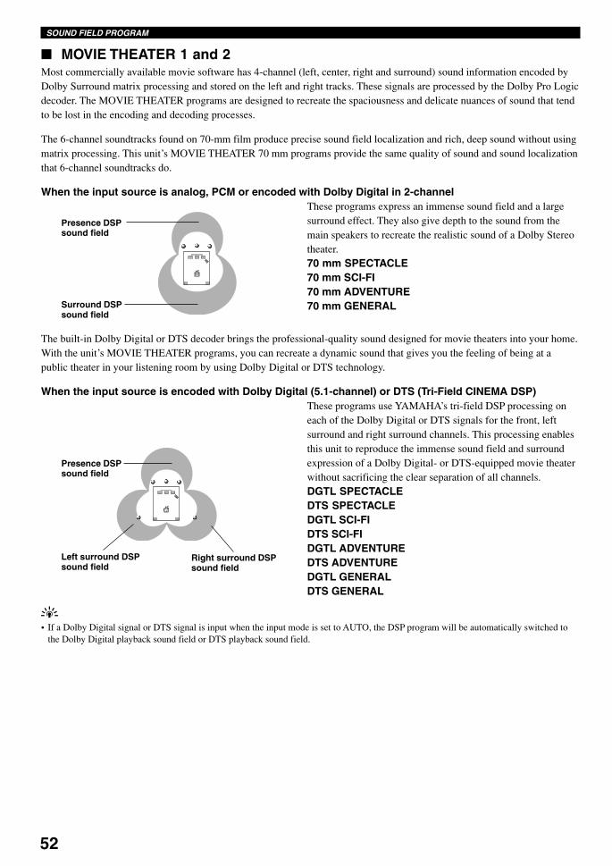
52
SOUND FIELD PROGRAM
Presence DSPsound field
Surround DSPsound field
MOVIE THEATER 1 and 2Most commercially available movie software has 4-channel (left, center, right and surround) sound information encoded byDolby Surround matrix processing and stored on the left and right tracks. These signals are processed by the Dolby Pro Logicdecoder. The MOVIE THEATER programs are designed to recreate the spaciousness and delicate nuances of sound that tendto be lost in the encoding and decoding processes.
The 6-channel soundtracks found on 70-mm film produce precise sound field localization and rich, deep sound without usingmatrix processing. This unit’s MOVIE THEATER 70 mm programs provide the same quality of sound and sound localizationthat 6-channel soundtracks do.
When the input source is analog, PCM or encoded with Dolby Digital in 2-channelThese programs express an immense sound field and a largesurround effect. They also give depth to the sound from themain speakers to recreate the realistic sound of a Dolby Stereotheater.70 mm SPECTACLE70 mm SCI-FI70 mm ADVENTURE70 mm GENERAL
The built-in Dolby Digital or DTS decoder brings the professional-quality sound designed for movie theaters into your home.With the unit’s MOVIE THEATER programs, you can recreate a dynamic sound that gives you the feeling of being at apublic theater in your listening room by using Dolby Digital or DTS technology.
When the input source is encoded with Dolby Digital (5.1-channel) or DTS (Tri-Field CINEMA DSP)These programs use YAMAHA’s tri-field DSP processing oneach of the Dolby Digital or DTS signals for the front, leftsurround and right surround channels. This processing enablesthis unit to reproduce the immense sound field and surroundexpression of a Dolby Digital- or DTS-equipped movie theaterwithout sacrificing the clear separation of all channels.DGTL SPECTACLEDTS SPECTACLEDGTL SCI-FIDTS SCI-FIDGTL ADVENTUREDTS ADVENTUREDGTL GENERALDTS GENERAL
Presence DSPsound field
Right surround DSPsound field
Left surround DSPsound field
y• If a Dolby Digital signal or DTS signal is input when the input mode is set to AUTO, the DSP program will be automatically switched to
the Dolby Digital playback sound field or DTS playback sound field.
0109V520RDS50-52_EN 1/31/1, 4:24 PM52
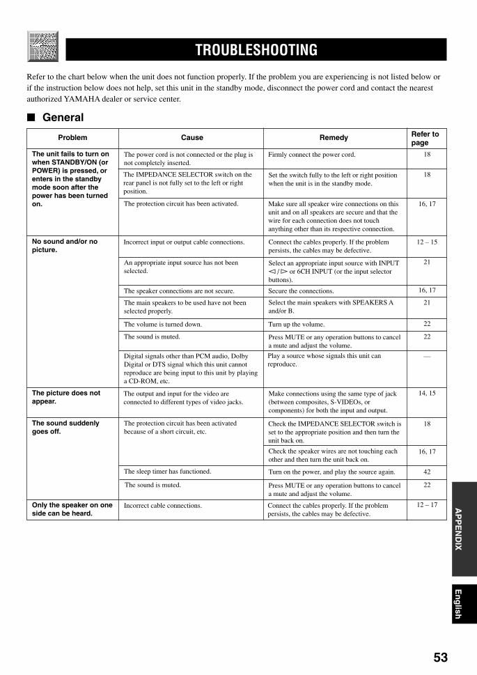
53
En
glish
BA
SIC
OP
ER
AT
ION
ADVA
NC
ED O
PERA
TIO
NA
PP
EN
DIX
INT
RO
DU
CT
ION
PR
EPA
RA
TIO
N
TROUBLESHOOTING
Refer to the chart below when the unit does not function properly. If the problem you are experiencing is not listed below orif the instruction below does not help, set this unit in the standby mode, disconnect the power cord and contact the nearestauthorized YAMAHA dealer or service center.
General
Problem Cause Remedy
APPENDIX
Refer topage
The unit fails to turn onwhen STANDBY/ON (orPOWER) is pressed, orenters in the standbymode soon after thepower has been turnedon.
The power cord is not connected or the plug isnot completely inserted.
Firmly connect the power cord.
The IMPEDANCE SELECTOR switch on therear panel is not fully set to the left or rightposition.
Set the switch fully to the left or right positionwhen the unit is in the standby mode.
The protection circuit has been activated. Make sure all speaker wire connections on thisunit and on all speakers are secure and that thewire for each connection does not touchanything other than its respective connection.
No sound and/or nopicture.
Incorrect input or output cable connections. Connect the cables properly. If the problempersists, the cables may be defective.
An appropriate input source has not beenselected.
Select an appropriate input source with INPUTl / h or 6CH INPUT (or the input selectorbuttons).
The speaker connections are not secure. Secure the connections.
The main speakers to be used have not beenselected properly.
Select the main speakers with SPEAKERS Aand/or B.
The volume is turned down. Turn up the volume.
The sound is muted. Press MUTE or any operation buttons to cancela mute and adjust the volume.
Digital signals other than PCM audio, DolbyDigital or DTS signal which this unit cannotreproduce are being input to this unit by playinga CD-ROM, etc.
Play a source whose signals this unit canreproduce.
The picture does notappear.
The output and input for the video areconnected to different types of video jacks.
Make connections using the same type of jack(between composites, S-VIDEOs, orcomponents) for both the input and output.
The sound suddenlygoes off.
Check the IMPEDANCE SELECTOR switch isset to the appropriate position and then turn theunit back on.
The protection circuit has been activatedbecause of a short circuit, etc.
Check the speaker wires are not touching eachother and then turn the unit back on.
The sleep timer has functioned. Turn on the power, and play the source again.
The sound is muted. Press MUTE or any operation buttons to cancela mute and adjust the volume.
Only the speaker on oneside can be heard.
Incorrect cable connections. Connect the cables properly. If the problempersists, the cables may be defective.
18
18
16, 17
12 – 15
21
16, 17
21
22
22
—
14, 15
18
16, 17
42
22
12 – 17
0110V520RDS53-62_EN 1/31/1, 4:24 PM53

54
Problem Cause RemedyRefer topage
TROUBLESHOOTING
No sound from the effectspeakers.
The sound effect is off. Press EFFECT to turn it on.
A Dolby Surround, Dolby Digital or DTSdecoding DSP program is being used withmaterial not encoded with Dolby Surround,Dolby Digital or DTS.
Select another DSP program.
A 96-kHz sampling digital signal is being inputto this unit.
No sound from thecenter speaker.
The output level of the center speaker is set tominimum.
Raise the level of the center speaker.
“CENTER SP” in the SET MENU is set toNON.
Select the appropriate mode for your centerspeaker.
One of the Hi-Fi DSP programs (1 to 4) has beenselected.
Select another DSP program.
The source encoded with a Dolby Digital orDTS signal does not have a center channelsignal.
No sound from the rearspeakers.
The output level of the rear speakers is set tominimum.
Raise the output level of the rear speakers.
A monaural source is being played with theprogram 9.
Select another DSP program.
No sound from thesubwoofer.
“BASS OUT” in the SET MENU is set toMAIN when a Dolby Digital or DTS signal isbeing played.
Select SWFR or BOTH.
“BASS OUT” in the SET MENU is set toSWFR or MAIN when a 2-channel source isbeing played.
Select BOTH.
The source does not contain low bass signals(90 Hz and below).
Poor bass reproduction. “BASS OUT” in the SET MENU is set toSWFR or BOTH and your system does notinclude a subwoofer.
Select MAIN.
The output mode for each speaker (main, centeror rear) in the SET MENU does not match yourspeaker configuration.
Select the appropriate output mode for eachspeaker based on the size of the speakers inyour configuration.
A “humming” sound canbe heard.
Incorrect cable connections. Firmly connect the audio plugs. If the problempersists, the cables may be defective.
25
50, 51
22
40
36
50, 51
—
40
50, 51
37
37
—
37
36, 37
12 – 15
0110V520RDS53-62_EN 1/31/1, 4:24 PM54
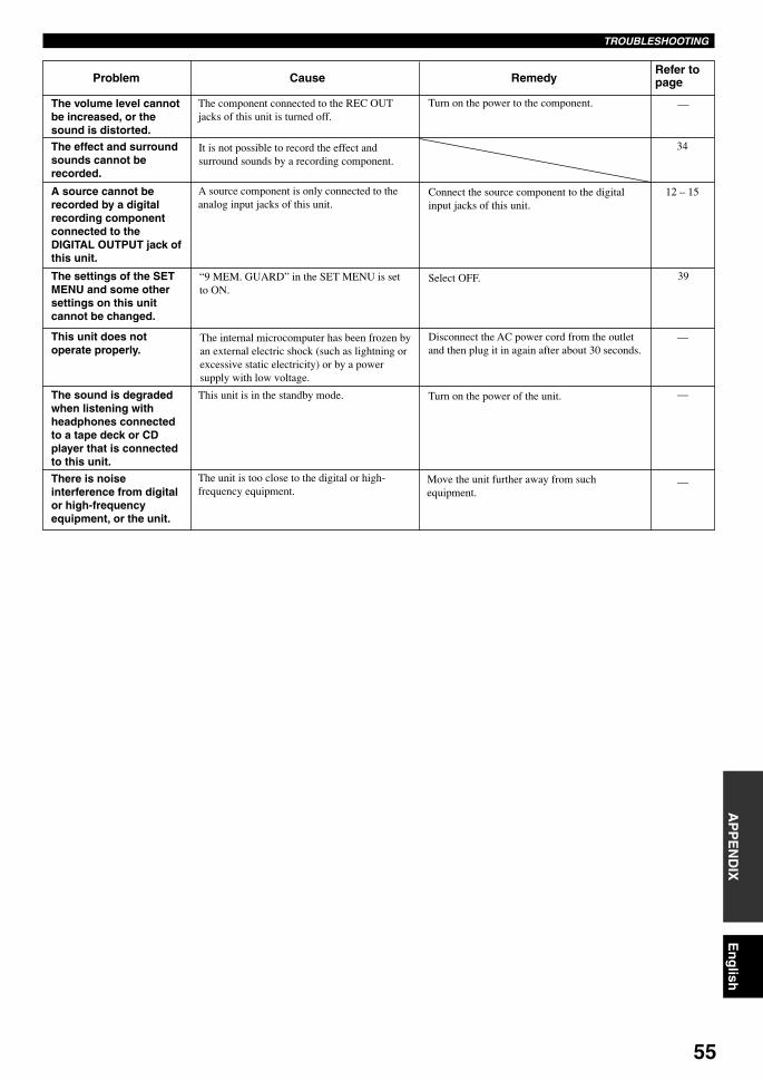
55
En
glish
BA
SIC
OP
ER
AT
ION
ADVA
NC
ED O
PERA
TIO
NA
PP
EN
DIX
INT
RO
DU
CT
ION
PR
EPA
RA
TIO
NTROUBLESHOOTING
12 – 15
The volume level cannotbe increased, or thesound is distorted.
The component connected to the REC OUTjacks of this unit is turned off.
Turn on the power to the component.
The effect and surroundsounds cannot berecorded.
It is not possible to record the effect andsurround sounds by a recording component.
A source cannot berecorded by a digitalrecording componentconnected to theDIGITAL OUTPUT jack ofthis unit.
A source component is only connected to theanalog input jacks of this unit.
Connect the source component to the digitalinput jacks of this unit.
The settings of the SETMENU and some othersettings on this unitcannot be changed.
“9 MEM. GUARD” in the SET MENU is setto ON.
Select OFF.
This unit does notoperate properly.
The internal microcomputer has been frozen byan external electric shock (such as lightning orexcessive static electricity) or by a powersupply with low voltage.
Disconnect the AC power cord from the outletand then plug it in again after about 30 seconds.
The sound is degradedwhen listening withheadphones connectedto a tape deck or CDplayer that is connectedto this unit.
This unit is in the standby mode. Turn on the power of the unit.
There is noiseinterference from digitalor high-frequencyequipment, or the unit.
Move the unit further away from suchequipment.
—
—
—
Refer topage
The unit is too close to the digital or high-frequency equipment.
Problem Cause Remedy
34
39
—
0110V520RDS53-62_EN 1/31/1, 4:24 PM55

56
After this unit has been exposed to a strong external electric shock (such as lightning and strong static electricity) or if youmishandle the operation of this unit, it may not function properly. In these cases, set this unit in the standby mode, disconnectthe power cord, plug it back in after 30 seconds, and start operating.
TROUBLESHOOTING
FM
AM
26
27
28
26
26
—
Tuner
Problem
FM stereo receptionis noisy.
The characteristics of FM stereo broadcastsmay cause this problem when the transmitter istoo far away or the antenna input is poor.
Check the antenna connections.Try using a high-quality directional FMantenna.
There is distortion,and clear receptioncannot be obtainedeven with a good FMantenna.
There is multipath interference. Adjust the antenna position to eliminatemultipath interference.
The desired stationcannot be tuned inwith the automatictuning method.
The station is too weak. Use the manual tuning method.
Previously presetstations can nolonger be tuned in.
The unit has been disconnected for a longperiod.
Re-store the stations.
The desired stationcannot be tuned inwith the automatictuning method.
The signal is weak or the antenna connectionsare loose.
Tighten the AM loop antenna connections andorient it for best reception.
There are continuouscrackling and hissingnoises.
There are buzzing andwhining noises(especially in theevening).
Cause Remedy Refer topage
Use an outdoor antenna and a ground wire. Thiswill help somewhat, but it is difficult toeliminate all noise.
Noises result from lightning, fluorescent lamps,motors, thermostats and other electricalequipment.
A TV set is being used nearby. Move this unit away from the TV.
Problem Cause Remedy Refer topage
The remote control doesnot work nor functionproperly.
Wrong distance or angle. The remote control will function within amaximum range of 6 m (20 feet) and no morethan 30 degrees off-axis from the front panel.
Direct sunlight or lighting (from an inverter typeof fluorescent lamp, etc.) is striking the remotecontrol sensor of this unit.
Reposition the unit.
The batteries are weak. Replace all batteries with new ones.
The unit or othercomponent cannot becontrolled.
The component to be controlled has not beenselected.
Press one of the component selector buttons,corresponding to the component to becontrolled.
The remote control cannot control systemcomponents.
The manufacturer code has not been set upproperly.
Enter the code again.
Try setting another code for the samemanufacturer.
Depending on the manufacturer or the model,some components cannot be controlled with thisunit’s remote control even though the code hasbeen set up properly.
Use the original remote control supplied withyour component.
7
7
3
43
—
48
—
Remote control
26
Use the manual tuning method. 27
Use a high-quality directional FM antenna. 26
Use the manual tuning method. 27
0110V520RDS53-62_EN 1/31/1, 4:24 PM56
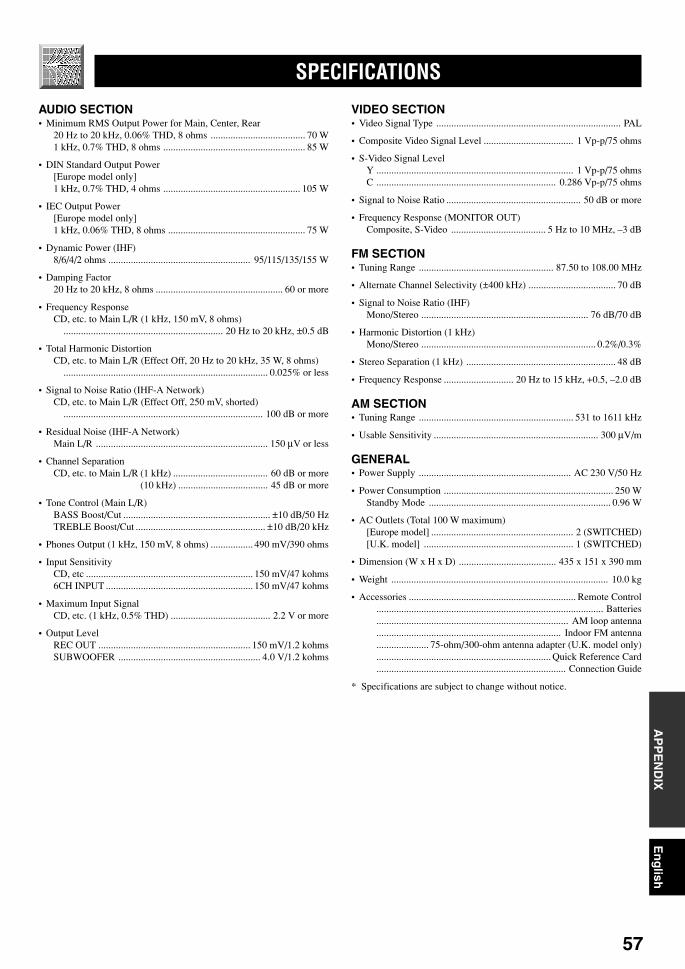
57
En
glish
BA
SIC
OP
ER
AT
ION
ADVA
NC
ED O
PERA
TIO
NA
PP
EN
DIX
INT
RO
DU
CT
ION
PR
EPA
RA
TIO
N
SPECIFICATIONS
AUDIO SECTION• Minimum RMS Output Power for Main, Center, Rear
20 Hz to 20 kHz, 0.06% THD, 8 ohms ...................................... 70 W1 kHz, 0.7% THD, 8 ohms ......................................................... 85 W
• DIN Standard Output Power[Europe model only]1 kHz, 0.7% THD, 4 ohms ....................................................... 105 W
• IEC Output Power[Europe model only]1 kHz, 0.06% THD, 8 ohms ....................................................... 75 W
• Dynamic Power (IHF)8/6/4/2 ohms ......................................................... 95/115/135/155 W
• Damping Factor20 Hz to 20 kHz, 8 ohms ................................................... 60 or more
• Frequency ResponseCD, etc. to Main L/R (1 kHz, 150 mV, 8 ohms)
................................................................ 20 Hz to 20 kHz, ±0.5 dB
• Total Harmonic DistortionCD, etc. to Main L/R (Effect Off, 20 Hz to 20 kHz, 35 W, 8 ohms)
.................................................................................. 0.025% or less
• Signal to Noise Ratio (IHF-A Network)CD, etc. to Main L/R (Effect Off, 250 mV, shorted)
................................................................................ 100 dB or more
• Residual Noise (IHF-A Network)Main L/R ..................................................................... 150 µV or less
• Channel SeparationCD, etc. to Main L/R (1 kHz) ...................................... 60 dB or more
(10 kHz) .................................... 45 dB or more
• Tone Control (Main L/R)BASS Boost/Cut ........................................................... ±10 dB/50 HzTREBLE Boost/Cut .................................................... ±10 dB/20 kHz
• Phones Output (1 kHz, 150 mV, 8 ohms) ................. 490 mV/390 ohms
• Input SensitivityCD, etc ................................................................... 150 mV/47 kohms6CH INPUT ........................................................... 150 mV/47 kohms
• Maximum Input SignalCD, etc. (1 kHz, 0.5% THD) ........................................ 2.2 V or more
• Output LevelREC OUT ............................................................. 150 mV/1.2 kohmsSUBWOOFER ......................................................... 4.0 V/1.2 kohms
VIDEO SECTION• Video Signal Type .......................................................................... PAL
• Composite Video Signal Level .................................... 1 Vp-p/75 ohms
• S-Video Signal LevelY ............................................................................... 1 Vp-p/75 ohmsC ........................................................................ 0.286 Vp-p/75 ohms
• Signal to Noise Ratio ...................................................... 50 dB or more
• Frequency Response (MONITOR OUT)Composite, S-Video ...................................... 5 Hz to 10 MHz, –3 dB
FM SECTION• Tuning Range ...................................................... 87.50 to 108.00 MHz
• Alternate Channel Selectivity (±400 kHz) ................................... 70 dB
• Signal to Noise Ratio (IHF)Mono/Stereo ................................................................... 76 dB/70 dB
• Harmonic Distortion (1 kHz)Mono/Stereo ...................................................................... 0.2%/0.3%
• Stereo Separation (1 kHz) ............................................................ 48 dB
• Frequency Response ............................ 20 Hz to 15 kHz, +0.5, –2.0 dB
AM SECTION• Tuning Range .............................................................. 531 to 1611 kHz
• Usable Sensitivity .................................................................. 300 µV/m
GENERAL• Power Supply ............................................................. AC 230 V/50 Hz
• Power Consumption .................................................................... 250 WStandby Mode ......................................................................... 0.96 W
• AC Outlets (Total 100 W maximum)[Europe model] ......................................................... 2 (SWITCHED)[U.K. model] ............................................................ 1 (SWITCHED)
• Dimension (W x H x D) ....................................... 435 x 151 x 390 mm
• Weight ....................................................................................... 10.0 kg
• Accessories ................................................................... Remote Control........................................................................................... Batteries............................................................................. AM loop antenna.......................................................................... Indoor FM antenna..................... 75-ohm/300-ohm antenna adapter (U.K. model only)...................................................................... Quick Reference Card............................................................................ Connection Guide
* Specifications are subject to change without notice.
0110V520RDS53-62_EN 1/31/1, 4:24 PM57
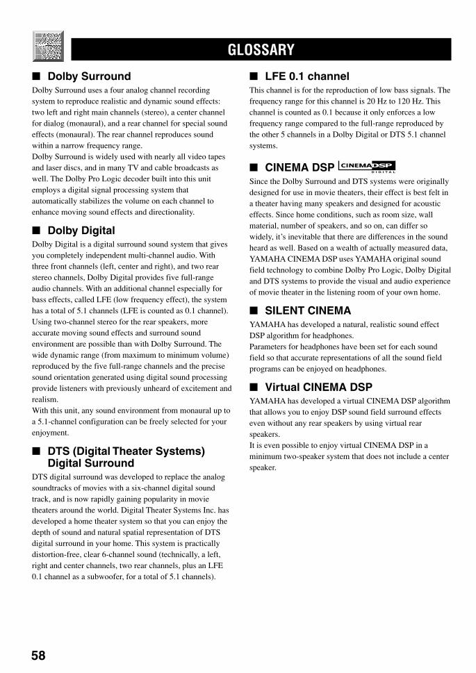
58
GLOSSARY
Dolby SurroundDolby Surround uses a four analog channel recordingsystem to reproduce realistic and dynamic sound effects:two left and right main channels (stereo), a center channelfor dialog (monaural), and a rear channel for special soundeffects (monaural). The rear channel reproduces soundwithin a narrow frequency range.Dolby Surround is widely used with nearly all video tapesand laser discs, and in many TV and cable broadcasts aswell. The Dolby Pro Logic decoder built into this unitemploys a digital signal processing system thatautomatically stabilizes the volume on each channel toenhance moving sound effects and directionality.
Dolby DigitalDolby Digital is a digital surround sound system that givesyou completely independent multi-channel audio. Withthree front channels (left, center and right), and two rearstereo channels, Dolby Digital provides five full-rangeaudio channels. With an additional channel especially forbass effects, called LFE (low frequency effect), the systemhas a total of 5.1 channels (LFE is counted as 0.1 channel).Using two-channel stereo for the rear speakers, moreaccurate moving sound effects and surround soundenvironment are possible than with Dolby Surround. Thewide dynamic range (from maximum to minimum volume)reproduced by the five full-range channels and the precisesound orientation generated using digital sound processingprovide listeners with previously unheard of excitement andrealism.With this unit, any sound environment from monaural up toa 5.1-channel configuration can be freely selected for yourenjoyment.
DTS (Digital Theater Systems)Digital Surround
DTS digital surround was developed to replace the analogsoundtracks of movies with a six-channel digital soundtrack, and is now rapidly gaining popularity in movietheaters around the world. Digital Theater Systems Inc. hasdeveloped a home theater system so that you can enjoy thedepth of sound and natural spatial representation of DTSdigital surround in your home. This system is practicallydistortion-free, clear 6-channel sound (technically, a left,right and center channels, two rear channels, plus an LFE0.1 channel as a subwoofer, for a total of 5.1 channels).
LFE 0.1 channelThis channel is for the reproduction of low bass signals. Thefrequency range for this channel is 20 Hz to 120 Hz. Thischannel is counted as 0.1 because it only enforces a lowfrequency range compared to the full-range reproduced bythe other 5 channels in a Dolby Digital or DTS 5.1 channelsystems.
CINEMA DSP D I G I T A L
Since the Dolby Surround and DTS systems were originallydesigned for use in movie theaters, their effect is best felt ina theater having many speakers and designed for acousticeffects. Since home conditions, such as room size, wallmaterial, number of speakers, and so on, can differ sowidely, it’s inevitable that there are differences in the soundheard as well. Based on a wealth of actually measured data,YAMAHA CINEMA DSP uses YAMAHA original soundfield technology to combine Dolby Pro Logic, Dolby Digitaland DTS systems to provide the visual and audio experienceof movie theater in the listening room of your own home.
SILENT CINEMAYAMAHA has developed a natural, realistic sound effectDSP algorithm for headphones.Parameters for headphones have been set for each soundfield so that accurate representations of all the sound fieldprograms can be enjoyed on headphones.
Virtual CINEMA DSPYAMAHA has developed a virtual CINEMA DSP algorithmthat allows you to enjoy DSP sound field surround effectseven without any rear speakers by using virtual rearspeakers.It is even possible to enjoy virtual CINEMA DSP in aminimum two-speaker system that does not include a centerspeaker.
0110V520RDS53-62_EN 1/31/1, 4:24 PM58

59
En
glish
BA
SIC
OP
ER
AT
ION
ADVA
NC
ED O
PERA
TIO
NA
PP
EN
DIX
INT
RO
DU
CT
ION
PR
EPA
RA
TIO
N
S VIDEO signalWith S VIDEO signal system, the video signal normallytransmitted using a pin cable is separated and transmitted asthe Y signal for the luminance and the C signal for thechrominance through the S VIDEO cable. Using the SVIDEO jack eliminates video signal transmission loss andallows recording and playback of even more beautifulimages.
PCM (Linear PCM)Linear PCM is a signal format under which an analog audiosignal is digitized, recorded and transmitted without usingany compression. This is used as a method of recording CDsand DVD audio. The PCM system uses a technique forsampling the size of the analog signal per very small unit oftime. Standing for “pulse code modulation”, the analogsignal is encoded as pulses and then modulated forrecording.
Sampling frequency and number ofquantized bits
When digitizing an analog audio signal, the number of timesthe signal is sampled per second is called the samplingfrequency, while the degree of fineness when converting thesound level into a numeric value is called the number ofquantized bits.The range of rates that can be played back is determinedbased on the sampling rate, while the dynamic rangerepresenting the sound level difference is determined by thenumber of quantized bits. In principle, the higher thesampling frequency, the wider the range of frequencies thatcan be played back, and the higher the number of quantizedbits, the more finely the sound level can be reproduced.
I/O ASSIGN (SET MENU)Although component is normally connected according tojack names shown on the rear panel, this unit includes afunction that assigns jacks according to the componentbeing connected. If the component being used differs fromthe component name shown for this unit’s digital input/output jacks, it is possible to assign jacks according to thecomponent being connected. This makes it possible tochange the jack assignment and effectively connect morecomponent.
GLOSSARY
0110V520RDS53-62_EN 1/31/1, 4:24 PM59

60
INDEX
AAC outlets ...................................................................................... 18Antennas ........................................................................................ 26
BBALANCE .................................................................................... 22BGV function ................................................................................ 22
CCBL/SAT mode ............................................................................. 47CD mode ........................................................................................ 45CINEMA DSP ......................................................................... 50, 58Connections
Antennas ................................................................................. 26Audio components (MD recorder, CD recorder andCD player) .............................................................................. 12External decoder ..................................................................... 12Power supply cords ................................................................ 18Speakers ................................................................................. 16Video components (DVD player, VCR andTV/digital TV or cable TV/satellite tuner) ............................. 14
DDelay time ..................................................................................... 40Display ............................................................................................. 8DISPLAY SET (SET MENU)
DIMMER ............................................................................... 39DOLBY D. SET (SET MENU)
D-RANGE .............................................................................. 38LFE LEVEL ........................................................................... 38
Dolby Digital ................................................................................. 58Dolby Surround (Dolby Pro Logic) ............................................... 58DSP program
CINEMA DSP program .......................................................... 50Hi-Fi DSP program ................................................................. 50
DTS ............................................................................................... 58DTS SET (SET MENU) ................................................................ 38Dust protection cap ........................................................................ 12DVD/LD mode .............................................................................. 46DVD MENU mode ........................................................................ 46
EExternal decoder ............................................................................ 12
FFront panel ....................................................................................... 4
HHP TONE CTRL (SET MENU) .................................................... 37
IIMPEDANCE SELECTOR switch ............................................... 18INPUT MODE (SET MENU) ....................................................... 38Input modes ................................................................................... 23I/O ASSIGN (SET MENU) ..................................................... 37, 59
LLFE .................................................................................... 38, 39, 58
MManufacturer codes .................................................................... 48, iMemory back-up ............................................................... 28, 36, 41MEM. GUARD (SET MENU) ...................................................... 39Muting ........................................................................................... 22
PPackage contents ............................................................................. 3PCM ............................................................................................... 59Playing ........................................................................................... 21Power supply cords ....................................................................... 18Preset stations
Exchanging preset station ....................................................... 30Tuning in to a preset station ................................................... 29
Presetting tuningAutomatic preset tuning ......................................................... 28Manual preset tuning .............................................................. 29
RRDS stations
EON function ......................................................................... 33PTY SEEK function ............................................................... 32RDS mode .............................................................................. 31
Rear panel ........................................................................................ 9Recording ...................................................................................... 34Remote control
Basic operation ......................................................................... 6Batteries .................................................................................... 3Operation range ........................................................................ 7Setup codes ............................................................................. 48
SSampling frequency ................................................................. 22, 59SET MENU ................................................................................... 35SILENT CINEMA................................................................... 25, 58Sleep timer ..................................................................................... 42SP DLY TIME (SET MENU) ........................................................ 39Speaker
Output balance (test tone) ...................................................... 19Output levels (TIME/LEVEL mode) ...................................... 40Placement ............................................................................... 10
SPEAKER SET (SET MENU)BASS OUT ............................................................................. 37CENTER SP ........................................................................... 36MAIN LVL ............................................................................. 37MAIN SP ................................................................................ 36REAR LR SP .......................................................................... 36
Subwoofer ..................................................................................... 17S VIDEO ....................................................................................... 59
TTAPE/MD mode ............................................................................ 44Test tone ........................................................................................ 19Tuning
Automatic tuning .................................................................... 27Manual tuning ........................................................................ 27
TV mode ........................................................................................ 47
VVCR mode ..................................................................................... 47Virtual CINEMA DSP ............................................................. 25, 58
0110V520RDS53-62_EN 1/31/1, 4:24 PM60

i
TVAdmiral 0411, 0451, 0911,
1021, 1081Aiko 0891Akai 0061, 0101, 0231,
1191, 1351, 1591,1641, 1791, 1891,1981
Akura 1331Alba 1241, 1331, 2361Albiral 1971Amstrad 1301, 1511Anam 1171Arc En Ciel 0571Arcam 0571, 0761Aristona 0751Arthur Martin 0451, 1641ASA 0411, 0451, 0521,
0781, 0871, 1021,1081, 1421, 2051,2091, 2151, 2551
Astra 1511Atantic 0761Atlantic 0761Atori 1511Audiosonic 1181, 1321, 1511Ausind 0491, 1411Autovox 0091, 0351, 0481,
0491, 0601, 0781,0951, 1051, 1081,1391, 1421
Baird 1101, 1351Bang & Olufsen 1081Basic Line 1321, 1331Bauer 1451Baur 0041, 0061, 0121,
0131, 0221, 1561Beko 2491, 2501Blaupunkt 0221, 0231, 0241,
0251, 0471, 0741,2201, 2211, 2221,2231, 2241, 2261,2571, 2581
Brandt 0571, 0651, 0731,0901, 1821
Brionvega 1021, 1051, 1081Britannia 0761Bruns 0821, 0991, 1021,
1081BSR 0391, 0691, 1621,
1901, 1981Bush 0451, 1241, 1331,
1641, 1741, 2131,2151
Bush (UK) 0481, 1561, 1611Candle 0791Century 1021, 1081CGE 0491, 0811, 0981,
1401, 1531, 1611,1621, 1981, 2201,2251, 2271
Citizen 0791
Clarivox 0821, 0961, 1971Clatronic 1181, 1331Concerto 0791Condor 0761Contec 0151, 1171Continental Edison 0571, 0651,
0901Craig 1171Crosley 0021, 0491, 1021,
1081, 1401, 1981,2201, 2251, 2271
Crown 2541Ctc Clatronic 0261CXC 1171Daewoo 0101, 1501, 1511,
2611Dansai 0101Decca 0271, 0581, 0601,
0971, 1101, 1691Decca (UK) 0271, 0581, 0601,
1101, 1681Degraaf 0451, 1351Dixi 0991, 1511Domeos 0101Doric 1031Dual 0091, 0601, 1611,
1641, 2101Dual-Tec 0601, 1511, 1621,
2111Dumont 0261, 0521, 0781,
1021, 1081, 1981,2121, 2151
Dynatron 0101Elbe 1551, 1971, 2031Electro Tech 1511Elektronska 0771Elman 0261, 1621Elta 1511Emerson 0921, 1021, 1081,
1121, 1171, 1261,1301
Erres 0101Etron 1981Europhon 0261, 0581, 0601,
0771, 1091, 1621,2001
Fenner 0101, 1511Ferguson 0281, 0371, 0551,
0651, 0781, 0861,0881, 1131, 1181,1361, 1461, 1971,1991, 2281, 2311,2341
Fidelity 0451, 0761, 2281Fidelity (UK) 0561, 0591, 1931,
2281Filmnet 1141Finlandia 0451, 2321Finlux 0021, 0261, 0491,
0521, 0781, 0811,0871, 1081, 1411,1421, 1981, 2051,2091, 2121, 2151,2551
Hitachi 0001, 0011, 0031,0081, 0141, 0291,0331, 0341, 0451,0601, 0631, 0701,1281, 1561, 1601,1821, 1831, 1841,1861, 1871, 1881,1891, 1941, 1981,2051, 2321, 2341
Hyper 0591, 0601, 1511,1621
Imperial 0451, 0491, 0811,0981, 1401, 1611,1621, 2201, 2251,2271
Ingersol 1511Inno Hit 0581, 0601, 0841,
1101, 1331, 1371,1511, 2011
Innovation 2591, 2601, 2611,2621, 2641, 2651,2661, 2711, 2721,2761, 2771, 2781
Interfunk 0031, 0041, 0061,0121, 0181, 0451,0491, 1081, 1641,1791, 1821, 1981,2231
Irradio 0491, 1321, 1331,1371, 1411, 1511,2011
Isukai 1331ITT 0031, 0041, 0051,
0061, 0071, 0081,0181, 0411, 0451,0491, 1241, 1291,1351, 1501, 1601,1641, 1741, 1921,1981, 2091, 2331,2431
ITT-nokia 0031, 0041, 0051,0061, 0071, 0081,0181, 0411, 0451,0491, 1241, 1291,1351, 1501, 1601,1641, 1741, 1921,1981, 2091, 2331,2431
JVC (Victor) 0071, 0721, 1441,1581, 1591, 1741,1791
Kaisui 0591, 1321, 1331Kamosonic 0601Karcher 0591, 0601, 0841,
1091, 1321, 1511,1561, 2051
Kawasho 0761Kendo 0261Kennedy 0021, 0351, 0951,
1981
LIST OF MANUFACTURER’S CODESLISTES DES CODES FABRICANTVERZEICHNIS DER HERSTELLERCODESLISTA ÖVER TILLVERKARKODERELENCO DEI CODICI DEL FABBRICANTELISTA DE CÓDIGOS DE FABRICANTESLIJST VAN CODES VAN FABRIKANT
First Line 1981Fisher 0021, 0091, 0141,
0511, 0601, 0801,0821, 0981, 1021,1081, 1981, 2091
Forgestone 2281Formenti 0451, 0491, 0761,
1081, 1451, 1541,1981
Formenti-phoenix 0021, 0431,0451, 0591,1411
Fortress 1081Frontech 0451, 1181, 1981Fujitsu 1261Funai 0391, 0691, 1171,
1181, 1261Futuretech 1171GBC 0021, 0141, 1321,
1511, 1621, 1981GEC 0451, 1101, 1281,
2321GEC (UK) 0031, 0081, 0581,
0601, 1101, 1281,1561
Geloso 0021, 0411, 0451,1321, 1511, 1621,1981
General Technic 2681Genexxa 0451, 1331GoldStar 0591, 0601, 0761,
0791, 1371, 1491,1511, 1561, 1621,1641
Goodmans 0141, 1101, 1371,1641, 2301
Gorenje 0981, 1061Graetz 0451Granada 0141, 0451, 0491,
0581, 0601, 1101,1111, 1351, 1981,2321
Granada (UK) 0081, 0141, 0451,0491, 0581, 0601,1031, 1311, 1521,1561, 1641
Grundig 0221, 0231, 0471,0491, 0711, 0741,1381, 2021, 2041,2141, 2151
Hanseatic 0021, 0121, 0141,0431, 0591, 1561
Hantarex 0581Hemmermann 0061Hifivox 0331, 0571Hinari 0071, 0141, 0451,
1261, 1351, 1511,1641, 1981, 2011
08V520RDS-code(GB) 2/2/1, 5:44 PM1
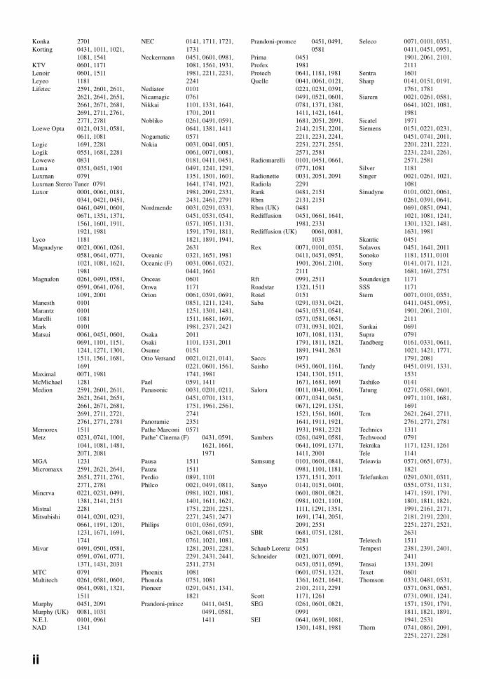
ii
Konka 2701Korting 0431, 1011, 1021,
1081, 1541KTV 0601, 1171Lenoir 0601, 1511Leyeo 1181Lifetec 2591, 2601, 2611,
2621, 2641, 2651,2661, 2671, 2681,2691, 2711, 2761,2771, 2781
Loewe Opta 0121, 0131, 0581,0611, 1081
Logic 1691, 2281Logik 0551, 1681, 2281Lowewe 0831Luma 0351, 0451, 1901Luxman 0791Luxman Stereo Tuner 0791Luxor 0001, 0061, 0181,
0341, 0421, 0451,0461, 0491, 0601,0671, 1351, 1371,1561, 1601, 1911,1921, 1981
Lyco 1181Magnadyne 0021, 0061, 0261,
0581, 0641, 0771,1021, 1081, 1621,1981
Magnafon 0261, 0491, 0581,0591, 0641, 0761,1091, 2001
Manesth 0101Marantz 0101Marelli 1081Mark 0101Matsui 0061, 0451, 0601,
0691, 1101, 1151,1241, 1271, 1301,1511, 1561, 1681,1691
Maximal 0071, 1981McMichael 1281Medion 2591, 2601, 2611,
2621, 2641, 2651,2661, 2671, 2681,2691, 2711, 2721,2761, 2771, 2781
Memorex 1511Metz 0231, 0741, 1001,
1041, 1081, 1481,2071, 2081
MGA 1231Micromaxx 2591, 2621, 2641,
2651, 2711, 2761,2771, 2781
Minerva 0221, 0231, 0491,1381, 2141, 2151
Mistral 2281Mitsubishi 0141, 0201, 0231,
0661, 1191, 1201,1231, 1671, 1691,1741
Mivar 0491, 0501, 0581,0591, 0761, 0771,1371, 1431, 2031
MTC 0791Multitech 0261, 0581, 0601,
0641, 0981, 1321,1511
Murphy 0451, 2091Murphy (UK) 0081, 1031N.E.I. 0101, 0961NAD 1341
NEC 0141, 1711, 1721,1731
Neckermann 0451, 0601, 0981,1081, 1561, 1931,1981, 2211, 2231,2241
Nediator 0101Nicamagic 0761Nikkai 1101, 1331, 1641,
1701, 2011Nobliko 0261, 0491, 0591,
0641, 1381, 1411Nogamatic 0571Nokia 0031, 0041, 0051,
0061, 0071, 0081,0181, 0411, 0451,0491, 1241, 1291,1351, 1501, 1601,1641, 1741, 1921,1981, 2091, 2331,2431, 2461, 2791
Nordmende 0031, 0291, 0331,0451, 0531, 0541,0571, 1051, 1131,1591, 1791, 1811,1821, 1891, 1941,2631
Oceanic 0321, 1651, 1981Oceanic (F) 0031, 0061, 0321,
0441, 1661Onceas 0601Onwa 1171Orion 0061, 0391, 0691,
0851, 1211, 1241,1251, 1301, 1481,1511, 1681, 1691,1981, 2371, 2421
Osaka 2011Osaki 1101, 1331, 2011Osume 0151Otto Versand 0021, 0121, 0141,
0221, 0601, 1561,1741, 1981
Pael 0591, 1411Panasonic 0031, 0201, 0211,
0451, 0701, 1311,1751, 1961, 2561,2741
Panoramic 2351Pathe Marconi 0571Pathe’ Cinema (F) 0431, 0591,
1621, 1661,1971
Pausa 1511Pauza 1511Perdio 0891, 1101Philco 0021, 0491, 0811,
0981, 1021, 1081,1401, 1611, 1621,1751, 2201, 2251,2271, 2451, 2471
Philips 0101, 0361, 0591,0621, 0681, 0751,0761, 1021, 1081,1281, 2031, 2281,2291, 2431, 2441,2511, 2731
Phoenix 1081Phonola 0751, 1081Pioneer 0291, 0451, 1341,
1821Prandoni-prince 0411, 0451,
0491, 0581,1411
Prandoni-promce 0451, 0491,0581
Prima 0451Profex 1981Protech 0641, 1181, 1981Quelle 0041, 0061, 0121,
0221, 0231, 0391,0491, 0521, 0601,0781, 1371, 1381,1411, 1421, 1641,1681, 2051, 2091,2141, 2151, 2201,2211, 2231, 2241,2251, 2271, 2551,2571, 2581
Radiomarelli 0101, 0451, 0661,0771, 1081
Radionette 0031, 2051, 2091Radiola 2291Rank 0481, 2151Rbm 2131, 2151Rbm (UK) 0481Rediffusion 0451, 0661, 1641,
1981, 2331Rediffusion (UK) 0061, 0081,
1031Rex 0071, 0101, 0351,
0411, 0451, 0951,1901, 2061, 2101,2111
Rft 0991, 2511Roadstar 1321, 1511Rotel 0151Saba 0291, 0331, 0421,
0451, 0531, 0541,0571, 0581, 0651,0731, 0931, 1021,1071, 1081, 1131,1791, 1811, 1821,1891, 1941, 2631
Saccs 1971Saisho 0451, 0601, 1161,
1241, 1301, 1511,1671, 1681, 1691
Salora 0011, 0041, 0061,0071, 0341, 0451,0671, 1291, 1351,1521, 1561, 1601,1641, 1911, 1921,1931, 1981, 2321
Sambers 0261, 0491, 0581,0641, 1091, 1371,1411, 2001
Samsung 0101, 0601, 0841,0981, 1101, 1181,1371, 1511, 2011
Sanyo 0141, 0151, 0401,0601, 0801, 0821,0981, 1021, 1101,1111, 1291, 1351,1691, 1741, 2051,2091, 2551
SBR 0681, 0751, 1281,2281
Schaub Lorenz 0451Schneider 0021, 0071, 0091,
0451, 0511, 0591,0601, 0751, 1321,1361, 1621, 1641,2101, 2111, 2291
Scott 1171, 1261SEG 0261, 0601, 0821,
0991SEI 0641, 0691, 1081,
1301, 1481, 1981
Seleco 0071, 0101, 0351,0411, 0451, 0951,1901, 2061, 2101,2111
Sentra 1601Sharp 0141, 0151, 0191,
1761, 1781Siarem 0021, 0261, 0581,
0641, 1021, 1081,1981
Sicatel 1971Siemens 0151, 0221, 0231,
0451, 0741, 2011,2201, 2211, 2221,2231, 2241, 2261,2571, 2581
Silver 1181Singer 0021, 0261, 1021,
1081Sinudyne 0101, 0021, 0061,
0261, 0391, 0641,0691, 0851, 0941,1021, 1081, 1241,1301, 1321, 1481,1631, 1981
Skantic 0451Solavox 0451, 1641, 2011Sonoko 1181, 1511, 0101Sony 0141, 0171, 1121,
1681, 1691, 2751Soundesign 1171SSS 1171Stern 0071, 0101, 0351,
0411, 0451, 0951,1901, 2061, 2101,2111
Sunkai 0691Supra 0791Tandberg 0161, 0331, 0611,
1021, 1421, 1771,1791, 2081
Tandy 0451, 0191, 1331,1531
Tashiko 0141Tatung 0271, 0581, 0601,
0971, 1101, 1681,1691
Tcm 2621, 2641, 2711,2761, 2771, 2781
Technics 1311Techwood 0791Teknika 1171, 1231, 1261Tele 1141Teleavia 0571, 0651, 0731,
1821Telefunken 0291, 0301, 0311,
0551, 0731, 1131,1471, 1591, 1791,1801, 1811, 1821,1991, 2161, 2171,2181, 2191, 2201,2251, 2271, 2521,2631
Teletech 1511Tempest 2381, 2391, 2401,
2411Tensai 1331, 2091Texet 0601Thomson 0331, 0481, 0531,
0571, 0631, 0651,0731, 0901, 1241,1571, 1591, 1791,1811, 1821, 1891,1941, 2531
Thorn 0741, 0861, 2091,2251, 2271, 2281
08V520RDS-code(GB) 2/2/1, 5:44 PM2
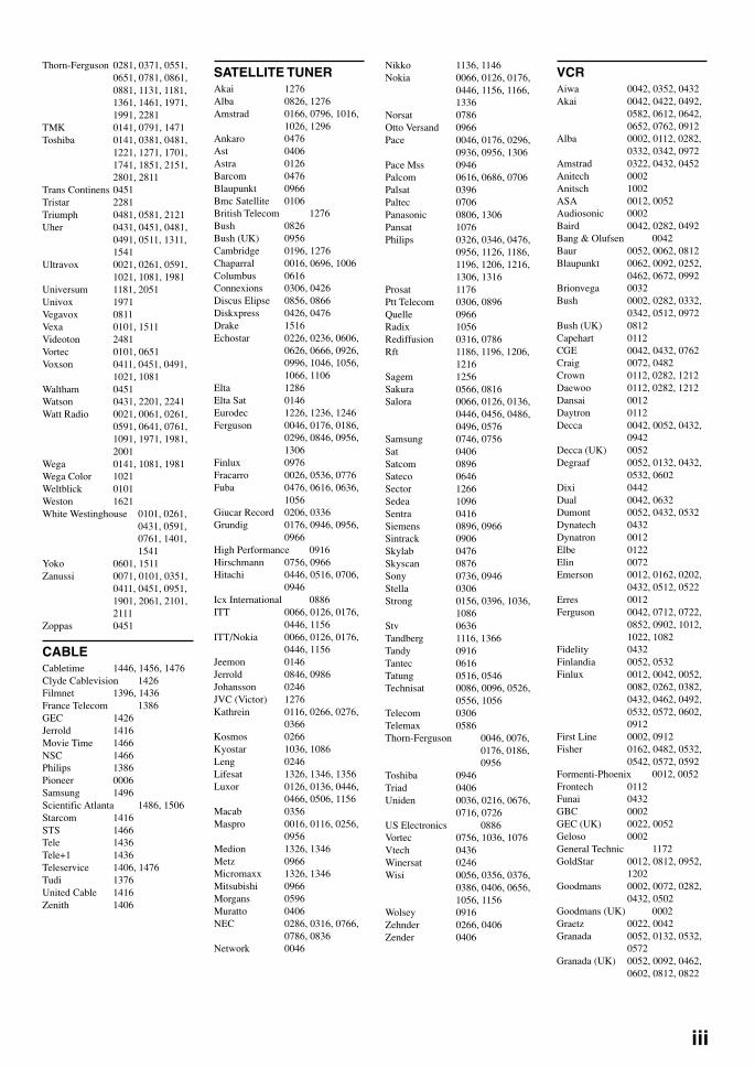
iii
Thorn-Ferguson 0281, 0371, 0551,0651, 0781, 0861,0881, 1131, 1181,1361, 1461, 1971,1991, 2281
TMK 0141, 0791, 1471Toshiba 0141, 0381, 0481,
1221, 1271, 1701,1741, 1851, 2151,2801, 2811
Trans Continens 0451Tristar 2281Triumph 0481, 0581, 2121Uher 0431, 0451, 0481,
0491, 0511, 1311,1541
Ultravox 0021, 0261, 0591,1021, 1081, 1981
Universum 1181, 2051Univox 1971Vegavox 0811Vexa 0101, 1511Videoton 2481Vortec 0101, 0651Voxson 0411, 0451, 0491,
1021, 1081Waltham 0451Watson 0431, 2201, 2241Watt Radio 0021, 0061, 0261,
0591, 0641, 0761,1091, 1971, 1981,2001
Wega 0141, 1081, 1981Wega Color 1021Weltblick 0101Weston 1621White Westinghouse 0101, 0261,
0431, 0591,0761, 1401,1541
Yoko 0601, 1511Zanussi 0071, 0101, 0351,
0411, 0451, 0951,1901, 2061, 2101,2111
Zoppas 0451
CABLECabletime 1446, 1456, 1476Clyde Cablevision 1426Filmnet 1396, 1436France Telecom 1386GEC 1426Jerrold 1416Movie Time 1466NSC 1466Philips 1386Pioneer 0006Samsung 1496Scientific Atlanta 1486, 1506Starcom 1416STS 1466Tele 1436Tele+1 1436Teleservice 1406, 1476Tudi 1376United Cable 1416Zenith 1406
SATELLITE TUNERAkai 1276Alba 0826, 1276Amstrad 0166, 0796, 1016,
1026, 1296Ankaro 0476Ast 0406Astra 0126Barcom 0476Blaupunkt 0966Bmc Satellite 0106British Telecom 1276Bush 0826Bush (UK) 0956Cambridge 0196, 1276Chaparral 0016, 0696, 1006Columbus 0616Connexions 0306, 0426Discus Elipse 0856, 0866Diskxpress 0426, 0476Drake 1516Echostar 0226, 0236, 0606,
0626, 0666, 0926,0996, 1046, 1056,1066, 1106
Elta 1286Elta Sat 0146Eurodec 1226, 1236, 1246Ferguson 0046, 0176, 0186,
0296, 0846, 0956,1306
Finlux 0976Fracarro 0026, 0536, 0776Fuba 0476, 0616, 0636,
1056Giucar Record 0206, 0336Grundig 0176, 0946, 0956,
0966High Performance 0916Hirschmann 0756, 0966Hitachi 0446, 0516, 0706,
0946Icx International 0886ITT 0066, 0126, 0176,
0446, 1156ITT/Nokia 0066, 0126, 0176,
0446, 1156Jeemon 0146Jerrold 0846, 0986Johansson 0246JVC (Victor) 1276Kathrein 0116, 0266, 0276,
0366Kosmos 0266Kyostar 1036, 1086Leng 0246Lifesat 1326, 1346, 1356Luxor 0126, 0136, 0446,
0466, 0506, 1156Macab 0356Maspro 0016, 0116, 0256,
0956Medion 1326, 1346Metz 0966Micromaxx 1326, 1346Mitsubishi 0966Morgans 0596Muratto 0406NEC 0286, 0316, 0766,
0786, 0836Network 0046
Nikko 1136, 1146Nokia 0066, 0126, 0176,
0446, 1156, 1166,1336
Norsat 0786Otto Versand 0966Pace 0046, 0176, 0296,
0936, 0956, 1306Pace Mss 0946Palcom 0616, 0686, 0706Palsat 0396Paltec 0706Panasonic 0806, 1306Pansat 1076Philips 0326, 0346, 0476,
0956, 1126, 1186,1196, 1206, 1216,1306, 1316
Prosat 1176Ptt Telecom 0306, 0896Quelle 0966Radix 1056Rediffusion 0316, 0786Rft 1186, 1196, 1206,
1216Sagem 1256Sakura 0566, 0816Salora 0066, 0126, 0136,
0446, 0456, 0486,0496, 0576
Samsung 0746, 0756Sat 0406Satcom 0896Sateco 0646Sector 1266Sedea 1096Sentra 0416Siemens 0896, 0966Sintrack 0906Skylab 0476Skyscan 0876Sony 0736, 0946Stella 0306Strong 0156, 0396, 1036,
1086Stv 0636Tandberg 1116, 1366Tandy 0916Tantec 0616Tatung 0516, 0546Technisat 0086, 0096, 0526,
0556, 1056Telecom 0306Telemax 0586Thorn-Ferguson 0046, 0076,
0176, 0186,0956
Toshiba 0946Triad 0406Uniden 0036, 0216, 0676,
0716, 0726US Electronics 0886Vortec 0756, 1036, 1076Vtech 0436Winersat 0246Wisi 0056, 0356, 0376,
0386, 0406, 0656,1056, 1156
Wolsey 0916Zehnder 0266, 0406Zender 0406
VCRAiwa 0042, 0352, 0432Akai 0042, 0422, 0492,
0582, 0612, 0642,0652, 0762, 0912
Alba 0002, 0112, 0282,0332, 0342, 0972
Amstrad 0322, 0432, 0452Anitech 0002Anitsch 1002ASA 0012, 0052Audiosonic 0002Baird 0042, 0282, 0492Bang & Olufsen 0042Baur 0052, 0062, 0812Blaupunkt 0062, 0092, 0252,
0462, 0672, 0992Brionvega 0032Bush 0002, 0282, 0332,
0342, 0512, 0972Bush (UK) 0812Capehart 0112CGE 0042, 0432, 0762Craig 0072, 0482Crown 0112, 0282, 1212Daewoo 0112, 0282, 1212Dansai 0012Daytron 0112Decca 0042, 0052, 0432,
0942Decca (UK) 0052Degraaf 0052, 0132, 0432,
0532, 0602Dixi 0442Dual 0042, 0632Dumont 0052, 0432, 0532Dynatech 0432Dynatron 0012Elbe 0122Elin 0072Emerson 0012, 0162, 0202,
0432, 0512, 0522Erres 0012Ferguson 0042, 0712, 0722,
0852, 0902, 1012,1022, 1082
Fidelity 0432Finlandia 0052, 0532Finlux 0012, 0042, 0052,
0082, 0262, 0382,0432, 0462, 0492,0532, 0572, 0602,0912
First Line 0002, 0912Fisher 0162, 0482, 0532,
0542, 0572, 0592Formenti-Phoenix 0012, 0052Frontech 0112Funai 0432GBC 0002GEC (UK) 0022, 0052Geloso 0002General Technic 1172GoldStar 0012, 0812, 0952,
1202Goodmans 0002, 0072, 0282,
0432, 0502Goodmans (UK) 0002Graetz 0022, 0042Granada 0052, 0132, 0532,
0572Granada (UK) 0052, 0092, 0462,
0602, 0812, 0822
08V520RDS-code(GB) 2/2/1, 5:44 PM3

iv
Grundig 0052, 0062, 0092,0232, 0252, 0262,0752, 0802
Hanseatic 0052, 0812Harman/Kardon 0922, 1202Hcm 0002Hinari 0002, 0202, 0412,
0442, 0522Hitachi 0042, 0172, 0292,
0432, 0602, 0662,0812, 1022
Imperial 0072, 0432Ingersol 0442Inno Hit 0002, 0052, 0072Innovation 1142, 1162, 1172Interfunk 0022, 0052Irradio 0002, 0012ITT 0022, 0032, 0042,
0072, 0292, 0492,0532, 0572, 0762
ITT-Nokia 0022, 0032, 0042,0072, 0292, 0492,0532, 0572, 0762
Jensen 0042JVC (Victor) 0042, 0102, 0142,
0272, 0742, 0762,0782, 0902
Karcher 0052, 0072, 0812Kendo 0492Kenwood 0042, 0142, 0572Lifetec 1142, 1162, 1172Lloyd 0432Loewe Opta 0052, 0092, 0152Logik 0002, 0072, 0442Luma 0162Luxor 0492, 0572, 0812M Electronic 0432Magnadyne 0052Magnasonic 0572Manesth 0012Marantz 0012, 0052, 0092,
0502, 1202Mark 0012Marta 0012Matsui 0012, 0442, 0512,
0522, 0812, 0972Medion 1142, 1162, 1172Memorex 0012, 0132, 0432,
0482, 0532, 0572Metz 0062, 0092, 0932MGA 0912Micromaxx 1142, 1162, 1172Minerva 0062, 0092, 0252Minolta 0172, 0602Mitsubishi 0052, 0062, 0142,
0912, 0922MTC 0072, 0432Multitech 0002, 0052, 0062,
0282, 0432Murphy 0432N.E.I. 0012, 0052National 0462NEC 0042, 0122, 0142,
1202Neckermann 0032, 0042, 0052,
0072, 0092, 0202,0522, 0572, 0762,0812
Nikkai 0112Nobliko 0092Nokia 0022, 0032, 0042,
0072, 0292, 0492,0532, 0572, 0762,1152
Nordmende 0042, 0102, 0142,0192, 0222, 0242,0392, 0402, 0632,0732, 0742, 0762,0782, 0792, 0832,0842, 0872
Olympus 0462Optonica 0132, 0502Orion 0162, 0202, 0312,
0442, 0512, 0522,0982
Osaka 0432Osaki 0002, 0012, 0432Otto Versand 0052, 0062, 0812Panasonic 0022, 0212, 0462,
0672, 0992, 1092,1102, 1182
Pentax 0172, 0602Perdio 0432Philco 1062Philips 0052, 0082, 0092,
0152, 0182, 0362,0372, 0472, 0502,1072
Phonola 0052, 0152Pilot 0012Pioneer 0052, 0142, 0372,
0472Portland 0112Proline 0432Pye 0052, 0152Quartz 0572Quelle 0012, 0032, 0042,
0052, 0062, 0072,0092, 0202, 0462,0552, 0942
Radionette 0022Realistic 0012, 0072, 0132,
0432, 0482, 0502,0532, 0572
Ret 1072Rex 0042, 0742, 0782Ricoh 0952Saba 0042, 0142, 0192,
0222, 0242, 0392,0632, 0732, 0742,0762, 0772, 0782,0792, 0872
Saisho 0162, 0202, 0292,0442, 0512, 0522,0972
Salora 0192, 0572, 0812,0822, 0912
Samsung 0052, 0072, 0652,1192, 1212
Sansui 0042, 0142Sanyo 0482, 0532, 0562,
0572SBR 0052, 0152, 0182Schaub Lorenz 0022, 0042Schneider 0002, 0012, 0052,
0072, 0432SEG 0002, 0072Sei-Sinudyne 0442Seleco 0042Sentra 0112Sharp 0132, 0502, 0702Shintom 0002Siemens 0062, 0092, 0252,
0572Sinudyne 0052, 0382, 0442,
0932Sonoko 0282Sony 0432, 0552, 0682,
0692, 0942, 0952,0962, 1122, 1132
STS 0602Sunkai 0512Sunstar 0432Sylvania 0432, 0912Symphonic 0432, 0912Tandegerg 0062, 0162, 0522,
0932Tashiko 0132, 0432Tatung 0042, 0052, 0432,
0922TCM 1142, 1162, 1172Teac 0042, 0432Technics 0462Teknika 0012, 0432Telefunken 0042, 0192, 0632,
0732, 0742, 0762,0782, 0882, 0892
Tempest 1032, 1042, 1052Tenosal 0002Thomson 0042, 0102, 0142,
0192, 0402, 0632,0762
Thorn 0042, 0902Thorn-Ferguson 0042, 0222, 0302,
0712, 0722, 0742,0762, 0852, 0862,0872, 0902
TMK 0522Tonsai 0002Toshiba 0042, 0622, 0912,
1212Totevision 0012, 0072Triumph 0922Uher 0042, 0072Ulravox 0032Unitech 0072Vector Research 0122Videon 1162, 1172Weltblick 0012White Westinghouse 0032Xenon 0162Yamaha 0042, 1202Yoko 0012, 0062, 0072
DVD PLAYERAkai 0108Denon 0368Hitachi 0388JVC (Victor) 0168, 0348Kenwood 0288Magnavox 0248Mitsubishi 0268Onkyo 0128, 0248Panasonic 0048Philips 0188, 0248Pioneer 0208, 0228Proscan 0308RCA 0067, 0308Samsung 0148Sharp 0068Sony 0028Technics 0048Thomson 0328Toshiba 0088, 0248Yamaha 0008, 0048, 0188,
0248Zenith 0248
LD PLAYERAiwa 0137Funai 0137Hitachi 0047Magnavox 0077Panasonic 0027Pioneer 0037Realistic 0137Samsung 0017, 0087Sony 0057, 0097, 0107,
0117Victor 0127Yamaha 0007
CD PLAYERAccuphase 0315Adc 0865Adcom 0785, 1015Akai 0115, 0125, 0725,
0735, 0745, 0935,1155
Arcam 1875Arcam-Rotel 0165Audio-Technica 0835Audiosonic 0155Awia 1105, 1235, 1245,
1765, 1915, 1935BSR 0875California Audio Lab 1075Carrera 0555, 0875Carver 0825, 1415Cyrus-Rotel 0205Denon 0045, 0955, 1045,
1595, 1795, 1805Dual 1005Elin 0185Emerson 1015, 1285, 1675Fisher 0105, 0595, 0605,
0825, 1165, 1175Genexxa 0525, 0825, 0855,
0875, 0995, 1265,1285, 1345, 1355,1485, 1575, 1675,1715, 1825
GoldStar 0555, 1185, 1195,1585
Grundig 0175Harman Kardon 0495, 0565, 0325,
1135, 1145, 1155Hitachi 0065, 0585, 0685,
0945, 1005, 1015,1225, 1545
Innovation 1995, 2005, 2015ITT-Nokia 0185JVC (Victor) 0385, 0395, 0455,
0575, 0585Karcher 0485Kenwood 0025, 0055, 0145,
0215, 0595, 0675,0695, 0705, 0715,0925, 1355, 1485,1575, 1675, 1715,1825
Korting 0175Lifetec 2015Light Control 1155, 1645, 1655,
1665Linn 0165, 1875Luxman 0265, 0275, 0795,
0805, 1295, 1305,1555, 1925
Luxor 0185, 1895, 1905Magnavox 1865, 1875
08V520RDS-code(GB) 2/2/1, 7:24 PM4
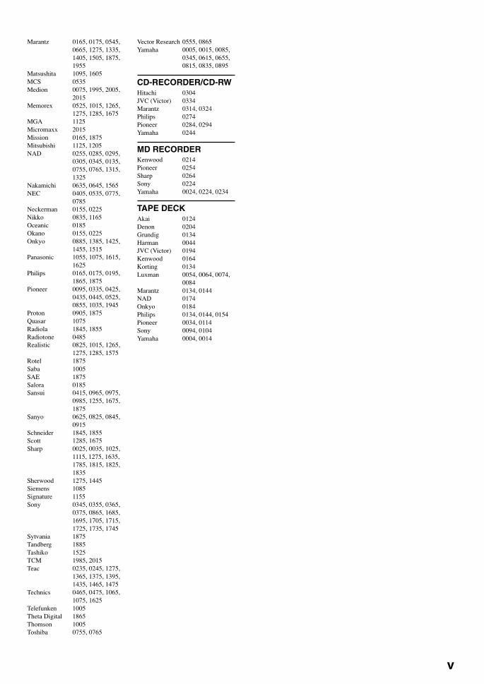
v
Marantz 0165, 0175, 0545,0665, 1275, 1335,1405, 1505, 1875,1955
Matsushita 1095, 1605MCS 0535Medion 0075, 1995, 2005,
2015Memorex 0525, 1015, 1265,
1275, 1285, 1675MGA 1125Micromaxx 2015Mission 0165, 1875Mitsubishi 1125, 1205NAD 0255, 0285, 0295,
0305, 0345, 0135,0755, 0765, 1315,1325
Nakamichi 0635, 0645, 1565NEC 0405, 0535, 0775,
0785Neckerman 0155, 0225Nikko 0835, 1165Oceanic 0185Okano 0155, 0225Onkyo 0885, 1385, 1425,
1455, 1515Panasonic 1055, 1075, 1615,
1625Philips 0165, 0175, 0195,
1865, 1875Pioneer 0095, 0335, 0425,
0435, 0445, 0525,0855, 1035, 1945
Proton 0905, 1875Quasar 1075Radiola 1845, 1855Radiotone 0485Realistic 0825, 1015, 1265,
1275, 1285, 1575Rotel 1875Saba 1005SAE 1875Salora 0185Sansui 0415, 0965, 0975,
0985, 1255, 1675,1875
Sanyo 0625, 0825, 0845,0915
Schneider 1845, 1855Scott 1285, 1675Sharp 0025, 0035, 1025,
1115, 1275, 1635,1785, 1815, 1825,1835
Sherwood 1275, 1445Siemens 1085Signature 1155Sony 0345, 0355, 0365,
0375, 0865, 1685,1695, 1705, 1715,1725, 1735, 1745
Sytvania 1875Tandberg 1885Tashiko 1525TCM 1985, 2015Teac 0235, 0245, 1275,
1365, 1375, 1395,1435, 1465, 1475
Technics 0465, 0475, 1065,1075, 1625
Telefunken 1005Theta Digital 1865Thomson 1005Toshiba 0755, 0765
Vector Research 0555, 0865Yamaha 0005, 0015, 0085,
0345, 0615, 0655,0815, 0835, 0895
CD-RECORDER/CD-RWHitachi 0304JVC (Victor) 0334Marantz 0314, 0324Philips 0274Pioneer 0284, 0294Yamaha 0244
MD RECORDERKenwood 0214Pioneer 0254Sharp 0264Sony 0224Yamaha 0024, 0224, 0234
TAPE DECKAkai 0124Denon 0204Grundig 0134Harman 0044JVC (Victor) 0194Kenwood 0164Korting 0134Luxman 0054, 0064, 0074,
0084Marantz 0134, 0144NAD 0174Onkyo 0184Philips 0134, 0144, 0154Pioneer 0034, 0114Sony 0094, 0104Yamaha 0004, 0014
08V520RDS-code(GB) 2/2/1, 5:44 PM5

YAMAHA ELECTRONICS CORPORATION, USA 6660 ORANGETHORPE AVE., BUENA PARK, CALIF. 90620, U.S.A.YAMAHA CANADA MUSIC LTD. 135 MILNER AVE., SCARBOROUGH, ONTARIO M1S 3R1, CANADAYAMAHA ELECTRONIK EUROPA G.m.b.H. SIEMENSSTR. 22-34, 25462 RELLINGEN BEI HAMBURG, F.R. OF GERMANYYAMAHA ELECTRONIQUE FRANCE S.A. RUE AMBROISE CROIZAT BP70 CROISSY-BEAUBOURG 77312 MARNE-LA-VALLEE CEDEX02, FRANCEYAMAHA ELECTRONICS (UK) LTD. YAMAHA HOUSE, 200 RICKMANSWORTH ROAD WATFORD, HERTS WD1 7JS, ENGLANDYAMAHA SCANDINAVIA A.B. J A WETTERGRENS GATA 1, BOX 30053, 400 43 VÄSTRA FRÖLUNDA, SWEDENYAMAHA MUSIC AUSTRALIA PTY, LTD. 17-33 MARKET ST., SOUTH MELBOURNE, 3205 VIC., AUSTRALIA
RX-V520RDSNatural Sound AV ReceiverAmpli-tuner audio-vidéo
G B
OWNER’S MANUALMODE D’EMPLOI
BEDIENUNGSANLEITUNGBRUKSANVISNING
MANUALE DI ISTRUZIONIMANUAL DE INSTRUCCIONES
GEBRUIKSAANWIJZING
RX
-V5
20R
DS
Printed in Malaysia ID V723020
00RX-V520RDS(ML)-cv1/4 2/1/1, 4:41 PM1
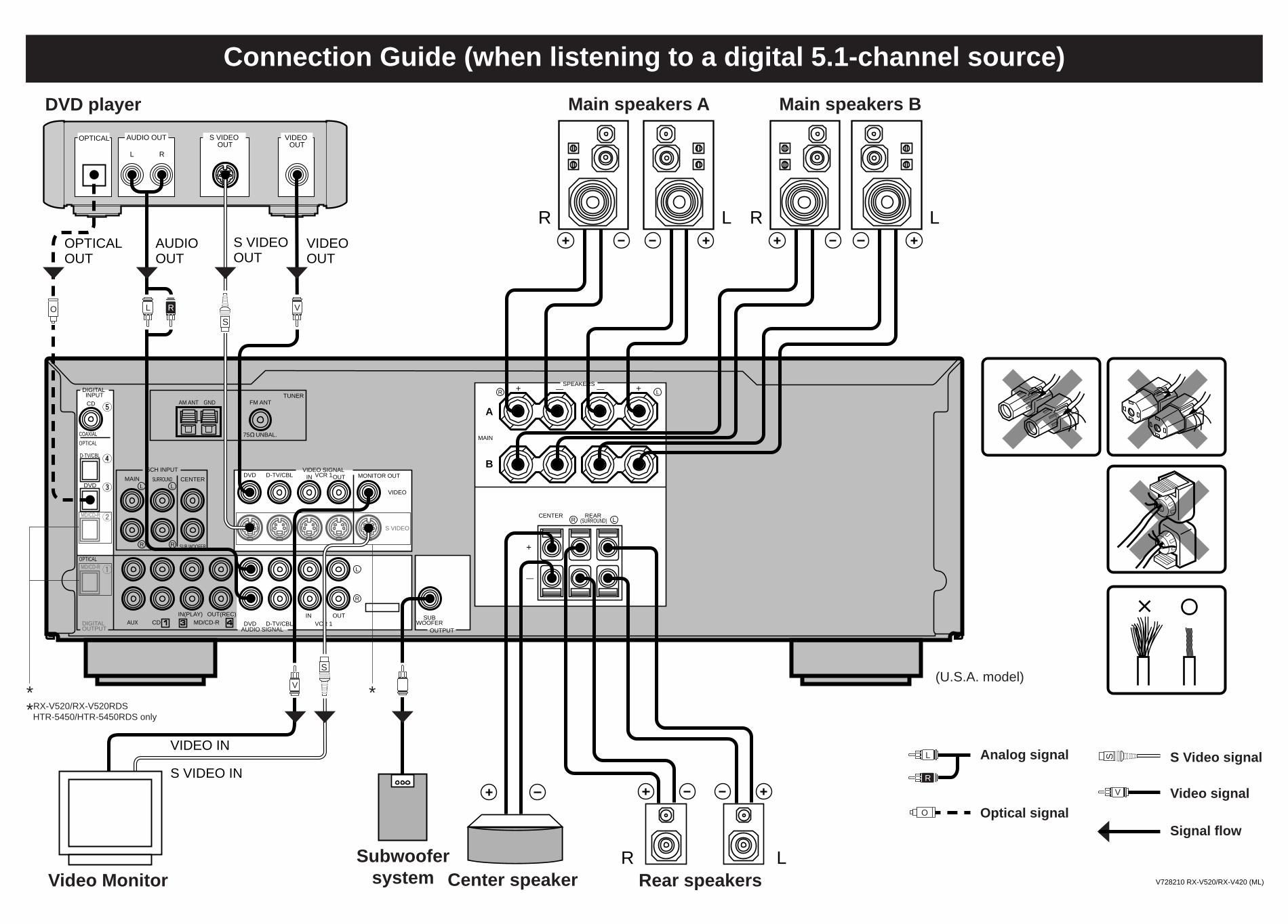
*
SPEAKERS
MAIN
+ —R L
A
— +
B
CENTER REAR (SURROUND)R L
+
—
S VIDEO
VIDEO
MONITOR OUTDVD
DVD
DVD
D-TV/CBL
D-TV/CBL
D-TV/CBL
IN VCR 1OUTVIDEO SIGNAL
AUDIO SIGNAL
SUBWOOFER
OUTPUT
INVCR 1
OUTOUT(REC)IN(PLAY)CDAUX MD/CD-R
MD/CD-R
MD/CD-R
DIGITAL OUTPUT
OPTICAL
OPTICAL
COAXIAL
AM ANT GND FM ANT
75 UNBAL.
TUNER
MAIN CENTER
SUB WOOFER
SURROUND
DIGITAL INPUT
6CH INPUT
CD
R
L
R
L
R
L
L R
AUDIO OUT S VIDEO OUT
VIDEO OUT
OPTICAL
V
V
AUDIO OUT
S VIDEO IN
VIDEO IN
S VIDEOOUT
VIDEOOUT
OPTICAL OUT
R L R L
DVD player Main speakers A Main speakers B
R LRear speakers
Video signalOptical signal
Signal flow
Center speakerSubwoofer
systemVideo Monitor
Connection Guide (when listening to a digital 5.1-channel source)
L
R
V
Analog signal
(U.S.A. model)
S Video signal
L R
S
S
O
O
S
*RX-V520/RX-V520RDSHTR-5450/HTR-5450RDS only
*
V728210 RX-V520/RX-V420 (ML)

SLEEP
TESTA/B/C/D/E
MUTE
VOLUME
–/+
POWER
TIME/LEVEL
Quick Reference Card
DISPLAY (MD)SLEEP
EFFECT
MUTE TV VOLUME
VOLUME
POWER
REC/PAUSEPLAY
DIR A (TAPE)SKIP– (MD)
REWIND (TAPE)SEARCH (MD)
PAUSE (MD)
DECK A/B (TAPE)
DIR B (TAPE)SKIP+ (MD)
STOP
FAST FORWARD (TAPE)SEARCH (MD)
TAPE/MD
DISPLAYSLEEP
EFFECT
MUTE TV VOLUME
VOLUME
POWER
PLAYSKIP–
SEARCH
PAUSE
TV INPUT
SKIP+
STOP
SEARCH
CD
DISC SKIP–/+
DVD/LD
DISPLAYSLEEP
EFFECT
MUTE TV VOLUME
VOLUME
POWER
PLAYSKIP–
SEARCH
PAUSE
TV INPUT
SKIP+
STOP
SEARCH
DISC SKIP–/+
V728130
SETMENU
EFFECT
6CH INPUT
PRESET–/+
TV VOLUME
PRG+,PRG–
Input selector buttons
TV INPUT
AMP(TUNER)
6CH INPUT
Input selector buttons
6CH INPUT
Input selector buttons
6CH INPUT
Input selector buttons
V520(Q)_Quick 2/1/1, 1:37 PM1
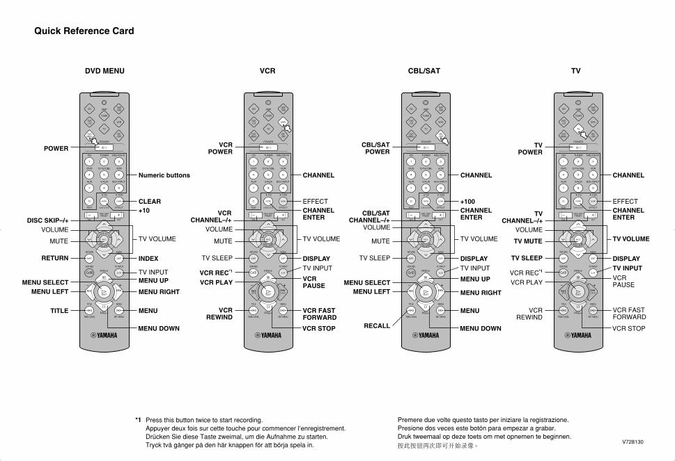
Quick Reference Card
RETURN
TITLE
CLEAR
INDEX
+10
MUTE TV VOLUMEVOLUME
DISC SKIP–/+
POWER
Numeric buttons
TV INPUT
DVD MENU
MENU SELECTMENU LEFT MENU RIGHT
MENU DOWN
MENU
MENU UP
CHANNEL
CBL/SAT CHANNEL–/+
DISPLAYTV SLEEP
+100
MUTE TV VOLUME
VOLUME
CBL/SAT POWER
MENU SELECTMENU LEFT
RECALL
MENU UP
TV INPUT
MENU RIGHT
MENU DOWN
MENU
CBL/SAT
CHANNEL ENTER
VCR REC
TV
DISPLAYTV SLEEP
EFFECT
TV MUTE TV VOLUMEVOLUME
TV POWER
VCR PLAY
VCR REWIND
CHANNEL
VCR PAUSE
TV INPUT
VCR STOP
VCR FAST FORWARD
TV CHANNEL–/+
CHANNEL ENTER
*1
DISPLAYTV SLEEP
EFFECTCHANNEL ENTER
MUTE TV VOLUME
VOLUME
VCR POWER
VCR PLAY
VCR REWIND
CHANNEL
VCR PAUSE
TV INPUT
VCR STOP
VCR FAST FORWARD
VCR CHANNEL–/+
VCR
VCR REC*1
Press this button twice to start recording.Appuyer deux fois sur cette touche pour commencer l’enregistrement.Drücken Sie diese Taste zweimal, um die Aufnahme zu starten.Tryck två gånger på den här knappen för att börja spela in. V728130
*1 Premere due volte questo tasto per iniziare la registrazione.Presione dos veces este botón para empezar a grabar.Druk tweemaal op deze toets om met opnemen te beginnen.
V520(Q)_Quick 2/1/1, 1:38 PM2
Related Documents