A Design presentation on Natural Gas Processing Plant Presented by : Abdulla-Al-mamun St. ID: 0802021 Dept: Ch.E. BUET

Natural gas processing plant Presentation
Dec 12, 2015
Thesis Defense presentation
Welcome message from author
This document is posted to help you gain knowledge. Please leave a comment to let me know what you think about it! Share it to your friends and learn new things together.
Transcript
A Design presentation on
Natural Gas Processing Plant
Presented by :
Abdulla-Al-mamun
St. ID: 0802021
Dept: Ch.E.
BUET
Objectives
By using Aspen hysis simulation
Ensuring more efficient and profitability design.
Improving plant control, operability.
Eliminating process bottle necks and minimizing process network.
Reducing human error and time requirement.
Definition of the project
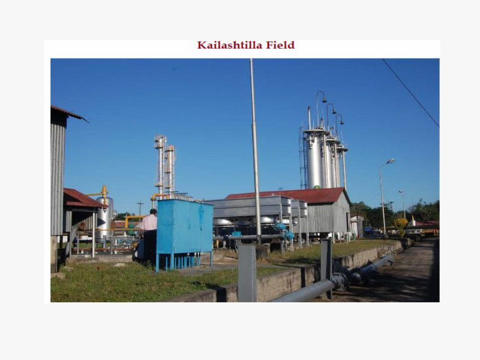
Location- Kailashtilla, Sylhet
Capacity-550 MMSCFD
Raw materials-Raw Natural Gas From 3 Producing Gas Wells
DEAmine Solution, TEG.
Utility- Electricity(2 MW Capacity), Natural Gas.

Available Process
Gas Sweetening
Solid Bed Sweetening Process:
Molucular Sieves
Aquasorption Process (Wash Water
Process)
Selexol Process
Chemical Absorption
Process(MEA,DEA,TEA Processes)
The Holmes-Stretford Process
Gas Dehydration
Absorption Process(Methanol,
Glycol Process)
Adsorption Process (Solid
Dessicants, Alumina, Silica Gel,
Molecular Sieves)

Design Basis
Climate Condition-
Ambient Temperature- Max- 35OC
Min-12OC
Design max temp- 40OC
min temp-5OC
Annual Avg. Atmospheric pressure-0.11 MPa
Annual Avg. relative Humidity- 80%
Wind Velocity-52 miles/hr
Rain- Annual Avg. Rainfall- 2850 mm

Process Block Diagram

Hysis Simulation
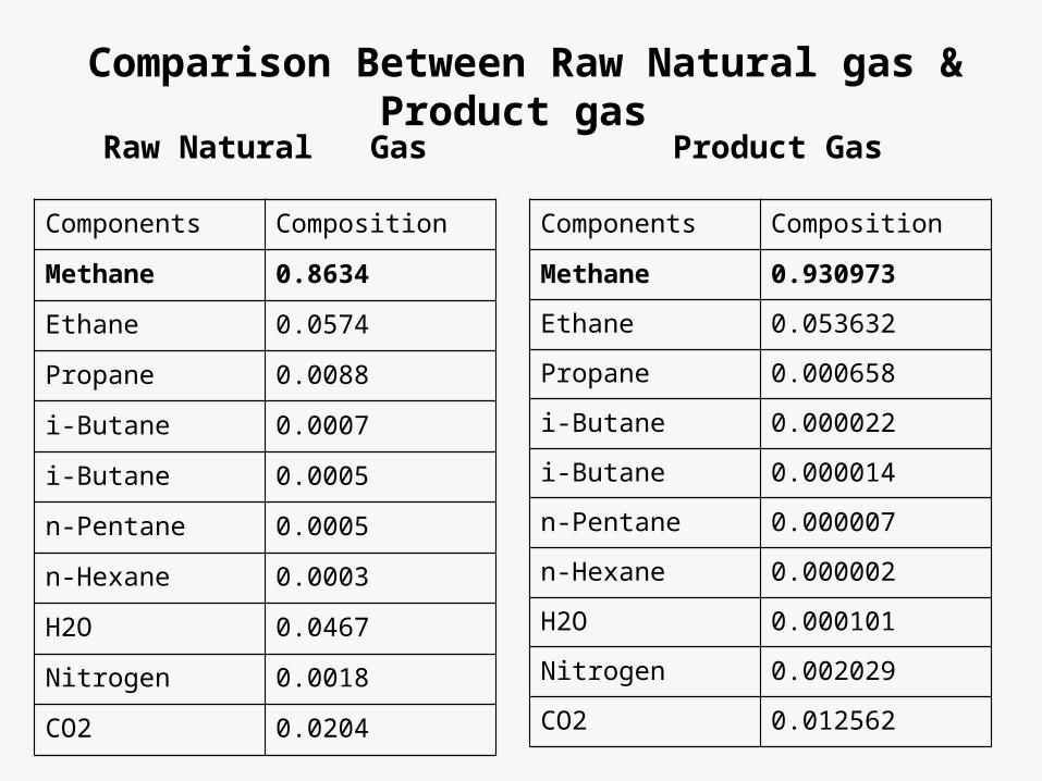
Comparison Between Raw Natural gas & Product gas
Raw Natural Gas
Components Composition
Methane 0.8634
Ethane 0.0574
Propane 0.0088
i-Butane 0.0007
i-Butane 0.0005
n-Pentane 0.0005
n-Hexane 0.0003
H2O 0.0467
Nitrogen 0.0018
CO2 0.0204
Product Gas
Components Composition
Methane 0.930973
Ethane 0.053632
Propane 0.000658
i-Butane 0.000022
i-Butane 0.000014
n-Pentane 0.000007
n-Hexane 0.000002
H2O 0.000101
Nitrogen 0.002029
CO2 0.012562

List of Equipment
Equipment Name QuantityDesignation in the HYSYS Simulation
Compressor 1 K-100
Heat Exchanger 2 E-100, E-102
Absorber 2 T-100, T-102
Separator 3 V-100, V-101, V-104
Pump 2 P-100, P-101
Storage Tank 1 V-106
Stripper Column 2 V-102, V-103
Stabilizer Column 1 V-105
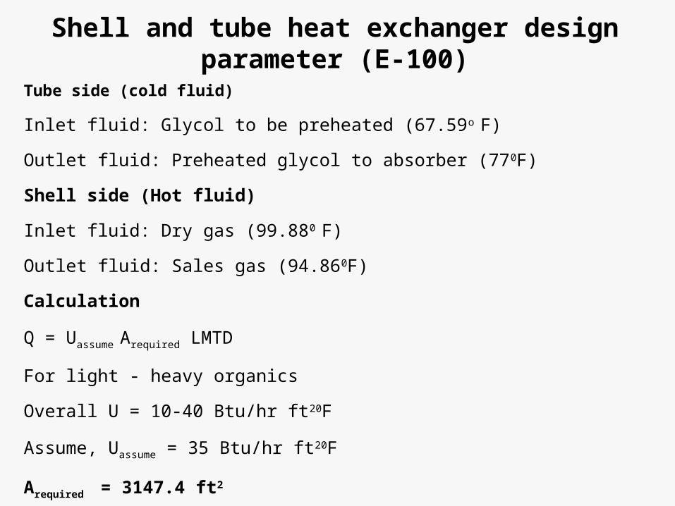
Shell and tube heat exchanger design parameter (E-100)
Tube side (cold fluid)
Inlet fluid: Glycol to be preheated (67.59o F)
Outlet fluid: Preheated glycol to absorber (770F)
Shell side (Hot fluid)
Inlet fluid: Dry gas (99.880 F)
Outlet fluid: Sales gas (94.860F)
Calculation
Q = Uassume Arequired LMTD
For light - heavy organics
Overall U = 10-40 Btu/hr ft20F
Assume, Uassume = 35 Btu/hr ft20F
Arequired = 3147.4 ft2
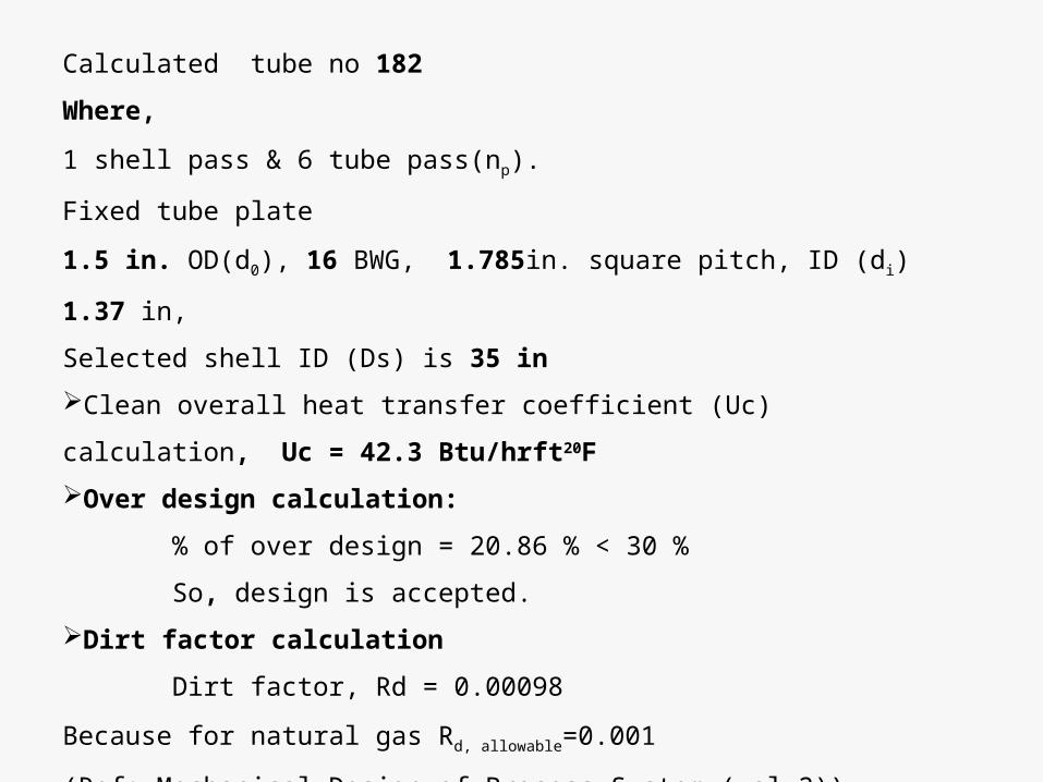
Calculated tube no 182
Where,
1 shell pass & 6 tube pass(np).
Fixed tube plate
1.5 in. OD(d0), 16 BWG, 1.785in. square pitch, ID (di) 1.37 in,
Selected shell ID (Ds) is 35 in
Clean overall heat transfer coefficient (Uc) calculation, Uc = 42.3 Btu/hrft20F
Over design calculation:
% of over design = 20.86 % < 30 %
So, design is accepted.
Dirt factor calculation
Dirt factor, Rd = 0.00098
Because for natural gas Rd, allowable=0.001
(Ref: Mechanical Design of Process System (vol-2))
Therefore, Rd is acceptable.
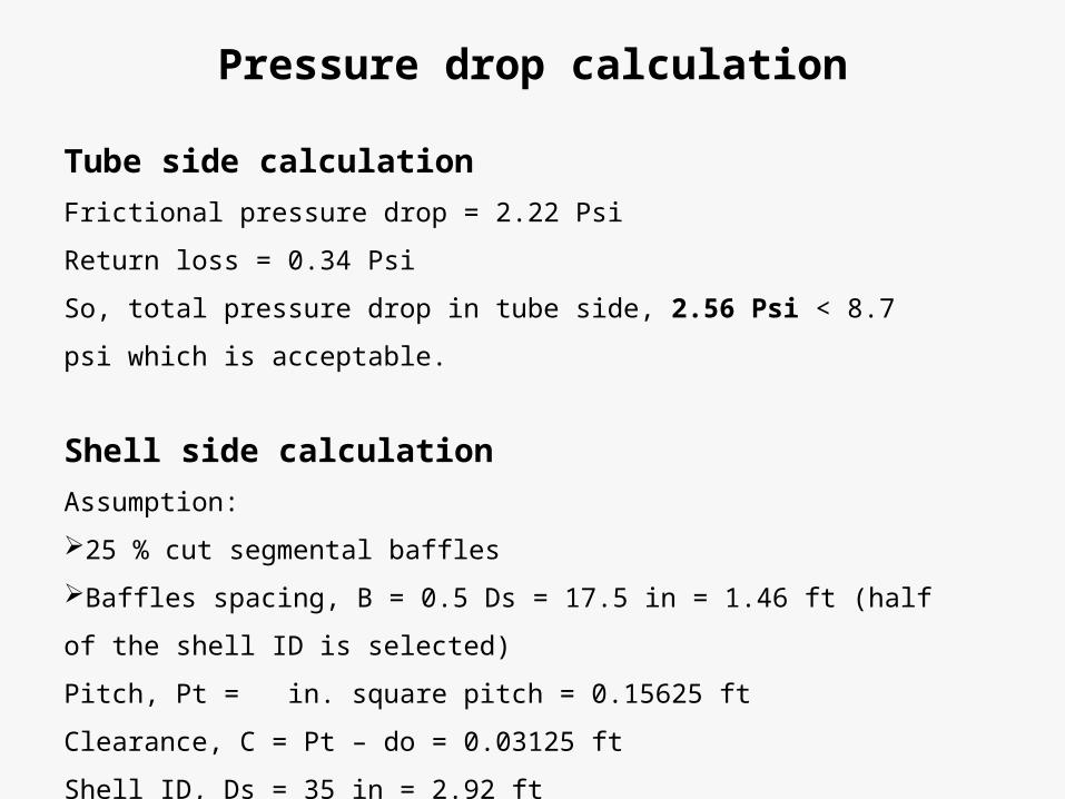
Pressure drop calculation
Tube side calculation
Frictional pressure drop = 2.22 Psi
Return loss = 0.34 Psi
So, total pressure drop in tube side, 2.56 Psi < 8.7 psi which is acceptable.
Shell side calculation
Assumption:
25 % cut segmental baffles
Baffles spacing, B = 0.5 Ds = 17.5 in = 1.46 ft (half of the shell ID is selected)
Pitch, Pt = in. square pitch = 0.15625 ft
Clearance, C = Pt – do = 0.03125 ft
Shell ID, Ds = 35 in = 2.92 ft
So, pressure drop = 9.38 Psi < 14.5 Psi, which is acceptable.
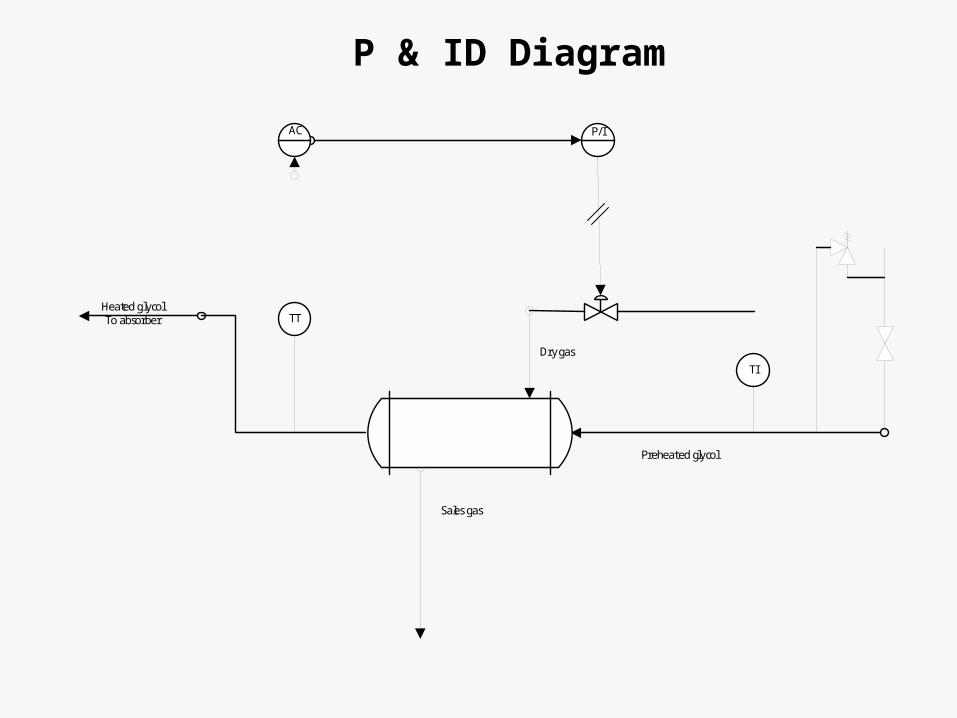
P & ID Diagram
TT
TI
AC P/I
Preheated glycol
Heated glycolTo absorber
Dry gas
Sales gas
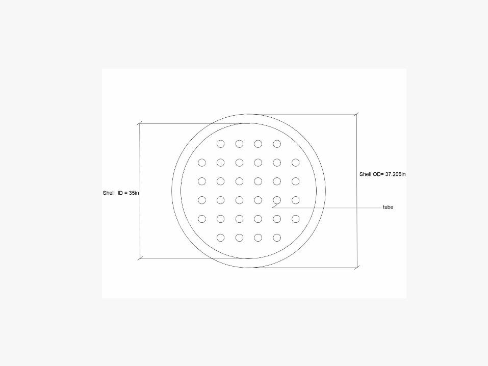

Figure: 1 shell pass - 6 tube pass heat exchanger
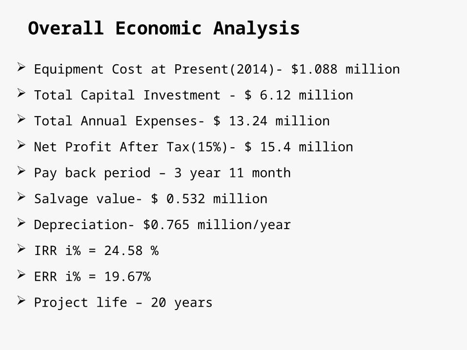
Overall Economic Analysis
Equipment Cost at Present(2014)- $1.088 million
Total Capital Investment - $ 6.12 million
Total Annual Expenses- $ 13.24 million
Net Profit After Tax(15%)- $ 15.4 million
Pay back period – 3 year 11 month
Salvage value- $ 0.532 million
Depreciation- $0.765 million/year
IRR i% = 24.58 %
ERR i% = 19.67%
Project life – 20 years

The End
Related Documents


![Radiation Modification of Natural Polymers - Hacettepe · matrix, plant growth stimulator ... CHITOSAN Food processing, ... Topic: Radiation Modification of Natural Polymers [13]](https://static.cupdf.com/doc/110x72/5ac116db7f8b9a1c768c7345/radiation-modification-of-natural-polymers-plant-growth-stimulator-chitosan.jpg)