CCAC O&G Methane Partnership – Technical Guidance Document Number 1: Natural Gas Driven Pneumatic Controllers and Pumps Modified: March 2017 Page 1 of 20 SG17.1. 1 TECHNICAL GUIDANCE DOCUMENT NUMBER 1: NATURAL GAS-DRIVEN PNEUMATIC CONTROLLERS AND PUMPS Introduction This document provides technical guidance to Partners of the CCAC Oil and Gas Methane Partnership (OGMP). It is one in a series describing a core source of methane emissions from oil and natural gas production operations. The guidance documents introduce suggested methodologies for quantifying methane emissions from specific sources and describe established mitigation options that Partners should reference when determining if the source is “mitigated.” 1 The OGMP recognizes that the equipment and processes described in these documents are found in a variety of oil and gas operations, including onshore, offshore, and remote operations, and the way in which the emissions are quantified and mitigated may vary across locations and operational environments. As such, operational conditions, as well as logistical, safety and cost considerations, must be evaluated on a case-by-case basis. The OGMP assumes that methane emission mitigation actions that require shut-downs of non-redundant equipment/processes (e.g., that would result in a stoppage of operations) would be carried out during regularly scheduled maintenance activities, unless the Partner deems the corrective action to be worthy of an early/additional shut-down. Description of Source A major component of remote, automated control of natural gas and petroleum industry facilities is the operation of control valves, which are often powered and actuated by natural gas through pneumatic controllers. In addition, there are natural gas-powered pumps used for injecting chemicals and other purposes. Several types of these equipment release or “bleed” natural gas to the atmosphere by design. In addition to emissions by design, pneumatic controller loops and pneumatic pumps can also emit gas because they have a defect or a maintenance issue. In fact, recent field measurement studies 2 have pointed out that a large fraction of total emissions from pneumatic devices in the Production segment are a result of devices that are not operating as designed (due to a defect or maintenance issue). Because millions of pneumatic controllers are used in the oil and gas industry worldwide, they collectively comprise a major source of methane emissions. Depending on a device’s function, design, and operation, the emission rate can vary (e.g., a controller’s bleed, valve actuation gas vent, and a pneumatic-driven pump’s actuation gas). Controllers and pumps may be powered by compressed air or utility-supplied electricity. At remote production, gathering, and gas transmission facilities, compressed air or electricity may not be available and economical. In such cases, operators may use the available inherent energy of pressurized natural gas to power these devices. 1 As described in the CCAC Oil and Gas Methane Partnership Framework, Section 3. 2 Methane Emissions from Process Equipment at Natural Gas Production Sites in the United States: Pneumatic Controllers, Allen et al. 2014. dx.doi.org/10.1021/es5040156 | Environ. Sci. Technol. 2015, 49, 633−640.

Welcome message from author
This document is posted to help you gain knowledge. Please leave a comment to let me know what you think about it! Share it to your friends and learn new things together.
Transcript

CCAC O&G Methane Partnership – Technical Guidance Document Number 1: Natural Gas Driven Pneumatic Controllers and Pumps
Modified: March 2017
Page 1 of 20
SG17.1. 1
TECHNICAL GUIDANCE DOCUMENT NUMBER 1:
NATURAL GAS-DRIVEN PNEUMATIC CONTROLLERS AND PUMPS
Introduction
This document provides technical guidance to Partners of the CCAC Oil and Gas Methane Partnership
(OGMP). It is one in a series describing a core source of methane emissions from oil and natural gas
production operations. The guidance documents introduce suggested methodologies for quantifying
methane emissions from specific sources and describe established mitigation options that Partners should
reference when determining if the source is “mitigated.”1 The OGMP recognizes that the equipment and
processes described in these documents are found in a variety of oil and gas operations, including onshore,
offshore, and remote operations, and the way in which the emissions are quantified and mitigated may vary
across locations and operational environments. As such, operational conditions, as well as logistical, safety
and cost considerations, must be evaluated on a case-by-case basis. The OGMP assumes that methane
emission mitigation actions that require shut-downs of non-redundant equipment/processes (e.g., that would
result in a stoppage of operations) would be carried out during regularly scheduled maintenance activities,
unless the Partner deems the corrective action to be worthy of an early/additional shut-down.
Description of Source
A major component of remote, automated control of natural gas and petroleum industry facilities is the
operation of control valves, which are often powered and actuated by natural gas through pneumatic
controllers. In addition, there are natural gas-powered pumps used for injecting chemicals and other
purposes. Several types of these equipment release or “bleed” natural gas to the atmosphere by design. In
addition to emissions by design, pneumatic controller loops and pneumatic pumps can also emit gas because
they have a defect or a maintenance issue. In fact, recent field measurement studies2 have pointed out that
a large fraction of total emissions from pneumatic devices in the Production segment are a result of devices
that are not operating as designed (due to a defect or maintenance issue).
Because millions of pneumatic controllers are used in the oil and gas industry worldwide, they collectively
comprise a major source of methane emissions. Depending on a device’s function, design, and operation,
the emission rate can vary (e.g., a controller’s bleed, valve actuation gas vent, and a pneumatic-driven
pump’s actuation gas).
Controllers and pumps may be powered by compressed air or utility-supplied electricity. At remote
production, gathering, and gas transmission facilities, compressed air or electricity may not be available
and economical. In such cases, operators may use the available inherent energy of pressurized natural gas
to power these devices.
1 As described in the CCAC Oil and Gas Methane Partnership Framework, Section 3. 2 Methane Emissions from Process Equipment at Natural Gas Production Sites in the United States: Pneumatic
Controllers, Allen et al. 2014. dx.doi.org/10.1021/es5040156 | Environ. Sci. Technol. 2015, 49, 633−640.
CCAC O&G Methane Partnership – Technical Guidance Document Number 1: Natural Gas Driven Pneumatic Controllers and Pumps
Modified: March 2017
Page 2 of 20
Natural gas driven chemical injection pumps are common equipment in the natural gas industry where there
is no reliable electricity available. These pumps inject methanol and other chemicals into wells and
pipelines, and are vital to the production process. For example, methanol prevents crystalline methane
hydrate formation that can lead to blockages in pipelines. Pneumatic pumps use gas pressure to alternately
push on one side and then on the other side of a diaphragm connected to a piston pump. The gas is vented
at each pump movement.
Most pneumatic controllers in oil and gas production are designed to vent gas as part of normal operation.
Sufficient, pressurized natural gas available in the operating facility, called supply gas or power gas -
typically pressure regulated to 20-50 pounds per square inch gage (psig), (1.4-3.6 kilograms per square
centimeter (kg/cm2)) - is sent to a pneumatic controller loop. Pneumatic control loops consist primarily of
a gas pressure actuated valve and a system to regulate the actuation gas.3 Pneumatic gas pressure pushes
against a diaphragm in the valve actuator, which pushes a connecting rod to move the valve plug open or
closed. Venting this gas to the atmosphere at the controller allows a spring to push the diaphragm back,
closing or opening the valve. The valve regulates various process parameters such as temperature, pressure,
flow rate, and liquid level. Examples include liquid level in separators, suction and discharge pressures for
compressors, and temperature in heaters or gas dehydrator regenerators.
BLEED: Actuation gas regulation is done in several ways, including manual open and close (shut-off
valves), and automatically by measurement of the process parameter. Automatic controllers have devices
that measure the process parameter (i.e. liquid level, pressure, temperature, flow-rate) and translate that
measurement into a modulated gas pressure signal to the valve actuator. This signal from the process
measurement to the valve controller is called a “bleed,” and in some types of pneumatic controllers, the
bleed stream continuously flows to the atmosphere even when the valve position is not changing. In
continuously modulated control valves the bleed stream is diverted into the valve actuator and flows to the
atmosphere when the valve position is restored or stationary. A second type of valve controller, called
intermittent bleed, has the process signal flowing only when the process parameter needs to be adjusted by
opening or closing the valve. In this type of process control, sometimes called “snap-action” or “dump
valve,” there is no vent or bleed of gas to the atmosphere when the valve is stationary. A third type, called
“gas pressure regulators,” discharges the valve actuation gas back into the process stream, and thereby have
no atmospheric gas vent. Manual shut-off pneumatic valves and gas pressure regulators are not subject to
this core source.
There are many remote, unmanned facilities in oil and gas production (e.g., wellheads), gathering and
boosting stations (e.g., gas/liquid separators, tanks, dehydrators, compressors), and transmission
compressor stations that use methane-containing natural gas to regulate process control valves. Many
complex processes at these facilities require pneumatic controllers, each of which can vent an average of
one-half cubic foot of gas per minute for continuous bleed and one-quarter cubic foot per minute for
intermittent bleed controllers.4 As a result, millions of pneumatic controllers exist throughout the industry
worldwide and together emit significant volumes of methane.
Pneumatic devices within the context of this core source are designed in three basic configurations:
3 U.S. EPA. Lessons Learned: Options For Reducing Methane Emissions From Pneumatic Devices In The Natural Gas
Industry. June 2016. https://www.epa.gov/sites/production/files/2016-06/documents/ll_pneumatics.pdf 4 GRI-EPA. Methane Emissions From The Natural Gas Industry, Volume 12: Pneumatic Devices. June 1996. Table
4-6.https://www.epa.gov/sites/production/files/2016-08/documents/12_pneumatic.pdf.

CCAC O&G Methane Partnership – Technical Guidance Document Number 1: Natural Gas Driven Pneumatic Controllers and Pumps
Modified: March 2017
Page 3 of 20
Continuous bleed5 means a continuous flow of pneumatic supply natural gas to the process control
device (e.g., level control, temperature control, pressure control) where the supply gas pressure is
modulated by the process condition and then flows to the valve controller where the signal is
compared with the process set-point to adjust gas pressure in the valve actuator. Continuous bleed
devices can be either high- or low-bleed devices, and vent gas to the atmosphere at the average
bleed rate when the valve is in a stationary position.
o Low-bleed pneumatic devices6 mean automated control devices powered by pressurized
natural gas that continuously modulate the process control valve position. The process
measurement signal gas flows to the valve controller continuously and vents (bleeds) to
the atmosphere at an average rate equal to or less than 6 standard cubic feet per hour (scfh)
(0.17 standard cubic meter per hour (scmh)). These are used for continuously modulating
a process condition. The bleed stream may or may not vent to the atmosphere continuously,
depending on whether the valve actuator is accumulating gas or discharging gas.
o High-bleed pneumatic devices7 are automated control devices powered by pressurized
natural gas that continuously modulate a process condition. The process measurement
signal gas flows to the valve controller continuously and vents (bleeds) to the atmosphere
at an average rate in excess of 6 scfh (0.17 scmh). The bleed stream may or may not vent
to the atmosphere continuously, depending on whether the valve actuator is accumulating
gas or discharging gas.
Intermittent bleed pneumatic devices8 mean automated process control devices powered by
pressurized natural gas and used for automatically maintaining a process condition such as liquid
level, pressure, delta-pressure, and temperature. These are snap-acting or throttling devices that
discharge all or a portion of the full volume of the actuator intermittently when control action is
necessary (i.e. when the control valve position needs to change), but do not bleed natural gas to the
atmosphere when the valve is in a stationary position and functioning properly.
Non-methane emitting pneumatic controllers come in two types: 1) those that discharge the valve
actuation gas back into the process (gas pressure regulators), and 2) those that use sources of power
other than pressurized natural gas, such as compressed air or nitrogen. Both of these types of
devices do not release methane to the atmosphere, but they may have energy impacts as electrical
power is required to drive the instrument air compressor system. Gas processing plants generally
use instrument air for pneumatic controllers and pumps.
Natural gas driven pneumatic pump means a pump that uses pressurized natural gas to move a piston or
diaphragm, which pumps liquids on the opposite side of the piston or diaphragm.9
Natural gas-driven pneumatic controllers and pumps can be configured in a variety of ways. Partners
should identify the configuration for each controller and pump. Some options include those listed in the
Table 1.1. 10
5 Mandatory Reporting of Greenhouse Gases: Petroleum and Natural Gas Systems, 40 CFR Part 98.6, U.S. EPA. 6 Ibid. 7 Ibid. 8 Ibid. 9 Ibid. 10 The Partners may identify additional mitigation options and the following list is not meant to be a comprehensive
list of all mitigation technologies.

CCAC O&G Methane Partnership – Technical Guidance Document Number 1: Natural Gas Driven Pneumatic Controllers and Pumps
Modified: March 2017
Page 4 of 20
Table 1.1: Configurations for Natural Gas-Driven Pneumatic Controllers and Pumps
Configurations Mitigated or Unmitigated
A “high-bleed” pneumatic controller bleeds on average greater than 6
scfh (0.17 scmh) natural gas to the atmosphere. Exhibit A
Unmitigated
A pump is pneumatically powered and vents natural gas to the
atmosphere. Exhibit D
A “low-bleed” pneumatic controller bleeds on average less than or equal
to 6 scfh (0.17 scmh) natural gas. (Mitigation Option A) Exhibit A
Mitigated
An intermittent bleed controller only vents/emits natural gas during the
de-actuation portion of a control cycle; there is no emission when the
valve is in a stationary position (Mitigation Option B) Exhibit B
Pneumatic controllers and pumps are powered by compressed air
(Mitigation Option C) Exhibit C
A pump is pneumatically powered and natural gas emissions are routed
through a closed vent system to a control device or process. (Mitigation
Option D) Exhibit E
Small chemical injection pump is driven by solar electric power.
(Mitigation Option E) Exhibit F
Note: pneumatic controller driven by solar, electric or instrument air are not part of the “unmitigated”
source category.
As a matter of best operating practice, Partners should implement appropriate measures to identify
malfunctioning devices in a timely manner. As part of these practices, it is recommended that all pneumatic
controllers, including intermittent controllers, should also be inspected during Leak Detection and Repair
(LDAR) or Directed Inspection and Maintenance (DI&M) programs to identify and repair leaks in
pneumatic gas supply tubing fittings and confirm that they are operating per design and emissions remain
within specified ranges based on Partner experience or program requirements.11 Malfunctioning controllers
should be repaired or replaced. Direct measurements and/or engineering equations could be used to
determine the emission rates.
11 See TGD 2, “Fugitive Equipment and Process Leaks”
CCAC O&G Methane Partnership – Technical Guidance Document Number 1: Natural Gas Driven Pneumatic Controllers and Pumps
Modified: March 2017
Page 5 of 20
In addition, as equipment may be moved from one location to the other (especially with different operating
pressures), it is recommended that the controller device (e.g. separator liquid level controller) is optimized
for the new operating conditions at the new site.
Quantification Methodology
It is recommended that one or more of the following methodologies be used to quantify volumetric methane
emissions from venting of natural gas driven pneumatic controllers and pumps. In principle, direct
measurement can be considered as the most accurate method for quantifying methane emissions.12 Where
a sound basis is in place, measurement can contribute to greater certainty on emissions levels and economic
costs and benefits (i.e., value of gas saved). As such, measurement is highly encouraged whenever possible
to establish this basis.
The OGMP recommends partner companies use one of the following methodologies to assure the consistent
quantification of emissions and the comparable evaluation of mitigation options. These quantification
methodologies include activity data count, direct measurement, manufacturer estimate, engineering
estimates, or emission factor approach. Individual Partners may choose an alternative quantification
methodology if judged to be more accurate by the Partner; in this case, the Partner should document and
explain the alternative methodology in the Annual Report.
Activity Data Count: A key and often undervalued part of emission quantification is the activity
factor, or count, of gas-driven pneumatic devices and pumps. As part of the OGMP, Partners must
inventory all gas-driven controllers that emit natural gas to the atmosphere within their participating
operations. A sample pneumatic site survey form is included in Table 1.4.
Direct Measurement: Because continuous, high-bleed pneumatic controllers do not operate with a
steady gas atmospheric flow rate, measurements is best made while the valve is in a stationary position:
this represents the average bleed rate. Alternatively they should be measured over a long enough period
to capture several valve movement cycles to determine the average flow rate of bleed (the process
measurement pneumatic signal) and valve actuation gas. These measurements will provide the total gas
flow rate, which is then converted to methane emissions using the methane content of the gas. For
continuous high-bleed devices, Partners should extrapolate the methane flow rate to account for an
entire year of normal operations. Continuous, low-bleed pneumatic controllers can be measured the
same way as continuous, high-bleed devices to confirm that they meet the low-bleed standard of less
than or equal to 6 standard cubic feet per hour (scfh) (0.17 standard cubic meter per hour (scmh)).
Intermittent bleed devices are controlled, and thereby do not need to be quantified. Other quantification
methodologies are provided for cases where direct measurement is not feasible. Partners are encouraged
12 Partners should conduct measurements with appropriately calibrated instruments and per the instrument
manufacturer instructions. Measurements should also be conducted in different operating conditions, to the extent that
those can affect emissions levels. Appendix A to the Technical Guidance Documents includes guidance on instrument
use. Partners seeking to generate Emission Factors for their operations should use direct measurement based on a
statistically sound number of measurements and gas analyses to understand the content of methane and other valuable
hydrocarbons.

CCAC O&G Methane Partnership – Technical Guidance Document Number 1: Natural Gas Driven Pneumatic Controllers and Pumps
Modified: March 2017
Page 6 of 20
to quantify annual volumetric methane emissions from uncontrolled pneumatic devices and pumps
using one of the following methodologies:
Direct measurement13 should start with an engineering analysis (field observation) of the pneumatic
control loop to determine how the control loop operates and where the bleed emissions occur from a
particular pneumatic controller or pump. This is important so that the measurement points are
accurately identified and that measurements completely capture a device’s methane emissions. A
chemical injection pump typically vents methane locally and has no other equipment associated with
its emissions.
Methods from Allen et al. (201314) and Allen et al. (2014) should be employed and should cover at least
15 minutes of sampling for continuous bleed controllers. Recommended measurement tools for
pneumatic devices include the following15:
Direct gas measurement by upstream flow meter in the supply gas line in conjunction with a
leak detection and repair inspection of the supply gas system
High volume sampler or equivalent
Calibrated vent bag
Partners should measure the actuator gas from a pneumatic chemical injection pump vent over a period
of time that includes several cycles of pumping strokes. Recommended measurement tools for chemical
injection pumps include the following:
Direct gas measurement by upstream flow meter in the supply gas line
High volume sampler (ideally altered to capture 1-2 second data)
Calibrated vent bag
If Partners have a large number of pneumatic controllers and pumps of similar type and manufacturer
at their facilities, they might find measuring bleed rates for each device burdensome. The operator may
consider measurement of a representative sample of the total population in lieu of measurement at every
device, taking into account controller service and design used by the Partner across its facilities.
For more details regarding each measurement tool, including applicability and measurement methods,
please refer to Appendix A.
Manufacturer Estimate: Manufacturer estimates for emission rates on pneumatic controllers should be
used with caution. Experience suggests that manufacturers’ bleed rates are understated, so measurement
data should be used when the data can be acquired. Appendix A in the Natural Gas STAR technical
document “Options for Reducing Methane Emissions from Pneumatic Devices in the Natural Gas
Industry”16 lists the brand, model, and gas bleed rate information for various pneumatic controllers as
provided by manufacturers. This list is not exhaustive, but it covers the most commonly used devices.
Where available, actual field data on bleed rates are included. Also, Partners can consult product lists
13 U.S. EPA. Greenhouse Gas Reporting Program, Subpart W – Petroleum and Natural Gas Systems, Section 98.234
Monitoring and QA/QC requirements, 40 CFR 98.234(c) and 98.234(d). http://www.ecfr.gov/cgi-bin/text-
idx?SID=95affd971d3d1bb66447d65bcc8df6c4&mc=true&node=se40.23.98_1234&rgn=div8. 14 Measurements of methane emissions at natural gas production sites in the United States,
www.pnas.org/cgi/doi/10.1073/pnas.1304880110. October 29, 2013. 15 Methane Emissions from Process Equipment at Natural Gas Production Sites in the United States: Pneumatic
Controllers, Allen et al. 2014 dx.doi.org/10.1021/es5040156 | Environ. Sci. Technol. 2015, 49, 633−640. 16 EPA Natural Gas STAR Lessons Learned Options For Reducing Methane Emissions From Pneumatic Devices in
the Natural Gas Industry. June 2016. https://www.epa.gov/sites/production/files/2016-06/documents/ll_pneumatics.pdf

CCAC O&G Methane Partnership – Technical Guidance Document Number 1: Natural Gas Driven Pneumatic Controllers and Pumps
Modified: March 2017
Page 7 of 20
on manufacturer websites for any recent updates and additional details on particular pneumatic
device(s). For chemical injection pumps, emissions data might be available online or by contacting the
manufacturer(s) directly. The OGMP has developed a list of commonly used controller devices listed
by various manufacturers in Table 1.5. Partners may use this list to classify the controllers in the Survey
Form and also employ the manufacturer’s stated emission rate or the rates included in Table 1.5.
Partners should verify the manufacturer provided bleed rates for the continuous bleed devices as they
may not apply to local site conditions (e.g. gas composition, supply pressure, etc.). For example, “data
provided by the manufacturer” is subject to interpretation as sometimes the manufacturer is providing
bleed data in order to make sure a supply gas system is not undersized, rather than to characterize bleed
emissions rates. Finally, manufacturer data is only accurate for new instruments in the exact application
(the specific supply gas pressure, for example).
Engineering Estimates: For intermittent vent controllers in on/off service (i.e. snap-acting controls or
dump-valves) every time the device shifts from “on” to “off”, the same volume of gas is vented. This
volume per actuation (Volscf) can be calculated by Equation 117:
𝑉𝑜𝑙scf = [𝜋
4𝐼𝐷2×Lpipe+∆Volbonnet] × ⌈
𝑃control + 𝑃atm
𝑃std⌉
Annual Emissions = (Estimated number of actuations per device per year) X (Volscf)
Variable Description FPS Units SI Units
IDpipe Inside diameter of piping scf scm
Lpipe Length of all piping in system ft m
ΔVolbonnet
The change in the physical volume of a
pneumatic valve actuator when changed from at
rest to fully actuated
scf scm
Patm Local atmospheric pressure psia kPaa
Pcontrol Pressure of the supply gas system psig kPag
Pstd
Pressure designated by proper authority to
represent the standard pressure to be used for
aggregating volumes
psia kPaa
This approach requires a count of actuations for each device per year in order to calculate annual
emissions. Therefore, an estimated number of actuations per year must be developed employing onsite
knowledge. If the process is highly variable or cyclic throughout the year, estimation of the number of
actuations per year can be inaccurate. Throttling intermittent controllers do not lend themselves to
engineering estimates because the bonnet volume and the frequency of actuation are both highly
variable.
17 Simpson, D.A. “Pneumatic Controllers in Upstream Oil and Gas.” Oil and Gas Facilities, Society of Petroleum
Engineers. October 2014. pp. 83-96.
CCAC O&G Methane Partnership – Technical Guidance Document Number 1: Natural Gas Driven Pneumatic Controllers and Pumps
Modified: March 2017
Page 8 of 20
Emission Factors: If they do not select the direct measurement or the manufacturers’ data approach is
not selected, an emission factor approach may be used. Partners are encouraged to use emission
factors that best represent conditions and practices at their facilities. Default methane emission factors
are provided in Table 1.2, Table 1.3, and Table 1.4 at the end of this section.
The default emission factors represented in Table 1.2 and 1.3 are based on data derived from the 1996
GRI/EPA report18 and generally represent estimates of average emissions and populations of devices
during the survey period in the early 1990s. These factors may be inaccurate representations of any
individual device, particularly for intermittent devices or even current production operations (e.g.,
hydraulically fractured oil and gas wells). Partners should determine which emission factors best
represent conditions and practices at their facilities and internal corporate protocols.
Mitigation Option A – Retrofit pneumatic high-bleed gas controllers with low-/intermittent-bleed
controllers to reduce gas emitted.
Partners can achieve significant methane emission reductions and save money by replacing or retrofitting
high-bleed pneumatic controllers if the process can handle a reduction in end-device (combination of the
actuator and process valve controlling the process) responsiveness and slower operation of the controller.
Low-bleed gas-driven controllers can replace high-bleed gas-driven controllers in many, but not all,
applications.19 Partners should consult pneumatic controller vendors or other instrumentation specialists for
details such as costs, applicability, and specifications of various controllers. Partners should specify
pneumatic controllers with bleed rates at or less than 6 scfh (0.17 scmh). Not all manufacturers report their
controllers’ bleed rates similarly; therefore, Partners should ensure a controller is indeed low-bleed at their
service’s pneumatic gas supply pressure before purchasing.
Before purchasing low-bleed equipment, Partners also should first identify all the candidates for
replacement or retrofit. This process can occur during a specific facility-wide pneumatics survey or during
normal maintenance. Partners should use the sample survey template or develop a comparable survey and
include the make/model, function, location, condition, and bleed rate (also recording either continuous or
intermittent bleed).
Operational Considerations
Applicability can depend on the function of an individual controller (i.e., whether the controller monitors
level, pressure, temperature, or flow rate). As stated in the previous section, some high-bleed pneumatic
controllers might not be suitable for low-bleed replacement because a process condition might require a
fast or precise control response so that it does not drift too far from the desired set point. A slower acting
controller could damage equipment, become a safety issue, or both. An example is a compressor where
pneumatic controllers monitor the suction and discharge pressure and actuate a recycle by-pass when one
or the other is out of the specified target range. Other scenarios for fast and precise control include transient
(non-steady) situations where a gas flow rate might fluctuate widely or unpredictably. This situation
requires a responsive high-bleed controller to ensure that the gas flow can be mitigated in all situations.
18 Methane Emissions From the Natural Gas Industry. June1996. Volume 12: Pneumatic Devices. 19 Oil and Natural Gas Sector Pneumatic Devices Report for Oil and Natural Gas Sector Pneumatic Devices Review
Panel April 2014. Prepared by U.S. EPA Office of Air Quality Planning and Standards (OAQPS).
http://www.epa.gov/airquality/oilandgas/2014papers/20140415pneumatic.pdf.
CCAC O&G Methane Partnership – Technical Guidance Document Number 1: Natural Gas Driven Pneumatic Controllers and Pumps
Modified: March 2017
Page 9 of 20
Temperature and level controllers are typically present in control situations that are not prone to wide
fluctuation or the equipment can readily and safely accommodate the fluctuation. Therefore, such processes
can accommodate control from a low-bleed device, which is slower acting.
Safety concerns could be an issue, but only in specific situations because emergency isolation of pressure
relief valves are not bleeding controllers. Thus, the connection between the bleed rate of a pneumatic device
and safety is not a direct one. Pneumatic devices are designed for process control during normal operations
and to keep the process in a normal operating state. If an emergency shutdown (ESD) or pressure relief
valve (PRV) actuation occurs, the equipment in place for such an event is spring loaded. During a safety
issue or emergency, the pneumatic gas supply could be lost. For this reason, control valves are deliberately
selected to either open or close on loss of pneumatic gas supply.
The implementation of this technology will occur during shutdown of the equipment or system related to
the pneumatic device(s) and requires the installation of:
Low-bleed/intermittent-bleed pneumatic controller or retrofit kits
Any additional piping, fittings, etc. (if needed)
Methane Emission Reduction Estimate
Partners can expect to achieve a significant reduction in methane emissions from high-bleed pneumatic
devices after implementing this technology. Once converted to low-bleed, a pneumatic device should emit
no more than 0.17 scmh or 6 scfh. Recent U.S. regulations do not allow installation of high-bleed pneumatic
controllers in new or modified oil and gas production facilities (i.e., continuous bleed rate greater than 6
scfh (0.17 scmh).20
Methane Emissions Reductions = Baseline “Unmitigated” Emission Rate (scfh or scmh) – “Mitigated”
Emission Rate (scfh or scmh)
Baseline “unmitigated” emission rate for high-bleed controllers are calculated using one of the following
methods:
Direct measurement averaged on a scfh basis per device or scm basis per device.
Manufacturer’s estimate.
If using default values, the unmitigated emission rates from high-bleed controllers equals 37.3 scfh
or 1.1 scmh.
Mitigated emission rate for low-bleed controllers:
Direct measurement averaged on a standard cubic feet per hour (scfh) per device or standard cubic
meter (scm) per device.
Manufacturer’s estimate
20 U.S. EPA. Oil and Natural Gas Sector: New Source Performance Standards and National Emission Standards for
Hazardous Air Pollutants Reviews: Final Rule (40 CFR Part 60, Subpart OOOO). August 16, 2012.
http://www.gpo.gov/fdsys/pkg/FR-2012-08-16/pdf/2012-16806.pdf.
CCAC O&G Methane Partnership – Technical Guidance Document Number 1: Natural Gas Driven Pneumatic Controllers and Pumps
Modified: March 2017
Page 10 of 20
If using default values, uncontrolled emission rates from low bleed controllers equals 1.39 scfh or
0.04 scmh
For more information, see Natural Gas STAR technical documents “Options for Reducing Methane
Emissions from Pneumatic Devices in the Natural Gas Industry” (https://www.epa.gov/sites/production/
files/2016-06/documents/ll_pneumatics.pdf).
Economic Considerations
The costs for installing a low-bleed pneumatic controller include capital and annual operation and
maintenance (O&M) costs. The capital costs for a low-bleed controller can range from approximately $400
to $3,500, depending on the controller’s function and design.21 Annual O&M costs are typically negligible,
and the avoided maintenance costs for an older controller are typically included as a benefit in the economic
analysis.
Partners should determine the volume of gas that will be saved when replacing a high-bleed controller with
a low-bleed one. Direct measurement of bleed emissions from both the high- and low-bleed controllers is
the most accurate method. If direct measurement is not possible, operators should use the bleed rates
specified by manufacturers on product data sheets. The annual gas savings are equal to the difference in the
annual bleed rates between the replaced high-bleed controller and the new low-bleed device (assuming
8,760 hours of operation) multiplied by the gas price.
Once Partners have determined which pneumatic controllers can be cost-effectively replaced or retrofitted,
they should develop a strategy for implementing this project. Depending on their schedules and procedures,
replacement and retrofits can be prioritized, or replacing all eligible high-bleed devices (those that meet the
criteria in a company’s analysis) at one time might be more economical. A full replacement can help
minimize labor/installation costs and shutdown time.
Mitigation Option B – Ensure intermittent bleed controller only vents/emits during the de-actuation
portion of a control cycle with no emission when the valve is in a stationery position
Intermittent bleed controllers typically have lower emissions than continuous controllers: 323 scfd (9.15
scmd) versus 654 scfd (18.5 scmd).22 However, Allen et al. 2014 found that intermittent controllers with
malfunctions23 can have high emissions due to venting between actuations. Partners should insure that
intermittent bleed controllers are functioning properly while designating these pneumatic devices are, and
remain controlled.
Mitigation Option C – Install instrument air system for pneumatic gas supply/use.
Partners can achieve significant methane emission reductions when converting a natural gas pneumatic
system from natural gas to compressed instrument air. By substituting air, companies are effectively
eliminating methane emissions entirely from control valves and pumps, and creating additional safety
benefits (because of the elimination of a flammable substance). Partners should first fully evaluate their
facilities to identify viable candidates for this mitigation option, however, because it is not as universal as
21 EPA. Lessons Learned: Options for Reducing Methane Emissions from Pneumatic Devices in the Natural Gas
Industry. Appendix B. June 2016. https://www.epa.gov/sites/production/files/2016-06/documents/ll_pneumatics.pdf. 22 GRI-EPA. Methane Emissions From The Natural Gas Industry, Volume 12: Pneumatic Devices. June 1996. Table
4-6.https://www.epa.gov/sites/production/files/2016-08/documents/12_pneumatic.pdf. 23 Intermittent* time-series classification (clear actuation pattern) with non-zero baseline.
CCAC O&G Methane Partnership – Technical Guidance Document Number 1: Natural Gas Driven Pneumatic Controllers and Pumps
Modified: March 2017
Page 11 of 20
other options. Instrument air systems require an accessible and reliable source of electricity and
compression to be economical and beneficial to partner companies. Typically, processing plants and
facilities have the most consistently available use of electricity; however, Partners might have production,
transmission, and distribution facilities with a reliable electricity system as well.
An instrument air system consists of a compressor(s), dehydrator, volume tank, and power source. The
principal costs for converting a gas-powered pneumatic system to instrument air are the initial capital costs
(for compressors, dehydrator, volume tank, etc.) and the O&M costs to power the compressor motor. If a
facility has a centralized power gas system, existing gas-powered pneumatic components (e.g., piping,
controllers, and actuators) are likely compatible with instrument air, so Partners will save on capital costs
for this equipment.
Operational Considerations
The two main requirements for an instrument air system are 1) reliable electric power and 2) a large enough
number of pneumatic devices to justify the cost. Once a project site has been identified, it is important to
determine the necessary capacity of the instrument air system. The capacity needed is a direct function of
the amount of compressed air needed to 1) meet utility air requirements, including pumps, and 2) operate
the pneumatic instrumentation.
Utility air does not have to be dried. The frequency and volumes of such utility air uses are additive. Partners
will need to evaluate these other compressed air services on a site-specific basis, allowing for the possibility
of expansion at the site. A general rule of thumb is to assume that the maximum rate of compressed air
needed periodically for utility purposes will be double the steady rate used for instrument air24 (e.g.,
pneumatic air uses: one-third for instrument air, two-thirds for utility air).
The compressed air needs for the pneumatic system are equivalent to the volume of gas being used to run
the existing instrumentation, adjusted for air losses during the drying process. The current volume of gas
usage can be determined by a direct meter reading (if a meter has been installed). In non-metered systems,
a conservative rule of thumb for sizing air systems is one cubic foot per minute (cfm) of instrument air for
each control loop (consisting of a pneumatic controller and a control valve).25
The instrument air volume adjustment for air losses from a membrane filters air dryer is about 17 percent
of the air input.26 As a result, the estimated volume of instrument air usage is 83 percent of the total
compressed air supply (i.e., divide estimated air usage by 83 percent). Desiccant dryers do not consume air
and therefore require no adjustment.
The implementation of this technology will occur during shutdown of the equipment or system related to
the pneumatic device(s) and requires the installation of:
Instrument air compressor
Power source for compressor
Dehydrator or air dryer
Weatherproof enclosure and piping
Volume tank
24 U.S. EPA. Lessons Learned: Convert Gas Pneumatic Controls To Instrument Air. June 2016.
https://www.epa.gov/sites/production/files/2016-06/documents/ll_instrument_air.pdf. 25 Ibid. 26 Ibid.

CCAC O&G Methane Partnership – Technical Guidance Document Number 1: Natural Gas Driven Pneumatic Controllers and Pumps
Modified: March 2017
Page 12 of 20
Methane Emission Reduction Estimate
Companies can expect to reduce methane emissions from pneumatic controls and pump venting by
approximately 100 percent after implementing this technology.
For more information, see Natural Gas STAR technical Document “Converting Gas Pneumatic Controls to
Instrument Air” (https://www.epa.gov/sites/production/files/2016-06/documents/ll_instrument_air.pdf).
Economic Considerations
The typical costs associated with installing and operating an instrument air system include the installation
costs for compressors, dryers, and volume tanks, and energy costs. The actual installation costs are a
function of the size, location, and other location-specific factors. A typical conversion of a natural gas
pneumatic control system to compressed instrument air costs approximately $45,000 to $75,000.27
To estimate the cost for an instrument air system, all expenses associated with the compressor, dryer,
volume tank, and power supply need to be calculated. Most vendors will typically provide equipment cost
estimates and installation requirements (e.g., compressor size, motor horsepower, electrical power
requirements, and storage capacity).
For the instrument air compressor, it is common to install two compressors at a facility (one operating and
one on stand-by) to ensure reliability and allow for maintenance and overhauls without service
interruptions. The capacity of each compressor must be sufficient to handle the total expected compressed
air volume for the project (i.e., both instrument and utility air). For screw-type compressors, Partners should
expect to overhaul the unit every five to six years.28 This normally involves exchanging the compressor
core for a rebuilt compressor at a cost of approximately $4,000, with an additional $700 in labor expenses
and a $650 salvage value.29
For volume tanks, the rule of thumb in determining the size of the tank is 1-gallon capacity for each cubic
foot of compressed air. Volume tanks have essentially no O&M costs. A typical equipment cost range is
$650 to $4,000, depending on the tank capacity.30
For air dryers, the most common dryer used in small to medium applications is a permeable membrane
dryer. Larger air systems can use multiple membrane dryers or alumina bed desiccant dryers (more cost-
effective). Membrane dryers filter out oil mist and particulate solids and have no moving parts. As a result,
annual operating costs are kept low. The appropriate sized dryer would need to accommodate the expected
volume of gas needed for the instrument air system. Typical air dryer equipment costs are $2,000 to $13,100
and annual service costs are $700 to $4,300.31
It is also necessary to estimate the energy costs associated with operating the instrument air system. The
highest operating cost is electricity for the air compressor (unless there is another on-site energy source).
Electricity costs average around $13,100 annually.32 This assumes that electricity is $0.75 per kilowatt-
27 Ibid. 28 Ibid. 29 Ibid. 30 Ibid. 31 Ibid. 32 Ibid.

CCAC O&G Methane Partnership – Technical Guidance Document Number 1: Natural Gas Driven Pneumatic Controllers and Pumps
Modified: March 2017
Page 13 of 20
hour, the main compressor runs at full capacity half the time (i.e., 50 percent operating factor), and the
backup compressor is on standby.
Due to the economic considerations, this option may only be viable for multi-well pads, large compressor
stations, or large gas handling facilities.
Mitigation Option D – Routing natural gas-driven pump emissions to an existing combustion device
or vapor recovery unit.
The methane emissions from natural gas-driven chemical/methanol pumps and diaphragm pumps can be
economically reduced by 95 percent if an existing control device is already available on site.
This mitigation option can reduce emissions from piston and diaphragm natural gas-driven pumps, which
involves routing the gas to a process or routing the gas to a combustor (often done as part of the storage
tank control system). Based on a 95 percent reduction, OGMP estimates the reduction in emissions in the
production segment to be 0.36 tons per year (tpy) methane and 0.10 tpy volatile organic compounds (VOC)
per piston pump and 3.29 tpy of methane and 0.91 tpy of VOC per diaphragm pump.
Mitigation Option E – Replace pneumatic pumps with electric pumps, including solar electric pumps
for smaller applications such as chemical and methanol injection.
Chemical injection pumps typically operate on pressurized natural gas because they are located at remote
field sites that do not have reliable electrical power. Partners also have achieved cost-efficient methane
emission reductions by replacing pneumatic chemical injection pumps with alternative pumps including
solar-charged DC electric devices and standard AC electric devices. In particular, the use of electric
chemical injection pumps can increase operational efficiency, decreases maintenance costs, and reduce
emissions of methane, hazardous air pollutants (HAPs), and VOCs.
Operational Considerations
Low-volume chemical injection pumps at remote sites are candidates for electric pumps if the site has an
electricity source or if sunlight is available for solar-charged DC pumps. Other operating considerations are
the installation of solar panels and a storage battery for each solar device. Besides reviewing the operating
manual, minimal additional training is involved to operate solar electric devices.
This mitigation project is applicable to all industry sectors where pneumatic pumps are available for
conversion. In gas production, typical applications include methanol injection in wells and pipelines and
corrosion inhibitor injection for wells and other applicable equipment. Chemical injection pumps in
production are usually sized to inject 6 to 8 gallons (23 to 30 liters) of methanol a day.33
Solar-powered chemical injection pumps can accommodate various ranges of injection pressures and
throughputs. Small-volume solar pumps can handle about 5 gallons per day (19 liters per day) at 1,000 psig
discharge.34 Large-volume solar pumps typically can inject approximately 38 to 100 gallons per day (144
to 380 liters per day) at 1,200 to 3,000 psig discharge.35 For maintenance considerations, solar panels and
storage batteries help lower downtime and service costs because they typically require very minimal
33 U.S. EPA. PRO #202: Convert Natural Gas-Driven Chemical Pumps. June 2016.
https://www.epa.gov/sites/production/files/2016-06/documents/convertgasdrivenchemicalpumpstoinstrumentair.pdf. 34 Ibid. 35 Ibid.

CCAC O&G Methane Partnership – Technical Guidance Document Number 1: Natural Gas Driven Pneumatic Controllers and Pumps
Modified: March 2017
Page 14 of 20
maintenance. Solar panels can last up to 15 years, and electric motors in continuous use have a lifespan of
approximately five years.
The implementation of pneumatic pumps powered by solar/electric power will occur during well or pipeline
downtime and requires the installation of the following equipment:
Solar/electric power
o Electric control valve with actuator and controller or electric pump
o Solar panels
o Storage battery(ies)
Methane Emission Reduction Estimate
Companies can expect to achieve a 100 percent reduction in methane emissions associated with pump
venting after replacing a gas-assisted system with solar power electricity.
For more information, see the Natural Gas STAR technical document “Convert Natural Gas-Driven
Chemical Pumps” June 2016. (https://www.epa.gov/sites/production/files/2016-06/documents/
convertgasdrivenchemicalpumpstoinstrumentair.pdf).
Economic Considerations
As replacements for pneumatic pumps (e.g., chemical injection), solar-charged electric pumps cost about
$2,000 per pump.36 The installation cost is approximately $2,000 and no training costs for operating electric
pumps are necessary. Data on the annual O&M costs for solar pumps are minimal, but costs are estimated
to be lower than pneumatic pump annual O&M costs at $100 to $1,000. Gas savings are typically 200 Mcf
(5.7 Mcm) per pump, and at $3 per Mcf, the value saved is $600 annually. The payback for this project will
fluctuate with the gas price, and at $3 per Mcf, the payback is three to four years per pump replacement.
36 Ibid.
CCAC O&G Methane Partnership – Technical Guidance Document Number 1: Natural Gas Driven Pneumatic Controllers and Pumps
Modified: March 2017
Page 15 of 20
APPENDIX
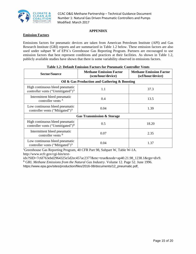
Emission Factors
Emissions factors for pneumatic devices are taken from American Petroleum Institute (API) and Gas
Research Institute (GRI) reports and are summarized in Table 1.2 below. These emission factors are also
used under subpart W of EPA’s Greenhouse Gas Reporting Program. Partners are encouraged to use
emission factors that best represent conditions and practices at their facilities. As shown in Table 1.2,
publicly available studies have shown that there is some variability observed in emissions factors.
Table 1.2: Default Emission Factors for Pneumatic Controller Vents
Sector/Source Methane Emission Factor
(scm/hour/device)
Methane Emission Factor
(scf/hour/device)
Oil & Gas Production and Gathering & Boosting
High continuous bleed pneumatic
controller vents (“Unmitigated”)A 1.1 37.3
Intermittent bleed pneumatic
controller vents A 0.4 13.5
Low continuous bleed pneumatic
controller vents (“Mitigated”)A 0.04 1.39
Gas Transmission & Storage
High continuous bleed pneumatic
controller vents (“Unmitigated”)B 0.5 18.20
Intermittent bleed pneumatic
controller vents B 0.07 2.35
Low continuous bleed pneumatic
controller vents (“Mitigated”)A 0.04 1.37
1Greenhouse Gas Reporting Program, 40 CFR Part 98, Subpart W, Table W-1A.
http://www.ecfr.gov/cgi-bin/text-
idx?SID=7c6f763ebd2964325e5d2ec457ac2377&mc=true&node=ap40.21.98_1238.1&rgn=div9. B GRI. Methane Emissions from the Natural Gas Industry. Volume 12. Page 52. June 1996.
https://www.epa.gov/sites/production/files/2016-08/documents/12_pneumatic.pdf.

CCAC O&G Methane Partnership – Technical Guidance Document Number 1: Natural Gas Driven Pneumatic Controllers and Pumps
Modified: March 2017
Page 16 of 20
Table 1.3: Default Emission Factors for Pneumatic Pumps
Sector/Source Methane Emission Factor
(scm/hour/pump)
Methane Emission Factor
(scf/hour/pump)
Oil & Gas Production
Pneumatic pumps – Diaphragm
(“Unmitigated”)A 0.53 18.58
Pneumatic pumps – Piston
(“Unmitigated”)A 0.06 2.03
Solar, electric, or instrument air
pump (“Mitigated”) 0.0 0.0
A Table 7-2, Control Technique Guidelines, USEPA (August 18, 2015), Data Source: EPA/GRI.
Methane Emissions from the Natural Gas Industry, Volume 13: Chemical Injection Pumps. June
1996.
(EPA-600/R -96-080m), Sections 5.1 – Diaphragm Pumps and 5.2 – Piston Pumps.
Table 1.4: Pneumatic Controller Survey Form
Company
Device
Identifier
Classificatio
n based on
time series
(intermittent
(I) OR
continuous
(C)
Manufacturer/
Model
Manufacturer
Classification
(High (H),
Low (L))
Controller
application
(Level,
Temperature,
Pressure,
Position,
Safety)
Tubing
Diameter
(in or m)
Tubing Length
Between
Device and
Control Valve
(in or m)
Supply
Pressure(psig
or kPag)
Actuation
frequency
(average
number of
actuations
per hour)

CCAC O&G Methane Partnership – Technical Guidance Document Number 1: Natural Gas Driven Pneumatic Controllers and Pumps
Modified: March 2017
Page 17 of 20
Table 1.5: High-Bleed Pneumatic Devices 37
Pneumatic Device Average Bleed
Rate (scm/hr) Type
Norriseal 100138 0.19 Level Controller
Fisher i2P-100 0.22 Transducer
Generic High-Bleed Intermittent Controller 0.25
Generic High-Bleed Controller 0.26
Fisher Fieldvue DVC600030 0.26 Positioner
Fisher 546 0.35 Transducer
Williams P125 0.41 Pump
Fisher 4150 0.42 Pressure Controller
Generic Piston Pump 0.59 Pump
Williams P500 0.70 Pump
Williams P250 0.80 Pump
Texsteam 5100 0.97 Pump
Generic Diaphragm Pump 1.05 Pump
Morgan HD312 1.13 Pump
Invalco Snap-Acting 7.76
Invalco CTU 8.07
Invalco CTU 9.17
Invalco CTU-415 11.75
Invalco Throttling 14.66
Invalco CTU 15.28
Invalco CTU-415 16.91
Invalco CTU-415 16.96
Invalco CTU-415 18.00
Invalco CTS-215 18.54
Invalco CTU 18.59
Invalco CTU 19.89
Invalco CTU 20.15
Invalco CTU-215 21.06
Invalco CTU 27.85
Invalco CTU 29.26
Invalco CTU-215 29.78
37 Prasino Group (2013). http://www2.gov.bc.ca/assets/gov/environment/climate-change/stakeholder-support/reporting-
regulation/pneumatic-devices/prasino_pneumatic_ghg_ef_final_report.pdf.
Blue Source Canada (2011). http://www2.gov.bc.ca/assets/gov/environment/climate-change/stakeholder-support/offset-project-
development-opportunities/high-bleed_to_low-bleed_module.pdf. 38 OGMP Partners report that these instruments now come in a generic intermittent bleed model.

CCAC O&G Methane Partnership – Technical Guidance Document Number 1: Natural Gas Driven Pneumatic Controllers and Pumps
Modified: March 2017
Page 18 of 20
Exhibit A Continuous Bleed Throttling Control Loop39,40
Exhibit B Intermittent Bleed Control Loop41
39 Producer Technology Transfer Workshop, Vernal, Utah, March 23, 2010: “Options for Reducing Methane Emissions
from Pneumatic Devices,” presentation by EPA 40 Natural Gas STAR Processors Workshop, Houston, Texas, June 25, 2002: “Green House Gas Control & Business Opportunity,” presentation by BP 41 Producer Technology Transfer Workshop, Vernal, Utah, March 23, 2010: adapted from “Options for Reducing Methane Emissions from Pneumatic Devices,” presentation by EPA
Pneumatic
Controller
Process
Measurement
Liquid Level
Pressure
Temperature
Flow
Actuator Vent
(Bleed)
Intermittent
Variable Process Flow
Throttling Control Valve
Valve Actuator
Actuator
Gas
Weak Pneumatic
Continuous Signal
(3 - 15 psi)
Regulator
Natural Gas
100+ psi
Regulated Gas Supply
20 - 30 psi
Liquid level measurement
Pneumatic
Controller
Process
Measurement
Liquid Level
Pressure
Temperature
Flow
Actuator Vent
Intermittent
Valve Closes
On/Off Process Flow
Snap Acting Valve
(Open Position)
Valve Actuator
Actuator
Gas
Pneumatic Signal
On/Off
(20 - 30 psi)
Regulator
Natural Gas
100+ psi
Regulated Gas Supply
20 - 30 psi

CCAC O&G Methane Partnership – Technical Guidance Document Number 1: Natural Gas Driven Pneumatic Controllers and Pumps
Modified: March 2017
Page 19 of 20
Exhibit C Instrument Air Control Loop42
Exhibit D Gas Pneumatic Pump43
42 Natural Gas STAR Processors Workshop, Houston, Texas, June 25, 2002: “Convert Gas Pneumatic Controls to
Instrument Air,” presentation by EPA 43 CCAC Oil and Gas Methane Partnership: webinar March 18, 2015: “Natural Gas Driven Pneumatic
Controllers/Pumps,” presentation by UNEP
Gas
Out
Pressure Controller
Air from
Atmosphere
Inlet
gas and
liquid
Liquid
Out
Utility
Services
Instrumentation
and Control
Systems Piping
Network20-30 PSI
Network
Level
Control
Air
Drier
Compressor Volume
Tank

CCAC O&G Methane Partnership – Technical Guidance Document Number 1: Natural Gas Driven Pneumatic Controllers and Pumps
Modified: March 2017
Page 20 of 20
Exhibit E Gas Pneumatic Pump Discharge Routed to a Control Device44,45
Exhibit F Solar-Electric Chemical Pumps46,47
44 Natural Gas STAR Processors Workshop, Houston, Texas, June 25, 2002: “Green House Gas Control & Business
Opportunity,” presentation by BP 45 Natural Gas STAR Processors Workshop, Charleston, West Virginia, February 27, 2009: “Installing Vapor Recovery
Units,” presentation by EPA 46 Natural Gas STAR Program, Producers Technology Transfer Workshop, Rock Springs, Wyoming, May 1, 2008:
“EnCana’s Energy Efficiency and Environmental Innovation Fund,” presentation by EnCana 47 Natural Gas STAR Annual Implementation Workshop, San Antonio, Texas, November 2008: “Success With the Solar
Methanol and glycol pumps,” presented by BP Moxa Operating Center
Crude Oil
Stock
Tank(s)
Control
Pilot
Vent Line
Back Pressure Valve
Suction
Scrubber
Suction
Line
Condensate
Return
Bypass
Valve
Electric
Control
Panel
Electric Driven
Rotary Compressor
Gas Sales
Meter Run
Gas
Liquid
Transfer Pump
Check Valve
Source: Evans & Nelson (1968)
Sales
Related Documents