NATO Precision Airdrop Initiatives and Modeling and Simulation Needs Richard J. Benney and Walter J. Krainski U.S. Army Research Development & Engineering Command Natick Soldier Center Natick, MA 01760 United States [email protected] and [email protected] Capt Pieter Onckelinx Belgium Army Parachute Training Center, Belgium [email protected] Capt Cecile Delwarde Delegation Generale pour lArmement (DGA), France [email protected] Lutz Mueller Bundesamt für Wehrtechnik und Beschaffung (BWB), Germany [email protected] Sqn Ldr Mick Vallance Joint Air Transport Evaluation Unit (JATEU), United Kingdom [email protected] ABSTRACT The U.S. Army Natick Soldier Center (NSC) is the lead agency for most U.S. Department of Defense (DoD) airdrop programs and is teamed with numerous DoD organizations and contractors to plan and execute numerous Joint Precision Airdrop System (JPADS) efforts to include an Advanced Concept Technology Demonstration (ACTD). The JPADS ACTD is integrating a USAF-developed laptop- computer-based precision airdrop planning system known as the Joint Precision Airdrop System Mission Planner (JPADS-MP) with the US Army Joint Precision Airdrop System (JPADS) in the light category of weight (2,201-10,000 lbs rigged weights). The integrated system objectives include the ability to airdrop JPADS systems of up to 10,000 lbs rigged weight, from altitudes of up to 25,000 ft mean sea level (MSL), with up to 10+kms of offset, and land precisely within 100 meters of a preplanned ground impact point. The NSC is also chairing the NATO ad hoc Joint Precision Airdrop Capabilities Working Group (JPACWG) within the NATO Air Force Armaments Group (NAFAG) with numerous NATO Nations participating. The JPACWG was formed in Sept 04 to support the use of precision airdrop in military operations as one of ten (10) high-priority, short-term requirements identified by the Conference of RTO-MP-AVT-133 KN2 - 1 UNCLASSIFIED/UNLIMITED UNCLASSIFIED/UNLIMITED Benney, R.J.; Krainski, W.J.; Onckelinx, P.; Delwarde, C.; Mueller, L.; Vallance, M. (2006) NATO Precision Airdrop Initiatives and Modeling and Simulation Needs. In Fluid Dynamics of Personnel and Equipment Precision Delivery from Military Platforms (pp. KN2-1 – KN2-22). Meeting Proceedings RTO-MP-AVT-133, Keynote 2. Neuilly-sur-Seine, France: RTO. Available from: http://www.rto.nato.int/abstracts.asp.

Welcome message from author
This document is posted to help you gain knowledge. Please leave a comment to let me know what you think about it! Share it to your friends and learn new things together.
Transcript
NATO Precision Airdrop Initiatives and Modeling and Simulation Needs
Richard J. Benney and Walter J. Krainski U.S. Army Research Development & Engineering Command
Natick Soldier Center Natick, MA 01760
United States
[email protected] and [email protected]
Capt Pieter Onckelinx Belgium Army Parachute Training Center, Belgium
Capt Cecile Delwarde Delegation Generale pour l�Armement (DGA), France
Lutz Mueller Bundesamt für Wehrtechnik und Beschaffung (BWB), Germany
Sqn Ldr Mick Vallance Joint Air Transport Evaluation Unit (JATEU), United Kingdom
ABSTRACT
The U.S. Army Natick Soldier Center (NSC) is the lead agency for most U.S. Department of Defense (DoD) airdrop programs and is teamed with numerous DoD organizations and contractors to plan and execute numerous Joint Precision Airdrop System (JPADS) efforts to include an Advanced Concept Technology Demonstration (ACTD). The JPADS ACTD is integrating a USAF-developed laptop-computer-based precision airdrop planning system known as the Joint Precision Airdrop System Mission Planner (JPADS-MP) with the US Army Joint Precision Airdrop System (JPADS) in the �light� category of weight (2,201-10,000 lbs rigged weights). The integrated system objectives include the ability to airdrop JPADS systems of up to 10,000 lbs rigged weight, from altitudes of up to 25,000 ft mean sea level (MSL), with up to 10+kms of offset, and land precisely within 100 meters of a preplanned ground impact point.
The NSC is also chairing the NATO ad hoc Joint Precision Airdrop Capabilities Working Group (JPACWG) within the NATO Air Force Armaments Group (NAFAG) with numerous NATO Nations participating. The JPACWG was formed in Sept 04 to support the use of precision airdrop in military operations as one of ten (10) high-priority, short-term requirements identified by the Conference of
RTO-MP-AVT-133 KN2 - 1
UNCLASSIFIED/UNLIMITED
UNCLASSIFIED/UNLIMITED
Benney, R.J.; Krainski, W.J.; Onckelinx, P.; Delwarde, C.; Mueller, L.; Vallance, M. (2006) NATO Precision Airdrop Initiatives and Modeling and Simulation Needs. In Fluid Dynamics of Personnel and Equipment Precision Delivery from Military Platforms (pp. KN2-1 – KN2-22). Meeting Proceedings RTO-MP-AVT-133, Keynote 2. Neuilly-sur-Seine, France: RTO. Available from: http://www.rto.nato.int/abstracts.asp.
National Armaments Directors (CNAD) for the Defense Against Terrorism (DAT), and a Long Term Capability Requirement (LTCR) within NATO. The JPACWG executed a Precision Airdrop Technology Conference and Demonstration (PATCAD) at the US Army Yuma Proving Ground on 17-21 Oct 05. The PATCAD-2005 event attracted 350 participants from throughout the world. During this week long event, 115 airdrops were conducted using five aircraft, demonstrating 23 different precision airdrop systems and numerous related technologies.
This paper provides an overview of the current status of U.S. DoD precision airdrop programs, as well as recent activities of the NATO JPACWG. The paper also highlights the research, technology, and integration challenges associated with precision airdrop systems, and the airdrop community�s Modeling and Simulation needs; including issues associated with personnel and all weights and sizes of cargo airdrop deployments from transport aircraft in order to help set the need for �Fluid Dynamics of Personnel and Equipment Precision Delivery from Military Platforms.�
1.0 INTRODUCTION
Many NATO Nations are investing in precision airdrop technologies/systems, and many more will likely begin investments to help meet NATO and national precision airdrop requirements. This paper discusses the need for precision airdrop and provides an overview of U.S. Department of Defense (DoD) precision airdrop programs and recent activities of the NATO JPACWG. The paper also highlights the airdrop community�s Modeling and Simulation needs, including the tools that could help speed the introduction of precision airdrop into military operations.
Precision airdrop does not allow for �one system fits all� because the payload weight, altitude, range, accuracy, and many other requirements are significantly different. For example, the U.S. DoD is investing in numerous precision airdrop initiatives within a program known as the Joint Precision Airdrop System (JPADS). The JPADS is a guided precision airdrop system that provides significantly improved accuracy (and reduced dispersion) over currently fielded, unguided (ballistic) airdrop methods.
Within the primary U.S. DoD programs, JPADS is comprised of four weight classes (fully rigged weights): JPADS-Extra-Light (JPADS-XL) for 500 to 2,200 pounds, JPADS-Light (JPADS-L) for 2,201 to 10,000 pounds, JPADS-Medium (JPADS-M) for 10,001 to 30,000 pounds, and JPADS-Heavy (JPADS-H) for 30,001 to 60,000 pounds. The systems are expected to operate from altitudes up to 25,000 to 35,000 feet MSL, and have accuracies of 100 meters or better. Many other initiatives are also underway in much smaller weight classes for a range of resupply and other applications all the way down to 1- to 2-pound payloads. The U.S. DoD weight classes will all be fielded using a single JPADS Mission Planner (JPADS-MP) that can plan missions and program all of the JPADS family of systems.
This paper focuses on the first two JPADS weight increments, since these are the most rapidly maturing and are most needed by NATO nations. Therefore, systems within these two weight increments will likely be fielded by the majority of NATO members.
The use of the term JPADS is used throughout this paper and should be considered a generic term for all related technologies. Why the �J�? Most NATO Nations consider airdrop a �joint� mission, and for most Nations, JPADS capabilities have application to all services. It should be emphasized that �JPADS� is the name given to the U.S. DoD�s precision airdrop program, and that not all NATO Nations use the term. Common JPADS subsystems include the Parachute, Airborne Guidance Unit (AGU), Cargo Container/Pallet, and Mission Planning. A brief description of each follows.
1.1 Parachute
The JPADS generally uses a round parachute, parafoil, or a parafoil/round parachute hybrid for
NATO Precision Airdrop Initiatives and Modeling and Simulation Needs
KN2 - 2 RTO-MP-AVT-133
UNCLASSIFIED/UNLIMITED
UNCLASSIFIED/UNLIMITED
deceleration of the load through descent. The �controlled� parachute provides JPADS with directional capability in flight. Often other parachutes are also utilized in the overall system for final load recovery. Parachute control line(s) run to the airborne guidance unit (AGU) and are used to control the shape of the parachute/parafoil for directional control. One primary difference between each category of deceleration technology, i.e. type of parachute, is the horizontal achievable offset each type of system can deliver. In very generic terms, offset is often measured in terms of the systems lift to drag ratio (L/D) �in zero winds.�
1.2 Airborne Guidance Unit (AGU) The AGU houses the GPS receiver and/or other sensors in an avionics suite; guidance, navigation, and
control (GN&C) software package; the hardware required to operate the control line(s), and battery power packs for nearly all JPADS. The AGU, using initialization data from the JPADS-MP, acquires its position prior to exit from the aircraft generally through a GPS retransmission kit (RTK). Once the position is reacquired upon exit from the aircraft, the AGU steers in accordance with the planned trajectory or towards waypoints, making corrections in flight as necessary via an actuator/pulley system attached to the control line(s).
1.3 Cargo Container/Pallet For JPADS-XL: A-22 containers or the container delivery system (CDS) or equivalent is used. Many
NATO Nations have customized rigging procedures for unique equipment/supplied in a CDS-equivalent weight range.
For JPADS-L: Either a 463L pallet (for payload suspended items), a Type V platform, an enhanced container delivery system (ECDS) platform, and/or equivalents can be used.
Many NATO Nations have different platform types, requirements and criteria for load restraint within the aircraft, and release procedures. For most of the precision airdrop systems described in this paper, the objective is to be as independent as possible from the cargo shape, platform/container type, center of gravity, and moments of inertia. This goal allows for the maximum amount of flexibility by the user within any weight class.
The ECDS is a multimodal platform sized to the dimensions of a standard USAF 463-L pallet (108 inches by 88 inches). The ECDS enables the airdrop roller systems of the C-130 and C-17 aircraft to support the 10,000 pounds of total rigged weight of one JPADS. The 463-L sizing allows the platform to be transported by a variety of aircraft such as rotary wing using sling attachment points built into the platform. The ECDS is currently being developed by the US Army Product Manager-Force Sustainment Systems (PM-FSS) and has not yet been fielded.
1.4 Mission Planning Nearly all precision airdrop systems require mission planning prior to being airdropped. The JPADS
requires at a minimum, a payload weight and a desired ground impact coordinate (i.e. GPS latitude/longitude). In addition, most systems take advantage of wind information that also allows the user to determine the area of opportunity in which the payload can be dropped from the aircraft and still make it to the intended ground impact target. This view can be reversed by looking at the ground impact area as the potential area of opportunity the payload can land on from a given CARP. A more detailed description of the U.S. Air Force JPADS-MP system is provided later in this paper. [1]
NATO Precision Airdrop Initiatives and Modeling and Simulation Needs
RTO-MP-AVT-133 KN2 - 3
UNCLASSIFIED/UNLIMITED
UNCLASSIFIED/UNLIMITED
2.0 THE NEED FOR PRECISION AIRDROP
Sustainment operations in the U.S. Central Command (CENTCOM) Area of Operations (AOR) and potentially most future conflicts encompass expansive, non-contiguous territories that are time/distance sensitive and subject to an asymmetric threat. Employment of forces calls for significant dispersion, extending units from supply bases and extending the Ground Lines of Communication (GLOC). The likelihood that these conditions will be replicated in other AORs in which nations find themselves combating terrorism is high given the propensity of terrorist elements to disperse utilizing difficult and compartmentalized terrain to mitigate the informational and maneuver overmatches presented to them by US and Allied Nation forces. Theater resupply operations can be greatly enhanced with the accelerated development and immediate employment of enablers such as JPADS as a component of the Theater Distribution system.
The proliferation of Man Portable Air Defense Systems (MANPADS) and other non-traditional threats
presents a serious risk for airmen and soldiers conducting resupply operations. While GLOC security is never guaranteed, insurgent forces are able to continually interdict supply lines and the convoys that utilize them. The result of this action is two fold. Enemy action is targeted at non-armored, combat service support vehicles, often with devastating effects. Mitigation of the enemy�s ability to interdict the GLOC is met by application of combat power to GLOC security; ensuring freedom of movement for supply operations but robbing the fighting force of operational flexibility and resources. Similarly, there are significant risks and shortfalls associated with conducting conventional airdrop operations. For example, US and Allied Nation aircraft cannot meet desired accuracy standards once drop altitudes exceed 2000 feet above ground level (AGL). While drops below this altitude are more accurate, they are subject to small arms, Anti-Aircraft Artillery (AAA) and MANPADS threats. In addition, the time associated with deploying multiple payloads out of an aircraft necessitates a drop zone of substantial length for low altitude drops.
Strategic, operational, and tactical employment of forces in the contemporary operating environment
requires a change in the way US and Allied Nations sustain their forces. The time and place of the next battle is unknown. Military planners are no longer able to define the next area of operations with certainty and thus often carefully prepare by strategic forward positioning of forces, equipment, and stocks. This is what we can know longer do because the threat is so dispersed. In the contemporary operating environment, adversaries have the ability to threaten National interests or attack coalition partners with little or no warning. Additionally, our adversaries have changed. They have developed tactics, techniques, and procedures that result in significant disruption of operations. Helicopters are downed by rocket-propelled grenades (RPGs); Vulnerable Ground Lines of Communication (GLOCs) are disrupted by improvised explosive devices (IEDs), and direct action. These two significant changes (strategic warning and asymmetric operations) in the strategic environment are effecting changes in the way US and Allied Nation forces must deploy and employ forces. To provide maximum global agility and flexibility in response to global contingencies, forces will increasingly deploy from a strategic base. Current and emerging US guidance tells us that forces must be able to rapidly deploy, immediately employ upon arrival in the theater of operations and be continuously sustained throughout the operation. New technologies enable US and Allied Nations forces to maneuver against a dispersed enemy in a distributed, non-linear, and non-contiguous fashion. These forces can operate cohesively and maintain situational awareness even while separated by long distances. However, these operations outpace the ability of the logistics tail to keep up. These new methods of maneuver must be matched by new methods of agile sustainment. NATO commanders require sustainment capabilities that can support forces that will be rapidly deployed, immediately employed upon arrival in theater, and conduct widely dispersed operations with lightning agility. The Joint Precision Airdrop System (JPADS) is just such a capability, and is receiving increased focus with the DoD and Allied Nations. [2]
NATO Precision Airdrop Initiatives and Modeling and Simulation Needs
KN2 - 4 RTO-MP-AVT-133
UNCLASSIFIED/UNLIMITED
UNCLASSIFIED/UNLIMITED
3.0 U.S. DEPARTMENT OF DEFENSE JPADS PROGRAM
The U.S. DoD�s Joint Precision Airdrop System (JPADS) program encompasses a variety of efforts, partners and funding sources. Most of these efforts are currently managed/executed by the U.S. Army RDECOM Natick Soldier Center (NSC) in conjunction with other military/government/industry team members. The JPADS is a family of systems consisting primarily of �self-guided� cargo parachute systems, a common mission planning and weather system, and more recently linked in Military Free Fall (MFF) parachute systems. All of these are considered to be Science & Technology (S&T) programs, i.e., they have not yet entered the System Development & Demonstration (SDD) phase, yet many are or likely will be used under Rapid Fielding Initiatives (RFI). Most of these systems are scheduled to enter SDD, i.e., reach a Milestone-B decision in FY07 or beyond. A brief overview of ongoing JPADS-L and JPADS-XL programs and their status is provided in this section.
3.1 JPADS Advanced Concept Technology Demonstration (ACTD) Under the oversight of the Office of the Secretary of Defense (OSD) Advance Systems and Concepts
(AS&C) office, the U.S. Army Natick Soldier Center (NSC) is currently teamed with the U.S. Joint Forces Command (JFCOM), U.S. Air Force Air Mobility Command (USAF AMC), the U.S. Army Product Manager Force Sustainment Systems (PM FSS), and numerous other government agencies and contractors to plan and execute the Joint Precision Airdrop System (JPADS) Advanced Concept Technology Demonstration (ACTD). The JPADS ACTD is integrating a USAF developed laptop-computer-based precision airdrop planning system known as the Joint Precision Airdrop System Mission Planner (JPADS-MP) with a JPADS concept called �SCREAMER� in the JPADS-L category of weight (2201-10000lbs rigged weights).
An ACTD program emphasizes the assessment and integration of maturing commercial or government technologies that address critical military needs to expedite transition of those technologies to the warfighters. ACTD�s must be Joint and are considered to be the highest priority Office of the Secretary of Defense sponsored science and technology programs within the DoD. The overarching objectives of an ACTD are to conduct meaningful demonstrations of a capability, develop and test concepts of operation to optimize military effectiveness, and prepare (if warranted) to transition the capability into acquisition without loss of momentum. There are three outcomes possible at the conclusion of an ACTD. These include: 1) Acquisition and fielding of the residual capability that remains at the completion of the demonstration phase of the ACTD to provide an interim and limited operational capability. 2) Fielding of the residual capability without acquiring additional units if the user�s need is fully satisfied. 3) Terminating the project or returning it to the technology base if the capability or system does not demonstrate military utility. Instead of testing to requirements as in an operational or developmental test, a Joint Military Utility Assessment (JMUA) is utilized, which identifies �value added� as the overarching assessment metric to determine if the capability (technology and/or procedures) warrants further development or acquisition. The JPADS ACTD conducted the first of three planned JMUAs in June 06.
3.1.1 Joint Precision Airdrop System Mission Planner (JPADS-MP)
Each JPADS requires some type of laptop-based mission planning system, as well as different input parameters and data, prior to being deployed. The JPADS-MP is the most sophisticated mission planner for precision airdrop systems being developed and is currently in use by U.S. Special Operations Forces for MFF applications. The JPADS-MP is being developed by a large team for the USAF Air Mobility Command, Scott AFB, Illinois and other services. Program management and execution is being carried out by the U.S. Army Natick Soldier Center, with Planning Systems Inc., Reston, Virginia, as the lead contractor for hardware, weather, and integration. Charles Stark Draper Laboratory, Cambridge, Massachusetts, is doing the mission planning (software lead), and Forecast Systems Laboratory, Boulder, Colorado, the weather assimilation software, in conjunction with many other supporting services.
NATO Precision Airdrop Initiatives and Modeling and Simulation Needs
RTO-MP-AVT-133 KN2 - 5
UNCLASSIFIED/UNLIMITED
UNCLASSIFIED/UNLIMITED
The JPADS-MP enables aircrews to plan and initiate load release at an accurate Computed Aerial Release Point (CARP) (or area) through the application of accurate models of the JPADS components and enhanced wind profile/weather knowledge. As the U.S. DoD is investing in a family of JPADS decelerator systems, the requirement has been established to have the JPADS-MP be capable of programming any/all JPADS parachute systems both on the ground and/or while in-route to the CARP.
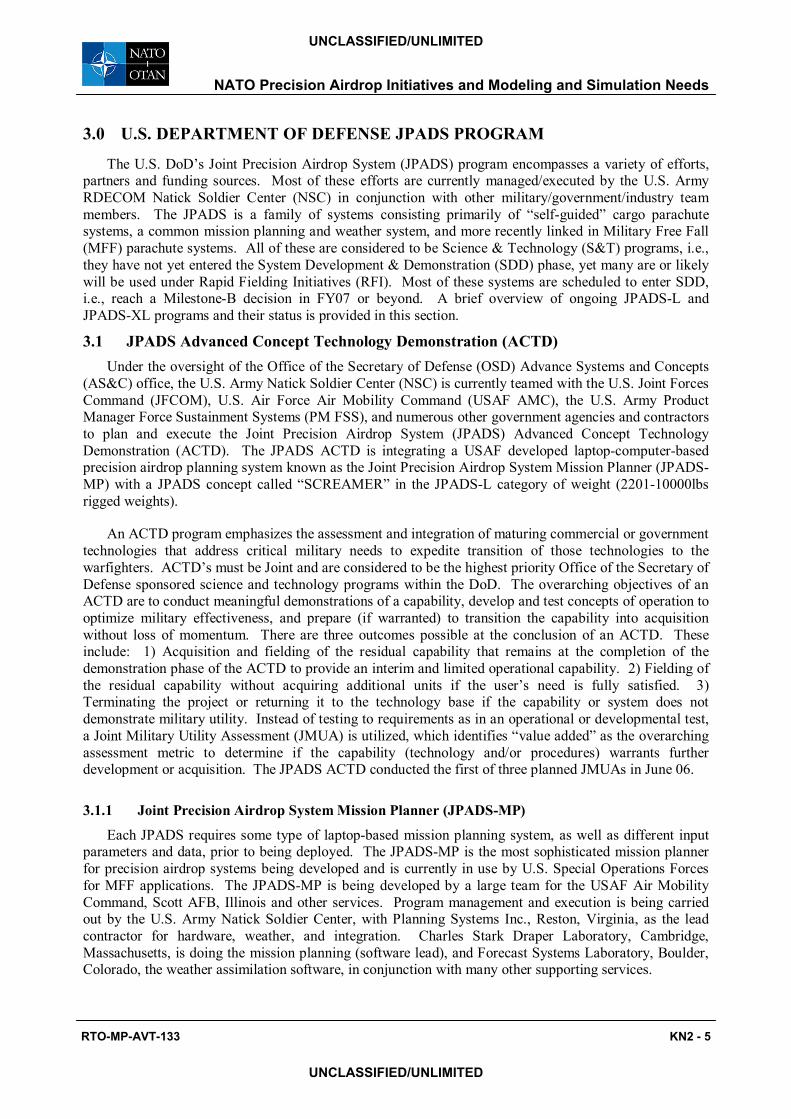
The basic JPADS-MP hardware components include a portable, rugged, low- or high-pressure tolerant laptop computer, a JPADS-MP interface processor (PIP), dropsondes, a GPS RTK, and cabling for C-130, C-17, and other aircraft. Recent JPADS-MP enhancements include the ability to program a number of JPADS systems by either plugging the JPADS-MP into each AGU respectively or wirelessly programming each AGU individually or in combination while the JPAD-MP is installed in the aircraft cockpit. Integration of the JPADS-MP into not only the SCREAMER, but also the DRAGONFLY, AGAS, and Sherpa systems was demonstrated at PATCAD-2005. For wireless programming, the JPADS-MP kit includes wireless common navigation interface units (CNIUs), which have been developed for use with the various JPADS systems. The CNIUs are attached to the AGUs and can either be removed prior to exit from the aircraft or stay with the AGU through flight. The PIP includes an ultra-high frequency (UHF) radio receiver and a dropsonde interface processor. The JPADS-MP hardware is man-portable and installed aboard the selected precision airdrop aircraft in a roll-on/roll-off configuration in less than one hour. The high-pressure tolerant laptop computer and system components enable operation in non-pressurized flight up to 35,000 feet MSL pressure altitude. The current JPADS-MP fly-away kit is shown in Figure 1, including its carrying case and a dropsonde (A-sonde shown).
Figure 1: JPADS-MP Fly-Away Kit. (From left to right: Dropsonde, JPADS-MP Hardware, Laptop, and Carrying Case)
The JPADS-MP is certified to fly on both the C-130 and C-17 aircraft, having recently passed separate C-17 and C-130 aircraft Operational Utility Evaluations (OUEs) for ballistic system airdrops. Both were executed by the USAF Air Mobility Commands Test and Evaluation Squadron for high altitude high-speed CDS systems using a 26-foot Ring Slot (ballistic) Parachute system. Improvements in accuracy over current mission planning methods of 70% and 56% were realized respectively during the C-17 and C-130 OUE�s. Many JPADS-MP enhancements are on-going at the time of this paper submission and as noted, many other MP systems exist of varying levels of maturity for programming (in most cases) a specific JPADS. During the summer of 2004, the NSC adapted the JPADS-MP capability to meet a U.S. Special Operations Command (SOCOM) Military Free Fall (MFF) requirement. The JPADS-MP has been utilized operationally with great success by Special Operations Forces, to the extent where SOCOM now considers the JPADS-MP to be mission essential equipment. Currently, the U.S. Air Force Air Mobility Command (AMC) has numerous JPADS-MP kits (some parts to be ordered) ready to support
NATO Precision Airdrop Initiatives and Modeling and Simulation Needs
KN2 - 6 RTO-MP-AVT-133
UNCLASSIFIED/UNLIMITED
UNCLASSIFIED/UNLIMITED
possible JPADS-XL Rapid Fielding Initiatives (RFIs). In addition, the Deputy Under Secretary for Defense, Advanced Systems and Concepts (DUSD, AS&C) has funded integration of the JPADS-MP into U.S. Marine Corp (USMC) KC-130J aircraft, and USMC and U.S. SOCOM MFF Navigation Aids, with linkage scheduled for later this fiscal year. [3, 4, 5, and 6]
3.1.2 SCREAMER
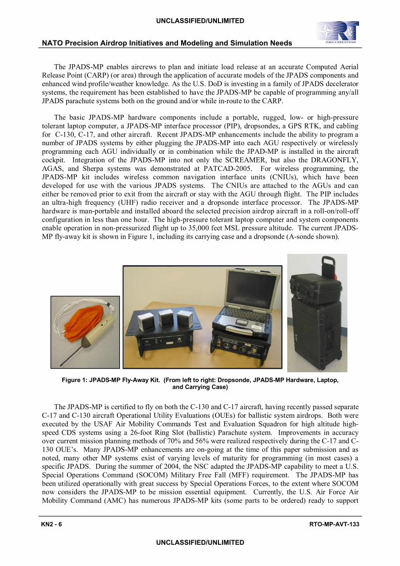
The �SCREAMER� is a modified High Altitude Low Opening (HALO) aerial delivery system. The SCREAMER consists of a Ram Air Drogue (RAD) parafoil and recovery chute(s) all integrated into the platform/payload by Strong Enterprises, Orlando, Florida, and a single actuator AGU produced by RoboTeK Engineering, Inc., Garland, Texas. Upon gravity drop from the aircraft, a static line deploys the RAD canopy. Under the control of the AGU, the SCREAMER autonomously navigates during drogue parafoil flight to a programmed target point. This target point is set above, and slightly offset from, the desired ground impact point based on anticipated ground winds. After descending in a circular pattern above the target to a preset mission recovery altitude, the 10Klb SCREAMER variant deploys two G-11 cargo parachutes to arrest forward glide and affect a standard ballistic recovery descent of approximately 24 feet per second. The SCREAMER AGU has been used to fly systems ranging in weight from 500lbs all the way up to 10Klbs. At the time of this submission, the 10Klb SCREAMER system had been flown autonomously on numerous occasions from deployment altitudes up to 25Kft MSL and air speeds up to 150KIAS from both C-130 and C-17 aircraft. The SCREAMER is shown in Figure 2 descending under its final recovery parachutes. SCREAMER is composed of modular man-portable components. It flies fast and is designed to penetrate 60- to 70- knot winds.
The major components of the 10Klb SCREAMER include the 850-square foot parafoil RAD main
canopy, the AGU, a pair of G-11 recovery parachutes and a small platform or Recovery Mantle on which the parachutes and AGU are rigged. An ECDS platform-based payload (or Type V platform or 463L pallet) is slung beneath the SCREAMER and decoupled through a single point swivel. [7]
Figure 2: 10,000-lb SCREAMER system in the final stages of flight.
NATO Precision Airdrop Initiatives and Modeling and Simulation Needs
RTO-MP-AVT-133 KN2 - 7
UNCLASSIFIED/UNLIMITED
UNCLASSIFIED/UNLIMITED
The JPADS ACTD program has entered its third and final year. Integrated testing of the SCREAMER linked with the JPADS-MP continues with numerous airdrop tests planned to lock in on a configuration, and increase reliability at higher altitudes (up to 25KftMSL). One JMUA has been conducted to date, and two additional JMUA�s are planned. The first JMUA took place on 12-16 June 06, with the other two tentatively scheduled for October 06 and January 07. The JPADS-L technologies are then expected to transition into the System Development & Demonstration (SDD) phase under a formal program of record at the Milestone B level during the spring of 07. A two year residual phase with remaining JPADS ACTD assets will be executed with support from DUSD AS&C during FY07 and FY08. Low Rate Initial Production (LRIP) will start in FY10 if the SDD program is successful and meets all Key Performance Parameters during Operational Testing (OT).
3.2 JPADS-XL Rapid Fielding Initiatives Precision airdrop systems within the JPADS-XL weight category (500 to 2,200 pounds) are generally
considered to be the most mature systems currently available. This weight range encompasses the vast majority of loads delivered during airdrop operations, and thus, precision systems within this category will likely be fielded by most NATO members. As a result, these systems have benefited from industry- and government-funded development the longest; with efforts stretching back a decade or more in some cases. The U.S. Army NSC and PM FSS are continuing their efforts to mature and prep a number of JPADS-XL systems, in order to support interim fielding of JPADS-XL capabilities as part of various Rapid Fielding Initiatives (RFIs). RFIs are viewed as having the potential to provide long term benefits since they provide the user the opportunity to conduct an in-depth evaluation of systems and concepts in advance of Milestone B. This translates into better informed requirements trade-offs and down selection decisions once systems enter the SDD phase. Ongoing RFI-related efforts include the integration of the JPADS-MP using secure 802.11g wireless communication and Mil-GPS into various JPADS-XL systems, as well as testing of various JPADS-XL systems to increase system reliability during high altitude deployment (up to 25,000 ft. MSL). Systems that have been purchased, fielded, or have been proposed for fielding, include the Sherpa, SCREAMER, and Affordable Guided Airdrop System (AGAS). Each of these systems have strengths/advantages in terms of cost, glide ratio, operational employment, ease of rigging, training, etc. The systems represent the three primary types of systems being developed around the world, i.e., steerable round parachutes, traditional parafoils, and hybrids. A brief description of each JPADS-XL system and its status follows:
3.2.1 Mist Mobility Integrated System Technology, Inc. (MMIST) Sherpa
The Sherpa is a commercial-off-the-shelf (COTS) cargo delivery system manufactured by MMIST of Nepean, Ontario, Canada. The system consists of a programmable timer-released drogue parachute that deploys a ram-air canopy, a parachute control unit, and a remote control. The system is capable of delivering between 400 and 2,200 pounds of payload with 3 to 4 different parafoil sizes and small modifications to the AGU cage. The Sherpa mission can be planned before flight by entering the coordinates of the intended impact point, current available wind data, and payload characteristics. The Sherpa MP software uses the data to generate a mission file and calculate a CARP within the release area. Upon release from the aircraft, the Sherpa system drogue parachute, a small round stabilization parachute, is static-line deployed. The drogue is attached to a release latch that can be programmed to release at a preset time after deployment. Upon releasing the drogue, it pulls out the main parafoil, which inflates while concurrently deflating the drogue. This is a desired feature of all JPADS systems to ensure that all components of the system are retained by the system throughout flight for both simplified recovery and to minimize residuals (residuals are any items that leave the aircraft and do not stay with the system all the way to ground impact) in the airspace. The Sherpa system then flies autonomously towards preprogrammed waypoints (if used) or the intended impact point.
The Sherpa system also comes with a ground control. Ground control is difficult to do during low-visibility and at far distances, but has advantages for testing and some military applications. In addition,
NATO Precision Airdrop Initiatives and Modeling and Simulation Needs
KN2 - 8 RTO-MP-AVT-133
UNCLASSIFIED/UNLIMITED
UNCLASSIFIED/UNLIMITED
the Sherpa ground control unit has a beacon mode in which a ground user can reprogram the intended impact point by wirelessly sending the ground GPS location via the ground controller, which has a built-in GPS receiver.
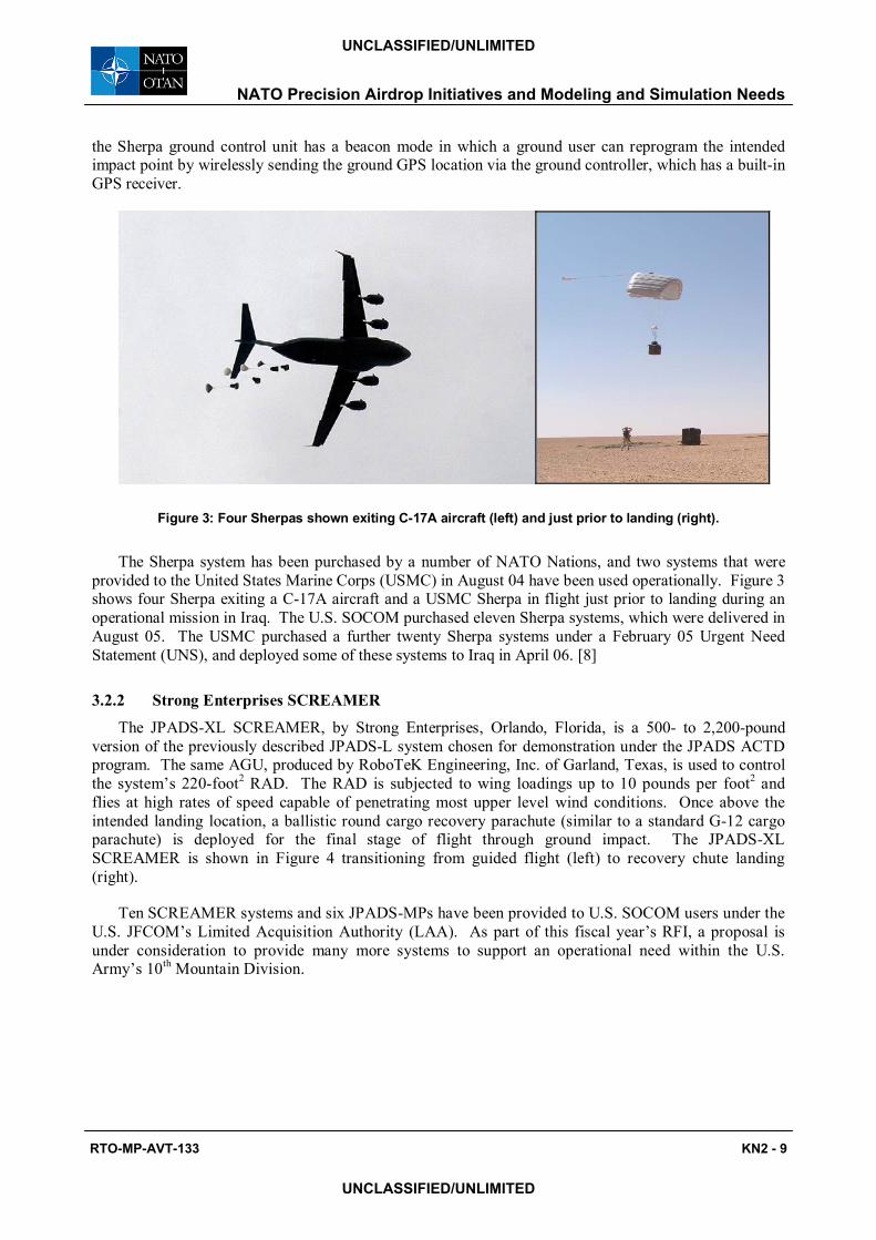
Figure 3: Four Sherpas shown exiting C-17A aircraft (left) and just prior to landing (right).
The Sherpa system has been purchased by a number of NATO Nations, and two systems that were provided to the United States Marine Corps (USMC) in August 04 have been used operationally. Figure 3 shows four Sherpa exiting a C-17A aircraft and a USMC Sherpa in flight just prior to landing during an operational mission in Iraq. The U.S. SOCOM purchased eleven Sherpa systems, which were delivered in August 05. The USMC purchased a further twenty Sherpa systems under a February 05 Urgent Need Statement (UNS), and deployed some of these systems to Iraq in April 06. [8]
3.2.2 Strong Enterprises SCREAMER
The JPADS-XL SCREAMER, by Strong Enterprises, Orlando, Florida, is a 500- to 2,200-pound version of the previously described JPADS-L system chosen for demonstration under the JPADS ACTD program. The same AGU, produced by RoboTeK Engineering, Inc. of Garland, Texas, is used to control the system�s 220-foot2 RAD. The RAD is subjected to wing loadings up to 10 pounds per foot2 and flies at high rates of speed capable of penetrating most upper level wind conditions. Once above the intended landing location, a ballistic round cargo recovery parachute (similar to a standard G-12 cargo parachute) is deployed for the final stage of flight through ground impact. The JPADS-XL SCREAMER is shown in Figure 4 transitioning from guided flight (left) to recovery chute landing (right).
Ten SCREAMER systems and six JPADS-MPs have been provided to U.S. SOCOM users under the U.S. JFCOM�s Limited Acquisition Authority (LAA). As part of this fiscal year�s RFI, a proposal is under consideration to provide many more systems to support an operational need within the U.S. Army�s 10th Mountain Division.
NATO Precision Airdrop Initiatives and Modeling and Simulation Needs
RTO-MP-AVT-133 KN2 - 9
UNCLASSIFIED/UNLIMITED
UNCLASSIFIED/UNLIMITED
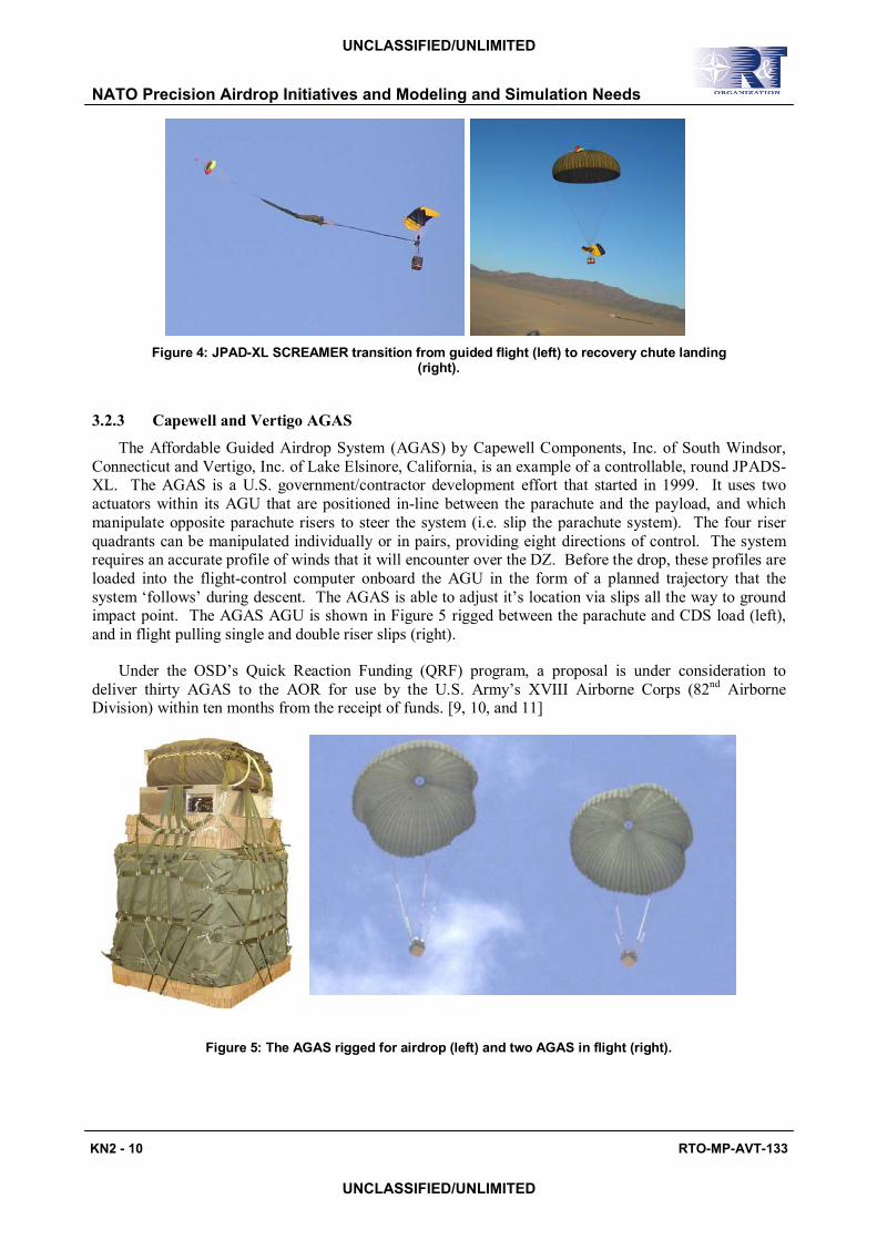
Figure 4: JPAD-XL SCREAMER transition from guided flight (left) to recovery chute landing (right).
3.2.3 Capewell and Vertigo AGAS
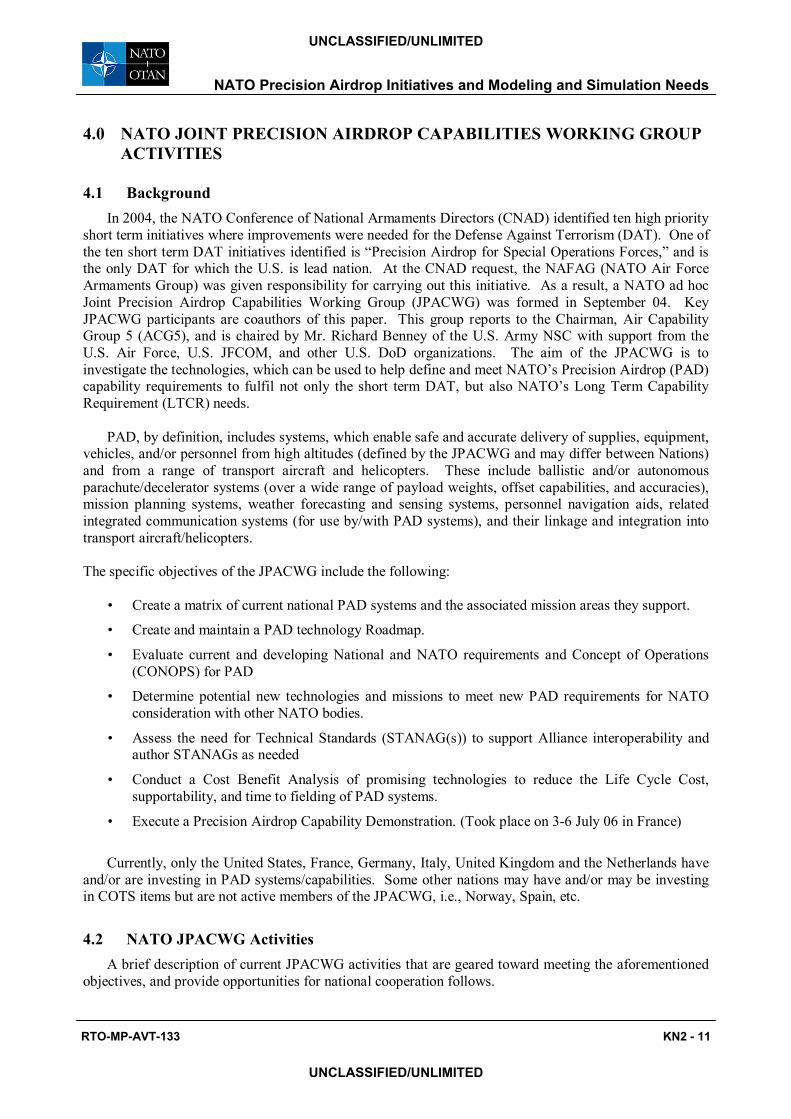
The Affordable Guided Airdrop System (AGAS) by Capewell Components, Inc. of South Windsor, Connecticut and Vertigo, Inc. of Lake Elsinore, California, is an example of a controllable, round JPADS-XL. The AGAS is a U.S. government/contractor development effort that started in 1999. It uses two actuators within its AGU that are positioned in-line between the parachute and the payload, and which manipulate opposite parachute risers to steer the system (i.e. slip the parachute system). The four riser quadrants can be manipulated individually or in pairs, providing eight directions of control. The system requires an accurate profile of winds that it will encounter over the DZ. Before the drop, these profiles are loaded into the flight-control computer onboard the AGU in the form of a planned trajectory that the system �follows� during descent. The AGAS is able to adjust it�s location via slips all the way to ground impact point. The AGAS AGU is shown in Figure 5 rigged between the parachute and CDS load (left), and in flight pulling single and double riser slips (right).
Under the OSD�s Quick Reaction Funding (QRF) program, a proposal is under consideration to deliver thirty AGAS to the AOR for use by the U.S. Army�s XVIII Airborne Corps (82nd Airborne Division) within ten months from the receipt of funds. [9, 10, and 11]
Figure 5: The AGAS rigged for airdrop (left) and two AGAS in flight (right).
NATO Precision Airdrop Initiatives and Modeling and Simulation Needs
KN2 - 10 RTO-MP-AVT-133
UNCLASSIFIED/UNLIMITED
UNCLASSIFIED/UNLIMITED
4.0 NATO JOINT PRECISION AIRDROP CAPABILITIES WORKING GROUP ACTIVITIES
4.1 Background In 2004, the NATO Conference of National Armaments Directors (CNAD) identified ten high priority
short term initiatives where improvements were needed for the Defense Against Terrorism (DAT). One of the ten short term DAT initiatives identified is �Precision Airdrop for Special Operations Forces,� and is the only DAT for which the U.S. is lead nation. At the CNAD request, the NAFAG (NATO Air Force Armaments Group) was given responsibility for carrying out this initiative. As a result, a NATO ad hoc Joint Precision Airdrop Capabilities Working Group (JPACWG) was formed in September 04. Key JPACWG participants are coauthors of this paper. This group reports to the Chairman, Air Capability Group 5 (ACG5), and is chaired by Mr. Richard Benney of the U.S. Army NSC with support from the U.S. Air Force, U.S. JFCOM, and other U.S. DoD organizations. The aim of the JPACWG is to investigate the technologies, which can be used to help define and meet NATO�s Precision Airdrop (PAD) capability requirements to fulfil not only the short term DAT, but also NATO�s Long Term Capability Requirement (LTCR) needs.
PAD, by definition, includes systems, which enable safe and accurate delivery of supplies, equipment,
vehicles, and/or personnel from high altitudes (defined by the JPACWG and may differ between Nations) and from a range of transport aircraft and helicopters. These include ballistic and/or autonomous parachute/decelerator systems (over a wide range of payload weights, offset capabilities, and accuracies), mission planning systems, weather forecasting and sensing systems, personnel navigation aids, related integrated communication systems (for use by/with PAD systems), and their linkage and integration into transport aircraft/helicopters. The specific objectives of the JPACWG include the following:
� Create a matrix of current national PAD systems and the associated mission areas they support.
� Create and maintain a PAD technology Roadmap.
� Evaluate current and developing National and NATO requirements and Concept of Operations (CONOPS) for PAD
� Determine potential new technologies and missions to meet new PAD requirements for NATO consideration with other NATO bodies.
� Assess the need for Technical Standards (STANAG(s)) to support Alliance interoperability and author STANAGs as needed
� Conduct a Cost Benefit Analysis of promising technologies to reduce the Life Cycle Cost, supportability, and time to fielding of PAD systems.
� Execute a Precision Airdrop Capability Demonstration. (Took place on 3-6 July 06 in France)
Currently, only the United States, France, Germany, Italy, United Kingdom and the Netherlands have
and/or are investing in PAD systems/capabilities. Some other nations may have and/or may be investing in COTS items but are not active members of the JPACWG, i.e., Norway, Spain, etc.
4.2 NATO JPACWG Activities A brief description of current JPACWG activities that are geared toward meeting the aforementioned
objectives, and provide opportunities for national cooperation follows.
NATO Precision Airdrop Initiatives and Modeling and Simulation Needs
RTO-MP-AVT-133 KN2 - 11
UNCLASSIFIED/UNLIMITED
UNCLASSIFIED/UNLIMITED
4.2.1 Precision Airdrop Technology Conference and Demonstration
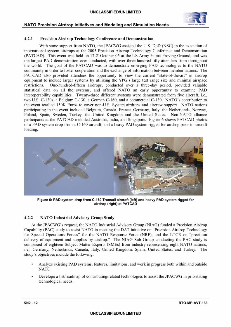
With some support from NATO, the JPACWG assisted the U.S. DoD (NSC) in the execution of international system airdrops at the 2005 Precision Airdrop Technology Conference and Demonstration (PATCAD). This event was held on 17-21October 05 at the US Army Yuma Proving Ground, and was the largest PAD demonstration ever conducted, with over three-hundred-fifty attendees from throughout the world. The goal of the PATCAD was to demonstrate emerging PAD technologies to the NATO community in order to foster cooperation and the exchange of information between member nations. The PATCAD also provided attendees the opportunity to view the current �state-of-the-art� in airdrop equipment to include larger systems by utilizing the YPG�s large test range size and minimal airspace restrictions. One-hundred-fifteen airdrops, conducted over a three-day period, provided valuable statistical data on all the systems, and offered NATO an early opportunity to examine PAD interoperability capabilities. Twenty-three different systems were demonstrated from five aircraft, i.e., two U.S. C-130s, a Belgium C-130, a German C-160, and a commercial C-130. NATO�s contribution to the event totalled 150K Euros to cover non-U.S. System airdrops and aircrew support. NATO nations participating in the event included Belgium, Canada, France, Germany, Italy, the Netherlands, Norway, Poland, Spain, Sweden, Turkey, the United Kingdom and the United States. Non-NATO alliance participants at the PATCAD included Australia, India, and Singapore. Figure 6 shows PATCAD photos of a PAD system drop from a C-160 aircraft, and a heavy PAD system rigged for airdrop prior to aircraft loading.
Figure 6: PAD system drop from C-160 Transall aircraft (left) and heavy PAD system rigged for
airdrop (right) at PATCAD
4.2.2 NATO Industrial Advisory Group Study
At the JPACWG�s request, the NATO Industrial Advisory Group (NIAG) funded a Precision Airdrop Capability (PAC) study to assist NATO in meeting the DAT initiative on �Precision Airdrop Technology for Special Operations Forces� for the NATO Response Force (NRF), and the LTCR on �precision delivery of equipment and supplies by airdrop.� The NIAG Sub Group conducting the PAC study is comprised of eighteen Subject Matter Experts (SMEs) from industry representing eight NATO nations, i.e., Germany, Netherlands, Canada, Italy, United Kingdom, Spain, United States, and Turkey. The study�s objectives include the following:
� Analyze existing PAD systems, features, limitations, and work in progress both within and outside NATO.
� Develope a list/roadmap of contributing/related technologies to assist the JPACWG in prioritizing technological needs.
NATO Precision Airdrop Initiatives and Modeling and Simulation Needs
KN2 - 12 RTO-MP-AVT-133
UNCLASSIFIED/UNLIMITED
UNCLASSIFIED/UNLIMITED
� Compile a comprehensive list of testing and training facilities and needs.
� Conduct an assessment of available weather information/interfacing methods and evolving �state-of-the-art� weather sensing technologies
� Identify NATO scenarios and CONOPS
The study�s overall goal is to make recommendations for PAD investments by the NATO Nations in order to meet the LTCR. Work on the PAC study commenced during the third quarter of CY05, and is expected to take one year to complete. The NIAG invested 200K Euros to conduct the study. The NIAG Sub Group is scheduled to finish their report by the Fall of CY06 and will present the results at the next ACG5 meeting at NATO HQ in October 06.
To meet the PAD DAT initiative and LTCR, the JPACWG is bringing NATO Nations� SMEs together to produce a PAD technology roadmap; a matrix of national PAD capabilities/systems; a better understanding of this capability for NATO investments in PAD technology/systems; and recommended solutions for interoperability/STANAGs.
Furthermore, the US Coalition Warfare Office has expressed interest in supporting collaborations between the US and allied Nations. Many other methods of �partnering� exist for NATO Nations as well. The U.S. Army NSC has offered and is willing to develop project agreements with NATO Nations and/or develop Cooperative Research and Development Agreements (CRADAs) with companies to foster partnering. In addition, the U.S. Army NSC has offered NATO National Representatives and users the opportunity to participate in PAD tests and/or training and has provided NATO Nations with a DoD test/training schedule for the remainder of CY06.
4.2.3 Precision Airdrop Capabilities Demonstration
At the time this paper was being written, the JPACWG was preparing to execute a NATO Special Operations Forces (SOF) based Precision Airdrop Capabilities Demonstration (PACD) less than 100 km from Bordeaux in the southwest of France. The PACD is scheduled to take place on 3-7 July 06 with a VIP day on 5 July 06 in Biscarrosse France. The demonstration will actually be conducted at two locations; with a conference and meeting held at the Cazaux Air Force Base and airdrops performed in Biscarrosse at the CELM. In preparation for the event, France required that both a Memorandum of Understanding (MOU) and Project Demonstration Agreement (PDA) be signed by the participating nations.
The objectives of the NATO PACD are as follows:
� Demonstrate emerging technologies/systems capabilities in PAD.
� Expose senior NATO leaders/decision makers to emerging PAD capabilities/systems.
� Expose a larger audience from NATO to PAD systems, technologies, capabilities, and their military utility.
� Provide an early look at standardization and interoperability considerations for PAD systems.
� Foster joint NATO/coalition development on some common PAD programs.
� Promote additional coalition partnering (interoperability, commonality, joint project agreements)
� Demonstrate Capabilities for potential use by the NATO Response Force (NRF).
� Collect the maximum amount/appropriate quantity/quality test/demo data
Three aircraft are to be utilized for the airdrops; a German C-160 Transall, an American C-130, and a
French C-160 Transall. Airdrops will be conducted from altitudes between 6,000 and 15,000 feet during
NATO Precision Airdrop Initiatives and Modeling and Simulation Needs
RTO-MP-AVT-133 KN2 - 13
UNCLASSIFIED/UNLIMITED
UNCLASSIFIED/UNLIMITED
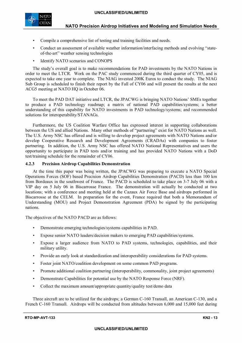
the demonstration. The SOF-based operational scenarios to be demonstrated were designed for a tactical situation considering a portable ground to air missiles threat and no aerial threat. Two ways of dropping the systems are possible under the concept of operations envisioned, depending upon the type of system to be dropped, i.e., ballistic or self guided, and the system�s glide ratio. Therefore, two drop axes are to be used during the demonstration. The first drop axis, or Classic drop axis, is West-to-East and will be used for non guided ballistic systems, or systems with low glide ratio (< 2). The second drop axis, or Stand Off drop axis, is South-to-North along the coast. This axis represent a fictional airway and will be used for systems with high glide ratio (> 2). Figure 7 shows both the Classic (left) and Stand Off (right) drop axes selected for the demonstration.
Figure 7: PACD Classic (left) and Stand Off (right) Drop Axes
5.0 THE NEED FOR AIRDROP SIMULATION TOOLS AND THEIR APPLICATION
5.1 Problem Definition The airdrop simulation task encompasses modelling all aspects of the airdrop environment; from
insertion of the delivery system into the flow fields in, around, and between airdrop aircraft, to the point where the delivery system reaches and stops on the ground. Each component of this scenario must be either explicitly modelled as an element in the simulation or accounted for as a modelling parameter based upon empirical experience.
Traditionally, airdrop systems have been designed using what can be described as lower-order simulation tools to determine the system�s aerodynamic behaviour during various phases of flight, including the opening phase and steady state descent. Two dimensional simulations containing two- and three-Degree of Freedom (DoF) models of the parachute and payload are used to examine a system�s aerodynamic behaviour in a single plane. Higher fidelity, three dimensional simulations, containing six- and nine-DoF models of the parachute and payload, respectively permit one to examine coning effects and the relative motion between the parachute and payload. These aerodynamic simulation tools have traditionally been used in conjunction with commercially available finite element codes, or parachute stress analysis codes such as CANO, developed by Northrup Ventura in the 1960s, and CANA, developed at the Sandia National Laboratory in the 1980s, to design parachutes. The difficulty in applying these simulation tools is not mathematical or numerical in nature, but aerodynamic. Reasonable results are achieved only when the aerodynamic forces and moments are properly modelled. Thus, expensive instrumented flight/airdrop tests must currently be conducted in order to obtain the necessary aerodynamic inputs to the simulations.
Recognizing a need for improved techniques that could be used to speed the fielding of new airdrop
W E
N
S W E
N
S
NATO Precision Airdrop Initiatives and Modeling and Simulation Needs
KN2 - 14 RTO-MP-AVT-133
UNCLASSIFIED/UNLIMITED
UNCLASSIFIED/UNLIMITED
systems while minimizing development costs, the U.S. Army NSC some time ago embarked on the development of a higher-order simulation tool that would not only model the aerodynamic decelerator system as a flexible structure, but also its interaction with the fluid medium through which it passes. In this higher-order simulation scheme, solid dynamics (SD) calculations simulate the response of a system of solid material elements, while computational fluid dynamics (CFD) simulations model the response of the fluid regions of a computational domain. The domain�s fluid is given the additional ability to deform the structural elements of the parachute, i.e., canopy and suspension lines, through what are called fluid-structure-interactions (FSI).
The goal envisioned is to be able to not only approximate quasi-steady-state conditions, but also capture dynamically varying characteristics of the aerodynamic decelerator system from the time it exits the aircraft to the time it reaches the ground. In order to do this, SD calculations will be required to handle non-isotropic material properties, nonlinear material response, large deformations, or even fracture or breaking of material elements. Similarly, CFD calculations will typically need to address modeling issues such as jet dynamics, vortical motion, regions of flow separation, or modeling the turbulent nature of the flow.
Before this goal can ultimately be realized, a number of obstacles in the areas of modeling and airdrop phenomenology, i.e., characterizing the basic mechanics and dynamics of the fluid and structural components, will need to be overcome. Phenomenology-related issues include characterizing the size, shape, construction method, and material composition of the canopy, the size, shape, weight, and operating characteristics of the delivery aircraft and its influence on the resultant airflow, and the way the payload or paratrooper is inserted into the airflow. Modeling issues include implementing stable coupling algorithms between the SD and CFD discretization that control or minimize the build up of such things as projection errors between the domains, being able to interpret the results of a simulation in a meaningful fashion either graphically or through animation, and verifying and validating the simulation methodology against problems that have been well characterized over the years. It is not the intent here to describe ongoing S&T programs to address these issues, since other papers to be presented later at this conference will report on the specifics of those efforts. The intent here is to emphasize why higher-order simulation design tools are needed, and to highlight areas that could benefit from their application. [12, 13, 14, and 15]
5.2 Applications A brief overview of potential areas in which the FSI simulation tools currently under development
might find application is provided in this section. The application areas are directly linked to current or future operational airdrop needs in the form of deployable hardware and mission operational requirements. Applications relate to both the near field ability to predict personnel and cargo airdrop initial deployment, parachute opening, and steady state descent from various aircraft under different conditions, as well as the far field ability to determine the effect of an aircraft�s wake on a system deployed from a trailing aircraft in a flight.
5.2.1 Aircraft-Induced Effects During Deployment
The introduction of larger, more capable delivery aircraft, such as the C-17A, the C-130J, and soon the A400M, has led to a need to more closely examine the flow around the aircraft and its effect on the airdrop deployment of both personnel and cargo. For example, attendant with the C-17�s increased capability to deliver troops and equipment were a number of issues, discovered during operational testing, that FSI simulation tools could have predicted or helped solve. In general, the larger, heavier, and faster the aircraft is, the more it disturbs the ambient air conditions. A prominent effect of the passage of an aircraft through the air is the rollup of the air into wingtip vortices. These vortices extend from the wingtips a significant distance behind the aircraft. The strength of the vortices is dependent on several variables including the speed, size, angle of attack, and weight of the aircraft. Thus, for formations of delivery aircraft, the timing and spacing of the aircraft is a significant consideration in determining the environment
NATO Precision Airdrop Initiatives and Modeling and Simulation Needs
RTO-MP-AVT-133 KN2 - 15
UNCLASSIFIED/UNLIMITED
UNCLASSIFIED/UNLIMITED
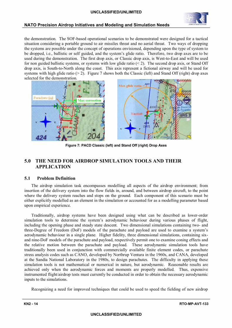
that a decelerator system will encounter after leaving the aircraft. A depiction of wingtip vortices with arrows used to indicate the flow direction is shown in Figure 8 (left) along with a picture of vortices in the C-17 aircraft�s wake (right).
Figure 8: Wingtip Vortices Visualization (left) and C-17 Wingtip Vortices (right)
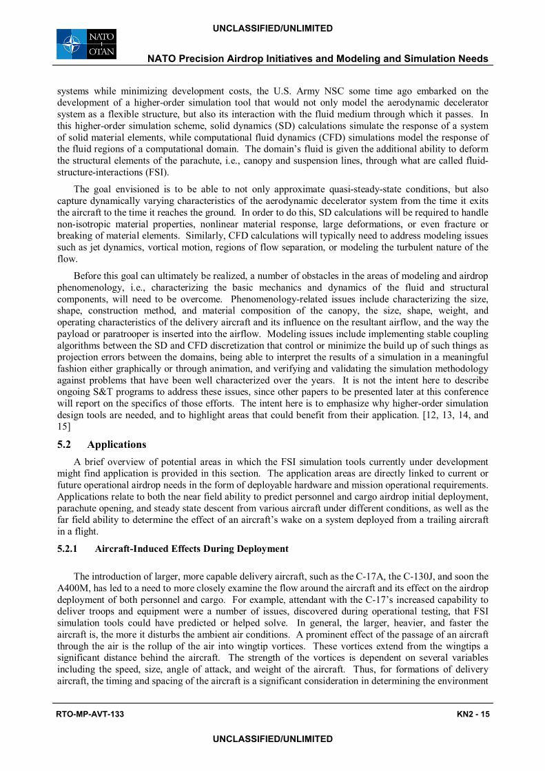
Flow around the C-17 aircraft and the magnitude of the vortices created in its wake, led to a number of issues during the static line deployment of personnel from the side paratrooper doors of the aircraft as shown in Figure 9.
Figure 9: Personnel Static Line Deployment Sequence from C-17 Aircraft
Problems encountered during initial deployment included jumpers coming into contact with the deployment bags attached to the end of other static lines suspended in the air stream, and so called �centerlining,� in which jumpers exiting opposite sides of the aircraft tend to be driven together and come into contact by the vortical flow in the aircraft�s wake. The effect of these vortices on airdrop systems is depicted in Figure 10.
Both materiel and operational solutions were found respectively to these problems; consisting of lengthening the personnel static line by five feet, and increasing the spacing between aircraft carrying paratroopers in the formation. However, it�s worth noting that the latter almost precluded use of the C-17 for the strategic brigade airdrop (SBA) mission, and necessitated another materiel solution for cargo airdrops in the form of the Dual Row Airdrop System (DRAS). During an SBA, 2,400 troops and their support equipment and vehicles must be airdropped in as little time as possible to take advantage of surprise, secure the area, and limit the aircrafts� exposure to ground threats. The much larger wake created by the C-17 aircraft, when compared to that of the smaller C-141 it replaced, and its effect on personnel and cargo airdropped using the Low Velocity Airdrop (LVAD) system, dictated that aircraft in the formation be spaced farther apart. This greatly increased the time it would take to complete the SBA compared to that using the C-141 aircraft. Introduction of the DRAS increased the C-17�s cargo airdrop capacity by 266 percent and reduced the number of aircraft needed for the SBA by up to 30 percent.
NATO Precision Airdrop Initiatives and Modeling and Simulation Needs
KN2 - 16 RTO-MP-AVT-133
UNCLASSIFIED/UNLIMITED
UNCLASSIFIED/UNLIMITED
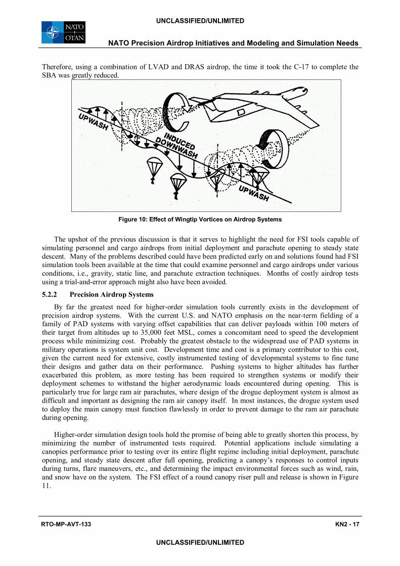
Therefore, using a combination of LVAD and DRAS airdrop, the time it took the C-17 to complete the SBA was greatly reduced.
Figure 10: Effect of Wingtip Vortices on Airdrop Systems
The upshot of the previous discussion is that it serves to highlight the need for FSI tools capable of simulating personnel and cargo airdrops from initial deployment and parachute opening to steady state descent. Many of the problems described could have been predicted early on and solutions found had FSI simulation tools been available at the time that could examine personnel and cargo airdrops under various conditions, i.e., gravity, static line, and parachute extraction techniques. Months of costly airdrop tests using a trial-and-error approach might also have been avoided.
5.2.2 Precision Airdrop Systems
By far the greatest need for higher-order simulation tools currently exists in the development of precision airdrop systems. With the current U.S. and NATO emphasis on the near-term fielding of a family of PAD systems with varying offset capabilities that can deliver payloads within 100 meters of their target from altitudes up to 35,000 feet MSL, comes a concomitant need to speed the development process while minimizing cost. Probably the greatest obstacle to the widespread use of PAD systems in military operations is system unit cost. Development time and cost is a primary contributor to this cost, given the current need for extensive, costly instrumented testing of developmental systems to fine tune their designs and gather data on their performance. Pushing systems to higher altitudes has further exacerbated this problem, as more testing has been required to strengthen systems or modify their deployment schemes to withstand the higher aerodynamic loads encountered during opening. This is particularly true for large ram air parachutes, where design of the drogue deployment system is almost as difficult and important as designing the ram air canopy itself. In most instances, the drogue system used to deploy the main canopy must function flawlessly in order to prevent damage to the ram air parachute during opening.
Higher-order simulation design tools hold the promise of being able to greatly shorten this process, by minimizing the number of instrumented tests required. Potential applications include simulating a canopies performance prior to testing over its entire flight regime including initial deployment, parachute opening, and steady state descent after full opening, predicting a canopy�s responses to control inputs during turns, flare maneuvers, etc., and determining the impact environmental forces such as wind, rain, and snow have on the system. The FSI effect of a round canopy riser pull and release is shown in Figure 11.
NATO Precision Airdrop Initiatives and Modeling and Simulation Needs
RTO-MP-AVT-133 KN2 - 17
UNCLASSIFIED/UNLIMITED
UNCLASSIFIED/UNLIMITED
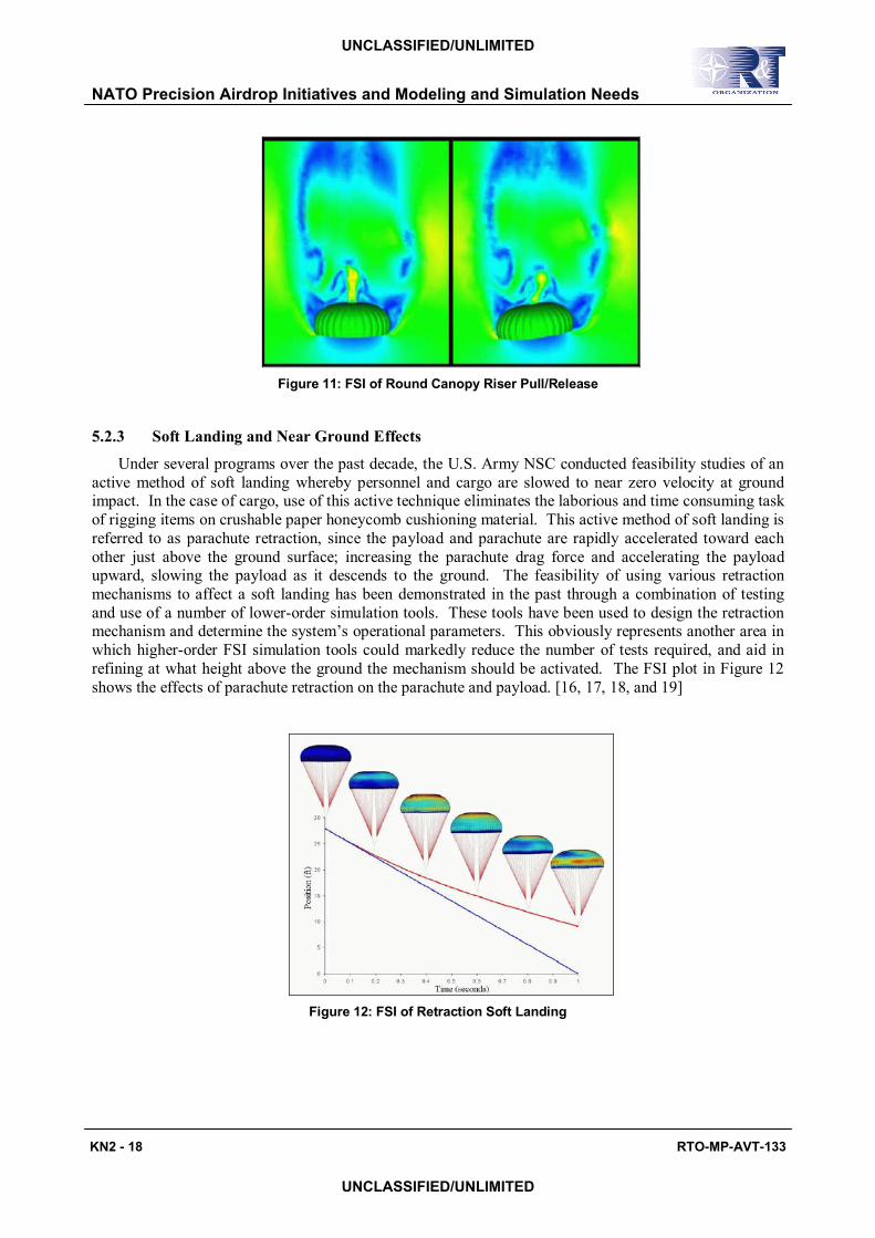
Figure 11: FSI of Round Canopy Riser Pull/Release
5.2.3 Soft Landing and Near Ground Effects
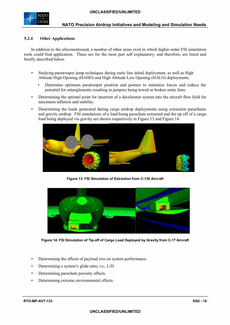
Under several programs over the past decade, the U.S. Army NSC conducted feasibility studies of an active method of soft landing whereby personnel and cargo are slowed to near zero velocity at ground impact. In the case of cargo, use of this active technique eliminates the laborious and time consuming task of rigging items on crushable paper honeycomb cushioning material. This active method of soft landing is referred to as parachute retraction, since the payload and parachute are rapidly accelerated toward each other just above the ground surface; increasing the parachute drag force and accelerating the payload upward, slowing the payload as it descends to the ground. The feasibility of using various retraction mechanisms to affect a soft landing has been demonstrated in the past through a combination of testing and use of a number of lower-order simulation tools. These tools have been used to design the retraction mechanism and determine the system�s operational parameters. This obviously represents another area in which higher-order FSI simulation tools could markedly reduce the number of tests required, and aid in refining at what height above the ground the mechanism should be activated. The FSI plot in Figure 12 shows the effects of parachute retraction on the parachute and payload. [16, 17, 18, and 19]
Figure 12: FSI of Retraction Soft Landing
NATO Precision Airdrop Initiatives and Modeling and Simulation Needs
KN2 - 18 RTO-MP-AVT-133
UNCLASSIFIED/UNLIMITED
UNCLASSIFIED/UNLIMITED
5.2.4 Other Applications
In addition to the aforementioned, a number of other areas exist in which higher-order FSI simulation tools could find application. These are for the most part self explanatory, and therefore, are listed and briefly described below.
� Studying paratrooper jump techniques during static line initial deployment, as well as High
Altitude High Opening (HAHO) and High Altitude Low Opening (HALO) deployments.
� Determine optimum paratrooper position and posture to minimize forces and reduce the potential for entanglements resulting in jumpers being towed or broken static lines.
� Determining the optimal point for insertion of a decelerator system into the aircraft flow field for maximum inflation and stability.
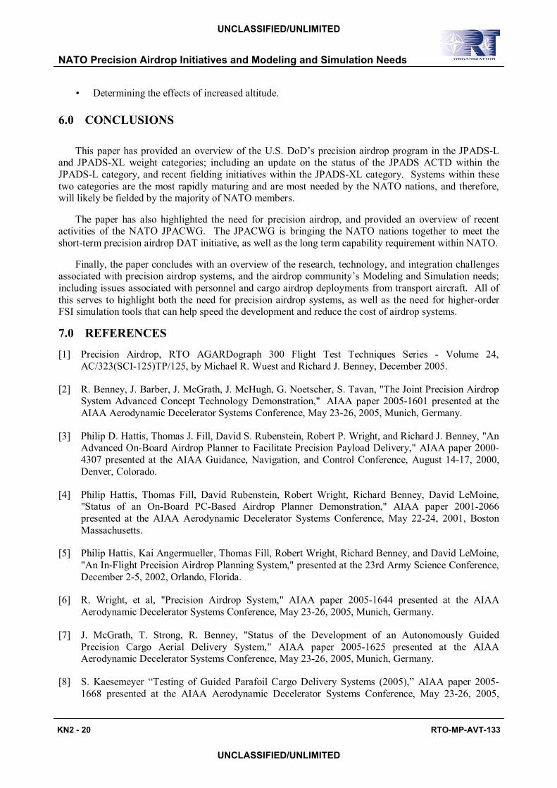
� Determining the loads generated during cargo airdrop deployments using extraction parachutes and gravity airdrop. FSI simulations of a load being parachute extracted and the tip off of a cargo load being deployed via gravity are shown respectively in Figure 13 and Figure 14.
Figure 13: FSI Simulation of Extraction from C-130 Aircraft
Figure 14: FSI Simulation of Tip-off of Cargo Load Deployed by Gravity from C-17 Aircraft
� Determining the effects of payload size on system performance.
� Determining a system�s glide ratio, i.e., L/D.
� Determining parachute porosity effects.
� Determining extreme environmental effects.
NATO Precision Airdrop Initiatives and Modeling and Simulation Needs
RTO-MP-AVT-133 KN2 - 19
UNCLASSIFIED/UNLIMITED
UNCLASSIFIED/UNLIMITED
� Determining the effects of increased altitude.
6.0 CONCLUSIONS
This paper has provided an overview of the U.S. DoD�s precision airdrop program in the JPADS-L and JPADS-XL weight categories; including an update on the status of the JPADS ACTD within the JPADS-L category, and recent fielding initiatives within the JPADS-XL category. Systems within these two categories are the most rapidly maturing and are most needed by the NATO nations, and therefore, will likely be fielded by the majority of NATO members.
The paper has also highlighted the need for precision airdrop, and provided an overview of recent activities of the NATO JPACWG. The JPACWG is bringing the NATO nations together to meet the short-term precision airdrop DAT initiative, as well as the long term capability requirement within NATO.
Finally, the paper concludes with an overview of the research, technology, and integration challenges associated with precision airdrop systems, and the airdrop community�s Modeling and Simulation needs; including issues associated with personnel and cargo airdrop deployments from transport aircraft. All of this serves to highlight both the need for precision airdrop systems, as well as the need for higher-order FSI simulation tools that can help speed the development and reduce the cost of airdrop systems.
7.0 REFERENCES
[1] Precision Airdrop, RTO AGARDograph 300 Flight Test Techniques Series - Volume 24, AC/323(SCI-125)TP/125, by Michael R. Wuest and Richard J. Benney, December 2005.
[2] R. Benney, J. Barber, J. McGrath, J. McHugh, G. Noetscher, S. Tavan, "The Joint Precision Airdrop System Advanced Concept Technology Demonstration," AIAA paper 2005-1601 presented at the AIAA Aerodynamic Decelerator Systems Conference, May 23-26, 2005, Munich, Germany.
[3] Philip D. Hattis, Thomas J. Fill, David S. Rubenstein, Robert P. Wright, and Richard J. Benney, "An Advanced On-Board Airdrop Planner to Facilitate Precision Payload Delivery," AIAA paper 2000-4307 presented at the AIAA Guidance, Navigation, and Control Conference, August 14-17, 2000, Denver, Colorado.
[4] Philip Hattis, Thomas Fill, David Rubenstein, Robert Wright, Richard Benney, David LeMoine, "Status of an On-Board PC-Based Airdrop Planner Demonstration," AIAA paper 2001-2066 presented at the AIAA Aerodynamic Decelerator Systems Conference, May 22-24, 2001, Boston Massachusetts.
[5] Philip Hattis, Kai Angermueller, Thomas Fill, Robert Wright, Richard Benney, and David LeMoine, "An In-Flight Precision Airdrop Planning System," presented at the 23rd Army Science Conference, December 2-5, 2002, Orlando, Florida.
[6] R. Wright, et al, "Precision Airdrop System," AIAA paper 2005-1644 presented at the AIAA Aerodynamic Decelerator Systems Conference, May 23-26, 2005, Munich, Germany.
[7] J. McGrath, T. Strong, R. Benney, "Status of the Development of an Autonomously Guided Precision Cargo Aerial Delivery System," AIAA paper 2005-1625 presented at the AIAA Aerodynamic Decelerator Systems Conference, May 23-26, 2005, Munich, Germany.
[8] S. Kaesemeyer �Testing of Guided Parafoil Cargo Delivery Systems (2005),� AIAA paper 2005-1668 presented at the AIAA Aerodynamic Decelerator Systems Conference, May 23-26, 2005,
NATO Precision Airdrop Initiatives and Modeling and Simulation Needs
KN2 - 20 RTO-MP-AVT-133
UNCLASSIFIED/UNLIMITED
UNCLASSIFIED/UNLIMITED
Munich, Germany.
[9] S. Dellicker, R. Benney, S. Patel, T. Williams, C. Hewgley, P. Yakimenko, R. Howard, and I. Kaminer, "Performance, Control, and Simulation of the Affordable Guided Airdrop System," AIAA paper 2000-4309, presented at the AIAA Guidance, Navigation, and Control Conference, August 14-17, 2000, Denver, Colorado.
[10] V. Dobrokhodov, O. Yakimenko, I. Kaminer, R. Howard, S. Dellicker, and R. Benney, "Development and Flight Testing of the Affordable Guided Airdrop System for G-12 Cargo Parachute," AIAA paper 2001-2060 presented at the AIAA Aerodynamic Decelerator Systems Conference, May 22-24, 2001, Boston, Massachusetts.
[11] B. Gilles, M. Hickey, W. Krainski, "Flight-Testing of a Low-Cost Precision Aerial Delivery System," AIAA paper 2005-1651 presented at the AIAA Aerodynamic Decelerator Systems Conference, May 23-26, 2005, Munich, Germany.
[12] R. Charles, M. Accorsi; S. Morton, R. Tomaro, K. Stein, S. Sathe and T. Tezduyar, �Overview of the Airdrop Systems Modeling Project within the Collaborative Simulation and Test (CST) Common High Performance Computing Software Support Initiative (CHSSI) Portfolio,� AIAA paper 2005-1621 presented at the AIAA Aerodynamic Decelerator Systems Technology Conference, May 23-26, 2005, Munich, Germany.
[13] M. Accorsi, R. Charles, R. Benney, �Computer Simulation and Evaluation of Static Line Deployment Procedures,� AIAA paper 2005-1631 presented at the AIAA Aerodynamic Decelerator Systems Technology Conference, May 23-26, 2005, Munich, Germany.
[14] Z. Xu and M. Accorsi, University of Connecticut, Storrs, CT; R. Benney and R. Charles, Natick Soldier Center, �Large-Scale Parallel Simulation of Contact Phenomena in Airdrop Systems,� AIAA paper 2003-2147 presented at the AIAA Aerodynamic Decelerator Systems Technology Conference, May 19-22, 2003, Monterey, California.
[15] B. Zhou, M. Accorsi, R. Benney, R. Charles, �Two Specialized Structural Elements for Airdrop System Modeling,� AIAA paper 2003-2152 presented at the AIAA Aerodynamic Decelerator Systems Technology Conference, May 19-22, 2003, Monterey, California.
[16] W. J. Krainski Jr. and S. E. Kunz, �The Dynamics of a Parachute Retraction Soft Landing System,� AIAA paper 1997-1540 presented at the AIAA Aerodynamic Decelerator Systems Technology Conference, June 3-5, 1997, San Francisco, CA.
[17] W. J. Krainski Jr. and N. P. Rosato, �Demonstration of a 1,000-Pound Capacity Parachute Retraction Soft Landing System,� AIAA paper 2001-2049, presented at the AIAA Aerodynamic Decelerator Systems Technology Conference, May 21-24, 2001, Boston, MA.
[18] J. Warrick, S. Bulle, S. Motoyama, B. Bagdonovich, R. Benney, �Soft Touchdown and Rapid Rigging/Derigging Airdrop System (STARRDAS),� AIAA paper 2003-2111 presented at the AIAA Aerodynamic Decelerator Systems Technology Conference, May 19-22, 2003, Monterey, California.
[19] G. Brown, R. McCracken, B. Bagdonovich, R. Benney, B. McDermott, �Design, Simulation and Test of a Retraction Softlanding System for Payloads to 20,000 Pounds,� AIAA paper 2003-2112 presented at the AIAA Aerodynamic Decelerator Systems Technology Conference, May 19-22, 2003, Monterey, California.
NATO Precision Airdrop Initiatives and Modeling and Simulation Needs
RTO-MP-AVT-133 KN2 - 21
UNCLASSIFIED/UNLIMITED
UNCLASSIFIED/UNLIMITED
NATO Precision Airdrop Initiatives and Modeling and Simulation Needs
KN2 - 22 RTO-MP-AVT-133
UNCLASSIFIED/UNLIMITED
UNCLASSIFIED/UNLIMITED
Related Documents