831 Nat’l Highway Traffic Safety Admin., DOT § 571.209 S26.3.2 Adjust the steering controls so that the steering wheel hub is at the geometric center of the locus it de- scribes when it is moved through its full range of driving positions. If there is no setting at the geometric center, position it one setting lower than the geometric center. Set the rotation of the steering wheel so that the vehicle wheels are pointed straight ahead. S26.3.3 Locate the vertical plane par- allel to the vehicle longitudinal axis which passes through the geometric center of the opening through which the driver air bag deploys into the oc- cupant compartment. This is referred to as ‘‘Plane E.’’ S26.3.4 Place the dummy in the driv- er’s seat position such that: S26.3.4.1 The midsagittal plane is co- incident with Plane E. S26.3.4.2 The legs are perpendicular to the floor pan and the back of the legs are in contact with the seat cush- ion. The legs may be adjusted if nec- essary to achieve the final head posi- tion. S26.3.4.3 The dummy’s thorax instru- ment cavity rear face is 6 degrees for- ward (toward the front of the vehicle) of the steering wheel angle (i.e., if the steering wheel angle is 25 degrees from vertical, the thorax instrument cavity rear face angle is 31 degrees). S26.3.4.4 The initial transverse dis- tance between the longitudinal centerlines at the front of the dummy’s knees is 160 to 170 mm (6.3 to 6.7 in), with the thighs and legs of the dummy in vertical planes. S26.3.4.5 The upper arms are parallel to the torso and the hands are in con- tact with the thighs. S26.3.5 Maintaining the spine angle, slide the dummy forward until the head/torso contacts the steering wheel. S26.3.6 While maintaining the spine angle, position the dummy so that a point on the chin 40 mm below the cen- ter of the mouth (chin point) is in con- tact with the rim of the uppermost por- tion of the steering wheel. If the dum- my’s head contacts the vehicle wind- shield or upper interior before the pre- scribed position can be obtained, lower the dummy until there is no more than 5 mm (0.2 in) clearance between the ve- hicle’s windshield or upper interior, as applicable. S26.3.7 If the steering wheel can be adjusted so that the chin point can be in contact with the rim of the upper- most portion of the steering wheel, ad- just the steering wheel to that position and readjust the spine angle to coin- cide with the steering wheel angle. Po- sition the dummy so that the chin point is in contact with the rim of the uppermost portion of the steering wheel. S26.3.8 If necessary, material with a maximum breaking strength of 311 N (70 lb) and spacer blocks may be used to support the dummy in position. The material should support the torso rath- er than the head. Support the dummy so that there is minimum interference with the full rotational and translational freedom for the upper torso of the dummy and the material does not interfere with the air bag. S26.4 Deploy the left front outboard frontal air bag system. If the air bag system contains a multistage inflator, the vehicle shall be able to comply with the injury criteria at any stage or combination of stages or time delay be- tween successive stages that could occur in a rigid barrier crash at speeds up to 26 km/h (16 mph) under the test procedure specified in S22.5. S27 through S29 [Reserved] See § 571.208, S27 through S29. [69 FR 3840, Jan. 27, 2004] § 571.209 Standard No. 209; Seat belt assemblies. S1. Purpose and scope. This standard specifies requirements for seat belt as- semblies. S2. Application. This standard applies to seat belt assemblies for use in pas- senger cars, multipurpose passenger ve- hicles, trucks, and buses. S3. Definitions. Adjustment hardware means any or all hardware designed for adjusting the size of a seat belt assem- bly to fit the user, including such hard- ware that may be integral with a buck- le, attachment hardware, or retractor. Attachment hardware means any or all hardware designed for securing the webbing of a seat belt assembly to a motor vehicle. Automatic-locking retractor means a retractor incorporating adjustment hardware by means of a positive self- locking mechanism which is capable VerDate Aug<31>2005 14:58 Dec 10, 2008 Jkt 214214 PO 00000 Frm 00841 Fmt 8010 Sfmt 8010 Y:\SGML\214214.XXX 214214 yshivers on PROD1PC62 with CFR

Welcome message from author
This document is posted to help you gain knowledge. Please leave a comment to let me know what you think about it! Share it to your friends and learn new things together.
Transcript
831
Nat’l Highway Traffic Safety Admin., DOT § 571.209
S26.3.2 Adjust the steering controls so that the steering wheel hub is at the geometric center of the locus it de-scribes when it is moved through its full range of driving positions. If there is no setting at the geometric center, position it one setting lower than the geometric center. Set the rotation of the steering wheel so that the vehicle wheels are pointed straight ahead.
S26.3.3 Locate the vertical plane par-allel to the vehicle longitudinal axis which passes through the geometric center of the opening through which the driver air bag deploys into the oc-cupant compartment. This is referred to as ‘‘Plane E.’’
S26.3.4 Place the dummy in the driv-er’s seat position such that:
S26.3.4.1 The midsagittal plane is co-incident with Plane E.
S26.3.4.2 The legs are perpendicular to the floor pan and the back of the legs are in contact with the seat cush-ion. The legs may be adjusted if nec-essary to achieve the final head posi-tion.
S26.3.4.3 The dummy’s thorax instru-ment cavity rear face is 6 degrees for-ward (toward the front of the vehicle) of the steering wheel angle (i.e., if the steering wheel angle is 25 degrees from vertical, the thorax instrument cavity rear face angle is 31 degrees).
S26.3.4.4 The initial transverse dis-tance between the longitudinal centerlines at the front of the dummy’s knees is 160 to 170 mm (6.3 to 6.7 in), with the thighs and legs of the dummy in vertical planes.
S26.3.4.5 The upper arms are parallel to the torso and the hands are in con-tact with the thighs.
S26.3.5 Maintaining the spine angle, slide the dummy forward until the head/torso contacts the steering wheel.
S26.3.6 While maintaining the spine angle, position the dummy so that a point on the chin 40 mm below the cen-ter of the mouth (chin point) is in con-tact with the rim of the uppermost por-tion of the steering wheel. If the dum-my’s head contacts the vehicle wind-shield or upper interior before the pre-scribed position can be obtained, lower the dummy until there is no more than 5 mm (0.2 in) clearance between the ve-hicle’s windshield or upper interior, as applicable.
S26.3.7 If the steering wheel can be adjusted so that the chin point can be in contact with the rim of the upper-most portion of the steering wheel, ad-just the steering wheel to that position and readjust the spine angle to coin-cide with the steering wheel angle. Po-sition the dummy so that the chin point is in contact with the rim of the uppermost portion of the steering wheel.
S26.3.8 If necessary, material with a maximum breaking strength of 311 N (70 lb) and spacer blocks may be used to support the dummy in position. The material should support the torso rath-er than the head. Support the dummy so that there is minimum interference with the full rotational and translational freedom for the upper torso of the dummy and the material does not interfere with the air bag.
S26.4 Deploy the left front outboard frontal air bag system. If the air bag system contains a multistage inflator, the vehicle shall be able to comply with the injury criteria at any stage or combination of stages or time delay be-tween successive stages that could occur in a rigid barrier crash at speeds up to 26 km/h (16 mph) under the test procedure specified in S22.5.
S27 through S29 [Reserved] See § 571.208, S27 through S29.
[69 FR 3840, Jan. 27, 2004]
§ 571.209 Standard No. 209; Seat belt assemblies.
S1. Purpose and scope. This standard specifies requirements for seat belt as-semblies.
S2. Application. This standard applies to seat belt assemblies for use in pas-senger cars, multipurpose passenger ve-hicles, trucks, and buses.
S3. Definitions. Adjustment hardware means any or all hardware designed for adjusting the size of a seat belt assem-bly to fit the user, including such hard-ware that may be integral with a buck-le, attachment hardware, or retractor.
Attachment hardware means any or all hardware designed for securing the webbing of a seat belt assembly to a motor vehicle.
Automatic-locking retractor means a retractor incorporating adjustment hardware by means of a positive self- locking mechanism which is capable
VerDate Aug<31>2005 14:58 Dec 10, 2008 Jkt 214214 PO 00000 Frm 00841 Fmt 8010 Sfmt 8010 Y:\SGML\214214.XXX 214214yshi
vers
on
PR
OD
1PC
62 w
ith C
FR
832
49 CFR Ch. V (10–1–08 Edition) § 571.209
when locked of withstanding restraint forces.
Buckle means a quick release con-nector which fastens a person in a seat belt assembly.
Emergency-locking retractor means a retractor incorporating adjustment hardware by means of a locking mecha-nism that is activated by vehicle accel-eration, webbing movement relative to the vehicle, or other automatic action during an emergency and is capable when locked of withstanding restraint forces.
Hardware means any metal or rigid plastic part of a seat belt assembly.
Load-limiter means a seat belt assem-bly component or feature that controls tension on the seat belt to modulate the forces that are imparted to occu-pants restrained by the belt assembly during a crash.
Nonlocking retractor means a retrac-tor from which the webbing is extended to essentially its full length by a small external force, which provides no ad-justment for assembly length, and which may or may not be capable of sustaining restraint forces at max-imum webbing extension.
Pelvic restraint means a seat belt as-sembly or portion thereof intended to restrain movement of the pelvis.
Retractor means a device for storing part or all of the webbing in a seat belt assembly.
Seat back retainer means the portion of some seat belt assemblies designed to restrict forward movement of a seat back.
Seat belt assembly means any strap, webbing, or similar device designed to secure a person in a motor vehicle in order to mitigate the results of any ac-cident, including all necessary buckles and other fasteners, and all hardware designed for installing such seat belt assembly in a motor vehicle.
Strap means a narrow nonwoven ma-terial used in a seat belt assembly in place of webbing.
Type 1 seat belt assembly is a lap belt for pelvic restraint.
Type 2 seat belt assembly is a combina-tion of pelvic and upper torso re-straints.
Type 2a shoulder belt is an upper torso restraint for use only in conjunction
with a lap belt as a Type 2 seat belt as-sembly.
Upper torso restraint means a portion of a seat belt assembly intended to re-strain movement of the chest and shoulder regions.
Webbing means a narrow fabric woven with continuous filling yarns and fin-ished selvages.
S4. Requirements. S4.1(a) Incorporation by reference. SAE
Recommended Practice J211–1 rev. De-cember 2003, ‘‘Instrumentation for Im-pact Test—Part 1—Electronic Instru-mentation,’’ is incorporated by ref-erence in S5.2(j) and is hereby made part of this Standard. This incorpora-tion by reference was approved by the Director of the Federal Register in ac-cordance with 5 U.S.C. 552(a) and 1 CFR Part 51. Copies of SAE Recommended Practice J211–1 rev. December 2003, ‘‘Instrumentation for Impact Test— Part 1—Electronic Instrumentation’’ may be obtained from the Society of Automotive Engineers, Inc., 400 Com-monwealth Drive, Warrendale, PA 15096–0001. Copies may be inspected at the National Highway Traffic Safety Administration, Technical Information Services, 400 Seventh Street, SW., Plaza Level, Room 403, Washington, DC 20590, or at the National Archives and Records Administration (NARA). For information on the availability of this material at NARA, call (202) 741–6030, or go to: http://www.archives.gov/ federallregister/ codeloflfederallregulations/ ibrllocations.html.
(b) Single occupancy. A seat belt as-sembly shall be designed for use by one, and only one, person at any one time.
(c) Upper torso restraint. A Type 2 seat belt assembly shall provide upper torso restraint without shifting the pelvic restraint into the abdominal region. An upper torso restraint shall be de-signed to minimize vertical forces on the shoulders and spine. Hardware for upper torso restraint shall be so de-signed and located in the seat belt as-sembly that the possibility of injury to the occupant is minimized.
A Type 2a shoulder belt shall comply with applicable requirements for a Type 2 seat belt assembly in S4.1 to S4.4, inclusive.
VerDate Aug<31>2005 14:58 Dec 10, 2008 Jkt 214214 PO 00000 Frm 00842 Fmt 8010 Sfmt 8010 Y:\SGML\214214.XXX 214214yshi
vers
on
PR
OD
1PC
62 w
ith C
FR
833
Nat’l Highway Traffic Safety Admin., DOT § 571.209
(d) Hardware. All hardware parts which contact under normal usage a person, clothing, or webbing shall be free from burrs and sharp edges.
(e) Release. A Type 1 or Type 2 seat belt assembly shall be provided with a buckle or buckles readily accessible to the occupant to permit his easy and rapid removal from the assembly. Buckle release mechanism shall be de-signed to minimize the possibility of accidental release. A buckle with re-lease mechanism in the latched posi-tion shall have only one opening in which the tongue can be inserted on the end of the buckle designed to re-ceive and latch the tongue.
(f) Attachment hardware. A seat belt assembly shall include all hardware necessary for installation in a motor vehicle in accordance with Society of Automotive Engineers Recommended Practice J800c, ‘‘Motor Vehicle Seat Belt Installation,’’ November 1973. However, seat belt assemblies designed for installation in motor vehicles equipped with seat belt assembly an-chorages that do not require anchorage nuts, plates, or washers, need not have such hardware, but shall have 7⁄16–20 UNF–2A or 1⁄2–13UNC–2A attachment bolts or equivalent metric hardware. The hardware shall be designed to pre-vent attachment bolts and other parts from becoming disengaged from the ve-hicle while in service. Reinforcing plates or washers furnished for uni-versal floor, installations shall be of steel, free from burrs and sharp edges on the peripheral edges adjacent to the vehicle, at least 1.5 mm in thickness and at least 2580 mm2 in projected area. The distance between any edge of the plate and the edge of the bolt hole shall be at least 15 mm. Any corner shall be rounded to a radius of not less than 6 mm or cut so that no corner angle is less than 135° and no side is less than 6 mm in length.
(g) Adjustment. (1) A Type 1 or Type 2 seat belt assembly shall be capable of adjustment to fit occupants whose di-mensions and weight range from those of a 5th-percentile adult female to those of a 95th-percentile adult male. The seat belt assembly shall have ei-ther an automatic-locking retractor, an emergency-locking retractor, or an
adjusting device that is within the reach of the occupant.
(2) A Type 1 or Type 2 seat belt as-sembly for use in a vehicle having seats that are adjustable shall conform to the requirements of S4.1(g)(1) regard-less of seat position. However, if a seat has a back that is separately adjust-able, the requirements of S4.1(g)(1) need be met only with the seat back in the manufacturer’s nominal design riding position.
(3) The adult occupants referred to in S4.1(g)(1) shall have the following measurements:
5th percen- tile adult female
95th percentile adult male
Weight ........................... 46.3 kg ............... 97.5 kg. Erect sitting height ........ 785 mm .............. 965 mm. Hip breadth (sitting) ...... 325 mm .............. 419 mm. Hip circumference (sit-
ting).925 mm .............. 1199 mm.
Waist circumference (sitting).
599 mm .............. 1080 mm.
Chest depth .................. 190 mm .............. 267 mm. Chest circumference:
Nipple ........................ 775 mm .............. 1130 mm. Upper ......................... 757 mm .............. 1130 mm. Lower ......................... 676 mm .............. 1130 mm.
(h) Webbing. The ends of webbing in a seat belt assembly shall be protected or treated to prevent raveling. The end of webbing in a seat belt assembly having a metal-to-metal buckle that is used by the occupant to adjust the size of the assembly shall not pull out of the ad-justment hardware at maximum size adjustment. Provision shall be made for essentially unimpeded movement of webbing routed between a seat back and seat cushion and attached to a re-tractor located behind the seat.
(i) Strap. A strap used in a seat belt assembly to sustain restraint forces shall comply with the requirements for webbing in S4.2, and if the strap is made from a rigid material, it shall comply with applicable requirements in S4.2, S4.3, and S4.4.
(j) Marking. Each seat belt assembly shall be permanently and legibly marked or labeled with year of manu-facture, model, and name or trademark of manufacturer or distributor, or of importer if manufactured outside the United States. A model shall consist of a single combination of webbing having a specific type of fiber weave and con-struction, and hardware having a spe-cific design. Webbings of various colors
VerDate Aug<31>2005 14:58 Dec 10, 2008 Jkt 214214 PO 00000 Frm 00843 Fmt 8010 Sfmt 8010 Y:\SGML\214214.XXX 214214yshi
vers
on
PR
OD
1PC
62 w
ith C
FR
834
49 CFR Ch. V (10–1–08 Edition) § 571.209
may be included under the same model, but webbing of each color shall comply with the requirements for webbing in S4.2.
(k) Installation instructions. A seat belt assembly, other than a seat belt assembly installed in a motor vehicle by an automobile manufacturer, shall be accompanied by an instruction sheet providing sufficient information for in-stalling the assembly in a motor vehi-cle. The installation instructions shall state whether the assembly is for uni-versal installation or for installation only in specifically stated motor vehi-cles, and shall include at least those items specified in SAE Recommended Practice J800c, ‘‘Motor Vehicle Seat Belt Installations,’’ November 1973. If the assembly is for use only in specifi-cally stated motor vehicles, the assem-bly shall either be permanently and legibly marked or labeled with the fol-lowing statement, or the instruction sheet shall include the following state-ment:
This seat belt assembly is for use only in [insert specific seating position(s), e.g., ‘‘front right’’] in [insert specific vehicle make(s) and model(s)].
(l) Usage and maintenance instructions. A seat belt assembly or retractor shall be accompanied by written instruc-tions for the proper use of the assem-bly, stressing particularly the impor-tance of wearing the assembly snugly and properly located on the body, and on the maintenance f the assembly and periodic inspection of all components. The instructions shall show the proper manner of threading webbing in the hardware of seat belt assemblies in which the webbing is not permanently fastened. Instructions for a nonlocking retractor shall include a caution that the webbing must be fully extended from the retractor during use of the seat belt assembly unless the retractor is attached to the free end of webbing which is not subjected to any tension during restraint of an occupant by the assembly. Instructions for Type 2a shoulder belt shall include a warning that the shoulder belt is not to be used without a lap belt.
(m) Workmanship. Seat belt assem-blies shall have good workmanship in accordance with good commercial prac-tice.
S4.2 Requirements for webbing. (a) Width. The width of the webbing
in a seat belt assembly shall be not less than 46 mm, except for portions that do not touch a 95th percentile adult male with the seat in any adjustment posi-tion and the seat back in the manufac-turer’s nominal design riding position when measured under the conditions prescribed in S5.1(a).
(b) Breaking strength. The webbing in a seat belt assembly shall have not less than the following breaking strength when tested by the procedures specified in S5.1(b): Type 1 seat belt assembly— 26,689 N; Type 2 seat belt assembly— 22,241 N for webbing in pelvic restraint and 17,793 N for webbing in upper torso restraint.
(c) Elongation. Except as provided in S4.5, the webbing in a seat belt assem-bly shall not extend to more than the following elongation when subjected to the specified forces in accordance with the procedure specified in S5.1(c): Type 1 seat belt assembly—20 percent at 11,120 N; Type 2 seat belt assembly 30 percent at 11,120 N for webbing in pel-vic restraint and 40 percent at 11,120 N for webbing in upper torso restraint.
(d) Resistance to abrasion. The web-bing of a seat belt assembly, after being subjected to abrasion as specified in S5.1(d) or S5.3(c), shall have a break-ing strength of not less than 75 percent of the breaking strength listed in S4.2(b) for that type of belt assembly.
(e) Resistance to light. The webbing in a seat belt assembly after exposure to the light of a carbon arc and tested by the procedure specified in S5.1(e) shall have a breaking strength not less than 60 percent of the strength before expo-sure to the carbon arc and shall have a color retention not less than No. 2 on the Geometric Gray Scale published by the American Association of Textile Chemists and Colorists, Post Office Box 886, Durham, NC.
(f) Resistance to micro-organisms. The webbing in a seat belt assembly after being subjected to micro-organisms and tested by the procedures specified in S5.1(f) shall have a breaking strength not less than 85 percent of the strength before subjection to micro-or-ganisms.
S4.3 Requirements for hardware.
VerDate Aug<31>2005 14:58 Dec 10, 2008 Jkt 214214 PO 00000 Frm 00844 Fmt 8010 Sfmt 8010 Y:\SGML\214214.XXX 214214yshi
vers
on
PR
OD
1PC
62 w
ith C
FR
835
Nat’l Highway Traffic Safety Admin., DOT § 571.209
(a) Corrosion resistance. (1) Attach-ment hardware of a seat belt assembly after being subjected to the conditions specified in S5.2(a) shall be free of fer-rous corrosion on significant surfaces except for permissible ferrous corro-sion at peripheral edges or edges of holes on underfloor reinforcing plates and washers. Alternatively, such hard-ware at or near the floor shall be pro-tected against corrosion by at least an electrodeposited coating of nickel, or copper and nickel with at least a serv-ice condition number of SC2, and other attachment hardware shall be pro-tected by an electrodeposited coating of nickel, or copper and nickel with a service condition number of SC1, in ac-cordance with American Society for Testing and Materials B456–79, ‘‘Stand-ard Specification for Electrodeposited Coatings of Copper Plus Nickel Plus Chromium and Nickel Plus Chro-mium,’’ but such hardware shall not be racked for electroplating in locations subjected to maximum stress.
(2) Surfaces of buckles, retractors and metallic parts, other than attach-ment hardware, of a seat belt assembly after subjection to the conditions spec-ified in S5.2(a) shall be free of ferrous or nonferrous corrosion which may be transferred, either directly or by means of the webbing, to the occupant or his clothing when the assembly is worn. After test, buckles shall conform to applicable requirements in para-graphs (d) to (g) of this section.
(b) Temperature resistance. Plastic or other nonmetallic hardware parts of a seat belt assembly when subjected to the conditions specified in S5.2(b) shall not warp or otherwise deteriorate to cause the assembly to operate improp-erly or fail to comply with applicable requirements in this section and S4.4.
(c) Attachment hardware. (1) Eye bolts, shoulder bolts, or other bolt used to secure the pelvic restraint of seat belt assembly to a motor vehicle shall withstand a force of 40,034 N when test-ed by the procedure specified in S5.2(c)(1), except that attachment bolts of a seat belt assembly designed for in-stallation in specific models of motor vehicles in which the ends of two or more seat belt assemblies cannot be at-tached to the vehicle by a single bolt
shall have breaking strength of not less than 22,241 N.
(2) Other attachment hardware de-signed to receive the ends of two seat belt assemblies shall withstand a ten-sile force of at least 26,689 N without fracture of a section when tested by the procedure specified in S5.2(c)(2).
(3) A seat belt assembly having single attachment hooks of the quick-dis-connect type for connecting webbing to an eye bolt shall be provided with a re-taining latch or keeper which shall not move more than 2 mm in either the vertical or horizontal direction when tested by the procedure specified in S5.2(c)(3).
(d) Buckle release. (1) The buckle of a Type 1 or Type 2 seat belt assembly shall release when a force of not more than 133 N is applied.
(2) A buckle designed for pushbutton application of buckle release force shall have a minimum area of 452 mm2 with a minimum linear dimension of 10 mm for applying the release force, or a buckle designed for lever application of buckle release force shall permit the insertion of a cylinder 10 mm in diame-ter and 38 mm in length to at least the midpoint of the cylinder along the cyl-inder’s entire length in the actuation portion of the buckle release. A buckle having other design for release shall have adequate access for two or more fingers to actuate release.
(3) The buckle of a Type 1 or Type 2 seat belt assembly shall not release under a compressive force of 1779 N ap-plied as prescribed in paragraph S5.2(d)(3). The buckle shall be operable and shall meet the applicable require-ment of paragraph S4.4 after the com-pressive force has been removed.
(e) Adjustment force. The force re-quired to decrease the size of a seat belt assembly shall not exceed 49 N when measured by the procedure speci-fied in S5.2(e).
(f) Tilt-lock adjustment. The buckle of a seat belt assembly having tilt-lock adjustment shall lock the webbing when tested by the procedure specified in S5.2(f) at an angle of not less than 30 degrees between the base of the buckle and the anchor webbing.
(g) Buckle latch. The buckle latch of a seat belt assembly when tested by the procedure specified in S5.2(g) shall not
VerDate Aug<31>2005 14:58 Dec 10, 2008 Jkt 214214 PO 00000 Frm 00845 Fmt 8010 Sfmt 8010 Y:\SGML\214214.XXX 214214yshi
vers
on
PR
OD
1PC
62 w
ith C
FR
836
49 CFR Ch. V (10–1–08 Edition) § 571.209
fail, nor gall or wear to an extent that normal latching and unlatching is im-paired, and a metal-to-metal buckle shall separate when in any position of partial engagement by a force of not more than 22 N.
(h) Nonlocking retractor. The webbing of a seat belt assembly shall extend from a nonlocking retractor within 6 mm of maximum length when a tension is applied as prescribed in S5.2(h). A nonlocking retractor on upper torso re-straint shall be attached to the non-adjustable end of the assembly, the reel of the retractor shall be easily visible to an occupant while wearing the as-sembly, and the maximum retraction force shall not exceed 5 N in any strap or webbing that contacts the shoulder when measured by the procedure speci-fied in S5.2(h), unless the retractor is attached to the free end of webbing which is not subjected to any tension during restraint of an occupant by the assembly.
(i) Automatic-locking retractor. The webbing of a seat belt assembly equipped with an automatic locking re-tractor, when tested by the procedure specified in S5.2(i), shall not move more than 25 mm between locking posi-tions of the retractor, and shall be re-tracted with a force under zero accel-eration of not less than 3 N when at-tached to pelvic restraint, and not less that 2 N nor more than 5 N in any strap or webbing that contacts the shoulders of an occupant when the retractor is attached to upper torso restraint. An automatic locking retractor attached to upper torso restraint shall not in-crease the restraint on the occupant of the seat belt assembly during use in a vehicle traveling over rough roads as prescribed in S5.2(i).
(j) Emergency-locking retractor. (1) For seat belt assemblies manufac-
tured before February 22, 2007. Except for manufacturers that, at the manufac-turer’s option, voluntarily choose to comply with S4.3(j)(2) during this pe-riod (with said option irrevocably se-lected prior to, or at the time of, cer-tification of the seat belt assembly), an emergency-locking retractor of a Type 1 or Type 2 seat belt assembly, when tested in accordance with the proce-dures specified in paragraph S5.2(j)(1)—
(i) Shall lock before the webbing ex-tends 25 mm when the retractor is sub-jected to an acceleration of 7 m/s2 (0.7 g);
(ii) Shall not lock, if the retractor is sensitive to webbing withdrawal, before the webbing extends 51 mm when the retractor is subjected to an accelera-tion of 3 m/s2 (0.3 g) or less;
(iii) Shall not lock, if the retractor is sensitive to vehicle acceleration, when the retractor is rotated in any direc-tion to any angle of 15° or less from its orientation in the vehicle;
(iv) Shall exert a retractive force of at least 3 N under zero acceleration when attached only to the pelvic re-straint;
(v) Shall exert a retractive force of not less than 1 N and not more than 5 N under zero acceleration when at-tached only to an upper torso re-straint;
(vi) Shall exert a retractive force not less than 1 N and not more than 7 N under zero acceleration when attached to a strap or webbing that restrains both the upper torso and the pelvis.
(2) For seat belt assemblies manufac-tured on or after February 22, 2007 and for manufacturers opting for early compli-ance. An emergency-locking retractor of a Type 1 or Type 2 seat belt assem-bly, when tested in accordance with the procedures specified in paragraph S5.2(j)(2)—
(i) Shall under zero acceleration loading—
(A) Exert a retractive force of not less than 1 N and not more than 7 N when attached to a strap or webbing that restrains both the upper torso and the pelvis;
(B) Exert a retractive force not less than 3 N when attached only to the pel-vic restraint; and
(C) Exert a retractive force of not less than 1 N and not more than 5 N when attached only to an upper torso restraint.
(D) For a retractor sensitive to vehi-cle acceleration, lock when tilted at any angle greater than 45 degrees from the angle at which it is installed in the vehicle or meet the requirements of S4.3(j)(2)(ii).
(E) For a retractor sensitive to vehi-cle acceleration, not lock when the re-tractor is rotated in any direction to
VerDate Aug<31>2005 14:58 Dec 10, 2008 Jkt 214214 PO 00000 Frm 00846 Fmt 8010 Sfmt 8010 Y:\SGML\214214.XXX 214214yshi
vers
on
PR
OD
1PC
62 w
ith C
FR
837
Nat’l Highway Traffic Safety Admin., DOT § 571.209
any angle of 15 degrees or less from its orientation in the vehicle.
(ii) Shall lock before the webbing payout exceeds the maximum limit of 25 mm when the retractor is subjected to an acceleration of 0.7 g under the ap-plicable test conditions of S5.2(j)(2)(iii)(A) or (B). The retractor is determined to be locked when the web-bing belt load tension is at least 35 N.
(iii) For a retractor sensitive to web-bing withdrawal, shall not lock before the webbing payout extends to the minimum limit of 51 mm when the re-tractor is subjected to an acceleration no greater than 0.3 g under the test condition of S5.2(j)(2)(iii)(C).
(k) Performance of retractor. A retrac-tor used on a seat belt assembly after subjection to the tests specified in S5.2(k) shall comply with applicable re-quirements in paragraphs (h) to (j) of this section and S4.4, except that the retraction force shall be not less than 50 percent of its original retraction force.
S4.4 Requirements for assembly per-formance.
(a) Type I seat belt assembly. Except as provided in S4.5, the complete seat belt assembly including webbing, straps, buckles, adjustment and attachment hardware, and retractors shall comply with the following requirements when tested by the procedures specified in S5.3(a):
(1) The assembly loop shall withstand a force of not less than 22,241 N; that is, each structural component of the as-sembly shall withstand a force of not less than 11,120 N.
(2) The assembly loop shall extend not more than 7 inches or 178 mm when subjected to a force of 22,241 N; that is, the length of the assembly between an-chorages shall not increase more than 356 mm.
(3) Any webbing cut by the hardware during test shall have a breaking strength at the cut of not less than 18,683 N.
(4) Complete fracture through any solid section of metal attachment hardware shall not occur during test.
(b) Type 2 seat belt assembly. Except as provided in S4.5, the components of a Type 2 seat belt assembly including webbing, straps, buckles, adjustment and attachment hardware, and retrac-
tors shall comply with the following requirements when tested by the proce-dure specified in S5.3(b):
(1) The structural components in the pelvic restraint shall withstand a force of not less than 11,120 N.
(2) The structural components in the upper torso restraint shall withstand a force of not less than 6,672 N.
(3) The structural components in the assembly that are common to pelvic and upper torso restraints shall with-stand a force of not less than 13,345 N.
(4) The length of the pelvic restraint between anchorages shall not increase more than 508 mm when subjected to a force of 11,120 N.
(5) The length of the upper torso re-straint between anchorages shall not increase more than 508 mm when sub-jected to a force of 6,672 N.
(6) Any webbing cut by the hardware during test shall have a breaking strength of not less than 15,569 N at a cut in webbing of the pelvic restraint, or not less than 12,455 N at a cut in webbing of the upper torso restraint.
(7) Complete fracture through any solid section of metal attachment hardware shall not occur during test.
S4.5 Load-limiter. (a) A Type 1 or Type 2 seat belt assembly that includes a load-limiter is not required to comply with the elongation requirements of S4.2(c), S4.4(a)(2), S4.4(b)(4) or S4.4(b)(5).
(b) A seat belt assembly that includes a load limiter and that does not com-ply with the elongation requirements of this standard may be installed in motor vehicles at any designated seat-ing position that is subject to the re-quirements of S5.1 of Standard No. 208 (§ 571.208).
S4.6 Manual belts subject to crash pro-tection requirements of Standard No. 208.
(a)(1) A manual seat belt assembly, which is subject to the requirements of S5.1 of Standard No. 208 (49 CFR 571.208) by virtue of any provision of Standard No. 208 other than S4.1.2.1(c)(2) of that standard, does not have to meet the re-quirements of S4.2(a)–(f) and S4.4 of this standard.
(2) A manual seat belt assembly sub-ject to the requirements of S5.1 of Standard No. 208 (49 CFR 571.208) by virtue of S4.1.2.1(c)(2) of Standard No.
VerDate Aug<31>2005 14:58 Dec 10, 2008 Jkt 214214 PO 00000 Frm 00847 Fmt 8010 Sfmt 8010 Y:\SGML\214214.XXX 214214yshi
vers
on
PR
OD
1PC
62 w
ith C
FR
838
49 CFR Ch. V (10–1–08 Edition) § 571.209
208 does not have to meet the elon-gation requirements of S4.2(c), S4.4(a)(2), S4.4(b)(4), and S4.4(b)(5) of this standard.
S5. Demonstration procedures. S5.1 Webbing—(a) Width. The width
of webbing from three seat belt assem-blies shall be measured after condi-tioning for at least 24 hours in an at-mosphere having relative humidity be-tween 48 and 67 percent and a tempera-ture of 23° ±2 °C. The tension during measurement of width shall be not more than 22 N on webbing from a Type 1 seat belt assembly, and 9786 N ±450 N on webbing from a Type 2 seat belt as-sembly. The width of webbing from a Type 2 seat belt assembly may be measured during the breaking strength test described in paragraph (b) of this section.
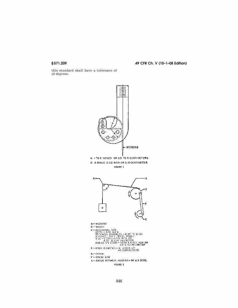
(b) Breaking strength. Webbing from three seat belt assemblies shall be con-ditioned in accordance with paragraph (a) of this section and tested for break-ing strength in a testing machine of ca-pacity verified to have an error of not more than one percent in the range of the breaking strength of the webbing in accordance with American Society for Testing and Materials E4–79 ‘‘Standard Methods of Load Verification of Testing Machines.’’ The machine shall be equipped with split drum grips illustrated in Figure 1, hav-ing a diameter between 51 and 102 mm. The rate of grip separation shall be be-tween 51 and 102 mm per minute. The distance between the centers of the grips at the start of the test shall be between 102 and 254 mm. After placing the specimen in the grips, the webbing shall be stretched continuously at a uniform rate to failure. Each value shall be not less than the applicable breaking strength requirement in S4.2(b), but the median value shall be used for determining the retention of breaking strength in paragraphs (d), (e) and (f) of this section.
(c) Elongation. Elongation shall be measured during the breaking strength test described in paragraph (b) of this section by the following procedure: A preload between 196 N and 245 N shall be placed on the webbing mounted in the grips of the testing machine and the needle points of an extensometer, in which the points remain parallel
during test, are inserted in the center of the specimen. Initially the points shall be set at a known distance apart between 102 and 203 mm. When the force on the webbing reaches the value specified in S4.2(c), the increase in sep-aration of the points of the exten-someter shall be measured and the per-cent elongation shall be calculated to the nearest 0.5 percent. Each value shall be not more than the appropriate elongation requirement in S4.2(c).
(d) Resistance to abrasion. The web-bing from three seat belt assemblies shall be tested for resistance to abra-sion by rubbing over the hexagon bar prescribed in Figure 2 in the following manner: The webbing shall be mounted in the apparatus shown schematically in Figure 2. One end of the webbing (A) shall be attached to a mass (B) of 2.35 kg ±.05 kg, except that a mass of 1.5 kg ±.05 kg shall be used for webbing in pel-vic and upper torso restraints of a belt assembly used in a child restraint sys-tem. The webbing shall be passed over the two new abrading edges of the hex-agon bar (C) and the other end at-tached to an oscillating drum (D) which has a stroke of 330 mm. Suitable guides shall be used to prevent move-ment of the webbing along the axis of hexagonal bar C. Drum D shall be oscil-lated for 5,000 strokes or 2,500 cycles at a rate of 60 ±2 strokes per minute or 30 ±1 cycles per minute. The abraded web-bing shall be conditioned as prescribed in paragraph (a) of this section and tested for breaking strength by the procedure described in paragraph (b) of this section. The median values for the breaking strengths determined on ab-raded and unabraded specimens shall be used to calculate the percentage of breaking strength retained.
(e) Resistance to light. Webbing at least 508 mm in length from three seat belt assemblies shall be suspended vertically on the inside of the specimen track in a Type E carbon-arc light ex-posure apparatus described in Standard Practice for Generating Light-Expo-sure Apparatus (Carbon-Arc Type) With and Without Water for Exposure of Nonmetallic Materials, ASTM Des-ignation: G23 81, published by the American Society for Testing and Ma-terials, except that the filter used for 100 percent polyester yarns shall be
VerDate Aug<31>2005 14:58 Dec 10, 2008 Jkt 214214 PO 00000 Frm 00848 Fmt 8010 Sfmt 8010 Y:\SGML\214214.XXX 214214yshi
vers
on
PR
OD
1PC
62 w
ith C
FR
839
Nat’l Highway Traffic Safety Admin., DOT § 571.209
chemically strengthened soda-lime glass with a transmittance of less than 5 percent for wave lengths equal to or less than 305 nanometers and 90 percent or greater transmittance for wave lengths of 375 to 800 nanometers. The apparatus shall be operated without water spray at an air temperature of 60° ±2 °Celsius ( °C) measured at a point 25 ±5 mm outside the specimen rack and midway in height. The tempera-ture sensing element shall be shielded from radiation. The specimens shall be exposed to light from the carbon-arc for 100 hours and then conditioned as prescribed in paragraph (a) of this sec-tion. The colorfastness of the exposed and conditioned specimens shall be de-termined on the Geometric Gray Scale issued by the American Association of Textile Chemists and Colorists. The breaking strength of the specimens shall be determined by the procedure prescribed in paragraph (b) of this sec-tion. The median values for the break-ing strengths determined on exposed and unexposed specimens shall be used to calculate the percentage of breaking strength retained.
(f) Resistance to micro-organisms. Web-bing at least 508 millimeters (mm) in length from three seat belt assemblies shall first be preconditioned in accord-ance with Appendix A(1) and (2) of American Association of Textile Chem-ists and Colorists Test Method 381, ‘‘Fungicides Evaluation on Textiles; Mildew and Rot Resistance of Tex-tiles,’’ and then subjected to Test I, ‘‘Soil Burial Test’’ of that test method. After soil-burial for a period of 2 weeks, the specimen shall be washed in water, dried and conditioned as pre-scribed in paragraph (a) of this section. The breaking strengths of the speci-mens shall be determined by the proce-dure prescribed in paragraph (b) of this section. The median values for the breaking strengths determined on ex-posed and unexposed specimens shall be used to calculate the percentage of breaking strength retained.
NOTE: This test shall not be required on webbing made from material which is inher-ently resistant to micro-organisms.
S5.2 Hardware. (a) Corrosion resistance. Three seat
belt assemblies shall be tested in ac-cordance with American Society for
Testing and Materials B11773, ‘‘Stand-ard Method of Salt Spray (Fog) Test-ing.’’ Any surface coating or material not intended for permanent retention on the metal parts during service life shall be removed prior to preparation of the test specimens for testing. The period of test shall be 50 hours for all attachment hardware at or near the floor, consisting of two periods of 24 hours exposure to salt spray followed by 1 hour drying and 25 hours for all other hardware, consisting of one pe-riod of 24 hours exposure to salt spray followed by 1 hour drying. In the salt spray test chamber, the parts from the three assemblies shall be oriented dif-ferently, selecting those orientations most likely to develop corrosion on the larger areas. At the end of test, the seat belt assembly shall be washed thoroughly with water to remove the salt. After drying for at least 24 hours under standard laboratory conditions specified in S5.1(a) attachment hard-ware shall be examined for ferrous cor-rosion on significant surfaces, that is, all surfaces that can be contacted by a sphere 19 mm in diameter, and other hardware shall be examined for ferrous and nonferrous corrosion which may be transferred, either directly or by means of the webbing, to a person or his clothing during use of a seat belt assembly incorporating the hardware.
NOTE: When attachment and other hard-ware are permanently fastened, by sewing or other means, to the same piece of webbing, separate assemblies shall be used to test the two types of hardware. The test for corrosion resistance shall not be required for attach-ment hardware made from corrosion-resist-ant steel containing at least 11.5 percent chromium or for attachment hardware pro-tected with an electrodeposited coating of nickel, or copper and nickel, as prescribed in S4.3(a). The assembly that has been used to test the corrosion resistance of the buckle shall be used to measure adjustment force, tilt-lock adjustment, and buckle latch in paragraphs (e), (f), and (g), respectively, of this section, assembly performance in S5.3 and buckle release force in paragraph (d) of this section.
(b) Temperature resistance. Three seat belt assemblies having plastic or non-metallic hardware or having retractors shall be subjected to the conditions prescribed in Procedure D of American Society for Testing and Materials
VerDate Aug<31>2005 14:58 Dec 10, 2008 Jkt 214214 PO 00000 Frm 00849 Fmt 8010 Sfmt 8010 Y:\SGML\214214.XXX 214214yshi
vers
on
PR
OD
1PC
62 w
ith C
FR
840
49 CFR Ch. V (10–1–08 Edition) § 571.209
D756–78, ‘‘Standard Practice for Deter-mination of Weight and Shape Changes of Plastics under Accelerated Service Conditions.’’ The dimension and weight measurement shall be omitted. Buckles shall be unlatched and retractors shall be fully retracted during conditioning. The hardware parts after conditioning shall be used for all applicable tests in S4.3 and S4.4.
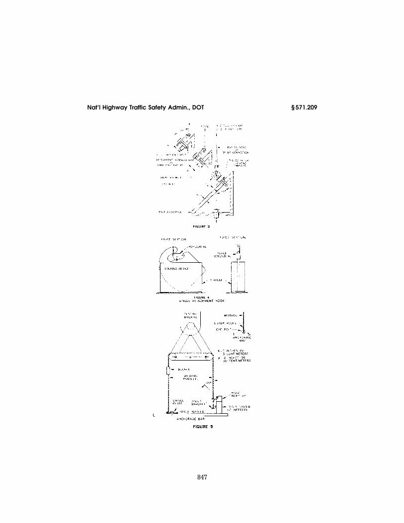
(c) Attachment hardware. (1) Attach-ment bolts used to secure the pelvic re-straint of a seat belt assembly to a motor vehicle shall be tested in a man-ner similar to that shown in Figure 3. The load shall be applied at an angle of 45° to the axis of the bolt through at-tachment hardware from the seat belt assembly, or through a special fixture which simulates the loading applied by the attachment hardware. The attach-ment hardware or simulated fixture shall be fastened by the bolt to the an-chorage shown in Figure 3, which has a standard 7⁄16–20UNF–2B or 1⁄2-UNF–2B or metric equivalent threaded hole in a hardened steel plate at least 10 mm in thickness. The bolt shall be installed with two full threads exposed from the fully seated position. The appropriate force required by S4.3(c) shall be ap-plied. A bolt from each of three seat belt assemblies shall be tested.
(2) Attachment hardware, other than bolts, designed to receive the ends of two seat belt assemblies shall be sub-jected to a tensile force of 26,689 N in a manner simulating use. The hardware shall be examined for fracture after the force is released. Attachment hardware from three seat belt assemblies shall be tested.
(3) Single attachment hook for con-necting webbing to any eye bolt shall be tested in the following manner: The hook shall be held rigidly so that the retainer latch or keeper, with cotter pin or other locking device in place, is in a horizontal position as shown in Figure 4. A force of 667 N ±9 N shall be applied vertically as near as possible to the free end of the retainer latch, and the movement of the latch by this force at the point of application shall be measured. The vertical force shall be released, and a force of 667 N ±9 N shall be applied horizontally as near as possible to the free end of the retainer latch. The movement of the latch by
this force at the point of load applica-tion shall be measured. Alternatively, the hook may be held in other posi-tions, provided the forces are applied and the movements of the latch are measured at the points indicated in Figure 4. A single attachment hook from each of three seat belt assemblies shall be tested.
(d) Buckle release. (1) Three seat belt assemblies shall be tested to determine compliance with the maximum buckle release force requirements, following the assembly test in S5.3. After subjec-tion to the force applicable for the as-sembly being tested, the force shall be reduced and maintained at 667 N on the assembly loop of a Type 1 seat belt as-sembly, 334 N on the components of a Type 2 seat belt assembly. The buckle release force shall be measured by ap-plying a force on the buckle in a man-ner and direction typical of those which would be employed by a seat belt occupant. For push button-release buckles, the force shall be applied at least 3 mm from the edge of the push button access opening of the buckle in a direction that produces maximum re-leasing effect. For lever-release buck-les, the force shall be applied on the centerline of the buckle lever or finger tab in a direction that produces max-imum releasing effect.
(2) The area for application of release force on pushbutton actuated buckle shall be measured to the nearest 30 mm2. The cylinder specified in S4.3(d) shall be inserted in the actuation por-tion of a lever released buckle for de-termination of compliance with the re-quirement. A buckle with other release actuation shall be examined for access of release by fingers.
(3) The buckle of a Type 1 or Type 2 seat belt assembly shall be subjected to a compressive force of 1779 N applied anywhere on a test line that is coinci-dent with the center line of the belt ex-tended through the buckle or on any line that extends over the center of the release mechanism and intersects the extended centerline of the belt at an angle of 60°. The load shall be applied by using a curved cylindrical bar hav-ing a cross section diameter of 19 mm and a radius of curvature of 152 mm, placed with its longitudinal center line
VerDate Aug<31>2005 14:58 Dec 10, 2008 Jkt 214214 PO 00000 Frm 00850 Fmt 8010 Sfmt 8010 Y:\SGML\214214.XXX 214214yshi
vers
on
PR
OD
1PC
62 w
ith C
FR
841
Nat’l Highway Traffic Safety Admin., DOT § 571.209
along the test line and its center di-rectly above the point or the buckle to which the load will be applied. The buckle shall be latched, and a tensile force of 334 N shall be applied to the connected webbing during the applica-tion of the compressive force. Buckles from three seat belt assemblies shall be tested to determine compliance with paragraph S4.3(d)(3).
(e) Adjustment Force. Three seat belt assemblies shall be tested for adjust-ment force on the webbing at the buck-le, or other manual adjusting device normally used to adjust the size of the assembly. With no load on the anchor end, the webbing shall be drawn through the adjusting device at a rate of 508 mm ±50 mm per minute and the maximum force shall be measured to the nearest 1 N after the first 25 mm of webbing movement. The webbing shall be precycled 10 times prior to measure-ment.
(f) Tilt-lock adjustment. This test shall be made on buckles or other manual adjusting devices having tilt-lock ad-justment normally used to adjust the size of the assembly. Three buckles or devices shall be tested. The base of the adjustment mechanism and the anchor end of the webbing shall be oriented in planes normal to each other. The web-bing shall be drawn through the adjust-ment mechanism in a direction to in-crease belt length at a rate of 508 mm ±50 mm per minute while the plane of the base is slowly rotated in a direc-tion to lock the webbing. Rotation shall be stopped when the webbing locks, but the pull on the webbing shall be continued until there is a resistance of at least 89 N. The locking angle be-tween the anchor end of the webbing and the base of the adjustment mecha-nism shall be measured to the nearest degree. The webbing shall be precycled 10 times prior to measurement.
(g) Buckle latch. The buckles from three seat belt assemblies shall be opened fully and closed at least 10 times. Then the buckles shall be clamped or firmly held against a flat surface so as to permit normal move-ment of buckle part, but with the metal mating plate (metal-to-metal buckles) or of webbing end (metal-to- webbing buckles) withdrawn from the buckle. The release mechanism shall be
moved 200 times through the maximum possible travel against its stop with a force of 133 N ±13 N at a rate not to ex-ceed 30 cycles per minute. The buckle shall be examined to determine compli-ance with the performance require-ments of S4.3(g). A metal-to-metal buckle shall be examined to determine whether partial engagement is possible by means of any technique representa-tive of actual use. If partial engage-ment is possible, the maximum force of separation when in such partial en-gagement shall be determined.
(h) Nonlocking retractor. After the re-tractor is cycled 10 times by full exten-sion and retraction of the webbing, the retractor and webbing shall be sus-pended vertically and a force of 18 N shall be applied to extend the webbing from the retractor. The force shall be reduced to 13 N when attached to a pel-vic restraint, or to 5 N per strap or webbing that contacts the shoulder of an occupant when retractor is attached to an upper torso restraint. The resid-ual extension of the webbing shall be measured by manual rotation of the re-tractor drum or by disengaging the re-traction mechanism. Measurements shall be made on three retractors. The location of the retractor attached to upper torso restraint shall be examined for visibility of reel during use of seat belt assembly in a vehicle.
NOTE: This test shall not be required on a nonlocking retractor attached to the free end of webbing which is not subjected to any tension during restraint of an occupant by the assembly.
(i) Automatic-locking retractor. Three retractors shall be tested in a manner to permit the retraction force to be de-termined exclusive of the gravitational forces on hardware or webbing being retracted. The webbing shall be fully extended from the retractor. While the webbing is being retracted, the average force or retraction within plus or minus 51 mm of 75 percent extension (25 percent retraction) shall be deter-mined and the webbing movement be-tween adjacent locking segments shall be measured in the same region of ex-tension. A seat belt assembly with automatic locking retractor in upper torso restraint shall be tested in a ve-hicle in a manner prescribed by the in-stallation and usage instructions. The
VerDate Aug<31>2005 14:58 Dec 10, 2008 Jkt 214214 PO 00000 Frm 00851 Fmt 8010 Sfmt 8010 Y:\SGML\214214.XXX 214214yshi
vers
on
PR
OD
1PC
62 w
ith C
FR
842
49 CFR Ch. V (10–1–08 Edition) § 571.209
retraction force on the occupant of the seat belt assembly shall be determined before and after traveling for 10 min-utes at a speed of 24 kilometers per hour (km/h) or more over a rough road (e.g., Belgian block road) where the oc-cupant is subjected to displacement with respect to the vehicle in both hor-izontal and vertical directions. Meas-urements shall be made with the vehi-cle stopped and the occupant in the normal seated position.
(j) Emergency-locking retractor. (1) For seat belt assemblies manufac-
tured before February 22, 2007. Except for manufacturers that elect to comply with S4.3(j)(2) and the corresponding test procedures of S5.2(j)(2), a retractor shall be tested in a manner that per-mits the retraction force to be deter-mined exclusive of the gravitational forces on hardware or webbing being retracted. The webbing shall be fully extended from the retractor, passing over or through any hardware or other material specified in the installation instructions. While the webbing is being retracted, the lowest force of re-traction within ±51 mm of 75 percent extension shall be determined. A re-tractor that is sensitive to webbing withdrawal shall be subjected to an ac-celeration of 3 m/s2 (0.3 g) within a pe-riod of 50 milliseconds (ms) while the webbing is at 75 percent extension, to determine compliance with S4.3(j)(1)(ii). The retractor shall be sub-jected to an acceleration of 7 m/s2 (0.7 g) within a period of 50 ms, while the webbing is at 75 percent extension, and the webbing movement before locking shall be measured under the following conditions: For a retractor sensitive to webbing withdrawal, the retractor shall be accelerated in the direction of webbing retraction while the retractor drum’s central axis is oriented hori-zontally and at angles of 45°, 90°, 135°, and 180° to the horizontal plane. For a retractor sensitive to vehicle accelera-tion, the retractor shall be:
(i) Accelerated in the horizontal plane in two directions normal to each other, while the retractor drum’s cen-tral axis is oriented at the angle at which it is installed in the vehicle; and
(ii) Accelerated in three directions normal to each other while the retrac-tor drum’s central axis is oriented at
angles of 45°, 90°, 135°, and 180° from the angle at which it is installed in the ve-hicle, unless the retractor locks by gravitational force when tilted in any direction to any angle greater than 45° from the angle at which it is installed in the vehicle.
(2) For seat belt assemblies manufac-tured on or after February 22, 2007 and for manufacturers opting for early compli-ance. A retractor shall be tested in a manner that permits the retraction force to be determined exclusive of the gravitational forces on the hardware or webbing being retracted.
(i) Retraction force: The webbing shall be extended fully from the retrac-tor, passing over and through any hard-ware or other material specified in the installation instructions. While the webbing is being retracted, measure the lowest force of retraction within ±51 mm of 75 percent extension.
(ii) Gravitational locking: For a re-tractor sensitive to vehicle accelera-tion, rotate the retractor in any direc-tion to an angle greater than 45 degrees from the angle at which it is installed in the vehicle. Apply a force to the webbing greater than the minimum force measured in S5.2(j)(2)(i) to deter-mine compliance with S4.3(j)(2)(i)(D).
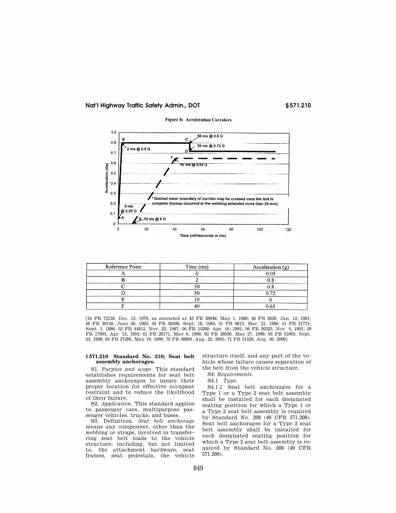
(iii) Dynamic tests: Each accelera-tion pulse shall be recorded using an accelerometer having a full scale range of ±10 g and processed according to the practices set forth in SAE Rec-ommended Practice J211–1 rev. Decem-ber 2003, ‘‘Instrumentation for Impact Test—Part 1—Electronic Instrumenta-tion,’’ Channel Frequency Class 60. The webbing shall be positioned at 75 per-cent extension, and the displacement shall be measured using a displacement transducer. For tests specified in S5.2(j)(2)(iii)(A) and (B), the 0.7 g accel-eration pulse shall be within the accel-eration-time corridor shown in Figure 8 of this standard.
(A) For a retractor sensitive to vehi-cle acceleration—
(1) The retractor drum’s central axis shall be oriented at the angle at which it is installed in the vehicle ±0.5 de-grees. Accelerate the retractor in the horizontal plane in two directions nor-mal to each other and measure the webbing payout; and
VerDate Aug<31>2005 14:58 Dec 10, 2008 Jkt 214214 PO 00000 Frm 00852 Fmt 8010 Sfmt 8010 Y:\SGML\214214.XXX 214214yshi
vers
on
PR
OD
1PC
62 w
ith C
FR
843
Nat’l Highway Traffic Safety Admin., DOT § 571.209
(2) If the retractor does not meet the 45-degree tilt-lock requirement of S4.3(j)(2)(i)(D), accelerate the retractor in three directions normal to each other while the retractor drum’s cen-tral axis is oriented at angles of 45, 90, 135, and 180 degrees from the angle at which it is installed in the vehicle and measure webbing payout.
(B) For a retractor sensitive to web-bing withdrawal—
(1) The retractor drum’s central axis shall be oriented horizontally ±0.5 de-grees. Accelerate the retractor in the direction of webbing retraction and measure webbing payout; and
(2) The retractor drum’s central axis is oriented at angles of 45, 90, 135, and 180 degrees to the horizontal plane. Ac-celerate the retractor in the direction of the webbing retraction and measure the webbing payout.
(C) A retractor that is sensitive to webbing withdrawal shall be subjected to an acceleration no greater than 0.3 g occurring within a period of the first 50 ms and sustaining an acceleration no greater than 0.3 g throughout the test, while the webbing is at 75 percent ex-tension. Measure the webbing payout.
(k) Performance of retractor. After completion of the corrosion-resistance test described in paragraph (a) of this section, the webbing shall be fully ex-tended and allowed to dry for at least 24 hours under standard laboratory conditions specified in S5.1(a). The re-tractor shall be examined for ferrous and nonferrous corrosion which may be transferred, either directly or by means of the webbing, to a person or his clothing during use of a seat belt assembly incorporating the retractor, and for ferrous corrosion on significant surfaces if the retractor is part of the attachment hardware. The webbing shall be withdrawn manually and al-lowed to retract for 25 cycles. The re-tractor shall be mounted in an appa-ratus capable of extending the webbing fully, applying a force of 89 N at full extension, and allowing the webbing to retract freely and completely. The webbing shall be withdrawn from the retractor and allowed to retract re-peatedly in this apparatus until 2,500 cycles are completed. The retractor and webbing shall then be subjected to the temperature resistance test pre-
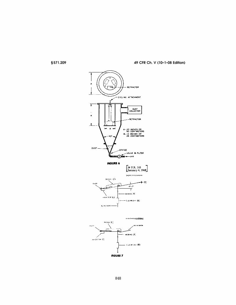
scribed in paragraph (b) of this section. The retractor shall be subjected to 2,500 additional cycles of webbing with-drawal and retraction. Then, the re-tractor and webbing shall be subjected to dust in a chamber similar to one il-lustrated in Figure 8 containing about 0.9 kg of coarse grade dust conforming to the specification given in Society of Automotive Engineering Rec-ommended Practice J726, ‘‘Air Cleaner Test Code’’ Sept. 1979. The dust shall be agitated every 20 minutes for 5 seconds by compressed air, free of oil and mois-ture, at a gage pressure of 550 ±55 kPa entering through an orifice 1.5 ±0.1 mm in diameter. The webbing shall be ex-tended to the top of the chamber and kept extended at all times except that the webbing shall be subjected to 10 cy-cles of complete retraction and exten-sion within 1 to 2 minutes after each agitation of the dust. At the end of 5 hours, the assembly shall be removed from the chamber. The webbing shall be fully withdrawn from the retractor manually and allowed to retract com-pletely for 25 cycles. An automatic- locking retractor or a nonlocking re-tractor attached to pelvic restraint shall be subjected to 5,000 additional cycles of webbing withdrawal and re-traction. An emergency locking retrac-tor or a nonlocking retractor attached to upper torso restraint shall be sub-jected to 45,000 additional cycles of webbing withdrawal and retraction be-tween 50 and 100 per cent extension. The locking mechanism of an emer-gency locking retractor shall be actu-ated at least 10,000 times within 50 to 100 percent extension of webbing during the 50,000 cycles. At the end of test, compliance of the retractors with ap-plicable requirements in S4.3 (h), (i), and (j) shall be determined. Three re-tractors shall be tested for perform-ance.
S5.3 Assembly performance—(a) Type 1 seat belt assembly. Three complete seat belt assemblies, including webbing, straps, buckles, adjustment and at-tachment hardware, and retractors, ar-ranged in the form of a loop as shown in Figure 5, shall be tested in the fol-lowing manner:
(1) The testing machine shall con-form to the requirements specified in S5.1(b). A double-roller block shall be
VerDate Aug<31>2005 14:58 Dec 10, 2008 Jkt 214214 PO 00000 Frm 00853 Fmt 8010 Sfmt 8010 Y:\SGML\214214.XXX 214214yshi
vers
on
PR
OD
1PC
62 w
ith C
FR
844
49 CFR Ch. V (10–1–08 Edition) § 571.209
attached to one head of the testing ma-chine. This block shall consist of two rollers 102 mm in diameter and suffi-ciently long so that no part of the seat belt assembly touches parts of the block other than the rollers during test. The rollers shall be mounted on antifriction bearings and spaced 305 mm between centers, and shall have sufficient capacity so that there is no brinelling, bending or other distortion of parts which may affect the results. An anchorage bar shall be fastened to the other head of the testing machine.
(2) The attachment hardware fur-nished with the seat belt assembly shall be attached to the anchorage bar. The anchor points shall be spaced so that the webbing is parallel in the two sides of the loop. The attaching bolts shall be parallel to, or at an angle of 45° or 90° to the webbing, whichever re-sults in an angle nearest to 90° between webbing and attachment hardware ex-cept that eye bolts shall be vertical, and attaching bolts or nonthreaded an-chorages of a seat belt assembly de-signed for use in specific models of motor vehicles shall be installed to produce the maximum angle in use in-dicated by the installation instruc-tions, utilizing special fixtures if nec-essary to simulate installation in the motor vehicle. Rigid adapters between anchorage bar and attachment hard-ware shall be used if necessary to lo-cate and orient the adjustment hard-ware. The adapters shall have a flat support face perpendicular to the threaded hole for the attaching bolt and adequate in area to provide full support for the base of the attachment hardware connected to the webbing. If necessary, a washer shall be used under a swivel plate or other attachment hardware to prevent the webbing from being damaged as the attaching bolt is tightened.
(3) The length of the assembly loop from attaching bolt to attaching bolt shall be adjusted to about 1295 mm, or as near thereto as possible. A force of 245 N shall be applied to the loop to re-move any slack in webbing at hard-ware. The force shall be removed and the heads of the testing machine shall be adjusted for an assembly loop be-tween 1220 and 1270 mm in length. The length of the assembly loop shall then
be adjusted by applying a force be-tween 89 and 98 N to the free end of the webbing at the buckle, or by the re-traction force of an automatic-locking or emergency-locking retractor. A seat belt assembly that cannot be adjusted to this length shall be adjusted as closely as possible. An automatic-lock-ing or emergency locking retractor when included in a seat belt assembly shall be locked at the start of the test with a tension on the webbing slightly in excess of the retractive force in order to keep the retractor locked. The buckle shall be in a location so that it does not touch the rollers during test, but to facilitate making the buckle re-lease test in S5.2(d) the buckle should be between the rollers or near a roller in one leg.
(4) The heads of the testing machine shall be separated at a rate between 51 and 102 mm per minute until a force of 22,241 ±222 N is applied to the assembly loop. The extension of the loop shall be determined from measurements of head separation before and after the force is applied. The force shall be decreased to 667 ±45 N and the buckle release force measured as prescribed in S5.2(d).
(5) After the buckle is released, the webbing shall be examined for cutting by the hardware. If the yarns are par-tially or completely severed in a line for a distance of 10 percent or more of the webbing width, the cut webbing shall be tested for breaking strength as specified in S5.1(b) locating the cut in the free length between grips. If there is insufficient webbing on either side of the cut to make such a test for break-ing strength, another seat belt assem-bly shall be used with the webbing repositioned in the hardware. A tensile force of 11,120 ±111 N shall be applied to the components or a force of 22,241 ±222 N shall be applied to the assembly loop. After the force is removed, the break-ing strength of the cut webbing shall be determined as prescribed above.
(6) If a Type 1 seat belt assembly in-cludes an automatic-locking retractor or an emergency-locking retractor, the webbing and retractor shall be sub-jected to a tensile force of 11,120 ±111 N with the webbing fully extended from the retractor.
VerDate Aug<31>2005 14:58 Dec 10, 2008 Jkt 214214 PO 00000 Frm 00854 Fmt 8010 Sfmt 8010 Y:\SGML\214214.XXX 214214yshi
vers
on
PR
OD
1PC
62 w
ith C
FR
845
Nat’l Highway Traffic Safety Admin., DOT § 571.209
(7) If a seat belt assembly has a buck-le in which the tongue is capable of in-verted insertion, one of the three as-semblies shall be tested with the tongue inverted.
(b) Type 2 seat belt assembly. Compo-nents of three seat belt assemblies shall be tested in the following man-ner:
(1) The pelvic restraint between an-chorages shall be adjusted to a length between 1220 and 1270 mm, or as near this length as possible if the design of the pelvic restraint does not permit its adjustment to this length. An auto-matic-locking or emergency-locking retractor when included in a seat belt assembly shall be locked at the start of the test with a tension on the webbing slightly in excess of the retractive force in order to keep the retractor locked. The attachment hardware shall be oriented to the webbing as specified in paragraph (a)(2) of this section and illustrated in Figure 5. A tensile force 11,120 ±111 N shall be applied on the components in any convenient manner and the extension between anchorages under this force shall be measured. The force shall be reduced to 334 ±22 N and the buckle release force measured as prescribed in S5.2(d).
(2) The components of the upper torso restraint shall be subjected to a tensile force of 6,672 ±67 N following the procedure prescribed above for testing pelvic restraint and the extension be-tween anchorages under this force shall be measured. If the testing apparatus permits, the pelvic and upper torso re-straints may be tested simultaneously. The force shall be reduced to 334 ±22 N and the buckle release force measured as prescribed in S5.2(d).
(3) Any component of the seat belt assembly common to both pelvic and upper torso restraint shall be subjected to a tensile force of 13,344 ±134 N.
(4) After the buckle is released in tests of pelvic and upper torso re-straints, the webbing shall be examined for cutting by the hardware. If the yarns are partially or completely sev-ered in a line for a distance of 10 per-cent or more of the webbing width, the cut webbing shall be tested for break-ing strength as specified in S5.1(b) lo-cating the cut in the free length be-tween grips. If there is insufficient
webbing on either side of the cut to make such a test for breaking strength, another seat belt assembly shall be used with the webbing reposi-tioned in the hardware. The force ap-plied shall be 11,120 ±111 N for compo-nents of pelvic restraint, and 6,672 ±67 N for components of upper torso re-straint. After the force is removed, the breaking strength of the cut webbing shall be determined as prescribed above.
(5) If a Type 2 seat belt assembly in-cludes an automatic-locking retractor or an emergency-locking retractor the webbing and retractor shall be sub-jected to a tensile force of 11,120 ±111 N with the webbing fully extended from the retractor, or to a tensile force of 6,672 ±67 N with the webbing fully ex-tended from the retractor if the design of the assembly permits only upper torso restraint forces on the retractor.
(6) If a seat belt assembly has a buck-le in which the tongue is capable of in-verted insertion, one of the three as-semblies shall be tested with the tongue inverted.
(c) Resistance to buckle abrasion. Seat belt assemblies shall be tested for re-sistance to abrasion by each buckle or manual adjusting device normally used to adjust the size of the assembly. The webbing of the assembly to be used in this test shall be exposed for 4 hours to an atmosphere having relative humid-ity of 65 per cent and temperature of 18 °C. The webbing shall be pulled back and forth through the buckle or man-ual adjusting device as shown sche-matically in Figure 7. The anchor end of the webbing (A) shall be attached to a mass (B) of 1.4 kg. The webbing shall pass through the buckle (C), and the other end (D) shall be attached to a re-ciprocating device so that the webbing forms an angle of 8° with the hinge stop (E). The reciprocating device shall be operated for 2,500 cycles at a rate of 18 cycles per minute with a stroke length of 203 mm. The abraded webbing shall be tested for breaking strength by the procedure described in paragraph S5.1(b).
S5.4 Tolerances on angles. Unless a range of angles is specified or a toler-ance is otherwise explicitly provided, all angles and orientations of seat belt assemblies and components specified in
VerDate Aug<31>2005 14:58 Dec 10, 2008 Jkt 214214 PO 00000 Frm 00855 Fmt 8010 Sfmt 8010 Y:\SGML\214214.XXX 214214yshi
vers
on
PR
OD
1PC
62 w
ith C
FR
846
49 CFR Ch. V (10–1–08 Edition) § 571.209
this standard shall have a tolerance of ±3 degrees.
VerDate Aug<31>2005 14:58 Dec 10, 2008 Jkt 214214 PO 00000 Frm 00856 Fmt 8010 Sfmt 8006 Y:\SGML\214214.XXX 214214 EC
01A
U91
.090
</G
PH
>
yshi
vers
on
PR
OD
1PC
62 w
ith C
FR
847
Nat’l Highway Traffic Safety Admin., DOT § 571.209
VerDate Aug<31>2005 14:58 Dec 10, 2008 Jkt 214214 PO 00000 Frm 00857 Fmt 8010 Sfmt 8006 Y:\SGML\214214.XXX 214214 EC
01A
U91
.091
</G
PH
>
yshi
vers
on
PR
OD
1PC
62 w
ith C
FR
848
49 CFR Ch. V (10–1–08 Edition) § 571.209
VerDate Aug<31>2005 14:58 Dec 10, 2008 Jkt 214214 PO 00000 Frm 00858 Fmt 8010 Sfmt 8006 Y:\SGML\214214.XXX 214214 EC
01A
U91
.092
</G
PH
>E
C01
AU
91.0
93<
/GP
H>
yshi
vers
on
PR
OD
1PC
62 w
ith C
FR
849
Nat’l Highway Traffic Safety Admin., DOT § 571.210
[44 FR 72139, Dec. 13, 1979, as amended at 45 FR 29048, May 1, 1980; 46 FR 2620, Jan. 12, 1981; 48 FR 30140, June 30, 1983; 49 FR 36508, Sept. 18, 1984; 51 FR 9813, Mar. 21, 1986; 51 FR 31774, Sept. 5, 1986; 52 FR 44912, Nov. 23, 1987; 56 FR 15299, Apr. 16, 1991; 56 FR 56325, Nov. 4, 1991; 59 FR 17994, Apr. 15, 1994; 61 FR 20171, May 6, 1996; 63 FR 28936, May 27, 1998; 63 FR 51003, Sept. 24, 1998; 64 FR 27206, May 19, 1999; 70 FR 48894, Aug. 22, 2005; 71 FR 51529, Aug. 30, 2006]
§ 571.210 Standard No. 210; Seat belt assembly anchorages.
S1. Purpose and scope. This standard establishes requirements for seat belt assembly anchorages to insure their proper location for effective occupant restraint and to reduce the likelihood of their failure.
S2. Application. This standard applies to passenger cars, multipurpose pas-senger vehicles, trucks, and buses.
S3. Definition. Seat belt anchorage means any component, other than the webbing or straps, involved in transfer-ring seat belt loads to the vehicle structure, including, but not limited to, the attachment hardware, seat frames, seat pedestals, the vehicle
structure itself, and any part of the ve-hicle whose failure causes separation of the belt from the vehicle structure.
S4. Requirements. S4.1 Type. S4.1.1 Seat belt anchorages for a
Type 1 or a Type 2 seat belt assembly shall be installed for each designated seating position for which a Type 1 or a Type 2 seat belt assembly is required by Standard No. 208 (49 CFR 571.208). Seat belt anchorages for a Type 2 seat belt assembly shall be installed for each designated seating position for which a Type 2 seat belt assembly is re-quired by Standard No. 208 (49 CFR 571.208).
VerDate Aug<31>2005 14:58 Dec 10, 2008 Jkt 214214 PO 00000 Frm 00859 Fmt 8010 Sfmt 8010 Y:\SGML\214214.XXX 214214 ER
22A
U05
.016
</G
PH
>
yshi
vers
on
PR
OD
1PC
62 w
ith C
FR
Related Documents