.,. ,., NATIONALADVISORYCOMMITTEE FOR AERONAUTICS TECHNICAL MEMORANDUM 1341 APPROXIMATE HYDRODYNAMIC DESIGN OF A FINITE SPAN HYDROFOIL By A. N. Vladimirov Translation Pkiblizliennyi gidrodinarnicheskii raschet podvodnogo kryla konechnogo ra zmakha. Central Aerb -Hydrodynamical Institute, Report 311, 1$)37. June 1955

Welcome message from author
This document is posted to help you gain knowledge. Please leave a comment to let me know what you think about it! Share it to your friends and learn new things together.
Transcript

.,.,.,
NATIONALADVISORYCOMMITTEEFOR AERONAUTICS
TECHNICAL MEMORANDUM 1341
APPROXIMATE HYDRODYNAMIC DESIGN OF A FINITE
SPAN HYDROFOIL
By A. N. Vladimirov
Translation
Pkiblizliennyi gidrodinarnicheskii raschet podvodnogo kryla konechnogo
ra zmakha. Central Aerb -Hydrodynamical Institute, Report 311, 1$)37.
June 1955

—
1illllllllllllll~MIMlllll~llllllll!n..< :_17~ol~0 4652
NATIONAL ADVISORY COMMITTEE FORCAERONAUTICS
TECHNICAL MEMORANDUM 1341
& APPROXIWE HYDRODYNAMIC DESIGN OF A FINITE SPAN HYDROFOIL*,.
By A. N. Vladimirov
suMMARY
Some problems concerning the motions of a hydrofoil are discussed.The results of theoretical investigations on motions of different bodiesunder a free surface of a heavy perfect fluid are revised, and for allcases diagrams of forces acting on moving bodies are given. The problemsolved by Lamb for the motion of a circular cylinder and several problemssolved during the last three years in the Central Aero-HydrodynamicalInstitute (Moscow) are discussed. The latter are: the work by L.Sretensky on the motion of a vortex, the work by N. Kotchin on the mo-tion of an arbitrary contour of streamline form (in the present articleonly a particular case of motion of a circular cylinder with a circula-tion around it is discussed) , and the work by M. Keldysh and M.Lavrentiev on the motion of a plate and a circular aerofoil.
.-
The analytical solution of the problem of motion of a plate isapplied to an approximate hydrodynamic design of a hydrofoil, and on thebasis of this solution diagrams are plotted allowing the determination ofthe lift and wave resistance of an infinite span hydrofoil during itsmotion in a fluid without friction.
Further, some considerations of the viscosity effect are given anda method of taking into account the finite span of the hydrofoil issuggested where an attempt is made at an approximate consideration of theeffect of a free surface on the downwash behind a hydrofoil.
Further, some descriptions and experimental data for a hydrofoiltested in the CAHI tank are given and a comparison of theoretical withexperimental data is made.
The described work forms a basis for an approximate hydrodynamicdesign of a finite span hydrofoil for small angles of incidence and fordepths of immersion equaling and somewhat exceeding the chord length.
*Priblizhennyi gidrodinamicheskii raschet podvodnogo kryla konechnogorazmakha. Central Aero-Hydrodynamical Institute, Report 311, 1937.

2 NACA TM 1341
INTRODUCTION
The hydrodynamic supporting forces act only on the lower surface ofa planing boat. The supporting wings of airplanes are subject to theaction of pressure forces on the lower surface and to suction forces onthe upper surface. The motion of a planing profile inclined at a smallsngle of attack and the motion of the same body in infinite flow areconsidered here. The analogy established by Wagner (ref. 1) existsbetween the two flows considered.
From this analogy, with an accuracy up to second-order smallness,it follows that a planing foil during its motion is acted upon by a liftforce A, a spray-forming resistance r, and the sum of all other resist-ances R, while a vane moving in an infinite flow is acted upon by a liftforce 2A and the sum of all resistances 2R (all measured in kg); thatis, it has no spray-forming resistance.the planing foil kl is therefore equal
The hydrodynamic efficie~cy ofto
(a)
and the efficiency k2 of the foil entirely submerged is equal to
k2=~ (b)
that is,
kz > kl (c)
Investigations of the problem of increasing the speed of boats andlowering the power required by mounting hytiofoils on the bottom havebeen carried on abroad for some time. Investigations along this lineare also being conducted in this country. The efficiency of hydrofoils
decreases in the presence of the frontal resistance of the supports towhich the vanes are attached. It is therefore desirable that during themotion of the boat the hydrof’o~ls be located stificiently near the free
water surface. Because of the nearness of the free surface the hydro-dynamic characteristics of the hydrofoil change; they do not follow thelaws of motion of the same hydrofoil in an infinite fluid. The needtherefore arises for an available method for the hydrodynamic computa-tion of a hydrofoil on the basis of which the designer, by a computationalprocedure, could obtain the hydrodynamic polar curves of the foil selectedfor its motion at various depths of submersion. It is customary for thedesigner to have available the aerodynamic polar curves for the hydrofoilof interest.
If a body of streamlined shape, for example, a wing, moves in aninfinite real fluid, the effect of the gravity force which shows up in
.,,. ,,., . . —_I

NACA TM 1341 3
the Archimedean law of buoy.~cy can very simply be taken into account andonly the effect of the forces of inertia and viscosity need be considered.There the~ holds true the.well-kno~ Recnolds law of similitude on thebasis””of which the forces exerted by the fluid on the wing or body areexpressed by the formulas
Lift force A = Cypsvz
Frontal resistance R = Cxpsvz
[NACA Translator’s note: The more generally used coefficients today(1951) are twice the magnitude of the coefficients used in this report,since p is now replaced by p/2.]
where the nondimensional coefficients Cy ad Cx are functions of the
Reynolds number and the shape and position of the body. The scheme ofan infinite flow of a weightless liquid is adopted in problems in whichthe flight dynamics of an airplane at large distance from the ground areconsidered. In studying the motion of a wing near the free surface ofthe water, it is necessary to take into account the action of the forceof gravity on the fluid, because the wave disturbances of the free surfacebehind the wing alter in a fundamental way the hydrodynamics of the lat-ter. It is known that in this case of motion, the forces exerted on thewing by the water are expressed by the formulas given. The nondimensionalcoefficients Cy and Cx, however, will in this case be functions not
only of the Reynolds number but also of the Froude number. In the for-eign literature on theoretical hydrodynamics there is very little infor-mation on the motions of bodies under the free surface of a heavy fluid.There is a particular lack of information on the problems of the motionof underwater wings (hydrofoils), and the papers available refer only tothe circular cylinder. In regard to the history of this problem, a quo-tation is presented from the work of L. N. Sretensky (ref. 2):
“The problem here studied (the flow of a heavy fluid about an immersedcircular cylinder)l is presented in literature. The problem was firstposed by Keldysh in 1904 and was first solved by Lamb (ref. 3). Thesolution, given by Lamb, is-approximate and consists of the addition tothe potential of the infinite flow of a correction term, the object ofwhich is to satisfy the condition at the surface. The introduction ofthis term, however, disturbs the conditions of flow about the cylinder.
“The next step in the solution of the problem was taken by Havelock(ref. 4). Making use of the methods of conformal mapping, Havelockextended the equation of Lamb by the addition of new terms with the pur-pose of setting up the conditions of flow about the cylinder. The SOIU-
tion of Havelock is also approximate, but the method indicated by him
%?he remark in parentheses is ours.

4 NACA TM 1341
can give an unlimited approximation to the complete solution of the prob-lem if the extreme complexity of the formulas is disregarded. And fur-ther on, Lamb .md HaveIock, in presenting their approximate formulas,entirely omitted the velocity circulation about the cylinder.”
There is still another series of papers by Havelock in which con-sidered motions which give rise to the formation of waves are considered,but only the solution for the wave resistance is sought. Experimentalwork on hydrofoils has been carried out abroad, but the vanes were consid-ered only in combination with vsrious types of boats. No test data onisolated hydrofoils have been reported.
For the last three years work on the problem of the motion of bodiesunder the surface of a heavy fluid has mde considerable progress at theCAHI . Approximate solutions have been given of the problems of the mo-tion of a circular cylinder, a cylinder with velocity circulation aboutit, a thin plate, a circular disk, and, finally, an arbitrary profile ofstreamline shape. The workers at the CAHI test tank conducted tests in
1935 on the isolated underwater hydrofoil. The foil was towed at variousangles of attack under various loads and measurements were made of thehydrodynamic forces (the lift and frontal drag) acting on the foil. Thetheoretical and experimental data available have been used in the presentpaper for investigating the essential character of the hydrodynamics ofhydrofoils and for working out a method of the approximate hydrodynamicsolution.
BRIEF REVIEW OF RESULTS OF THEORETICAL WORK
Only the theoretical investigations of interest for present purposesare considered. The feature common to all these investigations is thestatement of the problem and the assumptions which make the solution ap-proximate but permit reducing it to practical formulas. The authors con-sider the rectilinear and uniform motion of a body in a heavy, ideal, incom-pressible fluid at a certain depth from its free surface. Below the freesurface the fluid is infinite in extent. The flow is assumed irrotationaland most frequently plane-parallel. The boundary condition for the free
surface is satisfied on the line of the undisturbed free surface. The
velocities of the fluid particles on the free surface are so small thattheir squares may be neglected. Since the fluid is an ideal one and theflow possesses a potential, the frontal resistance encountered by themoving body is the wave resistance. If the fluid is infinite there is
no wave resistance. In all the solutions given by the authors, the change
i.nthe lift force on the body with change of depth of submersion is setup and in each individual case the law of this change is given. Individ-
ual problems will now be considered.

NACA TM 1341 5
Lamb considered the motion of a circular cylinder of radius r at.the distance h from the free surface. The flow at a large distancefrom-the cy’linderhas the velocity, V; there is no circulation about the.-.cylinder. The same case of motion was considered by M. V. Keldysh (ref.5) . The formulas obtained by Keldysh are the following:
2gh-—
()
3R= 4fi2pa2 _&e
V2
v’) (2)
where
A lift of cylinder, kg
R wave resistance, kg
a Vr2
v velocity of flow at infinity, m/see
r radius of cylinder, m
d diameter of cylinder, m
h distance from level of undisturbed surface, m
P“ mass density of fluid, kg sec2/m4
g acceleration of gravity, m/sec2
n ratio of circumference of circle to diameter
Eil integral exponent of function (refs. 6 and 7)
The same notation will be used in what follows. The system of co-ordinates connected with the body is chosen in the usual manner; that is,the positive half-axis of ordinates y is directed upward and the posi-tive half-axis of abscissas x is to the right. The flow past the cyl-inder is from left to right; the cylinder itself is stationary and itscenter has the coordinates x = 0, y = -h. The x-axis is placed alongthe free surface of the undisturbed fluid. As may be seen from formula
(l), the lift force of the cylinder, for infinite submersion, is equal to
—
6 NACA TM 1341
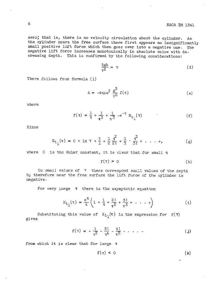
zero; that is, there is no velocity circulation about the cylinder. Asthe cylinder nears the free surface there first appears an insignificantlysmall positive lift force which then goes over into a negative one. Thenegative lift force increases monotonically in absolute value with de-creasing depth. This is confirmed by the following considerations:
There follows from formula (1)
A= -4fipa2~f(-c)~6
where
Since
(d)
(e)
(f)
(d
where C is the Euler constant, it is clear that for small T
f(z) > 0 (h)
To small values of z there correspond small values of the depthh; therefore near the free surface the lift force of the cylinder isnegative.
For very lsrge ‘c there is the asymptotic equation
Substituting this value of ilE (%) in the expression for f(~)gives
f(d=-$-~+.. .-
from which it is clear that for lsrge z
(i)
(J)
f(’c)< 0 (k)
.

NACA TM 1341 7
Hence, for sufficiently large depth, the lift force of the cylinderis positive.
-... In order to study the behavior of the function f(z)}. . _,
f.’(z) = e-T Eil(~) -~ ---~ -~ (2)~2
must be found and the function g(’c)= e%f’(z)
must be investigated. The range of small z isfor small z, Eil(~) is of the order of in (’c),
g(T) < 0
and that
(m)
considered first. Sinceit is clear that
g’(t) = e=(%+3’0Hence g(~) increases monotonically in the range of small ‘c.
The rsnge of very large T is now considered. For this r~ge,
( )g(T) .e=~+T~+2-J-+. ..+
(n)
(o)
(P)
that is,
g(-c) > 0 (d
Hence g(z), and therefore f’(~), are negative in a certain intervalo<’r<zo and positive for ‘r>To; that is, f(z) at first decreases and
then increases.
In figure 1 is plotted a curve which shows that at a very largedepth the lift force of the cylinder is positive smd has a msximum at‘c= 3.8, that is, at the depth h = 3.8 V2/2g; at z = 2.8, that is, atthe depth h = 2.8 V2/2g, the lift force of the cylinder becomes zero,and with further decrease of the depth it becomes negative.
Nondimensional magnitudes are used to construct the curves charac-terizing the hydrodynamic forces acting on the cylinder. The followingconcepts are introduced:
.—.— . . .,,, --- . .. . .. . . ,,,,,,.,. -..., ——--— ----- -.. —. . ,-. —

F. =--/’@@
NACA TM 1341
(r)
the
andthe
ratio
the nondimensional coefficients ofcylinder
Cyh = +pdV
the
From equations (1) and (2) are obtained
Crh
lift and wave resistance of
Ra!—pdV2
(s)
r
2F-2-—
>F-6 ek
Crh =
The curves ofof the ratio h/d
the lift coefficients of thefor two values of the Froude
(3)
<F-2
( )]k Eil ~
(4)
cylinder as a functionnumber are constructed
on the basis of”formula (3) as shown in figure 2. The position of tan-gency of the cylinder to the undisturbed free surface corresponds to theratio h/d = 0.5. As may be seen from the constructed curves the coeffi-cients of the lift force directed downward attain their largest valuesnear the free surface, exceeding the maximum values of the lift coeffi-cients of airfoils. As has been stated previously, the curves mustintersect the axis of abscissas. The points of intersection were notshown on the figurej since fOr V/@d = 1.59 Cyh = O Only fOrh/d = 6.2; and for V/&d= 5.0, Cyh= O for h/d= 70.
The maxima of the positive lift coefficients are vanishingly small.
The curves of the coefficients of the wave resistance of the cyl-inder as a function of the Froude number for various ratios d/h areconstructed on the basis of formula (4) in figure 3.
The position of contact of the cylinder relative to the undisturbedfree surface corresponds to the ratio d/h= 2. Each curve of waveresistance coefficients has one maximum, the position of which is deter-mined by the ratio
F = l/@

NACA TM 1341
The wave resistancerespect to the velocity,
9
itself for h = constant has a maximum withand the position
v.@
Far behind the cylinder the equationform
gh.=
of this maximum is given by
of the wave surface has the
4figrze Vz sin ~y..—+’ V2
The maximum of the wave resistance corresponds to theof the wave which, as is easily seen, occurs at v=~.of propagation of the waves is equal to V and the length
(5)
maximum heightThe velocityof the wave is
With this, the description of the results obtained for the motion ofa circulsr cylinder without circulation is concluded.
The problem of the motion of a circulsx cylinder has also been solvedby Sretensky. In it he introduced the circulation about the cylinder.The approximate solution obtained by the author justifies the conclusionthat a cylinder with circulation produces the same flow disturbance as avortex placed at the ssme depth. This result was obtained because forthe degree of accuracy assumed by the author the terms which characterizethe motion of the cylinder without circulation were rejected. Since theresults of the work of N. E. Kotchin who retained the terms of Lamb inthe problem solved by Sretensky are to be presented, the solution ofSretensky will be considered as the solution of the problem of the motionof a vortex qesr the free surface of a cylinder. The formulas obtainedby Sretensky have the form
[ 2gh-— .1
[
A=-pI’V-pr2 -&-~eVz
Ei(J
2gh
# 17
2gh
()
~2-~R=pgVe
where r in square meters per second isin its motion in an infinite flow.
The system of coordinates is chosenThe positive value of the circulation I’
(6)
(7)
the circulation about the vortex
as in the preceding problem.corresponds to the counter

10 NACA TM 1341
clockwise rotation (if the velocity of the approaching flow is directedfrom the left to the right of the observer). Hence, the sign of theJoukowsky lift force (prV) is opposite to the sign of the circulation.For constructing the graphs characterizing the hydrodynamic forces actingon the vortex, we go over, as in the preceding problem, to the nondimen-sional magnitudes F and k. But for this purpose we first replaced,for convenience, the vortex by the supporting wing having the same cir-culation. On the basis of the Joukowsky theorem onand the formula expressing the lift in terms of theficient Cy, we then obtain
r = CybV = fiabV
where b is the chord of the wing in meters and a,attack of the wing in radisms.
After all transformations
Crhcy2m
the lift of a wingnondimensional coef-
(t)
is the angle of
have been made, formulas (6) and (7) give
1-—2
1=—
2
where F = V/~~2gb and k = b/h.
The curves characterizing the
(8)
F ‘2-—
F-2e k (9)
change of the excess lift force ofthe wing, that is, the total lift after subtraction of the Joukowsky
lift, are constructed as a function of the ratio h/b for two Froude
numbers on the basis of formula (8) in figure 4. The constructed curves
show that the free surface of the fluid gives rise to the appearance ofan additional lift force (besides the Joukowsky force), the direction ofwhich does not depend on the sign @ the circulation (as is Cl=rlY s-nfrom the structure of formula (6)). For small ratios h/b this addi-
tional lift force is directed downward; it then passes through zero andbecomes positive. After forming a positive maximum it asymptotically
approaches zero. On the basis of formula (9) there are constructed onfigure 5 the curves characterizing the change in the coefficients oftotal resistance of the wing as a function of the Froude number forvarious values of the ratio b/h. Each curve has one maximum, the posi-
tion of which is determined by the ratio F = l/*.
The wave resistance itself, as a function of the velocity, does nothave a maximum and increases with increase in the velocity, asymptotically

NACA TM 1341 11
approaching a constant value. This occurs because for a wing the circu-lation is proportional to the velocity only if the angle of attack andthe chord are constant. If, however, the motion of a vortex is consider-ed and the fact that the circulation about it r = constant is takeninto account, the wave resistance, as a function of the velocity, willhave a maximum, the position of which is determined by the relation
Far behind the vortex, the equation of the wave surface is of theform
y.2rev
. sin (9a)
The msximum of the wave resistance corresponds to the maximum of thewave height, which, as is easily seen, occurs for V = @h. The veloc-ity of propagation of the wave is equal to V snd the wavelength
k= 2flv2/g.
With this the description of the results obtained by L. N. Sretenskyfor the motion of a vortex is concluded.
N. E. Kotchin (ref. 8) gave general formulas for the hydrodynamicforces acting on profiles of arbitrary shape in a flow and selected theparticular case of the motion of a cylinder of radius r with velocitvcirculation rular case have
A= Prv -4fia2p
~r2
about it. The formuias obtained by him for this psrti~-the form
2gr2
V2h
g-—
T(V2+
1m
e Ei1
J
(lo)
— .—.

12 NACA TM 1341
2gh
()
3R
-~= 4fi2,a2p~ e
~2
The system of coordinatesbut the direction of motion isJoukowsky lift force thereforeIf in formulas (10) and (11) rterms not depending on r, and
2gh 2gh
r2 ‘~()
-—
+ Pg T,+ 4flpg2r2r e V2
e (11)~3
is chosen as in the preceding problems,opposite to the others. The sign of theagrees tith the sign of the circulation.is set equal to 0, there remain onlythe formulas agree with formulas (1) and
(2) for the forces-acting- on the cylinder wit~out circulation. If informulas (10) and (11) r is set equal to O, there remain the terms notdepending on r and the formulas agree with formulas (6) and (7) for theforces acting on a vortex.
The hydrodynamic forces acting on a cylinder with circulation willbe described in somewhat greater detail. Formula (10) for the lift forcemay be written in the following form:
A= prv+~+Ar+~r (12)
where prv is the Joukowsky lift force~ Ar is the lift force of a cyl-inder of radius r without circulation (the same as by formula (1)), andAr is the lift force of a vortex (the same as by formula (6)), and
~,2gh
2-—
Arr =()
+ 2gr2 4g2r2 e V2 ~ 2gh I-Pr~ ;~—-—(+I (u)
V2h v’il V2
~ J
that is, the lift force depending simultaneously on the radius of thecylinder and on the circulation about it.
From the preceding, the variations of the forces Ar and Ar areknown . For very large depths of submersion of the cylinder, the forceArr has the same direction as the Joukowsky lift force; while for smalldepths it has the opposite direction.
For an explanation of this, it is necessary to consider the sign ofthe brackets in the expression for Arr.
Setting
2gh~=~
leads to an investigation of the function
f(%) = ~+~ - e-z Eil(T)2T
(v)
(w)

In.
Ii
NACA TM 1341
It is evident that, for small ‘r,
,..,... .-,. f(-c)> 0
since Eil(’c) is of the order of
For large ‘c,the asymptotic
is used to obtain
f(%) = - -L2T2
so that
in(z) .
formula
2! 3!-— .—. . . .
=3 =4
f(z) < 0
Forging the derivative f’(~) and investigating the function
I-3
(x)
(Y)
(z)
(a’)
g(’T)= e=f’(z) show that f’(~) < 0 in a certain interval () < ~ <T.
and f’(~) > 0 for T >Z(). Hence f(~) at first decreases and thenincreases, having a negative minimum.
Formula (11) for the wave resistance may be written in the form
R =Rr+Rr+Rrr (13)
where
Rr wave resistance of cylinder of radius r without circulation (sameas by formula (2))
Rr wave resistace of a vortex (same as by formula (7))
2gh
R4fipg2r2r e- F
rr = ~3(b’)
and the wave resistance depends simultaneously on the radius of the cyl-inder and on the circulation about it. For negative circulation the lastpart of the wave resistance Rrr is also negative, and therefore the waveresistance of a cylinder with positive circulation is greater than thewave resistance of a cylinder with negative circulation. From formula
(11) it also follows that under certain conditions of motion of the cyl-inder at a finite depth its wave resistsmce may be equal to zero. This

14 NACA TM 1341
will evidently occur when the wave behind the cylinder will have a heightequal to zero. Since the problem is solved on the basis of the lineartheory of waves, the 6quati.onof the waves behind a cylinder with circu-lation can be obtained by tsking the sum of the amplitudes of the wavesbehind a cylinder without circulation and behind a vortex. The rightsides of equations (5) and (9a) are combined to obtain the equation ofthe waves behind a cylinder with circulation:
(14)
The condition of motion for which the wave resistance of a cylinderwith circulation is equal to zero is obtained by assuming the amplitude
Y=o”
r2figr2=-
v
The same relation could have been obtained directly if the rightside of expression (11) were set equal to zero. It is necessary toremark, however, that this condition does not give anything of practicalvalue because it entirely fails to correspond to the real conditions ofmotion, at least in that the circulation I’,and therefore the lift force,
is negative.
In figure 6 the curves of the lift force and wave resistance of acylinder of radius 0.1 meter with circulation I’= 0.25 square meter persecond are constructed as a function of the submersion h for constantvelocity of motion V = 6 meters per second. The forces A and R arerepresented by their component parts. In figure 7 analogous curves areconstructed for the same cylinder but with negative circulation,r = -0.25 square meter per second. The forces %) Ar, afid ~r on
these curves do not become zero because the zero points lie at a depthgreater than 1 meter. The curves are given as an illustration of what hasbeen said concerning the forces acting on a cylinder with circulation.With this, the description of the results obtained by N. E. Kotchin forthe motion of a cylinder with circulation is complete.
The formulas for the hydrodynamic forces acting on a cylinder withcirculation may be used to find the forces acting on a foil of chord bat singleof attack a moving with velocity V at depth h. For thispurpose, the wing is replaced by a cylinder of diameter equal to thechord of the foil multiplied by a. The motion of the foil is consideredunder such small angles of attack that in the formulas for the forces itis possible to neglect the terms containing G of degree higher than thesecond. Substituting in formulas (10) and (11) the values d = ab andr = fiubv gives the formulas for the lift and wave resistance of a foil:

NACA TM 1341 I-5
. ..-——. .,. ,{[
2gh
A=-bgn~bV21 -u-&—-e
-FE
..(. j].
2gh
V2il
7(I-5)
2gh
R = fi2u2pgb2 e-~
(16)
In these formulas only the terms depending on the circulation aboutthe foil were retained, that is, the possibility of neglecting the termswith degree of a higher than the second justifies replacing the foil bya vortex. If the motion of the foil is considered at somewhat greaterangles of attack, when in the formulas for the forces it is possible toneglect only the terms containing u of degree higher than the third,then formulas (10) and (11) after substitution of d = ab and r = fiabVgive
{[
2gh-—bg v2~__A= fi~bV2 1 - u & -— e
(i
2gh
V2 ‘1 V2
2gh 2gh-— -7
R fi2a2pgb2 e~z
= + ti2a3pg2b3~ e ‘zV2
In these formulas only the Lamb terms are rejected.terms will be retained when it is necessary to tslseintofourth power of u; that is, the motion of a wing havingb is considered.
(18)
The rejectedaccount thea large value of
The last paper to be presented is that of Keldysh and Lavrentiev(ref. 9) on the motion of a thin contour under the free surface of a heavyfluid. The circulation consists of a system of vortices replacing thecontour. The distribution of the vortices is such that one of the crit-ical points is located at the rear edge of the contour. The circulationis therefore determined, and the hydrodynamic forces acting on the contourin its motion in the flow are expressed in terms of the geometric param-eters defining the dimensions and position of the foil, that is, in termsof its chord and the angle of attack. The formulas obtained by the authorsfor the lift force and the wave resistance of a plane foil have the form

16 NACA TM 1341
.
{
2gh 4gh- ~ b2 gb2 + ~2#b2 ~ ~2 +
.—figb ~
Asy(~bV2 l-— -— -—V2 16h2 4V2h V4
2gh 2gh
g2b2 ~- ~ ~
()[
-—2gh b 2gb ~
()
2gh@E_—~v4 il ~ -Z%-~ il V2
2gh 4gh-—ngb2
()
4 + 2gh ~ V2 + 4fig2b2 ~- ~
( j}
2gh
F‘il ~ (19)
4V2h +
2gh
{
2gh-— -—
R = fi2u2pgb2eV2 ~
[
2figbe V2 +a gb b-—V2 ~ -z+
and the simplified formulas
{
2gh
[
_ 2gh-—
21-— figb~ V2 b 2gb e ~ E.A= mpbV( !]
2gh
V2 ‘x-~(21)
11 ~
2gh_—
R = n2a2pgb2 e V2 (22)
Formulas (19) and (20) entirely agree with the formulas obtained ifthe aforementioned general solution of N. E. Kotchin on the motion of acontour of sxbitrary shape is applied to the case of the plane foil.
Expressions (19) and (20) for the forces acting on the foil areapproximate since they were obtained on the basis of the linear theory ofwaves, but they are, of course, closer approximations than the formulas(15) to (18) which were obtained by replacing tinefoil by a circular cyl-inder with circulation. This is explained by the fact that a cylinderwith circulation is a system of a double source and vortex concentratedat one point, and no account is taken of the extension of the foil inthe direction of the chord.

—.. . ..-—....-——
NACA TM 1341 “ 17
The expression for the forces acting on the foil, replaced by asystem of vortices, is used for the approximate hydrodynamic computationof m underwater foil having infinite span. The lift force will be com-—--
‘ puted by’formula (19) smd the wave resistance by the simplified formula(22) which was obtained by replacing the wingby a vortex. The computa.tion of the wave resistance by the more accurate formula (20) is ofpractically no advsntage in view of the smallness of the terms whichrender it different from formula (22) . Before the computation itself ispresented, the difference is discussed between formula (18) of the waveresistance of a foil derived by replacing the wing by a cylinder withcirculation and formula (21), obtained from the condition of replacingthe foil by a system of vortices. Onexpression for the coefficient of theby a cylinder with circulation is
Crh = ~m2
where
the basis of formula (18); the -wave resistance of a foil replaced
+ Nra3 (23)
T7F-2
%=&-2 e-T
that is, for aresistance fornegative angle
It is evident that, for allratio b/h,
Mr>O
Hence, with the coefficientfunction of the amgle of attack,
values of the
and Nr>O
(24)
(25)
Froude number and the
of the wave resistance considered as a
Crh(a) > Crh(”) (c’)
wing replaced by a cylinder with circulation, the wavea positive angle of attack is always greater than for aof attack. On the basis of formula (20), an expression
for the coefficients of the wave resistance of a foil replaced by a systemof vortices is
Crh = kf,&2+ Nrcx3 (26)
where
.—.

18 NACA TM 1341
1#F-2
(
F-2
%“~F-2’-T 1-’F-2’-T ) (27)
I/~ -2
[
F ‘2_—
Nr s ~F-2e k‘— ~F-2 -~k+F-2e k E.F-2 1
(i11 y (28)
If as before
2gh—=%V2
(d’)
the sign of the brackets in the expression for Nr(28) always agrees withthe sign of the expression
f(’c)=%+4Te ‘TEil(~) - 2 (28a)
Therefore
Formula (28) is
cr~(u) > Crh(+) if f(~) > 0 (e’)
crh(~) < Crh(-a) if f(~) < 0 (f’)
used as a basis for constructing the curve of f(%)on figure 8. However, in both cases the effect of the terms Nr isvery small.
Three series of hydrodynamic polars of a hydrovane are constructedon the basis of formulas (19) and (22) on figure 9 to indicate the gen-eral form of the hydrodynamic forces acting on the foil in its motionnesr the free surface of an ideal fluid. Each series corresponds to adefinite constant Froude nu?iber. The different polars of a single seriescorrespond to different values of the ratio b/h . The dotted curves passthrough the points of the same angles of attack. For all Froude numbersan increase of the ratio b/h (which for constmt b corresponds to adecrease in the depth of submersion) gives rise to a decrease in theabsolute values of the lift coefficients and an increase in the waveresistance coefficients. The coefficient Crh does not depend on thesign of the angle of attack since the additonal terms were neglected,while Cyh for a negative angle of attack is always greater in absolutevalue than it is for a positive angle. The effect of an increase in theFroude nuniber is to decrease the coefficients of the wave resistance ofthe foil while increasing the coefficients of the lift force in absolutevshe. This completes the review of results of theoretical work on themotion of bodies under the free surface of a heavy fluid.
NACA TM X341
CONSTRUCTION
FOIL IN A
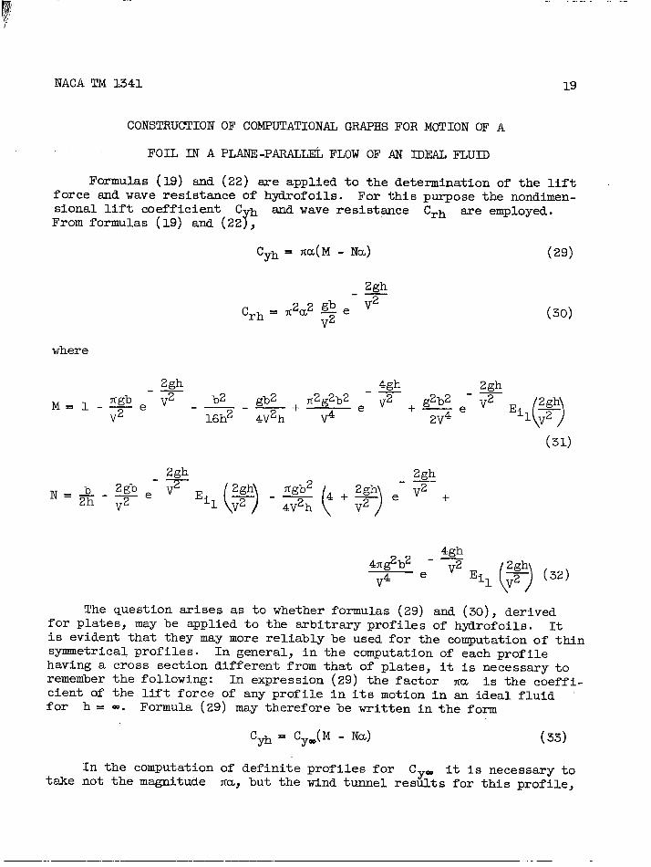
FO?.TKlhLS (19) and
19
OF COMPUTATIONAL GRAPHS FOR MOTION OF A
PLANE -PARALLEL FLOW OF AN IDEAL FLUID
(22) are applied to the determination of the liftforce and wave resistance of hydrofoils. For this purpose the nondimen-SiOIld lift coefficient C.h and wave resist~ce Crh are employed.From formulas (19) and (22~,
Cyh = fia(M - Nu) (29)
2gh_—
Crh~ ~2a2 @ e V2
~2 (30)
where
2gh 4gh.— 2gh.—ngb e V2
M=l-—~2 gb2 + fi2g2b2 e V2 + g2b2 ~- ~ ~
()
2gh\-— _—~2 16h2 4V2h ~4 2v4 il ~
(31)
The question arises as to whether formulas (29) and (30), derivedfor plates, may be applied to the arbitrsry profiles of hydrofoils. Itis evident that they may more reliably be used for the computati.onof thinsymmetrical profiles. In general, in the computation of each profilehaving a cross section different from that of plates, it is necessary toremember the following: In expression (29) the factor fi~ is the coeffi-cient of the lift force of any profile in its motion in an ideal fluidfor h = CO. Formula (29) may therefore be written in the form
In the computationtake not the magnitude
Cyh = CY=(M - NcL) (33)
of definite profiles for C it is necessary tofia,but the wind tunnel res~~ts for this profile,
—. .—-—. —.—.-. ———. —-— ..-——-——.

——..—
20 NACA TM 1341
the lift coefficients having first been computed for infinite span. Inthis manner the shape of the profile will be approximately taken intoaccount. The section devoted to the consideration of the effect of theviscosity of the fluid will discuss this
Formula (30) for the coefficient ofsented in the form:
further.
wave resistance may be repre-
2gh.—
Crh = Cyz= ~ e~2
~z
The Cy2~ does not represent the magnitudethe actual resistance coefficiat of the wing of
(34)
fizuz,but the square ofinfinite spa. Graphs
were constructed for the convenient and rapid application of formulas(33) and (34) to the hydrodynamic computation of the hydrofoils. Themagnitudes M and N sre plotted as functions of the Froude number onthe basis of formulas (31) and (32) for various values of the ratio b/h
(figs. 10 and 11) to aid in computing the lift coefficients. To computethe coefficients of the wave resistance, the curves Crh/Cy2= were con-
structed on the basis of formula (34) also as a function of the Froudenumber for various ratios b/h (fig. 12) . The variations of the mag-nitudes F and k in the constructed graphs were taken in ranges whichpermitted obtaining the lift force and the wave resistance of hydrofoilsof infinite span for all cases of motion of practical interest. The
graphs constructed on figures 10, 11, and 12 representing formulas (33)and (34) thus permit obtaining approximately the lift force and wave re-sistance of a foil of infinite span moving near the free surface of anideal fluid provided the lift coefficient for the motion of the wing inan infinite flow is known (e.g., from wind tunnel test data).
Effect of Viscosity of Fluid
A method for taking into account the effect of the viscosity of thefluid is now considered. The lift force of a foil in its motion in areal fluid depends little on the viscosity of the fluid since the lift ofthe foil is entirely determined by the potential circulatory flow aboutit. The viscosity appears to be only one of the factors giving rise tothe circulation (ref. 10). The lift of the foil may therefore be obtained
by the classical methods of hydrodynamics without introducing any correc-tions for the viscosity. A confirmation of this statement may be found
in the comparison of the theoretical md experimental results on thedetermination of the lift of the wing. Betz (ref. 11), for ex~le,
carried out a computation of the pressures on the surface of wings of theJoukowsky type on the basis of the potential flow of am ideal fluid aboutthe wing. He also made a comparison between his obtained results and
— I

NACA TM 1341 21
experimental data for the sane wings. Good agreement was obtained. Theslight increase of the theoretical lift force above that actually obtained.is eqlained as caused by a separation of the flow which occurs at theupper surface of-the ~~ not fti ’from it’s‘traili& edge “and th”is somewhatlowers the total pressure on the wing. All that has been said relativeto the small dependence of the magnitude of the lift force of the wi~ onthe viscosity of the fluid refers to the motion in an infinite flow. Inthe motion of the wing near a free surface, however, the effect of theviscosity on the lift force may likewise be regarded as practicallyabsent because the change in the lift of the wing in its motion at afinite depth is brought about by a different pressure distribution on thewing different from the distribution which occurs in the motion at in-finite depth (and gives the Joukowsky theorem). The other pressure dis-tribution is due to the fact that the wave disturbances of the fluidremain behind and is not connected with the viscosity. It is true thatin a real fluid the wave disturbances sre dsmped, but this damping may beneglected for the case of water.
In the preceding section it was stated that cyan does not representthe magnitude ma but rather the result of wind tunnel tests on the foil.With this understood, the change in the lift of the wing due to the effectof the viscosity in its motion in an infinite flow is taken into account.The fact that no added corrections are msde for the effect of the viscos-ity on the lift of the wing means only that the effect of the free sur-face on the lift is not connected with the viscosity. Thus in computingthe lift force of a hydrofoil moving in a real fluid it is permissible touse the formula obtained for em ideal fluid without introducing any cor-rections for the viscosity except interchanging ITU with the magnitudeCym obtained experimentally.
Accounting for the viscosity of the fluid for a certain total frontalresistance of the hydrofoil must be considered. For the present, thewell-known considerations for the case of motion of a wing in an infiniteflow are adduced. If the fluid is an ideal one, the foil during its mo-tion is net subject to any frontal resistance, since it is known that ina potential flow the pressure at the forward part of the wing is equal inmagnitude to the pressure at the sfter part. By a potential flow is heremeant a nonsepsrated, nonvertical flow about the foil. The viscosity ofthe fluid is primsrily the cause of the appearance of frictional resist-ance which is represented by the sum of the horizontal components of theforces tangential to the surface of the foil. Moreover, the viscositybrings about a general change in the potential flow about the wing. Tothese chsnges must be ascribed the formation of the boundary layer andthe appearance of circulatory motions. Because of these changes in theflow, there is a change in the initial pressure distribution over thewing such that a frontal pressure resistance appears. The pressureresistance, together with the frictional resistance, is termed the formresistance. For wings of finite span the form resistance is divided into

22 NACA TM 1341
the profile and induced resistances. As has already been said at thebeginning of this paper, in the motion of a wing in an infinite flow thefluid may be considered as weightless and the Reynolds law of motion willthen be valid. For the total frontal resistance of the wing the Reynoldslaw of motion gives the formula
R = Cxpsvz
where the resistace coefficient Cx is a function of the shape of thefoil, its position in the flow, and the Reynolds number. The similitudelaw of Reynolds consists of the following: If two wings are geometricallysimilar and their similar elements are inclined by equal angles to thedirection of motion, and if the Reynolds numbers are equal, then there iscomplete similarity of the motions. In this case the drag coefficientsfor the two wings sre the same. The values of the resistance coefficientsof the wing for the different angles of attack are obtained from modeltests in the wind tunnel, the tests being conducted at some single valueof the Reynolds number near full scale. This is sufficient for the reasonthat at large mgles of attack the drag coefficient depends little on theReynolds number, while at small angles of attack when the flow is poten-tial and the resistance is practically only the frictional drag, a cor-rection for the change in the Reynolds number may be made by the knownformulas for the resistance of a flat plate. It is understood, ofcourse, that test results are entirely applicable when the foil modelis tested for different values of the Reynolds number.
The motion of a wing in a real fluid near its free surface is nowconsidered. Total frontal resistance of the foil is represented as thesum of three resistances: frictional, pressure, and wave resistances,although, generally speakingj such decomposition must not be made. Itwould be more correct to combine the pressure and wave resistsmces intoone since they are similar in character; that is, they are brought aboutby the forces normal to the surface of the foil. Such formal decomposi-tion must be considered, however, because of the absence at the presenttime of a solution of the problem of the motion of a foil near a freesurface of a heavy real fluid. The manner in which the form resistance,that is, the pressure and frictional resistance considered apart from thewave resistance, vsries in the transition of the foil from an infiniteflow to the region nesr a free surface must be studied. The distributionof the streamlines changes and the velocity of the flow about the foilwill be different. These changes in the flow give rise to changes in thefrictional and pressure resistances; that is, it is necessary to take intoaccount the fact that the dependence of the form resistance coefficienton the Reynolds number will be different from the corresponding relationfor the motion of the same foil in an infinite flow. In reference to thenonvalidity of the separation of the wave resistance from the”pressureresistance, there is no experimental possibility of separating these tworesistances from each other and thereby obtaining the dependence of the

NACA TM 1341 23
form resist~ce coefficient on the Reynolds number. On the basis of allthat has been said there remains only the possibility of assuming thatthe coefficient of form resistance is the ssme as in the motion of thefoil at infinite depth as it is at finite depth (of course, for the ssmeR“ey?iolds’-ntibers)and “that its dependence on the Reynolds number is inboth cases expressed by the same law.
It can be said that the wave resistance arises from only the forceof gravity and vanishes with increasing depth although the fluid continuesto remain viscous. In a viscous, incompressible, heavy but infinitefluid, waves behind the moving foil cannot arise because their formationnecessitates two layers of fluid of different densities. The viscositywill not be considered as the damping factor of the wave motions, sincethe motion of the wing in water where such damping maybe practicallyneglected is considred. In this manner the wave resistance of the foilis assumed to not depend on the viscosity; snd for determining the mag-nitude of the wave resistance, use is msde of the theoretical formulaobtained for the motion in an ideal fluid. For determining the over-allfrontal resistsmce of a hydrofoil of infinite span, it is necessary toadd to the wave resistance the form resistance, which is obtained fromaerodynamic wind tunnel tests on the wing, initially computed for infinitespan . If the data are available, corrections are made on the form resist-ance thus obtained for different Reynolds numbers in tests on the foil ina tunnel in relation to its motion in water.
Effect of the Finite Span of Hydrofoil
The finiteness of the span in its motion in an infinite fluid istaken into account by applying the theory of bound and free vortices.This theory was developed by L. Prandtl. The basis for this theory isthe theorem of Joukowsky on the lift force of a wing applied to a wingof finite span and the theorem of Helmholtz on vortices. The physicalpicture of the formation of vortices may be obtained from the followingconsiderations: In the presence of a ltit force on the wing and there-fore of a circulatory flow about it, there is a difference between thepressures on the upper and lower surfaces of the wing. Hence, at thetips of the wing the fluid will move from one surface onto the other inthe direction of lower pressure. This transition of the fluid, becauseof its steady character, gives rise to the formation of a system of freevortices. Since, according to the theorem of Helmholtz, the vorticesconsist of the same particles of the fluid, the wing in its motion leavesbehind it free vortices having a length equal to the path traversed bythe wing. By the theorem of Helmholtz, the vortices cannot break awaywithin the fluid; hence in the motion of the wing in an infinite flow thevortices either travel on with their ends at infinity or adhere to eachother behind the wing to form closed systems. In the presence of a free
surface of the fluid, the vortices may support themselves on the free

24
surface. Theing fluid anding the wing.
NACA TM 1341
system of free vortices leads to the motion of the surround-gives rise to a deflection or downwash of the flow approach-The downwash decreases the actual angle of attack and de-
flects the lift force behind the perpendicular drawn to the true directionof the motion of the wing. The projection of the lift force thus deflectedon the direction of motion is the induced resistance of the wing. It isidentical with the energy required to maintain the motion of the vortices.For all practical cases of the motion of a wing, the free vortices may betaken as half-filsments, that is, may be assumed as infinitely long, not-withstanding the finite interval of time from the starting instant of themotion. Actually, the velocity W induced by a segment of length c ofthe free vortex at a point distant h from its forward end is expressedby the formula
We=—” b:h ~czc+hzIf C= =, that is, the vortex is a half-filament, then
Set c = nh smd obtain
If, for exsmple, n = 5, thatas large as h, Wc/W==0.98;
vortex of length c = 5h is
w==&
the ratio We/W=:
.-
(35)
(36)
(g’)
is, if the length of the vortex is five timesthat is, the velocity induced by a finite98 percent of the velocity induced at the
same point by a half-filament. If the free vortex is supported on thefree surface, its final length may be assumed as equal to a half-filament,since the point of support of the vortex remains in its place while thewing moves; therefore the length of the vortex rapidly attains practicallyan infinitely large value. The quantitative results of the theory ofinduced resistance are based on the magnitude of the induced velocity dueto a straight vortex half-filament at any point of the surrounding fluid.For an infinite flow this velocity is expressed by formula (36). For afree vortex shed from the foil in its motion near a free surface, formula(36) is no longer applicable because the usual circular distribution ofthe streamlines about the vortex will be distorted by the presence of thefree surface, snd the magnitude of the induced velocity at any point ofthe fluid will therefore be other than in an infinite flow. The effect
of the finite span of a hydrofoil is now considered. For simplicity, the
wing of finite span is replaced by a horseshoe vortex which will consistof the actual vortices satisfying the theorem of Helmholtz. The horseshoevortex moves near the free surface of the fluid. The resistance of the
.!,/,(’
L.
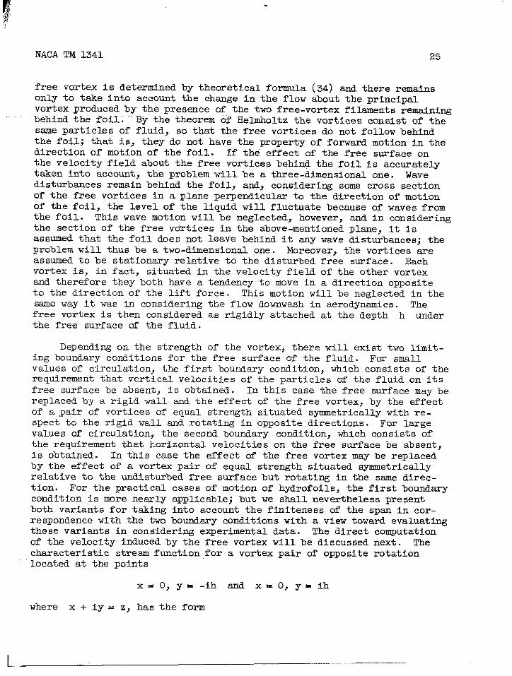
NACA TM 1341 25
free vortex is determined by theoretical formula (34) and there remainsonly to take into account the chsmge in the flow about the principalvortex produced by the presence of the two free-vortex filaments remainingbehind the foil. By the theorem of Hetioltz the vortices consist of thesame particles of fluid, so that the free vortices do not follow behindthe foil; that is, they do not have the property of forward motion in thedirection of motion of the foil. If the effect of the free surface onthe velocity field about the free vortices behind the foil is accuratelytaken into account, the problem will be a three-dimensional one. Wavedisturbances remain behind the foil, and, considering some cross sectionof the free vortices in a plane perpendicular to the direction of motionof the foil, the level of the liquid will fluctuate because of waves fromthe foil. This wave motion will be neglected, however, and in consideringthe section of the free vortices in the above-mentioned plsne, it isassumed that the foil does not leave behind it any wave disturbances; theproblem will thus be a two-dimensional one. Moreover, the vortices areassumed to be stationary relative to the disturbed free surface. Eachvortex is, in fact, situated in the velocity field of the other vortexand therefore they both have a tendency to move in a direction oppositeto the direction of the lift force. This motion will be neglected in thesame way it was in considering the flow downwash in aerodynamics. Thefree vortex is then considered as rigidly attached at the depth h underthe free surface of the fluid.
Depending on the strength of the vortex, there will exist two limit-ing boundary conditions for the free surface of the fluid. For smallvalues of circulation, the first boundary condition, which consists of therequirement that vertical velocities of the particles of the fluid on itsfree surface be absent, is obtained. In this case the free surface may bereplaced by a rigid wall and the effect of the free vortex, by the effectof a pair of vortices of equal strength situated symmetrically with re-spect to the rigid wall and rotating in opposite directions. For largevalues of circulation, the second boundary condition, which consists ofthe requirement that horizontal velocities on the free surface be absent,is obtained. In this case the effect of the free vortex may be replacedby the effect of a vortex pair of equal strength situated symmetricallyrelative to the undisturbed free surface but rotating in the same direc-tion. For the practical cases of motion of hydrofoils, the first boundarycondition is more nesrly applicable; but we shall nevertheless presentboth variants for taking into account the finiteness of the span in cor-respondence with the two boundary conditions with a view toward evaluatingthese variants in considering experimental data. The direct computationof the velocity induced by the free vortex will be discussed next. Thecharacteristic stream function for a vortex pair of opposite rotationlocated at the points
x =0, y=-ih and x=O, y=ih
where X+iy= z, has the form

26 NACA TM 1341
h = zfi~z+hi
-%lz- hi (37)
The characteristic stream function for a vortex pair of the same direc-tion of rotation located at the same points is
w2=& hl(Z2 + h2) (38)
Consider the point of the fluid lying at the distance h from thelevel of the undisturbed free surface with abscissa x and find thevelocity induced by the half vortex at this point. For this purpose thewell-known relation
dw-X=u-iv (39)
is used, where u is the horizontal velocity of the particles of thefluid, and v is the vertical velocity of the particles.
Applying this preceding relationthe corresponding vertical velocities
to formulas (37) and (38) givesinduced by the half vortices:
x
)(40)
X2 + 4h2
(41)
In the case of the infinite flow, that is, for h = CO,the expression
v = r/4fix
would be obtained in place of expressions (40) and (41).
Consider the foil at depth h with two free vortices trailing fromits edges. Let the span of the foil be equal to Z. In order to avoid
obtaining, in the further computation, an infinitely large mean inducedvelocity over the foil span, it is necesssry to assume that the distance
between the free vortices 2’ > 2. On the basis of equations (40) and
(41), the mean value of the induced velocity over the wing span isobtained:
[
21+2_~
1
t2 + 22 + 22t + 4h2Vm+ ln— – in
21 - 1 ‘2 t2 + 4h2(42)

27
where
t‘l-z=
2(h’)
-4, ..,.. .... ............... .
The minus sign refers to the first variant and the plus sign, to thesecond variant for taking into account the effect of the finite span.
It is known from
whence
Moreover, in themagnitude t2 may be
tests that for the majority of foils,
(i’)
t ~ 0.0252 (j’)
numerator of the second term of expression (42) theneglected because of its smallness. Then
r[4;;ln 122+2zt + 4h2
‘m=~t2 + 4h2
. .(43)
Replacing t by 0.025 2 in expression (43) and introducing thechord of the foil b, the ratio k = b/h, and the aspect ratio k = 2/bgive the final expression for the mean induced velocity over the foilspan
Vm=g
For an infinite flow,formula
The downwash angle of
[
~ 05x2k2 + 4l;~ln “ 10.000625k2k2 + 4
the induced velocity is computed by the
Vm= 2r/fi2
the flOW ~+h
(coefficient of induced drag) can now%physical sense of the downwash sngle andto be
and the induced drag Cihreadily found according tothe coefficient of induced
v.
where V- is the velocity of motion of the foil.expression (44) for the mean induced velocity, thedownwash ale smi induced drsg of the foil movingfree surface are found to be
(44)
thedrag
(k’)
Hence, on the basis ofexpressions for theat depth h from the
1 .—

28 NACA TM 1341
Zcyh
[
~ih.~ 1$ ;In 1.05A2k2 + 4
0.000625A2k2 + 412cyh2
[~ln 1.05X2k2 + 4
Cih= ~A 178 0.000625A2k2 + 41
(45)
(46)
As seen from formulas (45) and (46), the angle of downwash and theinduced drag of an underwater foil are either smaller or greater than thevalues of these magnitudes in the motion of a foil in an infinite flowdepending upon the vortex scheme applied - either a vortex pair of oppo-site direction of rotation or one of the ssme direction of rotation. Onfigure 13 have been constructed the curves ~ih/Pi~= f(h/b) for X = 6for the two variants under consideration. The same curves represent, ofcourse, also the relation
(z’)
To reduce the computation of the angle of downwash and the induceddrag of a hydrofoil according to formulas (45) and (46), these formulasare rewritten in the form
2C h$ih = *(lTg)
2C2 hc~~ = +(l+E)
where
~ 05A2k2 + 4E :ln “=-
0.000625k2k2 + 4
(45a)
(46a)
(46b)
On figure 14 the magnitude ~ has been constructed as a function ofthe product Xk= Z/h. The use of this curve in the computation is clearfrom formulas (45a) and (46a).
Next, the relative error incurred if the usual formulas are used fordetermining the downwash angle and the induced drag of a hydrovane, withno account taken of the effect of the free surface on the magnitude ofthe induced velocity, will be obtained. For this purpose the followingtable is used:

NACA TM 1341 29
A a l~b b/h = 0.5 b/h = 1.0
I Method III I I11,,, ,,.. .-, .- ,., 2 ‘“ ‘‘-’ 3’ ““ ““3’”“- 11 9
5 15 11 33 2010 , 33 20 67 2915 52 25 111 34
T1I 11
’25 1767 2993 32190 40
For the vsrious aspect ratios of the wing A and ratio of wingchord to depth, the relative error is computed in percent for the down-wash angle and the induced drag of the hydrofoil, using in place offormulas (45) and (46) the aerodynamic formulas. As may be seen, therelative error may attain a lsrge value at large values of b/h, that is,near the free surface. The relative error increases with increasing Abut the absolute values of the sngle of downwash and the induced dragdecrease, and therefore the absolute error decreases with increasing 1.In considering the problem of accounting for the finiteness of the spanof the hydrofoil, the following should be added: ‘Thedownwash angle andthe induced drag of hydrofoils must, as a rule, be determined by formulas(45) and (46) because the aerodynamic formulas would give a considerableerror even for submersions equal to twice the chord of the wing. Suchdepth of submersion is already equal to the maximum suitable for use.Before anything can be said in regard to the final choice of boundarycondition on the free surface determining the direction of rotation of afictitious vortex,mutational example
In 1935 teststhe CAHI tank on a
the experimental resuits must be considered. A com-of a hydrofoil will be given also.
TANK TEST ON A HYDROFOIL
were conducted by A. N. Vladimirov and V. G. Frolov atplane underwater foil. The object of the test was to
obtain the hydrodynamic characteristics of the foil at various submersionswith a view toward mounting this foil on a seaplane. A thin synnuetricalNACA 0.0009 profile of rectangular plan form having a chord b = 0.14meter, span Z = 0.84 meter, and therefore aspect ratio X = 6 was tested.The thickness of the foil was 9 percent of the chord. On figure 15 aregiven the coordinates of this profile taken from the mentioned report.On figure 16 are given the aerodynamic characteristics of the profileobtained in the high pressure wind tunnel for a value of Reynolds numberof 3.2x10⁶, whereby A and R sre denoted, as everywhere below,A= c@v2 andR= CNSV2 . For the tests in the tsmk the foil of thegiven dimensions was constructed of kolchugaluminum (an aluminum alloy)and was supported by two steel brackets which at their bases were fittedinto the body of the foil from above, being attached to them by counter-sunk rivets and having at the places of juncture with the surface of thefoil a smooth form. The scheme of arrangement of the brackets on thefoil is shown in figure 17. The test was conducted on a special apparatus

30 NACA TM 1341
which permitted measuring the lift and the frontal resistance of the foilwith the brackets. The moment due to the hydrodynamic forces was notmeasured. The test setup is given on figure 18. The”upper hinge axisof the vertical frsme of the apparatus had one degree of freedom, thatis, it could be displaced over an arc of sufficiently lsrge radius. Theimpossibility of the deflection of the vertical frame toward one side wassecured by a special device. For this reason the foil, being itself atconstant angle of attack, that is, immovably connected with the verticalframe, had two degrees of freedom. The angle of attack of the foil wasdetermined with an accuracy up to *8 minutes. The required depth ofsubmersion of the foil was first approximately determined at standstilland in motion was measured with an accuracy up to *1 millimeter. By thedepth of submersion of the foil is meant the distance of the geometriccenter of the foil from the level of the undisturbed free surface. Thetotal frontal resistance of the foil with the submerged part of thebrackets was measured by a contact dynamometer of the Gebers system. Tothe drum of this dynamometer was attached the towing rope, care beingtaken that the rope was always horizontal during the motion. Since thevertical frsme was subjected to pressure from the air stream, this partof the resistance was experimentally taken into account. The hydrodynamiclift force of the foil was measured by a spring dynamometer with anaccuracy up to ~1 kilogram. For this purpose one measurement was made atstandstill, that is, the load on the foil (weight of the structure) wasdetermined, and another measurement was made during motion. The differ-ence between the values of these measurements gave the magnitude of thelift force of the foil. The box on the vertical frame shown in thesketch was intended for the loads in the case where the positive lift(force directed upward) exceeded the weight of the structure. The lengthof the towing rope was so regulated that the axis of the principal frameof the apparatus occupied a vertical position. In the test setup used
there was only one position of the foil when its center of pressure wasdisplaced away from the vertical. The lift force was then somewhat de-flected and therefore gave an additional resistance, which was taken intoaccount by a special correction. The frontal resistance of the hydrofoilwithout support brackets was determined as the difference between themeasured resistance of the foil with the brackets and the resistance ofthe brackets. The resistance of the brackets was computed by the formulaR= c@Sv2, and Cx was determined from the air polars since the bracketsconstituted aeronautical profiles. The srea S of the brackets was afunction of the depth of submersion of the foil. It was assumed that
there was no interference effect between the foil and the brackets. Sincea wave remained after each test, an interval was required between thetests during which the surface of the water regained its calm.
,,,
The basic tests were conducted at constant towing velocity V = 6meters per second. The depth of submersion of the foil was varied overa range from zero to the chord of the foil, and angle of attack was var-ied from -18° to +18°. For small submersions the tests were restricted

NACA TM 1341 31
to small angles of attack in order to maintain as far as possible completesubmersion of the foil. Since the actual towing velocity for each testdiffered from V = 6 meters per second with a deviation up to 0.2 meter.>.,–-per ‘second’in either direction, all values of the lift force end resist-ance of the foil obtained in the measurements were recomputed for V = 6meters per second on the assumption that in the interval of deviation ofthe velocity the hydrodynamic forces acting on the foil were proportionalto the squsre of the velocity.” Positive angle of attack was assumed inthe usual sense of this term. For exsmple, at an angle of attack of +lZOthe lift of the foil is directed upward; at -12° it is directed downward.In addition to tests at constant velocity, curves were obtained for thelift and drag of the foil as functions of the velocity for two differentsubmersions hl and ~. The angle of attack was here taken as constsnt
and equal to 4°, and the velocity was varied in the range from 2 to 12meters per second in 2-meter-per-second increments. All tests were con-ducted for constsmt submersion of the foil, that is, for each run theamount by which the load exceeded the lift was determined and the raisingor submersion of the foil during the motion occurred only tithin thelimits of the compression or extension of’the springs of the dynamometermeasuring the lift. The results of the tests on the hydrofoil are pre-sented in the figures. On figures 19 and 20 sre constructed the curves ofthe lift force A (in kg) snd frontal drag R (in kg) of the hydrofoilas a function of the depth of submersion h (in m) for various sngles ofattack a, for constant towing velocity V = 6 meters per second. Onfigure 21 are constructed the curves of hydrodynamic efficiency of thehydrofoil as a function of the depth of submersion for two angles ofattack a = +4° and a= -40. In this case, too, the towing velocitywas constant (V = 6 m/see). On figures 22 and 23 sre constructed thecurves of the lift force A (in kg) and frontal resistsmce R (in kg) ofthe hydrofoil as a function of the towing velocity for two differentsubmersions hl = 41 snd h2 = 82 millimeters. The angle of attack was
here constant and equal to 4°. For the present, an analysis of theexperimental data obtained is not of concern, and the characteristicfeatures of the constructed curves will not be explained; the discussionwill be restricted to the presentation of the data. A comparison willsubsequently be presented of the theoretical and experimental data, sndit will then be easier to note the laws which govern the hydrodynamicsof a hydrofoil.
The data obtained from the tank tests on the hydrofoil were valuablein that they brought out with particular clearness the effect of the mostimportmt factor, namely, the depth of submersion. The fact that thetest was made on a thin symmetrical profile was a favorable circumstance.As a result, the conditions of the test very closely approached those forwhich the problem was theoretically solved. These favorable conditions
were obtained in other tests on hydrofoils. For example, in the tank atDumbarton (ref. 13), tests were conducted on a series of profiles for thescale effect, a part of the profiles being tested in a vertical position

32 NACA TM 1341
and a part in a horizontal. The chord of the profiles tested in thehorizontal position was equal to 16 centimeters and the submersion wasconstant at 60 centimeters, almost four times as large as the chord.The tests on the profiles under the free surface of water were in gen-eral repeated several times for the purpose of investigating the per-formance of propellers. The free surface of the water was, however, anecessity only in that it was unavoidable, and attempts were msde to goas far as possible below the surface. In the present tests, however, anattempt was made to approach nearer the surface, and for this reason thepossibility existed of clarifying the effect of the free surface and ofcomparing the experimental results with the theoretical.
HYDRODYNAMIC COMPUTATION PROCEDURE FOR THE HYDROFOIL
The first step is to recompute the air polars of the hydrofoil pro-file from finite to infinite span. On figure 24 are shown the curves ofthe lift coefficient of the foil for A = 6 and the recomputed valuesfor 1= -. The foil of infinite span has no induced drag so that theprofile drag of the foil for X = m is obtained from the total drag for
x= 6 with the induced drag subtracted. After proceeding to the motionof the foil in a plane-parallel flow, the foil is transferred from theair to the water for, at first, infinitely great depth. There is a changein Reynolds number which, in agreement with a preceding section, must betaken into account. The air polar was obtained for a value Re = 3.2xM$.
In the water there is first of all a change in the coefficient ofkinematic viscosity v. For a temperature of the tank t = 180 C,
v 0.013 (cm2/see). Since the foil chord b = 14 centimeters, the ve-lo;ity V = 600 centimeters per second is the following value for theReynolds number Re = V-b/v= cJ.6x@5.
The lift force of the foil is assumed not to change with the changein Reynolds number, and only the profile drag and that part of the pro-file which constitutes the friction drag sre recomputed. The formula ofPrandtl for the frictional drag coefficient ofthis purpose (ref. 14). This formula includesthe Reynolds numbers under consideration. Thethe form
1700
Cf=s-=
plane surfaces is used forthe range of motion forformula of Prandtl is of
(47)
Recomputing by this formula the frictional drag of the foil givesthe curve of profile drag for water. In figure 25 are constructed theprofile drag curves for water smd for air as functions of the angle ofattack.
. . .

NACA TM 1341 33
It should be remarked that the efficiency of the profile accordingto wind tunnel test data at the Reynolds number Re = 3.2x10⁶ was equalto 23 at an angle of attack of 4°. The hydrodynamic efficiency of the
,.,,, ssme profilefortheReynolds number Re --O.6X1O6 was equal.to 18.2 asa result of the increase in the profile drag.
It is interesting to note that if the coefficient of the frictionaldrag of the foil is determined in its motion in air by formula (47), thatis, for the ssme Reynolds number for which the air polar was obtained,then
while theattack is
actual profile dragequal to
100 Cf = 0.32
coefficient of the foil for zero angle of
100 Cf = 0.40
as seen from figure 25.
The total drag of the foil in its motion in air atattack consists therefore of 80 percent frictional drag
zero sngle ofand 20 percent
pressure drag srising from the thickness of the foil. At the same time,the value 100 Cf = 0.32 indicates the good agreement of the value ofCf obtained by the formula of Prandtl with the actual values and justi-fies the application of the Prandtl formula.
Since curves for the different towing velocities are still required,the curve of the profile drag of the foil as a function of the velocityin water at angle of attack of 4° has been constructed on figure 26.After the first stsge of the computation, the hydrodynamic forces actingon a foil of infinite span moving in an idinite fluid sre known.
It is nowsurface of thethe lift forcecoefficient offormula
and the graphs
necessary to consider the motion of the foil when near thewater.of thea foil
For this motion waves are formed behind the foil,foil changes, and a wave drsg appears. The liftmoving at depth h is obtained by means of the
cyh
= Cy~M - Nu) (33)
shown in figures 10 and 11. The value Cv. entering theformula is taken from the curve for A = o shown in fig~e 24. Thecoefficient of wave resistance of the foil is obtained by means of theformula
I

34
2gh.—
c ~2@ev2rh = y-v2
NACA TM 1341
(34)
and the curves constructed in figure 12.
In the tank tests on the hydrofoil, the depth of submersion was var-ied starting from zero. For comparison, however, the theoretical curveswere constructed for only the submersion starting from 50 millimeters}since for smaller submersions formulas (33) and (34) will not give acorrect result because the
and terms of higher degreemay therefore be used onlyleast the inequality
term
(b/2h)3
were neglected in these formulas. The formulasfor those values of b/2h which satisfy at
b/2h <’1
Since the chord of the foil was b = 140 millimeters, the limiting caseobtained for which these formulas may still be considered as valid is fora value of the submersion depth of
h =70mm
In the computations deviations are made from the value h = 70 milli-meters by another 20 millimeters. A closer approach to the free surfacedoes not give anything even formally$ since for this value M and Napproach infinitely large values. The hydrodynamic forces acting on afoil of infinite span moving near the free surface of the water are nowknown .
The finite span of the foil must be taken into account; the changeof its lift force due to downwash and the value of the induced drag aredetermined. The correction for the finiteness of the span was made fortwo variants corresponding to the two boundary conditions at the freesurface. For the first variant, in which the free surface is replaced bya rigid wall, the dowxwash angle 13i
fis always less at finite depth
than the downwash angle for infinite y large depth. In both cases, ofcourse, the same lift force is considered. For the second variant, inwhich the effect of the free surface is replaced by the effect of a vortexpair rotating in the ssme direction, the downwash ~le Pih at finitedepth is always greater than the corresponding angle at infinitely lsrgedepth, again for the same lift forces.
The downwash angle behind the foil is found from the formula
2Cyh~ih=~(l~~) (45a)

NACA TM 1341 35
and the curve on figure 14, where the magnitude ~ entering formula(45a) has been constructed as a functi,onof the product kk. For the
>.. foil tested in the tanl.,,~= 6 .aK@ k= b/h ,depend,oq,those depths hfor which computational data are to be obtained. For each d’epth of sub-mersion h there is a different downwash angle. The difference betweenone vsriant and the other is the fact that for the same depth of submer-sion of the foil, different values of the downwash angle are obtained.Having, for a given depth h, the lift curve of a foil of infinite spanas a function of the angle of attack and knowing for this depth the mag-nitude of the downwash angle it is easyforce against the angle of attack for afor this purpose of the usual graphicalThe computation is therefore individual
The formula
to construct the curve of liftfoil of finite span, making usemethods applied in aerodynamics.for each depth.
(46a)
and the curve ~ = f(kk) constructed in figure 14 are used to determinethe induced drag of the foil. The computation is again conducted foreach depth and, since the magnitude ~ entering the formula for Cih isknown, no difficulties are encountered. It is here likewise necessary tomake use of the graphical methods applied in aerodynamics. A comparisonof the theoretical curves with the experimentally obtained data will nowbe made.
COMPARISON OF THEORETICAL AND EXPERIMENTAL RESULTS
The lift forces are considered first. On figure 27 sre given thetheoretical curves for the lift force coefficients of the foil as a func-tion of the submersion h in millimeters, and the test points are shownin the same figure. All data were reduced to the velocity V = 6 metersper second. There may first of all be observed the qualitative agreement.The lift force of a hydrofoil at all angles of attack decreases in abso-lute value with decrease in depth of submersion. A somewhat differentcharacter is possessed by the curve for zero sngle of attack where thereverse phenomenon is indicated. Theoretically, for negative angles ofattack the lift force should be greater than for the positive in absolutevalue, but this was not cofiirmed experimentally. In general, it mustbe said that the quantitative agreement of the theoretical with the ex-perimental results is better the smaller the angle of attack and thelarger the depth of submersion. This is understandable since the theo-retical solution based on the linearized wave theory gives a betterapproximation when the foil produces a small disturbance. Best agreementof the results is givenby the first variant (~~h< ~i~.

36 NACA TM 1341
Two theoretical curves and one experimental curve for the constantdepth of submersion h = 82 millimeters and constant angle of attack 4°are constructed on figure 28 for comparison; these curves show the effectof the velocity of motion of the foil on its lift coefficient. Fromtheoretical considerations it follows that the lift coefficient of thefoil should increase with increasing velocity. The experimental curveactually has this tendency; however, it is only weakly indicated. Thequantitative agreement very clearly spesks in favor of the first variant
(~ih< ~i~) -
The data on the total drag of the hydrofoil are now compared. Thetheoretical curves of the coefficients of total drag of the foil areconstructed as a function of the submersion h for the constant velocityof motion V = 6 meters per second on figure 29, and on the same figureare shown the test points. First noted is a characteristic feature ofthe theoretical smd experimental results, namely, the increase of thedrag coefficient of the foil with increase in depth of submersion. Theincrease is ascribed to the increase in the induced drag of the foilcorresponding to the increase of its lift force with increased submersion.It is seen that starting from a certain depth the increase in the drag isdiscontinued and a drop begins as a result of the decreasing wave resist-ance. That such is the case is clesr from the mutual positions of thecurves zmd asymptotes. The quantitative agreement for positive angles ofattack is as before better the smaller the sngle of attack and the greaterthe depth of submersion. In comparing the drag for negative angles ofattack, the opposite result is obtained. From the theoretical curves, itfollows that
Cxh(a) < c~h(+)
which is explained by the fact that theoretically the lift force isgreater for negative than for positive angles of attack, a fact whichgives rise to the corresponding inequality in the induced drags. Experi-ment shows, howeva, that
Cxh(ct)> c~h(d
In the given case the experimental data obtained are assumed to be cor-rect and the following explsmation is given:
First of all, it is assumed that in taking account of the finitespan the free surface is replaced by a solid wall. As has previously
been pointed out, the downwash angle then decreases with approach of thefoil (and therefore also the free vortices) to the surface; and forh+O, @ih alSO +0. It was remarked also that the free vortices mustpossess a motion directed opposite to the lift force. Hence, for nega-tive angles of attack the free vortices moving upward may approach very

NACA TM 1341 37
near the free surface of the water and the downwash angle, and thereforealso the induced drag, will be very small. From this it follows that thetotal drag..of.,,thehydrofoil for negative angles of attack will always beless than for positive angles. There is, unfortunately, as yet, no math-ematical theory of this problem, nor does the possibility exist, on thebasis of the above supposition, of finding the relation between the mag-nitude of the downwash angle for negative angle of attack smd the depthof submersion of the foil.
On figure 30 are constructed two theoretical curves, and the testpoints of the drag coefficients of the foil are plotted for a constantsubmersion of the foil h = 82 millimeters and constant angle of attackho. From these data it is possible to learn the effect of the velocityof motion of the foil on its total drag coefficient. The theoreticalcurves give a decrease in Cxh with increase in velocity and a sharpincrease in Cxh at small velocities. This is explained by the factthat for small Froude numbers, the coefficients of wave drag sharplyincrease. This was not confirmed experimentally. In the range of veloc-ities starting from V = 6 meters per second and higher, good quantita-tive agreement is observed between the experimental data and the theoret-ical curve for the first variant (Pih< 111~).
On figure 31 are given the theoretical curves of the hydrodynamicefficiency of the hydrofoil as a function of the depth h for a = 4°and velocity V = 6 meters per second. The test points are indicatedalso. The position of the test points confirms the general character ofthe theoretical curves. The quantitative agreement is better for thecurve of the first variant, as has already been observed for the curvesused as a basis for obtaining the curves of hydrodynamic efficiency.
On figure 32 the two diagrams are constructed so as to illustrateclearly the relations and changes in the parts of the total drag of thehydrofoil with change in depth of submersion of the wing. The curvesare theoretically constructed for angle of attack u = 4° and velocityv = 6 meters per second.
CONCLUSIONS
The comparison here given between the experimental and theoreticalresults of an investigation of the hydrodynamic forces acting on a hydro-foil has shown that the theoretical solution based on the theory of smallwaves gives an essentially correct representation of the phenomena OCcur-ring in the actual motion. The agreement of the results is less favorablewith increase in angle of attack (in absolute value) and decrease indepth of submersion.

38 NACA TM 1341
An attempt has been made in this paper to take into account approx-imately the finite span of the hydrofoil. The proposed method of findingthe sngle of downwash behind the hydrofoil is given simultaneously in twovariants . For the velocities of motion considered the more accuratevariant is that in which the free surface of the fluid is replaced by arigid wall.
The viscosity of the fluid is tsken into account in the usual msnner,which is also approximate.
On the basis of the results obtained, it may be said that a reliablehydrodynamic computation of a hydrofoil may be made for those conditionsof motion for which the absolute value of angle of attack is small andthe depth of submersion is not less than the chord of the hydrofoil.
REFERENCES
1. Wagner, Herbert: Planing of Watercraft. NACA TM 1139, 1948.
2. Sretensky, L. N.: Motion of a Cylinder under the Surface of a HeavyFluid. NACA TM 1335, 1952.
3. Lamb, Horace: Hydrodynamics.
4. Havelock, T. H.: Some Cases of Wave Motion Due to a Submerged Obsta-cle. Proc. Roy. Sot. (London), ser. A, VO1. 93, 1917, PP. 520-532”
5. Keldysh, M. V.: Remarks on Certain Motions of a Heavy Fluid. Tech.
Notes CAHI No. 52, 1935.
6. Shpilrein, Y. N.: Tables of Special Functions, Pt. I. Moscow,1933, p. 9.
7. Jahnke und Erode: Functionentsfeln mit Formeln und Kurven.
8. Kotchin, N. E.: On the Motion of a Contour of Arbitrary Shape underthe Surface of A Heavy Fluid. Paper presented at CAHI (Moscow)8/xII, 1935.
9. Keldysh, M. V., and Lavrentiev, M. A“: On the Motion of awing underthe Surface of a Heavy Fluid. Paper presented at CAHI (Moscow)
Jan. 1935.
10. Prandtl, L., md Tietjens, 0. G.: Applied HYdro- ~d Aeromech~ics”McGraw-Hill Book Co., Inc., vol. 2, sec. 107~ 1935.

NACA TM 1341 39
11.
,-- ‘-“12.
13.
14.
Betz, A.: Untersuchung einer Joukowskychen Tragfl~che. Z.F.M.T.VO1. 6, 1915, p. 173.
Jacobs, Eastman N.,Ward, Kenneth E., and,Pinkerton, R. M.: TheCharacteristics of 78 Related Airfoil Sections from Tests in theVariable-Density Wind Tunnel. NACA Rep. 460, 1933.
Al&m, E.: Scale Effect in Screw Propellers. Trans. Inst. of NavalArchitects, V, LXXVI, L. 1934, pp. 110-135.
Prsmdtl, L., and Tietjens, O. G.: Applied Hydro- and Aeromechanics.McGraw-Hill Book Co., Inc., vol. 2, sec. 68, 1935.
Translated by S. ReissNational Advisory Committeefor Aeronautics

40 NACA TM 1341
TABLE I. - VALUES OF M AND N FOR FORMUIA (33)
.N k- ;-—
—
1.2
b=—
h_=
0,2
M N
~,
0,600
0,620.6280.6180.52s0.2550.121
–0.037.
0.700
0.7210.726
0.713O,fm
0,2930,132
–0,069
M
0.910
0.892
0.881
0.846
0,7350.6500,620
0.594
0.9980.9820.9720.9480,9100,8970,9090,933
O,lm0.1180,1220,1130.046
—0.073–0,119-0,159
(w
10.0
7.5
5,0
3.02,01.751.50
cm10.0
7.5
5,0
3,02.01.751.50
(3.878
0.859
0,848
0.813(j@7
0.608
0.579
0,550
0,9900374
0,963
0.935
0.865
0,814
0.(806
0.808
0.978
0.961
0.948
0,913
0.8t34
0.768
0.748
0.739
0,200or2~4
o,~2g
(-).228
0.166
0.039
–0.027
–0.091
OJ
10,0
7,5
5,0
3.0
2,0
1.75
1,50
cm10.0
7.55,03,02,01.751.50
1.40.4
0,840
0,821
0.810
0.773
0.653
0,561
0.522
(),495
0.8(h2
0,81!)O&l
0.810
(),676
0,31s
0,1.lj
–0,117
0.90!)
(3917
(J()]g
0,897
0,7S2
0,3.1I
0.131
—0,1.i’l
1,000
1,015
I,014
().990
0,824
0,:368
0,130
–0,206—.. ...+
0.3000.3J4
0,331
0,333(),~gz
0.108
0,0?.5
–0.108
co
10.07.5
5.0
3,0
2.0
1.75
1,50
al
10,0
7,5
‘od,
3,0
2,0
1.75
I,50
m
10.07.5
‘o0.
3.0
2,0
1.75
1,50
0.6 1.6
0.960
0.943
0,930
0,900
(),8()4
0.7:]()
0,7040,684
o.:);;~
O9200,908
0,8750,771O.(i!)l0,6620.631
0,400
0,425
0,431
0,430
0.3590,1710s192O,(n):j
().500
0,524().53()
0.527{).446
0>2160,111
—0.003
0,798
0,778
0,767
0.730
0,(;0,5
0.509
0,471
0,439
ccl
10.0
7..5
5,0
3,0
2.0
1,7s
1.50
0.8
I.0
1.8
2.1)
w10.()7.5
5.0
3,0
2.0
1.75
1,50
0,7500.730
0,718(),(;s10,.5,72
0,.1,-)1(),!120.\j.>.—
w10,0
7,5
5,()
“o.,,
2,0
1,75
1.50

VALUES al?clqJcy 2 FOR FORMULA.(~)TABLE II. -
“b=—3, R
I‘=*6
i
I 7.50
5,00
4.00
mb
2.50
0.2 2.23
2.00
1.75
1.50
I 1.“0
I 0.80
TI
:Wo
2,50
2,00
0.4 I.75
1.58
1.50
1,20
1.00
0.so
0.60
7.50
.->.()0
4,00
0.6:;.00
0.080
0.161
0.226
0.314
0.354
0.W3
0.354
0.316
0.236
0.100
0.003
0.084
0.178
~,~64
O.ilii
0.530
0.660
0.712
0,725
().72()
O.filo
0.:190
0,154
().()10
—
0,085
0.184
().277
0.456
().li()!i
(),s1 I
k:’=——. _
0.6
0.8
1.0
I.2
F =&
1.75
1.50
1.29
7.50
5.00
4,00
3.00
2s0
2.00
1.75
1,50
1.12
0.90
0,70
0,60
0.50
7.50
5.00
4.00
3,00
2.50
2.00
1.75
I.50
1,00
0,60
7.50
5,00
4.00
3,00
Crh~
--
0,935
1,042
1.840
0,086
0,188
0.285
0.476
0.646
0.900
I.070
1.253
1.450
1,280
0.805
0.414
0.110
0,086
0.189
0.2s0
0.490
0.674
0.960
1.162
1.403
1,815
I.s40
0.860
0.191
0.292
0,500

..
42 NACA TM 1341
TABLE II. - Concluded. VALUES OF Cr#Cj
“k=+
1,2
1,4
1.6
TAB
‘=7%2.50
2,00
1.75
1.50
0,!31
7.50
5.00
4.(M)
3,1k)
1,30
1,00
084
0,70
().60
0.50
0.40
7,50
5.00
4,00
3.00
2,50
2.00
1.75
I,50
0.79
0.50
III. - V&L{
0.691
1.000
]y2s
1.510
!.170
0,0s7
0,191
(),294
0.505
0.705
1,032
],~75
1.590
2.430
2,340
2,320
1,Stio
1.190
O.CWO
0,087
0,193
0,296
0.510
0,715
1.057
1.311
1.660
2.W
0.I62
SOF$F~
k=+
1,8
2.0
FORMULJ
FOR FORMUIA (34)
F=~—Jf2gb
7.50
5.00
4.00
3.00
2.50
2.00
1.75
1,50
0,74
0.50
7.50
5.00
4.00
3.~lf.)
~,,~,)
2.00
1.7j
I.50
1.20
1.00
0.80
0.70
0.60
0.50
0.45
().40
0.30
(45a) AND ~
. ..I.()
I
O:(W3 1 20
I
0:57.52.0 0.090 ~fi 0.6X)5,() 0.252 :Jo 0.670
0.08i
()*1(j:j
0.298
0.51,5
0.72:%
1,072
1w)
1.7113
3.260
?.17{)
0.087
0.193
0,298
0,,517
O.i:w
1,(J!H)
1.365
I.750
2.400
3,020
3.560
3.6d0
3.440
2,660
1,950
0,124
0,020
6a)

NACA TM 1341
TABLE IV. - HYDRODYNAMICCM.RICTIII/ISTICS OF HYDROFOILWSURED
#
7 .. ’--,
2
lint
1
2
3
4
5
6
7
8
9
10
11
12
13
14
15
16
17
18
19
20
21
22
23
24
25
?6
27
28
29
30
31
32
33
34
35
.jm,6ec
6.07
6.05
6.04
(W
6,01
6,0s
6,03
6.O(i
6.06
6,05
6,05
6,04
6,08
6.06
6,10
6.05
6,0.>
~i,ol;
(i,o[;
6.06
6,05
6,03
6,04
6,01
5,95
5.94
5,94
5,93
6,01
6,01
5,94
5,93
5.94
5.98
6.22
h,mm
*2
*2
1
0
–5
11
11
9
8
5
7
5
17
19
22
12
42
41
38
36
18
80
75
67
58
58
51
59
85
87
82
69
68
83
83
IN TOM
o
-2
2
4
8
–2
o
2
4~
8
8
4
2
0
–2
–2
o
2
4
8
0
4
8
12
16
17.5
14
—4
—8
–!2
–i6
–18
—16 .5
—16 .5
1 ‘I!EST
R, kg
1.74
1.18
2.90
4,79
:J,m
2.38
1.52
1.6!!
2.19
&q3
8.h7
10..55
2.39
1.W
1,3.3
1,87
1.76
IJ4
l.al
2,82
6,79
1.48
3,68
9.16
27.11
41.28
44,85
37.33
2,60
6,62
!8.05
38,61
37.54
49,18
46,65
—
. .
— 15
—4
24
– 40
_ 19
2
24
Ii
39
lb
:{1
7
— 11
— 31
-3— ,)
—3
20
39
10
>
50
92
121
1~1
11(;
1.;1
— 4!
— w-l
—l:\;
—1.jl;
— :)(;
—1(;7
—Ilil
Blues of
for.@m/see,
E
1,70
i.16
2.96
4,79
9,60
2.33
1,49
1,58
2.14
8,$0
8,46
10,4
2,26
1,58
1,2s
1,83
1,73
1,41
1,77
2,76
(;,64
1.46
3,62
9,16
27,5
42,0
45.6
S8,2
Q..l!)
(i,li.!
ls,!
:;\),.1
38
49,2
44,2
dues offorAm/see,
r
—
—
– 14.8
—4
24
— 39.(;
— 18.6
1,95
23,4
16,7
5X
15.7
29.4
6,s
— 10.li
– 30,4
— 22,5
— 2,Ni
19,5
3s
9,7
1,97
4g,2
91
123
1~1
11s
1:3!
— 4.3,s
— s.*
--I39
--159
— !);
– 168
–149.5
43
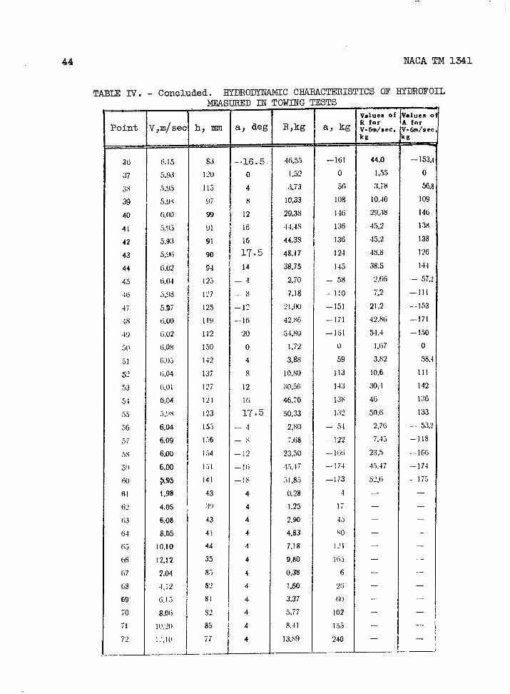
—
44 NACA TM 1341
TABIE IV. - Concluded. HYDRODYNAMIC CHARACTERISTICS OF HYDROFOIL
Point
36
:37
3s
39
40
41
42
43
44
45
46
47
4s.19
so
.51~:
!53
54
,’)5
56
:)i
Ss5!)
60
61(j)
(is
M
6>
(fi
(i7
G9
69
70
7172
_...—
T,m/sel
6.15
5.93
~.g~
,i.~<
(i.00
j.$j
5.93
,5.9(;
(;.02
6.04
S.gs
5.97
6.00
6.02
(i.os
6.(),3
(;.04
(i.ol
6.04
,j.!l,!
6,04
6,09
6.OO
6,00
9.95
I,9a
4.05
6.08
8.05
10,10
12,12
2.04
4,12
6.I.3
8.O(i
1IJ.20
l_’,1[1
-—. -.-—-..
h, mm
83
120
1[5
!)7
99
91
91
90
94
125
127
125
Ilg
l]?
150
I42
137
127
121
I23
155
1.-,6
I54
I.-)I
141
43
;J)
43
41
44
35
8.5
8?
81
8Q
85
77
——
–16.5
o
4
8
12
16
16
17.5
14
— 4
— 8
–lo
--16
20
0
4
s
12
1t;
17.5
—4
Y—,
_ly
—16
—1s
4
4
4
4
4
4
4
4
4
4
4
4-
‘OWING
R,kg
4(;.55
1.s2
3.73
10,33
29.38
4’4,4s
44.38
48.17
38.75
2,70
7.18
?1,00
42,86
54,s0
1,72
3,88
10.s0
;10,56
46.70
50,33
2.80
7.68
23.50
4,5..17
.i1,83
().X4
1.25
2.90
4.83
7.18
9.80
0.38
1.60
3,37
5,77
8.41
13!S9
lSTS
a, kg
—161
o
56
I08
146
136
136
I24
145
– 58
-110
–151
—171
—1.51
o
59
113
143
136
1W
— 5.1
–122
—I{j(j
-..]74
—173
4
,7
45
so
121
1(ij
6
~(j
(;()
102
1,58>
240
values oiR forV-6m/see,kg. ——
44.0
1,<55
3,78
10.40
29+38
45,2
45,2
4s.s
38,5
2,66
7.?
21.2
42.X6
54.4
1,67
3.82
10.6
30.4
46
50.6
2.76
7.43
23,5
4.5.47
52,6
—
—
—
—
—
—
—
—
—
—
—
—
—.{dues c4 for~-6m/se<:g
—153.4
o
56.8
109
I46
1.38
138
1?6
144
— 57;j
—111
--153
—171
— 1.50
0
58.4
111
142
136
133
– 532
–118
—166
–174— 17,5
—
—
—
.—
—
—
—
—
—
—
—
—
—

NACA TM 1341 45
TABLE V . - CHARACTEROF FLOW ABOUT HYDROFOILIN TANK TESTS
>int Conditionof motion Remarks
., -..-.,Spray film from leading edge of fOii’in upward direction.
1Foil undergoes
vertical vibrationwith amplitudeof 2millimeters.
h=O, a=-2° Spray film from leadingedge inclined2 V=6 m/see somewhatbackward..Vertical vibration
as under 1.
h=O, ci=4°,Spray f’ilm from leadingedge inclined
3 V=6 m/seesomewhatforward. Vibrationof foildiscontinued.
h=ll mm, --2°, From the leadingedge of the foil a6 V=6 mlsec
film adheringto the upper surfaceis formed.
From the trailingedge of the foil afilm is formed having a horizontal
h=5 mm, -8°, direction.10
From the leadingedge a filmV=6 m/see is formed making with the chord an angle
of 45° and forming a water arch over thefoil.
The flow about the foil is smooth,averticalfilm being formed at each bracket.
h=17 mm, G4°, This smoothcharacterof the flow occurs in13 V=6 m/see all cases where the angle of attack is not
too large and the foil is submergedat asufficientdepth.
h=58 mm, 0_=12°, Behind the foil there is a depression25 V=6 m/see which, after 3 meters, ends in turbulence.
Eehind the foil there is ~depression cov-h=58 mm, a=16°, ered with jets running off the foil. At a
26 V=6 m/see distanceof about 1 meter the jets are trans-parent and beyond that point have a foamystructure.From the middle of the foil over the e’ritirespan verticalfilamentssimilar to systems of
h=51 m, -17.5°,27 free vorticesare formed.
V=6 m/seeA group of such
vorticesdoes not adhere stronglyto the foiland periodicallybreaks away, and in its placnew vorticesaxe formed.
-l_
From the lower surfaceof the foil (the low-h=68 mm, a=-18° ~pressure surface),a vortex film periodical:
33 V=6 m/see breaks away as under 27. This phenomenonisthe cause of the vertical. Vibration of thefoil.
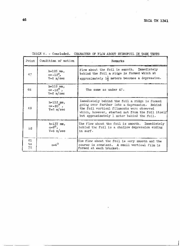
46 NACA TM 1341
TABLE V . - Concluded. CHARACTER OF FLOW ABOUT EYDROFOIL IN TANK TESTS
PointICondition of motion
I
h=125 mm,47 --120,
V=6 m/see
h=1120mm,
49G-X) ,V=6 m/see
——— __ ______61
a=4°;;
..—.-.——_— ——
RemarksI
Flow about the foil is smooth. Iimnediately
behind the foil a ridge is formed which at
4
approximately l+ meters becomes a depression.
The same as under 47.
Immediately behind the foil a ridge is formedgoing over farther into a depression. Behindthe foil vertical filaments were observedwhich, however, started not from the foil itselfbut approximately 1 meter behind the foil.
The flow about the foil is smooth. Immediatelybehind the foil is a shallow depression endingin surf.
?he flow about the foil is very smooth and the
:ourse is constant. A small vertical film is‘ormed at each bracket.
I

m>., . .-. ., .,,.
r
Figure 1. - Effect of T = 2gh/V2 on liftforce of a cylinder without circulation.
-02+-++{~
,-1 I I I I 1
H-FRT#l
47
(2J4
Figure 2. - Dependence of lift forcecoefficient of a cylinder withoutcirculation on h/d andV/~.
I

.,. . .—..-. .
48
\
NACA TM 1341
Figure 3. - Dependence of wave drag coefficient of a cylinder
without circulation on d/h andV/~.

NACA TM 1341 49
.
+
Figure 4. - Dependence of lift of a foil replacedby a vortex on h/b and V/~.
(%h
K
04
03
a
01
&
Figure 5. - Dependence of wave drag coefficientof a foil replaced by a vortex on b/h and V/E.

Io-l0
A, kgPI--V
i50
I I ! ! i I I IJI1
crtr. n .n -n
II I I f II 1 I I I I I 1 I 1 i ‘~@l-/,,.;>,+.—–ET-k%iz’no
50
0 h
“50
,,meter
R, kg
$0
@
(0
o423
h, meterq50 475 /,0
“ml
Figure .6. - Dependence of lift and wave resistance of a cylinder with positive circulationon depth of submersion.

R, kgI
h, meter
ependence of lift and wave resistanceer with negative circulation on depthon.
–’==%4s
Cnr

52 NACA TM 1341
Figure 8. - Effect of T = 2gh/V2 on f(~) from formula (28a).
v -/5Cy ~’ v% =30 *429
-5Cy gI Cu
Figure 9. - Polars of foil of infinite span moving in ideal fluid.
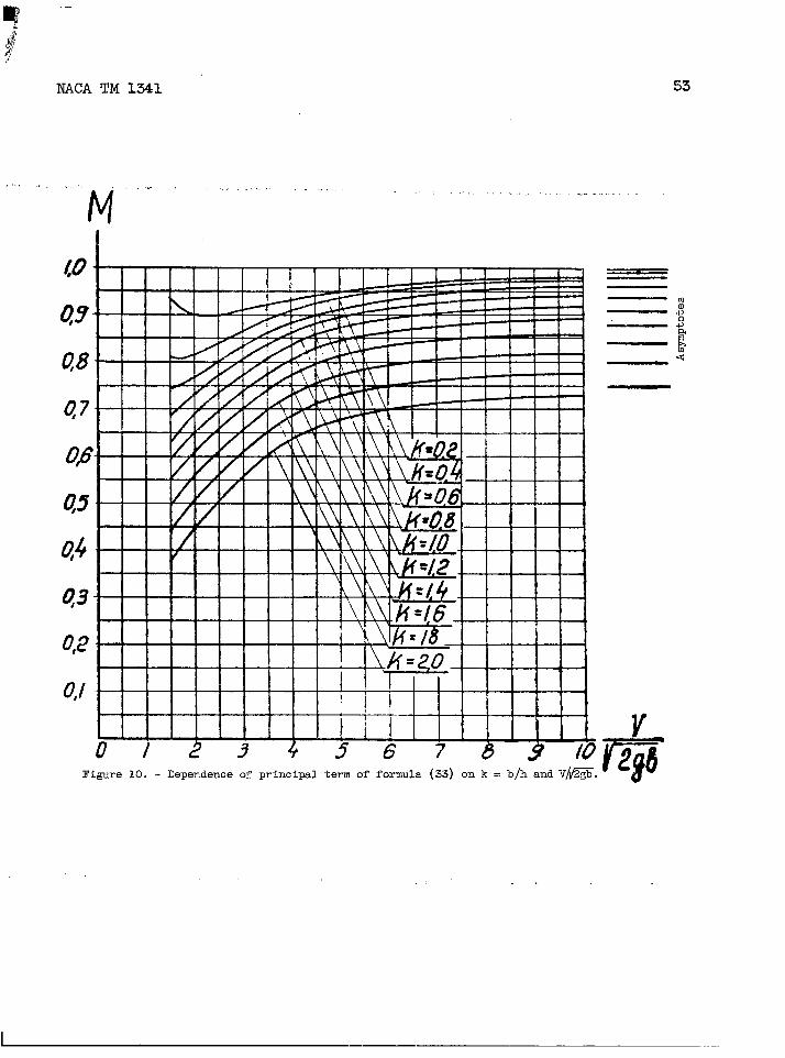
NACA TM 1341 53
,, .,=. ., ,. ..
M,,.. . .,!.,... . . . . . . . . . .
Figure 10. - Dependence of principal term of formula (33) on k = b/h andV~.
—K2

Cl 1“ 2
I I I
21
1+:I I
1 I I I I 1.
—.
“$
Figure 11. - Dependenceof additionalterm offormula (33) on k = b/h and V/~.
Figure 12. - Dependence of Crh/C~~from formula (34) on k = b/h sand V/~. s
5?
5

AhL7.m
I
1.
I
&“-
Figure 13. - Dependence of ~ih/~icofrom formulas (45) and (46) onh/bfor the two variants to accountfor the finite span.
J.
I I I I I 1 I I I I f I-—
I 1 [ ! 1 1 1 1 z
IN
I1
I I I I .,76
05
04
q3
q2
q
Figure 14. - Effect of Ah/h= 2/h on thecorrection $ from formula (46b). ,
CJlul

x
d 20 40 6L7 80 /uo
Figure 15. - Coordinates of symmetrical profile NACA 0.0009.
Yx Y x Y
\
0.001.252.505.007.50
10.015.020.025.030.0
0.00+ 1.420~ 1.961-t- 2,666+3.150: p:
.~ 4:303z- 4.456+ 4.501—
40.050.060.070.080090,095.0100I00
J
+ 4,352~ 3.971+ 3.423~ 2.748+ 1,967T 1.086~ 0.605* 0,0950.000

NACA TM 1341 57
%zc~a
r.x
fl~.
—.
25 1-1f /n*m.
0
/ ‘ L ./\
// r
/830’A A C&
a f Cx/
// { /
/ /!
iI
}
-/5 I { I
/1 f , I
,
I
I
/ I (
—.
Position of centerof gravity fromleading edge
1’, —-
1 = —.. —r / I—
f
e 4° 6° 8“ /0” /2” /4” 16” /8° #& A“
1 2 3 45 k + & 9 lb lmcx
Figure 16. - Aerodynamic characteristics of profile NACA 0.0009.
.,, -. ...
70
66
60
#
50
45
40
35
30e
/i90-25
2(9
/5-fd-
/0
5-
@d
.--, , .,, , ,.-. .--- ..--, -,— -- ,.,..-. . .. —.— .--.-..,-. —------- . ..- -

58 NACA TM 1341
e—-43.m- — 57.. — ~
.—. . —.-. — — —
/4c7A. — >
Figure 17. - Scheme of arrangement of supportingbrackets on hydrofoil.
Instrument for measuringlift force
Instrument for measuring
depth of submersion of foil
LeverInstrument for measuringangle of attack
of attachment of steadying device
... .— ———— -..-—— .—— —
Figure 18. - Set-up for testing the hydrofoil intank.

NACA TM 134.1
,. -.,
● A, kg /2”
.
1f’7e--ti/=$
\ 11111 -/A~/
tiiiiilt’iil,-
-24701, , L ?I,.,
{
Figure 19. - Dependence of lift of foil on depthof submersion and angle of attach for V = 6meters per second (test data).
59
h, mm
—

60
R,
50-
40-
3P
20
/o-
(
0
NACA TM 1341
kg
-h, mm
Figure 20. - Dependence of total frontal drag of hydrofoil on depthof submersion and angle of attack for V = 6 meters per second(test data).
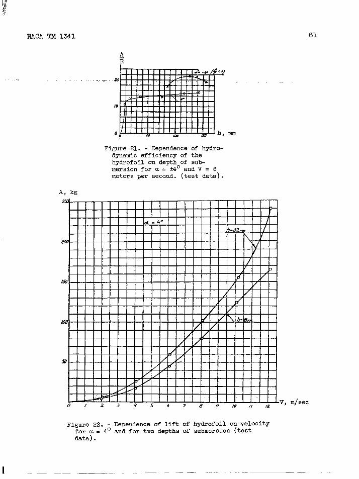
NACA TM 1341 61
Figure 21. - Dependence of hydro-dynamic efficiency of thehydrofoil on depth of sub-mersion for u = f4° and V = 6meters per second. (test data).
A, kg
0).?3 + ~ 6 7 8 9 10 II 12
Figure 22. - Dependence of lift of hydrofoil on velocityfor u = 4° and for two depths of submersion (testdata) .
V, m/see
1 –.-–– -.–. —–– — —

CnIN
d= ‘+OR, kg
/5
Q
5
U~234f 67 &9/o///.2Figure 23. - Dependence of total frontal drag of hydrofoil on velocity for a= 4° and for two depths of submersion
(test data).
V, m/6ec
.
1
I
1
II
I
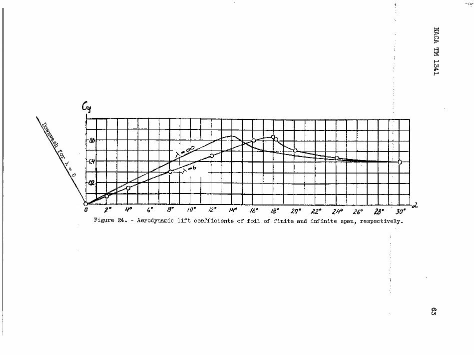
Ctj
Figure 24. - Aerodynamic lift coefficientsof foil of finite and infinite span, respectively.
U-JCN

64 NACA TM 1341
Figure 25. - Dependence of profile drag coefficient
on angle of attack and Reynolds number.
Ioo,cp
1,
0
m/ sec
Figure 26. - Dependence of profile drag coefficient
on velocity for, u = 4°.

Pdr=a-
L
o 0
1 I & I , , . ,
41EEE1!!! 0--!!::.A -
,,—
L!!u
o
I
25 – – -
I I 1/1 I I 1 l-l I I-/2? A I l-m+ !“1 n
0
1 1 1 I I I I 1 } w I /[. ●
IN
\
-8” / \u
I * I I I I
, -
-o~o‘ I I I -oJo}1 I I I I I I I ! i I I I
Test data,
{
4*:;8”02J2”
Theoretical data —.. ---
‘=@
Figure 27. - Comparison of experimentalwith theoreticalresults for lift coefficientsof hydrofoil for twovariants taking into account the finite-span.
.

cy*
n/5I ~Test data
Cvo
1!!!!!!!!!!
reticaldata
V, m/see
Figure 28. - Comparisonoffor lift coefficientsofmillimeters.
experimental with theoretical resultsa hydrofoil for a = 4° and h = 82
wcx~, fl(b/3i.
so Jo
h/’2
2,5 2!5~ -m
~ -co
o ,h> mmO5-o 100 /50
Symbols denote test data
Figure 29. - Comparison of experimentalV = 6 meters per second.
50 100 /50-’ “-/-
Theoreticaldata
(---
and theoreticalcoefficientsof total drag of a hydrofoil for
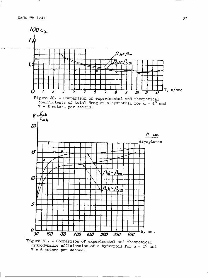
NACP.??4 1341 67
V, m/see
Figure 30. - Comparison of experimental and theoreticalcoefficients of total drag of a hydrofoil for u = 4° andv = 6 meters per second.
s
Figure 31. - Comparison of experimental and theoreticalhydrodynamic efficiencies of a hydrofoil for a . 4° andv= 6 meters per second.
I

68
/00(2
h,
/oocx
h,
Fi~e 32. - Effect of depth of submersion of ahydrofoil on the components of its frontal dragfor a = 4°,and V = 6 meters per second, and A = 6
(theoretical data).
NACA -Langley -6-6-55- 1000
Related Documents