NATIONAL TRANSPORTATION SAFETY BOARD Office of Aviation Safety Washington, D.C. 20594 January 25, 1999 GROUP CHAIRMAN’S FACTUAL ADDENDUM CONCERNING RE-EXAMINATION OF FUEL PROBES DCA-96-MA-070 A. ACCIDENT Location : East Moriches, New York Date : July 17, 1996 Time : 2031 Eastern Daylight Time Airplane : Boeing 747-131, N93119 Operated as Trans World Airlines (TWA) Flight 800 B. SYSTEMS GROUP Chairman : Robert L. Swaim National Transportation Safety Board Washington, D.C. Member : Richard Lidicker Boeing Commercial Airplane Co. Seattle, Washington Member : Jon Regimbal Federal Aviation Administration Seattle, Washington Member : Chris Hartonas Federal Aviation Administration Seattle, Washington Member : Lou Taylor Honeywell Commercial Aviation Systems, Sensor Products Operation (CAS-SPO) Minneapolis, Minnesota Member : William Savage Honeywell Commercial Aviation Systems, Sensor & Guidance Products Minneapolis, Minnesota

Welcome message from author
This document is posted to help you gain knowledge. Please leave a comment to let me know what you think about it! Share it to your friends and learn new things together.
Transcript

NATIONAL TRANSPORTATION SAFETY BOARDOffice of Aviation SafetyWashington, D.C. 20594
January 25, 1999
GROUP CHAIRMAN’S FACTUAL ADDENDUM CONCERNINGRE-EXAMINATION OF FUEL PROBES
DCA-96-MA-070
A. ACCIDENT
Location : East Moriches, New YorkDate : July 17, 1996Time : 2031 Eastern Daylight TimeAirplane : Boeing 747-131, N93119
Operated as Trans World Airlines (TWA) Flight 800
B. SYSTEMS GROUP
Chairman : Robert L. SwaimNational Transportation Safety BoardWashington, D.C.
Member : Richard LidickerBoeing Commercial Airplane Co.Seattle, Washington
Member : Jon RegimbalFederal Aviation AdministrationSeattle, Washington
Member : Chris HartonasFederal Aviation AdministrationSeattle, Washington
Member : Lou TaylorHoneywell Commercial Aviation Systems, Sensor Products Operation (CAS-SPO)Minneapolis, Minnesota
Member : William SavageHoneywell Commercial Aviation Systems, Sensor & Guidance ProductsMinneapolis, Minnesota

2
Member : Ken CraycraftTrans World Airlines (TWA)Kansas City, Missouri
C. SUMMARY
On July 17, 1996, at 2031 EDT, a Boeing 747-131, N93119, crashed into the Atlantic Ocean,about 8 miles south of East Moriches, New York, after taking off from John F. Kennedy InternationalAirport (JFK). The airplane was being operated on an instrument flight rules (IFR) flight plan underthe provisions of Title14, Code of Federal Regulations (CFR), Part 121, on a regularly scheduledflight to Charles De Gaulle International Airport (CDG), Paris, France, as Trans World Airlines(TWA) Flight 800. The airplane was destroyed by explosion, fire, and impact forces with the ocean.All 230 people aboard were killed.
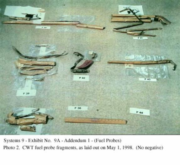
A group of party representatives was convened at the Safety Board Materials Laboratory inWashington, DC, from April 27 through May 1, 1998, to examine fuel probe components from theTWA flight 800 wreckage. The activity included a re-examination of components that had alreadybeen examined and fragments of fuel probes and compensators that had not previously beendocumented by the group. The group of new fragments included parts recovered from the ocean afterthe last group meeting and parts that had been found mixed with other hangar wreckage.
Two general types of fuel probe and compensator terminal block wire retention designs werefound. Both styles are illustrated and described in the Honeywell Overhaul Manual.1 The wireretention area of the earlier style of terminal blocks, used in Series 1-3 assemblies, has wires betweena knurled area of conical plastic points by a metal bracket. The Overhaul Manual showed that“smooth” terminal blocks used in Series 4 and subsequent did not have the knurled feature. Theillustration shows that wires attached to Series 4 and subsequent assemblies are routed through theopening of a nylon (plastic) “P” shaped clamp.
One compensator had plastic internal parts with lower edges that appeared resolidified,blackened, and pitted. Visual inspection did not detect similar damage to Teflon (PTFE) parts andtwo types of wire insulation found inside the fragment. Similar damage was also not found to theexternal features of the compensator fragment. The compensator was identified as fragment #80 andhad not been described by an earlier set of group notes. According to the FBI Log number, the parthad been recovered on about April 22, 1997, by a trawler that had been in what had been called the“green” area. The compensator did not have a terminal block, but had marks that were unique to theFG6C2 design that would have been built with an unknurled “smooth” terminal block.
1 The overhaul manual and other information were used in the Safety Board Public Hearing into TWA flight 800 of
December 8-12, 1997, and are contained in Systems Group Chairman’s Factual Report of Investigation, datedNovember 17, 1997. The Fuel Quantity Tank Unit Overhaul Manual pages cited are located in section 9C, pages 208-209 (9C208-209).

3
D. DETAILS OF THE INVESTIGATION
The details of these activities are additions to the previous descriptions of the FQIScomponents, contained in the November 17, 1997, Systems Group Chairman’s Factual Report ofInvestigation, section 9A, pages 87-100. The fragment numbers used in the Factual Report havebeen retained and new fragments have been added.
Sources of information for installations, descriptions of fuel probe Series numbers, andfragment features include the following:
1. References to fuel tank unit (probe) nomenclature and features have been taken fromHoneywell Overhaul Manual for Part FG420 Tank Units, primarily Figure 1101 (SystemsGroup Chairman’s Factual Report of Investigation, dated November 17, 1997, pages 9C204-209).
2. References to compensators were taken from the Honeywell Overhaul Manual for the PartFG6C (includes 9C247).
3. Fuel probe installation locations (for example, the first fragment below calls out “F62”) weretaken from TWA Wiring Diagram Manual 28-41-01, page 102 (9C188-189, 9C246) andBoeing drawing 60B92010 (9C187).
4. Wiring information has been found in Honeywell drawing C13467AA01 and various TWAWiring Diagram Manual pages contained in Chapter 28 (9C264-268), as well as from Chapter 91-00 of the TWA Master Wire Bundle drawings.
Item Length (in.) FBI ID Mfg Identification Tank(Fragment)
1 FG420-A41 #4The terminal block is a Series 3 type, with set screws to attach the FQIS wires. The probe ismarked with MFD and FT dates of OCT 1969.2 The number of wires and HI Z wire terminationof this part number are unique to the tank 4 probe (Boeing identification) F62.
According to Honeywell personnel present during the activity, the set-screw type of connectionswere not developed by Boeing or Honeywell. The modification replaced the screws used to attachwires to the Series 1-3 terminal blocks. The replacement set-screws allowed use of nuts to attachwires, as in Series 4 and subsequent fuel probes.
2 MFD denotes the manufacturing date. FT denotes the Functional Test date.

4
2 FG420-A8 #1RA data plate states that this is a FG420-A8, Series 3, S/N A-132. A wire number marking (W722-Q107) was found that wire diagrams show unique to tank 1R. The terminal block is the knurledtype, with a metal clamp, as used in Series 3 and earlier probes. The dates marked on the outershell are MFD OCT 69 and FT OCT 69. The wire attachment connections have set-screw typesof hardware. The LO Z terminal has the set screw installed with the allen-wrench point reversedand hidden.
3 FG420-A36 #4The HI-Z terminal is a threaded stud, as shown used in Series 4 and later terminal blocks. Thehead of the stud was crushed into the probe.
This fragment combines with fragments 35 and 50 to create a complete FG420-A36 probe, uniqueto tank 1 or tank 4. The group noted that the another FG420-A36 was identified and that theremaining probe identification is F64, from tank 4.
4 FG420-A39 #1 or #4The end of the fragment matches the fracture of fragment 6. Information concerning the opposingprobe is described in fragments 64 & 77.
5 FG420-A34 #4The HI Z mounting bolt for the terminal block has a flat washer, not a lock washer, and the flatwasher was unique to Series 5 terminal block installations (and subsequent). The probe is markedwith MFD and FT dates of JUN 1970.
The fragments add to the nearly complete probe length, with the inner electrode. Note: Item 51does not match these parts.
A wire fragment in an attached bag has 3 partial tags with number markings of F65, W1180-Q152. The Boeing wiring diagram shows the markings for this probe and wire are at installationlocation F65 in tank 4.
6 FG420-A39 #1 or #4The probe is marked with MFD and FT dates of NOV 1970. The end of the fragment may matchthe fracture of fragment 4. Note: Data concerning similar fragments from the opposing probe,found to be fragments 64 & 77, is contained in descriptions of fragments 64 & 77.
7 FG420-A38 #1The HI Z terminal has a tuning washer, as used in the Series 5 and subsequent terminal blocks.The probe is marked with MFD date of MAY 1970.
Two FG420-A38 probes are installed in the B-747. Item 14 had probe features and a wireidentification that used in the tank 4 installation. The installation number in tank 1 is F11. Theinner electrode is complete at 21 inches; the outer electrode is 15 inches long.

5
8 FG420-A28 #2 or #3The ends of fragments #17 and #8 match and the cumulative length is the approximate length ofone complete inner probe element. These fragments add to 38 of 58.27 inches of the outer shell,with the bottom end missing. These fragments are separate and different from #38 and #71,which assemble into a second -A28 probe. Neither FG420-A28 probe has features that identify itto the left or right wing.
9 FG420-A31 #1 or #4The marked MFD and FT are JUL 1970. A fragment of the upper terminal block top has thethinner casting of the unknurled type, found on an exemplar part that Honeywell provided. Thissmooth type of casting was used in Series 4 and subsequent probes. The HI Z mounting screw isconsistent with the Series 5 or subsequent terminal block. This fragment has the length of anearly complete probe.
10 FG420-A35 #4The probe is marked with MFD and FT dates of FEB 1970.
Two of the FG420-A35 probes are used in the B-747 and fragment #61 was another -A35, with awire identification used in the tank 1 installation. The remaining installation shown on theinstallation drawing is probe F71 at tank 4.
11 FG420-A26 #2The fracture surfaces and overall length of this fragment, with #32, add to one FG420-A26 probe.The other FG420-A26 that was found has wiring from the #3 main tank. The remaining locationthat the installation and wiring diagrams show would use a -A26 is the #2 main tank.
12 FG420-A24 #2The outer tube was found with MFD and FT dates of AUG 1970. Two of the FG420-A24 probesare used in the B-747 and fragment #18 has a wire identification used in the #3 tank. This probe(fragment 12) has material that would overlap with #18. The remaining installation shown on theinstallation drawing is in tank 2.
13 FG420-A41 #4The length of the total probe was verified from the (above) activities of August 25 and October16, 1996. This length was found approximately equal to fragments #1 and #13 and alignment wasverified at the ends of the outer tube fragments. Item #1 was found with a wire used at the F62installation in the #4 main tank.
14 FG420-A38 #4The stud type of terminal was found, as used in Series 4 and later probes, but without a “tuningwasher” (Fig. 1101, Item 26A) that was used in Series 5 and later assemblies. The stud used forthe HI Z terminal was found to be 1.562 inches in length, a measurement unique to the Series 4.The probe and wire numbers are shown in the Boeing installation identification as unique toinstallation F63, as used in tank 4. Of the orange lettering used for the MFD and FT dates, only“70” is visible. The fragment is different than fragment 7.
6
15 FG420-A33 #4
The data plate identified this as a FG420-A33, Series 5, S/N Y20. The MFD and FT datesmarked on the outer shell were MAR 71.
Item 42 is a FG420-A33 with attached wires that are used in tank 1. Tank 4 is the remaininginstallation location for the FG420-A33 probes.
16 FG420-A18 #2 or #3The probe is marked with MFD and FT dates of NOV 1971. The HI Z mounting has a flatwasher, as used in Series 5 and subsequent assemblies.
17 FG420-A28 #3Wire numbers were found that were used in the Boeing F58 installation in tank #3. The HI-Z is astud, as used in Series 4 and later terminal blocks, as well as the “tuning washer” that was used inSeries 5 or later fuel probes (Fig 1101, Item 26A). The terminal block is the “smooth” type.Marked on the outer shell was FEB 1971 for both MFD and FT dates.
The ends of fragments #17 and #8 match, also combining to a nearly complete inner element.These fragments add to about 38 of 58.27 inches of the outer shell, missing the bottom end.These are separate and different from #38 and #71, which assemble into a separate -A28 probe.
18 FG420-A24 #3An attached wire fragment has a number that is used in the #3 main tank at Boeing installationF55. A data plate identifies this as a FG420-A24, Series 6, S/N Z150.
Unique inner element steps that are used only once per probe are in both this fragment and probefragment #12.
19 FG420-A20 #2 or #3The HI Z mounting stud terminal is on the inner element, with a flat washer and a “tuningwasher” that are unique to the Series 5 and subsequent fuel probes. The probe is marked withMFD and FT dates of JUN 1970.
20 FG420-A21 #2 or #3The HI Z mounting bolt for the terminal block has a flat washer and a “tuning washer,” not a lockwasher. These are features shown in the Overhaul Manual as unique to Series 5 and subsequentprobes. The probe is marked with MFD and FT dates of JUN 1970.
21 FG420-A27 #2 or #3The terminal block has a nylon Adel clamp for strain relief, rather than the metal clip used onSeries 1-3 fuel probes (per Fig 1101). MFD is DEC 1970 and FT JAN 1971.
22 Comp. FG6C2The part marked with S/N Z-1213 and Honeywell manufacturing records showed that the “Z”denoted a 1970 manufacturing date. The FT date marking was NOV (year illegible). The name
7
plate shows FG6C2, Series 1, which Honeywell records show to be a terminal block style that hasno knurling. No identifying features or attached wires were found that described the originallocation. The compensator has no evidence of general sooting to the internal or external features.
The inner diameter of an inner shell (inner LO Z) has a small black mark that would be oppositean upper cut-out, according to position on a Honeywell engineering drawing (FG6C). This is thelocation of a blue plastic spacer, according to the drawing. Other marks are on the walls oppositeto the other two cut-outs, as well, but without the black.
Terminal studs (2) found in the plastic bag were from a terminal block style that would not havebeen knurled. The LO-Z terminal stud has black deposits around the interior plastic sleeve of theattached crimped terminal that is on the terminal side. The black is also at the wire end of theLO-Z crimped metal and the plastic sleeve. Orienting the stud and crimped connector on asubstitute terminal block found that the crimped connector was oriented up and to the right, sothat the crimped wire connector covered the “Z” of the “LO Z” marking.
The HI-Z crimped connector has significantly less blackening and the blackening that exists isprimarily on the exposed portion of the wire.
An internal blue (LO-Z) wire from within the compensator had corrosion in the crimpedconnectors. One had a slight amount of darkening in the plastic, but not the blackened featuresseen in the LO-Z crimped connector.
23 Comp. FG6C Rt. SurgeThis compensator had been installed in the right surge (vent) tank when the wing tip wasrecovered.
24 Comp. FG6C(No factual information added.)
25 FG-420-A8 #4RDocumentation is contained in NTSB Laboratory Report No. 96-160.
26 FG420-A37 #1 or #4The probe is marked with MFD and FT dates of JAN 1971. The HI Z stud is missing the bolthead. This is a nearly complete length of a FG420-A37 probe.
27 FG420-A13 CWTThe HI Z mounting bolt for the terminal block has a flat washer, not a lock washer, and the flatwasher was a feature unique to Series 5 and subsequent assemblies, according to the OverhaulManual. The probe is marked with MFD and FT dates of APR 1971. Wire numbers correspondto Boeing number F41.
28 9-23-96-5 RK FG420-A22 #2 or #3(No factual information added.)
8
29 9-19-96-1 DJ/LA FG420-A17 #2 or #3The terminal block is not the knurled type that was used in Series 3 or earlier.
30 9-22-96-1 DEL FG420-A27 #2 or #3The HI-Z bolt from the terminal block has the “tuning washer” that was used in Series 5 or laterfuel probes (Fig 1101, Item 26A).
31 9-23-96-5 RWK FG420-A30 #1 or #4The terminal block is not knurled and has a nylon strain relief clamp attached, as used in Series 4and subsequent probes. The assembly was not taken apart to examine for a “tuning washer.”
The fragment appears to have both manufactured ends.
32 9-20-96-35 JNY/PW FG420-A26 #2The top half of the terminal block is not the knurled type. The HI Z stud has the “tuning washer”of the Series 5 and higher terminal block assembly.
The fracture surface and length visually match with fragment #11. Fragment #11 was identifiedas from tank #2.
33 9-21-96-1 FG420-A20 #2 or #3The outer shell was cut to gain access to the HI Z terminal. The HI-Z has the “tuning washer”that was used in Series 5 or later fuel probes (Fig 1101, Item 26A).
34 9-23-96-5 DMW FG420-A23 #2 or #3The terminal block is not knurled and has a nylon strain relief clamp, as used in Series 4 andsubsequent probes. The HI Z has a “tuning washer,” used in Series 5 assemblies or subsequent.
The fracture surface and length of this fragment match with the top of fragment #63.
35 9-20-96-33 JMV/BW FG420-A36 #1The fuel probe has a terminal block that does not have a knurled area, as used in Series 4 and laterterminal blocks. The terminal block was not disassembled to examine for a “tuning washer,” asused in Series 5 or later fuel probes (Fig 1101, Item 26A). Wire identification marks were foundthat were used in tank #1 at Boeing location F12.
The fracture surface of the fragment mates with fragment 50, identified as a tank #1 part.
9
36 9-23-96-5 ON/NY Compensator #1Wires were found looped to pass through the nylon strain relief (Adel) clamp twice (photo in theNovember 17, 1997, Systems Group Chairman’s Factual Report on page 9E1). The terminalblock is the “smooth” style that is unique to the Series 4 and subsequent terminal blocks. Theprobe is marked with MFD and FT dates of JAN 1971. The rolled bottom is unique to the FG6C1and FG6C2 series of compensators, although all FG6C1 parts had the knurled terminal block.
A F7/F59 installation wire marker that is used in tank 1 was found attached.
37 9-23-96-5 FG420-A29 #1 or #4The HI-Z bolt from the terminal block has the “tuning washer” that was used in Series 5 or laterfuel probes (Fig 1101, Item 26A)
38 9-21-96-1 FG420-A28 #2 or #3Matches with fragment #71 & #38 to form a nearly complete probe, missing several inches fromthe middle and top, with #38 as the lower portion.
39 9-20-96-33 DJ/LA FG420-A19 #2 or #3The fragment has a HI Z mounting bolt that has the tuning washer” (Fig 1101, item 26A) of aSeries 5 or later terminal block. The fragment has a HI Z stud assembly (fragment 5A), which isSeries 4 or above. A small fragment of wire is attached by the metal part of a crimped connectorto the HI Z stud. A small amount of blackening is on the crimped connector and the wire visibleat the stud end of the connector. The wire fragment protruding from the end that is opposite thestud has no insulation remaining and has no blackening.
40 9-20-96-33 DJ/LA FG420-A22 #2 or #3The probe is marked with MFD and FT dates of FEB (unknown year).
41 9-20-96-35 DJ/LA FG420-A32 #1 or #4(No factual information added.)
42 9-20-96-33 JMY/DW FG420-A33 #1The HI Z washer was of the flat washer, not lock washer, and the terminal block had a nylon Adelclamp, each of which are features unique to Series 5 and subsequent. Wiring identification isused in Boeing tank 1 at the probe F18 installation. The probe is marked with a FT date of MAR1971.
43 9-22-96-1 DEL FG420-A25 #2 or #3The HI-Z connection feature is a stud, as used in Series 4 and later terminal blocks, and has the“tuning washer” that was used in Series 5 or later fuel probes (Fig 1101, Item 26A).
44 10-13-96-3 TLL/EP FG420-A11 #4RThe MFD and FT dates marked are APR. A scrape through the lettering covers the yearmarkings, obscuring the MFD year. The FT can be seen under magnification to be 1971. The HI

10
Z mounting bolt has a flat washer and a tuning washer, as used in Series 5 and subsequent fuelprobe assemblies.
The group noted that tank 4R had resolidified aluminum, blackening, and soot (probe installationF77). Tank 1R had none of these features. See also the notes for fragment 58 (tank 1R,installation F4) and mating fragment 65.
45 Comp. [None] CompensatorThe bag contains miscellaneous parts. The bottom of the outer compensator shell has the rolledfeature of the FG6C1 or C2. The terminal block parts each has a curved feature that is foundunique to a single terminal block. Each terminal block fragment has features of Series 4 or laterterminal block; one having a nylon Adel clamp attached and the other not having the open "pass-through" feature of the earlier terminal block series. In the bag is a red LO Z wire, marked “F11-63,” which is a probe feature and not from a compensator. Black wires (“pig-tail” groundconnections) are also not a compensator feature, but are used for wire terminations at fuel probes.A photo was enclosed in the parts bag and shows the black wires attached to the terminal blockfragment that does not have the nylon Adel clamp. The wires were reattached to resemble thephoto and no unique orientation features were noted.
46 9-24-96-16 JM FG420-A18 #2 or #3(No factual information added.)
47 9-21-96-1 FG420-A37 #1 or #4The HI Z is a stud type of terminal with a flat washer and “tuning washer,” as unique to the Series5 and subsequent fuel probes.
48 9-24-96-16 PMO FG420-A ?(No factual information added.)
49 9-22-96-1 DEL FG420-A12 CWT(No factual information added.)
50 9-20-96-33 DJ/LA FG420-A36 #1The fracture surface mates with the end of fragment 35, which had wires used in tank #1.
51 9-20-96-33 JMY/DW FG420-A34 #1The small amount of fragments are duplicative of what was found on fragment #5. The remaininginstallation number is F13 in tank 1.
52 9-22-96-1 FG420-A25 #2 or #3The fracture matches with fragment #43, not fragment #42, based on fracture surface and length,verifying this to be the FG420-A25 part, used in tanks #2 and #3.
53 9-22-96-1 FG420-A15 CWTThe HI-Z terminal is a stud, as used in Series 4 and later terminal blocks. The “tuning washer”found was used in Series 5 or later fuel probes (Fig 1101, Item 26A).

11
54 9-22-96-1 FG420-A20 #3The terminal block is not knurled and has a nylon strain relief clamp. The style was used inSeries 4 and subsequent probes. The HI Z is not with the parts. A separate LO Z wire found inthe parts bag is twisted downward on the stud.
55 [None](No factual information added.)
56 11/23/96-58 JB FG420-A23 #3The terminal block is not knurled and has a shadow that matches the edges of a nylon strain reliefclamp. The features found were used in Series 4 and subsequent probes. The HI Z mounting studis missing the end that could have a “tuning washer.”
The fragment was renumbered as -A26 after positive identification of two -A23 probes. The wirefragment described by the April 14, 1997, group activity has been found to have been routedbetween the -A23 and -A26.
57 11/17/96-11 DRR FG420-A23 # 2 or #3The terminal block is not knurled and has a nylon strain relief clamp. The features found wereused in Series 4 and subsequent probes.
Fragments 57, 69, and 76 had distance measurements between varying diameters that are uniqueto the top, middle, and bottom (respectively) of one -A23 probe. The mating fracture surfaces andlengths combine to one nearly complete probe, separate from the lengths of the opposing -A23fragments.
58 11/17196-9 GC FG420-A11 #1RThe small fragment has a terminal block of the knurled type and has the larger relief (pass-through) beneath the center area that was used in Series 1-3 terminal blocks. A small section ofplastic wall was found broken next to the HI Z mounting location. The HI Z mounting screw isconsistent with a Series 3 terminal block. The external plastic sleeve on the crimped HI Z wireconnector is blackened, curled, and possibly heat damaged.
Found with fragment 65 to match the opposing (clearly burned fragment #44, installation #F77)FG420-A11 from tank #4R in the area of the terminal block. The installation drawings show onlytwo usage locations and the remaining number found is tank #1R at installation #F4.
59 2-13-97-134 W[illeg.] FG420-A12 CWTThe terminal block is not knurled and the nylon strain relief clamp used in Series 4 andsubsequent probes.
60 11-11-96-19 SC FG420-A10 # 4RThe terminal block is the unknurled type used in Series 4 and subsequent.
61 11-14-96-105 LMV FG420-A35 # 1

12
The terminal block is a non-knurled type and has a tuning spacer on the HI Z stud, features usedin the Series 5 and later parts. The MFD and FT were found to have been incorrect in the originalfactual description (April 14, 1997) and the dates should read JUN 1970, not JAN 1970.
62 10/27/96-1 DEL FG420-A18 #2 or #3(No factual information added.)
63 12-14-96-46 K FG420-A23 #2 or #3The fracture surface and length mate with the bottom of fragment #34.
64 11 - 17-96-2 GC FG420-A39 #1 or #4The fracture of this fragment matches the fracture of fragment #77, from tanks 1 or 4. Note:Another FG420-A39 probe was assembled from fragments 4 & 6.
65 12-14-96-65 FG420-A11 or -A29 # lR, #4R, #1, or #4Found with fragment 58 to be the same as the -A11 bottom section (burned fragment 44,installation F77). The remaining number is from tank 1R, probe F4.
66 11 - 16-96- 10 GI(?) FG420-A17 #2 or #3(No factual information added.)
67 10-8-96-1,LEB-EP(No factual information added.)
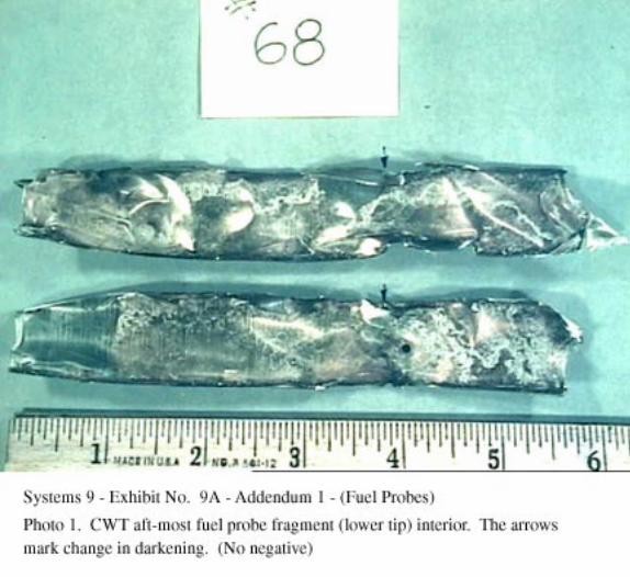
68 11-11-96-69 GJ FG420-A14 CWT(No factual information added.)
69 11/17/96-11 DRR FG420-A23 #2 or #3(No factual information added.)
70 11-5-96-25 SKC COMPENSATOR # 4RThis part has the FG6C2 type of flat collar, rolled bottom edge to the outer shell, and theunknurled terminal block. The data plate is missing. The MFD and FT dates marked on the outershell were MAR 71.
71 11-16-96-137 GC FG420-A28 # 2 or # 3This is a 15.5 inch combination of two pieces, the longer being 11 inches long. The fracture ofthis fragment matches with the fracture of fragment #38.
72 11/16/96-168 SHE FG420-A16 CWT(No factual information added.)
13
73 10/30/96-2 DMW FG420-A25 #2 or #3The HI Z screw from the terminal block was found in the assembly. The screw has a “tuningwasher” (reference item 26A, fig 1101) and flat washer that the Honeywell Overhaul Manualshows only to be in the Series 5 (and subsequent) terminal blocks.
74 2/3/97-220 GF FG420-A12 CWT(No factual information added.)
75 11/23/96-198[illeg.] COMPENSATORAn orange date “NOV 70” is where the MFD typically is located on other fragments, but othermarkings are illegible. The terminal block is the unknurled type.
76 11-17-96-15 GC FG420-A23 #2 or #3(No factual information added.)
77 11-23-96-208 DP FG420-A39 #1 or #4Fragments 77 and 64 have a raggedly torn edge that matches, to a combined length of the totalprobe. These fragments do not mate with fragments #4 or #6. Fragments #4 and #6 were foundto have fractures that mated with each other. No further identification found regardinginstallations of this fragment in tank 1 or 4.
78 9-9-96-49 BJW FG420A-13 CWT(No factual information added.)
79 3-1-97 71DM FG420A-9 4RThis is a nearly complete probe that includes burned and molten/resolidified plastic end caps, butno terminal block. The group noted that although the part would have been interchangeablebetween the #1R and #4R tanks, but that only tank #4R had burned features. The HI Z mountingscrew does not have a “tuning washer.” The Series 4 part used a longer HI Z mounting screw,identifying this by elimination as a Series 1-3 part. The MFD marking was OCT 1969.
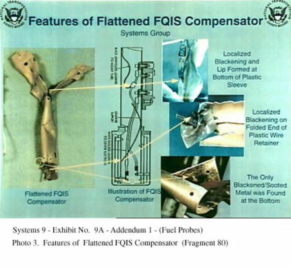
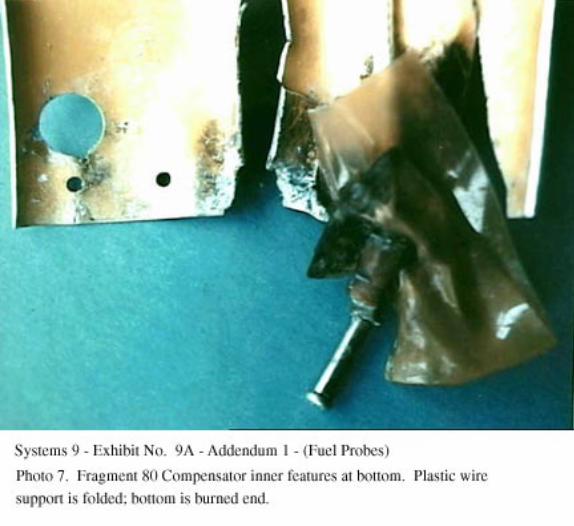
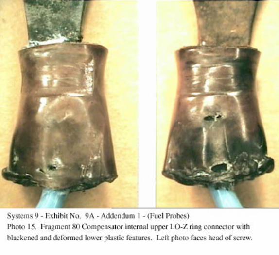
80 4-30-97-62 G FG6C2The fragment is the support tube (central core) of a compensator. The walls of the top third of thesupport tube were found flattened together, with the terminal block bands remaining intact. Thelongitudinal edges of the flattened portion were not connected. The fragment was found withoutthe plastic mounts, the terminal block and the lower elements. No MFD or FT numbers arevisible along the length of the tube.
Although the terminal block is missing, the white Teflon insulator from beneath the terminalblock remains attached to the support tube. A demarcation in the reflection of light from theanodized surface of the fragment aligned with the (outer electrode) top cover of a FG6C1 or C2exemplar. The HI Z attachment machine screw sleeve (FG6C Overhaul Manual, Fig. 1101, item38) from the lower end of the compensator has a diameter of .124 inches, corresponding to partsused in FG6C2 or FG6C4 Series 1, both of which use non-knurled “smooth” terminal blocks.
14
The location of the white Teflon insulator on the tube was marked with a red marker during theactivity and the Teflon part was released by slipping off the band clamp. The upper third of thetube was then spread apart. The edges of the spread surfaces were the existing fractures in thetube. Two screws were found trapped in the collapsed portion of the tube. One internal screwwas found with material missing from one side of the screw head. A protrusion of different shadeand texture was seen under (75X) magnification in the missing area of the screw. The lower twothirds of the tube was split with small snips that did not create metal chips or dust. The cuts wereminimized by cutting only to connect the existing splits and damage.
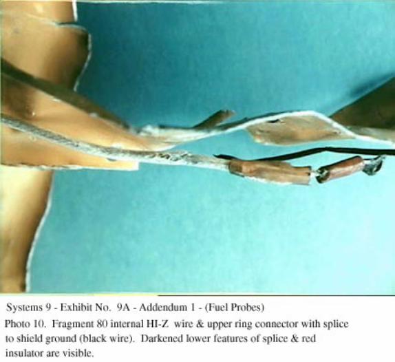
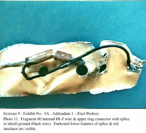
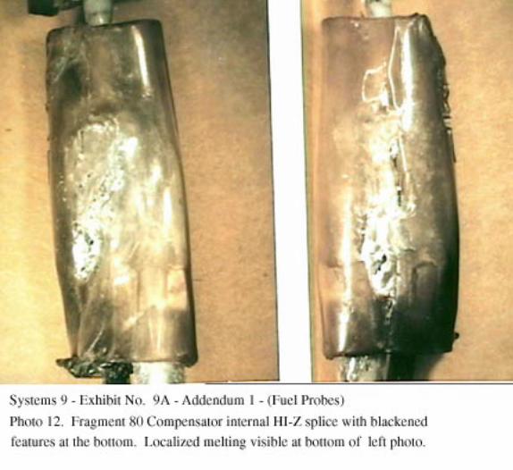
Once the flattened top of the support tube was opened, four plastic electrical parts inside werefound blackened, pitted, and resolidified along the lower edges. The blackening had an upwardflow pattern and was confined to the lowest edges of a plastic sleeve that covers a wire shieldingconnection, two plastic insulators on ring connectors, and the plastic leadwire support. Thegeneral features of each plastic part did not appear to have been molten and each part retained itscolor. The bottom of one of the tube halves had a soot accumulation, but this was in an enclosedarea that did not have the scouring marks found on the external surfaces or smoothness of theinner surfaces.
Plastic parts were found inside the tube that had not blackened, including two types of wireinsulation and the internal features of the Teflon components. The FG6C Overhaul Manual(docket page 9C247) calls out use of MIL-W-16878/5 (PTFE) leadwire, which is the type of fuel-exposed wire that was found through-out the B-747 fuel tanks during the investigation. The blueand black wire insulations resembled this type of material. The other type of insulation found inthe compensator was a clear plastic cover, over an off-white woven inner material that coveredthe core conductor.
The only potential external evidence of blackening damage on the external surface was a smalldarkened flow pattern around a hole that was under the terminal block Teflon insulator. No otherexternal evidence of soot or heat was found, including in the enclosed areas of folded aluminumwhere it had been bent, or under the Teflon insulator.
The FBI Log number was compared with recovery records. The records showed that for that FBILog number, the part would have been found in area PP, lines 93 TWA W and 94 TWA E.Trawling recovery charts showed that this area corresponded to what had been called the “green”recovery zone and that the parts had been accepted from the trawler on 4/22/97.
81. Miscellaneous loose parts found in the bottom of the shipping boxes include:
An assembly strap for a terminal block (Fig 1101, item 3 or 4).
A loose terminal block stud with an attached crimped wire connector. The crimped connector isoriented on the block in a direction that holds the wire downward, appropriate for a HI Z terminal.Held over an exemplar terminal block, the position interferes at the SHLD and LO Z positions.The diameter of the stud matches a HI Z part.
An end cap from a probe.
15
82 3-26-97-34 GL FG420A-34 #1 or #4This is a 6 inch fragment of the inner and outer elements, marking numbers were not found oneither fragment. The diameters and length only match the configuration of the bottom of theFG420-A34, as used in #1 or #4 main fuel tank, in the F13, or F65 installations. The group notedthat fragment 51 has a similar area and was found to be the upper portion of an F13 installation.
83 FG420A-This is a 6 inch probe fragment, including both inner and outer elements. It is the midsection of aprobe that has no unique exterior features, such as mounting holes or for the terminal block.
Robert L. SwaimTWA 800 Systems Group Chairman
National Transportation Safety Board - Systems Group
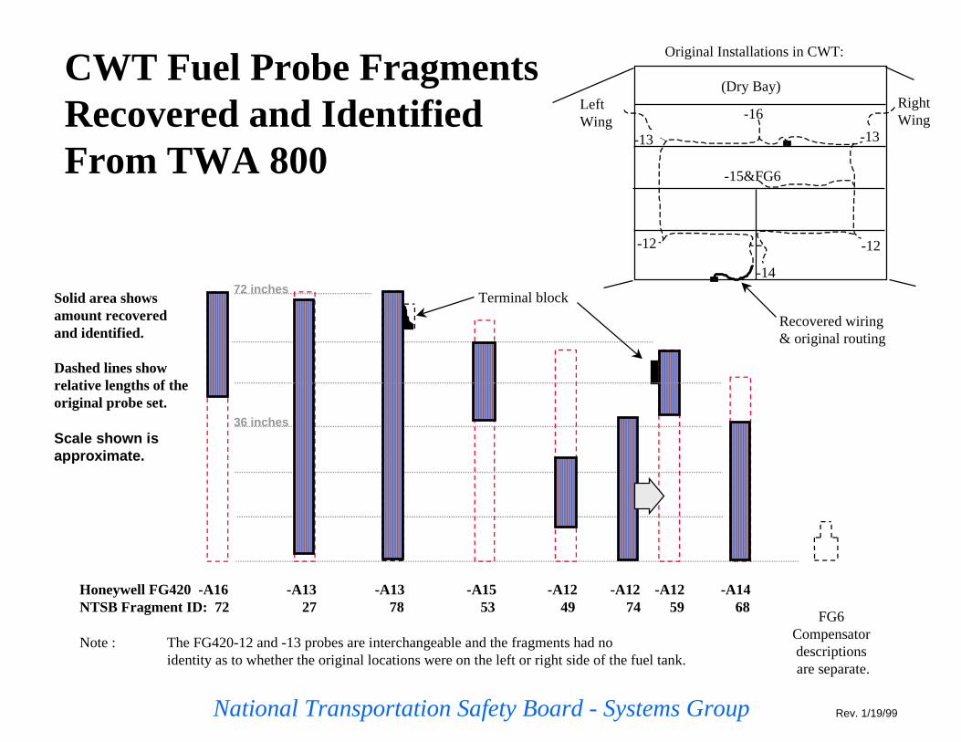
CWT Fuel Probe FragmentsRecovered and IdentifiedFrom TWA 800
Honeywell FG420 -A16 -A13 -A13 -A15 -A12 -A12 -A12 -A14NTSB Fragment ID: 72 27 78 53 49 74 59 68
Note : The FG420-12 and -13 probes are interchangeable and the fragments had noidentity as to whether the original locations were on the left or right side of the fuel tank.
FG6Compensatordescriptions are separate.
Terminal block
-16
-13
-15&FG6
-12 -12
-14
(Dry Bay)
Original Installations in CWT:
Recovered wiring& original routing
RightWing
LeftWing
Solid area showsamount recoveredand identi fied.
Dashed lines showrelative lengths of theoriginal probe set.
Scale sh own isapproxima te.
-13
Rev. 1/19/99
72 inches
36 inches

National Transportation Safety Board - Systems Group
FQIS COMPENSATORS(January 25, 1999)
SurgeTank
CWT & tank 4R contain resolidified aluminum & blackened features.
Tank 2
Tank 1Tank 1Reserve
SurgeTank
Tank 3
Tank 4Tank 4Reserve
CWT
THE 13 ORIGINAL LOCATIONS FOR COMPENSATORS ARE SHOWN AS CIRCLES:
SurgeTank
Tank 2
Fragment36
Tank 1Reserve
SurgeTank
Tank 3
Tank 4Tank 4Reserve
Fragment23
Fragment70
CWT
OF THE EIGHT COMPENSATORS FOUND, THREE WERE ATTACHED TOIDENTIFIABLE FUEL TANK WIRES OR STRUCTURE FROM THE LOCATIONS
SHOWN AS DARKENED CIRCLES:
Tank 1


Related Documents