NATIONAL RADIO ASTRONOMY OBSERVATORY VERY LARGE ARRAY PROJECT VLA ELECTRONICS MEMORANDUM NO. 165 VLA RELIABILITY AND MAINTENANCE - AN EARLY LOOK M. Balister, J.R. Fisher J. Payne and S. Weinreb October 1977

Welcome message from author
This document is posted to help you gain knowledge. Please leave a comment to let me know what you think about it! Share it to your friends and learn new things together.
Transcript
NATIONAL RADIO ASTRONOMY OBSERVATORY VERY LARGE ARRAY PROJECT
VLA ELECTRONICS MEMORANDUM NO. 165
VLA RELIABILITY AND MAINTENANCE - AN EARLY LOOK
M. Balister, J.R. Fisher J. Payne and S. Weinreb
October 1977
TABLE OF CONTENTS
Page
I. Introduction .................................. 1II. The Overall System............................ 1
A. Reliability Criteria and Goals........ 1B. Maintenance .......................... 4C. Record Keeping........................ 5D. Analysis of Early D a t a ................ 8
III. Subsystems.................................... 10A. Cryogenics............................ 10B. Front E n d s ............................ 11C. L.O. and I.F........................... 12D. Antenna Servo System.................. 12E. Focus and Rotation.................... 13F. Vertex Room Temperature Control . . . . 13G. Monitor and Control System............ 14H. Digital Delay and Multiplier System . . 14I. Waveguide............................ 15
i
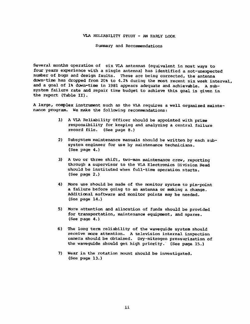
VLA RELIABILITY STUDY - AN EARLY LOOK
Summary and Recommendations
Several months operation of six VLA antennas (equivalent in most ways to four years experience with a single antenna) has identified a not-unexpected number of bugs and design faults. These are being corrected, the antenna down-time has dropped from 20% to 4.2% during the most recent six week interval/ and a goal of 1% down-time in 1981 appears adequate and achievable. A subsystem failure rate and repair time budget to achieve this goal is given in the report (Table II).
A large, complex instrument such as the VLA requires a well organized maintenance program. We make the following recommendations:
1) A VLA Reliability Officer should be appointed with prime responsibility for keeping and analyzing a central failure record file. (See page 8.)
2) Subsystem maintenance manuals should be written by each subsystem engineer for use by maintenance technicians.(See page 4.)
3) A two or three shift, two-man maintenance crew, reporting through a supervisor to the VLA Electronics Division Head should be instituted when full-time operation starts.(See page 2.)
4) More use should be made of the monitor system to pin-point a failure before going to an antenna or making a change.Additional software and monitor points may be needed.(See page 14.)
5) More attention and allocation of funds should be provided for transportation, maintenance equipment, and spares.(See page 4.)
6) The long term reliability of the waveguide system should receive more attention. A television internal inspection camera should be obtained. Dry-nitrogen pressurization of the waveguide should get high priority. (See page 15.)
7) Wear in the rotation mount should be investigated.(See page 13.)
- 1-
VLA Reliability and Maintenance - An Early Look
M. Balister, J.R. Fisher, J. Payne and S. Weinreb
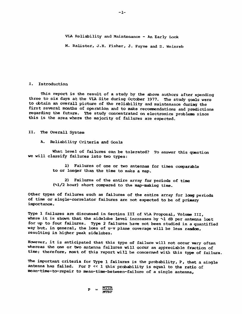
I. Introduction
This report is the result of a study by the above authors after spending three to six days at the VLA Site during October 1977. The study goals were to obtain an overall picture of the reliability and maintenance during the first several months of operation and to make recommendations and predictions rscf^^-^9 the future. The study concentrated on electronics problems since this is the area where the majority of failures are expected.
II. The Overall System
A. Reliability Criteria and Goals
What level of failures can be tolerated? To answer this question we will classify failures into two types:
1) Failures of one or two antennas for times comparable to or longer than the time to make a map.
2) Failures of the entire array for periods of time (^1/2 hour) short compared to the map-making time.
Other types of failures such as failures of the entire array for long periods of time or single-correlator failures are not expected to be of primary importance.
Type 1 failures are discussed in Section III of VLA Proposal, Volume III, where it is shown that the sidelcbe level increases by ^1 dB per antenna lost for up to four failures. Type 2 failures have not been studied in a quantified way but, in general, the loss of u-v plane coverage will be less random, resulting in higher peak sidelobes.
However, it is anticipated that this type of failure will not occur very often whereas the one or two antenna failures will occur an appreciable fraction of time; therefore, most of this report will be concerned with this type of failure.The important criteria for Type 1 failures is the probability, P, that a single antenna has failed. For P << 1 this probability is equal to the ratio of mean-time-to-repair to me an- time-be twee n- f ai lure of a single antenna.
MTTRMTBF
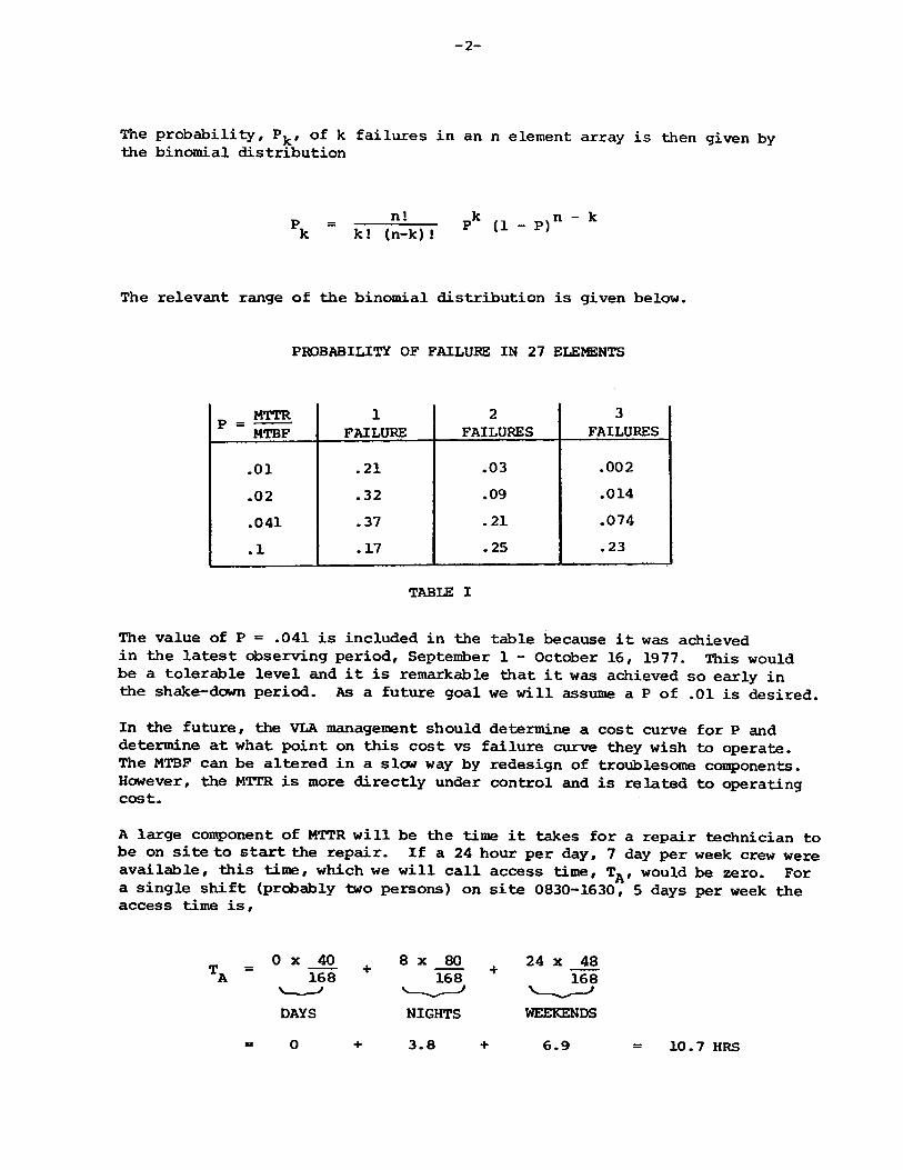
The probability, Pk , of k failures in an n element array is then given by the binomial distribution
The relevant range of the binomial distribution is given below.
PROBABILITY OF FAILURE IN 27 ELEMENTS
MTTR ” MTBF
1FAILURE
2FAILURES
3FAILURES
.01 .21 .03 .002
.02 .32 .09 .014
.041 .37 .21 .074
.1 .17 .25 .23
TABUS I
The value of P = .041 is included in the table because it was achieved in the latest observing period, September 1 - October 16, 1977. This would be a tolerable level and it is remarkable that it was achieved so early in the shake-down period. As a future goal we will assume a P of .01 is desired.
In the future, the VLA management should determine a cost curve for P and determine at what point on this cost vs failure curve they wish to operate.The MTBF can be altered in a slaw way by redesign of troublesome components. However, the MTTR is more directly under control and is related to operating cost.
A large component of MTTR will be the time it takes for a repair technician to be on site to start the repair. If a 24 hour per day, 7 day per week crew were available, this time, which we will call access time, TA , would be zero. For a single shift (probably two persons) on site 0830-1630, 5 days per week the access time is,
T_ = 0 x 40 168
DAYS0
8 x 80 24 x 48
10.7 HRS
-3-
If a second shift which works days on weekends and any three evenings a week during the week overlapping 1/2 hour with the day shift, the access time is,
0 x 78.5 168
DAYS + 3 EVENINGS
4.25 x 25.5 168
3 SHORT NIGHTS
64168
4 LONG NIGHTS
0.65 3.05 = 3.7 HRS
If a third shift is added to give 0830-2400 coverage 7 days per week and also take care of holidays, vacation, and sick leave, the access time is,
0 x 108.5168
4.25 x 59.5168
0 + 1.5 = 1.5 HRS.
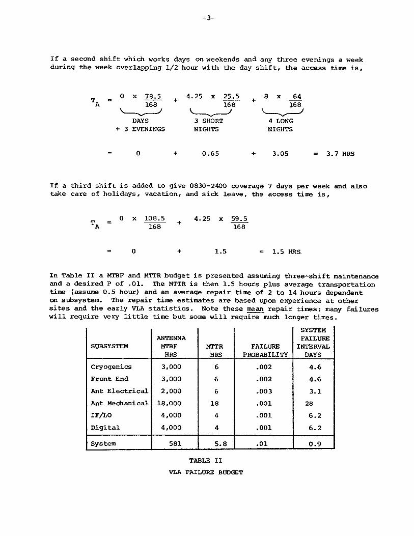
In Table II a MTBF and MTTR budget is presented assuming three-shift maintenance and a desired P of .01. The MTTR is then 1.5 hours plus average transportation time (assume 0.5 hour) and an average repair time of 2 to 14 hours dependent on subsystem. The repair time estimates are based upon experience at other sites and the early VLA statistics. Note these mean repair times; many failures will require very little time but some will require much longer times.
SUBSYSTEMANTENNAMTBFHRS
MTTRHRS
FAILUREPROBABILITY
SYSTEMFAILUREINTERVAL
DAYSCryogenics 3,000 6 .002 4.6Front End 3,000 6 .002 4.6Ant Electrical 2,000 6 .003 3.1Ant Mechanical 18,000 18 .001 28IF/LO 4,000 4 .001 6.2Digital 4,000 4 .001 6.2System 581 5.8 • o H 0.9
TABLE II VLA FAILURE BUDGET
-4-
These values are viewed as fairly pessimistic with a high level of confidence in achieving better values. Nevertheless, the effect upon array operation is small giving 1 dB increase in sidelobes on every 5th map, 2 dB on every 30th map and 3 dB on every 500th map. The most noticeable effect of higher MTBF would be lower operating cost.
B. Maintenance
Good maintenance requires more than having bodies on site for the required number of hours specified in the previous section! They must have the right training, equipment, transportation, and spares. Some specific suggestions for the VLA are as follows:
1) Each subsystem engineer should write a maintenance manual for his subsystem. The manual should be written for the system repair technicians and show how to isolate faults to a replaceable module rather than how to repair the module (which is covered in module manuals). It should state what to do after replacing a module and when it is best to do nothing except phone the subsystem engineer. Isolation of the fault from the control room using the monitor system and a fault "tree" should be covered.
2) It is our observation that the monitor system is underused. This may be due to some early unreliability of the data, to the present closeness of the antennas, to insufficient understanding of the monitor points, to insufficient software to interpret the data, or to some missing key monitor points. All of these have been or can be overcome. We believe that pinpointing problems with the monitor system will lead to more efficient maintenance.
3) Good coordination is needed between system repair technicians and subsystem engineers and technicians. To aid this we recommend that the system repair technicians report, thru a supervisor, to the VLA Electronics Division Head.
4) Transportation to distant antennas has been discussed for several years but the problem is not solved. We urge attention to this problem. Improvement of the winch and ladders on antennas also needs attention.
5) We note that spare modules are often not available or need to be borrowed from antennas under construction. We urge that funds be made available for spare modules.
6) A goal in the system design was the isolation and replacement of faulty modules without test equipment other than a portable digital volt-meter. Extensive test equipment is not needed by the system repair group but a DVM, oscilloscope, and power meter should be immediately available. Some filter- detector-meter jigs to measure power at specific frequencies may be useful.
-5-
C. Record Keeping
Accurate, consistent, and complete failure records are of vital importance to the efficient operation of a large, complex, repeated-element, instrument such as the VLA. An analogy can be made with the necessity of an accounting system for a business. The failure record system should be designed to answer the following questions:
1) For the user - what fraction of working antenna elements can be expected?
2) For the VLA management - what is the failure rate and repair time for each subsystem? Where should resources be applied to redesign components, increase or decrease maintenance personnel?
3) For maintenance personnel - as an aid in pin-pointing a fault, what previous problems have occurred in a given module or subsystem?
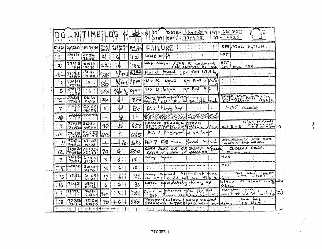
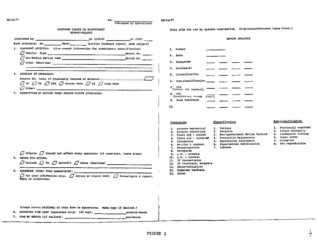
At present a failure record system for the VLA is evolving. Within a few months the system should be somewhat "frozen” so that changes with time can be associated with actual reliability changes rather than record keeping changes.The present records are based upon two forms which are attached as Figures 1 and 2. The first form "Down-Time Log" is kept by the array operator and gives a brief description of the symptom, action, and lost time. The second form, "Maintenance Request", is a request (usually by the operator) for repair of a particular problem. On the reverse side of this form is an analysis of the failure in terms of subsystem and classification of failure. This analysis is performed after the failure has been corrected and the data is filed in the computer for further analysis.
This system, with some minor changes, should be adequate if it is rigorously followed. Some of the recommended changes and present complications in the system are as follows.
1) The matching of data from the two forms is difficult. The Maintenance Request log number has not been recorded on the Down-Time Log.
2) Approximately 20% of the entries on the Down-Time Log do not have Maintenance Request forms (and hence have no analysis).The Maintenance Request is not just that; it is an analysis of the failure and must be filled out for each failure.
3) The Observing Time Lost column has not been filled in on the back of the Maintenance Request form because of 1) above. This prevents computer analysis of down-time.
U A v T X? I I U 1 ITTJ1 ^ 1
s u m■w
p^ cjb) iKijroirir■ 1 i ! ( CtrttV
Ur x>{ (Utli) <M\W| ftU.Uvvi
1 • ' F w i ^ R E i i ;■: . . . j . i ; o v t jw o v ^ . p.t.-novJ :
: i : :774 jjh zv.aiCi I
Z5:a« 1 a j ; i d n ! l i i ! 'Co’iMvi !ciw'4 ^ I • • • • ; ; : i ; ; : H j» r| • .............. j
I * ! ,1 1 o lt$
■ 'iVia0 0 : i s )' ©O'.ST 1 ■*L% 4 : ; 1 2 1
W \
cvciliU > / s o l i ,• * • r • > ( c J i s?
2% Cowvw.k»iJj.*4. \*s*, 4. ui» ! S-*4L
H v r -
.TtH II,22.13,0 I•"htJtb-r safe© :-M J ' f i i
v o _ \ y - ! • oW Rvvi \ . . . i • i
i - H : i-23j $2%o M•Wo; ;K Ipcj.Ktl ; ; ovv fv»^
*' » * * ' ‘
: $’ 2W lP
: : i»:: $Z1D % " ' 4 * w 1KJo' L' ;
1 i 1 ! ! ‘ ?p a w c) ; 0 . ftvvJ: 4 , ]iet
j .............. ! ...................; ~
. . . . . . .: . j •
770* n.oa^ o-
o h .Mo TT<i i . n s f c llV-Ura .«\)Vc.w<i--------------
1 cdX 1 \F V ^ oU-._ t& s if
7t 55|77 06'. i f f 1
' S ' : ! : { j ; : : i3<j . l ) d s : ! -L '/f •*J
M c b ' C r a l c a d )
J L
• :q :
-■szjFrsr-fj ■ ! ’: • isLi
!■ i-r- 1
t i i r o \
■ & 4\t ?
77o8l<j■770Xlu
2.2.: 3«W | :
K ftss iu e [T^u»J P tJ^ JS TO R H •
C.ve-.sJ i.i .L.vt i!ai=A--hr\\■ S'C^TtM 0*0 tv
ftw-V S 4-.S___ vp
:/t> 77oJl<?77oWo
2 / ,‘ Z ^£»7 * &7I
• i -C 3 S
& S 6
ftvjt 7 |tv 1 Hw‘\vvh > •. i . . . .
n i o y i L110112.
07 * / t/ :2 d — 4/a- ; 7-- ....
jPcuTritrecusi’Y c * ™ * s a c k .APTSft V etZo&S-
l i & Z Z / z . ‘. 0 3 j ✓ 3-' X5 i n S t y d 1
Co m //u
S A te tL d l; Cw
ufi. O A T V firJ 'r <^z m i L , C L M / U i * 0 0 /0 1 -
. (377o1■7?o
Tn*u2JMuLXx2Uny2.C S C I 2 f : 5 <i ! :s . ( v : !
u •
• 7 ? '7-70 4-2 c
; : If-2 “2 '. 53 j *2-2?J5 1 r . r ^ r r r r f a - r j
•••i-ff— —f--- j. :-; •! . . . ..............| ...................
; :/s : 7 # ^ C z liO jo c z ? : \ i : - ! ! { l 1 . l o t
■Covwy jCvkvW JL- • o f .^ r u - wiw 1- 1 CbuVJ 'WloiA-' ^TTL ti.
'V -V A-*-fJuo^ . # > ' M T i +i H P r ■
, ■/&■t>5'.H7b&'.5fc ■: 4 1 1 : ; 3 t |
COYCsi ; CpvviyNx^cC-^l - U v * . ^ u P l c \ * & y ■ V C i W V - LOV’^J/ict-<Os.w' II li II 11
: 1 7 ..7^aw
j•O ^ Hlidiffc*- % 0 : I :% \ i ■f e d j
• \,w\* ft-v+jCvM e-S f i l ^ 'Jo y ' ^v'-\ cvmmTAmem.cxuA
i-' j&y^r .■ VV' v* Vc '\*V Vw i~cJc\
! i s7 7 6 # .77<» ?.y 1 oor? 0 ! J o q " ^ } ” s h o !
^O VYfcV '(♦wVluV-C f COVvN V> v -t L pvuM.ew>.!* V T^ t't'V ^ c-ov^ LvL,
• : I : • U> V ■ •
'■ i -j•; : | H ! if- l i - r i Hi 1 i : T 4' r l i ' t T T : i _ L i L i . u . : . i ... ....!........1...:.:T I . . . : ...... : : . L : . . : : . . : l : . :..
-cy
.t)
icni
FIGURE 1
R8/16/77(Assigned by Operations)
HARDWARE CHANGE OR MMNTENANCE REPORT/REQUEST
Originated by ________Back referencos No.1. COMPONENT AFFECTED s
/ / Module» Type _
at (MST)Datet
__on (y/m/d) _______________(earlier Hardware report, same subject)
/ / Non-module device name / / Other (describe) _____
(Give enough information for unambiguous identification)_________ Serial No.
____________________________________ Serial No.
2. LOCATION OF COMPONENTSAntenna No. (only if physically located at antenna)........................... ]_/ / VR / / PR / / CER / / Screen Room /~7 CR /~7 Comp Room / / Others
3. DESCRIPTION OP ACTION TAKEN AND/OR FAULTS DISCOVERED s
(This side for use by systems engineering. Originator/Addressee
REPORT ANALYSIS
R8/16/77
1. Number
2. Date3. Subsystem
4. Antenna(s)5. Classification
6. Sub-classification
7. TTR , _____('n'v>c t o r?cfVM«08. OTL _____
r - / O i c )9. Back Reference _____
10. __
i_J Affects [_/ Should not affect array operation (if uncertain, leave blank)4. REASON FOR ACTIONS
/ / Failure / / PM / / Retrofit / / Other (describe) _______________________
5. ADDRESSEE (other than operation*) j __________________________________________l_J For your information only. l_J Adjust or repair ASAP. /~7 Investigate & report. Reply to originator:
Subsystems Classification
1. Antenna mechanical 1. Failure2. Antenna electrical 2. Retrofit3. Front end - cooled 3. Non-operational device failure4. Front end - uncooled 4. Preventive maintenance5. Cryogenics 5. Operational adjustment6. Mo.iitor & control 6. Experimental modification7. Focus/rotation 7. Unknown8. Waveguide9. L.O. - antenna
10. L.O. - central11. IF transmission12. IF receivers, samplers13. Delay-multiplier14. Computer hardware15. Other
(Always return ORIGINAL of this form to Operations. Make copy if desired.)6. OBSERVING TIME LOST (operators only) (if any) t antenna-hours7. TIME TO REPAIR (if failure) i man-hours
leave blank.)
Sub-classification
1. Previously reported2. Infant mortality3. Inadequate testing4. Human error5. Connector6. Mot reproducible
FIGURE 2 ii
-8-
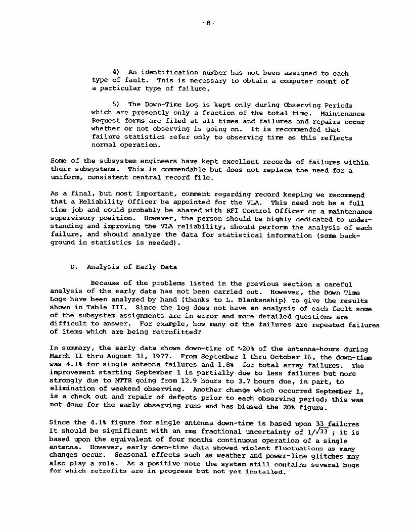
4) An identification nuiriber has not been assigned to each type of fault. This is necessary to obtain a computer count of a particular type of failure.
5) The Dcwn-Time Log is kept only during Observing Periods which are presently only a fraction of the total time. Maintenance Request forms are filed at all times and failures and repairs occur whether or not observing is going on. It is recommended that failure statistics refer only to observing time as this reflects normal operation.
Some of the subsystem engineers have kept excellent records of failures within their subsystems. This is commendable but does not replace the need for a uniform, consistent central record file.
As a final, but most important, comment regarding record keeping we recommend that a Reliability Officer be appointed for the VLA. This need not be a full time job and could probably be shared with RFI Control Officer or a maintenance supervisory position. However, the person should be highly dedicated to understanding and improving the VLA reliability, should perform the analysis of each failure, and should analyze the data for statistical information (some background in statistics is needed).
D. Analysis of Early Data
Because of the problems listed in the previous section a careful analysis of the early data has not been carried out. However, the Down Time Logs have been analyzed by hand (thanks to L. Blankenship) to give the results shown in Table III. Since the log does not have an analysis of each fault some of the subsystem assignments are in error and more detailed questions are difficult to answer. For example, how many of the failures are repeated failures of items which are being retrofitted?
In summary, the early data shows down-time of ^20% of the antenna-hours during March 11 thru August 31, 1977. From September 1 thru October 16, the down-time was 4.1% for single antenna failures and 1.8% for total array failures. The improvement starting September 1 is partially due to less failures but more strongly due to MTTR going from 12.9 hours to 3.7 hours due, in part, to elimination of weekend observing. Another change which occurred September 1, is a check out and repair of defects prior to each observing period; this was not done for the early observing runs and has biased the 20% figure.
Since the 4.1% figure for single antenna down-time is based upon 33 failures it should be significant with an rms fractional uncertainty of 1//33 ; it is based upon the equivalent of four months continuous operation of a single antenna. However, early down-time data showed violent fluctuations as many changes occur. Seasonal effects such as weather and power-line glitches may also play a role. As a positive note the system still contains several bugs for which retrofits are in progress but not yet installed.
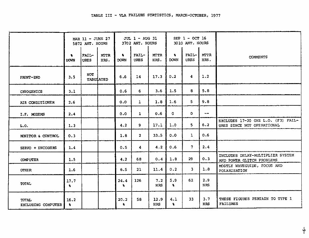
TABLE III - VLA FAILURE STATISTICS, MARCH-OCTOBER, 1977
MAR5872
%DOWN
11 - JL ANT. H
FAILURES
INE 27 OURS
MTTRHRS.
JUL3702
%DOWN
1 - AUC ANT. HC
FAILURES
3 31 5URS
MTTRHRS.
SEP 301C
%DOWN
1 - OCT ANT. H
FAILURES
16OURS
MTTRHRS. COMMENTS
FRONT-END 3.5 NOTTABU]jATED 6.6 14 17.3 0.2 4 1.2
CRYOGENICS 3.1 0.6 6 3.6 1.5 8 5.8
AIR CONDITIONER 2.6 0.0 1 1.8 1.6 5 9.8
I.F. MODEMS 2.4 0.0 1 0.6 0 0 —
L.O. 1.3 4.2 9 17.1 1.0 5 6.2EXCLUDES 17-20 GHZ L.O. (F3) FAILURES SINCE NOT OPERATIONAL
MONITOR & CONTROL 0.3 1.8 2 33.5 0.0 1 0.6
SERVO + ENCODERS 1.4 0.5 4 4.2 0.6 7 2.4
COMPUTER 1.5 4.2 68 0.4 1.8 29 0.3 INCLUDES DELAY-MULTIPLIER SYSTEM AND POWER GLITCH PROBLEMS
OTHER 1.6 6.5 21 11.4 0.2 3 1.8 MOSTLY WAVEGUIDE, FOCUS AND POLARIZATION
TOTAL 17.7%
24.4%
126 7.2HRS
5.9%
62 2.9HRS
TOTALEXCLUDING COMPUTER
16.2%
20.2%
58 12.9HRS
4.1%
33 3.7HRS
THESE FIGURES PERTAIN TO TYPE 1 FAILURES
Ivoi
-10-
III. Subsystems
A. Cryogenics
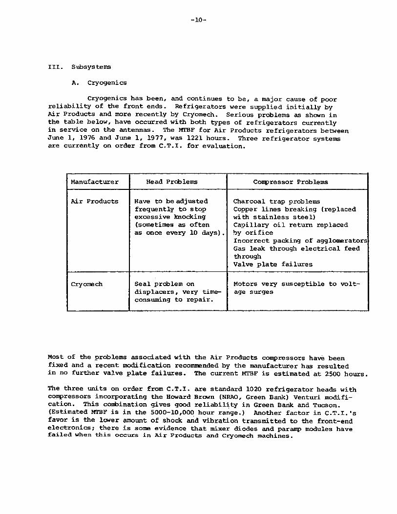
Cryogenics has been, and continues to be, a major cause of poor reliability of the front ends. Refrigerators were supplied initially by Air Products and more recently by Cryomech. Serious problems as shown in the table below, have occurred with both types of refrigerators currently in service on the antennas. The MTBF for Air Products refrigerators between June 1, 1976 and June 1, 1977, was 1221 hours. Three refrigerator systems are currently on order from C.T.I. for evaluation.
Manufacture r Head Problems Compressor Problems
Air Products Have to be adjusted frequently to stop excessive knocking (sometimes as often as once every 10 days).
Charcoal trap problems Copper lines breaking (replaced with stainless steel)Capillary oil return replaced by orificeIncorrect packing of agglomerators Gas leak through electrical feed throughValve plate failures
Cryomech Seal problem on displacers, very time- consuming to repair.
Motors very susceptible to voltage surges
Most of the problems associated with the Air Products compressors have been fixed and a recent modification recommended by the manufacturer has resulted in no further valve plate failures. The current MTBF is estimated at 2500 hours.The three units on order from C.T.I. are standard 1020 refrigerator heads with compressors incorporating the Howard Brown (NRAO, Green Bank) Venturi modification. This conbination gives good reliability in Green Bank and Tucson. (Estimated MTBF is in the 5000-10,000 hour range.) Another factor in C.T.I.'s favor is the lower amount of shock and vibration transmitted to the front-end electronics; there is soma evidence that mixer diodes and paramp modules have failed when this occurs in Air Products and Cryomech machines.
-11-
In conclusion the reliability of both the Air Products and Cryomech systems is improving, however, it is not yet clear whether they will ever reach the MTBF's often claimed by some users of C.T.I. systems of >10,000 hours.
However, the current 2500 hr. MTBF of the cryogenics is tolerable but esqpen- sive and it remains to be seen whether it will be prudent to retrofit the first 11 antennas with C.T.I. machines.
B. Front Ends
The most common cause of front end failure is pararap failure and it is an area of great concern. The original supplier of paramps was Comtech and although the anplifiers were electrically satisfactory, they were very susceptible to failure after thermal cycling. There were several failure inodes, the manufacturer and NRAO have not been able to significantly lessen the chances of one of these failures occurring after several thermal cycles. NRAO is currently fixing them at the VLA Site and these amplifiers are still installed in the earlier front ends. Provided the cryogenics does not fail they are satisfactory, however, every time there is a refrigerator failure there is a significant chance that an amplifier will fail also.The current supplier of paramps is A.I.L. and they appear to have a more reliable construction. There have been failures of the earlier A.I.L. amplifiers due to cracking of the rexolite substrate material; this has now been changed to stycast and no further failures have occurred. Currently, manufacturing problems exist with these amplifiers; these problems are unrelated to reliability. Cooled paramps have been used in many applications for several years and have given excellent reliability. No mechanical wear or high power is involved and it is hoped that with good cooperation between NRAO and A.I.L. the reliability will be greatly improved.
The other dewar mounted components are considerably more reliable and very rarely cause problems. It is very encouraging to hear that dewar leaks are almost non-existent. There have been a considerable number of analog multiplexer failures in F5 (Front End Control), however, the addition of some protection components has fixed the problem.
Two modules associated with front ends which have been troublesome are F2 (Up-converter Pump) and F3 (17-20 GHz L.O.). F2 has had several VCO failures in the last few weeks and this problem is being currently investigated.The F3 module has Uad design faults which have only recently been corrected. The harmonic mixer has been redesigned and together with some circuit cleanup one module appears to be performing as required. The problems with this unit, although relatively minor, have held up significant operation of the VLA at 15 GHz and 22 GHz. It is suggested that the production of sufficiently satisfactory F3 modules be considered to be of the highest priority so that esqperience can be obtained with the array at the higher frequencies. This will enable a complete check out of the front ends at all four frequencies so that any further reliability problem areas will become evident.
-12-
In conclusion, we believe the front end problems are not inherent and should be solved in the next several months to give MTBF's of >3000 hrs.
C. L.O. and I.F.
Most of the reported failures within the L.O. and I.F. occur in a relatively small number of modules. These occur as a result of marginal design in some areas.
L6 has been a major problem mainly because of difficulties with the phase lock indicator circuit. This is being modified, and together with some other minor changes which are currently being implemented, should greatly improve the reliability of this module. L14 has had serious problems with the 1200 MHz and 1800 MHz phase lock loops. A new phase-lock-loop circuit is currently being incorporated and this should cure the problem. Hie T1 and T2 modules are now showing a relatively low number of failures. Most of the causes of the initial high failure rates have been identified and the current failure rate for the 18 operating units is about one failure per week.There has been some concern regarding connectors, especially the OMQ R.F. connectors. An investigation of the problems with the OMQ connectors has shown that there are problems in two areas. There has been poor quality control on the part of OSM and many parts received have been out of specification, resulting in incorrect fitting of mated connectors. Incorrectly sized collars have been supplied to NRAO which resulted in excessive angular movement of the chassis mounted connector resulting in possible connector damage on mating. These problems do not appear to present a serious reliability problem provided received parts are carefully checked before assembly and also provided that some attempt is made to align the connectors by hand before pushing the modules fully into the rack.In conclusion the reliability of the I.F./L.O. section is improving and when the design problems with L6 and L14 have been corrected, the reliability should improve considerably such that the down-time will be considerably better than the 3.7% for the period March 11 thru June 27, 1977.
D. Antenna Servo System
The Antenna Servo System has given several problems since the start of the VLA. These problems, along with the solutions are outlined below.A major problem has been the reliability of the Inductosyn Position Readout. An environmental enclosure, using a filtered, positive pressure blower system and installation of a new coupling will improve the reliability. A problem with unstable low-order bits has been traced to inadequate design of a 30 kHz oscillator. A new oscillator will be installed in early November. Various other electronic problems of a minor nature have occurred and these are to be expected during the first few months of operation.
-13-
We were inpressed by the thought being given to routine maintenance in the future. The construction of the test stand for simulating a complete antenna drive system is a particularly wise step. The construction of the servo electronics is of a high standard, and we see no particular reliability problems with the servo system in the future.
E. Focus and RotationThe electronics associated with the focus and rotation servo
mechanisms appears to have been quite reliable. One motor and one translator unit have failed and this does not appear unreasonable. Spare parts, documentation, and troubleshooting procedures appear to be well organized.The readout for rotation is marginal in resolution and it may be necessary to replace the present potentiometer with a digital encoder. A major question that should be answered immediately concerns the wear of the rotation mount. There is some belief that the rotating mechanism is wearing quite rapidly.A very crude measurement made by J. Payne on antenna 7 indicated a backlash in rotation of about 0.3° which is outside specifications.
F. Vertex Room Temperature Control
There have been reliability problems with this system, it is not certain whether the system meets specifications on all antennas in all seasons, and, it may be desirable to put in some inexpensive changes to improve performance beyond the E-Systems specifications. Tighter temperature control appears to be an economical way to improve the phase stability of the VLA and we recommend that this be pursued.The reliability problems appear to be associated with poor quality control, missing SCR transient protectors, and underrated SCR's. These are minor and are being corrected. To clarify the specification question we suggest that a temperature sensor, read out by the monitor system, could be installed at a location agreed with E-Systems. However, it may be more advantageous to accept the system properly installed with the present design and make changes to go beyond specifications.We recommend that an engineer investigate improvement of the system. Specific comments regarding improvement are as follows:
1) Improve air circulation through the racks and install a small local control loop for the critical rack.
2) Is outside temperature the best criteria for switching the air conditioner? Perhaps current through the heater would be more appropri ate.
-14-
3) Is the gain and order of the servo system optimum?4) The insulation of some of the vertex rooms is inadequate
at present and should be improved.
5) Are the heater capacity and the cooler capacity matched? There seems to be some evidence they may not be.
6) Could better temperature uniformity be achieved by sensing at more than one point and using the average temperature to control the servo?
G. Monitor and Control System
A key ingredient of the service and reliability of the VLA is the monitor and control system. With this system a large number of critical and informative test points in the VLA electronics are continuously monitored and sent to the control room via a digitally multiplexed data channel. All of this data is available to the central computer and as data taps for direct display on a chart recorder. With this system it should be possible to troubleshoot most of the electronics from the control building and save a lot of time traveling to and from antennas for service.
To be of any use this system must be reliable. Until the middle of 1977 there were enough failures in the monitor system itself to limit its value, but most of the initial bugs appear to have been corrected. Record keeping in this area has been quite good and shows that while the nuntoer of antennas has continued to grow, the total number of failures per month has fallen by about a factor of five from its peak at the beginning of this year. There are still a couple of known fault areas, but the fixes are fai-rly straightforward and are being implemented.
At this stage the most important concern is that all members of the electronics group become confident enough in the monitor system to make it the first step in any troubleshooting. While most of the monitor data is available through the central computer much of the present display is rather cryptic. We recommend that people directly concerned with electronics service begin using the monitor system on a regular basis and, with the help of the computer people, evolve useful data displays. Eventually a semi-automatic troubleshooting program can be developed for the computer.
H. Digital Delay and Multiplier System
This system is being built in two stages. The first stage is a temporary continuum-only system with the full bandwidth of the final system.It has been notably trouble-free with the failure rates following what one
-15-
expects from IC manufacturers predictions. The system design has been unusually good in that no areas of marginal performances have showed up in operation.
Most of the individual boards for the second stage have been prototyped and tested. They appear to operate quite conservatively and should be at least as reliable as the present system. Judging from experience so far and the total number of IC's the failure rate on the full spectral line delay system is predicted to be about six per month. This is quite acceptable with the continuous checking and self healing features and a mean time to repair of about six hours.
I. Waveguide
The increases in loss which occurred after the early waveguide installations appear to have stopped and improved installation techniques have resulted in a lower initial loss and less increase. There has been one rotary joint failure, traced to a manufactured defect, and two or three broken flexible waveguides.
We note that the waveguide has not been under dry nitrogen pressurization since burial due to gas leakage at the couplers. Water has leaked into the system at several points and has been pumped out. The waveguide is designed for internal corrosion protection by the dry nitrogen and we are concerned about the long term effects of moist air. It may cause corrosion of joints and breakdown of the epoxy-steel bond within the guide. We urge that high priority be given to pressurization of the waveguide.
The waveguide represents a $5 million investment, previous experience of long-term effects is limited, and it is not easily inspected. We recommend more attention to inspection and study of long-term reliability. We believe that a TV camera system to inspect the inside of the pipe is a prudent investment.
Related Documents