METAL FRAMING SYSTEMS JANUARY 2022 NATIONAL PIPE HANGER CORPORATION NATIONAL NATIONAL PIPE HANGER CORPORATION PIPE HANGER CORPORATION PIPE HANGERS AND SUPPORTS • CUSTOM FABRICATION • ENGINEERING THE COMPLETE LINE OF STRUT, FITTINGS & ACCESSORIES

Welcome message from author
This document is posted to help you gain knowledge. Please leave a comment to let me know what you think about it! Share it to your friends and learn new things together.
Transcript
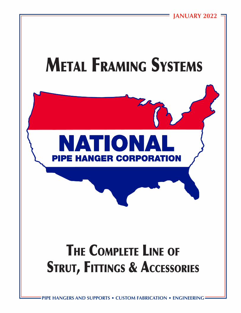
Metal FraMing SySteMS
JANUARY 2022
NATIONALPIPE HANGER CORPORATIONNATIONALNATIONAL
PIPE HANGER CORPORATIONPIPE HANGER CORPORATION
PIPE HANGERS AND SUPPORTS • CUSTOM FABRICATION • ENGINEERING
the CoMplete line oF
Strut, FittingS & aCCeSSorieS

1
Introduction
National Pipe Hanger Corporation is proud to present our Metal Framing Systems catalog containing a complete and versatile line of strut, fittings and accessories. These prod-ucts have been selected to accomodate a wide range of applications in the mechanical, plumbing, HVAC, electrical and industrial fields. This selection results from more than fifty years of concentrated and direct exposure to the piping industry, from the design engi-neer’s selection, to the piping contractor’s installation. This is where needs are discovered and where products and services are genuinely tested. In this area, National Pipe Hanger Corporation’s experiences are unequaled.
National Pipe Hanger Corporation takes pride in being an American manufacturing company in the United States. A constant awareness of the customers’ requirements and efforts is the foundation in the development of National Pipe Hanger Corporation’s manufacturing skills. All of National Pipe Hanger Corporation’s products are carefully manufactured to meet the highest standards in the industry. Our 80,000 square foot manufacturing facility in NJ can accommodate any project nationwide. National Pipe Hanger Corporation is a full service fabricator with A.W.S. – D1.1 certified welders, a participating member of the Manufacturer’s Standardization Society (MSS) and manufactures pipe hangers and supports in accordance with MSS Standard Practice SP-58. Many of National Pipe Hanger Corporation’s products meet and exceed Factory Mutual Listings (FM), Underwriters Laboratory Listings (UL), and Federal Specifications (WW-H-171E).
In addition to a wide range of strut, fittings and accessories, National Pipe Hanger Corpora-tion offers pipe hangers and supports, and custom options backed by our skilled engineers. Contact National Pipe Hanger Corporation’s New Jersey headquarters or Maryland branch for special pipe support requirements including: other pipe sizes and types, dimensional requirements, installation methods, finishes, etc. National Pipe Hanger Corporation’s sales team will always provide you with impeccable service and will respond quickly to your prod-uct and service needs on both standard items and specialized fabrications. For a detailed look at National Pipe Hanger Corporation’s full line of products, please refer to our Pipe Hangers and Supports catalog. For a detailed look at National Pipe Hanger Corporation’s Pre-Insulated Pipe Supports, please refer to our Pre-Insulated Pipe Supports catalog. Visit our website at nationalpipehanger.com for additional information.
All units in this catalog are inch-pound unless otherwise noted. Additional information pro-vided at the end of this catalog can aid the user in lateral bracing loads and SH-Strut Channel Specifications.
National Pipe Hanger Corporation reserves the right to make specification changes without notice. While every effort has been made to assure the accuracy of information contained in this catalog at the time of publication, National Pipe Hanger Corporation cannot accept responsibility for inaccuracies resulting from undetected errors or omissions.
NATIONALPIPE HANGER CORPORATION
2
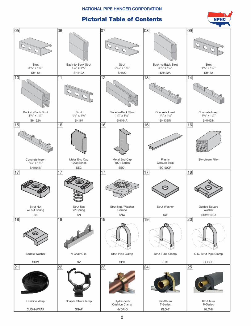
Pictorial Table of Contents
Strut13/16” x 15/8”
SH164
Back-to-Back Strut31/4” x 15/8”
SH132A
1110
Concrete Insert13/8” x 15/8”
SH142IN
Concrete Insert15/8” x 15/8”
SH132IN
1413
Concrete Insert13/16” x 15/8”
SH164IN
15
Metal End Cap1000 Series
SEC
Plastic Closure Strip
SC-900P
Metal End Cap1001 Series
SEC1
Styrofoam Filler
16 1616 16
17
Strut Nutw/ out Spring
SN
Snap N Strut Clamp
SNAP
22 24
Klo-Shure7-Series
KLO-7
Klo-Shure8-Series
KLO-8
Hydra-ZorbCushion Clamp
HYDR-D
2523
18
V Chair Clip
SV
19 19 20
O.D. Strut Pipe Clamp
ODSPC
Strut Pipe Clamp
SPC
Strut Tube Clamp
STC
21
Cushion Wrap
CUSH-WRAP
Saddle Washer
SUW
18
17 17
Strut Nut / WasherCombo
SNW
Strut Washer
SW
Guided SquareWasher
SSW619-D
18
Back-to-Back Strut15/8” x 15/8”
SH164A
12
NATIONAL PIPE HANGER CORPORATION
Back-to-Back Strut61/2” x 15/8”
SH112A
Strut31/4” x 15/8”
SH112
Strut27/16” x 15/8”
SH122
Strut15/8” x 15/8”
SH132
05 07 09
Back-to-Back Strut47/8” x 15/8”
SH122A
06 08
17
Strut Nutw/ Spring
SN
3
Klo-Shure9-Series
KLO-9
26
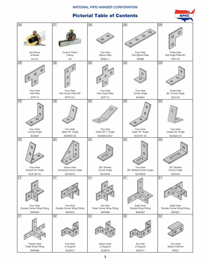
NATIONAL PIPE HANGER CORPORATION
Pictorial Table of Contents
Four HoleCorner Angle
SCA607
29
Four HoleClosed 45° Angle
SCA793-45
30
Two HoleOpen 45° Angle
SOA633-45
29
Two HoleOpen 221/2° Angle
SOA633-2212
Two HoleClosed 45° Angle
SCA624-45
Four HoleOpen 45° Angle
SOA781-45
29 29 30
Five HoleU Support
SUS613
32 32
Six HoleU Support
SUS721
Two HoleSplice Channel
SP631
Seven HoleU Support
SUS679
3232
31
Five HoleDouble Corner Wing Fitting
SWF923
31 31 31
Eight HoleDouble Corner Wing Fitting
SWF821
Six HoleTriple Corner Wing Fitting
SWF668
Eight HoleDouble Wing Fitting
SWF667
31
Twelve HoleTriple Wing Fitting
SWF669
Four HoleDouble Corner Wing Fitting
SWF665
31
30
Seven HoleUniversal Corner Angle
SCA3373
30 30
90° SlottedCorner Angle
SCA2545
Two Hole90° Slotted Corner Angle
SCA3049
90° SlottedCorner Angle
SAA763
30
Five Hole Flat Cross Plate
SCP712
Four Hole Flat Corner Plate 90°
SFP718-1
2828
Three Hole90° Corner Angle
SCA745
29
Two HoleCorner Angle
SCA604
29
Four HoleTee Plate
STP714
28
Two Hole Splice Plate
SP601-1
Cush-A-ThermClamp
UX
Four Hole Flat Splice Plate
SP888
27 28
Three Hole Flat Angle Plate 90°
SFP718
28 28
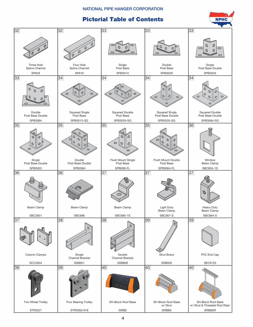
4
32
NATIONAL PIPE HANGER CORPORATION
Pictorial Table of Contents
Single Post Base Double
SPB3025
35
Beam Clamp
SBC2651
36
DoublePost Base Double
SPB2064
35
Flush Mount SinglePost Base
SPB280-FL
WindowBeam Clamp
SBC855-1S
Flush Mount DoublePost Base
SPB3064-FL
35 35 36
SH-Block Roof Basew/ Strut
SRBBS
SH-Block Roof Basew/ Strut & Threaded Rod Riser
SRBBSR
4040
Four Bearing Trolley
STR2950-916
39
SH-Block Roof Base
SRBB
40
38
SingleChannel Bracket
SSB651
38 39 39
PVC End Cap
SEC6153
DoubleChannel Bracket
SSB809
Strut Brace
SSB926
39
Two Wheel Trolley
STR2521
Column Clamps
SCC2654
37
36
Beam Clamp
SBC686
37 37
Beam Clamp
SBC685-1S
Light DutyBeam Clamp
SBC907-S
Heavy DutyBeam Clamp
SBC684-S
37
Squared DoublePost Base
SPB3029-SQ
Squared SinglePost Base
SPB3013-SQ
3434
Squared DoublePost Base Double
SPB3064-SQ
34
Squared SinglePost Base Double
SPB3033-SQ
34
DoublePost Base Double
SPB3064
33
SinglePost Base
SPB3013
Four HoleSplice Channel
SP616
DoublePost Base
SPB3029
32 33
SinglePost Base Double
SPB3033
33 33
Three HoleSplice Channel
SP629
NATIONAL PIPE HANGER CORPORATION
NJ (609) 261-5353 MD (301) 568-8805www.nationalpipehanger.com5
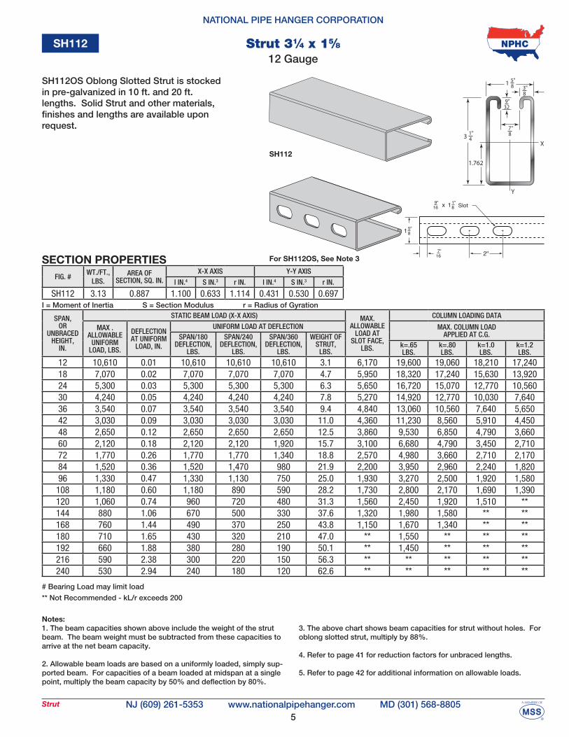
Strut
SPAN,OR
UNBRACEDHEIGHT,
IN.
STATIC BEAM LOAD (X-X AXIS) MAX.ALLOWABLE
LOAD ATSLOT FACE,
LBS.
COLUMN LOADING DATA
MAX .ALLOWABLE
UNIFORMLOAD, LBS.
DEFLECTIONAT UNIFORM
LOAD, IN.
UNIFORM LOAD AT DEFLECTION MAX. COLUMN LOAD APPLIED AT C.G.SPAN/180
DEFLECTION,LBS.
SPAN/240DEFLECTION,
LBS.
SPAN/360DEFLECTION,
LBS.
WEIGHT OFSTRUT,
LBS.k=.65LBS.
k=.80LBS.
k=1.0LBS.
k=1.2LBS.
12 10,610 0.01 10,610 10,610 10,610 3.1 6,170 19,600 19,060 18,210 17,24018 7,070 0.02 7,070 7,070 7,070 4.7 5,950 18,320 17,240 15,630 13,92024 5,300 0.03 5,300 5,300 5,300 6.3 5,650 16,720 15,070 12,770 10,56030 4,240 0.05 4,240 4,240 4,240 7.8 5,270 14,920 12,770 10,030 7,64036 3,540 0.07 3,540 3,540 3,540 9.4 4,840 13,060 10,560 7,640 5,65042 3,030 0.09 3,030 3,030 3,030 11.0 4,360 11,230 8,560 5,910 4,45048 2,650 0.12 2,650 2,650 2,650 12.5 3,860 9,530 6,850 4,790 3,66060 2,120 0.18 2,120 2,120 1,920 15.7 3,100 6,680 4,790 3,450 2,71072 1,770 0.26 1,770 1,770 1,340 18.8 2,570 4,980 3,660 2,710 2,17084 1,520 0.36 1,520 1,470 980 21.9 2,200 3,950 2,960 2,240 1,82096 1,330 0.47 1,330 1,130 750 25.0 1,930 3,270 2,500 1,920 1,580108 1,180 0.60 1,180 890 590 28.2 1,730 2,800 2,170 1,690 1,390120 1,060 0.74 960 720 480 31.3 1,560 2,450 1,920 1,510 **144 880 1.06 670 500 330 37.6 1,320 1,980 1,580 ** **168 760 1.44 490 370 250 43.8 1,150 1,670 1,340 ** **180 710 1.65 430 320 210 47.0 ** 1,550 ** ** **192 660 1.88 380 280 190 50.1 ** 1,450 ** ** **216 590 2.38 300 220 150 56.3 ** ** ** ** **240 530 2.94 240 180 120 62.6 ** ** ** ** **
I = Moment of Inertia S = Section Modulus r = Radius of Gyration
Notes:1. The beam capacities shown above include the weight of the strut beam. The beam weight must be subtracted from these capacities to arrive at the net beam capacity.
2. Allowable beam loads are based on a uniformly loaded, simply sup-ported beam. For capacities of a beam loaded at midspan at a single point, multiply the beam capacity by 50% and deflection by 80%.
3. The above chart shows beam capacities for strut without holes. For oblong slotted strut, multiply by 88%.
4. Refer to page 41 for reduction factors for unbraced lengths.
5. Refer to page 42 for additional information on allowable loads.
# Bearing Load may limit load
** Not Recommended - kL/r exceeds 200
SECTION PROPERTIES
SH112
1
1.762
41"
X
Y
3 87"
329"
83"8
5"
Slot
For SH112OS, See Note 3
FIG. #WT./FT.,
LBS.AREA OF
SECTION, SQ. IN.X-X AXIS Y-Y AXIS
I IN.4 S IN.3 r IN. I IN.4 S IN.3 r IN.
SH112 3.13 0.887 1.100 0.633 1.114 0.431 0.530 0.697
12 Gauge
SH112OS Oblong Slotted Strut is stocked in pre-galvanized in 10 ft. and 20 ft. lengths. Solid Strut and other materials, finishes and lengths are available upon request.
Strut 31⁄4 x 15⁄8
SH112
6
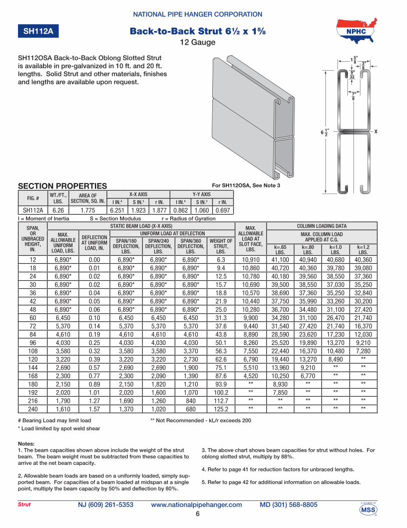
NATIONAL PIPE HANGER CORPORATION
NJ (609) 261-5353 MD (301) 568-8805www.nationalpipehanger.comStrut
SPAN,OR
UNBRACEDHEIGHT,
IN.
STATIC BEAM LOAD (X-X AXIS) MAX.ALLOWABLE
LOAD ATSLOT FACE,
LBS.
COLUMN LOADING DATA
MAX. ALLOWABLE
UNIFORMLOAD, LBS.
DEFLECTIONAT UNIFORM
LOAD, IN.
UNIFORM LOAD AT DEFLECTION MAX. COLUMN LOAD APPLIED AT C.G.SPAN/180
DEFLECTION,LBS.
SPAN/240DEFLECTION,
LBS.
SPAN/360DEFLECTION,
LBS.
WEIGHT OFSTRUT,
LBS.k=.65LBS.
k=.80LBS.
k=1.0LBS.
k=1.2LBS.
12 6,890* 0.00 6,890* 6,890* 6,890* 6.3 10,910 41,100 40,940 40,680 40,36018 6,890* 0.01 6,890* 6,890* 6,890* 9.4 10,860 40,720 40,360 39,780 39,08024 6,890* 0.02 6,890* 6,890* 6,890* 12.5 10,780 40,180 39,560 38,550 37,36030 6,890* 0.02 6,890* 6,890* 6,890* 15.7 10,690 39,500 38,550 37,030 35,25036 6,890* 0.04 6,890* 6,890* 6,890* 18.8 10,570 38,690 37,360 35,250 32,84042 6,890* 0.05 6,890* 6,890* 6,890* 21.9 10,440 37,750 35,990 33,260 30,20048 6,890* 0.06 6,890* 6,890* 6,890* 25.0 10,280 36,700 34,480 31,100 27,42060 6,450 0.10 6,450 6,450 6,450 31.3 9,900 34,280 31,100 26,470 21,74072 5,370 0.14 5,370 5,370 5,370 37.6 9,440 31,540 27,420 21,740 16,37084 4,610 0.19 4,610 4,610 4,610 43.8 8,890 28,590 23,620 17,230 12,03096 4,030 0.25 4,030 4,030 4,030 50.1 8,260 25,520 19,890 13,270 9,210
108 3,580 0.32 3,580 3,580 3,370 56.3 7,550 22,440 16,370 10,480 7,280120 3,220 0.39 3,220 3,220 2,730 62.6 6,790 19,440 13,270 8,490 **144 2,690 0.57 2,690 2,690 1,900 75.1 5,510 13,960 9,210 ** **168 2,300 0.77 2,300 2,090 1,390 87.6 4,520 10,250 6,770 ** **180 2,150 0.89 2,150 1,820 1,210 93.9 ** 8,930 ** ** **192 2,020 1.01 2,020 1,600 1,070 100.2 ** 7,850 ** ** **216 1,790 1.27 1,690 1,260 840 112.7 ** ** ** ** **240 1,610 1.57 1,370 1,020 680 125.2 ** ** ** ** **
FIG. #WT./FT.,
LBS.AREA OF
SECTION, SQ. IN.X-X AXIS Y-Y AXIS
I IN.4 S IN.3 r IN. I IN.4 S IN.3 r IN.
SH112A 6.26 1.775 6.251 1.923 1.877 0.862 1.060 0.697I = Moment of Inertia S = Section Modulus r = Radius of Gyration
Notes:1. The beam capacities shown above include the weight of the strut beam. The beam weight must be subtracted from these capacities to arrive at the net beam capacity.
2. Allowable beam loads are based on a uniformly loaded, simply sup-ported beam. For capacities of a beam loaded at midspan at a single point, multiply the beam capacity by 50% and deflection by 80%.
3. The above chart shows beam capacities for strut without holes. For oblong slotted strut, multiply by 88%. 4. Refer to page 41 for reduction factors for unbraced lengths.
5. Refer to page 42 for additional information on allowable loads.
SECTION PROPERTIES
SH112A
6
1
X21"
87"
329"
83"8
5"
For SH112OSA, See Note 3
SH112OSA Back-to-Back Oblong Slotted Strut is available in pre-galvanized in 10 ft. and 20 ft. lengths. Solid Strut and other materials, finishes and lengths are available upon request.
12 GaugeBack-to-Back Strut 61⁄2 x 15⁄8
# Bearing Load may limit load
* Load limited by spot weld shear
** Not Recommended - kL/r exceeds 200
7
NATIONAL PIPE HANGER CORPORATION
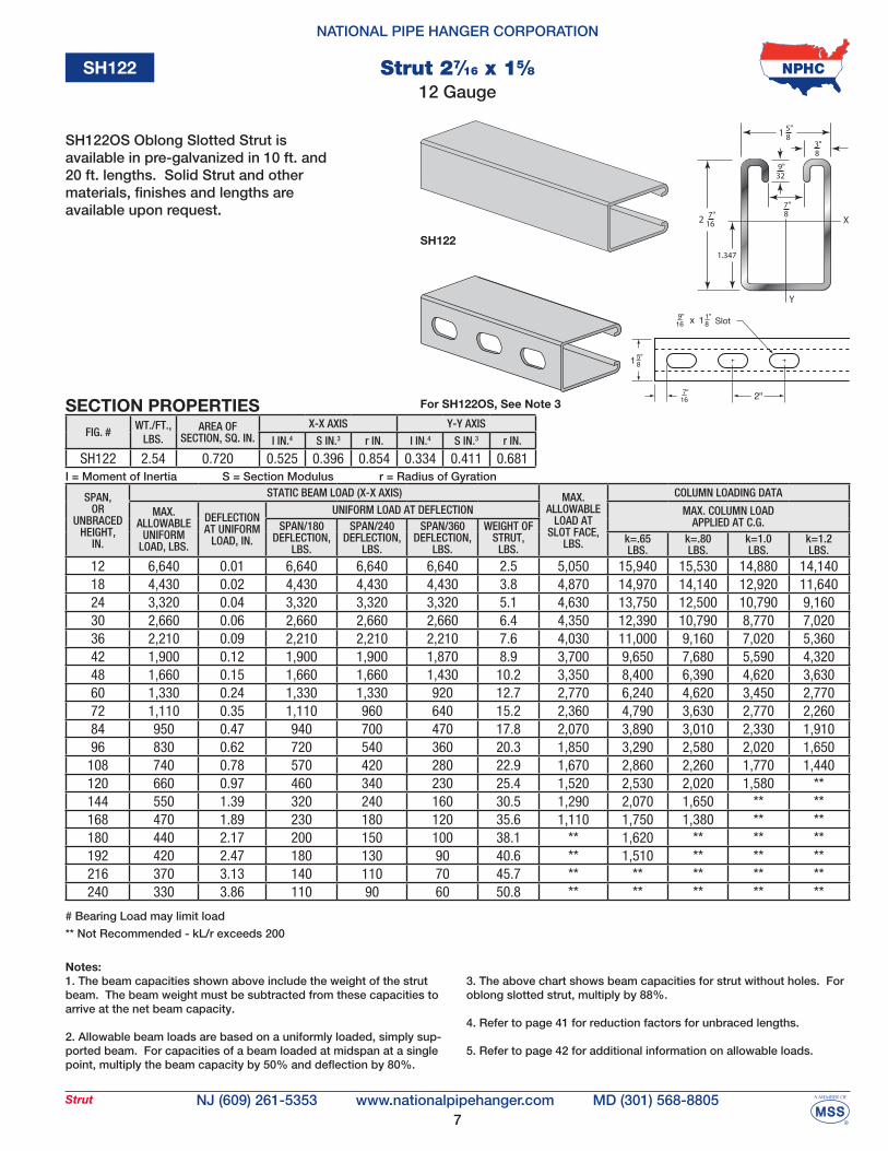
NJ (609) 261-5353 MD (301) 568-8805www.nationalpipehanger.comStrut
SPAN,OR
UNBRACEDHEIGHT,
IN.
STATIC BEAM LOAD (X-X AXIS) MAX.ALLOWABLE
LOAD ATSLOT FACE,
LBS.
COLUMN LOADING DATA
MAX. ALLOWABLE
UNIFORMLOAD, LBS.
DEFLECTIONAT UNIFORM
LOAD, IN.
UNIFORM LOAD AT DEFLECTION MAX. COLUMN LOAD APPLIED AT C.G.SPAN/180
DEFLECTION,LBS.
SPAN/240DEFLECTION,
LBS.
SPAN/360DEFLECTION,
LBS.
WEIGHT OFSTRUT,
LBS.k=.65LBS.
k=.80LBS.
k=1.0LBS.
k=1.2LBS.
12 6,640 0.01 6,640 6,640 6,640 2.5 5,050 15,940 15,530 14,880 14,14018 4,430 0.02 4,430 4,430 4,430 3.8 4,870 14,970 14,140 12,920 11,64024 3,320 0.04 3,320 3,320 3,320 5.1 4,630 13,750 12,500 10,790 9,16030 2,660 0.06 2,660 2,660 2,660 6.4 4,350 12,390 10,790 8,770 7,02036 2,210 0.09 2,210 2,210 2,210 7.6 4,030 11,000 9,160 7,020 5,36042 1,900 0.12 1,900 1,900 1,870 8.9 3,700 9,650 7,680 5,590 4,32048 1,660 0.15 1,660 1,660 1,430 10.2 3,350 8,400 6,390 4,620 3,63060 1,330 0.24 1,330 1,330 920 12.7 2,770 6,240 4,620 3,450 2,77072 1,110 0.35 1,110 960 640 15.2 2,360 4,790 3,630 2,770 2,26084 950 0.47 940 700 470 17.8 2,070 3,890 3,010 2,330 1,91096 830 0.62 720 540 360 20.3 1,850 3,290 2,580 2,020 1,650108 740 0.78 570 420 280 22.9 1,670 2,860 2,260 1,770 1,440120 660 0.97 460 340 230 25.4 1,520 2,530 2,020 1,580 **144 550 1.39 320 240 160 30.5 1,290 2,070 1,650 ** **168 470 1.89 230 180 120 35.6 1,110 1,750 1,380 ** **180 440 2.17 200 150 100 38.1 ** 1,620 ** ** **192 420 2.47 180 130 90 40.6 ** 1,510 ** ** **216 370 3.13 140 110 70 45.7 ** ** ** ** **240 330 3.86 110 90 60 50.8 ** ** ** ** **
I = Moment of Inertia S = Section Modulus r = Radius of Gyration
Notes:1. The beam capacities shown above include the weight of the strut beam. The beam weight must be subtracted from these capacities to arrive at the net beam capacity.
2. Allowable beam loads are based on a uniformly loaded, simply sup-ported beam. For capacities of a beam loaded at midspan at a single point, multiply the beam capacity by 50% and deflection by 80%.
3. The above chart shows beam capacities for strut without holes. For oblong slotted strut, multiply by 88%.
4. Refer to page 41 for reduction factors for unbraced lengths.
5. Refer to page 42 for additional information on allowable loads.
# Bearing Load may limit load
** Not Recommended - kL/r exceeds 200
SECTION PROPERTIES
SH122
FIG. #WT./FT.,
LBS.AREA OF
SECTION, SQ. IN.X-X AXIS Y-Y AXIS
I IN.4 S IN.3 r IN. I IN.4 S IN.3 r IN.
SH122 2.54 0.720 0.525 0.396 0.854 0.334 0.411 0.681
2
Y
X
1
1.347
167" 8
7"
329"
83"
85"
Slot
For SH122OS, See Note 3
SH122OS Oblong Slotted Strut is available in pre-galvanized in 10 ft. and 20 ft. lengths. Solid Strut and other materials, finishes and lengths are available upon request.
12 GaugeStrut 27⁄16 x 15⁄8
SH122
8
NATIONAL PIPE HANGER CORPORATION
NJ (609) 261-5353 MD (301) 568-8805www.nationalpipehanger.comStrut
SPAN,OR
UNBRACEDHEIGHT,
IN.
STATIC BEAM LOAD (X-X AXIS) MAX.ALLOWABLE
LOAD ATSLOT FACE,
LBS.
COLUMN LOADING DATA
MAX. ALLOWABLE
UNIFORMLOAD, LBS.
DEFLECTIONAT UNIFORM
LOAD, IN.
UNIFORM LOAD AT DEFLECTION MAX. COLUMN LOAD APPLIED AT C.G.SPAN/180
DEFLECTION,LBS.
SPAN/240DEFLECTION,
LBS.
SPAN/360DEFLECTION,
LBS.
WEIGHT OFSTRUT,
LBS.k=.65LBS.
k=.80LBS.
k=1.0LBS.
k=1.2LBS.
12 5,220* 0.01 5,220* 5,220* 5,220* 5.1 8,800 33,310 33,180 32,950 32,68018 5,220* 0.01 5,220* 5,220* 5,220* 7.6 8,750 32,980 32,680 32,190 31,60024 5,220* 0.02 5,220* 5,220* 5,220* 10.2 8,680 32,530 32,000 31,150 30,14030 5,220* 0.03 5,220* 5,220* 5,220* 12.7 8,590 31,950 31,150 29,860 28,36036 5,220* 0.05 5,220* 5,220* 5,220* 15.2 8,480 31,270 30,140 28,360 26,33042 5,220* 0.06 5,220* 5,220* 5,220* 17.8 8,350 30,470 28,980 26,680 24,12048 4,870 0.08 4,870 4,870 4,870 20.3 8,200 29,580 27,710 24,870 21,79060 3,900 0.13 3,900 3,900 3,900 25.4 7,860 27,540 24,870 21,010 17,09072 3,250 0.19 3,250 3,250 3,250 30.5 7,440 25,240 21,790 17,090 12,67084 2,780 0.26 2,780 2,780 2,530 35.6 6,960 22,770 18,650 13,390 9,31096 2,440 0.34 2,440 2,440 1,930 40.6 6,420 20,220 15,570 10,270 7,130
108 2,160 0.43 2,160 2,160 1,530 45.7 5,820 17,670 12,670 8,110 5,630120 1,950 0.52 1,950 1,860 1,240 50.8 5,230 15,200 10,270 6,570 **144 1,620 0.76 1,620 1,290 860 61.0 4,230 10,800 7,130 ** **168 1,390 1.03 1,260 950 630 71.1 3,470 7,930 5,240 ** **180 1,300 1.18 1,100 830 550 76.2 ** 6,910 ** ** **192 1,220 1.34 970 730 480 81.3 ** 6,070 ** ** **216 1,080 1.70 760 570 380 91.4 ** ** ** ** **240 970 2.10 620 460 310 101.6 ** ** ** ** **
FIG. #WT./FT.,
LBS.AREA OF
SECTION, SQ. IN.X-X AXIS Y-Y AXIS
I IN.4 S IN.3 r IN. I IN.4 S IN.3 r IN.
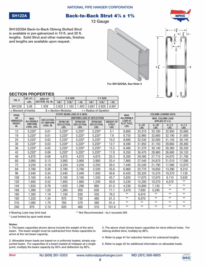
SH122A 5.08 1.439 2.832 1.162 1.403 0.667 0.820 0.681I = Moment of Inertia S = Section Modulus r = Radius of Gyration
Notes:1. The beam capacities shown above include the weight of the strut beam. The beam weight must be subtracted from these capacities to arrive at the net beam capacity.
2. Allowable beam loads are based on a uniformly loaded, simply sup-ported beam. For capacities of a beam loaded at midspan at a single point, multiply the beam capacity by 50% and deflection by 80%.
3. The above chart shows beam capacities for strut without holes. For oblong slotted strut, multiply by 88%.
4. Refer to page 41 for reduction factors for unbraced lengths.
5. Refer to page 42 for additional information on allowable loads.
SECTION PROPERTIES
SH122A
4 X
Y
1
87"
87"
329"
83"
85"
For SH122OSA, See Note 3
12 GaugeBack-to-Back Strut 47⁄8 x 15⁄8
# Bearing Load may limit load
* Load limited by spot weld shear
** Not Recommended - kL/r exceeds 200
SH122OSA Back-to-Back Oblong Slotted Strut is available in pre-galvanized in 10 ft. and 20 ft. lengths. Solid Strut and other materials, finishes and lengths are available upon request.
9
NATIONAL PIPE HANGER CORPORATION
NJ (609) 261-5353 MD (301) 568-8805www.nationalpipehanger.comStrut
SPAN,OR
UNBRACEDHEIGHT,
IN.
STATIC BEAM LOAD (X-X AXIS) MAX.ALLOWABLE
LOAD ATSLOT FACE,
LBS.
COLUMN LOADING DATA
MAX. ALLOWABLE
UNIFORMLOAD, LBS.
DEFLECTIONAT UNIFORM
LOAD, IN.
UNIFORM LOAD AT DEFLECTION MAX. COLUMN LOAD APPLIED AT C.G.SPAN/180
DEFLECTION,LBS.
SPAN/240DEFLECTION,
LBS.
SPAN/360DEFLECTION,
LBS.
WEIGHT OFSTRUT,
LBS.k=.65LBS.
k=.80LBS.
k=1.0LBS.
k=1.2LBS.
12 3,480 0.01 3,480 3,480 3,480 1.9 3,850 12,240 11,940 11,480 10,96018 2,320 0.03 2,320 2,320 2,320 2.9 3,710 11,540 10,960 10,130 9,29024 1,740 0.06 1,740 1,740 1,740 3.9 3,530 10,690 9,850 8,740 7,71030 1,390 0.09 1,390 1,390 1,310 4.9 3,330 9,780 8,740 7,470 6,38036 1,160 0.13 1,160 1,160 910 5.8 3,120 8,880 7,710 6,380 5,31042 990 0.17 990 990 670 6.8 2,910 8,020 6,800 5,470 4,43048 870 0.23 870 770 510 7.8 2,710 7,240 6,000 4,690 3,81060 700 0.35 660 490 330 9.7 2,340 5,910 4,690 3,630 2,96072 580 0.51 460 340 230 11.6 2,040 4,840 3,810 2,960 2,40084 500 0.69 340 250 170 13.6 1,800 4,040 3,200 2,480 1,98096 430 0.90 260 190 130 15.5 1,600 3,480 2,750 2,110 1,670108 390 1.14 200 150 100 17.5 1,440 3,050 2,400 1,820 **120 350 1.41 160 120 80 19.4 1,290 2,700 2,110 ** **144 290 2.03 110 90 60 23.3 1,060 2,180 1,670 ** **168 250 2.77 80 60 40 27.2 ** 1,790 ** ** **180 230 3.18 70 50 40 29.1 ** ** ** ** **192 220 3.61 60 50 NR 31.0 ** ** ** ** **216 190 4.57 50 40 NR 34.9 ** ** ** ** **240 170 5.65 40 NR NR 38.8 ** ** ** ** **
I = Moment of Inertia S = Section Modulus r = Radius of Gyration
Notes:1. The beam capacities shown above include the weight of the strut beam. The beam weight must be subtracted from these capacities to arrive at the net beam capacity.
2. Allowable beam loads are based on a uniformly loaded, simply sup-ported beam. For capacities of a beam loaded at midspan at a single point, multiply the beam capacity by 50% and deflection by 80%.
3. The above chart shows beam capacities for strut without holes. For oblong slotted strut, multiply by 88%
4. Refer to page 41 for reduction factors for unbraced lengths.
5. Refer to page 42 for additional information on allowable loads.
# Bearing Load may limit load
NR = Not Recommended
** Not Recommended - kL/r exceeds 200
SECTION PROPERTIES
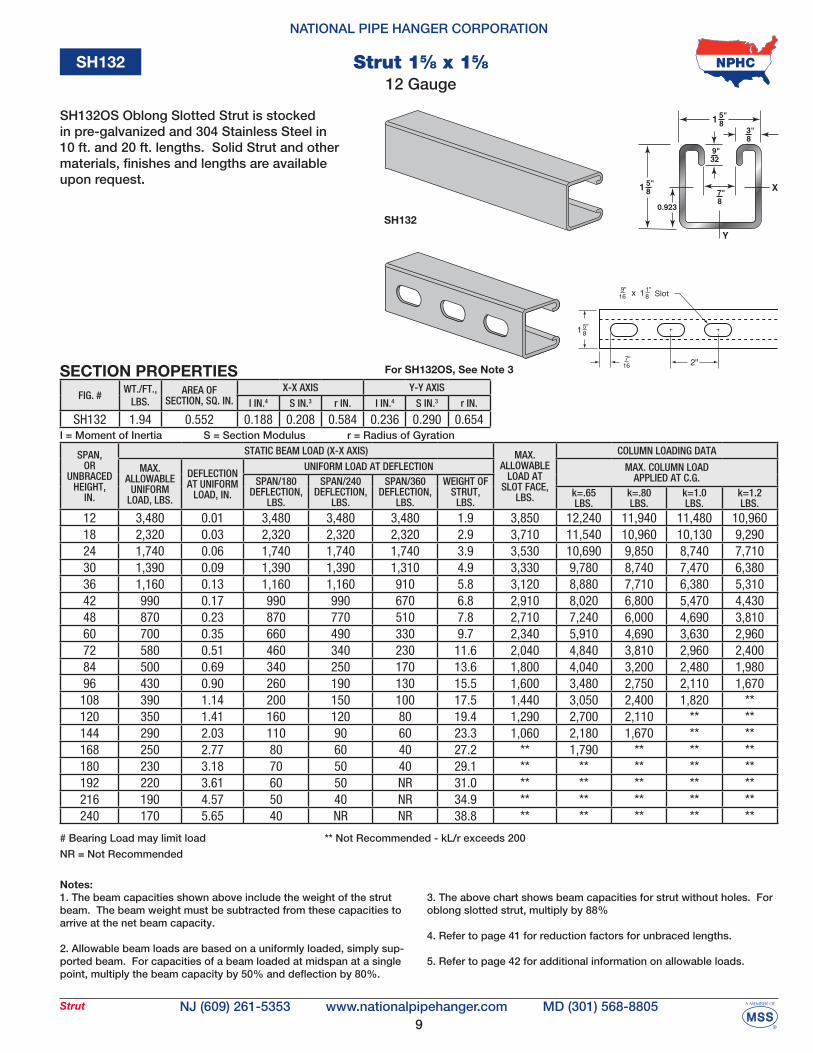
SH132
FIG. #WT./FT.,
LBS.AREA OF
SECTION, SQ. IN.X-X AXIS Y-Y AXIS
I IN.4 S IN.3 r IN. I IN.4 S IN.3 r IN.
SH132 1.94 0.552 0.188 0.208 0.584 0.236 0.290 0.654
SH132OS Oblong Slotted Strut is stocked in pre-galvanized and 304 Stainless Steel in 10 ft. and 20 ft. lengths. Solid Strut and other materials, finishes and lengths are available upon request.
Slot
For SH132OS, See Note 3
12 GaugeStrut 15⁄8 x 15⁄8
SH132
10
NATIONAL PIPE HANGER CORPORATION
NJ (609) 261-5353 MD (301) 568-8805www.nationalpipehanger.comStrut
SPAN,OR
UNBRACEDHEIGHT,
IN.
STATIC BEAM LOAD (X-X AXIS) MAX.ALLOWABLE
LOAD ATSLOT FACE,
LBS.
COLUMN LOADING DATA
MAX. ALLOWABLE
UNIFORMLOAD, LBS.
DEFLECTIONAT UNIFORM
LOAD, IN.
UNIFORM LOAD AT DEFLECTION MAX. COLUMN LOAD APPLIED AT C.G.SPAN/180
DEFLECTION,LBS.
SPAN/240DEFLECTION,
LBS.
SPAN/360DEFLECTION,
LBS.
WEIGHT OFSTRUT,
LBS.k=.65LBS.
k=.80LBS.
k=1.0LBS.
k=1.2LBS.
12 3,500* 0.01 3,500* 3,500* 3,500* 3.9 6,640 25,540 25,430 25,240 25,02018 3,500* 0.02 3,500* 3,500* 3,500* 5.8 6,580 25,270 25,020 24,610 24,12024 3,500* 0.03 3,500* 3,500* 3,500* 7.8 6,510 24,890 24,460 23,750 22,92030 3,500* 0.05 3,500* 3,500* 3,500* 9.7 6,410 24,420 23,750 22,690 21,46036 3,260 0.07 3,260 3,260 3,260 11.6 6,300 23,850 22,920 21,460 19,80042 2,790 0.10 2,790 2,790 2,790 13.6 6,170 23,190 21,970 20,090 18,01048 2,440 0.13 2,440 2,440 2,440 15.5 6,030 22,460 20,930 18,620 16,14060 1,950 0.20 1,950 1,950 1,660 19.4 5,690 20,790 18,620 15,510 12,41072 1,630 0.28 1,630 1,630 1,150 23.3 5,310 18,920 16,140 12,410 8,99084 1,400 0.39 1,400 1,270 840 27.2 4,890 16,920 13,630 9,510 6,60096 1,220 0.50 1,220 970 650 31.0 4,450 14,880 11,220 7,280 5,060
108 1,090 0.64 1,020 770 510 34.9 3,980 12,860 8,990 5,750 3,990120 980 0.79 830 620 410 38.8 3,560 10,930 7,280 4,660 **144 810 1.13 570 430 290 46.6 2,870 7,660 5,060 ** **168 700 1.54 420 320 210 54.3 ** 5,630 ** ** **180 650 1.77 370 280 180 58.2 ** 4,900 ** ** **192 610 2.01 320 240 160 62.1 ** 4,310 ** ** **216 540 2.55 260 190 130 69.8 ** ** ** ** **240 490 3.15 210 160 100 77.6 ** ** ** ** **
FIG. #WT./FT.,
LBS.AREA OF
SECTION, SQ. IN.X-X AXIS Y-Y AXIS
I IN.4 S IN.3 r IN. I IN.4 S IN.3 r IN.
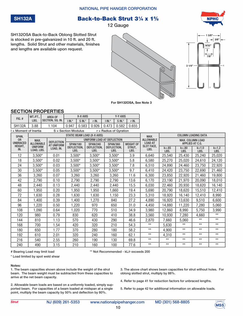
SH132A 3.88 1.104 0.947 0.583 0.926 0.473 0.582 0.655I = Moment of Inertia S = Section Modulus r = Radius of Gyration
Notes:1. The beam capacities shown above include the weight of the strut beam. The beam weight must be subtracted from these capacities to arrive at the net beam capacity.
2. Allowable beam loads are based on a uniformly loaded, simply sup-ported beam. For capacities of a beam loaded at midspan at a single point, multiply the beam capacity by 50% and deflection by 80%.
3. The above chart shows beam capacities for strut without holes. For oblong slotted strut, multiply by 88%. 4. Refer to page 41 for reduction factors for unbraced lengths.
5. Refer to page 42 for additional information on allowable loads.
SECTION PROPERTIES
SH132A
For SH132OSA, See Note 3
SH132OSA Back-to-Back Oblong Slotted Strut is stocked in pre-galvanized in 10 ft. and 20 ft. lengths. Solid Strut and other materials, finishes and lengths are available upon request.
12 GaugeBack-to-Back Strut 31⁄4 x 15⁄8
# Bearing Load may limit load
* Load limited by spot weld shear
** Not Recommended - kL/r exceeds 200
11
NATIONAL PIPE HANGER CORPORATION
NJ (609) 261-5353 MD (301) 568-8805www.nationalpipehanger.comStrut
SPAN,OR
UNBRACEDHEIGHT,
IN.
STATIC BEAM LOAD (X-X AXIS) MAX.ALLOWABLE
LOAD ATSLOT FACE,
LBS.
COLUMN LOADING DATA
MAX. ALLOWABLE
UNIFORMLOAD, LBS.
DEFLECTIONAT UNIFORM
LOAD, IN.
UNIFORM LOAD AT DEFLECTION MAX. COLUMN LOAD APPLIED AT C.G.SPAN/180
DEFLECTION,LBS.
SPAN/240DEFLECTION,
LBS.
SPAN/360DEFLECTION,
LBS.
WEIGHT OFSTRUT,
LBS.k=.65LBS.
k=.80LBS.
k=1.0LBS.
k=1.2LBS.
12 970 0.03 970 970 970 1.0 2,010 6,500 6,340 6,090 5,82018 640 0.06 640 640 520 1.5 1,890 6,120 5,820 5,410 5,01024 480 0.11 480 440 300 2.1 1,740 5,690 5,270 4,700 3,98030 390 0.17 380 280 190 2.6 1,590 5,240 4,700 3,800 2,93036 320 0.25 260 200 130 3.1 1,420 4,790 3,980 2,930 2,05042 280 0.33 190 140 100 3.6 1,250 4,200 3,270 2,170 1,51048 240 0.44 150 110 70 4.1 1,090 3,620 2,600 1,660 1,15060 190 0.68 90 70 50 5.2 830 2,520 1,660 1,060 **72 160 0.98 70 50 30 6.2 650 1,750 1,150 ** **84 140 1.34 50 40 20 7.2 ** 1,280 ** ** **96 120 1.75 40 30 20 8.2 ** ** ** ** **
108 110 2.21 30 20 10 9.3 ** ** ** ** **120 100 2.73 20 20 NR 10.3 ** ** ** ** **144 80 3.93 20 NR NR 12.4 ** ** ** ** **168 70 5.34 NR NR NR 14.4 ** ** ** ** **180 60 6.13 NR NR NR 15.5 ** ** ** ** **192 60 6.98 NR NR NR 16.5 ** ** ** ** **216 50 8.83 NR NR NR 18.5 ** ** ** ** **240 50 10.91 NR NR NR 20.6 ** ** ** ** **
FIG. #WT./FT.,
LBS.AREA OF
SECTION, SQ. IN.X-X AXIS Y-Y AXIS
I IN.4 S IN.3 r IN. I IN.4 S IN.3 r IN.
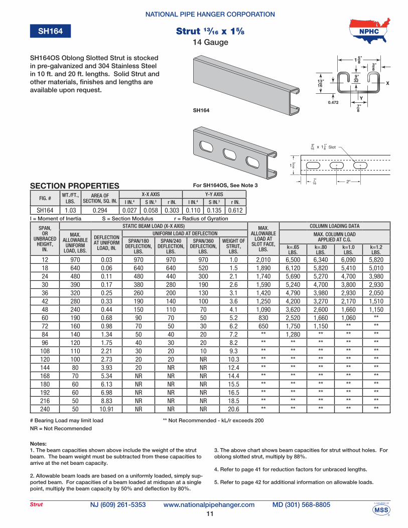
SH164 1.03 0.294 0.027 0.058 0.303 0.110 0.135 0.612I = Moment of Inertia S = Section Modulus r = Radius of Gyration
Notes:1. The beam capacities shown above include the weight of the strut beam. The beam weight must be subtracted from these capacities to arrive at the net beam capacity.
2. Allowable beam loads are based on a uniformly loaded, simply sup-ported beam. For capacities of a beam loaded at midspan at a single point, multiply the beam capacity by 50% and deflection by 80%.
3. The above chart shows beam capacities for strut without holes. For oblong slotted strut, multiply by 88%.
4. Refer to page 41 for reduction factors for unbraced lengths.
5. Refer to page 42 for additional information on allowable loads.
SECTION PROPERTIES
SH164
SH164OS Oblong Slotted Strut is stocked in pre-galvanized and 304 Stainless Steel in 10 ft. and 20 ft. lengths. Solid Strut and other materials, finishes and lengths are available upon request.
Slot
For SH164OS, See Note 3
14 GaugeStrut 13⁄16 x 15⁄8
# Bearing Load may limit load
NR = Not Recommended
** Not Recommended - kL/r exceeds 200
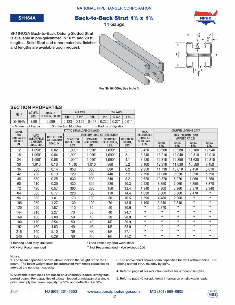
SH164
12
NATIONAL PIPE HANGER CORPORATION
NJ (609) 261-5353 MD (301) 568-8805www.nationalpipehanger.comStrut
SPAN,OR
UNBRACEDHEIGHT,
IN.
STATIC BEAM LOAD (X-X AXIS) MAX.ALLOWABLE
LOAD ATSLOT FACE,
LBS.
COLUMN LOADING DATA
MAX. ALLOWABLE
UNIFORMLOAD, LBS.
DEFLECTIONAT UNIFORM
LOAD, IN.
UNIFORM LOAD AT DEFLECTION MAX. COLUMN LOAD APPLIED AT C.G.SPAN/180
DEFLECTION,LBS.
SPAN/240DEFLECTION,
LBS.
SPAN/360DEFLECTION,
LBS.
WEIGHT OFSTRUT,
LBS.k=.65LBS.
k=.80LBS.
k=1.0LBS.
k=1.2LBS.
12 1,090* 0.02 1,090* 1,090* 1,090* 2.1 3,420 13,500 13,380 13,180 12,94018 1,090* 0.04 1,090* 1,090* 1,090* 3.1 3,340 13,210 12,940 12,510 12,01024 1,090* 0.06 1,090* 1,090* 1,090* 4.1 3,230 12,810 12,350 11,630 10,81030 1,010 0.10 1,010 1,010 860 5.2 3,100 12,310 11,630 10,590 9,45036 850 0.14 850 850 600 6.2 2,950 11,730 10,810 9,450 8,01042 720 0.19 720 660 440 7.2 2,790 11,080 9,920 8,250 6,59048 630 0.25 630 500 340 8.2 2,620 10,370 8,970 7,060 5,26060 510 0.39 430 320 220 10.3 2,280 8,850 7,060 4,850 3,37072 420 0.57 300 220 150 12.4 1,940 7,300 5,260 3,370 2,34084 360 0.77 220 160 110 14.4 1,630 5,800 3,860 2,470 **96 320 1.01 170 130 80 16.5 1,390 4,480 2,960 ** **
108 280 1.27 130 100 70 18.5 1,190 3,540 2,340 ** **120 250 1.57 110 80 50 20.6 ** 2,870 ** ** **144 210 2.27 70 60 40 24.7 ** ** ** ** **168 180 3.08 50 40 30 28.8 ** ** ** ** **180 170 3.54 50 40 NR 30.9 ** ** ** ** **192 160 4.03 40 NR NR 33.0 ** ** ** ** **216 140 5.10 NR NR NR 37.1 ** ** ** ** **240 130 6.29 NR NR NR 41.2 ** ** ** ** **
FIG. #WT./FT.,
LBS.AREA OF
SECTION, SQ. IN.X-X AXIS Y-Y AXIS
I IN.4 S IN.3 r IN. I IN.4 S IN.3 r IN.
SH164A 2.06 0.589 0.123 0.151 0.457 0.220 0.271 0.611I = Moment of Inertia S = Section Modulus r = Radius of Gyration
Notes:1. The beam capacities shown above include the weight of the strut beam. The beam weight must be subtracted from these capacities to arrive at the net beam capacity.
2. Allowable beam loads are based on a uniformly loaded, simply sup-ported beam. For capacities of a beam loaded at midspan at a single point, multiply the beam capacity by 50% and deflection by 80%.
3. The above chart shows beam capacities for strut without holes. For oblong slotted strut, multiply by 88%.
4. Refer to page 41 for reduction factors for unbraced lengths.
5. Refer to page 42 for additional information on allowable loads.
SECTION PROPERTIES
SH164A
For SH164OSA, See Note 3
SH164OSA Back-to-Back Oblong Slotted Strut is available in pre-galvanized in 10 ft. and 20 ft. lengths. Solid Strut and other materials, finishes and lengths are available upon request.
14 GaugeBack-to-Back Strut 15⁄8 x 15⁄8
# Bearing Load may limit load
NR = Not Recommended
* Load limited by spot weld shear
** Not Recommended - kL/r exceeds 200
13
NATIONAL PIPE HANGER CORPORATION
NJ (609) 261-5353 MD (301) 568-8805www.nationalpipehanger.comConcreteInserts
CL
CL
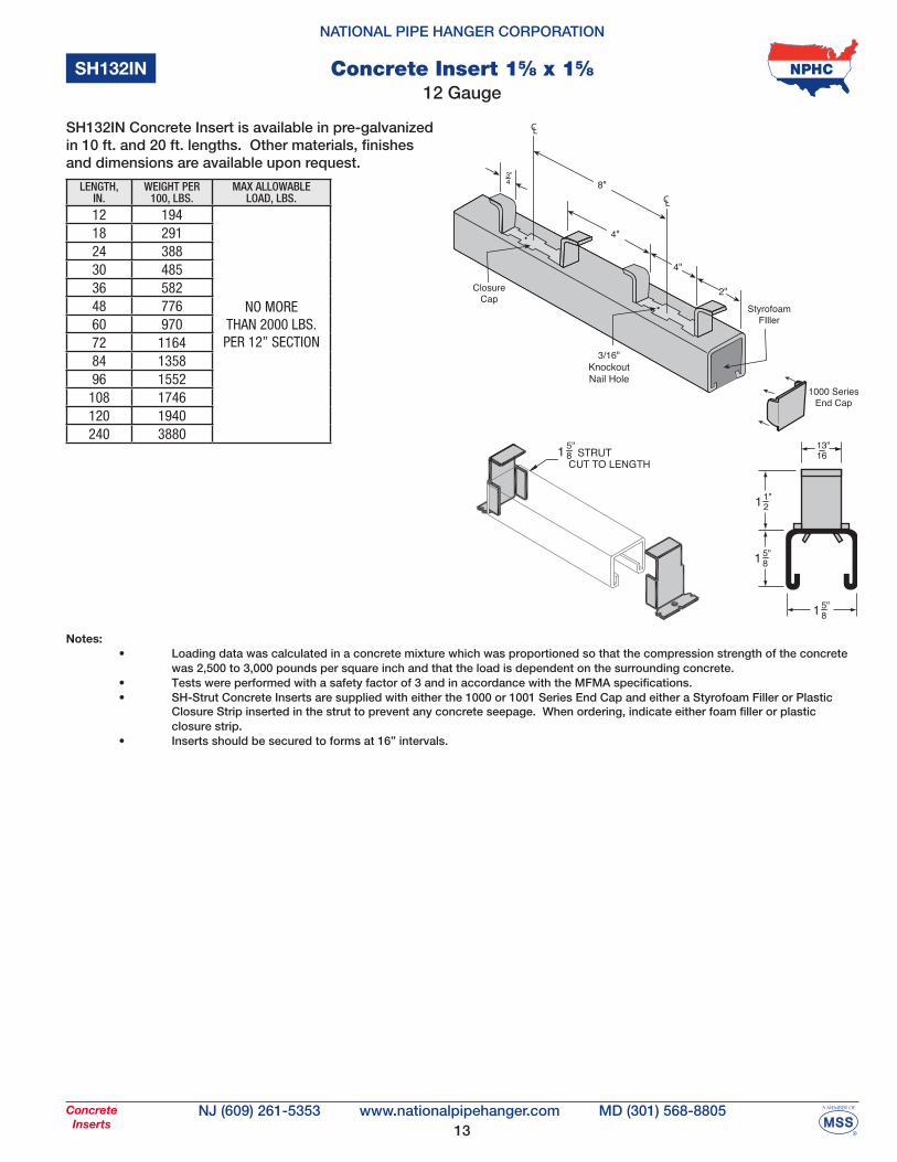
SH132IN
LENGTH, IN.
WEIGHT PER 100, LBS.
MAX ALLOWABLE LOAD, LBS.
12 194
NO MORE THAN 2000 LBS.PER 12” SECTION
18 29124 38830 48536 58248 77660 97072 116484 135896 1552108 1746120 1940240 3880
Notes: • Loading data was calculated in a concrete mixture which was proportioned so that the compression strength of the concrete was 2,500 to 3,000 pounds per square inch and that the load is dependent on the surrounding concrete. • Tests were performed with a safety factor of 3 and in accordance with the MFMA specifications. • SH-Strut Concrete Inserts are supplied with either the 1000 or 1001 Series End Cap and either a Styrofoam Filler or Plastic Closure Strip inserted in the strut to prevent any concrete seepage. When ordering, indicate either foam filler or plastic closure strip. • Inserts should be secured to forms at 16” intervals.
SH132IN Concrete Insert is available in pre-galvanized in 10 ft. and 20 ft. lengths. Other materials, finishes and dimensions are available upon request.
12 GaugeConcrete Insert 15⁄8 x 15⁄8
14
NATIONAL PIPE HANGER CORPORATION
NJ (609) 261-5353 MD (301) 568-8805www.nationalpipehanger.comConcreteInserts
CL
CL
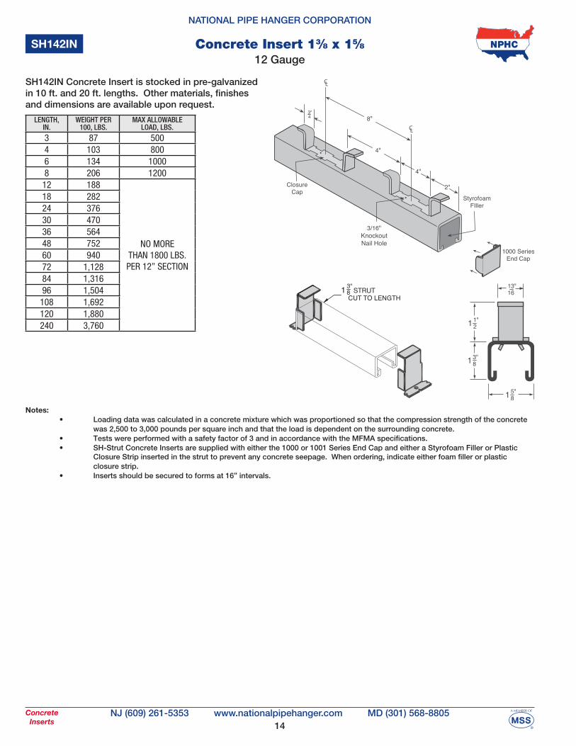
SH142IN
LENGTH, IN.
WEIGHT PER 100, LBS.
MAX ALLOWABLE LOAD, LBS.
3 87 5004 103 8006 134 10008 206 120012 188
NO MORE THAN 1800 LBS.PER 12” SECTION
18 28224 37630 47036 56448 75260 94072 1,12884 1,31696 1,504108 1,692120 1,880240 3,760
Notes: • Loading data was calculated in a concrete mixture which was proportioned so that the compression strength of the concrete was 2,500 to 3,000 pounds per square inch and that the load is dependent on the surrounding concrete. • Tests were performed with a safety factor of 3 and in accordance with the MFMA specifications. • SH-Strut Concrete Inserts are supplied with either the 1000 or 1001 Series End Cap and either a Styrofoam Filler or Plastic Closure Strip inserted in the strut to prevent any concrete seepage. When ordering, indicate either foam filler or plastic closure strip. • Inserts should be secured to forms at 16” intervals.
SH142IN Concrete Insert is stocked in pre-galvanized in 10 ft. and 20 ft. lengths. Other materials, finishes and dimensions are available upon request.
12 GaugeConcrete Insert 13⁄8 x 15⁄8
15
NATIONAL PIPE HANGER CORPORATION
NJ (609) 261-5353 MD (301) 568-8805www.nationalpipehanger.comConcreteInserts
CL
CL
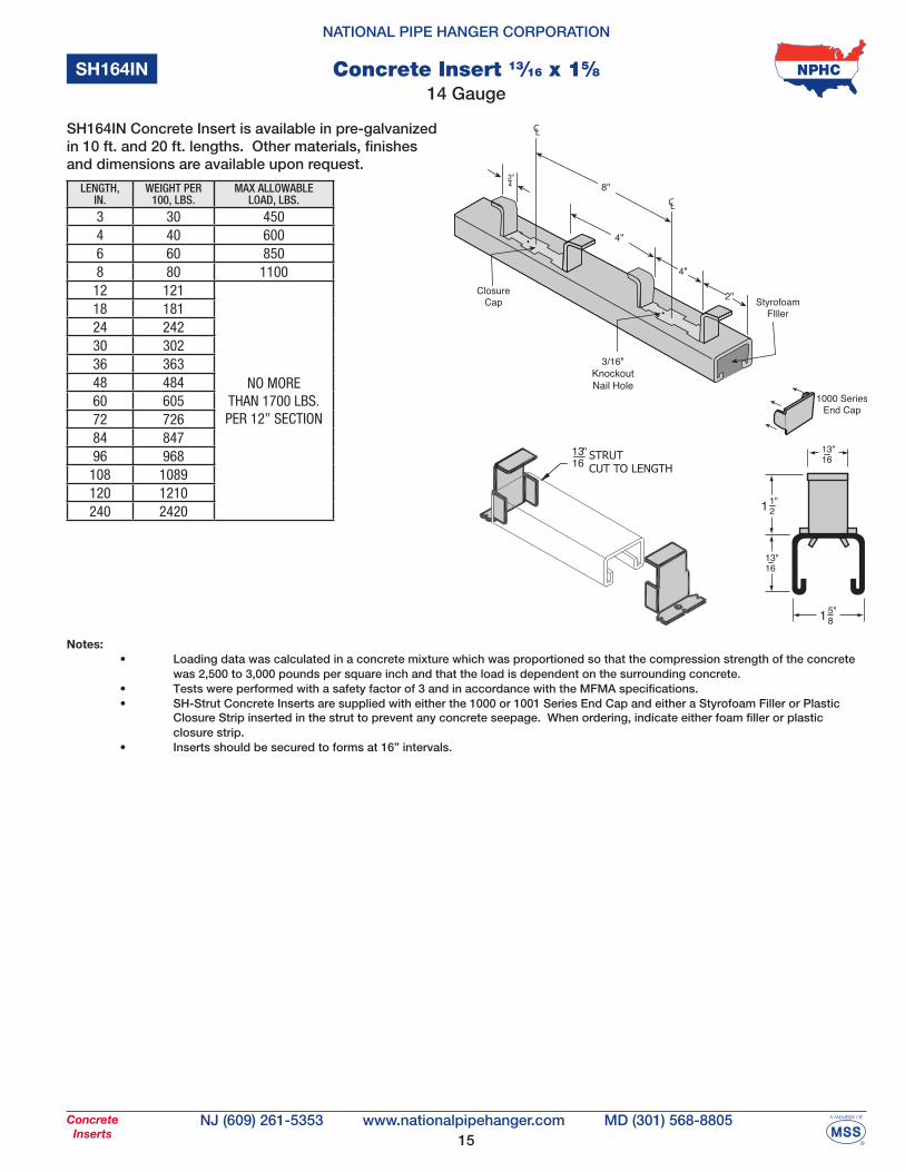
SH164IN
LENGTH, IN.
WEIGHT PER 100, LBS.
MAX ALLOWABLE LOAD, LBS.
3 30 4504 40 6006 60 8508 80 110012 121
NO MORE THAN 1700 LBS.PER 12” SECTION
18 18124 24230 30236 36348 48460 60572 72684 84796 968108 1089120 1210240 2420
Notes: • Loading data was calculated in a concrete mixture which was proportioned so that the compression strength of the concrete was 2,500 to 3,000 pounds per square inch and that the load is dependent on the surrounding concrete. • Tests were performed with a safety factor of 3 and in accordance with the MFMA specifications. • SH-Strut Concrete Inserts are supplied with either the 1000 or 1001 Series End Cap and either a Styrofoam Filler or Plastic Closure Strip inserted in the strut to prevent any concrete seepage. When ordering, indicate either foam filler or plastic closure strip. • Inserts should be secured to forms at 16” intervals.
SH164IN Concrete Insert is available in pre-galvanized in 10 ft. and 20 ft. lengths. Other materials, finishes and dimensions are available upon request.
1613" STRUT
CUT TO LENGTH
14 GaugeConcrete Insert 13⁄16 x 15⁄8
16
NATIONAL PIPE HANGER CORPORATION
NJ (609) 261-5353 MD (301) 568-8805www.nationalpipehanger.comConcreteAccessories
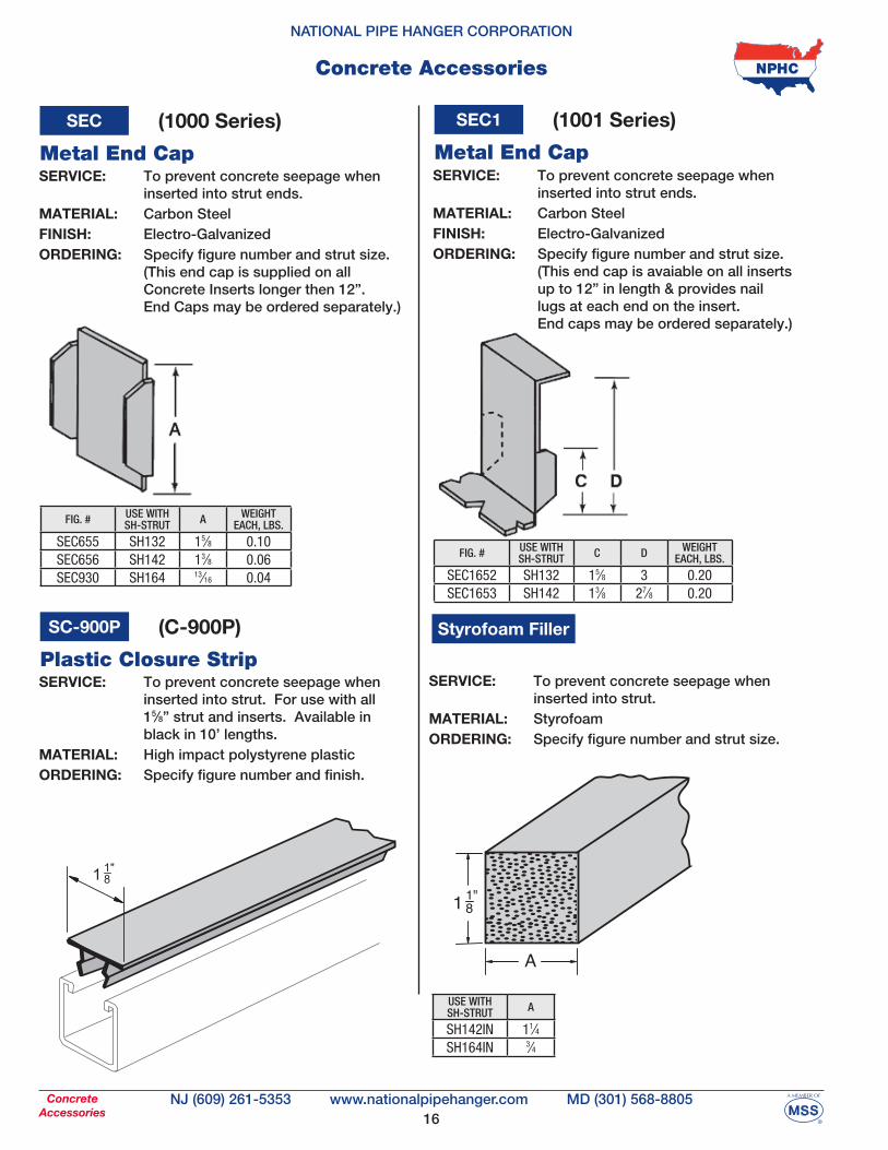
Concrete Accessories
A
SEC
Metal End Cap
FIG. # USE WITHSH-STRUT A WEIGHT
EACH, LBS.
SEC655 SH132 15⁄8 0.10SEC656 SH142 13⁄8 0.06SEC930 SH164 13⁄16 0.04
(1000 Series)
SERVICE: To prevent concrete seepage when inserted into strut ends.MATERIAL: Carbon SteelFINISH: Electro-GalvanizedORDERING: Specify figure number and strut size. (This end cap is supplied on all Concrete Inserts longer then 12”. End Caps may be ordered separately.)
SC-900P (C-900P)
Plastic Closure StripSERVICE: To prevent concrete seepage when inserted into strut. For use with all 15⁄8” strut and inserts. Available in black in 10’ lengths. MATERIAL: High impact polystyrene plasticORDERING: Specify figure number and finish.
SEC1
Metal End Cap
C D
FIG. # USE WITHSH-STRUT C D WEIGHT
EACH, LBS.
SEC1652 SH132 15⁄8 3 0.20SEC1653 SH142 13⁄8 27⁄8 0.20
(1001 Series)
SERVICE: To prevent concrete seepage when inserted into strut ends.MATERIAL: Carbon SteelFINISH: Electro-GalvanizedORDERING: Specify figure number and strut size. (This end cap is avaiable on all inserts up to 12” in length & provides nail lugs at each end on the insert. End caps may be ordered separately.)
Styrofoam Filler
USE WITHSH-STRUT A
SH142IN 11⁄4SH164IN 3⁄4
SERVICE: To prevent concrete seepage when inserted into strut.MATERIAL: StyrofoamORDERING: Specify figure number and strut size.
17
NATIONAL PIPE HANGER CORPORATION
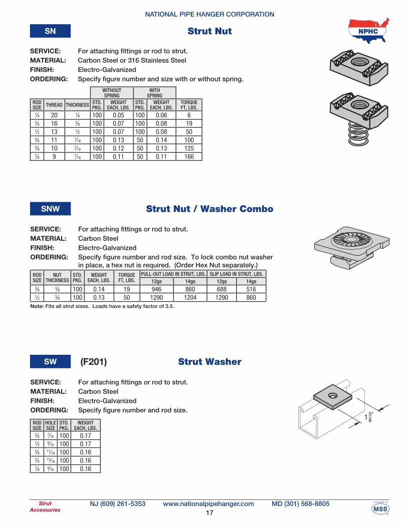
NJ (609) 261-5353 MD (301) 568-8805www.nationalpipehanger.comStrutAccessories
Strut NutSN
WITHOUT SPRING
WITH SPRING
ROD SIZE THREAD THICKNESS STD.
PKG.WEIGHT
EACH, LBS.STD. PKG.
WEIGHT EACH, LBS.
TORQUEFT, LBS.
1⁄4 20 1⁄4 100 0.05 100 0.06 63⁄8 16 3⁄8 100 0.07 100 0.08 191⁄2 13 1⁄2 100 0.07 100 0.08 505⁄8 11 7⁄16 100 0.13 50 0.14 1003⁄4 10 7⁄16 100 0.12 50 0.13 1257⁄8 9 7⁄16 100 0.11 50 0.11 166
Strut WasherSW
ROD SIZE
HOLE SIZE
STD. PKG.
WEIGHT EACH, LBS.
3⁄8 7⁄16 100 0.171⁄2 9⁄16 100 0.175⁄8 11⁄16 100 0.163⁄4 13⁄16 100 0.167⁄8 5⁄16 100 0.16
(F201)
Strut Nut / Washer ComboSNW
ROD SIZE
NUTTHICKNESS
STD. PKG.
WEIGHT EACH, LBS.
TORQUEFT, LBS.
PULL-OUT LOAD IN STRUT, LBS. SLIP LOAD IN STRUT, LBS.12ga 14ga 12ga 14ga
3⁄8 3⁄8 100 0.14 19 946 860 688 5161⁄2 3⁄8 100 0.13 50 1290 1204 1290 860
Note: Fits all strut sizes. Loads have a safety factor of 3.5.
SERVICE: For attaching fittings or rod to strut. MATERIAL: Carbon Steel or 316 Stainless SteelFINISH: Electro-GalvanizedORDERING: Specify figure number and size with or without spring.
SERVICE: For attaching fittings or rod to strut. MATERIAL: Carbon SteelFINISH: Electro-GalvanizedORDERING: Specify figure number and rod size. To lock combo nut washer in place, a hex nut is required. (Order Hex Nut separately.)
SERVICE: For attaching fittings or rod to strut. MATERIAL: Carbon SteelFINISH: Electro-GalvanizedORDERING: Specify figure number and rod size.
18
NATIONAL PIPE HANGER CORPORATION
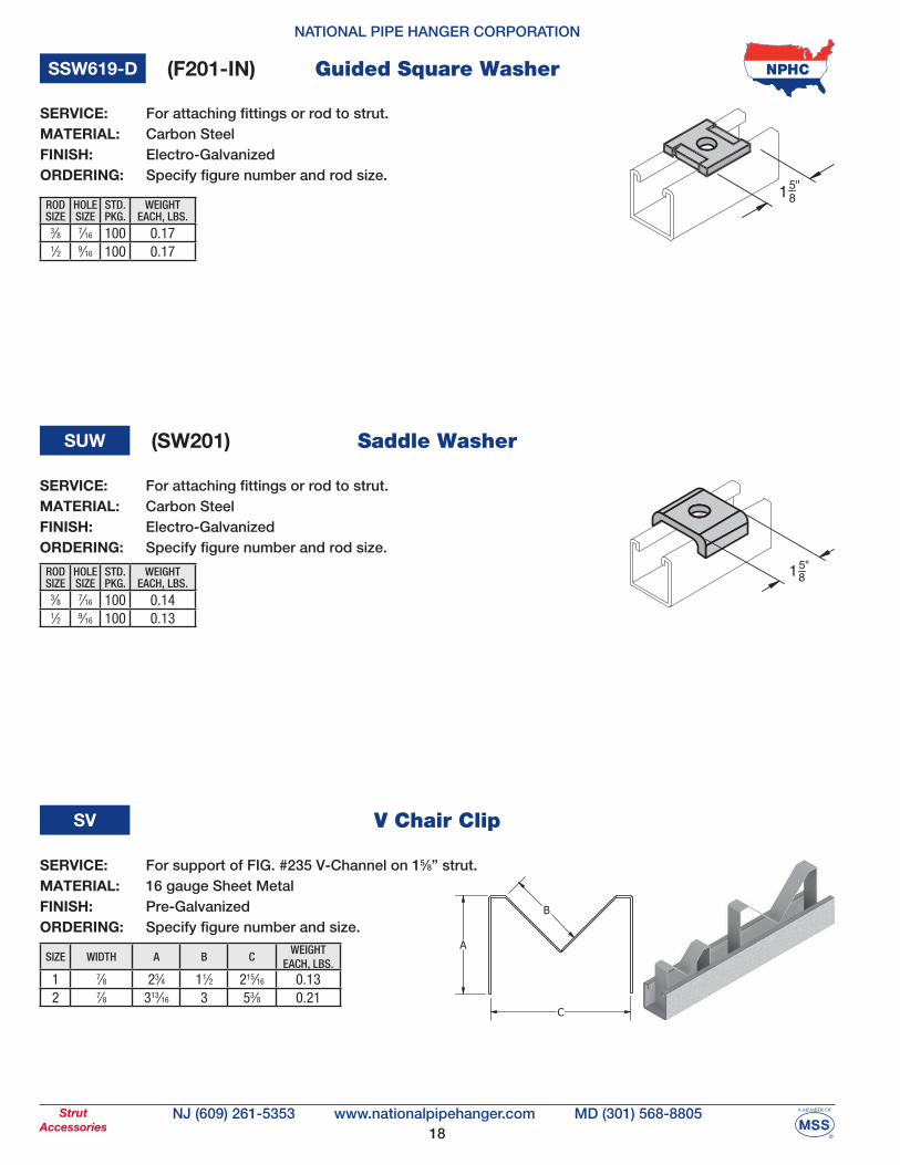
NJ (609) 261-5353 MD (301) 568-8805www.nationalpipehanger.comStrutAccessories
V Chair ClipSV
SIZE WIDTH A B CWEIGHT
EACH, LBS.1 7⁄8 23⁄4 11⁄2 215⁄16 0.132 7⁄8 313⁄16 3 53⁄8 0.21
SERVICE: For support of FIG. #235 V-Channel on 15⁄8” strut.MATERIAL: 16 gauge Sheet MetalFINISH: Pre-GalvanizedORDERING: Specify figure number and size.
Guided Square WasherSSW619-D
ROD SIZE
HOLE SIZE
STD. PKG.
WEIGHT EACH, LBS.
3⁄8 7⁄16 100 0.171⁄2 9⁄16 100 0.17
(F201-IN)
Saddle WasherSUW
ROD SIZE
HOLE SIZE
STD. PKG.
WEIGHT EACH, LBS.
3⁄8 7⁄16 100 0.141⁄2 9⁄16 100 0.13
(SW201)
SERVICE: For attaching fittings or rod to strut. MATERIAL: Carbon SteelFINISH: Electro-GalvanizedORDERING: Specify figure number and rod size.
SERVICE: For attaching fittings or rod to strut. MATERIAL: Carbon SteelFINISH: Electro-GalvanizedORDERING: Specify figure number and rod size.
19
NATIONAL PIPE HANGER CORPORATION
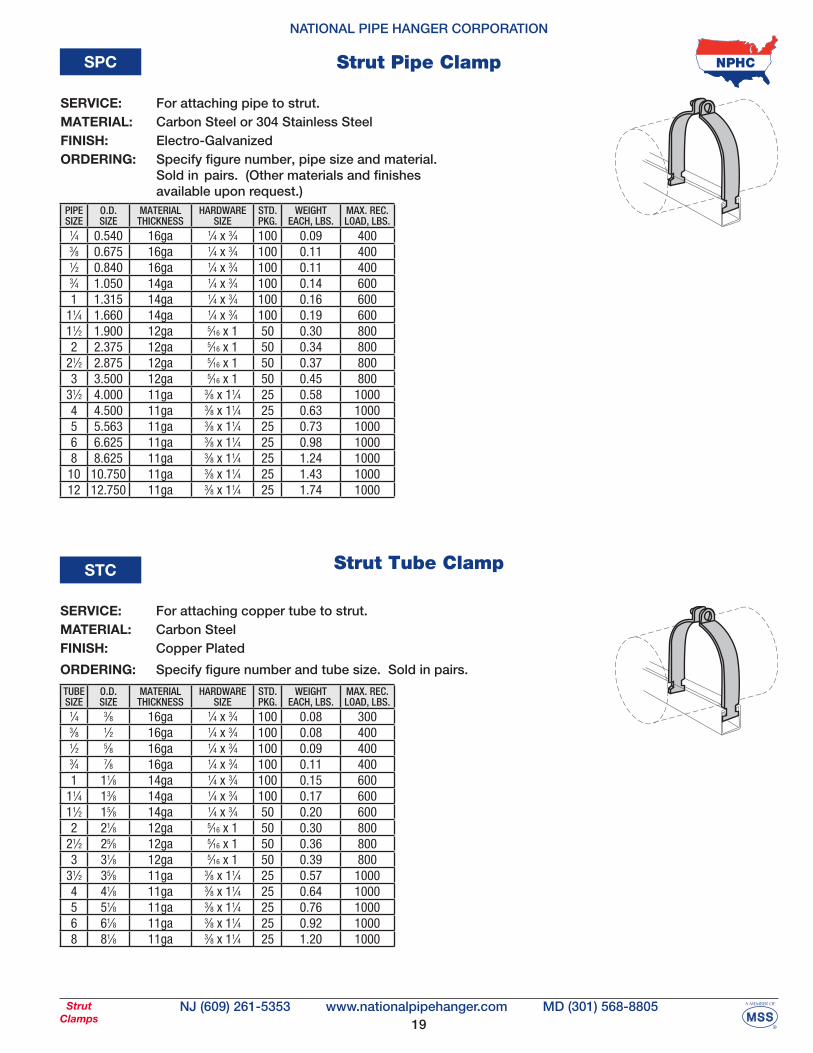
NJ (609) 261-5353 MD (301) 568-8805www.nationalpipehanger.comStrutClamps
Strut Pipe ClampSPC
Strut Tube Clamp STC
PIPE SIZE
O.D.SIZE
MATERIALTHICKNESS
HARDWARESIZE
STD. PKG.
WEIGHT EACH, LBS.
MAX. REC.LOAD, LBS.
1⁄4 0.540 16ga 1⁄4 x 3⁄4 100 0.09 4003⁄8 0.675 16ga 1⁄4 x 3⁄4 100 0.11 4001⁄2 0.840 16ga 1⁄4 x 3⁄4 100 0.11 4003⁄4 1.050 14ga 1⁄4 x 3⁄4 100 0.14 6001 1.315 14ga 1⁄4 x 3⁄4 100 0.16 600
11⁄4 1.660 14ga 1⁄4 x 3⁄4 100 0.19 60011⁄2 1.900 12ga 5⁄16 x 1 50 0.30 8002 2.375 12ga 5⁄16 x 1 50 0.34 800
21⁄2 2.875 12ga 5⁄16 x 1 50 0.37 8003 3.500 12ga 5⁄16 x 1 50 0.45 800
31⁄2 4.000 11ga 3⁄8 x 11⁄4 25 0.58 10004 4.500 11ga 3⁄8 x 11⁄4 25 0.63 10005 5.563 11ga 3⁄8 x 11⁄4 25 0.73 10006 6.625 11ga 3⁄8 x 11⁄4 25 0.98 10008 8.625 11ga 3⁄8 x 11⁄4 25 1.24 100010 10.750 11ga 3⁄8 x 11⁄4 25 1.43 100012 12.750 11ga 3⁄8 x 11⁄4 25 1.74 1000
TUBE SIZE
O.D.SIZE
MATERIALTHICKNESS
HARDWARESIZE
STD. PKG.
WEIGHT EACH, LBS.
MAX. REC.LOAD, LBS.
1⁄4 3⁄8 16ga 1⁄4 x 3⁄4 100 0.08 3003⁄8 1⁄2 16ga 1⁄4 x 3⁄4 100 0.08 4001⁄2 5⁄8 16ga 1⁄4 x 3⁄4 100 0.09 4003⁄4 7⁄8 16ga 1⁄4 x 3⁄4 100 0.11 4001 11⁄8 14ga 1⁄4 x 3⁄4 100 0.15 600
11⁄4 13⁄8 14ga 1⁄4 x 3⁄4 100 0.17 60011⁄2 15⁄8 14ga 1⁄4 x 3⁄4 50 0.20 6002 21⁄8 12ga 5⁄16 x 1 50 0.30 800
21⁄2 25⁄8 12ga 5⁄16 x 1 50 0.36 8003 31⁄8 12ga 5⁄16 x 1 50 0.39 800
31⁄2 35⁄8 11ga 3⁄8 x 11⁄4 25 0.57 10004 41⁄8 11ga 3⁄8 x 11⁄4 25 0.64 10005 51⁄8 11ga 3⁄8 x 11⁄4 25 0.76 10006 61⁄8 11ga 3⁄8 x 11⁄4 25 0.92 10008 81⁄8 11ga 3⁄8 x 11⁄4 25 1.20 1000
SERVICE: For attaching pipe to strut. MATERIAL: Carbon Steel or 304 Stainless SteelFINISH: Electro-GalvanizedORDERING: Specify figure number, pipe size and material. Sold in pairs. (Other materials and finishes available upon request.)
SERVICE: For attaching copper tube to strut. MATERIAL: Carbon SteelFINISH: Copper Plated
ORDERING: Specify figure number and tube size. Sold in pairs.
20
NATIONAL PIPE HANGER CORPORATION
NJ (609) 261-5353 MD (301) 568-8805www.nationalpipehanger.comStrutClamps
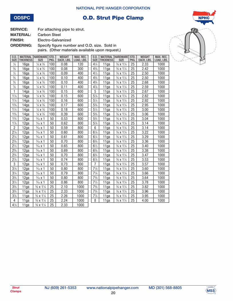
O.D. Strut Pipe ClampODSPC
O.D. SIZE
MATERIALTHICKNESS
HARDWARESIZE
STD. PKG.
WEIGHT EACH, LBS.
MAX. REC.LOAD, LBS.
1⁄4 16ga 1⁄4 x 3⁄4 100 0.08 1203⁄8 16ga 1⁄4 x 3⁄4 100 0.08 3001⁄2 16ga 1⁄4 x 3⁄4 100 0.09 4005⁄8 16ga 1⁄4 x 3⁄4 100 0.10 4003⁄4 16ga 1⁄4 x 3⁄4 100 0.10 4007⁄8 16ga 1⁄4 x 3⁄4 100 0.11 4001 14ga 1⁄4 x 3⁄4 100 0.15 600
11⁄8 14ga 1⁄4 x 3⁄4 100 0.15 60011⁄4 14ga 1⁄4 x 3⁄4 100 0.16 60013⁄8 14ga 1⁄4 x 3⁄4 100 0.17 60011⁄2 14ga 1⁄4 x 3⁄4 100 0.18 60015⁄8 14ga 1⁄4 x 3⁄4 100 0.39 60013⁄4 12ga 5⁄16 x 1 50 0.53 80017⁄8 12ga 5⁄16 x 1 50 0.62 8002 12ga 5⁄16 x 1 50 0.59 800
21⁄8 12ga 5⁄16 x 1 50 0.60 80021⁄4 12ga 5⁄16 x 1 50 0.61 80023⁄8 12ga 5⁄16 x 1 50 0.70 80021⁄2 12ga 5⁄16 x 1 50 0.65 80025⁄8 12ga 5⁄16 x 1 50 0.69 80023⁄4 12ga 5⁄16 x 1 50 0.70 80027⁄8 12ga 5⁄16 x 1 50 0.74 8003 12ga 5⁄16 x 1 50 0.73 800
31⁄8 12ga 5⁄16 x 1 50 0.80 80031⁄4 12ga 5⁄16 x 1 50 0.79 80033⁄8 12ga 5⁄16 x 1 50 0.80 80031⁄2 12ga 5⁄16 x 1 50 0.86 80035⁄8 11ga 3⁄8 x 11⁄4 25 2.10 100033⁄4 11ga 3⁄8 x 11⁄4 25 2.33 100037⁄8 11ga 3⁄8 x 11⁄4 25 2.26 10004 11ga 3⁄8 x 11⁄4 25 2.24 1000
41⁄8 11ga 3⁄8 x 11⁄4 25 2.33 1000
O.D. SIZE
MATERIALTHICKNESS
HARDWARESIZE
STD. PKG.
WEIGHT EACH, LBS.
MAX. REC.LOAD, LBS.
41⁄4 11ga 3⁄8 x 11⁄4 25 2.33 100043⁄8 11ga 3⁄8 x 11⁄4 25 2.42 100041⁄2 11ga 3⁄8 x 11⁄4 25 2.50 100045⁄8 11ga 3⁄8 x 11⁄4 25 2.50 100043⁄4 11ga 3⁄8 x 11⁄4 25 2.68 100047⁄8 11ga 3⁄8 x 11⁄4 25 2.59 10005 11ga 3⁄8 x 11⁄4 25 2.67 1000
51⁄8 11ga 3⁄8 x 11⁄4 25 2.82 100051⁄4 11ga 3⁄8 x 11⁄4 25 2.92 100053⁄8 11ga 3⁄8 x 11⁄4 25 2.95 100051⁄2 11ga 3⁄8 x 11⁄4 25 3.00 100055⁄8 11ga 3⁄8 x 11⁄4 25 3.06 100053⁄4 11ga 3⁄8 x 11⁄4 25 3.04 100057⁄8 11ga 3⁄8 x 11⁄4 25 3.14 10006 11ga 3⁄8 x 11⁄4 25 3.14 1000
61⁄8 11ga 3⁄8 x 11⁄4 25 3.22 100061⁄4 11ga 3⁄8 x 11⁄4 25 3.29 100063⁄8 11ga 3⁄8 x 11⁄4 25 3.36 100061⁄2 11ga 3⁄8 x 11⁄4 25 3.40 100065⁄8 11ga 3⁄8 x 11⁄4 25 3.38 100063⁄4 11ga 3⁄8 x 11⁄4 25 3.47 100067⁄8 11ga 3⁄8 x 11⁄4 25 3.53 10007 11ga 3⁄8 x 11⁄4 25 3.57 1000
71⁄8 11ga 3⁄8 x 11⁄4 25 3.60 100071⁄4 11ga 3⁄8 x 11⁄4 25 3.66 100073⁄8 11ga 3⁄8 x 11⁄4 25 3.64 100071⁄2 11ga 3⁄8 x 11⁄4 25 3.78 100075⁄8 11ga 3⁄8 x 11⁄4 25 3.82 100073⁄4 11ga 3⁄8 x 11⁄4 25 3.96 100077⁄8 11ga 3⁄8 x 11⁄4 25 3.95 10008 11ga 3⁄8 x 11⁄4 25 4.00 1000
SERVICE: For attaching pipe to strut. MATERIAL: Carbon Steel FINISH: Electro-GalvanizedORDERING: Specify figure number and O.D. size. Sold in pairs. (Other materials available upon request.)
21
NATIONAL PIPE HANGER CORPORATION
NJ (609) 261-5353 MD (301) 568-8805www.nationalpipehanger.comStrutAccessories
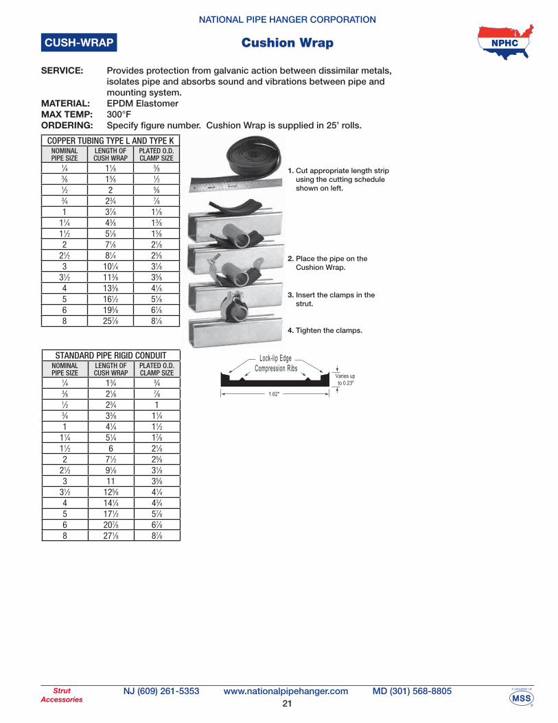
Cushion WrapCUSH-WRAP
1. Cut appropriate length strip using the cutting schedule shown on left.
2. Place the pipe on the Cushion Wrap.
3. Insert the clamps in the strut.
4. Tighten the clamps.
SERVICE: Provides protection from galvanic action between dissimilar metals, isolates pipe and absorbs sound and vibrations between pipe and mounting system.MATERIAL: EPDM ElastomerMAX TEMP: 300°FORDERING: Specify figure number. Cushion Wrap is supplied in 25’ rolls.
STANDARD PIPE RIGID CONDUITNOMINALPIPE SIZE
LENGTH OFCUSH WRAP
PLATED O.D.CLAMP SIZE
1⁄4 13⁄4 3⁄43⁄8 21⁄8 7⁄81⁄2 23⁄4 13⁄4 33⁄8 11⁄41 41⁄4 11⁄2
11⁄4 51⁄4 17⁄811⁄2 6 21⁄82 71⁄2 25⁄8
21⁄2 91⁄8 31⁄83 11 35⁄8
31⁄2 125⁄8 41⁄44 141⁄4 43⁄45 171⁄2 57⁄86 207⁄8 67⁄88 271⁄8 87⁄8
COPPER TUBING TYPE L AND TYPE KNOMINALPIPE SIZE
LENGTH OFCUSH WRAP
PLATED O.D.CLAMP SIZE
1⁄4 11⁄8 3⁄83⁄8 15⁄8 1⁄21⁄2 2 5⁄83⁄4 23⁄4 7⁄81 37⁄8 11⁄8
11⁄4 43⁄8 13⁄811⁄2 51⁄8 15⁄82 71⁄8 21⁄8
21⁄2 81⁄4 25⁄83 101⁄4 31⁄8
31⁄2 113⁄8 35⁄84 133⁄8 41⁄8
5 161⁄2 51⁄86 195⁄8 61⁄88 257⁄8 81⁄8
22
NATIONAL PIPE HANGER CORPORATION
NJ (609) 261-5353 MD (301) 568-8805www.nationalpipehanger.comStrutClamps
PLUMBING SELECTION CHARTFIG#
(mm range)STEEL-PLASTIC
Sch. 40 & 80COPPER TYPESK, L, M, DMV
REFRIGERATION COPPER
STD. PKG.
MAX. REC. LOAD, LBS.
12-161⁄4
0.5403⁄8 - 1⁄2
0.500 - 0.6251⁄2 - 5⁄8
0.500 - 0.625 100 170
17-203⁄8
0.6755⁄8
0.7503⁄4
0.750 100 195
21-241⁄2
0.8403⁄4
0.8757⁄8
0.875 100 215
25-293⁄4
1.0501
1.12511⁄8
1.125 100 315
30-34 11.315 100 320
35-38 11⁄4
1.37513⁄8
1.375 100 342
40-44 11⁄41.660
11⁄21.625
15⁄81.625 100 365
48-54 11⁄21.900
22.125
21⁄82.125 50 380
56-63 22.375 50 410
66-76 21⁄22.875
21⁄22.625
25⁄82.625 50 500
79-93 33.500
3 - 31⁄23.125 - 3.625
3 - 31⁄23.125 - 3.625 20 600
101-115 31⁄2 - 44.000 - 4.500
44.125
44.125 10 950
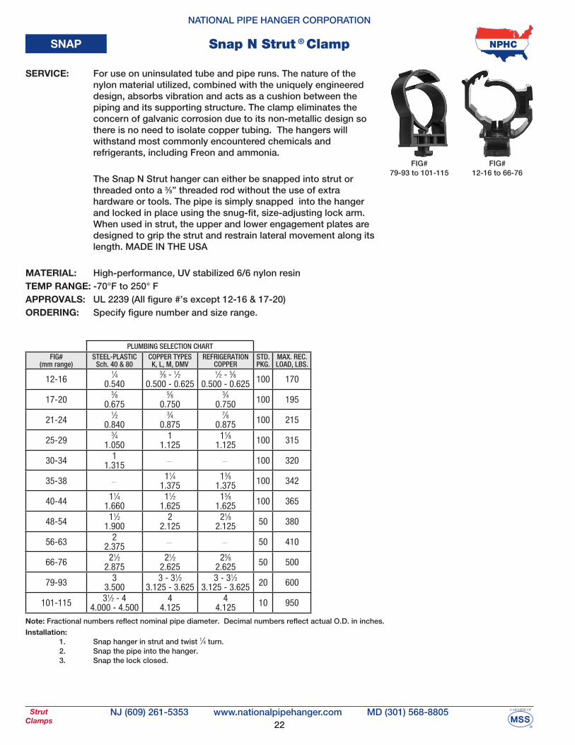
SNAP Snap N Strut ® Clamp
Note: Fractional numbers reflect nominal pipe diameter. Decimal numbers reflect actual O.D. in inches.
Installation: 1. Snap hanger in strut and twist 1⁄4 turn. 2. Snap the pipe into the hanger. 3. Snap the lock closed.
FIG#12-16 to 66-76
FIG#79-93 to 101-115
SERVICE: For use on uninsulated tube and pipe runs. The nature of the nylon material utilized, combined with the uniquely engineered design, absorbs vibration and acts as a cushion between the piping and its supporting structure. The clamp eliminates the concern of galvanic corrosion due to its non-metallic design so there is no need to isolate copper tubing. The hangers will withstand most commonly encountered chemicals and refrigerants, including Freon and ammonia.
The Snap N Strut hanger can either be snapped into strut or threaded onto a 3⁄8” threaded rod without the use of extra hardware or tools. The pipe is simply snapped into the hanger and locked in place using the snug-fit, size-adjusting lock arm. When used in strut, the upper and lower engagement plates are designed to grip the strut and restrain lateral movement along its length. MADE IN THE USA
MATERIAL: High-performance, UV stabilized 6/6 nylon resinTEMP RANGE: -70°F to 250° FAPPROVALS: UL 2239 (All figure #’s except 12-16 & 17-20)ORDERING: Specify figure number and size range.
23
NATIONAL PIPE HANGER CORPORATION
NJ (609) 261-5353 MD (301) 568-8805www.nationalpipehanger.comStrutClamps
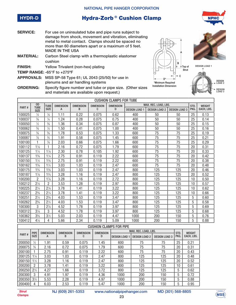
Hydra-Zorb ® Cushion ClampHYDR-D
A
B
CD*
Top ofStrut
*Minimum RequiredInstallation Dimension
DESIGN LOAD 1
DESIGNLOAD 2
DESIGNLOAD 3
CUSHION CLAMPS FOR TUBE
PART #OD
TUBE SIZE
TUBE SIZE
DIMENSIONA
DIMENSIONB
DIMENSIONC
DIMENSIOND
MAX. REC. LOAD, LBS. STD. PKG.
WEIGHT EACH, LBS.DESIGN LOAD 1 DESIGN LOAD 2 DESIGN LOAD 3
100025 1⁄4 1⁄8 1.11 0.22 0.075 0.62 400 50 50 25 0.13100037 3⁄8 1⁄4 1.24 0.28 0.075 0.75 400 50 50 25 0.14100050 1⁄2 3⁄8 1.36 0.34 0.075 0.87 400 50 50 25 0.15100062 5⁄8 1⁄2 1.50 0.41 0.075 1.00 400 50 50 25 0.16100075 3⁄4 5⁄8 1.78 0.53 0.075 1.33 600 75 75 25 0.19100087 7⁄8 3⁄4 1.91 0.58 0.075 1.45 600 75 75 25 0.21100100 1 7⁄8 2.03 0.66 0.075 1.66 600 75 75 25 0.29100112 11⁄8 1 2.16 0.72 0.075 1.79 600 75 75 20 0.31100125 11⁄4 11⁄8 2.30 0.78 0.105 1.92 600 75 75 20 0.33100137 13⁄8 11⁄4 2.75 0.91 0.119 2.22 600 75 75 20 0.42100150 11⁄2 13⁄8 2.75 0.91 0.119 2.22 600 75 75 20 0.38100162 15⁄8 11⁄2 3.03 1.03 0.119 2.47 600 75 75 20 0.48100175 13⁄4 15⁄8 3.03 1.03 0.119 2.47 800 125 125 20 0.46100187 17⁄8 13⁄4 3.28 1.16 0.119 2.47 800 125 125 20 0.52100200 2 17⁄8 3.28 1.16 0.119 2.72 800 125 125 10 0.50100212 21⁄8 2 3.53 1.28 0.119 2.97 800 125 125 10 0.57100225 21⁄4 21⁄8 3.78 1.41 0.119 3.22 800 125 125 10 0.62100237 23⁄8 21⁄4 3.78 1.41 0.119 3.22 800 125 125 10 0.66100251 21⁄2 23⁄8 4.03 1.53 0.119 3.47 800 125 125 5 0.60100262 25⁄8 21⁄2 4.03 1.53 0.119 3.47 800 125 125 5 0.58100300 3 27⁄8 4.52 1.78 0.119 3.97 800 125 125 5 0.69100312 31⁄8 3 4.52 1.78 0.119 3.97 800 125 125 5 0.68100362 35⁄8 31⁄2 5.03 2.03 0.119 4.47 1000 200 150 5 0.76100412 41⁄8 4 5.66 2.34 0.119 5.09 1000 200 150 5 0.88
CUSHION CLAMPS FOR PIPE
PART # PIPESIZE
DIMENSIONA
DIMENSIONB
DIMENSIONC
DIMENSIOND
MAX. REC. LOAD, LBS.STD. PKG.
WEIGHT EACH, LBS.DESIGN LOAD 1 DESIGN LOAD 2 DESIGN LOAD 3
200050 1⁄2 1.91 0.59 0.075 1.45 600 75 75 25 0.21200075 3⁄4 2.16 0.72 0.075 1.79 600 75 75 20 0.31200100 1 2.75 0.91 0.119 2.22 600 75 75 20 0.43200125 11⁄4 3.03 1.03 0.119 2.47 800 125 125 20 0.48200150 11⁄2 3.28 1.16 0.119 2.47 800 125 125 20 0.52200200 2 3.78 1.41 0.119 3.22 800 125 125 10 0.61200250 21⁄2 4.27 1.66 0.119 3.72 800 125 125 5 0.62200300 3 4.91 1.97 0.119 4.36 1000 200 150 5 0.72200350 31⁄2 5.53 2.28 0.119 4.97 1000 200 150 5 0.88200400 4 6.03 2.53 0.119 5.47 1000 200 150 5 0.95
SERVICE: For use on uninsulated tube and pipe runs subject to damage from shock, movement and vibration, eliminating metal to metal contact. Clamps should be spaced no more than 60 diameters apart or a maximum of 5 feet. MADE IN THE USAMATERIAL: Carbon Steel clamp with a thermoplastic elastomer cushionFINISH: Yellow Trivalent (non-hex) platingTEMP RANGE: -65°F to +275ºFAPPROVALS: MSS SP-58 Type 61; UL 2043 (25/50) for use in plenums and air handling systemsORDERING: Specify figure number and tube or pipe size. (Other sizes and materials are available upon request.)
24
NATIONAL PIPE HANGER CORPORATION
NJ (609) 261-5353 MD (301) 568-8805www.nationalpipehanger.comStrutClamps
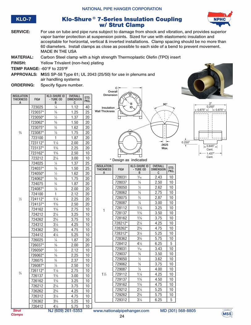
KLO-7 Klo-Shure ® 7-Series Insulation Coupling w/ Strut Clamp
SERVICE: For use on tube and pipe runs subject to damage from shock and vibration, and provides superior vapor barrier protection at suspension points. Sized for use with elastomeric insulation and acceptable for horizontal, vertical & inverted installations. Clamp spacing should be no more than 60 diameters. Install clamps as close as possible to each side of a bend to prevent movement. MADE IN THE USAMATERIAL: Carbon Steel clamp with a high strength Thermoplastic Olefin (TPO) insert FINISH: Yellow Trivalent (non-hex) platingTEMP RANGE: -60°F to 225ºFAPPROVALS: MSS SP-58 Type 61; UL 2043 (25/50) for use in plenums and air handling systemsORDERING: Specify figure number.
COverall
Dimension
InsulationWall Thickness
BID
90°
.0625Max.
0.250"
2"0.250"
0.875" 0.875"
1.437"Cent.
0.845"Cent.
* Design as indicated
INSULATIONTHICKNESS
AFIG#
KLO-SHURE ID- TUBE OD
B
OVERALLDIMENSION
C
STD. PKG.
3⁄8
723025 1⁄4 1.12 40723037* 3⁄8 1.25 25723050* 1⁄2 1.37 20723062* 5⁄8 1.50 20723075* 3⁄4 1.62 20723087* 7⁄8 1.75 20723100 1 1.87 20723112* 11⁄8 2.00 20723137* 13⁄8 2.25 20723162* 15⁄8 2.50 10723212 21⁄8 3.00 10
1⁄2
724025 1⁄4 1.37 25724037* 3⁄8 1.50 25724050* 1⁄2 1.62 20724062* 5⁄8 1.75 20724075 3⁄4 1.87 20724087* 7⁄8 2.00 20724100 1 2.12 20724112* 11⁄8 2.25 20724137* 13⁄8 2.50 20724162 15⁄8 2.75 10724212 21⁄8 3.25 10724262 25⁄8 3.75 10724312 31⁄8 4.25 10724362 35⁄8 4.75 10724412 41⁄8 5.25 10
3⁄4
726025 1⁄4 1.87 20726037* 3⁄8 2.00 20726050* 1⁄2 2.12 10726062* 5⁄8 2.25 10726075 3⁄4 2.37 10726087* 7⁄8 2.50 10726112* 11⁄8 2.75 10726137 13⁄8 3.00 10726162 15⁄8 3.25 10726212 21⁄8 3.75 10726262 25⁄8 4.25 10726312 31⁄8 4.75 10726362 35⁄8 5.25 10726412 41⁄8 5.75 10
INSULATIONTHICKNESS
AFIG#
KLO-SHURE ID- TUBE OD
B
OVERALLDIMENSION
C
STD. PKG.
1
728031 5⁄16 2.43 10728037 3⁄8 2.50 10728050 1⁄2 2.62 10728062 5⁄8 2.75 10728075 3⁄4 2.87 10728087 7⁄8 3.00 10728112 11⁄8 3.25 10728137 13⁄8 3.50 10728162 15⁄8 3.75 10728212* 21⁄8 4.25 10728262* 25⁄8 4.75 10728312* 31⁄8 5.25 10728362 35⁄8 5.75 10728412 41⁄8 6.25 5
11⁄2
729031 5⁄16 3.43 10729037 3⁄8 3.50 10729050 1⁄2 3.62 10729062 5⁄8 3.75 10729087 7⁄8 4.00 10729112 11⁄8 4.25 10729137 13⁄8 4.50 10729162 15⁄8 4.75 10729212 21⁄8 5.25 10729262 25⁄8 5.75 10729312 31⁄8 6.25 5
25
NATIONAL PIPE HANGER CORPORATION
NJ (609) 261-5353 MD (301) 568-8805www.nationalpipehanger.comStrutClamps
KLO-8 Klo-Shure ® 8-Series Insulation Coupling
SERVICE: A single piece product used on insulated tube runs and provides superior vapor barrier protection at suspension points. Sized for use with elastomeric insulation and acceptable for horizontal installations. Coupling spacing should be no more than 60 diameters. Install clamps as close as possible to each side of a bend to prevent movement. MADE IN THE USAMATERIAL: High strength Thermoplastic Olefin (TPO)
TEMP RANGE: -60°F to 225ºFAPPROVALS: UL Classified 2043 (25/50) for use in plenums and air handling systemsORDERING: Specify figure number.
INSULATIONTHICKNESS
AFIG#
KLO-SHURE ID- TUBE OD
B
OVERALLDIMENSION
C
STD. PKG.
1⁄2
824050 1⁄2 1.62 25824062 5⁄8 1.75 25824087 7⁄8 2.00 25824112 11⁄8 2.25 25824137 13⁄8 2.50 25824162 15⁄8 2.75 25824212 21⁄8 3.25 25
3⁄4
826062 5⁄8 2.25 25826087 7⁄8 2.50 25826112 11⁄8 2.75 25826137 13⁄8 3.00 25
1
828087 7⁄8 3.00 25828112 11⁄8 3.25 25828137 13⁄8 3.50 25828162 15⁄8 3.75 25828212 21⁄8 4.25 25828262 25⁄8 4.75 25
AInsulation
Wall Thickness
COverall
Dimension
1.437"Cent.
2"
0.875"0.250"
0.875"
BID
26
NATIONAL PIPE HANGER CORPORATION
NJ (609) 261-5353 MD (301) 568-8805www.nationalpipehanger.comStrutClamps
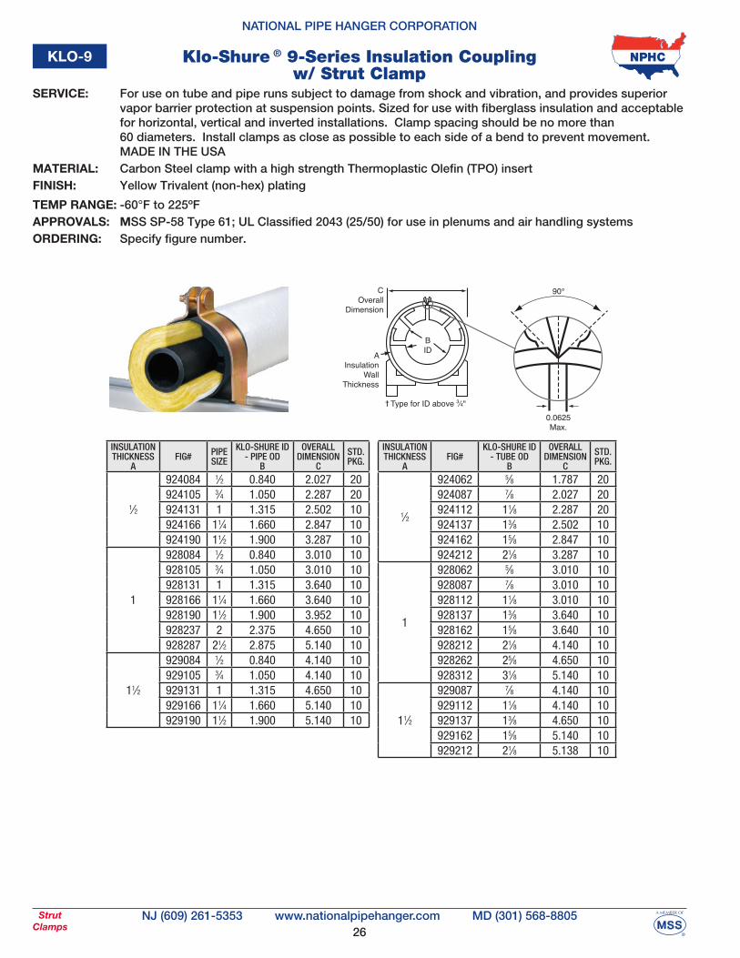
KLO-9 Klo-Shure ® 9-Series Insulation Couplingw/ Strut Clamp
SERVICE: For use on tube and pipe runs subject to damage from shock and vibration, and provides superior vapor barrier protection at suspension points. Sized for use with fiberglass insulation and acceptable for horizontal, vertical and inverted installations. Clamp spacing should be no more than 60 diameters. Install clamps as close as possible to each side of a bend to prevent movement. MADE IN THE USAMATERIAL: Carbon Steel clamp with a high strength Thermoplastic Olefin (TPO) insertFINISH: Yellow Trivalent (non-hex) plating
TEMP RANGE: -60°F to 225ºFAPPROVALS: MSS SP-58 Type 61; UL Classified 2043 (25/50) for use in plenums and air handling systemsORDERING: Specify figure number.
INSULATIONTHICKNESS
AFIG# PIPE
SIZE
KLO-SHURE ID- PIPE OD
B
OVERALLDIMENSION
C
STD. PKG.
1⁄2
924084 1⁄2 0.840 2.027 20924105 3⁄4 1.050 2.287 20 924131 1 1.315 2.502 10924166 11⁄4 1.660 2.847 10924190 11⁄2 1.900 3.287 10
1
928084 1⁄2 0.840 3.010 10928105 3⁄4 1.050 3.010 10928131 1 1.315 3.640 10928166 11⁄4 1.660 3.640 10928190 11⁄2 1.900 3.952 10928237 2 2.375 4.650 10928287 21⁄2 2.875 5.140 10
11⁄2
929084 1⁄2 0.840 4.140 10929105 3⁄4 1.050 4.140 10929131 1 1.315 4.650 10929166 11⁄4 1.660 5.140 10929190 11⁄2 1.900 5.140 10
INSULATIONTHICKNESS
AFIG#
KLO-SHURE ID- TUBE OD
B
OVERALLDIMENSION
C
STD. PKG.
1⁄2
924062 5⁄8 1.787 20924087 7⁄8 2.027 20924112 11⁄8 2.287 20924137 13⁄8 2.502 10924162 15⁄8 2.847 10924212 21⁄8 3.287 10
1
928062 5⁄8 3.010 10928087 7⁄8 3.010 10928112 11⁄8 3.010 10928137 13⁄8 3.640 10928162 15⁄8 3.640 10928212 21⁄8 4.140 10928262 25⁄8 4.650 10928312 31⁄8 5.140 10
11⁄2
929087 7⁄8 4.140 10929112 11⁄8 4.140 10929137 13⁄8 4.650 10929162 15⁄8 5.140 10929212 21⁄8 5.138 10
AInsulation
WallThickness
COverall
Dimension
90°
0.0625Max.
Type for ID above 3⁄4"
BID
27
NATIONAL PIPE HANGER CORPORATION
NJ (609) 261-5353 MD (301) 568-8805www.nationalpipehanger.comStrutClamps
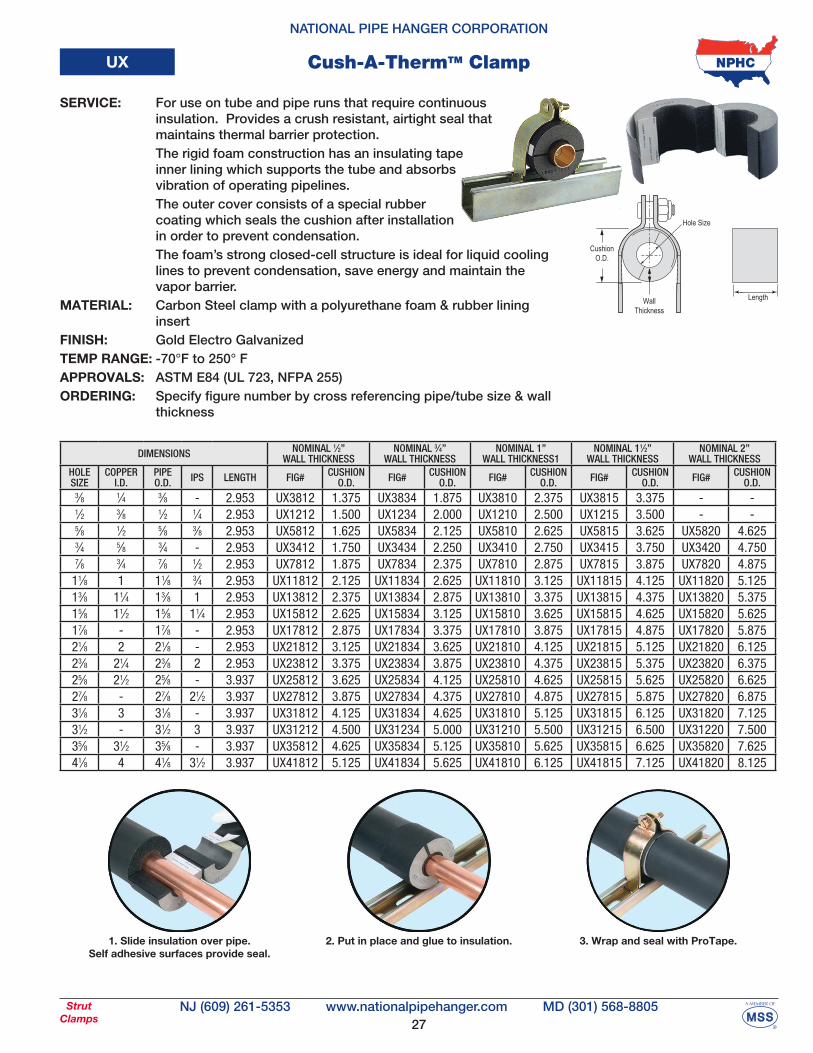
UX Cush-A-ThermTM Clamp
Length
Hole Size
CushionO.D.
WallThickness
1. Slide insulation over pipe.Self adhesive surfaces provide seal.
2. Put in place and glue to insulation. 3. Wrap and seal with ProTape.
SERVICE: For use on tube and pipe runs that require continuous insulation. Provides a crush resistant, airtight seal that maintains thermal barrier protection. The rigid foam construction has an insulating tape inner lining which supports the tube and absorbs vibration of operating pipelines. The outer cover consists of a special rubber coating which seals the cushion after installation in order to prevent condensation. The foam’s strong closed-cell structure is ideal for liquid cooling lines to prevent condensation, save energy and maintain the vapor barrier. MATERIAL: Carbon Steel clamp with a polyurethane foam & rubber lining insertFINISH: Gold Electro GalvanizedTEMP RANGE: -70°F to 250° FAPPROVALS: ASTM E84 (UL 723, NFPA 255)ORDERING: Specify figure number by cross referencing pipe/tube size & wall thickness
DIMENSIONS NOMINAL 1⁄2”WALL THICKNESS
NOMINAL 3⁄4”WALL THICKNESS
NOMINAL 1”WALL THICKNESS1
NOMINAL 11⁄2”WALL THICKNESS
NOMINAL 2”WALL THICKNESS
HOLESIZE
COPPERI.D.
PIPEO.D. IPS LENGTH FIG# CUSHION
O.D. FIG# CUSHIONO.D. FIG# CUSHION
O.D. FIG# CUSHIONO.D. FIG# CUSHION
O.D.3⁄8 1⁄4 3⁄8 - 2.953 UX3812 1.375 UX3834 1.875 UX3810 2.375 UX3815 3.375 - -1⁄2 3⁄8 1⁄2 1⁄4 2.953 UX1212 1.500 UX1234 2.000 UX1210 2.500 UX1215 3.500 - -5⁄8 1⁄2 5⁄8 3⁄8 2.953 UX5812 1.625 UX5834 2.125 UX5810 2.625 UX5815 3.625 UX5820 4.6253⁄4 5⁄8 3⁄4 - 2.953 UX3412 1.750 UX3434 2.250 UX3410 2.750 UX3415 3.750 UX3420 4.7507⁄8 3⁄4 7⁄8 1⁄2 2.953 UX7812 1.875 UX7834 2.375 UX7810 2.875 UX7815 3.875 UX7820 4.875
11⁄8 1 11⁄8 3⁄4 2.953 UX11812 2.125 UX11834 2.625 UX11810 3.125 UX11815 4.125 UX11820 5.12513⁄8 11⁄4 13⁄8 1 2.953 UX13812 2.375 UX13834 2.875 UX13810 3.375 UX13815 4.375 UX13820 5.37515⁄8 11⁄2 15⁄8 11⁄4 2.953 UX15812 2.625 UX15834 3.125 UX15810 3.625 UX15815 4.625 UX15820 5.62517⁄8 - 17⁄8 - 2.953 UX17812 2.875 UX17834 3.375 UX17810 3.875 UX17815 4.875 UX17820 5.87521⁄8 2 21⁄8 - 2.953 UX21812 3.125 UX21834 3.625 UX21810 4.125 UX21815 5.125 UX21820 6.12523⁄8 21⁄4 23⁄8 2 2.953 UX23812 3.375 UX23834 3.875 UX23810 4.375 UX23815 5.375 UX23820 6.37525⁄8 21⁄2 25⁄8 - 3.937 UX25812 3.625 UX25834 4.125 UX25810 4.625 UX25815 5.625 UX25820 6.62527⁄8 - 27⁄8 21⁄2 3.937 UX27812 3.875 UX27834 4.375 UX27810 4.875 UX27815 5.875 UX27820 6.87531⁄8 3 31⁄8 - 3.937 UX31812 4.125 UX31834 4.625 UX31810 5.125 UX31815 6.125 UX31820 7.12531⁄2 - 31⁄2 3 3.937 UX31212 4.500 UX31234 5.000 UX31210 5.500 UX31215 6.500 UX31220 7.50035⁄8 31⁄2 35⁄8 - 3.937 UX35812 4.625 UX35834 5.125 UX35810 5.625 UX35815 6.625 UX35820 7.62541⁄8 4 41⁄8 31⁄2 3.937 UX41812 5.125 UX41834 5.625 UX41810 6.125 UX41815 7.125 UX41820 8.125
28
NATIONAL PIPE HANGER CORPORATION
NJ (609) 261-5353 MD (301) 568-8805www.nationalpipehanger.comStrutFittings
Flat Plates
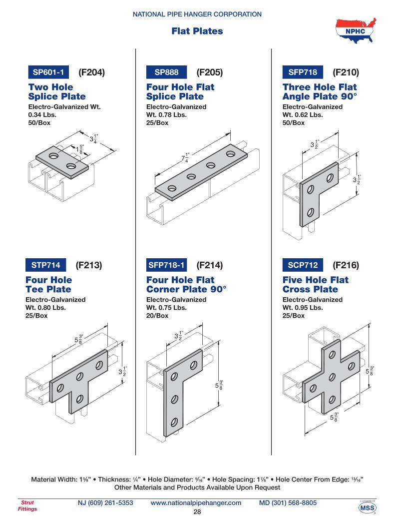
Electro-Galvanized Wt. 0.34 Lbs.50/Box
SP601-1
Two Hole Splice Plate
Electro-GalvanizedWt. 0.78 Lbs.25/Box
SP888
Four Hole FlatSplice Plate
Electro-GalvanizedWt. 0.62 Lbs.50/Box
SFP718
Three Hole Flat Angle Plate 90°
Electro-GalvanizedWt. 0.80 Lbs.25/Box
STP714
Four Hole Tee Plate
Electro-GalvanizedWt. 0.75 Lbs.20/Box
SFP718-1
Four Hole Flat Corner Plate 90°
Electro-GalvanizedWt. 0.95 Lbs.25/Box
SCP712
Five Hole FlatCross Plate
(F204) (F205) (F210)
(F213) (F214) (F216)
Material Width: 15⁄8” • Thickness: 1⁄4” • Hole Diameter: 9⁄16” • Hole Spacing: 17⁄8” • Hole Center From Edge: 13⁄16”Other Materials and Products Available Upon Request
29
NATIONAL PIPE HANGER CORPORATION
NJ (609) 261-5353 MD (301) 568-8805www.nationalpipehanger.comStrutFittings
Angle Brackets
Electro-GalvanizedWt. 0.38 Lbs.50/Box
SCA604
Two Hole Corner Angle
Electro-GalvanizedWt. 0.57 Lbs.25/Box
SCA745
Three Hole 90° Corner Angle
1516
(A301) (A306)
Material Width: 15⁄8” • Thickness: 1⁄4” • Hole Diameter: 9⁄16” • Hole Spacing: 17⁄8” • Hole Center From Edge: 13⁄16”Other Materials and Products Available Upon Request
Electro-Galvanized Wt. 0.78 Lbs.25/Box
SCA607
Four Hole Corner Angle
(A311)
Electro-GalvanizedWt. 0.58 Lbs.25/Box
SOA633-45
Two Hole Open45° Angle
1516
116
(A316)
Electro-Galvanized Wt. 0.75 Lbs.25/Box
SOA781-45
Four Hole Open 45° Angle
(A3194-6)
Electro-Galvanized Wt. 0.58 Lbs.25/Box
SOA633-2212
Two Hole Open221⁄2° Angle
1516
(A320-2)
30
NATIONAL PIPE HANGER CORPORATION
NJ (609) 261-5353 MD (301) 568-8805www.nationalpipehanger.comStrutFittings
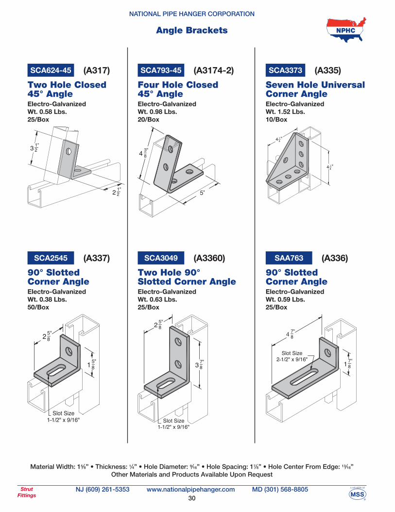
Angle Brackets
Material Width: 15⁄8” • Thickness: 1⁄4” • Hole Diameter: 9⁄16” • Hole Spacing: 17⁄8” • Hole Center From Edge: 13⁄16”Other Materials and Products Available Upon Request
Electro-GalvanizedWt. 0.38 Lbs.50/Box
SCA2545
90° SlottedCorner Angle
(A337)
Electro-Galvanized Wt. 0.63 Lbs.25/Box
SCA3049
Two Hole 90° Slotted Corner Angle
(A3360)
Electro-Galvanized Wt. 0.59 Lbs.25/Box
SAA763
90° SlottedCorner Angle
(A336)
Electro-Galvanized Wt. 0.58 Lbs.25/Box
SCA624-45
Two Hole Closed 45° Angle
(A317)
Electro-Galvanized Wt. 0.98 Lbs.20/Box
SCA793-45
Four Hole Closed 45° Angle
(A3174-2)
4 "18
4 "18
Electro-Galvanized Wt. 1.52 Lbs.10/Box
SCA3373
Seven Hole Universal Corner Angle
(A335)
31
NATIONAL PIPE HANGER CORPORATION
NJ (609) 261-5353 MD (301) 568-8805www.nationalpipehanger.comStrutFittings
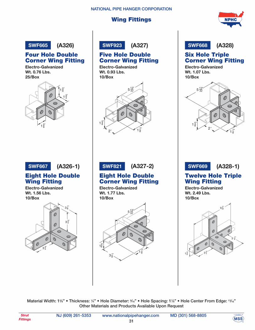
Wing Fittings
Electro-Galvanized Wt. 0.76 Lbs.25/Box
SWF665
Four Hole Double Corner Wing Fitting
(A326)
Material Width: 15⁄8” • Thickness: 1⁄4” • Hole Diameter: 9⁄16” • Hole Spacing: 17⁄8” • Hole Center From Edge: 13⁄16”Other Materials and Products Available Upon Request
Electro-Galvanized Wt. 1.07 Lbs.10/Box
SWF668
Six Hole TripleCorner Wing Fitting
(A328)
Five Hole DoubleCorner Wing Fitting
SWF923 (A327)
Electro-Galvanized Wt. 0.93 Lbs.10/Box
SWF821
Eight Hole DoubleCorner Wing Fitting
(A327-2)
Electro-Galvanized Wt. 1.77 Lbs.10/Box
Electro-Galvanized Wt. 2.49 Lbs.10/Box
SWF669
Twelve Hole TripleWing Fitting
(A328-1)
Electro-Galvanized Wt. 1.56 Lbs.10/Box
SWF667
Eight Hole DoubleWing Fitting
(A326-1)
32
NATIONAL PIPE HANGER CORPORATION
NJ (609) 261-5353 MD (301) 568-8805www.nationalpipehanger.comStrutFittings
U Fittings
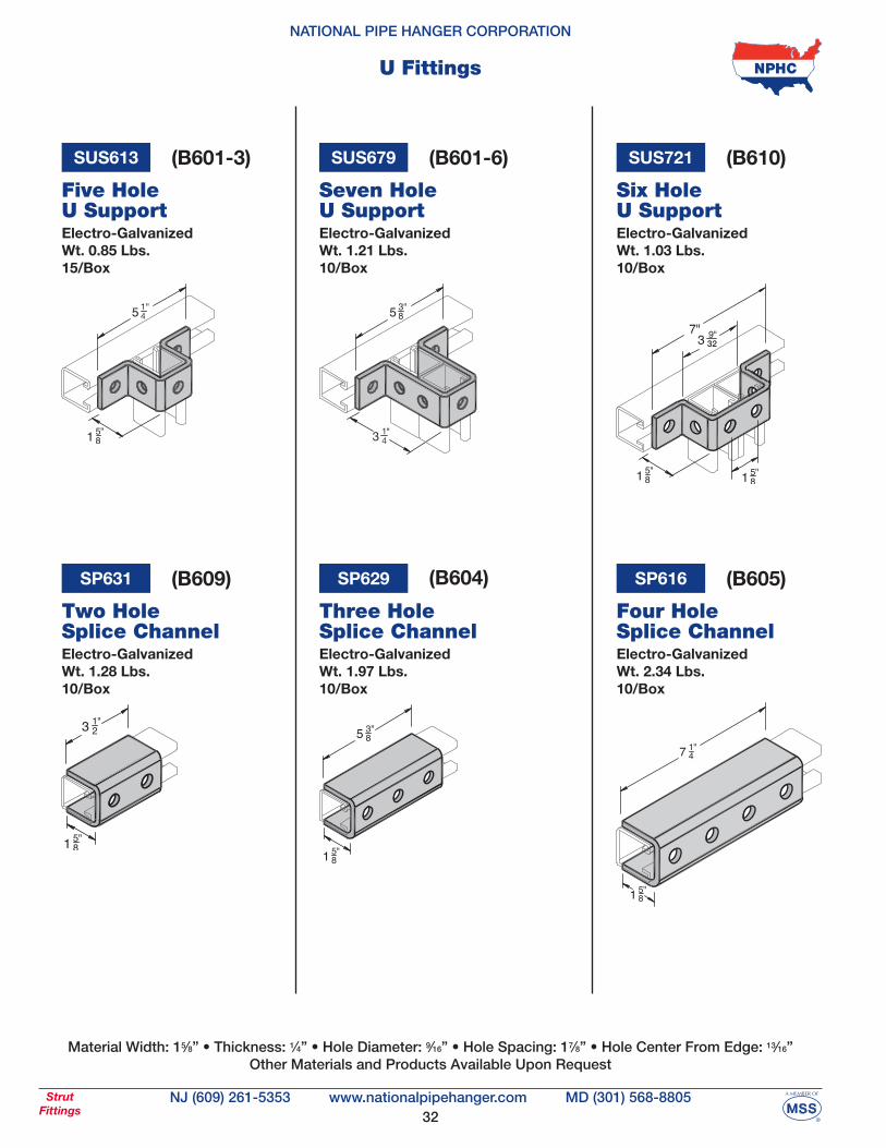
Electro-Galvanized Wt. 0.85 Lbs.15/Box
SUS613
Five Hole U Support
SP629
Three HoleSplice Channel
(B601-3)
Electro-Galvanized Wt. 1.28 Lbs.10/Box
SP631
Two HoleSplice Channel
(B609) (B604)
Material Width: 15⁄8” • Thickness: 1⁄4” • Hole Diameter: 9⁄16” • Hole Spacing: 17⁄8” • Hole Center From Edge: 13⁄16”Other Materials and Products Available Upon Request
Electro-Galvanized Wt. 1.97 Lbs.10/Box
Electro-Galvanized Wt. 2.34 Lbs.10/Box
SP616
Four Hole Splice Channel
(B605)
Electro-Galvanized Wt. 1.21 Lbs.10/Box
SUS679
Seven Hole U Support
(B601-6)
Electro-Galvanized Wt. 1.03 Lbs.10/Box
SUS721
Six Hole U Support
(B610)
33
NATIONAL PIPE HANGER CORPORATION
NJ (609) 261-5353 MD (301) 568-8805www.nationalpipehanger.comStrutFittings
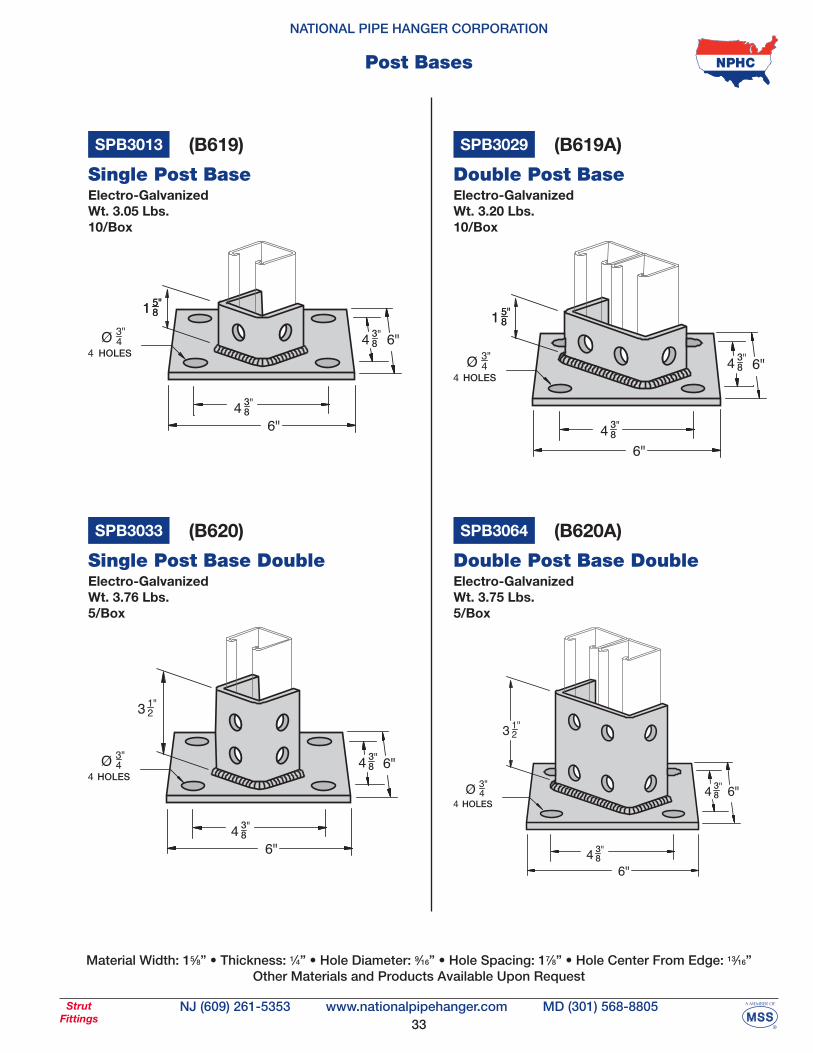
Post Bases
HOLES
38
38
Electro-Galvanized Wt. 3.05 Lbs.10/Box
SPB3013
Single Post Base
SPB3029
Double Post BaseElectro-Galvanized Wt. 3.20 Lbs.10/Box
HOLES
38
38
(B619) (B619A)
Electro-Galvanized Wt. 3.76 Lbs.5/Box
SPB3033
Single Post Base Double
HOLES
38
38
Electro-Galvanized Wt. 3.75 Lbs.5/Box
SPB3064
Double Post Base Double
HOLES
38
38
(B620) (B620A)
Material Width: 15⁄8” • Thickness: 1⁄4” • Hole Diameter: 9⁄16” • Hole Spacing: 17⁄8” • Hole Center From Edge: 13⁄16”Other Materials and Products Available Upon Request
34
NATIONAL PIPE HANGER CORPORATION
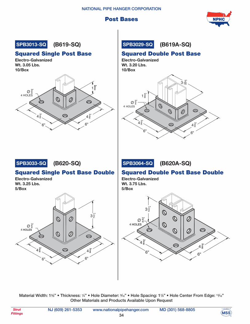
NJ (609) 261-5353 MD (301) 568-8805www.nationalpipehanger.comStrutFittings
Post Bases
Electro-Galvanized Wt. 3.05 Lbs.10/Box
SPB3013-SQ
Squared Single Post Base
SPB3029-SQ
Squared Double Post BaseElectro-Galvanized Wt. 3.20 Lbs.10/Box
HOLES
38 3
8
(B619-SQ) (B619A-SQ)
Material Width: 15⁄8” • Thickness: 1⁄4” • Hole Diameter: 9⁄16” • Hole Spacing: 17⁄8” • Hole Center From Edge: 13⁄16”Other Materials and Products Available Upon Request
HOLES
38
38
Electro-Galvanized Wt. 3.25 Lbs.5/Box
SPB3033-SQ
Squared Single Post Base Double
SPB3064-SQ
Squared Double Post Base DoubleElectro-Galvanized Wt. 3.75 Lbs.5/Box
38 3
8
(B620-SQ) (B620A-SQ)
35
NATIONAL PIPE HANGER CORPORATION
NJ (609) 261-5353 MD (301) 568-8805www.nationalpipehanger.comStrutFittings
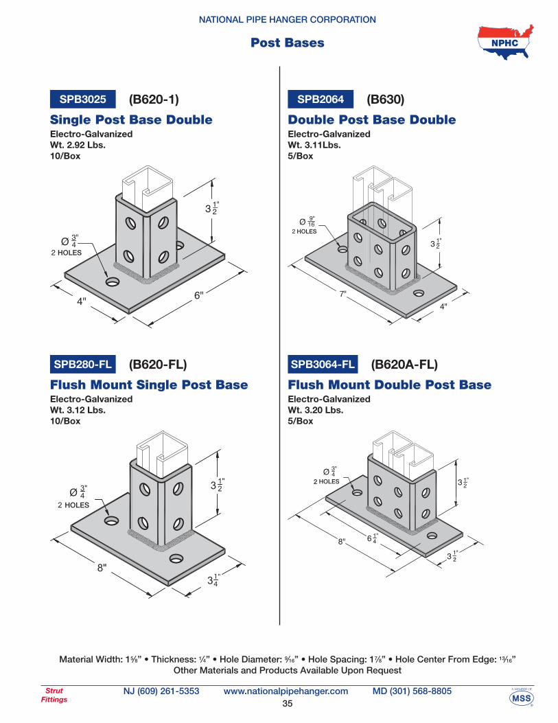
Post Bases
Material Width: 15⁄8” • Thickness: 1⁄4” • Hole Diameter: 9⁄16” • Hole Spacing: 17⁄8” • Hole Center From Edge: 13⁄16”Other Materials and Products Available Upon Request
Electro-Galvanized Wt. 2.92 Lbs.10/Box
SPB3025
Single Post Base Double
HOLES
(B620-1)
Electro-Galvanized Wt. 3.12 Lbs.10/Box
SPB280-FL
Flush Mount Single Post Base
HOLES
(B620-FL)
Electro-Galvanized Wt. 3.11Lbs.5/Box
SPB2064
Double Post Base Double
(B630)
Electro-Galvanized Wt. 3.20 Lbs.5/Box
Flush Mount Double Post Base
SPB3064-FL (B620A-FL)
36
NATIONAL PIPE HANGER CORPORATION
NJ (609) 261-5353 MD (301) 568-8805www.nationalpipehanger.comBeamClamps
Beam Clamps
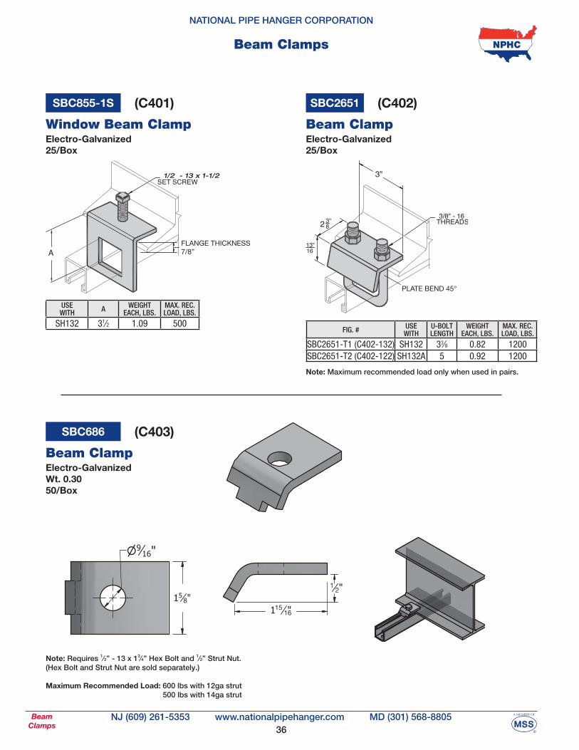
Electro-Galvanized 25/Box
SBC855-1S
Window Beam Clamp Beam Clamp
USE WITH A WEIGHT
EACH, LBS.MAX. REC.LOAD, LBS.
SH132 31⁄2 1.09 500FIG. # USE
WITHU-BOLTLENGTH
WEIGHT EACH, LBS.
MAX. REC.LOAD, LBS.
SBC2651-T1 (C402-132) SH132 33⁄8 0.82 1200SBC2651-T2 (C402-122) SH132A 5 0.92 1200
(C401) SBC2651 (C402)
Electro-Galvanized 25/Box
Note: Maximum recommended load only when used in pairs.
Electro-Galvanized Wt. 0.3050/Box
SBC686
Beam Clamp
(C403)
Note: Requires 1⁄2” - 13 x 13⁄4” Hex Bolt and 1⁄2” Strut Nut. (Hex Bolt and Strut Nut are sold separately.)
Maximum Recommended Load: 600 lbs with 12ga strut 500 lbs with 14ga strut
37
NATIONAL PIPE HANGER CORPORATION
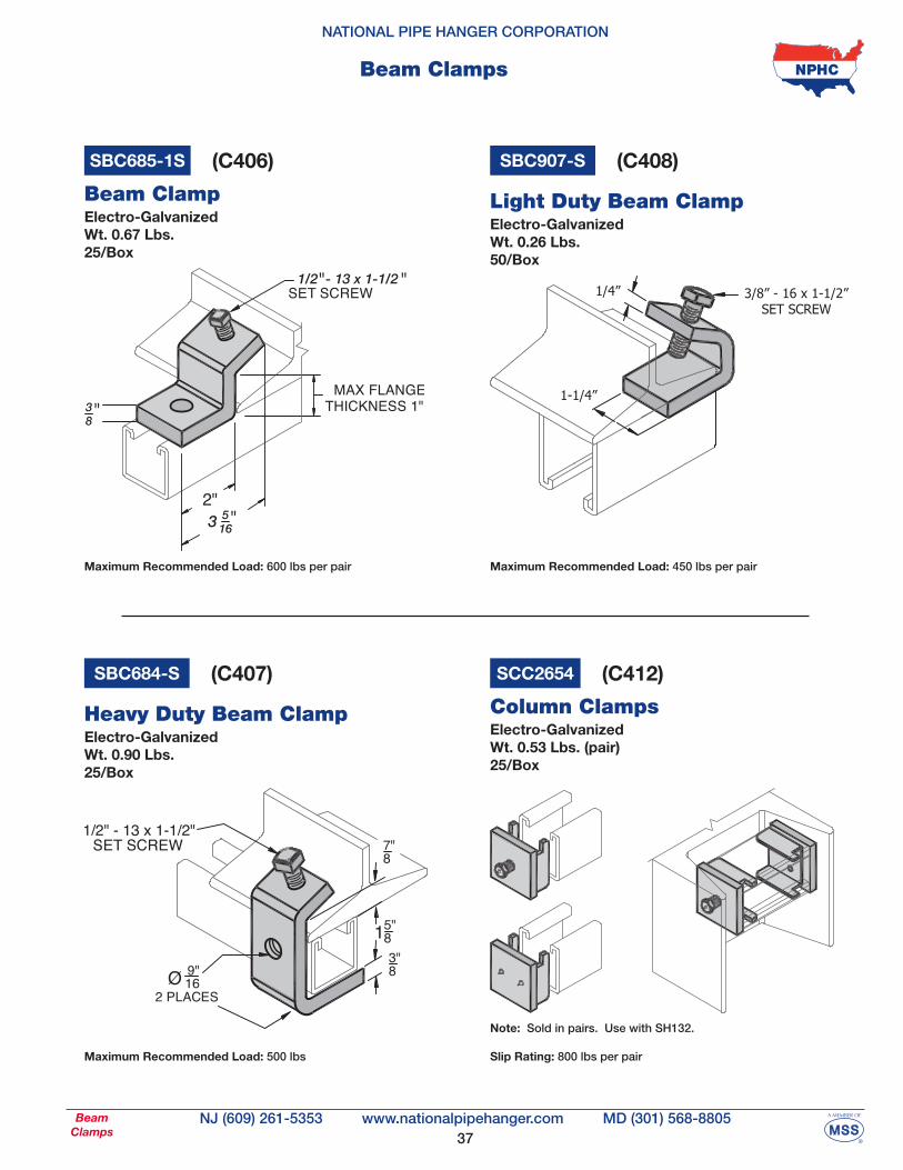
NJ (609) 261-5353 MD (301) 568-8805www.nationalpipehanger.comBeamClamps
Beam Clamps
Electro-Galvanized Wt. 0.53 Lbs. (pair)25/Box
SCC2654
Column Clamps
Note: Sold in pairs. Use with SH132. Slip Rating: 800 lbs per pair
(C412)
Electro-Galvanized Wt. 0.90 Lbs.25/Box
Heavy Duty Beam Clamp
SBC684-S (C407)
Electro-Galvanized Wt. 0.26 Lbs.50/Box
Light Duty Beam Clamp
1/4” 3/8” - 16 x 1-1/2”SET SCREW
1-1/4”
SBC907-S (C408)
Electro-Galvanized Wt. 0.67 Lbs.25/Box
SBC685-1S
Beam Clamp
(C406)
Maximum Recommended Load: 600 lbs per pair Maximum Recommended Load: 450 lbs per pair
Maximum Recommended Load: 500 lbs
38
NATIONAL PIPE HANGER CORPORATION
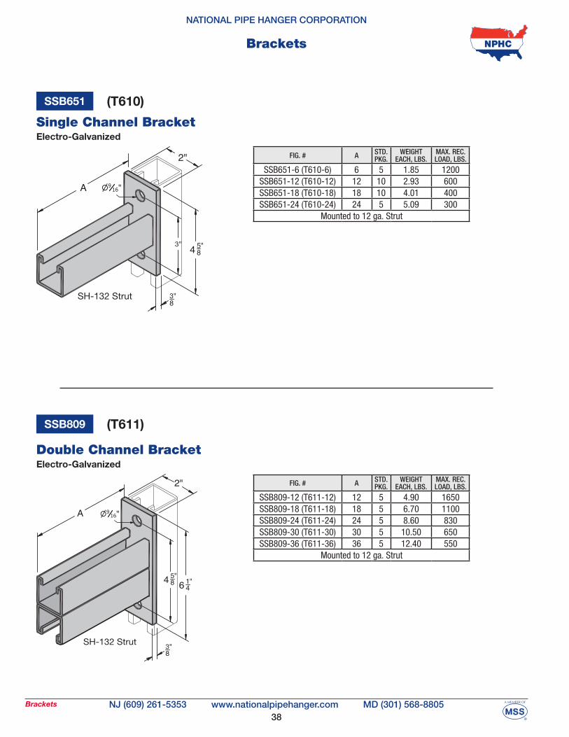
NJ (609) 261-5353 MD (301) 568-8805www.nationalpipehanger.comBrackets
Electro-Galvanized Double Channel Bracket
SSB809 (T611)
Electro-Galvanized
SSB651
Single Channel Bracket
(T610)
FIG. # A STD. PKG.
WEIGHT EACH, LBS.
MAX. REC.LOAD, LBS.
SSB651-6 (T610-6) 6 5 1.85 1200SSB651-12 (T610-12) 12 10 2.93 600SSB651-18 (T610-18) 18 10 4.01 400SSB651-24 (T610-24) 24 5 5.09 300
Mounted to 12 ga. Strut
FIG. # A STD. PKG.
WEIGHT EACH, LBS.
MAX. REC.LOAD, LBS.
SSB809-12 (T611-12) 12 5 4.90 1650SSB809-18 (T611-18) 18 5 6.70 1100SSB809-24 (T611-24) 24 5 8.60 830SSB809-30 (T611-30) 30 5 10.50 650SSB809-36 (T611-36) 36 5 12.40 550
Mounted to 12 ga. Strut
Brackets
39
NATIONAL PIPE HANGER CORPORATION
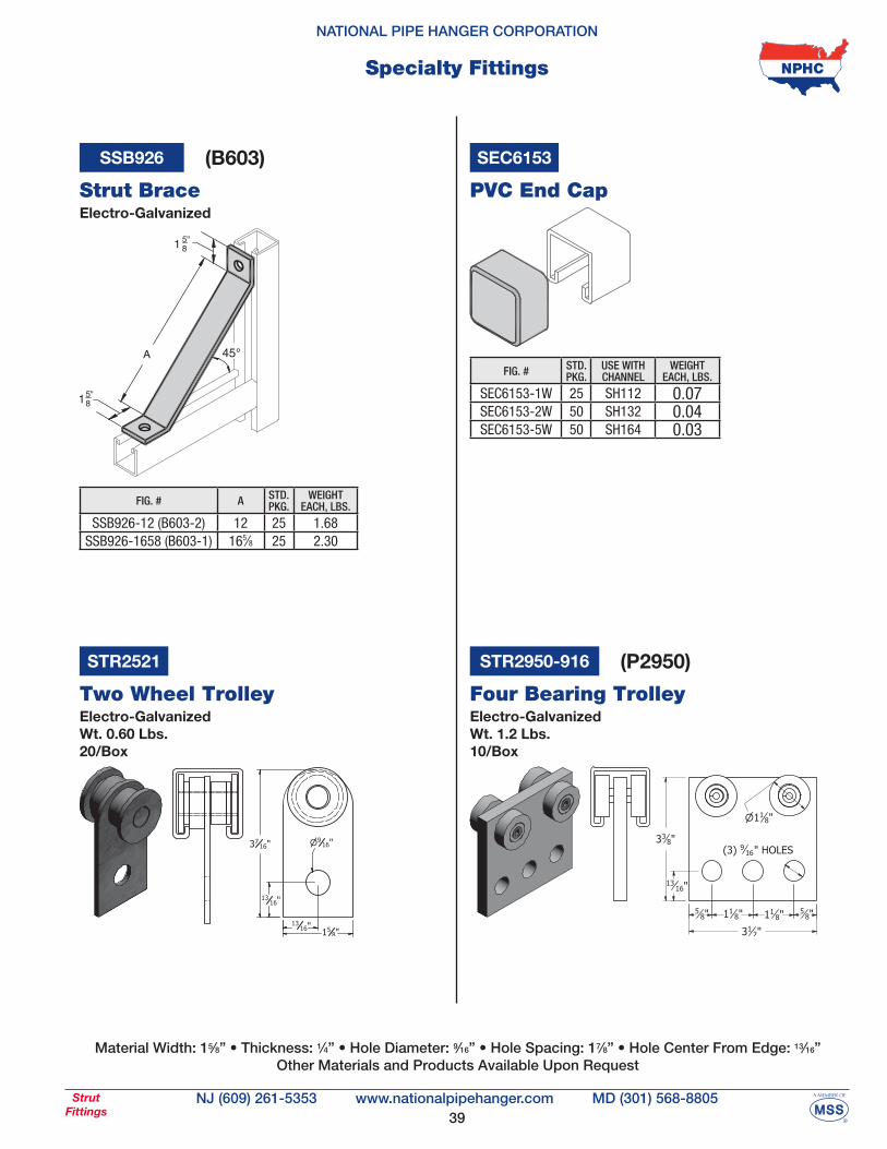
NJ (609) 261-5353 MD (301) 568-8805www.nationalpipehanger.comStrutFittings
Specialty Fittings
Material Width: 15⁄8” • Thickness: 1⁄4” • Hole Diameter: 9⁄16” • Hole Spacing: 17⁄8” • Hole Center From Edge: 13⁄16”Other Materials and Products Available Upon Request
STR2521
Two Wheel Trolley Four Bearing TrolleyElectro-Galvanized Wt. 1.2 Lbs.10/Box
Electro-Galvanized Wt. 0.60 Lbs.20/Box
STR2950-916 (P2950)
SSB926
Strut Brace
FIG. # A STD. PKG.
WEIGHT EACH, LBS.
SSB926-12 (B603-2) 12 25 1.68SSB926-1658 (B603-1) 165⁄8 25 2.30
(B603)
Electro-Galvanized
SEC6153
PVC End Cap
FIG. # STD. PKG.
USE WITHCHANNEL
WEIGHT EACH, LBS.
SEC6153-1W 25 SH112 0.07SEC6153-2W 50 SH132 0.04SEC6153-5W 50 SH164 0.03
40
NATIONAL PIPE HANGER CORPORATION
NJ (609) 261-5353 MD (301) 568-8805www.nationalpipehanger.comStrutAccessories
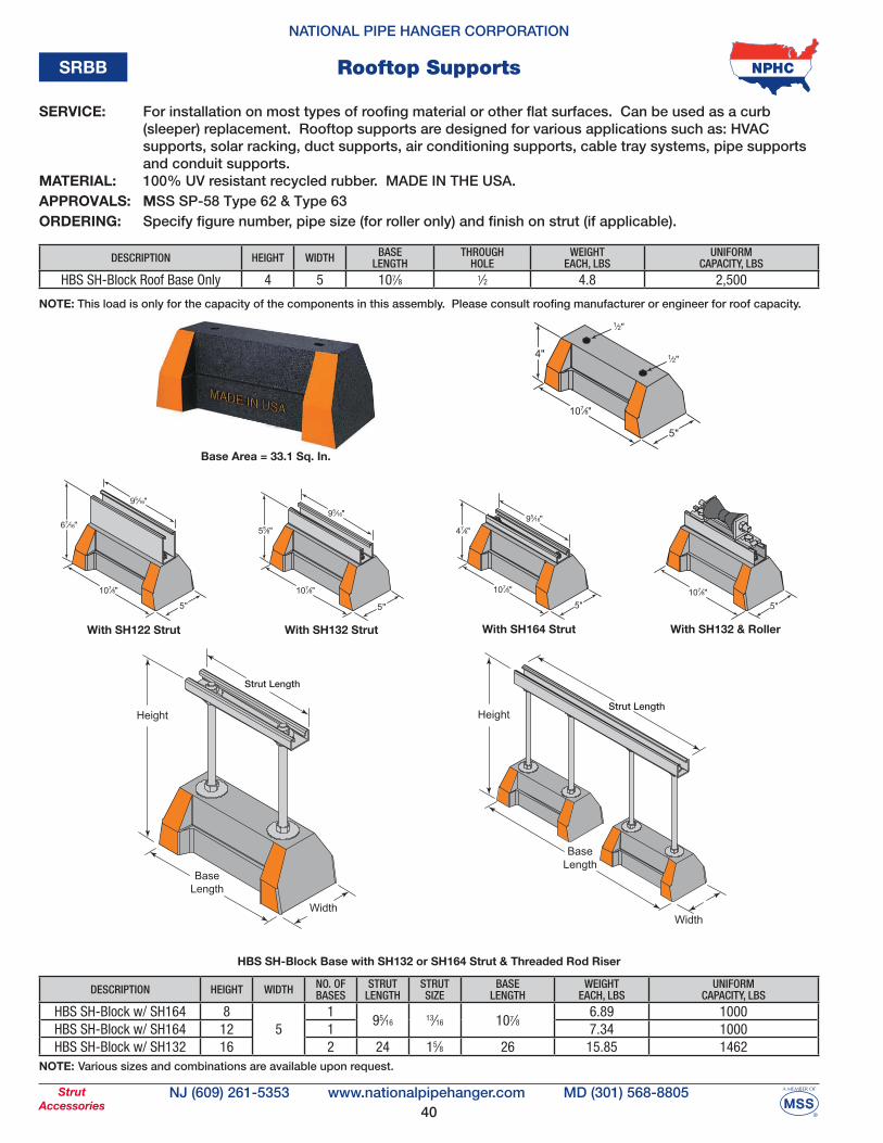
SERVICE: For installation on most types of roofing material or other flat surfaces. Can be used as a curb (sleeper) replacement. Rooftop supports are designed for various applications such as: HVAC supports, solar racking, duct supports, air conditioning supports, cable tray systems, pipe supports and conduit supports. MATERIAL: 100% UV resistant recycled rubber. MADE IN THE USA. APPROVALS: MSS SP-58 Type 62 & Type 63ORDERING: Specify figure number, pipe size (for roller only) and finish on strut (if applicable).
DESCRIPTION HEIGHT WIDTH BASE LENGTH
THROUGH HOLE
WEIGHT EACH, LBS
UNIFORM CAPACITY, LBS
HBS SH-Block Roof Base Only 4 5 107⁄8 1⁄2 4.8 2,500
NOTE: This load is only for the capacity of the components in this assembly. Please consult roofing manufacturer or engineer for roof capacity.
⁄
⁄
Base Area = 33.1 Sq. In.
With SH132 StrutWith SH122 Strut With SH164 Strut With SH132 & Roller
Strut Length
Strut Length
HBS SH-Block Base with SH132 or SH164 Strut & Threaded Rod Riser
NOTE: Various sizes and combinations are available upon request.
Rooftop SupportsSRBB
DESCRIPTION HEIGHT WIDTH NO. OFBASES
STRUT LENGTH
STRUT SIZE
BASE LENGTH
WEIGHT EACH, LBS
UNIFORM CAPACITY, LBS
HBS SH-Block w/ SH164 85
195⁄16
13⁄16 107⁄86.89 1000
HBS SH-Block w/ SH164 12 1 7.34 1000HBS SH-Block w/ SH132 16 2 24 15⁄8 26 15.85 1462
41
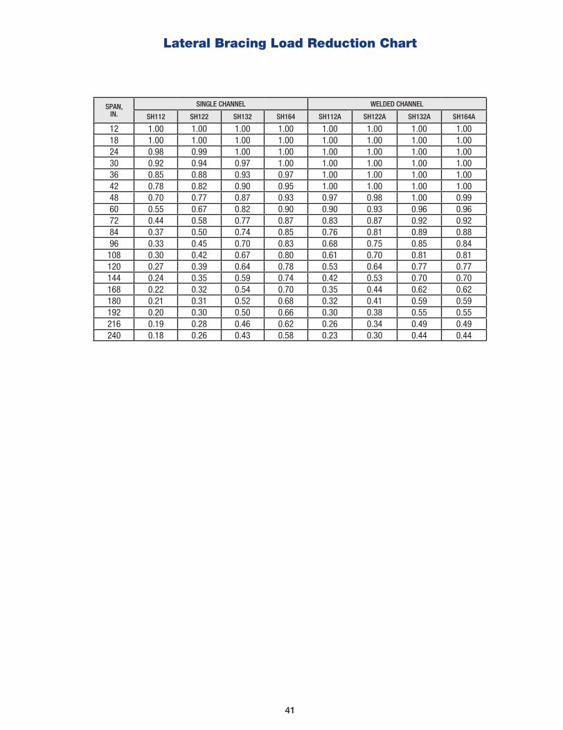
Lateral Bracing Load Reduction Chart
SPAN,IN.
SINGLE CHANNEL WELDED CHANNEL
SH112 SH122 SH132 SH164 SH112A SH122A SH132A SH164A
12 1.00 1.00 1.00 1.00 1.00 1.00 1.00 1.0018 1.00 1.00 1.00 1.00 1.00 1.00 1.00 1.0024 0.98 0.99 1.00 1.00 1.00 1.00 1.00 1.0030 0.92 0.94 0.97 1.00 1.00 1.00 1.00 1.0036 0.85 0.88 0.93 0.97 1.00 1.00 1.00 1.0042 0.78 0.82 0.90 0.95 1.00 1.00 1.00 1.0048 0.70 0.77 0.87 0.93 0.97 0.98 1.00 0.9960 0.55 0.67 0.82 0.90 0.90 0.93 0.96 0.9672 0.44 0.58 0.77 0.87 0.83 0.87 0.92 0.9284 0.37 0.50 0.74 0.85 0.76 0.81 0.89 0.8896 0.33 0.45 0.70 0.83 0.68 0.75 0.85 0.84
108 0.30 0.42 0.67 0.80 0.61 0.70 0.81 0.81120 0.27 0.39 0.64 0.78 0.53 0.64 0.77 0.77144 0.24 0.35 0.59 0.74 0.42 0.53 0.70 0.70168 0.22 0.32 0.54 0.70 0.35 0.44 0.62 0.62180 0.21 0.31 0.52 0.68 0.32 0.41 0.59 0.59192 0.20 0.30 0.50 0.66 0.30 0.38 0.55 0.55216 0.19 0.28 0.46 0.62 0.26 0.34 0.49 0.49240 0.18 0.26 0.43 0.58 0.23 0.30 0.44 0.44
42
GENERAL: SH-Strut channel is manufactured by a series of forming dies or rolls which progressively cold work the strip steel into the desired channel configuration. This method produces a cross section of uniform dimen-sions within a tolerance of plus or minus 0.015”, on outside dimensions.
WELDING: SH-Strut channel combinations of two or more elements are spot welded together. The spot welds are spaced two or three inches on centers throughout the length of the multiple channel sections. Various com-binations are available upon request.
LENGTH INFORMATION: SH-Strut channel is available in 10’ and 20’ lengths with a tolerance of ± 1/8”. Custom-ized cut lengths are available upon request.
LOADING DATA:
• When calculating load at center of span, multiply load from table by 0.5 and deflection by 0.8. • The allowable loads in the tables are based on an allowable stress of 25000 psi in accordance with the Metal Framing Manufacturers Association’s Metal Framing Standards Publication MFMA-4, 2004. For commonly used pre-galvanized carbon steel ASTM A653, the loads in the tables have a safety factor of 1.8. The allowable stress in accordance with Manufacturers Standardization Society’s Pipe Hangers and Supports - Materials, Design, Manufacture, Selection, Application, and Installation MSS SP-58, 2009 is 12900 psi . The safety factor in accordance with MSS SP-58 is 3.5. When strut is to be used in accordance with MSS SP-58 or ASME B31.1, the loads in the table shall be multiplied by 1.8/3.5 = 0.52. This correction is in addition to any corrections for the presence of slotted holes or concentrated loads.
MATERIALS & FINISHES: SH-Strut channel is produced from prime structural steel covered by the following specifications:
• Pre-Galvanized Steel G-90…….ASTM A653 • Stainless Steel, Type 304 & Type 316…….ASTM A240 • Powder Coated Supr-Green…….ASTM B117
Other materials, finishes and specifications available upon request.
SH-Strut Channel Specifications
43
Copyright © 2022 National Pipe Hanger Corporation- All Rights Reserved January 2022
AGREEMENTS: All agreements are subject to strikes, accidents or other causes beyond our control. Prices and terms are not subject to verbal changes or other agreements unless approved in writing by the seller.
TAXES: The buyer is liable for any federal or state taxes imposed on the seller unless the buyer provides the seller with a tax exemption certificate acceptable to the taxing authority.
WARRANTY: We guarantee our manufactured products for one year from date of shipment to the extent that we will replace those having manufacturing defects when used for the purpose which we recommended. If goods are defective, the amount of damage is the price of the defective goods only and no allowance will be made for labor or expense of repairing defective goods or damage resulting from the same. We warrant the products we sell of other manufacturers to the extent of the warranties of their respective maker.
RETURNS: Permission to return standard stocked merchandise must be obtained in writing. Credit may be issued subject to the following:
1. Return freight charges must be prepaid.
2. All material must be in first-class condition and in box quantities upon arrival at our plant; if not, repackaging and reconditioning costs will be deducted from the credit.
3. If material is in approved condition, credit will be allowed on the basis of the price charged less a minimum restocking charge of 30% and less any out-bound freight allowed or paid by us. 4. Special, non-stocked and custom-made merchandise is NOT RETURNABLE.
5. Materials are NOT RETURNABLE after 30 days beyond date of invoice.
CLAIMS: No claims for shortages allowed unless made in writing within ten (10) days of receipt of goods. All material sent out will be carefully counted and packed. Claims for goods damaged or lost in transit should be made to the carrier as our responsibility ceases on delivery to the carrier.
TERMS AND DESIGN: National Pipe Hanger Corporation reserves the right to make specification changes with-out notice. While every effort has been made to assure the accuracy of information contained in this catalog at the time of publication, we cannot accept responsibility for inaccuracies resulting from undetected errors or omissions.
WARNING: National Pipe Hanger’s products are designed and manufactured in accordance with industry codes and standards and are intended for service and installation as illustrated or described herein. National shall not be responsible for any losses or damages sustained by the buyer or any other person as a result of misapplica-tion. Products used for unintended purposes could fail, resulting in property loss, injury or death.
National Pipe Hanger Corporation’s Terms of Sale supersede Buyer’s supplemental or conflicting terms and conditions to which notice of objection is hereby given.
Terms of Sale


NATIONAL
Printed in the U.S.A.© 2022 National Pipe Hanger Corporation Revision Date: 1/2/2022
E-MAIL: [email protected] WEBSITE: WWW.NATIONALPIPEHANGER.COM
PIPE HANGER CORPORATION
CORPORATE HEADQUARTERS200 CAMPUS DR
MOUNT HOLLY, NJ 08060
MARYLAND OFFICE15850 COMMERCE CT, SUITE PUPPER MARLBORO, MD 20774
(609) 261-5353(609) 261-3249
TEL:FAX:
(301) 568-8805(301) 967-1456
TEL:FAX:
Related Documents