1 NATIONAL LIBRARY OF SOUTH AFRICA 228 Johannes Ramokhoase Street 5 Queen Victoria Street Private Bag X397 Cape Town Pretoria 8001 0001 BID DESCRIPTION ELECTRICAL WORK SPECIFICATION FOR NATIONAL LIBRARY OF SOUTH AFRICA TENDER NO: NLSA.PTA.ELECTRICAL WORK 10/2017 CLOSING DATE: 06 November 2017 TIME: 11h00 COMPULSORY BRIEFING SESSION Pretoria Campus VENUE : AUDITORIUM DATE : 20 October 2017 TIME : 10h00 NB. Note that Saturday will be treated as the normal working day, should you want to drop off the bid documents Library opens at 8:30 am and closes at 16:00. Upon the submission of the bid documents service providers are requested to sign the register at the Reception. BID DOCUMENTS ARE AVAILABLE ON: o NLSA Website (www.nlsa.ac.za) o National Treasury (www.e-tenders.gov.za) NB. Completed Bid Documents must be deposited in the Tender Box at the Offices of NLSA in Pretoria 75, Thabo Sehume Street, Pretoria CBD before the closing date and time on Monday the 06 November 2017@ 11:00.

Welcome message from author
This document is posted to help you gain knowledge. Please leave a comment to let me know what you think about it! Share it to your friends and learn new things together.
Transcript

1
NATIONAL LIBRARY OF SOUTH AFRICA 228 Johannes Ramokhoase Street 5 Queen Victoria Street
Private Bag X397 Cape Town
Pretoria 8001
0001
BID DESCRIPTION
ELECTRICAL WORK SPECIFICATION FOR NATIONAL LIBRARY OF SOUTH AFRICA
TENDER NO: NLSA.PTA.ELECTRICAL WORK 10/2017
CLOSING DATE: 06 November 2017 TIME: 11h00
COMPULSORY BRIEFING SESSION
Pretoria Campus
VENUE : AUDITORIUM
DATE : 20 October 2017
TIME : 10h00
NB. Note that Saturday will be treated as the normal working day, should you want to drop off
the bid documents Library opens at 8:30 am and closes at 16:00. Upon the submission of the
bid documents service providers are requested to sign the register at the Reception.
BID DOCUMENTS ARE AVAILABLE ON:
o NLSA Website (www.nlsa.ac.za)
o National Treasury (www.e-tenders.gov.za)
NB. Completed Bid Documents must be deposited in the Tender Box at the Offices of NLSA in
Pretoria 75, Thabo Sehume Street, Pretoria CBD before the closing date and time on Monday
the 06 November 2017@ 11:00.

2
1. INTRODUCTION
National Library of South Africa (NLSA) identified as a key priority the need to maintain high
standards of equipment and facilities within its building. Results from the inspection of
problems surrounding electrical infrastructure and need for full compliance identified the need
to appoint service providers to conduct an audit, and consequently develop specifications for
the appointment of electrical contractors to conduct works regarding the aforesaid problems.
Therefore, this document is a result of the audit work undertaken which summarises the
problems and needs required to develop scope and specifications for conducting work
required to undertake this assignment.
2. OBJECTIVES
The objective of the proposed project is to review the key systems including BMS, UPS,
Distribution Boards and other general electrical installations. The current systems have
limitations towards promoting the effective and efficient operations of the general electrical
systems. Consequently they need to overhauled to improve the operation of the Library which
is desirable for its efficient and successful management.
3. BACKGROUND

3
Following the identification by National Library of South Africa, the need to evaluate the
problems associated with electrical management systems which includes UPS, BMS,
Distribution Boards and General electrical installations, service providers were appointed to
undertake the audit. The audit informed the need to undertake specific projects aimed at
improving or solving the electrical problems. Based on the above, the audit identified
numerous non-compliance issues surrounding the problems on the current electrical
infrastructure and its operation.
Circuits, rewiring and testing of the Distribution boards (DBs) is desirable to be done.
Conductors for lights circuits on Building Management (BM) System is currently not working.
Legend Cards which guides the identification of features requiring attention need to be
corrected since these features do not correspond with circuits. Therefore new Legend Cards
should be revised and issued.
Below is a summary of some of the key areas requiring attention:
3.1 UPS
The main server room consists of one 10KVA UPS that supplies only the IT equipment in the
server room. The UPS installed does not serve the purpose because critical equipment such
as CCTV, Access Control, Fire Detection and Security Systems are not connected to this unit.
The UPS batteries of the existing 10KVA unit are also incomplete. Therefore there is a need to
increase the UPS capacity to serve other critical equipment as highlighted above.
3.2 BMS
The Building Management system (BMS) is currently not functioning as it should be, making it
difficult to identify where the faults are and the causes of these faults. This makes it difficult for
the management team to diagnose, manage and address the electrical issues they are facing
in the building. Therefore resulting from the electrical audit which was conducted, the proposal
is that the BMS should be replaced.
3.3 Distribution Boards

4
Circuits rewiring and testing of the DBs is essential. Conductors for lights circuits on Building
Management (BM) System is not working. Legends Cards do not correspond with circuits
therefore new Legends Cards should be issued.
3.4 General Electrical (Plugs, Sockets, Lights, Sensors etc)
The electrical installation is in a functional state in some of the library areas, but the wiring and
contactors inside distribution board fittings needs attendance. The fittings (light fittings,
sockets, switches, circuit breakers, etc.) are recently installed. The luminaires lamps used in
the building are fluorescent lamps, MH and HPS which are not energy efficient compared to
LED. As part of the above, occupational sensors will equally receive attention as highlighted in
this specification. The electrical light fittings (Bulkhead lights) installed on the wall were stolen.
Therefore the proposal is that vandal proof light fitting must be installed along the ramps. In
addition, all IT equipment, Access control, fire detection, CCTV, emergency lights (escape
route) and dedicated plugs must be connected to emergency load (Existing Generator). See
photograph annexure 1.
3.5 Summarised quantities of problems
3.5.1 Currently, 761 lights are neither operating nor working. These lights are categorised as
fluorescent (346), Down Lights (170) and other lights (245) which require attention, within the
overall building. This highlights the status of the problems which are currently experienced and
require attention.
3.5.2 With regard to plugs, there are approximately 94 plugs which are not working. Apart
from these plugs, other problems relate to earthing on some of the plugs, network and blank
covers, replacement and addition of dedicated plugs, rewiring of wires and labelling of these
plugs.
4 SUMMARY OF SCOPE

5
4.1 Scope
4.1.1 This Specification covers the technical requirements with respect to Plant, Material,
installation, testing and commissioning of the Uninterruptible Power Supply (UPS) units and
Building Management System (BMS). Installation, testing and commissioning of all general
electrical equipment as highlighted in this specification which includes occupational sensors,
plugs, lights, etc for National Library of South Africa Pretoria Campus. Item 8, 9,10 and 11
which details scope of works herein summarised.
4.1.2 The conditions and / or specifications in this Specification shall be regarded as the
absolute minimum requirement.
4.1.3 All works nor expressly called for in this specification, but necessary for the complete,
proper installation and operation of the works shall be performed and furnished by the
contractor at no additional cost to the employer.
4.1.4 The following is considered part of the Contractor’s Scope of Work:
All inspection and testing as specified
All necessary manpower, labour, supervision, equipment, materials (installed and
consumable), tools, services and testing devices for all aspects of this Contract.
Installation, labour and supervision of the plant and material to ensure the
manufacture’s specification are met;
4.1.5 The Contractor shall submit the following within two weeks of the award of the Contract:
A procurement, manufacturing, installation and commissioning program for the
Works which shall indicate the following key milestones:
Commencement.
Main design, documentation and manufacturing milestones.
Delivery of equipment to Site.
Completion of installation.
Site Acceptance Tests per system.
Final commissioning.
Final documentation and takeover.
4.2 Precedence

6
4.2.1 This specification shall be read in conjunction with rest of this contract and Drawings in
its entirety.
4.2.2 This Specification quotes various international and national standards. This
Specification shall take precedence over the quoted standards.
4.2.3 Wherever areas of the Works are not covered by the particular specifications or
standards quoted in this Specification, the Works shall comply with relevant SANS, IEC, BS,
ISA or ISO standards.
4.2.4 Wherever quoted standards or specifications duplicate requirements for particular
performance criteria, the more stringent standard shall be complied with and this fact
indicated. Any conflict in requirements shall be brought to the attention of the Engineer.
4.2.5 Wherever no relevant specification or standard, as specified above, is available, the
Contractor shall propose an appropriate national or alternative standard for the Engineer's
approval.
4.2.6 In case of any conflict in interpretation, ambiguity or discrepancy between any of the
documentation and this Specification or Conditions of Contract, the following shall apply:
Payment shall in all cases be in accordance with the Conditions of Contract;
Approval, acceptance, handover and takeover certification etc, shall in all cases
be in accordance with the conditions of the contract.
4.3 Maintenance
Due to the complex nature of this project, it is desirable that the contractor to be appointed will
also have to be commissioned and responsible for the maintenance of this infrastructure for a
period 36 months.
Below it is a summary of all the minimum requirements which need to be covered when
general electrical work is to be addressed.
5. PART 1 – GENERAL

7
5.1 Tests
After completion of the works and before first delivery is taken, a full test will be carried out on
the installation for a period of sufficient duration to determine the satisfactory working thereof.
During this period the installations will be inspected and the Contractor shall make good, to the
satisfaction of the Representative/Agent, any defects which may arise.
The Contractor shall provide all instruments and equipment required for testing required for the
commissioning and testing of the installations at completion.
5.2 Maintenance of installations
With effect from the date of the First Delivery Certificate the Contractor shall at his own
expense undertake the regular servicing of the installation during the maintenance period and
shall make all adjustments necessary for the correct operation thereof.
If during the said period the installations is not in working order for any reason for which the
Contractor is responsible, or if the installations develops defects, he shall immediately upon
being notified thereof take steps to remedy the defects and make any necessary adjustments.
Should such stoppages however be so frequent as to become troublesome, or should the
installations otherwise prove unsatisfactory during the said period the Contractor shall, if called
upon by the Representative/Agent, at his own expense replace the whole of the installations or
such parts thereof as the Representative/Agent may deem necessary with apparatus specified
by the Representative/Agent.
5.3 Regulations
The installation shall be erected and tested in accordance with the Acts and Regulations as
indicated in the scope of works
5.4 Schedule of fittings
In all instances where the schedule of lights, socket outlets and power points are attached to
or included on the drawings, these schedules are to be regarded as forming part of the
specification.
5.5 Quality of materials

8
Only materials of first class quality shall be used and all materials shall be subject to the
approval of the NLSA. NLSA specifications for various materials to be used on this Contract
are attached to and form part of this specification.
Wherever applicable the material is to comply with the relevant South African Bureau of
Standards, specifications, where no SABS Specifications exist.
Materials wherever possible, must be of South African manufacture.
5.6 Conduit and accessories
The type of conduit and accessories required for the service, i.e. whether the conduit and
accessories shall be of the screwed type, plain-end type or of the non-metallic type and
whether metallic conduit shall be black enamelled or galvanised, is specified in Part 2 of this
specification.
PVC power skirting and channels may be used where necessary.
Unless other methods of installation are specified for certain circuits, the installation shall be in
conduit throughout. No open wiring in roof spaces or elsewhere will be permitted.
The conduit and conduit accessories shall comply fully with the applicable SABS specifications
as set out below and the conduit shall bear the mark of approval of the South African Bureau
of Standards.
a) Screwed metallic conduit and accessories: SABS 1065, parts 1 and 2.
b) Plain-end metallic conduit and accessories: SABS 1065, parts 1 and 2.
c) Non-metallic conduit and accessories: SABS 950
All conduit fittings except couplings, shall be of the inspection type. Where cast metal conduit
accessories are used, these shall be of malleable iron. Zinc base fittings will not be allowed.
Bushes used for metallic conduit shall be brass and shall be provided in addition to locknuts at
all points where the conduit terminates at switchboards, switch-boxes, draw-boxes, etc.
Draw-boxes are to be provided in accordance with the “Wiring Code” and wherever necessary
to facilitate easy wiring.

9
For light and socket outlet circuits, the conduit used shall have an external diameter of 20mm.
In all other instances the sizes of conduit shall be in accordance with the “Wiring Code” for the
specified number and size of conductors, unless otherwise directed in part 2 of this
specification or indicated on the drawings.
Only one manufactured type of conduit and conduit accessories will be permitted throughout
the installation.
Running joints in screwed conduit are to be avoided as far as possible and all conduit systems
shall be set or bent to the required angles. The use of normal bends must be kept to a
minimum with exception of larger diameter conduits where the use of such bends is essential.
All metallic conduit shall be manufactured of mild steel with a minimum thickness of 1,2mm for
plain-end conduit and 1,6mm in respect of screwed conduit.
Under no circumstances will conduit having a wall thickness of less than 1,6mm be allowed in
screeding laid on top of concrete slabs.
Bending and setting of conduit must be done with special bending apparatus manufactured for
the purpose and which are obtainable from the manufacturers of the conduit systems.
Damage to conduit resulting from the use of incorrect bending apparatus or methods applied
must on indication by the Department’s inspectorate staff, be completely removed and rectified
and any wiring already drawn into such damaged conduits must be completely renewed at the
Contractor’s expense.
Conduit and conduit accessories used for flame-proof or explosion proof installations and for
the suspension of luminaires as well as all load bearing conduit shall in all instances be of the
metallic screwed type.
All conduit and accessories used in areas within 50 km of the coast shall be galvanised to
SABS 763.
Tenderers must ensure that general approval of the proposed conduit system to be used is
obtained from the local electricity supply authority prior to the submission of their tender.
Under no circumstances will consideration be given by the Department to any claim submitted
10
by the Contractor, which may result from a lack of knowledge in regard to the supply
authority’s requirements.
5.7 Conduit in roof spaces
Conduit in roof spaces shall be installed parallel or at right angles to the roof members and
shall be secured at intervals not exceeding 1,5m by means of saddles screwed to the roof
timbers.
Nail or crumpets will not be allowed.
Where non-metallic conduit has been specified for a particular service, the conduit shall be
supported and fixed with saddles with a maximum spacing of 450 mm. The Contractor shall
supply and install all additional supporting timbers in the roof space as required.
Under flat roofs, in false ceilings or where there is less than 0,9m of clearance, or should the
ceilings be insulated with glass wool or other insulating material, the conduit shall be installed
in such a manner as to allow for all wiring to be executed from below the ceilings.
Conduit runs from distribution boards shall, where possible terminate in fabricated sheet steel
draw-boxes installed directly above or in close proximity to the boards.
5.8 Surface mounted conduit
Wherever possible, the conduit installation is to be concealed in the building work; however,
where unavoidable or otherwise specified under Part 2 of the specification, conduit installed on
the surface must be plumbed or levelled and only straight lengths shall be used.
The use of inspection bends is to be avoided and instead the conduit shall be set uniformly
and inspection coupling used where necessary.
No threads will be permitted to show when the conduit installation is complete, except where
running couplings have been employed.
Running couplings are only to be used where unavoidable, and shall be fitted with a sliced
couplings as a lock nut.
Conduit is to be run on approved spaced saddles rigidly secured to the walls.

11
Alternatively, fittings, tees, boxes, couplings etc., are to be cut into the surface to allow the
conduit to fit flush against the surface. Conduit is to be bedded into any wall irregularities to
avoid gaps between the surface and the conduit.
Crossing of conduits is to be avoided, however, should it be necessary purpose-made metal
boxes are to be provided at the junction. The finish of the boxes and positioning shall be in
keeping with the general layout.
Where several conduits are installed side by side, they shall be evenly spaced and grouped
under one purpose-made saddle.
Distribution boards, draw-boxes, industrial switches and socket outlets etc., shall be neatly
recessed into the surface to avoid double sets.
In situations where there are no ceilings the conduits are to be run along the wall plates and
the beams.
Painting of surface conduit shall match the colour of the adjacent wall finishes.
Only approved plugging materials such as aluminium inserts, fibre plugs, plastic plugs, etc.,
and round-head screws shall be used for fixing saddles, switches, socket outlets, etc., to walls,
wood plugs and the plugging in joints in brick walls are not acceptable.
5.9 Conduit in concrete slabs
In order not to delay building operations the Contractor must ensure that all conduits and other
electrical equipment which are to be cast in the concrete columns and slabs are installed in
good time.
The Contractor shall have a representative in attendance at all times when the casting of
concrete takes place.
Draw-boxes, expansion joint boxes and round conduit boxes are to be provided where
necessary. Sharp bends of any nature will not be allowed in concrete slabs.
Draw and/or inspection boxes shall be grouped under one common cover plate and must
preferable be installed in passages or male toilets.

12
All boxes, etc., are to be securely fixed to the shuttering to prevent displacement when
concrete is cast. The conduit shall be supported and secured at regular intervals and installed
as close as possible to the neutral axis of concrete slabs and/or beams.
Before any concrete slabs are cast, all conduit droppers to switchboards shall be neatly
spaced and rigidly fixed.
5.10 Flexible connections for connecting up of stoves, machines, etc
Flexible tubing connections shall be of galvanised steel construction, and in damp situations of
the plastic sheathed galvanised steel type. Other types may only be used subject to the prior
approval of the Department’s site electrical representative.
Connectors for coupling onto the flexible tubing shall be of the gland or screw-in types,
manufactured of either brass or cadmium or zinc plated mild steel, and the connectors after
having been fixed onto the tubing, shall be durable and mechanically sound.
Aluminium and zinc alloy connectors will not be acceptable.
5.11 wiring
Except where otherwise specified in Part 2 of this specification, wiring shall be carried out in
conduit throughout. Only one circuit per conduit will be permitted.
No wiring shall be drawn into conduit until the conduit installation has been completed and all
conduit ends provided with bushes. All conduits to be clear of moisture and debris before
wiring is commenced.
Unless otherwise specified in Part 2 of this specification or indicated on the service drawings,
the wiring of the installation shall be carried out in accordance with the “Wiring Code”. Further
to the requirements concerning the installation of earth conductors to certain light points as set
out in the “Wiring Code”, it is a specific requirement of this document that where plain-end
metallic conduit or non-metallic conduit has been used, earth conductors must be provided
and drawn into the conduit with the main conductors to all points, including all luminaires and
switches throughout the installation.

13
Wiring for lighting circuits is to be carried out with 1,5mm² conductors and a 1,5mm²-earth
conductor. For socket outlet circuits the wiring shall comprise 4mm² conductors and a
2,5mm²-earth conductor. In certain instances, as will be directed in Part 2 of this specification,
the sizes of the aforementioned conductors may be increased for specified circuits. Sizes of
conductors to be drawn into conduit in all other instances, such as feeders to distribution
boards, power points etc., shall be as specified elsewhere in this specification or indicated on
the drawings. Sizes of conductors not specified must be determined in accordance with the
“Wiring Code”.
The loop-in system shall be followed throughout, and no joints of any description will be
permitted.
The wiring shall be done in PVC insulated 600/1000 V grade cable to SABS 150.
Where cable ends connect onto switches, luminaires etc., the end strands must be neatly and
tightly twisted together and firmly secured. Cutting away of wire strands of any cable will not
be allowed.
5.12 Switches and socket outlets
All switches and switch-socket outlet combination units shall conform to the Department
Quality Specifications, which form part of this specification.
No other than 16 A 3 pin sockets are to be used, unless other special purpose types are
distinctly specified or shown on the drawings.
All light switches shall be installed at 1,4m above finished floor level and all socket outlets as
directed in the Schedule of Fittings which forms part of this specification or alternatively the
height of socket outlets may be indicated on the drawings.
5.13 Switchgear
Switchgear, which includes circuit breakers, iron-clad switches, interlocked switch-socket
outlet units, contactors, time switches, etc., is to be in accordance with the NLSA Quality
Specifications which form part of this specification and shall be equal and similar in quality to
such brands as may be specified.

14
For uniform appearance of switchboards, only one approved make of each of the different
classes of switchgear mentioned in the Quality Specifications shall be used throughout the
installations.
5.14 Switchboards
All boards shall be in accordance with the types as specified, be constructed according to the
detail or type drawings and must be approved by the National Library of South Africa before
installation.
In all instances where provision is to be made on boards for the supply authority’s main switch
and/or metering equipment the contractor must ensure that all requirements of the authorities
concerned in this respect are met.
Any construction or standard type aboard proposed, as an alternative to that specified must
have the prior approval of the national library of South Africa.
All bus bars, wiring, terminals, etc., are to be adequately insulated and all wiring is to enter the
switchgear from the back of the board. The switchgear shall be mounted within the boards to
give a flush front panel. Cable and boxes and other ancillary equipment must be provided
where required.
Clearly engraved labels are to be mounted on or below every switch. The wording of the
labels in English, is to be according to the lay-out drawings or as directed by the National
Library of South Africa’s representative and must be confirmed on site. Flush mounted boards
to be installed with the top of the board 2,0m above the finished floor level.
5.15 Workmanship and staff
Except in the case of electrical installations supplied by a single-phase electricity supply at the
point of supply, an accredited person shall exercise general control over all electrical
installation work being carried out.
The workmanship shall be of the highest grade and to the satisfaction of the Department.
All inferior work shall, on indication by the Department’s inspecting officers, immediately be
removed and rectified by and at the expense of the Contractor.

15
5.16 Certificate of compliance
On completion of the service, a certificate of compliance must be issued to the Department’s
Representative/Agent in terms of the Occupational Health and Safety Act, 1993 (Act 85 of
1993).
5.17 Earthing of installation
Main earthing
The type of main earthing must be as required by the supply authority if other than the NLSA,
and in any event as directed by the NLSA’s representative, who may require additional
earthing to meet test standards.
Where required an earth mat shall be provided, the minimum size, unless otherwise specified,
being 1,0m x 1,0m and consisting of 4mm diameter hard-drawn bare copper wires at 250mm
centres, brazed at all intersections.
Alternatively or additionally earth rods or trench earths may be required as specified or
directed by the Department’s authorised representative.
Installations shall be effectively earthed in accordance with the “Wiring Code” and to the
requirements of the supply authority. All earth conductors shall be stranded copper with or
without green PVC installation.
Connection from the main earth bar on the main board must be made to the cold water main,
the incoming service earth conductor, if any and the earth mat or other local electrode by
means of 12mm x 1,60 mm solid copper strapping or 16 mm² stranded (not solid) bare copper
wire or such conductor as the Department’s representative may direct. Main earth copper
strapping where installed below 3m from ground level, must be run in 20 mm diameter conduit
securely fixed to the walls.
All other hot and cold water pipes shall be connected with 12mm x 0,8mm perforated for solid
copper strapping (not conductors) to the nearest switchboard. The strapping shall be fixed to
the pipework with brass nuts and bolts and against walls with brass screws at 150-mm
centres. In all cases where metal water pipes, down pipes, flues, etc., are positioned within
1,6m of switchboards an earth connection consisting of copper strapping shall be installed

16
between the pipework and the board. In vertical building ducts accommodating both metal
water pipes and electrical cables, all the pipes shall be earthed at each distribution board.
Roofs, gutters and down pipes
Where service connections consist of overhead conductors, all metal parts of roofs, gutters
and down pipes shall be earthed. One bare 10mm² copper conductor shall be installed over
the full length of the ceiling void, fixed to the top purlin and connected to the main earth
conductor and each switchboard. The roof and gutters shall be connected at 15m intervals to
this conductor by means of 12mm X 0,8mm copper strapping (not conductors) and galvanised
bolts and nuts. Self-tapping screws are not acceptable. Where service connections consist of
underground supplies, the above requirements are not applicable.
Sub-distribution boards
A separate earth connection shall be supplied between the earth bus bar in each sub-
distribution board and the earth bus bar in the Main Switchboard. These connections shall
consist of a bare or insulated stranded copper conductors installed along the same routes as
the supply cables or in the same conduit as the supply conductors. Alternatively armoured
cables with earth continuity conductors included in the armouring may be utilised where
specified or approved.
Sub-circuits
The earth conductors of fall sub-circuits shall be connected to the earth bus bar in the supply
board in accordance with SABS 0142.
Ring Mains
Common earth conductors may be used where various circuits are installed in the same wire
way in accordance with SABS 0142. In such instances the sizes of earth conductors shall be
equivalent to that of the largest current carrying conductor installed in the wire way,
alternatively the size of the conductor shall be as directed by the Engineer. Earth conductors
for individual circuits branching from the ring main shall by connected to the common earth
conductor with T-ferrules or soldered. The common earth shall not be broken.
Non-metallic Conduit

17
Where non-metallic conduit is specified or allowed, the installation shall comply with the
Department’s standard quality specification for “conduit and conduit accessories”.
Standard copper earth conductors shall be installed in the conduits and fixed securely to all
metal appliances and equipment, including metal switch boxes, socket-outlet boxes, draw-
boxes, switchboards, luminaires, etc. The securing of earth conductors by means of self-
threading screws will not be permitted.
Flexible Conduit
An earth conductor shall be installed in all non-metal flexible conduit. This earth conductor
shall not be installed externally to the flexible conduit but within the conduit with the other
conductors. The earth conductor shall be connected to the earth terminals at both ends of the
circuit.
Connection
Under no circumstances shall any connection points, bolts, screws, etc., used for earthing be
utilised for any other purpose. It will be the responsibility of the Contractor to supply and fit
earth terminals or clamps on equipment and materials that must be earthed where these are
not provided.
Unless earth conductors are connected to proper terminals, the end shall be tinned and
lugged.
5.18 Mounting and positioning of luminaires
The Contractor is to note that in the case of board and acoustic tile ceilings, i.e. as opposed to
concrete slabs, close co-operation with the building contractor is necessary to ensure that as
far as possible the luminaires are symmetrically positioned with regard to the ceiling pattern.
The layout of the luminaires as indicated on the drawings must be adhered to as far as
possible and must be confirmed with the Department’s representative.
Fluorescent luminaires installed against concrete ceilings shall be screwed to the outlet boxes
and in addition 2 x 6mm expansion or other approved type fixing bolts are to be provided. The
bolts are to be ¾ of the length of the luminaires apart.

18
Fluorescent luminaires to be mounted on board ceilings shall be secured by means of two
40mm x No. 10 round head screws and washers. The luminaires shall also be bonded to the
circuit conduit by means of locknuts and brass bushes. The fixing screws are to be placed ¾
of the length of the fitting apart.
Earth conductors must be drawn in with the circuit wiring and connected to the earthing
terminal of all fluorescent luminaires as well as other luminaires exposed to the weather in
accordance with the “Wiring Code” Incandescent luminaires are to be screwed directly to outlet
boxes in concrete slabs. Against board ceilings the luminaires shall be secured to the
brandering or joints by means of two 40mm x No. 8 round head screws.
Apart from the description as outlined under general, it is essential to also outline
installation details as a guidance to the contractors to take care of these issues. Below
is a summary of these installation details
6. PART 2: INSTALLATION DETAILS
6.1 Notices
The Contractor shall issue all notices and make the necessary arrangements with Supply
Authorities, the Postmaster-General, S.A. Transport Services, Provincial or National Road
Authorities and other authorities as may be required with respect to the installation.
6.2 Electrical equipment
All equipment and fittings supplied must be in accordance with the suitability for the relevant
supply voltage, and frequency and must be approved by the Department’s representative.
6.3 Drawings
The drawings generally show the scope and extent of the proposed work and shall not be held
as showing every minute detail of the work to be executed.
The position of power points, switches and light points that may be influenced by built-in
furniture must be established on site, prior to these items being built in.
6.4 Balancing of load

19
The Contractor is required to balance the load as equally as possible over the multiphase
supply.
6.5 Service conditions
All plant shall be designed for the climatic conditions appertaining to the service.
6.6 Switches and socket outlets
The installation of switches and socket outlets must conform to clause 5.13 of Part 1 of this
specification.
6.7 Light fittings and lamps
The installation and mounting of luminaires must conform to Part 1 of this specification.
All fittings to be supplied by the Contractor shall have the approval of the Department.
Incandescent lamps shall bear the approved mark of the SABS.
The light fittings must be of the type specified in the Schedule of Light Fittings.
6.8 Earthing and bonding
The Contractor will be responsible for all earthing and bonding of the building and installation.
The earthing and bonding is to be carried out strictly as described in clause 18 of Part 1 of this
specification and to the satisfaction of the Department’s representative.
6.9 Maintenance of electrical supply
All interruptions of the electrical supply that may be necessary for the execution of the work,
will be subject to prior arrangement between the Contractor and NLSA and the NLSA’s
representative.
6.10 Extent of work
The work covered by this contract comprises the complete electrical installation, in working
order, as shown on the drawings and as per this specification, including the supply and
installation of all fittings and also the installation of such equipment supplied by the
Department.

20
6.11 Supply and connection
[The supply voltage, responsibility of the Supply Authority and the contractor must be
specified]
EXAMPLE:
The supply will be at 400/230 Volt 50Hz.
The Contractor must arrange in good time with the local Municipality for the installation of the
500kVA transformer and low-tension meter point and submit the account to the Department’s
Regional Office for payment.
The Contractor will be responsible for the supply and installation of the supply cable from the
meter box to the main low-tension distribution board (MDB). The size and length of the cable
is listed in the Schedule of Cables and measured in the Bills of Quantities.
Standby Plant
The 10kVA standby plant complete with automatic changeover control panel (Distribution
Board – X) be supplied, installed and commissioned by others.
The Contractor will only be responsible for the supply and installation of the cable connections
between the Main Distribution Board and the Charge- over Control Panel (Distribution Board -
X).
The supply cables are listed in the Schedule of Cables and measured in the Bills of Quantities.
6.12 Conduit and wiring
Conduit and conduit accessories shall be black enamelled/galvanized screwed conduit or
black enamelled/galvanized plain end conduit in accordance with SABS 162, 763 and 1007
respectively.
All conduits, regardless of the system employed, shall be installed strictly as described in the
applicable paragraphs of clauses 5.4 to 5.8 of Part 1 of the specification. Wiring of the
installation shall be carried out as directed in clause 9 part 1 of this specification.

21
Where plain end conduit is offered all switches and light fittings must be supplied with a
permanent earth terminal for the connection of the earth wire. Lugs held by switch fixing
screws or self-tapping screws will not be acceptable.
The Contractor shall be responsible for the supply and installation of all power trunking
complete with corner pieces, end pieces, junction pieces, supply conduits, cover plates and
power outlets as specified and indicated on the drawings.
The power trunking must comply with SABS 1197. The Contractor must ensure that the power
trunking is installed to satisfaction of the Department’s representative before commencing with
the wiring of the power trunking.
[The method of installing and wiring of the power trunking must be specified in detail.]
6.13 Power points
Allow for the installation of power points and equipment as listed in the schedule, indicated on
the drawings and described below:
ELECTRIC STOVE
ELECTRIC COOKING TOP
WATER HEATERS, ETC.
[The power points required for the service must be specified in detail with reference to supplier
of the equipment, method of installation and final connection. The size of the conduit/the
conductors and cable must be listed in the Schedule of Power Points.]
Example: Water Heaters
The Contractor must electrically connect all water heaters as specified and listed in the
Schedule of Power Points.
NOTE: The hot water installation must be approved by the Department’s
Representative/Agent. Detail with regard to the size and type of water heaters that must be
provided must be obtained from the Architect.
6.14 Cables

22
The Contractor shall supply and completely install all distribution cables as indicated on the
drawings, and listed in the Schedule of Cables.
The storage, transportation, handling and laying of the cables shall be according to first class
practice, and the contractor shall have adequate and suitable equipment and labour to ensure
that no damage is done to cables during such operations.
All joints in underground cables and terminations shall be made either by means of compound
filled boxes according to the best established practice by competent cable jointers using first
class materials or by means of approved epoxy-resin pressure type jointing kits such as
“Scotchcast”. Epoxy-resign joints must be made entirely in accordance with the
manufacturer’s instructions and with materials stipulated in such instructions. Low tension
PVC cables are to be made off with sealing glands and materials designed for this purpose
which must be of an approved make. Where cables are cut and not immediately made off, the
ends are to be sealed without delay.
The laying of cables shall not be commenced until the trenches have been inspected and
approved. The cable shall be removed from the drum in such a way that no twisting, tension or
mechanical damage is caused and must be adequately supported at intervals during the whole
operation. Particular care must be exercised where it is necessary to draw cables through
pipes and ducts to avoid abrasion, elongation or distortion of any kind. The ends of such pipes
and ducts shall be sealed to approval after drawing in of the cables.
Backfilling (after bedding) of the trenches is to be carried out with a proper grading of the
material to ensure settling without voids, and the material is to be tamped down after the
addition of every 150mm. The surface is to be made good as required.
On each completed section of the laid and jointed cable, the insulation resistance shall be
tested to approval with an approved “Megger” type instrument of not less than 500 V for low
tension cables.
Earth continuity conductors are to be run with all underground cables constituting part of a low
tension distribution system. Such continuity conductors are to be stranded bare copper of a
cross-sectional area equal to at least half that of one live conductor of the cable, but shall not
be less than 4mm² or more than 70mm². A single earth wire may be used as earth continuity

23
conductor for two or more cables run together, branch earth wires being brazed on where
required.
6.15 Laying, jointing and making off of electrical cables
[The requirements specified hereafter, are aimed essentially at high tension cable but are also
valid for low tension cable, where applicable.]
The use of the term “Inspector”, includes the engineer or inspector of the NLSA or an
empowered person of the concerned supervising consulting engineer’s firm.
After the cable has been laid and before the cable trench is back-filled the inspector must
ensure that the cable is properly bedded and that there is no undesirable material included in
the bedding layer.
All cable jointing and the making off of the cables must only be carried out by qualified
experienced cable jointers. Helpers of the jointers may not saw, strip, cut, solder, etc. The
cable and other work undertaken by them must be carried out under the strict and constant
supervision of the jointer.
Before the Contractor allows the jointer to commence with the jointing work or making off of
the cable (making off is recognized as half a joint) he must take care and ensure:
That he has adequate and suitable material available to complete the joint properly and
efficiently. Special attention must be given to ensure the cable ferrules and cable lugs are of
tinned copper and of sufficient size. The length of the jointing lugs must be at least six times
the diameter of the conductor,
That the joint pit is dry and that all loose stones and material are removed,
That the walls and banks of the joint pit are reasonably firm and free from loose material which
can fall into the pit,
That the necessary coffer-dams or retaining walls are made to stop the flow of water into the
joint pit,
That the joint pit is provided with suitable groundsheets so that the jointing work is carried out
in clean conditions,

24
That the necessary tents or sails are installed over the joint pit to effectively avert unexpected
rainfall and that sufficient light or lighting is provided,
That the necessary means are available to efficiently seal the jointing or cable end when an
unexpected storm or cloudburst occurs, regardless of how far the work has progressed,
That the cables and other materials are dry, undamaged and in all respects are suitable for the
joint work or making off,
That the heating of cable oil, cable compound, plumbers metal and solder is arranged that they
are at the correct temperature when required so that the cable is not unnecessary exposed to
the atmosphere and consequently the ingress of moisture (care must be taken of overheating)
Flow temperatures of cable oil and compound must be determined with suitable thermometers.
Cable oil and compound must not be heated to exceed the temperatures given on the
containers and precaution must be taken to ensure that the tin is not overheated in one
position. The whole mass must be evenly and proportionally heated. (Temperatures of solder
and plumbers metal may be tested with brown paper (testing time: 3 seconds). The paper
must colour slightly - not black or burnt).
Before the paper-insulated cables are joined, they must be tested for the presence of moisture
by the cable jointers test. This consists of the insertion of a piece of unhandled insulated
impregnated paper tape in warm cable oil heated to a temperature of 130 ± 5°C.
Froth on the surface of the oil is an indication that moisture is present in the impregnated
insulation and the amount of the froth gives an indication of the moisture present.
If the cable contains moisture or is found to be otherwise unsuitable for jointing or making of
the inspector is to be notified immediately and he will issue the necessary instruction to cope
with the situation.
The joint or making off of paper insulated cables must not be commenced during rainy
weather.
Once a joint is in progress the jointer must proceed with the joint until it is complete and before
he leaves the site.

25
The jointer must ensure that the material and his tools are dry at all times, reasonably clean
and absolutely free from soil.
Relating to the jointing of the cable the following requirements apply:
All jointing must be carried out in accordance with recognized and tried techniques and comply
strictly with the instructions given by the supplier of the jointing kit.
The cables must be twisted by hand so that the cores can be joined according to the core
numbers. If necessary the cable is to be exposed for a short distance to accomplish this.
Under no circumstances may the cores in a joint be crossed so as to enable cores to be joined
according to the core numbers. If it is not possible to twist the cables so that the preceding
requirements can be met, then cores are to be joined in the normal way without any
consideration of the core numbers.
Normally the cables will have profile conductors. The conductors shall be pinched with gas
pliers to form a circular section, bound with binding wire so that they do not spread, and then
tinned before jointing.
Jointing ferrules, the length of which are at least 6 times the diameter of the conductors, must
be slid over the conductor ends to be joined and pinched tightly. Then they are soldered by
means of the ladle process whilst being pinched further closed.
Use resin only as a flux. The slot opening in the ferrule must be completely filled, including all
depressions.
Remove all superfluous metal with a cloth dipped in tallow. Work during the soldering process
must be from top to bottom. Rub the ferrule smooth and clean with aluminum oxide tape after
it has cooled down to ensure that there are not any sharp points or edges.
NB: The spaces between the conductor strands must be completely filled by soldering
process and must be carried out quick enough to prevent the paper insulation from burning or
drying out unnecessarily.
After the ferrules have been rubbed smooth and clean, they and the exposed cores must be
treated with hot cable oil (110°C) to remove all dust and moisture. These parts are to be
thoroughly basted with the oil.

26
The jointer must take care that his hands are dry and clean before the joint is insulated. Also
the insulating tape which is to be used must first be immersed in warm cable oil (110°C) for a
sufficient period to ensure that no moisture is present.
After the individual cores have been installed they must be well basted with hot cable oil and
again after the applicable separator and/or belt insulation tape is applied before the lead joint
sleeve is placed in position.
The lead joint sleeve must be thoroughly cleaned and prepared before it is placed on the cable
and must be kept clean during the whole jointing process. Seal the filling apertures of the
sleeve with tape until the sleeve is ready for compound filling.
The plumbing joints employed to solder the joint sleeve to the cable sheath, must be cooled off
with tallow and the joint sleeve is to be filled with compound while it is still warm. Top up
continuously until the joint is completely filled to compensate for the compound shrinkage.
The outer joint box must be clean and free from corrosion. After it has been placed in position
it must be slightly heated before being filled with compound. Top up until completely full.
As far as cable end boxes are concerned the requirements as set out above are valid where
applicable.
7. PART 3: QUALITY SPECIFICATION FOR MATERIALS AND EQUIPMENT
7.1 conduit and conduit accessories
General
This section covers the requirements for conduit and conduit accessories for general
installations under normal environmental conditions.
The type of conduit and accessories required for the service, i.e. whether the conduit and
accessories shall be of the screwed type, plain-end type or of the non-metallic type and
whether metallic conduit shall be black enamelled or galvanised, is specified in Part 2 of this
specification. Unless other methods of installation are specified for certain circuits, the
installation shall be in conduit throughout. No open wiring in roof spaces or elsewhere will be
permitted.

27
The conduit and conduit accessories shall comply fully with the applicable SANS
Specifications as set out below and the conduit shall bear the mark of approval of the South
African National Standards.
(a) Screwed metallic conduit and accessories: SANS 1065 parts 1 and 2.
(b) Plain-end metallic conduit and accessories: SANS 1065 Parts 1 and 2.
(c) Non-metallic conduit and accessories: SANS 950
Bushes used for metallic conduit shall be brass and shall be provided in addition to lock nuts at
all points where the conduit terminates at switchboards, switch-boxes, draw-boxes, etc.
Only one manufacture of conduit and conduit accessories will be permitted throughout the
installation.
All metallic conduits shall be manufactured of mild steel with a minimum thickness of 1,2mm
for plain-end conduit and 1,6mm in respect of screwed conduit.
Screwed conduit
• Conduits shall comply with SANS 1065 and shall bear the SANS mark.
• All conduits shall be heavy gauge, welded or solid drawn, hot-dip
galvanised or black enamelled, screwed tube.
• Galvanised conduit shall be hot-dipped inside and outside in accordance
with SANS 32 & 121.
• All conduit ends shall be reamed and threaded on both sides and
delivered with a coupling at one end and a plastic cap on the other end.
Metal conduit accessories
All metal conduit accessories shall be of malleable cast iron or pressed steel with brass
bushes in accordance with SANS 1065. Alloy or pressure cast metal accessories or zinc base
alloy fittings are not acceptable. All fittings whether galvanised or black enamelled, shall be
fitted with brass screws.
Circular type boxes

28
• The boxes shall be of the long spout pattern, manufactured of malleable
cast iron or pressed steel and stove enamelled jet black or galvanised as
required. The two cover fixing holes shall be diametrically opposite each
other, drilled and tapped at 50mm centres.
• Junction, draw-in and inspection boxes shall be of adequate size and shall
be supplied with heavy gauge metal cover plates.
• Boxes shall comply with SANS 1065.
Flexible conduit
Flexible steel conduit and adaptors shall comply with BS 731, part 1 where applicable. Flexible
conduit shall be of galvanised steel construction and in damp areas of the plastic sheathed
galvanised steel type. Flexible conduit shall only be used as specified and shall then be
installed in accordance with par. 5.4.4 of SANS 10142.
Plain-end metallic conduit
• As an alternative to the threaded conduit, plain-end (unthreaded) metallic
conduit with accessories may be used under the conditions stated in the
specification for "INSTALLATION AND TERMINATION OF CONDUITS
AND CONDUIT ACCESSORIES".
• Unthreaded conduit shall be manufactured of mild steel with a minimum
thickness of 1,2mm and shall comply with SANS 1065.
• Bending and setting of conduit shall be done with the correct apparatus
recommended by the manufacturer of the conduit.
• The Contractor or Supplier shall be responsible for obtaining the approval
of local authorities for the use of this system.
• All conduit and accessories used in areas within 50 km of the coast shall
be hot-dip galvanised to SANS 32 & 121. In inland areas electro-
galvanised or cadmium-plated accessories will be accepted.
Non-metallic conduit
Non-metallic conduit shall comply fully with SANS 950 and shall be installed in accordance of
the specification as well as the specification for "INSTALLATION AND TERMINATION OF
CONDUITS AND CONDUIT ACCESSORIES".

29
Earth clamps
Earth clamps shall consist of copper strips at least 1,2mm thick and not less than 12mm wide
secured with a brass bolt, nut and washer and shall be so constructed that the clamp fit firmly
to the conduit without any additional packing.
7.2 PVC-INSULATED CABLES 600/1 000 V GRADE
General
This section covers the requirements for PVC-insulated cables for general installations under
normal environmental conditions.
Construction
• Cables shall be manufactured in accordance with SANS 1507, shall come
only from fresh stocks, and shall be constructed as follows:
(a) Unarmoured cables PVC-insulated/PVC-sheathed
(b) Armoured cables PVC-insulated/PVC-bedded/armoured/black extruded PVC outer
sheath
(c) Single core cables PVC-insulated/unsheathed
• The conductors shall be of high conductivity annealed stranded copper
and the cores may be shaped or circular.
• The insulation shall be general purpose PVC, 600/1 000V Grade.
• The bedding shall consist of a continuous impermeable sheath of PVC
extruded to fit the core or cores closely and in the case of multi-core
cables, to fill the interstices between the cores
• Where armouring is specified it shall consist of one layer of galvanised
steel wire in the case of multi-core cables and nonmagnetic metallic wire
in the case of single core cables. Aluminium strip or tape armouring is not
acceptable.
• Where specified, an earth continuity conductor shall be provided in the
armouring in accordance with SANS 1507.
30
Lengths
Cable shall be manufactured and supplied in one length to the lengths specified unless these
lengths exceed a standard drum length in which case a ruling shall be obtained from the NLSA
Representative/Agent.
Tests
At the option of the NLSA, acceptance tests shall be carried out on production runs of the
cable in accordance with SANS 1507.
7.3 GLANDS FOR PVC-INSULATED CABLES
• Glands to be used for terminating PVC/PVC/SWA/PVC cables shall be of the adjustable
type.
• Glands shall be suitable for general purpose 600/1 000 V Grade cable with steel
armouring.
• The glands shall be made of nickel-plated cadmium plated or in coastal area bronze or
brass.
• The glands shall consist of a barrel carrying a cone bush screwed into one end and a
nickel-plated brass nipple carrying a nickel-plated brass or a heavy galvanised steel
locknut screwed into the other end. The galvanising shall comply with SANS 32 & 121.
• Non-watertight glands must be easily converted to watertight glands by means of a
waterproofing shroud and inner seal kit. On the cable entry side of the barrel a concave
groove shall be provided to accommodate the top rim of the waterproofing shroud.
• The shrouds shall be made of non-deteriorating neoprene or other synthetic rubber, and
shall be resistant to water, oil and sunlight. The shrouds shall fit tightly around the
glands and cable.
• Glands shall be provided with ISO threads and shall be suitable for the specified cable
sizes.
• Flameproof glands shall comply with SANS 808, Groups 1, 2a and 2b.
• Suitable accessories shall be provided with glands to be used on ECC armoured cables
to facilitate a bolted lug connection of the earth continuity conductors. Grooves cut into

31
the barrel or cone bush to accommodate the earth continuity conductors are not
acceptable.
• For unarmoured cables the cone bush and compression ring of the gland shall be
replaced with a synthetic rubber compression bush and ring to provide the required grip
on the outer sheath of the cable.
7.4 CABLE TERMINATIONS AND JOINTS
Heat-shrinkable materials
• Heat-shrinkable materials may only be used in exceptional circumstances with the
written permission of the NLSA Representative/Agent.
• The complete kit shall be packed in a container that is marked for the type of cable
insulation and construction as well as the voltage range for which the materials are
suitable.
• An illustrated set of instructions for the installation of the materials shall accompany
every kit.
• The joints and terminations shall make minimal, if any, use of insulating or stress
relieving tapes. The use of electrical stress control and insulating tubing that is heat-
shrunk onto the termination or joint, is preferred above other methods.
• The materials shall comply with VDE 0278 and the supplier shall be called upon to
confirm this aspect before acceptance of the materials or installation.
• The heat-shrinkable and other materials used for the terminations and joints shall be of
a high quality and shall retain their electrical and mechanical properties without
deterioration.
Terminations with Heat-Shrinkable Materials
• Terminations shall be made of a material that gives lasting protection against ultraviolet
radiation.
• The cores of all cables terminated outdoors and the cores of 3,3 kV and higher voltage
cables terminated indoors, shall be completely covered with a shrunk-on protective
layer against surface tracking, ultraviolet radiation and weathering.

32
• Outdoor terminations shall be designed to prevent flashover under wet or contaminated
conditions and to ensure additional mechanical strength. This shall be achieved with
shrunk-on insulating spacers and rain shields.
Joints with Heat-Shrinkable Materials
• The electrical continuity of all the conductors, screens and armouring shall not be
impaired by the joints and the earth continuity shall be accomplished within the joints,
i.e. no external earth continuity conductor that will be subject to corrosion, is acceptable.
The joints shall be completely covered by a watertight sheath to prevent corrosion.
• In the case of joints in cables with an outer PVC anti-electrolysis sheath, the joints shall
be subject to the same electrical insulation test as the outer sheath of the cable.
Resin filled joints
• The resin filled joint kit shall comprise a self-sealing plastic mould of high mechanical
strength having sufficient connector space.
• The exact amount of cold hardening resin shall be provided in a two-compartment
plastic bag.
• The resin shall have absolute minimum shrinkage.
• The mould and resin shall be completely waterproof and non-hygroscopic and shall be
resistant to ultraviolet radiation.
• Joint kits shall be of "SCOTCHCAST", "CELLPACK" or similar
Cable joints box
• Cable joint boxes shall be manufactured of die cast aluminium material for normal
conditions or glass fibre reinforced thermosetting compound where exposed to
corrosive conditions.
• The lid shall provide an absolute moisture barrier.
• Boxes shall contain 2. 3 or 4 entries as required.
• Unused entries shall be sealed with watertight blanking plugs.
• Earth continuity shall be maintained through the box by means of the material of the box
in the case of aluminium boxes or by means of earth straps and studs in the case of
glass fibre reinforced boxes.
7.5 wiring terminals

33
• Terminal bodies and screws shall be of non-corrosive metal, enclosed in fire resistant,
moulded plastic insulating bodies. Terminal bodies or screws shall not project beyond
the insulating material and shall afford suitable protection against accidental contact by
personnel and against short circuits and tracking
• The construction of the terminal block and mounting rail shall be such as to ensure a
firm and positive location of the terminal blocks. It shall be possible to add additional
terminal blocks within the terminal sequence without having to disconnect or dismantle
the terminal strip. The terminal blocks shall be held in position by means of standard
end clamps.
• It shall be possible to intermix terminals of various sizes, i.e. for different sizes of
conductors, whilst utilising the same mounting rail. Where smaller terminal blocks occur
adjacent to larger terminal blocks, suitable shielding barriers shall be inserted to cover
the terminals that might otherwise be exposed.
• The terminal bodies and clamping screws shall be so constructed as to ensure that
conductors are not nicked or severed when the clamping screws are tightened. Screws
shall not come in direct contact with the conductors.
• Terminals shall be sized and rated to match the conductors that are connected to them.
• Each terminal block shall have provision for clip-in numbering or labelling strips to be
installed, together with protective, clear caps over the sheets.
7.6 Occupancy sensors
General
This section covers the requirements for occupancy sensors for use in general installations
under normal environmental conditions.
Surface and ceiling mounted occupancy sensors
• Occupancy sensors shall be suitable for wall mounting mounting in 100 x 50 x 50mm
boxes and also in ceiling mounted. All occupancy sensors shall be of dual technology
type and shall bear the SABS mark.
• Shall be rated at 16A, 220/250V.
7.7 earthling electrodes

34
General
This section covers uncoated, coated and metal clad circular rod electrodes intended to
provide an earth in soil for electrical and lightning arrestor systems.
Category and type
Only the following type of earth rods shall be used:
1(a) - Solid copper.
1(b) - Solid stainless steel.
2 (a) - Solid steel with bonded copper protection.
2 (b) - Solid steel with plated copper protection.
2 (c) - Solid steel with a shrunk-on copper jacket.
3 - Solid steel with a shrunk-on stainless steel jacket.
4 - Galvanised steel.
• Bare aluminium is not acceptable as an electrode material.
• All rods shall be solid and of circular cross section with length as specified in the Detail
Technical Specification.
• The nominal diameter of the earthing rods shall not be less than 16mm unless the rods
are specified for placing in pro-drilled holes in which event the minimum nominal
diameter shall not be less than 12mm
Couplings and conductor clamps
• Earthing electrodes shall be provided with (n-1) couplings where n = number of rods
supplied.
• Rods designed for coupling by means of external sleeves shall be provided with an
adequate quantity of hydrocarbon or silicon grease to be applied to the coupling
before the joint is made.
• Rods designed for coupling by means of internal pins or splines shall be provided
with thin-walled tubes and hydrocarbon or silicon grease to seal the joint.
35
• Conductor clamps shall be provided to suit the type and size of rods provided and
the type and size of conductor specified in the Detail Technical Specification.
• The material of the clamps shall be electrolytically compatible with the rod and
conductor materials.
• Where brazed or welded connections are specified, the supplier of the rods shall
stipulate at least two types of metals which are compatible with the rod and
conductor materials.
• An adequate number of driving caps or bolts shall be supplied with the rods to
protect the ends of the earthing rods whilst being driven into hard soil.
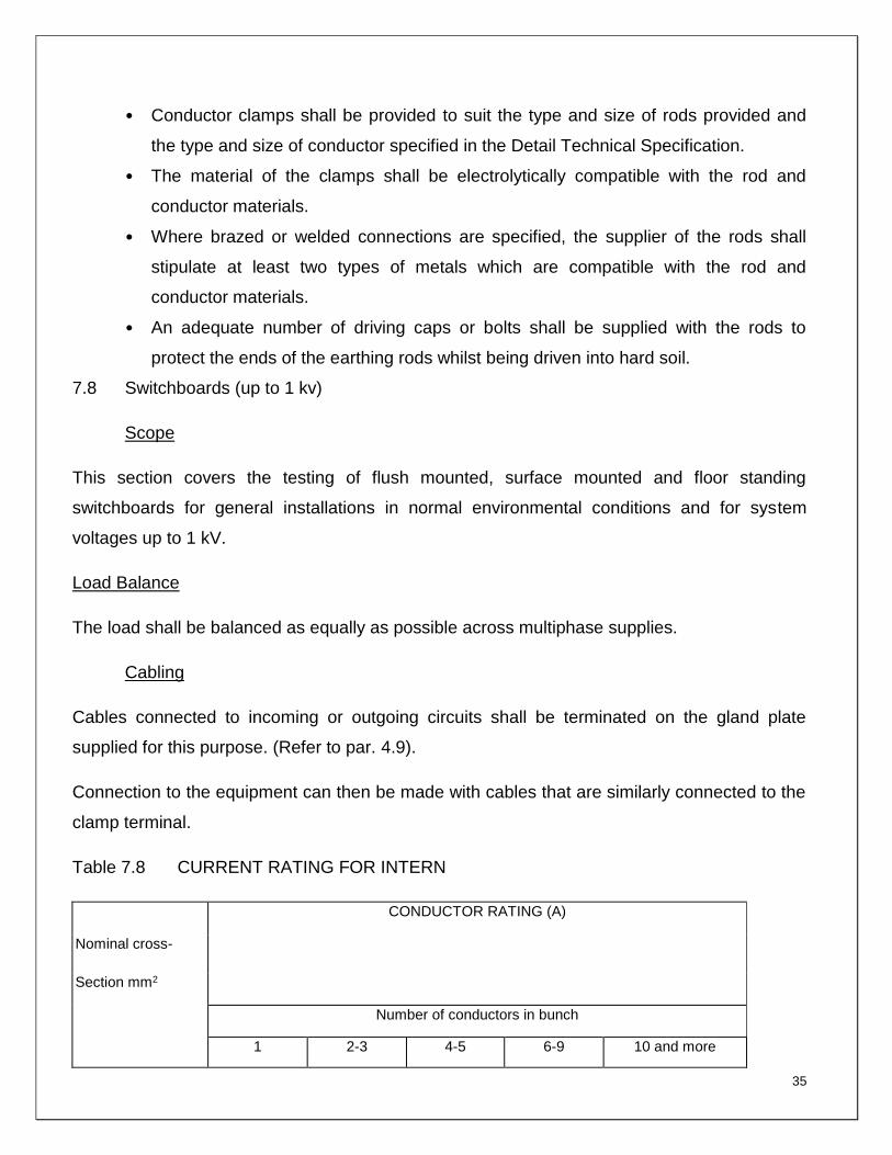
7.8 Switchboards (up to 1 kv)
Scope
This section covers the testing of flush mounted, surface mounted and floor standing
switchboards for general installations in normal environmental conditions and for system
voltages up to 1 kV.
Load Balance
The load shall be balanced as equally as possible across multiphase supplies.
Cabling
Cables connected to incoming or outgoing circuits shall be terminated on the gland plate
supplied for this purpose. (Refer to par. 4.9).
Connection to the equipment can then be made with cables that are similarly connected to the
clamp terminal.
Table 7.8 CURRENT RATING FOR INTERN
CONDUCTOR RATING (A)
Nominal cross-
Section mm2
Number of conductors in bunch
1
2-3
4-5
6-9
10 and more

36
2,5
28
25
22
19
16
4
37
33
30
26
22
6
47
42
38
33
28
10
64
54
51
44
38
16
85
76
68
59
51
25
112
101
89
78
67
35
138
124
110
96
88
50
172
154
137
120
103
70
213
191
170
149
127
The above table shall be applied for ambient temperatures up to 30ºC. (Refer to table 41.2 in
VDE 0100). For higher ambient temperatures the values shall be derated as prescribed by
SANS 10142. Table 10.
LABELLING
Care shall be taken to ensure that all equipment is fully labelled and that accurate descriptions
and safety warning notices appear.
Material
Engraved plastic or ivory sandwiched strips shall be used throughout. The strips shall bear
white lettering on a black background for normal labels and red letters on a white or yellow
background for danger notices.
Main Switchboards
Main switchboards and sub-main switchboards shall be supplied with the following bilingual
labels:
(a) Number and allocation of switchboard. Example:
CONTROL BOARD A4
BEHEERBORDA4
Lettering: at least 10 mm high prominent position. Label on the outside in a prominent position.

37
(b) Designation of busbar sections. Example:
BUSBAR SECTION 2
GELEISTAMSEKSIE2
Lettering: at least 10mm high. Label on the outside in a prominent position.
(c) Designation of all switchgear including circuit-breakers, isolators, contactors, etc. If the
current rating of circuit-breakers is not clearly marked on the equipment, the value shall be
indicated on the engraved label. Example:
SUPPLY TO BOARD C3 TOEVOER NA BORD C3
PUMP SUPPLY
POMPTOEVOER
Letters at least 5mm high. Label on the outside of the switchboard.
(d) All other equipment including meters, instruments, indicator lights, switches, push-
buttons, circuit-breakers, fuses, contactors, control relays, protection relays, etc. shall be
identified. The function of the equipment and circuits shall be clearly indicated. The main
switch shall be labelled as such and designated:
"SWITCH OFF IN CASE OF EMERGENCY"
"SKAKEL AF IN NOODGEVAL"
Flush mounted equipment within doors or front panels shall be identified with labels fixed to
the doors or front panels respectively. The labels for equipment installed behind panels, shall
be fixed to the chassis close to the equipment. If this equipment is positioned too close
together to accommodate descriptive engraved labels, the equipment may be identified by a
code or number on an engraved label which shall be fixed close to the equipment. The code
number shall be identified on a legend card which shall be installed on the switchboard behind
a plastic or other protective cover.
OTHER SWITCHBOARDS

38
All equipment on switchboards shall be identified with the necessary bilingual labels. The
circuit numbers shall appear at grouped single-pole circuit-breakers. The circuit numbers shall
correspond to the circuit numbers on the final installation drawings.
The above-mentioned circuits shall be identified on a legend card, which shall be installed on
the inside of the switchboard door, or in any other position where it can conveniently be
observed. All fuses, including instrument fuses, shall have labels stating function, fuse rating
and duty or type where applicable. All other equipment shall be identified separately and their
functions shall be clearly indicated.
FIXING OF LABELS
Labels shall not be fixed to components or trunking but to doors, panels, chassis or other
permanent structures of the switchboard.
Engraved strips shall be secured to facilitate a neat alteration of the designation of the labels.
Sufficient fixing points shall be provided to prevent labels from warping. Labels in slotted
holders shall be secured in position to prevent unauthorised removal. Labels may be secured
by the use of brass bolts and nuts, self-tapping screws, slotted label holders or pop-rivets.
NOTICES
At least one with the words "DANGER/INGOZI/GEVAAR" shall be mounted outside on the
front of the kiosk. This notice shall be riveted to the steel or cast iron door so that it cannot
easily be removed. Brass rivets shall be used. The notice shall be laminated into the fibreglass
door in the case of fibreglass kiosks.
7.9 Earth leakage relays
Earth leakage relays shall be single or three-phase units with a sensitivity of 30mA with
associated circuit breaker or on-load switch for use on 220/250V single phase or 380/433 V
three phase, 50 Hz, supplies.
The units shall be suitable for installation in switchboards in clip-in trays or bolted to the
chassis.

39
The earth leakage relay shall function on the current balance principle and shall comply with
SANS 767 as amended, and shall bear the SANS mark. Integral test facilities shall be
incorporated in the unit.
Circuit breakers with trip coils used integrally with earth leakage units (two pole for single
phase units and three pole for three phase units) shall comply with SANS 156.
On-load switches used integrally with earth leakage units (two pole for single-phase units and
three pole for three phase units) shall comply with SANS 60497.
The fault current rating of the unit shall be 2,5kA or 5kA as required, when tested in
accordance with SANS 156.
7.10 Photocells
General
The switches shall be used for the control of street lights and shall be provided with switch
contacts able to carry at least 5 A. The current during no-load conditions may not exceed 50
mA.
The units shall be suitable for 240 V + 6%. 50Hz. single-phase alternating current.
Construction
The units shall be weather and vibration resistant as they are to be mounted on top of
streetlight luminaires. The design shall be of such a nature that the units will be able to
withstand both hail damage and damage by stone-throwers. If the units do not meet with these
requirements, separate wire screens shall be provided for this purpose.
The units shall be provided with a standard NEMA plug and socket. The socket shall have a
bracket for mounting on a pole.
All components shall be treated to be corrosion resistant.
Operating conditions
The units shall be suitable for operating under dusty conditions between temperatures of -5 EC
and 55 EC.

40
Technical requirements
Units shall switch on when the light intensity drops to 15 lux + 20% and shall switch off when
the light intensity again reaches 40 lux + 20%.
When the unit is in the "on" position there must be a delay of one minute if it were to switch off
in the case of a sudden increase in the light intensity.
7.11 Contactors
Contactors shall be of the open or totally enclosed, triple- or double-pole, electromechanically
operated, air-break type suitable for 380/433 V or 220/250 V supplies and shall comply with
SANS 1092.
2 Contactors shall have the following characteristics:
(a) Enclosed coil easily replaceable.
(b) A permanent air gap in the magnetic circuit to prevent sticky operation.
(c) Provision for quick and simple inspection of contacts.
(d) Clearly marked main and auxiliary terminals.
All parts shall be accessible from the front.
Contactors which are not located in switchboards shall be housed in enclosures which comply
with IP 54 of IEC 144.
The current rating of the contactor shall be as specified for the circuit with a switching duty in
accordance with the SANS 1092 or IEC 158-1, utilisation category ACI for lighting and power
circuits and utilisation category AC3 for motor starting.
In addition to the required current carrying capacity and switching duty of a contactor, the
contactor chosen for a particular application shall be rated for the maximum through fault
current allowed by the back-up protection devices at the point where the contactor is installed.
Careful co-ordination of short circuit devices shall take place.

41
All laminations of the magnetic system of the contactor shall be tightly clamped. Noisy
contactors will not be accepted.
Non-current-carrying metallic parts shall be solidly interconnected and a common screwed
earth terminal shall be provided. The contactor shall be earthed to the switchboard earth bar.
Latched contactors shall be provided with a trip coil and a closing coil. The contactor shall
remain closed after de-energising the closing coil and shall only trip on energising the trip coil.
Contactor operating coils shall have a voltage rating as required by the control circuitry and
shall have limits of operation and temperature rise as specified in Clause 7.5 and Table IV of
IEC 158-1. Latched contactors shall be capable of being tripped at 50% of the rated coil
voltage.
Contactors for normal/standby changeover circuits shall be electrically and mechanically
interlocked. Contactors in star-delta starters shall be electrically interlocked.
Contactors with provision to add auxiliary contacts and convert auxiliary contacts on site are
preferred. Contactors with permanently fixed auxiliary contacts shall have at least 1 x N/0 and
1 x N/C spare auxiliary contacts in addition to the contacts specified or control purposes and in
addition to contacts required for self-holding operations or economy resistances. Where the
number of auxiliary contacts required is greater than the number of contacts that can be
accommodated on the contactor, an auxiliary relay or additional contactor shall be provided to
supply the additional contacts.
It shall be possible to replace main contacts without disconnecting wiring.
Auxiliary contacts shall be capable of making, carrying continuously and breaking 6A at 230V
AC, unity power factor for contactors used on 380-433/220-250 V systems.
Auxiliary contact functions required e.g. "lazy" contacts late-make, late-break, make-before-
break, etc. shall be inherent in the contact design. Under no circumstances may these
functions be improvised by bending contacts, loading contacts, etc. These functions shall be
available in all contactors.
Spare auxiliary contacts shall be wired to numbered terminal strips in the switchboard and
shall appear on the switchboard drawings.

42
All contactors on a specific project shall be from a standard range of one single manufacturer,
unless specified to the contrary.
8 DETAILED SCOPE OF WORK AND SPECIFICATIONS FOR UNINTERRUPTED
POWER SUPPLY (UPS)
8.1 Uninterrupted Power Supply (UPS) Scope of Work
8.1.1 The scope of work entails, supply, delivery, installation and commissioning of the
complete 2 of 3-Phase 20kVA (for Main Server Room), 1 of 3-Phase 20kVA (for Control Room
Area) and 4 of 1-Phase 5kVA (for Network Rooms) uninterrupted power supply units complete
with battery cabinets suitable for 1 hour battery back-up at NLSA’s Pretoria Campus, as
specified in this document, and also the provision of electrical installations for electrical power
supply to the UPS units in accordance with SANS 10142 Codes.
8.1.2 This Specification defines the minimum electrical and mechanical characteristics and
requirements for a continuous-duty three-phase, solid-state, uninterruptible power supply
system. It is intended to cover the complete UPS installation but does not cover all the details
of design and construction which are the sole responsibility of the Contractor.
8.1.3 The uninterruptible power supply system, hereafter referred to as the UPS, shall provide
high quality AC power for sensitive electronic equipment and other loads with battery to
maintain uptime.
8.1.4 The UPS shall operate in conjunction with the existing building electrical system to
protect electronic equipment from power disturbances that may occur with utility power, such
as voltage fluctuations, frequency variations, brownouts, power surges and sags.
8.1.5 The UPS units will be housed in the various rooms as per the schedule/ table below:

43
8.1.6 Prior to energizing and commissioning the contractor shall inspect, verify and sign-off
the connection of each UPS unit into local isolators.
8.1.7 Site Information
The site is at the National Library of South Africa, Pretoria Campus which is an
existing operational library facility.
Existing Main Server room shall be used to house 2 of 20KVA 3 Phase UPS
units complete with battery cabinets. The existing floor must be reinforced to
withstand the weight of two 20kVA UPS units.
Network rooms shall be used to house 4 of 1-Phase 5kVA.
The existing Control room shall be used to house 1 of 20KVA 3 Phase UPS unit
complete with battery cabinet and 2 x 3kW split inverter cooling type air-
conditioning unit for ventilation purposes.
8.1.8 Co-ordination
Due to nature of the installation, a fixed sequence of operation is required to
properly install the complete UPS. The contractor shall program his activities
closely with the main contractor and other trades in order to delay the entire
project (Where applicable).
The Contractor shall familiarise himself with the requirements of the other trades
and shall examine the plant and specification covering each of these sections
(where applicable).
The space requirements shall be carefully checked to ensure that the equipment
can be installed in the proper sequence in the space allocated.
No System Description Room Quantity
1 Three-Phase 20KVA UPS Main Server Room 2
2 Three-Phase 20KVA UPS Control Room 1
3 One-Phase 5KVA UPS Network Rooms 4

44
8.2 UPS Requirements
8.2.1 Quality, Standards and Regulations
All material and equipment supplied for this contract shall be new and the best of
their respective kind. All new materials and equipment supplied, shall comply
fully with the requirements laid down in the specification. The whole of the works
shall be executed in accordance with best practice and to the approval of the
engineer and shall in addition be executed by an accredited person who is in
possession of a valid 3 phase installation certificate and is also a member of the
ECA. The equipment shall comply with the latest issues of the following
standard specifications and shall bear the South African Bureau of Standards
(SABS) mark:
SABS 150 - Insulated wire
SANS 1091 - Colour standards for paint
SANS 10142 - Wiring code of practice
SANS 1474 - UPS units
8.2.2 Regulations and Rights of Engineer
Apart from any other authority, which the engineer may have in terms of the
contract, he shall have the right to set the standard and to accept or reject part of
the specified equipment depending on the quality of material and workmanship
offered, and materials for the project shall bear the SABS mark.
The Contractor shall be notified if the quality of such materials and/or
workmanship is not acceptable. In such an event, the Contractor shall replace
the specific part or repair it to the satisfaction of the Engineer, all at the cost of
the Contractor. Such an instruction shall not exempt the Contractor from any of
his obligations in terms of the contract.

45
8.2.3 Installation
The installation shall be erected and carried out in accordance with:
The Basic Conditions of Employment Act and the Machinery and Occupational
Safety Act of 1983, as amended.
The local Municipality By laws and Regulations as well as the regulations of the
local Supply Authority.
The local fire regulations
The Regulations of the Department of Posts and Telecommunications.
The Standard regulations of any Government Department or public service
company where applicable.
The latest issue of SANS 10142: Code of Practice for Wiring of Premises.
The Occupational Health and Safety Act, 1993 (Act 85 of 1993) as amended.
8.2.4 In addition, the Contractor shall at his cost issue all notices in respect of the installation
to the local authorities and shall exempt the client from all losses, costs or expenditures which
may arise as a result of the Contractor's failure to comply with the requirements of the
regulations enumerated above.
8.2.5 It shall be assumed that the Contractor is conversant with the above-mentioned
requirements. Should any requirements, by law or regulation, which contradicts the
requirements of this document, apply or become applicable during erection of the installation,
the Contractor shall immediately inform the engineer of such a contradiction. Under no
circumstances shall the Contractor carry out variations to the installation in terms of such
contradictions without obtaining the written permission to do so from the NLSA Representative
or Engineer.
8.2.6 Uninterrupted Power Supply (UPS)
System Requirements (The Required Input and Output Voltages are detailed
bellow)
Input to the UPS
Input voltage : 400/230V ± 10% or 230V ± 5%
Frequency : 50Hz ± 4%

46
System : 1 phase 2 wire or 3 phase 4 wire with
operative earth conductor, supplied from utility network or standby
generator set. Refer to detail specification.
Power factor : Not less than 0,8 lagging
Max starting current : 10 times full load current for not more
than ½ a cycle with rectifier soft starting facility.
Output to load
Rating : Refer to detail specification
Output voltage : Refer to detail specification
Frequency : 50 Hz ± 0,5 Hz
System : 1 phase 2 wire or 3 phase 4 wire with
operative earth conductor. Refer to detail specification
Voltage regulator : ± 10% maximum deviation of steady state
voltage recovering to within 5% in less than 50 ms and to within 1% less in
that 100 ms
Frequency stability : Normally automatically synchronised to
mains frequency if the latter is within 50 Hz ± 2% (adjustable window)
Runs free at 50 Hz ± 0,5 Hz at any load when mains is out of limits.
Harmonic content : Less than 4% total distortion
Amplitude modulation : Less than 2%
Overall Performance
Efficiency (overall) : 80 85%
8.2.7 System Description
The static UPS system will include a minimum of one rectifier, one inverter, one
static bypass and one battery system.
The UPS shall operate as a double conversion UPS with the operations modes.
The system shall be capable of providing an uninterrupted supply to the load with
the output characteristics as specified for a minimum period of 30 minutes during
47
a total mains failure (i.e. normal mains and standby generator supply failure).
The batteries shall be rated at an AC load power factor of 0,8 lagging.
The complete system, including all controls shall be designed in such a way that
the failure of any vital central component will NOT cause a complete system
failure.
The UPS shall operate satisfactory synchronous with the mains supply even
under severe conditions of up to 100% unbalanced load.
The UPS shall be amply rated to carry the stated full load current. The UPS shall
furthermore be capable of withstanding the following overloads;
Static Overload:
100% of full load continuously.
125% of full load for 5 minutes.
150% of full load for 2 minutes.
165% of full load for 1 second with inductive decay after initial equipment
switch on surge current.
Dynamic Overload:
300% for less than 5 msec.
1000% for less than 1 msec.
All component parts, cables and other connections shall be amply rated to
withstand the overloads stated and maintain the input voltage at the load within
the tolerances stated.
The equipment shall be designed for the maximum operating efficiency. The
efficiency shall be determined when the system is delivering full load at 0,8
power factor with the batteries fully charged. The load required by the auxiliary
equipment (controls, alarms, etc). Electronic switches and cabinet fan shall be
included in the determination of overall efficiency. A typical test report clearly
showing how the efficiencies are calculated shall be submitted with the tender.
It shall be the responsibility of the successful Tender to ensure satisfactory
operation of the complete system for the load to be supplied. It is, therefore,
essential that the tenderer acquaint himself fully typical conditions before the
tender closing date.

48
All cabinets containing power electronics shall be adequately screened and
earthed to prevent direct radio frequency radiation.
Tenderers shall submit with their tenders a schematic diagram(s) showing:
Input circuit breakers.
System busbars.
Rectifiers.
Batteries.
Inverters.
Electronic switches.
Bypass circuit.
Detour circuit.
Fuse protection.
Output circuit breakers.
Oscillator.
Power supply circuits to oscillator, alarms, controls, etc
Battery isolator.
Compulsory system components:
Rectifier
Inverter
Batteries
Battery charger
Automatic electronic no-break bypass circuit and switch
User interface panel
Protective devices and measuring equipment
Serial (RS-232) communication interface
Communication card slots (2)
Remote emergency power off contacts
Relay output contact (1)
Environmental inputs (2)
Self-monitoring system with digital readout by means of which all critical
functions can be checked (only required for systems above 200kVA).
49
8.2.8 Inverter Oscillator
The inverter shall contain an oscillator capable of operating and maintaining the
inverter output frequency as specified. The inverter oscillator shall be capable of
frequency synchronisation and phase locking to the mains (or standby generator)
power source frequency. When operating as a slave to the mains or standby
power and a failure occurs in the slaving signal, the invertor oscillator shall
automatically revert to a free running state and maintain the specified limits. All
changes in output frequency to free run or synchronise shall be gradual to suit
the load requirements.
8.2.9 Rectifier
The UPS shall have its own rectifier and rectifier transformer which shall operate
satisfactorily from the mains or standby supply.
The rectifier shall be of the solid state type providing full wave rectification of the
input voltage suitably regulated to suit the input requirements of the inverter.
Where necessary, a high grade DC filter shall be utilised to limit the output ripple
to within acceptable levels for the inverter input. Current limiting features shall be
provided to protect the rectifier. The current limiting settings shall be variable for
final adjustment on site.
Voltage free contacts shall be provided for the malfunction alarms of the rectifier.
An input monitoring circuit shall be provided for the rectifier. This circuit shall
switch off the rectifier when the r.m.s. value or frequency of the input voltage falls
below present values.
The necessary protection circuitry shall be provided to switch off the rectifier if
any one of the rectifier phases should fail, thus presenting an unbalanced load to
the incoming supply.
The output of the rectifier shall be connected in parallel to the battery and
inverter.
The rectifier shall have over temperature protection. Temperature sensing
probes shall be placed on the thyristor housing, thyristor mounting, or on the heat
sink close to the thyristor. The sensing of the off coming air temperature alone is
not acceptable.

50
Tenderers shall take into account the possible effects of harmonics that may be
present on the input supply due to non-sinusoidal waveforms at the rectifier
input, phase commutation, the effect of reactance during phase commutation etc.
The input voltage monitoring circuits of the rectifiers shall be adequately filtered
and buffered to ensure reliable load control and to prevent continuous on off
switching of the rectifiers.
For three phase units each of the three rectifier transformers shall have a
different primary to secondary phase displacement in order to minimise the
harmonics generated by the rectifiers.
8.2.10 Inverter
The inverter shall be adequately protected against any excessive overload or
short circuits that occur in the load. Reactive current limiting or other methods
shall be employed to render the thyristors short circuit proof. The successful
tenderer shall replace any thyristors or any inverter components at his own
expense if these should be damaged.
The necessary feedback and control circuits shall be incorporated to ensure
satisfactory operation separately or in synchronisation with the mains supply
under all conditions of dynamic load variations, stated overloads, severe
unbalanced conditions and high operating temperatures. The Thyristor Bridge
shall contain the necessary auxiliary circuitry to ensure satisfactory operation.
The output of the inverter shall be connected in parallel with the thyristor switch
output.
Each inverter shall have over temperature protection similar to the over
temperature protection for the rectifier.
A discharge device shall be provided across the D.C. input to the inverter, which
will discharge any capacitors in the inverter module when it is switched off.
8.2.11 Battery charger
The battery charger shall be a solid state, constant voltage type providing full
wave rectification of the input voltage with the output regulated to an accuracy as
specified. A high grade D.C. filter shall be utilised to limit the output ripple to the
stated tolerance. Current limiting features shall be provided. The value of the

51
current limit setting shall be in accordance with the maximum allowable charging
current that the batteries can withstand.
The maintained voltage on float charge shall be such as to give maximum life to
the batteries whilst maintaining the maximum charge conservation and
minimising gas formation and water loss. The optimum float charge voltage shall
be specified by the battery manufacturer but is expected to be approximately
2,23 volts per cell. The voltage shall be kept within ± 0,5% of the nominal value
for all loads from no load to the full rated battery charger current when supplying
the full output with batteries discharged.
8.2.12 Computer rooms/office UPS installation
The rectifier shall be equipped with 2 independent over voltage shutdown
contacts for maximum charger security.
The battery charger shall be designed to charge the batteries to 90% of its fully
charged capacity within 14 hours and to 100% capacity within 20 hours.
The battery charger shall be capable of boost charging the batteries to 2,6 volt
per cell. The boost facility shall be manually operated.
The battery charger shall be provided with a current limiting circuit.
The current limit setting shall be variable for easy adjustment on site.
The necessary voltage free contacts for the alarms and battery charger failures
shall be allowed for in the tender price.
The battery charger shall have over temperature protection similar to the
protection specified for the rectifier.
8.2.13 Battery
The battery capacity shall be sufficient to provide full load for the specified time.
The capacity shall be rated at a maximum specific gravity of 1,245 at 25 C and
correctly filled.
Tenderers shall state the discharge capacity of the battery after 10 hours of
charge and the battery voltage at its terminals under various conditions. The
inverter shall switch off on low battery voltage.
52
The battery cells shall be of the maintenance free type.
The batteries shall give satisfactory service for a minimum period of 3 years.
Tenderers shall state the maximum expected lifetime of the batteries, motivate
their statement, provide a statement by the battery manufacturer supporting this
and state that the charger offered is suitable for the battery.
The cells must be mounted in a matching steel cabinet or in the same cabinet as
the control equipment. The vented type cells should be mounted on a wooden
stand, consecutively, numbered with positive and negative terminals clearly
marked in a ventilated battery room.
The batteries shall be complete with cell inter-connectors and row inter
connectors. The output terminals shall be robust and adequately dimensioned for
the output cable terminations.
The inter connectors between cells and shall be made in a manner giving the
lowest volt drop and maximum resistance to corrosion.
All connections to cells must consist of flexible cable to avoid mechanical stress
at the cell terminals.
The tenderer shall describe the method of removal and replacement of a faulty
cell.
The battery shall be complete with a battery fuse isolator capable of breaking the
full load current drawn by the inverter. These battery fuse isolators shall be
installed in the inverter unit room or cabinet.
Terminal posts should be effective for the expected lifetime of the battery and
should be effective even if the cell is overfilled.
The battery may be resistance grounded through 5000 ohm to 10000 ohm for the
purpose of ground fault.
Tenderers shall submit full details with dimensioned drawings of the batteries
offered.
Tenderers shall submit the calculations and motivations complete with curves
supporting the selection of a specific battery cell.
All cabling for the battery shall be installed on PVC cable trays and fitted to the
satisfaction of the engineer.

53
8.2.14 Automatic by pass switch
break to the mains should the UPS unit fail. The latter unit shall simultaneously
be disconnected from the critical load bus. This transfer shall, however, be
inhibited if the mains is out of synchronism with the UPS output. Retransfer to the
UPS output shall be on a manual or automatic command. This switch must have
a cover fitted screwed to the panel so as to make the operating of this switch
impossible without having first removed the cover. This switch cover must also
have the following words etched in white with a red background mounted on or
adjacent the cover: CAUTION: BYPASS SWITCH ONLY: ONLY TO BE
OPERATED BY QUALIFIED STAFF.
The static switch should prevent "hunting" and after trying unsuccessfully to
switch a maximum of three (3) times the static switch should be inhibited from
further switching.
8.3 UPS System Ratings and Operating Characteristics
8.3.1 Construction
All material and components making up the UPS shall be new, of current
manufacture, and shall not have been in prior service except as required during
factory testing. The UPS shall be constructed of replaceable subassemblies. All
electronic devices shall be solid-state.
The UPS unit comprised of: input rectifier/battery charger, inverter, bypass, and
battery system (consisting of the appropriate number of sealed battery modules),
shall be housed in a single free-standing enclosure. The UPS cabinet shall be
cleaned, primed, and painted with the manufacture’s standard colour. Casters
and levelling feet shall be provided as standard.
Matching external battery cabinets shall be provide if required for extended
backup times.
8.3.2 Cubicles and switchboard

54
All the converter equipment shall be housed in totally enclosed, free standing,
floor mounted cubicles, designed to provide adequate ventilation for the
equipment.
All cubicles shall be rigid with suitably braced doors providing front access.
All cubicles shall be vermin proof.
All equipment shall be mounted on the metal framework, suitably arranged to
provide safe operation and ease of access. Fuses and switchgear in particular
should be safely accessible even under load conditions.
All power bridges, filters and other major components both in the inverter and
rectifier shall be completely withdrawable to facilitate rapid repair and/or
replacement. The method of withdrawal shall be such that a complete module
can be extracted in the operating condition so that checks and measurements
may be made while in operation and access to all components facilitated.
All electronic printed circuit cards shall be of a good quality and shall be easy
and simple to interchange.
All auxiliary power supplies shall be duplicated and shall be connected so as to
operate in parallel redundancy. At least two primary sources of power shall be
provided for each of the power supplies in the system.
Flexible wires shall not be soldered directly onto terminals but shall have a
crimped tab, which is soldered onto a terminal or post. The wire wrapping
technique shall be employed for electronic circuits where possible.
The front panel alarms shall be clearly and adequately marked in both official
languages. A single line mimic layout of the switchgear shall be provided on the
front of the cubicles providing a graphic display of the circuitry of the equipment
involved.
All input and output power cables shall be terminated using approved cable
glands, onto a cable gland support bracket. The cable conductors shall terminate
at the connecting busbars or shall be connected directly to the appropriate
switchgear. All power cables shall be properly numbered with wrap around cable
markers with punched figures to identify cables at each termination point.

55
9. DETAILED SCOPE OF WORK AND SPECIFICATIONS FOR BUILDING
MANAGEMENT SYSTEM (BMS)
9.1 The scope of utilizes under the considered set of intelligent Building management
system (IBMS) are sub classified as follows:
This shall comprise the monitoring & control of the following:
Air conditioning
Ventilation and exhaust fans
Electricals (UPS, DG sets, Power distribution panels)
Fire Suppression system
Water treatment and management
Lifts
9.2 Purpose
The purpose of this specification is to obtain the services of an experienced service
provider for the replacement of Building Management System (BMS); the Supervision
Control and Data Acquisition (SCADA) and Three (3) year maintenance contract at
National Library of South Africa Pretoria Campus.
9.3 Description of Service
Service to maintain the Building Management System SCADA is for the collection of
real-time vital data from each system and its various sub system and displays all this
information to the front end of Building Management System SCADA. The main function
is to monitor how the Infrastructure is performing and to be aware of the status of each
infrastructure. This will enable a prompt and timeous response to any infrastructure
damage or equipment breakdowns.
9.3.1 Service Description for Maintenance
Daily Operations monitoring and maintenance
Maintenance of field systems i.e. (CPU Cards, Moxa Protocol Converters,
Individual system input sensors)
Conduct repairs on communication faults and sensors displayed
Quarterly Engineering Services and Major Issue Maintenance
9.3.2 Service Description for the Upgrade
Database and OPC Maintenance
Upgrade Server Maintenance (Software and Hardware)

56
Powersmart Software Configuration
BMS SCADA application Software to be installed on the upgraded servers
Server Setup and Configuration
Server – Rackmount
BMS SCADA and subset software to be upgraded to be able to run on the
latest Microsoft platform (Clients & Servers).
Redundancy configured for the main and secondary BMS SCADA HMI
Servers
The BMS SCADA GUI (graphical user interface) should be re-designed to
the latest industry standards and features (e.g. Alarm and Event
management)
9.4 Extent of Service Upgrade
Supply and install Building Management System SCADA which is compatible to
the Windows 7 or higher application and complaint to the NLSA IT security
requirements
Redesign and as-build Architectural network diagrams
Software packages licenses as per scope of work
As build programming languages in areas that the Logics might need to be
reconfigured
Training of users in operation of the new system
9.5. Scope of Supply:
9.5.1 All materials including the labour force etc. required for the completion of the work are
to be supplied by the contractor unless mentioned otherwise. The contractor shall have to
make necessary arrangements for proper storage of materials brought for the execution of
work.
9.5.2 The above scope of the work is not limited to the brief given above if any work is
required to complete the entire air conditioning system the same shall be carried out by the
contractor.
9.5.3 Training on the BMS system to be provided to NLSA staff.
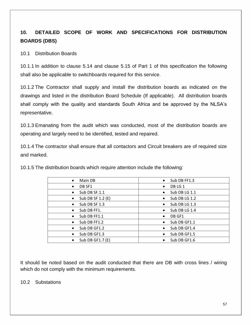
57
10. DETAILED SCOPE OF WORK AND SPECIFICATIONS FOR DISTRIBUTION
BOARDS (DBS)
10.1 Distribution Boards
10.1.1 In addition to clause 5.14 and clause 5.15 of Part 1 of this specification the following
shall also be applicable to switchboards required for this service.
10.1.2 The Contractor shall supply and install the distribution boards as indicated on the
drawings and listed in the distribution Board Schedule (If applicable). All distribution boards
shall comply with the quality and standards South Africa and be approved by the NLSA’s
representative.
10.1.3 Emanating from the audit which was conducted, most of the distribution boards are
operating and largely need to be identified, tested and repaired.
10.1.4 The contractor shall ensure that all contactors and Circuit breakers are of required size
and marked.
10.1.5 The distribution boards which require attention include the following:
Main DB Sub DB FF1.3
DB SF1 DB LG 1
Sub DB SF.1.1 Sub DB LG 1.1
Sub DB SF 1.2 (E) Sub DB LG 1.2
Sub DB SF 1.3 Sub DB LG 1.3
Sub DB FF1. Sub DB LG 1.4
Sub DB FF1.1 DB GF1
Sub DB FF1.2 Sub DB GF1.1
Sub DB GF1.2 Sub DB GF1.4
Sub DB GF1.3 Sub DB GF1.5
Sub DB GF1.7 (E) Sub DB GF1.6
It should be noted based on the audit conducted that there are DB with cross lines / wiring
which do not comply with the minimum requirements.
10.2 Substations

58
10.2.1 The Substations and DBs must be maintained regularly and kept clean to minimize the
dust level.
10.2.2 The following Electrical Maintenance must be adhered to in order to keep all the
equipment in good operational conditions,
Preventative Maintenance PM
Corrective Maintenance CM
10.2.3 These Maintenances must be done monthly and all records and reports be submitted to
the NLSA’s representative or Agent.
Preventative Maintenance PM
Purpose
To limit random failure of electrical equipment.
Reduce the number of breakdowns and stoppages.
Increase productivity of employees.
Maintain the life time of equipment by reducing equipment failure.
Maintenance
Corrective Maintenance CM
Purpose
To limit the breakdown time.
Ensure the productivity of employees
11. DETAILED SCOPE OF WORK AND SPECIFICATIONS FOR GENERAL
ELECTRICAL
11.1 Schedule of light fittings
The light fittings and accessories are to be according to the quality specifications and shall be
approved by the NLSA.
Type A: Industrial fluorescent luminaire 600 x 600 3 or 4-tube -switch start with SABS
mark or SABS mark of compliance
Type B: Channel fluorescent luminaire 1500 2-tube 2 x 58W-switch start with SABS mark
or SABS mark of compliance.
Type C: PL 9W, 14, 18W OR 24W fittings and Lamps shall be according to the quality in
the specifications and with SABS mark.

59
Type D: Flood light luminaire with 150 W LED, IP65 mark, for mounting on a round
conduit box with tapped fixing holes at 50 mm centres.
12. BILL QUANTITIES
Preamble
TYPICAL ITEMS/PREAMBLES TO BE INSERTED IN THE BILLS OF QUANTITIES
The Schedule of Quantities shall not be used for ordering purposes. The Contractor
shall check the lengths of cables and overhead conductors on site before ordering any
of the cables. Any allowance for off-cuts shall be made in the unit rates.
The descriptions in these bills of quantities shall be read in conjunction with the
specification.
The unit rate for each item in the Bills of Quantities shall include for all materials, labour,
profit, transport, etc., everything necessary for the execution and complete installation
of the work in accordance with the description.
The Bills of Quantities shall not be used for ordering purposes. The Contractor shall
check the lengths of cables and overhead conductors on site before ordering any of the
cables. Any allowance for off-cuts shall be made in the unit rates.
The rates shall exclude Value-Added Tax and the total carried over to the final
summary.
All material covered by this Specification shall, wherever possible, be of South African
manufacture.
{NB: The supply and installation of material and equipment must be measured separately}.
BILL NO 1: PRELIMINAIRIES AND GENERALS
Item Description Unit Qty Unit Rate Total Amount
BILL NO.1 – PRELIMINAIRIES AND GENERALS
1
General: Allow for complying with the special and general conditions of the contract and labour requirements, for site establishment, for providing site office, ablution facilities, project name boards, adequate and suitable water, temporary electricity, sanitary and first aid services, and for attending all inspections and meetings.
Item 1

60
2 Guarantee: Allow for providing all sureties, guaranties and insurance as required in the conditions of contract.
Item 1
3
Drawings: Allow for marking-up a full set of drawings to show the exact routes of cables and sensors etc. to render a complete as-installed set of drawings.
Item 1
4 Permits and Notices: Allow obtaining permits and giving notices and for co-ordination with other contractor.
1
5 Storage: Provide storage for plant, materials and equipment with proper security.
Item 1
6
Additional Items: Any additional items not included in the schedule of quantities that the Contractor wishes to specify and price separately.
Item 1
7
Dismantling and disposal: Allow for R 5 000.00 (Five Thousand Rand Only) for removal and disposal of existing electrical light switches.
Item 1
8 Contingencies: Allow for R 50 000.00 (Fifty Thousand Rand Only)
Item 1
SUB TOTAL 1
BILL NO 2: GENERAL ELECTRICAL INSTALLATIONS
Item Description Unit Qty Unit Rate Total Amount
Do not add VAT to the individual items. Add VAT in the final summary. The prices for the items must be inclusive of all costs to provide a COMPLETE installation.
PART B: SECTION 1
BILL NO. 2: GENERAL ELECTRICAL INSTALLATIONS
1 EXISTING DISTRIBUTION BOARD
Infrared thermography inspection, Testing, Commission, and issued certificate of compliance for all Distribution Board to comply with Occupational Health and safety Act (OHS Act) of 1993 and SANS 10142-1.
No 32
2 LV SWITCHGEARS
Remove faulty, supply and install low voltage switchgears to existing distribution boards.
Supply and install low voltage switchgears

61
2.1 20A SP MCB 5kA
Remove damaged No. 4
Supply No. 4
Install No. 4
2.2 10A SP MCB 5kA
Remove damaged No. 7
Supply No. 7
Install No. 7
2.3 60A TP MCB 5kA
Supply No. 1
Install No. 1
2.4 40A TP MCB 5kA
Supply No. 1
Install No. 1
2.5 230V Contactor
Remove damaged No. 3
Supply No. 3
Install No. 3
2.6 Surge Arrestors, 3 Pole and Neutral 275V with indication
Remove damaged No. 8
Supply No. 8
Install No. 8
2.7 60A, 230V Single phase Earth leakage protection
Remove damaged No. 4
Supply No. 4
Install No. 4
Item Description Unit Qty Unit Rate Total Amount
Do not add VAT to the individual items. Add VAT in the final summary. The prices for the items must be inclusive of all costs to provide a COMPLETE installation.
3 L.V CABLES
Supply and Install 600/1000V grade PVC/SWA insulated stranded copper conductors drawn into conduit, laid in ground or cable tray.
3.1 10mm² 4 core PVC SWA cable copper cable + 6mm² BCEW for Tumble Dryers.
Supply m 90
Install m 90

62
3.2 6mm² 4 core PVC SWA copper cable+ 4mm² BCEW for Washer Extractors
Supply m 100
Install m 100
3.3 4mm² 4 core PVC SWA cable + 2.5mm² BCEW for Roller Iron & Iron Press.
Supply m 80
Install m 80
4 CABLES TERMINATIONS
Supply and Install cable termination including glands, shrouds, lugs and locknut.
4.1 10mm² 4 core PVC SWA copper cable
Supply No 2
Install No 2
4.2 6mm² 4 core PVC SWA copper cable
Supply No 2
Install No 2
4.3 4mm² 4 core PVC SWA copper cable
Supply No 2
Install No 2
5 BCEW TERMINATIONS
Supply and Install cable termination including glands, shrouds, lugs and locknut.
5.1 6mm² BCEW
Supply No 2
Install No 2
Item Description Unit Qty Unit Rate Total Amount
Do not add VAT to the individual items. Add VAT in the final summary. The prices for the items must be inclusive of all costs to provide a COMPLETE installation.
5.2 4mm² BCEW
Supply No 2
Install No 2
5.3 2.5mm² BCEW
Supply No 2
Install No 2

63
6 CONDUIT AND ACCESSORIES
Galvanised Steel Conduit
Galvanised Steel conduit including bending, short lengths, draw boxes, cutting, bands, jointing, couplings, saddles and wastage
6.1 20 mm
Supply m 200
Install m 200
6.2 25 mm
Supply m 100
Install m 100
Galvanised Steel round boxes installed inside ceiling void for occupancy sensors.
6.3 65mm deep round box side entry way
Supply No 102
Install No 102
7 PVC INSULATED CONDUCTORS
Conductors drawn into conduit or installed in wiring channel
7.1 2,5 mm²
Supply m 3000
Install m 3000
7.2 4 mm²
Supply m 800
Install m 800
PVC INSULATED EARTH CONDUCTORS
Earth conductors drawn into conduit or installed in wiring channel
7.3 2,5 mm²
Supply m 3800
Install m 3800
Item Description Unit Qty Unit Rate Total Amount
Do not add VAT to the individual items. Add VAT in the final summary. The prices for the items must be inclusive of all costs to provide a COMPLETE installation.

64
8 OCCUPANCY SENSORS
Occupancy sensors are to be 230V, connected to conductors and terminated as per SANS 10142 Code of Practice for Wiring Premises
8.1
Type C1: Wall mounted Dual Technology-Passive Infrared & Ultrasonic Occupancy Sensor c/w IntelliDAPT, for offices.
Supply No 14
Install No 14
8.2
Type C2: Dual Technology-Passive Infrared & Ultrasonic Ceiling mounted Occupancy Sensor c/w IntelliDAPT, for offices c/w UVPP universal power pack
Supply No 88
Install No 88
9
PHOTOCELL Type Pcell: Photocell in an empty round oval shaped bulkhead
Supply No 1
Install No 1
10 SOCKET OUTLETS:
Socket outlets are to be 230V 16A 3-pin socket outlets the Crabtree type, installed on power skirting(measured elsewhere) including cover plates and connected to conductor ends
10.1 16A, 230V round 3-pin dedicated switch socket outlet
Supply No 2
Install No 2
11 Testing and commissioning the complete electrical installation including issuing electrical certificate of compliance.
Item 1

65
ITEM
DESCRIPTION UNIT QUANTITY UNIT RATE
TOTAL
12. Test, remove faulty / damaged, supply and install the following equipment.
12.1 FLOURISCENT TUBE PHILIPS T8 36W
No 320
12.2 FLOURISCENT TUBE PHILIPS T8 18W
No 75
12.3 FLOURISCENT TUBE PHILIPS T8 58W
No 215
12.4 FLOURISCENT TUBE PHILIPS T8 58W COVER 2 BULBS
No 05
12.5 FLOURISCENT TUBE PHILIPS T8 36W COVER 3 BULBS
No 06
12.6 FLOURISCENT TUBE PHILIPS T8 36W COVER 2 BULBS
No 06
12.7 FLOURISCENT TUBE PHILIPS T8 18W COVER 3 BULBS
No 04
12.8 DOWNLIGHTS BULBS No 35
12.9 P9 LIGHT BULB 4 PIN 18W No 45
12.10 FLOOR LIGHTS 4 PIN 18W No 43
12.11 P9 LIGHT BULB 4 PIN 26W No 35
12.12 PL-L LIGHT BULB 36W No 260
12.13 RL 737 MINI FLOOD LIGHT No 09
12.14 100W LED FLOOD LIGHTS No 07
12.15 FLOURESCENT LIGHT BALLAST 58W
No 120
12.16 FLOURESCENT LIGHT BALLAST 18W
No 24
12.17 FLOURESCENT LIGHT BALLAST 36W
No 84
12.18 UNDER TABLE LIGHT BOX BULB No 05
12.19 10 W PIN LIGHT BULB No 08
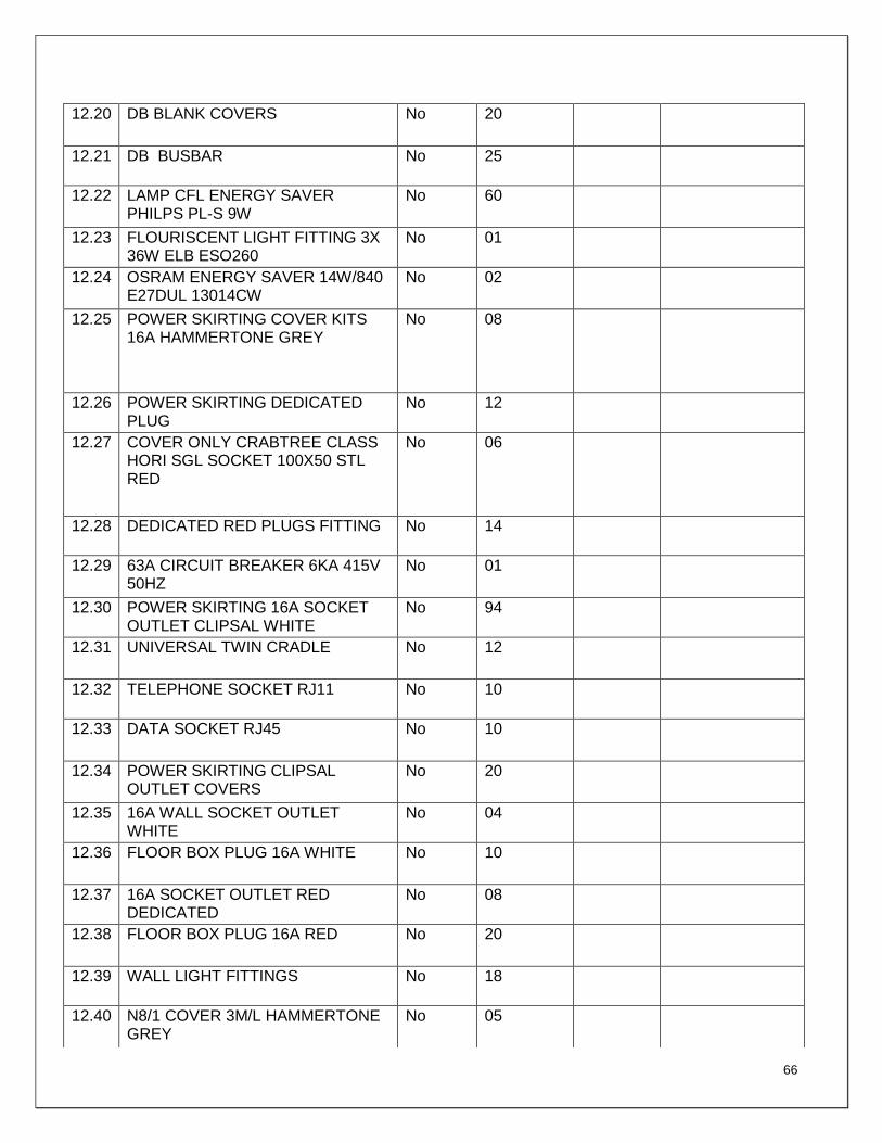
66
12.20 DB BLANK COVERS No 20
12.21 DB BUSBAR No 25
12.22 LAMP CFL ENERGY SAVER PHILPS PL-S 9W
No 60
12.23 FLOURISCENT LIGHT FITTING 3X 36W ELB ESO260
No 01
12.24 OSRAM ENERGY SAVER 14W/840 E27DUL 13014CW
No 02
12.25 POWER SKIRTING COVER KITS 16A HAMMERTONE GREY
No 08
12.26 POWER SKIRTING DEDICATED PLUG
No 12
12.27 COVER ONLY CRABTREE CLASS HORI SGL SOCKET 100X50 STL RED
No 06
12.28 DEDICATED RED PLUGS FITTING No 14
12.29 63A CIRCUIT BREAKER 6KA 415V 50HZ
No 01
12.30 POWER SKIRTING 16A SOCKET OUTLET CLIPSAL WHITE
No 94
12.31 UNIVERSAL TWIN CRADLE No 12
12.32 TELEPHONE SOCKET RJ11 No 10
12.33 DATA SOCKET RJ45 No 10
12.34 POWER SKIRTING CLIPSAL OUTLET COVERS
No 20
12.35 16A WALL SOCKET OUTLET WHITE
No 04
12.36 FLOOR BOX PLUG 16A WHITE No 10
12.37 16A SOCKET OUTLET RED DEDICATED
No 08
12.38 FLOOR BOX PLUG 16A RED No 20
12.39 WALL LIGHT FITTINGS No 18
12.40 N8/1 COVER 3M/L HAMMERTONE GREY
No 05
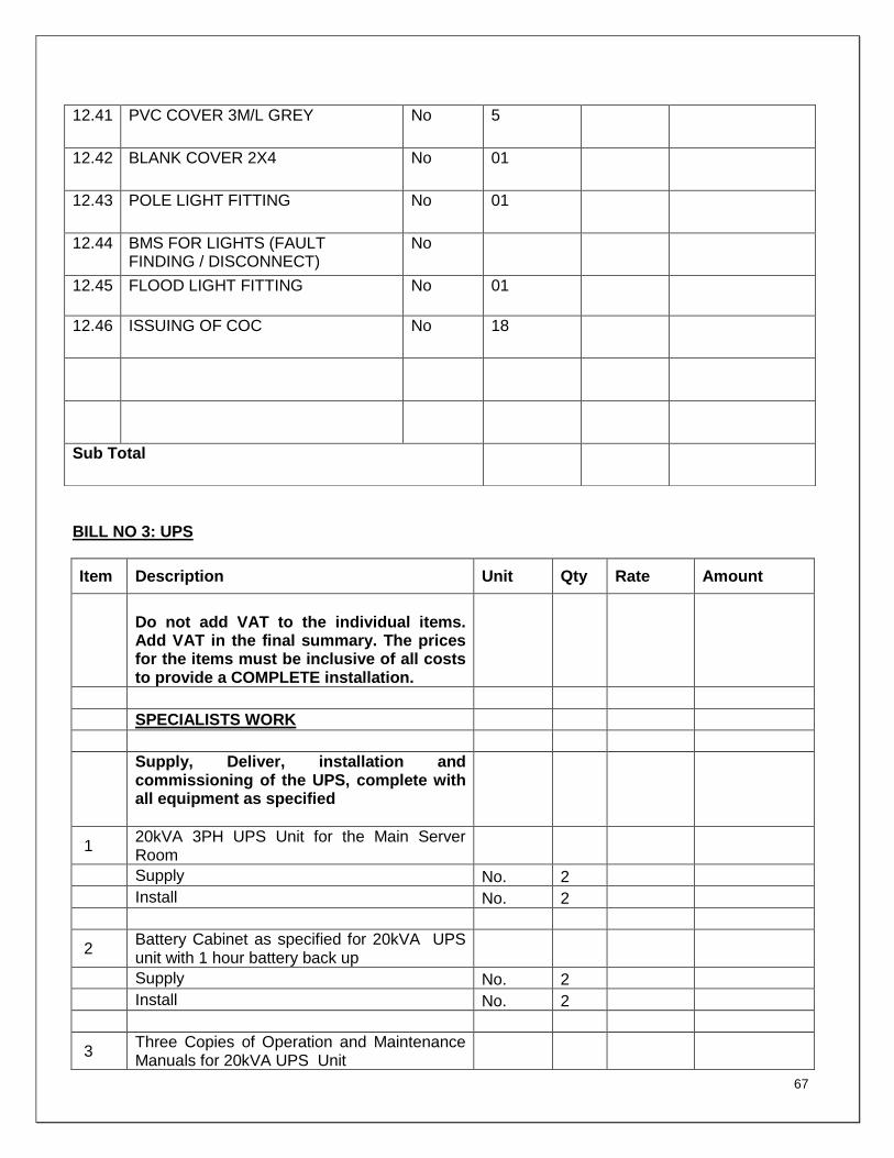
67
BILL NO 3: UPS
Item Description Unit Qty Rate Amount
Do not add VAT to the individual items. Add VAT in the final summary. The prices for the items must be inclusive of all costs to provide a COMPLETE installation.
SPECIALISTS WORK
Supply, Deliver, installation and commissioning of the UPS, complete with all equipment as specified
1 20kVA 3PH UPS Unit for the Main Server Room
Supply No. 2
Install No. 2
2 Battery Cabinet as specified for 20kVA UPS unit with 1 hour battery back up
Supply No. 2
Install No. 2
3 Three Copies of Operation and Maintenance Manuals for 20kVA UPS Unit
12.41 PVC COVER 3M/L GREY No 5
12.42 BLANK COVER 2X4 No 01
12.43 POLE LIGHT FITTING No 01
12.44 BMS FOR LIGHTS (FAULT FINDING / DISCONNECT)
No
12.45 FLOOD LIGHT FITTING No 01
12.46 ISSUING OF COC No 18
Sub Total

68
Supply No. 1
Install No. 0
4 20kVA 3PH UPS Unit for the Control Room
Supply No. 1
Install No. 1
5 Battery Cabinet as specified for 20kVA UPS Unit with 1 hour battery back up
Supply No. 1
Install No. 1
6 Three Copies of Operation and Maintenance Manuals for 20kVA UPS Unit
Supply No. 1
Install No. 0
Do not add VAT to the individual items. Add VAT in the final summary. The prices for the items must be inclusive of all costs to provide a COMPLETE installation.
SPECIALISTS WORK
Supply, Deliver, installation and commissioning of the UPS, complete with all equipment as specified
7 5kVA 1PH UPS Unit for the Network Rooms
Supply No. 4
Install No. 4
8 Battery Cabinet as specified for 5kVA UPS Unit with 1 hour battery back-up
Supply No. 4
Install No. 4
9 Three Copies of Operation and Maintenance Manuals for 5kVA UPS Unit
Supply No. 1
Install No. 0
10 Medium Duty Steel Galvanised Cable Tray, 114mm wide c/w accessories
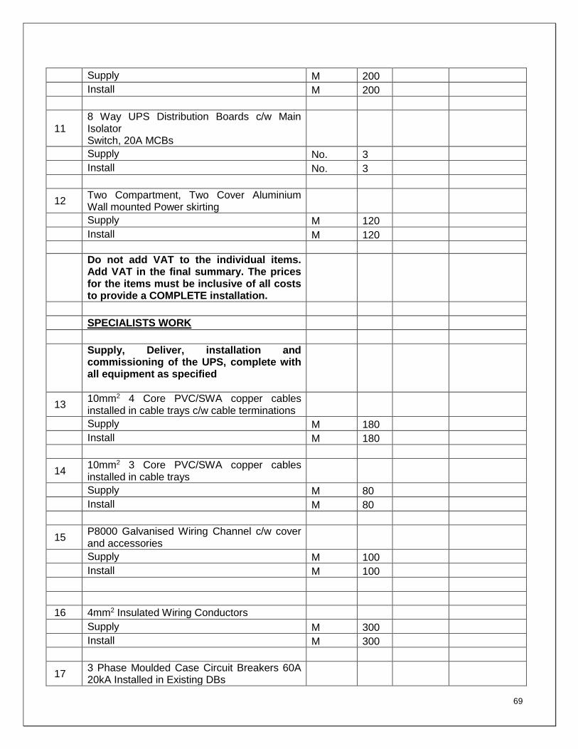
69
Supply M 200
Install M 200
11 8 Way UPS Distribution Boards c/w Main Isolator Switch, 20A MCBs
Supply No. 3
Install No. 3
12 Two Compartment, Two Cover Aluminium Wall mounted Power skirting
Supply M 120
Install M 120
Do not add VAT to the individual items. Add VAT in the final summary. The prices for the items must be inclusive of all costs to provide a COMPLETE installation.
SPECIALISTS WORK
Supply, Deliver, installation and commissioning of the UPS, complete with all equipment as specified
13 10mm2 4 Core PVC/SWA copper cables installed in cable trays c/w cable terminations
Supply M 180
Install M 180
14 10mm2 3 Core PVC/SWA copper cables installed in cable trays
Supply M 80
Install M 80
15 P8000 Galvanised Wiring Channel c/w cover and accessories
Supply M 100
Install M 100
16 4mm2 Insulated Wiring Conductors
Supply M 300
Install M 300
17 3 Phase Moulded Case Circuit Breakers 60A 20kA Installed in Existing DBs
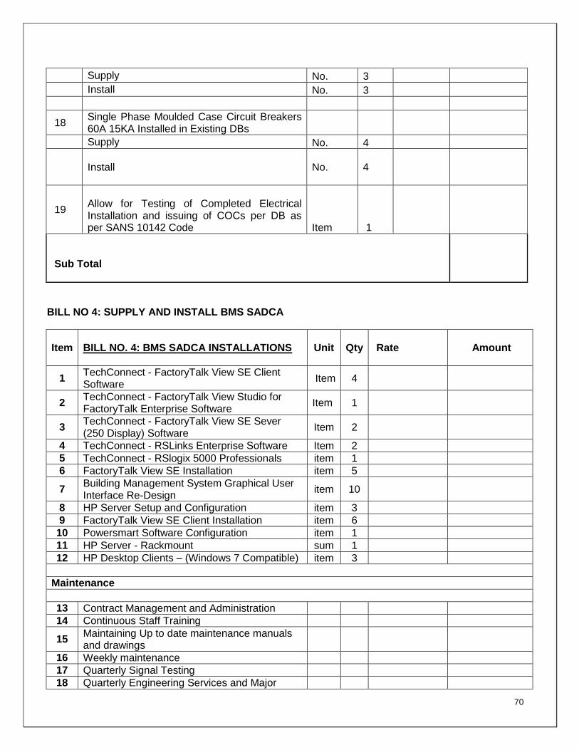
70
Supply No. 3
Install No. 3
18 Single Phase Moulded Case Circuit Breakers 60A 15KA Installed in Existing DBs
Supply No. 4
Install No.
4
19
Allow for Testing of Completed Electrical Installation and issuing of COCs per DB as per SANS 10142 Code Item 1
Sub Total
BILL NO 4: SUPPLY AND INSTALL BMS SADCA
Item BILL NO. 4: BMS SADCA INSTALLATIONS Unit Qty Rate
Amount
1 TechConnect - FactoryTalk View SE Client Software
Item 4
2 TechConnect - FactoryTalk View Studio for FactoryTalk Enterprise Software
Item 1
3 TechConnect - FactoryTalk View SE Sever (250 Display) Software
Item 2
4 TechConnect - RSLinks Enterprise Software Item 2
5 TechConnect - RSlogix 5000 Professionals item 1
6 FactoryTalk View SE Installation item 5
7 Building Management System Graphical User Interface Re-Design
item 10
8 HP Server Setup and Configuration item 3
9 FactoryTalk View SE Client Installation item 6
10 Powersmart Software Configuration item 1
11 HP Server - Rackmount sum 1
12 HP Desktop Clients – (Windows 7 Compatible) item 3
Maintenance
13 Contract Management and Administration
14 Continuous Staff Training
15 Maintaining Up to date maintenance manuals and drawings
16 Weekly maintenance
17 Quarterly Signal Testing
18 Quarterly Engineering Services and Major

71
Issue Maintenance *incl. Building Management System Meetings (Building Management System Engineer / Manager for a period of one week per quarter)
All required Travelling
SUB TOTAL
BILL NO 5: PROVISIONAL AMOUNT FOR WORK TO BE DONE BY SPECIALIST FIRM
Item BILL NO. 4: PROVISIONAL AMOUNT FOR WORK TO BE DONE BY SPECIALIST FIRM
Unit Qty Provisional
Amount Amount
1 EARTHING AND LIGHTING PROTECTION
1.1
Provide the sum of R85 000.00 (Eighty Five Thousand rands) for testing and restoring of Earthing & Lighting Protection, and issue earthing certificate.
Item 1
1.2 Allow for 10% mark-up if required Item 1
1.3 Allow for 5% general attendance, etc. Item 1
2 REMEASUREMENTS OF QUANTITIES
2.1 Provide the sum of R5000-00 (Five Thousand Rands) for re-measurements of quantities
Item 1
2.2 Allow for 10% mark-up if required Item 1
2.3 Allow for 5% general attendance, etc. Item 1
Sub Total

72
SUMMARY
Item Description Amount
SUMMARY
1 BILL NO.1- Preliminaries and Generals
2 BILL No.2 : General Electrical Installations
3 BILL NO. 3: Supply and installation of UPS
4 BILL NO. 4: Supply and Install BMS; SADCA
5 BILL No.5 : Provisional Amount for Work to be Done by Specialist Firm
Sub-Total 1 (Excluding VAT)
ADD 10% Contingencies
ADD 14% VAT
Sub-Total 2 (Including VAT)
TOTAL ELECTRICAL COST ESTIMATES INSTALLATION EXCL VAT
Carried to Summary R……………………………………………..
VAT 14% R……………………………………………..
TOTAL INCLUSIVE OF VAT R………………………………………………

73
13. TIME FRAME
It is expected that the project would commence as soon as the service provider is appointed.
The project will run for 5 months.
14. EVALUATION CRITERIA
14.1 Format of bids
The attached bid documents must be completed and each page initialled by bidders'
authorised representatives and witnesses. All the compulsory documents as listed below must
be provided.
NB: Failure to submit the documents listed on requirements shall result in the
disqualification of your bid. All bidders who have state employees as shareholders and
or directors in their companies must submit with the bids the permission to conduct
remunerative work outside the public service as contemplated in Section 30 of the
Public Service Act.
14.2 Pre-qualification of Bids (Stage 01)
The following mandatory requirements must be met to qualify for this tender:
CIDB with a minimum grading level 4
Attendance of the compulsory briefing session
Valid Tax Clearance Certificate with ( SARS PIN CODE)
Valid Certified Broad-Based Black Economic Empowerment Certificate
Certified copy of UIF Certificate / Letter of Good Standing
Certificate of Incorporation, documents of Partnership or CC or Company
Certified ID copies of the shareholders
ECA registered company.
CSD registration summary report
One (1) original and four (4) copies of the tender document
Company profile with a contactable and traceable references list where
similar projects have been successfully completed

74
NB: Failure to submit the documents listed above shall result in the disqualification of
your bid.
In Stage 02, all bids which qualify in Stage 01 will be evaluated for functionality. The bid
documents will be evaluated individually on score sheets by representatives of the Bid
Evaluation Committee according to the evaluation criteria indicated below. The Evaluation
Committee will allocate points out of 100 for functionality according to the criteria set out
below. Bidders who fail to score 70 points for functionality will be considered as having
submitted a non-responsive bid and will not be considered for further evaluation.
Proposals will be evaluated on a scale of 1 – 5 in accordance with the criteria below.
The rating will be as follows:
1 = Very Poor
2 = Average
3 = Good
4 = Very Good
5 = Excellent
Bidders are expected to furnish detailed information in substantiation of compliance to
the evaluation criteria mentioned above.
Evaluation Criteria
14.3 Stage 02: Functionality Evaluation
The Following Functionality Criteria will be used:
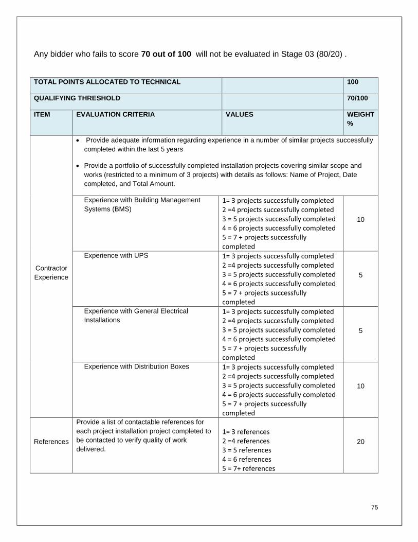
75
Any bidder who fails to score 70 out of 100 will not be evaluated in Stage 03 (80/20) .
TOTAL POINTS ALLOCATED TO TECHNICAL 100
QUALIFYING THRESHOLD 70/100
ITEM EVALUATION CRITERIA VALUES WEIGHT
%
Contractor
Experience
Provide adequate information regarding experience in a number of similar projects successfully
completed within the last 5 years
Provide a portfolio of successfully completed installation projects covering similar scope and
works (restricted to a minimum of 3 projects) with details as follows: Name of Project, Date
completed, and Total Amount.
Experience with Building Management
Systems (BMS)
1= 3 projects successfully completed 2 =4 projects successfully completed 3 = 5 projects successfully completed 4 = 6 projects successfully completed 5 = 7 + projects successfully completed
10
Experience with UPS 1= 3 projects successfully completed 2 =4 projects successfully completed 3 = 5 projects successfully completed 4 = 6 projects successfully completed 5 = 7 + projects successfully completed
5
Experience with General Electrical
Installations
1= 3 projects successfully completed 2 =4 projects successfully completed 3 = 5 projects successfully completed 4 = 6 projects successfully completed 5 = 7 + projects successfully completed
5
Experience with Distribution Boxes 1= 3 projects successfully completed 2 =4 projects successfully completed 3 = 5 projects successfully completed 4 = 6 projects successfully completed 5 = 7 + projects successfully completed
10
References
Provide a list of contactable references for
each project installation project completed to
be contacted to verify quality of work
delivered.
1= 3 references 2 =4 references 3 = 5 references 4 = 6 references 5 = 7+ references
20

76
Key Staff
Provide adequate information regarding
experience of key staff in electrical
installations of this nature by demonstrating
that key staff are well qualified and
competent in the application of their skills that
relate to the scope of the project – submit
CV’s of the key staff members and their
qualifications/ certifications with clear work
description and references
1= Detail not provided 2 =Detail partially provided 3 = Detail provided no supporting documents 4 = Detail provided with supporting documentation 5 = Detail fully provided with full supporting documentation
30
Program
and
Schedule
Provide adequate Program & schedule
demonstrating estimated start and finish
dates, major milestones and critical path and
estimated duration and logic to research
works completion. Program and schedule
also contain information on execution
integration and redundancy for unforeseen
delays or occurrences
1= Detail not provided 2 =Detail partially provided 3 = Detail provided no timelines 4 = Detail provided with timelines, milestones & critical path 5 = Detail fully provided with full timelines
20
14.4 PRICE and BEE POINTS
The 80/20 scoring will be used as the criteria for appointment. The criteria are in terms of the
Preferential Procurement Policy Framework where would be allocated as follows:
o Capability & offering: 80 points
o B-BBEE: 20 points

77
B-BBEE Status
B-BBEE Status Level Of Contributor Number of Points
1 20
2 18
3 14
4 12
5 8
6 6
7 4
8 2
Non-compliant contributor 0
15. BASIS OF BIDS
Specify standard government rates and discounted rates and stipulate the type of
concessions that can be provided on all required services. Documentary proof with regards to
rates, discounts and concessions must form part of the tender and NLSA will pay an agreed
fee for the service rendered.
15.1 Other Conditions
All prices quoted must be VAT inclusive.
NLSA will not make upfront payments. Submit invoice once the installation is
completed.
Bidders must certify their work with COC.
The detailed quotation must be valid for 90 days.
Upon award of the bid, the successful bidder shall enter into an agreement with the
NLSA and the said agreement shall be in the format prescribed by the NLSA.
The successful bidder shall provide the services required based on the set timelines
and as per the schedule to be provided by the NLSA.

78
15.2 Submission of Bids
Bidders are required to submit their bids (both technical and financial) in one envelope. Four
copies of the bid must be submitted comprising of one (1) original and four copies.
NLSA may request clarification or further information regarding any aspect of the bidder. The
bidder must provide the requested information within twenty four (24) hours after the request
has been made; otherwise the bidder may be disqualified.
The following information must be endorsed on the envelopes:
Bid Number
Closing date
Name of the bidder
16. ENQUIRIES
Please refer all enquiries pertaining to the technical specification to:
Manager: Administration and facilities
Mr. Daniel Tladi NLSA (012) 401 9768 [email protected]
All enquiries regarding bid documents must be directed to the SCM Office
Manager: Supply Chain
Miss Lydia Maleka NLSA (012) 401 9765 [email protected]

79
SBD1
PART A INVITATION TO BID
YOU ARE HEREBY INVITED TO BID FOR REQUIREMENTS OF THE (NAME OF DEPARTMENT/ PUBLIC ENTITY)
BID NUMBER: NLSA. PTA.ELECTRICALWORKS 10/2017
CLOSING DATE:
06 November 2017
CLOSING TIME:
11:00
DESCRIPTION ELECTRICAL WORK
THE SUCCESSFUL BIDDER WILL BE REQUIRED TO FILL IN AND SIGN A WRITTEN CONTRACT FORM (SBD7).
BID RESPONSE DOCUMENTS MAY BE DEPOSITED IN THE BID BOX SITUATED AT (STREET ADDRESS)
75 THABO SEHUME STREET,
PRETORIA CBD
SUPPLIER INFORMATION
NAME OF BIDDER
POSTAL ADDRESS
STREET ADDRESS
TELEPHONE NUMBER CODE NUMBER
CELLPHONE NUMBER
FACSIMILE NUMBER CODE NUMBER
E-MAIL ADDRESS
VAT REGISTRATION NUMBER
TCS PIN: OR CSD No:
B-BBEE STATUS LEVEL VERIFICATION CERTIFICATE [TICK APPLICABLE BOX]
Yes
No
B-BBEE STATUS LEVEL SWORN AFFIDAVIT
Yes
No
IF YES, WHO WAS THE CERTIFICATE ISSUED BY?
AN ACCOUNTING OFFICER AS CONTEMPLATED IN THE CLOSE CORPORATION ACT (CCA) AND NAME THE
AN ACCOUNTING OFFICER AS CONTEMPLATED IN THE CLOSE CORPORATION ACT (CCA)

80
APPLICABLE IN THE TICK BOX
A VERIFICATION AGENCY ACCREDITED BY THE SOUTH AFRICAN ACCREDITATION SYSTEM (SANAS)
A REGISTERED AUDITOR
NAME:
[A B-BBEE STATUS LEVEL VERIFICATION CERTIFICATE/SWORN AFFIDAVIT(FOR EMEs& QSEs) MUST BE SUBMITTED IN ORDER TO QUALIFY FOR PREFERENCE POINTS FOR B-BBEE]
ARE YOU THE ACCREDITED REPRESENTATIVE IN SOUTH AFRICA FOR THE GOODS /SERVICES /WORKS OFFERED?
Yes No [IF YES ENCLOSE PROOF]
ARE YOU A FOREIGN BASED SUPPLIER FOR THE GOODS /SERVICES /WORKS OFFERED?
Yes No [IF YES ANSWER PART B:3 BELOW ]
SIGNATURE OF BIDDER ……………………… DATE
CAPACITY UNDER WHICH THIS BID IS SIGNED (Attach proof of authority to sign this bid; e.g. resolution of directors, etc.)
TOTAL NUMBER OF ITEMS OFFERED
TOTAL BID PRICE (ALL INCLUSIVE)
BIDDING PROCEDURE ENQUIRIES MAY BE DIRECTED TO:
TECHNICAL INFORMATION MAY BE DIRECTED TO:
DEPARTMENT/PUBLIC ENTITY NLSA
CONTACT PERSON Daniel Tladi
CONTACT PERSON Lydia Maleka TELEPHONE NUMBER 012 401 9768
TELEPHONE NUMBER 012 401 9765
FACSIMILE NUMBER 086 650 8264
FACSIMILE NUMBER 086 650 8264
E-MAIL ADDRESS
E-MAIL ADDRESS

81
PART B TERMS AND CONDITIONS FOR BIDDING
1. BID SUBMISSION:
1.1. BIDS MUST BE DELIVERED BY THE STIPULATED TIME TO THE CORRECT ADDRESS.
LATE BIDS WILL NOT BE ACCEPTED FOR CONSIDERATION. 1.2. ALL BIDS MUST BE SUBMITTED ON THE OFFICIAL FORMS PROVIDED–(NOT TO BE
RE-TYPED) OR ONLINE
1.3. BIDDERS MUST REGISTER ON THE CENTRAL SUPPLIER DATABASE (CSD) TO UPLOAD MANDATORY INFORMATION NAMELY: (BUSINESS REGISTRATION/ DIRECTORSHIP/ MEMBERSHIP/IDENTITY NUMBERS; TAX COMPLIANCE STATUS; AND BANKING INFORMATION FOR VERIFICATION PURPOSES). B-BBEE CERTIFICATE OR SWORN AFFIDAVIT FOR B-BBEE MUST BE SUBMITTED TO BIDDING INSTITUTION.
1.4. WHERE A BIDDER IS NOT REGISTERED ON THE CSD, MANDATORY INFORMATION NAMELY: (BUSINESS REGISTRATION/ DIRECTORSHIP/ MEMBERSHIP/IDENTITY NUMBERS; TAX COMPLIANCE STATUS MAY NOT BE SUBMITTED WITH THE BID DOCUMENTATION. B-BBEE CERTIFICATE OR SWORN AFFIDAVIT FOR B-BBEE MUST BE SUBMITTED TO BIDDING INSTITUTION.
1.5. THIS BID IS SUBJECT TO THE PREFERENTIAL PROCUREMENT POLICY FRAMEWORK
ACT 2000 AND THE PREFERENTIAL PROCUREMENT REGULATIONS, 2017, THE GENERAL CONDITIONS OF CONTRACT (GCC) AND, IF APPLICABLE, ANY OTHER LEGISLATION OR SPECIAL CONDITIONS OF CONTRACT.
2. TAX COMPLIANCE REQUIREMENTS
2.1 BIDDERS MUST ENSURE COMPLIANCE WITH THEIR TAX OBLIGATIONS.
2.2 BIDDERS ARE REQUIRED TO SUBMIT THEIR UNIQUE PERSONAL IDENTIFICATION NUMBER (PIN) ISSUED BY SARS TO ENABLE THE ORGAN OF STATE TO VIEW THE TAXPAYER’S PROFILE AND TAX STATUS.
2.3 APPLICATION FOR TAX COMPLIANCE STATUS (TCS) OR PIN MAY ALSO BE MADE VIA E-FILING. IN ORDER TO USE THIS PROVISION, TAXPAYERS WILL NEED TO REGISTER WITH SARS AS E-FILERS THROUGH THE WEBSITE WWW.SARS.GOV.ZA.
2.4 BIDDERS MAY ALSO SUBMIT A PRINTED TCS TOGETHER WITH THE BID.
2.5 IN BIDS WHERE CONSORTIA / JOINT VENTURES / SUB-CONTRACTORS ARE INVOLVED, EACH PARTY MUST SUBMIT A SEPARATE PROOF OF TCS / PIN / CSD NUMBER.
2.6 WHERE NO TCS IS AVAILABLE BUT THE BIDDER IS REGISTERED ON THE CENTRAL SUPPLIER DATABASE (CSD), A CSD NUMBER MUST BE PROVIDED.

82
3. QUESTIONNAIRE TO BIDDING FOREIGN SUPPLIERS
3.1. IS THE BIDDER A RESIDENT OF THE REPUBLIC OF SOUTH AFRICA (RSA)? YES NO
3.2. DOES THE BIDDER HAVE A BRANCH IN THE RSA? YES NO
3.3. DOES THE BIDDER HAVE A PERMANENT ESTABLISHMENT IN THE RSA? YES NO
3.4. DOES THE BIDDER HAVE ANY SOURCE OF INCOME IN THE RSA? YES NO
IF THE ANSWER IS “NO” TO ALL OF THE ABOVE, THEN, IT IS NOT A REQUIREMENT TO OBTAIN A TAX COMPLIANCE STATUS / TAX COMPLIANCE SYSTEM PIN CODE FROM THE SOUTH AFRICAN REVENUE SERVICE (SARS) AND IF NOT REGISTER AS PER 2.3 ABOVE.
NB: FAILURE TO PROVIDE ANY OF THE ABOVE PARTICULARS MAY RENDER THE BID INVALID.
.

83
SBD 3.1
PRICING SCHEDULE – FIRM PRICES (PURCHASES)
NOTE: ONLY FIRM PRICES WILL BE ACCEPTED. NON-FIRM PRICES (INCLUDING PRICES
SUBJECT TO RATES OF EXCHANGE VARIATIONS) WILL NOT BE CONSIDERED IN CASES WHERE DIFFERENT DELIVERY POINTS INFLUENCE THE PRICING, A
SEPARATE PRICING SCHEDULE MUST BE SUBMITTED FOR EACH DELIVERY POINT
Name of bidder………………………………….. Bid number NLSA. PTA.ELECTRICALWORKS 10/2017 Closing Time 11:00 Closing date 06 November 2017
OFFER TO BE VALID FOR 90 DAYS FROM THE CLOSING DATE OF BID. __________________________________________________________________________ ITEM QUANTITY DESCRIPTION BID PRICE IN RSA CURRENCY NO. ** (ALL APPLICABLE TAXES INCLUDED)
- Required by: …………………………………. - At: ………………………………….
………………………………… - Brand and model …………………………………. - Country of origin …………………………………. - Does the offer comply with the specification(s)? *YES/NO - If not to specification, indicate deviation(s) …………………………………. - Period required for delivery …………………………………. *Delivery: Firm/not firm
- Delivery basis ……………………………………
Note: All delivery costs must be included in the bid price, for delivery at the prescribed destination. ** “all applicable taxes” includes value- added tax, pay as you earn, income tax, unemployment insurance fund contributions and skills development levies. *Delete if not applicable

84
SBD 3.2
PRICING SCHEDULE – NON-FIRM PRICES (PURCHASES)
NOTE: PRICE ADJUSTMENTS WILL BE ALLOWED AT THE PERIODS AND TIMES SPECIFIED IN THE BIDDING DOCUMENTS. IN CASES WHERE DIFFERENT DELIVERY POINTS INFLUENCE THE PRICING, A SEPARATE PRICING SCHEDULE MUST BE SUBMITTED FOR EACH DELIVERY POINT
Name of Bidder…………………………………………… Bid number NLSA. PTA.ELECTRICALWORKS 10/2017 Closing Time 11:00 Closing date 06 November 2017
OFFER TO BE VALID FOR 90 DAYS FROM THE CLOSING DATE OF BID.
------------------------------------------------------------------------------------------------------------------------------------------------
ITEM QUANTITY DESCRIPTION BID PRICE IN RSA CURRENCY NO. ** (ALL APPLICABLE TAXES INCLUDED)
----------------------------------------------------------------------------------------------------------------------------------------- -------
- Required by: …………………………………………
- At: …….…..……………………………….
- Brand and model ……..…………………………………. - Country of origin …...…………………………………. - Does the offer comply with the specification(s)? *YES/NO - If not to specification, indicate deviation(s) …………………………………………. - Period required for delivery …………………………………………. - Delivery: *Firm/not firm
** “all applicable taxes” includes value- added tax, pay as you earn, income tax, unemployment insurance fund contributions and skills development levies.
*Delete if not applicable

85
SBD 3.2
PRICE ADJUSTMENTS
A. NON-FIRM PRICES SUBJECT TO ESCALATION
1. IN CASES OF PERIOD CONTRACTS, NON FIRM PRICES WILL BE ADJUSTED (LOADED) WITH THE
ASSESSED CONTRACT PRICE ADJUSTMENTS IMPLICIT IN NON FIRM PRICES WHEN CALCULATING THE COMPARATIVE PRICES
2. IN THIS CATEGORY PRICE ESCALATIONS WILL ONLY BE CONSIDERED IN TERMS OF THE FOLLOWING
FORMULA:
VPt
oR
tRD
oR
tRD
oR
tRD
oR
tRDPtVPa
4
44
3
33
2
22
1
111
Where:
Pa = The new escalated price to be calculated. (1-V)Pt = 85% of the original bid price. Note that Pt must always be the original bid
price and not an escalated price. D1, D2.. = Each factor of the bid price eg. labour, transport, clothing, footwear, etc. The total
of the various factors D1, D2…etc. must add up to 100%. R1t, R2t…… = Index figure obtained from new index (depends on the number of factors used). R1o, R2o = Index figure at time of bidding. VPt = 15% of the original bid price. This portion of the bid price remains firm i.e. it is not
subject to any price escalations.
3. The following index/indices must be used to calculate your bid price:
Index………. Dated………. Index………. Dated………. Index………. Dated……….
Index………. Dated………. Index………. Dated………. Index………. Dated……….
FURNISH A BREAKDOWN OF YOUR PRICE IN TERMS OF ABOVE-MENTIONED FORMULA. THE TOTAL OF
THE VARIOUS FACTORS MUST ADD UP TO 100%.
FACTOR (D1, D2 etc. eg. Labour, transport etc.)
P PERCENTAGE OF BID PRICE

86
SBD 3.2
B. PRICES SUBJECT TO RATE OF EXCHANGE VARIATIONS
1. Please furnish full particulars of your financial institution, state the currencies used in the conversion of the prices of the items to South African currency, which portion of the price is subject to rate of exchange variations and the amounts remitted abroad.
PARTICULARS OF FINANCIAL INSTITUTION
ITEM NO PRICE CURRENCY RATE
PORTION OF PRICE
SUBJECT TO ROE
AMOUNT IN FOREIGN
CURRENCY REMITTED ABROAD
ZAR=
ZAR=
ZAR=
ZAR=
ZAR=
ZAR=
2. Adjustments for rate of exchange variations during the contract period will be calculated by using the average monthly exchange rates as issued by your commercial bank for the periods indicated hereunder: (Proof from bank required)
AVERAGE MONTHLY EXCHANGE RATES FOR THE PERIOD:
DATE DOCUMENTATION MUST BE SUBMITTED
TO THIS OFFICE
DATE FROM WHICH NEW CALCULATED PRICES
WILL BECOME EFFECTIVE
DATE UNTIL WHICH NEW
CALCULATED PRICE WILL BE
EFFECTIVE

87
SBD 4
DECLARATION OF INTEREST
1. Any legal person, including persons employed by the state¹, or persons having a kinship with persons
employed by the state, including a blood relationship, may make an offer or offers in terms of this invitation to bid (includes a price quotation, advertised competitive bid, limited bid or proposal). In view of possible allegations of favouritism, should the resulting bid, or part thereof, be awarded to persons employed by the state, or to persons connected with or related to them, it is required that the bidder or his/her authorised representative declare his/her position in relation to the evaluating/adjudicating authority where-
- the bidder is employed by the state; and/or - the legal person on whose behalf the bidding document is signed, has a relationship with
persons/a person who are/is involved in the evaluation and or adjudication of the bid(s), or where it is known that such a relationship exists between the person or persons for or on whose behalf the declarant acts and persons who are involved with the evaluation and or adjudication of the bid.
2. In order to give effect to the above, the following questionnaire must be completed and submitted
with the bid. 2.1 Full Name of bidder or his or her representative: ………………………………………… 2.2 Identity Number: ……………………………………………………………………………… 2.3 Position occupied in the Company (director, trustee, shareholder²): …………………… 2.4 Company Registration Number: …………………………………………………………….. 2.5 Tax Reference Number: ……………………………………………………………………… 2.6 VAT Registration Number: ……………………………………………………………… 2.6.1 The names of all directors / trustees / shareholders / members, their individual identity numbers, tax
reference numbers and, if applicable, employee / persal numbers must be indicated in paragraph 3 below.
¹“State” means – (a) any national or provincial department, national or provincial public entity or constitutional institution within the meaning of
the Public Finance Management Act, 1999 (Act No. 1 of 1999); (b) any municipality or municipal entity; (c) provincial legislature; (d) national Assembly or the national Council of provinces; or (e) Parliament. ²”Shareholder” means a person who owns shares in the company and is actively involved in the management of the enterprise or business
and exercises control over the enterprise.

88
2.7 Are you or any person connected with the bidder YES / NO presently employed by the state? 2.7.1 If so, furnish the following particulars:
Name of person / director / trustee / shareholder/ member: ....……………………………… Name of state institution at which you or the person connected to the bidder is employed : ………………………………… Position occupied in the state institution: ………………………………… Any other particulars: ………………………………………………………………
……………………………………………………………… ………………………………………………………………
2.7.2 If you are presently employed by the state, did you obtain YES / NO
the appropriate authority to undertake remunerative work outside employment in the public sector?
2.7.2.1 If yes, did you attached proof of such authority to the bid YES / NO
document? (Note: Failure to submit proof of such authority, where applicable, may result in the disqualification of the bid.
2.7.2.2 If no, furnish reasons for non-submission of such proof:
……………………………………………………………………. ……………………………………………………………………. …………………………………………………………………….
2.8 Did you or your spouse, or any of the company’s directors / YES / NO trustees / shareholders / members or their spouses conduct business with the state in the previous twelve months?
2.8.1 If so, furnish particulars:
………………………………………………………………….. ………………………………………………………………….. …………………………………………………………………...
2.9 Do you, or any person connected with the bidder, have YES / NO any relationship (family, friend, other) with a person employed by the state and who may be involved with the evaluation and or adjudication of this bid?
2.9.1 If so, furnish particulars. ……………………………………………………………... …………………………………………………………..….

89
……………………………………………………………… 2.10 Are you, or any person connected with the bidder, YES / NO aware of any relationship (family, friend, other) between
any other bidder and any person employed by the state who may be involved with the evaluation and or adjudication of this bid?
2.10.1 If so, furnish particulars.
……………………………………………………………… ……………………………………………………………… ………………………………………………………………
2.11 Do you or any of the directors / trustees / shareholders / members YES/NO
of the company have any interest in any other related companies whether or not they are bidding for this contract?
2.11.1 If so, furnish particulars: ……………………………………………………………………………. ……………………………………………………………………………. ……………………………………………………………………………. 3 Full details of directors / trustees / members / shareholders.
Full Name Identity Number Personal Tax
Reference
Number
State
Employee
Number /
Persal Number

90
4 DECLARATION
I, THE UNDERSIGNED (NAME)………………………………………………………………………
CERTIFY THAT THE INFORMATION FURNISHED IN PARAGRAPHS 2 and 3 ABOVE IS CORRECT. I ACCEPT THAT THE STATE MAY REJECT THE BID OR ACT AGAINST ME IN TERMS OF PARAGRAPH 23 OF THE GENERAL CONDITIONS OF CONTRACT SHOULD THIS DECLARATION PROVE TO BE FALSE. ………………………………….. ..…………………………………………… Signature Date …………………………………. ……………………………………………… Position Name of bidder
May 2011

91
SBD 5
This document must be signed and submitted together with your bid
THE NATIONAL INDUSTRIAL PARTICIPATION PROGRAMME
INTRODUCTION
The National Industrial Participation (NIP) Programme, which is applicable to all government
procurement contracts that have an imported content, became effective on the 1 September
1996. The NIP policy and guidelines were fully endorsed by Cabinet on 30 April 1997. In
terms of the Cabinet decision, all state and parastatal purchases / lease contracts (for goods,
works and services) entered into after this date, are subject to the NIP requirements. NIP is
obligatory and therefore must be complied with. The Industrial Participation Secretariat (IPS) of
the Department of Trade and Industry (DTI) is charged with the responsibility of administering
the programme.
PILLARS OF THE PROGRAMME
1.1 The NIP obligation is benchmarked on the imported content of the contract. Any contract
having an imported content equal to or exceeding US$ 10 million or other currency
equivalent to US$ 10 million will have a NIP obligation. This threshold of US$ 10 million
can be reached as follows:
(a) Any single contract with imported content exceeding US$10 million. or
(b) Multiple contracts for the same goods, works or services each with
imported content exceeding US$3 million awarded to one seller over a
2 year period which in total exceeds US$10 million. or
(c) A contract with a renewable option clause, where should the option be
exercised the total value of the imported content will exceed US$10
million. or
(d) Multiple suppliers of the same goods, works or services under the same
contract, where the value of the imported content of each allocation is
equal to or exceeds US$ 3 million worth of goods, works or services to
the same government institution, which in total over a two (2) year
period exceeds US$10 million.
1.2 The NIP obligation applicable to suppliers in respect of sub-paragraphs 1.1 (a) to 1.1 (c) above
will amount to 30 % of the imported content whilst suppliers in respect of paragraph 1.1 (d)
shall incur 30% of the total NIP obligation on a pro-rata basis.

92
1.3 To satisfy the NIP obligation, the DTI would negotiate and conclude agreements such as
investments, joint ventures, sub-contracting, licensee production, export promotion,
sourcing arrangements and research and development (R&D) with partners or suppliers.
1.4 A period of seven years has been identified as the time frame within which to discharge the
obligation.
REQUIREMENTS OF THE DEPARTMENT OF TRADE AND INDUSTRY
2.1 In order to ensure effective implementation of the programme, successful
bidders (contractors) are required to, immediately after the award of a contract that
is in excess of R10 million (ten million Rands), submit details of such a contract to
the DTI for reporting purposes.
2.2 The purpose for reporting details of contracts in excess of the amount of R10
million (ten million Rands) is to cater for multiple contracts for the same goods,
works or services; renewable contracts and multiple suppliers for the same goods,
works or services under the same contract as provided for in paragraphs 1.1.(b) to
1.1. (d) above.
BID SUBMISSION AND CONTRACT REPORTING REQUIREMENTS OF BIDDER AND SUCCESSFUL BIDDERS (CONTRACTORS)
3.1 Bidders are required to sign and submit this Standard Bidding Document (SBD 5)
together with the bid on the closing date and time.
3.2 In order to accommodate multiple contracts for the same goods, works or
services; renewable contracts and multiple suppliers for the same goods, works or
services under the same contract as indicated in sub-paragraphs 1.1 (b) to 1.1 (d)
above and to enable the DTI in determining the NIP obligation, successful bidders
(contractors) are required, immediately after being officially notified about any
successful bid with a value in excess of R10 million (ten million Rands), to contact
and furnish the DTI with the following information:
• Bid / contract number.
• Description of the goods, works or services.
• Date on which the contract was accepted.
• Name, address and contact details of the government institution.
• Value of the contract.
• Imported content of the contract, if possible.
3.3 The information required in paragraph 3.2 above must be sent to the
Department of Trade and Industry, Private Bag X 84, Pretoria, 0001 for the
attention of Mr Elias Malapane within five (5) working days after award of the
contract. Mr Malapane may be contacted on telephone (012) 394 1401, facsimile

93
(012) 394 2401 or e-mail at [email protected] for further details about the
programme.
PROCESS TO SATISFY THE NIP OBLIGATION
4.1 Once the successful bidder (contractor) has made contact with and furnished the
DTI with the information required, the following steps will be followed:
a. the contractor and the DTI will determine the NIP obligation;
b. the contractor and the DTI will sign the NIP obligation agreement;
c. the contractor will submit a performance guarantee to the DTI;
d. the contractor will submit a business concept for consideration and approval by
the DTI;
e. upon approval of the business concept by the DTI, the contractor will submit
detailed business plans outlining the business concepts;
f. the contractor will implement the business plans; and
g. the contractor will submit bi-annual progress reports on approved plans to the
DTI.
4.2 The NIP obligation agreement is between the DTI and the successful bidder
(contractor) and, therefore, does not involve the purchasing institution.
Bid number ………………………………….. Closing date:…………………………
Name of bidder………………………………………………………………………………
Postal address ……………………………………………………………………
…………………………………………………………………
Signature…………………………………….. Name (in print)………………………..
Date…………………………………………..

94
SBD 6.1
PREFERENCE POINTS CLAIM FORM IN TERMS OF THE PREFERENTIAL PROCUREMENT REGULATIONS 2017
This preference form must form part of all bids invited. It contains general information and serves as a claim form for preference points for Broad-Based Black Economic Empowerment (B-BBEE) Status Level of Contribution NB: BEFORE COMPLETING THIS FORM, BIDDERS MUST STUDY THE GENERAL
CONDITIONS, DEFINITIONS AND DIRECTIVES APPLICABLE IN RESPECT OF B-BBEE, AS PRESCRIBED IN THE PREFERENTIAL PROCUREMENT REGULATIONS, 2017.
1. GENERAL CONDITIONS
1.1 The following preference point systems are applicable to all bids:
- the 80/20 system for requirements with a Rand value of up to R50 000 000 (all applicable taxes included); and
- the 90/10 system for requirements with a Rand value above R50 000 000 (all applicable taxes included).
1.2
a) The value of this bid is estimated to exceed/not exceed R50 000 000 (all applicable taxes included) and therefore the ………….. preference point system shall be applicable; or
b) Either the 80/20 or 90/10 preference point system will be applicable to this tender (delete whichever is not applicable for this tender).
1.3 Points for this bid shall be awarded for:
(a) Price; and
(b) B-BBEE Status Level of Contributor.
1.4 The maximum points for this bid are allocated as follows:
POINTS
PRICE
B-BBEE STATUS LEVEL OF CONTRIBUTOR
Total points for Price and B-BBEE must not exceed
100
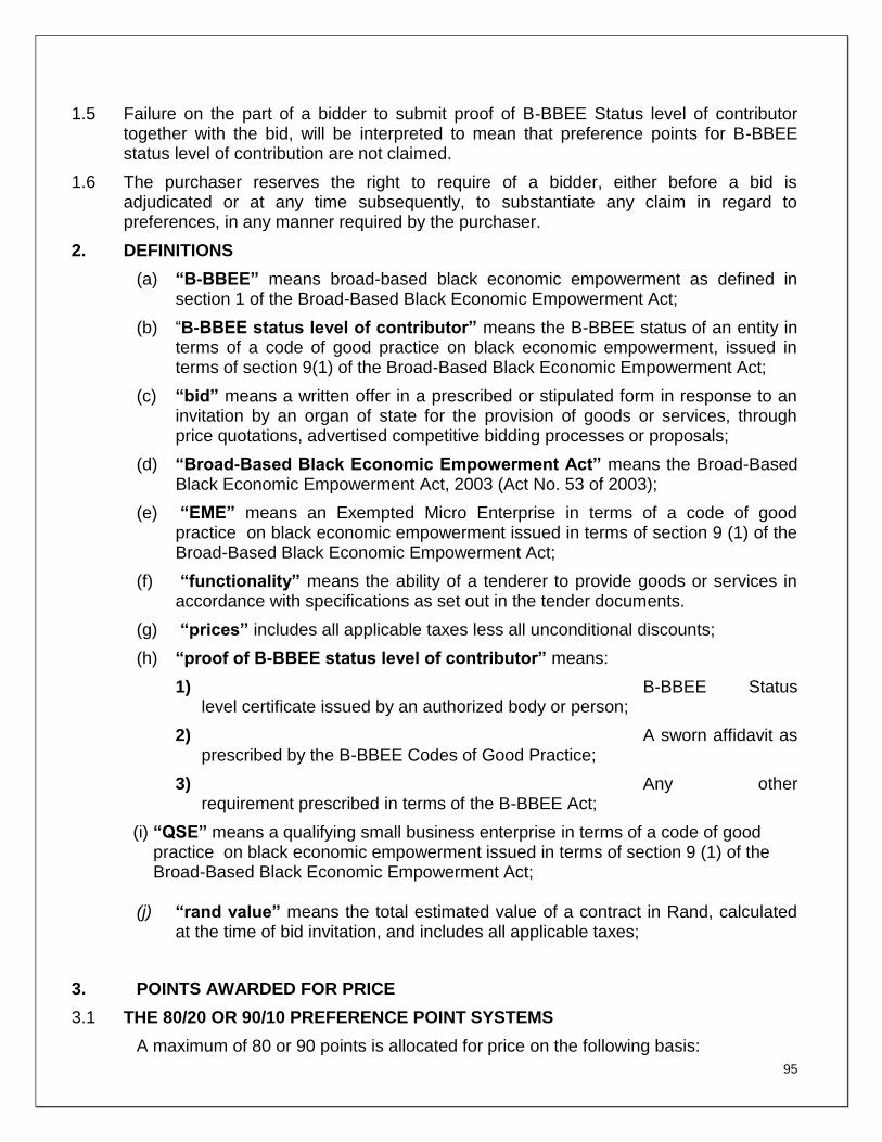
95
1.5 Failure on the part of a bidder to submit proof of B-BBEE Status level of contributor together with the bid, will be interpreted to mean that preference points for B-BBEE status level of contribution are not claimed.
1.6 The purchaser reserves the right to require of a bidder, either before a bid is adjudicated or at any time subsequently, to substantiate any claim in regard to preferences, in any manner required by the purchaser.
2. DEFINITIONS
(a) “B-BBEE” means broad-based black economic empowerment as defined in section 1 of the Broad-Based Black Economic Empowerment Act;
(b) “B-BBEE status level of contributor” means the B-BBEE status of an entity in terms of a code of good practice on black economic empowerment, issued in terms of section 9(1) of the Broad-Based Black Economic Empowerment Act;
(c) “bid” means a written offer in a prescribed or stipulated form in response to an invitation by an organ of state for the provision of goods or services, through price quotations, advertised competitive bidding processes or proposals;
(d) “Broad-Based Black Economic Empowerment Act” means the Broad-Based Black Economic Empowerment Act, 2003 (Act No. 53 of 2003);
(e) “EME” means an Exempted Micro Enterprise in terms of a code of good practice on black economic empowerment issued in terms of section 9 (1) of the Broad-Based Black Economic Empowerment Act;
(f) “functionality” means the ability of a tenderer to provide goods or services in accordance with specifications as set out in the tender documents.
(g) “prices” includes all applicable taxes less all unconditional discounts;
(h) “proof of B-BBEE status level of contributor” means:
1) B-BBEE Status level certificate issued by an authorized body or person;
2) A sworn affidavit as prescribed by the B-BBEE Codes of Good Practice;
3) Any other requirement prescribed in terms of the B-BBEE Act;
(i) “QSE” means a qualifying small business enterprise in terms of a code of good practice on black economic empowerment issued in terms of section 9 (1) of the Broad-Based Black Economic Empowerment Act;
(j) “rand value” means the total estimated value of a contract in Rand, calculated at the time of bid invitation, and includes all applicable taxes;
3. POINTS AWARDED FOR PRICE
3.1 THE 80/20 OR 90/10 PREFERENCE POINT SYSTEMS
A maximum of 80 or 90 points is allocated for price on the following basis:

96
80/20 or 90/10
min
min180
P
PPtPs or
min
min190
P
PPtPs
Where
Ps = Points scored for price of bid under consideration
Pt = Price of bid under consideration
Pmin = Price of lowest acceptable bid
4. POINTS AWARDED FOR B-BBEE STATUS LEVEL OF CONTRIBUTOR
4.1 In terms of Regulation 6 (2) and 7 (2) of the Preferential Procurement Regulations, preference points must be awarded to a bidder for attaining the B-BBEE status level of contribution in accordance with the table below:
B-BBEE Status Level of Contributor
Number of points
(90/10 system)
Number of points
(80/20 system)
1 10 20
2 9 18
3 6 14
4 5 12
5 4 8
6 3 6
7 2 4
8 1 2
Non-compliant contributor
0 0
5. BID DECLARATION
5.1 Bidders who claim points in respect of B-BBEE Status Level of Contribution must complete the following:
6. B-BBEE STATUS LEVEL OF CONTRIBUTOR CLAIMED IN TERMS OF PARAGRAPHS 1.4 AND 4.1
6.1 B-BBEE Status Level of Contributor: . = ………(maximum of 10 or 20 points)
(Points claimed in respect of paragraph 7.1 must be in accordance with the table reflected in paragraph 4.1 and must be substantiated by relevant proof of B-BBEE status level of contributor.
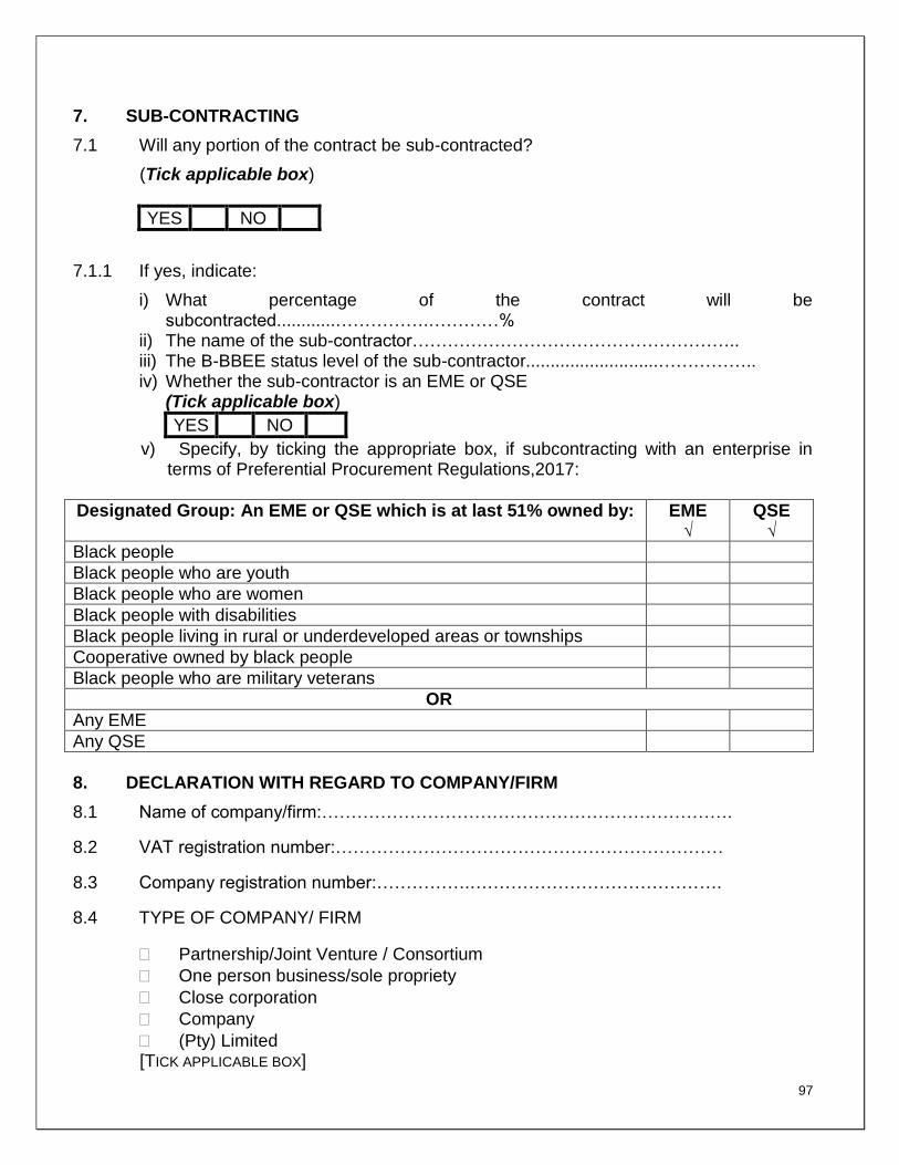
97
7. SUB-CONTRACTING
7.1 Will any portion of the contract be sub-contracted?
(Tick applicable box)
YES NO
7.1.1 If yes, indicate:
i) What percentage of the contract will be subcontracted............…………….…………%
ii) The name of the sub-contractor……………………………………………….. iii) The B-BBEE status level of the sub-contractor...........................…………….. iv) Whether the sub-contractor is an EME or QSE
(Tick applicable box)
YES NO
v) Specify, by ticking the appropriate box, if subcontracting with an enterprise in terms of Preferential Procurement Regulations,2017:
Designated Group: An EME or QSE which is at last 51% owned by: EME √
QSE √
Black people
Black people who are youth
Black people who are women
Black people with disabilities
Black people living in rural or underdeveloped areas or townships
Cooperative owned by black people
Black people who are military veterans
OR
Any EME
Any QSE
8. DECLARATION WITH REGARD TO COMPANY/FIRM
8.1 Name of company/firm:…………………………………………………………….
8.2 VAT registration number:…………………………………………………………
8.3 Company registration number:…………….…………………………………….
8.4 TYPE OF COMPANY/ FIRM
Partnership/Joint Venture / Consortium
One person business/sole propriety
Close corporation
Company
(Pty) Limited [TICK APPLICABLE BOX]

98
8.5 DESCRIBE PRINCIPAL BUSINESS ACTIVITIES
……………………………………………………………………………………………………
……………………………………………………………………………………………………
……………………………………………………………………………………………………
……………………………………………………………………………………………………
……..
8.6 COMPANY CLASSIFICATION
Manufacturer
Supplier
Professional service provider
Other service providers, e.g. transporter, etc. [TICK APPLICABLE BOX]
8.7 Total number of years the company/firm has been in
business:……………………………
8.8 I/we, the undersigned, who is / are duly authorised to do so on behalf of the
company/firm, certify that the points claimed, based on the B-BBE status level of
contributor indicated in paragraphs 1.4 and 6.1 of the foregoing certificate, qualifies
the company/ firm for the preference(s) shown and I / we acknowledge that:
i) The information furnished is true and correct;
ii) The preference points claimed are in accordance with the General Conditions as indicated in paragraph 1 of this form;
iii) In the event of a contract being awarded as a result of points claimed as shown in paragraphs 1.4 and 6.1, the contractor may be required to furnish documentary proof to the satisfaction of the purchaser that the claims are correct;
iv) If the B-BBEE status level of contributor has been claimed or obtained on a fraudulent basis or any of the conditions of contract have not been fulfilled, the purchaser may, in addition to any other remedy it may have –
(a) disqualify the person from the bidding process;
(b) recover costs, losses or damages it has incurred or suffered as a result of that person’s conduct;
(c) cancel the contract and claim any damages which it has suffered as a result of having to make less favourable arrangements due to such cancellation;
(d) recommend that the bidder or contractor, its shareholders and

99
directors, or only the shareholders and directors who acted on a fraudulent basis, be restricted by the National Treasury from obtaining business from any organ of state for a period not exceeding 10 years, after the audi alteram partem (hear the other side) rule has been applied; and
(e) forward the matter for criminal prosecution.
………………………………………. SIGNATURE(S) OF BIDDERS(S)
DATE: …………………………………..
ADDRESS …………………………………..
…………………………………..
…………………………………..
WITNESSES 1. ……………………………………..
2. …………………………………….

100
SBD 8
1. DECLARATION OF BIDDER’S PAST SUPPLY CHAIN MANAGEMENT PRACTICES
1 This Standard Bidding Document must form part of all bids invited. 2 It serves as a declaration to be used by institutions in ensuring that when goods and
services are being procured, all reasonable steps are taken to combat the abuse of the supply chain management system.
3 The bid of any bidder may be disregarded if that bidder, or any of its directors have-
a. abused the institution’s supply chain management system; b. committed fraud or any other improper conduct in relation to such system; or c. failed to perform on any previous contract.
4 In order to give effect to the above, the following questionnaire must be completed and submitted with the bid.
Item Question Yes No
4.1 Is the bidder or any of its directors listed on the National Treasury’s Database of Restricted Suppliers as companies or persons prohibited from doing business with the public sector?
(Companies or persons who are listed on this Database were informed in
writing of this restriction by the Accounting Officer/Authority of the
institution that imposed the restriction after the audi alteram partem rule
was applied).
The Database of Restricted Suppliers now resides on the National
Treasury’s website(www.treasury.gov.za) and can be accessed by
clicking on its link at the bottom of the home page.
Yes
No
4.1.1 If so, furnish particulars:

101
4.2 Is the bidder or any of its directors listed on the Register for Tender Defaulters in terms of section 29 of the Prevention and Combating of Corrupt Activities Act (No 12 of 2004)? The Register for Tender Defaulters can be accessed on the National Treasury’s website (www.treasury.gov.za) by clicking on its link at the bottom of the home page.
Yes
No
4.2.1 If so, furnish particulars:
4.3 Was the bidder or any of its directors convicted by a court of law (including a court outside of the Republic of South Africa) for fraud or corruption during the past five years?
Yes
No
4.3.1 If so, furnish particulars:
4.4 Was any contract between the bidder and any organ of state terminated during the past five years on account of failure to perform on or comply with the contract?
Yes
No
4.4.1 If so, furnish particulars:
CERTIFICATION
I, THE UNDERSIGNED (FULL NAME)…………………………………………………
CERTIFY THAT THE INFORMATION FURNISHED ON THIS DECLARATION FORM IS TRUE AND CORRECT.
I ACCEPT THAT, IN ADDITION TO CANCELLATION OF A CONTRACT, ACTION MAY BE TAKEN AGAINST ME SHOULD THIS DECLARATION PROVE TO BE FALSE.
………………………………………... …………………………..
Signature Date
………………………………………. …………………………..
Position Name of Bidder

102
SBD 9
CERTIFICATE OF INDEPENDENT BID DETERMINATION
1 This Standard Bidding Document (SBD) must form part of all bids¹ invited.
2 Section 4 (1) (b) (iii) of the Competition Act No. 89 of 1998, as amended, prohibits an
agreement between, or concerted practice by, firms, or a decision by an association of firms, if
it is between parties in a horizontal relationship and if it involves collusive bidding (or bid
rigging).² Collusive bidding is a pe se prohibition meaning that it cannot be justified under any
grounds.
3 Treasury Regulation 16A9 prescribes that accounting officers and accounting authorities must take all reasonable steps to prevent abuse of the supply chain management system and authorizes accounting officers and accounting authorities to:
a. disregard the bid of any bidder if that bidder, or any of its directors have abused the
institution’s supply chain management system and or committed fraud or any other improper conduct in relation to such system.
b. cancel a contract awarded to a supplier of goods and services if the supplier committed
any corrupt or fraudulent act during the bidding process or the execution of that contract.
4 This SBD serves as a certificate of declaration that would be used by institutions to ensure that,
when bids are considered, reasonable steps are taken to prevent any form of bid-rigging.
5 In order to give effect to the above, the attached Certificate of Bid Determination (SBD 9) must
be completed and submitted with the bid:
¹ Includes price quotations, advertised competitive bids, limited bids and proposals.
² Bid rigging (or collusive bidding) occurs when businesses, that would otherwise be expected to compete, secretly conspire to raise prices or lower the
quality of goods and / or services for purchasers who wish to acquire goods and / or services through a bidding process. Bid rigging is, therefore, an
agreement between competitors not to compete.

103
SBD 9
CERTIFICATE OF INDEPENDENT BID DETERMINATION
I, the undersigned, in submitting the accompanying bid:
_______________________________________________________________________
(Bid Number and Description)
in response to the invitation for the bid made by:
_______________________________________________________________________
(Name of Institution)
do hereby make the following statements that I certify to be true and complete in every respect:
I certify, on behalf of: __________________________________________________that:
(Name of Bidder)
1. I have read and I understand the contents of this Certificate;
2. I understand that the accompanying bid will be disqualified if this Certificate is found not to be
true and complete in every respect;
3. I am authorized by the bidder to sign this Certificate, and to submit the accompanying bid, on
behalf of the bidder;
4. Each person whose signature appears on the accompanying bid has been authorized by the
bidder to determine the terms of, and to sign the bid, on behalf of the bidder;
5. For the purposes of this Certificate and the accompanying bid, I understand that the word
“competitor” shall include any individual or organization, other than the bidder, whether or not
affiliated with the bidder, who:
(a) has been requested to submit a bid in response to this bid invitation;
(b) could potentially submit a bid in response to this bid invitation, based on their
qualifications, abilities or experience; and
(c) provides the same goods and services as the bidder and/or is in the same line of
business as the bidder
SBD 9

104
6. The bidder has arrived at the accompanying bid independently from, and without consultation,
communication, agreement or arrangement with any competitor. However communication
between partners in a joint venture or consortium³ will not be construed as collusive bidding.
7. In particular, without limiting the generality of paragraphs 6 above, there has been no
consultation, communication, agreement or arrangement with any competitor regarding:
(a) prices;
(b) geographical area where product or service will be rendered (market allocation)
(c) methods, factors or formulas used to calculate prices;
(d) the intention or decision to submit or not to submit, a bid;
(e) the submission of a bid which does not meet the specifications and conditions of
the bid; or
(f) bidding with the intention not to win the bid.
8. In addition, there have been no consultations, communications, agreements or arrangements
with any competitor regarding the quality, quantity, specifications and conditions or delivery
particulars of the products or services to which this bid invitation relates.
9. The terms of the accompanying bid have not been, and will not be, disclosed by the bidder,
directly or indirectly, to any competitor, prior to the date and time of the official bid opening or of
the awarding of the contract.
³ Joint venture or Consortium means an association of persons for the purpose of combining their expertise, property, capital, efforts, skill and knowledge in an activity for the execution of a contract.

105
SBD 9
10. I am aware that, in addition and without prejudice to any other remedy provided to combat any
restrictive practices related to bids and contracts, bids that are suspicious will be reported to
the Competition Commission for investigation and possible imposition of administrative
penalties in terms of section 59 of the Competition Act No 89 of 1998 and or may be reported
to the National Prosecuting Authority (NPA) for criminal investigation and or may be restricted
from conducting business with the public sector for a period not exceeding ten (10) years in
terms of the Prevention and Combating of Corrupt Activities Act No 12 of 2004 or any other
applicable legislation.
………………………………………………… …………………………………
Signature Date
…………………………………………………. …………………………………
Position Name of Bidder
Js914w 2
NB: PLEASE DOWNLOAD GENERAL CONDITIONS OF THE CONTRACT FROM TREASURY WEBSITE AND NLSA WEBSITE , SUBMIT ALONG WITH THE TENDER DOCUMENT
Related Documents