National Fire Protection Association 1 Batterymarch Park, Quincy, MA 02169-7471 Phone: 617-770-3000 • Fax: 617-770-0700 • www.nfpa.org MEMORANDUM TO: Technical Committee on Water Additives for Fire Control and Vapor Mitigation FROM: Kelly Carey, Project Administrator DATE: July 14, 2016 SUBJECT: NFPA 18A Second Draft Technical Committee FINAL Ballot Results (F2016) According to the final ballot results, all ballot items received the necessary affirmative votes to pass ballot. 11 Members Eligible to Vote 2 Members Not Returned (Halpin, III, Tinsley, Jr.) 7 Members Voted Affirmative on All Revisions (w/ comment: Gude, Greiner, Natale) 2 Members Voted Negative on one or more Revisions (Gude, Shugarman) 0 Members Abstained on one or more Revisions The attached report shows the number of affirmative, negative, and abstaining votes as well as the explanation of the vote for each revision. To pass ballot, each revision requires: (1) a simple majority of those eligible to vote and (2) an affirmative vote of 2 /3 of ballots returned. See Sections 3.3.4.3.(c) and 4.3.10.1 of the Regulations Governing the Development of NFPA Standards.

Welcome message from author
This document is posted to help you gain knowledge. Please leave a comment to let me know what you think about it! Share it to your friends and learn new things together.
Transcript
National Fire Protection Association
1 Batterymarch Park, Quincy, MA 02169-7471
Phone: 617-770-3000 • Fax: 617-770-0700 • www.nfpa.org
M E M O R A N D U M
TO: Technical Committee on Water Additives for Fire Control and Vapor Mitigation
FROM: Kelly Carey, Project Administrator
DATE: July 14, 2016
SUBJECT: NFPA 18A Second Draft Technical Committee FINAL Ballot Results (F2016)
According to the final ballot results, all ballot items received the necessary affirmative votes to pass
ballot.
11 Members Eligible to Vote
2 Members Not Returned (Halpin, III, Tinsley, Jr.)
7 Members Voted Affirmative on All Revisions (w/ comment: Gude, Greiner, Natale)
2 Members Voted Negative on one or more Revisions (Gude, Shugarman)
0 Members Abstained on one or more Revisions
The attached report shows the number of affirmative, negative, and abstaining votes as well as the
explanation of the vote for each revision.
To pass ballot, each revision requires: (1) a simple majority of those eligible to vote and (2) an
affirmative vote of 2/3 of ballots returned. See Sections 3.3.4.3.(c) and 4.3.10.1 of the Regulations
Governing the Development of NFPA Standards.

Second Revision No. 1-NFPA 18A-2016 [ Chapter 2 ]
Chapter 2 Referenced Publications
2.1 General.
The documents or portions thereof listed in this chapter are referenced within this standard and shall be considered part of therequirements of this document.
2.2 NFPA Publications.
National Fire Protection Association, 1 Batterymarch Park, Quincy, MA 02169-7471.
NFPA 10, Standard for Portable Fire Extinguishers, 2017 edition.
NFPA 13, Standard for the Installation of Sprinkler Systems, 2016 edition.
NFPA 14, Standard for the Installation of Standpipe and Hose Systems, 2016 edition.
NFPA 15, Standard for Water Spray Fixed Systems for Fire Protection, 2017 edition.
NFPA 25, Standard for the Inspection, Testing, and Maintenance of Water-Based Fire Protection Systems, 2017 edition.
NFPA 70E ® , Standard for Electrical Safety in the Workplace ® , 2015 edition.
NFPA 1001, Standard for Fire Fighter Professional Qualifications, 2013 edition.
NFPA 1081, Standard for Industrial Fire Brigade Member Professional Qualifications, 2012 edition.
NFPA 1901, Standard for Automotive Fire Apparatus, 2016 edition.
2.3 Other Publications.
2.3.1 ASTM Publications.
ASTM International, 100 Barr Harbor Drive, P.O. Box C700, West Conshohocken, PA 19428-2959.
ASTM D92, Standard Test Method for Flash and Fire Points by Cleveland Open Cup Tester, 2012b.
ASTM D97, Standard Test Method for Pour Point of Petroleum Products, 2012.
ASTM D1141, Standard Practice for the Preparation of Substitute Ocean Water , 2013.
ASTM D1293, Standard Test Methods for pH of Water, 1999 (2012).
ASTM D2196, Standard Test Methods for Rheological Properties of Non-Newtonian Materials by Rotational (Brookfield type)Viscometer, 2015.
ASTM D2240, Standard Test Method for Rubber Property — Durometer Hardness, 2010.
ASTM E729, Standard Guide for Conducting Acute Toxicity Tests on Test Materials with Fishes, Macroinvertebrates, andAmphibians, 2014.
ASTM G1, Standard Practice for Preparing, Cleaning, and Evaluating Corrosion Test Specimens,2014 2011 .
ASTM G31, Standard Practice Guide for Laboratory Immersion Corrosion Testing of Metals,1972 (2011) 2012 .
2.3.2 EPA Publications.
Environmental Protection Agency, William Jefferson Clinton East Building, 1200 Pennsylvania Avenue, NW, Washington, DC20460.
OPPTS 835.3110, Ready Biodegradability , Section M, CO 2 Evolution (Modified Sturm) Test , Fate, Transport, and
Transformation Test Guidelines, January 1998.
OPPTS 850.1075, Fish Acute Toxicity Test , Freshwater and Marine, Ecological Effects Test Guidelines, 1996.
OPPTS 870.1100, Acute Oral Toxicity , Health Effects Test Guidelines, 1998.
OPPTS 870.1200, Acute Dermal Toxicity , Health Effects Test Guidelines, 1998.
OPPTS 870.2400, Acute Eye Irritation , Health Effects Test Guidelines, 1998.
OPPTS 870.2500, Acute Dermal Irritation , Health Effects Test Guidelines, 1998.
2.3.3 ISO Publications.
International Organization for Standardization, 1 rue de Varembé, Case postale 56, CH-1211, Genève 20, Switzerland ISO CentralSecretariat, BIBC II, Chemin de Blandonnet 8, CP 401, 1214 Vernier, Geneva, Switzerland .
ISO/IEC 17025, General requirements for the competence of testing and calibration laboratories, 2005, Technical Corrigendum1:2006 .
2.3.4 NACE Publications.
NACE International, 1440 South Creek Drive, Houston, TX 77084-4906.
NACE/ASTM TM0169 G0031 12A, Standard Test Method — Guide for Laboratory Immersion Corrosion Testing of Metals,2000 2012 .
National Fire Protection Association Report http://submittals.nfpa.org/TerraViewWeb/ContentFetcher?commentPara...
1 of 18 7/14/2016 1:41 PM

2.3.5 UL Publications.
Underwriters Laboratories Inc., 333 Pfingsten Road, Northbrook, IL 60062-2096.
ANSI/ UL 162, Foam Equipment and Liquid Concentrates, 1994, revised 1999 2015 .
ANSI/UL 711/CAN/ULC S508, Rating and Fire Testing of Fire Extinguishers, 2004, revised 2009 2013 .
2.3.6 ULC Publications.
Underwriters Laboratories of Canada, 7 Underwriters Road, Toronto ON M1R 3B4 3A9 Canada .
CAN/ ULC S560, Category 3 Aqueous Film-Forming Foam (AFFF) Liquid Concentrates, 2006 2009 .
2.3.7 U.S. EPA Publications.
Environmental Protection Agency, William Jefferson Clinton East Building, 1200 Pennsylvania Avenue, NW, Washington, DC20460.
OPPTS 835.3110, Ready Biodegradability , Section M, CO 2 Evolution (Modified Sturm) Test, Fate, Transport and
Transformation Test Guidelines, January 1998.
OPPTS 850.1075, Fish Acute Toxicity Test, Freshwater and Marine, Ecological Effects Test Guidelines, 1996.
OPPTS 870.1100, Acute Oral Toxicity, Health Effects Test Guidelines, 1998.
OPPTS 870.1200, Acute Dermal Toxicity, Health Effects Test Guidelines, 1998.
OPPTS 870.2400, Acute Eye Irritation, Health Effects Test Guidelines, 1998.
OPPTS 870.2500, Acute Dermal Irritation, Health Effects Test Guidelines, 1998.
2.3.7 U.S. Government Publications.
U.S. Government Publishing Office, 732 North Capitol Street, NW, Washington, DC 20401-0001.
Title 29, Code of Federal Regulations, Part 1910.332, Subpart S, “Training,” Occupational Safety and Health Standards.
Title 40, Code of Federal Regulations, Part 86.113-94, Air Programs, “Fuel Specifications.” 2012.
Title 40, Code of Federal Regulations, Part 160, Pesticide Programs, “Good Laboratory Practice.” 2011.
Title 40, Code of Federal Regulations, Part 792, Toxic Substances Control Act, “Good Laboratory Practice.” 2011.
2.3.8 Other Publications.
Merriam-Webster’s Collegiate Dictionary, 11th edition, Merriam-Webster, Inc., Springfield, MA, 2003.
2.4 References for Extracts in Mandatory Sections.
NFPA 10, Standard for Portable Fire Extinguishers, 2017 edition.
NFPA 36, Standard for Solvent Extraction Plants, 2017 edition.
NFPA 1145, Guide for the Use of Class A Foams in Manual Structural Fire Fighting, 2017 edition.
NFPA 1150, Standard on Foam Chemicals for Fires in Class A Fuels, 2017 edition.
Submitter Information Verification
Submitter Full Name: Jaqueline Wilmot
Organization: [ Not Specified ]
Street Address:
City:
State:
Zip:
Submittal Date: Wed Apr 27 20:06:32 EDT 2016
Committee Statement
Committee Statement: Updated reference edition year in accordance with the NFPA Manual of Style.
Response Message:
Public Comment No. 1-NFPA 18A-2015 [Chapter 2]
Ballot Results
This item has passed ballot
11 Eligible Voters
2 Not Returned
8 Affirmative All
1 Affirmative with Comments
National Fire Protection Association Report http://submittals.nfpa.org/TerraViewWeb/ContentFetcher?commentPara...
2 of 18 7/14/2016 1:41 PM
0 Negative with Comments
0 Abstention
Not Returned
Halpin III, Gerald J.
Tinsley, Jr., Robert E.
Affirmative All
Brandao, Armand V.
Foster, Brian R.
Greiner, Michael T.
Groden, Walter
Johnson, Cecilia W.
Natale, Anthony
Shugarman, Blake M.
Wang, Qingsheng
Affirmative with Comment
Gude, Alison C.
Agree - no issue with manual of style update.
National Fire Protection Association Report http://submittals.nfpa.org/TerraViewWeb/ContentFetcher?commentPara...
3 of 18 7/14/2016 1:41 PM
Second Revision No. 3-NFPA 18A-2016 [ Section No. 8.1 ]
Chapter 8 Class C Fire Test Methods
8.1 General.
Water additive solutions for Class C fires shall be tested and listed in accordance with one or more of the following test procedures:
(1) Conductivity Extinguisher test
(2) Manual operations test
(3) Arcing conductor test
8.2 Extinguisher Test.
8.2.1
The safe use of water additives in extinguishers to mitigate or suppress a Class C fire shall be evaluated in accordance withSection 8.2 .
8.2.1.1*
The test and setup shall require a test voltage of 100 kV ac.
8.2.1.2*
The extinguisher shall be discharged on the target for a duration of 15 seconds at a minimum distance of 0.92 m (36 in.) from thenozzle to the surface.
8.2.1.3*
At no time shall current leakage back to the extinguisher exceed 250 µA.
8.2.2
Water additives shall be evaluated to determine whether the agent pooling will be large enough to expand beyond the standoffdistance, which could pose the risk of electrocution.
8.2.3
The entire contents of a maximum 9.5 L (2 1 ⁄2 gal) extinguisher shall be discharged onto a vertical surface from a distance of 0.92m (36 in.).
8.2.3.1
A minimum of half the contents of the extinguisher shall adhere to that vertical surface.
8.2.3.2
The runoff shall not traverse the 0.92 m (36 in.) standoff distance to the discharge point.
8.2.3.3
Agents which spread beyond the standoff distance specified in 8.2.3 shall be required to pass the conductivity test as requiredby NFPA 10 .
8.2.4
The water additive solution shall be tested at both the minimum and maximum concentrations, as specified by the manufacturer’slisting.
8.2.5*
Use of these extinguishers shall be limited to trained fire fighters.
8.3* Manual Operations Test.
8.3.1
The ability of water additives to mitigate or suppress a Class C fire in manual operations shall be evaluated in accordance withSection 8.3 .
8.3.2
The agent shall be tested with application and mixing hardware specified by the manufacturer in a consolidated stream and at themaximum flow rate.
8.3.3
The test apparatus shall be configured and the agent prepared for application per the agent manufacturer’s published instructions.
8.3.4*
Tests shall be conducted using a solution of water additive made with the concentrate, as received, in potable water and at theconcentration specified by the manufacturer.
8.3.5
Tests shall be conducted indoors and only when the ambient temperature is above 5°C (40°F).
National Fire Protection Association Report http://submittals.nfpa.org/TerraViewWeb/ContentFetcher?commentPara...
4 of 18 7/14/2016 1:41 PM
8.3.5.1
If tested outdoors, wind speeds shall be less than 8 km/hour (5 mph).
8.3.6
Testing shall be conducted in accordance with Section 9 of UL 711 as modified herein.
8.3.6.1
Testing shall be scaled for manual fire-fighting operations using ac or dc.
8.3.6.2*
The 0.3 m × 0.3 m (12 in. × 12 in.) copper target shall be replaced with a 138 kV disconnect switch as used in an electricalsubstation for the category voltage.
8.3.6.3*
The disconnect switch shall be energized using a power supply that is capable of supplying the desired test voltage while theinsulators isolate the bus bar from ground.
8.3.6.4*
A #12 AWG copper wire shall be stripped and inserted into a predrilled 4.8 mm (3/16 in.) hole in the side of the nozzle after thehose coupling.
8.3.6.4.1
The wire shall extend 25.4 mm (1 in.) beyond the tip of the nozzle.
8.3.6.4.2
The wire shall be connected to a ground source with two multimeters placed in series in the circuit.
8.3.6.4.3
One multimeter shall be set to capture milliamps and the other microamps.
8.3.6.5*
The two multimeters shall be set to read current, one in milliamps and one in microamps.
8.3.6.6
The current measurements shall be recorded during each test, after stabilization of the readings.
8.3.6.7*
The discharge appliance shall be fixed in place on a test stand for safety.
8.3.6.7.1*
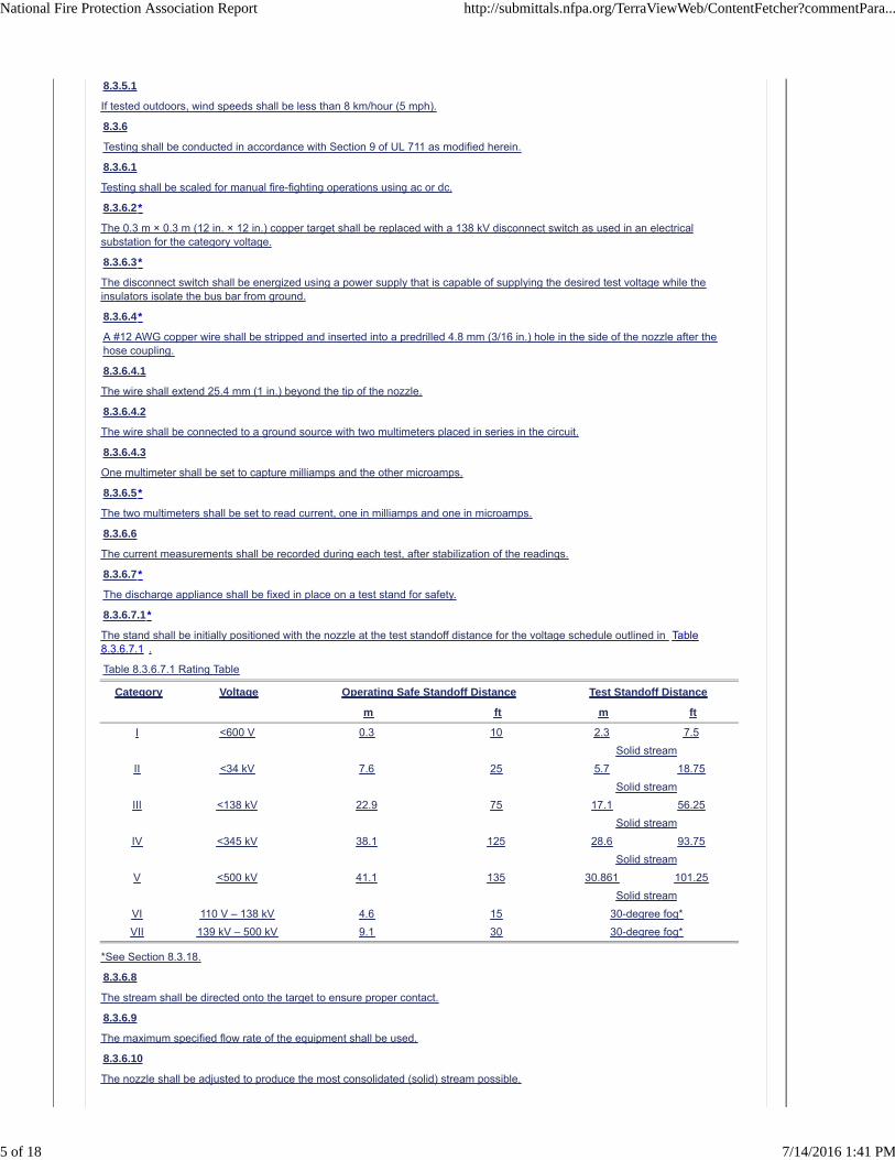
The stand shall be initially positioned with the nozzle at the test standoff distance for the voltage schedule outlined in Table8.3.6.7.1 .
Table 8.3.6.7.1 Rating Table
Category Voltage Operating Safe Standoff Distance Test Standoff Distance
m ft m ft
I <600 V 0.3 10 2.3 7.5
Solid stream
II <34 kV 7.6 25 5.7 18.75
Solid stream
III <138 kV 22.9 75 17.1 56.25
Solid stream
IV <345 kV 38.1 125 28.6 93.75
Solid stream
V <500 kV 41.1 135 30.861 101.25
Solid stream
VI 110 V – 138 kV 4.6 15 30-degree fog*
VII 139 kV – 500 kV 9.1 30 30-degree fog*
*See Section 8.3.18.
8.3.6.8
The stream shall be directed onto the target to ensure proper contact.
8.3.6.9
The maximum specified flow rate of the equipment shall be used.
8.3.6.10
The nozzle shall be adjusted to produce the most consolidated (solid) stream possible.
National Fire Protection Association Report http://submittals.nfpa.org/TerraViewWeb/ContentFetcher?commentPara...
5 of 18 7/14/2016 1:41 PM

8.3.6.11
After the flow has been established and all personnel are at a safe distance, the target shall be energized to the specified ac/dcvoltage.
8.3.6.12
The concentrate shall be proportioned into the water stream at the manufacturer’s specified concentration.
8.3.6.13
The solution shall be applied to the target for a minimum period of 90 seconds.
8.3.6.14
Tests shall be repeated while incrementally closing the distance to the target until the leakage current has exceeded the 250 µAthreshold.
8.3.6.15
Three tests shall be conducted at a given distance to derive the average leakage current.
8.3.6.16
Acceptable performance shall be defined as maximum leakage current less than 250 µA at 75 percent of the test standoff distanceoutlined in Table 8.3.6.7.1 .
8.3.6.17
Tests VI and VII outlined in Table 8.3.6.7.1 shall be completed using a 30-degree or greater fixed fog pattern with acceptableperformance defined as follows:
(1) 110 V – 138 kV: <250 µA at 15 ft
(2) 139 kV – 765 kV: <250 µA at 30 ft
8.3.6.18
Table 8.3.6.7.1 shall be used to assign a Class C rating category to the water additive solution, based on the distance at whichthe maximum leakage current criterion was met.
8.3.6.19
The following data shall be recorded for each test:
(1) Water additive and solution concentration
(2) Application and proportioning devices makes and models
(3) Ambient temperature and wind conditions
(4) Viscosity and conductivity of the concentrate and solution
(5) Leakage currents measured, including the maximum and average leakage
(6) Water pressure and flow
(7) Breakdown distance for 250 µA leakage current
8.4* Arc Conductor Test.
8.4.1
The ability of water additives in arc conductor tests to suppress artificially generated faults using copper cables shall be evaluatedin accordance with Section 8.4 .
8.4.2
The tests shall be monitored for heat release and products of combustion.
8.4.3 Test Protocol.
8.4.3.1
The test arrangement shall be configured indoors.
8.4.3.2
New 500 kcmil copper conductor 600 V ethylene alkene/low smoke non-halogen (EAM/LSNH) installed in a precast concretedistribution box type B-3.6 shall be used to produce a phase-to-phase fault creating an arc with a target fault current of 2 kA at atest voltage of 480 V ac.
8.4.3.3*
Tests shall be conducted using a solution of water additive made with the concentrate, as received, in potable water and at theconcentration specified by the manufacturer.
8.4.3.4
Water additive concentrate viscosity and conductivity shall be measured and reported.
8.4.3.5
Six tests shall be conducted to derive the average arc suppression results.
National Fire Protection Association Report http://submittals.nfpa.org/TerraViewWeb/ContentFetcher?commentPara...
6 of 18 7/14/2016 1:41 PM
8.4.3.5.1
Three tests shall be conducted without the water additive and three tests with the solution.
8.4.3.6*
The maximum length of 500 kcmil cable shall be 7.6 m (25 ft).
8.4.3.6.1
The 500 kcmil cable shall be connected to the 480 V source.
8.4.3.6.2
An inductor shall be placed in series between the voltage source at the faulted cable in the test box to control the current.
8.4.3.6.3
From the inner walls of each cable at the terminal ends, 50.8 mm (2 in.) of insulation shall be removed.
8.4.3.6.4
The cables shall be installed at the bottom of the concrete box, with the terminal ends of each cable positioned so that a 25.4 mm(1 in.) air-gap resides between the stripped portions of cable.
8.4.3.7*
The approximate dimensions of the interior volume of the concrete box shall be 0.84 m (33 in.) long by 0.61 m (24 in.) wide by0.61 m (24 in.) deep.
8.4.3.8
One calorimeter shall be installed above the concrete box to measure the incident energy generated by the fault.
8.4.3.9
The fault duration shall be until the fault self-extinguishes or a steady state is reached.
8.4.3.10
The solution shall be discharged into the concrete service box once the cable has been faulted so that the height of the agentreaches 152.4 mm (6 in.) above the burning cable.
8.4.3.11*
Combustible gases shall be measured continuously from 2 minutes prior to the inception of the cable fault through 5 minutes afterthe solution has risen to the prescribed level.
8.4.3.12*
The results of the test shall be evaluated using arc suppression as the criterion for success.
8.4.3.13
The following data shall be recorded for each test:
(1) Arc duration
(2)
(3) Ambient temperature
(4) Calorimeter data
(5)
Supplemental Information
File Name Description
Chapter_8_TC_working_draft_JRW_Review.docx New Chapter 8
AUC-338-Rev-10.pdf Latest draft of the FDNY policy on transformer firefighting
Substation_Firefighting_0300-28.pdf ConEd procedure on substation fire fighting
FI_Report_Final.pdf
FireIce Test Data: Report shows electrical safety tests conducted for use of FireIce. FireIce is used in arc suppression – two tests were conducted to demonstrate safe standoff distances for manual suppression by FDNY (manhole fires at 50Kv) and safe standoff distance for use of FireIce in an extinguisher at 100kV.
Fire_Suppression_Spray_Test_-_FINAL.pdf
F-500: Report titled fire spray test was conducted to evaluate F500 using the full gamut of FDNY appliances, apparatus and spray patterns to determine the safe standoff distance for 30 degree fog and solid stream applications on 345kV equipment.
Submitter Information Verification
Submitter Full Name: Jaqueline Wilmot
Organization: [ Not Specified ]
* Current and voltage waveforms
* Video (high and normal speed)
National Fire Protection Association Report http://submittals.nfpa.org/TerraViewWeb/ContentFetcher?commentPara...
7 of 18 7/14/2016 1:41 PM

Street Address:
City:
State:
Zip:
Submittal Date: Mon May 09 11:02:35 EDT 2016
Committee Statement
CommitteeStatement:
Chapter 8 was developed to provide the fire service with established safe limits for fire attack on energized electrical equipmentin the field as necessary. The conductivity test previously listed in the First Draft Report unnecessarily restricted the use of theseadditives in Class C Fires. The extinguisher test, manual operations test and arcing conductor test provide methods to establishsafe standoff distances for these operations. The extinguisher test was developed to establish safe limits for manual firefightingusing portable extinguishers on energized electrical equipment. The manual operations test was developed to establishdistances for hand line and master stream application on energized electrical equipment. The arcing test simulates as-installedunderground cable conditions for electrical distribution systems and the fires they generate. The outlined tests have beenconducted with ConEdison and FDNY which has resulted in their tactical application methods and current procedures for thesuppression of electrical fires.
ResponseMessage:
Public Comment No. 16-NFPA 18A-2015 [Chapter 8 [Title Only]]
Public Comment No. 19-NFPA 18A-2015 [Chapter 8 [Title Only]]
Public Comment No. 5-NFPA 18A-2015 [Section No. 8.1]
Public Comment No. 13-NFPA 18A-2015 [Section No. 8.1]
Public Comment No. 38-NFPA 18A-2015 [Section No. 8.1]
Public Comment No. 3-NFPA 18A-2015 [Chapter 8]
Public Comment No. 7-NFPA 18A-2015 [Chapter 8]
Public Comment No. 8-NFPA 18A-2015 [Chapter 8]
Public Comment No. 12-NFPA 18A-2015 [Chapter 8]
Public Comment No. 28-NFPA 18A-2015 [Chapter 8]
Public Comment No. 33-NFPA 18A-2015 [Chapter 8]
Public Comment No. 20-NFPA 18A-2015 [Global Input]
Ballot Results
This item has passed ballot
11 Eligible Voters
2 Not Returned
6 Affirmative All
1 Affirmative with Comments
2 Negative with Comments
0 Abstention
Not Returned
Halpin III, Gerald J.
Tinsley, Jr., Robert E.
Affirmative All
Brandao, Armand V.
Foster, Brian R.
Greiner, Michael T.
Groden, Walter
Johnson, Cecilia W.
Wang, Qingsheng
Affirmative with Comment
National Fire Protection Association Report http://submittals.nfpa.org/TerraViewWeb/ContentFetcher?commentPara...
8 of 18 7/14/2016 1:41 PM

Natale, Anthony
Currently, NFPA 18a only considers a test protocol for Class A & B fires while Class C fires present a significant safety issue to the fireservices and general public in addition to the potential impact on the reliability of the electrical grid. In this case the AHJ fails to provideguidance to the fire services in terms of a viable agent capable of being used safely and effectively in a high voltage environment. Theabsence of a Class C test standard does not mean these problems will go away. As such, the first response community is left to solve theseissues independent of the AHJ. All tests recommended were carried out by the FDNY and Con Edison of New York. They have enabled us toidentify suppression agents that can be used safely and effectively. Based on the referenced test standards, these agents were memorializedinto the response policies for both agencies. We hope you will support us in managing these low frequency high hazard incidents.
Negative with Comment
Gude, Alison C.
Do not agree with the safety of using water and or water additive on a Class C fire. Do not believe NFPA 10 recognized the poolingexception. Training firefighters is not adequate to prevent firefighters from stepping in pooled agents and risking electrocution.
Shugarman, Blake M.
Regarding the proposed NFPA 18A, 8.1 and 8.2, the following is offered. |¶| NFPA 18A, 8.2.1.1 added the language “the test and setup shallrequire a test voltage of 100 kV ac” and further added Annex reference to UL 711. |¶| UL 711 (ULC S508) is not a standalone document &requires further evaluation to determine safe use of fire extinguishers, fire extinguishing agents, or both. |¶| The requirements of UL 711 (ULCS508) cover rating, & performance during fire tests, of fire extinguishers intended for use in attacking Class A, B, C, D, & K fires as definedtherein. The ultimate rating of an extinguisher or the prescribed use of an extinguisher or fire extinguishing agent is based on itsfire-extinguishing potential as determined by fire tests & presupposes installation & use in accordance with the Standard for Portable FireExtinguishers, NFPA 10, & with the National Fire Code of Canada. |¶| Portable fire extinguishers complying with NFPA 10 shall be listed &labeled & shall meet or exceed all the requirements of the fire test standard UL 711 (ULC S508) & in the case of water-based extinguishers,all of the requirements of the performance standard UL 8 (ULC S554). |¶| There is a hazard in the use of a water-based extinguisher as itrelates to conductivity of the fire extinguishing agent during & after discharge & the conductivity test reference has been struck from NFPA18A, 8.1 (1). While the conductivity test of NFPA 10 is required to be passed as added to NFPA 18A, 8.2.3.3, it is a conditional test based onrunoff from the extinguisher discharge from an undefined vertical surface at an undefined distance. |¶| NFPA 18A, 8.2.3, added requirementsfor the use of a 9.5 L (2-1/2 gal) extinguisher be discharged onto a vertical surface from a distance of 0.92 m (36 in.). The size of theextinguisher can make a difference in the amount of runoff from the extinguisher discharge & the proposal to NFPA 18A does not take intoconsideration different sizes of extinguishers. In addition, the vertical surface is not defined by size, material, surface finish, temperature, etc.,which all can have an effect on the amount of runoff of the fire extinguishing agent. Lastly, the distance is not defined relative to the verticalsurface & the presumed object of importance, the user. The distance is further confused by the proposal to NFPA 18A, 8.2.3.2 by the additionof a standoff distance to the discharge point. |¶| NFPA 18A, 8.2.5, indicates “use of these extinguishers shall be limited to trained fire fighters.”While the intent is understood, this is not enforceable language except when the Authority Having Jurisdiction is the User & has a means inplace to monitor & control the extinguishers use. There are also no marking requirements to distinguish these extinguishers as being limited touse by trained fire fighters. |¶| While the test & setup are intended to be the same in the proposed NFPA 18A, 8.2.1.1, & UL 711, the test &setup need not be in accordance with UL 711 since it is Annex material. It is also noted that a very important part of UL 711 (ULC S508) hasbeen left out of the proposed requirements of NFPA 18A, 8.2: The discharge of an agent from an extinguisher charged with its rated capacityshall not show a visible breakdown between the electrically charged target & the discharging extinguisher. This is a huge oversight that doesnot allow for the safe use of water additives in extinguishers to mitigate or suppress a Class C fire. |¶| Regarding the proposed NFPA 18A, 8.3& 8.4, review has not been completed; however, based upon the comments made on the proposed NFPA 18A, 8.1 & 8.2, we recommend thatChapter 8 & the related material be returned to the committee for further review & consideration.
National Fire Protection Association Report http://submittals.nfpa.org/TerraViewWeb/ContentFetcher?commentPara...
9 of 18 7/14/2016 1:41 PM
Chapter 8 Class C Fire Test Methods 8.1 General. Water additive solutions for Class C fires shall be tested and listed in accordance with one or more of the following test procedures.
(1) Conductivity Test (2)(1) Extinguisher test (3)(2) Manual Operations test (4)(3) Arcing Conductor test
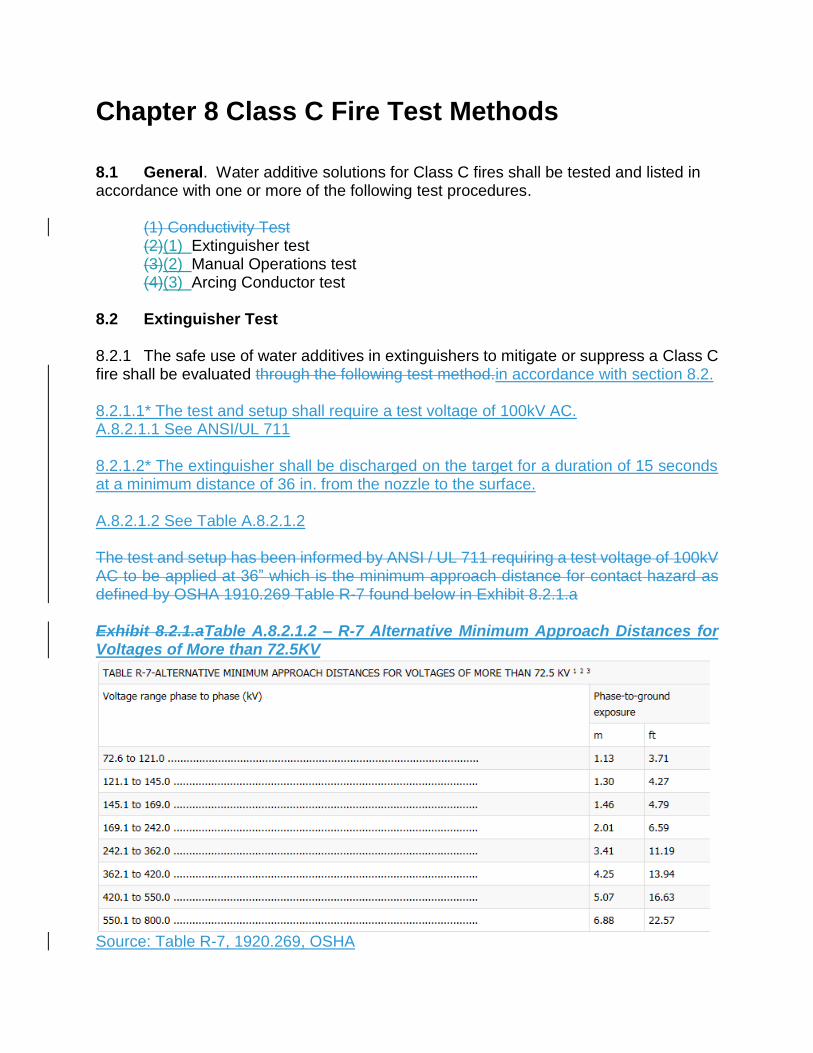
8.2 Extinguisher Test 8.2.1 The safe use of water additives in extinguishers to mitigate or suppress a Class C fire shall be evaluated through the following test method.in accordance with section 8.2. 8.2.1.1* The test and setup shall require a test voltage of 100kV AC. A.8.2.1.1 See ANSI/UL 711 8.2.1.2* The extinguisher shall be discharged on the target for a duration of 15 seconds at a minimum distance of 36 in. from the nozzle to the surface. A.8.2.1.2 See Table A.8.2.1.2 The test and setup has been informed by ANSI / UL 711 requiring a test voltage of 100kV AC to be applied at 36” which is the minimum approach distance for contact hazard as defined by OSHA 1910.269 Table R-7 found below in Exhibit 8.2.1.a Exhibit 8.2.1.aTable A.8.2.1.2 – R-7 Alternative Minimum Approach Distances for Voltages of More than 72.5KV
Source: Table R-7, 1920.269, OSHA

8.2.1.3* At no time shall current leakage back to the extinguisher exceed 250 µA. A.8.2.1.3 Per NFPA 70E, Standards for Electrical Safety in the Workplace (effects of current of the human body; 0.5 mA is the perception threshold level so a leakage half of that value to pass the test is required) 8.2.3 The pass/fail criterion shall be a maximum measured leakage current below 500uA at 36”. As informed by NFPA 70E Standards for Electrical Safety in the Workplace (effects of current of the human body - 1 mA is the perception threshold level so a leakage half of that value to pass the test is required) 8.2.2.4 Water additives shall be evaluated for viscosity and surface tension values to determine if the agent pooling will be sufficiently large enough to expand beyond the standoff distance which could pose the risk of electrocution. 8.2.3 The entire contents of a maximum 2 ½ gallon extinguisher shall be discharged onto a vertical surface from a distance of 36 in. 8.2.3.1 A minimum of half the contents of the extinguisher shall adhere to that vertical surface. 8.2.3.2 The runoff shall not traverse the 36 in. standoff distance to the discharge point. 8.2.3.3 Agents which spread beyond the standoff distance specified in Section 8.2.3 shall be required to pass the conductivity test as required by NFPA 10. If it is found the agent cannot spread beyond the standoff distance as stated in the instructions the agent shall not be subjected to the conductivity test required by NFPA 10. 8.2.45 The water additive solution shall be prepared tested at both the minimum and maximum concentrations, as specified by the manufacturers listing.at the manufacturer’s minimum and maximum recommended concentrations. 8.2.5*6 Use of these extinguishers shallould be limited to trained fire fighters., such as fire services meeting the qualifications of NFPA 1001, private brigades who are NFPA 1081 qualified, and Electrically Qualified Workers 1910.332 (b)(3), as defined by OSHA. A.8.2.5 Trained fire fighters include: (1) Fire fighters meeting the qualifications outlined in NFPA 1001 (2) Private brigades who are qualified in accordance with NFPA 1081 (3) Electrically Qualified Workers as defined by OSHA1910.332 (b)(3) (4) Fire fighters of equivalent qualifications acceptable to the authority having jurisdiction
8.3* Manual Operations Test 8.3.1A.8.3 This section of code addresses the ability of water additive solutions to be evaluated for use in manual firefighting operations to suppress Class C fires or on fires impinged by “Live” electrical sources. 8.3.1[WJ1] The ability of water additives to mitigate or suppress a Class C fire in manual operations shall be evaluated in accordance with Section 8.3. 8.3.212 The agent shall be tested with application and mixing hardware specified by the manufacturer in a and under the worst case application conditions, including consolidated stream and at maximum flow rate. 8.3.323 The test apparatus shall be configured and the agent prepared for application per the agent manufacturersmanufacturer’s published written instructions. 8.3.43*4 Tests shall be conducted using a solution of water additive made with the concentrate, as received, in fresh potable water and at the concentration specified by the manufacturer. A.8.3.34 Water additive solutions made with synthetic seawater, as defined by ASTM D1141, may also be tested, if such usage is specified by the manufacturer. 8.3.5 Tests shall be conducted indoorsonly and only when the ambient temperature is above 5°C (40°F) and in still air. 8.3.5.1 If tested outdoors, wind speeds shall be less that 5 miles/hourmph (8 km/hour). 8.3.6 Testing shall be conducted similarly toin accordance with section 9 of UL 711, Rating and Fire Testing of Fire Extinguishers as modified herein: 8.3.6.1 Testing can be scaled for manual firefighting operations using AC or DC. , section 9,but scaled for manual firefighting operations using AC or DC. 8.3.6.2*7 The 12 inch by 12 inch copper target shall be replaced with a 138 kV disconnect switch such asas used in an electrical substation or other appropriate target for the category voltage. A.8.3.6.2 See Figure A. 8.3.6.2, illustrating a Illustration below is a typical electrical substation disconnect switch.

Exhibit 8.3.7.a 138Kv substation Disconnect switch
Figure A. 8.3.6.2:138Kv substation Disconnect switch Source: ConEdison 8.3.6.3*8 The disconnect switch shall be located at the top of the bus bar and energized using a power supply that is capable of supplying the desired test voltage while the insulators isolate the bus bar from ground.
A. 8.3.6.33.9 Disconnect switches designed for target voltages above 138kV, such as 345kV and 500kV, are ideal since their designs consider insulation from a ground reference via the insulators.
8.3.10 A wire shall be inserted into the nozzl8.3.6.4* A #12 AWG copper wire shall be stripped and inserted into a pre-drilled 3/16 in. hole in the side of the nozzle after the hose coupling.
A.8.3.6.4 The wire inserted into the nozzle ensures contact is made with the stream of solution being tested.
8.3.6.4.1 The wire shall extend 1 in. beyond the tip of the nozzle.
8.3.6.4.2 The wire shall be connected to a ground source with two multimeters placed in series in the circuit.
8.3.6.4.3 One multimeter shall be set to capture milliamps and the other microamps.
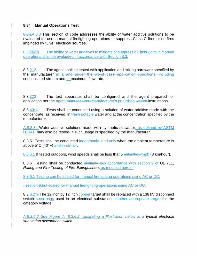
8.3.6.5* The two multimeters shall be set , one each, to read current, one in milliamps and one in microamps. A.8.3.6.5 See Figure A. 8.3.106.5 (multi-meter arrangement)
e to ensure contact is made with the stream of solution being tested. The wire shall be attached to ground through a circuit containing two multimeters in series, The two multimeters shall be set, one each, to read current in milliamps and microamps. The current measurements are to be recorded during each test, after stabilization of the readings. Exhibit 8.3.10.a Multi-meter arrangement in the current measuring circuit.
Figure A.8.3.6.510: Multi-meter arrangement in the current measuring circuit. Source: ConEdison
8.3.6.6 The current measurements shall be recorded during each test, after stabilization of the readings.
8.3..11 6.7* The discharge appliance shall be fixed in place on a test stand for safety. A.8.3.6.7 Test stand that will receive appliance should be constructed of dielectric material. 8.3.6.7.1* The stand shall be initially positioned with the nozzle at the test standoff distance at the Test Standoff distance for the voltage schedule outlined in Table 8.3.6.7.1 exhibit 8.3.11.a rating table.
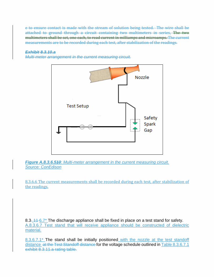
A. 8.3.6.7.1 The rating table provided establishes categories to define voltage, the operating safe standoff distance, and test standoff distance (75 percent of the operating standoff distance) for common electrical equipment thresholds. TableExhibit 8.3.11.a6.7.1: Rating Table
Category Voltage Operating Safe Standoff
Distance, ft
Test Standoff Distance, ft
I < 600 V 10 7.5
Solid Stream
II < 34 kV 25 18.75
Solid Stream
III < 138 kV 75 56.25
Solid Stream
IV < 345 kV 125 93.75
Solid Stream
V < 500 kV 135 101.25
Solid Stream
VI 110 V – 138kV 15 30 Degree Fog
See 8.3.18
VII 139kV – 500kV 30 30 Degree Fog
See 8.3.18
8.3.12 The rating table provided as exhibit 8.3.11.a establishes categories to define voltage, the operating safe standoff distance, and test standoff distance (75 percent of the operating standoff distance) for common electrical equipment thresholds. 8.3.6.8.13 The stream shall then be directed onto the target to ensure the proper trajectoryproper contact. 8.3.14 6.9 The maximum specified flow rate of the equipment shall be used. 8.3.6.10 and theThe nozzle shall be adjusted to produce the most consolidated (solid) stream possible.
8.3.6.11 Once After the flow has been established and all personnel are at a safe distance, the target shall be energized to the specified ac AC/DC voltage. 8.3.15 6.12 The concentrate shall then bebe proportioned into the water stream at the manufacturer’s specified concentration and the 8.3.6.13 The solution shall be applied to the target for a minimum period of 90 seconds. 8.3.16.14 Tests shall be repeated while incrementally closing the distance to the target until the leakage current has exceeded the 250500uA threshold. 8.3.6.15 Three tests shall be conducted at a given distance to derive the average leakage current. 8.3.178.3.6.16 Acceptable performance shall be defined as maximum leakage current less than 250500 uA at 75 percent of the Test Standoff Distance outlined in Rating Table provided as exhibit 8.3.11.aTable 8.3.6.7.1. 8.3.6.178 Tests VI & VII outlined in the Rating Table 8.3.6.7.1(exhibit 8.3.11.a) shall be completed using a 30 degree or greater fixed fog pattern with acceptable performance defined as follows: .
(1) 110v-138kV: < 250500 uA at 15 feetft. (2) 139kV-765kV: < 250500 uA at 30 ft.feet
8.3.6.189 The Table (exhibit 8.3.11.a6.7.1 ) shall be used to assign a Class C rating category to the water additive solution, based upon the distance at which the maximum leakage current criterion was met. 8.3.6.1920 The following data shall be recorded for each test:
(1) Water additive and solution concentration (2) Application and proportioning devices makes and models (3) Ambient temperature and wind conditions (4) Viscosity and conductivity of the concentrate and solution (5) Leakage currents measured, including the maximum and average leakage (6) Water pressure and flow (7) Breakdown distance for 500 250 uA leakage current
8.4* Arc Conductor Test A.8.4 See Figure A.8.4.3.4 which illustrates the configuration for the arc conductor.

[WJ2] Figure 8.4.3.4:Arc conductor test configuration Source: GelTech Solutions, Kinectrics Report “Arc Performance & Byproducts of FireIce – Summary of Air Sampling Results” 8.4.1 The ability of water additives in arc conductor tests to suppress artificially generated faults using copper cables shall be evaluated in accordance with this section 8.4. 8.4.1 Water additive solutions shall demonstrate the ability to suppress artificially generated faults using copper cables. 8.4.2The tests shall be monitored for heat release and products of combustion. 8.4.2 Test Set-UpProtocol 8.4.2.1 The test set up arrangement shall be configured indoors. in a conditioned environment. 8.4.2.2 Test Equipment: New 500 kcmil Copper conductor 600V EAM/LSNH installed in a precast concrete distribution box type B-3.6 shall be used to produce a

phase to phase fault creating an arc with a target fault current of 2 kA at . Ta he required test voltage of is 480Vv AC. 8.4.2.3* Tests shall be conducted using a solution of water additive made with the concentrate, as received, in fresh potable water and at the concentration specified by the manufacturer. A.8.4.2.3 Water additive solutions made with synthetic seawater, as defined by ASTM D1141, may also be tested, if such usage is specified by the manufacturer. 8.4.2.4 Water additive concentrate viscosity and conductivity shall be measured and reported. 8.4.3 Test Procedures. 8.4.2.5 3.1 Number of Tests - Six tests shall be conducted to derive the average arc suppression results. 8.4.2.5.1 Three tests willshall be conducted without the water additive and another three tests will be conducted with the solution. 8.4.2.63.2 The maximum length of 500 Kcmil cable shall be 25 ft. A.8.4.2.6* The purpose of the maximum 25ft. cable length is to limit resistance. 8.4.2.6.1 To limit resistance, the 500 Kcmil cable for the test will be no longer the 25’. The 500 Kcmil cable shallwill be connected to the 480Vv source 8.4.2.6.2 Anand an inductor shallwill be placed in series between the voltage source at the faulted cable in the test box to control the current. 8.4.2.6.3 Two inches in. of insulation willshall be removed from the inner walls of each cable at the terminal ends. 8.4.2.6.4 The cables shall be installed at the bottom of the concrete box, with the terminal ends of each cable positioned in manner that a 1 in. inch air-gap resides between the stripped portions of cable. 8.4.2.7* The approximate dimensions of the interior volume of the concrete box shall be: 33 in. wide L x 24in. Wlong x 24 in.1248 in. deepD. A.8.4.2.7 * See Figure A.8.4.2.7 (insert newThe concrete box drawing) is shown in exhibit 8.4.3.2.a

Exhibit Figure A.8.4.23.27: .a Concrete Box Drawing Source: ConEdison
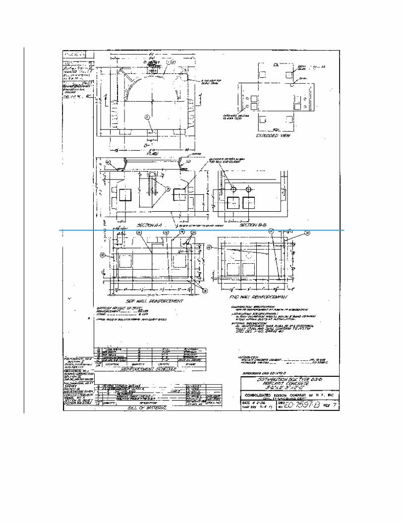
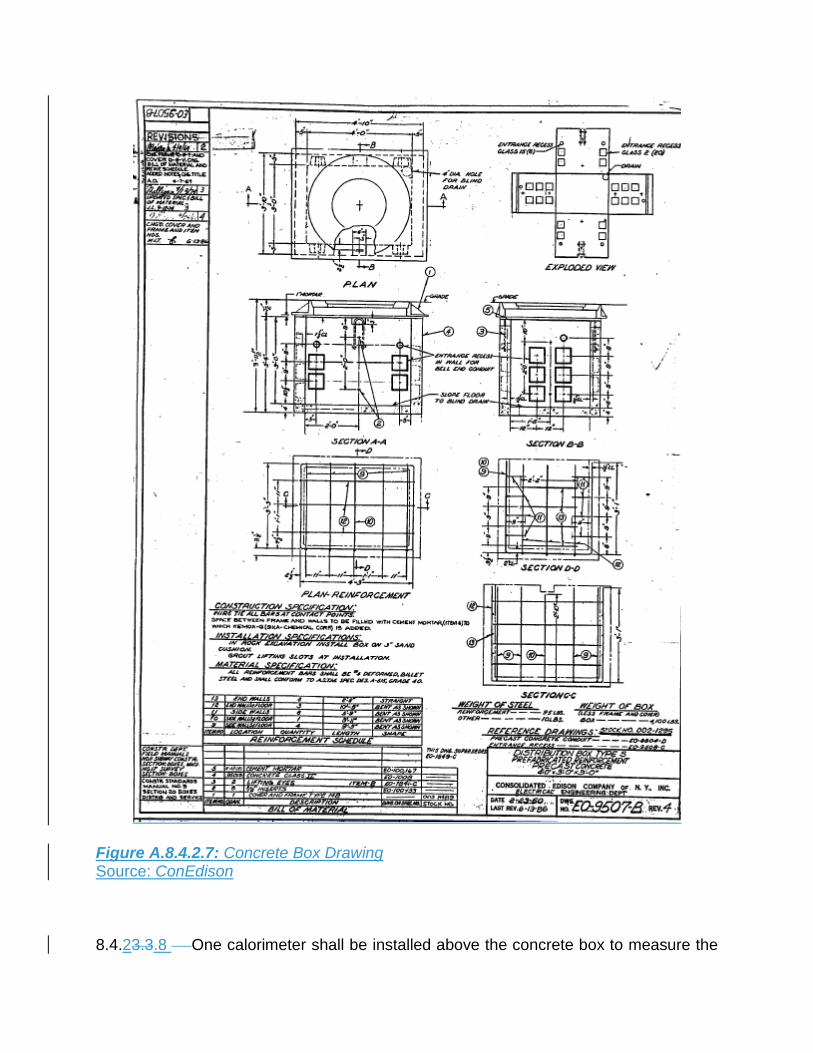
Figure A.8.4.2.7: Concrete Box Drawing Source: ConEdison
8.4.23.3.8 One calorimeter shall be installed above the concrete box to measure the
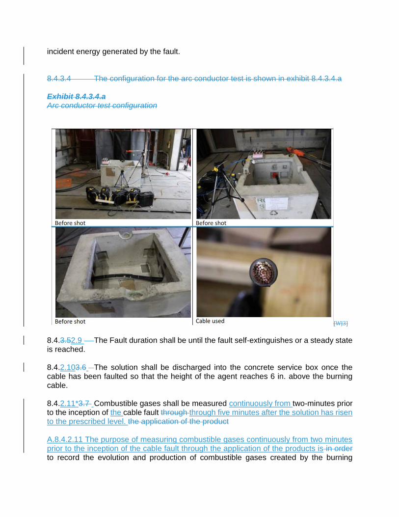
incident energy generated by the fault. 8.4.3.4 The configuration for the arc conductor test is shown in exhibit 8.4.3.4.a Exhibit 8.4.3.4.a Arc conductor test configuration
[WJ3]
8.4.3.52.9 The Fault duration shall be until the fault self-extinguishes or a steady state is reached. 8.4.2.103.6 The solution shall be discharged into the concrete service box once the cable has been faulted so that the height of the agent reaches 6 in. above the burning cable. 8.4.2.11*3.7 Combustible gases shall be measured continuously from two-minutes prior to the inception of the cable fault through through five minutes after the solution has risen to the prescribed level. the application of the product A.8.4.2.11 The purpose of measuring combustible gases continuously from two minutes prior to the inception of the cable fault through the application of the products is in order to record the evolution and production of combustible gases created by the burning

insulation on the jacket of the cable. Measurements shall continue for five minutes after the solution has risen to the prescribed level. 8.4.3.8 The production of combustible gases is the cause of secondary explosions in electrical fires. 8.4.2.12*3.9 The results of the test shall be evaluated using arc suppression as the criterion for success. A.8.4.2.12 The arc is considered to have been suppressed through observation and verified by the use of calorimetry. 8.4.2.13 3.10 The following data shall be recorded for each test:
(1) Arc duration (2)* Current and Voltage waveforms (exhibit 8.4.3.10.a) (3) Ambient temperature (4) Calorimeter data (6)* Video (high and normal speed) A.8.4.2.13 (2) See Figure 8.4.3.13 A.8.4.2.13 (6) Video should be in real-time and in high-speed
Exhibit 8.4.3.10.a Illustrates test report format.

Figure 8.4.2.13: Illustration of test report format. Source: ConEdison

A.U.C. 338
April 20th
2016
Substation Fire Fighting Revision 10
1. INTRODUCTION
1.1 The Department in conjunction with Con Edison has developed a protocol for
controlling fires on electrical equipment. Once a transformer has suffered a
catastrophic failure which results in a fire, the breakers supplying transformer
open automatically. So essentially, members will not be fighting “energized”
fires. However equipment surrounding the failed transformer will in most cases
remain energized. The protocol discusses the initial considerations, size-up,
hazards along with recommended suppression agents. In addition to Con Edison
there are seven other power providers in New York City; this policy can be
applied universally since all these facilities have similar equipment.
2. PURPOSE
2.1 Failed transformers cannot be salvaged and are of no useful value to the utility.
The intention of this protocol is to prevent collateral damage from fire & smoke
impinging adjacent equipment which can result in large scale blackouts. This
would compromise civilian safety and over-tax the response capabilities of the
first response community.
3. UTILITY TERMINOLOGY
3.1 Utilities classify electrical equipment at their facilities as follows:
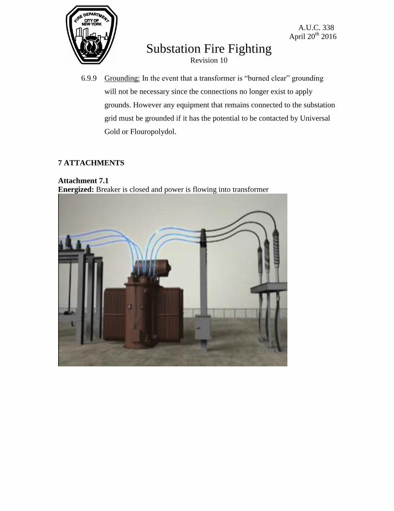
3.1.1 Energized: Equipment that is connected to an electrical source. Illustrated
in attachment 7.1
3.1.2 De-energized: Circuit breakers supplying the equipment are open. No
power is flowing but is treated as “Live” since the equipment is not
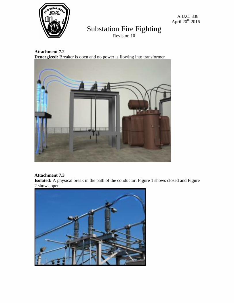
isolated and grounded. Illustrated in attachment 7.2
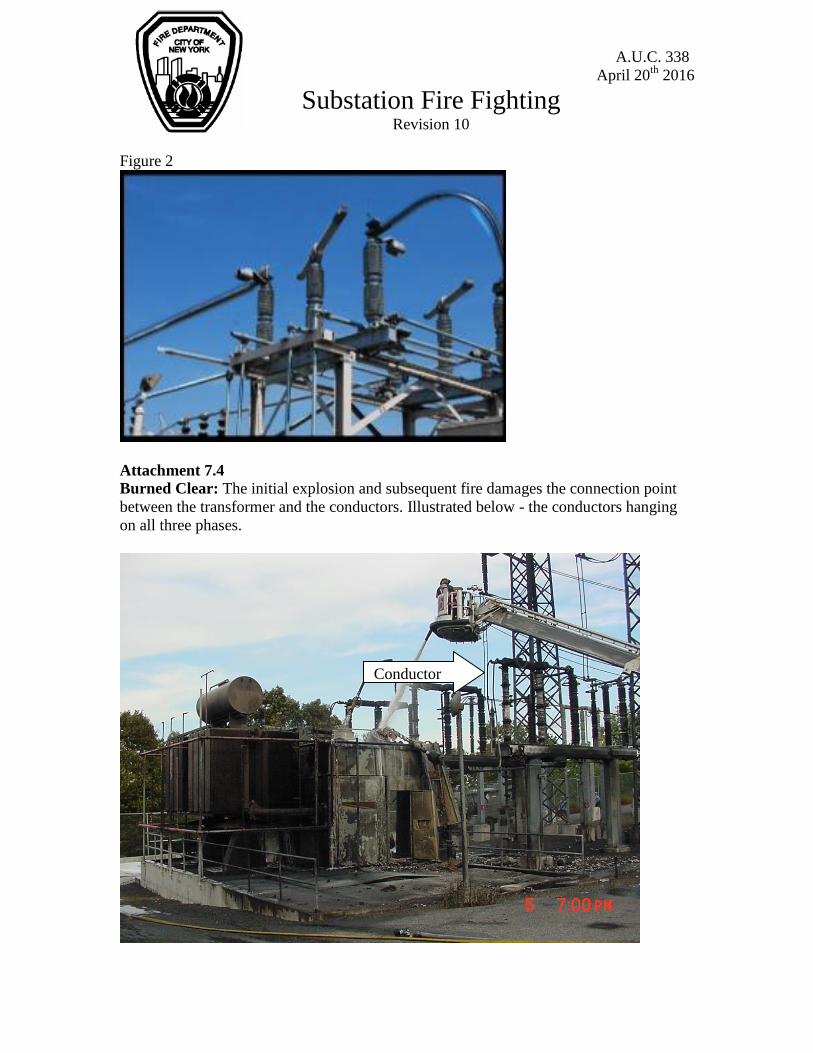
3.1.3 Isolated: A physical break exists and equipment is isolated from all
electrical sources but is not grounded. A static charge can remain on the
equipment and is treated as “Live”. Illustrated in attachment 7.3

A.U.C. 338
April 20th
2016
Substation Fire Fighting Revision 10
3.1.3 Grounded: The equipment is denergized, electrically isolated and
grounds have been applied. Essentially the equipment is safe to touch.
When the equipment is grounded you may use any suppression agent at
any distance since the electrical hazard has been mitigated.
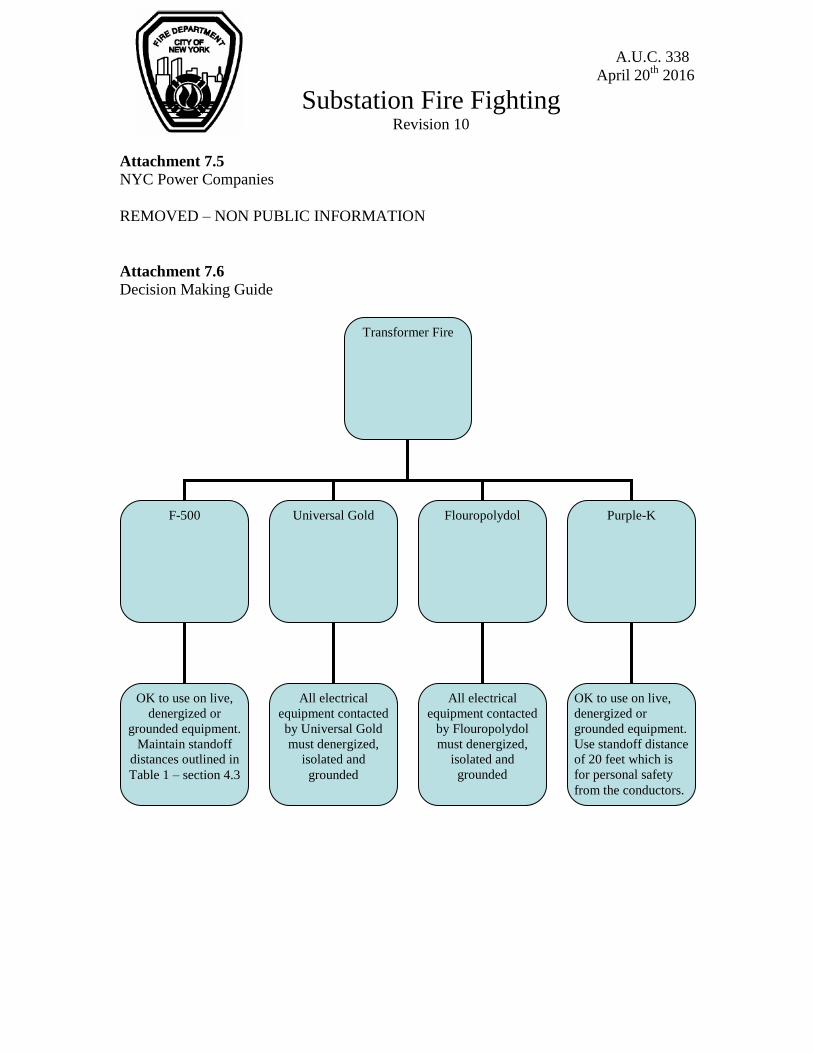
3.1.4 Burned Clear: The conductor(s) supplying power to the transformer were
burned clear by the fire. The transformer is no longer physically connected
to the electrical system in the substation. Illustrated in attachment 7.4
3.2 Power Providers: In addition to Con Edison there are seven other power
companies operating within the City spanning fifteen locations. A list of those
companies along with their locations and contact information has been provided
as Attachment 7.5.
3.3 White Hat: ConEd employees all wear blue hard hats. The ConEd representative
in charge of the emergency is identified by wearing a white hard hat. This policy
only applies to Con Edison. When operating at facilities other than Con Edison,
Chief Officers should clearly identify the utility representative in charge and
instruct them to remain at the Command Post.
Note: For example, employees at the Trans-Canada Generating Station on
Vernon Boulevard in Long Island City all wear white hard hats – remember this
is only a ConEd policy.
3.4 Tracking: Smoke can become a conductor causing a phenomenon called
tracking. In this case smoke can act as a bridge (tracking path to ground) and
allow current to flow from the conductor to ground. A water fog pattern can be
used to control the direction of smoke and push it away from electrical equipment.
A.U.C. 338
April 20th
2016
Substation Fire Fighting Revision 10
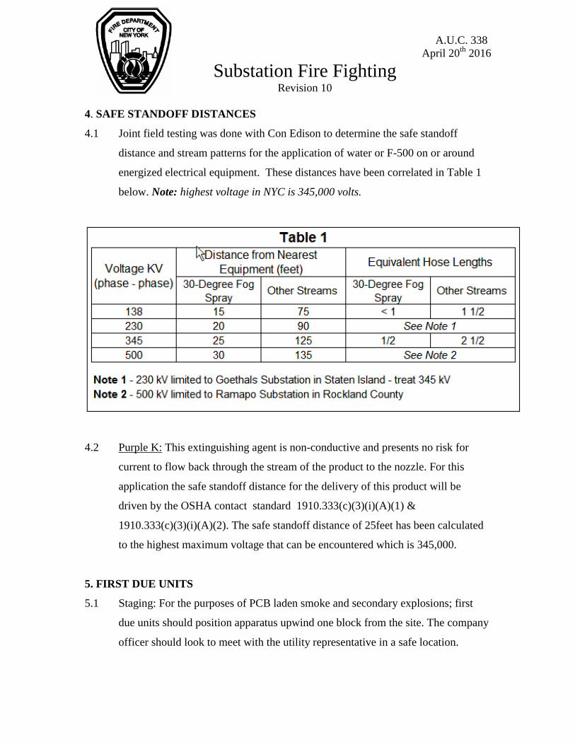
4. SAFE STANDOFF DISTANCES
4.1 Joint field testing was done with Con Edison to determine the safe standoff
distance and stream patterns for the application of water or F-500 on or around
energized electrical equipment. These distances have been correlated in Table 1
below. Note: highest voltage in NYC is 345,000 volts.
4.2 Purple K: This extinguishing agent is non-conductive and presents no risk for
current to flow back through the stream of the product to the nozzle. For this
application the safe standoff distance for the delivery of this product will be
driven by the OSHA contact standard 1910.333(c)(3)(i)(A)(1) &
1910.333(c)(3)(i)(A)(2). The safe standoff distance of 25feet has been calculated
to the highest maximum voltage that can be encountered which is 345,000.
5. FIRST DUE UNITS
5.1 Staging: For the purposes of PCB laden smoke and secondary explosions; first
due units should position apparatus upwind one block from the site. The company
officer should look to meet with the utility representative in a safe location.

A.U.C. 338
April 20th
2016
Substation Fire Fighting Revision 10
5.2 DO NOT FORCE ENTRY: These facilities have the potential to pose numerous
electrical and chemical hazards to members. Wait for utility representative who
will act as an escort and assist in the size-up.
5.3 Exposures: It is ok to protect exposures impinged by fire from a neighboring
substation. Do not direct streams onto substation equipment and maintain the
standoff distances outlined in section 4.1 above. It should be noted that no
suppression operations will begin until a Deputy Chief has conferred with the
utility representative.
5.3 Tools: Any tools or ladders carried into the substation must be carried below the
shoulder so as to avoid contact with the exposed overhead electrical conductors.
5.2 Suppression Operations: The decision to apply water, foam, Purple-K or F-500
on or near electrical components will not be undertaken by first responding units.
This decision can only be made by a Deputy Chief or above following a
consultation with the utility representative in charge.
6 SIZE-UP
6.1 Sustained Arcing: Officers should look for this condition on arrival. When a
transformer fails the breakers supplying the unit will trip similar to how the
breakers in your home clear a fault. If a breaker fails to open and clear the fault,
power will continue to feed the fault. This condition will appear as a bright blue
flame with a pronounced humming sound which will be accompanied by one of
two scenarios. The equipment will continue to fail and burn clear resolving the
issue or there may be a violent failure resulting in an explosion. First due units
should position a block from the facility in order to protect members. Members
cannot suppress or contain this condition; it can only be resolved through the
utility by opening additional breakers. Illustrated in attachment 7.7.is the
appearance of a normal fire vs. a sustained arcing condition.
A.U.C. 338
April 20th
2016
Substation Fire Fighting Revision 10
6.2 PCB’s: Consider all smoke and liquid to contain PCB’s. Members should don
masks when operating at any utility fires. Note: Do not stage apparatus in a
position to be contaminated by smoke generated from the fire.
6.3.1 Decontamination: In the absence of PCB tests results, members who were
exposed to the smoke or liquid should go through the decontamination process.
The HazMat Battalion will serve as the subject matter expert in this area and
should be assigned to the box.
6.3 Hydrant: Before taking a hydrant the Engine should look to flush the hydrant for
three to five minutes in order to clear out any sediment conditions. Sediment such
scale (brown water) in the stream promotes the flow of current. If conditions do
not improve, find an alternative water source.
6.4 Utility Briefing: The following questions should be discussed with the utility
representative on arrival.
6.6.1 Pumphouse Fire: These facilities supply insulating oil at an elevated
pressure to the high voltage underground feeders. The loss of oil pressure
can cause the caps called potheads that keep the oil in the feeder to
explode. The utility must denergize every high voltage line that is
pressurized by the affected pumphouse to eliminate the potential for
secondary explosions prior to beginning suppression operations.
6.6.2 Deluge System: Is the transformer equipped with a deluge system. If the
system is activated and has not suppressed the fire, consider shutting down
the system as it may over-run the containment moat. This will potentially
spread PCB contaminated oil on members, hose and apparatus.
6.6.3 What is the status of the affected equipment?
Denergized, isolated and or grounded
See decision making guide illustrated in attachment 7.6.
6.6.4 What is the highest voltage in the facility?

A.U.C. 338
April 20th
2016
Substation Fire Fighting Revision 10
Standoff distances for suppression operations will be determined
by the available suppression agent.
In terms of personal safety or placement of apparatus maintain 20’
clearance from all conductors. All tools such as hooks or ladders
must be carried below the shoulder.
6.7 Apparatus: If the decision is made to position the apparatus inside a substation or
generating station to conduct suppression operations the apparatus must be
grounded by utility personnel. This is done because the electrical fields within
these facilities can cause a static charge to build up on the apparatus since it is
insulated from ground by its rubber tires. This is not necessary when operating
from the street. In the event that a tower ladder is put into operation it must
remain a minimum of 20 feet from all surrounding conductors. Utility personnel
will direct the position of the tower ladder for safety. Note: After having been
positioned by the utility representative, members should not articulate the bucket
without the guidance of the utility representative.
6.8 Appliances: The consideration for type of attack will be dependent upon the
location of the fire, required standoff distance and product. Manned tower ladders,
deck guns and handlines may be used at the discretion of the Deputy Chief as
long as required standoff distances are maintained.
6.9 Suppression Agents: This section will expand on the use of water, F-500,
Flouropolydol, Universal Gold AFFF-AR & Purple-K.
6.9.1 Water: The use of water should be limited to protecting exposures and
controlling smoke. Attempts to use water to suppress a transformer fire
may result in a “Boil-Over” given the normal elevated temperature of the
oil inside the transformer.
6.9.2 Water Standoff Distances: For Live, Denergized or Isolated Equipment
• 15 feet on live 138 kV electrical components for 30° or greater fog streams
• 75 feet on live 138 kV electrical components for all straight or solid streams
A.U.C. 338
April 20th
2016
Substation Fire Fighting Revision 10
• 25 feet on live 345 kV electrical components for 30° or greater fog streams
• 125 feet on live 345 kV electrical components for all straight or solid streams
6.9.3 Drafting: If consideration is given to employing the use of a marine unit or
in absence of a viable water source, drafting may be conducted providing
the following: All electrical equipment that salt water may contact must be
denergized, isolated and grounded given the high conductivity value of
salt water.
6.9.4 F-500 Encapsulator Agent: This product is used exclusively by Con
Edison. They will supply the product via five-gallon cans. ConEd will also
supply large caliber fixed monitors and a 2 ½ eductor that will enable
members to draw from the five-gallon containers.
6.9.5 F-500 Standoff Distances: For Live, Denergized or Isolated Equipment
• 15 feet on live 138 kV electrical components for 30° or greater fog streams
• 75 feet on live 138 kV electrical components for all straight or solid streams
• 25 feet on live 345 kV electrical components for 30° or greater fog streams
• 125 feet on live 345 kV electrical components for all straight or solid streams
6.9.6 Universal Gold AFFF – AR Standoff Distances: None - all equipment that
may be contacted with Universal Gold must be Denergized, Isolated &
Grounded. At this point standoff distance is unimportant since the
electrical hazard has been mitigated with the application of the ground.
6.9.7 Flouropolydol Standoff Distances: None - all equipment that may be
contacted with Flouropolydol must be Denergized, Isolated & Grounded.
At this point standoff distance is unimportant since the electrical hazard
has been mitigated with the application of the ground.
6.9.8 Purple-K Standoff Distances: None – this product has a Class C rating and
may be discharged on or near live equipment at any distance. Note: This
product offers no cooling value so success in suppressing these types of
fires may be limited.
A.U.C. 338
April 20th
2016
Substation Fire Fighting Revision 10
6.9.9 Grounding: In the event that a transformer is “burned clear” grounding
will not be necessary since the connections no longer exist to apply
grounds. However any equipment that remains connected to the substation
grid must be grounded if it has the potential to be contacted by Universal
Gold or Flouropolydol.
7 ATTACHMENTS
Attachment 7.1
Energized: Breaker is closed and power is flowing into transformer
A.U.C. 338
April 20th
2016
Substation Fire Fighting Revision 10
Attachment 7.2
Denergized: Breaker is open and no power is flowing into transformer
Attachment 7.3
Isolated: A physical break in the path of the conductor. Figure 1 shows closed and Figure
2 shows open.
A.U.C. 338
April 20th
2016
Substation Fire Fighting Revision 10
Figure 2
Attachment 7.4
Burned Clear: The initial explosion and subsequent fire damages the connection point
between the transformer and the conductors. Illustrated below - the conductors hanging
on all three phases.
Conductor
A.U.C. 338
April 20th
2016
Substation Fire Fighting Revision 10
Attachment 7.5
NYC Power Companies
REMOVED – NON PUBLIC INFORMATION
Attachment 7.6
Decision Making Guide
Transformer Fire
F-500 Universal Gold Flouropolydol Purple-K
OK to use on live,
denergized or
grounded equipment.
Maintain standoff
distances outlined in
Table 1 – section 4.3
All electrical
equipment contacted
by Universal Gold
must denergized,
isolated and
grounded
All electrical
equipment contacted
by Flouropolydol
must denergized,
isolated and
grounded
OK to use on live,
denergized or
grounded equipment.
Use standoff distance
of 20 feet which is
for personal safety
from the conductors.

A.U.C. 338
April 20th
2016
Substation Fire Fighting Revision 10
Attachment 7.7
Sustained Arcing
Normal Fire – Figure 1
Sustained Arcing – Figure 2
SUBSTATION FIRE FIGHTING
Number: 0300-0028/02
Date Issued: 11/24/2014
PROCEDURE
Substation Operations
Revised: Tara Bellew
Approved: Bruce Gavioli
Page 1 of 10
TABLE OF CONTENTS
SECTION HEADING PAGE
1.0 PURPOSE........................................................................................................ 2
2.0 APPLICATION.................................................................................................. 2
3.0 DEFINITIONS................................................................................................... 2
4.0 PROCEDURE .................................................................................................. 3
4.4 Unified Command Meeting.................................................................... 4
4.5 Size-Up.................................................................................................. 5
4.6 Spray Clearance.................................................................................... 5
4.7 Operations from Outside the Station Property (Exterior Attack)............ 6
4.8 Operations from Inside the Station Property (Interior Attack)................ 6
4.9 Equipment not Automatically De-energized .......................................... 7
4.10 Follow Up .............................................................................................. 7
4.11 Alternative Suppression Methods.......................................................... 7
5.0 RESPONSIBILITIES ........................................................................................ 7
6.0 EXHIBITS ......................................................................................................... 8
7.0 REFERENCES................................................................................................. 8
SUMMARY OF CHANGES .............................................................................. 9

SUBSTATION FIRE FIGHTING 0300-0028/02
Page 2 of 10
1.0 PURPOSE
1.1 To establish a safety protocol for the application of water or F-500 on exposed energized orunprotected substation equipment during fire fighting operations or the protection of exposures.
2.0 APPLICATION
2.1 This procedure establishes the conditions under which the fire department will conduct firefightingoperations on exposed energized or unprotected equipment within a substation or cable coolingplant.
3.0 DEFINITIONS
3.1 Con Edison Terminology
a. De-energized – A condition in which no potential exists.
b. Energized – A condition in which potential exists.
c. Fire Brigade - The Emergency Response Group holds a fire brigade certification whichenables them to mitigate, control and extinguish fires as necessary.
d. Grounded – The elimination of potential difference between station equipment and earth.This state implies that physical breaks are present and that station or portable groundshave been applied to the equipment in a manner that would eliminate static charge.
e. Isolated – Disconnected from the system by opening of switches, disconnecting potheads,cutouts, or links or by cutting or disconnecting conductors.
f. Unified Command Meeting – an interagency meeting attended by all stakeholders. Thesemeetings are usually run by the lead organization (Fire Department.)
g. Unprotected – A condition wherein station equipment has not been isolated and protectedin accordance with established lockout/tag procedures.
3.2 Fire Department Terminology
a. Blitzfire - An unmanned mobile delivery nozzle which can be positioned proximate the fireand is supplied by a pumper.
b. F-500 Encapsulating Agent - Fire fighting suppression media tested jointly with FDNY.This product is currently stored in five gallon containers at strategic substations throughoutthe system. The product can be used on transformers, potheads, OCB's and cap bankfires.

SUBSTATION FIRE FIGHTING 0300-0028/02
3.2 (continued)
Page 3 of 10
c. Fire Ice - This agent maintains a dielectric phenomenon that impedes the unintended pathof current flow. In addition, equipment impinged by fire can be coated with the product toeliminate or reduce collateral damage.
d. Fixed Mount – A delivery nozzle, which is affixed to a fire department pumper or aerialladder.
e. Fog Stream – When applied to live electrical equipment a minimum 30 Degree waterdispersion pattern is required.
f. Hand Line – A length or multiple lengths of hose carried by firefighters with a nozzleattached to the end in order to expel suppression media.
g. IFEX Impulse Extinguisher - A high pressure water extinguisher.
h. Portable Monitor – An unmanned mobile delivery nozzle which can be positionedproximate the fire and is supplied by a pumper.
i. Purple-K - A dry type suppression media that is expelled using nitrogen. It can bedelivered through extinguishers, but the FDNY maintains several apparatus staged aroundthe city which have the capability to deliver the product in large quantities. The productcan be used on fires involving battery rooms, transformers, cap banks, OCB's andpothead fires.
j. Solid Stream – A smooth bore delivery of water.
k. Standoff Distance – The safe minimum distance that must be maintained between thenozzle delivering suppression agents and the nearest exposed energized or unprotectedequipment.
l. Suppression Media – water, foam or dry chemical used in extinguishing fires.
4.0 PROCEDURE
4.1 In the event that a fire occurs, call 911 and notify the Control Center Shift Manager.
4.2 Upon confirmation of a fire, the Control Center Shift Manager will coordinate the transport ofF-500 to the fire scene. This will be done through either the local area, Field Supervisor or otheroff-watch staffing depending on what time of day the incident occurs. At a minimum, 25 cans mustbe mobilized to the affected location. The product is strategically stored throughout the system asfollows:
a. \\M06010r4\erg\Fire\F-500

SUBSTATION FIRE FIGHTING 0300-0028/02
Page 4 of 10
4.3 If the deluge system has not extinguished the fire and fails to make progress in furthersuppressing the fire within ten to twenty minutes, consideration should be given to shuttingdown the system to eliminate the off-site migration of oil. This will allow for free-board in thetransformer moat which will enable the containment of manual fire suppression water delivered bythe local fire department.
Note: In the event that the deluge system does not extinguish the fire, but is actively protectingadjacent equipment or property the deluge system should remain in operation until such timeexposures are no longer impinged by fire, or the fire department arrives onsite.
4.4 Unified Command Meeting
a. Prior to the positioning of apparatus or large caliber stream devices, for the application ofsuppression media the ConEd White Hat/Incident Commander must provide the firedepartment with:
(1) Accountability of all station personnel.
(2) A briefing on the incident.
(3) An overview of the facility using the information contained in the Fire DepartmentLock Box such as:
(a) Aerial Photo - Indicates where the affected equipment is located. The lockboxes are either located in the control room or adjacent to the mainentrance of the station.
(b) Site Map - Entry and egress from the station.
(c) PCB Data - All oil filled equipment should be considered >50 PPM PCB forthe purpose of emergency response operations until lab results can confirmthe actual quantity, if any, within.
(d) Material Safety Data Sheets (MSDS) for the chemicals involved in theincident.
(4) Maximum station voltage.
b. The fire department will be responsible for establishing the required standoff distance fromsaid equipment to their delivery nozzle.
(1) The measurement methods used by the fire department may consist of stretchingstandard 50’ lengths of hose to obtain the safe standoff distance.
c. The ConEd White Hat/Incident Commander shall insure that fire department personneland equipment maintain appropriate clearances from energized equipment.
SUBSTATION FIRE FIGHTING 0300-0028/02
Page 5 of 10
4.5 Size-Up
a. The White Hat, or their designee, will accompany the fire officer into the station in order toconduct a hazard assessment, and develop the appropriate response tactics.
(1) Pothead - If fire impinges an energized pothead, or if a ground fire should occurbeneath a pothead, the feeder shall be called out on Category I. Radiant heat fromthe fire has the potential to compromise the integrity of the porcelain resulting in acatastrophic failure of the pothead.
(2) Cable Trench - During a cable trench fire, consideration should be given toremoving the feeds to motor operated disconnects. The fire may cause adisconnect to open under load.
(3) Pumphouse - Isolate normal and emergency feeds then identify the location of ALLthe potheads on the ladder. Any potheads located in the corridor of firefightingshould be removed Category I. A rapid loss of pressure may cause the pothead tofail before the District Operator can de-energize it.
(4) Battery Room - Ensure the door to the battery room remains closed. Firesuppression should be limited to the FDNY or SSO Fire Brigade members who areequipped with structural fire fighting gear and self containing breathing apparatus'(SCBA).
Acid can present a dermal and respiratory hazard.
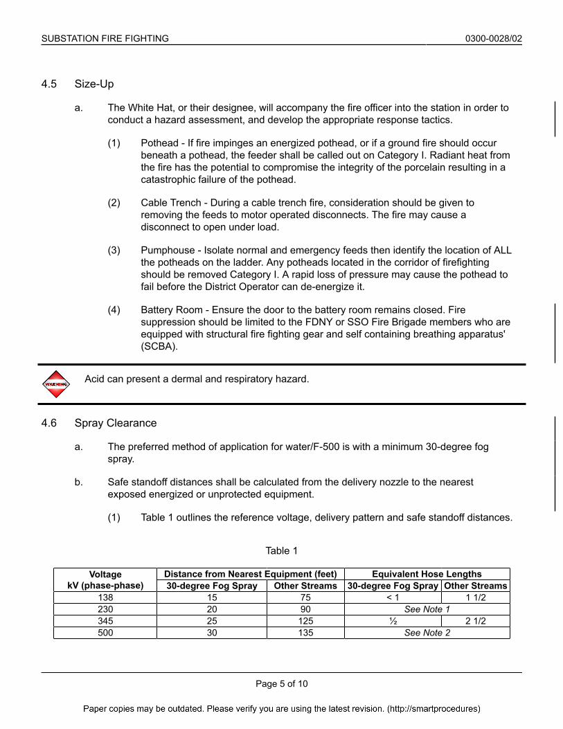
4.6 Spray Clearance
a. The preferred method of application for water/F-500 is with a minimum 30-degree fogspray.
b. Safe standoff distances shall be calculated from the delivery nozzle to the nearestexposed energized or unprotected equipment.
(1) Table 1 outlines the reference voltage, delivery pattern and safe standoff distances.
Table 1
VoltagekV (phase-phase)
Distance from Nearest Equipment (feet) Equivalent Hose Lengths30-degree Fog Spray Other Streams 30-degree Fog Spray Other Streams
138 15 75 < 1 1 1/2230 20 90 See Note 1345 25 125 ½ 2 1/2500 30 135 See Note 2

SUBSTATION FIRE FIGHTING 0300-0028/02
4.6.b (continued)
Page 6 of 10
Note: 230 kV limited to Goethals Substation in Staten Island - treat as 345 kV
Note: 500 kV limited to Ramapo Substation in Rockland County
c. Additional safety measures to be followed by the fire department are as follows:
(1) Clearing of sediment or minerals from the water main before applying the waterstream/spray onto the energized or unprotected equipment. This is done to preventelectrical flashover.
4.7 Operations from Outside the Station Property (Exterior Attack)
a. The preferred positioning for the fire department equipment during fire fighting operationsis outside the station property. If this positioning cannot be utilized, an interior attackshould be used.
4.8 Operations from Inside the Station Property (Interior Attack)
a. Given the various station configurations, logistical constraints may require localizedmethods to access the affected equipment.
(1) An authorized person, designated by the White Hat, must accompany firedepartment personnel at all times when operating within substation property toensure their safety and direct suppression operations.
(2) Fire Apparatus - positioning of fire apparatus within stations shall be conducted inaccordance with SSO Procedure 0800-0011/03, “Use of Mechanical Equipment withinSubstation Property”. Grounds will be applied as required by SSO Procedure0800-0011/03. If two or more separate locations are utilized by the FireDepartment, a station representative will be dedicated to each location.
(3) Mechanical equipment shall not be driven or parked in areas where exposedenergized equipment is present unless the minimum clearance distance between“Energized Equipment” and the nearest projection of ground parked or in transitmechanical equipment, is more than the minimum distance in both horizontal andvertical direction as specified in Table 2.
Table 2 - Minimum Transit Clearance for Mobile Equipment
500kV - 20Ft 345kV - 15Ft 138kV - 7Ft69kV - 5Ft 33kV - 4Ft 27kV - 4Ft.13kV - 4Ft

SUBSTATION FIRE FIGHTING 0300-0028/02
Page 7 of 10
4.9 Equipment not Automatically De-energized
a. If the affected equipment has not been automatically de-energized via relay operations, anOOE (Off On Emergency) Category I request must then be made to the District Operatorhaving jurisdiction utilizing the emergency number. Where available, additional requestsmay be made for the supervisory operation of disconnects switches or other isolatingdevices.
4.10 Follow Up
a. After firefighting operations have commenced, affected equipment will continue to beprocessed concurrently during fire suppression activities. Circuit breakers connected tothe affected equipment shall be checked open and blocked to prevent inadvertentre-closure. Where applicable, physical breaks will be provided and grounds will then beapplied as necessary. Equipment processing will be dependant on safe access.
b. Once the effected equipment is isolated from the system, it will remain under thejurisdiction of the Emergency Response Group until the fire has been extinguished andthe Incident Commander places the situation under control.
4.11 Alternative Suppression Methods
a. IFEX Extinguisher - Conditions may dictate the deployment of the IFEX ExtinguishingSystem based on the size and location of the fire. This is an effective water managementsystem that reduces environmental run-off and water damage. It also offers excellentcooling capabilities to extinguish and keep fires out. The Emergency Response Group isequipped with these fire fighting units.
b. Purple-K - The FDNY maintains several large apparatus that are capable of delivering thisdry suppression media. This system may be called upon to operate within a section orother location where handlines with water/F-500 would not be advantageous.
c. Fire Ice - This suppression agent can be used in two unique applications on 50 kV or less.The product can be applied to "Live" burning cable or conductors to suppress fire andarcing.
5.0 RESPONSIBILITIES
5.1 The ConEd White Hat/Incident Commander will be responsible for the execution of thisprocedure.
5.2 The Control Center Shift Manager will be responsible for coordinating the transportation of theF-500 from the dedicated staging areas to the affected station.
5.3 The Emergency Response Group will serve as the subject matter experts for all fire conditionswithin a substation.
SUBSTATION FIRE FIGHTING 0300-0028/02
Page 8 of 10
6.0 EXHIBITS
6.1 None
7.0 REFERENCES
7.1 SSO Procedure 0300-0002, “Substation Response to Incidents & Emergencies”
7.2 SSO Procedure 0800-0011, “Use of Mechanical Equipment within Substation Properties”
7.3 260-3 CI Rule Book Committee for General Instructions Governing Work on System ElectricalEquipment

SUBSTATION FIRE FIGHTING 0300-0028/02
Page 9 of 10
SUMMARY OF CHANGES
Location ReasonStep 3.2.c(Changed)
Added "on 50 kV or less"
Step 3.2.i(Changed)
Added: "de-energized equipment in"
Step 4.1(Added)
Step 4.3(Changed)
Added: "and fails to make progress in further suppressing the fire within ten totwenty minutes, consideration should be given to shutting the system down."
NoteStep (Unnumbered) - 4.4(Changed)
Added: "or the fire department arrives onsite."
Step 4.4.a.(3).(a)(Changed)
Added: "The lock boxes are either located in the control room or adjacent to themain entrance of the station."
Step 4.5.a.(4)(Changed)
Removed: "In the event that a fire occurs on a battery, call 911 and notify theControl Center Shift Manager." Added: "self containing breathing apparatus"
WarningStep (Unnumbered) - 4.6(Added)
Section 4.6(Changed)
Changed "Water Spray Clearance" to "Spray Clearance"
Step 4.6.a(Changed)
Added: "F-500"
Step 4.6.b(Changed)
Removed "water" from delivery nozzle
Step 4.11.a(Changed)
Replaced: "eliminates" with "reduces"
Step 4.11.c(Added)
Step 7.1(Changed)
Added hyperlink to reference.

SUBSTATION FIRE FIGHTING 0300-0028/02
Page 10 of 10
Location ReasonStep 7.2(Changed)
Added hyperlink to reference.
Step 7.3(Changed)
Added hyperlink to reference.

AMPED I LLC 4410 N Ravenswood Chicago, IL 60640 www.ampedi.com W.312.981.8889 F.312.981.8891
Enhanced Fire Extinguisher Project Class C FireIce Testing
Prepared for:
Consolidated Edison Company of New York, Inc. 4 Irving Place New York, NY
Prepared by:
Amped I, LLC 4410 N Ravenswood Ave.
Chicago, IL 60640
September 4, 2014
The distribution of this document to third parties is prohibited without written approval from Amped I, LLC.
Consolidated Edison Table of Contents
Page ii
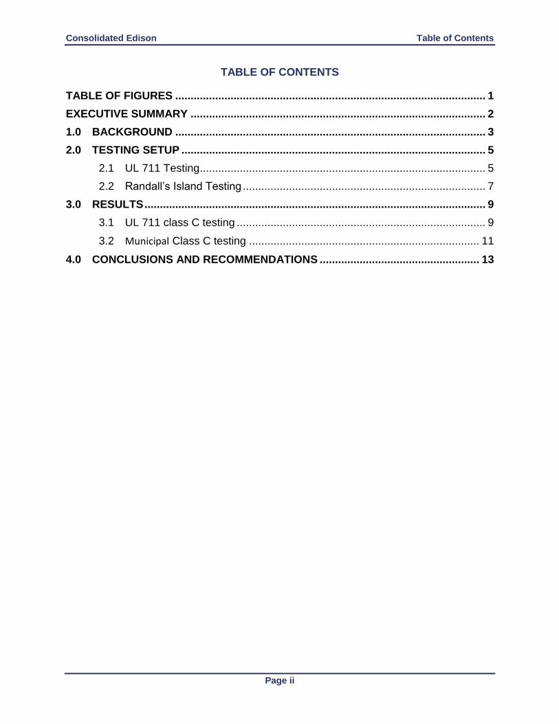
TABLE OF CONTENTS
TABLE OF FIGURES ..................................................................................................... 1
EXECUTIVE SUMMARY ................................................................................................ 2
1.0 BACKGROUND ..................................................................................................... 3
2.0 TESTING SETUP ................................................................................................... 5
2.1 UL 711 Testing ............................................................................................. 5
2.2 Randall’s Island Testing ............................................................................... 7
3.0 RESULTS ............................................................................................................... 9
3.1 UL 711 class C testing ................................................................................. 9
3.2 Municipal Class C testing ........................................................................... 11
4.0 CONCLUSIONS AND RECOMMENDATIONS .................................................... 13

Consolidated Edison Executive Summary
Page 1
TABLE OF FIGURES
Figure 1- Schematic of UL711 test setup for class C rating ........................................................... 6 Figure 2- FireIce extinguisher on isolated platform and remote actuator ....................................... 6 Figure 3 - AC test system capable of 120 kV phase to ground – 200 mA output .......................... 6 Figure 4 - 138 kV disconnect switch which was energized by a conEd Hi-Pot truck .................... 7 Figure 5 - ConEd Truck with power supply ................................................................................... 7 Figure 6 - ConEd power supply mounted in truck .......................................................................... 8 Figure 7 - Nozzle mounted to stack of pallets ................................................................................ 8 Figure 8 - Data acquisition from multimeters and 5000 Ω resistor ................................................ 8 Figure 9 - Hose stream striking energized target .......................................................................... 11
TABLE OF EXHIBITS
Table 1 - The Effect of Current on the Human Body ..................................................................... 3 Table 2 – Minimum Approach Distances for Qualified Workers................................................... 4 Table 3 - Test Results and Conditions ............................................................................................ 9 Table 4 - Municipal class C testing at Randall’s Island ................................................................ 12

Consolidated Edison Executive Summary
Page 2
EXECUTIVE SUMMARY
This test series expands on results obtained during initial testing that was performed on a 2.5
gallon Amerex portable extinguisher filled with FireIce and pressurized to approximately 100 psi
and the manual hand-line testing conducted on Randal’s Island. This report is a comprehensive
report of multiple test series conducted with ConEd and FDNY.
The testing was based on UL 711, Rating and Fire Testing of Fire Extinguishers, specifically;
the testing outlined in section 9, performance of Class C extinguishers. Variables during this test
series were limited to the distance between the extinguisher and the electrified target, the nozzle
used, and the concentration of FireIce used. The FireIce was premixed the day before using de-
ionized water. The goal was to determine if the extinguisher and agent combination could be
safely used for class C fires.
The scope of the UL 711 requires the extinguisher to be discharged onto a target energized to
100kV at 10” with the no return current through the stream. This test methodology seems
somewhat unrealistic since the OSHA minimum approach distance (MAD) for 100kV is 11’ 8”
as referenced in 1910.333 (c) (3) (i) (a) (2) for “Unqualified Persons”. The extinguisher however,
was able to pass the required test voltage of 100kV at 20”. The intent of the project was to
determine if the extinguisher charged with FireIce could be used safely by the workers of Con
Edison who meet the OSHA definition of “Qualified Persons”. The highest distribution voltage
encountered by these “Qualified Persons” is 33kV requiring a minimum approach distance of 3’.
In addition to the manual fire extinguisher testing, a scaled up class C test was developed for the
induction (similar to a foam operation) of FireIce through traditional handlines from a fire
apparatus. The stream was directed at a target energized to 50kV at a 25’ standoff distance. The
test process called for the nozzle to be repositioned in order to close the distance to the energized
target until return current through the stream exceeded the established threshold. At 13’ return
current was measured at 3,500 microamps which was well above the established 900 microamps.
In addition, the return current through the solid stream nozzle was measured for both straight
water and water/FireIce. This was done to gauge the current variation that may occur if there was
a failure in the induction process. It was noted that an increase in the leakage was seen when
water/FireIce was used, in comparison to water however the increase was negligible.
Testing confirmed that current rise is not linear with movement closer to the energized target but
rather exponential. Within 3’ current reading changed from safe to deadly. It should be noted that
a variation of 100mA could be the difference between an undetectable level and injury/death.
The highest voltage that the FDNY can encounter in this operation is 33kV. It remains clear that
testing has established that it is safe to apply the product on or around energized equipment of
50kV or less employing a conservative standoff distance of 25’. It is imperative that no person
engaged in this application violate the 25’ safe standoff distance.

Consolidated Edison Background
Page 3
1.0 BACKGROUND
Electrical fires pose an increased danger due not only to the heat and products of combustion
produced from a typical fire but the potential for electrocution due to leakage back to the user.
For this reason UL classifies extinguishing agents not only by the fire’s fuel source and size, but
also by whether the product can be safely used on electrical fires, known as class C fires. UL
class C fire testing does not test extinguishment performance on electrical fires, only the
conductivity of the agent. Section 5.5 of UL 711 states;
“There is no numerical component for class C ratings of extinguishers, as only the electrical
conducting characteristics of the agent when being discharged are significant, and no effort is
made to indicate the extinguishing potential for fires that involve electrical equipment.”
This presents a significant issue to fire fighting personnel as they may be under the impression
that an agent listed for class C fires is capable of extinguishing class C fires. The reality of the
situation is that the agent has only demonstrated its ability to be non conductive. An agent
capable of extinguishing a class C fire, on the other hand, may not be able to pass the high
standard of non conductivity established by the UL 711 standard. Additionally, the class C
rating in UL 711 only applies to extinguishers. It does not address firefighter operations or other
methods of applying the agent.
The UL 711 test configuration comprises of a pressurized extinguisher being mounted 10 inches
from a charged target measuring 12 in by 12 in The target is bent at 90 degrees and charged with
100 kV. The extinguisher is discharged onto the target and electrical leakage is measured
between the tip of the extinguisher nozzle or horn and the target. In order to pass the test, the
leakage measured must be no greater than 1 mA. In addition to the performance test, the agent
itself must have a measured conductance of no more than 1 micro Siemen per centimeter.
Table 1 - The Effect of Current on the Human Body
Reference: NIOSH [1998]. Worker Deaths by Electrocution; A Summary of NIOSH Surveillance and Investigative Findings. Ohio: US
Health and Human Services.

Consolidated Edison Background
Page 4
Table 1 indicates that the perception level begins at 1mA (1000 microamps). As such, the
acceptable leakage rate for this project was set by Consolidated Edison (ConEd) at 0.9 mA (900
microamps) which remains below the perception level.
Three primary factors affect the severity of a shock that a person receives. First, the amount of
current flow is critical; as the rate of current rises, survivability decreases. The second critical
factor is the path that current takes through the body. Current flowing across the heart is the least
desirable path and the most likely to cause death. Finally, the amount of time the body is in
contact with the circuit will increase the severity of thermal burns and cardiac distress.
To ensure that workers remain safe around high voltage electrical sources, OSHA has established
minimum approach distances (MAD) for “Qualified Persons” who are familiar with the hazards
and “Unqualified Persons” who remain unaware of the potential electrical hazards.
Minimum approach Distances for Unqualified Persons
1910.333(c)(3)(i)(A)(1)
For voltages to ground 50kV or below - 10 feet (305 cm);
1910.333(c)(3)(i)(A)(2)
For voltages to ground over 50kV - 10 feet (305 cm) plus 4 inches (10 cm) for every 1kV over
50kV.
Table 2 references the minimum approach distances for Qualified Persons that correlate to the
voltage schedule.
Table 2 – Minimum Approach Distances for Qualified Workers
Reference: OSHA 1910.333
The minimum safe work distances set by OSHA and ConEd demonstrate that the UL 711 test is
overly conservative. When you consider that an Unqualified Person should be greater than 10
feet from 100 kV, using an extinguisher at 10 inches seems irrational. Irrelevant of possessing
an extinguisher or not, personnel could not survive to operate an extinguisher within the 10
inches of a 100 kV target as established by the UL 711 standard.
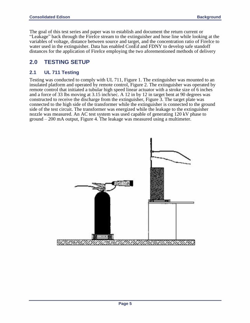
Consolidated Edison Background
Page 5
The goal of this test series and paper was to establish and document the return current or “Leakage” back through the FireIce stream to the extinguisher and hose line while looking at the variables of voltage, distance between source and target, and the concentration ratio of FireIce to water used in the extinguisher. Data has enabled ConEd and FDNY to develop safe standoff distances for the application of FireIce employing the two aforementioned methods of delivery 2.0 TESTING SETUP
2.1 UL 711 Testing
Testing was conducted to comply with UL 711, Figure 1. The extinguisher was mounted to an insulated platform and operated by remote control, Figure 2. The extinguisher was operated by remote control that initiated a tubular high speed linear actuator with a stroke size of 6 inches and a force of 33 lbs moving at 3.15 inch/sec. A 12 in by 12 in target bent at 90 degrees was constructed to receive the discharge from the extinguisher, Figure 3. The target plate was connected to the high side of the transformer while the extinguisher is connected to the ground side of the test circuit. The transformer was energized while the leakage to the extinguisher nozzle was measured. An AC test system was used capable of generating 120 kV phase to ground – 200 mA output, Figure 4. The leakage was measured using a multimeter.

Consolidated Edison Testing Setup
Page 6
Figure 1- Schematic of UL711 test setup for class C rating
Figure 2- FireIce extinguisher on isolated platform and remote actuator
Figure 3 - AC test system capable of 120 kV phase to ground – 200 mA output

Consolidated Edison Testing Setup
Page 7
2.2 Randall’s Island Testing
Additional class C testing was conducted as part of this test series at the Fire Department of New
York (FDNY) Randall’s Island Fire Academy. The class C testing is a scaled up version of the
test setup for manual hand line operations. The 12 in by 12 in target was replaced by a 138 kV
disconnect switch from a substation, Figure 5. The disconnect switch was energized using a
power supply capable of supplying 50 kV mounted in a ConEd Truck, Figures 6 and 7. The
nozzle was mounted to a platform constructed of pallets and moved using a pallet jack to adjust
the distance, figure 8. Measurements were collected using three multimeters, Figure 9. Two
Multimeters collected current readings in milli-amps and micro-amps. The third measured
current across a 5000 Ω resistor. A 5000 Ohm resistor was placed in-series with the ammeter in
order to simulate the electrical resistance of a fire fighter.
Figure 4 - 138 kV disconnect switch which was energized by a conEd Hi-Pot truck
Figure 5 - ConEd Truck with power supply
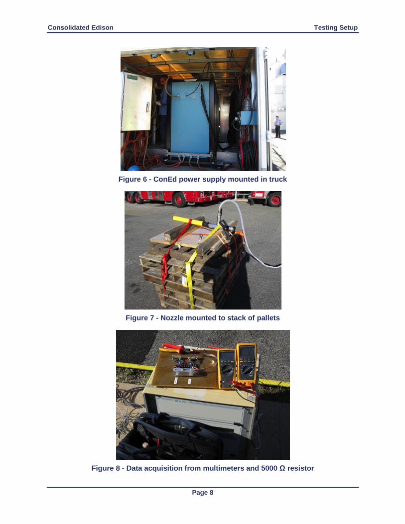
Consolidated Edison Testing Setup
Page 8
Figure 6 - ConEd power supply mounted in truck
Figure 7 - Nozzle mounted to stack of pallets
Figure 8 - Data acquisition from multimeters and 5000 Ω resistor

Consolidated Edison Results
Page 9
3.0 RESULTS
Ten tests were conducted at the ConEd electrical test lab and twenty-three tests were conducted
at the FDNY Randall’s Island Fire Academy over two series of tests. It is the desire of ConEd
and the FDNY to establish and verify safe practices for use of the FireIce product by means of a
2.5 gallon fire extinguisher and hand line operations. FDNY and ConEd are currently using the
product on a limited basis during manual firefighter operations to extinguish class C manhole
and electrical pole fires. This test report is additional data to further justify the use of the FireIce
product on class C fires.
3.1 UL 711 class C testing
During the UL711 testing, the concentration, nozzle, and distance were varied. The test result
was a pass/fail with the leakage either remaining below the 0.9 mA threshold or resulting in an
arc back to the can. The concentration refers to the amount of FireIce that was mixed with 2.5
gallons of distilled water. Two concentrations were used during testing: 90 grams and 100 grams
per 2.5 gallons. The concentrations were chosen based on the manufactures recommendation.
Voltage remained at 100 kV and the distance was adjusted from 10 in to 30 in. The extinguisher
nozzle was changed during test from a fan tip nozzle with a spray of 15 degrees, to a mist nozzle
with a cone spray of 45 degrees. Table 3 contains the conditions and results for the ten (10) tests
conducted.
Table 3 - Test Results and Conditions
Test Number
Distance (in) Voltage (kV) Concentration (grams)
Nozzle Pass / Fail
1 10 100 100 Fan Tip nozzle Fail
2 20 100 100 Fan Tip nozzle Fail
3 30 100 100 Fan Tip nozzle Pass
4 30 100 90 Fan Tip nozzle Pass
5 20 100 90 Fan Tip nozzle Fail
6 20 100 90 Mist nozzle Pass
7 10 100 90 Mist nozzle Fail
8 15 100 90 Mist nozzle Fail
9 10 100 Water Mist Mist nozzle Fail
10 10 100 Water Mist Mist nozzle Fail
Test 1 was conducted at 10 inches with 100 kV using a concentration of 100 grams. The
extinguisher failed the test on activation of the actuator. During
Test 2 the extinguisher was moved back to 20 inches while the voltage and FireIce concentration
remained the same. The extinguisher again failed, however, the failure did not occur during the
activation or application of the agent, but upon release of the trigger.
Test 3 moved the extinguisher back to 30 inches. The voltage and concentration remained the
same. The extinguisher passed the test, however there was an arc to the plastic curtain that
surrounds the test setup to limit splatter. It is unclear if the results would have changed if the test
was to have continued. The plastic curtain was pushed away from the test setup repeatedly, but
due to build up of agent on the curtain the target continually arced to the plastic curtain during
testing.

Consolidated Edison Results
Page 10
Test 4 was a repeat of test three at 30 inches with the target energized to 100 kV however the
concentration was lowered to 90 grams. The extinguisher passed but again there was an arc to
the plastic curtain. The lower concentration of FireIce resulted in a lower conductivity. It also
thins out the agent which would allow for more atomization when released from the
extinguisher. The gaps of air between the agent (atomization) created during release are the
biggest factor in determining if leakage occurs. A fine mist prevents leakage because air gaps are
maintained producing a less conductive path for travel. This mist is more likely to be maintained
when full pressure is available. When the trigger of the extinguisher is initiated and then released
lower pressures can be seen which results in a “straight stream” of agent.
Test 5 moved the extinguisher to 20 inches. The voltage remained at 100 kV and the
concentration remained at 90 grams. The extinguisher failed the tests due to leakage reading
greater than 1 mA at the start of the actuator.
Test 6 was a repeat of test 5 with a standoff distance of 20 inches, a voltage of 100 kV and a
concentration of 90 grams. However the nozzle on the extinguisher was replaced with a water
mist nozzle. This nozzle results in a wider more atomized spray. The extinguisher passed the test
and the test ended when an arc to the plastic curtain occurred.
Test 7 moved the extinguisher to 10 inches, voltage and concentration remained at 100 kV and
90 grams respectively. The extinguisher failed.
Test 8 moved the extinguisher to 15 inches, the extinguisher passed the test during the first
release. The extinguisher was then activated a second time and failed the test. The failure on the
second release was likely due to the lower pressure available in the can.
Test 9 changed out the extinguisher to a class C approved water mist that was placed at 10
inches. The target was energized to 100 kV. The class C approved extinguisher failed similar to
what was experienced using the extinguisher carrying FireIce. Both worked well with no leakage
during activation but as pressure declined there was a visible arc that tracked back to the
extinguisher.
Test 10 was a repeat of the setup used in test 9. The extinguisher had a lower pressure due to the
release during Test 9. The extinguisher failed again. The testing was concluded after test 10 due
to the actuator being destroyed.
After testing, ConEd supplied the resistivity measurement for the FireIce agent. ConEd personnel
baselined a FireIce concentration of 100 grams per 2.5 gallons of water to that of tap water and
distilled water. Distilled water had a resistivity of 470 kΩ/cm while tap water drops to 12 kΩ/cm
and FireIce to 0.8 kΩ/cm. This verified that FireIce is above the UL711 class C acceptable
conductivity of 1 μS/cm.

Consolidated Edison Results
Page 11
3.2 Municipal Class C testing
The Randall’s Island test setup was designed to exceed the highest voltage of 33kV which would
be found in a ConEd electrical distribution fire. The target was energized to 50,000 volts and the
nozzle was placed at 25 feet to start.
Water Tests were conducted first to get a baseline for water applications utilizing the FireIce
Setup. The nozzle was moved closer towards the target until a leakage of 0.9 mA was met or
exceeded.
The leakage measurements were collected during both straight water and FireIce/water mixed
(solution) using the FireIce induction system. The hose line was pressurized to 80 psi which
resulted in a flow rate of approximately 110 GPM, Figure 9. All readings were captured with a
peak reading as the agent was in a steady state while the Hi-Pot Truck ramped up to the desired
voltage (or highest voltage capability in some tests). The maximum lock function on the
multimeters was used to capture the highest spike throughout the testing for a conservative
approach. All voltages were measured in DC.
Figure 9 - Hose stream striking energized target
The test stand was repositioned at roughly 5 foot intervals toward the energized target until
return current through the stream exceeded the established limit. It was further confirmed that the
leakage values track closely with an exponential curve. A dramatic spike in leakage was found
between the 16’ and 13’ marks. In addition, FireIce generates a leakage higher than that of water
at each distance tested however the variations were nominal. Adding a safety factor of 10’ makes
the product safe to use for municipal departments or industrial brigades at 25 ft standoff distance.

Consolidated Edison Results
Page 12
Table 4 - Municipal class C testing at Randall’s Island
Test Number
Distance (ft) Voltage (kV) Agent Leakage (mA)*
1 25 50 Water 0.004
2 25 50 FireIce 0.0045
3 25 38 Water baseline
4 25 38 FireIce 0.0029
5 25 50 Water 0.00336
6 25 18 Water 0.0038
7 25 50 Water 0.00285
8 25 50 FireIce 0.0037
9 25 50 Water 0.0052
10 25 50 Water 0.00272
11 25 50 FireIce 0.003
12 20 50 Water 0.0124
13 20 40 FireIce 0.0051
14 20 50 Water 0.0064
15 20 50 FireIce 0.0657
16 20 50 Water 0.0045
17 20 50 FireIce 0.0058
18 16 50 Water 0.0202
19 16 50 FireIce NA
20 16 50 Water 0.170
21 16 50 FireIce 0.66
22 13 50 Water 0.862
23 13 50 FireIce 3.500 *Leakage takes background measurement into effect. Background leakage was approximately 0.7 – 1.4 uA

Consolidated Edison Conclusions and Recommendations
Page 13
4.0 CONCLUSIONS AND RECOMMENDATIONS
Class C testing of both the 2.5 gallon FireIce extinguisher assembly and the application of
FireIce employing a municipal hose stream induction process demonstrated both methods to be
safe given the following:
FireIce Extinguisher – UL 711 testing:
Testing demonstrated the extinguisher carrying FireIce does not conform to the ultra-
conservative standoff distance set by UL at 10” for a 100kV with < 1mA of return current
through the stream. However the extinguisher assembly will produce the required < 1mA return
current at 20 inches for 100kV. As such, safety in this application will be driven by the
Minimum Approach Distances set by OSHA for electrical conductors rather than the values
established by UL. OSHA defines the minimum approach distances for two groups. Qualified
Workers at 3 feet (15kV to 37kV) and Unqualified Workers require a 10 foot standoff distance
(50kV). We do not recommend this product for use by Unqualified Workers. All personnel
meeting the OSHA description of Qualified Workers can engage in the process of applying
FireIce using a 2.5 gallon extinguisher assembly at 5 feet. An additional 2 feet was added to the
required 3 foot minimum approach distances for Qualified Workers in order to provide an
additional safety buffer. For the purpose of this application 5 feet will be deemed the safe
working distance for the FireIce extinguisher assuming the following:
Distilled water is used for mixing the FireIce,
A concentration of 90 grams per 2.5 gallons is used,
The mist nozzle supplying a 45 degree cone spray is used, and
The extinguisher is properly pressurized to 100 psi.
FireIce Hose Stream – Municipal/Brigade Operations: No UL standards exist to govern Class
C suppression operations as they relate to municipal or brigade departments. As such, we
considered what existing authorities such as OSHA or UL deem acceptable for return leakage
and applied conservative approach distances to the existing standards.
1000 microamps is the threshold of detection for current flow through the body. As such, Con
Edison assumed the position that fire department members should not encounter any current
sensation which drove the selection of 900 microamps as the threshold/failure point.
Test voltages were set at 50kV well in excess of the 33kV that can reasonably be encountered on
the Con Edison Distribution System. FireIce product was applied to the 50kV conductor by
employing an eduction process similar to that of a traditional foam operation. The test began at
25’ and the distance between the placement of the nozzle and the energized target was closed
until failure occurred. At 16 feet return current through the stream was at a safe level of 650
microamps. At 13 feet, return current excelled to 3,500 microamps which suggests current rise is
not linear but exponential.
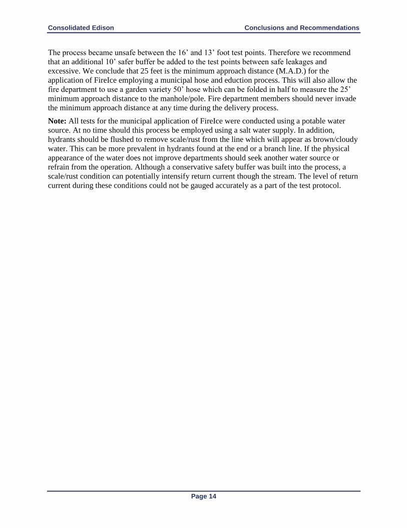
Consolidated Edison Conclusions and Recommendations
Page 14
The process became unsafe between the 16’ and 13’ foot test points. Therefore we recommend
that an additional 10’ safer buffer be added to the test points between safe leakages and
excessive. We conclude that 25 feet is the minimum approach distance (M.A.D.) for the
application of FireIce employing a municipal hose and eduction process. This will also allow the
fire department to use a garden variety 50’ hose which can be folded in half to measure the 25’
minimum approach distance to the manhole/pole. Fire department members should never invade
the minimum approach distance at any time during the delivery process.
Note: All tests for the municipal application of FireIce were conducted using a potable water
source. At no time should this process be employed using a salt water supply. In addition,
hydrants should be flushed to remove scale/rust from the line which will appear as brown/cloudy
water. This can be more prevalent in hydrants found at the end or a branch line. If the physical
appearance of the water does not improve departments should seek another water source or
refrain from the operation. Although a conservative safety buffer was built into the process, a
scale/rust condition can potentially intensify return current though the stream. The level of return
current during these conditions could not be gauged accurately as a part of the test protocol.

“ENCAPSULATOR” FIRE SURPRESSION AGENT TEST ON
ENERGIZED ELECTRICAL EQUIPMENT
CONDUCTED AT
345 KV FRESH KILLS SUBSTATION
OCTOBER 15, 2010
Supplement to report on Water Spray Test on Energized Electrical Equipment conducted at 138kV Dunwoodie Substation on December 9, 2003, report dated April 12, 2004, and to report on Water Spray Test on Energized Electrical Equipment conducted at 345kV Fresh Kills Substation on May 9, 2006, report dated February 16, 2007

2
ENCAPSULATOR FIRE SUPPRESSION AGENT TEST ON ENERGIZED ELECTRICAL EQUIPMENT AT 345 KV FRESH KILLS SUBSTATION
CONDUCTED ON OCTOBER 15, 2010 Supplement to report on Water Spray Test on Energized Electrical Equipment conducted at 138kV Dunwoodie Substation on December 9, 2003, report dated April 12, 2004, and to report on Water Spray Test on Energized Electrical Equipment conducted at 345kV Fresh Kills Substation on May 9, 2006, report dated February 16, 2007
TABLE OF CONTENTS
1.0 EXECUTIVE SUMMARY 3 2.0 BACKGROUND 4
3.0 ENCAPSULATOR AGENT – WATER SPRAY TESTS 4 4.0 TEST DATA ANALYSIS 8
5.0 NEW YORK CITY FIRE DEPARTMENT EQUIPMENT 9
6.0 TEST LOCATION 9 7.0 CON EDISON INSTRUMENTATION 10
8.0 CON EDSION FRESH KILLS SUBSTATION EQUIPMENT STATUS 11
9.0 SUMMARY 11
10.0 ACKNOWLEDGEMENTS 12
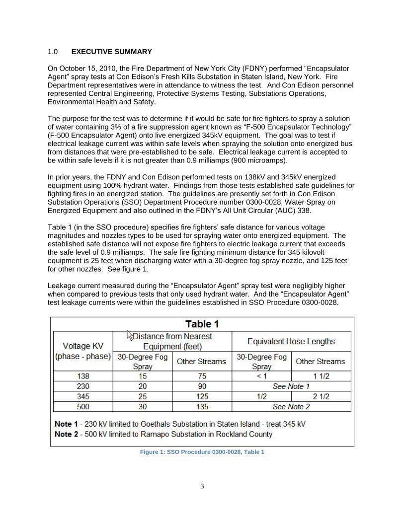
3
1.0 EXECUTIVE SUMMARY On October 15, 2010, the Fire Department of New York City (FDNY) performed “Encapsulator Agent” spray tests at Con Edison’s Fresh Kills Substation in Staten Island, New York. Fire Department representatives were in attendance to witness the test. And Con Edison personnel represented Central Engineering, Protective Systems Testing, Substations Operations, Environmental Health and Safety. The purpose for the test was to determine if it would be safe for fire fighters to spray a solution of water containing 3% of a fire suppression agent known as “F-500 Encapsulator Technology” (F-500 Encapsulator Agent) onto live energized 345kV equipment. The goal was to test if electrical leakage current was within safe levels when spraying the solution onto energized bus from distances that were pre-established to be safe. Electrical leakage current is accepted to be within safe levels if it is not greater than 0.9 milliamps (900 microamps). In prior years, the FDNY and Con Edison performed tests on 138kV and 345kV energized equipment using 100% hydrant water. Findings from those tests established safe guidelines for fighting fires in an energized station. The guidelines are presently set forth in Con Edison Substation Operations (SSO) Department Procedure number 0300-0028, Water Spray on Energized Equipment and also outlined in the FDNY’s All Unit Circular (AUC) 338. Table 1 (in the SSO procedure) specifies fire fighters’ safe distance for various voltage magnitudes and nozzles types to be used for spraying water onto energized equipment. The established safe distance will not expose fire fighters to electric leakage current that exceeds the safe level of 0.9 milliamps. The safe fire fighting minimum distance for 345 kilovolt equipment is 25 feet when discharging water with a 30-degree fog spray nozzle, and 125 feet for other nozzles. See figure 1. Leakage current measured during the “Encapsulator Agent” spray test were negligibly higher when compared to previous tests that only used hydrant water. And the “Encapsulator Agent” test leakage currents were within the guidelines established in SSO Procedure 0300-0028.
Figure 1: SSO Procedure 0300-0028, Table 1

4
2.0 BACKGROUND
In 2006 Con Edison began a joint venture with the New York City Fire Department (FDNY) to prove that water could be used safely in a high voltage environment to extinguish or protect equipment impinged by fire. Two recent incidents caused the Company to rethink its response posture. We realized that we needed to look for a product that was electrically safe and will enable us to knock the fire down quickly without the risk of a boil-over. With the FDNY we looked at the products available on the market and chose three; AFFF, Alcohol Resistant Foam (AR-AFFF) and F-500 Encapsulator Agent. Preliminary testing was conducted at the fire academy using a disconnect switch energized to 50,000 Volts. The leakage current values from the AFFF and the AR-AFFF exceeded the established safety limit of 0.9 milliamps, but the F-500 Encapsulator Agent produced leakage current values similar to water, which we already knew to be safe. Findings from the tests enabled us to move forward and conduct a live field test on October 15, 2010 at the Fresh Kills 345,000 Volt Substation. The selection of the site was driven by our need to conduct this testing on the highest voltage that the FDNY could reasonably encounter. The F-500 Encapsulator Agent does not fall into the category of traditional foam whose fire suppression mechanics rely on the formation and maintenance of bubbles or a film over the fuel to separate the fuel from the oxygen smothering the fire and providing a temporary burnback resistance until the heat is slowly dissipated below the auto ignition temperature of the fuel. F-500 is considered an encapsulating agent whose fire suppression mechanics involve encapsulating the hydrocarbon vapor and/or liquid molecules in a “Chemical Cocoon” rendering them non flammable and non ignitable, while simultaneously rapidly reducing the heat below the auto ignition point of the fuel providing permanent burnback resistance. Based on the fire suppression mechanics, Encapsulator Agents work effectively on three dimensional fires and are capable of providing quick knockdown coupled with heat dissipation. 3.0 ENCAPSULATOR AGENT - WATER SPRAY TESTS A solution of 3% F-500 Encapsulator Agent with 97% New York City hydrant water was sprayed onto energized 345kV equipment. FDNY provided an eductor device for mixing the solution. The eductor is outfitted with a proportioning valve that allows the user to select a 1% thru 6% additive mixture to deliver onto the target. For our purpose the selector was set for 3%. See Figure 2.
Figure 2: F500 Encapsulator Agent Additive Storage Tanks with Eductor

5
FDNY provided nozzles for a fog stream and for a solid stream that were used to discharge the solution from varying distances and onto the energized 345kV equipment. See figure 3.
Figure 3: 30-Degree Fog Spray Nozzle
The fog spray nozzle was mounted on a portable test stand and connected to the pumper truck’s 2 ½” hose, while the solid stream nozzle was mounted onto the turret of a pumper truck. Electric leakage current was measured via a wire that was connected to the nozzle, and the other end of the wire was connected to a circuit for measuring leakage current. See figure 4.
Figure 4: Fog Nozzle with Wire to Measure Leakage Current
A digital ammeter in the circuit measured for electric leakage current conducting from the live 345kV equipment through the water solution spray and to the nozzle and then to ground. A 5000 Ohm resistor was placed in-series with the ammeter in order to simulate the electrical resistance of a fire fighter.
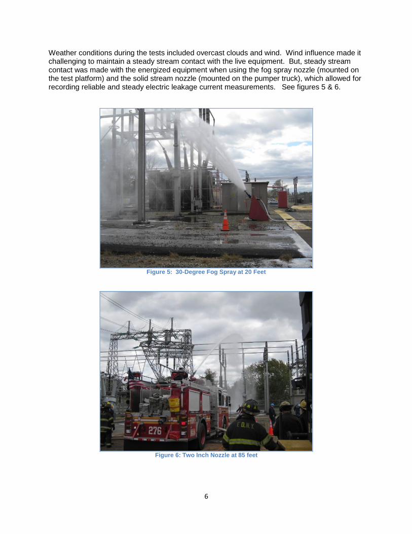
6
Weather conditions during the tests included overcast clouds and wind. Wind influence made it challenging to maintain a steady stream contact with the live equipment. But, steady stream contact was made with the energized equipment when using the fog spray nozzle (mounted on the test platform) and the solid stream nozzle (mounted on the pumper truck), which allowed for recording reliable and steady electric leakage current measurements. See figures 5 & 6.
Figure 5: 30-Degree Fog Spray at 20 Feet
Figure 6: Two Inch Nozzle at 85 feet

7
Water discharging from a Multiversal nozzle mounted to the turret on an extended tower ladder did not make steady stream contact. Wind forces prevented adequate steady contact as the spray pattern broke down. Although, it is reasonable to conclude that this type of wide spray pattern would not produce greater leakage values than that of a smooth bore straight stream. See figure 7.
Figure 7: Turbomaster Nozzle from Ladder Truck
4.0 TEST DATA ANALYSIS
Electric leakage current with 3% additive solution was negligibly higher than with 100% water. Examples of results are shown below: 100% Water: Test Stand @ 25 feet, 30 degree fog total electric leakage current 0.100 milliamps. (Reference: Fresh Kills 345kV Water Spray Report, page 18 of 22, Turbomaster, fog spray @ 25’)
With Encapsulator Agent Additive: Test Stand @ 20 feet, 30 degree fog total electric leakage current 0.119 milliamps. With Encapsulator Agent Additive: Test Stand @ 30 feet, 30 degree fog total electric leakage current 0.100 milliamps.
The “Encapsulator Agent” tests’ indicate that the established guidelines (in SSO Procedure 0300-0028) for fighting fires with city hydrant water sprayed onto live 345kV equipment are also applicable when using a solution of 3% additive of F-500 Encapsulator Agent with 97% city hydrant water. See figure 8, test results below.

8
Test Results: Con Edison Fresh Kills Substation 345kV Live Bus Encapsulator Agent Spray Test
Nozzle Type (on Test Stand)
Contact Distance
to Conductor
Leakage Current w/5k Ohm In Ckt
Leakage Current with
Resistor Shorted
Voltage Across 5k Ohm Resister
Recorder Current Trace #
Background Current
Setup (feet) (milli-Amp) (milli-Amp) (AC
Volts) Ben # (milli-Amp)
Platform Solid Stream 30 1.000 1.100 5 N/A 0.034-0.050
Platform Fog Stream 30 0.080-0.090 0.100 0.4-0.45 2442 0.034-0.050
Platform Fog Stream 20 0.105 0.119 0.53 2443 0.034-0.050
Platform Fog Stream 10 0.150 0.165 0.72 2444 0.034-0.050
Pumper Truck Solid Stream 85 2.000-4.000 2.000-4.000 10.0-20.0 2446 0.0035-0.0139
Pumper Truck Solid Stream 95 0.200-0.600 0.200-0.800 1.0-3.0 2447 0.0035-0.0139
Pumper Truck Solid Stream 105 0.200-0.450 0.400-0.600 1.0-2.3 2448 0.0035-0.0139
Figure 8: Encapsulator Agent-Water Spray Test Results
5.0 NEW YORK CITY FIRE DEPARTMENT EQUIPMENT Tower Ladder: This apparatus is equipped with a Multiversal nozzle that can deliver fog or smooth bore/straight stream at 500 GPM. Foam Tender: This apparatus is similar to that of an Engine in appearance and is designed to deliver a large caliber foam and/or Encapsulator Agent solution stream through a deck gun off the rig at 300 GPM. Foam Eductor device: An eductor is designed to produce a strong venturi effect (vacuum) as a given flow range of water passes through the eductor. The venturi effect causes the concentrate from the concentrate storage tank to be ejected into the flow of water. The eductor is outfitted with a proportioning valve that allows the user to select a 1% thru 6% agent concentrate mixture to deliver onto the target.
6.0 TEST LOCATION (see figure 9)
Fresh Kills 345kV Substation was selected for the test location and a 345kV coupling capacitor voltage transformer (CCVT) in 345 kV Bus Section 1-2 was the equipment selected to be sprayed with the solution, because it satisfied the following requirements: (1) The exposed live 345 kV equipment is located 22 feet above ground level, which is closer to the ground than any other 345 kV equipment installed at Fresh Kills Substation, and therefore presents the worst-case condition. A vertical conductor connects the CCVT to the live 345 kV bus, which is 15 feet above the CCVT. This selection ensured that the test would be performed

9
at the distance established in the guidelines and provided a large surface area as a target for the water spray. If the equipment was mounted any higher above ground level, then the distance from the hose nozzle to the equipment would be longer. A longer distance would result in lower leakage current, which could skew the test results. (2) In the event of flashover to ground or phase-to-phase during testing, the impact on the Con Edison system would be minimal. (3) The ground area by the equipment is large and provided adequate safe clearance for all personnel, and FDNY and Con Edison equipment.
Figure 9: Test Site - Fresh Kills 345kV Energized Bus
7.0 CON EDISON INSTRUMENTATION
Leakage current was recorded with the following meters: VM - Fluke 77 digital voltmeter: Used to measure the voltage across the 5000 resistor AM - Fluke 287 digital ammeter: Used to measure leakage current in the micro Amp Scale (with a hold feature to capture the highest current measurement) Ammeter - Weston analog ammeter on the 2 amp scale and read as low as 2 milliamps. Ammeter - Weston analog ammeter on the 10 Amp scale. Ammeter – Ben 500 digital fault recorder has a sensitivity of 100 microamps but the scaling works best in the milliamp range. A safety spark gap set at 400 volts, was installed between the nozzle and the station ground to protect the instrumentation and personnel in case of a high voltage transient. Figure # 10 represents the simplified circuit.

10
Figure 10: Con Edison Leakage Current Circuit
A 5000-Ohm resistor was installed in the circuit between the nozzle and earth ground. A shorting switch was installed across the resistor. The 5000-Ohm resistor represents the upper limit of body resistance. With hands and feet wet, body resistance would be considerably less than 5000-Ohms. For this reason, a shorting switch across the 5000-Ohm resistor was used to represent a resistance of 0-Ohms. Measurements were made with the shorting switch open and with it closed. A similar value of 5000-Ohm resistance was used in previous studies and Con Edison/FDNY water spray tests.
8.0 CON EDISON FRESH KILLS SUBSTATION EQUIPMENT STATUS
The targeted coupling capacitor voltage transformer (CCVT) connected to 345kV Bus Section # 1-2 was energized by the following Equipment arrangement at Fresh Kills Substation. See One Line diagram in figure 11. Equipment Status: 345kV Circuit Breaker # 1 was CLOSED 345kV Circuit Breaker # 2 was OPEN (TRIPPED) 138kV Circuit Breaker # TA-1 was OPEN (TRIPPED) 138kV Disconnect Switch # TA-1 was OPEN
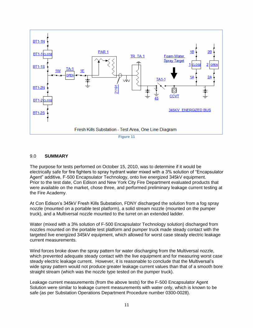
11
Figure 11
9.0 SUMMARY
The purpose for tests performed on October 15, 2010, was to determine if it would be electrically safe for fire fighters to spray hydrant water mixed with a 3% solution of “Encapsulator Agent” additive, F-500 Encapsulator Technology, onto live energized 345kV equipment. Prior to the test date, Con Edison and New York City Fire Department evaluated products that were available on the market, chose three, and performed preliminary leakage current testing at the Fire Academy. At Con Edison’s 345kV Fresh Kills Substation, FDNY discharged the solution from a fog spray nozzle (mounted on a portable test platform), a solid stream nozzle (mounted on the pumper truck), and a Multiversal nozzle mounted to the turret on an extended ladder. Water (mixed with a 3% solution of F-500 Encapsulator Technology solution) discharged from nozzles mounted on the portable test platform and pumper truck made steady contact with the targeted live energized 345kV equipment, which allowed for worst case steady electric leakage current measurements. Wind forces broke down the spray pattern for water discharging from the Multiversal nozzle, which prevented adequate steady contact with the live equipment and for measuring worst case steady electric leakage current. However, it is reasonable to conclude that the Multiversal’s wide spray pattern would not produce greater leakage current values than that of a smooth bore straight stream (which was the nozzle type tested on the pumper truck). Leakage current measurements (from the above tests) for the F-500 Encapsulator Agent Solution were similar to leakage current measurements with water only, which is known to be safe (as per Substation Operations Department Procedure number 0300-0028).

12
10.0 ACKNOWLEDGEMENTS The following persons are acknowledged as contributors for this report. Anthony J Natale, Sr Specialist, Emergency Response Group Stephen Raynis, Chief of Safety, New York City Fire Department
Timothy Sieban, Manager, Protective Systems Testing Michael T. Greiner, President, Hazard Control Technologies
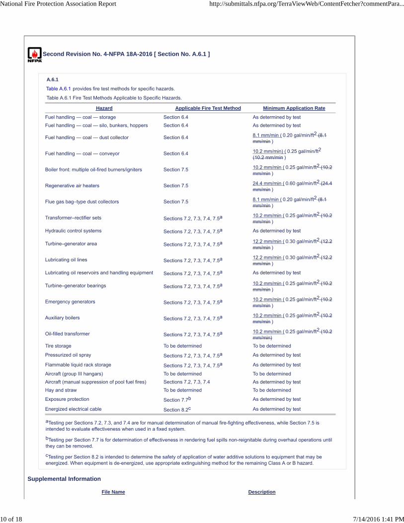
Second Revision No. 4-NFPA 18A-2016 [ Section No. A.6.1 ]
A.6.1
Table A.6.1 provides fire test methods for specific hazards.
Table A.6.1 Fire Test Methods Applicable to Specific Hazards.
Hazard Applicable Fire Test Method Minimum Application Rate
Fuel handling — coal — storage Section 6.4 As determined by test
Fuel handling — coal — silo, bunkers, hoppers Section 6.4 As determined by test
Fuel handling — coal — dust collector Section 6.4 8.1 mm/min ( 0.20 gal/min/ft2 (8.1mm/min )
Fuel handling — coal — conveyor Section 6.4 10.2 mm/min) ( 0.25 gal/min/ft2
(10.2 mm/min )
Boiler front: multiple oil-fired burners/igniters Section 7.5 10.2 mm/min ( 0.25 gal/min/ft2 (10.2mm/min )
Regenerative air heaters Section 7.5 24.4 mm/min ( 0.60 gal/min/ft2 (24.4mm/min )
Flue gas bag–type dust collectors Section 7.5 8.1 mm/min ( 0.20 gal/min/ft2 (8.1mm/min )
Transformer–rectifier sets Sections 7.2, 7.3, 7.4, 7.5a 10.2 mm/min ( 0.25 gal/min/ft2 (10.2mm/min )
Hydraulic control systems Sections 7.2, 7.3, 7.4, 7.5a As determined by test
Turbine–generator area Sections 7.2, 7.3, 7.4, 7.5a 12.2 mm/min ( 0.30 gal/min/ft2 (12.2mm/min )
Lubricating oil lines Sections 7.2, 7.3, 7.4, 7.5a 12.2 mm/min ( 0.30 gal/min/ft2 (12.2mm/min )
Lubricating oil reservoirs and handling equipment Sections 7.2, 7.3, 7.4, 7.5a As determined by test
Turbine–generator bearings Sections 7.2, 7.3, 7.4, 7.5a 10.2 mm/min ( 0.25 gal/min/ft2 (10.2mm/min )
Emergency generators Sections 7.2, 7.3, 7.4, 7.5a 10.2 mm/min ( 0.25 gal/min/ft2 (10.2mm/min )
Auxiliary boilers Sections 7.2, 7.3, 7.4, 7.5a 10.2 mm/min ( 0.25 gal/min/ft2 (10.2mm/min )
Oil-filled transformer Sections 7.2, 7.3, 7.4, 7.5a 10.2 mm/min ( 0.25 gal/min/ft2 (10.2mm/min)
Tire storage To be determined To be determined
Pressurized oil spray Sections 7.2, 7.3, 7.4, 7.5a As determined by test
Flammable liquid rack storage Sections 7.2, 7.3, 7.4, 7.5a As determined by test
Aircraft (group III hangars) To be determined To be determined
Aircraft (manual suppression of pool fuel fires) Sections 7.2, 7.3, 7.4 As determined by test
Hay and straw To be determined To be determined
Exposure protection Section 7.7b As determined by test
Energized electrical cable Section 8.2c As determined by test
aTesting per Sections 7.2, 7.3, and 7.4 are for manual determination of manual fire-fighting effectiveness, while Section 7.5 isintended to evaluate effectiveness when used in a fixed system.
bTesting per Section 7.7 is for determination of effectiveness in rendering fuel spills non-reignitable during overhaul operations untilthey can be removed.
cTesting per Section 8.2 is intended to determine the safety of application of water additive solutions to equipment that may beenergized. When equipment is de-energized, use appropriate extinguishing method for the remaining Class A or B hazard.
Supplemental Information
File Name Description
National Fire Protection Association Report http://submittals.nfpa.org/TerraViewWeb/ContentFetcher?commentPara...
10 of 18 7/14/2016 1:41 PM

NFPA_18A_First_Revisions_Brandao_Additions_SI_units_first.docx Table with new format for units. FOR STAFF USE ONLY
Submitter Information Verification
Submitter Full Name: Jacqueline Wilmot
Organization: National Fire Protection Assoc
Street Address:
City:
State:
Zip:
Submittal Date: Fri Jun 10 13:08:08 EDT 2016
Committee Statement
Committee Statement: Updated units from US (SI) in the table to SI (US) per the NFPA Manual of Style.
Response Message:
Ballot Results
This item has passed ballot
11 Eligible Voters
2 Not Returned
8 Affirmative All
1 Affirmative with Comments
0 Negative with Comments
0 Abstention
Not Returned
Halpin III, Gerald J.
Tinsley, Jr., Robert E.
Affirmative All
Brandao, Armand V.
Foster, Brian R.
Greiner, Michael T.
Groden, Walter
Johnson, Cecilia W.
Natale, Anthony
Shugarman, Blake M.
Wang, Qingsheng
Affirmative with Comment
Gude, Alison C.
Agree - no issue with manual of style update.
National Fire Protection Association Report http://submittals.nfpa.org/TerraViewWeb/ContentFetcher?commentPara...
11 of 18 7/14/2016 1:41 PM

Add: A.6.1. Table A.6.1 provides fire test methods for specific hazards.
Table A.6.1 Fire Test Methods Applicable to Specific Hazards
Hazard Applicable Fire Test Method Minimum Application Rate
Fuel Handling – Coal - Storage Section 6.4 As determined by test
Fuel Handling – Coal – Silo, Bunkers, Hoppers
Section 6.4 As determined by test
Fuel Handling – Coal – Dust Collector Section 6.4 8.1 mm/min (0.20 gal/min/ft2)
Fuel Handling – Coal – Conveyor Section 6.4 10.2 mm/min (0.25 gal/min/ft2)
Boiler Front: Multiple Oil-Fired Burners/Igniters
Section 7.5 10.2 mm/min (0.25 gal/min/ft2)
Regenerative Air Heaters Section 7.5 24.4 mm/min (0.60 gal/min/ft2)
Flue Gas Bag-Type Dust Collectors Section 7.5 8.1 mm/min (0.20 gal/min/ft2)
Transformer-Rectifier Sets Sections 7.2, 7.3, 7.4, & 7.5* 10.2 mm/min (0.25 gal/min/ft2)
Hydraulic Control Systems Sections 7.2, 7.3, 7.4, & 7.5* As determined by test
Turbine-Generator Area Sections 7.2, 7.3, 7.4, & 7.5* 12.2 mm/min (0.30 gal/min/ft2)
Lubricating Oil Lines Sections 7.2, 7.3, 7.4, & 7.5* 12.2 mm/min (0.30 gal/min/ft2)
Lubricating Oil Reservoirs and Handling Equipment
Sections 7.2, 7.3, 7.4, & 7.5* As determined by test
Turbine-Generator Bearings Sections 7.2, 7.3, 7.4, & 7.5* 10.2 mm/min (0.25 gal/min/ft2)
Emergency Generators Sections 7.2, 7.3, 7.4, & 7.5* 10.2 mm/min (0.25 gal/min/ft2)
Auxiliary Boilers Sections 7.2, 7.3, 7.4, & 7.5* 10.2 mm/min (0.25 gal/min/ft2)
Oil-Filled Transformer Sections 7.2, 7.3, 7.4, & 7.5* 10.2 mm/min (0.25 gal/min/ft2)
Tire Storage To be determined To be determined
Pressurized Oil Spray Sections 7.2, 7.3, 7.4, & 7.5* As determined by test
Flammable Liquid Rack Storage Sections 7.2, 7.3, 7.4, & 7.5* As determined by test
Aircraft (Group III Hangars) To be determined To be determined
Aircraft (Manual Suppression of Pool Fuel Fires)
Sections 7.2, 7.3, & 7.4 As determined by test
Hay & Straw To be determined To be determined
Exposure Protection Section 7.7** As determined by test
Energized Electrical Cable Section 8.2*** As determined by test
*Testing per Sections 7.2, 7.3, & 7.4 are for manual determination of manual firefighting effectiveness, while
Section 7.5 is intended to evaluate effectiveness when used in a fixed system.
**Testing per Section 7.7 (reviewers please note: was 7.6 prior to insertion of new 7.5) is for determination
of effectiveness in rendering fuel spills non-reignitable during overhaul operations and until they can be
removed.
***Testing per Section 8.2 is intended to determine the safety of application of water additive solutions to
equipment that may be energized. When equipment is de-energized, extinguishment as appropriate to the
remaining Class A or B hazard.
Second Revision No. 5-NFPA 18A-2016 [ Section No. A.7.5 ]
National Fire Protection Association Report http://submittals.nfpa.org/TerraViewWeb/ContentFetcher?commentPara...
12 of 18 7/14/2016 1:41 PM

A.7.5
National Fire Protection Association Report http://submittals.nfpa.org/TerraViewWeb/ContentFetcher?commentPara...
13 of 18 7/14/2016 1:41 PM

Test Setup. The Class B pool fire containment area should be 4.65 m 2 ( 50 ft2) [2.15 m (7.07 ft) on a side) ] ; the height of the panshould be 0.3 m ( 1.0 ft) . The pan should be filled with diesel approximately 25 mm ( 1 in.) deep. The pan should be filled with watersuch that the freeboard height (i.e., the height between the top lip of the pan and the top of the fuel) is 203 mm ( 8.0 in.) The testpan should be self-leveling such that the free-board height remains relatively constant throughout the test. An elbow and pipeconnected to the bottom of the pan should drain off the leveling water as fuel from the cascade and water from the sprinklersaccumulates in the pan. Initially the pan should incorporate 0.96 L ( 0.25 gal) of heptane on top of the diesel as an accelerant toincrease flame spread across the pool.
The test apparatus should be a cascade array, consisting of five inclined trays mounted above a 0.3 m ( 3.25 ft) square pan. Thefuel should be discharged onto the top tray and allowed to flow down that tray to the tray below, which should be inclined in theopposite direction. Fuel should be discharged through a two pipe manifold; the topmost pipe should be connected to the fuel supplyat one end and to the bottom pipe by three vertical pipes, one at the center and one near each end. The three connections areintended to balance the flow to the bottom pipe. A slit, 6.35 mm ( 0.25 in.) wide and 0.61 m ( 2.0 ft) long, in the bottom pipe allowsthe fuel to flow evenly onto the tray below. The fuel should flow successively down each of the inclined trays prior to reaching thebottom pan. The bottom pan should have a notch cut in the front of the pan to facilitate the flow of the fuel to the larger containmentpan. The bottom pan of the fuel cascade should be initially filled with 25 mm ( 1.0 in.) of water and 4.5 L ( 1.2 gal) of diesel, with0.05 gal of heptane as an accelerant.
The cascade apparatus should be centered within the containment pan. The containment pan should be filled with 51 mm ( 2 in.) ofwater.
A fuel flow rate of 7.6 L/min ( 2 gpm) should be used. The flow rate through the fuel system should be measured using a flow meter.Figure A.7.5(a) and Figure A.7.5(b) show general layouts of the test area and test setup.
Figure A.7.5(a) Cascade Array. (Source: Scheffey et al., 2013)
Figure A.7.5(b) Test Setup. (Source: Scheffey et al., 2013)
A modified UL 162 sprinkler test should be used for this test. The parameters are as follows:
National Fire Protection Association Report http://submittals.nfpa.org/TerraViewWeb/ContentFetcher?commentPara...
14 of 18 7/14/2016 1:41 PM

(1) Test pan — 4.65 m 2 ( 50 ft2) (2.15 m × 2.15 m) (7.07 ft × 7.07 ft)
(2) Nozzle height — 4.57 mm ( 15 ft) to centerline of piping
(3) Sprinkler grid — four sprinklers located near the corners of the pan
(4) Cascade apparatus — centered in 4.65 m 2 ( 50 ft2) test pan
Test Procedure. The test procedure is as follows:
(1) Ignite the fuel in the cascade pan.
(2) One minute after full involvement of the pan, initiate the fuel flow to the cascade.
(3) Thirty seconds after full involvement of the cascade as determined by visual observation, begin application of the water withadditive.
(4) Stop the sprinkler system flow after the fire is extinguished or a minimum five minute application period has been completed,whichever comes first.
Test Results. The following criteria should be applied to determine successful extinguishment:
(1) No trays burning, fire just in cascade pan; or
(2) If bottom cascade pan extinguished, fire on just one tray
Submitter Information Verification
Submitter Full Name: Jacqueline Wilmot
Organization: National Fire Protection Assoc
Street Address:
City:
State:
Zip:
Submittal Date: Fri Jun 10 13:30:01 EDT 2016
Committee Statement
Committee Statement: Updated the unit format from US to SI (US) to comply with the NFPA Manual of Style.
Response Message:
Ballot Results
This item has passed ballot
11 Eligible Voters
2 Not Returned
7 Affirmative All
2 Affirmative with Comments
0 Negative with Comments
0 Abstention
Not Returned
Halpin III, Gerald J.
Tinsley, Jr., Robert E.
Affirmative All
Brandao, Armand V.
Foster, Brian R.
Groden, Walter
Johnson, Cecilia W.
Natale, Anthony
Shugarman, Blake M.
Wang, Qingsheng
National Fire Protection Association Report http://submittals.nfpa.org/TerraViewWeb/ContentFetcher?commentPara...
15 of 18 7/14/2016 1:41 PM

Affirmative with Comment
Greiner, Michael T.
Cascade Apparatus should not have a roof. In the NFPA Funded Research Project conducted by Hughes and Associates at UnderwritersLaboratory where three separate Water Additives were successfully tested, these was not roof on the cascade apparatus.
Gude, Alison C.
Agree - no issue with manual of style update.
National Fire Protection Association Report http://submittals.nfpa.org/TerraViewWeb/ContentFetcher?commentPara...
16 of 18 7/14/2016 1:41 PM
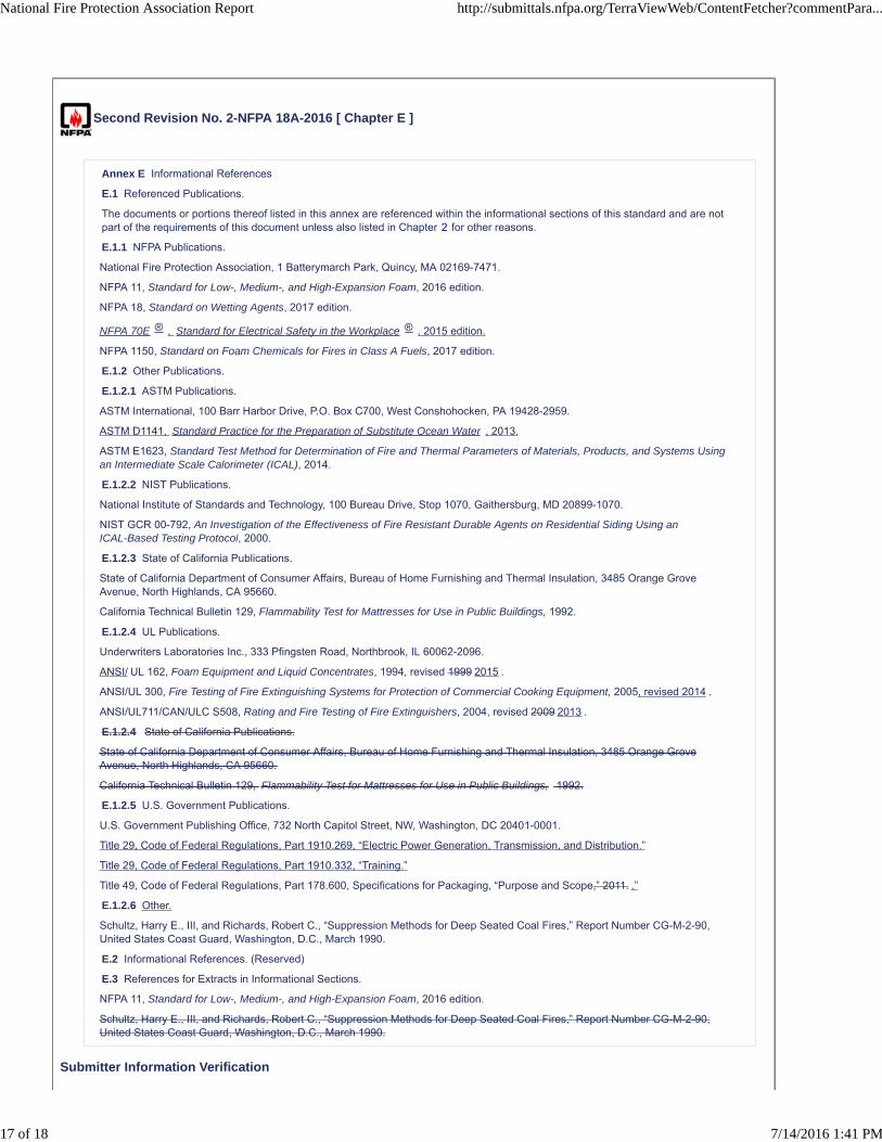
Second Revision No. 2-NFPA 18A-2016 [ Chapter E ]
Annex E Informational References
E.1 Referenced Publications.
The documents or portions thereof listed in this annex are referenced within the informational sections of this standard and are notpart of the requirements of this document unless also listed in Chapter 2 for other reasons.
E.1.1 NFPA Publications.
National Fire Protection Association, 1 Batterymarch Park, Quincy, MA 02169-7471.
NFPA 11, Standard for Low-, Medium-, and High-Expansion Foam, 2016 edition.
NFPA 18, Standard on Wetting Agents, 2017 edition.
NFPA 70E ® , Standard for Electrical Safety in the Workplace ® , 2015 edition.
NFPA 1150, Standard on Foam Chemicals for Fires in Class A Fuels, 2017 edition.
E.1.2 Other Publications.
E.1.2.1 ASTM Publications.
ASTM International, 100 Barr Harbor Drive, P.O. Box C700, West Conshohocken, PA 19428-2959.
ASTM D1141, Standard Practice for the Preparation of Substitute Ocean Water , 2013.
ASTM E1623, Standard Test Method for Determination of Fire and Thermal Parameters of Materials, Products, and Systems Usingan Intermediate Scale Calorimeter (ICAL), 2014.
E.1.2.2 NIST Publications.
National Institute of Standards and Technology, 100 Bureau Drive, Stop 1070, Gaithersburg, MD 20899-1070.
NIST GCR 00-792, An Investigation of the Effectiveness of Fire Resistant Durable Agents on Residential Siding Using anICAL-Based Testing Protocol, 2000.
E.1.2.3 State of California Publications.
State of California Department of Consumer Affairs, Bureau of Home Furnishing and Thermal Insulation, 3485 Orange GroveAvenue, North Highlands, CA 95660.
California Technical Bulletin 129, Flammability Test for Mattresses for Use in Public Buildings, 1992.
E.1.2.4 UL Publications.
Underwriters Laboratories Inc., 333 Pfingsten Road, Northbrook, IL 60062-2096.
ANSI/ UL 162, Foam Equipment and Liquid Concentrates, 1994, revised 1999 2015 .
ANSI/UL 300, Fire Testing of Fire Extinguishing Systems for Protection of Commercial Cooking Equipment, 2005, revised 2014 .
ANSI/UL711/CAN/ULC S508, Rating and Fire Testing of Fire Extinguishers, 2004, revised 2009 2013 .
E.1.2.4 State of California Publications.
State of California Department of Consumer Affairs, Bureau of Home Furnishing and Thermal Insulation, 3485 Orange GroveAvenue, North Highlands, CA 95660.
California Technical Bulletin 129, Flammability Test for Mattresses for Use in Public Buildings, 1992.
E.1.2.5 U.S. Government Publications.
U.S. Government Publishing Office, 732 North Capitol Street, NW, Washington, DC 20401-0001.
Title 29, Code of Federal Regulations, Part 1910.269, “Electric Power Generation, Transmission, and Distribution.”
Title 29, Code of Federal Regulations, Part 1910.332, “Training.”
Title 49, Code of Federal Regulations, Part 178.600, Specifications for Packaging, “Purpose and Scope,” 2011. .”
E.1.2.6 Other.
Schultz, Harry E., III, and Richards, Robert C., “Suppression Methods for Deep Seated Coal Fires,” Report Number CG-M-2-90,United States Coast Guard, Washington, D.C., March 1990.
E.2 Informational References. (Reserved)
E.3 References for Extracts in Informational Sections.
NFPA 11, Standard for Low-, Medium-, and High-Expansion Foam, 2016 edition.
Schultz, Harry E., III, and Richards, Robert C., “Suppression Methods for Deep Seated Coal Fires,” Report Number CG-M-2-90,United States Coast Guard, Washington, D.C., March 1990.
Submitter Information Verification
National Fire Protection Association Report http://submittals.nfpa.org/TerraViewWeb/ContentFetcher?commentPara...
17 of 18 7/14/2016 1:41 PM
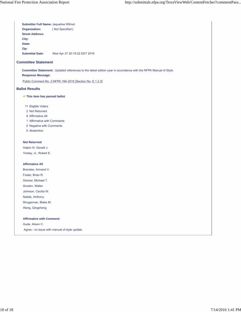
Submitter Full Name: Jaqueline Wilmot
Organization: [ Not Specified ]
Street Address:
City:
State:
Zip:
Submittal Date: Wed Apr 27 20:19:32 EDT 2016
Committee Statement
Committee Statement: Updated references to the latest edition year in accordance with the NFPA Manual of Style.
Response Message:
Public Comment No. 2-NFPA 18A-2015 [Section No. E.1.2.3]
Ballot Results
This item has passed ballot
11 Eligible Voters
2 Not Returned
8 Affirmative All
1 Affirmative with Comments
0 Negative with Comments
0 Abstention
Not Returned
Halpin III, Gerald J.
Tinsley, Jr., Robert E.
Affirmative All
Brandao, Armand V.
Foster, Brian R.
Greiner, Michael T.
Groden, Walter
Johnson, Cecilia W.
Natale, Anthony
Shugarman, Blake M.
Wang, Qingsheng
Affirmative with Comment
Gude, Alison C.
Agree - no issue with manual of style update.
National Fire Protection Association Report http://submittals.nfpa.org/TerraViewWeb/ContentFetcher?commentPara...
18 of 18 7/14/2016 1:41 PM
Related Documents