Nathan Childress, Ph.D., DABR

Welcome message from author
This document is posted to help you gain knowledge. Please leave a comment to let me know what you think about it! Share it to your friends and learn new things together.
Transcript

Nathan Childress, Ph.D., DABR
I own Mobius Medical Systems, LP, manufacturer of Mobius3D, MobiusFX, and DoseLab
I used Mobius3D to generate results for this talk
Financial Disclaimer

Dosimetrists are exposed to every aspect of clinical care, and have the opportunity to notice many clinical improvements
There are many opportunities in modern radiotherapy clinics for mistakes
A new generation of QA software is being introduced, each containing different design elements
This presentation will focus on avoiding errors and understanding how QA systems can help automatically detect errors that slip by
Introduction

What types of errors are we looking for?◦ Commissioning◦ Treatment planning◦ Data transfer◦ Machine performance◦ Patient positioning
How do you evaluate new QA tools?◦ Efficiency◦ Accuracy◦ Reliability: false negatives / false positives
How are the current QA systems designed?◦ Treatment log files with CBCT◦ EPID only◦ EPID with CBCT
Overview

2001-2004: PhD student at MD Anderson Cancer Center◦ Developed open-source DoseLab software (IMRT QA)
2004-2010: Clinical physicist at The Methodist Hospital in Houston, TX
2010-present: Founded Mobius Medical Systems, LP◦ Designed DoseLab TG-142 for machine QA◦ Designed Mobius3D for treatment plan QA◦ Designed MobiusFX for patient delivery QA◦ Designed CBCT module for patient positioning QA
My Background

Mia Claire Childress (mc2)
Will be shamelessly used to illustrate this presentation
Will never experience a normal dating life

Common Errors

Most clinics do not verify their “CT to density” table, which can lead to errors in patients but not in QA devices
Beam modeling is a complex and long process
Many clinics do not measure MLC-defined output factors◦ IROC-Houston has published values for comparison◦ Jaws are set to 10x10◦ MLC is set to 2x2 to 6x6◦ If your TPS cannot accurately calculate these, it cannot accurately
calculate IMRT or VMAT plans
Commissioning errors
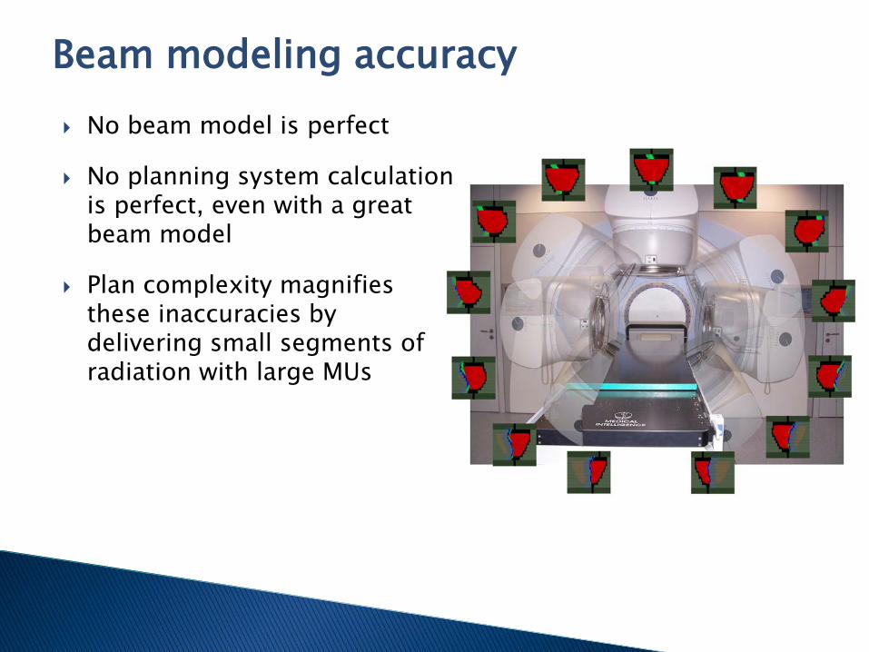
No beam model is perfect
No planning system calculation is perfect, even with a great beam model
Plan complexity magnifies these inaccuracies by delivering small segments of radiation with large MUs
Beam modeling accuracy
IROC-Houston phantom mailers are available for ~$1200◦ Includes comparing OSLD and film measurements to your TPS◦ ~18% of centers historically have failed hetereogeneous
verifications using 7% / 4 mm criteria
Perform measurements of IMRT and VMAT plans◦ Do not ignore failures
Check MLC-defined OFs against IROC-Houston published data◦ IROC-Houston finds that 65% of institutions do not match MLC
feld output factors within 2.5%◦ 10% do not match within 5%
Checking TPS beam models

All these errors can be overwhelming

In my opinion, high beam modulation is the number one preventable cause of treatment inaccuracies
More modulation creates prettier pictures and DVHs in the TPS, but magnifies beam modeling and delivery errors
Modulation can be described by the Modulation Factor
Beam modeling and delivery errors are multiplied by a patient’s Modulation Factor to determine the accuracy of the delivered dose
Treatment planning errors

A precise value is not necessary, as this value is used as a general indication of plan complexity level
Modulation Factor is typically defined as the MU of a modulated plan divided by the MU of an open field plan
But I’m lazy
So this talk will use MU / Rx dose (cGy) to calculate the Modulation Factor
Example!◦ 50 Gy / 25 fx = 200 cGy/fraction◦ Total MU = 800◦ Modulation factor: 800 / 200 = 4
Calculating the Modulation Factor
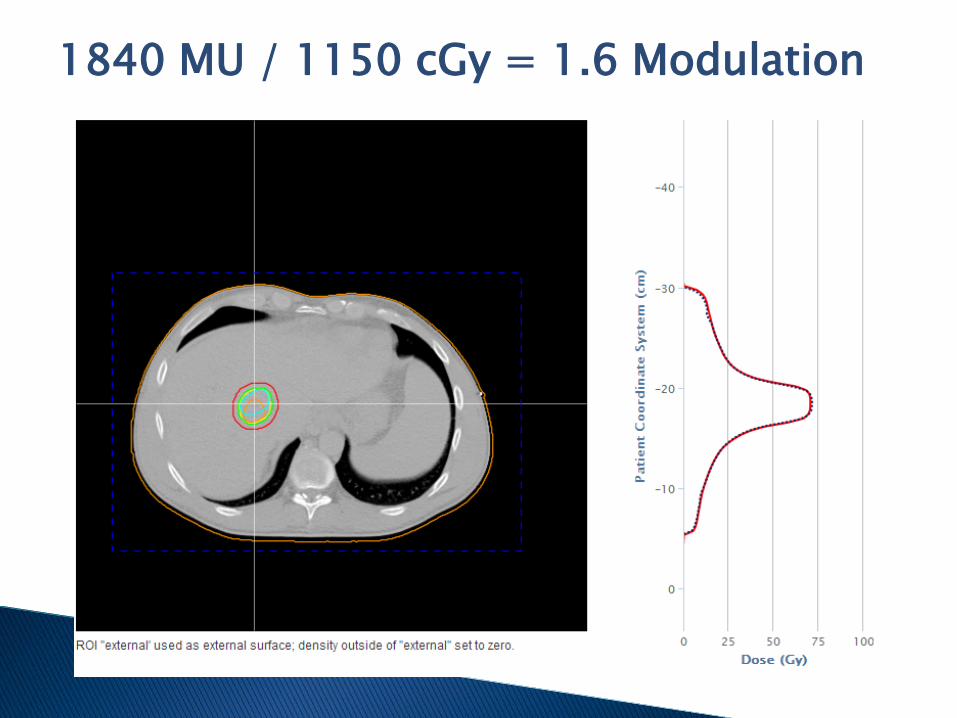
1840 MU / 1150 cGy = 1.6 Modulation
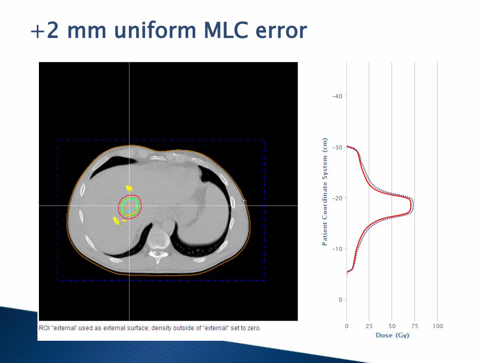
+2 mm uniform MLC error
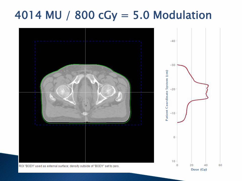
4014 MU / 800 cGy = 5.0 Modulation

5.0 Modulation + 4 mm
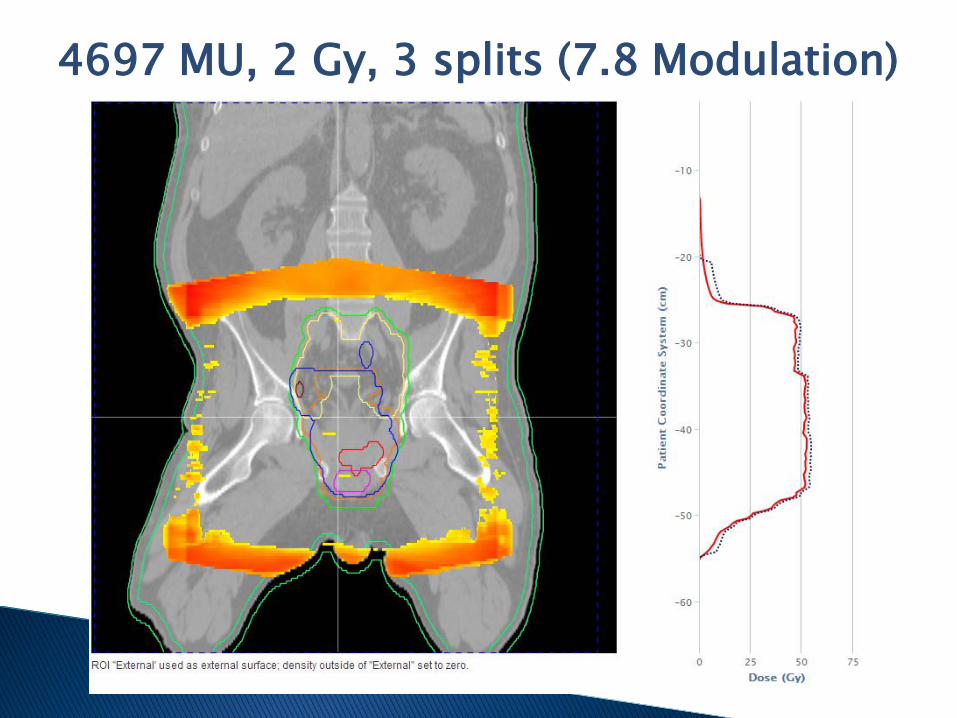
4697 MU, 2 Gy, 3 splits (7.8 Modulation)

7.8 Modulation + 4 mm
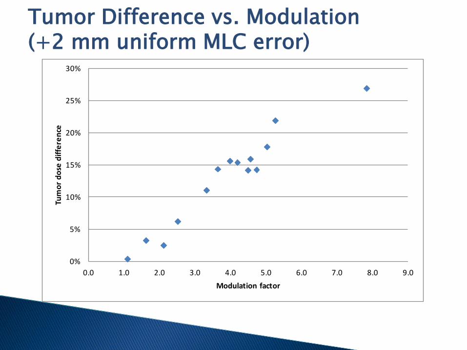
Tumor Difference vs. Modulation (+2 mm uniform MLC error)
0%
5%
10%
15%
20%
25%
30%
0.0 1.0 2.0 3.0 4.0 5.0 6.0 7.0 8.0 9.0
Tum
or d
ose
diffe
renc
e
Modulation factor

Don’t just copy someone else’s plan

Do not overmodulate beams◦ Delivering many <2 cm leaf
openings magnifies problems in your TPS dose calculation
◦ Small segments also magnify delivery errors
◦ Look at your modulation factor. Is it above 5?
Do not have beams that go through mobile parts of patients (such as arms)
Create safe treatment plans

We’ve found TPS => R&V and R&V => linac data transfer errors are rare◦ A couple minor errors reported in around a million fractions
It is more common for a treatment parameter (jaw setting, MU, etc.) to be manually changed without generating a new plan
Data transfer errors

QA is good for you, but not always fun
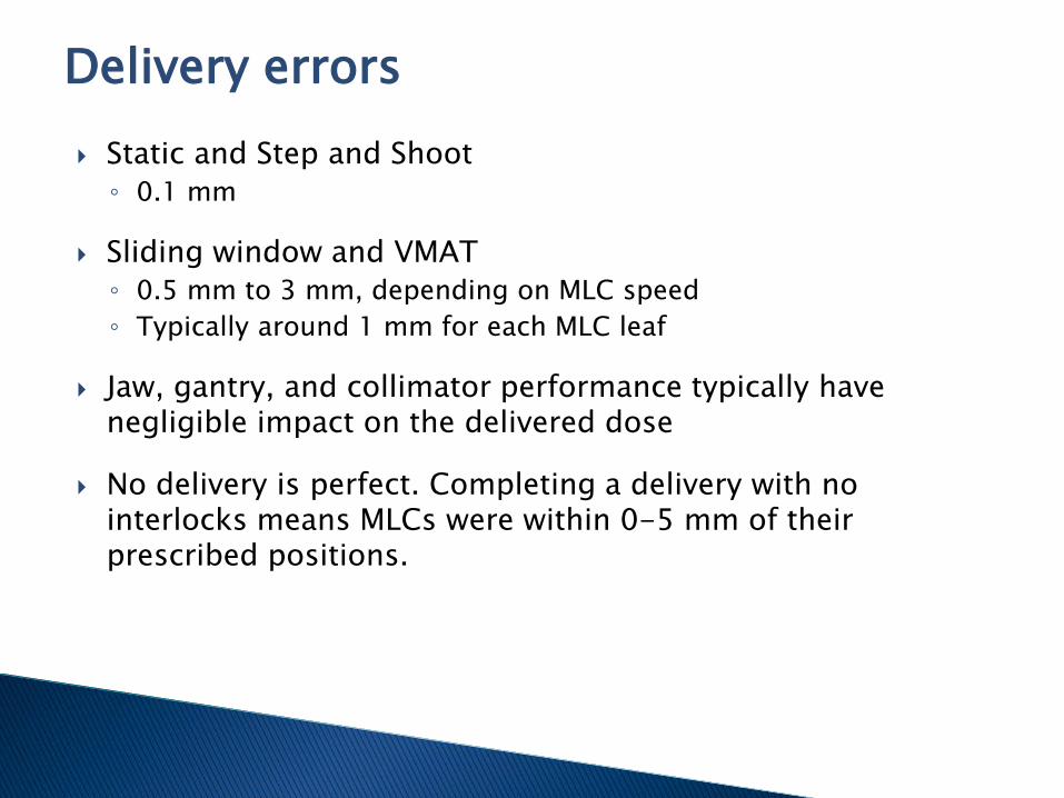
Static and Step and Shoot◦ 0.1 mm
Sliding window and VMAT◦ 0.5 mm to 3 mm, depending on MLC speed◦ Typically around 1 mm for each MLC leaf
Jaw, gantry, and collimator performance typically have negligible impact on the delivered dose
No delivery is perfect. Completing a delivery with no interlocks means MLCs were within 0-5 mm of their prescribed positions.
Delivery errors
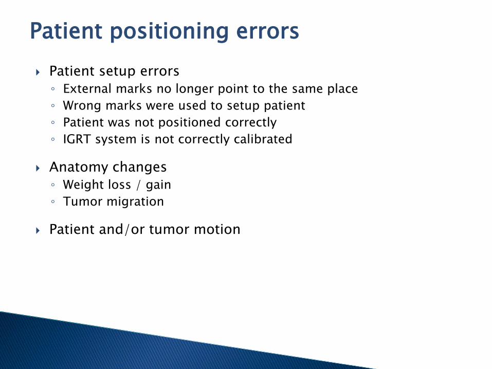
Patient setup errors◦ External marks no longer point to the same place◦ Wrong marks were used to setup patient◦ Patient was not positioned correctly◦ IGRT system is not correctly calibrated
Anatomy changes◦ Weight loss / gain◦ Tumor migration
Patient and/or tumor motion
Patient positioning errors
How to Evaluate QA Tools
Automatic tools reduce human errors

Every QA system detects different types of errors depending on its design
Only measuring planar dose limits your ability to both segregate error sources and evaluate the clinical relevance of detected errors
Converting to 3D dose in the patient planning CT allows you to see the impact of errors on the DVH and discern clinical relevance◦ No system places measurement devices in the patient, so the
accuracy of reconstructed patient dose is critical
QA tools: Accuracy

No QA system is perfect
Errors flagged by a patient-specific QA system must be investigated and resolved before treatment◦ Frequent occurrences of false positives and false negatives are
unacceptable
Introducing new data sources to a QA system increases your potential for false positives◦ Device miscalibration◦ Device setup errors◦ Noise / artifacts in images
Ignoring data in a QA system increases your potential for false negatives◦ Homogeneous QA for a heterogeneous patient
QA tools: Reliability

Some things aren’t as great as you hope
Efficiency is not just the level of automation in a QA system
Efficiency is a result of accuracy, reliability, and automation◦ At least one clinic has a panel of clinicians to evaluate false
positive results for a daily QA system
Performing daily QA amplifies any problem in the QA system◦ When an error is detected, it must be investigated and resolved
before the next fraction◦ As clinics start to rely more heavily on automatic error detection,
they must have manual processes to detect weak areas of the system
◦ If there are a lot of false positives, the system constantly generates errors that are ignored
QA tools: Efficiency

Efficiency lets us drink and watch TV
Current QA Systems
Pick the right tools

Generated by Varian and Elekta linear accelerators
Include Planned and Delivered values
Measurements recorded 3-100 times per second
MLC and jaw positions recorded with 0.1 mm precision
Gantry and collimator angles recorded with 0.1° mm precision
Treatment log files
Log files are automatically monitored as patients are being treated
Log files are compared to the plan to verify data transfer
Their data is used to calculate the machine performance for each patient’s delivery
Measured MLC, gantry, collimator, etc. positions can be used to find the 3D dose in the patient
This process can be performed both before treatment as IMRT QA and during treatments
QA systems: Treatment log files

Pros◦ Fully automatic◦ Measurements in log files are highly precise (0.01 mm, 0.1°)◦ Measurements have primary and backup detectors◦ Allows nearly perfect data transfer checking◦ Separates error sources for easily problem resolution
Cons◦ Relies on internal dosimeters◦ Cannot detect machine calibration errors (machine QA is essential)◦ Do not contain patient positioning information
Systems◦ MMS Mobius3D, others in development
QA systems: Treatment log files

QA lets you sleep well
CBCT is widely used, but almost always qualitatively
Automatic software is used for the initial 3D matching but not for further analysis
CBCTs are not as accurate at reporting densities (HUs) compared to CTs◦ This makes dose calculation on CBCTs difficult
CBCT results can be used to identify when patients need to be rescanned and replanned, but this is also highly qualitative
CBCT today

Systems take CBCTs and quantitatively compare them to CTs◦ HU renormalization is required
This leads to actual numbers – ie, % passing
Passing rates can be used both to double check anatomy / positioning before treatment and as a metric to quantitatively indicate when to replan
Clinics can now set limits. For example:◦ >90%: treat with no further review◦ 80-90%: treat after physician review◦ <80%: resimulate
QA systems: CBCT quantitative analysis
Pros◦ Fully automatic◦ Can be performed for every CBCT before treatment◦ Can be used to indicate when replanning is necessary◦ Sensitive to patient positioning, weight loss, and weight gain
Cons◦ Cannot detect differences in soft tissues◦ Cannot detect tumor migration in soft tissue◦ Cannot be used to calculate 3D dose in patient
Systems◦ MMS Mobius3D, others in development
QA systems: CBCT quantitative analysis

Think about what your QA system does

DIR creates a 3D map of how a patient’s anatomy has moved from one image to another, ie, the planning CT to a CBCT
This 3D map can be used to automatically place contours on CBCTs, to deform the planning CT to the shape of the CBCT for dose calculations, etc.
This is an incredibly complex process that can be difficult to perform manually and harder to do automatically ◦ Anatomy can do more than move or squish – it can disappear,
reappear, change density, etc.◦ CBCT artifacts make it difficult to know which parts of the image
to trust
Deformable image registration (DIR)
Applying DIR to CBCT allows dose to be calculated on the patient’s daily treatment images
Cumulated dose and DVHs can be generated
This allows clinicians to identify the need for replanningbased on DVH objectives
QA systems: CBCT with DIR

Pros◦ Allows dose to be calculated on CBCT◦ Allows daily DVHs to be generated◦ Can detect tumor migration and other soft tissue differences
Cons◦ Relies heavily on accuracy of DIR algorithm Any inaccuracy in DIR can invalidate results
◦ Unclear what to do when minor deviations are detected ◦ Output only helps clinicians determine if a new sim is needed
Systems◦ Standard Imaging Adaptivo, others in development
QA systems: CBCT with DIR
Don’t get devastated by QA choices
Everyone knows and loves EPID images!
The EPID panel was created for patient imaging but now is being used for many other purposes
EPIDs capture the beam after it exits the patient, meaning it can theoretically detect nearly every problem in a treatment delivery◦ Patient positioning◦ Patient anatomy◦ Machine performance
EPID images

The fluence from an EPID image is compared to a previous treatment or a calculated gold standard◦ Treatment plan + CT image + 3D calculation at EPID panel
Fluences are compared to automatically detect anatomy / positioning / machine performance errors◦ If fluences are compared to the first fraction, you lose the ability
to check for systematic errors
The measured fluence can be backprojected to calculate 3D dose in the patient
QA systems: EPID images

Pros◦ Fully automatic◦ Can check patient positioning and machine performance
Cons◦ Does not detect data transfer errors◦ Typical limits flag 30% of treatments and have 99% false positives◦ Difficult to calculate gold standard EPID image◦ Fluence image differences are difficult to interpret to fix problems
Systems◦ Elekta iViewDose, Sun Nuclear PerFRACTION, Math Resolutions
Dosimetry Check, Dosisoft EPIgray, Epidose EPIQA, Standard Imaging Adaptivo
QA systems: EPID images

Don’t regret your QA program
If your QA system detects a failure, does your resolution process make sense?
If your secondary calculation fails, do you repeat with minor adjustments or analyze the cause of the failure?
If your IMRT QA fails, do you repeat with minor adjustments or analyze the cause of the failure?
If the standard process is to ignore failures until a pass is achieved, your quality system is broken
Clinical use of QA systems

Don’t cheat on your QA

The Future of QA

Technology is fun

Integrating the Healthcare Enterprise-Radiation Oncology (IHE-RO) is an ASTRO-sponsored initiative for improving the functionality of the radiation oncology clinic
The IHE-RO task force develops IHE Integration Profiles, which specify how industry standards can address specific clinical problems and ambiguities
The upcoming Quality Assurance with Plan Veto (QAPV) profile will force plans to be validated before being delivered to the patient, at every treatment day
IHE-RO

Linacs will send DICOM-RT files to Check Providers, which will detect if a plan contains critical errors
Vendors can implement custom checks◦ Must be at least single-point MU recalculation◦ Can be based on dose recalculations and previous treatment
information◦ Can be as complex as vendor would like
The entire process is automatic, and the beam cannot be turned on until a Check Provider completes a valid check
Tentative availability: 2018
IHE-RO QA Plan Veto Profile

In the future, the first fraction of a patient’s delivery can automatically be stopped for certain errors◦ Incorrect data transfer◦ Use of an unapproved treatment plan◦ Treatment plans that would likely result in injury
Subsequent fractions of a patient’s delivery can automatically be stopped for additional reasons◦ Incorrect data processing◦ Poor linac performance◦ Inaccurate patient positioning
QAPV and New QA Tools

A good QA system makes you happy
There are many sources of error in radiation treatments, and dosimetrists should be aware of how to detect them
A new generation of QA tools is becoming available to help your clinic
New tools feature automation, but clinics must be aware of their limitations
Summary

Just when you think you have things figured out, something else comes along…

Questions?
Related Documents