NAT Administration Guide, StarOS Release 21.26 First Published: 2021-12-22 Americas Headquarters Cisco Systems, Inc. 170 West Tasman Drive San Jose, CA 95134-1706 USA http://www.cisco.com Tel: 408 526-4000 800 553-NETS (6387) Fax: 408 527-0883

Welcome message from author
This document is posted to help you gain knowledge. Please leave a comment to let me know what you think about it! Share it to your friends and learn new things together.
Transcript

NAT Administration Guide, StarOS Release 21.26First Published: 2021-12-22
Americas HeadquartersCisco Systems, Inc.170 West Tasman DriveSan Jose, CA 95134-1706USAhttp://www.cisco.comTel: 408 526-4000
800 553-NETS (6387)Fax: 408 527-0883

THE SPECIFICATIONS AND INFORMATION REGARDING THE PRODUCTS IN THIS MANUAL ARE SUBJECT TO CHANGE WITHOUT NOTICE. ALL STATEMENTS,INFORMATION, AND RECOMMENDATIONS IN THIS MANUAL ARE BELIEVED TO BE ACCURATE BUT ARE PRESENTED WITHOUT WARRANTY OF ANY KIND,EXPRESS OR IMPLIED. USERS MUST TAKE FULL RESPONSIBILITY FOR THEIR APPLICATION OF ANY PRODUCTS.
THE SOFTWARE LICENSE AND LIMITED WARRANTY FOR THE ACCOMPANYING PRODUCT ARE SET FORTH IN THE INFORMATION PACKET THAT SHIPPED WITHTHE PRODUCT AND ARE INCORPORATED HEREIN BY THIS REFERENCE. IF YOU ARE UNABLE TO LOCATE THE SOFTWARE LICENSE OR LIMITED WARRANTY,CONTACT YOUR CISCO REPRESENTATIVE FOR A COPY.
The Cisco implementation of TCP header compression is an adaptation of a program developed by the University of California, Berkeley (UCB) as part of UCB's public domain version ofthe UNIX operating system. All rights reserved. Copyright © 1981, Regents of the University of California.
NOTWITHSTANDING ANY OTHERWARRANTY HEREIN, ALL DOCUMENT FILES AND SOFTWARE OF THESE SUPPLIERS ARE PROVIDED “AS IS" WITH ALL FAULTS.CISCO AND THE ABOVE-NAMED SUPPLIERS DISCLAIM ALL WARRANTIES, EXPRESSED OR IMPLIED, INCLUDING, WITHOUT LIMITATION, THOSE OFMERCHANTABILITY, FITNESS FOR A PARTICULAR PURPOSE AND NONINFRINGEMENT OR ARISING FROM A COURSE OF DEALING, USAGE, OR TRADE PRACTICE.
IN NO EVENT SHALL CISCO OR ITS SUPPLIERS BE LIABLE FOR ANY INDIRECT, SPECIAL, CONSEQUENTIAL, OR INCIDENTAL DAMAGES, INCLUDING, WITHOUTLIMITATION, LOST PROFITS OR LOSS OR DAMAGE TO DATA ARISING OUT OF THE USE OR INABILITY TO USE THIS MANUAL, EVEN IF CISCO OR ITS SUPPLIERSHAVE BEEN ADVISED OF THE POSSIBILITY OF SUCH DAMAGES.
Any Internet Protocol (IP) addresses and phone numbers used in this document are not intended to be actual addresses and phone numbers. Any examples, command display output, networktopology diagrams, and other figures included in the document are shown for illustrative purposes only. Any use of actual IP addresses or phone numbers in illustrative content is unintentionaland coincidental.
All printed copies and duplicate soft copies of this document are considered uncontrolled. See the current online version for the latest version.
Cisco has more than 200 offices worldwide. Addresses and phone numbers are listed on the Cisco website at www.cisco.com/go/offices.
Cisco and the Cisco logo are trademarks or registered trademarks of Cisco and/or its affiliates in the U.S. and other countries. To view a list of Cisco trademarks, go to this URL:https://www.cisco.com/c/en/us/about/legal/trademarks.html. Third-party trademarks mentioned are the property of their respective owners. The use of the word partner does not imply apartnership relationship between Cisco and any other company. (1721R)
© 2021 Cisco Systems, Inc. All rights reserved.

C O N T E N T S
About this Guide viiP R E F A C E
Conventions Used viii
Supported Documents and Resources viii
Contacting Customer Support ix
Network Address Translation Overview 1C H A P T E R 1
NAT Overview 1
NAT Realms 2
NAT IP Pool Groups 5
NAT IP Address Allocation and Deallocation 5
NAT IP Address Allocation 6
NAT IP Address Deallocation 6
NAT Port-chunk Allocation and Deallocation 7
NAT Port-chunk Allocation 7
NAT Port-chunk Deallocation 7
NAT IP Address/Port Allocation Failure 8
TCP 2MSL Timer 8
Flow Mapping Timer 9
NAT Binding Records 9
NAT Binding Updates 10
Firewall-and-NAT Policy 11
NAT Application Level Gateway 14
NAT Aware H323 Clients 16
Accelerated ECS Feature Support 16
EDRs and UDRs 16
Bulk Statistics 17
NAT Administration Guide, StarOS Release 21.26iii

Alarms 18
Session Recovery and ICSR 18
NAT64 Overview 21
ICMP Host Unreachable 23
Port Control Protocol Support 23
Logging Support 25
Enhanced Syslog Reporting 25
Increasing Maximum Chunks Per User NAPT for 5G MiFi 28
Feature Summary and Revision History 28
Feature Description 28
Configuring Many-to-One NAT IP Pools 29
Supported Standards 29
How NAT Works 30
NAT Configuration 35C H A P T E R 2
Before You Begin 35
Configuring the System 35
Configuring NAT 36
Enabling the ECS Subsystem and Creating the ECS Service 37
Configuring Port Maps 37
Configuring Host Pools 38
Configuring IMSI Pools 38
Configuring NAT IP Pools/NAT IP Pool Groups 38
Configuring Firewall-and-NAT Policies 41
Configuring Firewall-and-NAT Action 42
Configuring Access Ruledefs 42
Configuring IP address allocation for NAT realm 43
Configuring Action on NAT IP Address/Port Allocation Failure 44
Configuring Action on Packets During NAT IP Allocation 44
Configuring NAT TCP-2msl-timeout Setting 44
Configuring Action on TCP Idle Timeout 45
Configuring Private IP NPU Flow Timeout Setting 45
Configuring NAT Reassembly Timer 45
Configuring Flow Recovery 45
NAT Administration Guide, StarOS Release 21.26iv
Contents
Configuring NAT Flow Checkpointing 46
Configuring Flow-mapping Timeout 46
Configuring NAT Unsolicited Packets 46
Enabling NAT for APN/Subscribers 47
Configuring the Default Firewall-and-NAT Policy 48
Configuring NAT Application Level Gateways/Dynamic Pinholes 48
Configuring PCP Service 49
Configuring EDR Format for NAT Packet Drops 50
Configuring EDR Format 51
Configuring UDR Format 51
Configuring NAT Binding Record Format 51
Configuring Bulkstats Collection 52
Configuring NAT Thresholds 53
Configuring NAT Backout 54
Changing Firewall-and-NAT Policy in Mid-session 55
Verifying the Configuration 55
Gathering NAT Statistics 56
NAT Administration Guide, StarOS Release 21.26v
Contents

NAT Administration Guide, StarOS Release 21.26vi
Contents
About this Guide
Control andUser Plane Separation (CUPS) represents a significant architectural change in the way StarOS-basedproducts are deployed in the 3G, 4G, and 5G networks. Unless otherwise specified, it should not be assumedthat any constructs (including, but not limited to, commands, statistics, attributes, MIB objects, alarms, logs,services) referenced in this document imply functional parity with CUPS products. References to any CUPSproducts or features are for informational purposes only. Please contact your Cisco Account or Supportrepresentative for any questions about parity between this product and any CUPS products.
Note
The documentation set for this product strives to use bias-free language. For purposes of this documentationset, bias-free is defined as language that does not imply discrimination based on age, disability, gender, racialidentity, ethnic identity, sexual orientation, socioeconomic status, and intersectionality. Exceptions may bepresent in the documentation due to language that is hardcoded in the user interfaces of the product software,language used based on RFP documentation, or language that is used by a referenced third-party product.
Note
The HA, HSGW, PDSN, and SecGW products have reached end of life and are not supported in this release.Any references to these products (specific or implied) their components or functions including CLI commandsand parameters in this document are coincidental and are not supported. Full details on the end of life for theseproducts are available athttps://www.cisco.com/c/en/us/products/collateral/wireless/asr-5000-series/eos-eol-notice-c51-740422.html.
Note
This preface describes the NAT Administration Guide, how it is organized and its document conventions.
Network Address Translation (NAT) is a StarOS™ in-line service application that runs on Cisco® ASR 5500and virtualized platforms.
The NAT in-line service translates non-routable private IP address(es) to routable public IP address(es) froma pool of public IP addresses that have been designated for NAT. This enables to conserve on the number ofpublic IP addresses required to communicate with external networks, and ensures security as the IP addressscheme for the internal network is masked from external hosts, and each outgoing and incoming packet goesthrough the translation process.
• Conventions Used, on page viii• Supported Documents and Resources, on page viii
NAT Administration Guide, StarOS Release 21.26vii
• Contacting Customer Support, on page ix
Conventions UsedThe following tables describe the conventions used throughout this documentation.
DescriptionNotice Type
Provides information about important features orinstructions.
Information Note
Alerts you of potential damage to a program, device,or system.
Caution
Alerts you of potential personal injury or fatality. Mayalso alert you of potential electrical hazards.
Warning
DescriptionTypeface Conventions
This typeface represents displays that appear on yourterminal screen, for example:
Login:
Text represented as a screen display
This typeface represents commands that you enter,for example:
show ip access-list
This document always gives the full form of acommand in lowercase letters. Commands are notcase sensitive.
Text represented as commands
This typeface represents a variable that is part of acommand, for example:
show card slot_number
slot_number is a variable representing the desiredchassis slot number.
Text represented as a command variable
This typeface represents menus and sub-menus thatyou access within a software application, for example:
Click the File menu, then click New
Text represented as menu or sub-menu names
Supported Documents and ResourcesRelated Common Documentation
The following common documents are available:
• AAA Interface Administration and Reference• Command Line Interface Reference
NAT Administration Guide, StarOS Release 21.26viii
About this GuideConventions Used
• GTPP Interface Administration and Reference• Installation Guide (platform dependant)• Release Change Reference• SNMP MIB Reference• Statistics and Counters Reference• System Administration Guide (platform dependant)• Thresholding Configuration Guide
Related Product Documentation
The most up-to-date information for this product is available in the product Release Notes provided with eachproduct release.
The following product documents are also available and work in conjunction with CF:
• ECS Administration Guide• GGSN Administration Guide• P-GW Administration Guide• SaMOG Administration Guide
Obtaining Documentation
The most current Cisco documentation is available on the following website:
http://www.cisco.com/cisco/web/psa/default.html
Use the following path selections to access the CF documentation:
Products > Wireless > Mobile Internet > In-Line Services > Cisco NAT Network Address Translation
Contacting Customer SupportUse the information in this section to contact customer support.
Refer to the support area of http://www.cisco.com for up-to-date product documentation or to submita service request. A valid username and password are required to access this site. Please contact your Ciscosales or service representative for additional information.
NAT Administration Guide, StarOS Release 21.26ix
About this GuideContacting Customer Support

NAT Administration Guide, StarOS Release 21.26x
About this GuideContacting Customer Support
C H A P T E R 1Network Address Translation Overview
This chapter provides an overview of Network Address Translation (NAT) in-line service feature.
The following topics are covered in this chapter:
• NAT Overview, on page 1• How NAT Works, on page 30
NAT OverviewThis section provides an overview of the NAT in-line service feature.
NAT translates non-routable private IP address(es) to routable public IP address(es) from a pool of public IPaddresses that have been designated for NAT. This enables to conserve on the number of public IP addressesrequired to communicate with external networks, and ensures security as the IP address scheme for the internalnetwork is masked from external hosts, and each outgoing and incoming packet goes through the translationprocess.
The NAT in-line service works in conjunction with the following products:
• GGSN• HA• PDSN• P-GW• SaMOG
NAT works by inspecting both incoming and outgoing IP datagrams and, as needed, modifying the source IPaddress and port number in the IP header to reflect the configured NAT address mapping for outgoingdatagrams. The reverse NAT translation is applied to incoming datagrams.
NAT can be used to perform address translation for simple IP and mobile IP. NAT can be selectivelyapplied/denied to different flows (5-tuple connections) originating from subscribers based on the flows' L3/L4characteristics—Source-IP, Source-Port, Destination-IP, Destination-Port, and Protocol.
NAT works only on flows originating internally. Bi-directional NAT is not supported.Important
NAT Administration Guide, StarOS Release 21.261

NAT is supported only for TCP, UDP, and ICMP flows. For other flows NAT is bypassed. For GRE flows,NAT is supported only if the PPTP ALG is configured. For more information on ALGs, please refer to theNAT Application Level Gateway section.
Important
In 14.1 and earlier releases: If a subscriber is assigned with a public IP address, NAT is not applied. For 15.0and later releases, NAT can be applied for private and public addresses if the IP pool is configured with theskip-nat-subscriber-ip-check CLI option.
Important
To get NATed, the private IP addresses assigned to subscribers must be from the following ranges: Class A10.0.0.0 – 10.255.255.255, Class B 172.16.0.0 – 172.31.255.255, and Class C 192.168.0.0 – 192.168.255.255,and 100.64.0.0/10 as per RFC 6598.
Important
As per a new implementation, NAT can now be enabled or disabled irrespective of whether the IP assignedis a private or public IP by enabling a CLI option in IP pool. On enabling this option, the private IP check forthe corresponding pool will be skipped and NAT will be enabled (if configured) for this pool although it is apublic pool. Refer to the Configuring One-to-One NAT IP Pools/NAT IP Pool Groups section in the NATConfiguration chapter for more information.
NAT supports the following mappings:
Once a flow is marked to use a specific NAT IP address the same NAT IP address is used for all packetsoriginating on that flow. The NAT IP address is released only when all flows and subscribers associated withit are released.
When all NAT IP addresses are in use, and a subscriber with a private IP address fails to get a NAT IP addressfor a specific flow, that specific flow will not be allowed and will fail.
All downlink—inbound from external networks—IP packets that do not match one of the existing NATbindings are discarded by the system.
Qualified Platforms
NAT is a StarOS in-line service application that runs on Cisco ASR 5500 and virtualized platforms. Foradditional platform information, refer to the appropriate System Administration Guide and/or contact yourCisco account representative.
License Requirements
The NAT is a licensed Cisco feature. A separate feature license may be required. Contact your Cisco accountrepresentative for detailed information on specific licensing requirements. For information on installing andverifying licenses, refer to theManaging License Keys section of the Software Management Operations chapterin the System Administration Guide.
NAT RealmsANAT realm is a pool of unique public IP addresses available for translation from private source IP addresses.IP addresses in a NAT IP pool are contiguous, and assignable as a subnet or a range that constitutes less than
NAT Administration Guide, StarOS Release 21.262
Network Address Translation OverviewNAT Realms
an entire subnet. IP addresses configured in NAT IP pools within a context must not overlap. At any time,within a context, a NAT IP address must be configured in any one NAT IP pool. IP addresses can be addedto a NAT IP pool as a range of IP addresses. Based on the chosen port chunk-size, the number of subscribersthat can be shared per IP varies.
The minimum number of public IP addresses that must be allocated to each NAT IP pool must be equal tothe number of Session Managers (SessMgrs) available on the system. Theoretically, the number of SessMgrsthat can be brought up is 384. However, the number of SessMgrs can vary based on the cards on the system.
Up to 2000 unique “IP pools + NAT IP pools” can be configured per context. A maximum of twenty NATIP pools/NAT IP pool groups can be configured in a Firewall-and-NAT policy. At any time a subscriber canbe associated with a maximum of three different NAT IP pools/NAT IP pool groups and can have NATedflows on three different NAT IP addresses at the same time.
In 20 and later releases, each many-to-one NAT realm can support multiple NAT IP addresses for the sameNAT realm for a given subscriber. If no ports are available for a given NAT IP, then instead of droppingpackets, another NAT IP will be requested for the same NAT realm as long as the maximum number of portchunks configured is not reached. The number of NAT IPs that can be allocated for a given NAT realm fora particular subscriber is limited to a maximum of three IPs. This is applicable only to many-to-one NATrealms. Refer to the Configuring IP address allocation for NAT realm section in the NAT Configurationchapter for more information on enabling and disabling this feature.
Allocation of NAT IP addresses in NAT IP pools to subscriber traffic is based on the L3/L4 characteristics—IPaddresses, ports, and protocol—of the subscriber flows. It is possible to configure the system to perform ornot perform NAT based on one or more L3/L4 parameters. This feature is also known as Target-based NAT.For more information, see the Target-based NAT Configuration section.
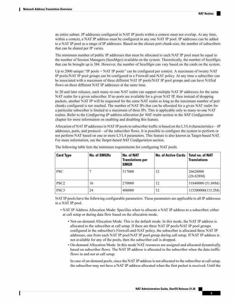
The following table lists the minimum requirements for configuring NAT pools.
Total no. of NATTranslations
No. of Active CardsNo. of NATTranslations perSMGR
No. of SMGRsCard Type
26628000(26.628M)
123170007PSC
51840000 (51.84M)1227000016PSC2
115200000(115.2M)1240000024PSC3
NAT IP pools have the following configurable parameters. These parameters are applicable to all IP addressesin a NAT IP pool.
• NAT IP Address Allocation Mode: Specifies when to allocate a NAT IP address to a subscriber; eitherat call setup or during data flow based on the allocation mode.
• Not-on-demand Allocation Mode: This is the default mode. In this mode, the NAT IP address isallocated to the subscriber at call setup. If there are three NAT IP pools/NAT IP pool groupsconfigured in the subscriber's Firewall-and-NAT policy, the subscriber is allocated three NAT IPaddresses, one from each NAT IP pool/NAT IP pool group during call setup. If NAT IP address isnot available for any of the pools, then the subscriber call is dropped.
• On-demand Allocation Mode: In this mode NAT resources are assigned and allocated dynamicallybased on subscriber flows. The NAT IP address is allocated to the subscriber when the data trafficflows in and not at call setup.
In case of on-demand pools, since the NAT IP address is not allocated to the subscriber at call setup,the subscriber may not have a NAT IP address allocated when the first packet is received. Until the
NAT Administration Guide, StarOS Release 21.263
Network Address Translation OverviewNAT Realms
successful allocation of a NAT IP address, based on the configuration, the packets can either bebuffered or dropped. Once a free NAT IP address is available, it is allocated to the subscriber to beused for flows matching the pool.
For On-demand NAT realms, the subscribers can be filtered based on NAT IP usage time to findout how long (in seconds) the subscriber has been using the assigned NAT IP.
• NAT Binding Timer: Specifies the timeout period, in seconds, to deallocate NAT resources that wereallocated to subscriber flows.When a subscriber flow stops the timer starts counting down, and on expirythe NAT resources are deallocated to be made available for other subscriber flows.
• In one-to-one allocation, for a given NAT IP address, the NAT Binding Timer starts counting downwhen there are no active flows using that NAT IP address. When the NAT Binding Timer expires,the NAT IP address gets deallocated.
• In many-to-one allocation, wherein subscribers are allocated port-chunks rather than individualports, as long as a port-chunk is allocated to a subscriber, all ports from that port-chunk are reservedfor that subscriber. When all flows using ports from that port-chunk get timed out/cleared, the NATBinding Timer starts counting down. If any new flows come up before the NAT Binding Timerexpires, ports are once again allocated from that port-chunk, and the NAT Binding Timer getscancelled. As long as there are active flows using the port-chunk it cannot be deallocated. But, ifno new flows come and the NAT Binding Timer expires, the port-chunk gets deallocated. In thecase of on-demand NAT, if it is the last port-chunk for the NAT IP address, on NAT Binding Timerexpiry, the NAT IP address gets deallocated along with the last port-chunk.
• Maximum Users per NAT IP Address: Applicable only to many-to-one NAT IP pools. Specifies themaximum number of subscribers sharing one NAT IP address.
In 18 and earlier releases, a maximum number of 2016 subscribers can be configured per NAT IP address.
In 19 and later releases, a maximum number of 8064 subscribers can be configured per NAT IP address.
• Port Chunk Size: Applicable only to many-to-one NAT IP pools. Specifies the block size of contiguousports to be assigned to a many-to-one NAT subscriber.
In 18 and earlier releases, the minimum supported port chunk size was 32 and the chunk size wasconfigurable in multiples of 32, that is, 32, 64, 96, and so on. This number has to be divisible by 32 upto a maximum of 32,256.
In 19 and later releases, the minimum port chunk size configurable is reduced to 8 and the chunk sizecan be configured in multiples of 8 starting 8, 16, 24, 32, and so on. The default port chunk size is 32.If no chunk size is configured, then the chunk size is calculated by dividing the entire NAT port rangeby the number of users per NAT IP and then rounding off to the nearest multiple of 32.
• Maximum Port-chunks per User: Applicable only to many-to-one NAT IP pools. Specifies the maximumnumber of port-chunks allowed for an individual subscriber from the same NAT IP address. This willlimit subscribers from dominating all the available ports in a many-to-one NAT IP.
In 18 and earlier releases, a maximum number of 2016 port chunks can be configured per subscriber.
In 19 and later releases, the maximum number of port chunks that can be configured per subscriber is8064.
Consider a case where a single TCP flow is active in a port-chunk. When this connection gets cleared,the TCP NAT port goes to Time Wait state. Since it is the last flow of the port-chunk, the NAT BindingTimer also gets started. Assume NAT Binding Timer >= TCP 2MSL Timer. Once the 2MSL Timerexpires, the TCP port would go to Free state. However, the NAT Binding Timer keeps running. On NAT
NAT Administration Guide, StarOS Release 21.264
Network Address Translation OverviewNAT Realms
Binding Timer expiry, the port-chunk is deallocated. If this was the last port-chunk for that subscriber,the NAT IP address is also deallocated along with this port-chunk.
In case NATBinding Timer < TCP 2MSLTimer, at NATBinding Timer expiry, the TCP port is forcefullymoved to Free state from Time Wait state and the port-chunk deallocated.
• Port Chunk Thresholds: Applicable only to many-to-one NAT IP pools. Specifies threshold in terms ofpercentage of allocated port-chunks against total port-chunks available. Once the threshold is reached,new subscribers will not be allocated the same NAT IP address.
• Packet Drop Thresholds: Specifies threshold in terms of percentage of NAT packet drops.
• AAA Binding Update Message Required: Applicable only to one-to-one NAT IP pools. Enables AAAbinding messages for one-to-one NAT IP pools. This is not supported for many-to-one NAT IP pools.
• Alert Thresholds: Threshold limits can be specified to trigger alarms for NAT IP pools for pool-used,pool-free, pool-hold, and pool-release cases.
• SRP-Activate: Applicable to both one-to-one and many-to-one NAT IP pools. When configured, theNAT IP pool will become usable only when the SRP state is active.
Network broadcast is supported for NAT pools and ordinary pools. The Busyout feature is also supported forNAT pools and ordinary pools.
NAT IP Pool GroupsSimilar NAT IP pools can be grouped into NAT IP pool groups. This enables to bind discontinuous IP addressblocks in individual NAT IP pools to a single NAT IP pool group.
When configuring a NAT IP pool group, note that only those NAT IP pools that have similar characteristicscan be grouped together. The similarity is determined by the NAT IP pool Type (One-to-One / Many-to-One),users configured per NAT IP address (applicable only to many-to-one NAT IP pools), NAT IP AddressAllocation Mode (On Not-on-demand), and Port Chunk Size (applicable only to many-to-one NAT IP pools)parameters. Dissimilar NAT IP pools cannot be grouped together.
It is recommended that all the NAT IP pools in a NAT IP pool group be configured with the same values forthe other parameters, so that the NAT behavior is predictable across all NAT IP pools in that NAT IP poolgroup.
The NAT IP pool from which a NAT IP address is assigned will determine the actual values to use for allparameters.
It is recommended that in a Firewall-and-NAT policy all the realms configured either be NAT IP pools orNAT IP pool groups. If both NAT IP pool(s) and NAT IP pool group(s) are configured, ensure that none ofthe NAT IP pool(s) are also included in the NAT IP pool group.
NAT IP Address Allocation and DeallocationCisco System’s implementation of NAPT is Endpoint-independent Mapping, wherein NAT reuses the sameNAT source port mapping for subsequent packets sent from the same private IP address and port, and withthe same protocol to any public destination host IP address and port.
That is, all flows coming from the subscriber for the current session with the same protocol and same sourceIP address and source port (X:x) would get the same NAT IP address and NAT port (X:x) irrespective of thedestination IP address and port. NAT will not allow any inbound packets to the NAT IP address and NAT
NAT Administration Guide, StarOS Release 21.265
Network Address Translation OverviewNAT IP Pool Groups
port (X:x) from an external host IP address and host port (Y:y), unless the internal host (MS) had previouslysent a packet of the same protocol type to that external IP address and Port (Y:y). However, this behaviorchanges if NATALG is enabled. The ALG creates pin holes / dynamic routes in the NAT and allows downlinkpackets that match the pin holes / dynamic routes towards the internal host (MS) given that there was alreadya parent connection from MS towards the external host.
The advantage of endpoint-independent mapping is that applications are unaffected by NAT translations.
Inbound connection to the NAT IP address can be allowed in one-to-one pools based on configuration.
NAT IP Address AllocationThe NAT IP address is allocated based on the following parameters:
• Maximum Users per NAT IP Address: The maximum number of subscribers sharing a NAT IP address.Once the number of active subscribers using a NAT IP address reaches this limit, that NAT IP addresswill not be allocated to new subscribers.
In 19 and later releases, the number of users per NAT IP address canbe configured dynamically for optimal utilization of NAT IPaddresses.
Important
Any new NAT IP allocated by VPN will take the configuration in the NAT pool. When a NAT IP isalready allocated to Sessmgr, the change in configuration in NAT pool will not be applied to that NATIP. This NAT IP will still use the value that was configured when it was allocated to Sessmgr by VPN.With NAT pool groups, each pool in a group must have the same number of users per NAT IP configured.If number of users per NAT IP configured in pools are different, though the configuration will still beallowed, the distribution of calls across pools in the group may not be even.
• Port-chunk Thresholds: The threshold is configured in percentage of total number of port-chunks. If thenumber of port-chunks already allocated from a given NAT IP address is less than the configured thresholdlimit of port-chunks, then the NAT IP address can be chosen for a new subscriber provided the “MaximumUsers per NAT IP Address” is not reached. But if the number of chunks allocated is greater than or equalto the threshold limit of port-chunks, then the NAT IP address will not be chosen for a new subscriber.The remaining free port-chunks will be used for existing subscribers using the NAT IP address.
NAT IP Address DeallocationWhenever a NAT IP address is deallocated, all the port-chunks associated with the subscriber are releasedback to the pool.
In case there is only one port-chunk associated with the subscriber:
• In case of many-to-one not-on-demand NAT IP pools, the last port-chunk is not released back to the pooleven after NAT Binding Timer expires. Only when the call gets disconnected, the port-chunk is releasedalong with the NAT IP address.
• In case of many-to-one on-demand NAT IP pools, when the last flow using the port-chunk gets cleared,the NAT Binding Timer is started. When the NAT Binding Timer expires, the port-chunk along with theNAT IP address is released back to the pool. NAT IP addresses can be forcibly released from SessMgrto VPNMgr for NAT pools using the clear nat-ip CLI command.
• In case of one-to-one on-demand NAT IP pools, when there are no active flows using a NAT IP address,the NAT Binding Timer is started. When the NAT Binding Timer expires, the NAT IP address getsdeallocated.
NAT Administration Guide, StarOS Release 21.266
Network Address Translation OverviewNAT IP Address Allocation
NAT Port-chunk Allocation and DeallocationThis section describes the Port-chunk Allocation and Deallocation feature for many-to-one NAT.
NAT Port-chunk AllocationSubscribers sharing a NAT IP address are allocated NAT ports in chunks. The ports in a port-chunk are alwaysused for the subscriber to whom that port-chunk is allocated irrespective of the protocol.
Whenever a NAT IP address gets allocated to a subscriber, the first port-chunk gets allocated along with theNAT IP address. Thus, for not-on-demand pools, the first port-chunk gets allocated during call setup, and foron-demand pools during data flow.
A subscriber’s TCP and UDP data traffic is NATed with ports chosen in a random fashion from the port-chunkallocated to that subscriber. For other protocol traffic, the first available port is allocated. When all the portsin a port-chunk are in use, a free port-chunk is requested for. A new port-chunk is only allocated if the“Maximum Port-chunks Per User” limit is not reached.
The port utilization data of subscribers is aggregated at the NAT pool level. The number of ports are groupedinto buckets of size 8. There are 9 defined port buckets — [0-8], [9-16], [17-24], [25-32], [33-40], [41-48],[49-56], [57-64] and [>=65]. The first bucket [0-8] includes not-on-demand calls, that is, subscribers who areallocated a port chunk without using any ports at all will fall into the first bucket. The last bucket [>=65]includes all subscribers using greater than 64 ports. The maximum number of ports that were required by asubscriber at any point of time is recorded.
In 19 and later releases, the port chunk size of an existing N:1 NAT pool can be changed dynamically withoutdeleting or reconfiguring the pool.
Important
When port chunk size is modified at pool level, it is possible that some NAT IP addresses will be already inuse; for those active NAT IPs older value of port chunk size will be used. Only new NAT IPs being allocatedfrom VPN will take the modified port chunk size. With NAT pool groups, each pool in a group must havethe same port chunk size configured. If different chunk sizes are configured, though the configuration willstill be allowed, the distribution of calls across pools in the group may not be even.
In release 19, the port chunk size is reduced to improve efficient usage of port chunks and NAT IP addressesallocated to a given Sessmgr. By increasing the number of users per NAT IP, the number of NAT IPs requiredto handle the calls in a given Sessmgr could come down. This will free NAT IP addresses and can be used byother Sessmgrs for allocation. The minimum port chunk size is reduced to 8 and the chunk size is configuredin multiples of 8. The default chunk size will still be 32. If no chunk size is configured, then the chunk sizeis calculated by dividing the entire NAT port range by the number of users per NAT IP and then rounding offto the nearest multiple of 32.
NAT Port-chunk DeallocationA port-chunk gets deallocated in the following cases:
• NAT Binding Timer expiry• Subscriber session disconnect
NAT Administration Guide, StarOS Release 21.267
Network Address Translation OverviewNAT Port-chunk Allocation and Deallocation
NAT Binding Timer
When all flows using ports from a particular port-chunk get timed out/cleared, the port-chunk gets freed.When the last port of that port-chunk gets freed, the NAT Binding Timer starts counting. Before the NATBinding Timer expires, if any new flows come up, ports are reallocated from the port-chunk, and the timergets cancelled. The port-chunk cannot be deallocated as long as there are active flows using that port-chunk.But, if no new flows come and the NAT Binding Timer expires, the port-chunk gets deallocated.
In case of not-on-demand pools, the additional port-chunks that were allocated on demand will be deallocatedbased on the NAT binding timeout. However, the last port-chunk will not be deallocated even after the BindingTimer expires. This last port-chunk will only be deallocated when the NAT IP address is deallocated fromthe subscriber.
In case of on-demand pools, the port-chunks are deallocated based on the NAT binding timeout. When thelast port-chunk gets freed, the NAT IP address also gets deallocated from the subscriber.
It is ensured that a port-chunk is associated with the subscriber as long as a valid NAT IP address is allocatedto the subscriber.
Subscriber Session Disconnect
When a subscriber disconnects, all port-chunks associated with that subscriber are freed.
If the NAT Binding Timer has not expired, the port-chunks will not be usable immediately, only on NATBinding Timer expiry will the port-chunks become available for new subscribers.
NAT IP Address/Port Allocation FailureWhen a packet cannot be translated, the application can be notified by way of ICMP error messages, ifconfigured. Translation failures may be due to no NAT IP address or port being available for translation.
In the case of P-GW, NAT IP Address/Port Allocation Failure notification is not applicable.Important
TCP 2MSL TimerNAT does port management only for many-to-one pools. Hence, The TCP 2MSL timer is only available formany-to-one NAT. It is necessary to ensure that a TCP NAT port in Time Wait state is not reused if there areother free ports available for the subscriber. If such a reuse happens, then there is a possibility that connectionsmight get terminated by the server. To avoid such issues, whenever a many-to-one NAT TCP flow gets cleared,the NAT port goes to Time Wait state (2MSL started for that port). Once 2MSL timer expires, the NAT portbecomes usable. The 2MSL timer is started for every TCP NAT port as soon as the TCP connection getscleared. This ensures that a NAT TCP port gets reused only after expiry of the configured TCP 2MSL timer.
Consider a case where a single TCP flow is active in a port-chunk. When this connection gets cleared, theTCP NAT port goes to Time Wait state. Since this is the last flow of the port-chunk, the NAT Binding Timeralso gets started.
Assume NAT Binding timer >= TCP 2MSL timer. Once the 2MSL timer expires, the TCP port becomesusable. However, the NAT Binding Timer keeps counting, and on expiry, the port-chunk is released. In casethe NAT Binding Timer < TCP 2MSL Timer, on NAT Binding Timer expiry, the TCP port is forcefullymoved to Free State (made usable) from Time Wait state and the port-chunk released.
NAT Administration Guide, StarOS Release 21.268
Network Address Translation OverviewNAT IP Address/Port Allocation Failure
Flow Mapping TimerThe FlowMapping timer is a new timer implemented as an extension to the existing idle-timeout in ECS, andis supported only for TCP and UDP flows. This flow mapping applies only for NAT enabled calls.
The purpose of this timer is to hold the resources such as NAT IP, NAT port, and Private IP NPU flowassociated with a 5-tuple ECS flow until Mapping timeout expiry. If the feature is disabled, the Flowmappingtimeout will not get triggered for TCP/UDP idle timed out flows. The resources such as NAT mapping willbe released with the 5-tuple flow itself.
NAT Binding RecordsWhenever a NAT IP address or NAT port-chunk is allocated/deallocated to/from a subscriber, NAT BindingRecords (NBR) can be generated. Generation of NBRs is configurable in the Firewall-and-NAT policyconfiguration.
NAT Binding Records are now supported for NAT64.Important
NBRs are supported for both on-demand and not-on-demand NAT IP pools. For a one-to-one NAT IP pool,an NBR is generated whenever a NAT IP address is allocated/deallocated to/from a subscriber. For amany-to-one NAT IP pool, an NBR is generated when a port-chunk is allocated/deallocated to/from a subscriberfor a NAT IP address. It is also possible to configure generation of NBRs only when a port-chunk is allocated,or deallocated, or in both cases.
NBRs can now hold both IPv4 and IPv6 addresses in case of an IPv4v6 subscriber. If the existing “ipsubscriber-ip-address” is used for IPV4 or IPv4v6 call, IPv4 address will be generated and IPv6 address willbe generated for IPv6 only call.
The following is the list of attributes that can be present in NBRs. You can configure a subset of these attributesor all of them to be logged in NBRs. If an attribute is not available, while logging records that field is populatedwith NULL.
• ip subscriber-ip-address: The private IP address.• radius-calling-station-id: The IMSI of the mobile node.• radius-fa-nas-identifier: A string that identifies PDSN. This field is optional if PDSN-NAS-IP addressfield is present.
• radius-fa-nas-ip-address:• radius-user-name: NAI of the mobile node.• sn-correlation-id: If available. The HA-Correlation-ID identifying the entire MIP session.• sn-fa-correlation-id: If available. The PDSN-Correlation-ID as sent by the PDSN using the same formatand length.
• sn-nat-binding-timer: Optional. The NAT Binding Timer assigned to the Realm.• sn-nat-gmt-offset: Optional. The offset from GMT to correlate timestamps of records; GMT offset ofthe node generating this record. For example: -5.00, +5.30
• sn-nat-ip: The NAT IP address of mobile node.• sn-nat-last-activity-time-gmt: The time the last flow in a specific NAT set of flows was seen in GMTtime.
• sn-nat-port-block-end: The NAT Port Block End of the mobile node.• sn-nat-port-block-start: The NAT Port Block Start of the mobile node.
NAT Administration Guide, StarOS Release 21.269
Network Address Translation OverviewFlow Mapping Timer
• sn-nat-port-chunk-alloc-dealloc-flag: 1: allocate; 0: deallocate• sn-nat-port-chunk-alloc-time-gmt: The NAT Port Chunk Allocation Timestamp (Sample time format:03/11/2009 10:38:35)
• sn-nat-port-chunk-dealloc-time-gmt: The NAT Port ChunkDeallocation Timestamp (Sample time format:03/11/2009 10:38:35)
• sn-nat-realm-name: Optional. The name of the locally configured NAT Realm.• sn-nat-subscribers-per-ip-address: Optional. NAT Multiplier assigned to the Realm.• subscriber-ipv4-address: The subscriber IPv4 address in the NBR.• subscriber-ipv6-address: The subscriber IPv6 prefix address in the NBR.• bearer 3gpp charging-id: The charging ID for the PDN Session.• bearer 3gpp sgsn-address: The S-GW/SGSN address.• bearer ggsn-address: The P-GW/GGSN address.• bearer 3gpp imsi: The IMSI value of the subscriber.
The NBR attributes: sn-correlation-id, sn-fa-correlation-id, radius-fa-nas-ip-address, radius-fa-nas-identifierare not applicable for P-GW and GGSN.
Important
Bulk Statistics Support
Bulk statistics for NBRs are supported in the ECS schema. These bulk statistics are collected when NBRs aregenerated for IP/Port chunk allocations/deallocations.
• total-nbrs-generated
• nbrs-for-port-chunk-alloc
• nbrs-for-port-chunk-release
NAT Binding UpdatesWhenever a NAT IP address or NAT port-chunk is allocated/deallocated to/from a subscriber, to update NATbinding information for that subscriber in the AAA, a NAT Binding Update (NBU) can be sent to the AAAserver.
NAT Binding Updates are not supported for NAT64.Important
P-GW and GGSN do not support the NBU feature.Important
Since port-chunk allocation/deallocation happens on a per-call basis, this ensures that AAA messaging isreduced to a great extent. NBUs are sent to the AAA server in accounting-interim messages. To send or notto send NBUs to the AAA server is configurable in the NAT IP pool configuration.
NBUs are supported for both one-to-one and many-to-one NAT IP pools.
An NBU contains the following attributes:
NAT Administration Guide, StarOS Release 21.2610
Network Address Translation OverviewNAT Binding Updates
• Alloc-Flag• Binding-Timer• Correlation-Id• Loading-Factor• NAT-IP-Address• NAT-Port-Block-End: In the case of one-to-one NAT, the value is 65535• NAT-Port-Block-Start: In the case of one-to-one NAT, the value is 1
CoA NAT Query
If the NAT binding information is not available at the AAA, the AAA server can query the chassis for theinformation. This query uses the Change of Authorization (CoA) format, wherein the AAA sends a one-to-oneNAT IP address as a query, and in the CoA query response the NBU is obtained if available at the time ofquery.
CoA NAT Query is not supported for NAT64.Important
CoA query for NAT binding information is only supported for one-to-one NAT.Important
The CoA query request must contain the following attributes:
• Event-Timestamp• NAS-IP-Address• SN1-NAT-IP-Address
For SN1-NAT-IP-Address, supported VSA-Type values 0 and 1.
For a successful query, the CoA ACK response contains the following attributes:
• Acct-Session-Id• Correlation-Id• Framed-IP-Address• NAT-IP-Address• NAT-Port-Block-End• NAT-Port-Block-Start• User-Name
For more information on the AVPs/VSAs, if you are using StarOS 12.3 or an earlier release, please refer tothe AAA and GTPP Interface Administration and Reference. If you are using StarOS 14.0 or a later release,refer to the AAA Interface Administration and Reference.
Important
Firewall-and-NAT PolicyA Firewall-and-NAT policy contains a set of access ruledefs with priorities and actions, and the NATconfigurations. On a system, multiple such policies can be configured, however at any point of time only one
NAT Administration Guide, StarOS Release 21.2611
Network Address Translation OverviewFirewall-and-NAT Policy

policy is associated to a subscriber. Firewall-and-NAT policies are configured in the CLI Firewall-and-NATPolicy Configuration Mode.
In release 8.x, NAT for CDMA and early UMTS releases used rulebase-based configurations, whereas in laterUMTS releases NAT used policy-based configurations. In 9.0 and later releases, NAT for UMTS and CDMAreleases both use policy-based configurations. For more information, please contact your local servicerepresentative.
Important
In a Firewall-and-NAT policy, a maximum of twenty NAT IP pools/NAT IP pool groups can be configured.At any time a subscriber can be associated with a maximum of three different NAT IP pools/NAT IP poolgroups and can have NATed flows on three different NAT IP addresses at the same time.
Important
New NAT IP pools/NAT IP pool groups cannot be added to a policy if the maximum allowed is alreadyconfigured in it. However, a pool/pool group can be removed and then a new one added. When a pool/poolgroup is removed and a new one added, the pool/pool group that was removed will stay associated with thesubscriber as long as the subscriber has active flows using that pool/pool group. If the subscriber is alreadyassociated with three NAT IP pools (maximum allowed), any new flows from that subscriber for the newlyadded pool will be dropped. A deleted pool is disassociated from the subscriber on termination of all flowsfrom that subscriber using that pool. The new pool/pool group is associated with the subscriber only whenthe subscriber sends a packet to the newly added pool.
In the Firewall-and-NAT policy configuration, the NAT44/NAT64 policy must be enabled. Once NAT isenabled for a subscriber, the NAT IP address to be used is chosen from the NAT IP pools/NAT IP pool groupsspecified in matching access rules configured in the Firewall-and-NAT policy.
The Firewall-and-NAT policy used for a subscriber can be changed either from the command line interface,or through dynamic update of policy name in Diameter and RADIUS messages. In both the cases, NAT statuson the active call remains unchanged.
The Firewall-and-NAT policy to be used for a subscriber can be configured in:
• ECS Rulebase: The default Firewall-and-NAT policy configured in the ECS rulebase has the least priority.If there is no policy configured in the APN/subscriber template, and/or no policy to use is received fromthe AAA/OCS, only then the default policy configured in the ECS rulebase is used.
• APN/Subscriber Template: The Firewall-and-NAT policy configured in the APN/subscriber templateoverrides the default policy configured in the ECS rulebase. To use the default policy configured in theECS rulebase, in the APN/subscriber configuration, the command to use the default rulebase policy mustbe configured.
• AAA/OCS: The Firewall-and-NAT policy to be used can come from the AAA server or the OCS. If thepolicy comes from the AAA/OCS, it will override the policy configured in the APN/subscriber templateand/or the ECS rulebase.
The Firewall-and-NAT policy received from the AAA and OCS have the same priority. Whichever comeslatest, either from AAA/OCS, is applied.
Important
The Firewall-and-NAT policy to use can also be received from RADIUS during authentication.
NAT Administration Guide, StarOS Release 21.2612
Network Address Translation OverviewFirewall-and-NAT Policy
Disabling NAT Policy
By default, NAT processing for subscribers is disabled.Important
NAT processing for subscribers is disabled in the following cases:
• If the AAA/OCS sends the SN-Firewall-Policy AVP with the string “disable”, the locally configuredFirewall-and-NAT policy does not get applied.
• If the SN-Firewall-Policy AVP is received with the string “NULL”, the existing Firewall-and-NAT policywill continue.
• If the SN-Firewall-Policy AVP is received with a name that is not configured locally, the subscribersession is terminated.
Updating Firewall-and-NAT Policy in Mid-session
The Firewall-and-NAT policy can be updated mid-session provided the policy was enabled during call setup.Firewall-and-NAT policy can also be updated during mid-session rulebase update if the Firewall-and-NATpolicy was previously assigned through rulebase.
When the firewall AVP contains “disable” during mid-session firewall policy change, there will be no actiontaken as the Firewall-and-NAT policy cannot be disabled dynamically. The policy currently applied willcontinue.
Important
For all NAT/Firewall-enabled subscribers, when the Firewall-and-NAT policy is deleted, the call is dropped.Important
In a Firewall-and-NAT policy, you can change the NAT enabled/disabled status at any time. However, theupdated NAT status will only be applied to new calls, active calls using that Firewall-and-NAT policy willremain unaffected.
Target-based NAT Configuration
A NAT IP pool can be selected based on the L3/L4 characteristics of a subscriber’s flows. NAT can beconfigured such that all subscriber traffic coming towards specific public IP address(es) always selects aspecific NAT IP pool based on the L3/L4 traffic characteristics.
A subscriber can be allocated only one NAT IP address per NAT IP pool/NAT IP pool group from a maximumof three NAT IP pools/NAT IP pool groups. Hence, at anytime, there can only be a maximum of three NATIP addresses allocated to a subscriber.
Important
This association is done with the help of access ruledefs configured in the Firewall-and-NAT policy. TheNAT IP pool/NAT IP address to be used for a subscriber flow is decided during rule match. When packetsmatch an access ruledef, NAT is applied using the NAT IP address allocated to the subscriber from the NATIP pool/NAT IP pool group configured in that access ruledef.
NAT Administration Guide, StarOS Release 21.2613
Network Address Translation OverviewFirewall-and-NAT Policy
If no NAT IP pool/NAT IP pool group name is configured in the access ruledef matching the packet, and ifthere is a NAT IP pool/NAT IP pool group configured for “no ruledef matches”, a NAT IP address from theNAT IP pool/NAT IP pool group configured for “no ruledef matches” is allocated to the flow.
If no NAT IP pool/NAT IP pool group is configured for “no ruledef matches” and if there is a default NATIP pool/NAT IP pool group configured in the rulebase, a NAT IP address from this default NAT IP pool/NATIP pool group is allocated to the flow.
If a NAT IP pool/NAT IP pool group is not configured in any of the above cases, no NAT will be performedfor the flow. Or, if bypass NAT is configured in a matched access rule or for “no ruledef matches” then NATwill not be applied even if the default NAT IP pool/NAT IP pool group is configured. The order of priorityis:
1. Bypass NAT
2. NAT IP pool/NAT IP pool group in ruledef
3. NAT IP pool/NAT IP pool group for “no-ruledef-matches”
4. Default NAT IP pool/NAT IP pool group
When a new NAT IP pool/NAT IP pool group is added to a Firewall-and-NAT policy, it is associated withthe active subscriber (call) only if that call is associated with less than three (maximum limit) NAT IPpools/NAT IP pool groups. If the subscriber is already associated with three NAT IP pools/NAT IP poolgroups, any new flows referring to the newly added NAT IP pool/NAT IP pool group will get dropped. Thenewly added NAT IP pool/NAT IP pool group is associated to a call only when one of the previously associatedNAT IP pools/NAT IP pool groups is freed from the call.
NAT Application Level GatewaySome network applications exchange IP/port information of the host endpoints as part of the packet payload.This information is used to create new flows, by server or client.
As part of NAT ALGs, the IP/port information is extracted from the payload, and the flows are alloweddynamically (through pinholes). IP and port translations are done accordingly. However, the sender applicationmay not be aware of these translations since these are transparent, so they insert the private IP or port in thepayload as usual. For example, FTP NAT ALG interprets “PORT” and “PASV reply” messages, and NATtranslates the same in the payload so that FTP happens transparently through NAT. This payload-leveltranslation is handled by the NAT ALG module.
The NAT module will have multiple NAT ALGs for each individual application or protocol.
Supported NAT ALGs
NAT ALGs are supported only for the following protocols:
• H323
• File Transfer Protocol (FTP)
• Point-to-Point Tunneling Protocol (PPTP): If PPTP ALG is enabled, NAT is supported for GRE flowsthat are generated by PPTP.
• Real Time Streaming Protocol (RTSP)
• Session Initiation Protocol (SIP)
NAT Administration Guide, StarOS Release 21.2614
Network Address Translation OverviewNAT Application Level Gateway

• Trivial File Transfer Protocol (TFTP)
For NAT ALG processing, in the rulebase, routing rules must be configured to route packets to thecorresponding analyzers.
Session recovery is supported for ALG. Only one contact pinhole, and only one connected call and its associatedmedia pinholes will be recovered for a subscriber. Any subscriptions, ongoing transactions, or unconnectedcalls will not be recovered. SIP ALG recovery data will be check-pointed using the variable length microcheckpointing mechanism.
SIP ALG is made compatible with user-to-user authentication and processing 4xx responses as described inRFC 3261 (SIP - Session Initiation Protocol).
SIP and H323 ALGs support multiple IPs per NAT realm and other ALGs (FTP, PPTP, TFTP, RTSP) do notsupport multiple IPs per NAT realm.
H323 ALG Support
H323 ALG is supported to traverse NAT by inspecting and altering information contained in existing H323messages as they pass through the NAT. It can alter address and port information in registration, call signalingand automatically open pinholes in the NAT to allow media flow.
H323 ALG performs the following functions:
• Communicates with the core for binding management
• Communicates with NAT for signaling messages
• Uses H323 stack for parsing and encoding the H323 messages
• Performs protocol specific processing if required
The following supplementary services are currently supported in H323 ALG:
• Call Transfer: The Call Transfer supplementary service enables the served user (User A) to transforman existing call with a User B (primary call) into a new call between current User B and a new User C(transferred-to user) selected by served user A.
• Call Hold: The Call Hold supplementary service allows the served user, which may be the originallycalling or the called user, to interrupt communications on an existing call and then subsequently, ifdesired, re-establish (i.e. retrieve) communications with the held user.
• Call Diversion: Call Diversion supplementary service permits a served user to have incoming callsaddressed to the served user's number redirected to another number; on busy service, it enables a serveduser to have calls redirected to another endpoint; on No Answer, it enables a served user to have callsaddressed to the served endpoint's number and redirected to another endpoint if the connection is notestablished within a defined period of time.
• Call Waiting: The Call Waiting supplementary service permits a busy user to be informed of an incomingcall while being engaged with one or more other calls.
• Call Offering: The Call Offering supplementary service on request from the calling user, enables a callto be offered to a busy user and to wait for that called user to accept the call, after the necessary resourceshave become available.
NAT Administration Guide, StarOS Release 21.2615
Network Address Translation OverviewNAT Application Level Gateway
NAT Aware H323 ClientsAn application layer gateway, at the Firewall/NAT, examines all the H323 packets and modifies the packetsuch that all the private addresses are replaced by public addresses. It also opens all the pinholes required forsuccessful call establishment. A NAT aware endpoint establishes end-to-end media session through FW/NATwithout the need of ALG. Any TCP connection or UDP packet sent from the internal network through thefirewall opens a pinhole dynamically in the firewall. This pinhole allows incoming messages to be sent fromthe destination of the TCP connection or the UDP packet. The pinhole stays open as long as the network sendsinformation through the pinhole to the same destination.
If an end point supports NAT traversal, H323 ALG disables itself so that end point directly opens requiredpinhole and establishes media path between them. The ALG will not manage any pinhole for media traversalacross Firewall/NAT for NAT aware clients. By default, the ALG will bypass all the clients that supportH460.18/19 and H460.23/24.
Accelerated ECS Feature SupportAccelerated-ECS (A-ECS) feature speeds up the processing of certain types of flows such that packet-actionsand charging applicable to packets from those flows is done in a fast manner. The throughput in terms of PPS(Packets Processed per Second) is improved by caching rule matching results for a flow for selected flows soas to not incur the lookup penalty for a large number of packets in that flow. The A-ECS path is capable ofperforming a full range of basic functions including handling charging, modification of packet headers andincrementing various counters. Accelerated ECS identifies packets that need only a small amount of processing,and performs only those necessary tasks on these packets. Only those packets that do not require DPI areallowed to enter the Accelerated path.
Layer-3/Layer-4 NAT interworks with A-ECS, so that A-ECS will capture a larger chunk of traffic at variousoperators that use L3/L4 NAT. This basically involves separating out the NAT and SFW functionalities, andwithin that, separate out L3/L4 NAT from ALG-NAT. Once that is done, the accelerated-path is modified toallow L3/L4 NAT flows, and not SFW or ALG flows.
For more information on the Accelerated-ECS, refer to the ECS Administration Guide.
EDRs and UDRsThis section describes the NAT-specific attributes supported in EDRs and UDRs.
EDRs
The following NAT-specific attributes are supported in regular EDRs:
• sn-nat-subscribers-per-ip-address: Subscriber(s) per NAT IP address
• sn-subscriber-nat-flow-ip: NAT IP address of NAT-enabled subscribers
• sn-subscriber-nat-flow-port: NAT port number of NAT-enabled subscribers
UDRs
The following NAT-specific attribute is supported in regular UDRs:
NAT Administration Guide, StarOS Release 21.2616
Network Address Translation OverviewNAT Aware H323 Clients
sn-subscriber-nat-flow-ip: NAT IP addresses that are being used by NAT-enabled subscribers. The NAT IPaddresses assigned from each of the associated pool for the call are logged. A space is used as a separatorbetween individual IP addresses.
Bulk StatisticsThe NAT realms are configured in a context and statistics are stored per context per realm. These statisticvariables, both cumulative and snapshot, are available in the nat-realm schema.
Bulkstats are only generated for the first 100 NAT IP pools from an alphabetical list of all NAT IP pools,which is based on the context name and pool name. Therefore, to generate bulkstats for a specific NAT IPpool it must be named such that it gets selected in the first 100 bulkstats.
The following are cumulative statistics that can be part of NAT bulkstats:
• vpnname: Context name
• realmname: Realm name
• nat-bind-updates: Total interim AAA NBU sent.
This is available only in StarOS 12.3 and earlier releases.
• nat-rlm-bind-updates: Total interim AAA NBU sent.
This is available only in StarOS 14.0 and later releases.
• nat-rlm-bytes-tx: Total number of NAT44 and NAT64 bytes transferred by realm (uplink + downlink).
This is available only in StarOS 12.3 and earlier releases.
• nat-rlm-bytes-txferred: Total number of NAT44 and NAT64 bytes transferred by realm (uplink +downlink).
This is available only in StarOS 14.0 and later releases.
• nat-rlm-bytes-nat44-tx: Total number of NAT44 bytes transferred by realm.
• nat-rlm-bytes-nat64-tx: Total number of NAT64 bytes transferred by realm.
• nat-rlm-flows: Total number of NAT44 and NAT64 flows used by the realm.
This is available only in StarOS 12.3 and earlier releases.
• nat-rlm-ip-flows: Total number of NAT44 and NAT64 flows used by the realm.
This is available only in StarOS 14.0 and later releases.
• nat-rlm-nat44-flows: Total number of NAT44 flows processed by realm.
• nat-rlm-nat64-flows: Total number of NAT64 flows processed by realm.
• nat-rlm-ip-denied: Total number of NAT44 and NAT64 flows denied NAT IP address.
• nat-rlm-ip-denied-nat44: Total number of NAT44 flows denied IP.
• nat-rlm-ip-denied-nat64: Total number of NAT64 flows denied IP.
• nat-rlm-port-denied: Total number of NAT44 and NAT64 flows denied ports.
• nat-rlm-port-denied-nat44: Total number of NAT44 flows denied ports.
NAT Administration Guide, StarOS Release 21.2617
Network Address Translation OverviewBulk Statistics

• nat-rlm-port-denied-nat64: Total number of NAT64 flows denied ports.
• nat-rlm-max-port-chunk-subs: Total number of subscribers who used maximum number of port chunks.
• nat-rlm-max-port-chunk-used: Maximum port chunks used.
• nat-rlm-memory-denied: Total number of NAT44 and NAT64 flows denied memory.
• nat-rlm-memory-denied-nat44: Total number of NAT44 flows denied memory.
• nat-rlm-memory-denied-nat64: Total number of NAT64 flows denied memory.
The following are snapshot statistics that can be part of NAT bulkstats:
• vpnname: Context name
• realmname: Realm name
• nat-rlm-ttl-ips: Total number of NAT public IP addresses, per context per NAT realm. Is a static value.
• nat-rlm-ips-in-use: Total number of NAT IP addresses currently in use, per context per NAT realm.
• nat-rlm-current-users: Total number of subscribers currently using the NAT realm.
• nat-rlm-ttl-port-chunks: Total number port-chunks, per context per NAT realm. Is a static value.
• nat-rlm-chunks-in-use: Total number of port-chunks currently in use, per context per NAT realm.
• nat-rlm-max-cur-port-chunk-subs: Current number of subscribers usingmaximum number of port chunks.
• nat-rlm-max-cur-port-chunk-used: Maximum port chunks used by active subscribers.
• nat-rlm-port-chunk-size: Size of the port chunk in the NAT realm.
• nat-rlm-port-chunk-average-usage-tcp: Average TCP port usage in the allocated TCP ports, i.e. out ofallocated TCP ports how many got used. Not percentage value.
• nat-rlm-port-chunk-average-usage-udp: Average UDP port usage in the allocated UDP ports, i.e. out ofallocated UDP ports how many got used. Not percentage value.
• nat-rlm-port-chunk-average-usage-others: Average other (ICMP or GRE) port usage in the allocatedother ports, i.e. out of allocated ‘other’ ports how many got used. Not percentage value.
AlarmsAlert threshold values can be specified to generate alarms for NAT IP pools. To specify realm-specific thresholdlimits (pool-used, pool-free, pool-release, and pool-hold) “alert-threshold” NAT IP pool parameter can beused, or it can also be specified across context. These thresholds can be specified to any number of NAT IPpools.
In case of many-to-one NAT, it is possible to specify port-chunks usage threshold per NAT IP pool. Thisthreshold value is applicable to all many-to-one NAT IP pools across the system. However, note that alarmsare only generated for the first 100 many-to-one NAT IP pools from an alphabetical list of all NAT IP pools.
Session Recovery and ICSRIn session recovery, as part of the Private IP assigned to the subscriber:
NAT Administration Guide, StarOS Release 21.2618
Network Address Translation OverviewAlarms

• The public IP address used for the subscriber is recovered. The NAT IP address being used by thesubscriber can be on-demand or not-on-demand. In case of many-to-one NAT, the port-chunks associatedwith the NAT IP address for the subscriber needs to check-pointed as well.
• In case Bypass NAT feature is used, then the private IP flow needs to be recovered.
To be recovered the NAT IP addresses need to be checkpointed. The checkpointing can be:
• Full Checkpoint
• Micro Checkpoint
To recover the bypass NAT flow, the bypass flow needs to be checkpointed. The checkpointing of BypassNAT flow can be:
• Full Checkpoint
• Micro Checkpoint
In case of not-on-demand, the NAT IP address being used by the subscriber is known after call setup. Thisgets checkpointed as part of the normal full checkpoint. In case of on-demand NAT, the NAT IP address beingused by the subscriber is known only in the data-path. This will be checkpointed as part of micro checkpoint.
In case of many-to-one NAT, the port-chunks being used will always be checkpointed as part of microcheckpoint.
In case of bypass NAT flow, in most cases the flow gets checkpointed as part of micro checkpoint.
Any information that is checkpointed as part of full checkpoint is always recovered. Data checkpointed throughmicro checkpoint cannot be guaranteed to be recovered. The timing of switchover plays a role for recoveryof data done through micro checkpoint. If failover happens after micro checkpoint is completed, then themicro checkpointed data will get recovered. If failover happens during micro checkpoint, then the datarecovered will be the one obtained from full checkpoint.
Once NAT IP/and Port-Chunks/Bypass NAT flow are recovered, the following holds good:
• One-to-one NAT: Since NAT IP address being used for one-to-one NAT is recovered, on-going flowswill be recovered as part of Firewall Flow Recovery algorithm as one-to-one NAT does not change theport.
• Many-to-one NAT: On-going flows will not be recovered as the port numbers being used for flows acrosschassis peers/SessMgr peers are not preserved.
It is now possible to enable/disable the checkpointing of NATed flows and control the type of flows tobe checkpointed based on criteria. Check pointing is done only for TCP and UDP flows.
Many-to-one NAT flow recovery is supported for ICSR.
• Bypass NAT Flow: On-going flows will be recovered as part of Firewall Flow Recovery algorithm.
All of the above items is applicable for ICSR as well. SIP ALG also supports ICSR and is applicable only toUDP flows.
In Firewall-and-NAT policy, checkpointing and ICSR recovery for basic NAT, SIP and H323 flows can beconfigured. A maximum of 100 basic flows can be checkpointed.
NAT Administration Guide, StarOS Release 21.2619
Network Address Translation OverviewSession Recovery and ICSR
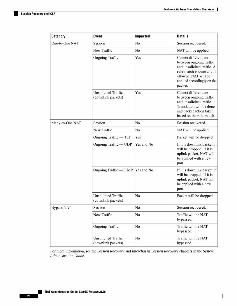
DetailsImpactedEventCategory
Session recovered.NoSessionOne-to-One NAT
NAT will be applied.NoNew Traffic
Cannot differentiatebetween ongoing trafficand unsolicited traffic. Arule-match is done and ifallowed, NAT will beapplied accordingly on thepacket.
YesOngoing Traffic
Cannot differentiatebetween ongoing trafficand unsolicited traffic.Translation will be doneand packet action takenbased on the rule-match.
YesUnsolicited Traffic(downlink packets)
Session recovered.NoSessionMany-to-One NAT
NAT will be applied.NoNew Traffic
Packet will be dropped.YesOngoing Traffic — TCP
If it is downlink packet, itwill be dropped. If it isuplink packet, NAT willbe applied with a newport.
Yes and NoOngoing Traffic — UDP
If it is downlink packet, itwill be dropped. If it isuplink packet, NAT willbe applied with a newport.
Yes and NoOngoing Traffic— ICMP
Packet will be dropped.NoUnsolicited Traffic(downlink packets)
Session recovered.NoSessionBypass NAT
Traffic will be NATbypassed.
NoNew Traffic
Traffic will be NATbypassed.
NoOngoing Traffic
Traffic will be NATbypassed.
NoUnsolicited Traffic(downlink packets)
For more information, see the Session Recovery and Interchassis Session Recovery chapters in the SystemAdministration Guide.
NAT Administration Guide, StarOS Release 21.2620
Network Address Translation OverviewSession Recovery and ICSR
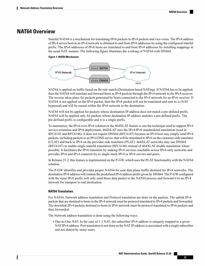
NAT64 OverviewStateful NAT64 is a mechanism for translating IPv6 packets to IPv4 packets and vice-versa. The IPv4 addressof IPv4 server/host in an IPv4 network is obtained to and from IPv6 addresses by using the configured statefulprefix. The IPv6 addresses of IPv6 hosts are translated to and from IPv4 addresses by installing mappings inthe usual NAT manner. The following figure illustrates the working of NAT64 with DNS64.
Figure 1: NAT64 Mechanism
NAT64 is applied on traffic based on the rule match (Destination based NATing). If NAT64 has to be applied,then the NAT64 will translate and forward them as IPv4 packets through the IPv4 network to the IPv4 receiver.The reverse takes place for packets generated by hosts connected to the IPv4 network for an IPv6 receiver. IfNAT64 is not applied on the IPv6 packet, then the IPv6 packet will not be translated and sent as is (NATbypassed) and will be routed within the IPv6 network to the destination.
NAT64 will not be applied for packets whose destination IP address does not match a pre-defined prefix.NAT64 will be applied only for packets whose destination IP address matches a pre-defined prefix. Thepre-defined prefix is configurable and it is a single prefix.
To summarize, the IPv4-over-IPv6 solution or the 464XLAT feature is one the technique used to support IPv4service extension and IPv6 deployment. 464XLAT uses the IPv4/IPv6 standardized translation (used inRFC6145 and RFC6146). It does not require DNS64 (RFC6147) because an IPv4 host may simply send IPv4packets, including packets to an IPv4 DNS server, that will be translated to IPv6 on the customer-side translator(CLAT) and back to IPv4 on the provider-side translator (PLAT). 464XLAT networks may use DNS64(RFC6147) to enable single stateful translation (RFC6146) instead of 464XLAT double translation wherepossible. It facilitates the IPv6 transition by making IPv4 services reachable across IPv6-only networks andprovides IPv6 and IPv4 connectivity to single-stack IPv4 or IPv6 servers and peers.
In Release 21.2, this feature is implemented on the P-GW, which uses the PLAT functionality with the NAT64solution.
The P-GW identifies and provides proper NAT64 for user data plane traffic destined for IPv4 networks. Thedestination IPv6 address will contain the predefined IPv6 address prefix given byDNS64. The P-GWconfiguredwith the same IPv6 prefix will only send those data packet to the NAT64 process and forward it to an IPv4network for transport to end destination.
NAT64 Translation
For NAT64, Network address translation and Protocol translation are done on the packets. The uplink IPv6packets that are destined to hosts in the IPv4 networkmust be protocol translated to IPv4 packets and forwarded.The downlink IPv4 packets destined to hosts in IPv6 network must be protocol translated to IPv6 packets andthen forwarded.
The Network address translation is done using the following ways:
• One-to-One NAT: In the case of 1:1 NAT, the subscriber IPv6 address is uniquely mapped to a givenNAT IPv4 address. Port translation is not done as the NAT IP address is associated with a single subscriberand not shared by many users.
NAT Administration Guide, StarOS Release 21.2621
Network Address Translation OverviewNAT64 Overview
One-to-One NAT IP allocated to a subscriber can be simultaneously used for NATing IPv4 traffic andIPv6 traffic from a given subscriber. When downlink packets are received, firstly the NAT64 bindinglookup is performed for NAT64 translation. If lookup is not successful, then the packet will be NAT44translated.
• Many-to-One NAT: In the case of N:1 NAT, the subscriber IPv6 address and source port is mapped toa given NAT IPv4 address and NAT port. Port translation must be done as the same NAT IPv4 addressis shared by multiple users. Hence, the L4 ports must be translated to differentiate the connectionsoriginating from multiple users sharing the same NAT IPv4 address.
Limitations for One-to-One NAT64
This section lists the limitations for One-to-One NAT64.
• In the case of One-to-One NAT, a given destination can be associated with only one prefix at any pointof time as maintained in the destination prefix list. If the same destination has to be associated withmultiple prefixes, then such packets will be dropped.
• Any downlink traffic received on One-to-One NAT IP will always be translated to the same 128-bit IPv6address (though interface IDs can actually be different).
• One-to-One NAT IP status is lost after recovery. The NAT IP that was previously used for NAT44 orNAT64 is not recovered. Based on the first packet that is received after call recovery and the PDN type,the IP will be used for NATing IPv4 or IPv6 traffic.
Protocol Translation
This section describes the Uplink and Downlink Packet translation.
• Uplink Packet Translation: The uplink packets are translated from IPv6 to IPv4. The IP headers in thepacket will be translated. The existing NAT APIs are enhanced to perform Protocol translation. Alongwith the NAT mapping, the prefix/suffix to be used for translation will also be passed. In case offragmented packets, the packets need to be reassembled and then translated. The uplink packet translationincludes:
• IPv6 to IPv4 Header Translation: The original IPv6 header on the packet is removed and replacedby an IPv4 header.
• ICMPv6 to ICMPv4 Header Translation: The original ICMPv6 header on the packet is removedand replaced by an ICMPv4 header.
• Packet Translation
• Downlink Packet Translation: The downlink packets need to be translated from IPv4 to IPv6. Theexisting NAT APIs are to be enhanced to perform Protocol translation. Along with the NAT mapping,the prefix/suffix to be used for translation will also be passed. In case of fragmented packets, the packetsneed to be reassembled and then translated. The downlink packet translation includes:
• IPv4 to IPv6 Header Translation: The original IPv4 header on the packet is removed and replacedby an IPv6 header.
• ICMPv4 to ICMPv6 Header Translation: The original ICMPv4 header on the packet is removedand replaced by an ICMPv6 header.
NAT Administration Guide, StarOS Release 21.2622
Network Address Translation OverviewNAT64 Overview
NAT64 ALGs Support
NAT64 ALGs support the following protocols:
• File Transfer Protocol (FTP)
• Point-to-Point Tunneling Protocol (PPTP)
• Real Time Streaming Protocol (RTSP)
• Session Initiation Protocol (SIP)
• Trivial File Transfer Protocol (TFTP)
ICMP Host UnreachableIn earlier releases, the NAT44 and NAT64 features could not forward downlink-initiated flows on ASR 5500because of the unknown public IP address, port, private IP address and port binding, and as a result the packetswere getting dropped. The Internet server and other nodes that forward the packets from the Internet serverto the ASR 5500 are unaware of this drop, and maintain the flow-related parameters for the dropped packet.
To resolve the condition of packets getting dropped, NAT44/NAT64 now sends ICMP Host Unreachable forall downlink packets that get dropped. In the case of Many-to-Many NAT, there are chances of downlinkpackets getting dropped when there is no existing flow. In Many-to-Many NAT, downlink packets will beconsidered as unsolicited under the following conditions:
• No NAT Binding exists.
• Binding exists but there is no active 5 tuple flow.
In case of One-to-One NAT, downlink packets will be considered as unsolicited under the condition that thereis no 5-tuple flow. With ICMP-HU feature enabled, NAT sends ICMP-HU after dropping the unsolicitedpackets.
Port Control Protocol SupportThe Port Control Protocol (PCP) feature provides a mechanism to control how incoming packets are forwardedby upstream devices such as Network Address Translation IPv4/IPv4 (NAT44) and IPv4 firewall devices,and to reduce application keepalive traffic.
The PCP feature is customer specific. For more information contact your Cisco account representative.Important
PCP is a licensed Cisco feature. Contact your Cisco account representative for more information. A separatefeature license may be required. Contact your Cisco account representative for detailed information on specificlicensing requirements. For information on installing and verifying licenses, refer to the Managing LicenseKeys section of the Software Management Operations chapter in the System Administration Guide.
Important
The PCP server is supported on ASR 5500 chassis running in-line services such as NAT44 and StatefulFirewall(s) individually or in collocated configurations. PCP supports the following functions:
NAT Administration Guide, StarOS Release 21.2623
Network Address Translation OverviewICMP Host Unreachable
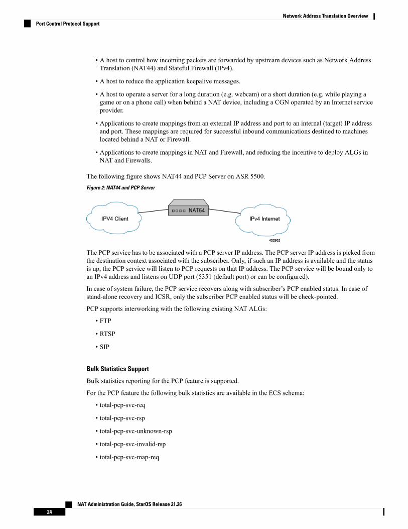
• A host to control how incoming packets are forwarded by upstream devices such as Network AddressTranslation (NAT44) and Stateful Firewall (IPv4).
• A host to reduce the application keepalive messages.
• A host to operate a server for a long duration (e.g. webcam) or a short duration (e.g. while playing agame or on a phone call) when behind a NAT device, including a CGN operated by an Internet serviceprovider.
• Applications to create mappings from an external IP address and port to an internal (target) IP addressand port. These mappings are required for successful inbound communications destined to machineslocated behind a NAT or Firewall.
• Applications to create mappings in NAT and Firewall, and reducing the incentive to deploy ALGs inNAT and Firewalls.
The following figure shows NAT44 and PCP Server on ASR 5500.
Figure 2: NAT44 and PCP Server
The PCP service has to be associated with a PCP server IP address. The PCP server IP address is picked fromthe destination context associated with the subscriber. Only, if such an IP address is available and the statusis up, the PCP service will listen to PCP requests on that IP address. The PCP service will be bound only toan IPv4 address and listens on UDP port (5351 (default port) or can be configured).
In case of system failure, the PCP service recovers along with subscriber’s PCP enabled status. In case ofstand-alone recovery and ICSR, only the subscriber PCP enabled status will be check-pointed.
PCP supports interworking with the following existing NAT ALGs:
• FTP
• RTSP
• SIP
Bulk Statistics Support
Bulk statistics reporting for the PCP feature is supported.
For the PCP feature the following bulk statistics are available in the ECS schema:
• total-pcp-svc-req
• total-pcp-svc-rsp
• total-pcp-svc-unknown-rsp
• total-pcp-svc-invalid-rsp
• total-pcp-svc-map-req
NAT Administration Guide, StarOS Release 21.2624
Network Address Translation OverviewPort Control Protocol Support
• total-pcp-svc-map-valid-req
• total-pcp-svc-map-invalid-req
• total-pcp-svc-map-rsp
• total-pcp-svc-map-rsp-success
• total-pcp-svc-peer-rsp-error
• total-pcp-svc-peer-req
• total-pcp-svc-peer-valid-req
• total-pcp-svc-peer-invalid-req
• total-pcp-svc-peer-rsp
• total-pcp-svc-peer-rsp-success
• total-pcp-svc-peer-rsp-error
• total-pcp-svc-announce-req
• total-pcp-svc-announce-valid-req
• total-pcp-svc-announce-invalid-req
• total-pcp-svc-announce-rsp
• total-pcp-svc-announce-rsp-success
• total-pcp-svc-announce-rsp-error
• total-pcp-svc-subscribers
• current-pcp-svc-subscribers
Logging SupportNAT supports logging of various messages on screen if logging is enabled for NAT. These logs providedetailed messages at various levels, like critical, error, warning, and debug. NAT attack logs also provideinformation on the source IP address, destination IP address, protocol, or attack type for any packet droppeddue to an attack. These logs are also sent to a syslog server if configured in the system.
Enhanced Syslog Reporting
Feature Summary and Revision History
Summary Data
All ProductsApplicable Product(s) or FunctionalArea
NAT Administration Guide, StarOS Release 21.2625
Network Address Translation OverviewLogging Support
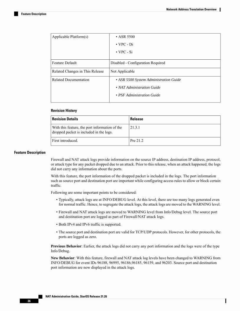
• ASR 5500
• VPC - Di
• VPC - Si
Applicable Platform(s)
Disabled - Configuration RequiredFeature Default
Not ApplicableRelated Changes in This Release
• ASR 5500 System Administration Guide
• NAT Administration Guide
• PSF Administration Guide
Related Documentation
Revision History
ReleaseRevision Details
21.3.1With this feature, the port information of thedropped packet is included in the logs.
Pre 21.2First introduced.
Feature Description
Firewall and NAT attack logs provide information on the source IP address, destination IP address, protocol,or attack type for any packet dropped due to an attack. Prior to this release, when an attack happened, the logsdid not carry any information about the ports.
With this feature, the port information of the dropped packet is included in the logs. The port informationsuch as source port and destination port are important while configuring access rules to allow or block certaintraffic.
Following are some important points to be considered:
• Typically, attack logs are at INFO/DEBUG level. At this level, there are too many logs generated evenfor normal traffic. Hence, to segregate the attack logs, the attack logs are moved to the WARNING level.
• Firewall and NAT attack logs are moved to WARNING level from Info/Debug level. The source portand destination port are logged as part of Firewall/NAT attack logs.
• Both IPv4 and IPv6 traffic is supported.
• The source port and destination port are valid for TCP/UDP protocols. However, for other protocols, theports are logged as zero.
Previous Behavior: Earlier, the attack logs did not carry any port information and the logs were of the typeInfo/Debug.
New Behavior: With this feature, firewall and NAT attack log levels have been changed to WARNING fromINFO/DEBUG for event IDs 96188, 96995, 96186,96185, 96159, and 96203. Source port and destinationport information are now displayed in the attack logs.
NAT Administration Guide, StarOS Release 21.2626
Network Address Translation OverviewFeature Description
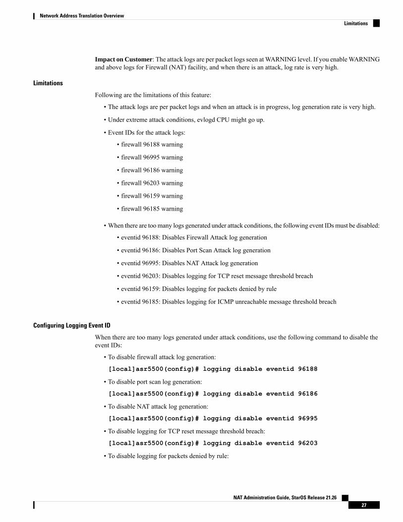
Impact on Customer: The attack logs are per packet logs seen atWARNING level. If you enableWARNINGand above logs for Firewall (NAT) facility, and when there is an attack, log rate is very high.
Limitations
Following are the limitations of this feature:
• The attack logs are per packet logs and when an attack is in progress, log generation rate is very high.
• Under extreme attack conditions, evlogd CPU might go up.
• Event IDs for the attack logs:
• firewall 96188 warning
• firewall 96995 warning
• firewall 96186 warning
• firewall 96203 warning
• firewall 96159 warning
• firewall 96185 warning
• When there are toomany logs generated under attack conditions, the following event IDsmust be disabled:
• eventid 96188: Disables Firewall Attack log generation
• eventid 96186: Disables Port Scan Attack log generation
• eventid 96995: Disables NAT Attack log generation
• eventid 96203: Disables logging for TCP reset message threshold breach
• eventid 96159: Disables logging for packets denied by rule
• eventid 96185: Disables logging for ICMP unreachable message threshold breach
Configuring Logging Event ID
When there are too many logs generated under attack conditions, use the following command to disable theevent IDs:
• To disable firewall attack log generation:
[local]asr5500(config)# logging disable eventid 96188
• To disable port scan log generation:
[local]asr5500(config)# logging disable eventid 96186
• To disable NAT attack log generation:
[local]asr5500(config)# logging disable eventid 96995
• To disable logging for TCP reset message threshold breach:
[local]asr5500(config)# logging disable eventid 96203
• To disable logging for packets denied by rule:
NAT Administration Guide, StarOS Release 21.2627
Network Address Translation OverviewLimitations
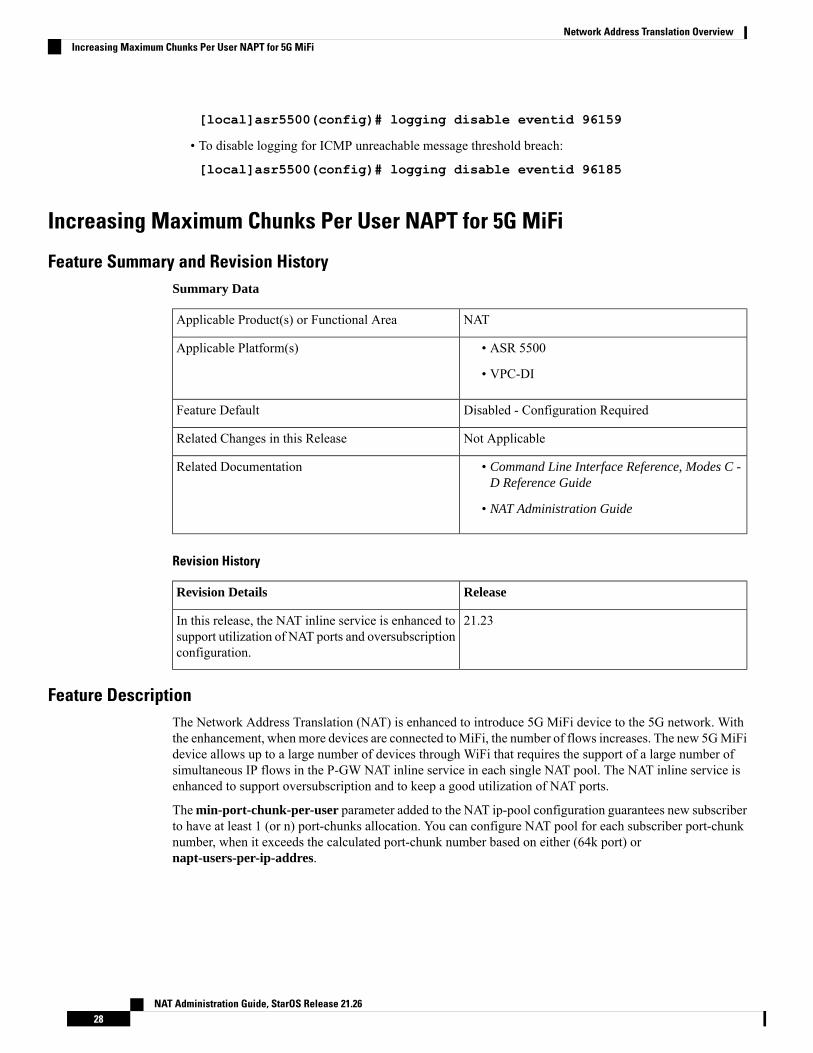
[local]asr5500(config)# logging disable eventid 96159
• To disable logging for ICMP unreachable message threshold breach:
[local]asr5500(config)# logging disable eventid 96185
Increasing Maximum Chunks Per User NAPT for 5G MiFi
Feature Summary and Revision HistorySummary Data
NATApplicable Product(s) or Functional Area
Applicable Platform(s) • ASR 5500
• VPC-DI
Disabled - Configuration RequiredFeature Default
Not ApplicableRelated Changes in this Release
Related Documentation • Command Line Interface Reference, Modes C -D Reference Guide
• NAT Administration Guide
Revision History
ReleaseRevision Details
21.23In this release, the NAT inline service is enhanced tosupport utilization of NAT ports and oversubscriptionconfiguration.
Feature DescriptionThe Network Address Translation (NAT) is enhanced to introduce 5G MiFi device to the 5G network. Withthe enhancement, when more devices are connected toMiFi, the number of flows increases. The new 5GMiFidevice allows up to a large number of devices through WiFi that requires the support of a large number ofsimultaneous IP flows in the P-GW NAT inline service in each single NAT pool. The NAT inline service isenhanced to support oversubscription and to keep a good utilization of NAT ports.
Themin-port-chunk-per-user parameter added to the NAT ip-pool configuration guarantees new subscriberto have at least 1 (or n) port-chunks allocation. You can configure NAT pool for each subscriber port-chunknumber, when it exceeds the calculated port-chunk number based on either (64k port) ornapt-users-per-ip-addres.
NAT Administration Guide, StarOS Release 21.2628
Network Address Translation OverviewIncreasing Maximum Chunks Per User NAPT for 5G MiFi
• The min-port-chunk-per-user is only applicable to NAPT single-ip.
• min-port-chunk-per-user and port-chunk-threshold are mutually exclusive.
• Allows over subscription configuration.
• The number of port chunks per IP is reduced when you configure port-chunk size to a higher value. Thisis because the first 1024 ports are reserved.
Note
For more information about Minimum Port-Chunks Reservation and configurations, refer the Minimum PortChunks Reservation section in the NAT Configuration chapter of the NAT Administration Guide.
Configuring Many-to-One NAT IP PoolsUse the following configuration commands to configure NAT IP pool.
configurecontext context_name
ip pool min-port-chunk-per-user max_chunks_per_user
ip pool port-chunk-thresholdend
NOTES:
• ip pool min-port-chunk-per-user : Specifies NAT Port minimum number of chunks per user formany-to-one NAT pool. max_chunks_per_user must be an integer from 1 through 100.
• ip pool port-chunk-threshold and ip pool min-port-chunk-per-user are mutually exclusive.
Supported StandardsThe NAT feature supports the following RFCs:
• RFC 1631: The IP Network Address Translator (NAT); May 1994
• RFC 1918: Address Allocation for Private Internets; February 1996
• RFC 2663: IP Network Address Translator (NAT) Terminology and Considerations; August 1999
• RFC 2765: Stateless IP/ICMP Translation Algorithm (SIIT); February 2000
• RFC 2766: Network Address Translation - Protocol Translation (NAT-PT); February 2000
• RFC 3022: Traditional IP Network Address Translator (Traditional NAT); January 2001
• RFC 3027: Protocol Complications with the IP Network Address Translator; January 2001
• RFC 3261: SIP: Session Initiation Protocol
• RFC 4787: Network Address Translation (NAT) Behavioral Requirements for Unicast UDP; January2007
• RFC 4966: Reasons toMove the Network Address Translator - Protocol Translator (NAT-PT) to HistoricStatus; July 2007
NAT Administration Guide, StarOS Release 21.2629
Network Address Translation OverviewConfiguring Many-to-One NAT IP Pools
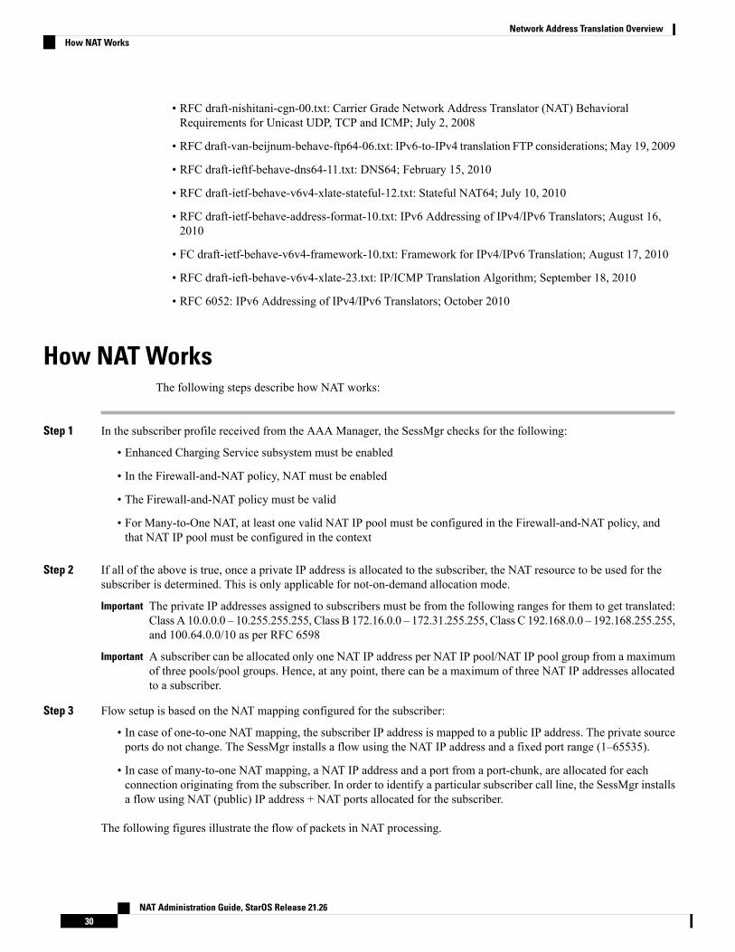
• RFC draft-nishitani-cgn-00.txt: Carrier Grade Network Address Translator (NAT) BehavioralRequirements for Unicast UDP, TCP and ICMP; July 2, 2008
• RFC draft-van-beijnum-behave-ftp64-06.txt: IPv6-to-IPv4 translation FTP considerations;May 19, 2009
• RFC draft-ieftf-behave-dns64-11.txt: DNS64; February 15, 2010
• RFC draft-ietf-behave-v6v4-xlate-stateful-12.txt: Stateful NAT64; July 10, 2010
• RFC draft-ietf-behave-address-format-10.txt: IPv6 Addressing of IPv4/IPv6 Translators; August 16,2010
• FC draft-ietf-behave-v6v4-framework-10.txt: Framework for IPv4/IPv6 Translation; August 17, 2010
• RFC draft-ieft-behave-v6v4-xlate-23.txt: IP/ICMP Translation Algorithm; September 18, 2010
• RFC 6052: IPv6 Addressing of IPv4/IPv6 Translators; October 2010
How NAT WorksThe following steps describe how NAT works:
Step 1 In the subscriber profile received from the AAA Manager, the SessMgr checks for the following:
• Enhanced Charging Service subsystem must be enabled
• In the Firewall-and-NAT policy, NAT must be enabled
• The Firewall-and-NAT policy must be valid
• For Many-to-One NAT, at least one valid NAT IP pool must be configured in the Firewall-and-NAT policy, andthat NAT IP pool must be configured in the context
Step 2 If all of the above is true, once a private IP address is allocated to the subscriber, the NAT resource to be used for thesubscriber is determined. This is only applicable for not-on-demand allocation mode.
The private IP addresses assigned to subscribers must be from the following ranges for them to get translated:Class A 10.0.0.0 – 10.255.255.255, Class B 172.16.0.0 – 172.31.255.255, Class C 192.168.0.0 – 192.168.255.255,and 100.64.0.0/10 as per RFC 6598
Important
A subscriber can be allocated only one NAT IP address per NAT IP pool/NAT IP pool group from a maximumof three pools/pool groups. Hence, at any point, there can be a maximum of three NAT IP addresses allocatedto a subscriber.
Important
Step 3 Flow setup is based on the NAT mapping configured for the subscriber:
• In case of one-to-one NAT mapping, the subscriber IP address is mapped to a public IP address. The private sourceports do not change. The SessMgr installs a flow using the NAT IP address and a fixed port range (1–65535).
• In case of many-to-one NAT mapping, a NAT IP address and a port from a port-chunk, are allocated for eachconnection originating from the subscriber. In order to identify a particular subscriber call line, the SessMgr installsa flow using NAT (public) IP address + NAT ports allocated for the subscriber.
The following figures illustrate the flow of packets in NAT processing.
NAT Administration Guide, StarOS Release 21.2630
Network Address Translation OverviewHow NAT Works
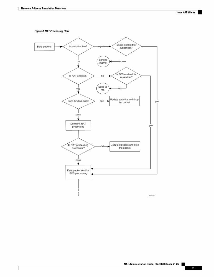
Figure 3: NAT Processing Flow
NAT Administration Guide, StarOS Release 21.2631
Network Address Translation OverviewHow NAT Works
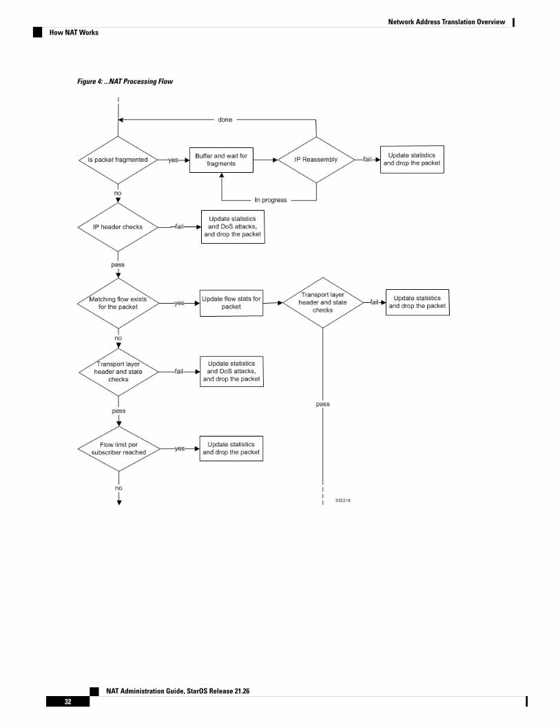
Figure 4: ...NAT Processing Flow
NAT Administration Guide, StarOS Release 21.2632
Network Address Translation OverviewHow NAT Works
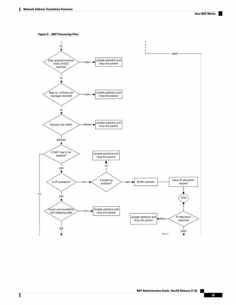
Figure 5: ...NAT Processing Flow
NAT Administration Guide, StarOS Release 21.2633
Network Address Translation OverviewHow NAT Works
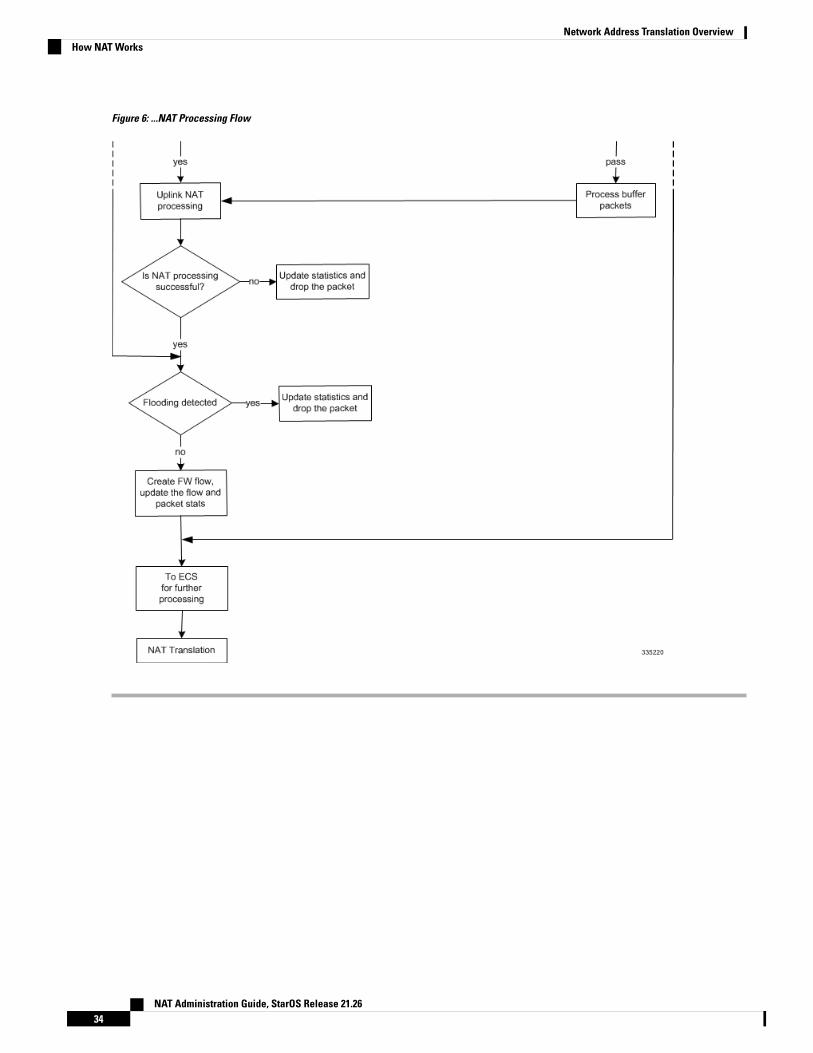
Figure 6: ...NAT Processing Flow
NAT Administration Guide, StarOS Release 21.2634
Network Address Translation OverviewHow NAT Works
C H A P T E R 2NAT Configuration
This chapter describes how to configure the Network Address Translation (NAT) in-line service feature.
In release 8.x, NAT for CDMA and early UMTS releases used rulebase-based configurations, whereas in laterUMTS releases NAT used policy-based configurations. In 9.0 and later releases, NAT for UMTS and CDMAreleases both use policy-based configurations. For more information, please contact your local servicerepresentative.
Important
The following topics are covered in this chapter:
• Before You Begin, on page 35• Configuring the System, on page 35• Configuring NAT, on page 36• Verifying the Configuration, on page 55• Gathering NAT Statistics, on page 56
Before You BeginThis section lists the steps to perform before you can start configuring NAT support on a system:
Step 1 Configure the required core network service on the system as described in the System Administration Guide.Step 2 Obtain and install the required feature licenses for the required number of subscriber sessions.Step 3 Proceed to the Configuring the System section.
Configuring the SystemThis section lists the high-level steps to configure the NAT feature.
Step 1 Configure the NAT feature as described in the Configuring NAT section.Step 2 Verify your configuration as described in the Verifying the Configuration section.
NAT Administration Guide, StarOS Release 21.2635
Step 3 Save your configuration to flash memory, an external memory device, and/or a network location using the Exec modecommand save configuration. For additional information on how to verify and save configuration files, refer to the SystemAdministration Guide and Command Line Interface Reference.
Configuring NATThis section describes how to configure the NAT in-line service feature.
Step 1 Enable the Enhanced Charging Service (ECS) subsystem and create the enhanced charging service as described in theEnabling the ECS Subsystem and Creating the ECS Service, on page 37 section.
Step 2 (Optional) Configure port maps as described in the Configuring Port Maps section.Step 3 (Optional) Configure host pools as described in the Configuring Host Pools section.Step 4 (Optional) Configure IMSI pools as described in the Configuring IMSI Pools section.Step 5 Configure access ruledefs as described in the Configuring Access Ruledefs section.Step 6 Configure allocation of multiple IP addresses for a NAT realm as described in the Configuring IP address allocation
for NAT realm, on page 43 section.Step 7 Configure NAT IP pools/NAT IP pool groups as described in the Configuring NAT IP Pools/NAT IP Pool Groups, on
page 38 section.Step 8 Configure Firewall-and-NAT policies as described in the Configuring Firewall-and-NAT Policies section.Step 9 Configure Firewall-and-NAT actions as described in the Configuring Firewall-and-NAT Action section.Step 10 Configure action on NAT IP address/port allocation failure as described in the Configuring Action on NAT IP
Address/Port Allocation Failure section.Step 11 Configure action on packets during NAT IP allocation as described in the Configuring Action on Packets During NAT
IP Allocation section.Step 12 Configure NAT TCP-2msl-timeout setting as described in the Configuring NAT TCP-2msl-timeout Setting section.Step 13 Configure action on TCP idle timeout as described in the Configuring Action on TCP Idle Timeout section.Step 14 Configure Private IP NPU Flow Timeout setting as described in the Configuring Private IP NPU Flow Timeout Setting
section.Step 15 Configure NAT reassembly timer as described in the Configuring NAT Reassembly Timer section.Step 16 Configure Flow Recovery as described in the Configuring Flow Recovery section.Step 17 Configure NAT Flow Checkpointing as described in the Configuring NAT Flow Checkpointing section.Step 18 Enable NAT support for APN/subscribers as described in the Enabling NAT for APN/Subscribers section.Step 19 (Optional) Configure the default Firewall-and-NAT policy as described in the Configuring the Default Firewall-and-NAT
Policy section.Step 20 Configure NAT ALGs as described in the Configuring NAT Application Level Gateways/Dynamic Pinholes section.Step 21 (Optional) Configure the PCP service as described in the Configuring PCP Service section.Step 22 Configure the EDR Format for NAT Packet Drops as described in the Configuring EDR Format for NAT Packet Drops,
on page 50 section.Step 23 Configure EDR format as described in the Configuring EDR Format section.Step 24 Configure UDR format as described in the Configuring UDR Format section.Step 25 Configure NBR formats as described in the Configuring NAT Binding Record Format section.
NAT Administration Guide, StarOS Release 21.2636
NAT ConfigurationConfiguring NAT
Step 26 Configure NAT realm bulk statistics collection as described in the Configuring Bulkstats Collection section.Step 27 Configure NAT thresholds as described in the Configuring NAT Thresholds section.Step 28 Configure a secondary IP pool, which is not overwritten by the RADIUS supplied list, as described in the Configuring
NAT Backout section.
Commands used in the configuration examples in this section provide base functionality to the extent thatthe most common or likely commands and/or keyword options are presented. In many cases, other optionalcommands and/or keyword options are available. Refer to theCommand Line Interface Reference for completeinformation regarding all commands.
Important
Enabling the ECS Subsystem and Creating the ECS ServiceTo enable the ECS subsystem and create the enhanced charging service, use the following configuration:
configurerequire active-charging serviceactive-charging service acs_service_name [ -noconfirm ]
end
After you configure this command, you must save the configuration and then reload the chassis for thecommand to take effect. For information on saving the configuration file and reloading the chassis, refer tothe System Administration Guide for your deployment.
Important
Configuring Port MapsThis is an optional configuration. To create and configure an application-port map for TCP and UDP protocols,use the following configuration:
configureactive-charging service acs_service_name
port-map port_map_name [ -noconfirm ]
port { port_number | range start_port to end_port }
end
Notes:
• A maximum of 256 host pools, IMSI pools, and port maps each, and a combined maximum of 4096 rules(host pools + IMSI pools + port maps + charging ruledefs + access ruledefs + routing ruledefs) can becreated in a system.
• Port maps, host pools, IMSI pools, and charging, access, and routing ruledefs must each have uniquenames.
• A maximum of 10 entries can be configured in each port map.
NAT Administration Guide, StarOS Release 21.2637
NAT ConfigurationEnabling the ECS Subsystem and Creating the ECS Service

Configuring Host PoolsThis is an optional configuration. To create and configure a host pool, use the following configuration:
configureactive-charging service acs_service_name
host-pool host_pool_name [ -noconfirm ]
ip { ip_address | ip_address/mask | range start_ip_address to end_ip_address }
end
Notes:
• A maximum of 256 host pools, IMSI pools, and port maps each, and a combined maximum of 4096 rules(host pools + IMSI pools + port maps + charging ruledefs + access ruledefs + routing ruledefs) can becreated in a system.
• Port maps, host pools, IMSI pools, and charging, access, and routing ruledefs must each have uniquenames.
• A maximum of 10 entries can be configured in each host pool.
Configuring IMSI PoolsThis is an optional configuration. To create and configure an IMSI pool, use the following configuration:
configureactive-charging service acs_service_name
imsi-pool imsi_pool_name [ -noconfirm ]
imsi { imsi_number | range start_imsi to end_imsi }
end
Notes:
• A maximum of 256 host pools, IMSI pools, and port maps each, and a combined maximum of 4096 rules(host pools + IMSI pools + port maps + charging ruledefs + access ruledefs + routing ruledefs) can becreated in a system.
• Port maps, host pools, IMSI pools, and charging, access, and routing ruledefs must each have uniquenames.
• A maximum of 10 entries can be configured in each IMSI pool.
Configuring NAT IP Pools/NAT IP Pool GroupsThis section describes how to create and configure NAT IP pools/NAT IP pool groups.
The following topics are covered in this section:
• Configuring One-to-One NAT IP Pools/NAT IP Pool Groups, on page 38
• Configuring Many-to-One NAT IP Pools/NAT IP Pool Groups, on page 40
Configuring One-to-One NAT IP Pools/NAT IP Pool Groups
To create and configure a one-to-one NAT IP pool/NAT IP pool group, use the following configuration:
NAT Administration Guide, StarOS Release 21.2638
NAT ConfigurationConfiguring Host Pools

configurecontext context_name [ -noconfirm ]
ip pool nat_pool_name { ip_address subnet_mask | ip_address/mask | rangestart_ip_address end_ip_address } nat-one-to-one [ alert-threshold { { pool-free| pool-hold | pool-release | pool-used } low_thresh [ clear high_thresh ] } + ]
[ group-name nat_pool_group_name ] [ nat-binding-timer binding_timer ] [
nexthop-forwarding-address ip_address ] [ include-nw-bcast ] [ on-demand ] [
send-icmp-dest-destunreachable ] [ send-nat-binding-update ] [
skip-nat-subscriber-ip-check ] [ srp-activate ] + ]
ip pool pool_name { ip_address subnet_mask | ip_address/mask | range start_ip_address
end_ip_address } public priority
end
Notes:
• Within a context, all IP pool and NAT IP pool and NAT IP pool group names must be unique.
• IP pool and NAT IP pool and NAT IP pool group names are case sensitive.
• The IP addresses configured in the NAT IP pools within a context must not overlap. At any time, withina context, a NAT IP address must be configured in any one NAT IP pool.
• The IP addresses in a NAT IP pool may be contiguous, and must be assignable as a subnet or a rangethat constitutes less than an entire subnet.
• For many-to-one NAT IP pools, the default NAT Binding Timer value is 60 seconds. For one-to-oneNAT IP pools, by default the feature is disabled—the IP addresses/ port-chunks once allocated will neverbe freed.
• The skip-nat-subscriber-ip-check keyword is added to skip private IP address check for non-NATpools. This can be configured only for non-NAT pools during call-setup if NAT is enabled for thesubscriber.
If NAT is disabled, this value is not considered. Default: Disabled (subscriber IP check is done).
• Thresholds configured using the alert-threshold keyword are specific to the pool that they are configuredin. Thresholds configured using the threshold ip-pool-* commands in the Context Configuration Modeapply to all IP pools in the context, and override the threshold configurations set within individual pools.
• Not-on-demand allocation mode is the default NAT IP Address Allocation mode.
• To add a NAT IP pool to a NAT IP pool group, use the group-name nat_pool_group_name option.
NAT IP pool and NAT IP pool group names must be unique.
When configuring a NAT IP pool group, note that only those NAT IP pools that have similar characteristicscan be grouped together. The similarity is determined by the “nat-one-to-one” and “on-demand”parameters. Dissimilar NAT IP pools cannot be grouped together.
It is recommended that for each NAT IP pool in a NAT IP pool group the other parameters(“nat-binding-timer", “send-nat-binding-update”, “nexthop-forwarding-address”,“send-icmp-dest-unreachable”, and “srp-activate" also be configured with the same values, so that theNAT behavior is predictable across all NAT IP pools in that NAT IP pool group.
The NAT IP pool from which a NAT IP address is assigned will determine the actual values to use forall parameters.
NAT Administration Guide, StarOS Release 21.2639
NAT ConfigurationConfiguring NAT IP Pools/NAT IP Pool Groups

• It is recommended that in a Firewall-and-NAT policy all the realms configured either be NAT IP poolsor NAT IP pool groups. If both NAT IP pool(s) and NAT IP pool group(s) are configured, ensure thatnone of the NAT IP pool(s) are also included in the NAT IP pool group.
• Network broadcast is supported for NAT pools and ordinary pools using the include-nw-bcast option.
Configuring Many-to-One NAT IP Pools/NAT IP Pool Groups
To create and configure a Many-to-One NAT IP pool/NAT IP pool group, use the following configuration:
configurecontext context_name [ -noconfirm ]
ip pool nat_pool_name { ip_address subnet_mask | ip_address/mask | rangestart_ip_address end_ip_address } napt-users-per-ip-address users [ alert-threshold{ { pool-free | pool-hold | pool-release | pool-used } low_thresh [ clearhigh_thresh ] } + ] [ group-name nat_pool_group_name ] [ max-chunks-per-user chunks
] [ nat-binding-timer binding_timer ] [ nexthop-forwarding-address ip_address
] [ on-demand ] [ port-chunk-size size ] [ min-port-chunk-per-user chunks ] [
port-chunk-threshold threshold ] [ send-icmp-dest-destunreachable ] [
send-nat-binding-update ] [ srp-activate ] + ]
ip pool pool_name { ip_address subnet_mask | ip_address/mask | range start_ip_address
end_ip_address } public priority
end
Notes:
• Within a context, all IP pool and NAT IP pool and NAT IP pool group names must be unique.
• IP pool and NAT IP pool and NAT IP pool group names are case sensitive.
• The IP addresses configured in the NAT IP pools within a context must not overlap. At any time, withina context, a NAT IP address must be configured in any one NAT IP pool.
• The IP addresses in a NAT IP pool may be contiguous, and must be assignable as a subnet or a rangethat constitutes less than an entire subnet.
• For many-to-one NAT IP pools, the default NAT Binding Timer value is 60 seconds. For one-to-oneNAT IP pools, by default the feature is disabled—the IP addresses/ port-chunks once allocated will neverbe freed.
• Thresholds configured using the alert-threshold keyword are specific to the pool that they are configuredin. Thresholds configured using the threshold ip-pool-* commands in the Context Configuration Modeapply to all IP pools in the context, and override the threshold configurations set within individual pools.
• Not-on-demand allocation mode is the default NAT IP Address Allocation mode.
• To add a NAT IP pool to a NAT IP pool group, use the group-name nat_pool_group_name option.
NAT IP pool and NAT IP pool group names must be unique.
When configuring a NAT IP pool group, note that only those NAT IP pools that have similar characteristicscan be grouped together. The similarity is determined by the “napt-users-per-ip-address”,“napt-users-per-ip-address <users>”, “on-demand” and “port-chunk-size” parameters. Dissimilar NATIP pools cannot be grouped together.
It is recommended that for each NAT IP pool in a NAT IP pool group the other parameters(“nat-binding-timer", “send-nat-binding-update”, “nexthop-forwarding-address”,
NAT Administration Guide, StarOS Release 21.2640
NAT ConfigurationConfiguring NAT IP Pools/NAT IP Pool Groups
“send-icmp-dest-unreachable”, “srp-activate” and “port-chunk-threshold”) also be configured with thesame values, so that the NAT behavior is predictable across all NAT IP pools in that NAT IP pool group.
The NAT IP pool from which a NAT IP address is assigned will determine the actual values to use forall parameters.
• It is recommended that in a Firewall-and-NAT policy all the realms configured either be NAT IP poolsor NAT IP pool groups. If both NAT IP pool(s) and NAT IP pool group(s) are configured, ensure thatnone of the NAT IP pool(s) are also included in the NAT IP pool group.
Configuring Firewall-and-NAT PoliciesTo create and configure a Firewall-and-NAT Policy, use the following configuration:
configureactive-charging service acs_service_name
fw-and-nat policy fw_nat_policy_name [ -noconfirm ]
nat policy [ ipv4-and-ipv6 | ipv4-only | ipv6-only ] [
default-nat-realm nat_realm_name [ fw-and-nat-action action_name ] ]
access-rule priority priority { [ dynamic-only | static-and-dynamic] access-ruledef access_ruledef_name { deny [ charging-action charging_action_name
] | permit [ nat-realm nat_pool_name/nat_pool_group_name | [ bypass-nat ] ] }
access-rule no-ruledef-matches { downlink | uplink } action { deny[ charging-action charging_action_name ] | permit [ bypass-nat | nat-realmnat_pool_name/nat_pool_group_name ] }
end
Notes:
• In StarOS 8.x, NAT for CDMA and early UMTS releases used rulebase-based configurations, whereasin later UMTS releases NAT used policy-based configurations. In StarOS 9.0 and later releases, NATfor UMTS and CDMA releases both use policy-based configurations. For more information, pleasecontact your local service representative.
• In 12.1 and earlier releases: The nat policy nat-required command enables NAT44 for all subscribersusing the policy. This keyword is supported in release 12.2 for backward compatibility.
• In 12.2 and later releases: The nat policy [ ipv4-and-ipv6 | ipv4-only | ipv6-only ] command enablesNAT processing for IPv4/IPv6 or both using the policy.
• Duplicate ruledef names or priorities are not allowed in the same rulebase.• A maximum of twenty NAT IP pools/NAT IP pool groups can be configured in a Firewall-and-NATpolicy. A subscriber can be allocated only one NAT IP address per NAT IP pool/NAT IP pool groupfrom a maximum of three pools/pool groups. Hence, at anytime, there can only be a maximum of threeNAT IP addresses allocated to a subscriber.
• It is recommended that in a Firewall-and-NAT policy all the realms configured either be NAT IP poolsor NAT IP pool groups. If both NAT IP pool(s) and NAT IP pool group(s) are configured, ensure that aNAT IP pool is not a part of a NAT IP pool group.
• NAT is applied only to packets in the uplink direction.• Rule matching is done for the first packet for a flow. Only when no rules match, the no-ruledef-matchesconfiguration is considered. The default settings for uplink direction is “permit”, and for downlinkdirection “deny”.
NAT Administration Guide, StarOS Release 21.2641
NAT ConfigurationConfiguring Firewall-and-NAT Policies
• If there are no rules matching a packet, then the NAT IP pool/NAT IP pool group to be used for the flowis taken from the following configuration:
access-rule no-ruledef-matches uplink action permit nat-realm nat_pool_name/nat_pool_group_name
• If there is no NAT IP pool/NAT IP pool group name configured in the matching access ruledef, NATwill be bypassed, i.e., NAT will not be applied to the flow.
Configuring Firewall-and-NAT ActionTo create and configure a Firewall-and-NAT Action, use the following configuration:
configureactive-charging service acs_service_name
fw-and-nat action fw_nat_action_name [ -noconfirm ]
flow check-point [ data-usage data_usage [ and | or ] | time-durationduration [ and | or ] ]
end
Configuring Access RuledefsTo create and configure an access rule definition, use the following configuration:
configureactive-charging service acs_service_name
access-ruledef access_ruledef_name [ -noconfirm ]
bearer 3gpp apn [ case-sensitive ] operator value
bearer 3gpp imsi { operator msid | { !range | range } imsi-pool imsi_pool}
bearer username [ case-sensitive ] operator user_name
icmp { any-match operator condition | code operator code | type operator type}
ip { { { any-match | downlink | uplink } operator condition } | { {
dst-address | src-address } { { operator { ip_address | ip_address/mask } } | { !range| range } host-pool host_pool_name } | protocol { { operator { protocol |
protocol_assignment } } | { operator protocol_assignment | server-ipv6-network-prefixoperator ipv6_prefix/prefix_length } } }
tcp { any-match operator condition } | { dst-port | either-port | src-port} { operator port_number | { !range | range } { start_range to end-range | port-mapport_map_name } } }
udp { any-match operator condition } | { { dst-port | either-port |
src-port } { { operator port_number } | { !range | range } { start_range to end-range
| port-map port_map_name } } }
create-log-recordend
Notes:
• If the source IP address is not configured, then it is treated as any source IP.
• If the destination IP address is not configured, then it is treated as any destination IP.
• If the source port is not configured, then it is treated as any source port.
NAT Administration Guide, StarOS Release 21.2642
NAT ConfigurationConfiguring Firewall-and-NAT Action
• If the destination port is not configured, then it is treated as any destination port.
• If no protocol is specified, then it is treated as any protocol.
• If both uplink and downlink fields are not configured, then the rule will be treated as either direction,i.e. packets from any direction will match that rule.
• Access ruledefs are different from enhanced charging service ruledefs. A combined maximum of 4096rules (host pools, IMSI pools, port maps, and access, charging, and routing ruledefs) can be created in asystem. A combined maximum of 2048 access and charging ruledefs can be created in a system.
• The server-ipv6-network-prefix operator ipv6_prefix/prefix_length rule is matched against theDestination IPv6 address of the incoming packet to decide whether NAT64 has to be applied or not.
• Configuring access ruledefs involves the creation of several ruledefs with different sets of rules andparameters. For more information, see the Firewall Ruledef Configuration Mode Commands chapter ofthe Command Line Interface Reference.
Configuring Server IP Address
To configure an access rule definition to analyze user traffic based on server IP address, use the followingconfiguration:
configureactive-charging service acs_service_name
access-ruledef access_ruledef_name
[ no ] ip server-ip-address { operator { ipv4/ipv6_address |
ipv4/ipv6_address/mask } | { !range | range } host-pool host_pool_name }
end
Notes:
The ip server-ip-address command is added in access rule definitions to avoid configuring multiple ruleoptions as part of Firewall rules. If any address or host-pool range is specified as the server IP address, thisaddress in the uplink direction will be treated as the destination address, and in downlink direction will betreated as the source address.
Configuring IP address allocation for NAT realmTo enable or disable the allocation of multiple NAT IP addresses for the same many-to-one (N:1) NAT realmfor a subscriber, use the following configuration:
configureactive-charging service service_name
fw-and-nat policy policy_name
nat max-chunk-per-realm { multiple-ip | single-ip }{ default | no } nat max-chunk-per-realmend
Notes:
• The nat max-chunk-per-realm multiple-ip command enables the feature, that is, allows allocation ofmore than one IP address for a NAT realm if required.
NAT Administration Guide, StarOS Release 21.2643
NAT ConfigurationConfiguring IP address allocation for NAT realm
• The nat max-chunk-per-realm single-ip command disables the feature, allows allocation of only oneIP address for NAT realm. If the port chunks get exhausted, packets will be dropped. This is the defaultbehavior.
• The no nat max-chunk-per-realm command disables the allocation of multiple IP addresses for thesame NAT realm for a subscriber. This command when configured, allows only one IP address to beallocated for a NAT realm.
• This enhancement is applicable only for N:1 NAT realms and not for 1:1 NAT realms.
Configuring Action on NAT IP Address/Port Allocation FailureTo configure sending ICMP error messages in the event of NAT IP address/port allocation failure, use thefollowing configuration:
configureactive-charging service acs_service_name
nat allocation-failure send-icmp-dest-unreachableend
Configuring Action on Packets During NAT IP AllocationTo configure action to take on packets when NAT IP/NPU allocation is in progress, use the followingconfiguration:
configureactive-charging service acs_service_name
nat allocation-in-progress { buffer | drop }
end
Notes:
In On-demand NAT IP allocation (wherein a NAT IP address is allocated to the subscriber when a packet isbeing sent), if no free NAT IP address is available, a NAT-IP Alloc Request is sent to the VPNMgr to get aNAT IP. During that time packets are dropped. This command enables to either buffer or drop the packetsreceived when IP Alloc Request is sent to VPNMgr.
Configuring Forcible NAT IP Release
To forcibly clear NAT IP addresses from SessMgr to VPNMgr, use the following configuration:
clear nat-ip { ip_address | pool pool_name } context context_name [ -noconfirm ]
Configuring NAT TCP-2msl-timeout SettingTo configure NAT TCP 2msl Timeout setting, use the following configuration:
configureactive-charging service acs_service_name
nat tcp-2msl-timeout timeout
end
NAT Administration Guide, StarOS Release 21.2644
NAT ConfigurationConfiguring Action on NAT IP Address/Port Allocation Failure
Configuring Action on TCP Idle TimeoutTo configure action to take on TCP idle timeout expiry for NAT flows, use the following configuration:
configureactive-charging service acs_service_name
fw-and-nat policy fw_nat_policy_name
firewall tcp-idle-timeout-action { drop | reset }
end
Configuring Private IP NPU Flow Timeout SettingTo configure Private IP NPU Flow Timeout setting, use the following configuration:
configureactive-charging service acs_service_name
fw-and-nat policy fw_nat_policy_name
nat private-ip-flow-timeout timeout
end
Notes:
• By default, for NAT-enabled calls the downlink private IP NPU flow will not be installed at call setupfor a subscriber session. The flow will only be installed for uplink traffic on demand. When there is notraffic on the private flow, the private IP flow will be removed after the configurable timeout period.Downlink traffic will be dropped after flow is deleted after the configurable timeout period.
• Downlink traffic will be dropped after flow is deleted after the configurable timeout period.
Configuring NAT Reassembly TimerTo configure the maximum duration for which IP packet fragments can be retained, use the followingconfiguration:
configureactive-charging service acs_service_name
[ default ] nat ip downlink reassembly-timeout timeout
end
Configuring Flow RecoveryTo configure Flow Recovery parameters for NAT flows, use the following configuration:
configureactive-charging service acs_service_name
firewall flow-recovery { downlink | uplink } [ [ no-flow-creation ] [
timeout timeout ] + ]
end
Notes:
The no-flow-creation keyword specifies not to create data session/flow-related information fordownlink-initiated packets (from the Internet to the subscriber) while the downlink flow-recovery timer isrunning, but send to subscriber.
NAT Administration Guide, StarOS Release 21.2645
NAT ConfigurationConfiguring Action on TCP Idle Timeout
NAT64 flow binding recovery is not supported in Release 21.2.
Configuring NAT Flow CheckpointingTo enable/disable checkpointing of basic NAT, SIP and H323 ALG recovery, enable/disable ICSR recoveryfor basic NAT and SIP flows, and configure the maximum basic flows that can be checkpointed, use thefollowing configuration:
configureactive-charging service acs_service_name
fw-and-nat policy fw_nat_policy_name
[ default | no ] nat check-point-info { basic [ icsr-also | limit-flowslimit ] h323-alg | sip-alg [ icsr-also ] }
end
Configuring Flow-mapping TimeoutTo configure flow-mapping timeout, use the following configuration in either of the two modes: ActiveCharging Service Configuration mode and ACS Charging Action Configuration mode.
In ACS Configuration mode:
configureactive-charging service acs_service_name
idle-timeout flow-mapping { tcp | udp } timeout
end
In ACS Charging Action Configuration mode:
configureactive-charging service acs_service_name
charging-action charging_action_name
flow idle-timeout flow-mapping flow_timeout
end
Notes:
• The value configured in charging action takes precedence to the value configured in the ACS servicemode. In global mode (ACS Configuration mode), the default values are different for TCP and UDP.
• Even if the flow-mapping timeout is configured inside a charging action, and if the flow that matchedthe charging action was not a TCP or a UDP flow, then the Mapping timer will not be triggered for theflow.
Configuring NAT Unsolicited PacketsTo configure NAT unsolicited packets, use the following configuration:
configureactive-charging service acs_service_name
nat unsolicited-pkts { icmp-host-unreachable { max-rate packets_num } |
server-list { max-limit servers_num } }
end
NAT Administration Guide, StarOS Release 21.2646
NAT ConfigurationConfiguring NAT Flow Checkpointing
Enabling NAT for APN/SubscribersThis section describes how to enable NAT support for APN/subscribers.
The following topics are covered in this section:
• Enabling NAT for APN, on page 47
• Enabling NAT for Subscribers, on page 47
Enabling NAT for APN
To configure the Firewall-and-NAT Policy within an APN, use the following configuration:
This configuration is only applicable to UMTS networks.Important
configurecontext context_name
apn apn_name
fw-and-nat policy fw_nat_policy_name
end
Notes:
• fw_nat_policy_name must be a valid Firewall-and-NAT policy in which NAT policy is enabled asdescribed in the Configuring Firewall-and-NAT Policies, on page 41 section.
• To specify that the default Firewall-and-NAT policy configured in the rulebase be used for subscriberswho use this APN, in the APN Configuration Mode, apply the following command: default fw-and-natpolicy
Enabling NAT for Subscribers
To configure the Firewall-and-NAT Policy in a subscriber template, use the following configuration:
configurecontext context_name
subscriber defaultfw-and-nat policy fw_nat_policy_name
end
Notes:
• fw_nat_policy_name must be a valid Firewall-and-NAT policy in which NAT policy is enabled asdescribed in the Configuring Firewall-and-NAT Policies, on page 41 section.
• To specify that the default Firewall-and-NAT policy configured in the rulebase be used for subscriberswho use this APN, in the Subscriber Configuration Mode, apply the following command: defaultfw-and-nat policy
NAT Administration Guide, StarOS Release 21.2647
NAT ConfigurationEnabling NAT for APN/Subscribers
Configuring the Default Firewall-and-NAT PolicyThis is an optional configuration to specify a default Firewall-and-NAT policy to use if in the APN/subscriberconfigurations the following command is configured:
default fw-and-nat policy
To create a rulebase and configure a default Firewall-and-NAT policy in it, use the following configuration:
configureactive-charging service acs_service_name
rulebase rulebase_name [ -noconfirm ]
fw-and-nat default-policy fw_nat_policy_name
end
Configuring NAT Application Level Gateways/Dynamic PinholesThis section describes how to configure routing rules to open up dynamic pinholes for Application LevelGateways (ALG) functionality.
The following topics are covered in this section:
• Creating Routing Ruledefs, on page 48
• Configuring Routing Ruledefs in Rulebase, on page 48
• Enabling NAT ALG, on page 49
• Configuring SIP ALG Parameters, on page 49
Creating Routing Ruledefs
To configure ECS routing rules for FTP and RTSP protocols, use the following configuration:
configureactive-charging service ecs_service_name
ruledef ruledef_name
tcp either-port operator value
rule-application routingend
Notes:
• Create a separate routing ruledef for each protocol.
Configuring Routing Ruledefs in Rulebase
To configure the routing ruledefs in the rulebase, use the following configuration:
configureactive-charging service ecs_service_name
rulebase rulebase_name
route priority priority ruledef ruledef_name analyzer { ftp-control |
h323 | pptp | rtsp | sip advanced | tftp }
rtp dynamic-flow-detectionend
NAT Administration Guide, StarOS Release 21.2648
NAT ConfigurationConfiguring the Default Firewall-and-NAT Policy
Notes:
• Add each routing ruledef as a separate route priority.
• If PPTP ALG is enabled, NAT is supported for GREv1 flows that are generated by PPTP.
• For RTSPALGprocessing, in the rulebase, the rtp dynamic-flow-detection commandmust be configured.
• For SIP ALG processing, the advanced option must be configured to ensure that packets matching therouting rule will be routed to the SIP ALG for processing and not to the ECS SIP analyzer.
Enabling NAT ALG
To enable NAT44/NAT64 ALGs, use the following configuration:
configureactive-charging service ecs_service_name
firewall nat-alg { all | ftp | h323 | pptp | rtsp | sip } [ ipv4-and-ipv6| ipv4-only | ipv6-only ]
idle-timeout alg-media idle_timeout
end
Notes:
• If enabled, in the rulebase, a routing rule for the protocol must be configured. For example:
route priority 1 ruledef ftp analyzer ftp-controlroute priority 2 ruledef rtsp analyzer rtsp
• For RTSP NAT ALG processing, in the rulebase, the following command must be configured:
rtp dynamic-flow-detection
• The idle-timeout alg-media idle_timeoutCLI command configures theMedia Inactivity Timeout setting.The timeout gets applied on RTP and RTCP media flows that are created for SIP calls. The timeout isapplied only on those flows that actually match the RTP and RTCP media pinholes that are created bythe SIP ALG.
• Configuration changes are only applied to new flows.
• The ipv4-and-ipv6 | ipv4-only | ipv6-only keyword enables or disables NAT44/NAT64 ALG or both.
• NAT64 supports only the FTP, PPTP, RTSP and TFTP ALGs.
Configuring SIP ALG Parameters
To enable SIP ALG to maintain the same tag parameters (from and to tag) for Authorization or ProxyAuthentication requests, use the following configuration:
configureactive-charging service acs_name
sip advanced out-of-dialog-request retain-tagend
Configuring PCP ServiceThis section describes how to configure PCP service for the PCP Server feature.
NAT Administration Guide, StarOS Release 21.2649
NAT ConfigurationConfiguring PCP Service
The PCP Server feature is customer specific. Contact your Cisco account representative for more information.Important
The following topics are covered in this section:
• Configuring PCP Service and PCP Policy Control, on page 50
• Enable/Disable PCP Service in Rulebase, on page 50
Configuring PCP Service and PCP Policy Control
To create and configure a PCP Service, and configure PCP Policy Control related parameters, use the followingconfiguration:
configureactive-charging service acs_service_name
pcp-service pcp_svc_name [ -noconfirm ]
policy-controlrequest-opcode [ announce | map [ filter | prefer-failure ] | peer
]
response-opcode { map | peer } [ error { long life-time life_time
| short life-time life_time } | success life-time life_time ]
server ipv4-address ipv4_address [ port port_num ]
end
Notes:
• A maximum of 5 PCP services can be configured in the ACS.
Enable/Disable PCP Service in Rulebase
To configure the PCP service to associate subscribers with in the rulebase, use the following configuration:
configureactive-charging service ecs_service_name
rulebase rulebase_name
pcp service pcp_service_name
end
Configuring EDR Format for NAT Packet DropsTo configure EDR format in which records for dropped NAT packets will be saved, use the followingconfiguration:
configureactive-charging service ecs_service_name
fw-and-nat policy policy_name
nat pkts-drop { edr-format edr_format_name | timeout timeout_value
{ default | no } nat pkts-drop { edr-format | timeout }end
NAT Administration Guide, StarOS Release 21.2650
NAT ConfigurationConfiguring EDR Format for NAT Packet Drops
Configuring EDR FormatTo configure EDR format for NAT-specific attributes, use the following configuration:
configureactive-charging service ecs_service_name
edr-format edr_format_name
attribute sn-nat-no-port-packet-dropped priority priority
attribute sn-nat-subscribers-per-ip-address priority priority
attribute sn-subscriber-nat-flow-ip priority priority
attribute sn-subscriber-nat-flow-port priority priority
end
Notes:
• The sn-nat-no-port-packet-dropped attribute reports the number of packets dropped because of noNAT IP/port.
Configuring UDR FormatTo configure UDR format for NAT-specific attributes, use the following configuration:
configureactive-charging service ecs_service_name
udr-format udr_format_name
attribute sn-subscriber-nat-flow-ip priority priority
end
Configuring NAT Binding Record FormatTo configure NBR format, use the following configuration:
configureactive-charging service ecs_service_name
edr-format nbr_format_name
attribute sn-correlation-id priority priority
attribute subscriber-ipv4-address priority priority
attribute subscriber-ipv6-address priority priority
rule-variable ip subscriber-ip-address priority priority
rule-variable bearer 3gpp charging-id priority priority
rule-variable bearer 3gpp sgsn-address priority priority
rule-variable bearer ggsn-address priority priority
rule-variable bearer 3gpp imsi priority priority
attribute sn-fa-correlation-id priority priority
attribute radius-fa-nas-ip-address priority priority
attribute radius-fa-nas-identifier priority priority
attribute radius-user-name priority priority
attribute radius-calling-station-id priority priority
attribute sn-nat-ip priority priority
attribute sn-nat-port-block-start priority priority
attribute sn-nat-port-block-end priority priority
attribute sn-nat-binding-timer priority priority
NAT Administration Guide, StarOS Release 21.2651
NAT ConfigurationConfiguring EDR Format
attribute sn-nat-subscribers-per-ip-address priority priority
attribute sn-nat-realm-name priority priority
attribute sn-nat-gmt-offset priority priority
attribute sn-nat-port-chunk-alloc-dealloc-flag priority priority
attribute sn-nat-port-chunk-alloc-time-gmt priority priority
attribute sn-nat-port-chunk-dealloc-time-gmt priority priority
attribute sn-nat-last-activity-time-gmt priority priority
exitfw-and-nat policy fw_nat_policy_name
nat binding-record edr-format nbr_format_name port-chunk-allocationport-chunk-release
end
Notes:
• The NBR format name configured in the edr-format nbr_format_name and the nat binding-recordedr-format nbr_format_name commands must be the same.
Configuring Bulkstats CollectionTo configure NAT realm bulk statistics collection, use the following configuration:
configurebulkstats collectionbulkstats historical collectionbulkstats mode
sample-interval sample_interval
transfer-interval transfer_interval
file file_number
remotefile format format
receiver ip_address primary mechanism { tftp | { ftp | sftp } loginlogin encrypted password password }
exitnat-realm schema schema_name format format_string
end
The following is a sample configuration for cumulative bulkstats collection:
nat-realm schema cumulativenatschema format "NAT-REALM Schema: cumulativenatschema\nVPNName: %vpnname%\nRealm Name: %realmname%\n Total binding updates sent to AAA:%nat-bind-updates%\nTotal bytes transferred by realm: %nat-rlm-bytes-tx%\nTotal flows usedby realm: %nat-rlm-flows%\nTotal flows denied IP: %nat-rlm-ip-denied%\nTotal flows deniedports: %nat-rlm-port-denied%\n-----------------------\n "
The following is a sample configuration for snapshot bulkstats collection:
nat-realm schema snapshotnatschema format "NAT-REALM Schema: snapshotnatschema\nVPNName: %vpnname%\nRealm Name: %realmname%\nTotal NAT public IP address:%nat-rlm-ttl-ips%\nCurrent NAT public IP address in use: %nat-rlm-ips-in-use%\nCurrentsubscribers using realm: %nat-rlm-current-users%\nTotal port chunks:%nat-rlm-ttl-port-chunks%\nCurrent port chunks in use:%nat-rlm-chunks-in-use%\n-----------------------\n "
NAT Administration Guide, StarOS Release 21.2652
NAT ConfigurationConfiguring Bulkstats Collection
Configuring NAT ThresholdsThis section describes how to configure NAT thresholds.
The following topics are covered in this section:
• Enabling Thresholds, on page 53
• Configuring Threshold Poll Interval, on page 53
• Configuring Thresholds Limits, on page 53
• Enabling SNMP Notifications, on page 54
Enabling Thresholds
To enable thresholds, use the following configuration:
configurethreshold monitoring firewallcontext context_name
threshold monitoring available-ip-pool-groupend
Notes:
• The threshold monitoring available-ip-pool-group command is required only if you are configuringIP pool thresholds. It is not required if you are only configuring NAT port chunks usage threshold.
Configuring Threshold Poll Interval
To configure threshold polling interval, use the following configuration:
configurethreshold poll ip-pool-used interval interval
threshold poll nat-pkt-drop interval interval
threshold poll nat-port-chunks-usage interval interval
end
Configuring Thresholds Limits
To configure threshold limits, use the following configuration:
configurecontext context_name
threshold ip-pool-free high_threshold clear low_threshold
threshold ip-pool-hold high_threshold clear low_threshold
threshold ip-pool-release high_threshold clear low_threshold
threshold ip-pool-used high_threshold clear low_threshold
exitthreshold nat-kt-drop high_threshold clear low_threshold
threshold nat-port-chunks-usage high_threshold clear low_threshold
end
Notes:
NAT Administration Guide, StarOS Release 21.2653
NAT ConfigurationConfiguring NAT Thresholds
• Thresholds configured using the threshold ip-pool-* commands in the Context Configuration Modeapply to all IP pools in the context.
• The thresholds configured for an individual NAT IP pool using the alert-threshold keyword will takepriority, i.e it will override the above context-wide configuration.
Enabling SNMP Notifications
To enable SNMP notifications, use the following configuration:
configuresnmp trap { enable | suppress } { ThreshNATPortChunksUsage |
ThreshClearNATPortChunksUsage }
snmp trap { enable | suppress } { ThreshIPPoolUsed | ThreshIPPoolFree |
ThreshIPPoolRelease | ThreshIPPoolHold | ThreshClearIPPoolUsed }
end
Configuring NAT BackoutNAT backout is a licensed feature. A separate feature license may be required. Contact your Cisco accountrepresentative for detailed information on specific licensing requirements. For information on installing andverifying licenses, refer to theManaging License Keys section of the Software Management Operations chapterin the System Administration Guide.
Configuring NAT Backout for APN
To configure a secondary IP pool that is not overwritten by the RADIUS supplied list, use the followingconfiguration. The secondary pool configured will be appended to the RADIUS supplied IP pool list / APNprovided IP pool list whichever is applicable during call setup.
This configuration is only applicable to UMTS networks.Important
configurecontext context_name
apn apn_name
secondary ip pool pool_name
exitbusyout ip pool name private_pool_name
end
Notes:
• The secondary ip pool pool_name command is license dependent.
• The busyout ip pool name private_pool_name command must be configured in the destination context.This command makes addresses from the specified IP pool in the current context unavailable once theyare free.
NAT Administration Guide, StarOS Release 21.2654
NAT ConfigurationConfiguring NAT Backout
Configuring NAT Backout for Subscribers
To configure a secondary IP pool that is not overwritten by the RADIUS supplied list, use the followingconfiguration. The secondary pool configured will be appended to the RADIUS supplied IP pool list/subscribertemplate provided IP pool list whichever is applicable during call setup.
configurecontext context_name
subscriber defaultsecondary ip pool pool_name
exitbusyout ip pool name private_pool_name
end
Notes:
• The secondary ip pool pool_name command is license dependent.
• The busyout ip pool name private_pool_name command must be configured in the destination context.This command makes addresses from the specified IP pool in the current context unavailable once theyare free. Busyout feature is now supported for both NAT and ordinary pools.
Changing Firewall-and-NAT Policy in Mid-sessionTo change Firewall-and-NAT policy in mid-session, use the following configuration:
update active-charging { switch-to-fw-and-nat-policy fw_nat_policy_name |switch-torulebase rulebase_name } { all | callid call_id | fw-and-nat-policyfw_nat_policy_name | imsi imsi | ip-address ipv4_address | msid msid | rulebaserulebase_name | username user_name } [ -noconfirm ]
Notes:
• To be able to change the Firewall-and-NAT policy in mid session, firewall-and-NAT must have beenenabled for the subscriber in the APN/Subscriber template configuration, or in the rulebase (the defaultpolicy) during call setup.
• The above command takes effect only for current calls. For new calls, the RADIUSreturned/APN/subscriber template/rulebase configured policy is used.
Verifying the ConfigurationTo verify your configurations:
Step 1 To view subscriber configuration, in the Exec mode, enter the following command:
show subscribers full
The output displays subscriber information. Verify the NAT IP pools associated with subscriber and the NAT IP addressesallocated from each pool.
If a pool type is not-on-demand, the pool’s type is indicated explicitly.
NAT Administration Guide, StarOS Release 21.2655
NAT ConfigurationChanging Firewall-and-NAT Policy in Mid-session
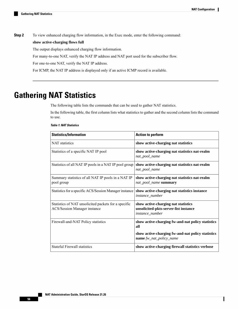
Step 2 To view enhanced charging flow information, in the Exec mode, enter the following command:
show active-charging flows full
The output displays enhanced charging flow information.
For many-to-one NAT, verify the NAT IP address and NAT port used for the subscriber flow.
For one-to-one NAT, verify the NAT IP address.
For ICMP, the NAT IP address is displayed only if an active ICMP record is available.
Gathering NAT StatisticsThe following table lists the commands that can be used to gather NAT statistics.
In the following table, the first column lists what statistics to gather and the second column lists the commandto use.
Table 1: NAT Statistics
Action to performStatistics/Information
show active-charging nat statisticsNAT statistics
show active-charging nat statistics nat-realmnat_pool_name
Statistics of a specific NAT IP pool
show active-charging nat statistics nat-realmnat_pool_name
Statistics of all NAT IP pools in a NAT IP pool group
show active-charging nat statistics nat-realmnat_pool_name summary
Summary statistics of all NAT IP pools in a NAT IPpool group
show active-charging nat statistics instanceinstance_number
Statistics for a specific ACS/SessionManager instance
show active-charging nat statisticsunsolicited-pkts-server-list instanceinstance_number
Statistics of NAT unsolicited packets for a specificACS/Session Manager instance
show active-charging fw-and-nat policy statisticsall
show active-charging fw-and-nat policy statisticsname fw_nat_policy_name
Firewall-and-NAT Policy statistics
show active-charging firewall statistics verboseStateful Firewall statistics
NAT Administration Guide, StarOS Release 21.2656
NAT ConfigurationGathering NAT Statistics
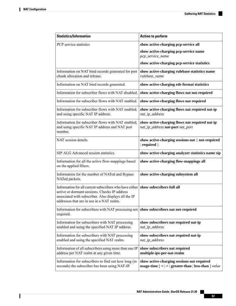
Action to performStatistics/Information
show active-charging pcp-service all
show active-charging pcp-service namepcp_service_name
show active-charging pcp-service statistics
PCP service statistics
show active-charging rulebase statistics namerulebase_name
Information on NAT bind records generated for portchunk allocation and release.
show active-charging edr-format statisticsInformation on NAT bind records generated.
show active-charging flows nat not-requiredInformation for subscriber flows with NAT disabled.
show active-charging flows nat requiredInformation for subscriber flows with NAT enabled.
show active-charging flows nat required nat-ipnat_ip_address
Information for subscriber flows with NAT enabled,and using specific NAT IP address.
show active-charging flows nat required nat-ipnat_ip_address nat-port nat_port
Information for subscriber flows with NAT enabled,and using specific NAT IP address and NAT portnumber.
show active-charging sessions nat { not-required| required }
NAT session details.
show active-charging analyzer statistics name sipSIP ALG Advanced session statistics.
show active-charging flow-mappings allInformation for all the active flow-mappings basedon the applied filters.
show active-charging subsystem allInformation for the number of NATed and BypassNATed packets.
show subscribers full allInformation for all current subscribers who have eitheractive or dormant sessions. Checks IP addressassociated with subscriber. Also displays all the IPaddresses that are in use in a NAT realm.
show subscribers nat not-requiredInformation for subscribers with NAT processing notrequired.
show subscribers nat required nat-ipnat_ip_address
Information for subscribers with NAT processingenabled and using the specified NAT IP address.
show subscribers nat required nat-ipnat_ip_address
Information for subscribers with NAT processingenabled and using the specified NAT realm.
show subscribers nat requiredmultiple-ips-per-nat-realm
Information of all subscribers using more than one IPaddress per NAT realm at any given time.
show active-charging sessions nat requiredusage-time [ < | > | greater-than | less-than ] value
Information for subscribers to find out how long (inseconds) the subscriber has been using NAT-IP.
NAT Administration Guide, StarOS Release 21.2657
NAT ConfigurationGathering NAT Statistics

Action to performStatistics/Information
show ip pool nat-realm wideNAT realm IP address pool information.
show session disconnect-reasonsCall drop reason due to invalid NAT configuration.
NAT Administration Guide, StarOS Release 21.2658
NAT ConfigurationGathering NAT Statistics
Related Documents