NASAContractorReport15900 Adhesives for Bonding RSI Tile to GrPI Structure for Advanced Space Transportation Systems K.E. Smith, C.L. Hamermesh, P.A. Hogenson ROCKWELL INTERNATIONAL CORPORATION Los Angeles, CA 90009 Contract NAS1-15152 April 1979 National Aeronautics and Spa:ce Administration Langley Research Center Hampton, Virginia 23665 AC 804 827-3966 i https://ntrs.nasa.gov/search.jsp?R=19790012947 2018-07-09T02:30:59+00:00Z

Welcome message from author
This document is posted to help you gain knowledge. Please leave a comment to let me know what you think about it! Share it to your friends and learn new things together.
Transcript

NASAContractorReport15900
Adhesives for Bonding RSI Tileto GrPI Structure for Advanced
Space Transportation Systems
K.E. Smith, C.L. Hamermesh,
P.A. Hogenson
ROCKWELL INTERNATIONAL CORPORATION
Los Angeles, CA 90009
Contract NAS1-15152
April 1979
National Aeronautics and
Spa:ce Administration
Langley Research CenterHampton, Virginia 23665AC 804 827-3966
i
https://ntrs.nasa.gov/search.jsp?R=19790012947 2018-07-09T02:30:59+00:00Z

i
!

FOREWORD
This report was prepared by the Satellite Systems
Division of Rockwell International under Contract NASI-
15152 for the LanEley Research Center, National Aero-
nautics and Space Administration. The contract was
initiated November Ii, 1977. This report covers work
from that date through December 20, 1978.
The prosram at Rockwell International was directed
by the Design and Materials Group under the supervision
of L.L. Bissins. The work was coordinated by K.E. Smith.
Materials screenins, mixture formulation, and exploratory
testing were conducted at the Science Center under direc-
tion of Dr. C.L. Hamermesh, principal investigator,
assisted by Mrs. Carolyn M. McArthur and J. Ratto. Veri-
fication testinE was by the Laboratories and Test Group
at Space Division under the supervision of Stanley Kritzer.
The test proEramwas conducted by P.A. Hosenson. Chemical
characteristic tests were conducted by D.W. Houston, Jr..
Outline specifications were prepared by R.L. LonE;
these are included as Appendix C.
iii

Section
i
2
3
4
5
6
CONTENTS
INTRODUCTION ...........
SUMMARY ............
REQUIREMENTS ...........
Task I. Establish Criteria for Selection . . .
Task II. Selection of Bond Evaluation Techniques . .
Task III. Adhesive Screening .......
Task IV. Adhesive System Characterization . . .
Task V. Procurement Specification Outline . . .
Task VI. Process Specification Outline ....
SCREENING AND SELECTION ........
EXPERIMENTAL TESTS ..........
VERIFICATION TESTING .........
6.1 Introduction .........
6.2 Purpose ...........
6.3 Conclusions ..........
6.4 Procedure and Results .......
6.5 Refurbishment .........
6.6 Recommendation .........
APPENDIXES
A. Experimental Results - ii Nov. 1977 to I March 1978
B. Experimental Results - March 1978 Through June 1978
C. Specification Outlines .......
REFERENCES .........
Page
i
3
7
7
8
9
i0
Ii
ii
13
15
21
21
22
22
23
61
64
67
89
97
123
v


ILLUSTRATIONS
Figure
i0
Ii
12
13
14
15
16
17
18
19
20
21
22
23
24
25
26
27
28
29
30
31
32
33
34
35
36
SQS Molecular Structure .......
Comparison of FWT Test Specimen Failures ....
Comparison of FWT Test Specimen Failures ....
Mechanical Mixer ..........
Tensile Lap Shear Panel and Specimens .....
Tensile Lap Shear Panel and Specimens .....
Tensile Lap Shear Strength Versus Catalyst
Versus Concentration .......
Cure, Time ............
TGA Curves for RA59 Prepared at Different Weight
Percentages of Curing Agent .......
Shear Strength Versus Temperature Exposure . . .
Lap Shear Strength Versus Aging ......
Double-Lap Strap Shear Specimen ......
Lap Shear Strength Versus Test Temperature -
Graphite Substrate .........
Lap Shear Strength After Thermal Exposure .....
Lap Shear Strength at Temperature After Thermal Exposure .
Adhesive After Lap Shear Testing .......
Room Temperature Exposure .........
Dispersion - 0.5 Hour at 370C ........
Dispersion - I Hour at 370C ........
Dispersion - 4 Hours at 370C ........
Dispersion - 6 Hours at 370C ........
Dispersion - 8 Hours at 370C ........
Flatwise Tensile Test Specimens Before and After Test . .
Flatwise Tensile Tests After 4 Hours at Temperature . .Flatwise Tensile Tests at 700F after 4 Hours at
Temperature ..........
TGA Curves for RA59 Prepared at Different Weight
Percentages of Curing Agent ........
TMA Curves for RA-59 at 1-Percent Catalyst Concentration .Endotherm of 908 Resin ........
DSC Run on 908 Resin Sample .......
908 Resin IR Spectra - Room Temperature .....
908 Resin IR Spectra - 300F for i Hour .....
908 Resin IR Spectra - 600F for i Hour ....
Composite Panel Before Testing .......
Tile Cracks ..........
Tile Cracks ...........
Failed Tile Data .......
Page
16
19
20
25
27
28
29
30
31
36
37
38
4O
41
42
43
43
46
46
46
46
47
47
48
49
50
52
53
55
57
57
58
62
63
63
64
vii


TABLES
Table
1
23
Shore A Hardness Versus Catalyst ConcentrationVersus Time .........
Tensile Lap Shear Strength ......Lap Shear Test Data Spread ......
Page
32
34
44
ix


i. INTRODUCTION
The primary structure of the Shuttle orbiter is presently built of aluminum
alloy having a design temperature limit of 350F (177C). A thermal protection
system (TPS) consisting of fused silica tiles is bonded to the outer surface to
protect the skin from temperatures that may reach 2650F (1454C) during
reentry. As a key element of the Project CASTS (Composites for Advanced Space
Transportation Systems), serious consideration is being given the use of
filamentary composites as the structural material for selected orbiter compo-
nents, such as the aft body flap. Graphite/polyimide (Gr/PI) laminates, which
are being developed under the CASTS Program, have the capability of sustained
operation at 600F (316C). This would provide the potential for weight
savings, with a corresponding increase in payload capability. Weight savings
would result primarily from the use of thinner tiles. The possibility also
exists of eliminating the strain isolation pad (SIP) which is now bonded
between the tiles and the orbiter skin. This would result in further weight
savings and reduced manufacturing costs.
The limiting factor in taking full advantage of the 600F (316C) capability
offered by the composite is the adhesive used in the TPS. The RTV 560 silicone
adhesive now used has a maximum design temperature of 500F (260C). Prior to
undertaking the current contract, the Satellite Systems Division, supported by
Rockwell's Science Center, conducted an experimental program aimed specifically
at developing adhesive systems to operate over a temperature range of -300F to
+700F (-184C to 370C). The results of this effort are presented in Reference i.
Ability to perform over this range would provide adequate margin for the
i

foreseeable future. Emphasis was placed on developing polymer systems that
could be bonded at room temperature by techniques compatible with manufacturing
procedures to be applied during initial construction and in the field. This
effort provided a starting point for initial screening of adhesive candidates
for development under the current contract program.
2

2. SI_ARY
The main objective of the program was to develop a system for bonding RSI
tiles to a Gr/PI composite substrate which would withstand the full range of
environmental conditions imposed on the orbiter. While it was recognized that
complete environmental testing to verify this capability was beyond the pro-
gram scope, it was intended to provide high confidence, in the form of test
data, that a bonding system with such capability had been developed. The
program was successful in satisfying this objective. The bonding system,
designated RA 59, consists of a mixture of glass (sesquisiloxane, SQS) resin
in RTV 560 silicone. RA 59 has desirable processing characteristics similar
to RTV 560 and, based on limited data, has the capability of withstanding all
environmental and operating conditions required of the orbiter. It has
material properties similar to the RTV over the normal operating range for
RTV (-175F to +50OF) but extends the upper operating range to 70OF. Both
adhesives appeared to perform satisfactorily down to -300F when used to bond
RSI tiles directly to a Gr/PI composite substrate.
While results of most recent tests by both lap shear and flatwise
tensile test methods exhibit considerable data scatter, a significant number
of data points for the RA59 are in the 65-psi failure range both when tested
at, and after exposure to, 70OF. This is over two times the best shear and
tensile values obtained with RTV 560 at this temperature. Perhaps the most
important overall conclusion to be drawn is that with a thorough understanding
of the critical parameters involved, the higher values should be obtained

conslstently with the RA59. This would be of particular significance if higher
strength tiles were to be used in a "hard-bonded" configuration as is now
being considered for the aft body flap.
While not crucial to qualification, it would be highly desirable to
develop an understanding of the chemical interractions involved in the
mixture. Such understanding could lead to both optimization of materials and
better consistency of the product. It is recommended therefore that the
current program be continued to provide this information prior to undertaking
a program of flight qualification.
This report describes the initial materials screening, formulation and
exploratory testing conducted by the Science Center followed by the results of
verification tests conducted by the Space Division. This effort complies with
the Contract Statement-of-Work (Reference 2)p Tasks I through IV. In additionp
outline specifications for processing and procurement are provided in response
to Tasks V and VI. Sufficient data on materials and processing could not be
obtained to support preparation of detail specifications.
The original program plan included both direct bond and SIP (strain
isolation pad) applications. By mutual agreement, SIP was dropped from
consideration during the early stages of the program.
We belleve that the contract effort has resulted in a new class of high
performance adhesives with RA 59 as the first product of this class, and that_
with further development, RA 59 type resin should fulfill the objectives of
application to Gr/Pi composite retrofit components for the orbiter. It is
recommended that the current effort be continued to resolve the questions
previously raised and to characterize and optimize adhesives of this type for
Project CASTS application wherever wide range temperature capability is needed.

The report contains a brief description of the experimental work
conducted at the Science Center and a detailed discussion of verification
testln8 by the Satellite Systems Division.


3. REQUIREMENTS
TASK I. ESTABLISH CRITERIA FOR SELECTION
The adhesive must serve as a satisfactory bond between the RSI tiles and
Gr/PI substrate over the full environmental and operational regimes of the
orbiter. Figures i and 2 along with Table I of the SOW define Shuttle orbiter
design criteria. While these requirements are well defined, the actual
conditions existing at the bondline and at each interface are not well known.
In addition, processing and refurbishment must be considered. However, except
for temperature capability inherent to the characteristics of the material,
the suitability of the adhesive, RTV 560, to perform as a bond agent for
TPS tiles has been determined primarily by empirical methods. Based on
experience with RTV 560, the following criteria were selected as the basis
for evaluating a new, higher performance adhesive:
i. Minimum cohesive strength of 25 + 5 psi at 650 F (343C), 4 of 5
specimens, 2 batches.
2. When tested with tiles, all failures should be within the tile, not
at the bondllne (adhesive) or within the adhesive (cohesive). For
a valid test, failure within the tile must equal 8 psi or above
3. Thermal cycle tile�composite bond twice, allowing time to stabilize
followed by RT tests consistent with (2) above. Cycle limits will
be -300 to 700F as a goal with -250 to 600F required.
7 •

4. Manufacturing compatibility
Minimum potlife: 30 minutes
Maximum cure time at RT: 24 hours
Mastic-like consistency
Removable without dama2ing suhstrate
5. Envlronmental Exoosure
Humidity
Salt spray
Fungus
Fuel
U]traviolet
Acoustic
The capability of withstanding environmental exposure should be based on
Judgment considering the generic properties of the adhesive.
TASK II. SELECTION OF BOND EVALUATION TECHNIQUES
The following evaluation methods were selected which were consistent with
the scope of work while providing reasonable confidence that each of the
requirements had been addressed:
o Lap Shear Testing - Selected as the simplest method of determinin_
basic strength of the material and bond and determining failure mode.
o Flatwis_ Tensile Testing - More difficult and expensive than lap
shear. However, FWT tests provide a better simulation of actual
conditions end permit testing with tile as well as structural
adherends. A variety of conditions were imposed on lap shear and
FWT specimens to cover both thermal steady-state and cycling
situations over the range -300F to +700F.

o Direct-Bond/Cold Soak - 6" x 6" tile specimens were bonded directly
to Gr/Pi honeycomb panel and subjected to progressively lower soak
temperatures - as low as -300°F - to determine if failure occurred due
to differential contraction. Cold soak was followed by full tile
tensile te_tin_ (Process Quality Validation, POV).
o Cold Soak -Ti]e specim=ns were coated with adhesive and soaked at
temp=ratures as low as -300°F to determine if failure occurred due to
differential contrartio-.
o Refurbishment - Capability oF remnvin_ the test adhesive from the
Gr/Pi substrate without damage using simple mechanical methods and/or
solvents _s with the RTV 560 was to he demonstrated.
o Processing - C=pabilitv of mixin,, Preparing, and applying the
adhesive in reasonable quantities without imposinK difficult
constraints or controls was to be demonstrated.
Other method_ of test and analvsiswhich w_re to be used but for which
criteria for selection were not established included:
o Differ-ntial colorimetrv (DSC)
o Therm_-gravim, trir analysis (TGA)
o Thermo-mechanical analysis (TMA)
o IR spectrographic analysis
o Microscopic analysis
o Peel tests
TASK III. ADHESIVE SCREENING
Screening was accomplished by in-house effort prior to the starting
funded work under the contract to the point of concentrating on the RTV 560 -
glass resin mixtures. Results of preliminary tests, presented to NASA during

the third month, resulted in approval to proceed with these mixtures
exclusively and to eliminate any further consideration of using a strain
isolation pad (SIP).
TASK IV. ADHESIVE SYSTEM CHARACTERIZATION
Specimens were tested and analyzed using all of the methods selected for
evaluation as defined in Task II.
l0

TASK V. PROCUREMENT SPECIFICATION OUTLINE
An outline specification was prepared for procurement, including quality
control provisions.
TASK VI. PROCESS SPECIFICATION OUTLINE
An outline specification was prepared for processing the adhesive system.
11


4. SCREENING AND SELECTION
Under a prior IRD program wlthin Space Division, as reported in
Reference 1, extensive screening of materials was conducted which identified
two candidates with a potential for room temperature curing. These were
polyphenylquinoxalenes (PPQ) and sesqulsiloxanes (SQS). Experimental effort
at the Science Center developed the capability for processing and solvent
curing PPQ. However, the resin failed to meet criteria subsequently developed
(Section 3.0) from the standpoints of both processing and toxicity. SQS,
while nontoxic and capable of RT curing had insufficient 'body" and, upon
curing, was too friable to permit consideration as an RSI bonding agent. Yet
of all the materials identified, SQS-type materials alone appeared to offer the
potential for development to meet the full range of requirements. In an attempt
to combine the best propertles of SQS and RTV_ mixtures of the two resins were
prepared and evaluated as the initial work conducted under the contract program.
Experimental work involving these mixtures is summarized in the following
section and discussed in some detail in Appendices A and B.
13


5. EXPERIMENTAL TESTS
SQS polymers are of the general type described in Reference 3. Their
planer structure, as shown in Figure i, provides thermal stability without
cross-llnklng. The result predictably is the achievement of higher strength
once sufficient temperature has been achieved to result in cross-linklng. The
difficulty is in providing required characteristics at RT without destroying
the inherent ability to perform at high temperature.
For experimental tests, small quantities of three SQS resins were obtained
from Owens-Illinols. Designated by Ol as types i00, 650 and 908 glass resins (GR),
these had slightly differing formulations as indicated in Figure i (i.e., methyl,
phenyl, etc.). Glass resins, received in flake form, were ground, dissolved in
acetone and mixed with RTV 560. The most workable mixtures were initially
obtained with 30.5% GR (glass resin) 650 in RTV 560. Experimental testing was
concentrated primarily on this mixture and variations thereof. RTV 560 was used
as a control throughout° Results of these tests indicated the following:
- The new mixture and the control have comparable strength at RT.
- The mixture has 2 x control strength at 600F and 4 x control at 700F.
- Similar results were obtained with and without SIP.
- The use of primer increased performance at RT but not at high temperature.
- Excursion to high temperature significantly increased subsequent bond
strength of the mixture but not of the control.
- Mixtures of GR in RTV 566 (a highly refined RTV 560) showed no different
results from those with RTV 560.
15

RTV 560- SILICONE
R
I
Si-
I
R
GLASS RESIN (OWENS ILLINOIS)- SESQUISILOXANE
Figure i. SqS Molecular Structure
16

Test results, shown in Appendix A, were presented to representatives of
the CASTS Program Management and members of the Materials Division on
March 7, 1978. At that time, based on results to date, authorization was
given to proceed with the remainder of the program and to emphasize the direct
bond application, eliminating SIP from future test specimens.
Subsequent to the March meeting problems were encountered in which mixtures
of RTV 560 and GR 650 were often lumpy and difficult to bond. Upon recommendation
by OI a change was made to type 908 as being a more stable formulation with
longer shelf llfe. Additional experimental work led to selection of a mixture
of 25% GR 908 in RTV 560 as the "test" adhesive. This was subsequently
designated RA 59.
Experimental testing continued to evaluate RA59 at temperatures to
700F. However test specimens and conditions were modified in an attempt to
Better simulate the orbiter application. RSI tile specimens were cut from Li
900 material obtained as manufacturing rejects. These were 1.5 inch diameter
cylinders one-half inch thick. Tiles were bonded to Gr/PI adherends which
had previously been sandblasted or scrubbed using "Bear Tex" to pass a
water-break test.
Flatwise tensile test (FWT) specimens were then fabricated. Early tests,
conducted at soak temperatures of up to 700F in an Instron, were made in which
the entire FWT specimen was subjected to the test condition. This procedure
proved unsuitable for thermal cycling however due to failure of the HT424
adhesive at the brass block - Gr/PI bondline. Instead, cycling (temperature
excursion) was performed on the tile - Gr/PI specimen then brass blocks were
bonded and FWT tests conducted at room temperature.
17

The photograph of Figures 2 ano 3 show typica± failures occuring sub-
sequent to excursion testing. Failure of the RA 59-bonded specimens was
almost Invariably within the tile at tensile loads _ 12 psi. Failure of
RTV D60 control specimens almost invariably exhlblted some percentage of
adhesive failure at the tile interface.
18

i
o
P_
0
o
c_
_J
q_o
o
.,-I
u
_4
o
._P_
19

÷
QJ
qLJ
2O

6. VERIFICATION TESTING
6.1 INTRODUCTION
The laboratory development and verification test program was to evaluate
a modified RTV 560 with improved thermal stability at 700F. As previously
discussed development and initial testing had been accomplished at the Science
Center prior to initiation of verification testing.
The formulation for modifying RTV 560 silicone adhesive with a solid
silicone resin to increase its thermal stability was provided to the Space
System Group Materials and Processes Laboratory by the Rockwell International
Science Center. This material has tentatively been identified as RA 59. Goals
of the program were: to develop scale-up and processing techniques for
producing and using the adhesive; to perform thermo-chemical and mechanical
property tests; and to demonstrate the validity of the material through full
scale tile bonding and thermal cycling. In all testing, RTV 560 was to be
included as a control material.
Procedures for preparing RA 59 in one pound quantities were developed
which can be used as a basis for mixing larger amounts. Thermal cycling of
RSI tiles bonded directly to a graphite/polylmlde honeycomb structure resulted
in acceptable performance by both adhesive materials. Thermo - chemical
testing of RA 59 gave predictable results based on known characteristics for
each component and demonstrated an improvement in thermal stability for RA 59
over RTV 560.
During mechanical property testing, which consisted of tensile adhesive
tests, several questions were raised as data were accumulated. Initial data
indicated that increasing exposure time at 700F tended to increase the
strength of RA 59 while it degraded the properties of RTV 560. Additional
testing at various temperatures up to 700F didn't show as distinct an improve-
21

ment over RTV 560 and subsequently, the thermo-chemical analysis was broadened
to investigate the RA 59 more thoroughly. Questions raised during this effort
which should be answered prior to initiating a qualification program included.-
I) is there a chemical reaction among the Si containing components of the
adhesive system; 2) does the catalyst used act selectively with RTV 560 or
randomly with each silicone; 3) would a separate catalyst for each component
improve silicone interaction and system performance; 4) what is the primary cause
of the wide range of tensile adhesive values at 700F.
6.2 PURPOSE
The purpose of this laboratory phase of the program was to verify that
the adhesive formulation provided by Rockwell International Science Center
personnel is a valid material for consideration in bonding RSI tile to
graphite composite structures. This goal was to be accomplished by performing
the following investigations
I. Develop processing techniques for the preparation of large batches
of RA 59 adhesive compound and evaluate working characteristics.
2. Determine the thermo-chemlcal properties of the cured adhesive
formulation.
3. Determine the adhesive properties of RA 59 after thermal exposure.
4. Evaluate the performance of RA 59 when used to Join RSI tile to
polyimlde/graphite composite honeycomb panel during exposure to
temperatures over the range -300 to 700F.
5. Compare each of the above investigations with RTV 560 baseline
adhesive.
6.3 CONCLUSIONS
In general, it can be concluded from the results of this investigation
that RA 59 is comparable to RTV 560 in all significant aspects and has
superior elevated temperature adhesive properties after exposure to temperatures
at or above 600F. Specific conclusions include:
22

i. Techniques for mixing Owens-Illinois 908 silicone resin into RTV 560
on a large scale were developed and demonstrated in the preparation
of three separate batches of RA 59 in quantities up to one pound.
2. Thermo-gravimetric analysis data indicate that cured RA 59 and RTV 560
demonstrate similar thermo-chemical characteristics at elevated
temperatures.
3. In general, increasing exposure time at 700F increases the strength
of RA 59 while degrading the properties of RTV 560.
4. These were no apparent cracks in RSI tile bonded directly to a
graphite composite honeycomb skin with RA 59 and RTV 560 after
cycling to -300F. A layer of each adhesive applied to tile
surface but unrestrained by bonding to graphite composite laminate
resulted in tile cracking during thermal cycling to -300F.
6.4 PROCEDURE AND RESULTS
The laboratory effort performed during this program consisted of three
separate subtasks: (i) RA 59 preparation and process development; (2) mech-
anical and physical property determination; and (3) performance demonstration.
Each of these are discussed in subsequent paragraphs.
6.4.1 RA 59 Preparation and Process Development
Initial small batches of adhesive mixture were prepared by dissolving
Owens-Illinois 908 resin in acetone, adding small quantities of that mixture
to RTV 560, stirring until a smooth paste is obtained and, finally, allowing
acetone to evaporate from the compound. Hand mix tlmewas approximately
30 minutes and acetone evaporation required up to 17 hours.
23
For large batch scale-up preparation of the RA 59 adhesive mixture,
several automated techniques were investigated.
i. A mixture of 3.3 grams OI 908 and 18 grams acetone was added to
10 grams of RTV 560 in a pint can and agitated on a Red Devil paint
shaker for one hour. There was no mixing of the 908/acetone
solution with the RTV 560.
2. Twenty five grams of acetone were combined with 75 grams RTV 560
and agitated 15 minutes on paint shaker. In a separate container
25 grams of 908 were dissolved in 50 grams of acetone. The two
mixtures were poured into a pint can 1/4 full of clean, dry,
ceramic pebbles and agitated on paint shaker for one hour. There
was no mixing of 908/acetone with RTV 560.
3. A mixture of 66 grams Ol 908 resin and 154 grams acetone was added
incrementally to 150 grams of RTV 560 in a pebble mill container
1/3 full of ceramic pebbles. After five hours of rotation, mixing
of all components was incomplete.
4. Based on failures of the above techniques, it was concluded that a
means of duplicating hand mixing using mechanical equipment should
be explored. Therefore, a metal-blade stirrer was attached to an
air-powered drill motor as shown in Figure 4. The motor was set
at 180 RPM with blade in RTV 560 and 908/acetone mixture was added
in 5-10 cc quantities at i0 minute intervals. Three batches of
RA 59 material ranging in size from 266 to 532 grams were successfully
prepared using this technique.
24

Figure 4. Mechanical Mixer
In order to evaluate RA 59 as an adhesive, three processing questions
were investigated: (i) the optimum percentage of di-butyl tin di-laurate
catalyst (Thermalite, T-12) required to provide optimum mechanical properties
and processing time; (2) cure time required for maximum properties; and
(3) need for a primer for bonding to materials other than silicone or silica.
These questions were investigated by means of tensile lap shear
adhesive tests, Shore A hardness measurements, peel adhesive tests and
thermo-gravimetric analysis. RA 59 was prepared from RTV 560 batch 719 and
OI 908 batch 51666 using the power driven mixer technique described above.
The RA-59 was catalized with 0.5%, 1.0% and 1.5% T-12 and used to prepare the
following specimens:
25

Lap Shear - per Federal Test Method Standard HMH-A-132 using 0.050-inch
steel adherends (See Figures 5 and 6) with and without SE4155 primer,
minimum 1.5 psi dead weight pressure with 0.Ol0-inch wire in bond line
to control thickness.
Hardness -Material cast in aluminum cup resulting in specimen i/4-inch
thick by 2 inches in diameter.
Peel - T-peel specimen per ASTM using 0.020-inch aluminum adherends,
with and without SE4155 primer, and minimum 1.5 psi dead weight pressure.
Thermo-gravimetric Analysis - catalyzed RA 59 de-gassed under vacuum
and cast i. x i. x 0.187-inch thick specimens. In all cases control
specimens were prepared from the same batch of RTV 560 and T-12 catalyst.
Results of the process variable investigation indicated that: (i) 1.0%
catalyst concentration (of the RA 59 mixture which is 1.3% of the RTV 560
present) is optimum for adhesive properties; and (2) use of SE4155 silicone
primer substantially improves adhesion to metallic substrates. In addition,
maximum cure of RA 59 with 1% catalyst is achieved within 15 days. However,
90% cure (as measured by hardness) occurs within three days and bonded
components could be handled within 48 hours.
Data to substantiate these conclusions are summarized in Figures 7
through 9 and Table i. Figure 7 gives the results of lap shear testing of
specimens at room temperature after exposure to 700F for four hours. Curd
time as indicated by Shore A hardness is shown in Table i and Figure 8.
The effect of thermal exposure in air as indicated by weight loss for RA 59
with varied catalyst concentration is given in Figure 9. T-peel testing was
found to be an invalid method of quantitatively determining the effect on
26

Ii
!
I
a _tA +-0e4"
ASSEIvmLEDP_J_,nSl.
plI_I'NS/_IS IH IHCklES
_L
t
-(D-
Ii
II
m m
' II!
1
.050 _.C_ er_ies_4
Figure 5. Tensile Lap Shear Panel and Specimens
27

Bonded Configuration Failed Specimen Halves
Figure 6. Tensile Lap Shear Panel and Specimen
adhesion of the use of primer. This was because the modulus of aluminum,
even in the "S" condition, was too high to permit proper bending of the
specimen before adhesive failure occurred at the bond line. Instead, the
recommendation to use primer is based on qualitative information such as the
failure of un-primed lap shear specimens during handling and the total
adhesive failure mode (no adhesive on metal surface) for all peel specimens
and most lap shear specimens bonded without primer. Based on the data
produced during this process investigation phase of the program, all sub-
sequent specimens were made from RA 59 catalyzed with 1.0% T-12 and primer
was used on all surfaces which were not silicone or silica.
28

TENSILE LAP SHEAR STRENGTH VS CATALYST CONCENTRATION
TESTED AT R.T. AFTER 4 HOURS AT 700F
• = RA59WITH PRIMER
0 = RA59 NO PRIMER
+ = RTV 560 PRIMER
=="I--.
;i¢IJJ
PP
IJJ
,.pO_
O.
150
100
5O+
+,
•-.,, ,. / 0
.5 1.0 1.5
%CATALYST
Figure 7. Tensile Lap Shear Strength Versus
Catalyst Concentration
29

[
E
I
! i :m
: i
! .... !
SS:INQHYH Y :IUO HS
I
i
3O

4!
i
i
!
!
[*
• " t " " "
;0"%"REFER TO
..... I
RTV 560CONTROL,1%C.R.
J
300i
TEMPERATURE(°C) i
PI" iFigure 9.
J DUPONT951TGA/940 TA
I HEATING RATESC/MININ AIR
4O0 5OO
TGA Curves for RA59 Prepared at Different Weight Percentages'
of Curing Agen£
31

Table I. Shore A Hardness Versus Catalyst Concentration Versus Time
Material
RA-59
RTV-560
RA-59
RTV-560
RA-59
RTV-560
CatalystConcentration
.5
.5
1.0
1.0
1.5
1.5
1
Soft
5O
2O
5O
20
5O
Days
2 3 4 15 25
Soft lU 30 40 40
50 50 50 50 50
40 45 50 55 55
50 50 50 55 55
45 45 50 52 55
50 50 5u 54 54
30
40
50
55
55
60
55
32

During the preparation, use and evaluation of RA 59, the effect of
additional material and process variables on mechanical and physical properties
was studied. Variables noted and/or evaluated included physical appearance
of RA 59 compound prior to catalyst addition, RA 59 batch variation relative
to RTV 560 batch and shelf life of RA 59 mixture. Evaluation of variables
was primarily based on lap shear testing, however, visual observation and TMA
testing was also used.
It was noted tnat smootnness of R_ 59 mlx varied between batches of the
RTV 56U component as shown by tne foAlowlng materlal combinations:
Supplier's Batch
No.
RTV 560 Ol 908
719 51600
719 51666
731 51666
719 51666
Date
Prepared
7/12
7/3i
8/4
9/15
RA 59 Mixture Appearance
Smooth-no lumps or graininess
Smooth-no lumps or graininess
Granular, sand filled
Smooth-no lumps or graininess
(This condition was also noticed at the Science Center during the experimental
phase of the program.) Lap shear test data were tabulated to correlate
RA 59, RTV 560 and Ol 908 batch number and RA 59 shelf life with lap shear
strength. These data which are presented in Table 2 show no trend among
these variables and therefore, may not be significant relative to RA 59
performance. However, the spread in tensile data noted in a subsequent
section of this report (Figure 14) may result from and be controllable by
material or processing variables. Areas for further investigation include
iron oxide particle size control, Ol 908 resin variables and effect of time after
catalyzation.
33

Table 2. Tensile Lap Shear Strength RA 59
Test Temp/Conditioning Temp (psi)*
RA-59 RTV 560 GR 908 Fab
Spec. Batch Batch Batch Date RT/RT RT/700 700/RT
1-2 50 GR 719 51666 7/24 126
V-2 2 731 " 8/9 128
V24 2 " " 9/1 54
V6 2 " " 8/9
V25 2 " " 9/1
V9 2 " " 8/9 200
VII 2 " " 8/9 245
VI6 2 " " 8/9 238
VI7 2 " " 8/9 220
V26 2 " " 9/1 360
V27 2 " " 9/1 18
V36 2 " " 10/3 50
V37 2 " " 10/3
V38 3 719 " 10/3 80
V39 3 719 " 10/3
V42 2 731 " 10/3 190
V46 3 719 " 10/3 320
V41 2 731 " 10/3
V45 3 719 " 10/3
V40 2 731 " 10/3
V44 3 719 " 10/3
700/700 RT/175 700/175,=.
59
34
23
38
15 15
15 15
394
328
*The first temperature is that at which specimens were tested; the second
is that temperature at which specimens were soaked for 4 hours prior to
test. All values are an _verage of four specimens. Range of values is_
given in Table 3.
34

6.4.2 Mechanical and Physical Property Determination
The second subtask of the laboratory program consisted of examining the
effect of thermal exposure, humidity and R.T. aging on adhesion as measured
by tensile tests. In addition, thermo-physical properties of the RA 59 adhesive
as well as the Ol 908 resin were studied.
Since 700F is the temperature at which thermal degradation becomessevere
as shownby TGA(Figure 9), and since bond line temperature could approach
that temperature during Orbiter flight, the effect on adhesion versus time at
700Fwas determined. Steel finger specimens per FTMSMMM-A-132were primed
with SE 4155 and bonded with RA 59 using 0.Ol0-inch wire for thickness control
and 2.0 + 0.5 psi vacuumpressure. RTV560 specimenswere prepared
concurrently as control. Figure i0 gives the results of this study which shows
a direct correlation between lap shear strength and exposure time at 700F up to
eight hours. Cohesive failure (failure within the adhesive) occurred in all
specimens.
The effect of humidity and room temperature aging on lap shear strength
is under study with preliminary data given in Figure ii. Specimenswere
fabricated with those described in the preceeding paragraph. No effect was
noticed through two months aging.
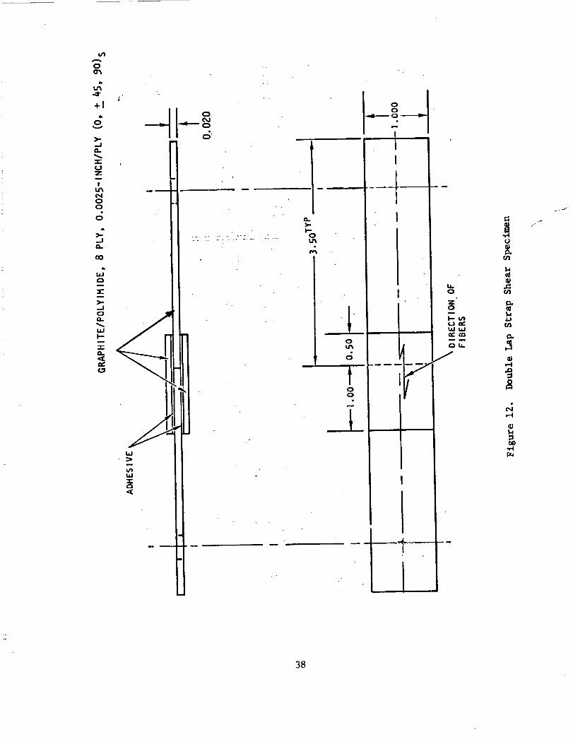
Adhesion to polyimide/graphite composite laminate was evaluated by means
of double lap-strap tensile shear specimenshownin Figure 12. Materials and
cure procedure were the sameas those described above except that wire was not
used for thickness control.
35

• RA 59 TESTED AT R.T.
(_) RA 59 TESTED AT 370C+ RTV 560 TESTED AT RT(_) RTV 560 TESTED AT 370C
1%CATALYSTPRIMED
Z
ft.
ulz
60O+
\
20O
150
.100
5O
0
\\
\
\
\
\
1 2 -3 4 5 6 7 8
HOURSAT 70OF'
Figure I0. Shear Strength Versus Temperature Exposure
36

I I
×®
>,<
®
®
®
(ISd)H19N:::IU18EIV3H8dV'l
oo
4..)
"0
p,..
"1"44J
I---4
v
.n .6)
-= :> :_¢JJ:Er-_o
4-) 0
37
I,I
GI
I-4
_4,.-I
3B

Test results shown in Figure 13 indicate much lower room temperature
values than with steel adherends for both RA 59 and RTV 650. Since failure
mode was cohesive it is felt that the lower values are a result of specimen
configuration rather than adhesion to graphite. In addition, the 15 psi
average at 700F for RA 59 with no prior conditioning correlates with 18 psi
average for steel adherends tested under the same conditions.
Thermo-physical property tests indicated that molecular changes occurred
within RA-59 at temperatures as low as 140F. A group of lap shear specimens
was prepared for testing after exposure to temperatures below 700F in order
to determine if low temperature post cure can provide high temperature
stability. In order to give some indication of shelf llfe of uncatalyzed
mixture the same batch of RA 59 and processing parameters used for the
700F study were used for these specimens. Testing was performed at room
temperature and at 175F 300F, 600F and 700F with prior conditioning for four
hours at those temperatures. Because of a reduction in tensile strength at
700F, a new batch (identified as batch 3) of RA 59 was prepared using RTV 560
Batch No. 719 which originally produced the smooth, non-granular mixture
discussed above. Batch 3 was a smoother mixture than Batch 2. However, as
shown in Table 2 and Figure 14, this factor of smooth vs. grainy RA 59 was
not always, or alone, significant in affecting shear strength.
Results of these groups of tests are shown in Figures 14 through 17.
Figure 14 gives lap shear strength at room temperature after a four hour
exposure at several temperatures. The spread in values at R.T. and 700F is
probably caused by unknown and uncontrolled processing variables such as time
between mixing and pressure application rather than erratic behavior of the
adhesive.
39

• RA 59
+ R'T'V560
DOUBLE LAPSTRAP SPECIMEN
TESTED AFTER 15 MIN. SOAKAT 370C
v
-,1,.'I.-
i.U
re.'
LLn"L,"t,nQ,.
5O0
100
5O
I0
25 100 200 3OO 400
TEST TEMPERATURE (°C)
Figure 13. Lap Shear Strength Versus Test Temperature
- Graphite Substrate
40

, _igure i4.
i :'[
3oo 4O0 500TEMPEBATURE (°F}
Lap Shear Strength After Thermal Exposure

100 2_ 300 _0 §_ 6_ 7_
TEMPERATURE(OF)
":Figure 15. Lap Shear Strength at Temperature After Thermal Exposure
/,42

r
iI- - •
Figure 16. Adhesive After Lap Shear Testing
Figure 17. Room Temperature Exposure
43

This conclusion is based on the narrow range of values from the four specimens
represented by each symbol on the graph. Tabulated data in Table 3 demonstrate
this point.
Panel No.
1-2
V2
V24
V36
V38
V9
VII
VI6
V17
V26
V42
V46
Table 3.
RA 59
Batch No.,m ,
i
2
2
2
3
2
2
2
2
2
2
3
Lap Shear Test Data Spread
Test
Temp.
RT
RT
RT
RT
RT
RT
RT
RT
RT
RT
RT
RT
Conditioning
Temp. °F
i
Test Values, Psi
700
700
700
700
700
RT
RT
RT
RT
RT
RT
RT
High
137
146
57
52
87
208
267
254
232
380
200
334
Low
120
114
52
49
79
190
235
220
188
336
188
300
Average
126
128
54
51
81
200
245
238
220
360
190
320
Figure 15 provides data from an investigation of a characteristic of RA 59
probably resulting from the presence of the GR 908 resin in the mixture. Early
tests showed an increase in strength at 700F at post cure time at 700F was
increased up to 8 hours (refer to Figure 10). Additionally, TGS curves showed
a "curing" type reaction as low as 175F. Therefore, the possibility of high
strength values at 700F after a lower temperature post cure was investigated
with results shown in Figure 15. Although the data indicate that the post-cure
temperature must be at least above 400F to provide a completely stable
material 70OF, adhesive strength is more than adequate after RT cure and no
adverse effects of aging have been noted in the absence of a post cure of
elevated temperature.
44

In comparing the exposed adhesive of tested lap shear specimens, as shown
in Figure 16, it was noted that the adhesive surface was granular for those
specimens which had not been exposed to elevated temperatures while specimens
exposed to 370C had a uniform rubber-like appearance. Microscopic examination
revealed a heavy concentration of small shiny glass-like globules dispersed
throughout the exposed adhesive. From specimens made at the same time with
the same adhesive mix but post-cured at 700F, the globules were smaller and
significantly fewer. It was apparent that the form and mode of dispersion of
the GR 908 in the RTV 560 matrix was changed by application of heat.
This phenomenon was pursued briefly by microscopic examination of failed
lap shear specimen adhesive after various exposure periods at 700F. Figures 18
through 22 are 20X microphotos that illustrate the change in dispersion of
GR 908 in RTV 560 as time at 700F is increased. Additional investigation is
suggested in this area.
Flatwise tensile tests were performed on RA 59 and RTV 560 under selected
cenditions. Specimen configuration is shown in Figure 23 and consists of
2 1/4 inch diameter aluminum blocks bonded together with the test adhesive.
Center hole is for a pin which assures alignment of the two halves during bonding.
The two specimen halves shown on the right of Figure 23 illustrate the cohesive
failure mode (failure within the adhesive rather than between adhesive and load
block) which was typical of all specimens tested.
Data bhown in Figures 24 and 25 demonstrate a significant advantage in
RA 59 at 700F in this specimen configuration. All RA 59 specimen were fabricated
using Batch 3 material and RTV 560 specimens utilized Batch 729.
Dynamic weight loss measurements for RA 59, prepared at different weight
percentages of curing agent, Thermolyte 12p are shown in Figure 26. A curve
45

Figure 18. Dispersion - 0.5 Hour
at 700FFigure 19. Dispersion - i Hour
at 700F
Figure 20. Dispersion - 4 Hours
at 700F
Figure 21. Dispersion - 6 Hours
at 700F
46

Figure 22. Dispersion - 8 Hours at 700F
_ii_i_̧_ i 0 _"i
ii _ _
I
Figure 23. Flatwise Tensile Test Specimens
Before and After Test
47

IL::
Flatwtse Tensile Tests After 4 Hours at Temperature
/

Figure 25.
-:±- 1
..:'::-.....:-.:l',:"lq..
200 300 400 500 600
TEMPERATURE(°F)
Flatwise Tensile Tests at 700F After 4 Hours at Temperature
49

4
I
• . L t .
I
Figure 26.
1%
- "%'REFERTO.... PERCENTCATALYST(pbw) .....
I .S%
i __ TEMPERATURE(°C) ! _ : _ _ • k
TGA Curves for RA59 Prepared at Different Weight Percentages
of Curing Agent (Repeated From Figure 9)
DUPONT951 TGA/990 TAHEATING RATESC/MIN.
• IN AIR
50

for RTV 560 control material is included for comparison. These curves were
obtained with a Dupont 951 TGAmodule and 990 Thermal Analyzer. _le runs were
made in air at a heating rate of 5C per minute. The curves show that rapid
oxidative degradation begins to occur at 700 to 725F. The differences
between RA 59 and RTV 560 are slight with respect to the total weight loss
profile to 10 to 15 percent, and the variations obtained would probably be
close to batch to batch variations if such a study were made.
Figure 27 presents TMA curves for RA 59 at 1 percent catalyst concentration.
The curves were generated with a 10 mil flat tip penetration probe at 20 g,
(approximately 50 psi), load. The runs were made with a Dupont 941 TMA and
900 Thermal Analyzer. Heating rate was 5C per minute. The curve for room
temperature cured material shows a phase change occurring at 71 to 84C. This
phase change is irreversible. The second curve is a re-run of the same sample
after exposure to 250C during the first run. The phase change is no longer
present. The third curve is for a sample, taken from the same specimen, con-
ditioned at 257C (500F) for 30 to 40 minutes in an air-circulatlng oven. As
can be seen, the phase change is gone.
This phase change is due to the 908 resin present in the RA 59 adhesive.
Expansion measurements at zero load with the _A expansion probe do not show
this phase change. Only the RTV 560 glass transition at -118 tO -I12C is
present. The penetration probe at load is required to show this change during
expansion. Differential Scanning Calorimetry (DSC) runs on neat 908 resin
readily show this phase change. Figure 38 shows an endotherm at 61C for as-
received resin. Repeated re-runs on the same sample show the absence of the
endotherm but the presence of a slope change characteristic of a glass transition.
51

I
i
_d;Z
I=..J
n-O
_N3_33V_dSlG 3_OBd
,w,I
0
0
52

0c,3000'_
dZ
I-
0,..
SAMPLE '
OX3
53
.RUN NO.'
.I.V OGN3
,.I k,__ o
_1 I11
U _
uo _;. N
I--

As the re-runs are carried out to higher temperature the temperature of the slope
change increases. Figure 29 presents a DSC run on the same sample used in the
Figure 28 DSC runs after sample conditioning at 600 F for i hour. The apparent
glass transition is now gone.
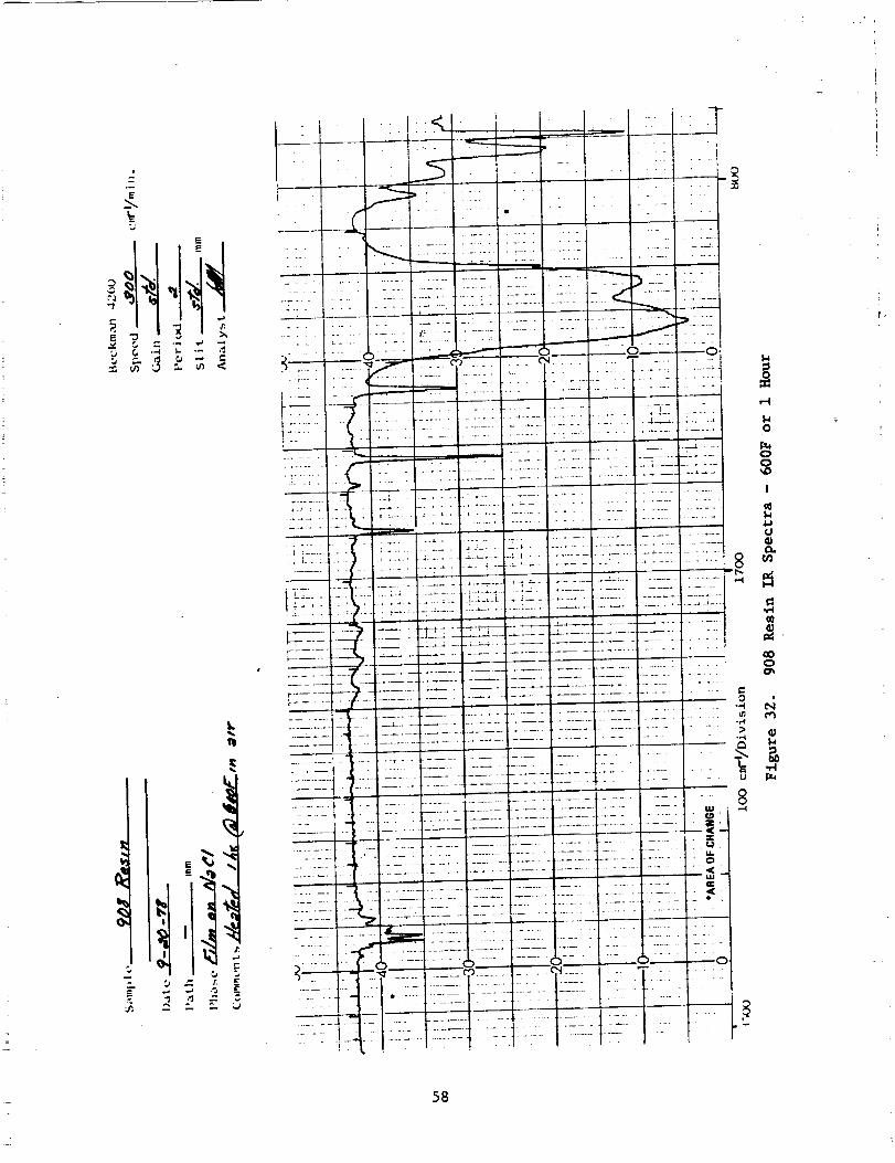
In order to further characterize the 908 resin a film on sodium chloride was
prepared for infrared (IR) analyses. The film was cast from carbon tetrachlorlde,
and, after air dry, dried in a vacuum oven for 4 hours at 86F. Figures 30, 31
and 32 show the 111 spectra for the same 908 film after, respectively, room
temperature application, 300F for 1 hour, and 600F for 1 hour. The spectrum
for the 300F conditioning shows a reduction in the absorption bands at approxi-
mately 3400 and 890 wavenumbers. After i hour at 600F these bands are completely
gone. The absorbance at about 3400 can be assigned to the bonded SI-OH stretch
and the absorbance at 890 tentatively to the silicone hydroxy assymetric stretch.
The spectrum for as-received resin is, generically, typical of a methyl, phenyl
silicon.
54

O
OO
SAMPLE- RUN NO."
!
OX3 .[ _-7 OGN3
55

I
uQJ
56

IIl'
57
I
..... i
0
o
oo
I
u_J
H
_J
00o
_J
J !i!
i
!
I
.... i
I-I
o
0_o
!
J_Ju
r_
Go
_o
58

6.4.3 Performance Demonstration
The use of RA 59 as a hard bond adhesive (no SIP) for bonding RSI tiles
to polylmlde/graphite skin homeycomb sandwich structure was demonstrated.
RSI tiles with RCG coating were bonded to the composite honeycomb panel with
RA 59 and RTV 560. The panel/tile assembly was cycled several times from room
temperature to temperatures down to -300F with a one hour soak at temperature
and examined for cracks after each cycle. No cracks were observed after the
final cycle. A full tile tensile test was subsequently performed and resulted
in tile failure at relatively low loads. Details were as follows:
Components:
Honeycomb Panel - 4 ply skins each 0°, +45 °, 90 ° skybond 703/eelion 3000
3/16" HRH 4# cure, FM34 adhesive.
Tile = 2-1/2" X 6" X 6", Nos. 0060, 0065, 0075, 0082
RA 59, Batch #2 (Ref. Page -35)
RTV 560, Batch 731
Procedure
Tile _bonding surface lightly sanded and blown clean with compressed air.
Adhesive evenly spread over bonding surface as follows:
Tile #0065-RA59, 5 grams
Tile #0060 - RTV560, 4.5 grams
59

Composite bonding surface scuff sanded and primed with SS4155
(MB0125-050) Batch #LCK 4319. Approx. 0.008" of each adhesive applied
to bond surface area. Tile adhesive cured under 4" Hg at R.T. for 24 hours.
Evaluation of adhesive applied to tile bonding surface and exposed to
cryogenic temperatures:
#i - Tile #0022
#2 - Tile #0075
in., RA 59
in., RTV 560
Light sand, air blow,
apply i0 mil (8.3 grams)
adhesive to each tile
Specimens described abovewere located in an environmental chamber and
exposed to the following thermal cycles:
Cycle #
i
2
3
Temperature Cycle (°F)_
R.T. To -125, i Hr. @ -125, -125 to R._.
R.T. To -175, i Hr. @ -175, -175 to R.T.
R.T. To -225, i Hr. @ -225, -225 to R.T.
4
5
R.T. To -250, i Hr. @ -250, -250 to R.T.
R.T. To -300, i Hr. @ -300, -300 to R.T.
Observations
No Change
No Change
No cracks in bonded
tiles. Some shrinkage
of RA 59 from one lose til_
Same as Cycle #3
Cracks in tile Just above
adhesive - both tiles,
more severe in RA 59.
Possible crack in tile at
Bond in bonded panel
*No apparent cracks in tile at adhesive interface of bonded specimen.
Ice accumulated in gaps between tile corners and substrate, however, no
propagation was observed.
60

Somerecession of adhesive from tile edge was noted on both individual specimens.
This was more severe on RA 59.
6" X 6" X 1/2" AI load plate bonded to top surface of each tile. Tensile
load applied and load at failure recorded.
2RTV 560 - 85 lb. load, 36 in. area = 2.36 psi, tile failure
2RA 59 -160 lb. load, 36 in. area = 4.44 psi, tile failure
Figure 33 shows the bonded tile/composite panel prior to thermal cycle and
tensile testing. Figures 34 and 35 illustrate tile cracks caused by unrestrained
adhesive contraction which occurred during the -300F cycle. Figure 36 shows
that failure occurred in the tile rather than at the adhesive bond line during
tensile testing. The low contraction coefficient of graphite/polyimide laminate
probably restrains normal adhesive contraction for both RTV 560 and RA 59 thus,
preventing the type of failure found in adhesive coated but unbonded tiles.
6.5 REFURBISHMENT
It was demonstrated that the RA 59 adhesive could be removed from the GrPi
composite substrate by scraping with a dull plastic scraper. This was easily
accomplished on specimens regardless of previous thermal conditioning. The
substrate could be refurbished by light "scuff" sanding with fine sandpaper.
61

0
IJ
0
Q
o'3
._
62

Figure 34. Tile Cracks
Figure 35. Tile Cracks
63

Figure 36. Failed Tile
6.6 Recommendations
Several questions developed during the verification test program which
should be considered prior to entering a qualification phase. Specific areas
which require further investigation are listed in the following paragraphs.
i. Probably the most important item is determining the curing mechanism
(polymerization, cross-linking, etc.) of the two silicone components.
The effect of T-12 catalyst on each component, the addition of A-f100
silicone as a catalyst for the OI 908, and the combinedeffect of these
with various amounts of heat on cure mechanismall need study in order
to optimize processing and properties.
2. The large data spread which is probably caused by someunidentified
variable such as pot life should be determined. This should lead to
the ability to obtain consistently high values at all temperature
ranges and thus, would show a clear advantage for RA-59 over RTV560.
for high-temperature applications.64

3. Direct bonding thermal cycle and tensile tests should be conducted
with 22PCF tile projected for use on orbiter. Previous tests with
LI900 tile resulted in all failures being within the tile at low tensile
values characteristic of the latter. The use of higher strength tile
should give a better indication of the actual strength of the adhesive
or bond.
4. The phenomenon of GR 908 dispersion within the RTV 560 matrix with
heat addition should be investigated. There is some indication this
is a function of RTV 560 batch variation; thus, the effect of iron
oxide particle size within RTV 560 would be included in the study.
5. A study of the cure mechanism of GR 908 alone was performed using IR
techniques; however, this could not be accomplished with the RA 59
mixture due to iron oxide within the RTV 560. An attempt should be
made to obtain "unfilled" RTV 560 so that this technique can be extended
to the mixed materials.
6. Quality control of both GR 908 and RTV 560 should be investigated at
the source to identify critical parameters and determine the effects of
variability in both raw material quality and subsequent performance of
RA 59.
65


APPENDIX A
EXPERIMENTAL RESULTS
11 NOV 1977 TO 1 MARCH 1978
PREPARED BY: C. L. HAMERMESH
67


I_mmIM sme_mT REPORT
ADHESIVE BONDING OF RSI TILES TO GRAPHITE/
POLYIMIDE COMPOSITE
Summ@ry:
RTV560 mastic has been successfully modified to extend the
high temperature working range without affecting the method
of mastic application or the room temperature cure properties.
Lap shear stress tests show a twofold increase in strength at
685°F. Flatwise tensile tests show a fourfold increase in
bond strength at 700°F. Room temperature and 600°F measure-
ments areeither unchanged or enhanced. This improvement has
been obtained by adding 30% by weight of Owens-Illinois Type
650 glass resin (a sesquisiloxane PolYmer ) as an acetone
solution to the RTV560 mastic, evaporating off the excess
solvent at room temperature, and subsequently curing at room
temperature with the addition of dibutyltin dilaurate catalyst
in the same manner as is done with the RTV560 mastic alone.
Discussion:
Sesquisiloxanes are heat-setting silicone polymers. Owens-
Illinois Type 650 glass resin is so called because the flake
form has a glassy appearance. It is easily pulverized to a
fine powder with a mortar and pestle, however. The initial
approach, which was an attempt to prepare a room temperature
curing mastic from the glass resin alone, was not successful.
69

The next approach was to develop an RTV-glass resin mastic
mixture. Compatible mixtures were obtained in the range
0-45.8% by weight of glass resin in RTV560 mastic. The Type
650 glass resin was first dissolved in acetone, then the ace-
tone solution was slowly added with stirring to the RTV560
mastic. The excess solvent was allowed to evaporate off in a
hood at room temperature, with frequent stirring (every 1/2!
t
hour) to prevent lumping of the glass resin. A 61% mixture
of glass resin in mastic was prepared, but difficulty was en-
:
countered in obtaining a uniform mixture without gellation of
the glass resin, and the high temperature lap shears were, in
fact, lower than with lesser concentrations of glass resin.
Preliminary results with the Type 650 glass resin indicate
that mixing glass resin with RTV560 results in a mastic with
the desired properties of satisfactory bond strength to 700°F,
room temperature cure, spreadable consistency, low VCM, and
no toxicity.
Lap shear stress tests were run at room temperature, 600°F,
and 685°F with a 30.5% glass resin - 69.5% RTV560 mixture.
RTV560 samples were run as controls. In all cases the bond
strengths were at least as good as those of the controls, and
were superior at the high temperature (685") (Fig. A-l, Table A-l).
7O

TABLE A_I
LAPSHEAR STRESS VALUES, PSI
TEMP,°F 30.5% GR RTV-560
220
6000 .i
685 i
54.8
20.7
24.0
51.4
20.I
I0.8
71

Next, experiments were performed to optimize the composition
of the mastic mixture. At 61% glass resin, poor results were
obtained. Separation of the glass resin was found to be a
problem. Mixtures of 22.9% and 45.8Z glass resin gave good
results at room temperature and 600°F, but were poorer at
685"F (Table A-2, Figs. A-2 through A-5). Room temperature lap shear
stress measurements made after excursion to 600°F for I0 minutes
clearly show the superior potential of the 30.5% glass resin
composition (Fig. A-6, Table A-3). These results show promise for
this mixture to perform well in cycling tests to be carried out
in the next phase of the work effort.
In order to test the glass-resin mastic mixture in a manner
more closely approximating the use situation, flatwise tensile
tests were performed on the 30.5% glass resin mixture. A layer
of sIP felt was sandwiched between two graphite-polyimide com-
posite pieces, using the mastic mixture on each piece of
graphite. Again RTV560 served as the control. Results at room
temperature were essentially the same for the control and the
test mixture. At 600°F, the new mixture was twice as strong,
and at 700%F the control mastic experienced definite cohesive
failure at the GR/PI composite - SIP interface, while the glass
resin mixture did not fail. Only SIP stretching was seen, even
after 15 minutes of such stretching. Failure of the adhesive
could not be obtained (Table A-4). To get some measure of relative
bond strengths, the flatwise tensile tests were performed at
72

8g,g
6g.g
I
PSI VALUES '"l'" t i "' I J
+ - 3g,SX GR- - g Y, GR
I
4g.g
2g.g
Qb3b'l' I I ....I ....... I I " I"":ggg 2gg, g 4gg. g 6gg .-g
TEMPERATURE, DEG FLAP SHEAR STRESS
Figure A-I
8gg. g
73

TABLE A-2
LAP SHEARS (PSi) FOR RTU56Q-GLASS RESIN MASTICS
_. GR RT 688 685
1" . ee8 33.2 20.1 10. 8Z" 22.9 32.4 28.8 9.783: 38.5 182. 28.7 24. O4"- 45.8 28.5 27.3 16.3
TABLE A-3
LAP SHEARS AT ROOM TEMP (EXCURSIOH)
GR PSI
1: .088 33.22 • 22.9 :32.43= 3e. 5 182.4= 45.8 28.5
74

6g.g
5g. g
4g,g
:_g.g
2g.g
lg,g
LAP
PSI VALUESi i I......., I i" i- I i" i
+ -RT
u
m
I
•egg
SHEAR
I I I I I I ! _.__1Ig.g 2g. g 3g. g 4g. g
% GLASS RESINSTRESS FOR S6@RTV-GLASS RESIN MASTICS
Figure A-2
75

UG- l-
I
Ill
iiiI-
s3nIUA ISd
76

I 'I I " I I I I
U..
<_ ,43..-4
I.-.-<Z:
G 01
a n a I ,,I ! I
G G G
G G G
|
<g
,in
G,b
rl
GGG
Lr)
<:)14.
01LL!
I.-.-0'1
a:ILl
01
S ICITUA TSd0..,a:_.1
77

s3nTu^ i_d _1
78

G,iw
=.-I
ZI-4
<_,,--I
= !
<_ I.L.,,--I
G
G IJD
" OG l--
Z
- (:_G"+"_ 0n,,N
I
l l J | _I I l _ l .| i
G G G G G <g,D u • • •
<_ cO t.0 ,_r N -,,=l
I---
01
ILl
1--01
<I:14.1:%:01
0.
...Is3nqUA ISd
79

l-I
I"4
I--
I--
I--"¢t)
I.i.I_I •
fJ_
I--
I:I.
CO
I--I
(/)
O
8O

700°F without the SIP layer. The glass resin - RTV560 mastic
was four times stronger than RTV560 alone (Table A-4).
Experiments were also carried out to determine the influence
of a primer on the bond strength. As expected, bond strengths
were increased at room temperature. At 685°F, however, the
primer had virtually no effect on the measurements obtained
(Table A-5).
The individual behavior of the various mixtures of glass
resin - mastic at the test temperatures is shown in Table A-6
and Fig. A-7.
Experimental Details:
Lap Shear Stress Tests - Lap shear samples were prepared
using strips of graphite/polyimide composite (GR/PI) which
were i" wide and 4" long. Before bonding, the strips were
sandblasted, dusted, and then washed with methylene chloride
and allowed to air dry. An overlap of 1/2" formed a bond area
of l" x i/2" or I/2 in 2. After the catalyst was added to the
mastic, it was thoroughly mixed, and spread after waiting a
minimum of 10 minutes. The mastic was carefully spread into
each bonding surface, and then a thin layer of mastic was
smoothed on top of both surfaces before the overlap was made.
Shims of GR/PI composite were placed under the samples to keep
the bond line even. Weights were placed on the samples during
81

S_nTUA I!_d
82

!
r-_
LLJ
.-I
e_IBGe_
e_
-r-
r_c_--J
• Q
LLI3_
r_
LL0
l'--
IJ.JI,I-LLl.a.l
,-4-
t_
c_
ILle_
C_
c_--J
!C_
ImJ.v"
c_r_p.m
"-
C_
cO
Ip'm
0_
pmB
Omm
D.
83

0
! r- ¢0
!
! •P- _ 0rl
U.
UJ
ee eor-- _1
84

the cure period (usually overnight or longer). The measure-
ments were obtained on an INSTRON tester, using a crosshead
speed of 0.01 cm/min.
Primer Tests - After sandblasting and washing with methylene
chloride, the bonding ends of the GR/PI strips were wiped
lightly with an adhesive primer, GE 554155 silicone primer,
which is a cobalt-blue-colored thin liquid. This was allowed
to air dry and then mastic was applied as above.
Flatwise Tensile Tests - Brass cylinders were prepared for
5onding by first wiping the surface with methylene chloride,
allowing it to air dry, and then dipping in a FeCI3-HCI bath
for i-2 minutes. The bath consists of 50 parts concentrated
HCI, 20 parts FeCI3-6H20, and 30 parts water. The cylinders
were rinsed with distilled water and air dried. Then a l"xl"
square of film adhesive HT424 was placed on the surface, and a
dry l"xl'I/4" piece of graphite/polyimide composite, which had
been previously sandblasted on both sides and washed in methylene
chloride, was placed on top. These were baked at 350°F for
1 hour with weights for pressure, then cooled to room temper-
ature with weights still applied. The exposed surface of the
brass cylinder was wiped with a silicone mold release. A l"xl"
piece of SIP was cut for each sample. Mastic was rubbed in well
85

on the GR/PI surface, then a film of mastic was spread on,
and the SIP piece was sandwiched between two such specimenS.
The samples were held together with weights applied, and
allowed to cure at least 24 hours before testing.
Conclusions:
The addition of sesquisiloxane polymer to RTV560 mastic
imparts high temperature stability to the mastic and increases
the room temperature strength after excursion to high temper-
atures, which is a desirable property for_the intended appli-
cation of bonding heat-shielding tiles to'a GR/PI struc£ural
part.
Additional flatwise tensile measurements need to be made at
several points in the temperature range 600 ° - 700°F, both
with SIP and without SIP. Also_ OWens-Illinois Type 100 and
Type 908 glass resins will be investigated to see if these resins
can yield even better results.
Material loss occurred at 700°F with the 560 mastic mixture
in the fla%wise tensile tests. RTV566 glass resin mixtures
will also be studied, since RTV566 has an even lower concentration
of volatiles than RTV560 and thus may provide additional high
temperature strength.
86

Cryogenic measurements will be made on the materials under
.investigation, both for lap shear tests and flatwise tensile
tests.
Cycling tests to study performance and durability are also
planned.
87


APPENDIXB
EXPERIMENTAL RESULTS
MARCH 1978 THROUGH JUNE 1978
89


Internal Letter
Date: 5 October 1978
Rockwell InternationalNO: .
TO: tName, Organization, /nternal Address)
Kenneth E. Smith
041, Dept. 190-900, SL48
FROM: (Name, Organization, Internal Address, Phone)
C. L. Hamermesh
083, Dept. 020, AI2
253-2196
Subject:.Status Report - March i, 1978 to Sept. 30, 1978.
"Adhesive for Bonding Reuseable Insulation (RSI) Tiles
to Graphite/Polylmlde Structure for Advanced Space
Transportation Systems"
Contract NASI-15152, IDWA M19557-SC 30016-6173
Previous work up to March I, 1978, showed that the high temper-
ature working rangeoOf RTV560 mastic could be increased from itsdesign limit of 500 F up to 700VF by addition of 30% by weightof Type 650 (Owens lllinois Glass Resin) which is a sesquisiloxane
type polymer (Fig. B-l). Problems with the lack of reproducibility
of Type 650 glass resin mixtures and the short shelf life of the
resin alone (3-6 weeks) made it necessary to replace it with
Type 908 Glass Resin which has 50% silicon and oxygen, versus 80%
silicon and oxygen for Type 650. This was done as the result of
conversations with personnel from Owens-lllinols which revealed
that GR 650 is not a shelf stable material and in which they
recommended a switch to 908 or i00.
Lap shear tests indicated that the optimum concentration of
Type 908 glass resin is 25% by weight in the mastic. After
mixing this combination consistently produces a smooth mastic
with long shelf life, whereas many of the RTV560-GR650 mixtures
became lumpy and unspreadable within a few hours. Type I00 glass
resin (60% silicon and oxygen) was also studied via lap shear
tests. It was more difficult to work with than 908, but less so
than 650. Strengths were equal to but no better than 908 masticmixture.
Mastic Preparation: RTV560-25% GR908
The method of preparation is the same as was developed for
the RTV560-GR650 mastic. The glass resin is dissolved in ace-
tone, the acetone solution is mixed into the RTV560, the excess
solvent is evaporated at room temperature with frequent stir-
ring, and the mastic mixture is then kept covered until used,
and the dibutyl tin dilaurate catalyst is added prior to applica-tion. About twice as much catalyst is used as for RTV560 alone
(i.e. 40 drops catalyst per I00 g of RTV560 in the mixture).
The adhesive after curing i_ still very rubbery, not brittle
(some cured samples with RTV560-GR650 were brittle).
91

TO:FROM:SUBJ:
Kenneth E. SmithC. L. HamermeshStatus Report
Page 2
Flatwise Tensile Testing
Flatwise tensile teStSoCOnflrm the capability of the mastic
mixture to psrform at S00 F and t_en withstand repeated cyclingbetween -250 and +700 F. At 700 F, the mastic mixture showed
a sixfold increase in strength over the RTV560 control specimens
in a composite-to-composlte bond (4.0 psi vs. 0.6 psi, average
of 5 tests). In testing the SIP-tAle bond at 700 F and at room
temperature after excursion to 700vF for 30 minutes, RTV560failed cohesively in all specimens, while the RTV560-GR908
mixture showed tile failure in all specimens (FWT strength for
the tile is 8-20 psi). Cycling tests were performed on sand-
wiches of GR/PI-Adheslve-Tile-Adhesive-GR/PI 6 (GR/PI is graphite/
polyimide composite). One cycle is: R_ _700 F (30 min) _RT(cold block) _-250VF (1 hour) _RT _700 F (30 min.) *RT (cold block).The sandwiches were then bonded to brass cylinders with RTV560 and
the flatwise tensile tests were performed at room temperature.
Two sets of 3 samples each were run (Table B-l). The failure mode
for RTV560 was largely cohesive failure at the tile-composite
interface while the RTV560 + 25GR908 showed deep tile failure in
most cases and little or no cohesive failure.
The most conclusive data showing the capability of the RTV560-
GR908 mixture is presented in Table B-l. The earlier data now dis-
cussed also shows this, but less dramatically. This is because
of two problems with FWT tests with these materials: (I) the
expansion coeffficlent of GR/PI composite is so different fromthat of the brass cylinders that the brass-composlte bond is
subjected to severe stress and fails at low psi, (2) the tile FWT
strength is variable and very low (8-20 psi). Thus, the failuremode becomes more important than the psi values in analyzing this
data (Tables B-2 and B-3).
In an attempt to evaluate the composite'-composlte bond strengthin a flatwise tensile test after cycling, sandwiches of composite/
adhesive/composite were made and cycled once, then bonded to
brass cylinders with RTV adhesive. Most of the samples failed
at the composite/brass interface. One RTV560 control sample
failed at 13.3 psi in the composlte/composlte interface. One
RTV560 + 25GR908 sample failed at 22.2 psi at the composite/
composite interface. Upon examination, the RTV560 in all sampleswas tacky after cycling, whi_e the glass resin mastic was not.
It appeared unaffected by cycling.
C. L. Hamermesh
92

RTV 560- SILICONE
R
I
Si
I
R
m
• GLASS RESIN (OWENSILLINOIS)-
RI
Si
I
0
I
\ - si-_o -
R..
Figure B-1
i. t
SESQUISILOXANE
!'• •
93
SD 78-AP-0133

Table B-I. FWT Cycling Tests (psi)
RTV560
One Cycle
RTV560 + 25GR908
Set I
12.3 16.2
14.5 26.1
* 17.6
RTV560Two Cycles
RTV560 + 25GR908
12.6 13.8
12.2 15.3
11.9 12.6
Set 2
5.8 13.3
2.1 12.1
i0.6 15.8
*Tile failed during loading
I0.0 17.6
9.7 16.9
12.6 15.4
Averages of all results:
No. of Cycles
1
2
RTv560 RTV560 + 25GR908
9.1 16.9
11.5 15,.3
Table 3-2. FWT Test, 700°F, 700 °Excursion
Sample arrangement: BRASS-ADHESIVE-BRASS-SIP -ADHESIVE-TILE -ADHESIVE-SIP-ADHESIVE-BRASS
RTV560*
13.8
12.8
13.4
12.1
Temperature
700°F (30 min) 13.9
?00°F (60 min) ll.0
R.T. (700 °Exc. for 30 min) 10.7
R.T. (700 e Exc. for 60 min) 12.1
RTV560 + 25GR908"*
* cohesive failure in all specimens
**tile failure in all specimens
94

Table B-3. FWT Test - 700" Excursion,
30 ,tin., RT Measurement
Sample arrangement: BRASS/ADHESIVE/SIP/ADHESIVE/COMP/ADHESIVE/
COMP/ADHESIVE/SIP/ADHESIVE/BRASS
RTV560, psi
17.6"
9.5**
700°F (30 min), tested at 700°F:
RTV560 + 25GR908, psi
20.7**
17.9'*
RTV560 RTV560 + 25GR908
* Failure in SIP - Composite Bond
** Failure in Composlte-Composite Bond
95


APPENDIXC
SPECIFICATIONOUTLINES
97


PREPARED BY
R.L. Long
APPROVALS
CODE IDENT. NO.: 03953
i_4_ Space DivisionRockwell International12214 Lakewood Boulevard
Downey, California 90241
SPECIFICATION
NUMBERMB0120-
TYPEMaterial
DATE
SUPERSEDES SPEC. DATED:
REV. LTR.PAGE 1 of
TITLELOW VOLATILE CONDENSIBLE MATERIAL,
-300 TO 700=F ADHESIVE
TWO-PART,
I
FORM M 131--H--1 REV 5-73 99

CODEIDENT. NO. 03953
OOCUM ENT NUMBI'R
ParagraphNo.
i
2
3
4
5
6
TABLE OF CONTENTS
SCOPE
APPLICABLE DOCUMENTS
REQUIREMENTS
QUALITY ASSURANCE
PREPARATION FOR DELIVERY
NOTES
FORM 3945--E--I RE:V 9--72. I00

i. SCOPE
CODE IDENT. NO. 03953
I SD 78-AP-0133DOCUMENT NUMBER
m
PAGE 2
This specification establishes the requirements for a low volatile condensible
material, two-part room temperature curing, -300 to 700°F service adhesive system.
2. APPLICABLE DOCUMENTS
The latest issues of the following documents form a part of this specification to
the extent specified herein. In case of a conflict between these documents and this
specification, this specification shall prevail.
Federal Specification
MMM-A-132
Adhesives, Heat Resistant, Airframe
Structure, Metal to Metal
Military SpecificationMIL-A-9067
Adhesive Bonding, Process and Inspection,
Requirements for
NASA SpecificationSP-R-0022
General Specification, Vacuum Stability
Requirements of Polymeric Material for
Spacecraft Application
ASTM C 177 Thermal Conductivity of Materials by
Means of the Guarded Hot Plate. Test for
ASTM D 2240 Identation Hardness of Rubber and
Plastics by Means of a Durometer, Test for
FORM 3945--E--I REV 9-;,z i01

CODE IDENT. NO. 03953
3. REQUIREMENTS
3.1 Form. The adhesive shall be supplied in a two-part system consisting of a
compounded base resin with fillers, and a separate curing agent, catalyst. The base resin
shall contain no solvents.
3.2 Mixin K. The adhesive shall be mixed in accordance with the adhesivemanufacturer's instructions.
3.3 Application. The mixed adhesive shall be capable of being applied to metal,
composite, or ceramic surfaces at temperatures between 60 and 90eF, and at relative
humidities between 30 and 70 percent.
3.4 Pot Life. The pot llfe, or adhesive working llfe, shall be at least i hour at
a temperature of 75 _ 5°F for a 100-gram mixture of adhesive and catalyst.
3.5 Cur__.._e.The adhesive mixture shall be capable of meeting the requirements of
3.6, 3.7, and 3.8 after being cured for hours minimum at 75 _ 5°F.
3.6 Mechanical Properties. The cured adhesive shall meet the requirements of
Table I.
3.7 Physical Properties. The cured adhesive shall meet the requirements ofTable II.
3.8 Volatile Condensible Materials. The cured adhesive mixture shall meet the
requirements of Specification SP-R-0022,
3.9 Storage Life. Storage llfe shall be at least six months for the separate
components when stored at ambient temperatures not exceeding 80"F. Storage life is
defined as the length of time, starting with the date of manufacture, during which the
material will meet all the requirements of this specification.
FORM _94P-K--! RKV 9->z 102

CODE IDENT. NO. 03953
SD 78-AP-0133DOCUMENT NUMBER
i I ofTable I. Mechanical Properties
Test
Lap Shear
S treng th
(psi)
Peel Strength
(Ib/in. width)
Hardness
Shore A
Specimen
Conditioning
30 + 5 min at test
temperature
Salt spray 30 days at75 + 5 OF
Humidity 30 days at 120 + 5°F
and 95 to 100% relative humidity
None
48 + 1 hours at 75 + 5°F
Test
Temperature
(°F)
-300 + i0
75+5
400 + i0
700 + i0
75 +5
75+5
75+5
75 +5
Minimum
Average
Value*
Test
Method
Paragraph
4.5.2
4.5.2
4.5.2
4.5.2.2
4.5.3
4.5.5
*All values are minimum for the average of four specimens with no individual
value less than 90% of the value listed.
Table II. Physical Properties
Test
Thermal conductivity(Btu/hr-ft2-OF/in.
minimum)
Test
Temperature
(OF)
-300 to 700
Minimum
AverageValue
Test
Method
Paragraph
4.5.4
FORM 3945--E--I REV 9-->Z 103

CODE IDENT. NO. 03953
PAG E
DOCUMENT NUMBER
4. QUALITY ASSURANCE
4.1 qualification.
4.1.1 Material submitted for qualification to this specification shall meet all
requirements of this specification.
4.1.2 If there is any change in the formulation of the material originally qualified
to this specification, a new manufacturer's designation shall be assigned and the material
shall be resubmitted for qualification.
4.2 A.cceptance.
4.2.1 For purposes of sampling, inspection, and tests, a "lot" shall consist of all
material supplied to one Purchase Order and submitted for acceptance at one time; a "batch"
shall be that quantity of material compounded and manufactured at one time. Each batch
in each lot shall be tested for conformance to the acceptance requirements of 4.2.2.
4.2.2 Acceptance shall be defined as the minimum number of tests that shall be
performed on each batch within a shipment. The tests performed shall be as follows:
• Lap shear strength 75 _ 5°F
• Lap shear strength 700 _ 10@F
• Peel strength at 75 _ lOaF
4.3 Certification. A certified report from the supplier shall accompany each ship-
ment stating conformance to the acceptance requirements of 4.2.2. This report shall
include actual test data for the acceptance tests required in 4.2.2 and shall also include
this specification number, Purchase Order number, batch number or lot number, manufacturer's
designation, and date of manufacture.
4.4 Responslbillty for Inspection and Testing. The supplier is responsible for the
performance of all inspection and testing specified herein. The supplier may use his own
facilities or those of a commercial laboratory. Rockwell International reserves the right
to perform any of the inspection and testing set forth in this specification, where such
are deemed necessary to assure compliance with specification requirements.
4.5 Test Methods.
4.5.1 Surface Preparation. Both stainless steel and aluminum specimens shall have
laying surfaces to be bonded prepared per the applicable method in MIL-A-9067.
4.5.2 Lap Shear Strength. Aluminum and stalnless steel specimens and test methods
shall conform to MMM-A-132. The aluminum alloy shall be base 2024-T3 or -Tgl and shallbe used for the 75 + 5°F and colder tests." The stainless steel shall be and shall
be used for the 400°F and higher temperature tests. All tests conducted at other than room
temperature shall be soaked at the test temperature for a 35 _ 5 minutes before the
initiation of test.
FORM 3,45-E-, REV 9-7z 104

CODE IDENT. NO. 03953
DOCUMENT NUMBER
4.5.2.1 Salt Spray. Salt spray exposure panels shall be fabricated and tested at
75 _ 5°F in accordance with MMM-A-132 using bare aluminum alloy 2024-T3 or -TSI.
4.5.2.2 Humidity. Humidity exposure panels shall be fabricated and tested at
75 ! 5°F in accordance with MMM-A-132 using bare aluminum alloy 2024-T3 or -TSI.
4.5.3 Peel Strensth. Peel specimens shall be 0.025-inch-thick aluminum (i inch wide
by 12 inches long) bonded to 0.063-inch-thick aluminum (i inch wide by i0 inches long).
The aluminum alloy shall be bare 2024-T3 or -TSI. Style 112 glass cloth may be used as a
scrim cloth to maintain a uniform bondline thickness. The cured specimen shall be
installed in the fixture shown in Figure I, or equivalent, and tested as shown in Figure 2.
The rate of Read travel on the testing machine shall be 5 to 6 inches per minute. Alltests shall be conducted at 75 + 5°F.
4.5.4 Thermal Conductivity. The thermal conductivity shall be determined perASTM-C-177.
4.5.5 Hardness. A Shore A hardness instrument shall be used. Three readings shall
be taken at 75 ! 5°F after 48 hours from application per ASTM D 2240.
4.5.6 Volatile Condensible Materials. The volatile condensible materials shall
be determined per NASA specification SP-R-0022.
FORM 3945--E--1 REV 9--7_' 105

CODE IDENT. NO. 03953
DOCUMENT NUMBER
5. PREPARATION FOR DELIVERY
5.1 Packaging. The material shall be packaged in suitable containers for shipping
in accordance with standard commercial practice. The shipping containers shall be so
constructed as to assure safe transportation to the point of delivery.
5.2 Marking. Each shipping container shall be permanently marked with the followinginformation:
MATERIAL: Low Volatile Condensible Material r Two-Part Silicone Adhesive
ROCKWELL INTERNATIONAL SPECIFICATION NO.: MB0120-
MANUFACTURER'S NAME:
PRODUCT IDENTIFICATION:
LOT NO.
DATE OF MANUFACTURE:
(Resln, Catalyst_ Primer_ etc.)
BATCH NO.
FORM 394S--_--,REV 9--7Z 106

CODE IDENT. NO. 03953
OOCUM E NT NUMBER
im_ m_
I FRAME PLATE
3/8" ROD-E
i 9/16"
!(2 PLCS.) THREADED ON:- BOTH ENDS
F*> J 9/16" R TYP.-"/"
Jk'-"°s3'q'i I o_" TWO FAF NIR DWGI'_--1. 188"-_J DOUBLE ROW BALL125" BEARINGS
/4"
THREADED HOLE
Figure i. Metal-to-Metal Peel Test Fixture
LOAD
I mlEV IS_oIPAG" --
PEEL TESTSPECIMEN
C)
02.5" SKIN
_3" SKIN
Figure 2.
LOAD
Test Specimen Loaded in Peel Test Fixture
FO_M 3,4s-E-, REv 9-. 107


PREPAREDBY
R. L. Long
APPROVALS
TITLE
CODE IDENT, NO.: 03953
(_ Space DivisionRockwell International
12214 Lakewood Boulevard
Downey, California 90241
SPECIFICATION
NUMBER
MA0106-
TYPEProcess
DATE
SUPERSEDES SPEC. DATED:
REV. LTR.PAGE 1 of 14
ADHESIVE BONDING SILICA REUSABLE
SURFACE INSULATION (RSI) SYSTEM
DRAFT COPY
FORM M 13"1--H--1 REV 5-73 109

CODE IDENT. NO. 03953
DOCUMENT NUMBIKR
Paragraph
NO.
i
2
3
4
5
6
TABLE OF CONTENTS
SCOPE
APPLICABLE DOCUMENTS AND MATERIALS
REQUIREMENTS
GUALITY ASSURANCE
PREPARATION FOR DELIVERY
NOTES
FORM 394S-,-E--I REV 9--7Z 110

i.
i.i
CODE IDENT. NO. 03953
I DOCUM ENT NUMBER
SCOPE
General. This material processing specification (MPS) establishes the engineering
requirements for an adhesive bonded silica thermal protection system (TPS) using a room
temperature curing adhesive.
1.2 Applicability. The MPS is applicable, but not restricted to bonding silica
reusable surface insulation (RSI) tile, and subassemblies and filler-bar assemblies to
Shuttle orbiter interface mold line (IML) surfaces as defined in ML0301-0010.
2. APPLICABLE DOCUMENTS AND MATERIALS
2.1 Documents. The latest issues of the following documents form a part of this MPS
to the extent specified herein. In case of conflict between referenced documents and this
MPS, the requirements of this MPS shall prevail.
FED-STD-601
MMM-A-132
ASTM D 297
2.2
MF0004-045
MF0004-048
Materials.
TT-M-261
ST0210GB0002
MB0125-050
MBOI20-XXX
Rubber, Sampling and Testing
Adhesive, Heat Resistant, Airframe Structural,Metal to Metal
Tension Test of Flat Sandwich Construction in
Flatwise Plane
Reusable Surface Insulation (RSI) - Tile Surface
Features
Close-out Tile and Composite Tile, Surface Features
Methyl Ethyl Ketone
Trichloroethane, i,i,i Stabilized, Vapor
Degreasing and Solvent Flusing Grade
Primer, Silicone, for Low Volatile Content
Applications
Low Volatile Condensible Material, Two-Part,-300 to 700°F Adhesive
mFORM s94s-E-_ REVg--72 iii

CODE IDENT. NO. 03953
DOCUMENT NUMBER
PAGE
3. REQUIREMENTS
3.1 Materials.
3.1.1 Silica Tile and Bonding MaterialS. The silica tile and the bonding materials
shall be as specified by the engineering drawing for reusable surface insulation. See
Figure i for the configuration of a typical thermal protection system installation.
/
/LRSI/HRSI
( r!L_
.... MB0120-ADHESIgg
AT TILE/IML SUBSTRATE
INTERFACE OVER MB0125-050
PRIMER
CERAMIC COATING
ON PSI TILE --\
--F--'-- '
STRUCTITRAL IML
SUBSTRATE
LRSI/HRSI 7
TILE/
Fisure i. Typical LRSI/HPSI Tlle Installation
3.1.2 Adhesive. The adhesive system shall consist of a room temperature curing
material conforming to MB0120-XXX.
3.2 IML Surface Fairing, Structural Gap Sealing and Fairing Non-Conforming StepsBetween Panels of the IML Structure.
3.2.1 IML Surface Fairing. Waviness in the interface mold line or structural
substrate surface shall not exceed the requirements defined on the engineering drawing
(i,e., substrate smoothness versus waviness criteria).
3.2.1.1 If required, low areas/localized depressions in the acreage IML that exceed
the surface waviness requirement shall be faired (filled) with MB0120-XXX adhesive to
conform to the applicable IML smoothness requirement.
3.2.1.1.1 Prepare affected zones by:" (i) scuff-sanding nonmetallic surfaces per
3.4.1.1 and (2) solvent wiping surfaces per 3.4.1.3.
3.2.1.1.2 Apply MB0125-050 adhesive primer per 3.4.2, 3.4.3, and 3.4.4.
FORM 3945--E--I REV 9-->t 112

CODE IDENT. NO. 03953
PAGE
DOCUMENT NUMBER
3.2.1.1.3 Apply and fair the filling compound into low areas by screeding to
appropriate thickness using MB0120-XXX adhesive per 3.5.1 followed by curing per 3.6.2.
3.2.2 Gap Seal ins. Butt-Joint gaps in the IML structure shall be sealed with
MBOI20-XXX adhesive to insure that vacuum-bag bonding of the RSI tile subassemblies or
arrays can be achieved.
3.2.2.1 Foreign matter shall be removed from gaps at Joints in the IML structure
using nonmetallic scrapers.
3.2.2.2 Gaps in nonmetallic areas shall be: (i) scuff-sanded per 3.4.1.1 and
(2) solvent-wiped per 3.4.1.2.
3.2.2.3 Gaps shall be primed with MB0125-050 adhesive primer per 3.4.2, 3.4.3, and3.4.4.
3.2.2.4 Gaps shall be sealed using MB0120-XXX adhesive per 3.5.1, followed by curing
per 3.6.2.
3.2.3 Ste_ Fairin$. When required, non-conforming steps at butt-joints and
doublers in structural IML panels shall be faired to provide conformance to the applicable
IML smoothness requirements defined on the engineering drawing.
3.2.3.1 Non-conforming butt-joints, steps (and adjacent areas) in the IML nonmetallic
structure shall be: (I) scuff-sanded per 3.4.1.i and, (2) solvent-wiped per 3.4.1.2.
3.2.3.2 Areas to be faired shall be primed with MB0125-050 adhesive primer per
3.4.2, 3.4.3, and 3.4.4.
3.2.3.3 Steps shall be faired using MB0120-XXX adhesive per 3.5.1 followed by curing
per 3.6.2. Fairing runout to the IML shall be in the approximate proportion of lO0 milsfor each mil of rise.
3.3 Tile Mismatch.
3.3.1 Tile IML Defect Filling. Visible defects in tile IML surfaces that conform to
the allowable defect depth/width/length criterion defined in MF0004-045 or MF0004-048 shall
be treated as follows:
3.3.1.1 Vacuum clean the entire IML surface of affected tile.
3.3.1.2 Visible tile IML defects (or IML surface voids) that are determined to be
totally within the bond interface shall be filled with MB0120-XXX and faired flush with the
tile IML surface while wet. The filling of the defects, shall be accomplished
concurrently while applying the wet tie-coat using the same mix of adhesive (Case I,
Figure 2).
3.3.1.3 Visible tile IML defects (or IML surface voids) determined to be totally
contained within the 0.56 to 0.i zone shall be processed per 3.3.1.2 (Case II, Figure 2).
3.3.1.4 Visible tile T_ML defects (or _ surface voids) totally contained within the
0.15 to edge zone shall not be filled if _ 0.15 inch in depth (Case IIl, Figure 2).
FORM 3945"E--! REV _-TZ 113

CODE IDENT. NO. 03953
DOCUMENT NUMBER
PAG E 6
IHL, SID£dALL, AND EDGE DEFECTS- TILES
T
o.loMin. (1)(Tyn. All Sides) "
0.20 Ma_
SIDEWALL DEFECTS
%.
._.__0.05
.. : Max,
. ,._Total Length of ._
- [:ll ,oid. j• side equal to 25_:length of tile i
side, max,.
0.I0All Ed
CASE II (2}
/
CASE I (2)
• _ CASt.IV (2)
• !HL/EDGE DEFECTS: ......
(1) Sidewall voids whic_ extend be_ow.O.10 mtDimum dimension shall be evaluatedas an edge defect.
(2) Not to exceed 25 'percent of tile %hicknesl.
Figure 2. Adhesive Filling Requirements
FORM $@45--E--I REV 9--7Z 114

CODE IDENT. NO. 03953
DOCUMENT NUMBER
PAGE
i
7
3.3.1.5 Visible tile IHL defects (or IML surface voids) that cross the seal zone shall
be filled with MB0120-XXX and faired flush with the tile IML surface while wet. Cure
until a firm tack-free surface is attained prior to further processlng/handling of tilt.
The fill shall be flush to within 0.010 inch below the tile IML surface when cured. If
flushness to within 0.010 inch below the tile IML surface has not been achieved, refill the
zone over the first fill uslng HB0120-XXX and fair flush to the tile IP[L surface while wet.
Refilling the defects shall be accomplished concurrently while applying the wet tie-coat
using the same mix of adhesive (Case IV) Figure 2).
3.3.1.6 Sidewall defects (or sidewall voids) that are contained in a zone below the
coating terminator, but above 0.i inch from the tile IML and measure (i) 0.05 inch maximum
width by 0.2 inch maximum depth by 25-percent maximum length of the tile side in a tile of
0.6 inch in thickness and (2) 0.15 inch maximum width by 0.2 inch maximum depth by
25-percent maximum length of the tile side in a tile 0.6 inch in thickness, shall not be
filled (Figure 2).
3.3.2 Tile Mismatch with Corresponding IML Surface. Mismatch of tile to the structural
IML substrate shall not exceed the requirements shown on the engineering drawing. If tile/
IML surface mismatch is predicted, such areas shall be adjusted by any combination of the
following methods:
3.3.2.1 Machining the uncoated (backface) surfaces of the tile per the engineering
drawing prior to application of tile to substrate.
3.3.2.2 Using a pre-cast, cured film (or shim) of adhesive which is adhered to
the IML surface in a secondary bond application per 3.3.3.1.1 through 3.3.3.1.3.
3.3.3 Tile/OML Steps. OML steps shall not exceed the requirements shown on the
engineering drawing.
3.3.3.1 If out-of-tolerance tile/OML step mismatch is predicted, such areas shall be
adjusted by any combination of the following methods:
3.3_3.1.I Machining the uncoated (backface) surface(s) of the tile per the engineering
drawing prior to application of adhesive to the tile.
3.3.3.1.2 Screeding localized depressions per 3.2.1.1.1 through 3.2.1.1.3.
3.3.3.1.3 Using a pre-cast, cured film (or shim) of adhesive which is adhered to the
IML surface in a secondary bond application per 3.3.3.1.1 through 3.3.3.1.2.
3.3.3.2 The pre-cast films shall be fabricated to the appropriate thicknesses using
MB0120-XXX adhesive per 3.5.1, followed by curing per 3.6.2.
3.3.3.3 The IML surface zones to which the pre-cast adhesive shims are to be applied
shall be: (i) scuff-sanded per 3.4.1.1 i_ a structural nonmetallic surface, and (2) shall
be solvent-wiped per 3.4.1.3.
3.3.3.4 The affected IML surface zones shall be primed with MB0125-050 adhesive
primer per 3.4.2, 3.4.3, and 3.4.4.
FORM 3945--E--I REV 9--_Z 115

CODE IDENT. NO. 03953
PAGE 8
DOCUMENT NUMBER
3.3.3.5 The pre-cast shims shall be bonded as required to applicable IML surface
zones with MB0120_XXX adhesive per 3.5,1.1, The bond of the shim to the IML surface shall
consist of one thin continuous wet coat of MB0120-)CKX adhesive cured per 3.6.2.
NOTE: Thickness measurements for the thin continuous wet-film secondary bond are notrequired.
3.4 pr_mlng Substrates wlthMBO125-050 Adhesive Primer,
3.4.1 Surface Preparation. The types of surfaces defined below shall be prepared
for subsequent TPS bonding as follows:
3.4.1.1 MB0120-XXX Screeded Surfaces.
3.4.1.1.1 Dry sand to remove "gloss" and/or roughen the adhesive surface and fair
edges (if necessary) using 240 grit (or finer) abrasive paper.
3.4.1.1.2 Dry wipe using clean cheesecloth (or equivalent).
NOTE: If the sanded surface subsequently becomes soiled or contaminated prior to
bonding, solvent wipe appropriate zones using TT-M-261 methyl-ethyl-ketone,
wiping to dryness using clean cheesecloth (or equivalent), followed by air
drying for 16 hours (minimum).
3.4.1.2 MB0120-XXX Bonded Heat Sink Pad Surfaces.
3.4.1.2.1 Process per 3.4.1.1 if requi_ed to remove "gloss" from cured adhesive
bond interface.
3.4.1.3 Non Koropon-Primed Polyimide and Polylmide Graphite Structure Surface.
3.4.1.3.1 Scuff-sand (dry) to remove "gloss" using 180 grit (or finer) abrasive paper.
3.4.1.3.2 Solvent wlp using ST02.0GB0002,1,1,1 trichloroethane followed by TT-M-261
methyl-ethyl-ketone; wipe to dryness using clean cheesecloth.
3.4.1.3.3 Air dry one hour (minimum) to four hours (maximum) prior to applying
silicone primer.
3.4.2 Applications.
3.4.2.1 All nonmetallic structural substrate surfaces shall be primed with
MB0125-050 adhesive primer prior to the subsequent application of MB0120-XXX adhesive for
the following:
a. IML surface fairing
b. IML gap sealing/fairing
c. IML structural step fairing
d. Bonding shims for adjustments in tile OML steps
e. Bonding tiles to the IML substrate.
F'ORM 3945--E--1 REV 9-_z 116

CODE IDENT. NO. 03953
DOCUMENT NUMBER
NOTES: I. RSI tile shall not be primed with MB0125-050 adhesive primer.
. Adhesive coating, sealants, filling fairing compounds already presenton substrate bond surfaces shall not be primed with MB0125-050
adhesive primer.
EXCEPTIONS: a. Primer applied to adhesive used as a sealant in butt-Joint gaps
< 0.250 inch is permitted.
b. A nominal 0.125-inch overlap of primer onto previously appliedadhesive is permitted.
3.4.3 Cure of Applied Primer.
3.4.3.1 The MB0125-050 adhesive primer shall be allowed to cure (hydrolyze) for two
hours minimum at at ambient temperature/humidity conditions prior to the subsequentapplication of the MB0120-XXX adhesive.
3.4.3.2 Primer left to cure in excess of 24 hours shall be removed per 3.4.1.2 and
the applicable substrate zone reprimed per 3.4.2.1.
3.4.4 Appearance.
3.4.4.1 The adhesive primer applied to structural IML substrate surfaces shall
exhibit evidence of having been applied in a continuous film.
3.5 Application of MBOI20 Adhesive.
3.5.1 Fairing, Sea ling_ Shimming Applications and RSI Tile Bondin$.
3.5.1.1 MB0120-XXX adhesive shall be used for the applications defined in a throughe. The adhesive shall exhibit a continuous film, wetting all surfaces to which it is
applied. Such areas shall include, but not be limited to:
a. Screeded IML surface fairing and/or heat sink zones.
b. IML gap sealing zones
c. IML step fairing zones
d. Bonding heat sink pads or shims for adjustments in steps of tile OML.
e. Bonding tile to the IML substrate.
3.5.1.2 The bondlines of TPS composite (i.e., substrate, tile) shall be comprisedof:
3.5.1.2.1 Tile to IML Bonds. A one-coat application of MB0120-XXX adhesive
applied to the IML substrate when bonding the tile to the substrate. The substrate
bondline shall have a continuous wet-film thickness of MBOI20-XXX adhesive measuring5.5 to 9.5 mils thick (0.075 + 0.002 inch).
m
FORM 3945--E--1 REV 9-72 117

CODE IDENT. NO. 03953
DOCUMENT NUMBER
4. QUALITY ASSURANCE
4.1 Personnel Qualification.
personnel.
All bonding operations shall be performed by qualified
4.2 Process qualification.
4.2.1 The bonding procedure for the process shall be qualified prior to acceptance
of production binding for each combination of substrate and adhesive used. Qualificationshall consist of documented evidence that the process is capable of producing bonds that
will meet all requirements of this MPS. Any change in procedure, substrate, or adhesive
will require requallflcation.
4.2.2 Lap shear test specimens shall be fabricated under the same conditions and at
the same time as the bonding of a tile (RSI) array and shall meet the requirements of
Table I. The primers and adhesive used to fabricate lap shear specimens shall be the
same as those used to install RSI.
4.2.2.1 A minimum of eight lap shear specimens shall be tested for each temperature
to qualify the process for the strengths specified in Table I.
4.2.3 A minlmum of five Shore A hardness readings shall be taken at room temperature
to qualify the procedure for the hardness requirements of 3.6.2.
4.2.4 Flatwise tensile composite specimens shall be fabricated as shown in Figure 4
and shall meet the requirements of 3.6.3.
./SILICA TiLE MATERIAL
GRAPHITE/POLYIMIDE/'
SIrBSTRATE
I
I
tI,
1
II
//_ TEST BLOCK
/ MBOI20- ADHESIVE/
/ -'--BONDING 0VERMB0125-050J
_" ADHESIVE PRIMED SURFACES
/
:- ,2_ 7 - • r /7 '" _ .........
[.I ""'I
] 1
5/8"
°
-- TEST BLOCK
Figure 4. Cylindrical Flatwlse Tensile Test Composite
118FORM 394S"-E--I REV 9--7Z

CODE IDENT. NO. 03953
_NUMBER
3.5.1.3 In each bondline, the total amount of adhesive shall be applied to thesubstrate when bonding the tile to the IML.
3.5.1.4 The temperature/humidity limitations as related to work life for all
adhesive applications shall be governed by Figure 3 requirements.
3.6 Adhesive Used for Fairing, Sealin_Shin_ning Applications and For Bondin_
Tile to the IML Substrate. When cured the adhesive used for the fairing, sealing,
shimming applications and for bonding tile to the IML substrate shall meet the
following requirements:
3.6.1 Cured Adhesive Strength (for Process Qualification Only). The cured
adhesive shall meet the strength requirements of Table I by evaluating adhesive primed
steel lap shear specimens that have been prepared, bonded, and cured concurrently with
the qualification test part and tested per 4.2.2.
Table I. Lap Shear Strength
Test Temperature Minimum Average
(°F _ i0) Value (psi)
75
700
RELATIVE HUMIDITY
_4
FORM 3945,.-E--I REV 9--72
TEMPERATURE DEG. F
Figure 3. MB0120- Work Life
119

CODE IDENT. NO. 03953
DOCUMENT NUMBER
NOTES:
i. One inch overlap for lap-shear specimens.
2. No individual specimen value shall be less than 90
percent of the average value specified.
3. Hold (soak) at 700°F for 30 minutes minimum prior
to testing.
. Bondline thickness shall be maintained at 0.015 +
0.005 inch.
5. A minimum of eight lap shear specimens shall be
tested at each temperature.
3.6.2 Hardness. The cured adhesive on a test specimen prepared and cured concurrently
with the assembly shall have a Shore A hardness of minimum for MB0120-XXX when tested per
4.2.3 and 4.3.1.
3.6.3 Cured Assembly Strength (For Process Qualification Oniy). The bond strength
between the tile and the substrate shall be greater than the flatwise tensile strength of
the silicon tile when tested per 4.2.4 at room temperature and 700°F.
3.6.4 Assembly Appearance. The coating on silica tiles shall be free from cracks
and chipped areas when examined per 4.4.1.
3.7 Tile Gaps/Steps. Expansion gaps and steps between silica tiles shall be as
specified by the engineering drawing.
3.8 Process Quality Validation (PQV) Test. The bonded tile shall not fail when
subjected to the PQV tension loading specified (based on tile footprint area) during testing
per 4.3.3. The tensile load shall be applied through the centroid of the footprint, exceptas noted below.
3.8.1 Low Temperature Reusable Surface Insulation (LRSI). The load applied shall be
1.0 + 0.I psi. No individual measurement shall exceed 20 mils corrected "true" value.
In ad--dition, the maximum difference between the highest and lowest uncorrected peakdeflection values at the tile corners (i.e., tilb) shall not exceed 25 mils.
NOTE: When tile configurations do not permit tension testing to the load
specified, a qualitative test may be substituted. The load need not be
directed through the centroid in these instances.
3.8.2 Mini-Tile. Mini-tiles shall be PQV tested to verify the integrity of the
tile to structure loads.
3.8.3 Hish-Temperature Reusable Surface Insulation (HRSI) . The load shall be2.0 + 0.i psi. No individual deflection measurement shall exceed 35 mils corrected "true"
value. In addition, the maximum difference between the highest and lowest uncorrected
peak deflection values at tile corners (i.e., tilt) shall not exceed 35 mils.
NOTE: When tile configurations do not permit tension testing to the load specified,
a qualitative test may be substituted. The load need not be directed through
the centroid in these instances.
CODE IDENT. NO. 03953
DOCUMENT NUMBER
F
13
4.2.4.1 Four specimens each shall be tested at room temperature, 600°F, and 700°F.
4.2.5 PQV testing of bonded tile by the vacuum method shall meet the requirements of
3.8. Frequency, quantity and location shall be determined by Quality Assurance.
4.3 Product Acceptance.
4.3.1 Product acceptance shall be based on evidence of compliance with the require-
ments of this MPS and the detailed operating and inspection procedures that were used in
qualification of the process and by Shore A hardness test specimens that accompany the
product. The hardness specimens shall be prepared concurrently with the assembly usingthe same mixes of adhesive.
4.3.2 A minimum of five Shore A hardness readings shall be made at room temperature
to verify process control for product acceptance. Shore A hardness shall meet the
applicable requirement of 3.6.2.
4.3.3 PQV testing by the vacuum method shall meet the requirement of 3.8. Method,
frequency, quantity, and location shall be determined by Quality Assurance.
4.4 Inspection Methods.
4.4.1 Visual. Visual inspection with the unaided eye (without magnification) shall
be used to determine conformance to the visual requirements of this MPS.
4.4.1.1 Substrate. The cleaned substrate surface shall be inspected for conformance
to 3.4.1.
4.4.1.2 Primed Surfaces. Primed surfaces shall be inspected for conformance to
3.4.2, 3.4.3 and 3.4.4.
4.4.1.3 A_lied Adhesive. Applied adhesive shall be inspected for conformance to3.5.1.
4.4.1.4 Cured Adhesive. The cured adhesive shall be inspected for conformance to
3.6.2.
4.4.1.5 Bonded Assemblies. The bonded insulation shall be inspected for conformance
to 3.6.4.
4.4.2 Lap Shear Testing. The lap shear strength shall be determined per MMM-A-132.
4.4.3 Flatwise Tensile Strength. The tensile strength shall be determined in
accordance with ASTM D 297 using cylindrical flatwise tensile specimens (Figure 4).
4.4.4 Hardness. The Shore A hardness shall be measured per FED-STD-601, Method 3021.
FORM 3945--E--I REV 9--7Z 12]

CODE IDENT. NO. 03953
5. PREPARATION FOR DELIVERY. Not applicable.
6. NOTES.
6.1 RSl. The RSI is comprised of HRSI and LRSI tile. Each type of tile consists of
a low density fibrous silica block coated on all sides except the bond interface with a
waterproof ceramic coating. The uncoated (backface) side of the tile is bonded to the
substrate as specified by the engineering drawing and Figure I.
6.2 RRSI Tile. High temperature reusable surface insulation.
6.3 LRSI Tile. Low temperature reusable surface insulation.
6.4 Hini-Tile. LRSI tile diced into smaller segments.
"o_M 3_4s-_-_ nev 9-7z 122

REFERENCES
i. Smith, R. E., Development of an Alternate Orbiter TPS Tile Attachment
,
Subsystem. Rockwell International, Space Division, SD 76-SA-0069
(Feb 1977).
Statement of Work "Adhesives for Bonding Reusable Surface Insulation
(RSI) tiles to a graphite/polylmide structure for Advanced Space
Transportation Systems," Contract NASI-15152, NASA, Langley Research
Center (March 9, 1977).
123

Related Documents