NASA TECHNICAL NOTE 04 DEVELOPMENT OF A SEALED BRUSHLESS DC MOTOR GPO PRICE $ r l 1 I ~ 1 OTS PRICE(S) $ I 1 1 ~ NATIONAL AERONAUTICS AND SPACE ADMINISTRATION WASHINGTON, D. C. MAY 1965 https://ntrs.nasa.gov/search.jsp?R=19650014776 2020-01-19T09:18:54+00:00Z

Welcome message from author
This document is posted to help you gain knowledge. Please leave a comment to let me know what you think about it! Share it to your friends and learn new things together.
Transcript

N A S A TECHNICAL NOTE
04
DEVELOPMENT OF A SEALED BRUSHLESS DC MOTOR
GPO PRICE $r l 1 I ~
1 OTS PRICE(S) $ I
1 1
~
N A T I O N A L A E R O N A U T I C S A N D SPACE A D M I N I S T R A T I O N WASHINGTON, D. C. MAY 1965
https://ntrs.nasa.gov/search.jsp?R=19650014776 2020-01-19T09:18:54+00:00Z

NASA TN D-2819
DEVELOPMENT O F A SEALED BRUSHLESS DC MOTOR
By Philip A. Studer
Goddard Space Flight Center Greenbel t , Md.
NATIONAL AERONAUTICS AND SPACE ADMINISTRATION
For sale by the Clearinghouse for Federal Scientific and Technical Information Springfield, Virginia 22151 - Price $1.00

..
DEVELOPMENT OF A SEALED BRUSHLESS DC MOTOR
by Philip A. Studer
Goddard Space Flight Center
SUMMARY
Sealed "brushless" d.c. instrument motors for space application have achieved p e r f o r m a n c e levels that indicate no size o r efficiency penalty remains, while increased independence of the environment is se- cured through photo-electronic commutation. The motors reach effi- ciencies of 65%. A typical unit develops 0.25 in.-oz. of torque at 3000 rpm with a power input of one watt. A stall torque of 3.25 in.-oz. re- duces the mechanical time constant to an extremely low value. The pre- dicted reliability for one year of continuous operation is 94.4%. Sealing of the windings and electronicsprevents outgassing from affecting nearby sensitive instrumentation. This type of motor should be considered for space applications where high torque, efficiency and reliability as well as minimal outgassing a r e important factors. This report e x t y d s the
& work reported earlier in NASA Technical Note D-2108.
iii
L
CONTENTS
Summary . . . . . . . . . . . . . . . . . . . . . . . . . . . . . . . . . iii
INTRODUCTION . . . . . . . . . . . . . . . . . . . . . . . . . . . . 1
EFFICIENCY . . . . . . . . . . . . . . . . . . . . . . . . . . . . . . 3
RELIABILITY .............................. 4
HERMETIC SEALING ........................ 5
SIZE REDUCTION . . . . . . . . . . . . . . . . . . . . . . . . . . . 6
PERFORMANCE ............................ 7
CONCLUSION .............................. 7
References ................................ 8
V

DEVELOPMENT OF A SEALED BRUSHLESS DC MOTOR
by Philip A. Studer
Goddard Space Flight Center
INTRODUCTION
This report describes the recent developments in a brushless dc motor program. The pro- gram objectives were to increase the efficiency and reliability of the device while reducing its size. The program included the development of a hermetically sealed motor which could be used in vacuum chambers o r space applications where outgassing of organic vapors was objectionable.
The feasibility of the brushless motor concept and a practical device have been reported earlier (Reference 1). The concept of electronic commutation itself had been developed to provide the characterist ics of a t rue dc motor for operation in high vacuum. Safe operation in hazardous atmospheres, lower friction, lower radio frequency (electrical) and audio (acoustic) noise gener- ation, and very low mechanical time constants a r e characteristic features that also recommend it for certain applications.
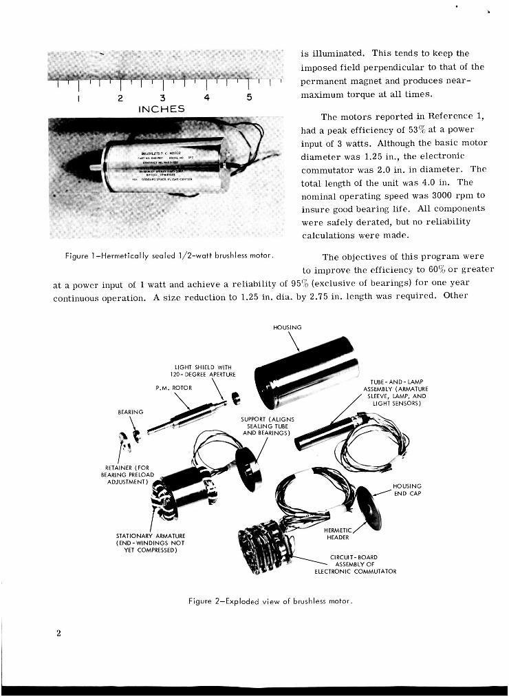
The particular requirements imposed by the intended application of these prototypes (ball bearing test instruments) determined the power rating and the need for elimination of organic outgassing products. Figure 1 illustrates the sealed motor developed on this program. Figure 2 shows the various assemblies which constitute the device.
The dc motor has two elements, one being electro-mechanical (torque-producing) and the other being photo-electronic (commutating).
The torque-producing elements are a two pole permanent magnet rotor, 0.375 in. diameter by 1 in. in length, and a wound stator. The permanent magnet material chosen was highly grain- oriented Alnico V alloy, which has an energy product of 7.5 x lo6 gauss-oersteds. The stator is of laminated construction, and uses a high permeability nickel-iron alloy. The armature is a continuous winding in a twelve slot stator, with three terminations.
The photo-optical commutator consists of a tungsten filament lamp, around which rotates a cylindrical sleeve with a slit producing a directional beam. Arranged radially around the rotat- able sleeve are six photodiodes which conduct electrical current when illuminated. Power transis- to rs apply the source voltage to the appropriate winding termination when the related photodiode
1
I 2 3 4 5 INCHES
Figure 1-Hermetically sealed 1/2-watt brushless motor.
is illuminated. This tends to keep the imposed field perpendicular to that of the permanent magnet and produces near- maximum torque at all times.
The motors reported in Reference 1, had a peak efficiency of 53% at a power input of 3 watts. Although the basic motor diameter was 1.25 in., the electronic commutator was 2.0 in. in diameter. The total length of the unit was 4.0 in. The nominal operating speed w a s 3000 rpm to insure good bearing life. All components were safely derated, but no reliability calculations were made.
The objectives of this program were to improve the efficiency to 60% o r greater
at a power input of 1 watt and achieve a reliability of 95% (exclusive of bearings) for one year continuous operation. A size reduction to 1.25 in. dia. by 2.75 in. length was required. Other
HOUSl N G
TUBE-AND- LAMP ASSEMBLY (ARMATURE
SLEEVE, LAMP, AND
RETAINER (FOR
(END- WINDINGS NOT YET COMPRESSED)
CIRCUIT- BOARD ASSEMBLY OF
TRONIC COMMUTATOR
Figure 2-Exploded view of brushless motor.
2

*-
specific requirements were: hermetic seal- ing of the windings and electronics to prevent outgassing of organic vapors, the operating speed, and the load. These were imposed by the application of these units for bearing and gear test instrumentation, and bearing torque test data.
The performance characteristics of a typical motor developed on this program are illustrated in Figure 3 .
EFFICIENCY
Power losses fall into three categories: fixed, which includes light source power; shunt current and voltage drop in the elec- tronic commutator; rotating, primarily eddy current and hysteresis loss in the magnetic iron of the stator; and copper, due to the 12R heating in the armature winding.
' " I
0 0.5 1.0 1.5 2.0 2.5 TORQUE ( i n . 02. )
Figure 3-Performance characteristics (24 volt motor).
The f ixed losses a r e especially important at low power levels. The power consumed by the light source in the initial prototypes, for example, was 0.3 watt, which was reasonable for a 3 watt motor, but intolerable for a motor with .5 watt total input. Since the silicon photo-detectors have a threshold intensity, and since the luminous efficiency of the light sources varies inversely with the life of the filament; the most direct approach seemed to be to place the detectors closer to the source. This required a smaller diameter lamp, available only in lower voltage ratings. A separate supply for the lamp was ruled out in order to simplify the circuit; and the lamp was placed in series with the motor, using the forward drop of a pair of silicon diodes in parallel with the lamp to limit the lamp voltage to approximately 1.4 volts. Now, however, since the armature switches a r e open until the detectors are illuminated, it wa'slound necessary to add a shunt cir- cuit which would be non-conducting at normal speed. Additionally, at maximum (no-load) speed, the current through the armature is not normally sufficient to maintain the lamp intensity. A secondary winding was added in order to generate a voltage maintaining the lamp intensity re- gardless of motor speed and also cut off the starting circuit as the motor speed increased. The power required f o r the new lamp is approximately .03 watt, a tenfold reduction from the previous design.
\
The lamp selected for this application, rated at 5.0 volts, is being operated at 1.5 volts, thereby vastly reducing the evaporation rate. The theoretical filament life-to-burnout exceeds 1 x lo9 hours (114,000 years). Its mechanical ruggedness is indicated by preliminary vibration tests Of a small sample (hard mounted) which recorded no failures at levels up to 70g.
3

The rotational losses were considerably reduced by changing from a high silicon steel to a nickel-iron alloy and by using thinner laminations.
"CoPPeY" losses were reduced by two changes; the first a reduction in the yoke thickness. This and the above-mentioned material change were made possible by a detailed study of the flux
level and flux distribution. Secondly, a thin-
increase in the slot area by use of a larger
PRESENT ORIGINAL 4 WATT 1 WATT DESIGN wall stainless steel case made possible further
3 WATT SEALED SEALED MOTOR MOTOR MOTOR 3 WATT
0 I I I I I I
diameter lamination.
The effects of the improvements incor- porated can best be seen in the chart (Fig- u re 4) which shows the power breakdown for the original motor design, the one-half and one watt motors built on this program, and calculated values for a 3 watt motor incorpo- rating these latest concepts. The chart indi- cates a forty percent reduction of copper . -
Figure 4-Power breakdown. losses. The application of the new design features to the original motor requirement
would increase the efficiency from 53% to 73%. A new circuit concept for the electronic commu- tator, tested too late to be jncluded in the devices actually fabricated, reduced the voltage drop in the power switches from approximately 1.5 volts to 0.2 volt, yielding an additional five percent improvement.
RELIABILITY
The major reliability improvement resulted from a simplification of the switching circuitry. The motor winding was changed from a six terminal ring winding to a three terminal configuration as shown in Figure 5. Since transistor switches conduct current unidirectionally, two a r e re- quired at each terminal in either case. Theoretical consideration of the flux distribution and current flow patterns showed that alternate stepping of each of six switches could produce torque with the same smoothness and efficiency as simultaneous commutation of pairs of switches in the ring configuration. The result of this discovery was the reduction, by one-half, of the electronic switching elements required.
The individual elements chosen were analyzed with respect to their operating levels and s t resses . Failure rates were assigned based on previous histories and current literature (Reference 2).
The light sowce received special attention since i t is a series element in the reliability chain. The voltage dependency of filament life allowed accelerated testing to be adopted. This, combined with fair-sized samples, made possible testing to millions of equivalent unit hours. The lamp initially selected was rejected after testing when the necessary average life was not

achieved. Continued testing of other types showed that lamps of sufficient brilliance could be obtained with sufficient life. The final selection w a s based on achievement, at a 90% confidence level, of a filament failure rate of less than 1 per 2,000,000 equivalent unit hours of operation. Preliminary vibration tests of short duration up to 70g's uncovered no failures.
R = 0.9925
The reliability of the bearings is a function of bearing speed, lubricant, environment, and external loading. Therefore each application must be analyzed individually. However, for the case where axial preload is the predominant load and fatigue is the anticipated failure mode, a B,, life of 500,000 hours was calculated. This leads to a failure rate of 0.15% per 10,000 hours.
R = 0.9925
The estimated reliability of the entire motor for one year operation (8760 hours) as illus- trated in Figure 6 is 91.3%. The actual value is somewhat higher since continuous operation would not normally be required of the starting circuit (92.7%) and satisfactory operation fo r most appli- cations has been demonstrated with one or more of the commutator switches inoperative (94.4%). Hence, a reliability of 93 to 95% depending on the application is predicted for these prototypes.
RING DELTA A B C D E F
STARTING R - ,6 CIRCUIT
4 R = 0.981 R = 0.9985
T.B. 1 I
R = 0.994
T.B. 2
R = 0.994 R MOTOR = 1 0.9192
I t = 8760 T.B. 51 hours
Figure 5-Ring and delta diagrams. Figure 6-Reliabi l i ty block diagram.
HERMETIC SEALING
Since these motors were intended fo r satellite application, outgassing was a design consider- ation. Organic materials in the motor windings and electronics could contaminate the motor bearings and impair the usefulness of the motor as a test instrument, or adversely affect optical systems in certain applications. The motors were specified to be hermetically sealed to prevent these organic materials from being deposited on the ball bearings; so that the motors might be utilized for bearing test instrumentation in space o r i n vacuum test chambers. After consideration of the poor space factor' of inorganic insulations and the mechanical problems associated with
*Space factor i s a term used to describe the ratio of copper in the windings to the insulating materials in the motor.
5

glass or other ceramics in the motor bore, it was decided to utilize a metal tube in the air gap. This construction can be seen in Figure7.
Experimental work indicated that a tube wall thickness of .005 inch w a s the minimum
LDER practical for stability and handling. The permanent magnet rotor was capable of driving through a considerably larger air gap, there- fore, no design change was required. By comparative tests it was found that a high resistivity material of this thickness would not
Figure 7-Motor construction detai I.
introduce appreciable power loss at the operating speed; therefore, Nichrome was selected. The resultant power loss was ,012 watt at 3000 rpm.
The entire stationary portion of the motor is located within a solder sealed metal-ceramic barr ier . Only the rotating assembly (i.e., the permanent magnet, shaft, light cup, and bearings) is exposed to the environment.
The glass envelope was sealed with a "solder glass" to a metallic holder which, along with the six photo-sensors, were soldered in the conventional manner to metallized areas on a ceramic cylinder. The differential expansions of these joints were held, by proper choice of materials, to a maximum of 1 x in. for the temperature extremes of -10°C to 70°C.
A degradation of light source performance, due to high sealing temperatures, necessitated the use of an epoxy seal substitution which was metallized by vapor deposition on these units. Ef- for ts to return to a completely inorganic seal are being continued for future units.
SIZE REDUCTION
The circuit design which resulted in a reduction by one-half in the number of commutator switches (as previously mentioned) was very helpful in achieving significant size reduction. Also, the photosensors, which were 3/4 in. long and mounted radially in the previous design, required the 2 in. diameter. These photosensors became available in a case less than l/lO-in. long, thus contributing to the size reduction. Efforts to improve the efficiency by reduction of power losses in the commutator made possible the use of micro-packaged solid state components, except for the power switches themselves, which a r e packaged in ''short hat" versions of TO-5 cases.
A size reduction, by a factor of six (to 1.1 cu. in.), was obtained for the electronic commutator. Since this satisfactorily met the design objectives, discrete components on printed circuit boards were used. This choice facilitated testing and utilized devices on which reliability data were available (which would not have been obtainable if integrated circuitry were used).
6

PERFORMANCE
The characteristics of the two types of motors built during this program a r e listed below:
Power input Torque Stall torque No-load speed 3200 rpm
Power input Torque Stall torque No-load speed 3100 rpm
1 watt at 24 vdc .25 in.-oz. at 3000 rpm 3.25 in.-oz. at 10 watts
1/2 watt at 24 vdc .115 in.-oz. at 3000 rpm 2.60 in.-oz. 7.8 watts
Peak efficiencies as high as 65% a re attained at slightly higher-than-rated loads, and the one watt motor is capable of handling continuous stall current of one-half ampere, providing a high available starting torque.
At higher speeds, acceptable for appli- cations where bearing life is adequate, greatly increased power can be obtained from this motor frame size (Figure 8). Although the curve in Figure 8 was calculated, the data has been experimentally verified for a ten- fold increase of power.
CONCLUSION
The state of the art in electronically commutated dc motors has been advanced to a point where no performance or weight penalty remains. Photo-electronic commu- tation provides a means of improving relia- bility by eliminating brushes, making the performance of the motor more independent of its environment.
I 1 I I I I 6 IO 14 16 18 20
SPEED ( rpm X 1,000 )
Figure 8-Power output vs. speed.
Sealing, to prevent outgassing of organic materials from contaminating adjacent sensitive instruments, was accomplished without significantly affecting performance. The rotating assembly consists only of the main shaft, a permanent magnet rotor, and a light deflector. This inherent simplicity of moving par ts make fo r reliability and the small diameter provides an exceptional. torque-to-inertia ratio for fast response.
Since the electronic commutator has built-in power amplification, the control of mechanical output by low-level control signals is possible. Where higher speed operation is feasible f rom the standpoint of bearing life, more power can be efficiently handled by the same motor size.
7

The techniques have been applied to the area where fixed power losses a r e very significant, i.e., low power levels. There is no barr ier to their application at higher speed and power levels up to the limits of available power transistors. The reliability of the device makes i t suitable for applications with stringent environmental and life requirements.
(Manuscript received November 13 , 1964)
REFERENCES
1. Studer, P. A., "Development of a Brushless DC Motor for Satellite Application," NASA Tech- nical Note D-2108, February 1964.
2. "Reliability Stress and Failure Rate Data for Electronic Equipment," Military Standardization Handbook 217 (Department of Defense), Washington: U. S. Government Printing Office, 8 Au- gust 1962.
8 NASA-Langley, 1965 G- 6 12
Related Documents