NASA TECHNICAL NOTE CO r-». CM NASA TN D-8273 wo EFFECTS OF MODIFICATIONS TO THE SPACE SHUTTLE ENTRY GUIDANCE AND CONTROL SYSTEMS Richard W. Powell, Howard W. Stone, and Lawrence F. Rowell Langley Research Center Hampton, Va, 23665 '^s-ia 1 * NATIONAL AERONAUTICS AND SPACE ADMINISTRATION • WASHINGTON, 0. C. • OCTOBER 1976

Welcome message from author
This document is posted to help you gain knowledge. Please leave a comment to let me know what you think about it! Share it to your friends and learn new things together.
Transcript
NASA TECHNICAL NOTE
COr-».CM
NASA TN D-8273
wo
EFFECTS OF MODIFICATIONSTO THE SPACE SHUTTLE ENTRYGUIDANCE AND CONTROL SYSTEMS
Richard W. Powell, Howard W. Stone,
and Lawrence F. Rowell
Langley Research Center
Hampton, Va, 23665' s-ia1*
NATIONAL AERONAUTICS AND SPACE ADMINISTRATION • WASHINGTON, 0. C. • OCTOBER 1976
1 Report No
NASA TN D-82732 Government Accession No 3 Recipient's Catalog No
4 Title and Subtitle
EFFECTS OF MODIFICATIONS TO THE SPACE SHUTTLEENTRY GUIDANCE AND CONTROL SYSTEMS
5 Report DateOctober 1976
6 Performing Organization Code
7 Author($)Richard W. Powell, Howard W. Stone, andLawrence F. Rowell
8 Performing Organization Report No
L-10U08
9 Performing Organization Name and Address
NASA Langley Research CenterHampton, VA 23665
10 Work Unit No
506-26-30-01
11 Contract or Grant No
12 Sponsoring Agency Name and Address
National Aeronautics and Space AdministrationWashington, DC 205ll6
13 Type of Report and Period CoveredTechnical Note
14 Sponsoring Agency Code
15 Supplementary Notes
16 Abstract
A nonlinear six-degree-of-freedom entry simulation study was conducted toidentify space shuttle orbiter guidance and control system software modifica-tions which would reduce the control system sensitivity to the guidance systemsampling frequency. Several modifications which eliminated the control systemsensitivity and associated control limit cycling were examined; the result ofthe modifications was a reduction in required reaction control system fuel.
17 Key Words (Suggested by Author(s))Space shuttleEntry guidance systemEntry control system
18 Distribution Statement
Unclassified - Unlimited
Subject Category 15
19 Security Qassif (of this report!
Unclassified20 Security Classif (of this page)
Unclassified
21 No of Pages
8U22 Price*
$U.75
* For sale by the National Technical Information Service, Springfield, Virginia 22161
EFFECTS OF MODIFICATIONS TO THE SPACE SHUTTLE
ENTRY GUIDANCE AND CONTROL SYSTEMS
Richard W. Powell, Howard W. Stone,
and Lawrence F. Rowell
Langley Research Center
SUMMARY
A study was conducted using a nonlinear six-degree-of-freedom
digital simulator to identify modifications which would reduce the
space shuttle orbiter control system sensitivity to guidance sys-
tem sampling frequency and would eliminate limit cycling of the
controls. Previous nonlinear three-degree-of-freedom trajectory
analyses indicated that entry guidance requirements were satisfied
with attitude commands issued at 2-second intervals. Six-degree-
of-freedom analyses of the control system response to commands with
this long interval indicated that it resulted in limit cycling of
the reaction controls and, consequently, required large increases
in reaction control system fuel. A combination of control system
software modifications (a "ramp" designed to smooth the step sig-
nals to the control system together with gain modifications in
the yaw and the aileron control circuits) was identified that
eliminated the limit cycling and the sensitivity to guidance
sampling frequency. This combination resulted in a 64-percent
savings in reaction control system fuel during a nominal entry.
INTRODUCTION
A reusable Earth-to-orbit transportation system known as the
space shuttle is being developed under contract to the National
Aeronautics and Space Administration (NASA). The space shuttle is
to be capable of inserting payloads of up to 29 500 kg (65 000 Ib)
into a near-Earth orbit, retrieving payloads already in orbit, and
landing with a payload of up to 14 500 kg (32 000 Ib). The space
shuttle consists of an orbiter, an external fuel tank, and two
solid rocket boosters (SRB). The SRB's are to be recovered after
launch for reuse. The external tank is designed for one use and
is not recovered. The orbiter is to have the capability to reenter
the atmosphere of the Earth, to fly up to 2040 km (1100 n. mi.)
crossrange, and to land horizontally. A general description of
the configuration and mission is given in reference 1.
The space shuttle "orbiter can be automatically guided and
controlled from entry to landing by onboard digital computers in
conjunction with navigation, guidance, and flight control systems.
The guidance system calculates the vehicle attitudes required to
meet the targeting requirements without violating any in-flight
constraints. The control system directs the aerodynamic surfaces
(elevens, rudder, speed brake, and body flap) and the reaction
control system (RCS) thrusters.
To maintain proper control, the control system is sampled at
the minimum pulse width of the RCS thrusters, i.e., 0.04 second.
However, it is not necessary to sample the guidance system so fre-
quently, and from a computer burden standpoint, it is desirable
to make the time between samples as long as possible. Previous
three-degree-of-freedom nonlinear analyses of the entry have shown
that a guidance sampling rate of once every 2.00 seconds is ade-
quate to meet the targeting and in-flight constraints. However,
six-degree-of-freedom simulations indicated that this lower fre-
quency results in limit cycling in the RCS.
Four software modifications (developed 'in cooperation with
E. E. Smith, Jr., and J. H. Suddath of the NASA Johnson Space
Center, Houston, Texas) to the guidance and control systems are
proposed to eliminate the limit cycling and accompanying fuel
increase at the longer guidance intervals. This paper presents
results of a study of the longer guidance intervals with the nom-
inal systems and the effects of adding the proposed modifications.
SYMBOLS
Values are given in both SI and U.S. Customary Units.The measurements were made in U.S. Customary Units. Symbolsused in the appendixes are defined therein.
dt time between guidance system samplings, sec
Ey yaw RCS error signal
E1 signal in yaw RCS control circuit
g acceleration of gravity, m/sec^ (ft/sec^)
M Mach number
p roll rate about body axis, deg/sec
q pitch rate about body axis, deg/sec
q dynamic pressure, Pa (psf)
r yaw rate about body axis, deg/sec
r» = r - 180ft sin * cos 6 deg/sec
irV
t current trajectory time, sec
fcguide time of last guidance sampling, sec
V Earth relative velocity, m/sec (ft/sec)
ycg lateral center-of-gravity offset, m (ft)
a angle of attack, deg
aQ commanded angle of attack sent to control system,
deg
ac new commanded angle of attack from guidance system atlatest sampling, deg
ac old commanded angle of attack from guidance system atprevious sampling, deg
B sideslip angle, deg
6 aileron deflection angle, deg
<$a up commanded aileron deflection from up-down counter, deg
<S gp body-flap deflection angle, deg
6e elevator deflection angle, deg
6r rudder deflection angle, deg
<$ SB speed-brake deflection angle, deg
e pitch angle about body axis, deg
<t> roll angle about body axis, deg
<t> c commanded roll angle about body axis sent to control
system, deg
*c new commanded roll angle from guidance system at latestsampling, deg
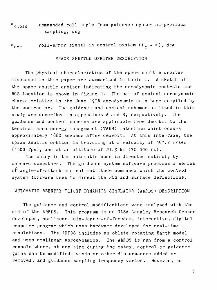
c old commanded roll angle from guidance system at previoussampling, deg
err roll-error signal in control system (<t>c - * ) , deg
SPACE SHUTTLE ORBITER DESCRIPTION
The physical characteristics of the space shuttle orbiter
discussed in this paper are summarized in table I. A sketch of
the space shuttle orbiter indicating the aerodynamic controls and
RCS location is shown in figure 1. The set of nominal aerodynamic
characteristics is the June 197^4 aerodynamic data base compiled by
the contractor. The guidance and control schemes utilized in this
study are described in appendixes A and B, respectively. The
guidance and control schemes are applicable from deorbit to the
terminal area energy management (TAEM) interface which occurs
approximately 1880 seconds after deorbit. At this interface, the
space shuttle orbiter is traveling at a velocity of 457.2 m/sec
(1500 fps), and at an altitude of 21.3 km (70 000 ft).
The entry in the automatic mode is directed entirely by
onboard computers. The guidance system software produces a series
of angle-of-attack and roll-attitude commands which the control
system software uses to direct the RCS and surface deflections.
AUTOMATIC REENTRY FLIGHT DYNAMICS SIMULATOR (ARFDS) DESCRIPTION
The guidance and control modifications were analyzed with the
aid of the ARFDS. This program is an NASA Langley Research Center
developed, nonlinear, six-degree-of-freedom, interactive, digital
computer program which uses hardware developed for real-time
simulations. The ARFDS includes an oblate rotating Earth model
and uses nonlinear aerodynamics. The ARFDS is run from a controlconsole where, at any time during the entry, control or guidancegains can be modified, winds or other disturbances added or
removed, and guidance sampling frequency varied. However, no
winds or gusts were considered in this study. The entry states
can be observed on time-history strip charts, deficiencies can be
noted, and appropriate solutions can be incorporated.
MISSION DESCRIPTION
The space shuttle mission considered was a once-around return
that had been launched into a 104° inclined orbit from the Western
Test Range. This orbit results in a crossrange requirement of
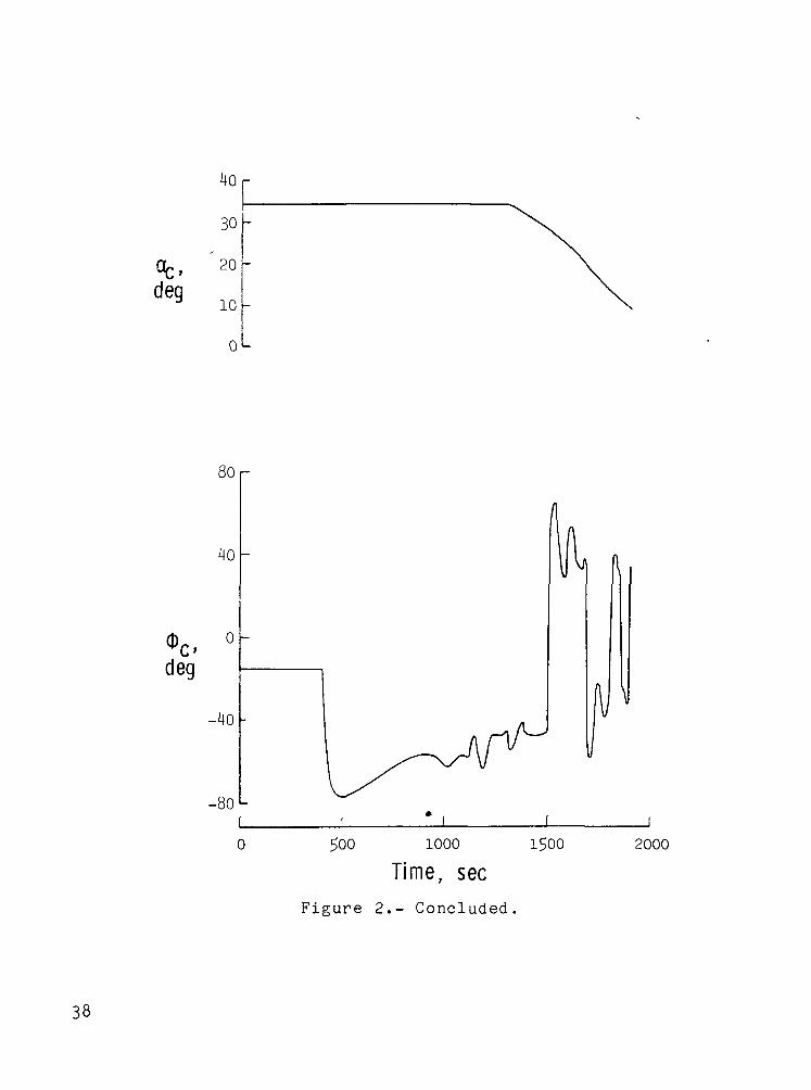
2040 km (1100 n. mi.). Figure 2 shows some of the trajectory
parameters associated with this entry.
RESULTS AND DISCUSSION
Nominal Guidance and Control Systems Simulation Results
During the nominal entry, the guidance system issues step
commands to the control system at a predetermined rate. To deter-
mine the effect of varying this rate, the guidance sample time was
increased from 0.04 second (the control system sample time) to
2.00 seconds (the desired rate) in six steps.
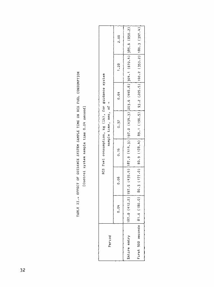
Table II shows the fuel consumption associated with the
selected guidance sample times. Sampling times for the entire
entry between 0.04 and 0.64 second are within a fuel-consumption
range of 10 percent, whereas the 1.28- and 2.00-second times showed
fuel-consumption increases of 63 and 106 percent, respectively,
over that for the 0.04-second case. For the remainder of the
study, a 0.32-second sample time was used as typical of the shorter
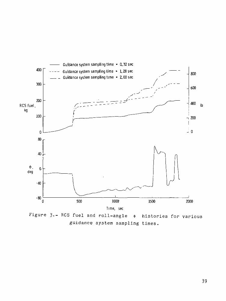
times. Figure 3 shows the time histories of RCS fuel consumption
and roll angle <t> for guidance sampling times of 0.32, 1.28, and
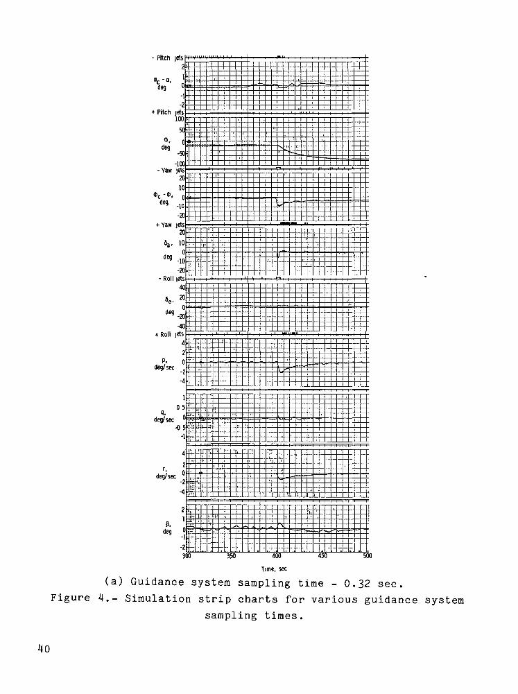
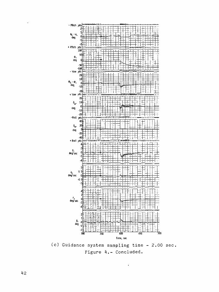
2.00 seconds, and figure 4 shows the corresponding simulation strip
charts for the entry between 300 and 500 seconds. The roll-angle
histories do not vary appreciably in these cases.
The shuttle is commanded to fly a roll angle of -15° until
approximately 400 seconds after deorbit. Between 400 and 500 sec-
onds, the angle increases to approximately -75°. During this
period, there is a significant increase in RCS fuel consumption
when the sampling time goes from 0.32 second to 1.28 seconds.
There is a smaller increase between 1.28 seconds and 2.00 seconds
(fig. 3). Alternate firings of both positive and negative yaw and
roll jets, indicative of a control system limit cycle, occur for
both the 1.28- and 2.00-second cases (figs. Mb) and 4(c),
respectively) .
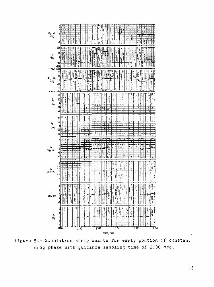
Limit cycling for the longer sampling times (1.28 and
2.00 sec) appears three more times in the trajectory. At approxi-
mately 1140 seconds into the entry, the guidance scheme changes
from equilibrium glide to constant drag relationships to calculate
<t>c. (See appendix A.) The constant drag relationships tend to
produce wider variations in the $ signal; these variations
result in limit cycling for the longer sampling times (shown by
fig. 5 for a sampling time of 2.00 sec). At approximately
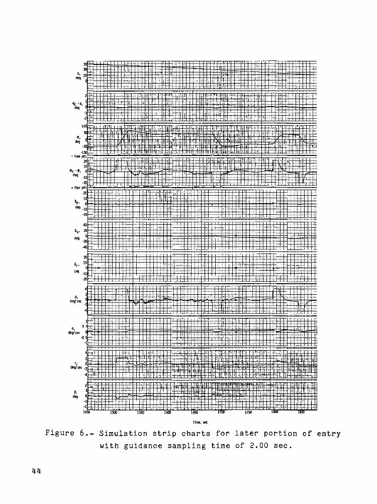
1500 seconds, the vehicle is commanded to perform a roll reversal.
(The commanded roll angle 4>c changes signs.) At the end of the
reversal, some limit cycling takes place again for the longer times
(shown by fig. 6 for a sampling time of 2.00 sec). At a velocity
of 2316 m/sec (7600 fps), which occurs at approximately 1550 sec-
onds into the entry, additional guidance changes produce limit
cycling (fig. 6). Figure 3 shows that during each of these periods
of limit cycling of the roll and yaw jets, there is a corresponding
increase in RCS fuel consumption that indicates that this limit
cycling is the primary cause of the marked increase in fuel con-
sumption. The control system changes to a more conventional
aileron-rudder mode at approximately 1715 seconds and no further
limit cycling is noted.
Modified Guidance and Control Systems Simulation Results
Four modifications designed to alleviate the RCS limit
cycling associated with lower guidance sampling frequencies were
examined. The first, designated "ramp," reduces the amplitude
of the step signal to the control system. The second modification,
designated "gain," reduces the roll-rate response to small changes
in <(> err by changing a gain in the yaw RCS circuit. "Up-down
gain," the third modification, reduces the amount of aileron
incremented by the up-down counter. Both gain and up-down gain
provide improvements even for the more frequent guidance samplings.
The fourth, "hysteresis," modifies the deadband filter in the
4>err signal of the yaw RCS circuit to a hysteresis type dead-band filter.
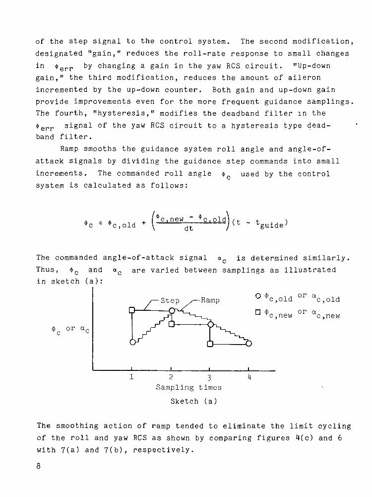
Ramp smooths the guidance system roll angle and angle-of-
attack signals by dividing the guidance step commands into small
increments. The commanded roll angle <|> used by the control\
system is calculated as follows:
+ Te,new " *c|Old (t _ t
The commanded angle-of-attack signal ac is determined similarly
Thus, <bc and ac are varied between samplings as illustrated
in sketch (a):
or
or a c,old
or a c,new
1 2 3 l|Sampling times
Sketch (a)
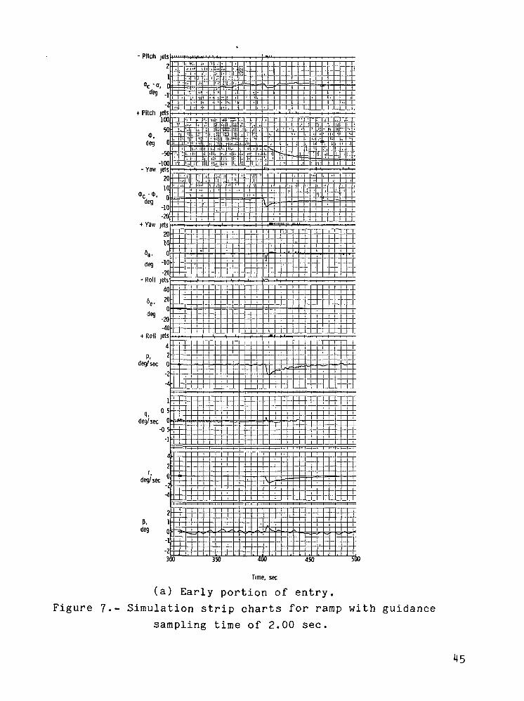
The smoothing action of ramp tended to eliminate the limit cycling
of the roll and yaw RCS as shown by comparing figures 4(c) and 6
with 7(a) and 7(b), respectively.
8
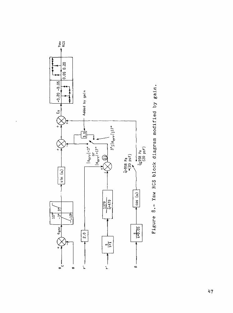
Gain reduces the commanded roll rate for small changes in
*err by multiplying E1 in the yaw RCS circuit (fig. 8) by three
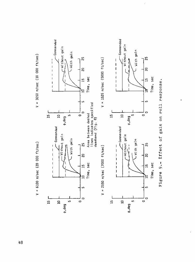
for 3° < |*err| < 17°. The value of <t>err is the differencebetween the commanded roll angle $c and the actual roll angle
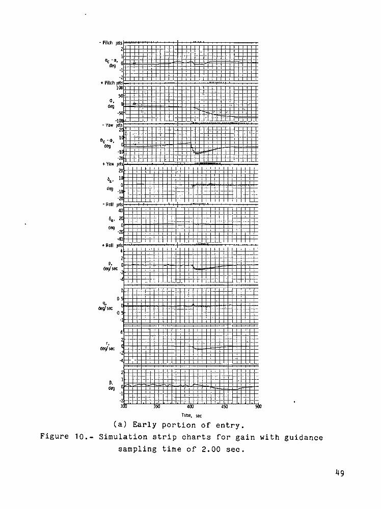
*^*err = *c ~ *)• figure 9 shows the effects of gain for a com-manded roll angle change of 10° for typical points along thetrajectory. Gain reduces the roll-rate response to small valuesof> *err* ^e striP charts of the entry with this modification(fig. 10) show that limit cycling is still present. A comparison
of figures Me) and 10(a) shows that the amplitude of the roll rate
and aileron oscillations and the duration of the yaw RCS cycling
are somewhat reduced.
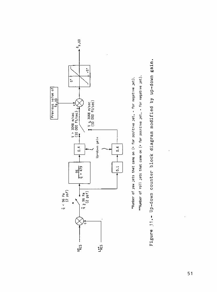
Up-down gain reduces the sensitivity of the 6a UD circuit to40 percent of the nominal (fig. 11). The up-down counter calculatesthe aileron deflection 6 nr, necessary to correct for the induced
d. • \J Ls
B caused by ycg offsets and disturbances such as winds. Sincethe induced B will bias the firings, the up-down counter can be
used to find an appropriate aileron deflection for lateral trim6a,UD' This modification was designed to reduce fuel consumptioncaused by overtrimming by the ailerons; the time histories indi-cated there was no effect on the limit cycling.
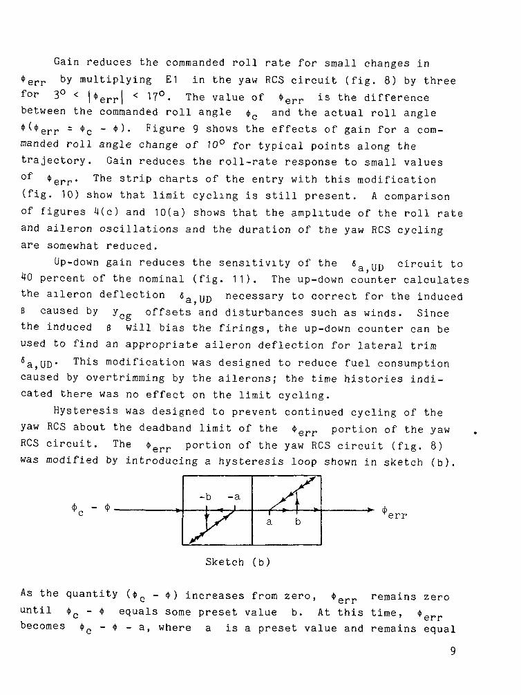
Hysteresis was designed to prevent continued cycling of the
yaw RCS about the deadband limit of the <l>err portion of the yaw
RCS circuit. The <t>err portion of the yaw RCS circuit (fig. 8)was modified by introducing a hysteresis loop shown in sketch (b).
-b -a— L_
a err
Sketch (b)
As the quantity («t>c - <j>) increases from zero, <t>
until <t>c - 4> equals some preset value b.becomes <j> - <t> - a, where a
err remains zero
''errAt this time,is a preset value and remains equal
9
to this function as <t>c - <t» continues to increase. When <t>c - $
decreases, ^err continues to remain equal to <t>c - <t> - a untilit becomes zero at <t>0 - * = a, and remains zero until <t>_ - <t>
{* C*
equals b again. A similar relationship for <t>err occurs for
negative values of <t>c - 4.. Two sets of a's and b's were
tried (a = 1.5, b = 3-0, and a = 3.0 and b = 4.5). Both sets
tended to decrease the limit cycling slightly, but an a = 1.5
increased the total jet firing as the system activity increased
because of the tighter deadband. For b = 4.5, large values of
*err caused some increased jet firing as higher rates were com-
manded when jet firing was initiated.
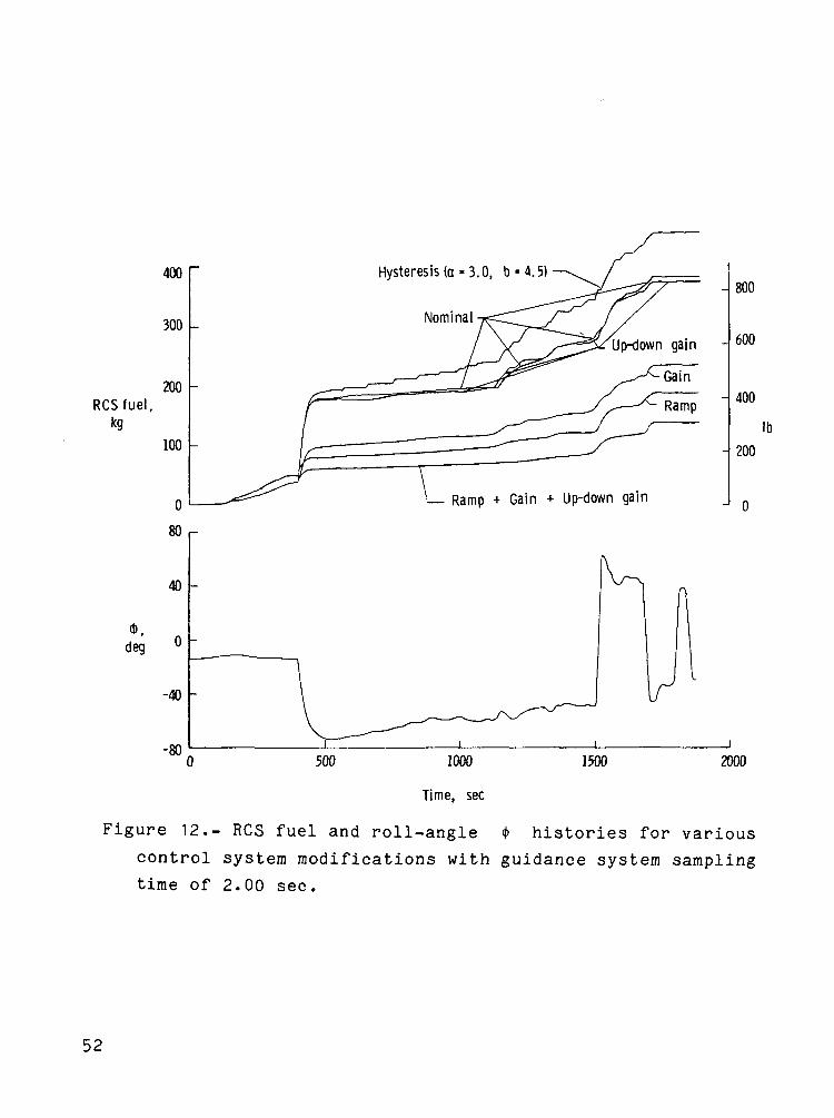
The results of the simulations are summarized in table III and
figure 12. The roll-angle time history shown in figure 12 is typi-
cal for all the simulations conducted. The data in this figure show
that the most effective modifications were ramp and gain. Up-down
gain showed negligible improvement, whereas hysteresis indicated
an increase in fuel consumption. A combination of ramp with gain
resulted in additional improvement in' RCS fuel consumption over
either modification alone (table III), and the addition of up-down
gain improved the combined system resulting in a 64-percent reduc-
tion in total fuel requirement for a sampling frequency of
2.00 seconds.
To determine the effect of yn_ offsets, two combinations of6
these modifications were examined with the maximum expected offset
of 0.038 m (1.5 in.). The two combinations were ramp with gain
and ramp together with gain and up-down gain. The system with up-
down gain still provided the smallest fuel consumption (table III)
and required only 5.7 kg (12.5 Ib) or 4 percent more fuel to handle
the y.,- offset for the entire entry with a 2.00-second sampling6
time.
CONCLUDING REMARKS
A six-degree-of-freedom simulation study was conducted to iden-
tify space shuttle orbiter guidance and control system modifications
10
which would reduce the system sensitivity to guidance system sam-
pling frequency and would eliminate limit cycling of the controls.
Previous nonlinear three-degree-of-freedom trajectory analyses indi-
cated that a guidance sampling rate of once every 2.00 seconds is
adequate to meet the targeting and in-flight constraints. However,
six-degree-of-freedom analyses of the control system response to
commands at this long interval indicated that it resulted in limit
cycling of the reaction controls and, consequently, required large
increases in reaction control system fuel. The system modifica-
tions examined were
1. Replacement of the step changes in commanded angle of
attack and roll attitudes with linear variations
(ramp-like)
2. Modification of a gain in the yaw reaction control system
circuit to reduce the roll-rate response to small roll-
attitude corrections
3. Modification of a gain to reduce the commanded aileron
increment produced by the up-down counter circuit
4. Addition of a hysteresis-deadband filter to the roll-angle
error-signal circuit
A combination of the first three modifications resulted in a
64-percent reaction control system fuel savings over the nominal
with a 2.00-second sampling time. The combination eliminated sys-
tem sensitivity to guidance system sampling frequency and limit
cycling tendencies. In addition, the combination was relatively
insensitive to lateral center-of-gravity offsets and required only
a 4-percent increase in reaction control system fuel consumption
for the maximum expected offset of 0.038 m (1.5 in.).
Langley Research Center
National Aeronautics and Space Administration
Hampton, VA 23665
June 29, 1976
11
APPENDIX A
ANALYTIC DRAG CONTROL ENTRY GUIDANCE SYSTEM
The baseline guidance scheme controls the entry by roll
modulation while the space shuttle orbiter is flying a preselected
angle-of-attack profile. Downrange is controlled by the magnitude
of the roll angle, and crossrange is controlled by multiple bank
reversals. The guidance system output to the control system is
commanded roll angle and angle of attack.
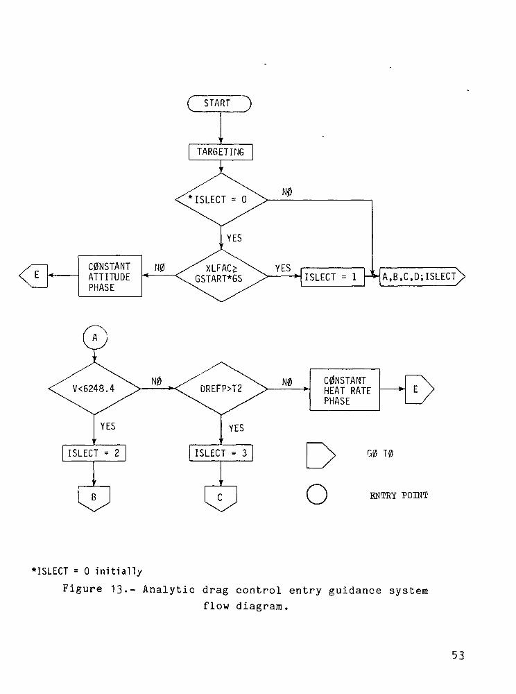
The analytic drag control entry guidance system (ADC) was
developed by the NASA Johnson Space Center to approximate an opt.i-
mum entry profile determined previously. This profile is achieved
by dividing the entry into five major phases as illustrated in
figure 13:
(1) Constant attitude phase
(2) Constant heat-rate phase
(3) Equilibrium-glide phase
(4) Constant drag phase
(5) Transition phase
The space shuttle orbiter is commanded to fly a constant atti-
tude trajectory until a specified total acceleration is attained.
At this point, a constant stagnation heat-rate trajectory is flown
through pullout to a relative velocity of 6248.4 m/sec (20 500 fps)
or until the reference drag level becomes larger than that required
to reach the target. If the latter condition is reached, the guid-
ance scheme jumps to the constant drag phase. If this condition
is not met, an equilibrium-glide profile is flown either until the
reference drag level intersects the constant drag profile required
to reach the target and jump to the constant drag phase or until
the velocity drops off to 2743.2 m/sec (9000 fps). Whenever the
velocity drops to 2?43.2 m/sec (9000 fps), the transition phase is
entered. During the transition phase, the commanded angle of
attack is decreased to the value required at the terminal area
energy management (TAEM) point, which occurs at a velocity of
12
APPENDIX A
457.2 m/sec (1500 fps) and at an altitude of approximately
21.3 km (70 000 ft) .
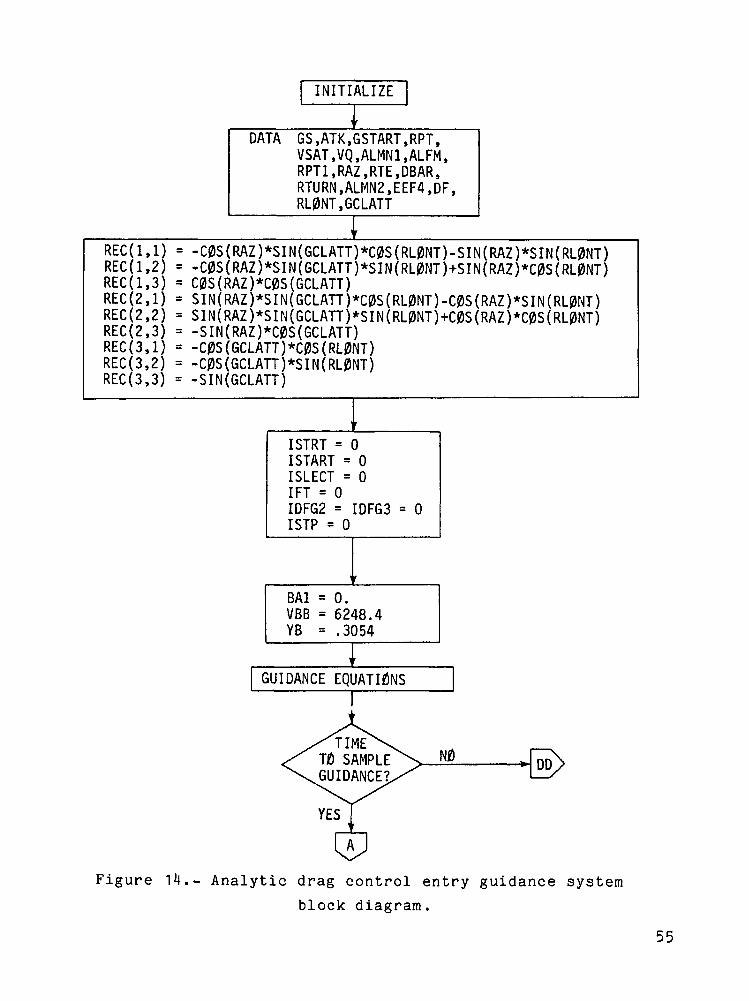
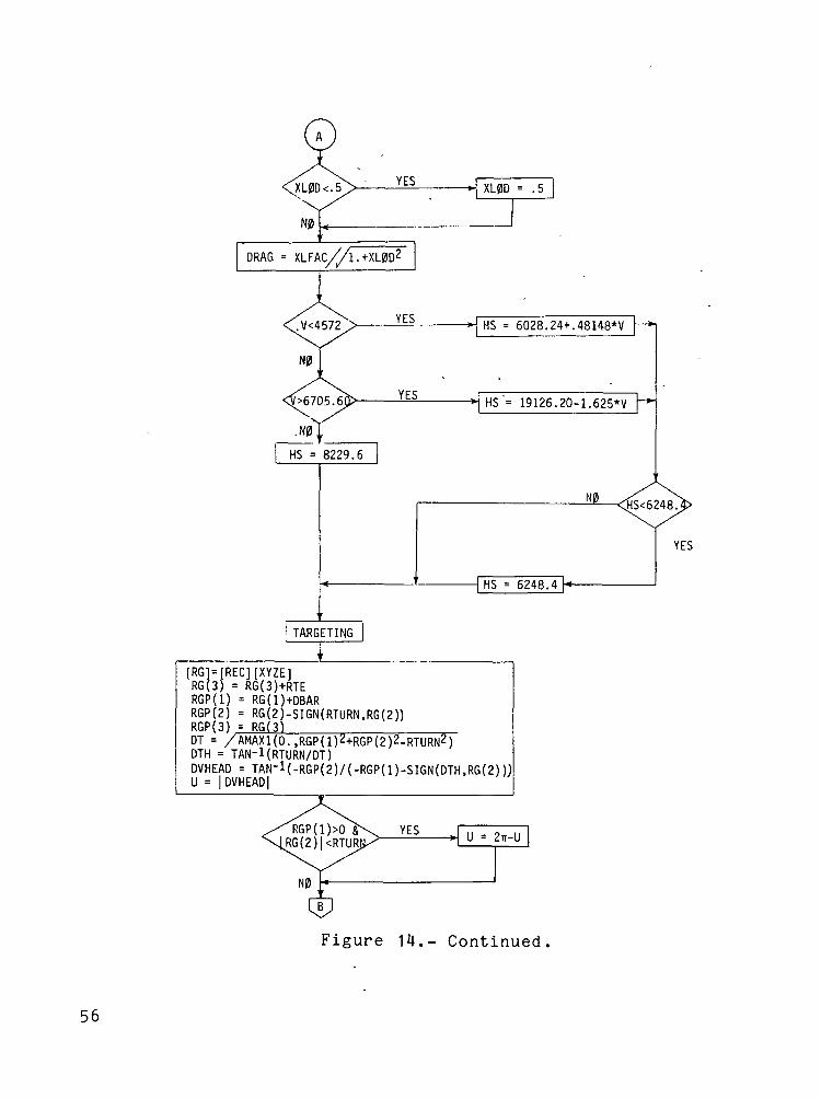
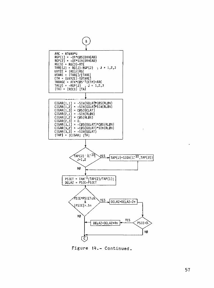
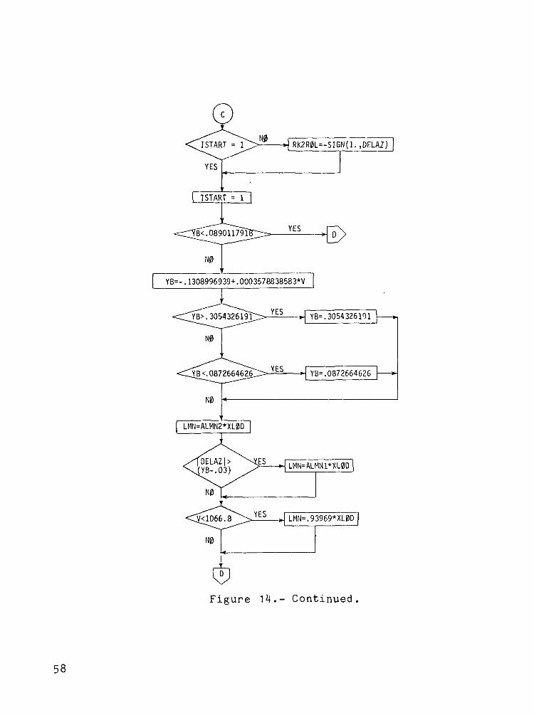
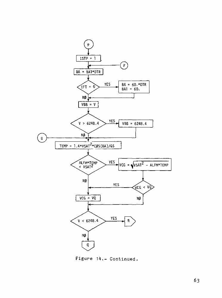
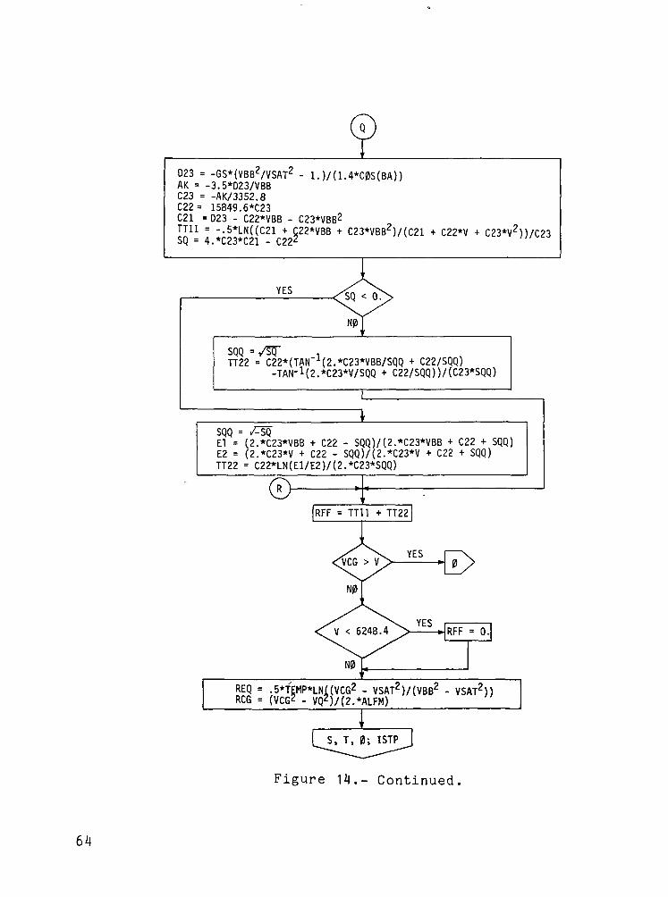
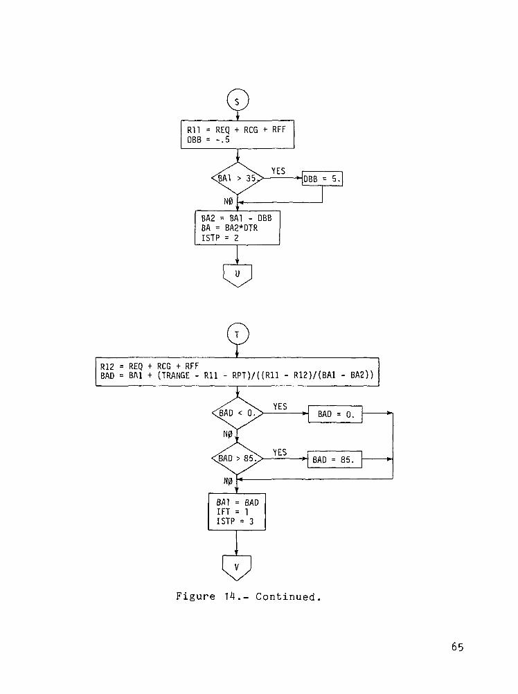
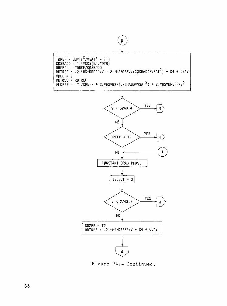
Table IV shows the input constants that were used, and
figure 14 shows the block diagram of the guidance laws.
SYMBOLS
AK dD/dV for constant heat-rate phase, used to define
C23, sec'1
ALDREF (L/D)ref, used in controller
ALFM reference equilibrium-glide drag, m/sec2 (ft/sec2)
ALMN1 minimum roll command outside of lateral deadband (YB),
rad
ALMN2 minimum roll command inside of lateral deadband (YB),
rad
ALPCMD angle-of-attack command, ac, degi
AMAX1 maximum value function
ARC distance from intersection with alinement circle to
target, m (ft)
ARC (L/D)V/(L/D) , used in roll-command equations, rad
ATK radius of Earth, m (ft)
BA equilibrium-glide roll angle used in iteration loop,
rad
BAD final equilibrium-glide roll angle, deg
13
APPENDIX A
BA1 first iteration equilibrium-glide roll angle, deg
BA2 second iteration equilibrium-glide roll angle, deg
CAGI temporary calculation used in transition phase to
calculate ALDREF and RDTREF, sec2/m2 (sec2/ft2)
CIGAR transformation matrix from Earth-centered inertial
(ECI) axes to geocentric axes
COSBADD temporary calculation in equilibrium-glide ranging
phase used to calculate DREFP
CTH gr;eat circle range from orbiter to target, rad
coefficient used to calculate RDTREF, m/sec (ft/sec)
C5
C11
C16
C17
C21
coefficient used to calculate RDTREF
parameter used to calculate RER1 and RDTREF, m~1 (ft~1)
coefficient used to calculate LOD1, sec^/m (sec2/ft)
coefficient used to calculate LOD1, sec/m (sec/ft)
parameter used to calculate DREFP, RDTREF, SQ, and
TT11 , m/sec2 (ft/sec2)
C22
C23
D
14
parameter used to calculate DREFP, E1, E2, RDTREF,
SQ, TT11, and TT22, sec~1
parameter used to calculate C22, DREFP, E1, E2, SQ,
TT11 , and TT22, m"1 (ft~1)
total drag force, N (Ib)
APPENDIX A
DEAR distance from runway to alinement circle, ra (ft)
DBB increment in roll angle in equilibrium-glide phase,
deg
DELAZ azimuth error, rad
DF final drag level in transition phase, m/sec2 (ft/sec2)
DLIM control system limit drag level in transition phase,
m/sec2 (ft/sec2)
DRAG current drag acceleration level, m/sec (ft/sec )
DREFP drag reference used in controller, m/sec2 (ft/sec2)
DT planar range to target, m (ft)
DTH angle between alinement circle center and tangency
point, rad
DTR = Tr/180, rad/deg
DVHEAD azimuth between runway and heading to tangency point
of alinement circle, rad
D23 parameter used to calculate AK, m/sec2 (ft/sec )
EEF current energy level, m2/sec2 (ft2/sec2)
EEFH reference energy level used in transition phase,
m2/sec2 (ft2/sec2)
E1,E2 parameters used to calculate TT22
15
APPENDIX A
GAMMA flight-path angle, rad
GCLAT orbiter geocentric latitude, rad
GCLATT target geocentric latitude, rad
GS acceleration of gravity at sea level, m/sec (ft/sec )
GSTART acceleration required to initiate constant heat-rate
phase, g units
HA current altitude, m (ft)
HADOT = d(HA)/dt, m/sec (ft/sec)
HDSER parameter in oblate Earth correction term to RDTREF,
m^/sec (ft-Vsec)
HS altitude scale height, m (ft)
IDFG2 switching flag in constant drag phase
IDFG3 switching flag in transition phase
IFT initialization flag in equilibrium-glide phase
ISLECT phase selector
ISTART initialization flag
ISTP iteration flag in equilibrium-glide phase
ISTRT flag indicating acceleration level equal to GSTART
has been reached
16
APPENDIX A
ITR iteration flag in transition phase
L/D lift-to-drag ratio
(L/D) lift-to-drag ratio in vertical plane
LMN minimum value of LOD1
LN natural logarithm function
LOD1 desired (L/D),
PSIE current heading of orbiter, rad
PSIET current heading to target, rad
RAZ runway azimuth, rad
RCG predicted range in constant drag phase, m (ft)
RDC parameter used in RDTREF calculation
RDTOLD final RDTREF in equilibrium-glide phase, m/sec (ft/sec)
RDTOL2 final RDTREF in constant drag phase, m/sec (ft/sec)
RDTREF altitude rate reference, m/sec (ft/sec)
REC vector defining runway coordinate system
REC1
REH
REQ
= [REC]-1
distance from center of Earth to vehicle, m (ft)
predicted equilibrium-glide phase range, m (ft)
17
APPENDIX A
RER1
RFF
RG
RGP
parameter in range prediction for transition phase, m (ft)
predicted range in constant heat-rate phase, m (ft)
vector from orbiter to runway center, m (ft)
vector from orbiter to alinement circle center, m (ft)
RK2ROL roll direction ( + right, - left)
RLON
RLONT
ROLLC
RPT
RPT1
RTE
RTURN
R1 1
R12
SIGN(A,B)
longitude of orbiter, rad
target longitude, rad
roll-angle command,
desired range in transition phase, m (ft)
range bias below velocity of 456.2 m/sec (1500 fps) ,
m (ft)
radius of Earth at runway, m (ft)
radius of alinement circle, m (ft)
first iteration of range prediction in equilibrium-
glide and transition phases, m (ft)
second iteration of range prediction in equilibrium-
glide and transition phases, m (ft)
function which gives to the value of A the
algebraic sign of the variable B
18

APPENDIX A
SQ parameter used in constant heat-rate range prediction,
sec
SQQ parameter used in constant heat-rate range prediction,
sec
TA vector from alinement circle tangency point to
vehicle, m (ft)
TAP vector TA in geocentric coordinates, m (ft)
TARE target vector from alinement circle center to
runway, m (ft)
TDREF parameter used in DREFP calculation in equilibrium-
glide phase, m/sec2 (ft/sec2)
TEMP
T1
temporary calculation in equilibrium-glide phase,
m (ft)
TRANCE great circle range from orbiter to target, m (ft)
parameter used in calculation of ALDREF, m/sec2 (ft/sec2)
T2 constant drag level required to reach target,
ra/sec2 (ft/sec2)
TT11,TT22 parameters used in range prediction in constant
heat-rate phase, m (ft)
u = IDVHEAD!, rad
UTARE TARE unit vector
UXYZE RG unit vector
19
APPENDIX A
V Earth relative velocity, m/sec (ft/sec)
VBB intersection velocity between constant heat-rate phase
and equilibrium-glide phase, m/sec (ft/sec)
VCG predicted intersection velocity between constant drag
phase and equilibrium-glide phase, m/sec (ft/sec)
VINERT inertial velocity, m/sec (ft/sec)
VOLD final velocity in equilibrium-glide phase, m/sec (ft/sec)
VOLD2 final velocity in constant drag phase, m/sec (ft/sec)
VQ predicted final velocity for constant drag phase,
m/sec (ft/sec)
VSAT reference circular orbit velocity, m/sec (ft/sec)
V10LD value of VOLD - 152.4 m/sec (500 ft/sec), m/sec (ft/sec)
V20LD value of VOLD2 - 152.4 m/sec (500 ft/sec), m/sec (ft/sec)
XLFAC total acceleration, m/sec^ (ft/sec^)
XLOD L/D of vehicle with undeflected control surfaces
including viscous effects
XYZE geocentric position vector, m (ft)
YB lateral deadband (amount of overshoot that guidance
system will allow before commanding roll reversal),
rad
20

APPENDIX B
DIGITAL AUTOPILOT
Symbols
The following symbols are used in this appendix:
ay side acceleration at center of gravity, m/sec2 (ft/sec2)
cg eleven reference chord, m (ft)
c rudder reference chord, m (ft)
C^ eleven hinge-moment coefficient
Ch =3(Rudder hinge-moment coefficient)/33 , deg
Ch = 3 (Rudder hinge-moment coefficient)/36r, deg"6r
CLN rolling-moment coefficient due to yaw RCS
CML pitching-moment coefficient due to roll RCS
C^ pitching-moment coefficient due to yaw RCS
C,, yawing-moment coefficient due to roll RCS
DEMX maximum eleven rate, deg/sec
DRMX maximum rudder rate, deg/sec
Ep pitch RCS error signal
Ep roll RCS error signal
21
APPENDIX B
Ey yaw RCS error signal
f(6Q) function of 6_, used to limit 6_ 0, degC C Cl y V-*
g acceleration of gravity, m/sec^ (ft/sec^)
h integration step size, sec
Hrae eleven hinge moment, N-m (Ib-ft)
Hmr rudder hinge moment, N-m (Ib-ft)
KL rolling-moment RCS amplification factor
KMD pitching-moment RCS amplification factor from down-
firing jets
KMJJ pitching-moment RCS amplification factor from up-firing
jets
KJJ yawing-moment RCS amplification factor
Kp aileron gain
Ka elevator gain
t 5r rudder gain
LRCS rolling moment due to RCS, N-m (Ib-ft)
LRJ ideal rolling moment due to firing of one roll jet,
N-m (Ib-ft)
M Mach number
22
APPENDIX B
Mpj ideal pitching moment due to firing of one pitchjet, N-m (Ib-ft)
MRCS pitching moment due to RCS, N-m (Ib-ft)
^RCS yawing moment due to RCS, N-m (Ib-ft)
Nyj ideal yawing moment due to firing of one yaw jet,N-m (Ib-ft)
p roll rate, deg/sec
P convolution coefficient
PJN number of negative pitch jets firing
PJP number of positive p.itch jets firing
q pitch rate, deg/sec
q dynamic pressure, Pa (psf)
q-j convolution coefficient, sec
$2 convolution coefficient, sec2
Q vector of convolution coefficients
r yaw rate, deg/sec
r' = r - (I80g sin * cos e)AvR, deg/sec
RJN number of negative roll jets firing
RJP number of positive roll jets firing
23
APPENDIX B
s Laplacian operator
S0 eleven reference area, m^ (ft^)fcJ
Sp rudder reference area, m^ (ft^)
t time, sec
t^ time at kth sample, sec
U convolution forcing function
U vector of forcing-function terms
U = dU/dt
Vp Earth relative velocity, m/sec (ft/sec)
W filter root, sec~^
x convolution state variable
x = dx/dt
YJN number of negative yaw jets firing, nondimensional
YJP number of positive yaw jets firing, nondimensional
a angle of attack, deg
ac commanded angle of attack from guidance system, deg
B angle of sideslip, deg
<$a aileron deflection, deg
24
APPENDIX B
6a,c commanded aileron deflection, deg
6 a UD commanded aileron deflection from up-down counter,
deg
<Sgp body-f lap de f l ec t ion , deg
6e elevator def lec t ion , deg
<5A ~ commanded elevator de f lec t ion , degC , Is,
6ei left eleven panel deflection, deg
6e«- c command left eleven panel deflection, deg
6e £m maximum change in eleven command that can be realized
in one control cycle, deg
5er right elevon panel deflection, deg
6er c commanded right elevon panel deflection, deg
6e,t initial elevator setting, deg
$r rudder deflection, deg
6r,c commanded rudder deflection, deg
6r £m maximum change in rudder command that can be realized
in one control cycle, deg
6gB speed-brake deflection, deg
9 pitch angle, deg
APPENDIX B
<)> roll angle, deg
<t> c commanded roll angle to control system, deg
T variable of integration, sec
Description of Digital Autopilot
The digital autopilot (DAP) is designed to fly the space
shuttle orbiter automatically from deorbit to the terminal area
energy management (TAEM) interface which occurs at an altitude of
approximately 21.3 km (70 000 ft) with a velocity of 457.2 m/sec
(1500 fps). The DAP directs both the reaction control system
(RCS) and the aerodynamic control surfaces.
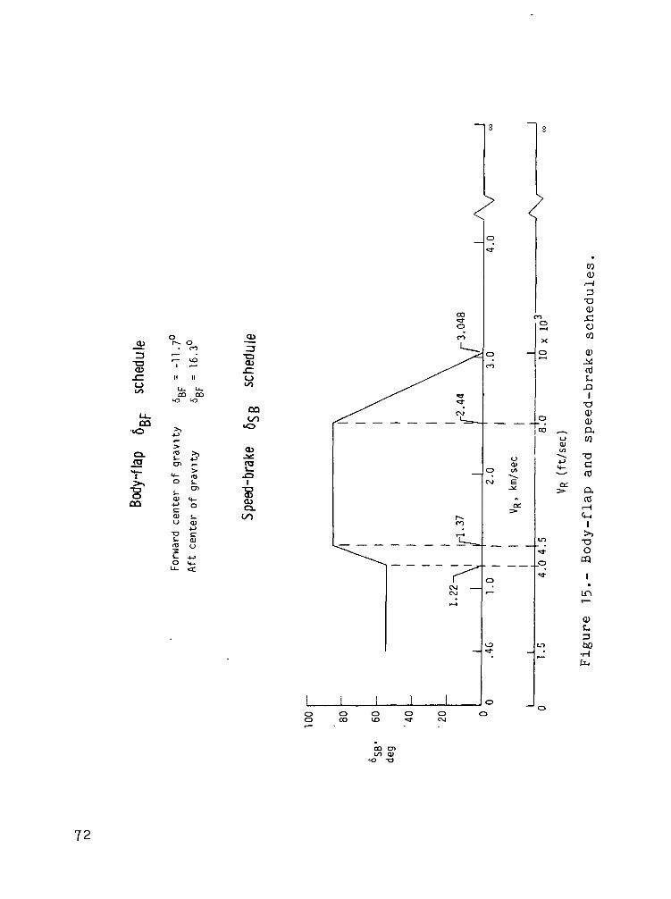
The speed-brake 6 SB and body-flap 6 BF deflection schedules
are shown in figure 15, where s gB is determined from a preset
velocity schedule and 5 BF is dependent on the center-of-gravity
location. Figures 16 to 24 are block diagrams of the various ele-
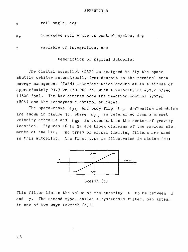
ments of the DAP. Two types of signal limiting filters are used
in this autopilot. The first type is illustrated in sketch (c):
A
x--
err
Sketch (c)
This filter limits the value of the quantity A to be between x
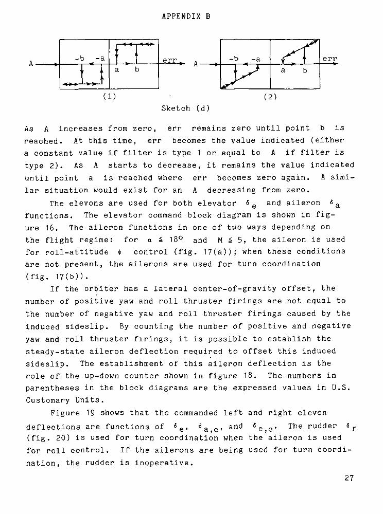
and y. The second type, called a hysteresis filter, can appear
in one of two ways (sketch (d)):
26
APPENDIX B
-b -a\ t
\i
rr I i
a berr ^ A
-b -a
a berr
(1) (2)Sketch (d)
As A increases from zero, err remains zero until point b is
reached. At this time, err becomes the value indicated (either
a constant value if filter is type 1 or equal to A if filter is
type 2). As A starts to decrease, it remains the value indicated
until point a is reached where err becomes zero again. A simi-
lar situation would exist for an A decreasing from zero.
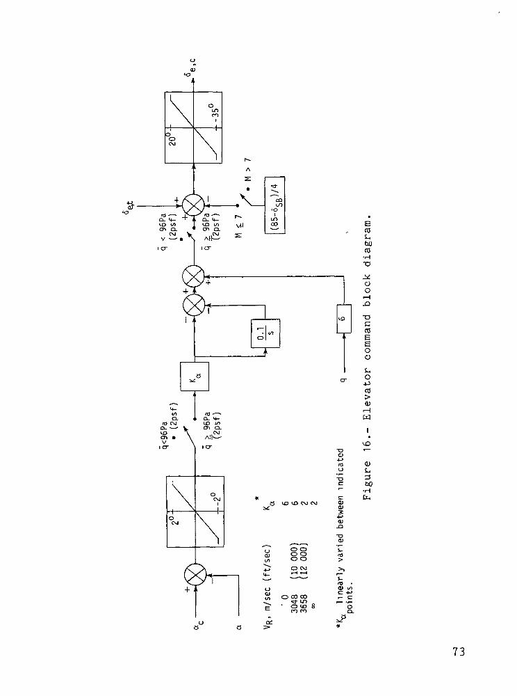
The elevens are used for both elevator 6 e and aileron 6 afunctions. The elevator command block diagram is shown in fig-
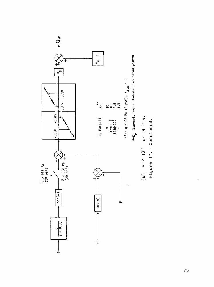
ure 16. The aileron functions in one of two ways depending on
the flight regime: for o ^ 18° and M ^ 5, the aileron is used
for roll-attitude * control (fig. 17(a)); when these conditions
are not present, the ailerons are used for turn coordination
(fig. 17(b)).
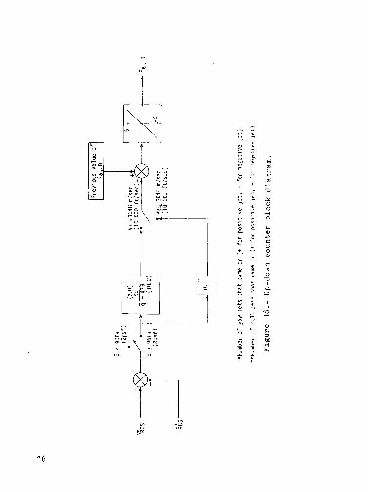
If the orbiter has a lateral center-of-gravity offset, the
number of positive yaw and roll thruster firings are not equal to
the number of negative yaw and roll thruster firings caused by the
induced sideslip. By counting the number of positive and negative
yaw and roll thruster firings, it is possible to establish the
steady-state aileron deflection required to offset this induced
sideslip. The establishment of this aileron deflection is the
role of the up-down counter shown in figure 18. The numbers in
parentheses in the block diagrams are the expressed values in U.S.
Customary Units.
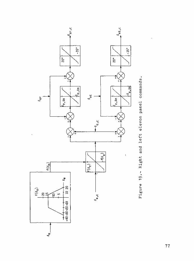
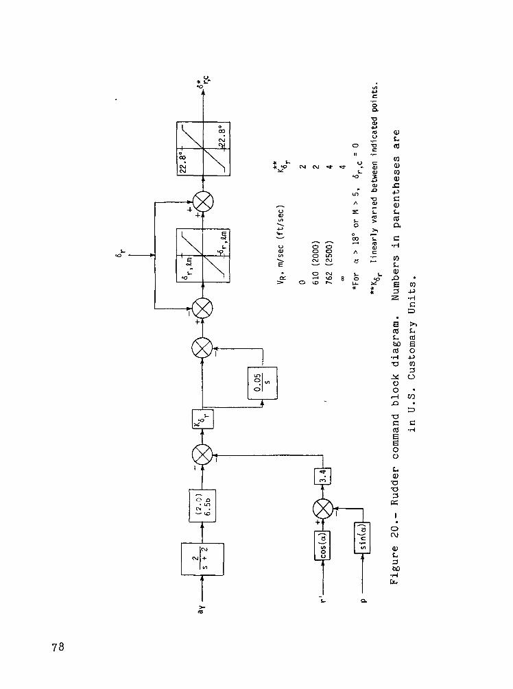
Figure 19 shows that the commanded left and right eleven
deflections are functions of , and Tne rudder 6e , a c, e,c' r
(fig. 20) is used for turn coordination when the aileron is used
for roll control. If the ailerons are being used for turn coordi-
nation, the rudder is inoperative.
27
APPENDIX B
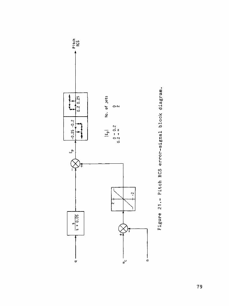
The pitch RCS (fig. 21) is operative for q less than 958 Pa
(20 psf). In this regime the pitch RCS is used, along with the
elevator, for longitudinal control.
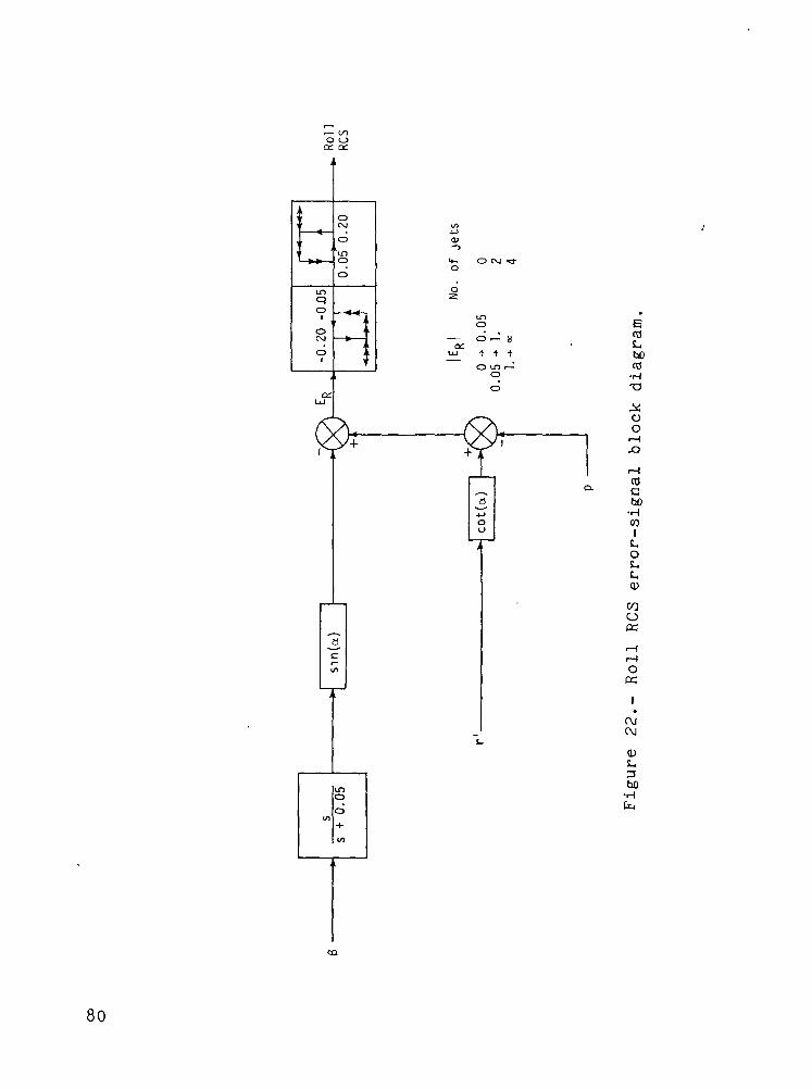
The roll RCS (fig. 22) is operative for q less than 479 Pa
(10 psf) and is used, together with the ailerons, for turn
coordination.
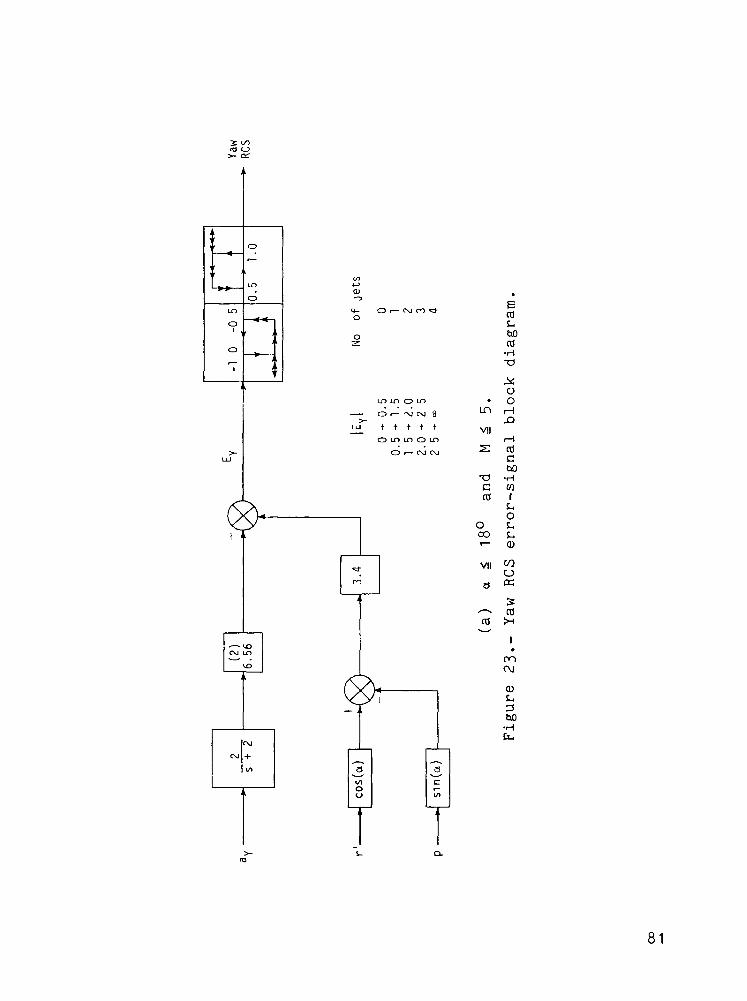
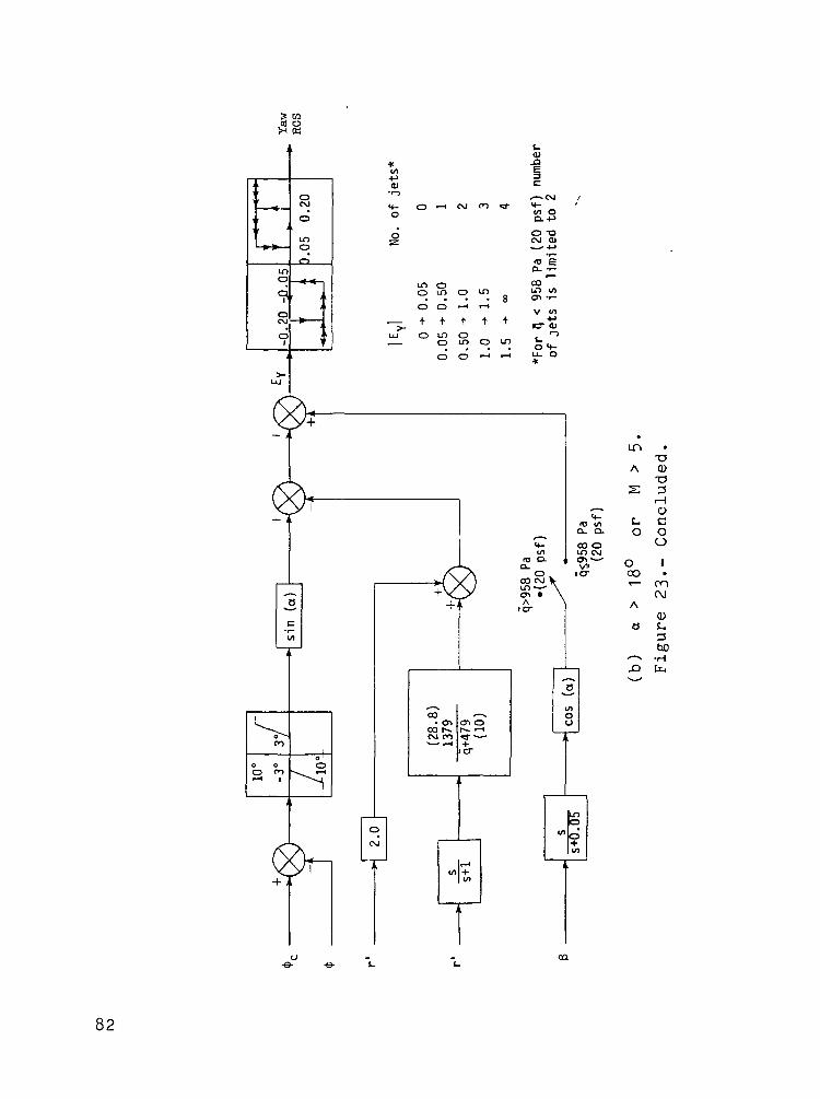
The yaw RCS (fig. 23) is operative throughout the entry until
TAEM and serves one of two purposes depending on the flight condi-
tions. If the ailerons are used for attitude control, the yaw
RCS (fig. 23(a)) aids the rudder in maintaining turn coordination.
If the conditions are such that the ailerons are used for turn
coordination, the yaw RCS (fig. 23(b)) is used for roll-attitude <J>
control.
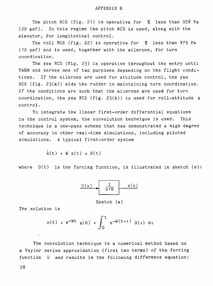
To integrate the linear first-order differential equations
in the control system, the convolution technique is used. This
technique is a one-pass scheme that has demonstrated a high degree
of accuracy in other real-time simulations, including piloted
simulations. A typical first-order system
x(t) + W x(t) = U(t)
where U(t) is the forcing function, is illustrated in sketch (e):
U ( s ) t1
s+Wx ( s )
The solution is
x(t) = e~wt x(o)
Sketch (e)
- U(T)
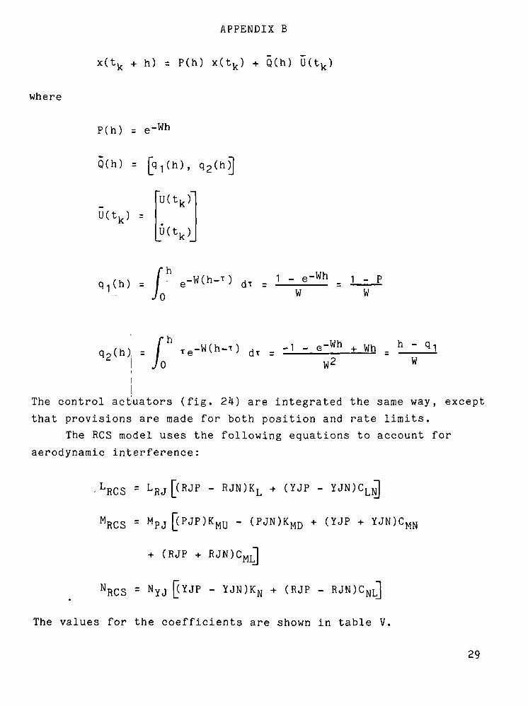
The convolution technique is a numerical method based on
a Taylor series approximation (first two terms) of the forcing
function U and results in the following difference equation:
28
where
APPENDIX B
x(t,_ + h) = P(h) x(t,J + Q(h)
P(h) = e
Q(h) =
U(t,
-Wh
, q2(h)]
U(tk)
U(tk)
h
W- PW
,, . /'I Jo
I
-Wh Wh . h ~W
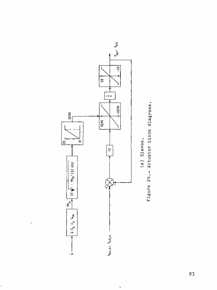
The control acbuators (fig. 24) are integrated the same way, except
that provisions are made for both position and rate limits.
The RCS model uses the following equations to account for
aerodynamic interference:
JRCS =
MRCS =
'RCS
L R J [ (RJP - R J N ) K L + (YJP -
M p J [ ( P J P ) K M U - ( P J N ) K M D + (YJP + Y J N ) C
+ (RJP + RJN)C M I 1
= NYJ [(YJP - Y J N ) K N + ( R J P - RJN)C N L ]
The values for the coefficients are shown in table V.
29
REFERENCE
1. Malkin, M. S.: Space Shuttle/The New Baseline. Astronaut. &
Aeronaut., vol. 12, no. 1, Jan. 19?4, pp. 62-68.
30
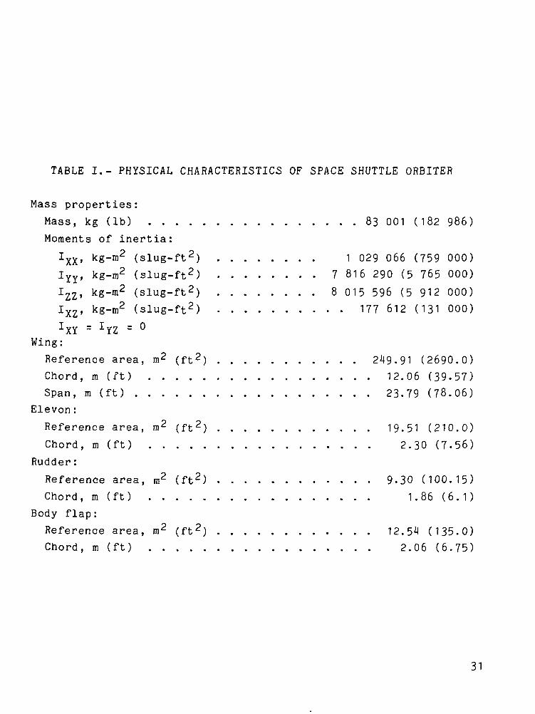
TABLE I.- PHYSICAL CHARACTERISTICS OF SPACE SHUTTLE ORBITER
Mass properties:
Mass, kg (Ib) 83 001 (182 986)
Moments of inertia:
Ixx, kg-m2 (slug-ft2) 1 029 066 (759 000)
IYy> kg-m2 (slug-ft2) 7 816 290 (5 765 000)
Izz, kg-m2 (slug-ft2) 8 015 596 (5 912 000)
Ixz, kg-m2 (slug-ft2) 177 612 (131 000)IXY = IYZ = °
Wing:
Reference area, m2 (ft2) 249.91 (2690.0)
Chord, m (ft) 12.06 (39-57)
Span, m (ft) 23-79 (78.06)
Eleven:
Reference area, m2 (ft2) 19.51 (210.0)
Chord, m (ft) 2.30 (7-56)
Rudder:
Reference area, m2 (ft2) 9-30 (100.15)
Chord, m (ft) 1.86 (6.1)
Body flap:
Reference area, m2 (ft2) 12.54 (135.0)
Chord, m (ft) 2.06 (6.75)
31
O_
s:
OO
COOcc
O
w
PL,s<CO
HCO
b.O
ow[L.
w
w_]CO<H
•OcOO
oo0)E
CDrHO.
rt03
Co
ECD
4->COr*>
in
(U0cro•aH3bo I
!-. CMO O
- o
n coiH
— ' -<uhD E^ H
J-J
C <UO MH Q*-u EQ. cdB CO30)coo
»— (<u3<i-i
COOcc
OO
CM
COCM
*~
^T^O
•0
CMro
•o
vO
*—•
O
COo
o
3-0
o
T3OHt.CUO_
CM
0inCO
^o
inCOro
zr
ot^^3
^•
.=roro
co>
CO.3-^~~ f
vO•
roOCM
ro
crror
— x0
t—ON
—,-,ro.r
T—
.ITs
cr\
t~-co
^^in.
inro=r
in
c^cr.
CM
CMT—
^~
0
f-co
>,LaJCcua>H
cCd
.3-
f-o>ro~~^ro
0CO
CM
roinro
CM*
0vo*~
in•
in0CM
—CM
roa\
in
UDON*—— ,
*~CJN
CO
^rr
•COt—t—
—o>0CO
^o
•t—f-
ro
oCO
0
oCO*~
VO
r-
co
CO•ac0o0)0)
ooin
01£-<H
Cb
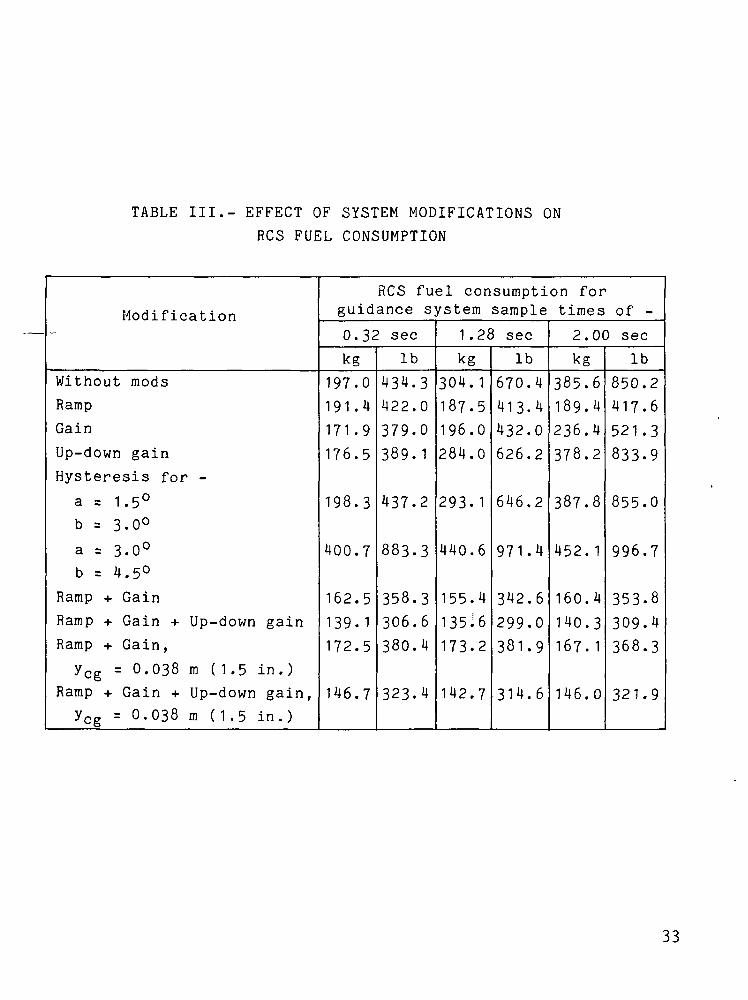
TABLE III.- EFFECT OF SYSTEM MODIFICATIONS ON
RCS FUEL CONSUMPTION
Modification
Without modsRampGain
Up-down gainHysteresis for -
a = 1.5°b = 3.0°
a = 3.0°b = 4.5°
Ramp + Gain
Ramp + Gain + Up-down gainRamp + Gain,
ycg = 0.038 m (1.5 in.)Ramp + Gain + Up-down gain,ycg = 0.038 m (1.5 in.)
RCS fuel consumption forguidance system sample times of -
0.32 sec
kg197.0
191.4171.9
176.5
198.3
400.7
162.5
139.1172.5
146.7
Ib
434.3422.0379.0
389.1
437.2
883.3
358.3306.6380.4
323.4
1.28 sec
kg304.1
187.5196.0
284.0
293.1
440.6
155.4
135^6
173.2
142.7
Ib
670.4
413.4
432.0
626.2
646.2
971.4
342.6
299.0
381.9
314.6
2.00 sec
kg385.6189.4
236.4
378.2
387.8
452. 1
160.4
140.3167. 1
146.0
Ib
850.2417.6
521.3833-9
855.0
996.7
353.8309.4
368.3
321.9
33
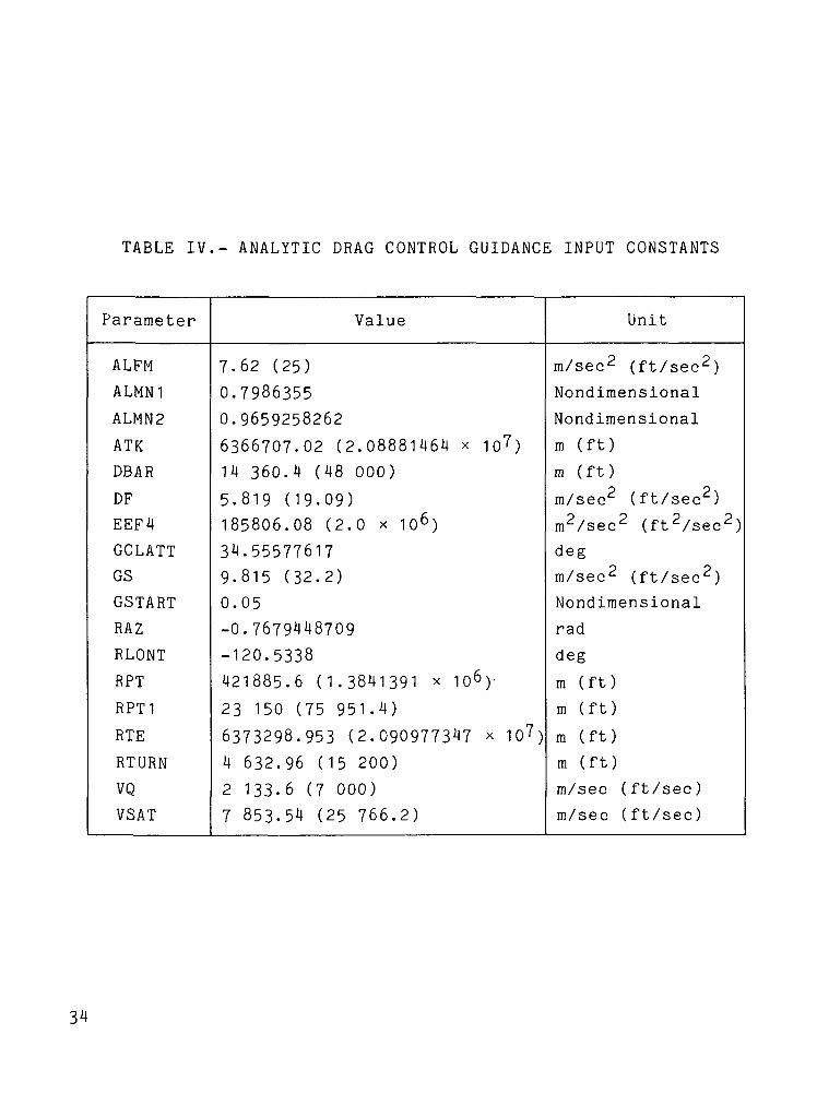
TABLE IV.- ANALYTIC DRAG CONTROL GUIDANCE INPUT CONSTANTS
Parameter Value Unit
ALFM
ALMN1
ALMN2
ATK
DEAR
DF
EEF4
GCLATT
GS
GSTART
RAZ
RLONT
RPT
RPT1
RTE
RTURN
VQ
VSAT
7.62 (25)
0.79863550.9659258262
6366707.02 (2.08881464 x io7)
14 360.4 (48 000)
5.819 (19.09)185806.08 (2.0 x io6)
34.555776179.815 (32.2)
0.05
-0.7679448709-120.5338
421885.6 (1.3841391 x 10⁶)'
23 150 (75 951.4)
6373298.953 (2.090977347 x 10⁷)
4 632.96 (15 200)
2 133.6 (7 000)
7 853.54 (25 766.2)
m/sec2 (ft/sec2)
Nondimensional
Nondimensional
m (ft)
m (ft)
m/sec2 (ft/sec2)
m2/sec2 (ft2/sec2)
deg
m/sec2 (ft/sec2)
Nondimensional
rad
deg
m (ft)
m (ft)
m (ft)
m (ft)
m/sec (ft/sec)
m/sec (ft/sec)
34
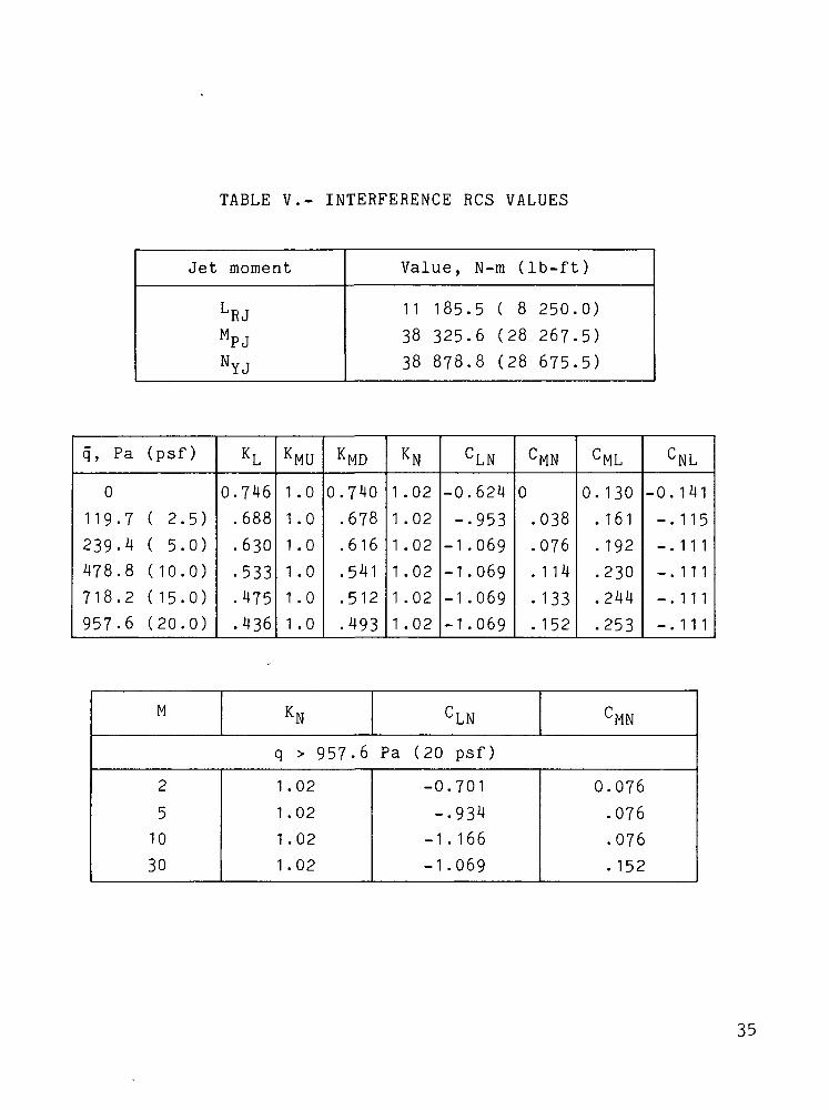
TABLE V.- INTERFERENCE RCS VALUES
Jet
L
M
N
moment
RJ
PJ
YJ
Value,
1 1
38
38
185
325878
N-m (
.5
.6
.8
( 8
(28(28
Ib-ft
250.
267.
675.
)
0)
5)5)
q, Pa (psf)
0
119-7 ( 2.5)
239.4 ( 5.0)
478.8 (10.0)
718.2 ( 15.0)
957.6 (20.0)
KL
0.746.688.630.533.475
.436
KMU
1 .0
1 .0
1 .0
1 .0
1 .0
1 .0
KMD
0.740
.678
.616
.541
.512
.493
KN
1 .02
1 .02
1 .021 .021 .021 .02
CLN
-0.624
-.953-1 .069-1 .069-1 .069-1 .069
CMN
0
.038
.076
.114
.133
. 152
CML
0. 130. 161. 192
.230
.244
.253
CNL
-0. 141
-.115-.111-.111-.111
-.111
M KN CLN CMN
q > 957.6 Pa (20 psf)
2
5
10
30
1.02
1.02
1.02
1 .02
-0.701
-.934-1 . 166
-1 .069
0.076
.076
.076
.152
35

£_0
o(U
na;ocoD.
coI
0)L3hO
36

150
100
Altitude,km 5o
10 r
Velocity,km/sec
Range,km
0
12
10
8
6
h
2
0 L-
103
o 500 1000 1500 2000
Time, secFigure 2.- Space shuttle orbiter entry trajectory parameters.
37
deg
40
30
20
10
0
80
«>c.deg
-40
-80 L
(
I\J
o 500 1000Time, sec
Figure 2.- Concluded.
1500 2000
38
400
300
200RCSfue l ,
kg100
Guidance system sampling time - 0.32 sec
Guidance system sampling time - 1.28 secGuidance system sampling time • 2.00 sec
40
Hdeg
-40
0
Ib
500 1500 2000lOOff
Time, sec
Figure 3.- RCS fuel and roll-angle <t> histories for various
guidance system sampling times.
- Pitch jets
300 350
Time, sec
(a) Guidance system sampling time -0.32 sec.
Figure 4.- Simulation strip charts for various guidance system
sampling times.
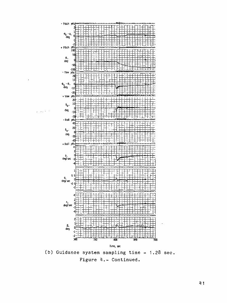
(b) Guidance system sampling time - 1.28 sec.
Figure 4.- Continued.
- Pitch jets21
«C - Q,
deg
-2+ Pitch jets
100
50
deg 0
-50-100
-Yaw jets2010
*c-*,
-20+ Yaw jets
206a, 10
-10-20
-Roll jets40
6e, 20
deg-20-40
+ Roll jets
p,deg/ sec
deg/sec
-0 5-1
r,deg/sec "
deg
r~ 'i , 'i ' ',
" Z!L_ ~^' ' '
, ,- r—
ti n rt-7
55 ;pl «. = ,— == -i fc
Jb.
[__),^_=s--pv
"v
L
=K = ;= = = =• -n
^- — ^.^^-^jAft lW-""^ff^T
!_ 1 J \ t LLJ-IJi i i 1 . . T 1 ")
f— *** — , t*-» i*r >ri *•-
. """LL
^ -T, L np -H 1^
i i L _L. J_ -LL
~*** L. ^<^{£.'i "— pK **» 5
It l' '
"****" -^*— — *•
Vt ^•u
i >* ""
S "S •« in r~ i f«- n
_u 1__ — ^1. — 1 »-
-B/ — -
""---- =
|
^^
_J_
^Tj_
u iMl&t ^
, i j_
— L
_
S3- OP P-
I
1 — rT
i11
-V"*-1.( "
. l
300 350 400
Time, sec
450 500
(c) Guidance system sampling time - 2.00 sec
Figure 4.- Concluded.
1100 1150 1200 1250
Time, sec
1300
Figure 5.- Simulation strip charts for early portion of constant
drag phase with guidance sampling time of 2.00 sec.
1500 1530 1600 1650
Time, sec
1750
Figure 6.- Simulation strip charts for later portion of entry
with guidance sampling time of 2.00 sec.
44
- Pitch jets
1
°c °» Cledeg _,
«
t Pitch jets100
500
deg 0-50
-100- Yaw jets
V1 ode9 in
-20+ Yaw jets
in
5a, 0j -indeg 1U
6e, 'u6 n
riPn
^ ?n
4 Roll jets
Pt *deg/ sec 0
A
H, '
deg/ sec 0_n c
47
'• ndeg/ sec
-4
A
ft 1
deg 0
.]-230
,
1
V
'
1
1
,.
-1
1
i
,1'1
r
i1
1
'!
1
.
!('
1
I'l
1t
HI
1
1 1
1!
t,i •
_
^
3
•M•i
,!
H
f i .
'jt
t
,
50
It-^i 1
! -
j- L>.,
lil "I :__
41 -
ITITj
1
^<£
,;G
i
Lj_
T. >
K (
11
r,
,it'1i
!
i
ijr i,,ll1
1
*!',j~1
w
i
— "7,
t] ~'
i
-•if
\\ii
n
> /
Ur
V>ti
ii
"f*
i
^^
* .i
• •
-I
r*
i
-J!
i|
-=?
j-"1
^
i'
\
i
*~*
iiii
i' '
'!'
!
"
-J
"*• —
450
,1
4r*tj -1 ''
! ni
II
11
^~ t—= =r
*" •—
i
i( •1 i)
»
{
i
'
i_
i
1
i
i':
1
_
_
)OU
Time, sec
(a) Early portion of entry.
Figure 7.- Simulation strip charts for ramp with guidance
sampling time of 2.00 sec.
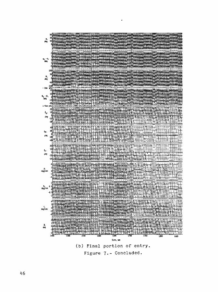
Time, sec
(b) Final portion of entry,
Figure ?.- Concluded.
T3<a
CObO
Q)
V-1
((-1
kT>O
-
<- 1
\
1- ,
i
'
r>oroi
s-0)9-
<t-
-e-
>
>S
3
n
h-*,
?S
u
l'?
-1 !
•— t
N,r\
-€>•
1C
O"
cc\
s.
>
L 1• -* —
o oro r~.V t— 1
!- AS- OS- S_0) i-
-©- <u
4
S)
Kv/-r,
.— t
,
Ul
J
i.
or>.
V
-eV
oO"
7]V
CT>
5icr
E
1
iit
<Dt-
11
Q. C
CO Ocn — -A •
icr
>
i
t/i
C£
IM•H•ooE
EcOL,
C bO<T3 trt frtQ. Q. _*H
Ol — 'vn i i0o
CO
PC
a ?
irt ^*oLJ 1
•
oo
<D
^in &CO -H
w
i
o01
OOO
O<u
OinOro
o<D
OOCO
OCM
O0)
OO
ID
II
T301-ocID
ILf)CM
OCM
oOl
oooin
OO)
E
inCMin
01x>c.
&
O-D 0)D (X^ Vt ^~.V) COID <n
-o <u ••M 01
<U (J if-
•u C T30) — C
XI CTJV) &
(D 01 T>II C (D1_ — 11< — -a
oCM
oin <u
Eo ••-
O0)
Ooo
oat
oinCMii
en<U-a
ft
•e-
nCoa
coc•HrtbO
CMO
O0)
<MCMW
0)f-DbO•H
48
- Pitch jets ' "'? i^
T, ' f] _« , _
i 1*
+ Pitch jets i i i i i i i100 ' M
\ i ' i50 <_
' ndeg u . _ _ £: -i
-50 '
-100 J- -J- -
2C-
(D dl
-1C £2
OA
. n
6., 1°3 n _,
/Ion °de9 in9n
40A
6e. 20
dea«j
™
p, 0"---deg/sec
~2 °.
i |.
dew sec
'2
deg/ sec
«
i
deg 0-^^
300
i i
i
. . _ -\ ^: -T
j
I '
S" ' * ji
1 "^• • 1
ip rp'j J ,*.--1*
' ' f,V ' 'i
-
i
I
Vi W *> "• """
1
"" l^_ _- — •""""'"
-^ •"•-«
t
350 400
— ' k-
, . !
~ ,
1
1
-
. - -
—»''"'
J50 500
Time, sec
(a) Early portion of entry.
Figure 10.- Simulation strip charts for gain with guidance
sampling time of 2.00 sec.
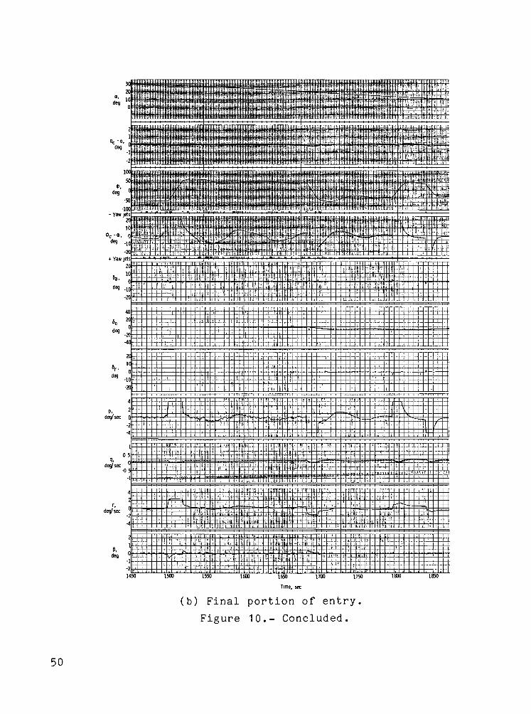
deg
1650 1700
Time, sec
(b) Final portion of entry.
Figure 10.- Concluded.
50
O=3
10
soin
**- ioOJ
<TJ O S*
rA0*° -b
O> O US_ 01 OlQ. t/1 in
00
O 0
A 0
"i«=1
C
,
fO i/lQ_ O.
VO OO V
r AICT
C
2n bO
1 - j-i
N 4-* OJ !0) r, Or^ "O
0) > I
(O CT>cn O)
\y o> <u i- o^y i/i i/i o t- _E -l-1 ' 000 -H«* 0 " *J &_.O O -4-> Ol *""
v«o ^ o; T3
\ Tr 1 1 a. N « S B; .5 ~ ~ 2
fD o *£ W)
c „ + Z, -HJ O C 3 C ' O
T 3 C O
Q- , 0) -^= o) e o
CT> »— 1 4-> fO X^r~ • 10 -c"* ° •c *"* L
cr j_> oj -P<1) r-j j-j
S o 0"^ L O
• — • > * - < * -<T3 t+- O O Ca. ui r*
Q. S- S- 3U3 OJ Ol /-,Ol CSJ J3 J3 <->
1 1 "7f f o.
CDi_3bO•Ht,
51
RCSfue l ,kg
Hysteresis (a-3.0, b -4 .5 )
deg
-40
0
'• Ramp + Gain + Up-down gam
800
600
400
Ib
200
500 1500 20001000
Time, sec
Figure 12.- RCS fuel and roll-angle <J> histories for various
control system modifications with guidance system samplingtime of 2.00 sec.
52
( START ~)
1 r
TARGETING
EC0NSTANTATTITUDEPHASE
N0A.B.C,D;ISLECT^>
N0 CONSTANTHEAT RATEPHASE
oG0 T0
ENTRY POINT
*ISLECT = 0 initially
Figure 13.- Analytic drag control entry guidance systemflow diagram.
53

EQUILIBRIUMGLIDEPHASE
TRANSITI0NPHASE
CONSTANTDRAGPHASE
C0NTR0LSYSTEM
Figure 13-- Concluded.
INITIALIZE
DATA GS,ATK,GSTART,RPT,VSAT.VQ.ALMNl.ALFM,RPTl.RAZ.RTE.DBAR,RTURN.ALMN2.EEF4.DF,RL0NT,GCLATT
REC(l.l)REC(1,2)REC(1,3)REC(2,1)REC(2,2)REC(2,3)REC(3,1)REC(3,2)REC(3,3)
-C0S(RAZ)*SIN(GCLATT)*C0S(RL0NT)-SIN(RAZ)*SIN(RL0NT)-C0S(RAZ)*SIN(GCLATT)*SIN(RL0NT)+SIN(RAZ)*C0S(RL0NT)C0S(RAZ)*C0S(GCLATT)SIN(RAZ)*SIN(GCLATT)*C0S(RL0NT)-C0S(RAZ)*SIN(RL0NT)SIN(RAZ)*SIN(GCLATT)*SIN(RL0NT)+C0S(RAZ)*C0S(RL0NT)-SIN(RAZ)*C0S(GCLATT)-C0S(GCLATT)*C0S(RL0NT)-C0S(GCLATT)*SIN(RL0NT)-SIN(GCLATT)
ISTRT = 0ISTART = 0ISLECT = 0IFT = 0IDFG2 = IDFG3ISTP = 0
= 0
BA1 = 0.VBB = 6248.4YB = .3054
GUIDANCE EQUATIONS
TIME
TJO SAMPLEGUIDANCE?
-HDD
Figure 14.- Analytic drag control entry guidance system
block diagram.
55
YES
DRAG = XLFAC//1.+XL0D2
YES
YES
HS = 6028.24+.48148*V
HS = 19126.20-1.625*V
HS = 8229.6
1 TARGETING
N0
LIT ro/IO A -*
YES
[RG]= [REC] [XYZE]RG(3) = RG(3)+RTERGP(l) = RG(1)+DBARRGP(2) = RG(2)-SIGN(RTURN,RG(2))RGP(3)DT = /AMAX1(0.,RGP(1)Z+RGP(2)2-RTURN2)DTH = TAN-1(RTURN/DT)DVHEAD = TAN-l(-RGP(2)/(-RGP(l)-SIGN(DTH,RG(2)))U = |DVHEAD|
Figure 14.- Continued.
56
ARC = RTURN*URGP(l) = -DT*C0S(DVHEAD)RGP(2) = -DT*SIN(DVHEAD)RG(3) = RG(3)-RTETARE(J) = RG(J)-RGP(J) ; J = 1,2,3UXYZE = [RG]/ RG|UTARE = [TAREJ/ITARE!CTH = [UXYZE]-[UTARE]TRANGE = ATK*C0S-1(CTH)+ARCTA(J) = -RGP(J) , J = 1,2,3[TAl = [REC1] [TA]
CIGAR(1,1) = -SIN(GCLAT>C0S(RL0N)CIGAR(1,2) = -SIN(GCLAT7*SIN(RL0N)CIGAR(1,3) = C0S(GCLAT)CIGAR(2,1) = -SIN(RL0N)CIGAR(2,2) = C0S(RL0N)CIGAR(2,3) = 0.CIGAR(3,1) = -C0S(GCLAT)*C0S(RL0N)CIGAR(3,2) = -C0S(GCLAT)*SIN(RL0N)CIGAR(3,3) = -SIN(GCLAT)[TAP] = [CIGAR] [TA]
TAP(J)=SIGN(i:10,TAP(J))
PSIET = TAN'1 [TAP(2)/TAP(1)]DELAZ = PSIE-PSIET
Figure U.- Continued
57
R K 2 R 0 L = - S I G N ( 1 . . D E L A Z )
YB=-.1308996939+.0003578838583*V
•- YB=.0872664626 »
Figure 14.- Continued
58
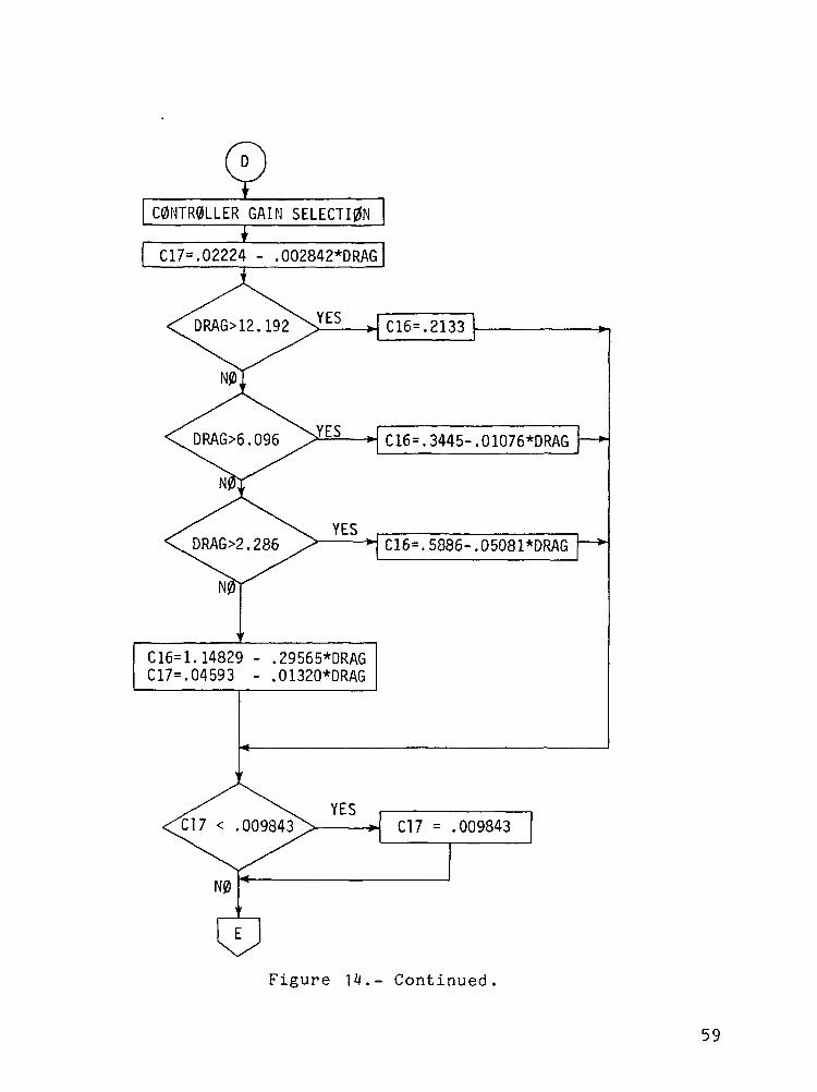
C0NTR0LLER GAIN SELECTI0N
C17=.02224 - .002842*DRAG
*. C16=.2133
C16=.3445-.01076*DRAG
C16=.5886-.05081*DRAG
C16=l.14829 - .29565*DRAGC17=.04593 - .01320*DRAG
Figure 14.- Continued
59
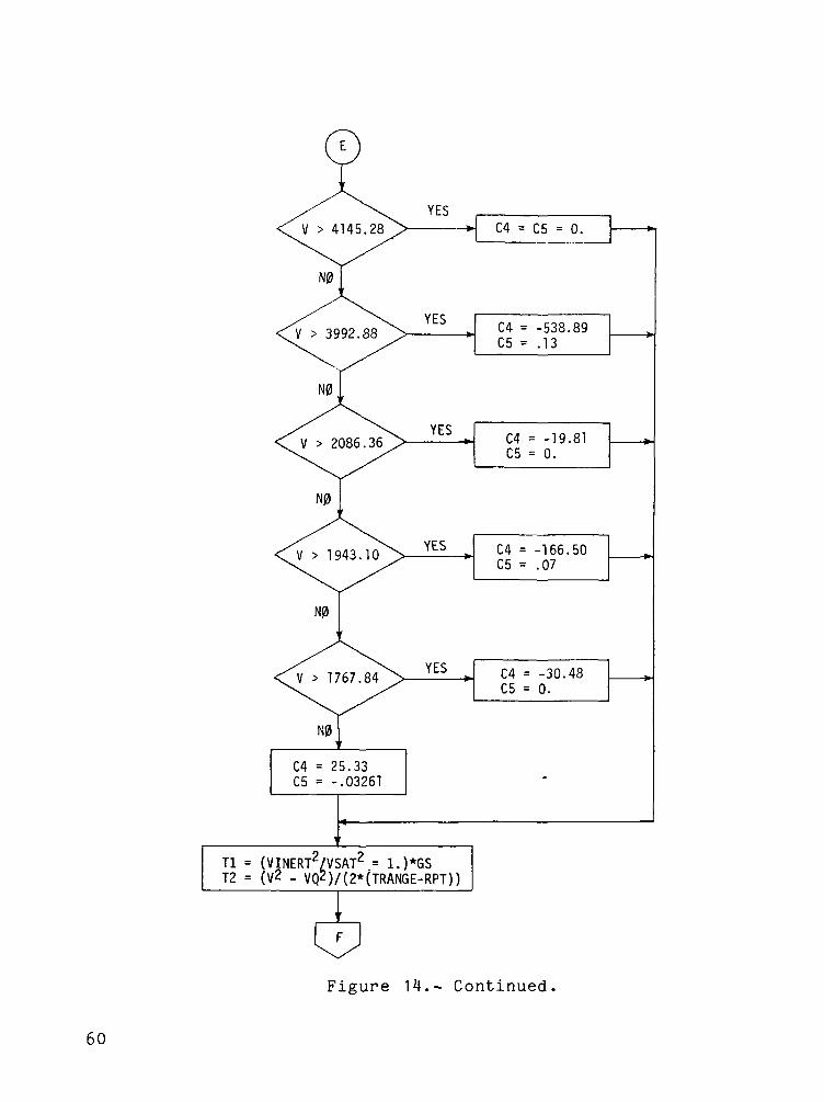
C4 = 25.33C5 = -.0326!
C4 = C5 = 0.
C4 = -538.89C5 = .13
C4 = -19.81C5 = 0.
C4 = -166.50C5 = .07
C4 = -30.48C5 = 0.
Tl = (VINERT2/VSAT2 = l.)*GST2 = (V2 - VQ2)/(2*(TRANGE-RPT))
Figure 14.- Continued
60
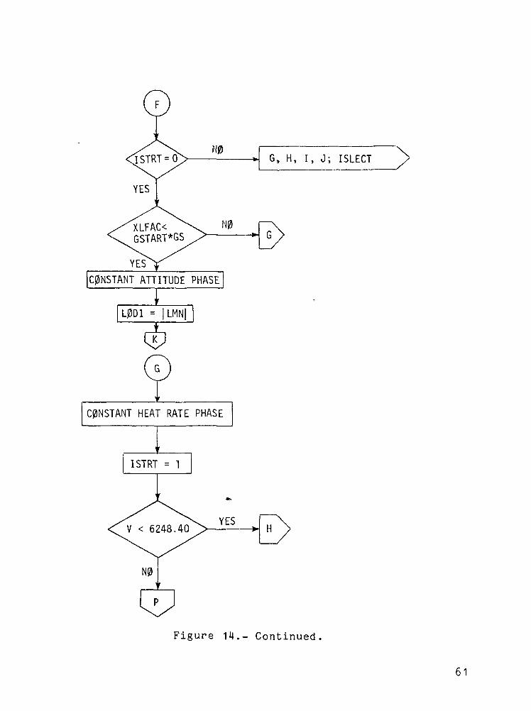
G, H, I, J; ISLECT
C0NSTANT ATTITUDE PHASE
L0D1 = |LMN|
CONSTANT HEAT RATE PHASE
Figure 14.- Cont inued .
61
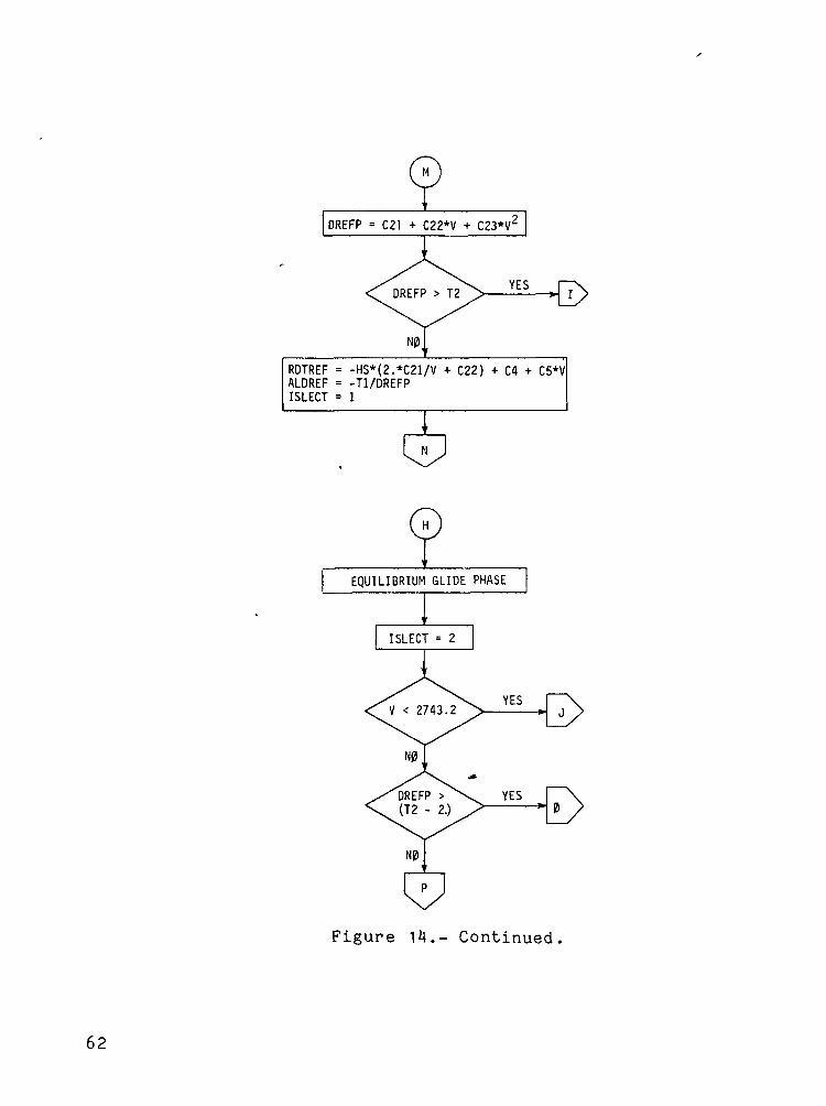
DREFP = C21 + C22*V + C23*V2
RDTREF = -HS*(2.*C21/V + C22) + C4 + C5*VALDREF = -Tl/DREFPISLECT = 1
EQUILIBRIUM GLIDE PHASE
Figure 14.- Continued.
62
I ISTP * 1 [
BA = 60.*OTRBA1 = 60.
TEMP = 1.4*VSAT2*C0S(BA)/GS
ALFM*TEMP \ YES< VSAT2
Figure 14.- Cont inued .
63
023 = -GS*(VBB2/VSAT2 - 1.)/(1.4*C0S(BA))AK = -3.5*D23/VBBC23 = -AK/3352.8C 2 2 = 15849.6*C23C21 = D23 - C22*VBB - C23*VBB2
Till = -.5*LN((C21 + C22*VBB + C23*VBB2)/(C21 + C22*V + C23*V2))/C23SQ = 4.*C23*C21 - C22*
YES
SQQ ,TT22 = C22*(TAN~1(2.*C23*VBB/SQQ + C22/SQQ)
C22/SQQ))/(C23*SQQ)
SQQ = /3QEl = (2.*C23*VBB + C22 - SQQ)/(2.*C23*VBB + C22 + SQQ)E2 = (2.*C23*V + C22 - SQQ)/(2.*C23*V + C22 + SQQ)TT22 = C22*LN(E1/E2)/(2.*C23*SQQ)
REQ = .5*fEMP*LN((VCG2 - VSAT2)/(VBB2 - VSAT2))RCG = (VCG2 - VQ2)/{2.*ALFM)
S, T, 0; ISTP
Figure 14.- Continued
Rll = REQ + RCG + RFFDBB = -.5
BA2 = BA1 - DBBBA = BA2*DTRISTP = 2
R12 = REQ + RCG + RFFBAD = BA1 + (TRANCE - Rll - RPT)/((R11 - R12)/(BA1 - BA2))
Figure 14.- Continued
65
TDREF = GS*(V2/VSAT2 - 1.)C0SBADD = 1.4*C0S(BAD*DTR)DREFP = -TDREF/C0SBADD 9
RDTREF = -2.*HS*DREFP/V - 2.*HS*GS*V/(C0SBADD*VSA"T) + C4 + C5*VV0LD = VRDT0LD = RDTREFAIDREF = -Tl/DREFP + 2.*HS*GS/(C0SBADD*VSAT^) + 2.*HS*DREFP/V^
C0NSTANT DRAG PHASE
DREFP = T2RDTREF = -2.*HS*DREFP/V + C4 + C5*V
Figure 14.- Cont inued
66
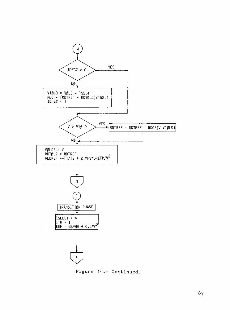
YES
V10LD = V0LD - 152.4RDC = (RDTREF - RDT0LD)/152.4IDFG2 = 1
RDTREF = RDTREF - RDC*(V-V10LD)
N0U
V0LD2 = VRDT0L2 = RDTREFALDREF =-Tl/T2 + 2.*HS*DREFP/V'
TRANSITION PHASE
ISLECT = 4ITR = 1EEF = GS*HA + 0.5*V<
Figure 14.- Cont inued
67
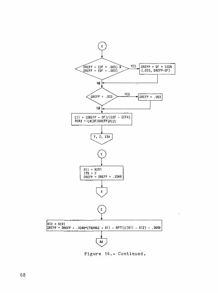
DREFP = OF + SIGN.003, DREFP-DF)
REFP < (DF + .003)DREFP > DF - .003
Cll = (DREFP - DF)/(EEF - EEF4)RER1 =-LN(DF/DREFP)/Cll
Y, Z; ITR
Rll = RER1ITR = 2DREFP = DREFP + .3048
R12 = RER1DREFP = DREFP - .3048*(TRANGE - Rll - RPT1)/(R11 - R12) - .3048
Figure 14.- Continued
68
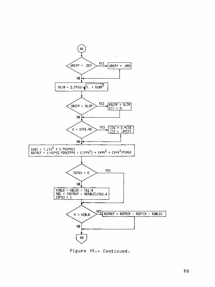
CAGI = l./(V + 2.*GS*HS) ,RDTREF = (-HS*(2.*DREFP*V - C11*V3)
V20LD = V0LD2 - 152.4RDC = (RDTREF - RDT0L2)/152.4IDFG3 = 1
RDTREF = RDTREF - RDC*(V - V20LD)
Figure 14.- Continued.
69
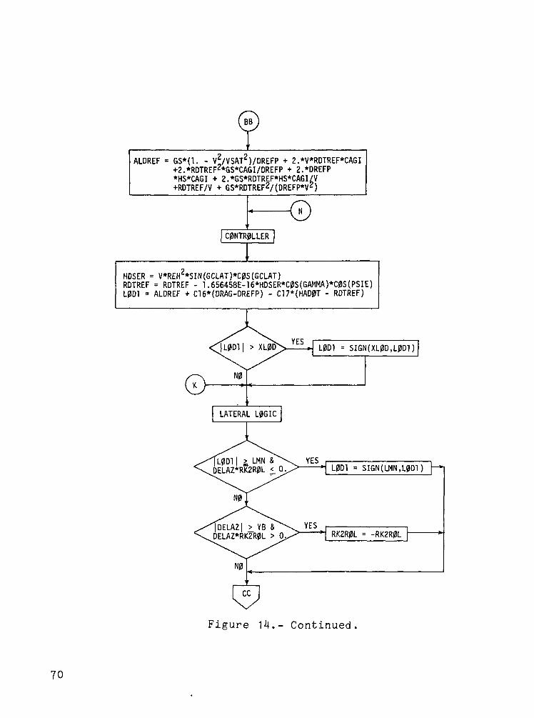
ALDREF = 6S*(1. - V2/VSAT2)/DREFP + 2.*V*RDTREF*CAGI+2.*RDTREF2*GS*CAGI/DREFP + 2.*DREFP*HS*CAGI + 2.*GS*RDTREF*HS*CAGI/V+RDTREF/V + GS*RDTREF2/(DREFP*VZ)
HDSER = V*REH2*SIN(GCLAT)*C0S(GCLAT)RDTREF = RDTREF - 1.656458E-16*HDSER*C0S(GAMMA)*C0S(PSIE)L0D1 = ALDREF + C16*(DRAG-DREFP) - C17*(HAD0T - RDTREF)
L0D] = SIGN(XL0D,L0D1)
LATERAL L0GIC
|L0D1| £ LMN &DELAZ*RK2R0L 1 0 L0D1 = SIGN(LMN,L0D1)
|DELAZ| >.YB &DELAZ*RK2R0L > 0 RK2R0L = -RK2R0L
Figure - Continued
70
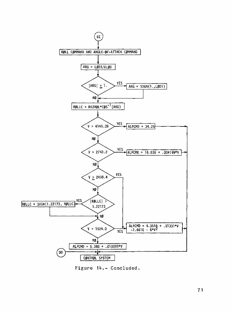
FR0LL CUMMAND AND ANGLE^F-ATTACK COMMAND
ARG = L0D1/XL0D
ARG = SIGN(1.,L0D1
R0LLC = RK2R0L*C0S '(ARG)
ALPCMO = 34.25
ALPCMD = 16.836 + .004199*V -»
|R0LLC|1.22173
R0LLC = SIGN 1.22173, R0LLC
ALPCMD = 4.3516 + .01331*V-1.661E - 6*V
ALPCMD = 5.385 + .010095*V
C0NTR0L SYSTEM
Figure 14.- Concluded.
71
CD
ZJ•oCD
OQ<O
tq
CO
oro
CO CO<O <O
M-o
01o
<oS-cn
O)u
CD-CU
CQOO
•O
CD
2.OI
CDQ.
oOl
OO
oCO
o10
J oo
X
o
wo;
3•a0
ow0)
rt£)I
TD00a,w•oc
a,(0rHCMI
TDO
PQ
in
3bO
i a)•a
72
ECO£-bOCO•HTD
!OO
•0CCOSEOO
o-pCO>0)rH
w
(U
bO•rH
73

* 10"O
oII
Q_
CO
10cr>
ou_*
ECOS-bO
LTl OO
•oC
TD COC ECO S
ou
C
in
CO
V||
8
O
CO£-CDrH•H
3bO
oo
OCM
OCM
ino
Oft
o0 1ii a<-> rt.0-1•p
O
IT) If) CLc. o o • •
^ r-H t—t CM CXI CM
(OCl-
o o«— < CO
o 01 ir-
cnV
i cri.ou.*
<DH
<D
a AT33
O
£-, Co o
OOO
A
a
I•
t>-
(UL,3bO
ou
75
't-o
Ol3
ro o> ZD
Pre
viou
s «a
1 >
LO
•6V
__+J
o oO> OlI/I to
<4-co*3- 0O 0ro O
Aoa:'—
*
°J
J
4-m m
Q- C- )
S£i V
v « \cr
LT>',
N-~
4-> 01Q) <->r—>
Ol >
r- Ij
+-> fO .
CT) Ol S
X " " c ?y si s; ° ° rt
^^ "V ' £ro • TD<a- o - +JO O -!-> Ol v
vllO ^ Ol ^1 orr- 01 > O\ >" > £ rH
\ " U u,Ul O ..0 Q- S-ia. d)
!- 0 -Po •*- C
+ 3+ — O"" c 0C 00 (-,
oi CO) E 3
§ S °° r- ° 4-> "°
Tl c3 ""• 4-) TO '^ r— O (O -C O.3 -C 4-> i— ,
l/> -U Icr ->-> 01 '
0) r-j .
••> co3 •— »—fQ O
" ^ Q)• — • ' « - ' « - c.
IO M- O O _Q- in 3VO Q- S- S- Kncn co 01 a) ~
— -o -o -HAll E E fj_.
3 3 MJ
icr z z:
* **
(/)o
«C£
to*O*D::
76
co•ocraSEOo
CDCCOQ,
CO>CDfHCD
CMCD
•oCCO
-Ps:bC•H
Icr\
Q)
3bO
77
O0.
oO ID
(Ui,(0
CO
^
,-»uo></>"•+-*
^-*
<Jcuiner
S-•0
in"A
s:
oo
^ ^ COo o """O O Ao ur>CM CJ S
01
35•aJJs_03>
>.
S_
sc
( —
ra<D
4Jc<1JJ^aJex
c•H._f
e3
aCOtn
Oo
•accdB
o
•aT33
OCM
i.3bO•H
CO
>.CHtO
O4-3
W
3
O
00
C•H
78
o
o
PJd 8t t
O CSJ
o
s(0L.bOCO•H•o
OO
COCbO•HCO
£-,O
00
CJ
CO
(1)£~3bO
79
'o0£
i
1 '
1J
\
unQ0i ioCSJ
0t
oooo:
0t\J
0
'uno0
i ,i ,
J ,
1
->111o
14-o
o
O CM ^J-
0 — 8
t t to ir> r—•
o
S-,t>0CO•H•a
00
00
cdcbO•HCOI
t<oSH
£H
(!)
COCOoq
CMCM
CO£-,ahO
80
5 ento o
, ,
LO
01 ,
o
1
o
LO
0
' '
1
o
o
LT> IT) O LO
o i— -NJ oj 8t t t t t
o in Ln o LDO i— <NJ 00
inVII
s
VII
s
ECOt,bDCO
.itfOo
COcbO
•HnI
£-.oSL,f^0)
COOPC
SCO
on
Q)I.,Dbo•Hfa-.
81
1J
, ,
IT)O
<?ot\J
o1
CO
g
oC\J
o
mor-i
l/l4JO)
o
o
>-UJ
in oo in oO O
t to m o
o m o
t-Ol
o -aCM <u
00LD 10CT1 ••-
V «4->
1C" 0)
. "I So-r-l I-H U- O
>-LU
V
1
c(
o cO <t-H
<- i
<
<1
- J
f~
•s.
(•rI
i
~"
•*>
V}1
i
\
<v ,
f
?\
3^
/)
• ^
>S
^+
) (
*
0
Oi— l
^
L.n~cc
j
3
J
H
CO
COCSJ
/<-^
o>r~coi— «
i
w
;
>*-(/i
r{J Q.^v Q-/) OO CO V\J in-^\
r *' Nicr
f
*.
en or . •-<^f ^~^ J+cr
in
7t/>
•
LO ••o
A Q)•o
S 3
C °TO vi £-1 Co-o- O OCO 0 Uin c\jCTt ' — ' /-» ivii O I
icr OO
CMA
a L.3faO
' — -H
O
iOU
in0
?'in
o-e- -e-
82
ot0
CO>(D
CO
WEnJt,bo03•H•O
OO
£-,O^>cd3-pO
bO•H
83
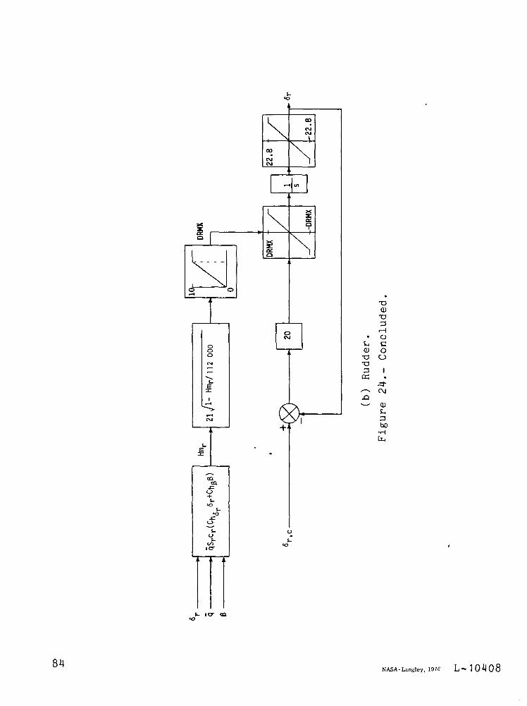
•o•oD
•a3rH
Oco
eg
OJSH3bO•H
84NASA-Langley, 1976 L — 1 0 4 0 8
NATIONAL AERONAUTICS AND SPACE ADMINISTRATION
WASHINGTON. DC 2O546
OFFICIAL BUSINESS
PENALTY FOR PRIVATE USE S3OO SPECIAL FOURTH-CLASS RATEBOOK
POSTAGE AND FEES PAIDNATIONAL AERONAUTICS AND
SPACE ADMINISTRATION451
POSTMASTER If Undeliverable (Section 158Postal Manual) Do Not Return
"The aeronautical and space activities of the United States shall beconducted so as to contribute . . to the expansion of human knowl-edge of phenomena m the atmosphere and space The Administrationshall provide for the widest practicable and appropriate disseminationof information concerning its activities and the results thereof "
—NATIONAL AERONAUTICS AND SPACE ACT OF 1958
NASA SCIENTIFIC AND TECHNICAL PUBLICATIONSTECHNICAL REPORTS Scientific andtechnical information considered important,complete, and a lasting contribution to existingknowledge.
TECHNICAL NOTES Information less broadin scope but nevertheless of importance as acontribution to existing knowledge
TECHNICAL MEMORANDUMSInformation receiving limited distributionbecause of preliminary data, security classifica-tion, or other reasons Also includes conferenceproceedings with either limited or unlimiteddistribution.
CONTRACTOR REPORTS Scientific andtechnical information generated under a NASAcontract or grant and considered an importantcontribution to existing knowledge.
TECHNICAL TRANSLATIONS Informationpublished in a foreign language consideredto merit NASA distribution in English
SPECIAL PUBLICATIONS Informationderived from or of value to NASA activities.Publications include final reports of majorprojects, monographs, data compilations,handbooks, sourcebooks, and specialbibliographies
TECHNOLOGY UTILIZATIONPUBLICATIONS Information on technologyused by NASA that may be of particularinterest in commercial and other non-aerospaceapplications Publications include Tech Briefs,Technology Utilization Reports andTechnology Surveys
Details on the availability of these publications may be obtained from:
SCIENTIFIC AND TECHNICAL INFORMATION OFFICE
N A T I O N A L A E R O N A U T I C S A N D S P A C E A D M I N I S T R A T I O N
Washington, D.C. 20546
Related Documents