NASA Contractor Report 3321 Satellite Power Systems (SPS) Concept Definition Study Volume IV - Transportation Analysis G. M. Hanley CONTRACT NASS-32475 SEPTEMBER 1980 Nl\S/\

Welcome message from author
This document is posted to help you gain knowledge. Please leave a comment to let me know what you think about it! Share it to your friends and learn new things together.
Transcript
.,;.~------
NASA Contractor Report 3321
Satellite Power Systems (SPS)
Concept Definition Study
Volume IV - Transportation Analysis
G. M. Hanley
CONTRACT NASS-32475 SEPTEMBER 1980
Nl\S/\
r11.1 i I '' u ":1
NASA Contractor Report 3321
Satellite Power Systems (SPS) Concept Definition Study
Volume IV - Transportation Analysis
G. M. Hanley Rockwell International Downey, California
Prepared for Marshall Space Flight Center under Contract NASS-32475
N/\S/\ National Aeronautics and Space Administration
Scientific a11d Technical Information Branch
1980
Tl!CH UBRARY KAFB, NM
1111111111 0061931

r
FOREWORD
This is Volume IV - Transportation Analyses, of the SPS Concept Definition Study final report as submitted by Rockwell International through the Satellite Systems Division. In addition to effort conducted in response to the NASA/MSFC Contract NAS8-32475, Exhibit C, dated March 28, 1978, company sponsored effort on a Horizontal Take-Off, Single-Stage-to-Orbit concept is included.
The SPS final report will provide the NASA with additional information on the selection of a viable SPS concept and will furnish a basis for subsequent technology advancement and verification activities. Other volumes of the final report are listed as follows:
Volume Title
I Executive Summary
II Systems Engineering
III Experimentation/Verification Element Definition
v Special Emphasis Studies
VI In-Depth Element Investigations
VII Systems/Subsystems Requirements Data Book
The SPS Program Manager, G. M. Hanley, may be contacted on any of the technical or management aspects of this report. He may be reached at 213/594-3911, Seal Beach, California.
iii

r
CONTENTS
Section Page
1.0 INTRODUCTION 1-1 2.0 TRANSPORTATION SYSTEM ELEMENTS 2-1 3.0 TRANSPORTATION SYSTEM REQUIREMENTS 3-1 4. 0 HEAVY LIFT LAUNCH VEHICLE • 4-1
4 .1 HLLV REQUIREMENTS/GROUND RULES 4-1 4.2 HLLV CONFIGURATION 4-2
4.2.1 HLLV First Stage (Booster) 4-3 4.2.2 HLLV Second Stage (Orbiter) 4-3
4. 3 HLL V PERFORMANCE • 4-6 4.4 TRADE STUDY OPTIONS 4-20
5.0 LEO-TO-GEO TRANSPORTATION -.EOTV 5-1 5 .1 ELECTRIC ORBITAL TRANSFER VEHICLE CONCEPT 5-1
5.1.1 EOTV Sizing Assumptions 5-2 5.1.2 EOTV Sizing Approach 5-2 5.1.3 EOTV Sizing Logic • 5-3 5.1.4 EOTV Weight/Performance Summary 5-5
5.2 ELECTRIC ORBITAL TRANSFER VEHICLE TRADE STUDIES 5-7 5.2.1 Solar Array Voltage, Grid Temperature, Numbers
of Thrusters 5-7 5.2.2 Power Distribution and Control Weight 5-7 5.2.3 Gallium Arsenide Versus Silicon Solar Cells 5-9 5.2.4 Attitude Control System 5-10 5.2.5 Trip-Time Optimization Analysis 5-13
6.0 ON-ORBIT MOBILITY SYSTEMS • 6-1 7.0 PERSONNEL TRANSFER SYSTEMS 7-1
7.1 PERSOilliEL LAUNCH VEHICLE (PLV) 7-1 7.1.l Liquid Rocket Booster (LRB) 7-2 7.1.2 Liquid Rocket Booster Engine (SSME-35) 7-5 7.1.3 Liquid Rocket Booster Recovery Concept 7-5
7 .2 PERSONNEL ORBITAL TRAi~SFER VEHICLE (POTV) 7-7 7.2.1 Personnel Orbital Transfer Vehicle
Configuration 7-8 7.2.2 Personnel Module (PM) • 7-11
8.0 COST AND PROGRAMMATICS 8-1 APPENDIX A - HORIZONTAL TAKEOFF - SiclGLE STAGE TO ORBIT TECHNICAL
SUMMARY A-1 APPENDIX B - HLLV REFERENCE VEHICLE TRAJECTORY AND TRADE STUDY
DATA B-1 APPENDIX C - ELECTRIC ORBITAL TRANSFER VEHICLE SIZING C-1
v

Figure
1.0-1 2.0-1 2.0-2 2.0-3 2.0-4 2.0-5 2.0-6 3.0-1 3.0-2 4.2-l 4.2-2 4.2-3 4.3-1 4.3-2 4.3-3 4.3-4 4.3-5 4.3-6 4.3-7 4.3-8 4.3-9 4.3-10 4.3-11 4.3-12 4.3-13 4.3-14 4 .. 3-15 4.3-16 4.3-17 4.3-18 4.3-19 4.3-20 4.3-21 4.3-22 4.3-23 4.3-24 4.3-25 4._3-26 4._3-27 4.3-28 4.3-29 4.3-30 4._3-31 4.3-32
ILLUSTRATIONS
Transportation System Options - Vehicle Size HTO/SSTO HLLV Concept VTO/HL HLLV Concept • STS-HLLV Configuration Growth Shuttle PLV EOTV Configuration POTV Configuration SPS LEO Transportation Operations SPS GEO Transportation Operations Reference HLLV Launch Configuration • HLLV First Stage (Booster) - Landing Configuration HLLV Second Stage (Orbiter) - Landing Configuration • First Stage Thrust vs Time First Stage Specific Impulse vs Time First Stage Relative Velocity vs Time First Stage Flight Path Angle vs Time First Stage Altitude vs Time First Stage Weight and Range vs Time Second Stage Thrust vs Time • Mach Number vs Time • Normal and Total Load Factor vs Time Q and QV vs Time Lift and Drag vs Time a, E and aQ vs Time • Relative Velocity and Q vs Altitude • Body Attitude vs Time Inertial Velocity vs Time Flight Path Angle vs Time Altitude vs Time Total Load Factor vs Time Weight vs Time Thrust Attitude vs Time • Total Thrust vs Time Dynamic Pressure vs Time Altitude vs Range Total Thrust vs Weight Inertial Velocity vs Time Flight Path Angle vs Time Altitude vs Time Total Load Factor vs Time Weight vs Time Thrust Attitude vs Time • Total Thrust vs Time Dynamic Pressure vs Time
vii
Page
1-1 2-1 2-2 2-2 2-3 2-4 2-4 3-1 3-2 4-3 4-4 4-5 4-9 4-9 4-10 4-10 4-10 4-10 4-11 4-11 4-11 4-11 4-12 4-12 4-12 4-12 4-13 4-13 4-13 4-13 4-14 4-14 4-14 4-14 4-15 4-15 4-16 4-16 4-16 4-16 4-17 4-17 4-17 4-17
Figure
4.3-33 4.3-34 4.3-35 5.1-1 5.1-2
5.1-3 5.2-1 5.2-2 5.2-3 5.2-4 5.2-5 5.2-6 5.2-7 5.2-8 5.2-9 5.2-10 5 .2-11 7.1-1 7.1-2 7. l-3 7.1-4 7.1-5 7.1-6 7.2-1 7.2-2 7. 2-3 7.2-4 8,0-1
8.0-2
Altitude vs Range Total Thrust vs Weight First Stage Flyback Trajectory EOTV Configuration Plasma Power Losses from a 15 kW Solar Array with 90%
Insulating Surface Selected EOTV Configuration • EOTV Power Distribution Simplified Block Diagram .• EOTV Power Distribution and Control Weight Comparisons EOTV Solar Array Comparisons (GaAs versus Si Solar Cells) Typical Gravity Gradient Torque Curves Alternative Thruster Configurations • Partial Solar Pointing Apportioned Resupply and Operations Cost/kg of EOTV Payload • Electric EOTV Fleet Sizes and Program Buys EOTV Capital Investment Streams • Time-Value of Money Impact on Cost Comparisons Electric EOTV Cost Comparisons Baseline Space Shuttle Vehicle L02/LH2 SSME Integral Twin Ballistic Booster STS HLLV Configuration Liquid Rocket Booster Main Engine (SSME-35) • Integral Booster Recovery Concept Booster Recovery System • POTV Operations Scenario Recommended POTV Configuration Advanced Space Engine POTV/PM Configuration Options SPS Transportation System DDT&E Program Schedule
Page
4-18 4-18 4-19 5-1
5-4 5-6 5-8 5-9 5-10 5-12 5-13 5-14 5-17 5-18 5-18 5-19 5-20 7-1 7-2 7-3 7-5 7-6 7-7 7-8 7-8 7-9 7-11
(Technology Advancement Phase) 8-6 SPS Transportation Systems--DDT&E, Technology Advancement Pnase 8-7
viii
Tabla
3.0-1 3.0-2
3.0-3 4.1-1 4.1-2 4.2-1 4.2-2 4.2-3 4.3-1 4.3-2 4.3-3 5.1-1 5 .l-2 5.1-3 5.1-4 5.1-5 5.2-1 5.2-2 5.2-3 5.2-4 5.2-5 5.2-6 5.2-7 5.2-8 6.0-1 7.1-1 7.2-1 7.2-2 7.2-3 8.0-1 8.0-2
8.0-3 8.0-4
TABLE
TFU Transportation Requirements SPS Program Transportation Requirements, 30-Year
Construction Phase Total Transportation Requirements, 60-Year Program • HLLV Sizing - Ground Rules/Assumptions • Technology Advancement - Weight Reduction HLLV Mass Properties x l0-6 • • •
HLLV Weight Statement kgxl0-3 (lbx10-3)
HLLV Propellant Weight Summary x 10-6
Engine Performance Parameters Vehicle Characteristics (Nominal Mission) Summary Weight Statement (Nominal Mission) EOTV Sizing Assumptions EOTV Sizing Approach EOTV Sizing Logic EOTV Thruster Characteristics EOTV Weight/Performance Summary (kg) EOTV Configuration Trades GaAlAs and Silicon Powered EOTV Weight Comparison (kg) • Preliminary Moments of Inertia • Thruster Requirements in Shadow ACS Trade Study Results Basic Equations Used in Analysis Sizing the EOTV - Payload Mass Capabilities Assumptions Affecting EOTV Trip-Time Cost Comparisons IOTV Weight Summary Shuttle LRB Unique Design Features • Current ASE Engine Weight POTV Weight Summary POTV/PM Options - Element Mass • Satellite Power System (SPS) Program Development Cost Satellite Power System (SPS) Transportation System Develop-
ment Cost Satellite Power System (SPS) Program Average Cost Satellite Power System (SPS) Transportation System Average
Cost
ix
Page
3-3
3-3 3-4 4-1 4-2 4-3 4-4 4-5 4-6 4-7 4-8 5-2 5-3 5-3 5-5 5-5 5-8 5-11 5-11 5-12 5-14 5-15 5-16 5-16 6-1 7-4 7-10 7-10 7-12 8-2
8-3 8-4
8-5
111111
1. 0 INTRODUCTION
I.
1 .O INTRODUCTION
The SPS transportation system, not unlike the SPS, presents a formidable challenge to our current concepts of space-oriented endeavors. Cost, more than ever, becomes the key denominator in transportation system selection. Methods of reducing transportation costs contribute significantly to the establishment of the SPS as a viable energy source option.
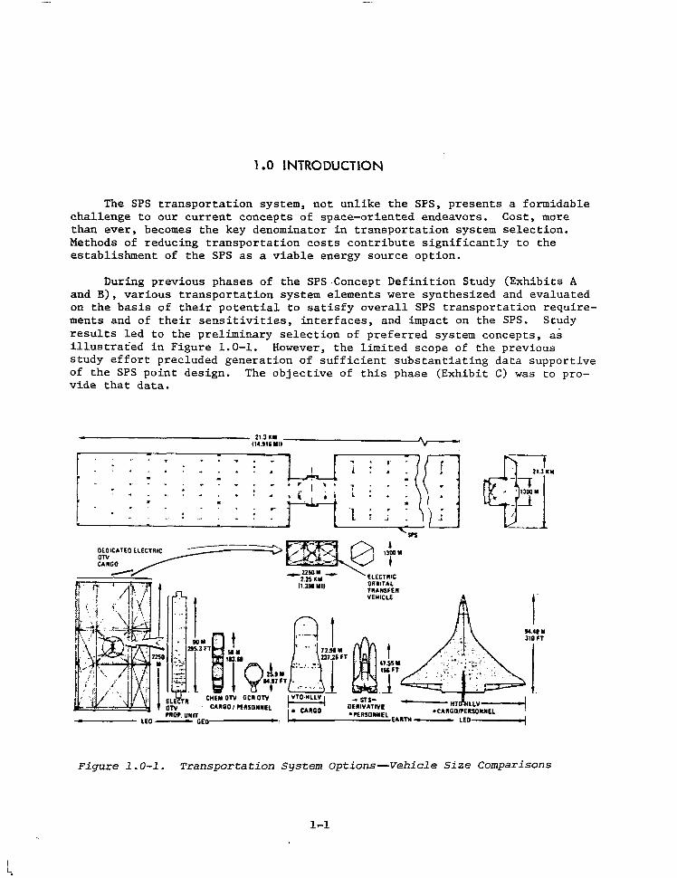
During previous phases of the SPS-Concept Definition Study (Exhibits A and B), various transportation system elements were synthesized and evaluated on the basis of their potential to satisfy overall SPS transportation requirements and of their sensitivities, interfaces, and impact on the SPS. Study results led to the preliminary selection of preferred system concepts, as illustrated in Figure 1.0-1. However, the limited scope of the previous study effort precluded generation of sufficient substantiating data supportive of the SPS point design. The objective of this phase (Exhibit C) was to provide that data.
CHEii OTV GCR OTV CARGO 1 l'ERSOllllEL
- srsou1vATIVE 0
'ERSDllllEL lARTll ----
r !IUlll llOFT
Figure 1.0-1. Transportation System Options-Vehicle Size Comparisons
Additional analyses and investigations have been conducted to further define transportation system concepts that will be needed for the developmental and operational phases of an SPS program. To accomplish these objectives, transportation systems such as Shuttle and its derivatives have been identified; new heavy-lift launch vehicle (HLLV) concepts, cargo and personnel orbital transfer vehicles (EOTV and POTV), and intra-orbit transfer vehicle (IOTV) concepts have been evaluated; and, to a limited degree, the program implications of their operations and costs were assessed. The results of these analyses have been integrated into other elements of the overall SPS concept definition studies.
Emphasis, in the area of HLLV analyses, was initially directed toward an update of the Rockwell winged, single-stage, air-breathing HLLV and in performing a comparative evaluation of that configuration with a two-stage version of that concept. Upon completion of the HTO-SSTO update, effort in this area was redirected toward the development of an alternate vertical launch/horizontal landing two-stage HLLV concept with a concomitant reduction of effort in the operations definition tasks. Configuration updates and additional data relative to the feasibility and cost of the cargo EOTV and POTV concepts were generated and requirements and concepts definition of an IOTV were pursued. Within each of these areas, supporting programmatic data (e.g., costs and schedule requirements) for the transportation system elements were developed.
SPS program and transportation system analyses continue to show that the prime element of transportation systems cost, and SPS program cost, is that of payload delivery to LEO or HLLV feasibility/cost.
1-2
I ,
2. 0 TRANSPORTATION SYSTEM ELEMENTS
'!, .!"'1"· ·:; •IJ'
.. ~.
2.0 TRANSPORTATION SYSTEM ELEMENTS
As identified in previous study phases (Exhibits A and B), the SPS program will require a dedicated transportation system. In addition, because of the high launch rate requirements and environmental considerations, a dedicated launch facility for the vertical launch HLLV configurations is indicated.
The major elements of the SPS transportation system consist of the following:
• Heavy-Lift Launch Vehicle (HLLV)--SPS cargo to LEO
• Personnel Transfer Vehicle (PTV)--Personnel t-0 LEO (Growth STS)
• Electric Orbit Transfer Vehicle (EOTV)--SPS cargo to GEO
• Personnel Orbit Transfer Vehicle (POTV)--Personnel from LEO to GEO
• Personnel Module (PM)--Personnel carrier from earth-LEO-GEO
• Intra-Orbit Transfer Vehicle (IOTV)--On-orbit transfer of cargo/personnel
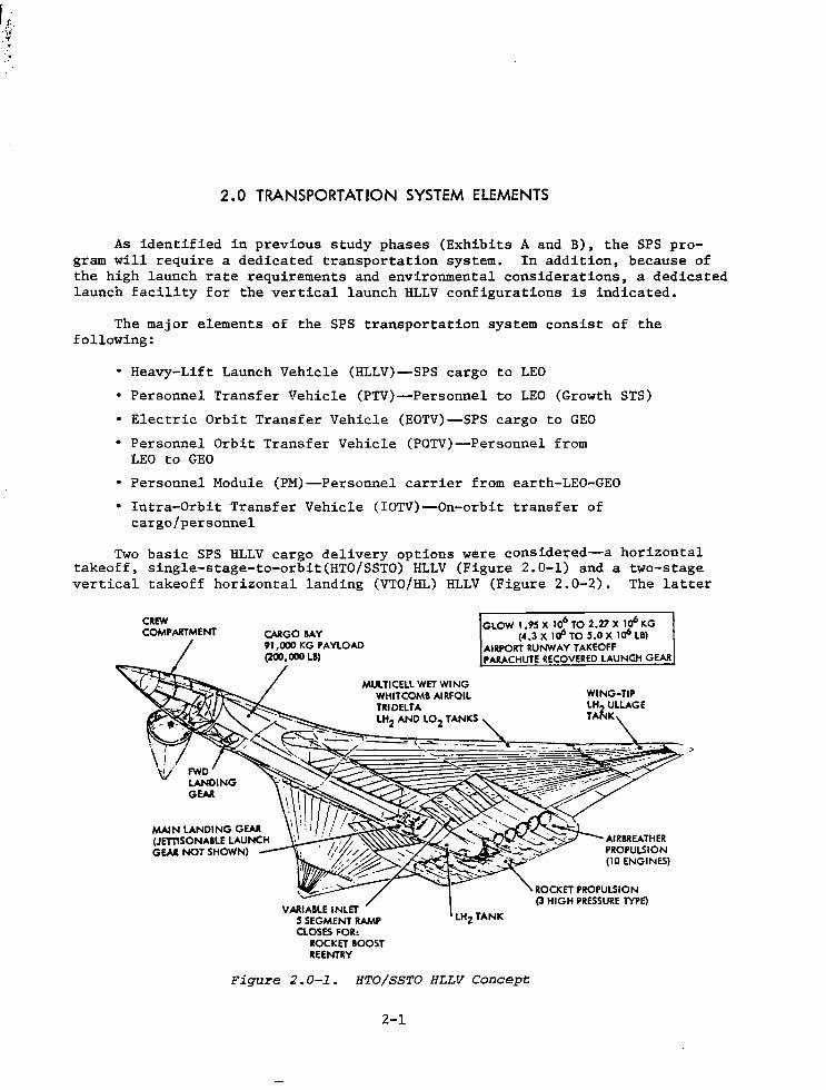
Two basic SPS HLLV cargo delivery options were considered--a horizontal takeoff, single-stage-to-orbit(HTO/SSTO) HLLV (Figu~e 2.0-1) and a two-stage vertical takeoff horizontal landing (VTO/HL) HLLV (Figure 2.0-2). The latter
CREW COMPARTMENT
VARIABLE INLET 5 SEGMENT RAMP ClOSES FOR:
ROCKET BOOST REENTRY
GLOW 1.95 X 10⁶ TO 2.27 X 1a6 KG (4.3 X 1a6 TO 5.0 X 1a6 LB)
AIRPORT RUNWAY TAKEOFF PARACHUTE RECOVERED LAUNGH GEAR
Figure 2.0-1. HTO/SSTO HLLV Concept
2-1
72.0M
I BOOSTER
I
I 12.113,.
L
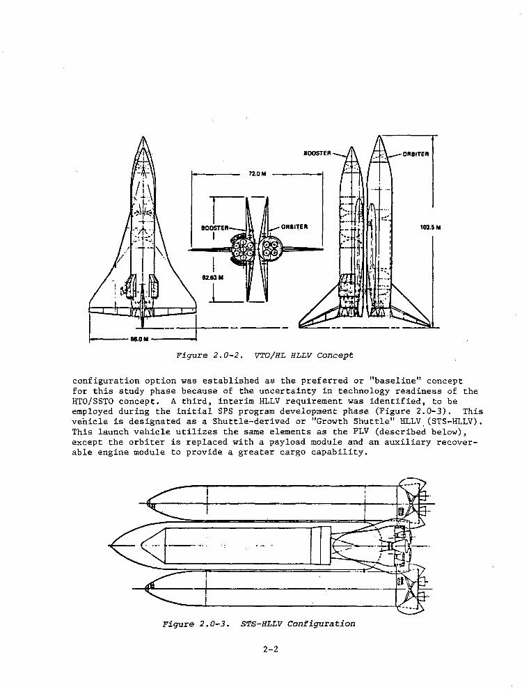
Figure 2.0-2. VTO/HL HLLV Concept
configuration option was established as the preferred or "baseline" concept for this study phase because of the uncertainty in technology readiness of the HTO/SSTO concept. A third, interim HLLV requirement was identified, to be employed during the initial SPS program development phase (Figure 2.0-3). This vehicle is designated as a Shuttle-derived or "Growth Shuttle" HLLV. (STS-HLLV). This launch vehicle utilizes the same elements as the PLV (described below), except the orbiter is replaced with a payload module and an auxiliary recoverable engine module to provide a greater cargo capability.
Figure 2.0-3. STS-HLLV Configuration
2-2
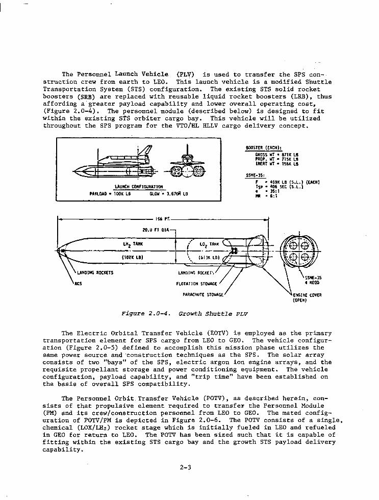
The Personnel Launch Vehicle (PLV) is used to transfer the SPS construction crew from earth to LEO. This launch vehicle is a modified Shuttle Transportation System (STS) configuration. The existing STS solid rocket boosters (SRB) are replaced with reusable liquid rocket boosters (LRB), thus affording a greater payload capability and lower overall operating cost, (Figure 2.0-4). The personnel module (described below) is designed to fit within the existing STS orbiter cargo bay. This vehicle will be utilized throughout the SPS program for the VTO/HL HLLV cargo delivery concept.
,_. I . I • I «t (12- .-: -'?@ LAUNCH tOMFlGURATlOM
,AYLOAD • IDOK LS GI.OW·. 3.67oil LO
20.U Fl DIA
LHz TAll!C
(10211: LI)
LllNO I Hr. AOCKEf',
FLOTA Tl ON STOWAGE
BOOSTER (EACH):
GROSS WT • 87111: LI PROP. WT • 71SK LB lMERT WT • 156!C LB
SSHE-JS:
F • 459!C LB (S.L.) (EJICll) t5p • 4011 SEC IS .L.) • • 35:1 Mii • 6:1
Figure 2.0-4. Growth Shuttle PLV
The Electric Orbital Transfer Vehicle (EOTV) is employed as the primary transportation element for SPS cargo from LEO to GEO. The vehicle configuration (Figure 2.0-5) defined to accomplish this mission phase utilizes the same power source and ·construction techniques as the SPS. The solar array consists of two "bays" of the SPS, electric argon ion engine arrays, and the requisite propellant storage and power conditioning equipment. The vehicle configuration, payload capability, and "trip time" have been established on the basis of overall SPS compatibility.
The Personnel Orbit Transfer Vehicle (POTV), as described herein, consists of that propulsive element required to transfe~ the Personnel Module (PM) and its crew/construction personnel from LEO to GEO. The mated configuration of POTV/PM is depicted in Figure 2.0-6. The POTV consists of a single, chemical (LOX/LH2 ) rocket stage which is initially fueled in LEO and refueled in GEO for return to LEO. The POTV has been sized such that it is capable of fitting within the existing STS cargo bay and the growth STS payload delivery capability.
2-3
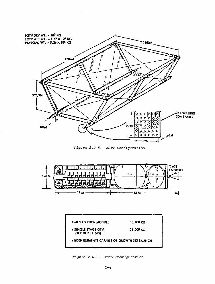
EOTV DRY WT. - 1o6 KG · EOTV WET WT. • 1.67 X 1o6 KG PAYLOAD WT. • 5.26 X 1o6 KG
Figure 2.0-5. EOTV Configuration
• 60 MAN CREW MODULE
•SINGLE STAGE OTV (GEO REFUELING)
..,_ -·
18,000 KG
36,000 KG
• BOTH ELEMENTS CAPABLE OF GROWTH STS LAUNCH
Figure 2.0-6. POTV Configuration
2-4
36 INauoes 20% SP ARES
The personnel module is designed to transport a 60-man construction crew from LEO to GEO to LEO (Figure 2.0-6). Primary considerations in sizing the PM were given to SPS construction crew demands and compatibility with the PLV concept. A considerable degree of latitude remains in the ultimate definition of a PM/POTV concept.
The intra-orbit transfer vehicle is defined in concept only. Because of the potential problems associated with docking and cargo transfer between the HLLV and EOTV in LEO and the EOTV and GEO construction base, a transfer vehicle capable of accomplishing this function is postulated. From cost and programmatic aspects of the overall SPS program, this element is depicted as a ~hemical rocket stage, manned or remotely operated.
In the following sections, each transportation system element will be discussed in more detail and the rationale for configuration selection presented. However, in order to maintain a continuity of data presentation, appendixes have been added to provide the substantiating technical analyses and trade study results where applicable.
2-5

3.0 POINT DESIGN
3.0 TRANSPORTATION SYSTEM REQUIREMENTS
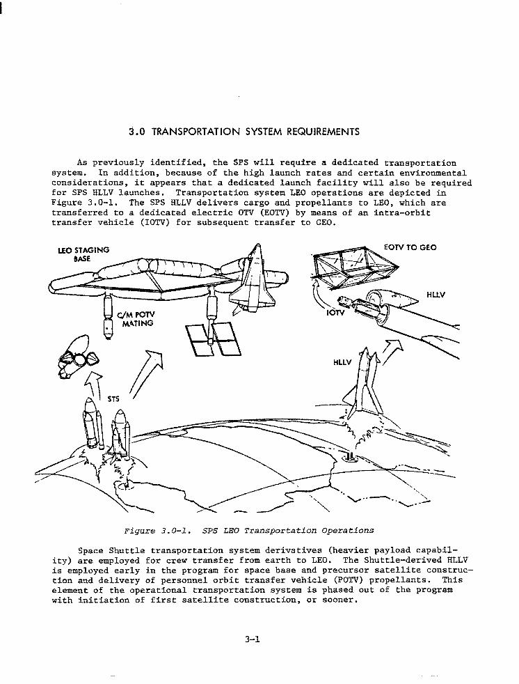
As previously identified, the SPS will require a dedicated transportation system. In addition, because of the high launch rates and certain environmental considerations, it appears that a dedicated launch facility will also be required for SPS HLLV launches. Transportation system LEO operations are depicted in Figure 3.0-1. The SPS HLLV delivers cargo and propellants to LEO, which are transferred to a dedicated electric OTV (EOTV) by means of an intra-orbit transfer vehicle (IOTV) for subsequent transfer to GEO.
LEO ST A.GING 9ASE
~·
4~:~ ~ ~( / c Figure 3.0-1. SPS LEO Transportation Operations
Space Shuttle transportation system derivatives (heavier payload capability) are employed for crew transfer from earth to LEO. The Shuttle-derived HLLV is employed early in the program for space base and precursor satellite construction and delivery of personnel orbit transfer vehicle (POTV) propellants. This element of the operational transportation system is phased out of the program with initiation of first satellite construction, or sooner.
3-1
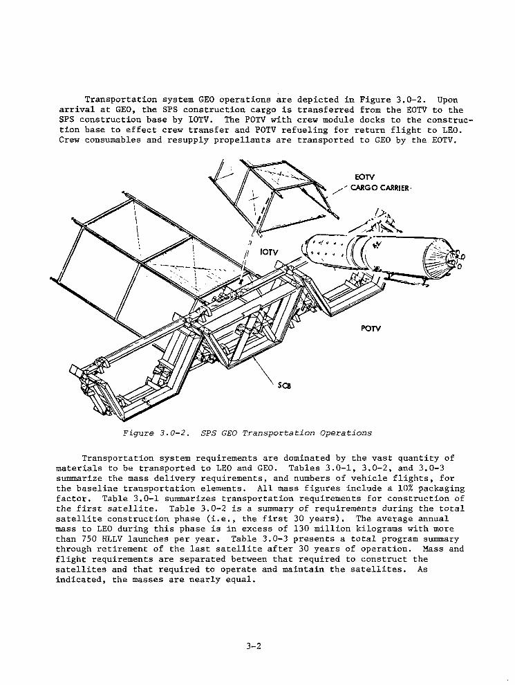
Transportation system GEO operations are depicted in Figure 3.0-2. Upon arrival at GEO, the SPS construction cargo is transferred from the EOTV to the SPS construction base by IOTV. The POTV with crew module docks to the construction base to effect crew transfer and POTV refueling for return flight to LEO. Crew consumables and resupply propellants are transported to GEO by the EOTV.
sea
EOTV
/"CARGO CARRIER·
POTV
Figure 3.0-2. SPS GEO Transportation Operations
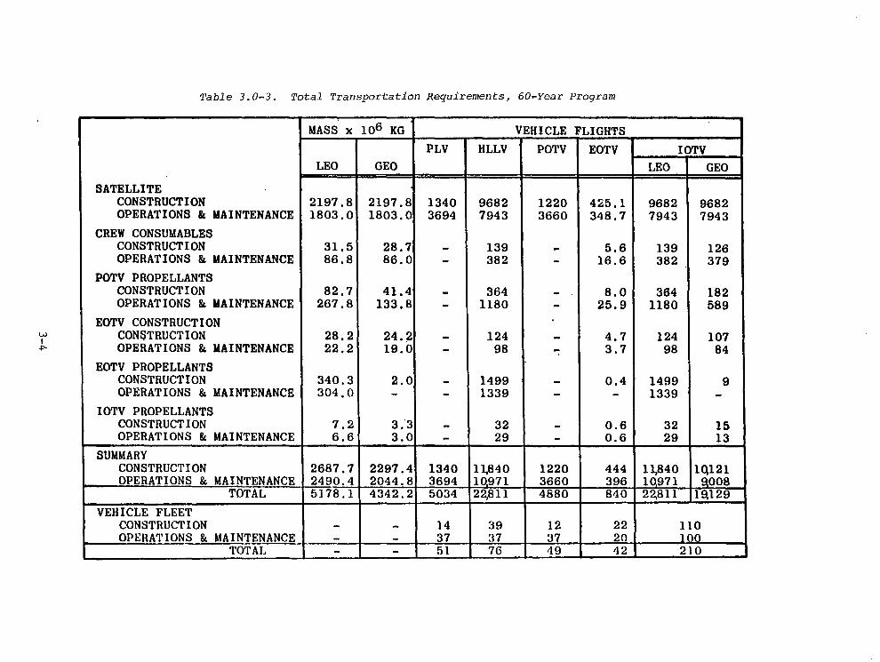
Transportation system requirements are dominated by the vast quantity of materials to be transported to LEO and GEO. Tables 3.0-1, 3.0-2, and 3.0-3 summarize the mass delivery requirements, and numbers of vehicle flights, for the baseline transportation elements. All mass figures include a 10% packaging factor. Table 3.0-1 summarizes transportation requirements for construction of the first satellite. Table 3.0-2 is a summary of requirements during the total satellite construction phase (i.e., the first 30 years). The average annual mass to LEO during this phase is in excess of 130 million kilograms with more than 750 HLLV launches per year. Table 3.0-3 presents a total program summary through retirement of the last satellite after 30 years of operation. Mass and flight requirements are separated between that required to construct the satellites and that required to operate and maintain the satellites. As indicated, the masses are nearly equal.
3-2
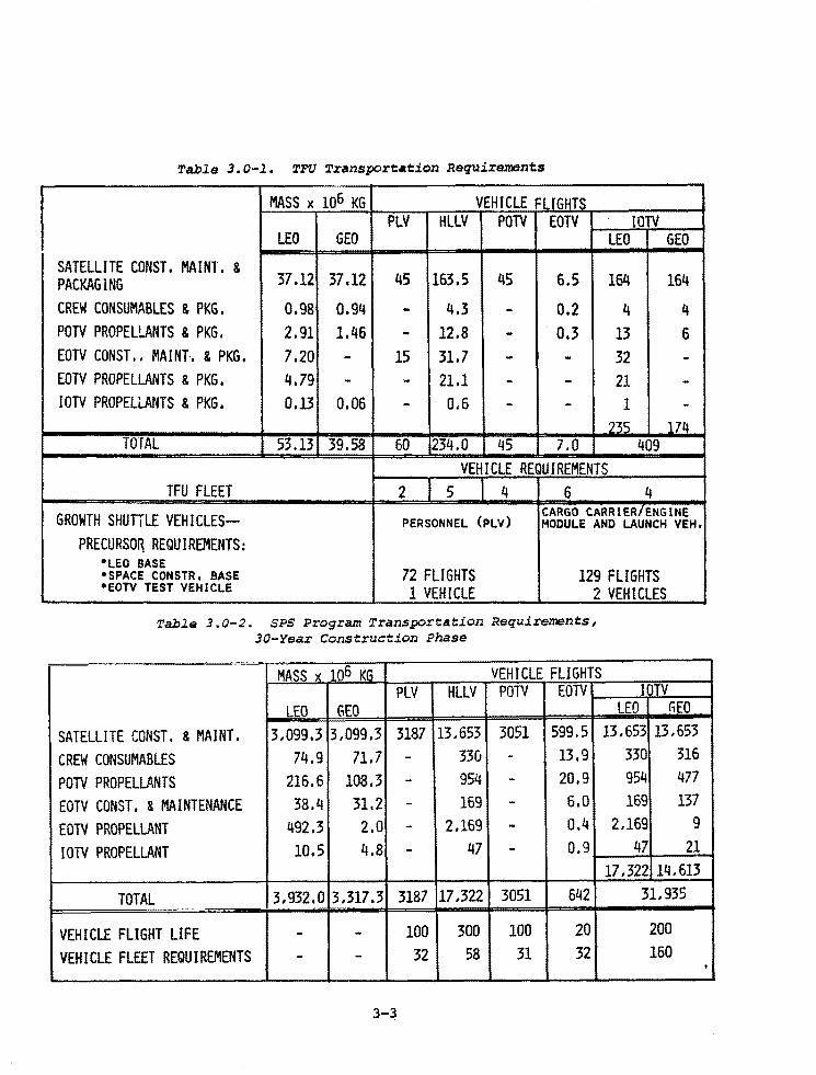
Table 3.0-l. TFU Transport•tion Requirements
MASS x 106 KG VEHICLE FLIGHTS PLV HLLV POTV EOTV IOTV
LEO GEO LEO GEO SATELLITE CONST. MA INT, & PACKAGING 37.12 37.12 45 163.5 45 6.5 164 164
CREW CONSUMABLES & PKG. 0.98 0.94 - 4.3 - 0.2 4 4 POTV PROPELLANTS & PKG. 2.91 1.46 - 12.8 - . 0.3 13 6 EOTV CONST .. MAI NL & PKG. 7.20 - 15 31.7 - - 32 -EOTV PROPELLANTS & PKG. 4.79 - - 21.1 - - 21 -IOTV PROPELLANTS & PKG. 0.13 0.06 - 0.6 - - 1 -
7'2JS 174 TOTAL 53.13 39.58 60 234.0 45 7.0 409
VEHICLE REQUIREMENTS TFU FLEET 2 5 4 6 4
GROWTH SHUTTLE VEHICLES-- PERSONNEL (PLV) CARGO CARRIER/ENGINE MODULE AND LAUNCH VEH,
PRECURSO~ REQUIREMENTS: •LEO BASE •SPACE CONSTR, BASE 72 FLIGHTS 129 FLIGHTS •EOTV TEST VEHICLE 1 VEHICLE 2 VEHICLES
Table 3.0-2. SPS Program Transportation Requirements, 30-Year Construction Phase
MASS x 106 KG VEHICLE FLIGHTS PLV HLLV POTV EOTV IDTV
LEO tiEO LEO tiEO
SATELLITE CONST. & MAINT. 3,099.3 3,099.3 3187 13,653 3051 599.5 13,653 13,653
CREW CONSUMABLES 74.9 71.7 - 330 - 13.9 330 316
POTV PROPELLANTS 216.6 108.3 - 954 - 20.9 954 477
EOTV CONST. & MAINTENANCE 38.4 31.2 - 169 - 6.0 169 137
EOTV PROPELLANT 492.3 2.0 - 2,169 - 0.4 2,169 9
IOTV PROPELLANT 10.5 4.8 - 47 - 0.9 47 21 17,322 14,613
TOTAL 3.932.0 3.317.3 3187 17,322 3051 642 31,935
VEHICLE FLIGHT LIFE - - 100 300 100 20 200
VEHICLE FLEET REQUIREMENTS - - 32 58 31 32 160
3-~
•
w I
""'
Table 3. o~J. Total Transportation Requi·rements I 60~Year Program
MASS x 106 KG VEHICLE FLIGHTS PLV HLLV POTV EOTV
LEO GEO
SATELLITE CONSTRUCTION 2197,8 2197.8 1340 9682 1220 425.1 OPERATIONS & MAINTENANCE 1803.0 1803.0 3694 7943 3660 348.7
CREW CONSUMABLES CONSTRUCTION 31.5 28.7 - 139 - 5.6 OPERATIONS & MAINTENANCE 86.8 86.0 - 382 - 16.6
POTV PROPELLANTS CONSTRUCTION 82.7 41.4 - 364 - 8.0 OPERATIONS & MAINTENANCE 267.8 133,8 - 1180 - 25.9
EOTV CONSTRUCTION CONSTRUCTION 28,2 24.~ - 124 - 4.7 OPERATIONS & MAINTENANCE 22.2 19.0 - 98 - 3.7
EOTV PROPELLANTS CONSTRUCTION 340.3 2.0 - 1499 - 0.4 OPERATIONS & MAINTENANCE 304,0 - - 1339 - -
IOTV PROPELLANTS CONSTRUCTION 7.2 3.3 - 32 - 0.6 OPERATIONS & MAINTENANCE 6.6 3.0 - 29 - 0.6
SUMMARY CONSTRUCTION 2687.7 2297.4 1340 11,840 1220 444 OPERATIONS & MAINTENANCE 2490.4 2044.8 3694 1Q971 3660 396
TOTAL 5178.1 4342.2 5034 22,811 4880 840 VEHICLE FLEET
CONSTRUCTION - - 14 39 12 22 OPERATIONS & MAINTENANCE - - 37 37 37 20
TOTAL - - 51 76 '19 42
IOTV LEO GEO
9682 9682 7943 7943
139 126 382 379
364 182 1180 589
124 107 98 84
1499 9 1339 -
32 15 29 13
11,840 10,121 1Q971 Q008 22,811 19,129
110 100 210
4.0 HEAVY-LIFT LAUNCH VEHICLE
4.0 HEAVY LIFT LAUNCH VEHICLE
Initial Heavy Lift Launch Vehicle (HLLV) studies were directed toward a horizontal takeoff sinple stage to orbit (HTO/SSTO) concept advanced by Rockwell during Exhibit A and B study phases, After providing an update of the HTO/SSTO, the reference launch vehicle configuration for the Exhibit C study phase was changed to a two stage vertical takeoff-horizontal landing (VTO/HL) configuration. This section of the report is directed toward the "Reference Vehicle" concept only. A summary of the HTO/SSTO effort conducted under a company sponsored program is included in Appendix A. An interim shuttle derived or "growth" shuttle HLLV configuration has been identified to satisfy early SPS precursor satellite construction requirements; and, because of it's similarity to the personnel launch vehicle (PLV), is discussed in that section of the report. In addition, the reference HLLV trade studies data are included in Appendix B along with the reference HLLV trajectory.
4.1 HLLV REQUIREMENTS/GROUND RULES
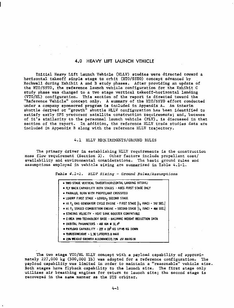
The primary driver in establishing HLLV requirements is the construction mass flow requirement (Section 3). Other factors include propellant cost/ availability and environmental considerations. The basic ground rules and assumptions employed in vehicle sizing are summarized in Table 4.1-1.
Table 4.l-l. HLLV Sizing - Ground Rules/Assumptions
•TWO-STAGE VERTICAL TAKEOFF/HORIZONTAL LANDING lVTO/HLl
• FlY BACK CAPABILITY BOTH STAGES - ABES FIRST STAGE ONLY
• PARALW. BURN WITH PROPELLANT CROSSFEED
• LOX/RP Fl RST STAGE • LOXILHz SECOND STAGE
• HI Pc GAS GENERATOR CYCLE ENGINE - FIRST STAGE lls !VACI • 352 SEC.,
• HI Pc STAGED COMBUSTION ENGINE - SECOND STAGE !Is !VACI • 466 SEC.j
•STAGING VELOCITY - HEAT SINK BOOSTER COMPATIBLE
•CIRCA 1990 TECHNOLOGY BASE - BAC/MMC WEIGHT REDUCTION DATA
• ORBITAL PARAMmRS - 481 KM i 31. 6°
• PAYlOAD CAPABILITY - 2Z7 x 103 KG UP145 KG DOWN
• lltRUST/WEIGHT - I. 30 LIFTOFF/3. 0 MAX
•!~WEIGHT GROWTH ALLOWANCE/0.7~ tlV MARGIN
The two stage VTO/HL HLLV concept with a payload capability of approximately 227,000 kg (500,000 lb) was adopted for a reference configuration. The payload capability was limited in order to maintain a "reasonable" vehicle size. Both stages have flyback capability to the launch site. The first stage only utilizes air breathing engines for return to launch site; the second stage is recovered in the same manner as the STS orbiter.
4-1
The launch vehicle utilizes a parallel burn mode with propellant crossfeed from the first stage tanks to the second stage engines. The first stage employs high chamber pressure gas generator cycle LOX/RP fueled engines with LH2 cooling and the second stage employs a staged combustion engine similar to the space shuttle main engine (SSME) which is LOX/LH2 fueled.
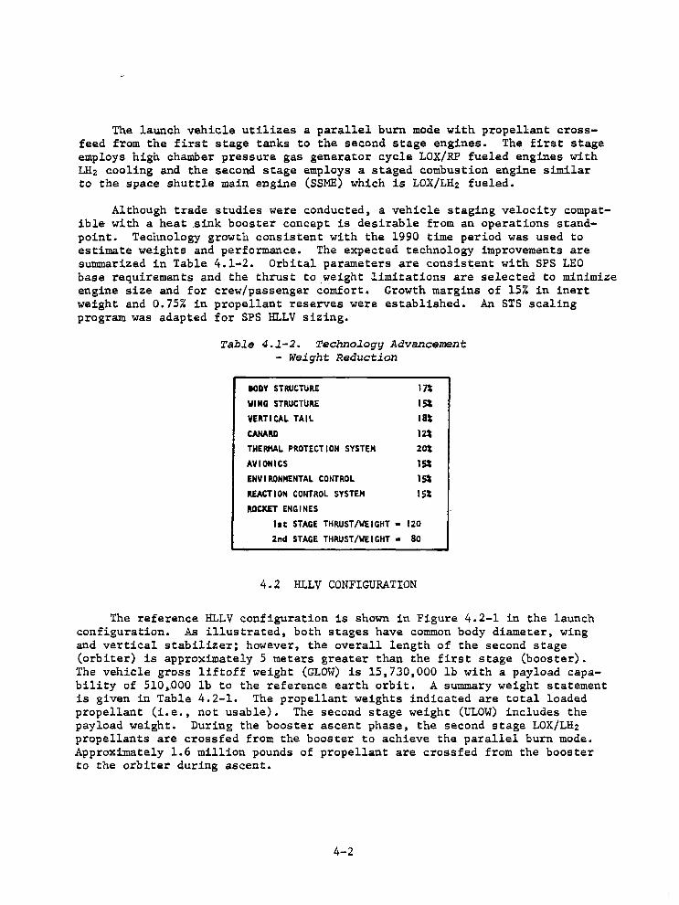
Although trade studies were conducted, a vehicle staging velocity compatible with a heat .sink booster concept is desirable from an operations standpoint. Technology growth consistent with the 1990 time period was used to estimate weights and performance. The expected technology improvements are sunnnarized in Table 4.1-2. Orbital parameters are consistent with SPS LEO base requirements and the thrust to ~eight limitations are selected to minimize engine size and for crew/passenger comfort. Growth margins of 15% in inert weight and 0.75% in propellant reserves were established. An STS scaling program was adapted for SPS HLLV sizing.
Table 4.l-2. Technology Advancement - Weight Reduction
IODY STRUCTURE l"A WING STRUCTURE 15l VERTICAL TAIL 18t CANARD 12t THERMAL PROTECTION SYSTEM 20t AVIONICS 1st ENVIRONMENTAL CONTROL 1st REACTION COHTROL SYSTEM I St ROCKET ENGINES
lit STAGE THRUST/WEIGHT • 120 2nd STAGE THRUST/WEIGHT • 80
4.2 HLLV CONFIGURATION
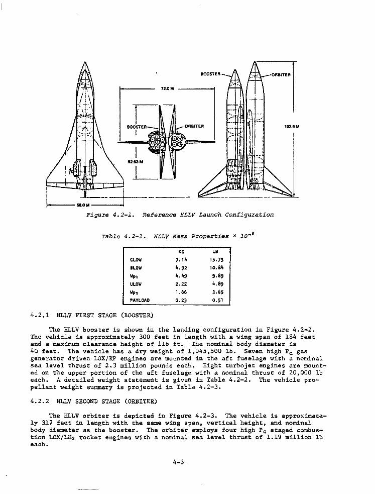
The reference HLLV configuration is shown in Figure 4.2-1 in the launch configuration. As illustrated, both stages have common body diameter, wing and vertical stabilizer; however, the overall length of the second stage (orbiter) is approximately 5 meters greater than the first stage (booster). The vehicle gross liftoff weight (GLOW) is 15,730,000 lb with a payload capability of 510,.000 lb to the reference earth orbit. A summary weight statement is given in Table 4.2-1. The propellant weights indicated are total loaded propellant (i.e., not usable). The second stage weight (ULOW) includes the payload weight. During the booster ascent phase, the second stage LOX/LH2 propellants are crossfed from the booster to achieve the parallel burn mode. Approximately 1.6 million pounds of propellant are crossfed from the booster to the orbiter during ascent.
4-2
72.0M
I BOOSTER
I
I 82.e3M
J__
Figure 4.2-l. Reference HLLV Launch Configuration
Table 4.2-1. HLLV Mass Properties x io-6
KG LB GLOW 7. lit 15.73 BLOW lt.92 10.8.lt
Wp1 lt. 49 9.89
ULOW 2.22 l+.89
Wp2 1.66 3.65 PAYLOAD 0.23 0.51
4.2.l IU..LV FIRST STAGE (BOOSTER)
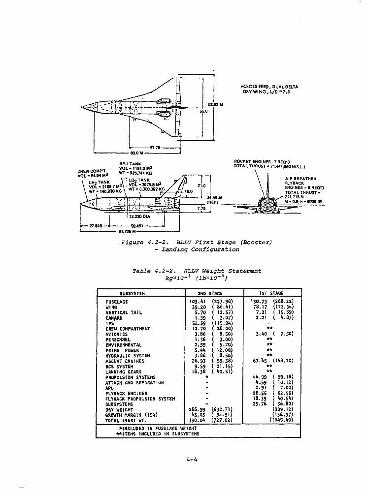
The IU..LV booster is shown in the landing configuration in Figure 4.2-2. The vehicle is approximately 300 feet in length with a wing span of 184 feet and a maximum clearance height of 116 ft. The nominal body diameter is 40 feet. The vehicle has a dry weight of 1,045,500 lb. Seven high Pc gas generator driven LOX/RP engines are mounted in the aft fuselage with a nominal sea level thrust of 2.3 million pounds each. Eight turbojet engines are mounted on the upper portion of the aft fuselage with a nominal thrust of 20,000 lb each. A detailed weight statement is given in Table 4.2-2. The vehicle propellant weight summary is projected in Table 4.2-3.
4.2.2 HLLV SECOND STAGE (ORBITER)
The IU..LV orbiter is depicted in Figure 4.2-3. The vehicle is approximately 317 feet in length with the same wing span, vertical height, and nominal body diameter as the booster. The orbiter employs four high Pc staged combustion LOX/LH2 rocket engines with a nominal sea level thrust of 1.19 million lb each.
4-3·
N.---47.78--....; ..._ ____ <80.0M -----"'
RP-1 TANK VOL" 1181.0M3 WT•925,741 KG
12.23001.A
27.518 !'i0.451 __ _.
----- IU.728M-------"
•CROSS FEED, DUAL DELTA DRY WING I l/D .. 7 .5
ROCKET ENGINES· 7 REO'O TOTAL THRUST• 71,.._.1,960 NIS.L)
Figure 4.2-2. HLLV First Stage (Booster) - Landing Configuration
Table 4.2-2. HLLV Weight Stateme~t kgXl0- 3 (lbXlQ- 3)
SUBSYSTEH 2ND STAGE !ST STAGE
FUSELAGE J0].41 (227.98} 130.73 (288.22) WING 39.20 ( 86.41) 78.17 ( 17.2..34) VERTICAL TAIL S.70 ( 12.s;> 1.21 ( lS.69) t.AN('RD 1.39 ( 3.07) 2.21 ( 4.87) TPS sz.59 (I I 5.94) -CREW COHPARTHElfl' 12.70 ( 28.00) •• AVIONICS ].86 ( a.so> 3.40 ( 7,50) PERSONNEL 1.36 ( 3.00) ** ENV I RONHENTAL 2.S!I ( s.10> •• PRIHE POWER s.44 ( 12.00) ** HYDRAULIC SYSTEM ].86 ( 8.50) ** ASCENT ENGINES 26.93 ( 59.38} 67.\5 (148. 70) RCS SYSTEH 9,59 ( 21.15) ** LANDING GEARS 18.38 ( 40.51) ** PROPULSION SYSTEMS * 44.99 (99.18) ATTACH AND SEPARATION - 4.59 ( 10.12) APU - 0.91 ( 2.00) FLYllACK ENGltlES - 28.55 ( 62.95) FLYBACK PROPULSION SYSTEM - 18.39 ( 40.54) SUBSYSTEMS - 25.76 ( 56.80) DRY WEIGHT 286.99 (632. 71) (909. 12) GROWTH HARGltl (1Si) 43.05 ( 9.1t.91) (136.37) TOTAL INERT WT. 330.04 (727.62) (1045.li!:I)
*INCLUDED IN FUSELAGE WEIGHT **ITEHS INCLUDED IN SUBSYSTEMS
4-4
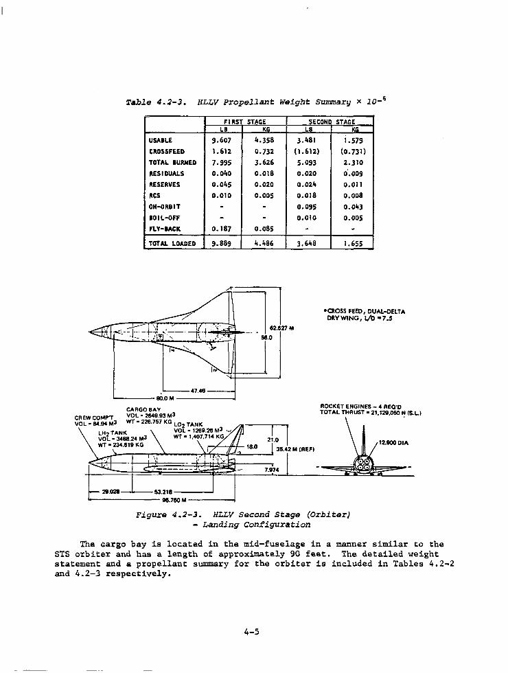
Table 4.2-3. HLLV Propellant Weight Summary x l0-6
FIRST STAGE SECOND STAGE LB
USA I LE 9.607 CROSSF£ED 1.612 TOTAL BURJIED 7.995 RESIDUALS 0.040 RESERVES o.01i5 RCS 0.010 ON-ORBIT -IOIL-OFF -f'\.Y-IACK 0.187
TaTAL LOADED 9.889
---47.48----------eo.o M --------1
CREWCOMP'T VOL • 114.94 Ml
CARGO BAY VOL • 2649.9l Ml WT• 228.757 KG L0
2 TANK
VOL• 1269.28 Ml '•' WT• 1,407,714 KG
KG LB 4.358 J.481
0.732 (1.612) 3.626 5.093 0.018 0.020 0.020 0.024 o.oos 0.018
- 0.095
- 0.010 0.085 -li.486 3.648
21.0
l5.42 M (REFI _.;,---,---.-~..._~~....,.++..,,...-if<~----i ..
. ·-------~, . 7.1174
211.028 53.218 -----98.760 M -----
KG
1.579 (0.731) 2.310 o·.009
0.011 0.008
0.043 0.005
-1.655
•CROSS FEED, DUAL-DELTA ORY WING, l/O •7.S
ROCKET ENGINES - 4 REQ'D TOTAL THRUST• 21, 129,060 ~ (5.LI
Figure 4.2-3. HLLV Second Stage (Orbiter) - Landing Configuration
The cargo bay is located in the mid-fuselage in a manner similar to the STS orbiter and has a length of approximately 90 feet. The detailed weight statement and a propellant summary for the orbiter is included in Tables 4.2-2 and 4.2-3 respectively.
4-5
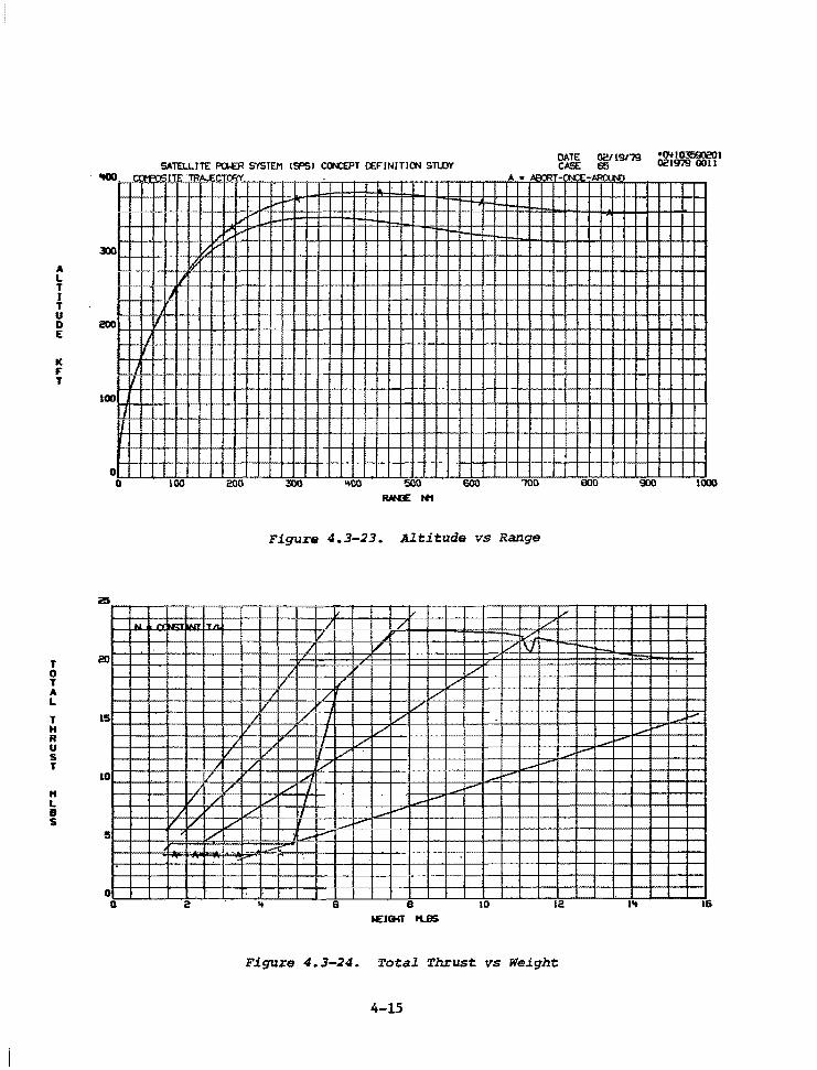
4.3 HLLV PERFORMANCE
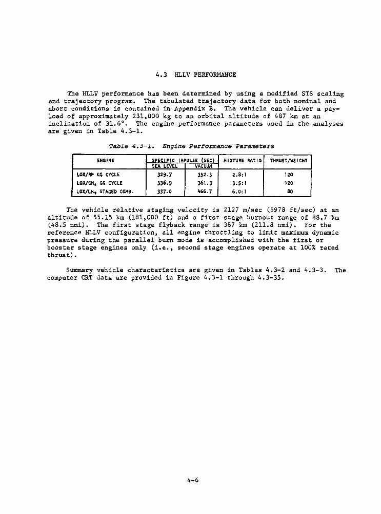
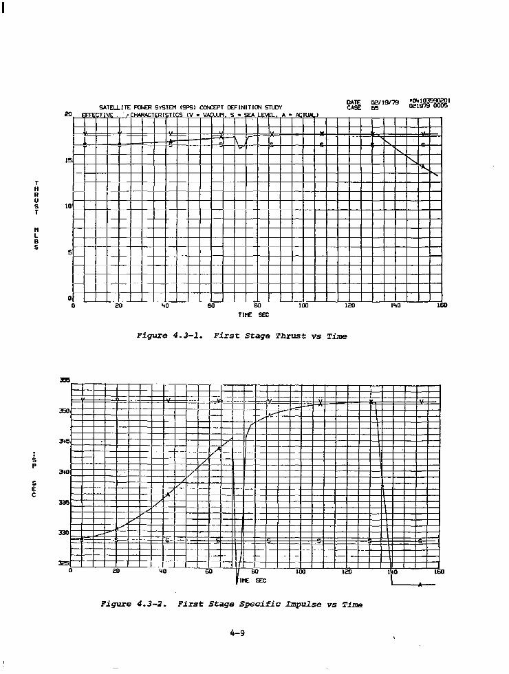
The HLLV performance has been determined by using a modified STS scaling and trajectory program. The tabulated trajectory data for both nominal and abort conditions is contained in Appendix B. The vehicle can deliver a payload of approximately 231,000 kg to an orbital altitude of 487 km at an inclination of 31.6°. The engine performance parameters used in the analyses are given in Table 4.3-1.
Table 4.3-l. Engine Performance Parameters
ENGINE SPECIFIC IMPULSE (SEC} MIXTURE RATIO THRUST/WEIGHT SEA LEVEL VACUUM
LOX/RP GG CYCLE 32~.7 352.3 2.8:1 120 LOX/CH• GG CYCLE 336.~ 361.3 3.5:1 120 LOX/LH 2 STAGED COMB. 337.0 466.7 6.0:l so
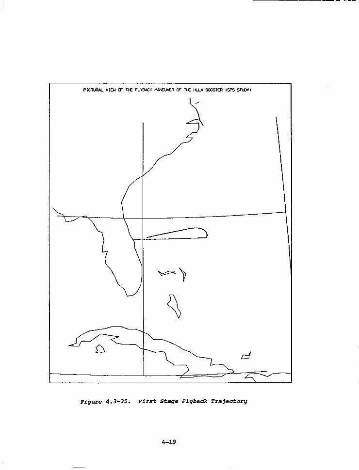
The vehicle relative staging velocity is 2127 m/sec (6978 ft/sec) at an altitude of 55.15 km (181,000 ft) and a first stage burnout range of 88.7 km (48.5 nmi). The first stage flyback range is 387 km (211.8 nmi). For the reference HLLV configuration, all engine throttling to limit maximum dynamic pressure during the parallel burn mode is accomplished with the first or booster stage engines only (i.e., second stage engines operate at 100% rated thrust).
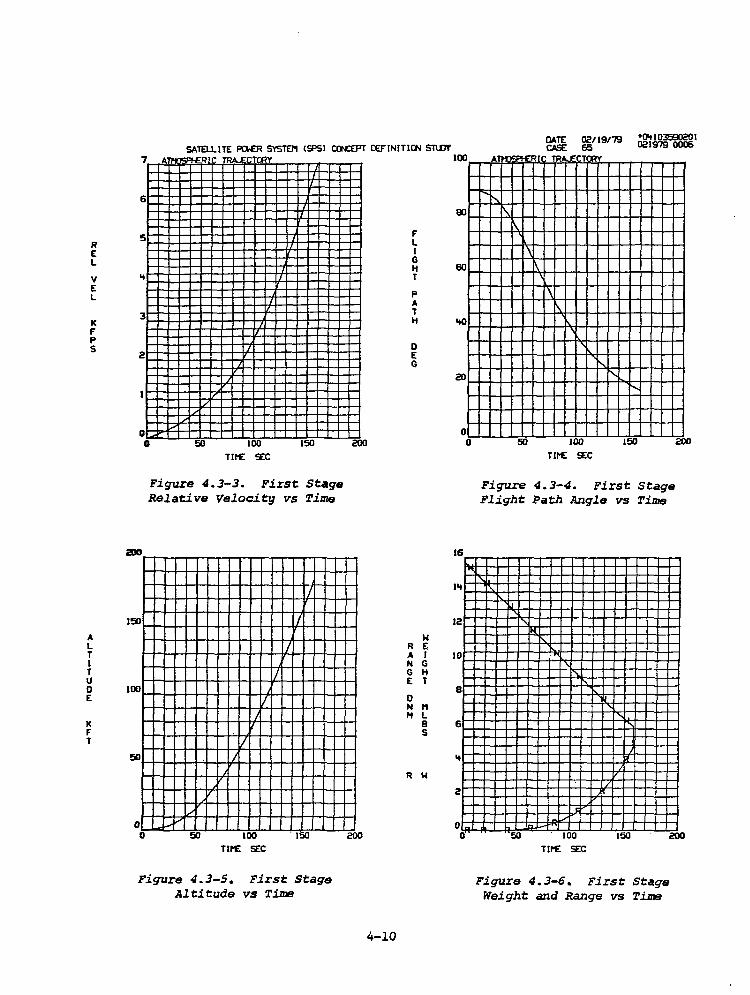
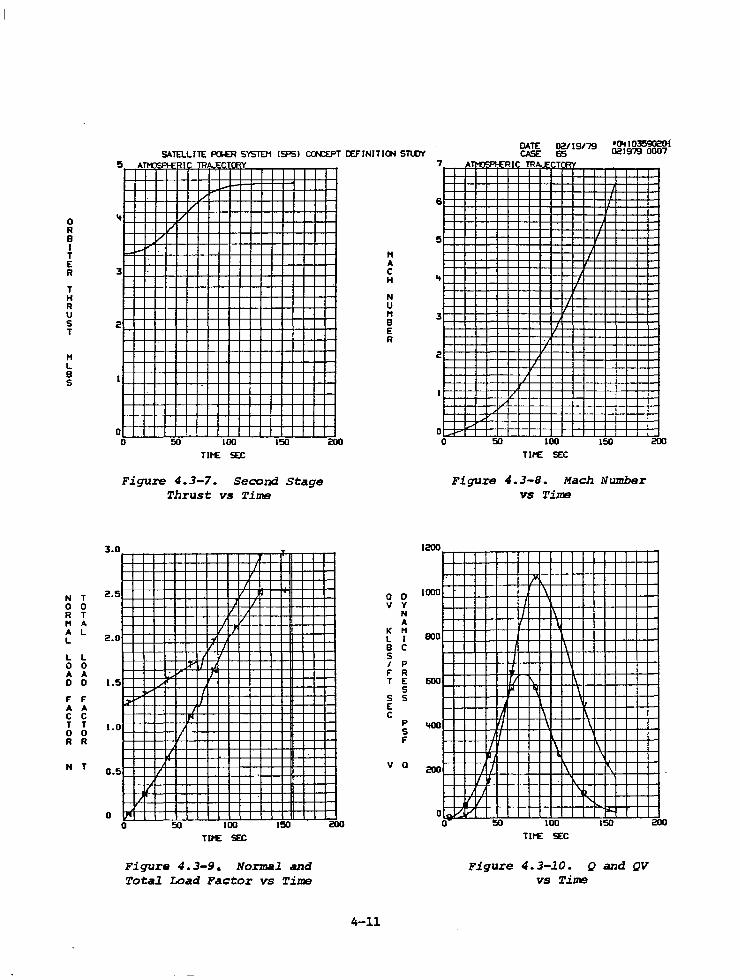
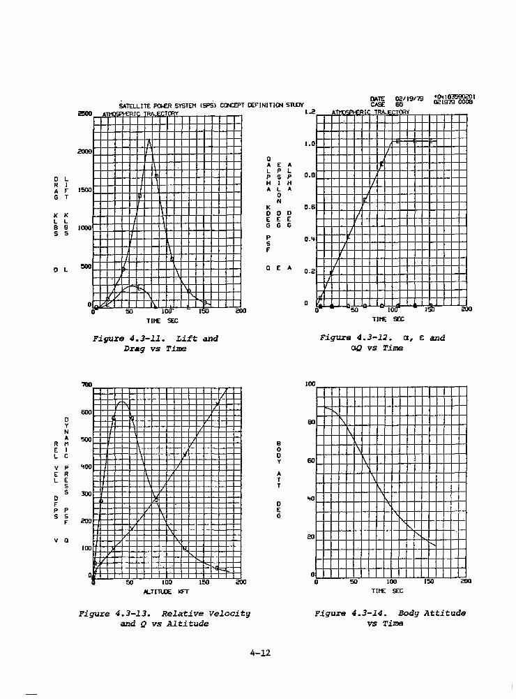
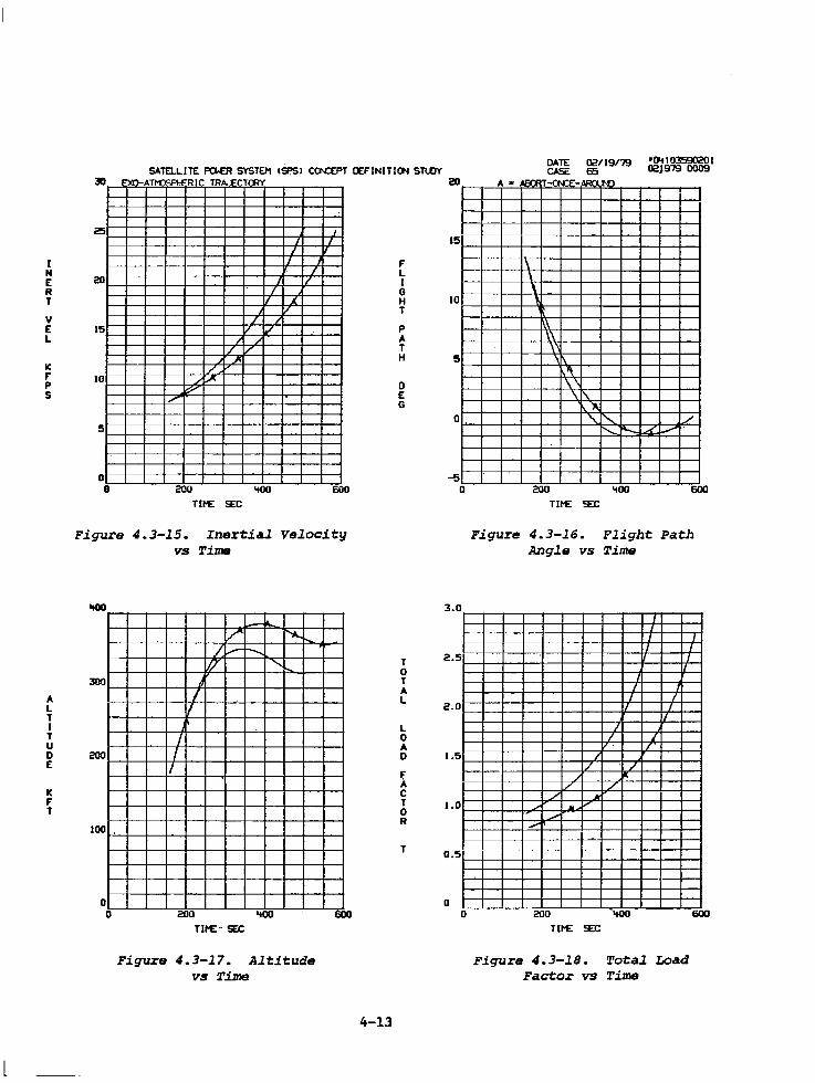
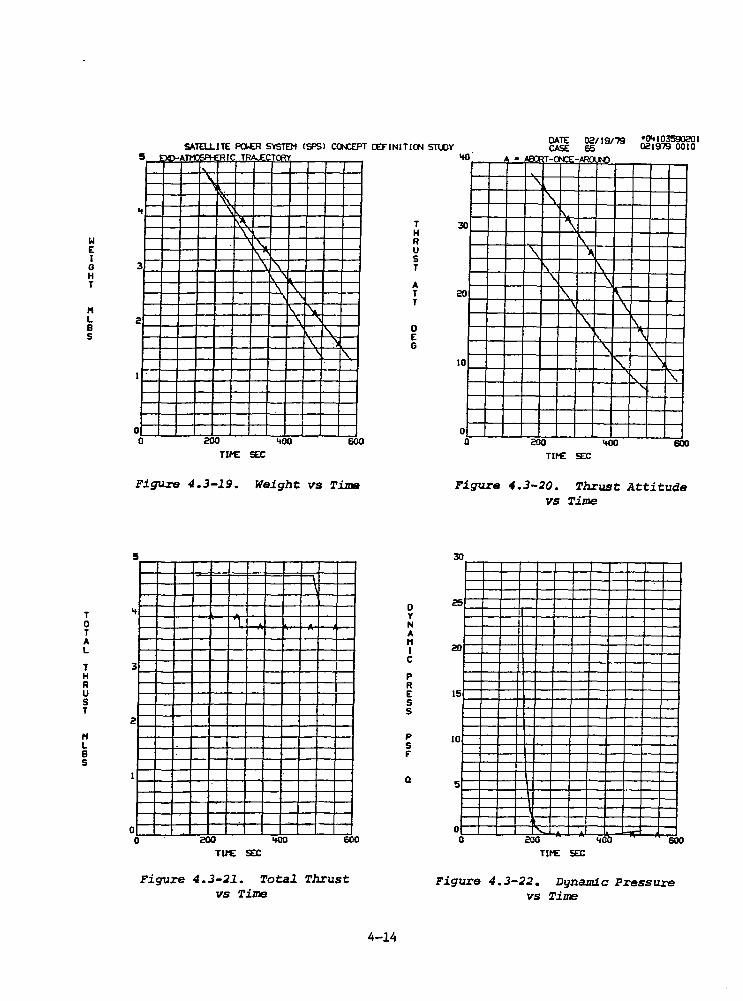
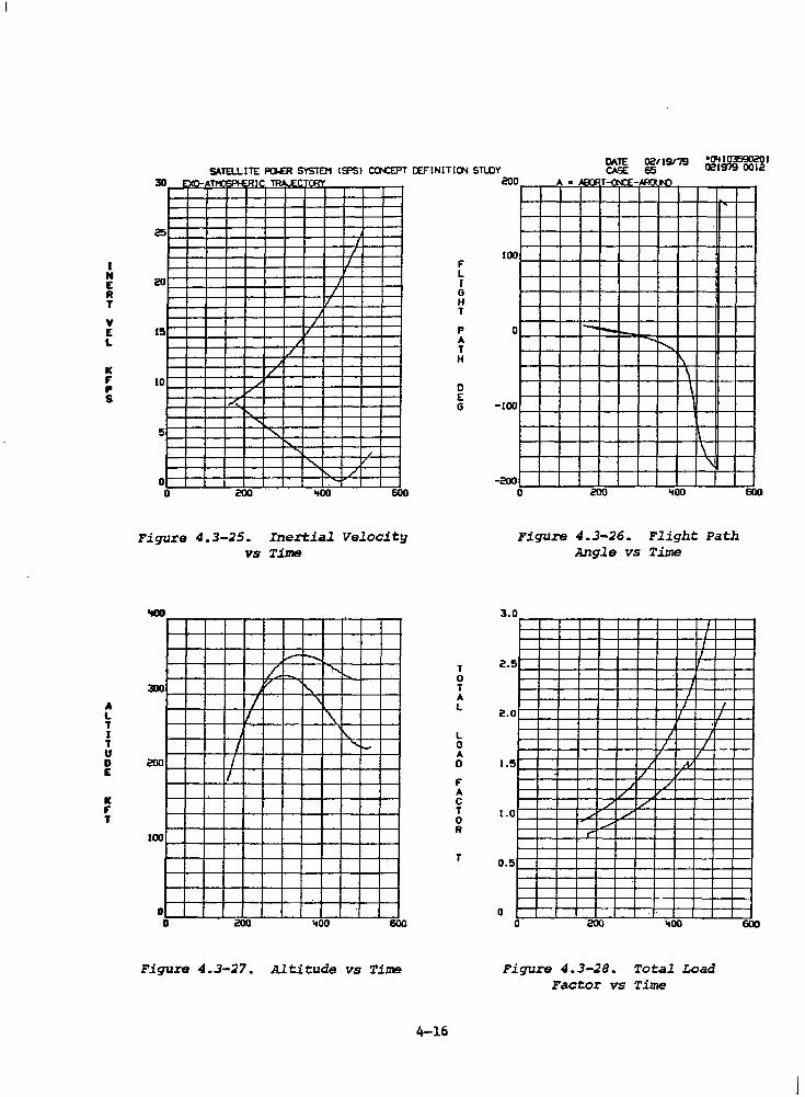
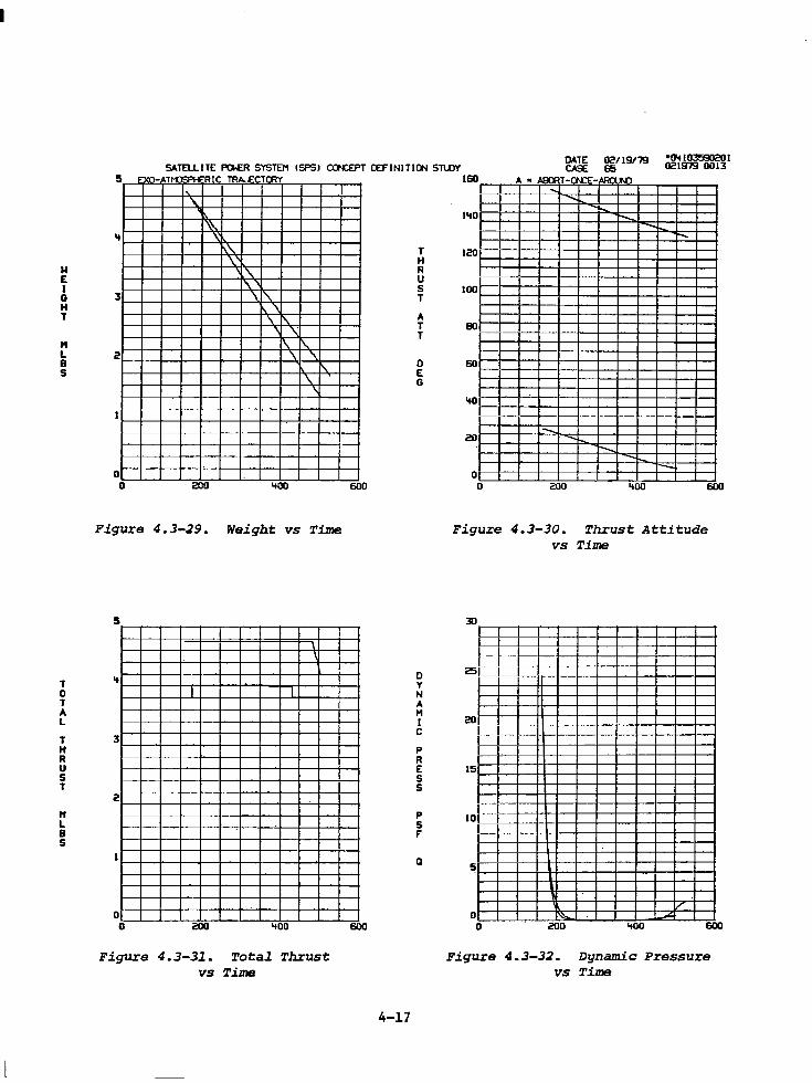
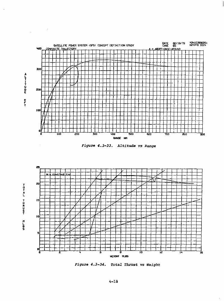
Summary vehicle characteristics are given in Tables 4.3-2 and 4.3-3. The computer CRT data are provided in Figure 4.3-1 through 4.3-35.
4-6
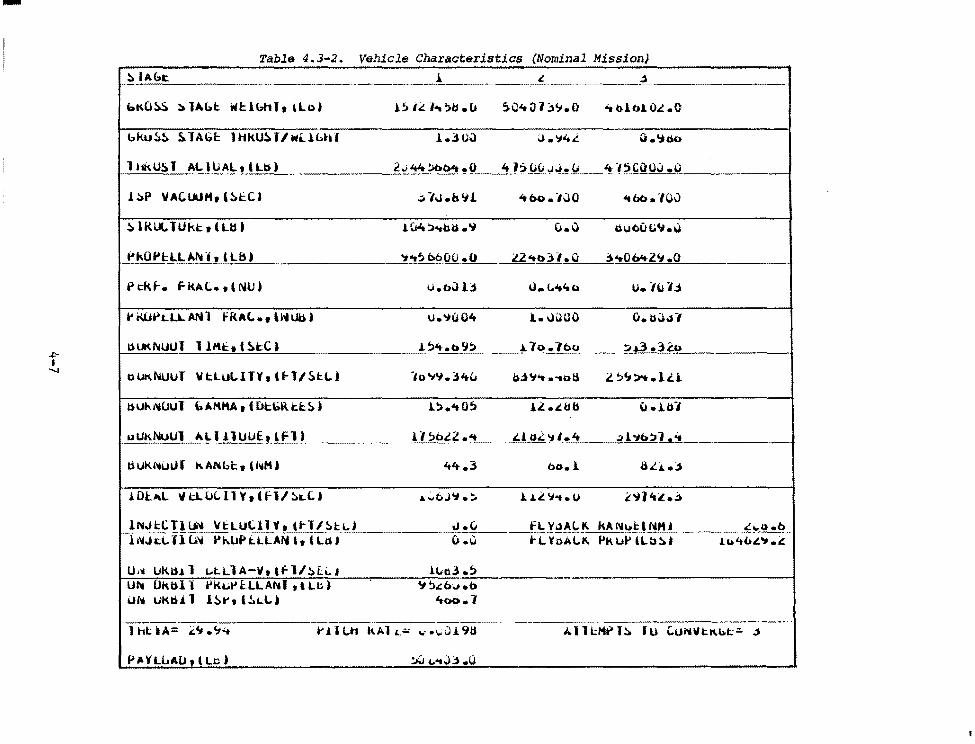
Table 4.3-2. Vehicle Characteristics {Nominal Mission) ~ IAut: i ' ,j
bKU~ ~ lAl>t Wl:lbHlt llbl l:. IL 1 .. ,B.u s.c.:.a 1 ~<.;.o ~ bl610.l .O
bku~~ S. lAGf: 1 HkU~ Tl WlH,,tH l.3UQ (J. '14i.. a .';;oo
1 t1k.U~ T AL 1UAL1 I Ll:i) 2.;"t4~0't .o 4h0Cl.JJ.u 4 -,5coo.:i .o
.l.::..P VAC.WH, &~l:C) :..-IJ.blll 'tbo.-IYO "tbt>.-,Ov
~ I K UL 1 U kt: t l Ljj ) 1 Ult ;;i..,.uu • 'i o.o nuou Lt'J.\)
fikOPl:LLAfvl, lllH 't"t5b600.0 l2"tC>)1.0 ;;...QM-2'1 .o
Pt:kf-. fKA.t.. t & NU) u.«>ul3 u. t."t'ii C> u. -,\i 1.i
t' tii.H" L LL AN 1 fRA(..., li~UtU u.'1004 l.. JUOO o. b~_,-,
1.HIKNUUT 1 l"'t: I '~t:C) 1 !:>'t.o9!> ;.7o.lbo ~.&3 .)lo
ollKNuUT VtluLlTY,(~l/5t:L) -,Q '1'1. , ... " b.i'l"t .-.oli z ~'l>t .1 ... u.
l:)Ut-.1-.UUT bAMto\A t ( Dt:\>R ti:~) l~ .... 05 .ll .i.bb u.1b-,
DUkNUUT ~LI llUIJE.1 lFl) ll~b.ll ..... Ll o.l '1 I. 't .;)ht>!Jl ...
til.Jk. rtu 1.n kANbl::, lhtHJ 4't.3 bo.l 8LJ,.;,
..1.Dl"l llt.LULll'rtffl/~t.C.I .a. .:..bJ'J.:. l. .... .l 'J"t. u ~'il'tL.._j
lNJl:C Tl l..j'A Vt:LUC.llY1t~rt~tLI J.(J fL Vi.lAl.l\ kA Nlrt_l NH I "'°'u .b l NJ cl. ll u\4 Pt.UPtLLAN It ( Lt>J o.c 1-LYoAl..I\. PtHd' l L::i !lo j .lu't<.£'1.~
u ... Ukl:U. l 1...t.LlA-111 tfl/!>E.i.. I lltti3 .5 UI\ Ok.bl .• t'kut'tLLANI tllt-) 4:1~..::b~.b
ur11 UK.t:H 1 1~ .... (!ad ... 4oo.1
·-.. ht iA= ~"' ''.t t' J.l l.h l\Al L"' ..... i,;ui 91i A. 11 l:Ht> l!:i. f U CU1'4VtK.bt:;. .;)
Pll>VLLAlJ, t Lo) ~ ..... o;,.o
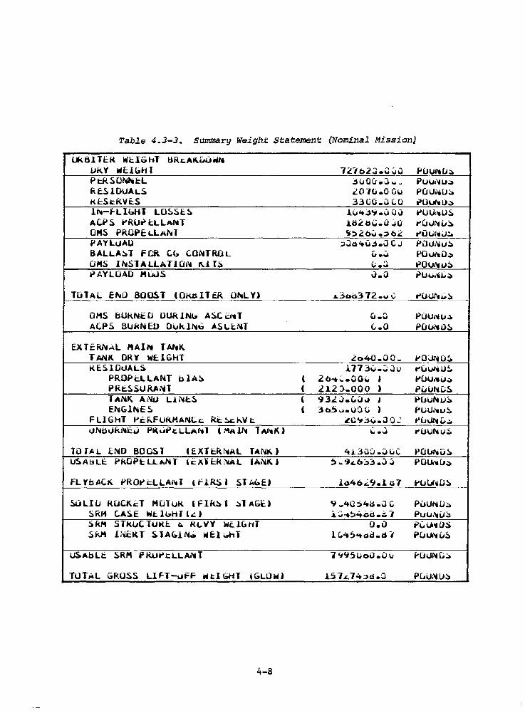
Table 4.3-3. Summa.rg Weigh.t Statement (Nominal Mission}
Uk61 TE:R Wt:IGl-tf tiRcAKuuw~ 1.Jk.Y ~EH~HI 1[tb2J.C.:iiJ PUUitCJ;;) P t:kSONhi:L jvoei.o .. _ Puui'4u.:a f.i.fSlOUAL~ 2070.0Gv PUlJi..ilJ;;. Ki::StRVt:S 3300.0 co e>OUl'tl)~
11-.-fLIGHT L0~5t:~ l"<t;,'i .I) 0 ii t'UU.•U~
Ac.PS t'RUr tLLANT tti~ tsi;;.u .Ju ruU~u~ OMS PROPELLANI ti~4:'.b~ -~ b2 t'UUh1~;:. PAY LUAU :.Jo<tu~.a c. J f'ilu:'4u~ BALLA!>T FCR C.G CONTROL " • .:i POu.'eO~ OMS 11"4$1ALLAT10f"' 1\.1 rs ii-~ t-iOUNtJ!> PAYLOAD MIJJS J.Q PUu.~t;~
TOlAL E~D BOOS. T tOKnlltR OhLY) .L.3~3 72.v C t'(HJl't.i.;.~
OHS bUk.Nt:O DUR.I Nb A!)(: 6-.T u.~ Puu1-.1.1.:l. AC.PS BUkNED Dllk l"'b ASl.b'H (...0 POU.'4 il!>
EXTERNAL 1'AIN TAhK TANK DRY WE:lGHT lo40.00w t'O\JNO!i. iU.SlDIJAL~ l773v.~Ju ruuttU!.
PROPELLANT blA!> ' 2b ... ~.CO\i ) ... ou ... iJ-> PRt:SSURANT ( Ll2 J..000 ) Puul'&L:.!:. TANK. A:~ L.1.•'4cS ( 93L..J.(,\Jo.1 ' il'uul'-tu~ E,._.GlfllE S ' 3o.S ..... uo (; , f'Lu .... u!i..
FLlG11T f'cf..FUKHANl.~ Rt ~h.V t. ~o-,;,~.JO.:: t>ul.JN&j.:. lJNti\Jk.NE~ PKut> t LLAfd ( t'!AlN 1At4K) - ...
""•'-" ,.uur-. u::.
luUL END BOOST ( £ X l t:k 1'1A L TANI<. ) 413uCJ.OllC p (i l.J"4 IJ ~ US.Ab LE PK.OPi: LL ANT l c X. i t:k :'CAL -IANK I 5 .. '}d,::,3 .J ;j POU.'tlJ~
FL Yb AC~ PROtl t:LLAl'.1 T l fl.RS J ST ~<>El lo46.i.<J.l u7 i'lJUf'4 LJ!>
~LIU RuCK'=T HuTul{ & Flk~ l ~1 AGC.I 9 .. <tC:>4li.J C PoUNU~ !)RH C.ASE Wt: lbHl l.:) i;J-t~4od.~ I Puu.-..iJ~ :lRM STkuClUKt: c.; Ri. W' Y' WEIGHT o.o ~(,u~os
Sf<Jt Ii~KT S. lAG.lNo ~E:l ~t-11 lC..lt~"t-od.d I Pu~IJ!>
~Ablt !:aRM P IUJ*"i=LLAl"11 T 1 '.t'i5lioD.u \J f'(HJN[.;~
TUT AL GROSS Llf-T-uFF WtlGHT &GLOW) l51L7.+:>d.0 P~UNU~
4-8
T H R u
1!5
S lO T
H L e s
I s p
s E c
5
0 0
F'FF'E"
----
SATEU.ITE PGE:R SYSTEl1 ISPSI CCN'.:EPT CEFINITICN STLOY Tl~ . __ _,- CHNlACTE:R I c;r I
I
- .
-
I I I I
'tO
':S. IV • v;. ~LU"I •
. "'
I
-
-· 60
5 • ''""' LE'wf:L.
\ 'I"
v-
80
Tit£ SEC
u
"'
_A• . .acn1.11 l
100
DATE 021191'79 •0Lfl03'590201 CASE 65 021979 0005
w
- !'.. -- -' ........
-,.,,_ '
l20 l'tO 160
Figure 4.3-l. First Stage Thrust vs Time
I I
I I ~
L•
~
_/
I' I
/ ,,..
/
/ ,, /
./ F
/ _,,
'-"'" ...--
5-~· c.
20 'tO 60 80 100 120 l 0 l60 It£ SEC
Figure 4.3-~. First Stage Specific Impulse vs Time
4-9
R E L.
v E L.
K F' p s
A L. T I T u 0 E
K F' T
SATEU.ITE PG£R SYSTEl'I ISPSJ CCN:EPT ~INITltN Sl\Df 7
6
5
.. 3
2
0 0
A - !I
~
......
50
TC l '~TnlY
j
j
/
100
Tll'E SEC
I
I
'
I
150
Figure 4.3-3. First Stage Relative Velocity vs Time
150
100
50
0 0
I/
'-"v 50
I I
v J
J
100 Tit£ SEC
I
Ii
j
I
150
Figure 4.3-S. First Stage Altitude vs Time
4-10
F' L. I G H T
p A T H
0 E G
R A N G E
0 N
"'
R
w E I G H T
l'I L. B s
w
100
90
60
20
0 0
16
l't
12
10
B
6
.. 2
,_ 0 0
A
" ' I\ I'
I\ '
50
DATE 02119/79 CASE 65
l)j . " ~T~,.
\ I\
JOO
Tit£ SEC
' '
•Q&t I 0359020 I 021979 0006
.......
150
Figure 4.3-4. First Stage Flight: Path Angle vs Time
I' 1'-
I\. L.J
' IN
... ·-50
" ' .....
"
~
100
Tll'E SEC
~ ~
~
·~
~
/
)~
150 200
FigUre 4.3-6. First Stage Weight: and Range vs Time
0 R B I T E R
T H R u s T
l'1 L B s
N 0 R l'1 A L
L 0 A 0
F" A c T 0 R
N
T 0 T A L
L 0 A 0
F" A c T 0 R
T
SATELLITE PG£R SYSTEM !SPSI COICEPT CEF"INITICJll STLOY
..
3
0 0
AT
i...-
!/ v
v
50
v
TD I ·rTn:IY
,.,,
100 Tit£ SEC
150
Figure 4.3-7. Second Stage Thrust vs Time
3.0
C?.5
C?.O
1.5
1.0
0.5
0
I
v
'"
I/
Li
I/
' '"
0 50
I
J
J / I/ , .
'i' J
...- II
J
"'
II
I II
100 TltE SEC
I
~ ,,
150
Figura 4.3-9. Normal and Total Load Factor vs TilDB
4-11
l'1 A c H
N u l'1 B E R
a v
K L B s I F" T
s E c
v
0 y N A l'1 I c p R E s s
p s F"
a
7
6
..
3
0 0
1200
1000
BOO
600
200
0 0
AlW"
-
=.rR11 ~ TR' c-cT"""
17
50
-, 17
·J
" I
I
100 Tit£ SEC
-, 17
,, ' 7
150
Figure 4.3-8. Mach Number vs Time
7, n
-, g
j J ,, " ' J I/
1..- 1-'
50
J" \
I \ l
\
' '
\ -, I\
I\
100
Tit£ SEC
.\
' \
~
['\
• " ....
150
Figure 4.3-10. Q and QV vs Time
. . SATELLITE PG£R SYSTEM C5PSI CCN:EPT O::F'INITICN Sn.DY
0 L R I
A - r ·c <C 1n::v
" I
I
" A F' 1500 I G T
K K L L
~
I
B B 1000 I s s
0 L
0 y N A
R M E r L c v p E R L E
s s
0 F' p p 5 5
F'
v a
I
I
' I I
\ I
v b \
// ' '-0 ,_ v: \ ~
o- 50 1oa I iD
600
500
'100
300
200
100
0
Tit£ SEC
Figure 4.3-11. Lift and Dr•g vs Time
, ,
I \ I /
/
I I
I / I
r7 I
Al
/ I \
Iv' \
' r-.. / ·- ~
" '-.__ I/
50 100 150
M.. T llUE l<F'T
200
7
200
Figure 4.3-13. Relative Velocity and Q vs Altitude
a A L p H A
K 0 E G
p s F'
a
4-12
E p 5 r L 0 N
0 E G
E
B 0 0 y
A T T
0 E G
A L p H A
0 E G
A
1.2 .., ..... ""'~RI<
1.0
0.8
pl 0.6
I
I O.'t
I
J
0.2 J
.J 0 - ' -
Dot.TE 02119179 CASE 65
OA c T"QY
I
I
~
I
-
•<1t I 0359020 I 021979 0008
o- 50 - - IOCf l!ill 200
JOO
80
60
20
0 0
Tit£ SEC
Figure 4.3-12. a, € and aQ vs Time
..... , \
\
\ \
50
\ ~
" ' '
100
Tlt'E SEC
' ~ r.....
150
-
200
Figure 4.3-14. Bodg Attitude vs Time
I N E R T
v E L
K ,,. p s
A L T I T u D E
K ,,. T
SATELLITE PG£R SYSTEM 19'5> CCN:l:PT r£F"INITICN STl.OY
20
15
10
5
II 8
< vn....ATMr CCU •0 1c m; rcr,...,.,
J I
I
I I ,,. .,, / /
/ I/ ~ ... ,, ,,.
"""" , .....
200 '+00
Tit£ SEC
I
I I I
I I I
" I. ,,.
600
Figure 4.3-15. Inertial Velocity vs Time
300
200
100
0 0
-~
v "" ..... / V" r---..
IT ......
~
I I
I I
I
200 Lt()()
TltE· SEC
Figure 4.3-17. Altitude vs Time
600
4-13
,,. L I G H T
p A T H
D E G
T 0 T A L
L 0 A D
f A c T 0 R
T
20
15
10
5
0
-5 0
3.0
2.5
2.0
1.5
1.0
0.5
0 0
DATE 02119179 •Qltl03590201 CASE 65 02J979 0009
A • ai:n: T-cN:E - """" ""
I\ \ \ ,
l\ \\ \'
"' \\ \I\.
",.._
" 1"- / I'....
.._ _,r ~·
200 '+00 600
Tit£ SEC
Figure 4.3-16. Flight Path Angle vs Time
I I I I
I I I
I
I I I I
I I
/ ~ v I
I / /
I .. / /
./ .. _, M ,
~ -i I I
200 Lt()()
Tit£ SEC
Figure 4.3-18. Total Load Factor vs Time
600
M E I G H T
" L B s
T 0 T A L
T H R u s T
" L B s
Sot.TEL.LITE Pa.ER S'VSTEM ISPSl CCN:EPT c::Ef"INITJCN STLOY DATE 02/ J 9119 •QI+ I 03590201 CASE 65 021979 0010
5
..
3
2
0 0
'"'""'-ATM"~ Rrt re. "'"'"Trni ,, '\.
I"\'\ \
\'A
\ \ "\... , ...
\ \
' \ " ' ' I\
\
'+00 Tit£ SEC
'-' ' \ .)
\ "
600
Figure 4.3-19. Weight vs 7'il1Jfl
..
3
2
'l
Figure 4.3-21. Total Thrust vs Time
4-14
T H R u s T
A T T
0 E G
0 y N A
" I c p R E s s
p s F
Q
.. 0
30
20
10
0 0
' . ...... r-n~C"-•Dn ....... ' •"-
r\ .
'\ \
'\. ~ r-._ I\
\ \ I'\.
' '\.
I\. \
200
Tll'£ SEC
r\. \
I\ ."\
I\.
'" )
" " '
600
Figure 4.3-20. Thrust Attitude VS Time
30
20
15
10
5
0 " -0 200 '+JO 600
Tit£ SEC
Figure 4.3-22. Dynamic Pressure VS Time
A L T I T u D E
IC F' T
T 0 T A L
T H R u s T
" L B s
SATELL.ITE PQ.ER SYSTEM lSPSI CCN:EPT OCFINITICN STl.OY
Figure 4.3-23. Altitude vs Range
o.!:--'--'-_,.l..--.c!~'--+--.l.-.-..f..--'-~'--.1-..-4------'-----'~L-+-_.___._----'___,'=-..__.__..._......,i,,__.__......__._..,i,.-..1---,.__.._~ 0 2 It 6 8 ID IC! I.. 16
1€1Gf1' tt..BS
Figure 4.3-24. Total Thrust vs Weight
4-15
I N E R T
v E L
IC F' p s
A L T I T u D E
IC F' T
SATa.LITE f'G£R S'tSTEM ISPSl CCN:EPT CEFINITI~ STlOY ~ ~119/79 ogj~I
30
20
15
10
5
0 0
SYn-A
/
"" I/.
' "
200
TR, """T'°'
I I
I
I I
I/
J I
I
I
~ , ,,
' ..... ....
I
...... / . ,,
'tOO 600
Figure 4.3-25. Inertial Velocity VS Time
100
0 0
I I
I/
/_ ,, I
I
,,...-r--.. " .....
I\.. "\
"\ I\. "i-
'tOO 600
Figure 4.3-27. Altitude vs Time
4-16
F' L I G H T
p A T H
0 E G
T 0 T A l.
l. 0 A 0
F' A c T 0 R
T
200
100
0
-100
-200 0
A• ....... T ~--
1--
ADn o.n
,
-t--... \ \ \
\ '\
'tOO
Figure 4.3-26. Flight Path Angle vs Time
3.0 I
I -, I
2.5
' I 7
2.0 I/
) J / I
17 I/ 1.5 I A.I
f7 17
' I
I/ / I/
1.0 . /
~ ,..
0.5
0 0 200 'tOO
Figure 4.3-28. Total Load Factor vs Time
I I
600
600
SATELLITE PG£R SYSTEM ISPSI CCN:EPT CEFINITICN STWY <Yn-AT....- <:DI.JI RIC TR .,.,..T,..,,
w E I
"
G 3 H T
" L 2 B s
0 0
1~
'\. '
\.'-\
'\'\. \.'
200
'\. I'\ '
\. '\.
\ '\. ' ' i\ '\.
\ '\ I\.
\ \
'100
Figure 4.3-29. Weight vs Time
!5
I
T " 0 I I T A L
T 3 H R u s T
2
" L B s
0 0 200 '100
Figure 4.3-31. Total Thrust vs Time
T H R u s T
A T T
0 E G
600
0 y N A
" I c p R E s s
p s F'
Q
600
4-17
160~--r-~A't-'=•-ro,s:n:;=+T~-~n.....-...._.-p~-""¥..n""'--r-""T""-T~..---. .....
1'10
120
100
80
60
"° --20
0 0 200 '100 600
Figure 4.3-30. Thrust Attitude vs Time
30
25
20
15
10
5
'/ 0 "'- -"'
0 200 '100 600
Figure 4.3-32. Dynamic Pressure vs Time
" l T I T u D £
IC F' T
T 0 T
" L
T H R u s T
H L B s
SATELLITE PQ.ER SYSTEM ISPSl CCN:EPT C£FINITICN STLOY I T
Figure 4.3-33. Altitude vs Range
1£1GfT tt.8S
Figure 4.3-34. Total Th.rust vs Weight:
4-18
----------·---·-·--· -· "'""'""
PICn.RM.. VIEW CE' Tl-E FLYB.4CK IW£l.M:R CE' Tl-£ H.LV EIOOSTER ISPS STl..OVl
Figure 4.3-35. First Stage Flyback. Trajectory
4-19
4.4 TRADE STUDY OPTIONS
The trade study options data are given in Appendix B. The several trade options evaluated included the following:
• First and Second Stage Engine Throttling
• First Stage Propellant Weight Sensitivity
• Second Stage Propellant Weight Sensitivity
• Lift-off Thrust-to-Weight Sensitivity
• Alternate First Stage Propellants (LOX/CH4 and LOX/LH2)
With the exception of the engine throttling trades, all trajectories assumed 100% throttling by the first stage engines (i.e., second stage engines operate at maximum thrust throughout the parallel burn ascent phase) in order to. stay within maximum allowable load factor and dynamic pressure• 3 g and 650 psf respectively.
The engine throttling study shows little effect on vehicle payload capability when doing 100% of the throttling with either stage. All intermediate options (i.e., partial throttling of both stages) shows a degradation in payload capability.
The first stage prop~llant weight sensitivity analyses show·an improvement in glow/payload weight ratio (smaller) as first stage propellant weight is increased, however, the staging velocity exceeds the capability of a heat sink booster. The second stage propellant weight sensitivity indicates an opposite effect to the first stage data.
By combining the effects of throttling of second stage only and increasing first stage propellant weight could result in a 10-15% improvement over the reference HLLV configuration.
The alternate propellant trades, LOX/CH4 and LOX/LH2, show 7% and 37% increased performance over the reference HLLV configuration. The LOX/LH2 configuration, however, becomes extremely large (volume) and less cost effective because of handling and propellant costs. The LOX/CH4 booster appears to be a viable option.
4-20
5. 0 LEO-TO-GEO TRANSPORTATION, EOTV
5.0 LEO-TO-GEO TRANSPORTATION - EOTV
It was previously shown that a chemical orbital transfer vehicle requires a prohibitive propellant mass to place the SPS mass in GEO because of the limited available specific impulse of chemical systems. An electric argon ion orbital transfer system was therefore selected as a baseline for SPS cargo transfer from LEO-to-GEO. This study phase was directed toward better definition and a degree of optimization of the EOTV concept. Detailed electric thruster analyses and parametric scaling data are included in Appendix C.
5.1 ELECTRIC ORBITAL TRANSFER VEHICLE CONCEPT
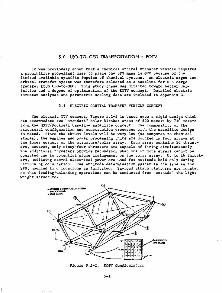
The electric OTV concept, Figure 5.1-1 is based upon a rigid design which can accommodate two 11 standard" solar blanket areas of 600 meters by 750 meters from the MSFC/Rockwell baseline satellite concept. The commonality of the structural configuration and construction processes with the satellite design is noted. Since the thrust levels will be very low (as compared to chemical stages), the engines and power processing units are mounted in four arrays at the lower corners of the structure/solar array. Each array contains 36 thrusters, however, only sixty-four thrusters are capable of firing simultaneously. The additional thrusters provide redundancy when one or more arrays cannot be operated due to potential plume impingement on the solar array. Up to 16 thrusters, utilizing stored electrical power are used for attitude hold only during periods of occultation. The attitude determination system is the same as the SPS, mounted in 6 locations as indicated. Payload attach platforms are located so that loading/unloading operations can be conducted from "outside" the light weight structure •
• Aml'l-'IE onEIWINATION SYSTlM I' LOCATIONSl
oSAMl AS SP5
Figure S.l-l. EOTV Configuration
5-1
361NQ.IJDU 2Cli.SPAll5
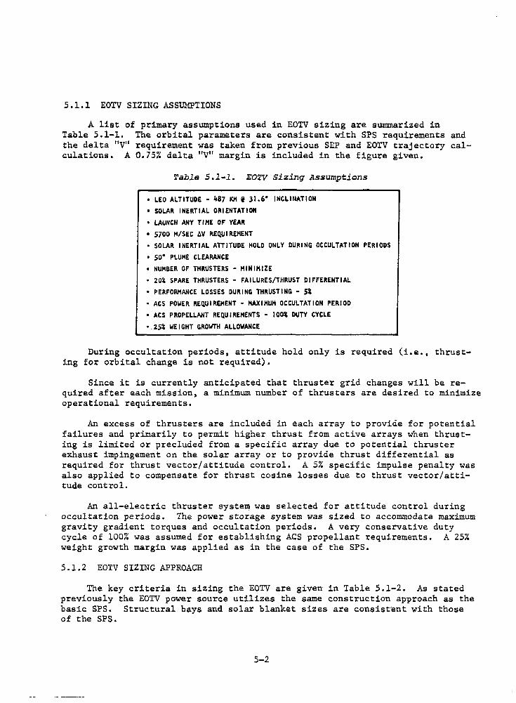
5.1.1 EOTV SIZING ASSUMPTIONS
A list of primary assumptions used in EOTV sizing are summarized in Table 5.1-1. The orbital parameters are consistent with SPS requirements and the delta "V" requirement was taken from previous SEP and EOTV trajectory calculations. A 0.75% delta "V" margin is included in the figure given.
Table S.l-1. EOTV Sizing Assumptions
• LEO ALTITUDE - li87 K11 i 31.6° INCLlllATION • SOLAR INERTIAL ORIENTATION • LAUNCH ANY TIHE OF YEAR • 5700 H/SEC ~V REQUIREMENT • SOLAR INERTIAL ATTITUDE HOLD ONLY DURING OCCULTATION PERIODS • so• PLUHE CLEARANCE • NUHBER OF THRUSTERS - HINIHIZE • 2oi SPARE THRUSTERS - FAILURES/THRUST DIFFERENTIAL • PERFOR/o!ANCE LOSSES DURING THRUSTING - Si • ACS POWER REQUIREMENT - HAXIHUH OCCULTATION PERIOD • ACS PROPELLANT REQUIREMENTS - 1ooi DUTY CYCLE
•.2si WEIGHT GROWTH ALLOWANCE
During occultation periods, attitude hold only is required (i.e., thrusting for orbital change is not required).
Since it is currently anticipated that thruster grid changes will be required after each mission, a minimum number of thrusters are desired to minimize operational requirements.
An excess of thrusters are included in each array to provide for potential failures and primarily to permit higher thrust from active arrays when thrusting is limited or precluded from a specific array due to potential thruster exhaust impingement on the solar array or to provide thrust differential as required for thrust vector/attitude control. A 5% specific impulse penalty was also applied to compensate for thrust cosine losses due to thrust vector/attitude control.
An all-electric thruster system was selected for attitude control during occultation periods. The power storage system was sized to accommodate maximum gravity gradient torques and occultation periods. A very conservative duty cycle of 100% was assumed for establishing ACS propellant requirements. A 25% weight growth margin was applied as in the case of the SPS.
5.1.2 EOTV SIZING APPROACH
The key criteria in sizing the EOTV are given in Table 5.1-2. As stated previously the EOTV power source utilizes the same construction approach as the basic SPS. Structural bays and solar blanket sizes are consist·ent with those of the SPS.
5-2
,---·--··-·-· .... , ____ , __ -· ' ...
I
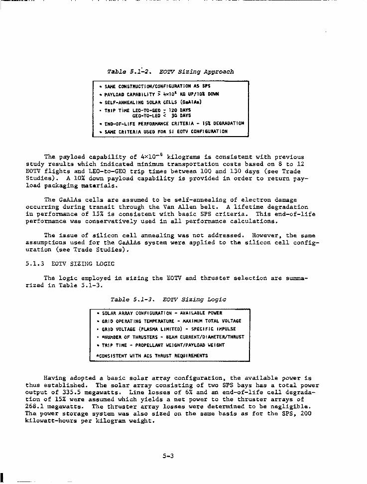
Table S.1~2. EOTV Sizing Approach
• SAKE CONSTRUCTION/CONFIGURATION AS SPS • PAYLOAD CAPABILITY > 4xl01 KG UP/IOi DOWN • SELF-ANNEALING SOLAR CELLS (G.AlA1) • TIUP Th1E LEO-TO-GEO - 120 DAYS
GEO•TO-LEO < 30 DAYS • END-OF-LIFE PERFO.RHANCE CRITERIA • lSl DEGRADATION • SAllE CRITERIA USED FOR SI EOTV CONFIGURATION
The payload capability of 4x10- 6 kilograms is consistent with previous study results which indicated minimum transportation costs based on 8 to 12 EOTV flights and LEO-to-GEO. trip times between 100 and 130 days (see Trade Studies). A 10% down payload capability is provided in order to return payload packaging materials.
The GaAlAs cells are assumed to be self-annealing of electron damage occurring during transit through the Van Allen belt. A lifetime degradation in performance of 15% is consistent with basic SPS criteria. This end-of-life performance was conservatively used in all performance calculations.
The issue of silicon cell annealing was not addressed. However, the same assumptions used for the GaAlAs system were applied to the silicon cell configuration (see Trade Studies),
5.1.3 EOTV SIZING LOGIC
The logic employed in sizing the EO'lV and thruster selection are sununarized in Table 5.1-3.
Table 5.l-3. EOTV Sizing Logia
• SOLAR ARRAY CONFIGURATION - AVAILABLE POWER • GRID OPERATING TEMPERATURE - MAXIMUM TOTAL VOLTAGE • GRID VOLTAGE (PLASMA LIMITED) - SPECIFIC IMPULSE • *tlUHBER OF THRUSTERS - BEAH CURRENT/DIAMETER/THRUST • TRIP TIHE - PROPELLANT WEIGHT/PAYLOAD WEIGHT
*CONSISTENT WITH ACS THRUST REQUIREMENTS
Having adopted a basic solar array configuration, the available power is thus established. The solar array consisting of two SPS bays has a total power output of 335.5 megawatts. Line losses of 6% and an end-of-life cell degradation of 15% were assumed which yields a net power to the thruster arrays of 268.1 megawatts. The thruster array losses were determined to be negligible. The power storage system was also sized on the same basis as for the SPS, 200 kilowatt-hours per kilogram weight.
5-3
The practical upper operating temperature·limit of 1900°K for molybdenum thruster grids fixes the maximum absolute operating voltage of the thrusters at 8300 volts (see Appendix C).
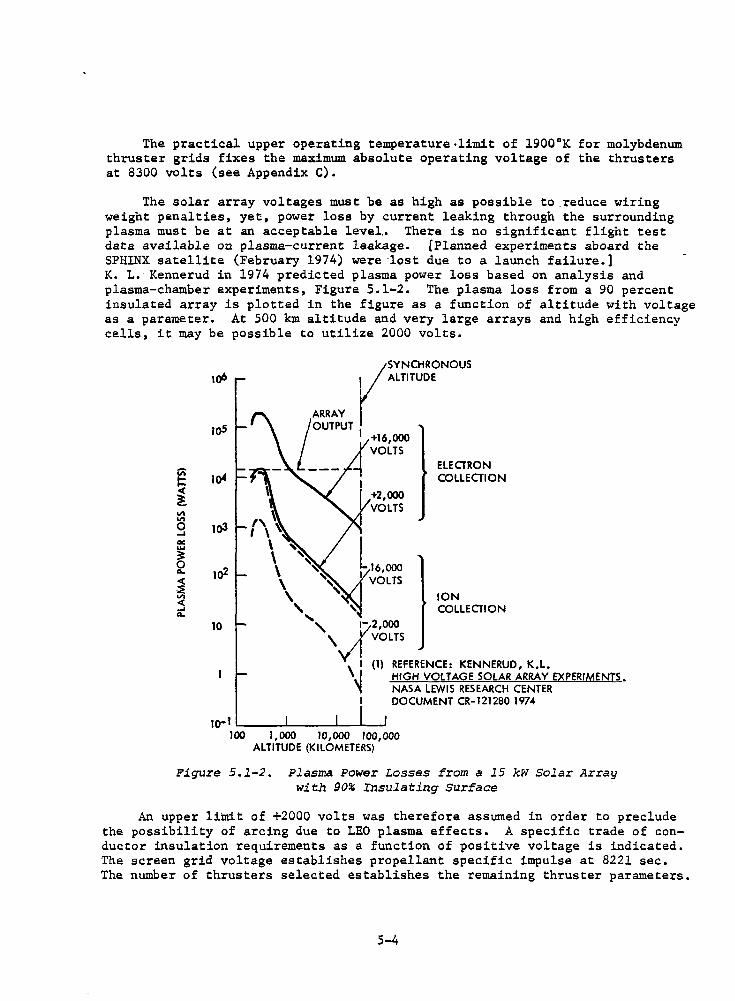
The solar array voltages must be as high as possible to reduce wiring weight penalties, yet, power loss by current leaking through the surrounding plasma must be at an acceptable level.. There is no significant flight test data available on plasma-current leakage. [Planned experiments aboard the SPHINX satellite (February 1974) were ·lost due to a launch failure.] K. L. Kennerud in 1974 predicted plasma power loss based on analysis and plasma-chamber experiments, Figure 5.1-2. The plasma loss from a 90 percent insulated array is plotted in the figure as a function of altitude with voltage as a parameter. At 500 km altitude and very large arrays and high efficiency cells, it may be possible to utilize 2000 volts.
E ~ "' "' 0 ..... "' ..... 3: 0 .... < -~ "' < ..... ....
1oS
1o4
1o3
1o2
10
I'\ ~ I \ ~
\ \ \ \ \ ' '\:
+16,000 VOLTS
+2,000 VOLTS
', , .. 2,000
ELECTRON COLLECTION
ION COLLECTION
\v(voLTs
I (1) REFERENCE: KENNERUD, K.L. \! HIGH VOLTAGE SOLAR ARRAY EXPERIMENTS. ~ NASA LEWIS RESEARCH CENTER
DOCUMENT CR-121280 1974
10- l ,__ __ _._ __ ___. __ ___.
100 1,000 10,000 100,000 ALTITUDE (KILOMETERS)
Figure S.l-2. Plasma Power Losses from a 15 kW Solar Array with 90% Insulating surface
An upper limit of +2000 volts was therefore assumed in order to preclude the possibility of arcing due to LEO plasma effects. A specific trade of conductor insulation requirements as a function of positive voltage is indicated. The screen grid voltage establishes propellant specific impulse at 8221 sec. The number of thrusters selected establishes the remaining thruster parameters.
5-4
(The number of thrusters should be selected such that the individual thrust is consistent with attitude control thrust requirements in order to preclude the need ·for dedicated ACS thrusters.) Thruster characteristics are summarized in Table 5.1-4.
Table 5.1-4. EOTV Thruster Charaateristics
• MAXIMUM OPERATING TEMPERATURE - 1900• K.
• TOTAL VOLTAGE - 8300 VOLTS •GRID VOLTAGE • 2000 VOLTS 11AXIHUM ,. 8EN1 CURRENT • 1887 AMP ,. SPECIFIC IMPULSE - 8213 SEC • THRUSTER DIAMETER - 76 CH
•THRUST/THRUSTER - 69.7 NEWTON • NUMBER OF THRUSTERS - 1 lili (INCLUDES 2St SPARES) • HAX!HUM OF 64 THRUSTERS OPERABLE SIMULTA!~EOUSLY
By establishing trip time (see Trade Studies), the maximum quantity of propellant which can be consumed during transit is established; which in turn fixes maximum payload capability.
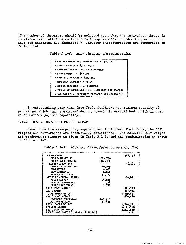
5.1.4 EOTV WEIGHT/PERFORMANCE SUMMARY
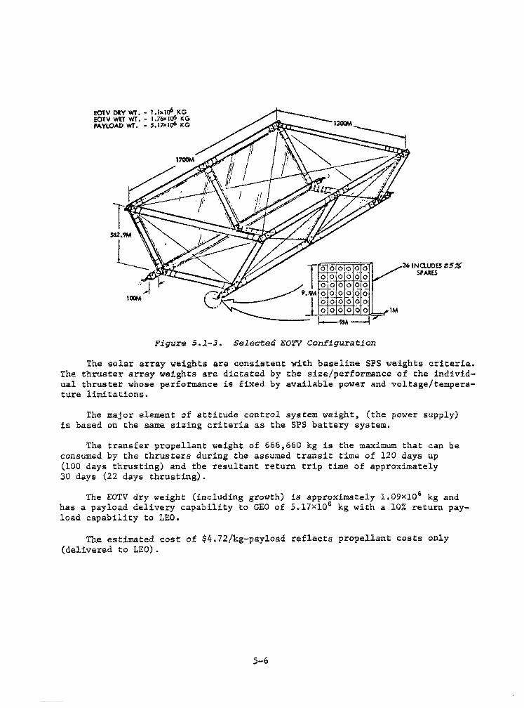
Based upon the assumptions, approach and logic described above, the EOTV weights and performance are essentially established. The selected EOTV weight and performance summary is given in Table 5.1-5, and the configuration is shown in Figure 5.1-3.
Table S.l-5. EOTV Weight/Performance Summary (kg)
SOLAR ARRAY CELLS/STRUCTURE POWER CONDITIONING
THRUSTER ARRAY (4) THRUSTERS/STRUCTURE CONDUCTORS BEAHS/GIH8ALS PROPELLANT TANKS
ATTITUDE CONTROL SYSTEM POWER SUPPLY SYSTEM COMPONENTS PROPELLANT TAHICS
EOTV INERT WEIGHT 25~ GROWTH TOTAL INERT WEIG.HT PROPELLANT WEIGHT
TRANSFER PROPELLANT ACS PROPELLANT
EOTV LOADED WEIGHT PAYLOAD WEIGHT LEO DEPARTURE WEIGHT PROPELLANT COST DELIVERED ($/KG P/L)
5-5
299,756 288,440
10,979 4,607 2,256
78,843
184,882 274
1,716
655,219 11,.lfltl
588, 196
96,685
186,872
871,753 217,938
1,089,691 666,660
1,756,351 S,171,318 6,,27,669
4.72
EOTV ORY W'r. - 1. lxl<f' KG EOTV WET Wl. - I .76'< I~ KG PAYLOAD WT, - 5.17xhr KG
Figure S.l-3. Selected EOTV Configuration
36 INO.UOES z.5% SPARES
The solar array weights are consistent with baseline SPS weights criteria. The thruster array weights are dictated by the size/performance of the individual thruster whose performance is fixed by available power and voltage/temperature limitations.
The major element of attitude control system weight, (the power supply) is based on the same sizing criteria as the SPS battery system.
The transfer propellant weight of 666,660 kg is the maximum that can be consumed by the thrusters during the assumed transit time of 120 days up (100 days thrusting) and the resultant return trip time of approximately 30 days (22 days thrusting).
The EOTV dry weight (including growth) is approximately l.09xl06 kg and has a payload delivery capability to GEO of 5.17x10⁶ kg with a 10% return payload capability to LEO.
Tne estimated cost of $4.72/kg-payload reflects propellant costs only (delivered to LEO).
.5-6
5.2 ELECTRIC ORBITAL TRANSFER VEHICLE TRADE STUDIES
Several trade studies were conducted with the objective of achieving a near cost-optimum EOTV configuration. In addi~ion, parametric sizing data were generated for thrusters, thruster arrays, conductors, and overall EOTV sizing. These data are contained in Appendix C. The results of selected trade studies are summarized herein.
5.2.l SOLAR APJJ..A.Y VOLTAGE, GRID TEMPERATURE, NUMBERS OF THRUSTERS
The effects of lowering the total solar array voltage from the baseline of .8300 volts to 5500 volts was evaluated and the results were found to be negligible. The thruster diameter increased to 120 cm and the grid temperature was lowered to 1500°K. Although the thruster array weight increased approximately 2.5 times the total impact on EOTV inert weight is negligible. In addition the added array weight could be offset by a reduction in conductor insulation weight. A lower total voltage would appear to be advantageous only if the power conditioning weight would be effected significantly which present data indicates would not be the case.
Similarly, the number of thrusters in the baseline was reduced by 50%, thus doubling the unit beam current and thrust. The thruster diameter increases to 108 cm with no significant change in thruster array weight. The higher thrust appears to be disadvantageous from the standpoint of ACS requirements (i.e., dedicated lower thrust units might be required to satisfy minimum ACS demands).
Three EOTV configurations reflecting changes of the type described and also trip time are summarized in Table 5.2-1. As may be seen the relative propellant costs between configuration llA and llB show an increase with a decrease in trip time from the baseline. Configuration 12 also shows an increase in cost with increased numbers of thrusters with lower accelerating voltage. Although configuration llA appears to be more efficient than the baseline, it is noted that only 10% spare thrusters and a 15% weight growth was allowed in these configurations. When these corrections are made, all three configurations exceed the baseline selection.
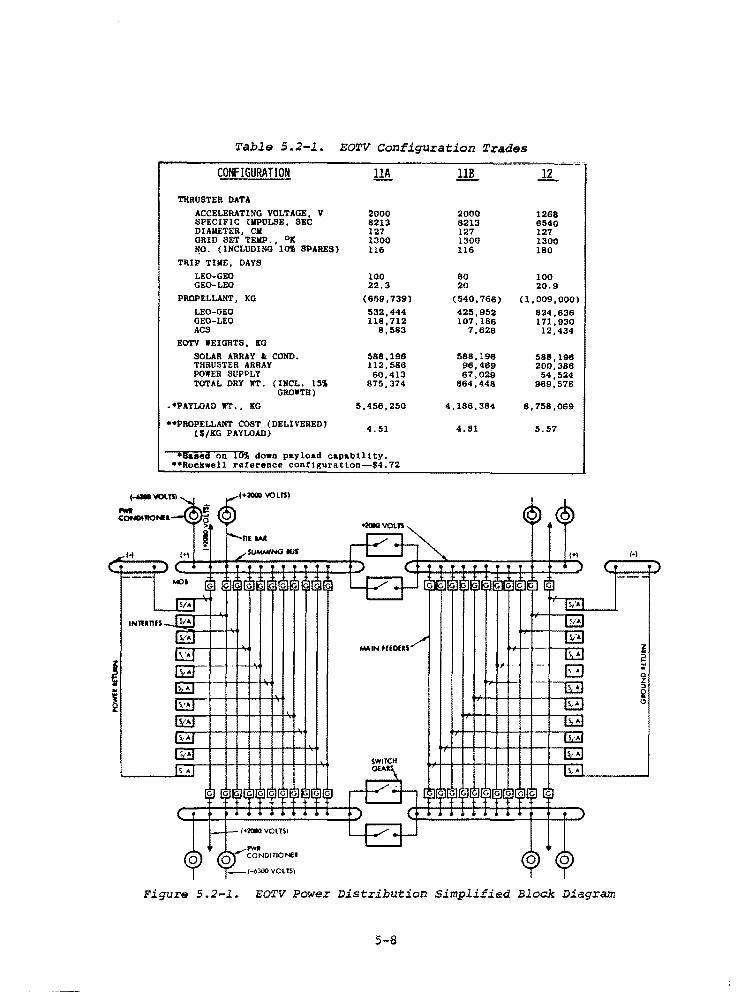
5.2.2 POWER DISTRIBUTION AND CONTROL WEIGHT
A simplified block diagram, Figure 5.2-1, illustrates the EOTV power distribution interface for the solar photovoltaic concept. The distribution subsystem consists of interties, main feeders, summing bus, tie bar, switch gears, and de/de converters. The solar arrays feed the load buses with a direct energy transfer. Provisions are included to switch power.from any bus to any thruster location. The basic voltages supplied are +2000 V de and -6300 V de. Individual power supplies will be included as required at the thrusters to supply other voltages.
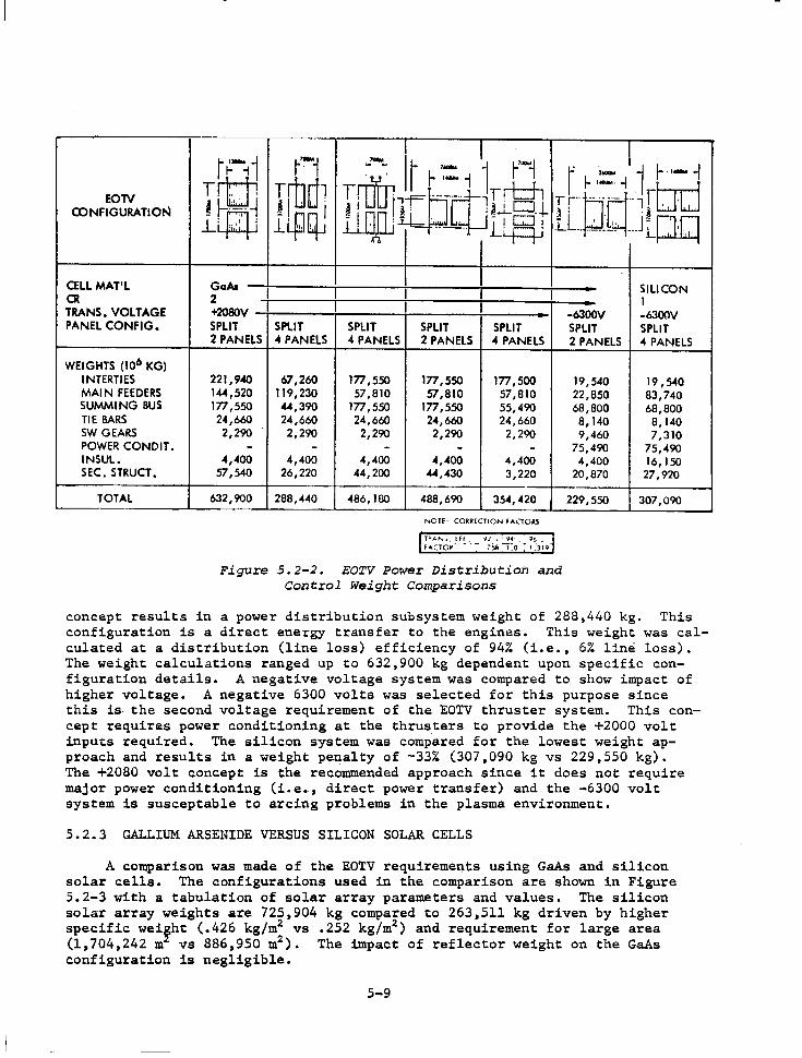
Figure 5.2-2 shows the power distribution and control weight comparisons for several EOTV configurations studied. A solar array voltage output of 2080 V de was selected as the upper limit for power generation to stay within tolerable plasma power losses for low earth orbit operations. The lowest weight
5-7
. ~
Table 5.2-l. EOTV Configuration Trades
CONFIGURATION
THRUSTER DATA ACCELERATING VOLTAGE, V SPECIFIC IMPULSE, SEC DIAMETER, Cll GRID SET TEllP. , 0JC ~O. (INCLUDING lO'I SPARES)
TRIP TIME, DAYS LEO-GEO GEO-LEO
PROPELLANT, KG LEO-GEO GEO-LEO ACS
EOTV WEIGHTS, KG SOLAR ARRAY • COMO. THRUSTER ARRAY POWER SUPPLY TOTAL DRY WT. (INCL. 151
GROWTH) .•PAYLOAD WT., KG
••PROPELLANT COST (DELIVERED) ($/KG PAYLOAD)
2000 8213 127 1300 116
100 22.3
(659,739)
532,444 118, 112
8,583
588,198 112, 586 60,413
875,374
5,456,250
4.51
•Based on 10\ down payload capability. ••Rockwell reference con!iguration~$4.72
G!r
[EJ
2000 8213 127 1300 116
80 20
(540,766)
4211,952 107, 186
7,628
588, 196 96,469 87,029
864,448
4,186,384
4.81
I
1268 6540 127 1300 180
100 20.9
(l,009,000)
824,636 171,930 12,434
588,196 200,386
54,524 969,578
6,758,069
5.57
E!J II!]
Figure 5.2-1. EOTV Power Distribution Simplified Block Diagram
5-8
ii z ':: 0 z :> ~
"'
EOTV OONFIGURATION
CELL MAT'L CR TRANS, VOLTAGE PANEL CONFIG.
WEIGHTS (106 KG) INTERTIES MAIN FEEDERS SUMMING BUS TIE BARS SW GEARS POWER CONDIT. INSUL. SEC. STRUCT.
TOTAL -
-
1~--1i ~-i
ThtJ~ T~dl J_uzµ ilpqJ ,.,
GaAa 2 I +2080V SPLIT SPLIT 2 PANELS 4 PANELS
221,940 67,260 144,520 119, 230 177,550 44,390 24,660 24,660 2,290 2,290
- -4,400 4,400
57,540 26,220
632,900 288,440
I I . ~-~ 11 r ·= i I r'1
TmDim:ictra ~I ~, :~J_O+ illJ1JJ • . . . -I GJ ··-·· lLff
SPLIT 4 PANELS
177 ,550 57,810
177,550 24,660
2,290
-4,400
44,200
486, 180
I
SPLIT SPLIT 2 PANELS 4 PANELS
177,550 177,500 57,810 57,810
177,550 55,490 24,660 24,660 2,290 2,290
- -4,400 4,400
44,430 3,220
488,690 354,420
NOif · CORRECTION FACTOlilS
PA"lJ. tFf. il , '~4·. ~ei , F4.(lCli'- - - - 75fi J~o . I ."319
. I I ·- I r··-1 ~ ·-~ bd rrpq1r · l' . ·A
LL.. _'._ __ _': ... J LPQ
SILICON I 1 -6300V -6300V SPLIT SPLIT 2 PANELS 4 PANELS
19,540 19 ,540 22,850 83,740 68,800 68,800 8, 140 8, 140 9,460 7,310
75,490 75,490 4,400 16, 150
20,870 27,920
229,550 307,090
Figure 5.2-2. EOTV Power Distribution and Control Weight Comparisons
concept results in a power distribution subsystem weight of 288,440 kg. This configuration is a direct energy transfer to the engines. This weight was calculated at a distribution (line loss) efficiency of 94% (i.e., 6% line loss). The weight calculations ranged up to 632,900 kg dependent upon specific configuration details. A negative voltage system was compared to show impact of higher voltage. A negative 6300 volts was selected for this purpose since this is. the second voltage requirement of the EOTV thruster system. This concept requires power conditioning at the thrusters to provide the +2000 volt inputs required. The silicon system was comp.ared for the lowest weight approach and results in a weight penalty of -33% (307,090 kg vs 229,550 kg). The +2080 volt concept is the recommended approach since it does not require major power conditioning (i.e., direct power transfer) and the -6300 volt system is susceptable to arcing problems in the plasma environment.
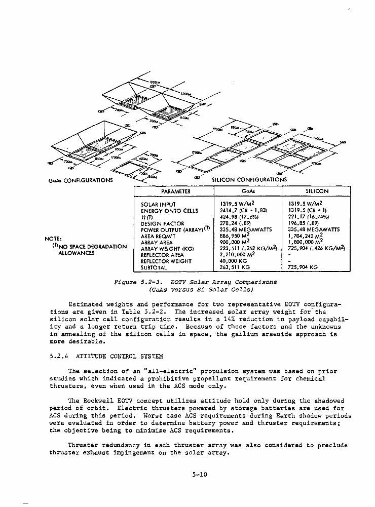
5.2.3 GALLIUM ARSENIDE VERSUS SILICON SOLAR CELLS
A comparison was made of the EOTV requirements using GaAs and silicon solar cells. The configurations used in the comparison are sho'Wn in Figure 5.2-3 with a tabulation of solar array parameters and values. The silicon solar array weights are 725,904 kg compared to 263,511 kg driven by higher specific weifht (.426 kg/m2 vs .252 kg/m2 ) and requirement for large area (1,704,242 m vs 886,950 m2 ). The impact of reflector weight on the GaAs configuration is negligible.
5-9
NOTE:
(J)NO SPACE DEGRADATION ALLOWANCES
PARAMETER
SOLAR INPUT ENERGY ONTO CELLS 77 (Tl DESIGN FACTOR POWER OUTPUT (ARRAY)(!) AREA REQM'T ARRAY AREA ARRAY WEIGHT (KG) REFLECTOR AREA REFLECTOR WEIGHT SUBTOTAL
SILICON CONFIGURATIONS
GaAs
1319.5 W/M2 2414,7 (CR"" 1.83) 424, 98 (17 .6%) 278,24 (.89) 335.48 MEGAWATTS 886, 950 M2 900,000 M2 223,511 (.252 KG/M2> 2,210,000 M2 40,000 KG 263,511 KG
Figure 5.2-3. EOTV Solar Array Comparisons (GaAs versus Si Solar Cells)
SILICON
1319,5W/M2 1319.5 (CR" I) 221.17 (16,74%) 196.85 (,89) 335.48 MEGAWATTS 1,704,242 M2 1,800,000 M2 725,904 (.426 KG/M2>
--725,904 KG
Estimated weights and performance for two representative EOTV co?figurations are given in Table 5.2-2. The increased solar array weight for the silicon solar cell configuration results in a 14% reduction in payload capability and a longer return trip time. Because of these factors and the unknowns in annealing of the silicon cells in space, the gallium arsenide approach is more desirable.
5.2.4 ATTITUDE CONTROL SYSTEM
The selection of an "all-electric" propulsion system was based on prior studies which indicated a prohibitive propellant requirement for chemical thrusters, even when used in the ACS mode only.
The Rockwell EOTV concept utilizes attitude hold only during the shadowed period of orbit. Elec·tric thrusters powered by storage batteries are used for ACS during this period. Worst case ACS requirements during Earth shadow periods were evaluated in order to determine battery power and thruster requirements; the objective being to minimize ACS requirements.
Thruster redundancy in each thruster array was also considered to preclude thruster exhaust impingement on the solar array.
5-10
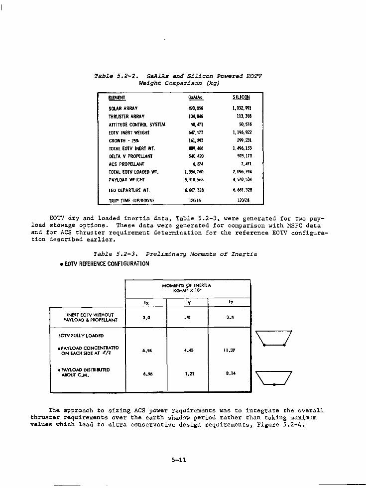
Table 5.2-2. GaAlAs and Silicon Powered EOTV Weight Comparison (kg)
ElfMENT ~ ~
SOUR ARRAY 493,056 1, 032, 991
THRUSTER ARRAY 104, 046 113,355
ATTITUDE CONTROL SYSTEM ')(),471 50, 576
EOTV INERT WEIGHT MT, 573 l, 196, 922
GR<7NTH - 25S 161, 893 299,231
TOTAL EOTV INERT WT. 1119, 466 1,496, 153
DELTA V PROPELI.ANT 540,420 593, 170
ACS PROPELI.ANT 6, 814 7,471
TOTAL EOTV LOADED WT. 1,356, 760 2,096,794
PAYLOAD WEIGHT 5. 310, 568 4, 570, 534
l.£0 DEPARTURE WT. 6,667, 328 6,661, 328
TRIP TIME tUPIDCNINI 12<Yl6 12<Y28
EOTV dry and loaded inertia data, Table 5.2-3, were generated for two payload stowage options. These data were generated for comparison with MSFC data and for ACS thruster requirement determination for the reference EOTV configuration described earlier.
Table 5.2-3. Preliminary Moments of Inertia
• EOTV REFERENCE CONFIGURATION
MOMENTS ~F INERTIA KG-M X 10"
Ix ly lz
INERT EOTV WITHOUT 3.0 .!11 3 •. ~
PAYLOAD & PROPELLANT
EOTV FULLY LOADED
ePAY'..OAD CONCENTRATED 6.94 4.43 11.37 ON EACH SIDE AT '/2
\ I •PAYLOAD DISTRIBUTED
8.14 AIOUT C.M. 6.96 1.21 \ __ .I
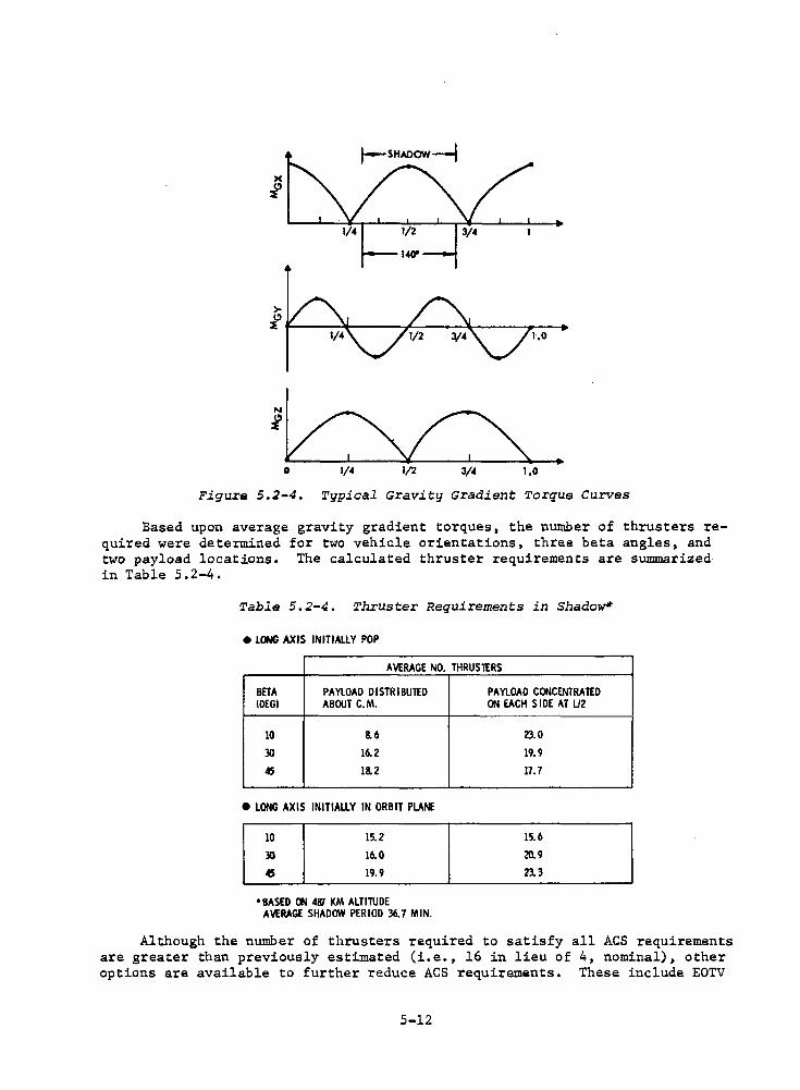
The approach to sizing ACS power requirements was to integrate the overall thruster requireme~ts over the earth shadow period rather than taking maximum values which lead to ultra conservative design requirements, Figure 5.2-4.
5-11
> ~~.-~~~t-~~--.,._~--~~~~ ....... ..-~.
1.0
j~ ..
0 1/4 1/2 3/4 1.0
Figure 5.2-4. Typical Gravity Gradient Torque Curves
Based upon average gravity gradient torques, the number of thrusters required were determined for two vehicle orientations, three beta angles, and two payload locations. The calculated thruster requirements are summarized in Table 5.2-4.
Table 5.2-4. Thruster Requirements in Shadow*
e LONG AXIS INITIALLY POP
AVERAGE NO. THRUS1£RS
BETA PAYLOAD DISTRIBUTED IDEGI ABOUT C.M.
lD 8. 6
30 16. 2
45 18.2
e LONG AXIS INITIALLY IN ORBIT PLANE
lD
30
45
15.2
16. 0
19.9
•BASED CJ.I 4Kl KM ALTITUDE AVERAGE SHADOW PERIOD 36. 7 MIN.
PAYLOAD CONCENTRATED ON EACH SIDE AT U2
23.D
19.9
17. 7
15.6
20. 9
23. 3
Although the number of thrusters required to satisfy all ACS requirements are greater than previously estimated (i.e., 16 in lieu of 4, nominal), other options are available to further reduce ACS requirements. These include EOTV
5-12
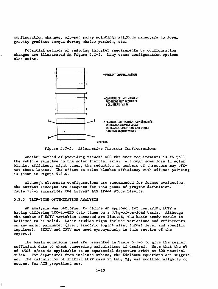
configuration changes, off-set solat' point:!ng, attttude. maneuvers to lower gravity gradient torque during shadow periods, etc.
Potential methods of reducing thruster require.men.ts by configuration changes are illustrated in Figure 5.2-5. Many other configuration options also exist.
. •PRESENT CONFIGURATION
•CAN REDUCE IMPINGEMENT PROBlfMS BUT REQUIRES I CLUSTERS IVS 41
•REDUCES IMPINGEMENT CO~STRAINTS, INCREASES MOt.'lNT ARMS, INCREASES STRUCTURE AND POWER CABLING REQUI REt.'lNTS
•OMRS
Figure S.2-S. Altern•tive Thruster Configurations
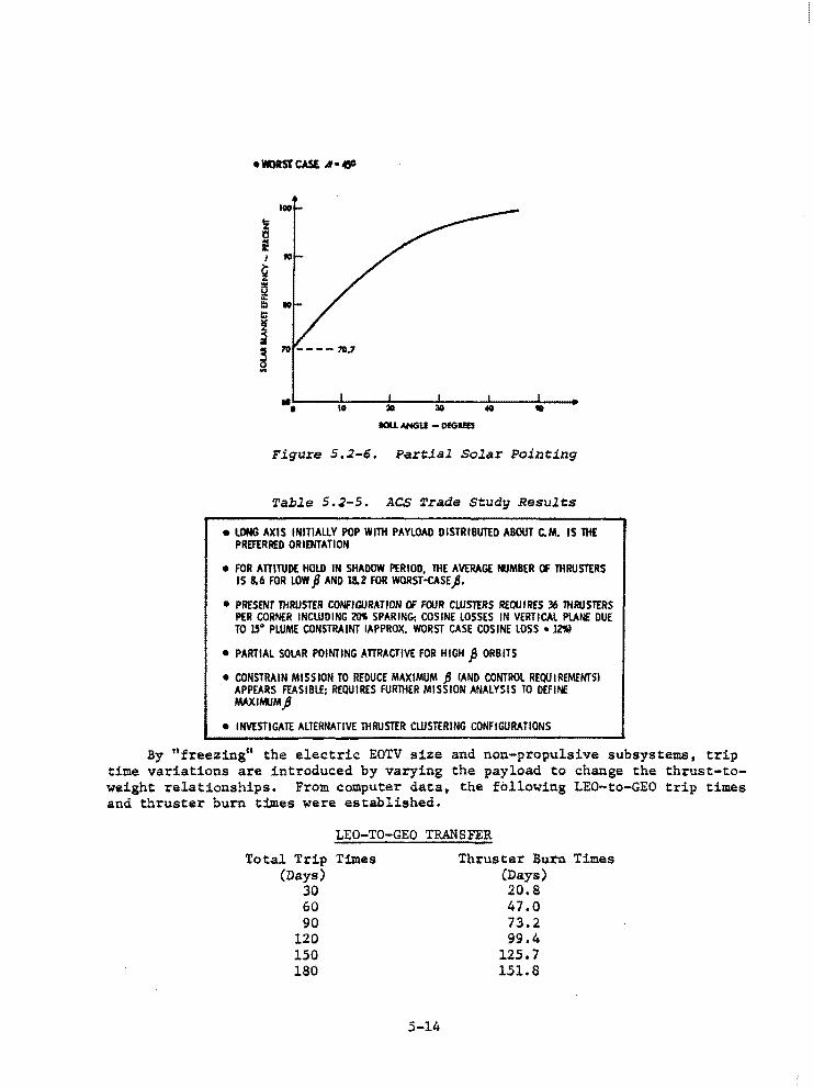
Another method of providing reduced ACS thruster requirements is to roll the vehicle relative to the solar inertial axis. Although some loss in solar blanket efficiency might occur, the reduction in numbers of thrusters may offset those losses. The effect on solar blanket efficiency with off-set pointing is shown in Figure 5.2-6.
Although alternate configurations are recommended for future evaluation, the current concepts are adequate for this phase of program definition. Table 5.2-5 summarizes the current ACS trade study results.
5.2.5 TRIP-TIME OPTIMIZATION ANALYSIS
An analysis was performed to define an approach for comparing EOTV's having differing LEO-to-GEO trip times on a $/kg-of-payload basis. Although the number of EOTV variables assessed are limited, the basic study result is believed to be valid. Later studies might include variations and refinements on any major parameter (i.e., electric engine size, thrust level and specific impulses). (EOTV and COTV are used synonymously in this section of the report.)
The basic equations used are presented in Table 5. 2-6 to give· the reader sufficient data to check succeeding calculations if desired. Note that the AV of 4508 m/sec is applicable to an equatorial departure orbit at 300 nautical miles. For departures from inclined orbits, the Edelbaum equations are suggested. The calculation of initial EOTV mass in LEO, Mi,· was modified slightly to account for ACS propellant use.
5-13
•WORST CASE I• 11!1'
... II 30 1D
IOU. ANGU - DfGl!B
Figure 5.2-6. Partial Solar Pointing
Table S.2-5. ACS Trade Study Results
• I.ONG AXIS INITIALLY POP Willi PAYLOAD DISTRIBUTED ABOUT C.M. IS THE PREFERRED ORIENTATION
• FOR ATTITUDE HOLD IN SHADOW PERIOD, THE AVERAGE lllMBER OF THRUSTERS IS &.6 FOR LOW ft AND 18.2 FOR WORST-CASE).
• PRESENT THRUSTER CONFIGURATION Of FOUR CLUSTERS REQUIRES 36 THRUSTERS PER CORNER INCLUDING 20I SPARING: COSINE LOSSES IN VERTICAL PLANE DUE TO 15° PWME CONSTRAINT IAPPROX. WORST CASE COSINE LOSS • lZ'Jil
• PARTIAL SOLAR POINTING ATTRACTIVE FOR HIGH ft ORBITS
• CONSTRAIN MISSION TO REDUCE MAXIMUM ~ !ANO CONTROL REQUIREMENTS! APPEARS FEASIBLE: REQUIRES FURlliER MISSION ANALYSIS TO DEFINE MAXINIJMjJ
• INVESTIGATE ALTERNATIVE THRUSTER CLUSTERING CONFIGURATIONS
By 11 freezing11 the electric EOTV size and non-propulsive subsystems, trip time variations are introduced by varying the payload to change the thrust-toweight relationships. From computer data, the following LEO-to-GEO trip times and thruster burn t:lmes were established.
LEO-TO-GEO TRANSFER
Total Trip Times (Days)
30 60 90
120 150 180
5-14
Thruster Burn Times (Days) 20.8 47.0 73.2 99.4
125.7 151.8
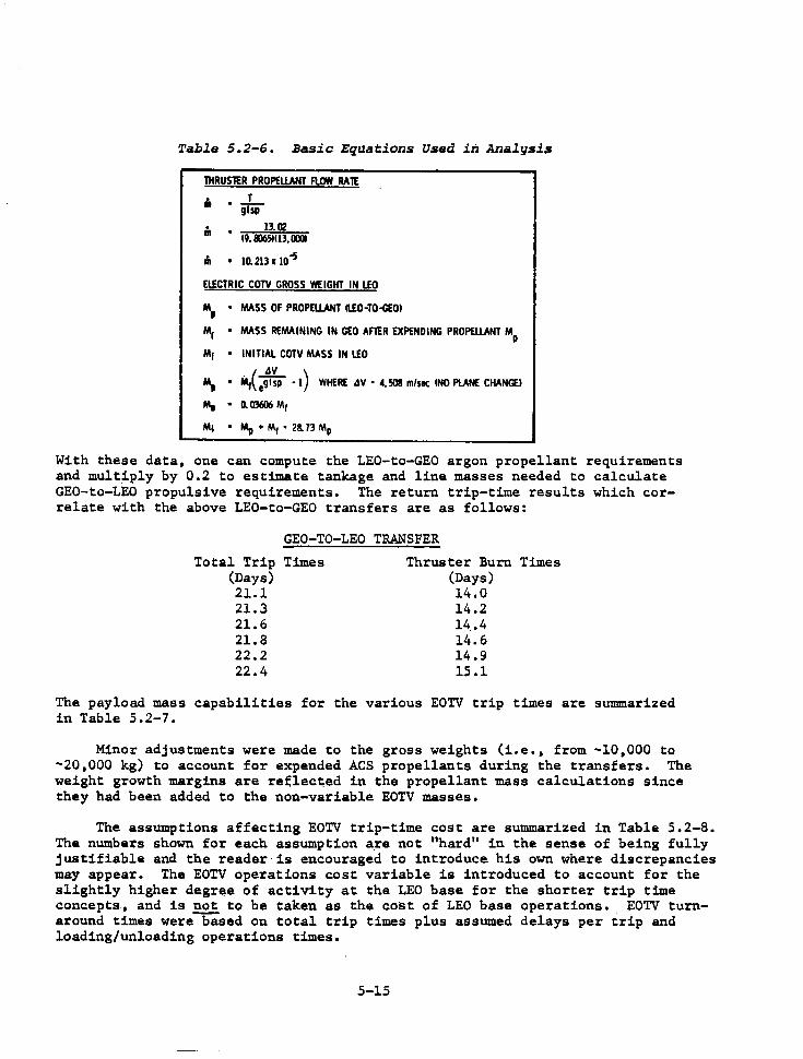
Table 5.2-6. Basic Equations Used in Analysis
lHRUSlER PROPELLANT Fl<M RAlE
ii T • glsp
n. 13.02 (9. lll651U3, IDll
.n 10. 213 x 10-5
ElfCTRIC COTY GROSS WEIGHT IN LEO
MP • MASS OF PROPELLANT ll.£0-TO-<:EOI
Mr • MASS REMAINING IN GEO AFlER EXPENDING PROPELLANT MP
M1 • INITIAL COTY MASS IN LEO
M, • Mi( e:.~p - l) WHERE 4V • 4, 508 m/sec (NO PLANE CHANGE!
Mt " 0. 0'3606 Mr
M1 • Mp + Mr • 28. 73 Mp
With these data, one can compute the LEO-to-GEO argon propellant requirements and mult~ply by 0.2 to estimate tankage and line masses needed to calculate GEO-to-LEO propulsive requirements. The return trip-time results which correlate with the above LEO-to-GEO transfers are as follows:
GEO-TO-LEO TRANSFER
Total Trip Times (Days) 21.l 21.3 21.6 21.8 22.2 22.4
Thruster Burn Times (Days) 14.0 14.2 14 .• 4 14.6 14.9 15.1
The payload mass capabilities for the various EOTV trip times are summarized in Table 5.2-7.
Minor adjustments were made to the gross weights (i.e., from -10,000 to -20,000 kg) to account for expended ACS propellants during the transfers. The weight growth margins are reelected in the propellant mass calculations since they had been added to the non-variable EOTV masses.
The assumptions affecting EOTV trip-time cost are summarized in Table 5.2-8. The numbers shown for each assumption are not "hard" in the sense of being fully justifiable and the reader· is encouraged to introduce his own where discrepancies may appear. The EOTV operations cost variable is introduced to account for the slightly higher degree of activity at the LEO base for the shorter trip time concepts, and is not to be taken as the cost of LEO base operations. EOTV turnaround times were based on total trip times plus assumed delays per trip and loading/unloading operations times.
5-15
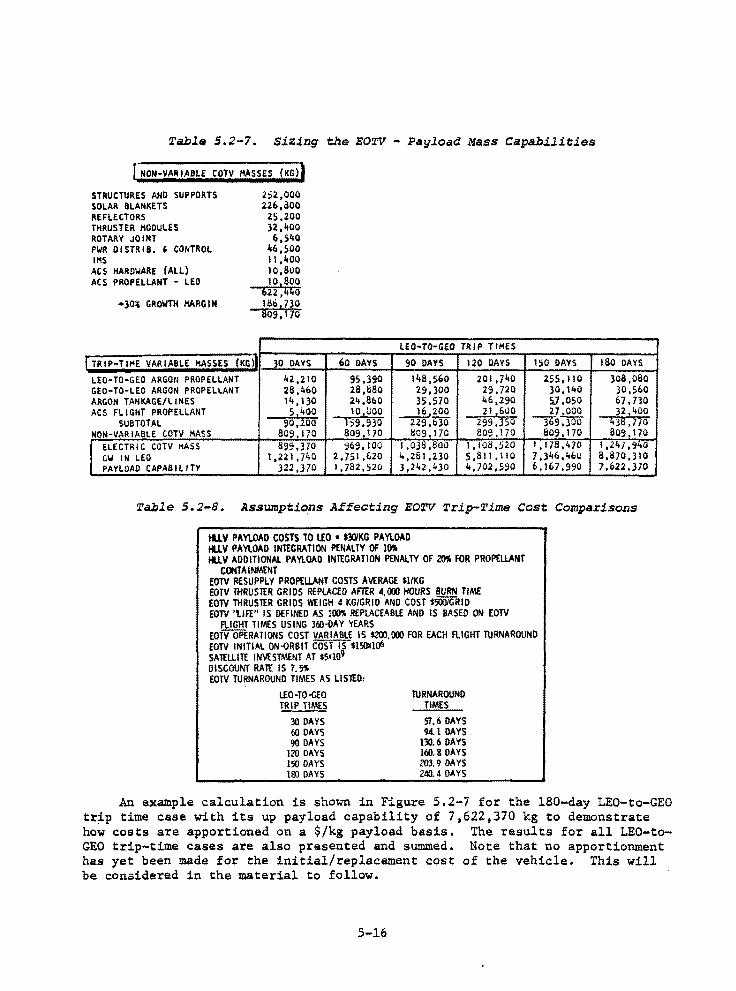
Table S.2-7. Sizing the EOTV - Payload Mass Capabilities
rNON·VARIABLE COTV MASSES (KG))
STRUCTURES ANO SUPPORTS SOLAR BLANKETS REFLECTORS THRUSTER 1100ULES ROTARY JOINT PWft DISTRl8. ' CONTROL IMS
ACS HARDWARE (ALL) ACS PROPELLANT - LEO
+30~ GROWTH MARGIN
I TRIP-TIME VARIABLE MASSES (Ktil
LEO-TO-GEO ARGON PROPELLANT GEO-TO-LEO ARGON PROPELLANT ARGON TANKAGE/LINES ACS FLIGHT PROPELLANT
SUBTOTAL NON-VARIABLE COTV MASS I ELECTR! c COTV MASS
GW IN LEO PAYLOAD CAPABILITY
2:;2,000 226,aoo
2S,200 32.,400 6,540
46,500 11,400 I0,81.lO 10,800
622 ,4'0 lllb,730 809,170
30 DAYS
42,210 28,460 l'+, 130 51400
90,200 809, 170 1199,370
t,221,JliO 322,370
60 DAYS
95,390 28,880 24,8bO I0 1UOO
159,930 809, I 70 969. 100
2,751 ,620 I, 782, 520
LEO•TO·GEO TRIP TIMES
90 DAYS 120 DAYS ISO DAYS
148,560 201 ,740 255, l 10 29,300 29.720 30, 140 35,570 46,290 5],050
__j!,200 229,bJO
211600 299.350
271000 ,-9,)00
B09,170 809, 170 809, 170 I ,OJ8,800 l,108,520 1,178,470 4,261,230 5 ,811, 110 7,)li6,460 3 ,242, li)O 4,702,590 6,167,990
180 DAYS
308,080 30,560 67.730 32,l+OO
~36. 770 809, 170
1,247,940 8,870,310 7,f.>22,370
Table s.2-s. Assumptions Affecting EOTV Trip-Time Cost Comparisons
tll.V PAYLOAD COSTS TO lEO • $30/KG PAYLOAD tll.V PAYLOAD INTEGRATION PENALTY OF IO'li tll.V ADDITIONAL PAYLOAD INTEGRATION PENALTY OF 20'llo FOR PROPELLANT
CONTAINMENT EOTV RESUPPLY PROPELLANT COSTS AVERAGE $1/KG EOTV THRUSTER GRIDS REPLACED AFl£R 4,00J HOURS BURN TIME EOTV THRUSTER GRIDS WEIGH 4 KG/GRID ANO COST $500/GRID EOTV 'tlfI" IS DEFINED AS Jim REPLACEABLE AND IS BASED ON EOTV
A.IGHT TIMES USING 360--0AY YEARS EOTV OPERATIONS COST VARIABLE IS $200,00J FOR EACH FLIGHT TURNAROUND EOTV INITIAL ON-ORBIT COST IS $150illo6 SA1£LLITE INVESTMENT AT $5Xl09 DISCOUNT RAlt IS 7.5.,. EOTV TURNAROUND TIMES AS usn:D:
LEO·TO-GEO TRIP TIMES
30 DAYS 60 DAYS 90 DAYS
120 DAYS 150 DAYS l&l DAYS
TURNAROUND TIMES
57.6 DAYS 94.l DAYS
130.6 DAYS Ui0.8 DAYS 203.9 DAYS 240.4 DAYS
An example calculation is shown in Figure 5.2-7 for the 180-day LEO-to-GEO trip time case with its up payload capability of 7,622,370 kg to demonstrate how costs are apportioned on a $/kg payload basis. The results for all LEO-toGEO trip-time cases are also presented and sUl!lllled. Note that no apportionment has yet been made for the initial/replacement cost of the vehicle. This will be considered in the material to follow.
5-16
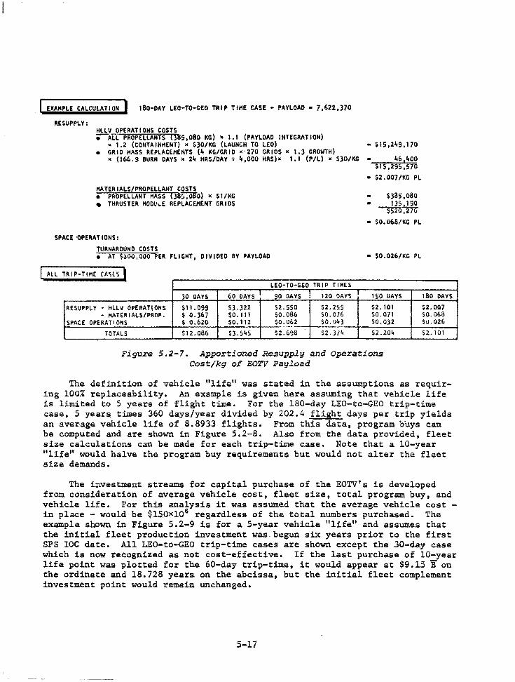
EXAMPLE CALCULATION I 180-0AY LEO-TO-GEO TRIP TIHE CASE - PAYLOAD. 7,622,370
RESUPPLY: HLLV OPERATIONS COSTS ;--ALL PROPELLANTS (385,080 KG) x 1.1 (PAYLOAD INTEGRATION)
x 1.2 (CONTAINHENT) x $30/KG (LAUNCH TO LEO) • GRID HASS REPLACEHENTS (4 KG/GRID x·270 GRIDS x 1.3 GROWTH)
.. $15,249,170
x (166.9 BURN DAYS x 24 HRS/DAY t 4,000 HRS)x 1.1 (P/L) x $30/KG • 46,40D $15,295,570
MATERIALS/PROPELLANT COSTS a PROPELLANT HASS (385,080) x $1/KG • THRUSTER HODl.• .. E REPLACEHENT GRIDS
SPACE ·OPERATIONS:
TURNAROUND COSTS • AT $ioo,ooo PER FLIGHT, DIVIDED BY PAYLOAD
(ALL TRIP·TlHE CA~ts I 30 DAYS 60 OAYS I
RESUPPLY • HLLV OPERATIONS SI I. 099 $3.322 • HATERIALS/PROP. $ 0.367 $0. 111
SPACE OPERATIONS $ 0.620 $0.112
TOTALS $12.086 SJ.545
LEO·TO·GEO TRIP TIHES
90 DAYS 120 DAYS l
$2. 550 S2.2S5 S0.08(> $0.076 $0.0£.2 so.oi.3 $2.69$ 52.)/li
• $2,007/KG PL
$385,080 • _ill.i!22,
$520,270
• $0.068/KG PL
• $0.026/KG PL
150 llAYS S2. 101 so. 071 so.032 $2.204
Figuze S.2-7. Apportioned Resupply and Operations Cost/kg of EOTV Payload
180 DAYS $2.007 $0.068 $().02C.
S2. l01
The definition of vehicle "life" was stated in the assumptions as requiring 100% replaceability. An example is given here assuming that vehicle life is limited to 5 years of flight time. For the 180-day LEO-to-GEO trip-time case, 5 years. times 360 days/year divided by 202. 4 flight days per trip yields an average vehicle life of 8.8933 flights. From this data, program buys can be computed and are shown in Figure 5.2-8. Also from the data provided, fleet size calculations can be made for each trip-time case. Note that a 10-year 11 life0 would halve the program buy requirements but would not alter the fleet size demands.
The investment streams for capital purchase of the EOTV's is developed from consideration of average vehicle cost, fleet size, total program buy, and vehicle life. For this analysis it was assumed that the average vehicle cost in place - would be $15.0xl0 6 regardless of the total numbers purchased. The example shown in Figure 5.2-9 is for a 5-year vehicle "life" and assumes that the initial fleet production investment was.begun six years prior to the first SPS IOC date. All LEO-to-GEO trip-time cases are shown except the 30-day case which is now recognized as not cost-effective. If the last purchase of 10-year life point was plotted for the 60-day trip-time, it would appear at $9.15 B on the ordinate and 18.728 years on the abcissa, but the initial fleet complement investment point would remain unchanged.
5-17
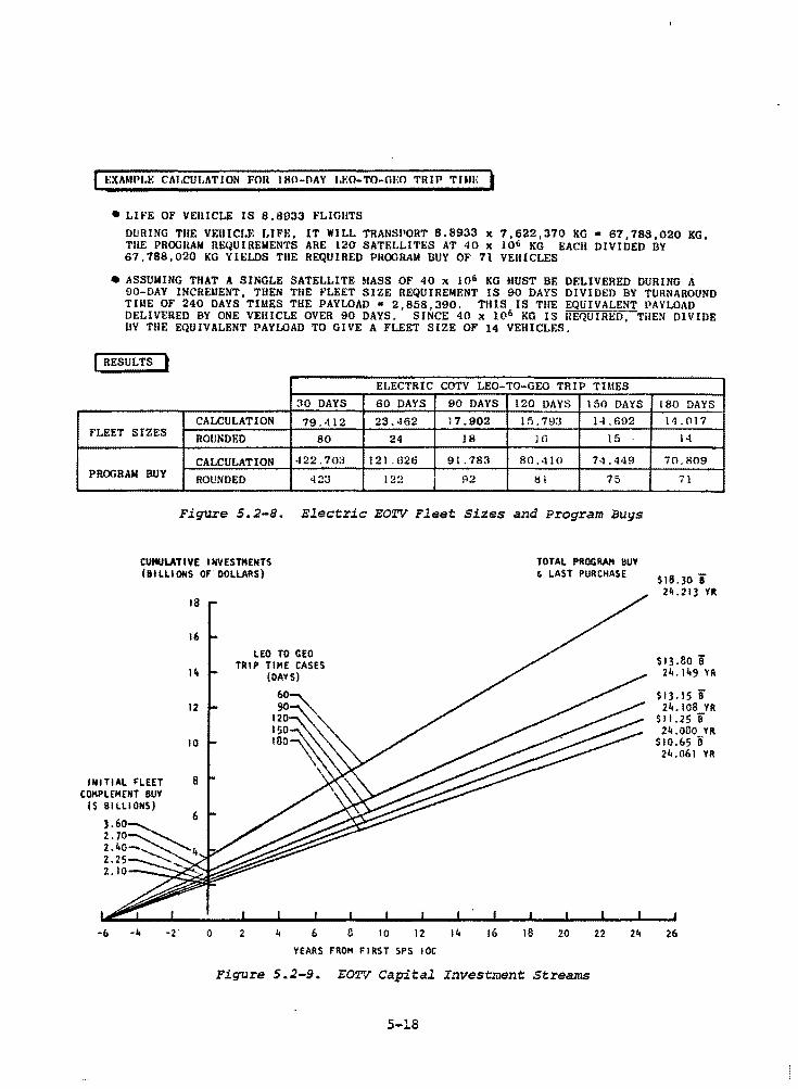
~:XAMflL•: CAl.CUl.ATION FOU !HO-PAY l.F.O-TO-mm TRIP TUii-: •
• LI1"E OF VEHICLE IS 8,8933 PLIGHTS DURING THE VEHICLE LIFE, IT WILL TRANSJ10RT 8.8933 x 7,622,370 KG• 67,788,020 KG. TUE PROGRAM REQUIREMENTS ARE 120 SATELLITES AT 40 x lQb KG EACH DIVIDED BY 67,788,020 KG YIELDS THE REQUIRED PROORAM BUY OF 71 VEHICLES
• ASSUMING THAT A SINGLE SATELLITE MASS OF 40 x 106 KG MUST BE DELIVERED DURING A 90-DAY INCREilENT, THEN THE FLEET SIZE REQUIREMENT IS 90 DAYS DIVIDED BY TURNAROUND TUtE OF 240 DAYS TIMES THE PAYLOAD • 2,858,390. THIS IS THE EQUIVALENT PAYLOAD DELIVERED BY ONE VEHICLE OVER 90 DAYS. SINCE 40 x 106 KG IS HEQUIRED, THEN DIVIDE BY THE EQUIVALENT PAYLOAD TO GIVE A FLEET SIZE OF 14 VEHICLF.S.
I RESULTS I ELECTRIC COTV LEO-TO-GEO TRIP Tl!.IES
30 DAYS 60 DAYS 90 DAYS 120 DAYS 150 DAYS
CALCULATION 79.412 23.462 17.902 In. 79:J H.692 FLEET SIZES
ROUNDED 80 24 18 Hl 15
CALCULATION 422. 70:J 121.626 91. 783 80.410 74.449 PROGRAM BUY ROUNDED 423 l 'J•J !-12 81 75
Figure 5.2-S. Electric EO~V Fleet Sizes and Program Buys
CUMIJLATI VE I HVESTMENTS (BILLIONS OF' DOLLARS)
YEARS FROM FIRST SPS IOC
TOTAL PROGRAM HUY & LAST PURCHASE
Figure 5.2-9. EOTV Capj.tal Investment Streams
5-18
180 DAYS
14.017
14
70. 809
71
$18.30 i 2ii.213 YR
$13.80 i 24. 149 YR
$13. IS ii 24. 108 YR
$11.25 ii 24.0!lO YR
$10.65 ii 24.061 YR
26
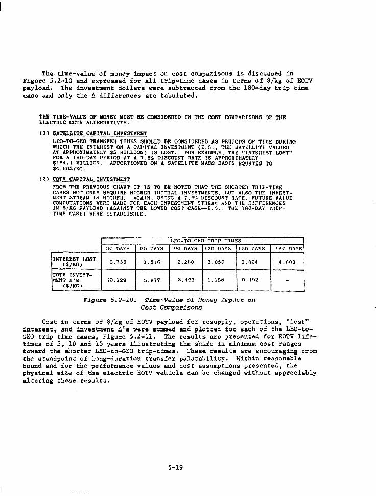
The time-value of money impact on cost. comparisons is discussed in Figure 5.2-10 and expressed for all trip-time cases in terms of $/kg of EOTV payload. The investment dollars were subtracted from the 180-day trip time case and only the A differences are tabulated.
THE TIME-VALUE OF MONEY MUST BE CONSIDERED IN THE COST COMPARISONS OF THE ELECTRIC COTV ALTERNATIVES.
(1) SATELLITE CAPITAL INVESTMENT
LEO-TO-GEO TRANSFEH TIM!o:S SHOULD BE CONSIDERED AS PERIODS OF THIE DURING WllICll THE IN'1'£1U~ST ON A CAI' ITAL INVESTMENT (E.G., Till~ SATEJ,l.ITI~ VALUED AT APPROXIMATl::LY $5 DILLION) IS LOST. FOR EXAMPLE. THE "INTt:UEST LOST" FOR A 180-DAY PERIOD AT A 7.5~ DISCOUNT RATE IS APPROXIMATELY $184.1 UILLION. APPORTIONED ON A SATELLITE MASS BASIS EQUATES TO $4.603/KG.
(2) COTV CAPITAL INVESTMENT
FROM THE PREVIOUS CHART IT IS TO BE NOTED THAT THE SHORTER TRIP-TIME CASES NOT ONLY REQUIRE HIGHER INITIAL INVEST~IENTS, BUT ALSO TllE INVESTMENT STREAM IS HIGHER. AGAIN, US ING A 7. 5':'. DISCOUNT HATE, FUTURE VALUE COUPUTATIONS WERE MADE FOR EACH INVESTMENT STREAM AND THE DIFf'ERENCES IN $/KG PAYLOAD (AGAINST THE LOWER COST CASE-E.l'.l., THE 180-DAY TRIPTHIE CASE) WERE ESTABLISHED.
LEO-TO-GEO TRIP THIES
30 DAYS 60 DAYS !JO DAYS 120 DAYS 150 DAYS
INTEREST LOST 0.755 1. 516 2.280 3.050 3 .fl24 ($/KG)
COTV INVEST-Ml:NT t:. 's 40.128 5,877 2.403 1.158 0 .. 192
($/KG)
Figure S.2-10. Tims-Value of Money Impact an Cast Comparisons
180 DAYS
4.603
-
Cost in tenns of $/kg of EOTV payload for resupply, operations, "lost" interest, and investment A1 s were summed and plotted for each of the LEO-toGEO trip time cases, Figure 5.2-11. The results are presented for EOTV lifetimes of 5, 10 and 15. years illustrating the shift in minimum cost ranges toward the shorter LEO-to-GEO trip-times. These results are encouraging from the standpoint of long-duration transfer palatability. Within reasonable bound and for the pe~formance values and cost assumptions presented, the physical size of the electric EOTV vehicle can be changed without appreciably altering these results.
5-19
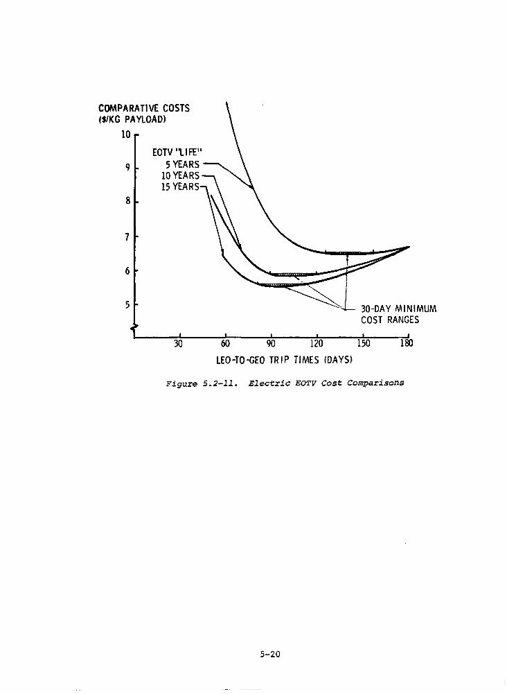
COMPARATIVE COSTS 1$/KG PAYLOAD)
10
EOTV 'ti FE" 9 5 YEARS
8
7
6
5
10 YEARS 15 YEARS
30
30-DAY MINIMUM COST RANGES
00 W IW l~ 180
LEO-TO~EO TRIP TIMES IDAYS)
Figure 5.2-11. Electric EOTV Cost Comparisons
5-20
•
6.0 ON-ORBIT MOBILITY SYSTEMS
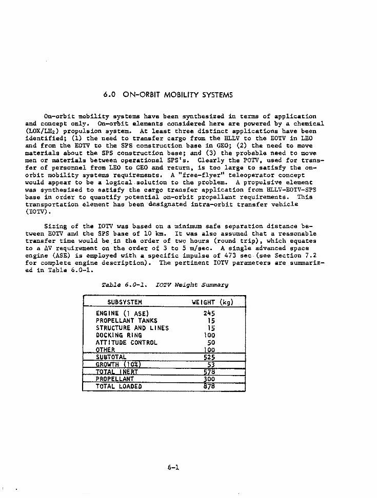
6 .0 ON-ORBIT MOBILITY SYSTEMS
On-orbit mobility systems have been synthesized in terms of application and concept only. On-orbit elements considered here are powered by a chemical (LOX/LH2) propulsion system. At least three distinct applications have been identified; (l) the need to transfer cargo from the HL~V to the EOTV in LEO and from the EOTV to the SPS construction base in GEO; (2) the need to move materials about the SPS construction base; and (3) the probable need to move men or materials between operational SPS's. Clearly the POTV, used for transfer of personnel from LEO to GEO and return, is too large to satisfy the onorbit mobility systems requirements. A 0 free-flyer" teleoperator concept would appear to be a logical.solution to the problem. A propulsive element was synthesized to. satisfy the cargo transfer application from HLLV-EO'I:V-SPS base in order to quantify potential on-orbit propellant requirements. This transportation element has been ·designated intra-orbit transfer vehicle (IOTV).
Sizing of the IOTV was based on a minimum safe separation distance between EOTV and the SPS base of 10 km. It was also assumed that a reasonable transfer time would be.in the order of two hours (round trip), which equates to a AV requirement on the order of 3 to 5 m/sec. A single advanced space engine (ASE) is employed with a specific impulse of 473 sec (see Section 7.2 for complete engine description). The pertinent IOTV parameters are su11U11arized in Table 6.0-1.
Table 6.0-1. IOTV Weight Summary
SUBSYSTEM WEIGHT (kg)
ENGINE (1 ASE) 245 PROPELLANT TANKS 15 STRUCTURE AND LINES 15 DOCKING RING 100 ATTITUDE CONTROL 50 OTHER 100 SUBTOTAL 525 GROWTH (10%) 53 TOTAi INERT 57~
PROPELLANT 300 TOTAL LOADED 1$71$
6-1

7. 0 PERSONNEL TRANSFER SYSTEMS
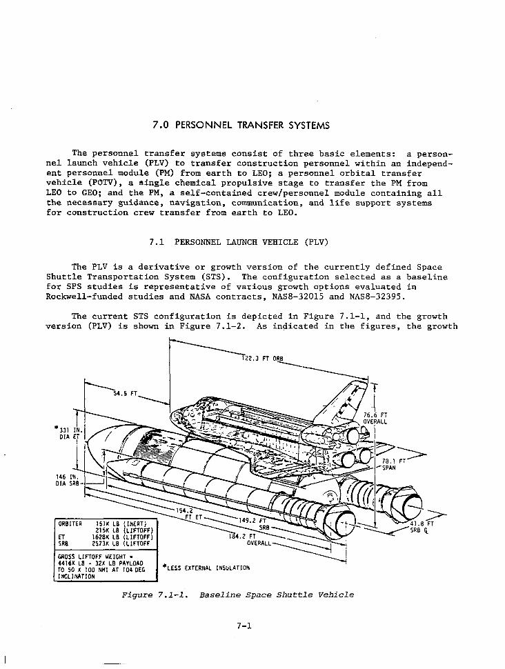
7 .O PERSONNEL TRANSFER SYSTEMS
The personnel transfer systems consist of three basic elements: a personnel launch vehicle (PLV) to transfer construction personnel within an independent personnel module (PM) from earth to LEO; a personnel orbital transfer vehicle (POTV), a single chemical propulsive stage to transfer the PM from LEO to GEO; and the PM, a self-contained crew/personnel module containing all the necessary guidance, navigation, communication, and life support systems for construction crew transfer from earth to LEO.
7.1 PERSONNEL LAUNCH VEHICLE (PLV)
The PLV is a derivative or growth version of the currently defined Space Shuttle Transportation System (STS). The configuration selected as a baseline for SPS studies is representative of various growth options evaluated in Rockwell-funded studies and NASA contracts, NASB-32015 and NASB-32395.
The current STS configuration is depicted in Figure 7.1-1, and the growth version (PLV) is shown in Figure 7.1-2. As indicated in the figures, the growth
ORBITER 151K LB (INERT) 215K LB (LIFTOFF)
ET 1628K LB (LIFTOFF) SRB 2573K LB (LIFTOFF
GROSS LIFTOFF WEIGHT • 4416K LB - JZK LB PAYLOAD TO 50 X 100 ~Ml AT 104 DEG l~CLINATION
*LESS EXTERNAL INSULATION
Figure 7.1-1. Baseline Space Shuttle Vehicle
7-1
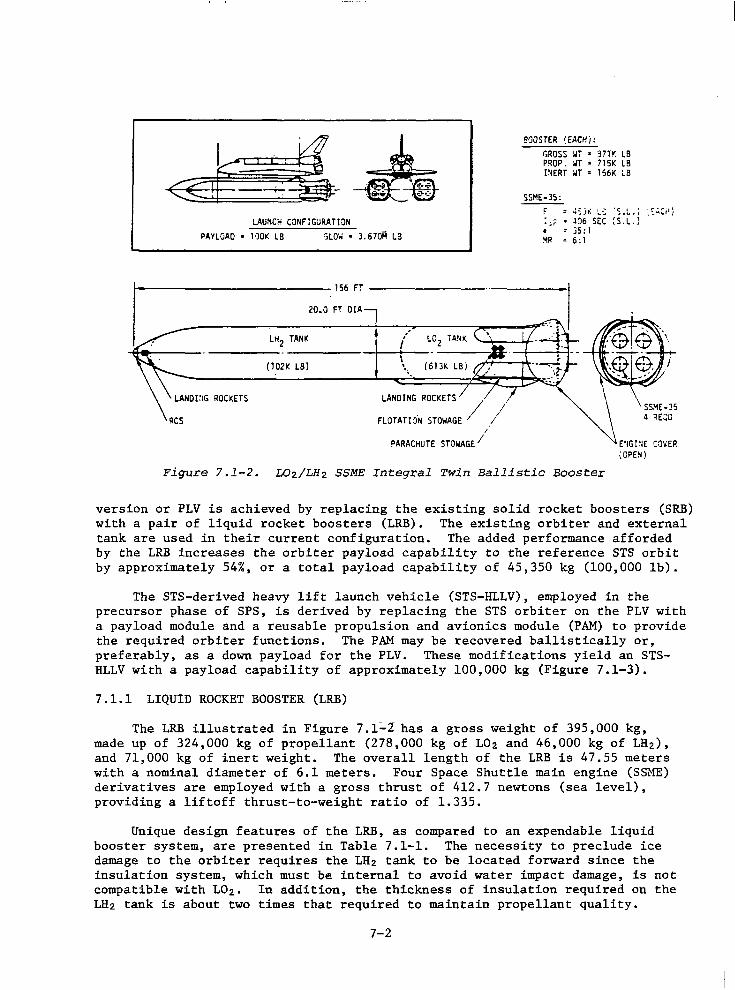
LAUNCH CONFIGURATION PAYLOAD • 1'JOK LB :;LOW • 3. 67oM L3
20.0 FT DIA
LHz TANK
(lDU LB)
/ L02 TANK ~----\--- --------...E~
'.,~
LANDING ROCKETS / //
FLOTATHJ°N STOWAGE /
~ARACHUTE STOWAGE/
BOOSTER (EACHi: r.Ross :.ir • 37lr. LS PROP. :.IT= 715K LB I~ERT :.IT = 156K LB
SSME-35: F = ~:j~ L:: ·s.:....J ·.::.:-c; 1
/
:;;: = l06 SEC :s.L.) • = j5: I '.-lR = 6: 1
\OPE~)
Figure 7.1-2. L02/LH2 SSME Integral Twin Ballistic Booster
version or PLV is achieved by replacing the existing solid rocket boosters (SRB) with a pair of liquid rocket boosters (LRB). The existing orbiter and external tank are used in their current configuration. The added performance afforded by the LRB increases the orbiter payload capability to the reference STS orbit by approximately 54%, or a total payload capability of 45,350 kg (100,000 lb).
The STS-derived heavy lift launch vehicle (STS-HLLV), employed in the precursor phase of SPS, is derived by replacing the STS orbiter on the PLV with a payload module and a reusable propulsion and avionics module (PAM) to provide the required orbiter functions. The PAM may be recovered ballistically or, preferably, as a down payload for the PLV. These modifications yield an STSHLLV with a payload capability of approximately 100,000 kg (Figure 7.1-3).
7.1.l LIQUID ROCKET BOOSTER (LRB)
The LRB illustrated in Figure 7.1~2 has a gross weight of 395,000 kg, made up of 324,000 kg of propellant (278,000 kg of 102 and 46,000 kg of LH2), and 71,000 kg of inert weight. The overall length of the LRB is 47.55 meters with a nominal diameter of 6.1 meters. Four Space Shuttle main engine (SSME) derivatives are employed with a gross thrust of 412.7 newtons (sea level), providing a liftoff thrust-to-weight ratio of 1.335.
Unique design features of the LRB, as compared to an expendable liquid booster system, are presented in Table 7.1-1. The necessity to preclude ice damage to the orbiter requires the LH2 tank to be located forward since the insulation system, which must be internal to avoid water impact damage, is not compatible with L02 • In addition, the thickness of insulation required on the LH2 tank is about two times that required to maintain propellant quality.
7-2
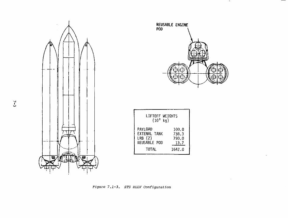
....... I w
REUSABLE ENGINE POD
LIFTOFF WEIGHTS (10 3 kg)
PAYLOAD EXTENAL TANK LRB (2) REUSABLE POD
TOTAL
Figure 7 .1.-3. STS HLLV Configuration
100.0 738.3 790.0 13. 7
1642.0
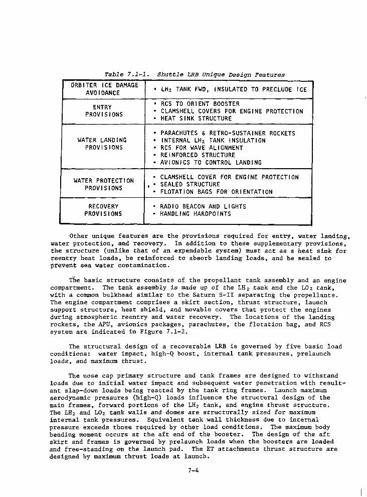
Table 7.1-1. Shuttle LRB Unique Design Features
ORBITER ICE DAMAGE • LH2 TANK FWD, INSULATED TO PRECLUDE ICE AVOIDANCE
ENTRY • RCS TO ORIENT BOOSTER
PROVISIONS • CLAMSHELL COVERS FOR ENGINE PROTECTION • HEAT SINK STRUCTURE
• PARACHUTES & RETRO-SUSTAINER ROCKETS WATER LANDING • INTERNAL LH2 TANK INSULATION
PROVISIONS • RCS FOR WAVE ALIGNMENT • REINFORCED STRUCTURE • AVIONICS TO CONTROL LANDING
WATER PROTECTION • CLAMSHELL COVER FOR ENGINE PROTECTION
PROVISIONS • • SEALED STRUCTURE • FLOTATION BAGS FOR ORIENTATION
RECOVERY • RADIO BEACON AND LIGHTS PROVISIONS • HANDLING HARDPOINTS
Other unique features are the provisions required for entry, water landing, water protection, and recovery. In addition to these supplementary provisions, the structure (unlike that of an expendable system) must act as a heat sink for reentry heat loads, be reinforced to absorb landing loads, and be sealed to prevent sea water contamination.
The basic structure consists of the propellant tank assembly and an engine compartment. The tank assembly is made up of the LH 2 tank and the L02 tank, with a common bulkhead similar to the Saturn S-II separating the propellants. The engine compartment comprises a skirt section, thrust structure, launch support structure, heat shield, and movable covers that protect the engines during atmospheric reentry and water recovery. The locations of the landing rockets, the APU, avionics packages, parachutes, the flotation bag, and RCS system are indicated in Figure 7.1-2.
The structural design of a recoverable LRB is governed by five basic load conditions: water impact, high-Q boost, internal tank pressures, prelaunch loads, and maximum thrust.
The nose cap primary structure and tank frames are designed to withstand loads due to initial water impact and subsequent water penetration with resultant slap-down loads being reacted by the tank ring frames. Launch maximum aerodynamic pressures (high-Q) loads influence the structural design of the main frames, forward portions of the LH 2 tank, and engine thrust structure. The LH 2 and L0 2 tank walls and domes are structurally sized for maximum internal tank pressures. Equivalent tank wall thickness due to internal pressure exceeds those required by other load conditions. The maximum body bending moment occurs at the aft end of the booster. The design of the aft skirt and frames is governed by prelaunch loads when the boosters are loaded and free-standing on the launch pad. The ET attachments thrust structure are designed by maximum thrust loads at launch.
7-4
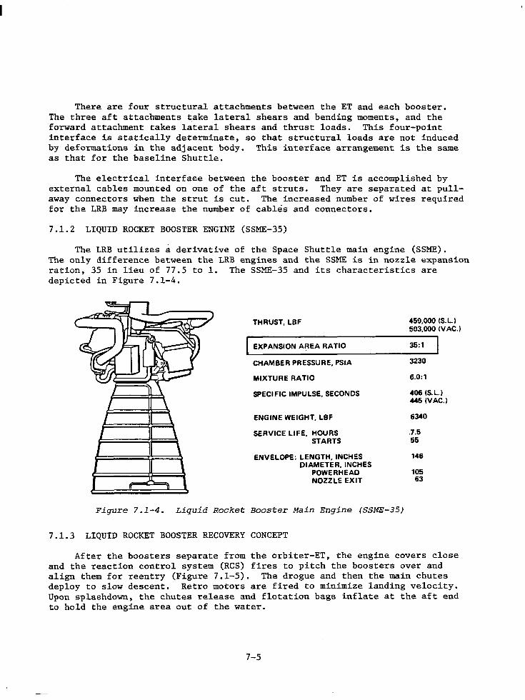
There are four structural attachments between the ET and each booster. The three aft attachments t.ake lateral shears and bending moments, and the forward attachment takes lateral shears and thrust loads. This four-point interface is statically determinate, so that structural loads are not induced by deformations in the adjacent body. This interface arrangement is the same as that for the baseline Shuttle.
The electrical interf aee between the booster and ET is accomplished by external cables mounted on one of the aft struts. They are separated at pullaway connectors when the strut is cut. The increased number of wires required for the LRB may increase the number of cables and connectors.
7.1.2 LIQUID ROCKET BOOSTER ENGINE (SSME-35)
The LRB utilizes a derivative of the Space Shuttle main engine (SSME). The only difference between the LRB engines and the SSME is in nozzle expansion ration, 35 in lieu of 77.5 to 1. The SSME-35 and its characteristics are depicted in Figure 7.1-4.
THRUST, LBF
I EXPANSION AREA RATIO
CHAMBER PRESSUR~. PSIA
MIXTURE RATIO
SPECIFIC IMPULSE, SECONDS
ENGINE WEIGHT, LBF
SERVICE LIFE, HOURS STARTS
ENVELOPE: LENGTH, INCH!:S DIAMETER, INCHES
POWE RHEAD NOZZLE EXIT
Figure 7.1-4. Liquid Rocket Booster Main Engine (SSME-35)
7.1.3 LIQUID ROCKET BOOSTER RECOVERY CONCEPT
459,000 !S.L..I 503,000 (V AC.)
35:1
3230
6.0:1
406 (S.L.) 445 !VAC.)
6340
.7.5 55
146
105 63
After the boosters separate from the orbiter-ET, the engine covers close and the reaction control system (RCS) fires to pitch the boosters over and align them for reentry (Figure 7.1-5). The drogue and then the main chutes deploy to slow descent. Retro motors are fired to minimize landing velocity. Upon splashdown, the chutes release and flotation bags inflate at the aft end to hold the engine area out of the water.
7-5
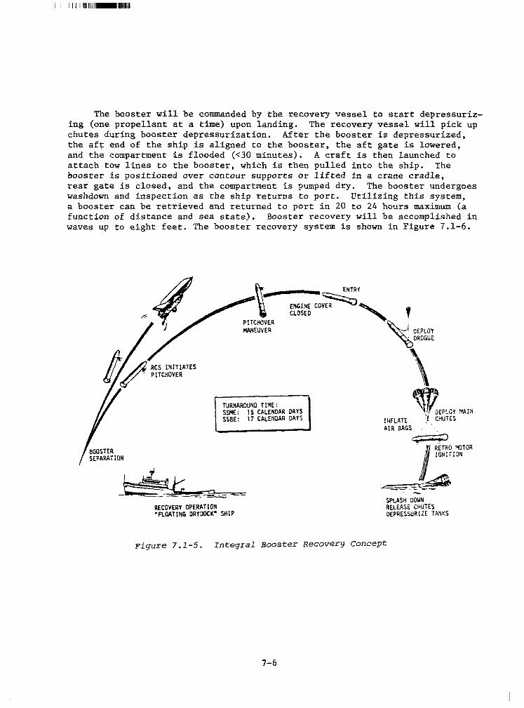
The booster will be commanded by the recovery vessel to start depressurizing (one propellant at a time) upon landing. The recovery vessel will pick up chutes during booster depressurization. After the booster is depressurized, the aft end of the ship is aligned to the booster, the aft gate is lowered, and the compartment is flooded (<30 minutes). A craft is then launched to attach tow lines to the booster, which is then pulled into the ship. The booster is positioned over contour supports or lifted in a crane cradle, rear gate is closed, and the compartment is pumped dry, The booster undergoes washdown and inspection as the ship returns to port. Utilizing this system, a booster can be retrieved and returned to port in 20 to 24 hours maximum (a function of distance and sea state). Booster recovery will be accomplished in waves up to eight feet. The booster recovery system is shown in Figure 7.1-6.
ENTRY
ENGINE:~, ' CLOSED '
PlTCHOVER MANEUVER
TURNAROUND TIME: SSME: 15 CALENDAR DAYS SSBE: 17 CALENDAR DAYS
RECOVERY OPERATION "FLOATING ORYDOCK" SHIP
~._J DEPLOY ~OROGU~
\ ~EPLOY ."-!AHi
!UFLATE ,1 CHUTES AIR BAGS ' ,
~ ·1 RETRO ~TOR IGNITION
-'------=-~ SPLASH 00\IN RELEASE CHUTES DEPRESSUR!ZE TMIKS
Figure 7.1-5. Integral Booster Recovery Concept
7-6
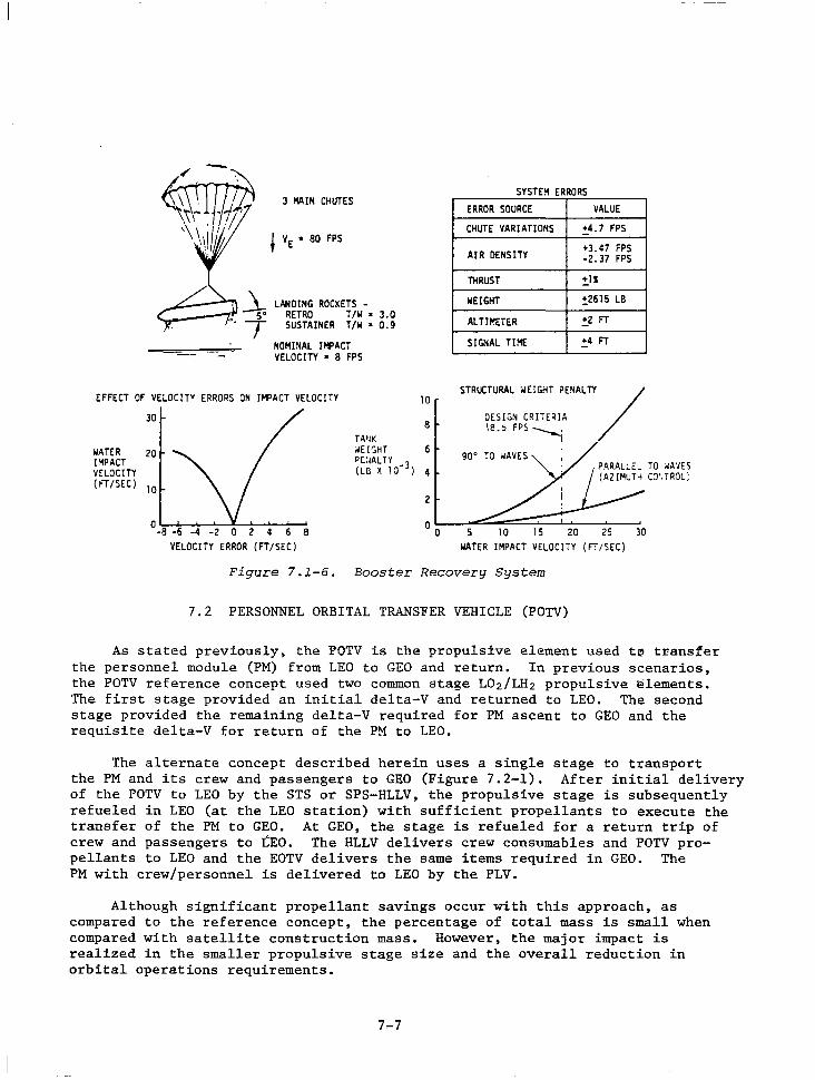
--
/
I '\ \ 1/' . ,\ I
:10,
,..
3 HAIN CHUTES
VE • 80 FPS
LANDING ROCKETS -RETRO T/W • 3.0 SUSTAINER T/W • 0.9
NOMINAL IMPACT VELOCITY • 8 FPS
EFFECT OF VELOCITY ERRORS ON IMPACT VELOCITY 10
JO
WATER 20 IMPACT VELOCITY {FT/SEC) lO
8 TA•lK OIE!SHT 6 PE:lAL TY _3 {LB X 10 ) 4
2
SYSTEM ERRORS ERROR SOURCE VALUE
CHUTE VARIATIONS !:_4. 7 FPS
AIR DENSITY +J.47 FPS -2.J7 FPS
THRUST !:_ls;
WEIGHT !,2615 LB
ALTifo!HER !:_2 FT
SIGNAL TIHE !:_4 FT
STRUCTURAL WEIGHT PENALTY/
DESIGN CRITERIA 18.~ FPS---i
0 -8 -6 -4 -2 0 2 4 6 8
VELOCITY ERROR {FT/SEC) O O 5 10 15 20 25 JO
WATER IMPACT VELOCITY {FT/SEC)
Figure 7.1-6. Booster Recovery System
7.2 PERSONNEL ORBITAL TRANSFER VEHICLE (POTV)
As stated previously, the POTV is the propulsive element used t~ tr,ansfer the personnel module (PM) from LEO to GEO and return. In previous scenarios, the POTV reference concept used two common stage L02/LH2 propulsive ~lements. The first stage provided an initial delta-V and returned to LEO. The second stage provided the remaining delta-V required for PM ascent to GEO and the requisite delta-V for return of the PM to LEO.
The alternate concept described herein uses a single stage to transport the PM and its crew and passengers to GEO (Figure 7.2-1). After initial delivery of the POTV to LEO by the STS or SPS-HLLV, the propulsive stage is subsequently refueled in LEO (at the LEO station) with sufficient propellants to execute the transfer of the PM to GEO. At GEO, the stage is refueled for a return trip of crew and passengers to tEO. The HLLV delivers crew consumables and POTV propellants to LEO and the EOTV delivers the same items required in GEO. The PM with crew/personnel is delivered to LEO by the PLV.
Although significant propellant savings occur with this approach, as compared to the reference concept, the percentage of total mass is small when compared with satellite construction mass. However, the major impact is realized in the smaller propulsive stage size and the overall reduction in orbital operations requirements.
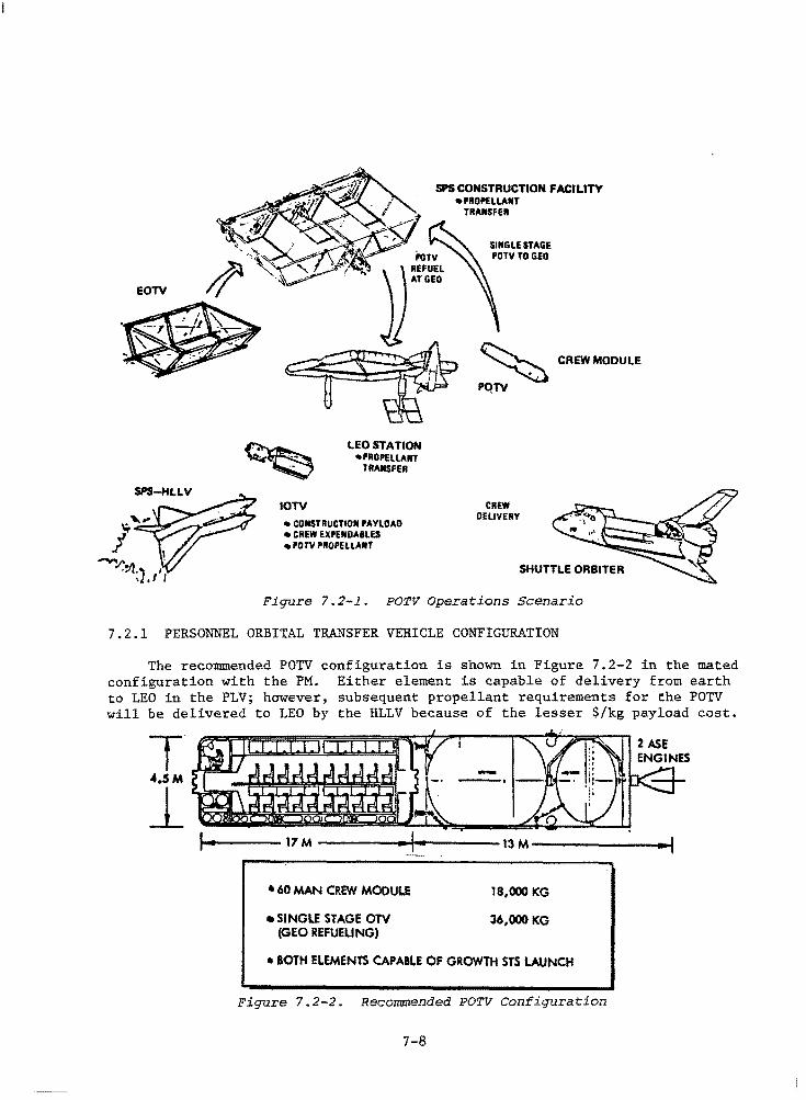
EOTV
SPS CONSTRUCTION FACILITY •PROPELLANT
IOTV
PoTV
., \ ) REFUEL jj ATGEQ
LEO STATION •PROPELLANT
TRANSFER
• CONSTRUCTION PAYLOAD •CREW EXPENDAILES • l'OTV PROPELLANT
TRANSFER
SINGLE STAGE POTY TO GEO
~ CREW MODULE
PQTV
CREW DELIVERY
SHUTTLE ORBITER
Figure 7.2-1. POTV Operations Scenario
7.2.1 PERSONNEL ORBITAL TRANSFER VEHICLE CONFIGURATION
The recommended POTV configuration is shown in Figure 7.2-2 in the mated configuration with the PM. Either element is capable of delivery from earth to LEO in the PLV; however, subsequent propellant requirements for the POTV will be delivered to LEO by the HLLV because of the lesser $/kg payload cost.
• 60 MAN CREW MODULE
•SINGLE STAGE OTV (GEO REFUELING)
---·
18,000 KG
36,000 KG
•BOTH ELEMENTS CAPABLE OF GROWTH STS LAUNCH
Figure 7.2-2. Recommended POTV Configuration
7-8
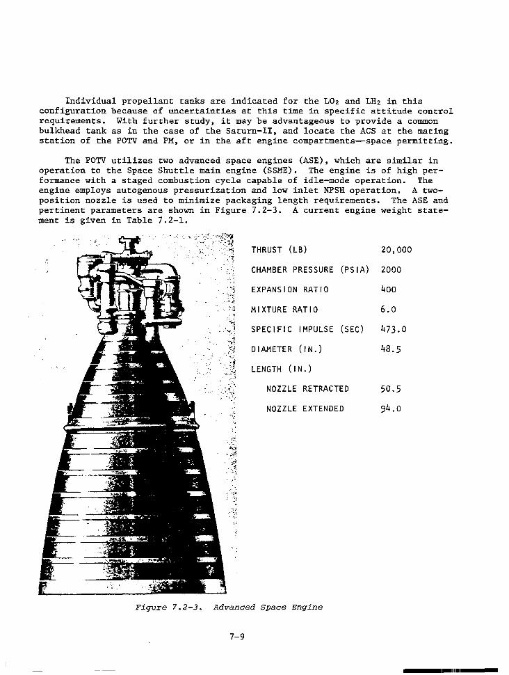
Individual propellant tanks are indicated for the L02 and LH2 in this configuration because of_uncer.tainties at this time in specific attitude control requirements. With further study, it may be advantageous to provide a common bulkhead tank as in the case of the Saturn-II, and locate the ACS at the mating station of the POTV and PM, or in the aft engine compartments~space permitting.
The POTV utilizes two advanced space engines (ASE), which are similar in operation to the Space Shuttle main engine (SSME). The engirte is of high performance with a staged combustion cycle capable of idle-mode operation. The engine employs autogenous pressurization and low inlet NPSH operation. A twoposition nozzle is used to minimize packaging length requirements. The ASE and pertinent parameters are shown in Figure 7.2-3. A current engine weight statement is given in Table 7.2-1.
THRUST (LB) 20,000
· ~: CHAMBER PRESSURE (PSIA) 2000
·~ EXPANSION RATIO 400
.: ~ "'·1' . ·"l .. ··~.
·"··· ,., ~1\:i; ( ~ '• i::.:t . :~ ~·
. , ... '.: -:~.~~;
MIXTURE RATIO
SPECIFIC IMPULSE (SEC)
DIAMETER (IN.)
LENGTH ( IN. )
NOZZLE RETRACTED
NOZZLE EXTENDED
Figure 7.2-3. Advanced Space Engine
7-9
6.0
473.0
48.5
50.5
94.o
----1-1111 ___ _
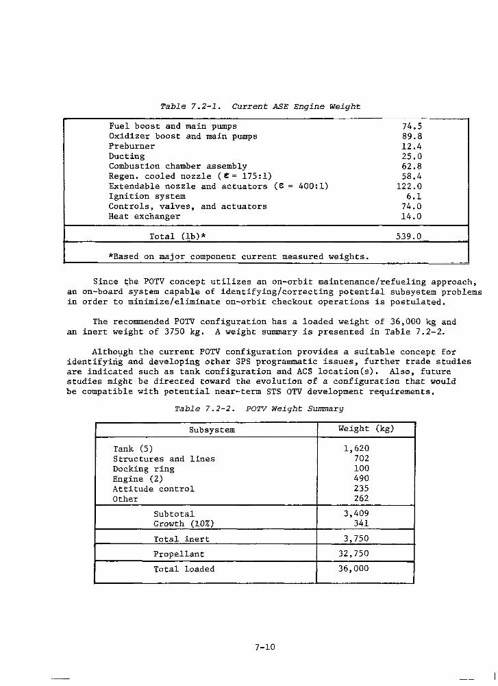
Table 7.2-1. Current ASE Engine Weight
Fuel boost and main pumps 74.5 Oxidizer boost and main pumps 89.8 Preburner 12.4 Ducting 25.0 Combustion chamber assembly 62.8 Regen. cooled nozzle (t= 175:1) 58.4 Extendable nozzle and actuators (e = 400:1) 122.0 Ignition system 6.1 Controls, valves, and actuators 74.0 Heat exchanger 14.0
Total (lb)* 539.0
*Based on major component current measured weights. -- . -- -·-- . --·
Since ~he POTV concept utilizes an on-orbit maintenance/refueling approach, an on-board system capable of identifying/correcting potential subsystem problems in order to minimize/eliminate on-orbit checkout operations is postulated.
The recommended POTV configuration has a loaded weight of 36,000 kg and an inert weight of 3750 kg. A weight summary is presented in Table 7.2-2.
Altho~gh the current POTV configuration provides a suitable concept for identifying and developing other SPS programmatic issues, further trade studies are indicated such as tank configuration and ACS location(s). Also, future studies might be directed toward the evolution of a configuration that would be compatible with potential near~term STS OTV development requirements.
Table 7.2-2. POTV weight Summary
Subsystem Weight (kg)
Tank (5) 1,620 Structures and lines 702 Docking ring 100 Engine (2) 490 Attitude control 235 Other 262
Subtotal 3,409 Growth (10%) 341
Total inert 3,750
Propellant 32,750
Total loaded 36,000
7-10
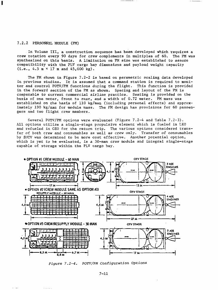
I
7.2.2 PERSONNEL MODULE (PM)
In Volume III, a construction sequence has been developed which requires a crew rotation everj' 90 days for crew complements in multiples of 60. The PM was synthesized on this basis. A limitation on PM size was established to assure compatibility with the PLV cargo bay dimensions and payload weight capacity (i.e., 4.5 m x 17 m and 45,000 kg).
The ~M shown in Figure 7.2-2 is based on parametric scaling data developed in previous studies. It is assumed that a command station is required to monitor and control POTV/PM functions during the flight. This function is provided in the forward section of the PM as shown. Spacing and layout of the PM is comparable to current commercial airline practice. Seating is provided on the basis of one meter, front to rear, and a width of 0.72 meter. PM mass was established on the basis of 110 kg/man (including personal effects) and approximately 190 kg/man for module mass. The PM design has provisions for 60 passengers and two flight crew members.
Several POTV/PM options were evaluated (Figure 7.2-4 and Table 7.2-3). All options utilize a single-stage propulsive element which is fueled in LEO and refueled in GEO for the return trip. The various options considered transfer of both crew and consumables as well as crew only. Transfer of consumables by EOTV was determined to be more cost effective. Another potential option, which is yet to be evaluated, is a 30-man crew module and integral single-stage capable of storage within the PLV cargo bay.
•OPTION fl CREW MODULE - 60 MAN
,.., 17M-----...i
• OPTION 12 (CREW MODULE SAME AS OPTION Ill RESUPPLY MODULE - 60 MAN
T .. :
OTVSTAGE
i------13M---------o~
OTVSTAGE
~ ~1........., ..... :~~~--~~~----"""" ...... ,__..=..__.... ------'l1 M--------'"1
•OPTION 13 CREW/RESUPPLY MODULE - 30 MAN OTVSTAGI!
Figure 7.2-4. POTV/PM Configuration Options
7-11
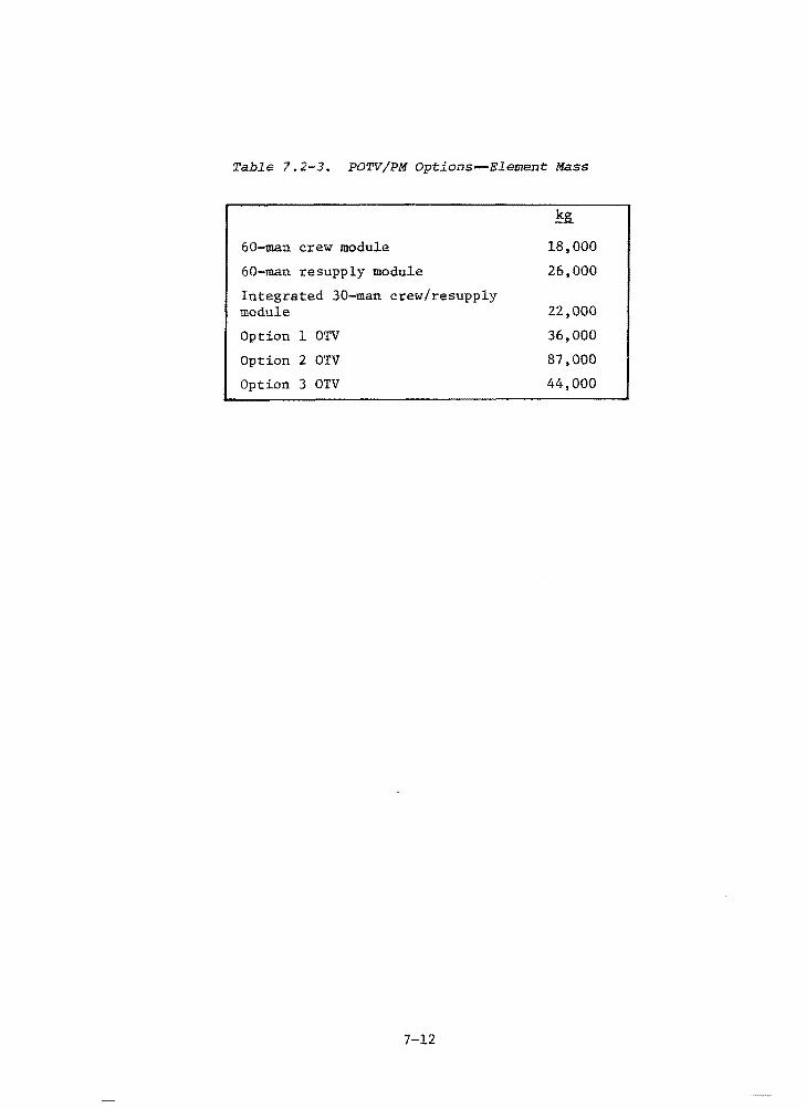
Table 7 .2-3. POTV/PM Options-Element Mass
g_
60-man crew module 18,000
60-man resupply module 26,000
Integrated 30-man crew/resupply module 22,000
Option 1 OTV 36,000
Option 2 OTV 87,000
Option 3 OTV 44,000
7-12
8.0 COST AND PROGRAMMATICS
I
8.0 COST AND PROGRAMMATICS
A summary of transportation costs and schedules are presented. More detailed data and costing assumptions are included in Volume II, Part 2.
Table 8.0-1 presents a summary of the SPS program development cost. The transportation system elements (WBS 1.3) account for approximately 42 percent of the total program development cost. In Table 8.0-2 it may be seen that the PLV and STS-derived HLLV (WBS 1.3.3) contribute almost 26 percent to the transportation development costs.
Table 8.0-3 presents a swmnary of SPS program average cost, where the transportation cost is approximately 15 percent of that average cost. The PLV and STS-derived RLLV accounts for approximately 22.5% of that cost (Table 8.0-4).
The amortized HLLV cost/kg to LEO can be obtained by multiplying Column 1 (Investment per Satellite) by the number of satellites (60), and adding the product of Column 4 (Total Operation) and the number of satellites (60) and the number of satellite years (30); then divide that quantity by the product of total number of HLLV flights from Table 3.0-3 (22,811) and the HLLV payload (0,231XlQ 6 kg),
The results of that calculation yields a payload cost to LEO of $62/kg ($28/lb).
SPS transportation schedules are presented in Figures 8.0-1 and 8.0-2. The schedules show the need for major technology development programs commitment in CY 1981, and a commitment for full-scale development of transportation elements by 1990 in order to meet an IOC date at the end of CY 2000. ·
8-1
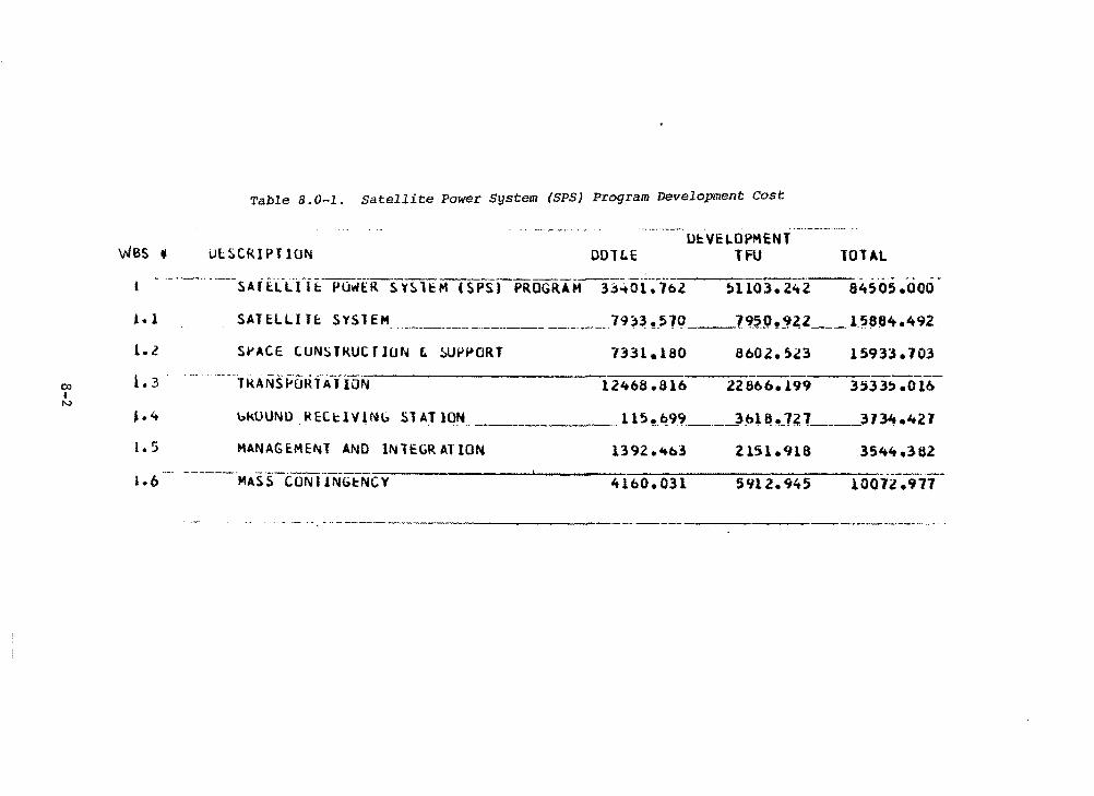
wss "
•• 1
1.2
00 1. 3 I N
J. 4
1. 5
1.6
Table 8.0-l. satellite Power System (SPS) Program Development Cost
UlSCRlPTlON OOTC.E IJl:VELOPMENT
TFU TOTAL ·------
8450~.ooo
SATELLITt SYSlEM -·--·-··-----··------- ___________ 79~~ !.57Q __ 19.?.(h~a.z ___ l.:>P~4.492
S~ACE CUNSTRUCTIUN t !>UP~ORT 7331.180 8602. !>.23 15933 .103 ..... ' ...... ---· ---· -·--·-----·--------------:-----:-:---:-:-:---:-:-:-·
TKANSf'ORlATION 12468.616 22866.199 3533!:> .o 16
ukOUNI.) REC.cll/1Ni.,; Sl AT lON_ -
HANAG~MENT ANO INlEGR AT ION
___ .. 115!.~9.<f. ____ ...)!>l~!!-1l.l ___ 313't.421
1392 e'tb3
-::---------i..-..-------:-~-=---~-:-:----::-----:---=-::-:----·-MAS S-CON fJNGtNC Y 4160. 031 5Yl 2. 945 10072 .977
-----·--------
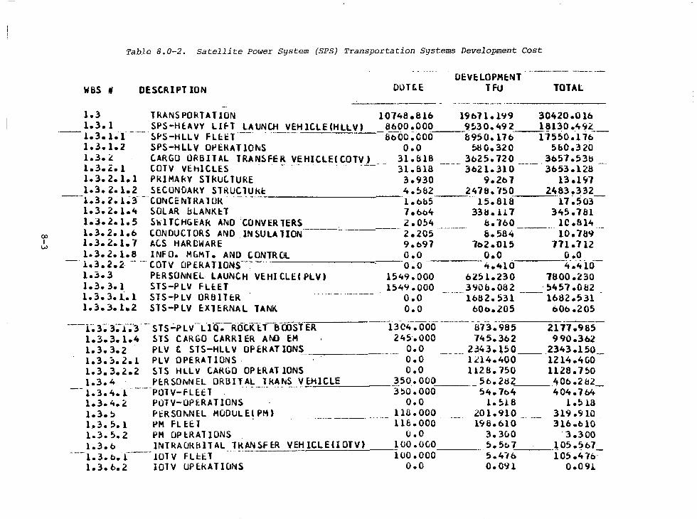
OJ I w
Table B.0-2. Satellite Power System (SPS) Transportation Systems Development Cost
was # OESCRIPT ION OL>T&E 01: VE: LOPHE:NT
TFU TOTAL -----·- - .. ·····- ·---·-·- ·------------
1.3 TRANSPOkTATlON 1.3.l SPS-HEAVY Llfl LAUNCH VEHlCLECHLLV)
---1.3.1.·1-··-·sf'S-HLLV FLE:tl·-- . ------1.3. l.2 SPS-HLLV O~EKAllO~S 1.3.t CARGO ORBITAL TRANSFER VEHICLECCOTV) 1.3.2. l COTV VEhlCLE.S -- --- -- ·-· --- . 1.3.2.1.1 PKIHAkY STRUCTURE 1.3.2.l.2 SECUNDAKY SlRUCTUk~
--·-1.3. 2~ i.;3- --C.ONCE 11.!TRA 1 OR. -- - - ---------1.3. 2. l.4 ~OLAR bLANKE:T l.J.2.1.5 SWlTCHGEAk ANO CONVERTERS 1.3.2.l.b CONDUCTORS AND INSULATION 1.3.2.1.7 ACS HARDWARE l.3.2.l.8 INFO. MGMT. AND CONTROL
-· l.3.2.~· -- -- COTV CJPERAllONS-• ----- -------1.~. 3 PERSONNEL LAUNCH VEHICLECPLV) 1.3.3.1 STS-PLV FLEET 1.3.3.(.l STS-PLV ORBITER 1.3.3.1.2 STS-PLV E:XTE.RNAL TANK
---1~3-;;·3~-1-~·3. -- sTs.:..PLV_L.fQ~-ROi:KlT--8-00ST ER 1.3. 3.1.4 STS CARGO CARRIER Ar-Ll EM 1.3.3.z PLV &. STS-HLLV OP fl{ AT IONS 1. 3. ~. 2 .1 PLV OPERATlONS · 1. 3. 3. 2.2 STS HLLV C.AkGO OP i:::RAT IONS 1.3. 4 f' E:R SOl'.IN EL ORBIT AL TkANS V E.HICLE
-- l. 3. 4. l .. ----- - - . - ·-··- ··- - --· -POlV-FLEt.T
1.3.4.l JJUTV-OPERAT IONS 1.3.~ Pt:R SONNEL HCJOUL,E~PM) ·------- ---· 1.3. 5.1 PM FL EE: T l.3.5.2 PH OP ~RAT IONS 1.3. b lNTRACJRB lT AL TH.AN SF E:R VEHICLECIOTV) l. 3. b • .l.---- 101 v FLH.T 1. 3. b. 2 lOlV UP E.kA TIONS
10748.816 l9b7l.1~9 30420.0lb 8600.000 ___ 9.~30.'992 1~130 .4~~--ab"oo:ooo a950.11b i15so.11b
o.o ~0.320 5&0.320 31.818 3b25.720 3b51.53b 31.818 3b2l.310 3653.128 3.930 9.2b7 13.197 4.~82 2478.750 2483.332 l.bb5 --15.818 ··11~~03-7.bo4 33~.li7 345.781 2.0~4 &.760 lC.&14 ·----·· 2.205 &.584 10.789 9.b97 7b2.015 771.712 o.o o.o o.o o~o 4.410 -"--~i.ti-
1549.ooo 0251.230 1aoo.z30 15'99.000 3~0b.082 ·~'957.0&2
o.o 1682.531 1682.531 O.O bOo.205 60b.205
-------·----- - - -- -- -----13C4. 000 873.985 2177.985 245.000 74' s. 3b2 990.362
o.o 2.343.150 2343.150 o.o 1~14.400 1214.4<i0 o.o 1128. 750 1126. 750
-~50. 000 Sb.282 40b.2b2 -3~0. 000 54. 7o4 404. 7b4
o.o l.~l.8 l. .518 116. 000 201.910 319.910 lle. ooo l'i6.bl0 316.blO
o.o 3. 300 '3 .300 100.0CO 5.5o7 J05.~b7_ 100.000 5.4-16 105 .4-fo·
o.o 0.09.l. 0.091
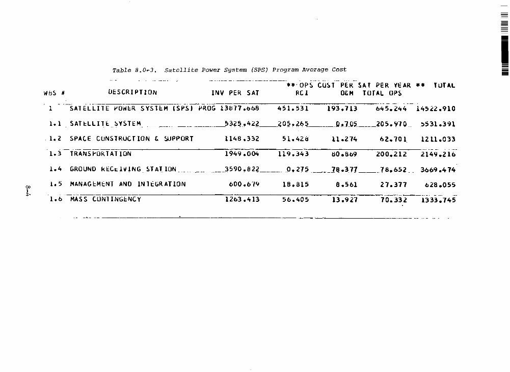
CXl 1 .i:--
Table 8.0~3. Satellite Power System (SPS) Program Average Cost
·- .. ·---- - - ·------. ----- --·--·· .. -··· ••·OP~ CU~l PER SAT PER VEAR** TUT AL
WbS # UESCRI PTI ON INV PER SAT RC! O&H TOTAL OPS ----- -----·- -··-· - ··-
CSPSI PROG 13U77.ob8 451. 53 l 193.713 b45.l~4 14522.910
l. l . SAH:LLITI:. ~Y~Tt~ _____ . ___________ 53~~-,4~~--~0~.~b~ ______ .0!t7J,)~ ______ 205. '00. ~531.391
. 1. 2 SPAC.E CUNSlRUC T ION & !il.JPPORT 1148 .332 11.214 b2. 701. 1211.033
1.3 TRANS~ORlATION 1949 .004 119 .343 80 e8b9 200.212
1.4 GROUND ktCi:. l~lNG STAT __ lON _______________ ~590 .82? ___ j)! 27~ __ ]Q_.37J ____ 78.b52 3bb9.4 74
1.5 MANAGcMcNT AND lNltbRATION 600 .b-1'1 18.815 8 .5bl 27.377 b28.05S
---------------------------·--------· - --· .. ·--1.b MASS CUNllNGcNCY 1203.413 Sb.405 13.927 70.332 1333.745
--•- ··- ------------'-----------------------
i ;;;;;;;;;;
= =
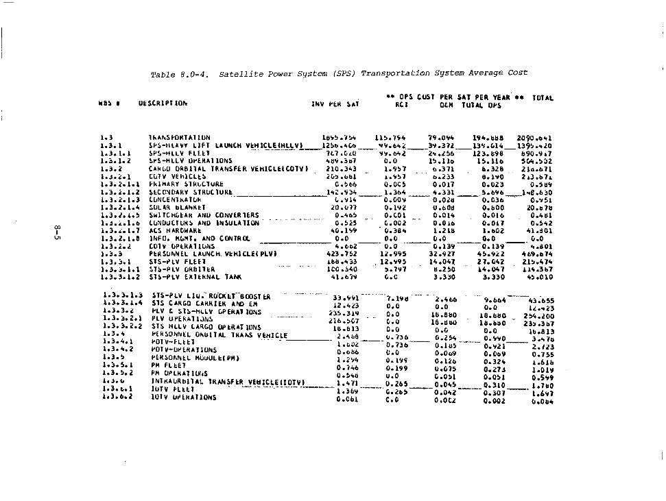
00 I Vl
Table 8.0-4. Satellite Power System (SPS) Transportation System Average Cost
UUCRIPJ lOh •• OP$ COST P~R SAT PER YEAR.•• TOTAL
Rtl OLM TOTAL o~s
1.3 1.3. l l.3. lo l 1.::i.1.2 l.~. 2 l.J • .;:.1 1.3.2.1.1 1.3.4:.1.2 1.3.2.1.3 1.3.2.1 .... 1.3.J..i.!I l.J.i..l.b l.3 • .:.1. l 1.3.2.1.e 1.3. , .. , 1. :i.) l.). "· l 1.3. ::i.1.1 l.3 .. 3.1.2
1.3. 3. l.) 1.3.3.!.4 l.3.3.<! 1.3.~.2.1 1.3.3.2.2 t.3 ... 1.3.4.l 1.3 .... 2 1.3.; 1.::..5.1 1.3.!l.2 .l.J.c. 1.3.t..l lo3o bo 2
lhAll.Sf'OMTAHUN 111.,!> • "l!>'t ll!I. l'i't 79 .O'ilo 194.oU 2090 ob"l Sf'S-tllA VY L l fl u UNC.H v~~ l~L-~!:l!-J:. v_a __ 12!>b ... ,b --... .,. b't.i: ____ 3'1 .3ll ___ 13'1.C.l't _ U'!> ... .zo SP~-HLLll FLU.1 1t1 .C..t.U 'l'tobltl. Z'tol!ib 123.1:98 &90.Y.i.7 ~l'S-HLLV Ot'E.RAllOl'tS "6'io!>ll7 O.O l!>.llo 15.llta 5Cilt.!>~2 tAk!.O OR611AL TRANSFER VEHltLEltOTVI 210.343 1.9!>7 o.311 &.326 2l1s.b1l CCilV VthlC.Ll:S 2u!>.ubl 1.o'il!>l o.233 tl.1'10 .. 2il.bl.L f-klMAl\Y SllU .. C.TURt O.!lt-b o.OC!i 0.011 0.023 o.su<; f,lCCl'.'4DARV !i.TRIJC. lUIU: _____ 1 .. c: .'i3lt 1.364 't.331 s.o'lb i..e.b~O C.tiNC.ENH1A11.ik L.'illt--o.co .. -- O.O.?ij ___ O.C3b-.-- O.'t51 !.OLAR bLAhKtT 20.1111 0.1'12 O.t>Olt O.bOO 20.C>lb ~WlTC.HCl:Ak ANO tONVlRlE.RS o ... o!i o.c.01 O.Ol't ~.Olb 0.4111 t:uNOIJC:JlJk~ ANO IN~ULAUON. - - . - - ---- -··. o.!ia G.002 0.010 0.011 o.:>'iZ ~cs HARCWARI: .. u.l'tCJ • ().31l't 1.2111 1.c.cz 41.:101 lNFU. M!.Mlo AND CONTRCl. O.O O.O O.O O.O v.O COTY !JPl:kAllllNS -------- ... t>t.2 ___ O.O ---- Ci.139---0.139 ___ ... i:IOl Pt:RSU~NtL LAUNtH. Vl:HltLEIPLVJ 423.7~2 12.CJ9S 32.927 4!>.9~2 4b9oo14 SJS-t>LV FLHl .Lbll ... !>3 , 12 .. t9S 14.041. 27.042 Zl:J.ltllt ~U.-PLV OklHlt:R ICC .;;40 .. !>. lY7 11.2!i0 i.4.0'o7 Ult.3b7 Sl!i.-PLV E.Xll:kNAL lAfll( 'ti.bl.. c.c 3.3~0 3.330 .. ~.010
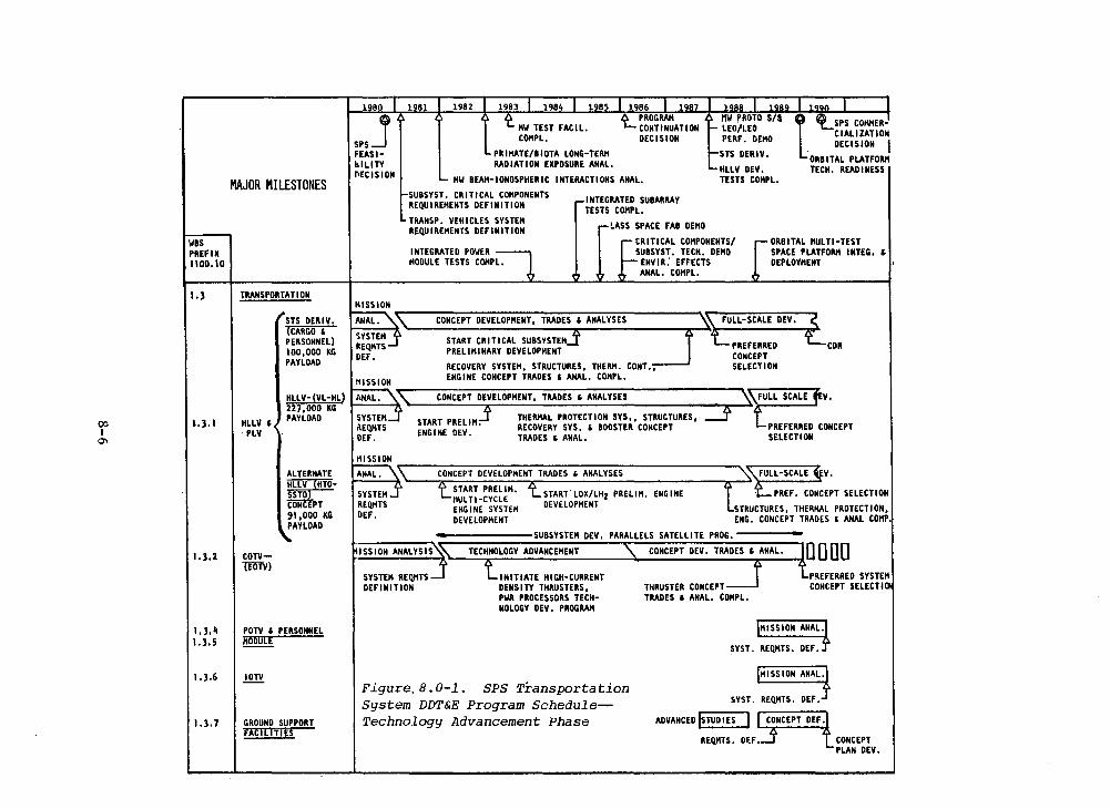
00 I 0\
was PREFIX 1100. ID
1.3
1.3. I
I. 3,2
I. 3. ~ 1.3.5
I .3.6
I. 3, 7
MAJOR MILESTONES
TRANSPORTATION
HLLV I · PLV
COTV\ffiV)
STS D~RIV. (CARGO ' PERSONNEL) 100,000 KG PAYLOAD
HLLV- !VL·HL) 227,000 KG PAYLOAD
ALTERNATE HLLV HTO-SSTO CONff PT 91 ,000 KG PAYLOAD
POTV ' PERSONNEL HO DU LE
GROUND SUPPORT FACILITIES
1 80
SPSj FEASlblLITY flECISION
1984 1985
llW TEST FACIL. COllPL,
PRlllATE/BIOTA LONG-TERI\ RADIATION EXPOSURE ANAL.
llW BEAii-iONOSPHERiC INTERACTIONS ANAL.
SUBSYST. CRITICAL COllPONENTS RE!lUIREllENTS DEFINITION
TRANSP. VEHICLES SYSTEll RE!lU I REllENTS DEFINITION
INTEGRATED SUIARRAY TESTS COllPL.
LASS SPACE FAI OEHO
STS DERIV.
HLLV DEV. TESTS COllPL.
INTEGRATED POWER llODULE TESTS COHPL,
CRITICAL COllPONENTS/ SUBSYST, TECH. DEHO
ENV IR: EFFECTS ANAL, COllPL.
ORBITAL llULTl-TEST SPACE PLATFORll I NTEG, I DEPLOYllENT
lllSSION
MISSION
HISSION
CONCEPT DEVELOPllENT, TRADES ' ANALYSES
START CR I Tl CAL SUBSYSTEM PRELllllNARY DEVELOPllENT
RECOVERY SYSTEll, STRUCTURES, THERll. CONT,, ENG I NE CONCEPT TRADES ' ANAL, COHPL,
START PRELlll. ENGINE DEV.
THERllAL PROTECTION SYS., STRUCTURES, RECOVERY SYS, ' BOOSTER CONCEPT TRADES ' ANAL,
CONCEPT DEVELOPHENT TRADES ' ANALYSES
START PRELlll. 11UL Tl -CYCLE ENGINE SYSTEll DEVELOPHENT
START. LOX/LHz PRELlll. ENGINE DEVELOPHENT
ISSION ANALYSIS
L PREFERRED CDR CONCEPT SELECTION
PREFERRED CONCEPT SELECTION
SYSTEll REQ/ITS DEFINITION
INITIATE HIGH-CURRENT DENS I TY THRUSTERS, PWR PROCESSORS TECHNOLOGY DEV, PROGRAll
THRUSTER CONCEPT TRADES I ANAL, COllPL.
PREFERRED SYSTEll CONCEPT SELECTI
Figure.B.0-1. SPS Transportation System DDT&E Program Schedule~ Technology Advancement Phase
HISSION ANAL.
SYST. REQllTS. DEF.
CONCEPT PLAN DEV.
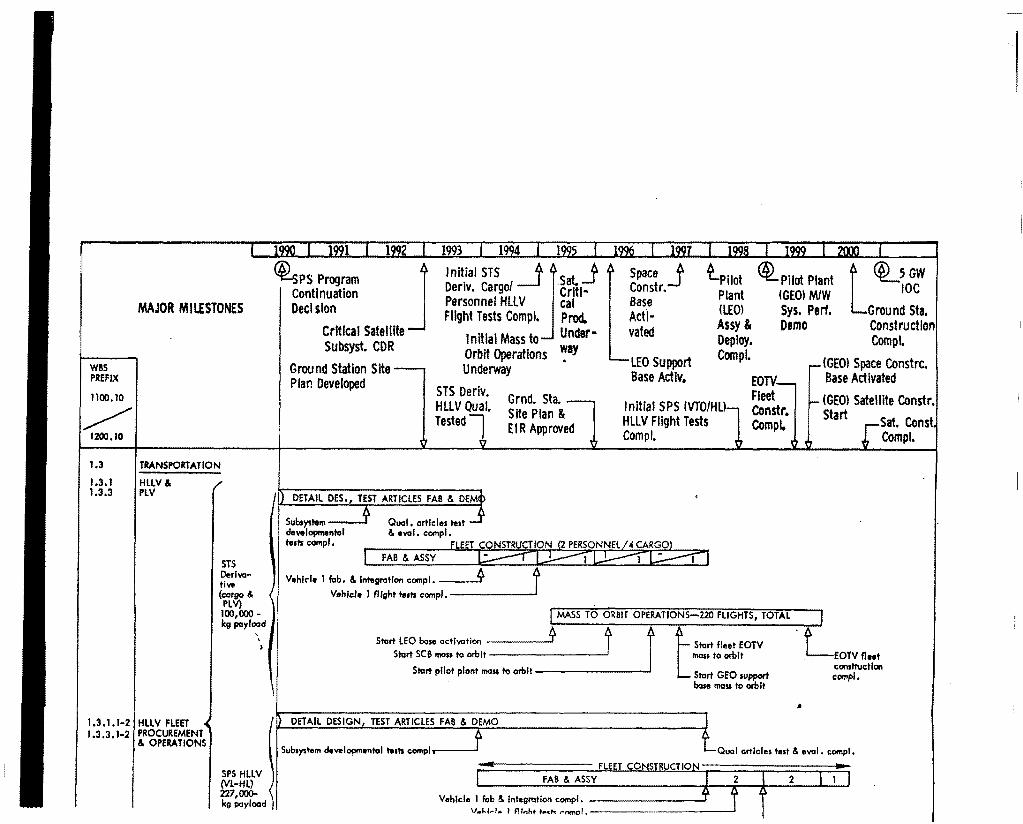
MAJOR MILESTONES
WBS PREFIX
1100.10
~ 1200.10
t.3
1.3. I 1.3.3
TRANSPORTATION
HLLV & PLV
1.3.1. T-2 HLLV FLEET 1.3.3,1-2 PROCUREMENT
& OPERATIONS
STS Deriwtiw (cargo &
PLV) 100,000 -kg payload
' '
SPS HLLV (VL-HL) 227,000-kg payload
1993 19
~PS Program J Continuation Deel slon
lnlt.ial STS _lj.Sat. j Deriv. Cargo/ Critl· Personnel HLLV cal Flight Tests Compl. Prod.
Space j Constr. Base Actl·
lPllot Plant (lEOI Assy & Deploy. Comp!.
~Pilot Plant (GEOl M/W Sys. Perf. Demo
L~GW
IOC
Ground Sta. Construction Critical Satelllte
Subsyst. CDR
Ground Station Site Plan Developed
Initial Mass to Under· Orbit Operations ~ay Underway
STS Deriv. HLLV Qual. Testedl
Grnd. Sta. Site Plan & EI R App roved
DETAIL DES,, TEST ARTICLES FAB & DEM
Subt)"tem __j developmentol tesh compl,
FAB & ASSY
Vehkle I fob. & lntegr:itlon c:ompl. __ _.
Vehicle l flight teah comp!.------
vated
LEO Support Base Activ.
Initial SPS IVTO/Hl) HLLV Flight Tests Com pl.
I MASS TO ORBIT OPERATIONS-220 FLIGHTS, TOTAL
Compl.
IGEOl Space Constrc. Base Activated
(GEO> Satellite Constr. Start Sat. Const
Comp I.
* * f t .L Start LEO bose acti111:1ti0<1 - j Start fleet EOTV Stort SCB rnas1 to orbit mass to orbit EOTV fleet
_ c:on1tructfgn Start pllot plant moss to orbit --------' Start GEO support comp!,
base moss to orbit
DETAIL DESIGN, TEST ARTICLES FAii & DEMO
Subsystem developmentot t .. ts c:omplr----' Oual articles te1t & eval. compl.
FLEET CONSTRUCTION FAii & ASSY 2
Vehicle 1 l'ab & lntegr:ition comp!. ______ ___,
v,.1.1~1 .. I Fllnhl ''"'"' rnmol, --------~
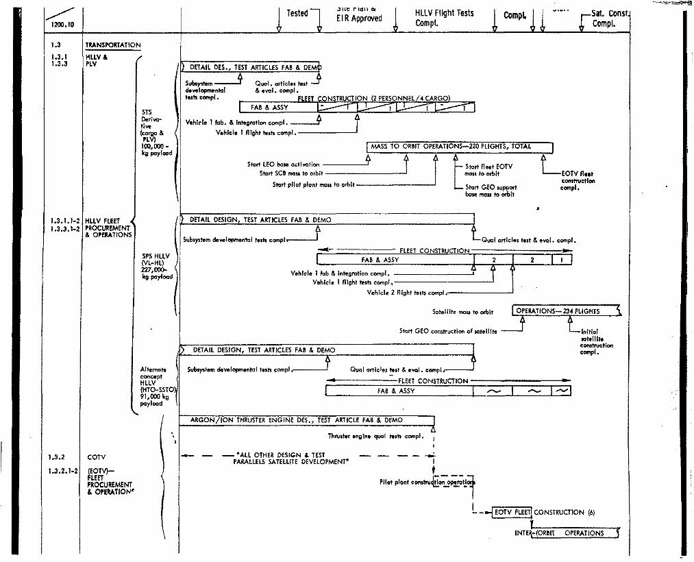
~ 1200.10
1.3
1.3. l 1.3.3
TRANSPORTATION
HLLV& PLV
1.3.1. 1-2 HLLV FLEET 1.3.3.1-2 PROCUREMENT
& OPERATIONS
1,3,2 COTV
1.3.2.1·2 (EOTV)-FLEET PROCUREMENT & OP!RATIOW
STS Derivative (cargo & PLV) 100,000-kg payload
SPS HLLV (VL-HL) 227,000-kg payload
Alternate concept HLLV (HTO-SSTO) 91,000 kg payload
' ' I
DETAIL DES., TEST ARTICLES FAB & DEM
Subs}"hlm _J dewlapmental tests compl •
FAB & ASSY
Vehl~le I fab. & Integration ccmpl. fr.
.) Ht: rlGll OI
EIR Approved
Vehicle 1 flight teah compl.-------'
HLLV Flight Tests Comp!.
Sat. Const Comp I.
MASS TO ORBIT OPERATIONS-220 FLIGHTS, TOTAL
Start LEO base activation ----~* J r Start SCB masa to orbit ----------
Start pilot plant mau ta orbit-------~
DETAIL DESIGN, TEST ARTICLES FAB & DEMO
t St.:irt fleet EOTV man to orbit
Start GEO aupport base mass ta orbit
EOTVflt1t con1truc:t Jon compl,
Subsystem developmental tesh ccmpl.-----' Oual articles teat & eval. compl.
FLEET CONSTRUCTION FAB & ASSY
Vehicle 1 fob & Integration compl. -------~ Vehicle I flight tests compl, ------------'
Vehicle 2 11 ight tests compl •. --------'
Satellite mass to orbit
Start GEO construction of satellite
DETAIL DESIGN, TEST ARTICLES FA8 & DEMO
Subsystem developmental tesh compl .......----' Ouol articles test & ewl. complr----'
2
Initial 'IOhtlllht construction ccmpl.
-------FLEET CONSTRUCTION----------
FAB & ASSY
ARGON/ION THRUSTER ENGINE DES., TEST ARTICLE FAB & DEMO
Thruster engine qual tesh compl.
- - - "ALL OTHER DESIGN I. TEST PARALLELS SATELLITE DEVELOPMENT"
. - ---1
t Piiot plant con11ruifilon_o;~~1
I
-- 1-1
EOTV FLEET CONSTRUCT10N (6)
INTE -(ORB('[ OPERATIONS
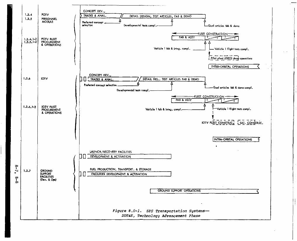
00 1
1.3.4 1.3.5
POTV PERSONNEL MODULE
1.3 .4. 1-2 POTV FLEET 1.3.5, l-2. PROCUREMENT
& OPERATIONS
1.3.6
1.3.6.1-2
IOTV
IOTV FLEET PROCUREMENT & OPERATIONS
..... 1.3.7 GROUND SUPPORT FACILITIES (o ..... & ap.)
.. 00 1 co
CONCEPT DEV.,
I l'->_T_RA_D_ES_&_A_N_A_L_. __ __,7/._ __ 0_ET.;..A....;l_.,L _o.;;,.ES..;..1G ..... N_._, ..;..TE;.;..ST_A_.RT-.IC.._L_ES_.,_F_A_B _&_D_E_M_o __ __,]
Pref.rred concept ----'* 1 t s11l11ctfon Developmentol t111h compl .---- Qua I articles fob & demo
... .,..,..._ ____ -i:fLEET CONSTRUCTION -
( FAB & ASSY jJ;;:::::=r-L!?:f:j '
__j l Vehicle 1 flight tesh comp!.
k-----, I !J.lo!_fla~{GEO) !}_e!!!f operations
Vehlde 1 fob & illteg, compl,
INTER-ORBITAL OPERATIONS (
I CONCEPT DEV., D 0 : TRADES & ANAL. IL DETAIL DES., TEST ARTICLES FAB & DEMO
Pntf.mid concept alectlonDewlopmental te:ts compl • t I LQIJCll articles fab & demo compl.
-.... ------FLEET CONSTRUCTION ,...
I V1hlcl1 1 f'ob & l1lt1g, compl.,..-----'t t-vehlcle I flight tests compl. I
' rorv FLULC.9!:!sr~Cl [s.\1. £.~Jmic.
(INTRA-ORBITAL OPERATIONS f
LAUNCH/RECOVERY FACILITIES
I D 0 DEVELOPMENT & ACTIVATION
FUEL PROOOCTION, TRANSPORT. & STORAGE
D 0 FACILITIES DEVELOPMENT & ACTIVATION
GROUND SUPPORT OPERATIONS
Figure B.0-1. SPS Transportation Systems-DDT&E, Technology Advancement Phase
<
APPENDIX A. HORIZONTAL TAKEOFF-SINGLE STAGE TO ORBIT TECHNICAL SUMMARY
APPENDIX A
HORIZONTAL TAKEOFF - SINGLE STAGE TO ORBIT TECHNICAL SUMMARY
A.O INTRODUCTION
Evolving Satellite Power System (SPS) program concepts envision the assembly and operation of sixty solar-powered satellites in synchronous equatorial orbit over a period of thirty years. With each satellite weighing approximately 35 million kiolgrams, economic feasibility of the SPS is strongly dependent upon low-cost transportation of SPS elements.. The rate of delivery of SPS elements alone to LEO for this projected program is 70 million kilograms per year. This translates into 770 flights per year or 2.1 flights per day using a fleet of vehicles, each delivering a cargo of 91,000 kilograms.
The magnitude and sustained nature of this advanced space transportation program concept require long-term routine operations somewhat analogous to commercial airline/airfreight operations. Vertical-takeoff, heavy lift launch vehicles (e.g., 400, 000 kg payload) can reduce the launch rate to· 17 5 or more flights per year. However, requirements such as water recovery of stages with subsequent refurbishment, stacking, launch pad usage, and short turnaround schedules introduce severe problems for routine operations. Studies performed previously showed that substantial operational advantages are offered by an advanced horizontal takeoff, single-stage-to-orbit (HTO-SSTO) aerospace vehicle concept. Further analysis of this concept was needed to provide a promising alternative to vertical launch heavy lift launch vehicle approaches for LEO logistics support of the SPS.
The technical problems requiring investigation were of two types: (a) the need for further development of the vehicle system concept including a multicell wet wing containing cryogenic propellants in a blended wing-body configuration; and (b) technology issues, particularly the technical feasibility and performance potential of an advanced hybrid airbreathing engine system, and technical assessment of a flight mode invol.ving horizontal takeoff, long range cruise, subsequent insertion into an equatorial orbit and return via aeromaneuver to the higher-latitude take-off site.
The general objective of this study was to improve system definition and to advance subsystem technologies for a horizontal takeoff, single-stage-taorbit vehicle which can provide economical, routine earth-to-LEO transportation in support of the Satellite Power Systems program. Specific objectives were:
l~ To improve the design definition and technical and operational features of the HTO•SSTO vehicle concept primarily using existing aerodynamic, aerothermal, structural, thermal protection, airbreather and rocket propulsion, flight mechanics and operations technology integrated into a total systems design.
A-1
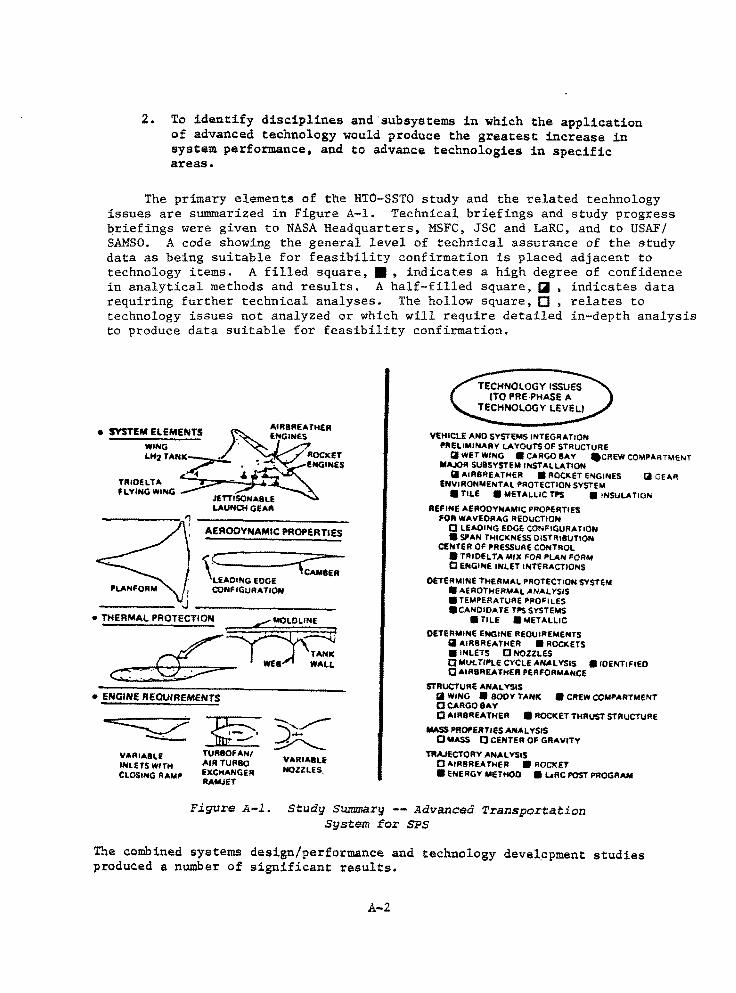
2. To identify disciplines and subsystems in which the application of advanced technology would produce the greatest increase in system performance, and to advance technologies in specific areas.
The primary elements of the HTO-SSTO study and the related technology issues are summarized in Figure A-1. Technical briefings and study progress briefings were given to NASA Headquarters, MSFC, JSC and LaRC, and to USAF/ SAMSO. A code showing the general level of technical assurance of the study data as being suitable for feasibility confirmation is placed adjacent to technology items. A filled square, II, indicates a high degree of confidence in analytical methods and results. A half-filled square, Ciil , indicates data requiring further technical analyses. The hollow square, [J , relates to technology issues not analyzed or which will require detailed in-depth analysis to produce data suitable for feasibility confirmation.
SVST£M ELEMENTS ~AIRBREATHER e . £NGINE.S WING . LH2TANK~ ROCKET
~ ;;fl~-<; . EHGIN£$ TRIOELT... -FLYING WING
J£ TTIS0NABL£ LAUNCH GEAR
AERODYNAMIC PROPERTIES
"'C ,. ~BER
LEADING EDGE CONF IGURA TlON
•THERMAL PffOTECTION ==D' ,I
~· ~ TANK WEB WALL
c::::~ • ENGINE REQUIREMENTS
VARIABLE INLETS WITH CLOSING RAMI'
~ -,__,,,.,.-~~
TURBOFAN/ AIR TURBO VARIABLE EXCHANGER NOZZLES. RAMJET
VEHICLE ANO SYSTEMS INTEGRATION "'IELIMINARY LAYOUTS OF STRUCTURE
13 WET WING • CARGO BAY .CREW COMPARTMENT MAJOR SUBSYSTEM INSTALLATION
Ii AIRBREATHEA • ROCKET E"IGINES Iii CiEAR £NVIRONMENTAL PROTECTION SYSTEM
• TILE • METALLIC TI'S • INSULATION
REFINE AEAOOYNAMIC PROPERTIES FOR WAVEORAG REDUCTION
0 1.EAOING EDGE CONFIGURATION • SPAN THICKNESS OISTR18UTION
CENTER OF PRESSURE CONTROL • TFllOEL TA MIX FOR PLAN FORM 0 ENGINE INLET INTERACTIONS
DETERMINE THERMAi. PROTECTION SYSTEM • AEROTHERMAL ANALYSIS • TEMPERATURE PROFILES •CANOIOATE TPS SYSTEMS
•r11.e •METALLIC
DETERMINE ENGINE REQUIREMENTS Iii ... IR8REATHER • ROCKETS • INLETS 0 NOZZLES 0 Mvt.Tll"LE CYCLE AN>ll YSIS a 10ENT1F1EO 0 AIR8REATHER PERFORMANCE
STRUCTURE ANALYSIS II WING • SOOY TANK • CREW COMPARTMENT 0 CARGO BAY 0 AIR8REATHER • ROCKET THRUST STRUCTURE
MASS PROPERTIES AN.ill YSIS 0 MIASS 0 CENTER OF GRAVITY
TRAJECTORY ANALYSIS 0AIRBREATHEll • ROCKET • ENERGY METHOD • L..oRC POST PROGRAM
Figure A-1. St~dy Summary -- Advanced Transportation System Eor SPS
The combined systems design/performance and technology devel.opment studies produced a number of significant results.
A-2
1. Demonstrated, with end-to-end simulation, the ability of the vehicle to take off from KSC, cruise to the equatorial plane, insert into a 300 nmi equatorial orbit with 151,000-pound payload, and then to re-enter and return to the launch site; also to deliver a 196,000-pound payload with a due-East launch.
2. Devised a modified airbreathing engine cycle for operation in turbofan, air-turbo-exchanger and ramjet modes to provide an effective match with takeoff, cruise and acceleration requirements.
3. Showed that the HTO-SSTO lower.surface temperatures during reentry are several hundred degrees lower than the STS orbiter lower surf ace temperatures because of a lower wing loading. As a result, an advanced titanium aluminide system shows promise of being lighter than the RSI tile for this application.
This study-was funded primarily by Rockwell IR&D funds and a summary only is contained herein.
A.l OPERATIONAL FEATURES
The HTO-SSTO concept adapts existing and advanced commercial and/or military air transport system concepts, operations methods, maintenance procedures, and cargo handling equipment to include a space-related environment. The principal operational objective is to provide economic, reliable transportation of large quantities of material between earth and LEO at high flight frequencies with routine logistics operations and minimal environmental impact, An associated operational objective was to reduce the number of operations required to transport material and equipment from their place of manufacture on earth to low earth orbit.
Operations features derived in the stu4y are as follows:
• Single orbit up/down to/from the same launch site (at any launch azimuth subject to payload/launch azimuth match)
• Capable of .obtaining 300 nmi equatorial orbit when launched from KSC
• Takeoff and land on 8,000 to 14,000-foot runways (launch velocity ~ 225 knots; landing velocity ~ 115 knots)
• Simultaneous multiple launch capability
• Total system recovery including the takeoff gear which is jettisoned and recovered at the launch site
• Aerodynamic flight capability from payload manufacturing site to launch site, addition of launch gear and fueling, and launch into earth orbit
A-3
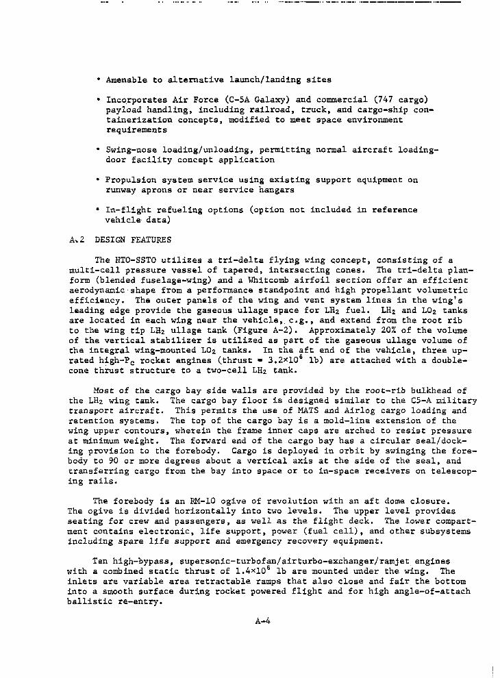
• Amenable to alternative launch/landing sites
• Inco.rporates Air Force (C-SA Galaxy) and commercial (747 cargo) payload handling, including railroad, truck, and cargo-ship containerization concepts, modified to meet space environment requirements
• Swing-nose loading/unloading, permitting normal aircraft loadingdoor facility concept application
• Propulsion system service using existing support equipment on runway aprons or near service hangars
• In-flight refueling options (option not included in reference vehicle data)
A,2 DESIGN FEATURES
The HTO-SSTO utilizes a tri-delta flying wing concept, consisting of a multi-cell pressure vessel of tapered, intersecting cones. The tri-delta planform (blended fuselage-wing) and a Whitcomb airfoil section offer an efficient aerodynamic shape from a performance standpoint and high propellant volumetric efficiency. The outer panels of the wing and vent system lines in the wing's leading edge provide the gaseous ullage space for LH2 fuel. LH2 and L02 tanks are located in each wing near the vehicle, e.g., and extend from the root rib to the wing tip LH2 ullage tank (Figure A-2). Approximately 20% of the volume of the vertical stabilizer is utilized as part of the gaseous ullage volume of the integral wing-mounted L02 tanks. In the aft end of the vehicle, three uprated h~gh-Pc rocket engines (thrust • 3,2Xl0 6 lb) are attached with a doublecone thrust structure to a two-cell LH2 tank.
Most of the cargo bay side walls are provided by the root-rib bulkhead of the LH2 wing tank. The cargo bay floor is designed similar to the C5-A military transport aircraft. This permits the use of MATS and Airlog cargo loading and retention systems. The top of the cargo bay is a mold-line extension of the wing upper contours, wherein the frame inner caps are arched to resist pressure at minimum weight. The forward end of the cargo bay has a circular seal/docking provision to the forebody. Cargo is deployed in orbit by swinging the forebody to 90 or more degrees about a vertical axis at the side of the seal, and transferring cargo from the bay into space or to in-space receivers on telescoping rails.
The forebody is an RM-10 ogive of revolution with an aft dome closure. The ogive is divided horizontally into two levels. The upper level provides seating for crew and passengers, as well as the flight deck. The lower compartment contains electronic, life support, power (fuel cell), and other subsystems including spare life support and emergency recovery equipment.
Ten high-bypass, supersonic-turbofan/airturbo-exchanger/ramjet engines with a combined static thrust of l.4xl06 lb are mounted under the wing. The inlets are variable area retractable ramps that also close and fair the bottom into a smooth surface during rocket powered flight and for high angle-of-attach ballistic re-entry.
A-4
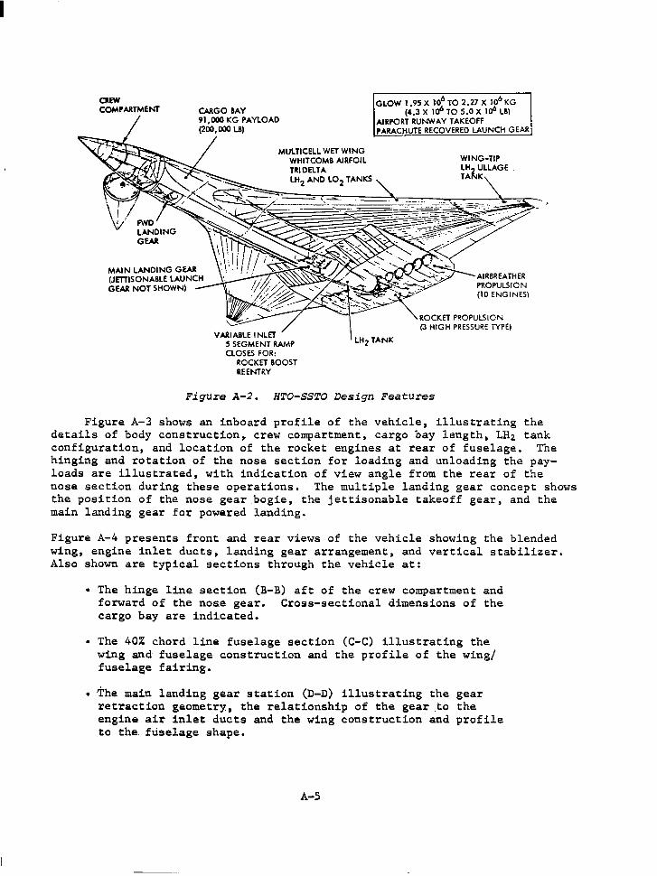
I
OEW COMPARTMENT
MAIN LANDING GEAR (JffilSONABLE LAUNCH GEAR NOT SHOWN)
VARIABLE INLET 5 SEGMENT RAMP CLOSES FOR:
ROCKET BOOST REENTRY
GLOW 1.95 X 10⁶ TO 2.'Zl X I06 KG (4.3 X 1<f' TO 5.0 X l<f' LB)
AIRPORT RUNWAY TAKEOFF PARACHUTE RECOVERED LAUNCH GEAR
LH2 TANK
Figure A-2. HTO-SSTO Design Features
Figure A-3 shows an inboard profile of the vehicle, illustrating the details of body construction~ crew compartment, cargo bay length, LH2 tank configuration, and location of the rocket engines at rear of fuselage. The hinging and rotation of the nose section for loading and unloading the payloads are illustrated, with indication of view angle from the rear of the nose section during these operations. The multiple landing gear concept shows the position of the nose gear bogie, the jettisonable takeoff gear, and the main landing gear for powered landing.
Figure A-4 presents front and rear views of the vehicle showing the blended wing, engine inlet ducts, landing gear arrangement, and vertical stabilizer. Also shown are ty~ical sections through the vehicle at:
• The hinge line section (B-B) aft of the crew compartment and forward of the noae gear. Cross-sectional dimensions of the cargo bay are indicated.
• The 40% chord line fuselage section (C-C) illustrating the wing and fuselage construction and the profile of the wing/ fuselage fairing.
• The main landing gear station (D-D) illustrating the gear retraction geometry, the relationship of the gear to the engine air inlet ducts and the wing construction and profile to the. fuselage shape.
A-5
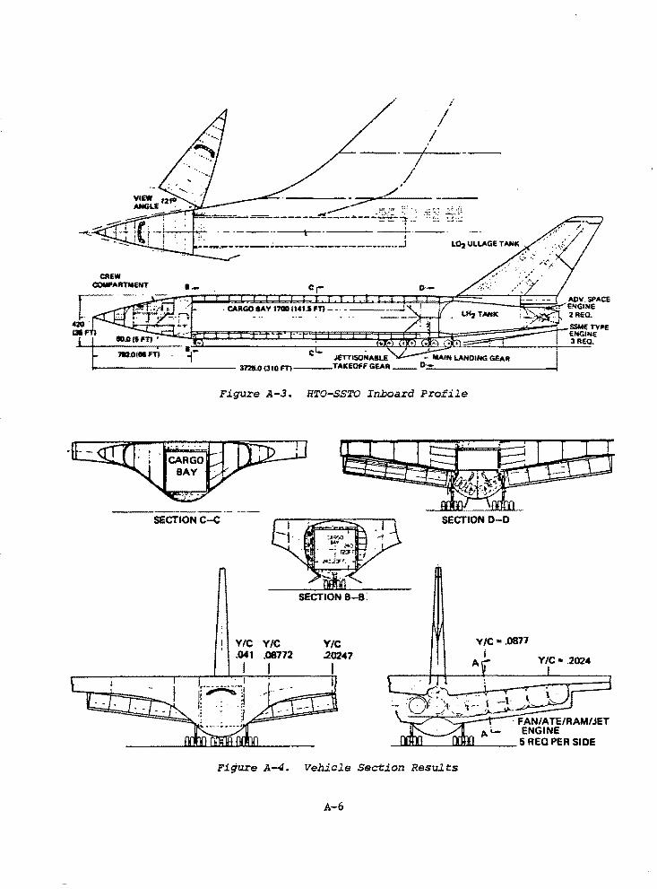
. CARGOIAY 17001141.SFT}-- - -----
~ 7W.Olll Fn · ~,.."' C JETTlsoHA9LE - MAIN LANDING GEAR 1-C----------- 3725.0(llOFTl---TAKEOFF GEAR __ D-.'-----------;
. - .
Figure A-3. HTO-SSTO Inboard Profile
SECTIONC-C
VIC Y/C .041 .08772
I I
SECTION B-B:
Y/C .20247
I
SECTION D-0
Y/C• .0877
Y/C• .2024
FAN/ATE/RAM/JET . ENGINE
_..... ......... .___........,........_ ___ 5 REQ PER SIDE
Figure A-4. Vehicle Section Results
A-6
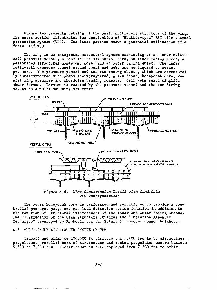
Figu~e A-5 presents details of the basic multi-cell structure of the wing. The upper portion illustrates the application of 11 Shuttle-type11 RSI tile thermal protection system (TPS). The lower portion shows a potential utilization of a "metallic" TPS.
The wing is an integrated structural system consisting of an inner multicell pres-sure vessel, a foam-filled structural core, an inner facing sheet, a perforated structural honeycomb core, and an outer facing sheet. The inner multi-cell pressure vessel arched shell and webs are configured to resist pressure. The pressure yessel and the two facing sheets, which are structurally interconnected with phenolic-impregnated, glass fiber, honeycomb core, resist wing spanwise and chordwise bending moments. Cell webs react winglift shear forces. Torsion is reacted by the pressure vessel and the two facing sheets as a multi-box wing structure.
=2.00
"4£TALLIC TPS
TRUSS CORE PANEL
WING TANK STRUCTUllE
CELL ARCHED SHELL
FOAM FILLED HONEYCOMB CORE
Figure A-5. Wing Construction Detail with Candidate TPS Configurations
The outer honeycomb core is perforated and partitioned to provide a controlled passage, purge and gas leak detection system function in addition to the function of structural interconnect of the inner and outer facing sheets. The construction of the wing structure utilizes the 11 Inflation Assembly Technique" developed by Rockwell for the Saturn II booster common bulkhead.
A.3 MULTI-CYCLE AIRBREATHER ENGINE SYSTEM
Takeoff and climb to 100,000 ft altitude and 5,800 fps is by airbreather propulsion. Parallel burn of airbreather and rocket propulsion occurs between 5,800 to 7,200 fps. Rocket power is then employed from 7,200 fps to orbit.
A-7
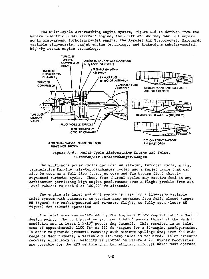
The multi-cycle airbreathing engine system, Figure A-6 is derived from the General Electric CJ805 aircraft engine, the Pratt and Whitney SWAT 201 supersonic wrap-around turbofan/ramjet engine, the Aerojet Air Turborocket, Marquardt variable plug-nozzle, ramjet engine technology, and Rocketdyne tubular-cooled, high-Pc rocket engine technology.
TURBOJET TURlllNE COMPRESSOR DRIVE
AIRTURllO EXCHANGER MANIFOLD (LH2 RANKINE CYCLE)
DESIGN POINT ORlllT Al FLIGHT AIR INLET CLOSED
TURIOJET~-~--1-,..-~-~.,..,;;;;~......- J
Dll~ DESIGN POINT MACH 6 (100,000 FD
SHUTOFF VALVE
•EXTERNAL VALVES, P'LUMllNG, AND l'UMP~ NOT SHOWN
llQ]lll~ DESIGN POINT TAK EOFF AIR INLET OPEN
Figure A-6. Mul t:i-Cycle Airbreat:hing Engine and Inlet, Turbofan/Air Turboexchanger/Ramjet
The multi-mode power cycles include: an aft-fan, turbofan cycle, a LH2, regenerative Rankine, air-turboexchanger cycle; and a ramjet cycle that can also be used as a full flow (turbojet core and fan bypass flow) thrustaugmented turbofan cycle. These four thermal cycles may receive fuel in any combination permitting high engine performance over a flight profile from sea level takeoff to Mach 6 at 100,000 ft altitude.
The engine air inlet and duct system is based on a five-ramp variable inlet· system with actuators to provide ramp movement from fully closed (upper RH figure) for rocket-powered and re-entry flight, to fully open (lower RH figure) for takeoff operation.
The inlet area was determined by the engine airflow required at the Mach 6 design point. The configuration required l.4xl0 6 pounds thrust at the Mach 6 condition and at least l.2xl0 6 pounds for takeoff. This resulted in an inlet area of approximately 1200 ft 2 or 120 ft 2/engine for a 10-engine configuration. In order to provide pressure recovery with minimum spillage drag over the wide range of. Mach numbers, a variable multi-ramp inlet is required. Inlet pressure recovery efficiency vs. velocity is plotted on Figure A-7. Higher recoveries are possible for the HTO vehicle than for military aircraft which must operate
A-8
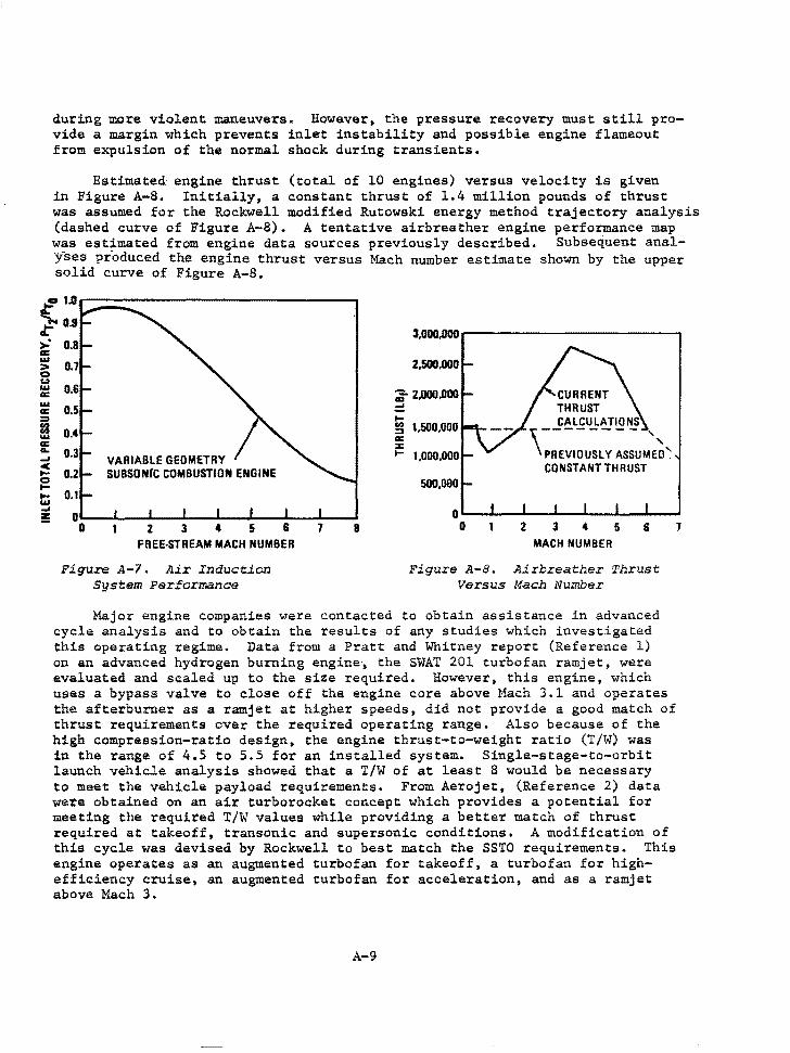
during more violent maneuvers. However, the pressure recovery must still provide a margin which prevents inlet instability and possible engine flameout from expulsion of the normal shock during transients.
Estimated· engine thrust (total of 10 engines) versus velocity is given in Figure A-8. Initially, a constant thrust of 1.4 million pounds of thrust was assumed for the Rockwell modified Rutowski energy method trajectory analysis (dashed curve of Figure A-8). A tentative airbreather engine performance map was est~mated from engine data sources previously described. Subsequent analyses produced the engine thrust versus Mach number estimate shown by the upper solid curve of Figure A-8.
~u -.... D.9 c >. a: w > 0 u w a: w a: ::I
ti w a: a.. -' < .... 0 .... .... w -' :!
0.8
0.7
0.6
0.5
0.4
0.3 VARIABLE GEOMETRY 0.2 SUBSON(C COMBUSTION ENGINE
0.1
0 0 2 3 4 5 6
FREE-STREAM MACH NUMBER
Figure A-7. Air Inauation System Performance
7 8
3,•.ooo
2,500,000
;;- 2,000 .000
= t; :::> a: :c ....
1,500,000
1.D00,000
500,000
0 0 2 3 4 5 6
MACH NUMBER
Figure A-8. Airbreather Thrust Versus Maah Number
Major engine companies were contacted to obtain assistance in advanced cycle analysis and to obtain the results of any studies which investigated this operating regime. Data from a Pratt and Whitney report (Reference 1) on an advanced hydrogen burning engine, the SWAT 201 turbofan ramjet, were evaluated and scaled up to the size required. However, this engine, which uses a bypass valve to close off the engine core above Mach 3.1 and operates the afterburner as a ramjet at higher speeds, did not provide a good match of thrust requirements over the required operating range. Also because of the high compression-ratio design, the engine thrust-to-weight ratio (T/W) was in the range of 4.5 to 5.5 for an installed system. Single-stage-to-orbit launch vehicle analysis showed that a T/W of at least 8 would be necessary to meet the vehicle payload requirements. From Aerojet, (Reference 2) data were obtained on an air turborocket concept which provides a potential for meeting the required T/W values while providing a better match of thrust required at takeoff, transonic and supersonic conditions. A modification of this cycle was devised by Rockwell to best match the SSTO requirements. This engine operates as an augmented turbofan for takeoff, a turbofan for highefficiency cruise, an augmented turbofan for acceleration, and as a ramjet above Mach 3.
A-9
1
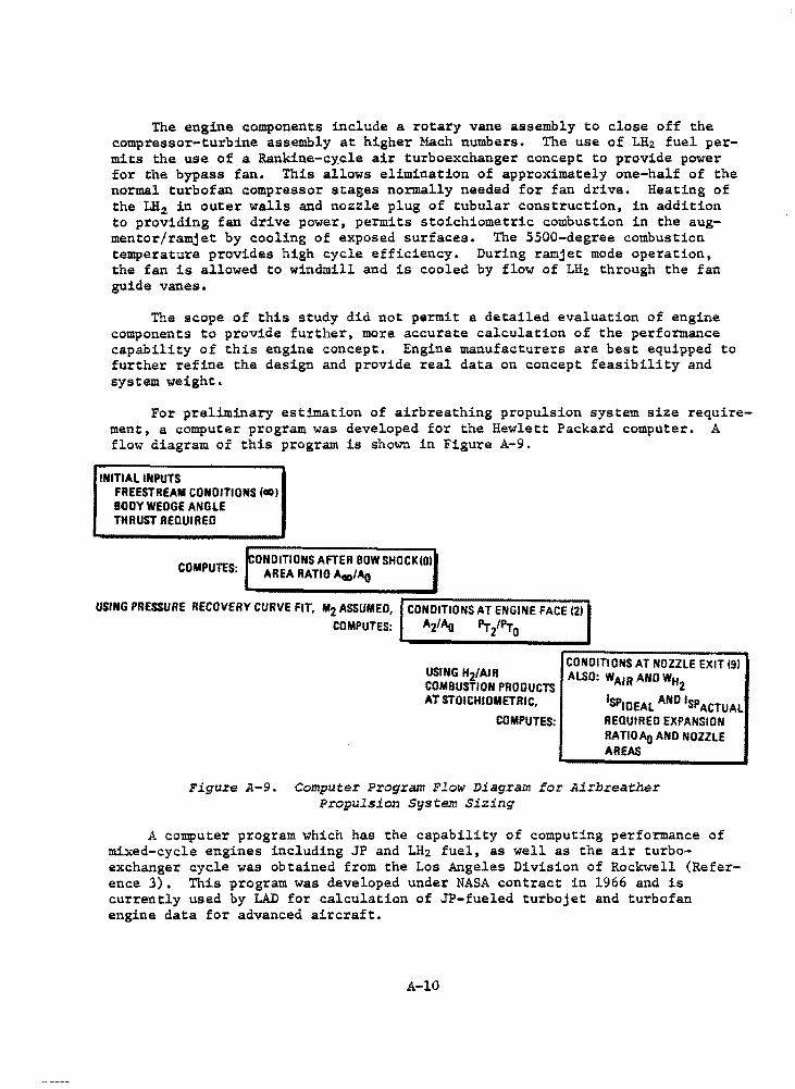
The engine components include a rotary vane assembly to close off the compressor-turbine ass_embly at higher Mach numbers. The use of LH2 fuel permits the use of a Rankine-cycle air turboexchanger concept to provide power for the bypass fan. This allows elimination of approximately one-half of the normal turbofan compressor stages normally needed for fan drive. Heating of the LH2 in outer walls and nozzle plug of tubular construction, in addition to providing fan drive power, permits stoichiometric combustion in the augmentor/ramjet by cooling of exposed surfaces. The 5500-degree combustion temperature provides high cycle efficiency. During ramjet mode operation, the fan is allowed to windmill and is cooled by flow of LH2 through the fan guide vanes.
The scope of this study did not permit a detailed evaluation of engine components to provide further, more accurate calculation of the performance capability of this engine concept. Engine manufacturers are best equipped to further refine the design and provide real data on concept feasibility and system weight.
For preliminary estimation of airbreathing propulsion system size requirement, a computer program was developed for the Hewlett Packard computer. A flow diagram of this program is shown in Figure A-9.
INITIAL INPUTS FREESTREAM CONDITIONS {CID) BODY WEDGE ANGLE THRUST REQUIRED
COMPUTES· CONDITIONS AFTER BOW SHOCK IOI • AREA RATIO AflO/Ao
USING PRESSURE RECOVERY CURVE FIT, M2 ASSUMED, CONDITIONS AT ENGINE FACE 12)
COMPUTES: A2/Ao Pri'Pro
USING Hz/AIR COMBUSTION PRODUCTS AT STOICHIOMETRIC,
COMPUTES:
CONDITIONS AT NOZZLE EXIT 191 ALSO: WAIR AND WH
2 1SPIDEAL AND lsp ACTUAL REQUIRED EXPANSION RATIOAQ AND NOZZLE AREAS
Figure A-9. Computer Program Flow Diagram for Airbreather Propulsion System Sizing
A computer program which has the capability of computing performance of mixed-cycle engines including JP and LH2 fuel, as well as the air turboexchanger cycle was obtained from the Los Angeles Division of Rockwell (Reference 3). This program was developed under NASA contract in 1966 and is currently used by LAD for calculation of JP-fueled turbojet and turbofan engine data for advanced aircraft.
A-10
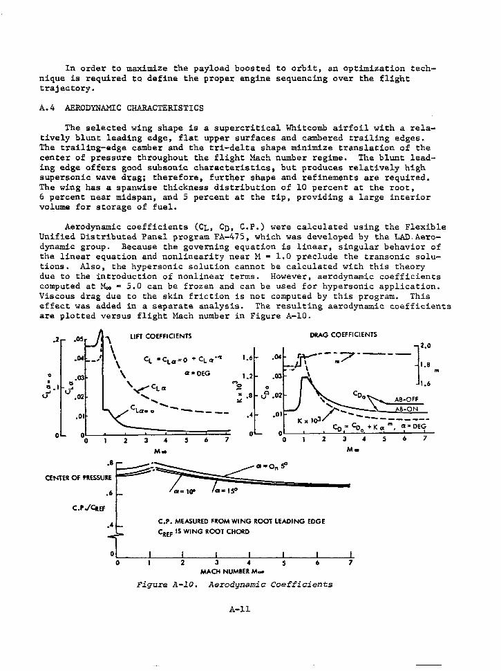
In order to maximize the payload boosted to orbit, an optimization technique is required to define the proper engine sequencing over the flight trajectory.
A.4 AERODYNAMIC CHARACTERISTICS
The selected wing shape is a supercritical Whitcomb airfoil with a relatively blunt leading edge, flat upper surfaces and cambered trailing edges. The trailing-edge camber and the tri-delta shape minimize translation of the center of pressure throughout the flight Mach number regime. The blunt leading edge offers good subsonic characteristics. but produces relatively high supersonic wave drag; therefore, further shape and refinements are required. The wing has a spanwise thickness distribution of 10 percent at the root, 6 percent near midspan, and 5 percent at the tip, providing a large interior volume for storage of fuel.
Aerodynamic coefficients (CL, Cn, C.P.) were calculated using the Flexible Unified Distributed Panel program FA-475, which was developed by the LAD.Aerodynamic group. Because the governing equation is linear, singular behavior of the linear equation and nonlinearity near M • 1.0 preclude the transonic solutions. Also, the hypersonic solution cannot be calculated with this theory due to the introduction of nonlinear terms. However, aerodynamic coefficients computed at Mo. a 5.0 can be frozen and can be used for hypersonic application. Viscous drag due to the skin friction is not computed by this program. This effect was added in a separate analysis. The resulting aerodynamic coefficients are plotted versus flight Mach number in Figure A-10.
.2 .05 \ LIFT COEFFICIENTS DRAG COEFFICIENTS
\ ·°' I \ CL •CL a= O + CL a ·'I 1.6 _,
\ 0 .03 \ Cl" DEG 1.2
.04 r.+---:7·---.-..µ \ 1.8 m
\ I
" \"'C • ..- CL a '"'2 " •I .... .... u .. • 8
12.0
1.6
.... Coo~ AB-OFF u .02
.01
0 0 0
CENTER Of PRESSURE
.6
C.P./CtlEF
.4
2
....... ~
,_ cl(lso ------ ...
/' - -~ AB-ON --
3 0
4 5 6 7
Ka lol ---------Co "' Co
0 + K a m, Cl 2 DEG
OL-~.1.-~-'-----=-'-~""'--~-'-~-'---....... -0 2 3 4 5 6 7
M• M•
;~•·o.'1' ·o::::: C.P. MEASURED FROM WING ROOT LEADING EDGE
CREF IS WING ROOT CHORD
MACH NUMBER M-
F igure A-10. Aerodynamic Coefficients
A-11
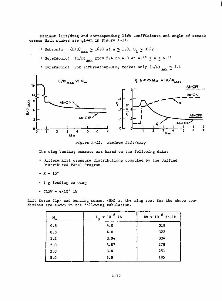
Maximum lift/drag and corresponding lift coefficients and angle of attack versus Mach number are given in Figure A-11.
• Subsonic: (L/D) ~ 16.0 at a ~ 1.0, CL ~. 0.22 max - -
• Supersonic: (L/D) from 5.4 to 4.0 at 4.5° < a < 6.2° max
• Hypersonic: For airbreather-OFF, rocket only (L/D) ~ 3.4 max -
(l/Dl MA:X VS M 00 ~ & avsM. AT (l/D) MA:X
AB-OFF 8 ----
~ 6
~ 0 4 d
2
0 0
AB-ON .3 6 ___ ,---
't , Q 6
.2 e. 4 a
.1 2 AB-Off/
AB-ON
0 0 2 3 ... 7 Moo 2 3 4 s 6 M•
Figure A-11. Maximum Lift/Drag
The wing bending moments are based on the following data:
• Differential pressure distributions computed by the Unified Distributed Panel Program
• x - 10°
• 2 g loading on wing
• GLOW • 4Xl0 6 lb
s
AB-OFF
6
Lift force (LF) and bending moment (BM) at the wing root for the above conditions are shown in the following tabulation.
M ~ x 10-6 lb BM x 10-6 ft-lb .. 0.5 4.0 318
0.8 4.0 322
1.2 3.94 334
2.0 3.87 278
3.0 3.8 251
5.0 3.0 185
A-12
7
A.5 FLIGHT MECHANICS
The majority of the ascent performance analysis for the SSTO vehicle concept was accomplished using a recently developed lifting ascent program based on a modified Rutowski Energy Method (Ikawa Method). This technique accurately estimated payload and propellant performance; however, it did not provide a bona fide integrated time history of trajectory state from liftoff to orbit insertion. A second computer program, the Two-Dimensional Trajectory Program (TDTP), was then used to compute the ascent trajectory timeline.
In order to do an end-to-end simulation of the SSTO (i.e., airbreather horizontal takeoff, climb, cruise, turn, airbreather ascent. rocket ascent, coast, and final orbit insertion) with flight optimization including aerodynamic effects, Rockwell acquired the Langley POST computer program (program to optimize simulated trajectories, developed by Martin-Marietta). POST was installed on the CDC system at Rockwell and several launch cases were executed.
The SSTO uses aircraft-type flight from airport takeoff to approximately Mach 6, with a parallel burn transition of airbreather and rocket engines from Mach 6 to 7.2, and rocket-only burn from Mach 7.2 to orbit. Figure A-12 illustrates a nominal trajectory from KSC to 300-nmi earth equatorial orbit. Prime elements of the trajectory are:
• Runway takeoff under high-pass turbofan/airturbo exchanger (ATE)/ ramjet power, with the ramjets acting as supercharged afterburners
• Jettison and parachute recovery of launch gear
• Climb to optimum cruise altitude with turbofan power
• Cruise at optimum altitude, Mach number, and direction vector to earth's equatorial plane, using turbofan power
• Execute a large-radius turn into the equatorial plane with turbofan power
• Climb subsonically at optimum climb angle and velocity to an optimum altitude, using high bypass turbofan/ATE/ramjet (supercharged afterburner) power
• Perform an optimum pitch-over into a nearly constant-energy (shallow y-angle) dive if necessary, and accelerate through the transonic region to approximately Mach 1.2, using turbofan/ramjet (supercharged afterburner) power
• Execute a long-radius optimum pitch-up to an optimum supersonic climb flight path, using turbofan/ATE/ramjet power
• Climb to approximately 29 km (95 kft) altitude, and 1900 m/s (6200 fps) velocity, at optimum flight path angle and velocity, using proportional fuel-flow throttling from turbofan/ATE/ramjet, or full ramjet, as required to maximize total energy acquired per unit mass of fuel consumed as function of velocity and altitude
A-13
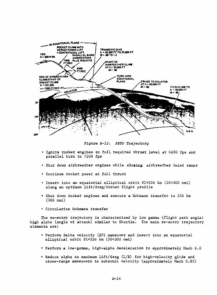
100
. .i.
TllANSONIC DIVE II • 45,000 FT TO 37,000 " ll••TO 1.2
START Of AIRBREATHER CLIMe AT h • 20,000 FT
11•.85
Figure A-12. SSTO Trajectory
• Ignite rocket engines to full required thrust level at 6200 fps and parallel burn to 7200 fps
• Shut down airbreather engines while closing airbreather inlet ramps
• Continue rocket power at full thrust
• Insert into an equatorial elliptical orbit 9lx556 km (50x300 nmi) along an optimum lift/drag/thrust flight profile
• Shut down rocket engines and execute a Hohmann transfer to 556 km (300 nmi)
• Circularize Hohmann transfer
The re-entry trajectory is characterized by low gamma (flight path angle) high alpha (angle of attack) similar to Shuttle. The main re-entry trajectory elements. are:
• Perform delta velocity (lV) maneuver and insert into an equatorial elliptical orbit 91X556 km (50xJOO nmi)
• Perform a low-gamma, high-alpha deceleration to approximately Mach 6.0
• Reduce alpha to maximum lift/drag (L/D) for high-velocity glide and cross-range maneuvers to subsonic velocity (approximately Mach 0.85)
A-14
I
• Open inlets and start airbreather engines as required
• Perform powered flight to landing field, land on runway, and taxi to dock
Flyback fuel requirements include approximately 300 nmi subsonic cruise and two landing approach maneuvers (first approach waveoff with flyaround for second approach).
Typical Isp characteristics of AB/rocket engine system are:
• Subsonic range - Linear reduction of Isp from 9700 to 4000 sec at 1200 fps
• Supersonic range - Reduction of Isp from 4000 sec at 1200 fps to 3500 sec at ~5600 fps (AB)
• Rocket - I 8 p • 455 sec
The airbreather cruise mode, which results in an economical orbit plane change from the launch site to the equatorial orbit, was analyzed. The estimated fuel requirements to cruise 1000 statute miles down-range for alternate propulsion modes are given below.
v (ft/sec)
800
6000
Altitude (k-f t).
20
85
6600
880
72,000
386,000
Engine
Turbofan Jet
Ramjet
Although subsonic cruise takes a longer time (110 minutes), the amount of fuel consumed is substantially less when the orbital plane change is accomplished with subsonic cruise at maximum L/D.
A transition maneuver from high-lift configuration to (L/D)max configuration is performed shortly after liftoff (beginning at 3000 ft altitude). The maximum angle of attack of 13 degrees is reduced gradually to 1 degree for subsonic (L/D)max climb configuration.
Velocity and·angle of attack vs flight time indicate the time required to reach 300 nmi orbit (not including subsonic cruise leg) varies from 1800 to 2300 sec, depending upon (W/S)o. (T/W), and engine operational mode.
Variation in load factor, altitude, and dynamic pressure with respect to velocity and time during supersonic ascent show a maximum load acceleration less than 2.3 g. Maximum dynamic pressure is 940 psf, which is within load limits. From takeoff to burnout, the ascent profile is quite shallow - with flight path angle ranging between -0.7 and 4.5 degrees.
Ascent and descent trajectories of the SSTO and the Space Shuttle missions are compared in Figure A-13. Because the performance of airbreathing engines and aerodynamic lifting of winged vehicle depend on the high dynamic pressure,
A-15
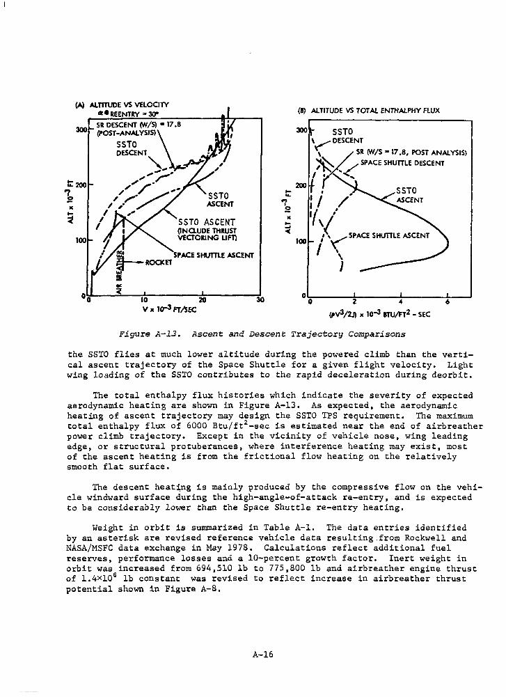
(A) ALTITUDE VS VELOCITY ct e REENTRY '" 309
300 SR DESCENT rN/S) '" 17 .8 (POST-ANAL YSISli.
SSTO DESCENT ft " ~ , _... ,, ,. _,
t:: 200 ,,,,"' ·' ,, / ... -,/ ,,,,-·' ,/ .., le
100
',. / L SSTO ASCENT
I ,, , I SSTO ASCENT
(INaUDE THRUST VECTORING LIF'Tl
i__ SPACE SHUTILE ASCENT ~ -ROCKET ... :& .. <
10 20 V x lo-3 FT/SEC
30
... ... .., I
2 •
(9) ALTITUDE VS TOT AL ENTHALPHY FLUX
300 SSTO \~DESCENT
\ SR rN/S • 17 .8, POST ANALYSIS)
~ .. <SPACE SHUTTLE DESCENT
I ' "' 200
100
O~------~---------!---------!-----' 0 2 4 6
"v3/2.J). 10-3 aru/FT2 - SEC
Figure A-13. Ascent and Descent Trajectory Comparisons
the SSTO flies at much lower altitude during the powered climb than the vertical ascent trajectory of the Space Shuttle for a given flight velocity. Light wing loading of the SSTO contributes to the rapid deceleration during deorbit.
The total enthalpy flux histories which indicate the severity of expected aerodynamic heating are shown in Figure A-13. As expected, the aerodynamic heating of ascent trajectory may design the SSTO TPS requirement. The maximum total enthalpy flux of 6000 Btu/ft2 -sec is estimated near the end of airbreather power climb trajectory. Except in the vicinity of vehicle nose, wing leading edge, or structural protuberances, where interference heating may exist, most of the ascent heating is from the frictional flow heating on the relatively smooth flat surface.
The descent heating is mainly produced by the compressive flow on the vehicle windward surface during the high-angle-of-attack re-entry, and is expected to be considerably lower than the Space Shuttle re-entry heating.
Weight in orbit is summarized in Table A-1. The data entries identified by an asterisk are revised reference vehicle data resulting from Rockwell and NASA/MSFC data exchange in May 1978. Calculations reflect additional fuel reserves, performance losses and a 10-percent growth factor. Inert weight in orbit was increased from 694,510 lb to 775,800 lb and airbreather engine thrust of l.4xl0 6 lb constant was revised to reflect increase in airbreather thrust potential shown in Figure A-8.
A-16
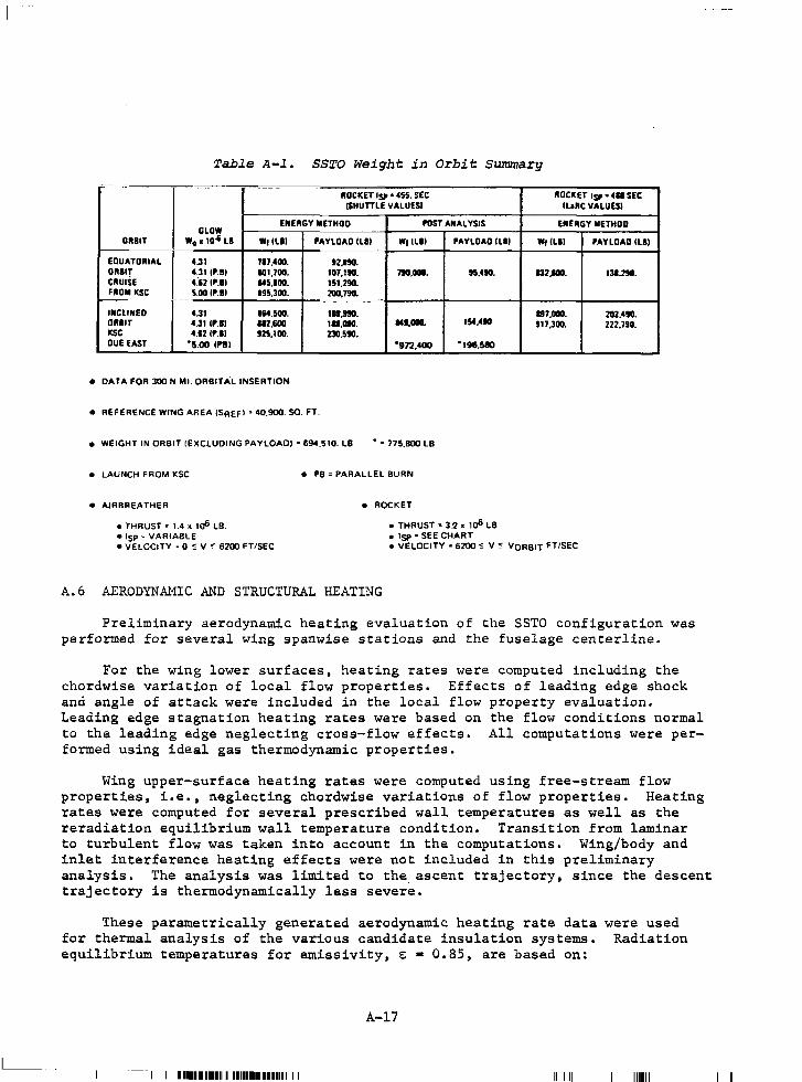
Table A-1. SSTO Weight in Orbit Summary
·- -- -llOCICET ISP• 455. SEC llOCKET ISP• 4A SEC
(SHUTTLE VALUESI ILIRC VALUES!
GLOW ENERGY METHOD POST ANALYSIS ENERGY METHOD
OllBIT W0 x 10-l u W1llll PAYLOAD llll W1llll PAYLOAD ILll Wt (Lii PAYLOAD (LI)
EQUATORIAL 4.31 717.400. 12.no. ORBIT 4.31 IP.Bl IOl,700. 107,190. 190,000. 95,490. CRUISE (&2 IP.11 145.100. 151,290. FROM KSC 5.00 IP.II 195.300. 200,790.
INCLINED 4.31 1&4.500. 18.990. ORllT 4.31 IP.II 112.600 lA,090. Mt.ODO. 154,490 KSC 4.12 IP.11 925,100. 230.!i90. DUE EAST ·s.oo 1PB1 •gn,400 "196,580
• DATA FOR JOO N Ml. ORBITAL INSERTION
e REFERENCE WING AREA tSREFI • 40.900. SO. FT.
e WEIGHT IN ORBIT !EXCLUDING PAYLOADI • 694.510. LB "• 775,800 LB
e LAUNCH FROM KSC
• AIRBREATHER
•THRUST • 1.4 • 1o6 LB. •ISP~ VARIABLE
e PB= PARALLEL BURN
e ROCKET
• THRUST • 3.2 x 1a6 LB • ISP• SEE CHART
132.IOO.
a1.aoa. 917,300.
•VELOCITY ~ 0 "V '!" 6200 FT/SEC • VELOCITY• 6200" V" VORBIT FT/SEC
A.6 AERODYNAMIC AND STRUCTURAL HEATING
131.290.
202,490. 222,790.
Preliminary aerodynamic heating evaluation of the SSTO configuration was performed for several wing spanwise stations and the fuselage centerline.
For the wing lower surfaces, heating rates were computed including the chordwise variation of local flow properties. Effects of leading edge shock and angle of attack were included in the local flow property evaluation. Leading edge stagnation heating rates were based on the flow conditions normal to the leading edge neglecting cross-flow effects. All computations were performed using ideal gas thermodynamic properties.
Wing upper-surface heating rates were computed using free-stream flow properties, i.e., neglecting chordwise variations of flow properties. Heating rates were computed for several prescribed wall temperatures as well as the reradiation equilibrium wall temperature condition. Transition from laminar to turbulent flow was taken into account in the computations. Wing/body and inlet interference heating effects were not included in this preliminary analysis. The analysis was limited to the_ ascent trajectory, since the descent trajectory is thermodynamically less severe.
These parametrically generated aerodynamic heating rate data for thermal analysis of the various candidate insulation systems. equilibrium temperatures for emissivity, E • 0.85, are based on:
A-17
I I 111111111111111111111111111 11 11111
were used Radiation
111111 I I
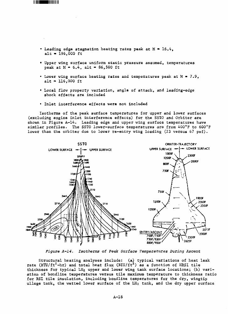
1111111111111••1111111111111111111111
• Leading edge stagnation heating rates peak at M • 16.4, alt • 196,000 ft
• Upper wing surface uniform static pressure assumed, temperatures peak at M • 6.4, alt • 86,500 ft
• Lower wing surface heating rates and temperatures peak at M • 7.9, alt • 116,000 ft
• Local flow property variation, angle of attack, and leading-edge shock effects are included
• Inlet interference effects were not included
Isotherms of the peak surface temperatures for upper and lower surfaces (excluding engine inlet interference effects) for the SSTO and Orbiter are shown in Figure A-14. Leading edge and upper wing surface temperatures have similar profiles. The SSTO lower-surface temperatures are from 400°F to 600°F lower than the orbiter due to lower re-entry wing loading (23 versus 67 psf).
LOWER SURFACE UPPER SURFACE
370Cl"F
Figure A-14. Isotherms of Peak Surface Temperatures During Ascent
Structural heating analyses include: (a) typical variations of heat leak rate (BTU/ft2-hr) and total heat flux (BTU/ft2) as a function of HRS! tile thickness for typical LH2 upper and lower wing tank surface locations; (b) variation of bondline temperatures versus tile maximum temperature to thickness ratio for RSI tile insulation~ including bondline temperatures for the dry, wingtip ullage tank, the wetted lower surface of the LH2 tank, and the dry upper surface
A-18
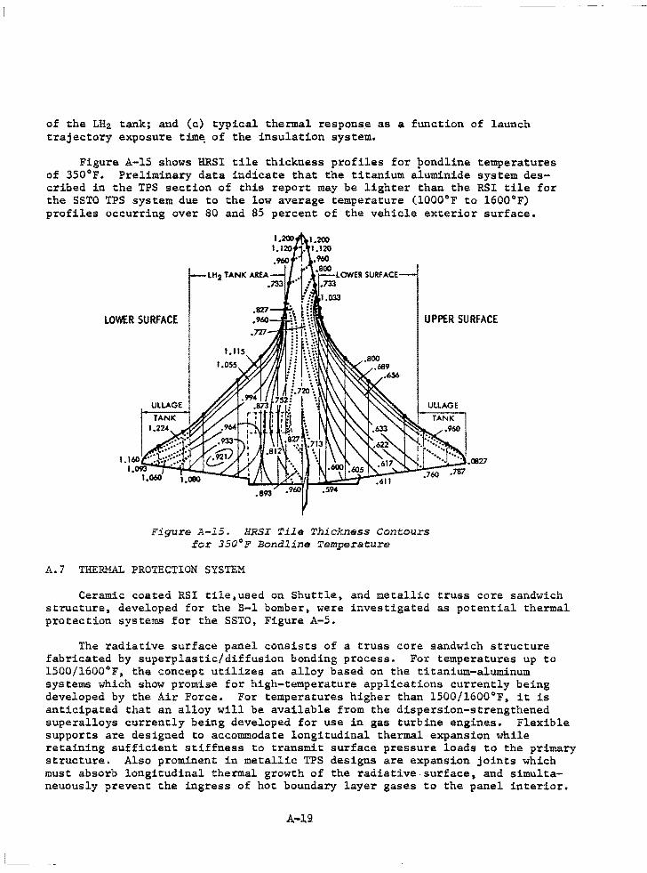
I_
of the LH2 tank; and (c) typical thermal response as a function of launch trajectory exposure tim~ of the insulation system.
Figure A-15 shows HRSI tile thickness profiles for bondline temperatures of 350°F. Preliminary data indicate that the titanium aiuminide system described in the TPS section of this report may be lighter than the RSI tile for the SSTO TPS system due to the low average temperature (1000°F to 1600°F) profiles occurring over 80 and 85 percent of the vehicle exterior surface.
LOWER SURFACE UPPER SURFACE
.893
Figure A-l5. HRSI Tile Thickness Contours ror 350°F Bondline Temperature
A.7 THERMAL PROTECTION SYSTEM
Ceramic coated RSI tile,used on Shuttle, and metallic truss core sandwich structure, developed for the B-1 bomber, were investigated as potential thermal protection systems for the SSTO, Figure A-5.
The radiative surface panel consists of a truss core sandwich structure fabricated by superplastic/diffusion bonding process. For temperatures up to 1500/1600°F, the concept utilizes an alloy based on the titanium-aluminum systems which show promise for high-temperature applications currently being developed by the Air Force. For temperatures higher than 1500/1600°F, it is anticipated that an alloy will be available from the dispersion-strengthened superalloys currently being developed for use in gas turbine engines. Flexible supports are designed to accommodate longitudinal thermal expansion while retaining sufficient stiffness to transmit surface pressure loads to the primary structure. Also prominent in metallic TPS designs are expansion joints which must absorb longitudinal thermal growth of the radiative surface, and simultaneuously prevent the ingress of hot boundary layer gases to the panel interior.
A-l.9
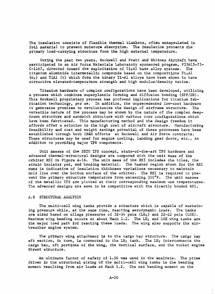
The insulation consists of flexible thermal blankets, often encapsulated in foil material to prevent moisture absorption. The insulation protects the primary load-carrying structure from the high external temperature.
During the past two years, Rockwell and Pratt and Whitney Aircraft have participated in an Air Force Materials Laboratory sponsored program, F33615-75-C-1167 • directed toward the exploitation of TisAl base alloy systems. The titanium aluminide intermetallic compounds based on the compositions Ti 3Al ~z) and TiAl (y) which form the binary Ti-Al alloys have been shown to have attractive elevated-temperature strength and high modulus/density ratios.
Titanium hardware of complex configurations have been developed, utilizing a process which combines superplastic forming and diffusion bonding (SPF/DB). This Rockwell proprietary process has profound implications for titanium fabrication technology, per se. In addition, the unprecedented low-cost hardware it _generates promises to revolutionize the design of airframe structure. The versatile nature of the process may be shown by the nature of the complex deepdrawn structure and sandwich structure with various core configurations which have been fabricated. This manufacturing method and the design freedom it affords offer a solution to the high cost of aircraft structure. Manufacturing feasibility and cost and weight savings potential of these processes have been established through both IR&D efforts at Rockwell and Air Force contracts, These structures may be used for engine cowling, landing gear doors, etc., in addition to providing major TPS components.
Unit masses of the SSTO TPS concept, state-of-the-art TPS hardware and advanced thermal-structural designs are compared with the unit mass of the orbiter RSI in Figure A-16. The unit mass of the RSI includes the tiles, the strain isolator pad, and bonding material. The hashed region shown for the RSI mass is indicative of insulation thickness variations necessary to maintain mold line over the bottom surface of the orbiter. The RSI is required to prevent the primary structure temperature from exceeding 350°F. The unit masses of the metallic TPS are plotted at their corresponding maximum use temperatures. The advanced designs are seen to be competitive with the directly bonded RSI.
A.8 STRUCTURAL ANALYSIS
The multi-cell wing tanks provide a structure which is capable of sustaining pressure while, at the same time, reacting aerodynamic loads. The tanks are sized based on ullage pressures of 32-34 psia (LH2) and 22-22 psia (LOX). Maximum wing bending occurs at about Mach 1.2. The LH2 and LOX wing tanks are the major load path for reacting these loads. The wing also supports the airbreather engine system.
The primary wing attachment is to the cargo bay structure. The cargo bay aft section, in turn. is connected to the LH 2 tank. The LH2 interconnects the cargo bay, aft portions of the wing, the vertical surface, and the rocket engine thrust structure.
An ultimate factor of safety of 1.50 was used in the analysis. The prime driver in the structural sizing of the multi-cell wing tanks is the bending moment resulting from air loads· at Mach 1.2. The net bending moment on the
A-20
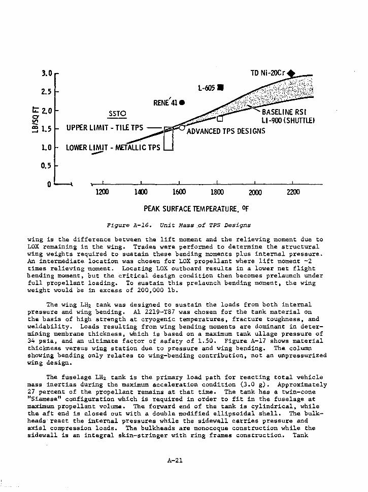
3.0
2.5
t: 2.0 0
"' -~ 1.5
1.0
0.5
0 1200 1400 1600 1800 2000 2200
PEAK SURFACE TEMPERATURE, Of
Figure A-16. Unit Mass of TPS Designs
wing is the difference between the lift moment and the relieving moment due to LOX remaining in the wing. Trades were performed to determine the structural wing weights required to sustain these bending moments plus internal pressure. An intermediate location was chosen for LOX propellant where lift moment -2 times relieving moment. Locating LOX outboard results in a lower net flight bending moment, but the critical design condition then becomes prelaunch under full propellant loading. To sustain this prelaunch bending moment, the wing weight would be in excess of 200,000 lb.
The wing LH2 tank was designed to sustain the loads from both internal pressure and win.g bending. Al 2219-T87 was chosen for the tank material on the basis of high strength at cryogenic temperatures, fracture toughness, and weldability. Loads resulting from wing bending moments are dominant in determining membrane thickness, which is based on a maximum tank ullage pressure of 34 psia, and an ultimate factor of safety of 1.50. Figure A-17 shows material thickness versus wing station due to pressure and wing bending. The column showing bending only relates to wing-bending contribution, not an unpressurized wing design.
The fuselage LH2 tank is the primary load path for reacting total vehicle mass inertias during the maximum acceleration condition (3.0 g). Approximately 27 percent of the propellant remains at that time. The tank has a twin-cone "Siamese" configuration which is required in order to fit in the fuselage at maxi.mum propellant volume. The forward end of the tank is cylindrical, while the aft end is closed out with a double modified ellipsoidal shell. The bulkheads· react the internal pressures while the sidewall carries pressure and axial compression loads. The bulkheads are monocoque construction while the sidewall is an integral skin-stringer with ring frames construction. Tank
A-21
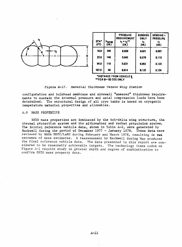
f
I
PRESSURE REQUIREMENT
STA• HNOM t1 '"'12•· (FT) UN.I (IN.)
10.9 240 0.066
23.0 146 0.040
54.0 110 0.031
107.D 48 0.014
•01STANCE FROM VEHICLE~ -FOR g .. 60 DEG ONLY
BENDING ONLY ,, (IN.)
0.021
0.076
0.092
0.120
Figure A-l7. Material Thickness Versus Wing Station
BENDING+ PRESSURE ,,
UN.I
O.OB7
0.116
0.123
0.134
configuration and bulkhead membrane and sidewall "smeared'' thickness requirements to sustain the internal pressure and axial compression loads have been determined. The structural design of all cryo tanks is based on cryogenic temperature material properties and allowables.
A.9 MASS PROPERTIES
SSTO mass properties are dominated by the tri-delta wing structure, the thermal protection system and the airbreather and rocket propulsion system. The initial reference vehicle data, shown in Table A-2, were generated by Rockwell during the period of December 1977 - January 1978. These data were reviewed by NASA MSFC/LaRC during February and March 1978, resulting i~ tt.ri9 extremes of mass estimates. A reassessment by Rockwell during May produced the final reference vehicle data. The data presented in this report are considered to be reasonably achievable targets. The technology items coded on Figure A-1 require study in greater depth and degree of sophistication to confirm SSTO mass property data.
A-22
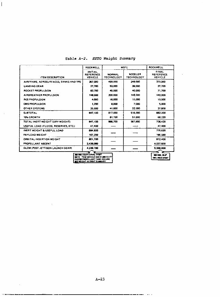
Table A-2. SS'l'O Weight Summary
- -ROCKWELL MSFC ROCKWELL
INITIAL FINAL REFERENCE NORMAL "ACCELER REFERENCE
ITEM OESCRIPTION VEHICLE TECHNOLOGY TECHNOLOGY VEHICLE
AIRFRAME. AEROSURFACES. TANKS ANO TPS 387.000 458.000 249,000 370.000
LANDING GEAR 27.700 53.000 39.000 27,700
ROCKET PROPULSION 113.700 40.000 40,000 71.700
AIRBREATHER PROPULSION 148.000 200.000 148.000 140.000
RCS PROPULSION 4.000 16.000 11.000 10.000
OMS PROPULSION 1.200 9,000 7.000 5.000
OTHER SYSTEMS 35.500 41.000 22.000 37.800 --
SUBTOTAL 1147.100 817.000 516.000 662.200
10'll.GROWTH 81.700 51.600 611.220
TOTAL INERT WEIGHT IDRY WEIGHT) 1147, 100 8118,700 567,600 728.420
USEFUL LOAD I FLUIDS. RESERVES, ETC.) 47.400 - - 47,400
INERT WEIGHT & USEFUL LOAD 694.500 775.B20 - -PAYLOAD WEIGHT 107.200 196.SSO
ORBITAL INSERTION WEIGHT 801.700 972.400 - -PROPELLANT ASCENT 3,438.Dm 4.027.600
-· GLOW !POST-JETTISON LAUNCH GEAR) 4,239,780 - - 5.000.000 - -
1 • - EOUATOAIAL OAllT ·1 r=:-i~ llCITf: Tllll VEHICLE MAI 51- CU n llEO OA•T EXCEii PllCWELLA•T THC VOLUME •E WEIGHT I• OAllT SU-AAY
A-23
---....--.--..---··--·-.. ---·------ . ·---- ·--------------·---·--·-·-······-..
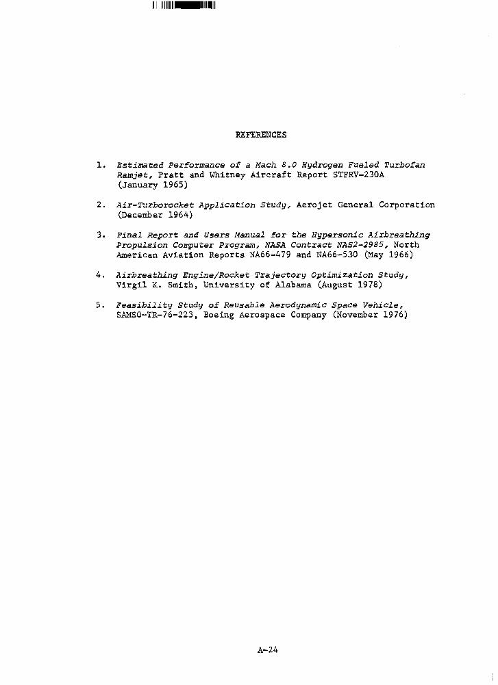
111111111111111111-11111111111111111
REFERENCES
1. Estimated Performance of a Mach 8.0 Hydrogen Fueled Turbofan Ramjet, Pratt and Whitney Aircraft Report STFRV-230A (January 1965)
2. Air-Turborocket Application Study, Aerojet General Corporation (December 1964)
3. Final Report and Users Manual for the Hypersonic Airbreathing Propulsion Computer Program, NASA Contract NAS2-2985, North American Aviation Reports NA66-479 and NA66-530 (May 1966)
4. Airbreathing Engine/Rocket Trajectory Optimization Study, Virgil K. Smith, University of Alabama (August 1978)
5. Feasibility Study of Reusable Aerodynamic Space Vehicle, SAMSO-TR-76-223, Boeing Aerospace Company (November 1976)
A-24
APPENDIX B. HLLV REFERENCE VEHICLE TRAJECTORY AND TRADE STUDY DATA
APPENDIX B
HLLV REFERENCE VEHICLE TRAJECTORY AND TRADE STUDY DATA
B.O INTRODUCTION
The reference heavy lift launch vehicle trajectory data and a summary of the various trade studies performed are contained in this appendix. The several trade options include:
• First and Second Stage Engine Throttling
• First Stage Propellant Weight Sensitivity
• Second Stage Propellant Weight Sensitivity
• Lift-off Thrust-to-Weight Sensitivity
• Alternate First Stage Propellants (LOX/CH~ and LOX/LH2)
With the exception of the engine throttling trades, all trajectories assumed 100% throttling by the first stage engines (i.e., second stage engines operate at maximum thrust throughout the parallel burn ascent phase) in order to stay within maximum allowable load factor and dynamic pressure,3 g and 650 psf respectively.
The engine throttling study shows little effect on vehicle payload capability when doing 100% of the throttling with either stage. All intermediate options (i.e., partial throttling of both stages) shows a degradation in payload capability.
The first stage propellant weight sensitivity analyses show an improvement in glow/payload weight ratio (smaller) as first stage propellant weight is increased, however, the staging velocity exceeds the capability of a heat sink booster. The second stage propellant weight sensitivity indicates an opposite effect to the first stage data.
By combining the effects of throttling of second stage only and increasing first stage propellant weight could result in a 10-15% improvement over the reference HLLV configuration.
The alternate propellant trades, LOX/CH~ and LOX/LH2, show 7% and 37% increased performance over the reference HLLV configuration. The LOX/LH2 configuration, however, becomes extremely large (volume) and less cost effective because of handling and propellant costs. The LOX/CH~ booster appears to be a viable option.
B-1
B.l HLLV REFERENCE VEHICLE TRAJECTORY
This section contains the tabulated reference vehicle characteristics and trajectory data. The nominal and abort modes [once around and second stage return to launch site (RTLS)) data are included. Because an adaptation of the space shuttle transportation system scaling program was used, certain vehicle parameters are listed under headings of 11External Tank" and "Solid Rocket Booster."
The first two pages of the tabulated data list the pertinent ground rules and assumptions employed in making the computer run. In the list of "Vehicle Characteristics" (third page), the structure weight given refers to the booster total inert .weight plus residuals and reserves but exclusive of flyback propellant. The propellant value given is the total usable ascent propellant loaded in the first stage (i.e., includes that propellant crossfeed to the second stage during first stage burn).
In the summary weight statement (fourth page), the "Orbiter" and "External Tank" listings refer to second stage weights. The "External Tank" values apply to main propulsion residuals and reserves. The total usable propellant (External Tank) is the total propellant burned in the second stage (i.e., propellant loaded plus crossfeed from first stage). The usable SRM propellant listing is the total propellant burned through the first stage engines. To determine the amount of crossfeed propellant, the usable SRM propellant may be subtracted from the total propellant loaded in the second stage which is given under Vehicle Characteristics, third page of data.
CRT plots of significant HLLV parameters are included following the tabulated data.
The reference vehicle has a gross liftoff weight of 7,135,492 kg (15,731,068 lb) and a payload capacity of 231,195 kg (509,653 lb).
B-2
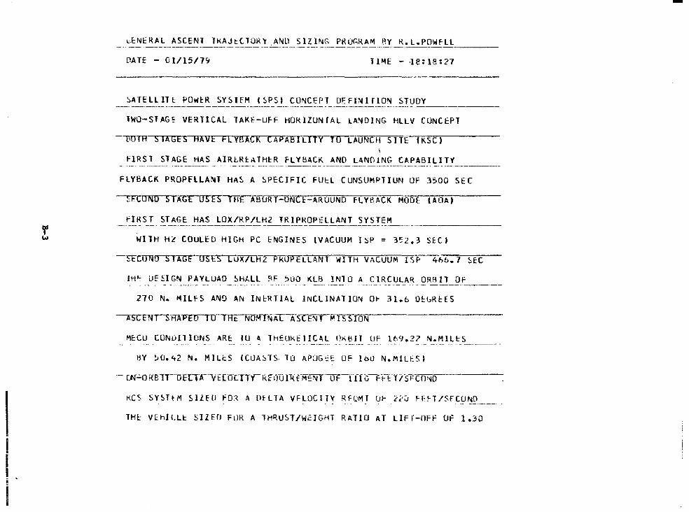
DATE - 01115/7~
~AHLLITt: POWl:R SYSHM CSPSI CONCEPT DF.FINHlON STUDY
lWO-STAG~ VERTICAL lAKE-UFf HORIZONTAL LANDING HLLV CONCEPT
BOIH SIAGES HAVE FLVBACK CAPABILITY TO LAUNCH SITE fKSC) I
flRST STAGE HAS AIR~Rl:ATHtR FLYBACK ANO LANO!NG CAPABILITY --·-·-----FLYBACK PROPFLLA~l HAS A SPECIFIC FUEL CUNSUMPTIUN OF 3500 SEC
::FCOND STAGE USES HIE ABURT-ONCE-ARUUND F-LYBACK MODE: lAOAJ
fIRST STAGE HAS LOX/RP/LH2 TRlPKOPELLANT SYSTEM
WllH Hl COULED HIGH PC ENGINES (VACUUM ISP = 3~2.3 SECJ
-·rrcTINO s lAGf USF5-WX/LH2 PkUPELLANT WITH VACUUM ISi' 4h6. 7 ~E:C
JH~ UESIGN PAYLUAD SHALL ~F ~00 KLB INlO A CIRCULAR ORBIT OF
270 N. MILES AND AN INERTIAL INCLINATION Of 31.6 Ol:GREES
M~CU CON~llIONS ARt lU l lHEUkEllCll OKBIT UF 169.2? N.MlltS ----·---
ev ~0.42 N. MlL~S (CUA~l~ 10 APOG~E OF lb0 N.MlLESJ
KCS SY~hM SIHCJ fO:< A DHTA VFLOCITY Rff.:,MT lJI- _n;; F-HT/~FC9~Q .. ~-· _
lH~ VEhlLLt SIZED F~R A 1HRUST/W2IGHT RATIO AT LIFT-OFF OF l.30
-
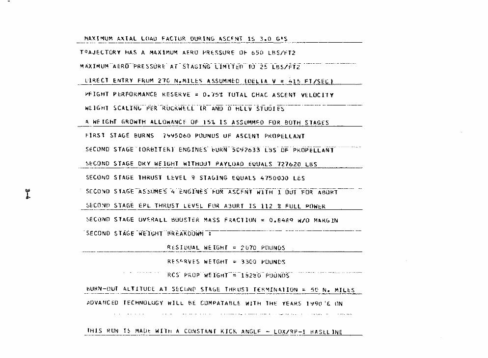
r
MAXIMUM AX.UL LOAO FA.CTUR DURING ASU LS 3.0 G1
JQAJECTORY HAS A MAXlMUM AERO PR~SSU~E O~ 650 LAS/FT2
ll~ECT ENTRY fkUM 27G N.M!LES ASSUMM~O (DELIA y = 415 FT/SECt
~FIGHT PcRFORMANCE KESERV~ = 0.15~ TUTAL CHAC ASCENT VELOCllY
wU(;;HT SC-ALlNG--P-ER-Rl.1C1(wTCL-HC-ANO-·o·-HLTv s1u0I ES _________ ----···---
~ WElGhT GROWTH ALLOWANCF OF l5i IS ASSUMMFO FOR BOTH STAGES
FIRST STAGE BURNS 1~~5060 POUNDS UF ASCENT PROPELLANT
SECOND STAG'E IOR.blTtK.r rNGINE$" 't.li"Rt·F5C9-i6.f3' L3S-OF PKOPELLAi.ff _______ _
~ttONO STAGE OKY WEIGHT WITHOUT PAYLOAD EUUALS 727620 LBS --~~-- -
SECOND STAGE THRUST LEVEL ~ STA~ING EQUALS 47500JO L6S
StCO~D s lAG-E-·"As !:iUME"s -4" "i:t11Gi~'4ES- -fORASCFNY-wi"fH·-·coui-F0~--,.-05~1------
~ECONO STAGE EPL THRUST LEVEL FOR A3URT IS 112 % FULL POW~K
~ECONO STAGE uv~~ALL ~OUSltR MASS F~•CTlUN = O.B48Q W/0 MARGIN
R~SIUUAL WEIGHT = 2070 POUNDS
RES~RVES WEIGHT - 3300 POUNDS
bURN-OUT ALTJTUUE Al SECGNQ ST•bE TrlkUSl ffK~IN~lION • 5C N. M ~
ADVMfCE:D JECHNDLUGY WILL bE ClJMPATABLE WITH THE YEARS l'J90 't:. 1lN
IHIS RL,11 H MALlt Wilt1 A CDNSTA.Nf KICK ANGLF - lOXnP-1 HASH INE --~·-"--·---·------------~
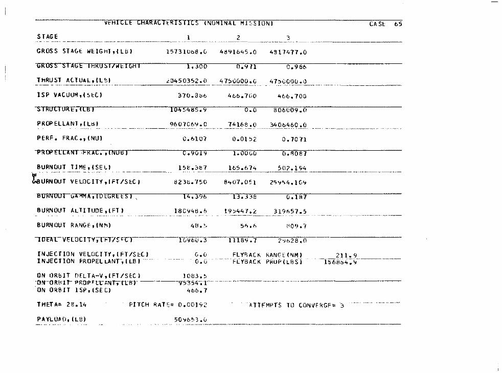
Vt:HrcCE CAARACTl::RI$ffi-S (NOMINAL Ml SS lONJ
STAGE l 2 3
GROSS sur,i: WE.IGHlt(Lb) 15731Ub8.u 4891645.0 4!! 17477 .0
mss SIAGE IHROSl/wEIGAJ 0.986
ThRUST At TUAL, t l f.'.,) ~0450352.0 47~0000.G 47~0000.i} ----ISP VACUUM,(St:C.) :no.ati6
-sTRUCTOR E, I LB J 104~:A88.9
PROPELLANT, I Ltit .. ' -·-··
PERF. FRAC.,(NUJ
-PRUFTITINJ -FRAC. 1 INOB J c.%19
BURNOUT TIME,(SEl.t l~b.3b7
-~u~·~~;-~-~-~~c~;-~-~-, ;;;~~·----~;-;:~1-;·o
lHJRNUOIG".01M'A;TD EGRE Es I ,
BURNOUT ALTITUDE, I FT)
BURNOUT RA~Gt.-, (NM)
INJECTION VELOCITY,(FT/S~C) INJECTION PROPEL LANr, (LBJ .... -·
14.396
18C'748.b
0.0 0. (j
ON ORbIT 0ELTA-V 1 1Fl/SEC) 1083.~ -o!'t-ORBI r- PRQpi:: tt' PNTt-run· -----'1:>""354-;;r----· ON ORBIT lSP,ISECJ 466.7
THE-TA= 2B.14 PITCH RATE= o.co1~2
PA YL UH1, (LB ) 50'16~3.0
466.700
o.o 806009.0
74168 .(\ 3406460 .o
0.0152. 0.10 71
1.00(;0 o.aoa1
165.674 507. l S-4
8~07.051 2'l'j'>4. l G'1
13.338 o.187
19::>44.,. £ 31%57.S -~···-·---·-- "·-·-------·
5"> .6 1.109 .1
1118"1.7 2'-1628.0
FLY~AC~ kAN~E(NM) "F(YBACK-P~UP(LB~j
. -~TTFMPTS TO tONVFRGF= j
CASE 65
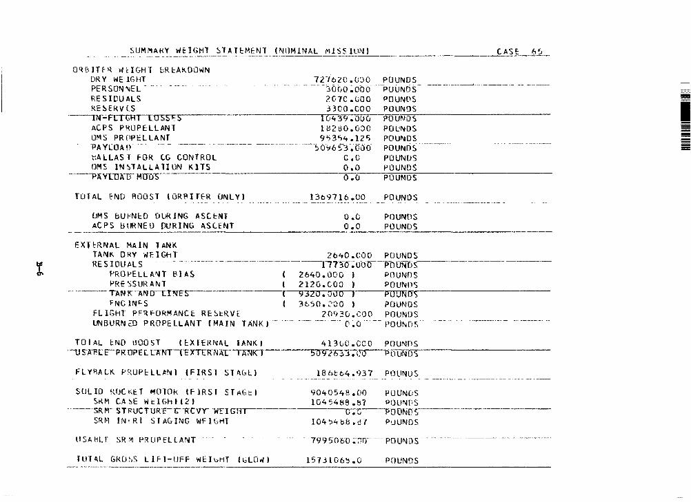
SUMMAt<Y WtlGHl STAT!::MENl (NlJMlNAL MISS lUN) --·· - - -----·--------------------------------·------
QqBJTfR W~lGHl bRtAKDOWN ORY WEIGHT 12ie20.ooo POUNDS PERSON'lEL - ... . -~Or10;000-·· -POUND RESIDUALS ?C7C.UOO POUNPS RE~ERV CS .HOO .000 POUNDS
-~----iN~Fr-1~G~R~l~L~u~s~s~~-~5---~--------,17G--;--;;43CJ.OOu ?OUN~ID~S:;;-------------
ACPS PROPELLANT lM2tiO.GOO POuNDS OMS PRf~ELLANT 9~3~4.12~ POUNDS 'PA YLOA tr . -·--··-- ------ (f~6-~3 .·ooo-- "PdD'N05 _______ _ ~ALLAST FGR C.G CONTROL c.o POUNDS OMS lN~TALLAllON KlTS O.O POUNDS
·- --PlVl.1JA"lTMffi1S-- 0 .CJ POUNDS
TOTAL ~ND ROOST (ORPlffR ONLYJ
OMS bU~NtO D\.Jk1NG ASCtNT AC PS lHJRNE O pURING ASC.ENT
13ti9716.00
o.o o.o
POUNDS
POUNliS POUNDS
-----------------------------~·
2640.COO POUNDS E X l l::R NA l MA IN T AN K
TANK DRY Wr.IGhT RES IOU Al S
f'ROPELLA!\IT BIAS !'RE ':>SUIHNl
··- ---- -- ----- ---- ---rn·:rcr; u-oo--Po owos _____________ _ ( 2640.000 ) POUNDS ( 2120.coo ) POUNDS
... ··----TANK"--Al\IUT!NFS-- ( 9320.DOO J PTilJNrr..,.----------~-
FNG JN"-S ( 3bSO.~OO I POUNDS FLIGHT PF~~ORMANCE RE~i:RVE 20~30.000 POUNDS UN BURN ill P ROPE LL ANT (MA IN TANK J -·-Ci ~o POUNri~,
TOIAL ~NO HOOST l~XlEMNAL IANKI 41300.COO POUNns ·-us-.A1!t: c'PRDPE l UNT-TEXTEKNALIANK--1----..-s-09-r--26 jJ. co POUNDS ·-----------
FLY~ALK ~RUP~LLANl (FIRSl STAG~) 186b64.937 PllLINUS
SllLID RUCt\cl M010k lFlRSI STAGtl 9040548.00 POUNuS S1U1 C.A~E Wt:IC~htt21 1045488.!;7 POU!\4f!S
------ $RW STl<UCTURE'-c-R·cvr 1ilFJG'r"-rr-----·-----,c...-.-it,.----,,PUUN1),.--------------
SRM lNiRl STAC.lNG WFIGHT 104~'1b8.t!7 PuUMDS
llSAHU SR~ PRUPfltANT
flHAL GkO\S LlFl-llFF WfluHT (t;LD~I 157.H06~.o POUNDS
I -= ---
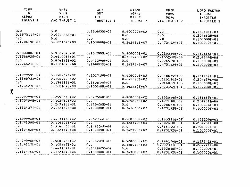
td I ....,
TIMF ---w
o. 0
ALPHA THRU!:l l l
o. 1573 lTFFOU o. 0 0.1704l"i!E+08
VKEL voo.MACH
VAC THRUST 1
o.o 0 .914443Ef01 o.o 0.182167f:+OS
--·------ ---·---· - --- - --------·-----
o. 10000uE+O l 0.982707E ... Ol -u;T5"6092F+ 0 8 0.99IU05t+Ol o.o 0 .a 64 l82E-02 O. l7Ci421E+08 0 .18216 7E ... v8
o.19999r;r+Ol 0.1'18209E+02 -c;-fS-5Cf73 E+ 0 g 0 • I CO l/9H02 O. G 0 .174 H3E-Ol 0.17u4~7t+O& 0.1~216H+OS -· - --· ---·· ·--·-·-·----------- --··---------·
o. 2CJ999':1f+O l 0. 2 99 83oE +02 -cr.n~4-5"lt"E-F 0 8 0 .102480E+02 o. 0 0 • 2 b3n~E-01 0.17C4J7l+OU 0 .1 tl2 l67E+Oil
t.39999CE ... Ol 0.403174E+G2 --o;-r.,-.~"3"6F.+~u~u,--~-u-;rc4202e+c2
o. 0 0. 3 54650E-O l 0.1704~lf+OB O.lb2l67E+08
ALT GOT
LHT "IHROTTLt. 1
o.1s:;ocoE+C3 o.o l: .o O.lOOOOOE+Ol
0.18#900H03 o.o 0.941394E+02 C.lGUOCOE+Ol
o.202noi:+o3 o.o 0.38281'1E+03 o.1000oot+o1
---------·
C...22759dE+03 u.o 0.87~430E+03 O. luOOOOE+O l
o.26rb4E+03 o.o 0 .1~l!13.:.'=+04 LI• l OCOUOE ... Cd
GAMMA VGRAV RANGE THRUST 2
0.9COOC:CE+02 o.o o.o O. 3't243lE+07
08AR V!JRG OKA(,
VAC THRUST 2
o.o o.o o.o 0.473192f+C7
LOAD FACTOR THRUST lHROHLE THROTTLE 2
0.1301ClE+Ol 0.204b62E+08 o.1ooouoc+o1 O. l OOCJOOE=+Ol ·------------------
O. 90000CE ... 02 o.32194\li:+o2 o.c o. 342454E-t-07
o. 900000'=+02 O. 6<t~897E+C2 o.o O • 34 l ~ 2 2 E + (17
c. 900000f + C2 0.965844E+02 o.o c. 342h3')~+07
o. <,000001':+02 u. 1213 7 79E+o_, o.o O. 34279">!:+G7
O. ll0324E+OO 0 .155268'=-03 0. 2265 t;9E+03 o.473tni:+o7
0.448634E+OO 0.1251176E-02 0 • 'i 1 6 B 62 E + 0 3 O.'t73l'i2E+07
0 .102 :>'i4E-t01 0.427170E-02 0.203667E+04 0.4 73 l 92E+07
0. l 95321E+O( 0.102<t08E-Cl 0 .37 1:>194E ... 04 O."i73192f:+07
0.130blbE+Ol 0.2046o6E+08 O.H.OOOOE+Ol O.lGOOOOE+Ol
O.l3ll37E+Ol 0.2 O'tt> 7'1E. +08 O.lOOOOOE+Ol 0.1 OOOOOHOl
O.l 31665E.f.Ol 0.2CJ4701E+Oti 0 .1 COCJOE+O l o.1ocoooE+o1
O. l 32200f:+Ol 0.~04731E:+C8 0 .1OOOOOE:+O1 u.IOOOOOE+Ol
0.499996l+Ol o.~l824bE+C2 o.3U62ti9E+OJ 0.900CCCE+Cl 0.294136E+Ol O.l32742E+Ul -U;-l"!:> 'f lrti-+ eru----o-;1-05..,ltfFi'"'0_.,.2---,crr;-.· ~-------'O".-ilrio~on:9:-:7rr4Cl:'.E~+70:".131----rro-. ~zr.o""r2~3TITI ~E -:=7'0 r1----;0c;-• ....,2"'<,"4"7'>'7>'111E:::-+uo"i;>· -o.o G.<t't71~4E-Ol G.2~L9u7F+v~ 0.u o.592UobE+04 o.1oooool+Ol c.11cAnt.:+uu c·.ul?t67bus o.1c..0000E+o1 o.34·3002t:+C7 o.473l'i2E+07 o.1cooooi:+o1
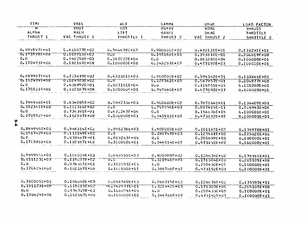
rlM[ VREL Alf GAMMA QRAR LOAD FACTOR VG~-A-V.;,_ _____ ~V~D~R~~,--------"~J~HRUSl ------w-------vuor- blil' ____ _
ALPHA MACH LIH KAN GE DKAG THROTTLf THRUST l VAC lHRUSr l THK011Lt l fHRUSl 2 VAC IHRUSl ltfKllllLE 2
-~- ------------~--------· -- ~·-~--- -~-----~---- ------------------- -·-----------·-~------
o.~9~9~7l+Ol C.b1~073E+02 u.~h4419E+03 0.900U00E•02 0.430121E+Ol c.t33291E+Ol -u;-lll)"3591rr+U8 0. l GI 113E+C2 O.O o.193161.!E-t 03 0.3536 IOt:-01 G.20't&l 9E+OB o.o o.54125BE-Ol 0.367C22E+04 o.o 0.863285E+04 o.100000E+Ol 0.17049.:JE+Ob 0.182167E+CB o.1oouooE+Ol 0.343251E+C7 O.'t73192E+C-f 0.11.>0CGOE+(}
--·-····-·--·------·-·-··------------·--·--------- --------··----·-·--------------------
O. 699997f+Ol 0. 7 23o"/9E+02 0.43 t:::l6H+O:; o. %000\':E+02 -o-;1~n·t9C""+""'ocaa---...o-.-t1...,.c"'1 9'""5,..,0'"'3reEC'.l+:-r:or"l2.-----ro1-...... o.----------,.or.-:zr12r.:'.:>~3;-.:6:-'l2i?'E'"'.i:+:ror"l3.-
o. o o.o~6992E-01 o.~011~1E+C4 o.o o.17c5~lf+oe o.1~2107E+oa o.1oooou~+o1 o.343~bOE+07
0.594342£-+0l O. ~b w/9 57E-Ol o.ueeC5E+u~
0.473192E+07
0. l 33U46E+Ol G .2 04B77f +03 u.lGOOOOE+Ol o.1aooooi:+c.1
0.7~7~7oE+Ol 0.834085E+02 o.~0~23~t+03 o.~~Ou00E+02 0.7H7844E+vl o.t34409E+Ol ··o·.--r5n·f'.'TB o·s...----cr;nrn-:-4,..E--;+...,.,0 ..... 2.-----,.c~.-....o.------·--,c•, ...... ?"'<.>"""'l7rc5"""E':l"t.."E'--=+'o""3.---ro•."a;-.;sc-::;1"4.,e:o:~-r:E,_-..,,c,...1-----,o•.-;;2.-:-i.:;-;4-;9:.4-:;3:-.=E::--:+-;:o;--;;e:--o. o o.734J91E-Ol 0.67~2n7E+04 o.o 0.1Sbti7oE+O~ u.100000E+Ol 0.17C5~2f+O~ O.lb2lo7E+08 o.1uuouOE•Ol G.343912E+u7 0.47~192E+07 o. 00
o.B9v9~~r+o1 o.946314E+t~ c.598236t+o3 1l.-r5 rr 't7F+u-a---u-.;,--rJ"Y--I4,.,..,9"'E,.....,+;:-,o ...... z..-----..o.--. er O.O 0.8334d7F-Ol 0.863243F+04 0.17G58bE+GH D.102lh7~+CS 0.100000~+01
c.c,ioocooE+o2 o. 2897i.eE+o3 o.o 0.34431'tf:+07
0.10llb5E+O?. 0. l234tHE+OO 0. 200699E-tCi5 0 .4731 ':t2E +0-1
0.134978E+Ol o.205020E+oa 0 .I OOOOOE:+Ol 0. l uOOOOE+O l
G.9999~Sl+Ol O.l(b039E+03 C.h':tB5~~E+OJ 0.9000ttDE+02 0.12hhlhE+02 O.l3~~~~E+Ol ·o-.-15nz1£+0-a----o·;.115-co-n:+-oz·---u-;-c o. 32191+ lF.'"+03 o.111 '.:>04E:+co 0.2 o5 l05E.+oa c.o 0.934jl5E-Cl o.1oe0Y3E+05 c.o 0.250430E+05 o.100000E+Ol O.l7C62~t+0J O.lU2lb7E+Ob 0.1L(000E+Ol 0.344lhbE+u7 0.4l~l92E•01 o.1cooooE
-··-·----------·- ------- -·-·--- --------------
c.1oooool+o2 o.t06u40E•03 u.69b~60E:+C3 u.B9b31~E+G2 o.12ct7&F+C2 c.t35555E+Ol -c.;·151 rz31:+or---c .115CT3F+-cz---.;.;;c-;T4297TF-o~1--~ff;nr9z.7£+c--1~3---o-;i.1nl.i7E+oo o ;.zo~Iosi:+oa o.u 0.93<t'.H9E-C:l O.l(,()l.)t!4E:+(J~ o.o 0.2504.HE+05 o.tcooooE+Ol D.17U629E+Ob 0.1&2lb7l+OU O.lLUUCOE+Ol 0.344l6bE+01 0.41~1~2f+Dl C.lCOOOOE+ill
~---------·-. ··--·-----
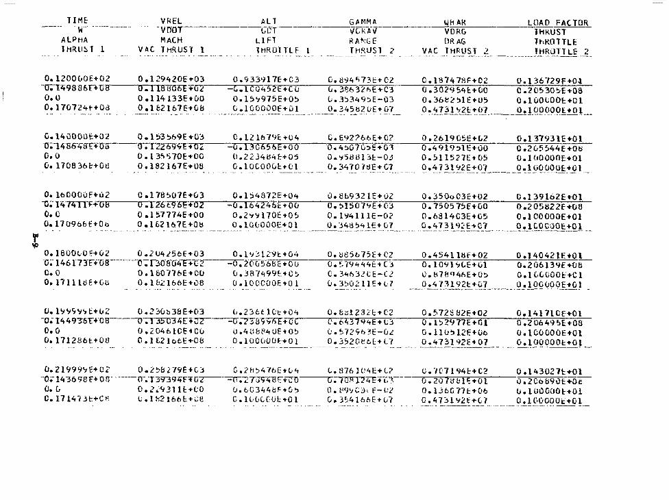
TIME VkH Al T .. w·---···- -·-·--- ----voor-------·-Gcl ALPHA MACH LI FT T liRll!:. T l VAC TliRUSl 1 lHROlllF l
GAMMA ---vcR-.iv
RA!\:GE THRlJSl 2
~-~~0~H~A~R--~---L~l~AO FA(TOR VDRG lHKUST ORAG ThKOTTLE
VAC THRUST l lHROTTLE 2 . ~--· ·--- ------·--------·--~
0.1200CJOE+02 O.l29420E+03 0.933917E:+C3 O.iN4'>73E•C2 C.1S7478F•C2 0.136729F+Ot -o;-Tlt 98 B 6 n-u.,...a---...o-...... 1 ..... 181fOOE 'Hi2----_..,,.c-. v-1C""""0"'"""45 2~E~+~C~u---v~-.~3~!%~. 3 2 h E + c·3 0 • 30 2 9 ~4f:. + 00 c • 2 ()~ 30 5E +08 o.o O.ll4133E+OO o.1~~975E+O~ 0.3~349~E-03 o.36~~~1E+05 a.1oo~OOl+Ol O. 170724t-+Oc_j ___ ----~-~! __ fl? l 6 7E ... Gt! 0 .1 OOODOf_~_!_ ___ ---~· 3_458~-~-~ ! ~! _____ (!~ 4 ?_?_l '>'2£::!_('7 ____ .Q!lQQ.9_Q..Q1_.!Q.L_
C.14u000t+02 0.1S3~69E+C3 C.12lb79f:.+U4 0;14-s6'ltiH:mr--o.nz09H+'K"o, ....... ---o.TIOb56E ... o o O.O 0.13'l570E+OO 0.22J4t:l4f:-+05 o. 170B36t+o~ o.1s2167E•oe o.1ocoo0~+01
G.E92?6bE+G? o. 4~07C.::IE ... OJ O.tj58Ul31::-03 Cl. 34 70 7t1E+ C.7
·-.--·--·- ·-- --· ---·- ·--- ·--·~·-·-·
0. 2b 19 t!:>ETt2 0.491CJ:>ll:i-OO 0.~11527E ... 05
O.l 3793 lE+Ol 0.2C.5~44E+Oll 0.1(10000[:+01 O.luOOOOE+Ol -----·-----'--·---- -- ..... - -·---·---·-- ·-·
O.lb0000f+u2 0.17B~07E+03 O.l:>4872E+04 u.eb9J21E+02 0.350oC3E•02 o.t39l62E+Ol o.~15079E+-~0=3~--o~.~7=5~o~s~1=~~E~+~o~o~~_,,,o-.~2~0~5~ij~z~2~E-+~o~a~ -u;-1lf. ~·n·i::+-oe~--CJ.TzcBJOE-+0' .... 2,....._-_....,0.,.... ...... 1...,....0 4 2 46E + ou
o.o o.1~7774E+OO o.2~~170E+O~ O. l'i4ll lE-02 o.o814C3E+05 0.1 OOOOOE ... 01 0.17096bt+Oo o.1B2lb7E+08 O.lOLOOOE+Ol _______ o. _!~~ 2~ .. !.~!...~?. ___ ..... o. 4 7 31 q~~-!S\_? ___ . --~.tl-~.Qt?.~9c..!O ~ __
o.1aoOLOE+02 0.20425bE+03 O.l~31Z9t+04 o.~S5b75E+02 0.45411Hf+02 0.14042lf.+Ol o; l46r71F+·os---·--··o:-noa·u4r+-c:ir----_..,.,o-. zoG56bE+oo o. ~ -,9444E+ o 0.109l~LE+vl 0.206139f+Oti C.O 0.180176E+OO G.387499t+O~ 0.34h3!CE-C2 v.~78Q46E+0) C.lL~COOr+Cl D.llllltiE+0b 0.182IobE•06 O.lOOOOOE+Ol O.J~02llE•~7 0.4 3 -t:\::L _______ Q~J_QQu9_()J_~L-
O. l'J'J5''7'1c+v2 0.230ti3&E+03 (1.236f l(;t;+04 0.f;~l23.l::t:+C'2 o.S72S82E+02 0.1417l0f+Ol -o. 14 493cit"+"mr----o • I 35 c 31f E +;JT---=cJ ;z'.rff9"'1F>E +-=--o,...c,........--;C'"'""• .-6:-cli ..... 3""'7r:9""'4'"""E,...,+.....,t;....,· :,.,....· --,,o:--.-:cl-;-?:-.::;2:'7:9:-'!1::;:7~E-:-+-;;:;G·1----=-o-,. 2=-:::-0b;-4;-9~~ E;::-+-:-0~8;:--o. o 0.2046lCEtC0 u.4U8P'tUE+O~ 0.~72~h3E-OL o.110~12E+Ob o.1cooooE+Ol o. 1712861::+08 0. _l_ ~2 _lo~~-~-~~·- . 0 .100(100~~~.!..__ ----~-- ~~~_e_c.~! C?_ 0 .4 7 31 ~2E t - -· o.~_QQ_QOOt::+_QJ _.
o. 21999'11:+02 o.2:-li,09EH::S c. •. ui~4 ""fbE•0't (... !:176 l04E+t? u. ·rn1l94E:+C2 0 .143027r+Ol -o;-1lt"369e f + 0 a----o-.T39"39ltH rrz--·--=v.-z7irl11tRF.f"C"D--........-G. trrfffl4E+{,5--~·0"'"""'7.,..a"u•17t +-:-O.,,...-l ---o·=-• .....,2;::-:C"'o:-:bC7;9~u~E~+~O e
O. (, 0.2 ~-431 lE:+(;O u. 60344bF +fl~ O. t!9'JC::.h F-t:z O. UbG 77E+06 u.1000001:+01 C.17141J~+C~ ~.lh2166~·~e G.l00LCUl•Ol 0.3~4166E+0l 0.47~1~2E+t1 o.100000E•Gl
·---··-·. --·-- --
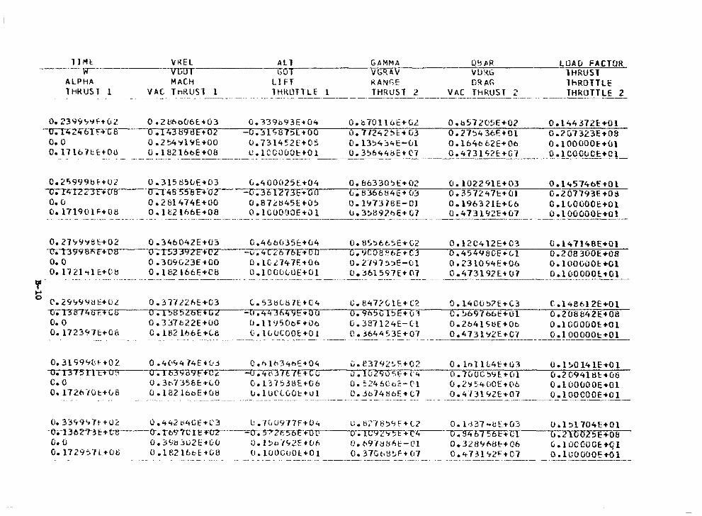
llMI: \/REL All GAMMA QI; JIR ------w-- -vuoT ----i.;o VGR.AV \IURG .,,;.------~-~~-r.--------fT:-7.:'::'-~---~LUAu FACTOR
lHRUSl
,, ~
ALPHA 1 HRUS T 1
o. 239~"i'jf+u2 --v.-rzt2~n--c-a
o. 0 0.1710-lt:E:+OU
C. 2">999bHU2 --u;-p-;;1z4JE+08 o. (J
O. l7190H+Oti
MACH VA( lH!WSl l
- -··--~- - -----·-
0 .21:l6o06E+03 O.I4389dE+02 0.254'7l!:JE+OO o. l 8216oE+08
LI FT Fl.ANGE DRAG lHROTlLE l THRUST 2 VAC THRUST '>
' ---~----- - ---~~---~~---- ---------
-o. :n;:; a 1st+ oo 0.731452E+O:. o.1coooo1:+01
O. bWl lt.E+Gl o. 77242!'.'>E:+ 03 O. l3~4'.j4E-ul o. 3S644bE+C'7
O.l157205E+02 0.27~43eE+Ol O.l64662E+Oo 0.473
TnROTTLE THROTTLE 2
0.144372£:+01 0 .l\('323E+08 o.1ooooof+u1
__ 0 .1 CCC<.i OE:+C !_
0.315ti5~E+03 i.400025E+04 0.8b330SE+02 0.1D2291E+03 O.l45746E+Ol o.t4855BF+u--~2~~-~c~i ....... 3el77·3--E-.~o~o--_,_0_.~8-~J~6~6~8~4=E-+~0=3---=o-.~3~5~7~2~4~7~1:-+~0~1---=-o-.-2~~0~1~1~9~3·~£-+~o~s-o.2s1414E+oo 0.872~45E+O~ 0.1~7378E-Ol 0.19632l~+tb O.lLOOOOE+Ol O.lb216bE+08 o.1000~0E+Ol u.3~897hE+G7 0.4731~2E+07 o.100000E+Ol
0.27~~~8~+02 0.346042E+03 0.466035~+04 0.8~~665E+G2 0.12C412E+03 0.147148E+Ol ·-o-.;-n 9'~ -r-A-.-f-.-+.,.,.e=a---,.,.o-.,.1-r:;.-,.3,3n9-rz.,..E.,_+."c-r2---_..,.,o-.-r4-r-c....,.:.::· bTbT+ o O o.9coau.0E+t3~--~o..:-.4~?~-4~y~a~o~e~.~i-,-.-1---o~.2~o~a~3o~o~Er·+~o~a;;--
O.O 0.309G23E+OO D.1Cl747E+Ob o.2191~~E-01 o.2310~4E+Ob o.1ooooot+o1 o.1121~1~+oe o.1e2166E+oe o.100000E+o1 o.~61597E+07 o.473192E+o7 o.1oooool+O
- 0.29~~Yti~+UL 0.31722AE+03 G.53HLBlE+04 U.847?Ll~+C2 0.1400~?E+C3 t.l48612E+Ol u-;-T3"BT4lfF.T-C8~~--un-.~1~~~a57zr6~Er+rro~2---=-~c~,.-;:4~-:f6·~4~9~E~+~a~u,----,.,o-.~9~6T5~o~17~~E-:-+7u~l,-------..:o-.7~7b"9~7'b'b"t'+7.o~1----;;o-.-~27.o~a~e'4~2~E~+no~a-
o. 0 0. 337b22E+OO O. l 1950oHOo o. 387 l24E-C:l 0.2641 SUHOo 0 .100000E+Ol 0.1723~1~+08 C.182166E+L8 0.ILUCOOE+O& 0.364453E+01 0.4731~2E+Ol O.lOOOOOt+Ol
-·---------·-------,------·---------
O. 3l 99%H02 0 .4(,<;4 74EH.•3 C .h lt>34nE+04 c.e:H92:.!:+02 0.11'>11L4E+u3 O.l~Ol41E•Ol --o;-T37~rtT'f~u~~---u~-.~1~6~3gaYF+~c~~~~=o--;-40~7t7f.+Cc 0 • 10 2 9 o ~ f + r-4----o-.-=1=0"""0""""0-:-~..,.,'1-::-f.-+-::o-=-1----:::o-.-=2-=o-=9-:-4-=1....,li,,..t::-+-=o-=-t>-C.O 0.3o7~56E+LO O.l37538E~06 o .~24&062-c1 o.2~5400E+06 o.100000E•Ol 0.1120/0t+ve o.1s2160E+ua u.1urtvOt+u1 o.3b74H6E+c7 o.4131~2E+o1 o.1oocooe+o1
~33~9~7t+O~ 0.442b4Gf+C3 U.7GU977F+04 u.H27B~9F+t2 O.ld37~~E+03 u.1~1704E+Ol -e.-130?.1'-3 e+ ett---o-.-n-,<:J'~te rc ,..trL·--.;;;;o-.;·57 zc:s-o-i:--roro---o • 1c 9 2'15 E+--r·4--~o:-• ..,.,9,.,.4-r5mn·--~G-.~2~1~0~0-2 ..... s-=E-+~o-=-a-o. o 0.3~~jU2E•00 D.l~b1~2E•OA o.~91db~E-Cl o.3289h8E+06 G.lOCOOOE+Ql 0.1729~7L+Oti O.lB2l6bE•G8 o.1oocuOl+01 0.37G~8~F+01 o.~731~2~+07 D.lGOOOOE+Ol
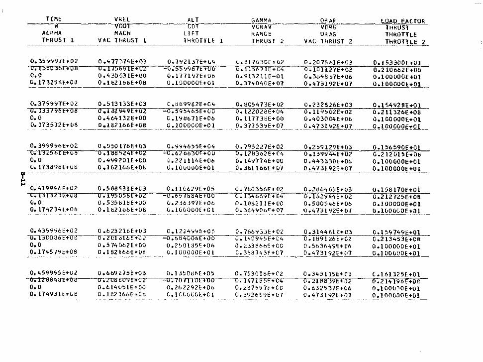
TI ME: VREL ALT GAMMA ~~~·w~~~~~~--,,....,.,., ........... ~~~~~~--.. .... ~~~~~~~-:.~· vno1 CDT VGRAV
ALPHA THRUS l l
MACH VAC THRUST l
L1 FT K.ANGE lHROTTU: 1 THRUST 2
OB AR Vl'RG OKAG
VAC THRUST ~~--~~~~-~~~·----~~
0 .4 7721741:::+03 o. 7'12137E+C.4 O.I15681E+C2 -0. 559<J8TE+OO
o. 35<i41\71E+02 -u;-T35U3·or+~a~a~~'-TT"_,...~.,...,.......,.,.,....,...--~--r~'T7~
o.o 0.430531E+CO Ool77197t:+Oo O. l7325Sf+09 0.182ltibE+08 O.lOOOOOE+Ol
0.513133E+03 C.889982E+04 o.I81949E+02 -0.595465E+CJO 0.464132E+OO C.19~c71E+Ob O. l e2 l66E +08 o.1ooacoe+o1
e:. t11103vE+ 02 t • ll5t> 7 lE ... c4 O. 9132 llE-Ol o. 374040E+01
O. 8C54 7 3E + O?. o.12202aE+04 O. ll7731:lE+OO O. 37753'7E+07
0. 20 76 t:.1 E+03 o.1011r1E+o2 Oe3b48 ~7E+Ob 0 .473192£:-t-07
LOAD FACTOR THRUST THROTTLE
0.153300[.+01 0.2106b2E+08 O.lOOOOOE+Ol 0 .1 OOOOOl:.+Ol
O. 3999%\:+02 0 .5~0 l7bE+03 O.<J~46:>5E-t04 0. 793227E+02 0.2~9129E+CJ3 O.l56590E•Ol 0.13~56TE+{l~5r--~-...0-.~l~8n8~~~274PfT+~02..-~--~o~.~6rl~b~~~3~0~F~+~Q~0z-~---r0r.•1~2~8~3~b~2~E~+rC~4~~--,.0-.'1~3n99~447Er+70~2:;-~~0~.~2~1~2~0~1~5~~~+~0~U;--
Q.0 0.4Y9201E+CO u.22lll4E+Ob G.14~774E+OO 0.443330t+Ob o.100000E+Ol u.173898c+U~ o.182l66E+Ob o.100000E+Ol 0.3till66E+u7 0.473192E+07 o.100000E+Ol ,, ··-- - --·--·-----
!: 0.4199~6F+02 0.588~31E+L3 O.II0629E+05 C.760356~+02 0.2~6405E+03 Oal58170f+Oi
-c-;-I3f323"E+·~o-a~~---a-.~1~9-5-o~s~6-E~+o-~~7 ~~-~o~.~6~5,........,16~s~·4~E~+~o~o,.---~--,,G~.,1~374'6'6~~~E~+#G~4~~...,.o-.~1072~~~4~4~E~+~o~2;:-~---:o~.~2~1~2~1~2~5~E~•~o~a:--
o. o o.535ul~E+oo u.2~0397E+Ob o.1atl211E+uo o.soo~4oE+Ob o.1oooooe+o1 0.174234l+O& O.lb2lb6E+08 L.lG&OOOE+Cl 0.3d4~0b~+07 C.4731V2E+UJ D.l~OO~OE+Jl
--------~---------------
0.43799bE+02 0.6282lbE+03 -u;·nocrsOF+ucr----u-;zor.n11r+u 2
0.1224':1\;f:+O' 0.76b~::3jE+C2 0.3144ME+C3 0.1~':1749E:•Ol -0.6B40TI'6t+~~D.---~,u~.-:l~4~0~9~4~~~E~+~t~'4~--,,,c-.~1~8~9~1~2~6~E-+~C2:=----:c~.-:2~1~3;::-4~5~3~E~.~c~a=--
O.O 0.574062E+OO o.2~01a5E+06 o.~33B66E+CO 0.563h49~+e~ o.100000E+Ol 0.1745/~c+OS 0.182166E+08 ___ ?~]-~Oo 9E_E __ + ~ l ____ c ~3-~_3_7 ~-~£-~£!_ _ O. 4131 92E+Ct7 ._J?..!.!_OOOOOE: +O l_
0.4599~~E+Ol O.b69215E+03 0.13~0bbE+05 0.753018E+C2 0.343ll5E+C3 C.l61325E+Ol --o.-rzss 4 in: "'o-s---cr..·z-oa-oovc-•"'o..,.2----:-u;10n1-o~E~• ....-o o,.,.......---..o-.-.-1 li711T5~+c·_,.4--....-,.;-o-. =2';"-1 =a.,.,.s=3':f""· F,,,..: +.,...t""'"D 2.,,;-----:o""'".-:2~1....,1t'"'"'1"'""9~6""E""'+-;o~s=---o. o O.bl4051E+OO 0.2b2292f:+Ob O.l~7~g7f+CG O.b32'37E+Ob o.tOOu)OE+Ol O.l7493lc+LB C.l82l66E+CH C.lCLULC~+Cl 0.392659E+07 0.473l92E+07 o.1ooonoE+Ol
·-----·........------~~-~---- ---,·--··-----
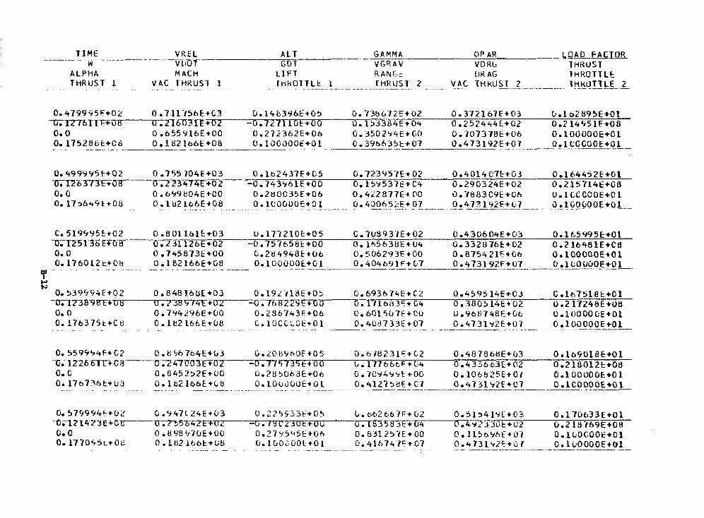
1 I M E V K E L ALT G A M M A @P AR LOAD FACTOR i3 v [Llf" GUT V G R A V VD Kb "
THRUST ALPHA MACH L l F T K AN C. c I )K AG l H K f l T T L t THRUST 1 V A C THRUST 1 I H k O I T L t 1 [HKUST -2 VAL THKUST 2 1 H K O T T L E 2
. . . . . . .. . - . . . . .. . . - - . . . . . . . , . .. .- -
0.0 0 .655916E+00 0 . 2 7 2 3 h Z E + 0 6 Cie3502Y4E+GO 0.707378E+06 0*100000E+01 O.l7528Ok+Oti 0 182 166E+08 0*10COOOE+01 C0396635E+07 0.473192E+07 O.lCGCGOE+01
.- - .. . " . _ "" ~ -. __-__--- ------___ . ___ ____"
0. 499995F+02 0 .755 704€+03 OoLb2437E+05 0.723957€+02 0*401407t+G3 O* lh4452E+Gl -(r;-2-2'6 373Fia H O . n 3 4 / 4 E + 0 2 -0.74396lE+00 Ue159537E+C4 0*290324E+02 0.215714E+08 0.0 0 . 6 9 9 t i04E+CO 0.2M0035E+06 0'. 422 877E+ GO O . Y 8 8 3 C Y E + G b O . l C C C C O E + C l
C. 5194Y5E+02 0 -801 161€+03 U.177210€+05 C,708937E+02 Oe430604E+03 Oel t~5995E+01 3 X 2 5 I3&ETD'i3--"731126E+bZ -0*757658E+CO O,lh563UE+U4 0.332876k+02 00216481E+CB 0.0 0.745873E+00 0*284948€+06 0.506293E+GO 0 . 8754 21F+C;h 0.1000QOE+Ol 0*176012t+C!9 0 . 182 166E+G8 0 ~ 1 0 0 0 0 0 € + 0 1 Oe404691F+C~? Os473192F+U7 0.1LOWOE+01
Y G
. . . . .. .. ~ . ". ... . - - -
0.33955i.iI-+02 0.8481bUE+03 0.192-i18€+03 Ge693674E+CZ 0.4595 14€+C;1 G.16-7518t+Cl -0512383EE+~G€T-"U3?3574E-il)~ -Rmf + G 0 0.171hb3'++G4 0 3005 14f+W 0.2 1724tfE+O8 0.0 Oe7442Y6E+00 O.Z36743F+Ob U. 601 5 0 7 F + C O 0.968748f+Ob 0.10OOOGi+O1 Oe176375t+C8 C . 1 e2 l 6 t E t U B C. 10CCLGE+Ol 0.4C3733E+@7 0.4731Y2E+07 G.l00000E+01
. . . . .. , . . . -~ . .. .. .. .. " .. " . .. .... .. .- - .- .- - "" . . . . . . . . __ -
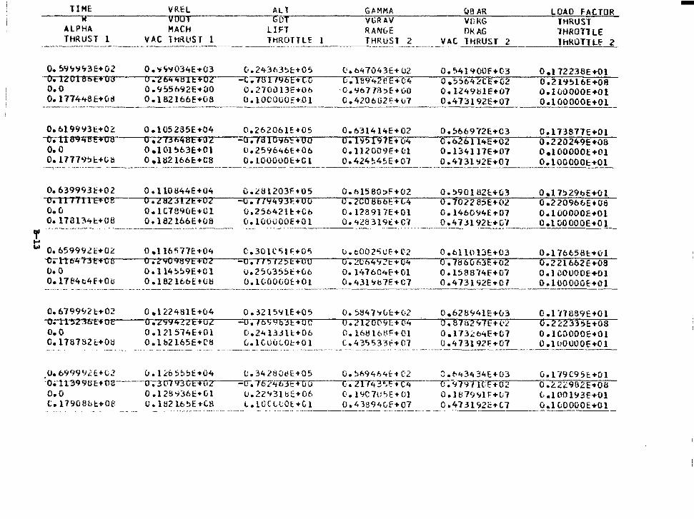
llME VREL ALT GAMMA QB AR LOAD FACTOR w~--~-~-v-o-a-r~~~---_,...GD~T-~--~~~V~G~.R~A~V-:-~~~--~V~O~R~G~--~--=~,~H~R~U~S~T=-:..=:..;....
ALPHA MACH LIFT RAN&E DRAG lHROTlLE THRUST l VAC THRUST l THROTTLE 1 THRUSl 2 VAC THRUST 2 lHROTTLE 2 ·--------- _____ .,. ____ _
o. 59'1'1'13E+02 0.'1S'i034E+03 v.24363~E:+05 O.M7043E+02 0.541900F+03 o.t 72238E+Ol ·-oetzorsts~E~+~o~a~-~o...--.2T6~4~4~s~1ne~+~o~zr--~-~c-."'n3n1"l"9~6~E~+7t~c,----r:G-.~1~~0974~2°e~E~+r.074~~,o~.~!>~·s~ou4<-?~C~E~+~o~2.---ro~.~2~1~9~~~l~6cE~+~O~R~
o.o o.~55b92E+DO 0.270013E+Ob ·0.967J~~E•OO O.l249tilE+07 o.1oooooe+Ol 0.177448E+06 o. t B2lb6E+08 o.1ocouo::+.01 o.4206tl2i:+u7 0.473192E+07 o
O.bl99!.J3t+OZ -o;-n894BE+U8 o. 0 0.17779!>1::+08
0.105285E+04 0 .Z 13f'l4BE+OZ 0 .101 !,\63E+Ol 0 .11:12 166E:+CB
C.262061!:+05 -a. taI096!:+oo
o.259646E+Ob O.lOOOOOE+Cl
O.b31414E+02 o.,b6972E+C3 O.l7387lE+Ol 0.195197E+04 O.o2oll4E+02 0.220249E+08 o.1120C9E+Dl O.l34117E+07 o.100000E+Ol 0.424~45E+07 0.4l31~2E+07 O.lOOOOOE+Ol -· -------··-·-·---------·----------- ------- --------------------------*---·-·----
O. 639993H02 O. ll7711E+cmO.C O. 17813"tl:+OB
0. l l0844E+04 0.282312E..,02 O .1C:.7890E+Ol o.1e2166E+OB
=u.179493~+00 0.2C0886f+C4 0.702285E+OZ 0.22096bE+08 o.25642le+Co 0.128917E+Ol 0.1460~4£+07 o.100000E+Ol o.100000E+Ol 0.4l83l9£+C1 0.47ll92l+Cl o.tDOOOOE+Ol
-~~---~, -~------------- --~------- ---- ------··-·-------------·----·---
6 Oe L5999)"+0" u -~ ' o.tl6577E+04 C.301C~lf+05 u.e002~Uf+C2 O.bll013E+03 O.ll6t58l+Ol -o.tt·o-tt"T'.$~"-c-e---o ..:. .... z ..... 90-9 8""9 ... e.,..+=0"'"2.,...._-_,_::-10...-.-, ... , .... 5=-1,_2,.,,5""'E:-:i+'.'TclT1 o.-----.,,or-• ...,~""076'-4.-;9..,.!L:'t:T+7!Q7:'4--'o~. 1~~~6Z:<0"'6r3'IIEl!".+:'.io""2.,_.--,o"."2"zri1"0::-;:6:--:;2"'Ec:;+1o;aa• o.o o.114~~9E+Ol o.25u3S~E+06 0.14760~~+01 o.15aa14f+o7 o.1cooooE+o1 0.17S4c4f+Ob O.l8216bE+O~ o.1000DOE+01 0.43l'lb7E+C7 0.473192E+DJ o.1oooooe+o1
o. 6 799'12 t+02 -Oi'11: 52 36 E+ a e o.o O. l78782t:+Ol:I
o.t22481E+04 0.3215~1E+05 O.Z994lZFf-oz---~---o;TOC;9b3E+OC
0.121574E+Ol 0.24133ll+06 O.lb2l65E+~8 c...1cuO~Oc+Ol
o. :.B47"1u1:+02 O.l!20P9E+(l4 o. 16tH6tlF+ 01 c. 4 3r,533f+()7
o.628'14IE+u3 0. 87&2 '17E+l•:t O.H3.<'.b4E+C7 0.47319717+07
0.1 -0889E+Ol (j .2 :::233sE:+08 0. lC.\:IOOOE+Ol 0 .l liOOOOE+Ol
o.o99992c+u2 u.l~hS~~E+04 C.34280uE+05 0.~~9464t+C2 C.~43434E+03 ual79C9Sc+Ol :0•1.t3'99Ut:+na---·-cr;-3'D7'9'3\'.iETO-z---~o~.7c74t63F+uu r:. 2114 3-i:;n-c4 o. 97971CE+o2 o .2..24.:'.982E+Oli O.O 0.128~36~+Gl U.22~3ltiE+06 0.1YC7U~E+Ol O.l879~1E+07 L.!D01~3E+Dl C.17908bc+08 o.1H2lb~E+C8 L.lCCLtOl+Cl 0.43B94vf+07 0.473192c'l'L7 u.lvOOOOE+Ol
-~·--- --- -------------- ----·------------ -
-
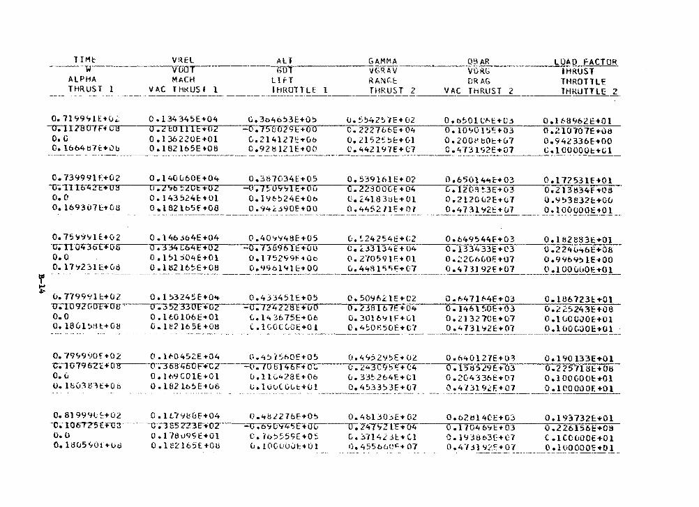
' ... ~
lIMI:: ---·111
ALPHA THRUST l
V~El All GAMMA ___ ~~----.,C~,l9~AR-:--------.VUOT GoT·---~~-~V~GRAV VDK~
MACH LifT RAN~t DRAG VAC IHKUSI l lHROTTLE l THRUST 2 VAC THRUST 2
. --------· ·------··-----···- --·----------·----···----
LOAD FACTOf( IHRUST THROTTLE lHKUTTLE 2_
o.7199~1E+u2 O.l34345E+04 0.3o46~3E+O~ u.554251E+02 O.b501C~E+O~ O.lf..8'tb2E•Ol 0 .210707E+OIJ 0.9423361:+00
-o-;-1r78UTFfu ~-a --~a~.~2 "ED u 1 E ·..Ci2 -o • 7S-uTfl9 ~ ~i: +-0~0~-__,o,,_._,2221 t.t:- E + 04 o. 10 '10 1 ~ i: + o 3 O.O 0.136220E+Ol C.214127E+G6 0.2152~~E+Gl o.2ooeeOE+u7 0.16b4ti7t+ub 0.182165E+08 D.928121E+OO C.442197E+07 C.473192E+07 C. 00 Hi ·----·-------- --------------·~-
0.73999lf+02 0.140u60E+04 0.387G34f+O~ o.5~9161E+O? 0.65014~c+03 0.17253lf•Ol u-;~1ro~~2~E~+~o~s--_;;,.u~.~2~~~6~5·~2~u~E~+~o~2---=c~1~.~1~~~0~9~9~1~E~+~o~0---;..o~.~2~2~9~0~0~07E7+~o74--_,,.c~.71~2ho~g7~~3~E7+r.0~3~~-;:;o~.~2~1~3~B~374~f7+~o~s-o. o o.1435241:-iOl o.I9~!:>24E+Oo o.2.4183ul:+Ol o.212ou2E+o1 o.9!:>3B32E:+Ou o. lb9307E-tOU 0. l 82 lb5f +08 0. 'i4d90E+OO 0. 4452n E+ 01 ----~·'!}}!_~_?~_"!: u_7__ o. !~099q~:t_Q! __ -·--·--------·- ·-·
o. 75"19'.tlE+02 -u;n·oitJt>Ho B o. 0 O. l7'12:>U:+Od
u. 7799'111:+02
0. 146 .:>64E +04 rnC64E+02
0.40'1'748E+05 ~~~~~~-~a-.-,.l~69b1c+ou
0 .1 ~l j04E+Ol 0 • U:\2 1 6 5 E + 0 8
-------- "--~
0.17'S2'19t:•06 0.996141E+OO
C:. ~24254E+Ci2 0. c..33 13 4 E Hl4 o. no 5 9 1 r. • o l 0.448l"i"if7+(17
0.649544E+03 0.133433E+C3 0.;::2Ch<JOE+07 0.473192E+07
0.1828831:+01 0.2240-tbE+Ofi 0 .9%9':> lE+OO
_____ _Q.!l OO(;_~Q.E+_QL
0 .1 :.324!;:E+O<t v.-1U9ZCiITF+UB· 0.352330E+G2
0.43345lc+05 c.50962lE+C2 O.t>471~4f+03 O.lU6723E+Ol ·~~~-rr-...,...,,__....,.,,.,.....,.~~~~--~o-, • ...,.,.,,2-z;7"21TI~•~o~o-~~o~.~2~3~s~1~0~7~F.-+~o~4:...__-;o~.~1~4~6~1~~~0~E-,+~0~3-----=o~.~2~,~.s~2~4~3~E~+~o~a'--
o.o 0.1CO106E+Ol 0. 1801 !:>H t+08 G. U!2 l65E+Ot:I
o. 79'1990f +02 0. lfi0452E+04 -o;.-10 79 OZE -f 0 3 ·-o-~~68'4'00F+-CZ
o. u O • l t.9 C 0 1E+01 o. lbO'.HFH:+Oti 0 .182 lo5E+(J8
L. 143675E+ oc G.3016~1F+Gl 0.213270E+07 o.tuCCJOE+Ol C.ICOCGOE+Ol 0.4~0R50E+G7 0.4731'12E+07 o.1oooaoE+Ol
o.4:,-ht>OE+05 ---=t~i-..... , ITFPtt*+ 0 (.,
u.ll(.428E+06 1;. luuCli0t:+ul
o. 4't:) 29'.>E-t- 02 o. t.'43C9~T+U4 u. 33~·264E+Cl 0.4~33,3E+o-1
---------· -----~----- ·------·-·------ ---
0.640127E+03 O.l90133E+Ol 0.15d529E+03 0.2257ltlc+OH 0.204336E+07 O.lOOGOOt+Ol o.413192E+o7 o.1eooooE+o1
---.-~---·------· ·-·-------
0.81999~~+02 O.ll7~b&f+04 0.4~l276f+O~ 0.4bl30~E+02 0.62~14CE+O~ 0.193732E+Ol -c-;-io6r-Z-SE'flJ3------·c·;3ss7Z3c-t=U2---~ff'i2tSE+o~~c:;--~o-.z47'J2TF+o4 __ _,o,,_ • ....,1 .... 1"""0~4-:-o.,..,'1~. i:C--·+-0=3,,._-___,o""" • ....,2~2"""6,,_1;:-,s,,-·6:"".t:""'·+_,o""'s,,__
o.o o.178v9S.E+Ol C.fo!>:·59E+05 c.Y/142.:H:+Cl 0.19]Ub3E+C:7 c.1ccuoOE+Ol o. ld(J5 'i01+0ti 0 .1 t:2 l65E +OU (J .1OCUU.JH·0 l o. 4 55b&OC::+ 07 0. 4 -n l_'~.?:~!-~H ··-·----o. ___ • l lift_QOQ~•O_L
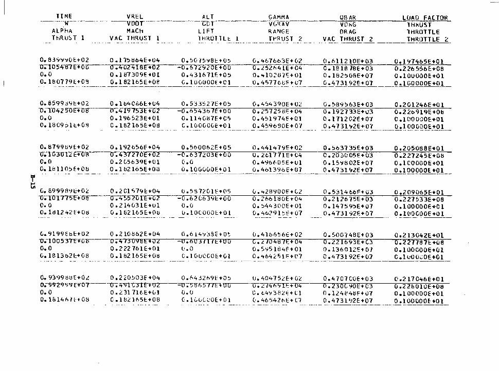
,, t;:
TIME VRl:L ALT -------·-w-------·- ---· ··--vnor·---------Gt r
ALPhA MACh LI FT ThRU~T 1 VAC TH~UST 1 lHKOlllt l
GAMMA VLRAV RANGE Tt-•RUST 2
QBAR LUAO FACTOR VD~G lHkUST ORAG lHROTTLE
VAC THRUST 2 THROTTLE 2 . ---·· ·------ -----··----------
0.83~~~01:+02 O.l758b4E+04 o.~G75~8t+O~ o.~676b3E+02 0.611210E+03 0.197465E+Ol u-;-ins 4-ITTE+ 0.,,--1} --~UZ7ifar+n~2..----_.....,o"°""".-,6 ..... 7~L.-,Cj·~2"o""E:,....,+...,,O;-,.O:-----..o,-.-,i.""'5~2 h 4 l E + 04 0 • le 18 78 E + 0 3 0 • 2 26 556 E: +OB o.o o.187309E+o1 o.431671F.+05 o.4102u1~+01 o.1a2~osE+o1 o.1ouoooe+o1 o. 18_~7-?.~_E+O_~----- ·- _o. ~~2 ~-6~~~~-~----~~-~-o~~_gp __ t.!£_1 ____ ~_~'!_">7? ~-!.!£ ~2_?_ ____ .Q~1}J_92E+crr_ _ _Q_.!_l C_Q_OOOE+!l_l_
o. 8599d9t+02 1l ~11> ltZ50l::HrF o.o
O.lb4C~6t+U4 0.533527E+O~ 0.454390E+U2 G.589~63E+03 0.2Gl246E+Ol o.419?53F+u:r·~---o~.,-h~543b7E~+~o~o-=------,o~.~~=·s~7~2~5~i~1E~+~o~4---=o-.~1~9~2~1~3~3~E-+-u~3----=-o-.2-=-=--2b--=-9~19~E~+-o~b~
O.l96523E+Ol 0.1140H7E+C~ 0.4~l974E+Ol O.l71202E+07 c.1oooaoE+Ol O. l8C:9::>lt+GB C.l82165E+G8 C.luOGOGt+Ol 0.459630E+07 0.4731~2E+07 o.lOOGQOE+Ol
0.8799U~l+02 0.192b56f+04 0.5600o2E+05 0.44l47~F+02 Ti;-Hi3U12E+o-s·--~o-. lt3777or+·o,...,..2----o~. 6'__,3,...,7""':...""') 0=3"E,,...+'"0"'1 o.,..----;u:-.-;-:--2ll 111 E+tA C.O 0.2G5639E+Ul O.O 0.49bi05E+Ul o.1~11o~f+Ou O.lu2165E+OU O.lOGvOOE+Ol 0.4bl396E+U7
----- ·------·-· ·-· ---··· -------- ..• ---- -- - --- --------
O. ~637 35E+03 C.20~u05E+03
0.15~802E+07 0.4731Cj2E+07
0.205088E+Ol 0.2 27245E+08 o.1cooaoE+o1 -~.! 00090E +9__!__
G. 8999H9l+OL 0.2Cl~79~+04 u.557201E+05 v.~28900E+t2 0.531466F+U3 0.209065E+Ol 0.4552GTr-+a~2---~c~ .• ~67"D639~+00---=-o-.=2~66.,--:--l~8~UE~+~04-----.,o~.~2~1~2~6~-~,5~.E~+~0~3:-----::o~.~2~2~7~5~3~3~E-+~078~ 1i"~-TOT175F+U-S-
c. 0 0.214G31E+Ul o.G o.~4430CE+Ol O.l47~9~E+07 o.100000E+Ol O. l!H2 t.t2 f+ Oti G.l82165E+Ob u.lOCOOOE+Ol 0.4b29l~E+07 0.4731~2E+07 o.1uocooE+Ol
G.9199Sb~+02 o.210~62E+04 o.614~~3E+O~ -o;.-100537-i:-..-a""B---o. 413 0988 ..... o....,.2---=u-;-50 3 II lt:+Ov O.O 0.222761E+Ol G.O G.1Bl3b2~+G8 0.1B2165E+Otl c.100ccoE+Gl
u. 4l6656E+ 02 C.L 70487E+04 G.5'i51U4f+Ol C • 4 64 £' "i l f= +l' 7
0.9399tlUE+OL 0.2~0~03E+04 0.~4j2h9E•O~ U.40475lE+GL -o.-9q-zq c; q 1:+-0 ·,------u-; z-t""11.--CTIF+ry-z--;;:o-;'.>S Fi 577F.+ .... O'"'"'u----,u.,--. L7zttil1TF+u4 O.O 0.2317lt:.E+lil CJ.U C.t.4':1382t:+l'l 0.1814hll+08 c.1a21h5~•08 0.lLliL~OE+Ol 0.46542bl:+Cl
0.~00748E+03
0 .2216<J3E+C3 0. 1360121:+ 07 0.473192E+OJ
0.4 707 OOE+03 o. 23oc, 'JIOE+ C;3 0. l24l'4tlF+u7 0.473l'J2E+07
0.213042E+Ol 0.227787t.+08 o.1oocooE+o1 0. l cOli<:OE+Ol
C .217 046E+O l 0.22h010E+Ott O.l00(100E+Ol 0 .1 00 00 0 E: +O l
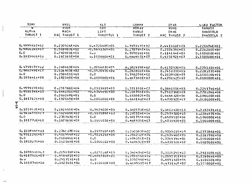
TIMF --w-------
ALPHA THRUST l
o. '7599e8EHi2 -u;-91l0c 24 E+ 0 I c. 0 o. l& 1560 HOd
o. '1799 &7f+02 -C;-96ff:?. 4 9 E + C I o.o ,o. 18 lb4U:+08
o. tJ999 en+o~ -0;-9!>5"8TltFi'Uf o. 0 C. Hll 712E+GB
VRE:l vuo.-MACH
VAC lhRUST l
0. 2 30504E -t-04 o. 50898 IE+02 0 .?.40~J2 3E+Cl o. l 82 l65E+08
Alf (;01
LIFT lHROTfU: l
0.6-/21U8fT05 =o ;5b9336t'.+O u c.u 1..1.1000001::+01
GAMMA VG RAV RAN(;E THRUST 2
Q~ AR VORG DI< AC::
2
LUAO FACTOR -THRUST
THk.OTTLE THKfllTLE 2
C.3931~3~+02 0.441500E+03 0.221076E+Ol 0.218~E+U4-~-.,,,0-.~2~3~7~b~779~E-+~0~3-----:::0-.~2~2~b~2~0~5~E-+~O~e-
O. 7070l6E+Ol O. ll4l44E+O'f O.lOOOOOE+Ol 0.46o457E:!"C?. ____ _p .4.13192E+C7 0.1 OOOOOE!Qt._
0.240ti63E+04 C.701687E+D5 0.38l979E+02 0.413293E+03 D.225131~+01 u-;-5z&lJ5"3F+112~---.,.o.::. • ..;?~S..;2..,,;o...,...1.J,..;.7,;.E-+"o'""o,----=o...: • ..;2-=a-:2-:::s-=-e;-::c-:E,-+-=0~4----:::o_;; •. -;:2~4-:::!'.-:::o-=1=-=1:-:=E...-+--::o-=3---=o-".-::2-::2:::s-::3-::7:-::7-::E:-+-::o-=-ts-o. 250411E+o1 o.o o.1nB209E+c1 o.1039~3E+07 o.1ooc~o~•Ol a .. 1 B2 lb5E+08 _o __ ._1 .... 0_._o.~~~1::-to !.---~.~-4b_7~60E+ 07 ----~·41?_! tt2'E+JJ7 ___ _!)~~QQOO!_+O!__
0.251580E+04 0. 544l:OIE+ 02 0.260209E+Ol 0. l 82165E+08
0.73116}ET05 -o. 5 34949E+ 00 o.o 0.100000E:-t01
u.371103E+C2 0.39blelE+03 0.229l74E+Ol o.~&670&E+04 0.251716E+03 0.228~26E+08 0.833082E+Ol o.~46o32E+06 O.lOOGOOE+Ol 0.46314~F+07 0.413192F.+C7 0 1 'r ····-·- ... -. ~-------·-----------·-~
......
~ 0.1019~~E+Ol o.2~2b5~E+04 o.lb24COE-t0~ O.lb0573E+G2 0.3bCl43E+G3 0.2~3247E+Dl 1r.92t3~9T?·c;:-r-~-;-5o7oo"9~E=+~a-2----~u-.TsT1T1i~~~aT6rE7+~o~J----,..o-.~2~~~0?5'1'nrE7+7u'4---;:;o-.~2's~1"n~1~07E7+7u~3---,u-.~2~2°870Ts~1~E~+~o7~-
o. 0 0. r10 343E+Gl o.o o. 90l 7'>5f+tH C' .tl'>89!:>lf+Oc 0.1 OOOOOE+Ol 0.18177~E+C8 0.182l65E+Ce u.l~lGCOE+Ol 0.4beR35E+G7 0.473l~2E+01 o.lOOGOOE+Ol
-·---·---· -- ~~~-- --------~-----------------·
O. 1039 '7<tf+ U3 0. 2 74f H7E-t C.4 0. H 3:>;,.5c +05 0. 3 :>O 36 ~~F. + C2 0. :\3 ~!'21E+u".l 0 .2 3"i 354E +O 1 "lr.93TI?ZfB="7'0'""/~---,..ur-.-.:is.-,,e""C1-.:'):-1'5Tlf"'"E-.:+"T"Qr'!l.r----::_-,.or-.,,5-r,or;1r-;-4,-..,2"4-"f'"=T70:TOr----rc;-."""2;79;-;-4-;;2"":.1;-:>;2:;::F-.+'""'.'C~4----;;o;-.~2;-;613"4-;4"0:;:E-.+-;0;-;;3;-----;:;o;-.-;;2;-::2;-;:t>;-::.,;:;7;-;::0~c-=+-;;0~8:-
o. o o.2eOH4Lt+(l o.o t.~7435CE+Ol D.7764l~i+O~ o.100000E+Ol o.1s1e~1~+ou o.tb2lb~E+oe o.1000uo1::+01 0.4b9432E+Ol 0.413192~·01 o.1oooooe+o1
·-----···------------~----------
0.10594~~·~3 o.zt5H7~F•04 L.82~?~bf-tt~ L.340474E+Gl 0.31202~E•03 0.241500~+01 u.·~1 87 ~ C1::'+'C1---o-;;·5qs:4trr£T(FZ---=r.;-z+ 815TIOF+-m:r---u-;797s"5'ztt+O...----T;. 2 6 8~E + 0 ~·----.o-.-..2'""2~8-;8:-:-b""'tt'""E:'""'+-.0'"""8,.-o. o o.z~llllE+Ol 0.0 -O.lOS0Y9E+D2 O.b99143E+Ch ~.lVOCOOE+Ol O.lbl87~~+0H 0.1H2lb5E+Oti 0.1cooooE+O} 0.4t~95l~+C7 0.4731~2F+07 O.lCJOOOF+Ol

TIME VREL ALT GAMMA;.;._ _____ ~0~6~A~R~----~L~O~A=D-F~A~C~I~O=R.;;... ----,.w-.--------..-.v ..... D"""'O ... t--·------.G'"D..,...'T..-------~v=-GR AV VfikG THRUST ALPHA MACH Ll FT RANGE DRAG lHROTTLE: THRUST l VAC ThRUST l lHROTTLE l THRUST 2 VAC lHMUST ~ lHRUlTLE 2
0.1Cl79'i'1E+03 O. 906315E+O I o.o O. l819l'tE+Ob
0.29802bE+04 a.6163o3E+cz 0 .3C2'i183E+Ol O,lt!2165E+08 ---··------------
0.109999f;+03 O. 89ltOOOE+o7 o. 0 o.1s194~f+oa
0 .310527E+04 0 .633791E+02 0 .3 l4C:.23E+Ol O.l82165E+08
O.h~7ol2E:+O~ -C.410S06E+Ou L. (j o.1oouuoE.+01
0.89C414E+O.:> -0.4~~~<;4E+OO o.o O.lOOOOOE+Ol
O. 330'JOGE-t-G2 O. 3013Bf.E+C4 O. U317t\E+02 0.41040(>E:+C,7
0.273249E•03 0.630902E+v6 0.47319?E+07
0.245644E+Ol 0.228':#54E+08 O.lOOOOOE-tOl o .1oooooe..o1
C.3?lo3bE+C2 0.26So15E+03 0.249715E+Ol 0,.30482'1E+04 0.2775o9E+03 0.2290ll:iE+08 0.12lbd6E+02 0.578312E+Ob 0.100000~+01 0.4707 _fJ ____ Q..0Jll 92E±_07 ______ Q_,.!JJOOQ9E~_QL_
0.1119991:+03 0.3L3379E+04 0.923729E+05 0.3l2b74E+02 0,.248632E+03 0.253852E+Ol o.ss15Z5F+~o ........ ,-~~o~.~6~s~1-3~a~a~E~+~o~2,--~--~o-.74~47.0~6Tb~o~£+~0~0...-~__,o~.~3~0~a~1"3~4~E:~•~o~4'----;;o~.~2~a~175~7~9~E~+~o~3~--o=--.i~h~?9~0~9~2~E~+~o~s:-.
O.O 0.326501E+Ol O.C 0.130b33E+02 0.529027E+06 O.JOOUOOE+Ol 0.1619-/'JE+C8 O. lBZ 165E+08 G. lCuCtiGE:+Ol C.47112hE+07 0.473192E-t-07 _____ Q_!l00()00E+Ol_
···------ -----------·---~-· ,. . ·- -----··-------
.... .., D.113999~+03 0.336584E+04 o.9~7546E•O~ &.304007~+07 0.228&91E+03 0.258080E+Ol 1r.809T5U'~E+~a,.........1--,a~.~6~6n9~1~1n6~E-.+~0~2.--~-=-~o,......74~2767G~976FE7+~ono-~-o~ • .:...,,,31n1~4"~"'·~~E~+~o~4~----,,o~.~2~e~~~2~9~C~~~+~o~3~-.. o~.2~29~14~a~E~+~o~a~·-o.o 0.338173E+Ol O.O O.l40031E+G2 0.481233E+Ob O~lOOOOOE+Ol o.1a2con~+o8 o.1H2t65E+os u.100000~+01 0.411421~+01 o.~131~2E+o1 o.100000E+o1 ----- ~·-~-..,-·-·-·--~-- ·-----·--·-- -·---------
O.ll5~~8E+03 0.3~0146E+04 0.99lb~4E+O~ v.~9~~2lt+Ol 0.210341E+03 D.2623H2E+DJ lr.1J5 6ff76 H v 7----0.0bTC97E+G2·--=:r,. 411 'JTI E: +-L:.,...' C,..----(;,......-:3""'1:-:4-:f:i-:4-:3:-::E=--... ·-=a:-:,4----=o-.-=2-::-8-=3-=7-:-o"::'.9-::::-E-+""'"0.,,..3---0:::--. 2=-::.::-•1.J::-l::-'1-6:-:E:-+-:0:-'.&:--o.o 0. 3!:>004bE+Ol
0. lt12 165E+06 o.u 0. l 49b9lE+U2 0.4367b0E+O~ O.lOOOOOE+Ol
o. 1820.lof+Ou G .1OOfiOOt+01 __ ~~ :':'?.~f:,-l 3E+ C7 Q~_'tJ~l'!.?!:::t:Q:!_ ___ .-9•!.00QOO~.!_l"!l_
O.ll7998f::+03 0.3MC.:6'1E-t-04 L.10.?664E-t-C6 0.2e75.?7E+C:? O.l9?.':1!:>4E+03 -o-.-t:11ftt!HiTE'ft;7·---n-u-. To!>n2c+.-!"lo,....2---=--cr.-J9mzH·.....,o.,.,o.,-----o,,,_.-3.,,1,....,1,....,15Ur..--c;i;-- o. 2915 55E+o3 c.o 0.3o2 l03E-t-Ol o.o (·.16022(,f;+C•:? 0.3-)54'131:•0e o.1&204BE+08 O.l82l65E+08 0.1000ooc+Ol C.47lb90E+07 0.473192E+07
0.266lb4E+Ol 0 .2 29.l31E+Od 0 .. 1 OOO!)QE +O 1 o.1oooc.oc-+o
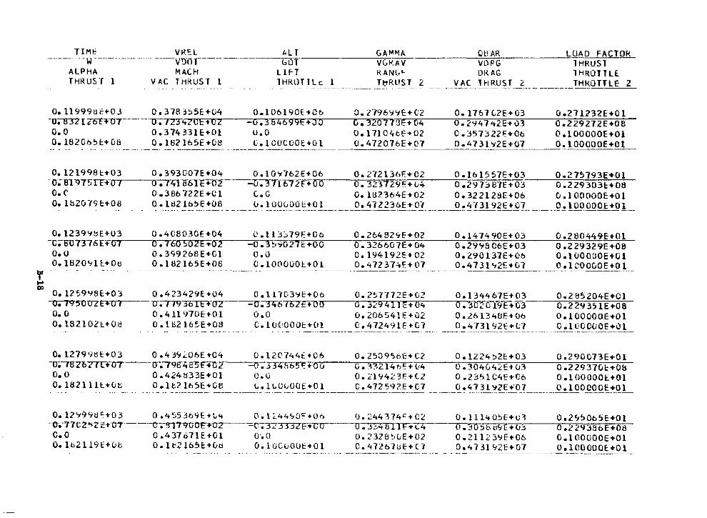
----· T_ ~ ~~ -------- - ·-· - ----~~~ ~----- ------ ~ ~~- ~~:: ~ ____ Q=-v~=-).:...:.~R:_:_G _____ .....cL=-0=--/'-'-H D~Ru--=-~;::-c~T~O~R~ ALPHA MACH LlFT RANb~ DKAG lHROlTLE
THRUST 1 v A_C _ T !1~~~-T ___ l --· 1 HRlJ_T !.~.i:: ___ l_ -·---·- _!_1:1R~~~- ? - - ----~~~--!~~us r _ L - - ---- lHKOTTLE 2
O.ll999Uf.+OJ 0.378j~5E+G4 -o;in-zrzoc""'·o,--- o. 123·420E +tz O.O 0.374331E+Ol 0.1820o~t+08 O.l82l65E+08
0.106190£:-+06 -o.384699E+Jo u.o c.1cocooE:+o1
0.2796~~E+02 0.1767L2E+G3 0.211232E+Dl u.320773E~:+_;_G4.;:_ __ o~.~2~~4~1~~~2~E+-=--o~3---0.,,.-.2~29:.:--:::-27::-;:::-2~E~+0:;::-;:-8~ 0.17104bf+02 C.357322t+Co o.100000E+Ol 0.472076E+07 0.4l31~2E+07 O.lOOOOOE+Ol
0.121998t+03 0.393G07E+04 0.10~162E+06 0.272136E+02 O.l61557E+03 0.27~193E+Ol ·o;cn1175TF+-L,.,..., ...... ,--...,..,o,_ ....... 7411!'61E+02 -0.37167.?f+OO o. 32l729F.+04 0.29B8"1E+03 0.229303l:.+08 o.r 0.386722E+Ol c.c O.lti2364E+02 0.322128E+06 o.100000E+Ol O. 1~2019 c+08 0 ·-~ ~2-~~~-~~~-8- ·- ___ _ 5!. !_~g_0go_ !:~-~ ! ______ Q_!~? 22~6E :t-_0_1 _______ _Q ! ~ l 3l 9~E+ _9? __ ____ _9_! ! 00 OOOE:+O l __
0.1239~~E+U3 0.4C8030E+04 0.ll3~79E+Oo 0.26482~E+02 D.147490E+03 0.280449E+Ol -c;-su7376H'·~u~7~--o-;T60 502E+02 -o. 3~"1027C:+OO o. 326607E+04 0 .29% C:6E+03 0 .229329E+OS o.u 0.39926BE+Cl o.o c.194192E+02 0.290137E+0b o.1ooouOE+Ol o. 1820'11 l:+Oti . _?_·-~~~-l65E+C~8--------~-·l_?~~~~~+O_! _____ -~ 4 72 3!~f !:_~7 _____ o_~ ~ 7 3_l '12E_:!_~l_ __ o_. l co900E +O_L f --
..... GI
0.125998E+03 0.423429E+04 O.ll703~E+06 0.257772E+02 O.l34467E+03 0.2~5204E+Ol \T;f9"50UZE"',..,.,o~,-- U-;779301Fl'~u~2~---~u~ ........ 3r-r4-r6....,, ..... 6~2rt:~--+...,.,O"'O.-----...or-.~_,,......:.""'9·-.4,1-.1"'t:.....,+'0"4----,.o•.-.:3"0"'2"0"'1"9:rE~+-,.-,03 __ ___,,o,.....-=2-=2=9-=3-=;-=1-=E,....+-=oc-::a-o. o D.4ll970E+Ol o.o 0.206541F.+02 D.26134UE+06 o.100000E+Ol o.182102l+08 O.lti2165E+O~ 0.1000001:+01 0.472491E+C7 0.473192E+t7 c.10ccuoE+Ol
0.1279~HE+03 0.4J~~06E+04 0.120744E•C6 0.250956E+C2 0.1224~2c+03 0.290C73E+Ol -0;-782077T+-o--7---cr.7987t2'5f+TIT--=ri-;TTlt1ib51: + 0 u o. :·BZ 14 bl'.+ {14 0. 3040 4 ~ E+ u3 0 .2 29 37G l:+Ob o.o 0.424H33E+Ol o.o o.~19423E+t2 0.23~1C4E+06 o.100000E+Ol o. 18211 ~-1:.+yt:;__ - - o_. __ l ~?_!ti_:~-·~-~---~-·~ l:_(J~-~Ot_~~.!:_ _____ 9_. ~!_2 5_~5_+ C1 -- -- _Q_ .4_7_3_l_'J~E_+'O_..? _________ o_. l 000_0_0~!~_1
O.l?'i99ec+o3 0.4~5Jb9E+~4 O.l~44~0F+Oo -·o-.-1n2•»zc:+·o7----c--;-in;'90on~a~2-- -r-;"37TIUE+co c.o 0.437B71E+Ol o~o O.lb2ll9E+ub O.lv2165E:+0d O.lOCuOOE+Ol
I). 2441741= + c;.~ O. ~:, .. B 11F+1...4 0 • 232 8 ~ u E + 0 2 o. 47261t>E+ C1
O. Ul40~E:+i.::ol 0 dO '.:ib 1:19 E +u2S 0.21123'if+06 D.4Bl92E+07
0.2<t50c5E:+Ol 0.229386E+08 O.lOOGOOE+Ol O.lOOOOOE:+-01
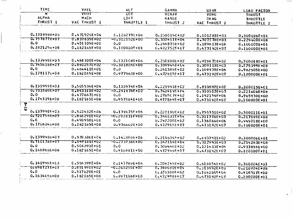
TIME VREL ALT GAMMA QB AR LOAD FACTOR ~~~~-~~~~~~~v~11u=-~~--~~~~G~.D~T;.._~~~~~-;;V~G~R~A~V:--~-'-~~~~V~D~RG;;.......~~~~-..!~l~H~R~U~S~,;.::...:=-=-::..--
ALPHA MACH LlrT RAN&E D~AG lHROTTLE THRUST 1 VAC TH~UST 1 THROTTLE l THRUST 2 VAC THRUST 2 THROTTLE 2
0.13199tiE+03 0.471924E+04 D.12H279l:+O~ 0.2~80l~E+02 0.101281E+03 0.300186E+Ol ~--o-.~1-5Ta77FF·~u-1~~~u...-.s ....... 3~16~3~5~E~+~o~2..--~--~u~.~3n1~2n1~5~lrrE~+70~o.--~-...o~.~3~3~7r4T1Tt~E7+~or4~~~0.,......,.3~o~7~S~7~6nE~+~o~3;---~-,o'.~2~2~9~47o~o~E~+~o~s~--
o. o 0.451109E+Ol o.o C.246835c+02 0.189613E+06 O.lOtOOOE+Ul o.1a212~t+OB O.lt2lb~E+08 o.1ooo~OF+Ol C.472752f+07 0.473192E+07 o.100000E+O
~--~___;_:....;_:_:"....::--=..:__::_:,__~~-=-=--=-=-_:___::_...::....=..=_~~~~
u. l33'7'i8E+OJ o. 14!.oraFt-uro. o 0.178117t+03
0.13599!3H03 O. 1335tsOE.+O f o. 0 o. l743 l9l:+Oe
0 .4&8100E+04 0.84025 IE+Oz 0 .4t.4411E .. Ol O.l8.?l65E+08
0 .~(;5 ~36E+04 0 .B43318E+02 0.417667E+Cl 0.182165E+08
O.l32108E+Ob -0.301806E+OO o.o 0.977963£+00
C.231880~+02 O.~l967~E+02 0.300018E+01 O. 33994hE+C4 O.::S09113E+U3 0.2?5399E+C8 0.26138oE+02 0.169976E+Ob o.9~2~05r+OO C.472blSE+07 0.473192E+07 O.l
--·------~~--~-:_.;;;_;__:___::_ __________ ~.:;__--~~-~-~-
0.135~74E+06 0.225943E+C2 0.8331l9?E+02 0.300Cl5E+Cl -0.29l976E+OO o.342419E+C4
O.C U.27b5C7E+u2
r·-, ·---· ·-----·---·-- ----·-----· C.957084E+OO 0.472869E+07 ----
0. 31O~13E+ u3 0 .152154F+06 0.473l'i2E+07
0.22lb0bE+Ot1 0.965930E+OO O.l OOOOOE+Ol
' ..... IO
O.l37998f.+03 0.522432E+u4 Ool39b75~+0b 0.22019&E+02 0.75~351E+02 0.300011E+Ol o.121T5~t:~~o~,,__--...o~.~e~4·5~~2~9~1~e~+~o~2~~-~o~.-2~B~2~6~3~1nF~+nonor--~o~.~3n4~4~b~3~1~E~+7o~4~~-f;o~.~3T1T1~7~a~oFE+~o3:i---~--.o~.~2~1~1~s~~~5~e~+~o~ai--~ c.o 0.490938c+Ol o.o 0.2';2200E+02 0.136066E+Ob o.~4'7718E+OO o.11uou4t+oa o.lb2lo~E+oa o.93oo~2E+oo 0.4129l~E+07 o.473192E+07 o.100000E+ __ o_1~-
0.13999S~+03 a.53936cE+C4 L.14~80~t+Ob 0.214634f+Ol O.b~37~lf+u2 o.30000bE+Ol ·~~o-.-1-1~~F+=o~7..--~--.o~.~n~4~~r1ns~1HE~+~o~2:r-~~-~o•.~2n1~3n1,3~6~E~+nor.o~~..,.,o-.~~r4T/r13~4DE~+~o~4-;:-~-,o~.~3n1r2r.~n4~~~E~+Ju~3.-~~o~.~2~1L4~i~o~3~~~+7.o~~~~
o.o o.5C4?93E+Ol o.o 0.30~4~cE+02 0.121~13t+06 0.93385bc+OO O.lb69bUt+OH 0.182165E•Od 0.9166Hll+OO 0.4729~4E+07 0.4731~2E• o.1onoooE
.---··--··-·- - -··---- --- - -----·--- - ·- --- - ·-----· ----·-------·--··-----·-- ----- ------ ----- =.__ _______ _:_ __ ::_:_:_:_::__::...:_:_:_: _____ .__::__..:....=.....:...:......:...:...::.....:.__:__;;;;.__
c. l419'1tiE:+c:; c .s;o 39eE+04 .--o;-6"9S727C-+C;---m 91HBU2 , O.O 0.517ti20E+Ol
0.1634G5t+Ce 0.182lb5E+08
C .14 776<;E +06 -C.265255E•OC o.o Ci.!j<J7l0bE+CIO
0.20';24~E+02 O.bld8~4E+Ol 0.300004E+Ol o.3494dOt7+~0~4~~-o~-~.~3r13~9~~2~·E~+~o~~,,__~__,o'.~2~-1~0~1~0~4~E~+~u~B:--~ G.32~30UF+02 u.10&2&o~+Cb 0.9l6317E+OO C.47LQ98E+C7 0.473192F+07 O.lOOCOOE+Ul
-·-------·- ----·------·-------------------
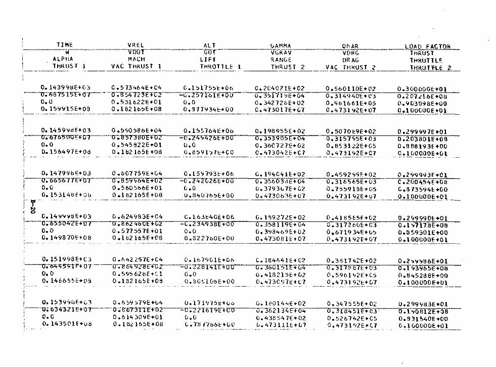
TI Mt w
ALPHA lHRllS T l
~~~-i~~~----=~=~~~~~~~--~~~·~~~-~--~--~..-.:~~~~l~~~~-~-~~"L~~~~~~~t~J~~;~c~T~O~R"'--MACH LIFf RANGE DRAG lHRUTll~
VAC THKUST 1 THROllU 1 THRUST AC fHl<UST 2 _______ JJ:!_KUT1'Lf _ _? __
0.14399~E+O~ 0.573464E+C4 C.l5l15)t+06 C.2C4021E+02 0.560110E+02 0.3uOOOOE+Ol ~--o-.DB75"l"!>F+1J7~--u-;-a:;zt12""JE~+~c-2~---c;75"711)[E+OO'---o-.~3-51~71'~9~E~+~Q~4---;.o~.~3~1~4~~~4~0~t-+~O~j~---;.o~.~2~0~7~L~l~b=E~+7c~u~
0.53lb22E+Ol o.o 0.342728E+02 0.9ol661E+05 0.9030~8E+OO 0.162lb~E+OB 0.977934t+OO 0.473017E+~7 0.473l~2E+07 O.lOOGOOE+Ol
:__~:__.....:.....:.._:._::...;;;_c.::..;=-..;,_:________ --~
0.1459~tlf+03 o.~~OS8bE+u4 O.l5~1b4c+06 O.l989S5E+02 0.5070b9E+02 0.299997E+Ol ,---rr.-670-S-OUFm7·---a-.~a-5-1 "3;:...Bo;..;...e+.,...;..,.o..;.2---_;.o::..... ,;;.2 ..,..4.;.,-11 ;-4~2 .;....6 ;..E ...... ;.0.,:...0---,:..0..:.... ~3.;_);.-3 ~9~o'l"").;..t-:-+?<"07-4---;.;-o ..:.... ;.;-3 .;-1.;,,.s :.-7.;;.(j..,.5F-E 7+ "'o;;,3---no.;;... ::;-2-;::0~3 T.a;:-o •1;::-E7+ ;;-o;;-s-
o. o 0.545822E+Ol u.O 0.36C727E+02 O.B531~2E+05 0.888193f+OO 0.156497t+O~ 0.1&2165E+08 0.859l~7t+CO 0.473042~+C7 0.473192E+C7 C.lGOOOOE+ul
) O. l4799bE+03 j--cr;o65077E+U 1 \ o.o
o. 15.H 4ll f+ Ou
D.607759E+G4 O.l59?~3E+Oo O.l94041E+02 0.4592~9f+02 0.2~99~3E+Ol o.B59S64~e~+~o-2.----_-~o~.~2~4---z<J2tiE~+-o~o~~-o~.~3~~-b~0~3~o~t~+~o~4,__ _ ___,o~.~3~1~6~5~6~5~E~+~o~3,._~--::c~.~2~0~0~4~5~4~f~+~c~8----
o.s60~66E+o1 o.o 0.3793L7E+G~ 0.755918E+u5 C.873~94c+GO
·- -~~1_8.~_l65E+08 o.B4CU6~~:!:_~~----0._4_7_3~~]_E!_~J-·----~-.!473192E+u1 ___ '?..!_1000,00~.:t:Ql_
O.l4~~~8E+03 0.624983E+04 C.l63~40E+Ob G.l~9272E+02 0.41H5ESf+02 0.2~9990c+Ol ~--..o~.~65-s-O'l'tZF-vcrr--~o-.-so24SGE+C2 -c.2~-3=s~e~+~a~o-~~o~.~3=5~a~171~q~E-+~074---o~~.~3~1~1~27o'urE~+Ac~1----;:o~.~1~,~1711:;-;:-s~E-+~o~s~-
o.o 0.149B70H08
0.517557E+Ol O .1 b2 l65E+(l8
o.u o.3984b9E+02 o.o71934E+u:. o.8~9S01E+OO o.s221bOE+oo o.4730B1E+07 0.473192E+u7 o.1oocooE+o1
0.1511.J98E+C] o.n42~57E+C4 O.lb?9GlE+Oh C.l84n41E+C?. 0.3~1742E+02 0.27~~8oE+Ol ---o. o-.rttt517TF+n·r--o-;-so4"92lffllJ2---~u·-; 2 t.8T4TE'+-o-o--~o-.-3~b~G~1-~~1 E-+~G4...---o""'".-3"'""1~1-1,.,_1.,...ti"'"lt:"'"": +..,...0,...3,,,__ _ ___,o. l '13% !:iE+oa
o.o 0.595628E+~l o.o 0.4l821SE+u2 0.59bl~2E+C5 o.B~5238F.+00 O.l46655E+09 O.l82lb5E+OS o.SO~lObE+OO o.~73097E+C7 0.473192~+G7 o.1oouooE+Dl
1, o.15394&F:+G'3 o.b:.9:.79E+v4 o.l11Yl5t+uo ':---o;"53 4""3 ZlE+o-r--·· cr;S-6T3TIF-rn2---=-1J-;z 2T6T9F•-o-o--l O.O 0.614301.JE+Ol O.u
0.143501E+U8 O.l8~lb~E+OU C.7817bbc+uC
O.l~Ol4~E+02 0.~47555E+OZ iJ.3b 2134F+o-~----o-• .....,3 i a"+ s 1 E + (Ll , 0.438547£+02 o.~26742E+C~ u.47Jlllt+L7 0.473142E+C7
0.299':183E+Ol 0. l 'i'OlH2E+J8 0.831~40E+OO Ci.l<JOOOOE+Ol
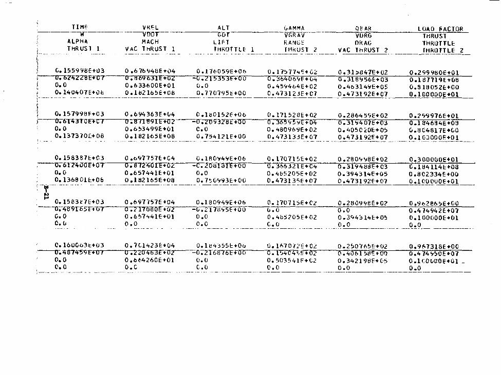
TIMI;' VKH ;-------w-----·--- .. -----vnnT--
ALT GAMMA --"Gn-r-------v-r,~,RAV
QE'AR VURG DKAG lhRUST 2
LllAD !'ACTOR THRUST -rHRUTTLE rHROTTLE 2
, ALPH' MACH LIFT RANG: , THRUSl 1 VAC HtRUST 1 THROTTLE l f HkUST 2 VAC r·-- -- ·--···--~- ---·-· -·--·- -t• I
1 , G.1559'i8E+IJ3 0 .6-/6'148E+04 O.l"16059E+Ob O. l7~774':+GL 0.31!>847E+02 '---~o-.~s-z~Z2BE+07 O.R69631E+o2 =o.zt5353F+OO 0.36406~F+u4 0.318956E+03
0.2999HOE+O1 O.llH119E.+u8 0.8 lS052E:+OO O.lOOOOOE+Ol
O.O 0.633600E+Ol O.O 0.4594b4E+C2 0.463l4~E+05 , O.l40407E+Ob O.lb2l6~E+CB 0.770195t+OO C.473123E+C7 0.473192E+C7 ~----·· ----- -· -- ··- -·- ---·----------·----------··-·-----------· -· ----------~-------------------
' ) l 0.157998f+03 )--cr.6T43TOHC I
0.694363E+v4 0.1~0152F+06 0.171528E+02 0.2H64~~E+02 0.2~9976E+Ol o.a11e9TF+~a~2~---~a~.-~2~0~9~3~2~a-~t-+-o~c---..-c-.~3..,..,...6s~s~~E-+~0~4--_;,.o~.~3~1-9~4~0=1=E•--.;..03=---o~.~1~s~4~6~a~4~E~+~o~3:---
o. 0 0.137370[+08
o.6~3499E•o1 c.o 0.480969E+02 0.405C20E+Q~ u.8C4817E+GO 0.1821-65E+08 0.754121E+OO 0.473133E+07 0.47.H92f+07 O.lGJOOOE+Ol
0.158387E+C3 O.b97757E+C4 0.1A0~4~E+06 O.ll0715E+02 0.280~~8E+02 0.300000E+Ol --.... 0.617'tv0c+Ot o.8124U!Ft(')L -C.2(Jlff()1E+OO 0.366321E+C4 0.31948dF.+03 G.11!41141:+08
O.O 0.657441E+Ol O.O 0.4b520~E+02 0.394314E+05 O.BC2334E+OO O.l36801E+06 o.182165E•08 D.7~0993E+OO 0.473135E+07 0.473192f+07 o.1coouOE+Ol :--,,---------- -----. - -·-· -·- ··-··--------·--·-------·------ - ----------·----------------------------------------------
~
~ 0.1583t7E•03 0.697i57E+04 0.180949E+06 0.1707l5E•C2 0.2B09~8E+O? 0.9o2e6~E+CO . ----CJ."1ta·9n; 5H-u-7--~a ~tTiro"F •0,,...2~---c • 21 Tu.,-=-;;...s f;..+_o.;:...o;,_ __ u:~.=-o;...:....::....:....::..::....::__::....=.... __ ~o--=.-=o:.=....::..:.....:.-=-=--=..:::_---=-o-"-. 4-:--::-74=--=-94:::...2=-E=-+-o::--:1::--
G. o 0.6~7441E+Ol O.O 0.4bj205E+02 0.3~4~l4E+05 D.lOOOOOE+Ol ~·_L_ _ _ ? • ~- ___ .. ____________ D. O _________________ ~-~-~ _____ _ _ ____ ___ _ __ Q~----·----------·- ____ q_!.9 __ --------------·--
C.l60063t+03 o.7Ll423E+u4 O.lc4j551:+~0~o;:._ _ __;u~·-~1~~~7~0~i~~:'~~~·~c~L;,._ _ _;0~-~2~~~0~1~~~~~E_+~0~2 __ -;::,o~·~9~~7~3~1~8E~+~O~C~·~ ----u;.-1t874""511H~o~1~--.....u-...... 22rnmr---::::1J.LT&IITOF+ o o c. 1~4 64 ~,i: + 02 o. 40t-- 1 58t: • oo o .4 74 '1!10 E +01
o.o 0.6t4260E•Ol o.o 0.503541F+C2 0.34-2198F•05 o.1co0uoE+Gl -c. 0 0. c (. 0 (). 0 o.o o.o ·----·-- --------··· ---------·--------
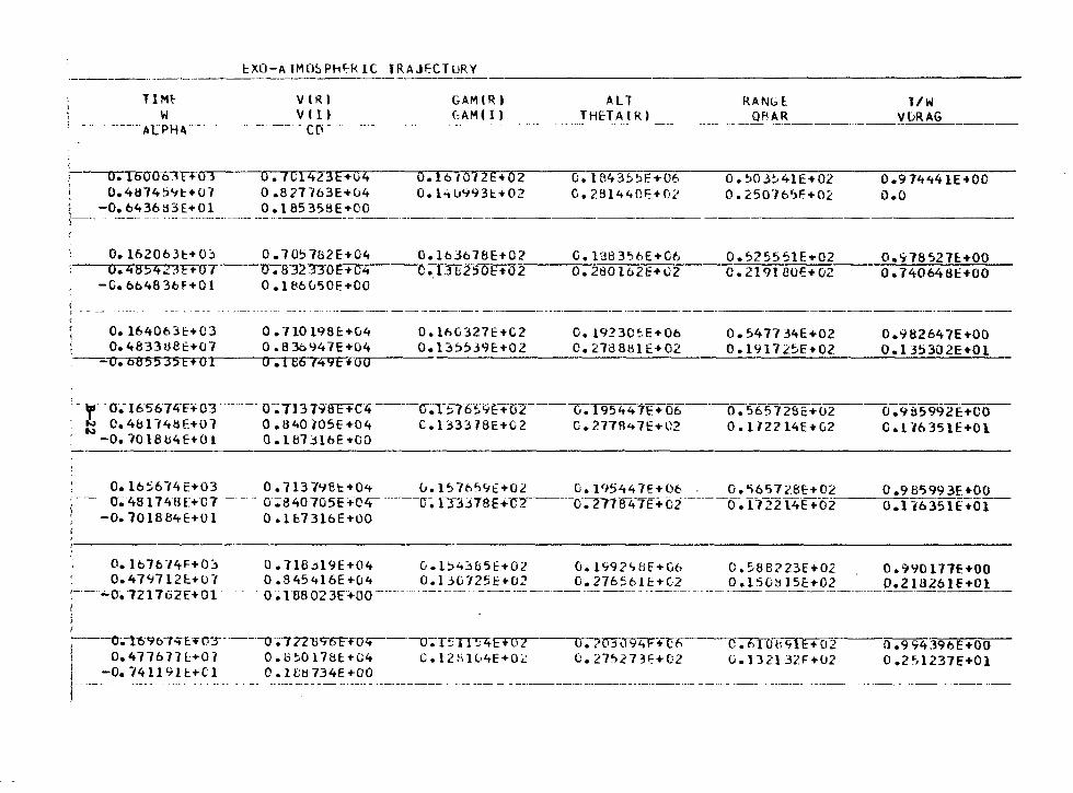
TIM~
w ----·-Al PH~. -
~XO-AlMO~PH~klC TRAJECTURY
VlR) v ( 1)
--· -·-· - Cl'i - ····---··--· - ·-·-··
GAM(R) ALT RANGl 1/W _____ f0~l-~ ~---------!_!:!_E-l A(~_) ___________ QFIAR ______ yuR~----
0.1600-o1T+o.3 0.101423E+u4 O.l6t072E+02 o. 1843!)~[+06 0.2814401:+0;:>
O.!:i03~41E+02
0.250765F+0.2 0.974441E•OO o.o 0.4ij74S9E:+07 0.8?7763E+u4 O.l~u993t+02
( -0.6436::i3E+Ol 0.18535SE+OO /---- - --·- ····-- -·--·----------·-- ---··------------·--'
0.1620631:+0~ ---,.,,0;7t8542-"4E+-o I
-0.6b4836F+Ol i
0.105182E+C4 o.832330E+04 0 .186 L50E +CO
0.16J678E+02 G.1383~bE+G6 o.~25551E+02 o.~78527E+OO 0.13b2~0E+~0~2---=-o-.~2-8~0~1-6~2~E-+~~~2----=-o-.~2~1-9-l-8-0~E-+-0=2---0-.~7-4~0-6~4-6_E_+_O~O~
! - - - -···-------------·-----------·---------------------
O. 164063E:+C3 O. 48 33 08 E+O 7
-0. 685535E+OI
0. 710 l98E+CJ4 0 .830'147E+04
O.lhC327E+C2 0.135539E+02
O. 19230~-E+Ob 0.2788tHE+02
o. 547134E+02 0. l 917 2.~E+02
0.982647E+OO O. l 35302E+Ol
o.tE674"11Fi"~u~o------------------------------------
·: - 'r'" -0-; 165 674T+ 03 -·- n -- o-~ 713 B-ffF+Clt ------G~r 57659£:+-cfr----(J. l 95 4 4 "1E + 66----~-56:.'l 7 2B c:+o_z ____ o ~9ti 5 99 2 E +CO-
: ~ C.4HU48E+07 0.840105E+04 C.133318E+C2 G.?.778<+7E+C2 O.l12214E+G2 C.116351E+Ol ' -O.-I018tl4E+01 O.l81jlbE+OO
O.lb~614E+03 0.1137~8t+O~ 0.l~7h~~f+02 O.I95447E+06 . o.~65728E+02 0.985993£+00 u~4s174BE+c1 - - -- o;s40105E+o4- ·------c~ r.Bj1ee+·c-r----0. r1re47f+c2------o~ 172214E+-02--o:I1635fE;o1-
-o.101se~f+o1 o.1b73lbE+oo
O. lb76-14F+O::. 0.4797121:+07
'.-·-·.-09 "l21762f+Ol I
0.71B~l9E+04 C.l~4~b5E+OZ G.1~92~8E+G6 c.~88?23E+02 o.~90177E+OO 0.845416E+04 0.130725E+02 0.27656!E+C2 O.l50Hl5E+02 0.218261E+Ol 0·~1uso23F+oo-----····-------· ----------------·------·---·------------------------·--··-------
l---o~--l6~bl~E:t:03"---·-o-~·772ui;-rr-tco4-----o-;TS"rr;ztE+Oz o-;-?"~\f9"2tF+T-h 0. 61 Ob9fr+Ci2 fJ .9 94396E+OO I 0.477677L+07 O.b~Ol7&1:+04 C.l281G4E+O~ 0.27~273E+02 U.132132F+02 0.2~1237E+01 j -0.74119H+Cl O.Hitl734E+OO #----- -- - . -- -··-------·--- -------------~--. ··----- - ---·-----------·---------·--· ---·- ----------------------------
!
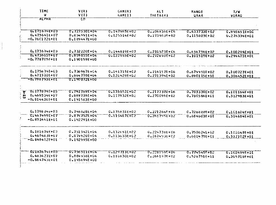
TIME w
VCR) v (I,
0.111614E+03 0.121~3oE+04 (: o.47564H:+07 o.e~«:!91E-t·04 ,. -0. 76C'l 721:+01 0.189447E+v0 !.---------·---·---·-----------·
GAM(R) l?AM(I)
O. l47%5E+Ol G.125Sl4E+02
AL l THHAttO
RANGE BAR
T/W
-----------·---·----·----~
0.206836E+C6 0 • .2739f>jf+02
0.633733E+Ol 0. ll 5S03E+ 02
0 .9 98 65 lE+OC (J.276334E+Ol
~~oo~·.;~i~ri~45T~~*.~~~73 ___ o..-:-.~7~32;.r.....,.22~0~E~+~G~·4r-~--;o~·~lr.4~4~8~1~9~E~+70~2.-~--;:;c~.~2~l~O,sr.27'3~E7+~C~b~~~o.,,........6~5~·o~7~5~6~E~+~0~2,-~--;o~.~l~0~0~2~9~4~E~+~O~l~ ., -= u o.B59855E+o4 o.12295!>E+02 0.2"l2690E+C2 0.101519E+02 0.29447lc•Ol
-0.778705f+Ol 0.190159E+OO
--·-·- -·-····--··------·----------
O. 1756 74E+03 0.47l570E:+O"i
-~-~0;79"6193E+Ol
0. 736967£:+(.4 Oel:lb4170E+04 0.1908 72E+OO
O.l41715E+C2 0.12G428E+ul
-----------··-··- ~·-- ·------------------------C. 2141 !:. ·1E+Ob o. 271394E+02
0.679'751E+02 O. 890115E+ul
O.l 00727E+Ol 0.30b452H01
··- · -· -·o;n161:ttE+o3-···---u-;-rztl7o9F+u1t"""-------u-;n-a-o:.-21:+-o""L ---u;nrn-r1:H16--o. 103330E+o2 ~ t 0.4b9534t+Ol 0.869l36E+C4 O.ll7932E+OZ 0.270096E+02 0.780586E+~l --6.1 Olib4f +of-
0 .312C:,83E+Ol ·; w -O.Bl443bE.:+Ol 0.1~1583E+OO
0.1796/4t+03 0.74b6L8E.:+04 0.13~631E+02 0.221264F+Ub 0.72bbB~E+02 0.1Gl604E+Ol -c;-46 7499e+OT ______ - --o. s14-,s2c: +04--··-···-- o ~-1154·61E+c:-2----o-;"2-,.;fr145E"..-o:r·--o~-684t,03E:+or---o. 314·6a4E+of--
J -0.83l64lE+Ol 0.19229lE+OO
O. ltllb74£+03 I D.465463~+01 r---~o~a48412f+o1 :1 ~)
i
0.7!:>l542E.:+04 0 .B-l':t820E+C4
O. l 32t,S U +02 O.l Dl..i33E+(,2
0.192995E+Oo·· .. ·-·· .. ---- -----~-- .. ·---~--
·:----o.-i-H301'<t H03--cr.7505UET~-~u;u'T7T3no2 I o.463421E•07 o.884~38E+u4 u.11uc30t•02 L-- _..o.86474>1:.+0l O.Ilf3o94E-rCO
j
O. 224 73tH:"+ Ob 0. 26 ?<t'dl:+ C2
o.nst59r:+o6 C • 2.bti l i~ "ff: Hll
0.750624E.:+v2 0.1C2048E+Ol ___ ~!.~2SJ.~ 75E•Cl ·----- 0.3.!2lQ_~f+fJ_!_ ___ _
o.7~45~5~+o~ o.tG2490E+a1 0.52b7~1E+Ol 0.30~7l&f+Ol
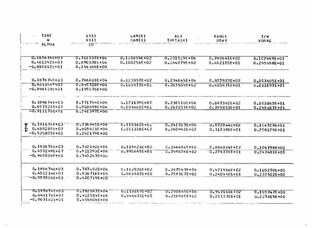
l I
i vt~t v ti, co---· ·-·------ .
0.1B-S677+B--o-3' 0.161531E+04 I 0.4bl3~2E+07 0.890108l+O~
O. 1.:: 6814E +o 2 0.108256E+02
~--- -o. 8806521::+01 ______ o. ~-~4_3_1:1_9_~-~oo _________ _
~
0.187674t+03 0.766n16E+04 :--rr;.·7t~3-5«';-n--~a~,~-___,,,o-.-.ro 95 328 e + o4
-0.896128t+Ol 0.195C7bE+OO
0.123957E+C2 O.H.i!>'713t:+OL
All THf'T Al R)
0. 2315.!9£+ 06 o. 264879E+02
O. 234845E+Oh 0.263'.:>o9E+Ol
RANGE - -· . -___ f{~~ _R ___________ _
O. 798641E+02 0.462105E+Ol
0.822923E..,.02 0.405'!- 71E+Ol
T/W VORAG
~---·--·--. --·-·-·-·.
0.1C2949E+Ol 0.295'7'.:>8E+Ol
O.IG340SE+Ol 0.2t13197E+Ol
O.l896l~l::+C3 0.71175~E+04 U.12ll39E+02 0.238110E+06 O.B473~2E+02 O.l038b5E+Ol . 0.45732lf-t-07 0.900~99E+04 O.l03o01E+Ol 0.26225-IE+OZ 0.3558~3E+Ol 0.269<i87E+Ol .'-·-=o-;;91117"bFHYr---o.24·;..1:;.~~97~E:;:_+.;...~-;.,_-__::.:....::_::::::.::.::.:....:..:...::....::....... __ :::..:_::;:::::.;:.:::...:..!::....::...:::.::_ __ ..:::...=...:::..::..:...:::...=.::..::...:....::::..::.. __ -.:::..!:..:::..::~::::...:~~'--
'
-,, ·-o.;191674HOT. -N 0.4~52851:+07 ...,. -O. '12!>805H01
I Oel93674t+03 i·--. o.;·t:t53249£+CT I -0.940014E+Ol
l-1
0.19~6741:+03 c. 4512141:+07
··-- ;.;o.;·'9!.'38 05 E+O i ·
-----o-;-i 97o74"f TO 3 O. 44"1 l 7b E+O "/
-C. 9611U2t+()1
··o-.--,-,6 9tt5E +o21----ci-;;Tra "'.lo-it:-+u2 0.~05~21E+04 C.1Cl318E+G2 0 .Z'12179E+OO
o. 24.l323E+06·----o. 872044EH12 0.260942E+O?. 0.312380E+Cl
o. ic4329E+O_l __ CJ.2~·8125E+Ol
0.782192~+04 0.11~624E+02 C.2444~4E+C6 C.8968U4F+02 0.104798E+Ol 0 .9 U293E +rr4···- - .. (i~9'H:J64"51:+-o·r---·--·u-.-li)96-'-6E·+o:z-- ·-·--cr;214·314E+oT·--·----o .24-74BTE+Ol--o. 345 2t:.3E+Ou
0.7ll7'192E+04 0 .916 716E+04
- o .4 oo 719E +00--·-
O. llL926E+Ol 0.'16S412t+Ol
·o-;-r9ZBtt7F+-cr~---u;m26 IE +O l O.'i22lB'iE+04 o.~46415[+01 0.4~860bt+OO
c. 24 7~ '; 3f+06 o. ?58307E+02
u. i50649E+ 06 O. 2~64t\5E+02
0',, 9ll 9 lbE+G2 0.240'i'1GE:+Ol
o.9.1t714ot: ... 02 0 • 21 18 32 E + 0 l
0.105270H01 0.237502E+Ol
0.10574 7E+Ol 0 • 2 2.7 IH 1.H:: +0 l
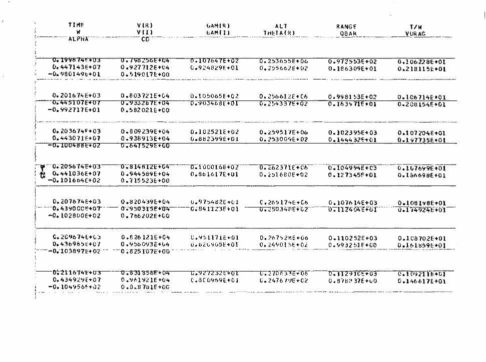
Til"1E w
A.LPHA ____ .
O. l996 7ztH03 0.447143H07
-0.980149t+Ol
VlR) VI I> co----------·-
6AM(R) ALT GAMIII THtTAfk)
0 • /'i8 l56E+U4 0 .927712E+C4 0 • ') l9017HOO
o.107b47E+o2 0.924829f+Ol
O. 2~36~~E+Ot> o. 2556b2t=+02
RANGf TIW ___ QBA_k ___ ·····-__l[_!:!R_A~G __
0.972!>~3E+02 O.l86309E+Ol
0.10b228E+Ol 0.218ll5E+Ol
----------~··. «-- ···- --~~----- -·~·--·~~----------- ----·-----·---~--------------------··
O. 20lb-14E+03 .'.---0;7+-zt5T07E"+-OI
-0.992717E+Ol
0.803l21E+04 0.10~0b5E+02 0 ?5bbl7£+(6 0.9981~3E+02 0.1Cbll4E+Ol o • 9 .:)3 zs 7E +~-------u-;"iuJltb·a--i: -.. 0-1---v-:-2-!·4 3 3 7E~-+_0_2 __ --;o....: • ....:1....:6-=3:..::":...;7""1..;;E;....•....:o:..::1--~o..::. • ..::.2..:.o.:..e...:..1..::.5..:.4.;;;-e-+""'"u"""1-o. s a2021 E +oo
---·-----0.203674f+03 o.809239E+04 o.102521E+02 o.~~951/E+Oo O.l0239~E+03 0.107204E+Ol 0.44307lf+07 __ ~~0~·~9~38;.;.9~13~E~+~0~4;.._ _ ___:u~·~8~8~2~~~9~9~E~+~0~1:__ _ __:0~·~2~S=3~0~0~~~E~+~0~2---0.::..:..•~14~4~4..:...::;32~f~+~O~l:_~_..:.0~.~1~~~7~7~3~5~E~+~O~l.__
,----(J;T()lJltS'HE·Hf2 o • 641529 E + Oo 1
I ;--·,.-··0;;20567ItH03-----o-.-si:.rt812l:+v4---o.n5COf6E+02 j tJ: 0.441036E+07 0.944589E+04 0.86l617E+Ol . -0.101664(+02 0.115523c+OO
l I
o. 262371E+06--~o-.164994E+C3 o.~~l680E+02 0.127345~+01
u.1L7b'l9E+Ol O. l0b698E+Ol
! 0.207674E+03 1- ---o•4311ooc1?+01· j -0.102BOOE+02
0.8204J9E+04 u.97~482E+tl o·.'1'503l5HW.-----c; .-a4ITZ3H 0 l 0. 7b6202E+CO
C.265l74E+Co O.l07nl4E+03 O.l081~8E+Ol ---o-.-~5IT34llE+cr---·-u-;nT4VZIE'+<if--u.~T#4924E+oT-
C.209b74l+LJ 0.826121E+C4 I 0.4369b5E+01 0.9~60Y3E+~4
C.Y~ll71E+Ol 0.2b772HE+G6 O.b2G905E+Ol 0.~440l~E+Oi
:···---o.-103a91c+o2 --- ---o.s2sro?c+ou-
•---0;·2nt>14·r+u-:r---v·;.inl1r50E+-'"'C14,,,_--u--~-gm32no1 v. "2' iC163 h: .. 06 0.43492~E+07 0.9~1921E+04 C.BC09b9E+Cl C.247619E+O~
-0.10~956~+~2 0.8~87UlE+OO --------- ---·--·-
O.ll0252E+03 0.9932~lf+CO
O. ll2'11CE+03 O. 81t111 37E +1.Jil
0.108702E+Ol 0 .1 b lts~9E: +O
0.109211E+Cl Ci. l46617E +01
-·-- ---------------·---
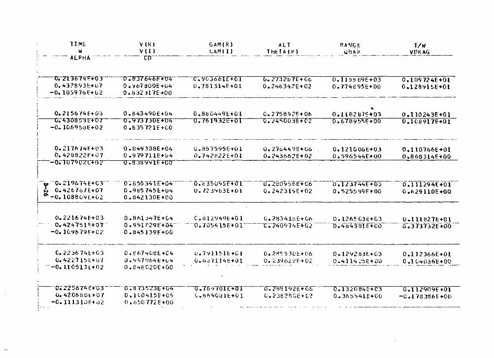
TIME vuu v (I)
G.AM(R) t,AMI I)
ALT RA~GE ThETA(K) WBA~
l/W VDK AG w
·-ALPHA. -----·To--·-·--- .. ·----·--·-···- -----·-· -------·------· ---
-·-_...,o~ . ..... 2 ...... 1-3-s..,,.1 z;;::-+-u:r o. 43?8'J3E+o7
-0.10!>976E+v2
D.837b46E+04 0.'167800E-t-04 0. b323l1E+OO
C:911Jo61(+tl1 0. 7813l'tE+Ol
v. 27321J1E +Go 0.24o342E+02
---·-·-·-· -------· ..
u. z-lb449E+06 O. 243o62E+ 02
0 • 11 :> !> B9E-+03 0.114e95HOO
..
0.121006E+03 0.596544E+OO
0 .1O'i724E +01 0 .12891 :.E+Ol
0.110166E:+Ol Oo8683l4f+OO
o.2210-f4E-+03 o. 424751 ~:+or
-o. 109b79HC2
O.Bhl~~7E+04 C.Bl2949E+Ol G.2B34l~E+~h 0.1265G3E+G3 O.lll827E+Ol o. 9111 P29FH>4- · -- ·oao5415F+OT-----c-;-24u97.i1 r:+ti2-------0~-4c>'t'"ruTt+oo-·--·- o. 3 73"'i32E+ao·-o. a45139f+oo
·-------- ----- -G. 22:>6 74t+G3 o. 4;t_;,:71~1:+0·1
-0.110513[+02
0. e b7 •t08E:: +C4 u .<tt;7•104E+t;4 0.848G20E+OO
U • 7 'I) 1? 1 E +C-1. u.e.;;i ., l 14E+Ol
0.2~~93('t'f'06
o. c.596lef+o2 0.12'i253h(J3 0.4114;.'.~E'f'Ou
1----o;z2s-674E+·o3---·o-;.-sn'573F+u~-·--u-.T69rurr+1n----u.7ttl:IPT.2E+li6--o;r32oe4E+c3 1 U.420bBOt+OJ 0.1G0415E+O~ t.6b~CU1E+01 t.2382BOE+C2 0.3b~~41E+00 ' -O.lll3lJE+02 O.b~077~E+OO
0.112366£+01 0 .1 u"t036E+OO ·- - -- . ------·---<~ ~- -~-
o.t l2909f+Ol -c.1-1tB86E+O(l
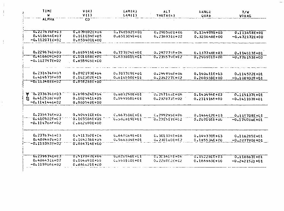
TIME w
ALPHA -- - --
O. 22'16?ltf+U3 1 0.418644E+Ol 1
1 -O.ll2071E+02
v lR) v (1)
CD
o.619b92E+u4 0 .1tl03'Jf+05 O.t153'tOH+OO
GAMIR) ALT ~~~(!) THcTACkl
Cl.74B592E+Ol 0.65130<1E+Cl
0. 290 5013 E+ Cb CJ. 23b93lt:+02
RANGE QBAk
o. 1349051:::+03 0. 32 56 46H 00
T/W VDRAG
O.l 13458E+Ol -0.4 72172E+OO
---------------------------' , -;
~ 0.229674E+O~ O.b659l6E•_0~4~~~o_.~7~2~7~U~?~4~E~•~O~l~~-..-o_.=2=9~27~7~~~~-·-0~b;-:--~---::o~·~l~3~1~7~4~8~E~+~0~3:--~--.,,o~·~l~l~4~t~l~3~E_+~O~l~ 1' O;ltT6oU9t:+OT--Cl.TUICOSF+05 G.6:Bt10lE+Cl O. 23~57'-fH02 0.2'J09lllE+OO -0.77bl53E+OO
-O.ll2797c+02 o.s559G~E+CO _:/
i -~ i 0.23lbl4f+03 j C.414573F+07 ;·-----o..--...... 1134-BiIE-H:lZ--l \
o.892193E+04 o.7013e9E+Ol 0.2~499oE+Ob 0 .ll2~02E+v5 O.olt.550E+Ol 0.234227E+C2 0 .B 58 28SFtOo
0.140ollE+u3 0.260558E+OO
O .. l 14572E+Ol -O.l08932E+Ol
y ··o. ·233674E+'03 -- -----0-;0 9e·s2-,,E-+04-------c,,-.ti-tr'12c;.-0E·-...-o-1-·-o. 2s-7Io-j-E+o6 ___ 0:-11. 34%E +o3 ___ 0. u5-l37E+o1-~ 0.41253~f+07 0.102~41E+05 0.5~Y~58~+01 0.232873~+02 - 0.2319lbE+OD -0.14ll07E+Dl
-O.ll4l44E+02 0.860~48E+OO
0.23~b74E+03 0.904~1CE+04 c.&67~lb[+Cl C.299Z9~E+Oo O.l4b4C2E+U3 O.ll5108E+Gl ·o. 410502F+c.1 · - - · - o ~ IG358t.E+-as - - ·o: ~B21;19·E+-01 ---·-o;nf~l7E"+t."2 -·---o~fo7o ()fi;+oc;-·---·--::e:f;;T74offoE +0T-
-o. 1141oor+o2 C.8tlo90E+oo
0.237b74f:+C3 , O. 4084o7t+G l ~----o;;.1153~3F•Or
j
0 .<t ll 3:>2E+C-4 O.lC4236E+CJ~
... o·.B64714E+GO - -
1--·-1:1;239674Tf"CT-----U-;-9"1TBZiTE+Ult 1 o.40M3U+07 o.H4c91E+u5 l -O.l159b!H_+02 O.tlbbL2lE_~~°-----
u.64P.Gb9E+Ol O. 5t>o::H4E+Ol
G. 62"b"li4"5E Tc l C.:>~OICOE+Ol
u. 301374E+C6 o. 2J01 oOE +C?
~-"34V~h O. 2lo8C2tf'C2
O.l4~330E+03 O.ll62S5E+Ol 0 .1855 34E +OQ_ __ __::0.2U?790f+j)_l_
O. l52280E-t03 o. l6b"Jb3E+uo
0 .116 86 7 E +O l -0 .24215 2-f_ +O 1
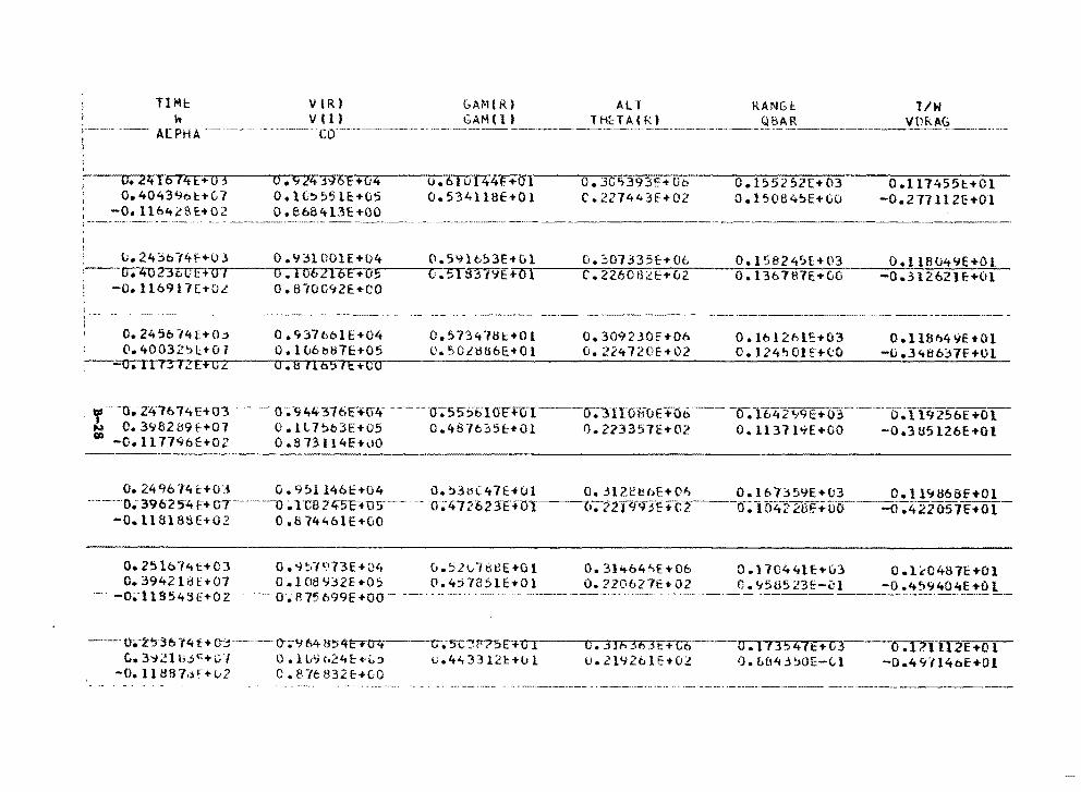
THH: w
VlR) v ll)
GAM(R) All RANGI: T/W
A[PHA ·-- ---- ·co·---------- -- GAM (I ~----~l t1_(:__13_C~_!_ ________ .9_~_A:.:..:.-_______________ c. _______ ---------
O. 24T574E+O 3 0.4043':161:+(;7
-O. ll6'tt8E:+02
0. <124 .1'1oE'+G4 O. lC!:>551E:+G5 0.8bB413E+OO
o.61ut44i:+o1 o.534118E+Ol
0. 30'>393!:+ Oo c. 22744 3E+ 02
0.1552S2H03 0.15084~E+GO
0 .1174551:. +C 1 -0.277 ll 2E+01
, u.24~b14f+03 0.93lOOlE+D4 o.59lc~3E+ul ,---u;-i;ozJouF+~u-1--·-0-...... 1...,.,.0021..,.6 ...... E-=-+..,..o,..,.5--__,.c:-• .,..s....-1· :n ·,':IE+ i)[
G.~01335c+Ol 0.1582~5f+03 0.118U4~E+Ol C.2260Bi'E~-... ~v~2~~-o-=-=-.~l~3~6~1~8~1~E-+~G~O---_-=--o~.=3-=1~2=0~2~1.=E-+0~·=1-
. -O.ll6917E+OL 0.810G92E+CO
0.2456-14E+O..:> 0.40032')1.:+01
:---1J.TI"7TTZE·FITZ
O.<t:.HoblE+04 0. l l.i61Hl7E+05 0.8 fl651E+CO
0.5734181:+01 0.~0L~ti6E•Ol
0.309230E'+Oh u. 224 720H02
o .1ti 12Mc+03 0.124~0JE+(;0
O.ll8M9E+Ol -0.3486:HE+Ol
. 'f ·o-. ztt76T4£+o3 · -- -- o-~"944316t:+u-4- -----·a-;ss-~6-I<H:+c11----o.:nroffuE+o6 ___ --<r~lI.42tr9E+o_3_ -~---,r~r192soE +o1 N 0.3982~9~+07 0.1L7~b3E+05 0.4876~5~•01 0.223357E+02 0.1137l~E+OO -0.3U5126E+Ol ~ -0.117796E+02 0.813ll4E+il0
o. 24qoJ4t+O:i 0. 9!'>11461:+04 o. 531::1i.:'.47E:HJ1 o •. :n2etil>E+O~ 0.16'7:S59E+{)3 O. l l<.1868E+Ol ----·-o; 39 02 54 r+ m--- ----·1) • TCB 2 ttSF+ us---- -- ·a;n 20 2 JEHJ-r--~o- • 220<rJt: +c2----o~ To42 2tiF. .t:uo ___ -o-;;-422os1e-+o1 -
-0.11818SE+02 0.87446lE+GO
c. 2!:>16"/"tt.+03 o. 3942181.'+07
-o.;-ll 8543"E+02
C. 3~21 b~c+c.·1 -o. l l 1Hl "/•'lf+li2
0.9~1~13E+04 0.5l01SHE+Ol 0.31'tb4kE+06 O.l08Y~2E+05 0.4j7851E+Dl 0.2206Z7E+02
--- o.R75o9'9F+oo-- --- ---------------
0. l L'/ t•24t:•L::> C. 8-/61:!32 E-+CO
G • 5C ?tr7"5 E"+ () I u.4.i..33121:-tul
C ."""3lfl36 3 E +Cb u. 219261E+Cl2
0.170441E+ul 0.1~0481E+Ol 0.95U523E-~l -0.4~9404E+Ol ~ - ·--~--- -----------·---~--~ --
0.1 f3547t+03 0. b(l4 3 ~OE-(, l
0 .171 ll2E+O l -0.49H4oE+Ol
__ ,, _______ ------
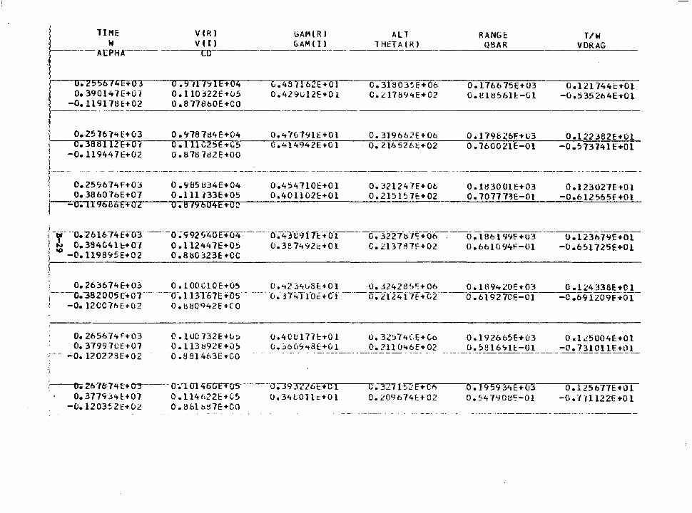
1-TIME V(R) l>AM(Rl
W V ( I ) GAM ( I ) -------At PH A _____ ·-------co-----··------------
o. 2556 lz+E+u-r-• 0.39Cl47E+01 } -O.ll9178E+02 !-·-------·------ ----~ '
0 .9 tl1'11E+04 O.ll0322E+u5 0.877860Et-CO
0. 978-fd4E+04 I 0.2576l4E+03 -~--.c~.~381fIT2FtU1·,__--..--.-.-.---. o.111C~5E+C5
' I )
-O. ll9447E ... 02 Q.8787d2E+OO
L.48 tlbZE+Ol 0 .42%12E+O l
·-------·------
O.<t-/0791E+Ol U.414942E+Ol
ALT RANGE. 1 Hf.TA ( 10 QBAR
0.3180J~E+06 0. l766 75Et-03 C • .il7tl94E+02 0.818561!:-(.il
O. 319b62E+06 0. 179& 56ft-lJ3 o. 2165261:+-02 0.760021E-Ol
T/W VDRAG
C.121744~•01 -0.5 35 264E•O l
0.122382E+Ol -0.573741 E+Ol
r-·--·-· 0.259674F+03 0.985U34E•04 0.454710E+Ol 0.32l247E+06 0.1H3001E+03 O.l23027E+Ol 0.386076E•07 O.lll133E+05 0.40ll02E+Ol 0.2151~7E•02 0.70777~E-Ol -0.612565f+Ol
·---~o~.~1~1«1006F+~a~2...----.a~.~a~19~6~0~4~e~ ... ~o"o.-------------------------"'"""-----------'--~---------~
i- -- --o."261674H-o3 ----0·;99z·c;4-0E""+o4-------11' l 0.384041~+01 O.ll2447Et-05 1 ~ -0.119B~5E+02 0.8~0323E+-CC
o-;-43-,;;91 n •·cn-----~322~1·ti·i~-+o;;--~ ---0:186199E•o3-- ----0.1236 79E .to1 0.3874~2t+Ol C.2137~1F+02 0.6ol094F-Ol -0.6~1725E+Ol
l . 0.263674E+Oj o.1ooc10E+05 O.'t2l4~SE+Ol 0.32428~~+06 0.109420Et-03 0.1~4338E+Ol ;--------o. ""Js2005T+or--- -----o-. t 13T67E .,os- - --- -·0. -n4 Tfo.: ... c-f ----,y;z-124"i."ff +·c2·----o:-bi9210E=Iff- -o ~69izo9f:-+oi-1 -0. 12007~f:t-02 0. tHJ0942E +-CO
o. 2656"/41'+03 O. 37997CE+07
-0. 120228E+02
ci .1uo 732E+-u!) O.ll3892E+O~
0.881463E+CO
u.40LJ177E+Ol o.32)74CE+0o 0.192665E+03 0.125004E+Ol u. ::.o C1'J't8~+--~!--. _ ----~-~! !~£14~~-•_02 __ ----~ ~.?_~~'7 lE:-o l _______ ~o. ?_~!Q!!~!Q.L
:--o. lbr/5141+ en--- u.roi-lt5UFTOS---u.-3937?6F+ C I U-~27152c+Ni
0. 209674E:t-02 o. 19 5'1,j4E+03 0.547901!':-0l
O.l:l5b77E+Ol -u. -1-1112 2E +O 1 0.377934~+07 0.114h22E+LS o.34L0llc+Ol
-0.1203~2t+O~ O.H&lo~7E+-OO
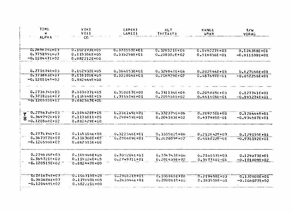
l i
TIME w
ALPHA
v ( ~, v ( l)
CD ----
GAM(R) ALT RANGE T/W LAM (I ) T hFT A ( P. l W~AR VDRAG ----· ----------------- --- -------- - ·------··--- -·
~---o;-209674-T-t="'C"r--LJ;TGZ1'13Ft--U5 o.37e553E+Ol o.335298!:+01
o.328521E+Ob 0.20830~E+02
0.1'1922ff:+03 O.Slf>8~8E-Ol
O.l26358E+Ol -C.8ll538E ... 01 0.37S899t+07 0.11535bE+05
-0.120447[+02 0.862212E+u0
o.271614t+03 O.lu2Y32E+05 o.3641S3E+Ol --~0;~73a-o.rr+7'0...,,-----...o-.-...-1--.-1-r6,-Io-or+o·s..----o.~ 2 ~a u4 e+ c; i
O. 32984i!E+Ci6 o. 20692'iE+O?
0.202544E+03 G.487697E-Ol
u. t 27U46E+Ol -0.~52256E ... Ol
-0.120514~+02 O.B82444E+OO
0.273614t+03 0.1036l7E+05 0.3~0017E+Ol 0.33ll34E+06 0.205885E+03 0.127741E+Ol ' 0.3718Lut+C7 O.ll6b4BE+QS L.31u~24E+Ol 0.2055?6E+02 0.46l~G8E-Ol -0.8~3274E+Ol :----o;u 0 5 55F+ OT--u-;tIB~-S1f3t+Oli-----=------=------'------'----"-----'-:;;__~__;'-=----~----~-'--'-~"-=--
' I
i----- --u-~-2756 NF+03 __ _ i ~ 0.36'17'12t+07 '. -O.l205b8E+02
0-~1G4428Ffu5----u.-33tT4'n:+-o-1------lf~-~D237i.}[; + Ob-~092 511:+ 03------o:l 28444E ... ~ O.ll760lt+05 0.2~845YE+Ol 0.204l83E+02 0.437985E-Ol -0.934~87E+Ol 0.882t:i~9E+Ci0
----·-----------------------------------------------------
O.Z77t:»l4l+O::> O. 36 7157E+07
-0. 12C5~'.>l-.+C2
o.10~1B4t+05 o.322~4bE+Cl 0.33358~~+0& 0.212&42f+C3 o.129155E+Ol o-.11b 360E+05- . - --u.-2H6609f+OT - -----o~ .i:'GZtfO~F-+0_i_ ---- cY~4l6822F....:of ----=0:9i6f92E+Of-0 .8t?~'J3E+Ci0
0.2796/4F+03 O.IO~Y46E+O~ 0.309204t+Ol 0.334743E+Ob 0.2lb057E+03 0.365721f+OJ 0.11912•E+G5 U.27497ll+Ol 0.20143SE+02 0.3~7761E-Ol
;·-·--·--o~-·12os1sE+o2 - -- - o ~882447E+o-o·-·------ ------· ------ ---·------------··------------
'
:----o.-zttt6-;-4-E+-03---cr-;-rc67T5Ff~-----ci-;ZVol 2- I t+O l 0.3b36Bb~+D7 O.ll9M95E+05 0.263~44t+Ol
-0.120449~+02 O.t82~~1E+OO
c.3351IT;~E+06 o. 2000611=+0'-:
o.21949aE+o3 0.38J558E-Ul
O.l29t573E+Ol -0.101809E+02
0. l30600E+Ol -O.l06027E+02
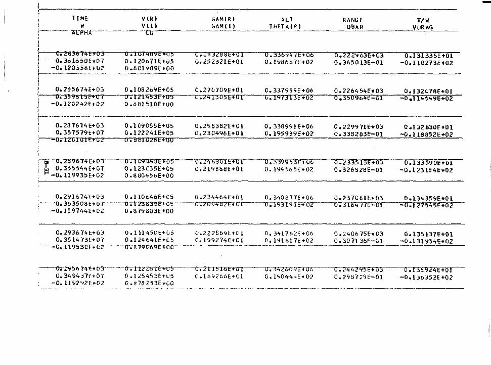
J ~ J i TIME VlR) GAM(R) All RANGE: T/W )
w v '1) GAM ( I) THH A(R J QBAR VURAG j---ACPHA co i i 'l
f c. 283674E+03 0. IOFi89E+05 c • .::s 32BSE+O l 0.33694 iE+06 0.222'>'63E+03 0.131335E+Ol l
I O. 36l650E+07 0. 1200 71 E+u5 0.2523ZIE+OI O.l'J8687t+02 0.365013E-Ol -O.ll0273E+02 ) -0.1202>58E.+02 0 .81:ll 909t+OO ) {-· ) 0.285674E+03 0 .I 08269E+Ci5 0. 2 7 u ·/O 9E +O l 0.33798'1E+06 0. 2264 54E+03 0.132ti76f+OI ' i O..-n9515F+O 1 o. rn453E+o5 C.241305E+Ol G. l'H313E+02 o.3509b4E-Ol -0 .114 ~4'1E+02 ~ -o. 1202421:'+02 o.as1s10E+oo i ! I !---- .. ----.----------- __ ,, _________
J \ o. 287614 E:+03 O. I 09055E+O~ 0.2"i6382E+Ol o. 338991 F.+06 0. 229971 E+03 0 .l 32830f +01 I o. 357579l:+07 O.l22241E+05 0.230490E+Ol 0.195939E+02 0.338283E-Ol -0.118852E+02
-o.12c101r:+vz O.BBIC26E•OO
i :----·o.;-zs96 71f Ei'0'3----u-atl91J:li'S"E+05 ____ Cl.-Z-'t""63'0T E + 0 I o. 3J9'951-E+u6"-- 0 .l33513F+0'.:1 0 .l 33590E+Ol l ! 0.355~44E+G1 0.123C35E+G5 c.2198b8E+Ol o. l94!>b5E+02 0.326!lll3E:-Ol -O.l23l84E+02 ; ~ -o. ll 9935E+02 0. tHl04!>oE+OO I
0.291614~+03 O.ll0o46E+C5 0.234464E+Ol 0.3~0~77E+Ob 0.237C6lc+03 O.l34359E+Ol · -o. 3:>350tst:·+tn------:-o;t13tn5t:+-c;!l------o~7u9""tt87F+ur---u-;-193T9IE+--or---o-;316 .. nE-crr- -o.r21·545£-+02 -0.119744E+02 0.879803E+OO
o.293674c+OJ o.111450c+~; O. 3514-(~(:+01' 0 .124 c41E 't'(; 5
0.22266%-tOl 0.199274E+01
-C• U 953CE+ C2 . _, -- o-.; 8 79to9E+CC - ------ -
·---o•-z'15ti tLtH c::t----o-.-nzzon-,.m----cr. 211516E+u I o.3494~1f+07 O.I25453E+u5 0.lb~266E•Ol
-0.1192~2E+02 0.879253E+GO
O. 3417o2i:+Cb O. l9ltil 7t+02
0 • .i4261J9i::i IJ6 O. l't044-=+E+02
0. ~406 75E:H~3 O. 307l 36F-Cll
a.244245E+03 o. n1n :.:>11:-01
- -----·--·--·---
Oa 13!> 137E+Ol -0.13l'J34E+02
O.l3!924E+Ol -O. Uo352E+02
--·-·----------
-
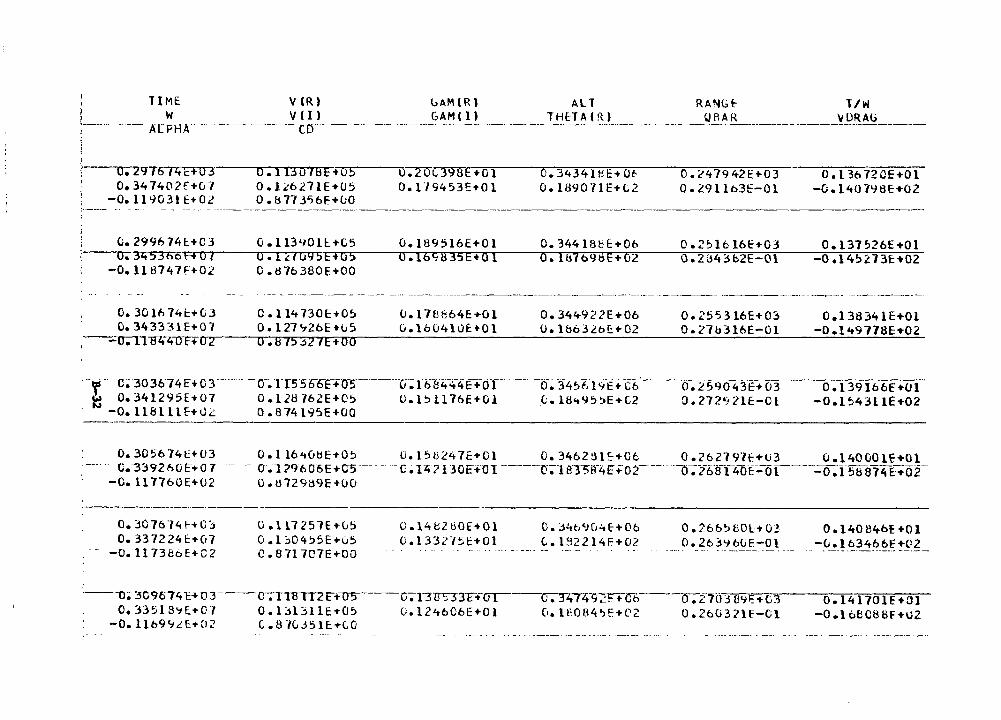
TIME V(R) uAM(R) ALT RANG~ T/W W V(I) GAM(l) THHACR) Qf\AR \/ORAG
-- ·--- A [PH A·- ----------- r·o------ --- ------------- -------------- ------------- -- ----··- -·---------- ---·-----------------
:·-·---..o..-....... 2976 I 4 i:: + 0 3 o. 347402f+07
-O. ll'103l ti-02
o • 113 o 78 E + o 5 0 • Lc6 271E+U5 o. 8113'>6F.+uo
0:70C398E +O l O. l "19453E-t01
0.3434leE+Ot 0.1890nE+C2
----------
0. '2479 421:+03 0.29llb3E-Ol
o. t 3o72CE+Ol -{;. l 40 798E+02
~.299674l+C3 O.ll390ll+C5 0.189516E+Ol 0.34418bE+Ob 0.2~1616f+03 O.l37~26E+Ol ~-~u-.-3~4530--c;i:--+~o~,--~o~.~1~,~,0~9~5~~E~+~o~5;..._-___,o,:.....:.....1~6~9~a~3~5~E~+~o;...;...1--~a~.:.....r1a~-~16~9~~~e~+~o~2,.-----:oz.~2~~~4~3'7L'b2~E~-~0~1.---_~o~.1~4~~~-~~-1~3~~~.~0~2~
-O.ll8747fi-02 O.d76380E+OO
- --- --------------- ----- ------------- -----------------·------------------------- ---------------~-·- -------------
0.30lh74t+03 O.ll4730c+O~ u.178664E+Ol 0.344922E+06 0.255316E+O~ 0.13S341E+Ol 0.343331E+07 o.t27~2bE+u5 G.1604luE•Ol 0.1&63Lb~+02 o.27u316E-Ol -0.149778E+02
,~-~rr;J.!1'lt41fR-rr2~---o=-=-.s,:..:,75;.....;..~2~1:...:.E+~o~o:..---=-=-:...::...:._:_-=-=..=-::..:..----=-.:....::...::..::..=-=-=-=--=-=---::....::...~=-=-.::..::..=--=-=---_:;_-=-..:...:..,;._;_=:..-=-;=-
--if c~ 30J674E+o3-- --- - -o-~1T5566F+o-5------,T~1·t.i1'f44-4E+-or--ci:-34~t:-i 9E+ c6·---0:25-9043E+ 03 ~ 0.341295E+07 O.l28762E+05 O.l51176E+Ol ~.18~~5~E+C2 0.272~21E-Cl N -O.ll8lllf+0~ 0.874195E+OO
-(5~T39Ib6f+Ol -0.1~4311E+02
----------·-------------
0.305674~+03 O.ll6~0tiE+05 D.158247E+Ol 0.3462~1~+06 O.l6219lf+U3 O.l40001E+Ol c.-3392t>OE:+o 1 -- - o.1 nt>06E+cs ·--- -- --c ~ iz;? 1 JoE+o1----o;·urr5tr4E+o2- ---- ·a-:26-ffCii'CYE~or-----0. P:ib a11i E:+or
-C.ll7760E+U2 o.u729a9E+OO
·-----------·-----~------------0.::107614HO::; O. 337224E+C17
-O. ll 73e6E+C2
O,.ll.7251E+v5 0. I ~04':>5E+05 C. B71707E+OO
·---o; 3C9o74 E+ u 3---o--;-i15m no 5 0.33518~l-tCJ O.l~l311E+05
-O.ll699iE+02 C.87L351E+t0
0.14t2tiOE+Ol C.3~b9G~E+06 0.2665BOL+03 0.14084bE+Ol o.133215~+01 c.1g2214~+02 0.263~bOE-Ol -v.l63466f+02
·-· - - . --- . -- - --· . ·- -------- -- . - -- - ·----- ---------·· __ ,,, __ _
---c-;T3TI:33F+Cfl"--u.3"4T4-9'2ITGb ___ --0:-.270::l U9i:+L3 Q. 141 701 E HJI -O.loE!C8Bf+U2 U.124606Ei-Ol 0.lE084~E+0Z 0.26U371E-Cl
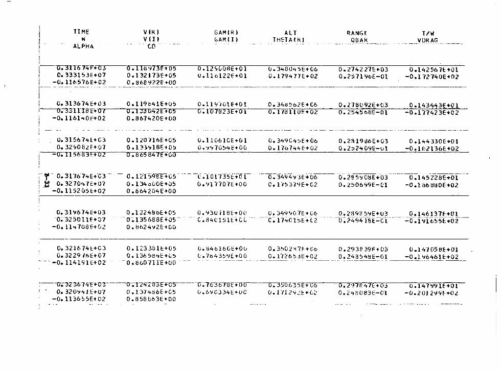
I i l 1 I -l
TIME w
ALPHA
i----CJ.31.T674F"+1J3 1 0.3331~3E+07
-o. ll6576E+02
vou V(l)
- - C.D ---- -
o .1 tu 'i73r+os 0. l 32 l13E+05 0 • B 68 •J2 2 E +00
GAM(R) GAM I I )
0.12'1(,0liE+Ol u.ll6122E+Ol
ALT THETAlkl
u.3~804'H:+G6
(). 1794 77E:+02
RANGf QBAk
0. 2742 l1E+03 D.257196E-Ol
T/W
0.1425b7E+Ol -O.l 72740E+02
,---- - -·-··--· -···-·--· ·-·· -- ···- ------------·--------·---· ---------------------------------
\ 0.313614E+C3 O.ll9b4lE+05 0.119/0lE+Ol 0.34u~b2E+C6 0.278V92t+C3 O.l43443E+Ol i---U-;-33TfT8T+-·""o .... ,--.... o-;i33U47E+C~s--~a-. TifTB23E•=o_,...1----=o-. -=-11=e""'1=-1=-o"""'E'"_+.....,0"""'2,,,...----=o=-.-=~::--:,_5::--4-::5::-t.-:8c:!:,..--=o-=1------=o-.-=-1-:::-,-=7-:-4-=2-=3-=E-+=-o-=2-
-o.1161~0f+02 0.867420E+OO
0.315674L+C3 0.1L0116E+05 0.32~08LE+07 0.13l~l8E+05
0.1Hi61CE+Ol o.<t'170!:>4t:+ou
O. 349C4:.E+Co 0.17o744E+02
0.2819l36E+03 0.2:>2~09E-Ol
O.l44330E+Ol -O.lf\2136E:+02 -----------------------------------i---IJ. T 1 5b-9"3"F+O?----o--~ffE5" iJ4Tf+GU
' ,
:· r-·· o~ 317674E+-c3 -- o-~ rz1~9-irn--cs--- -0 .-ro1·n--5·i:·•-01--~:3A94~-,.3E:+o6 ____ 0.2"85-ic8E+o_3 _______ o-:T4522sE+ol ___ _ ! t O. 3270't 7£+0-i 0.134 oOOE+05 0 .91 770n +00 c. U5::HlJE+G2 o. 2~06<i9E-C:l -0.1 bb880E ... 02 .. -0.1152051:+02 0.864204E+OO
-=--~--_;:__ ________ ~-----~---~-----------~---~--~~
o. 31%74E-+03 -0~·32so11E+o1
0.1224BbE+05 0.93U118E•OU U.349~07E+Ub 0.2899~9E+03 0.146137f+Ol --0:-135 68"8E+:o5-· --- c-. 84(.; l ~ lt:+C t --- --c: l 7<tc f~E--... T2 _______ -6: ?494T8-~=tT--·----=~fci"it.~5fio2-
-o.11 .. 1oaf+ri2
O. 321674!::..+C3 O. 32 29 16E+07
-o. 1141';1E+02"
o. li624'i2f:+CO
0.1233811:+05 O. l36!:>!3<tf: ... C5
-o~8W7lrE+UO - -----
C.ti4bl6Gt:+Ov (;. 7b435YE-t00
~---o-.;-3236-14c+o:r--o---;-r2't2-s-3F~~-----u--;763b7UE+oo
0.320~41E+U7 0.1374S6E+C5 G.6~G334E•UO -0.11365,F.+02 0.858863E+OO
O. 3'l0.2117F+Cb O. l7?6~dt:+C2
o. 35ffli35E+ G6 (J.1 "112'1~1:+(:;:
0.2938 ~9F-+ 03 0.24354tiE-Ol
O. 297fl 4-IE+ 03 0.24~UB3t:-Gl
0.14-/05~E+Ol
-O.l '164blE:+02
0. 147'19lE-+01 -0.2012-t~f+Ol
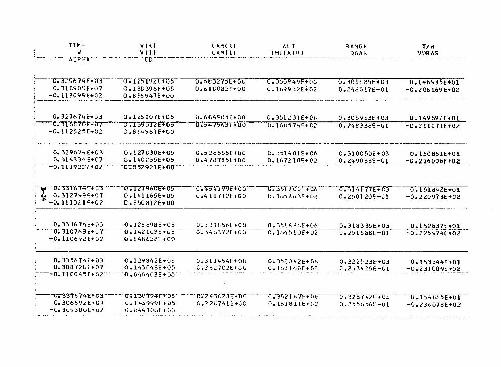
TIMi:- VlR) GAM(R) ALT RA~G~ l/W W
ALPHA--v l l) ------ -- -- -- --~~~ !_1._~ ____ _!__Hf:TA_!!_!_ ____________ :~~A_R _________ vn~_~_!? __ _ ---- -co----
I
O. 3L57>7ZtF+03 O. 31890'>F+07
-0. ll 3C99E:+02
a .1.5 t9..!E+05 0 .138 396F+U5 0. 8 56'i47E+OO
o.tie3n5E+Clv 0.6tU0tJ3E+OO
0.1:>094<fE+tib O. lb99j2f+G2
i ---- ·---- - -- ·-- -- -·- ·---·----------------------------------------------·---·,
0.30lfl&5E+v3 0.2480171:'-0l
0.14t)935E+Ol -0.2 06 l69l+02
I 0.327674E+03 O.l26107E+05 0.60490~[+00 ---u~"-3ToB7vF+""'CJ .... ,--~o ~cr.n-zr+-u~s----.0--._,5_4,_,7..__,56 ti 1:+ o o
0.35123lE+O~ 0.30~9~3E+03 0.149892E+Ol O.l6ti57~E+·~o-?--~o~.~7-4~8-3_;_3~8~~---~~l----~c~.~2-l-1~0~7~l~E~+-O~~~
-0.112525E+02 0.854~67E+GO
0.32967~E+03 O.l27U30E+05 , o.~l4B34E+07 o.140235E+05
0.528555E+OO 0.478785E+OO
C.j~l481E+06
o. l67218F:+ ('2 0.310050[+03 o. 2490381:-{;l
0 .1!;086 lE+O l -0.2lt>O'J6F+02
:~-~-u;-rrT93ZC+-u~2-----..u~.~s~5~zn9~2~1~E-+~o~u..---------------------------------------1
;-- . - -0-~33T6 74 H OT------o-.T2T96"U~+os------c-. 4:-i 4199E..-Oo- --c-: :;i;, l 1CdE-+a-----o:-3I 41 77 E + 03-: ! 0.3127~9~+07 O.l41165E+O~ 0.411712E+OO Oolb:>8b3E+O! 0.2~0120E-tl ~ -0.111321F.+02 O.B'l0812E-+00
0.1511342E+Ol -0 .2 20 97 3E+02
o. 3336 74t+ 03 O.I28b9HE+05 O.)~lbS6c+CO 0.3~1S36E+06 0.318)3~E+03 0.1~2b31E+Ol O~ 310763E+07 ___ _ - 0 .-l42 lG'3~+05- ---- - --o. 34-637<!ti=Ou _____ b~l64S-l or-+-c:;z----------0-~L5f5-68E-OC ___ ---:..:o:-iX5"-74E.•02--
-o. 1106'121:+02 0.tl48638E1-00
O. 335674E+u3 0.12~842E+05 D.3ll4~4E+OG 0.3~2042E+G6 I Oa30872bl+07 O.l43048E+05 G.2H27C2E+00 0.l63lb~E+C? ;------o.-11004sf+oz-- -o-. B46403E+-;::m----- ------- -----· --------------------------- -----
i
,---u.-3·Ji't:---rl.f-·t+u--3--o-;·e3o:r?ctET-O~ C. 7l!:3 GZB"t+ 0 0 Ci.? ?L74 H:+G u
0. 3"02 JFIF+TiE 0.161"3llE ... 02 0.30t>6''2t+C-l CJ. !...-3'f99E+05
-o. l0938ut-+C2 0. t44 luoE-tuO
0.322~.c3E+C3 0.2~3425E-(;l
0 o l ~3 ti44F +01 -C.231009E+02
·----------------·---------
0.326l<t2F+o..:. o.z'::,~6~6E-Ol
O.r54ti65E+Ul -o.2:1b078E+02
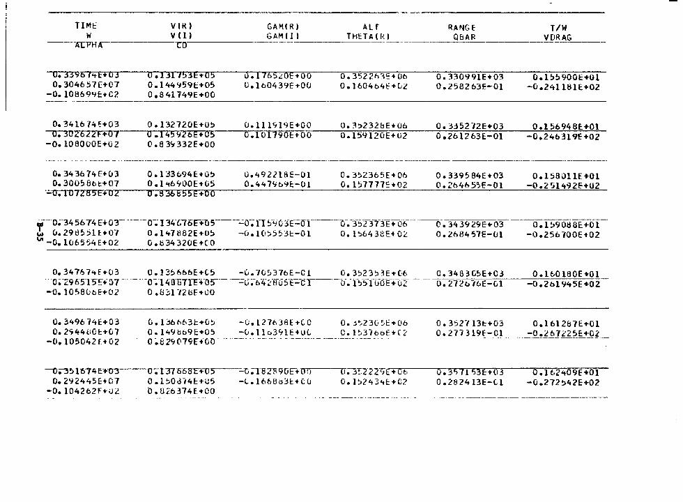
TI Mt w
----ALPHA
u. 3396 l<tE+03 o. 304657[+07
-0. 10B699c-tC2
0.341674H03 --u;""JU .! 6 a F + 01 -o.1oaoooE+o2
O. 34 3b 74 FH.13 0.30058bt+07
-~-u-;ui /285E+02
VIK) GAM(R) GAM ( l) v (I)
ro·------·------
0.1311!>3E+05 0 .144 '1591:+05 Oe84l 749E+OO
0. l32720E+O~ 0 .145<J26E+05 0.83'7332E+OO
0. l 33694E+O!:> 0. l 't6'700E-tG5 0 .8 36855E+OO
u.1765.;::0E+OO 0.160439h00
CJ.lll'119E+OO 0.10l790f:+OO
0.4922l8E-Ol 0.447~6%-0l
ALT THETA ( R l
0.3522hJ':-t06 O. I60464t:=+ul
o. ?1:>232bE+06 0.15'1120E-tU2
O. 3~2365E+06 o. 157777':-t02
~ANGE QBAR
O. 330991E+03 0 .2582 63E-Ol
O. 335272E+03 0.261263E-Ol
0.339584E+03 0.26465.,E-Ol
T/W VDRAG ----
0.15!:>9001:+01 -0.24llBlE+02
O.l5694BE+Ol -0.24b319E+02
0. l 58011£. +01 -o .2 51492E--t02
,---o~3456 74 HoT- ---·--o-~ I 341.?l>c+ns·-----=o-;n ~4o::ff;:oy·--u-.-I5T3'BE"+ oti ____ ---o·.-343'12<tE:+o3 ____ o-:T~9o8af+oi-w 0.29135!:>U+o·1 O.l47882E+05 -0.1(1~5531:-01 0.1~6438EHlL 0.26B457E-lJl -0.256700E+02 "'-0.10655'1E+02 O.!:i34320E+CO
0.34767~f+03 0.135666E+C5 -0.7Ci5376E-Cl 0.3523~3E+(6 C.34S3C5E+C3 ·o;-z965T5E+tH - · ··- ---0~14an1rE+ns--- ·--=0~-·64-~·s-0sE~.-cr--o-.-1~~-n:.i-oE:-+-li2· -- --o:-~f2t. 10E-c,1
__ 0_._160160E +O 1 -o .2bl 945E +02
-0.1058ubf+Ol 0.8~172tiF+00
o. 3496 74t.+03 o. 2'744ll01:+07
-0.-105042 f + 02· -
-O;-J!:>"lti74t:+03 o. 2'12445f:+07
-0. l04262f+Ol
(; .136tib31:+0!:i 0. l<t9bo9E+05 0 ~8 2'1011fE+CiO
-(;. 1276 JIH +(J 0 -u.1 lo39lE+uL
0. t3T55EF~-S---u;l82"F9uHOU O.l~Odl4c+U5 -l.l66Uti~l:+Cu
b.8~6374f+OO
o. j';,23(.51::+06 C.1~37bt>E+C<:·
lT;-3~2 2 2'i-I: + 0 t· 0.1~243<tE+O?
0.3,2113t+03 O.l612~7E+Ol
_Q_~_?_7_!_319f-Ol ________ ':"Q.!l~Jl~-~t_+:Q? __
o.3">1153E:+o3 0. 28 2413E-C. l
0.162409E+Ol -0.272~42E:+02
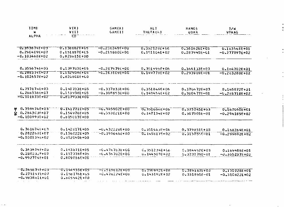
TIME' V(R) GAM(R) All RANGE: l/W w v (I) (...AM ( l t l Hl::T Al k) iJBA R VOkAG
ALPHA en·-- -·-- .. --· ---·- .. -· -~ ~ . -- . - ... ··-· ------- ...
---i::r.353674T+~ 0. I 3B682Hv5 -0.2.::il349F.+OU o.3:>212ui::+oc. 0.361626£+03 0.163~48E+Ol O. 2':104C9t:+07 O.l~l887E+C5 -0.21~800E+OO O.l~llC4E+02 0.2B7<f45E-Cil -o.211a91i:+o2
-0.1034b8H02 0. B 23ol 5E+OO "-------·~----·· --------·
o. 3556741:-+03 -cr.7fftJ37IT+O I
o.I397U3E+05 -C.2c7~79E+OG 0.351~9~f+C6 0.366133E+03 G.lo4702E+ul o.15z9o~E·-·+~t .......... s~~---~c-.2~6..-.-3~1~G~~·E~+~a~"?C'o~~-,.o-.•14~9~1~1~~E~+7"0~2-~~o...-.2~·1~)~39~69~E~.--;:-o~1----o-;:;---.2-:;:-Tt3;;-:;-2s~a;;-;:-E+~o~2::-
-o. 102b5 7E+02 o.a208coE+t.o
.. ---·------------·-·-------- ··---------------· ---·-------·----
0.35767~l+03 0.1~0733E+05 -0.337~33~+00 D.~51846E+06 0.37Dbl2E+03 .0.lh5672E+Ql L.286338E+07 0.1~3~38E+05 -0.308853~+00 O.l434~4E+G2 0.3U0477E-Ol -~.2t8718E+02
;.;.u;-ro1a33E+-o .... 2---CJ.'ITTT'T33E+rrrr-----------------------------------
'f o-. 359674HOr. O~T.C.1771E-+u5----=G;'.UJ590?FffU ____ o--;-:hT&boC:+o6 ___ cr;;.-3'f5245E+u3 ~ o. 2&43CJf+07 0 .154 '176E+IJ5 -o.:;; 5302 lE+OO o. 14713-t-£+02 0. ;,o7505E-Ol -0.100993~+02 0.815Cl3E+OO
0 ;lb 7-660E+Cr -0.2'l4185E+02
---- --~---------------~-----~-----------
O. 36lb74t+G::\ . 0;282Zt>3£+C7 --o. 100134 t+02
o. 3b3b 14h03 o. 2802J.l:ft.07
-0. 99 27C4 F.+01
o. t42ol7E+05 0.156CT22E•05 0. tH2G40E:+OO
0.143b11E+05 0.1~1:.H6E+O~
0 ;809ClbFH10
-0.43222tlE+OO 0.3514bjE+06 0.3l9851E+03 O.lb82b4E+Ol -er~ 39 56~61::+00-----·-o; .-~.-s-en(-t 02 _____ 0-;; 3 1--------::0 ~i'T%92E +02-
-(; .4 ·1e 16 3E: + 00 -0 .4 3c-. 702E:+OC
C.j:>l234E+Gt. u. l44'.>01E+02
C.3844<t2E+03 0.323l 79E-Ol
O.lM14B6E+Ol -v • .:H.J~237E+02
---er.- 3b ~o7 'f~ H;s---c-;-i-c,4 q3 s i:+us----..:c;"519cTI E + o o 0. 35(19 f\2E + 06 0.143l9.<!E+02
0. 38916'(1:+03 O. Bl891E-Ol
O.l 707261:+01 -0.31Cti22E+02 0.278l~Jl+07 0.1~~11~1:+~5 -0.4~a214E+UU
-0.9ti38bll+Ol 0.&05~42E+OO
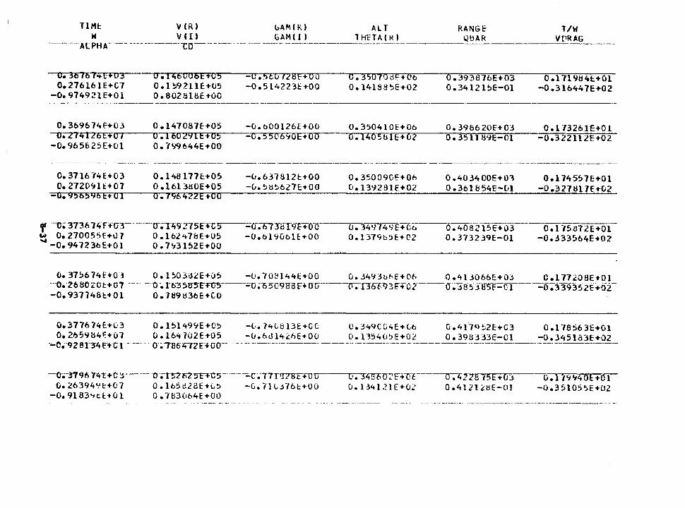
TIMI: VlR) l:.AM(R) ALT W V (I) GAM I 1 I THETA ltU
-------ALPHA----- ------------i:::o------- --- ------- ---------------------
o. 36767-tE+03 0.276161E+C7
-0. 974921E+Ol
O.t46C06E+05 0 .1~9Z11 E +U5 O.B02818E+OO
-C.56ll 728F+Oo -0.5142231:+00
0. 3S07o di:+ Ot:i 0.14188':>E+02
RANGE ___ l.lllA_R __ _
0.3931376E+03 0.3412l!:>E-Ol
T/W VPRAG --------
O.l 719tl'tt:.+01 -0.316447E+02
0.369674f+03 0.147087E+05 -G.t:i00l26E+OO o.350410c+Ob 0.398620E+03 0.173261E+Ol --u;-zTztl7'6~~E~+~u~1-~~a..---..100291E+C5 -c.~506~01:+-o-o--·~o-.-1-4-o-s-b~l~c-+~0~2-~-o~.3~5~1~1~1;1-9-E~--c=,1,__--_~o~.~3~2"~2~1~1~2=F~.+-=-02
-0.96562SE+Ol 0.7'19644E+OO
O. 3716 HE+03 0. l48 l 77E+05 -u. 631812E:+OO O. 350090i::+06 0 .403400E+Ol O. l 74557E+Ol 0.2720~1~+07 O.l613HOE+05 -0.5~~627E+OO 0.13~2~1E+02 0.3t:il854E-&l -0.327t117f+02
-0.9565~5Ft·o~~1~~~a;:....:....~,q~6~4~z~2~E~+~c~o..--~---=....:...:_:__:_-=-=:_:.-~~---=-.=....:...:....=----=-_::___.;_:=_~~--'-:...;_:....::....:....::....-=---'=--~~-"-"....;;;.._;.__;;._;;;~-'-=-
f ·-u; 3736 74 f+('J3- ----u-;rzt9-:_>75t+G :>
w O. 270055E+u 1 0 .162<t78E+05 "-0.94723bE+Ol 0.7'73152E+OO
~ff;673lff9E+o-o-----u.-:14•H49 E +cb ___ 6. 40 8215E+ 03 -O.ol9GolE+OO 0.1379bjf+C2 0.31323qE-Ol
o.1 ·1su72E+Ol -0.333~64E+02
O. 37!:>674f+Q] O. l ~0.H2E+05 -u. -IO~l44E+OG CJ. 34'Hut-.t+Ot> 0 .4l 306bE+03 C.1772-0BE+Ol ---o. zbao zo1:+01 -- - -··o-. tb'358-S-cf1J-s----~o ;o5o9aa i=+mr----v.TJof.TJ3F+o2----o ~3i.rs-sll5r:~cr---~<.r;:n9352T+o2 -0.9377481::+01 0.789836E+CO
0.3776l4E+G3 0.151499E+O~ -L.14L813E•GC 0e349CG4E+Lb 0.265~U4E+07 0.164102E+05 -u.6dl4~hE•OO 0.1154U~E+02
0.411Q!;;2E+C3 0. 391.U 3JE-Ol
O.U8563E+Ol -0.345183E+02
--0. 928134f+CI - -·- - 0 ~ 7S6zt72E+Oo-- ----------- ---- ------------ ---- ------------------- --------------
--C-.-J'1'96 rt+~+c~---o·;-t52ti-Z5F'f--c5----=c-.-77T1J78F-FDu 0.26394Yl:+07 O.loS~2HE+~~ -G.71L~761:•00
-0.9183~c~+Ol O.l83064E+OO
o. 34860.._'E.+lY~ o .4226 t5E+CJ~ 0.134121E+02 0.4121~8E-OJ
o.1 H940E+Ol -0.35105~E+02
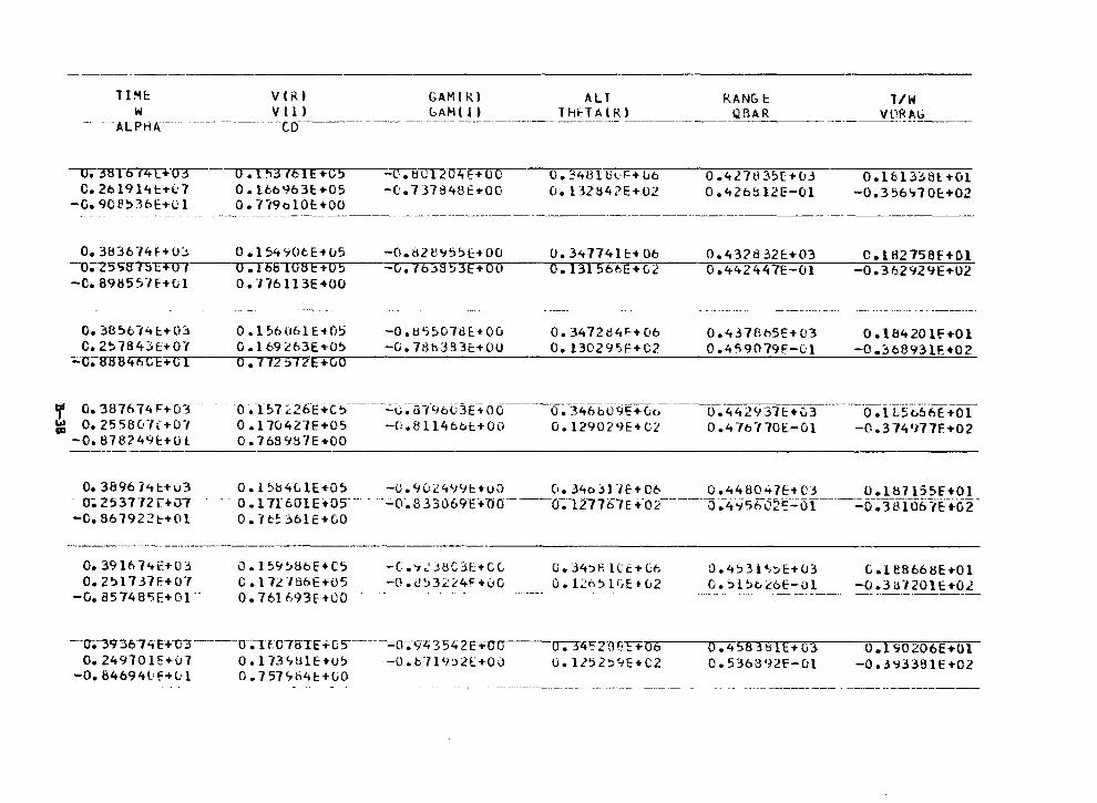
llMI:: VCR) GAM(R) All W V(l) LAH(!) lliHAlRI
-· - -ALPHA- -- - ---------- - -co-----------------·-··-·------·---··---·--------·---·---·---
--u;38T674THJ3-C. 2t>l9141::+l.:7
-G.90!!53t>E+01
0.1"13761E+C5 0. lt.b%3E::+05 O. Ti9olOE+OO
~m·i'.T4E+OO
-0.13784BE+OO 0.34Bltl(•F+lJb O. 13Z842E+02
·- ------·---·- - --·- ·-------·----- -·-- -----------------------··---
RANGE: QBAR --'------ ------------------
l/W Vl1R~.G
0.4l7tD~E+(J3
0.426812E-Ol O.lfil3~81:.+0l
-0.356~70E:+02
0.383674F+U~ 0.15490tE+05 -0.82H~5~E+OO 0.3<t77411::+06 0.43?d32E:+03 C.1H2758E+Gl -u;2s~eT5T'i"U?----...u-.~15s1·~ona~E·+~o~5----,o~.-1~t>r~~a~'~~3~E~+-;-...,.-o~o---,.;o'.,1~3~1"5~ti~~~-E~+~u~'~~---,_.o-.7474~27474~7H-E--'0~1:----_~o~.~3~6~2~~~2:;-;;-9~E7+~u-;;-2
-C.898551F+01 0.776113E+OO
O. 3856-14 E::+ O.'.:i 0 .1 %06H+O~ -O.tl5~07t>E.•Ou c.2~7843t+O"I O.l69c63E+(J5 -G. 78h3Bt:+OO
0. 34 72 cl4i:+ Ot:i O. l3029">F+C2
0.4378b5E+03 0. 4"i 90 79F-l:l
O.l8420lf+Ol -o .:-; 6893 lF. +02
;;;o~ff8847lCt-+-c~1--~a~.-7~7~2~~~1~2~·E,....,.+~G~a-------------------------------------
f G.387674F~O~ ~ o. 2558C·h+o·1
-0.878249E:+Ol
o. 3B96 7<tt+u3 O; 253TT2r+07
-0. 867922t+Ol
O. 391614E+O j 0.2517.HF.-+07
-G. 85748'>E+Ol --
·a ·.T57 i.26E:+c.,---------.;:.~ ~o-t"'J6L13E:-+oo----o.-:~46tiif9r:+ut.:- ----o. 4429 37E+c3·-----o .iT5(:;6-bf.;01-o .170421E +05 -0. 8114 t.t.l:. + 00 0. 1290 2 <JE+ C2 0 .4 lb-, ?OE-01 -0. 3 74'H7F +02 O. 768987E+OO
--~-----~---~----~------------~-----~
O.l~84ClE+O~ -U.90i4~9E+uo 0.34D~l1f+C6 0.448047E+C3 0.187155E+Ol - - a .11r 601 E:.os- -- -.;;..o·. s 33069E+no----o-;;-1n16"1E .-02--------0.-4-t56c2r:-~i.'.ff-----=o .3-8To67E-+o2-
o. 7t.~:l61E+GO
0.159~8t>E+C':)
C. l 72 "f86E+05 0.761693E+OO
-C.'7<.':-:l8C3E+CC. -0. U53:<'.~4Hu0
C. 34~fi lCE+C6 O.l.2o~UiE•u2
0. 4 '.> 31•;:;,E:+u3 O.'.>l~t.:.'.'oE-01
G.H8668E+Ol -o .3 u.nou +02
---o;-39 36 7 4 E+o3---·-cr;·n 07BTI: +G s------,;;,;u~Ytt 35 lt 2[ t:O 0 CJ.""T4~2-ffFF+ o 6 O.ll?2SC,..E+C2
0.45838[E .. o3 0. 5363921:'-0l
O.l90206E+Ol -o .3 ~338 lE +02 0.249701E+07 0.173~~1E+U':) -O.b719~2E+OO
-0.84694Gf+01 0.757~b4t+OO
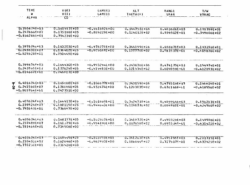
TI ME w
-ALPHA - --
---u;-3"95~T+·o TO. 24 76b6E+07
-0.8362661:.+0l
VCR) v (I) --co--.
0.161'1S7E+o5 0 .115 l!:l6E +05 0. 754234E+Ou
GAM CR) GAMll)
-O.'ibl692l::+OO -0.8B<:t229E+OO
ALT T Htf A CH)
u. 344751E+G6 O. l24012E+02
RANC..f: T/W UAAR VORAG
0.463606E+03 0.559502E-Ol
O. l 91-/69E+Ol -0.399606E:+02
o. 3976 74t+03 -c;-zr+ 563UF+ ur---o. 825~28E+Ol
O.l63203E+U5 -0.97B271E+CO 0.1164C2E+o,----~o-.9C5G68E+OO
0. 7!:i0Lt45E+Ci0
0.344199E+vo 0.468tl71E+03 O.l933SijE+Ol o.J22770E+0~2r--~-.,.,.o-.=5a~35~3=7=E~-~O~l~~--~o-.~4~0~56~7~6~E~+~O~Z:o--
0.399b74F+03 O.lo4430E+05 -o. 9'i 32'1"ti:+OO 0.2435~5E+GI 0.177b2~E+05 -CJ. 'i l 'i4!BE+Ou
0.3436361:-+0b 0.121 !>34E+CJ2
-·----- ----- ----- -------- _____ ,, __________ _
0.474175(+03 0.6090~%-Cil
0.194974E+Ol -G.4121931::+02
-;;..--o;·s14667F+-OT-----o--;Tzt1.i1'T7F+-........ ---------------------------------
-o;ro(1t:>ni:+o-1--o-;;f4~3 06 -0.932474t+OO 0.120303E+02
.,,. o. 4016 74 E + 03 -- . ' -o-;165 6b6'F+05 ~ 0.2415bOE+07 O.l78866E+05 . -0.8037~4t+01 0.742751E+OO
o. 4795 hE+iH ---0 .1ci66t6E-:t-0I--0. 63tl boE-~l -0.4l8556E+02
------------------------~--------~-~
0.403b74f+03 ... o. 239524€+07. -o. 79264H:+O1
0.4056"/4t+U3 0.23748'.H.+07
-~o. 78 l4b4E+Ol
0. lon917E+O~ o-;.-1b0ll5E +05 0. 7 3t:Hl47E+OO
0 • 168 n "IE +O 5 O.lbl..i75E+li5 o. T34 9C6E +oo-
---0~401-01 tt+·o:r---1J ;-n:tT.:t411F+o s v.2~545it+07 0.1~2b46E+05
-0. 17C23Cl:+Ol 0. ·13Ci't2BE+CO
-u.lulbb9t+Cl 0.3~2471E+Gb 0.4849u4t+03 0.19h2&7E+Ol -ci'.94'tu<t3t: +oo ·------o~-i 1901·11::+ oi ·--0-:·66496~oT-oi---=o~·4i~9b6~-+62-
-o.Iu29~7l::+Ol 0.34l872E+O~
-0.954190E+OO 0.1178~!:lE+C2
-O.Iu31':dt+Ol -L.96?910HOO
o. 341 Zo_ff+C-6 O. lH>644t:-+li?
0.~9032'-tE+03 O.l~9986E+Ol 0.6955J4~-0l -0.431422E+Ol
o.49Si%f:+03 0. "12.7'7 U7'5:-0l
·-~-~~------·--
0.2 0171 SE+Ol -o .4 3792 !>F.-t-i1.2
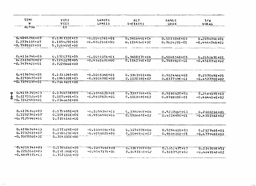
lIMf V(R) W V(l)
ALPHA---- -------------co·----·--
-u;i;u%7ltF+~
O. 23341BH07 -o. 758862F+Ol
o. 4116 741::+03 --u;-zJJ363t:+O 1 -0. 747442E+Ol
0 .110 132E+C5 0. lf',3~29E+05 0.726</15EHrO
0 .112 C27 E +O!> o. l bll3E+05 0. 722866E+OO
GAM IR) (:.AM (I)
-0 .104~26E:+O l -o. (rt u 2 !:>:>E+O 0
All ·1 HH A ( ;>,)
0.34Cb44E:+Co u. 11~43oE+02
RANGE l/W __________ A_R_:._ ________________ V_ °-~-~-G _______ _
o. 50 l304E+03 o. 76242.IE:-Ol
0 .203474E:. +01 -0 .4.44476E+02
---------·---
0.413674c+03 0.113J34E+05 -0.105534E:+Ol 0.339381E+Ob o.512446E+03 0.2070(j5E+Ol -0.457720E+O:? 0.229347€+07 O.l86530E+05 -0.98C678E+OO 0.11303BE+02 D.637749E-Cl
-o.735913r.~·~a~1~~-..o~.~,~1~u~1~u~2~E~+~omo.--~----------~.........;--------------------~
ll" 0~7"41'56 74t:+0-"3"-------·- 0 ;i. 74ti53E+1r5--..;;0·;1·oi;-E11-:ri:+·o1-·----cr;331J7-,9F+C'b --o:-~180 b2E+03-----0:2u1:f939E+Cl ~ 0.2273llt+07 0.167t49E:+C~ -C.9S3lB2t+OC. O.lll848E+02 0.879a6SE-Cl -0.464414E+02 0 -o.1242416E+Ol o.-/14oo5E+OO
0.4l 76Nt+03 C.-Z25276E+OT
-o. 712594!::+{Jl
0. I 7~985E+C.5 o-~l -eq l8CE"+05-0. 110 ~ l4E +00
0.419b74F+03 0.117~29E+05 0.22324lf+07 0.1~0~23E+O~
-0.70C806E+Jr----- 0~7CbHOE-+oo-
-O. li.JS<f3'1t=+C 1 c. 338U'JLlf+06 0 .'>2 37cul::+C3 -ir; 98S494t1-G c---·o.Tf<fo"(.;51:+02··----0.
-0.10!:>9161:1'01 ~.337431E+Co o.529482E+03 0.212748E+Ol -u. '7 S:, !j02 E+O 0 ~]._9~~~-~~~-~2 ___ _ p !...9680 20E-O!_ ______ :O•i 77?_.'!:~_E+.QL
"---0.4"2 l614f"+ tr-r-·-- 0-;-!IBT.<;6 E"i'U5----=c·;ro'> f "t'tGO-r- O. 33C77CT+IT6-. --a. !i~~· 4 lY:-t(.j
O.JC931"E+Ci2 0.1017~2f+O;:: 0 .214 705E Hll
-C.484784E-t02 0. 2212 Lb E+01 O.l~lJHOE•C~ -0.434117E+OC -0.688937t:+Cl 0.7C2114!::+CO
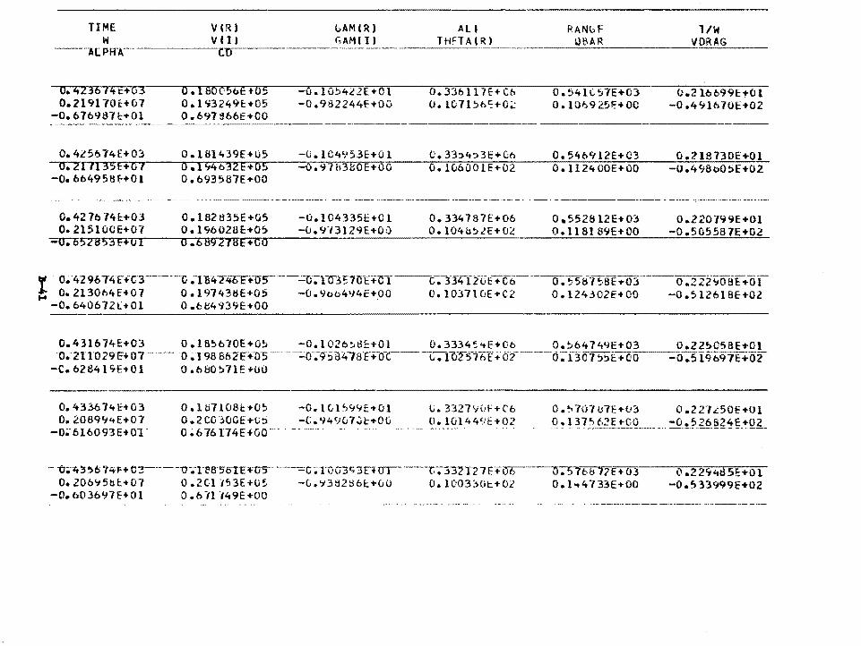
TIME VIR} GAMlR} ALI 1/W W VII) GAMII) T H!=TA t R l
---··A[. PAr·--------r:n:--------- ------------------------------------------
o. 423614t::+03 o. 2191701::+07
-o. b7b9lHt+Ol
o. I &OC-5t>E +05 0. l '73249E:-t-05 0.697B66E+CO
-o.1o:i422E. ... 01 -0.982244f+Ov
O. 33611 7£+ Cb o. rnn:ie.r:+o~
O. 54ll.~aE+03 0 .101:19 2.51:+00
o.2166991:+01 -o .4<;lb70t:+02
0.4l56l4E+03 0.181439E+05 -U.lC4953E+Ol C.33~4~3E+Gb 0.546912E+C3 0.21S730E+Ol -i:r.7f7T3"5'.~E+~o~1--·o.r:-..1~;~4ro~3~2"E~+~o"s~---~o'.7.9~7~11~3~~~0~E~+~o~o---r.o~ •• 17u6'o~o;:;-;-1E~+7o~2z----;o'.~1~1~2~4~0~0~E~·.~o~o:----_7.o~.~4~9~a~o~o7~7-E~+7.o-::-2 -0.664958~+01 0.693587E+OO
--·----- -- - ---
0.42 76 74l+03 0.182 835E+05 -O. l04335E+C 1 O. 334 7 B 7E+06 0 .552812E+OJ O.Z 20"f99E+Ol o. 215100E+07 O. l96028E+05 -u.cn3129E+OQ 0.104h5lE+02 o. I 18l 89E+OO -D.5C5587E+02
-;o-;o578"'5'3F+·~o~1---..o-.~6~a~9~2~1~a~E~+~c~a~~~~~~~--~~~~--~-~~~~~~~~-~~-~~~~-
"' . 0;;·429674t+C3 _____ 1l .TB4NOF+O'S-'---=o;nr3~70E+'CT ___ c~-:rl4ftt'E+Cb ___ --0._558•1~.8E+O~f-f; O. 2130ME+07 0 .19743tiE+05 -u.9oo4'J4E+,OO 0.10371 OE+C2 0 .124302E+OO
o .-2 2z-;:;oaf.f.ol-o .~1261sE+o2
-0.640672l+Ol o.c~4439E+OO
0.431674E+03 O.l8~b70E+o; -O.l02b~~c+Ol 0.3334~'tE+Oo o.~64144E+03 o.22;C58E+Ol -0 ... 211029 r:+ o7 ·-- ··-·- ·o ~T9BS62E+-!Js--- -;;:o-;9-5 B47a'l~-.-o-c-- -t-;;-nfl'5-76I+ 02----0 ;13·cf1 ,~E+oo--:o:-519'6911;+02 -C.6284l~E+Ol O.o&0~71E+OO
o. 4336 7'tE+03 o. zosqy,.E+07
-0•·01ao93E+o1-
0.1071081::,..0~
0.2CG30GE..-t.;::> 0 ~6 76174E+GO
-o. 1 C; l '>94E-t-OJ -C.949u7..Ji:-t-OG
L. 33279\t!-=+('6 ll.1Gl449E+02
·- ·o;·..r..;, '>6' 7.itr-+ cr3------o-.-i-ea·551E+-US- -----=c;;ToG3c;3r+ ur---r;-;3'32T2Tf.+ITTJ 0.206~5~~+01 0.2Cl1~3E+U5 -C.~392~6~-t-00 0.1003~0~+02
-O.b03697E+Ol 0.6lll49E+OO
0.~707U7E+~3 0.227L50E+Dl o .13?~-f,~i__!.QQ _______ -o !?.26 ~~~~-~QI_
0. 5 7T.F7Lt+ 03 0. l-+4./33E+OO
0.2294d5i:+Ol -0.1)33999E+02
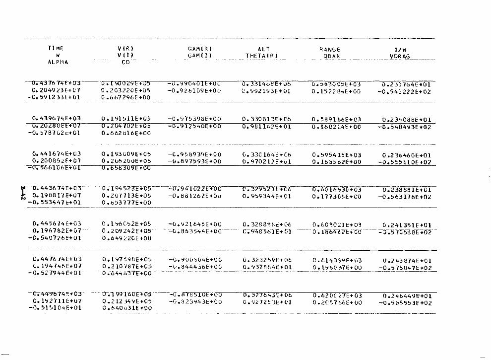
-·----·-------------- ----·------
TI ME w
ALPH4
VtR) v tn co·--
GAM(R) GAM(I)
-0-;<t3 76 Tltr+ 0-T ____ -().T9\JffZ9F-t--:ys---=\r;qw~ .. 0 (, 0.2049L3f+C7 0.2C322uE•05 -0.92ol09c+OU
-0.591233l+ul 0.6o7296E•OO
ALT THU A ( R J
0.3314e;~E+U6 0. '19ll 9.-:iE:+(j1
R.ANGE OBAR
G.:>ti30C:>t:+G3 0 .1522 B4E:+OO
JI W VDRAG
-- --- - -- - . ------··--------
0.23l1<>4r:+u1 -o. 5412221:.+02
--- --·- --- ------· --- ------·- ---------- -----·---·----------·-------------------·----·-------
o. 4396-l4E+03 ---u.?OZ!ni ET +07 -0. ~787 C.2 c+Ol
0.191~11E•05 -0.97~398E+OO 0.330313E+C6 0.589l86E+C3 0.234088E+Ol 0.2047CJ2_E_+_0_5 _____ 0_.-9·-1~2~5~4-0~E~-... -o~o--~o-.~9~8~l~l-6~2~E~+~O~l:----o-o---.71~670~2~~~4~f~+~O~O,------_~c~.~5~4~8~4~~~·3==-E-+7072-o • 6 62 ti 1 6 E + 0 0
0.441614E+C3 O.l93009E+O~ -C.9~b939c+OO G.33Cl64E+C6 o.~95415c+03 0.236460~+01 o.2ooa~~F+07 0.2u620VE+O'~~-----u_._8_97593E+_O~O-=----~o~._;_9_;_7~0~2~l~?~E~+~u~l=----o~·~l6_:._:_tl~~~6~2~E_•~O~O ____ -~U~·~~-~~5_b_l~O~E~--·-o~2-
-;.;.-u;-566TG6FFOT--r.isa3011r+oo
f o~ 4436 74E+or- · - · o.; 194 523T+cs------..:.a~9'+1022E-+-oc--~,-.;r5-.z-rt+c·6-----0-:60IT<t-:rt:;-cr3---------0:23if8a fE+oI-t O.l98811E+07 0.207713E+05 -O.HB12b2E+00 0.9~9344E+Ol 0.177305E+CO -0.563l76E+02
-0.553447t+Ol 0.653777E•OO ---·----·-----
o. 4456 /41:+03 O. 19678Zt+Or·
-0. 540726!:+01
O.l96C~2E+05 -0.~21645E+uo 0.328BRi~+06 0.60~021~+03 0.241351E+Ol o. 2 09 242E+os-- -- - .:_c;. a6 3~4ztE+~o-----c-;9ztest>1E..-!'.ii----o~1864 c.-L>-~.f:cc ----=-::i~~7c~i3 aT+o2-o. 649 :::2GE +oo
·- ---------~·----
o. 44 76 14 t+ (J 3 l.. l9414t-.E+07
-0. 527944E+Ol.
O.l97~9BE+O~ -0.iU0~04E•OC 0.3232~9E+Ot 0.614399F+G3 0.24~874E+Ol 0. 2 10 ·1&7E +C5 -tJ. 3444 .'.l6E +C (; O. 937 Bt.4 t +O l ____ --~! ~.~(\ j7 E+ 00 ____ _:-_0. ~_1~(_)_4 7c:!.Q_?_ - 0;644i:.37Ft-GO ------- -- - -- -- ---------------------- -
-o-.-ei:ct7574 '!: + o 3-----u--;-rc19T5Cc:Fcr5 -o • lITFS-10 E+ 0 0 O.l92711E:+OI 0.212349E+05 -G.tl2~'743t::+OO
-0.51~104E+Ol O.h40031E+OO
o. ,j? 76<tJE+ C•t o. lj 2'. 12 ~ :'.t: + 01
0. 62 Cit~ 27E:+ 03 0 • ~ (' ~ 7 66 E • CJ 0
0.246449E+Ol -0.'>:,'>5?3F+02
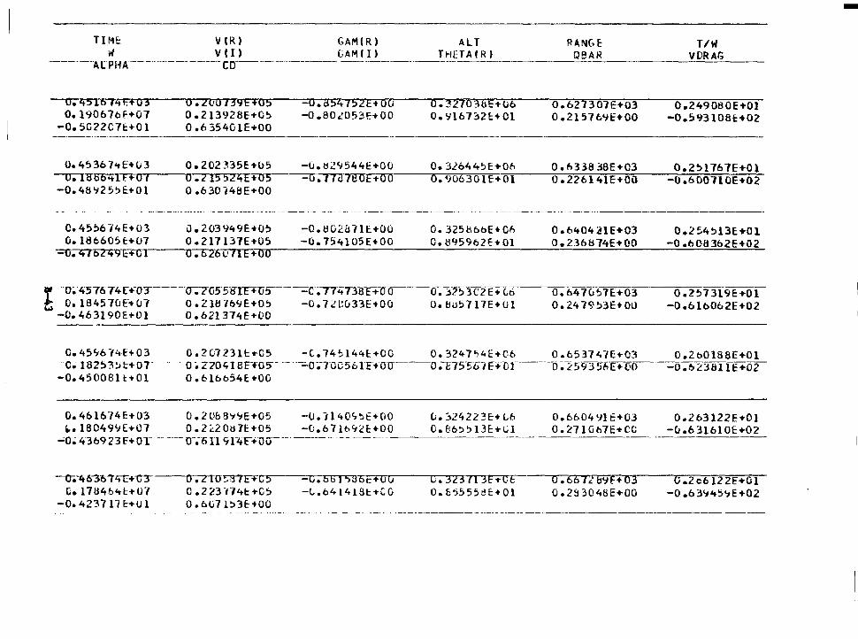
TIM!:: VIR) GAM(R) ALT W Vil) CAMI!) THtTAfR)
--------AlPHA---------------co--·-·-··--·-·--------- --------------
O. 451614H03 o. 1906 7of+07
-0. 5G22C71:+0 l
0. 2UO /39E +05 0. 21392 BE+-05 0 .6 3540 lE+OO
------···----------------------
o. 4536 7<tE+u3 -u;iaas ... n+o 1 -0.48'i25~E+Ol
0. 202 335E+lJ5 0. 215 524E +-05 0 .630 i48E+OO
o.a5475zE+oa -O.BO..'U53!:+00
-O.tl2'1544E•OO o.1 lc lt!OE+oo
o.32763tiE+-U6 0.'.7167212!::+01
O. 32644~E+Ofi 0.906301E+Ol
R-.NGf: QBA_R __
0.627301E+03 0 .2157f.'Jf+OO
O.fi33838E+C3 0 .226141E+OO
T/W VDRAG
0.249080E+Ol -0.593108t:+02
0.2~1767E+Ol -0.600110E+02
- _____ , ___ ,, ______ -------------·------- -- --·----------- ---------- ·- -------------------
C. 45!:16 74E+03 u.186605E+07
-u. 416249E+GI
0. 203 949E+-O!:i 0.217137E+-05
-O.IHJ2fi71E+OO -0.754105E+OO
If' -o~-4576 74T+-or----u-;zosstrTE+us----=o~77ifT3s r+-oo t O.l84570E'+07 0.2187b9E+05 -0.7d:033E+OO -0.463190£:+01 0.621374E+OO
O. 3251:\boE+CfJ o. 895962!:+01
O. ~-l~3C2E+(;6 O. bu5717E+Ul
0. 6404 21E+03 0. 23b874E+OO
0.647u~7E+03
0. 24 79 !:>3E+ 00
0.2~4!:>13E+Ol -0 .608362E+-02
0 • 2 ~ 1 31 9 E: +0 1 -O.bloObZE+02
o. 45116 -/4-t+ 0 3 -c. 182S3!'Jt+o7-
0.2u723ll:+C5 -C. 74~144!::+00 o. 324-7"4E+06 0.65371t7E:+-03 0.2b0l88E+Ol - 0 ~ Z2041Bf"f'05- ----~o~700561F+'OU ___ O.t75567F+l;l" ____ o~-~5'135-f.E+('O -~O.t:i2T811E+02
-0. 45008l HOl o. 6 lbo54E: •00
0.4bl674E+-03 0.2Ub3~~E+05 -U.ll40~~E+OO ~.180499£+07 0.2~20d7E+05 -0.67lb'1~E+OO
.;..:o.; 4369 23f+OT -- ---o-.-611 'il-itHOG _________ ----- -- ----
-c-;-46"3'br 4-r+ 173 ----1"1or-• ...,2'1'1O~F-t'C5 C.17U46~l+U7 0.2231741:+-C~
-0.423717!::+-Ul O.b071~3E+OO
G.661'580-E+Ou -L.b4l4181:+GO
C.. ::,z4223E+L6 O.bo:>~UE:+Gl
----------- -
c. 323 713E+C6 0. & '55 5 5 tH: + 0 l
0.6604~lt+03 0.2b3122E+-01 0.271Gb7E+CC -0.63lbl0E+02 -------- -----------
0.6672b~F.+03 0.293048E+OO
0 .2 e612 2E+-Ol -0.63'14~'1E+02
-
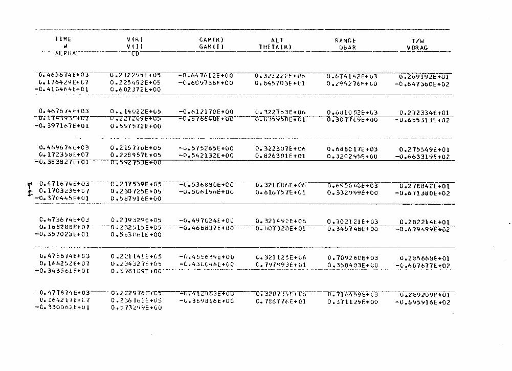
TIME VIKI GAMIRI ALT RANG~ l/W w VIII GAMIII THETAIK.I 08AR VDRAG Al PH A ______________ CD _____ _ ---------------- ---- - --------------- --- -----·-
-- c-;-4 6 507 4t + U"J c... 1764241:+07
-0.4l<J4h4c+Ol
0. "2 IZ"2'15F+ 05 0.225482E+O!:i 0.6023721::.+00
0.4o761lt~+Ol o.~l4U22E+~!:i --o-~ 174393r--+u7---o-;z27-zo9E+o5 -0.397161E+Ol 0.~~7~72E+OO
-o.t>47012E+UO -C.60'i736HCO
-o • 6 l 21 7 CE + 0 0 -C.5 76640T+Oo
0. 323 222':: +Oh G. b45703E+C1
0.1227:>3E+Ob o. B j5950E+ 6 l
0.674142E+u3 D.£9'">;'76F+LO
0.otl10 52E:+G3 0.30T1l.9C+OO
0.2o9192E:+Ol -0 .64.1360E +02
o.2n334£+01 -u.6~5313H02
0.4696J4l:+C3 0.1723~bi:+07
-;.,-o~-3-g-35 2TF+u1
0.2157/uE+O!:i -0.~7526~E+OO o.322307E+C~ 0.688Cl7E+OJ 0.27~~49E+Ol o.22sq57[+05 -0.542132l+OO 0.826301E+Ol 0.3202~~f+GO -0.663319F.+02 o.~92/53E+ti~----=_:____::_::....:_:::..::.... ____ _:_-=-=--=---==---:_.:.....::..-=....:.....:.. ____ __:_.:.___::__:::.....;_.;:._.:..=_
'r o. 4 716 74 r+ 03 - -- - - c;. 211539E+as-- ---.:..:.-c.-s:rt.ti l:ioi:+c-c-------c.-3?. rBlft:.-E +Gt-. ~ O.H03L3f-tC.l o.2::;on_~E+O!:> -0.!:iObbbE+OO Ooblo"/~dE+Ol ~ -0. 37044~£-'+CJ l 0. ~879l 6E+u0
O.b95G'0E+03 0.27e842t+Ol 0.3329991:+00 -O.bll3ti0t+02
------------~-------------~---------
C.47j6 /4f.:+0J O. lbfl2UU!::+O 1
-0.35702:::.t:+Cl
0.219:::.2qE+O~ -G.497u24l+OC 0.3214'J2E+06 D.102121E+03 0.282214t+Ol --o ~ z32n~E+-os--- - -~o~-4o-off37E+ac---·--o-;--F07J2-0~+0T ____ t:r:-Y4~74EH~+od ___ -6 .6794-99E+o2-·
0.5b3t•6H+OO
-------· ------·-- ·--·---------
o. 4156 t4E+03 O. l662~Zf+07
-0. 34 35 61 f+O l
0 .2 21141E:+G5 U. L J4j2 .IE +fJS o.:J78IS9E+uc·
-(). 4 ~ ': b ;j '1t:+0 (! -C;.4JLL<t6f:+u0
- O. 477074 E+o3--- o-. 2 ZZ976F-t'-C~--=c;--;-ztt<:RMCTOO C'.1642l7l:+C7 0.2::;6J6H:+liS -t...3B':!!ll6t+OC
-c. 1300h~:t+u l
v. 32l 12~E+l6 C. 7'-i7'l93E:+Gl
o.-~ZOT-::rT,-HT6
O. 7~877t..f:+Ol
D. 709260E+03 0. 3'.>84 S3E+C0
o. Tl 64 ':i9E+L;3 0. H ll 2'7F. +00
0 .z :;o:,66iiE-i-Ol -Ci.i'iU7677E+02
0.2t9209f+Ol -0 .6'J~Yl 6E +02
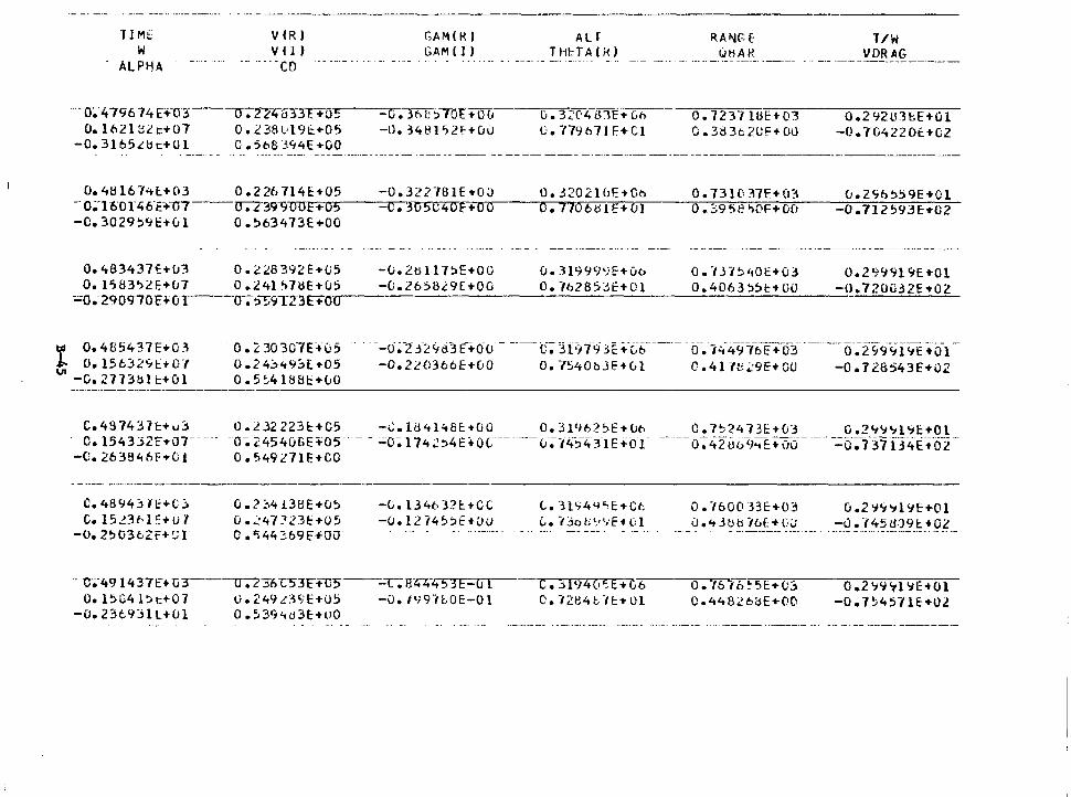
... -·-- ---·· ·-··------- ··- --·- ---··------'fl Mt V(R)
v I l ) -- --- -co
c;AM(R) ALr w
ALPHA GAMIJ) THl:TAIH)
·---0~-4 79674 n--o~.;---11.7£'4-53"31:--..:-us -G. 3t>l: ~7dt +Ou O.l621B2c+07 0.238019~+05 -l). 3481'>2!'-+0iJ
-0.3165Ltic+Ul 0.5683~4E+OO
0.41H6"7>tt.+03 0.2267141::+05 - o;T6-0I't6-E+-U7---u-;-z-391100E ... 05 -C.3029,4c+Gl o.~63473E+OO
Oe483437~+u3 0.2l8392E+05 -0.2till7SE+OO 0.1'>83~2F.+u7 0.241~7dE+u5 -0.2658i9£+00
~o.-290970HOT---o-;s-~9TZ3E+O'""O,..---
G. 3ZC'4i31E+ (,fl
C·. T/9671 F+Cl
o. 31999'-)E+vt> O. -1628S3t:+Ol
0. 723711!!:+03 0. 3tl 3t 2l!F--t OU
0 •. , 3 7 ~'101::+03 0.4063~Sl:+OO
T/W VDRAG
0.292t.13H+Ol -o. 704220t+02
0.2'1'191 ~E+Ol -0.720G32E+02
tfl 0.4!J5437E+0~7\ ,i. O. l5632'1t+07 UI -G. 2773b l i::+Ol
0.230307U05 0.24j"t9.'.::l[.+05 0. 5 ~41881::'.+LO
---0-~-2 .f2<'tti3 E-+oo - ---c--;-3FJ19 3E +-c.-6 _____ -cr.-,'1-49~16T:+o3 ______ iY:2c;9'if9"E :tcf1 --0.220366E+00 0.7540bJ~+Gl C.417E~9E+OO -0.728543E+02
C. 48 743 7t+u3 0. 2 .32 223f:+C5 -.:.184148£:+00 o. 3l'1625E+ CJt> C. 7")?4 73E+Cd 0 .2'19"1 ~1:+01 c. 154332: ... or- ····· -o~ 2.4540f>E1-"o5···- - :.;;o~ I 74 2:>4noc-----0;·14-~4·:n E .:o i- ---- o: 42t16<,~E:+ c,0- -----· --=o:Y:fif34i::-+-o-F
-C.263846F+01 0.~49271E+CO
C. 48943 H·+C..l c. isnt-1!:+u7
-o. 2~03oZf+!Jl
- C•-49 l437E+G3 Oe l!>C4 l::-.t:+07
-0.23e931L+Ul
0.?::.4138E+O~
0. ;:_47 '.l23!:'+05 0 .~44:?,69F+OO
li. 249 .c3'1E+OS 0 .~394u3E:+UO
-L. l34b 321::.+0C -0 .1214 ~:>E +vu
C... H'74'P'E'f-Ct (, • r>o ti ~,.,. f t (: I
c. _jf<)4C•':.E+C6 c. -12e4c -H:+o1
0.760033E+03 0.2~9~191:+01 0.43bblbE+0LJ -0.145U191:.+02
o. 761c.~5tt-0::i 0.4482b8E+00
0 .2~11~1 ljE+Ol -0.7~45HE+02
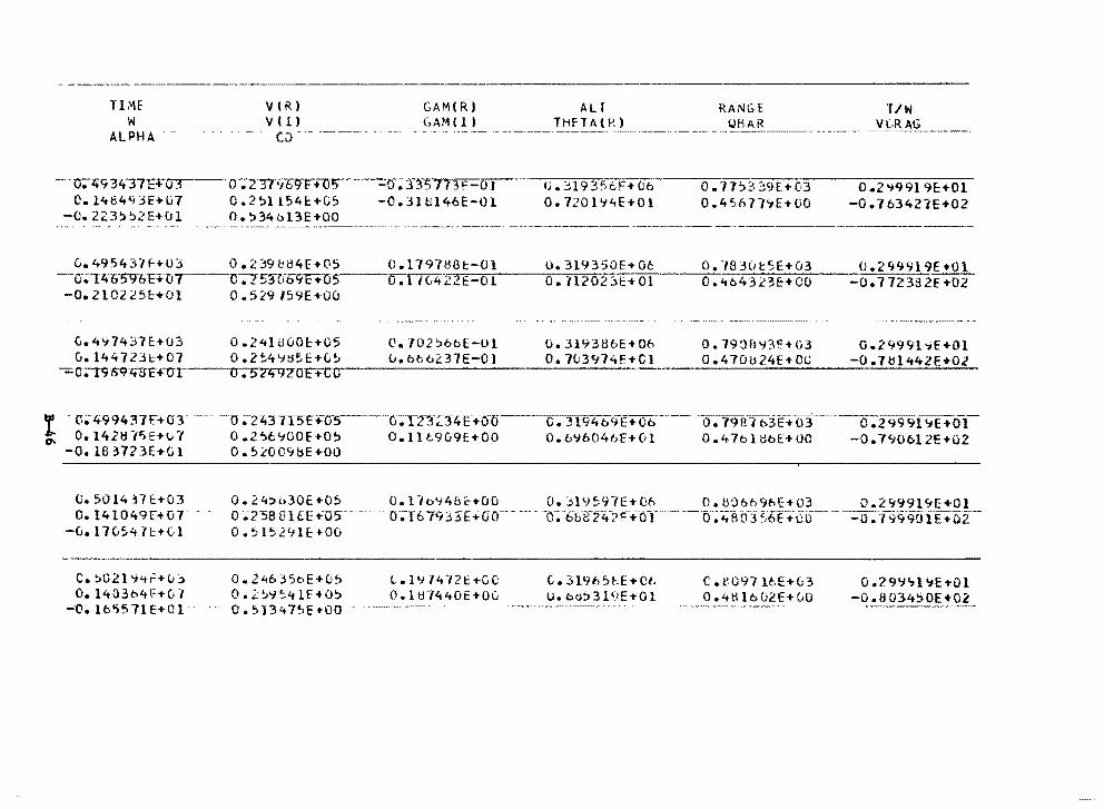
TIME w
ALPHA
-v.zt'134"3TE+ 0 3 O. l464'13E+ll7
-o. 223??2E+CJ1
V(R)
v ( 1)
c::i
GAM(R) &AM( 11
0. Z-37'16IT+n~"'5 7'n~ -o I 0.2?1154c+C5 -0.3l~l46E-Ol 0.!>34ol3E+OO
AU THFT A( R)
CJ. :::H93'i6F+06 0. 7201'14E+Ol
RANGE
0. 71?339[+03 0.4S677':1E+OO
l/W _YJ·~-AG -·-----.
O .2 ~99l 9E:+Ol -0 .16342'iE+02
0.495431f+UJ 0.239be4E+OS 0.179788t-Ol u.319350E+06 o. ·rn::H1t5E+u3 O.<t643£3E:+CO
0.2'19919E+Ol -0.772382E+02 -c-.;-r1+t1590HD/--cr;;-z 53"Ci-69r+os···---o . 1 n4 22·""E--"""0 ""'"1 ___ 0:::-.-.=11:-::2=-=o:-::2,.-:'."l-=E:-+,.-:o-:-.;;1-
-o. 21022sc+o1 o.529159E•Ou
G.4~7437~+03 0.24lti00E+05 V.702~6bE-Ol 0.3193UbE+Ob 0.1938~3E+G3 G.2499l~E+Ol G. l4472Jt:+07 0.2!':.4'-IU~Hu~ uob66237E-OJ O. 703974F.+Cl 0.47CH.124E+OC -0.7tll442E+Ol
-;;;c;-rc;·r;9·.rts£ro .... 1--_,o.....-...... 5 ... 2z;qzo.-.+..,..,..,---------------------'-----------...;;__------
U;499437F.+OT 0.1421fl5E+v-I
-0. lB :l723E+G l
c. so 14 n t:+oJ 0.1410491:+07
-G. 17 G54 Jt+(, l
C. ~02l 9<tF+uj o. 140364\=+(; .,
-ti. 16')571 E+C t ·
-o ;;-2437T5E+05 0 .2 l)e '100f+O~ o.s~00'18E+UO
. ·v;TZ3Z14 E-+iJ'O O.llc909E+OO
C. 31941:.>ri-E+Ob-- ·o. 7981t:>3E+03 0.6~6046E+vl 0.47ole6E+OO
0 .29991 ~E+Ol-o. 7'i0bl 2E+u2
0.24,b30E•05 O.l1oY4&~+00 O.jl9~97E+O~ O.H06h9bE+03 0.2999l~E+Ol o ;.;rsa 1:nEE .:05·- -- o·;I6 793'.iE+Go-·- ---- -c~-6bi:f24-:>!="+or---·0·~1:;I~tf3 +c:u-----o :7-9·9-9fffE.+02·-o. 515291E: +oo
0. 2 46 j ?o E +CJ 5 l • l '1 7 4 7? t +C C: 0.~~~~41E+O~ 0.1~74<t0E+OG o. 513 .:+ 7S-E ~uo ··- ----
G. 3191>~~.E+Ot, U.bo~319E+Ol
C • C'-O'fl H"E+u3 0 .4ti I b u2E+ LO
0.?9'1C,.l':iE+Ol -0.0034!>0E+02 --------- ~- -------~-~--·------· ----------
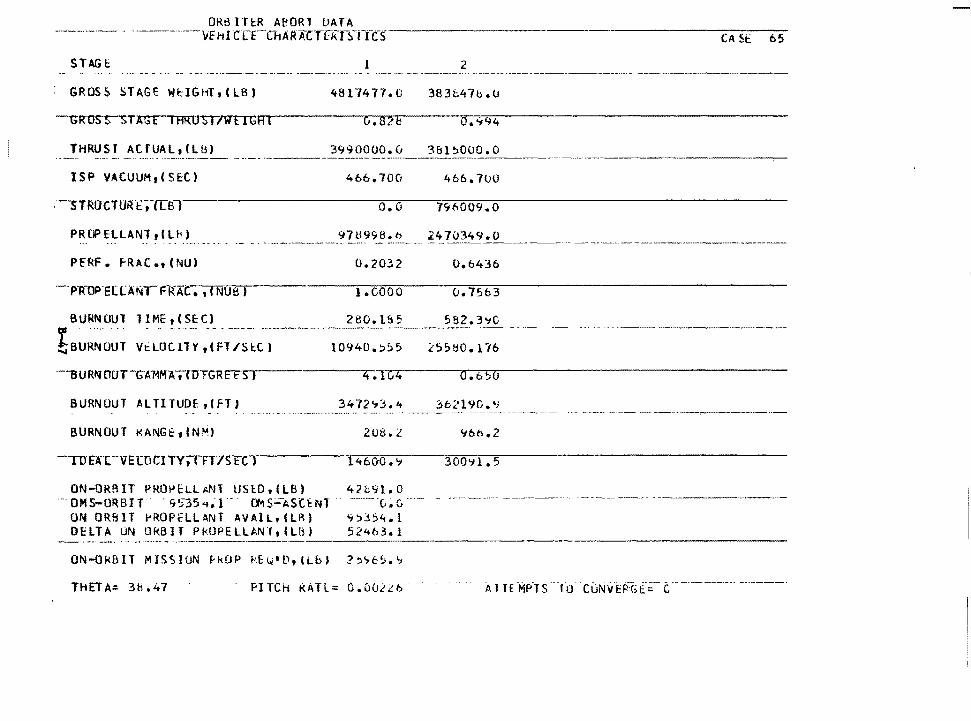
ORBITtR AeORl UATA ··---- ·----vE HI CL"t"CHARXcn:-kr!lTfcs
STAGE l 2
: GROS~ STAGE Wl::IG11T,(LBJ 4817477.0 383t47b.O
THRUST AtfUAL,(Lb) 3990000.v 3&1~000.0
ISP VACUUl1 1 CSE:C) 466.70CI 466.700
o.o 7~6009.0
CA St 65
PRDPELLANT,Clh)
PE"RF. f-RAC.,(NU)
97U99!L.o 24 7_Q:3-_49 ~--- --··- ----·--·-------------·-----
0.2032 o.ti4:56
i.cooo o.75o3
8 URN OUl l ~ M_E ! ~ ~-~ C_)_ _ ___ _ _ ________ _3_~~~-! ~2 __ 5 B_?. 3 'tC
t~UR~-OUT Vt:LOCllY,(FT/Sl:.C) 10940.::>55 25580.176
-- -- ------------------·--
.6!;;0
BURNOUT ALTITUOf ,{FTJ 3b2l '10. •; --------------·- ·-- --·-·-·- -·---·---~---------··--
BURNOUT t<ANGE:, (NM) 208. l
-TDE"ACVE[OCJl'Y;TFY-/St:C J l<t600.'1 300'11.5
ON-ORBIT PROPELLANl USlD,lLB) 42b9l.O ·--OMS-ORBIT. 953541,;} -- CY-lS:ASUl'fl Ci.C. - ------- ------·- ------·--·----------
ON ORBlT PROPfLLANT AVAIL,(LB) ~!:>354.l OHTA UN llkBIT P!<OPELLAN·r,CLB) 52<t63.l
THETA:. 38.47 PITCH KATL= o.u02~b ----·-·--· ------·
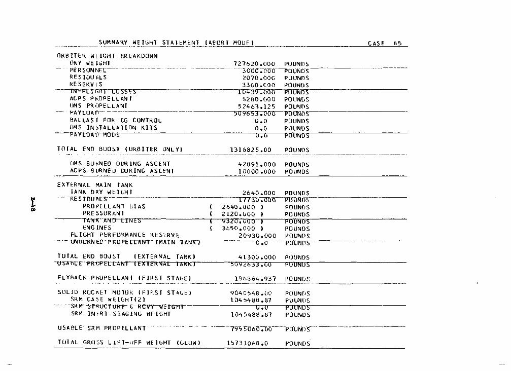
SUMMARY WEIGHl STAl~MtNT (AEO~-~R~T~M~O~U~~'._!_, ________________ C=-=AS==-f_6~-~5-
ORBITE~ WtlGHT BR~AKDOWN
DRY WEIGHT 727620.000 POUNDS . PERSON NE[ ____ ------------ --- ---- - -- - ------- ------- --3crnc·~-O(Hf"-p[fl.ii'-.itis"
RESIDUALS 2010.ooc POUNDS KESERVlS 33GO.tOO POUNDS
------irr--Ftrr;HI LDSStS 1G4j9.000 PU~u=N~D~S,__-----------
ACPS PkOPELLAN' 82&0.r_,oo POUl'll.JS OMS PROPcLLANT 52463.125 POUNOS f'AYt.OA n--· - -------------·-----sug-65'.r."OffU-VOUNOS BALLAST FOK CG CONTROL O.O POUNDS OMS IN~TALLAllON KITS 0.0 POUNDS
---P1iYLO-nn-muS 'OUN,,.,.,.-----------
TOIAL ENO BUO~T (URBllER ONLY)
UHS BUkNED OlRlNG ASCENT ACl-IS BURNEi> WRING ASUNT
EXHR~AL MA IN r ANK
1316825 .oo POU NOS
42891.000 POUNDS 10000.000 POUNDS
TANK DRY W~IGHT 2640.000 POUNDS --- -RESIDUA Ls------------------ 171 '.30-;®li-POUNli~
PROPELLANl blAS 2640.000 J POUNDS PRESSURANl 2120.~oo , POUNDS
·-----A~D LINES 9320.uoo , PDUN ENGINF.S 3c~o.ooo ) POUNDS
FLIGHT PERFOkMANlE REStRV~ 20930.000 POUNQS -- -- t"'tltJRN t:.O - p KOPI: ltAtn--tMA1 N"-T-A!lfKT------------u-;u----pouNos-------------
TOTAL END BOU~T (EXTEHNAL TANKI -USA"Ut:"C--PRUP"Ft:T"AWr--~r-T7\NK I
FLYAACK PkUPELLANI CFlRST STAloEI l8b864.937 POUN8S
SLILJO KOCK~T MUlUk IFIRSr ST~GEJ 904C~4B.OO PUUN~5 SRM CA~E WEIGHTC21 l04'.>4lW.87 POUNDS
---- - -sRM-!iimJCTURr c;-Rcvr-wctGRr---------.0..-.-.0.,.----rp'<MOUND'~-----------SR M lNtRl STAGING WFICHT 104S4e8.t:l7 POUNDS
U~A8LE SRM PROPELLANT" - ---- - -- - ----- --
TUTAL GRO~S L1Fl-uFF WElbHT (LLUWJ 1~7310h8.0 POUNDS

SUMMARY WEIGHT STAHMENl lRTLS MOD~) CASE b5
UkBllER WtlGHl ~RE~KOOWN DRY WEiGHT 7L 1620.GC:G POUNDS
.. PERSONMEr·----- - ---- - 300tf~o6Ci - -POUNDS KESIDur,LS 2010.000 POu-..us RESfRV~S 3300.l;OO POUNDS
----m-;;.FCTl-HI LOSSES 10439.COO P ... OU'"l'-:o-IJ-:--S-----------
ACPS Pk.OPELLANl 7530.000 POUNDS OMS PRuPELLAt.IT Ci.C POUNDS
-- -- PA YLITATJ ____ ----·-------------SO<,oS-c>;1ar· -POiJNos·--------8AlLAS T FOR LG CONlRUL O.O POUNDS OMS IN ST Al LA Tl UN K HS 0 .o POUNDS :-::------------ ----,,-AY l 1JATl~Ol)S 0 .o POUNDS
TuTAL END BOOST (ORBITCR uNLY) 1263615.00 POUNUS --··· ·---------- --- ·---- -·
UMS ElUkNFD DUR ING ASCfNT 9 ~354 .125 POUNuS ACPS BlJRNE:D DURING ASCt:Nl lt:i-t5o.ooo POUNDS
. __ .;_:.._ __________ ~--------------~ EXTE:.RNAL MAIN TANK
TANK O~Y WtIGHl 2640.000 PUUNOS - --- RESIDUALS---- --- -------1n~u.;c-o-0--Po-0Nos-
PROr'F.LLANT ~!AS 2o40.C.OO > POUNDS PRESSU'UNl 2120.000 I POUNDS
-----rANl\ANU-U~ 1132u.t.'00 I POUND ENGINES 3650.CIOO I POllNDS
FLIGHT PER~UkMANCl R~SlKVE 11837.COO POU~OS - - \JllBURN EO"PROPE lLANr-(MAIN TANKT ___ ----4-54r;;:9 ;uI.? POUNDS
FLYBACK PkOPHLANl CflRST STAGE) 186864.~37 POUNDS ----- -- --~ ~- - ·--· -- ---------·-----------
SULIO RUCKH MUlUk CFlRSl STAGE) 'J04C~48.00 POUND~ SRM CASE Wi::JGhf(2l 104~4b8.t1-/ POUMDS
--- --- --s1:rM--sp~oCTURT-~RCVY-llfIGH .......... ---------.-:--.-,...o--PUlT"11'.,.,.U~----------SRM INLKT STAGING W~IGhT l04~~ee.81 POUNUS
USA5LE SRM PROPELL~Nr-· 7995o6c,·.uo - Pnu~ms -
l~BllJ68.CJ POUNfJ$
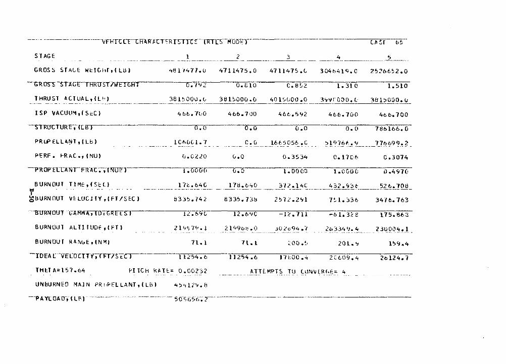
STAGE
GROSS STALE WtlGHftCLU)
THRUST ACTUAL, IL\\J -------- -----·---
ISP VACUU~ 1 (S~C)
-s-T"RU'CTURF,--([B)
PRl.P HLAtH, C Lb)
PERF. ~RAC.,(NU)
BURN OU 1 T1 ME, I Si:(.)
Y' ~EiURNOUl \It LtlC l TY• I FT /S f:C J
----s-URNOUT .. GAMMA;IOl-GRFtS"J
BURNOUT ALTITUOf 1 CFT)
B URN OU T R A Nb Et ( N -111 1
l
o.o 1CM.1Cl. 7
11.1
llL54.t
THH A=l51.64 ~ITCH kAT!.:= o.co2~2
UNBURNED MAIN PR1~fLLANT,(LB) 4~'112'1.8
2
4711475.0
o.e10
381~000.0
4bb.700
o.o
c.u
(,.0
o.o
11254.6
3 4 ---~~~--~------471147!>.L 2526652 .o
c.0~2 1. 310 1.510
401~000 .o
466. 592 4b6.700 4cc.700
u.o o.o 78bl66.G
16f,'.)056 .c --- - ",_ .. ? ! c-qr_: f_": ~--- -- _ 1_1 h_ "'9 '! ._ ?
o. 3534 0.17C:6 0.3074
l. ooco l.OC.00 0.4970
34Hi. 763
-IL'. 711 175.863
;:oo .~. 201. '-J
171;00 • .:i 20124.1
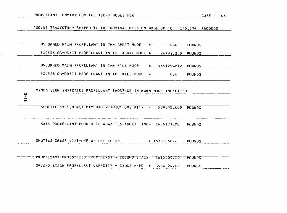
PRO~~LLANT SUMMARY FOR THE ABOKT MODtS FOK CASE
ASCl-NT TRAJf.CTORY SHAPED TO THE NtJMlNAL MISSION MOD[ UP TO lt:.5.6"/4 SE:CONOS
EXCESS Qf\;-IJRoll f'iWPELLJl.NT IN lHt. ABORT MODI' = 264~7.2~0 POUNDS
UN~URNfO MAI~ PROPELLANl IN THf RlLS MUDE = 4~4129.812 POUNDS
fXCES~ ON-ORBIT PROPELLANT lN THE RTLS MODE = o.o POUNDS
~lNUS SIGN INDICATES PROPELLANT SHORTAGE IN bURN MODf INDICATED
-----------SHUrTTc~YSTmrr-p-A'f[LJAD WI rHOIJr OMS kITS ~09653.uUO POUNDS
MAIN PRU~ELLANT bURNED TO AOA/~TLS AHORl TIM~= lh86177.00 PUUN!lS
SHUTTLE GRl1SS LlFT-LlFF WEIGHT ((,LlJWI POUNDS
Sf:CtJNO ~JA(,1:_ PROPl:LLANT CAPACITY - CROSS 1-H-D = ".:S41:lut2'-t.i.J0 POUNDS
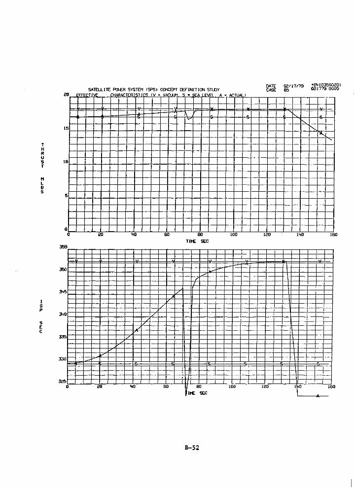
T H R u
15
s 10 T
H L B s
I s p
s E c
5
0 0
350
:J.tO
335
330
0
SATELLITE PCW:R SYSTEM CSPSI CCN:EPT OCFINITICJll STLOY ·= Tl.£ . Cf-WlACTER ISTI s rv = VA
... ~ -
20 'tO 60
v /
./ ,, I/
./
/ /
/ ~
~
20 'tO 60
LLM
r -
/
~
S • SEA LEVEL A z ACTUAl l
V"
ao TIHE SEC
,r
/ I
j
I 80
IHE SEC
B-52
--
100
_,...--~~
100
DATE 02117179 •04103590201 CASE 65 021779 0005
I
- '- --' "' ""' ....
120 l'tO 160
I I I I
I
!
I I I I I I I !
120 I tO I 60
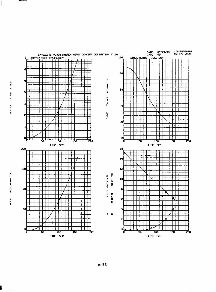
L_
R E L
v E L
K F p s
A L T I T u 0 E
K F T
7
6
..
3
2
0 0
200
150
100
0 0
A
.....
SATELLITE Pa.ER SYSTEM ISPSI CCN:EPT OCFINITICN STlOY
_, !...-
i..,.V
- IC TR I CTalY
,/ _,
v
I/
50
I
I I
I
I
I
100 Tlf'£ SEC
I I
I.I
I/ I
' v
100 Tlf'£ SEC
,
I
150 200
I
I
I
I
150 200
F L I G H T
p A T H
0 E G
R A N G E
0 N M
R
B-53
w E I G H T
M L B s
w
100
80
60
'tO
20
0 0
16
" l'I
12
10
B
6
" 2
,_ 0 0
DATE 02117179 •0'+103590201 CASE 65 021779 0006
ATM'.3SPl-ER IC TRA...ECTalY
~"' !'-..
\
I\
' ... " ...
' '\.
50
\ \
w
I\ \
' \ '
100
Tlf'£ SEC
' " ' ' '
' -,_' -100
Tlf'£ SEC
' i'.... r-....
150 200
j
' " r.. I
' 'r:I
, I/
I/
150 200
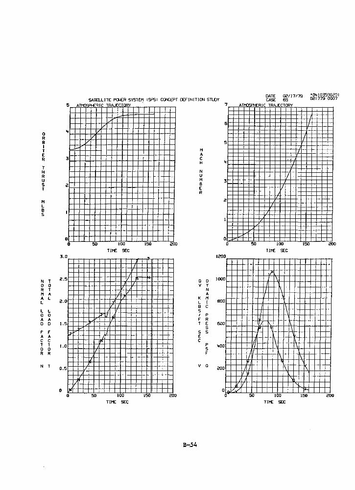
0 R B I T E R
T H R u s T
t1 L B s
N 0 R t1 A L
L 0 A D
f" A c T 0 R
N
T 0 T A L
L 0 A D
f" A c T 0 R
T
SATELLITE PGER SYSTEM tSPSJ CCN:EPT OCF"INITICN Sll.OY 5 ATl'1)SP!-£RIC TRA....ECTCRY
..
3
2
0 0
3.0
2.5
2.0
1.5
'"
1.0
0.5
0 II' 0
I.; I/
I/ I/
v ~--
50
,, ....
I
I/
I/
/
50
100
Tit£ SEC
)
J I/ I
J / / f
~
/ I I If
A',/ ·'
' If'
I ,,
100 Tit£ SEC
150 200
-I
I I/
150 200
B-54
M A c H
N u M B E R
a v
K L B s I f" T
s E c
v
D y N A M I c p R E s s
p s f"
a
7
6
5
3
2
0 0
1200
!ODO
BOO
600
400
200
,_ 0 0
DATE 02/17179 •04103590201 CASE 65 021779 0007
ATl"OSPl-£RIC TRA....ECTCRY
I/
50
I 1 1.
<Ill
·~ 71 I
II Ill
,) I .i/J
' ' I/
I/&' 50
f7
I
'
7
7
100 TIME SEC
JI-\
I
I \
\
I
I
I
~
I
' \
I\
100
TIME SEC
\
'n
'
I
' I
7
150 200
' \ ' I\
·->--
' .... 150 200
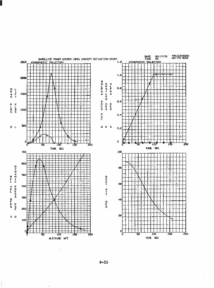
Ill
SATELLITE PGER SYSTEM !SPSI CCN:EPT OCFINIT ICl'l STLOY 0 AT .... "'CLC Df
2000
0 L R I A F 1500 G T
I( I(
L L 8 8 1000 s s
0 L 500
0
700
600 0 y N A
R M 500
E I L c v p '+00 E R L E
s s
0 300
F p p s s
F 200
v a 100
0
,_v o-
I I I
I./
I
I I
I/ v jv
50
-\
' Ill
I I I I
,/
II' I/
50
I I
Ill
lb
I I
I
TD • CTffiY
~
I
' 1
I I
I I
\
\
' I'-'\
IOC
Tll"E SEC
I
I ,, /
r7
Al
II' II \
'N
'
100
A.TI TlCE l<FT
1:1-...
150 20 0
/
/
/
/
"- -150 200
a A L p H A
K 0 E G
p s F
a
E p s I L 0 N
0 E G
E
8 0 0 y
A T T
0 E G
B-55
A L p H A
0 E G
A
1.2
1.0
0.8
0.6
0.'+
0.2
.. 0 l.
o-
100
BO
60
'10
20
0 0
=o.rR[( AT....,
rl
I
I
I
I I
I
,_ 50
.... , r'\ ~
\ \
\
50
TRA..ECTffiY
I/
,. j
-- locr Til"E SEC
\ \
' '
100
Tll"E SEC
~
. I! lb 20 0
~
!'-..
150 200
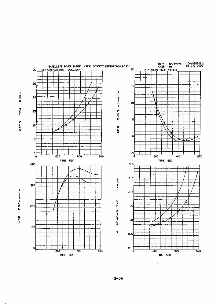
I N E R T
v E L
K F p s
A L T I T u 0 E
K F T
30
15
10
5
0 0
'+00
300
200
100
0 0
SATELLITE f'Cl,ER SYSTEM ISPSl CCN:EPT OCFINITICN STlOY ~XO-AT"'" Cl?'-' ·01c TRA.£CTCflY
I
I I
/I I/ I
I 1'. /
I / / ./
/ /
/ v _J J(
/ ,,,J<.
,...... _,,..
200 '+00 Tit£ SEC
_ .. /' ""-~
/ v- r--..... 17 "
;
I I
J I
I/
200 '+00 Tit£ SEC
I I
I
J /
600
I
600
F L I G H T
p A T H
0 E G
T 0 T A L
L 0 A 0
F A c T 0 R
T
. B-56
20
15
10
5
0
-5 0
3.0
2.5
2.0
J.5
J.O
0.5
0 0
DATE 02117/79 •Cl'tl03'590201 CASE 65 021779 0009
A = 'en: T-CN:E- AC>n f\J)
\ \ \ ,
l\ \\ ,, ' \
'l\ ,, \I\.
1' "- 1'- ./
1 ........ I/
200 '+00 600
Tit£ SEC
I I I I
I I I I ,,
I I J
I I I I
I I
I I / ' / I/
I / / /
_J "' I
/ / I
./ k. i / - / I
,/ I
-- I I I I I I I I I
200 '+00 600
Tit£ SEC
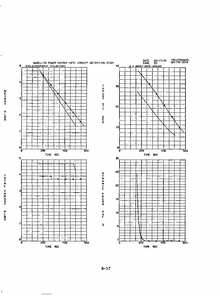
w E I G H T
11 L B s
T 0 T A L
T H R u s T
11 L B s
..
3
0 0
3
2
0 0
SATEl.LITE Pa.ER SYSTEM CSPSJ CCN:EPT CEFINITJ()\j STl.OY EXO-AT,,.. c:.C>LI RIC TR ""CTrRY
'
" ~ \.'\
\ ~l\
\
'·'-I\ \ '\
' ' '\ '\ ' ' I\
\
200 '100
Tll1E SEC
1
200 '100
Tll1E SEC
"' " I\ \
\ '\
I I
600
600
T H R u s T
A T T
0 E G
0 y N A 11 I c p R E s s
p s f"
Q
B-57
30
20
10
0 0
30
20
15
10
0 0
A a •er<: T-l'l .J.:E-M>n l\n
. '\
"' ~ '-
\. \. ~
' \. '\ \
I\. ~ ' \
\.
' \. "'
200 'tOO
Tl11E SEC
I I
'-200 .. 10
Tll1E SEC
\ '\
\. )
"' '\,.
'
600
60 0
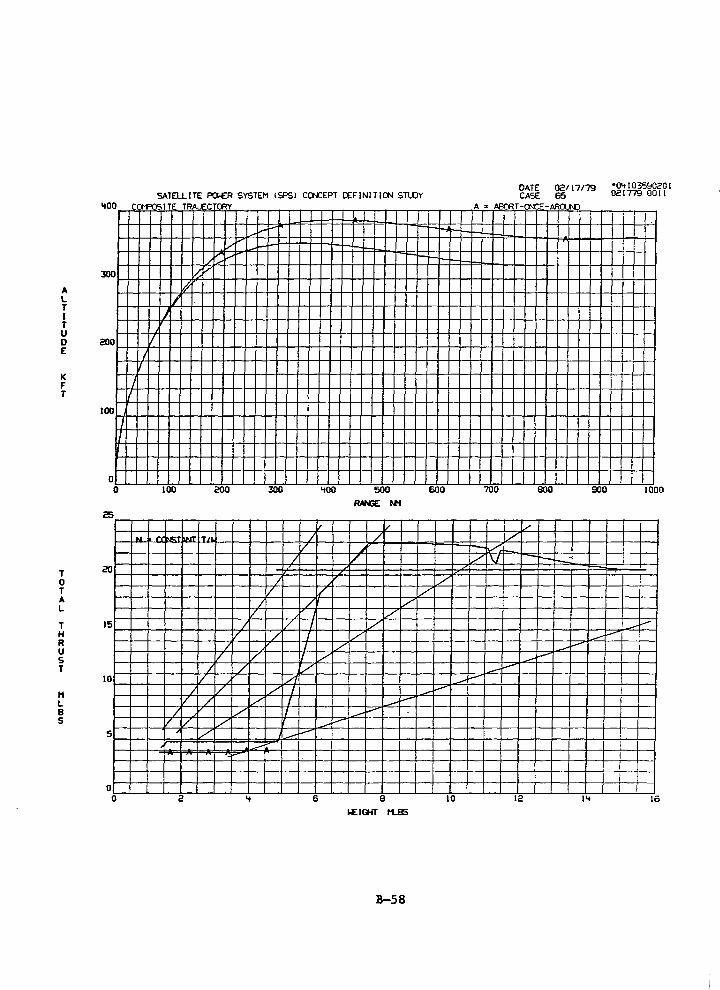
A L T I T u
lfOO
300
D 200 E
K F T
T 0 T A L
T H R u s T
H L B s
100
J I
0 0
25
20
JS
JO
5
0 0
SATELLITE PG£R SYSTEM lSPSl CCN:EPT OCFINIT!CJll STLOY ,., .... tislTE TR~ I C CAY
L---
y .... ,., -/ ~
I/ ,r
'# I
)
v I
I I
100 200 300 '100 600
/ / .. -IT" J / / ~
/ /
/ I/ / / /
/ / v v /
/ '/ I / / / I I/
/ I / v / I v
/ / v / /I
/ I/ ,/ I ~----/ / / I _..-
/ I/ I ~......- -v / / _..-,
I/ ~ ---
2 " 6 JO
B-58
DATE 02117/79 •IJ<tl03590201 CASE 65 021779 0011
A z ~T-CN:E-ARCUO
I -
700 800 900 JOOO
[/
/ ...,.-:
./ v -r---~
_i.--
-- .-- I _..-
~---- .--~--
I
i
12 l't JS
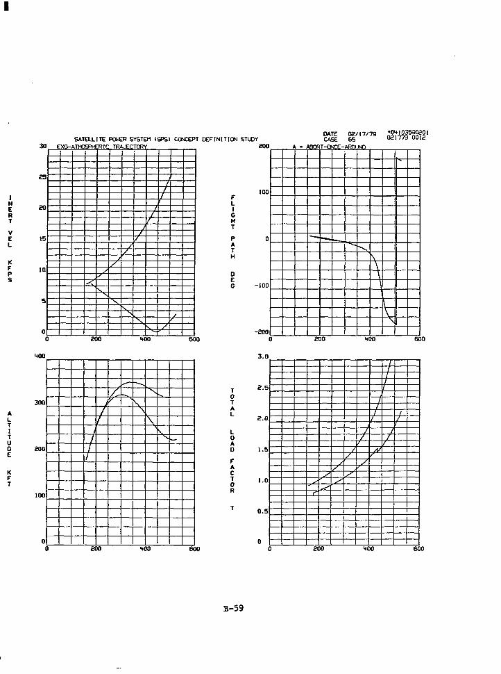
II
J N E R T
v E L
K F p s
A L T I T u 0 E
K F T
30
20
15
JO
5
0 0
'tOO
300
200
JOO
D 0
SATELLITE Pa.ER SYSTEM ISPSl CCN:EPT OCFINITIO'l STlDY EJCO-AT~ RIC TRt...ECTCRY
I I
I
I
I /
j
I I/
/ /
/ ,I ,,
''-
' ..... .......
r-..
' , ........ r
' /
200 '100
I--" -/.~ ............ y
" I ' I '\ I\.
I ,..._ I
I/
200 '100
600
600
F L I G H T
p A T H
0 E G
T 0 T A L
L 0 A 0
F A c T 0 R
T
B-59
200
IOD
0
-JOO
-200 0
3.D
2.5
2.0
1.5
J.D
D.5
0 0
OATE Oii!/17179 •04103590201 CASE &5 021779 0012
A s u:n: T-0-CE- At:p ..n
'
I
1-- -..........
\ \ \ I
\
\ '\
200 '100 600
I I I
I
I I
I I I I
I I / I
I I
/ Al I/ r
/ / /
./ / / ./ _,, r"
I
200 '100 600
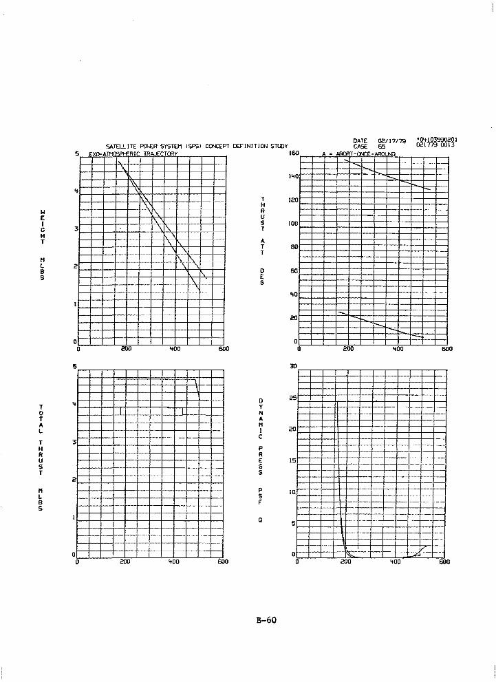
DATE 02/17179 •04103590201 CASE 65 021779 0013
T H
w R E u I s G T H T A
T T
H L B 0 s E
G
'+0
20
0 0 0 '+00 6oO 0 200 '+00 600
L___J__J
D T y 0 N T A A H L I
c T H p R R u E s s T s
H p L s ~ B f' ~ ---s
a 5
0 0 0 200 '+00 600 0 200 '+00 600
B-60
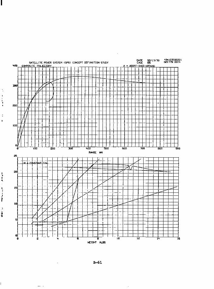
I
I
J .. T
--i
a s
SATELLITE PG£R SYSTEM CSPSl CO-CEPT CEF"INITIGI STLOY DATE 02117/79 •0'+103590201 CASE 65 021779 001'+
'tOO CCM'OSl_TE TRMCTNY A • Al r;:; T - "N E -ARO..N:l
1--+-t-+--+--t---t---t-t--1--+-t l I
(/ ,-II' j
200 I I
I
I I
1001--11-+1-+-1-t--+-+--i-+--t-+--i-t--+-+-1------t----t-+-1------t----t---+-1-t----t---+-r-+---+---+-+--+-+--+-+-+-+--+-+--+-+-+-~ I I I I ~1-+---+---+-+--+-+--+---F+-+--+-1-+---+---+-t--t----t--+-t--t----+---+-+--+-+--+-+-1------t----t---+-1------t--+-+-1-T--+-+-l-T---+-I
o L-= J~ _[ >-- =-__ ' -_-j_ - -+---_ -1--__ +-+-+-t-+---+-+-+---+--+---+--+--t-+-t--+-+-i-+-t--t--+-t--t--+-+-+---+--+---+--+--+-+-1
1J 100 200 300
25
~ +~--l----1-- ~
I T/L J
1~1 -1-l-t~ ;~ /
/ I - I / 20
I I I / ,.
1-1-1 I- - - v / / /
H 1--I __ I -1----~--1-~-IVI I I I 15
I _1 Jf-1 I-~~ / I v I
1-=f-l 1-1- -1-%-+- / I v I/
i ,--1 r1- f/ ~v: 1/1 10 I f I ·1--T17 / ___ I/ I l-f~r:. L7V ~y-
---/ I
;/ I rt-1-¥,/ y('L~ ----- --::..P~ I I I -. I i- --- • . - -
5
1-1·-- 1 -r---i--:---r- i-~ r ·1 1 l+j·1THffnlTll. r::..i-1_:_ -=-n·--r~_T_ -~:I_ I - _I I 0 0 2 '+ 6
'+00 500
/
/
....-
RNG:: N1
I/ / ,.
"
v I/
;/ /
~-__..,,..--~
8 1£1GIT tt.BS
B-61
I/
600 700 800 900
/ /
./. / \I ---/
_/
-------~-
~..--
_..--~-..--
10 12 I'+ 16
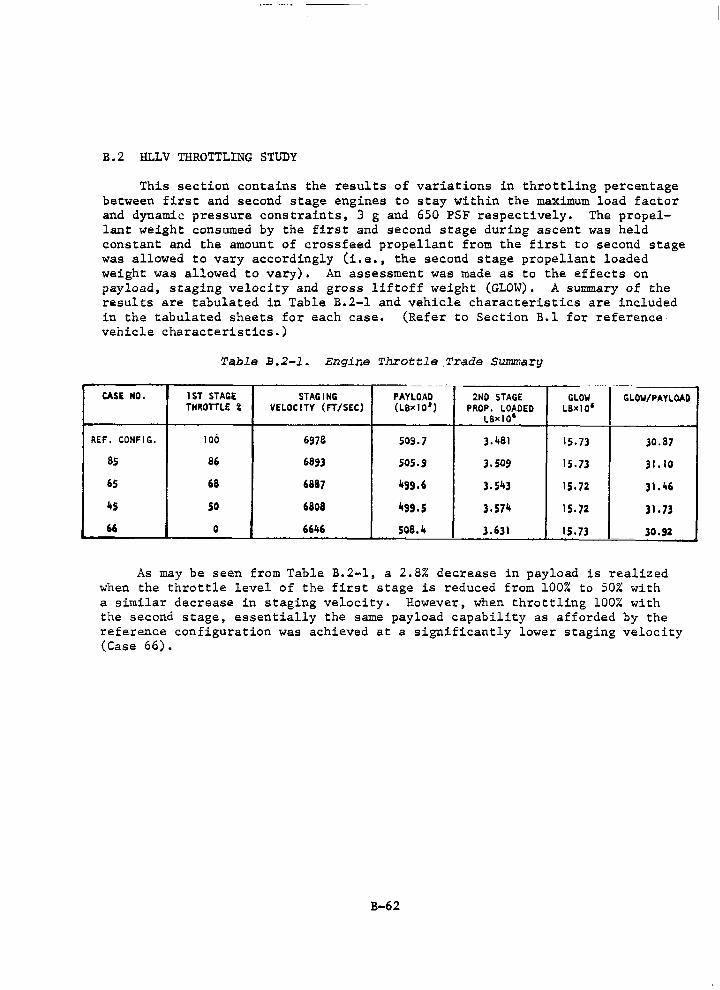
B.2 HLLV THROTTLING STUDY
This section contains the results of variations in throttling percentage between first and second stage engines to stay within the maximum load factor and dynamic pressure cons train ts, 3 g and. 650 PSF respectively. The propellant weight consumed by the first and second stage during ascent was held constant and the amount of crossfeed propellant from the first to second stage was allowed to vary accordingly (i.e., the second stage propellant loaded weight was allowed to vary). An assessment was made as to the effects on payload, staging velocity and gross liftoff weight (GLOW). A summary of the results are tabulated in Table B.2-1 and vehicle characteristics are included in the tabulated sheets for each case. (Refer to Section B.l for reference· vehicle characteristics.)
Table B.2-1. Engine Throttle .Trade Summary
. -- ---··
CASE NO. lST STAGE STAGING PAYLOAD 2ND STAGE GLOW GLOW/PAYLOAD THROTTLE i VELOCITY (FT/SEC) (L8><10 1 ) PROP. LOAOED LB><IO'
LB><tO'
REF. CONFIG. 106 6978 509.7 J.481 15.73 J0.87
as 86 6893 sos.9 J.509 IS. 73 31.10
65 68 6887 499.6 3.543 15.72 31.46
45 50 6808 499,5 3.574 15.72 31.7)
" 0 6646 508.4 3.631 15.73 30.92 ·-- - . - . -·-
As may be seen from Table B.2-1, a 2.8% decrease in payload is realized when the throttle level of the first stage is reduced from 100% to 50% with a similar decrease in staging velocity. However, when throttling 100% with the second stage, essentially the same payload capability as afforded by the reference configuration was achieved at a significantly lower staging velocity (Case 66).
B-62
-
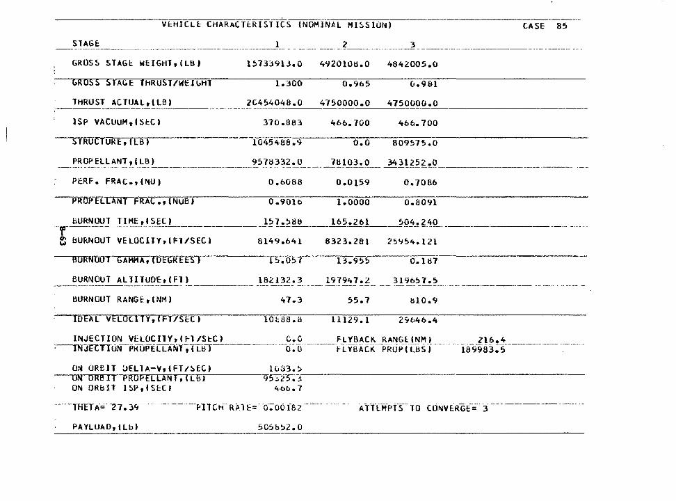
V~HICLE CHARACTtRISTICS (NOHiNAL Hl~SIUN) -----------LASE 85
STAGE I ----·------·---·-·-·------------~-- ··~-·--~~~ -··--
GROSS STAGc WEIGHT,(Lb)
GROSS STAbE THRUST/WtlbHT
15733913.o 492010~.o 4842005.o
1.300 o.965 o.981
THRUST ACTUAL,(LBI 2t454048.0 4750000.0 4750000.0 --------1 SP VACUUM,CSl:.C) 370.863 466.700 466.700
-----slRUCTURE,CLB) 1045488.9 o.o 809575.0
---~~~~~lLANTtl':_~!_ _________________ ~57833~.._£_ ____ _:!1;j_l_0_3_.Q_-=:....:.-=--·-=-=-=-="o.:: ___________ _
PERF. FRAC.,(l\IU) 0.,6088 0.0159 0. 7086
--PROPELLANT FRAC.,(NUB) 0 .901C:> 1.0000 0.8091
liURNOUT TI ME f SEC J -,,-------- --________ J~h~~~----165._.2_· 6~1 ___ 504.£'!:9_ ---
~ bURNOUT VELOCllY,(Fl/SECt
BURNOUT GAHMA,(OEGREES)
BURNOUT AllllUDftCFTJ ---·------
BURNOUT RANGE,lNM)
IDEA[ VELOtlTV,(FT/SEC)
INJECTION VELOCllY,C~l/StC) ~El:-TTON-PkliPELLA-NT, (LB l
8149.641
15.057
182132. 3 ---- -----
't7.3
10t88.8
ON ORBIT aELlA-VrtFT/~ECJ lv33.~
8323.281 251/54.121
13.955 0.187
19791t7.z 3l9b57 .. 5 --· ~------
55.7 bl0.9
11129.1
ON ORBlf PROFELLANT;\Tl~BTJ~----r.95~2-....--.J--:-~-~-~-~---~-~-~~---~~ ON ORblT lSP,(SEC) 4bo.7
PAYLUAO, tLbl 505b=>2.0
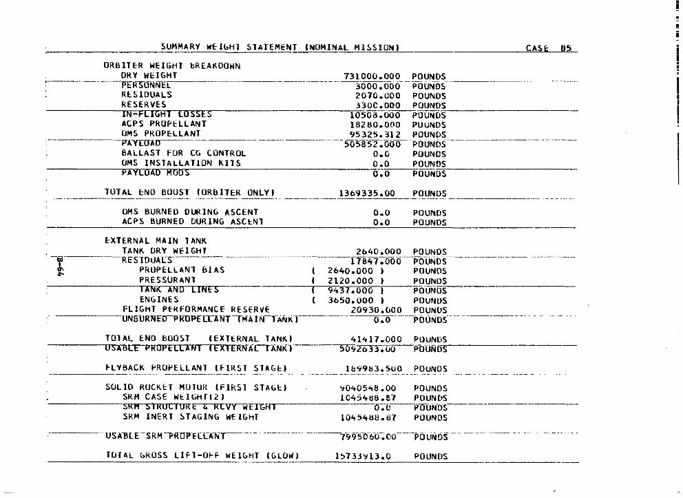
SUMMARY WflbHl STATEMENT CNOMINAL MISSION) CASI: 85
ORBIT~R WEIGHT bREAKDOWN ORY WEIGHT 731000.000 POUNDS
-------Pl:,~-s-clNNE~L -- ---------- -~-000.000- -- Pciuf.ios-R~ s 1ouA Ls 2070.GOO POUNDS RESERVES 330C.OOO POUNDS
~----~~1~N--~FL,-...,IG-.H~T..--rL~o~s~s~E~s-----------·1Aor5~oha-.~u~o~o--~POU~O=s-------~
ACPS PRUPtLLANT 18280.000 PUUNOS OMS PROPELLANT 95325.312 POUNDS JTAYI:mur ·· --5o51f52 ~ooo :p·ouNos __________ -- ----------· BALLAST FUR CG CONTROL O.G POUNDS UMS INSTALLATION KITS o.o POUN_~o~s---------~-
~-----~p~A=v~L~a~Ao...-.H~o~o~s~-----------~--Ao-.o~--;;;-POUNDS
TOTAL cNO BOOST (ORBITER ONLY) 13b9335.00 POUNDS
OMS BURNEO DURING ASCENT ACPS BURNED DURING ASCtNT
EXTERNAL MAIN TANK
- ------... ----------··----·--------- -·---·------------- -----· --·
o.o o.o
POUNDS POUNDS
TANK ORY WEIGHT 2b40.000 POUNDS · ---Rcs1ou1n:-s----------· 17a41 .oo-o----pQuNos·--------..
PRUPELLANl blAS ( 2640.000 ) POUNOS PRESSURANl ( 2120.000 ) POUNDS
-------..... ,c-rANK AND LINES ( 9437.000 , POUNo'-=-s----------EN&lNES ( 3b50.000 I POUNDS
FLIGHT PfRFORMANCE REStRVE 20930.~00 POUNOS ------uNGURNED-PRO"PE"lLANTtMAl!iCTANKr-------·---o~o--··--ptJ(JN·os··-------~---··- - ..
TOlAL ENO BOOST tEXTtRNAL TANKI 41417.000 PUUNOS USABLE PROP ELLAN I I EXl ERNA( TANKr-----,.,5~0~9:2o33. 00 POUND"'S..--------
~LYBACK PROPELLANT (FIRSr STAGc) lb9983.SUO POUNDS ----SOLID RUCKEi MUTUR lFikSl STAGt) '7040548.00 POUNDS
SRM CASE WtlbHfl2) l0454tHS.87 POUNDS ------sRM SIROCIORE & RlvrwETGHT--·--------o.c--plf(JjiiO'S
SRM INERT ~TAGING WEIGHT l0454ij8.87 POUNDS
TUIAL GROSS LIFT-O~F WElbHT (GLOW) 1!:>7H'713.0 POUNDS

VEHICLE CHARACTERISflCS lNOMINAL M!SSlUN) CASE b5
___..S1.A1if. __ ---··-·-----·-·· --- ___ ...}_ ------ -2---------~ - -·--------
6HOSS SJAGE Wl::IGHl,(l~) 15719430.0 49~2269.0 4873984.0
GROSS STAGE JHRUST/Wl::IGHT l.3oo o.~59 o.975
· __ THRUST AtIUA .... L.a..1 LJ{ L...,B""'l.___ _____ ~2...,U...:' 4:...3 .... !>232_.J}_!t;J')(jOOo.o 4l50CO.O.L---------
1SP VACUUM,(SEC) 370.9vO 466.700 4bb.700
STRUCTURE,CLBJ 104541::16.9 o.o 814 780 .o
·--· !='BQe.E.kLA.N.J 1 I Lb} -- ------·----~5!t5u6Q.[) _7aus. • .o ___ l.4ott330 .1L---------------------· ---
Pl::RF. FRAC.,(NUI 0.6072 0.0158 o. 7108
PROPELLANT FRAC. 1 CNUbl 0.9013 1.0000
fJB.!RN.QllJ_J_l ME-1 l S.E.C.l
. e'; BURNOUT VHOCITY,CFT/Sl:C) 81=>2.324 8.3:H.051 25954.117
BURNOUT GAMMA 1 (0EGRl::ES) 13.752 12.493 lJ. l 87
bUkNOUT RANGt,(NMI 47.b s~.o !H 7.0
IDEAL VELOCITV,lFT/SECJ 29093.2
-~l~N~JECllUN...Y_!;J •. QC.l.lL l~l:.L) lNJ~CTION PROPELLANT,ILBJ
_____ Q,. (L _____ .ELY.BAC.ILRA.tih.t.!Nkl--- - ---14lh.8--------··------·
ON ORBil DELlA-V,(Fl/StC) UN ORBIT PROPELLANT 1 (Ltl) ON ORBIT lSP,(SECl
O.O FLYBACK PROPILBS) 170597.2
l0b3.:? ct5db.ts
'H>O• 7
THUA= 31.41 PllCh RAlr~ O.Cu2Zu AllfMPTS TO CONVERGE= 3
PAYLOAD, I UH
-
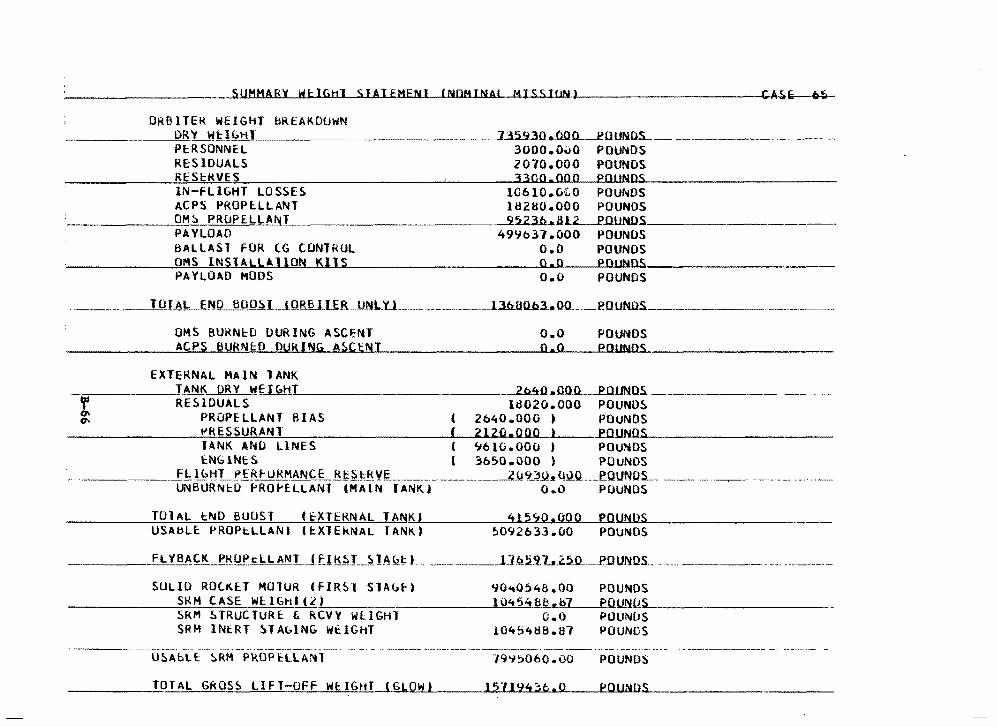
ORBITER HEIGHT bREAKDUWN ------~D~R~Y~WH GH I ___ 732.2.30 .._OQo__eourtns__
PlRSONNEL 3000.G~O POUNDS RcSlDUALS 2070.000 POUNDS RES~MVES 3300.000 POl™DS IN-FLIGHT LOSSES 10610.GtO POUNDS ACPS PROPlLLANT 18260.000 POUNDS
______ O~M'-'-=~~P~R~D~P~E~L=L=A=N~T'--------------~~b~a~..O.UNDS, ____ _ PAYLOAD 499b37.000 POUNUS BALLAST FOR CG CONTROL O.O POUNDS OMS INSJALLAllON KllS 0.0 POlWDS PAYLOAD MOOS O.O POUNDS
TOT M .. __ fM!) BOO.S.L .. H}RB 1 .. li.!LJJ.NL .. 'O .. ______________ l.3.6..BD..Q3..0<l._._eouNOs. __
OMS BUKN~O DURING ASCENT ACPS BURN~O DURING A~CENT
EXTEKNAL MAIN lANK
o.o o.o
POUNDS POl!NOS
:-:------~T. ANK. ORY WE I C.111 -2..b.~o.aoo POUN.OS --t RE~IDUALS ld02u.OOO POUNO~ °' PROPELLANT BIAS C 2640.000 > POUNDS
---··------·---~-
~RESSURANl f 2120.000 ) ...eo.UN~n~s---------~~ IANK ANO LINES ( ~6tQ.OOO ) POUNDS tNGlNES l 3&50.000 ) POUNDS
.. -----·-__ _f !:!!'>!:H __ ,!>£ RF URMAN~LBt~tfl, YI;, ____________________ __l_Y9...}J.t_. Ui.l.O. .... _e.OUNUS. __ UNBURNtD ~RO~ELLANT IMAlN lANKl O.O POUNDS
TOlAL tND BUUST ftXTERNAL TANKI 415~0.000 POUNOS USABLc PROPcLLANI CtXlEkNAL fANKt 5092633.00 POUNDS
---- FLYBACK P~U~ClLANl (f._!~~J __ ~JA~!;:t ---··---·----l_lQ.!i'i.L2!iO... _ _pouNDS ... --····-------------····--·--·-··--
SULIO ROtKlT MOlUR lFIRSl SlA~r) 90~0548.00 POUNOS SRH CASE WE.I Gt-I I ( £_.._) _________ ~l~0~4~5~"'~8_8~_._b7~~PO.U..~L!.s_ __________ _ SRM STRUCTURc & RCVY WllGHT C.O POUNDS SRH INERT ~TAGlNG WEIGHT 10454H8.H7 POUNDS
--------· '·------ -· --···-·---··-U5AbLt ~RM PROP~LLA~l POUNDS
_____ T~OfAL GROSS LIFT-OFF WclGHJ (GLOW) 15U94;b.O POUNDS
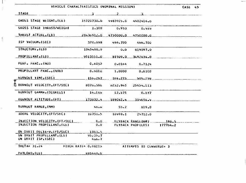
VfHlCLE CHARALltRISTlCS (NOMINAL MISSION) CASF; 4!>
GRO~S STAGE WclGHT,tLB) 1s120130.o 4"18392~.o 4902416.o
bROSS STAGc lHRUSl/WtlGhl
ISP VACUUM,(HC) 370.8"16 466.700 466.700
. STRUCTURt, I LB) l045't88.9 o.o tH9097.0
PERF. FRAC., (NU) 0.6052 0.0104 o. 7124
PROPELLANT FKAC.,(NUb) O.'JOlO 1.0000 0.8 ICO
•bURNOUT l lHf_tJ.~~f;L. ______ 15_.Q..,2il_ ___ .. _lg.4_.2_1.2___.!>.0h2!19-________ , __
! BURNOUT VELOCITY,IFT/SECt H07u.58b tl2)2.945 25~~4.113 BURNOUT GAMMA,(OEGRE~SI l4.l6b l2.::S75 0.187
___,,B~U:.i.:k..:.::N:.:D.:U...:..T_:_:.A. ,,,_L T-'-'l=-T,_,U=U<..::E:...1'-'(_,_F_,,_l~l_. ____ __,,l...,.7"""3_,,,B 3 2_.._lt __ _l.ll2.C.~Z ... ~--3-l':ib.5.b.a '.:t __________________ _
BURNOUT RAN6E 1 INM)
lOEAl VELOCIJY,CFl/S~Ct
INJECTION VELOCJTY,(FT/SECl INJH T ION PROPELLANT 1 ( Ll:i I
ON ORBll OtLlA-VrlFl/StC) UN ORbJT PRUPELLANT,(Lbl UN ORBIT I5Ptl~EC)
-----·-- -·--------
4b.c. 55.2 819.0
unsu.5 lOC:;98. I 2C..7l2 .o
0 .. -'L. __ f=~L~Y.BA.c.LB.AlllG.UNM J ·---1'18..5_ __ ---·- - -O.O FLYBACK PKO~lLBSI 1777b4.2
9!>.d!>.7 4t>b. 7
---------·--·--·-----THE.TA= 31.24 ~llCH RAT~= 0.0021~ AlT~MPJS 10 CUNVER&E= 3
PAYLOAO,fLI?) 495449.CJ
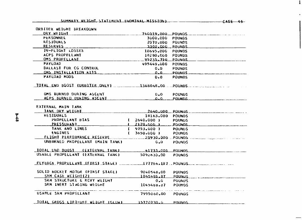
Sl!MfiARY WflGHT !>TAJEM£tll.I_(N0MINAL H l SS lUb.1)
0RB11ER WElbHT bREAK.OOWN __ Qfil'.__WE I GH I
1-'i:R SONNE:l RESIDUAL~ REStRVES IN-FLIGHT LOSSES ACPS PROPfLLANT OMS PROPELLANT PAYLOAD BALLAST FOR CG CONTROL OMS lNSIALLATlON KllS PAYLOAD MODS
. __ JAOQ.1.9.00Q _ _pQUNOS- ·---3000 .000 POUN~S 201U.OOO POUNDS 3300.COO POllNOS
10695.000 POUNDS 18280.000 POUNOS
___ 9_5_23.~-5(l_PflUNO$_ __________ -------· 49~449.000 POUNOS
O.O POUNDS o.o PUUNUS.~-~-------o.o POUNDS
TOT AL ENlL~QQs_L-1.URtUJ_flLONLY. ---- ·-·--l.3.6.BO~nu ___ POUNOS. -· - - - ·-
OMS BURNcO DURING ASCtNT ACPS BURNtD DUKING ASCtNI
EXTERNAL MAIN TANK
o.o o.o
POUNUS PO!INDS
__ _lA_~K. DRY _ _.Wf..._l=G,._,_HJ.._______ 2640...UOQ_ellUNUS-------------· RESIDUALS 16163.000 POUNDS
PROPELLANT ~IAS I 2b40.000 I POUNDS PRESSUKANT l 2120.000 I Pfllll'iDS TANK. ANO LINES l 9753.000 ) POUNDS £NGINES ( 3650.uOO ) POUNDS
--EL IGt:H _P._l:RFO R'1A~..E.S.f.RVL. -·--·----·--· --··-2J.i2.30 ... ..00.o __ pouNO!\ ---··--- ----·-·-·-· UNBURNED PROPELLANT (MAIN TANK. I u.o POUNltS
JOJAL t~D BUOSJ CEXIERNA.L...1.At.i~J U~AbLt PROPELLANT IEXTcRNAL TANKt
41733.000 P01JN.1l • .,_ _______ _
50~~b33.00 POUNDS
_________ l 717o'i.a lB7. _POUNDS.--·---·--
SOLID ROCKET MOluR IFIRSI STAGt) 9040548,00 POUNDS --=S.:..=.k.;...:.M_C=-:..:..AS=l:=--'W=c::..:· l"-'G=H-'"l._.(.._,,2,._,)'------·---·--~l~O~ll......-87~~POUNJ.!,...__ ___________ _
SRM STRUCTURE & RCVY WllGHT o.a POUNDS SRM INERT ~ T AGING WE:lbHT l0't~4bd .o7 POUNOS
USARLE SRM ~ROPELLANT 7995000.00 POUNOS
Io J A LJZ!i!JS s L 1E1 ~~.1:.JJitl.I __ u:. .... Lu""'"w..._._i ___ __.1~!'.> ... 1, ..... 2_..o ..... 1_3...,.o._. ...... n.___~e.uUN~-·------
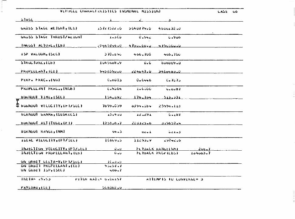
l.A!:>I: ub
bl\u::,!J !> 11..C,1:. .. f:.lbhl , lL c) ... :.h.i!;.l!.it..(> !> C.4 UI ·l':I. (; 'tb.&.t..a.3.£.v
bku!:>!:> !:> l"Gt: l ttl\.U!) TI ht J.bHl " .. ;.) c.u 0 ·"'"*~ ".'J~b
lhku!»l AC. 1U14L, (lb J .-tr"t4 ~1 .. 4 .o 41:>ui..Lu.v .. l~vVO\t.V
.l i:,p VAl..WKt (!:>t.l.) :::. 'ID.I:. 7\J 'too .1uo 'tcb.7uu
~ lk.ui,; rukt., 1 Lb) 1 Vt ~'toli • '7 o. (J but.OU'.t .\J
t'k.ut>tLLANl r &lb J 7'f!:I t.,:;.'7u .u "i! 'tb " 1 • (J .;, It C,o't b .1. Q
PtKt-. 1-kAC. 1(NlJ) e;.bulj o. (,'"t'tb C. -Ii.; ·1..:.
P KUt'LLL 1ir..i J l-k.111..., INUb I '-·."Iv CJ.1t J. • {, .J(J" '-• '"' il I
bUKNuu·1 ·1 HU., & ~!:(.) 1 ~ ... .::."" 17o.7o<t !u3 .;,::H
! bUk."4UU1 VlLuC11Ytl~l/~L(.) ·n1 w .o :::.1.1 UJ"I ... ib .. L 5':#!:l-. .1J.J
bl..kNUUl bkf'lfoiA, I i.Jl::GK t.l!. I .a.:::..4 .i..U .&.t. • .t.'J ... (; •.i.ll.,
bl.Jl\NUuT All lTUL.1:.t U' i I l "I !'.;6.A:> • ·1 .C:J.U..)£:J..b jJ.~02·1 ....
bUKNl.iUl KM'4l:.t, (NMJ ...... 3 oc • .l i.".a..,j
.l 1.>l::.AL ~l::.LULllYtll-1/~tLj H6V1.::. u..;.: '.f.:>. 'I ..:"J1•u:..b
li'vJtl.11 u .. VlLULlTYt lfl/~tl.I J.u h \'.>'-1..l<. KANbt l f11M I .2.Vb. t 11\fJl(.TJ. uh: t- kUt' lLL Al',. 1 t I Lb )
(i •"' f-L l'llAl..K l'kLt'iLb~) i<>4oo3.7
or.. URtU. T 1..lLl A-V, U- U !:.t.L I ! c. ..,..:; .,:, UN Ukt>l ·1 f'kLP t LLA~ J • t U:.) "1 :.,.L~I • l lJN IJkb.il l~ht!>U .. J .. ou. /
t'AYLlJAU t l Lt; i
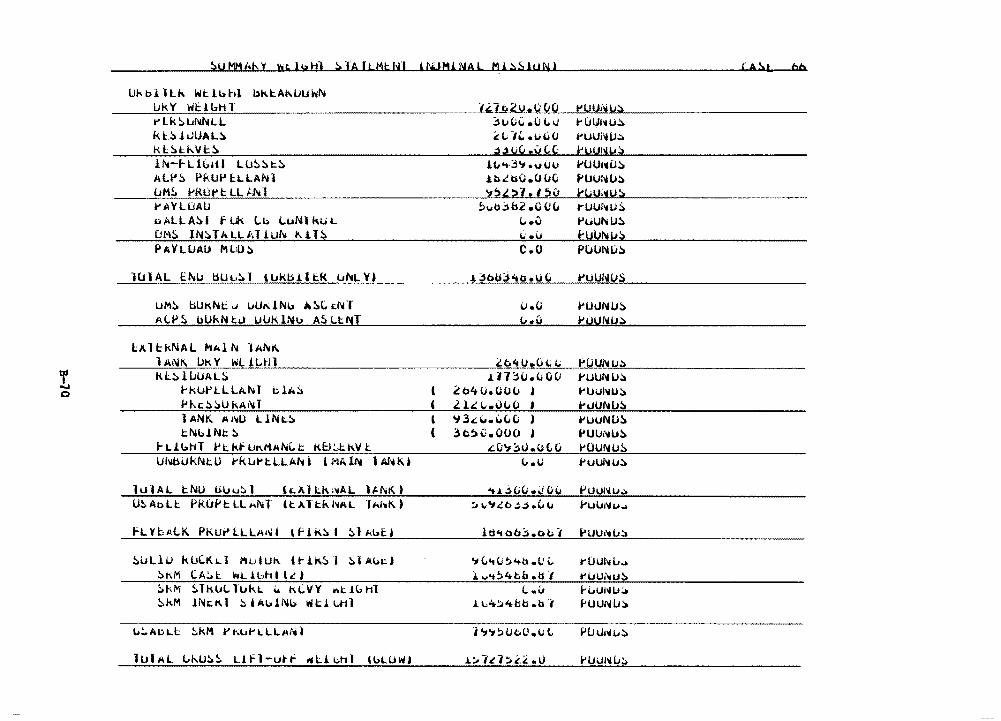
! c
!>UMM/;hY Wt.11.zHl !>IAl!:.Mt;h!I H-ilMJ.l\IAL "'J.::.~lUN}
Ukblllh Wtlb~~ bkl::A~UUl\i!\!
l.JkY Wt.lbHl t'Lk!:.uNNLl kl:.~lUUAL~
kl!:.t~Vt:~
ll-c-f-Ll(;.1tl LU::.!:>t:!:. ALt'!i. PKUi' l:.LLANl uM;. t'RUt' I:: LL J..h 1 t'A'VLUAU ~ALLA~( fl~ Lb ~uNlkUL DHS IN~TALLAT1Uh ~ll~
PAYLlJAl> Ml;O!;
llJIAL Ehu ~Uu!;l IUkb!ltk UhLY)
UM!l. bUKNt;;"" ltUl\lNi.> il.!i.C. t.l'tl AL~~ bUkNtu UUklNu A~LtNT
LAl~kNAL MAlh lAh~ l Ai\11\ Uk Y WL J..Ltll kL~llJUAL~
1-'kUl-'lLLA.Nl b.l;.;) l'f...1: !> )U kAl'd 1 ANK Ai-..1.) llNt..~
tNb.lNI: !. f-LJ.bHT l>t:.kfllK.MA1'i\..t K8:.l::.kVl Ul11bUkNt U t'K u.- t LLA~ l l MA lt\I 1Af't Ki
lulAL l::NlJ UlJu!:.1 h:,)llt:.k.:'llAL l/.1'<10
::.~LlU kDCKLl ~u•u~ l~lk~l ~]Abel
~KM CA~l wt..!bhll~)
!:.kM !.Tkul. lukt. .. M:.llY 1r11t.H:d1l !:.kM lNt.K.1 !:. I AulNb lfllll::l "-'11
' (
' (
i'"'1t.2u.uCIO ::H;(;C .(J l. Ii
~"-''- .u~o .:),jU(>,i.J(,(:
lu,,..3'1.uuu .ihibO.OliCi 'l!>l.~·1. 15v
!>vb~&2 .o Ou L. ·" ti.u c.o
J. :;,bU::i"to .u (i
1.1.0
"·"' .i:.o'iu.oc1..;
J.H2H;.(.;0() 2o4o.uov j
l li 1....0110 • 'i 3.d ... \.!C,{J )
3c~i:•.ooo ' .::01:1:.0.otv L..u
41.UC;Cl .\J C"1
!:; 1;'140 ~,:) ·""
lti"I ob:. .obi
':t e; .. v:. '+b • CJ i.. J.. .... t!;4bb .ti.,
(.. .i.i L L.4:J4tb .o i
h'1!:10c.0.1.1 l.
1:.1ia:.£I.. .o
( A!>l bb
t'UU11i!J;> t'U\¥1'l1U~
t'UUNU~
j:'UUl'jU.> t'UU1'40!:. J>UUNU,') tuu;'fu!> ruur11u;) t'UUNU~
i-YU!\11.!!> Pu UNI.I!>
t'UUhliJS
l'UIJNIJ!:. f'UUNlJ.:t
PUUNl.J.':. t'UlJNl.J.!) t'UUNU~
hJUl\llJ~
t'IJUNIJ!:l t'UIJNIJ!:. t'OUNl.ll> t'ulJNlJ,')
PUUNu..:. 1-'Ullf\lu.,.
i'UU1-.iu~
t'OUl'\iL..:. t'i.JUi'<iu:-.. f'i.IUNl.J~
f'UUNIJ~
Puu1~i..:)
i'lJUNl.J~
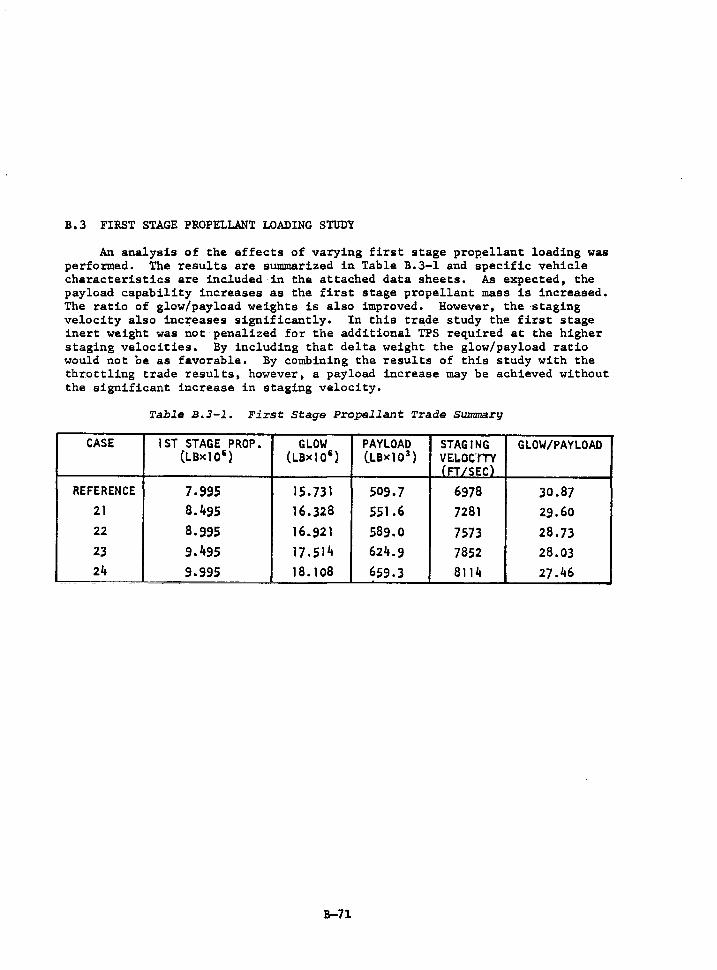
B.3 FIRST STAGE PROPELLANT LOADING STUDY
An analysis of the effects of varying first stage propellant loading was performed. The results are summarized in Table B.3-1 and specific vehicle characteristics are included in the attached data sheets. As expected, the payload capability increases as the first stage propellant mass is increased. The ratio of glow/payload weights is also improved. However, the ·staging velocity also inc~eases significantly. In this trade study the first stage inert weight was not penalized for the additional TPS required at the higher staging velocities. By including that delta weight the glow/payload ratio would not be as favorable. By combining the results of this study with the thr.ottling trade results, however, a payload increase may be achieved without the significant increase in staging velocity.
Table B.3-l. First Stage Propellant Trade Summary
CASE 1 ST STAGE PROP. GLOW PAYLOAD STAGING GLOW/PAYLOAD (LBxl05 ) (LBxl0 5 ) (LBx10 3
) VE.LOClTY (FT/SEC)
REFERENCE 7.995 15.731 509.7 6978 30.87 21 8.495 16.328 551 .6 7281 29.60 22 8.995 16.921 589.0 7573 28.73 23 9.495 17.514 624.9 7852 28.03 24 9.995 18. 108 659.3 8114 27.46
B-71
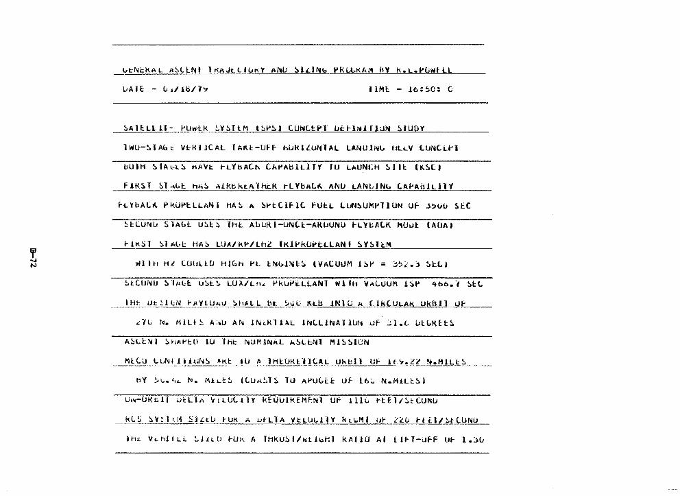
LiAlE: - udlb/h IHU. - .lb:~O: C
S.AlE:LL!l~ PUwtk ~Y!:.TlM l~P~J tUNCEP1 ~trl~!rlUN ~lUOY
HiU-~ l Abt VH< l JC AL T AK.t-(Jf f hl.Jk l lUN T AL LANU lNb liU ... V lUNC:. U•I
bUIH S.IAb~~ nAVt rLVbAC~ C:.APAtilLJTY ID LAUNCH S.llt (K~lJ
f1R!>T S.l~l>I: h;o!> ,>.J.k.bktA"fl1t.K t-LYbAl.~ ANlJ LANldNb C.Af'AttJ.LllY
1-LYbA(.~ PkUl'tLLANI MA!:. A S.l'tllfl(. fUl:.L t.UN~Uf'.l'llUN Uf _j!>t.i(; ~EC
Hl.UNlJ s ·1Abl u:.1:.:.. lhL Ab GR 1-LINC.l:-ARIJUNLI i-LYt:AtK. l'\Uul: (AUA I
rJ.KSl S.l Al>i: HAS. LUA/kl'/Lh2 fKli>klJi"l:l.LAN I S.YS.H:f1
' ..... N wl I tr ML (.OtJli:[J HIGH PL tl'llb1Nl:S. 'VACUUM J S.1' = :bi.::. S.l::L I
Hit Ut:!.llN f'P.YlU1<U ~tt/.LL lit. ~l.iL KLb JNlG A ClkC.ULAK Uk!Sll Ur
dL N. MJ.U !:. A: .. u AN lf\li..Kl 1.\L lNl.LJ.NAOlJN Uf j} .. t. IJl:.6KH~
AS.Lt~I !:.HA~tU IU lHt NUMINAL ~S.Ll:.Nl HJS.S.lCN
Ml:.C.il l.l1Nililul-.1S. AK.I:. w A lHl-UKl:.'lll.AL Ukbll L;f H-,.z:t ~.MlLtS.
U~-CJKhll U~LlA ~tLULllY kEQ~lk£M~Nl Uf 1110 ~tE1/~tLUNU
kLS ~Y!ltM SjLt~ rUK A utLlA VtL~Ll1Y kt~HI u~ 2~0 ~til/~tlUNU
lh~ VLNllLl ~J£LU ~Uk A THKu~l/~tlb~l KAllU Al Lt~T-ufF u~ 1.~~
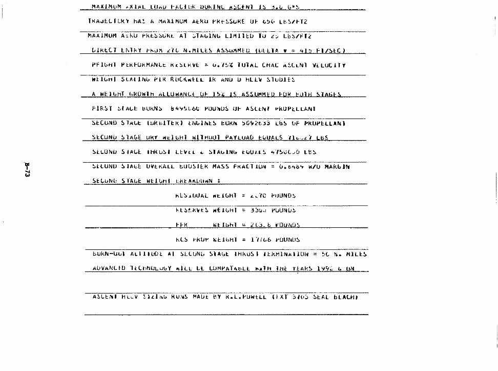
l KAJf:. LIU<~ hA!: A MA Xl MUM At f<lJ l' I< f- ~SURE IJ I- t.~(. u. !:ii 1-T .2
AblNb LJMlltU lU £~ Lb~/fl~
Pflbtil f't:kH.JkMANLt: Kt~lKVl:::. v.I~~ lUlAL CHAl ll~li..Nl Vt.LtJCilY
~tlbH1 SLAll~b .. LK RUl~~tLL lk ANU U HLLV SlUUl~~
A WtlbhT hk0W1H ALLU~ANLt UI- I~~ JS ASSUMMED tUM bUlH ~lAijt~
flRSl ~lA~t bU~N~ &4~~lbC f'UU~U~ U~ ASLtNf ~KUPl:.LLANI
StCUNU ~lAbE UKt ~clbH1 WllHUUl PAYLUAD f:.~UALS Jl~-il LbS
lJVl:.KALL t.UlJ!>H.K MASS fKAll 1U1~ :. u.t.<tG'7 W/U HAkbl!'4
bUkl'.l-lJul 1.LlllUlil:. Al !i.l:ll.JNL, SlAbl:. IHkli~d 11:.kMlNAllll~ = ~·(., 1'. MILi:.~
AUVANLlD lllhhULubV ~lLL Ll LUMPAT~bLf ~~TH lHt Yl:.Ak~ 1~9~ L UN
ASLt~• HL~w ~lLl~b Ru~S MAUt ~y K.L.PUWtLL (IXT 310) ~tAL bLALHJ
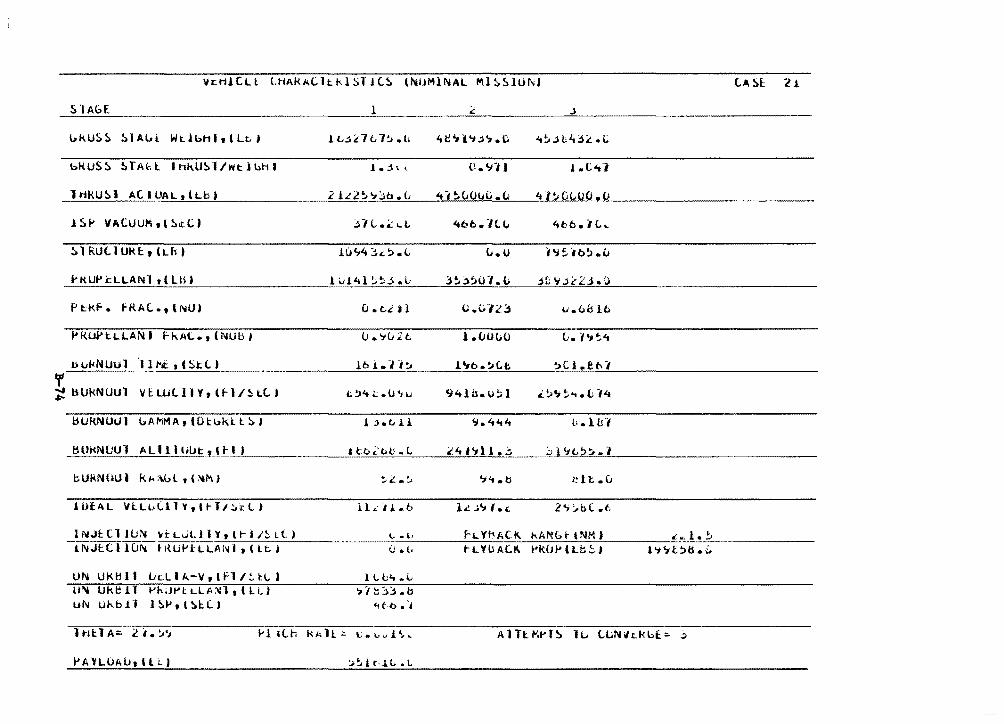
VcHlCLl LHAkALltklSllL~ l~UMlNAL ~1~51UNJ (.A 5l 2 .l
l>kU!:.5 !>]Aloi. Wt.lbh It l Lt,J H-:.:C.7t.7~.(; .. ~~l·d~.(; 't~..:lt~j4i. .c
bk US!> !>TAU. I hk.U::.1 /wt i uh t j • .; \ ( u .. 91) l.C.41
1 Hk.U~ l A( I UAL t l Lb J 2 lLl~';;jb .(; -.-,~c..ouc.<.i ·H~G(,00.0
l 5 f' VACUUJlli, l ~itC J ;fH .• .t:...t .. "tti-b. Jtl .. 4bb.t(.._
!> l RUU URI:, (Lfi J lu~4 ),~.'- c.i.o i'J~."lb!> .u
i>KUPl::LLANl tllB) l i.1141 ~~.; ·'-' 3 !. 2)!'>t:H. L _jf; 'i j.{ 2.:i. IJ
Pt::Kf. fRAC..,lNU) (J. t,~ Jl c.<a~.::s li.o~ lo
f'KOPtLLAN I F- k AL• 1 (NU b I 0.'7u2t; 1.00(;0 (i. 1•1';'t
bvf.<NUul 1 H.t t t ~tC. ) lb 1. r;:;.. l';b.~C.t. ;CJ.et•7
' ~ bUkNUUl VELUtllYrlrl/~ltJ t !)4 4: • u., I.I 'l"tlu. u!i I i!.>'Jt. ... Cl4
l:H.Jf{NOIJI l.AMMA t tDl:bkl l SI .l .;.(, 11 '7."t't"t L•. l u I
l:WKNUUl ALlllOIJt,lH J ato.C't>c-L £41'-Jll • .:. ;;,,1'it..!;>~.1
bUk1'40U I kl< ;;.l,l 'l :-Wl'-d .. ·. . ':l"t.b ~~lt .c. ..J L. • ..,;.
i O{AL Vl:LvCllY,ltll~~LI l l,; ., J. .. b 1.c. :,:.-.,. I• c. 2<; :,.!;(. .t
lN..IHl Wr-. ~tL~LllYtl~l/~tlJ \..; .. l1 h .. Yf-:IAC.11.. t-.All!& t l NM ) ..:~.!.~ -iNJtC I HJI'« • l{UJ>l:t..U:l.N 1, (Lt. I 0 .. t. t-t..YbA(.K. PldJP l Lb!:. I l '7 '1 t!>ts. ir
UN UklH I Lc:L I A-V, l fl I!. l::l.. ) l Lu't .L u~ lJktH 1 1-'h;H'L LLA~-1, l LL) ,, :::~.:; .. b
UN 01-.bll l~J>,t~l:(.J .. t-6 •. ,
lt1t:.TA:. 2 i.'..'1
:..~l r.j,t,, • L
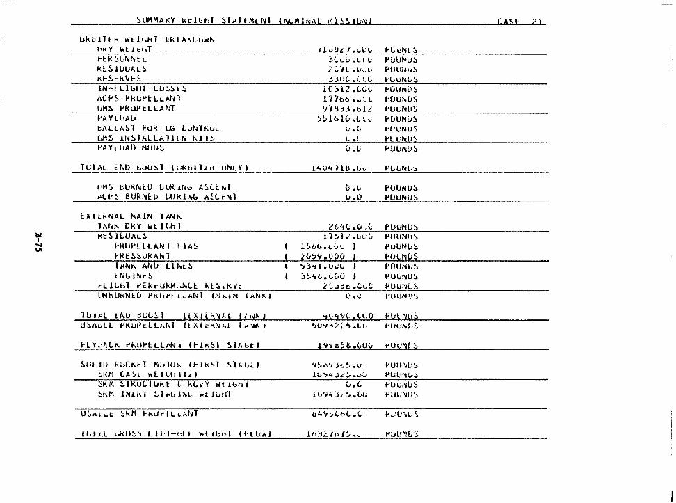
lJkiHll:k wt.lblil i;kLAl\.L·!.H4~
L kLSHJUALS Kt:~l::kl/l::S
lN-1-LlGHI LLJ,'.,.!>t!l ACf'~ l'klJl"'l:LLANl l1M!> l"'kUPt:LLAf-~T
1-'A V l i1AIJ bALLA~l FUk Lb lUl\llKUL IJMS !NS f ALU. H t;N 1\11 S PA YLUAD MUIJ~
uMS uURNt.U uUR 1Nb A~lt. f'ltl .M .. I•!:. BURl~f:IJ Wkhb A!:C..1-:'lll
l::Jl.I U<NAL MA!N l A.NI\. 1 Af~I\ Dl<'I Wt. l U1 l
f Kt!>luUAL!:> ~ ~KUPflLANl liA~
1-'Kt:::.::.ukA!>tl I ANt\ ANU Ll l\t!:> 1.N<.,hi:.S
t-Ll l.h l l'£kr UkM,.~Ll kl:::, & I\ VI:
SULJU hULKtl MLllUh (~lK~l ~lALL) :.tUI (.A!. L w E:J l.t1 ll d SkM ~lRULJUkt L kL~Y Wt1bhl ::.kM J~tkl ~l~LJ~L ~t.JbHl
C.AH 2 l
3Li;u .u 1.: l'lJ lJNU!> 2Vll .l•d.1 PtJL:f';u!> 3311(, .L U.i HJUl\ili'.:>
10jl2 .LL(, 1-'llUND!> l 1-lb6 ... ~ i..: f'OUklJS <.iHLU • o 12 l'UUl\IU!)
:i!:llt>l(;.t:_;) P(JUNl.JS v .<.i l'UlJl\IUS L .l H.Jvl\4.U~
(J .G l>UlJl\IUS
1'4\.lttHb.u ... I'll IJNL·::>
o.u PUUNU!l l..r .. (J PUUlllUS
L'tA(; .CJ .. \,; Pl.JUND~
O~l:C:.t·C(; l'UUNIJS L:~bb.1.·:.. u ) l'UUNl.J~
;:<i;,';.000 J POUNCJS '.t3'1i.. lJuu ) l'OllNu~
::>~tit>. C.(,O ; t'UUNU!> LL..ijc .CL{i 1-'UUNL~
(} .i.; PUU;'\f!J~
4tL·•1~·C .tt•O Pul•~ws
~l,)•,d.;::-~·~ .1..11 f'UUl'91.J$·
l '1"> c5 I:. .ttH.i t-lJtmf.r!:>
'J~&~'IJc.~ .u .. l'UUMJ:i. 1L'7.,Ji:'.~.l>G 1-'lilfl~li!>
u. (, rUllNLIS 1\,1'.;'t:.il.::,.(J(j 1-'UUNLJ!>
lJ4'1::-Lt>L.L:. Pt.:Ul\;l.')
.lt1:il. ·101~ .,,, l"i.JUNL~
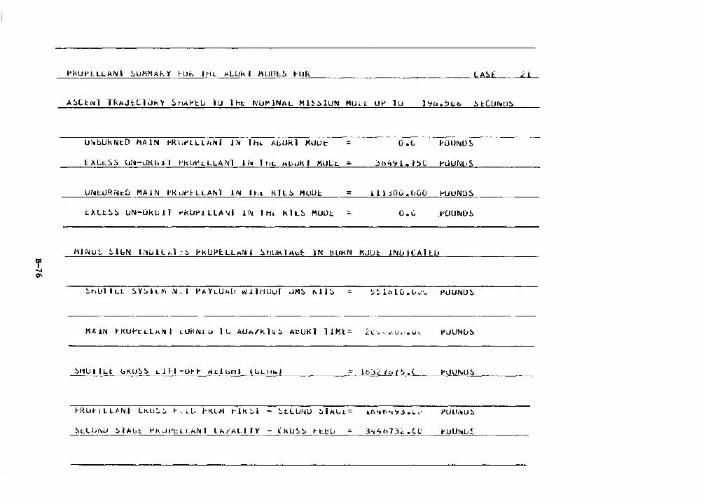
PkUPtLLANI ~UMMAkV ~U~ IHL ALUkl MUOlS ~UR (.A Sf
ASl.b'tl lRAJf:(.llJk'y ShAf't:.u ·1u lht: l\'UMJNAL Ml!i:>IUN MULi:. UP lll
u: .. bUkNt:.D MAIN l'RUrlLLl\N[ 1:>4 ltii. Ai.;Ukl MUUt: =- 0 .t.
E>.Lt:SS lJli-uKtlJ"I l'klWi:LLANl Jh1 ltu:. hl:..JKf ~1UL:t. =-
UNtURNtD MA!N ~K~P~LLANT IN lhL KlLS MUU~ = illJO~.uGO ~UUNuS
1:.)1.LtSS UN-LlkbJl ~kUPlLLA~l lN IHt klLS MUUt: =- O • .J P'UUNDS
HJNu~ ~lbN i~Ull~l ~~ PkUP~LLMNl ShUklAbt JN bUkN MJDt:. JNUJCAllU
SHUI ILt uKllSS Lll---l-Ut-~ ~dbtil lbLl11<ol
PLllli11U::.
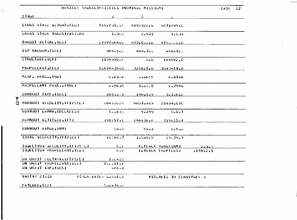
ltthlllr LhAhALltkJ~IJL~ INUMINAL Ml~~lUNj CA5l 22.
~ l Abl:. 1 ;: ;:,
GkU!.!> ~lAo.l WL Jl>Hl t I Lu I lt.?LlJl.<:.L 'itl't <: .j,l u. ll .. ~7J6'1'7.L
l.klJ~~ ~TA~L I l-11\l•!. I/ i'l l 1 uh k l. jL:.. v.'>71 I• v j':t
1 llKU!, l All UAL, ILL>) .::J.,97ut>'t.L .,,~l.C..;J.v 4-, :; L \..0
\.. l.' e (,;
I !>I' 'JAlUuM,(!.tL) Jo._,.:..:~ lfbl'Je 7~..i 'iC>b. 71,;_,
~ l kl.IL J UK t , l Le ) .11:,9-.~(J. c u. u -, U'i L•'l2. (J
J:'._~~t>t.:LLAflll ,c LbJ l ut. "i<t'-1J'I. CJ .:itGbd.u ::Hr1 j't J 'I. U
Ptkf. t-1\.Al.. •, ( h1U) (.. .td~c ~.\.Jo~~ lJ. 67 06
~K UP l:L LAN I rKA(.. , ( NUU ,_..'tu.>:;, l • .:i ... ·~ 0 l. 79f::tU
c.UKN liU 1 ·1 lt'iE:_, l ~t LI 10 ~ .... -· -, l '71:>. ~ .i '1 ~" l .ti-.£
'f ...... !j Uf{f.jlJU -1 It I: LUl..11 Y, l HI!.. tC .. I vb't :>.LL l1 '-Jt.~l.'tt.~ 2)"1::>4.C; IC ......
b Ut<N i.JlJ l l> i.MMA, ([JI: LkH. :.>1 1 ... 01:.. '7.£4'-i C.ld
b likN UlJ l hLllh.Lt,lt-·l j 1 't l l-'7 7 • l i'.4t. .. Jt· .• t- j l <; ';:.:. • -,
bUkNUUl l{Al'll>l:1lNMI !..o • !,) '10 • .:l 0£6 • ..:.
J.IJtAL lllllill TY, lt-1/!al I ! .I. ~bb. 7 .i. .::.tH>. ~ ~ '7:..3'1. :1
li>iJt LI J.U,11 it LULJ.I Y ,& t- I/~. - (.. ) L. l 1-LYt:Alll. KAf\ll>t 'NM J '.:d .•• , J. ;-~Jl:(. ·1 JUN 1•Kut-'lLU1i'f1, Clo ) i.1. (! tLYbALI\ tKiJPC Ll:l!) I
l.Jl'll UkllU L-lLlA-\i,tt-T/~1(. J l \.(.~.:.
I UN i.Jk.b ll l-t<UPl:LLAl1d, llt-1 iLL-Lll.t_. UN Ukbil 1 ~I' , l !:.t: L j .,r.0.1
---·-----H1UA= rt.lb 1·1 ILh kAH:-"- L.. Lul ;;7 AlhMH!. IU (UN\ilKl..t:;. .:1
I' A YL U"- LI, I l t: I
I
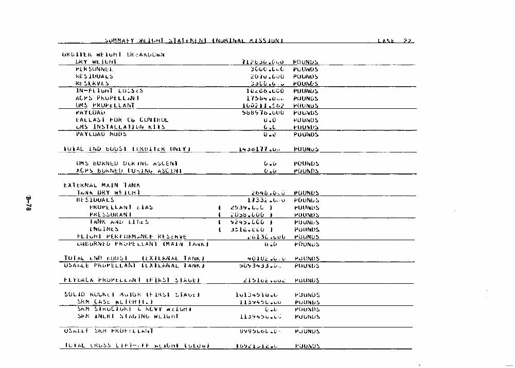
If ..... 00
!:.uMMA~Y ~tl~HI ~lAlrMtl\il 11\iUMl~AL M1SS1UNI
l.Jkblll:P.. wt-luhl Lk•:Al\.lJLw~
U<.Y Wt1Gt·tl t>tk SlJNl\il.: L kE!:.HtUAL!:. Ht ~ l kV IL!:. lN-fl ll:.hl LU~!:. c.S A(. I-'!:. P f<.lJPt l L f.N ·1 I.JM!. l'HUhLLAr-..1 t"~YLOAl.1
lALLA!:.I I-Uk Cb LUNlkUL LM!:> lNSTALLAlJldli l\H~ PAY LllAO t'IU(l ~
llJkAL ll\iU bUU~I ILX.llllc.K tll\iLYJ
UM!:. bUkNl.:U llLk il'iL A~ltNJ AC.P~ bUkf\;t:IJ t·ur.11\u ;.~C.tl'.11
lXltkNAL MAIN lANK lA•'f"'- OKY wt: .l.LH 1 IU: ~ llJUA L ~
1-'KUl"'t LLAllil dA!:. 1-'Kl::.~!:.Ul{AN I 1 ANK A;,.l, L.l f\L !:. Ht l:.J l'l l ~
fLJ~hl 1-lkfLikMhNL~ Kt~tK~f
Lhll.luk~l:u 1-'kUPI:: LLAN·1 IMA!».i I A•,." J
TUIAL 1:N£) t.uu:.1 ltXILhNAL TANKI U!:.A1.L1:. f'kul"'l:.LLAt•.J°I HXILi-.l'liAL IAl'lll\I
1-L'fLALI\ 1-'klJPtLL>Jll I 11-'lk~l !.lhuU
~ULiO kUL~tl ~ul~k tl-lK~I ~IAbtt
!:.k1"1 LA~:: ftLJl-Hll,j !>"-M 5.IKuC.luht t. 1,(.yy nd.l:.ril Sk~I il'llLl<l ~11\ldNL• WLlubl
' (
1' li c .l0 .C:l>U 3CLC .L<-t £. (JI u • L«.1 (.J
::..lCu .(.. .... ludlb .1,;{)0 l 'f~b .. • (l .,,,
lC..ud l .~t.l ~bbS"lb.UliO
u.o (, . (.
o.~
i't.lUl 7"/ .u,;
(., • (J
(J .u
.it>'t(i .(,,,., u 11:::.3.<:: .(.,, v
~'>3'1. V~ L )
~-.Ojb .C..Ou J 'i~<t~. LCu J .l!:.Hht:((J )
.: .:, Lil. • i. u u u .(1
<tOlUL .(,. ~. :>v'F3't::U.G ..
.i.l ~ lu.<:: .i.o..:
lvl:.S .. :.lu .. L U3':i4~L.i..u
(· • L-
1l3't't'.>v.i..'.:.
U't9~·1tt>L .(;·.
• o'J.:' L.'1 .£: .L.
I ASt 2?
PUUNlJ!:. PLJU1 .. os PUlJNL)!:. i-'OlJf'lt(J 5 PUU1'4u:i. f"LlUNlJS 1-0lJ:'tiJ!:. hH.ii'.IOS t'UUNDS t'UU:'OL.1!:. PUUh10S
1-UUNu!:.
i>uu1 .. os t'UUl'l.DS
PlJUNL!S H1UNu!:. t>UlliiH.1S t'UllND!:. PULll\li,S l'UllND!. PUUNLiS 1-'DUNt;!:.
f>Ll UND S PLIU~ms
PUlJNU5
!''JUNO S f'UUNL1~
t'ltU:-011!:. PUUMi~
P.JUNUS
1-'UlJl'tU~
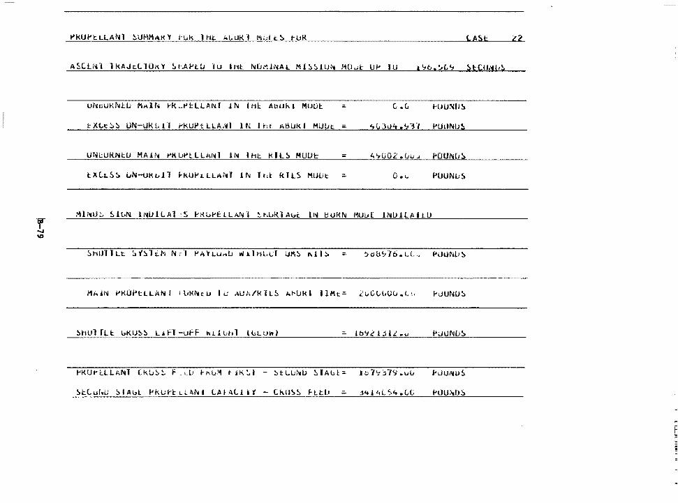
PkUPiLLANl ~UMMAKY ~~k lHt A~URl M~L~~ t~K LA St
A5LlNl lkAJ~LlUKY ~l~PtU 1u INt ~8MlNAL Ml~~lU~ MOut U~ JU
c .c..
~XLc~~ UN-UKLll PkUPtLLA~I lN lht AHUKI MU~t :.
UN~UKNtU MA&~ ~K~~llLANl IN lht KIL~ MUUt :.
lXLt.~!. i.JN-UKt.Jl 1-kUl-'i.LLAiltT 1~ ltd: kTLS MUIJt: :. 0 • 1.. l'UUNu S
hJUNU~
~hulrU: l.KIJ~~ L.iH-ufF wl.1bt1l ll>Lllttl
i-
F 1:
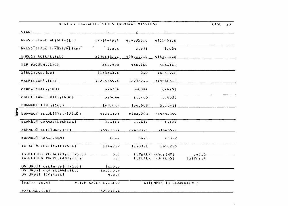
~I Abt. l :.t. :,
GKU~~ ~ lALt Wlibhl,lLc-1 lblit't'tb.i.. 4ti':> _j3L 3. (; •d V; t. u J • t:
GKU!. ~ !> 1 AL.I: ·1t1kU~d/Wt 11.;ht }.;)\.\.; .;.'1i1 l • l. C:':i
I tlRU ~ ( ALI lJAL, llb J £ ~ fotl f'.:.,.:" .• L. -.-PH,C•J'~ .1.; Lt l ~ ~ ~, ... ..; • D
1 ~ ... VA C. ll U 1't , l !> U:. ) ::it.b.'J'7b 'tt.o. ·H,u "t Lb• -10•-'
~ 1 kUC I Ukt:, (LIH llo.}b(;:>. C (J. u /lli:::O l'l.0
~Ki.JPLLLANl ,\LL:.) ll:.!1.:>'.>~'J.L i .. ·n2~ ..... )l'l";"+L~.L
t> t: KF. f-KP.C., (NU) U.L,j'"tL u.(;.Ju.4 i.;.b-1'>1
t' K.LP LL LAN I t-1<.A(.., l NUt:) v.':>o't't l.li .. L.0 .... ou 3.;_
t:lll k N lJlJl ' 1'1t ' '!:.t LJ le;, ti.l L~ Joo.~i..9 ~ ... J.<tll
r OD uuk1,.uu 1 'IL LUL l H'' l ... II~ Ll. ' ~1LO./.t./ 's~b.l • .2(,) 2~ts~.~.li~~ c
cLit<NUUT l.. A J'1 ·tA , l I., I: LK I: l:. '.:. ) } ,,_. J. c J. J.L.CH l. l t 7
bUkNUUl ~ L 11 l Ul.J I:, (I- I ) 1'7:.i~.;1, .• ·1 ,'£c._j'J.:>. l .:>l ~vS&.-,
t:lUHNUul K A l\l.. i.. , l NM I b~I .. ~ b'<.l i:.Jj. -,
J. iJl:.AL Vi:.lUtllY,lfl/!:.t:LI iJ t- .. 'i • . , J.< .. .JJ.l .O:':l'.1U2 .~
1 ;aJtL I lln Vt L l •L J. I Y , l t- I I!> _ L I u - ( tlfoAll< :-.A1 .. L t l NM I <'"ti. j J. ;>iJt: L.0 uN f'kUl'tLLA•'il t I u. I .... l F-U LALi\ h\Uf'tlb~I
UN .. HU:ll l Lt L.1 .. -v, H ·11:. t.L 1 l. l. il•:,, • l,.,
UN Ukb ii t-r\Ui>tLLAMtlll) J.u~ :;."·~ • '7 (J ;>,! l.IR~ l I l~P,\~tL) 'tLv. I
~1 ll ti ki>.H: ::c c. ~ .. ,J. ., .. _.
t' A 'IL UAL , ( L ll I
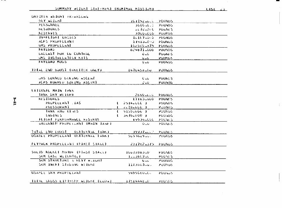
t.A:>t ,';
lJktUl::k lr'll:!l>h-1 t"i<.1i..i\L.1...>r1i~
IL I l•1t •'-'• i.. 1-'l11JNUS f ,;.. Y' I\ L. 1.., H 1 ~-~~-- .:...:...~~~~~~~~~~--~~~~~--'C.::..=-=-~-=...:::...:_::____:_-=.:~=-"''---~~~~~~~~~~~~
1-'l::J....!:>i..NNl::L kt.!:> lULJAL!> 1,i::~tkvr!:>
Ji\1-1-Llbhl Lu:..~t~
i.(.p::, Pl<ut"l'LLl;N I Ui"l.'.:. t'KUPL LL l\M i'A't'LlJAL: LALLA!:>l I-Uk Lb CUNlkUL uM~ l~.'.:.lMLL;.lJL~ Kil~ ~·A 't LlJAU MUu !>
,.M~ LUk"4LLi l>LkiNl, ;,!,(..t:1,r
tC~~ tiUkNtU LLJ~lNb A~ltNl
tXll:.R~AL MAIN IPNK lANI'. ukY Wtll,H»
kt~ llJUAL!:. 1-'l\uPlLLAf~l . lAS I-kt: !l ~lJr< AN 1 1 ANI\ ANu ll ~':: !:. l:.Nl> Hu.'.:.
~Ll~HI ~~Kt~KMAhLt Kt~~KVE --uN~i.;./;~llr .,kuh L~.J.1flll lM1d:>I IA'~ l
l ul ... L t Nu Luu~. I l 1. x l t ~ i\I ·~L I a NI\ 1
fLYPALI\ PR~~tLL~Nl lfiK~f ~IA~L)
'.:)l.JLH1 klJLt,LI MldU~ ll-l"~I !:.IA .... ::..I !..k I'\ c A!:> L w ~ l LH ll L. J ~KN ~lklJCluKl i. KLVf W.:H,rtl ~KM lNtkl ::.·11.uli.:'iL. wt:lbtil
jLl)(..L,:• Pu U~Lr!> ,._I.; .~1 (·l PUlJM S .:13(,lJ .(Lu Puur:u~
h1L-l.0•.u t-'lllJNiJ~
l I 'i L> • C• I j. 1-'Uui\ILi!:> l 0 L ~ L' ~ • 1:'. -, 'J flJUi\i1~
o..'4t111.ouu t'iillt-..:l'!:> ll .L PlJUlllL·5 ll .u t'lJUl'!(J~
(; . (; 1-'llUi'cU.'.:.
.1.4 7v-.:.r1 .( .. ,, PLJ lll'tUS
(; • i., PUUM S .. \ . (: PUU.'110!:>
2c<tlJ wl· ... ·v f-'UUNlJ~
l -/ lcj .uuu PlJUl\ll'~ L".)14 • ...,L(. J l-'OU1\.l1') .:1 .. lti.LL;(; ) Pu UN!>:>
'7 l'..>!.>. t•vv i"UU!\U~
.,,,,, 1t,.l100 1-'UU;,L•.'.:. I 'i'-Jj"- .Lld_, ~· U L' :·u .'.:.
() • Li 1-'U lih1Li ~
:>'Jt:;f ..... __ , f"U Lil\JI :_. ~l,, '1· "it...-':· 'J • ~ ,_ I'll lJl(U~
l- j n c2 .:,1 :i r-ut.Jf\iuS
10v/;>~b.:>.U t'Uuf\[J~
1.._..,jbl j .L PllU\.l ~ lo .... t'lJUMJ!i.
ll<J_jbl-3 ... ., PuU:\u~
'1 "t '1 ') (,, t. U o l L 1-'lJU\LI~'
1 / ':. 1 4-4 4 b • (: t>UU'·;.l •!..
-
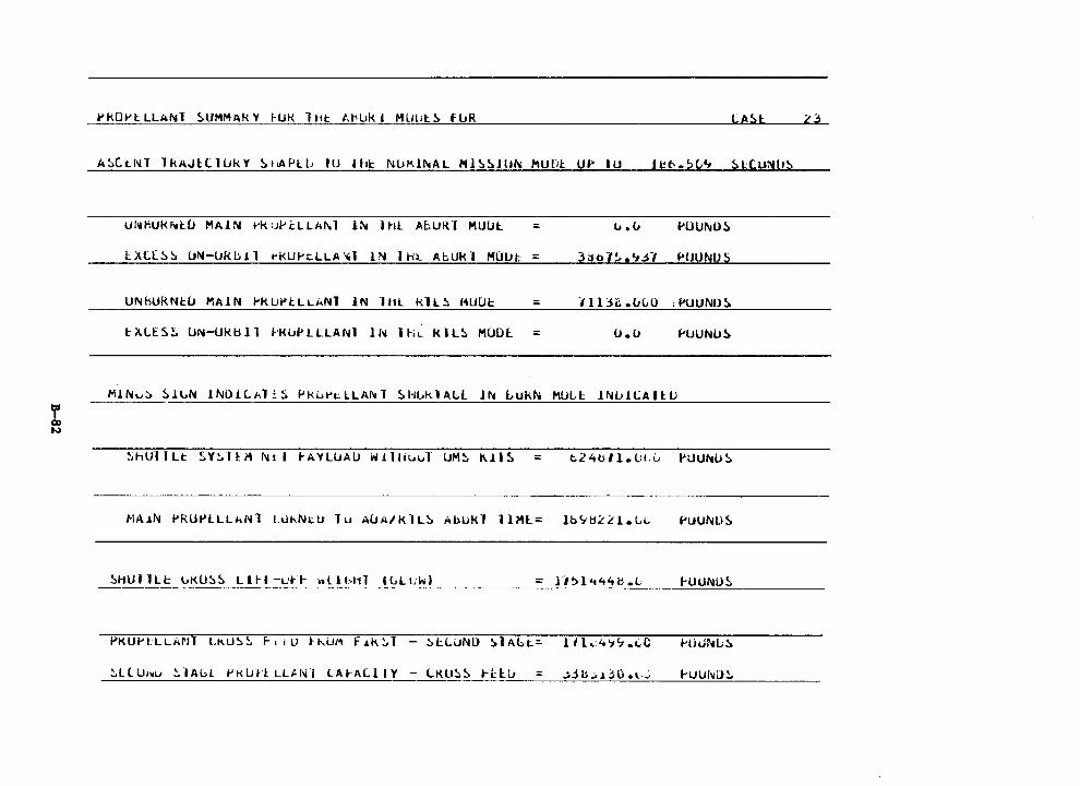
PkOl't LLANl !>UMMAk Y I-UK l ttt Al'lJk. I MUlit~ fl.JR LA!>t
A!>Ct..Nl lkAJl:llUkY S1tAPll.1 IU Hti: Nlll'.ll'tAL Ml!>!>Jltl\; Mur1t u•· IU
UNHUM~t.Ll MA!N ~ku~tLLA~l !N 1Ht AbURT HUUl ::: l; .u
lXt[~~ UN-UKbil rKUPcLLA~l lN IH~ AbUkl MUUt =
UNhURNI:~ MA!N PKUPl:LLANT IN lht Kll~ HUUt = tXLES~ UN-Uk.bll 1-KlJPLLLANl l~ IHL KIL~ MUDl = o.o
MIN~~ !>lLN lNO!Lkli~ Pk~~tLLA~T !>HLklAbl !N buk~ MULt !N~i~All:U
ShUl I Lt ~Y~I ~ i .. Nt I 1-AYLUAU w 11 lit.ul UMS l\.J.1 ~ =
MAiN PRUPLLL~Nl L~kN~U lu AUA/KlL~ AbUkl llMl::: lb~tl~~l.L~ PUUf\lliS
::: H~l't44H .L- 1-UUNU~
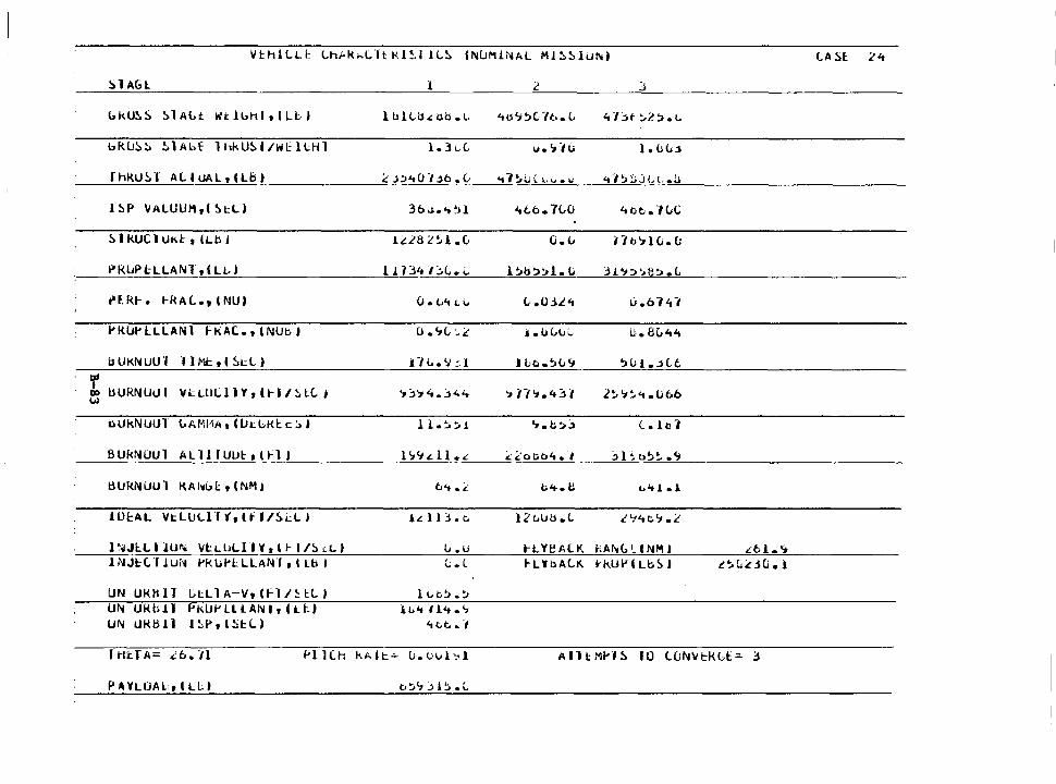
VE:h1LL~ Lh~k~Lltkl~I lL~ lNLlM1NAL MJ~51U~) LA 51: 24
Sl AGl l 2 J
bkU~!) !>lALt Wtlb111, l Lld ltilLdd.lo.l- 41l'7'.>C7t..L 4T:.t ::-l:>.1..
bRl!!:. !. !. 1 Abf lhkU~l/WcllHl l.JL.C. lie'»-,(; l. Oli.l
f hlUJ!. l AC.IUAL,(Lb) £ .l::>4(J/ .lb. v <t7~u( l•vou 4-l~uj\;c.~
l !IP VALUUM,l 5tL) 3b <lo 't ~)} 'tlb. 7(,CJ 4ot..lLC
51 kUCl Uk.I:· I (Lb j lLL8 L'~l .C, O.L i"/o'71Ci.CI
P'R~PHLANT,lLL) 11 B4 /":.(,. i. l~b~'.>l. u JJ. 'J:>'>e~ .L
n:. kt-. t-RAC.., (NU) {J. t..4 t."' l-.03L4 li.b14-,
l'KLlt'llLANl F-kAC..1lNUbJ u.i,c,:..:c J .oLlJi.. u. 8l.4't
bUKNUUT l I Ml: , l 51: L ) .l7L.'.I :l JLo.~u'1 ':>uJ • .jc.t
r l.WRNUUI VI: LllL l JY , l 1-1 / ~ lt I '1j'14.j'44 '> n'i.4~ I 2~'1~<t.U6b 00
w
tH.lkNUUl {,AMMA, l lJLGKI: t::, J 11.:.::..i '1.t,jj (_. lc1
BUkNOUl ALllfUIJl:,tt'l I l':r'J.dl • .: ~:Coob't.I jEa~~.c;
tHJkNUUl KAl~(,I:, l NM I t;,4 .:.- 1;;4.e t."t 1 .1
lUcAL VtLULlft,lff/5~LI .l.:ll~.t. l2t.UU.L £'1'tt:.'J .2
l ~;iJl:L t lUrw Vl:LUL11Y,lt-l/!>cLJ v.u t-LY~All'. hAll.i(, I_ I NM J lNJH.f 1Uii Pl< Li't:. L LAf>H , I Lb I t. t 1-LYbALK. t'k.UPlLbSJ
UN UI01 ll l.,;tl l A-V, (fl I!: l:C. I 11..t.~.~
UN UKb.11 Pk.UP LU.AN It h .. 1:.1 iv"t-114.';
UN URbJl 1:.-P,l!i~L) 4CI:. • .,
r 1-1t.T A= a .. n
P.HLIJAltlLLI
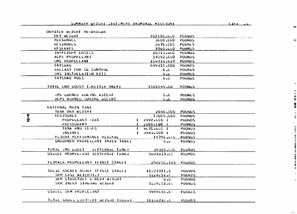
!:.UMMAk)' wf: l bh I !:. I Al d1t f.!l I Ni.JM JNAL MI.:> ~1 IUM I
UKHll~K W~J~HI eRtAKIJLWN lJk Y WI:: lbH1 H:.kSUNNl:.L t<C.!:.JDUALS Kf StkVf::. lN-1-Ll<.:>Hl LCJ~S l!> A(.J>~ .. RUt"l::LLPNI UM!) 1-'RtlPf:LLANl f'AYLUAU bALLA~l ~UR Lb LUNlkUL LiMS lN~lALLAllLN Kll~ I-A YLUAU MOu S
101 t.iH,.<..1.:0 :;<,(JO .<.·vO 2u7(l.COL :nuo .t.1 .. 0
luOH .ul-G 112:.2 .. CvO
lu't 1l't ."1'.H b!>'J:;H .000
ll .. O {t ....
G.C
PUUNlJS PlJUNIJ::. l'UUNLS PIJUNU~
PU UNO!:> f'OUNUS PUUl\IOS PUU'.'liDS f.'OUNIJS tl'UUNUS POuNu!>
l~OJ~44.C..CJ i"OU"11.1S l U I AL l:. NO hlJU S 1 ( .!:!!.;K"-!b'--'· 1"-'l,_,i:._,K"--'U'°'N-"l"'-V_.__._i --------"'-"'-"'-"-"'-'--'-"-'~--'-==-""-------------
uMS t..ukNi:.IJ l..UkJN(; A!>Cl:.M ALf'S liUkNl:U WklN6 A::-.Cc.Nl
tXltkNAL MAlN lkNK lANK Ok.V WL HoH • kf:S JUUAL5
i'kUl-'t. LLAN 1 l l AS ,.kl::!:.!WKAN l l A!'tl\ ANLI U :,t: S tNl.:dN!:!.
tLlbHI Pl:.KtlikMkNLI: Kl::StkVI::
UNnUkNEU Pk.Li;.t:LL1-1NI IMAJ~ lANt<...I
lUlAL ~NO b~U~l (tXllKNAL 1~NK)
t-L'lf'.At.I\ i>Rll~HLANI Hlk!.T SlAbU
!)ULJ.li kUC.K.U KlillJI<. (1-Jn.~I !>IAbc.J ~KM LA~L WtlLHll~)
::..KM !.TKUClUtd. t. KC..\/Y wtluHl ::.KM 1Nkk1 ::.IAblN~ ~{l~hl
1Ll~L ~kO~~ LJrl-1tt ~lJbnl l~Lu~I
' l (
(
G .c, l'UU~L•S I.I .u t'UUN11S
.lt.4(; .(J(;(J POU~[.;\
i tuv~ .CJou l'OUNUS L44.J2 .. {,(){I ) ,..lJUh1l>S .: vov. (,{)(l PUIJNU~
'ti: IC •u·JC iJUUtwLS :,44~.uuO ' l'l.JUl\l!JS
l'17~li.;.;LL PUUNl.J.S.
(J ·" f'UUND::.
j(j j't:. .i;J (, PUUlllO~
!:I0'1lbl3 .1.;(.. IJ'UUNU!:.
2'>ll4.'3(J .1.:-:. PUUNIJ~
JlL2Hl1.0 t>DU'd1S lc:'..t:U.::01 .. (.. t>ULtl\llS
I.I.<.. PUlJN[JS,
lC:.t.:ti<.:.!il.LL t>OU:'tiu~
'it"llt ~L t:.li • V fUlJl\L•S
Ha.;.n:..i!tl:; .L i"Ul>,~[1~
=
!ii = I !!
=
= !! ii
ii !! =
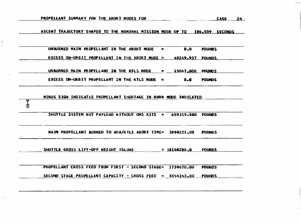
PROPELUNT SUMMARY FOR THE ABORT MO=D=E=S::.._::_f=O=R ____________ _,,C....,A.,..S.-E _ _.2._.4.__
ASCENT TRAJECTORY SHAPED TO TtE NOMINAL MISSION MODE UP TO 186.509 SECONDS
UNBURNED MAIN PROPELLANT IN THE ABORT MODE s o.o POUNDS
EXCESS ON-ORBIT PROPELLANT IN THE ABORJ MODE : i0249.937 POUNDS
-----~_.YNBURN~~ MAIN PROPELLANf IN .THE R.T,,,_LS~M.:.::OO=E'----'•::___-""13=0~4"-'lLl.,,..OO~O___,PO'-"""'UNQ"""""" .... S ____ _
excess ON--ORBIT PROPELLANT lN TtlE RTLS HOOE I: o.o
MINUS SIGN INOIC.AT·t:S PROPELLANT SHORTAGE IN BURN PIJOE INDICATED
SHUTTLE SYSTEM NET PAYLOAD WITHOUT OMS KITS = 659315.0GO POUNDS
HAIN PROPELLANT BURNED TD AOAJ'RTLS ABORT TIME= 1898221.00 POUNDS
SHUTTLE GROSS LIFT-OFF WEIGHT IGLOWI ·------==~1•~1~0!'.."'•~z~a~a~.o!!___..!..PO,,,,.UN!!:e.l!!D~S~----
PROPELLANT CROSS FEED FRCl4 FIRST - SECOND STAGE= 1739670.00 POUNDS
SECOND STAGE PROPELLANT CAPACITY - CROSS FElD = 33541~3.00 POUNDS
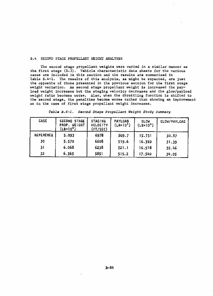
B.4 SECOND STAGE PROPELLANT WEIGHT ANALYSES
The second stage propellant weights were varied in a similar manner as the first stage (B.3). Vehicle characteristic data sheets for the various cases are included in this section and the results are summarized in Table B.4-1. The results of this analysis, as might be expected, are just the opposite of those presented in the previous section for the first stage weight variation. As second stage propellant weight is increased the pay-load weight increases but the staging velocity decreases and the glow/payload weight ratio becomes worse. Also, when the throttling function is shifted to the second stage, the penalties become worse rather than showing an improvement as in the case of first stage propellant weight increases.
Table B.4-l. Second Stage Propellant Weight Study Summary
CASE SECOND STAGE STAGING PAYLOAD GLOW GLOW/PAYLOAD PROP. WEIGHT VELOCITY (LBx10 3 ) (LBxl0 6 ) (LBxlo6 ) (FT /SEC)
REFERENCE 5.093 6978 509.7 15. 731 30.87 30 5.570 6608 519.6 16.3·ip 31.39 31 6.068 6238 521. 1 16.918 32.46 32 6.565 5851 515.2 17.540 34.os
.B-86
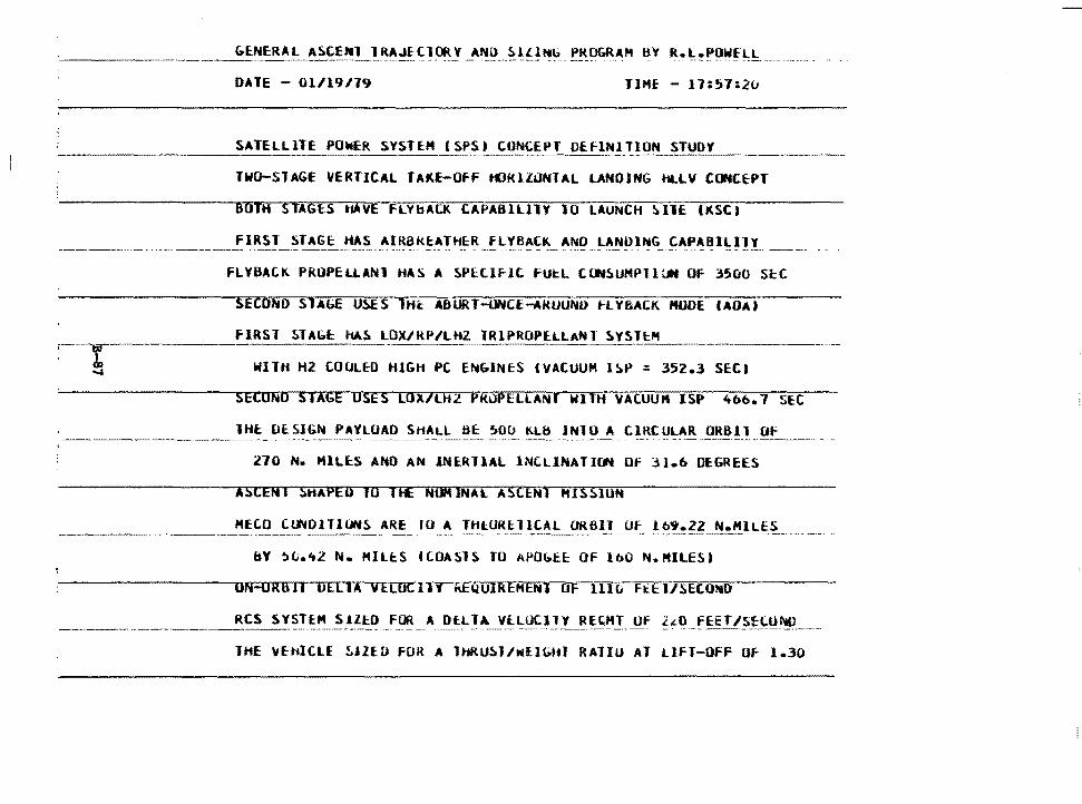
DATE - 01/19119 HME - 17:!>7:2v
TWO-STAGE VERTICAL TAKE-Off tC'JKllONTAL LANDING HLLV CONCEPT
BOTH STAGES HAVE FLVbAU<. CAPABllllY 10 LAUNCH ~IlE (KSCJ
__________ -----------~If!..~!"-~TAGE: HAS --~~~~K~~I~~R FLYBAC~-A~Q ~~!Jll~G fA_PA81~H!_ __ _
FLYBACK PROPELLANl HA~ A SPltlflt fU~L ClJfSUHPJlUN OF 3500 ScC
SECOhD SlA6E USES THt ADURT-oNCE-ARUUNO FLY&ACK MODE IAOAJ
FIRST STAll.t: 11AS LOX/RP/Ut2 lRlPROPELLANT SYSTEM ----- ·- ·------~-
WITH H2 COOLED HIGH PC ENGINES CVACUUM ISP = 352.3 SECI
SECOND STAGE USES LOX/LHl PKOPELLANl WITH VACUUM ISP 4b6.7 SEC
lH~ OcSIGN PAYLOAD SHALL BE ~00 Klb INlO A CIRCULAR ORBll Of
270 N. Hllt:S ANO AN JNlRllAL INCLINATION Of 31.b DEGREES
ASCEN I SRA PED 10 I fE MOM lNAl A~CENl klS510tf
MECO CtWOlllONS ARE IU A THlUR~llCAl OR6ll Of 169.22 N.HILES - -·· -··---------- --· ~·
BY ~L.~l N. MlltS f(OASlS TO APObE~ OF lbO N.MILES)
ON-ORlill DELlA VELOCllY ii:EQUIREHENJ OF 1110 Fttl/SECOMO
---------------~cs S!~!EM SHED FOR A Dl:Ll,\ Y[LOCl_~!__!~~~_!_!!f ?:"-~ __ fEET/~_!:J;!!~--- -
lHE ~thJCLf ~!ZED FOR A lHRU~l/NllGHl RAJIU AT Llfl-OFF Of 1.30
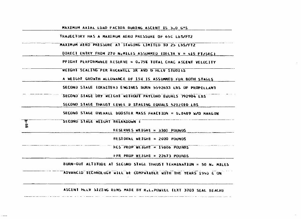
MAXIMUM AXIAL LOAD fAClOR DURlNb ASC~NT IS ~.O G1 S
TRAJEtlURY HAS A MAXIMUM AERO PRE~SURE Of 6~C LbS/fT2
----MAXlMOH -Af-iftf-PRESsi.JRE--A-t-sfAGINb UMITt:D--Tii_2_!> __ i.bS/Ft2 _______________ -
OIRECl ENTRY FROM 270 M.HlLE~ A~~UMHEO lOfllA V = 415 fl15EC)
PFIGHT PtRfOkMANLE RESERVE = o.1si lOTAL CHAC ASCEMT VELOCITY
·wEIGH.-S-C-Al.TNbP.EfCR:UCKWELTlR ANO-D HLL\' STUOI t:S
A WElbhl GRONTH ALLOWANCE Of 15~ IS ASSUMMEO fUK BOTH STAGtS
SECOND SlAbE IORblTEK) E:.<tGJNES SORN ~~92633 LBS OF PROPELLANl
-SECOND" SlAGl" -oRv-wn Gttrwntiool"PAYLOAO--El.iU-A1:s "792904-i"as__________ -- .
SECOND SlAGE THRUST LEVEL @ STAGING EQUALS ~212010 LBS
SECOND STAbE UVEkALL bOOSTER HASS FkACllON = 0.6489 W/0 MARGIN
--y---------------SEtONO~SlA&E-WEfGHT._BREA-k:tfcfw-N--:------------------------------------
c:o C)D
RESERVES Wf.lGHl : 3.300 POUNDS
RESIDUAL WEIGHl : 2010 POUNDS
--- -kCS-PROPWEiGHl = f~81:f6--P00NDS ______________ ., _____ _
f PR PROP WtlbHl = 22673 POUNDS
BURN-OUT AlllTUOE Al SlCUNO SlAG~ lhKUST 1EKM1NA110N : 50 N. MILES
---------- ---- -------ADVANC. l0··-1 ·e·cttNotu~Y- --~-ILL- -b~ toMf#A"lAB-LE ---w-11H·-·1HE~ -YEARS- 19'1~-- ,----Ott .
ASCENI 11LLV !iollllib RUNS MADE: BY R.L.POWC:lL lt:XT 3703 ScAL BEAC..H)
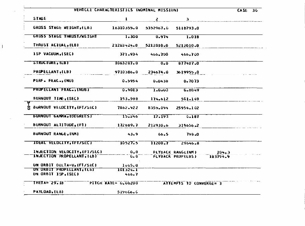
VEHillt CHAR~tTERISTlCS (NOMINAL MISSIONJ CA SE: 3!>
STAGE ________ l _____ ~-----3 -------------------·------·-
GROSS STAGt WElGHTrlLBJ l631Q:,j5S. 0
GROSS STAGE THRUST/WE JGHT 1.300
THRUST AtlUALrCLB) 2 l20::J 'tl't. 0
ISP VAC.UUJlt,CSEC) 371.934
S 1 ROCTURE, ILB) 1063207. 0
PRCPELLANT rl LB) 9710~86. 0
PERF • fRAt., INU) a. !>954 0.043b
PRlPEllANl FRAC.,INUBI 0 .'1013 l.OvlJJ.
BURNOUT TUErlSEC) 153.596 ll4.bl2
8l5'1.0'14 T-----·-·---·-----·------- --
\D BURNOUT YE:LOCITYr CFT/~t.C) 78b2.'122
bORNOUT G4Hi4Ar1DEGREESJ
BURNOUT ALllTUDErCFTJ l12b69. l
BURNOUT RANbE:r I NM)
IDEAL VELOCllYrlFT/SECJ 10527.5
lNJECllON VELOCllYrlFT/SlC.) o.o ---IMJ£CTION--PROPELLANTr l LBl ___________ -- -·e;. 0---·
UN ORBIT DtLTA-Vrlfl/StC) ON ORBll PROPELLANlrlLb) ON ORBIT HPrlSEC)
PAYLOAD, I LB)
lut:5.o 101324.l
4ot:>.7
5l 9bCb. C.
12.193
21L9JO.b
66.5
11200.1
F-LYBAC.K ----F-LYBACK
0.1073
G.8049
501.149 --------·· ·----·--·----·- -- - --- . ·- .
259!.14.l 02
CJ.187
JI 96!>6 .2 ----- - - -- ---- ·----·- ---·-· -- --- ....
79&.o
29646.6
RANGE:.I NM ) 204. _j
PRUP i LliS) 18379"4·:~- ----- --·- .... --·-------
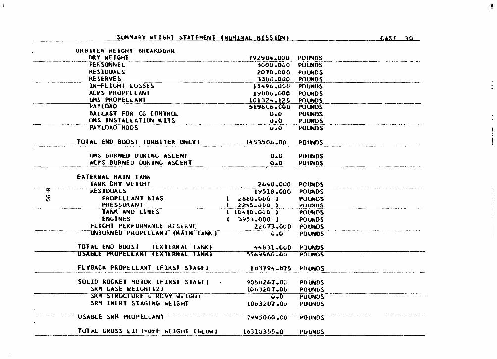
SUMMARY WElbHl ~TATEMENT INOHl~AL "ISSIONJ
ORBlTER WEIGHT BREAKDOWN ORV WEIGHT
CASE: 30
POUNDS ----·-···--PE:RSONNli _______ _ 192904.000 ------ ------·3000~0"0
~ -- . ·-------~
POl.JllDS KESlOUALS RE: Sf.RYES lN-FllGHl LOS.SE~ AC.PS P~OPELLANT Cl4S PROPEllANT
2070.000 3300.000
PUlfiOS POlftOS POUNUS POlfiOS POUNDS
·----~PA'f[DAD -------
ll't9b.OOO l'IBOo.000
l01321t.l2~ ~l4JbCb.COO
o.o i>ot.Nfis __ _
-,, '° c
8ALLAST FOR CG CONTROL OMS INSTALLATION KllS PAYLOAD Moos
TOUL END BOOS.I (ORDIU:R ONLYl
LftS liURNED DI.JUNG ASC.ENT ACPS BURNEU DURING ASCENT
EXTERNAL HAIN TANK
o.o o.o
1453!.>0b.OO ·----·-·· ·-···. -· ... ·- - .
o.o o.o
POlfl4DS POUNDS (.'UUNOS
POU'o«DS
POlfiOS POUNDS
TANK ORV WEIGH ------~--2-cb~'t_,_O_.ooo ~~Q~----------------···----RESlbOAI"S --------· l'l;1s.ooo POUNDS PROPELLANT BIAS I ~Hb0.000 ) PO~OS PRESSURANT C 2295.000 ) POUNDS lANK ANO LINES C 1~410.000 t POUNDS ENGINES t ~953.000 i POUNDS
FLIGHT PERFUKHANLE REStR~E 2Lb73.000 PO~DS -·-- -------LNsuRNED -P1to-..t:LL:ANT -," .\n.--'f A·•T _______ · ----o:-o··- ---PouPios· -----------
TOTAL ENO BOOSl IEXTEKNAL TANK) 446ll.OUO POU~DS USABLE PROPELLANT lEXlERNAL TAN~j ~5b9~bO.au POUNOS
FLYBACK PROPELLANT (flRST SlAGEa POutOS -----M~ ----. ----·--- ' •
SOLID ROCKET HOIOR lFlkSl SIAblJ 9056267.00 POlfiOS SRM LASE WElbHTl2) lObJ207.0~ POUNDS
~--~~~--....SR ...... M-r-s~1Rmurr.c~1nu~R~E.-.&.--.R~c~v~vruw~E~1~G~H~1~-~~----ro•.~o;---r.p~uuN·~o~s--~~~-~---~~~ ~RM lNtRT ~lAGlN~ WEIGHT l0b320l.OO POUNDS
POUNDS
TOT AL GROSS LHT-Uff hf;IGHT ( bUJW t lb3UB55.0 POlJNDS
!! =
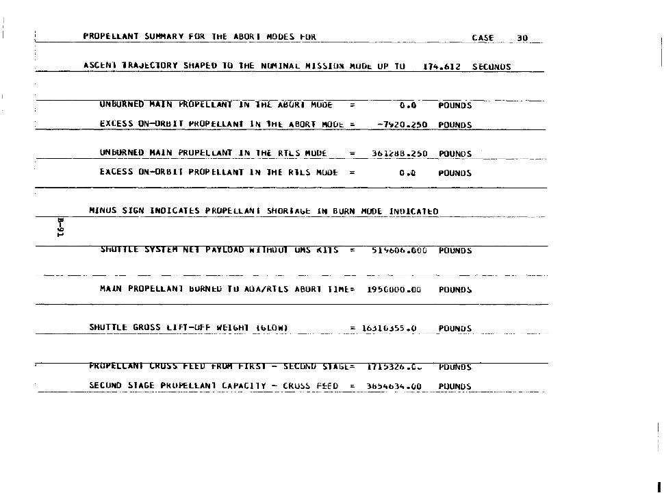
PROPELLANT SUMMARY FOR THE: ABOR l HODES f-OR CASE 30 --------------- -----
ASCl:.N-1 lRAJl::ClORY SttAPED 10 THE Nll11NAL HISSIU~ MUOt UP TO 171t.6l Z S E:tONUS
= n.o POUNDS
EXCESS ON-ORBIT PROPtLLANT IN THI:. ABORT HOU~ = -7~20.250 POUNDS
UNbURNlO HAIN PROPELLANT JN lHl RTLS HUU£ = 3bl~aB.2~0 POUNDS -----------
EAC:ESS ON-ORBH PROPl:LLANT lN lHE RlLS HlJO~ = 0 .in POUNDS
MINUS SIGN INDlCAH:S PROPE:LLAN I SHORIAbt J.N BURN HOOE. INDICATl:.O -----==------------ ----------- ----------------------
! .... ShUIHE SYS1tM NEl PAYLOAD WilHOUl UHS i<.US Sl~60b.600 POUNDS
----------- ---------
HAIN PROPE:LLANl bURNl:.U TU AOA/RTLS ABURl llHl= 19~0000.00 POUNOS
SHUTTLE GROSS LlfT-Uff WE:lbHl lblOW) = l6.HL.j55 .O POUNOS
PROPELLANI CROSS FEED ~RUM FIRSl - SECO~U SlAbl= 171;32b.C~ ~OUNOS
PUUNOS
I
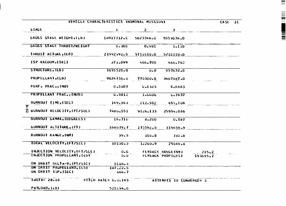
VEHICL~ CHARAlltRISTICS &NOMINAL HISSIO~) CASl: 31
1 2 3 - -· ·-- ----·--------·-----------------
GRO~S STAb~ WElGHltllbl lb'Jl7112 .c ~1)2 33'tb. 0 505j03b .o
GkOSS ~TAG~ THKUST/WEIGHT 1 • .JOC O. 'ilH l.130
lHkU~l AClUAL,(LB) ---------·--·----------- l l?'i~~'J.l_. ~--~? lul_l_O_.o __ ,_l!~_HQ.~!L ____ _ -------· -··- -·-----
ISP YACUUM,CSEC) 'tbb.100 'tbb.1UO
STROCTURb ILB l 1076520.0 o.o 957032.0
PRCF l:LLANl ti UU 9624150.v 110310.0 34t.76tl7.o - ----- --- .______ .. -- - ---- ·- ------ -·-·-------------- --·-----------·- ·---------- ----·
Ptkf. FRAC.,(NU)
PRUPELLANl FRAC.,(NUB) u.9012 l .t.uO<.; L. lb37
BURNOUT l l HE, C SEC) llt~_~5_'!~ _____ ?_ ll! !>02 _____ ~~'(!.J~~- ____________________ -----··· -y-·-- ·---·---·-- ·- -- . -------··- -- ---- --------~ liUkNOUT YcLOCIJY,CfT/Sl:C) 74tlu.551 ~lLb.133 25954.0bb
6URNOU1 GA~A,CDEGREl:Sl lb.7lli d.200 O.lb7
______ bU~~~~-!- ~~J!!~~ ! .. ~~_T_) __________________ !_b~!J.!2~- ! _______ ?_ 1~?~~ ._!l _____ :H~f>?~·-~ ________________________________ _
8URNOU1 kANbE, tNM)
IDEAL VELOCITY,(ff/StCl 10 u.o.;:,
INJECTION VELOllTV,CfT/Sll) o.c --1 hJEC:T !Oh·- F>ROPH.[ANl, (Lb r- -·. --- . -- --- -- - o. u
lUb.8
fLV8ACK KANGl:CNM) Fi.. 'tb Ali - fikOPfi.b ~ l
---~~~-~? ______ . - -· - . l'i 3(;~,,. -,
ON UklHT lJt:LlA-V,(fl/~lCI lC..bb.~ ON ORBIT PRUP~E~L~i~A~N~r-,~,~L~b~l---~--1~u=1~~~i~2~.~~~--~---~~-----~-~-~~-~--~ UN ORBIT l~P,ISEC) ~ob.1
ATTE~~TS lU CON~ERGE= 3
PA YLUAO, C Ll:l l ~21 v.-4. o
I
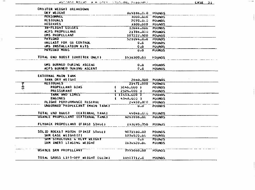
ORblTER WElGHl bREAKDOWN DRY WEIGHT 8b;l8b.O~O POUNUS
LA~E 3!
PEkS(.t;Nf"L -. ------1ooc.-: 6Uo--M PO u~o·s----M----·-----~ -. ·-· ---------· .. -·~~
RESIDUALS RESl:kVES IN-FLIGHT LO~SES AC.F'S PROPE:LLANI OMS PKOPELLANT
2010.0LO POl.fiD~
3300.000 POu~DS
l2b44.0uu POUNDS 21764.0Gu POUNDS
107222.500 POUNDS ------~PAYiJlAD ~210~4.0~0 POUNDS-------~
UALLAST FOR CG tONlROL "4S INSTAlLAllON K~lS PAYLOAD Moos
TOlAL END BOOST lORBllER ONLY) -·----·-· -··-·-··· - -···--··
OHS BURNED OIJ<.l~G ASC.E~I ACPS bURNEO 0UK1NG ASCENT
EXlERNAl HAIN lANK
O.G POUNDS O.O POUNDS u.O PUUNOS
};3olOO.OO
o.o c.o
1-0UNOS
.. 01.*DS POUND~
lANk DRY WEIGHT 2640.000 PUUNOS -~r~----RESTDU~ 21411.000 POl.Jftos·------~ PROPELLANl BIAS t 3146.000 J POUNDS
PRESSURANT I 2!>4!4.000 ) 1-'0U.'llOS TANK AND LINES ( ll4S3.Ci.OO ) PUl.J;'fOS EttGINE.S I 1t3-.d.uau I POUNDS
FLIGttl PERF-URMANC.E RlSlRVt :l't<j::n .aoo l'OUNOS -----·--·---mauRH·eo-PkoPi:a.:r:Atn·-fHAlrii ··1A"Nk--.----------o~-o-- -- i>ouHos--------·-··--------- -----
TOTAL tND BOUST (tXltfU.ilAL lA~K) USAHLE PROPELLANT (EXTERNAL TANKJ
FLYSAC.K PROPELLANl lf!RSl SlAulJ
SOLID ROCK~T MOTOR If JkST SlAbt) SRH C.ASt WtlG111(2) SR" SIRUCIURE & RLVY WEIGHI SRM INERl ~lAGlNG WEIGHT
-- -· - -·usA"B[E -sRM··· PR 0 p l:L [ANT-- -
T01AL Cl.RUSS Llfl-OFf N~IG~T lGLUW)
4'1048 .ou; PUUNDS b0b7b9b.OO POUNDS
i~3li9S.750 PU~us
~011~ao.oo POUNDS l07o~l0.0~ l'OUNDS
·--- -----·--·-·---
O.G POU~-...,.----~-~~~~~~
lti7o~20.0v POUNDS
lo'il 17ll.O POUNOS
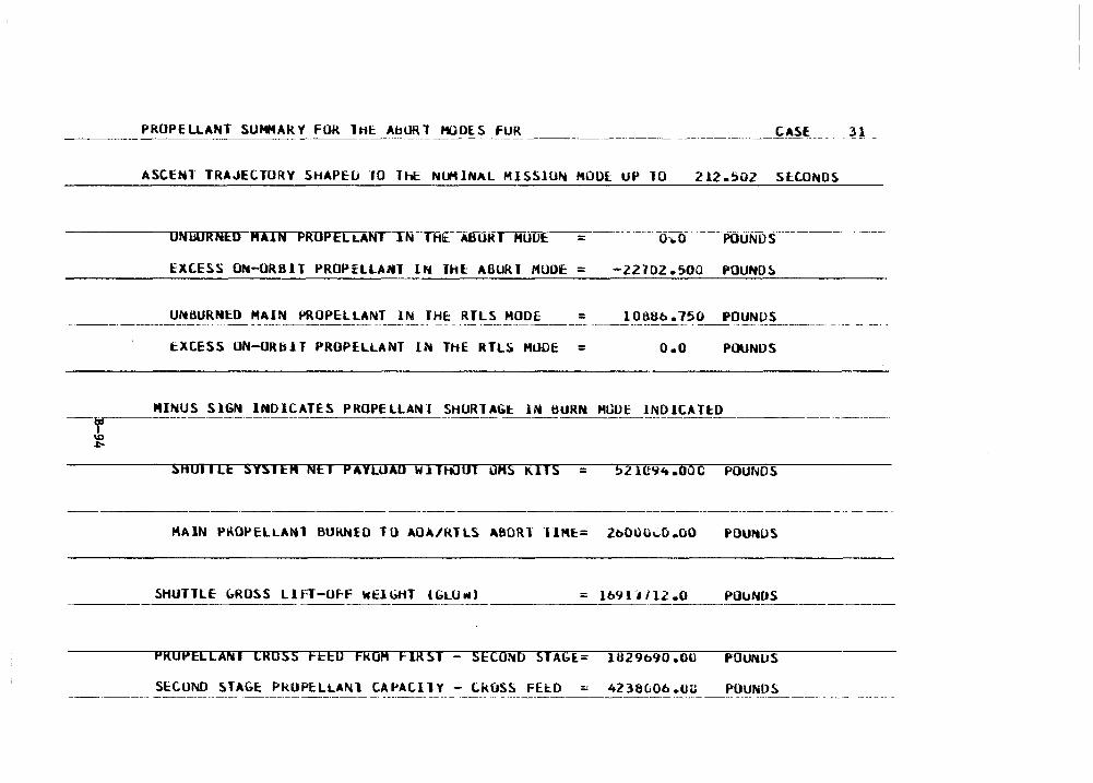
____ P~OPEUANT SUMMAR!__ FOR ~~~A~~-!-~-O~~_t=~!_{ _______________ ---------~ASE____ ~l _
ASCEtH TRAJECTORY SHAPEU lO ThE Nl.11 INAL MISSlUN HOOE: UP TO 212.502 SltONDS
-yir---\D .r:-
o-.o ---POUNDS-____ --·--
EXC.ESS ON-ORS 11 PROP i:LLAHl IN THl A6UR T MODE = -22702.500 POUND~
UNBURNED HAIN PROPELLANT IN fHt RTLS HOOE l088b.750 POUNUS
tXCESS UN-URblT PROPELLANT IN THE RTLS HOOE = o.o POUNDS
MINUS SIGN INDICATES PROPELLAN.I SHURlAGl:. IN BURN MODE lNDltATl:O
SHOllLE SVSIEH NEI PAYLOAD Wilft001 OHS ~ITS = 521C94.00C POUNDS
MAIN PROPELLAl'61 BU~lO TO AOA/RTLS A80Rl ·11111:= 2bOUu..:;.o.oo POUrtUS
SHUTTLE bROSS LIFT-O~f WElbtfT (GLU~J = lb<Jl-1112.0 POUNDS
PROPELLANI CROSS FEEU FROM FIRSl - SECOND SlAbl- 1B29b90.00 POUNlJS
SECO~D STAGt PkOPtLLANl CAPACllY - CkOSS FEED 4238(;06 .ou POUNDS
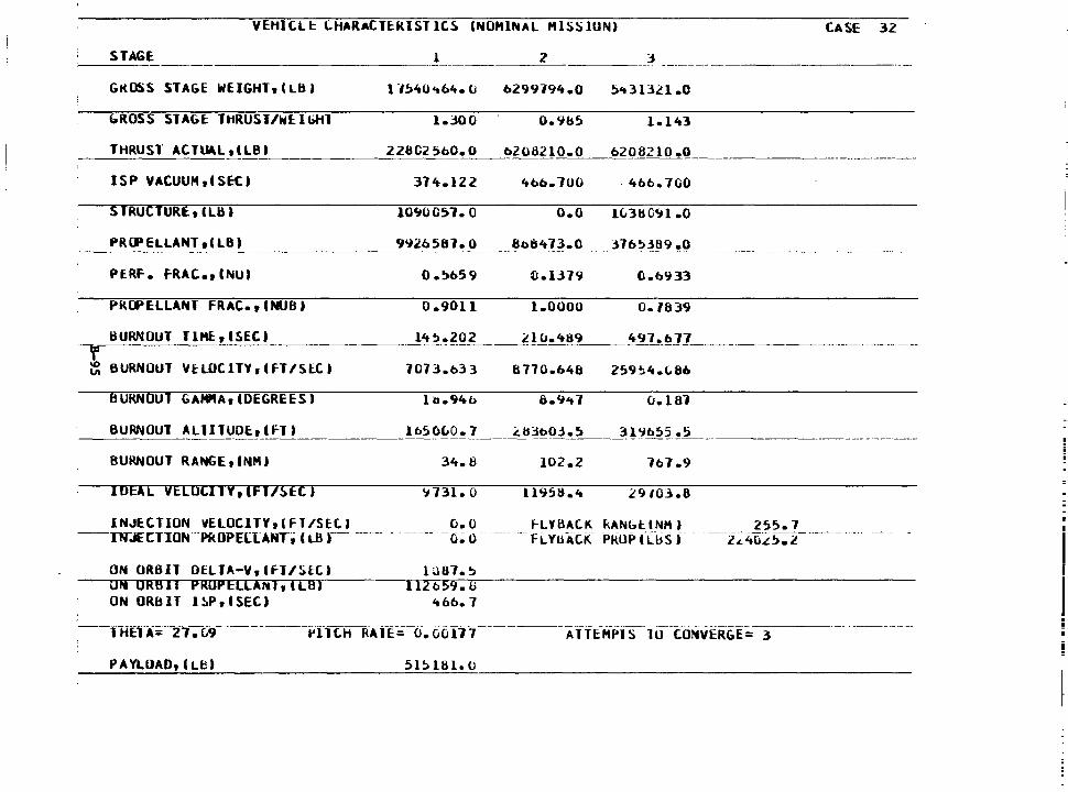
VEHICL I: C.HARACTE:RIST ICS (NOMINAL HISS lUN) CASE 32
STAGE
GROSS STAGE WEIGHT,(LBI
&ROSS STAGE: THRUST/Wllbttl
THRUST' ACTUALtlLB)
ISP VACUUH,CSE:tl
S TRUClURE, C Lli I
PERF. fRAC., CNU)
PRCPELLANT FRAC.,CNUBI
BURNOUT TIME:, ISEC !__ ---y- --~ BURNOUT VHOC ITV ,C fT /SlC I
BURNOUT GA ... A,(DEGREES)
1
l "/~40't64. CJ
I.JOO
22ao2 5oO. o
374.122
10'.10051. 0
0 .!)b59
0.9011
14~.202
7073.033
2 3 -- - - ---- ---
b299794.0 !)'t 31321 .o
0.9&5 I.l't3
b2082IO.O __ b£08210.Q ____
'tbb.700 . 'tbb. 700
o.o 1Ci3ts0'.ll .O
1.0000 0.1639
497.677
8770.b48
o.1 a1
BURNOUT ALTITUDE:, I F-T) lb5~~0._? ___ ~3t>~j~5 __ _3_!_%52.!5 ___ _ ----------·--- ------- --------- -------···
BURNOUT RANGE,CNH) 34.8
IDEAL vELOCl1Y,(Ff/5EC) ~731. 0
INJE.CTION VELOCITY,(Fl/SH.1 o.o --INJEtTION--PkOPELlAtffl (LS,------ --- - ------ -0~ O.
ON OR81T OEllA-V,lfl/SlCI ON ORBll PROPEllA~l,lLBI ON ORBIT l~P,CSEC)
PAYLOAD, (Lb)
lu67.~ 112 b59. 6
'ebb. 1
51~1s1.o
102.2 1b1.9
ll95lt.'t
~LYBACK kANbllNM) 255.7 -- FL YliAtiC PROP fClis f - ----i~1t-o:.l'.!J-:i ____ --
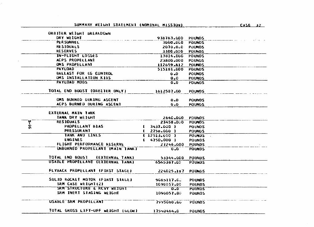
SUMMARY llfElbtiT SlAH.HE.NI (NOMlNAL HlSSlU10
ORBllt:R WElbHT uRE:A~DOWN ORY WEIGHI
·---------Pt:R SllNNE c-·----------···--
RE SI DUALS RESERVES
938lb3.000 POUNDS -- ·-·----~----·--·3000-~o(;o .POUNDS- ---------2010 .Ouil POUNDS 330<l .OOO POUNDS
13814.000 POUNDS 2'800.000 POUNUS
CA~E j2
IN-FLIGHT LO~E:S ACPS PROPELLANT ~S PROPE:LLANl ----PAYLOAD _._ ____ _ ·-----~l~l-cc2_b59 .&12 PU~~-------------------
515181.000 POUNDS bAlLAST FOR CG CONTROL OMS lNSlALLAllON KllS PA YLOAO HOOS
101AL END BOOST IORBllER ONLY) ---····--·--· -----·- ··- -· ~~· ----·-------- .. - --
OMS BURNED Ol.RlNG ASCENT ACPS BURNED DURING ASCENl
EXTE.RNAL MAIN 1 ANK
O.O POUNDS O.O POUNDS O.O POUNDS
o.o o.o
POUNDS --- ---·-------· ---- --------
POUNDS POUN[JS
TANK DRY WElbHT 264G.OGO POUNDS ----RE'SUlUAlS 23458 .ooo POUN=o-s __ _
PROPELLANT BIAS t 3431.00Q ) POUNDS PRt:SSURA~l t 275u.ooo , POUNOS lANK AND LlNlS I 125H.u00 ) POUNDS tNGINES I 4150.000 a POUNDS
FLIGHT P~RFORMANCE RES~RV~ 21246.fiOO POUNDS ----lMBUkNe·o-PROPEL[ANl--CHAlf.-lANtCr---··---cr:o--·--POUNOS--------·-----------··
TOTAL lND bOU~T IEXlERNAL TANK) USABLE PROPELLANT (EXlERNAL lAN~I
fLYliAtK PROPElLANl If IRST ~TAGk) ---- -------·-·---·------ ·----·--- -·
SOLID ROCKET MOTOR tf lRSl SIAbtJ SRM CASE W~ILH1(2) SRM SlRUCIORE & RCVY WEJGHI SRH INERT ~ 1 AGING WUGHl
TOTAL &ROSS LlfT-Uff -EIGHT (bLOWJ
~3~44.000 POUNUS b5b53&7.no POUHDS
ll4025.1~7 POl.-"'OS
9ulbll7.c..: 109uo5·1.co
o.o 10'10051.00
POUNDS POUNDS t>OUNOS POUND~
POUNDS
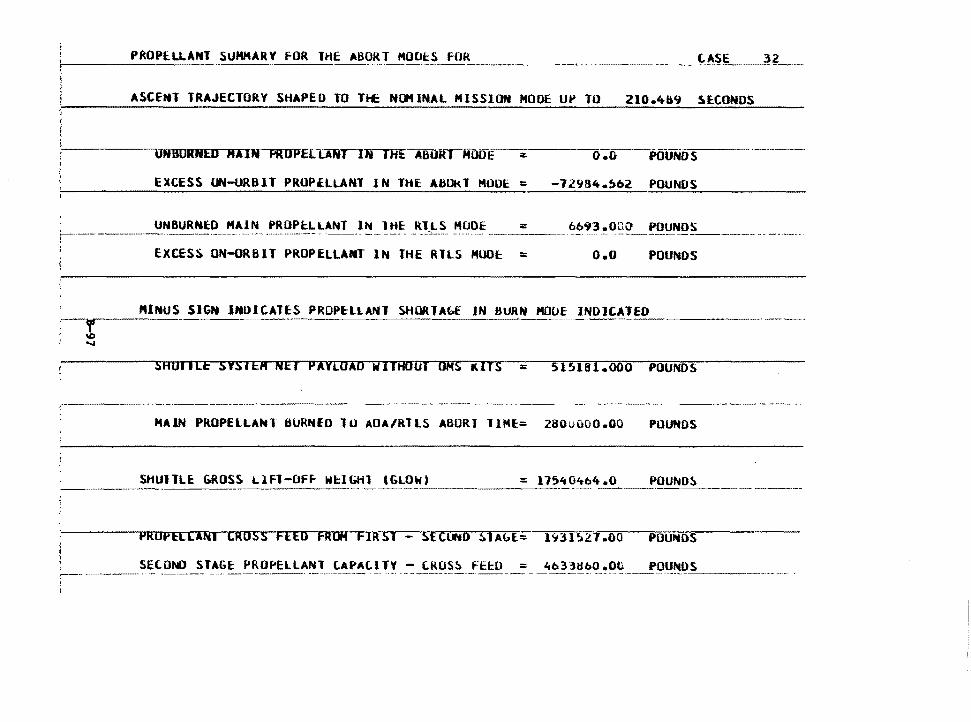
ASCENT TRAJECTORY SHAPED TO Tl£ NOHINAL MISSION MOOE U~ TO 210.4&9 ~ECOMDS
UNBURNED MAIN PRDPELCANy-JN THE~Rr-MOi.>E o.o pa·iJNo_s ______ .. ___ _
EXCESS ON-tJRBll PROPiLLANT IN THE A80KT MOOc = -7298~.~62 POUNDS
_________ UNBURttfO MAIN PROPcLLANT l~-!~~- _R:lJ.~. MODE ___ :_ ___ t:>~93.!()_~~-~~~Q~-----
EXCESS ON-ORBIT PROPELLANT IN THE RllS MUOt = o.o POUNDS
MINUS SIGN INDICATES PRDP~LLANl SHORlAr:.E IN BUR" HOOE INDICATED -----.,---, "° .....
SHUllLE SYSIEM NEf PAYLOAD WIIHOUT OMS KITS = 51~181.ooo POUNDS
,-------- ------------------MAIN PROPELLANT 8URNED TO AOA/RTLS ABORT lIMt= 280uooo.oo POUNDS
SHUlTLE GROSS LlFl-OFf W~IGHl lGLOW) = 17,40464.0 POUNDS ----- -------------------·
PROPELLANl CROSS FEED FROM FIRSt - SECOND ~]AGE- l~ll~l1.oo POUNDS
SECOND STAG~ PROPELLANT tAPAtlTY - CROSS fE~D = ~o33Hb0.0G POU~OS ------ ----~--- ··-· ----~--, -·~----------
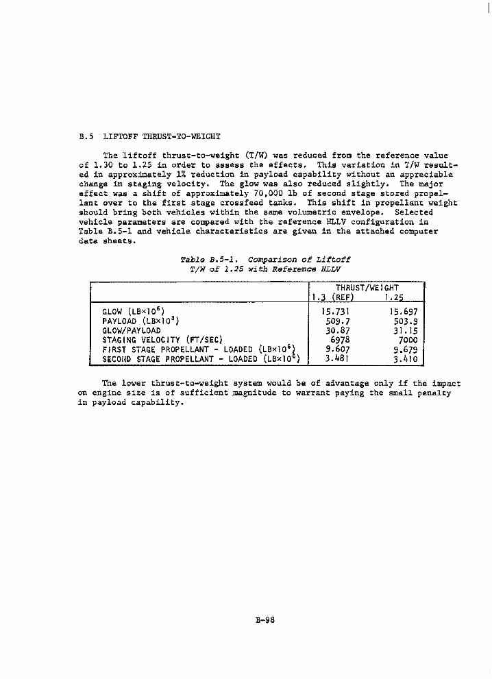
B.5 LIFTOFF THRUST-TO-WEIGHT
The liftoff thrust-to-weight (T/W) was reduced from the reference value of l.30 to l.25 in order to assess the effects. This variation in T/W resulted in approximately 1% reduction in payload capability without an appreciable change in staging velocity. The glow was also reduced slightly. The major effect was a shift of approximately 70,000 lb of second stage stored propellant over to the first stage crossfeed tanks. This shift in propellant weight should bring both vehicles within the same volumetric envelope. Selected vehicle parameters are compared with the reference HLLV configuration in Table B.5-1 and vehicle characteristics are given in the attached computer data sheets.
Table B.5-1. Comparison of Liftoff '1! /W of 1. 25 with Reference HLLV
~~~ --THRUST/WEIGHT
l.3 (REF) l.25 .. ·-
GLOW (LBxJ0 6 ) 15. 7:31 15.697 PAYLOAD (t.BxJ03
) 509.7 503.9 Gt.OW/PAYLOAD 30.87 3 l. 15 STAGING VELOCITY (FT/SEC) 6978 7000 FIRST STAGE PROPELLANT - LOADED (LBxl06 ) 9.607 9.679 SECOHO STAGE PROPELLANT - LOADED (LSxl0 6 ) 3.481 3.410
The lower thrust-to-weight system would be of advantage only if the impact on engine size is of sufficient Jnagnitude to warrant paying the small penalty in payload capability.
B-98
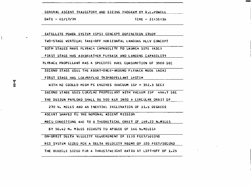
GENERAL ASCENT TkAJl:.CTORY AND SIZING PROGRAM BY R.L.~OWELL
DATE - Cil/17/"/9 TIME - 21:31:36
SATELLITE PUWEK SYSTE:M (SPS) CONCEPT DEFINilION STUDY
TWO-STAGE VERTICAL TAKE-OFF HOR1Za-4TAL LANDING HLLV CONCEPT
BOTH STAGES HAVE fLYBACK CAPAblLITY TO LAUNCH SITE (KSC)
__ _f_!B_ST STAGE HAS ~!_Kl\R!:ATt-!~B_f_LYBACK AND LANDING CAPABILITY ___ _
FLYBACK PROPELLANT HAS A SPECIFIC FUEL CONSUMPTION OF 3500 SEC
SECOND STAGE USI:.~ THE ABORT-ONCE-AROUND FLYl\ACK. MODE (AOA)
FIRST STAGE HAS LOX/RP/LH2 TRlPROPELLANT ~YSTEM
WITH H2 COOLED HIGH PC ENGINES (VACUUM ISP = 352.3 SEC)
SECOND ~TAGE USES LUX/LH2 PROPELLANT WITH VACUUM ISP 4bb.1 SEC
THE DESIGN PAYLOAD SHALL BE 500 KLB INTO A CIRCULAR ORBIT OF
270 N. HILES AND AN INERTIAL INCLINATION OF 31.6 DEGREES
ASCENT SHAPED Tu THE NOMINAL ASCENT MISSION
HECO CONDITIONS AkE TO A THEORETICAL ORBIT OF 169.22 N.HILES
BY 50.42 N. HILES (COASTS TO APOGEE OF 160 N.HlLES)
ON-ORBIT DELTA VtLOCITY RE~UIREHENT OF 1110 Fl:.ET/~ECOND
RCS SYSTEM SIZEU fOR A DELTA VELOCITY Rl:.QMl OF 220 FEET/SECOND
THE Vl:.HlCLE SIZED FuR A THRUST/WEIGHT RATIO AT LIFT-OFF OF 1.25
-
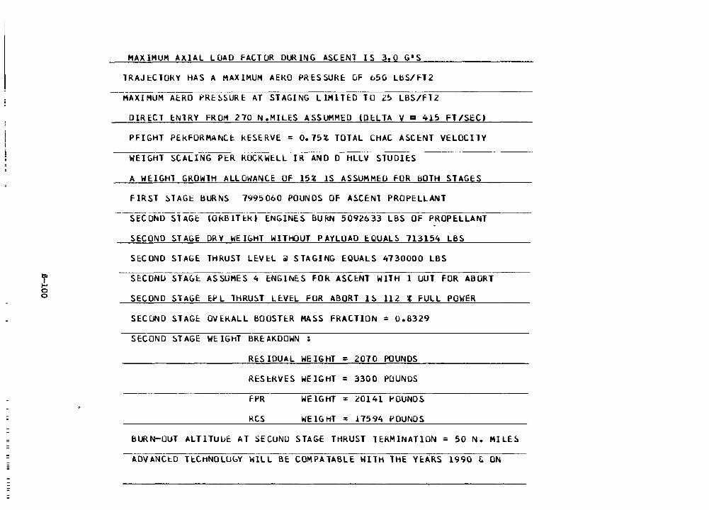
= =
! 0 0
MAXIMUM AXIAL LOAD FACTOR DURING ASCENT IS 3.0 G'S
TRAJEClOkY HAS A MAXIMUM AEKO PRESSURE uF b50 UlS/F-12
MAXIMUM AERO ~RE~SURE AT STAGING LIMITED TO 25 LBS/FT2
DIRECl ENTRY FROM 270 N.MILES ASSUMMl::O (DELTA Va 415 FT/SEC)
PFIGHT PEKFORMANCI: kESERVE = 0.75% TOTAL CHAC ASCENT VELOCilY
WEIGHT SCALING PER ROCKWELL IR ANO D HLLV STUDIES
A WEIGHl GROWlH ALLOWANCE OF 15% lS ASSUMMED FOR BOTH STAGES
fIRST STAGE BURNS 7995060 POUNDS OF ASCENT PROPELLANT
SECOND STAGE: COkBITl:k) ENGINES BUKN 5092633 LBS OF PROPE.LLANT
SECOND STAGE DRY WEIGHT WITHOUT PAYLOAD E:QUALS 7I3154 LBS
SECOND STAGE THRUST LEVEL iii STAGING EQUALS 4730000 LBS
SECOND STA~E ASSUMES 4 ENGINES FOR ASCENT WITH 1 OUT FOR ABORT
SECOND STAGE EPL THRUST LEVEL FOR ABORT IS Il2 i FULL POWER
SECOND STAGE OVEKALL BOOSTER MASS FRACTION = 0.8329
SECOND STAGE WEIGhT BREAKDOWN :
RES !DUAL WEIGHT = 2070 POUNDS
RESEJWES WEIGHT = 3300 POUNDS
FPR WEIGHT = 20141 POUNDS
RCS WE lG HT = .l7594 POUNDS
BURN-OUT ALTITUl.JE: AT SECOND STAGE THRUST TERMINATION = 50 N. MILES
ADVANCED TtCHNOLLlbY WILL BE COMPATABLE WITH THE YEARS 1990 & ON
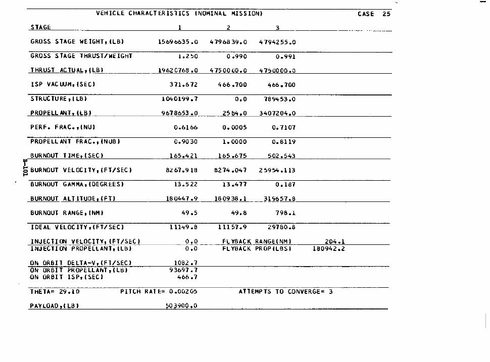
THETA= 29.10 PITCH RATE= O.Ou2u5 ATTEMPTS TO CONVERGE= 3
PAYLOAD rl LB t !>03900.0
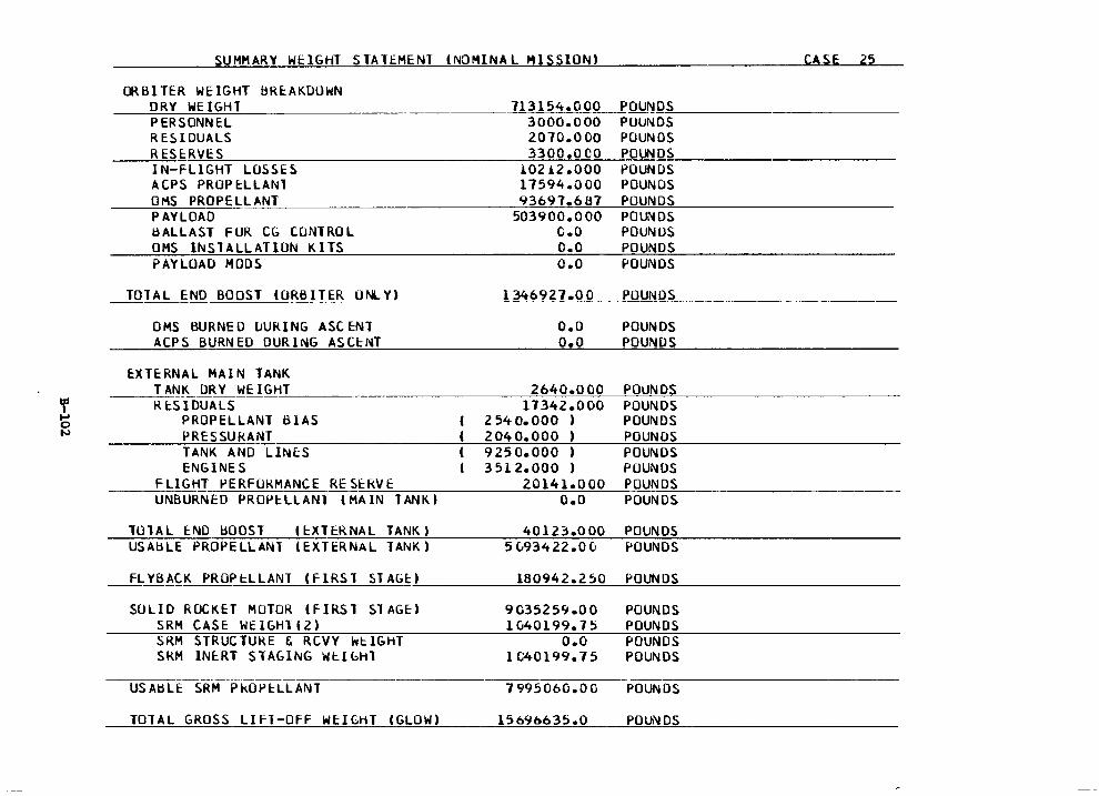
SUMMARY WElGHT STATEMENT (NOMINAL MISSION) CASE 25
ORBITER WEIGHT BREAKDOWN DRY WEIGHT PERSONNEL RE5IDUALS RESE:RVES
713154.000 3000.000 2010.0 00 3300.0 co
POUN=D-=S------~-----POUNDS
IN-FLIGHT LOSSES ACPS PROP EL LANT OMS PROPELLANT PAYLOAD BALLAST FOR CG CONTROL OMS INSTALLATION KITS PAYLOAD HODS
10212 .ooo 17594.000 93697.687
503900.000 c.o o.o o.o
POUNDS POUNDS POUNDS POUNDS POUNDS POUNDS POUNDS POUNDS POUNDS
TOT AL END BO OST (ORB IT ER u NL YJ_ - -------=l-=34----'----=-6--'----9=2 7--=----=c.o=---o=------'P--=O"---'U"-'--N=O=S~ _________ _
OMS BURNED lJURING ASCENT ACPS BURNED DURING ASCENT
EXTERNAL MAIN TANK
o.o o.o
POUNDS POUNDS
--~T-'--'-'ANK DRY WEIGH~T ___ --------~2~6=---4--'----0=---·~o~o~o~~P--=O=U~N=D-=S ___________ _ RESIDUALS 17342.000 POUNDS
PROPELLANT BIAS 2540.000 ) POUNDS PRESSUkANT 2040.000 ) POUNDS TANK ANO LINES 9250.000 ) POUNDS ENGINES 3512.000 ) POUNDS
___ F_L_l~G_HT PERFORMANCE RES_E_RV_E ______ ~2_0~1_4~1_.~0~0~0_P_O~U~N_D_S~----------~ UNBURNED PROPELLANT (MAIN TANK) O.O POUNDS
TOTAL END bOOST (EXTERNAL TANK) 40123.000 POUNDS USABLE PROPELLANT (EXTERNAL TANK) 5(;93422.00 POUNDS
FLYBACK PROPl::LLANT (FIRST STAGE) 180942.250 POUNDS --------------------------SOLID ROCKET MOTOR IFIRS l ST AGE)
SRH CASE WEIGH1(2) SRH STRUCTURE & RCVY wl::IGHT SRM INE:RT STAGING Wl::lbHl
USABLE SRM PkOPE:LLANT
TOTAL GROSS LIFT-OFF WEIGHT (GLOW)
9 0352 59 .O 0 POUNDS 1040199.75 POUNDS
O.O POUNDS IC40199.75 POUNDS
7995060.00 POUNDS
15696635.0 POUNDS
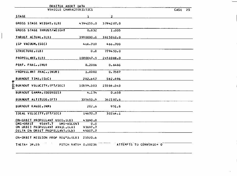
ORBITER ABORT OATA VEHICLE CHARACTERISTICS
STAGE 1
GROSS STAGE WEJGHT,(LB) 4794255.0
GROSS STAGE THRUST/WEIGHT 0.832
THRUST ACTUAL,(LBJ 3990000 .o
ISP VACWH, (SEC) 4t.6. 700
STRUCTURE, (LB) 0 .o
J> RO P£.bL Al'ih.l.bli_ ____________ l 00 OO'!J !..2.
PERF. F RAC., ( NUJ 0.2086
jo)ROPHLANT FRAC., (NUBJ 1.0000
BURNOUT TlHE,(Sct) 262.647 T' b BURNOUT VELOCITY, (FT/SECJ w
10859.383
BURNOUT GAHHA,(OEGREESJ 4.174
BURNOUT ALTllUDE,(FTJ_~----~335653.9
BURNOUT RANGE,(NHJ 20.2 .b
IUEAL VE.LuCJTV,(FT/SECJ 14670.7
43890 .o
2
3794207.0
l.005
3 8150 LO. 0
466 .100
7194 53.0
24510 BS .O
o. 6460
o. 7567
582.496
25586 .543
0 .650
362187.6
9 51. 8
30264. l
ON-ORBIT PROPELL~NT USED,(LBJ OHS-ORBIT 93697.7 uMS-ASCENT ON ORBIT PROPELLANT AVAlL,(Ld) DELTA ON ORBIT PROPELLANT,(Lb)
----------
ON-ORBIT MISSION PRO~ REQ 1 0,(LB)
o. o 93697. 7 49807.7
THETA= 39 • 5 5 PITCH RATE= 0.00236 ATTEMPTS TU CONVERGE= 0
CASE 25
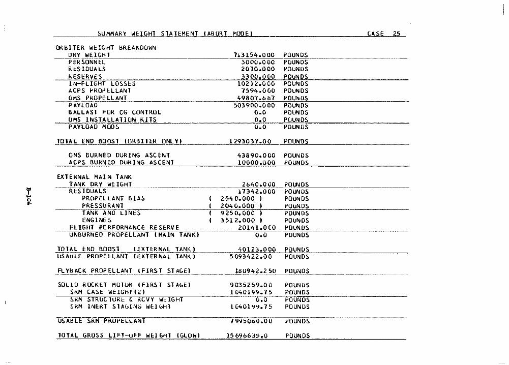
SUMMAR'1 WE:IGHT STATEMENT (ABORT MODE) CASE 25
CRBITER WEIGHT BREAKDOWN ~-=D~R~Y WEIGH~l.:__~~~~~~~--~----'-113154.000 POUNDS
PERSONNEL 3000.000 POUNDS RcSIDUALS 2070.000 POUNDS kESERVES 3300.000 POUNDS IN-FLIGHT LOSSES 10212.000 POUNDS ACPS PROPcLLANT 1594.000 POUNDS OMS PROPELLANT ·---~---4~9~8~0~7~·~b~b~7~~P~O=U~N=O=S~~-~-~----~-PAYLOAO 503900.000 POUNDS BALLAST FOR CG CONTROL O.O POUNDS OMS INSTALLATION KITS O.O POUNDS PAYLOAD MOOS O.O POUNDS
TOTAL END BOOST (URBITcR ONLY) ----- .
OMS BURNED DURING ASCENT ACPS BURNED OUklNG ASCENT
EXTERNAL MAIN TANK
1293037.00
43890.000 10000.000
POUNDS
POUNDS POUNDS
TANK ORY WEIGHT 2b40.000 POl.f.J DS ~-R[SIDUALS 11342.000 POUNDS
POUNDS POllNDS
PROPELLANT BIAS 2540.000 ) PRESSURANl 204 0.000 ) TANK AND LINES 9250.000 ) POUl~DS
POUNDS POUNDS POUNDS
ENGINES 3512.000 I FLIGHT PERFORMANCE RE_S_E_RV_E~-------2~0_1_4_1_._o_c~o
~lJNBURNED PROPELLANT CHAIN TANK) O.O
TOTAL END BOOST lEXTERNAL TANK) USAtiLE PROPELLANT (EXTERNAL TANK)
F_L Y~~~~-~ROP EL LANT l Fl RS T ST AC:.E ) __ _
SOLlO ROC.KET MOlUR (flRST STAbE) SRM CASE WEIGHT(2) SRM STRuClURt & RCVY WtIGHT SRM INERT SlAblNG WElbHl
-U!,-ABLCSfUCPROPELLANT
TOTAL GROSS LIFT-uff WEIGHT (GLOW)
40123.000 POUNDS 5093422.00 POUNDS
9 0352 59.0 G PO UN US 1 040 l 'iCJ. 7 5 POUNDS
O.O POUNDS lC-401~'1.75 POUNDS
1995060.00 POUNDS
15 6966J5.0 POUNDS
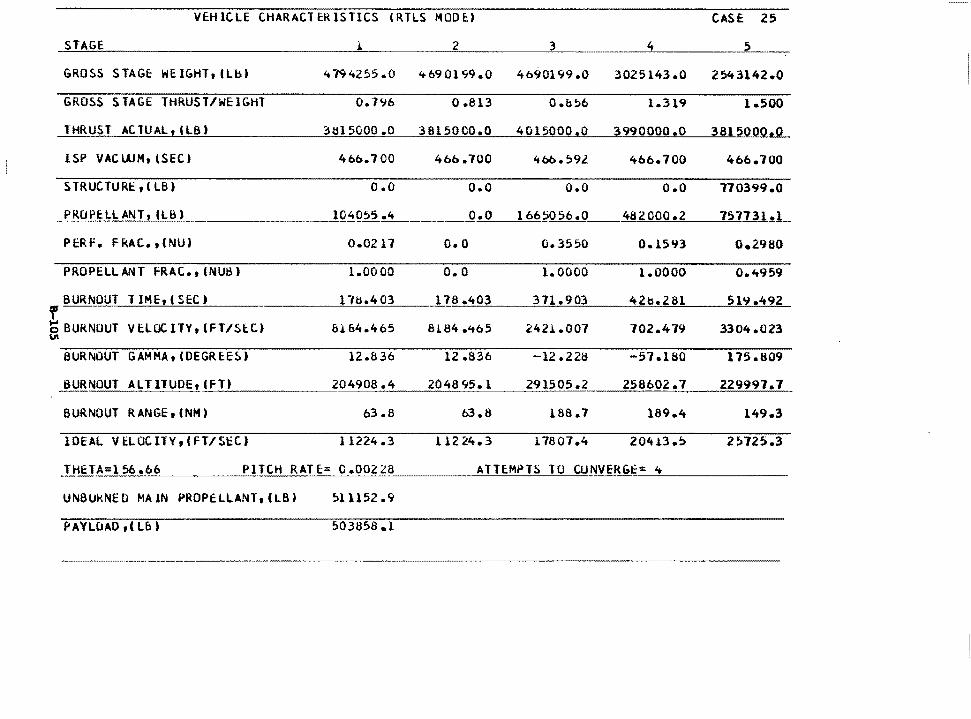
VEHICLE CHARACTERISTICS lRTLS MODE) CASE 25
GRO!iS STAGE WEIGHT,(Lb) 4794255 .o 469 01 '19 .o 4690199.0 3025143.0 25't3l42.0
GROSS STAGE THRUST/WEIGHT 0. 7'16 0 .813 0.056 l.319 i.soo THRUST ACTUAL,CLBJ 3~15000 .o 3815000.0 4015000.0 3990000.0 3815000.0
ISP VAC WM, lSEC) 4bb. 700 400 .100 4bb.59l 4b6.700 466. 700
S TR UC. TU Rt, (LB) o.o o.o o.o o.o 770399.0
_f_~CJPE:LL ANT, tLB) 104055.4 o.o 1665056.0 482000.2 757J3J...t.L
PERF. FRAC.. ,CNUJ 0.0211 o.o 0.3550 0.1593 o.29so
PROPELLANT fRAC,, (NUB) 1.0000 o.o 1.0000 1.0000 0.4t959
BURNOUT 1 IHE, (SEC) l W.403 178.403 371.903 42b.281 519.492 f t) BURNOUT VELOCITY,IFT/SlC) &164.465 \II
8!.84 .465 2421.007 702.479 3304.023
BURNOUT GAMMA, (DEGREE!>) 12.836 12 .836 -12 .22a -57 .1ao 175.809
BURNOUT ALTITUDE, (FT) 204908 .4 204895.l 291505.2 258602.7 229997. 7
BURNOUT RANGE, CNM) 63 .8 63.8 188.7 189.4 149.3
IDEAL VELOCITV,CFT/ScC.J 11224 .3 112 24.3 17807 .4 20.ft .l.3 .!) 25725.3
_!_HtTA=l 56 .06 PITCH RATE= G.00228 ATT~MPT~ TU CUNVERGc= ~
UNBUkNE D MA lN PROPa:LLANT,CLB) 511152 .9
PAYLOAO,CLBJ 503858 .1
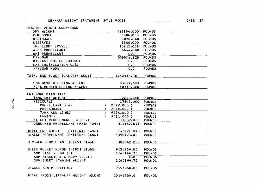
SUMMAR't' WE:IGHT SlAH:MENT lRTLS MOOE)
OKBITER WEIGHT BRE:AKDUWN ~-D~Y~W~!G=H~l_,__ ______ ~
P ERSONNE:L RESIDUALS RE:SERVES IN-FLIGHT LOSSES ACPS PROPELLANT UMS PROPELLANT PAYLOAD BALLAST FOR CG CONTROL OMS INSTALLATION KITS l'AYLOAD MOD~
TOT AL t:ND BO OST (ORB IT E:R UNL Y) --------------- -- --- ---·------------- -
UMS BURNED DURING ASCE:Nl ACPS BURNED lJURlNG ASCENT
E:XTERNAL MAIN TANK TANK ORY WEIGHT ~ ESIOUALS
PROPE:LLANT BIAS PRESSURANT TANK AND LINES ENGi NE S
__ F_LIGHT PERFOKMANCE: RE:~_tR_V_c_· __ _ UNBUkNED PROPELLANT (MAIN TANK)
TOTAL END BOOST (EXTERNAL TANK) USABLE PROPELLANT (EXTERNAL TANr<)
FLYBACK PROPcLLANT (FIRST STAGE:>
SOLID ROCKET MOlOR (FIRST STAGE) SRH CASE WEIGHT(2) SkM STRUCTURE L RCVY WtlGhT SkM INERT ~TAGlNG WE:lGHT
USABLE SRH PROPlLLANl
TOTAL GROSS LIFT-ufF WE:lGHT (GLOW)
713154.000 3000.000 2070.0CO 3300.000
10212.000 6844.000
o.o 503858.125
o.o o.o 0 .()
l 24243b .oo
93697.bti7 10750.0 CJO
2640.000 17342.000
2540.000 ) 204C.OOO )
9250.000 ) 3512.000 )
11837.0CiO 5111 s2 .8 ·15
542971.8 75 4590573.00
180942.2 ~o
9<..35259.00 l 04 0 l 99. 7 5
c.o 1040199.75
7995060.00
15 696635.0
CASE 25
POUNDS POUNDS POUNDS POUNDS POUNDS POUNDS POUNDS POUNDS POUNUS POUNIJS POUNDS
POUNDS ---'--'=-=-=-=--='---·-----------·-·
POUNDS POUNDS
POUNDS POUNDS POUNDS t>Ol.JNDS POUNDS POUNDS POUNDS POUNDS
POUNDS POUNDS
POUNDS
POUNDS POUNDS l'OUNDS POUNDS
POUNDS
POUNDS
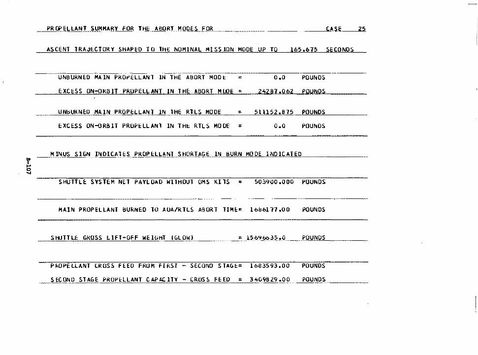
PROPELLANT SUMMARY FOR THE ABORT MODES FOR CASE 25
ASCENT TRAJECTORY SHAPED TO lHE NOMINAL MISSION MODE UP TO 165.675 SECONDS
UNBURNED MAIN PRO~ELLANl IN THE ABORT MODt = o.o POUNDS
EXCESS ON-ORBIT PROPELLANT IN THE ABORT MlDE = 2~287.062 POUNDS
UNbURNEO MAIN PROPtLLANl IN lHE RTLS MOOE = 511152.~75.~~PO~U~N~O~S~~~~~
EXCESS ON-ORBIT PROPcLLANl IN THc RTLS MOOE = o.o POUNDS
MINUS SIGN INDICAlES PROPELLANT SHORTAGE IN BURN MODE INDICATED
SHUTTLE SYSTEM NET PAYLOAD WITHOUT OMS KilS = 503900.000 POUNDS
HAIN PROPELLANT BURNED 10 AUA/RTLS ABORT TIME= 10&0177.00 POUNDS
SHJTTLE GROSS LIFT-OFF WEIGHT IGLOW) = l56~6o35.0 POU NUS
PkOPELLANT lROSS FEED FRUM FIRST - SECOND STAGt= 1683593.00 POUNDS
StCOND STAGE PROPELLANT CAPt.CITY - CRUS~ f~ED = 3~09829.00 POUNDS
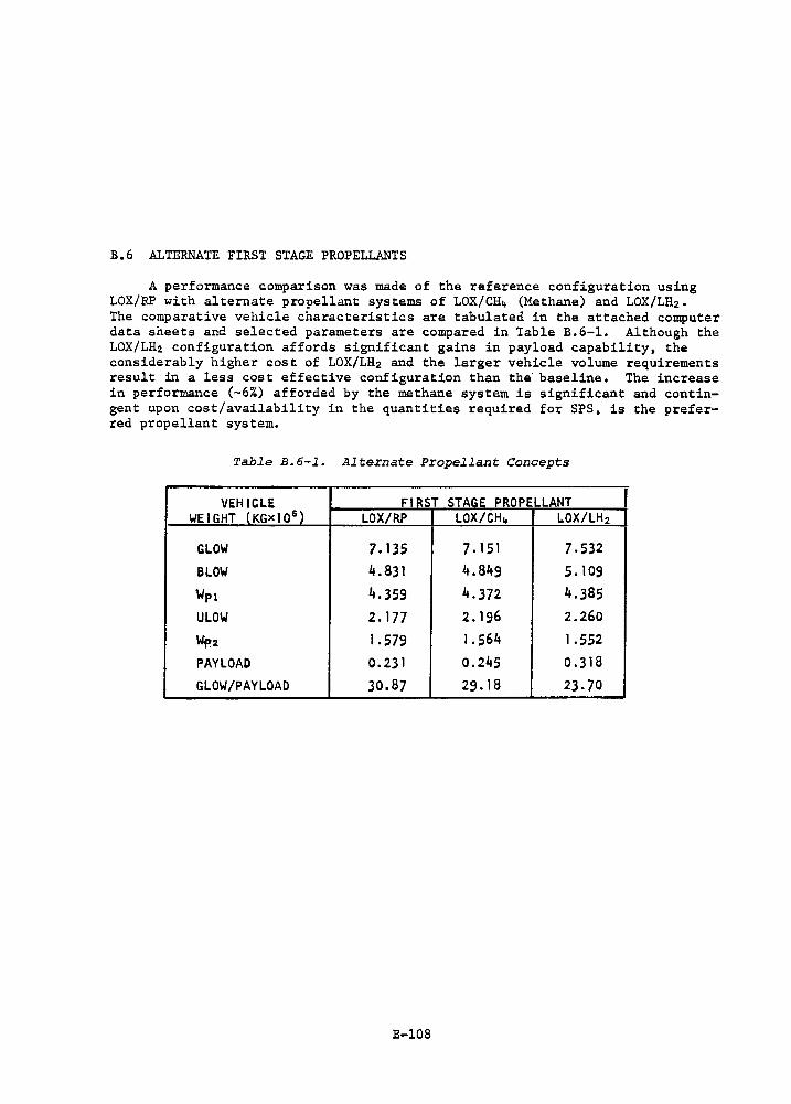
B.6 ALTERNATE FIRST STAGE PROPELLANTS
A performance comparison was made of the reference configuration using LOX/RP with alternate propellant systems of LOX/CH~ (Methane) and LOX/LH2. The comparative vehicle characteristics are tabulated in the attached computer data sheets and selected parameters are compared in Table B.6-1. Although the LOX/LH2 configuration affords significant gains in payload capability, the considerably higher cost of LOX/LH2 and the larger vehicle volume requirements result in a less cost effective configuration than the baseline. The increase in performance (-6%) afforded by the methane system is significant and contingent upon cost/availability in the quantities required for SPS, is the preferred propellant system.
Table B.6-1. Alternate Propellant Concepts
VEHICLE FIRST STAGE PROPELLANT I WEIGHT (KGxl0 6 ) LOX/RP LOX/CH~ LOX/LH2
GLOW 7. 135 7. 151 7.532 BLOW 4.831 4.849 5. 109
Wp1 4.359 4.372 4.385
ULOW 2.177 2. 196 2.260
W.,.2 1.579 1.564 1.552
PAYLOAD 0.231 0.245 0.318
GLOW/PAYLOAD 30.87 29.18 23.70
B-108
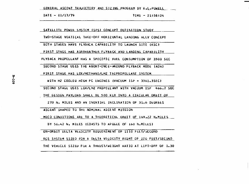
GENERAL ASCENT lRAJECTORY AND SIZING PROGRAM BY R.L.PUWELL
DATE - 01/17/79 TIME - 21:58:24
SATELLilE POWER SYSTEM ISPS) CONCEPT DEFINITION STUDY
TWO-STAGE VERTICAL lAKE-OFF HORIZLJ..ITAL LANDING HLLV CONCEPT
BOTH STAGES ·HAVE fLYBACK CAPABILITY TO LAUNCH SITE (KSC)
FIRST STAGE HAS AlRBRtATHtR FLYBACK AND LANDING CAPABILITY
FLYBACK PROPELLANT HAS A SPECIFIC FUEL CONSUMPTION OF 3500 SEC
SECOND STAGE USES THE ABORT-ONCE-AROUND FLYBACK MOOE IAOA)
FIRST STAGE HAS LOX/METHANE/LH2 TIUPROPELLANT SYSTEM
WITH H2 COOLED HIGH PC ENGINES (VACUUM ISP = 336l.3SEC)
SECOND STAGt USES LOX/LH2 PROPELLANT WITH VACUUM ISP 466.7 SEC
THE DESIGN PAYLOAD SHALL BE 500 KLB INTO A CIRCULAR OR~Il OF
270 N. MILES AND AN INERTIAL lNCLlNATION OF 31.b DtGRtES
ASC E.Nl SHAPED 10 lHE NOMINAL ASCENT MISS I ON
MECO CONUlTlONS AKE TO A 1Ht0RE1ICAL ORBIT OF 169.22 N.MlLES
BY 5U.42 N. HILES (COASTS TO APUGEE OF LbO N.MlLES)
ON-ORblT DELTA VLLOCilY REQUIREMENT OF 1110 Ftll/~ECOND
RCS SYSTtM SIZED FOR A DtLTA VELOCITY REQMT OF 220 FEET/SEC(.j\10
THE VE:HlCLE SIZl::U FOR A THkUSl/WEIGHT kAIIO AT LIFT-OFF OF 1.30
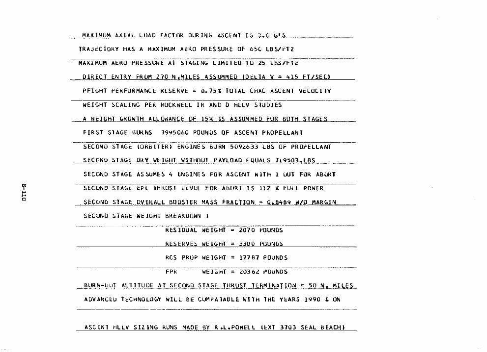
f ..... .... 0
MAXIMUM AXIAL LUAO FACTOR DURING ASCENT IS 3.0 ~·S
IRAJtCTORY HAS A MAXIMUM AERO PRESSURE OF o~v LBS/fT2
MAXIMUM AERO PRESSURE AT STAGING LIMITED TO 25 2
DIRECT E:.NTRY fRUM 210 N.MlLES ASSUMMED (Dt.LTA V = 415 FT/SEC.)
PFlbHT PEkFORMANC.E RESERVE= 0.75% TOTAL CHAC ASCENT VtLOCllV
WEIGHT SCALING PER ROCKWELL IR ANO 0 HLLV STUDIES
A WEIGHT GROWTH ALLOwANCE OF 15, lS ASSUMMED FOR BOTH STAGES
FIRST SlAGE BURNS 7995060 POUNDS OF ASCENT PROPELLANT
SECOND STAGE (ORBITER) ENGINES BURN 5092.633 LBS OF PROPELLANT
SECOND STAGE DRY WEIGHT WITHOUT PAYLOAD EQUALS 719503,LBS
SECOND STAGE ASSUMES 4 E:NGINES FOR ASCENT WlTH l OUT FOR ABORT
SECOND STAGt EPL THRUST LtVE:L FOR ABORT IS 112 % FULL POWER
SECOND STAGE OVEKALL BOOSlER MASS fRACTION = 0,8469 W/O MARblN
SECOND ~1AbE WEIGHT BREAKDOWN :
RESIDUAL WEIGHT = 2070 POUNDS
RESERVE~ HEIGHT = 3300 POUNDS
RCS PROP WE lGHT = 17787 POUNDS
FPR WEIGhT = 203ol POUNDS
BURN-UUT ALllTUOE AT SECOND STAGE THRUST TEkMlNATION = 50 N. HILES
ADVANC~u TcCHNOLUGY WILL BE CUMPAlABLE WITH THE Y~ARS 1~90 t ON ---------·-------·--------------------------
ASCENT HLLV SIZlNG RUNS MADE BY R.L.POWELL &EXT 3703 SEAL BEACH)
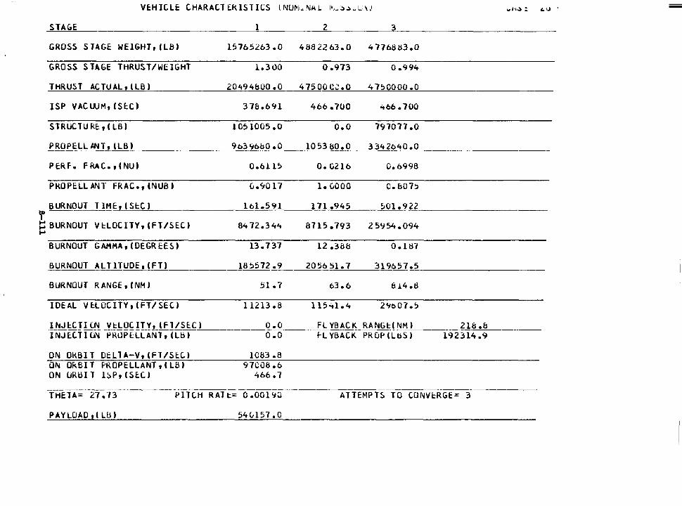
STAGE 1 2 3
GROSS STAGE WElGHTrlLB) 15765263 .o 4882263.0 4 776883.0
GROSS STAGE THRUS.T/WUGHT l.300 0.973 0.994
THRUST ACTUAL1 (LB) 20'49'4&00 .o 4 7500 CJ .O 4 750000 .o
ISP VACWM, ISEC) 378.6'11 466.700 466. 700
S TRUC TU RE:, I LB) 1051005 .o o.o 797077 .o
f.B_OPELL J.NJ-' tLBl 9b~9b.!;l~O 1053 liO. 0 3342640.0
PERF. F RAC., (NU) 0.6l l5 o. 0216 0.6998
PRO PELL ANT FRAC., INUB) Ci .90 17 l. CiOOO C.b075
BURNOUT TIME, I Sl::C) lol.591 171.945 501 .922 t ~BURNOUT Vl::LOCITY,tFT/SEC) 84 72.34'-t &715.793 25'754.094 ....
BURNOUT GAHHA, (DEGREES) 13. 7 37 12 .3d8 0.187
BURNOUT ALTlTUOE,(FT) 185572.9 205651.7 319657 .5
BURNOUT RANGE, (NM) 51.7 63.6 8 .l..4.8
IDEAL VE:.LOCITV,IFT/SEC) 11213.8 l 15"tl .4 2%07.5
INJl::CTILN Vl::LOCITV, (fl/SEC) o.o FL YBAC K RANGl::t~M) 218 .& TNJ E.c 11u'i -Vi~uii[Ll.-A~fr; 1 Lb , o.o fl YBACK PROP (LbS) 192314 .9
ON OKBI T Dt:LTA-V, (Fl/SE:.C) 1C83 .8 ON Ok BIT PROPELLANT, I LB I 97(;08.6 ON URBI T l!>Pr (SE:CI 466.7
----------------- - -- -THETA= 27. 73 PITCH RAT t:..= 0 .001 '7~ ATTEMPTS TO CONVl::RGE= 3
PAYLOAD rt LU) 54e,,1s1 .o
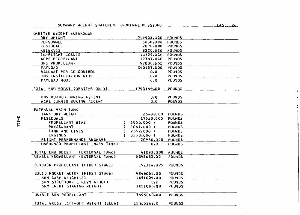
SUMMARY WElGHl SlAH:ME:NT (NOMINAL MISSION) CASE 2b
ffiBITER WEIGHT bRE:AKDOWN __ _Q_!i~- WEIGHT
PERSONNEL RESIDUALS RESl:.RVES lN-FLIGHT LOSSES ACPS PROPELLANT OMS PROPELLANT PAYLOAD BALLAST FOR CG CONTROL OMS INSTALLATION KITS PAYLOAD MOD~
__ WI!~ ~~[) ~Q_Q~LH!~~!J!;!LQ_~LY! ______ _
OMS BURNED UUkING ASClNl AC~S BURNED DURING ASCE:NT
E~TERNAL MAIN TANK ___ T ANK__Q~ Y WEIGHT
RESIDUALS PROPELLANT BlAS PRESSURANT TANK ANO LINES ENGINES
___ FLIC:itfT PERFORMANCE RE: SE:l\VE UNBURNED PROPE:LLANT (MAIN TANK)
TOTAL END BOOST (EXTE:RNAL TANK) USABLE PRO~ELLANT (lXTERNAL TANK)
119 503.0 GO _P~O~U~N~D~S~· __________ _ 3000.0 00 POUNDS 2070.000 POUNCJS 33CO.OCO POUNDS
10324.0CO POUNDS 17787.0CO POUNDS 97006.5b2 POUNDS
54015-1.000 POUNDS O.O POUNDS 0. 0 i>OLJl.I OS C.O POUNDS
1393149.00
o.o o.o
2640.000 1"1523.000
2 560.000 , 206I.OOO ) 935~.ooo > 355 o.ooo )
20930.0CJO o.o
41093.0 00 5 092033.00
_j>QU"!Q~
POUNDS POLJl.I DS
POUNDS PuUNDS POUNDS POUNDS t>OUNDS POUNDS POUNDS POUNDS
PUU~DS
FLYBACK PROPELLANT (FIRS_T_~T_AG_-1:._· ) _______ I_9~2~3_1_4~·~~_7_5 ___ PO_U~N~D~S __________ _
SOLID ROCKET MOTOR (FIRST ST AGE) SRM CASE WEIGHTl2) SRH STRUCTURE ~ RCVY WEIGHT SkM INERT ~TAbING WElbHT
USABLE ~RM PROP~LLANT
TOTAL GROSS LlfT-UfF WEIGHT lGLUW)
9 04b0b5.00 I 051 0 0 5 • 0 (J
o.o l 051005.00
7 995060.0 0
15 705263.0
POUNDS POUNDS POl.lllDS POUNDS
POUNDS
POUNDS
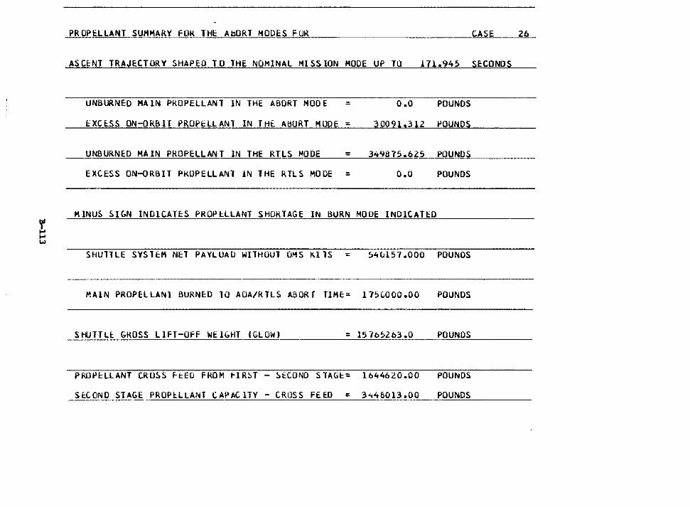
PROPl:LLANT SUMMARY FOR THE AbORT MODES FOR CASE 26
ASCENT TRAJECTORY SHAPED TO THE NOMINAL MISSION HOOE UP TO 171.945 SECONDS
UNBURNED MAIN PROPELLANl IN THE ABORT MOOE = o.o POU NOS
EXCESS ON-ORBIT PROPELLANT IN THE. ABORT MODE = 3 00 91,3 12 POUNDS
UNBURNED MAIN PROPELLANT IN THE RTLS MODE = 349875.625 PO~U~N=D~S ____ _
EXCESS ON-ORBIT PROPELLANl lN THE RTLS HOOE = O.O POUNDS
MINUS SibN INDICATES PROPiLLANl SHORTAGE IN BURN MOUE INDICATED
SHUTTLE SYSTEM NET PAYLUAU WITHOUT OMS KllS = 54ul57.000 POUNDS
MAIN PROPELLANl BURNED 10 AOA/RTLS ABORT TIME= 175LOOO.OO POUNDS
SHUTTLE GROSS LIFT-OFF WEl~HT lGLOWJ POUNDS
PROPELLANT CROSS ftED FROM flR~T - StCONO SlAGt= 1644620.00 POUNDS
SE:.CONO STAGE PROPl:LLANT CAPAClTY - CROSS FEED :: 3.,48013.00 POUNDS
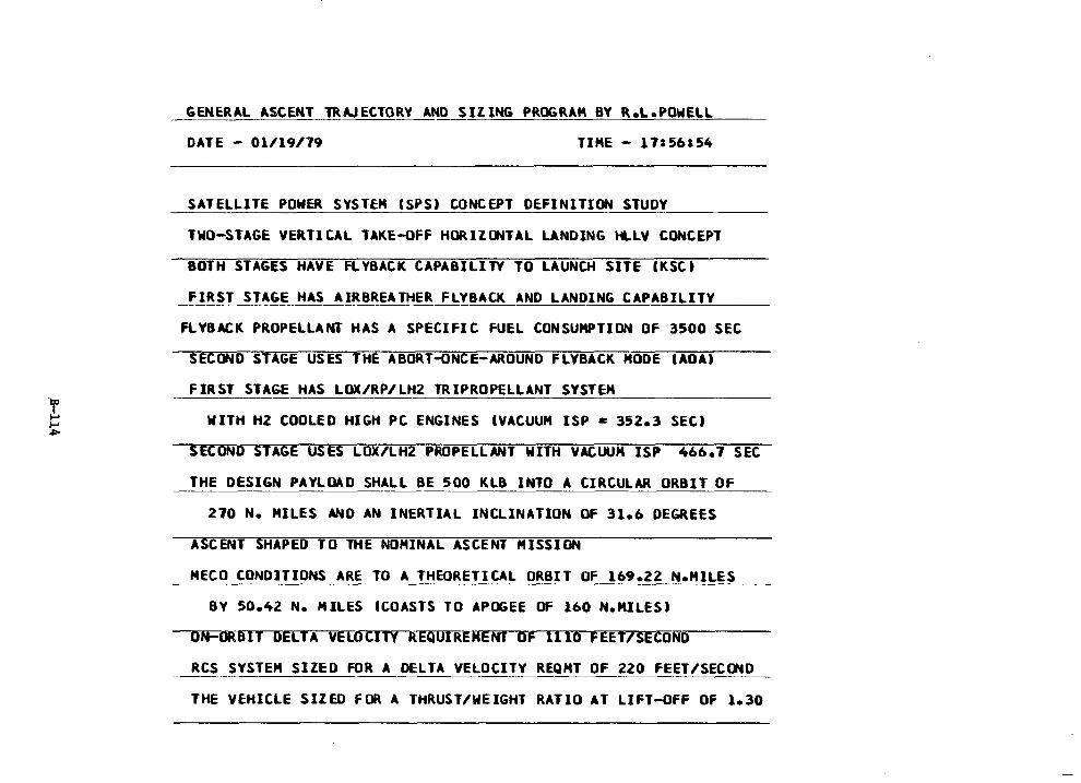
GENERAL ASCENT TRAJECTORY AND SIZING PROGRAM BY R.L.POWELL
DATE - 01/19/79 TIME - 17: 56154
SATELLITE POWER SYSTEM CSPS) CONCEPT DEFINITION STUDY
TWO-STAGE VERTICAL TAKE-OFF HORIZCNTAL LANDING HLLV CONCEPT
BOTH STAGES HAVE FLYBACK CAPABILITY TO LAUNCH SITE IKSC)
_f_!_RS_T_SJ~~_E_H_A_S __ A_IR_B~EA THER FLYBACK AND LANDING CAPAB=I=L=I,__,_T~Y __ _
FLYBACK PROPELLANT HAS A SPECIFIC FUEL CONSUMPTION Of 3500 SEC
SECOND STAGE USES THE ABORT-ONCE-AROUND FLYBACK HOOE CADA)
FIRST STAGE HAS LOX/RP/LHZ TRIPROPELLANT SYSTEM
WITH HZ COOLED HIGH PC ENGINES IVACUUH ISP = 352.3 SEC)
SECOND STAGE USES LOX/LHZ PROPELLANT WITH VACUUM ISP 466.7 SEC
THE DESIGN PAYLOAD SHALL BE 500 KLB INTO A CIRCULAR ORBIT OF
270 N. MILES AND AN INERTIAL INCLINATION Of 31.6 DEGREES
ASCENT SHAPED TO THE NOMINAL ASCENT MISSION
HECO CONDITIONS ARE TO A THEORETICAL ORBIT OF 169.22 NeHILES
BY 50.42 N. HILES CCOASTS TO APOGEE OF 160 N.MILES)
ON'90RBIT DELTA VELOCITY REQUIREMENT OF 1110 FEET/SECOND
RCS SYSTEM SIZED FOR A DELTA VELOCITY REQHT OF 220 FEET/SECCND
THE VEHICLE SIZED FOR A THRUST/WEIGHT RATIO AT LIFT-OFF OF 1.30
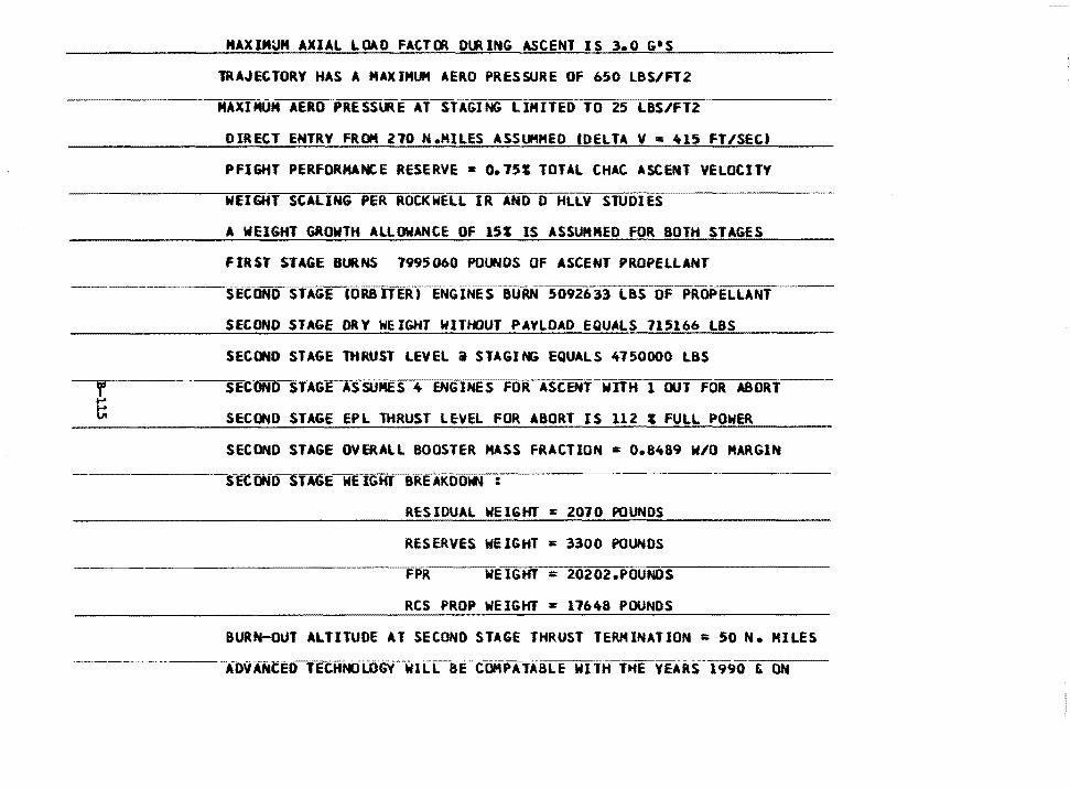
HAXIMUM AXIAL LOAD FACTCR DlRING ASCENT IS 3.0 G•S
lRAJEtTORY HAS A MAXIMUM AERO PRESSURE OF 050 LBS/FTZ
HAXIMUM AERO PRESSl.RE AT STAGING LIMITED TO 25 LBS/FT2
DIRECT ENTRY FROM 210 N.MILES ASSUMMEO IDELTA V • 415 FT/SEtt
PFIGHT PERFORMANCE RESERVE• 0.151 TOTAL CHAC ASCENT VELOCITY
WEIGHT SCALING PER ROCKWELL IR AND 0 HLLY STUDIES
A WEIGHT GROWTH ALLOWANCE OF 151 IS ASSUHMED FOR BOTH STAGES
FIRST STAGE BURNS 7995060 POUt<i!OS OF ASCENT PROPELLANT
--------S-ECONO STAGE IORBITERT-ENGINES BURN 5092633 LBS OF PROPELLANT
SECOND STAGE ORY WEIGHT WJTl«JUT PAYLOAD EQUALS 715166 LBS
SECOND STAGE THRUST LEVEL a STAGJNi EQUALS 4750000 LBS
SECOND S1AGE ASSUMES 4 ENGINES FOR ASCENT wnH l OUT FOR ABORT
SECOND STAGE EPL THRUST LEVEL FOR ABORT IS 112 I FULL POWER
SECOND STAGE OVERALL BOOSTER HASS FRACTION = 0.8489 W/O MARGIN
----·------S-ECONDSTAGE WE IGHT-BRE AKDO~ :
RESIDUAL WEIGHT = 2070 POUNDS
RESERVES WEIGHT s 3300 POUNDS
FPR WEIGHT : 20202.POUNDS
RCS PROP WEIGHT = 11648 POUNDS
BURN-OUT ALTITUDE AT SECOND STAGE THRUST TERMINATION = 50 N. MILES
-----·-· -------·-ADVANCED'fECHNCflJ)G'r-w1Li-8tCC-OMPATABLE WITH-THE VEARS-1990 &. ON
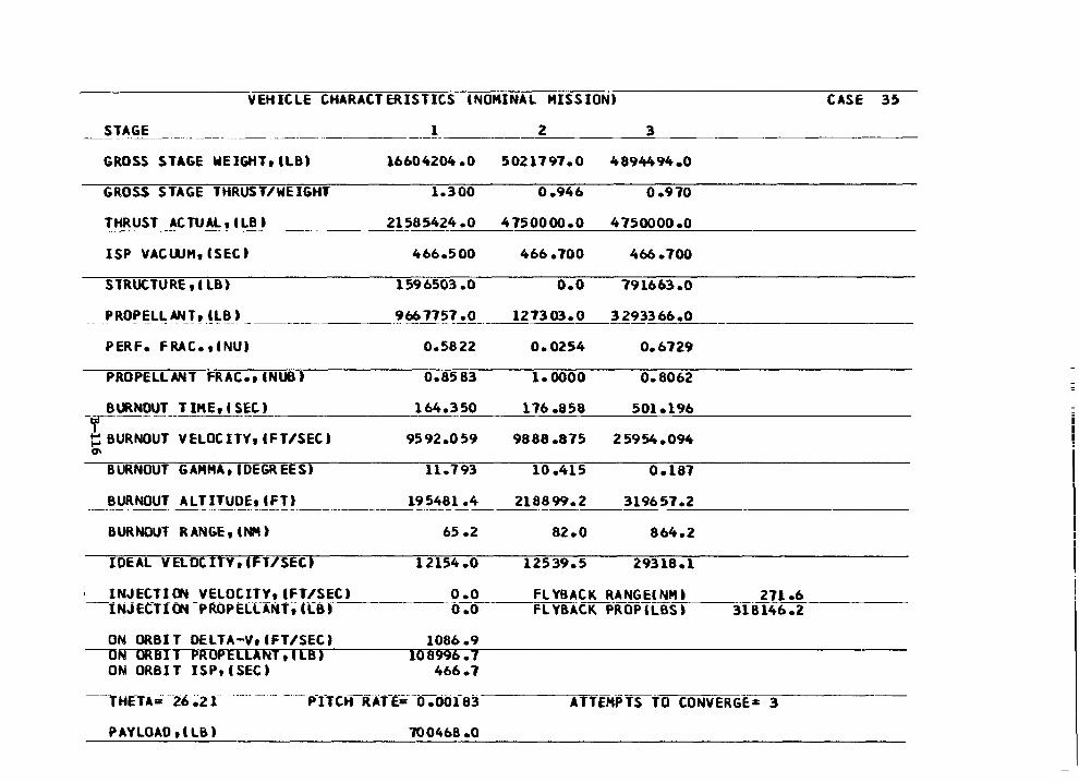
VEHICLE CHARACTERISTICS CNOMINAL MISSION)
-~ 1' ~GE ____________________ _ 1 2 3
GROSS STAGE WElGHTttLB) 16604204.0 5021797.0 4894494.0
GROSS STAGE THRUST/WEIGHT 1.300 0.946 0 .970
THRUST ACTUAL, CLB I
ISP VACWH, (SEC)
______ 21585424.0 4750000.0 4750000.0
466.500 466.700 466.700
STRUCTURE, l LB) 1596503.0 o.o 791663.0
PROPELL:ANJ~-~l.~J ______________ ?~17~?_!_Q_ 127303.0 3293366.0
PERF. FRAC. ti NU) 0.5822 0.0254 0.6729
PROPELLANT FRAC., CNUB) 0.8583 1.0000 0.8062
CASE 35
-rll\_NQUT TIHE,CSEC) -------~16~4~·~3c~5~0 ___ ~1~7~6~·=8=5=8 __ ~5~0=1~·=19~6~----------
t:: BURNOUT VELOCITY, CFT/SEC) 9592.059 9888 .875 25954.094 (7\
BURNOUT GAMMA, tDEGREESi 11.793 10.415 0.187
BURNOUT ALTITUDE1 Cfl) 195481.4 218899.2 319657.2 ---------- -·--·-·---------------------------- --- ------------BURNOUT RANGE, INM)
IDEAL VELOC ITV, (FT/SEC)
65 .2
12154.0
INJECTI CW VELOCITY, tFT/SECI 0 .O -lNJECTtl'W-PRoPEL[ANt~ ((8,---------o-;o
ON ORBIT DELTA-VtCFT/SEC) -UN ORBITtilUIPELLANT,ILB)
ON ORBIT ISP,ISEC)
PAYLOAD ti LB)
1086 .9 108996. 7
466.7
700468 .o
82.0 864.2
12539.5 29318.1
FL YB ACK RANG EC NH I __:2::__:1:_::::1:_::•=6 ______ _ FLYBACK PROPCLBS-~to----,31Bl46.2
ATTEMPTS to CONVERGE= 3
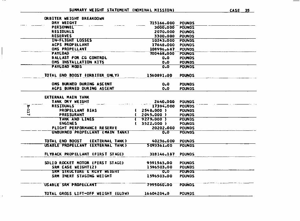
SUMMARY WEIGHT STATEMENT Cl'«JMINAL MISSION) CASE 35
CRBITER WEIGHT BREAKDOWN DRY WEIGHT PE1rso~E~L--~-----
RESIDUALS RESERVES tN=FLIGHT LOSSES ACPS PROPELLANT OMS PROPELLANT
715166.000 POUNDS --~3000.~POUNDS ______ _
2070.000 POUNDS 3300.000 POUNDS
--------PAVLO~
10243.000 POUNDS 17648.000 POUNDS
108996.687 POUNDS ----100468.000 POUND·s-=------------
BALLAST FOR CG CONTROL OMS INSTALLATION KITS PAYLOAD MOOS
TOTAL END BOOST tORBJTER ONLY)
OHS BURNED DURING ASCENT AtPS BURNED DURING ASCENT
EXTERNAL MAIN TANK TANK DR V WEIGHT
---·------r···-----R-ES-fl)UALS ~ PROPELLANT BIAS ~ PRES SU RANT
TANK AND LINES ENGINES
FLIGHT PERFORMANCE RESERVE ------ ---ONBURNEO-PFtO-PELLANITKAIN--TANK)
TOTAL END BOOST (EXTERNAL TANK) USABLE PROPELLANT IEXTERNAL TANK)
FL VB ACK PROPELLANT CFIRS T ST AGE)
SOLID ROCKET MOTOR CFIRST STAGE) SRH CASE WEIGHT(2) SRM SIRUC1URE t RCVY WEIGAI SRM INERT STAGING WEIGHT
------- -us ABIE--SRM--PROP-EIIANT
TOTAL GROSS LIFT-OFF WEIGHT IGLOW)
0.0 POUNDS O.O POUNDS O.O POUNDS
1560891.00 POUNDS
o.o POUNDS o.o POUNDS
2640.000 POUNDS 17394.000 POLNDS
' 2548.000 , POUNDS ( 2045.000 , POUNDS c 9279.000 , POUNDS ( 3522.000 ) POUNDS
20202.000 POUNDS o.o POUNDS
40236.000 POlNDS 5093361.00 POUNDS
318146.187 POUNDS
9591563.00 POUNDS 1596503.00 POUNDS
o.o PO CMOS 1596503.00 POUNDS
1995060.00 POUNDS
16604204.0 POUNDS
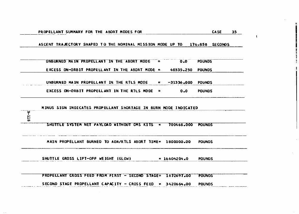
ASCENT TRAJECTORY SHAPED TO THE NOMINAL MISSION HOOE UP TO 176.858 SECONDS
---UNBLR~UfttJ:lfrl>A:OPELLANllNIHEABORT HOOE = EXCESS ON-ORBIT PROPELLANT IN THE ABORT MOOE =
o.o POUNDS
40335.250 POUNDS
UNBURNED HAIN PROPELLANT IN THE RTLS MOOE = -31336.000 POUNDS - -- --·-~ ---------- ------·--··-·-·---
EXCESS ON-ORBIT PROPELLANT IN THE RTLS MODE = o.o POUNDS
MINUS SIGN INDICATES PROPELLANT SHORTAGE IN BURN HOOE INDICATED
SHUTILE SYSTEM NET PAYLOAD WITHOUT OMS KITS = 700468.000 POUNDS
--·-·--- --·- -···----·---
HAIN PROPELLANT BURNED TD AOA/RTLS ABORT TIME= 1800000.00 POUNDS
StlJTTLE GROSS LIFT-OFF WEIGHT CGLOWt : l660it204.0 POUNDS
PROPELLANT CROSS FEED FROM FIRST - SECOND STAGE= 1612691.oo POUNDS
SECOND STAGE PROPELLANT CAPAC ITV - CROSS FEED = 3420664.00 POUNDS
APPENDIX C. ELECTRIC ORBITAL TRANSFER VEHICLE SIZING
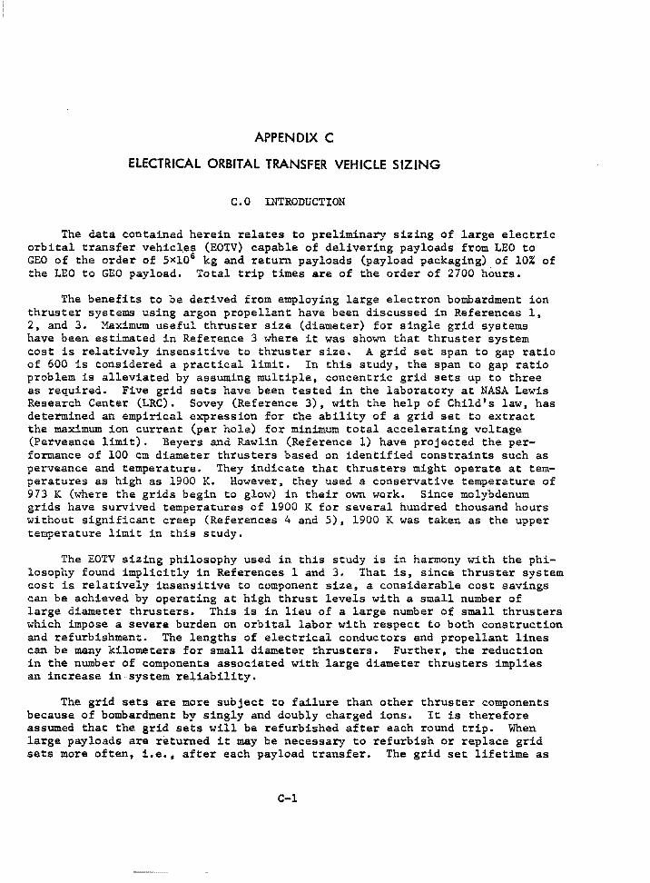
APPENDIX C
ELECTRICAL ORBITAL TRANSFER VEHICLE SIZING
C.O INTRODUCTION
The data contained herein relates to preliminary sizing of large electric orbital transfer vehicl.es (EOTV) capable of delivering payloads from LEO to GEO of the order of 5Xl06 kg and return payloads (payload packaging) of 10% of the LEO to GEO payload. Total trip times are of the order of 2700 hours.
The benefits to be derived from employing large electron bombardment ion thruster systems using argon propellant have been discussed in References l, 2, and 3. Maximum useful thruster size (diameter) for single grid· systems have been estimated in Reference 3 where it was shown that thruster system cost is relatively insensitive to thruster size. A grid set span to gap ratio of 600 is considered a practical limit. In this study, the span to gap ratio problem is alleviated by assuming multiple, concentric grid sets up to three as required. Five grid sets have been tested in the laboratory at NASA Lewis Research Center (LRC). Sovey (Reference 3), with the help of Childts law, has determined an empirical expression for the ability of a grid set to extract the maximum ion current (per hole) for minimum total accelerating voltage (Perveance limit). Beyers and Rawlin (Reference l) have projected the performance of 100 cm diameter thrusters based on identified constraints such as perveance and temperature. They indicate that thrusters might operate at temperatures as high as 1900 K. However, they used a conservative temperature of 973 K (where the grids begin to glow) in their own work. Since molybdenum grids have survived temperatures of 1900 K for several hundred thousand hours without significant creep (References 4 and 5), 1900 K was taken as the upper temperature limit in this study.
The EOTV sizing philosophy used in this study is in harmony with the philosophy found implicitly in References 1 and 3. That is, since thruster system cost is relatively insensitive to component size, a considerable cost savings can be achieved by operating at high thrust levels with a small number of large diameter thrusters. This is in lieu of a large number of small thrusters which impose a severe burden on orbital labor with respect to both construction and refurbishment. The lengths of electrical conductors and propellant lines can be many kilometers for small diameter thrusters. Further, the reduction in the number of components associated with large diameter thrusters implies an increase in system re~iability.
The grid sets are more subject to failure than other thruster components because of bombardment by singly and doubly charged ions. It is therefore assumed that the grid sets will be refurbished after each round trip. When large payloads are returned it may be necessary to refurbish or replace grid sets more often, i.e., after each payload transfer. The grid set lifetime as
C-1
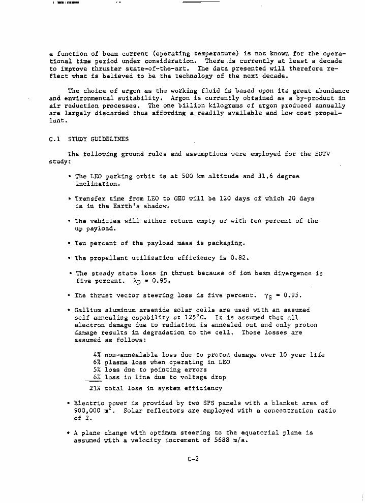
I -1111••1
a function of beam current (operating temperature) is not known for the operational time period under consideration. There .is currently at least a decade to improve thruster state-of-the-art. The data presented will therefore reflect what is believed to be the technology of the next decade.
The choice of argon as the working fluid is based upon its great abundance and environmental suitability. Argon is currently obtained as a by-product in air reduction processes. The one billion kilograms of argon produced annually are largely discarded thus affording a readiiy available and low cost propellant.
C.l STUDY GUIDELINES
The following ground rules and assumptions were employed for the EOTV study:
• The LEO parking orbit is at 500 km altitude and 31.6 degree inclination.
• Transfer time from LEO to GEO will be 120 days of which 20 days is- in the Earth's shadow.
• The vehicles will either return empty or with ten percent of the up payload.
• Ten percent of the payload mass is packaging.
• The propellant utilization efficiency is 0,82.
• The steady state loss in thrust because of ion beam divergence is five percent. AD • 0.95.
• The thrust vector steering loss is five percent. Ys • 0.95.
• Gallium aluminum arsenide solar cells are used with an assumed self annealing capability at 125°C. It is assumed that all electron damage due to radiation is annealed out and only proton damage results in degradation to the cell. Those losses are assumed as follows:
4% non-annealable loss due to proton damage over 10 year life 6% plasma loss when operating in LEO 5% loss due to pointing errors 6% loss in line due to voltage drop
21% total loss in system efficiency
• Electric ~ower is provided by two SPS panels with a blanket area of 900,000 m • Solar reflectors are employed with a concentration ratio of 2.
• A plane change with optimum steering to the equatorial plane is assumed with a velocity increment of 5688 m/s.
C-2
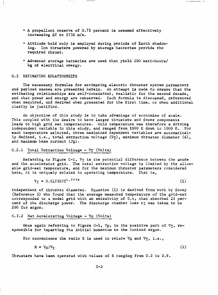
• A propellant reserve of 0.75 percent is assumed effectively increasing ~V to 5730 m/s.
• Attitude hold only is employed during periods of Earth shadowing. Ion thrusters powered by storage batteries provide the required thrust.
• Advanced storage batteries are used that yield 200 watt-hours/ kg of electrical energy.
C.2 ESTIMATING RELATIONSHIPS
The necessary formulas for estimating electric thruster system parameters and payload masses are presented herein. An attempt is made to ensure that the estimating relationships are self-consistent, realistic for the second decade, and that power and energy are conserved. Each formula is discussed, referenced when required, and derived when presented for the first time, or when additional clarity is justified.
An objective of this study is to take advantage of economies of scale. This coupled with the desire to have larger thrusters and fewer components leads to high grid set temperatures. Grid temperature was therefore a driving independent variable in this study, and ranged from 1900 K down to 1000 K. For each temperature selected, three maximized dependent variables are automatically defined, i.e., total extraction voltage (VT), maximum thruster diameter (d), and maximum beam current (JB).
C.2.1 Total Extraction Voltage - VT (Volts)
Referring to Figure C-1, VT is the potential difference between the anode and the accelerator grid. The total extraction voltage is limited by the allowable grid-set temperature, and for the maximum thruster parameters considered here, it is uniquely related to operating temperature. That is,
VT• 0.012307T 1 • 7778 (1)
independent of thruster diameter. Equation (1) is derived from work by Sovey (Reference 3) who found that the average measured temperature of the grid-set corresponded to a model grid with an emissivity of 0.4, that absorbed 25 percent of the discharge power. The discharge chamber loss EI was taken to be 200 for argon •.
C.2.2 Net Accelerating Voltage - VN (Volts)
Once again referring to Figure C-1, VN, is the positive part of VT, responsible for imparting the initial momentum to the ionized argon.
For convenience the ratio R is used to relate VN and VT, i.e.,
(2)
Thrusters have been operated with values of R ranging from 0.2 to 0.9.
C-3
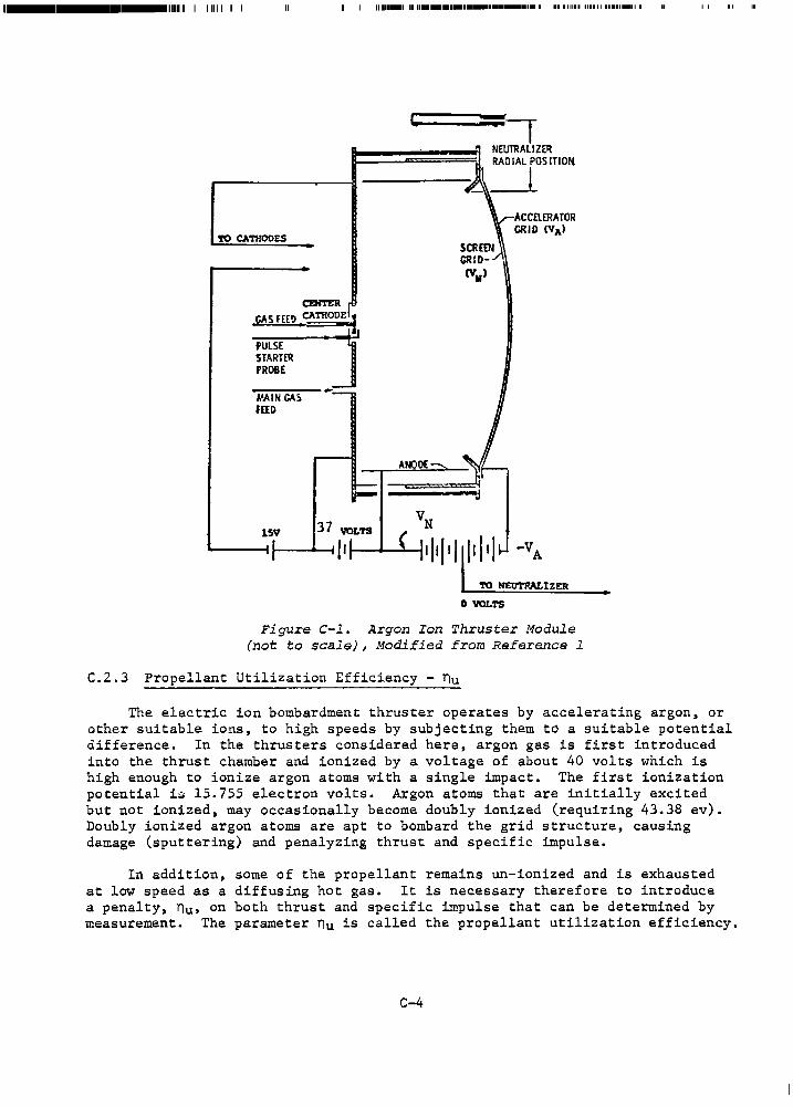
l-•l•l·--··-1111111 I 11111 I I I I 11111-1 1111111•1••••••-11••·-··· I II 111111 111111 .......... I
=1 NEUlRALIZ~ RADIAL POSITION
--------.tA'• _J_
TO CATHODES
"'.AIN GA~ fllD
0 VOLTS
ACCaERATOR GRID (VA)
Figure C-1. Argon Ion Thruster Module (not to scale), Modified from Reference l
C.2.3 Propellant Utilization Efficiency - nu
•
The electric ion bombardment thruster operates by accelerating argon, or other suitable ions, to high speeds by subjecting them to a suitable potential difference. In the thrusters considered here, argon gas is first introduced into the thrust chamber and ionized by a voltage of about 40 volts which is high enough to ionize argon atoms with a single impact. The first ionization potential i$ 15.755 electron volts. Argon atoms that are initially excited but not ionized, may occasionally become doubly ionized (requiring 43.38 ev). Doubly ionized argon atoms are apt to bombard the grid structure, causing damage (sputtering) and penalyzing thrust and specific impulse.
In addition, some of the propellant remains un-ionized and is exhausted at low speed as a diffusing hot gas. It is necessary therefore to introduce a penalty, nu, on both thrust and specific impulse that can be determined by measurement. The parameter nu is called the propellant utilization efficiency.
C-4
By making two reasonable assumptions, one can acquire a feeling for propellant utilization. First, assume that all singly charged argon ions are accelerated to identical speeds, v, by the net potential difference VN• Second, assume that the fraction of doubly charged ions is small compared to the fraction of singly charged ions. Then from conservation of momentum
k k E vim. • v E m • v m
i•l 1 i .. l i p
where v • v1 • v2 • - - - • vk • ion speed,
v • mean speed of all exhaust materials,
and mp• mass of exhausted material (ions and neutrals).
The propellant utilization efficiency is then defined by
0.8 s nu .. :!... -v
< 0.9
where the limits on nu apply to ionized argon.
C.2.4 Specific Impulse - Isp (seconds)
Actual specific impulse can be defined by
v Isp • g
(3)
(4)
where g • 9.807 m/s 2 the mean acceleration of gravity. This can also .be expressed in terms of electric parameters. If ions are accelerated through a potential difference VN one can write (summing i from 1 to k)
t E ~vi2 • t v 2 km • E qi VN (5)
where qi is the charge on each ion of mass m. Solving Eq. (5) for v 2
yields
2VNEqi 2VN (kq) • 2VN (q/m) v - km km
• :;;2;n 2 u
• gzI 2/n 2 sp u
and
I • Cnu/g) J2vN(q/m.) . sp (6)
C-5
The ratio of charge to mass for argon is
q/m • 2.4162xlo 6 C/kg, (7)
and
nu = o.82.
After substituting the numerical values from Eq. (7) into Eq. (6) one obtains
I sp
and conversely
- 223.96 v 0• 5 nu N
• 183.65 V 0•
5 seconds, N
= 2.9655 I 2 10-5 volts. sp
(8)
(9)
Specific impulse as a function of voltage ratio and grid temperature is depicted in Figure C-2.
Ideal or "electrical" specific impulse is obtained by setting nu equal to unity. The specific impulse used herein is as defined in Eq. (6). It is based on conservation of energy and momentum and yields either a maximum ion speed Cnusl) or a mean propellant exhaust speed. The fact that the beam may be diverging and producing a useless component of thrust will be considered later by introducing a thrust efficiency term, Yt• Thrust is a measurable quantity and, in particular. the useful thrust along the thruster axis can be determined.
Estimated thrust vector steering losses (ys) will also be introduced at the same time. With this approach there is no pseudo modification of maximum or mean propellant exhaust speeds or of specific impulse. The modification comes in the total propellant mass for rate (mp); part of it diverges and does no useful work. This is taken into account empirically and avoids giving the impression of an improvement in specific impulse.
Factors which enter into beam divergence include: (1) electric field intensity divergence; (2) mutual repulsions of singly and doubly charged ions; (3) the applied magnetic field; and (4) the discharge power that creates the ions. The discharge may be ten percent or more of the total power provided.
C.2.5 Maximum Thruster Diameter - Db (cm)
An expression for the maximum useful beam diameter, Db, which is tantamount to the maximum useful thruster diameter, d, was presented in Reference 2:
d • l.5x10-8 I 2 m/n 2 R sp u (10)
C-6
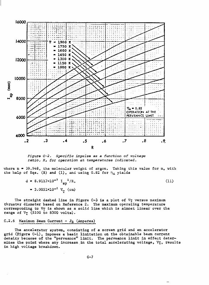
i •
. . . .... _.,, .. -. 14000--.---T
+-t-- .....
"" .... 12000 t---i---+
~ ; ~i ~ : : : : : : : ! : i:::
: ; ; ; ! i ! : : , • t ~ ,. ••••
t { f •I J • •
-• • -
--···. ' .... ... !. ~ • •. • • ••
11 • • 0.82 OPERATI0'-1 AT THE
60001""---:7'-~i:7'.cc_~--: .... =-~~-+~~~--+-·-·-"-·-·-·~~P~E~RV~E~A~N~C~ET=Ll~M~IT:.._==·~
. t .... r .... , . ·: :.:1: : : : :
4000--------------i"-------'-~~--L------....i..----~'-------' .2 .3 .4 .s .6 .7 .a
R
Figure C-2. Specific impulse as a function of voltage ratio, R, for operation at temperatures indicated.
• 9..
where m • 39.948, the molecular weight of argon. Taking this value for m, with the help of Eqs. {8) and (1), and using 0.82 for nu yields
d • 8.9117x10⁻¹
• 3.005lxlo-2
The straight dashed line in Figure thruster diameter based on Reference 2. correspon4ing to VT is shown as a solid range of VT (5100 to 8300 volts).
(11)
C-3 is a plot of VT versus maximum The maximum operating temperature
line which is almost linear over the
C.2.6 Maximum Beam Current - JB (Amperes)
The accelerator system, consisting of a screen grid and an accelerator grid (Figure C-1), imposes a basic limitation on the obtainable beam current densi.ty because of the "perveance11 limit. The perveance limit in effect determines the point where any increase in the total accelerating voltage, VT, results in high voltage breakdown.
C-7
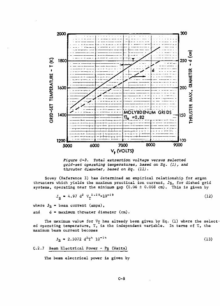
-~ -.... w a== F2 <( a== w a.. ~ w .... .... w ~ 0 a== C>
2000
--·--··-
. - - ----·--+-----
'E u -I
a== w .... ~
1600 ...... ~~~~~+..oc.-~~""""-~-+--··~-::::-_-_-_-_-~---+-----·--_--_-_-_-_-_---t- 200 Z5
,,,, ·--· ~ -- ....__--~-
• x <(
~ a== w .... I/') MOLYBDENUM GRI OS
l400-_ -=..-__ -_-:..._-:_--:_--t-_ -_-:._-:._-._::. ~---. -11'/u =O. 82 150 ~ a== __ ___.__.._. __ - ~- --·--· __ _____...._ ...... ~-
----~ .,............-.;...·----+----'"~- --------• I
----~-. -~- ... -~~--+--__._~~ .................. -+---..--+--L..-..--
1200 - -- ---· --~-_;___;__- ~~ -.
5000 6000 7000 8000 Vt (VOLTS)
100 9000
Figure c-3. Total _extraction voltage versus selected grid-set operating temperatures, based on Eq. (l), and thruster diameter, based on Eq. (ll).
J: ....
Sovey (Reference 3) has determined an empirical relationship for argon thrusters which yields the maximlim practical ion current, JB, for dished grid systems, operating near the minimum gap (0.06 ± 0.008 cm). This is given by
JB a 4.97 d2 VT2025 x10-10
where JB •beam current (amps),
and d m maximum thruster diameter (cm).
(12)
The maximum value for VT has already been given by Eq. (1) where the select~ ed operating temperature, T, is the independent variable. In terms of T, the maximum beam current becomes
JB ~ 2.5072 d2 T~ 10- 1 ~ (13)
C.2.7 Beam Electrical Power - PB (Watts)
The beam electrical power is given by
C-8
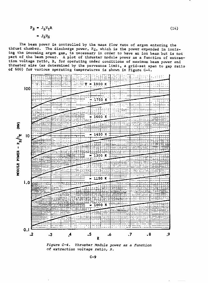
(14)
The beam power is controlled by the mass flow rate of argon entering the thrust chamber. The discharge power, Pd, which is the power expended in ionizing the incoming argon gas, is necessary in order to have an ion beam but is not part of the beam power. A plot of thruster module power as a function of extraction voltage ratio, R, for operating under conditions of maximum beam power and thruster size (as determined by the perveance limit, a grid-set span to gap ratio of 600) for various operat_ing temperatures is shown in Figure C-4.
1.0
0.1 .2
• 1450 K - . !
' - I "' . : ; l; - ; -
__ f=----=
----- ----- .. ---
--
. - - - - - - - : : ,-_, J ' - ' : - - '-' ' ' - '" c.--;-
.3 .4 .5 .6 .7 .a R
Figure C-4. Thruster Module power as a function of extraction voltage ratio, R.
C-9
.9
C.2.8 Thruster Module Electrical Effi~iency - ne
The electrical power efficiency, ne, of a thruster module in achieving a beam power, PB, is given by
(15)
where Pcs m Grid set loss*, • 0.0025 JBVN, (an empirical value)
Pn • Discharge power loss*, • 200 JB,
and a Beam neutralization loss*, • 300 Watts (assumed constant).
In terms of voltages and currents
(16)
RVN -~~~~~~~~~....,_~~~~~~.,..--RV N + 200 R + 0.0025 VN + 300 R/JB
1 -(
R + 0.0025) + 200 + 300 R VN PB
For the large, high power thrusters considered in this study the efficiency may be approximated by
within 0.6% at the extremes. When the beam power is small (i.e., < 300 W) Eqs. (15) and (16) should be used,
A plot of thruster electric efficiency versus R is presented in Figure C-5 for six values of Isp• A temperature of 1900 K was considered the maximum allowable for extended operation of molybdenum grids. This is indicated by the dashed line in Figure C-5. Operation in the shaded area is not permitted. At these higher temperatures it is assumed that the grids would be replaced periodically.
In Figure C-6 the electrical efficiency is plotted against R for various selected operating temperatures. The efficiency increases with grid-set temperature, and at a given temperature, also increases with R.
*Based on conversations with v. K. Rawlin, NASA, LRC
c-10
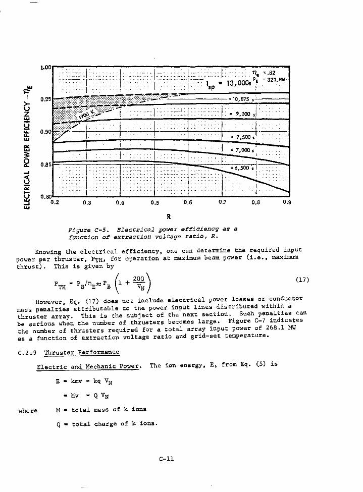
~ I
> u z w -~ u.. u.. w a.: w ~ 2
1.cor"'.""'.""'~-;-:----:----:"'---"."'---~-------
:; ~.::~.-::.I~~:.:-::::::!::~:.:.:·:: :1~~.:::::.::~~J.:::·:~:·:.-:::-r :·:::::: ~· :-82 M . : : :. : : : :I -: : : : : : : : .. : . ·: : ... I · · · · · - · · • r· -- - - I • 13 OOOs _E -
327• w ':: ·-J ·: ·:·····I , · ·,,, • I : , , : : , : : , •.,. Sp I ! . : : .
:::i.;l.,! .. if~!1l.p+r~l~=l;'~'~;o:l1 :: :II ~':.::Ii - ... ' . ' .. ' .... '.' ...
" 7 ,500 l : : : : : : :
= 7,000 s
. ~ . 4 .•
0.5 0.6 0.7
R
Flgure c-s. Electrjcal power efficiency as a fWlCtion of extraction voltage ratio, R.
I,
0,8 0.9
Knowing the electrical efficiency, one can determine the required input power per thruster, PTH• for operation at maximum beam power (i.e., maximum thrust). This is given by
PTH • .. /nE"'PB (1 + 2~~) (17)
However, Eq. (17) does not include electrical power losses or conductor mass penalties attributable to the power input lines distributed within a thruster array. This is the subject of the next section. Such penalties can be serious when the number of thrusters becomes large. Figure C-7 indicates the number of thrusters required for a total array input power of 268.l MW as a function of extraction voltage ratio and grid-set temperature.
C.2.9 Thruster Performance
Electric and Mechanic Power. The ion energy, E, from Eq. (5) is
E • kmv = kq VN
• Mv • Q VN
where M • total mass of k ions
Q • total charge of k ions.
c-11
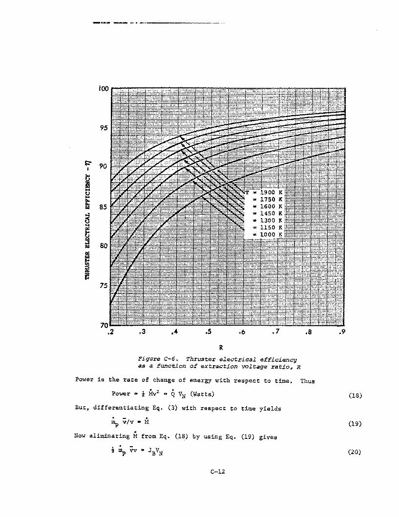
-..11m11U11 .. -..... 11• • -·~-·-----------
90
·-,_
-·-· 75 s~.
:y,: _,_ ~---1 -· ·#-
--
T • ... • ,_,_ .. .. "' -
1900 K 1750 K 1600 K 1450 K 1300 1150 1000
K K:.. K
--- ·+··-· ' ~--~· .... - ~·->-•
--
_,_,._,_.~~.~- ~--~ s:~~:~
70 --·· --- -------- ·:: ..... _. ___ -- ,.__. ---='- _-::-:: __ ::..~t:::;;: :_-::~:~ .2 .3 .... .s .7
R
Figure c-6. Thruster electrical efficiency as a ftm.ction of extraction voltage ratio~ R
.a
Power is the rate of change of energy with respect to time. Thus
.9
Power • t Mvi a Q VN (Watts) (18)
But, differentiating Eq. (3) with respect to time yields
~ vfv • -M
Now eliminating M from Eq. (18) by using Eq. (19) gives
i ~ Vv • JBVN
c-12
(19)
(20)
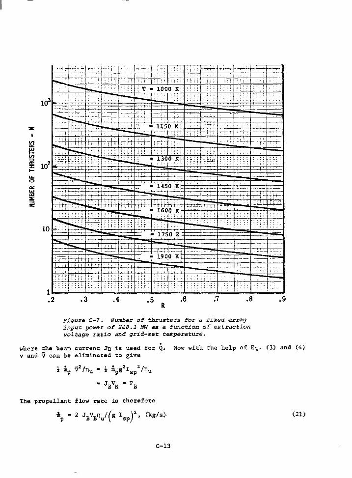
: ·.; : .. ; '.· =.· =.· _: ~.· •. · .. : .: "~L' ~" : :: • ~, i6'o'o 'ie: :;~- =. :. :. '·
. • ' • . . . • I : :.: ~ J_ __ : _: _: _; t--'-;--1,,__--+-. -· -· -· +-' .;..' -· -· +.....' -· -· ''-+-·-·--~ ~:.:;~ I .~i....._ ••• ,.
··~· ....... :.;::~. .
• l750 K
: i r t : 1 ;, : : . r r : J : ; : ~ : . . . 10 .... 1.._ ...
l
l i
-1900 K1 I,
I I
I
I
I
··-·+
I l
I ·I -
-:----
: i • ! ... . .. - ~4 .;._:--+---'---'-'-. .-. ' ; '
' : i i ~ i f ; : ! : ~ i :
tf~Tti i ! : : i ! I : I ; i : i .. . ' : t . : : . ' . ' . , - ' .. ' ··t • . •. ; 1 : t : ' : l : r ' : ~ r ~ 1 .... __ ..... ____ ... __ ..... ____ ._ __ ..... ____ ._ __ .;..;. ____ ... .;...;..;.~·~:-:_·.i..;..;...;..:..;....;....i..;. __ ....;, __ __,
.2 .3 .4 .5 R
.6 .7 .8
Figure c-7. Number of thrusters for a fixed array input power of 268.l MW as a function of extraction voltage ratio and grid-set temperature •
.9
. where the beam current JB is used for Q. Now with the help of Eq. (3) and (4) v and v can be eliminated to give
The propellant flow rate is therefore
(21)
C-13
11111 IUlll IU I 1111 ________ _
or for N thrusters each with beam power PB
~ - 2 N PBn !(g I ) 2 (kg/s). p u sp (22)
Clearly, the mechanical power, Pm,. is equal to the electric power PE• and is
(23)
Thrust. Thrust is the rate of ~h~nge of momentum with respect to time. Since the propellant exhaust speed is constant, the thrust, F, is derived from the mass flow rate. Thus
where
F •~Vy • mpgispy
y • YnYs ~ o.902s.
(24)
As defined here y is the thrust utilization.efficiency which accounts for thrust losses caused by beam divergence (yn) and the thrust vector steering (ys). According to v. K. Rawlin of NASA, LRC, grid compensation techniques should be able to maintain YD at 0.95 or more.
Equation (24) can be expressed in terms of beam power by employing Equation (22).
F • 2NPBn y/gI u sp
C.2.10 The Rocket Equation
(25)
Consider an EOTV with initial mass m1, final mass (at burnout) mf and a required velocity increment 6V.
The total propellant expended in time 6t is
m - m tit p p (26)
Gravity losses for low thrust flights between LED and GEO are assumed to be small. The thrust acting on the EOTV is given by
. - ( . ) . F • m vy • m -m t v p i p s
where t .. time, or thrust duration, . Vs ,. vehicle acceleration,
and mi .. vehicle initial mass (t•O).
The acceleration of the spacecraft at any time, t, from Eq. (27) is
vs - mp¥r!(m1-mpt)
C-14
(27)
(28)
and dW • ~dt,
in .Eq. (28) and integrating yields
With the help of exponentials, Eq. (29) can be written
mf
mi
m p
m p
t:.v/gI y • m e sp where i
.. mp +mf ' and
( /::,.v/gis y ) .. m e P -1
f or
( -/::,.v/gI
5 Y)
mi 1-e P .
C.2.11 Attitude Control Propellant
(29)
(30)
(31)
(32)
Some of the electric thrusters are used for attitude control while in the Earth's shadow. (Batteries are used to provide the required power). The maximum control thrust requirement occurs in LEO where the gravitational torques are highest. Control requirements become quite small in GEO. In this analysis, the average control thrust was taken to be 400 N, which is believed to be conservative.
The control propellant mass was estimated by taking appropriate fractions of the total propellant consumed during the daylight thrusting period. Thus, for a 120 day trip time and 100 days of thrusting time the shadow period is close to 20 days, which gives a factor of 0.2. The propellant mass is further reduced by the ratio of control thrust (400 N) to total thrust (F). Thus, the control propellant mass, Illpc• is given by
C-15
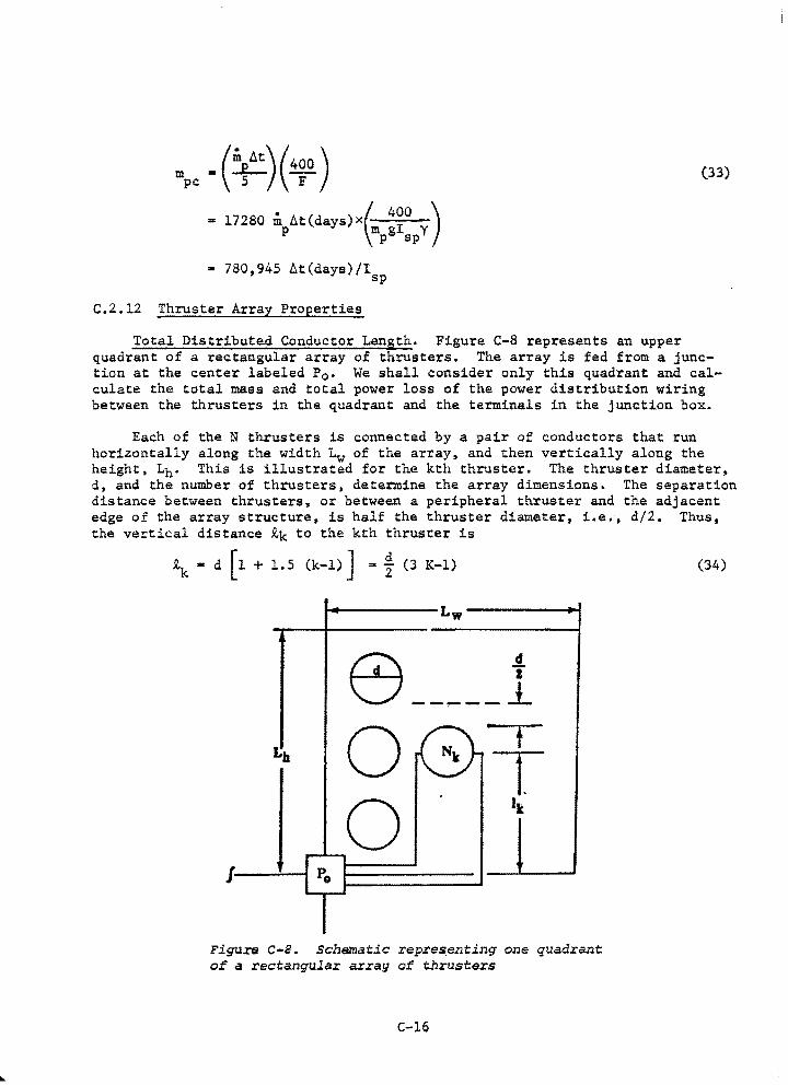
m pc -(¥:)(4~0) • 17280 m At days)x
1 • ( ~ 400 ) p mpg spy
• 780,945 At(days)/I sp
C.2.12 Thruster Array Properties
(33)
Total Distributed Conductor Length. Figure C-8 represents an upper quadrant of a rectangular array of thrusters. The array is fed from a junction at the center labeled P0 • We shall consider only this quadrant and calculate the total mass and total power loss of the power distribution wiring between the thrusters in the quadrant and the terminals in the junction box.
Each of the N thrusters is connected by a pair of conductors that run horizontally along the width Lw of the array, and then vertically along the height, Lh. This is illustrated for the kth thruster. The thruster diameter, d, and the number of thrusters, determine the array dimensions. The separation distance between thrusters, or between a peripheral thruster and the adjacent edge of the array structure, is half the thruster diameter, i.e., d/2. Thus, the vertical distance ~k to the kth thruster is
~ • d (1 + 1.5 (k-1) J ... t (3 K-1) (34)
Lw
e d "i'
----- J_
t:b 0 t
T 0 •t
J
Figure c-a. Schematic repre~enting one quadrant of a rectangular array of thrusters
C-16
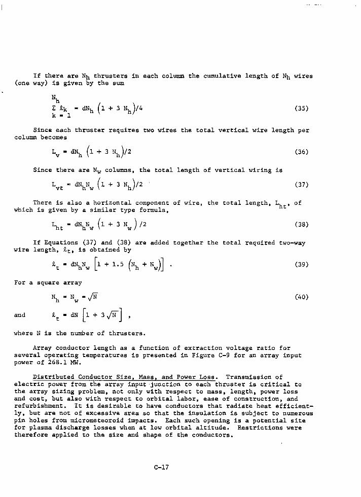
If there are Nh thrusters in each column the cumulative length of Nh wires (one way) is given by the sum
(35)
Since each thruster requires two wires the total vertical wire length per column becomes
Since there are Nw columns, the total length of vertical wiring is
Lvt m dNhNw (1 + 3 Nh)/2 .
(36)
(37)
There is also a horizontal component of wire, the total length, Lht' of which is given by a similar type formula,
(38)
If Equations (37) and (38) are added together the total required two-way wire length, tt, is obtained by
tt • dNhNw [1 + 1. 5 (Nh + Nw)] • (39)
For a square array
Nh • Nw • jN (40)
and tt • dN [ 1 + 3 JN J where N is the number of thrusters.
Array conductor length as a function of extraction voltage ratio for several operating temperatures is presented in Figure C-9 for an array input power of 268.1 MW.
Distributed Conductor Size, Mass, and Power Loss. Transmission of electric power from the array input junction to each thruster is critical to the array sizing problem, not only with respect to mass, length, power loss and cost, but also with respect to orbital labor, ease of construction, and refurbishment. It is desirable to have conductors that radiate heat efficiently, but are not of excessive area so that the insulation is subject to numerous pin holes from micrometeo.roid impacts. Each such opening is a potential site for plasma discharge losses when at low orbital altitude. Restrictions were therefore applied to the size and shape of the conductors.
C-17
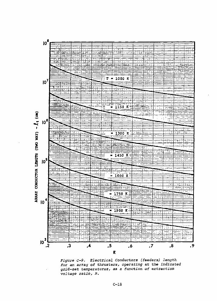
8 -
''·l -· -- -- - - -- - -
·- ~-. : ~ ;
~~:o_~_-:::: '-- -.. r-:_: :-: . . -~.:C:-~...:.-:-:::._:[:c.:.·-.:::::=;:.~===t==.:.:c -:------_.:_::::- - :_,__;__. --,E=.:_::. -=--· -b '°_':.:- ·=-::::.-=--~
7 1~~~~-~-~~~-1·r·~--~1~~g~~-~T~·~l~O~O~OgK~~=~1-~~1~~~~~~=r===~~ 10 ,___ ..• -r-- ·I- -+-- ~ - .... -
~ :i- -. :._:--_~ .:.t-.:=- :.-= .. ·- ,_·:-:.:-·- - -- - -----........
' l.. -·.:.·-=-~-- ~ ~~ :-...... . I .. ~-:.---=-r .- ... . I.
...c.=.... :.:···:.:.·:.;· ===.::.1 ·-+-
,...--· --1------
106 ~ ----~---r---~ ---~:-·:.
-~-L---------=-==----~•_.:._ ~ -· -··- -----_t_ ·-·-
=--:-:-------- -=-~ : : ··-· .: . :- ~ ;- .
: I '~ - : _, '-:- (· ·- ---~
:. c - I··_. ' -: ............
; r' . - . '--::;..:-.::._~
'~:: __ :;-..:. __ - :====·· ~--~ -'~~=·=;p:~;__:_;'::.,d·
f--.-. ->-
3 ------10 .2 .3
::=-:-.1=>-:=-::=:::t:===- >----
.4 .5
··-"
.6 .7 .8 R
Figure C-9. Electrical Conductors (feeders) length for an array of thrusters, operating at the indicated grid-set temperatures, as a function of extraction voltage ratio, R.
C-18
-.9
I
In a point design there are good reasons why cylindrical conductors might be preferred. For example, the conductor area exposed to meteor streams could be reduced by an order of magnitude. This is important with regard to the Kapton insulation which could deteriorate prematurely both thermally and electrically. Small "pinholes" can yield significant plasma discharge losses in LEO (Reference 6). The reduction in conductor area permits an associated increase in the Kapton mass density. Further, there is the possibility of heating the argon by piping it through the cylindrical conductors. This also tends to keep the conductors cooler and therefore yields more available electric power. However, time did not permit a completion of this analysis. For purposes .of this parametric study the conductors are assumed to be rectangular and shaded at all times.
A conducting strip with a width/thickness (m/n) ratio of 20 can be a reasonably good thermal radiator, and still retain structural integrity. A lower limit of 0.038 cm (15 mils) was placed on thickness. Strips of this size can be handled during construction or repair phases without excessive difficulties.
The power dissipated in a flat conductor is lost mostly by radiated heat. A layer of Kapton ).00254 cm thick (one mil) was used to improve the radiation efficiency and also for insulation to help prevent plasma discharges. Kapton has an emissivity, e, of approximately 0.68 which is an improvement on aluminum (0.05 to 0.11).
The maximum allowable wire temperature from electric power loss heating was assumed to be 373.16 K (100°C). A suIIllllary of the assumed conductor characteristics is given below:
T < 373.16 K maximum conductor temperature,
m • 20 n width of conductor,
A • mn • 0.05 mz cross section,
n > 0.0381 cm (15 mils) in thickness,
p • 2.70 g/cm3 density,
and for the electrical resistivity
YE • 2.828x10- 6 [l+0.0039 (T-293.16)] ohm-cm
• 3.7103Xl0-6 ohm-cm at 373.16 K
The thermal power radiated is given by
PH• 2~mea T4 + 2ineaT4 ,
• 2iea T4 (m + n)
where
C-19
(41)
The Stephan-Boltzman constant.
The thermal power radiated, PH, is balanced by the electrical power Pt lost, or dissipated, in the conductor. The power lost in a conductor of length i, with a voltage drop av and current I is
Equating the rhs's of Equations (41) and (42) yields
mn (m + n) a I 2yE/(2EOT4) • 0.0525 m3
,
and m • 9.5238 I 2yE/EOT4,
• 6.986xl0 6 I 2 [1+0.0039(T-293.16)]/T4
At the upper temperature limit (373.16 K)
m3 • 4.72696x10- 4 I 2, cm3
and m • 7.78982x10- 2 r 2 13 , cm
(42)
(43)
(44)
(45)
The total conductor mass Mc, of length it, which includes a 10 percent penalty for structural support is given by
Mc • 1.1 p.Ant • 1.1 pmnit
• l.485x10-4 m2 it, kg
the total power lost in the array wiring of length it is
5.656x10- 5 [l+0.0039(T-293.16)]it 2
Pit • m2
(46)
(47)
Equations (45 through (47) can be used to size the array conductors once the current I is known.
Solar Panel Bussbar Power. The required power. for the thruster array from the solar panels is
p • N(P' + P ) 0 o TH.
• N [r2yEi/ (mn) + JBVN/nEJ
where P' • conductor panel loss per thruster, 0
N • number of thrusters,
C-20
(48)
and i • it/N, average two-way conductor length from junction box
to each thr.us ter,
The net voltage drop, V0 , in the distributed wiring and thruster array is assumed to be
(49)
where conservation of current requires that
(50)
Equation (48) can therefore be written
(51)
The bussbar current for the entire array is therefore
(52)
Application to Electric Thruster Arrays. It is desired that the voltage VN at each thruster be fixed, for any given specific impulse, Isp• In order to keep the voltage, VN, at each thruster identical it will be assumed that the thrusters are connected in parallel, each with a properly designed "fuse" in case of a short circuit. The power losses, Pi in the distributed conductors are assumed to be identical for each thruster. In order to make a fair comparison of required wire mass and sizes the conductor width m is determined initially from Equation (45) under conditions where the current per thruster is at a maximum and therefore m is at a maximum. This occurs, assuming fixed total available power, when the array size is at a minimum (R • 0.9), and the gridset temperature, and therefore VT, are at the highest values to be considered [see Eqs. (1) and (2)].
Equation (47) is then used to determine total conductor power loss. This power loss Pit• is fixed thereafter in order to have a fair basis of comparison. Thus, as R is increased, m can be determined from the relation
(53)
which then leads to conductor mass.
Conductor masses are shown in Figure C-10. The increases in conductor mass are phenomenal with decreases in R and/or T.
For subsequent point design studies it was found beneficial to keep the ratio of Pit/Mc comparable to Mp1d/P0 where Mpld is the mass of the payload. In other words up to a point it pays to increase the array conductor mass, and thereby reduce the array electrical power loss. This increases thrust
C-21
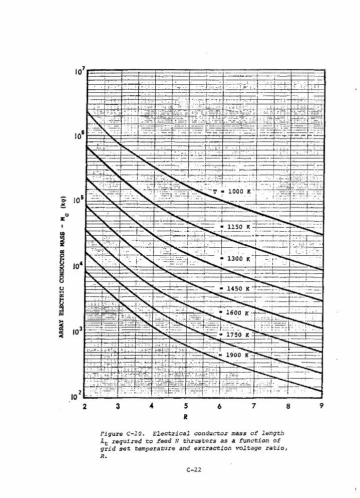
r."
' . : : : :· : :.:
.: i · . . • ·'. i , ·: : I · i
. ! '·· .·1.
' ' C-f •• :
·-".~.:_;,""-I .· ."""""- .J ., .. ·~ '·' ~-=-~·c '- . •_;::: .'>'-"-' __ , _ · -~-- -o __ .~0: L
, .... ...._- ,. . -.-c • 1450 K ..,.....- ~ - ·-
: ': _'-,... ':...... . .......... ' '~----;~ ·-~--4--,-~
102--·_--_· ___ -:_:~~_-~_i:_.-._:~_·:_:-.-----~--:.1.:__~--:-::_!: ___ -_-____ -~~~-::_· .. _1_:_:_1 ____ ........... _,
2 3 s R
6 7 8
Figure C-10. Electrical conductor mass of length ~t required to feed N thrusters as a function of grid set temperature and extraction voltage ratio, R.
C-22
9
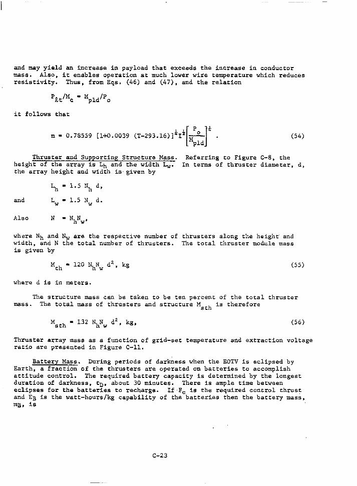
and may yield an increase in payload that exceeds the increase in conductor mass. Also, it enables operation at much lower wire temperature which reduces resistivity. Thus, from Eqs. (46) and (47), and the relation
it follows that
m • 0.78559 [l+0.0039 (T-293.16)]iii[Mpo ]k . pld
Referring to Figure C-8, the
(54)
Thruster and Supporting Structure Mass. height of the array is Lh and the width Lw· the array height and width is given by
In terms of thruster diameter, d,
~ • 1.5 Nh d,
and L • 1.5 N d.
Also N
w w
• N N • hw
where Nh and Nw are the respective number of thrusters along the height and width, and N the total number of thrusters. The total thruster module mass is given by
(SS)
where d is in meters.
mass. The structure mass can be taken to be ten percent of the total thruster
The total mass of thrusters and structure M h is therefore st
(56)
Thruster array mass as a function of grid-set temperature and extraction voltage ratio are presented in Figure C-ll.
Battery Mass. During periods of darkness when the EOTV is eclipsed by Earth, a fraction of the thrusters are operated on batteries to accomplish attitude control. The required battery capacity is determined by the longest duration of darkness, tn• about 30 minutes. There is ample time between eclipses for the batteries to recharge. If Fe is the required control thrust and En is the watt-hours/kg capability of the batteries then the battery mass, mB, is
C-23
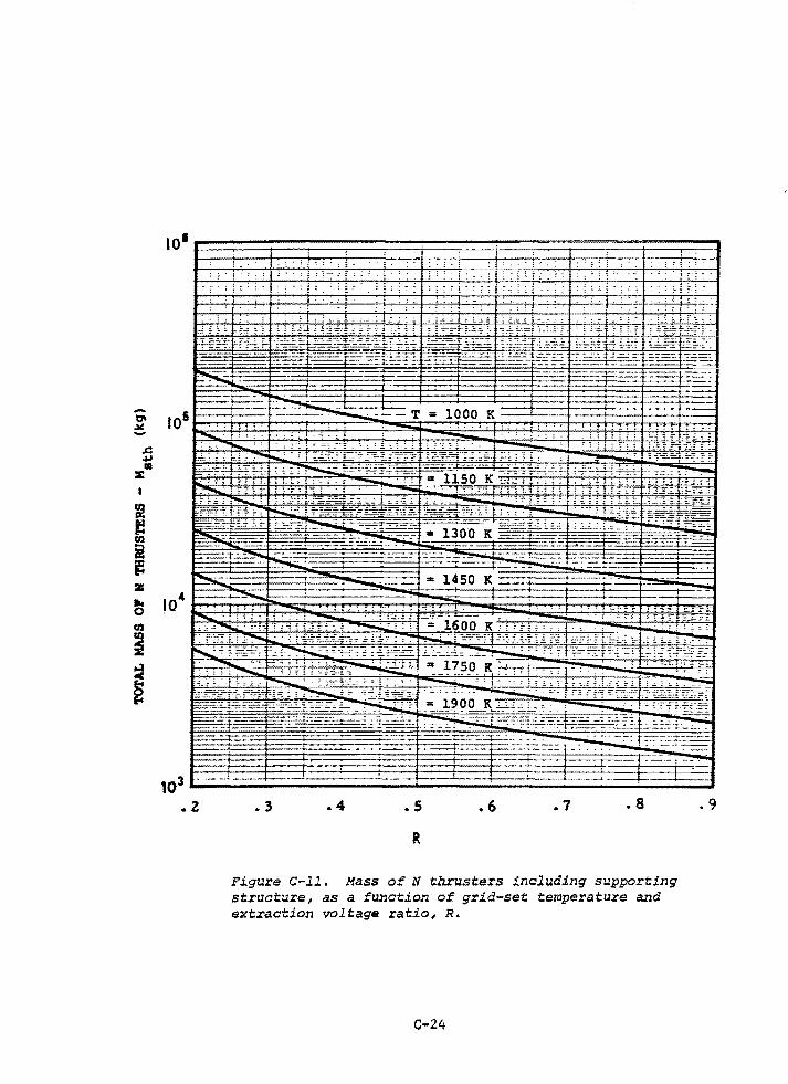
-"' .llC -J:: ,IJ llD
::E
&! t! CIJ
i ·~ lZ
~ fl.I
i :;j
~
104
103 t;..;;;;.;;;:.;:::::;:;;;::.::::::::::::::::::::::::;.;:;t::::::;::;::::;::::;:::.::::::::!::.::~==::!::.::::;:::::::;:J
.z • 3 .4 . s .6 .7 • 8
R
Figure c-11. Mass of N thrusters tnaluding supporting structure, as a fw:iction of grid-set temperature and extraction voltage ratio, R.
C-24
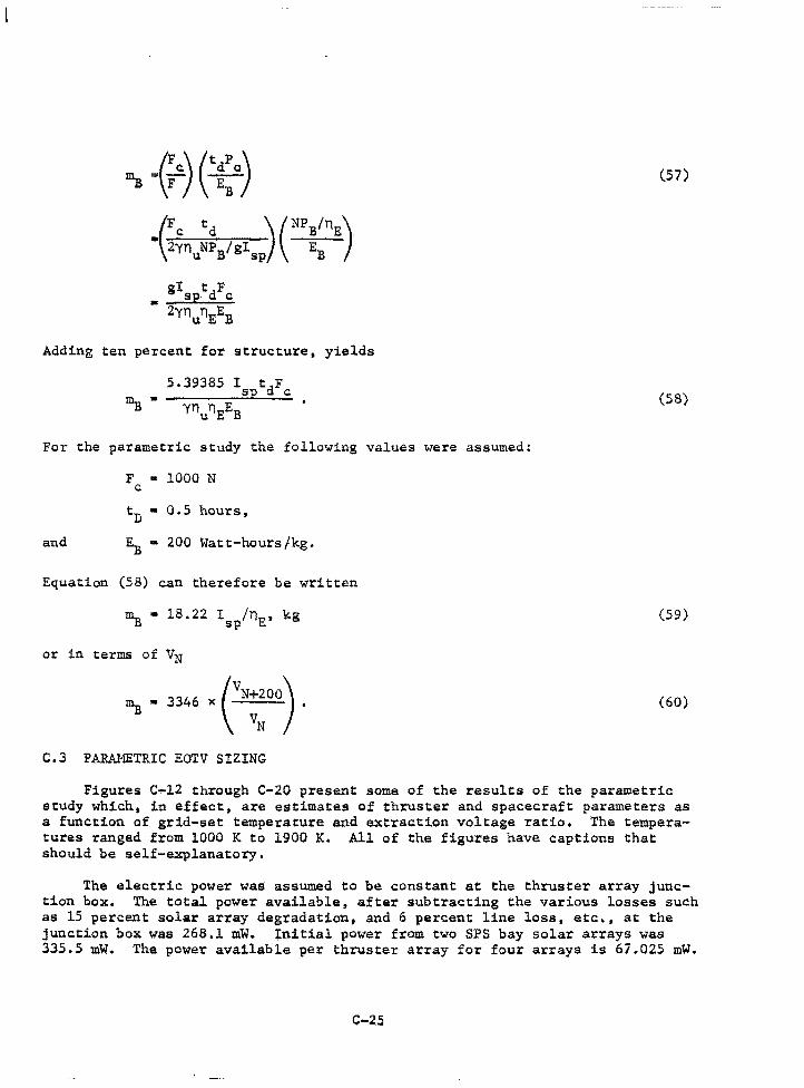
~ ·(.·) e~:o) -(:~nu:; BI sr.;) (NP ::"E)
• gI tdF sp c 2Y11ilEEB
Adding ten percent for structure, yields
5.39385 I tdF sp c
For the parametric study the following values were assumed:
F • 1000 N c
tD • 0.5 hours,
and EB • 200 Watt-hours/kg.
Equation (58) can therefore be written
or in terms of VN
~. 3346 x c~;00). C.3 PARAMETRIC EOTV SIZING
(57)
(58)
(59)
(60)
Figures c~12 through C-20 present some of the results of the parametric study which, in effect, are estimates of thruster and spacecraft parameters as a function of grid-set temperature and extraction voltage ratio. The temperatures ranged from 1000 K to 1900 K. All of the figures have captions that should be self-explanatory.
The electric power was assumed to be constant at the thruster array junction box. The total power available, after subtracting the various losses such as 15 percent solar array degradation, and 6 percent line loss, etc., at the junction box was 268.1 mW. Initial power from two SPS bay solar arrays was 335.5 mW. The power available per thruster array for four arrays is 67.025 mW.
C-25
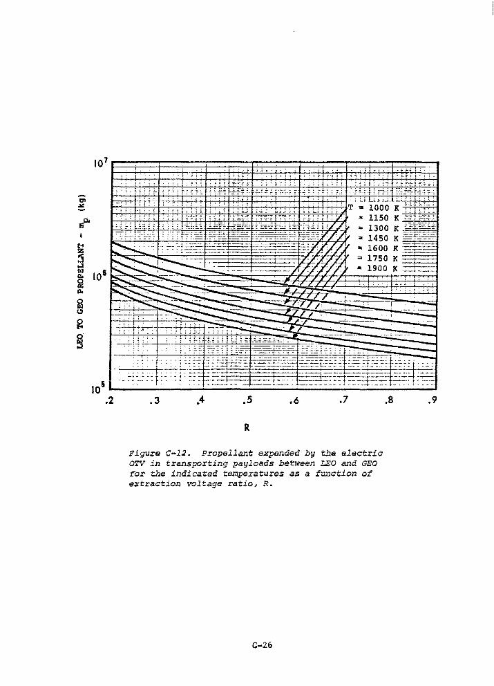
.--. ~ ~
~ I
~
~ ~ ~ ~
~ ~
2 ~
~
~
107
101
i
105 --------------------~----------------~-----------.2 .3 .s .6 .7
R
Figure c-12. Propella:nt expended by the electric OTV in transporting payloads between LEO and GEO for the indicated temperatures as a function of extraction voltage ratio, R.
C-26
.8 .9
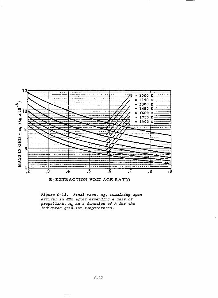
12
ia 0 tz:l 0 2S 6 Cll Cl)
< ::5 4
---"" -..... -- ---.._ -- -..... -- -- -- """ - --- --
I-"
--
f- · ..... 1~
I T .. 1000 K
I ~ "" 1150 K , ,, 1300 K , J == , ,, ,, 1450 , ,, -, .. K ., 1600 .. K
'"' 1750 K -~r, = 1900 K
#~ ~ Jlj ~ ---
f f I
I
'1'_,, , ,, ==r_ -' ~ ....!:: t---·~
r --,_ , -+----= - --- -·
.2 .3 .4 .5 .6 .7 .8
R-EXTRACTION VOU' AGE RATIO
Figure c-13. Final mass, mr, remaining upon arrival in GEO after expending a mass of propellant, mp as a funation of R for the indicated grid-set temperatures.
C-27
--
·----==--
-----:---
.9
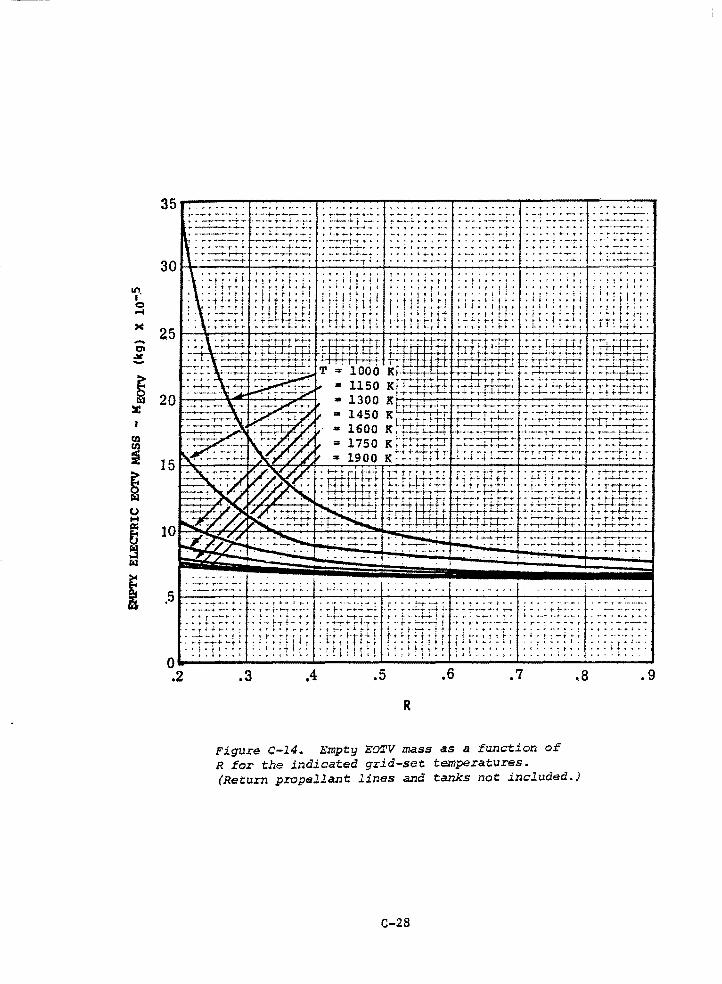
..... "' ,Jtl. -
... ; .... •· ~ ...... j ....... - ..
- •• t "'. t ....
....... ,. •• 'f" .. ,._ ~
.. ·-· ·-· .. -
••• ·-- .. - .. • - ·t .......... ... .. .... ., ... ------ • .. - • - .. -- - - f•
................ ~ • "',.-- ! .. ---; • • ...... ~ •.. +,.. • + •• - ....... _,,
. .. _,. __ ..... . ........... .
. ... ""' ·- ............... ,.. -.. ... .... .......... ·--t • :··4-- ~-?-•
........ ------· .
---··---•f'-t+· ...... t..~ ...... :, ... • ...... - ..... -·-·--·
,511---~.-.---.-~.-.~.+-.~.-.-,~.---.~ •. -.+-.~.---.-.---.-.. --~.-+--.-.--~.-'-+~-~~-.-+-.-.-.-.-.-.--~.-.~.+-.~.-.-.~.-.-.-.~.+-~.---.~".,....~--t ·----+.,_ ......... t,_T---r--·-• .... ;- ... -+...;._;. -!.- ...... -!.-.......-i.f· ... 7-·-- ... ·•'1""""'1 ;_,!.,..+-~··· --.1o~--·•·
>:.:t:~:-;·: :!.:~~t~:~ ;~-t;~-r;t :-~.t:·::_:_J; ::·;.:::.:L: :;:-::··::-:·: - r ~., _., ~ *,, · t •. r-· • t r-r rs.:-,. r +: • t- .. - ... t ~ ·.I,:.·.·.·,.·_!" ... · .. ~ ·- .. • ·:
., .. T ........ -~
• t ... -..- + ~ •
i I:::: :~:.:::.~! ;;t:r~11~ :tr;:-rt:~ f'!tr:t~t! ,1,.4-•:~·. ·•·t~-:-~~r :t:t:::~ ~::1!t: :~tit.~;! ·+·;~ti . ;:i···· .... :~:: o._ ____ _. ______ ....._ ____ ~.__ __ ..;.__,_ ______ ...._ ______ .__ ____ _.
.2 .3 .4 .5 .6 .7 .8
R
Figure c-14. Empty EOTV mass as a function of R for the indicated grid-set temperatures. (Return propellant lines and tanks not included.)
C-28
.9
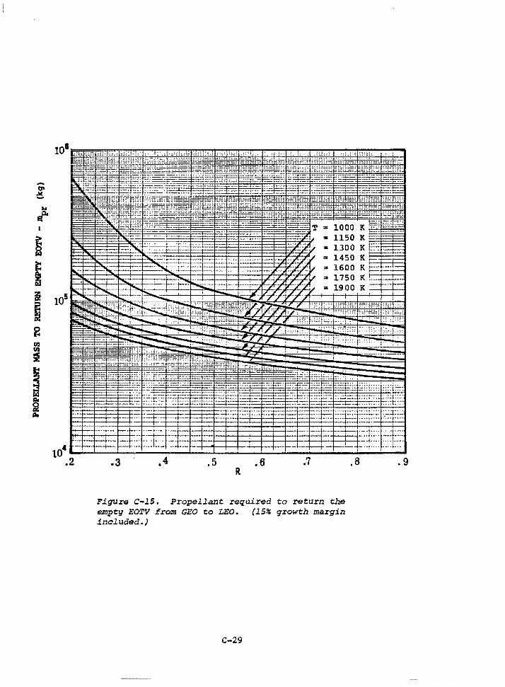
tp
~
... j'
~ w
i i
~ ~ en en ~
~ w
~ Do
105
104
.2 .3 .4 .5 .6 .7 R
Figure c-15. Propellant required to return the empty EOTV from GEO to LEO. (lS~ growth margin included.)
C-29
.8 .9
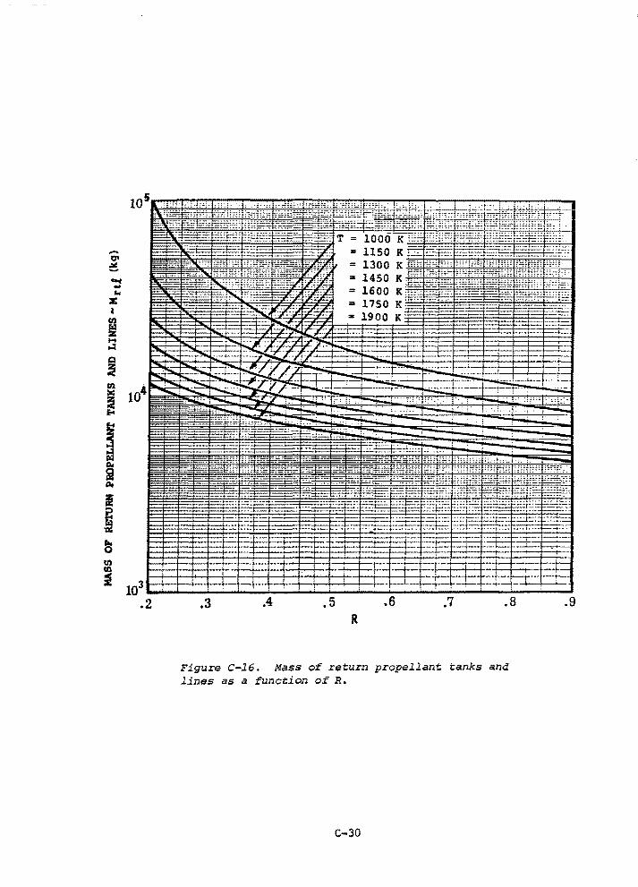
-O' ~ -c ... .. z ~
ti)
~ .... w Q
~ Ul 1111
~
~ ~
i Po
I
~ .. 0 Ul Ul
~ 103
.2 .3 .4 .5 .6 .7 .8 R
Figure c-16. Mass of return propellant tanks and lines as a function of R.
c-so
.9
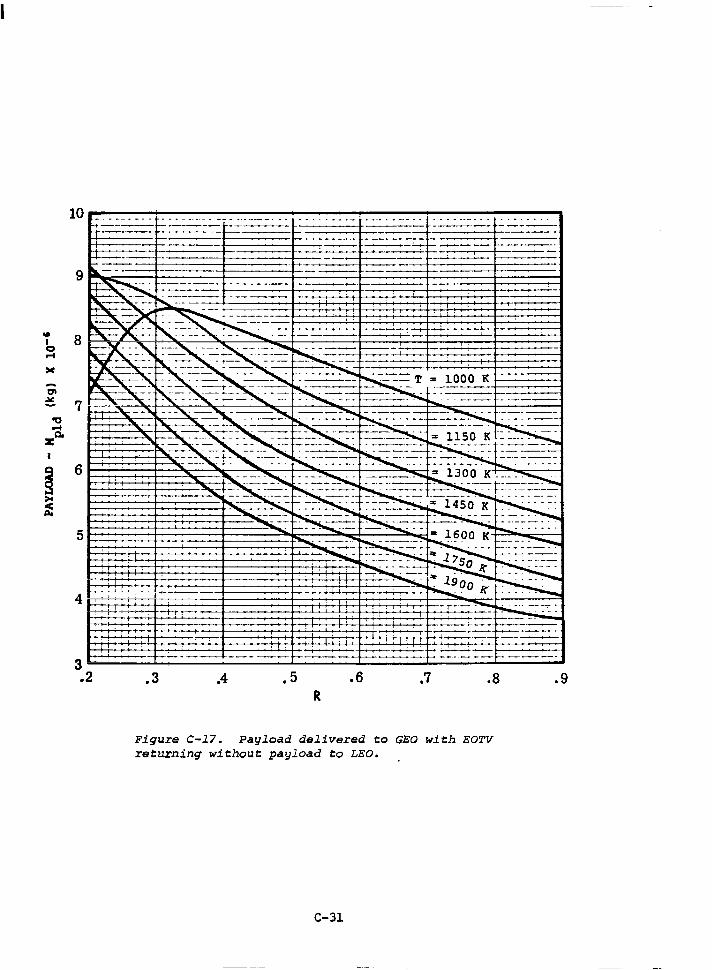
.. I 0 .... :IC
era ~ -
'O
'" a. z
~ >< f
9
8
7
6
5
3 .2
-----'---
.3 .4 • 5 .6 .7 .a R
Figure C-17. Payload delivered to GEO with EOTV returning without payload to LEO.
C-31
---~----
.9
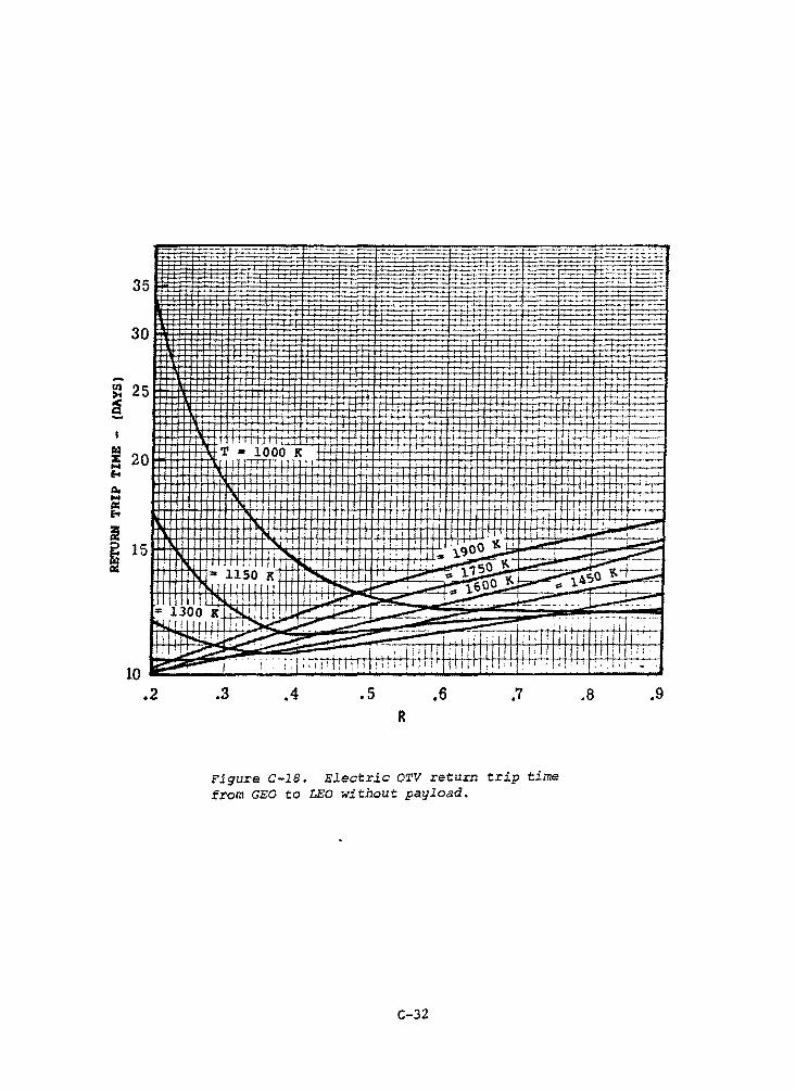
---·---- ~---i::_: -
Co ,.. ,i I I M:' ,1: ' II ·'I ,;' ;! ' i I I 1 I I " I I I I I
""' I I " I ' I . I I I . I ' i ' i' l 1 t l 1l If I f JI ! ! •I l I 1 ___..
~ • : ..... . I I ' ++ I l I ) I l l 1 '_'._'.. . , ~ r=:.oo "~ _!...j...!.. ....... ..._+4-+;;+'~, 1 i .,,:' ~ 1.900 ~...:. , __ __
- ii so K 1 --. 1 1 1
; : -~ · "" l.1 50 ~" 1 -=.-. ~50 +--::::; -111"\.JI 11111111 J 1 :1 I-._ ~i--" • ~ 1,.600-~;:: l.•~ ---!(jjll"\, .•. 11 I ii··~.,,,. •"" ..__- ·r· --·~
"'1300 Kl~~11;1 _,,,,... ~ - ~ ----·- ~ - ---· ~:_ .. ii4.L1r1 11111~ ..,,...... :.--- ----· ·;;;,·· -~ --
ll rr+-i-li·'~ ___.,,.,..-_ ---- ·--- 1 .. ;. •'l'I 111111 rll 1!11 r r 1 1 ~ ~ · · · · -- , 1 , 1 i r l r 1 T 111 ! 1 1 1 1 11 1 1111 11 : 1 : : : ·
10 -.2
... ~.i"'i~ ~1q:1111
.3 .4 .5 .6 .7 R
Figure C-18. Electric OTV return trip time from GEO to LEO without payload.
C-32
.8 .9
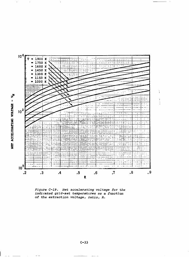
:l"' I
~
I i .... ~ f.iQ ..:I ra:i
~ Fa z
104 . T • 1900 K
• 1750 K -1600 K • 1450 • 1300 K • 1150 K
1000 K
103
IOz--.~~--~~~~~~--~~~~~~~~~~~~~--.2 .3 .4 .5 .6 .7
R
Figure C-19. Net accelerating voltage for the indicated grid-set temperatures as a function of the extraction voltage, ratio, R.
C-33
.8 ,9
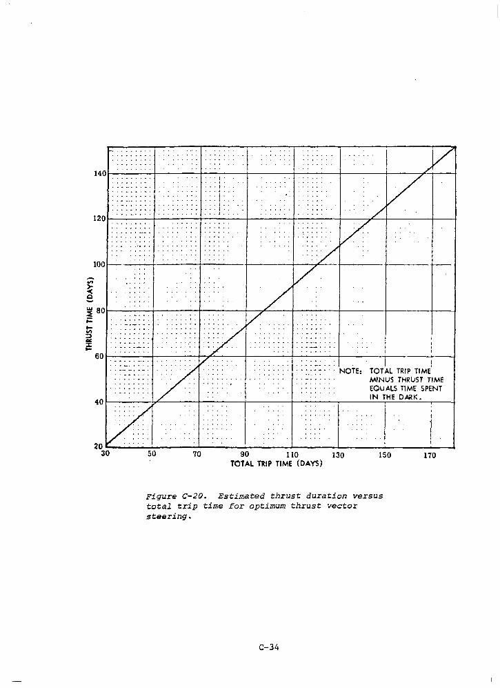
. .. . .... . . .
....... : I .. I .. . • t •
. . . . . . : : : i: : : . . . i . . ... I .. , •.I ..
120t-~~~-+~~~~-+-~~~-+~~~~-+-~~~~t--~--,;<.--+-~~~~+-~~
100
-"' ~ Q
~ 80t-~~~--+~~~~-+-~~~-+~~~~-+-~~~~+--~~~-+~~~~+-~-4
;: .... "' :J -= ::c .... 601--~~~-+~~~~-+-~~~-+~~~~-+-~~~~+--~~~-+~~~~~~~
I ! · · ~.::: · · · NOTE: TOT AL TRIP TIME
MINUS THRUST TIME EQUALS TIME SPENT IN THE DARK.
40t--~~~-J,~~~~+-~~~--+~~~~-+-~~~~.--~~~-....~~~~....-~-i
50 70 90 110 130 150 TOTAL TRIP TIME (DAYS)
Figure C-20. Estimated thrust duration versus total trip time for optimum thrust vector steering.
C-34
170
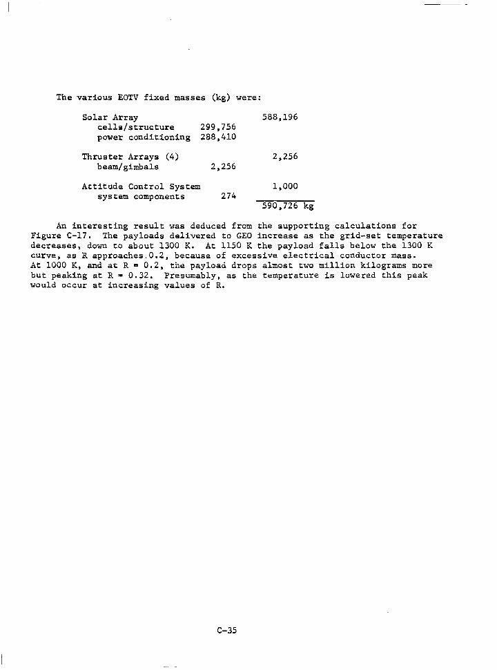
The various EOTV fixed masses (kg) were:
Solar Array 588,196 cells/structure 299,756 power conditioning 288,410
Thruster Arrays (4) 2,256 beam/ gimbals 2,256
Attitude Control System l,000 system components 274
590. 726 kg
An interesting result was deduced from the supporting calculations for Figure C-17. The payloads delivered to GEO increase as the grid-set temperature decreases, down to about 1300 K. At 1150 K the payload falls below the 1300 K curve, as R approaches.0.2, because of excessive electrical conductor mass. At 1000 K, and at R = 0.2, the payload drops almost two million kilograms more but peaking at R • 0.32. Presumably, as the temperature is lowered this peak would occur at increasing values of R.
C-35
REFERENCES
1. Electron Bombardment Propulsion System Characteristics for Large Space Systems, D. C. Byers and v. K. Rawlin, LRC, NASA TM.X-73554
2. Scaling Relationships for Mercury and Gaseous Propellant Ion Thrusters, P. J. Wilbur and H. R. Kaurman, Colorado State University
3. A 30 cm Diameter Argon Ion Source, J. S. Sovey, LRC, NASA TMX-73509
~. The Creep of Molybdenum, H. Carvalhinhos and B. B. Argent, Journal of the Institute of Metals, Vol. 95, 1967, pp. 364-368
5. Short-Time Creep-Rupture Behavior of Molybdenum at High Temperatures, W. v. Green, M. C. Smith and D. M. Olson, Transactions of the Metallurgical Society of AIME, Vol. 215, 1959. pp. 1061-1066
C-36
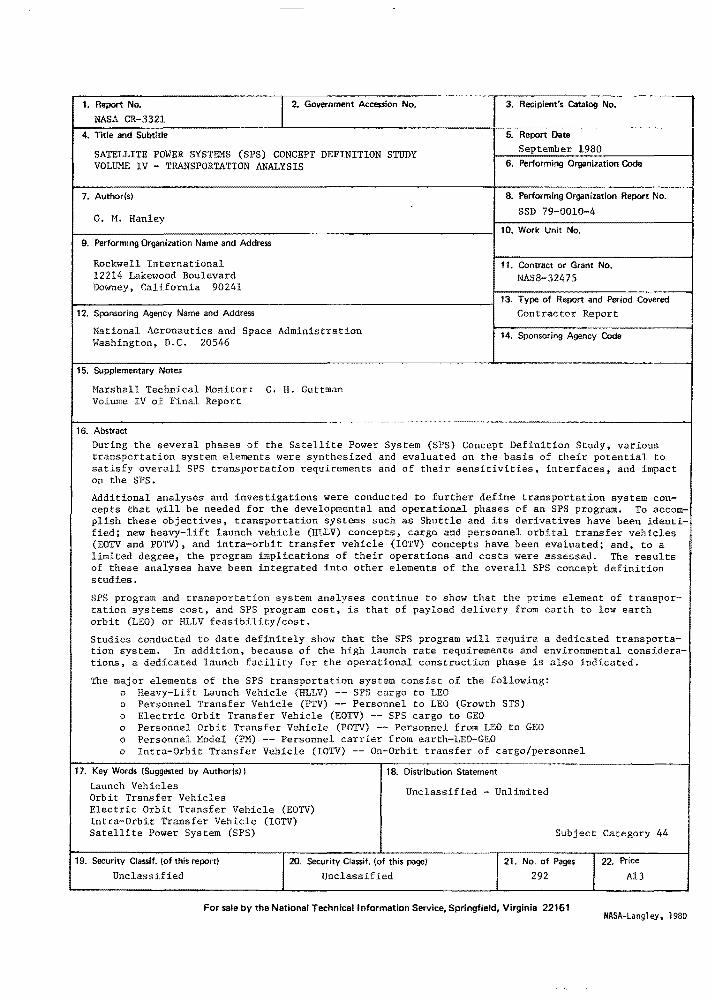
l--1_._N_RAS_epo-Art_cN_:_~_3_3_2_l __________ ~l_2_._G_o_v_e_r~-m_e_n_t_A ___ cc_ess_-_-io-n~N-o-.~~~~~~=*~3-·~-R-···-ec-i-pi-e~nt~. Catalog N:~.~--- I 4. Title and Subtitle 5. Report Date
September 1980 SATELLITE POWER SYSTEMS (SPS) CONCEPT DEFINITION STUDY VOLUME IV - TRANSPORTATION ANALYSIS 6. Performing Organization Code
7. Author(s)
G. M. Hanley
9. Performing Organization Name and Address
Rockwell International 12214 Lakewood Boulevard Downey, California 90241
8. Performing Organization Report No.
SSD 79-0010-4
10. Work Unit No.
11. Contract or Grant No. NASS-32475
!--------------------------------------; 13. Type of Report and Period Covered 12. Sponsoring Agency Name and Address Contractor Report
National Aeronautics and Space Administration Washington, D.C. 20546
14. Sponsoring Agency Code
15. Supplementary Notes
Marshall Technical Monitor: C. H. Guttman Volume IV of Final Report
16. Abstract
During the several phases of the Satellite Power System (SPS) Concept Definition Study, various transportation system elements were synthesized and evaluated on the basis of their potential to satisfy overall SPS transportation requirements and of their sensitivities, interfaces, and impact on the SPS.
Additional and investigations were conducted to further define transportation system con-cepts that needed for the developmental and operational phases of an SPS program. To accom-plish these objectives, transportation systems such as Shuttle and its derivatives have been identified; new heavy-lift launch vehicle (HLLV) concepts, cargo and personnel orbital transfer vehicles (EOTV and POTV), and intra-orbit transfer vehicle (IOTV) concepts have been evaluated; and, to a limited degree, the program implications of their operations and costs were assessed. The results of these analyses have been integrated into other elements of the overall SPS concep.t definition studies.
SPS program and transportation system analyses continue to show that the prime element of transportation systems cost, and SPS program cost, is that of payload delivery from earth to low earth orbit (LEO) or HLLV feasibility/cost.
Studies conducted to date definitely show that the SPS program will require a dedicated transportation system. In addition, because of the high launch rate requirements and environmental considerations, a dedicated launch facility for the operational construction phase is also indicated.
The major elements of the SPS transportation system consist of the following: o Heavy-Lift Launch Vehicle (HLLV) -- SPS cargo to LEO o Personnel Transfer Vehicle (PTV) -- Personnel to LEO (Growth STS) o Electric Orbit Transfer Vehicle (EOTV) -- SPS cargo to GEO o Personnel Orbit Transfer Vehicle (POTV) -- Personnel from LEO to GEO o Personnel Model (PM} -- Personnel carrier from earth-LEO-GEO o Intra-Orbit Transfer Vehicle (IOTV) -- On-Orbit transfer of cargo/personnel
17. Key Words (Suggested by Author(s))
Launch Vehicles Orbit Transfer Vehicles
18. Distribution Statement
Unclassified - Unlimited
Electric Orbit Transfer Vehicle (EOTV) Intra-Orbit Transfer Vehicle (IOTV} Satellite Power System (SPS) Subject Category 44
19. Security Classif. (of this report)
Unclassified Security Classif. (of this page)
Unclassified 21. No. of Pages
292
For sale by the National Technical Information Service, Springfield, Virginie 22161
122. Price
Al3
NASA-Langley, 1980
Related Documents