NASA CONTRACTOR REPORT 177440 Reduced Complexity Structural Modeling for Automated Airframe Synthesis Prabhat Hajela Department of Engineering Sciences University of Florida Gainesville, Florida Prepared for Ames Research Center under Contract NCA2-IR240-401 May 1987 National Aeronautics and Space Administration Ames Research Center Moffett F_etd. California 94035 https://ntrs.nasa.gov/search.jsp?R=19880003071 2020-03-20T08:38:06+00:00Z

Welcome message from author
This document is posted to help you gain knowledge. Please leave a comment to let me know what you think about it! Share it to your friends and learn new things together.
Transcript
NASA CONTRACTOR REPORT 177440
Reduced Complexity Structural Modeling
for Automated Airframe Synthesis
Prabhat Hajela
Department of Engineering Sciences
University of Florida
Gainesville, Florida
Prepared forAmes Research Center
under Contract NCA2-IR240-401
May 1987
National Aeronautics and
Space Administration
Ames Research CenterMoffett F_etd. California 94035
https://ntrs.nasa.gov/search.jsp?R=19880003071 2020-03-20T08:38:06+00:00Z


ABSTRACT
The present report documents a procedure for the optimum sizing of wingstructures that is based on representing the built-up finite element assemblyof the structure by equivalent beam models. The reduced-order beam models arecomputationally less demanding in an optimum design environment which dictatesrepetitive analysis of several trial designs, The design procedure is imple-mented in a computer program that requires geometry and loading informatlon to
create the wing finite element model and its equivalent beam model, and
provides a rapid estimate of the optimum weight obtained from a fully stressed
design approach applied to the beam. The synthesis procedure is demonstrated
for representative conventional-cantilever and joined wing configurations.
INTRODUCTION
Automated design synthesis programs provide a significant capability forassessing new concepts in aircraft design. Such concepts invariably entail a
multidisciplinary synthesis environment that is characterized by complex
analysis codes for various participating disciplines. Since optimum designinvolves repetitive analysis, the computational costs can be signficant,
particularly if no effort is made to substitute approximating strategies inlieu of more detailed analyses. The optimum synthesis scenario for the
present work resulted from studies directed at the optimum weight evaluation
of the joined wing. The joined wing (Ref. l) is a general concept that seeksaerodynamic and structural advantages by replacing the horizontal tail in a
conventional airplane design by a forward swept wing that is joined to thefront wing at the tip. The resulting truss-like structure is claimed to have
higher stiffness and a significant potential for structural weight savings.References 2 and 3 document the results of studies that primarily examined the
sensitivity of key geometric parameters on the optimum weight of the joined
wing design. In both of these studies, a finite element analysis capabilitywas employed in conjunction with a nonlinear programming based optimization
algorithm to determine the mathematical optima. The computational require-ments for these solutions were substantial, thereby precluding other combina-
tions of geometric parameters from consideration. Although these studies were
successful in establishing preliminary trends of the optimum weight, theapproach of using detailed finite element models with mathematical programming
based optimization algorithms was considered inappropriate for a more detailed
study. Such a detailed multidisciplinary synthesis study would includeoptimization for aerodynamics and stability/control in addition to thestructural performance.
The purpose of this study was to formulate a procedure for optimum
structural design with limitations on computational requirements enforced by amultidisciplinary design environment. The strategy adopted for this task was
to replace the built-up finite element model of the wing structure by a lowerorder beam framework model that would simulate the strength and stiffness
characteristics of the former with a minimum loss in accuracy. Subsequent
sections of this report describe the approach in greater detail, including its
numerical implementation into a synthesis program. An annotated listing of
the fortran programs and the related data files can be obtained as an appendixto this report.

THEORETICALBACKGROUNO
The configuration of an automated synthesis procedure requires carefulconsideration in the selection of the analysis and optimization capabili-ties. These programsmust incorporate approximating strategies to reduce theoverall computational effort and at the sametime must retain any peculiarcharacteristics of the problem. This is particularly true in the case of the
joined wing which has rather unique displacement and stiffness characteris-
tics. The present section develops the theoretical concepts that form thebasis for the design strategy proposed in this report.
Joined Win_ Structural Analysis
The joined wing configuration results in a stiff load carrying structurewhich has been shown to yield lower weights than the conventional wing-tail
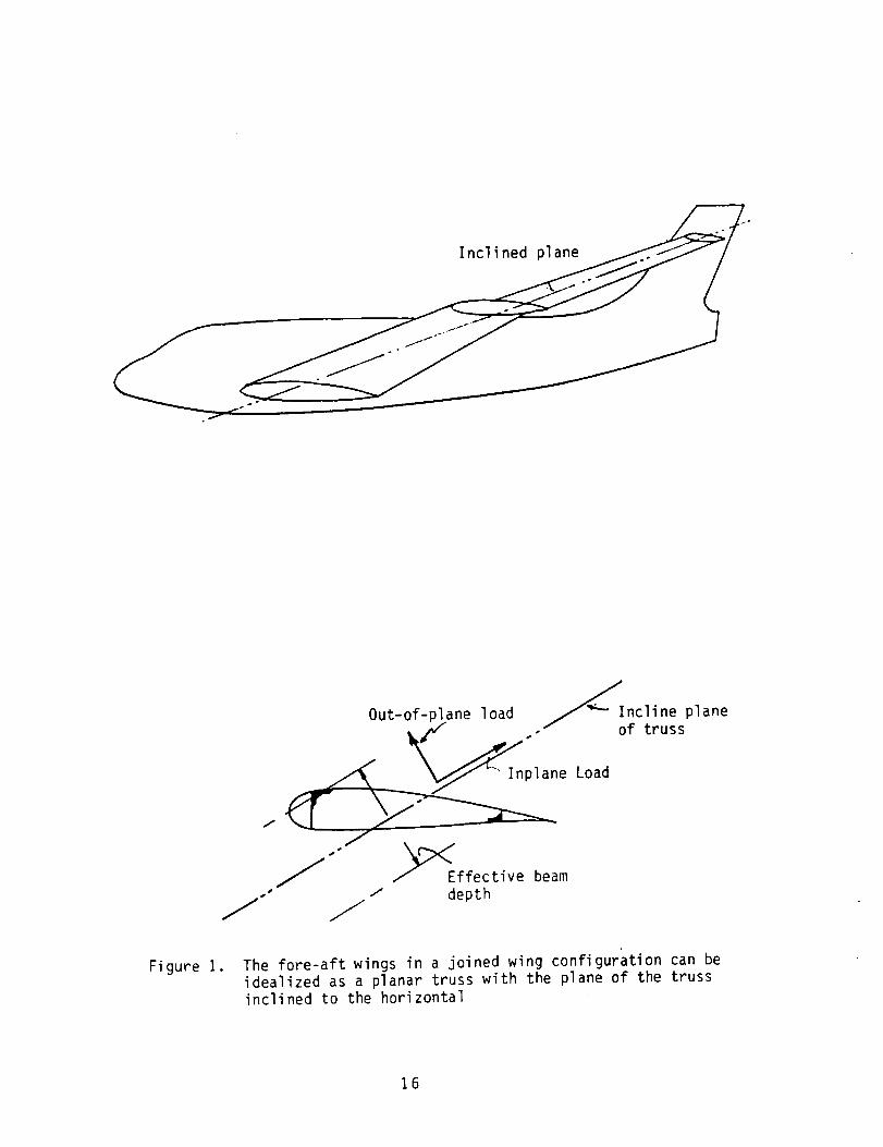
design. The potential for weight reduction is most simply explained by a'tilted-truss' visualization of the fore-aft wing combination as seen in
Figure I. The front and aft wings form a truss with the primary load carryingplane inclined to the horizontal by an angle which is determined by the
dihedral angle of the wings. The aerodynamic loads can be resolved into the
inplane and out-of-plane components, The load component perpendicular to theplane of the truss tends to concentrate material on the upper surface of the
leading edge and the lower surface on the trailing edge of the wings. Theeffective beam depth is thus determined by the chord length as opposed to the
thickness profile for conventional wings.
The structural joint between the front and aft wings is also critical in
determining the optimum weight of a configuration. It is an area of stressconcentration and its own rigidity in bending and torsion determines thematerial distribution on the front and aft wings. Furthermore, the location
of the joint along the span also influences the structural weight and the
optimal material distribution. The formulation of a mathematical design model
should therefore give special consideration to these characteristics.
Win9 Finite Element Modelin_
The finite element models for the conventional and joined wing
configurations studied in this effort were built-up models with axial rod
elements and quadrilateral membrane elements. The plan view and a typicalcross section are shown in Figures 2 and 3, Such a single cell representation
is considered appropriate in the preliminary design studies for which themodel is intended. The consistency of the design and analysis models is also
an important consideration in this exercise. At least two chordwise panelsare essential in the design model to allow for unsymmetrical distribution of
material that is predicted by the tilted bending-axis hypothesis. For an
improvement in the stress and displacement results, the analysis model can
have any even number of panels in the chordwise direction. The number of
spanwise stations is at the discretion of the user and is generally selectedto keep the panel aspect ratio close to unity. Ribs, modeled by quadrilateralmembrane elements were added to the built-up structure at a specified number
of locations.
The joint between the front and aft wings was modeled by a framework of

beamelements as shownin Figure 4. The beamsectional properties wereassigned numerical values to generate a structure that was extremely rigid inextension, bending and twisting deformations. The aerodynamic loads arespecified as an array of forces at the leading and trailing edges of thestructure. A unique feature of this study is the automated generation of thefinite element model and will be discussed in a later section.
Beam Representation of Win 9 Models
A typical finite element model of a joined wing with a relatively coarse
mesh has more than seven hundred degrees of freedom. Repetitive analysis inan optimization exercise with such a large model is prohibitive from a
computational standpoint. The approach adopted in the present work replaces
the detailed built-up models by equivalent beam models in the design loop.
A cantilever beam has deflection and stiffness characteristics that are
very similar to a conventional cantilevered wing. The wing can be regarded asa tapered plate with one end built-in and the other free. The deflection of
this plate in its primary bending mode can be represented by a canti|ever beamwith appropriately matched moment of inertia characteristics, An exact valueof the wing moment of inertia cannot be used for the beam as it would result
in an artificially stiff structure. This difference is attributed to the
phenomenon of shear |ag. If one considers the upper and lower surfaces of the
wing model as flange elements, shear lag is the description of the state in
which the flange strains decrease asymptotically when moving away from the web
section. Hence, the bending stiffness computed using the full width of theflange for the moment of inertia would result in a conservative estimate. A
reduced flange width should be used and this is dependent on the geometry ofthe web and flange, wing span, boundary conditions and the bending load
distribution. The beam should therefore have a moment of inertia equal to
that of the wing mulitplied by a reduction factor to account for wide flange
effects. In the present exercise, this factor was computed numerically by aprocess of matching the response of the built-up model to the simplified beammodel.
The cross sectional properties of the wing that are represented on the
equivalent beam model are the moments of inertia Ixx and I.., the product ofinertia Ixv , and the torsional constant J (see Figure 4). _he volume of the
material p_r unit length of the wing span is introduced as an additional
variable to establish a weight relation between the beam and wing models. The
torsional constant j is computed for a thin-walled closed section by the Bredtformula (Ref. 4)
j - 4A2ds (I)
t
The product of inertia term is essential to accomodate the unsymmetrical
bending that is present in conventional swept wings and the joined wing
configurations. The beam cross section to which these sectional propertiesare attributed is shown in Figure 5. The five sectional properties described
above can be expressed in terms of an equal number of independent wallthicknesses of the cross section. The choice of this cross section was
primarily dictated by the anticipated unsymmetrical material distribution in
the design of the joined wing. The wall thicknesses, updated during the
design process, can result in either a symmetrical or an unsymmetrical cross

section.
The deflections of the equivalent beamstructure under the applied loadswere computedfrom a finite element program. The specification of a specialbeamcross section precluded the computation of element stresses in the samefinite element program. These stresses are required for the strength sizingof the beam and were computed in a post-processing prograln using the following
unsymmetrical bending stress relatioship (Ref. 5)
= _ (Mzlyy + Mylyz_y MXI + M I z)°xx .- [ + C zz z
lyy_zz- yz lyylzz" lYz
z (2)
Here MV and Mz are the bending moments about the y and z axes, respectively.The distances y and z are measured in a centroidal axes system shown in Fig-
ure 6, The bending moments My and Mz are computed from the moment-curvaturerelations
d2w (3)
My : - Ely
d2v (4)Mz = - Elz
where v and w are the deflections in the y and z directions, respectively.
The curvatures in equations (3) and (4) were obtained from the displacement
field by a central finite difference approximation (see Fig. 7)
dx2d2wli : (Wi+l" 2wi + wi-1)/(ax)2C5)
d2v I (Vi+l - 2vi + Vi-l)/(Ax)2dx 2 i(6)
for the station at the root, the boundary conditions at a fixed support can be
invoked to obtain the approximation
w.l = w1
V_l = vI
(7)
To obtain better approximations for the second order derivatives described
above, the step size ax was reduced by increasing the number of nodes in thebeam model. The same effect can also be achieved by using an interpolated
4
polynomial obtained from the displacement corresponding to a coarser gridmodel. An approach such as the present one allows the specification of anarbitrary cross section and can be used in conjunction with any finite elementdisplacement analysis program. It can also be used with a displacement fieldobtained from a classical Galerkin or a Rayleigh Ritz type solution.
Optimum Sturctural Design
There are several options available to size the wing and the equivalent
beam structures for minimum weight and a prescribed structural strength. The
general mathematical problem statement for this problem can be written as
Minimize W(d) (8)
Subject to gj(_) ( 0
and d_1 < di ( diU
j : 1,2,...m (9)
i = 1,2,.,.n (i0)
Here W is typically the structural weight; _ is a vector of design _ariab1_swith prescribed lower and upper bounds on its components given as dT and di,respectively. The inequality constraints gi can be used to prescribe boundson strength and nodal displacements. This _pproach can be integrated into the
present design strategy with minor modifications but is computationally
demanding in the presence of a large number of design variables and con-
straints, An alternative strategy referred to as the fully-stressed design
approach was implemented instead. This approach is based on the hypothesisthat a strength governed design is optimal when all elements are stressed to
their maximum permissible limits. The assumption is va]id for singly loaded
structures that do not have multiple load paths (Ref. 6). The built-up wing
finite element model is a redundant structure and cannot be strictly consid-ered as optimum in the fully stressed state. The beam model, however, is
considered a good candidate for the fully stressed design philosophy. Inprevious work it has been shown that the fully stressed design strategy
provides a good first estimate of the optimum weight for even mildly redundantstructures.
A stress ratio algorithm was implemented in the present work where the
i-th wall thickness at the j+1-th iteration is given by
j+, jti = ti °alI
(11)
The allowable strengths in compression and tension are taken to be equal in
the above approach. Bending stresses were recovered frm_ six locations on thecross section and these are labeled one to six in Figure 5. The vertical
sections I-6 and 3-4 were kept equal in the design process. This equality wasenforced after each thickness had been obtained independently from equa-
tion II, with the greater value of thickness assigned to the two sections.Each element was sized on the basis of the maximum stress on the element. In
the present exercise the stresses are recovered at six locations with each
location corresponding to an extremity for an element, More stress recovery

points can be introduced with an insignificant addition in computational time.
Convergence in the stress ratio algorithm is very rapid in the initial
stages of the design. When approaching close to the optimum, the designiterations illustrate a 'tail-like' characteristic. Approaches which combine
a gradient based search algorithm with such a stress ratio approach have beenproposed and will be examined in future work. The other drawback in thisapproach is the lack of constraints to limit the displacements at nodal
locations. This can be circumvented by following up the stress ratio sizing
by a redesign based on the energy level in each element with the objective of
forcing the element energies to comparable values for all elements in theStructure.
COMPUTER IMPLEMENTATION
A stated objective of the present work was to generate an automated
synthesis procedure for airframe structures suitable for adaptation in a
multidisciplinary design environment. In particular, the program was tointeract with aerodynamic design codes that were in turn driven by external
optimization programs. Thus, the generation of the wing finite element model,
its reduction to an equivalent beam mode] and the subsequent optimum design of
the beam had to be completely automated. _ngineering Analysis __Language (EAL,see Ref. 7) was used for all structural analysis in the present task. The
fortran programs that automatically generate runstreams for various segments
of the program are currently written for EAL. However, these programs can be
adapted for other finite element environments with minor modifications. The
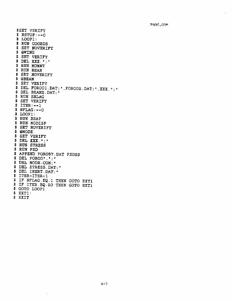
organization and execution of these program is controlled in the CommandLanguage feature on DEC systems. A flowchart depicting the order of execution
is shown in Figure 8. The primary function of each module is discussed next
and the corresponding input/output requirements are detailed in the _ppendix.
COORDS:
This program provides an automated finite element modeling capability forconventional and joined wings. The user provides input information pertaining
to the type of structure, semi-span, root and tip chords, thickness ratio,
I/4-chord sweep and the dihedral angle. Additional information is alsoprovided on the number of chordwise and spanwise stations, sizes of elements,
and the number of ribs in the model. The program then generates a finiteelement model of the structural box using axial rod elements for stringers and
quadrilateral membrane elements for the plate sections. This model includes
complete description of nodal co-ordinates, element connectivity anddistribution of nodal loads. In its present form, this information is
available as an EAL input runstream. Suitable modifications of format
statements can adapt this program for other finite element codes. The program
additionally generates data files that provide input data for programs
executed later in the optimization sequence. In particular, these files
transfer information related to wing geometry, loads, cross sectional geometryand element sizes.
MOMNT:
The cross sectional properties of the wing finite element model are
computedin this program. At each of the span stations specified by the user,the sectional momentsand products of inertia, torsional constant and mass perunit span are computedand data files generated to transfer this informationto a programwhich generates an equivalent beammodel with the samesectionalproperties.
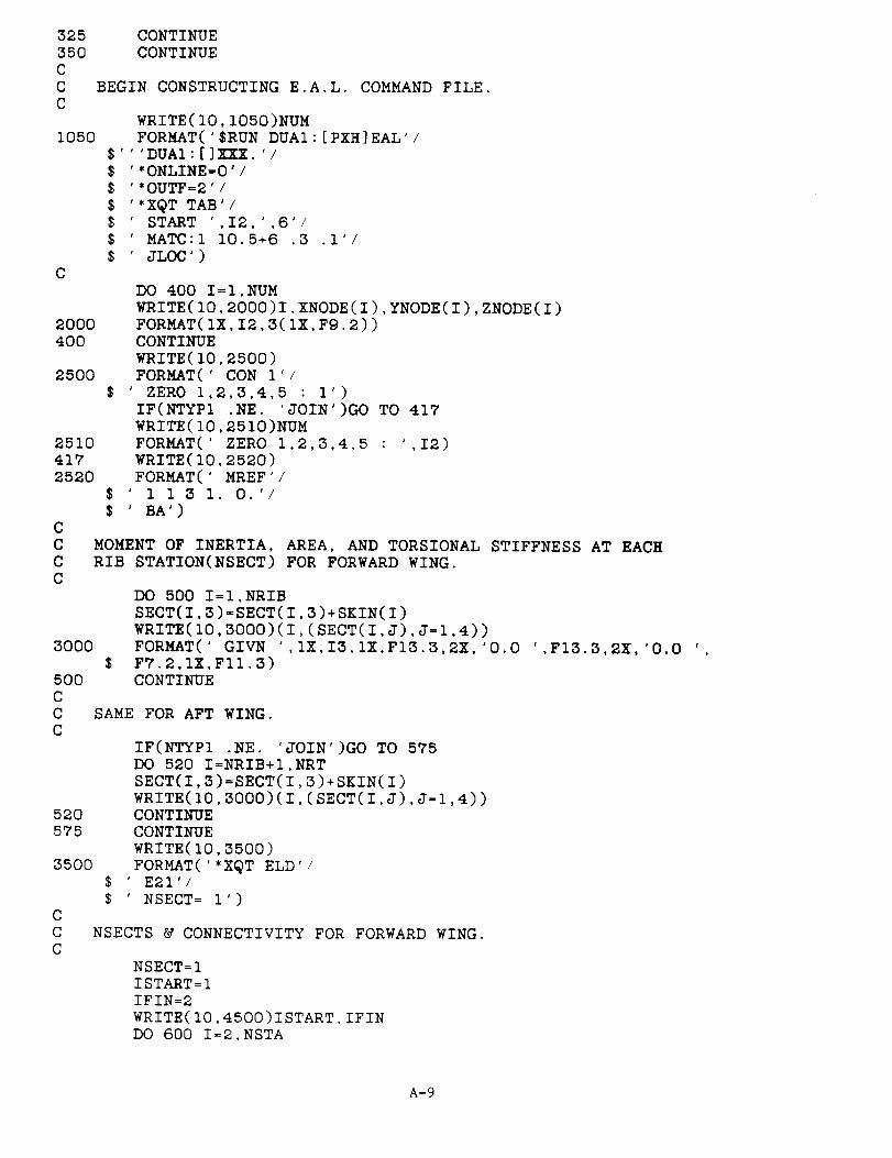
BEAM:
For the built-up finite element model of the wing created in programCOORDS, this program creates an equivalent finite element model with beam
elements located at the wing elastic axis. For a conventional wing, the
equivalent model is a cantilevered beam with section properties equal to those
obtained from MOMNT. The number of beam elements used in modeling thisequivalent beam is identical to the number of spanwise stations entered in
COORDS. The modeling is similar for the joined wing configuration with the
exception that there is an equivalent beam for each of the front and aft wingsand the joint between the beams is simply modeled as a common node. The two
equivalent beams are built-in at the root and permit the joint to be located
arbitrarily along the span. Element connectivity, load specifications andother execution runstream are in context of EAL but can be modified for other
finite element programs.
SHLAG:
This program is used to provide the correction required in the wingsectional properties before they are transferred to the beam model. The
moment of inertia about the primary bending axis of the wing would result in a
stiffer beam because of shear lag effects. This program reads the maximum
displacements, W, of the wing and beam models and defines a constant 'p'where
(Wmax)beam (El)wing
P : Ot
(Wmax)wing (El)beam
The chord on the beam and wing structural box were kept the same and the
height of the beam section was changed to account for the shear lag effects.If the moment of inertia corresponding to the thin sidewalls in the beam is
neglected, the bending rigidity is proportional to the square of the depth, d
(El)- d2
dwing C p dbeam
Numerical evaluation with test cases shows this to be a reasonable assump-
tion. The effect of wing sweep and dihedral was also incorporated in thisprogram.
BSAP:
The section properties of a general beam section with five independentwall thicknesses as shown in Figure 5 are computed in this program. All
section properties are computed about a centroida] axis which is also computed
in this segment. Since the finite element program EALneeds section proper-ties about the principal axes system for a section, additional computationsare necessary to transform centroidal properties to principal axes proper-ties. The orientation of the principal axes system with respect to the globalaxes system is necessary to complete element coordinate axes definitions andwas therefore computedin this program. In addition, the location of the sixstress recovery points in terms of y-z coordinates changewith each iterationand were computedhere.
MODISP :
This program is identical to BEAM except that it is configured to double
the number of elements from the previous beam finite element model. This was
necessary to increase the number of nodal points at which the displacements
were computed so as to enhance the quality of the finite difference approxi-mations for curvature. The section properties for each element were trans-
ferred from the BSAP program and used here to create an EAL runstream for the
equivalent beam.
STRESS:
The bending stresses necessary in the resizing algorithm were computed in
this program. The beam displacements are read in from a data file and used tocompute the curvatures and hence also the components of the sectional bending
moment. At the stress recovery points obtained in BSAP, the stresses were
computed using equation 2. These stresses were placed in an output file to be
accessed by the design optimization program.
FSD :
This is the computer implementation of the fully stressed design strategydiscussed in an earlier section. The wall thicknesses of each element are
transferred to this program as are the stresses computed in program STRESS.
The stress ratio algorithm (Eq. 11) is used to resize the wall thicknessesbased upon the most recently computed stresses and a user specified allowable
stress. The weight computed in three consecutive passes of the sizing
algorithm is used to terminate the optimization iterations based upon a userspecified value for the relative change in the weight.
In the sizing algorithm there are two items of which a user should beaware. The vertical walls of the beam section are kept equal and the largeststress of the four corners of the section is used to determine this thick-
ness. Additionally, lower and upper bounds are imposed on the thickness ofthe wails and these stem from two considerations. The wall thicknesses must
be kept such that they are physically meaningful dimensions within constraints
imposed by fixed width and depth of the section. Furthermore, the wallthicknesses should not be so large as to create a conflict with the thin wall
assumptions used in computing the beam sectional properties.
NUMERICAL RESULTS
The structural resizing procedure described in the preceding sections wasvalidated through a sequence of test problens consisting of both the joined
and the conventional wing configurations. The primary objective of the
present study was to establish trends on the deflection characteristics and
the optimumstructural weight as predicted by the equivalent beammodels, andto comparethese trends with those obtained from a fully stressed design of abuilt-up finite element model of the wing. The geometry parameters consideredin this validation study include the wing sweepand dihedral angle, and thespanwise location of the joint between the front and aft wings for the joinedwing configuration, The numerical results for the various test cases aresummarizedin Tables 1 - 4. The shear lag effects described in an earliersection are also dependent upon the geometry of the configuration. The
variation of these influences with sweep and dihedral were established by a
series of numerical experiments and the trends were mapped into cubic spline
functions for the purpose of interpretation for intermediate values. These
spline functions are valid for sweep angle variations between lO° and 30° anddihedral angle variations between 4° and 20°,
Table i lists the optimum structural weights for a conventional
cantilever wing with a dihedral angle of 4° and various sweep angles. Thewing span and the root and tip chords were held to constant values as the
sweep angle was varied. An increase in structural weight is expected with
increasing sweep angle and is clearly indicated by both the wing and theequivalent beam models. The material distribution on the beam was similar to
a conventional wing with maximum material located at the root section.
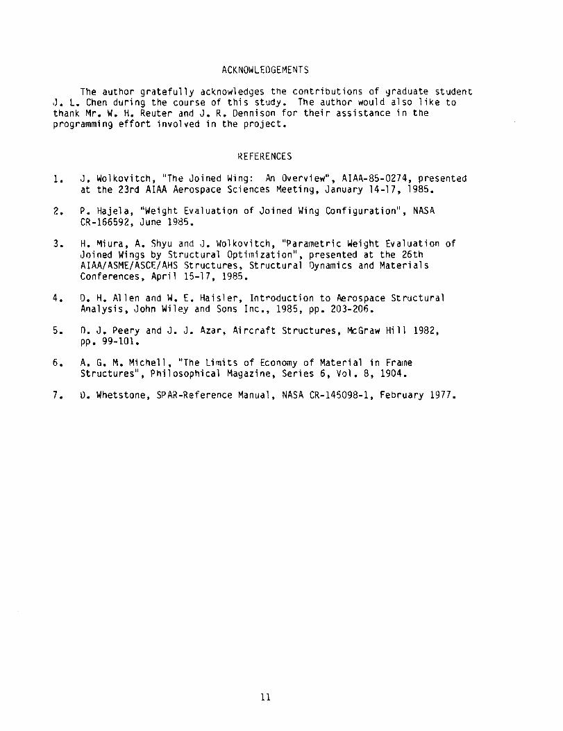
Results for a similar parametric variation of the sweep angle for similar
loading of a joined wing configuration are shown in Table 2. The front and
aft wings were identical and have a dihedral of ±4° , respectively. Theoptimum weight of the beam model displays the same qualitative trend as thebuilt-up finite element model. Furthermore, the deflection characteristics of
the two models also display the same behavior, with the maximum displacement
occurring at about 70_ of the semi-span. Consequently, the material distri-
bution along the span also displays similar qualitative trends.
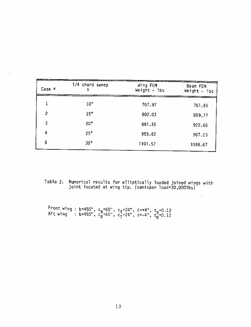
The influence of the dihedral angle on the optimum weight is illustrated
in Table 3. With increasing dihedral angle, the tilted-truss effect of the
joined wing structure becomes more predominant. The effective depth of the
beam is increased and provides for a reduction in the structural weight. The
effect of material concentration at the upper leading edge and the lowertrailing edge of the wing structural box was present in the built-up finite
element model and was clearly evident in the equivalent unsymmetrical beam
cross section obtained from a fully-stressed design of the beam model. Theresults presented are for a ±25 ° sweep of the quarter chord lines of the front
and aft wings.
Table _ demonstrates the influence of moving the joint between the front
and the aft wings inboard from the tip. A decrease in structural weight is
demonstrated in both the built-up wing models and the equivalent beam repre-
sentations. These results are for a dihedral of ±4° and a quarter chord sweepof ±25 °, respectively.
CONCLUSIONS AND RECOMMENDATIONS
This report describes a procedure for optimum structural design in apreliminary design environment where computational efficiency is a primary
consideration. Rapid estimates of the optimum structural weight of wingstructures for a specified load are obtained by the automated synthesis of
representative beam models which have considerably fewer degrees of freedom.The underlying design criterion for minimum weight is to stress each element

to its ultimate load carrying capacity.the proposed procedure are
a)
The most significant advantages of
automation of the design process to make the synthesis procedure
easily adaptable in a multidisciplinary design environment. Thisincludes an automated creation of all finite element models required
in the processb) considerable savings in computational resources over the conventional
approach of optimizing detailed built-up models of the wing
structure.
Although the automated process provides a reasonable strategy for
preliminary design, additional effort is required to enhance its effectivenessas a robust design tool. These modifications can be summarized as follows
a) Prescribing bounds on nodal displacements in addition to constraintson strength. In the present approach, this can be obtained by
creating a sizing ratio based on the strain energy within the element
b) The potential of the present approach can be extended further by
adding the ability to recover element sizes of the built-up finiteelement of the wing from the optimized sections of the beam. In the
present model, the five independent membrane element thicknesses canbe related to the five optimized values of the sectional properties
through nonlinear relations. Reasonable qualitative estimates ofthese dimensions can be obtained from the optimized beam and used as
input to a nonlinear equation solver to recover more precise values.
10
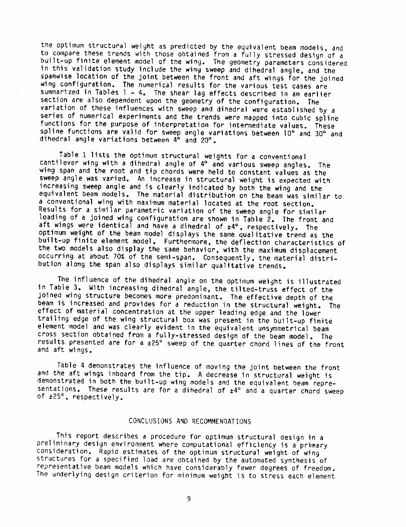
ACKNOWLEDGEMENTS
The author gratefully acknowledges the contributions of graduate student
J. L. Chen during the course of this study. The author would also like tothank Mr. W. H. Reuter and J. R. Dennison for their assistance in the
programming effort involved in the project.
I.
o
o
.
o
.
.
REFERENCES
J. Wolkovitch, "The Joined Wing: An Overview", AIAA-85-0274, presentedat the 23rd AIAA Aerospace Sciences Meeting, January 14-17, 1985.
P. Hajela, "Weight Evaluation of Joined Wing Configuration", NASA
CR-166592, June 1985.
H. Miura, A. Shyu and J. Wolkovitch, "Parametric Weight Evaluation of
Joined Wings by Structural Optimization", presented at the 26thAIAA/ASME/ASCE/AHS Structures, Structural Dynamics and Materials
Conferences, April 15-17, 1985.
0. H. Allen and W. E. Haisler, Introduction to Aerospace Structural
Analysis, John Wiley and Sons Inc., 1985, pp. 203-206.
D. J. Peery and J. J. Azar, Aircraft Structures, McGraw Hill 1982,
pp. 99-101.
A. G. M. Michell, "The Limits of Economy of Material in FrameStructures", Philosophical Magazine, Series 6, Vol. 8, 1904.
D. Whetstone, SPAR-Reference Manual, NASA CR-145098-1, February 1977.
11

Case#I/4 cilord sweep Wing FEM BeamFEM
,% Weight-lbs Weight- Ibs
I
2
3
4
5
10° I056.10 960.75
15° 1064.26 947.16
20° Ill2.41 I052.31
25° 1216.82 IllS.14
30° 1254.27 ll71.11
T_ble 1. Numerical results for an elliptically loaded conventional
cantilever wing.
(semi-span loads =30,O001bs, b=450",CR=60", CT=24", a=4°, tR=O-12)
12
I/4 chord sweep Wing FEM BeamFEMCase # A Weight- Ibs Weight- Ibs
1 10° 707.87 761.65
2 15° 802.03 859.77
3 20° 891.55 922.66
4 25° 958.62 967.15
5 30° 1101.57 I098.67
Table 2. N_nerical results for elliptically loaded joined wings withjoint located at wing tip. (semispan load=30,OOOlbs)
Front wing : b:450", CR:60", CT:24", 6:+4°, t =0.12Aft wing : b=450", CR=60", CT=24", 6=-4°, t_=O.12
13
Case#
i
2
3
4
5
Dihedral Angle Wing FEM Beam FEM
Weight - Ibs Weight - Ibsl
4 ° 958.60 967.15
8° 826.67 863.55
12° 753.49 787.63
16° 657.43 678.90
20° 595.37 618.87
Table 3. Numerical results for elliptically loaded joined wings with
joint located at wing tip. (semispan load=30,OOOlbs)
Front wing : b:450", CR=60: , CT:24", t,:+25°,Aft wing : b=450", CR=60 , CT=24", A=-25 °,
tR:O.]2
tR=O.12
14
Case#Wing FE_4 BeamFEM
B2/BI* Weight-lbs Weight- Ibs
I 0.889 832.65 921.31
2 0.778 637.78 662.55
3 0.667 459.01 430.78
4 0.556 323.70 293.82
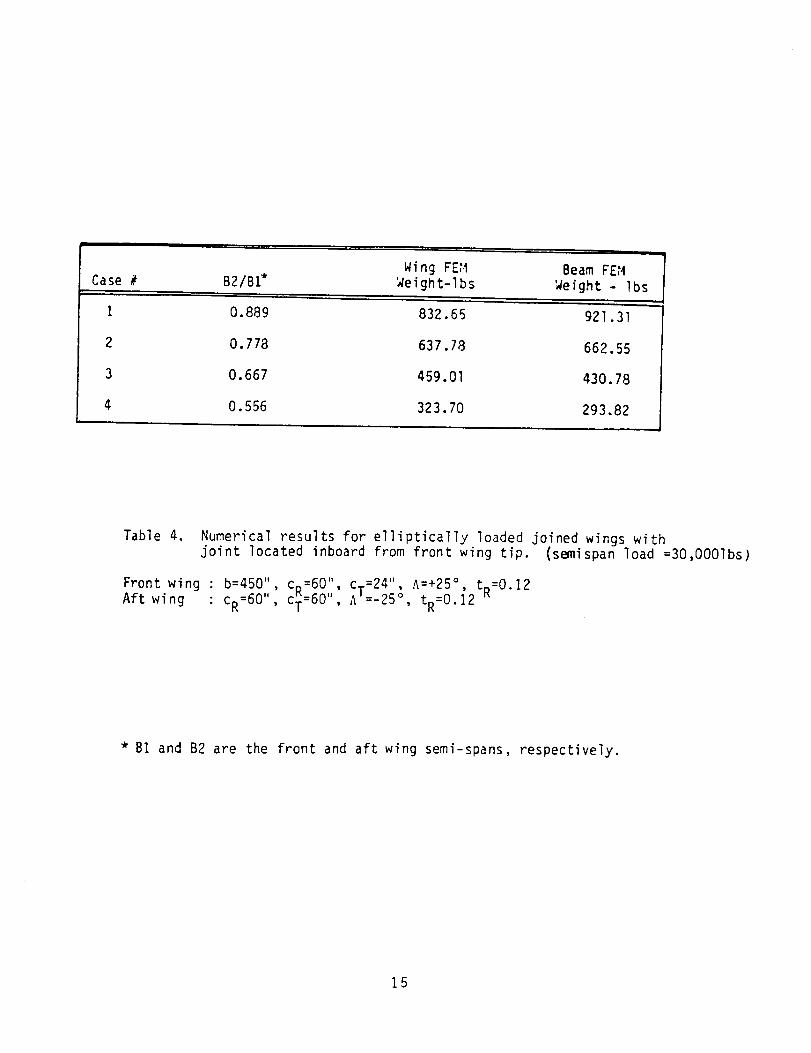
Table 4. Numerical results for elliptically loaded joined wings withjoint located inboard from front wing tip. (semispan load =30,O001bs)
, c.-24 , A:+25°, t_:0.12Front wing : b=450" c_=60 '', - "
K .... , tR=0.12 KAft wing : CR=60", CT=OU , AI=-25 °
* BI and B2 are the front and aft wing semi-spans, respectively.
15
,f
Out-of-plane load
ane Load
f
J ffective beamJ
Incline planeof truss
Figure I. The fore-aft wings in a joined wing configuration can be
idealized as a planar truss with the plane of the trussinclined to the horizontal
16

Ii
_,.Membra ne elements
! I _ _ I _ Axial rod nger
ii _ ,_ _'__ eme_tsri )
yew l
X-X
Figure 2. Finite element model of the wing structural box witheight stringer elements.
17

beam elements
Figure 3. A beam element grid joint between the front and aft structuralboxes. Each beam is rigid in bending and twisting deformations.
A
X
Figure 4. Cross sectional properties of__wing computed for typical sectionwith six stringer elements. A is the cross sectional area atenclosed by the section at a spanwise station.
18

• _ T J°
Figure 5. Unsymmetrical beam section used to model the wing crosssectional properties.
Z-
J
i_1 ""
Figure 6. General cross section depicting the y-z axes system used inbeam bending stress computations.
19

0 I & 1.-I t I,_1 t*._.
Figure 7. Grid point nomenclature for the finite difference representationof beam deformations and curvature.
20

(_)J
ITER= 0
L|'_ - N
IINITIALIZE WING STRUCTURE 1
EQUIVALENT BEAM MODEL J
F.E, ANALYSIS - WING 1
NO
F,E, NALYSIS - BEAM I
II SI-EARLAGEFFECTSJ
I
i BE/_ ANALYSI SINCREASED DOF MODEL
I[COMPUTE BEhM STRESSES[
]IBF_AMFULLY STRESSED DESIGN"I
ITER> ITMAX
YES
YES
Figure 8. Flow chart depicting the organization of the optimum
design procedure.
21

APPENDIX
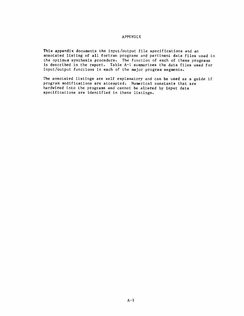
This appendix documents the input/output file specifications and an
annotated listing of all fortran programs and pertinent data files used in
the optimum synthesis procedure. The function of each of these programs
is described in the report. Table A-I summarizes the data files used for
input/output functions in each of the major program segments.
The annotated listings are self explanatory and can be used as a guide if
program modifications are attempted. Numerical constants that are
hardwired into the programs and cannot be altered by input data
specifications are identified in these listings.
A-I

PROGRAM
COORDS
MOMNT
MODISP
BEAM
SHLAG
BSAP
STRESS
FSD
WFSD
INPUT FILES
IGO.DAT,THICK.DAT,WING.DAT
INPUT.DAT
TRANSFR.DAT,BCSDI.DAT
BEAMI.DAT,BEAM2.DAT
KAPPA.DAT,WING.DAT,FOROO3.DAT,FOROO4.DAT
SKIN.DAT,BCSD.DAT,KAPPA.DAT,GEOM.DAT
TRANSFR.DAT,INERT.DAT,FOROO4.DAT,BCSD.DAT
WING.DAT,KAPPA.DAT,
ALST.DAT,SKIN.DAT,BCSD.DAT,FOROO4.DAT,STRESS.DAT
WING.DAT,FOROO2.DAT,ALST.DAT,THICK.DAT,FOROOI.DAT
OUTPUT FILES
INPUT.DAT, BEAMI.DAT,
SL.DAT,BCSD.DAT,THICK.DATWING.COM
BEAM2.DAT
MODE.COM
BEAM.COM,TRANSFR.DAT
KAPPA.DAT
INERT.DAT,BCSDI.DAT
STRESS.DAT
SKIN.DAT,FSDIF.DAT
THICK.DAT,FSDIF.DAT
A-2
$SET VERIFY
$ NSTOP:==O
$ LOOP1:
$ RUN COORDS
$ SET NOVERIFY
$ @WING
$ SET VERIFY
$ DEL XXX.*;*
$ RUN MOMNT
$ RUN BEAM
$ SET NOVERIFY
$ @BEAM
$ SET VERIFY
$ DEL FOR001.DAT;*,FOR002.DAT;*,XXX.*;*$ DEL BEAM2.DAT; _$ RUN SHLAG
$ SET VERIFY
$ ITER:z_I
S NFLAG:==O
$ LOOP1:
$ RUN BSAP
$ RUN MODISP
$ SET NOVERIFY
$ @MODE
$ SET VERIFY
$ DEL XXX.*;*
$ RUN STRESS
$ RUN FSD
$ APPEND FOR057.DAT FSDSS
$ DEL FORO0* *'*
$ DEL MODE.COM;*
$ DEL STRESS.DAT;*
$ DEL INERT.DAT;*
$ ITER=ITER+I
$ IF NFLAG.EQ,I THEN GOTO EXTI
$ IF ITER.EQ.20 THEN GOTO EXTI$ GOTO LOOP1
$ EXTI:
$ EXIT
PROC,.COM
A-3
THICK.DAT
5.0000001E-02 5.0000001E-02
5.0000001E-02 5.0000001E-02
5.0000001E-02 5.0000001E-02
05 .05 .05 .05 .050 5000000 0.5000000
05
55
5
50
0 50000000 50000000 SO000000 5O0OOOO0 5O0O0OO0 5000000
0 50000000 50000000 5O00OO00 50O00O00 50000000.50000000.5000000
0.50000000 5000000
0 50000000 50000000 50000000 5000000
0 50000000 50000000 50000000 50000000 5000000
0.S0000000.50000000.50000000 5000000
50000005 .5 .5 .5 .55 .5 .5 .5 .5
5 .5 .5 .5 .55 .5 .5 .5 .55 .5 .5 .5 .5SO00000
0.5000000
0 5000000
0 5O0O000
0 5000000
0 5000000
0 500OO0O
0 5000000
0.5000000
O.5000O00
0.5000000
0.5O0O00O
0.5O0O0O0
0.5000000
0.5000000
0.5000000
5.0000001E-025.0000001E-02
5.0000001E-02
0.5000000
0.5000000
0.5000000
0.5000000
0.5000000
0.5000000
0 50O0O00
0 5000000
0 5000000
0 5O00000
0 5O00000
0 5000000
0.5OO0OO0
0.5000OO0
0.5000000
5.0000001E-02
5.0000001E-025.0000001E-02
0.5000000
0.5000000
0.S000000
0.S000000
O.5OOO0OO
0.5000000
0.S000000
0.5000000
0 5000000
0 5000000
0 5000000
0 5000000
0 5000000
0 5000000
0 5000000
5.0000001E-02
5.0000001E-02
5.0000001E-02
0.5000000
0.5000000
0.5000000
0.5000000
0.5000000
0.5000000
0.5000000
0.5000000
0.5000000
0.5000000
0.5000000
0.5000000
0.5000000
0.5000000
0.5000000
A-4

SKIN. DAT
5 55 55 55 55 55 55 55 55 55 55 55 55 55 55 55 55 55 55 55 5
10. 20.
55555555555555555555
5 5-5 55 55 55 55 55 55 55 55 55 55 55 55 55 55 55 55 55 5
-beam wall thickness- five independent thicknessesfor each spanwise station.
_'_startin_ estimates of weights
A-5

VING. DAT
/wing typeJOINED
450. 60. 24. 8 I0 I0 15. 8. .12 0.7
450. 60. 24. 6 I0 I0 15. 6. .12 0.7_
\ct, nstr,nsta,nrib,sweep,ainearal, hicKness a_io, "se taDer
•001
35000. O0
6 - NSTR
- convergence tolerance
- allowable stress
ALST.DAT
20 - NSTA+NSTA2
20.0 I0.0
Arbitrary values of starting weights
GEOM.DAT
A-6
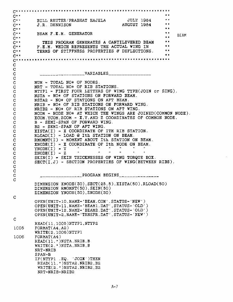
C *_ BILL REUTER/PRABHAT HAJELA JULY 1984 **C** J.R. DENNISON AUGUST 1984 **
C_, _*
C** BEAM F.E.M. GENERATOR **
C_* _*
C*" THIS PROGRAM GENERATES A CANTILEVERED BEAM **
C** F.E.M. WHICH REPRESENTS THE ACTUAL WING IN **
C** TERMS OF STIFFNESS PROPERTIES & DEFLECTIONS. **C_ _
CCCCCCCCCCCCCCCCCCCCCCCCCCC
C
C
1005
1006
BEAM
VARIABLES
NUM : TOTAL NO* OF NODES.NRT = TOTAL NO# OF RIB STATIONS.
NTYPI : FIRST FOUR LETTERS OF WING TYPE(JOIN or SING).
NSTA = NO# OF STATIONS ON FORWARD BEAM.NSTA2 = NO# OF STATIONS ON AFT BEAM.
NRIB = NO# OF RIB STATIONS ON FORWARD WING.NRIB2 = NO# OF RIB STATIONS ON AFT WING.
NCOM : NODE NO# AT WHICH THE WINGS ARE JOINED(COMMON NODE).
XCOM,YCOM,ZCOM = X,Y,AND Z COORDINATES OF COMMON NODE.B = SEMI-SPAN OF FORWARD WING.
B2 = SEMI-SPAN OF AFT WING.
XISTA(I) = X COORDINATE OF ITH RIB STATION.RLOAD(I) = LOAD @ Ith STATION ON BEAM.
RMOMNT(I) = MOMENT ABOUT Ith STATION ON BEAM.
XNODE(I) = X COORDINATE OF Ith NODE ON BEAM.YNODE(I) = Y ............
ZNODE(I) = Z ............
SKIN(I) = SKIN THICKNESSES OF WING TOR@UE BOX.SECT(I,J) = SECTION PROPERTIES OF WING(BETWEEN RIBS).
PROGRAM BEGINS
DIMENSION XNODE(30),SECT(25,B),XISTA(50),RLOAD(B0)
DIMENSION RMOMNT(50),SKIN(S0)DIMENSION YNODE(30),ZNODE(30)
OPEN(UNIT=I0,NAME=°BEAM.COM',STATUS='NEW ')
OPEN(UNIT=II,NAME='BEAMI.DAT',STATUS='OLD ,)OPEN(UNIT=I2,NAME='BEAM2.DAT',STATUS='OLD ')
OPEN(UNIT=2,NAME='TRNSFR.DAT',STATUS='NEW ,)
READ(II,1005)NTYPI,NTYP2
FORMAT(A4,A2)WRITE(2,1006)NTYP1FORMAT(A4)
READ(ll,*)NSTA,NRIB,BWRITE(2,*)NSTA,NRIB,BNRT=NRIB
SPAN=B
IF(NTYPI .EQ. 'JOIN')THENREAD(ll,*)NSTA2,NRIB2,B2WRITE(2,*)NSTA2,NRIB2,B2NRT=NRIB+NRIB2
A-7

CCCC
75C
CC
I00
125
CC
C
2OO
225
250C
C
C
3OO
SPAN=B2END IF
SHIFT BOTH BEAMS BACK & DOWN SO THAT THE ORIGIN OF THEFORWARD BEAM IS AT THE POINT(0,0,0).
NUM=NSTA+I
IF(NTYPI .EQ. 'JOIN')NUM=NUM+NSTA2WRITE(2,*)NUMDO 78 I=I,NSTA+I
READ(II,*)XNODE(I),YNODE(I),ZNODE(I),RLOAD(I),RMOMNT(I)IF(I.EQ.I)THEN
DY=YNODE(1)
DZ=ZNODE(1)ENDIF
YNODE(I)=YNODE(I)-DY
ZNODE(I)=ZNODE(I)-DZ
WRITE(2,_)XNODE(I),YNODE(I),ZNODE(I)
IF(XNODE(I) .E@. SPAN)THENNCOM=I
XCOM=XNODE(I)YCOM=YNODE(I)
ZCOM=ZNODE(I)ENDIF
CONTINUE
SAME FOR AFT WING.
IF(NTYPI .NE. 'JOIN')GO TO 125DO I00 I-NSTA+2,NUM
READ(II,')XNODE(I),YNODE(I).ZNODE(I),RLOAD(I),RMOMNT(I)YNODE(I)-YNODE(I)-DY
ZNODE(I)=ZNODE(I)-DZ
WRITE(2,*)XNODE(I),YNODE(I).ZNODE(I)CONTINUE
CONTINUE
READ IN THE RIB LOCATIONS.
DO 200 J=I,NRIBREAD(II,*)XISTA(J)
WRITE(2,*)XISTA(J)CONTINUE
IF(NTYPI .NE. 'JOIN')GO TO 250
DO 225 J=NRIB+I,NRTREAD(II,*)XISTA(J)
WRITE(2,')XISTA(J)CONTINUECONTINUE
READ IN THE SECTION PROPERTIES.
DO 300 I=I,NRIB
READ(II,*)SKIN(I)
READ(12,')(SECT(I,JJ),JJ=I,5)CONTINUE
IF(NTYPI .NE. 'JOIN')GO TO 350DO 325 I=NRIB+I,NRT
READ(II,*)SKIN(I)
READ(12,*)(SECT(I,JJ),Jj=I,5)
A-8
325350CCC
1050
C
2000
4OO
2500
25104172520
CCCC
3O0O$
500CCC
520575
3500
CCC
CONTINUECONTINUE
BEGIN CONSTRUCTING E.A.L. COMMAND FILE.
s
$$$$$$
WRITE(10,1050)NUMFORMAT('$RUN DUAI:[PXH]EAL'/'DUAI:[]X_.'/
*ONLINE=0'/*OUTF=2'/
*XQT TAB'/START ',I2,',6'/MATC:I 10.5+6 .3 .I'/
JLOC')
DO 400 I=I,NUM
WRITE (I0,2000 )I, XNODE (I ),YNODE (I ), ZNODE (I )FORMAT( IX, 12,3( IX, Fg. 2))CONTINUEWRITE(10,2500)
FORMAT(' CON i'/
$ ' ZERO 1,2,3,4,5 : I')IF(NTYPI .NE. 'JOIN')GO TO 417WRITE(10,2510)NUM
FORMAT(' ZERO 1,2,3,4,5 : ',I2)WRITE (10,2520)FORMAT( ' MREF' /
$ ' 1 1 3 1. 0. '/$ ' BA')
MOMENT OF INERTIA, AREA, AND TORSIONAL STIFFNESS AT EACHRIB STATION(NSECT) FOR FORWARD WING.
DO 500 I=I,NRIBSECT(I,3)=SECT(I,3)+SKIN(I)
WRITE(10,3000)(I,(SECT(I,J),J=I,4))
FORMAT(' GIVN ',IX,I3,1X,FI3.3,2X,'0.0 ',FI3.3,2X,'0.0 'FT.2,1X,FII.3)CONTINUE
SAME FOR AFT WING.
IF(NTYPI .NE. 'JOIN')GO TO 575
DO 520 I=NRIB+I,NRTSECT(I,3)=SECT(I,3)+SKIN(I)
WRITE(10,3000)(I,(SECT(I,J),J=I,4))CONTINUECONTINUE
WRITE(10,3500)
FORMAT('*XQT ELD'/$ ' E21'/
$ ' NSECT= 1')
NSECTS & CONNECTIVITY FOR FORWARD WING.
NSECT=IISTART=I
IFIN=2
WRITE(10,4500)ISTART,IFINDO 600 I=2,NSTA
A-9

40OO
450O6OOCC
C
625675C
5000
C
CC
5500
5570
55757OOCCC
710
6000
IF(XNODE(I).EQ.XISTA(NSECT))THENNSECT-NSECT+I
WRITE(10,4000)NSECT
FORMAT(' NSECT=',I2)ENDIF
ISTART=IIFIN=I+I
WRITE(10,4500)ISTART,IFIN
FORMAT(IX,2(I3,1X))CONTINUE
NSECTS & CONNECTIVITY FOR AFT WING.
IF(NTYPI .NE. 'JOIN')GO TO 675NSECT=NSECT+I
WRITE(10,4000)NSECT
WRITE(10,4500)NCOM,NSTA+2NSECT=NSECT+I
DO 625 I=NSTA+2,NSTA+NSTA2
IF(XNODE(1) .EQ. XISTA(NSECT))THENWRITE(10,4000)NSECTNSECT-NSECT+I
ENDIFISTART=I
IFIN=I+I
WRITE(10,4500)ISTART,IFINCONTINUECONTINUE
WRITE(10,5000)
FORMAT( '*XQT E'/RESET G=386.'/
*XQT TOPO'/"XQT EKS'/
*X_T K'/*XQT INV'/*XQT AUS'/SYSVEC: APPL FORC')
LOADS & MOMENTS FOR FORWARD BEAM.
DO 700 I=2,NSTAWRITE(10,5500)I,RLOAD(I)
FORMAT(' I=3:J=',I2,':',F9.2)
WRITE(10,5570)I,RMOMNT(I)FORMAT(' I-4:J=',I2,':',F9.2)
WRITE(2,5575)I,RLOAD(I),RMOMNT(I)FORMAT(IX,12,2(Fg.2))CONTINUE
LOADS & MOMENTS FOR AFT WING.
DO 710 I=NSTA+2,NSTA+NSTA2
WRITE(10,5500)I,RLOAD(I)
WRITE(10,S570)I,RMOMNT(I)WRITE(2,5578)I,RLOAD(I),RMOMNT(I)CONTINUE
CLOSE(UNIT=2)WRITE(10,6000)
FORMAT( '*X@T SSOL'/
A-IO

$ '*XQT DCU' "*OUTF=4'/
$ ' PRINT 1 STATIC DISPLACEMENTS'/
$ '*XQT EXIT')
STOP
END
A-11
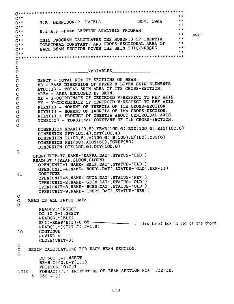
_ _
C** J.R. DENNISON/P. HAJELA NOV. 1984 **
C _* B.S.A.P.-BEAM SECTION ANALYSIS PROGRAM **
C** THIS PROGRAM CALCULATES THE MOMENTS OF INERTIA, **C** TORSIONAL CONSTANT, AND CROSS-SECTIONAL AREA OF **
C** EACH BEAM SECTION GIVEN THE SKIN THICKNESSES. **
_ _
CCCCCCCCCCCCCCC
C
11
CCC
lO
C
CC
VARIABLES
NSECT = TOTAL NO% OF SECTIONS ON BEAM.
BB - BASE DIMENSION OF UPPER _ LOWER SKIN ELEMENTS.
ATOT(I) = TOTAL SKIN AREA OF ITH CROSS-SECTION.AREA = AREA ENCLOSED BY SKIN.
XX = X-COORDINATE OF CENTROID W/RESPECT TO REF AXIS.
YY = Y-COORDINATE OF CENTROID W/RESPECT TO REF AXIS.RIXX(I) = MOMENT OF INERTIA OF ITH CROSS-SECTION.
RIYY(I) - MOMENT OF INERTIA OF Ith CROSS-SECTION.RIXY(I) = PRODUCT OF INERTIA ABOUT CENTROIDAL AXIS.
TCNST(I) = TORSIONAL CONSTANT OF Ith CROSS-SECTION.
DIMENSION XBAR(IOO,6),YBAR(IOO,6),RIX(IOO,6),RIY(IO0,6)DIMENSION YPT(100,4),ZPT(100,4)
DIMENSION T(100,6),A(100,6),B(100),H(100),DST(6)DIMENSION PHI(50),ATOT(S0),TCNST(50)DIMENSION DIX(100,6),DIY(100,6)
OPEN(UNIT=37,NAME='EAPPA.DAT',STATUS-'OLD')READ(37,*)RKAP,SLCON,SLCONI
OPEN(UNIT-I,NAME='SKIN.DAT',STATUS-'OLD')
OPEN(UNIT=_,NAME='BCSDI,DAT',STATUS='OLD',ERR=II)CONTINUE
OPEN(UNIT=3,NAME='OUT2.DAT',STATUS='NEW')
OPEN(UNIT-2,NAME-'GEOM.DAT',STATUS='0LD')
OPEN(UNIT=S,NAME='BCSD.DAT',STATUS='OLD')OPEN(UNIT=9,NAME='INERT.DAT',STATUS='NEW')
READ IN ALL INPUT DATA.
READ(2,')NSECT
DO i0 I=I,NSECTREAD(8,*)B(1)
H(I)=RL_P*B(I)/0.SS -READ(I,')(T(I,J),J=I,5)
CONTINUEREWIND 4
CLOSE(UNIT=8)
BEGIN CALCULATIONS FOR EACH BEAM SECTION.
I010$
BSAv
structural box is 65% of the chord
DO 500 I:I,NSECTBB=B(I)/2.0-T(I,I)
WRITE(3.1010)IFORMAT(/,.',' PROPERTIES OF BEAM SECTION NO# ',I2/IX,
33(':'))
A-12

CCC
CCC
25
1025C
CC
C
CCC
5O
CCC
77CCC
CALCULATE INDIVIDUAL AREA'S WHICH MAKE UP Ith BEAM SECTION.
A(I I)=T(I,I)*H(I)A(I 2)=T(I,2)*BB
A(I 3)=T(I,3)*BB
A(I 4)=A(I,I)A(I 5)=T(I,4)*BB
A(I 6)=T(I,5)*BB
CALCULATE THE TOTAL CROSS-SECTIONAL AREA.
SUM=0.0
DO 25 J=l,6
SUM=SUM+A(I,J)CONTINUE
ATOT(I)=SUM
WRITE(3,1025)ATOT(1)
FORMAT(/,2X,' TOTAL SKIN AREA = ',F15.5)
LOCATE CENTROIDS OF SKIN AREA'S W/RESPECT TO REFERENCE AXIS
XBAR(I,I)=-(B(I)-T(I,I))/2.0XBAR(I,2)=-EB/2.0
XBAR(I,3)=BB/2.0XBAR(I,4)=-XBAR(I,1)XBAR(I,5)=XBAR(I,3)XBAR(I,6)=XBAR(I,2)
YBAR(I I)=0.0YBAR(I 2)=(H(IJ-T(I,2))/2.0
YBAR(I 3)=(H(I)-T(I,3))/2.0YBAR(I 4)=0.0
YBAR(I 5)=-(H(1)-T(I,4))/2.0
YBAR(I 6)=-(H(I)-T(I,S))/2.0
FIND THE CENTROID OF THE TOTAL CROSS-SECTION.
SUMI=0.0
SUM2=0.0
DO 50 J=l,6SUMI=SUMI+A(I,J)*XBAR(I,J)
SUM2=SUM2+A(I,J)*YBAR(I,J)CONTINUE
XX=SUMI/ATOT(I)YY=SUM2/ATOT(I)
LOCATE CE_TROIDS OF SKIN AREA'S W/RESPECT TO NEW AXIS'
DO 77 3=1,6XBAR(I,J)=XBAR(I,J)-XXYBAR(I,J)=YBAR(I,J)-YYCONTINUE
CALCULATE MOMENTS OF INERTIA OF SKIN AREA'S.
RIX(I,1)=(T(I,1)*H(I)**3.0)/12.0RIX(I,2)=(BB*T(I,2)**3.0)/12.0RIX(I,3)=(BB*T(I,3)**3.0)/12.0RIX(I,4)=RIX(I,I)
A-13
C
C
C USEC
I00
1050
1051
C
CC
105
1070
CCC
RIX(I,5):(BB*T(I,4)'*3.0)/12.0RIX(I,6)-(BB*T(I,5)**3.0)/12.0
RIY(I,I):(H(I)*T(I,I)'*3.0)/12.0RIY(I,2):(T(I,2)*BB''3.0)/12.0RIY(I,3)=(T(I,3)*BB*'3.0)/12.0RIY(I,4)=RIY(I,I)RIY(I,B)-(T(I,4)*BB*'3.0)/12.0RIY(I,6)-(T(I,5)*BB''3.0)/12.0
PARALLEL-AXIS THEOREM TO TRANSFER MOMENTS
RIXX=O. 0
RIYY=O. 0
DO i00 J:l,6
RIX(I,J)=RIX(I,J)+A(I,J)*(YBAR(I,J)**2.0)RIY(I,J)=RIY(I,J)+A(I,J)*(XBAR(I,J)**2.0)RIXX:RIXX+RIX(I,J)RIYY=RIYY+RIY(I,J)CONTINUE
WRITE(3,1050)RIXX
FORMAT(2X,' IXX = ',F15.5)WRITE(3,1051)RIYY
FORMAT(2X,' IYY : ',F15.5)
CALCULATE THE PRODUCT OF INERTIA ABOUT
RIXY-O.O
DO 10S J=l,6
RIXY-RIXY+A(I,J)*XBAR(I,J)'YBAR(I,J)CONTINUE
WRITE(3,1OTO)RIXY
FORMAT(2X,' IXY : ',F15.5)RIXX-RIXX*SLCON
RIYY=RIYY'SLCONI
WRITE(9,*)RIXX,RIYY,RIXY
CALCULATE THE POLAR MOMENT OF INERTIA ABOUT
RIZZ=RIXX+RIYY
WRITE(3,1074)RIZZ
1074 FORMAT(2X,' IZZ : ',F15.5)C
C CALCULATE TORSIONAL CONSTANT FOR ITHC
AREA=B(I)'H(I)-ATOT(I)DST(1)=H(I)/T(I,I)DST(2)-BB/T(I,2)DST(3):BB/T(I,3)
DST(4):DST(1)DST(5):BB/T(I,4)
DST(6)=BB/T(I,5)SUM=O.O
DO 170 J:l,6
SUM:SUM+DST(J)CONTINUE
TCNST(1)=4.0'(AREA**2.0)/SUM
WRITE(3,1075)TCNST(I)FORMAT(2X,' TORSIONAL CONSTANT
170
1075C
SECTION.
',F15.5)
TO CENTROID.
CENTROIDAL AXIS'
CENTROID.
A-14

C
C
1076
C
C
C
1080
1081
C
C
C
C
DETERMINE ANGLE OF ROTATION OF PRINCIPAL AXIS.
PI=3.14159
PHI(I)=(180.O/PI)*O.5*ATAN(2.0*RIXY/(RIYY-RIXX))
WRITE(3olOTS)PHI(I)
FORMAT(2X,' PHI = ',F15.5,' DEGREES')
MAXIMUM & MINIMUM MOMENTS OF INERTIA ABOUT PRINCIPAL
RIMAX=RIZZ/2.0+SQRT(RIXY*'2+((RIXX-RIYY)/2.0)**2)
RIMIN=RIZZ/2.0-S_RT(RIXY**2+((RIXX-RIYY)/2.0)**2)
WRITE(3,1080)RIMAX
FORMAT(2X,' Il(MAX) = ',F15.5)
WRITE(3,1081)RIMIN
FORMAT(2X,' I2(MIN) = ',F15.5)
CALCULATE THE DERIVATIVES OF THE TOTAL MOMENT OF INERTIA
ABOUT X_4_/ AXIS' W/RESPECT TO THE SKIN THICKNESSES.
C
C
5O0
501
AXIS.
DIX(I,1DIX(I,2DIX(I,3
DIX(I,4
DIX(I,5
)=(H(I)**3.0)/6.0+2.0*(YY_*2.0)*H(I))=BB*(T(I,2)**2.0)/4.0+BB*(YY**2.0)
)=BB*(T(I,3)'*2.0)/g.0+BB*(YY**2.0))=BB*(T(I,4)**2.0)/4.0+BB*(YY**2.0)
)=BB*(T(I,5)''2.0)/4.0+BB*(YY**2.0)
DIY(I,1)=H(I)*(T(I,1)**2.0)/2.0+2.0*H(I)*(XX**2.0)
DIY(I,2)=(BB**3.0)/12.0+BB*(XX**2.0)
DIY(I,3)=DIY(I,2)
DIY(I,4)=DIY(I,3)
DIY(I,5)=DIY(I,4)
XB=ABS(XBAR(I,I))
PHI(I)-(PI/ISO.)'PHI(I)
SP=SIN(PHI(1))
CP=COS(PHI(I))
Y2=ABS(YBAR(I,2))
Y3=ABS(YBAR(I,3))
Y5=ABS(YBAR(I,5))
Y6=ABS(YBAR(I,6))
YPT(I,I)=-XB*CP+Y2*SP
YPT(I,2)=XB*CP+Y3*SP
YPT(I,3)=XB'CP-YS*SP
YPT(I,4)=-XB*CP-Y6*SP
ZPT(I,I)=+XB*SP+Y2*CP
ZPT(I,2)=-XB*SP+Y3*CP
ZPT(I,3)=-XB*SP-YS*CP
ZPT(I,4)=XB*SP-Y6*CP
WRITE(4,')I,RIMAX,RIMIN,ATOT(I),TCNST(I),PHI(I)
CONTINUE
DO 5011=I,NSECT
WRITE(9,*)ATOT(1),TCNST(I)
WRITE(4,*)B(1)
CONTINUE
WRITE(4,*)((YPT(I,J),I=I,NSECT),J=I,4)
WRITE(4.*)((ZPT(I,J),I=I,NSECT),J=I,4)
CLOSE(UNIT=3)
CLOSE(UNIT=4)
CLOSE(UNIT=9)
STOP
END
A-15

C "_ BILL REUTER/PRABHAT HAJELA JULY 1984 **
C** J.R. DENNISON AUGUST 1964 **
C_ _*
C** FINITE ELEMENT GENERATOR FOR WING WITH **C*" GIVEN NUMBER OF STATIONS AND STRINGERS **
C
C
C
C
5
I0
CC
DIMENSION XCOR(500),YCOR(500).ZCOR(500)
DIMENSION CHORD(100),RLOAD(100,S0),ISTA(50),ISTA2(50)DIMENSION AREA(50,50),THICK(50,50)
DIMENSION BLOAD(S0),XISTA(50),RMOMNT(50)
DIMENSION SKIN(50),VX(50)
OPEN(UNIT=I3,NAME='IGO,DAT',STATUS='OLD')
OPEN(UNIT=IS,NAME='WING.DAT°,STATUS='OLD ')
READ(13,*)IGO
READ(15,5) NTYPI,NTYP2FORMAT(A4,A2)
WRITE(6,10) NTYPI,NTYP2
FORMAT(/,' THIS ANALYSIS IS FOR A ',A4,A2,' WING'' WHOSE DIMENSIONS ARE AS FOLLOWS:')
2O$$$$
35
CC
45
READ IN DATA FOR FORWARD WING.
READ(IS,*) B,CR,CT,NSTR,NSTA,NRIB,RLAM,GAM,TR,RRFORMAT(/,' SEMI-SPAN = ',FS.2,' INCHES'/' ROOT CHORD = '
F7.2,' INCHES'/' TIP CHORD = ',F7.2,' INCHES'/IX,
I3,' STRINGERS'/IX,I3,' STATIONS'/IX,13,' RIB STATIONS'/' SWEEP ANGLE = ',F5.2.' DEGREES'/' DIHEDRAL ANGLE - ',
F5.2.' DEGREES'/' THICKNESS RATIO = ',F6.4)IF (NTYPI .NE. 'JOIN') THEN
WRITE(6,20) B,CR.CT,NSTR,NSTA,NRIB,RLAM,GAM,TR
GO TO 50ELSE
WRITE(6.35)
FORMAT(//,IX,'FORWARD WING'/IX,12('='))WRITE(6,20) B,CR,CT,NSTR,NSTA,NRIB,RLAM,GAM,TR
END IF
READ IN DATA FOR AFT WING.
READ(15,*) B2,CR2,CT2,NSTR2,NSTA2,NRIB2,RLAM2,GAM2,TR2,RRWRITE(6,45)
FORMAT(//,IX,'AFT WING'/IX,S('='))WRITE(6,20) B2,CR2,CT2.NSTR2.NSTA2,NRIB2,RLAM2,GAM2,TR2
C
_* **
C** GENERATE COORDINATES FOR FORWARD WING **
C_* _
COORDS
structural box is 65% of chord
C
5OCR=.65*CR ICT= 65"CT
IEND=NSTR*(NSTA+I)IREND=IEND
NSTPI=NSTA*I
A-16
C
CC
CC
C
CC
C
CC
C
CC
C
85
I00
I01
102
C
C
C
RLAM=RLAM*3.14159/180.
GAM=GAM*3.14159/180.
DENOTE THE ORIGINATION OF THE 1/4 CHORD LINE
AS THE ORIGIN OF THE CARTESIAN COORDINATE SYSTEM
DETERMINE COORDINATES OF TERMINUS OF 1/4 CHORD LINE
XEND=B
YEND=-B*TAN(RLAM)
DETERMINE COORDINATES OF BOX VERTICES AT ROOT AND TIP
XRLE=0.
XRTE=0.
YRLE=0.25*CR
YRTE=-0.75*CR
XTLE=B
XTTE=B
YTLE=YEND+.25*CT
YTTE=YEND-.75*CT
OBTAIN SLOPES OF LE AND TE FOR Z=CONST PLANE
SLOPLE=(YTLE-YRLE)/B
SLOPTE=(YTTE-YRTE)/B
GENERATE X-COORDINATES OF ALL NODES FOR FORWARD WING
IF (NTYPI .NE. 'JOIN') THEN
NSTA2 = NSTA
B2 = B
END IF
DO 85 I=I,NSTR
XCOR(1)=0.0
JEND = NSTR*(NSTA2+I)
DO I00 I=NSTR+I,JEND
XCOR(1)=((I-I)/NSTR)*B2/NSTA2
CONTINUE
IF (NSTA .EQ. NSTA2) GO TO I02
DO 1011=JEND+I,IEND
K=(I+NSTR)-(JEND+l)
XCOR(I) = (K/NSTR)'(B-B2)/(NSTA-NSTA2)+XCOR(JEND)CONTINUE
CONTINUE
Y-COORDINATES OF TE AND LE'S
II=(NSTR/2)+I
K=I-NSTR
KK=II-NSTR
DO 150 I=I,NSTPIK=K+NSTR
KK=KK+NSTR
KI=K+I
KKI=KK+I
YCOR(K)=YRTE + SLOPTE*XCOR(K)
YCOR(KK)=YRLE + SLOPLE*XCOR(KK)
YCOR(KI)=YCOR(K)
YCOR(KKI)=YCOR(KK)
A-17
150
CC
C
200
CC
C
26O
260275
CC
CC
C
C
CCCC
CCC
C
CC
28O
CONTINUE
DETERMINE CHORD LENGTH AT EACH STATION
II-I-NSTR
12-(NSTR/2)+2-NSTR
DO 200 I=I,NSTPIII_II+NSTR
I2-I2+NSTRCHORD(I)-AES(YCOR(12)-YCOR(II))
CONTINUE
Y-COORDINATES OF ANY INTERMEDIATE POINTS
IF(NSTR.LE.4)GO TO 275II=(NSTR/2)+I-NSTR
12=(NSTR/2)+2-NSTRNCRD=(NSTR/2)-l
DO 250 I=I,NSTPIII=II+NSTR
I2=I2+NSTR
DO 260 J=I,NCRD-I
YCOR(II-J)=YCOR(II)-CHORD(1)'(I./NCRD)*FLOAT(J)YCOR(12+J)=YCOR(II-J)CONTINUE
CONTINUECONTINUE
Z-COORDINATES OF NODE POINTS
ASSUME THAT THE DIHEDRAL ANGLE IS DEFINED
BETWEEN THE CENTER LINE AND THE HORIZONTAL PLANE
ZRCL=0.S*CR*TR/.65
ZTCL-ZRCL+B'TAN(GAM)
GENERATE CORNER COORDINATES FIRST
RR IS INPUT FROM WING.DAT, BUT HAS NO MEANING IF ONLY 4 STRINGERS
iF(NSTR.E_.4)RR=I.O
ZRLSC AND ZRLSC ARE LOWER SURFACE Z-COR OF CORNERS
ZRLSC=ZRCL-RR'O.5*TR*CHORD(1)/.65
ZTLSC=ZTCL-RR*O.5"TR*CHORD(NSTPI)/(.65)SLPLS=(ZTLSC-ZRLSC)/B
Z-COORDINATES OF TE AND LE
II=(NSTR/2)+2K=I-NSTRKK=II-NSTR
DO 280 I=I,NSTPIK=K+NSTR
KK=KK+NSTR
ZCOR(K)=ZRLSC+SLPLS*XCOR(K)
ZCOR(KK)=ZCOR(K)ZCOR(K+I)=ZCOR(K)+RR*TR*CHORD(I)/.65
ZCOR(KK-I)=ZCOR(K+I)CONTINUE
A-18
CCC
TERMINATE IF ONLY FOUR STRINGERS
IF(NSTR.EQ.4)GO TO 295II=(NSTR/2+I)-NSTR
I2=(NSTR/2+2)-NSTRDO 290 I=I,NSTPIII=II+NSTR
I2=I2+NSTR
DO 285 J=I,NCRD-I
ZCOR(II-J)=ZCOR(II)+TR*CHORD(I)/.S5*(I.-RR)*0.5
ZCOR(I2+J)=ZCOR(I2)-TR*CHORD(I)/.65*(I.-RR)*0.5285 CONTINUE
290 CONTINUE
295 CONTINUE
IF (NTYPI .NE. 'JOIN') GO TO 310C
***********************************************************
C _* *_
C** GENERATE COORDINATES FOR AFT WING **C** **
************************************************************
CR2 = .65"CR2CT2 = .65"CT2IEND2 = NSTR2*(NSTA2+I)IREND = 1END + IEND2RLAM2 = RLAM2*3.14159/180.GAM2 = GAM2*3.14159/180.
CCC
303
3O4C
CCC
CCCC
C
CC
CCC
GENERATE X-COORDINATES FOR REAR WING
IRTIP = 1END + NSTR2
DO 303 I=IEND+I,IRTIPXCOR(I) = XCOR(JEND)
DO 304 I=IRTIP+I,IRENDK=I-IEND-I
XCOR(1) = XCOR(IRTIP)-(K/NSTR2)*B2/NSTA2CONTINUE
DETERMINE COORDINATES OF TERMINUS OF 1/4 CHORD LINEON AFT WING.
YENDT = YCOR(JEND-NSTR+l)-0.07*CT2/.65-.25*CT2YENDR = YENDT - B2*TAN(RLAM2)
DETERMINE COORDINATES OF BOX VERTICES AT ROOT & TIPFOR AFT WING.
YTLE = YENDT + 0.25"CT2
YTTE = YENDT - 0.75"CT2YRLE = YENDR + 0.25'CR2
YRTE = YENDR - 0.75"CR2
OBTAIN SLOPES OF LE AND TE FOR AFT WING
SLOPLE = (YRLE-YTLE)/B2
SLOPTE = (YRTE-YTTE)/B2
GENERATE Y-COORDINATES OF LE AND TE
A-19

3O5
CC
C
306C
CC
306
307C
CC
C
C
CC
C
C
C
C
CC
II = (NSTR2/2)+I+IENDK = I-NSTR2+IENDKK = II-NSTR2
DO 305 I_I,NSTA2+IK = K+NSTR2
KK = KK+NSTR2
El - K+IKKI - KK+I
YCOR(K) - YTTE+(B2/NSTA2J'(I-I)*SLOPTE
YCOR(KK) - YTLE+(B2/NSTA2)'(I-I)'SLOPLEYCOR(K1) = YCOR(K)YCOR(KKI) = YCOR(KK)CONTINUE
DETERMINE CHORD LENGTH AT EACH STATION
II = I-NSTR2+IEND
12 = (NSTR2/2)+2-NSTR2+IENDNSTP2 = NSTA2+2+NSTA
DO 306 I=NSTA+2,NSTP2II = II+NSTR2
I2 _ I2+NSTR2
CHORD(I) = ABS(YCOR(I2)-YCOR(II))CONTINUE
GENERATE Y-COORDINATES AT INTERMEDIATE POINTS
IF (NSTR2 .LE. 4) GO TO 307
II - (NSTR2/2)+I-NSTR2+IENDI2 - (NSTR2/2)+2-NSTR2+IEND
NCRD _ (NSTR2/2)-I
DO 307 I-NSTA+2,NSTP2II - II+NSTR2I2 - I2+NSTR2
DO 308 J-I,NCRD-I
YCOR(II-J) - YCOR(II)-CHORD(I)*(I./NCRD)*FLOAT(J)YCOR(12+J) = YCOR(II-_)CONTINUE
CONTINUE
GENERATE Z-COORDINATES OF AFT WING
ZTCL = (ZCOR(JEND-NSTR+2)+ZCOR(JEND-NSTR+I))/2.0ZRCL = ZTCL+B2*TAN(GAM2)
GENERATE CORNER COORDINATES FIRST
RR IS INPUT FROM WING.DAT, BUT HAS NO MEANING IF ONLY 4 STRINGERSIF (NSTR2 .E_. 4) RR=I.0
ZRLSC AND ZTLSC ARE LOWER SURFACE Z-COR OF CORNERS
ZTLSC = ZTCL-RR*0.5*TR2*CHORD(NSTA+2)/.65
ZRLSC = ZRCL-RR*0.5*TR2*CHORD(NSTP2)/.65SLPLS = (ZRLSC-ZTLSC)/B2
GENERATE Z-COORDINATES OF TE AND LE
II = (NSTR2/2)+2+IENDK = 1-NSTR2+IEND
A-20

3O9CCC
311
310C
C
CC
KK = II-NSTR2
DO 309 I=I,NSTA2+I
K = K+NSTR2KK = KK+NSTR2
ZCOR(K) = ZTLSC+SLPLS*(B2/NSTA2)*(I-I)ZCOR(KK) = ZCOR(K)
ZCOR(K+I) = ZCOR(K)+RR*TR2*CHORD(I+NSTA+l)/.65
ZCOR(KK-I) = ZCOR(K+I)CONTINUE
BYPASS IF ONLY FOUR STRINGERS
IF (NSTR2 .EQ. 4) GO TO 310II = (NSTR2/2+I)-NSTR2+IEND12 = (NSTR2/2+2)-NSTR2+IEND
NCRD = (NSTR2/2)-I
DO 310 I=I,NSTA2+III=II+NSTR2I2=I2+NSTR2
DO 311J=I,NCRD-1
ZCOR(II-J)=ZCOR(II)+TR2*CHORD(I+NSTPI)/O.65*(I.-RR)'O.5ZCOR(I2+J)=ZCOR(I2)-TR2*CHORD(I+NSTP1)/0.65*(I.-RR)*0.5
CONTINUECONTINUE
PRINT OUT NODAL COORDINATES OF WING
************************************************************
C** **
C** GENERATE FINITE ELEMENT MODEL **C** **
************************************************************
COPEN(UNIT=9,NAME='WlNG.COM',STATUS='NEW')
WRITE(9,2220)IREND2220 FORMAT('$RUN DUAI:[PXH]EAL'/
$'''DUAI:[]XXX.'/$ '*OUTF=I'/
$ '*ONLINE=0'/
$ '*X_T TAB'/$' START ',I3,',4 5 6'/$' MATC'/' 1 10.5+6 .3 .I'/
$' 2 10.5+6 .3 .I'/
$' JLOC')CCC
2500500C
EAL runstream
WRITE IN JOINT LOCATIONS FOR ALL NODES.
DO 500 I=I,IRENDWRITE(9,2500)I,XCOR(1),YCOR(1),ZCOR(1)FORMAT(IX,13,1X,3(Fg.2,1X))
CONTINUE
C
C
2550
WRITE CONSTRAINT DEFINITION(S) [TWO IF JOINED WING]
WRITE(9,2550)NSTRFORMAT(' CON I'/' ZERO 1,2,3:1,',12)
IF(NTYPI .NE. 'JOIN')GO TO 502I = IREND-(NSTR2-1)
WRITE(9,2555)I,IREND
A-21

2555 FORMAT(' ZERO 1,2,3:',13,',',I3)
502 CONTINUE
C
C CONNECT FORWARD & AFT WINGS.
C
IF(NTYPI .EQ. 'JOIN')THEN
WRITE(9,1118)
1118 FORMAT(' MREF'/' 1 1 1 I. I.')
ENDIF
C
C CALCULATE TOTAL NO# RIB STATIONS.
C
IF(NTYPI .NE. 'JOIN')NRIB2=0
NRT = NRIB + NRIB2
DO 503 I=I,NRIB
DO 504 J=I,NSTR
504 AREA(I,J)=0.5
503 CONTINUE
IF(NTYPI.EQ.°JOIN')THEN
DO 505 I=NRIB+I,NRT
DO 506 J=I,NSTR2
506 AREA(I,J)=0.5
505 CONTINUE
ENDIF
C
IF(IGO.GT.I)THEN
OPEN(UNIT=4,NAME='THICK.DAT',STATUS='OLD')
ENDIF
C
C INITIALIZE RIB/SKIN THICKNESS' _ STRINGER AREA'S
C FOR IST RUN ONLY.
C
IF(IGO .GT. 1)GO TO 530
DO 5111=I,N-RT
THICK(I,I) = 0.05
511 CONTINUE
DO 515 I=I,NRIB
DO 514 J=I,NSTR
THICK(I+I,J) = 0.05
514 CONTINUE
515 CONTINUE
WEIGHT=t0.0
IF(NTYPI .NE. 'JOIN')GO TO 530
DO 525 I=NRIB+I,NRT
DO 520 J=I,NSTR2
THICK(I+I,J) = 0.05
520 CONTINUE
525 CONTINUE
C
C READ IN RIB/SKIN THICKNESS' & STRINGER AREA'S [IGOr1]
C
530 IF(IGO .EQ. I)GO TO 590
READ(_,*)(THICK(I,JK),JK=I,NRT)
DO 550 I=I,NRIB
READ(4,*)(THICK(I+I,JK),JK=I,NSTR)
550 CONTINUE
IF(NTYPI .NE. 'JOIN')GO TO 580
DO 575 I=NRIB+I,NRT
READ(4,*)(THICK(I+I,JK),JK=I,NSTR2)
575 CONTINUE
init£alization of
stringer areas
init&alization of
membrane thickness
A-22

580
59O
507
5O8
596
CC
C
60O
6102600
620630
C
READ(4,*)WGTI,WGT2
CLOSE(UNIT=4,DISP='DELETE ')
CONTINUE
OPEN(UNIT=4,NAME='THICK.DAT',STATUS='NEW')
WRITE(4,*)(THICK(I,JP),JP=I,NRT)
DO 507 IJJ=I,NRIB
WRITE(4,*)(THICK(IJJ+I,K),K=I,NSTR)
IF(NTYPI.EQ.'JOIN')THEN
DO 508 IJJ=NRIB+I,NRT
WRITE(4,*)(THICK(IJJ+I,K),K=I,NSTR2)
ENDIF
WRITE(4,*)WGTI,WGT2
CLOSE(UNIT=4)
CONTINUE
WRITE IN E23 SECTION PROPERTIES.
WRITE(9,*)' BC'
ISUB = 1
DO 610 I=I,NRIB
DO 600 J=I,NSTR
WRITE(9,2600)ISUB,AREA(I,J)
ISUB = ISUB + 1
CONTINUE
CONTINUE
FORMAT(1X,I3,1X,F6.2)
IF(NTYP1 .NE. 'JOIN')GO TO 650
DO 630 I=NRIB+I,NRTDO 620 J=I,NSTR2
WRITE(9,2600)ISUB,AREA(I,J)
ISUB = ISUB + 1
CONTINUE
CONTINUE
C
C
111765OC
CC
675
2620
680
685
BEAM ELEMENT GRIDWORK TO JOIN FRONT AND REAR WINGS
WRITE(9,*)' BA'
WRITE(9,1117)
FORMAT(' GIVN 1 I0000. O. I0000. O. I0. IO000.')--
CONTINUE
WRITE IN SHELL SECTION PROPERTIES.
WRITE(9,*)' SA'
DO 675 I=I,NRT
WRITE(9,2620)I,THICK(I,I)
CONTINUE
FORMAT(IX,I3,1X,F7.4)
ISUB = NRT + 1
DO 685 I=I,NRIB
DO 680 J=I,NSTR
WRITE(9,2620)ISUB,THICK(I+I,J)
ISUB = ISUB + 1
CONTINUE
CONTINUE
IF(NTYPI .NE. 'JOIN')GO TO 700
DO 695 I=NRIB+I,NRT
DO 690 J=I,NSTR2
WRITE(9,2620)ISUB,THICK(I+I,J)
ISUB = ISUB + 1
rigid beamelement joint
A-23
69069570O
2573
CCC
CCC
4001
4025
7O5CCC
701707CCC
CCC
CONTINUE
CONTINUECONTINUE
WRITE(9,2573)
FORMAT('*XQT ELD')WRITE(9,*)' E41'WRITE(9.*)' NMAT=2'
LOCATE NODES OF AFT QUADRANT ON IST RIB STATION.
III-NSTR+I
II2=NSTR*2
II3=NSTR+3114=111+1
GENERATE RIBS FOR FORWARD WING.
K = 0NINC = NSTA/NRIB
DO 7011=I,NSTA,NINC
K=K+INSECT=K
WRITE(9,4OOI)NSECT
FORMAT(' NSECT=',I2)WRITE(9,4025)III,II2,II3,II4
FORMAT(IX,4(13.1X))ISTA(K)=III
MI_NSTR/2-2IJl-II2
IJ2-IJl-IIJ3-II3+l
IJ4-II3
DO 705 J=l,MlWRITE(9,4025)IJI,IJ2,1J3,1J4
IJl-IJl-IIJ2-IJl-I
IJ3-IJ2-1IJ4=IJ3-1
CONTINUE
INCREMENT TO NEXT RIB STATION.
III-III+(NSTR*NINC)
II2-112+(NSTR*NINC)II3=II3+(NSTR*NINC)
II4=II4+(NSTR*NINC)
IF(K.EQ.NRIB)GO TO 707CONTINUE
IF(NTYPI .NE. 'JOIN')GO TO 712
LOCATE NODES OF AFT QUADRANT ON TIP RIB STATION.
III=IEND+III2=III+NSTR2-1
113=111+2114=111+1
GENERATE RIBS FOR AFT WING.
K=O
A-24

4026
4027
710
C
C
C
709
712C
CC
C
CC
C
C
3041
714
C
CC
3050
NINC=I
DO 709 I=I,NSTA2,NINC
IF(I .GT. I)NINC=NSTA2/NRIB2
K=K+I
NSECT=K+NRIB
WRITE(9,4026)NSECT
FORMAT(' NSECT=',I2)
WRITE(9,4027)III,II2,II3,II4
FORMAT(IX,4(13,1X))
ISTA2(K)=III
MI=NSTR2/2-2
IJl=II2
IJ2=IJl-i
IJ3=II3+l
IJ4=II3
DO 710 J=I,MI
WRITE(9,4027)IJI,IJ2,IJ3,IJ4
IJl=IJl-I
IJ2=IJl-I
IJ3=IJ2-1
IJ4=IJ3-1
CONTINUE
INCREMENT TO NEXT RIB STATION.
III=III+(NSTR2*NINC)
II2=II2+(NSTR2*NINC)
II3=II3+(NSTR2*NINC)
II4=II4+(NSTR2*NINC)
IF(K .EQ. NRT)GO TO 712CONTINUE
CONTINUE
GENERATE SKIN MEMBRANE FOR FORWARD WING.
LOCATE NODES ON BOTTOM AFT SKIN PANEL [BOTTOM PANEL IF NSTR=4]
Jl=l
J2=NSTR+I
J3=2*NSTR
J4=NSTR
NSECT=NSECT+I
DO 714 J=I,NSTR
WRITE(9,3041)NSECT,JI,J2,J3,J4
FORMAT(IX,'NSECT=',I2,/,IX,4(I3,1X))
NSECT=NSECT+I
Jl=J
J2=NSTR+J
J3=J2+l
J4=Jl÷l
CONTINUE
COMPLETE THE REST OF THE WING.
FORMAT(1X.4(I3,1X))K=I
KEND=NRIB+ 1
A-25
3O4O
719
717
715720
CC
CC
C
3054
3053
IF(NRIB .EQ. NSTA)KEND=NRIBDO 720 I=2,KEND
JI=ISTA(K)
J2=ISTA(K)+NSTRJ3=J2+(NSTR-1)J4=J3-NSTR
WRITE(9,3040)NSECTFORMAT(' NSECT=',I3)
K-K+I
NSECT=NSECT+I
IF(I .EQ. NRIB)ISTA(K+I)=IEND-(NSTR-I)
ITEMP=ISTA(K)-I
DO 719 II=ISTA(K-I),ITEMP.NSTR
WRITE(9,3050)JI,J2,J3,J4
JI=JI+NSTR
J2=J2+NSTR
J3=J3+NSTR
J4=J4+NSTR
CONTINUE
DO 715 J=I,NSTR-I
II=ISTA(K-I)+J-I
12=II+NSTR
I3=I2+i
I4=II+l
WRITE(9,3040)NSECT
NSECT=NSECT+I
DO 717 KK=ISTA(K-I),ITEMP,NSTR
WRITE(9,3050)II,I2,I3,I4
II=II+NSTR
I2-I2+NSTR
I3-I3+NSTR
I4-I4+NSTR
CONTINUE
CONTINUE
CONTINUE
GENERATE SKIN MEMBRANE FOR AFT WING.
IF(NTYPI .NE. 'JOIN' )GO TO 729
FORMAT( IX, 4( I3, IX) )
K=I
KEND=NR I B2 - 1
DO 728 I=I,KEND
Jl =ISTA2(K)
J2 = ISTA2 (K )+NSTR2
J3=J2+ (NSTR2-1)
J4--J3-NSTR2
WRITE( 9,3053 )NSECT
FORMAT( ' NSECT=' ,I3)
K=K+I
NSECT=NSECT+ 1
ITEMP=ISTA2(K)- 1
DO 725 J=ISTA2(K-I),ITEMP,NSTR2
WRITE(9,3054)JI, J2,J3, J4
JI=JI+NSTR2
J2=J2+NSTR2
J3=J3+NSTR2
J4=J4+NSTR2
A-26
725
727726728CCC
C
3018
730
729
CC
CC
C
2575
3019
731
3022
CONTINUE
DO 726 J=I.NSTR2-1
II=ISTA2(K-I)+J-I
I2=II+NSTR2
I3=I2+I
I4=II+l
WRITE(9,3053)NSECT
NSECT=NSECT+I
DO 727 II-ISTA2(K-I),ITEMP,NSTR2
WRITE(9,3054)II,I2,I3,I4
II=II+NSTR2
I2=I2+NSTR2
I3=I3+NSTR2
I4=I4+NSTR2
CONTINUE
CONTINUE
CONTINUE
GENERATE SKIN PANELS FOR ROOT SECTION.
JI=IREND-(2*NSTR2-1)
J2=JI+NSTR2
J3=J2+(NSTR2-1)
J4=J3-NSTR2
ll=Jl
DO 730 J=II,II+NSTR2-1
WRITE(9,3018)NSECT,JI,J2oJ3,J4
FORMAT(IX,' NSECT=',I3/IX,4(I3,1X))
NSECT - NSECT+I
JI-J
J2=J+NSTR2
J3-J2+l
J4=Jl+l
CONTINUE
CONTINUE
GENERATE BAR ELEMENTS FOR FORWARD WING.
WRITE(9,2575)
FORMAT(IX, _ E23'/IX,' NMAT=I')
NSEC=NSTR
DO 731 JJ=I,NSTR
Jl=JJ
J2=JJ+NSTR
WRITE(S.3019)JJ,JI,J2
FORMAT(' NSECT=',I2,/,2(IX,13))
CONTINUE
KEND=NRIB+I
IF(NRIB .EQ. NSTA)KEND=NRIB
DO 734 K=2,KEND
IF(K.EQ.NRIB)ISTA(K+I)=IEND-(NSTR-I)
DO 733 J=I,NSTR
DO 732 I=ISTA(K-I),ISTA(K)-I,NSTR
IF(I.EQ.ISTA(K-1))THENNSEC=NSEC+I
WRITE(9,3022)NSEC
FORMAT(' NSECT=',I2)
A-27

3025732
733734
CC
C
3030
3031
740742
745
746
1119
75O
405O
ENDIF
ISTART=J+(I-I)
ITERM=ISTART+NSTR
WRITE(9.3025)ISTART,ITERM
FORMAT(1X.2(I3,1X))
CONTINUECONTINUE
CONTINUE
GENERATE BAR ELEMENTS FOR AFT WING.
IF(NTYPI .NE. 'JOIN')GO TO 750
KEND2=NRIB2+I
IF(NRIB2 .EQ. NSTA2)KEND2=NRIB2
DO 745 K=I,KEND2-1
IF(K .EQ. NRIB2)ISTA2(K+I)= IREND-(NSTR2-1)
DO 742 J-I,NSTR2
DO 740 I-ISTA2(K),ISTA2(K+I)-I,NSTR2
IF(I .EQ. ISTA2(K))THENNSEC-NSEC+I
WRITE(9.3030)NSEC
FORMAT(' NSECT=',I3)
END IF
ISTART-6+(I-I)
ITERM-ISTART+NSTR2
WRITE(9,3031)ISTART,ITERM
FORMAT(IX,2(13.1X))
CONTINUE
CONTINUE
CONTINUE
II-IREND-2"NSTR2+I
I2-II+NSTR2-1
DO 746 J-ll,I2
6l-J
J2-J+NSTR2
NSEC_NSEC+I
WRITE(9,3030)NSEC
WRITE(9,3031)JI,J2
CONTINUE
IF(NTYPI.E_.'JOIN')THEN
WRITE(9.1119)
FORMAT(' E21',/,' NSECT=I')
JIzISTA2(1)+NSTR2/2
J2-Jl+l
J3=JEND-NSTR+I
J4=J3+l
WRITE(9.3025)JI.J4
WRITE(9.3025)J2,J3
WRITE(9,3025)JI,J3
WRITE(9,3025)J2,J4
WRITE(9.3025)JI,J2
WRITE(9,3025)J3,J4ENDIF
WRITE(9,4050)
FORMAT('*XQT E'/$ ' RESET G=386.'/
$ '*X_T TOPO'/
$ '*XQT EKS'/
$ '*XQT K'/ 'RESET SPDP=2'/ '*XQT INV'/ '*XQT AUS'/
$ ' SYSVEC:APPL FORC')
A-28
CCC
5000
755
760
765
770C
CC
APPLY SPANWlSE LOAD DISTRIBUTION TO FORWARD WING.--
RLOAD(I,I)=0.0
RLOAD(2,1)=0.0
READ(15,*)WT
WI=WT/2.0
IF(NTYPI .EW. 'JOIN')WI=0.7*WI
PI=3.1416
Q=(2.0*Wl)/(PI*B**2)vx(1)=o.oNODE=NSTR+2
DO 760 I=I,NSTA
VX(I+I)=Q*(XCOR(NODE)*SQRT(B**2-XCOR(NODE)**2)
+(B**2)*ASIN(XCOR(NODE)/B))
W=VX(I+I)-VX(I)
DO 755 J=l,2
CC=0.65
IF(J .EQ. I)CC=0.35
RLOAD(I+I,J)=W*CC
WRITE(9,5000)NODE,RLOAD(I+I,J)
FORMAT(' I=3: J=',I3,':',F7.2)
NODE=NODE+(NSTR/2-1)
CONTINUE
NODE=NODE+2
CONTINUE
FACTI=RLOAD(NSTA+I,I)/(NSTA-I)
FACT2-RLOAD(NSTA+I,2)/(NSTA-I)
DO 765 I=2,NSTA
RLOAD(I,1)=RLOAD(I,1)+FACT1RLOAD(I,2)=RLOAD(I,2)+FACT2
CONTINUE
RLOAD(NSTA+I,I)=0.0
RLOAD(NSTA+I,2)=0.0
DO 770 I=I,NSTA+I
CONTINUE
APPLY SPANWISE LOAD DISTRIBUTION TO AFT WING.
771
IF(NTYPI .NE. 'JOIN')GO TO 780N=NSTA+NSTA2+2
RLOAD(N,I)=0.0
RLOAD(N,2)=0.0
W2=0.3*WT/2.0
Q=(2.0*W2)/(PI*B2**2)vx(1)=o.0NODE=IREND-2*(NSTR2-1)
K=NSTA+NSTA2+I
DO 772 I=I,NSTA2
VX(I+I)=Q*(XCOR(NODE)*SQRT(B2**2-XCOR(NODE)**2)
+(B2**2)*ASIN(XCOR(NODE)/B2))
W=VX(I+I)-VX(1)
DO 771J=l,2
CC=0.65
IF(J .EQ. i)CC=0.35
RLOAD(K,J)=W*CC
WRITE(9,5000)NODE,RLOAD(K,J)
NODE=NODE+(NSTR2/2-1)
CONTINUE
NODE=NODE-2*(NSTR2-1)
application ofloads on the front
and aft wings.
replace segment byread statement for
aerodynamic loads
generated in an
external program.
A-29

772
773
776
78OC
C
C
K=K-I
CONTINUE
FACTI=RLOAD(NSTA+2.1)/(NSTA2-1)
FACT2=RLOAD(NSTA+2,2)/(NSTA2-1)
RLOAD(NSTA+2,1)=0.0
RLOAD(NSTA+2,2)=0.0
K=NSTA+NSTA2+I
DO 773 I=2,NSTA2
RLOAD(K,I)=RLOAD(K,I)+FACTI
RLOAD(K,2)-RLOAD(K,2)+FACT2
K=K-I
CONTINUE
DO 776 I=NSTA+2,N
CONTINUE
CONTINUE
CALL UP STRESSES AND STATIC DISPLACEMENTS
5O20
$$$$$$$
C
WRITE(9.5020)
FORMAT(''XQT SSOL'/
*OUTF=2'/
*X_T ES'/E41'/
*OUTF=3'/
*XQT DCU'/
PRINT 1STAT DISP'/
*XQT EXIT')
CLOSE(UNIT=g)
C _ _
C** GENERATE INPUT FOR MOMENT OF INERTIA PROGRAM **C_ _
C
C DATA FOR FORWARD WING.
C
OPEN(UNIT=2,NAME='INPUT.DAT',STATUS='NEW')WRITE(2,5031)NTYPI,NTYP2
5031 FORMAT(A4,A2)
WRITE(2,5032)NRIB
5032 FORMAT(1X,I2)ISTRT-I
DO 792 J=I,NRIB
WRITE(2,5032)NSTR
JJ=0
IF(J.GT.1)ISTRT=ISTA(J-I)
IFIN=ISTRT+NSTR-I
DO 7g0 I=ISTRT,IFIN
JJ=JJ+l
WRITE(2,50_0)YCOR(I),ZCOR(I),AREA(J,JJ),THICK(J+I,jj)
FORMAT(' l'.2X.3(F8.2,1X),FS.5)CONTINUE
CONTINUE
50_0
790792
C
C SAMEC
INFORMATION FOR AFT WING
IF(NTYPI .NE. 'JOIN')GO TO 800
WRITE(2,5032)NRIB2
DO 798 J=2,NRIB2+I
A-30
WRITE(2.5032)NSTR2JJ=0JI=J+NRIB-IISTRT=ISTA2(J)IF(J.EQ.NRIB2+I)ISTRT=ISTA2(NRIB2)+NSTR2IFIN=ISTRT+NSTR2-1DO 795 I=ISTRT.IFIN
JJ=JJ+1
WRITE(2,S040)YCOR(I),ZCOR(I),AREA(JI,JJ),THICK(JI+I,JJ)
795 CONTINUE
798 CONTINUE
800 CONTINUE
CLOSE(UNIT=2)
CC
__________
C_ _
C *_ GENERATE DATA FOR BEAM FINITE ELEMENT PROGRAM _*
C_ _
C_s_z___z_z_z______
CC
5050
5060
801
OPEN(UNIT= 1 I, NAME=' BEAM1. DAT', STATUS=' NEW' )
WRITE (1 I, 5050 )NTYPI, NTYP2
FORMAT (A4, A2 )
WRITE(ll, 5060)NSTA,NRIB, B
FORMAT(IX, 2(I3, IX), F7.2)
DD= 1
TSKVOL=0
K=2
IF(NTYPI .E_. 'JOIN')THENDI ST=B2/NSTA2
NDUM=NSTA2
ELSE
DIST=B/NSTA
NDUM=NSTA
ENDIF
DO 803 I--I,NSTA
IF(B2 .EQ. B)GO TO 801
IF(I .GT. NDUM)DIST=(B-B2)/(NSTA-NSTA2)
CONTINUE
DO 804 J=I,NSTR
CISUB=I*NSTR+J
C 1 =YCOR (I *NSTR+ J )
C2 =YCOR (I *NSTR+J+ l )
C3 =YCOR ( (I- I ) *NSTR+J )
C@=YCOR ( (I-I ) *NSTR+J+ 1 )
C_Z=ZCOR(C_SUB)C2Z=ZCOR(CISUB+I )
C3Z =ZCOR (Cl SUB-NSTR)
C@Z--ZCOR (CI SUB-NSTR+ 1 )
IF(CISUB. EQ.NSTR* (I+l))THEN
C2 =YCOR (Cl SUB-NSTR+ 1 )
C@ =YCOR (C 1SUB- (2 *NSTR )+ I )
C2Z= ZCOR (C ISUB-NSTR+ l )
C@Z =ZCOR (C1 SUB- (2 *NSTR )+ 1 )
ENDIF
RLEN= (XCOR (C 1SUB )-XCOR (C ISUB-NSTR ) ) * *2+
(ZCOR(CISUB)-ZCOR(CISUB-NSTR))*'2
IF(CISUB. EQ. NSTR*I+I. OR. CISUB. EQ. (NSTR/2+l)+
A-31
804
8O3
$$
C
C FORC
(NSTR'I))THENRLEN=(XCOR(CISUB)-XCOR(CISUB-NSTR))'*2+
(YCOR(CISUB)-YCOR(CISUB-NSTR))_*2
ENDIF
RLEN=SQRT(RLEN)SKAREA=RLEN*0.5 *
(S_RT((C2-C1)**2+(C2Z-C1Z)**2)+S_RT((CS-C4)**2+(c3z-c4z)**z))LL=J+I
IF(J.E_.NSTR)LL=ISKVOL=SKAREA*THICK(K,LL)TSKVOL=TSKVOL+SKVOL
CONTINUE
IF(ClSUB.E_.IEND)SKIN(K-I)=TSKVOL/DIST
IF(CISUB.NE.ISTA(K-I)+NSTR-I)DD=DD+IDIST=DIST*DD
IF(CISUB.E_.ISTA(K-I)+NSTR-I)THENSKIN(K-I)=TSKVOL/DIST
TSKVOL=0K=K+ 1
DD=I
ENDIFCONTINUE
IF(NTYPI.NE.'JOIN')GO TO 815
THE AFT WING
K=K+IWRITE(II,S060)NSTA2,NRIB2,B2
DD-ITSKVOL=0
DO 810 I=I,NSTA2
DIST-B2/NSTA2DO 806 J-IEND+I,IEND+NSTR2
CISUB-I'NSTR2+J
CI=YCOR(ISNSTR2+J)C2-YCOR(I'NSTR2+6+I)
C3=YCOR((I-I)'NSTR2+J)C4=YCOR((I-I)'NSTR2+J+I)
CIZ=ZCOR(CISUB)C2Z=ZCOR(CISUB+I)
CSZ=ZCOR(CISUB-NSTR2)C4Z=ZCOR(CISUB-NSTR2+I)
IF(CISUB.EQ.IEND+NSTR2*(I+I))THENC2=YCOR(CISUB-NSTR2+I)C4=YCOR(CISUB-(2"NSTR2)+I)
C2Z=ZCOR(CISUB-NSTR2+I)C4Z=ZCOR(CISUB-(2*NSTR2)+I)ENDIF
RLEN=(XCOR(CISUB)-XCOR(CISUB-NSTR2))**2+(ZCOR(CISUB)-ZCOR(CISUB-NSTR2))**2
IF(CISUE.EW.IEND+NSTR2*I+I.OR.CISUB.EW.(NSTR2/2+I)+IEND+NSTR2*I)THEN
RLEN=(XCOB(CISUB)-XCOR(CISUB-NSTR2))**2+(YCOR(ClSUB)-YCOR(CISUB-NSTR2))**2ENDIF
RLEN=S_RT(RLEN)SKAREA=RLEN*0.5 _
(SQRT((C2-CI)*'2*(C2Z-CIZ)**2)+S_RT((C3-C4)'*2+(c3z-caz),*2))
A-32

8O6
81081,5
CC
CC
$5070
817
$
818
820
5080
825
LL=J+I-IEND
IF(J-IEND.EQ.NSTR2)LL=ISKVOL=SKAREA*THICK(K-2,LL)
TSKVOL=TSKVOL+SKVOL
CONTINUE
IF(CISUB.E_.IREND)SKIN(K-2)=TSKVOL/DIST
IF(CISUB.NE.ISTA2(K-I-NSTA)+NSTR2-1)DD=DD+I
DIST=DIST*DD
IF(CISUB.E_.ISTA2(K-I-NSTA)+NSTR2-1)THENSKIN(K-2)=TSKVOL/DIST
TSKVOL=0
K=K+I
DD=I
ENDIF
CONTINUE
CONTINUE
GENERATE BEAM LOADS
ISUB=(NSTR+2)/2
DO 817 I=I,NSTA+I
BLOAD(I)=RLOAD(I,I)+RLOAD(I,2)
RMOMNT(I)=RLOAD(I,I)*(-0.S*CHORD(I))+RLOAD(I,2)
$ *0.5*CHORD(I)
IF(XCOR(ISUB) .EQ. B2)THENNCOM=I
YCOM=YCOR(ISUB)
ZCOM=ZCOR(ISUB)
ENDIF
WRITE(II,5070)XCOR(ISUB),YCOR(ISUB),ZCOR(ISUB),
BLOAD(I),RMOMNT(I)
FORMAT(1X,3(Fg.2,2X),F10.2,2X,Fg.2)ISUB=ISUB+NSTRCONTINUE
IF(NTYP1.NE.'JOIN')GO TO 820
ISUB=IEND+(NSTR2+2)/2DY=ABS(YCOM-YCOR(ISUB))
DZ=ABS(ZCOM-ZCOR(ISUB))
ISUB=IEND+3*NSTR2/2+I
DO 818 I=I,NSTA2
J=I+NSTA+I
BLOAD(J)=RLOAD(J+I,1)+RLOAD(J+I,2)
RMOMNT(J)=RLOAD(J+I,I)*(-0.5*CHORD(J+2))+RLOAD(J+I,2)*
$ 0.5*CHORD(J+2)
YCOR(ISUB)=YCOR(ISUB)+DY
ZCOR(ISUB)=ZCOR(ISUB)+DZ
WRITE(ll,5070)XCOR(ISUB),YCOR(ISUB),ZCOR(ISUB),
BLOAD(J),RMOMNT(J)
ISUB=ISUB+NSTR2
CONTINUE
CONTINUE
DO 825 J=I,NRIB
XISTA(J)=XCOR(ISTA(J))
WRITE(II,5080)XISTA(J)
FORMAT(IX,F9.2)CONTINUE
IF(NTYP1.NE.'JOIN')GO TO 831DO 829 J=I,NRIB2I=J+NRIB
A-33

829631
832
C*_**_*
C**C**C**
C
5061
C
C**
C**
C**
C
836
837
838
XISTA(I)=XCOR(ISTA2(J))
WRITE(II,5080)XISTA(I)
CONTINUECONTINUE
DO 832 I=I,NRTWRITE(II,5080)SKIN(1)
CONTINUECLOSE(UNIT-It)
GENERATE DATA FOR SHEAR LAG PROGRAM **
OPEN(UNIT-8,NAME='SL.DAT',STATUS='NEW ')WRITE(6,S081)NTYPI
FORMAT(A4)WRITE(S,*)NSTR,NSTA
IF(NTYPI .EW. 'JOIN')THENWRITE(B,*)NSTR2,NSTA2
ENDIFCLOSE(UNIT=8)
GENERATE DATA FOR BEAM SECTION ANALYSISPROGRAM [BSAP.FOR]. **
OPEN(UNIT=I2,NAME-'BCSD.DAT',STATUS-'NEW')J=I+NSTR
DO 636 I-I,NST^IF(XISTA(I) .E_. XCOR(J))THENWRITE(12,')CHORD(I)ENDIF
JzJ+NSTRCONTINUE
IF(NTYPI .ME. '60IN')GO TO 636J=IEND+I
DO 8S7 I=NSTA+I,NSTA2+NSTA
IF(XISTA(I) .EW. XCOR(J))THENWRITE(12,*)CHORD(I+2)ENDIF
J=J+NSTR2CONTINUE
CONTINUE
STOPEND
A-34

C_* *_
C** J.L. CHEN/ P. HAJELA MARCH 1985 **
C_ **
C** A PROGRAM TO DO FULLY STRESSED DESIGN **
C,_ _
C_,_**_,_,_,_,_,_,_,_,_,_******_****_**_
DIMENSION STRESS(100,6)
DIMENSION T(100,S),TN(100.5)
DIMENSION UTI(100),UT2(100)
DIMENSION B(100)
DIMENSION DD(100)
C
C
CC
READ THE NUMBER OF ELEMENTS ON BEAM
NSTA & NATA2
OPEN (UNIT=I ,NAME= 'WING.DAT' ,STATUS='OLD' )
OPEN(UNIT=64, NAME= 'KAPPA. DAT ',STATUS= 'OLD' )
READ(64, * )RKAP, SLCON, SLCONI
READ(I, 2) NTYPI
2 FORMAT (A4 )
READ( I, * )BSP, CR, CT, NSTR, NSTA, NRIB, RLAM, GAM, TR
IF(NTYPI.E_. 'JOIN' )THENREAD( 1, * )BSP2, CR2, CT2, NSTR2, NSTA2, NRIB2, RLAM2, GAM2, TR2
ENDIF
N =NSTA
IF(NTYP1.E@. 'JOIN')N=NSTA+NSTA2
CLOSE (UNIT= 1 )
C
C READ THE NUMBER OF POINT TO EVALUATE THE STRESS
C DURING THE FULLY STRESSED DESIGN
C N1 (IN EACH ELEMENT'S CROSS-SECTION)
C READ THE CONVERGENCE CRITERIA EP
C READ THE ALLOWABLE STRESS VALUE ALSTR(I)
C
OPEN (UNIT=9., NAME=' ALST. DAT' ,STATUS=' OLD' )
READ< 2, *) NI
READ(e, * )EP
READ(2,*) ALSTR
CLOSE (UNIT=2)
C
C READ THE CURRENT DESIGN VARIABLE (THICKNESS)
C T(I,J)
C
OPEN (UNIT=3,NAME='SKIN.DAT',STATUS='OLD')
DO _ I=l,N
READ(3, * ) (T(I,J),J=I,5)
4 CONTINUE
READ( 3, _ )Wl, we
CLOSE(UNIT=3, DISP= 'DELETE' )
C
C READ THE WIDTH OF BEAM FOR EACH ELEMENT
C & COMPUTE THE UPPER BOUND OF THICKNESS
C
OPEN(UNIT=9,NAME= 'BCSD. DAT' ,STATUS= 'OLD' )
DO 5 I=I,N
READ(9, * )B(I)UTl(I)=0.45*B(I)
UT2(I)=0.45*RKAP*B(I) J0.655 CONTINUE
FSD
Structural box is 65% of cho_
A-35
CLOSE(UNIT-9)CC READ THE CURRENT STRESS FROM EAL OUTPUT
C
OPEN (UNIT=S,NAME='FOR004.DAT',STATUS='OLD ')
READ(8,S)WEIGHT
S FORMAT(II(/).IOX,EII.5)
WEIGHT=WEIGHT'386.
CLOSE(UNIT-S)
C
C READ THE STRESS FROM STRESS.DAT
C
OPEN(UNIT=I0,NAME='STRESS.DAT',STATUS='OLD ')
DO 17 I=I,N
READ(10,*)(STRESS(I,J),J=I,NI)
17 CONTINUE
C
C FULLY STRESSED DESIGN STEPS
C
DO 20 II=I,N
DO 19 J=I,NI
DD(J)=ABS(STRESS(II,J))
19 CONTINUE
DDA=(DD(1)+DD(6))/(2.*ALSTR)
TI=T(II.1)*DDA
DDAs(DD(3)+DD(4))/(2.*ALSTR)
T2=T(II,I)*DDA
IF(TI.LT.T2)TI-T2
TN(II,I)=TI
DDA-DD(1)
IF(DD(2).GE.DDA)DDA=DD(2)
DDA-DDA/ALSTR
TN(II,2)-T(II,2)*DDA
DDA-DD(2)
IF(DD(3).GE.DDA)DDA=DD(3)
DDA-DDA/ALSTR
TN(II,3)=T(II,3)*DDA
DDA=DD(4)
IF(DD(5).GE.DDA)DDA=DD(5)
DDA=DDA/ALSTR
TN(II,4)=T(II,4)*DDA
DDA=DD(5)
IF(DD(6).GE.DDA)DDA=DD(6)
DDA=DDA/ALSTR
TN(II,5)=T(II,5)'DDAC
CC
14
C
C
C
15
20
C
CHECK THE UPPER BOUND OF THICKNESS
IF(TN(II,I).GT.UTI(II)) TN(II,I):UTI(II)
DO 14 12=2,5
IF(TN(II,12).GT.UT2(II)) TN(II,12)=UT2(II)
CONTINUE
CHECK THE MINIMUM ALLOWABLE THICKNESS=0.05 (IN)
DO 15 13=1,5
IF(TN(II,I3).LT.0.05) TN(II,I3)=0.05
CONTINUE
CONTINUE
lower bound on beam
wall thickness
A-36
C RENEW DESIGN VARIABLE
C
25
3O
OPEN (UNIT=3,NAME='SKIN.DAT',STATUS='NEW')
DO 30 J=I,N
WRITE(3,25) (TN(J,I),I=I,5)
FORMAT(1X,(F12.6,1X))CONTINUE
WRITE(3,*)WEIGHT,WI
CLOSE(UNIT=3)C
C PRINTOUT THE ITERATION
C
INFORMATION
31
35
36
38
39
OPEN (UNIT=5,NAME='FSDIF.DAT',STATUS='OLD',ERR=31)CONTINUE
DO 38 I2=I,N
WRITE(5,35)I2,(T(I2,J),TN(I2,J),J=I,5)
FORMAT(IX,'ELEMENT #',I3,/,(IX,'T(OLD)=',FI2.6,
* 1X,'T(NEW)=',F12.6,/))
WRITE(5,36) (STRESS(I2,J),J=I,N1)
FORMAT(/,1X,'STRESS=',/,(9X,E12.3,/))CONTINUE
WRITE(5,39)WEIGHT,W1
OPEN(UNIT=54,NAME='FOR057.DAT',STATUS-'OLD')WRITE(54,*)WEIGHT,W1
WRITE(6,*)WEIGHT,Wl
FORMAT(//,IX,'OBJECTIVE FUNCTION( WEIGHT )=',F12.6,* 'LBF')
CLOSE(UNIT=5)C
C CHECK THE CONVERGENCE OF FULLY STRESSED DESIGNC
D=(WEIGHT-Wl)/WEIGHT
DN=(WEIGHT-W2)/WEIGHT
DI=ABS(D)
D2=ABS(DN)
IF(DI.GT.EP.OR.D2.GT.EP) GO TO 50
C
C EXIT FROM FULLY STRESSED DESIGN ITERATION LOOPC
CALL LIB$DOCOMMAND
*('@ FSDEXIT')
50 CONTINUE
STOP
END
A-37
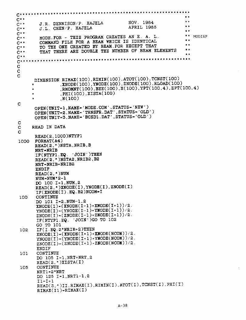
***********,_**_****_************.I**_********_**************
J.R. DENNISON/P. HAJELA NOV. 1984
J.L. CHEN/P. HAJELA APRIL 1985
C**
C**
C**
C**
C**
C**
C**
C**
C**
MODE.FOR - THIS PROGRAM CREATES AN E. A. L.
COMMAND FILE FOR A BEAM WHICH IS IDENTICAL
TO THE ONE CREATED BY BEAM.FOR EXCEPT THAT
THAT THERE ARE DOUBLE THE NUMBER OF BEAM ELEMENTS
** MODISP
C
C
C
C
C
C
i000
i00
I02
I01
DIMENSION RIMAX(100),RIMIN(100),ATOT(100),TCNST(100)
* ,XNODE(100),YNODE(100),ZNODE(100),RLOAD(100)
* ,RMOMNT(100),BEE(100),H(100),YPT(100,4),ZPT(100,4)* ,PHI(100),XISTA(100)
, ,N(IO0)
OPEN(UNIT-I,NAME='MODE.COM',STATUS-'NEW')
OPEN(UNIT-2,NAME='TRNSFR.DAT',STATUS-'OLD')
OPEN(UNIT=3,NAME-'BCSDI.DAT',STATUS-'OLD')
READ IN DATA
READ(2,1000)NTYP1
FORMAT(A4)
READ(2,*)NSTA,NRIB,B
NRT'NRIB
IF(NTYPI.E_. 'JOIN')TEEN
READ(2,*)NSTA2,NRIB2,B2
NRT'NRIB+NRIB2
ENDIF
READ(2,*)NUM
NUM=NUM*2-1
DO 100 I-I,NUM,2READ(2,*)XNODE(I),YNODE(I),ZNODE(I)
IF(XNODE(I).EW.B2)NCOM-I
CONTINUE
DO lOl I=2,NUM-I,2XNODE(I)=(XNODE(I-1)+XNODE(I+I))/2.
YNODE(I)=(YNODE(I-I)+YNODE(I+I))/2.
ZNODE(I)=(ZNODE(I-I)+ZNODE(I+I))/2.
IF(NTYPI.EW. 'JOIN')GO TO 102
GO TO I01
IF(I.EQ.2*NRIB+2)THEN
XNODE(I)=(XNODE(I+I)+XNODE(NCON))/2.
YNODE(I)=(YNODE(I+I)+YNODE(NCOM))/2.
ZNODE(I)=(ZNODE(I+I)+ZNODE(NCOM))/2.
ENDIF
CONTINUE
DO 105 I=I,NRT+NRT,2
READ(2,*)XISTA(I)
CONTINUE
NRTI=2*NRT
DO 125 I=I,NRTI-I,2ll=I+l
READ(3,*)II,RIMAX(I),RIMIN(I),ATOT(1),TCNST(1),PHI(I)
RIMAX(II)=RIMAX(I)
105
A-38
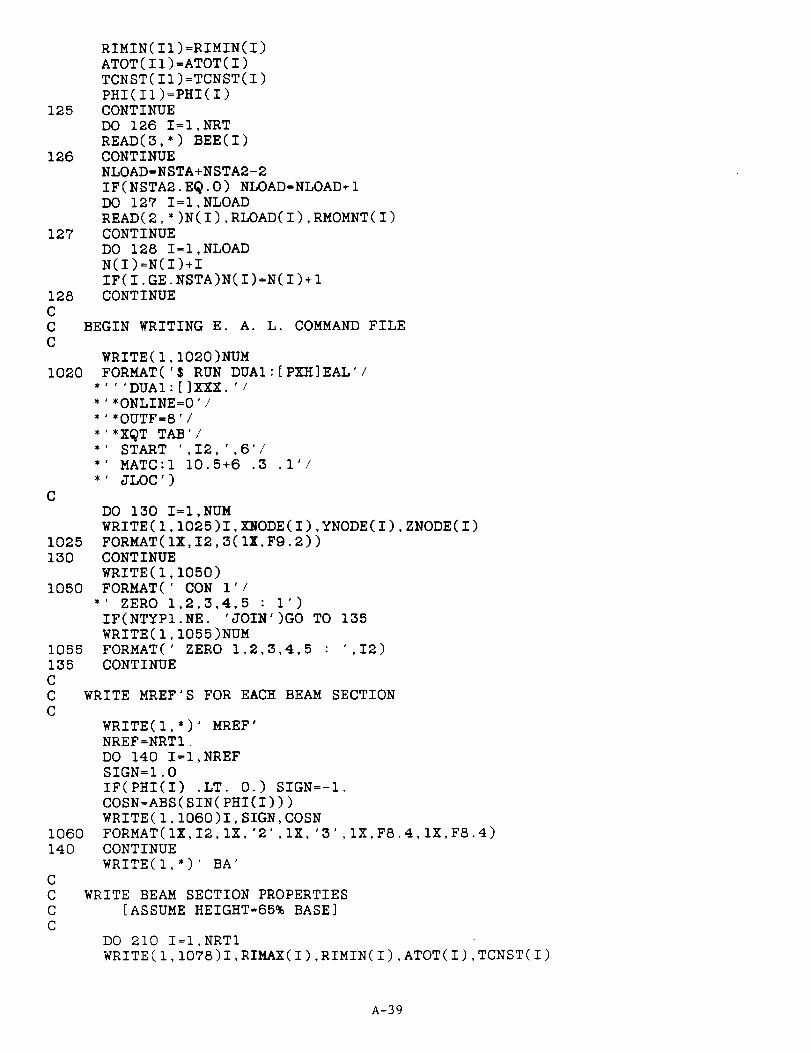
125
126
127
128
CC
C
1020
C
1025
130
1050
1055
135C
CC
1060
140
C
C
C
C
RIMIN(II)=RIMIN(I)
ATOT(I1)=ATOT(I)
TCNST(I1)=TCNST(I)
PHI(II):PHI(I)
CONTINUE
DO 126 I=I,NRT
READ(3,*) BEE(I)
CONTINUE
NLOAD=NSTA+NSTA2-2
IF(NSTA2.EQ.0) NLOAD=NLOAD+I
DO 127 I=I,NLOAD
READ(2,*)N(1),RLOAD(1),RMOMNT(1)
CONTINUE
DO 128 I=I,NLOAD
N(I)=N(I)+I
IF(I.GE.NSTA)N(I)=N(I)+I
CONTINUE
BEGIN WRITING E. A. L. COMMAND FILE
WRITE(1,1020)NUM
FORMAT('$ RUN DUAI:[PXH]EAL'/
''DUAI:[]XXX.'/
*ONLINE=0'/
*OUTF=8'/
*XQT TAB'/
START ',I2,',6'/
MATC:I 10.5+6 .3 .I'/
JLOC')
DO 130 I=I,NUM
WRITE(I,1025)I,XNODE(I),YNODE(I),ZNODE(I)
FORMAT(IX,I2,3(IX,Fg.2))
CONTINUE
WRITE(I,1050)
FORMAT(' CON I'/
*' ZERO 1,2,3,4,5 : 1')
IF(NTYP1.NE. 'JOIN')GO TO 135
WRITE(1,1055)NUMFORMAT(' ZERO 1,2,3,4,5 : ',I2)CONTINUE
WRITE MREF'S FOR EACH BEAM SECTION
WRITE(I°')' MREF'
NREF=NRTI.
DO 140 I=I,NREF
SIGN=I.0
IF(PHI(I) .LT. 0.) SIGN=-1.
COSN=ABS(SIN(PHI(I)))
WRITE(I,1060)I,SIGN,COSN
FORMAT(IX,12,1X,'2',IX,'3',IX,F8.4,1X,F8.4)
CONTINUE
WRITE(l,*)' BA'
WRITE BEAM SECTION PROPERTIES
[ASSUME HEIGHT=65% BASE]
DO 210 I=I,NRTI
WRITE(I,IO78)I,RIMAX(1),RIMIN(1),ATOT(I),TCNST(I)
A-39
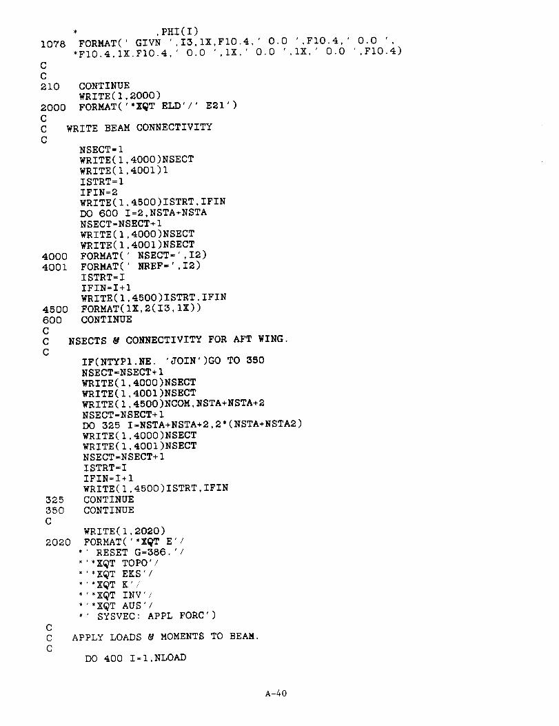
1078
C
C
210
2000C
C
C
4000
4001
450O6OOCCC
32535OC
2020
CCC
* ,PHI(l)FORMAT(' GIVN ',I3,1X,F10.4,' 0.0 ',FlO.4,' 0.0 '
*FI0.4,1X,FI0.4,' 0.0 ',IX,' 0.0 ',IX,' 0.0 ',FI0.4)
CONTINUEWRITE(I,2000)
FORMAT('*XQT ELD'/' E21')
WRITE BEAM CONNECTIVITY
NSECT=I
WRITE(I,4000)NSECT
WRITE(I,4001)IISTRT=I
IFIN=2
WRITE(I,4500)ISTRT,IFINDO 600 I=2,NSTA+NSTANSECT=NSECT+I
WRITE(I,4000)NSECT
WRITE(I,4001)NSECT
FORMAT(' NSECT=',I2)FORMAT(' _EF-',I2)ISTRT=I
IFIN=I+I
WRITE(I,4500)ISTRT,IFINFORMAT(IZ,2(I3,1X))
CONTINUE
NSECTS @ CONNECTIVITY FOR AFT WING.
IF(NTYPI.NE. 'JOIN')GO TO 350NSECT-NSECT+I
W!_ITE(I,4000)NSECT
WRITE(I,4001)NSECTWRITE(I,4500)NCOM,NSTA+NSTA+2NSECT=NSECT+I
DO 325 I=NSTA+NSTA+2,2*(NSTA+NSTA2)WRITE(I,4000)NSECT
WRITE(I,4001)NSECTNSECT-NSECT+IISTRT=I
IFIN=I+I
WRITE(I,4500)ISTRT,IFINCONTINUECONTINUE
WRITE(I,2020)
FORMAT(''X_T E'/* RESET G=386.'/* *XQT TOP0'/* *XQT EKS /
* *XQT K'/* *XQT INV /
* *XQT AUS /* SYSVEC: APPL FORC')
APPLY LOADS & MOMENTS TO BEAM.
DO 400 I=I,NLOAD
A-40

3000
3001
4OO
6100
6OOO
WRITE(1.3OOO)N(I),RLOAD(I)
FORMAT(' 1=3: J=',I2,':',Fg.2)
WRITE(I,3OOI)N(I),RMOMNT(I)
FORMAT(' I=4: J=',I2,':',F9.2)
CONTINUE
WRITE(I,61OO)NUM
FORMAT(' SYSVEC:UNIT VEC',/,
*' I=3:J=I,',13,' :i.0',/,
*' DEFINE UN=UNIT VEC',/,
*' DEFINE WT=DEM DIAG',/,
*' OBJF=XTY(UN,WT)')
WRITE(I,6000)
FORMAT( '*X_T SSOL'/
*'*OUTF=4',/,
*'*XQT DCU',/,*' PRINT 1 OBJF AUS',/,
*' PRINT 1 STATIC DISPLACEMENTS'/
*'*XQT EXIT')
CLOSE(UNIT=l)
STOP
END
A-41
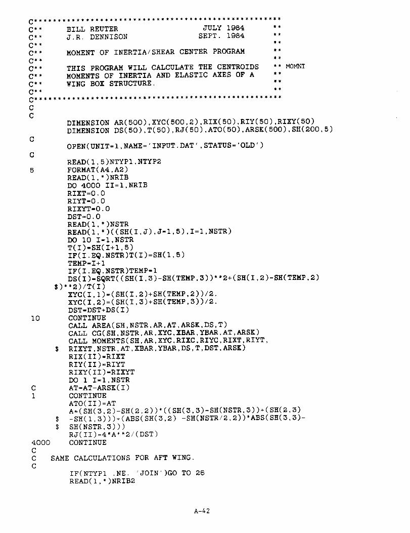
MOMENTOF INERTIA/SHEAR CENTER PROGRAM
THIS PROGRAM WILL CALCULATE THE CENTROIDS
MOMENTS OF INERTIA AND ELASTIC AXES OF A
WING BOX STRUCTURE.
C
C
5
MOMNT
DIMENSION AR(500),XYC(500,2),RIX(S0),RIY(50),RIXY(50)
DIMENSION DS(50),T(50),RJ(50),ATO(50),ARSK(S00),SH(200,5)
OPEN(UNIT=I,NAME='INPUT.DAT',STATUS='OLD ')
I0
C
1
4000
C
C SAME CALCULATIONS FOR AFT WING.
C
IF(NTYPI .NE. 'JOIN')GO TO
READ(I,*)NRIB2
READ(I,5)NTYPI,NTYP2
FORMAT(A4,A2)
READ(I,*)NRIB
DO 4000 II=I,NRIB
RIXT=0.0
RIYT-0.0
RIXYT=0.0
DST=0.0
READ(I,*)NSTR
READ(I,*)((SH(I,J),J-I,B),I=I,NSTR)
DO I0 I-I,NSTR
T(I)-SH(I+I,5)
IF(I.E_.NSTR)T(I)=SH(I,5)
TEMP-I+I
IF(I.E_.NSTR)TEMP=I
DS(1)-S_RT((SH(I,3)-SH(TEMP,3))**2+(SH(I,2)-SH(TEMP,2)
$)*'2)/T(I)
XYC(I,I)=(SH(I,2)+SH(TEMP,2))/2.
XYC(I,2)=(SH(I,3)+SH(TEMP,3))/2.
DST-DST+DS(I)
CONTINUE
CALL AREA(SH,NSTR,AR,AT,ARSK,DS,T)
CALL CG(SH,NSTR,AR,XYC,XBAR,YBAR,AT,ARSK)
CALL MOMENTS(SH,AR,XYC,RIXC,RIYC,RIXT,RIYT,
$ RIXYT,NSTR,AT,XBAR,YBAR,DS,T,DST,ARSK)
RIX(II)=RIXT
RIY(II)=RIYT
RIXY(II)-RIXYT
DO 11-I,NSTR
AT=AT-ARSK(I)
CONTINUE
ATO(II)=AT
A=(SH(3,2)-SH(2,2))*((SH(3,3)-SH(NSTR,3))+(SH(2,3)
$ -SH(1,3)))+(ABS(SH(3.2) -SH(NSTR/2,2))*ABS(SH(3,3)-
$ SH(NSTR,3)))
RJ(II)=4*A**2/(DST)CONTINUE
26
A-42

12
C40
400126
6002225
C
C
CC
C
4O
C
CC
DO 4001 II=NRIB+I,NRIB+NRIB2
RIXT=0.0
RIYT=0.0
RIXYT=0.0
DST=0.0
READ(I,*)NSTR2
READ(I,*)((SH(I,J),J=I,5),I=I,NSTR2)
DO 12 I=I,NSTR2
TEMP=I+I
IF(I .EQ. NSTR2)TEMP=I
T(I)=SH(TEMP,5)
DS(1)=SQRT((SH(I,3)-SH(TEMP,3))**2+(SH(I,2)-SH(TEMP,2)
)**2)/T(I)
XYC(I,1)=(SH(I,2)+SH(TEMP,2))/2.0XYC(I,2)=(SH(I,3)+SH(TEMP,3))/2.0
DST=DST+DS(I)
CONTINUE
CALL AREA(SH,NSTR2,AR,AT,ARSK,DS,T)
CALL CG(SH,NSTR2,AR,XYC,XBAR,YBAR,AT,ARSK)
CALL MOMENTS(SH,AR,XYC,RIXC,RIYC,RIXT,RIYT,RIXYT,
NSTR2,AT,XBAR,YBAR,DS,T,DST,ARSK)
RIX(II)=RIXT
RIY(II)=RIYT
RIXY(II)=RIXYT
DO 40 I=I,NSTR2AT=AT-ARSK(I)
CONTINUE
ATO(II)=AT
A=(SH(3,Z)-SH(2,2))*((SH(3,3)-SH(NSTR2,3))+(SH(2,3)-SH(I,3)))+(ABS(SH(3,2)-SH(NSTR2/2,2))*ABS(SH(3,3)-
SH(NSTR2,3)))RJ(II)=4.0*A**2/DST
CONTINUE
CONTINUE
OPEN(UNIT=I2,NAME='BEAM2.DAT',STATUS='NEW')
NDUM=NRIB
IF(NTYPI .EQ. 'JOIN')NDUM=NRIB+NRIE2
DO 225 I=I,NDUM
WRITE(12,6OO2)RIX(I),RIY(I),ATO(I),RJ(I),RIXY(I)
FORMAT(1X,B(F13.3,eX))CONTINUESTOP
END
SUBROUTINE AREA
SUBROUTINE AREA(SH,N,AR,AT,ARSK,DS,T)
DIMENSION SH(200,5),AR(500),ARSK(500),DS(50),T(50)
AT=0
DO 40 I=I,N
AR(I)=SH(I,4)
ARSK(I)=DS(I)*T(I)*'2
AT=AT+AR(I)+ARSK(I)
RETURN
END
SUBROUTINE CG
A-43
C
C
8O
C
CC
C
C
9O
99
89
15
CCC
CC
SUBROUTINE CG(SH,N,AR,XYC,XBAR,YBAR,AT,ARSK)
DIMENSION SH(200,5),AR(500),XYC(500,2),ARSK(500)
SUM1=0.SUM2-0.DO 80 I-I,NSUMI-SUMI+SH(I,2)*AR(I)+XYC(I,I)*ARSK(I)
SUM2-SUM2+SH(I,3)*AR(I)+XYC(I,2)*ARSK(I)CONTINUEXBAR=SUM1/ATYBAR=SUM2/ATRETURN
END
SUBROUTINE MOMENTS
SUBROUTINE MOMENTS(SH,AR,XYC,RIXC,RIYC,RIXT,RIYT,RIXYT
$,N,AT,XBAR,YBAR,DS.T.DST,ARSK)DIMENSION SH(200,5), AR(S00),XYC(S00,2),RIX(10).RIY(10),RIXY(10)
DIMENSION DS(50),T(50),ARSK(500)DO 15 I=I,NTHETA=O.
IF(I.EQ.1) GO TO 99IF(NTYPI.EQ. 'JOIN')THEN
IF([email protected])GO TO 99GO TO 90ENDIF
IF(I.E_.4)GO TO 99CONTINUERIOY-I./12.*T(1)*(DS(I)*T(I))'*3+(AR(I)**2)/(4.'3.141sg)
RIOX-I./12.*(DS(I)*T(I))*T(I)'*3+(AR(I)**2)/(4.*3.141Sg)GO TO 89RIOY=I./12.*(DS(I)*T(I))*T(I)**3+(AR(I)**2)/(4.*3.141sg)RIOX-I./12.*T(1)*(DS(1)*T(1))**S+(AR(I)**2)/(4.*3.141S9)
CONTINUE
UC=SH(I,2)-XBARUCS=XYC(I,I)-XBAR
VCS=XYC(I,2)-YBARVC=SH(I,3)-YBAR
CALL MOMAXIS(THETA,SH.AR,RIOX,RIOY.UC,VC,I,RIX,RIY,RIXY,$ RIXT,RIYT,RIXYT,VCS,UCS,ARSK)
CONTINUERETURN
END
SUBROUTINE MOMAXIS
SUBROUTINE MOMAXIS(THETA,SH,AR,RIOX,RIOY,UC,VC,I,RIX,RIY,
RIXY,RIXT,RIYT,RIXYT,VCS,UCS,ARSK)DIMENSION SH(200,5),AR(500),RIX(10),RIY(10),RIXY(10),ARSK(500)
RIX(I)=RIOX+AR(I)'VC**2+ARSK(I)*VCS**2RIY(I)=RIOY+AR(I)*UC**2+ARSK(I)*UCS''2
RIXY(I)=AR(I)*UC*VC+ARSK(I)*UCS*VCS
RIXT=RIXT+RIX(I)
A-44

CCC
RIYT=RIYT+RIY(1)RIXYT=RIXYT+RIXY(1)RETURNEND
A-45

_ **
C** P. HAJELA/ J.L. CHEN MARCH 1965 **
C *_ PROGRAM TO REDUCE SHEAR LAG EFFECTS **C,_ **
CDIMENSION WGDISP(500),BMDISP(100)
DIMENSION WGDISPI(S00),BMDISPI(100)
C
CCCC
2
I00
CC
C
C
SHLAC
105
CCC
66
6CC FIND
C
OPEN(UNIT=I,NAME='WlNG.DAT',STATUS='OLD ')
OPEN(UNIT=7.NAME='FOR003.DAT',STATUS='OLD ')
OPEN(UNIT=6,NAME='FOR004.DAT',STATUS='OLD ')
OPEN(UNIT=3T,NAME='KAPPA.DAT',STATUS='OLD ')
READ(37,*)RKAP,SLCON,SLCONIREWIND 37
READ THE DISPLACEMENTS OF ALLNODES ON WING & STORE IN ARRAY[WGDISP(I)].
READ(I,2)NTYPIFORMAT(A4)
READ(I,*)BSP,CR,CT,NSTR,NSTA,NRIB,RLAM,GAM,TR
RLAMD-RLAMRLAM=3.14159*RLAM/180.
GAMD-GAMGAM=3.14159"GAM/180.
IEND-NSTR*(NSTA+I)IREND-IEND
IF(NTYPI .E@. 'JOIN')THENREAD(1,*)BSP2,CR2,CT2,NSTR2,NSTA2,NRIB2,RLAM2,GAM2,TR2IREND=IEND+NSTR2*(NSTA2+I)
ENDIFREAD(T,100) (WGDISPI(1),WGDISP(1),I=I,IREND)
FORMAT(//////,(21X,EI2.5,EI2.5))
READ THE DISPLACEMENTS OF NODES ON BEAMSTORE IN ARRAY[BMDISP(I)]
INODE-NSTA+I
IF(NTYPI.EQ.'JOIN')INODE=NSTA+NSTA2+IREAD(8,105) (BMDISPI(I),BMDISP(I),I=I,INODE)FORMAT(/////,(21X,E12.5,E12.5))CLOSE(UNIT=7,DISP=°DELETE ')CLOSE(UNIT=8,DISP='DELETE ')
FIND THE MAXIMUM DISPLACEMENT ON BEAM
BMAX=ABS(BMDISP(1))BMAXI=ABS(BMDISPI(1))
DO 6 I=I,INODE
IF(ABS(BMDISPI(I)).LT.BMAXI)GOBMAXI=ABS(BMDISPI(I))CONTINUE
IF(ABS(BMDISP(I)).LT.BMAX)
BMAX=ABS(BMDISP(I))CONTINUE
TO 66
GO TO 6
THE MAXIMUM DISPLACEMENT ON WING
A-46

88
6
C
C
C
WMAX=ABS(WGDISP(1))
WMAXI=ABS(WGDISPI(1))
DO 8 I=I,IREND
IF(ABS(WGDISPI(I)).LT.WMAXI)GO TO 88
WMAXI=ABS(WGDISPI(I))
CONTINUE
IF(ABS(WGDISP(I)).LT.WMAX) GO TO 8
WMAX=ABS(WGDISP(I))
CONTINUE
CALCULATE THE SHEAR LAG CONSTANT
SLCONI=I.0
SLCON=BMAX/WMAX
RPAR=.925*TR/(S_RT(SLCON)*COS(RLAM))
SLCON=I.
IF(NTYPI .EQ. 'JOIN')THEN
CALL FACT(SINV,RLAMD,GAMD)
SLCONI=SINV*BMAX1/WMAXI
SLCON=SINV*BMAX/WMAX
RPAR=TR
ENDIF
WRITE(37,*)RPAR,SLCON,SLCONI
CLOSE(UNIT=I)
STOP
END
SUBROUTINE FACT(SINV,RLAMD,GAMD)
C __$___$______
C
C THIS PROGRAM PROVIDES AN INTERPOLATION FOR THE CORRECTIVE
C FACTOR USED TO ACCOUNT FOR SHEAR LAG EFFECTS -- INTERPOLATION
C IS BASED ON CUBIC SPLINE FITS. AUGUST 1985
C _Z__*_Z_S______
C
IF(GAMD.LT.4.)GAMD=4.
IF(GAMD.GE.20.)GAMD=Ig.95
IF(RLAMD.LT.IO.)RLAMD=IO.
IF(RLAMD.GE.30.)RLAMD=29.95
C
C BEGIN INTERPOLATION
C
IF(GAMD.GE.4.0.AND.GAMD.LT.8.0)THEN
C1=-9.8437E-2C2=0.0
C3=-8.7891E-4
YY=2.2
XI=4.0
GO TO 200
ENDIF
IF(GAMD.GE.8.0.AND.GAMD.LT.12.0)THEN
C3=-2.8320E-3
C2=-1.0547E-2C1=-0.1406
YY=l.75XI=8.0
GO TO 200
ENDIF
IF(GAMD.GE.12.0.AND.GAMD.LT.16.0)THEN
C3=-2.9297E-_
A-47

C2O0
C
3OO
C2---2. 3437E-2C1"_-8. 9063E-2YY=I. 2XI--12.0GO TO 2O0ENDIF
IF(GAMD. GE .16.0. AND. GAMD. LT. 20.0)THENC3=- I.6602E- 3
C2 - i. 9922E- 2CI=8.4375E-2
YY=I. 20Xl=16.0
GO TO 2OO
ENDIF
CONTINUE
FNG=((C3*(GAMD-XI)+C2)*(GAMD-XI)+CI)*(GAMD-XI)+YY
IF (RLAMD. GE. I0.0. AND. RLAMD. LT. 15.0)THEN
C3=-8. 7143E-4C2=0.0
CI--4. 8214E-2YY=3.25
XI=I0.0GO TO 300
ENDIF
IF (RLAMD. GE. I5.0. AND. RLAMD .LT. 20.0 )THENC3=2. 3871E-3C2--1. 3071E-2
CI--0. 1156YY-2.9
XI-15.0
GO TO 300ENDIF
IF (RLAMD. GE. 20.0. AND. RLAMD .LT. 25.0 )THENC3=2. 5571E-3
C2=2. 2266E-2
CI=-6.75E-2YY=2.3XI=20.0
GO TO 300ENDIF
IF (RlgtMD. GE. 25.0. AND. RLAMD .LT. 30.0) THENC3zl. 0714E-3
C2--I .6071E-2
CI--3. 6429E-2YY=2.2
XI=25.0
GO TO 300ENDIF
CONTINUE
FNR=( (C3" (RLAMD-XI)+C2 )*(RLAMD-XI)+CI )*(RLAMD-XI) +YYSINV=FNG'FNR/2.2RETURN
END
A-48
II
J.L. CHEN/ P. HAJELA APRIL 1985 "_
C _
C**
C**
C**
C**
S_
STRESS.FOR PROGRAM TO COMPUTE THE STRESS "*
FROM THE DISPLACEMENT RESULTS "*S_
STRESS
9
C
CC
C
C
CC
5
I0
C
C
C
20C
CC
C
DIMENSION RIXX(100),RIYY(100),RIXY(100),DISPI(100),DISP2(100)
DIMENSION B(IOO),YCORD(IOO),ZCORD(IO0)
DIMENSION YM(IOO),ZM(IOO),STRESS(IO0,6)
DIMENSION XCORD(IOO),YP(IOO,6),ZP(IO0,6)
DIMENSION TDISPI(IOO),TDISP2(IO0)
DIMENSION ATOT(100),RJ(100),NJOIN(100),RLOAD(100),RMONT(100)
DIMENSION V(100)
DIMENSION TOR_UE(100),SHEAR(100,6),DIS(100,6)
OPEN(UNIT=I,NAME='INERT.DAT',STATUS='OLD')
OPEN(UNIT=2,NAME='[email protected]',STATUS='OLD')
OPEN(UNIT=_,NAME='TRNSFR.DAT',STATUS='OLD')
OPEN(UNIT=4,NAME='STRESS.DAT',STATUS='NEW')
OPEN(UNIT=8,NAME='BCSD.DAT',STATUS='OLD')
OPEN(UNIT=_T,NAME='KAPPA.DAT',STATUS='OLD')
READ(_7,*)RKAP,SLCON,SLCONI
READ(_,g)NTYPI
FORMAT(A4)
READ(8,*)NSTA,NRIE,BI
N=NSTA
IF(NTYPI.E@. 'JOIN') THENREAD(_,*)NSTA2,NRIB2,B2
N=NSTA+NSTA2
ENDIF
READ(Z,*)NUM
NI=NUM
READ THE MOMENT OF INERTIA
RIXX,RIYY,RIXY
READ(I,*)(RIXX(I),RIYY(I),RIXY(I),I=I,N)
READ(I,')(ATOT(I),RJ(I),I=I,N)
READ THE DISPLACEMENT VALUES
READ(2,5)NN
FORMAT(18(/),I2)
READ(2,10)(DISPI(I),DISP2(I),I=I,N+NI)
FORMAT(21X,EI2.5,EI2.5)
READ THE NODE'S X-COORDINATES
DO 20 I=l,N1
READ(3,*)XCORD(1),YCORD(1),ZCORD(1)
IF((ABS(XCORD(I)-B2)).LE.0.001)NCOM=I
CONTINUE
READ THE CROSS-SECTION PROPERTY
COMPUTE THE POSITION TO EVALUTE THE STRESS
READ(8,*)(B(I),I=I,N)
DO 25 I=l, N
YP(I,I)=-B(I)/2.
A-49
25
26CCC
99
3130
40C
CC
50CCC
ZP(I,1)=RKAP*B(I)/(0.65*2.0) jYP(I,2)=0.
ZP(I,2)=RKAP*B(I)/(2.*0.65)
YP(I.3)=-YP(I.I)ZP(I,3)=ZP(I,I)
YP(I,4)=-YP(I,I)ZP(I,4)--ZP(I,I)
YP(I,6)=0.ZP(I,5)--ZP(I.I)
YP(I.6)=YP(I,I)
ZP(I,6)=-ZP(I,I)CONTINUE
DO 26 I=I,NDO 26 J=l,6
DIS(I,J)=S_RT((ABS(YP(I,J)))**2+(ABS(ZP(I,J)))**2)CONTINUE
Structural
COMPUTE THE CURVATURE OF THE BEAM'S DEFLECTION
DO 40 I=I.N
IF(I.E_.NSTA+I)THENJI=NCOM
GIS=(XCORD(I+I)-XCORD(J1))*'2 + (YCORD(I+I)-YCORD(JI)),*2$+ (ZCORD(I+I)-ZCORD(JI))**2GO TO 99ENDIF
GIS-(XCORD(I+I)-XCORD(I))**2 + (YCORD(I+I)-YCORD(I))**2$+ (ZCORD(I+I)-ZCORD(I))**2CONTINUE
H-(S@RT(GIS))/2.II=2"I-I
IF(I.E_.I)GO TO 30IF(I.GE.NSTA+I) II=I*2+l
IF(NTYPI.E_. 'JOIN') THEN
IF(I.E_.N)G0 TO 31ENDIF
TDISPI(I)=(DISPI(II-I)-2.*DISPI(II)+DISPI(II+I))/(H**2)TDISP2(I)=(DISP2(II-I)-2.*DISP2(II)+DISP2(II+I))/(H**2)GO TO 40
11=1"2
TDISPI(1)=2.*(DISPI(II+I)-DISPI(II))/(H**2)
TDISP2(I)=2.*(DISP2(II+I)-DISP2(II))/(H**2)IF(I.LE.NSTA)GO TO 40
EF(NTYPI.E_. 'JOIN')THENTDISPI(I)=-TDISPI(I)
TDISP2(I)=-TDISP2(I)ENDIFCONTINUE
COMPUTE THE MOMENT MY,MZ
E=I0.51+6
DO 50 I=I,N
YM(1)=E*RIXX(I)*TDISP2(I)
ZM(I)=E*RIYY(I)*TDISPI(I)CONTINUE
COMPUTE THE SHEAR STRESS
READ(3,*)(XCORD(I),I=I,N)
box is 65Z of che
A-50
7O
8O
859O
CC
C
55
60
K=NSTA-I
IF(NTYPI.EQ. 'JOIN')K=NSTA+NSTA2-2
READ(3,*)(NJOIN(I),RLOAD(I),RMONT(I),I=I,K)
TRMONT=O.
TRLOAD=O.
DO 70 I=1,5
TRMONT=TRMONT+RMONT(I)
TRLOAD=TRLOAD+RLOAD(I)
V(1)=TPJ/)AD
TORQUE(1)=TRMONT
DO 80 I=2,NSTA
TORQUE(I)=TORQUE(I-I)-RMONT(I-I)
V(1)=V(I-I)-RLOAD(I-I)
IF(NTYPI.EQ. 'JOIN')THEN
V(T)=RLOAD(5)+RLOAD(4)
TORQUE(7)=RMONT(5)+RMONT(4)
V(8)=RLOAD(6)+V(7)
TORQUE(8)=RMONT(6)+TORQUE(7)V(9)=RLOAD(7)+V(8)
TORQUE(9)=RMONT(7)+TORQUE(8)V(10)=RLOAD(8)+V(9)
TORQUE(10)=RMONT(8)+TORQUE(9)ENDIF
DogoI=I,N
DO 85 J=l,6
SHEAR(I,J)=(TORQUE(I)*DIS(I,J))/RJ(I)
V(I)=I.5*V(1)/ATOT(I)
COMPUTE THE STRESS IN EACH POSITION
DO 60 I=I,N
DO 55 6=1,6DD=((YM(1)*RIXY(1)-ZM(1)'RIXX(I))*YP(I,J)+
* (ZM(I)*RIXY(I)-YM(I)*RIYY(I))*ZP(I,E))/
* (RIXX(1)*RIYY(I)-RIXY(1)**2)
DI=(ABS(DD))**2
STRESS(I,J)=SQRT(DI)CONTINUE
WRITE(4,*)(STRESS(I,K),K=I,6)
CONTINUE
CLOSE(UNIT=l)
CLOSE(UNIT=2)
CLOSE(UNIT=3)
CLOSE(UNIT=4)
CLOSE(UNIT=8)STOP
END
A-51
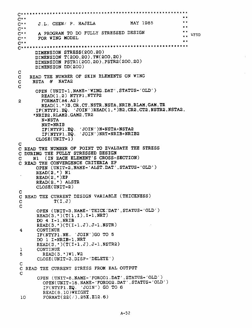
J.L. CHEN/ P. HAJELA MAY 1985
C**
C**
C**C**
C**
C**
A PROGRAM TO DO FULLY STRESSED DESIGN
FOR WING MODEL , , WFSD
DIMENSION STRESS(200,20)
DIMENSION T(200,20),TN(200,20)
DIMENSION PSTRI(200,20),PSTR2(200,20)
DIMENSION DD(200)
READ THE NUMBER OF SKIN ELEMENTS ON WING
NSTA & NATA2
C
C
C
C
OPEN (UNIT-I,NAME='WING.DAT',STATUS-'OLD')READ(I,2) NTYP1,NTYP2
2 FORMAT(A4,A2)
READ(I,*)B,CR,CT,NSTR,NSTA,NRIB,RLAM,GAM,TR
IF(NTYPI.E@. 'JOIN')READ(I,*)B2,CR2,CTe,NSTR2,NSTA2o
*NRIB2,RLAM2,GAM2,TR2
N=NSTA
NRT-NRIB
IF(NTYPI.E@. 'JOIN')N=NSTA+NSTA2
IF(NTYPI.E@. 'JOIN')NRT-NRIB+NRIB2
CLOSE(UNIT-l)
C
C READ THE NUMBER OF POINT TO EVALUATE THE STRESS
C DURING THE FULLY STRESSED DESIGN
C N1 (IN EACH ELEMENT'S CROSS-SECTION)
C READ THE CONVERGENCE CRITERIA EP
OPEN (UNIT=2,NAME='ALST.DAT'oSTATUS-'OLD')
READ(2,') N1
READ(2,*)EP
READ(2,*) ALSTR
CLOSE(UNIT=2)
C
C READ THE CURRENT DESIGN VARIABLE (THICKNESS)
C T(I,J)
C
OPEN (UNIT=3,NAME='THICKfDAT',STATUS='OLD')
READ(3,*)(T(I,I),I=I,NRT)
DO 4 I-I,NRIB
READ(3,*)(T(I+I,J),J=I,NSTR)
4 CONTINUE
IF(NTYPI.NE. 'JOIN')GO TO 5
DO I I=NRIB+IoNRT
READ(3,*)(T(I+I,J),J=I,NSTR2)
1 CONTINUE
5 READ(3,*)Wl,W2
CLOSE(UNIT=3,DISP='DELETE')C
C READ THE CURRENT STRESS FROM EAL OUTPUT
C
OPEN (UNIT=8,NAME='FOR001.DAT',STATUS='OLD')
OPEN(UNIT=IS,NAME='FOR002.DAT',STATUS='OLD')
IF(NTYPI.EQ. 'JOIN') GO TO 6
READ(8,10)WEIGHT
i0 FORMAT(22(/),25X,E12.6)
A-52
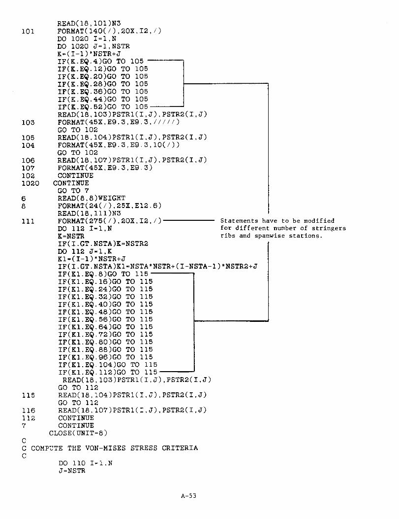
i01
103
105104
106
107
1021020
68
III
115
116
1127
C
CC
READ(18,101)N3FORMAT(140(/),20X,I2,/)
DO 1020 I=I,N
DO 1020 J=I,NSTRK=(I-1)*NSTR+J
4)GO TO 105IF(K.EQ
IF(K.EQ
IF(K.EQ
IF(K.EQ
IF(K.EQ
IF(K.EQ
IF(K.EQ
12)GO TO 105
20)GO TO 10528)GO TO 105
36)GO TO 10544)GO TO 105
52)GO TO 105
READ(18,103)PSTRI(I,J),PSTR2(I,J)FORMAT(45X,E9.3,E9.3,/////)
GO TO 102
READ(18,104)PSTRI(I,J),PSTR2(I,J)FORMAT(45X,Eg.3,E9.3,10(/))
GO TO 102READ(18,107)PSTRI(I,J),PSTR2(I,J)
FORMAT(45X,E9.3,E9.3)CONTINUE
CONTINUE
GO TO 7READ(8,8)WEIGHT
FORMAT(24(/),25X,EI2.6)
READ(18,111)N3
FORMAT(275(/),20X,I2,/)
DO 112 I=I,NK=NSTR
IF(I.GT.NSTA)K=NSTR2
DO 112 J=I,K
KI=(I-I)*NSTR+J
IF(I.GT.NSTA)KI=NSTA*NSTR+(I-NSTA-I)*NSTR2+J
8)GO TO 115
16)GO TO 115
IF(KI.EQ
IF(KI.EQ
IF(KI.EQ
IF(KI.EQ
IF(KI.EQ
IF(KI.EQ
IF(KI.EQ
IF(KI.EQ
IF(KI.EQ
IF(KI.EQ
IF(KI.EQ
IF(KI.EQ
IF(KI.EQ
IF(KI.EQ
READ(18
24)GO TO 115
32)GO TO 11540)GO TO 115
48)GO TO 11556)GO TO 115
64)GO TO 11572)GO TO 115
80)GO TO 11588)GO TO 115
96)GO TO 115104)GO TO 115
l12)GO TO 115103)PSTRI(I,J),PSTR2(I,J)
GO TO 112
READ(18,104)PSTRt(I,J),PSTR2(I,J)GO TO 112
READ(18,107)PSTRI(I,J),PSTR2(I,J)CONTINUE
CONTINUE
CLOSE(UNIT=8)
Statements have to be modified
for different number of stringers
ribs and spanwise stations.
COMPUTE THE VON-MISES STRESS CRITERIA
DO II0 I=I,N
J =NSTR
A-53

II0C
C
IF(I.GT.NSTA)J=NSTR2
IX3 II0 K=I,J
VMC=(ABS(PSTRI(I.K)))**2+(ABS(PSTR2(I,K)))**2
-PSTRI(I,K)*PSTR2(I,K)
VMC_ABS(VMC)
STRESS(I,K)=S_RT(VMC)
CONTINUE
C FULLY STRESSED DESIGN STEPS
C
DO 20 II=I.NSTA
DO 19 J=I,NSTR
DD(J)=ABS(STRESS(II,J))
19 CONTINUE
DO 60 K=I,NSTR
DDD-DD(K)/ALSTR
TN(II+I,K)_T(II+I,K)*DDD
60 CONTINUE
20 CONTINUE
IF(NTYPI.EQ. 'JOIN')THEN
DO 70 I-NSTA+I,N
DO 65 J-I,NSTR2
DD(J)=ABS(STRESS(I,J))
65 CONTINUE
DO 68 K-1,NSTR2
DDDzDD(K)/ALSTR
TN(I+I.K)-T(I+I,K)'DDD
68 CONTINUE
70 CONTINUE
ENDIF
C
CC
CC
CHECK THE UPPER BOUND OF THICKNESS-3.0
CHECK THE MINIMUM ALLOWABLE THICKNESS=0.03 (IN)
DO 15 II-I,N
IF(TN(II+I,2).LT.TN(II+I,5))TN(II+I,2)=TN(II+I,5)
IF(TN(II+I,2).GT.TN(II+I,5))TN(II+I,5)=TN(II+I,2)
I3=NSTR
IF(II.GT.NSTA)I3=NSTR2
DO 15 I2-i,I3
IF(TN(II+I,I2).GT.3.0) TN(II+I,I2)=3.0
IF(TN(II+I,I2).LT.0.03) TN(II+I,I2)=0.0315 CONTINUEC
C RENEW DESIGN VARIABLE
C
OPEN (UNIT=3,NAME='THICK.DAT',STATUS='NEW ')
WRITE(3,*)(T(I,I),I=I,NRT)
DO 30 J=I,N
K=NSTR
IF(J.GT.NSTA)K=NSTR2
WRITE(3,25) (TN(J+I,I),I=I,K)
25 FORMAT(1X,(F12.6,1X))30 CONTINUE
WRITE(3,*)W2,WEIGHT
CLOSE(UNIT=3)
C
C PRINTOUT THE ITERATION INFORMATION
lower and uppor
bounds on skin
thickness.
A-54
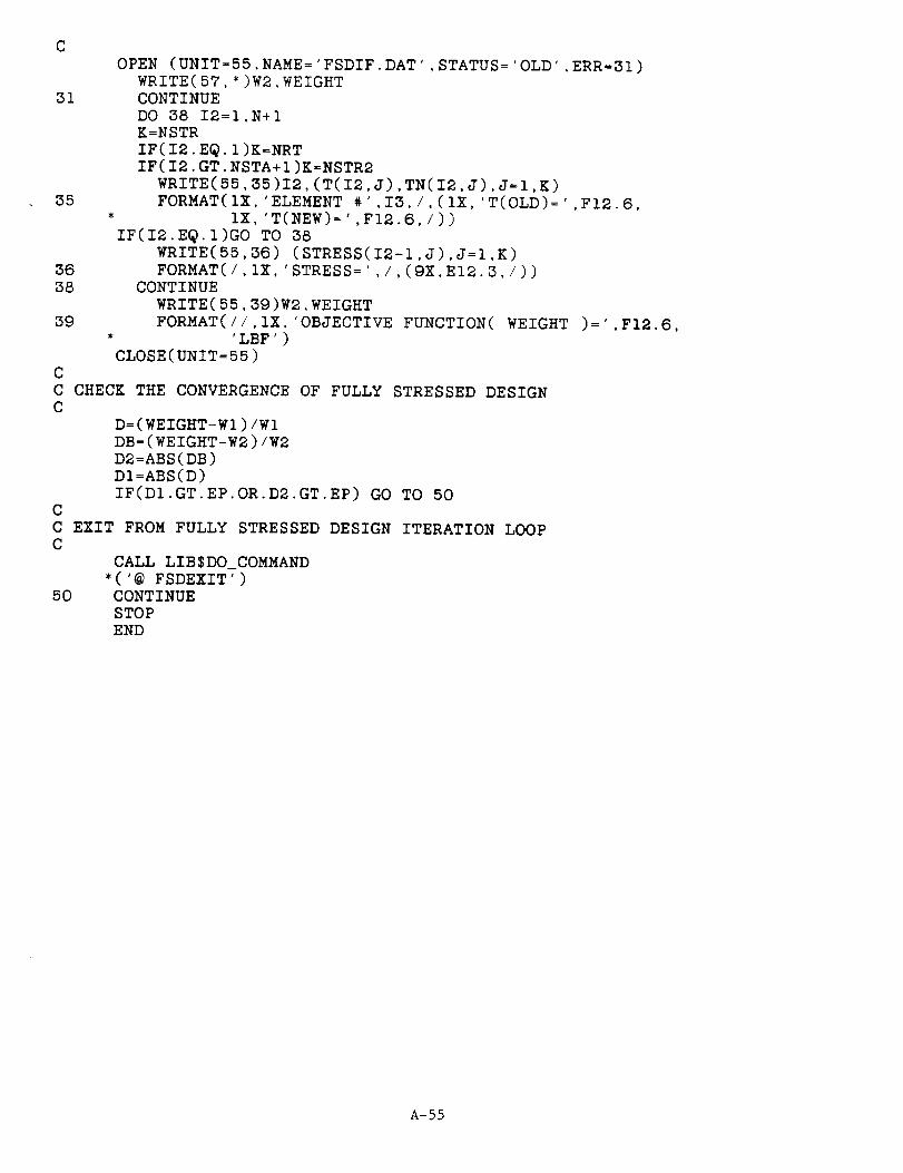
COPEN (UNIT=55,NAME='FSDIF.DAT',STATUS='OLD',ERR=31)
WRITE(57,*)W2,WEIGHT31 CONTINUE
DO 38 I2=I,N+IK=NSTRIF(I2.EQ.I)K=NRTIF(I2.GT.NSTA+I)K=NSTR2
WRITE(S5,35)I2,(T(12,J),TN(12,J),J=I,K)35 FORMAT(IX,'ELEMENT #',I3,/,(IX,'T(OLD)=',FI2.6,
* IX,'T(NEW)=',FI2.6,/))IF(Ie.EQ.I)GO TO 38
WRITE(55,36) (STRESS(I2-I,J),J=I,K)36 FORMAT(/,IX,'STRESS=',/,(9X,EI2.3,/))38 CONTINUE
WRITE(55,39)W2,WEIGHT39 FORMAT(//,IX_'OBJECTIVE FUNCTION( WEIGHT )=',F12.6,
* 'LEF')CLOSE(UNiT=55)
C
C CHECK THE CONVERGENCE OF FULLY STRESSED DESIGNC
D=(WEIGHT-Wl)/Wl
DB=(WEIGHT-W2)/W2
D2=ABS(DB)
DI=ABS(D)
IF(DI.GT.EP.OR.D2.GT.EP) GO TO 50
C
C EXIT FROM FULLY STRESSED DESIGN ITERATION LOOPC
CALL LIB$DO_COMMAND
*('@ FSDEXIT')
50 CONTINUE
STOP
END
A-55


Report Documentation Page
1. Report No.
CR-177440
4. Title and Subtitle
2. Government Accession No. 3. Recipient's Catalog No.
5. Report Date
Reduced Complexity Structural Modeling forAutomated Airframe Synthesis
7. Author(s)
Prabhat HajelaUniversity of Florida, Gainesville, FL
9. Performing Organization Name and Address
Ames Research Center
Moffett Field, CA 94035
12. Sponsoring Agency Name and Address
National Aeronautics and
Washington, DC 20546Space Administration
May 1987
6. Performing Organization Code
8. Performing Organization Report No.
10. Work Unit No.
505-43-01
11. Contract or Grant No.
NCA2- I R240- 40113. Type of Report and Period Covered
Contractor Report
14. Sponsoring Agency Code
15, Supplementaw Not_
Point of Contact: Steve C. Smith, Ames ResearchMoffett Field, CA 94035, (415)694-5856
Center, M/S 227-2
16. Abstract
The present report documents a procedure for the optimum sizing of wing structuresthat is based on representing the built-up finite element assembly of the
structure by equivalent beam models. The reduced-order beam models are computa-tionally less demanding in an optimum design environment which dictates repetitiveanalysis of several trial designs. The design procedure is implemented in a
computer program that requires geometry and loading information to create the wingfinite element model and its equivalent beam model, and provides a rapid estimate
of the optimum weight obtained from a fully stressed design approach applied tothe beam. The synthesis procedure is demonstrated for representative conventional-cantilever and joined wing configurations.
17. Key Words (Suggested by Author(s))
0ptimizati0n, Structures, StructuralAnalysis, Joined Wing
18. Distribution Statement
Unlimited- Unclassified
Subject Category - 01
19. Security Classif. (of this report)
Unclassified
NASA FORM 1626 OCT B6
20. Security Classif. (of this page)
Unclassifiedi
21. No. of pages 22.. Price

Related Documents


![NASA Contractor Report ]65685](https://static.cupdf.com/doc/110x72/6264cfa4d246584a7031f997/nasa-contractor-report-65685.jpg)