SECTION MODULE NO. RELIANCE INDUSTRIES LIMITED CKR-PR-P-001 PROCESS DESCRIPTION AND UTILITIES CKR-PR-P-011 CHECKED BY PAGE 1 N.S.P Process description and Utilities REV 0 ISSUE 0 APPROVED BY DATE 12/03/20 22 B. DAS AUTHOR BMK

Welcome message from author
This document is posted to help you gain knowledge. Please leave a comment to let me know what you think about it! Share it to your friends and learn new things together.
Transcript
SECTION MODULE NO.
RELIANCE INDUSTRIES LIMITED
CKR-PR-P-001
PROCESS DESCRIPTION AND
UTILITIES
CKR-PR-P-011
CHECKED BY PAGE 1 N.S.P Process description and Utilities REV 0
ISSUE 0APPROVED BY DATE 07/04/2023
B. DAS AUTHOR BMK
SECTION MODULE NO.
RELIANCE INDUSTRIES LIMITED
CKR-PR-P-001
Preface
This operating manual gives general guidelines for the
understanding and operation of the Cracker Plant. It provides
basic information on the process , utilities, effluent treatment
and emergencies. This shall be read with other Standard
Operating Procedures to understand precisely the operation
and control methodology of the plant.
It is recognised that several improvements can be made to this
manual for more efficient operation of the plant. Any such
changes shall be communicated to the Manager in charge for
proper updating and revision.
Author
B.M.Krishna
CHECKED BY PAGE 2 N.S.P Process description and Utilities REV 0
ISSUE 0APPROVED BY DATE 07/04/2023
B. DAS AUTHOR BMK

SECTION MODULE NO.
RELIANCE INDUSTRIES LIMITED
CKR-PR-P-001
CONTENTS:
1 NGL / NAPHTHA CRACKER PLANT AT RIL, HAZIRA
1.1 Introduction
1.2 Feed Stock
1.3 Other Products
1.4 Chemicals, Additives And Catalysts
1.5 Products Specification
2 Process Description
2.01 Cracking Furnaces
2.02 USC main furnace and recycle furnace quench fittings
2.03 Quench Oil Tower
2.04 HFO Stripper
2.05 LFO Stripper
2.06 Quench Water Tower
2.07 Dilution Steam generation system
2.08 Distillate stripper
2.09 Quench Water Circulation Circuit
2.10 Quench Oil Circulation Circuit
2.11 Pan Oil Circulation Circuit
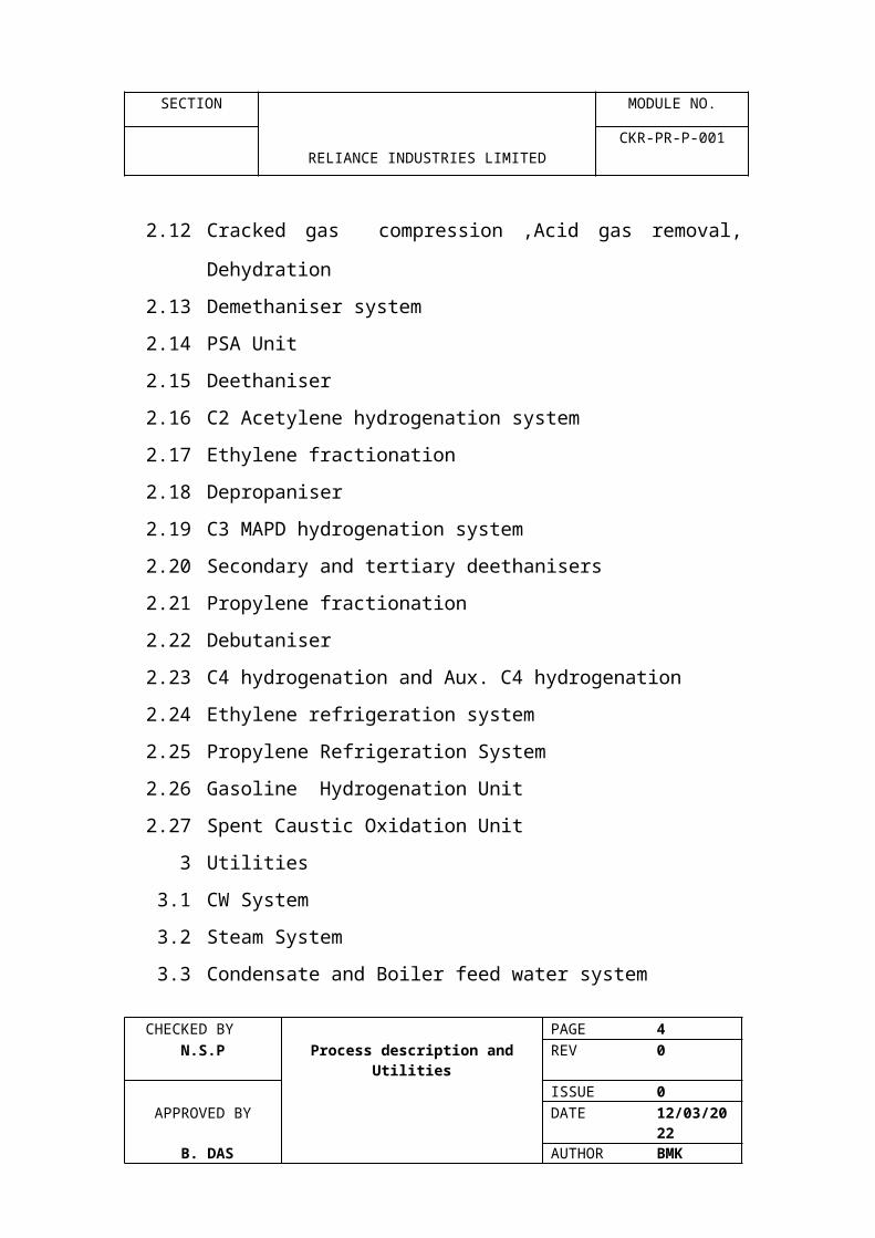
2.12 Cracked gas compression ,Acid gas removal,
Dehydration
2.13 Demethaniser system
2.14 PSA Unit
2.15 Deethaniser
2.16 C2 Acetylene hydrogenation system
CHECKED BY PAGE 3 N.S.P Process description and Utilities REV 0
ISSUE 0APPROVED BY DATE 07/04/2023
B. DAS AUTHOR BMK
SECTION MODULE NO.
RELIANCE INDUSTRIES LIMITED
CKR-PR-P-001
2.17 Ethylene fractionation
2.18 Depropaniser
2.19 C3 MAPD hydrogenation system
2.20 Secondary and tertiary deethanisers
2.21 Propylene fractionation
2.22 Debutaniser
2.23 C4 hydrogenation and Aux. C4 hydrogenation
2.24 Ethylene refrigeration system
2.25 Propylene Refrigeration System
2.26 Gasoline Hydrogenation Unit
2.27 Spent Caustic Oxidation Unit
3 Utilities
3.1 CW System
3.2 Steam System
3.3 Condensate and Boiler feed water system
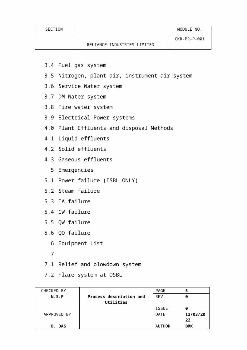
3.4 Fuel gas system
3.5 Nitrogen, plant air, instrument air system
3.6 Service Water system
3.7 DM Water system
3.8 Fire water system
3.9 Electrical Power systems
4.0 Plant Effluents and disposal Methods
4.1 Liquid effluents
4.2 Solid effluents
4.3 Gaseous effluents
5 Emergencies
CHECKED BY PAGE 4 N.S.P Process description and Utilities REV 0
ISSUE 0APPROVED BY DATE 07/04/2023
B. DAS AUTHOR BMK
SECTION MODULE NO.
RELIANCE INDUSTRIES LIMITED
CKR-PR-P-001
5.1 Power failure (ISBL ONLY)
5.2 Steam failure
5.3 IA failure
5.4 CW failure
5.5 QW failure
5.6 QO failure
6 Equipment List
7
7.1 Relief and blowdown system
7.2 Flare system at OSBL
8.0 Fire and Gas Detection System
CHECKED BY PAGE 5 N.S.P Process description and Utilities REV 0
ISSUE 0APPROVED BY DATE 07/04/2023
B. DAS AUTHOR BMK
SECTION MODULE NO.
1RELIANCE INDUSTRIES LIMITED
CKR-PR-P-001
1.1 INTRODUCTION
The NGL / Naphtha Cracker plant is designed to product
5,00,000 metric tonnes per annum of polymer grade ethylene
from cracking Naphtha and NGL. Subsequently, the plant was
engineered to increase the capacity from 5,00,000 MTA to
7,00,000 MTA.
It is designed to crack Naphtha, NGL, AGO and C2/C3 recycle
and fresh streams. However, the 7,00,000 MTA capacity of
ethylene is produced by cracking of low aromatics naphtha
only. Also, the recycle streams like C2,C3,C5, C6-C8 raffinate
from aromatics plant and hydrogenated mix C4 are cocracked
with Naphtha in the furnaces.
The minimum propylene production capacity is 3,20,000 MTA
for an optimum cracking severity of 3.11 KSFA for the designed
on stream time of 8000 hours per year.
The plant is able to produce HP ethylene vapour at
58kg/cm2g ,LP vapour ethylene at 27 kg/cm2g. and ethylene as
liquid at -980C for storage in atmospheric tank.
The plant also includes two IFP units C4 hydrogenation unit for
processing mixed C4 and GHU unit for the treatment of
gasoline generated during cracking. For the production of high
purity hydrogen, one PSA unit is installed supplied by UOP,
USA.
CHECKED BY PAGE 6 N.S.P Process description and Utilities REV 0
ISSUE 0APPROVED BY DATE 07/04/2023
B. DAS AUTHOR BMK

SECTION MODULE NO.
1RELIANCE INDUSTRIES LIMITED
CKR-PR-P-001
1.2 FEED STOCKS
The cracker plant is designed on the basis of single light
naphtha feed stock as defined below :
SG : 0.7
Distribution Curve : 0C
1BP : 45
10% : 68
50% : 100
90% : 130
FBP : 150
PONA : WT
Paraffins 74% Min.
Naphthalenes Balance
Aromatic 10%
Olefins Vol. Max. 1.0%
Hydrogen, WT% 15.2
Sulphur PPM wt/wt 800 max.
RVP kg/cm2a 0.94 max.
However, plant is capable in using other feed stacks
NGL/AGO,C2/C3, recycle hydrogenated C4 mix, C5 from GHU
and C6-C8 raffinates from aromatics.
CHECKED BY PAGE 7 N.S.P Process description and Utilities REV 0
ISSUE 0APPROVED BY DATE 07/04/2023
B. DAS AUTHOR BMK
SECTION MODULE NO.
1RELIANCE INDUSTRIES LIMITED
CKR-PR-P-001
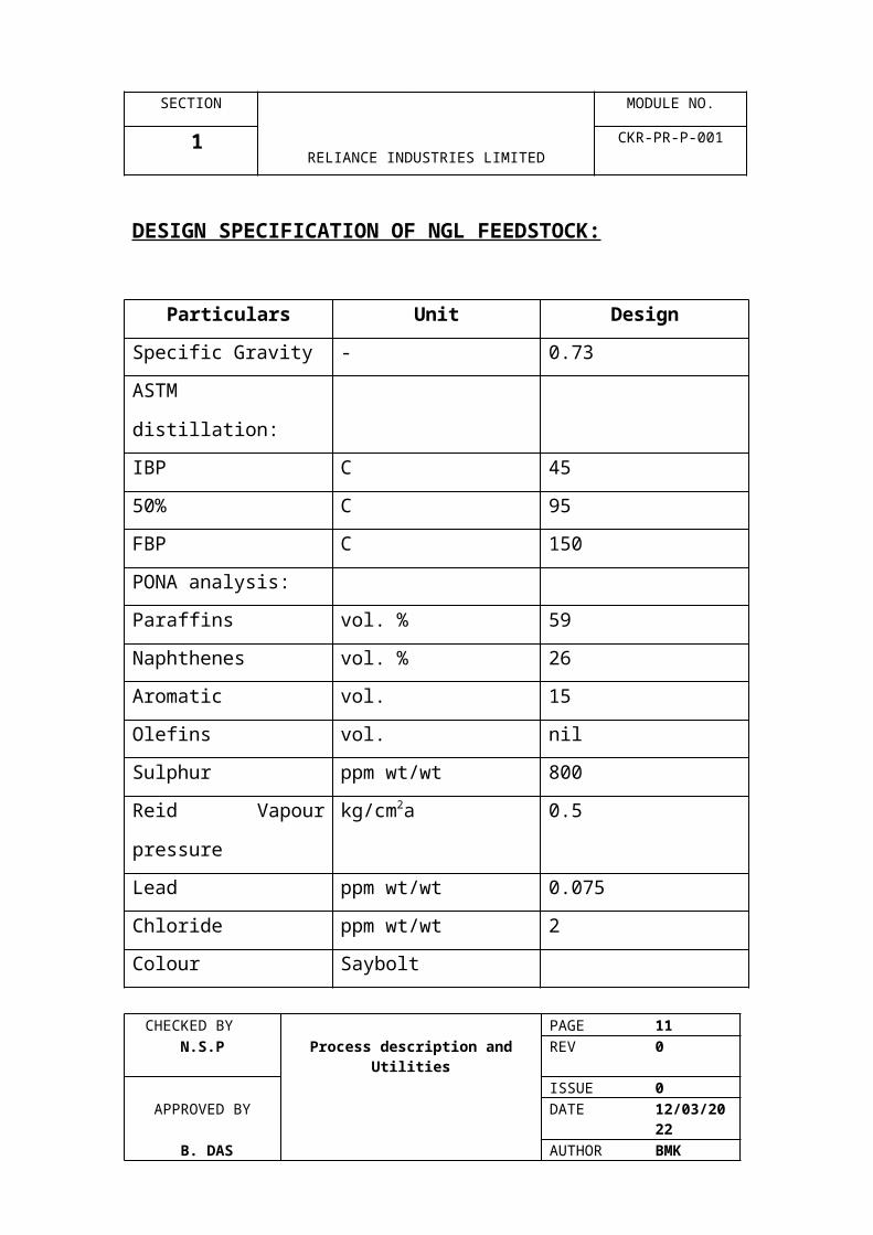
DESIGN SPECIFICATION OF NGL FEEDSTOCK:
Particulars Unit Design
Specific Gravity - 0.73
ASTM distillation:
IBP C 45
50% C 95
FBP C 150
PONA analysis:
Paraffins vol. % 59
Naphthenes vol. % 26
Aromatic vol. 15
Olefins vol. nil
Sulphur ppm wt/wt 800
Reid Vapour
pressure
kg/cm2a 0.5
Lead ppm wt/wt 0.075
Chloride ppm wt/wt 2
Colour Saybolt
Note :
The i-Paraffins may be present up to 50% by wt. of total
Paraffins
CHECKED BY PAGE 8 N.S.P Process description and Utilities REV 0
ISSUE 0APPROVED BY DATE 07/04/2023
B. DAS AUTHOR BMK

SECTION MODULE NO.
1RELIANCE INDUSTRIES LIMITED
CKR-PR-P-001
DESIGN SPECIFICATION OF C2/C3 FEEDSTOCK:
Components
Colour
Units Design
Methane % mol 0.7
Ethane % mol 75.54
Propane % mol 21.96
Butanes % mol 1.5
DESIGN SPECIFICATION OF C3/C4 FEEDSTOCK:
Components Units Design
Ethane % mol 0.98%
Propane % mol 49.02%
n-Butane % mol 34.31%
i-Butane % mol 14.71%
Pentane % mol 0.98%
1.3 Other Products:
While main products form cracker plant are ethylene and
propylene, there are a number of lesser products. These are
listed below :
Methane:
The plant is able to produce 500 kg/hr of methane vapour at 27
kg/cm2g and ambient temperature. It is intended to be used as
ballast gas MEG plants
CHECKED BY PAGE 9 N.S.P Process description and Utilities REV 0
ISSUE 0APPROVED BY DATE 07/04/2023
B. DAS AUTHOR BMK
SECTION MODULE NO.
1RELIANCE INDUSTRIES LIMITED
CKR-PR-P-001
Hydrogen:
The high purity hydrogen produced form PSA unit is intended
for captive use for Acetylene, MAPD , C4 mix and gasoline
hydrogenations. The excess hydrogen is exported to OSBL for
use in aromatics, PTA & PE Plants.
Fuel Oil:
The fuel oil component product during liquid feed stocks are
rich in carbon index. This can be used as feestock for carbon
block manufacture.
CHECKED BY PAGE 10 N.S.P Process description and Utilities REV 0
ISSUE 0APPROVED BY DATE 07/04/2023
B. DAS AUTHOR BMK
SECTION MODULE NO.
1RELIANCE INDUSTRIES LIMITED
CKR-PR-P-001
Ethane & Propane:
The ethane and propane produced form ethylene and
propylene fractionation system is cracked in recycle furnaces
or along with Naphtha in four main furnaces. Excess of ethane
and propane after vaporisation can be dumped in to fuel gas.
Also provision for export of ethane /propane mix is also
provided. However, liquid propane from propylene fractionation
system is preferentially exported to OSBL for storage to act as
back up fuel during emergency (or) during start-up of the plant.
C5 Mix.:
C5 Mixture reported from gasoline in depentaniser unit after
hydrogenation of diolefins impurities is recycled to furnace for
cracking along with Naphtha.
C6-C8 Cut :
C6-C8 after treatment in gasoline hydrogenation unit for the
improvement of stability, octane no. Bromine number and
sulphur is fed as feedstock for aromatics plant for the
separation of benzene, toluene and xylene.
Fuel Gas :
CHECKED BY PAGE 11 N.S.P Process description and Utilities REV 0
ISSUE 0APPROVED BY DATE 07/04/2023
B. DAS AUTHOR BMK
SECTION MODULE NO.
1RELIANCE INDUSTRIES LIMITED
CKR-PR-P-001
Fuel Gas which is a mix of primarily methane and hydrogen is
fed to furnaces for providing heat for cracking. The excess of
the requirement is sent to OSBL for use in fuel in gas turbines,
dowtherm heaters, VCM furnaces etc.
Hydrogenated C4 Mix :
Butadiene rich C4 mix from liquid cracking is hydrogenated in
main and aux. C4 hydrogenation units to remove butadiene to
extinction is sent to OSBL to the sold as industrial LPG (or)
excess of the maker is cracked in main furnaces along with
Naphtha.
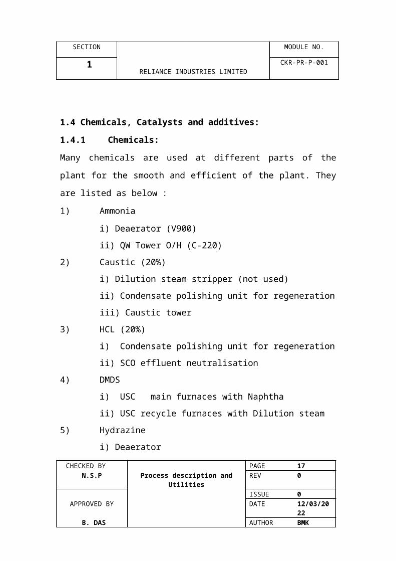
1.4 Chemicals, Catalysts and additives:
1.4.1 Chemicals:
Many chemicals are used at different parts of the plant for the
smooth and efficient of the plant. They are listed as below :
1) Ammonia
i) Deaerator (V900)
ii) QW Tower O/H (C-220)
2) Caustic (20%)
i) Dilution steam stripper (not used)
ii) Condensate polishing unit for regeneration
iii) Caustic tower
3) HCL (20%)
i) Condensate polishing unit for regeneration
ii) SCO effluent neutralisation
CHECKED BY PAGE 12 N.S.P Process description and Utilities REV 0
ISSUE 0APPROVED BY DATE 07/04/2023
B. DAS AUTHOR BMK

SECTION MODULE NO.
1RELIANCE INDUSTRIES LIMITED
CKR-PR-P-001
4) DMDS
i) USC main furnaces with Naphtha
ii) USC recycle furnaces with Dilution steam
5) Hydrazine
i) Deaerator
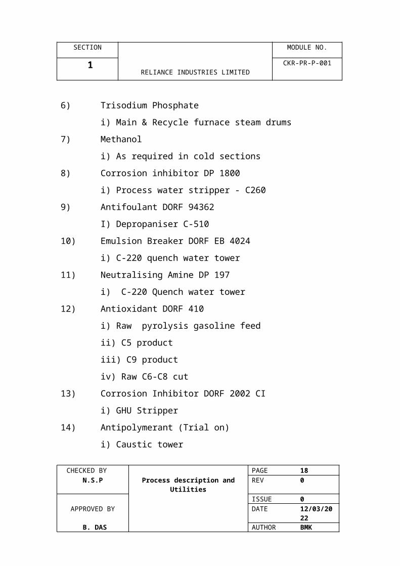
6) Trisodium Phosphate
i) Main & Recycle furnace steam drums
7) Methanol
i) As required in cold sections
8) Corrosion inhibitor DP 1800
i) Process water stripper - C260
9) Antifoulant DORF 94362
I) Depropaniser C-510
10) Emulsion Breaker DORF EB 4024
i) C-220 quench water tower
11) Neutralising Amine DP 197
i) C-220 Quench water tower
12) Antioxidant DORF 410
i) Raw pyrolysis gasoline feed
ii) C5 product
iii) C9 product
iv) Raw C6-C8 cut
13) Corrosion Inhibitor DORF 2002 CI
i) GHU Stripper
14) Antipolymerant (Trial on)
i) Caustic tower
CHECKED BY PAGE 13 N.S.P Process description and Utilities REV 0
ISSUE 0APPROVED BY DATE 07/04/2023
B. DAS AUTHOR BMK

SECTION MODULE NO.
1RELIANCE INDUSTRIES LIMITED
CKR-PR-P-001
1.4.2 Catalysts and Desiccants:
Unit Item No. Type Source1 Cracked Gas
DehydratorV 370 A/B Molecular sieve
EPG 118” and Alumina Balls
UOP
2 Secondary dehydrator
V 453 A/B Molecular sieve EPG 1/8 “ and Alumina Balls
UOP
3 C2 Acetylene hydrogenation
R-451 A/B/C R-452 A/B
G 58 E Catalysts and Alumina Balls
SUD CHEMIE UCIL
4 C3 MAPD Hydrogenation
R-531 A/B/C LD 273 catalyst and Alumina Balls
Procatalyse
5 C4 Main and auxiliary hydrogenation FIRST stage
R-801, R-803 LD 265 & Alumina Balls
Procatalyse
6 C4 Main & Auxiliary hydrogenation II stage
R-802, R-804 LD 271 & Alumina Balls
Procatalyse
7 Gasoline hydrogenation I stage
R-710 A/B LD 265 & Alumina Balls
Procatalyse
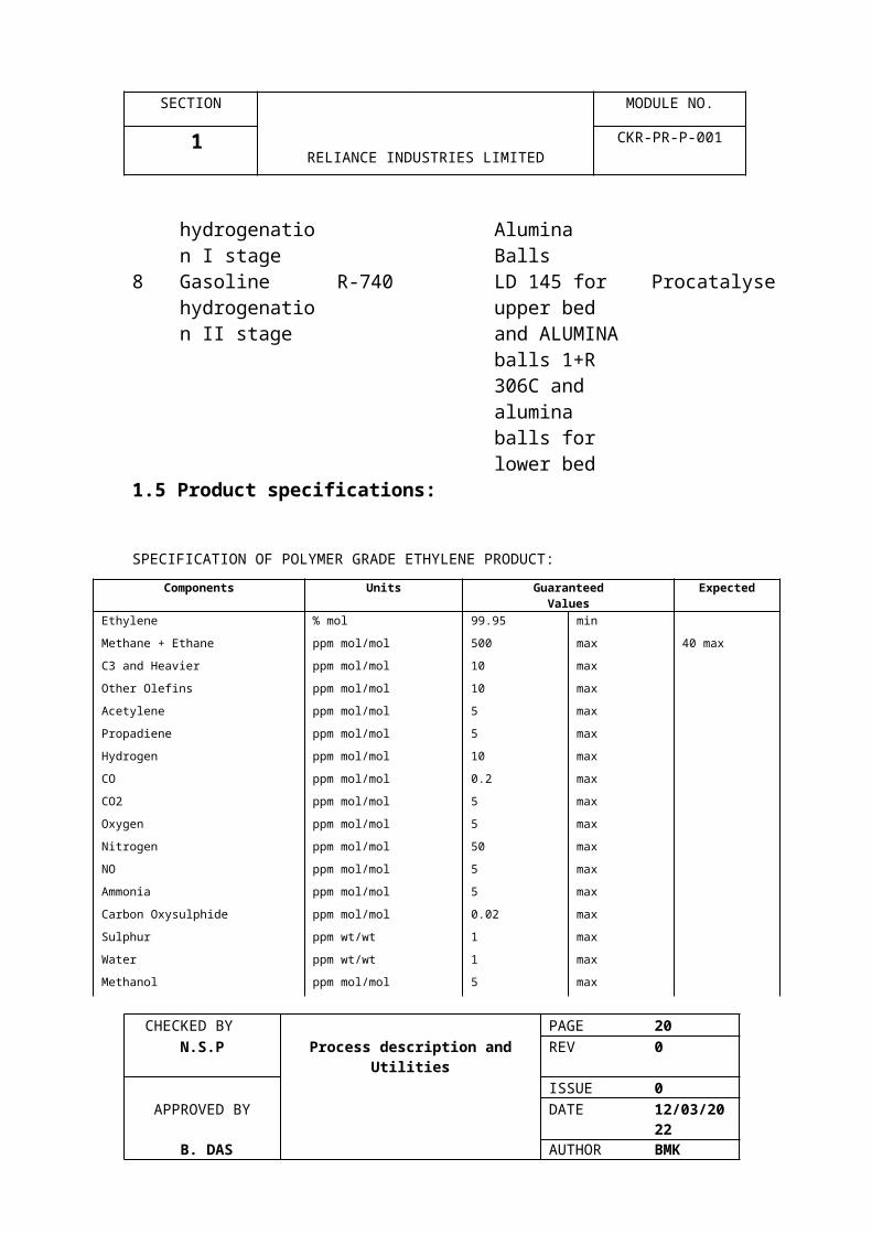
8 Gasoline hydrogenation II stage
R-740 LD 145 for upper bed and ALUMINA balls 1+R 306C and alumina balls for lower bed
Procatalyse
1.5 Product specifications:
SPECIFICATION OF POLYMER GRADE ETHYLENE PRODUCT:
Components Units Guaranteed Values
Expected
Ethylene % mol 99.95 min
Methane + Ethane ppm mol/mol 500 max 40 max
CHECKED BY PAGE 14 N.S.P Process description and Utilities REV 0
ISSUE 0APPROVED BY DATE 07/04/2023
B. DAS AUTHOR BMK

SECTION MODULE NO.
1RELIANCE INDUSTRIES LIMITED
CKR-PR-P-001
Components Units Guaranteed Values
Expected
C3 and Heavier ppm mol/mol 10 max
Other Olefins ppm mol/mol 10 max
Acetylene ppm mol/mol 5 max
Propadiene ppm mol/mol 5 max
Hydrogen ppm mol/mol 10 max
CO ppm mol/mol 0.2 max
CO2 ppm mol/mol 5 max
Oxygen ppm mol/mol 5 max
Nitrogen ppm mol/mol 50 max
NO ppm mol/mol 5 max
Ammonia ppm mol/mol 5 max
Carbon Oxysulphide ppm mol/mol 0.02 max
Sulphur ppm wt/wt 1 max
Water ppm wt/wt 1 max
Methanol ppm mol/mol 5 max
Chlorides ppm mol/mol 2 max
Acetone ppm mol/mol 2 max
Methylacetylene ppm mol/mol 5 max
Arsine ppm wt/wt 0.03 max
Carbonyl ppm mol/mol 5 max
CHECKED BY PAGE 15 N.S.P Process description and Utilities REV 0
ISSUE 0APPROVED BY DATE 07/04/2023
B. DAS AUTHOR BMK

SECTION MODULE NO.
1RELIANCE INDUSTRIES LIMITED
CKR-PR-P-001
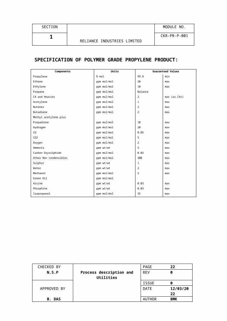
SPECIFICATION OF POLYMER GRADE PROPYLENE PRODUCT:
Components Units Guaranteed Values
Propylene % mol 99.8 min
Ethane ppm mol/mol 30 max
Ethylene ppm mol/mol 10 max
Propane ppm mol/mol Balance
C4 and Heavier ppm mol/mol 2 max (as C4s)
Acetylene ppm mol/mol 1 max
Butenes ppm mol/mol 2 max
Butadiene ppm mol/mol 2 max
Methyl acetylene plus
Propadiene ppm mol/mol 10 max
Hydrogen ppm mol/mol 20 max
CO ppm mol/mol 0.05 max
CO2 ppm mol/mol 5 max
Oxygen ppm mol/mol 2 max
Ammonia ppm wt/wt 5 max
Carbon Oxysulphide ppm mol/mol 0.02 max
Other Non condensibles ppm mol/mol 300 max
Sulphur ppm wt/wt 1 max
Water ppm wt/wt 2 max
Methanol ppm mol/mol 5 max
Green Oil ppm mol/mol
Arsine ppm wt/wt 0.03 max
Phosphine ppm wt/wt 0.03 max
Isopropanol ppm mol/mol 35 max
CHECKED BY PAGE 16 N.S.P Process description and Utilities REV 0
ISSUE 0APPROVED BY DATE 07/04/2023
B. DAS AUTHOR BMK
SECTION MODULE NO.
1RELIANCE INDUSTRIES LIMITED
CKR-PR-P-001
SPECIFICATION OF HYDROGEN PRODUCT:
Components Units Guaranteed Values
Hydrogen % mol 99.9 min
CO ppm mol/mol 5 max
CO2 ppm mol/mol 5 max
Ammonia ppm mol/mol 1 max
Mercury mg/m3 1 max
Oxygen ppm mol/mol 5 max
Total Sulphur ppm wt/wt 0.5 max
Water mg/m3 5 max
CH4s, C2H6s H2
Argon
Balance
Acetylene ppm mol/mol 10 max
SPECIFICATION OF METHANE PRODUCT:
Components Units Guaranteed Values
Methane % mol 95.0 min
Ethylene % mol 1.0 max
Hydrogen % mol 3.0 max
Carbon Monoxide % mol 1.0 max
Acetylene ppm
mol/mol
50 (1) max
CHECKED BY PAGE 17 N.S.P Process description and Utilities REV 0
ISSUE 0APPROVED BY DATE 07/04/2023
B. DAS AUTHOR BMK
SECTION MODULE NO.
1RELIANCE INDUSTRIES LIMITED
CKR-PR-P-001
SPECIFICATION OF C4 STREAMS:
A. Mixed C4 Stream (before hydrogenation):
Expected Value
C3s and Ligher 0.15% wt max
C9s 0.4% wt max
1, 3-Butadiene 52% wt min and 56% wt max
B. Hydrogenated C4 Stream
Butadiene 10 ppm wt max
Dimer (C8) content: 500 ppm max
Trimer (Green Oil) content: none
SPECIFICATION OF C5 PRODUCT (PARTIALLY
HYDROGENATED):
Components Units Values
Distillate Residue % wt 1.5
C9s and lighter % mol Balance
C6s % mol 1.2% max
Benzene % mol 0.3% max
Diene value 2 max
Copper Strip Corrosion 1B
Existing Gum mg/100ml after
heptane wash
4 max
SPECIFICATION OF HYDROGENATED C6/C8 CUT:
CHECKED BY PAGE 18 N.S.P Process description and Utilities REV 0
ISSUE 0APPROVED BY DATE 07/04/2023
B. DAS AUTHOR BMK

SECTION MODULE NO.
1RELIANCE INDUSTRIES LIMITED
CKR-PR-P-001
Components Units Values
C9s % mol
C9s-2000C % mol
C6-C8 Balance
Total Sulphur ppm wt 1.0 max
Bromine number gr/100 gr 0.1
Thiophene ‘S’ ppm wt 0.5 max
Copper Strip Corrosion IA
Diene Valve Nil
Existing Gum mg/100 ml after
heptane wash
Distillate Residue % 1.5 max (ASTM D-
62)
Oxidation Stability Minutes 960 min with 5
ppm antioxidant
CHECKED BY PAGE 19 N.S.P Process description and Utilities REV 0
ISSUE 0APPROVED BY DATE 07/04/2023
B. DAS AUTHOR BMK
SECTION MODULE NO.
1RELIANCE INDUSTRIES LIMITED
CKR-PR-P-001
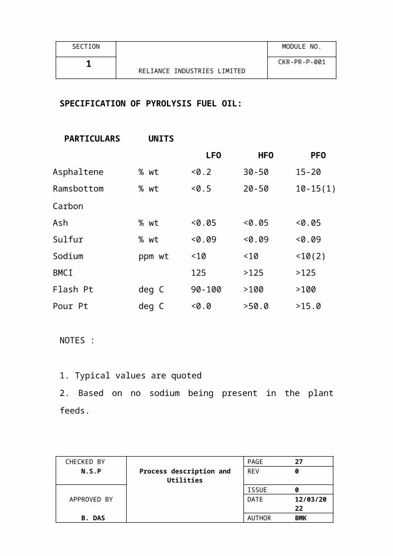
SPECIFICATION OF PYROLYSIS FUEL OIL:
PARTICULARS UNITS
LFO HFO PFO
Asphaltene % wt <0.2 30-50 15-20
Ramsbottom
Carbon
% wt <0.5 20-50 10-15(1)
Ash % wt <0.05 <0.05 <0.05
Sulfur % wt <0.09 <0.09 <0.09
Sodium ppm wt <10 <10 <10(2)
BMCI 125 >125 >125
Flash Pt deg C 90-100 >100 >100
Pour Pt deg C <0.0 >50.0 >15.0
NOTES :
1. Typical values are quoted
2. Based on no sodium being present in the plant feeds.
CHECKED BY PAGE 20 N.S.P Process description and Utilities REV 0
ISSUE 0APPROVED BY DATE 07/04/2023
B. DAS AUTHOR BMK

SECTION MODULE NO.
2 RELIANCE INDUSTRIES LIMITED
CKR-PR-P-001
PROCESS DESCRIPTION
CHECKED BY PAGE 21 N.S.P Process description and Utilities REV 0
ISSUE 0APPROVED BY DATE 07/04/2023
B. DAS AUTHOR BMK
SECTION MODULE NO.
2 RELIANCE INDUSTRIES LIMITED
CKR-PR-P-001
2.00 PROCESS DESCRIPTION:
This section contains a description of the process flow during
normal operation with the RIL “Expansion Case” FEEDSTOCK.
The description should be read in conjunction with process flow
diagrams 0320015-75D-01 to 10.
2.01 CRACKING FURNACES
A total of 15 cracking furnaces are provided to achieve the
required annual ethylene and propylene production.
Twelve of these furnaces, H-110 t0 H-190 and H-192, 194 and
196, described as USC (ultra selective conversion) furnaces are
utilised to crack liquid naphtha fresh feed and H-110 to H-190
for Naphtha and AGO both and the liquid recycle streams
generated within the plant or from the aromatics unit i.e.
hydrogenated C4s, hydrogenated C5s and C6-C8 raffinate.
The remaining three furnaces, H-111, H-121 and H-131
described as USC recycle furnaces are installed to crack
gaseous ethane and propane feedstocks which are recovered
and recycled from the recovery section. Four of the USC
furnaces H-110, 120,130 and 140, can be utilised for ethane /
propane co-cracking with naphtha while one of the USC recycle
furnaces is being decocked.
CHECKED BY PAGE 22 N.S.P Process description and Utilities REV 0
ISSUE 0APPROVED BY DATE 07/04/2023
B. DAS AUTHOR BMK

SECTION MODULE NO.
2 RELIANCE INDUSTRIES LIMITED
CKR-PR-P-001
The naphtha feedstock is stored in OSBL, tanks and pumped to
the battery limit at 10.5 kg/cm2g. Hydrogenated C5’s and C6-
C8 raffinate for recycle cracking can also be supplied from
OSBL storage as C5-C87 max naphtha fresh feed line. The total
flow of C5-C8’s blended into the Naphtha is regulated. The
naphtha liquid blend is preheated by exchange with circulating
quench water in the Naphtha feed Heater, E-041. Hydrogenated
C4’s for recycle cracking can be obtained from storage or
directly from the hydrogenation units. A separate hydrogenated
C4’s header is provided and the flow to each fresh feed furnace
can be independently controlled. The hydrogenated C4’s are
blended with the Naphtha upstream of the furnace convection
section. The combined Naphtha liquid blend is fed through the
USC furnace convection section and partly vaporised. Dilution
steam is added downstream to the hydrocarbon feed stream to
complete vaporisation. A weight ratio of 0.5 steam to
hydrocarbon is utilised.
The liquid hydrocarbon feed is divided equally into six streams
before being fed to the USC furnace convection section. the
hydrocarbon fed is preheated by the furnace flue gas in the
fifth from bottom bank of the six-bank convection section.
Slightly superheated dilution steam form the Dilution Steam
Stripper, C-270, overhead and from the auxiliary dilution
steam stripper, C-80 overhead is split into six streams and fed
CHECKED BY PAGE 23 N.S.P Process description and Utilities REV 0
ISSUE 0APPROVED BY DATE 07/04/2023
B. DAS AUTHOR BMK

SECTION MODULE NO.
2 RELIANCE INDUSTRIES LIMITED
CKR-PR-P-001
to the dilution steam superheating coils located in the second
from bottom bank of convection section.
Three streams from each of the hydrocarbon and dilution
steam coils are combined into one and mixed in a sparger to
complete the vaporisation of hydrocarbon. There are two
spargers per furnace. One outlet is taken from each sparger
and split into three streams. The six streams of hydrocarbon
and dilution steam mixture are further heated in the fourth and
then first bank of the convection section. Three streams of
heated hydrocarbon and dilution steam mixture at the outlet of
the first bank are combined into one mixing fitting. There are
tow mixing fittings per furnace. Four outlets are taken from
each mixing fitting, and each outlet is split into eight radiant
coils. Each radiant coil is fitted with a critical flow venturi
nozzle.
The boiler feed water from the Deaerator is preheated in the
sixth (top) bank of the USC Furnace convection section and fed
to the steam drums, V-110 to 190, 192, 194 and 196. The
saturated steam generated in USX and TLX exchangers is
superheated in the third bank of the convection section.
The recycle ethane feed to the USC Recycle Furnaces is
vaporised by heat exchange against demethanizer feed, in E-
461, and heated against propylene refrigerant, in E-411, while
recycle propane feed is vaporised against circulating quench CHECKED BY PAGE 24
N.S.P Process description and Utilities REV 0ISSUE 0
APPROVED BY DATE 07/04/2023 B. DAS AUTHOR BMK

SECTION MODULE NO.
2 RELIANCE INDUSTRIES LIMITED
CKR-PR-P-001
water in E-542. The ethane and propane is mixed and further
heated against circulating quench water, in E-011, before being
fed to the USC recycle furnaces. Dilution steam is added in a
weight ratio of 0.3 steam/hydrocarbon.
The ethane and propane mixed feed is split into four streams
before being fed to the USC Recycle Furnace Convection
section. The mixed hydrocarbon feed is preheated by the
furnace flue gas in the fourth (top) bank of the four-bank
convection section.
Slightly superheated steam from the dilution steam generator
is injected into each hydrocarbon stream at the outlet of the
fourth bank. The four mixed streams are further heated in the
first (hottest) bank of the convection section. Two streams of
the heated hydrocarbon and dilution steam mixture are
combined at the outlet of the first bank into one mixing fitting.
There are two mixing fittings per recycle furnace. Two outlets
are taken from each mixing fitting, and each feeds a separate
radiant coil. Each radiant coil is fitted with a critical flow venturi
Nozzle.
The boiler feedwater form the deaerator is preheated in the
third bank of the USC Recycle Furnace convection section and
fed to the steam Drums, V-111,121 and 131. The saturated
steam generated in USX exchangers is superheated in the
second bank of the convection section.CHECKED BY PAGE 25
N.S.P Process description and Utilities REV 0ISSUE 0
APPROVED BY DATE 07/04/2023 B. DAS AUTHOR BMK
SECTION MODULE NO.
2 RELIANCE INDUSTRIES LIMITED
CKR-PR-P-001
Both types of furnaces are vertical radiant tube type; the USC
Furnace employs 64 “U” coils with inlet and outlet at the top of
the radiant box. The USC recycle furnace employs four “M”
type radiant coils with inlet and outlet also at the top of the
radiant box.
The USC Furnaces each have 32 floor fired burners. The
burners are designed for gas firing only.
The USC Recycle Furnaces have both wall and floor burners.
Both floor and wall burners are gas fired. There are 16 floor
fired burners and 32 wall burners per furnace.
The feedstocks are thermally cracked in the furnaces where
dilution steam to feed ratios and furnace effluent temperature
are carefully controlled to achieve the desired olefin
distribution and yield. The furnace effluents are cooled rapidly
by heat exchange against boiler feed water in steam
generating USX exchangers, E-110 to 190, 192,194 and 196 A-
H & J-Q, and E-115/125/135 A-D, and TLX Exchangers, E-111 to
191, 193,195 and 197. Rapid quenching of the furnace effluent
is necessary to prevent degradation of olefins into undesirable
components. The high pressure steam generated in USX and
TLX exchangers is superheated in the convection section
before being used, mainly for compressor turbine drivers.
CHECKED BY PAGE 26 N.S.P Process description and Utilities REV 0
ISSUE 0APPROVED BY DATE 07/04/2023
B. DAS AUTHOR BMK
SECTION MODULE NO.
2 RELIANCE INDUSTRIES LIMITED
CKR-PR-P-001
2.02 USC Fresh feed and Recycle Furnace Quench
Fittings
The Quench Fittings, Z-110 to 190 and Z-192, 194 and 196, on
the USC fresh feed furnaces and Z-111/121 on the USC Recycle
Furnaces are provided to reduce the temperature of the
furnace effluent before entering the quench oil tower, C-210
and Heavy Fuel Oil Stripper, C-230, respectively. H-131 effluent
enters C-210 board on material balm to requirement . The
temperature reduction, or quenching, is achieved by contacting
individual furnace effluent streams with quench oil in specially
designed fittings.
2.03 Quench Oil Tower
The Quench Oil Tower, C-210 condenses the fuel oil
components and recovers higher level heat by cooling furnace
effluent from the discharge of the quench fittings to
approximately 1030C. It is divided into the following three
sections, each of which has a specific operating purpose
Quench Oil Circulating Section
Pan Oil Circulating Section
Rectifying Section
CHECKED BY PAGE 27 N.S.P Process description and Utilities REV 0
ISSUE 0APPROVED BY DATE 07/04/2023
B. DAS AUTHOR BMK
SECTION MODULE NO.
2 RELIANCE INDUSTRIES LIMITED
CKR-PR-P-001
2.03.1 Quench Oil Circulating (Scrubbing Section)
The effluents from the USC Furnace and USC Recycle Furnace
Quench Fittings flow to the Quench Oil Tower. The effluent from
all of the USC Quench Fittings and the new USC Recycle
Furnace Quench Fitting, Z-131 are routed via the top section of
the Heavy Fuel Oil Stripper C-230.
The vapour and liquid portions of the effluent stream are
separated in the bottom of the Quench Oil Tower and Heavy
Fuel Oil Stripper. The combined vapours rise through the
bottom section of the QO tower contains four trays and a
distributor. The Quench oil distributor is positioned below the
chimneys of the pan oil collection pan.
The Quench Oil Circulating Pumps, P-210 A/B/C, discharge
through the Quench Oil Filters, Z-210 A/B/C which remove any
coke particles, before heat is recovered from the oil. A slip
stream of hot quench oil is fed to the three USC recycle furnace
Quench fittings to better control the outlet temperature from
the three Quench fittings.
Heat is recovered from the quench oil in the Dilution Steam
Generator / Quench Oil Reboilers, E-271 A/H. The cooled
quench oil then flows to the all of the USC Furnace Quench
Fittings and the scrubbing section of the Quench oil tower.CHECKED BY PAGE 28
N.S.P Process description and Utilities REV 0ISSUE 0
APPROVED BY DATE 07/04/2023 B. DAS AUTHOR BMK

SECTION MODULE NO.
2 RELIANCE INDUSTRIES LIMITED
CKR-PR-P-001
2.03.2 Pan Oil Circulation Section
The pan oil (PO) circulating section of the Quench Oil Tower
condenses a portion fuel oil together with any vaporised
quench oil and also cools the cracked gas. The circulating
section contains ten trays, the pan oil collector pan, and the
pan oil distributor.
Vapour, cracked gas, and steam enter the bottom of this
section through the chimneys in the pan oil collector pan. The
pan oil from the collector pan flows to the Pan Oil Circulating
Pump, P-211 A/B from where it is pumped and circulated to
obtain heat recovery. A portion of the uncooled pan oil is sent
to the distributor spray in the Quench Oil Tower scrubbing
section. Another uncooled portion of the pan oil is fed to the
light fuel oil stripper, C-240 on flow control and the balance is
cooled in the pan oil user exchangers. The cooled pan oil is
reintroduced into the Quench Oil Tower pan oil circulating
section via the pan oil distributor.
2.03.3 Rectifying Section
Light Fuel Oil components contained in the vapours entering
the rectifying section are condensed in this section to prevent
their transfer to the QW tower and thereby maintain the end
point of the raw PYROLYSIS gasoline. The required fractionation CHECKED BY PAGE 29
N.S.P Process description and Utilities REV 0ISSUE 0
APPROVED BY DATE 07/04/2023 B. DAS AUTHOR BMK
SECTION MODULE NO.
2 RELIANCE INDUSTRIES LIMITED
CKR-PR-P-001
in this particular section is accomplished by using gasoline
reflux from the base of the Quench Water Tower, C-220 on a
flow control. The light fuel oil components are collected on the
draw - off tray and flow controlled to the light fuel oil stripper,
C-240. Overhead vapour from the stripper returns to the
rectifying section. The Quench Oil Tower overhead, at
approximately 1030C, is sent to the Quench Water Tower, C-
220.
2.04 Heavy Fuel Oil Stripper
The Heavy Fuel Oil Stripper, C-230 strips the light ends from
the heavy Fuel Oil and returns to the Quench Oil Tower.
The stripping effect is achieved by contacting quench oil with
the USC recycle furnaces vapour effluent in the Quench
Fittings, Z-111 and Z-121, and passing the combined mixture
into the Heavy Fuel Oil Stripper, C-230, where separation into
vapour and liquid is achieved.
The separation of light and heavy ends in the Heavy Fuel Oil
Stripper results in a return of light ends into the Quench Oil
Tower and build-up of a large middle boiling range quench oil
inventory as required for circulation and optimum heat
recovery. The heavy fraction separated out in the Heavy Fuel
Oil Stripper bottom contains all the asphaltenes and tar which
are formed in the cracking operation.CHECKED BY PAGE 30
N.S.P Process description and Utilities REV 0ISSUE 0
APPROVED BY DATE 07/04/2023 B. DAS AUTHOR BMK
SECTION MODULE NO.
2 RELIANCE INDUSTRIES LIMITED
CKR-PR-P-001
The heavy fuel oil stripper bottoms liquid is pumped by Heavy
Fuel Oil Product Pumps, P-230 A/B to product blending, cooling
and delivery to plant battery limits.
CHECKED BY PAGE 31 N.S.P Process description and Utilities REV 0
ISSUE 0APPROVED BY DATE 07/04/2023
B. DAS AUTHOR BMK
SECTION MODULE NO.
2 RELIANCE INDUSTRIES LIMITED
CKR-PR-P-001
2.05 Light Fuel Oil Stripper
The Light Fuel Oil Stripper, C-240 regulates the quench oil
quality and optimises the heat recovery in the Quench Oil
Tower.
The light Fuel Oil Stripper is fed from two sources. The main
source is the draw off tray in the quench oil tower rectification
section, the second source is the recycle stream form the pan
oil circuit. Stripping of the light components is effected by
dilution steam injection, which enters below the bottom tray.
The stripped vapour returns to the rectification section of the
Quench Oil Tower. The light fuel oil product passes from the
bottoms to the Light Fuel Oil Product Pumps, P-240 A/B, which
discharge it to the fuel oil blending, cooling and delivery
system.
2.06 Quench Water Tower
The cracked gas from the rectification section of the Quench Oil
Tower passes into the Quench Water Tower, C-220. In this
tower, the gas is further cooled to 40.60C, by direct contact
with circulating quench water. Effective contact and cooling of
the gas with quench water are attained by returning the
circulating quench water through distributors in the tower
middle and top sections. For this service, two packed beds are
provided for contacting the gas and quench water.CHECKED BY PAGE 32
N.S.P Process description and Utilities REV 0ISSUE 0
APPROVED BY DATE 07/04/2023 B. DAS AUTHOR BMK
SECTION MODULE NO.
2 RELIANCE INDUSTRIES LIMITED
CKR-PR-P-001
The flow and distribution of quench water into the middle and
top sections is regulated by flow controllers reset by the
temperature of middle section overhead and top section
overhead, respectively, to attain cooling of the cracked gas and
to provide a hot quench water supply for process reboiling and
heating.
In this tower, dilution steam and the gasoline fraction of the
cracked gas are condensed. The condensed hydrocarbon and
water are separated in the bottom section, which contains a
series of chevron-type plate baffles for the settling out of the
water and hydrocarbon phases. Part of the separated gasoline
is used as reflux to the Quench Oil Tower and the balance feeds
the distillate Stripper, C-250.
Most of the hot water from the base of this tower is circulated
through various process heaters and reboilers before returning
to the quench water tower, while the balance is fed to the
dilution steam generation system.
2.07 Dilution Steam Generation System
Most of the dilution steam contained in the furnace effluent is
condensed in the Quench Water Tower. The reuse of steam
condensate collected form both the condensation of dilution
steam in the Quench Water Tower and in the cracked gas CHECKED BY PAGE 33
N.S.P Process description and Utilities REV 0ISSUE 0
APPROVED BY DATE 07/04/2023 B. DAS AUTHOR BMK

SECTION MODULE NO.
2 RELIANCE INDUSTRIES LIMITED
CKR-PR-P-001
compression system minimises the demineralized water
makeup requirements and reduces the load on the waste water
effluent treatment system.
Water is circulated by the Quench Water Circulating Pumps, P-
220 A/B/C, to the dilution steam generation system. The water
is first delivered to the water stripper feed filter, Z-261 A/b,
which removes trace solids such s pipe scale and coke that
impair the effectiveness of the downstream coalescer.
The filtered water enters the water stripper feed coalescer, V-
262 A/B, where free hydrocarbon droplets are separated from
the water. These hydrocarbons are returned to the Quench
Water Tower from the top of the coalescer.
The water from the coalescer is heated by exchange against
dilution steam blowdown in the Dilution Steam Stripper
blowdown cooler / stripper feed heater, E-259. The water then
passes through the water stripper feed heater, E-258, where it
is heated against pan oil. It then enters the water stripper C-
260, where it is stripped of dissolved hydrocarbons, acid gases,
and ammonia. Stripping steam is provided from the Dilution
steam Stripper overhead. The overhead vapours flow to the
quench water tower.
The dilution steam stripper feed pumps, P-260 A/B, deliver the
water stripper bottoms to the two dilution steam strippers. The CHECKED BY PAGE 34
N.S.P Process description and Utilities REV 0ISSUE 0
APPROVED BY DATE 07/04/2023 B. DAS AUTHOR BMK
SECTION MODULE NO.
2 RELIANCE INDUSTRIES LIMITED
CKR-PR-P-001
main portion of the process water is routed to the DSS tower,
C-270, and en-route is heated by exchange against 3.5
kg/cm2g level steam in E-269. The water then passes through
the Dilution Steam Stripper Feed Heater No.1, E-268, where it is
heated against pan oil. The preheated condensate enters the
Dilution Steam Stripper, C-270, above the top tray.
The DSS tower, C-270 bottoms are reboiled against quench oil
in the Dilution Steam Stripper / Quench Oil Reboiler, E-271 A/H,
and against 12 kg/cm2g level steam in Dilution Steam
Stripper / Steam Reboiler, E-270 A/D.
The remaining portion of the process water stream is routed to
the auxiliary DSS tower, C-280 and en-route is preheated
against steam condenste in the auxiliary dilution steam stripper
feed heater, E-279. The preheated process water enters the
auxiliary Dilution steam stripper C-280 above the top tray. C-
280, bottoms are reboiled against 12 kg/cm2g steam in the
auxiliary dilution steam stripper reboiler, E-280 A/C.
Most of the generated dilution steam flows to the cracking
furnaces, where it is used for dilution of hydrocarbon feed,
decoking of furnace tubes, or operating a furnace on hot
standby without hydrocarbon feed. A small portion is used for
stripping in the light fuel oil stripper and LP Water Stripper.
Approximately 5 percent of the steam produced is returned to
the Water Stripper for use as stripping steam.CHECKED BY PAGE 35
N.S.P Process description and Utilities REV 0ISSUE 0
APPROVED BY DATE 07/04/2023 B. DAS AUTHOR BMK
SECTION MODULE NO.
2 RELIANCE INDUSTRIES LIMITED
CKR-PR-P-001
LMP steam injection into the dilution steam header maintains
sufficient superheat to avoid condensation in the piping to the
furnaces. LMP steam can also be used directly to supplement
the dilution steam to the furnaces. The blowdown, the net
bottoms stream from C-270, is cooled first in the Dilution
Steam Generator Blowdown / Water Stripper Feed Heater, then
against cooling water in the Dilution Steam Generator
Blowdown Cooler, E-273, before being discharged to the oily
water sewer. The blowdown from C-280 is cooled against
cooling water before being discharged to the oily water sewer.
2.08 Distillate Stripper
The Distillate Stripper, C-250, debutanizes the gasoline
collected in the bottom section of the Quench Water Tower and
first three stages of cracked gas compression, before it is fed to
the gasoline hydrotreating unit.
Gasoline from the Quench Water Tower is fed to the stripper by
a slip stream from the quench oil tower reflux pump, P-211 A/B
while the feed from the cracked gas second stage suction drum
is pumped by distillate stripper feed pump, P-230 A/B.
C4’s and light ends from the Distillate stripper are returned to
the cracked gas compressor via the Quench Water Tower.
CHECKED BY PAGE 36 N.S.P Process description and Utilities REV 0
ISSUE 0APPROVED BY DATE 07/04/2023
B. DAS AUTHOR BMK

SECTION MODULE NO.
2 RELIANCE INDUSTRIES LIMITED
CKR-PR-P-001
The Distillate Stripper is reboiled by pan oil in the Distillate
Stripper Reboiler, E-250. The gasoline product from the bottom
is pumped via the Distillate Stripper Bottoms Pump, P-250 A/B.
Most of the gasoline from this pump goes to the GHU. A portion
is recycled back to the Quench Oil Tower to provide additional
reflux inventory. The stream is sent to the Quench Oil Tower
Pan Oil section (rather than to the top of the tower) to ensure
that any heavy components are fractionated out.
2.09 Quench Water and Pan Oil circuits
Quench water is circulated to the following users from the
Quench Water tower, C-220, via the quench water circulation
pumps, P-220 A/C, at a temperature of approx. 820C :
Exchanger No. : Description
E-011 Ethane / Propane recycle heater
E-041 Naphtha feed heater
E-051 A/B AGO feed heater no.1
E-210 Fuel oil cooler
E-215 Quench water steam heater
E-340 Weak caustic heater
E-359 Condensate stripper feed heater
E-360 A/B Condensate stripper reboiler
E-410 Demethanizer prestripper reboiler
E-439 Demetahnizer prestripper bottoms heater
E-440 A/C Deethanizer ReboilerCHECKED BY PAGE 37
N.S.P Process description and Utilities REV 0ISSUE 0
APPROVED BY DATE 07/04/2023 B. DAS AUTHOR BMK

SECTION MODULE NO.
2 RELIANCE INDUSTRIES LIMITED
CKR-PR-P-001
E-530 Secondary deethanizer reboiler
E-535 Tertiary deethaniser reboiler
E-540 A/D Propylene tower auxiliary reboiler
E-542 Propane recycle vaporiser
E-731 Wash oil condenser
Two of the exchangers, E-731 and E-210, provide an additional
heat input to the quench water and a third exchanger, E-215,
utilises steam to adjust the quench water temperature. The
remaining users accept the waster heat from the quench water
system.
After interchanging heat with the QW users, all of the quench
water is cooled in the primary quench water cooler, E-220 A/g,
down to a temperature of 54.40C. The bulk of this water is fed
to the lower packed section of the QW tower. The remainder is
further cooled in the secondary quench water cooler, E-230
A/H, down to a temperature of 37.80C before being fed to the
upper packed section of the QW tower.
Pan oil is circulated to the following users from the quench oil
tower via pan oil circulation pumps, P-211 a/B :-
Exchanger No. Description
E-268 Dilution Steam Stripper Feed Heater No.1
E-258 Water Stripper feed Heater
E-250 Distillate Stripper ReboilerCHECKED BY PAGE 38
N.S.P Process description and Utilities REV 0ISSUE 0
APPROVED BY DATE 07/04/2023 B. DAS AUTHOR BMK

SECTION MODULE NO.
2 RELIANCE INDUSTRIES LIMITED
CKR-PR-P-001
E-510 Depropanizer Reboiler
The final Pan Oil temperature of 1210C is controlled by
diverting pan oil flow to the pan oil trim cooler, E-219, before
the pan oil is recirculated back to the middle section of the
quench oil tower.
2.10 Compression/Acid Gas Removal/Dehydration
The water saturated hydrocarbon overhead form the quench
water tower is fed to the cracked gas (C G) first stage suction
drum, V-310. The C.G. first stage condensate Pump, P-310 A/B,
discharges the liquid transferred from drum V-320 and any
slugs of liquid carryover in the cracked gas back to the quench
water tower. The vapour from this drum flows to the first stage
of the cracked gas compressor, B-300.
Wash oil is injected into the suction line of each compression
stage by the wash oil Injection Pump, P-300 A/B. Wash oil is
injected to keep the impeller blade tip wet, thus preventing
polymer accumulation. The first three stages of compression
are each followed by an aftercooler and a discharge drum used
to separate water / hydrocarbon condensate from vapour. Heat
is rejected to cooling water in each aftercooler. The first stage
aftercooler, E-310, effluent is combined with gasoline
hydrogenation unit vents in the 2nd stage suction drum, V-320
before entering the 2nd stage of compression. The condensate
CHECKED BY PAGE 39 N.S.P Process description and Utilities REV 0
ISSUE 0APPROVED BY DATE 07/04/2023
B. DAS AUTHOR BMK

SECTION MODULE NO.
2 RELIANCE INDUSTRIES LIMITED
CKR-PR-P-001
stripper overhead joins the second stage aftercooler, E-320,
into the 3rd stage suction drum, V-330.
The liquid form the C.G. Third stage Discharge Drum, V-335, is
successively cascaded to the CG. Third stage suction drum and
then to C.G. second stage suction drum, which is designed to
separate the hydrocarbon condensate from the water. The
hydrocarbon condensate from the CG second stage suction
drum is sent to the Distillate stripper, while the water is routed
to the CG 1st stage suction drum. The oily water is pumped via
P-310 A/B to the quench Water Tower, C-220.
To prevent C.G. compressor surging, two minimum flow
bypasses are provided. The first bypass protects the first three
stages of compression, and the second bypass protects the
fourth stage.
The first minimum flow bypass is provided form the third stage
discharge drum to the first stage suction drum. The recycle
automatically protects the compressor by keeping the flow
above surge point during reduced capacity operation.
The third stage discharge gas is passed through a caustic wash
followed by a water wash in the caustic tower, C-340. The acid
free tower effluent is combined with the vents from the
ethylene rectifier and secondary demethaniser reflux drums
and fed to the C G Fourth Stage Drum, V-340. The drum CHECKED BY PAGE 40
N.S.P Process description and Utilities REV 0ISSUE 0
APPROVED BY DATE 07/04/2023 B. DAS AUTHOR BMK
SECTION MODULE NO.
2 RELIANCE INDUSTRIES LIMITED
CKR-PR-P-001
overhead feeds the Fourth Compression Stage. The discharge
effluent is cooled in the C G Fourth Stage Aftercooler, E-345, by
cooling water and passed to the Cracked Gas Rectifier, C-350,
which fractionates the heavy ends and reduces the gas flow to
the demethaniser system. Reflux for the rectifier is provided by
hydrocarbon condensed in the C G Rectifier Overhead
Condenser, E-355, using propylene refrigerant. The C G
Rectifier Reflux Drum, V-346, is designed to separate the
hydrocarbon condensate from water. The water from the C G
Fourth Stage Suction Drum and C G Rectifier Reflux Drum is
sent to the Third Stage Suction Drum. Bottoms from the C G
Rectifier are discharged to the Fourth Stage Suction Drum.
The Fourth Stage Suction Drum condensate is routed to the
Condensate Stripper Feed Coalescer, V-359, for the removal of
free water. The water is collected in a boot and sent to the
Third Stage Suction Drum. The hydrocarbon stream is heated
against quench water in the Condensate Stripper Feed Heater,
E-359, to prevent hydrate formation and then fed to the
Condensate Stripper, C-360.
In the Stripper, c2s and lighter are recovered overhead and
sent to the C. G . Third Stage Suction Drum. The Condensate
Stripper Bottoms Pump, P-360 A/B, delivers the remaining
hydrocarbons to the Depropanizer, C-510. Stripping vapour is
produced by quench water in the Condensate Stripper Reboiler,
E-360 A/B.CHECKED BY PAGE 41
N.S.P Process description and Utilities REV 0ISSUE 0
APPROVED BY DATE 07/04/2023 B. DAS AUTHOR BMK

SECTION MODULE NO.
2 RELIANCE INDUSTRIES LIMITED
CKR-PR-P-001
The second minimum flow bypass line, taken from the C.G.
Rectifier overhead, is recycled to the C.G. Fourth Stage Suction
Drum. A small stream taken from upstream of the C.G. Fourth
Stage Aftercooler is used to heat this gas to avoid hydrate
formation across the kick-back minimum flow control valve. In
addition, a bypass stream to the third stage discharge is
provided to ensure adequate vapour loading on the Ripple trays
of the Caustic Tower during reduced capacity operation.
2.10.1 Acid Gas Removal
The caustic wash operation is installed to remove hydrogen
sulphide and carbon dioxide from the cracked gas in order to
meet product quality requirements on the ethylene and
propylene products. Also, the removal of these acid gases
protects downstream catalytic operations, since some acid gas
components are known to be catalyst poisons. Acid gases are
also removed to avoid corrosion and the possible formation of
CO2 ice within the cold process systems.
These acid gases, which are produced in the cracking furnaces,
are removed by scrubbing the gas from the C. G. third Stage
Discharge Drum with circulating caustic solutions in the Caustic
Tower, C-340. The tower is divided into four sections. The three
bottom sections provide for caustic scrubbing of the cracked
gas. The bottom section uses weak caustic, the middle uses CHECKED BY PAGE 42
N.S.P Process description and Utilities REV 0ISSUE 0
APPROVED BY DATE 07/04/2023 B. DAS AUTHOR BMK

SECTION MODULE NO.
2 RELIANCE INDUSTRIES LIMITED
CKR-PR-P-001
medium caustic, and the top circulates strong caustic. The
fourth section, at the top of the tower, is the water wash
section, which prevents caustic carryover into the cracked gas
Fourth Stage Suction Drum.
The acidic cracked gas enters the caustic tower below the
bottom section where it is contacted with weak caustic
solution. The weak caustic is circulated by the weak caustic
circulating pump, P-342 A/B, then heated against quench water
in the weak caustic Heater, E-340, prior to making contact with
the acidic cracked gas. This ensures that the cracked gas does
not fall below its dew point, which would cause hydrocarbon
condensation.
The cracked gas flows upward, contacting the medium caustic,
and then the strong caustic solution. These streams are
recirculated by the Medium Caustic Circulating Pump, P-343
A/B, and strong caustic circulating Pump, P-344 A/B,
respectively.
Spent caustic solution is contained in the caustic tower bottoms
section, where by any hydrocarbon condensate / polymer oils
are separated out via an overflow weir into a separate hold-up
compartment. The spent caustic is mixed with aromatic
gasoline from the discharge line of the Recirculating Gasoline
Pump, _347 A/B, via the spent caustic /aromatic gasoline mixer,
Z-343 and is then fed to the spent caustic deoiling drum, V-342.CHECKED BY PAGE 43
N.S.P Process description and Utilities REV 0ISSUE 0
APPROVED BY DATE 07/04/2023 B. DAS AUTHOR BMK

SECTION MODULE NO.
2 RELIANCE INDUSTRIES LIMITED
CKR-PR-P-001
Separation of entrained oil from the spent caustic, and some
hydrocarbon degassing, is achieved in the deoiling drum. The
recovered liquid hydrocarbons are discharged on level control
to quench water tower. The drum pressure floats on the CG 2nd
stage suction Drum pressure. The deoiled spent caustic is then
discharged to the spent caustic Degassing Drum, V-343, which
operates at neat-atmospheric pressure. The residual
hydrocarbon gas is flashed to the flare system, and the spent
caustic is finally pumped to the steam stripper, C-1101 via the
steam stripper feed preheater E-1101.
In the steam stripper benzene and other entrained aromatics
are stripped with live LP steam which is injected below the
bottom tray. The overhead vapour from the tower is recycled
back to the QW tower, via the water K.O. Drum, V-1102, which
collects any slugs of water that may be carried over. The
aromatics free spent caustic bottoms stream is pumped by the
steam stripper bottoms pump, P-1104 A/B to the spent caustic
oxidation unit for further treatment.
In the event that the steam stripper is out of commission the
raw spent caustic liquor can be sent to the spent caustic
holding tank, T-1101 A/B, and subsequently recycled to the
steam stripper utilising the spent caustic feed recycle pump, P-
1101 A/B.
CHECKED BY PAGE 44 N.S.P Process description and Utilities REV 0
ISSUE 0APPROVED BY DATE 07/04/2023
B. DAS AUTHOR BMK
SECTION MODULE NO.
2 RELIANCE INDUSTRIES LIMITED
CKR-PR-P-001
Fresh caustic is delivered from offsite as a 20 wt. percent
solution to the concentrated caustic tank, T-340. Makeup
caustic is drawn from the tank by the concentrated caustic
pump, P-341 A/B, and charged to the caustic tower via the
caustic diluent mixer, Z-341, where it is mixed with spent wash
water to produce a 10 percent caustic solution. The wash water
is supplied from the caustic tower wash water loop. The
consumption of caustic depends on the quantity of CO2 and
H2S in the feed to the tower and on the residual concentration
of NaOH in the spent caustic solution.
The Caustic Pump, P-341 A/B, supplies the required makeup
caustic to the Caustic Tower and is used for pH control in the
dilution steam generation system.
The make-up caustic to the caustic tower is combined with the
return circulating strong caustic, whereby the strong caustic
circulating pump provides mixing of the two streams. Excess
strong caustic overflows from the caustic strong section to the
medium section via an external downflow pipe on the strong
caustic chimney tray. In turn, the excess medium caustic
solution overflows to the weak caustic section via an internal
dowflow pipe on the medium caustic chimney tray.
Means for aromatic gasoline (C6-C8 cut) injection is provided
into the top of each of the caustic scrubbing sections. Injection
of gasoline into the suction of the strong caustic circulating CHECKED BY PAGE 45
N.S.P Process description and Utilities REV 0ISSUE 0
APPROVED BY DATE 07/04/2023 B. DAS AUTHOR BMK

SECTION MODULE NO.
2 RELIANCE INDUSTRIES LIMITED
CKR-PR-P-001
pump is on a continuous basis. The aromatic gasoline acts as a
solvent for any polymers being accumulated on the trays and
passes down with the spent caustic to the Deoiling Drum, V-
342 where it is separated and discharged to the Quench Water
tower.
The neutralised cracked gas passes to the wash water section
where it is cooled by rejecting heat to the circulating wash
water stream. Deaerated boiler feedwater is used as a makeup
supply to the wash water section. The wash water is circulated
by the wash water circulating pump, P-345 A/B, which directs
the water through the wash water cooler, E-341, where it is
cooled against cooling water. The cooled wash water flows to
the top tray of the Caustic Tower.
In the event of a cracked gas compressor shutdown, liquid in
each section of the tower will fall from the Ripple trays towards
the bottom of each section. For the top section, the excess
wash water will accumulate in the wash water chimney tray.
The strong caustic chimney tray is capable of holding the
majority of the dumping liquid from the strong caustic section,
following the provision of a control valve provided on the
external downflow pipe to the medium caustic section which is
to close when the cracked gas compressor trips. The bottoms
compartment below the C G Feed nozzle provides excess liquid
holding capacity for the excess strong caustic solution, and all
of the liquid from the medium and weak caustic sections.CHECKED BY PAGE 46
N.S.P Process description and Utilities REV 0ISSUE 0
APPROVED BY DATE 07/04/2023 B. DAS AUTHOR BMK
SECTION MODULE NO.
2 RELIANCE INDUSTRIES LIMITED
CKR-PR-P-001
2.10.2 C G Dehydration
The cracked effluent from the overhead of the C G Rectifier
Reflux Drum is fed to one of two cracked gas dehydrators, V-
370 A/B. These fixed-bed dehydrators are each composed of a
main bed and a guard bed. Both beds are filled with molecular
sieve. While one dehydrator is operating the second is either
being reactivated or is in a standby position.
The desiccant in the main bed is designed for a 24 hour
operating cycle at the end of bed life. The desiccant in the
guard section provides additional protection time before water
breakthrough. At the end of each cycle, the standby dehydrator
is put into service and the operating dehydrator is switched
over to reactivation.
Reactivation of the desiccant is accomplished with reactivation
gas (a methane/hydrogen mixture) by upward flow through the
beds. Fresh reactivation gas is supplied from the Demethanizer
System. It is first heated against reactivation gas effluent in the
Reactivation Gas Feed / Effluent Exchanger, E-371, and is then
further heated by HP steam in the Reactivation Gas Heater, E-
372. The hot gas passes upward through the dehydrator,
heating the bed and desorbing the water from the molecular CHECKED BY PAGE 47
N.S.P Process description and Utilities REV 0ISSUE 0
APPROVED BY DATE 07/04/2023 B. DAS AUTHOR BMK
SECTION MODULE NO.
2 RELIANCE INDUSTRIES LIMITED
CKR-PR-P-001
sieve. The effluent passes to the Reactivation Gas Feed/Effluent
Exchanger where heat is released to cooling water. The cooled
effluent enters the Reactivation Gas Separator, V-371, where
water and hydrocarbon liquids, removed from the desiccant,
are separated from the reactivation gas. The gas is then
returned to the fuel gas system, and the oily water gas is then
returned to the fuel gas system and the oily water is discharged
to the Quench Water Tower. The hot reactivated is discharged
to the Quench Water Tower. The hot reactivated desiccant is
then cooled to the normal temperature with cold residue gas
which is cooled and chilled in the Reactivation Gas Feed Cooler,
E-373, and in the Reactivation Gas Feed Chiller, E-374,
respectively.
2.11 Demethanizer System
The Demethanizer system consists of two parallel feed chilling
trains and three stages of fractionation : the Demethanizer
Prestripper, C-410, the Demethanizer, C-420, and the Residue
Gas Rectifier, C-430.
There are two parallel sets of precoolers. Each set consists of
three heat exchangers, through which the total cracked gas
feed from the dehydrators is cooled and partially condensed
prior to the first liquid fraction being separated in the
Demethanizer Prestripper Feed Drum, V-410, and the
Demethanizer Prestripper Parallel Feed Drum, V-414. The first CHECKED BY PAGE 48
N.S.P Process description and Utilities REV 0ISSUE 0
APPROVED BY DATE 07/04/2023 B. DAS AUTHOR BMK

SECTION MODULE NO.
2 RELIANCE INDUSTRIES LIMITED
CKR-PR-P-001
parallel set of precoolers are the Demethanizer Precooler No.1,
E-401, and Demethanizer Parallel Precooler No.1, E-407, which
use-6.7 C propylene refrigerant as coolant.
Further cooling of the cracked gas occurs in the Demethanizer
Bottoms Reheater, E-438, and its parallel reheater, E-408,
which utilise the Demethanizer net bottoms stream as coolant.
In Demethanizer Precooler No.2, E-402, and its parallel
precooler, E-409, the cracked gas mixture is cooled by -23.3 C
propylene refrigerant. The liquid condensed at this point
contains some methane and C2s and the major portion of the
C3 and heavier components; it is separated from the vapour in
the Demethanizer Prestripper feed drum, V-410, and its parallel
drum, V-414. The liquid streams from these drums are
combined and fed to the demethanizer Prestripper, C-410, as
the bottom feed for removal of methane.
The vapour from the Demethanizer Prestripper Feed Drum, V-
410 is cooled and partially condensed in the Ethane Recycle
Vaporiser, E-461, where recycle ethane from the Ethylene
Stripper bottoms is vaporised. The partially condensed stream
is further cooled by using -40C propylene refrigerant in the
Demethanizer precooler No.3, E-403. This partially condensed
stream is fed to the Demethanizer feed drum no. 1, V-411, for
separation of the vapour / liquid streams. The vapour from the
Demethanizer Prestripper Parallel feed drum is also cooled by
using-40C propylene refrigerant in the Demethanizer Parallel CHECKED BY PAGE 49
N.S.P Process description and Utilities REV 0ISSUE 0
APPROVED BY DATE 07/04/2023 B. DAS AUTHOR BMK

SECTION MODULE NO.
2 RELIANCE INDUSTRIES LIMITED
CKR-PR-P-001
Precooler no.3 This partially condensed stream is fed to the
demethanizer parallel feed drum no.1, V-415 for separation of
the vapour / liquid streams.
The liquid streams from V-411 and V-415 contain methane and
C2s, along with much of the remaining C3 and heavier
components. They are combined and fed to the Demethanizer
Prestripper as the top feed. The vapour phase from V-411 is
divided into two parallel streams, after which it is cooled further
and partially condensed. The larger portion of this vapour
stream is cooled by using the -51.1C and -73.3 C levels of
ethylene refrigerant in the reminder is cooled by heat exchange
with residue gas in demethanizer core exchanger no.2, E-412.
Both partially condensed streams are recombined and fed to
the demethanizer feed drum no.2, V-412, where vapour and
liquid streams Are separated. The vapour phase from V-415 is
also cooled using two levels of ethylene refrigerant (-51.1 C and
-73.3 C) in the Demethanizer parallel precooler no.4, E-422. The
partially condensed stream is then fed to demethanizer parallel
feed drum no.2, V-416, where vapour and liquid streams are
separated.
The liquid streams from V-412 and V-416 are combined and fed
to the Demethaniser, C-420. The vapour streams from these
drums (mainly hydrogen, methane, and ethylene) are further
cooled and partially condensed in an exchanger arrangement
identical to that of the previous stage, except for the use of -CHECKED BY PAGE 50
N.S.P Process description and Utilities REV 0ISSUE 0
APPROVED BY DATE 07/04/2023 B. DAS AUTHOR BMK
SECTION MODULE NO.
2 RELIANCE INDUSTRIES LIMITED
CKR-PR-P-001
100.6 C ethylene refrigerant in the Demethanizer Precooler
No.6, E-406, and Demethanizer Parallel Precooler No.6, E-424,
respectively. The split stream from V-412 is cooled by heat
exchange with residue gas in Demethanizer Core Exchanger
No.3, E-413. A vapour / liquid separation is repeated in the
Demethanizer Feed Drum No.3, V-413, and Demethanizer
Parallel Feed Drum No.3, V-417. The liquid streams, consisting
of ethylene , ethane, and methane, are combined and fed to
the Demethanizer, C-420. The vapour streams are combined
and cooled further and partially condensed in the
Demethanizer core exchanger No.4, E-414, prior to being fed
into the Residue Gas Rectifier, C-430, where the ethylene loss
to fuel is minimised.
The liquid streams from the Demethanizer Prestripper Feed
Drum and Demethanizer Prestripper Parallel Feed Drum, are
combined and fed to the Demethanizer Prestripper, C-410. A
second feed to the Prestripper tower comes form the
Demethanizer feed drum no.1 and the demethanizer parallel
feed rum no.1 The prestripper is reboiled with quench water in
the demethanizer prestripper reboiler, E-410. The stripper
bottoms product is essentially methane free with roughly one
third of the C2 components and goes directly to the
deethanizer, C-440, bypassing the demethanizer, C-420. The
prestripper overhead vapour is fed to the demethanizer.
CHECKED BY PAGE 51 N.S.P Process description and Utilities REV 0
ISSUE 0APPROVED BY DATE 07/04/2023
B. DAS AUTHOR BMK

SECTION MODULE NO.
2 RELIANCE INDUSTRIES LIMITED
CKR-PR-P-001
The purpose of the demethanizer is to make a sharp separation
between methane and ethylene. Each feed enters the tower at
different tray locations to gain the maximum benefit from the
pre-fractionation produced by the fractional condensation. The
heat input for the Demethanizer Reboiler, E-420, is supplied by
condensing 7.2 C propylene refrigerant vapour. The
demethanizer condenser, E-425, is cooled by evaporating
ethylene refrigerant at -100.6C. The overhead product vapour
stream is heated as it passes through the Demethanizer core
exchanger no.3 and is then directed to the Methane Expander,
B-421.
The Residue Gas Rectifier recovers the ethylene contained in
Demethanizer Feed Drum No.3, and Demethanizer Parallel
Feed Drum No.3. The liquid from the bottom of the Residue Gas
Rectifier is returned to the top of the Demethanizer, C-420. The
Residue gas overhead is partially condensed in the
Demethanizer core exchanger no.5, E-415, by gas which has
been chilled by expansion in the cryogenic expansion turbine.
The residue gas from the Residue gas rectifier reflux drum, V-
436, is cooled an partially condensed through the Hydrogen
core exchanger, E-419. The partially condensed stream is fed
to the hydrogen drum V-431, where 95 percent hydrogen
vapour is separated from the liquid. The maximum amount of
95 percent hydrogen vapour is sent to the pressure swing
Adsorption Unit, Z-400, for the production of extra high purity
hydrogen. The hydrogen vapour is heated through the CHECKED BY PAGE 52
N.S.P Process description and Utilities REV 0ISSUE 0
APPROVED BY DATE 07/04/2023 B. DAS AUTHOR BMK

SECTION MODULE NO.
2 RELIANCE INDUSTRIES LIMITED
CKR-PR-P-001
demethanizer core exchanger no.1 through 4 and through the
hydrogen core exchanger.
The remainder of the Hydrogen Drum vapour and the Hydrogen
Drum Bottoms (fuel gas) are flashed down to 1.45 kg/cm2g and
are reheated in the following multi-pass exchangers. Hydrogen
core exchanger, E-419, Demethanizer core exchangers Nos. 1
through 5. The fuel gas and the purge gas from the PSA unit
are then directed to the Fuel Gas Compressor, B-900, at a
temperature of about 320C.
The Demethanizer net overhead vapour stream is heated
through Demethanizer core exchanger no.3 and is then sent to
the Methane Expander, B-421. The expander outlet
temperature is such that the required amount of cooling is
supplied to the overhead rectifier condenser. The expander
effluent, which is at low pressure, is reheated in demethanizer
core exchangers nos. 1 through 5. The heated gas regn. goes
to the Methane Recompressor, B-420. The compressor is driven
by the expander, usually, an integral construction. The gas
leaves the compressor at a pressure of 5.6 kg/cm2g, sufficient
for regeneration requirements.
The Demethanizer bottoms product goes to the Deethanizer
after being heated by exchanger with cracked gas from
precooler no.1
CHECKED BY PAGE 53 N.S.P Process description and Utilities REV 0
ISSUE 0APPROVED BY DATE 07/04/2023
B. DAS AUTHOR BMK

SECTION MODULE NO.
2 RELIANCE INDUSTRIES LIMITED
CKR-PR-P-001
The Methane produce stream is obtained by removing a portion
of the liquid from the Demethanizer, Reflux Drum, V-426, and
vaporising in an air vaporiser, E-427, to about 5 C. The vapour
is then allowed to warm-up to ambient temperature by heat
gain from the atmosphere in the pipeline before transfer to
OSBL>
2.12 PSA Unit
The PSA unit, Z-400, provided by UOP, consists of a
prefabricated valve and piping skid, adsorber vessels,
molecular sieve type adsorbent control panel, instrumentation,
and a tail gas surge tank. The unit is designed to permit
outdoor unattended operation. It employs a pressure swing
adosrpiton (PSA) process to purify the 95 mol percent hydrogen
stream supplied from the Demethanizer system.
The PSA process uses a series of adsorbent beds to provide a
continuous and constant hydrogen product flow. The adsorbers
operate on an alternating cycle of adsorption and regeneration.
One adsorber is always in operation while the remaining are in
various stages of regeneration.
The unit produces a high purity hydrogen stream which fulfils
the export product stream requirement, as well as the C2, C3, CHECKED BY PAGE 54
N.S.P Process description and Utilities REV 0ISSUE 0
APPROVED BY DATE 07/04/2023 B. DAS AUTHOR BMK

SECTION MODULE NO.
2 RELIANCE INDUSTRIES LIMITED
CKR-PR-P-001
C4 and Gasoline hydrogenation unit needs. The hydrogen
stream has a minimum composition of 99.9 mol percent
hydrogen. The balance of the feed gas is purged to the fuel gas
system. Constant hydrogen recovery can be maintained at flow
rates as low as one-third of the design feed flow rate.
2.13 Deethanizer
The dual feed deethanizer , C-440 separates the Demethanizer
and Demethanizer Prestripper bottoms streams into a C2
stream and a C3 and heavier stream. The demethanizer net
bottoms is heated in the Demethanizer bottoms reheater, E-
438, and its parallel reheater, E-408, before entering the tower
as the top feed. The Demethanizer Prestripper Bottoms
Reheater, E-439 A/B, and is the lower feed to the tower.
The Deethanizer gross overhead, consisting primarily of C2’s, is
partially condensed in the Deethanizer condenser, E-445, using
-23.30C propylene refrigerant. The vapour-liquid mixture is
separated in the Deethanizer reflux drum, V-446. The liquid is
returned to the tower as reflux by the deethanizer reflux pump,
P-445 A/B, and the net overhead vapour is directed to the c2
acetylene hydrogenation system.
CHECKED BY PAGE 55 N.S.P Process description and Utilities REV 0
ISSUE 0APPROVED BY DATE 07/04/2023
B. DAS AUTHOR BMK

SECTION MODULE NO.
2 RELIANCE INDUSTRIES LIMITED
CKR-PR-P-001
The reboil heat to the tower is supplied by the deethanizer
reboiler, E-440 A/B, using quench water. The deethanizer net
bottoms stream, which is composed of C3’s and heavier
components, is fed to the Depropanizer.
CHECKED BY PAGE 56 N.S.P Process description and Utilities REV 0
ISSUE 0APPROVED BY DATE 07/04/2023
B. DAS AUTHOR BMK

SECTION MODULE NO.
2 RELIANCE INDUSTRIES LIMITED
CKR-PR-P-001
2.14 C2 Acetylene Hydrogenation System
Acetylene (C2H2) is produced in the cracking operation and as
an impurity must be removed from the deethanizer overhead
stream by catalytic hydrogenation (Palladium based catalyst),
so that the ethylene product contains less than 2 ppm of
acetylene. Acetylene's are hydrogenated into ethylene and
ethane, which are subsequently separated in the ethylene
fractionation system.
The acetylene is removed in a three step hydrogenation
process. Three identical adiabatic reactors are employed
working in series. The first step is performed by the primary C2
hydrogenation reactor, R-452 A/B which has its own spare. The
second and third steps are performed by the C2 hydrogenation
reactors, R-451 A/B/C, which share a common spare.
The deethanizer net overhead vapour leaving the deethanizer
reflux drum, V-446, is fed to the hydrogenation system on flow
control. Hydrogen from the PSA unit is injected, on ratio flow
control, before it enters the C2 hydrogenation feed / effluent
exchanger, E-452 A/D, and is steam heated by C2
hydrogenation feed heater, E-450, where the inlet temperature
to the FIRST reactor is made in the first reactor. The reaction is
controlled by adjusting the reaction temperature and by
bleeding in raw hydrogen containing CO into the pure hydrogen
stream from the PSA unit.CHECKED BY PAGE 57
N.S.P Process description and Utilities REV 0ISSUE 0
APPROVED BY DATE 07/04/2023 B. DAS AUTHOR BMK
SECTION MODULE NO.
2 RELIANCE INDUSTRIES LIMITED
CKR-PR-P-001
The effluent from the first reactor passes through the C2
hydrogenation adiabatic reactor Intercooler No.1, E-458, where
the inlet temperature to the second reactor is controlled. A split
range flow control system is provided such that part of the flow
may be by-passed across E-458 for better temperature control.
Hydrogen is injected on ratio flow control, upstream of E-458.
Approximately 35% of the conversion of the acetylene is made
in the second reactor. The reaction is controlled by adjusting
the reaction temperature and by bleeding in raw hydrogen
containing CO into the pure hydrogen stream from the PSA
unit.
The effluent from the second reactor is cooled in the C2
Hydrogenation Adiabatic Reactor Intercooler No.2, E-455,
before passing to the third reactor. Hydrogen is again injected
on ratio control. In this reactor, the remaining acetylene is
removed so that the reactor effluent contains less than 1.7 ppm
acetylene. The reaction is controlled by adjusting the reaction
temperature and by bleeding in raw hydrogen containing CO
into the pure hydrogen stream from the PSA unit.
Effluent leaving the third reactor is water-cooled in C2
hydrogenation Adiabatic Reactor Afterooler, E-456 A/B, prior to
preheating the feed to the first reactor in the C2 hydrogenation
feed / effluent exchanger, E-452 A/D.
CHECKED BY PAGE 58 N.S.P Process description and Utilities REV 0
ISSUE 0APPROVED BY DATE 07/04/2023
B. DAS AUTHOR BMK

SECTION MODULE NO.
2 RELIANCE INDUSTRIES LIMITED
CKR-PR-P-001
The reactor beds are periodically regenerated using
regeneration gas supplied from the reactor treatment furnace,
H-710, in the gasoline hydrogenation Unit. The three reactors,
R-451 A/B/C are rotated such that the newly regenerated bed
assumes the third reactor position.
The effluent from E-452 A/D passes to the C2 hydrogenation
effluent separator, V-455, where condensed polymers are
knocked out prior to the effluent being dried in the secondary
dehydrators, V-453 A/B. After drying, the effluent passes to the
Ethylene rectifier, C-470. The secondary dehydrators are
supplied for removal of any water formed in the acetylene
hydrogenation reaction any polymers not removed in the C2
Hydrogenation effluent separator. While one dehydrator is
operating, the second is either being reactivated or is in a
standby operation. Reactivation of the desiccant is
accomplished by upward flow of reactivation gas through the
beds. The reactivation gas is supplied from the same system
employed by the cracked gas dehydrators, V-370 A/B.
2.15 Ethylene Fractionation
The C2 acetylene hydrogenation system feeds the two-tower
ethylene fractionation system. The feed stream consists
essentially of ethylene and ethane with trace quantities of
methane, hydrogen and propylene. This system fractionates
the feed into an ethylene product stream and an ethane stream
for recycle cracking in the furnaces.CHECKED BY PAGE 59
N.S.P Process description and Utilities REV 0ISSUE 0
APPROVED BY DATE 07/04/2023 B. DAS AUTHOR BMK
SECTION MODULE NO.
2 RELIANCE INDUSTRIES LIMITED
CKR-PR-P-001
A pasteurising section is located at the top of the ethylene
rectifier, C-470, above the ethylene product drawoff, to
separate any lights from the ethylene product. The rectifier
gross overhead is condensed against -400C propylene
refrigeration in the ethylene rectifier condenser, E-475. The
condensed liquid is collected in the ethylene Rectifier Reflux
Drum, V-476, then pumped back to the top pasteurising tray by
the ethylene rectifier reflux pump, P-475 A/B. A vent is
recycled from the drum to the C. G. Fourth Stage Suction Drum.
Below the pasteurising section, the ethylene product is
withdrawn as liquid and fed under its own pressure to the
intermediate storage spheres.
The option also exists to either send the ethylene product to
atmospheric storage via the ethylene product coolers no.1,2 &
3, E-480, E-481, E-482 respectively, or to vaporise the ethylene
product and deliver it as a low pressure vapour to the battery
limits via the ethylene product vaporiser, E-477, and ethylene
product superheater, E-478 A/b.
Normally, the ethylene liquid will be imported from the
intermediate storage spheres after quality control and either
fed as a low pressure liquid to the ethylene product vaporiser,
E-477, and ethylene product superheater, E-478 A/B to produce
a low pressure vapour for export or fed as a high pressure
liquid to the HP ethylene product heater no.1, E-40, and HP CHECKED BY PAGE 60
N.S.P Process description and Utilities REV 0ISSUE 0
APPROVED BY DATE 07/04/2023 B. DAS AUTHOR BMK
SECTION MODULE NO.
2 RELIANCE INDUSTRIES LIMITED
CKR-PR-P-001
ethylene product no.2, E-491, to produce a high pressure
vapour for export.
Both ethylene fractionation towers are equipped with reboilers.
Desuperheated ethylene refrigeration compressor discharge
vapour is the reboiling medium for the ethylene rectifier
reboiler, E-470. Propylene refrigerant vapour at 7.20C is the
reboiling medium for the ethylene stripper reboiler, E-460.
The ethylene stripper, C-460, net bottoms supplies the ethane
recycle. The ethane recycle is routed to the ethane recycle
vaporiser, E-461, superheated in the demethanizer core
exchanger no.1, E-411, and then delivered to the USC recycle
furnace as feed for cracking.
2.16 Depropaniser
The dual-feed Depropanizer, C-510, is fed by the Deethanizer
bottoms and condensate stripper bottoms. Propylene, propane,
and any lighter components make up the tower overhead. This
stream is totally condensed by vaporising 9.40C propylene
refrigerant in the Depropanizer condenser, E-515. The
condensed liquid is collected in the Depropaniser Reflux Drum,
V-516. The liquid is pumped to the tower as reflux by the
Depropanizer Reflux pump, P-515 A/B. The net overhead
stream is pumped by the C3 hydrogenation feed pump, P-516
A/b, to the C3 Hydrogenation system.CHECKED BY PAGE 61
N.S.P Process description and Utilities REV 0ISSUE 0
APPROVED BY DATE 07/04/2023 B. DAS AUTHOR BMK
SECTION MODULE NO.
2 RELIANCE INDUSTRIES LIMITED
CKR-PR-P-001
The Depropanizer gross bottoms is reboiled against pan oil in
the Depropanizer Reboiler, E-510 A/B. The net bottoms stream,
composed mainly of C4’s and heavier components, is sent to
the Debutanizer.
2.17 C3 Hydrogenation System
The C3 Hydrogenation system, designed by Institut Francais du
Petrole (IFP) is a one stage, liquid-phase catalytic process.
There are three installed reactors, R-531 A/B/C. Two are
normally operated in parallel while the third is on stand-by.
Methyl acetylene (MA and propadiene (PD) in the Depropanizer
net overhead are selectively converted to propylene and
propane in the reactors.
The condensed Depropanizer net overhead is pumped into the
system by the C3 Hydrogenation Feed Pump, P-516 A/B. This
stream first flows through the C3 hydrogenation feed coalescer,
V-519, which eliminates any free water. The coalescer outlet is
split into two parallel passes, one for each operational reactor.
Each pass is diluted with liquid C3 recycled from the C3
hydrogenation recycle pump, P-520 A/B, and then mixed with
make-up hydrogen from the PSA unit. The purpose of the liquid
recycle is to control inlet concentration of MA+PD in the reactor
feed. This avoids excessive vaporisation in the reactors due to
the highly exothermic reactions.
CHECKED BY PAGE 62 N.S.P Process description and Utilities REV 0
ISSUE 0APPROVED BY DATE 07/04/2023
B. DAS AUTHOR BMK
SECTION MODULE NO.
2 RELIANCE INDUSTRIES LIMITED
CKR-PR-P-001
In the reactors, MA and PD are selectively hydrogenated to
propylene, propylene hydrogenation to propane is minimised.
The heat of reaction induces partial vaporisation of the
hydrocarbon stream.
Purge to the C.G. Fourth Suction Drum). During normal
operation, the effluent is sub-cooled and no off-gas is purged.
The drum bottoms are pumped out by the C3 hydrogenation
recycle pump, P-520 A/B, and divided into two streams : liquid
recycle for reactor feed dilution and the product which feeds
the secondary deethanizer, C-530.
The spare reactor allows catalyst reduction, reactivation or
regeneration operations with the C3 Hydrogenation unit
running.
For catalyst reduction or reactivation operations, hydrogen
make-up gas is combined with fuel gas of the methane type to
achieve mixed stream hydrogen content of 25 mol%.
Alternately, nitrogen may be used instead of fuel gas. The
mixed stream is then preheated to the required temperature in
the C3 hydrogenation catalyst treatment exchanger, E-522. The
off-gas, which is similar to the inlet gas, is sent to flare for
disposal.CHECKED BY PAGE 63
N.S.P Process description and Utilities REV 0ISSUE 0
APPROVED BY DATE 07/04/2023 B. DAS AUTHOR BMK
SECTION MODULE NO.
2 RELIANCE INDUSTRIES LIMITED
CKR-PR-P-001
The reactors are regenerated, as required, by regeneration gas
supplied from the GHU first Stage Reactor Treatment Furnace,
H-710. Spent regeneration gas is returned to the GHU decoking
drum, V-713, for disposal. The composition of the spent gas is
similar to the fresh regeneration gas except that it contains
small amount of light hydrocarbons at the beginning of reactor
sweeping and CO/CO2, during combustion steps.
2.18 Secondary and Tertiary Deethanizer
Secondary and Tertiary Deethanizer,C 530 & C-535, towers in
series are designed to remove water and C2 and lighter
hydrocarbons from the propylene / propane stream prior to C3
fractionation.
The liquid effluent from the C3 hydrogenation system is fed to
the secondary deethanizer at tray number 22. The overhead
vapour stream is condensed against cooling water in the
secondary Deethanizer condenser, E-535. Following the
separation of water in the secondary Deethanizer reflux drum,
V-536, the total hydrocarbon condensate phase is pumped
back to the top of the tower by the secondary deethanizer
reflux pump, P-535 A/B. Noncondensables in the secondary
deethanizer overhead are normally vented to the cracked gas
fourth stage suction drum. Any condensed water is removed
CHECKED BY PAGE 64 N.S.P Process description and Utilities REV 0
ISSUE 0APPROVED BY DATE 07/04/2023
B. DAS AUTHOR BMK

SECTION MODULE NO.
2 RELIANCE INDUSTRIES LIMITED
CKR-PR-P-001
from the boot of the reflux drum and is sent to the oily-water
sewer.
The secondary deethanizer reboiler, E-530, is heated by quench
water. The tower bottom stream flows to the Tertiary
Deethanizer, C-535 via the secondary deethanizer bottoms
pump, P-530 A/B.
The Tertiary Deethanizer, C-535, tower has been added to the
system in series with the secondary deethanizer to
accommodate the increased expansion loads. It is designed to
further remove water and C2 and lighter hydrocarbons from the
propylene / propane stream prior to C3 fractionation to meet
the required product specifications.
The Secondary Deethanizer Bottoms Pump effluent is fed to the
Tertiary Deethanizer, C-535, at tray number 22. The overhead
vapour stream is condensed against cooling water in the
Tertiary Deethanizer Condenser, E-537. Following the
separation of water in the Tertiary Deethanizer Reflux Drum, V-
537, the total hydrocarbon condensate phase is pumped back
to the top of the tower by the Tertiary deethanizer reflux pump,
P-537 A/B. Noncondensables in the Tertiary Deethanizer
overhead are vented to the cracked gas Fourth Stage Suction
Drum. Any condensed water is removed from the boot of the
Reflux Drum and is sent to the oily-water sewer.
CHECKED BY PAGE 65 N.S.P Process description and Utilities REV 0
ISSUE 0APPROVED BY DATE 07/04/2023
B. DAS AUTHOR BMK
SECTION MODULE NO.
2 RELIANCE INDUSTRIES LIMITED
CKR-PR-P-001
The Tertiary Deethanizer Reboiler, E-536, is heated by quench
water. The tower bottom stream flows to the Propylene
Stripper, c-540, via the Tertiary Deethanizer Bottoms Pump, P-
536 A/B.
2.19 Propylene Fractionation
The net bottoms stream from the secondary deethanizer,
containing propylene, propane, plus trace amounts of ethane
and C4’s , is fed to the propylene stripper, C-540. Because of
the large number of trays required to make the separation, two
towers are provided for the propylene / propane fractionation :
the Propylene Stripper, C-540, and the Propylene Rectifier, C-
550. Reboil heat I supplied to the bottom of the stripper by
circulating quench water in the Propylene Tower Reboilers, E-
540 A/D and if necessary by the Propylene Tower Auxiliary
Reboilers, E-541 A/B. The Stripper bottoms stream consists of
propane recycle which is vaporised in the Propane Recycle
Vaporiser, E-542, and is sent to the USC Recycle Furnaces for
cracking. Green oil formed in the C3 hydrogenation reactor is
continuously drained from E-542 and is sent back to the 2nd
stage suction drum V-320.
Vapour from the top of the stripper flows to the bottom of the
propylene rectifier. Liquid from the bottom of the rectifier is
pumped back to the top of the stripper via the propylene
transfer pump, P-550 A/B. Overhead vapour from the rectifier is
condensed using cooling water in the propylene tower CHECKED BY PAGE 66
N.S.P Process description and Utilities REV 0ISSUE 0
APPROVED BY DATE 07/04/2023 B. DAS AUTHOR BMK
SECTION MODULE NO.
2 RELIANCE INDUSTRIES LIMITED
CKR-PR-P-001
condenser, E-555 A/H, and passes to the Propylene tower reflux
drum, V-556. Condensate from the reflux drum is pumped to
the top of the rectifier as reflux and to offsite propylene storage
and uses by the propylene tower reflux / product pump, P-555
A/B. A slip stream, located off the propylene product stream
provides make up to the propylene refrigeration system, as
needed.
2.20 Debutanizer
The Depropanizer bottoms stream is fed to the debutanizer, C-
560. The tower gross overhead is condensed against cooling
water in the debutanizer condenser, E-565. The mixed C4’s
stream is pumped by the Debutanizer Reflux / Product Pump, P-
565 A/b, from the Debutanizer reflux drum V-566, to the C4
hydrogenation unit / intermediate storage and back to the
tower as reflux.
The Debutanizer bottoms stream is reboiled against LLP steam
in the Debutanizer Reboiler, E-560 A/B. The tower net bottoms,
consisting of C5s and heavier, are sent to the Gasoline
Hydrogenation Unit.
2.21 C4 Hydrogenation System :
The raw C4 cut is routed to the feed surge drum, V-801 and
then pumped under flow control by the feed pump, P-801 A/B.
CHECKED BY PAGE 67 N.S.P Process description and Utilities REV 0
ISSUE 0APPROVED BY DATE 07/04/2023
B. DAS AUTHOR BMK

SECTION MODULE NO.
2 RELIANCE INDUSTRIES LIMITED
CKR-PR-P-001
The vessel pressure is regulated at 4.5 kg/cm2g by a split range
control which regulates the N2 make up and release to flare.
The flow rate of hydrogen make up is regulated by flow ratio
control with the C4 feed. This flow ratio set point is calculated
in proportion to the butadiene content at reactor inlet
(feed+recycle).
The C4 cut feed is mixed with liquid recycle and hydrogen
make up gas and flow to the top of the reactor R-801. The
hydrogenation reaction is exothermic and a cooled recycle
stream is required to be mixed with the C4 feed and hydrogen
in order to prevent excessive temperatures within the catalyst
bed and in order to ensure a good hydraulic distribution
through the catalyst bed.
As the mixture flows down through the catalyst bed of the
reactor R-801, the temperature rises due to the exothermic
reaction. The inlet temperature of the reactor R-801 is
minimised (in order to prolong the active life of the catalyst)
consistent with achieving the required conversion rate of
diolefinic hydrocarbons. As the catalyst activity reduces, during
the run life, the feed temperature is increased form about 430C
at start of run (SOR), to about 600C at end of run (EOR). The
reactor outlet temperature should not exceed 1000C in order to
prevent excessive damage to the catalyst. Below 400C the
CHECKED BY PAGE 68 N.S.P Process description and Utilities REV 0
ISSUE 0APPROVED BY DATE 07/04/2023
B. DAS AUTHOR BMK

SECTION MODULE NO.
2 RELIANCE INDUSTRIES LIMITED
CKR-PR-P-001
reaction rate is not sufficient to achieve the required
conversion, even with fresh catalyst.
Steam preheating through the heater E-801 is necessary during
start-up to reach the inlet R-801 temperature.
The volume of the gaseous phase in the mixture reduces as
hydrogen reacts with the diolefinic hydrocarbons but some of
the C4 hydrocarbons are vaporised as the temperature rises.
The two phase mixture leaving the reactor R-801 flows directly
to the Hot Separator, V-802. Vapour from the Hot Separator V-
802 is cooled in the post-condenser, E-803. The condensate
which is formed, is separated in the post-condenser drum, V-
803, and is recycled to the separator V-802 after mixing with
reactor R-801 effluent. First reaction section pressure is
controlled by purging V-803 gas to the cracked gas compressor
suction.
The liquid collected in the Hot Separator is pumped by the
Recycle Pump, P-802 A/B and cooled in the Recycle Cooler, E-
802. Most of the cooled liquid represents the R-801 recycle
and the other part represents the first stage effluent. A
separate bypass control around the cooler E-802 enables the
regulation of R-801 inlet temperature.
CHECKED BY PAGE 69 N.S.P Process description and Utilities REV 0
ISSUE 0APPROVED BY DATE 07/04/2023
B. DAS AUTHOR BMK

SECTION MODULE NO.
2 RELIANCE INDUSTRIES LIMITED
CKR-PR-P-001
A second separate E-802 by-pass control enables the regulation
of the R-802 inlet temperature. This stream is sent under flow
control to the second stage hydrogenation reactor R-802.
The H2 make up to the finishing reactor R-802 is delivered
under flow ratio control. the set point of this flow ratio is
calculated in proportion to the butadiene content at R-802 inlet.
R-802 effluent is cooled down to 430C through the product
cooler, E-804, and flashed into the c4 product flash drum, V-
804 at fuel gas network pressure to eliminate potential remains
of hydrogen or other light components. the liquid product is
pumped to battery limit under level control by the C4 product
pump.
An identical unit called as auxilary hydrogenation is installed to
operate in parallel to main unit for additional loads .
2.22 Ethylene Refrigeration System
The Ethylene Refrigerant Compressor, B-600, is a three stage
single casing machine. The machine is designed to supply
ethylene refrigerant at -100.60C, and -51.10C, respectively. The
compressor is driven by a steam turbine.
The compressor third stage discharge vapour is desuperheated
by using cooling water in the Ethylene Refrigerant
Desuperheater No.1, E-645, then by using 7.2 C and -6.7 C CHECKED BY PAGE 70
N.S.P Process description and Utilities REV 0ISSUE 0
APPROVED BY DATE 07/04/2023 B. DAS AUTHOR BMK
SECTION MODULE NO.
2 RELIANCE INDUSTRIES LIMITED
CKR-PR-P-001
propylene refrigerant in the Ethylene Refrigerant
Desuperheaters No.2, E-646, and no.3, E-647, respectively. The
refrigerant vapour then flows through the ethylene refrigerant
oil filter, z-610 A/B, for removal of compressor lube or seal oil.
The takeoff for the minimum flow bypass line is downstream of
the filter. Normally, the desuperheated vapour is condensed in
the ethylene rectifier reboiler, E-470 A/B. For start-up and upset
conditions, the auxiliary ethylene refrigerant condenser, E-649
condensing the desuperheated ethylene vapour as required.
The condensed ethylene refrigerant flows to the ethylene
refrigerant surge drum, V-645.
The liquid from the surge drum is sub cooled using -40.00C
propylene refrigerant in a plate - fin exchanger, the ethylene
refrigerant subcooler, E-650. The subcooled liquid flows into the
ethylene refrigerant third stage suction drum, V-630, via a level
control valve. A slip stream of the subcooled liquid flows to the
ethylene product cooler no.1 refrigerant flash pot, V-480 and
demethanizer parallel precooler no.4 flash pot A, V-422, which
service ethylene product cooler no.1, E-480 (normally not in
service) and demethanizer parallel precooler no.4, E-422A,
respectively).
The third stage suction drum pressure is maintained by the
compressor, resulting in a refrigerant temperature of -51.10C.
This drum serves as a thermossyphon drum for demethanizer
CHECKED BY PAGE 71 N.S.P Process description and Utilities REV 0
ISSUE 0APPROVED BY DATE 07/04/2023
B. DAS AUTHOR BMK

SECTION MODULE NO.
2 RELIANCE INDUSTRIES LIMITED
CKR-PR-P-001
precooler no.4, E-404. The flash vapour generated in this drum
flow to the third stage suction nozzle of the compressor.
A portion of the -51.10C liquid flows into the ethylene product
cooler no.2 refrigerant flash pot, V-481, servicing the ethylene
product cooler no.2, E-481 and demethanizer parallel precooler
no.4 flash pot B, V-423, servicing the demethanizer parallel
precooler no.4, E-422B. The balance of the liquid from V-630, is
fed into the ethylene refrigerant second stage suction drum, V-
620, via a level control valve.
The second stage suction drum pressure is maintained at a
corresponding liquid temperature of -73.30C. This drum serves
as a thermosyphon drum for Demethanizer Precooler No.5, E-
405. The vapour generated in this drum flows to the second
stage suction nozzle of the compressor.
A majority of the -73.30C liquid satisfies four parallel process
users: the Demethanizer Precooler No.6, E-406; Ethylene
Product Cooler no.3, E-482; Demethanizer Condenser, E-425;
and Demethanizer Parallel precooler No.6, E-424. The ethylene
vapour out of the associated flash pots of these users is sent to
the ethylene Refrigerant first stage suction drum, V-619, at -
100.60C.
The entire first stage suction drum vapour is sent to the
ethylene refrigerant compressor.CHECKED BY PAGE 72
N.S.P Process description and Utilities REV 0ISSUE 0
APPROVED BY DATE 07/04/2023 B. DAS AUTHOR BMK
SECTION MODULE NO.
2 RELIANCE INDUSTRIES LIMITED
CKR-PR-P-001
Any accumulation of oil or liquid in the first stage suction drum
flows into the ethylene refrigerant drain drum, V-646. This
drum is equipped with a propylene refrigerant heating coil,
receiving propylene vapour upstream of propylene refrigerant
condenser, E-699 A/H, J/K, and discharging condensed
propylene liquid to the propylene refrigerant fourth stage flash
drum, V-690. Any ethylene refrigerant liquid in the drain drum
is evaporated, allowing the oil to accumulate and be
periodically drained from the drum.
Three minimum flow bypasses are provided into the
compressor suction drums to maintain the compressor in a
stable flow regime.
2.23 Propylene Refrigeration System
The Propylene Refrigerant Compressor, B-650, is a four stage
single - casing machine, which is designed to supply propylene
refrigeration at -400C, -23.30C, -6.70C and 7.20C, respectively.
The compressor is driven by an extraction condensing steam
turbine.
The compressor discharge vapour is desuperheated and
condensed in the water cooled propylene refrigerant condenser
, E-699 A/H, J/K.
CHECKED BY PAGE 73 N.S.P Process description and Utilities REV 0
ISSUE 0APPROVED BY DATE 07/04/2023
B. DAS AUTHOR BMK
SECTION MODULE NO.
2 RELIANCE INDUSTRIES LIMITED
CKR-PR-P-001
The minimum flow bypass is taken upstream of the propylene
refrigerant condenser. As required , this vapour goes to the
propylene refrigerant first stage suction, second stage suction,
third stage flash, and fourth stage flash drums.
The condensed propylene from E-699 A/H, J/K, flows into the
propylene refrigerant surge drum, V-695. The drum pressure is
maintained by saturated compressor discharge vapour. This is
necessary to prevent “stonewall operation”.
The liquid propylene at 40.60C flows from the surge drum and
divides into three separate streams. The propylene is
subcooled in all three streams, acting as the heating medium
for process streams. These services are :
Demethanizer core exchanger no.1, E-411. The subcooled
propylene flows to propylene refrigerant second stage suction
drum, V-670.
Ethylene product superheater, E-478 A/B. The subcooled
propylene flows to propylene refrigerant third stage flash drum,
V-680.
HP ethylene product heater no.2, E-491. The subcooled
propylene is divided into three parallel process services.
Reactivation gas feed chiller, E-374, Depropanizer condenser,
E-515 and cracked gas rectifier overhead condenser, E-355. CHECKED BY PAGE 74
N.S.P Process description and Utilities REV 0ISSUE 0
APPROVED BY DATE 07/04/2023 B. DAS AUTHOR BMK

SECTION MODULE NO.
2 RELIANCE INDUSTRIES LIMITED
CKR-PR-P-001
The vapour generated in these services and the balance of
liquid propylene refrigerant each flow to the propylene
refrigerant fourth stage flash drum, V-690.
The Fourth Stage flash drum vapour is used as the heat source
in the ethylene stripper reboiler, E-460, and demethanizer
reboiler, E-420. The condensed propylene flows through the
respective seal pots and is flashed into the propylene
refrigerant third stage flash drum, V-680.
The fourth stage flash drum operates at 7.20C. This drum
serves as a thermosyphon drum for ethylene refrigerant
desuperheater no.2, E-646. Some of the liquid is vaporised in
the demethanizer precooler no.1, E-401, and demethanizer
parallel precooler no.1, E-407. The balance of the liquid is
flashed directly to the third stage flash drum, V-680.
The third stage flash drum vapour, is condensed in the ethylene
product vaporiser, E-477, and the HP Ethylene product heater
no.1, E-490. The propylene condensed in these exchanger is
collected in the respective seal pot, V-477 and V-490, then
flashed to the propylene refrigerant second stage suction drum,
V-670.
The third stage flash drum operates at -6.70C. This drum serves
as a thermosyphon drum for the ethylene refrigerant
desuperheater No.3, E-647. The liquid propylene from the drum CHECKED BY PAGE 75
N.S.P Process description and Utilities REV 0ISSUE 0
APPROVED BY DATE 07/04/2023 B. DAS AUTHOR BMK
SECTION MODULE NO.
2 RELIANCE INDUSTRIES LIMITED
CKR-PR-P-001
supplies the following four services: Auxiliary ethylene
refrigerant condenser, E-649 A/B; Deethanizer condenser, E-
445 A/D; Demethanizer precooler No.2, E-402, and
Demethanizer Parallel precooler no.2, E-409. The vaporised
propylene is sent to the propylene refrigerant second stage
suction drum, V-670. Additionally, the third stage flash drum
liquid is flashed into the second stage drum.
All of the vapour from the second stage suction drum, at -
23.30C, is routed to the compressor. Some of the liquid satisfied
three parallel process users : Demethaniser parallel precooler
no.3, E-421; Demethanizer Precooler no.3, E-403 and ethylene
refrigerant subcooler, E-560. The propylene vapour out of these
services is sent to the propylene refrigerant first stage suction
drum, V-660. The balance of the liquid is flashed into the first
stage suction drum to satisfy the ethylene rectifier condenser,
E-475, requirement.
The first stage suction drum serves as a thermosyphon drum
for the ethylene rectifier condenser. The entire first stage
suction drum vapour is sent to the refrigerant compressor. Any
excess liquid in the first stage suction drum may be sent to the
LLP steam-traced propylene refrigerant drain drum, V-696. The
vapour from the drain drum is returned to the first stage
suction drum.
2.24 Gasoline Hydrogenation UnitCHECKED BY PAGE 76
N.S.P Process description and Utilities REV 0ISSUE 0
APPROVED BY DATE 07/04/2023 B. DAS AUTHOR BMK
SECTION MODULE NO.
2 RELIANCE INDUSTRIES LIMITED
CKR-PR-P-001
The GHU consists of two stages. This process provided by
Institut Francais du Petrole (IFP) produces a feedstock for
downstream aromatic recovery by selectively hydrogenating
the diolefins in the first stage and the olefins in the second
stage.
2.24.1 First stage reaction section
The raw pyrolysis gasoline, mixed with the recycled wash oil, is
fed to the feed surge drum, V-701 under slight pressure, after
being filtered through the Z-702 A/B package. The filtration
facility is mostly useful when some of the feed comes from the
storage tanks. Free water, if any, can be purged from V-701
boot.
The first stage feed pump, P-701 A/B raises the feed pressure
up to the reaction selection pressure. Part of the P-701
discharge can be routed to storage under V-701 level control.
H2 make up supply is introduced at the First stage feed pump
discharge under pressure control. The pressure of both reaction
sections, HD1 and HD2, is controlled from the same point, at
the top of the 2nd stage separator drum, C-740.
The fresh feed and H2 make up are mixed with cooled reactor
effluent to dilute the feed. The role of the dilution is to lower
CHECKED BY PAGE 77 N.S.P Process description and Utilities REV 0
ISSUE 0APPROVED BY DATE 07/04/2023
B. DAS AUTHOR BMK
SECTION MODULE NO.
2 RELIANCE INDUSTRIES LIMITED
CKR-PR-P-001
the feed reactivity and thus obtain a smooth control of
temperature elevation in R-710 A/B first catalyst bed.
The mixed stream is charged to the reactor after heating
through E-701, reactor feed effluent heat exchanger. R-710 A/B
reactor inlet temperature is controlled by by-passing part of the
reactor effluent around E-701. During start-up periods, the
temperature is controlled by means of the steam preheater E-
702.
The reactions (diolefins and alkenyl aromatics hydrogenation)
occur in mixed phase (mainly liquid) in a fixed bed type reactor
R-710 A/B. The catalyst is divided into two beds. The overall
temperature profile through the reactor is controlled by dilution
of feed, as mentioned above, and by the injection of quench
under temperature flow control cascade (TC at the inlet of
second bed).
Reactor R-719 effluent, partly cooled through E-701, is flashed
into the Hot Separator, V-710. Part of the liquids is recycled as
quench and dilution via the First stage quench pump, P-710 A/B
and First stage quench cooler, E-711. The remainder is sent
under level flow control cascade etc. the depentanizer, C-720.
V-710 vapour phase is cooled down through the hot Separator
Vapour Condenser , E-712 and flashed into cold separator V-
711. V-711 liquid is fed to C-720 under level control.CHECKED BY PAGE 78
N.S.P Process description and Utilities REV 0ISSUE 0
APPROVED BY DATE 07/04/2023 B. DAS AUTHOR BMK

SECTION MODULE NO.
2 RELIANCE INDUSTRIES LIMITED
CKR-PR-P-001
V-711 vapour feeds the second stage reaction section as
hydrogen rich make-up.
Decoking drum V-713 collects the regeneration effluents of first
and second stage reaction section, as well as C3 and C4
hydrogenation units.
Depentaniser:
The first purpose of the depentanizer C-720 is to stabilise the
first reactor product by eliminating the light components which
have been dissolved under high pressure in V-710 and V-711.
The second purpose is to split the C5 cut from the C6+ cut.
Stabilisation is performed in the uppermost trays. The overhead
vapours of C-720 are condensed in the depentanizer
condenser, E-725 and the liquid collected in reflux drum, V-726.
Reflux drum V-726 vapour phase is purged to flare or to
cracked gas compressor under pressure control.
The V-726 liquid is pumped by the depentanizer reflux pump, P-
725 A/B, as external reflux under flow control reset by level
control.
CHECKED BY PAGE 79 N.S.P Process description and Utilities REV 0
ISSUE 0APPROVED BY DATE 07/04/2023
B. DAS AUTHOR BMK

SECTION MODULE NO.
2 RELIANCE INDUSTRIES LIMITED
CKR-PR-P-001
The C5 cut is withdrawn in liquid phase under temperature flow
cascade control, and sent to battery limit after being water
cooled through the C5 product cooler, E-726.
The depentanizer reboiling is performed by the thermosyphon
reboiler E-720. C6 + Cut is fed to the deoctanizer, C-730, under
flow control reset by C-720 bottom level control.
Deoctoniser:
The purpose of the Deoctanizer, C-730 is to split the C6+ cut
into C6-C8 cut and C9+ cut, and also to withdraw a C9-2000C
wash oil cut.
C-730 is operated under slight vacuum in order to limit the
bottom temperature to 1750c and to allow the reboiling with
saturated LMP steam. Vacuum is maintained by means of
steam ejector Z-736. The pressure is controlled at the top of C-
730 by recycling MP steam at Z-736 outlet into the ejector
together with the non condensable components issued from
the column through post condenser, E-736.
The overhead vapours of C-730 are condensed in the
deoctanizer condenser, E-735, and the liquid is collected in
reflux drum, V-736.
The Deoctanizer Reflux Pump, P-735 A/B, sends the external
reflux to the column under flow control. The distillate feeds the
CHECKED BY PAGE 80 N.S.P Process description and Utilities REV 0
ISSUE 0APPROVED BY DATE 07/04/2023
B. DAS AUTHOR BMK
SECTION MODULE NO.
2 RELIANCE INDUSTRIES LIMITED
CKR-PR-P-001
second stage reaction section via the 2nd stage feed pump, P-
736 A/B, under flow control, reset by V-736 level control.
The Deoctanizer reboiling is performed by the thermosyphon
reboiler, E-730 A/B which is controlled by temperature control
of the bottom section of the tower.
C9+ cut is sent to battery limit via the deoctanizer feed pump,
P-730 A/B and water cooler, E-732.
The wash oil is withdrawn as a vapour phase 3 trays above the
bottom of the column. It is condensed in water cooler, E-731,
and collected in the wash oil holding drum, V-731. It is sent to
the battery limit via the wash oil transfer pump, P-731 A/B and
wash oil trim cooler, E-737, under flow control.
2.24.3 Second Stage Reaction Section
The feed to second stage reaction section is pumped via the
2nd stage feed pump, P-736 A/B under flow control reset by V-
736 level control. Fluctuation in V-736 level can also be
smoothed by the option of sending feed to storage.
CHECKED BY PAGE 81 N.S.P Process description and Utilities REV 0
ISSUE 0APPROVED BY DATE 07/04/2023
B. DAS AUTHOR BMK

SECTION MODULE NO.
2 RELIANCE INDUSTRIES LIMITED
CKR-PR-P-001
The feed is mixed with recycle and make up gas at the
compressor B-740 A/B discharge, before being heated up
through E-740 A/B/C/D/E feed effluent exchanger and feed
heater H-740. The second stage reactor inlet temperature is
controlled by the furnace H-740.
The reactions (hydrogenation of olefins and desulfurization)
occur in vapour phase on a fixed bed type reactor R-740 filled
with two types of catalysts :
LD 145 : mainly hydrogenation
HR306C : mainly desulfurisation.
The temperature profile through the reactor is kept under
control by the injection of quench between the two catalyst
beds regulated by temperature control of the second bed.
The effluent of R-740 is flashed in the second stage separator,
V-740, after consecutive cooling in E-740 A/B/C/D/E and E-741
water cooler.
V-740 vapour phase is partly released to flare or to cracked gas
compressor under flow control. The overall pressure control is
ensured from V-740 by action on H2 make-up to the first
reaction section. Both reaction section pressures are controlled
through this pressure control.
CHECKED BY PAGE 82 N.S.P Process description and Utilities REV 0
ISSUE 0APPROVED BY DATE 07/04/2023
B. DAS AUTHOR BMK

SECTION MODULE NO.
2 RELIANCE INDUSTRIES LIMITED
CKR-PR-P-001
The remaining vapour phase is recycled to the 2nd stage K.O.
drum, V-741, where it is mixed with first stage cold separator,
V-711, vapour, which is the h2 rich make up to the second
stage reaction section.
Both gases are sent under flow control back to the 2nd stage
reaction section via the recycle and make up compressor, B-
740 A/B.
The V-740 net liquid phase is fed to stripper section under level
flow cascade control, while some liquid is recycled as quench to
the reaction section via the 2nd stage quench pump, P-740 A/B.
2.24.4 Stripper Section
The purpose of the stripper, C-750, is to eliminate H2S and light
components dissolved at high pressure in the C6-C8 cut.
Before being fed to the stripper, the C6-C8 cut is heated up
against stripper bottom product through the feed / effluent
exchanger, E-749 A/B.
The stripper overhead vapours are partially condensed in the
stripper Condenser, E-755 and collected in reflux drum V-756.
The reflux is returned to the column by the reflux pump, P-755
A/B, under flow control reset by V-756 level control.CHECKED BY PAGE 83
N.S.P Process description and Utilities REV 0ISSUE 0
APPROVED BY DATE 07/04/2023 B. DAS AUTHOR BMK
SECTION MODULE NO.
2 RELIANCE INDUSTRIES LIMITED
CKR-PR-P-001
V-756 vapour phase is purged to flare or to the cracked gas
compressor under column overhead pressure control.
The stripper reboiling is performed by the thermosyphon
reboiler, E-750, using LMP steam.
The bottom product is pumped under level control to battery
limit by the C6-C8 product pump, P-750 A/B through the feed /
effluent exchanger, E-749 A/B and water cooler E-751.
the pump, P-752 is provided for the injection of corrosion
inhibitor into the stripper overhead.
The First stage reactor treatment furnace, H-710 is provided to
service the First stage reactor R-710 A/B, and the C2, C3 and
C4 reactors during catalyst treatments.
The purpose of the spent caustic oxidation unit is to oxidise the
sodium sulphide in the spent caustic as completely as
practicable to harmless sodium sulphate, to cool the resulting
effluent, and sent it to the effluent treatment plant.
Spent caustic is gasoline washed, de-oiled, stripped with steam,
cooled and sent to the SCO feed surge drum, V-1121, which is
nitrogen-blanketed and vented to the wet flare system.
CHECKED BY PAGE 84 N.S.P Process description and Utilities REV 0
ISSUE 0APPROVED BY DATE 07/04/2023
B. DAS AUTHOR BMK
SECTION MODULE NO.
2 RELIANCE INDUSTRIES LIMITED
CKR-PR-P-001
Alternatively, the spent caustic feed is pumped from holding
tank T-1101 A/B by P-1101 A/B, and sent to V-1121.
Spent caustic from V-1121 is pumped by reactor feed pump P-
1121 A/B on flow control through feed / vent gas exchanger E-
1122 A/B, where it is heated on temperature control. The
heated spent caustic is sent to the bottom of R-1122A, the first
reactor in a series of three.
The three reactors are fed with air from reactor feed air
compressor B-1121 A/B/C, by way of air surge drum V-1123.
The air is sent under pressure control through feed air filter Z-
1121 A/B/C to two flow controllers on each reactor, supplying a
special distributor at the bottom of each reaction zone. Each
distributor is also fed with desuperheated steam on flow
control.
Each reactor operates nearly full of liquid at 1300C, and is
divided into two zones by a valve tray. The spent caustic flows
slowly upward in contact with a stream of fine air bubbles.
The reactor pressures are individually controlled to allow the
flow of spent caustic through each reactor, under level control.
On the spent caustic stream from each reactor, a filter Z-1123
A/B/C is provided for removal of possible agglomerated
polymer.CHECKED BY PAGE 85
N.S.P Process description and Utilities REV 0ISSUE 0
APPROVED BY DATE 07/04/2023 B. DAS AUTHOR BMK

SECTION MODULE NO.
2 RELIANCE INDUSTRIES LIMITED
CKR-PR-P-001
The residence time in each reactor is approximately 4 hours at
the maximum design rate.
The high reactor temperatures required for good oxidation are
maintained by adjustment of the steam injection rates. The
sulphide content is highest in R-1122A, which therefore
requires more air than the other reactors. Heat from the
oxidation reactions is also highest in R-1122A, causing its
steam injection rate to be the lowest.
Oxidised spent caustic from R-1122C is filtered in Z-1123C,
cooled in E-1121 A/B, and released on level control to effluent
surge drum V-1122.
The vent gases from the reactors are released by their pressure
controls, and combined before flowing through feed / vent gas
exchanger E-1122A/B and vent gas cooler E-1123A/B to V-1122.
Vent gas from V-1122 is released on pressure control to
atmosphere at 400C. It consists mainly of nitrogen and oxygen,
with a small amount of water vapour. The oxidised spent
caustic from V-1122 at 400C is pumped by the effluent transfer
pump P-1122 A/b on level control to the T-1101 product tank.
This spent caustic is further neutralised in CPU pit to pH of 7.0
and pumped to effluent treatment plant.
CHECKED BY PAGE 86 N.S.P Process description and Utilities REV 0
ISSUE 0APPROVED BY DATE 07/04/2023
B. DAS AUTHOR BMK

SECTION MODULE NO.
3 RELIANCE INDUSTRIES LIMITED
CKR-PR-P-001
UTILITIES
CHECKED BY PAGE 87 N.S.P Process description and Utilities REV 0
ISSUE 0APPROVED BY DATE 07/04/2023
B. DAS AUTHOR BMK
SECTION MODULE NO.
3 RELIANCE INDUSTRIES LIMITED
CKR-PR-P-001
3.1 Cooling Water System
The cooling water in supplied by a dedicated cooling water
tower at OSBL. The cooling water quality supplied has the
following specifications :
pH : 7.2 to 7.8
Total Dissolved Solids Max. 2500 ppm as caco3.
Chlorides Max. 200 ppm as cl.
Silica Max. 100 ppm as S1O2
Free chlorine Max. 0.5 ppm
Turbidty Max. 15 NTV
Total viable count Max. 0.3 million colonies per ml.
Total hardness as Caco3 500 max.
0.P04 6.5-9.0 ppm
T-PO4 9-14
Total FC 3.0 max.
Zinc as Zn 2.0 max.
Corrosion monitoring system is provided at ISBL at the inlet of
E-230 exchangers.
Cooling water supply temperature is 340C. In order to keep the
circumstances to an optimum low quantity. a two level system
with some cooling services operating at an intermediate inlet
temperature of 390C which is known as cooling water tempered CHECKED BY PAGE 88
N.S.P Process description and Utilities REV 0ISSUE 0
APPROVED BY DATE 07/04/2023 B. DAS AUTHOR BMK

SECTION MODULE NO.
3 RELIANCE INDUSTRIES LIMITED
CKR-PR-P-001
(CWT). The maximum temperature rise through the entire
circuit is 90C. The typical return temperature will be 430C.
The cooling water supply pressure is 5.0 kg/cm2g with a return
pressure of 2.5 kg/cm2g
The cooling tower contains 16 cells and 8 main pumps and two
stand by pumps which supply into the common CWS header of
54” size. Also one more 20” parallel supply header
complements the cooling water supply to tertiary deethanizer.
Auxiliary C4 hydrogenation and propylene fractionation
overhead condensers.
Total of 54000 m3/hr cooling water supply requirement is met
by light pumps running continuously. The preselected three
standby pumps cut in on auto In case of drop in header
pressure to 4.6 kg / cm2g.
There are jumpover from CW supply to CW tempered and CW
supply to CW return to balance the header requirements.
However, these jump over valves are used only during start-up
and remained closed during normal plant running.
Apart from cooling water supply is provided to decoke pot
scrubbing , furnace decoke header injection and pump seal /
hearing house cooling which are routed to OWS system. This is
provided to convert water by reducing service water CHECKED BY PAGE 89
N.S.P Process description and Utilities REV 0ISSUE 0
APPROVED BY DATE 07/04/2023 B. DAS AUTHOR BMK
SECTION MODULE NO.
3 RELIANCE INDUSTRIES LIMITED
CKR-PR-P-001
requirement and accomplishing cooling tower blowdown which
otherwise it essential at holding tower to maintain circulating
water quality.
CHECKED BY PAGE 90 N.S.P Process description and Utilities REV 0
ISSUE 0APPROVED BY DATE 07/04/2023
B. DAS AUTHOR BMK

SECTION MODULE NO.
3 RELIANCE INDUSTRIES LIMITED
CKR-PR-P-001
Cooling Water Balance
Cooling Water User
CWS Header Flow (kg/h) CWT Header Flow (kg/h)
CWR Header Flow (kg/h)
In OutE-320 A-C 1.153.334 1.153.334E-330 A-C 1.119.791 1.119.791E-345 A-D 1.213.325 1.213.325A-101 Note 1 159,120 159,120B-420/421 22,599 22,599BTG-900 102,060 102,060E-900 167,907 167,907E-990 A/B 25,957 25,957E-645 169,180 169,180BTG-600 61,690 61,690E-960 3,790,129 3,790,129E-980 147,654 147,654BTG-650 102,060 102,060B-965 10,633,802 10,633,802BTG-300 92,988 92,988E-930 10,633,802 10,633,802E-981 125,528 125,528E-982 35,456 35,456E-699 A-K 11,562,225 11,562,225E-555 A-H 8,662,000 8,662,000E-556 10,500 10,500E-565 986,800 986,800E-725 864,500 864,500E-736 4,000 4,000E-737 82,500 82,500E-738 (Note 1) 63.648 63,648E-751 154,333 154,333E-755 63,167 63,167E-910 228,000 228,000E-920 436,926 436,926E-735 1,987,400 1,987,400E-273 46,000 46,000B-458 1,033,600 1,033,600E-455 1,090,600 1,090,600E-456 A/B 1,120,200 1,120,200E-521 449,783 449,783E-535 650,000 650,000E-566 513,400 513,400E-711 507,667 507,667E-712 13,000 13,000E-726 30,667 30,667E-732 66,500 66,500E-741 420,333 420,333E-742 5,000 5,000E-802 1,022,824 1,022,824E-803 6,600 6,600E-804 94,964 94,964E-230 A-K 4,198,000 4,198,000E-373 122,960 122,960E-220 A-G 8,436,750 8,436,750E-375 355,212 355,212G-1000 (NOTE 1) 672,000 672,000E-1102 A/B 177,000 177,000E-921 (NOTE 1) 263,543 263,543E-341 355,212 355,212
CHECKED BY PAGE 91 N.S.P Process description and Utilities REV 0
ISSUE 0APPROVED BY DATE 07/04/2023
B. DAS AUTHOR BMK

SECTION MODULE NO.
3 RELIANCE INDUSTRIES LIMITED
CKR-PR-P-001
P-900 A-C 33,654 33,654P-901 A/B 716 716P-989 A/B 716 716E-310 A-F 1,693,763 1,693,763E-274 37,700 37,700E-537 747,500 747,500SUB TOTAL 45,225,124 39,850,705 33,803,121 39,177,540BYPASS 6,047,584 6,047,584TOTAL 45,225,124 39,850,705 39,850,705 45,225,124
CHECKED BY PAGE 92 N.S.P Process description and Utilities REV 0
ISSUE 0APPROVED BY DATE 07/04/2023
B. DAS AUTHOR BMK
SECTION MODULE NO.
3 RELIANCE INDUSTRIES LIMITED
CKR-PR-P-001
Cooling Water Balance For 700 KTA Expansion Case
ALL FLOWS ARE FROM LATEST ISSUE OF PROCESS DATA SHEETS @ 31 AUG.94 (DESIGN FLOW i.e.NORMAL OPG+ DESIGN MARGIN) PLUS AVAILABLE VENDOR DATACooling Water
UserCWS Header Flow (kg/h) CWT Header Flow
(kg/h)CWR Header Flow
(kg/h)In Out
E-320 A-C 1,291,387 1,291,387E-330 A-C 1,219,203 1,219,203E-345 A-D 1,334,067 1,334,067A-101 Note 1 159,120 159,120B-420/421 22,599 22,599BTG-900 102,060 102,060E-900 167,907 167,907E-990 A/B 25,374 25,374E-645 203,934 203,934BTG-600 61,690 61,690E-960 3,790,129 3,790,129E-980 147,654 147,654BTG-650 102,060 102,060B-965 10,633,802 10,633,802BTG-300 92,988 92,988E-930 10,633,802 10,633,802E-981 125,528 125,528E-982 35,456 35,456E-699 A-K 13,273,629 13,273,629E-555 A-H 9,961,300 9,961,300E-556 11,550 11,550E-565 1,085,480 1,085,480E-725 1,037,400 1,037,400E-736 4,400 4,400E-737 90,750 90,750E-738 (Note 1) 63,648 63,648E-751 169,766 169,766E-755 75,334 75,334E-910 228,000 228,000E-920 480,619 480,619E-735 2,225,888 2,225,888E-273 831,266 831,266E-458 1,136,960 1,136,960E-455 1,199,660 1,199,660E-456 A/B 1,232,220 1,232,220E-521 494,761 494,761E-535 747,500 747,500E-566 564,740 564,740E-711 609,200 609,200E-712 14,300 14,300E-726 33,734 33,734E-732 73,150 73,150E-741 487,586 487,586E-742 5,000 5,000E-802 1,278,530 1,278,530E-803 13,200 13,200E-804 132,000 132,000E-230 A-K 4,198,000 4,198,000E-373 147,552 147,552E-220 A-G 10,602,000 10,602,000E-375 586,100 586,100G-1000 (NOTE 1) 672,000 672,000E-1102 A/B 177,000 177,000
CHECKED BY PAGE 93 N.S.P Process description and Utilities REV 0
ISSUE 0APPROVED BY DATE 07/04/2023
B. DAS AUTHOR BMK

SECTION MODULE NO.
3 RELIANCE INDUSTRIES LIMITED
CKR-PR-P-001
E-921 (NOTE 1) 263,543 263,543E-341 565,168 565,168P-900 A-C 33,654 33,654P-901 A/B 716 716P-989 A/B 716 716E-310 A-F 1,836,442 1,836,442E-274 41,470 41,470E-537 747,500 747,500SUB TOTAL 51,613,821 45,738,516 35,968,371 41,843,676BYPASS 9,770,146 9,770,146TOTAL 51,613,821 45,738,516 45,738,516 51,613,821
Notes : 1. Cooling Water flows for E-738, G-1000, A-101 & E-921 are based on Reliance data.
2. Deleted3. Cooling Water flows to analysers, analyser house and pump pedestals
are not included (minimal, typically 1-6 litres/min).
CHECKED BY PAGE 94 N.S.P Process description and Utilities REV 0
ISSUE 0APPROVED BY DATE 07/04/2023
B. DAS AUTHOR BMK
SECTION MODULE NO.
3 RELIANCE INDUSTRIES LIMITED
CKR-PR-P-001
3.2 Steam System
The steam system is based on well established principles
developed by S&W. The following sections shall be read with
reference to Utility flow diagram enclosed :
3.2.1 Steam Levels
Five steam levels are employed with the ISBL.
Pressure kg/cm2g Temperature 0CSteam Level
Normal
Min Max. Normal
Min. Max.
SHP Steam 105 102 107 510 480 5100CHP Steam 40 38 42 373 360 400MP Steam 17 15 18 255 235 28LMP Steam 12 11.5 13 260 240 270LLP Steam 3.5 3.0 4.5 187 165
SHP Steam (SH)
SHP Steam is generated in the main and cracking recycle
furnaces is utilised for driving CG Compressor and propylene
refrigeration compressor, along with import steam from OSBL.
SHP Header float with OSBL 105 kg level header. Normally, SHP
to M P let down remains closed and opens only during trip of
any one of the two machines to satisfy HP steam demand. The
import header is sized for 235 TPH.
CHECKED BY PAGE 95 N.S.P Process description and Utilities REV 0
ISSUE 0APPROVED BY DATE 07/04/2023
B. DAS AUTHOR BMK
SECTION MODULE NO.
3 RELIANCE INDUSTRIES LIMITED
CKR-PR-P-001
HP Steam (SM)
HP Steam is drawn as extraction from propylene refrigeration
turbine for ISBL requirements. Normally, no import or export of
HP steam taken place. However, the header that with OSBL
header. The header is sized for 60 TPH. Also HP to LMP
letdown closed and opens only during trip of propylene
refrigeration compressor.
MP Steam (SMP)
MP Steam is generated as extractor from cracked gas
compressor turbine. This extraction pressure is selected to float
with OSBL. existing pressure./ the header flats with OSBL
header. Normally, any excess of MP Steam letdown to LMP
steam is exported to OSBL network. However, import of steam
takes place In case of CG Compressor trip beyond the
requirement of letdown from HP to LMP steam.
The import export header is sized for 100 TPH.
MP SteamL (SLM)
LMP Steam steam generated from the letdown of MP steam
during normal operation (or) from HP steam during
emergencies / shutdown. There is nor LMP pressure level OSBL.
There is import / export facility for this steam.
CHECKED BY PAGE 96 N.S.P Process description and Utilities REV 0
ISSUE 0APPROVED BY DATE 07/04/2023
B. DAS AUTHOR BMK

SECTION MODULE NO.
3 RELIANCE INDUSTRIES LIMITED
CKR-PR-P-001
LLP Steam (SL)
This steam is imported by letdown of 5.5 kg/cm2g pressure
level at OSBL. to extent of excess requirements of let down
from LMP Level. The import header is sized for 50 TPH.
However, during start-up turndown and upsets two scenario is
different depending on furnaces cracking and running of major
turbine drives.
3.3 Condensate and Boiler feed water system
The cracker plant is self sufficient to handle and recycle all the
steam condenste into the BFW system after treatment. The
facility for condensate, export to OSBL is also provided. For the
net quantity of steam that is reported as there are no facilities
to import condensate, this loss is made up from the import of
DM water.
The Boiler feed water is generated in deaerator from recycling
of clean condensate and by polishing of contaminated
condensate in condensate polishing units. DM water imported
form OSBL is used to make up the loss of steam due to net
export or otherwise and loss of condensate. This steam is
heated and treated to meet boiler feed water for the generation
of steam in furnace steam drums.
Condensate Pressures :
HP Condensate : 37 kg/cm2
LMP Condensate : 10 kg/cm2CHECKED BY PAGE 97
N.S.P Process description and Utilities REV 0ISSUE 0
APPROVED BY DATE 07/04/2023 B. DAS AUTHOR BMK
SECTION MODULE NO.
3 RELIANCE INDUSTRIES LIMITED
CKR-PR-P-001
LLP Condensate : 2.5 kg/cm2
Condensate system is divided into two subsystems as clean
condensate and support condensate. All high pressure HP, LMP
from user equipment is condensate, flashed in flash drums to
generate steam and the condensate is returned to deaerator
directly as clean condensate.
LLP condensate from user equipments where process side
pressure is higher than the steam pressure is routed to suspect
condensate vessel and subsequently sent to CPU for polishing
or to deaerator through activated carbon filter.
All surface condensate from CGC,C2,C3R turbines are sent to
deaerator after polishing in condensate polishing unit.
During start-up and upset conditions, surface condensate can
be exported to OSBL, before polishing core after polishing.
After deaeration and pH adjustment using ammonia, this is
termed as Boiler, feed water. This BFW is pumped to furnace
steam drums for steam generation for make up in main and
auxiliary dilution steam generation systems and for
desuperheating in SHP to HP letdown system. Two motor driven
and a turbine driven high pressure BFW pumps ate provided
out of which two will be running normally and one motor driven
pump as stand by on auto. In case of pressure drop in HP BFW CHECKED BY PAGE 98
N.S.P Process description and Utilities REV 0ISSUE 0
APPROVED BY DATE 07/04/2023 B. DAS AUTHOR BMK

SECTION MODULE NO.
3 RELIANCE INDUSTRIES LIMITED
CKR-PR-P-001
header, stand by pump takes auto start to maintain header
pressure.
One LP boiler feed water pump is running to supply water to
desuperheating stations and nominal quantity is exported to
aromatics plant.
3.4 Fuel Gas System:
Cracker Plant is self sufficient of in fuel requirements. All fuel
gas majority methane from demethanise, residue gas from
chilling train and purge gas from PSA unit is mixed in fuel gas
mixing drum and is consumed in main, recycle and GHU
furnaces at 3.5 kg/cm2g pressure.
Excess fuel gas during normal plant operation is exported at
5.5 kg/cm2 g pressure level from the discharge off expander
compressor.
Provision of using C4 raffinate from main and aux. C4
hydrogenation units (or) form OSBL storage is provided as back
up.
Provision of using propane / off .spec propylene from OSBL
storage sphere. propane directly from propylene fracitonator is
also provided.
CHECKED BY PAGE 99 N.S.P Process description and Utilities REV 0
ISSUE 0APPROVED BY DATE 07/04/2023
B. DAS AUTHOR BMK
SECTION MODULE NO.
3 RELIANCE INDUSTRIES LIMITED
CKR-PR-P-001
LPG from OSBL LPG bullets can also be routed to fuel gas
system through vaporisers in case of requirement.
Due to various combination of full from methane during normal
operation to C4 raffinate during emergencies, homogeniser
system is provided at the down stream of mixing drum to
adjust density of fuel to furnaces.
Fuel gas is first superheated with LLP steam and LMP steam is
injected superheated in the homogeniser based on the density
of the fuel gas entering the homogeniser.
For initial start-up high pressure of fuel gas form OSBL is
provided as make up into the fuel gas mixing drum.
Design specification of fuel gas
Mole%
C1 92.5%
C2 1.68%
C3 0.1%
CO2 5.7%
H2O 0.01%
H2S 4 PPM mol/mol
Operating pressure : 27 kg/cm2g
Operating temperature : 1300C
Design MW : 17.9CHECKED BY PAGE 100
N.S.P Process description and Utilities REV 0ISSUE 0
APPROVED BY DATE 07/04/2023 B. DAS AUTHOR BMK
SECTION MODULE NO.
3 RELIANCE INDUSTRIES LIMITED
CKR-PR-P-001
3.5 Nitrogen Process Air, Instrument Air System
3.5.1 Nitrogen
Nitrogen is supplied to cracker at two pressure levels as HP
Nitrogen and LP Nitrogen. This is supplied from air separation
unit.
3.5.1.1 HP Nitrogen
HP Nitrogen is used during start-up as a sealing medium for
compressor during start-up air run. During normal operations.
HP Nitrogen is used in pump seals.
Apart from OSBL import, battery of HP nitrogen cylinders (two
sets) is provided to maintain ISBL header pressure to PMP seals
as back up in case of any drop in OSBL header pressure.
3.5.1.2 LP Nitrogen
LP Nitrogen is used for various services as tank blanketing, seal
gas for ethylene refrigerator compressors and for hose stations
with NRV to cannot to any equipment for purging etc.
Both HP & LP Nitrogen shall be oil free, dew point of -1000C at
atmospheric pressure and max. oxygen gas content of 10 ppm
mol/mol.CHECKED BY PAGE 101
N.S.P Process description and Utilities REV 0ISSUE 0
APPROVED BY DATE 07/04/2023 B. DAS AUTHOR BMK

SECTION MODULE NO.
3 RELIANCE INDUSTRIES LIMITED
CKR-PR-P-001
Pressure
Normal Min. Max.
HP Nitrogen 30 27 -
LP Nitrogen 7 - 8
3.5.2 Instrument Air
Instrument air is supplied form OSBL by CPP which is
compressed, dried and free of oil. Two parallel headers one at
102 N piperack and other at 105 N pipe rack maintain the
requirement of IA throughout the plant.
Pressure kg/cm2g Temperature (0C) (0C)
Min. Norma
l
Max. Min. Norma
l
Max
4.5 7.0 7.5 30 45 50 -40
3.5.3 Plant Air
Plant air is supplied from OSBL by CPP which is compressed,
saturated to moisture at the supply pressure. The oil content
shall be max. 0.5 ppm wt/wt supply propane. The air is fed from
the hose points to equipments which required deinertisation
etc.
Pressure Temperature
Min. Normal Max. Min. Normal Max.
6.0 7.0 8.0 30 45 50
CHECKED BY PAGE 102 N.S.P Process description and Utilities REV 0
ISSUE 0APPROVED BY DATE 07/04/2023
B. DAS AUTHOR BMK

SECTION MODULE NO.
3 RELIANCE INDUSTRIES LIMITED
CKR-PR-P-001
3.6 Service Water System
Service water which is treated raw water is supplied by CPP to
OSBL which is used as service water at hose stations for
washing etc. and an drinking water at control room,
changerooms and yard toilet. Also this water is supplied to
laboratory for cleaning, washing etc.
Specifications for Service Water
pH : 7.8
Thurbidity : 2 NTV
Chloride : 32 ppm as cl.
Sulphate : 35 ppm as SO4
P-Alkalinity : Nil
M-Alkalinity : 187 as Ca CO3 ppm
Total Anions : 269 as Ca CO3 ppm
Total Hardness : 134 as Ca CO3 ppm
Magnesium Hardness : 62 as Ca CO3 ppm
Sodium : 135 as Ca CO3 ppm
Total Cations : 269 as Ca CO3 ppm
Total Silica : 10 as SiO2 ppm
Collected silica : 0.2 as S1O2 ppm
Total iron : 0.5 as FE ppm
Total Dissolved solids : 170 ppm
CHECKED BY PAGE 103 N.S.P Process description and Utilities REV 0
ISSUE 0APPROVED BY DATE 07/04/2023
B. DAS AUTHOR BMK

SECTION MODULE NO.
3 RELIANCE INDUSTRIES LIMITED
CKR-PR-P-001
3.7 DM Water system
DM water is imported from CPP at a maximum peak flow rate of
250 m3/hr during start-up and upsets. DM water is received in
DM water storage tank and pumped to deaerator as make-ups.
Also provision is provided for make up into quench water tower
for make up. during upsets / start-up, DM water consumption is
minimised by recycling the condensate from various system.
DM water from OSBL has the following specifications :
pH : 6.5 to 7.0
Total dissolved solids : 0.5 ppm
Total hardness : Nil
Chlorides : Nil
Iron : .005 ppm as FE
Electricity conductivity : 0.2 ms/cm
Total silica : 0.02 as SiO2 ppm
Sodium : Nil
Colour : Colourless
CHECKED BY PAGE 104 N.S.P Process description and Utilities REV 0
ISSUE 0APPROVED BY DATE 07/04/2023
B. DAS AUTHOR BMK

SECTION MODULE NO.
3 RELIANCE INDUSTRIES LIMITED
CKR-PR-P-001
3.8 Fire water system
Fire water is received from the hydrant header surrounding the
plant ISBL from OSBL fire water system. Every area is provided
with divide headed fire hydrant points with fire hose box
adjacent to them. Each hydrant point has an isolation valve and
hydrant points (single) on the structures has been provided
with common isolation valve at grade. Apart from hydrant
points, on line water monitors are provided at strategic
locations. Quench fittings on main and recycle furnaces are
provided with manual deluge system to be care of any fire
emergency at this locations.
Headers in each area of the plant can be isolated by closing
slice valves provided at both the ends of the network. (Refer
enclosed singe line sketch).
CHECKED BY PAGE 105 N.S.P Process description and Utilities REV 0
ISSUE 0APPROVED BY DATE 07/04/2023
B. DAS AUTHOR BMK
SECTION MODULE NO.
3 RELIANCE INDUSTRIES LIMITED
CKR-PR-P-001
3.9 ELECTRIC POWER SYSTEM :
Electrical power at 33 KV, 50 Hz for start-up and normal operations shall
be available from the OSBL central electrical power handling facility at the
battery limit.
The electrical power system is characterised as follows :
Particulars Specification Suggested Users
A Frequency of all AC power supply
50 HZ # 3%
B Electrical Power Generation :Emergency Generator :TypeVoltage Level
AC 3 phase415 V # 6%
C Primary Distribution in OSBL:TypeVoltage Level
AC, 3 phase33 KV # 5%
D DC Power supply system: Voltage Level a)
b)
c)
220 V + 10%, -20%
110 V + 10%, -20%
24 V DC
Critical lighting control supply for circuit breakers, alarm annunciators.
Shutdown system (all solenoid valves) in existing plant area.
Relay logic, switches, solenoid valves in ISBL.
E Other AC Power Supply System :a) Type
Voltage LevelAC 3 phase6.6 KV # 6%
Motor drives above 160 KW
b TypeVoltage Level
AC, 3 phase415 V # 6%
Motor drives(0.18 KW to 160 KW, lighting, welding machine, overhead crane.
c TypeVoltage Level
AC 1 phase240 V # 6%
Motor drives below 0.18 KW & control supply for 415 V motor contactor, instrument cabinet lighting, hand lamp socket, portable tools, motor panel / space heater, plant communication, fire alarm, level gauge illumination.
d TypeVoltage Level AC, 1 phase
CHECKED BY PAGE 106 N.S.P Process description and Utilities REV 0
ISSUE 0APPROVED BY DATE 07/04/2023
B. DAS AUTHOR BMK
SECTION MODULE NO.
3 RELIANCE INDUSTRIES LIMITED
CKR-PR-P-001
UPS basedNon UPS
110 V # 2%110 V # 5%
All instrument, DCS
e TypeVoltage Level
AC, 1 phase24 V # 6%
For handheld / portable lighting
UTILITY CONDITIONS AT BATTERY LIMIT
ALL STREAM PRESSURE SHALL BE CONSIDERED AS AT GRADE LEVEL :
Sl. Particulars Unit Operating Conditions Design
Minimum Normal Maximu
m
A SHP SteamPressureTemperature
kg/cm2gC
102485
105500
107510
112 (4)510
B HP Steam :Pressuretemperature
kg/cm2gC
38360
40373
42400
47420
C HP Steam (Import):PressureTemperature
kg/cm2gC
15235
17245
18280
22350
D LMP Steam (Export):PressureTemperature
kg/cm2gC
11.5240
12260
13270
15300
E LP Steam (Import):PressureTemperature
kg/cm2gC
4160
4.5170
5.5200
8.1270
F LLP Steam (Export):PressureTemperature
kg/cm2gC
3.0165
3.5187
4.5 (4) 6.5250
G Steam Condensate (Export):Pressure (note-3)Temperature
kg/cm2gC
3AMB
4.5AMB
17.965
H Instrument Air :PressureTemperature
kg/cm2gC
430
6.545
7.550
10.565
I Plant AirPressureTemperature
kg/cm2gC
430
7.045
7.550
10.565
J LP Nitrogen Gas:PressureTemperature
kg/cm2gC
7Ambient
8Ambient
9 10.565
K HP Nitrogen Gas:PressureTemperature
kg/cm2gC
30Ambient
32Ambient
33Ambient
4065
L Service WaterPressureTemperature
kg/cm2gC
4 Ambient
5.5Ambient
7Ambient
1065
M Fire Water:
CHECKED BY PAGE 107 N.S.P Process description and Utilities REV 0
ISSUE 0APPROVED BY DATE 07/04/2023
B. DAS AUTHOR BMK
SECTION MODULE NO.
3 RELIANCE INDUSTRIES LIMITED
CKR-PR-P-001
PressureTemperature
kg/cm2gC
10Ambient
1265
N Cooling WaterSupply PressureSupply Temperature
Return PressureReturn Temperature
kg/cm2gC
kg/cm2gC
4.0Ambient
534
2.543
634
8.065
8.065
O Demineralized (DM) Water:PressureTemperature
kg/cm2gC
5Ambient
7.5Ambient
1065
P Drinking WaterPressureTemperature
kg/cm2gC
0.5Ambient
1Ambient
3.0 5.065
Q LP Boiler Feed Water:PressureTemperature
kg/cm2gC
21.2115
33.517.0
CHECKED BY PAGE 108 N.S.P Process description and Utilities REV 0
ISSUE 0APPROVED BY DATE 07/04/2023
B. DAS AUTHOR BMK

SECTION MODULE NO.
4 RELIANCE INDUSTRIES LIMITED
CKR-PR-P-001
EFFLUENTS
CHECKED BY PAGE 109 N.S.P Process description and Utilities REV 0
ISSUE 0APPROVED BY DATE 07/04/2023
B. DAS AUTHOR BMK

SECTION MODULE NO.
4 RELIANCE INDUSTRIES LIMITED
CKR-PR-P-001
4.0 Plant effluents and Disposal Methods:
Due to complex nature of operations, a variety of solid,
gaseous and liquid effluents are obtained form the gas cracker
plant. This is intended that all operating personnel shall take all
necessary measures to minimise effluents generation.
4.1 Solid effluents:
Coke:
Coke is the solid waste product obtained during decoking
operation from the decoke pots and during hydrojetting of USX
and collection headers. This is being disposed off to OSBL as
land fill.
By the addition of DMDS to the feed of cracking main and
recycle furnaces, this coke formation is minimised.
4.2Gaseous effluents :
Flue Gases :
There are produced in cracking furnaces and in GHU furnaces
which are released to atmosphere continuous. The quality of
this effluent from cracking furnace is continuously monitored
by one line CO and O2 analysers. Also, complete emission
constituents are analysed by central environmental monitoring
cell to ensure adherence to local statutory requirements.
Gases Hydrocarbons
CHECKED BY PAGE 110 N.S.P Process description and Utilities REV 0
ISSUE 0APPROVED BY DATE 07/04/2023
B. DAS AUTHOR BMK
SECTION MODULE NO.
4 RELIANCE INDUSTRIES LIMITED
CKR-PR-P-001
During normal operation, no gases effluents are produced as
most all of the vent gases are recycled into the process system
for recovery. Few discharges as GHU stripper vent and spent
caustic oxidation stripper vents are routed into flare system
where they are flared at 110 M high level. For the completion of
combustion, steam is injected into the flare system. Also,
hydrocarbon vent during unit upset is routed to flare stack for
complete combustion and safe disposal.
4.3Liquid Effluents :
Storm Water :
Water during rains is collected in the ISBL by means of catch
pits and are routed to two storm water walls, located at north
and south side of the plants with slice gate to stop flow into the
storm water channel.
During normal season, the water collected into these walls from
fire water drain, boiler drum CBD, decoke pot drain and steam
condensate drains are pumped to effluent treatment plant for
suitable treatment and disposal.
During monsoon, water collected in these walls overflow into
the storm water channel and are disposed into Tapi River
entry.
Oily water sewer :CHECKED BY PAGE 111
N.S.P Process description and Utilities REV 0ISSUE 0
APPROVED BY DATE 07/04/2023 B. DAS AUTHOR BMK
SECTION MODULE NO.
4 RELIANCE INDUSTRIES LIMITED
CKR-PR-P-001
Water containing traces are hydrocarbon, seal cooling liquid
form pump seals, dil. steam generation blowdown, suspect
condensate drain, and other process aqueous plant drain are
collected into OWS well via hubs connected to underground
closed piping system. This is pumped to effluent treatment
plant for suitable treatment and disposal.
Spent Caustic Effluent :
Spent Caustic from Caustic Tower after treatment with gasoline
and additives is pumped to spent caustic oxidation unit where
COD and sulfur content is reduced to the great extent. Also,
stripper provided at the upstream of spent caustic oxidation
unit removes aromatic components. Thus this effluent is
neutralised with hydrochloric acid to pit of 7.0 and pumped to
effluent treatment plant for disposal.
CPU regeneration waste :
Regeneration water effluent from condensate polishing unit is
mixed along with SCO effluent and neutralised to pH 7.0 and
sent to ETP for disposal.
Quench oil sewer :
All heavy oil drains in the prefractionation area is collected in a
hubs which are connected to double pipe underground network
to drain drum. From the drain drum it is recycle back into
quench oil tower or can be sent to OSBL storage tanks.CHECKED BY PAGE 112
N.S.P Process description and Utilities REV 0ISSUE 0
APPROVED BY DATE 07/04/2023 B. DAS AUTHOR BMK
SECTION MODULE NO.
5 RELIANCE INDUSTRIES LIMITED
CKR-PR-P-001
EMERGENCIES
CHECKED BY PAGE 113 N.S.P Process description and Utilities REV 0
ISSUE 0APPROVED BY DATE 07/04/2023
B. DAS AUTHOR BMK

SECTION MODULE NO.
5 RELIANCE INDUSTRIES LIMITED
CKR-PR-P-001
5.0 Emergency Shutdown
In all cases of emergency, the Operator in charge shall exercise
his discretion regarding shutdown, bearing in mind :
a) The safety of Personnel
b) The safety of equipment
Failure of an individual pumping unit, where a standby unit is
available for immediate service; individual instrument, failure,
where bypass or direct manual control (handjack) is available,
and similar isolated or individual failures must not be treated as
requiring emergency shutdown. Momentary failure of any utility
should be treated as a temporary emergency and any tripped
equipment or its standby unit must be commissioned, as
quickly as possible.
quench oil failure must not be treated as requiring emergency
shutdown. Quenching of the furnace effluent is automatically
continued by naphtha. Continue operation unit it is obvious that
oil circulation can't be restored and a planned shutdown is then
carried out. Shutdown of the furnaces should be undertaken if
the base liquid level of the quench oil tower, C-210, approaches
the transfer line inlet nozzle elevation and disposal of quench
oil continues to be a problem. If quenching of the furnace
effluent is insufficient for any reason, hydrocarbon feed should
be taken out of the furnaces. If a compressor should trip due to CHECKED BY PAGE 114
N.S.P Process description and Utilities REV 0ISSUE 0
APPROVED BY DATE 07/04/2023 B. DAS AUTHOR BMK

SECTION MODULE NO.
5 RELIANCE INDUSTRIES LIMITED
CKR-PR-P-001
an in-built safety system, the fault should be cleared before
restart; trips must not be overridden. The extent to which the
furnaces are kept on line during such an emergency will
depend upon individual circumstances but there should be
normally no necessity to use an emergency trip on the
furnaces.
The trip of any system, and in particular the reactor systems,
must be thoroughly investigated before attempting to bring
them back into operation. Again no emergency trip of any other
equipment should be necessary in this case.
Emergency shutdowns will be carried out for the following
events :
1. Total and sustained electric power failure
2. Total and sustained cooling water failure.
3. Total and sustained instrument air failure
4. Loss of steam pressure
5. Uncomfortable leakage of hydrocarbons
6. Serious and uncontrollable fire.
The P&I diagrams show the major automatic alarm and
shutdown systems included in the plant. SOP must be
consulted as necessary for detailed operation.
CHECKED BY PAGE 115 N.S.P Process description and Utilities REV 0
ISSUE 0APPROVED BY DATE 07/04/2023
B. DAS AUTHOR BMK

SECTION MODULE NO.
5 RELIANCE INDUSTRIES LIMITED
CKR-PR-P-001
Electric Power Failure
A sustained power failure is regarded as a remote possibility
but would however result in the shutdown of :
-furnaces, due to induced draft fan failure (SD-2
-pumps and normal plant lighting
Motor driven compressors
Actions to be taken if Power is not Immediately Restored:
a) Block off all hydrogen supply to the C2 Hydrogenation
Reactors, depressurise the reactors and nitrogen and
nitrogen purge. Block in regeneration air flow if any is being
used. Refer to the IFP Operating Manuals for information on
handling the C3,C4 Gasoline Hydrogenation units.
b) Close cracking furnace burner cocks, block in hydrocarbon
fuel supply, close dampers to reduce rate of refractory
cooling. Close decoking air if any was used. Try to maintain
dilution steam to furnaces as long as is necessary to purge
coils.
c) If available, continue cooling water flows to all units. Release
excessive pressures in equipments to the flare, using safety
valve bypass valves, or depressurization control valves, in
preference to allowing the safety valves to lift and possibly
not reset.
d) Block in cracked gas dehydrators, take note of regeneration
status when blocking in regeneration lines.
CHECKED BY PAGE 116 N.S.P Process description and Utilities REV 0
ISSUE 0APPROVED BY DATE 07/04/2023
B. DAS AUTHOR BMK
SECTION MODULE NO.
5 RELIANCE INDUSTRIES LIMITED
CKR-PR-P-001
e) Shut off heating medium to fractionation tower reboilers at
control valves and / or block valves.
f) Isolate the various refrigeration stages by block valves to
prevent pressure migration, if it is decided to shutdown the
compressors.
g) Reduce liquid levels in towers and drums to near normal, by
either pressuring to the next process sequence or to
blowdown drums, the choice being dependent upon
circumstances. In general, where a restart after an
emergency shutdown is anticipated fairly soon, levels should
be maintained at the optimum to facilitate the restart.
h) Equipment should be shutdown and shut in as far as possible
by means of control room instruments, particular attention
being paid to equipment pressures.
Cooling Water Failure
Cooling Water failure will automatically trip all USC and Recycle
furnaces to SD-2
-CG Compressor
-C2 Hydrogenation unit on offspec.
Actions to be taken at a Sustained Water Failure
a) Block in furnaces as under 9.2.1(b)
b) Stop electrically driven process compressors (B-740 A/B) and
block in.
c) Stop all heating media to reboilers.
CHECKED BY PAGE 117 N.S.P Process description and Utilities REV 0
ISSUE 0APPROVED BY DATE 07/04/2023
B. DAS AUTHOR BMK

SECTION MODULE NO.
5 RELIANCE INDUSTRIES LIMITED
CKR-PR-P-001
d) Remove hydrogen from reactors and block in as under 9.21.
(a)
e) Stop charge pumps, stop reflux pumps as reflux drum levels
drop.
f) On a system by system basis release excessive pressures in
equipment to the flare only when required, using safety
valve bypass valves or drpressurization control valves, in
preference to allowing the safety valves to lift and possibly
not reset. Great care must be taken not to overload the flare
relief system by dumping large relief loads simultaneously.
g) Reduce liquid levels in towers and drums to near normal by
either pressuring to the next process sequence or to
blowdown drums, the choice being dependent upon
circumstances. In general, where a restart after an
emergency shutdown is anticipated fairly soon, levels should
be maintained at the optimum, to facilitate the restart.
h) Equipment should be shutdown and shut in as far as
possible, by means of the control room instruments,
particular attention being paid to equipment pressures.
i) Stop the pumping of fresh caustic solution to the caustic
wash tower.
j) Stop the injection of DMDS to the Furnaces and shutdown all
other process chemicals injection systems.
k) Stop all product withdrawal
Instrument Air Failure
CHECKED BY PAGE 118 N.S.P Process description and Utilities REV 0
ISSUE 0APPROVED BY DATE 07/04/2023
B. DAS AUTHOR BMK
SECTION MODULE NO.
5 RELIANCE INDUSTRIES LIMITED
CKR-PR-P-001
Air failure would be result in the failure of activating air to
control valves. the instrument design of the plant is such that
the valves move to put the plant in the safest possible
condition under the circumstances.
Action to be taken on a General Instrument Air Failure
All automatic valves will have gone to the fail-safe position,
block valves on the following systems should also be closed to
make doubly sure of safe conditions.
a) Block off hydrogen to all reactors, proceed as under 9.2.1(a).
b) Shutdown furnaces as under 9.2.1(b).
c) block in compressors and refrigeration system.
d) Block in cracked gas dehydrators as under 9.2.1(d).
e) Isolate the various refrigeration stages to prevent pressure
migration.
f) Block off heating medium to reboilers, preheaters, etc.
g) Reduce liquid levels in towers drums to normal working
levels by use of control valve bypasses pressuring to the
next process sequence or the blowdown drum, maintaining
adequate levels to facilitate the starting operation.
Loss of steam pressure
Dependent upon the steam main involved various emergencies
could occur and the senior operator will need to exercise his
discretion upon the appropriate action to be taken. IN all cases
every effort must be made to continue dilution steam flows to
CHECKED BY PAGE 119 N.S.P Process description and Utilities REV 0
ISSUE 0APPROVED BY DATE 07/04/2023
B. DAS AUTHOR BMK
SECTION MODULE NO.
5 RELIANCE INDUSTRIES LIMITED
CKR-PR-P-001
the cracking furnaces until all hydrocarbon materials are
purged out.
Action to be taken
a) Conserve the dilution steam main pressure as long as
possible, reducing higher pressure steam consumption
wherever possible.
b) Activate shutdown 1 on all furnaces. This will cut out furnace
feed, add dilution steam to the hydrocarbon coils and cut
60% of the heat input to the furnaces.
c) If dilution steam failure is imminent, activate shutdown 2 on
all furnaces. In addition to the SD-1 trips, this will cut out all
gas burners and after a short purge period, shut off the
dilution steam flow.
It is possible that furnaces which suffer dilution steam failure
before the short purge period will require decoking before the
next start-up.
d) If the S-105 steam supply pressure falls, stop the cracked
gas compressor to maintain the Refrigeration Compressors
in service if required depending on the steam demand at low
levels.
NOTE : When intending to shutdown furnaces or any other
equipment in an emergency situation, do not proceed by an
indirect route, i.e. making a process alteration which will in
normal sequence lead to the desired shutdown action.CHECKED BY PAGE 120
N.S.P Process description and Utilities REV 0ISSUE 0
APPROVED BY DATE 07/04/2023 B. DAS AUTHOR BMK
SECTION MODULE NO.
5 RELIANCE INDUSTRIES LIMITED
CKR-PR-P-001
If shutdown 1 or 2 on the furnaces is called, for, activate the
switches provided, checking that all furnace conditions proceed
thereby to the desired safe condition.
CHECKED BY PAGE 121 N.S.P Process description and Utilities REV 0
ISSUE 0APPROVED BY DATE 07/04/2023
B. DAS AUTHOR BMK
SECTION MODULE NO.
5 RELIANCE INDUSTRIES LIMITED
CKR-PR-P-001
Uncontrollable Leakage and Fire
Actions to be taken at the occurrence of a large leakage or fire
will obviously depend upon the location of the fire, the
proximity of other inflammable materials and numerous other
variables. Company standard fire drill procedures should be
followed while the plant is being shutdown in as orderly a
manner as possible, extinguishing all furnace burners as
quickly as possible, stopping fans and closing furnace stack
dampers, isolating the burning equipment and cutting off
supplies of inflammable material to the source of the fire.
Motor operated isolation valves are installed on the common
suction lines to all hydrocarbon pumps and are also installed on
the first stage suction, third stage discharge, and the fourth
stage suction and discharge of the cracked gas compressor,
and the suction and discharge of all stages of the propylene
and ethylene refrigerant compressors, and also major product
streams. All these valves are operable from the field so that
easier isolation can be achieved. In the case of pumps, the
pump motor is tripped when the remote isolation switch is
activated. Snuffing steam purges to pump seals are provided
with remote field valves.
During any plant emergency or normal shutdown, the
containment of gaseous and liquid hydrocarbons with
controlled release to the flare and blowdown must be enforced.
Inflammable liquids accidentally entering surface drainage CHECKED BY PAGE 122
N.S.P Process description and Utilities REV 0ISSUE 0
APPROVED BY DATE 07/04/2023 B. DAS AUTHOR BMK
SECTION MODULE NO.
5 RELIANCE INDUSTRIES LIMITED
CKR-PR-P-001
systems and hydrocarbon vapours can lead to hazardous
conditions or an increase in an existing conflagration.
CHECKED BY PAGE 123 N.S.P Process description and Utilities REV 0
ISSUE 0APPROVED BY DATE 07/04/2023
B. DAS AUTHOR BMK
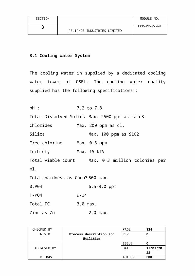
SECTION MODULE NO.
6 RELIANCE INDUSTRIES LIMITED
CKR-PR-P-001
EQUIPMENT LIST
CHECKED BY PAGE 124 N.S.P Process description and Utilities REV 0
ISSUE 0APPROVED BY DATE 07/04/2023
B. DAS AUTHOR BMK

SECTION MODULE NO.
6 RELIANCE INDUSTRIES LIMITED
CKR-PR-P-001
6.0 Equipment List
Section Title1 BUILDINGS2 ROTATING EQUIPMENTS3 TOWERS4 EXCHANGERS5 GENERAL EQUIPMENT6 FURNACES7 PUMPS8 REACTORS9 TANKS10 DRUMS
BUILDINGS
ITEM NO. DESCRIPTION
A 003 Mechanical Workshop/Dining RoomA 004 HVAC Chilling Unit Compressor HouseA 101 MCC & Control houseA 105 Gas Turbine Control HouseA 110 Furnace Analyser Shelter No.1A 120 Furnace Analyser Shelter No.2A 301 Cracker Gas Compressor ShelterA 401 Methane Compressor ShelterA 410 Cold Fractionation Analyser Shelter
No.1A 450 Cold Fractionation Analyser No.2A 510 Warm Fractionation Analyser ShelterA 601 Refrigeration Compressor ShelterA 701 G.H.U. Compressor ShelterA 901 Fuel Gas Compressor Shelter
CHECKED BY PAGE 125 N.S.P Process description and Utilities REV 0
ISSUE 0APPROVED BY DATE 07/04/2023
B. DAS AUTHOR BMK

SECTION MODULE NO.
6 RELIANCE INDUSTRIES LIMITED
CKR-PR-P-001
ROTATING EQUIPMENT
ITEM NO.
QTY. DESCRIPTION
B 100 1 Gas TurbineB 101 A/B 2 FD Fan (Motor Driven)B 102 1 FD Fan (Motor Driven)B 103 1 GT Fuel gas CompressorB 110 1 ID Fan (USC Furnace)B 111 1 ID Fan (USC Recycle Furnace)B 120 1 ID Fan (USC Furnace)B 121 1 ID Fan (USC Recycle Furnace)B 130 1 ID Fan (USC Furnace)B 131 1 ID Fan (USC Recycle Furnace)B 140 1 ID Fan (USC Furnace)B 150 1 ID Fan (USC Furnace)B 160 1 ID Fan (USC Furnace)B 170 1 ID Fan (USC Furnace)B 180 1 ID Fan (USC Furnace)B 190 1 ID Fan (USC Furnace)B 192 1 ID Fan (USC Furnace)B 194 1 ID Fan (USC Furnace)B 196 1 ID Fan (USC Furnace)B 300 1 Cracked Gas CompressorB 420 1 Methane RecompressorB 421 1 Methane ExpanderB 600 1 Ethylene Refrigerant CompressorB 650 1 Propylene Refrigerant CompressorB 710 A/B 2 1st Stage Make-up and Recycle CompressorB 740 A/B 2 2nd Stage Make-up and Recycle CompressorB 900 1 Fuel Gas CompressorB 915 1 Polisher Air BlowerB 1101 A/B 2 High Pressure Air CompressorsB 1121 A/B/C 3 SCO Reactor Feed Air CompressorBT 102 1 FD Fan TurbineBT 300 1 Cracked Gas Compressor TurbineBT 600 1 Ethylene Refrigerant Compressor TurbineBT 650 1 Propylene Refrigerant Compressor TurbineBT 900 1 Fuel Gas Compressor Turbine
CHECKED BY PAGE 126 N.S.P Process description and Utilities REV 0
ISSUE 0APPROVED BY DATE 07/04/2023
B. DAS AUTHOR BMK

SECTION MODULE NO.
6 RELIANCE INDUSTRIES LIMITED
CKR-PR-P-001
TOWERS
ITEM NO.
QTY. DESCRIPTION
C 210 1 Quench Oil TowerC 220 1 Quench Water TowerC 230 1 Heavy Fuel Oil StripperC 240 1 Light Fuel Oil StripperC 250 1 Distillate StripperC 260 1 LP Water StripperC 270 1 Dilution Steam StripperC 280 1 Auxiliary Dilution Steam StripperC 340 1 Caustic TowerC 350 1 Cracked Gas RectifierC 360 1 Condensate StripperC 410 1 Demethanizer PrestripperC 420 1 DemethanizerC 430 1 Residue Gas RectifierC 440 1 DeethanizerC 460 1 Ethylene StripperC 470 1 Ethylene RectifierC 510 1 DepropanizerC 530 1 Secondary DeethanizerC 535 1 Tertiary DeethanizerC 540 1 Propylene StripperC 550 1 Propylene RectifierC 560 1 DebutanizerC 720 1 DepentanizerC 730 1 DeoctanizerC 750 1 StripperC 1101 1 Steam Stripper
CHECKED BY PAGE 127 N.S.P Process description and Utilities REV 0
ISSUE 0APPROVED BY DATE 07/04/2023
B. DAS AUTHOR BMK

SECTION MODULE NO.
6 RELIANCE INDUSTRIES LIMITED
CKR-PR-P-001
EXCHANGERS
ITEM NO.
QTY. DESCRIPTION
E011 1 Ethane/Propane Recycle HeaterE 041 1 Naphtha Feed HeaterE 051 A/B 2 AGO Feed HeaterE 052 1 AGO Feed Heater No.2E053 1 AGO Feed Heater No.3E 110 A/H, J/Q 16 USX Exchanger (USC Fresh Feed Furn.)E 111 1 TLX Exchanger (USC Fresh Feed Furn.)E 115 A/D 4 USX Exchanger (USC Fresh Feed Furn.)E 120 A/H, J/Q 16 USX Exchanger (USC Fresh Feed Furn.)E 121 1 TLX Exchanger (USC Fresh Feed Furn.)E 125 A/D 4 USX Exchanger (USC Fresh Feed Furn.)E 130 A/H, J/Q 16 USX Exchanger (USC Fresh Feed Furn.)E 131 1 TLX Exchanger (USC Fresh Feed Furn.)E 135 A/D 4 USX Exchanger (USC Fresh Feed Furn.)E 140 A/H, J/Q 16 USX Exchanger (USC Fresh Feed Furn.)E 141 1 TLX Exchanger (USC Fresh Feed Furn.)E 150 A/H, J/Q 16 USX Exchanger (USC Fresh Feed Furn.)E 151 1 TLX Exchanger (USC Fresh Feed Furn.)E 160, A/H, J/Q 16 USX Exchanger (USC Fresh Feed Furn.)E 161 1 TLX Exchanger (USC Fresh Feed Furn.)E 170 A/H, J/Q 16 USX Exchanger (USC Fresh Feed Furn.)E 171 1 TLX Exchanger (USC Fresh Feed Furn.)E 180 A/H, J/Q 16 USX Exchanger (USC Fresh Feed Furn.)E181 1 TLX Exchanger (USC Fresh Feed Furn.)E 190 A/H, J/Q 16 USX Exchanger (USC Fresh Feed Furn.)E 191 1 TLX Exchanger (USC Fresh Feed Furn.)E 192 A/H, J/Q 16 USX Exchanger (USC Fresh Feed Furn.)E 193 1 TLX Exchanger (USC Fresh Feed Furn.)E 194 A/H, J/Q 16 USX Exchanger (USC Fresh Feed Furn.)E 195 1 TLX Exchanger (USC Fresh Feed Furn.)E 196 A/H, J/Q 16 USX Exchanger (USC Fresh Feed Furn.)E 197 1 TLX Exchanger (USC Fresh Feed Furn.)E 210 A/C 3 Fuel Oil Product CoolerE 215 A/B 2 Quench Water Steam HeaterE 219 1 Pan Oil Trim CoolerE 220 A/G 7 Primary quench water coolerE 230 A/H, J/K 10 Secondary quench water coolerE 239 1 LFO Stripping Steam Superheater
CHECKED BY PAGE 128 N.S.P Process description and Utilities REV 0
ISSUE 0APPROVED BY DATE 07/04/2023
B. DAS AUTHOR BMK

SECTION MODULE NO.
6 RELIANCE INDUSTRIES LIMITED
CKR-PR-P-001
ITEM NO.
QTY. DESCRIPTION
E 250 1 Distillate Stripper ReboilerE 258 1 Water Stripper Feed HeaterE 259 1 DSS Bd./Water Stripper Feed HeaterE 265 A/B 2 DSS Feed Heater No.1E 269 1 DSS Feed Heater No.2E 270 A/D 4 DSS Steam ReboilerE 271 A/H 8 DSS Q.O. ReboilerE 273 1 DSS Blowdown CoolerE 274 1 Auxiliary Dilution Steam Stripper Blowdown CoolerE 279 1 Aux. Dilution Steam Stripper Feed HeaterE 280 A/C 3 Aux. Dilution Steam Stripper ReboilerE 310 A/C 6 C.G. First Stage AftercoolerE 310 A/F 3 C.G. Second Stage AftercoolerE 320 A/C 3 C,G. Third Stage AftercoolerE 330 A/C 1 Weak Caustic HeaterE 340 1 Wash Water CoolerE 341 4 C.G. Fourth Stage AftercoolerE 345 A/D 1 C.G. Rectifier Overhead CondenserE 355 1 Condensate Stripper Feed HeaterE 359 2 Condensate Stripper ReboilerE 360 A/B 1 Condensate Stripper ReboilerE 371 1 React. Gas Feed / Effluent ExchangerE 372 1 React. Gas Feed HeaterE 373 1 Reactivation Gas Feed CoolerE 374 1 Reactivation Gas Feed ChillerE 375 1 Reactivation Gas Effluent CoolerE 401 1 Demethanizer Precooler No.1E 402 1 Demethanizer Precooler No.2E 403 1 Demethanizer Precooler No.3E 404 1 Demethanizer Precooler No.4E 405 1 Demethanizer Precooler No.5E 406 1 Demethanizer Precooler No.6E 407 1 Demethanizer Parallel Precooler No.1E 408 1 Demethanizer Parallel BTMS ReheaterE 409 1 Demethanizer Parallel Precooler No.2E 410 1 Demethanizer Prestripper ReboilerE 411 1 Demethanizer Core Exchanger No.1E 412 1 Demethanizer Core Exchanger No.2E 413 1 Demethanizer Core Exchanger No.3E 414 1 Demethanizer Core Exchanger No.4E 415 1 Demethanizer Core Exchanger No.5E 419 1 Hydrogen Core ExchangerE 420 1 Demethanizer ReboilerE 421 1 Demethanizer Parallel Precooler No.3E 422 1 Demethanizer Parallel Precooler No.4
CHECKED BY PAGE 129 N.S.P Process description and Utilities REV 0
ISSUE 0APPROVED BY DATE 07/04/2023
B. DAS AUTHOR BMK
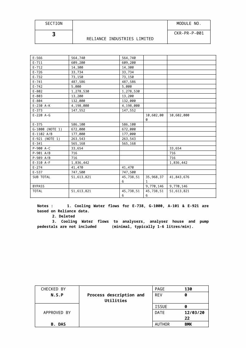
SECTION MODULE NO.
6 RELIANCE INDUSTRIES LIMITED
CKR-PR-P-001
EXCHANGERS
ITEM NO.
QTY. DESCRIPTION
E 424 1 Demethanizer Precooler No.6E 425 1 Demethanizer CondenserE 426 1 Methane Product HeaterE 427 1 Methane Product HeaterE 438 1 Demethanizer Bottoms ReheaterE 439 A/B 2 Demethanizer, Prestripper Btms ReheaterE 440 A/C 3 Deethanizer ReboilerE 445 A/D 4 Deethanizer CondenserE 450 1 C2 Hydrog. Feed HeaterE 452 A/D 4 C2 Hydrog. Feed / Effluent ExchangerE 455 1 C2 Hydrog. Adia. Rct. Intercooler No.2E 456 A/B 2 C2 Hydrog. Adia. Rct. AftercoolerE 458 1 C2 Hydrog. Adia. Rct. Intercooler No.1E 460 1 Ethylene Stripper ReboilerE 461 1 Ethylene Recycle Vaporiser E 470 A/B 2 Ethylene Rectifier ReboilerE 475 A/D 4 Ethylene Rectifier CondenserE 477 1 Ethylene Product VaporiserE 478 1 Ethylene Product SuperheaterE 480 1 Ethylene Product Cooler No.1E 481 1 Ethylene Product Cooler No.2E 482 1 Ethylene Product Cooler No.3E 490 1 HP Ethylene Product Heater No.1E 491 A/B 1 HP Ethylene Product Heater No.2E 510 A/B 2 Depropanizer ReboilerE 515 A/B 2 Depropanizer CondenserE 521 1 Interstage CoolerE 522 1 Catalyst TreatmentE 530 1 Secondary Deethanizer ReboilerE 535 1 Secondary Deethanizer CondenserE 536 1 Tertiary Deethanizer ReboilerE 537 1 Tertiary Deethanizer CondenserE 540 A/D 4 Propylene Tower ReboilerE 541 A/B 2 Propylene Tower Aux. ReboilerE 542 1 Propane Recycle VaporiserE 555 A/H 8 Propylene Tower CondenserE 556 1 Propylene Product CoolerE 560 A/B 2 Debutanizer ReboilerE 565 1 Debutanizer CondenserE 566 1 Pyrolysis Gasoline Product CoolerE 645 1 C2 Refrigerant Desuperheater No.1
CHECKED BY PAGE 130 N.S.P Process description and Utilities REV 0
ISSUE 0APPROVED BY DATE 07/04/2023
B. DAS AUTHOR BMK

SECTION MODULE NO.
6 RELIANCE INDUSTRIES LIMITED
CKR-PR-P-001
EXCHANGERS
ITEM NO.
QTY. DESCRIPTION
E 646 1 C2 Refrigerant Desuperheater No.2 E 647 1 C2 Refrigerant Desuperheater No.3E 649 A/B 2 Aux. C2 Refrigerant CondenserE 650 1 C2 Refrigerant SubcoolerE 695 1 C3 Refrigerant DesuperheaterE 699 A/H, J/K 10 C3 Refrigerant CondenserE 701 1 1t Stage Reactor Feed/Effl. ExchangerE 702 1 1st Stage Reactor Start-up HeaterE 711 1 1st Stage Quench CoolerE 712 1 Hot Separator Vapour CondenserE 713 1 1st Stage Compressor Bypass CoolerE 720 1 Depentanizer CondenserE 725 1 Depentanizer CondenserE 726 1 C5 Product CoolerE 730 A/B 2 Deoctanizer ReboilerE 731 1 Wash Oil Condenser E 732 1 Deoctanizer Bottoms CoolerE 735 1 Deoctanizer CondenserE 736 1 Decoct Post Condenser CoolerE 737 1 Wash Oil Trim CoolerE 738 1 Ejector CondenserE 740 A/B 5 2nd stage Feed / Effluent ExchangerE 741 1 2nd stage Reactor Effluent CoolerE 742 1 2nd stage Compressor Bypass CoolerE 749 A/B 2 Stripper Feed / Effluent ExchangerE 750 1 Stripper ReboilerE 751 1 C6-C8 Product Trim CoolerE 755 1 Stripper CondenserE 801 1 Reactor start-up heaterE 802 1 Recycle CoolerE 803 1 Post CondenserE 804 1 Product CoolerE 805 1 C4H Startup Heater (Unit-2)E 806 1 C4H Recycle Cooler (Unit-2)E 807 1 C4H Postcondensor (Unit-2)E 808 1 C4H Product Cooler (Unit-2)E 900 1 Fuel Gas Compressor Recycle CoolerE 902 1 Cold Blowdown VaporiserE 903 1 C5 Fuel VaporiserE 904 1 Suspect Cond. Drum vent CondenserE 905 1 C3/C4 Fuel VaporiserE 906 1 Fuel gas SuperheaterE 907 1 Methanol VaporiserE 909 1 Cold Flare Superheater
CHECKED BY PAGE 131 N.S.P Process description and Utilities REV 0
ISSUE 0APPROVED BY DATE 07/04/2023
B. DAS AUTHOR BMK

SECTION MODULE NO.
6 RELIANCE INDUSTRIES LIMITED
CKR-PR-P-001
EXCHANGERS
ITEM NO.
QTY. DESCRIPTION
E 910 1 Knock-out Drum Slops CoolerE 920 1 Contaminated Condensate CoolerE 921 1 Condensate Polisher Inlet CoolerE 922 1 CPU Effluent Heat ExchangerE 930 1 C.G. Comp. Steam Turbine CondenserE 938 1 Ejector CondenserE 960 1 C2 Refrig. Comp. Steam Turb CondenserE 961 1 Z-960 Ejector CondenserE 965 1 C3 Refrig. Comp. Steam Turb CondenserE 966 1 Z-965 Ejector CondenserE 980 1 C2/C3 Refrig. Compressor Lube/Seal Oil CoolerE 981 1 CG Compressor Lube Oil CoolerE 982 1 Cg Compressor Seal Oil CoolerE 990 A/B 2 Fuel Gas Compressor Lube / Seal Oil CoolerE 1101 1 Steam Stripper Feed Pre-heaterE 1102 A/B 1 Steam Stripper Effluent CoolerE 1103 1 Influent / Effluent Heat ExchangerE 1104 1 Oxidation Reactor Effluent CoolerE 1105 1 SCO Treated Effluent CoolerE 1121 1 SCO Effluent CoolerE 1122 1 SCO Feed / Vent Gas ExchangerE 1123 1 SCO Vent Gas Cooler
CHECKED BY PAGE 132 N.S.P Process description and Utilities REV 0
ISSUE 0APPROVED BY DATE 07/04/2023
B. DAS AUTHOR BMK
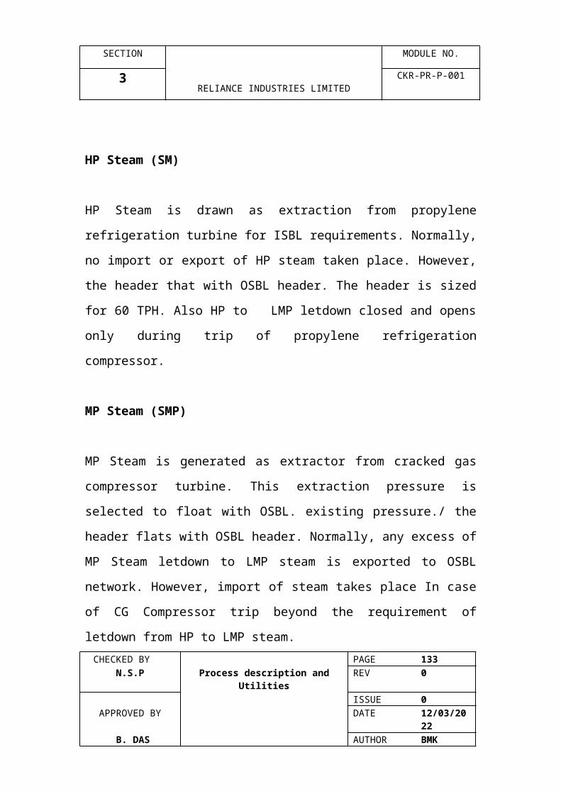
SECTION MODULE NO.
6 RELIANCE INDUSTRIES LIMITED
CKR-PR-P-001
GENERAL EQUIPMENT:ITEM NO.
QTY. DESCRIPTION
BG 300 1 Turning Gear MotorBG 650BL 300 1 CG Compressor Lube Oil ConsoleBL 650 1 E 650 & E 600 LO/SO ConsoleBL 900 1 FG Compressor LO/SO ConsoleBS 300 1 CG Compressor Seal Oil ConsoleBTG 300 1 CG Compressor Gland Stm Ejector PkgBTG 600 1 C2 Refrig. Comp. Gland Stm. Ejector PkgBTG 650 1 C3 Refrig Comp Gland Stm. Ejector PkgBTG 900 1 Fuel Gas Comp Gland Stm Ejector PkgG 101 1 Main Control Room HVAC PackageG 711 1 Polymerisation Inhibitor Package
Including : T-711, Z-711, P-711 A-DG 736 1 Deoctanizer Ejector SystemG 742 1 DMDS Injection Package
Including: P-742G 752 1 Corrosion Inhibitor Injection Package
Including : T-752, Z-752, P-752G 981 1 Phosphate Injection Package
Including : T-981, Z-981, P-981 A/CG 982 1 Hydazine Injection Package
Including: T-982, Z-982, P-982 A/BG 986 1 DMDS Injection Package
Including : T-986, P-986 A/B, P-995 A/DG 987 1 Corrosion Inhibitor Package
Including: T-987. Z-987, P-987 A/BG 988 1 Defoaming : T-987, Z-987, P-987 A/B
Including : T-988, Z-988, P-988 A/BG 1000 1 Spent Caustic Oxidation UnitZ 110 1 Quench Fitting (USC Furnace)Z 111 1 Quench Fitting (USC Recycle Furnace)Z 120 1 Quench Fitting (USC Furnace)Z 121 1 Quench Fitting (USC Recycle Furnace)Z 130 1 Quench Fitting (USC Recycle Furnace)Z 131 1 Quench Fitting (USC Furnace)Z 140 1 Quench Fitting (USC Furnace)Z 150 1 Quench Fitting (USC Furnace)Z 160 1 Quench Fitting (USC Furnace)Z 170 1 Quench Fitting (USC Furnace)Z 180 1 Quench Fitting (USC Furnace)Z 190 1 Quench Fitting (USC Furnace)Z 192 1 Quench Fitting (USC Furnace)Z 194 1 Quench Fitting (USC Furnace)Z 196 1 Quench Fitting (USC Furnace)Z 210 A/B 1 Quench Oil Filters
CHECKED BY PAGE 133 N.S.P Process description and Utilities REV 0
ISSUE 0APPROVED BY DATE 07/04/2023
B. DAS AUTHOR BMK
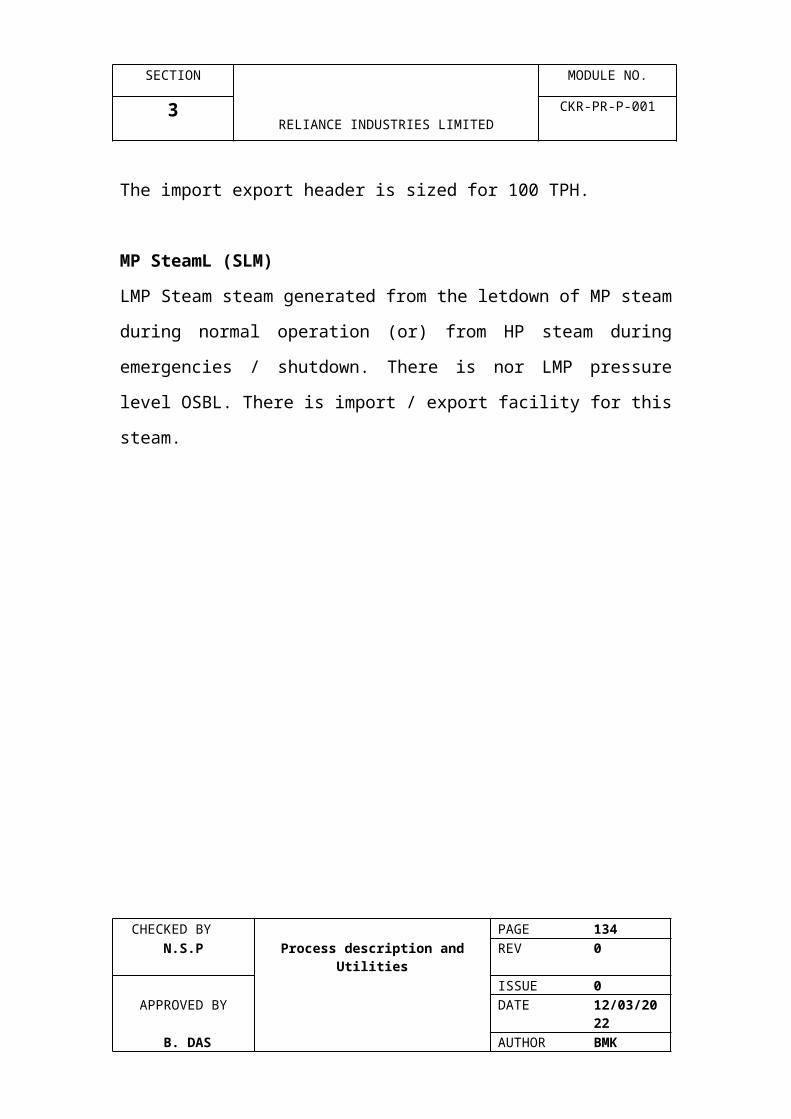
SECTION MODULE NO.
6 RELIANCE INDUSTRIES LIMITED
CKR-PR-P-001
GENERAL EQUIPMENT
ITEM NO.
QTY. DESCRIPTION
Z 230 A/B 2 Heavy Fuel Oil FilterZ 261 A/B 2 Water Stripper feed FiltersZ 300 1 Oil PurifierZ 301 1 Cracked Gas Compressor Service CraneZ 320 1 Vane Separator for 2nd stage suction drumZ 330 1 Vane Separator for 3rd stage Suction DrumZ 335 1 Vane Separator for 3rd stage suction drumZ 340 1 Vane separator for 4th Stage Suction DrumZ 341 1 Caustic Diluent MixerZ 342 1 Week Caustic Circ. Pump Suction StrainerZ 343 1 Spent Caustic / Aromatic Gasoline MixerZ 344 1 Caustic Area SumpZ 400 1 Pressure Swing Adsorption UnitZ 401 1 Methane Comp. Service CraneZ 601 1 Main Compressor Service CraneZ 602 1 Ethylene Compressor Service CraneZ 610 A/B 1 Ethylene Refrigerant Oil FiltersZ 611 1 Vane Separator for C2R 1st Stage Suction DrumZ 660 1 Vane Separator for C3R 1st Stage Suction DrumZ 690 1 Vane Separator for C3R 4th Stage Flash DrumZ 701 1 GHU Compressor Service CraneZ 702 A/B 2 RPG Feed FiltersZ 711 1 Polymerisation Inhibitor MixerZ 736 1 Deoctanizer Ejector SystemZ 740 1 2nd stage ejectorZ 752 1 Corrosion Inhibitor MixerZ 900 1 Condensate PolisherZ 901 A/B 2 S40 DesuperheaterZ 902 A/B 2 S12 DesuperheaterZ 903 A/B 2 S3.5 DesuperheaterZ 904 A/B 2 Suspect Condensate FiltersZ 905 1 GHU Reboiler Steam DesuperheaterZ 906 1 SMP Extraction Steam DesuperheaterZ 910 1 Flare System (outside Battery Limits of Cracker)Z 914 1 Polisher Acid Tank AgitatorZ 930 1 CG Compressor Turbine Ejector PackageZ 960 1 C2 refrig Compressor Turbine Ejector PkgZ 965 1 C3 refrig compressor Turbine Ejector PkgZ 981 1 Phosphate tank AgitatorZ 982 1 Hydrazine Tank AgitatorZ 987 1 Corrosion Inhibitor Tank AgitatorZ 988 1 Defoaming Agent Tank AgitatorZ 990 1 Emergency Power generator
CHECKED BY PAGE 134 N.S.P Process description and Utilities REV 0
ISSUE 0APPROVED BY DATE 07/04/2023
B. DAS AUTHOR BMK

SECTION MODULE NO.
6 RELIANCE INDUSTRIES LIMITED
CKR-PR-P-001
GENERAL EQUIPMENT
ITEM NO.
QTY. DESCRIPTION
Z 995 A/B 2 Storm Sewer Collection SumpZ 996 1 OWS Collection SumpZ 1101 1 Vapour ScrubberZ 1103 1 SCO Steam DesuperheaterZ 1104 2 Carbon CanistersZ 1121 1 SCO Feed Air FilterZ 1122 1 SCO Reactor Feed FilterZ 1123 A/B/C 3 SCO Reactor Effluent FiltersZ 1124 1 SCO SLM Steam DesuperheaterZ 1125 1 SCO Reactor Sparger Capsules (1 Lot)Z 1126 1 SCO Feed Steam FilterZ 1127 1 SCO Vent Gas Silencer
FURNACES
ITEM NO.
QTY. DESCRIPTION
H 110 1 USC Fresh Feed FurnaceH 111 1 USC Recycle FurnaceH 120 1 USC Fresh Feed FurnaceH 121 1 USC Recycle FurnaceH 130 1 USC Fresh Feed FurnaceH 131 1 USC Recycle FurnaceH 140 1 USC Fresh Feed FurnaceH 150 1 USC Fresh Feed FurnaceH 160 1 USC Fresh Feed FurnaceH 170 1 USC Fresh Feed FurnaceH 180 1 USC Fresh Feed FurnaceH 190 1 USC Fresh Feed FurnaceH 192 1 USC Fresh Feed FurnaceH 194 1 USC Fresh Feed FurnaceH 196 1 USC Fresh Feed FurnaceH 710 1 1st Stage Reactor Treatment FurnaceH 740 1 2nd Stage Reactor Feed Heater / Regeneration Furnace
CHECKED BY PAGE 135 N.S.P Process description and Utilities REV 0
ISSUE 0APPROVED BY DATE 07/04/2023
B. DAS AUTHOR BMK
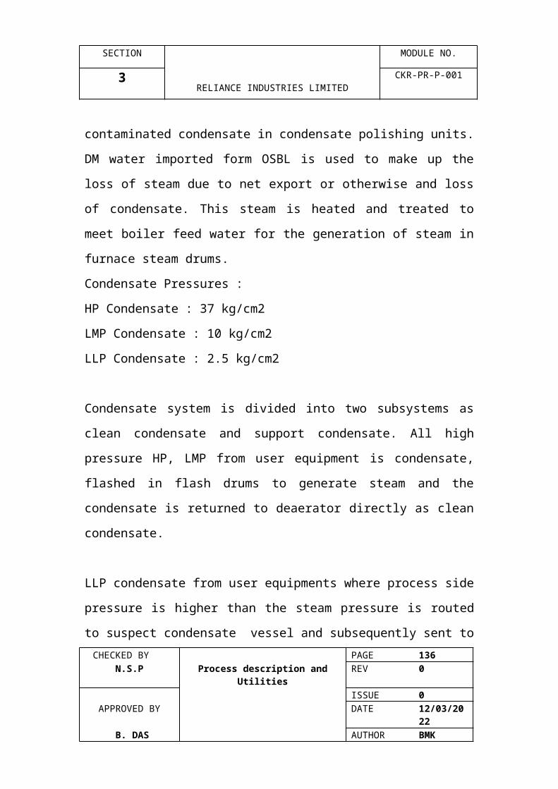
SECTION MODULE NO.
6 RELIANCE INDUSTRIES LIMITED
CKR-PR-P-001
PUMPS
ITEM NO.
QTY. DESCRIPTION
P 210 A/C 3 Q.O. Circulating PumpP 211 A/B 2 Pan Oil Circulating PumpP 220 A/C 3 Quench Water Circulating PumpP 221 A/B 2 Quench Oil Tower Reflux PumpP 225 A/C 3 Secondary Quench Water Circ. PumpP 230 A/B 2 Heavy Fuel Oil Product PumpP 240 A/B 2 Light Fuel Oil Product PumpP 250 A/B 2 Distillate Stripper Bottoms PumpP 260 A/B 2 Dilution Steam Stripper Feed PumpP 270 1 QO Drain Drum PumpP 300 A/B 2 Wash Oil Injection PumpP 310 A/B 2 C.G. 1st Stage Condensate PumpP 320 A/B 2 Distillate Stripper Feed PumpP 341 A/B 2 Concentrated Caustic PumpP 342 A/B 2 Weak Caustic Circulating PumpP 343 A/B 2 Medium Caustic Circulating PumpP 344 A/B 2 Strong Caustic Circulating PumpP 345 A/B 2 Wash Water Circulating PumpP 346 A/B 2 Caustic Area Sum[p PumpP 347 A/B 2 Aromatic Gasoline Circulating PumpP 348 A/B 2 Spent Caustic Discharge PumpP 349 1 Aromatic Gasoline Injection PumpP 355 A/B 2 Cracked Gas Rectifier Reflux PumpP 360 A/B 2 Condensate Stripper Bottoms PumpP 400 A/B 2 Methanol PumpP 401 1 Methanol Unloading PumpP 425 A/B 2 Demethanizer Reflux PumpP 445 A/B 2 Deethanizer Reflux PumpP 451 A/C 3 C4 Coolant Circ. PumpP 470 A/B 2 Ethylene Rectifier Bottoms PumpP 475 A/B 2 Ethylene Rectifier Reflux PumpP 515 A/B 2 Depropanizer Reflux PumpP 516 A/B 2 C3 Hydrogenation Feed PumpP 520 A/B 2 C3 Hydrogenation Recycle PumpP 530 A/B 2 Secondary Deethanizer Bottoms PumpP 535 A/B 2 Secondary Deethanizer Reflux PumpP 536 A/B 2 Tertiary Deethanizer Bottoms PumpP 537 A/B 2 Tertiary Deethanizer Reflux PumpP 550 A/B 2 Propylene Transfer PumpP 555 A/B 2 Propylene Tower Reflux/Product PumpP 565 A/B 2 Debutanizer Reflux/Product PumpP 701 A/B 2 1st Stage Feed PumpP 710 A/B 2 1st Stage Quench Pump
CHECKED BY PAGE 136 N.S.P Process description and Utilities REV 0
ISSUE 0APPROVED BY DATE 07/04/2023
B. DAS AUTHOR BMK

SECTION MODULE NO.
6 RELIANCE INDUSTRIES LIMITED
CKR-PR-P-001
PUMPS
ITEM NO.
QTY. DESCRIPTION
P 711 A/B 4 Polymerisation Inhibitor PumpP 725 A/b 2 Depent anizer Reflux PumpP 730 A/B 2 Deoctanizer Bottoms pumpP 731 A/B 2 Wash Oil Transfer PumpP 735 A/B 2 Deoctanizer Reflux PumpP 736 A/B 2 2nd Stage Feed PumpP 740 A/B 2 2nd stage Quench PumpP 742 1 DMDS Injection PumpP 750 A/B 2 C6-C8 Product PumpP 752 1 Corrosion Inhibitor PumpP 755 A/B 2 Stripper Reflux PumpP 801 A/B 2 Feed PumpP 802 A/B 2 Recycle PumpP 803 A/B 2 C4 Product PumpP 900 A/C 3 Boiler Feed Water PumpP 901 A/B 2 LP Boiler Feed Water PumpP 902 A/B 2 knock-out Drum Slops PumpP 910 A/C 3 Boiler Feedwater Make-up PumpP 914 1 CPU Feed PumpP 915 A/B 2 Polisher Caustic PumpP 916 A/B 2 Polisher Acid PumpP 917 1 Polisher Effluent PumpP 930 A/B 2 CG Compressor Turbine Condensate PumpP 931 A/B 2 Cracked Gas Compressor Seal Oil PumpP 932 A/B 2 Cracked Gas Compressor Lube Oil PumpP 942 A/B 2 Methane Expander / Rcomp. Condensate PumpP 956 A/B 2 Debutanizer Reboiler Condensate PumpP 960 A/B 2 C2R Comp. Turbine Condensate PumpP 961 A/B 2 C2/C3 Refrig Comp. Lube / Seal Oil PumpP 965 A/B 2 C3R Comp. Turbine Condensate PumpP 971 A/B 2 S/E LO Pump B-710 A/BP 974 A/B 2 S/E LO Pump B-740 A/BP 981 A/C 3 Phosphate Injection PumpP 982 A/B 2 Hydrazine Injection PumpP 983 A/C 3 Polymerisation Inhibitor Injection PumpP 985 A/D 4 Fresh Feed Furnaces DMDS Injection PumpsP 986 A/C 3 DMDS Injection PumpP 987 A/B 2 Corrosion Inhibitor Injection PumpP 988 A/B 2 Defoaming Agent Injection PumpP 989 A/B 2 Suspect Condensate PumpP 990 A/B 2 Fuel Gas Compressor Lube / Seal Oil PumpP 991 A/C 3 Boiler Feedwater Lube Oil Pump
CHECKED BY PAGE 137 N.S.P Process description and Utilities REV 0
ISSUE 0APPROVED BY DATE 07/04/2023
B. DAS AUTHOR BMK
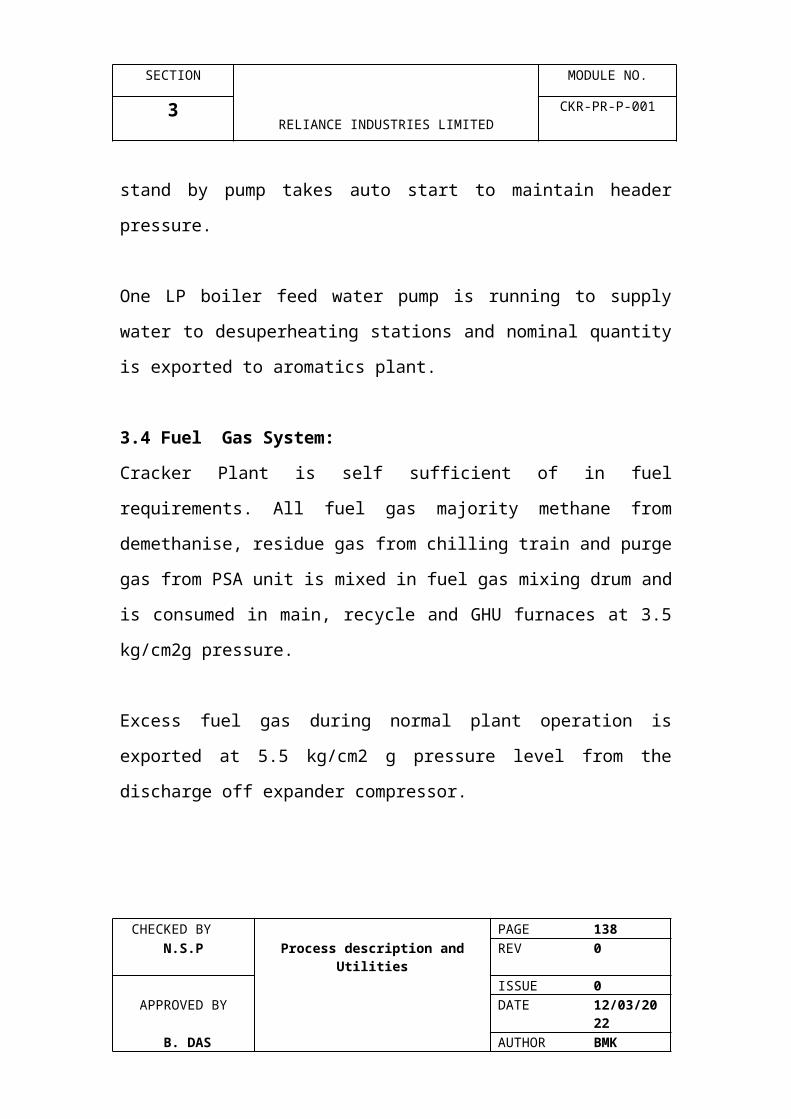
SECTION MODULE NO.
6 RELIANCE INDUSTRIES LIMITED
CKR-PR-P-001
PUMPS
ITEM NO.
QTY. DESCRIPTION
P 992 A/B 2 Aux. Corrosion Inhibitor Injection PumpsP 995 A/D 4 Storm Sewer Transfer PumpP 996 A/B 2 OWS Transfer PumpP 997 A/B 2 Portable Dewatering PumpP 1101 A/B 2 Spent Caustic Feed / Recycle PumpP 1102 A/B 2 High Pressure Feed PumpsP 1103 A/B 2 Effluent Transfer PumpsP 1104 A/B 2 Steam Stripper Bottoms PumpP 1121 A/B 2 SCO Reactor Feed PumpP 1122 A/B 2 SCO Effluent Transfer Pump
CHECKED BY PAGE 138 N.S.P Process description and Utilities REV 0
ISSUE 0APPROVED BY DATE 07/04/2023
B. DAS AUTHOR BMK

SECTION MODULE NO.
6 RELIANCE INDUSTRIES LIMITED
CKR-PR-P-001
REACTORS
ITEM NO.
QTY. DESCRIPTION
R 451 A/C 3 C2 Hydrog. Adiabatic ReactorR 452 A/B 2 Prim. C2 Hydrog. Adiabatic ReactorR 531 A 1 C3 Hydrog. Reactor # 1R 531 B 1 C3 Hydrog. Reactor # 2R 531 C 1 C3 Hydrog. Reactor # 3R 532 1 C3 Hydrog. Second Stage ReactorR 710 A/B 2 First Stage ReactorR 740 1 Second Stage ReactorR 801 1 Hydrogenation ReactorR 802 1 Final Hydrogenation ReactorR 803 1 C4H Reactor (Unit-2)R 804 1 C4H Final Hydrog. Reactor (Unit-2)R 1101 1 Oxidation ReactorR 1122 A/B/C 3 SCO Reactor
TANKS
ITEM NO.
QTY. DESCRIPTION
T 300 1 Wash Oil TankT 340 1 Concentrated Caustic TankT 400 1 Methanol TankT 711 1 Polymerisation Inhibitor TankT 752 1 Corrosion Inhibitor TankT 900 1 CPU Feed Surge DrumT 910 1 BFW Make-up Storage TankT 914 1 Polisher Acid Storage TankT 915 1 Polisher Caustic TankT 916 1 Polisher Acid TankT 981 1 Phosphate Mixing TankT 982 1 Hydrazine Mixing TankT 983 1 Polymerisation Inhibitor TankT 986 1 DMDS TankT 987 1 Corrosion Inhibitor Mixing TankT 988 1 Defoaming Agent Mixing TankT 1101 A/B 1 Spent Caustic Holding Tank
CHECKED BY PAGE 139 N.S.P Process description and Utilities REV 0
ISSUE 0APPROVED BY DATE 07/04/2023
B. DAS AUTHOR BMK
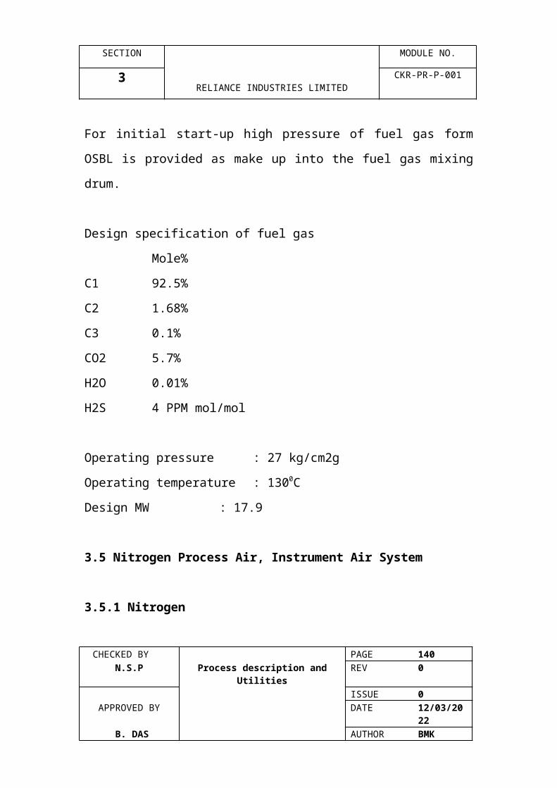
SECTION MODULE NO.
6 RELIANCE INDUSTRIES LIMITED
CKR-PR-P-001
DRUMS
ITEM NO.
QTY. DESCRIPTION
V 061 1 LPG/C4 raffinate Vaporiser Feed DrumV 110 1 Steam Drum (USC Furnace)V 111 1 Steam Drum (USC Recycle Furnace)V 120 1 Steam Drum (USC Furnace)V 121 1 Steam Drum (USC Recycle Furnace)V 130 1 Steam Drum (USC Furnace)V 131 1 Steam Drum (USC Recycle Furnace)V 140 1 Steam Drum (USC Recycle Furnace)V 150 1 Steam Drum (USC Recycle Furnace)V 160 1 Steam Drum (USC Recycle Furnace)V 170 1 Steam Drum (USC Recycle Furnace)V 180 1 Steam Drum (USC Recycle Furnace)V 190 1 Steam Drum (USC Recycle Furnace)V 192 1 Steam Drum (USC Recycle Furnace)V 194 1 Steam Drum (USC Recycle Furnace)V 196 1 Steam Drum (USC Recycle Furnace)V 198 1 Decoke Drum Separator/SilencerV 199 1 Decoke Drum Separator/SilencerV 262 A/B 2 Water Stripper Feed CoalescerV 270 1 Quench Oil Drain DrumV 310 1 CG First Stage Suction DrumV 320 1 CG Second Stage Suction DrumV 330 1 CG Third Stage Suction DrumV 335 1 CG Third Stage Discharge DrumV 340 1 CG Fourth Stage Suction DrumV 342 1 Spent Caustic Deoiling DrumV 343 1 Spent Caustic Degassing DrumV 346 1 Cracked Gas Rectifier Reflux DrumV 359 1 Condensate Stripper Feed CoalescerV 370 A/B 2 Cracked Gas DehydratorsV 371 1 Reactivation Gas SeparatorV 403 1 Demethanizer Preclr. No.3 Refrig. Flash PotV 406 1 Demethanizer Preclr. No.6 Flash PotV 410 1 Demethanizer Prestripper Feed DrumV 411 1 Demethanizer Feed Drum No.1V 412 1 Demethanizer Feed Drum No.2V 413 1 Demethanizer Feed Drum No.3V 414 1 Demethanizer Prestripper Parallel Feed DrumV 415 1 Demethanizer Parallel Feed Drum No.1V 416 1 Demethanizer Parallel Feed Drum No.2V 417 1 Demethanizer Parallel Feed Drum No.3
CHECKED BY PAGE 140 N.S.P Process description and Utilities REV 0
ISSUE 0APPROVED BY DATE 07/04/2023
B. DAS AUTHOR BMK

SECTION MODULE NO.
6 RELIANCE INDUSTRIES LIMITED
CKR-PR-P-001
DRUMS
ITEM NO.
QTY. DESCRIPTION
V 418 1 Methane Expander 2nd Stage Suction DrumV 419 1 E-419 Knockout DrumV 420 1 Demethanizer Reboiler Refrig. Seal PotV 422 1 Demethanizer Parallel Precooler # 4 Flash Pot AV 423 1 Demethanizer Parallel Precooler # 4 Flash Pot BV 424 1 Demethanizer Parallel Precooler # 6 Flash Pot BV 425 1 Demethanizer Condenser Refrig Flash PotV 426 1 Demethanizer Reflux DrumV 431 1 Hydrogen DrumV 432 1 PSA Unit Surge DrumV 436 1 Residue Gas Rect. Reflux DrumV 445 1 Deethanizer Condenser Refrig. Flash potV 446 1 Deethanizer Reflux DrumV 453 A/B 2 Secondary DehydratorsV 455 1 C2 Hydrogenation Effluent SeparatorV 460 1 Ethylene Stripper Refrig. Seal PotV 476 1 Ethylene Rectifier Reflux DrumV 477 1 Ethylene Prod. Vaporiser Refrig. Seal PotV 480 1 Ethylene Product Cooler No.1 Refrig. Flash PotV 481 1 Ethylene Product Cooler No.2 Refrig. Flash PotV 482 1 Ethylene Product Cooler No.3 Refrig. Flash PotV 490 1 HP Ethylene Product Heater No.1 Seal PotV 516 1 Depropanizer Reflux DrumV 519 1 C3 Hydrogenation Feed CoalescerV 525 1 C3 Hydrogenation SeparatorV 536 1 Secondary Deethanizer Reflux DrumV 537 1 Tertiary Deethanizer Reflux DrumV 556 1 Propylene Rectifier Reflux DrumV 566 1 Debutanizer Reflux DrumV 610 1 Ethylene Refrig. 1st Stage Suction DrumV 620 1 Ethylene Refrig. 2nd Stage Suction DrumV 630 1 Ethylene Refrig. 3rd Stage Suction DrumV 645 1 Ethylene Refrigerant Surge drumV 646 1 Ethylene Refrigerant Drain DrumV 650 1 Ethylene Refrigerant Subcooler Flash potV 660 1 Propylene Refrig. 1st Stage Suction DrumV 670 1 Propylene Refirg. 2nd Stage Suction DrumV 680 1 Propylene Refrig. 3rd Stage Suction DrumV 690 1 Propylene Refrig. 4th Stage Suction DrumV 695 1 Propylene Refrigerant Surge DrumV 696 1 Propylene Refrigerant Drain DrumV 701 1 Feed Surge DrumV 710 1 1st Stage Hot Separator
CHECKED BY PAGE 141 N.S.P Process description and Utilities REV 0
ISSUE 0APPROVED BY DATE 07/04/2023
B. DAS AUTHOR BMK
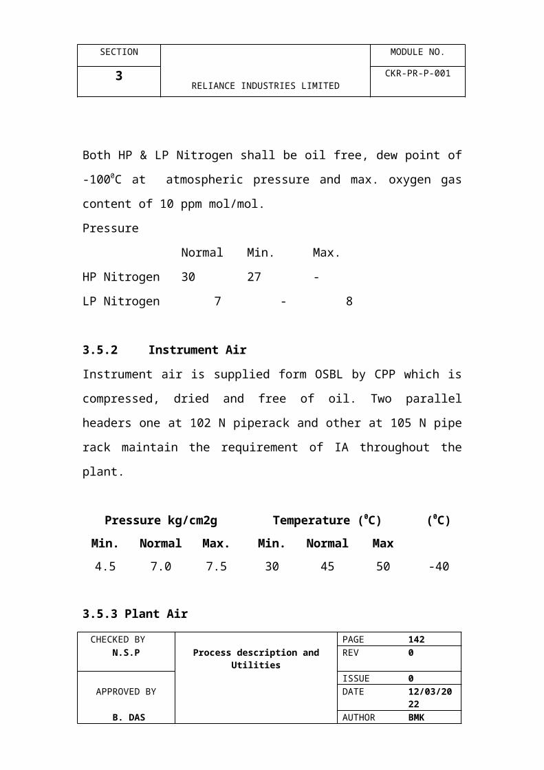
SECTION MODULE NO.
6 RELIANCE INDUSTRIES LIMITED
CKR-PR-P-001
DRUMS
ITEM NO.
QTY. DESCRIPTION
V 711 1 1st Stage Cold SeparatorV 712 1 1st Stage Knock-out DrumV 713 1 Decoking DrumV 726 1 Depentanizer Reflux DrumV 731 1 Wash Oil Holding DrumV 736 1 Deoctanizer Reflux DrumV 737 1 Z-736 Oily Water SeparatorV 740 1 2nd Stage Separator DrumV 741 1 2nd Stage Knock-out DrumV 756 1 Stripper Reflux DrumV 801 1 Feed Surge DrumV 802 1 Hot SeparatorV 803 1 Cold SeparatorV 804 1 C4 Product Flash DrumV 805 1 C4H Feed Surge Drum (Unit-2)V 606 1 C4H Hot Separator (Unit-2)V 807 1 C4H Cold Separator (Unit-2)V 808 1 C4 Product Flash Drum (Unit-2)V 900 1 DeaeratorV 901 1 Cold Flare Knock-out DrumV 902 1 Hot Flare Knock-out DrumV 904 1 S3.5 Suspect Condensate DrumV 905 1 AGO Feed Heater No.3 Condensate PotV 906 1 AGO Feed Heater No.2 Condensate PotV 907 1 Methanol Vaporiser No.1 Condensate PotV 908 1 Cold Blowdown Vaporiser Condnesate PotV 915 A-C 3 Polisher Mixed Bedsv 916 1 Polisher Regn VesselV 917 1 Polisher Effluent VesselV 920 1 S40 Steam Condensate Flash DrumV 926 1 DSG Feed Heater No.2 Condensate PotV 927 A/B 1 DSG Reboiler Condensate PotsV 928 1 Quench Water Steam Heater Condensate PotV 930 1 S12 Steam Condensate Flash DrumV 931 1 Continuous Blowdown DrumV 932 1 Intermittent Blowdown DrumV 937 1 Reactivation Gas Heater Condensate PotV 940 1 Fuel Gas Mixing DrumV 945 1 C2 Hydrog. Feed Water Condensate PotV 946 1 C2 Hydrog. Adia Reactor Feed Htr Cond. PotV 954 1 Propylene Tower Reboiler Condensate PotV 956 1 Debutanizer Reboiler Condensate PotV 961 1 LPG/C4 Raffinate Vaporiser Cond PotV 972 1 Depentanizer Reboiler Condensate Pot
CHECKED BY PAGE 142 N.S.P Process description and Utilities REV 0
ISSUE 0APPROVED BY DATE 07/04/2023
B. DAS AUTHOR BMK
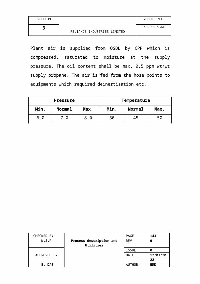
SECTION MODULE NO.
6 RELIANCE INDUSTRIES LIMITED
CKR-PR-P-001
Table 1
ITEM NO.
QTY. DESCRIPTION
V 973 1 Deoctoniser Reboiler Condensate PotV 975 1 Stripper Reboiler Condensate PotV 980 1 C3/C4 Fuel Vaporiser Condensate PotV 981 1 Fuel Gas Superheater Condensate PotV 1101 1 Steam Stripper Feed Preheater Condensate PotV 1102 1 Water K.O. DrumV 1103 1 SCO Reactor Feed Surge DrumV 1121 1 SCO Feed Surge DrumV 1122 1 SCO Effluent Surge DrumV 1123 1 SCO Air Surge Drum
CHECKED BY PAGE 143 N.S.P Process description and Utilities REV 0
ISSUE 0APPROVED BY DATE 07/04/2023
B. DAS AUTHOR BMK

SECTION MODULE NO.
7 RELIANCE INDUSTRIES LIMITED
CKR-PR-P-001
FLARE SYSTEM
CHECKED BY PAGE 144 N.S.P Process description and Utilities REV 0
ISSUE 0APPROVED BY DATE 07/04/2023
B. DAS AUTHOR BMK
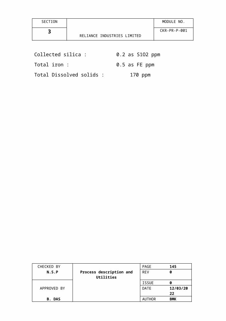
SECTION MODULE NO.
7 RELIANCE INDUSTRIES LIMITED
CKR-PR-P-001
7.1 Pressure Relief, Blowdown and flare system
7.1.1 Pressure Relief Valve Header System
Within Cracker Plant, a relief valve Header system is provided
to collect hydrocarbon discharges :
1. The C2 & lighter effluents which below -450C are collected in
the cold flare header made of autenitic steel subjected to
gravity separation in the cold flare knockout drum and steam
superheated prior to being discharged to the hot flare header.
2. Cold dry effluents (basically C3) at temperatures from 0C to -
450C are collected in the intermediate flare header (IF) which is
(LTCS) subjected to gravity separation in the same knock-out
drum as the C2 and lights effluents.
3. Hot wet effluents above 0C are collected in a carbon steel
header and subjected to gravity separation in the horflare
knockout drum. The gases from this drum joined by the
superheated effluent from the cold knockout drum and sent to
OSBL flare stack.
4. Cold flare knock out drum vaporiser which vaporises any
liquid lighters and the outlet superheater is provided, heated by
steam via an intermediate methanol loop as a heating medium.
7.1.2 Blowdown SystemCHECKED BY PAGE 145
N.S.P Process description and Utilities REV 0ISSUE 0
APPROVED BY DATE 07/04/2023 B. DAS AUTHOR BMK

SECTION MODULE NO.
7 RELIANCE INDUSTRIES LIMITED
CKR-PR-P-001
Blowdown Systems are provided to remove residual
hydrocarbon only during unit shut down or fire emergency. The
drains of all hydrocarbons that will vaporise when opened to
atmosphere are routed to the blowdown system. Hot blowdown
is having CS piping (above 0C) and cold blown is provided with
SS headers. These drain are collected in a common headers
and terminate in their corresponding relief valve header KW
drums.
Provision is made for vaporising any coalesced liquids. In cold
flare knockout drum, a steam heated indirect exchanger is
used while in hot flare knock out drum a steam coil is used.
Any accumulated liquid from cold or hot flare knock out drum
are pumped either to quench oil tower or to OSBL.
7.2 Flare system at OSBL
Flare from cracker ISBL, Tank farm, MEG & Aromatics gaseous
effluents are collected in the common header and are routed to
OSBL flea stack system.
Flare stack system, corrosion of knock out drum where any
liquid is separated. Then gases are passed to liquid drum where
these gases bubbled through water seal and reach the flea
stack. Then there gases pass through molecular seal at the
stack top and are burnt at the flare tip.CHECKED BY PAGE 146
N.S.P Process description and Utilities REV 0ISSUE 0
APPROVED BY DATE 07/04/2023 B. DAS AUTHOR BMK
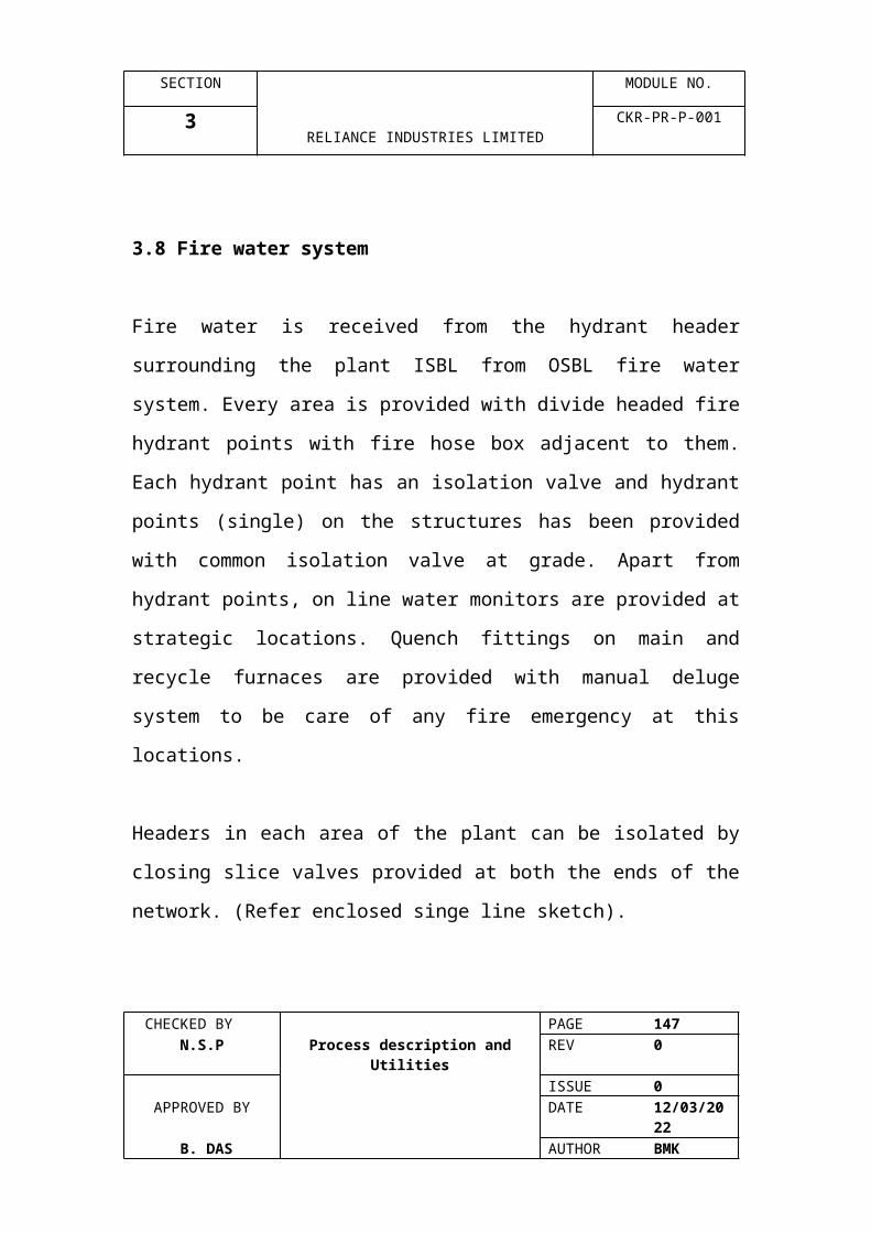
SECTION MODULE NO.
7 RELIANCE INDUSTRIES LIMITED
CKR-PR-P-001
4 No.s of burners continuously burn at the tip which is supplied
by fuel gas separately. Flare front generator located at grade
provides necessary ignition for putting pilots on these are
designed remain on even during heavy wind with rain. Each
pilot is provided with a thermocouple which sends any loss of
flare and connected to alarm. System both out the local panel
and in DCS. Also, one thermocouple provided at the centre of
the tip gives warning incase of any burnback.,
Two stages of steam are provided one at the centre into the
flare trip to cool the flea provides steam for complete
combustion. Centre, steam is adjusted manually at controlled
rate and the QS steam which is varied in accordance to the flow
to obtain smokeless flare.
Flare stack design parameters
Flare Gas:
Flow Rate : 1,050,689 kg/hr
Mot. Wt. : 33.26
Temp.: 800C
Pilot Gas:
Type : Fuel GasCHECKED BY PAGE 147
N.S.P Process description and Utilities REV 0ISSUE 0
APPROVED BY DATE 07/04/2023 B. DAS AUTHOR BMK
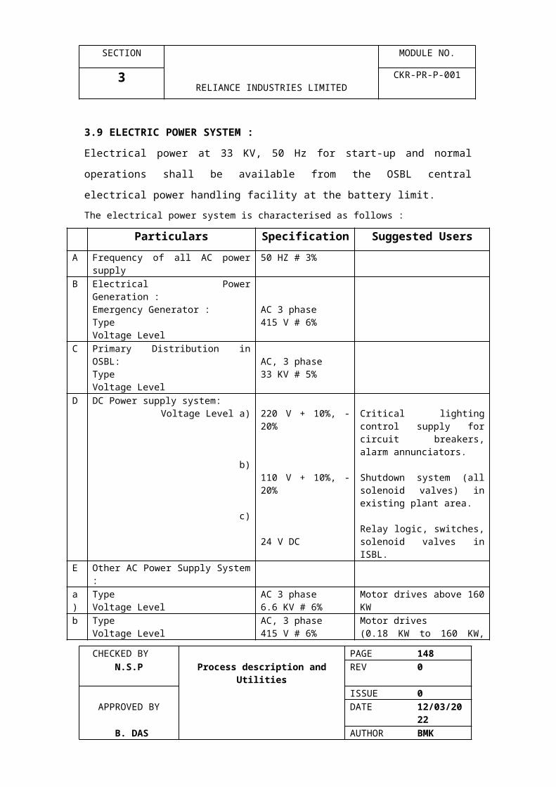
SECTION MODULE NO.
7 RELIANCE INDUSTRIES LIMITED
CKR-PR-P-001
Pressure : 1002 kg/cm2g
MW : 19.57
Steam :
Pressure : 7.03 kg/cm2g @ flare trip.
Flow max. : 32,659 kg/hr QS manifold @ 7.03 kg/cm2g
Flow : 430 kg/hr. Cooling rate for QS manifold
Flow Max. : 3855 kg/hr. through centre tip @ 7.03 kg/cm2g
Flow : 225 kg/cm2g cooling rate for center tip @ 7.03 kg/cm2
OPERATING INSTRUCITONS :
Pre-Start Up Check List
Before starting up the flare, checks should be made for the
following items :
1. Verify that all the flare components are installed in
accordance with the reference drawings.
2. If chromel-alumel Type K thermocouples are used, the blue
wire is negative (-) and the brown wire is positive (+).
3. All system lines should be dry and free of dirt and foreign
material.
4. Check that all drain and vent valves are closed and that all
drain and vent plugs are tightly secured. A drain plug or
valve is required at each low point in each pilot ignition line.
5. All manual valves in the pilot gas and waste gas systems
should be closed.
6. Check that all set points are properly adjusted.
CHECKED BY PAGE 148 N.S.P Process description and Utilities REV 0
ISSUE 0APPROVED BY DATE 07/04/2023
B. DAS AUTHOR BMK
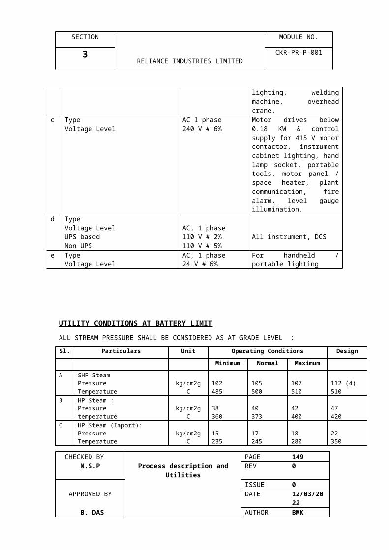
SECTION MODULE NO.
7 RELIANCE INDUSTRIES LIMITED
CKR-PR-P-001
7. The pilot ignition lines must be dry and unobstructed so that
the flame front is not quenched or blocked.
Start-Up and Operation Procedures for Smokeless Flare
System (QS-C):
The EEF-QS-60/66C flare uses 4 Energy Efficient Pilots as an
ignition source. The flare is equipped with a 8” QS Steam
Manifold and steam injectors capable of providing 32,659 kg/hr
of saturated steam @ 7.03 kg/cm2g. A 3” Centre Steam
Sparger is included which is capable of providing 3,855 kg/hr of
saturated steam @ 7.03kg/cm2g.
A continuous steam flow of 375 kg/hr should be maintained to
the QS Steam Manifold for cooling and to prevent cracking of
the steam injectors and manifold. The centre steam sparger
requires 225 kg/hr of cooling steam.
1. Start up and operation:
Light the pilots:
The method of lighting the 4 pilots should be carried out using
the flame front generator panel. (refer to appendix “A” -
“Operating Instructions for Flame Front Generator” - Bulletin
5401E (2 pages).
c) Introduce the cooling steam flow to the Centre Steam (225
kg/h). The Centre Steam rate should be set manually.
CHECKED BY PAGE 149 N.S.P Process description and Utilities REV 0
ISSUE 0APPROVED BY DATE 07/04/2023
B. DAS AUTHOR BMK

SECTION MODULE NO.
7 RELIANCE INDUSTRIES LIMITED
CKR-PR-P-001
d) Introduce the cooling steam flow to the upper QS Steam
Ring (375 kg/hr).
e) Start the waste gas flow at a nominal vent rate (500-1000
kg/hr)
f) With the QS Steam set at the cooling rate of 375 kg/hr,
adjust the Centre Steam until smokeless operation is
achieved. It may be necessary to make this adjustment
several times with the flea receiving gas at the nominal vent
rate.
When the required Centre Steam rate is achieved, it should be
changed. It is suggested that the Centre Steam manual valve
handle be removed.
Since one of the purposes of the Centre Steam is to prevent
burn-back inside the flare tip, it is advisable to observe the flare
tip at night for a glow (excessive heat) below the flare tip exit.
The above procedure should be followed for initial start-up.
g) During a flaring event, the steam flow to the QS Steam
Manifold should be adjusted to the point where smoke is not
visible and the flame is a yellow orange colour. The amount
of steam to achieve this is anticipated to be 0.4 kg steam
per 1.00 kg. waste hydrocarbon.
h) After cessation of a flaring event, the QS Steam Manifold
rate should be returned to a rate of 375 kg/h for cooling. Do
not readjust the centre steam rate as the flare will still be
experiencing a nominal vent rate of waste gas.CHECKED BY PAGE 150
N.S.P Process description and Utilities REV 0ISSUE 0
APPROVED BY DATE 07/04/2023 B. DAS AUTHOR BMK
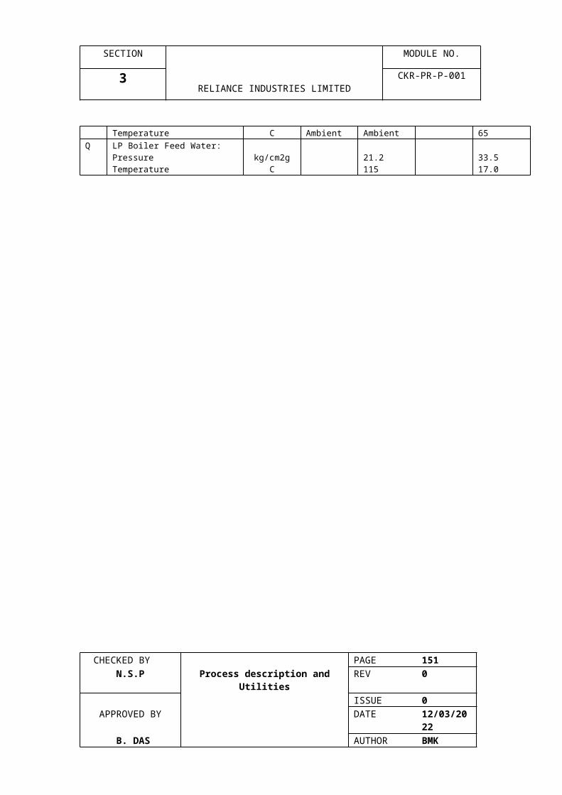
SECTION MODULE NO.
7 RELIANCE INDUSTRIES LIMITED
CKR-PR-P-001
2. Shut down
a) Close the steam supply valves to the QS Steam Manifold on
the flare trip. Close the steam supply to the Centre Steam
Sparger.
c) Shut Down the purge gas flow :
d) Extinguish the pilots by closing the pilot fuel gas block valve.
e) Close all hand valves.
f) Close all utility gas supply systems
OPERA TING INSTRUCITIONS FOR FLAME FRONT GENERATOR
Important :
A. All ignition lines must be one rich.
B. All low spots in ignition lines must be drained
Note : Sagging between supports is sufficient to cause low
spots in the line which can hold liquids and quench ignition
flame.
C. Confirm that all utilities are connected and operating
properly per the job drawing.
Ignition :
1. Purge flare system with nitrogen or fuel gas until all oxygen
has been replaced with purge gas.
Blow down air and gas supply lines to flame front generator at
blow down valves to remove condensate. Open all drains in the
low spots of ignition lines. Blow down each ignition line, one at
CHECKED BY PAGE 151 N.S.P Process description and Utilities REV 0
ISSUE 0APPROVED BY DATE 07/04/2023
B. DAS AUTHOR BMK

SECTION MODULE NO.
7 RELIANCE INDUSTRIES LIMITED
CKR-PR-P-001
a time, through valves A,E and C. Close all drains. Check each
ignition line for blockage by opening valve D and at a time.
When valve D is closed, pressure should fall off rapidly on the
pressure gauges. If pressure does not fall off rapidly,
investigate and correct the blockage in the ignition line.
3. Push switch ‘F” actuate Magiclite to check for spark at the
sight port.
4. Open valve “A’. Close valve “B” and “C” to ignite pilot No.1
5. Open valve “H”. This is the fuel for pilots.
6. Open valve “E” and set pressure gauge at 10 psig. (gas).
7. Open valve “D” and set pressure gauge at 13 psig. (air).
8. Wait two to three minutes after opening valves E and D.
9. Push and release quickly, switch “F”. At the same time
observe through the sight port to see if air/gas mixture was
ignited.
(If same is not observed, change either the air or gas slightly
until flame is observed). If the system uses Magiclite ignitor,
actuate as if you were using switch “F”.
10. If pilot does not light, repeat steps 8 and 9.
11. If repeating steps 8 and 9 two or three times does not ignite
the pilot, change air or gas pressure slightly using valve “D” or
valve “E”. Repeat steps 8 and 9 until pilot is ignited.
12. Close valve “A”. Open valve “B” to ignite Pilot No.3. Repeat
steps 8 and 9 until the pilot is ignited.
14. When all pilots are ignited, close valves ‘D” and “E”.
CHECKED BY PAGE 152 N.S.P Process description and Utilities REV 0
ISSUE 0APPROVED BY DATE 07/04/2023
B. DAS AUTHOR BMK
SECTION MODULE NO.
7 RELIANCE INDUSTRIES LIMITED
CKR-PR-P-001
15. On light or sunny days, if is difficult to observe pilot flame
to verify ignition. To observe pilot flame, close valve “D” and
open valve “E” fully for two or three minutes. If ignited, pilot
flame will become luminous. This can be repeated for each pilot
by opening and closing valves A,B, and C.
16. After all pilots are ignited and verified, the flea is ready for
operation. Waste gas can now be flared provided the remainder
of each system is operational.
1. If no spark is observed, check the electrical circuit and the
spark gap (1/16-1/8 inch).
If a blue flash cannot be observed at the sight glass, check for
gas and air delivery as follows :
A. Disconnect the spark plug lead and remove sight glass.
B. Check for air delivery by opening valve “D” and check for
gas delivery by opening valve “E”.
C. If a noticeable hiss does not occur, break the piping union
and check orifices at “I” (air). and “J” (gas).
3. If the pilot will not light and the above have been confirmed.
A. Check the piping between the flame front generator and the
pilot to ensue no low points in the piping have filled with
condensate.
B. Ensure that pilot gas pressures is per job drawing.
If a fuel gas other than that specified on the job drawing used,
the orifices “I” and “J” must be resized. Please contact John
Zink in Tulsa for specific recommendations.
CHECKED BY PAGE 153 N.S.P Process description and Utilities REV 0
ISSUE 0APPROVED BY DATE 07/04/2023
B. DAS AUTHOR BMK

SECTION MODULE NO.
8 RELIANCE INDUSTRIES LIMITED
CKR-PR-P-001
FIRE & GAS DETECTION SYSTEM
CHECKED BY PAGE 154 N.S.P Process description and Utilities REV 0
ISSUE 0APPROVED BY DATE 07/04/2023
B. DAS AUTHOR BMK
SECTION MODULE NO.
8 RELIANCE INDUSTRIES LIMITED
CKR-PR-P-001
1. INTRODUCTION
Industrial processes increasingly involve the use and manufacture of highly dangerous substances, particularly toxic and combustible gases. Inevitably, occasional escapes of gases occur creating a potential hazard to the industrial plant, its employees and people living nearby. In most industries, one of the key parts of any safety plan for reducing the risks to personnel and plant is the early-warning device such as Gas Detectors. These can help to provide more time in which to take remedial or protective action. They can also be used as part of total, integrated monitoring and safety system for an industrial plant.This report is intended to offer an overview of the Fire and Gas Detection System in Naphtha Cracker plant in RIL, Hazira. It provides a brief explanation of the principles involved in such systems and the instrumentation needed for satisfactory protection of personnel and environment.Some of the topics related to the Fire and Gas Detection system are also discussed.
2. COMBUSTIBLE GASES
Combustion is basically a simple chemical reaction, in which oxygen combines rapidly with another substance resulting in the release of energy. This energy appears mainly as heat - sometimes in the form of flames. The igniting substance is normally, but not always, an organic or hydrocarbon compounds and can be a solid, liquid, vapor or gas.
FIRE
AIR
FUEL
HEAT
The process of combustion can be represented by the well-known fire triangle. As can be seen, three factors are always needed i.e. a source of ignition, oxygen and fuel in the form of combustible gas or vapor. In any fire prevention system, therefore, the aim is always to remove at least one of these potentially hazardous items.
3. TOXIC GASES
Though there is a large group of gases, which are both combustible and toxic, the hazards and the regulations involved and the types of sensor required are different for the two categories of the gases. With toxic substances, (apart from the obvious environmental problems) the main concern is the effect on workers of exposure to even very low concentrations, which could be inhaled, ingested or absorbed through the skin. It is important not only to measure the concentration of gas, but also the total time of exposure, since adverse effects can often result from additive, long-term exposure.
CHECKED BY PAGE 155 N.S.P Process description and Utilities REV 0
ISSUE 0APPROVED BY DATE 07/04/2023
B. DAS AUTHOR BMK

SECTION MODULE NO.
8 RELIANCE INDUSTRIES LIMITED
CKR-PR-P-001
Sometimes these substances can interact and produce a far worse effect when together than the separate effect of each on its own.Concern about concentrations of toxic substances in the workplace focus on both organic and inorganic compounds, including the effects they could have on the health and safety of employees, the possible contamination of a manufactured end product (or equipment used in its manufacture) and also the subsequent disruption of normal working activities.Concentrations of gas in air are expressed as parts per million (ppm), which is a measure of gas concentration by its volume.
4. EXPLOSIVE LIMITS
There is only a limited band of gas/air concentration, which will produce a combustible mixture. This band is specific for each gas and vapor and bounder by an upper level, known as the Upper Explosive Limit (UEL) and a lower level, called the Lower Explosive Limit (LEL).
TOORICH
FLAMMABLE RANGE
TOOLEAN
100% air0% gas
LEL
UEL
100% gas0% air
At levels below the LEL, there is insufficient gas to produce an explosion (i.e. the mixture is too lean), whilst above the UEL, the mixture has insufficient oxygen (i.e. the mixture is too rich). The flammable range therefore falls between the limits of the LEL and UEL for each individual gas are mixture of gases. Outside these limits, the mixture is not capable of combustion.
5. HAZARD ZONES
Not all areas of an industrial plant or site are considered to be equally hazardous. For instance, an underground coal mine is considered at all times to be an area of maximum risk, because some methane gas can always be present. On the other hand, a factory where methane is occasionally kept on site in storage tanks, would only be considered potentially hazardous in the area surrounding the tanks or any connecting pipe work. In this case, it is only necessary to take precautions in those areas where leakage could reasonably be expected to occur.
CHECKED BY PAGE 156 N.S.P Process description and Utilities REV 0
ISSUE 0APPROVED BY DATE 07/04/2023
B. DAS AUTHOR BMK
SECTION MODULE NO.
8 RELIANCE INDUSTRIES LIMITED
CKR-PR-P-001
In order to bring some regulatory control into the industry, therefore, certain areas have been classified as follows :
ZONE 0 in which an explosive gas/air mixture is continuously present, or present for long periods.
ZONE 1 in which an explosive mixture is likely to occur in the normal operation of the plant.
ZONE 2 in which an explosive mixture is not likely to occur in normal operation.
6. GAS DETECTION SYSTEMS AND GDACS
For continuously monitoring an industrial plant for leakage of hazardous gases, a number of sensors are placed at strategic points around the plant at the places where any leaks are most likely to occur. These are then connected to a multi-channel controller located some distance away in a safe, gas free area having display and alarm facilities, recording devices, etc. This is known as Fixed point system. It is permanently located in the industrial plant (i.e. oil refinery, cold storage, etc.) and generally has a standard analogue electrical circuit design. The controllers used in the fixed systems are normally centrally located in a control panel. The control units normally have internal relays to control functions such as alarm, fault and shut down. The alarm can be set at either one or two levels, depending on statutory requirements or working practices within the industry. Alarm inhibit and reset, over-range indication and an analogue 4-20 mA output for a data logger or computer are some of the useful features of the control units.
GDACS stands for Gas Data Acquisition and Control System. This system uses transmitters to convert the 4-20 mA signal of standard gas sensors into digitally coded pulses. It also allows the information from a number of other sources, temperature or pressure sensors, fire detectors, etc. to be interfaced to a two-wire, digital highway. Highway is a simple digital communication channel. Each input to the highway is allocated a unique address code and when a sensor is ‘interrogated’ by the highway control card, it transmits status information back to the control room. The use of the microprocessor technology enables the compensation of external environmental influences for greater accuracy. By two-way communication with the sensors, the system can provide operational status and diagnostic information. The system can accept ‘status switches’ on the highway in addition to analogue devices. By using addressable output actuators, it is possible to operate local alarms or shut down procedures from the highway itself, instead of wiring all functions back to the controller.
The highway control cards give an output with detailed status information from the input devices and these can be passed via a serial port to a suitable host computer and visual display unit.
7. LOCATION OF SENSORS
CHECKED BY PAGE 157 N.S.P Process description and Utilities REV 0
ISSUE 0APPROVED BY DATE 07/04/2023
B. DAS AUTHOR BMK
SECTION MODULE NO.
8 RELIANCE INDUSTRIES LIMITED
CKR-PR-P-001
There are three methods of locating sensors: Point Detection, where sensors are located near the most likely sources of leakage, Perimeter Detection, where sensors completely surround the hazardous area (which could also be point detectors) and Open path detectors (uses IR beam for detection), in which the detectors can be connected covering a distance of several hundred meters.
Some of the factors to be kept in mind while deciding the location of a sensor are given below :
1. Any sensor which is to be used for detecting a gas with vapor density greater than 1 ( i.e. heavier than air), e.g. Butane, LPG and Xylem, etc. should be located near ground level.
2. Conversely, for any lighter-than-air gases, such as hydrogen, methane, ammonia, etc. The sensor is to be connected higher-up.
3. In the open, environmental conditions get more importance. Sensors are to be located downstream of the prevailing winds and the weather shields are to be fitted to protect against rain and snow. Diffusion-type sensors will normally be mounted so that they face downwards, particularly for light gases.
4. The location of IR sensors should be such that, there is no permanent blockade of the IR beam. Though normally sunlight does not cause any problem, it should not fall directly on the instrument window.
5. The locations mostly requiring protection are around gas boilers, compressors, pressurized storage tanks, cylinders or pipelines. Valves, gauges, flanges, T-joints, filling or draining connections, etc. are most vulnerable. Sensors should be positioned a little way back from any high-pressure parts to allow gas clouds to form. Otherwise any leakage of gas is likely to pass by in a high-speed jet and not be detected by the sensor.
8. GENERAL OVERVIEW OF THE F&G SYSTEM IN NAPHTHA CRACKER PLANT
The Fire & Gas Detection System in the Cracker plant in RIL, Hazira has been supplied by Zellweger Analytics (Sieger) Ltd, UK. The system consists of two independent detection systems: Gas detection system and Fire detection system. The Gas Data Acquisition and Control System (GDACS) within the control cabinet provides four RS485 internal highways for gas, fire and fault condition data collection. It is an Analogue Addressable System.
The different types of gas and fire detectors used in this plant are as follows:
Gas detectors : 1. Combustible (hydrocarbon) 0-100% LEL detectors,2. Toxic gas detectors : a) Hydrogen Sulphide detectors 0-50
ppmb) Carbon Monoxide detectors 0-500
ppm
Fire detectors : 1. Smoke detectors : a) Opticalb) Ionization
CHECKED BY PAGE 158 N.S.P Process description and Utilities REV 0
ISSUE 0APPROVED BY DATE 07/04/2023
B. DAS AUTHOR BMK

SECTION MODULE NO.
8 RELIANCE INDUSTRIES LIMITED
CKR-PR-P-001
2. Heat detectors3. IR Flame detectors4. Manual Alarm Callpoints.
The system comprises five dual bay cabinets namely :
1. Gas control cabinet2. Fire control cabinet3. Marshalling cabinet4. Control room mimic cabinet5. Fire station mimic cabinet.
Both the Gas and Fire detection systems have two highways each. Highways one & two are used for gas detection system and Highways three & four are used for fire detection system. Individual gas sensor and fire loop status from the GDACS is given to a Data Concentrator. This data from the Data Concentrator goes to the DCS ( Distributed Control System) via a Protocol Converter.
Gas and fire alarms on a fire area-grouping basis are annunciated via control room and fire station mimic panels and by siren/visual/internal audibles directly within the fire areas. All field detector loops are terminated within the marshalling cabinet, which houses the intrinsic safety (I.S.) MTL isolation units for these circuits. Gas detection transmitter 24V DC feeds are also terminated in this cabinet, each circuit having fuse/isolation terminals.
CHECKED BY PAGE 159 N.S.P Process description and Utilities REV 0
ISSUE 0APPROVED BY DATE 07/04/2023
B. DAS AUTHOR BMK
SECTION MODULE NO.
8 RELIANCE INDUSTRIES LIMITED
CKR-PR-P-001
FIG : FIRE & GAS DETECTION SYSTEM BLOCK DIAGRAM
9. DETECTORS
9.1 Gas Detectors :
CHECKED BY PAGE 160 N.S.P Process description and Utilities REV 0
ISSUE 0APPROVED BY DATE 07/04/2023
B. DAS AUTHOR BMK
SECTION MODULE NO.
8 RELIANCE INDUSTRIES LIMITED
CKR-PR-P-001
The gas detectors comprise two main units - a transmitter and a sensor. All units use a weather protection assembly providing protection to the sensor-input sinter against rainwater splash and high air speeds.
9.1.1 Combustible Gas Detectors :
Nearly all modern, low cost, combustible gas detection sensors are of the electro-catalytic type. They consist of a very small sensing element called a ‘bead’, a ‘Pellistor’ or a ‘Siegistor’. They are made of an electrically heated platinum wire coil. The coil is covered first with a ceramic base such as alumina and then with a final outer coating of palladium or rhodium catalyst dispersed in a substrate of thoria as shown in the figure below. When a combustible gas/air mixture passes over the hot catalyst surface, combustion occurs and the heat evolved increases the temperature of the ‘bead’. This in turn alters the resistance of the platinum coil and can be measured by using the coil as a temperature thermometer in a standard electrical bridge (Whetstones Bridge) circuit. The resistance change is then directly related to the gas concentration in the surrounding atmosphere and can be displayed on a meter or some similar indicating device. The change in resistance gets converted to a 4-20 mA signal (by amplifier) which corresponds to 0-100%
CHECKED BY PAGE 161 N.S.P Process description and Utilities REV 0
ISSUE 0APPROVED BY DATE 07/04/2023
B. DAS AUTHOR BMK
SECTION MODULE NO.
8 RELIANCE INDUSTRIES LIMITED
CKR-PR-P-001
LEL.
FIG : A COMBUSTIBLE SENSOR
CHECKED BY PAGE 162 N.S.P Process description and Utilities REV 0
ISSUE 0APPROVED BY DATE 07/04/2023
B. DAS AUTHOR BMK

SECTION MODULE NO.
8 RELIANCE INDUSTRIES LIMITED
CKR-PR-P-001
FIG : DIMENSIONS OF A COMBUSTIBLE GAS DETECTOR
9.1.2 Toxic Gas Detectors :
Toxic gases are generally needed to be detected and measured at very low concentrations. Therefore, although many toxic gases are also combustibles (e.g. ammonia, carbon monoxide or methanol), it is not possible to use combustible gas sensors for toxic gas measurements because the sensitivity needed is well below that which can be achieved with a flammable gas sensor.A toxic gas detector uses an electro-chemical sensor. It is an electrochemical cell, consisting of two electrodes immersed in a common electrolyte medium. This can be in the form of either a liquid, a gel-like fluid, or an impregnated, porous solid. The electrolyte is isolated from outside influences by means of a barrier, which may be in the form of either a gas permeable membrane, a diffusion medium, or a capillary. The cell is designed for maximum sensitivity combined with maximum interference from any other gases present.
During operation, a polarizing voltage is applied between the electrodes and when gas permeates through the barrier into the sensor, an oxidation-reduction reaction generates an electrical current that is linearly proportional to the gas concentration.
CHECKED BY PAGE 163 N.S.P Process description and Utilities REV 0
ISSUE 0APPROVED BY DATE 07/04/2023
B. DAS AUTHOR BMK
SECTION MODULE NO.
8 RELIANCE INDUSTRIES LIMITED
CKR-PR-P-001
FIG : A TOXIC SENSOR
FIG : DIMENSIONS OF A TOXIC GAS DETECTOR
The Combustible and toxic gas detectors are identical in appearance accept that, the transmitter of a toxic gas detector is slightly smaller than that of a combustible gas detector as shown in the figures above.
CHECKED BY PAGE 164 N.S.P Process description and Utilities REV 0
ISSUE 0APPROVED BY DATE 07/04/2023
B. DAS AUTHOR BMK
SECTION MODULE NO.
8 RELIANCE INDUSTRIES LIMITED
CKR-PR-P-001
Total 180 combustible gas detectors are in the plant. Since the combustible gases have a tendency to go up, these detectors are placed mostly at the top. Each of 6 H2S & CO detectors are used in the top and ground floors of the HVAC Inlet area.
FIG : CONNECTION DIAGRAM OF A GD TO GAS CONTROL CABINET
9.2 Smoke Detectors :
Optical and Ionization Smoke Detectors are the two most common types of plug-in smoke detectors. Ionization detectors are excellent for detecting the smaller aerosols associated with clean fires, which result from fibrous materials, i.e. paper or wood. Therefore this detector is a good selection for office areas. The Optical detectors provide a better response for mid-range range to heavy or large aerosols such as those produced by many synthetic products. Therefore this detector is a better selection for protecting areas where this type of material is prominent, i.e. electrical switch rooms, cable spreader room, rack room, where overheated cables and electrical components are the main risk.Large smoke particles can also result from smaller aerosols combining together, which usually happens as smoke travels over longer distances, i.e. along corridors. That is why, in the control room building area, both the types of detectors have been connected side by side.
CHECKED BY PAGE 165 N.S.P Process description and Utilities REV 0
ISSUE 0APPROVED BY DATE 07/04/2023
B. DAS AUTHOR BMK
SECTION MODULE NO.
8 RELIANCE INDUSTRIES LIMITED
CKR-PR-P-001
FIG : SENSITIVITY OF THE DETECTORS TOWARDS SMOKE PARTICLES OF DIFFERENT SIZES
9.2.1 Optical Smoke Detector :
The inner chamber of an optical smoke detector consists of two main parts : an infrared LED and a photo-diode. The LED is positioned at an obtuse angle to the photo diode. The photo-diode has an integral daylight filter for protection against ambient light. The LED emits a burst of collimated light every 10 second. In clear air conditions the photo-diode does not receive light particles (photons) due to the collimation of the light and the angle at which the light travels relative to the photo diode. When smoke enters the chamber, it excites the photo-diode by scattering photons onto it. Then the LED emits two further bursts of light at an interval of two seconds. Due to the presence of smoke, light is scattered on both these pulses of the photo-diode causing the detector to go to the alarm state. At the alarm state, a silicon controlled rectifier on the printed circuit board is switched on and the current drawn by the detector is increased from an average of 40 mA to a maximum of 61mA. To ensure reliability, the LED emits light modulated at about 3 KHz and the photo-diode reacts only on receiving light at this frequency.
9.2.2 Ionization Smoke Detectors :
CHECKED BY PAGE 166 N.S.P Process description and Utilities REV 0
ISSUE 0APPROVED BY DATE 07/04/2023
B. DAS AUTHOR BMK
SECTION MODULE NO.
8 RELIANCE INDUSTRIES LIMITED
CKR-PR-P-001
An Ionization Smoke detector has an inner and an outer chamber. The inner & outer chambers are called ionization (inner reference chamber) and smoke chambers respectively. (The smoke chamber has smoke inlet apparatus fitted with an insect resistant mesh.) A radioactive source holder and the smoke chamber acts as positive and negative electrodes respectively. The radioactive source is inside the ionization chamber. This radioactive source irradiates the air in both the chambers to produce positive and negative ions. On applying a voltage across the electrodes, an electric field is formed. The ions are attracted to the electrodes of opposite signs, some ions collide and recombine, but a small net electric current flows between the electrodes. A sensing electrode between the two chambers converts variations in the chamber currents into a voltage. When smoke particles enter the ionization chamber, ions become attached to them and reduce the current flowing through the ionization chamber. The current in the smoke chamber reduces far more than that of ionization. This imbalance causes the sensing electrode to go more positive. The sensor electronics monitors the voltage on the sensing electrode and produces a signal when a preset threshold level is reached and causes the detector to go to the alarm state. The total number of smoke detectors used in this plant is 155 and these have been supplied by Apollo Fire Detectors Limited. The detectors are used inside the control room building area. These are mounted on the ceiling, above ceiling and below false flooring. Remote indicators are also provided for giving indication of any actuation above ceiling.
The Ionization & Optical Smoke detectors are identical in appearance. The difference is that, the color of the LEDs on the Ionization and Optical Smoke detectors are red and white respectively. But when they get actuated, both emit red light.
The total number of smoke detectors used in the control room building area is 155.
9.3 Heat detectors :
Heat detectors are basically temperature-sensing devices. The main function of the heat detectors is to provide fire detection where speed of response is not so critical, or for the areas where unwanted triggering of smoke detectors is likely to occur, i.e. kitchen and workshop areas.
Heat detectors are available in three basic forms --- Fixed Temperature, Rate of Rise sensors and Rate Compensated sensors. Fixed Temperature type detectors are used in this plant. These heat detectors may be of bi-metal switch design or of single fixed electronic thermal sensor design. These are designed with a pre-set fixed temperature trip point e.g. 60, 75 or 900C. If the preset temperature value is exceeded, contacts of the switch changes and generates alarm signal. The detector contact closes at operating temperature. The contact is self-resetting.The detector temperature setting is the sum of ambient temperature and 100 0F. Here, ambient temperature has been taken as 400F. Therefore the set point of the heat detectors is 1400F or 600C. The detector will give a low-level alarm if the temperature increases to 25% of its preset value.
In cracker plant only 13 Heat detectors are in use. Most of them are used in the transformer yard and Diesel Generator room.
9.4 IR Flame Detectors :
CHECKED BY PAGE 167 N.S.P Process description and Utilities REV 0
ISSUE 0APPROVED BY DATE 07/04/2023
B. DAS AUTHOR BMK
SECTION MODULE NO.
8 RELIANCE INDUSTRIES LIMITED
CKR-PR-P-001
The IR Flame Detectors provide early warning of hydrocarbon flames. The detectors are used for the protection of high risk areas from fire (producing CO2 ) caused by the accidental burning of materials, like flammable liquids & gases, paper, wood, plastics, etc. The detector uses infrared sensors, filters and microprocessor that provide immunity to ‘black body’ false alarm sources. The detectors have a very fast speed of response -- typically 2 to 3 seconds.
Two signals (waveforms) are derived from the 4.3 µm wavelength, which corresponds to hot CO2
emissions of a hydrocarbon fire. The microprocessor analyses this signal and another one taken from the 3.8µm wavelength by means of a parented correlation technique to determine the presence of fire. The detectors can see hydrocarbon flames through smoke and high densities of solvent vapors. These are blind towards sunrays.
There are 16 IR Flame Detectors in the plant. These have been supplied by Thorn Security Limited. The detectors are used mostly in the Crack Gas Compressor (CGC) Building, Refrigeration Compressor, Methane Compressor Shelter, Recycle Compressor and Fuel Gas Compressor area.
9.5 Manual Call Points :
The MAC is the simplest of all the other detectors used in the Fire and Gas detection System. This is a manually operated device. The MAC used in this plant is of ‘Break-glass’ type. The unit is operated by applying thumb pressure to a pre-scored glass plate, releasing a micro-switch, which is normally held open, by the edge of the glass plate and alarm is generated. The glass is covered by a clear film to protect the operator from suffering glass cuts or splinters during operation. During operation, the LED in the front side also glows.
The number of MACs used in the whole plant is 90.
CHECKED BY PAGE 168 N.S.P Process description and Utilities REV 0
ISSUE 0APPROVED BY DATE 07/04/2023
B. DAS AUTHOR BMK
SECTION MODULE NO.
8 RELIANCE INDUSTRIES LIMITED
CKR-PR-P-001
FIG : CONNECTION DIAGRAM OF MAC & SD FROM FIELD TO GAS PANEL
There are two level alarms for gas detection system : For 0-100% LEL detectors, Ist (lower) level alarm is at 20% LEL and 2nd (higher) level alarm is
at 60% LEL For 0-500 ppm CO detectors, Ist level alarm is at 10% i.e. 50 ppm and 2nd level alarm is at 60%
i.e. 300 ppm. For 0-50 ppm H2S detectors, Ist level alarm is at 20% i.e. 10 ppm and 2nd level alarm is at 50%
i.e. 25 ppm.
10. AUDIBLE AND VISUAL ALARMS
For warning the persons working in the plant of gas leakage or fire, Electronic Sounders are used. The tone of the sounder is very piercing (500 - 1000 Hz). The sound generated can be modulated in a number of ways (pulse, warble, multi tone, etc.) which makes the sound stand out from other ambient noises. In areas where the ambient noise is particularly high to the point where the occupants are required to use ear defenders, ‘flashing light’ alarm devices are also used as a visual backup warning to the occupants.
11. SYSTEM DESCRIPTION
11.1 Gas Control Cabinet :
The signals from all the gas detectors come to this cabinet via the Marshalling cabinet and are terminated in the four channel Safe Area Quad Input (SAQI) cards. These signals act as the input to the Highway Control Cards (HCC). The Gas Control Cabinet has four pairs of HCCs, functioning in a main and standby configuration. There are two Highways in each HCC : Primary and Secondary. The Primary Highway is normally active. The Secondary Highway is automatically used if failure of the Primary Highway is detected by the HCC. Communication takes place in one Highway at a time. Each pair of HCC’s has both a dual power supply card and a highway bus
CHECKED BY PAGE 169 N.S.P Process description and Utilities REV 0
ISSUE 0APPROVED BY DATE 07/04/2023
B. DAS AUTHOR BMK

SECTION MODULE NO.
8 RELIANCE INDUSTRIES LIMITED
CKR-PR-P-001
manager module. The bus manager module controls the switching from the main to standby HCC whenever the dual power supply card fails.
Dual Highway Voting Cards (HVC) are interfaced to each of the four highways to provide voted alarms. HVC takes signals from the HCC and votes as per user logic, which is configured in HVC and generates output. These outputs are used to indicate alarms, sirens, etc. The voting of the Fire Area is explained with the help of the voting logic and the cause and effect diagrams in the next page.
FIG : VOTING LOGIC FOR THE DETECTORS IN THE FA-3
FA - 3 VOTING MAIN CONTROL PANEL GRAPHIC MIMIC PANELS
D G ROOM AUD. ALMS VISUAL ALMS
CAUSE EFFECTS 2 OUT OF 2
2 OUT OF 3
AUDIBLE ALM
VISUAL ALARM
FIRE GAS AUD ALM(FS ONLY)
FIRE & GAS FIRE/FLAME GAS
DETECTION CCT
HEAT (POINT) 1ST X X X X X X
HEAT (POINT) 2ND X X X X X X X
GAS-FLAM 20% X X X
GAS-FLAM 60% 1ST X X X X
GAS-FLAM 60% 2ND X X X X X X X
MANUAL X X X X X X
FIG : CAUSE & EFFECT DIAGRAM FOR THE FA-3
CHECKED BY PAGE 170 N.S.P Process description and Utilities REV 0
ISSUE 0APPROVED BY DATE 07/04/2023
B. DAS AUTHOR BMK
SECTION MODULE NO.
8 RELIANCE INDUSTRIES LIMITED
CKR-PR-P-001
Highways one and two have twenty-eight SAQI cards each. Total sixteen no of 16 channel input cards are used in highways three and four. A SAQI card has four channels whilst a 16 channel I/P card has sixteen channels as the name suggests. The whole plant has been divided into different fire areas. All the gas, heat and IR flame detectors have unique addresses and they are connected individually to the highways. In some cases, MAC and smoke detectors of some fire areas have been connected in loops and these loops have been assigned unique addresses. The system being an Analogue Addressable System cannot check the status of each of the detectors in the loop. The incoming data of gas concentration and fault information is gathered on highways one and two and fire alarm/fault switch inputs are gathered on highways three and four. The 4-20 mA analogue loop signals from the gas detectors come to the SAQI cards, which convert them to digital format. The outputs of the SAQI cards are the inputs to highway one and two. The signals from smoke, heat, IR flame detectors and MAC come to 16 channel I/P cards (via 2 channel and 6 channel Fire cards). The output of these cards is given to highways three and four.
The main function of HCC in polling mode is to request data from each address loop. The data collected is checked against the configuration data in the EPROM in the HCC. The configuration data contains alarm settings and relay driver channel allocations for each Highway device address. If any alarm level, fault or warning code is present in the received message from an addressed device, a transistor relay driver channel may be activated. In some specific areas, some but not all detectors are voted for final output, e.g. Two out of three detectors are voted i.e. if any two detectors out of the three get actuated then only an output will be generated.
The Highways of all the four HCCs are connected to a Data Concentrator which acts as a multiplexer. The Data Concentrator can time division multiplex upto 8 HCCs. The Data Concentrator converts the RS 422 data from the HCC to RS 232 and gives it to the Protocol Converter. The Protocol Converter (based on Intel 80186 compatible single board computer) internally builds a table of GDACS gas readings, sensor statuses, types and ranges. It then communicates these values in a suitable format via a second serial port to the DCS system. The Protocol Converter converts GDACS protocol to MODBUS protocol, which is acceptable for ABB DCS.
11.2 Fire control cabinet :
The signals from the detectors used for fire detection come to this cabinet via the Marshalling cabinet and are terminated in the 16 channel I/P cards. The signals then go to the HCCs in the Gas control cabinet.Two types of cards are used for fire detection control. Twin Zone Fire card monitors the smoke detection loops and Six Channel Switch Input cards monitors the MAC loops.
Below the Fire Cards, there is a sub panel for providing annunciation and operation functions. These are as follows :
System healthy (Green LED)System faults (Amber LEDs)
CHECKED BY PAGE 171 N.S.P Process description and Utilities REV 0
ISSUE 0APPROVED BY DATE 07/04/2023
B. DAS AUTHOR BMK

SECTION MODULE NO.
8 RELIANCE INDUSTRIES LIMITED
CKR-PR-P-001
HVAC/Plant Status (Amber LEDs)Alarm resetAcceptLamp TestAudible alarm
The System Healthy indicator in the panel goes off whenever there is any fault in the system. The Twin Zone Fire Module monitors the detector loop current for open and short circuits and also passes a nominal quiescent current of 4 mA through the loop for monitoring.Any HARDWARE error condition is annunciated by visual and audible alarms within the control room for initial attention seeking. The audible alarm has two tones, continuous to define fire or gas alarm and intermittent to define a fault condition.
11.3 Marshalling cabinet :
The dual bay marshalling cabinet provides the main termination facility between field and control electronics.The panel contains all intrinsic safety isolating modules for input and output loops.
Type/model and loop type:
MTL 3041 Gas Detection 4/20 mA loops MTL 3043 Fire Detection 1/40 mA loops
Connections into the other system panels are being terminated in ELCO sockets.
11.4 Control room mimic cabinet :
The control room mimic panel is considered the master mimic. It houses LED display, graphically representing fire and gas zonal alarm status.
LED colors: Red (fire detection)Amber (combustible gas detection)Blue (Toxic gas detection)
Master/function/indications: Supply onSystem Alert (HVAC status change)System fault Lamp test (switch)
At the normal condition, all the LEDs and the lamps on the mimic panel are off. The ‘System Alert’ and ‘System Fault’ glow only when there is any fault in the system. The ‘Lamp Test’ switch is used for checking the working condition of the LEDs on the panel. The LEDs on a Fire Area glow when any gas leakage or fire is detected in that particular area. A draft of the cabinet is given on the next page.
CHECKED BY PAGE 172 N.S.P Process description and Utilities REV 0
ISSUE 0APPROVED BY DATE 07/04/2023
B. DAS AUTHOR BMK

SECTION MODULE NO.
8 RELIANCE INDUSTRIES LIMITED
CKR-PR-P-001
11.5 Fire station mimic cabinet :
The fire station mimic cabinet is similar to the control room in respect to the display.
12. SIEGER CALIBRATION & COMMUNICATION SOFTWARE PACKAGE, CALCOM
The operation of the G.D.A.C.S. is fully monitored and controlled with the help of software, which is known as CALCOM. A PC having CALCOM can be connected to the RS 232C serial interface on a Bidicom. The Bidicom is a bi-directional communicator, which can convert both RS 422 & RS 485 into RS 232 communications suitable for connection into a serial port of a computer.Whenever there is no visual indication defining any hardware failure, a software diagnosis can be done through CALCOM. The operator can interrogate a highway and its respective device address electronics asking for responses to the control commands. The responses contain more detailed data on occurrence of a fault. CALCOM is also used for calibrating the gas detectors.
13. CALIBRATION PROCEDURE OF GAS DETECTORS
Small particles, corrosion, water may block the sinter of a combustible sensor thereby causing its failure. Exposure to certain ‘poisons’ can also degrade the performance of a sensor. Therefore it is essential that any gas monitoring system should be calibrated at the time of installation as well as checked regularly and re-calibrated as necessary. An accurately calibrated standard gas mixture should be used for checking, so that the ‘zero’ and ‘span’ levels can be set correctly on the transmitter. Here we are using 2.5% methane in air as the calibration gas.To calibrate, one has to expose the sensor to a flow of gas and the other to check the reading shown on the scale of its control unit (PC). Adjustments are then made to the ‘zero’ and ‘span’ potentiometers until the reading exactly matches that of the gas mixture concentration. The calibration procedure for both the combustible and toxic gas detectors is same. Calibration can be done in situ or remote from the transmitter. Sensors can be pre-calibrated and then plugged in. The transmitter is factory set and does not require calibration. If required, the transmitter can be calibrated using a Dummy Sensor.
The sensors are calibrated remote from the transmitter using the Calibration unit as follows :
1. Power is applied and waited for 5 minutes for stabilization. 2. The calibration cover above the adjustment potentiometers are loosen and slided
up. The display on the calibration unit will show ‘CAL’.3. Zero potentiometer (MZ) is adjusted to obtain zero reading on the display.4. Test gas at the rate of 1-2 liters/min is applied and waited for 5 minutes to
stabilize.5. Span potentiometer is adjusted until display indicates 50% LEL of the test gas.6. Test gas is removed and zero is re-checked.
CHECKED BY PAGE 173 N.S.P Process description and Utilities REV 0
ISSUE 0APPROVED BY DATE 07/04/2023
B. DAS AUTHOR BMK
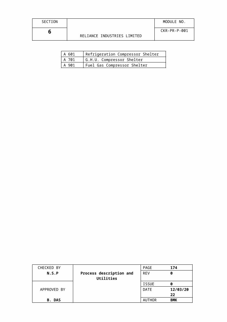
SECTION MODULE NO.
8 RELIANCE INDUSTRIES LIMITED
CKR-PR-P-001
7. The calibration cover is tightened (should not be over tightened). The display should read zero and the ‘CAL’ from the display should disappear.
The above procedure is repeated if necessary.
The dummy sensor is used to inject either a Zero or a variable signal into the transmitter. The procedure is as follows :
1. The sensor is removed from the transmitter to be calibrated and the dummy sensor is fitted in its place.
2. The transmitter local display should show ‘Fault’ and no gas reading.3. The transmitter should show zero reading when the switch on the dummy is in zero
position. If not, it should be made zero by adjusting the signal level knob until zero is displayed. Zero calibration command is given from the CALCOM (through the PC) connected to the Data Concentrator of the system.
4. The switch of the dummy sensor is changed to the Span position. Then the signal level knob is turned to inject a simulated ‘gas signal’ into the transmitter. The display on the transmitter should show 50% LEL. 50% Span calibration command from CALCOM is given.
5. The transmitter should indicate zero when the switch on the dummy sensor is kept in zero position. The transmitter should also indicate the correct value when the switch is kept on the span position.
6. After completing the tests, the dummy sensor is removed and the correct sensor is refitted to the transmitter.
The procedure is repeated if required.
14. CHECKING PROCEDURE
14.1 Smoke Detectors :
Smoke or spray is applied to the detectors to check their actuation.
14.2 Heat Detectors :
Heat is applied to the detector with the help of Heat Blower to see the actuation.
14.3 IR Flame Detectors :
Spark or fire flame is generated in front of the detectors and checked their actuation.
14.4 MAC :
CHECKED BY PAGE 174 N.S.P Process description and Utilities REV 0
ISSUE 0APPROVED BY DATE 07/04/2023
B. DAS AUTHOR BMK

SECTION MODULE NO.
8 RELIANCE INDUSTRIES LIMITED
CKR-PR-P-001
A special key to check its operation operates MAC. The LED in the front side does not glow when the MAC is in fault condition.
All the checking procedures given above are done online.
15. GRAPHICS PACKAGE
A Graphics computer having the Intellution FIX graphics software has been installed in the control room for quick and exact detection of the location of any fire or gas leakage. By the graphics interface, an operator gets an optimum presentation of site information. He can also view sensor and alarm data at any level of the hierarchical data structure.
An Overview screen provides the occurrence of alarm in any zone. It is indicated by the change of border color of that particular zone. The Menu bar at the bottom right corner in the overview screen has different function keys, e.g. Alarm, History, Engineer, etc. When Alarm screen is opened, a screen Menu appears at the right hand side of the Alarm Screen with options: Alarm Log Files & Log Files. The Alarm Log File enables the user to view the alarm log files listed in the date order. Log file option can be used to see the log on/off events and security violations. Alarm History gives the list of all the alarms in the buffer. The Engineering screen lists all the tags, their descriptions, current values, current status, and GDACS addresses for all the sensors in each zone. Normalization and Calibration of the gas sensors can be carried out from the Engineering screen Menu.
The Fire area select Menu on the top right corner of the Overview screen enables the user to view any particular fire area. A red surrounding of a fire area button indicates the occurrence of an alarm. The detectors on the screen as well as the alarm message appearing in the Alarm Summary field at the bottom of the screen changes their color corresponding to the type of alarm, e.g. a gas detector, which has been shown as Green at normal state, will become Orange to indicate a High alarm, Red to indicate HiHi alarm and Yellow to indicate a fault. This helps the operator to check whether actual fire or gas leak has taken place or not. Two buttons -- ‘Accept’ and ‘Alarm Reset’ are used for accepting and resetting an alarm.
A System screen can be viewed with the help of the ‘System’ button at the right side of the Overview screen.
CHECKED BY PAGE 175 N.S.P Process description and Utilities REV 0
ISSUE 0APPROVED BY DATE 07/04/2023
B. DAS AUTHOR BMK
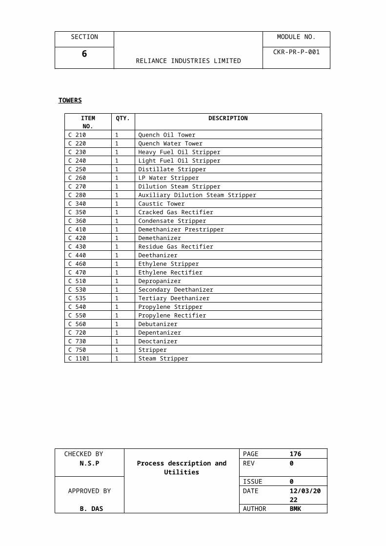
SECTION MODULE NO.
8 RELIANCE INDUSTRIES LIMITED
CKR-PR-P-001
By double clicking at a sensor the user can view the Trend Graphs. The trend logs record 30 days
of data at 1-minute intervals. The trend graphs of the gas detectors can be useful for relating or
comparing the gas levels of the plant area at different times.
CHECKED BY PAGE 176 N.S.P Process description and Utilities REV 0
ISSUE 0APPROVED BY DATE 07/04/2023
B. DAS AUTHOR BMK
Related Documents