Journal of Materials Chemistry C c5tc01475a Nano Q1 Q2 surface engineering of Mn 2 O 3 for potential light-harvesting application Prasenjit Kar, Samim Sardar, Srabanti Ghosh, Manas R. Parida, Bo Liu, Omar F. Mohammed, Peter Lemmens and Samir Kumar Pal* Manganese oxides are well known applied materials including their use as efficient Q3 catalysts for various environmental applications. Please check this proof carefully. Our staff will not read it in detail after you have returned it. Translation errors between word-processor files and typesetting systems can occur so the whole proof needs to be read. Please pay particular attention to: tabulated material; equations; numerical data; figures and graphics; and references. If you have not already indicated the corresponding author(s) please mark their name(s) with an asterisk. Please e-mail a list of corrections or the PDF with electronic notes attached – do not change the text within the PDF file or send a revised manuscript. Corrections at this stage should be minor and not involve extensive changes. All corrections must be sent at the same time. Please bear in mind that minor layout improvements, e.g. in line breaking, table widths and graphic placement, are routinely applied to the final version. Please note that, in the typefaces we use, an italic vee looks like this: n, and a Greek nu looks like this: n. We will publish articles on the web as soon as possible after receiving your corrections; no late corrections will be made. Please return your final corrections, where possible within 48 hours of receipt, by e-mail to: [email protected]

Welcome message from author
This document is posted to help you gain knowledge. Please leave a comment to let me know what you think about it! Share it to your friends and learn new things together.
Transcript

Journal of Materials Chemistry C c5tc01475a
Nano Q1 Q2surface engineering of Mn2O3 for potentiallight-harvesting application
Prasenjit Kar, Samim Sardar, Srabanti Ghosh,Manas R. Parida, Bo Liu, Omar F. Mohammed,Peter Lemmens and Samir Kumar Pal*
Manganese oxides are well known applied materialsincluding their use as efficient Q3catalysts for variousenvironmental applications.
Please check this proof carefully. Our staff will not read it in detail after you have returned it.
Translation errors between word-processor files and typesetting systems can occur so the whole proof needs to be read.Please pay particular attention to: tabulated material; equations; numerical data; figures and graphics; and references. If youhave not already indicated the corresponding author(s) please mark their name(s) with an asterisk. Please e-mail a list ofcorrections or the PDF with electronic notes attached – do not change the text within the PDF file or send a revisedmanuscript. Corrections at this stage should be minor and not involve extensive changes. All corrections must be sent at thesame time.
Please bear in mind that minor layout improvements, e.g. in line breaking, table widths and graphic placement, areroutinely applied to the final version.
Please note that, in the typefaces we use, an italic vee looks like this: n, and a Greek nu looks like this: n.
We will publish articles on the web as soon as possible after receiving your corrections; no late corrections will be made.
Please return your final corrections, where possible within 48 hours of receipt, by e-mail to: [email protected]

Queries for the attention of the authors
Journal: Journal of Materials Chemistry C
Paper: c5tc01475a
Title: Nano surface engineering of Mn2O3 for potential light-harvesting application
Editor’s queries are marked on your proof like this Q1, Q2, etc. and for your convenience line numbers areindicated like this 5, 10, 15, ...
Please ensure that all queries are answered when returning your proof corrections so that publication of yourarticle is not delayed.
Queryreference Query Remarks
Q1 For your information: You can cite this article before youreceive notification of the page numbers by using thefollowing format: (authors), J. Mater. Chem. C, (year), DOI:10.1039/c5tc01475a.
Q2 Please carefully check the spelling of all author names.This is important for the correct indexing and futurecitation of your article. No late corrections can be made.
Q3 Please check that the inserted Graphical Abstract text issuitable. Please ensure that the text fits between the twohorizontal lines.
Q4 The author’s name is spelled ‘‘Patoux’’ in ref. 33, but in thetext it is spelled ‘‘Patuox’’. Please check and correct asnecessary.
Q5 Fig. 3 contains a part labelled (e), but this does not appearto be mentioned in the caption. Would you like to modifythe caption or resupply the artwork (preferably as a TIF fileat 600 dots per inch)?

Nano Q1 Q2surface engineering of Mn2O3 for potentiallight-harvesting application
Prasenjit Kar,a Samim Sardar,a Srabanti Ghosh,a Manas R. Parida,b Bo Liu,c
Omar F. Mohammed,b Peter Lemmenscd and Samir Kumar Pal*a
Manganese oxides are well known applied materials including their use as efficient catalysts for various
environmental applications. Multiple oxidation states and their change due to various experimental
conditions are concluded to be responsible for their multifaceted functionality. Here we demonstrate
that the interaction of a small organic ligand with one of the oxide varieties induces completely new
optical properties and functionalities (photocatalysis). We have synthesized Mn2O3 microspheres via a
hydrothermal route and characterized them using scanning electron microscopy (SEM), X-ray diffraction
(XRD) and elemental mapping (EDAX). When the microspheres are allowed to interact with the
biologically important small ligand citrate, nanometer-sized surface functionalized Mn2O3 (NPs) are
formed. Raman and Fourier transformed infrared spectroscopy confirm the covalent attachment of the
citrate ligand to the dangling bond of Mn at the material surface. While cyclic voltammetry (CV) and X-
ray photoelectron spectroscopy (XPS) analysis confirm multiple surface charge states after the citrate
functionalization of the Mn2O3 NPs, new optical properties of the surface engineered nanomaterials in
terms of absorption and emission emerge consequently. The engineered material offers a novel
photocatalytic functionality to the model water contaminant methylene blue (MB). The effect of doping
other metal ions including Fe3+ and Cu2+ on the optical and catalytic properties is also investigated. In
order to prepare a prototype for potential environmental application of water decontamination, we have
synthesized and duly functionalized the material on the extended surface of a stainless steel metal mesh
(size 2 cm � 1.5 cm, pore size 150 mm � 200 mm). We demonstrate that the functionalized mesh always
works as a ‘‘physical’’ filter of suspended particulates. However, it works as a ‘‘chemical’’ filter
(photocatalyst) for the potential water soluble contaminant (MB) in the presence of solar light.
1. Introduction
The beauty of nanomaterials lies in their higher surface tovolume ratio compared to that of the bulk material with thesame chemical composition. Therefore, for tailor made appli-cations, nanomaterials are more promising compared to theirbulk counterpart. In addition, to be used in several practicalapplications further surface modifications of nanomaterials areessential.1–5 Attaching suitable organic ligands to their surfaceatoms is one of the most facile route for modification of metal
oxide nanomaterials.6 This leads, e.g. to protection of nano-particles (NPs) from agglomeration and makes them availablefor an interaction with other molecules. Frequent reports onfunctionalization of NPs with biocompatible ligands for cata-lysis, cancer therapy and biomedical applications exist.7–11
Previously, our group functionalized various NPs with biologi-cally important ligands to allow potential biomedical andenvironmental applications.12–15 Our recent attention towardsmanganese oxide NPs is due to their emerging use in biome-dical, photocatalysis, supercapacitor applications and alsobecause this material is relatively inexpensive, non-toxic, andnaturally abundant.16–20 It has been reported that differentvarieties of manganese oxide NPs (MnO, Mn2O3, Mn3O4) withtunable morphologies can be easily synthesized via differentroutes.21–25 By varying the dripping speed of NaOH in thepresence of MnCl2 and H2O2, different Mn3O4 morphologies,like nanoparticles, nanorods and nanofractals can beobtained.26,27 While hollow and core shell type Mn2O3 nanos-tructures are applied in CO reduction,28 the former are reportedto be useful in pollutant adsorption.29 Recently, Chen et al.
1
5
10
15
20
25
30
35
40
45
50
55
1
5
10
15
20
25
30
35
40
45
50
55
Cite this: DOI: 10.1039/c5tc01475a
a Department of Chemical, Biological and Macromolecular Sciences, S. N. Bose
National Centre for Basic Sciences, Block JD, Sector III, SaltLake, Kolkata 700 098,
India. E-mail: [email protected] Solar and Photovoltaics Engineering Research Center, Division of Physical Sciences
and Engineering, King Abdullah University of Science and Technology, Thuwal
23955-6900, Saudi Arabiac Institute for Condensed Matter Physics, TU Braunschweig, Mendelssohnstraße 3,
38106 Braunschweig, Germanyd Laboratory for Emerging Nanometrology, TU Braunschweig, Braunschweig,
Germany
Received 22nd May 2015,Accepted 5th July 2015
DOI: 10.1039/c5tc01475a
www.rsc.org/MaterialsC
This journal is �c The Royal Society of Chemistry 2015 J. Mater. Chem. C, 2015, 00, 1�12 | 1
Journal ofMaterials Chemistry C
PAPER

have shown that hierarchical mesoporous manganese dioxide(MnO2) synthesized by a soft interface method is a muchefficient catalyst for degradation of organic pollutants likemethylene blue.30 To make the low band gap material Mn2O3
photocatalytically active a contact between graphene sheets andMn2O3 nanoparticles has been made to facilitate easy electrontransfer from the metal oxide to the graphene sheet.31 Functio-nalized manganese oxide NPs are also reported to have noveloptical and catalytic properties.3 In recent reports from ourgroup we have shown that the interaction of Mn3O4 NPs withvarious hydroxyl and carboxylate containing ligands changesthe optical and magnetic properties of the NPs.32 While a-hydroxy-carboxylate is found to have an impact on the opticalproperties of the NPs through ligand to metal charge transfer(LMCT) and Jahn–Teller effects, interaction with carboxyl con-taining ligands is efficient in controlling the magnetic proper-ties of Mn3O4 NPs.32 Citrate functionalized Mn3O4 NPscontaining multiple oxidation states (+2, +3 and +4) have beenrecently found to be useful for the treatment of hyperbilirubi-nemia.13 The balance of different oxidation states in functio-nalized NPs is critical to achieve novel optical and catalyticproperties. In this context, the functionalization of Mn2O3
having only one oxidation state (+3) and inducing interestingoptical properties would be important, however, this is onlysparsely reported in the literature. This is one of the motives ofthe present work. Another important aspect is doping of Mn2O3
with metal ions in order to improve the functionality of thenative oxide. Patuox et al. have shown that nickel dopedQ4 spinelmanganese oxides are attractive materials for Li ion batteries.33
Zinc doped manganese oxides are efficient coal gas absorbersfor desulfurization.34 Recently, Fe-loaded mesoporous manga-nese dioxide with urchin-like superstructures have been suc-cessfully used for dye degradation.35 Therefore, we have alsoinvestigated the optical and catalytic properties of dopedMn2O3 upon functionalization with organic ligands.
In this work, we have synthesized Mn2O3 microspheres by ahydrothermal process and duly functionalized them with themodel organic ligand citrate. High resolution transmissionelectron microscopy (HRTEM) reveals the formation of Mn2O3
nanoparticles (NPs) from the microsphere as a result of ligandetching.36,37 We further confirmed the nature of citrate bindingto the NPs by a series of characterization techniques such asRaman scattering, Fourier transformed infrared (FTIR) spectro-scopy, cyclic voltammetry (CV) and X-ray photo-emissionspectroscopy (XPS). We also demonstrated that citrate functio-nalized NPs induce multiple photoluminescence (PL) pro-cesses. We further investigated the photocatalytic activity ofcitrate functionalized NPs using Methylene Blue (MB) as amodel organic pollutant. The effect of doping metal ions(Cu2+ and Fe3+) on the photoluminescence and catalytic activityof the NPs has also been investigated. In order to fabricateprototypes for potential applications, we have immobilizedcitrate functionalized Mn2O3 microspheres on a stainless steelmesh and confirmed the filtering activity of the mesh tosuspended particulates and catalytic degradation of a modelcontaminant in the presence of light.
2. Materials and methods2.1. Synthesis of materials
Manganese acetate dihydrate, sodium citrate, sodium hydro-xide, copper chloride dihydrate, ferric chloride, methylene blueand Nafion were purchased from Sigma Aldrich. Potassiumbromide and ethylene glycol were obtained from Merck. Thestainless steel mesh was purchased from Shangyu metal meshcompany, China. All other chemicals employed were of analy-tical grade and used without further purification. In a typicalsynthesis of Mn2O3 microspheres, 0.03 mol of manganeseacetate dihydrate and 0.27 mol of urea were added into 30 mlethylene glycol to form the solution.38 The resultant mixturewas continuously stirred for 2 hours and then transferred into a30 mL Teflon-lined stainless-steel autoclave. The Teflon-linedautoclave was put into an oven at 180 1C for 24 hours. Thesystem was then cooled to ambient temperature naturally. Thefinal product was collected and washed with distilled water andabsolute alcohol at least five times. Then as-prepared sampleswere further annealed at 500 1C for 10 hours in air.39 Thesynthesis of metal ion doped manganese oxides microspheresdesignated as Cu–Mn2O3 and Fe–Mn2O3 was carried out byaddition of 0.003 M copper chloride dihydrate and 0.003 Mferric chloride, respectively, under similar reaction conditions.
For the citrate functionalization of the Mn2O3 microspheres(C–Mn2O3 NPs), 0.5 M sodium citrate was prepared in Milli-Qwater. Then 10 mg of Mn2O3 microspheres were added, fol-lowed by extensive mixing for 16 hours in a cyclo mixer. Finally,the non-functionalized bigger particles were filtered out andthe resulting filtrate solution was used. In the same way, citratefunctionalized doped Mn2O3 NPs (C–Fe–Mn2O3 and C–Cu–Mn2O3) were synthesized. For the surface modification of thecitrate functionalized NPs the pH of the solution was adjustedto 12 by addition of 1 M sodium hydroxide. The resultingsolution was then finally heated at 60 1C for 12 hours. Finally,the solution became highly photoluminescent and the color ofthe solution turned into yellowish-brown. Generally, Mn3+ in anacid/neutral solution is unstable and has a tendency to dis-proportionate into Mn2+ and Mn4+, whereas in an alkali med-ium it is stabilized by comproportionation of Mn4+ and Mn2+.40
The C–Fe–Mn2O3 and C–Cu–Mn2O3 samples can also becomehighly luminescent by the above-described treatment.
In order to prepare microspheres on a stainless steel mesh,initially the mesh was cleaned through bath sonication inacetone for 30 min and dried on a hot-plate at 60 1C. Thendeposition of C–Mn2O3 on the mesh was done using a nebulizerfollowed by annealing at 400 1C for 10 hours, which has beenused as a seeding layer for the synthesis of Mn2O3 micro-spheres. Then, 0.03 mol of manganese acetate dihydrate and0.27 mol of urea were dissolved into 30 ml ethylene glycol. Theresultant mixture was continuously stirred for 2 h and thentransferred into a 30 mL Teflon-lined stainless-steel autoclavecontaining the mesh. The Teflon-lined autoclave was put intoan oven at 180 1C for 24 h. The system was then cooled toambient temperature. Then the mesh was washed thoroughlywith water to remove excess unreacted reagents. The as-
1
5
10
15
20
25
30
35
40
45
50
55
1
5
10
15
20
25
30
35
40
45
50
55
2 | J. Mater. Chem. C, 2015, 00, 1�12 This journal is �c The Royal Society of Chemistry 2015
Paper Journal of Materials Chemistry C

synthesized Mn2O3 microspheres on the mesh were furtherannealed at 500 1C for 10 h in air. The Cu–Mn2O3 and Fe–Mn2O3 microspheres on the mesh were synthesized by follow-ing the above-mentioned conditions with the addition of0.003 M copper chloride dihydrate and ferric chloride, respec-tively. Then the functionalization of the microspheres by citratewas performed accordingly.
2.2. Characterization
Field emission scanning electron microscopy (FESEM, QUANTAFEG 250) investigations were performed by applying a diluteddrop of NPs on a silicon wafer. Transmission electron microscopy(TEM) grids were prepared by applying a diluted drop of thecitrate functionalized NP samples to carbon-coated copper grids.The particle sizes were determined from micrographs recorded ata magnification of 100000X using an FEI (Technai S-Twin,operating at 200 kV) instrument. X-ray diffraction (XRD) patternsof the samples were obtained by employing a scanning rate of0.021 S�1 in the 2y range from 201 to 801 using a PANalyticalXPERTPRO diffractometer equipped with Cu Ka radiation (at 40mA and 40 kV). FTIR spectra of the as prepared samples wererecorded on a JASCO FTIR-6300 spectrometer, using a CaF2
window. Raman scattering experiments were performed inback-scattering geometry using a micro-Raman setup consistingof a spectrometer (LabRAM HR, Jobin Yvon) and a peltier-cooledcharge-coupled device (CCD) detector. An air cooled argon ionlaser with a wavelength of 488 nm was used as the excitation lightsource. Raman spectra of all the samples have been recorded atroom temperature in the frequency range 50–4000 cm�1. X-rayphotoelectron spectroscopy (XPS) measurements were performedusing a Kratos Axis Ultra DLD spectrometer equipped with amonochromatic Al Ka X-ray source (hn = 1486.6 eV) operated at150 W, a multichannel plate, and a delay line detector under avacuum of 1.3 � 10�19 Torr. More details can be found else-where.41 For steady state and time resolved optical study we havefollowed the methodology as described in our earlier work.42For
1
5
10
15
20
25
30
35
40
45
50
55
1
5
10
15
20
25
30
35
40
45
50
55
Fig. 1 FESEM images of (a) Mn2O3, (b) Fe doped Mn2O3 and (c) Cu dopedMn2O3 microsphere samples. (d) XRD pattern of Mn2O3, Fe doped Mn2O3
and Cu doped Mn2O3.
Fig. 2 (I) (a) SEM image, (b) Mn, (c) Fe, and (d) O elemental mapping images of Fe doped Mn2O3 microspheres. (Inset shows the EDAX spectrum of Fedoped Mn2O3 microspheres.) (II) (a) SEM image, (b) Mn, (c) Cu, and (d) O elemental mapping images of Cu doped Mn2O3 microspheres. (Inset shows theEDAX spectrum of Cu doped Mn2O3 microsphere.)
This journal is �c The Royal Society of Chemistry 2015 J. Mater. Chem. C, 2015, 00, 1�12 | 3
Journal of Materials Chemistry C Paper

electrochemical measurements cyclic voltammetry (CV) was car-ried out in an electrochemical cell using 0.01 M KCl electrolyte. 2mg of Mn2O3 sphere and 6 mg of C–Mn2O3 were dissolved in 50ml of ethanol containing 5 wt% Nafion as a binder. Then 10 ml ofsample solution were deposited on glassy carbon (working elec-trode). CV was carried out using CH Instruments and swept at 50mV S�1 between 0 and 3 V applied versus an Ag/AgCl referenceelectrode.
For photocatalysis studies, citrate functionalized NPs weretaken in deionized water (DI) and methylene blue in DI wasused as the test contaminant. An 8 W UV source was used as anirradiation source in this study. The mixture of photocatalystand contaminant was irradiated with UV irradiation and absor-bance data were collected continuously by using a setupreported earlier.43 The percentage degradation (%DE) of MBwas determined using:
%DE ¼ I0 � I
I0� 100 (1)
where I0 is the initial absorption intensity of MB at lmax =660 nm and I is the absorption intensity after UV irradiation.
3. Results and discussion
Fig. 1a–c show the morphology of the as-synthesized Mn2O3
microspheres without and with Fe+3/Cu+2 doping as revealedfrom FESEM. The average sizes of the native, Fe (Fe–Mn2O3)and Cu (Cu–Mn2O3) doped Mn2O3 microspheres are found tobe 6–8 mm, 4–6 mm and 5–7 mm, respectively. Fig. 1d shows XRDpatterns of native Mn2O3, Fe–Mn2O3 and Cu–Mn2O3, respec-tively. XRD patterns of Fe–Mn2O3 and Cu–Mn2O3 are similar tothat of native bare Mn2O3 and consistent with the diffractionpattern of pristine bulk Mn2O3 reported in the literature.38
1
5
10
15
20
25
30
35
40
45
50
55
1
5
10
15
20
25
30
35
40
45
50
55
Fig. 3 TEM image of Mn2O3 microspheres (a), C–Mn2O3 (b), FeQ5 doped C–Mn2O3 (c) and Cu doped C–Mn2O3 (d) NPs (inset shows size distribution ofNPs). (b) UV-vis absorption spectrum of C–Mn2O3 NPs (at pH B12 and70 1C for 12 h).
Fig. 4 (a) Raman spectra of the citrate, Mn2O3, Fe doped Mn2O3, Cudoped Mn2O3, C–Mn2O3, Fe doped C–Mn2O3 and Cu doped C–Mn2O3.(b) FTIR spectra of citrate, C–Mn2O3 and Mn2O3 NPs respectively.
4 | J. Mater. Chem. C, 2015, 00, 1�12 This journal is �c The Royal Society of Chemistry 2015
Paper Journal of Materials Chemistry C

During doping of bulk Mn2O3, the Cu2+ ion can easily replaceMn3+ in the crystal lattice due to the smaller radius of the Cu2+
ion (0.057 nm) compared to that of Mn3+ (0.066). Similarly the
substitution of the Mn3+ ion by Fe3+ occurs due to the smallerradius of the Fe3+ ion (0.063).44,45
In order to confirm the uniform distribution of Fe and Cuatoms in the Fe–Mn2O3 and Cu–Mn2O3 microspheres we haveperformed elemental EDAX mapping as shown in Fig. 2. Fromthe EDAX measurement, it is observed that 2.5 wt% of Fe isdoped into the Mn2O3 crystal and 1.96 wt% of Cu is doped intothe Mn2O3 crystal lattice. TEM was used in order investigate themicroscopic structure of as synthesized Mn2O3 microspheres(Fig. 3a). Upon interaction with citrate ligands the Mn2O3
microspheres become water soluble and smaller in size asevident from the HRTEM image (Fig. 3a). The citrate functio-nalized Mn2O3 nanoparticles (C–Mn2O3 NPs) are found to havea size distribution with an average diameter of 29.01 � 0.27 nm(inset of Fig. 3a). The HRTEM images of C–Mn2O3 NPs alsoshow the high crystallinity of the NPs. The inter-planar distancebetween the fringes is found to be about 0.268 nm consistentwith (222) planes of bulk Mn2O3.46 The citrate functionalized Fedoped Mn2O3 and Cu doped Mn2O3 NPs are found to have anaverage size of 43 � 0.16 and 40.38 � 0.45 nm respectively.
1
5
10
15
20
25
30
35
40
45
50
55
1
5
10
15
20
25
30
35
40
45
50
55
Fig. 5 Cyclic voltammogram of bare Mn2O3 (cyan line) and Mn2O3 afterfunctionalization with citrate (green line) recorded at a scan rate 50 mV S�1
in the range of 0 to 3 V using Ag/AgCl as a reference electrode.
Fig. 6 XPS spectra of C–Mn2O3 NPs (a) Mn 2p, (b) O 1s, and (c) C 1s. XPS spectra of Fe doped C–Mn2O3 NPs (d) Mn 2p, (e) Fe2p, and (f) O 1s (inset showsC 1s). XPS spectra of Cu doped C–Mn2O3 NPs (g) Mn 2p, (h) Cu2p, and (i) O 1s (inset shows C 1s).
This journal is �c The Royal Society of Chemistry 2015 J. Mater. Chem. C, 2015, 00, 1�12 | 5
Journal of Materials Chemistry C Paper

HRTEM images also indicate the highly crystalline nature ofcitrate functionalized Fe doped Mn2O3 and Cu dopedMn2O3 NPs.
The effect of citrate functionalization of the NPs is evident inthe UV-Vis absorbance spectra of the NPs at room temperature.While the citrate ligand and native Mn2O3 do not show anycharacteristic peak in the wavelength range of 300–600 nm,functionalized NPs show several absorption peaks (at 335, 365and 430 nm) in the wavelength window (as shown inFig. 3b).3,47 The observed peak at 335 nm may be assigned tohigh energy ligand to metal charge transfer (LMCT) processesinvolving citrate–Mn3+ interactions. The other peaks at 365 and430 nm correspond to the d–d transitions of Mn3+ in Mn2O3
NPs since Mn3+ (d4) forms a high spin complex. The groundstate term of Mn3+ (d4) is 5E in Mn2O3 from the high spincomplex which undergoes a Jahn–Teller distortion due tofunctionalization with citrate. This leads to band transitions
of 5B1–5E, 5B1–5B2 and 5B1–5A1.48,49 Fig. 4a shows Ramanspectra of the ligand, bare Mn2O3 and C–Mn2O3 revealing thestructural modification of Mn2O3 NPs upon functionalizationwith the citrate ligand. The main characteristic peak observedat 650 cm�1 of Mn2O3 NPs corresponds to M–O stretchingvibrations,50 and C–O stretching vibration of the citrate ligandlocated at 843 cm�1 are perturbed upon functionalizationwith citrate. This indicates the covalent binding of the citrateligand with the NP surface. Similar changes are observed forFe–Mn2O3 and Cu–Mn2O3 after citrate functionalization asshown in Fig. 4a. A strong electronic coupling of the ligandwith Mn2O3 NPs is also evident from FTIR spectra as shown inFig. 4b. Bare Mn2O3 shows two characteristic bands at 576 and521 cm�1 corresponding to M–O stretching vibrations of Mn2O3
NPs.51 After functionalization with citrate ligands, the bandsare distinctly diminished indicating strong interaction betweenMn2O3 NPs and the citrate ligand. It is also observed that two
1
5
10
15
20
25
30
35
40
45
50
55
1
5
10
15
20
25
30
35
40
45
50
55Fig. 7 (a), (c) and (e) are normalized steady-steady PL spectra collected from C–Mn2O3, Fe doped C–Mn2O3 and Cu doped C–Mn2O3 NPs respectivelyat three different excitation wavelength of 335, 365 and 430 nm at pH B 12. Figure (b), (d) and (f) are the excitation spectra of C–Mn2O3, Fe doped C–Mn2O3 and Cu doped C–Mn2O3 NPs, respectively, at different PL maxima.
6 | J. Mater. Chem. C, 2015, 00, 1�12 This journal is �c The Royal Society of Chemistry 2015
Paper Journal of Materials Chemistry C
sharp bands at 1156 and 1076 cm�1 responsible for the C–Ostretching modes of citrate52 are broadened in Mn2O3 NPs. Thisobservation is consistent with the fact that the carboxylatefunctional group in the citrate makes covalent bonding withthe NP surface.
A clear change in the redox property of bare Mn2O3 uponcitrate functionalization is evident from CV measurements asshown in Fig. 5. It is known that for bare Mn2O3, the firstreduction process at B1.1 V corresponds to the reduction ofMn3+ to Mn2+.53 As evident from Fig. 5, the reduction peak at1.06 V for bare Mn2O3 is significantly perturbed upon functio-nalization and a new peak at B0.35 V appears for Mn2O3 NPs.This peak can be attributed to the oxidation of Mn+3/Mn+4
species.54 This implies that after functionalization in Mn2O3
the charge state of Mn3+ disproportionates and is generatedominantly by the +4 charge state. It has to be noted that theformation of the +2 state as a result of disproportionation is notclear from these CV studies, however, evident in the XPSspectrum as shown below. Fig. 6 shows XPS spectra ofMn2O3, Fe–Mn2O3 and Cu–Mn2O3 after citrate functionaliza-tion. As reported in the earlier studies Mn2O3 shows two Mn 2ppeaks at 642.40 and 654.13 eV, which are attributed to Mn 2p3/2
and Mn 2p1/2, respectively.55 A spin energy gap of 11.73 eV isreported to be a significant signature of Mn3+ in Mn2O3.56 Asshown in Fig. 6a the XPS spectrum (Mn 2p) for C–Mn2O3 can bedeconvoluted into four peaks at 640.27, 640.46, 642.23 and653.18 eV. While 640.27 eV can be attributed to Mn2+, 640.46and 642.23 eV correspond to Mn3+ and Mn4+ respectively.57,58
The Mn 2p1/2 at 653.18 eV indicates a +3 oxidation state of Mnassuming the peak at 646.09 eV to be a shake-up satellite.32 Thedeconvoluted O 1s line spectra are composed of three peaks.The O 1s line at 530.72 eV corresponds to the surface hydroxylgroups and the peaks at 531.54 and 535.25 eV indicate thepresence of adsorbed water molecules.59 Again, the deconvo-luted C 1s line spectra were recorded with three peaks toanalyze the interactions between the citrate ligand and NPs.
The C 1s peak at 284.68, 286.3 and 288.12 eV can be assigned tocarbon present in citrate in the form of C–C, C–OH and COO,respectively.60 Therefore, functionalization with citrate sup-presses the +3 oxidation state of Mn and generates +4 and +2states via a disproportionation mechanism.61 As shown inFig. 6, similar changes in the oxidation state of Mn for Fe–Mn2O3 and Cu–Mn2O3 NPs after citrate functionalization areevident. The XPS spectrum of Fe doped Mn2O3 shows two Fe 2ppeaks at 710.19 and 724.51 eV which can be attributed to Fe2p3/2 and Fe 2p1/2 respectively.62,63 This indicates incorporationof Fe into the lattice of Mn2O3.The XPS spectrum of Cu dopedMn2O3 illustrates two Cu 2p peaks at 932.9 and 952.8 eV, whichcan be attributed to Cu 2p3/2 and Cu 2p1/2, respectively.38,64,65
The observation confirms the incorporation of Cu into thelattice of Mn2O3.
Fig. 7a shows normalized fluorescence spectra of C–Mn2O3
NPs at room temperature at pH 12. C–Mn2O3 NPs show multi-ple photoluminescence (PL maxima at 392, 462 and 491 nm)upon excitation at different wavelengths (335, 365 and 430 nm,respectively). Fig. 7b shows excitation spectra of C–Mn2O3 NPswith different emission wavelengths. The ligand field theorycan be useful in order to understand the multiple PL of the C–Mn2O3 NPs.66,67 Multiple PL of the C–Mn2O3 NPs arise mainlydue to the LMCT (citrate–Mn3+) excited states and the ligandfield excited states of the metal (Mn3+) d-orbitals. Thus the PLpeak at 392 nm arises due to LMCT from HOMO (highestoccupied molecular orbital, centered in the ligand) to LUMO(lowest unoccupied molecular orbital, centered in the metalcentre). On the other hand, PL peaks at 462 and 492 nm arisedue to d–d transition of the Mn3+ ion, in the presence of thecitrate ligand. Similarly, multiple PL (maxima at 411, 456 and509 nm) arises in C–Fe–Mn2O3 NPs and C–Cu–Mn2O3 NPs uponexcitation at different wavelengths (335, 365 and 435 nm, seeFig. 7c and e). Fig. 7d and f shows excitation spectra of C–Fe–Mn2O3 NPs and C–Cu–Mn2O3 NPs detected at different PLmaxima. It is observed that unfunctionalized Mn2O3, Fe–
1
5
10
15
20
25
30
35
40
45
50
55
1
5
10
15
20
25
30
35
40
45
50
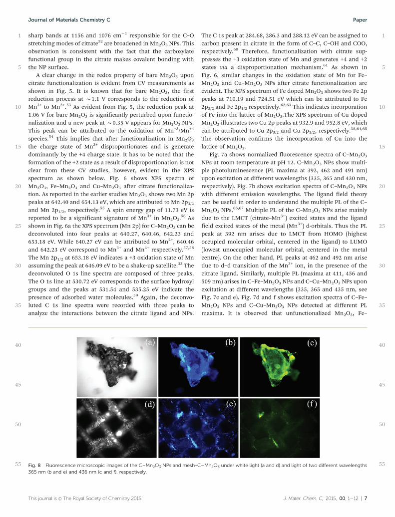
55Fig. 8 Fluorescence microscopic images of the C–Mn2O3 NPs and mesh-C–Mn2O3 under white light (a and d) and light of two different wavelengths365 nm (b and e) and 436 nm (c and f), respectively.
This journal is �c The Royal Society of Chemistry 2015 J. Mater. Chem. C, 2015, 00, 1�12 | 7
Journal of Materials Chemistry C Paper

Mn2O3 and Cu–Mn2O3 have no such PL properties due toabsence of LMCT and the J–T phenomenon. The multiple PLof the citrate functionalized NPs is further recorded under afluorescence microscope, see Fig. 8. Fig. 8a–c shows bright fieldimages and two fluorescence images of C–Mn2O3 NPs (excita-tion at 365 and 436 nm) respectively. C–Mn2O3 NPs upon365 nm excitation show cyan emission and 436 nm excitationshow green emission. Fig. 8d–f shows similar PL of functiona-lized Mn2O3 microspheres on the stainless steel mesh.
In order to investigate a detailed mechanistic insight intothe origin of the multiple PL of the functionalized NPs, we haveperformed picosecond-resolved fluorescence studies. FromFig. 9, the fluorescence decay of the C–Mn2O3, C–Fe–Mn2O3
and C–Cu–Mn2O3 NPs was determined at different PL maximaof 456 and 507 nm using lasers as an excitation source at 375and 445 nm, respectively. The lifetime values for 456 and507 nm emission (upon excitation by 375 and 445 nm lasersources) decays are shown in Table 1. From this table it isshown that the average lifetimes of C–Mn2O3 are 2.01 and 1.95ns when the PL is measured at 456 and 507 nm, respectively,upon 375 nm laser excitation, while it is 0.59 ns when PL ismeasured at 507 nm upon 445 nm laser excitation. The lifetimedata clearly suggest that the Jahn–Teller distortion leads to PLmaxima at 456 and 507 nm upon excitation at 375 and 445 nm,respectively. Here it is observed that after doping the J–Tdistorted d–d transition leads to PL maxima at 456 and507 nm. The average lifetimes of C–Fe–Mn2O3 are 0.76 and0.94 ns, respectively, upon 375 laser excitation, while it is 0.34ns when PL is measured at 507 nm upon 445 nm laserexcitation. The decrease in the average lifetime after irondoping may be attributed to the faster electron transfer fromC–Mn2O3 to Fe+3. The average lifetimes of C–Cu–Mn2O3 are0.74 and 0.91 ns upon 375 laser excitation while it is 0.33 nswhen PL is measured at 507 nm upon 445 nm laser excitation.The decrease in average lifetimes indicates an additional non-radiative time scale in the excited state which can alter thefluorescence lifetimes. The apparent rate constant (knr) isdetermined for the nonradiative processes by comparing thelifetimes of citrate functionalized Mn2O3 NPs in the absence(t0) and presence (t) of the doping metal ion, using theequation.
knr ¼1
th i �1
t0h i(2)
The apparent rate constant values for Fe doped C–Mn2O3 andCu doped C–Mn2O3 are shown in Table 1 which indicates theexcited state electron transfer from C–Mn2O3 to Fe and Cu.
It has been reported that adsorption plays an important rolein the removal of pollutants.68–71 However, in our case the asprepared microsphere has insignificant ability for methyleneblue adsorption (data not shown). During the photocatalyticreaction, MB forms a well-known colorless product leucomethy-lene blue (LMB)72,73 as shown in eqn (3).
2MB + 2e� + H+ = MB + LMB (3)
In order to confirm the formation of leucomethylene blue, thedegradation of methylene blue was performed in the presenceof citrate capped Mn2O3 NPs under UV light irradiation and theabsorption spectra were monitored at different time intervals.As shown in Fig. 10a, the methylene blue peak at 664 nmdecreases with time whereas another peak at 246 nm corres-ponding to the leucomethylene blue formation increases dur-ing photocatalysis. As shown in Fig. 10b, no degradation of MB
1
5
10
15
20
25
30
35
40
45
50
55
1
5
10
15
20
25
30
35
40
45
50
55
Fig. 9 (a) and (b) are the picosecond-resolved PL transients of C–Mn2O3
NPs, Fe-doped C–Mn2O3 NPs and Cu-doped C–Mn2O3 NPs measured atemission wavelengths 456 nm (I) and 507 nm (II) upon excitation at awavelength of 375 nm. (c) Picosecond-resolved PL transients of C–Mn2O3
NPs, Fe-doped C–Mn2O3 NPs and Cu-doped C–Mn2O3 NPs measured atan emission wavelength of 507 nm upon excitation at wavelength of445 nm.
8 | J. Mater. Chem. C, 2015, 00, 1�12 This journal is �c The Royal Society of Chemistry 2015
Paper Journal of Materials Chemistry C

is observed in the absence of light. With our experimental timewindow, MB shows o10% degradation under light illumina-tion in the absence of NPs. Under UV light illumination, C–Mn2O3 NPs show a 50% MB degradation after 80 minutes. It isimportant to note that with our experimental conditions (pH 3),Mn3+ ions easily disproportionate into Mn2+ and Mn4+. So there
is a possibility of d–d transitions involving Mn2+/4+ ions on theC–Mn2O3 NP surface. According to the selection rules offundamental electronic spectroscopy, LMCT bands (involvingthe interaction between the highest occupied molecular orbitalof citrate and the lowest unoccupied molecular orbital Mn2+/4+)are mainly responsible for photocatalytic degradation of the
1
5
10
15
20
25
30
35
40
45
50
55
1
5
10
15
20
25
30
35
40
45
50
55
Table 1 Lifetimes of picosecond time-resolved PL transients of C–Mn2O3, Fe doped C–Mn2O3 and Cu doped C–Mn2O3 NPs, detected at various PLmaxima uopn excitation at different wavelengths. The values in parentheses represent the relative weight percentages of the time components
System lex (nm) lem (nm) t1 (ns) t2 (ns) t3 (ns) tavg (ns) knr (1010 s�1)
C–Mn2O3 375 456 0.08(58) 1.5(23) 8.6(19) 2.01507 0.14(58) 1.65(26) 9.04(14) 1.95
445 507 0.04(80) 0.85(10) 4.59(10) 0.59
Fe doped C–Mn2O3 375 456 0.06(69) 1.1(22) 5.35(9) 0.76 8.14507 0.15(62) 1.17(10) 5.4(10) 0.94 5.51
445 507 0.03(88) 0.99(7) 5.26(5) 0.34 12.46
Cu doped C–Mn2O3 375 456 0.06(71) 1.13(20) 5.54(9) 0.74 8.53507 0.14(65) 1.2(26) 5.53(9) 0.91 5.86
445 507 0.11(88) 0.9(6) 4.63(6) 0.33 13.35
Fig. 10 (a) Photocatalytic degradation of MB in the presence of (a) C–Mn2O3 (b) C–Mn2O3, Fe doped Mn2O3 and Cu doped Mn2O3 NPs in solution underUV light illumination. (c) Ct/C0 versus time with various concentrations of methylene blue. (d) Langmuir–Hinshelwood plot (L–H) for photocatalyticdegradation of methylene blue using citrate functionalized Mn2O3 nanoparticles (solid line is the model fitting and solid circles are experimental data). (e)Photocatalytic degradation of MB in the presence of hydrogen peroxide under UV light illumination. (f) Photocatalytic degradation of MB in the presenceof sodium azide under UV light illumination. The recyclability study of C–Mn2O3 (g) Fe doped C–Mn2O3 (h) and Cu doped C–Mn2O3 (i) NPs under UV lightillumination.
This journal is �c The Royal Society of Chemistry 2015 J. Mater. Chem. C, 2015, 00, 1�12 | 9
Journal of Materials Chemistry C Paper

model pollutant, MB. After doping with Fe, the photocatalyticactivity of C–Fe–Mn2O3 NPs shows 65% MB degradation underUV light illumination. However, in C–Cu–Mn2O3 NPs thephotocatalytic activity decreases to 20%. As compared to othercatalysts reported in the literature, the photocatalytic activity ofcitrate functionalized Fe doped Mn2O3 NPs used in this workshows better catalytic activity.20,21,31,74–76 In order to find outthe effect of the surface on photocatalysis, the Langmuir–Hinshelwood (L–H) kinetics has been studied using differentconcentrations of MB. From Fig. 10c and d it is observed thatthe surface does not play any role in photocatalysis since a hugedeviation of the model from experimental data is evident.
In order to investigate the catalytic pathway, we furtherstudied the photocatalytic activity of citrate functionalizedNPs in the presence of a radical initiator (H2O2) and radicalquencher (sodium azide) separately. The photocatalytic activityof citrate functionalized NPs increases in the presence of H2O2
indicating a role of reactive oxygen species (ROS) in thedegradation of MB.32 Actually, in the presence of H2O2 andunder UV light illumination, the generation of �OH increasesthe enhanced photocatalytic activity. We further studied theeffect of sodium azide (a ROS quencher) on the degradation ofMB by citrate functionalized NPs under UV light illumination.Fig. 10f clearly shows that in the presence of sodium azide thedegradation rate of MB becomes slower. This indirectly con-firms that the reaction proceeds via a ROS mechanism. Theincrease in the photocatalytic activity of C–Fe–Mn2O3 NPscompared to C–Mn2O3 NPs may be due to the excited stateelectron transfer from Mn2O3 to Fe3+. This excited state electrontransfer may facilitate the charge separation. The regenerationof Fe3+ takes places via ROS generation in an aqueous mediumthat eventually enhances the photocatalytic activity of Fe–C–Mn2O3 NPs.77,78 However, in the case of C–Cu–Mn2O3 anexcited electron transfer from Mn2O3 to Cu2+ takes place whichis evident from the TCSPC data. The regeneration of Cu2+ maytake place efficiently through the ground state recovery of C–Mn2O3 and not via a ROS generation. To examine the stabilityof citrate functionalized nanoparticles, we examined the photo-catalytic degradation of MB up to four cycles under UV lightillumination at room temperature. The recyclability of C–Mn2O3, C–Fe–Mn2O3 and C–Cu–Mn2O3 NPs is shown inFig. 10g–i. These data suggest that C–Fe–Mn2O3 NPs show goodrecyclability up to the fourth cycle, whereas the C–Mn2O3 andC–Cu–Mn2O3 degradation efficiency decreases with each cycle.
In order to explore possible applications of citrate functio-nalized NPs for waste water treatment a stainless steel meshhas been used as a template. Fig. 11a and b show pure Mn2O3
microspheres on the stainless steel mesh at low and highmagnification, respectively. While the low magnificationFESEM image of the mesh confirms attachment of Mn2O3
microspheres, the high magnification image shows the uni-form size distribution of the microspheres ranging from 2.5–3.5mm. Upon doping with Fe3+ and Cu2+ the average size distribu-tions of the synthesized microsphere are 3.5–4.5 mm and 1.5–2mm, respectively. We have successfully functionalized themicrospheres in the mesh with the citrate ligand. Here, the
photocatalytic activity of C–Mn2O3, C–Fe–Mn2O3 and C–Cu–Mn2O3 has been studied on the mesh using MB as a modelcontaminant under solar light illumination. The pH of thesolution is maintained at 6. The area of the mesh used in thephotocatalytic study was 2 cm � 1.5 cm. From Fig. 11e it isevident that in the absence of light the citrate functionalizedmicrospheres show no photocatalytic activity. However, undersolar light illumination C–Mn2O3 exhibits 25% degradation,while the photocatalytic activity of C–Fe–Mn2O3 on the meshincreases to 34%. In the case of copper doping the photocata-lytic activity of the sensitized C–Cu–Mn2O3 on the meshdecreases down to 12%. Under the same experimental condi-tions, MB in the absence of functionalized Mn2O3 micro-spheres shows no such degradation (7%). To ourunderstanding such type of system is promising for waterpurification both by physical (filtration) and chemical (photo-catalysis) processes. Earlier Ochiai et al. showed that a TiO2
enhanced Ti mesh filter is very much useful in water purifica-tion.79 Li et al. showed that a Ti/TiO2 mesh photoelectrode is anexcellent system for photocatalytic degradation of humic acidin an aqueous solution.80 In comparison with these earlier
1
5
10
15
20
25
30
35
40
45
50
55
1
5
10
15
20
25
30
35
40
45
50
55
Fig. 11 (a) SEM images of Mn2O3 on the stainless steel mesh (inset showslow magnification). (b) SEM images of Mn2O3 on mesh in high magnifica-tion. (c) SEM images of Fe doped Mn2O3 on a mesh in high magnification.(d) SEM images of Cu doped Mn2O3 on a mesh in high magnification. (e)Photocatalytic degradation of MB by C–Mn2O3, Fe doped Mn2O3 and Cudoped Mn2O3 on the mesh under solar light illumination.
10 | J. Mater. Chem. C, 2015, 00, 1�12 This journal is �c The Royal Society of Chemistry 2015
Paper Journal of Materials Chemistry C

reports, our system is more cost effective if large scale waterpurification systems are concerned (Scheme 1).
4. Conclusions
In summary, we have successfully synthesized Mn2O3 micro-spheres via a hydrothermal route. The surface modification ofthe synthesized microspheres with citrate leads to new opticaland functional properties. A detail spectroscopic investigationleads to the conclusion that J–T splitting of the Mn3+ ions andthe LMCT bands are mainly responsible for the origin of suchoptical properties. The photocatalytic activity under solar lightillumination of the citrate functionalized microspheresembedded on a mesh has also been studied using MethyleneBlue as a model contaminant. Tuning of the photocatalyticactivity of the microspheres upon doping with metal ions (Fe3+
and Cu2+) has been demonstrated and correlated with intra-particle electron transfer. We have also realized a prototype fora larger scale water purification system using an ‘‘active filter’’,where the citrate functionalized Mn2O3 microspheres areattached on a stainless steel mesh. The system is supposed tofilter suspended particulates and decontaminate water solublepollutants in the presence of solar light.
Acknowledgements
P.K. thanks Council of Scientific and Industrial Research (CSIR,India) for fellowships. We thank the Department of Science andTechnology (DST, India) for financial grants DST/TM/SERI/2k11/103 and SB/S1/PC-011/2013. We also thank DAE (India)for financial grant 2013/37P/73/BRNS. PL thanks the NTH-School ‘‘Contacts in Nanosystems: Interactions, Control andQuantum Dynamics’’, the Braunschweig International Gradu-ate School of Metrology, and DFG-RTG 1953/1, Metrology forComplex Nanosystems. The authors would like to thank DrAbhijit Saha, UGC-DAE Consortium for Scientific Research,Kolkata center, for his assistance in Raman experiments.
References
1 R. Hu, X.-B. Zhang, R.-M. Kong, X.-H. Zhao, J. Jiang andW. Tan, J. Mater. Chem., 2011, 21, 16323–16334.
2 Y.-P. Sun, K. Fu, Y. Lin and W. Huang, Acc. Chem. Res., 2002,35, 1096–1104.
3 A. Giri, A. Makhal, B. Ghosh, A. K. Raychaudhuri andS. K. Pal, Nanoscale, 2010, 2, 2704–2709.
4 P. Sahu and B. L. V. Prasad, Langmuir, 2014, 30, 10143–10150.5 G. Palui, F. Aldeek, W. Wang and H. Mattoussi, Chem. Soc.
Rev., 2015, 44, 193–227.6 M. A. H. Muhammed, F. Aldeek, G. Palui, L. Trapiella-
Alfonso and H. Mattoussi, ACS Nano, 2012, 6, 8950–8961.7 C. S. S. R. Kumar and F. Mohammad, Adv. Drug Delivery
Rev., 2011, 63, 789–808.8 V. Polshettiwar, R. Luque, A. Fihri, H. Zhu, M. Bouhrara and
J.-M. Basset, Chem. Rev., 2011, 111, 3036–3075.9 A. Ito, M. Shinkai, H. Honda and T. Kobayashi, J. Biosci.
Bioeng., 2005, 100, 1–11.10 R. Hao, R. Xing, Z. Xu, Y. Hou, S. Gao and S. Sun, Adv.
Mater., 2010, 22, 2729–2742.11 S. Dhar, P. Murawala, A. Shiras, V. Pokharkar and
B. L. V. Prasad, Nanoscale, 2012, 4, 563–567.12 S. Sardar, S. Chaudhuri, P. Kar, S. Sarkar, P. Lemmens and
S. K. Pal, Phys. Chem. Chem. Phys., 2015, 17, 166–177.13 A. Giri, N. Goswami, C. Sasmal, N. Polley, D. Majumdar,
S. Sarkar, S. N. Bandyopadhyay, A. Singha and S. K. Pal, R.Soc. Chem. Adv., 2014, 4, 5075–5079.
14 S. Ghosh, D. Ghosh, P. K. Bag, S. C. Bhattacharya andA. Saha, Nanoscale, 2011, 3, 1139–1148.
15 S. Sardar, P. Kar and S. K. Pal, J. Mater. NanoSci., 2014, 1, 19.16 K. T. Nguyen and Y. Zhao, Nanoscale, 2014, 6, 6245–6266.17 P. Li, C. Nan, Z. Wei, J. Lu, Q. Peng and Y. Li, Chem. Mater.,
2010, 22, 4232–4236.18 J. Xiao, X. M. Tian, C. Yang, P. Liu, N. Q. Luo, Y. Liang,
H. B. Li, D. H. Chen, C. X. Wang, L. Li and G. W. Yang, Sci.Rep., 2013, 3, 3424.
19 G.-J. Lee, A. Manivel, V. Batalova, G. Mokrousov, S. Mastenand J. Wu, Ind. Eng. Chem. Res., 2013, 52, 11904–11912.
20 R. Saravanan, V. K. Gupta, V. Narayanan and A. Stephen,J. Taiwan Inst. Chem. Eng., 2014, 45, 1910–1917.
21 X. Hong-Yu, H. Lin and Y. Qi-Zhi, J. Inorg. Mater., 2011, 26,317–320.
22 T. Ahmad, K. V. Ramanujachary, S. E. Lofland andA. K. Ganguli, J. Mater. Chem., 2004, 14, 3406–3410.
23 F. Cheng, J. Zhao, W. Song, C. Li, H. Ma, J. Chen andP. Shen, Inorg. Chem., 2006, 45, 2038–2044.
24 Z. Chen, Z. Jiao, D. Pan, Z. Li, M. Wu, C.-H. Shek, C. M. L. Wuand J. K. L. Lai, Chem. Rev., 2012, 112, 3833–3855.
25 G. Salazar-Alvarez, J. Sort, S. Surinach, M. D. Baro andJ. Nogues, J. Am. Chem. Soc., 2007, 129, 9102–9108.
26 Z. W. Chen, Z. Jiao, M. H. Wu, C. H. Shek, C. M. L. Wu andJ. K. L. Lai, Prog. Mater. Sci., 2011, 56, 901–1029.
27 C. Chen, G. Ding, D. Zhang, Z. Jiao, M. Wu, C.-H. Shek,C. M. L. Wu, J. K. L. Lai and Z. Chen, Nanoscale, 2012, 4,2590–2596.
1
5
10
15
20
25
30
35
40
45
50
55
1
5
10
15
20
25
30
35
40
45
50
55
Scheme 1 Schematic representation of water purification by citratefunctionalized Mn2O3 under solar light illumination.
This journal is �c The Royal Society of Chemistry 2015 J. Mater. Chem. C, 2015, 00, 1�12 | 11
Journal of Materials Chemistry C Paper
28 L. Liu, X. Zhang, R. Wang and J. Liu, Superlattices Micro-struct., 2014, 72, 219–229.
29 J. Cao, Y. Zhu, L. Shi, L. Zhu, K. Bao, S. Liu and Y. Qian, Eur.J. Inorg. Chem., 2010, 1172–1176.
30 Y. Liu, Z. Chen, C.-H. Shek, C. M. L. Wu and J. K. L. Lai, ACSAppl. Mater. Interfaces, 2014, 6, 9776–9784.
31 S. Chandra, P. Das, S. Bag, R. Bhar and P. Pramanik, Mater.Sci. Eng., B, 2012, 177, 855–861.
32 A. Giri, N. Goswami, M. Pal, M. T. Zar Myint, S. Al-Harthi,A. Singha, B. Ghosh, J. Dutta and S. K. Pal, J. Mater. Chem. C,2013, 1, 1885–1895.
33 S. Patoux, L. Sannier, H. Lignier, Y. Reynier, C. Bourbon,S. Jouanneau, F. Le Cras and S. Martinet, Electrochim. Acta,2008, 53, 4137–4145.
34 L. Alonso and J. M. Palacios, Energy Fuels, 2002, 16,1550–1556.
35 R. Huang, Y. Liu, Z. Chen, D. Pan, Z. Li, M. Wu, C.-H. Shek,C. M. L. Wu and J. K. L. Lai, ACS Appl. Mater. Interfaces,2015, 7, 3949–3959.
36 N. Goswami, A. Baksi, A. Giri, P. L. Xavier, G. Basu,T. Pradeep and S. K. Pal, Nanoscale, 2014, 6, 1848–1854.
37 M. Habeeb Muhammed, S. Ramesh, S. Sinha, S. Pal andT. Pradeep, Nano Res., 2008, 1, 333–340.
38 Q. Li, L. Yin, Z. Li, X. Wang, Y. Qi and J. Ma, ACS Appl. Mater.Interfaces, 2013, 5, 10975–10984.
39 J. Li, S. Xiong, X. Li and Y. Qian, J. Mater. Chem., 2012, 22,23254–23259.
40 T. Takashima, K. Hashimoto and R. Nakamura, J. Am. Chem.Soc., 2011, 134, 1519–1527.
41 A. Fihri, R. Sougrat, R. B. Rakhi, R. Rahal, D. Cha,M. N. Hedhili, M. Bouhrara, H. N. Alshareef andV. Polshettiwar, ChemSusChem, 2012, 5, 1241–1248.
42 P. Kar, S. Sardar, E. Alarousu, J. Sun, Z. S. Seddigi,S. A. Ahmed, E. Y. Danish, O. F. Mohammed andS. K. Pal, Chem. – Eur. J., 2014, 20, 10475–10483.
43 S. S. Sinha, P. K. Verma, A. Makhal and S. K. Pal, Rev. Sci.Instrum., 2009, 80, 053109.
44 G. Z. Xing, J. B. Yi, J. G. Tao, T. Liu, L. M. Wong, Z. Zhang,G. P. Li, S. J. Wang, J. Ding, T. C. Sum, C. H. A. Huan andT. Wu, Adv. Mater., 2008, 20, 3521–3527.
45 D. Bravo and F. J. Lopez, J. Phys.: Condens. Matter, 1992,4, 10335.
46 G. Yang, W. Yan, J. Wang and H. Yang, CrystEngComm,2014, 16, 6907–6913.
47 J. Cao, Y. Zhu, K. Bao, L. Shi, S. Liu and Y. Qian, J. Phys.Chem. C, 2009, 113, 17755–17760.
48 M. Matzapetakis, N. Karligiano, A. Bino, M. Dakanali,C. P. Raptopoulou, V. Tangoulis, A. Terzis, J. Giapintzakisand A. Salifoglou, Inorg. Chem., 2000, 39, 4044–4051.
49 F. Aguado, F. Rodriguez and P. Nunez, Phys. Rev. B: Condens.Matter Mater. Phys., 2007, 76, 094417.
50 C. Zhiwen, T. Shun, Z. Shuyuan, W. Jian, J. Sizhao,Z. Yuheng and S. Hisashi, Jpn. J. Appl. Phys., 2000, 39, 6293.
51 R. Manigandan, R. Suresh, K. Giribabu, L. Vijayalakshmi,A. Stephen and V. Narayanan, AIP Conf. Proc., 2014, 1576,125–127.
52 A. K. Thottoli and A. K. A. Unni, J. Nanostruct. Chem., 2013,3, 1–12.
53 F. M. Courtel, H. Duncan, Y. Abu-Lebdeh and I. J. Davidson,J. Mater. Chem., 2011, 21, 10206–10218.
54 T. Nathan, M. Cloke and S. Prabaharan, J. Nano Mat., 2008,2008, 81.
55 P. Pal, A. K. Giri, S. Mahanty and A. B. Panda, CrystEng-Comm, 2014, 16, 10560–10568.
56 J. W. Lee, A. S. Hall, J.-D. Kim and T. E. Mallouk, Chem.Mater., 2012, 24, 1158–1164.
57 F. Li, L. Zhang, D. G. Evans and X. Duan, Colloids Surf., A,2004, 244, 169–177.
58 H. Nesbitt and D. Banerjee, Am. Mineral., 1998, 83, 305–315.59 F. Xiao and Y. Xu, Int. J. Electrochem. Sci., 2012, 7,
7440–7450.60 A. S. Tselesh, Thin Solid Films, 2008, 516, 6253–6260.61 L. L. Zhang, T. Wei, W. Wang and X. S. Zhao, Microporous
Mesoporous Mater., 2009, 123, 260–267.62 Y. Dai and L. Yin, J. Alloys Compd., 2013, 563, 80–84.63 T. Yamashita and P. Hayes, Appl. Surf. Sci., 2008, 254, 2441–2449.64 S. Gao, S. Yang, J. Shu, S. Zhang, Z. Li and K. Jiang, J. Phys.
Chem. C, 2008, 112, 19324–19328.65 D. H. Xu and W. Z. Shen, J. Phys. Chem. C, 2012, 116,
13368–13373.66 C. R. Vestal and Z. J. Zhang, J. Am. Chem. Soc., 2003, 125,
9828–9833.67 A.-H. Lu, E. L. Salabas and F. Schuth, Angew. Chem., Int. Ed.,
2007, 46, 1222–1244.68 X. Li, K. Lv, K. Deng, J. Tang, R. Su, J. Sun and L. Chen,
Mater. Sci. Eng., B, 2009, 158, 40–47.69 K. Lv and Y. Xu, J. Phys. Chem. B, 2006, 110, 6204–6212.70 Y. Xu and C. H. Langford, Langmuir, 2001, 17, 897–902.71 Y. Xu, K. Lv, Z. Xiong, W. Leng, W. Du, D. Liu and X. Xue,
J. Phys. Chem. C, 2007, 111, 19024–19032.72 C. Yogi, K. Kojima, N. Wada, H. Tokumoto, T. Takai,
T. Mizoguchi and H. Tamiaki, Thin Solid Films, 2008, 516,5881–5884.
73 A. Mills and J. Wang, J. Photochem. Photobiol., A, 1999, 127,123–134.
74 G. Panthi, A. Yousef, N. A. M. Barakat, K. Abdelrazek Khalil,S. Akhter, Y. Ri Choi and H. Y. Kim, Ceram. Int., 2013, 39,2239–2246.
75 S. Gnanam and V. Rajendran, J. Alloys Compd., 2013, 550,463–470.
76 M. M. Mohamed, I. Othman and R. M. Mohamed,J. Photochem. Photobiol., A, 2007, 191, 153–161.
77 D. Spuhler, J. Andres Rengifo-Herrera and C. Pulgarin, Appl.Catal., B, 2010, 96, 126–141.
78 I. Yamazaki and L. H. Piette, J. Biol. Chem., 1990, 265,13589–13594.
79 T. Ochiai, H. Nanba, T. Nakagawa, K. Masuko, K. Nakata,T. Murakami, R. Nakano, M. Hara, Y. Koide, T. Suzuki,M. Ikekita, Y. Morito and A. Fujishima, Catal. Sci. Technol.,2012, 2, 76–78.
80 X. Z. Li, F. B. Li, C. M. Fan and Y. P. Sun, Water Res., 2002,36, 2215–2224.
1
5
10
15
20
25
30
35
40
45
50
55
1
5
10
15
20
25
30
35
40
45
50
55
12 | J. Mater. Chem. C, 2015, 00, 1�12 This journal is �c The Royal Society of Chemistry 2015
Paper Journal of Materials Chemistry C
Related Documents