Standard Practice Pipeline External Corrosion Direct Assessment Methodology This NACE International standard represents a consensus of those individual members who have reviewed this document, its scope, and provisions. Its acceptance does not in any respect preclude anyone, whether he or she has adopted the standard or not, from manufacturing, marketing, purchasing, or using products, processes, or procedures not in conformance with this standard. Nothing contained in this NACE International standard is to be construed as granting any right, by implication or otherwise, to manufacture, sell, or use in connection with any method, apparatus, or product covered by Letters Patent, or as indemnifying or protecting anyone against liability for infringement of Letters Patent. This standard represents minimum requirements and should in no way be interpreted as a restriction on the use of better procedures or materials. Neither is this standard intended to apply in all cases relating to the subject. Unpredictable circumstances may negate the usefulness of this standard in specific instances. NACE International assumes no responsibility for the interpretation or use of this standard by other parties and accepts responsibility for only those official NACE International interpretations issued by NACE International in accordance with its governing procedures and policies which preclude the issuance of interpretations by individual volunteers. Users of this NACE International standard are responsible for reviewing appropriate health, safety, environmental, and regulatory documents and for determining their applicability in relation to this standard prior to its use. This NACE International standard may not necessarily address all potential health and safety problems or environmental hazards associated with the use of materials, equipment, and/or operations detailed or referred to within this standard. Users of this NACE International standard are also responsible for establishing appropriate health, safety, and environmental protection practices, in consultation with appropriate regulatory authorities if necessary, to achieve compliance with any existing applicable regulatory requirements prior to the use of this standard. CAUTIONARY NOTICE: NACE International standards are subject to periodic review, and may be revised or withdrawn at any time in accordance with NACE technical committee procedures. NACE International requires that action be taken to reaffirm, revise, or withdraw this standard no later than five years from the date of initial publication and subsequently from the date of each reaffirmation or revision. The user is cautioned to obtain the latest edition. Purchasers of NACE International standards may receive current information on all standards and other NACE International publications by contacting the NACE International First Service Department, 1440 South Creek Dr., Houston, Texas 77084-4906 (telephone +1 281-228-6200). Reaffirmed 2008-03-20 Approved 2002-10-11 NACE International 1440 South Creek Dr. Houston, Texas 77084-4906 +1 281-228-6200 ISBN 1-57590-156-0 © 2008, NACE International An American National Standard Approved December 11, 2008 ANSI/NACE SP0502-2008 (formerly RP0502) Item No. 21097 Amjad Mumtaz - Invoice INV-213015-GRRSLW, downloaded on 4/28/2009 1:26:29 AM - Single-user license only, copying and networking prohibited.

NACE SP0502-2008
Oct 10, 2014
Welcome message from author
This document is posted to help you gain knowledge. Please leave a comment to let me know what you think about it! Share it to your friends and learn new things together.
Transcript
A
Standard Practice
Pipeline External Corrosion Direct Assessment Methodology
This NACE International standard represents a consensus of those individual members who have reviewed this document, its scope, and provisions. Its acceptance does not in any respect preclude anyone, whether he or she has adopted the standard or not, from manufacturing, marketing, purchasing, or using products, processes, or procedures not in conformance with this standard. Nothing contained in this NACE International standard is to be construed as granting any right, by implication or otherwise, to manufacture, sell, or use in connection with any method, apparatus, or product covered by Letters Patent, or as indemnifying or protecting anyone against liability for infringement of Letters Patent. This standard represents minimum requirements and should in no way be interpreted as a restriction on the use of better procedures or materials. Neither is this standard intended to apply in all cases relating to the subject. Unpredictable circumstances may negate the usefulness of this standard in specific instances. NACE International assumes no responsibility for the interpretation or use of this standard by other parties and accepts responsibility for only those official NACE International interpretations issued by NACE International in accordance with its governing procedures and policies which preclude the issuance of interpretations by individual volunteers. Users of this NACE International standard are responsible for reviewing appropriate health, safety, environmental, and regulatory documents and for determining their applicability in relation to this standard prior to its use. This NACE International standard may not necessarily address all potential health and safety problems or environmental hazards associated with the use of materials, equipment, and/or operations detailed or referred to within this standard. Users of this NACE International standard are also responsible for establishing appropriate health, safety, and environmental protection practices, in consultation with appropriate regulatory authorities if necessary, to achieve compliance with any existing applicable regulatory requirements prior to the use of this standard. CAUTIONARY NOTICE: NACE International standards are subject to periodic review, and may be revised or withdrawn at any time in accordance with NACE technical committee procedures. NACE International requires that action be taken to reaffirm, revise, or withdraw this standard no later than five years from the date of initial publication and subsequently from the date of each reaffirmation or revision. The user is cautioned to obtain the latest edition. Purchasers of NACE International standards may receive current information on all standards and other NACE International publications by contacting the NACE International First Service Department, 1440 South Creek Dr., Houston, Texas 77084-4906 (telephone +1 281-228-6200).
Reaffirmed 2008-03-20 Approved 2002-10-11 NACE International
1440 South Creek Dr. Houston, Texas 77084-4906
+1 281-228-6200 ISBN 1-57590-156-0
© 2008, NACE International An American National Standard Approved December 11, 2008
ANSI/NACE SP0502-2008 (formerly RP0502)
Item No. 21097
mjad Mumtaz - Invoice INV-213015-GRRSLW, downloaded on 4/28/2009 1:26:29 AM - Single-user license only, copying and networking prohibited.
ANSI/NACE SP0502-2008
Amjad
________________________________________________________________________
Foreword
External corrosion direct assessment (ECDA) is a structured process that is intended to improve safety by assessing and reducing the impact of external corrosion on pipeline integrity. By identifying and addressing corrosion activity, repairing corrosion defects, and remediating the cause, ECDA proactively seeks to prevent external corrosion defects from growing to a size that is large enough to impact structural integrity. ECDA as described in this standard practice is specifically intended to address buried onshore pipelines constructed from ferrous materials. Other methods of addressing external corrosion on onshore ferrous pipelines, such as pressure testing and in-line inspection (ILI), are not covered in this standard but are covered in other industry standards. Users of this standard must be familiar with all applicable pipeline safety regulations for the jurisdiction in which the pipeline operates. This includes all regulations requiring specific pipeline integrity assessment practices and programs. This standard is intended for use by pipeline operators and others who must manage pipeline integrity. ECDA is a continuous improvement process. Through successive ECDA applications, a pipeline operator should be able to identify and address locations at which corrosion activity has occurred, is occurring, or may occur. One of the advantages of ECDA is that it can locate areas where defects could form in the future rather than only areas where defects have already formed. Pipeline operators have historically managed external corrosion using some of the ECDA tools and techniques. Often, data from aboveground inspection tools have been used to locate areas that may be experiencing external corrosion. The ECDA process takes this practice several steps forward and integrates information on a pipeline’s physical characteristics and operating history (pre-assessment) with data from multiple field examinations (indirect inspections) and pipe surface evaluations (direct examinations) to provide a more comprehensive integrity evaluation with respect to external corrosion (post assessment). This standard was originally prepared in 2002 by Task Group (TG) 041—Pipeline Direct Assessment Methodology, and it was reaffirmed in 2008 by Specific Technology Group (STG) 35—Pipelines, Tanks, and Well Casings. This standard is issued by NACE under the auspices of STG 35.
In NACE standards, the terms shall, must, should, and may are used in accordance with the definitions of these terms in the NACE Publications Style Manual. The terms shall and must are used to state a requirement, and are considered mandatory. The term should is used to state something good and is recommended, but is not considered mandatory. The term may is used to state something considered optional.
________________________________________________________________________
NACE International i
Mumtaz - Invoice INV-213015-GRRSLW, downloaded on 4/28/2009 1:26:29 AM - Single-user license only, copying and networking prohibited.

ANSI/NACE SP0502-2008
ii
Amjad Mum
________________________________________________________________________
NACE International Standard Practice
Pipeline External Corrosion
Direct Assessment Methodology
Contents 1. General .......................................................................................................................... 1 2. Definitions ...................................................................................................................... 5 3. Pre-Assessment ............................................................................................................ 7 4. Indirect Inspections ..................................................................................................... 14 5. Direct Examinations .................................................................................................... 17 6. Post Assessment ......................................................................................................... 23 7. ECDA Records ............................................................................................................ 26 References ........................................................................................................................ 27 Bibliography ...................................................................................................................... 28 Appendix A: Indirect Inspection Methods (Nonmandatory) .............................................. 29 Appendix B: Direct Examination—Data Collection Methods Prior to Coating Removal (Nonmandatory) ........................................................................................... 44 Appendix C: Direct Examination—Coating Damage and Corrosion Depth
Measurements (Nonmandatory) .................................................................................. 50 Appendix D: Post Assessment—Corrosion Rate Estimation (Nonmandatory) ................. 51 Figure 1a—External Corrosion Direct Assessment Flowchart—Part 1 .............................. 3 Figure 1b—External Corrosion Direct Assessment Flowchart—Part 2 .............................. 4 Figure 2—Pre-Assessment Step ........................................................................................ 7 Figure 3—Example Selection of Indirect Inspection Tools ............................................... 13 Figure 4—Illustration of ECDA Region Definitions ........................................................... 14 Figure 5—Indirect Inspection Step .................................................................................... 15 Figure 6—Direct Examination Step ................................................................................... 18 Figure 7—Post-Assessment Step ..................................................................................... 24 Figure A1—Surface Potential Survey ............................................................................... 40 Figure A2a—Reference Electrode Intervals for Potential Survey Using Stationary Meter
and Wire Reel .............................................................................................................. 43 Figure A2b—Reference Electrode Intervals for Potential Survey Using Moving Meter and
Wire Reel ..................................................................................................................... 43 Figure A2c—Variation of Pipe-to-Electrolyte Potential with Survey Distance .................. 43 Figure B1—Four-Pin Method with Voltmeter and Ammeter ............................................. 44 Figure B2—Four-Pin Method with Galvanometer ............................................................. 45 Figure B3—Pin Alignment Perpendicular to Pipe ............................................................. 46 Figure B4—Soil Box Resistivity ........................................................................................ 47 Figure B5—Single-Probe Method ..................................................................................... 48 Table 1—ECDA Data Elements .......................................................................................... 8 Table 2—ECDA Tool Selection Matrix .............................................................................. 12 Table 3—Example Severity Classification ........................................................................ 16 Table 4—Example Prioritization of Indirect Inspection Indications ................................... 19
________________________________________________________________________
NACE International
taz - Invoice INV-213015-GRRSLW, downloaded on 4/28/2009 1:26:29 AM - Single-user license only, copying and networking prohibited.
ANSI/NACE SP0502-2008
NACE International
________________________________________________________________________
Amjad Mumtaz - Invoice INV-213015-GRRSLW, downloaded on 4
Section 1: General
1.1 Introduction
1.1.1 This standard covers the NACE external corrosion direct assessment (ECDA) process for buried onshore ferrous piping systems. This standard is intended to serve as a guide for applying the NACE ECDA process on typical pipeline systems. 1.1.2 This standard was written to provide flexibility for an operator to tailor the process to specific pipeline situations. 1.1.3 ECDA is a continuous improvement process. Through successive applications, ECDA should identify and address locations at which corrosion activity has occurred, is occurring, or may occur.
1.1.3.1 ECDA provides the advantage and benefit of locating areas where defects can form in the future rather than only areas where defects have already formed. 1.1.3.2 Comparing the results of successive ECDA applications is one method of evaluating ECDA effectiveness and demonstrating that confidence in the integrity of the pipeline is continuously improving.
1.1.4 ECDA was developed as a process for improving pipeline safety. Its primary purpose is preventing future external corrosion damage.
1.1.4.1 This standard assumes external corrosion is a threat to be evaluated. It can be used to establish a baseline from which future corrosion can be assessed for pipelines on which external corrosion is not currently a significant threat.
1.1.5 ECDA as described in this standard is specifically intended to address buried onshore pipelines constructed from ferrous materials.
1.1.6 ECDA applications can include but are not limited to assessments of external corrosion on pipeline segments that:
1.1.6.1 Cannot be inspected using other inspect-ion methods (such as ILI or pressure testing). 1.1.6.2 Have been inspected using other inspect-ion methods as a method of managing future corrosion.
/28/2009 1:26:29
1.1.6.3 Have been inspected with another inspection method as a method of establishing a reassessment interval. 1.1.6.4 Have not been inspected using other inspection methods when managing future corrosion is of primary interest.
1.1.7 ECDA may detect other pipeline integrity threats, such as mechanical damage, stress corrosion cracking (SCC), microbiologically influenced corrosion (MIC), etc. When such threats are detected, additional assessments and/or inspections must be performed. The pipeline operator should utilize appropriate methods such as ASME(1) B31.4,1 ASME B31.8,2,3 and API(2) 11604 to address risks other than external corrosion. 1.1.8 ECDA has limitations and all pipelines cannot be successfully assessed with ECDA. Precautions should be taken when applying these techniques just as with other assessment methods.
1.1.8.1 This standard can be applied to poorly coated or bare pipelines in accordance with the methods and procedures included herein and given in Appendix A (nonmandatory). Poorly coated pipelines are usually treated as essentially bare if the cathodic current requirements to achieve protection are substantially the same as those for bare pipe.
1.1.9 For accurate and correct application of this standard, the standard shall be used in its entirety. Using or referring to only specific paragraphs or sections can lead to misinterpretation and misapplication of the recommendations and practices contained herein. 1.1.10 This standard does not designate practices for every specific situation because of the complexity of conditions to which buried piping systems are exposed. 1.1.11 The provisions of this standard should be applied under the direction of competent persons who, by reason of knowledge of the physical sciences and the principles of engineering and mathematics, acquired by education and related practical experience, are qualified to engage in the practice of corrosion control and risk assessment on buried ferrous piping systems. Such persons may be registered professional engineers or persons recognized as corrosion
____________________________ (1) ASME International (ASME), Three Park Ave., New York, NY 10016-5990. (2) American Petroleum Institute (API), 1220 L St. NW, Washington, DC 20005.
1
AM - Single-user license only, copying and networking prohibited.
ANSI/NACE SP0502-2008
Amjad
specialists or cathodic protection (CP) specialists by organizations such as NACE or engineers or technicians with suitable levels of experience if their professional activities include external corrosion control of buried ferrous piping systems.
1.2 Four-Step Process
1.2.1 ECDA requires the integration of data from multiple field examinations and from pipe surface evaluations with the pipeline’s physical characteristics and operating history.
1.2.2 ECDA includes the following four steps, as shown in Figures 1a and 1b:
1.2.2.1 Pre-Assessment. The Pre-Assessment Step collects historic and current data to determine whether ECDA is feasible, defines ECDA regions, and selects indirect inspection tools. The types of data to be collected are typically available in construction records, operating and maintenance histories, alignment sheets, corrosion survey records, other aboveground inspection records, and inspection reports from prior integrity evaluations or maintenance actions. 1.2.2.2 Indirect Inspection. The Indirect Inspection Step covers aboveground inspections to identify and define the severity of coating faults, other anomalies, and areas where corrosion activity may have occurred or may be occurring. Two or more indirect inspection tools are used
2
Mumtaz - Invoice INV-213015-GRRSLW, downloaded on 4/28/2009 1:26:29 AM
over the entire pipeline segment to provide improved detection reliability under the wide variety of conditions that may be encountered along a pipeline right-of-way. 1.2.2.3 Direct Examination. The Direct Exam-ination Step includes analyses of indirect inspection data to select sites for excavations and pipe surface evaluations. The data from the direct examinations are combined with prior data to identify and assess the impact of external corrosion on the pipeline. In addition, evaluation of pipeline coating performance, corrosion defect repairs, and mitigation of corrosion protection faults are included in this step. 1.2.2.4 Post Assessment. The Post-Assessment Step covers analyses of data collected from the previous three steps to assess the effectiveness of the ECDA process and determine reassessment intervals.
1.2.3 When ECDA is applied for the first time on a pipeline that does not have a good history of corrosion protection, including regular indirect inspections, more stringent requirements apply. These requirements include but are not limited to additional data collection, direct examinations, and post-assessment activities.
1.2.3.1 For initial ECDA applications, more strin-gent requirements are used to provide an enhanced understanding of pipeline integrity with respect to external corrosion.
NACE International
- Single-user license only, copying and networking prohibited.
ANSI/NACE SP0502-2008
N
Amjad M
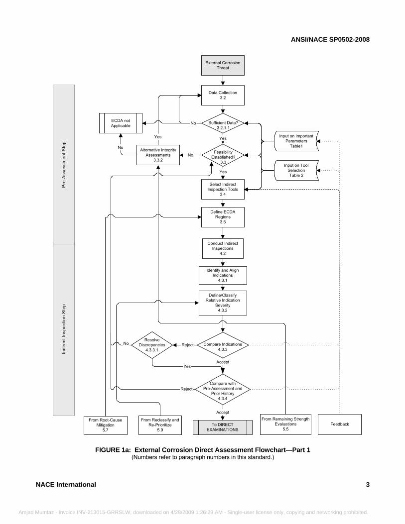
FIGURE 1a: External Corrosion Direct Assessment Flowchart—Part 1 (Numbers refer to paragraph numbers in this standard.)
Reject
Identify and AlignIndications
4.3.1
Define/ClassifyRelative Indication
Severity4.3.2
Compare withPre-Assessment and
Prior History4.3.4
ResolveDiscrepancies
4.3.3.1Reject
Yes
Compare Indications4.3.3
Accept
No
Accept
To DIRECTEXAMINATIONS
From Reclassify andRe-Prioritize
5.9
From Root-CauseMitigation
5.7Feedback
From Remaining StrengthEvaluations
5.5
Indi
rect
Insp
ectio
n S
tep
Data Collection3.2
External CorrosionThreat
Sufficient Data?3.2.1.1
FeasibilityEstablished?
3.3
Yes
Select IndirectInspection Tools
3.4
Yes
Define ECDARegions
3.5
Input on ImportantParameters
Table1
Input on ToolSelectionTable 2
Alternative IntegrityAssessments
3.3.2No
Yes
ECDA notApplicable
No
No
Conduct IndirectInspections
4.2
Pre
-Ass
essm
ent S
tep
ACE International 3
umtaz - Invoice INV-213015-GRRSLW, downloaded on 4/28/2009 1:26:29 AM - Single-user license only, copying and networking prohibited.
ANSI/NACE SP0502-2008
Amja
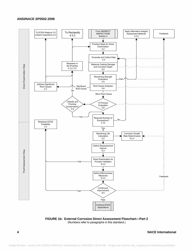
Address SignificantRoot Causes
5.7
To ECDA Regions 3.5Indirect Inspections 4.2
SignificantRoot Cause
No
Fail
Yes
Minor Root Cause
Apply Alternative IntegrityAssessment Methods
3.3.2
From INDIRECTINSPECTIONS
Section 4
Prioritize Need for DirectExamination
5.2
In-ProcessEvaluation
5.8
No
Classify andPrioritize
Conservative?5.9
Yes
Reassess orRe-Prioritize
4.3.2, 5.2
Required Number ofExcavations?
5.10
Remaining StrengthEvaluation
5.5
Root Cause Analyses5.6
Excavate and Collect Data5.3
Measure Coating Damageand Corrosion Depth
5.4
To ReClassify4.3.2 Feedback
Remaining LifeCalculation
6.2
Corrosion GrowthRate Determination
6.2.3
Define ReassessmentInterval
6.3
Define EffectivenessMeasures
6.4.3
ContinuousImprovement
6.5
Continue ECDAApplications
Pass
Fail
Reassess ECDAFeasibility
3.3
Feedback
Dire
ct E
xam
inat
ion
Ste
pP
ost A
sses
smen
t Ste
p
Direct Examination forProcess Validation
6.4.2Fail
FIGURE 1b: External Corrosion Direct Assessment Flowchart—Part 2 (Numbers refer to paragraphs in this standard.)
To Reclassify 4.3.2
-
4 NACE International
d Mumtaz - Invoice INV-213015-GRRSLW, downloaded on 4/28/2009 1:26:29 AM - Single-user license only, copying and networking prohibited.
ANSI/NACE SP0502-2008
NACE International
________________________________________________________________________
Amjad Mumtaz - Invoice INV-213015-GRRSLW, downloaded o
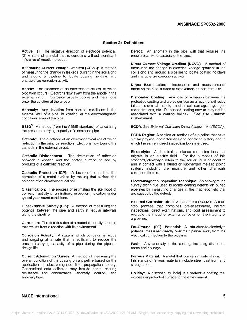
Section 2: Definitions
Active: (1) The negative direction of electrode potential. (2) A state of a metal that is corroding without significant influence of reaction product. Alternating Current Voltage Gradient (ACVG): A method of measuring the change in leakage current in the soil along and around a pipeline to locate coating holidays and characterize corrosion activity. Anode: The electrode of an electrochemical cell at which oxidation occurs. Electrons flow away from the anode in the external circuit. Corrosion usually occurs and metal ions enter the solution at the anode. Anomaly: Any deviation from nominal conditions in the external wall of a pipe, its coating, or the electromagnetic conditions around the pipe. B31G5: A method (from the ASME standard) of calculating the pressure-carrying capacity of a corroded pipe. Cathode: The electrode of an electrochemical cell at which reduction is the principal reaction. Electrons flow toward the cathode in the external circuit. Cathodic Disbondment: The destruction of adhesion between a coating and the coated surface caused by products of a cathodic reaction. Cathodic Protection (CP): A technique to reduce the corrosion of a metal surface by making that surface the cathode of an electrochemical cell. Classification: The process of estimating the likelihood of corrosion activity at an indirect inspection indication under typical year-round conditions. Close-Interval Survey (CIS): A method of measuring the potential between the pipe and earth at regular intervals along the pipeline. Corrosion: The deterioration of a material, usually a metal, that results from a reaction with its environment. Corrosion Activity: A state in which corrosion is active and ongoing at a rate that is sufficient to reduce the pressure-carrying capacity of a pipe during the pipeline design life. Current Attenuation Survey: A method of measuring the overall condition of the coating on a pipeline based on the application of electromagnetic field propagation theory. Concomitant data collected may include depth, coating resistance and conductance, anomaly location, and anomaly type.
n 4/28/2009 1:26:29
Defect: An anomaly in the pipe wall that reduces the pressure-carrying capacity of the pipe. Direct Current Voltage Gradient (DCVG): A method of measuring the change in electrical voltage gradient in the soil along and around a pipeline to locate coating holidays and characterize corrosion activity. Direct Examination: Inspections and measurements made on the pipe surface at excavations as part of ECDA. Disbonded Coating: Any loss of adhesion between the protective coating and a pipe surface as a result of adhesive failure, chemical attack, mechanical damage, hydrogen concentrations, etc. Disbonded coating may or may not be associated with a coating holiday. See also Cathodic Disbondment. ECDA: See External Corrosion Direct Assessment (ECDA). ECDA Region: A section or sections of a pipeline that have similar physical characteristics and operating history and in which the same indirect inspection tools are used. Electrolyte: A chemical substance containing ions that migrate in an electric field. For the purposes of this standard, electrolyte refers to the soil or liquid adjacent to and in contact with a buried or submerged metallic piping system, including the moisture and other chemicals contained therein. Electromagnetic Inspection Technique: An aboveground survey technique used to locate coating defects on buried pipelines by measuring changes in the magnetic field that are caused by the defects. External Corrosion Direct Assessment (ECDA): A four-step process that combines pre-assessment, indirect inspections, direct examinations, and post assessment to evaluate the impact of external corrosion on the integrity of a pipeline. Far-Ground (FG) Potential: A structure-to-electrolyte potential measured directly over the pipeline, away from the electrical connection to the pipeline. Fault: Any anomaly in the coating, including disbonded areas and holidays. Ferrous Material: A metal that consists mainly of iron. In this standard, ferrous materials include steel, cast iron, and wrought iron. Holiday: A discontinuity [hole] in a protective coating that exposes unprotected surface to the environment.
5
AM - Single-user license only, copying and networking prohibited.
ANSI/NACE SP0502-2008
Amjad
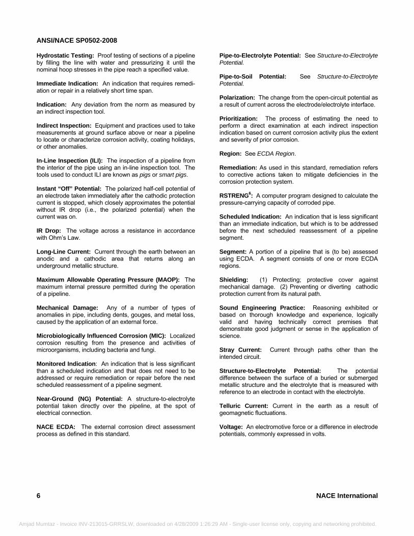
Hydrostatic Testing: Proof testing of sections of a pipeline by filling the line with water and pressurizing it until the nominal hoop stresses in the pipe reach a specified value. Immediate Indication: An indication that requires remedi-ation or repair in a relatively short time span. Indication: Any deviation from the norm as measured by an indirect inspection tool. Indirect Inspection: Equipment and practices used to take measurements at ground surface above or near a pipeline to locate or characterize corrosion activity, coating holidays, or other anomalies. In-Line Inspection (ILI): The inspection of a pipeline from the interior of the pipe using an in-line inspection tool. The tools used to conduct ILI are known as pigs or smart pigs. Instant “Off” Potential: The polarized half-cell potential of an electrode taken immediately after the cathodic protection current is stopped, which closely approximates the potential without IR drop (i.e., the polarized potential) when the current was on. IR Drop: The voltage across a resistance in accordance with Ohm’s Law. Long-Line Current: Current through the earth between an anodic and a cathodic area that returns along an underground metallic structure. Maximum Allowable Operating Pressure (MAOP): The maximum internal pressure permitted during the operation of a pipeline. Mechanical Damage: Any of a number of types of anomalies in pipe, including dents, gouges, and metal loss, caused by the application of an external force. Microbiologically Influenced Corrosion (MIC): Localized corrosion resulting from the presence and activities of microorganisms, including bacteria and fungi. Monitored Indication: An indication that is less significant than a scheduled indication and that does not need to be addressed or require remediation or repair before the next scheduled reassessment of a pipeline segment. Near-Ground (NG) Potential: A structure-to-electrolyte potential taken directly over the pipeline, at the spot of electrical connection. NACE ECDA: The external corrosion direct assessment process as defined in this standard.
6
Mumtaz - Invoice INV-213015-GRRSLW, downloaded on 4/28/2009 1:26:2
Pipe-to-Electrolyte Potential: See Structure-to-Electrolyte Potential. Pipe-to-Soil Potential: See Structure-to-Electrolyte Potential. Polarization: The change from the open-circuit potential as a result of current across the electrode/electrolyte interface. Prioritization: The process of estimating the need to perform a direct examination at each indirect inspection indication based on current corrosion activity plus the extent and severity of prior corrosion. Region: See ECDA Region. Remediation: As used in this standard, remediation refers to corrective actions taken to mitigate deficiencies in the corrosion protection system. RSTRENG6: A computer program designed to calculate the pressure-carrying capacity of corroded pipe. Scheduled Indication: An indication that is less significant than an immediate indication, but which is to be addressed before the next scheduled reassessment of a pipeline segment. Segment: A portion of a pipeline that is (to be) assessed using ECDA. A segment consists of one or more ECDA regions. Shielding: (1) Protecting; protective cover against mechanical damage. (2) Preventing or diverting cathodic protection current from its natural path. Sound Engineering Practice: Reasoning exhibited or based on thorough knowledge and experience, logically valid and having technically correct premises that demonstrate good judgment or sense in the application of science. Stray Current: Current through paths other than the intended circuit. Structure-to-Electrolyte Potential: The potential difference between the surface of a buried or submerged metallic structure and the electrolyte that is measured with reference to an electrode in contact with the electrolyte. Telluric Current: Current in the earth as a result of geomagnetic fluctuations. Voltage: An electromotive force or a difference in electrode potentials, commonly expressed in volts.
NACE International
9 AM - Single-user license only, copying and networking prohibited.
ANSI/NACE SP0502-2008
NACE International
________________________________________________________________________
Amjad Mumtaz - Invoice INV-213015-GRRSLW, download
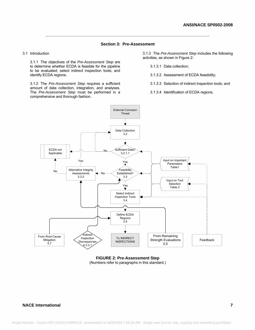
Section 3: Pre-Assessment
3.1 Introduction
3.1.1 The objectives of the Pre-Assessment Step are to determine whether ECDA is feasible for the pipeline to be evaluated; select indirect inspection tools; and identify ECDA regions. 3.1.2 The Pre-Assessment Step requires a sufficient amount of data collection, integration, and analyses. The Pre-Assessment Step must be performed in a comprehensive and thorough fashion.
ed on 4/28/2009 1:26:29 AM
3.1.3 The Pre-Assessment Step includes the following activities, as shown in Figure 2:
3.1.3.1 Data collection; 3.1.3.2 Assessment of ECDA feasibility; 3.1.3.3 Selection of indirect inspection tools; and 3.1.3.4 Identification of ECDA regions.
FIGURE 2: Pre-Assessment Step
(Numbers refer to paragraphs in this standard.)
From Root-CauseMitigation
5.7Feedback
From RemainingStrength Evaluations
5.5
Data Collection3.2
External CorrosionThreat
Sufficient Data?3.2.1.1
FeasibilityEstablished?
3.3
Yes
Select IndirectInspection Tools
3.4
Yes
Define ECDARegions
3.5
Input on ImportantParameters
Table1
Input on ToolSelectionTable 2
Alternative IntegrityAssessments
3.3.2No
Yes
ECDA notApplicable
No
No
To INDIRECTINSPECTIONS
IndirectInspection
Discrepancies4.3.3.1
FIGURE 2: Pre-Assessment Step (Numbers refer to paragraphs in this standard.)
7
- Single-user license only, copying and networking prohibited.
ANSI/NACE SP0502-2008
Amjad
3.2 Data Collection
3.2.1 The pipeline operator shall collect historical and current data along with physical information for the segment to be evaluated.
3.2.1.1 The pipeline operator shall define minimum data requirements based on the history and condition of the pipeline segment. In addition, the pipeline operator shall identify data elements that are critical to the success of the ECDA process. 3.2.1.2 All parameters that impact indirect inspection tool selection (Paragraph 3.4) and ECDA region definition (Paragraph 3.5) shall be considered for initial ECDA process applications on a pipeline segment.
8
Mumtaz - Invoice INV-213015-GRRSLW, downloaded on 4/28/2009 1:26:29 AM -
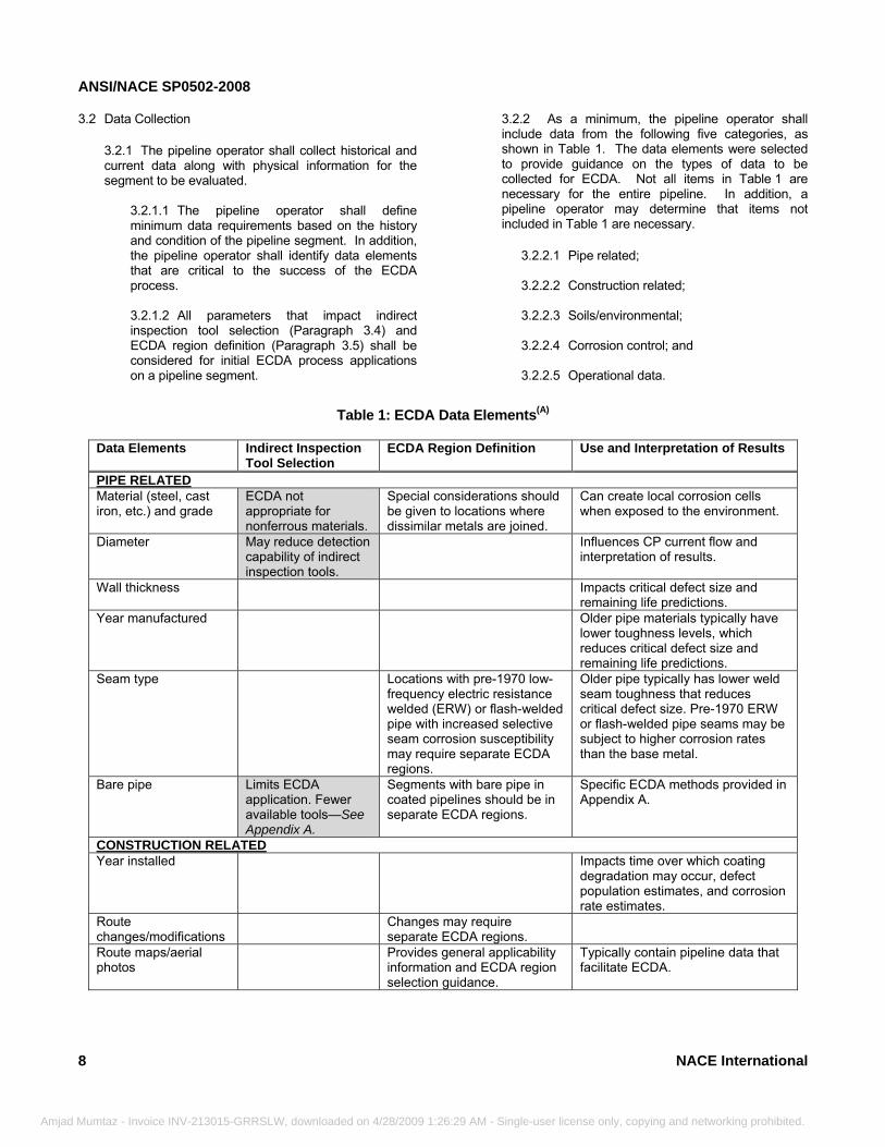
3.2.2 As a minimum, the pipeline operator shall include data from the following five categories, as shown in Table 1. The data elements were selected to provide guidance on the types of data to be collected for ECDA. Not all items in Table 1 are necessary for the entire pipeline. In addition, a pipeline operator may determine that items not included in Table 1 are necessary.
3.2.2.1 Pipe related; 3.2.2.2 Construction related; 3.2.2.3 Soils/environmental; 3.2.2.4 Corrosion control; and 3.2.2.5 Operational data.
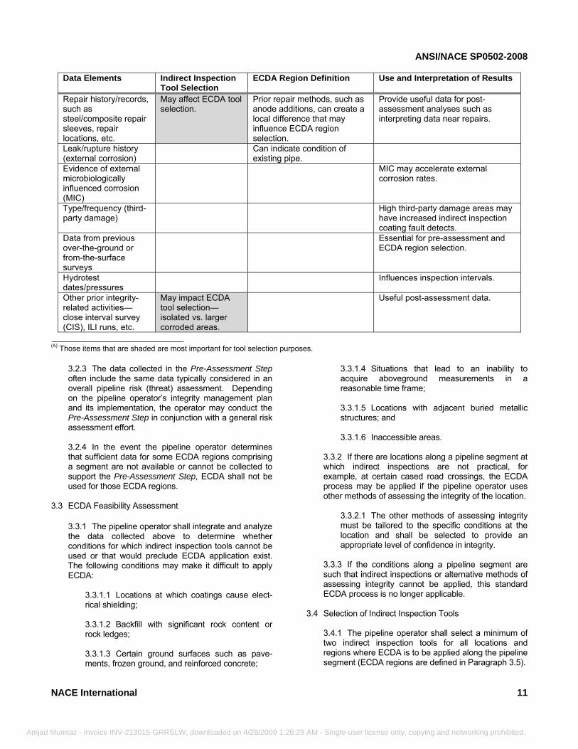
Table 1: ECDA Data Elements(A)
Data Elements Indirect Inspection
Tool Selection ECDA Region Definition Use and Interpretation of Results
PIPE RELATED Material (steel, cast iron, etc.) and grade
ECDA not appropriate for nonferrous materials.
Special considerations should be given to locations where dissimilar metals are joined.
Can create local corrosion cells when exposed to the environment.
Diameter May reduce detection capability of indirect inspection tools.
Influences CP current flow and interpretation of results.
Wall thickness Impacts critical defect size and remaining life predictions.
Year manufactured Older pipe materials typically have lower toughness levels, which reduces critical defect size and remaining life predictions.
Seam type Locations with pre-1970 low-frequency electric resistance welded (ERW) or flash-welded pipe with increased selective seam corrosion susceptibility may require separate ECDA regions.
Older pipe typically has lower weld seam toughness that reduces critical defect size. Pre-1970 ERW or flash-welded pipe seams may be subject to higher corrosion rates than the base metal.
Bare pipe Limits ECDA application. Fewer available tools—See Appendix A.
Segments with bare pipe in coated pipelines should be in separate ECDA regions.
Specific ECDA methods provided in Appendix A.
CONSTRUCTION RELATEDYear installed Impacts time over which coating
degradation may occur, defect population estimates, and corrosion rate estimates.
Route changes/modifications
Changes may require separate ECDA regions.
Route maps/aerial photos
Provides general applicability information and ECDA region selection guidance.
Typically contain pipeline data that facilitate ECDA.
NACE International
Single-user license only, copying and networking prohibited.
ANSI/NACE SP0502-2008
Amjad M
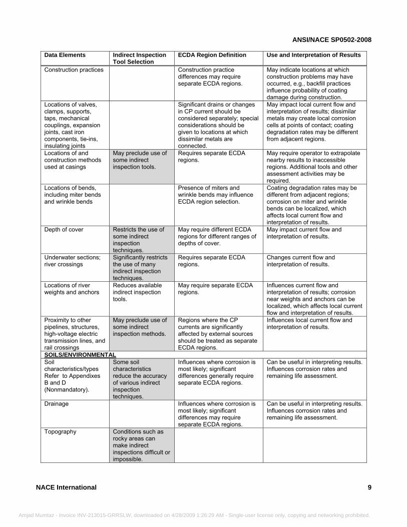
Data Elements Indirect Inspection
Tool Selection ECDA Region Definition Use and Interpretation of Results
Construction practices Construction practice differences may require separate ECDA regions.
May indicate locations at which construction problems may have occurred, e.g., backfill practices influence probability of coating damage during construction.
Locations of valves, clamps, supports, taps, mechanical couplings, expansion joints, cast iron components, tie-ins, insulating joints
Significant drains or changes in CP current should be considered separately; special considerations should be given to locations at which dissimilar metals are connected.
May impact local current flow and interpretation of results; dissimilar metals may create local corrosion cells at points of contact; coating degradation rates may be different from adjacent regions.
Locations of and construction methods used at casings
May preclude use of some indirect inspection tools.
Requires separate ECDA regions.
May require operator to extrapolate nearby results to inaccessible regions. Additional tools and other assessment activities may be required.
Locations of bends, including miter bends and wrinkle bends
Presence of miters and wrinkle bends may influence ECDA region selection.
Coating degradation rates may be different from adjacent regions; corrosion on miter and wrinkle bends can be localized, which affects local current flow and interpretation of results.
Depth of cover Restricts the use of some indirect inspection techniques.
May require different ECDA regions for different ranges of depths of cover.
May impact current flow and interpretation of results.
Underwater sections; river crossings
Significantly restricts the use of many indirect inspection techniques.
Requires separate ECDA regions.
Changes current flow and interpretation of results.
Locations of river weights and anchors
Reduces available indirect inspection tools.
May require separate ECDA regions.
Influences current flow and interpretation of results; corrosion near weights and anchors can be localized, which affects local current flow and interpretation of results.
Proximity to other pipelines, structures, high-voltage electric transmission lines, and rail crossings
May preclude use of some indirect inspection methods.
Regions where the CP currents are significantly affected by external sources should be treated as separate ECDA regions.
Influences local current flow and interpretation of results.
SOILS/ENVIRONMENTAL Soil characteristics/types Refer to Appendixes B and D (Nonmandatory).
Some soil characteristics reduce the accuracy of various indirect inspection techniques.
Influences where corrosion is most likely; significant differences generally require separate ECDA regions.
Can be useful in interpreting results. Influences corrosion rates and remaining life assessment.
Drainage Influences where corrosion is most likely; significant differences may require separate ECDA regions.
Can be useful in interpreting results. Influences corrosion rates and remaining life assessment.
Topography Conditions such as rocky areas can make indirect inspections difficult or impossible.
NACE International 9
umtaz - Invoice INV-213015-GRRSLW, downloaded on 4/28/2009 1:26:29 AM - Single-user license only, copying and networking prohibited.
ANSI/NACE SP0502-2008
Amjad M
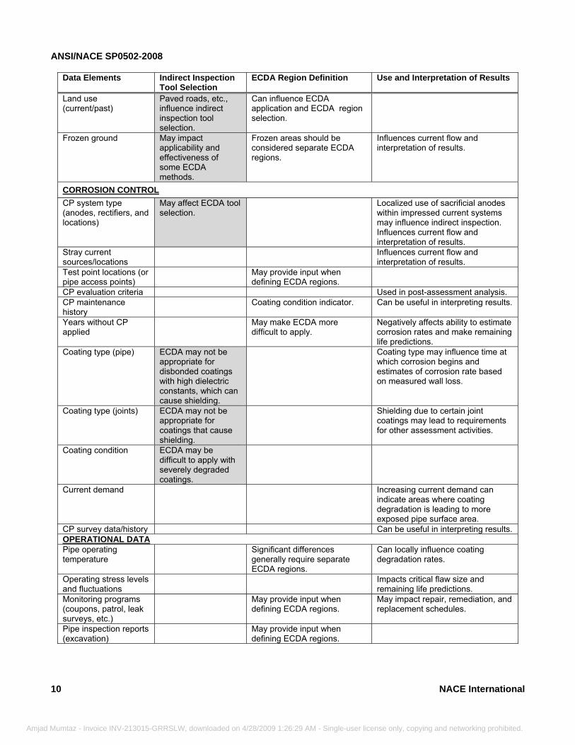
Data Elements Indirect Inspection
Tool Selection ECDA Region Definition Use and Interpretation of Results
Land use (current/past)
Paved roads, etc., influence indirect inspection tool selection.
Can influence ECDA application and ECDA region selection.
Frozen ground May impact applicability and effectiveness of some ECDA methods.
Frozen areas should be considered separate ECDA regions.
Influences current flow and interpretation of results.
CORROSION CONTROL CP system type (anodes, rectifiers, and locations)
May affect ECDA tool selection.
Localized use of sacrificial anodes within impressed current systems may influence indirect inspection. Influences current flow and interpretation of results.
Stray current sources/locations
Influences current flow and interpretation of results.
Test point locations (or pipe access points)
May provide input when defining ECDA regions.
CP evaluation criteria Used in post-assessment analysis. CP maintenance history
Coating condition indicator. Can be useful in interpreting results.
Years without CP applied
May make ECDA more difficult to apply.
Negatively affects ability to estimate corrosion rates and make remaining life predictions.
Coating type (pipe) ECDA may not be appropriate for disbonded coatings with high dielectric constants, which can cause shielding.
Coating type may influence time at which corrosion begins and estimates of corrosion rate based on measured wall loss.
Coating type (joints) ECDA may not be appropriate for coatings that cause shielding.
Shielding due to certain joint coatings may lead to requirements for other assessment activities.
Coating condition ECDA may be difficult to apply with severely degraded coatings.
Current demand Increasing current demand can indicate areas where coating degradation is leading to more exposed pipe surface area.
CP survey data/history Can be useful in interpreting results. OPERATIONAL DATA Pipe operating temperature
Significant differences generally require separate ECDA regions.
Can locally influence coating degradation rates.
Operating stress levels and fluctuations
Impacts critical flaw size and remaining life predictions.
Monitoring programs (coupons, patrol, leak surveys, etc.)
May provide input when defining ECDA regions.
May impact repair, remediation, and replacement schedules.
Pipe inspection reports (excavation)
May provide input when defining ECDA regions.
10 NACE International
umtaz - Invoice INV-213015-GRRSLW, downloaded on 4/28/2009 1:26:29 AM - Single-user license only, copying and networking prohibited.
ANSI/NACE SP0502-2008
Amjad
Data Elements Indirect Inspection
Tool Selection ECDA Region Definition Use and Interpretation of Results
Repair history/records, such as steel/composite repair sleeves, repair locations, etc.
May affect ECDA tool selection.
Prior repair methods, such as anode additions, can create a local difference that may influence ECDA region selection.
Provide useful data for post-assessment analyses such as interpreting data near repairs.
Leak/rupture history (external corrosion)
Can indicate condition of existing pipe.
Evidence of external microbiologically influenced corrosion (MIC)
MIC may accelerate external corrosion rates.
Type/frequency (third-party damage)
High third-party damage areas may have increased indirect inspection coating fault detects.
Data from previous over-the-ground or from-the-surface surveys
Essential for pre-assessment and ECDA region selection.
Hydrotest dates/pressures
Influences inspection intervals.
Other prior integrity-related activities—close interval survey (CIS), ILI runs, etc.
May impact ECDA tool selection—isolated vs. larger corroded areas.
Useful post-assessment data.
____________________________ (A) Those items that are shaded are most important for tool selection purposes.
3.2.3 The data collected in the Pre-Assessment Step often include the same data typically considered in an overall pipeline risk (threat) assessment. Depending on the pipeline operator’s integrity management plan and its implementation, the operator may conduct the Pre-Assessment Step in conjunction with a general risk assessment effort. 3.2.4 In the event the pipeline operator determines that sufficient data for some ECDA regions comprising a segment are not available or cannot be collected to support the Pre-Assessment Step, ECDA shall not be used for those ECDA regions.
3.3 ECDA Feasibility Assessment
3.3.1 The pipeline operator shall integrate and analyze the data collected above to determine whether conditions for which indirect inspection tools cannot be used or that would preclude ECDA application exist. The following conditions may make it difficult to apply ECDA:
3.3.1.1 Locations at which coatings cause elect-rical shielding; 3.3.1.2 Backfill with significant rock content or rock ledges; 3.3.1.3 Certain ground surfaces such as pave-ments, frozen ground, and reinforced concrete;
NACE International
Mumtaz - Invoice INV-213015-GRRSLW, downloaded on 4/28/2009 1:26:29
3.3.1.4 Situations that lead to an inability to acquire aboveground measurements in a reasonable time frame; 3.3.1.5 Locations with adjacent buried metallic structures; and 3.3.1.6 Inaccessible areas.
3.3.2 If there are locations along a pipeline segment at which indirect inspections are not practical, for example, at certain cased road crossings, the ECDA process may be applied if the pipeline operator uses other methods of assessing the integrity of the location.
3.3.2.1 The other methods of assessing integrity must be tailored to the specific conditions at the location and shall be selected to provide an appropriate level of confidence in integrity.
3.3.3 If the conditions along a pipeline segment are such that indirect inspections or alternative methods of assessing integrity cannot be applied, this standard ECDA process is no longer applicable.
3.4 Selection of Indirect Inspection Tools
3.4.1 The pipeline operator shall select a minimum of two indirect inspection tools for all locations and regions where ECDA is to be applied along the pipeline segment (ECDA regions are defined in Paragraph 3.5).
11
AM - Single-user license only, copying and networking prohibited.
ANSI/NACE SP0502-2008
12
Amjad Mumtaz
3.4.1.1 The pipeline operator shall select indirect inspection tools based on their ability to detect corrosion activity and coating holidays reliably under the specific pipeline conditions to be encountered. 3.4.1.2 The pipeline operator should endeavor to select indirect inspection tools that are complementary. That is, the operator should select tools such that the strengths of one tool compensate for the limitations of another.
3.4.1.3 The pipeline operator may substitute a 100% direct examination that follows the requirements of Appendixes B and C in lieu of indirect inspections and selected direct examinations at bellhole locations. In such a case,
- Invoice INV-213015-GRRSLW, downloaded on 4/28/2009 1:26:29 AM
the pre-assessment and post-assessment steps must also be followed.
3.4.2 The “indirect inspection tool selection” column in Table 1 includes items that should be considered when indirect inspection tools are selected. Those items that are shaded are most important for tool selection purposes. 3.4.3 Table 2 provides additional guidance on selecting indirect inspection tools and specifically addresses conditions under which some indirect inspection tools may not be practical or reliable. Refer to Appendix A, Paragraphs A2 to A2.1.8, for additional information on appropriate safety precautions that should be observed when electrical measurements are made.
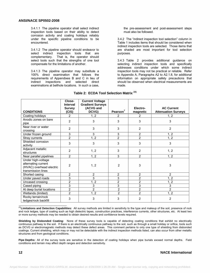
Table 2: ECDA Tool Selection Matrix (A)
CONDITIONS
Close-Interval Survey (CIS)
Current Voltage Gradient Surveys
(ACVG and DCVG) Pearson7
Electro-magnetic
AC Current Attenuation Surveys
Coating holidays 2 1, 2 2 2 1, 2 Anodic zones on bare pipe 2 3 3 3 3
Near river or water crossing 2 3 3 2 2
Under frozen ground 3 3 3 2 1, 2 Stray currents 2 1, 2 2 2 1, 2 Shielded corrosion activity 3 3 3 3 3
Adjacent metallic structures 2 1, 2 3 2 1, 2
Near parallel pipelines 2 1, 2 3 2 1, 2 Under high-voltage alternating current (HVAC) overhead electric transmission lines
2 1, 2 2 3 3
Shorted casing 2 2 2 2 2 Under paved roads 3 3 3 2 1, 2 Uncased crossing 2 1, 2 2 2 1, 2 Cased piping 3 3 3 3 3 At deep burial locations 2 2 2 2 2 Wetlands (limited) 2 1, 2 2 2 1, 2 Rocky terrain/rock ledges/rock backfill 3 3 3 2 2
____________________________ (A)Limitations and Detection Capabilities: All survey methods are limited in sensitivity to the type and makeup of the soil, presence of rock and rock ledges, type of coating such as high dielectric tapes, construction practices, interference currents, other structures, etc. At least two or more survey methods may be needed to obtain desired results and confidence levels required. Shielding by Disbonded Coating: None of these survey tools is capable of detecting coating conditions that exhibit no electrically continuous pathway to the soil. If there is an electrically continuous pathway to the soil, such as through a small holiday or orifice, tools such as DCVG or electromagnetic methods may detect these defect areas. This comment pertains to only one type of shielding from disbonded coatings. Current shielding, which may or may not be detectable with the indirect inspection methods listed, can also occur from other metallic structures and from geological conditions. Pipe Depths: All of the survey tools are sensitive in the detection of coating holidays when pipe burials exceed normal depths. Field conditions and terrain may affect depth ranges and detection sensitivity.
NACE International
- Single-user license only, copying and networking prohibited.
ANSI/NACE SP0502-2008
Amjad
KEY 1 = Applicable: Small coating holidays (isolated and typically <600 mm2 [1 in.2]) and conditions that do not cause fluctuations in CP potentials under normal operating conditions. 2 = Applicable: Large coating holidays (isolated or continuous) or conditions that cause fluctuations in CP potentials under normal operating conditions. 3 = Not Applicable: Not applicable to this tool or not applicable to this tool without additional considerations.
NACE
Mumtaz -
3.4.3.1 The techniques included in Table 2 are not intended to illustrate the only inspection methods that are applicable or the capabilities of these inspection methods under all conditions. Rather, they are listed as representative examples of the types of indirect inspection methods available for an ECDA program. Other indirect inspection methods can and should be used as required by the unique situations along a pipeline or as new technologies are developed. In
International
Invoice INV-213015-GRRSLW, downloaded on 4/28/2009 1:26:29 AM - Sing
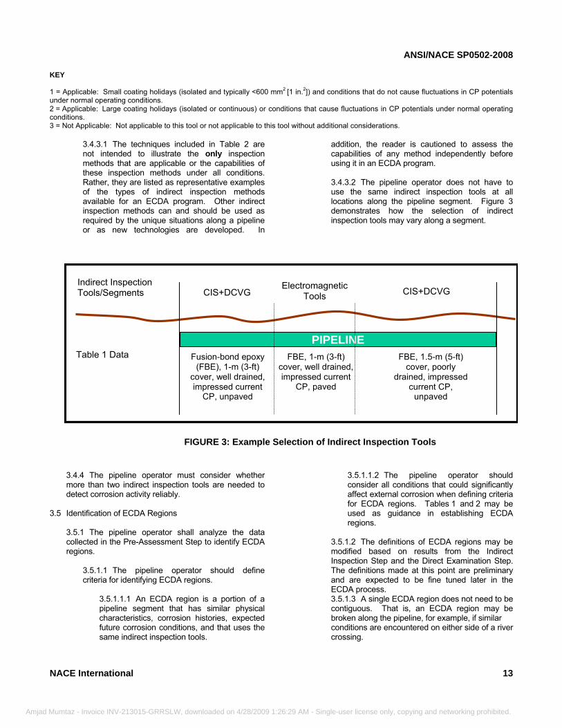
addition, the reader is cautioned to assess the capabilities of any method independently before using it in an ECDA program. 3.4.3.2 The pipeline operator does not have to use the same indirect inspection tools at all locations along the pipeline segment. Figure 3 demonstrates how the selection of indirect inspection tools may vary along a segment.
Table 1 Data
CIS + DCVG CIS + DCVGElectromagnetic
Tools Indirect Inspection Tools/Segments
PIPELINEFusion-bond epoxy
(FBE), 1-m (3-ft) cover, well drained, impressed current
CP, unpaved
FBE, 1.5-m (5-ft) cover, poorly
drained, impressed current CP,
unpaved
FBE, 1-m (3-ft) cover, well drained, impressed current
CP, paved
FIGURE 3: Example Selection of Indirect Inspection Tools
Indirect Inspection Tools/Segments
Table 1 Data
CIS+DCVG CIS+DCVG Electromagnetic Tools
FIGURE 3: Example Selection of Indirect Inspection Tools
3.4.4 The pipeline operator must consider whether more than two indirect inspection tools are needed to detect corrosion activity reliably.
3.5 Identification of ECDA Regions
3.5.1 The pipeline operator shall analyze the data collected in the Pre-Assessment Step to identify ECDA regions.
3.5.1.1 The pipeline operator should define criteria for identifying ECDA regions.
3.5.1.1.1 An ECDA region is a portion of a pipeline segment that has similar physical characteristics, corrosion histories, expected future corrosion conditions, and that uses the same indirect inspection tools.
3.5.1.1.2 The pipeline operator should consider all conditions that could significantly affect external corrosion when defining criteria for ECDA regions. Tables 1 and 2 may be used as guidance in establishing ECDA regions.
3.5.1.2 The definitions of ECDA regions may be modified based on results from the Indirect Inspection Step and the Direct Examination Step. The definitions made at this point are preliminary and are expected to be fine tuned later in the ECDA process. 3.5.1.3 A single ECDA region does not need to be contiguous. That is, an ECDA region may be broken along the pipeline, for example, if similar conditions are encountered on either side of a river crossing.
13
le-user license only, copying and networking prohibited.
ANSI/NACE SP0502-2008
14
Amjad Mu
3.5.1.4 All of the pipeline segments should be included in ECDA regions.
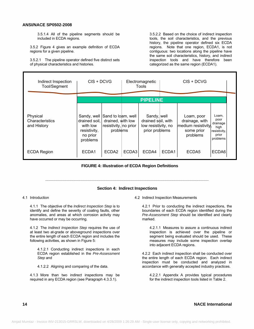
3.5.2 Figure 4 gives an example definition of ECDA regions for a given pipeline. 3.5.2.1 The pipeline operator defined five distinct sets of physical characteristics and histories.
_____________________________________________
mtaz - Invoice INV-213015-GRRSLW, downloaded on 4/28/2009 1:26:29 AM - Sin
3.5.2.2 Based on the choice of indirect inspection tools, the soil characteristics, and the previous history, the pipeline operator defined six ECDA regions. Note that one region, ECDA1, is not contiguous: two locations along the pipeline have the same soil characteristics, history, and indirect inspection tools and have therefore been categorized as the same region (ECDA1).
CIS + DCVG CIS + DCVG Electromagnetic Tools
Indirect Inspection Tool/Segment
ECDA1 ECDA2 ECDA3 ECDA4 ECDA1 ECDA5 ECDA6ECDA Region
PIPELINE
Physical Characteristics and History
Sandy, well drained soil,
with low resistivity, no prior
problems
Sand to loam, well drained, with low
resistivity, no prior problems
Sandy, well drained soil, with low resistivity, no
prior problems
Loam, poor drainage, with
medium resistivity, some prior problems
Loam, poor
drainage high
resistivity, prior
problems
FIGURE 4: Illustration of ECDA Region Definitions
___________________________
Section 4: Indirect Inspections
4.1 Introduction4.1.1 The objective of the Indirect Inspection Step is to identify and define the severity of coating faults, other anomalies, and areas at which corrosion activity may have occurred or may be occurring. 4.1.2 The Indirect Inspection Step requires the use of at least two at-grade or aboveground inspections over the entire length of each ECDA region and includes the following activities, as shown in Figure 5:
4.1.2.1 Conducting indirect inspections in each ECDA region established in the Pre-Assessment Step and 4.1.2.2 Aligning and comparing of the data.
4.1.3 More than two indirect inspections may be required in any ECDA region (see Paragraph 4.3.3.1).
4.2 Indirect Inspection Measurements
4.2.1 Prior to conducting the indirect inspections, the boundaries of each ECDA region identified during the Pre-Assessment Step should be identified and clearly marked.
4.2.1.1 Measures to assure a continuous indirect inspection is achieved over the pipeline or segment being evaluated should be used. These measures may include some inspection overlap into adjacent ECDA regions.
4.2.2 Each indirect inspection shall be conducted over the entire length of each ECDA region. Each indirect inspection must be conducted and analyzed in accordance with generally accepted industry practices.
4.2.2.1 Appendix A provides typical procedures for the indirect inspection tools listed in Table 2.
NACE International
gle-user license only, copying and networking prohibited.
ANSI/NACE SP0502-2008
NA
Amjad Mu
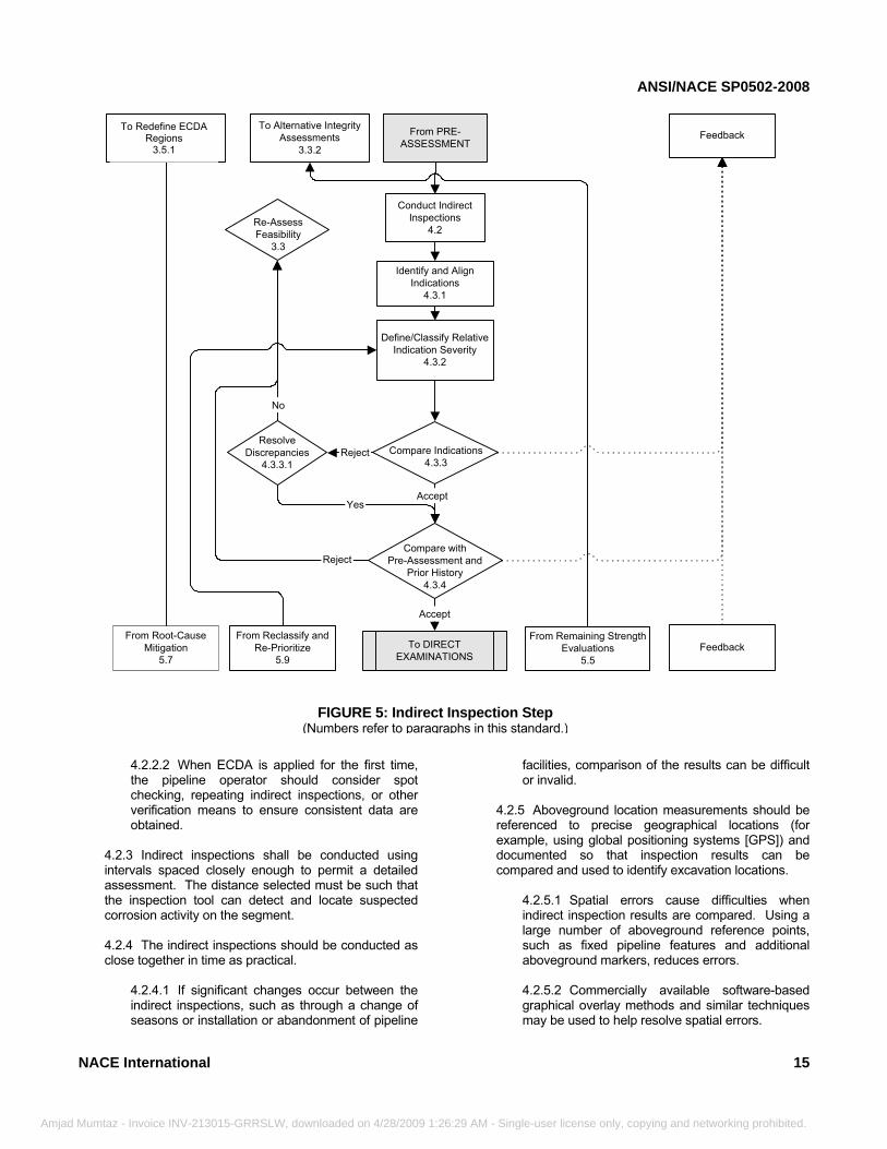
FIGURE 5: Indirect Inspection Step (Numbers refer to paragraphs in this standard.)
Reject
Identify and AlignIndications
4.3.1
Define/Classify RelativeIndication Severity
4.3.2
Compare withPre-Assessment and
Prior History4.3.4
ResolveDiscrepancies
4.3.3.1Reject
Yes
Compare Indications4.3.3
Accept
Accept
To DIRECTEXAMINATIONS
From Reclassify andRe-Prioritize
5.9
Feedback
From Remaining StrengthEvaluations
5.5
From PRE-ASSESSMENT
To Alternative IntegrityAssessments
3.3.2
Conduct IndirectInspections
4.2Re-AssessFeasibility
3.3
To Re-Define ECDARegions
3.5.1
From Root-CauseMitigation
5.7Feedback
No
To Redefine ECDA Regions
3.5.1
4.2.2.2 When ECDA is applied for the first time, the pipeline operator should consider spot checking, repeating indirect inspections, or other verification means to ensure consistent data are obtained.
4.2.3 Indirect inspections shall be conducted using intervals spaced closely enough to permit a detailed assessment. The distance selected must be such that the inspection tool can detect and locate suspected corrosion activity on the segment. 4.2.4 The indirect inspections should be conducted as close together in time as practical.
4.2.4.1 If significant changes occur between the indirect inspections, such as through a change of seasons or installation or abandonment of pipeline
CE International
mtaz - Invoice INV-213015-GRRSLW, downloaded on 4/28/2009 1:26:29 A
facilities, comparison of the results can be difficult or invalid.
4.2.5 Aboveground location measurements should be referenced to precise geographical locations (for example, using global positioning systems [GPS]) and documented so that inspection results can be compared and used to identify excavation locations.
4.2.5.1 Spatial errors cause difficulties when indirect inspection results are compared. Using a large number of aboveground reference points, such as fixed pipeline features and additional aboveground markers, reduces errors. 4.2.5.2 Commercially available software-based graphical overlay methods and similar techniques may be used to help resolve spatial errors.
15
M - Single-user license only, copying and networking prohibited.
ANSI/NACE SP0502-2008
Amjad
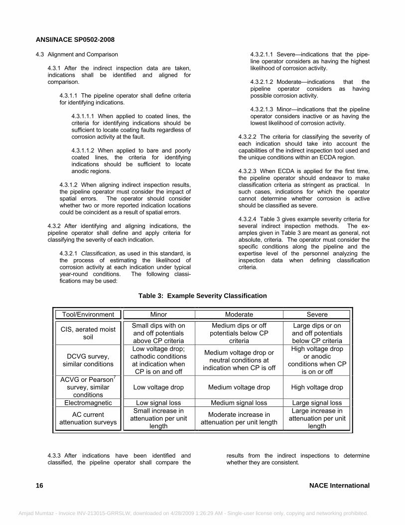
4.3 Alignment and Comparison
4.3.1 After the indirect inspection data are taken, indications shall be identified and aligned for comparison.
4.3.1.1 The pipeline operator shall define criteria for identifying indications.
4.3.1.1.1 When applied to coated lines, the criteria for identifying indications should be sufficient to locate coating faults regardless of corrosion activity at the fault. 4.3.1.1.2 When applied to bare and poorly coated lines, the criteria for identifying indications should be sufficient to locate anodic regions.
4.3.1.2 When aligning indirect inspection results, the pipeline operator must consider the impact of spatial errors. The operator should consider whether two or more reported indication locations could be coincident as a result of spatial errors.
4.3.2 After identifying and aligning indications, the pipeline operator shall define and apply criteria for classifying the severity of each indication.
4.3.2.1 Classification, as used in this standard, is the process of estimating the likelihood of corrosion activity at each indication under typical year-round conditions. The following classi-fications may be used:
16
Mumtaz - Invoice INV-213015-GRRSLW, downloaded on 4/28/2009 1:26:29 AM -
4.3.2.1.1 Severe—indications that the pipe-line operator considers as having the highest likelihood of corrosion activity. 4.3.2.1.2 Moderate—indications that the pipeline operator considers as having possible corrosion activity. 4.3.2.1.3 Minor—indications that the pipeline operator considers inactive or as having the lowest likelihood of corrosion activity.
4.3.2.2 The criteria for classifying the severity of each indication should take into account the capabilities of the indirect inspection tool used and the unique conditions within an ECDA region. 4.3.2.3 When ECDA is applied for the first time, the pipeline operator should endeavor to make classification criteria as stringent as practical. In such cases, indications for which the operator cannot determine whether corrosion is active should be classified as severe. 4.3.2.4 Table 3 gives example severity criteria for several indirect inspection methods. The ex-amples given in Table 3 are meant as general, not absolute, criteria. The operator must consider the specific conditions along the pipeline and the expertise level of the personnel analyzing the inspection data when defining classification criteria.
Table 3: Example Severity Classification
Tool/Environment Minor Moderate Severe
CIS, aerated moist soil
Small dips with on and off potentials above CP criteria
Medium dips or off potentials below CP
criteria
Large dips or on and off potentials below CP criteria
DCVG survey, similar conditions
Low voltage drop; cathodic conditions at indication when CP is on and off
Medium voltage drop or neutral conditions at
indication when CP is off
High voltage drop or anodic
conditions when CP is on or off
ACVG or Pearson7 survey, similar
conditions Low voltage drop Medium voltage drop High voltage drop
Electromagnetic Low signal loss Medium signal loss Large signal loss
AC current attenuation surveys
Small increase in attenuation per unit
length
Moderate increase in attenuation per unit length
Large increase in attenuation per unit
length
4.3.3 After indications have been identified and classified, the pipeline operator shall compare the
results from the indirect inspections to determine whether they are consistent.
NACE International
Single-user license only, copying and networking prohibited.
ANSI/NACE SP0502-2008
NACE
Amjad Mumtaz -
4.3.3.1 If two or more indirect inspection tools indicate significantly different sets of locations at which corrosion activity may exist and if the differences cannot be explained by the inherent capabilities of the tools or specific and localized pipeline features or conditions, additional indirect inspections or preliminary direct examinations should be considered.
4.3.3.1.1 Preliminary direct examinations may be used to resolve discrepancies in lieu of additional indirect inspections provided the direct examinations identify a localized and isolated cause of the discrepancy.
4.3.3.1.2 If direct examinations cannot be used to resolve the discrepancies, additional indirect inspections should be considered in accordance with Paragraph 3.4, after which the data must be aligned and compared as described above. 4.3.3.1.3 If additional indirect inspections are not performed or do not resolve the
International
________________________________________
Invoice INV-213015-GRRSLW, downloaded on 4/28/2009 1:26:29 A
discrepancies, ECDA feasibility should be reassessed. As an alternative, the pipeline operator may use other proven integrity assessment technologies. 4.3.3.1.4 For initial ECDA applications to any pipeline segment, any location at which discrepancies cannot be resolved shall be categorized as severe.
4.3.4 After discrepancies have been resolved, the pipeline operator shall compare the results with the pre-assessment results and prior history for each ECDA region.
4.3.4.1 If the pipeline operator determines that the results from the indirect inspections are not consistent with the pre-assessment results and prior history, the operator should reassess ECDA feasibility and ECDA region definition. As an alternative, the pipeline operator may use other proven integrity assessment technologies.
________________________________
Section 5: Direct Examinations
5.1 Introduction5.1.1 The objectives of the Direct Examination Step are to determine which indications from the indirect inspections are most severe and collect data to assess corrosion activity. 5.1.2 The Direct Examination Step requires excavations to expose the pipe surface so that measurements can be made on the pipeline and in the immediate surrounding environment. 5.1.3 A minimum of one dig is required regardless of the results of the indirect inspections and pre-assessment steps. Guidelines for determining the location and minimum number of excavations and direct examinations are given in Paragraph 5.10. 5.1.4 The order in which excavations and direct examinations are made is at the discretion of the pipeline operator but should take into account safety and related considerations. 5.1.5 During the Direct Examination Step, defects other than external corrosion may be found. While
M
defects such as mechanical damage and stress corrosion cracking may be found, alternative methods must be considered for assessing the impact of such defect types. Alternative methods are given in ASME B31.4,1 ASME B31.8,2,3 and API 1160.4 5.1.6 The Direct Examination Step includes the following activities, as shown in Figure 6:
5.1.6.1 Prioritization of indications found during the indirect inspections; 5.1.6.2 Excavations and data collection at areas where corrosion activity is most likely; 5.1.6.3 Measurements of coating damage and corrosion defects; 5.1.6.4 Evaluations of remaining strength (severity); 5.1.6.5 Root cause analyses; and 5.1.6.6 A process evaluation.
17
- Single-user license only, copying and networking prohibited.
ANSI/NACE SP0502-2008
18
Amjad Mu
Yes
Address SignificantRoot Causes
5.7
To ECDA Regions 3.5Indirect Inspections 4.2
SignificantRoot Cause
No
MinorRoot Cause
Apply Alternative IntegrityAssessment Methods
3.3.2
Fail
From INDIRECTINSPECTIONS
Section 4
Prioritize Need for DirectExamination
5.2
In-ProcessEvaluation
5.8
No
Classify andPrioritize
Conservative?5.9
Reassess orRe-Prioritize
4.3.2, 5.2
Required Number ofExcavations?
5.10
Remaining StrengthEvaluation
5.5
Root Cause Analyses5.6
Excavate andCollect Data
5.3
Measure Coating Damageand Corrosion Depth
5.4
To ReClassify4.3.2
Feedback
To POST-ASSESSMENT
Section 6
FIGURE 6: Direct Examination Step (Numbers refer to paragraphs in this standard.)
To Reclassify 4.3.2
5.2 Prioritization
5.2.1 The pipeline operator shall establish criteria for prioritizing the need for direct examination of each indication found during the Indirect Inspection Step.
5.2.1.1 Prioritization, as used in this standard, is the process of estimating the need for direct examination of each indication based on the likelihood of current corrosion activity plus the extent and severity of prior corrosion. 5.2.1.2 Table 4 gives example criteria for prioritizing indications. Different criteria may be required in different regions, as a function of the
mtaz - Invoice INV-213015-GRRSLW, downloaded on 4/28/2009 1:26:29 A
pipeline condition, age, corrosion protection history, etc.
5.2.1.2.1 This standard does not establish time requirements for scheduling remediation and other actions that may be required by ECDA.
5.2.2 Minimum prioritization requirements are given below:
5.2.2.1 Immediate action required⎯this priority category should include indications that the pipeline operator considers as likely to have ongoing corrosion activity and that, when coupled with prior corrosion, pose an immediate threat to the pipeline under normal operating conditions.
NACE International
M - Single-user license only, copying and networking prohibited.
ANSI/NACE SP0502-2008
NACE
Amjad Mumta
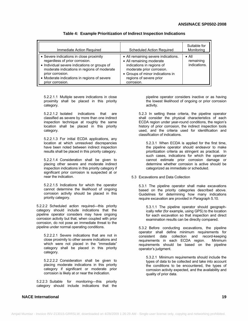
Table 4: Example Prioritization of Indirect Inspection Indications
Immediate Action Required Scheduled Action Required Suitable for Monitoring
• Severe indications in close proximity regardless of prior corrosion.
• Individual severe indications or groups of moderate indications in regions of moderate prior corrosion.
• Moderate indications in regions of severe prior corrosion.
• All remaining severe indications. • All remaining moderate
indications in regions of moderate prior corrosion.
• Groups of minor indications in regions of severe prior corrosion.
• All remaining indications.
z
5.2.2.1.1 Multiple severe indications in close proximity shall be placed in this priority category. 5.2.2.1.2 Isolated indications that are classified as severe by more than one indirect inspection technique at roughly the same location shall be placed in this priority category. 5.2.2.1.3 For initial ECDA applications, any location at which unresolved discrepancies have been noted between indirect inspection results shall be placed in this priority category. 5.2.2.1.4 Consideration shall be given to placing other severe and moderate indirect inspection indications in this priority category if significant prior corrosion is suspected at or near the indication. 5.2.2.1.5 Indications for which the operator cannot determine the likelihood of ongoing corrosion activity should be placed in this priority category.
5.2.2.2 Scheduled action required—this priority category should include indications that the pipeline operator considers may have ongoing corrosion activity but that, when coupled with prior corrosion, do not pose an immediate threat to the pipeline under normal operating conditions.
5.2.2.2.1 Severe indications that are not in close proximity to other severe indications and which were not placed in the “immediate” category shall be placed in this priority category. 5.2.2.2.2 Consideration shall be given to placing moderate indications in this priority category if significant or moderate prior corrosion is likely at or near the indication.
5.2.2.3 Suitable for monitoring—this priority category should include indications that the
International
- Invoice INV-213015-GRRSLW, downloaded on 4/28/2009 1:26:29
pipeline operator considers inactive or as having the lowest likelihood of ongoing or prior corrosion activity.
5.2.3 In setting these criteria, the pipeline operator shall consider the physical characteristics of each ECDA region under year-round conditions, the region’s history of prior corrosion, the indirect inspection tools used, and the criteria used for identification and classification of indications.
5.2.3.1 When ECDA is applied for the first time, the pipeline operator should endeavor to make prioritization criteria as stringent as practical. In such cases, indications for which the operator cannot estimate prior corrosion damage or determine whether corrosion is active should be categorized as immediate or scheduled.
5.3 Excavations and Data Collection
5.3.1 The pipeline operator shall make excavations based on the priority categories described above. Guidelines for determining how many indications require excavation are provided in Paragraph 5.10.
5.3.1.1 The pipeline operator should geograph-ically refer (for example, using GPS) to the location for each excavation so that inspection and direct examination results can be directly compared.
5.3.2 Before conducting excavations, the pipeline operator shall define minimum requirements for consistent data collection and record-keeping requirements in each ECDA region. Minimum requirements should be based on the pipeline operator’s judgment.
5.3.2.1 Minimum requirements should include the types of data to be collected and take into account the conditions to be encountered, the types of corrosion activity expected, and the availability and quality of prior data.
19
AM - Single-user license only, copying and networking prohibited.
ANSI/NACE SP0502-2008
20
5.
Amjad Mu
5.3.3 Data Collection⎯Prior to Coating Removal
5.3.3.1 The pipeline operator should include data taken prior to excavation, during each excavation, and after excavation but before coating removal. 5.3.3.2 Typical data measurements and related activities are listed below. Appendix A and Appendix B contain additional information.
5.3.3.2.1 Measurement of pipe-to-soil potentials 5.3.3.2.2 Measurement of soil resistivity 5.3.3.2.3 Soil sample collection 5.3.3.2.4 Water sample collection 5.3.3.2.5 Measurements of under-film liquid pH 5.3.3.2.6 Photographic documentation 5.3.3.2.7 Data for other integrity analyses such as MIC, SCC, etc.
5.3.3.3 The pipeline operator should increase the size (length) of each excavation, if conditions that indicate severe coating damage or significant corrosion defects beyond either side of the excavation are present.
4 Coating Damage and Corrosion Depth Measurements
5.4.1 The pipeline operator shall evaluate the condition of the coating and pipe wall at each excavation location, as described below. 5.4.2 Before making measurements, the pipeline operator shall define minimum requirements for consistent measurements and record-keeping requirements at each excavation.
5.4.2.1 Minimum requirements should include the types and accuracies of measurements to be made, taking into account the conditions to be encountered, the types of corrosion activity expected, and the availability and quality of prior measurement data. 5.4.2.2 For corrosion defects, minimum require-ments should include evaluation of all significant defects. The parameters of such a defect should be defined in terms of the remaining strength calculation to be used.
mtaz - Invoice INV-213015-GRRSLW, downloaded on 4/28/2009 1:26:2
5.4.3 Measurements 5.4.3.1 Typical measurements for evaluating the condition of the coating and the pipe are listed below. Appendix C (Nonmandatory) contains additional information.
5.4.3.1.1 Identification of coating type 5.4.3.1.2 Assessment of coating condition 5.4.3.1.3 Measurement of coating thickness 5.4.3.1.4 Assessment of coating adhesion 5.4.3.1.5 Mapping of coating degradation (blisters, disbondment, etc.) 5.4.3.1.6 Corrosion product data collection 5.4.3.1.7 Identification of corrosion defects 5.4.3.1.8 Mapping and measurement of corrosion defects 5.4.3.1.9 Photographic documentation
5.4.3.2 For initial ECDA applications, the pipeline operator should include all of the measurements listed in Paragraph 5.4.3.1. 5.4.3.3 Prior to identifying and mapping corrosion defects, the pipeline operator shall remove the coating and clean the pipe surface. 5.4.3.4 The pipeline operator shall measure and document all significant corrosion defects. Additional cleaning and pipe surface preparations should be made prior to depth and morphology measurements. 5.4.3.5 Other evaluations, unrelated to external corrosion, should be considered at this time. Such evaluations may include magnetic particle testing for cracks, ultrasonic thickness testing for internal defects, etc.
5.5 Remaining Strength Evaluation
5.5.1 The pipeline operator shall evaluate or calculate the remaining strength at locations where corrosion defects are found. Commonly used methods of calculating the remaining strength include ASME B31G,5 RSTRENG,6 and Det Norske Veritas (DNV)(3) Standard RP-F101.8
5.5.2 If the remaining strength of a defect is below the normally accepted level for the pipeline segment (e.g.,
____________________________ (3) Det Norske Veritas (DNV), Veritasveien 1, 1322 Høvik, Oslo, Norway.
NACE International
9 AM - Single-user license only, copying and networking prohibited.
ANSI/NACE SP0502-2008
Am
the maximum allowable operating pressure times a suitable factor for safety), a repair or replacement is required (or the MAOP may be lowered such that the MAOP times a suitable factor of safety is below the remaining strength). In addition, alternative methods of assessing pipeline integrity must be considered for the entire ECDA region in which the defect or defects were found unless the defect or defects are shown to be isolated and unique in a root-cause analysis (see Paragraphs 5.6.1 and 5.6.2).
5.5.2.1 The ECDA process helps find representative corrosion defects on a pipeline segment, but it may not find all corrosion defects on the segment. 5.5.2.2 If corrosion defects that exceed allowable limits are found, it should be assumed that other similar defects may be present elsewhere in the ECDA region.
5.6 Root-Cause Analysis
5.6.1 The pipeline operator shall identify any existing root cause of all significant corrosion activity. A root cause may include inadequate CP current, previously unidentified sources of interference, or other situations. 5.6.2 If the pipeline operator uncovers a root cause for which ECDA is not well suited, e.g., shielding by disbonded coating or biological corrosion, the pipeline operator shall consider alternative methods of assessing the integrity of the pipeline segment.
5.7 Mitigation
5.7.1 The pipeline operator shall identify and take remediation activities to mitigate or preclude future external corrosion resulting from significant root causes.
5.7.1.1 The pipeline operator may choose to repeat indirect inspections after remediation activities. 5.7.1.2 The pipeline operator may reprioritize indications based on remediation activities, as described below.
5.8 In-Process Evaluation
5.8.1 The pipeline operator shall perform an evaluation to assess the indirect inspection data and the results from the remaining strength evaluation and the root cause analyses. 5.8.2 The purpose of the evaluation is to assess the criteria used to categorize the need for repair critically (Paragraph 5.2) and the criteria used to classify the severity of individual indications (Paragraph 4.3.2).
NACE International
jad Mumtaz - Invoice INV-213015-GRRSLW, downloaded on 4/28/2009 1:26:2
5.8.3 Assess prioritization criteria
5.8.3.1 The pipeline operator shall assess the extent and severity of existing corrosion relative to the assumptions made in establishing priority categories for repair (Paragraph 5.2). 5.8.3.2 If existing corrosion is less severe than prioritized in Paragraph 5.2, the pipeline operator may modify the criteria and reprioritize all indications. 5.8.3.3 If existing corrosion is more severe than prioritized, the pipeline operator shall modify the criteria and reprioritize all indications.
5.8.3.4 Any indication for which comparable direct examination measurements show more serious conditions than suggested by the indirect inspection data shall be moved to a more severe priority category.
5.8.4 Assess classification criteria
5.8.4.1 The pipeline operator shall assess the corrosion activity at each excavation relative to the criteria used to classify the severity of indications (Paragraph 4.3.2). 5.8.4.2 If the corrosion activity is less severe than classified, the pipeline operator may reassess and adjust the criteria used to define the severity of all indications. In addition, the pipeline operator may reconsider and adjust the criteria used to prioritize the need for repair. For initial ECDA applications, the pipeline operator should not downgrade any classification or prioritization criteria. 5.8.4.3 If the corrosion activity is worse than classified, the pipeline operator shall reassess and appropriately adjust the criteria used to define the severity of all indications.
5.8.4.3.1 In addition, the pipeline operator shall consider the need for additional indirect inspections and reconsider and adjust the criteria used to prioritize the need for repair.
5.8.4.4 If repeated direct examinations show corrosion activity that is worse than indicated by the indirect inspection data, the pipeline operator should reevaluate the feasibility of successfully using ECDA.
5.9 Reclassification and Reprioritization
5.9.1 In accordance with Paragraph 5.8.3, reprioritization is required when existing corrosion is more severe than assumed in Paragraph 5.2.
21
9 AM - Single-user license only, copying and networking prohibited.
ANSI/NACE SP0502-2008
Amjad
5.9.1.1 In general, an indication that was originally placed in the immediate category should be moved no lower than the scheduled category as a result of reprioritization. 5.9.1.2 When ECDA is applied for the first time, the pipeline operator should not downgrade any indications that were originally placed in the immediate or scheduled priority category to a lower priority category.
5.9.2 In accordance with Paragraph 5.8.4, reclassification is required when results from the direct examination show corrosion activity that is worse than indicated by indirect inspection data. 5.9.3 In addition, for each root cause, the pipeline operator shall identify and reevaluate all other indications that occur in the pipeline segment where similar root-cause conditions exist. 5.9.4 If a repair and recoating or replacement is performed, the indication is no longer a threat to the pipeline and may be removed from further consideration, after completion of the root-cause analysis and mitigation activities required above. 5.9.5 If remediation is performed, an indication that was initially placed in the immediate priority category may be moved to the scheduled priority category, provided subsequent indirect inspections justify reducing the indication severity. 5.9.6 If remediation is performed, an indication that was initially placed in the scheduled priority category may be moved to the monitored priority category, if subsequent indirect inspections justify reducing the indication severity.
5.10 Guidelines for Determining the Required Number of Direct Examinations
5.10.1 In the event that no indications are identified in a pipeline segment, a minimum of one direct examination is required in the ECDA region identified as most likely for external corrosion in the Pre-Assessment Step. For initial ECDA applications, a minimum of two direct examinations shall be performed.
5.10.1.1 If more than one ECDA region was identified as likely for external corrosion in the Pre-Assessment Step, additional direct examinations should be considered. 5.10.1.2 The location(s) chosen for direct examination should be the location(s) identified in the Pre-Assessment Step as most likely for external corrosion within the ECDA region.
22
Mumtaz - Invoice INV-213015-GRRSLW, downloaded on 4/28/2009 1:26:29 AM
5.10.2 In the event that indications are identified, the following guidelines apply.
5.10.2.1 Immediate: All indications that are prioritized as immediate require direct examination.
5.10.2.1.1 The need to conduct direct examinations of indications that are reprioritized from immediate to scheduled may follow the guidelines for scheduled indications.
5.10.2.2 Scheduled: Some defects that are prioritized as scheduled require direct examination.
5.10.2.2.1 For all ECDA regions that contain scheduled indications but did not contain immediate indications, the pipeline operator may prioritize the indications based on indirect inspection data, historical corrosion records, and current corrosive conditions. After prioritizing, the pipeline operator must, at a minimum, perform a direct examination of the most severe of scheduled indications. When ECDA is applied for the first time, a minimum of two direct examinations shall be performed. 5.10.2.2.2 If an ECDA region contains scheduled indications and it contained one or more immediate indications, at least one scheduled indication must be subjected to direct examination in the ECDA region at the location considered most severe by the pipeline operator. When ECDA is applied for the first time, a minimum of two additional direct examinations shall be performed. 5.10.2.2.3 If the results of an excavation at a scheduled indication show corrosion that is deeper than 20% of the original wall thickness and that is deeper or more severe than at an immediate indication, at least one more direct examination is required. When ECDA is applied for the first time, a minimum of two additional direct examinations shall be performed.
5.10.2.3 Monitored: Defects in the monitored category may or may not require excavation.
5.10.2.3.1 If an ECDA region contains monitored indications but the ECDA region did not contain any immediate or scheduled indications, one excavation is required in the ECDA region at the most severe indication. When ECDA is applied for the first time, a minimum of two direct examinations shall be performed.
NACE International
- Single-user license only, copying and networking prohibited.
ANSI/NACE SP0502-2008
NACE Inte
Amjad Mumtaz - Invo
5.10.2.3.2 If multiple ECDA regions contain monitored indications but did not contain any immediate or scheduled indications, one excavation is required in the ECDA region
rnational
______________________________________________________
ice INV-213015-GRRSLW, downloaded on 4/28/2009 1:26:29 AM - Single-u
identified as most likely for external corrosion in the Pre-Assessment Step. For initial ECDA applications, a minimum of two direct examinations shall be performed.
__________________________
Section 6: Post Assessment
6.1 Introduction6.1.1 The objectives of the Post-Assessment Step are to define reassessment intervals and assess the overall effectiveness of the ECDA process. 6.1.2 Reassessment intervals shall be defined on the basis of scheduled indications.
6.1.2.1 All immediate indications shall have been addressed during direct examinations. 6.1.2.2 Monitored indications are expected to experience insignificant growth.
6.1.3 The conservatism of the reassessment interval is not easy to measure, because there are uncertainties in the remaining flaw sizes, the maximum corrosion growth rates, and the periods of a year in which defects grow by corrosion. To account for these uncertainties, the reassessment interval defined herein is based on a half-life concept. An estimate of the true life is made, and the reassessment interval is set at half that value.
6.1.3.1 Basing reassessment intervals on a half-life concept is commonly used in engineering practice.1 6.1.3.2 The estimate of true life is based on conservative growth rates and conservative growing periods. 6.1.3.3 To ensure unreasonably long reassessment intervals are not used, the pipeline operator should define a maximum reassessment interval that cannot be exceeded unless all indications are addressed. Documents such as ASME B31.4,1 ASME B31.8,2,3 and API 11604 may provide guidance.
6.1.4 The Post-Assessment Step includes the following activities, as shown in Figure 7.
6.1.4.1 Remaining life calculations;
6.1.4.2 Definition of reassessment intervals; 6.1.4.3 Assessment of ECDA effectiveness; and 6.1.4.4 Feedback.
6.2 Remaining Life Calculations
6.2.1 If no corrosion defects are found, no remaining life calculation is needed: the remaining life can be taken as the same as for a new pipeline. 6.2.2 The maximum remaining flaw size at all scheduled indications shall be taken as the same as the most severe indication in all locations that have been excavated (see Section 5).
6.2.2.1 If the root-cause analyses indicate that the most severe indication is unique, the size of the next most severe indication may be used for the remaining-life calculations.
6.2.2.2 As an alternative, a pipeline operator may substitute a different value based on a statistical or more sophisticated analysis of the excavated severities.
6.2.3 The corrosion growth rate shall be based on a sound engineering analysis.
6.2.3.1 When the operator has measured corrosion rate data that are applicable to the ECDA region(s) being evaluated, actual rates may be used. 6.2.3.2 In the absence of measured corrosion rate data, the values and methods provided in Appendix D should be used for rate estimates. These corrosion rates have been based on the free corrosion of ferrous material in various soil types.
6.2.4 The remaining life of the maximum remaining flaw shall be estimated using a sound engineering analysis.
23
ser license only, copying and networking prohibited.
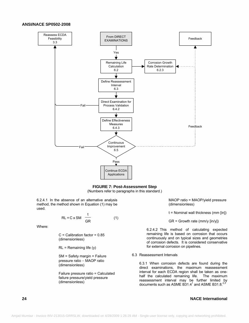
ANSI/NACE SP0502-2008
24
Amjad Mumtaz
Yes
From DIRECTEXAMINATIONS Feedback
Remaining LifeCalculation
6.2
Corrosion GrowthRate Determination
6.2.3
Define ReassessmentInterval
6.3
Define EffectivenessMeasures
6.4.3
ContinuousImprovement
6.5
Continue ECDAApplications
Pass
Fail
Reassess ECDAFeasibility
3.3
Feedback
Direct Examination forProcess Validation
6.4.2Fail
FIGURE 7: Post-Assessment Step (Numbers refer to paragraphs in this standard.)
6.2.4.1 In the absence of an alternative analysis method, the method shown in Equation (1) may be used.
GR
t SM x C = RL (1)
Where:
C = Calibration factor = 0.85 (dimensionless) RL = Remaining life (y) SM = Safety margin = Failure pressure ratio – MAOP ratio (dimensionless) Failure pressure ratio = Calculated failure pressure/yield pressure (dimensionless)
- Invoice INV-213015-GRRSLW, downloaded on 4/28/2009 1:26:2
MAOP ratio = MAOP/yield pressure (dimensionless) t = Nominal wall thickness (mm [in]) GR = Growth rate (mm/y [in/y])
6.2.4.2 This method of calculating expected remaining life is based on corrosion that occurs continuously and on typical sizes and geometries of corrosion defects. It is considered conservative for external corrosion on pipelines.
6.3 Reassessment Intervals
6.3.1 When corrosion defects are found during the direct examinations, the maximum reassessment interval for each ECDA region shall be taken as one-half the calculated remaining life. The maximum reassessment interval may be further limited by documents such as ASME B31.41 and ASME B31.8.2,3
NACE International
9 AM - Single-user license only, copying and networking prohibited.
ANSI/NACE SP0502-2008
6
Amjad
6.3.2 Different ECDA regions may have different reassessment intervals based on variations in expected growth rates between ECDA regions. 6.3.3 Any indications that are scheduled for evaluation should be addressed before the end of the reassessment interval.
6.4 Assessment of ECDA Effectiveness
6.4.1 ECDA is a continuous improvement process. Through successive ECDA applications, a pipeline operator should be able to identify and address locations at which corrosion activity has occurred, is occurring, or may occur. 6.4.2 At least one additional direct examination at a randomly selected location shall be conducted to provide additional confirmation that the ECDA process has been successful.
6.4.2.1 For initial ECDA applications, at least two additional direct examinations are required for process validation. The direct examinations shall be conducted at randomly selected locations, one of which is categorized as scheduled (or monitored if no scheduled indications exist) and one in an area where no indication was detected. 6.4.2.2 If conditions that are more severe than determined during the ECDA process (i.e., that result in a reassessment interval less than determined during the ECDA process) are detected, the process shall be reevaluated and repeated or an alternative integrity assessment method used.
6.4.3 The pipeline operator shall establish additional criteria for assessing the long-term effectiveness of the ECDA process.
6.4.3.1 An operator may choose to establish criteria that track the reliability or repeatability with which the ECDA process is applied. For example,
6.4.3.1.1 An operator may track the number of reclassifications and reprioritizations that occur during an ECDA process. A significant percentage of indications that are reclassified or reprioritized indicates the criteria established by the operator may be unreliable.
6.4.3.2 An operator may choose to establish criteria that track the application of the ECDA process. For example,
6.4.3.2.1 An operator may track the number of excavations made to investigate potential problems. An increase in excavations
NACE International
Mumtaz - Invoice INV-213015-GRRSLW, downloaded on 4/28/2009 1:26:29 A
indicates more aggressive corrosion monitoring. 6.4.3.2.2 An operator may track the total number of miles of pipeline that are subjected to multiple indirect inspections. An increase in mileage inspected indicates the need for more aggressive corrosion monitoring. 6.4.3.2.3 Similarly, an operator may track the mileage subjected to each indirect inspection methodology, seeking to increase the mileage used by the methods that prove most effective on the operator’s system. An increase in the use of techniques that are most effective indicates a more focused ECDA application.
6.4.3.3 An operator may choose to establish criteria that track the results of the ECDA process. For example,
6.4.3.3.1 The operator may choose to assess effectiveness by comparing the frequency at which immediate and scheduled indications arise. A reduction in frequency indicates an improved net management of corrosion. 6.4.3.3.2 The operator may monitor the extent and severity of corrosion found during direct examinations. A decrease in extent and severity indicates a reduction in the impact of corrosion on the structural integrity of a pipeline. 6.4.3.3.3 The operator may monitor the frequency at which CP anomalies occur along pipeline segments. A decrease in anomalies indicates better management of the CP system.
6.4.3.4 An operator may choose to establish absolute criteria. For example,
6.4.3.4.1 The operator may establish a minimum performance requirement that no leak or rupture due to external corrosion will occur after an ECDA application and before the next reassessment interval. Meeting such a criterion demonstrates integrity with regard to corrosion.
6.4.4 In the event that evaluation does not show improvement between ECDA applications, the pipeline operator should reevaluate the ECDA application or consider alternative methods of assessing pipeline integrity.
.5 Feedback and Continuous Improvement
6.5.1 Throughout the ECDA process, as well as during scheduled activities and reassessments, the pipeline
25
M - Single-user license only, copying and networking prohibited.
ANSI/NACE SP0502-2008
26
Amjad Mu
operator shall endeavor to improve the ECDA applications by incorporating feedback at all appropriate opportunities. 6.5.2 Activities for which feedback should be considered include:
6.5.2.1 Identification and classification of indirect inspection results (Paragraphs 4.3.2 through 4.3.4); 6.5.2.2 Data collection from direct examinations (Paragraphs 5.3 and 5.4); 6.5.2.3 Remaining strength analyses (Paragraph 5.5);
_____________________________________________
mtaz - Invoice INV-213015-GRRSLW, downloaded on 4/28/2009 1:26:29 AM - Sin
6.5.2.4 Root-cause analyses (Paragraph 5.6); 6.5.2.5 Remediation activities (Paragraph 5.7); 6.5.2.6 In-process evaluations (Paragraph 5.8); 6.5.2.7 Direct examinations used for process validation (Paragraph 6.4.2); 6.5.2.8 Criteria for monitoring long-term ECDA effectiveness (Paragraph 6.4.3); and 6.5.2.9 Scheduled monitoring and period reassessments.
___________________________
Section 7: ECDA Records
7.1 Introduction7.1.1 This section describes ECDA records that document in a clear, concise, workable manner data that are pertinent to pre-assessment, indirect inspection, direct examination, and post assessment.
7.2 Pre-Assessment Documentation
7.2.1 All Pre-Assessment Step actions should be recorded. This may include but is not limited to the following:
7.2.1.1 Data elements collected for the segment to be evaluated, in accordance with Table 1. 7.2.1.2 Methods and procedures used to integrate the data collected to determine when indirect inspection tools can and cannot be used. 7.2.1.3 Methods and procedures used to select the indirect inspection tools. 7.2.1.4 Characteristics and boundaries of ECDA regions and the indirect inspection tools used in each region.
7.3 Indirect Inspection
7.3.1 All indirect inspection actions should be recorded. This may include but is not limited to the following:
7.3.1.1 Geographically referenced locations of the beginning and ending point of each ECDA region and each fixed point used for determining the location of each measurement.
7.3.1.2 Date(s) and weather conditions under which the inspections were conducted. 7.3.1.3 Inspection results at sufficient resolution to identify the location of each indication.
7.3.1.3.1 When data are not recorded in a (near) continuous fashion, a complete description of the conditions between the locations of indications (epicenters).
7.3.1.4 Procedures for aligning data from the indirect inspections and expected errors for each inspection tool. 7.3.1.5 Procedures for defining the criteria to be used in prioritizing the severity of the indications.
7.4 Direct Examinations
7.4.1 All direct examination actions should be recorded. This may include but is not limited to the following:
7.4.1.1 Procedures and criteria for prioritizing the indirect inspection indications. 7.4.1.2 Data collected before and after excavation.
7.4.1.2.1 Measured metal-loss corrosion geometries. 7.4.1.2.2 Data used to identify other areas that may be susceptible to corrosion. 7.4.1.2.3 Data used to estimate corrosion growth rates.
NACE International
gle-user license only, copying and networking prohibited.
ANSI/NACE SP0502-2008
Amja
7.4.1.3 Results of root-cause identifications and analyses, if any.
7.4.1.3.1 Planned mitigation activities.
7.4.1.4 Descriptions of and reasons for any reprioritizations.
7.5 Post Assessment
7.5.1 All post-assessment actions should be recorded. This may include but is not limited to the following:
7.5.1.1 Remaining-life calculation results:
7.5.1.1.1 Maximum remaining flaw size determinations. 7.5.1.1.2 Corrosion growth rate deter-minations.
NACE International
___________________________________________
d Mumtaz - Invoice INV-213015-GRRSLW, downloaded on 4/28/2009 1:26:29 AM -
7.5.1.1.3 Method of estimating remaining life. 7.5.1.1.4 Results.
7.5.1.2 Reassessment intervals and scheduled activities, if any. 7.5.1.3 Criteria used to assess ECDA effectiveness and results from assessments.
7.5.1.3.1 Criteria and metrics. 7.5.1.3.2 Data from periodic assessments.
7.5.1.4 Feedback
7.5.1.4.1 Assessment of criteria used in each step of the ECDA process. 7.5.1.4.2 Modifications of criteria.
_____________________________
References
1. ANSI(4)/ASME B 31.4 (latest revision), “Pipeline Transportation Systems for Liquid Hydrocarbons and Other Liquids” (New York, NY: ASME). 2. ANSI/ASME B 31.8 (latest revision), “Gas Transmission and Distribution Piping Systems” (New York, NY: ASME). 3. ANSI/ASME B 31.8 Update (latest revision), “Gas Transmission and Distribution Piping Systems” (New York, NY: ASME). 4. API Standard 1160 (latest revision), “Managing System Integrity for Hazardous Liquid Pipelines” (Washington, DC: API). 5. ANSI/ASME B 31G (latest revision), “Manual for Determining the Remaining Strength of Corroded Pipelines: A Supplement to B31, Code for Pressure Piping” (New York, NY: ASME). 6. P.H. Vieth, J.F. Kiefner, RSTRENG2 (DOS Version) User’s Manual and Software (Includes: L51688B, Modified Criterion for Evaluating the Remaining Strength of Corroded Pipe) (Washington, DC: PRCI,(5) 1993). 7. J.M. Pearson, “Electrical Instruments and Measurement in Cathodic Protection,” CORROSION 3, 11 (1947): p. 549.8. DNV Standard RP-F101 (latest revision), “Corroded Pipelines” (Oslo, Norway: Det Norske Veritas). 9. NACE/CEA(6) Report 54277 (latest revision), “Specialized Surveys for Buried Pipelines” (Houston, TX: NACE and the Institute of Corrosion (ICorr). 10. NACE Standard TM0497 (latest revision, “Measurement Techniques Related to Criteria for Cathodic Protection on Underground or Submerged Metallic Piping Systems” (Houston, TX: NACE). 11. NACE SP0169 (latest revision), “Control of External Corrosion on Underground or Submerged Metallic Piping Systems” (Houston, TX: NACE). 12. NACE SP0177 (latest revision), “Mitigation of Alternating Current and Lightning Effects on Metallic Structures and Corrosion Control Systems” (Houston, TX: NACE). 13. ASTM(7) G 57, “Standard Test Method for Field Measurement of Soil Resistivity Using the Wenner Four-Electrode Method” (West Conshohocken, PA: ASTM).
____________________________ (4) American National Standards Institute (ANSI), 1819 L St. NW, Washington, DC 20036. (5) Pipeline Research Council International, Inc. (PRCI), 1401 Wilson Blvd, Suite 1101, Arlington, VA 22209. (6) Corrosion Engineering Association (CEA), now known as the Institute of Corrosion (Icorr), Corrosion House, Vimy Court, Leighton Buzzard, Bedfordshire, UK LU71FG. (7) ASTM International (ASTM), 100 Barr Harbor Dr., West Conshohocken, PA 19428.
27
Single-user license only, copying and networking prohibited.
ANSI/NACE SP0502-2008
Amjad
14. ASTM D 2487 (latest revision), “Standard Classification of Soils for Engineering Purposes (Unified Soil Classification System” (West Conshohocken, PA: ASTM). 15. AASHTO(8) Method T 265 (latest revision), “Standard Method of Test for Laboratory Determination of Moisture Content of Soils” (Washington, DC: AASHTO). 16. EPA(9) 376.1 (latest revision), “Standard Operating Procedure for the Analysis of Sulfide in Water (Titrimetric)” (Washington, DC: EPA). 17. ASTM D 1125 (latest revision), “Standard Test Methods for Electrical Conductivity and Resistivity of Water” (West Conshohocken, PA: ASTM). 18. ASTM D 4972 (latest revision), “Standard Test Method for pH of Soils” (West Conshohocken, PA: ASTM). 19. ASTM D 512 (latest revision), “Standard Test Methods for Chloride Ion in Water” (West Conshohocken, PA: ASTM).
28
_______________________________________
Mumtaz - Invoice INV-213015-GRRSLW, downloaded on 4/28/2009 1:26:29
20. ASTM D 516 (latest revision), “Standard Test Method for Sulfate Ions in Water” (West Conshohocken, PA: ASTM). 21. M. Romanoff, Underground Corrosion (Houston, TX: NACE, 1969 [reprinted 1989]). 22. ASTM G 59 (latest revision), “Standard Test Method for Conducting Potentiodynamic Polarization Resistance Measurements” (West Conshohocken, PA: ASTM). 23. M. Stern, A.S. Geary, Journal of the Electrochemical Society 104, 56 (1957). 24. ASTM G 102 (latest revision), “Standard Practice for Calculation of Corrosion Rates and Related Information from Electrochemical Measurements” (West Conshocken, PA: ASTM). 25. NACE Standard TM0169 (latest revision), “Laboratory Corrosion Testing of Metals” (Houston, TX: NACE).
_________________________________
Bibliography
API Specification 5L (latest revision), “Specification for LinePipe” (Washington, DC: API). API Standard 510 (latest revision), “Pressure Vessel
Inspection Code” (Washington, DC: API). Baboian, R. Corrosion Tests and Standards: Application
and Interpretation. Houston, TX: NACE, 1995. Baboian, R. Electrochemical Techniques for Corrosion
Engineering. Houston, TX: NACE, 1986. GPTC Technical Report 2000-19, “Review of Integrity
Management for Gas Transmission Pipelines.” New York, NY: ANSI Gas Piping Technology Committee (GPTC), 2000.
Lawson, K.M., and N.G. Thompson. “The Use of Coupons
for Monitoring the Cathodic Protection of Buried Structures.,” CORROSION/98, paper no. 672. Houston, TX: NACE, 1998.
NACE Standard RP0102 (latest revision). “In-Line Inspection of Pipelines.” Houston, TX: NACE.
NACE Publication 35100 (latest revision). “In-Line
Nondestructive Inspection of Pipelines.” Houston, TX: NACE.
NACE Publication 3T199 (latest revision). “Techniques for
Monitoring Corrosion and Related Parameters in Field Applications.” Houston, TX: NACE.
Peabody, A.W. Control of Pipeline Corrosion, 2nd ed. R.
Bianchetti, ed. Houston, TX: NACE, 2001. U.S. Code of Federal Regulations (CFR) Title 49.
“Transportation of Natural and Other Gas by Pipeline: Minimum Federal Safety Standards.” Part 192. Washington, DC: Office of the Federal Register, 1995.
U.S. Code of Federal Regulations (CFR) Title 49.
Transportation of Hazardous Liquids by Pipeline, Part 195. Washington, DC: Office of the Federal Register, 1995.
____________________________ (8) American Association of State Highway and Transportation Officials (AASHTO), 444 N Capitol St. NW, Suite 249, Washington, DC 20001. (9) U.S. Environmental Protection Agency (EPA), Ariel Rios Building, 1220 Pennsylvania Ave. NW, Washington, DC 20460.
NACE International
AM - Single-user license only, copying and networking prohibited.
ANSI/NACE SP0502-2008
NACE International
________________________________________________________________________
Amjad Mumtaz - Invoice INV-213015-GRRSLW, d
Appendix A: Indirect Inspection Methods
(Nonmandatory)
A1 IntroductionA1.1 This appendix describes the following methods of conducting indirect inspections. Other indirect inspection methods can and should be used as required by the unique situations along a pipeline. The techniques described herein are not intended to illustrate the only methods by which these tools can be applied. Rather, they demonstrate methods that have proved successful in the past. (Note that commercial products are not described in this appendix.)
A1.1.1 Close-interval surveys (CIS) are typically used to determine CP levels, shorts to other structures, and stray current areas. However, they are limited in detecting small coating holidays. A1.1.2 AC current attenuation surveys are typically used to assess coating quality and to detect and compare discrete coating anomalies. This technique does not require electrical contact with the soil and can often be used to gather information through magnetically transparent covers, such as ice, water, and concrete. A1.1.3 DCVG and ACVG surveys are typically used to detect small to large holidays. They are sometimes used to determine whether a region is anodic or cathodic, but they cannot determine CP levels. Small, isolated coating holidays associated with corrosion or third-party damage can sometimes be found, when survey crews are specifically asked to investigate small indications that ordinarily are considered inconsequential. A1.1.4 Pearson7 surveys are typically used to detect various coating holidays but cannot differentiate the size of each holiday. A1.1.5 Cell-to-cell surveys, which are similar to DCVG and ACVG techniques, are typically used on bare or poorly coated pipelines to determine corrosive or current discharge areas. These techniques are also applicable to electrically discontinuous pipelines.
A1.2 Basic Limitations A1.2.1 Shielding by Disbonded Coatings⎯None of these indirect inspection tools is capable of detecting problems that are shielded by disbonded coatings with no electrically continuous path to the soil. If there is an electrically continuous pathway to the soil, such as through a small holiday or orifice, some tools may detect problem areas. Pinholes are problematic with nearly all tools.
ownloaded on 4/28/2009 1:26:29
A1.2.2 Pipe Depths⎯All of the indirect inspection tools are less sensitive when pipe burials exceed normal depths. Field conditions and terrain may affect depth ranges and detection sensitivity. A1.2.3 Bare Pipe
A1.2.3.1 The key difference between ECDA methodology for coated and bare or poorly coated pipelines is that fewer indirect inspection tools are available for bare or poorly coated pipeline systems. A1.2.3.2 Bare underground pipelines are typically categorized into cathodically protected or nonprotected. A cathodically protected bare pipeline system is electrically continuous and has test leads installed for electrical measurements. A1.2.3.3 Nonprotected bare steel pipeline systems may not be electrically continuous and typically do not have test leads. Because of these differences, nonprotected bare steel pipelines may have even fewer indirect inspection tools available, unless steps are taken to provide continuity and test leads.
A1.3 Additional information regarding the techniques cited in this appendix can be found in the latest revisions of the following documents.
A1.3.1 NACE/CEA Report 542779
A1.3.2 NACE Standard TM049710
A1.3.3 NACE SP016911
A2 Safety Considerations
A2.1 Appropriate safety precautions, including the following procedures, should be observed when electrical measurements are made.
A2.1.1 Be knowledgeable and qualified in electrical safety precautions before installing, adjusting, repairing, removing, or testing impressed current protection equipment. A2.1.2 Use properly insulated test lead clips and terminals to avoid contact with an unanticipated high voltage (HV). Attach test clips one at a time using a single-hand technique for each connection.
29
AM - Single-user license only, copying and networking prohibited.
ANSI/NACE SP0502-2008
Amjad
A2.1.3 Use caution when long test leads are extended near overhead high-voltage alternating current (HVAC) power lines, which can induce hazardous voltages onto the test leads. High-voltage direct current (HVDC) power lines do not induce voltages under normal operation, but transient conditions may cause hazardous voltages.
A2.1.3.1 Refer to NACE SP017712 for additional information about electrical safety.
A2.1.4 Use caution when making tests at electrical isolation devices. Before proceeding with further tests, use appropriate voltage detection instruments or voltmeters with insulated test leads to determine whether hazardous voltages may exist. A2.1.5 Avoid testing when thunderstorms are in the area. Remote lightning strikes can create hazardous voltage surges that travel along the pipe under test. A2.1.6 Use caution when stringing test leads across streets, roads, and other locations subject to vehicular and pedestrian traffic. When conditions warrant, use appropriate barricades, flagging, and flag persons. A2.1.7 Before entering, inspect excavations and confined spaces to determine that they are safe. Inspections may include shoring requirements for excavations and testing for hazardous atmospheres in confined spaces. A2.1.8 Observe appropriate company safety procedures, electrical codes, and applicable safety regulations.
A3 Instrumentation and Measurement Guidelines
A3.1 Electrical measurements require proper selection and use of instruments. Pipe-to-electrolyte potential, voltage drop, potential difference, and similar measurements require instruments that have appropriate voltage ranges. The user should know the capabilities and limitations of the equipment, follow the manufacturer’s instruction manual, and be skilled in the use of electrical instruments. Failure to select and use instruments correctly causes errors during the indirect inspection measurements.
A3.1.1 Analog instruments are usually specified in terms of input resistance or internal resistance. This is usually expressed as ohms per volt of full meter scale deflection. A3.1.2 Digital instruments are usually specified in terms of input impedance expressed as megaohms.
30
Mumtaz - Invoice INV-213015-GRRSLW, downloaded on 4/28/2009 1:26:29 AM
A3.2 Factors that may influence instrument selection for field testing include:
• Input impedance (digital instruments);
• Input resistance or internal resistance (analog instruments);
• Sensitivity;
• Conversion speed of analog-to-digital converters
used in digital or data-logging instruments;
• Accuracy;
• Instrument resolution;
• Ruggedness;
• Alternating current (AC) and radio frequency (RF) signal rejection; and
• Temperature and climate limitations. A3.2.1 Some instruments are capable of measuring and processing voltage readings many times per second. Evaluation of the input waveform processing may be required if an instrument does not give consistent results. A3.2.2 Measurement of pipe-to-electrolyte poten-tials on pipelines affected by dynamic stray currents may require the use of recording or analog instruments to improve measurement accuracy. Dynamic stray currents include those from electric railway systems, HVDC transmission systems, mining equipment, and telluric currents.
A3.3 Instrument Effects on Voltage Measurements
A3.3.1 To measure pipe-to-electrolyte potentials accurately, a digital voltmeter should have a high input impedance (high internal resistance, for an analog instrument) compared with the total resistance of the measurement circuit.
A3.3.1.1 An input impedance of 10 MΩ or more should be sufficient for a digital meter. An instrument with a lower input impedance may produce valid data if circuit contact errors are considered. One means of making accurate measurements is to use a potentiometer circuit in an analog meter. A3.3.1.2 A voltmeter measures the potential across its terminals within its design accuracy. However, current flowing through the instrument creates measurement errors due to voltage drops that occur in all resistive components of a measurement circuit.
NACE International
- Single-user license only, copying and networking prohibited.
ANSI/NACE SP0502-2008
Amjad
A3.3.2 Some analog-to-digital converters used in digital and datalogging instruments operate so fast that the instrument may indicate only a portion of the input waveform and thus provide incorrect voltage indications. A3.3.3 Parallax errors on an analog instrument can be minimized by viewing the needle perpendicular to the face of the instrument on the center line projected from the needle point. A3.3.4 The accuracy of potential measurements should be verified by using an instrument with two or more input impedances (internal resistance, for analog instruments) and comparing potential values measured using different input impedances. If the measured values are virtually the same, the accuracy is acceptable. Corrections should be made if measured values are not virtually identical. Digital voltmeters that have a constant input impedance do not indicate a measurement error by changing voltage ranges. An alternative is to use a meter with a potentiometer circuit.
A3.4 Instrument Accuracy
A3.4.1 Instruments should be checked for accuracy before use by comparing readings to a standard voltage cell, to another acceptable voltage source, or to another appropriate instrument known to be accurate.
A4 Close-Interval Surveys (CIS)
A4.1 Applicability
A4.1.1 CIS, which are sometimes referred to as pipe-to-soil and potential gradient surveys, are applicable to all buried pipelines with earthen cover. When the pipeline is under concrete or asphalt, the contact resistance between the reference cell and the soil may affect the measurements. Therefore, precautions should be taken to ensure accurate readings, such as by drilling holes to facilitate contact with the underlying soil. A4.1.2 CIS are used to measure the potential difference between the pipe and earth. Data from CIS are generally used to assess the performance and operation of the CP system. CIS can also be used to detect some coating holidays. A4.1.3 Other Conditions and Anomalies: While other indirect inspection tools may be better suited, CIS also aid in identifying:
A4.1.3.1 Interference, A4.1.3.2 Shorted casings,
NACE International
Mumtaz - Invoice INV-213015-GRRSLW, downloaded on 4/28/2009 1:26:29 AM
A4.1.3.3 Areas of electrical or geologic current shielding, A4.1.3.4 Contact with other metallic structures, and A4.1.3.5 Defective electrical isolation joints.
A4.1.4 There are various types of CIS including on/off potential surveys, depolarized potential surveys, and on potential surveys.
A4.2 On/Off Potential Survey.
A4.2.1 On/off potential surveys are used to evaluate CP system performance in accordance with CP criteria and to detect some coating anomalies. A4.2.2 On/off surveys measure the potential difference between the pipe and the ground surface as the CP current is switched on and off.
A4.2.2.1 On/off surveys rely on electronically synchronized current interrupters at each CP current source, bond, and other current drain point that influences the pipeline potential in the survey area (synchronization is not required when there is only one current source on the line). Typical interrupter cycles are 8 seconds on, 2 seconds off; or 800 milliseconds on, 200 milliseconds off. The ratio of on-to-off should be long enough for readings to be made but short enough to avoid significant depolarization. A4.2.2.2 Reference cells are placed directly over the pipeline at close intervals (0.76 to 1.5 m [2.5 to 5 ft]). A4.2.2.3 On and off potentials are recorded with a handheld computer, data logger, or other method. A4.2.2.4 The accuracy of the on and off data is typically verified using the following techniques:
A4.2.2.4.1 Wave form capture and analysis, A4.2.2.4.2 Digital oscilloscope, and A4.2.2.4.3 Digitized signal equipment.
A4.2.2.5 In addition to on and off data, pipe-to-soil potential wave prints are often recorded at aboveground test stations at regular intervals (e.g., several times each day) to verify that the interrupters are
31
- Single-user license only, copying and networking prohibited.
ANSI/NACE SP0502-2008
32
Amjad Mu
synchronized. The wave print locations are documented to correlate with the survey data. These data can then be used to determine the presence of sources of error from:
A4.2.2.5.1 Line current flow, A4.2.2.5.2 Scale accuracy, A4.2.2.5.3 Potential spiking, A4.2.2.5.4 Interrupter synchronization drift, A4.2.2.5.5 Stray DC earth currents, and A4.2.2.5.6 Voltage signal noise.
A4.3 Depolarized Potential Surveys
A4.3.1 Depolarized potential surveys are used to evaluate the effectiveness of the CP system with respect to a polarization decay criterion. The surveys are often performed in conjunction with on/off potential surveys. A4.3.2 Depolarized potential surveys measure the potential difference between the pipe and the ground surface after the cathodic current has been switched off long enough for the pipe-to-soil potential to stabilize.
A4.3.2.1 All CP current sources, such as transformer-rectifiers or other DC power supplies, are de-energized by either breaking critical bonds or adjusting them so that they overcome interference effects while not providing additional CP. A4.3.2.2 The pipeline is allowed to depolarize until a plot of potential versus time indicates that the pipe-to-soil potential is no longer decaying. A4.3.2.3 Reference cells are placed over the pipeline at intervals similar to those used in on/off potential surveys (e.g., 0.76 to 1.5 m [2.5 to 5 ft]). A4.3.2.4 The depolarized potentials are recorded with a computer, data logger, or by hand. Data are typically plotted in conjunction with on/off potential survey data for calculation of the polarization shift.
A4.4 On Potential Surveys
A4.4.1 On potential surveys are used on pipelines protected with CP current sources that cannot be interrupted.
mtaz - Invoice INV-213015-GRRSLW, downloaded on 4/28/2009 1:26:29 A
A4.4.2 On potential surveys are performed by measuring the potential difference between the pipe and the ground surface above the pipe at regular intervals while the CP is operating in its normal mode.
A4.4.2.1 Reference cells are placed over the pipeline at intervals similar to those used in on/off potential surveys (e.g., 0.76 to 1.5 m [2.5 to 5 ft]). A4.4.2.2 On potentials are recorded with a handheld computer or by hand.
A4.5 Typical Methodology for Close-Interval Potential Surveys
A4.5.1 An insulated wire is electrically connected to a test station, valve, or other electrically continuous pipeline appurtenance and one terminal of the voltmeter. The other terminal of the voltmeter is attached to the reference electrode to be used for the potential measurements.
A4.5.1.1 Industry standard copper/copper sulfate reference electrodes (CSE) are commonly used for potential measurements. See NACE Standard TM0497.10
A4.5.2 The pipeline is located with a pipe locator prior to collecting data to ensure that the reference electrode is placed directly over the line.
A4.5.2.1 Marsh and water crossings, which cannot be walked, are typically located by the line-of-sight method, using pipeline markers and pipeline appurtenances. Magnetometers are also employed for greater accuracy.
A4.5.3 One of two types of current interrupters is typically used (for on/off potential surveys).
A4.5.3.1 Standard electronic synchronized: Standard units include 30-, 60-, or 100-A capacity AC/DC, AC, or battery-powered units with electronic synchronization. High-quality quartz crystal controlled timing provides a minimum 0.5-s accuracy in 24 h. A4.5.3.2 Global positioning system (GPS) Synchronized: The GPS units include 30-, 60-, or 100-A capacity AC/DC, 115-V AC, or DC battery-powered unit with GPS synchro-nization.
A4.5.4 Potentials are measured at close intervals using a high-input impedance voltmeter.
A4.5.4.1 Potential measurements are also taken at each test station, rectifier, highway
NACE International
M - Single-user license only, copying and networking prohibited.
ANSI/NACE SP0502-2008
Amjad
casing, railroad casing, and foreign pipeline crossing. A4.5.4.2 Near ground and far ground on/off potential measurements are recorded at each point of pipeline connection.
A4.5.5 A footage counter or other means is used to measure distance along the pipeline. The maximum variation between distance indicated and the wire dispensed is commonly specified as ±1 m per km (5 ft per mi) or less than 0.1%.
A4.5.5.1 Potential measurements above the pipe are recorded as a function of distance. A4.5.5.2 All permanent landmarks are identified and listed along with their appropriate locations.
A4.6 Interpretation of Data A4.6.1 The performance of the CP system is assessed by comparing the measured potentials along the pipe. Typical quantities used to assess performance include the measured potentials, changes in potentials along the pipe, separation distances between on, off, and depolarized potentials, and other signal features. A4.6.2 The component of the potential difference due to an IR drop can sometimes be used to detect coating holidays. The IR drop decreases in close proximity to a coating holiday, thereby reducing the absolute value of the potential. A4.6.3 When a potential gradient is measured, the gradient field is used to identify coating holidays.
A5 AC Current Attenuation Survey (Electromagnetic)
A5.1 Applicability A5.1.1 AC current attenuation surveys are used to provide an assessment of the overall quality of the pipe coating section by section and to identify coating holidays. A current is applied to the pipeline, and coating damage is located and prioritized according to the magnitude and change of current attenuation.
A5.1.1.1 When these connections are under ground, the field engineer can modify the system by installing aboveground junction boxes to allow the anodes or bonds to be disconnected in the future.
A5.1.2 AC current attenuation surveys can be performed with impressed current CP systems energized. Sacrificial anodes and bonds that are
NACE International
Mumtaz - Invoice INV-213015-GRRSLW, downloaded on 4/28/2009 1:26:29 AM -
not disconnected show up as anomalies. Sacrificial anodes and bonds to other structures are usually disconnected to prevent signal loss and enhance current flow down the pipeline. By turning off the rectifier and using the positive and negative leads at the rectifier station, signal generation capabilities of the equipment can be maximized. A5.1.3 AC current attenuation surveys can be used for pipelines under any type of magnetically transparent cover, such as ice, water, or concrete. A5.1.4 AC current attenuation surveys provide ancillary information concerning pipe depth, location of branch lines, and shorts to foreign structures. Coating resistance, coating conductance, and depth of cover can also be measured using the same instrument. A5.1.5 Current attenuation surveys are said to be capable of distinguishing between individual anomalies and continuous coating damage.
A5.2 Typical Methodology
A5.2.1 A transmitter/signal generator is set up at a point of connection to the pipeline.
A5.2.1.1 The signal generator is connected to the pipeline and appropriately grounded to earth. The transmitter is typically connected to a CP test lead. A constant AC signal is produced and transmitted along the pipe. The transmitter is energized and adjusted to an appropriate output.
A5.2.1.1.1 Commonly employed, commercially available battery-powered signal-generating units include units that provide a 937.5-Hz AC signal with a maximum output of 750 mA or a 4-Hz AC signal with a maximum output of 3 A. A5.2.1.1.2 A metal spike is typically used to establish an electrical ground.
A5.2.2 Signals are measured using a detector/receiver unit.
A5.2.2.1 The detector unit typically consists of a handheld, symmetrical, multi-axis antenna array. The electromagnetic field radiating from the pipeline is measured by the detector.
A5.2.2.1.1 The detector is used to measure the attenuation of a signal current that has been applied to the pipe. An electrical current, when applied to a well-coated buried pipeline, gradually
33
Single-user license only, copying and networking prohibited.
ANSI/NACE SP0502-2008
34
Amjad Mum
decreases as distance increases from the point of current application. The electrical resistivity of the coating tested and the surface area in contact with the soil per unit length of pipe are the primary factors affecting the rate of decline, along with the frequency of the signal. A5.2.2.1.2 The logarithmic rate of de-cline of the current (attenuation), which is effectively independent of the applied current and marginally affected by seasonal changes in soil resistivity, provides an indication of the average condition of the pipe coating between two given points on the date of the survey. A5.2.2.1.3 Changes in attenuation pro-vide a comparative change in coating condition between survey sections. Such comparative changes can indicate “better” coating (i.e., fewer anomalies or a small single anomaly) or “worse” coating (i.e., more anomalies or a larger single anomaly).
A5.2.3 Data acquired may either be stored and processed directly in a field detector unit or be transferred by hand from a field detector unit to an independent data logger.
A5.2.3.1 Measurements of survey intervals are determined either by direct, over-the-ground measurement (e.g., laser or chain), by GPS measurements, or taken from alignment sheets. Survey intervals can range from very short distances on the order of a few meters to a few hundred meters. A5.2.3.2 Flags pinned in the ground over the pipeline and labeled with the appropriate measurements are commonly used when indications are found.
A5.2.4 Survey data are analyzed in the field or after the survey to determine which survey intervals exhibit reduced coating quality. A5.2.5 A pin-to-pin survey is performed at close intervals (typically 0.76 to 1.5 m [2.5 to 5 ft]) to locate coating holidays for some electromagnetic survey techniques.
A5.3 Interpretation of Data
A5.3.1 The data recorded during an AC current attenuation survey typically include:
A5.3.1.1 Test point reference A5.3.1.2 Station number
taz - Invoice INV-213015-GRRSLW, downloaded on 4/28/2009 1:26:29
A5.3.1.3 Distance between survey points A5.3.1.4 Current remaining in the pipeline at the survey location
A5.3.2 From these data, the following are calculated:
A5.3.2.1 Signal level attenuation A5.3.2.2 Depth to center line A5.3.2.3 Depth of cover A5.3.2.4 Coating conductance A5.3.2.5 Coating resistance
A5.3.3 Signal attenuation and attenuation rates are usually plotted as a function of distance or presented as a histogram of attenuation rate. Histograms are often color coded for presentation and ease of interpretation. Using current loss by itself as an indicator of coating condition is not appropriate, because the current loss curve is logarithmic in nature. It is, therefore, very difficult, or even impossible, to visualize accurately a comparison of current loss over one section with another and arrive at the correct relationship. A5.3.4 Sections with reduced coating quality are identified and secondary holiday pinpoint surveys are initiated.
A5.3.4.1 Low resistance paths can be caused by improperly applied coating, mechanical damage to the coating before, during, or after installation, deterioration of the coating due to soil conditions, disbondment of the coating from the pipe associated with coating damage, high-temperature operating conditions, or by a leak in the pipe resulting in coating failure at the leak point.
A6 Direct and Alternating Current Voltage Gradient Surveys (DCVG and ACVG)
A6.1 Applicability
A6.1.1 Direct current voltage gradient (DCVG) surveys are used to evaluate coating condition on buried pipelines. In a DCVG survey, a DC signal is typically created by interrupting the pipeline’s CP current, and the voltage gradient in the soil above the pipeline is measured. Voltage gradients arise as a result of current pickup/discharge at holiday locations. A6.1.2 Alternating current voltage gradient (ACVG) surveys are similar to DCVG surveys
NACE International
AM - Single-user license only, copying and networking prohibited.
ANSI/NACE SP0502-2008
NA
Amjad Mum
except that an AC signal is applied to the pipeline by a signal generator. A6.1.3 Voltage gradients are located by a change in the signal strength. A6.1.4 DCVG and ACVG are said to locate coating holidays more precisely than other survey methods. A6.1.5 DCVG is said to be the only method that can be used to approximate the size of a coating holiday. DCVG signal strength is not always proportional to holiday size, because orientation of the holiday and other factors affect the measured signal. A6.1.6 ACVG and DCVG are said to be capable of distinguishing between isolated and continuous coating damage.
A6.1.6.1 The shape of the gradient field surrounding a holiday provides this information. Isolated holidays, such as rock damage, produce fairly concentric gradient patterns in the soil, while continuous coating damage, such as disbonded coatings or cracking, produces elongated patterns. This information is included in the results to help in calculating the extent of required excavation when repairs or recoating activities are planned.
A6.1.7 DCVG is said to provide other information for determining whether corrosion is active at each fault.
A6.1.7.1 DCVG measures the magnitude and direction of current flow in the soil. Because current flows away from coating faults when corrosion is active, while effective CP causes current flow toward faults, the electrochemical activity on the exposed metal surface can be determined. This behavior is recorded both while the CP is “on” and while it is “off,” and is shown as the characteristic of the individual holiday in the results.
A6.2 Equipment A6.2.1 A typical DCVG system consists of a current interrupter, an analog strap-on voltmeter, connection cables, and two probes with electrodes filled with water or a saturated copper sulfate solution.
A6.2.1.1 The interrupter is used to interrupt current on an existing rectifier unit or with a temporary CP system. The interrupter is installed in series in either leg of the DC output of the rectifier or by installing it in the
CE International
taz - Invoice INV-213015-GRRSLW, downloaded on 4/28/2009 1:26:29 A
AC circuit. The interrupter is set to cycle at a very fast rate with the “on” period less than the “off” period, such as 1/3 second on and 2/3 second off. This short cycle allows for a quick deflection measurement by an analog voltmeter. A6.2.1.2 An analog voltmeter with the ability to adjust the input impedance is used to display the data. A voltmeter with a high input impedance is used so that deflections of less than 1 mV are easily noticeable. In addition, the needle has the ability to deflect in both the positive and negative directions from the zero point, which assists in determining the direction the current is flowing in the soil.
A6.3 Procedure A6.3.1 While a surveyor walks along the pipeline, the probes are used as walking sticks. One electrode tip is in contact with the ground at all times. One probe is always kept near the pipeline center line, while the other is held between 1 and 2 m (3 and 6 ft) away either perpendicular to the pipe or over the pipe. The meter is read when both probes are in contact with the ground. The magnitude of the shift between the on and off readings of the interrupter and the direction of the meter is recorded. A6.3.2 When a coating holiday is approached, a noticeable signal swing can be observed on the voltmeter at the same rate as the interrupter switching cycle. The amplitude of the needle swing increases as the holiday is approached and reverses direction after it has been passed. A6.3.3 A straight-line attenuation effect is assumed between test locations to calculate the signal strength at intermediate holiday locations. A6.3.4 Precisely locating a holiday is achieved by marking the approximate location of the holiday at the area where the maximum amplitude is indicated. Near the approximate location and offset from the line by approximately 4 m (13 ft), the probes are placed along the voltage gradient to obtain a null (zero) on the meter. A right-angle line through the center of the probe locations passes over the coating holiday epicenter. This geometrical procedure repeated on opposite sides of the pipeline locates the exact point above the holiday. A6.3.5 After the epicenter of the coating holiday has been detected, a series of lateral (perpendicular) readings are measured moving toward remote earth. Lateral readings near the holiday yield maximum voltage differences where gradients are at a maximum. Readings at remote
35
M - Single-user license only, copying and networking prohibited.
ANSI/NACE SP0502-2008
36
Amjad Mu
earth indicate 0- to 1-mV deflections. The summation of these readings is commonly referred to as the over-the-line-to-remote-earth voltage. The expression “percentage IR” has been adopted to give an indication of holiday size. A6.3.6 Theoretically, this percentage IR is used to predict the reduction in protection levels ignoring polarization effect. Additionally, the percentage IR is used to develop a coating condition classification system to prioritize coating damage.
A6.4 Data Utilization A6.4.1 Once a holiday is located, its size or severity is estimated by measuring the potential lost from the holiday epicenter to remote earth. This potential difference is expressed as a fraction of the total potential shift on the pipeline (the difference between the “on” and “off” potential, also known as the IR drop), resulting in a value termed the % IR. DCVG survey readings are sometimes broken into four groups based on approximate size, for example, as follows:
A6.4.1.1 Category 1: 1 to 15% IR⎯Holidays in this category are often considered of low importance, and repair is not required. A properly maintained CP system generally provides effective long-term protection to these areas of exposed steel. A6.4.1.2 Category 2: 16 to 35% IR⎯Holi-days in this category may be recommended for repair, based on proximity to groundbeds or other structures of importance. The holi-days are generally considered of no serious threat and are likely to be adequately protected by a properly maintained CP system. This type of holiday may be slated for additional monitoring⎯fluctuations in the levels of protection could alter this status as the coating further degrades. A6.4.1.3 Category 3: 36 to 60% IR⎯Holi-days in this category are generally considered worthy of repair. The amount of exposed steel in such a holiday indicates it may be a major consumer of protective CP current and that serious coating damage may be present. These holidays would normally be recom-mended for programmed repair, based on proximity to groundbeds or other structures of importance. They may be considered a threat to the overall integrity of the pipeline. As in Category 2 holidays, this type of holiday may be slated for monitoring because fluctuations in the levels of CP could alter the status as the coating further degrades.
mtaz - Invoice INV-213015-GRRSLW, downloaded on 4/28/2009 1:26:29 AM -
A6.4.1.4 Category 4: 61 to 100% IR⎯Holi-days in this category are generally recom-mended for immediate repair. The amount of exposed steel indicates that the holiday is a major consumer of protective CP current and that massive coating damage may be present. Category 4 holidays typically indicate the potential for very serious problems with the coating and are often considered likely to pose a threat to the overall integrity of the pipeline.
A6.4.2 These example categories are empirical in nature and are based on the results of prior exploratory excavations at holiday locations determined by DCVG surveys. Other categories and interpretations are possible. A6.4.3 DCVG data are sometimes used to distinguish the direction of current flow in the soil. Because corrosion results in current flow away from coating faults and CP results in current flow to faults, the electrochemical activity on the exposed metal surface can be determined. This behavior is determined while the CP is both on and off and is characteristic of the individual holiday. In principle, there are four categories for assessing the corrosion state at a holiday:
A6.4.3.1 C/C⎯cathodic/cathodic⎯This cate-gory denotes holidays that are cathodic (protected) while the CP system is on and remain polarized when the CP is interrupted or off. They are consumers of CP current but are not actively corroding. A6.4.3.2 C/N⎯cathodic/neutral⎯This cate-gory refers to holidays that appear to be protected while the CP system is on but return to a native state when the CP is interrupted. These holidays consume current and may corrode when there is an upset in the CP system. A6.4.3.3 C/A⎯cathodic/anodic⎯This cate-gory denotes holidays that appear to be protected while the CP system is on and appear anodic when the CP is interrupted. Because the interrupted value corresponds to the potential at the interface between the pipe and the soil, these holidays may corrode even when the CP system is properly operating. They also consume CP current. A6.4.3.4 A/A⎯anodic/anodic⎯This category refers to holidays that receive no protection regardless of whether the CP system is on or off. They may be corroding and may or may not consume current.
NACE International
Single-user license only, copying and networking prohibited.
ANSI/NACE SP0502-2008
A
A6.4.4 The most severe condition is the A/A category because it is most prone to active corrosion, followed by the C/A category, which may or may not be corroding. C/N follows because it can become potentially active if the CP system were to fail. Last are the C/C holidays, which, based on size and proximity to anode groundbeds, may be consumers of CP current and act to prevent the flow of current to other areas requiring protection.
A7 Pearson7 Survey A7.1 General
A7.1.1 The Pearson survey, named after J.M. Pearson who developed the technique, is an aboveground survey technique used to locate coating holidays in buried pipelines. The survey compares potential gradients along the pipeline as measured between two movable electrical ground contacts. The potential gradients result from an applied AC signal leaking to earth at coating holidays. The following procedures are general and in all cases, the equipment manufacturer’s instructions must be followed. A7.1.2 The Pearson survey is conducted by connecting one lead of the transmitter to the pipeline and the second lead to a good remote earth. All rectifier connections and bonding to foreign systems are generally removed. Two people then strap steel cleats to their boots and walk over the center of the pipeline with approximately 6-m (20-ft) spacing between them. The cleats are connected to a receiver. The receiver measures the difference in potential between the cleats caused by the transmitter signal leaving the pipe at holidays. When the holiday is midway between the two people, the receiver indicates a null or zero potential difference. For the survey to operate properly, the cleats must have good contact with the soil above the pipeline. High resistivity or very dry soil can inhibit the accuracy of a Pearson survey.
A7.2 Equipment A7.2.1 Transmitter⎯a unit that provides an AC signal of approximately 1,000 Hz for conventional pipeline coatings (e.g., enamel, tape, extruded coating , etc.) and a reduced frequency of 175 Hz for thin-film coatings (e.g., fusion-bonded powder epoxy, etc.). The transmitter is generally powered from internal batteries, or for long surveys from an external high-capacity battery. A7.2.2 Receiver⎯a handheld, self-contained, battery-operated unit with pick-up sensitivity controls, audible warning, earphone output, and in
NACE International
mjad Mumtaz - Invoice INV-213015-GRRSLW, downloaded on 4/28/2009 1:26:29 AM
some cases, recording capability. The receiver is tuned to the transmitter frequency. A7.2.3 Earth contact⎯a set of boot cleats, studded boots, or modified aluminum ski poles. A7.2.4 Connecting cable⎯a harness between earth contacts and receiver. A7.2.5 Earth spike.
A7.3 Procedure
A7.3.1 The equipment is generally set up as follows. The transmitter is electrically connected with one lead to the pipeline, usually by connecting to a CP test lead or any accessible part of the pipeline, and the other lead to a good remote ground and then energized. A7.3.2 Using the receiver in the pipe-locating mode, or a separate pipe locator, the section of pipe to be tested is located and identified to enable the survey operators to follow the route of the pipe exactly above the pipe. For record purposes, pegs are sometimes inserted at measured intervals. A7.3.3 The survey may be carried out with an impressed current CP system energized. However, any sacrificial anodes, bonds to other structures, or similar items are usually disconnected prior to commencing the survey to ensure they do not mask holiday areas or drastically reduce the length that may be surveyed from one connection point. A7.3.4 With the line located, the receiver is connected via the cable harness to the earth contacts worn or held by the two operators such that at all times earth contact is made by each operator. Typical connecting cables provide for a separation of 5 to 8 m (15 to 25 ft) between the operators. Surveying commences at a sufficient distance from the transmitter and earth spike to minimize interference from the transmitter and return current flow in the earth. A7.3.5 The two operators walk over the top of the pipeline to locate coating holidays. When the front operator approaches a holiday, an increased signal level is indicated in earphones by an increase in volume or by a higher reading on the receiver signal level meter. As the front operator passes the holiday, the signal fades and then peaks again as the rear operator passes over the holiday. A7.3.6 The holiday is logged on the record sheet at a measured distance from a reference point (by triangulation if possible) or may be indicated with a marker or nontoxic paint. The signal is recorded
37
- Single-user license only, copying and networking prohibited.
ANSI/NACE SP0502-2008
38
Amjad Mumtaz -
automatically for later interpretation, if the receiver is fitted with recording equipment. When the signal is not easily interpreted or when there may be more than one holiday within the span of the operators, it may be clarified by surveying at right angles to the pipeline. One operator walks over the pipeline and the second walks parallel to the pipeline at 6 to 8 m (20 to 25 ft) from the pipeline. In this mode, each holiday is indicated as the operator over the pipeline traverses the fault. A7.3.7 The information obtained from a Pearson survey is the change of signal intensity at probable holiday locations. For instruments without a signal level meter, only the location and the operator’s interpretation of the signal strength can be recorded. When a signal level meter is fitted, further data concerning the rate of increase and decrease and the maximum signal level may be recorded, together with intensity variations around the holiday location that can assist in analyzing the magnitude and disposition of the holiday. This is usually done automatically when the receiver is of the recording type. A7.3.8 Holiday indications are either by audible tone or by the signal meter level. The accuracy of recording signal level changes either manually or automatically, and the locations at which they occur, are very important to enable further investigations. A7.3.9 Locations of probable holidays can be measured relative to fixed points so that they may be found at a later date. In addition to recording the probable holiday locations, valuable information may be gained by recording various observations of the signal levels on the meter, which will assist in the evaluation of the probable holiday. For example, if the signal level rises to a peak rapidly and then falls away, or if it rises steadily and remains high for a distance before decaying, these characteristics may be recorded. This is usually done automatically if the receiver is of the recording type. A7.3.10 The survey record sheet may provide adequate space to note all pipeline features, reference points, other service crossings, signal intensity levels, characteristics, etc., to enable the results of the survey to be analyzed and determine areas at which further investigations or remedial measures are required. When repeat surveys are performed, these records can be compared and may show further deterioration of the condition of the coating. A7.3.11 There are no set criteria for determining coating holidays by Pearson survey. The method is used for locating probable holidays, but interpretation of the results is very dependent on
Invoice INV-213015-GRRSLW, downloaded on 4/28/2009 1:26:29
the operators’ skill and experience. The Pearson survey always requires two people with a third person often included in the team for locating and marking out the route of the pipeline, for measuring locations of probable holidays to a reference point, and for removing markers on completion of the survey of that section. The receiver operator must generally be experienced in Pearson survey techniques, because the interpretation of the changes of signal levels is normally entirely dependent on the judgment of this operator. Use of automatic signal recording reduces this requirement.
A8 Survey Techniques for Bare or Poorly Coated Pipe A8.1 Principal anodic areas along a bare or poorly coated pipeline that is not cathodically protected can be located using pipe-to-electrolyte potential measurements.
A8.1.1 The two-reference-electrode potential sur-vey or a pipe-to-electrolyte potential survey method is used to detect the probable current discharge (anodic) areas along a pipeline.
A8.1.1.1 The two-reference-electrode meth-od measures the direction of the potential gradient along the earth’s surface. Measurements are generally made at 3-m (10-ft) intervals directly over the center line of the pipe. The instrument positive terminal is connected to the lead (front) reference electrode in the direction of survey travel. A suspected anodic condition is indicated by a change of the instrument polarity. Suspected anodic conditions and their magnitudes can be confirmed by making two-reference-electrode tests laterally to the pipeline. One reference electrode is placed over the line and the other spaced laterally the same distance as for the transverse measurements over the line. These tests are generally made on both sides of the pipe to verify that current is leaving the line.
A8.1.2 The pipe-to-electrolyte potential survey, when used as a tool for locating probable anodic conditions on unprotected pipe, is generally conducted by making individual readings at 3-m (10-ft) intervals along the route of the pipe. Probable anodic conditions are indicated at survey points at which the most negative readings are determined. It may be desirable to confirm these suspected anodic conditions by making the two-reference-electrode test lateral to the pipe as described for the two-reference-electrode method.
NACE International
AM - Single-user license only, copying and networking prohibited.
ANSI/NACE SP0502-2008
NA
Amjad Mum
A8.2 Two-Reference-Electrode Surface Survey
A8.2.1 Two-reference-electrode surface survey consists of measuring the potential difference between two matched copper/copper sulfate electrodes (CSE) in contact with the earth. This type of test, when made directly over the route of the pipe, is useful in locating suspected anodic conditions on the pipe. The two-reference-electrode survey is particularly suited for bare pipe surveys to locate anodic areas. The technique is not usually used on coated pipe. A8.2.2 For this survey technique to be effective, special attention must be given to the reference electrodes used. Because potential values to be measured can be expected to be as low as 1 mV, the reference electrodes are generally balanced to within 3 mV of each other. The potential difference between reference electrodes can be measured by:
(a) Placing about 25 mm (1 in) depth of tap water in a small plastic or glass container; (b) Placing the two reference electrodes in the water; and (c) Measuring the potential difference between them.
A8.2.3 If the potential difference between the two reference electrodes is not satisfactory, it can be
CE International
taz - Invoice INV-213015-GRRSLW, downloaded on 4/28/2009 1:26:29 AM - Sin
corrected by servicing both reference electrodes. This may be accomplished by thoroughly cleaning the inside of the plastic body, rinsing it with distilled water, soaking the porous plug in distilled water or simply replacing the old plug with a new one, cleaning the copper rod inside the reference electrode, and replacing the solution with new, clean saturated copper sulfate solution. If the first cleaning does not achieve the desired results, the process should be repeated. The copper rod should never be cleaned with emery cloth or any other material with metallic abrasive. Only nonmetallic sandpaper should be used. NOTE: Reference electrode potential values may change during the survey. Therefore, it is desirable to check reference electrodes periodically for balance and to have matched or balanced spares available for replacement if needed. A8.2.4 A voltmeter with sufficiently high input impedance, at least 10 MΩ, and sufficiently low ranges is generally used to make the two-reference-electrode surface survey. Measured values are usually less than 50 mV. The required equipment for this survey includes an appropriate voltmeter, two balanced CSEs, and related test leads. The front reference electrode in the direction of travel shall be connected to the positive terminal of the instrument. (See Figure A1.)
39
gle-user license only, copying and networking prohibited.
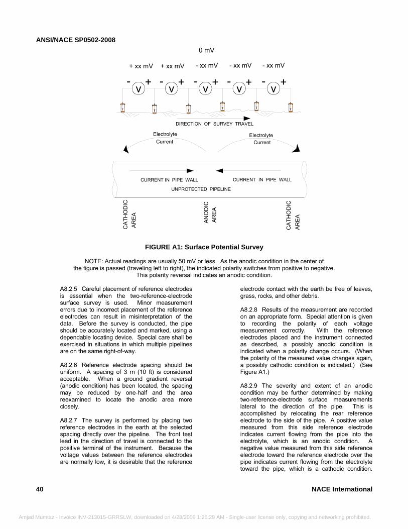
ANSI/NACE SP0502-2008
40
Amjad Mumtaz - Invo
FIGURE A1: Surface Potential Survey
NOTE: Actual readings are usually 50 mV or less. As the anodic condition in the center of the figure is passed (traveling left to right), the indicated polarity switches from positive to negative.
This polarity reversal indicates an anodic condition.
v- - - - -++ + + ++ xx mV - xx mV- xx mV- xx mV+ xx mV
CURRENT IN PIPE WALL CURRENT IN PIPE WALL
DIRECTION OF SURVEY TRAVELC
ATH
OD
ICAR
EA ANO
DIC
AR
EA
CA
THO
DIC
AREA
Electrolyte Current
Electrolyte Current
UNPROTECTED PIPELINE
v vvv
0 mV
A8.2.5 Careful placement of reference electrodes is essential when the two-reference-electrode surface survey is used. Minor measurement errors due to incorrect placement of the reference electrodes can result in misinterpretation of the data. Before the survey is conducted, the pipe should be accurately located and marked, using a dependable locating device. Special care shall be exercised in situations in which multiple pipelines are on the same right-of-way. A8.2.6 Reference electrode spacing should be uniform. A spacing of 3 m (10 ft) is considered acceptable. When a ground gradient reversal (anodic condition) has been located, the spacing may be reduced by one-half and the area reexamined to locate the anodic area more closely. A8.2.7 The survey is performed by placing two reference electrodes in the earth at the selected spacing directly over the pipeline. The front test lead in the direction of travel is connected to the positive terminal of the instrument. Because the voltage values between the reference electrodes are normally low, it is desirable that the referenceice INV-213015-GRRSLW, downloaded on 4/28/2009 1:26:29 AM - Sing
electrode contact with the earth be free of leaves, grass, rocks, and other debris. A8.2.8 Results of the measurement are recorded on an appropriate form. Special attention is given to recording the polarity of each voltage measurement correctly. With the reference electrodes placed and the instrument connected as described, a possibly anodic condition is indicated when a polarity change occurs. (When the polarity of the measured value changes again, a possibly cathodic condition is indicated.) (See Figure A1.) A8.2.9 The severity and extent of an anodic condition may be further determined by making two-reference-electrode surface measurements lateral to the direction of the pipe. This is accomplished by relocating the rear reference electrode to the side of the pipe. A positive value measured from this side reference electrode indicates current flowing from the pipe into the electrolyte, which is an anodic condition. A negative value measured from this side reference electrode toward the reference electrode over the pipe indicates current flowing from the electrolyte toward the pipe, which is a cathodic condition.
NACE International
le-user license only, copying and networking prohibited.
ANSI/NACE SP0502-2008
NACE
Amjad Mumtaz
Measurements are generally taken on both sides of the pipe. Enough measurements along the pipe and on both sides of the pipe are taken to define the limits of the anodic condition. A8.2.10 The presence of a galvanic anode connected to the pipe affects two-reference-electrode surface measurements and generally appears as an anodic condition. Close observation of measured values quite often suggests the presence of galvanic anodes. As an anode is approached, its presence is usually indicated by earth gradients that are somewhat higher than normal for the area being surveyed. The two-reference-electrode lateral test may provide higher measured values on the side of the pipe on which the anode is buried and lower values on the side of the pipe opposite the anode. Service taps, side connections, other components of the pipe (such as mechanical couplings or screw collars with a higher metallic resistance than the pipe), or other close buried metallic structures may provide measured values that indicate an anodic condition. The lateral test is useful to evaluate the data. Any situation not determined to be caused by some other factor is typically considered as an anodic condition. Adequate marking of anodic conditions is necessary so they can be located for future attention. A8.2.11 Soil resistivity tests are usually made at anodic areas discovered by using the two-reference-electrode surface survey. These tests are helpful in evaluating the severity of ongoing corrosion, anode current, and anode life. A8.2.12 The two-reference-electrode surface potential survey data may be used to generate a pipe-to-electrolyte potential gradient curve using closely spaced measurements. This curve appears as any other pipe-to-electrolyte potential curve and is usually generated by the following procedure:
A8.2.12.1 The pipe-to-electrolyte potential is measured at a test point, such as a test station. This value is recorded and becomes the reference value to which all other two-reference-electrode measurements are referenced.
International
- Invoice INV-213015-GRRSLW, downloaded on 4/28/2009 1:26:29 AM - Single-us
A8.2.12.2 The reference electrode is left in the same location and is connected to the negative terminal of the voltmeter. A second reference electrode is placed over the pipe center line in clean, moist earth a selected distance from the first reference electrode and is connected to the positive side of the instrument. A8.2.12.3 The potential between the two reference electrodes is then measured and recorded. Special attention shall be given to the polarity of the measurement between the two reference electrodes. A8.2.12.4 The measured value is then algebraically added to the pipe-to-electrolyte potential measured in the first step of this procedure. The sum obtained from the algebraic addition is the pipe-to-electrolyte potential at the location of the second reference electrode. A8.2.12.5 The rear reference electrode (connected to the instrument negative terminal) is moved forward and placed in the same spot previously occupied by the front reference electrode. A8.2.12.6 The front reference electrode is moved ahead over the line to the previously selected distance. A8.2.12.7 The potential between the two reference electrodes is again measured with special attention to reference electrode polarity. This value is algebraically added to the calculated value for the previous test. This calculated pipe-to-electrolyte potential is the pipe-to-electrolyte potential at the location of the front reference electrode. A8.2.12.8 This process is repeated until the next test station is met. At this time, the last calculated pipe-to-electrolyte potential is compared with the pipe-to-electrolyte potential measured using the test station. If the survey is carefully performed, upon comparison, these two values should be nearly identical. A8.2.12.9 These potential data can then be plotted as a typical pipe-to-electrolyte potential curve. A8.2.12.10 Errors in observing instrument polarities, incorrect algebraic calculations, unbalanced reference electrodes, and poor earth/reference electrode contacts cause the calculated values to be incorrect.
41
er license only, copying and networking prohibited.
ANSI/NACE SP0502-2008
42
Amjad Mum
A8.2.12.11 To use the data collected effectively, a form having a suitable format should be developed. The specific needs of each user should be considered when a data form is being developed. The form should have space for each measured numerical value, the polarity of each value, calculated values, and comments. It is also useful to provide space for a sketch of the area surveyed.
A8.2.13 Data Interpretation:
A8.2.13.1 Interpretation of survey data is complex but generally considers the following: (a) Polarity change of a measured value; (b) Magnitude of the value measured;
(c) Magnitude of the lateral two-reference- electrode value;
(d) Soil resistivity; (e) Unknown pipe resistances;
(f) Physical location of the pipe with respect to other structures; and
(g) Known corrosion leak history.
A8.3 Pipe-to-Electrolyte Potential Survey
A8.3.1 Pipe-to-electrolyte potential measure-ments record the potential difference between a CSE in contact with the earth and a connection to the pipeline. When taken and recorded at measurement intervals of 3 m (10 ft) directly over a pipeline, these measurements are useful in locating suspected anodic conditions of an unprotected pipeline. The interval of measurement may be shortened when anodic conditions are indicated or other unusual conditions occur (see Figures A2a and A2b). A8.3.2 Individual users may find it appropriate to modify the above suggested spacing based on the following conditions. (a) Pipeline length; (b) Availability of test leads to the pipe; (c) Terrain characteristics;
taz - Invoice INV-213015-GRRSLW, downloaded on 4/28/2009 1:26:29 AM - Sin
(d) Accessibility; (e) Presence of foreign pipelines and CP systems; (f) Coating condition or lack of coating; (g) Corrosion history of the pipeline; (h) Results of previous surveys; and (i) Pipe depth.
A8.3.3 The survey consists of measuring and recording voltages along an unprotected pipeline at specific intervals as shown in Figures A2a and A2b. To interpret the survey data correctly and to ensure meaningful results, the pipeline must be electrically continuous, or the location of insulating or high-resistance joints must be known. The peaks, or areas of highest negative potential, usually indicate anodic conditions. Pipe-to-electrolyte potential measurements are typically plotted or tabulated (see Figure A2c). A8.3.4 The presence of an unknown galvanic anode affects measurements, causing a location to appear to be an anodic condition. If records or measurements do not indicate that a galvanic anode has been installed, all peaks shall be considered as anodic conditions. If records regarding galvanic anodes in the area are not available or are believed to be inaccurate, a few additional measurements can help to determine the source of the peaks. Pipe-to-electrolyte (or electrode-to-electrode) potential measurements should be made in 0.3-m (1-ft) increments for about 1.5 to 3 m (5 to 10 ft) laterally to the pipe and through the peak. The maximum potential occurs a few m (ft) to the side of the pipe, if the peak is due to a galvanic anode. Moreover, if the pipe location is known with certainty and a galvanic anode is present, the potentials are a minimum over or to the side of the pipe opposite of where the maximum occurs. The closer the transverse measurements are to the anode, the more the location of the minimum is shifted away from the side of the pipe opposite the location of the maximum. A8.3.5 Stray current flowing to a pipe from sources such as foreign rectifiers and electrified railroads cause the pipe at that location to have more negative potential and may be misinterpreted as an anodic condition. Stray current discharging from a pipe causes a less negative potential and can be misinterpreted as a cathodic condition.
NACE International
gle-user license only, copying and networking prohibited.
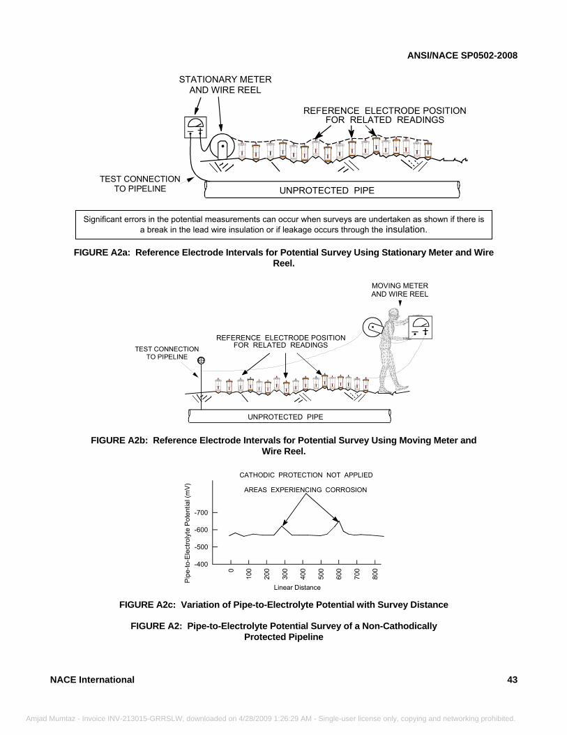
ANSI/NACE SP0502-2008
Amjad M
FIGURE A2a: Reference Electrode Intervals for Potential Survey Using Stationary Meter and Wire Reel.
STATIONARY METERAND WIRE REEL
UNPROTECTED PIPE
+_REFERENCE ELECTRODE POSITION
FOR RELATED READINGS
TEST CONNECTIONTO PIPELINE
Significant errors in the potential measurements can occur when surveys are undertaken as shown if there is a break in the lead wire insulation or if leakage occurs through the insulation.
N
FIGURE A2b: Reference Electrode Intervals for Potential Survey Using Moving Meter and Wire Reel.
UNPROTECTED PIPE
REFERENCE ELECTRODE POSITIONFOR RELATED READINGSTEST CONNECTION
TO PIPELINE
MOVING METERAND WIRE REEL
+_
ACE Inter
umtaz - Invoi
FIGURE A2c: Variation of Pipe-to-Electrolyte Potential with Survey Distance
FIGURE A2: Pipe-to-Electrolyte Potential Survey of a Non-Cathodically Protected Pipeline
0
100
200
300
400
500
600
700
800
-400
-500
-600
Pipe
-to-E
lect
roly
te P
oten
tial (
mV) AREAS EXPERIENCING CORROSION
-700
CATHODIC PROTECTION NOT APPLIED
Linear Distance
national 43
ce INV-213015-GRRSLW, downloaded on 4/28/2009 1:26:29 AM - Single-user license only, copying and networking prohibited.
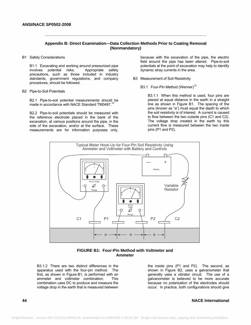
ANSI/NACE SP0502-2008
44
________________________________________________________________________
Amjad Mumtaz - Invoi
Appendix B: Direct Examination—Data Collection Methods Prior to Coating Removal
(Nonmandatory)
B1 Safety ConsiderationsB1.1 Excavating and working around pressurized pipe involves potential risks. Appropriate safety precautions, such as those included in industry standards, government regulations, and company procedures, should be followed.
B2 Pipe-to-Soil Potentials
B2.1 Pipe-to-soil potential measurements should be made in accordance with NACE Standard TM0497.10 B2.2 Pipe-to-soil potentials should be measured with the reference electrode placed in the bank of the excavation, at various positions around the pipe, in the side of the excavation, and/or at the surface. These measurements are for information purposes only,
ce INV-213015-GRRSLW, downloaded on 4/28/2009 1:26:29
because with the excavation of the pipe, the electric field around the pipe has been altered. Pipe-to-soil potentials at the point of excavation may help to identify dynamic stray currents in the area.
B3 Measurement of Soil Resistivity B3.1 Four-Pin Method (Wenner)13
B3.1.1 When this method is used, four pins are placed at equal distance in the earth in a straight line as shown in Figure B1. The spacing of the pins (known as “a”) must equal the depth to which the soil resistivity is of interest. A current is caused to flow between the two outside pins (C1 and C2). The voltage drop created in the earth by this current flow is measured between the two inside pins (P1 and P2).
FIGURE B1: Four-Pin Method with Voltmeter and Ammeter
B3.1.2 There are two distinct differences in the apparatus used with the four-pin method. The first, as shown in Figure B1, is performed with an ammeter and voltmeter combination. This combination uses DC to produce and measure the voltage drop in the earth that is measured between
AM - Sin
the inside pins (P1 and P2). The second, as shown in Figure B2, uses a galvanometer that generally uses a vibrator circuit. The use of a galvanometer is believed to be more accurate because no polarization of the electrodes should occur. In practice, both configurations should give
NACE International
gle-user license only, copying and networking prohibited.
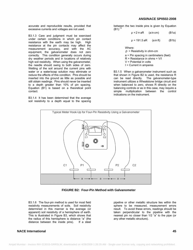
ANSI/NACE SP0502-2008
NACE
Amjad Mumtaz
accurate and reproducible results, provided that excessive currents and voltages are not used. B3.1.3 Care and judgment must be exercised under certain conditions in which pin contact resistance with the earth may be high. High resistance at the pin contacts may affect the measurement accuracy, and with the AC equipment, the galvanometer does not zero correctly. This condition generally occurs during dry weather periods and in locations of relatively high soil resistivity. When using the galvanometer, the needle should swing to both sides of zero. Wetting of the soil around the current pins with water or a water/soap solution may eliminate or reduce the effects of this condition. Pins should be inserted into the ground as little as possible and still obtain readings. Pins should never be inserted to a depth greater than 10% of pin spacing. Equation (B1) is based on a theoretical point contact. B3.1.4 It has been determined that the average soil resistivity to a depth equal to the spacing
International
- Invoice INV-213015-GRRSLW, downloaded on 4/28/2009 1:26:29 AM - S
between the two inside pins is given by Equation (B1):13
cm)in(aaRπ2=ρ (B1a) ft)in(aaR191.5=ρ (B1b)
Where: ρ = Resistivity in ohm-cm a = Pin spacing in centimeters (feet) R = Resistance in ohms = V/I V = Potential in volts I = Current in amperes
B3.1.5 When a galvanometer instrument such as that shown in Figure B2 is used, the resistance R can be read directly. The galvanometer-type instrument utilizes a Wheatstone bridge circuit and when balanced to zero, shows R directly on the balancing controls or as in this case, may require a simple multiplication between the control indications on the instrument.
FIGURE B2: Four-Pin Method with Galvanometer
B3.1.6 The four-pin method is used for most field resistivity measurements of soils. Soil resistivity determined in this manner is the average (or apparent) soil resistivity of a hemisphere of earth. This is illustrated in Figure B3, which shows that the radius of this hemisphere is distance “a” (the distance between the inside pins). If a steel
ing
pipeline or other metallic structure lies within the sphere to be measured, measurement errors result. To avoid these errors, readings should be taken perpendicular to the pipeline with the nearest pin no closer than 1/2 “a” to the pipe (or any other metallic structure).
45
le-user license only, copying and networking prohibited.
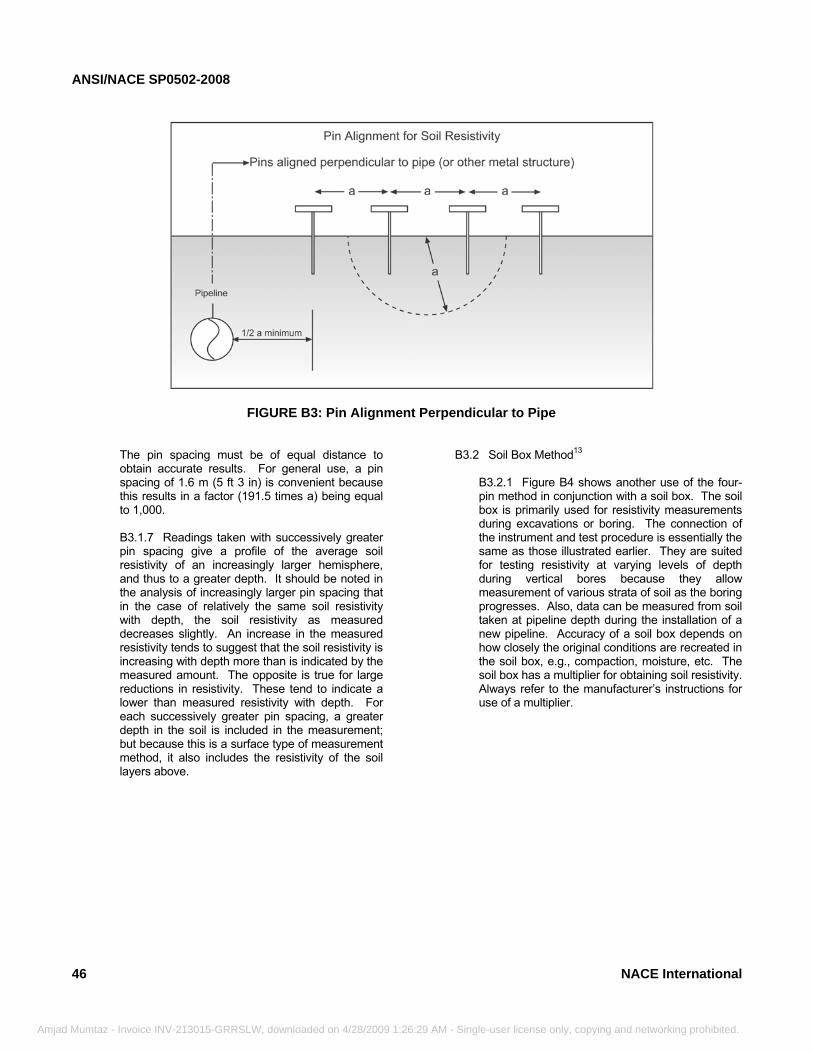
ANSI/NACE SP0502-2008
46
Amjad Mumtaz - Invoice IN
FIGURE B3: Pin Alignment Perpendicular to Pipe
The pin spacing must be of equal distance to obtain accurate results. For general use, a pin spacing of 1.6 m (5 ft 3 in) is convenient because this results in a factor (191.5 times a) being equal to 1,000. B3.1.7 Readings taken with successively greater pin spacing give a profile of the average soil resistivity of an increasingly larger hemisphere, and thus to a greater depth. It should be noted in the analysis of increasingly larger pin spacing that in the case of relatively the same soil resistivity with depth, the soil resistivity as measured decreases slightly. An increase in the measured resistivity tends to suggest that the soil resistivity is increasing with depth more than is indicated by the measured amount. The opposite is true for large reductions in resistivity. These tend to indicate a lower than measured resistivity with depth. For each successively greater pin spacing, a greater depth in the soil is included in the measurement; but because this is a surface type of measurement method, it also includes the resistivity of the soil layers above.
V-213015-GRRSLW, downloaded on 4/28/2009 1:26:29 AM
B3.2 Soil Box Method13
B3.2.1 Figure B4 shows another use of the four-pin method in conjunction with a soil box. The soil box is primarily used for resistivity measurements during excavations or boring. The connection of the instrument and test procedure is essentially the same as those illustrated earlier. They are suited for testing resistivity at varying levels of depth during vertical bores because they allow measurement of various strata of soil as the boring progresses. Also, data can be measured from soil taken at pipeline depth during the installation of a new pipeline. Accuracy of a soil box depends on how closely the original conditions are recreated in the soil box, e.g., compaction, moisture, etc. The soil box has a multiplier for obtaining soil resistivity. Always refer to the manufacturer’s instructions for use of a multiplier.
NACE International
- Single-user license only, copying and networking prohibited.
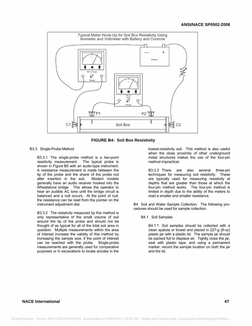
ANSI/NACE SP0502-2008
NACE Inter
Amjad Mumtaz - Invoi
FIGURE B4: Soil Box Resistivity
B3.3 Single-Probe MethodB3.3.1 The single-probe method is a two-point resistivity measurement. The typical probe is shown in Figure B5 with an audio-type instrument. A resistance measurement is made between the tip of the probe and the shank of the probe rod after insertion in the soil. Modern models generally have an audio receiver hooked into the Wheatstone bridge. This allows the operator to hear an audible AC tone until the bridge circuit is balanced and a null occurs. At the point of null, the resistance can be read from the pointer on the instrument adjustment dial. B3.3.2 The resistivity measured by this method is only representative of the small volume of soil around the tip of the probe and should not be thought of as typical for all of the total soil area in question. Multiple measurements within the area of interest increase the validity of this method by increasing the sample size, if the point of interest can be reached with the probe. Single-probe measurements are generally used for comparative purposes or in excavations to locate anodes in the
national
ce INV-213015-GRRSLW, downloaded on 4/28/2009 1:26:
lowest-resistivity soil. This method is also useful when the close proximity of other underground metal structures makes the use of the four-pin method impractical. B3.3.3 There are also several three-pin techniques for measuring soil resistivity. These are typically used for measuring resistivity at depths that are greater than those at which the four-pin method works. The four-pin method is limited in depth due to the ability of the meters to read a smaller and smaller resistance.
B4 Soil and Water Sample Collection. The following pro-cedures should be used for sample collection.
B4.1 Soil Samples
B4.1.1 Soil samples should be collected with a clean spatula or trowel and placed in 227-g (8-oz) plastic jar with a plastic lid. The sample jar should be packed full to displace air. Tightly close the jar, seal with plastic tape, and using a permanent marker, record the sample location on both the jar and the lid.
47
29 AM - Single-user license only, copying and networking prohibited.
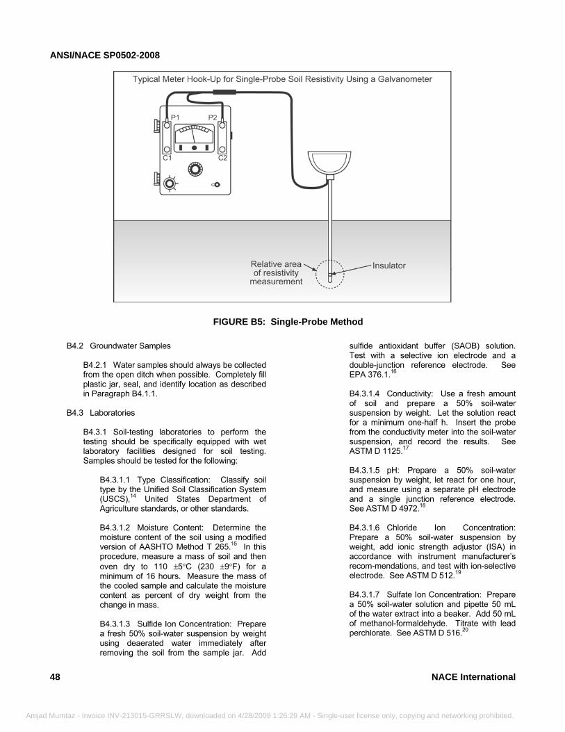
ANSI/NACE SP0502-2008
48
Amjad Mumtaz - Invoice
FIGURE B5: Single-Probe Method
B4.2 Groundwater Samples
B4.2.1 Water samples should always be collected from the open ditch when possible. Completely fill plastic jar, seal, and identify location as described in Paragraph B4.1.1.
B4.3 Laboratories B4.3.1 Soil-testing laboratories to perform the testing should be specifically equipped with wet laboratory facilities designed for soil testing. Samples should be tested for the following:
B4.3.1.1 Type Classification: Classify soil type by the Unified Soil Classification System (USCS),14 United States Department of Agriculture standards, or other standards. B4.3.1.2 Moisture Content: Determine the moisture content of the soil using a modified version of AASHTO Method T 265.15 In this procedure, measure a mass of soil and then oven dry to 110 ±5°C (230 ±9°F) for a minimum of 16 hours. Measure the mass of the cooled sample and calculate the moisture content as percent of dry weight from the change in mass. B4.3.1.3 Sulfide Ion Concentration: Prepare a fresh 50% soil-water suspension by weight using deaerated water immediately after removing the soil from the sample jar. Add
INV-213015-GRRSLW, downloaded on 4/28/2009 1:26:29 AM - Single-u
sulfide antioxidant buffer (SAOB) solution. Test with a selective ion electrode and a double-junction reference electrode. See EPA 376.1.16
B4.3.1.4 Conductivity: Use a fresh amount of soil and prepare a 50% soil-water suspension by weight. Let the solution react for a minimum one-half h. Insert the probe from the conductivity meter into the soil-water suspension, and record the results. See ASTM D 1125.17
B4.3.1.5 pH: Prepare a 50% soil-water suspension by weight, let react for one hour, and measure using a separate pH electrode and a single junction reference electrode. See ASTM D 4972.18
B4.3.1.6 Chloride Ion Concentration: Prepare a 50% soil-water suspension by weight, add ionic strength adjustor (ISA) in accordance with instrument manufacturer’s recom-mendations, and test with ion-selective electrode. See ASTM D 512.19
B4.3.1.7 Sulfate Ion Concentration: Prepare a 50% soil-water solution and pipette 50 mL of the water extract into a beaker. Add 50 mL of methanol-formaldehyde. Titrate with lead perchlorate. See ASTM D 516.20
NACE International
ser license only, copying and networking prohibited.
ANSI/NACE SP0502-2008
Amjad
B5 pH Testing
B5.1 If a liquid is present beneath the coating, take a sample using a syringe or cotton swab following procedures described above for testing purposes (see Paragraph B4). B5.2 Test the pH of the liquid using hydrion paper or its equivalent. Carefully slice the coating to a length to allow the test paper to be slipped behind the coating. Press the coating against the pH paper for a few seconds and then remove the pH paper. Note and record the color of the paper in relation to the chart provided with the paper.
B6 Microbiologically Influenced Corrosion (MIC) Analyses
B6.1 MIC analyses should be performed on corrosion products when MIC is suspected. These tests should be performed to determine whether microbial activity could be contributing to the observed corrosion. The tests should be performed in accordance with the procedures in kits designed for analyzing MIC, provided by the manufacturers of well-known MIC kits. One kit can be used to analyze qualitatively for the presence of carbonate (CO3
+2), sulfide (S–2), ferrous iron (Fe+2), ferric iron (Fe+3), calcium (Ca+2), and hydrogen (H+1, pH) ions while others only analyze for bacteria. The following procedures should be used.
B6.2 Corrosion Product Analysis B6.2.1 After the pipe is exposed, immediately sample and test the soil and any suspected deposits. Carefully remove the coating around the suspected area of corrosion using a knife or similar instrument. Sample contamination must be kept to a minimum. Therefore, avoid touching the soil, corrosion product, or film with hands or tools other than those to be used in sample collection and provided with the test kits. Samples should be obtained from the following areas: (a) Undisturbed soil immediately next to the
exposed pipe steel surface or at an area of coating damage,
(b) A deposit associated with visual evidence
of pipe corrosion, (c) A scale or biofilm on the steel surface or
the backside of the coating, and (d) Liquid trapped behind the coating.
B6.2.2 Collect a sample of soil, deposit, film, or liquid from the area of interest. Use only a clean
NACE International
Mumtaz - Invoice INV-213015-GRRSLW, downloaded on 4/28/2009 1:26:29 A
knife or spatula provided with the test kit. The films or deposits may be from the steel surface, coating surface, interior of a corrosion pit, or the back side of the coating. In all cases, note the color and type of sample. Carefully transfer the sample to the test kit vial for testing. Follow the detailed procedure given in the kit instruction sheets. For comparison purposes, obtain a reference sample taken at least 1 m (3 ft) from the previous collection site.
B6.3 The form of the corrosion pits associated with MIC is reasonably distinctive (See Paragraph B6.5). These features can be observed in the field with the unaided eye or a low-power microscope. B6.4 After any films or products sampled above have been obtained from a corroded area, remove the remaining product using a clean spatula or knife, being careful not to scratch the metal. Clean any remaining material with a clean, dry, stiff brush, such as a nylon-bristle brush. Do not use a metal brush, if possible, because the metal bristles can mar the pit features. If not all of the product can be removed with this method, use a brass bristle brush in the longitudinal direction only. Dry the area with an air blast or an alcohol swab. A shiny metallic surface of the pit suggests the possibility of active corrosion. However, judgment must be used to differentiate this condition from one created by scraping the steel surface with a metallic object, such as the knife or spatula used to clean the surface or to obtain the sample product. B6.5 Examine the newly cleaned corroded area first visually with the unaided eye. Then use a low-power magnifying lens at 5X to 50X to examine the detail of the corrosion pits. MIC often has the following features:
(a) large craters up to 50 to 80 mm (2 to 3 in) or more in diameter.
(b) cup-type hemispherical pits on the pipe surface or in the craters.
(c) craters or pits sometimes surrounded by uncorroded metal.
(d) striations or contour lines in the pits or craters running parallel to longitudinal pipe axis (rolling direction).
(e) tunnels sometimes at the ends of the craters, also running parallel to the longitudinal axis of the pipe.
49
M - Single-user license only, copying and networking prohibited.
ANSI/NACE SP0502-2008
50
________________________________________________________________________
Amjad Mumtaz - Invoice INV-213015-GR
Appendix C: Direct Examination—Coating Damage and Corrosion Depth Measurements
(Nonmandatory)
C1 Safety ConsiderationsC1.1 Excavating and working around pressurized pipe involves potential risks. Appropriate safety precautions, such as those included in industry standards, government regulations, and company procedures, should be followed.
C2 Coating Type Identification
C2.1 See Table 1 in NACE SP016911 for instructions on how to identify coating types.
C3 Coating Condition and Adhesion Assessment C3.1 Coating inspection for holiday testing purposes should precede any other type of coating evaluation planned. Three situations could be encountered when the pipe surface at an excavation site is evaluated:
C3.1.1 The coating is in excellent condition and completely adhered to the pipe surface. C3.1.2 The coating is partially disbonded or degraded. C3.1.3 The coating is completely missing; the pipe surface is bare.
C3.2 When the coating is in excellent condition, the likelihood of finding external corrosion is greatly reduced. When the coating is partially disbonded or degraded, the likelihood of finding external corrosion is increased. Therefore, it is important to determine and document coating type and disbonded areas. C3.3 The following coating inspection procedures are commonly used:
C3.3.1 Collect selected coating samples to determine the properties of coating associated with corrosion. Subsequent analysis of the coating can provide information pertaining to electrical and physical properties (e.g., resistivity, gas permeability, etc.). The samples can also be used to conduct microbial tests. C3.3.2 Coating samples must be removed from the pipe surface. Any liquid under the coating should be sampled. Procedures for coating removal and liquid pH measurements are in Appendix B of this standard. The steel surface condition and liquid pH should be evaluated.
RSLW, downloaded on 4/28/2009 1:26:2
C3.3.3 Determine the pH of groundwater away from the pipe in the ditch, if possible, for reference. Compare this pH value with the pH determined from liquid removed under coating to determine whether the pH near the pipe is elevated. An elevated pH indicates the presence of CP current reaching the pipe. A pH above about 9 would be considered elevated for most soils. It is not uncommon to determine a pH of 12 to 14 for well-protected steel. C3.3.4 Visually inspect the steel surface for corrosion after the coating analysis is performed. Identify areas that may contain other types of anomalies such as stress corrosion cracking (SCC) or where MIC may have contributed to external corrosion. This becomes essential when risk assessment results indicate the possibility of other threats that impact the pipeline or segment being evaluated. C3.3.5 Measure the pipe surface temperature under the coating.
C4 Corrosion Product Removal C4.1 Carefully remove the coating around the suspected area of corrosion using a knife or similar instrument. Sample contamination must be kept to a minimum. Avoid touching the soil, corrosion product, or film with hands or tools other than a clean knife or spatula to be used in collecting the sample.
C5 Corrosion Product Analyses C5.1 Corrosion product analyses may be useful in determining corrosion mechanisms or identifying unusual soil contaminants. Samples should be obtained from the following areas:
C5.1.1 A deposit associated with visual evidence of pipe corrosion, C5.1.2 A scale or biofilm on the steel surface or the backside of the coating, and C5.1.3 Liquid trapped behind the coating.
C5.2 The films or deposits may be from the steel surface, coating surface, interior of a corrosion pit, or the backside of the coating.
C6 Identification and Mapping of Corrosion Defects
NACE International
9 AM - Single-user license only, copying and networking prohibited.
ANSI/NACE SP0502-2008
NA
Amjad Mum
C6.1 General C6.1.1 At each excavation, an operator should measure and document the extent, morphology, and depths of any external corrosion to establish the overall pipeline integrity. During the direct examination process, certain anomalies may be identified and require further analysis to establish the overall integrity of the pipeline. The following paragraphs discuss some of the procedures used to assess such anomalies.
C6.2 Cleaning/Surface Preparation
C6.2.1 Accurate assessment of external corrosion anomalies can only be accomplished after thorough cleaning of the affected area. Following are guidelines for cleaning and preparation of the pipe surface prior to anomaly evaluation. The cleaning method chosen depends on the type of inspection technique and repair to be conducted. For instance, if risk assessment results indicate that other anomalies, such as SCC, may be present, cleaning methods must be modified so cleaning does not interfere with the detection of such anomalies. C6.2.2 The objective of the pipe preparation process is to remove coating residue and corrosion deposits to optimize the effectiveness of the inspection. The steel pipe surface must be clean, dry, and free of surface contaminants such as dirt, oil, grease, corrosion products, and coating remnants. C6.2.3 The pipeline operator should ensure that any cleaning material or technique selected meets the required occupational health and safety requirements.
CE International
__________________________________________
taz - Invoice INV-213015-GRRSLW, downloaded on 4/28/2009 1:26:29 AM
C6.3 Anomaly Measurement and Evaluation Methods
C6.3.1 The exposed and cleaned pipe surface should be examined for external corrosion and other anomalies that may be present. Such examinations should be suitable for other anomaly types expected (in addition to external corrosion) and conducted by a qualified person. C6.3.2 The results of all pipe surface examinations should be thoroughly documented. Supplemental photographic records are recommended. C6.3.3 The residual strength of the corroded pipe should be estimated using ASME B31G,5 RSTRENG,6 or equivalent assessment methods. Residual strength of anomalies other than corrosion should be assessed using other appropriate industry-accepted methods. C6.3.4 Corrosion depths may be determined using one or more of the following techniques. Additional nondestructive testing methods are typically required to determine the depths and extent of other anomaly types.
C6.3.4.1 Pit depth gauge C6.3.4.2 Ultrasonic thickness probe C6.3.4.3 Automated methods (e.g., laser mapping) C6.3.4.4 Profile gauges
C6.3.5 Measurement of all external corrosion or other anomalies should be conducted by a qualified person in accordance with the applicable assessment method.
______________________________
Appendix D: Post Assessment—Corrosion Rate Estimation (Nonmandatory)
D1 Introduction
D1.1 External corrosion rates are an essential variable for establishing the interval between successive integrity evaluations and pipeline remediation needed to assure that integrity is maintained. D1.2 When possible, external corrosion rates should be determined by directly comparing measured wall thickness changes that are detected after a known time interval. Such data may be from maintenance records, prior excavations (e.g., contained in pipeline inspection reports), or by other methods such as ILI.
D1.3 Other methods that may also be used for external corrosion rate estimates can include but are not limited to the following:
D1.3.1 Consideration of the external corrosion history on the pipe or segment being evaluated or in “like/similar” areas that contain the same pipe materials and similar environments. The data elements provided in Table 1 of this standard provide guidance for such evaluations.
51
- Single-user license only, copying and networking prohibited.
ANSI/NACE SP0502-2008
52
D
Amjad Mumtaz -
D1.3.2 Consideration of the soil characteristics and environment surrounding the pipe or segment being evaluated to determine its corrosiveness.
Invoice INV-213015-GRRSLW, downloaded on 4/28/2009 1:26:29 AM - Sing
Such soil characteristics and environmental factors can include:
Chloride ion content Microbiological activity
Moisture content Redox potential
Oxygen content Resistivity
Permeability Soil texture
pH Drainage characteristics
Stray currents Sulfate, sulfite ion concentrations
Temperature Total hardness
Total acidity Soil composition changes that may create long-line corrosion
D1.3.2.1 Other soil or environmental changes that can affect external corrosion rates include spillage of corrosive substances, pollution, and seasonal soil moisture content variations.
D1.3.3 Under some conditions, external corrosion rates may also be determined using buried coupons, linear polarization rate measurements, or electrical resistance probes. D1.3.4 Actual corrosion rates are difficult to predict and measure. Corrosion estimation techniques may not simulate actual field conditions. Caution should be exercised when computing corrosion rates.
2 Corrosion Rate Estimates D2.1 Additional guidance for establishing estimated external corrosion rates is provided below: D2.2 Estimating Corrosion Initiation Time
D2.2.1 Assuming that external corrosion initiated at the time a pipeline went into service may result in nonconservative rate estimates. A coating system may delay the onset of corrosion for a significant time period. D2.2.2 Corrosion initiation time estimates can be made by considering the following.
D2.2.2.1 Historical records evaluated during overall pipeline risk (threat) and the pre-assessment step.
le-us
D2.2.2.2 Evidence that the corrosion is associated with coating damage that most likely occurred during original construction or other maintenance action. For example, coating damage associated with rock or debris in the backfill is likely to have occurred during construction. D2.2.2.3 Evidence that the corrosion is associated with coating damage resulting from third-party activity that occurred at a known time. For example, external corrosion accompanied by mechanical damage to the pipe or coating on the top half of the pipe in an area where third-party activity is known to have occurred most likely initiated and grew since the time of the third-party activity. D2.2.2.4 Estimated time period that the coating provided an efficient barrier between the pipe and external environment and records that may indicate initial coating quality. Whenever available, the operator should use pipeline inspection records in an attempt to determine when the coating no longer provided effective protection. Published corrosion rate data describing long-term corrosion tests conducted on pipe coated with various materials indicate that coating degradation rates can be significantly influenced by soil type, original coating quality, and pipeline installation practices.21
D2.2.2.5 Time periods when CP systems were out of service, not functioning normally, or protective potentials were not maintained for significant time periods. Also, any significant time period between pipe
NACE International
er license only, copying and networking prohibited.
ANSI/NACE SP0502-2008
NA
Amjad Mu
construction and installation of an effective CP system should be considered when corrosion rates are estimated.
D2.3 Other Factors D2.3.1 Other factors that may affect external corrosion rate estimates are as follows:
D2.3.1.1 Exposure time: Corrosion rates often, but not always, decrease with longer exposure times. For example, data from tests of bare pipe in soils indicate that corrosion rates from 0 to about 7 years of exposure are typically higher than for longer exposure periods. D2.3.1.2 Surface area exposed: Testing has demonstrated that the probability of finding a larger pit increases when a test sample with a larger surface area is inspected. The larger the total area of coating damage, the greater the probability that the actual maximum corrosion rate will be higher than the rates described above. This influence may be particularly important for predicting the maximum penetration rate of bare pipelines. D2.3.1.3 Coating: Coatings are designed to delay the onset of corrosion by providing an effective barrier between the pipe and soil. However, pitting rates in the area of localized coating defects may exceed the pitting rates of bare steel exposed to the same environment. The effect of the coating on the rate of pitting is dependent on the coating type and the soil characteristics. D2.3.1.4 Seasonal variability on soil characteristics: Few published corrosion data include descriptions of the extent of seasonal variability on soil characteristics.21 Soil characteristics measured at one point in time may not be representative of soil corrosiveness at other times of the year. Soils that undergo cyclic wetting and drying can be more corrosive than soils that are constantly wet. The cyclic changes in moisture can cause soil stress that damages coatings and can also result in cyclic diffusion of oxygen into the soil. D2.3.1.5 Long-line corrosion cells: Pipelines passing through different soils can be influenced by long-line cells that are not apparent in localized corrosion tests. Long-line cells can result in higher corrosion rates on one segment of a pipeline, compared to corrosion rates measured on isolated samples buried in the same soil.
CE International
mtaz - Invoice INV-213015-GRRSLW, downloaded on 4/28/2009 1:26:2
D2.3.1.6 Microbiological activity can accel-erate external corrosion rates and must be considered in evaluations.
D3 Default Corrosion Rate
D3.1 Statistically valid methods based on the data developed may be used for corrosion rate estimates. D3.2 When other data are not available, a pitting rate of 0.4 mm/y (16 mpy) is recommended for determining reinspection intervals. This rate represents the upper 80% confidence level of maximum pitting rates for long-term (up to 17-y duration) underground corrosion tests of bare steel pipe coupons without CP in a variety of soils, including native and nonnative backfill. D3.3 The corrosion rate in Paragraph D3.2 may be reduced by a maximum of 24% provided it can be demonstrated that the CP level of all pipelines or segments being evaluated have had at least 40 mV of polarization (considering IR drop) for a significant fraction of the time since installation. D3.4 Linear Polarization Resistance Measurements
D3.4.1 Linear polarization resistance (LPR) measurements are performed to evaluate the ongoing, instantaneous rate of corrosion. LPR measurements in the laboratory are performed as described in ASTM G 59.22
D3.4.2 In this method, the coupon potential is scanned between –30 mV saturated calomel electrode (SCE) and +30 mV (SCE) of the free-corrosion potential at a scan rate of 0.17 mV/s (SCE). The ensuing current is monitored as a function of potential. The tangent to the potential-current plot at the free-corrosion potential is the polarization resistance (LPR value). These LPR values are then converted to corrosion currents using the Stern-Geary23 equation (Equation [D1]).
PR
β=cori (D1)
Where: icor is the corrosion current density in A/cm2 β is the Stern-Geary constant PR is the polarization resistance
D3.4.3 The Stern-Geary constant is dependent on the anodic and cathodic Tafel constants. Corrosion current density values are then converted to corrosion rates using Faraday’s Law.
53
9 AM - Single-user license only, copying and networking prohibited.
ANSI/NACE SP0502-2008
54
Amjad Mum
D3.4.4 Tafel slopes must be known to use the above technique. Another technique utilizes mass-loss data for calibration, which is the basis for two commercial systems (probes) that provide online corrosion rate monitoring. The systems are capable of producing a pitting index, which is an indication of the fluid to cause pitting of the electrodes. The two systems differ by the number of electrodes that are used. D3.4.5 The two-electrode system uses two electrodes of the same material. The potential between the two electrodes is set to 20 mV, and the current is measured. The potential drop is assumed to divide equally between the anode and the cathode. The current flowing is proportional to the corrosion rate. The corrosion rate can be calculated using ASTM G 102.24
D3.4.6 The three-electrode system is comprised of a working, reference, and counter electrode. The electrodes are typically composed of the same material. As the potential of the working electrode with respect to the reference electrode is monitored, current is applied to or from the counter electrode such that the potential of the working electrode shifts by 10 mV (positive or negative). At that point, the current flowing is proportional to the corrosion rate. D3.4.7 The LPR method is the only corrosion monitoring method that allows real-time measurement of corrosion rates. This enables remedial action shortly after an acceleration in the corrosion rate is observed. This is the chief advantage of LPR probes. Because the corrosion rates determined by LPR probes reflect conditions at the time of measurement, they may not necessarily correspond with the corrosion rates determined using coupons. Corrosion rates determined using coupons represent an average mass loss that accounts for corrosion that has occurred throughout the coupon’s exposure period. Because the operation of the LPR probe depends on electrical current, the accumulation of deposits on the electrodes can influence the pitting index reported by the probes.
D3.5 Determining Corrosion Rates Using Coupon Monitoring of Cathodically Protected Pipe
D3.5.1 The purpose of coupon methodology is to provide a means of determining the corrosion rates of steel with or without the influence of CP. Corrosion coupons provide the ability to measure corrosion rates without excavating a pipeline, and they can be used to determine the type of corrosion as well as the corrosion rate.
taz - Invoice INV-213015-GRRSLW, downloaded on 4/28/2009 1:26:29 AM - Sin
D3.5.2 Effective testing requires that coupons be located in soil having characteristics representative of the environment in which the pipe is located. Therefore, efforts should be made to locate the coupons close to the pipe surface and to ensure that coupon exposure to air and moisture are comparable to conditions at the pipe surface. D3.5.3 One design of corrosion coupon assemblies currently used for monitoring CP effectiveness involves burial of two bare coupons in a test station near the pipe surface. One coupon is connected to the pipeline (polarized coupon) and one coupon remains unconnected and allowed to corrode freely (native coupon). In this manner, it is expected that the polarized coupon will be polarized to a similar potential as a pipe surface holiday of similar area. The native coupon provides a “worst-case” illustration of the type and extent of corrosion that can occur if CP does not reach portions of the pipe. D3.5.4 It is recognized that the polarized potential of a coupon does not mirror the pipe polarized potential. There are several variables that combine to establish the pipeline polarized potential including coating quality, holiday size, and holiday configuration. It is theorized that the polarized potential of the coupon simulates the polarization of a holiday of similar size on the pipe. Therefore, the coupon does not estimate the pipe polarized potential but provides an evaluation of CP system effectiveness by accurately estimating the potential of a coupon connected to the CP system. D3.5.5 Evaluation consists of coupon retrieval, cleaning, and corrosion measurements. Guidance regarding coupon cleaning, corrosion rate calculations, and data reporting can be found in NACE Standard TM0169.25
NACE International
gle-user license only, copying and networking prohibited.
Related Documents