RM No. L7H05a NACA RESEARCH MEMORANDUM PERFORMANCE POSSIBILITIES OF THE TURBOJET SYSTEM AS A POWER PLANT FOR SUPERSONIC AIRPLANES By George P. Wood Langley Memorial Aeronautical Laboratory Langley Field, Va. jMN I iN - NATIONAL ADVI " r(ulrTEE fPONAUTtCS LANrIjY AE7' : V LrICLEY FIELD. . IA TU g N TO TH F pr ;UL t3E ADDRESD REQUESTS FOR FL'- AS FOLLOWS: t4P.T0NA. ADVSOR'r COMMITTEE r U p AFRONAUTICF 1bZ P4 WUEET. N. W. Ø.$N10N 26, . C. NATIONAL ADVISORY COMMITTEE FOR AERONAUTICS WASHINGTON August 26, 1947

Welcome message from author
This document is posted to help you gain knowledge. Please leave a comment to let me know what you think about it! Share it to your friends and learn new things together.
Transcript
RM No. L7H05a
NACA
RESEARCH MEMORANDUM PERFORMANCE POSSIBILITIES OF THE TURBOJET SYSTEM
AS A POWER PLANT FOR SUPERSONIC AIRPLANES
By George P. Wood
Langley Memorial Aeronautical Laboratory Langley Field, Va.
jMN I iN -
NATIONAL ADVI" r(ulrTEE fPONAUTtCS
LANrIjY AE7' : V
LrICLEY FIELD.. IA
TU g N TO TH F pr
;UL t3E ADDRESD REQUESTS FOR FL'-
AS FOLLOWS:
t4P.T0NA. ADVSOR'r COMMITTEE rU p AFRONAUTICF
1bZ P4 WUEET. N. W. Ø.$N10N 26, . C.
NATIONAL ADVISORY COMMITTEE FOR AERONAUTICS
WASHINGTON August 26, 1947
NACA EM No. L7fl05a
NATIONAL ADVISORY COMMITTEE FOR AERONAUTICS
RESARE. MEMORAUM'
PERFORMANCE POSSIBILITIES OF THE TURBOJET SYSTEM
AS A POWER PLANT FOR SUPERSONIC AIRPLANES
By George P. Wood
SUMMARY
The performance of hypothetloái turbojet systems, without thrust augmentation, as power plants for supersonic airplanes has been calculated. The thrust, thrust power, air—fuel ratio, 1 specific fuel consumption, cross—sectional area, and thrust coefficient are shown for free—stream Mach numbers from 1.2 to 3 . For comparison, the performance of ram—jet systems over the same Mach number range has also been calculated.
For Mach numbers between 1.2 and '2 the calculated thrust coefficient of the turbojet system was found to be larger than the estimated drag coefficient, and the specific fuel consumption was calculated to be àonsiderably less than the specific .fuol consumption of the ram—jet system. The turbojet system therefore appears to merit consideration as a propulsion method for free—stream Mach numbers between approximately 1.2 and 2.
INTRODUCTION
The National Advisory Comaittee for Aeronautics has issued several papers that .present analyses of the performance possibilities of jet engines. In references 1 and 2, for example, calculations of the performance of compressor—turbine jet—propulsion, or turbojet, systems operating at subsonic airplane speeds are given. In reference 3 results of an investigation of the performance of continuous,-flow ram—compressión jet—propulsion, or ram—jet, systems' propelling aircraft at supersonic speeds are presented. The question naturally arises as to the potentialities and the limitationà of the
2 NACA PN No. L71105a
turbojet system as a power plant for airplanes at Bupereonic speeds. The results obtained from analyses of the turbojet system operating at subsonic speeds, however, cannot-be expected to give quantitative information about the performance of the turbojet system operating at supersonic speeds. Because of the difference in the ccmpreseion available from the forward speed, the optimum blower compression ratio for operation at supersonic speeds, for example, may be quite different from the ratio for operation at subsonic speeds.
The purpose of the present paper is to report an analytical investigation of the turbojet system as a m€ans of propelling airplanes and missiles at supersonic speeds.
A comparison of the performances of the turbojet and the ram-jet systems at supersonic free-stream speeds is also given herein. -Tbee two systems differ in three inherent characteristics that-affect their performance as power plants, namely, maximum fluid temperature maximum fluid pressure, and. maximum cross-sectional area. The. maximum fluid temperature that can be used in the turbojet system is limited by; the mechanical properties of the turbine blades.. The ram-jet system, however, has no turbine, and higher maximum fluid temperatures can therefore be used. The maximum fluid pressure in the ram-jet system is limited to the pressure obtainable from ram. The turbojet system,. however, hasa mechanical compressor, and higher maximum fluid pressures can therefore be used. The cross-sectional area of the combistion chamber in the ram-jet system is greater than In the turbojet system because of the smaller density resulting from less compression. The turbojet system, however, has a compressor arA. a turbine, the cross-sectional areas of which may exceed the cross-sectional area of the combustion chamber. In the present paper the effects on performance of the differences in maximum temperature, maximum pressure, and maximum cross-sectional area are shout.
The scope and the limitations of the present paper should be understood. Answers arc given to the questions as to whether the turbojet system has a high enough thrust coefficient and a low enoui specific fuel consumption to merit any consideration as a means of supérsonic-airplane,propulsion. The effects of augmentation of the.. thrutof the turbojet system by means of injection of additional fuel behind the turbine, which is sometimes called afterburaing, are, not considered. Thrust augmentation might beused. for flight conditions In which additional thrust isnèed.ed, but an analytical...,. study of thrust augmentation is too extensive for inclusion herein.
The present paper, furthermore, considers only the performance of power plants and does not consider the performance of complete airplanes that are to be propelled by these power plants. As far as
NACA RM No. L7HO5a 3
the problem of choosing between the turbojet and the ram-jet methods. of propulsion is concerned, the present paeI the'erore 'gives nly a part of the information that is required for making a choice. Additional Information of a character different from that given herein is needed for making a choice of power plant for an airplane that would meet a given set of specifications as to speed, range, cargo capacity. This information should include the rate of air induction (some of the results presented herein are given In terms rate of flow of inducted air), the altitude of level flight, the estimated weights of the turbojet and. the ram.jet systeme and whether the alrølane must land. at the end of the flight or is tobe used as a flying bomb.
The symbols used herein are defined. In appendix A and the analysis 'and. method of calculation are given In a
ppendix B.
DESCRIPTION OF PROPULSION SYSTEMS AND
ASSUMPTIONS OF COMPONENT PRFOMA!'TCE
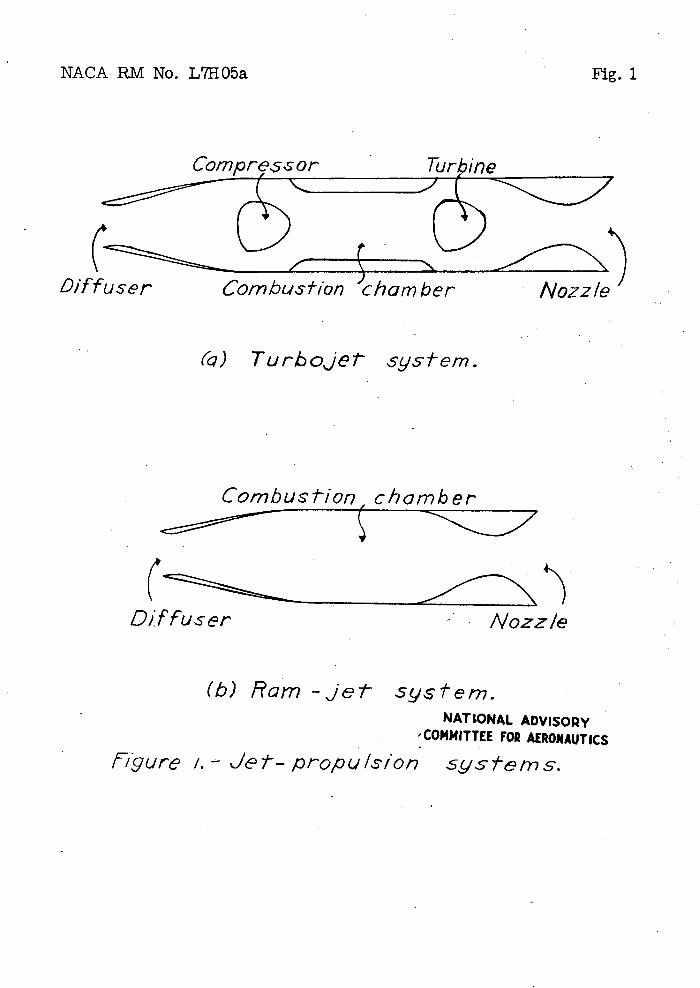
The turbojet system considered herein Is represented. In figure 1(a) Air enters the diffuser at supersonic speed and IS delivered to the mechanical compressor at subsonic speed.. After the air leaves the conpreEsor, the air and fuel burn in the combustion chamber. The combustion products drive the turbine and then are ejected through the exhaust nozzle.
In the present paper only hypothetical components of the system,, as &istinguishe& from production unite, were considered. Certain assumptions were made as to the performance of each component. Two types of supersonic diffuser were assumed. One of 'thes types was the fixed-geometry diffuser, which was termed "Diffuser A.'. The performance of the fixed..ge'Ometrydiffuser that was usàd in the present paper is.showa by the dashed curve of figure--2. The ratio of total prssures across the diffuser is 0.9 for free-stream Mach numbers from 1.2 to 1.6 and. decreases'rather rapidly, as Mach number is increased,to a value of 0.33 at a Mach ' number of-3. The part of the curve between Mach numbers of 1,6 and. 3 is the theoretical ratio of total pressures across a normal shock that occurs at free-stream Mach number.' This diffuser performance is essentially that obtained' in the experimental investigation of fixed-geometry diffusers reported in reference 4,
The other type of diffuser, which was termed "Diffuser B," was assumed to give the tothl-pressux'e ratio shown by the, solid curve -of
NACA BM No. L7'H05a
figure 2. The. total-pressure ratio, of this diffuser was assumed to. be also. 0.9 for... free-stream Mach numbers between 1.2 and 1.6 and to decl'ease linearly to. a value of 0.75 at a Mach number of 3. The performance shown by the solid curve can perhaps be obtained by variab1e-geomet'y diffusers or by diffusers of the type described-in references 5 and 6.
The compressor in the turbojet system was assumed to have an efficiency of 85 percent. Variouscomprossion ratios were assigned to the compressor. The ross-sectional area of the compressor was obtained by assigning a value of 01 to the-Mach number at the entrance to the compressor and a value of 0.6 to the hub-tip diameter ratio of the compressor. Burning in the combustion chamber was, assumed to.be 100 percent complete and to occur In a frictionless channel of constant cross-sectional area. The initial air velocity In the combustion chamber was set at 250 feet per second.. Losses of total pressure In the combustion chamber duo to the addition of heat to a compressible fluid were taken into account.
The total, or staation, temperature at the entrance to the turbine was set at 15000 F for most of the calculations. The over-all efficiency of-the turbine was assumed to be 85 percent.- The cross-sectional area of the turbine was obtained: with the assumptions that the turbine was of the single-stage, axial, impulse typo with full admission, that the flow through the blades was frictionless, that the absolute exit velocity from the blades was in the axial direction,, that the nozzles were at an angle of .15.0 to the plane of the wheel, that the turbine developed just the amount of power required to operate.tho compressor at any given compression ratio and. free-strom Mach number, and that-the hub-tip diameterratio was 0.7. These assumptions gave peripheral speeds that exceeded. 1350 feet per second in only a few casOs.
The efficiency of the exhaust nozzle was assumed to he 100 percent., Thrust was calculatea with the assumption that the nozzle was so d.esiied.that the exhaust. fluid. expanded. to free-stream static pressure at the nozzle exit.
Therein-jot system coneidçod herein is represented an, figure 1(b). Air enters the diffuser at supersonic eeed, is, delivered to the combustion chamber at subsonic speed, Is burned with fuel in the combustion . chambei', and. 'then Is ejected through the exhaust nozzle. .
The two diffuser performance. curves (fig. 2) that were used in tho.calculations for the turbojet system were also used. in the calculations for the rein-jot system. The Mach number at the entrance
NACA BM No. L705a 5
to the combustion chamber was varied, upward. from 0.2. Burning in the combustion chamber was-assumed to be 100 percent complete and to occur in a frictionless channel of constant cross-sectional area. Losses of total pressure in the combustion chamber d.ue .to-the: addition of heat to aconipressible fluid were. taken into account.. The efficiency of the exhaust nozzle was assumed to be 100 percent. Thrust was calculated with the assumption that the exhaust'fluid.' expanded to free-stream static pressure at the nozzle exit.
RESULTS AND DISCUSSION
Al]. the -results presented are for o peration in the stratosphere, that Is, in the isothermal region that begins at, an altitude of 35,332 feet. The results for the turbojet system that are discussed in detail are all-for a total tomerature at the turbine entrance Of 15000 F. A few curves for temperatures of 12000 and 18000 are also Included. -
Thrust' and 'Air-Fuel Ratio
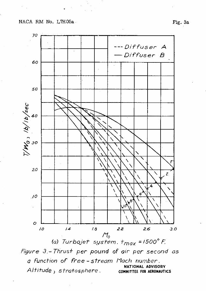
The thrust developed by the turbojet system per pound of air per second.. is shown in figure 3(a) as a function of-the free-stream Mach number. Curves are given for compression ratios of 2, ii, 6 9 85 and 10. The curves show that, for compression ratios of 4 and higher, the thrust decreases rapidly as Mach number is increased. above 1.2. For a compression ratio f Ii. the thrust becomes zero at a Mach number of approximately 3. As the compression ratio Is increased above I, the Mach number at 'which the thrust vanishes decreases. For a compression ratio of 10 the thrust--is zero at a Mach number of about 2.4.. At Mach numbers between 1.2 and 1.6, a compression ratio of 2 produces essentially the same thrust as that produced by higher compression ratios. At Mach numbers-greater than 1.6 a compression ratio of 2 producesmore thrust than that produced by higher compression ratios.,
- The foregoing results are duo principally to the faCt that a limit has been placed on the maxIrm temper ature that the fluid can have in the turbojet system and to the value set for that limit. At the smaller Mach numbers shown in figure 3(a) the temperature rise duo to ram -and. to 'mechanical compression is small enough to allow a large amount of fuel to be burned per pound. of air before the limiting temperature of 1500° P is reached.. At the larger Mach numbers shown in figure. 3(a), however, the temperature nsa duo to mechanical compression in combination with the tempCratüre rise due
6 NACA PM No. L7H05a
to ram brings the air temperature so close to the limit that relatively little fuel can be burned.. Air-fuel ratios for the various compression ratios arV shown in figure Ii. At.a Mach number of 1.2 the air-fuel ratio is 56 for a .compression ratio of 2. Increasing-the compression ratio-, to I increases the air-fuel ratio only to 63. At a Mach number of 3, for a compression ratio of 2 the air-fuel ratio Is 126, but-for a compression ratio of 1i. the air-fuel ratio is 280. At the higher Mach numbers, therefore, little or no thrust Is developed, by the turbojet system. The thrust produced by a propulsive system is derived from the burning of fuel. If little fuel can be burned per pound of air, thenlittle or no thrust can be developed.
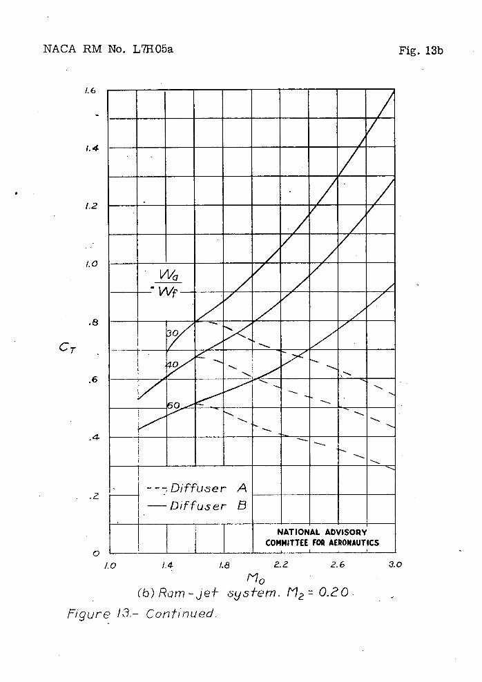
The thrust pf the ram-jet sy8temIe.$hown In figure 3(b) for air-fuel ratios of 30, itO, and 60, these air-fuel ratios remaining constant with Mach number.- It should be remembered that since there is no turbine there is; no limiting maximum temperature. At a Mach number of 1.2 the air-fuel ratio of the turbojet system with a compression ratio of 2 is very close to 60, and, the thrust developed by the two systems can therefore be compared at the air-fuel ratio of 60 at a Mach number of 1.2. The thrust of the turbojet system is 42pounds per pound of air per second and of the ram-Jet system is 25 pounds per pound of air per second. As the free-stream Mach number Is increased., the thrust of the ram-jet system does not decrease rapidly, as does the thrust of the turbojet system, but, with diffuser B Y Increases, at least up to a Mach number of 3.
Throughout the present paper it has been asuEed that the com-bustion chambers are of constant cross-sectional area. The cross-sectional area of the combustion chamber in the ram-jet system is a rather important quantity. In the first place, the thrust coeffi-cient of. the ram-jet system-is based. in the present paper on the combustion-chamber area. In the second place, a loss of total pres-sure occurs when heat is added to a compressible fluid in a constant- area combustion chamber.' The loss of pressure is - other factors being constant - a function of the Mach number of the fluid at the entrance to the combustion chamber, which in turn is a function of the combustion-chamber area. In the third place, the Mach number at the combustion-chamber entrance must be below a certain maximum value if choking in the combustio-i chamber is to be avoided.. Thus, the curve for an air-fuel ratio of 30 in figure 3(b) does not extend down to a Mach number of 1.2 but ends at a Mach number of 1.4 because of choking in the combustion chamber. As is well known, when heat is added to a compressible fluid in a constant-area passage, the fluid accelerates and the local Mach number Increases along the passage. The Increase in Mach.number depends upon the initial enthalpy, the initial Mach number, and the amount of heat added. (Or fuel burned.) per pound of air. If the initial-enthalpy Is low enough, or the lnitIaJ.. Mach number is high enough, or enough
NACA RM. No. L71195 7
fuel is burned, a finà.J. Mach numbez of unity is reached at the exit end of the combustion chamber and chokiig occurs. Figure 3(b) is based .on combustion chambers of such cross-sectidnal areas that the Mach number of the air as it enters the combustion chamber is 0.20. This Mach number, •i low enough, to avoid choking for air-fuel ratios of 140 and 60 bu : chokingdoes occur for an aii-fuel ratio of 3Q at a free-stream Mach number of 1.14,
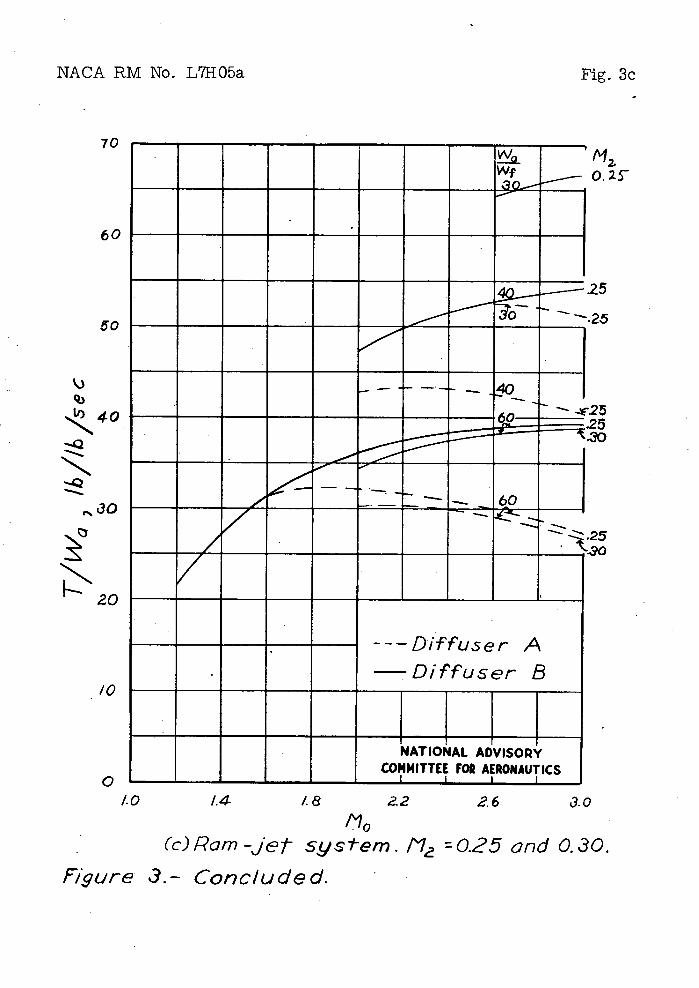
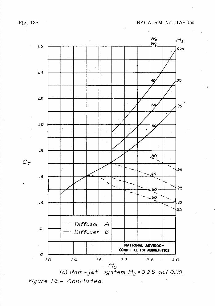
Curves for combustion-chamber entrance Maôh numbers of 0.25 and.'0,30 aro shon in 'figure3(c). The fact that some of these curvesalsoend at freó-stroemMachnumbera greater than 1.2 indicates choking in'the combustion chamber. Comparison of figures 3(b) and 3(c) shows that, if choking does . not occur, the combustion-chamber entrance Mach numbe' has ve±'y little effect on the thrust developed by the ram-jet system.
Thrust Power
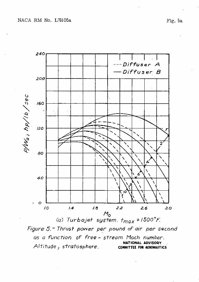
The thrust power developed by a jet-propulsion system is, at a given Mach number, proportional to the thrust force developed by that system. The same significant results therefore can be obtained from a plot of thrust. power that can be obtained, from a plo.t of-'- thrust. Névertholoss, as a matter of information, the thrust power developed by the systems under cpnsithration has been plotted. The variation' with free-st'eam Mach number of the thrust power per pound of air per second of the turbojet system is shown in figure 5(a). For a constant value of compression ratio, as Mach number is increased. above 1.2,' the thrust power rises to a maximum value and then .dcreaees. The existence of .a maximum is due to the fact that thrust power is proportional to the product 'of' two quantities, of which one, thrust, decreases asMch number is increased., and the other, • ,free-stream , speed,. increases as Mach number is increased..
The variation with free-stream Mach number of the thrust power per pound of air per: second o' the-ram-jet system is shown in figure 5(b). . . . '.
Specific Fuel Consumption
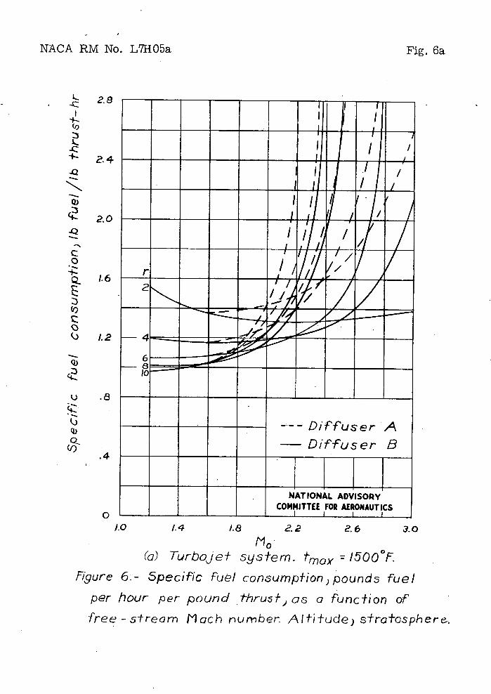
$pCcfic fuel consumption 'computed as pounds . of fuel per hour per pound. Of thrust is shown in figure 6(a) for the. tur1ojet system. For a compression ratio of, 2, the specific fuel, consumption remains at-values near 1.4 for all Mach numbers, between 1,2 an&3.0 if diffuser B is used. With diffuser A' the specific fuel consumption increases rapidly at the higher Mach numbers. At Mach numbers of about 1,2 to 1.6 the specific fuel consumption is decreased as the
8
NACA BM No. L71105a
compression ratio is increased., at least as far as a conr2ressioI ratio of 10. For compression ratios of 6 and higher,' howver, the specific fuel consumption begins to increase rapidly at a Mach number of Elbout 1.8 and reaches very high values at Mach numbers between 2.0 and' 3.0,
The specific fuel consumption of the ram-jet system is shown in figure 6(b). For air-fuel ratios from 30 to 60, the specific fuel consumption'of the ram- jeaystem is considerably greater than that of the turbojet .sstem at Mach numbers between 1.2 and. 2.0. At Mach numbers between 2.0 and 3.0 the specific fuel ponsumption.of the rum-jet system either is approximately the same as or is less than that of the turbojet system; On' the basis of specific fuel consumption, therefore, the tu'bojet 'system shows a decided superiority over the rani. et system at-Mach numbers between 1.2 and 2.0.
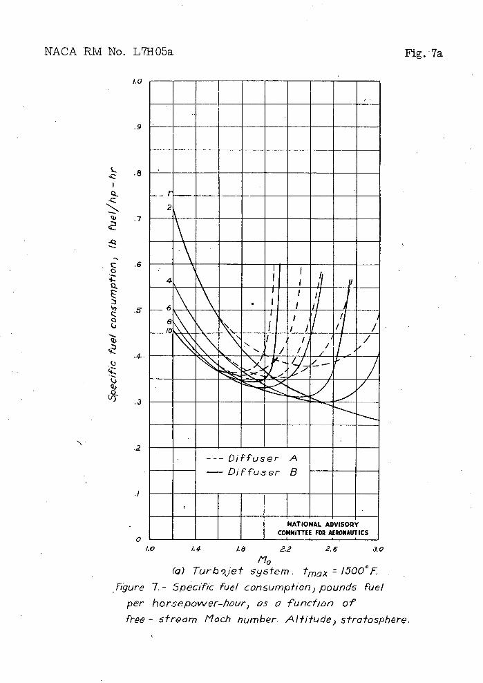
• Specific fuel consumption computed.' as pounds of fuel per thrust horsepower-hour is shown for theturbojet system. in figure 7(a). At a free-stream Mach number of' 3,0 a compression ratio of 2 gives a' lower specific fuel consumption than higher compression ratios. As the Mach number is decreased.,' the compression ratio 'that gives the lowest specific fuel consumption increases. Thus, at a Mach ñuber of 2.0 a compression ratio-of 6 gives a lower specific fuel consum'pton than any other compression ratio. At a Mach number of 2.0, however, the difference between the specific fuel 'consumpticis of systems with compression ratios from 2 to 10 is very small. At a Mach number of 1.2, however, a compression ratio Of"lO gives a'nui2áh lower specific fuel' consumption than a compression ratio of 2 but only a slightly lower specific fuel consumpt i on than a copression ratio of 6'.
The curves for the various compression'ratios show that quite low values of specific fuel consumption are, at least theoretically, attainable In the supersonic turbojet system. At a Mach nuber' of 1.2 the minimum specific fuel consumption shown is 0.46 pound per horsepower-hour, at a Mach number of 2.0 it is 0.32, and at a Mach number of 3.0'it is 0.26. These values are much lower than those attainable at present with a' conventional engine-propeller system at subsonic airplane. speeds.'
As has been shown In the section entitled. "Thrust and Air-Fuel Patio," as the free-stream Mach number is inôreased. the' thrust of the turbojet system with the higher values' of compression ratio decreases rapidly to zero. Correspor4ingly, as the thrust approaches zero, specific fuel consuption 'of the' systems with the higher values of' compression ratio increasesrapidly.
NACA RM No, L707a 9
In figure 7(b) the specific fuel cónsution of the ram-jet system is shown for comparison with that of the turbojet system. The specific fuel consumption of the ram-jet system is shown to be much greater :than that of the turbojet system at a Mach number of 1.2. The difference between the specific fuel consumptions of the two systems decreasesas the Mach number is increased. At a Mach number-of 3.0 the specific fuel consumptions of the ram-jet system and of the turbojet estem viith a compression ratio 'of 2 are about the same.
Cross-Sectional Areas
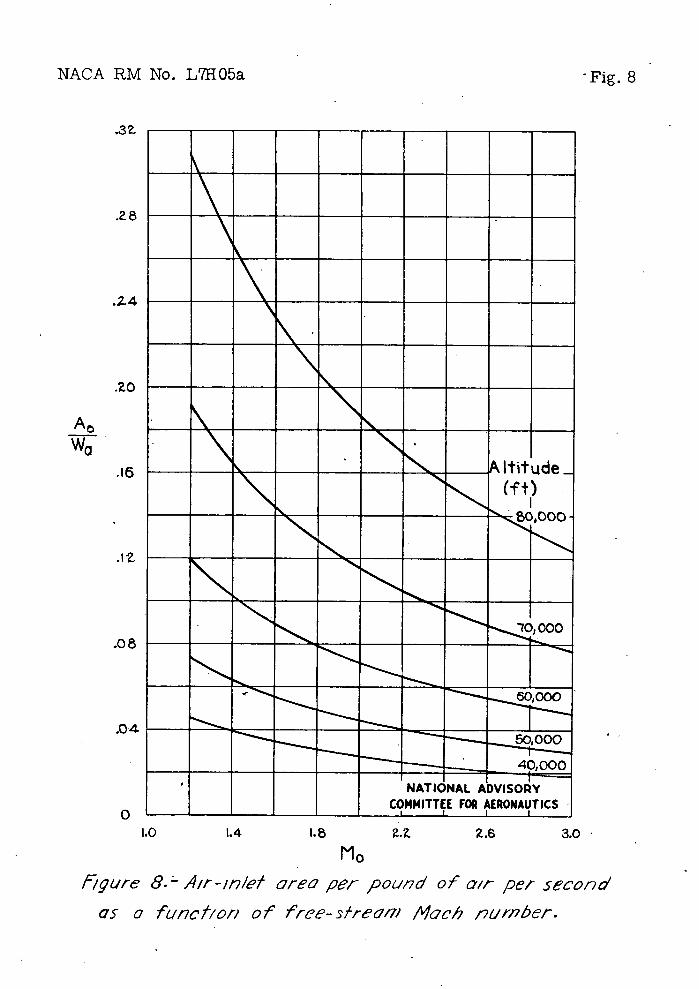
Cross-sectional areas that are of Interest are the free-stream area of the Inducted air, the total area of.the compressor, the area of the combustion chamber, the total area of the turbine, and the area of the exhaust-nozzle exit. The free-stream cross-sectioni1 area A0 of the inducted, air, which is the same as the air-inlet
area of a diffuser of the type shown in figure 1, is given in figure 8 for various altitudes. Although the area A 0 Is not
important in Itself, alf plots of other areas are given In terms of A0 and not in terms of Wa ifl order that a single curve will apply at all altitudes in the stratosphere and that therefore It will not be necessary to show a different curve for each altitude as is done in figure 8.
The ratio.of the compressor total area A 0 to A0 is . shown in
figure 9. Figure 9 applies to all the turbojet systems considered herein, that Is, to all compression ratios, all values of maximum temperature, and all altitudes in the stratosphere. Figure 9 was plotted on the conservative basis of cornpressor,entrance Mach number equal to 0.4 and compressor entrance hub-to-tip-diameter ratio equal to
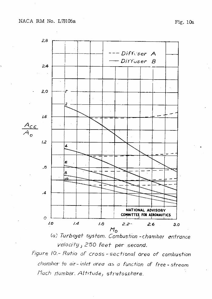
The ratio of the combustion.-chamber-area . Ace 'to A0 , is shown in figure 10. Figure 10(a), for the turbojet system, was prepared on the basis of combustion-chamber entrance velocity equal to 250 feet Per second. Figure 100), for the ram-jot system, wa prepared for combustion-chamber entrance Mach numbers of 0.20, 0.25; and 0.30.
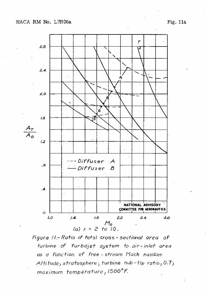
The ratio of the total cross-sectional area of the turbine AT to A0 Is shown in figure 11.. Figure 11 was, prepared on the
assumption that the turbine was a single-stage impulse type with a hub-to-tip diameter ratio of 0 . 7. The curves for the higher
10 NAA RM No. L7HO5a
compression ratios were not extend.ed to the largervalues of Mach number, because single-stage turbines would not be sufficient in this region unless their peripheral speeds exceeded 1350 feet per second.. The curves for the higher values of compression ratio actually are not néeded.:In the region of large Mach numbers, because the thrust decreases rapidly to zero in that region. The assumptions used 'heroin for calculating turbine areas are conservative and lead-to rather large' turbine areas for the lower values of the compressor compression ratio. Less conservative assumptions could, give considorebly smaller areas.
For a cOmpression ratio of 2 the turbine areas are much larger'. than the compressor areas. For a compression ratio of I the turbine areas are somewhat larger than the compressor areas. For a compression ratio of 6 the turbine and. compressor areas are very nearly the same. For compression ratios greater than 6 the area of the compressor Is greater than the area of the turbine.
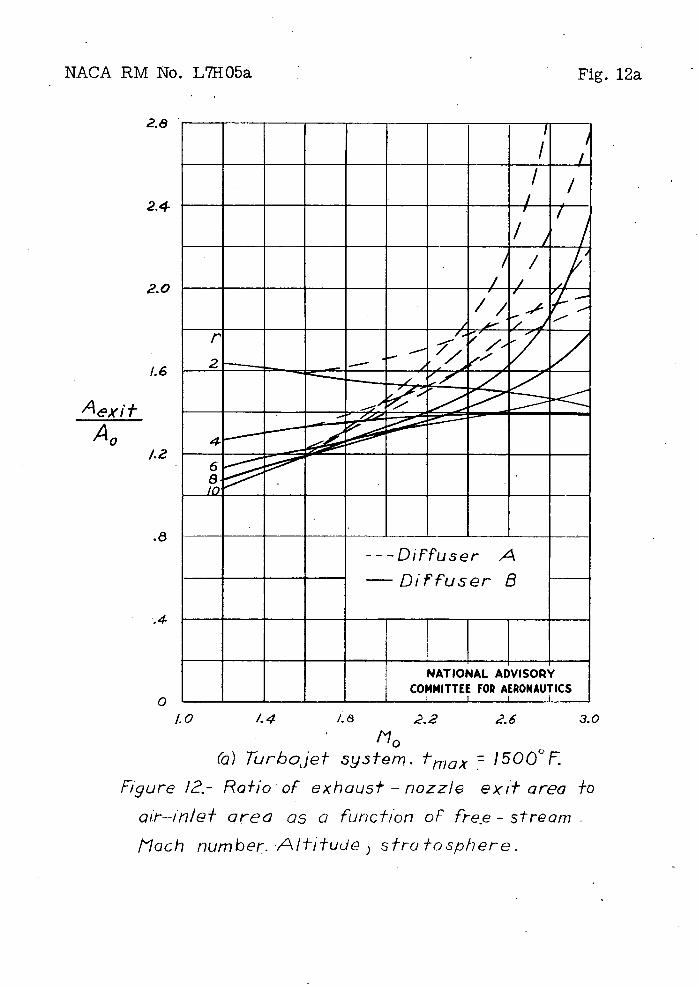
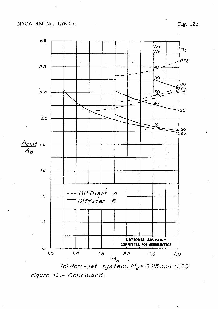
The' ratio of exhaust-nozle edt, or maximum, area Aexit to A0 is shown in figure 12.,. These areas were calculated on the
assumption that the exhaust fluid expanded at the nozzle exit to free-stream static pressure.
Thrust Coefficient
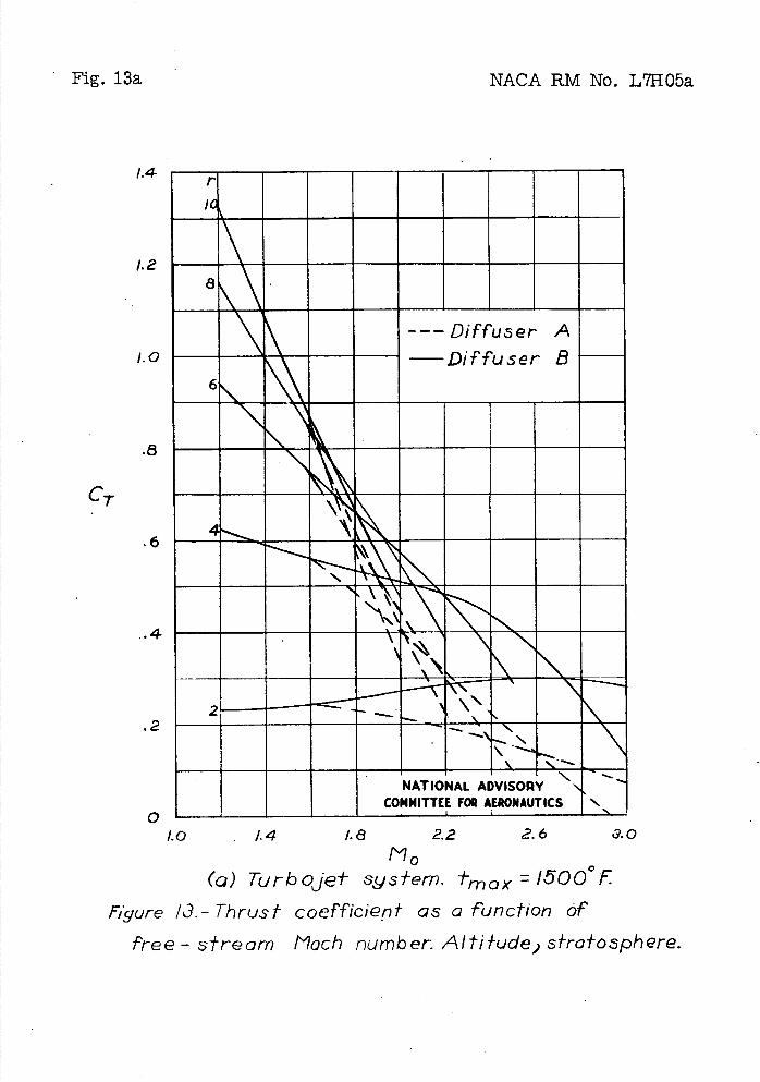
One of the most significant quantities for showing the performance of a pow&.r plant Is the thrust coefficient. The data on thrust and areas given in preceding figures have been used. to obtain figure 13, which shows the variation with free-stream Mach number of the thrust coefficients of the turbojet system and, for comparison, of the ram-Jet system. The thrust coefficient CT
defined- as the thrust divided by the product of free-stream dynamic pressure and an area. For, the turbojet system (fig. 13(a)') the area that was used in calculating the thrust coefficient was the cross-sectional area of the compressor or of the turbine, whichever area
was larger.
Comparison of figures 9 and 10(a) shows that the cross-sectional area of the compressor is greater than that of the combustion chamber. Comparison of fIgures 9 and 11 shows that for, compression ratios of 2 and I-i. the cross-sectional area of the turbine is greater than that of the compressor, for a compression ratio of 6 the areas of the , turbine and the compressor are very 'nearly the same, and for compression' ratios of 8 and 10 the area of the, compressor is greater than that of the turbine. , Comparison of figures 9 and 12(a) shows that at Mach
NACA RM. No. L7HO5a 11
• numbers less than 2.2 the area of the compressor is greater than that of the exhaust-nozzle exit and that at Mach numbers of ? .2 and. higher the area of the nozzle exit is either approximately equal to or greater than the area of the comtreseor. Nozzle-exit areas, however, were not used in calculating CT. If, for a given set of
conditions, the thrust of a jet systemere calculated for various nozzle-exit areas, the thrust would have a maximum value at the nozzle-exit area that expanded the fluid to the ambient pressure. There is a large variation in the nozzle-exit area that gives almost maximum values of thrust, however, and. not. much thrust is sacrificed by using exit areas considerably smaller than the exit area that gives maximum thrust. (See reference 3 . ) Por the urpo of . rduction of external drag, supersonic jet power plants would undoubtedly use exhaust nozzles the exit areas of which were no greater than the maximum area of the rest of the power plant. The thrust coefficients shown In fIgure 13(a)' can therefore be considered to be based on maxiinumcróss-sectional areas.
The thrust coefficients of the turbojet system with high compression ratios are large at the smaller values of Mach number shown in figure 13(a). The thrust coefficients decrease rapidly to zero as the Mach number is increased because the thrust decreases rapidly to zero. At the smaller values of Mach number the thrust coefficients for the lower compression ratios are much less than for the higher compression ratios because of the large turbine cross sections that are required with low compression ratios at the smaller Mach numbers.
• No details aregiven in the present paper of the external design of the housing, or fuselage, of the turbojet system, such as the wedge angle of the leading edge of the air inlet, the length of the fuselage, or the smoothness'of the fuselage surface; accordingly, no precise estimate of the drag of the housing is attem pted. At a given Mach number the drag due to shook depends on the wedge angle, and the drag duo to friction depends 'on the smoothness of the surface and. on the Reynolds number behind the shock. This Reynolds number in turn depends on the wedge angle, the fuselage length, and the altitude. The drag coefficient, of the system based on maximum cross-sectional area can however, be roughly estimated to be 0.15. This value of drag coefficient can be compared with the thrust coefficients shown in figure 13(a). The thrust coefficients are seen to be adequate with low or high compressIon ratios at the smaller Mach numbers and with low compression ratios t the larger Mach numbers.
The thrust coefficients of the ram-jet system areshown in figures .13(b) and 13(c). The d The-so are . the Ci"O56-
12 NACA RM No. L7H05a
sectional area of the combustion chamber: (See fig. 10(b).) The thrust coefficients generally far exceed the estimated drag coefficient of 0.15. The thrust coefficients of the ram—Jet system are generally greater than those of the' turbojet system at the larger Mach numbers. The thrust coefficients of the ram—jet system with diffuser A were calculated for the same kind of diffuser that was asbumed in-part of the analytical studies of reference 3. Diffuser B is much more efficient at the higher Mach numbers than diffuser A and results in much. larger values of the thrust coef-ficient at the higher Mach numbers. The large difference in the thrust coefficients with the two diffusers Is due principally to differences in the area of the combustion chamber. (See fig. 10(b).) Comparison of figures 13(b) and 13(c) shows also that an appreciable gain In thrust coefficient is obtained by making the Mach number at the entrance to thecombustionchambér as large as possible. The; Mach number at the entrance to the combustion chamber is made larger by decreasing the combustion—chamber area, and the resulting Increase in thrust coefficient is due., to the decrease in combustion—chamber area.
Maximum Temperature
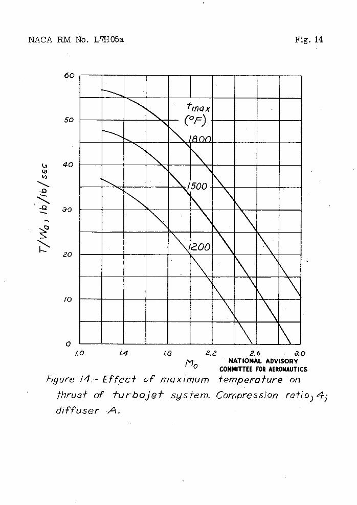
The curves showing the perfornianceof the turbojet systemwere calculated with the use of a maximum fluid total temperature. of 15000 F at the entrance to the turbine. The. fact that a inaxinium limiting temperature is necessary in the turbojet system has a large effect on the performanceof the system, particularly in that a' maximum 'temperature causes .the thrust, of the system to become zero at some value of free—stream Mach number In the neighborhood of 3. In subsonic turbojet systems some variation of maximum temperature from 15000 P does not have a very large effect on the performance of the system. Figures 14 and 15 are presented for the supersonic turbojet system with diffuser A, with a compression rat of 4, and with maximum temperatures of 1200, 1500 0, and 18009 F. Figure 14 shows the variation in the free—stream Mach number at which the .system develops no thrust, and figure 15 shows the variation in the free—stream Mach number at which the specific fuel consumption reaches a minimum and begins to increase rapidly.
'CONCLUDING REMARKS
The performance of hypothetical turbojet systems of propulsion of supersonic airplanes has been calculated for free—stream Mach numbers from 1.2 to 3. For comparison, the performance of the ram-Jet system has also been calculated for the same range of Mach number.
NACA RM No. L71105a 13
At Mach numbers between 1.2 and 2 the calculated thrust ooeffiient of the turbojet system was found to be greater than the estimated drag coefticient. As Mach number Is Increased the thrust coefficient of the system with a compression ratio of 6 or more rapidly decreases and reaches zero at Mach numbers between 2 and 3. At Mach numbers between 2 and. 3, therefore, only compression ratios less than 6 should be considered.
At a Mach number of 1.2 the specific fuel consumption of the turbojet system is much loss than , that of the rem-jet system with comparable thrust or thrust coefficient. As the Mach number Is increased toward. 2, the difference between the specific fuel consumptions of the two systems decreases.
The fact that at.free-stream Mach numbers between 1.2 and 2 the turbojet system has adequate thrust coefficient and low specific fual. consumption (compared with the ram-jet system) means that the turbojet system can logically be considered as a possible power plant for supersonic airplanes operitIng at those Mach numbers. The choice between use of the two systems should, of course, -not be based solely on the fact that the specific fuel consumption of the turbojet system is lower than that of the ram-jet system. The turbojet system is inherently heaver than. the ram-jet system. For flights of great enough time duration, however, the combined weight of the power plant and the fuel will be less for the turbojet system. Other factors than flight duration - such as the advantage that the turbojet system may have at take-off, in accelerating to flight speed, and in laning - should-also becOnsIderud..
Langley Memorial Aeronautical Laboratory. National Adviory Coittee for Aeronautics
Langley Field, Va.
itt. NACA RM No. L7HO5a
APPENDIX
SYMBOLS
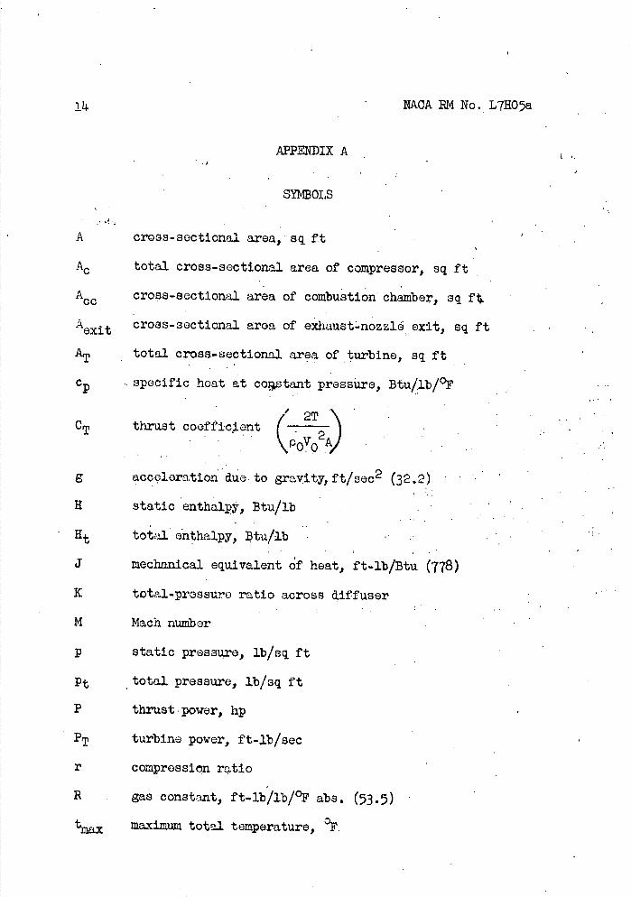
A cross-sectional area, sq ft
Ac total cross-sectional area of compressor, sq ft
A00 cross-sectional area of combustion chamber, sq ft
A0 t cross-sectional area of oxhaust.nozzlé exit, sq ft
AT total cross-sectional area of turbine, sq ft
c specific heat at cotant pressure, Btu/lb/°F
/ .
CT VCV
thrust coefficient2T 2
0 A .
g acceleration due. to gravity, ft/sec 2 (32.2) .....
H static enthalpy, Btu/lb .. .. ..
Ht total onthalpy, tu/lb . . . . .
J mechanical equivalent f heat, ft-lb/Btu (778)
K total-pressure ratio across aiffuser
M Mach number
p static pressure, lb/sq ft
Pt total pressure, lb/sq ft
P thrust power, hp
PT turbine power, ft-lb/sec
r compression ratio
B . gas constant, ft-lb/lb/°F abs - (53.5)
tmax maximum total temperature, °F.
NACA RM No. L7HQ5a15
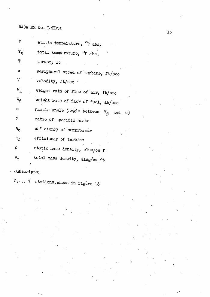
T static temportui'e, °F abs.
Tt total toperature, °F abs.
T thrust, lb
u peripheral speed Of turbine, ft/sec
V VelodIty, ft/sec
Wa weight rate of flow of air, lb/sec
Wf weight rate of flow of fuel, lb/sec
a nozzle angle (angle between V end u)
ratio of Specifjc heats
efficiency of compressor
TIT efficiency of turbine
P statIc mass density, slug/cu ft
Pt total mass density, slug/cu ft
- Subscripts:
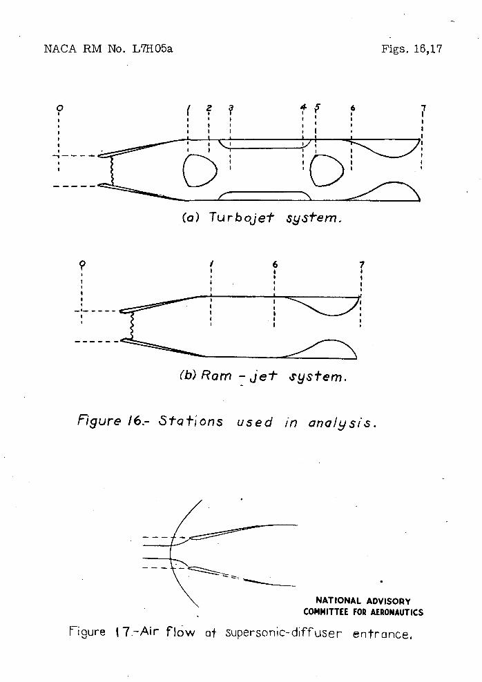
0,... 7 stations,shown In figure 16
16
NACA RM No. L7H05a
APPENDIX B
ANALYSIS AND METHOD OF CALCULATION
Turbojet System
The stations that were used in the analysis of the turbojet system are shown in figure 14(a). The performance of the system was obtained for each set of " . values assigned to the parameters by calculating the state of the -working fluid at each station.
At station 0, in the free stream,
= P0(1 + 7 1 M
0 (1) -
-T= T0
1
1 2) ()
(3) Wa gp0V0
V02 =. -/gRTOM0 (4)
The diffuser is between stations 0 and 1. The function of the diffuser is to receive air of Mach number greater than unity from the free stream and to deliver air Of Mach number less than unity to the compressor with a minimum loss of total pressure. The computations were nude for two typos of diffuser. One type is the fixed-geometry diffuser, a theoretical and experimental 'investigation of which was reported. In reference 4. The theory of reference 4
takes into account the fact that the configuration of the diffuser must be such that establishment of supersonic flow inside the diffuser can be effected. The establishment of supersonic flow in the converging part of the diffuser is generally preceded, before design speed is reached., by a regime in which there is a bow wave in front of the diffuser and subsonic flow In the converging section, as shown in figure 17. The shock first moves up to the entrance of the diffuser, provided that the throat, or minimum section, of the diffuser is large enough to accommodate the passage, at a Mach. number not greater than unity, of all the fluid contained between the
NACA RM No L7HO5a 17
dashed lines of figure 17. The shock then enters the diffuser, passes through the throat, and is established in the diverging section.
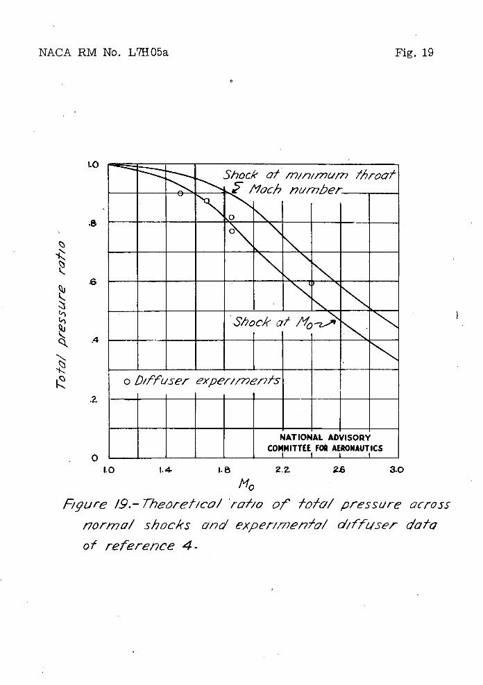
The net result of these considerations is, however, that the throat area cannot be much smaller than the entrance area, and therefore little diffusion of the supersonic flow is obtainable. The minimum Mach number that can be obtained, at the throat, according to the results of reference 4 . , is shown in figure 18 as a function of free-stieam Mach number. It is evident that the Mach number at the throat is only slightly sl1 er \ than the free-stream Mach number. For stability, furthermore, the shock should occur not at the throat but in the diverging section behind the throat. In the diverging section the Mach number increases downstream, and the shock that occurs In the diverging section must occur at a Mach number that is greater than the throat Mach number and that approaches free-stream Mach number. Losses in the subsonic part of the diffuser contribute to the total loss between stations 0 and 1. In figure 19 the upper curve is the theoretical ratio of total pressure across 'a normal shock that occurs at the minimum throat Mach number shown in figure 18. The test-point symbols in figure 19 are the experimentally obtained ratios of total pressure across the diffuser, as given in reference ti. The lower curve is the theoretical ratio of total pressures across a normal shock that occurs at free-stream Mach number. The experimental points lie close to the lower curve. This.curve, which is also shown In figure 2, was used herein as the performance curve of the fixed-geometry diffusers (of.the kind, described in reference 4) for free- stream Mach numbers between 1.6 and 3.
The other type of diffuser for' which computations were made was ,assumed to give the total pressure ratio shown by the solid, curve of figure 2. The diffuser performance shown by this curve can perhaps be obtained with variable-geometry diffusers or with diffusers of the type described in references 5 and. 6. ' Both types of diffusers were assumed to give a 'pressure ratio of 0.9 at Mach numbers from 1.2 to
.6.
Conditions at the entrance to the compressor (station 1, fig. 16(a)) are given by equations (5) to (U) as follows:
'Pt1 = Kpt0 (5)
= Kpt0 . (6)
18 NACA PM No. L71105a
••. Tt=Tt •. ()
Pt
Pi1
(8)
• • Ttl T1 = .( 9)
7-3-2 1+ —M •
2 1
V12 = yT1M (10)
Al 1. = (ii)
Wa p1V1
.In the present paper, in order that the cross-sectional areas of the compressors could an be calculated on the same basis, the compressor-entrance Mach number M1 was sot at the same value, 0.4,
for all compressors, that is, for all values of the compression ratio. The ratio of the' hub diameter to the total. diameter of the axial-flow compressor was set at 0.6 for all compression ratios. The total cross-. sectional area of the compressor A0 • is then 1.56A1.
Conditions at the. exit from the compressor (station 2) are given by equations (12) to (3A) as follows:
pto = rpt • (12)
Ht,/7-1 = cT_y__ + ic - (13)
NACA BM No. L7HO5a 19
A compressor efficiency of 85 percent was used- in all the calculations.
The temperature corresponding to a given value of the enthalpy, or the enthalpy corresponding to a given value of the temperature, was
'found- from the relation.
= C d-T = 0 . 239202T + (i. 63 x 10 T2 + (1.104x lcr9)T3(15) LT which was adapted. from eauation (3) of reference 7. Equation (15) written with li and- Tt in place of H and T gives the relation
between total enthalpy and total temperature. It should be noted that the enthalpy as defined- by equation (15) and as used. in the present parer is based-on a value of zero absolute enthalpy at zero absolute temperature. iatios of enthalpy frequently occur in the equations given herein. In these equations, therefore, values of absolute enthalpy must be used and not values of relative enthalpy based on a zero of enthalpy at se other temperature than absolute zero.
The initial velocity in thecbustion chamber V 3 . was set
at.250 feet per second. An isentropic change in flow, area between stations 2 and 3 was assumed. Then
Pt pt
H= 2 - .
(i')
(18)
The quttity . Tt. is found by means of equation (15). Then
1: . ,.
- 1
V 2''5
20 NACA BM No. L7HO5a
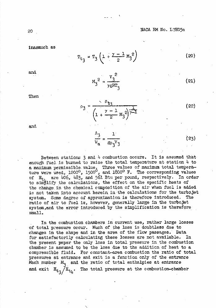
inasmuch as
Tt3 = T3 (1 - _- 1 M32) (20)
and.
M2= 3
Then
'/9T3(21)
= - -(22)
y
and.
2 3,
A3
=(23)
Wa gp3V3
Between stations 3 and 4 combustion occurs. It is assumed that enough fuel is burned to raise the total temperature at station i to a maximum permissible value. Three values of maximum total tempera-ture were used., 1200 0, 15000 , and 18000 F. The corresponding values of Ht are .06, 483, and. 561 Btu per pound., respectively. In order to simli±'r the calculations, the effect on the specific heats of the cha±ge. in the chemical composition of the air when fuel is added is not taken into account herein in the calculations for the turbojet system. Some degree of approximation is therefore introduced. The ratio of air to fuel is, however, generally large in the turbojet system,and. the error introduced, by the simplification is therefore small.
In the combustion chambers in current use, rather large losses of total pressure occur. Much of the loss is doubtless due to changes in the shape an& in the area of the flow passages. Data for satisfactorily calculating these losses are not available. In the present paper the only loss in total pressure in the combustion chamber is assumed to be the loss due to the addition of heat to a compressible fluid. For constant—area combustion the ratio of total pressures at entrance and exit is a function only of the entrance Mach number M and the ratio of total enthalpies at entrance
and exit Ht3/H. The total pressure at the combustion-chamber
NACA 1M No. L7TO5a
21
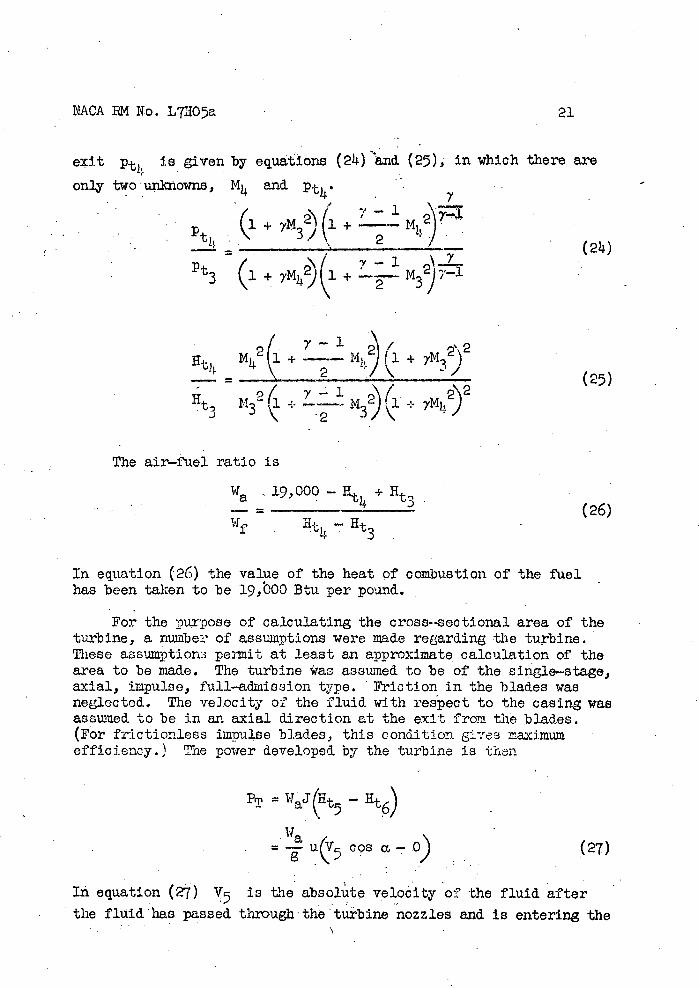
exit Pt4 Is give:
only two unkxowns,
Pt
a by equaiona (24) nd. (25), In which there are
and
(1 +. 7M 3 )(l + --
(21) / '.\( v-1 \..L.
+ 7M42)l + 2 M3 T_
Ut) N 2 + + 2 (25)
-( \( 2\2 Ht M3\. 4. - N3 ) \l-.- yMj)
The air-fuel ratio is
Wa 19,000 + Ut3(26)
Ht(26)
In, equation (26) the value of the heat of combustion of the fuel has been taken to be 19,000 Btu per pound.
For the purpose of calculating the cross--sectional area of the turbine, a number of assumptions were made regarding the turbine. These assumption$ permit at least an approximate calculation of the area to be made. The turbine was assumed to be of the single-stage, axial, impulse, full-admission type. 'Friction in the blades was neglected. The velocity of the fluid with respect to the casing was assumed to be in an axial direction at the exit from the blades. (For frictionless impulse blades, this condition ges maximum efficiency.) The power developed by the turbine is then
= WaJHt - nt6)
Wa _u(hTccosa_0) (27)
In equation (27) V is the absolute velocity of the fluid after
the fluid has passed through 'the turbine nozzles and Is entering the
22 NACA RM No. L7HO5a
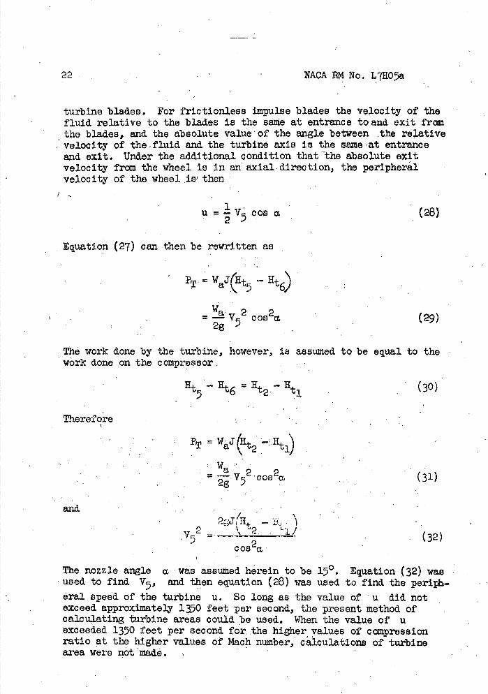
turbine blades. For frictionless impulse blades the velocity of the fluid relative to the blades Is the seine at entrance to and exit frm the blades, and the absolute value of the angle between the relative velocity of the - fluid and the turbine axis Is the same at entrance and exit. Under the add.Itional condition that the absolute exit velocity from the wheel is In an axial direction, the peripheral velocity of the wheel is' then
u=V5 cos M (28)
Equation (27) can then be rewritten as
WJ(H•j; * Ht
= v 2 cos2a. (29) 2g
The work done by the turbine, however, is assumed to be equal to the work done on the comDressor,
lit 5 6 2 Ht (30)
Therefore -
PT = waJ (; —H t1
(31)
and2;J(Ht -
52 (32) C08
2 M
The nozzle angle a was assumed herein to be 150. Equation (32) was used to find. V5, and then equation (28) was used to find the perib-éraJ. speed of the turbine u. So long as the value of u did not exceed. approximately 1350 feet per second., the present method of calculating turbine areas could be used. When the value of u exceeded. 1350 feet per secondfo. the higher values of compression ratio at the higher values of Mach number, calculatlone of turbine area were not made.
NACA IM No. L71105a
23
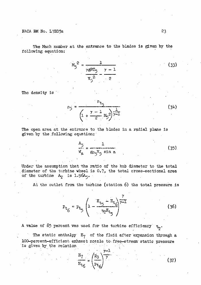
The Mach number at the entrance to the blades Is given by the following equation:
M2 = 1(33)
ygRT5 y - i
r2
The density Is
S
P5 )
H The open area at the entrance to the blades in a radial plane is given by the following equation:
Ar 1 - = (35). Wa gp5V5 sin a
Under the assumption that the ratio of the hub diameter to the total diameter of the turbine wheel is 0.7, the total cross-sectional area of the turbine AT is 1.96A 5'
At the outlet from the turbine (station 6) the total pressure is
7
/
Pt
Ht
= ' F' - 5 . 6 (36) 6 5\ •..1THt5)
A value of, 85 percent was used for the turbine efficiency
The static enthalpy H7 of the fluid after expansion through a
100-percent-efficient exhaust nozzle tó-fre-stre static pre$sure is given by the relation . .. . .
PO
() lit6 t)
NACA RM No. L7HO5a
There is a considerable difference between H. 6
and H7 and
consequently also between 6 and. 77 For the present calculations
the values of H7 were obtained fr the tables of reference 7. These tables give the enthalpy changes as$ociatod. with Isentropic pressure changes. Use of the tables eliminates much tedious calculation or interpolation on a Mollier chart and automatically takes into account the variation of y between stations 6 and 7. The tables were computed for air, but in the turbojet system the air-fuel ratio is so high that neglect of the change in, y with
air-fuel ratio is justified..
The velocity of exit from the airplane is given by the relation
V72 2gJ 6 -H7). (38)
The thrust per pound of air per second is
T V- •V WfV -= 7 (39) Wa .g
The thrust powe'r per pound of air per second is
P .V0T :.(!.Q)
W 550W
From H7 and equation (i), T7 is found. The exhaust-nozzle--
exit area per pound of air per second is then
A7 1 1T7. (41)
Wa 9p7V7 p0V7
Pam-Jet System
The stations that are üed in the analysis of the ram-jet system are shown in figure 16(b). Conditions at station 0 in the free strei are given by equations (1) to (4). The supersonic diffuser is between stations 0 and 1. The diffuser . performance of figure 2 was used for the ram-Jet as well as for the turbojet system. Conditions at the
NACA RM No. L71105a
25
entrance to the combustion chenber (station 1) are given by equa-tions (5) to (ii). The-Mach number at station 1:wa.s set at 0.20, 0.25, and 0.30.
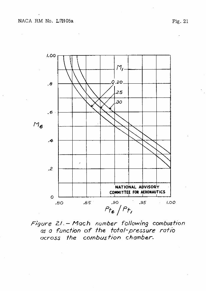
Conditions at station 6 following coibustion are given by equations (2I) to (26) with subscripts 1 and 6 substituted for subscripts 3 and 4, respectively. Air—fuel ratios of 30, 40, and 60 were used in equation (26). Figures 20 and 21 were plotted by means of equations (25) and. (21i), respectively. The ratio
Is found. from equation (26), then M 6 Is found from equation. (25) or figure 20, thetiPt6/Pt1 Is found from equation (24) or fig..-
ure 21. The conditions under which choking occurs can be, readily seen fromfigures 20 and 21. These figures also'show that even under choking conditions the los.s of total pressure due to the addition of heat is not vexr large.
The enthalpy change in the exhaust nozzle was calculated by equation (37). The quantity y in equation (37) was adjusted to take into account the fact that the - air—fuel ratios for the rain—jet system were small enough for the fuel to have an appreciable effect on the value of y. The effect on y of the temperature change between stations 6 and 7 was taken into account by estimating the temperature at station 7, obtaining the corresponding values of and then using the average of Y6 and 77. in equation (37). Effects of dissociation and hat—capacity lag were neglected..
Exhaust velocity is given by equation (38), thrust by equa-tion (39), thrust power by equation (10), and exhaust—nozzle exit area by equation (41).
C,
26 NACA EM No. L7H05a
REFERENCES
1.. Palmer, .Carl B.: lPerformance of Compressor—Turbine Jet—Propulsion Systems, NACAACR No.15E17, 1945.
2. Rubert, Keinedy P.: An Analysis of Jet—Propulsion Systems Making Direct Use of the Working Substance of a Thermodynamic Cycle. NACA ACR No. L5I30a, 1945.
3. 11111, Paul H.: Parameters Determining Performance of Supersonic PilotlessAirplanesPówered by Ram...—Comp ression Power Plants. NACA ACH No. L6D17, 1946.
s. Kantrowitz, Arthur, and Donaldson, Coleman duP.: Preliminary. Investigation of Supersoni .c.Diffusers. NACA ACRNo. L5D20,
1945-
5. Oswatltsch, Ki.: Der DruckrUckgewinn bei Geachossen mit Rückstossantrieb bei hQhén UborschaIlgeschwind.igkeiten. BerichtNr. 1005, Forsch. und. EntvlckI. des Heereswaffenamtes (Göttingen), 1944.
6. Oswatitsch, Ki., andH.: Luft}fte und. Strmungsvorgnge bel angetriebenen Geechossen. Berichte Nr. 10.10 and 1010/2, Forech. und. Entwickl. des Heereewaffenanites (Göttingen) % 19114.
7. Anon.: Tables of Available Energy of Air at High Teniperaturea. General Electric Co. (River Works, Lynn, Mass.), ca. .1941.
NACA RM No. L7HO5a Fig. 1
Corn prts or Turbine
Diffuser Combustion 'chain I.'er Nozzle
(Q) Turbojet system.
Combustion chamber
Diffuser Nozzle
(b) Ram -jet system. NATIONAL ADVISORY
COMMITTEE FOR AERONAUTICS
figure I.-Jet-pro,.ou/sion sysfems.
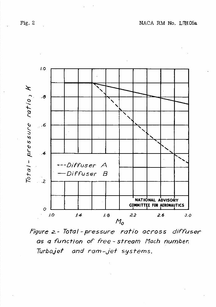
Fig. 2
NACA RM No. L7H05a
1.0
. .8
qj .6 c
'I)
'I) q•)
L.4
4-..2
ri
MEMENEEMEN MENNEIMM, 'MEN NEENE.EENHE NEENEENEEN MEMENEEM N_ EMENEEMEN
MEMEN MENEENINIMEN MENEM----L-NATIONAL ADVISORY
I
COMMITTEE FOR AERONAUTICS -- I I I
1.0 1. 4 /(9 22 26 3.0 fv7 figure 2. - Total - pressure ratio acro 55 diffuser
as a funct/o of free - stream tlac/i number. Turbojet and ram-jet systems.
NACA RM No. L7HO5a
Fig. 3a
70
60
50
1
40
30
20
/0
N Nor- Dl'-F-Fuser A
M
o
-J ENELIL111ILLIk
MENEm EMENEEMSAILIL11LI ENEENEELSILEks]
1.0 14 /8 Z2 2.6 3.0
(a) Thrbcjef system.
Figure 3.-Thrus* per pound of air per second 05
a Function of free - sfrea,-n IlacM number. NATIONAL ADVISORY
Altitude 5frcvt-osphere - COMMITTEE FOR AERONAUTICS
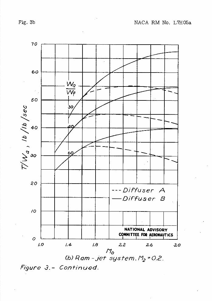
Fig. 3b
NACA RM No. L71{05a
VAE
60
50
g)
40
30
20
/0
- - - --- -
/
(
---Diffuser A —Diffuser B
NATIONAL ADVISORY
COMMITTEE FOR AERONAUTICS
1.0 1.4 48 2.6
3.0
110 (b) Ram -jet system. 1'12 =2.
Figure 3.- Continued.
70
60
50
¼)
40
r3O
20
/0
2. 25-
NACA RM No. L7H05a
Fig. 3c
1.0 1.4 /..S 2.2 2.6 3.0
f10 (c) Ram -je/- System . 112 0.25 and 0.30.
Figure 3.- Concluded.
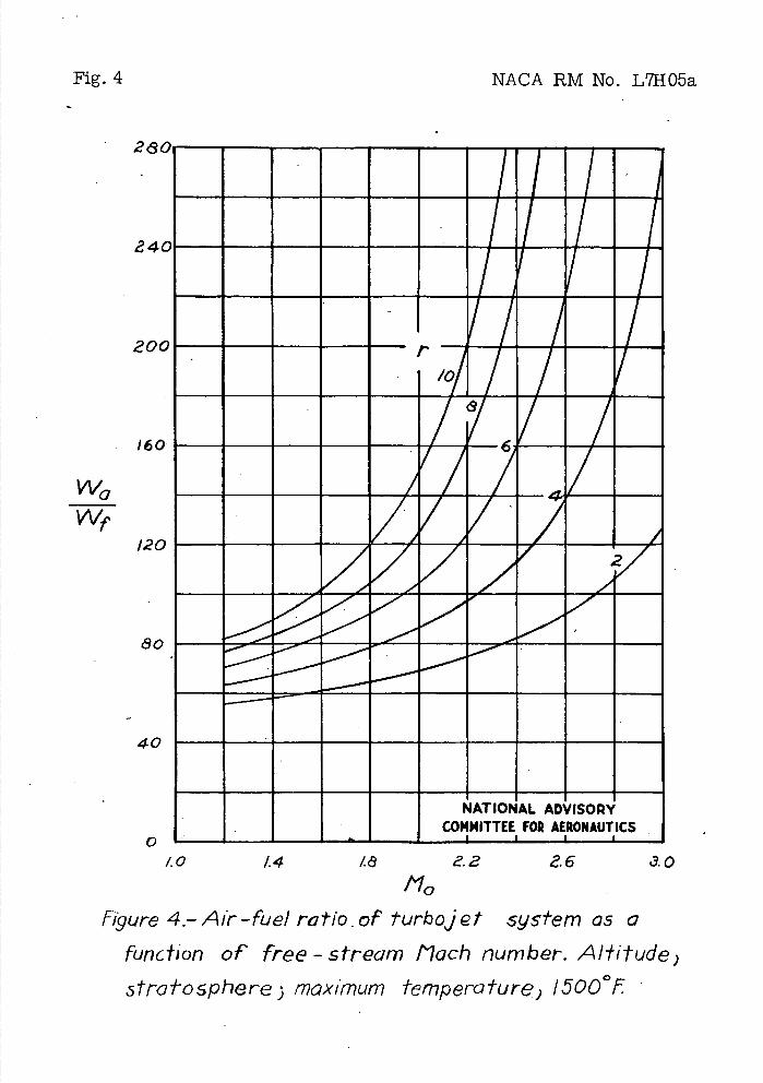
Fig. 4 NACA RM No. L7H05a
28
1a4
20
16(
Wa
Wr/2
40
__rnrivi-- • W11111
MEMOMMMMMMFj'MMFj 4 !FL1MFA NONE ^FJFJM'M MMMMwjvA' MEMENVEAPEFAM
MEMENAM'MPMEMA
0. 41 0 90AP P-.49MM-MPAP
EM
loop P-MOMMEM
NATIONAL ADVISORY
I-)
1.0 14 3.0
Figure 4.-Air-fuel ratioof 1urbojet system as a
function of' free - stream [loch number. A/lit ude)
strolo sphere maximum temperature) 150001
NACA RM No. L7H05a Fig. 5a
240
200
(-) q) (-) /60
I:: 40
ONE0 El —Dirfuser A —Diffuser, 8
MENEM -MEN 000- N._NNqbq,6
1
tO 1.4 ze 2.2 2.6 .30
(q) Turbojet system. tmox "00°1
Figure 51 Thru5t power per pound of air per second
as a function of free - 5±ream Mach njrnber. NATIONAL ADVISORY
Ai±!tude ) 5frQtosphere. COMMITTEE FOR AERONAUTICS
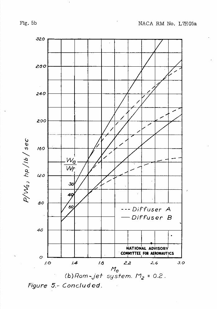
Fig. 5b
NACA RM No. L7H05a
8O
240
2 00
q) U) /60
-Q
-c
/,a o
40
0•
/7 do
-
/
_
l000
,
WQ
W I
47
Diffuser A —Diffuser B
NATIONAL ADVISORY COMMITTEE FOR AERONAUTICS
to 1.4 /.d102 2.6 3.0
/10
(b)Ram-jet 5ysIern. "2 0.2. Figure 5.- Concluded.
NACA RM No. L7H05a Fig. 6a
- 2.a
-f (0
L -c
2.4 -Q
2.0
-Q
0 -S
1-Q. 1.6
E rI)
0 .) 1.2
U .8
(•) qj
.4
FOA
I I
III
I /;
.1
I I
I I/ /
r
- - 6
---Diffuser A - Diffuser B
NATIONAL ADVISORY
COMMITTEE FOR AERONAUTICS
1.0 1.4 I. (9 2.2 2.6 3.0
LN (a) Turboje± SySPerrL tmax
Figure 6.- Specific fuel consumption, pounds fuel per hour per pound fhru* 1 as a function of' free -s#rear-n flack) number-. AI*i±ude ) sro±osphere
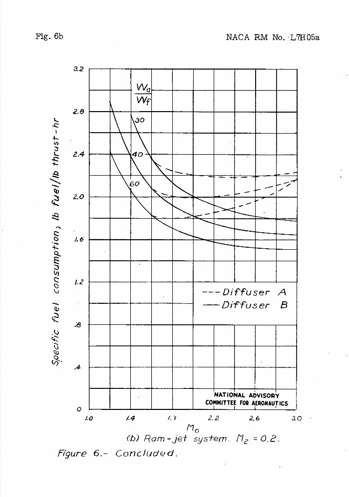
Fig. 6b
NACA RM No. L7H05a
3.2
2.8
L
IJ)
L 2.4
qj2.0
iz
L.
.0 1.6
I1.2
wc Wf
0
0
----Diffuser A —Diffuser B
NATIONAL ADVISORY COMMITTEE FOR AERONAUTICS
1.0 14 I.? 2.2 26 3.0
rio (b) Ram -jet sys-tem. /7 =
Figure 6.- Concluded.
NACA RM No. L7H05a Fig. 7a
0 - - ____________ 40 1.4 48 2.2 2.6 3.0
'via
(a) Turb'jet system. tmQx 1500f
figure 7.- 5pecif'ic fuel consumption ) pounds fuel
per horsepower-hour, as a -function of free - stream t'lach number. AIlitude ) strafosphere.
L
Q) -7 (2 -Q
.6
.4-
E.5
1.0
.2
NN I-
-
- ---- Diffuser A - Diffuser B - - -
NATIONAL ADVISORY
COMMITTEE FOR AERONAUTICS
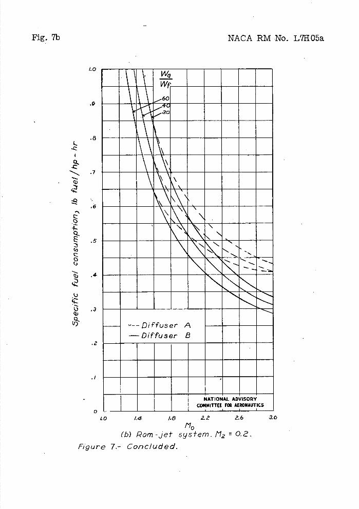
Fig. 7b NACA RM No. L7H05a
..-..-. .7
<2 -Q
.6
CZ
4-Q-
.5
IZ-
q) .4
iz.3
Q)
.2
.8 L
1.0
.9
X d
--Diffuser A —Diffuser B
NATIONAL ADVISORY
COMMITTEE FOR AERONAUTICS
.1
0
1.0 1.4 1.8 2.2 2.6
/10
(b) Rom-jet syslern. t'1 0.2.
Figure 7.- Concluded.
3.0
NACA RM No. L71105a
Fig. 8
.3?.
.26
24
.ao
WO
.16
.06
.04
Immum.-M
"70, 000 I
NATIONAL ADVISORY COMMITTEE FOR AERONAUTICS
I I I I
1.0 1.4 1.8 g2 Z.6 3.0
N0 f'gore 8.- Air-rn/c,1 circe per pound of air pet second
os a funct,'ori of free-strecitii Alcich ,ij,-nber.
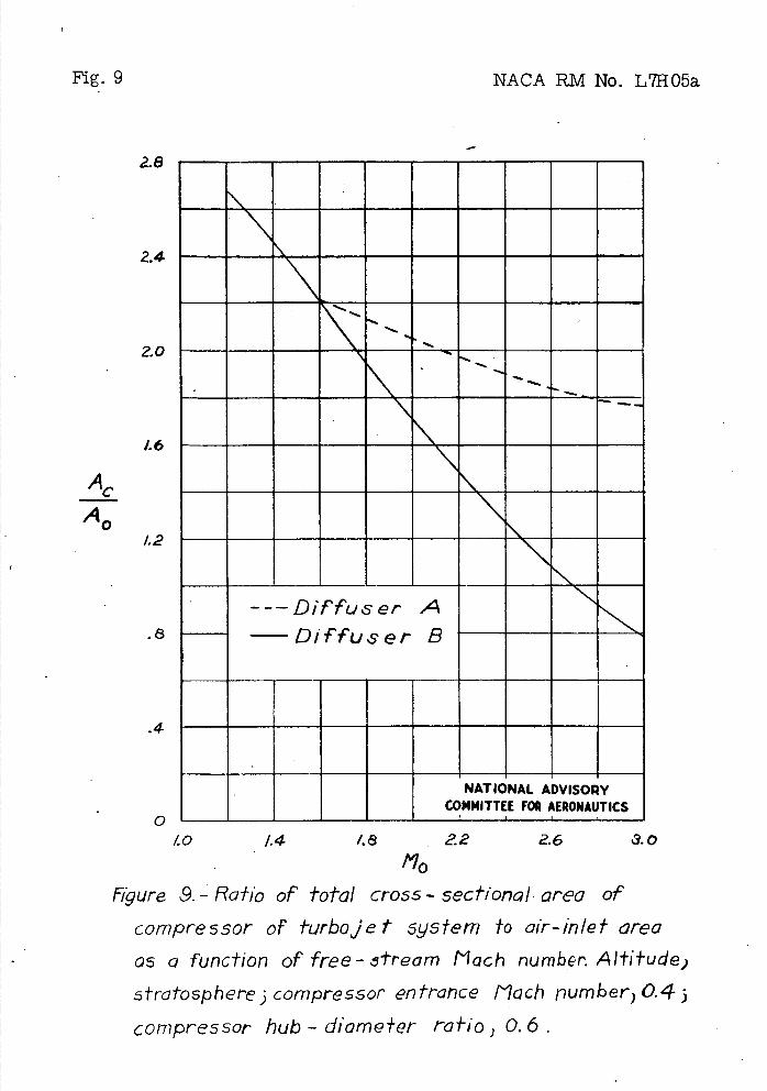
Fig.9
2.8
2.4
2.0
1.6
AC
AO1.2
.8
.4
'-I
NACA RM No. L7H05a
---Diffuser A Diffuser B
NATIONAL ADVISORY COMMITTEE FOR AERONAUTICS
40 1.4 481
2.2 2.6 30
I'10
Figure 9. - Raho of total cross - 5ecfiorlal area of
compressor of turbojet 5y5fem #0 air-in/el- area
as a function of free-5±ream Mach number. Altitude;
5fratospher'e j compressor entrance Ilach number ) 0.4;
compressor hub - diameter ratIo ) 0. 6.
NACA RM No. L71105a
2.8
2.4
- 2.0
• _
1.6
ACC
A0
1.24.
6.
Difft5er A bifTuser B
Fig. lOa
NATIONAL ADVISORY II4ITTEE FOR AERONAUTICS
1.0 1.4 /.a ê.- .6 3.0 t.10
(ci) Turbojet system. CombusI-/on-chmbe, entrance
VE/OCI7' ) 20 feet per second.
Figure /0.- f?a±io of cross - sectional area of combustion
C/7arilber to air - inlet area as a function of free - stream
/'loch ilumber. Alhtude) s-tra-/-ophere.
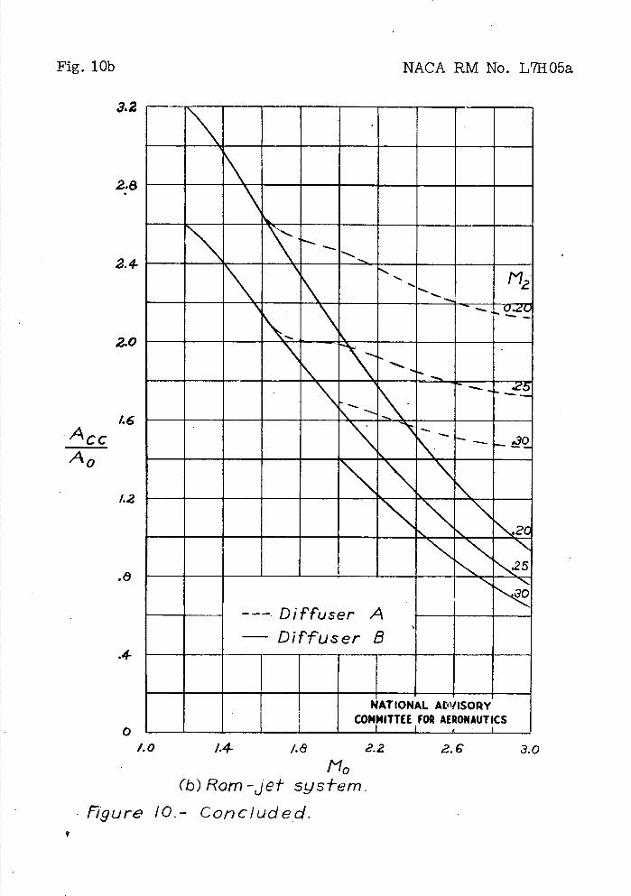
Fig. 1 O
3.2
28
2.4
2.0
1.6 Ac A0
1.2
.4-
NACA RM No. L7H05a
\\\
112 _____
- .30
Diffuser A - Diffuser B
'
NATIONAL ADVISORY COMMITTEE FOR AERONAUTICS
1.0 1.4- /.(9 2.2 2. C 3.0
I'10 (b) Ram -Jet 5y5*em.
Figure /0.- Concluded,
NACA RM No. L7H05a
Fig. ha
2.8
2.4
2.0
.8
.4
ra
r
- —
_ _ N --Diffuser A
—Diffuser 5
NATIONAL ADVISORY
COMMITTEE FOR AERONAUTICS
1.6
A,-
A0
1.2
1.0 1.4 1.8 2.2 2.6 3.0
tdlo (a) r 2 to /0.
Figure /1.-Ratio of total cross-5ectior,a/ area of'
lurbine of furboje* system fo ,air-in/ef area
as a func#ion of free - stream Mach p-,urnber-.
AI#itud ) 5tra±os,rJhere ) turbine hub-tip ratio ) 0.7)
maximum tempra#urC ) /500°F.
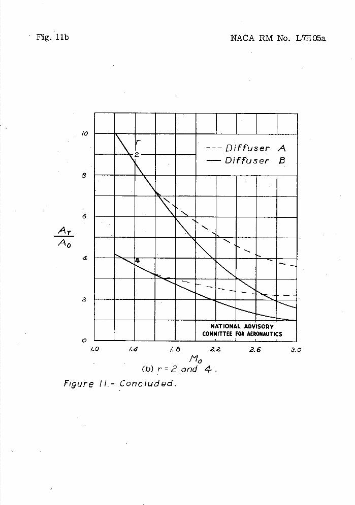
Fig. lib
NACA RM No. L7H05a
/0
8
6
AT A0
4
2
0
__---Diffuser A —Diffuser
NATIONAL ADVISORY COMMITTEE FOR AERONAUTICS
/..0 44 /.ô 2. 2.6 110
(b)r=orid 4.
Figure II.- Concluded.
NACA RM No. L71105a
Fig. 12a
2.8
2.4-
2.0
1.6
A exit A0
1.2
.8
.4
0
PS —
LQ
FH--Diffuser A
—Diffuser a
NATIONAL ADVISORY
COMMITTEE FOR AERONAUTICS
/.0 44 I. ô -0.2 2.6 3.0
110 (a) Turbojet 5y5fem. tmax /500°F.
Figure /&- Ro+io of exhaL.15* -nozzle e.',* area *0
ait---in/e* area as a func 1-ion of ' free - stream
Mach number. A/fi1-ucI slro 1-osphere.
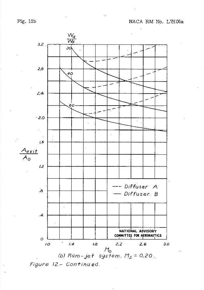
Fig. 12b
3.2
ae
2..O
1.6
A exit A0
1.2
.8
.4
NACA RM No. L71105a
Wa
-
60-- --
--
Diffuser A - Diffuser. B
NATIONAL ADVISORY
COMMITTEE FOR AERONAUTICS
44 1.8 2.2 2.6 3.0
0-
1.0 -
/"lo (b)R'am-je* sgsem.1'12O.2O.
Figure 12.- Cont/hued.
Wa
30
---Diffuser A Diffuser 5
NATIONAL ADVISORY
COMMITTEE FOR AERONAUTICS
1.4 1.8 2.2 3.0
a
2.8
2.4
2.0
Aexit 1.6
A0
1.2
.8
.4
0I.0
0.25
30 25 25
25
30 25
NACA RM No. L7H05a Fig. 12c
No 'c)Rom -jet sys1em. M. 0.25 and 0.30.
Figure 12- Concluded.
NACA RM No. L7H05a
r I'
---Diffuser A Diffuser B
6 \ __
2k- • -S.'
S.-___
NATIONAL ADVISORY N COMMITTEE FOR AERONAUTICS
• Fig. 13a
'.4
1.2
I.0
.8
CT
.6
'.4
.2
1.4 1.8 2.2 2.6 t9.O
(a) Turboje-t- sys*em. Figure 13.- Thrust coef'ficint as a function 61
free - stream f"loch number. A111*ude 1 stratosphere.
MACA RM No. L7HO6a
Fig. 13b
1.6
'.4
(.2
I.0
.8
CT
.6
.4
1.4 I.9 2.1 2.6 3.0
7Z
wo Wf-
- - -
)Q_
- -
r
- --Diffu.er A —Diffuser 8
NATIONAL ADVISORY
COMMITTEE FOR AERONAUTICS
r10
(b)Rarn-je+ oys*ern. M2 °°
Figure /3.- Con f/t-ued.
0
1.0 44 1.6 22 2.6 3.0 f.',?0
(c) Rarn-je* 59$fem.112 0.25 and 0.30.
Figure 13.- Concluded.
Fig. 13c
1.6
'.4
1.2
/.0
.8
Cr
.6
.4
.2
.17//
/
- - '.-
"S.'---
60— .5.
.
'5...
.5-
---Diffuser A DiFfuser B
NATIONAL ADVISORY COMMITTEE FOR AERONAUTICS
NACA RM No. L71105a
we WI'
M2
025
ce
25
30
25
25
25
NACA RM No. L7H05a
60
50
u 40 QI (I,
-Q
20
I0
Fig. 14
tmQx
(Of:)
/500
/200
0 I I I I I \I I I
1.0 1.4 48 2.2 2.6 NATIONAL ADVISORY
0 COMMITTEE FOR AERONAUTICS
f'gure 14- Effecf of max/mum femperature on thrusf of turbojet system. Compression roio)4; diffuser A.
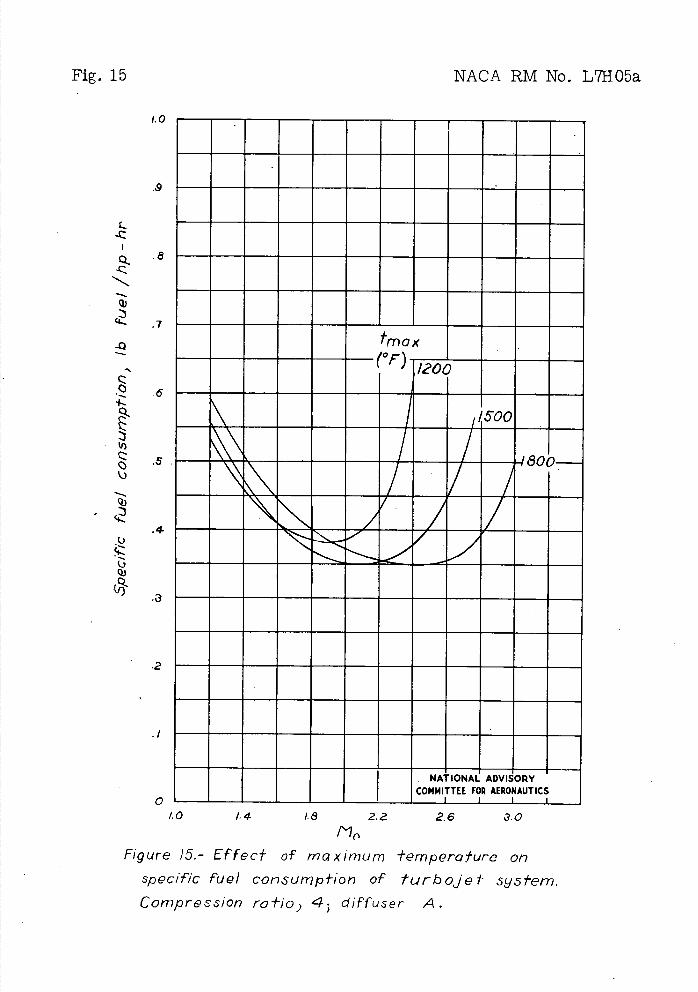
Fig. 15
NACA RM No. L7HO5a
ME
.9
L
Q a
Q)
7
-Q tma x
(°r) 1/200 6
500
.5
4
2
NATIONAL ADVISORY - COMMITTEE FOR AERONAUTICS
QL I I I
1.0
1.4 1.8 2.2 2.6 3.0
Figure 15.- Effect of maximum 1empera,Lure on
specific fuel consurrip1-ion of turbojet sy571em.
Compression ra*io ) 4 diffuser A.
/ 6 7
(h) Ram jet &fem.
NACA RM No. L7H05a Figs. 16,17
I - - - -
I I I I I
I I I I I I I I I I i
(a) Turbojef, &*em.
Figure /6.- &fations used in anc/ysi&.
NATIONAL ADVISORY
COMMITTEE FOR AERONAUTICS
Figure 7.-Air flow at supersonic-diffuser entrance,
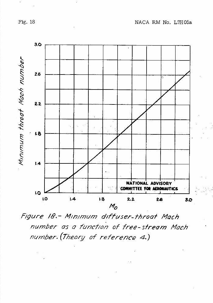
Fig. 18
NACA RM No. L7H0a
3.0
2.6
tj
e
CZ
'.4
NATIONAL ADVISORY • CONMITTU VON AEROAUTlS
I I I
1.0
1.4 1.5 Z.2. 2$ 3.0
NO
figure /8. - /41171127um diffuser- throw/ Mach nu,nbei- ors a funct/012 of free-s/ream Mach nc,mber. (Theory of referenc' 4.)
-. Shock at /77/tw/ThW?7 /,roct
• ON
• N
o Diffiser experiveri/s
NATIONAL . ADVISORY COMMITTEE FOR AERONAUTICS
I.0
.8
Rm
11
NACA RM No. L7HO5a
Fig. 19
1.0 114 1.6 2.Z 2.6 3.0
NO
Figure 19. - Theoretical 'rai'io of foiLa/ pressure across
normal shocks and expe'w71ern1o1 d,ffser QC/Q
of reference 4.
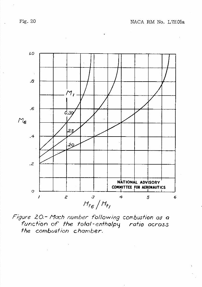
Fig. 20
NACA RM No. L7H05a
2 /1
NATIONAL ADVISORY
COMMITTEE FOR AERONAUTICS
I 2 a 4 5 6
"t6 tyfl Figure 20. - tioch number following combustion QS a
7'inc17On of the totof-enlhalpij ratio acros.s t/ g combustion chamber.
I.0
.8
.6
.4
.2
0
NACA RM No. L71105a Fig. 21
1.00
TI'
.8 .20.
.25
20
.6
.4
.2
i
NATIONAL ADVISORY COMMITTEE FOR AERONAUTICS
I I
.80 .85 .90 .95 1.00
P6
/I ),t-/
r;gure /. - Mach number following combustion QS o function of the total-pressure ratib across the combustion chamber.
Related Documents


